Installation and Operation Manual - IP-DECT Base ... - Zenitel
75
TD 92372GB 2007-06-18/ Ver. E Installation and Operation Manual IP-DECT Base Station and IP-DECT Gateway
-
Upload
khangminh22 -
Category
Documents
-
view
0 -
download
0
Transcript of Installation and Operation Manual - IP-DECT Base ... - Zenitel

TD 92372GB
2007-06-18/ Ver. E
Installation and Operation ManualIP-DECT Base Station and IP-DECT Gateway

TD 92372GBInstallation and Operation ManualIP-DECT Base Station & IP-DECT Gateway
Contents
1 Introduction............................................................................................................. 1
1.1 Abbreviations and Glossary ................................................................................ 1
2 Description............................................................................................................... 2
2.1 IP-DECT Base Station .......................................................................................... 2
2.1.1 IP-DECT Base Station with Internal Antenna ............................................... 2
2.1.2 IP-DECT Base Station with External Antennas ............................................. 4
2.2 IP-DECT Gateway ............................................................................................... 5
2.2.1 Overview ................................................................................................... 5
2.2.2 Power Supply ............................................................................................. 5
2.2.3 LED indication ............................................................................................ 5
2.3 DECT Base Station BS3x0 ................................................................................... 7
2.3.1 DECT Base Station ..................................................................................... 7
2.4 AC-adapter ........................................................................................................ 8
3 Safety and Regulations........................................................................................... 9
3.1 Safety ................................................................................................................ 9
3.1.1 Safety Rules ............................................................................................... 9
3.1.2 Safety Symbols ........................................................................................... 9
3.2 Protection Against Electrostatic Discharge (ESD) ............................................... 10
3.2.1 ESD Handling ........................................................................................... 10
3.3 Safety Aspects of the IP-DECT Base Station ...................................................... 10
3.4 Safety Aspects of the BS3x0 Base Station ......................................................... 10
3.5 Safety Aspects of the IP-DECT Gateway ........................................................... 10
3.6 Standards and Regulations for US .................................................................... 11
3.6.1 Standards and Regulations ....................................................................... 11
3.6.2 Radio Equipment ..................................................................................... 11
3.6.3 Fixed Position System Equipment: Power Adapters ................................... 11
3.6.4 Regulatory Compliance Statements .......................................................... 11
3.7 CE-marking ...................................................................................................... 12
4 Installation of the Base Station............................................................................ 13
4.1 Base Station Cabling ........................................................................................ 13
4.2 Install the Base Station ..................................................................................... 13
4.2.1 Fix the Mounting Bracket to a Wall .......................................................... 13
4.2.2 Fix the Mounting Bracket to a Ceiling ...................................................... 14
4.2.3 Fix the Mounting Bracket to a Pole or Beam ............................................. 14
4.2.4 Use the Cable Ducts ................................................................................. 15
4.2.5 Secure the Cable ...................................................................................... 16
4.2.6 Pinning .................................................................................................... 16
4.2.7 Connect the Base Station Cables .............................................................. 18
2007-06-18/ Ver. E

TD 92372GBInstallation and Operation ManualIP-DECT Base Station & IP-DECT Gateway
4.2.8 Mount the Base Station ........................................................................... 18
4.3 Power the Base Station .................................................................................... 19
4.3.1 Power the IPBS over Ethernet ................................................................... 19
4.3.2 Power the BS3x0 over Express Powering Pair (EPP) and data pairs ............. 19
4.3.3 Power the Base Station with a Local Power Supply ................................... 19
5 Installation of the IPBL.......................................................................................... 20
5.1 Install the IPBL .................................................................................................. 20
5.2 Pin the IPBL Cable ............................................................................................ 21
5.2.1 Synchronization Cable ............................................................................. 21
5.2.2 RFP Cable ................................................................................................ 22
5.2.3 LAN Cable ............................................................................................... 22
5.3 Power the IPBL ................................................................................................. 23
5.3.1 110/230 VAC ........................................................................................... 23
5.3.2 48 VDC ................................................................................................... 24
6 Configuration ........................................................................................................ 25
6.1 Requirements ................................................................................................... 25
6.1.1 Web Browser Requirements ..................................................................... 25
6.2 Access the GUI ................................................................................................. 25
6.2.1 Determine the IP Address ......................................................................... 25
6.2.2 Change the Default Password .................................................................. 27
6.3 Configure the Master ....................................................................................... 27
6.4 Configure the Standby Master ......................................................................... 28
6.5 Configure the Slave ......................................................................................... 29
6.6 Add Users ........................................................................................................ 30
6.6.1 Anonymous Registration .......................................................................... 30
6.6.2 Individual Registration .............................................................................. 31
7 Operation............................................................................................................... 32
7.1 General ............................................................................................................ 32
7.1.1 Change User Name and Password ............................................................ 32
7.1.2 Name the IPBS/IPBL .................................................................................. 32
7.1.3 Licence .................................................................................................... 33
7.1.4 Configure Automatic Firmware Update .................................................... 33
7.1.5 Configure the NTP Settings ...................................................................... 34
7.1.6 Configure Logging ................................................................................... 35
7.1.7 Configure the HTTP settings ..................................................................... 36
7.1.8 Configure the HTTP Client settings ........................................................... 36
7.2 LAN ................................................................................................................. 37
7.2.1 Set DHCP Mode ....................................................................................... 37
7.2.2 Set a Static IP Address .............................................................................. 37
7.2.3 Dynamic IP address via DHCP ................................................................... 38
2007-06-18/ Ver. E

TD 92372GBInstallation and Operation ManualIP-DECT Base Station & IP-DECT Gateway
7.2.4 Link ......................................................................................................... 38
7.2.5 Configure VLAN ....................................................................................... 38
7.2.6 View LAN Statistics .................................................................................. 38
7.3 IP ..................................................................................................................... 39
7.3.1 Configure IP Settings ............................................................................... 39
7.3.2 Routing ................................................................................................... 39
7.4 LDAP ............................................................................................................... 39
7.4.1 Configure LDAP Server ............................................................................. 39
7.4.2 Configure LDAP Replicator ....................................................................... 40
7.4.3 Check LDAP Replicator/Server status ........................................................ 40
7.5 DECT ............................................................................................................... 41
7.5.1 Change System Name and Password ........................................................ 41
7.5.2 Configure Authentication Code ............................................................... 42
7.5.3 Change Subscription Method ................................................................... 42
7.5.4 Select Tones ............................................................................................. 42
7.5.5 Set Default Language ............................................................................... 42
7.5.6 Set Frequency Band ................................................................................. 42
7.5.7 Enable Carriers ......................................................................................... 43
7.5.8 Enbloc Dialling ......................................................................................... 43
7.5.9 Local R-Key Handling ............................................................................... 43
7.5.10 DTMF through RTP Channel ................................................................... 43
7.5.11 No Transfer on Hangup .......................................................................... 43
7.5.12 Configure Coder .................................................................................... 43
7.5.13 Configure Supplementary Services ......................................................... 44
7.5.14 Select Mode ........................................................................................... 44
7.5.15 Configure Gatekeeper ........................................................................... 45
7.5.16 Enter IP Address to the Master and the Standby Master ......................... 45
7.5.17 PARI ....................................................................................................... 45
7.5.18 SARI ...................................................................................................... 46
7.5.19 Configure Messaging ............................................................................. 46
7.5.20 Configure Air Synchronization ............................................................... 46
7.6 Users ............................................................................................................... 50
7.6.1 Add a User .............................................................................................. 50
7.6.2 Search for User Information ..................................................................... 50
7.6.3 Show all Registered Users in the IP-DECT System ...................................... 50
7.6.4 Show Anonymous ................................................................................... 50
7.7 Device Overview .............................................................................................. 51
7.7.1 Radios ..................................................................................................... 51
7.7.2 Air Sync ................................................................................................... 52
7.7.3 RFPs ......................................................................................................... 52
7.7.4 Sync Ring ................................................................................................. 54
2007-06-18/ Ver. E

TD 92372GBInstallation and Operation ManualIP-DECT Base Station & IP-DECT Gateway
7.7.5 Sync Ports ................................................................................................ 54
7.8 Traffic .............................................................................................................. 55
7.8.1 Statistics .................................................................................................. 55
7.8.2 Display All Ongoing Calls in the System .................................................... 55
7.8.3 Display Calls ............................................................................................. 55
7.8.4 Handover ................................................................................................. 55
7.9 Backup ............................................................................................................ 56
7.10 Update .......................................................................................................... 56
7.10.1 Update Configuration ............................................................................ 56
7.10.2 Update Firmware ................................................................................... 56
7.10.3 Update the Boot File .............................................................................. 57
7.10.4 Update the RFPs ..................................................................................... 57
7.11 Diagnostics .................................................................................................... 58
7.11.1 Logging ................................................................................................. 58
7.11.2 Tracing ................................................................................................... 58
7.11.3 Config Show ......................................................................................... 58
7.11.4 Ping ....................................................................................................... 58
7.11.5 Environment .......................................................................................... 59
7.11.6 RFP Scan ................................................................................................ 59
7.11.7 Service Report ........................................................................................ 59
7.12 Reset ............................................................................................................. 60
7.12.1 Idle Reset ............................................................................................... 60
7.12.2 Immediate Reset .................................................................................... 60
7.12.3 TFTP Mode ............................................................................................. 60
7.13 Reset Using the Reset Button ......................................................................... 60
8 Commissioning...................................................................................................... 61
8.1 Radio coverage verification tests ...................................................................... 61
8.1.1 Base Station Operation Test ...................................................................... 61
8.1.2 Coverage Area Test .................................................................................. 61
8.1.3 Evaluation ................................................................................................ 61
8.2 Cordless Extension Number Test ....................................................................... 62
9 Troubleshooting .................................................................................................... 63
9.1 Load Firmware Using the Gwload Tool ............................................................. 63
10 Related Documents ............................................................................................. 64
Appendix A: How to Use the Update Server ......................................................... 66
Appendix B: RFP Power Consumption.................................................................... 71
2007-06-18/ Ver. E

TD 92372GBInstallation and Operation ManualIP-DECT Base Station & IP-DECT Gateway
1 Introduction
This documet describes how to install and operate the following equipment:
• IP-DECT Base Station (IPBS)
• IP-DECT Gateway (IPBL)
The document is intended as a guide for installation, troubleshooting and maintenance purposes and are relevant for the following personnel:
• System administrator
• Service technician
For information on the IP-DECT system, see System Description, Ascom IP-DECT System, TD92375.
1.1 Abbreviations and Glossary
DECT Digital Enhanced Cordless Telecommunications: global standard for cordless telecommunication.
DHCP Dynamic Host Configuration Protocol
DTMF Dual Tone Multiple-Frequency
FER Frame Error Rate
GUI Graphical User Interface
IP Internet Protocol: global standard that defines how to send data from one computer to another through the Internet
IPBL IP-DECT Gateway
IPBS IP-DECT Base Station
LAN Local Area Network:a group of computers and associated devices that share a common communication line.
LDAP Lightweight Directory Access Protocol
PBX Private Branch Exchange:telephone system within an enterprise that switches calls between local lines and allows all users to share a certain number of external lines.
PSCN Primary receiver Scan Carrier Number:defines the RF carrier on which one receiver will be listening on the next frame.
RFP Radio Fixed Part. DECT base-station part of the DECT Infrastructure.
RFPI Radio Fixed Part Identity
RSSI Radio Signal Strength Information
SST Site Survey Tool
VLAN Viritual Local Area Network
2007-06-18/ Ver. E 1

TD 92372GBInstallation and Operation ManualIP-DECT Base Station & IP-DECT Gateway
2 Description
This section gives a general description of the IP-DECT Base Station, IP-DECT Gateway and DECT Base Starion.
2.1 IP-DECT Base Station
The following versions of the IPBS are available:
• IPBS with Internal antenna
• IPBS with External antennas
2.1.1 IP-DECT Base Station with Internal Antenna
Figure 1.
Test (RJ12)
LAN(RJ45)
Power Supply(RJ45)
Front viewBack view
LED1
LED2
005
Reset
Figure 1. IPBS Overview
Contents of the Box
The box in which the IPBS is packed contains:
• An IPBS with integrated antennas
• A mounting bracket
• Two screws with wall plugs
Power Distribution
The IPBS can be powered using the following methods:
• Power over Ethernet, IEEE 802.3af
• A local AC-adapter
Note: For more information about power distribution, see 4.3 Power the Base Station on page 19.
2007-06-18/ Ver. E 2

TD 92372GBInstallation and Operation ManualIP-DECT Base Station & IP-DECT Gateway
Software
The software in the IPBS can be updated by downloading new software without disconnecting the equipment. The new software is stored in flash memory. See 7.10 Update on page 56 for information.
Connectors
• Two 8-pin RJ45 modular jacks for LAN/PoE and powering
• A 6-pin RJ12 modular jack for factory testing
LEDs
Status of LED1 (lower LED) Description
Steady Green Operational
Quick flashing amber Download of firmware in progress.
Steady Amber TFTP mode
Alternating red/green No Ethernet connection
Status of LED2 (upper LED) Description
Not lit IPBS operational and no trafficAir synchronization OK
Steady green IPBS operational and trafficAir synchronization OK
Slow flashing green Air synchronization OK and fully occupied with traffic
Flashing amber Air synchronization inadequate and no traffic
Slow flashing amber Air synchronization inadequate and fully occupied with traffic
Steady amber Air synchronization inadequate and traffic
Flashing red No air synchronization - searching for air sync candidates
Quick flashing red Download of RFP software in progress
2007-06-18/ Ver. E 3
TD 92372GBInstallation and Operation ManualIP-DECT Base Station & IP-DECT Gateway
2.1.2 IP-DECT Base Station with External Antennas
The IPBS is available with two omni-directional external antennas. Other external antennas can be mounted as well. This section contains the differences between the IPBS with internal and external antennas. For all other information see 2.1.1 IP-DECT Base Station with Internal Antenna on page 2.
Contents of the Box
The box in which the IPBS is packed contains:
• An IPBS for external antennas
• Two antennas
• A mounting bracket
• Two screws with wall plugs
Note: The IPBS cannot be mounted with the antennas pointing downwards as the mounting bracket does not support it.
Insert the antennas into the IPBS before following the installation instructions in 4.2 Install the Base Station on page 13.
2007-06-18/ Ver. E 4

TD 92372GBInstallation and Operation ManualIP-DECT Base Station & IP-DECT Gateway
2.2 IP-DECT Gateway
The following versions of the IPBL are available:
• IPBL IP-DECT Gateway VAC/VDC (for 110/230 VAC or 48 VDC)
• IPBL IP-DECT Gateway VDC (for 48 VDC)
2.2.1 Overview
Figure 2.
lan synchronization reference
1 2 ring in ring out in out
base station 01 02 03 04 05 06 07 08
09 10 11 12 13 14 15 16
006
1 2 3 4 5 6
Figure 2. Overview of the IPBL
Pos. Name Function
1 Reset Resets the IPBL, see 7.13 Reset Using the Reset Button on page 60 for more information.
2 Status LED Indicates the status on the IPBL.
3 Lan 10BASE-T/100BASE-TX Ethernet interface.
4 Synchronization Sync ring in and sync ring out interfaces.
5 Reference Reference sync in and reference sync out interfaces.
6 Base station 01-16 ISDN UPN DECT base station interfaces.
2.2.2 Power Supply
The power supply are located at the rear of the IPBL. The IPBL can be powered using the following alternatives:
• 110/230 VAC (only IPBL IP-DECT Gateway VAC/VDC)
• 48 VDC
Note: For more information, see 5.3 Power the IPBL on page 23.
Software
The software in the IPBL can be updated by downloading new software without disconnecting the equipment. The new software is stored in flash memory. See 7.10 Update on page 56 for information.
2.2.3 LED indication
Figure 3.
Status LED Description
Not lit Not powered, status is not defined.
Steady Green Status OK, system is fully operational.
Steady Red Status Fail, system error condition.
Steady Amber System is in TFTP server mode.Figure 4.
2007-06-18/ Ver. E 5

TD 92372GBInstallation and Operation ManualIP-DECT Base Station & IP-DECT Gateway
Figure 5.
Base station LED Description
Not lit No UPN link established.
Flashing UPN link established (activated state), RFP is not operational.
Steady RFP is fully initialised and operational.
Figure 6.
Base station LED Description
Not lit No speech activity in RFP.
Flashing All speech channels occupied in RFP.
Steady Speech activity in RFP.
Figure 7.
Sync/Ref sync LED Description
Not lit No sync communication established.
Steady Communication established.
Figure 8.
Sync/Ref sync LED Description
Not lit Sync port not selected as input sync source.
Flashing Sync port selected as input sync source but the sync signal is not in sync.
Steady Sync port selected as input sync source and the sync signal is in sync.
Figure 9.
Lan LED Description
Not lit No link.
Flashing Link present and network activity.
Steady Link present, but no network activity.
Figure 10.
Lan LED Description
Not lit 10 Mbps operation.
Steady 100 Mbps operation.
2007-06-18/ Ver. E 6

TD 92372GBInstallation and Operation ManualIP-DECT Base Station & IP-DECT Gateway
2.3 DECT Base Station BS3x0
The following versions of the are available:
• BS330 with Internal antenna
• BS340 with External antennas
2.3.1 DECT Base Station
Figure 11.
Test (RJ12)
Data/Power(RJ45)
Data/Power(RJ45)
Front viewBack view
LED1
LED2
007
Figure 3. BS3x0 Overview
Contents of the Box
The box in which the base station is packed contains:
• A base station
• Two antennas (only base station with external antenna)
• A mounting bracket
• Two screws with wall plugs
Power Distribution
The base station can be powered using the following methods:
• From the IPBL via the Express Powering Pair (EPP) and data pairs
• With a local AC-adapter
Note: For more information about power distribution, see 4.3 Power the Base Station on page 19.
2007-06-18/ Ver. E 7
TD 92372GBInstallation and Operation ManualIP-DECT Base Station & IP-DECT Gateway
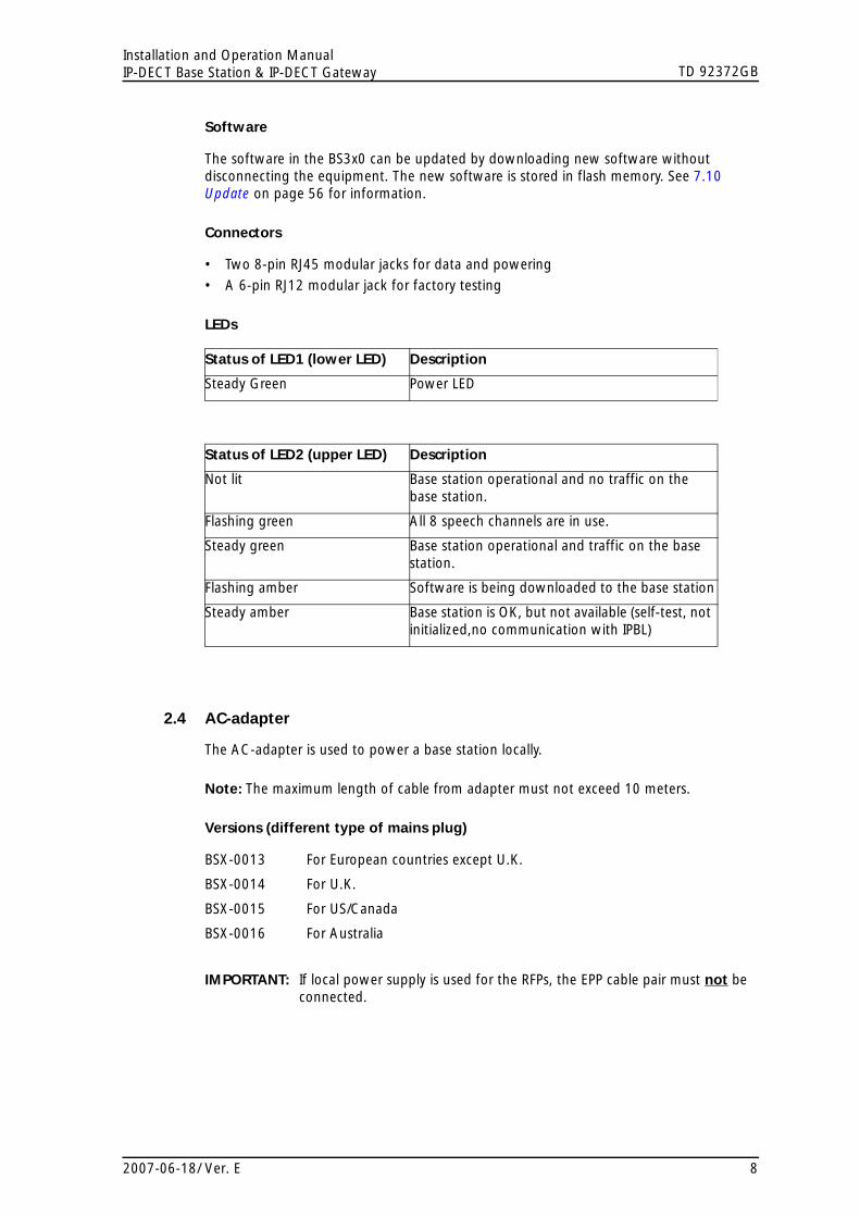
Software
The software in the BS3x0 can be updated by downloading new software without disconnecting the equipment. The new software is stored in flash memory. See 7.10 Update on page 56 for information.
Connectors
• Two 8-pin RJ45 modular jacks for data and powering
• A 6-pin RJ12 modular jack for factory testing
LEDs
Status of LED1 (lower LED) Description
Steady Green Power LED
Status of LED2 (upper LED) Description
Not lit Base station operational and no traffic on the base station.
Flashing green All 8 speech channels are in use.
Steady green Base station operational and traffic on the base station.
Flashing amber Software is being downloaded to the base station
Steady amber Base station is OK, but not available (self-test, not initialized,no communication with IPBL)
2.4 AC-adapter
The AC-adapter is used to power a base station locally.
Note: The maximum length of cable from adapter must not exceed 10 meters.
Versions
BSX-0013 For European countries except U.K.
BSX-0014 For U.K.
BSX-0015 For US/Canada
BSX-0016 For Australia
(different type of mains plug)
IMPORTANT: If local power supply is used for the RFPs, the EPP cable pair must not be connected.
2007-06-18/ Ver. E 8

TD 92372GBInstallation and Operation ManualIP-DECT Base Station & IP-DECT Gateway
3 Safety and Regulations
3.1 Safety
3.1.1 Safety Rules
• Installation and service is to be performed by service persons only.
• IPBL must be connected to a mains socket outlet with a protective earthing connection.
• IPBL must be permanently connected to protective earth when powered by 48 VDC.
• IPBL must be mounted in a Restricted Area Location (RAL) in Sweden, Finland and Norway.
• Ensure that the voltage and frequency of the mains power socket matches the voltage and frequency inscribed on the equipment’s electrical rating label.
• Never install telephone wiring during a thunderstorm.
Note: Avoid touching or punching down the IPBS/RFP signal and power pairs as there is 48Vdc or 24Vdc present on these wires at all times.
• Always install the base station conforming to relevant national installation rules.
• Disconnect all power sources before servicing the equipment.
• Use only approved spare parts and accessories. The operation of non-approved parts cannot be guaranteed and may cause damage or danger.
• Only approved power supplies according to valid editions of EN/IEC/CSA/UL/AU/NZS 60950 are to be used when the IPBS/RFPs are powered by local power supplies.
3.1.2 Safety Symbols
For protection and to avoid damage to the IP-DECT system you will find stickers where applicable. The stickers have the following symbols and meaning:
Figure 12.
CautionRead and follow the safety rules and warning messages in this manual. If the instructions are not followed, there is risk of damage to the equipment.
Caution ESDRead and follow the handling instructions described in chapter 3.2.1 ESD Handling on page 10. Boards which contain Electrostatic Sensitive Devices (ESD) are indicated by this sign. If the instructions are not followed, there is risk of damage to the equipment.For handling these boards see 3.2 Protection Against Electrostatic Discharge (ESD) on page 10.
WarningRead and follow the safety rules and warning messages in this manual. Hazardous voltages are present. If the instructions are not followed, there is risk of electrical shock and danger to personal health.
2007-06-18/ Ver. E 9

TD 92372GBInstallation and Operation ManualIP-DECT Base Station & IP-DECT Gateway
3.2 Protection Against Electrostatic Discharge (ESD)
Integrated circuits are sensitive to ESD.To avoid damage caused by ESD, service engineers and other people must handle equipment and boards carefully.
Electronic equipment has become more resistive to ESD, but we see an increase of situations where static electricity can build up. This is caused by an increasing application of man–made fibres like nylon, acrylic, etc. which are capable of generating ESD of 10,000 Volts and more.
Walking across a nylon carpet, even for a few feet, could cause a person to be charged–up to more than 10,000 Volts. Under these conditions, if a system board or a (C)MOS device is touched it could easily be damaged. Although the device may not be totally defective, it is often degraded, causing it to fail at a later date without apparent reason.
To make sure that equipment and parts are well protected during shipment, special packaging materials are utilized. System boards will be shipped in anti–static bags and (C)MOS devices and other sensitive parts in small shielded boxes.
3.2.1 ESD Handling
In the interest of quality and reliability, it is advisable to observe the following rules when handling system parts:
• Keep parts in their protective packaging until they are needed.
• When returning system parts like EEPROMS to the factory, use the protective packaging as described.
• Never underestimate the damaging power ESD can have and be especially careful when temperatures are below freezing point and during very warm weather in combination with low humidity. Make sure that the environmental conditions remain within the limits specified in the components’ data sheets.
Figure 13.
IMPORTANT NOTE
In the interest of quality and reliability system boards and other parts returned for exchange or credit may be refused if the proper protective packaging is omit-ted!
3.3 Safety Aspects of the IP-DECT Base Station
The IP-DECT Base Station meets the valid editions of safety standard EN/IEC/CSA/UL/AU/NZS 60950. The system is a class III equipment for stationary wall mounting.
3.4 Safety Aspects of the BS3x0 Base Station
The IP-DECT Base Station meets the valid editions of safety standard EN/IEC/CSA/UL/AU/NZS 60950. The system is a class III equipment for stationary wall mounting.
3.5 Safety Aspects of the IP-DECT Gateway
The IP-DECT Gateway meets the valid editions of safety standard EN/IEC/CSA/UL/AU/NZS 60950.
2007-06-18/ Ver. E 10

TD 92372GBInstallation and Operation ManualIP-DECT Base Station & IP-DECT Gateway
3.6 Standards and Regulations for US
3.6.1 Standards and Regulations
The IP-DECT System adheres to the following standards and regulations:
• FCC Part 15
• IEC 60950-1
3.6.2 Radio Equipment
• FCC Part 15, Subpart B - “Unintentional Radiators”
• FCC Part 15, Subpart D - “FCC Rules for Radio Frequency Devices”
• FCC/DET, Bulletin 63, Supplement C (2001) and IEEE St., IS28-2003 - “Safety Levels with Respect to Human Exposure to Radio Frequency
3.6.3 Fixed Position System Equipment: Power Adapters
• FCC Part 15 - “FCC Rules for Radio Frequency Devices.”
3.6.4 Regulatory Compliance Statements
Figure 14.
FCC CLASS B NOTICE
This equipment complies with part 15 of the FCC rules. Operation is sub-ject to the following conditions: 1) This equipment may not cause harmful interference, and 2) This equipment must accept any interference received, including interference that may cause undesired operation.
NOTE: This equipment has been tested and found to comply with thelimits for a Class B digital device, pursuant to part 15 of the FCC rules. These limits are designed to provide reasonable protection against harmful interfer-ence in a residential installation. this equipment generates, uses, and can radi-ate radio frequency energy and, if not installed and used in accordance with the instructions, may cause harmful interference to radio communications. However, there is no guarantee that interference will not occur in a particular installtion. If this equipment does cause harmful interference to radio or televi-sion reception, which can be determined by turning the equipment off and on, the user is encouraged to try to correct the interference by one or more of the following measures:
• Reorient or relocate the receiving antenna• Increase the separation between the equipment and the receiver.• Connect the equipment into an outlet on a circuit different from that to which the receiver is connected.• Consult the dealer or an experienced radio/tv technician for help.
MODIFICATIONS: Any modifications not expressly approved by Ascom could void the user's authority to operate the equipment.
Figure 15.
2007-06-18/ Ver. E 11

TD 92372GBInstallation and Operation ManualIP-DECT Base Station & IP-DECT Gateway
The term “IC:” before the radio certification number only signifies that industry of canada technical specification were met.
Figure 16.
EXPOSURE TO RADIO FREQUENCY SIGNALSThis device complies with FCC RF radiation exposure limits set forth for an uncontrolled environment. The antenna used for this transmitter must be installed to provide a separation distance of at least 20 cm from all persons and must not be co-located or operating in conjunction with any other antenna or transmitter.
Figure 17.
3.7 CE-marking
The IP-DECT System is CE-marked.
Products marked with the label comply with the following European Council Directives:
• 99/5/EC, concerning Radio- and Telecommunications Terminal Equipment (RTTE)
• 73/23/EC, concerning Low Voltage Directive (LVD)
• 89/336/EEC, concerning Electromagnetic Compatibility Directive (EMC)
Declarations of Conformity of the products are available at the web page: www.ascom.com/ws/solutions_ws/products_ws.htm
4 Installation of the Base Station
This section describes how to install the IPBS and BS3x0. Both base stations can be fixed to a wall, a ceiling, a pole or a beam, by means of the mounting bracket included. When fixing the base station to a wall or ceiling the included plugs and screws must be used. When fixing it to a pole or beam a strap or a flexible metal band must be used, this is not included.
4.1 Base Station Cabling
Recommended base station cable is a standard CAT5 unshielded ethernet cable with minimum 26 AWG copper conductors, this cable is also used for powering the base station. It is assumed that installation personnel know how to crimp RJ45 connectors to a cable.
Note: Since the distance between the base station and the wall is limited, a RJ45 modular jack without cable retention must be used.
2007-06-18/ Ver. E 12
TD 92372GBInstallation and Operation ManualIP-DECT Base Station & IP-DECT Gateway
Note: Ensure that during the installation of an base station, each base station is given an extra length (5-10 metres) of cable because it is possible that it will have to be moved for one reason or another.
4.2 Install the Base Station
The base station can be mounted vertically or horizontally. Mount the base station at places and positions as determined in the base station plan, see Considerations for Ascom IP-DECT System Planning, TD92422. The base station must be placed in a way that it is not facing large metal objects such as large heating pipes.
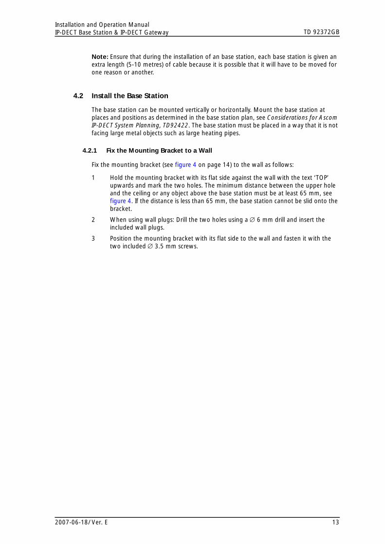
4.2.1 Fix the Mounting Bracket to a Wall
Fix the mounting bracket (see figure 4 on page 14) to the wall as follows:
1 Hold the mounting bracket with its flat side against the wall with the text ‘TOP’ upwards and mark the two holes. The minimum distance between the upper hole and the ceiling or any object above the base station must be at least 65 mm, see figure 4. If the distance is less than 65 mm, the base station cannot be slid onto the bracket.
2 When using wall plugs: Drill the two holes using a ∅ 6 mm drill and insert the included wall plugs.
3 Position the mounting bracket with its flat side to the wall and fasten it with the two included ∅ 3.5 mm screws.
2007-06-18/ Ver. E 13

TD 92372GBInstallation and Operation ManualIP-DECT Base Station & IP-DECT Gateway
Figure 18.
TOP
65 mm
Ceiling
011
Figure 4. Fixing the mounting bracket to a wall
4.2.2 Fix the Mounting Bracket to a Ceiling
Fixing to a ceiling is done in the same way as the a wall, see 4.2.1 Fix the Mounting Bracket to a Wall. When the base station has to be positioned above a suspended ceiling, make sure that the front of the base station points downwards.
4.2.3 Fix the Mounting Bracket to a Pole or Beam
The mounting bracket can be fixed to a pole (diameter ≥ 45 mm) or a beam (wider than 50 mm) by means of a strap or flexible metal band less than 30 mm wide. The strap or flexible metal band is not included in the box.
1 Fix the mounting bracket to a pole or beam using the metal band, see figure 5.
2007-06-18/ Ver. E 14

TD 92372GBInstallation and Operation ManualIP-DECT Base Station & IP-DECT Gateway
Figure 19.
Tied wrongly 012
Figure 5. Fixing the mounting bracket to a pole or beam
4.2.4 Use the Cable Ducts
When the base station is mounted to the wall, cable ducts can be used to route the wiring through.
1 Fix the cable duct to the wall in one of the positions shown in figure 6 on page 16.
2007-06-18/ Ver. E 15

TD 92372GBInstallation and Operation ManualIP-DECT Base Station & IP-DECT Gateway
Figure 20.
TOP
65 mm
125 mm
70 mm75 mm
57 mm
15 mm thick cable ducts 013
Figure 6. Minimum distances between a cable duct and the mounting bracket
4.2.5 Secure the Cable
1 For safety reasons secure the base station cable to a convenient point at about 30 cm from the base station.
If for some reason the base station drops, it is secured by the cable.
4.2.6 Pinning
1 Cut the cable to the correct length and connect the cable to a RJ45 modular jack.
2 For information on the pinning of the data jack see the following:
• IPBS, Pin the IPBS Cable on page 17.• BS3x0, Pin the BS3x0 Cable on page 17.
Do not plug the connector in the base station yet!
Note: Since the distance between the base station and the wall is limited, a RJ45 modular jack without cable retention must be used.
2007-06-18/ Ver. E 16
TD 92372GBInstallation and Operation ManualIP-DECT Base Station & IP-DECT Gateway
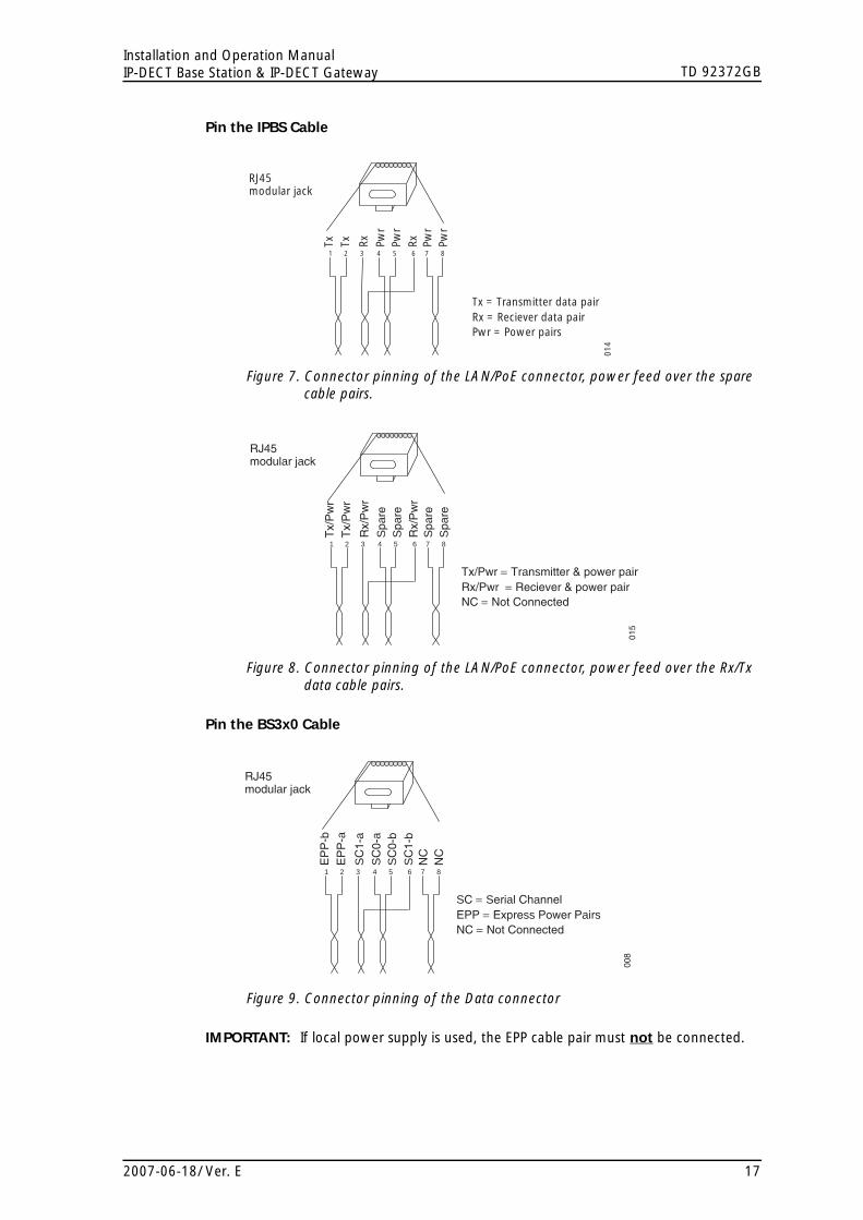
Pin the IPBS Cable
Figure 21.
RJ45modular jack
Tx Tx Rx Pwr
Pwr
Rx Pwr
Pwr
Pwr = Power pairsRx = Reciever data pairTx = Transmitter data pair
014
1 5432 6 7 8
Figure 7. Connector pinning of the LAN/PoE connector, power feed over the spare cable pairs.
Figure 22.
RJ45modular jack
Tx/
Pw
rT
x/P
wr
Rx/
Pw
r
Spa
reS
pare
Rx/
Pw
rS
pare
Spa
re
NC = Not ConnectedRx/Pwr = Reciever & power pairTx/Pwr = Transmitter & power pair
015
1 5432 6 7 8
Figure 8. Connector pinning of the LAN/PoE connector, power feed over the Rx/Tx data cable pairs.
Pin the BS3x0 Cable
Figure 23.
RJ45modular jack
EP
P-b
EP
P-a
SC
1-a
SC
0-a
SC
0-b
SC
1-b
NC
NC
NC = Not ConnectedEPP = Express Power PairsSC = Serial Channel
008
1 5432 6 7 8
Figure 9. Connector pinning of the Data connector
IMPORTANT: If local power supply is used, the EPP cable pair must not be connected.
2007-06-18/ Ver. E 17

TD 92372GBInstallation and Operation ManualIP-DECT Base Station & IP-DECT Gateway
4.2.7 Connect the Base Station Cables
1 If it is required that the cables enter the base station centrally from above, guide the cables through the recess in the middle of the base station as shown in figure 10 on page 18.Figure 24.
Power cable(if used)
Data cable
016
Figure 10. Cables entering centrally from above
2 Plug the modular jack of the data cable into one of the data/power connectors.
3 When an AC-adapter is used:
• Plug the modular jack of the AC-adapter in one of the data/power connectors.• Plug the AC-adapter into a wall-outlet.
4.2.8 Mount the Base Station
1 Hold the base station flat against the mounting bracket and move it downwards until it clicks, see figure 11.Figure 25.
017
Figure 11. Mounting the base station
2007-06-18/ Ver. E 18

TD 92372GBInstallation and Operation ManualIP-DECT Base Station & IP-DECT Gateway
4.3 Power the Base Station
The base station is powered the following ways:
• Power over Ethernet (only IPBS).
• Power over Express Powering Pairs (EPP) and data pairs (only BS3x0)
• By a local power supply.
Note: Do not power the base station using both power supplies. Parallel powering will not harm the base station but it can disturb the signalling.
4.3.1 Power the IPBS over Ethernet
The IPBS supports Power over Ethernet, IEEE 802.3af, class 2. The IPBS power consumption is maximum 5W. But according to the PoE standard for class 2 the PoE power source will allocate 7W to the IPBS. This must be regarded when planning the powering of the IPBSs so that the power limit of the PoE power source is not exceeded.
The PoE standard supports two ways of feeding the power:
1 Power over the Rx/Tx data pairs.
2 Power over the spare cable pairs.
Both power feed methods are supported in the IPBS, it is also insensitive to change of the polarity.
4.3.2 Power the BS3x0 over Express Powering Pair (EPP) and data pairs
When a base station is powered remotely via the IPBL, the maximum length between the base station and the IPBL depends on the supply voltage, the number of twisted pairs used and the wire size. The length of the cable should never exceed "data-limited" length of the cable, see Appendix B: RFP Power Consumption on page 69.
4.3.3 Power the Base Station with a Local Power Supply
Powering the base station with a local power supply can be done using the second data/power inlet on the base station. The base station can be powered individually by an AC-adapter. The AC-adapter is provided with an 8-pin RJ45 plug that can be plugged into the Power Supply jack. For specification see 2.4 AC-adapter on page 8.
Note: Only approved power supply according to valid editions of EN/IEC/CSA/UL/AU/NZS 60950 is to be used when the base station is powered by a local power supply.
5 Installation of the IPBL
This section describes how to install the IPBL.
5.1 Install the IPBL
IMPORTANT: To keep the same functionality of the system, do not mix different RPFs, Core (KRCNB 201) and Worf (KRCNB 30x and BS3x0), on the same IPBL. It is also recommended for the RFPs to use the same software version.
2007-06-18/ Ver. E 19

TD 92372GBInstallation and Operation ManualIP-DECT Base Station & IP-DECT Gateway
Figure 26.
lan synchronization reference
1 2 ring in ring out in out
base station 01 02 03 04 05 06 07 08
09 10 11 12 13 14 15 16
009
{ { {
1 2 3
Figure 12. Install the IPBL
The main steps of the installation is described below:
1 Install the IPBL in a standard 19’’ rack.
2 Pin the cables, see 5.2 Pin the IPBL Cable on page 21.
3 Connect the cables in the following order:
• Ethernet cable (1)• Synchronization cable (sync ring, reference sync) (2)• Base station cable (RFP cable) (3)
IMPORTANT: The connected RFPs must not be connected to protective earth.
4 Attach the power cable, see 5.3 Power the IPBL on page 23.
5 Monitor the total current consumption from the GUI. See 7.11.5 Environment on page 59. Make sure it not exceeds the following values:
• Max current consumption is 4,0 A when supplied with 110/230 VAC.• Max current consumption is 5,2 A when supplied with 48 VDC. Note: The IPBL current consumption is 0,3 A and is included in max current consumption.
For more information of power consumption of the RFPs, see Appendix B: RFP Power Consumption on page 69.
2007-06-18/ Ver. E 20

TD 92372GBInstallation and Operation ManualIP-DECT Base Station & IP-DECT Gateway
5.2 Pin the IPBL Cable
All data cables used for the IPBL is standard CAT5 unshielded cable. It is assumed that installation personnel know how to crimp these connectors to a cable.
5.2.1 Synchronization Cable
The maximum cable length between two IPBLs must not exceed 2000 meters.
1 Cut the cable to the correct length.
2 Connect the cable to a RJ45 modular jack. For information on pinning, see figure 13 and figure 14.
3 Label the cable.
Sync IN
Figure 27.
RJ45modular jack
Sign
Tx
+Si
gn T
x -
Sign
Rx
+
Rx +
Rx -
Sign
Rx
-Tx
+Tx
-
Sign = SignallingRx = Reciever data pairTx = Transmitter data pair
026
1 5432 6 7 8
Figure 13. Connector pinning of the Sync IN cable
Sync OUT
Figure 28.
RJ45modular jack
Sign
Rx
+Si
gn R
x -
Sign
Tx
+
Tx +
Tx -
Sign
Tx
-Rx
+Rx
-
Sign = SignallingRx = Reciever data pairTx = Transmitter data pair
027
1 5432 6 7 8
Figure 14. Connector pinning of the Sync OUT cable
2007-06-18/ Ver. E 21

TD 92372GBInstallation and Operation ManualIP-DECT Base Station & IP-DECT Gateway
5.2.2 RFP Cable
The RFP cable connects the IPBL with the RFPs. The maximum cable length between IPBL and a single RFP must not exceed 1500 meters.
Note: Ensure that during the installation, each RFP is given an extra length (5-10 metres) of cable because it is possible that it will have to be moved for one reason or another.
1 Cut the cable to the correct length.
2 Connect the cable to a RJ45 modular jack. For information on the pinning, see figure 15.
IMPORTANT: If local power supply is used for the RFP, the EPP cable pairs must not be connected.
3 Label the cable.Figure 29.
RJ45modular jack
EPP
-bEP
P -a
SC1
-a
SC0
-aSC
0 -b
SC1
-bN
CN
C
NC= Not Connected
EPP= Express Power pairsSC = Data pair lead
028
1 5432 6 7 8
Figure 15. Connector pinning of the RFP cable.
5.2.3 LAN Cable
1 Cut the cable to the correct length.
2 Connect the cable to a RJ45 modular jack. For information on the pinning, see figure 16.
3 Label the cable.Figure 30.
RJ45modular jack
Ethe
rnet
A +
Ethe
rnet
A -
Ethe
rnet
B +
NC
NC
Ethe
rnet
B -
NC
NC
NC = Not Connected
029
1 5432 6 7 8
Figure 16. Connector pinning of the Ethernet cable.
2007-06-18/ Ver. E 22

TD 92372GBInstallation and Operation ManualIP-DECT Base Station & IP-DECT Gateway
5.3 Power the IPBL
The IPBL power supply connectors are located at the rear. The power supply feeds both the IPBL and the connected RFPs. There are two alternatives to power the IPBL:
• 110/230 VAC, 60/50 Hz
• 48 VDC
5.3.1 110/230 VAC
The 110/230VAC (100 – 240 VAC) power input is protected against overload by a fuse. The IEC 60320 type C14 (male) connector consists of:
• live lead (1)
• neutral lead (2)
• protective earth (3)Figure 31.
1
2
301
0
Figure 17. Pinning of the 110/230 VAC power supply
1 Connect the power cable on the IPBL.
2 Connect the power cable in a wall socket with protected earth.
The IPBL is switched on.
2007-06-18/ Ver. E 23

TD 92372GBInstallation and Operation ManualIP-DECT Base Station & IP-DECT Gateway
5.3.2 48 VDC
The 48 VDC (42 – 56 VDC) power input includes a fuse on the 48 VDC input to protect against overload. The IPBL also has a protection circuit to protect both the IPBL and the external power supply from damages caused by the user reversing the input terminals during installation.
Figure 32.
1 2
3
034
Figure 18. Pinning of the 48 VDC power supply
Note: An ground cable must be fastened to the protective earth (3) when 48 VDC is used as power source.
1 Fasten the ground cable to the protective earth (3) using the attached M4 screw (Philips) and washer.
2 Cut the power cable to the correct length.
3 Attach the positive lead to (1).
4 Attach the negative lead to (2).
5 Connect the power cable to 48 VDC power source.
The IPBL is switched on.
6 Configuration
This section describes how to configure the IPBS and IPBL using the web interface. The recommended order to configure the equipment in the IP-DECT system is as follows:
1 Configure the master, see 6.3 Configure the Master on page 27.
2 Configure the standby master, see 6.4 Configure the Standby Master on page 28.
3 Configure the slaves, see 6.5 Configure the Slave on page 29.
6.1 Requirements
The following is required in order to configure the IP-DECT system:
• PC
• 10/100base-T Ethernet connection
6.1.1 Web Browser Requirements
To use the interface properly, the web browser has to meet the following requirements:
2007-06-18/ Ver. E 24
TD 92372GBInstallation and Operation ManualIP-DECT Base Station & IP-DECT Gateway
• HTTP 1.1 protocol
• HTML 4.0 protocol
• XML/XSL Version 1.0
The GUI has been tested with Internet Explorer 6.x, but can also be operated with other browsers in compliance with the requirements above.
6.2 Access the GUI
The GUI interface is accessed through a standard web browser. It is possible to use the name, ipbs-xx-xx-xx and ipbl-xx-xx-xx, where xx-xx-xx is the end of the MAC address.
Note: The IPBL name is always ipbl-xx-xx-xx regardless if LAN1 (MAC xx-xx-xx-xx-xx) or LAN2 (MAC yy-yy-yy-yy-yy) is used.
It is also accessed by entering http://xxx.xxx.xxx.xxx in the browser address field. In this address, xxx.xxx.xxx.xxx should be replaced with the IP address determined in 6.2.1 Determine the IP Address on page 25.
Access the GUI and change the default password as described in 6.2.2 Change the Default Password on page 27.
6.2.1 Determine the IP Address
The factory setting of the DHCP mode is "automatic", at first power up it will act as a DHCP client. If the network has a DHCP server, it will assign an IP address to the IPBS/IPBL. If there is no DHCP server in the network the IPBS/IPBL can be assigned a predefined IP address.
Note: After the first startup the DHCP mode should be changed from "automatic" to either "client" or "off", see 7.2.1 Set DHCP Mode on page 37.
2007-06-18/ Ver. E 25

TD 92372GBInstallation and Operation ManualIP-DECT Base Station & IP-DECT Gateway
This section describes how to determine the dynamically allocated IP address. The address is used to access the IPBS/IPBL using a web browser. Two methods are described:
• In a Network without a DHCP Server on page 26.
• In a Network with a DHCP Server on page 26.
In a Network without a DHCP Server
If the network does not have a DHCP server, and the DHCP mode is set to "automatic" (factory default), follow the steps below.
Note: If the IPBS/IPBL has been used before, it must be restored to factory default settings by performing a long hardware reset, see 7.13 Reset Using the Reset Button on page 60.
1 Connect a ethernet cable between the IPBS/IPBL and the computer.
Note: For IPBS, a power adapter must be used. Note: For IPBL, make sure to use the LAN1 port.
2 Perform a hardware reset by shortly pressing the reset button.
3 The IPBS/IPBL will be assigned the IP address 192.168.0.1 and the netmask 255.255.255.0.
4 Enter http://192.168.0.1 in the browser address field to access the IPBS/IPBL GUI.
5 After the first startup the DHCP mode should be changed from "automatic" to either "client" or "off", see 7.2.1 Set DHCP Mode on page 37.
In a Network with a DHCP Server
If the network has a DHCP server the IP address is determined following the steps below.
The IPBS/IPBL MAC address can be found on the label on the box and on the label on the backside. The hexadecimal numbers (xx-xx-xx-xx-xx-xx) represent the MAC address.
Note: Make sure to use the LAN1 port for the IPBL.
Note: In order to determine the IP address using this method it is necessary to have a PC with MS Windows. It must be connected to the same LAN (broadcast domain) as the IPBS/IPBL.
Determine the IP address following the steps below:
Note: If the IPBS/IPBL has been used before, it must be restored to factory default settings by performing a long hardware reset, see 7.13 Reset Using the Reset Button on page 60. Then remove the power supply cable and connect it again.
1 Open a command window in windows by selecting Start > Run and enter "cmd" in the Open: text field.
2 Enter the following commands: C:\ nbtstat -R C:\ nbtstat -a ipbs-xx-xx-xx (ipbl-xx-xx-xx)
Where xx-xx-xx should be replaced with the last 6 hexadecimal digits of the MAC-address.
3 The IP address is displayed in the command window, see the white frame in figure 19.
2007-06-18/ Ver. E 26

TD 92372GBInstallation and Operation ManualIP-DECT Base Station & IP-DECT Gateway
Figure 33.
018
Figure 19. Determine the IP address
4 Enter http://xxx.xxx.xxx.xxx (where xxx.xxx.xxx.xxx is the determined IP address) in the browser address field to access the GUI.
5 After the first startup of the IPBS/IPBL the DHCP mode should be changed from "automatic" to either "client" or "off", see 7.2.1 Set DHCP Mode on page 37.
6.2.2 Change the Default Password
1 Enter the IP address determined in 6.2.1 Determine the IP Address in the web browser address field.
2 Select General > Admin.
3 Enter user name and password in the dialogue box. Default user name is: admin. Default password is: changeme.
4 Enter a user name in the User Name text field.
5 Enter a password in the Password text field. Repeat the password in the second text field.
6 Click "OK".
6.3 Configure the Master
This section describes how to configure the Master. Each configuration step is briefly described in the step list below. For more detailed information see the corresponding subsection in 7 Operation on page 31.
1 Determine the address and access the GUI, see 6.2 Access the GUI on page 25.
2 Change the default password, see 6.2.2 Change the Default Password on page 27.
3 Configure LDAP user name and password, mark the Write Access check box, see 7.4.1 Configure LDAP Server on page 39.
4 Set a static IP address and set DHCP to off, see7.2.2 Set a Static IP Address on page 37.
2007-06-18/ Ver. E 27

TD 92372GBInstallation and Operation ManualIP-DECT Base Station & IP-DECT Gateway
5 Select system user name and password, see 7.5.1 Change System Name and Password on page 41.
6 Set the mode to Master, see Figure 45. on page 44.
7 Set frequency band, see 7.5.6 Set Frequency Band on page 42.
8 Select tones, see 7.5.4 Select Tones on page 42.
9 Enter gatekeeper IP address or ID, see 7.5.15 Configure Gatekeeper on page 45.
10 Set the master IP address to 127.0.0.1, see 7.5.16 Enter IP Address to the Master and the Standby Master on page 45.
11 Perform a reset to restart the IPBS/IPBL in master mode, see 7.12 Reset on page 60.
If problem to access the master from a certain PC after the reset;
• Open a command window in windows by selecting Start > Run and enter "cmd" in the Open: text field.
• Enter the following commands arp -d (Delete the arp cache) nbtstat -R (Empty the nbtstat cache)
• Restart the WEB browser.
12 Select supplementary services, see 7.5.13 Configure Supplementary Services on page 44.
13 Assign PARI, see 7.5.17 PARI on page 45.
14 Enter SARI, see 7.5.18 SARI on page 46.
Note: In some SW versions SARI is not available and a licence is needed, see 7.1.3 Licence on page 32.
15 Enter IMS IP address, see 7.5.19 Configure Messaging on page 46.
16 Configure air synchronization, see 7.5.20 Configure Air Synchronization on page 46.
17 Enter the Time Server address, see 7.1.5 Configure the NTP Settings on page 34.
18 Reset in order to make the configuration changes take effect, see 7.12 Reset on page 60.
6.4 Configure the Standby Master
It is recommended to have a standby master in the IP-DECT system. This section describes how to configure a standby master. Each configuration step is briefly described in the step list below, for more detailed information see the corresponding subsection in 7 Operation on page 31.
1 Determine the address and access the GUI, see 6.2 Access the GUI on page 25.
2 Change the default password, see 6.2.2 Change the Default Password on page 27.
3 Set a static IP address and set DHCP to off, see7.2.2 Set a Static IP Address on page 37.
4 Enter system user name and password, this should be the same user name and password as in the Master. See 7.5.1 Change System Name and Password on page 41.
5 Set the mode to standby master, see 7.5.14 Select Mode on page 44.
6 Enter gatekeeper address, see 7.5.15 Configure Gatekeeper on page 45.
7 Enter master IP address, see 7.5.16 Enter IP Address to the Master and the Standby Master on page 45.
2007-06-18/ Ver. E 28

TD 92372GBInstallation and Operation ManualIP-DECT Base Station & IP-DECT Gateway
8 Select supplementary services, see 7.5.13 Configure Supplementary Services on page 44.
9 Assign PARI, see 7.5.17 PARI on page 45.
10 Configure air synchronization, see 7.5.20 Configure Air Synchronization on page 46.
11 Enter IMS IP address, see 7.5.19 Configure Messaging on page 46.
12 Enter the Time Server address, see 7.1.5 Configure the NTP Settings on page 34.
13 Configure LDAP replicator, enter the IP address, user name and password to the LDAP server. Alternative LDAP server must not be entered. Check the Enable check box, see 7.4.2 Configure LDAP Replicator on page 40.
14 Reset in order to make the configuration changes take effect, see 7.12 Reset on page 60.
If problem to access the standby master from a certain PC after the reset;
• Open a command window in windows by selecting Start > Run and enter "cmd" in the Open: text field.
• Enter the following commands arp -d (Delete the arp cache) nbtstat -R (Empty the nbtstat cache)
• Restart the WEB browser.
6.5 Configure the Slave
This section describes how to configure the Slave. Each configuration step is briefly described in the step list below, for more detailed information see the corresponding subsection in 7 Operation on page 31.
Note: When one slave is configured, the configuration can be saved and uploaded to the other slaves in the system.
1 Determine the address and access the GUI, see 6.2 Access the GUI on page 25.
2 Change the default password, see 6.2.2 Change the Default Password on page 27.
3 Set DHCP mode to "Client", see 7.2.3 Dynamic IP address via DHCP on page 38.
4 Configure LDAP replicator, enter the IP address, user name and password to the LDAP server and the alternative LDAP server. Check the Enable check box, see 7.4.2 Configure LDAP Replicator on page 40.
5 Enter the system user name and password, this must be the same user name and password as in the Master, see 7.1.1 Change User Name and Password on page 32.
With LDAP replication enabled, the password will be verified against the master. If the password is wrong a single dot will appear in the text field.
6 Set the mode to Slave, see 7.5.14 Select Mode on page 44.
7 Enter master and standby master IP addresses, see 7.5.16 Enter IP Address to the Master and the Standby Master on page 45.
8 Configure air synchronization, see 7.5.20 Configure Air Synchronization on page 46.
9 Enter the Time Server address, see 7.1.5 Configure the NTP Settings on page 34.
10 Reset in order to make the configuration changes take effect, see 7.12 Reset on page 60.
11 Save the configuration of the Slave, see 7.9 Backup on page 56.
2007-06-18/ Ver. E 29

TD 92372GBInstallation and Operation ManualIP-DECT Base Station & IP-DECT Gateway
Configure the rest of the IPBS/IPBLs following the steps below:
Note: Uploading the same configuration to all slaves can only be done if the DHCP is set to client.
1 Determine the address.
2 Select Update > Config and browse to the previously saved configuration. Click "OK".
3 Reset in order to make the configuration changes take effect, see 7.12 Reset on page 60.
4 Repeat step 1 to 3 for all Slaves.
6.6 Add Users
This section describes how to add users to the IP-DECT system. There are two ways to register handsets:
• Using the handset to automatically associate the IPEI number to a user, see 6.6.1 Anonymous Registration on page 30.
• Entering the IPEI number of the handset manually, see 6.6.2 Individual Registration on page 31.
6.6.1 Anonymous Registration
The IPEI, which is the unique identification number of the handset, can be assigned automatically to a user. This is used to avoid having to enter the IPEI number manually.
Add users in the IP-DECT System
1 Under the Administration menu, select Users.
2 Click "New".
3 Enter the following information in the corresponding text fields, leave the IPEI and the Auth. Code text fields empty:
• Long Name - The name of the user, need to be unique throughout the system. This is the name presented in a called party´s display, unless this is configured in the IP-PBX.
• Name - The user name.• Number - The phone number extension, need to be unique throughout the
system.• Password - Optional, is used for registration towards the gatekeeper.• Display Text - Will be showed in the handset display when the phone is idle.
4 Click "OK".
5 Repeat step 2 to 4 for all users.
2007-06-18/ Ver. E 30

TD 92372GBInstallation and Operation ManualIP-DECT Base Station & IP-DECT Gateway
Assign Handsets to Users
1 Select DECT > System.
2 Enable anonymous registration by selecting "With System AC" in the Subscriptions drop-down list.
3 Click "OK".
4 Perform an "over air subscription" using the system Authentication Code. For information on how this is done, see the reference guide of the handset. The handsets’ IPEI number appears in the Anonymous list. To view the list: Select Users > Anonymous.
5 Assign the handset to any user defined in the system by calling the desired extension and hang up.
6 Go off hook to hear the dial tone and hang up.
7 Repeat step 4 to 6 for all handsets.
8 Under the Configuration menu, select DECT > System.
9 Disable anonymous registration by selecting "Disable" in the Subscription drop-down list.
10 Click "OK".
6.6.2 Individual Registration
1 Select Users.
2 Click "New".
3 Enter the following information in the corresponding text fields:
• Long Name - The name of the user, need to be unique throughout the system. This is the name presented in a called party´s display, unless this is configured in the IP-PBX.
• Name - The user name.• Number - The phone number extension, need to be unique throughout the
system.• Password - Optional, is used for registration towards the gatekeeper.• Display Text - Will be showed in the handset display when the phone is idle.• IPEI - The unique identification number of the handset.• Auth. Code - The individual authentication code for this user.
4 Perform an "over air subscription" using the individual authentication code. For information on how this is done, see the reference guide of the handset.
5 Click "OK".
7 Operation
This section describes the settings in the Configuration and Administration menu, each subsection represents a sub menu to the Configuration and Administration menu.
Some changes require a reset in order to take effect. It is possible to do several changes before resetting the IPBS/IPBL.
The GUI for the IPBS and IPBL are similar. Screen shots from the IPBS are used as default.
2007-06-18/ Ver. E 31

TD 92372GBInstallation and Operation ManualIP-DECT Base Station & IP-DECT Gateway
7.1 General
This section describes how to do the following configurations and settings.
• Change User Name and Password
• Name the equipment
• Licence (SW 2.06 and earlier)
• Configure automatic firmware update
• Configure the NTP settings
• Configure Logging
• Configure the HTTP settingsFigure 34.
Figure 20. Assigning a name, username, and password.
7.1.1 Change User Name and Password
The user name and password us used to access the IPBS/IPBL through the web GUI.
1 Select General > Admin.
2 Write a user name in the User Name text field.
3 Enter a new password in the Password text field. Repeat the password in the second text field.
4 Click "OK".
7.1.2 Name the IPBS/IPBL
Each IPBS/IPBL can be assigned a name. It is recommended to assign a descriptive name for example IPBS/IPBL location.
1 Select General > Admin.
2 Enter a name in the Device Name text field.
3 Click "OK".
7.1.3 Licence
This section only applies to the IPBS with SW 2.06 and earlier.
2007-06-18/ Ver. E 32
TD 92372GBInstallation and Operation ManualIP-DECT Base Station & IP-DECT Gateway
Add Licence
A licence is needed to make the IP-DECT system operate. The licence is added in the master.
1 Select General > Licence.
2 Click “Browse” and select the licence delivered by your supplier.
3 Click “Upload”
4 Reset in order to make the changes take effect, see 7.12 Reset on page 60.
Download Licence
The licence file can be downloaded from the IPBS/IPBL and saved on a disc or a server.
1 Select General > Licence.
2 Click the "download" link to the right of the licence or click "download all" if all licences shall be downloaded.
3 Click “Save” and select where to save the licence file.
Delete Licence
Note: A licence file is needed for the IPBS/IPBL to operate properly. Be sure to have a backup of the licence before deleting it.
1 Select General > Licence.
2 Click the "delete" link to the right of the licence or click "delete all" if all licences shall be deleted.
7.1.4 Configure Automatic Firmware Update
The IPBS/IPBL can be configured to automatically update its firmware. A script file must be uploaded to a suitable directory on an internal web server. For information on the script file syntax, see Appendix A: How to Use the Update Server on page 64.
1 Select General > Update
2 Enter the URL of the script file in the URL text field.
3 Enter the poll interval, in minutes, in the Interval (min) text field
4 Click "OK".
2007-06-18/ Ver. E 33

TD 92372GBInstallation and Operation ManualIP-DECT Base Station & IP-DECT Gateway
7.1.5 Configure the NTP Settings
Since the IPBS/IPBL does not have a battery-backed real-time clock, the internal time will be set to 0:00 hrs, 1.1.1970 in the case of a restart.
In order to get the correct time in the system, specify the IP address of a NTP time server. The IPBS/IPBL will synchronize its internal clock to the time server at startup and at the specified intervals. The clock is, for example, used by the handsets and log files.
Figure 35.
Figure 21. Configure NTP settings
1 Select General > NTP.
2 Enter the IP address to the NTP server.
3 Enter a time interval in the Interval (min) text field.
4 Select time zone in Time zone drop-down list. If the desired time zone is not in the list, select “Other” and edit the String text field following the instructions in the next step.
5 Enter the timezone string if automatically updates summer/winter is desired.
<String = StdOffset [Dst[Offset], Date/Time, Date/Time]>
• Std = Time zone (for example EST for Eastern Standard Time).• Offset = time difference between the timezone and the UTC (Universal Time
Coordinator).• Dst = summertime zone (for example EDT for Eastern Daylight Time).• Second Offset = time difference between the summer time and the UTC.• Date/ Time, Date/ Time = beginning and end of summertime.
- date format = Mm.n.d (d day of n week in the m month) - time format = hh:mm:ss in 24-hour format.
Note that a week always starts on a Sunday and the number for Sunday is 0.
Example: North Carolina is located in the Eastern Time Zone. Eastern Standard Time (EST) is 5 hours behind UTC (StdOffset = EST-5), the Eastern Daylight Time (EDT) is 4 hours behind UTC (DstOffset = EDT-4). Summertime for the year 2006 begins at two a clock, on a Sunday, the first week in April (M4.1.0/2). The summertime ends at two a clock, on a Sunday, the fifth week in October (M10.5.0/2). <String = EST-5EDT-4,M4.1.0/2,M10.5.0/2>
6 Click “OK”.
2007-06-18/ Ver. E 34

TD 92372GBInstallation and Operation ManualIP-DECT Base Station & IP-DECT Gateway
7.1.6 Configure Logging
There are two ways to collect logs, see the table below.
Figure 36.
SYSLOG The entries are reported to a “syslogd” server in the network, which is responsible for further evaluation or storage of the entries.
HTTP The syslog entries are transferred to a web server where they can be further processed. Each individual syslog entry is transmitted as form data to the web server in HTTP GET format.
Store the Syslog Entries in a Syslogd
1 Select General > Logging.
2 Select “SYSLOG” in the Type drop-down list.
3 Enter the “IP address” of the syslogd in the Address text field.
4 Enter the desired syslogd message class in the Class text field.
5 Click “OK”.
Store the Syslog Entries on a Web Server
1 Select General > Logging.
2 Select “HTTP” in the Type drop-down list.
3 Enter the “IP address” in the Address text field.
4 Enter the “relative URL of the form programme” on your web server in the Path text field.
5 Click “OK”.
Note: The IPBS/IPBL will make an HTTP GET request to the web server on the registered URL followed by the URL-encoded log entry.
Example:
Enter the value “/cdr/ cdrwrite.asp” in the “URL-Path” field if a page is on the web server with the name “/cdr/cdrwrite.asp” with a form that expects the log message in the “msg” parameter. In this example, the IPBS/IPBL will make a GET /cdr/cdrwrite.asp?event=syslog&msg=logmsg request to the server.
7.1.7 Configure the HTTP settings
The IPBS/IPBL is administered via the network via the TCP port 80 (http). If for some reason the port 80 is not supposed to be used, you can set up another port for the local HTTP server and then access the IPBS/IPBL via this port.
2007-06-18/ Ver. E 35

TD 92372GBInstallation and Operation ManualIP-DECT Base Station & IP-DECT Gateway
Figure 37.
Figure 22. Configure the HTTP settings
1 Select General > HTTP
• Mark the Disable HTTP basic authentication check box to require all administrative and programmatic clients to support HTTP digest authentication.
• Mark the Password protect all HTTP pages check box to password protect all HTTP pages.
• Enter "Port number" in the Port text field. The IPBS/IPBL is by default administered over the network via the TCP port 80 (http). If port 80 is not to be used another port can be set up for access.
• Enter "Network Base Adresss" / "Network Base Mask" in the Allowed stations text fields to only allow access only from matching network, for example:172.16.0.0/255.255.0.0
• In the Active HTTP sessions field all ongoing HTTP traffic is displayed.Figure 38.
2 Click "OK".
7.1.8 Configure the HTTP Client settings
A list of URL that require authentication can be specified.
1 Select General > HTTP Client.
2 Enter the “URL” in the URL text field.
3 Enter "User" and "Password" in the User and Password text fields.
4 Click “OK”.
A new row will be shown and more URLs can be added.
2007-06-18/ Ver. E 36

TD 92372GBInstallation and Operation ManualIP-DECT Base Station & IP-DECT Gateway
7.2 LAN
This section describes how to do the following configurations and settings.
• Set DHCP mode
• Set IP static address
• Set dynamic IP address
• Set link type
• Configure VLAN
• View LAN statistics
Note: The IPBL has two identical LAN connections.
7.2.1 Set DHCP Mode
The IPBS/IPBL can have different DHCP modes, see the table below.
Figure 39.
Off Used if the IPBS/IPBL should have a static IP address.
Client The IPBS/IPBL acts as a DHCP Client, if there is a DHCP server in the network it will be assigned an IP address
Automatic In automatic DCHCP mode the IPBS/IPBL will act as a DHCP client on power up. If the IPBS/IPBL is restarted by shortly pressing the reset button it will get the IP address 192.168.0.1 and the netmask 255.255.255.0
Change DCHP mode following the steps below.
1 Select LAN > DHCP.
2 Select DHCP mode in the Mode drop-down list.
3 Click “OK”.
4 Reset in order to make the changes take effect, see 7.12 Reset on page 60.
7.2.2 Set a Static IP Address
It is necessary for the master and the standby master to have static IP addresses. The slaves can have dynamic IP addresses retrieved from the network DHCP server.
Ask the network administrator to reserve an IP address for the master and standby master.
1 Select LAN > DHCP.
2 Select “Off” in the Mode drop-down list.
3 Click “OK”.
4 Select LAN > IP.
5 Enter "IP Address", "Network Mask", "Default Gateway" and "DNS Server" addresses provided by the network administrator in the text fields.
6 Click “OK”.
7 Reset in order to make the changes take effect, see 7.12 Reset on page 60.
8 Start the web-based configuration, using the static IP address.
2007-06-18/ Ver. E 37

TD 92372GBInstallation and Operation ManualIP-DECT Base Station & IP-DECT Gateway
7.2.3 Dynamic IP address via DHCP
The Slaves can have dynamic IP address allocation if the network has an DHCP server.
1 Select LAN > DHCP.
2 Select “Client” in the Mode drop-down list.
3 Click “OK”.
4 Reset in order to make the changes take effect, see 7.12 Reset on page 60.
7.2.4 Link
The link setting should be set to "auto" under all normal circumstances.
7.2.5 Configure VLAN
Identity and priority settings for VLAN are done in the "LAN > VLAN" sub menu.
Note: It is necessary to have a VLAN with the same ID as configured in the IPBS/IPBL otherwise it will not be possible to access the IPBS/IPBL.
7.2.6 View LAN Statistics
To view statistics of LAN events: Select LAN > Statistics
To reset the ethernet statistics counters: Click the clear-stat button.
2007-06-18/ Ver. E 38

TD 92372GBInstallation and Operation ManualIP-DECT Base Station & IP-DECT Gateway
7.3 IP
7.3.1 Configure IP Settings
The following settings can be done in the IP settings sub menu:
• Set ToS priority.
• Set RTP ports.
1 Select IP > Settings.
2 Enter ToS priority (0..7) in the ToS Priority text field.
3 Select which ports to use for RTP traffic by entering the first port in the First UDP-RTP Port text field.
4 Enter the number of ports to use in the Number of Ports text field.
Note: If the ports fields are left blank, the ports 16384 to 32767 will be used.
5 Click "OK".
7.3.2 Routing
View the IP routing by Select IP > Routing.
7.4 LDAP
The Lightweight Directory Access Protocol (LDAP) protocol is required for systems in which the server and a replicating client access a joint user database. All IPBS/IPBLs in the system have access to the database, one of the IPBS/IPBLs or the VoIP gateway can be configured to be the LDAP server.
The joint user database contains information about the users registered in the system. It also contains the system configuration, that is the configurations made under the "DECT" menu.
This section describes how to do the following configurations and settings.
• Configure LDAP Server
• Check LDAP server Status
• Configure LDAP Replicator
• Check LDAP Replicator Status
7.4.1 Configure LDAP Server
The IP-DECT system needs an LDAP server. If the VoIP gateway is setup as an LDAP server the master should be setup as an LDAP replicator, see 7.4.2 Configure LDAP Replicator on page 40.
Setup the IPBS/IPBL as an LDAP server:
Note: The selected user name and password must be the same in both the master and the standby master.
1 Select LDAP > Server.
2 Add a user, for example ldap-user, in the User text field.
2007-06-18/ Ver. E 39

TD 92372GBInstallation and Operation ManualIP-DECT Base Station & IP-DECT Gateway
3 Enter a password in the Password text field.
4 Mark the Write Access check box.
5 Click "OK".Figure 40.
Figure 23. Setting LDAP User Name and Password
7.4.2 Configure LDAP Replicator
The slaves are normally setup as LDAP replicators.
1 Select LDAP > Replicator.
2 Mark the Enable check-box.
3 Enter the IP address to the LDAP server in the Server text field.
4 Enter the IP address to the alternative LDAP server in the Alt. Server text field.
Note: If this IPBS/IPBL is configured as a standby LDAP server, enter "0.0.0.0" in the Alt. Server text field.
5 Enter the LDAP User name and Password in the User and Password text fields.
6 Click "OK".
7.4.3 Check LDAP Replicator/Server status
1 Select LDAP.
2 Select Replicator/Status or Server/Status.
2007-06-18/ Ver. E 40

TD 92372GBInstallation and Operation ManualIP-DECT Base Station & IP-DECT Gateway
7.5 DECT
This section describes how to do the following configurations and settings.
• Change DECT user name and password
• Set Authentication Code
• Change Subscription Method
• Select tone system
• Set Frequency Band
• Set Default Language
• Enable/Disable Carriers
• Enbloc Dialing
• Local R-Key handling
• Coder
• Select mode
• Configure gatekeeper
• Enter IP Address to the Master and the Backup IPBS/IPBLs
• Assign PARI
• Enter SARI
• Configure Air Synchronization
• Configure SMS Settings
• Configure Supplementary ServicesFigure 41.
Figure 24. The DECT System configuration page
7.5.1 Change System Name and Password
The system name and password must be the same for all IPBS/IPBLs throughout the system. Reset in order to make the changes take effect, see 7.12 Reset on page 60.
Note: If Ascom VoIP Gateway is the LDAP server, the password in the IPBS/IPBL must be identical to the Ascom VoIP Gateway (PBX/Password).
1 Select DECT > System.
2 Write a system name in the System Name text field.
2007-06-18/ Ver. E 41

TD 92372GBInstallation and Operation ManualIP-DECT Base Station & IP-DECT Gateway
3 Enter a new password in the Password text field. Repeat the password.
4 Click "OK".
7.5.2 Configure Authentication Code
If allow anonymous subscription method is selected it is needed for the IP-DECT system to have an authentication code configured, select a code consisting of 4 to 8 numbers (0-9).
1 Select DECT > System.
2 Enter an authentication code in the Authentication Code text field.
3 Click "OK".
7.5.3 Change Subscription Method
The IP-DECT system can be set to use the following subscription methods:
• With User AC
• With System AC
• DisableFigure 42.
Select subscription method:
1 Select DECT > System.
2 Select subscription method in the Subscriptions drop-down list.
3 Click "OK".
7.5.4 Select Tones
1 Select DECT > System.
2 Choose tones in the Tones drop-down list.
3 Click "OK".
7.5.5 Set Default Language
If the handset does not send language information to the system, this setting determine which language that is displayed for some text messages (for example hung-up and disconnected).
1 Select DECT > System.
2 Choose language in the Default Language drop-down list.
3 Click "OK".
7.5.6 Set Frequency Band
The IPBS/IPBL can operate in the following frequency bands:
• 1880 - 1900 MHz, Europe, Africa, Middle East, Australia, New Zeeland and Asia
• 1910 - 1930 MHz, South America
• 1920 - 1930 MHz, North AmericaFigure 43.
1 Select DECT > System.
2 Select frequency area in the Frequency drop-down list.
3 Click "OK".
4 Reset in order to make the changes take effect, see 7.12 Reset on page 60.
2007-06-18/ Ver. E 42

TD 92372GBInstallation and Operation ManualIP-DECT Base Station & IP-DECT Gateway
7.5.7 Enable Carriers
The IPBS/IPBL has 5 carriers for the North American frequency band and 10 carriers for the other frequency bands. Under all normal circumstances all carriers should be enabled.
To enable or disable carriers:
1 Select DECT > System.
2 Mark/unmark the Enabled Carriers check boxes.
3 Click "OK".
7.5.8 Enbloc Dialling
With this option enabled the keystrokes on the handsets are buffered in the IPBS/IPBL for a short period of time before sent to the IP-PBX (use this when the IP-PBX does not support overlap sending). If disabled the keystrokes are immediately sent to the IP-PBX.
1 Select DECT > System.
2 To enable, mark the Enbloc Dialling check box.
3 Click "OK".
7.5.9 Local R-Key Handling
With this option enabled keypad information is handled locally. If this option is disabled keypad information is sent transparently to the IP-PBX.
1 Select DECT > System.
2 To enable, mark the Local R-Key Handling check box.
3 Click "OK".
7.5.10 DTMF through RTP Channel
If enabled, DTMF digits are sent as RTP payload directly to the other endpoint. If disabled, the DTMF is sent in the signalling channel.
1 Select DECT > System.
2 To enable, mark the DTMF through RTP channel.
3 Click "OK".
7.5.11 No Transfer on Hangup
If enabled it will not be possible to do a transfer by hanging up the phone. R+4 must be pressed.
1 Select DECT > System.
2 To enable, mark the No Transfer on Hangup checkbox.
3 Click "OK".
7.5.12 Configure Coder
Select the preferred coder, and enter the desired frame length. If exclusive is selected for the coder the IPBS/IPBL is forced to use that coder. With Silence Compression enabled no information is sent during pauses in the conversation, this is used to save bandwidth.
2007-06-18/ Ver. E 43

TD 92372GBInstallation and Operation ManualIP-DECT Base Station & IP-DECT Gateway
Note: When exclusive is enabled for a coder it might be impossible to make calls outside the IP-DECT system.
1 Select DECT > System.
2 Choose the applicable coder in the Coder drop-down list.
Note: The G726-32 coder is not supported by SIP.
3 Enter the sample time in milliseconds in the Frame text field.
4 Choose Exclusive enabled or disabled by checking/unchecking the Exclusive check box.
5 Choose Silence Compression enabled or disabled by checking/unchecking the SC check box.
6 Click "OK".
7.5.13 Configure Supplementary Services
The supplementary services determine how to handle a call if for example busy or not answered by the user.
1 Select DECT > Suppl. Serv.
2 Mark the Enable check box to activate the following supplementary services.Figure 44.
Note: To disable a specific service, mark the Disable check box in front.
3 Enter the Message Center Number in the Message Center No. field.
4 Click "OK".
5 Reset in order to make the changes take effect, see 7.12 Reset on page 60.Figure 45.
Figure 25. Supplementary services
7.5.14 Select Mode
The IPBS/IPBL can operate in three different modes: master, strandby master and slave.
1 Select DECT > Master.
2007-06-18/ Ver. E 44

TD 92372GBInstallation and Operation ManualIP-DECT Base Station & IP-DECT Gateway
2 Select in the Mode drop-down list:
• ACTIVE, if this IPBS/IPBL is the Master.• STANDBY, if this IPBS/IPBL is the Standby Master.• OFF, if this IPBS/IPBL is a Slave.
3 Click "OK".
4 Reset in order to make the changes take effect, see 7.12 Reset on page 60.
7.5.15 Configure Gatekeeper
The Master need to know the address to the system gatekeeper.
1 Select DECT > Master.
2 Enter the address to the gatekeeper in the Gatekeeper IP address text field.
3 Enter the address to the alternative gatekeeper in the Alt-Gatekeeper IP address text field.
Note: As an alternative to the Gatekeeper IP Address, the Gatekeeper ID can be used.
4 In the drop-down list, select H.323 or SIP protocol.
5 Click "OK".
6 Reset in order to make the changes take effect, see 7.12 Reset on page 60.
7.5.16 Enter IP Address to the Master and the Standby Master
All IPBS/IPBLs need to know the IP address of the master and the standby master.
1 Select DECT > Radio.
2 Enter the address to the Master in the Master IP address text field. If this is the Master, enter 127.0.0.1.
3 Enter the address to the standby master in the Alt-Master IP address text field. If this is the standby master, enter 127.0.0.1.
4 Click "OK".
5 Reset in order to make the changes take effect, see 7.12 Reset on page 60.
7.5.17 PARI
The PARI is a part of the broadcast identity, which uniquely identifies an IPBS/IPBL. This PARI is automatically assigned to each IPBS/IPBL in the system. But if more than one Ascom IP-DECT system operates within the same coverage area, the systems need to have a unique system identity in the PARI assigned in order to differentiate the systems.
To see the occupied system IDs of other Ascom IP-DECT systems within the coverage area, perform an RFP scan, see 7.9 Backup on page 56.
1 Select DECT > PARI.
2 Select a number between 1 and 36. If this is not done the IPBS/IPBL will randomly select a number.
3 Click "OK".
4 Reset in order to make the changes take effect, see 7.12 Reset on page 60.
2007-06-18/ Ver. E 45

TD 92372GBInstallation and Operation ManualIP-DECT Base Station & IP-DECT Gateway
7.5.18 SARI
The SARI is the broadcast identity, which uniquely identifies an IP-DECT system. It is needed to make the IP-DECT system operate. The SARI is added in the master.
1 Select Dect > SARI.
2 Enter the licence number delivered by your supplier in the SARI text field.
3 Click “OK”.
4 Reset in order to make the changes take effect, see 7.12 Reset on page 60.
7.5.19 Configure Messaging
If an IMS is to be used in the IP-DECT system, enter the IP address following the steps below.
1 Select DECT > SMS.
2 Enter the address to the IMS in the IMS IP Address text field.
3 Click "OK".
4 Reset in order to make the changes take effect, see 7.12 Reset on page 60.
7.5.20 Configure Air Synchronization
This section only applies to the IPBS.
Mixed System
If IPBSs and IPBLs are mixed in the same coverage area, all IPBSs must be set as "Slave". It is not necessary to configure which RFP to synchronize with, this is handled automatically.
IPBS System
The IPBSs uses the DECT interface to synchronize, one IPBS is assigned the role as "Air Sync Master". It is not necessary to configure which IPBS to synchronize with, this is handled automatically. For more information on air synchronization, see System Description Ascom IP-DECT System, TD 92375GB.
Normally only one air sync master is allowed in one site. If however the site contains for example two buildings and no base station in one building is possible to synchronize to any base station in the other building, in this situation a air sync master may be used in each building. But if there is air sync coverage between the buildings only one master is allowed in one of the buildings. If two masters are configured within the same coverage area two different sync systems will be created instead of one. This will make handover and roaming between the systems impossible. As a consequense the air sync slaves will loose synchronization frequently.
Configure Air Sync mode:
1 Select DECT > Air Sync.
2 Select in the Sync mode drop-down list:
• Master, if this IPBS is the Air Sync Master.• Backup Master, if this IPBS is the Air Sync Backup Master.• Slave, if this IPBS is an Air Sync Slave.
3 Click "OK".
2007-06-18/ Ver. E 46
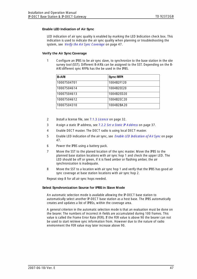
TD 92372GBInstallation and Operation ManualIP-DECT Base Station & IP-DECT Gateway
Enable LED Indication of Air Sync
LED indication of air sync quality is enabled by marking the LED Indication check box. This indication is used to indicate the air sync quality when planning or troubleshooting the system, see Verify the Air Sync Coverage on page 47.
Verify the Air Sync Coverage
1 Configure an IPBS to be air sync slave, to synchronize to the base station in the site survey tool (SST). Different B-ARIs can be assigned to the SST. Depending on the B-ARI different sync RFPIs has the be used in the IPBS.Figure 46.
B-ARI Sync RFPI
10007504701 1004B2F120
10007504614 1004B2EE20
10007504613 1004B2ED20
10007504612 1004B2EC20
10007504310 1004B2BA20
Figure 47.
2 Install a license file, see 7.1.3 Licence on page 32.
3 Assign a static IP address, see 7.2.2 Set a Static IP Address on page 37.
4 Enable DECT master. The DECT radio is using local DECT master.
5 Enable LED indication of the air sync, see Enable LED Indication of Air Sync on page 47.
6 Power the IPBS using a battery pack.
7 Move the SST to the planed location of the sync master. Move the IPBS to the planned base station locations with air sync hop 1 and check the upper LED. The LED should be off or green, if it is fixed amber or flashing amber, the air synchronization is inadequate.
8 Move the SST to a location with air sync hop 1 and verify that the IPBS has good air sync coverage at base station locations with air sync hop 2.
Repeat step 8 for all air sync hops needed.
Select Synchronization Source for IPBS in Slave Mode
An automatic selection mode is available allowing the IP-DECT base station to automatically select another IP-DECT base station as a host base. The IPBS automatically creates and updates a list of IPBSs, within the coverage area.
A general criterion in the automatic selection mode is that an evaluation must be done on the bearer. The numbers of incorrect A-fields are accumulated during 100 frames. This value is called the Frame Error Rate (FER). If the FER value is above 90 the bearer can not be used to start retrieve sync information from. However due to the nature of radio environment the FER value may later increase above 90.
2007-06-18/ Ver. E 47

TD 92372GBInstallation and Operation ManualIP-DECT Base Station & IP-DECT Gateway
Figure 48.
FER value Description
< 90 In this case the active sync bearer is only replaced if:Alternative sync bearer with lower HOP value is found. Even if an alternative bearer with better FER and RSSI is found this is only selected if the HOP value is lower.
> 90 In this case the active sync bearer is only replaced if:Another bearer with lower HOP value is found.ORAnother bearer with same HOP value is found and with BER < 90.
= 100 Assume the slave has locked to a RFP with hop value n. When the RFP have had FER = 100 on the active sync bearer for 80 seconds it is allowed to sync to a RFP with hop value n+1. After another 40 seconds it is allowed to sync to a RFP with hop value n+2, etc.After 9 minutes with FER = 100 the "Sync lost counter" is increased and a restart of the air sync procedure is done. ("Sync lost counter" may increase for a number of other reasons also)
Startup of Master IPBS
When a master starts up it searches for other IPBSs within the same system during 30 seconds. If any IPBS is found the values for slot, frame, multiframe and PSCN is received and applied to the master. After receiving all these values or after the timeout of 30 seconds the master enters the master state.
In master state the values are updated locally during all further operation of the master IPBS and no synchronization to other IPBSs in the same system is done.
With this method it will be possible to restart only the master in the system. The remaining slaves will be able to maintain synchronization for a few minutes during restart of the master. The master will adjust itself to the other base stations at startup. The slaves will notice the master is back and the sync will be received from the master.
If no IPBS within the same system is detected during the first 30 seconds at startup initial values will be selected and the IPBS will enter master state with these values.
Sync Backup Master
Only one sync master base station needs to be configured for a system. But if this single base station fails the entire system will fail. It is therefore possible to configure a sync backup master base station in the system.
If one or several backup master base stations are configured these base stations must be positioned next to the ordinary sync master. A good value for RSSI is between -30 and -50 dBm.
A sync backup master base station will start to search for an active sync master within the coverage for 1 minute. If a sync master is found during this first minute it will start up in slave mode. In slave mode it will continuously search for the master base station and if the master is not found it will enter the master mode. If no master is found during the first minute of search it will immediately start up in master mode.
2007-06-18/ Ver. E 48
TD 92372GBInstallation and Operation ManualIP-DECT Base Station & IP-DECT Gateway
Configure Synchronization to Another DECT System
An IPBS that is configured as a sync master can be configured to synchronize to another DECT system. If the site contains multiple DECT systems disturbance between the systems can be avoided if the systems are synchronized. Synchronization between the systems is done by configure an alien RFPI in the sync master.
The synchronization using alien RFPI is done on a "best effort" basis. If the alien system is powered down during operation of the IP-DECT system the IP-DECT system will still continue to operate. Also if the alien system is not found during startup of the sync master it will start to operate anyway. When configure an alien RFPI at least all carriers that are enabled in the alien RFPI must be enabled in the IP-DECT system.
When configure an alien RFPI and an alternative alien RFPI this must be different RFPIs on the same alien system, not different RFPIs on different alien DECT systems.
Note: If an alien RFPI is configured on an existing IP-DECT system it may take several hours before the system is synchronized to the alien system.
Configure an alien RFPI in the air sync master:
1 In the air sync master IPBS, select DECT > Air Sync.
2 Enter the alien RFPI in the Alien RFPI text field.
3 Enter an alternative alien RFPI in the Alt. Alien RFPI text field (optional).
4 Click "OK".
Configure Air Sync Backup Master
An backup air sync master may be configured to take over the air sync master role in case of failure or power down of the original air sync master. The backup master must be placed close to the original sync master. The backup master will start to operate as a sync master in case the sync master has not been heard within 5 minutes. As soon as the sync master is heard again the backup master will start to operate as a sync slave.
Note: If the IP-DECT system is configured to synchronize to another DECT system this synchronization will be lost during the time the original air sync master is not operating.
A backup master is normally not needed for short interruptions on the sync master (restart, software upload, etc.).
Normally no RFPI needs to be configured when using an backup master but if it is configured this must be the RFPI of the sync master.
Configure Air Sync Slave
Normally no configuration is needed for the air sync slaves.The air sync slaves can be configured to synchronize to a specific IPBS (a specific sync RFPI) in the IP-DECT system. This is normally not needed, but if a sync RFPI is configured care must be taken not to create sync rings.
Configure RFPI in the air sync slaves (optional):
1 In the air sync slave, select DECT > Air Sync.
2 Enter the sync RFPI in the Sync RFPI text field.
3 Enter an alternative sync RFPI in the Alt. Sync RFPI text field (optional).
4 Click "OK".
2007-06-18/ Ver. E 49
TD 92372GBInstallation and Operation ManualIP-DECT Base Station & IP-DECT Gateway
Example:
The following example is a description of a not allowed air sync ring:
- Base station A configured to listen to B- Base station B configured to listen to C- Base station C configured to listen to A
7.6 Users
This section describes the Users sub menu and how to do the following:
• Add a user.
• Search for user information.
• Show all registered users in the IP-DECT system.
7.6.1 Add a User
For information on how to add users to the IP-DECT system, see 6.6 Add Users on page 30.
7.6.2 Search for User Information
It is possible to search for users registered in the system by name or extension number. Search for a user following the steps below:
1 Select Users > Users.
2 Enter the name or number to search for in the text field. It is possible to enter only the beginning of the name or number.
3 Click "show".
7.6.3 Show all Registered Users in the IP-DECT System
1 Select Users > Users.
2 Click "show".
7.6.4 Show Anonymous
The IPEI number is displayed on anonymous registrated handsets.
1 Select Users > Anonymous.
2007-06-18/ Ver. E 50

TD 92372GBInstallation and Operation ManualIP-DECT Base Station & IP-DECT Gateway
7.7 Device Overview
7.7.1 Radios
Information about the devices in the IP-DECT system.
1 Select Device Overview > Radios.Figure 49.
Figure 26. Device Overview in the master IPBS
Figure 50.
Name The unique identification name. The name syntax is ipbs-xx-xx-xx (or ipbl-xx-xx-xx), where xx-xx-xx should be replaced with the last 6 hexadecimal digits of the MAC address.
RFPI Radio Fixed Part Identity.
IP Address The IP address, click on the IP address to access the configuration GUI of that IPBS/IPBL.
Sync The current synchronization status. Should be "Master OK" or "Slave OK" if synchronized.
LDAP The LDAP status, can be "up", "down" or "server". Should be "up" or "server".
Device Name The name entered in the general menu.
Version The current software version.
Connected Time The elapsed time since connected to the master.Figure 51.
2007-06-18/ Ver. E 51
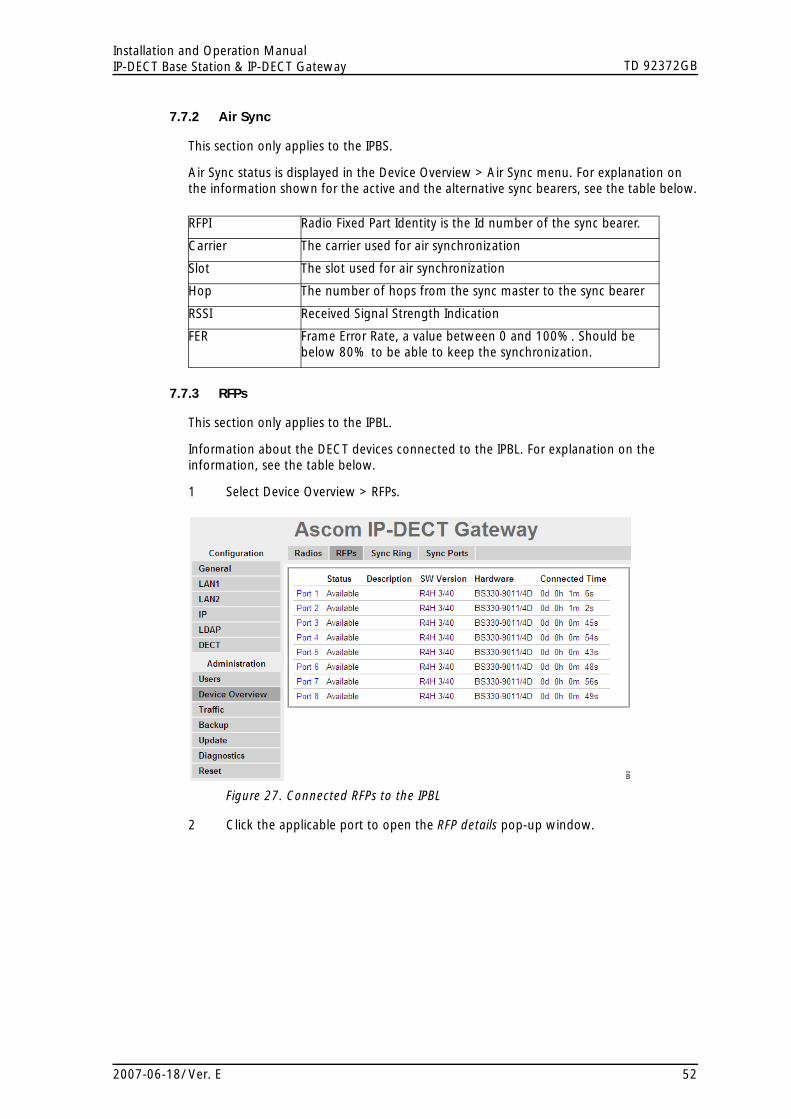
TD 92372GBInstallation and Operation ManualIP-DECT Base Station & IP-DECT Gateway
7.7.2 Air Sync
This section only applies to the IPBS.
Air Sync status is displayed in the Device Overview > Air Sync menu. For explanation on the information shown for the active and the alternative sync bearers, see the table below.
Figure 52.
RFPI Radio Fixed Part Identity is the Id number of the sync bearer.
Carrier The carrier used for air synchronization
Slot The slot used for air synchronization
Hop The number of hops from the sync master to the sync bearer
RSSI Received Signal Strength Indication
FER Frame Error Rate, a value between 0 and 100%. Should be below 80% to be able to keep the synchronization.
7.7.3 RFPs
This section only applies to the IPBL.
Information about the DECT devices connected to the IPBL. For explanation on the information, see the table below.
1 Select Device Overview > RFPs. Figure 53.
Figure 27. Connected RFPs to the IPBL
2 Click the applicable port to open the RFP details pop-up window.
2007-06-18/ Ver. E 52
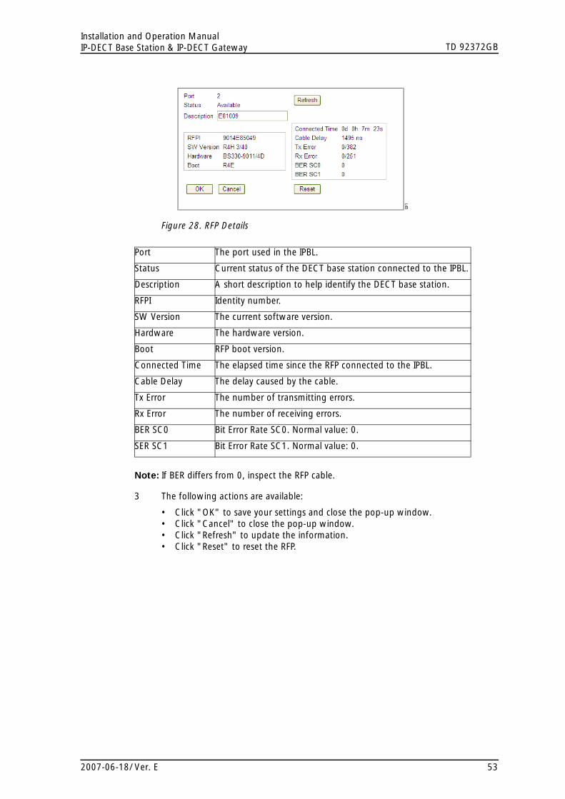
TD 92372GBInstallation and Operation ManualIP-DECT Base Station & IP-DECT Gateway
Figure 54.
Figure 28. RFP Details
Figure 55.
Port The port used in the IPBL.
Status Current status of the DECT base station connected to the IPBL.
Description A short description to help identify the DECT base station.
RFPI Identity number.
SW Version The current software version.
Hardware The hardware version.
Boot RFP boot version.
Connected Time The elapsed time since the RFP connected to the IPBL.
Cable Delay The delay caused by the cable.
Tx Error The number of transmitting errors.
Rx Error The number of receiving errors.
BER SC0 Bit Error Rate SC0. Normal value: 0.
SER SC1 Bit Error Rate SC1. Normal value: 0.
Note: If BER differs from 0, inspect the RFP cable.
3 The following actions are available:
• Click "OK" to save your settings and close the pop-up window.• Click "Cancel" to close the pop-up window.• Click "Refresh" to update the information.• Click "Reset" to reset the RFP.
2007-06-18/ Ver. E 53

TD 92372GBInstallation and Operation ManualIP-DECT Base Station & IP-DECT Gateway
7.7.4 Sync Ring
This section only applies to the IPBL.
A wire map of the synchronization ring is available in the GUI. The identities (IPBL-xx-xx-xx) of the IPBLs and the position in the ring is displayed. If the ring is broken it is possible to locate where. Click the IP address to access another IPBL.
1 Select Device Overview > Sync Ring.Figure 56.
Figure 29. Example on a Sync Ring
7.7.5 Sync Ports
This section only applies to the IPBL.
Displays the current status of the synchronization ports.
1 Select Device Overview > Sync Ports.Figure 57.
Status The current status of the port.
Sync Offset The synchronization offset for the IPBL.
Cable Delay The delay caused by the cable.
Sync Lost Counter The number of times synchronization lost.
Communication The present status of communication.
Connected to The IP address of the IPBL connected.
Tx Error The number of transmitting errors.
Rx Error The number of receiving errorsFigure 58.
2007-06-18/ Ver. E 54

TD 92372GBInstallation and Operation ManualIP-DECT Base Station & IP-DECT Gateway
7.8 Traffic
Traffic information is displayed in the Traffic sub menu. For the master the traffic information for the IP-DECT system is displayed as well as traffic information for the radio itself (if this radio is enabled).
7.8.1 Statistics
The Statistics page shows traffic statistics. If the IPBS/IPBL is a master, statistics for the whole IP-DECT system is shown under the Master heading. Traffic statistics for the radio part is shown under the Radio heading. See the table below for information about the different statistics fields.
Figure 59.
Master
Calls In The number of incoming calls to the system.
Calls In Connected The number of connected incoming calls in the system.
Calls Out The number of outgoing calls in the system.
Handover The number of handovers in the system.
Handover Failed The number of failed handovers in the system.
Abnormal Call Release The number of abnormal call terminations.
Radio
Calls In The number of incoming calls to the radio.
Calls Out The number of outgoing calls from the radio.
Handover The number of handovers in the radio.
Handover Failed The number of failed handovers in the radio.
7.8.2 Display All Ongoing Calls in the System
All ongoing calls in the IP-DECT system can be displayed by selecting Traffic > Master Calls in the master.
7.8.3 Display Calls
All ongoing calls on an IPBS/IPBL can be displayed by selecting Traffic > Radio Calls.
7.8.4 Handover
During call, all ongoing handovers in the IP-DECT system can be displayed by selecting Traffic > Handover in the master.
2007-06-18/ Ver. E 55

TD 92372GBInstallation and Operation ManualIP-DECT Base Station & IP-DECT Gateway
7.9 Backup
The IPBS/IPBL configuration can be downloaded and saved on a disc or a server. This is useful when identical configuration should be applied to several IPBS/IPBLs, for example when configure the slaves in a system. For information on how to load a saved configuration on the IPBS/IPBL, see 7.10 Update on page 56.
1 Select Backup > Config
2 Click "download"
3 Click "Save" in the dialogue window and browse to the place where the configuration should be saved.
4 Click "Save"
7.10 Update
This section describes how to do the following configurations and settings.
• Update Configuration
• Update Firmware
• Update the Boot File
• Update the RFPs
7.10.1 Update Configuration
A previously saved configuration can be loaded and activated on the IPBS/IPBL. See 7.9 Backup on page 56 for information on how to save a configuration.
1 Select Update > Config.
2 Click "Browse..." and browse to the saved configuration.
3 Click "OK"
4 Reset in order to make the changes take effect, see 7.12 Reset on page 60.
7.10.2 Update Firmware
The software can be updated. Follow the steps below to update IPBS/IPBL with the firmware. Download firmware from the IP-DECT system provider.
Note: If this operation is interrupted, the firmware in the device will be defect. If a firmware upload is for any reason interrupted, the firmware must be uploaded again. Do not execute a reset before the firmware upload is complete. For information on how to load new firmware if the IPBS/IPBL is unreachable through the web GUI, see 9.1 Load Firmware Using the Gwload Tool on page 62.
1 Select Update > Firmware.
2 Click "Browse..." and browse to the firmware file.
3 Click "OK"
4 Reset in order to make the changes take effect, see 7.12 Reset on page 60.
2007-06-18/ Ver. E 56

TD 92372GBInstallation and Operation ManualIP-DECT Base Station & IP-DECT Gateway
7.10.3 Update the Boot File
1 Select Update > Boot.
2 Click "Browse..." and browse to the boot file.
3 Click "OK"
4 Reset in order to make the changes take effect, see 7.12 Reset on page 60.
7.10.4 Update the RFPs
This section only applies to the IPBL.
The firmware can be updated. Follow the steps below to update RFP. Download firmware from the IP-DECT system provider.
In the RFP status list, information on connected RFPs are displayed.
1 Select Update > RFPs.
2 Click "Browse..." and browse to the RFP update file.
3 Click "Upload".Figure 60.
Figure 30. Upgrade the RFP
4 Select "Immediate" or "Scheduled" update.
5 Mark "In sequence" check box to update the selected RFPs one by one.
6 Mark "When idle" check box to start the update when the RFP is idle.
7 Mark the applicable RFPs to be updated.
8 Click "Start" to upgrade the selected RFPs.
The RFP restarts after the upload is finished.
2007-06-18/ Ver. E 57

TD 92372GBInstallation and Operation ManualIP-DECT Base Station & IP-DECT Gateway
7.11 Diagnostics
7.11.1 Logging
The IPBS/IPBL can generate a number of logs which can be useful when supervising and troubleshooting the IP-DECT system. For information on how to collect the log files, see 7.1.6 Configure Logging on page 35. For a description of each log, see the table below.
Figure 61.
Setting Description
TCP Logs generated upon TCP connection set-ups in the H.225 / H.245 protocol.
DECT Master Logs generated by the DECT master software component in the IPBS/IPBL.
DECT Radio Logs generated by the DECT Radio software component in the IPBS/IPBL.
H.323 Registrations Logs generated upon RAS registration.
Config Changes Logs generated upon configuration changes in the IPBS/IPBL or the IP-DECT system.
DECT Stack A low level DECT log, intended for support departments.
1 Select Diagnostics > Logging.
2 Select which logs to generate by marking the check box next to the log name.
3 Click "OK".
4 View the logs by clicking the "syslog" link. The logs are updated in real-time.
7.11.2 Tracing
The information gathered from the trace functionality is mainly used for troubleshooting in case of failure in the system. The trace information is intended for the support departments.
7.11.3 Config Show
Config Show displays the configuration as a text output.
7.11.4 Ping
The ping function is used to determine the response time from the IPBS/IPBL to a certain IP address. It can be used to analyse the connection between the IP-DECT system components.
1 Select Diagnostics > Ping.
2 Enter an IP address in the IP Address text field.
3 Press "Enter" on the keyboard.
2007-06-18/ Ver. E 58

TD 92372GBInstallation and Operation ManualIP-DECT Base Station & IP-DECT Gateway
7.11.5 Environment
This section only applies to the IPBL.
The environment tab gives information power supply and consumption. It also display temperature and fan status.
1 Select Diagnostics > Environment.
2 The following information is available in the Power field:
• Power supply - AC or DC power port.• Voltage - input voltage.• Current consumption - total consumption for the IPBL an the connected RFPs.
– Max 4,0 A when supplied with AC power port – Max 5,2 A when supplied with DC power port
Figure 62.
3 The following information is available in the Environment field.
• Temperature - °C • Fan status - OK, not OK
7.11.6 RFP Scan
This section only applies to the IPBS.
To scan for occupied system IDs of other Ascom IP-DECT systems within the coverage area, perform an RFP scan following the steps below.
Note: Executing an RFP scan will terminate all calls on the IPBS.
1 Select Diagostics > RFP Scan
2 Click "Start Scanning"
7.11.7 Service Report
This section only applies to the IPBL.
To download a service report do the following:
1 Select Diagnostics > Service Report.
2 Click "download".
3 Click “Save” and browse where to save the service report.
2007-06-18/ Ver. E 59

TD 92372GBInstallation and Operation ManualIP-DECT Base Station & IP-DECT Gateway
7.12 Reset
Some configuration changes requires a reset in order to take effect. A reset reboots the software. There are two ways to perform a reset:
• Idle reset - waits until there are no active calls in the IPBS/IPBL.
• Immediate reset - clears all calls and resets the IPBS/IPBL.
7.12.1 Idle Reset
1 Select Reset > Idle Reset.
2 Click "OK".
3 The IPBS/IPBL will reset when there are no active calls.
7.12.2 Immediate Reset
1 Select Reset > Reset.
2 Click "OK".
3 The IPBS/IPBL will terminate all active calls and reset.
7.12.3 TFTP Mode
Note: When the IPBS/IPBL is in TFTP mode it can only be reached using the gwload utility. This mode should not be used during normal operation.
7.13 Reset Using the Reset Button
It is possible to do a hardware reset of the IPBS and IPBL by pressing the reset button. The button is accessed through a hole in the back of the IPBS (figure 1 on page 2) and on the front of the IPBL (figure 2 on page 5).
Note: Use a pointed object in an non conducting material to perform a reset.
Short press < 1 sec Restart
Medium press ~3 sec Restart in TFTP mode. In TFTP mode the IPBS and IPBL can be accessed only through the gwload application. This mode is intended for support and development departments.
Long press ~ 10 sec Factory reset - all configuration parameters will be set to default values.
8 Commissioning
This section describes the visual inspection and tests that must be executed after completing the installation and initialization of the IP-DECT system. The purpose of the visual inspection and tests is to verify that all installation activities have resulted in a correctly functioning system. If it appears that a part is malfunctioning while the system is
2007-06-18/ Ver. E 60

TD 92372GBInstallation and Operation ManualIP-DECT Base Station & IP-DECT Gateway
installed correctly (i.e.: no cabling faults, no configuration faults), the technician must consult the maintenance section included in this manual for fault finding.
8.1 Radio coverage verification tests
The radio coverage verification consists of two tests:
• Base station operation test
• Coverage area test
Note: Be sure that all batteries in the cordless phones are charged before executing the tests.
8.1.1 Base Station Operation Test
The purpose of this test is to check if all base stations are operational.
1 Put a cordless phone in the service display mode (DCA mode) , see applicable user manual for the cordless phone.
2 Use the base station plan, see Considerations for Ascom IP-DECT System Planning, TD92422.
3 Move close to each base station and check that the cordless phone locks to it (the service display should display the correct number).
After having checked that all base stations are operational proceed with the coverage area test.
8.1.2 Coverage Area Test
The purpose of this test is to verify that there is satisfactory field strength to enable good speech quality everywhere within the covered area (rooms, lift shafts, staircases). This test is executed with two cordless phones and requires two persons.
1 Place the cordless phone in the service display mode (DCA mode) and call the other cordless phone. One user of the cordless phone should now start moving around the covered area. Both users must check that a good speech quality is maintained everywhere. Special attention should be paid to areas such as edges of the building and areas behind metal structures where there is a possibility of reduced speech quality.
2 Mark areas where cracking sounds or mutes are heard.
8.1.3 Evaluation
After having performed the coverage area test, the results should be evaluated. If the coverage is not sufficient you should review the planning and move or add equipment.
8.2 Cordless Extension Number Test
This test checks for each cordless phone the complete connection from the IP-DECT system to the PBX. Furthermore it checks that the cordless phones’ numbers have been correctly programmed. The test is performed by calling all cordless phone from one specific cordless phone.
1 Put all cordless phone together in order of extension number on a table.
2 Go off-hook with each cordless phone and check that the dial tone is heard.
2007-06-18/ Ver. E 61

TD 92372GBInstallation and Operation ManualIP-DECT Base Station & IP-DECT Gateway
3 Call with a cordless phone (cordless phone A) all other cordless phones sequentially and check that the cordless phone with the corresponding number on its display rings when called.
4 Call cordless phone A and check if it rings.
9 Troubleshooting
9.1 Load Firmware Using the Gwload Tool
If the firmware is corrupt, for example if firmware download is interrupted the IPBS/IPBL could become unreachable by the web GUI. It will not be possible to load new firmware or to start correctly. If this occurs, the IPBS/IPBL runs on the bootcode and the Gwload tool can be used to upload firmware.
1 Download the Gwload software from the IP-DECT system provider.
2 Set the IPBS/IPBL in TFTP-mode by performing a medium (~3 sec) hardware reset, see 7.13 Reset Using the Reset Button on page 60.
3 Start a command window.
To update with wew firmware, execute the following command from the folder where the gwload.exe file is located:
IPBS: gwload /setip /i <ipaddress> /gwtype 1201 /prot <..path/firmwarefilename> /go
IPBL: gwload /setip /i <ipaddress> /gwtype 4001 /prot <..path/firmwarefilename> /go
4 If there is more than one IPBS/IPBL in TFTP mode, select the unit to update and press enter.
10 Related Documents
System Description, Ascom IP-DECT System TD 92375GB
Data Sheet, IP-DECT Base Station TD 92370GB
Data Sheet, IP-DECT Gateway TD 92430GB
System Planning, Ascom IP-DECT System TD 92422GB
Function Description, Ascom IP-DECT System TD 92407GB
Function Description, Configuration Notes for Cisco Call Manager in Ascom IP-DECT System
TD 92424GB
Technical Product Manual, DCT1800-GAP TD 92093GB
2007-06-18/ Ver. E 62

TD 92372GBInstallation and Operation ManualIP-DECT Base Station & IP-DECT Gateway
Version Date Description
A 2006-06-02 First released version.
B 2007-01-15 System Planning removed.
C 2007-01-26 Chapter 4 updated.
D 2007-04-20 IPBL added.
E 2007-06-18 Chapter 3.1.1 Safety Rules updated.
Document History
For details in the latest version, see change bars in the document.
2007-06-18/ Ver. E 63

TD 92372GBInstallation and Operation ManualIP-DECT Base Station & IP-DECT Gateway
Appendix A: How to Use the Update Server
A.1 Summary
Automatic update is based on configuration and firmware information stored on a standard web server and retrieved by the devices on a regular basis.
There are 2 modules in the device which work in tandem. The first is known as "UP0" and actually executes the upload and download of configuration information as well as the download of updated firmware. UP0 is controlled by commands as described below.
The second module is known as "UP1". It serves to poll a given website for changed configuration information. If certain conditions are met, UP1 will issue commands to UP1 to perform the requested updates.
UP0 can also receive commands from the "Update clients" page of the PBX Administration user interface.
A.1.1 System Requirements
One or more regular Web Server that can be accessed by all devices are required. This has been tested with Microsoft IIS and Apache, but any regular Web Server should do.
For best results, the Web Server should be able to maintain a large number of HTTP sessions simultaneously, since potentially all devices may attempt a configuration update at the same time. For example, Microsoft's Personal Web Server is not adequate, since it only support 10 simultaneous sessions.
A.1.2 Installation
To be able to upload (save) device configuration information on the web server, it must allow HTTP PUT requests. All other functions require HTTP GET permissions only.
Since all HTTP requests are performed unauthenticated, the website used must allow anonymous read (and potentially write) access. You may want to restrict access to that site to certain network address ranges.
Configure a Microsoft IIS URL to allow PUT commands:
1 Create a directory where you want to save configurations to
2 Create a virtual directory in Microsoft's IIS manager
3 Select "read" and "write" access
No installation is needed on the IPBS/IPBLs.
A.1.3 Configuration
See 7.1.4 Configure Automatic Firmware Update on page 33 on how to configure the IPBS/IPBLs for automatic update.
The URL parameter must point to the site where the file containing the maintenance commands is stored. Note that in this URL, no host names are supported. The web servers IP address must be used.
A.1.4 Setting the UP1 Parameters
The applet saves the configuration in a line starting config change UP1.
The full syntax is:
2007-06-18/ Ver. E 64

TD 92372GBInstallation and Operation ManualIP-DECT Base Station & IP-DECT Gateway
config change UP1 /url <url> [/poll <slow>] [/poll-fast <fast>] [/disc]
If the URL ends with a '/' then a default filename is used based upon the product in question. If for example the URL is "http://1.2.3.4/configs/", it is expanded to "http://1.2.3.4/configs/update-IPBS.htm" (.../update-IPBL).
The product type name used is the one used in the Version line on the devices Info page. Note that the extension is irrelevant, .htm or .txt or no extension at all may be used. On some Web servers, URLs are case sensitive.
The maintenance command file is retrieved initially after the configured poll interval (in minutes) is expired after boot. Short poll intervals can create substantial load on a big network. A value less than 15 minutes (which is the default) is therefore not recommended.
However, for new devices (that is, devices which have been reset to factory settings and never had a successful download of a maintenance command file), the command file is retrieved every minute (for up to 30 minutes). This is done so that a fresh device can quickly retrieve a site depending standard configuration when it is installed. You can change this initial polling interval using the /poll-fast <fast> parameter (this is not recommended).
The /disc parameter can be specified to force the device to close the http sessions used immediately.
When the maintenance command file is retrieved, the commands found in the file are executed in sequence. Theoretically, all commands which can be typed in to a telnet session to the device or which appear in a config file can be used in the maintenance file. However, in most cases, you will use config change commands and commands to the UP0/UP1 modules.
The command file is executed every time it is retrieved (depending on the poll interval). However, in most cases, you don't want it to be executed each time, but only once. For example, if you are about to deploy a certain configuration change to all IPBSs, then you want this change to be done once per IPBS only. This can be achieved by the check command:
mod cmd UP1 check <final-command> <serial>
The devices maintain an internal variable UPDATE/CHECK which is initially (or when the device is reset to factory settings) empty. The check command will compare the <serial> parameter with the UPDATE/CHECK variable. If it is equal, any further processing of the command file is cancelled.
If it differs, the remainder of the file will be processed and, after the last command is executed, the UPDATE/CHECK variable will be set to <serial> and the <final-command> will be executed. The following commands are useful values for <final-command>:
Figure 63.
ireset resets the device as soon it is idle
reset resets the device immediately
iresetn resets the device as soon it is idle, only if a reset is required
resetn resets the device immediately, only if a reset is required
ser this is a no-op
Often, configuration changes shall be made only during certain times (e.g. non-working hours). This can be achieved using the times command:
mod cmd UP1 times [/allow <hours>] [/initial <minutes>]
2007-06-18/ Ver. E 65

TD 92372GBInstallation and Operation ManualIP-DECT Base Station & IP-DECT Gateway
The times command will check the current time against <hours>. If it does not match this restriction, any further processing of the command file is cancelled. <hours> is a comma separated list of hours. Only those hours listed are considered valid times for execution of the command file.
mod cmd UP1 times /allow 12,23,1,2,3,4
The command above allows command executions only between 12:00 and 12:59 and 23:00 and 4:59 local time (on a 24h clock). Note that if the device has no time set, all command executions will be cancelled.
If the /initial parameter is set, the no commands will be executed within the first <minutes> minutes after the device has been booted. This is done to avoid firmware download and flashing when installing devices.
mod cmd UP1 times /allow 12,23,1,2,3,4 /initial 6
The command above suppresses any command file processing within the first six minutes after each boot of the device. If /initial is set, new devices (or those that have been reset to factory settings), the command file will be retrieved even if it normally would be suppressed by the /allow parameter. This allows new devices to retrieve a site specific standard configuration quickly.
A.1.5 Setting the UP0 Parameters
To perform a firmware update, use the following command:
mod cmd UP0 prot <url> <final-command> <build-serial>
The command above downloads the new firmware from <url> and flash it to the device, then <final-command> is executed.
The IPBSs maintain an internal variable UPDATE/PROT which is initially (or when the device is reset to factory settings) empty. The prot command will compare the <build-serial> parameter with the UPDATE/PROT variable. If it is equal, no firmware will be loaded or flashed. If there is no UPDATE/PROT yet (like for a new device), <build-serial> is compared against the build number of the current firmware. After a successful download, UPDATE/PROT is set to <build-serial>. Note that <build-serial> is not checked against the firmware version actually loaded. It is your responsibility to keep this consistent.
If <url> ends with a slash ('/'), then a default firmware filename is added to the URL depending on the type of the device (e.g. ipbs.bin or ipbl.bin).
mod cmd UP0 prot http://192.168.0.10/firm ireset 1.2.2
The command above determines if firmware 1.2.2 is already installed. If not, new firmware will be downloaded from http://192.168.0.10/firm/ipbs.bin (.../ipbl.bin), the UPDATE/PROT variable will be set to 1.1.2 and the device will be reset as soon as it is idle.
Similar to the prot command, the boot command will update the boot code.
mod cmd UP0 boot http://192.168.0.10/firm ireset 205
The command above determines if boot code 205 is already installed. If not, new boot code will be downloaded from http://192.168.0.10/firm/boot_ipbs.bin (.../boot_ipbl.bin), the UPDATE/BOOT variable will be set to 205 and the device will be reset as soon as it is idle.
Using UP0, device configurations can be saved to a web server.
mod cmd UP0 scfg <url>
2007-06-18/ Ver. E 66

TD 92372GBInstallation and Operation ManualIP-DECT Base Station & IP-DECT Gateway
This will cause the device to upload its current config to url This will be done using an HTTP PUT command. url must be writable thus. With url, some meta character strings are replaces as follows:
Figure 64.
Sequence Replacement Example
#d Current date and time 20040319-162544
#m Prinmary device mac address 00-90-33-03-0d-f0
#h Device hardware ID ipbs-03-0d-f0
A.1.6 Setting the RFP_UPDATE0 Parameter
To perform a RFP firmware update, use the following commands.
mod cmd RFP_UPDATE0 firmware http://192.168.0.10/Worf4_GAP_R4H.s2
The command above specifies the url to the RFP firmware to use.
mod cmd RFP_UPDATE0 select 0x2753
Specifies which RFPs to update using a hex-encoded bit-mask. Each bit represents an RFP port starting with port 1 at the LSB (0x0001) up to port 16 (0x8000).
0x2753 specifies RFP "1,2,5,7,9,10,11,14" to be updated.
mod cmd RFP_UPDATE0 schedule DD.MM.YYYY-HH:MM
Specifies when the update shall start. If no date is provided, the update will be immediate when the start command is issued.
mod cmd RFP_UPDATE0 start /idle
Starts the update or activates the schedule. Normally the /idle command is selected and an update starts only if the RFP is idle.
If multiple RFPs are selected for update, they will be updated one at a time If /sequence command is used.
2007-06-18/ Ver. E 67

TD 92372GBInstallation and Operation ManualIP-DECT Base Station & IP-DECT Gateway
Example IPBL
This example shows an "update file" for the IPBL.
mod cmd UP0 prot http://172.20.8.125/ascom/firmware/ ireset 1.0.0
mod cmd UP0 boot http://172.20.8.125/ascom/boot/ ireset 412
mod cmd UP1 check ser 20070316-1
mod cmd RFP_UPDATE0 firmware http://172.20.8.125/ascom/rfp/Worf123.S2
mod cmd RFP_UPDATE0 select 0xffff
mod cmd RFP_UPDATE0 start /idle
Example IPBS
This example shows an "update file" for the IPBS.
mod cmd UP0 prot http://172.20.8.128/ascom/firmware/ ireset 1.0.0
mod cmd UP0 boot http://172.20.8.128/ascom/boot/ ireset 412
2007-06-18/ Ver. E 68

TD 92372GBInstallation and Operation ManualIP-DECT Base Station & IP-DECT Gateway
Appendix B: RFP Power Consumption
The tables below show power consumption for a base station connected to the IPBL. The power consumption of the IPBL is approximately 15 W.
Note: The maximum cable length for base stations connected to the IPBL must not exceed 1500 meters.
B.1 KRCNB 201/DCT1800Figure 65.
Cable length
(metres)
0.4 mm wire size (∅) 0.5 mm wire size (∅) 0.6 mm wire size (∅)
0 EPP 1 EPP 0 EPP 1 EPP 0 EPP 1 EPP
0 7.5 7.5 7.5 7.5 7.5 7.5
100 7.9 7.8 7.8 7.7 7.7 7.6
200 8.3 8.0 8.0 7.8 7.8 7.7
300 8.9 8.3 8.3 8.0 8.0 7.8
400 9.8 8.7 8.7 8.2 8.2 7.9
500 11.3 9.2 9.2 8.5 8.4 8.0
600 - 9.8 9.8 8.7 8.6 8.2
700 - 10.7 10.7 9.0 8.8 8.3
800 - 12.3 12.3 9.4 9.1 8.4
900 - - - 9.8 9.5 8.6
1000 - - - 10.3 9.9 8.8
1100 - - - 11.1 10.4 8.9
1200 - - - 12.3 11.1 9.1
1300 - - - - 12.1 9.3
1400 - - - - - 9.6
1500 - - - - - 9.9
1600 - - - - - 10.2
1700 - - - - - 10.6
1800 - - - - - 11.1
1900 - - - - - 11.7
2000 - - - - - 12.7
2100 - - - - - -
2200 - - - - - -
2300 - - - - - -
2400 - - - - - -
2500 - - - - - -
2600 - - - - - -
2700 - - - - - -
Table 1 Power consumption (watts) of base stations and cabling when powered with 48 V
2007-06-18/ Ver. E 69
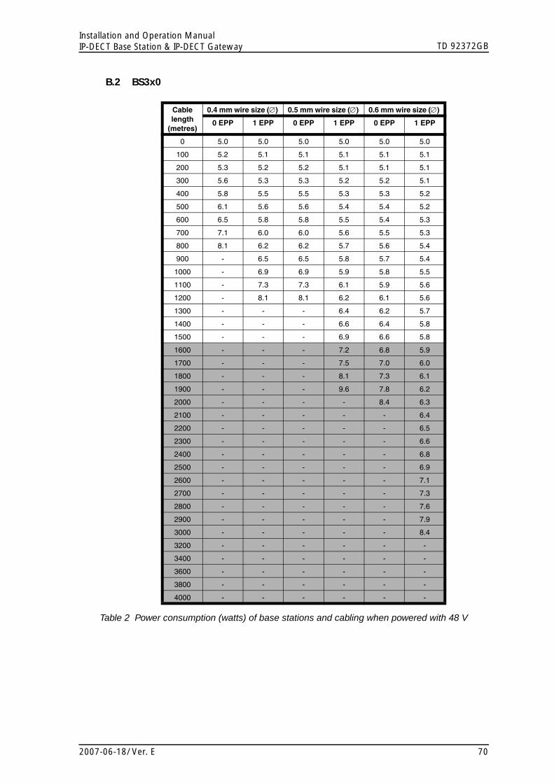
TD 92372GBInstallation and Operation ManualIP-DECT Base Station & IP-DECT Gateway
B.2 BS3x0Figure 66.
Cable length
(metres)
0.4 mm wire size (∅) 0.5 mm wire size (∅) 0.6 mm wire size (∅)
0 EPP 1 EPP 0 EPP 1 EPP 0 EPP 1 EPP
0 5.0 5.0 5.0 5.0 5.0 5.0
100 5.2 5.1 5.1 5.1 5.1 5.1
200 5.3 5.2 5.2 5.1 5.1 5.1
300 5.6 5.3 5.3 5.2 5.2 5.1
400 5.8 5.5 5.5 5.3 5.3 5.2
500 6.1 5.6 5.6 5.4 5.4 5.2
600 6.5 5.8 5.8 5.5 5.4 5.3
700 7.1 6.0 6.0 5.6 5.5 5.3
800 8.1 6.2 6.2 5.7 5.6 5.4
900 - 6.5 6.5 5.8 5.7 5.4
1000 - 6.9 6.9 5.9 5.8 5.5
1100 - 7.3 7.3 6.1 5.9 5.6
1200 - 8.1 8.1 6.2 6.1 5.6
1300 - - - 6.4 6.2 5.7
1400 - - - 6.6 6.4 5.8
1500 - - - 6.9 6.6 5.8
1600 - - - 7.2 6.8 5.9
1700 - - - 7.5 7.0 6.0
1800 - - - 8.1 7.3 6.1
1900 - - - 9.6 7.8 6.2
2000 - - - - 8.4 6.3
2100 - - - - - 6.4
2200 - - - - - 6.5
2300 - - - - - 6.6
2400 - - - - - 6.8
2500 - - - - - 6.9
2600 - - - - - 7.1
2700 - - - - - 7.3
2800 - - - - - 7.6
2900 - - - - - 7.9
3000 - - - - - 8.4
3200 - - - - - -
3400 - - - - - -
3600 - - - - - -
3800 - - - - - -
4000 - - - - - -
Table 2 Power consumption (watts) of base stations and cabling when powered with 48 V
2007-06-18/ Ver. E 70