Instability of the radial flow over a rotating disk in a separated edgewise stream
8
Instability of the radial flow over a rotating disk in a separated edgewise stream Vrishank Raghav and Narayanan Komerath Citation: Physics of Fluids (1994-present) 25, 111701 (2013); doi: 10.1063/1.4833435 View online: http://dx.doi.org/10.1063/1.4833435 View Table of Contents: http://scitation.aip.org/content/aip/journal/pof2/25/11?ver=pdfcov Published by the AIP Publishing This article is copyrighted as indicated in the abstract. Reuse of AIP content is subject to the terms at: http://scitation.aip.org/termsconditions. Downloaded to IP: 128.61.188.81 On: Sat, 30 Nov 2013 18:43:06
-
Upload
independent -
Category
Documents
-
view
0 -
download
0
Transcript of Instability of the radial flow over a rotating disk in a separated edgewise stream

Instability of the radial flow over a rotating disk in a separated edgewise streamVrishank Raghav and Narayanan Komerath Citation: Physics of Fluids (1994-present) 25, 111701 (2013); doi: 10.1063/1.4833435 View online: http://dx.doi.org/10.1063/1.4833435 View Table of Contents: http://scitation.aip.org/content/aip/journal/pof2/25/11?ver=pdfcov Published by the AIP Publishing
This article is copyrighted as indicated in the abstract. Reuse of AIP content is subject to the terms at: http://scitation.aip.org/termsconditions. Downloaded to IP:
128.61.188.81 On: Sat, 30 Nov 2013 18:43:06
PHYSICS OF FLUIDS 25, 111701 (2013)
Instability of the radial flow over a rotating diskin a separated edgewise stream
Vrishank Raghava) and Narayanan Komerathb)
School of Aerospace Engineering, Georgia Institute of Technology, 270 Ferst Drive,Atlanta, Georgia 30332, USA
(Received 6 September 2013; accepted 11 November 2013;published online 22 November 2013)
We present velocity field measurements showing the instability of the radial flowover a rotating disk in a separated flow due to an edgewise freestream. A uniformedgewise stream significantly modifies the radial jet profile. Under separated flowconditions, co-rotating vortical structures form at the edge of the radial jet layer. Theresults establish that the discrete structures formed in the breakup of the radial flowlayer on a rotor blade in retreating blade stall are also seen in the case of flow over arotating disk. C© 2013 AIP Publishing LLC. [http://dx.doi.org/10.1063/1.4833435]
Engineers have long been puzzled by the fact that the airloads on a helicopter or wind turbinerotor blade appear to not show the expected effects of radial acceleration. Some years ago, ourresearch team discovered that the radial jet layer immediately above the surface of a rotor bladein retreating blade stall broke up into discrete co-rotating vortical structures.1, 2 These structuresattenuated the growth of the radial jet and hence demonstrated to have a first-order significanceto the airloads on a rotating blade. Capturing such structures using computational fluid dynamicsposes extreme demands on spatial and temporal resolution, as the structures must arise from someinstability of the radial jet layer. A quasi-analytical way to predict the spacing, and thus the strength,of these structures would allow a breakthrough in such difficult problems as predicting the flowfield features, and airloads in dynamic stall, which occurs on helicopters in forward flight and windturbines in yaw. We hypothesized that fundamental insights to such predictions on a rotor blade couldbe developed from the flow over a rotating disk, which could in turn be linked to analytical solutions.An analytical solution is available for the steady axisymmetric three-dimensional boundary layerflow on an infinite rotating disk.3, 4 An analogous solution has been used in the past to help understandthe flow over a rotating helicopter rotor blade at small angles of attack.5 If structures similar to thoseobserved on the rotor blade could be found over a rotating disk that would open the way to link therotor blade phenomena to quasi-analytical solutions, and hence derive the fundamental relationshipsbetween parameters for the rotor blade problem. This would assist the development of computationalprediction methods for helicopter rotors, among other applications.
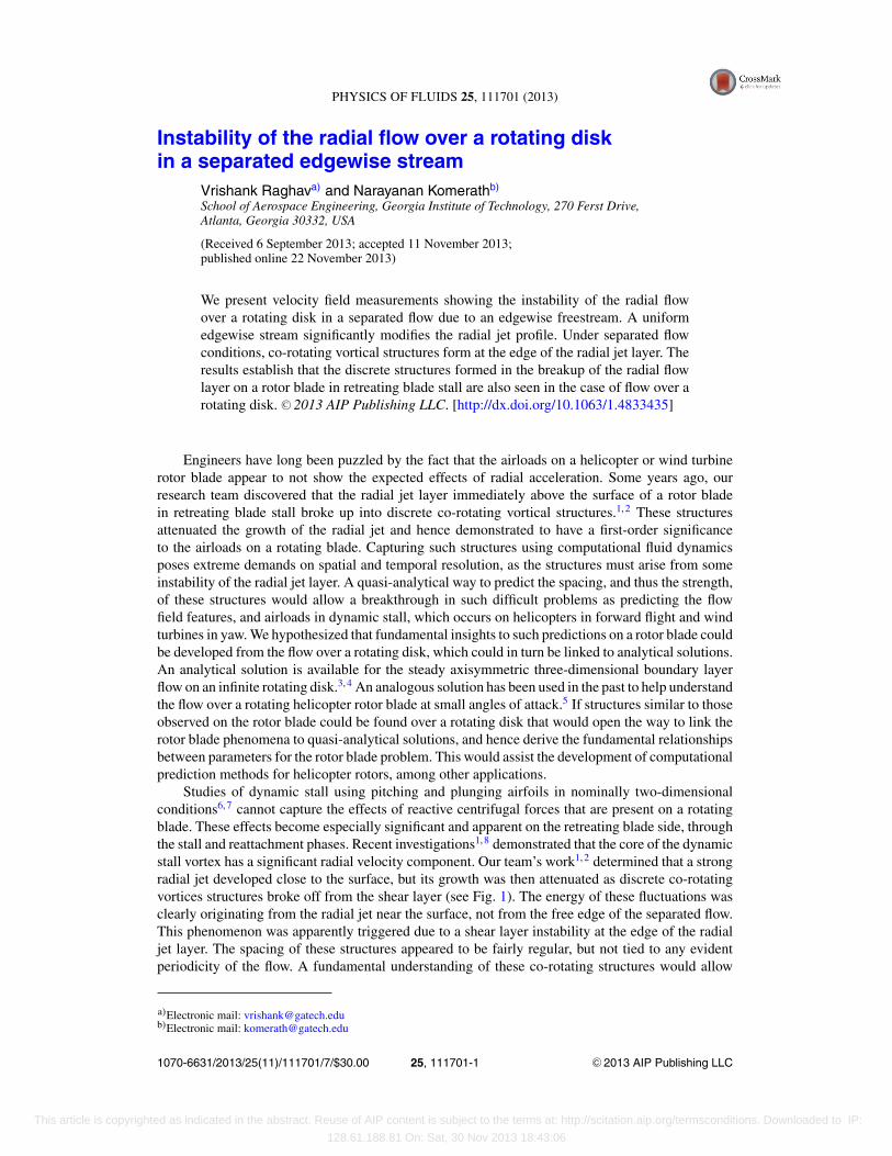
Studies of dynamic stall using pitching and plunging airfoils in nominally two-dimensionalconditions6, 7 cannot capture the effects of reactive centrifugal forces that are present on a rotatingblade. These effects become especially significant and apparent on the retreating blade side, throughthe stall and reattachment phases. Recent investigations1, 8 demonstrated that the core of the dynamicstall vortex has a significant radial velocity component. Our team’s work1, 2 determined that a strongradial jet developed close to the surface, but its growth was then attenuated as discrete co-rotatingvortices structures broke off from the shear layer (see Fig. 1). The energy of these fluctuations wasclearly originating from the radial jet near the surface, not from the free edge of the separated flow.This phenomenon was apparently triggered due to a shear layer instability at the edge of the radialjet layer. The spacing of these structures appeared to be fairly regular, but not tied to any evidentperiodicity of the flow. A fundamental understanding of these co-rotating structures would allow
a)Electronic mail: [email protected])Electronic mail: [email protected]
1070-6631/2013/25(11)/111701/7/$30.00 C©2013 AIP Publishing LLC25, 111701-1
This article is copyrighted as indicated in the abstract. Reuse of AIP content is subject to the terms at: http://scitation.aip.org/termsconditions. Downloaded to IP:
128.61.188.81 On: Sat, 30 Nov 2013 18:43:06
111701-2 V. Raghav and N. Komerath Phys. Fluids 25, 111701 (2013)
FIG. 1. Vorticity plot showing the co-rotating vortical structures on a rotating blade during dynamic stall conditions.Reprinted with permission from V. Raghav and N. Komerath, J. Am. Helicopter Soc. 58, 022005 (2013). Copyright 2013,AHS International.
prediction of the limiting strength of the radial jet, and hence a better prediction of the airloads onthe rotor blade through the critical regime of dynamic stall. As mentioned earlier, predicting theoccurrence and properties of these structures from first principles through large-scale computationalfluid dynamics is difficult, as they appear to stem from instabilities developing from very smallspatial and temporal scales in the radial jet layer. Hence an approach to provide guidance on theircharacteristics was sought. This led to the investigation of an analogy with the rotating disk flow ina separated edgewise stream.
This letter accordingly reports on experiments conducted on a finite rotating disk. Particle imagevelocimetry (PIV) is used to investigate the radial flow over the rotating disk with and without asuperimposed uniform stream to study the differences. First, the effect of a uniform stream on theradial velocity component on a rotating disk at zero angle of attack (α) is investigated. This isfollowed by experiments where a large separated flow region is induced on the rotating disk (bysetting it at α = 8◦) and the instability of the radial flow is studied. In summary, the primary objectiveis to demonstrate that the radial flow instability in the presence of a separated uniform stream is afundamental behavior of the radial flow over a rotating surface.
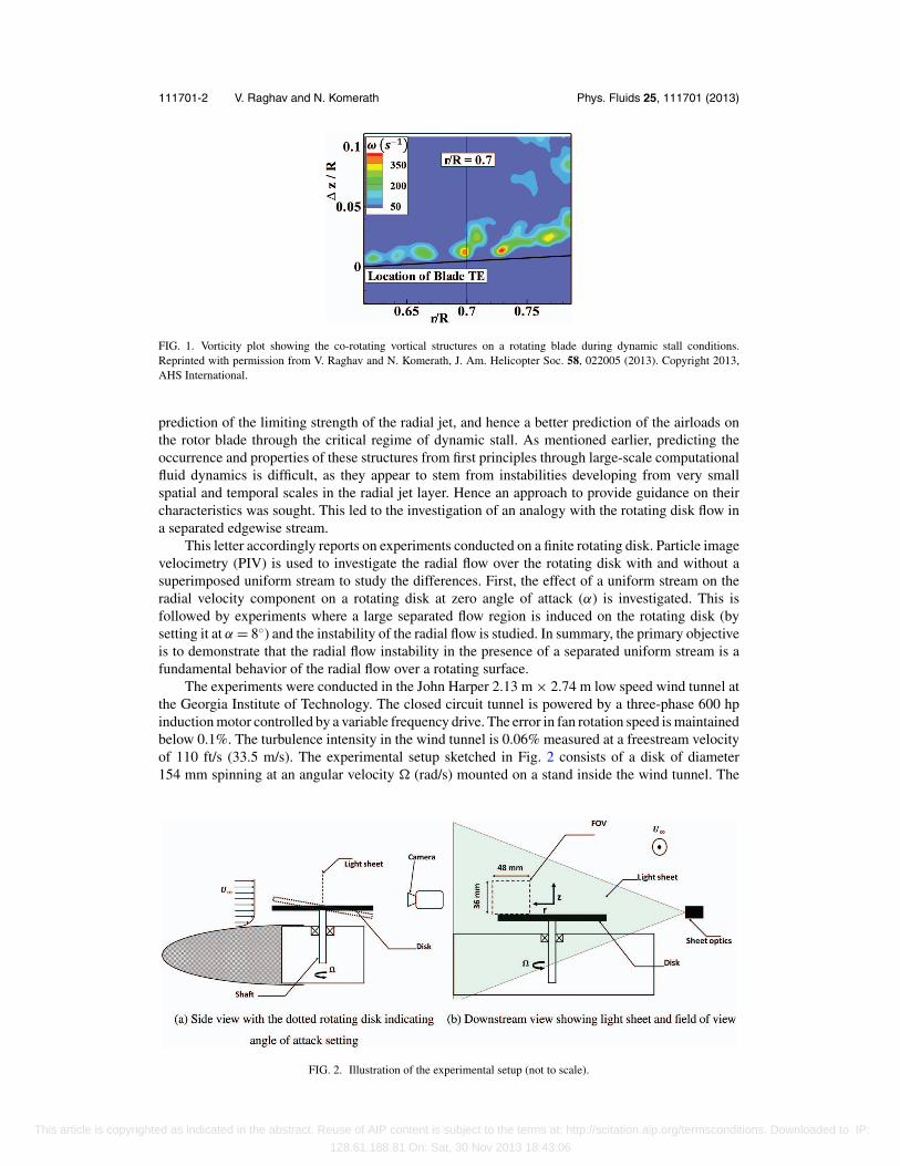
The experiments were conducted in the John Harper 2.13 m × 2.74 m low speed wind tunnel atthe Georgia Institute of Technology. The closed circuit tunnel is powered by a three-phase 600 hpinduction motor controlled by a variable frequency drive. The error in fan rotation speed is maintainedbelow 0.1%. The turbulence intensity in the wind tunnel is 0.06% measured at a freestream velocityof 110 ft/s (33.5 m/s). The experimental setup sketched in Fig. 2 consists of a disk of diameter154 mm spinning at an angular velocity � (rad/s) mounted on a stand inside the wind tunnel. The
FIG. 2. Illustration of the experimental setup (not to scale).
This article is copyrighted as indicated in the abstract. Reuse of AIP content is subject to the terms at: http://scitation.aip.org/termsconditions. Downloaded to IP:
128.61.188.81 On: Sat, 30 Nov 2013 18:43:06
111701-3 V. Raghav and N. Komerath Phys. Fluids 25, 111701 (2013)
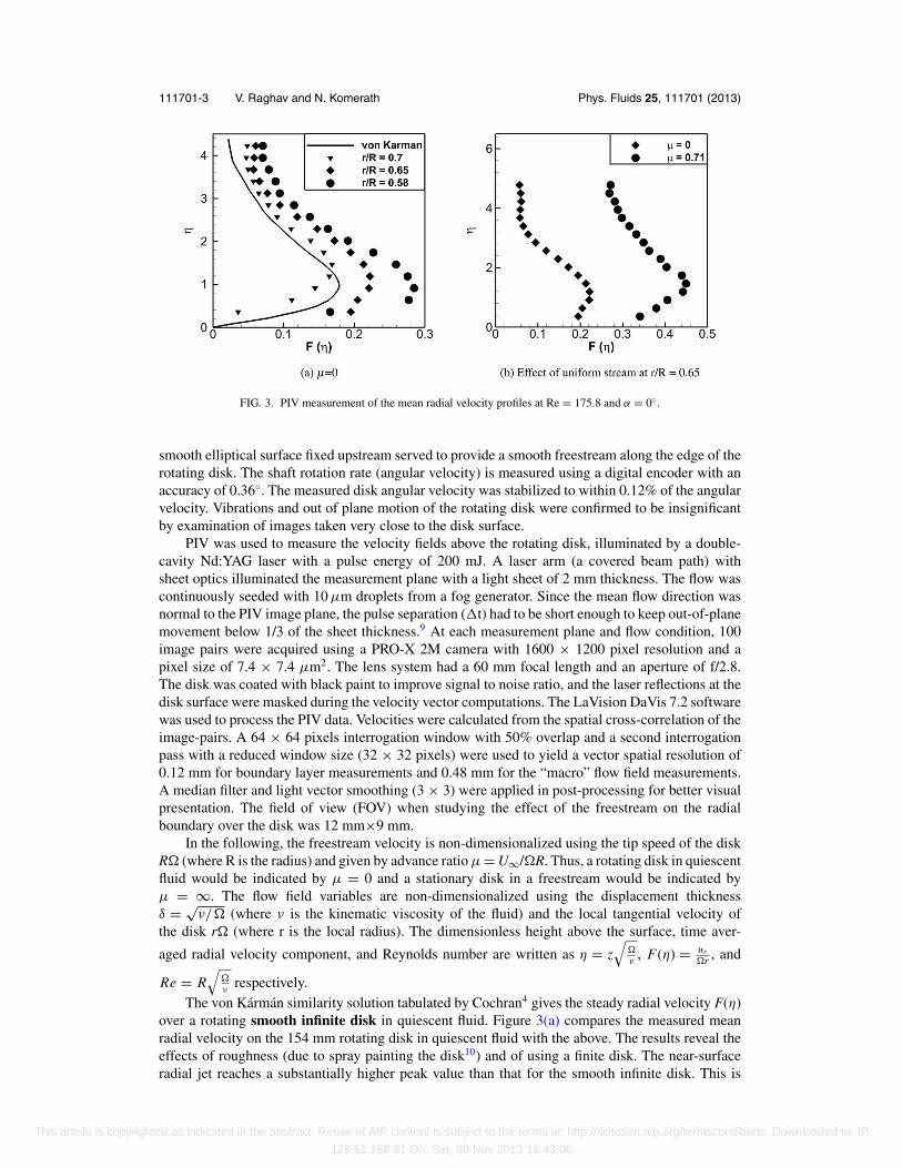
FIG. 3. PIV measurement of the mean radial velocity profiles at Re = 175.8 and α = 0◦.
smooth elliptical surface fixed upstream served to provide a smooth freestream along the edge of therotating disk. The shaft rotation rate (angular velocity) is measured using a digital encoder with anaccuracy of 0.36◦. The measured disk angular velocity was stabilized to within 0.12% of the angularvelocity. Vibrations and out of plane motion of the rotating disk were confirmed to be insignificantby examination of images taken very close to the disk surface.
PIV was used to measure the velocity fields above the rotating disk, illuminated by a double-cavity Nd:YAG laser with a pulse energy of 200 mJ. A laser arm (a covered beam path) withsheet optics illuminated the measurement plane with a light sheet of 2 mm thickness. The flow wascontinuously seeded with 10 μm droplets from a fog generator. Since the mean flow direction wasnormal to the PIV image plane, the pulse separation (�t) had to be short enough to keep out-of-planemovement below 1/3 of the sheet thickness.9 At each measurement plane and flow condition, 100image pairs were acquired using a PRO-X 2M camera with 1600 × 1200 pixel resolution and apixel size of 7.4 × 7.4 μm2. The lens system had a 60 mm focal length and an aperture of f/2.8.The disk was coated with black paint to improve signal to noise ratio, and the laser reflections at thedisk surface were masked during the velocity vector computations. The LaVision DaVis 7.2 softwarewas used to process the PIV data. Velocities were calculated from the spatial cross-correlation of theimage-pairs. A 64 × 64 pixels interrogation window with 50% overlap and a second interrogationpass with a reduced window size (32 × 32 pixels) were used to yield a vector spatial resolution of0.12 mm for boundary layer measurements and 0.48 mm for the “macro” flow field measurements.A median filter and light vector smoothing (3 × 3) were applied in post-processing for better visualpresentation. The field of view (FOV) when studying the effect of the freestream on the radialboundary over the disk was 12 mm×9 mm.
In the following, the freestream velocity is non-dimensionalized using the tip speed of the diskR� (where R is the radius) and given by advance ratio μ = U∞/�R. Thus, a rotating disk in quiescentfluid would be indicated by μ = 0 and a stationary disk in a freestream would be indicated byμ = ∞. The flow field variables are non-dimensionalized using the displacement thicknessδ = √
ν/� (where ν is the kinematic viscosity of the fluid) and the local tangential velocity ofthe disk r� (where r is the local radius). The dimensionless height above the surface, time aver-
aged radial velocity component, and Reynolds number are written as η = z√
�ν
, F(η) = ur�r , and
Re = R√
�ν
respectively.The von Karman similarity solution tabulated by Cochran4 gives the steady radial velocity F(η)
over a rotating smooth infinite disk in quiescent fluid. Figure 3(a) compares the measured meanradial velocity on the 154 mm rotating disk in quiescent fluid with the above. The results reveal theeffects of roughness (due to spray painting the disk10) and of using a finite disk. The near-surfaceradial jet reaches a substantially higher peak value than that for the smooth infinite disk. This is
This article is copyrighted as indicated in the abstract. Reuse of AIP content is subject to the terms at: http://scitation.aip.org/termsconditions. Downloaded to IP:
128.61.188.81 On: Sat, 30 Nov 2013 18:43:06
111701-4 V. Raghav and N. Komerath Phys. Fluids 25, 111701 (2013)
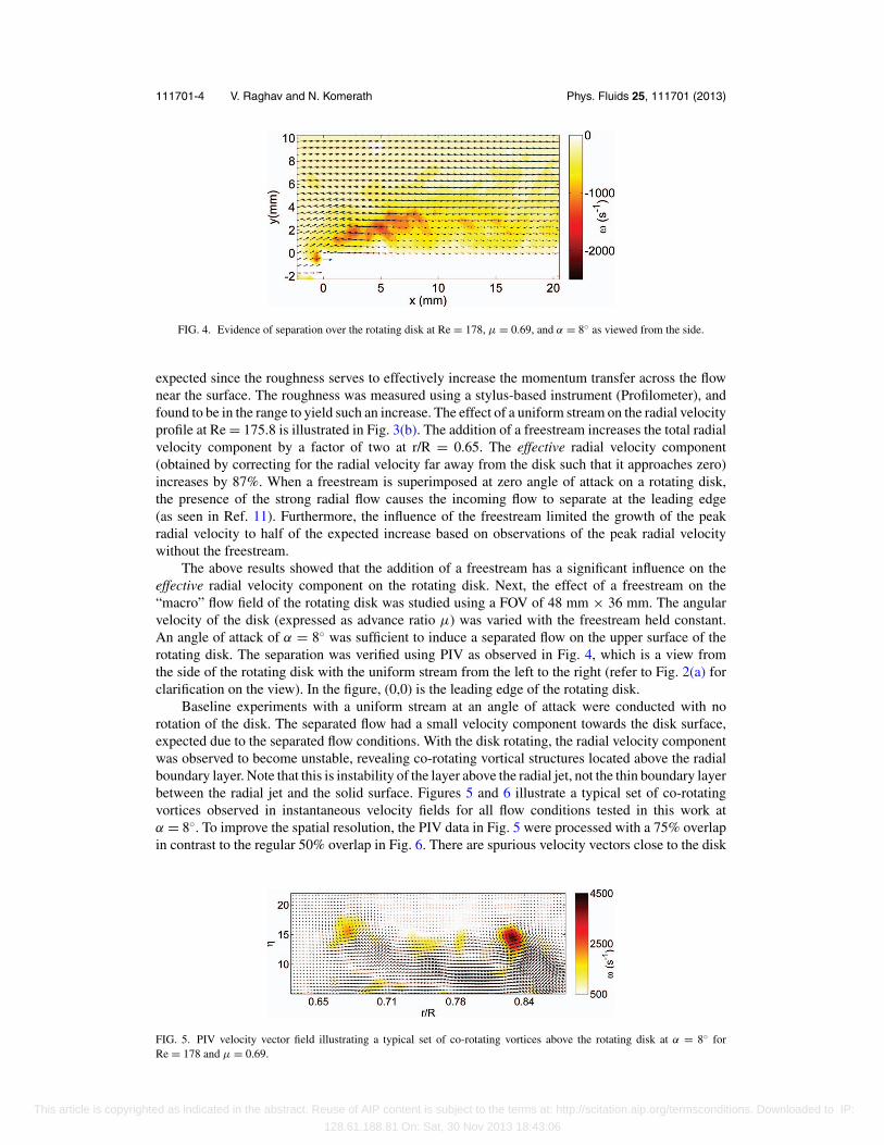
FIG. 4. Evidence of separation over the rotating disk at Re = 178, μ = 0.69, and α = 8◦ as viewed from the side.
expected since the roughness serves to effectively increase the momentum transfer across the flownear the surface. The roughness was measured using a stylus-based instrument (Profilometer), andfound to be in the range to yield such an increase. The effect of a uniform stream on the radial velocityprofile at Re = 175.8 is illustrated in Fig. 3(b). The addition of a freestream increases the total radialvelocity component by a factor of two at r/R = 0.65. The effective radial velocity component(obtained by correcting for the radial velocity far away from the disk such that it approaches zero)increases by 87%. When a freestream is superimposed at zero angle of attack on a rotating disk,the presence of the strong radial flow causes the incoming flow to separate at the leading edge(as seen in Ref. 11). Furthermore, the influence of the freestream limited the growth of the peakradial velocity to half of the expected increase based on observations of the peak radial velocitywithout the freestream.
The above results showed that the addition of a freestream has a significant influence on theeffective radial velocity component on the rotating disk. Next, the effect of a freestream on the“macro” flow field of the rotating disk was studied using a FOV of 48 mm × 36 mm. The angularvelocity of the disk (expressed as advance ratio μ) was varied with the freestream held constant.An angle of attack of α = 8◦ was sufficient to induce a separated flow on the upper surface of therotating disk. The separation was verified using PIV as observed in Fig. 4, which is a view fromthe side of the rotating disk with the uniform stream from the left to the right (refer to Fig. 2(a) forclarification on the view). In the figure, (0,0) is the leading edge of the rotating disk.
Baseline experiments with a uniform stream at an angle of attack were conducted with norotation of the disk. The separated flow had a small velocity component towards the disk surface,expected due to the separated flow conditions. With the disk rotating, the radial velocity componentwas observed to become unstable, revealing co-rotating vortical structures located above the radialboundary layer. Note that this is instability of the layer above the radial jet, not the thin boundary layerbetween the radial jet and the solid surface. Figures 5 and 6 illustrate a typical set of co-rotatingvortices observed in instantaneous velocity fields for all flow conditions tested in this work atα = 8◦. To improve the spatial resolution, the PIV data in Fig. 5 were processed with a 75% overlapin contrast to the regular 50% overlap in Fig. 6. There are spurious velocity vectors close to the disk
FIG. 5. PIV velocity vector field illustrating a typical set of co-rotating vortices above the rotating disk at α = 8◦ forRe = 178 and μ = 0.69.
This article is copyrighted as indicated in the abstract. Reuse of AIP content is subject to the terms at: http://scitation.aip.org/termsconditions. Downloaded to IP:
128.61.188.81 On: Sat, 30 Nov 2013 18:43:06
111701-5 V. Raghav and N. Komerath Phys. Fluids 25, 111701 (2013)
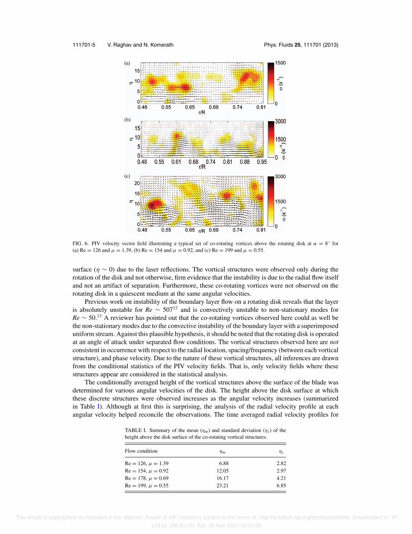
FIG. 6. PIV velocity vector field illustrating a typical set of co-rotating vortices above the rotating disk at α = 8◦ for(a) Re = 126 and μ = 1.39, (b) Re = 154 and μ = 0.92, and (c) Re = 199 and μ = 0.55.
surface (η ∼ 0) due to the laser reflections. The vortical structures were observed only during therotation of the disk and not otherwise, firm evidence that the instability is due to the radial flow itselfand not an artifact of separation. Furthermore, these co-rotating vortices were not observed on therotating disk in a quiescent medium at the same angular velocities.
Previous work on instability of the boundary layer flow on a rotating disk reveals that the layeris absolutely unstable for Re ∼ 50712 and is convectively unstable to non-stationary modes forRe ∼ 50.13 A reviewer has pointed out that the co-rotating vortices observed here could as well bethe non-stationary modes due to the convective instability of the boundary layer with a superimposeduniform stream. Against this plausible hypothesis, it should be noted that the rotating disk is operatedat an angle of attack under separated flow conditions. The vortical structures observed here are notconsistent in occurrence with respect to the radial location, spacing/frequency (between each vorticalstructure), and phase velocity. Due to the nature of these vortical structures, all inferences are drawnfrom the conditional statistics of the PIV velocity fields. That is, only velocity fields where thesestructures appear are considered in the statistical analysis.
The conditionally averaged height of the vortical structures above the surface of the blade wasdetermined for various angular velocities of the disk. The height above the disk surface at whichthese discrete structures were observed increases as the angular velocity increases (summarizedin Table I). Although at first this is surprising, the analysis of the radial velocity profile at eachangular velocity helped reconcile the observations. The time averaged radial velocity profiles for
TABLE I. Summary of the mean (ηm) and standard deviation (ηs) of theheight above the disk surface of the co-rotating vortical structures.
Flow condition ηm ηs
Re = 126, μ = 1.39 6.88 2.82Re = 154, μ = 0.92 12.05 2.97Re = 178, μ = 0.69 16.17 4.21Re = 199, μ = 0.55 23.21 6.85
This article is copyrighted as indicated in the abstract. Reuse of AIP content is subject to the terms at: http://scitation.aip.org/termsconditions. Downloaded to IP:
128.61.188.81 On: Sat, 30 Nov 2013 18:43:06
111701-6 V. Raghav and N. Komerath Phys. Fluids 25, 111701 (2013)
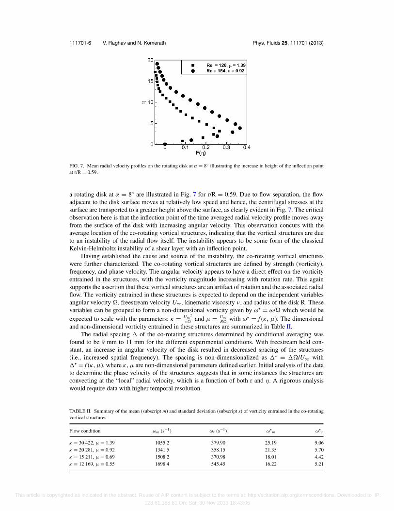
FIG. 7. Mean radial velocity profiles on the rotating disk at α = 8◦ illustrating the increase in height of the inflection pointat r/R = 0.59.
a rotating disk at α = 8◦ are illustrated in Fig. 7 for r/R = 0.59. Due to flow separation, the flowadjacent to the disk surface moves at relatively low speed and hence, the centrifugal stresses at thesurface are transported to a greater height above the surface, as clearly evident in Fig. 7. The criticalobservation here is that the inflection point of the time averaged radial velocity profile moves awayfrom the surface of the disk with increasing angular velocity. This observation concurs with theaverage location of the co-rotating vortical structures, indicating that the vortical structures are dueto an instability of the radial flow itself. The instability appears to be some form of the classicalKelvin-Helmholtz instability of a shear layer with an inflection point.
Having established the cause and source of the instability, the co-rotating vortical structureswere further characterized. The co-rotating vortical structures are defined by strength (vorticity),frequency, and phase velocity. The angular velocity appears to have a direct effect on the vorticityentrained in the structures, with the vorticity magnitude increasing with rotation rate. This againsupports the assertion that these vortical structures are an artifact of rotation and the associated radialflow. The vorticity entrained in these structures is expected to depend on the independent variablesangular velocity �, freestream velocity U∞, kinematic viscosity ν, and radius of the disk R. Thesevariables can be grouped to form a non-dimensional vorticity given by ω = ω/� which would beexpected to scale with the parameters: κ = U∞2
ν�and μ = U∞
R�with ω = f (κ , μ). The dimensional
and non-dimensional vorticity entrained in these structures are summarized in Table II.The radial spacing � of the co-rotating structures determined by conditional averaging was
found to be 9 mm to 11 mm for the different experimental conditions. With freestream held con-stant, an increase in angular velocity of the disk resulted in decreased spacing of the structures(i.e., increased spatial frequency). The spacing is non-dimensionalized as � = ��/U∞ with� = f (κ , μ), where κ , μ are non-dimensional parameters defined earlier. Initial analysis of the datato determine the phase velocity of the structures suggests that in some instances the structures areconvecting at the “local” radial velocity, which is a function of both r and η. A rigorous analysiswould require data with higher temporal resolution.
TABLE II. Summary of the mean (subscript m) and standard deviation (subscript s) of vorticity entrained in the co-rotatingvortical structures.
Flow condition ωm (s−1) ωs (s−1) ωm ω
s
κ = 30 422, μ = 1.39 1055.2 379.90 25.19 9.06κ = 20 281, μ = 0.92 1341.5 358.15 21.35 5.70κ = 15 211, μ = 0.69 1508.2 370.98 18.01 4.42κ = 12 169, μ = 0.55 1698.4 545.45 16.22 5.21
This article is copyrighted as indicated in the abstract. Reuse of AIP content is subject to the terms at: http://scitation.aip.org/termsconditions. Downloaded to IP:
128.61.188.81 On: Sat, 30 Nov 2013 18:43:06
111701-7 V. Raghav and N. Komerath Phys. Fluids 25, 111701 (2013)
From the above observations and discussion, it appears that the radial flow instability leadingto the formation of co-rotating vortices is a fundamental behavior of the radial component of thevelocity with a uniform edgewise stream. This allows for an analogy between the flow featureson the rotating disk and the rotating blade in similar flow conditions defined by non-dimensionalparameters κ and μ. It opens a path to systematically study the radial flow instability without havingto perform large scale rotor blade experiments or computational analyses on rotating blades. Theanalytical solution can in principle be modified to account for the uniform stream to check for theinstability and then incorporated into the radial flow model on rotating blades.5 Various hypothesesstill remain to be explored, for instance those suggested by the reviewers, to seek a closed-formanalytical prediction of the quantitative spatial frequency and strength of these structures, as relatedto relevant operating parameters. This in turn would lead to models that predict the limiting effect ofradial flow on the aerodynamic loads experienced by rotating blades, especially through the dynamicstall regime. Hence this letter establishes a promising avenue to make progress on the dynamic stallproblem and related aeromechanics of rotors.
In conclusion, we have shown that the radial flow on a rotating disk under separated flowconditions becomes unstable with the addition of a uniform stream. The instability leads to theformation and evolution of co-rotating vortices at the upper edge of the radial jet. The average heightabove the surface where the co-rotating structures form increases with angular velocity. This concurswith the increase in the height of the inflection point of the radial velocity profile above the surface.This clearly indicates that the source of the instability is the radial jet layer above the disk surface,and that the instability is not an artifact of separation of the freestream over the rotating disk. Vorticityentrained in these co-rotating structures has a direct correlation to the rotation rate, with the vorticitymagnitude increasing with the angular velocity of the disk. The spacing of these structures wasdetermined to be inversely proportional to the angular velocity of the rotating disk. The co-rotatingvortices appear to convect with a finite phase velocity; however, a definite quantitative conclusionon the convection velocity requires time resolved data.
This work was funded by the Army Research Office (ARO), Grant No. W911NF1010398. Theauthors acknowledge the assistance of Alex Forbes with the experimental setup and measurements,and the assistance of Roger Lascorz with the post processing of data. We are also grateful to theanonymous reviewers for their valuable feedback and hypotheses on this work.
1 J. DiOttavio, K. Watson, J. Cormey, N. Komerath, and S. Kondor, “Discrete structures in the radial flow over a rotor bladein dynamic stall,” in Proceedings of the 26th Applied Aerodynamics Conference, Honolulu, Hawaii, USA (AIAA, 2008).
2 V. Raghav and N. Komerath, “An exploration of radial flow on a rotating blade in retreating blade stall,” J. Am. HelicopterSoc. 58, 1–10 (2013).
3 V. Karman, “Uber laminare und turbulente reibung,” Z. Angew. Math. Mech. 1, 233–252 (1921).4 W. Cochran, “The flow due to a rotating disc,” in Mathematical Proceedings of the Cambridge Philosophical Society,
Vol. 30 (Cambridge University Press, Cambridge, 1934), pp. 365–375.5 W. McCroskey and P. Yaggy, “Laminar boundary layers on helicopter rotors in forward flight,” AIAA J. 6, 1919–1926
(1968).6 L. W. Carr, “Progress in analysis and prediction of dynamic stall,” J. Aircr. 25, 6–17 (1988).7 K. Mulleners and M. Raffel, “The onset of dynamic stall revisited,” Exp. Fluids 52, 779–793 (2012).8 K. Mulleners, K. Kindler, and M. Raffel, “Dynamic stall on a fully equipped helicopter model,” Aerosp. Sci. Technol. 19,
72–76 (2012).9 M. Raffel, C. E. Willert, and J. Kompenhans, Particle Image Velocimetry: A Practical Guide (Springer-Verlag, Berlin,
1998).10 F. Zoueshtiagh, R. Ali, A. J. Colley, P. J. Thomas, and P. W. Carpenter, “Laminar-turbulent boundary-layer transition over
a rough rotating disk,” Phys. Fluids 15, 2441 (2003).11 J. R. Potts and W. J. Crowther, “The flow over a rotating disc-wing,” in Aerodynamics Research Conference Proc., London,
UK (Royal Aeronautical Society, 2000).12 R. J. Lingwood, “An experimental study of absolute instability of the rotating-disk boundary-layer flow,” J. Fluid Mech.
314, 373–405 (1996).13 M. R. Malik, S. P. Wilkinson, and S. A. Orszag, “Instability and transition in rotating disk flow,” AIAA J. 19, 1131–1138
(1981).
This article is copyrighted as indicated in the abstract. Reuse of AIP content is subject to the terms at: http://scitation.aip.org/termsconditions. Downloaded to IP:
128.61.188.81 On: Sat, 30 Nov 2013 18:43:06