Inland AIS Shipborne Equipment - CESNI
37
European Committee for drawing up Standards in the field of Inland Navigation (CESNI) Test Standard Inland AIS Edition 2021/3.0 Page i European Committee for drawing up Standards in the field of Inland Navigation (CESNI) Edition 2021/3.0 Inland AIS Shipborne Equipment according to the Vessel Tracking and Tracing Standard for Inland Navigation Operational and performance requirements, methods of test and required test results (Test Standard Inland AIS)
-
Upload
khangminh22 -
Category
Documents
-
view
3 -
download
0
Transcript of Inland AIS Shipborne Equipment - CESNI

European Committee for drawing up Standards in the field of Inland Navigation (CESNI) Test Standard Inland AIS
Edition 2021/3.0 Page i
European Committee for drawing up Standards in the field of Inland Navigation (CESNI)
Edition 2021/3.0
Inland AIS Shipborne Equipment according to the
Vessel Tracking and Tracing Standard for Inland Navigation
Operational and performance requirements,
methods of test and required test results
(Test Standard Inland AIS)

European Committee for drawing up Standards in the field of Inland Navigation (CESNI) Test Standard Inland AIS
Edition 2021/3.0 Page ii

European Committee for drawing up Standards in the field of Inland Navigation (CESNI) Test Standard Inland AIS Table of contents
Edition 2021/3.0 Page iii
TABLE OF CONTENTS
Page
Foreword ................................................................................................................................................ 1
1. Scope ............................................................................................................................................ 3
2. Normative references.................................................................................................................. 3
3. Abbreviations .............................................................................................................................. 4
4. General requirements ................................................................................................................. 5
4.1. Class A functions not required .................................................................................................. 5
4.2. Functions in addition to Class A ................................................................................................ 5
4.3. Manuals ..................................................................................................................................... 5
5. Environmental, power supply, special purpose and safety requirements ............................ 5
6. Performance requirements ........................................................................................................ 5
6.1. Composition .............................................................................................................................. 5
6.1.1 Blue Sign input .................................................................................................................... 6
6.1.1.1 Blue Sign input via VSD sentence ............................................................................. 6
6.1.1.2 Blue Sign status via a dedicated input port ................................................................ 6
6.1.2 Internal GNSS receiver ....................................................................................................... 7
6.2. Information ................................................................................................................................ 7
6.3. Information processing .............................................................................................................. 7
6.3.1 Inland AIS Data input .......................................................................................................... 7
6.3.2 Inland AIS Data storage and message compilation ........................................................... 7
6.3.2.1 Initiation of an inland specific functional message ..................................................... 8
6.3.2.2 Processing of received inland specific functional messages ..................................... 9
6.3.2.3 Inland specific RFM 10 (Inland ship static and voyage related data) and
Inland specific RFM 55 (Persons on board) ............................................................... 9
6.3.2.4 Inland specific RFM’s other than RFM 10 or RFM 55 .............................................. 10
6.3.3 Alarms and status information .......................................................................................... 10
6.4. Minimum Keyboard and Display (MKD) .................................................................................. 10
6.4.1 Display of received Messages .......................................................................................... 10
6.4.2 Input of Data ..................................................................................................................... 11
6.4.3 Initiation of transmission of RFM 55 via MKD .................................................................. 12
7. Technical requirements ............................................................................................................ 12
7.1. Response to Assignment Commands ..................................................................................... 12
7.2. Presentation interface ............................................................................................................. 12
7.2.1 Required ports .................................................................................................................. 12
7.2.2 Input data and formats ...................................................................................................... 12
7.2.3 Output data and formats ................................................................................................... 14

European Committee for drawing up Standards in the field of Inland Navigation (CESNI) Test Standard Inland AIS Table of contents
Edition 2021/3.0 Page iv
8. Operational tests ....................................................................................................................... 14
8.1. Operating modes/capability ..................................................................................................... 14
8.1.1 Interrogation response ...................................................................................................... 14
8.1.1.1 Method of measurement .......................................................................................... 14
8.1.1.2 Required results ....................................................................................................... 14
8.2. Reporting intervals .................................................................................................................. 14
8.2.1 Static data reporting rates ................................................................................................ 14
8.2.1.1 Method of measurement .......................................................................................... 14
8.2.1.2 Required results ....................................................................................................... 15
8.3. Alarms and indicators, fall-back arrangements ....................................................................... 15
8.3.1 Method of measurement ................................................................................................... 15
8.3.2 Required results ................................................................................................................ 15
8.4. Input of Data on MKD .............................................................................................................. 15
8.4.1 Method of measurement ................................................................................................... 15
8.4.2 Required results ................................................................................................................ 15
8.5. Display of data on MKD........................................................................................................... 15
8.5.1 Method of measurement ................................................................................................... 15
8.5.2 Required results ................................................................................................................ 15
9. Specific tests of link layer ........................................................................................................ 16
9.1. Group assignment ................................................................................................................... 16
9.1.1 Assignment by $PIWWIVD ............................................................................................... 16
9.1.1.1 Method of measurement .......................................................................................... 16
9.1.1.2 Required results ....................................................................................................... 16
9.1.2 Assignment by message 16 ............................................................................................. 16
9.1.2.1 Method of measurement .......................................................................................... 16
9.1.2.2 Required results ....................................................................................................... 16
9.1.3 Increased reporting interval assignment........................................................................... 17
9.1.3.1 Increased reporting interval assignment by $PIWWIVD .......................................... 17
9.1.3.1.1 Method of measurement ...................................................................................... 17
9.1.3.1.2 Required results................................................................................................... 17
9.1.4 Addressing by station type ............................................................................................... 17
9.1.4.1 Method of measurement .......................................................................................... 17
9.1.4.2 Required result ......................................................................................................... 17
9.2. Inland AIS message formats ................................................................................................... 18
9.2.1 Received Inland specific messages ................................................................................. 18
9.2.1.1 Method of measurement .......................................................................................... 18
9.2.1.2 Required results ....................................................................................................... 18
9.2.2 Transmitted inland specific messages.............................................................................. 19
9.2.2.1 Position report message 1, 2 or 3 ............................................................................ 19
9.2.2.1.1 Method of measurement ...................................................................................... 19
9.2.2.1.2 Required results................................................................................................... 20

European Committee for drawing up Standards in the field of Inland Navigation (CESNI) Test Standard Inland AIS Table of contents
Edition 2021/3.0 Page v
9.2.2.2 Ship static and voyage related data (Message 5 and RFM 10) ............................... 20
9.2.2.2.1 Method of measurement ...................................................................................... 20
9.2.2.2.2 Required results................................................................................................... 20
9.2.2.3 Persons on board RFM 55 (DAC 200 / FI 55).......................................................... 21
9.2.2.3.1 Method of measurement ...................................................................................... 21
9.2.2.3.2 Required results................................................................................................... 21
9.2.3 Transmit inland specific interrogation messages ............................................................. 21
9.2.3.1 Transmit an interrogation for a specific FM (IFM 2) ................................................. 21
9.2.3.1.1 Method of measurement ...................................................................................... 21
9.2.3.1.2 Required results................................................................................................... 22
9.2.4 Response to inland specific interrogation messages ....................................................... 22
9.2.4.1 Response to “Capability interrogation” (IFM 3) with “Capability reply” (IFM 4) ........ 22
9.2.4.1.1 Method of measurement ...................................................................................... 22
9.2.4.1.2 Required results................................................................................................... 22
9.2.4.2 Response to interrogation for “Inland ship static and voyage related data”
(RFM 10) .................................................................................................................. 23
9.2.4.2.1 Method of measurement ...................................................................................... 23
9.2.4.2.2 Required results................................................................................................... 23
9.2.4.3 Response to interrogation for “Number of Persons on board” (RFM 55 and
IFM 16) ..................................................................................................................... 23
9.2.4.3.1 Method of measurement ...................................................................................... 23
9.2.4.3.2 Required results................................................................................................... 23
10. High speed input ....................................................................................................................... 23
10.1. Voyage data configuration ...................................................................................................... 23
10.1.1 Method of measurement ................................................................................................... 23
10.1.2 Required result ................................................................................................................. 24
10.2. Static data configuration .......................................................................................................... 24
10.2.1 Method of measurement ................................................................................................... 24
10.2.2 Required result ................................................................................................................. 24
11. Long Range functionality tests ................................................................................................ 24
Annexes ................................................................................................................................................ 25
Annex A: (informative) Block diagram of AIS .......................................................................... 27
Annex B: (normative) AIS Interface Overview ......................................................................... 28
Annex C: (Normative) Additional PI port sentences for Inland AIS ......................................... 29
C.1 Inland Waterway voyage data .......................................................................................... 29
C.2 Inland Waterway Static Ship data ..................................................................................... 30
Annex D: Ship dimensions ....................................................................................................... 31

European Committee for drawing up Standards in the field of Inland Navigation (CESNI) Test Standard Inland AIS Table of contents
Edition 2021/3.0 Page vi

European Committee for drawing up Standards in the field of Inland Navigation (CESNI) Test Standard Inland AIS Foreword
Edition2021/3.0 Page 1
FOREWORD
The concept of River Information Services (RIS) has emerged throughout several European research
projects, aiming at increasing safety and efficiency of inland waterway transport.
The European Commission (EC), the Central Commission for the Navigation of the Rhine (CCNR), the
Danube Commission, the Moselle Commission, the International Sava River Basin Commission and
the United Nations Economic Commission for Europe (UNECE) have recognized the need for means
of automatic exchange of navigational data between ships and between ship and shore for automatic
identification and tracking and tracing solutions in inland navigation.
In maritime navigation, the IMO has introduced the Automatic Identification System (AIS). All seagoing
vessels on international voyage falling under SOLAS convention Chapter V have to be equipped with
AIS since the end of 2004. The Guidelines and Recommendations for River Information Services (RIS
Guidelines) drawn up by World Association for Waterborne Transport Infrastructure (PIANC) and
published in particular by the CCNR and the European Union define Inland AIS as important
technology.
The Automatic Identification System AIS, as used in maritime navigation, is defined by the
International Maritime Organisation (IMO) “Resolution MSC.74(69) Annex 3, Performance Standard
for a Universal Shipborne Automatic Identification”. The technical requirements for AIS are provided
by ITU Recommendation ITU-R M.1371-5.
The European RIS Platform established in 2003 the International Expert Group for Tracking and
Tracing. The main task of this expert group is the development and maintenance of a European wide
harmonised Vessel Tracking and Tracing Standard for Inland Navigation. Because of mixed traffic
areas it is important that the standards and procedures for inland shipping are compatible with already
defined standards and procedures for seagoing navigation.
To serve the specific requirements of inland navigation, AIS has been further developed to the “Vessel
Tracking and Tracing Standard for Inland Navigation” while preserving full compatibility with IMO’s
maritime AIS and already existing standards in inland navigation.
The European Union has adopted the VTT standard in Commission Implementing Regulation (EU)
2019/838 of 20 February 2019 on technical specifications for vessel tracking and tracing systems and
repealing Regulation (EC) No 415/2007.
Given the tasks assigned to the European Committee for drawing up Standards in the field of Inland
Navigation (CESNI) and the need to define harmonised test requirements for Inland AIS devices for
applying the European Standard laying down Technical Requirements for Inland Navigation vessels
(ESTRIN), this standard shall be adopted on 13 October 2020. Reference is made to this standard in
Article 1.01(7.11) of the ES-TRIN.

European Committee for drawing up Standards in the field of Inland Navigation (CESNI) Test Standard Inland AIS Foreword
Edition2021/3.0 Page 2
This document describes the “Inland AIS Shipborne Equipment according to the Vessel Tracking and
Tracing Standard for Inland Navigation – Operational and performance requirements, methods of test
and required test results (Test Standard Inland AIS)”. Due to its nature it is mainly based on the
structure of the parent IEC International Standard IEC 61993-2 . The version takes into account
Recommendation ITU-R M.13715. This standard is published as edition 2021/3.0. This document was originally written in the English language.
European Committee for drawing up Standards in the field of Inland Navigation (CESNI) Test Standard Inland AIS
Edition2021/3.0 Page 3
Inland AIS Shipborne Equipment Operational and performance requirements,
methods of test and required test results
1. Scope
This Standard specifies the minimum operational and performance requirements, methods
of testing and required test results for Inland AIS shipborne stations.
This edition incorporates the technical characteristics of Class A shipborne equipment
included in Recommendation ITU-R M.1371-5 and further described by Standard
IEC 619932 “Class A shipborne equipment of the universal automatic identification system
(AIS) – Operational and performance requirements, methods of test and required test
results” as applicable.
2. Normative references
The following referenced documents are indispensable for the application of this document.
For dated references, only the edition cited applies. For undated references, the latest
edition of the referenced document (including any amendments) applies.
a) European Committee for
drawing up Standards in
the field of Inland
Navigation (CESNI)
Edition 2021 European Standard laying down
Technical Requirements for Inland
Navigation vessels (ESTRIN)
b) Commission
Implementing Regulation
(EU)
2019/838 of 20 February 2019 on technical
specifications for vessel tracking and
tracing systems and repealing
Regulation (EC) No 415/2007 (VTT
Standard)
c) Recommendation ITU-R M.1371-5 Technical characteristics for an
automatic identification system using
time division multiple access in the VHF
maritime mobile band.
d) International Standard IEC 61993-2 :2018 Maritime navigation and
radiocommunication equipment and
systems - Part 2: Class A shipborne
equipment of the universal automatic
identification system (AIS) - Operational
and performance requirements,
methods of test and required test
results.
e) RTCM SC-104 Interface to receive and process
differential correction data

European Committee for drawing up Standards in the field of Inland Navigation (CESNI) Test Standard Inland AIS
Edition2021/3.0 Page 4
3. Abbreviations
AI Application Identifier
AIS Automatic Identification System
BIIT built-in integrity tests
CESNI European Committee for drawing up
Standards in the field of Inland Navigation
COG Course Over Ground
DAC Designated Area Code
DGNSS Differential GNSS
DSC Digital Selective Calling
ECDIS Electronic Chart Display and Information
System
ENI Unique European vessel identification
number
EPFS electronic position fixing systems
ES-TRIN European Standard laying down Technical
Requirements for Inland Navigation vessels
ETA Estimated Time of Arrival
EUT equipment under test
FI Functional Identifier
GNSS Global Navigation Satellite System
GPS Global Positioning System
ID Identifier
IEC International Electrotechnical Commission
IFM international function message (DAC 001)
IMO International Maritime Organization
ITU International Telecommunication Union
LR Long Range
MHz Megahertz (Megacycles per second)
MKD Minimum Keyboard and Display
MMSI Maritime Mobile Service Identifier
PI presentation interface
RAI Regional Application Identifier
RAIM Receiver Autonomous Integrity Monitoring
RF radio frequency
RFM Inland specific regional function message
(DAC 200)
RIS River Information Services
ROT Rate Of Turn
RTA Requested Time of Arrival
Rx Receive
SAR Search And Rescue
SOG Speed Over Ground
SOLAS Safety Of Life At Sea
TDMA Time Division Multiple Access
Tx Transmit
UNECE United Nations Economic Commission for
Europe
UTC Universal Time Coordinated
VDL VHF Data Link
VHF Very High Frequency

European Committee for drawing up Standards in the field of Inland Navigation (CESNI) Test Standard Inland AIS
Edition2021/3.0 Page 5
4. General requirements
Inland AIS Shipborne Equipment is based on the specification of AIS Class A shipborne
equipment in accordance with Recommendation ITU-R M.1371-5 and International
Standard IEC 61993-2 unless otherwise stated.
4.1. Class A functions not required
Inland AIS Shipborne Equipment has to fulfil all requirements of AIS Class A shipborne
equipment as defined in IEC 61993-2 except:
• Long range application by interface to other equipment,
• Interface for long range port.
4.2. Functions in addition to Class A
Additionally the following functions are required:
• Initiate and transmit inland specific messages as specified in Table 2;
• Process and display received inland specific messages as specified in Table 3;
• Act upon group assignment for station type “inland waterways”;
• Interface to receive and process differential correction data (RTCM SC-104);
• Interface for Blue Sign function (switch and use of data field in VSD sentence);
• Suppress the transmission of certain ABM/BBM sentences from PI port as specified in
Table 2;
• Inland specific message RFM 10 shall be transmitted with a reporting interval of
6 minutes, alternating between both channels, following message 5;
• All speed information shall be displayed in km/h on MKD and all range information
shall be displayed in km.
4.3. Manuals
The manuals shall also cover the methods necessary to support the Inland AIS specific
function.
5. Environmental, power supply, special purpose and safety requirements
The same requirements as for AIS Class A mobile station shall be fulfilled.
6. Performance requirements
6.1. Composition
An interface (RTCM SC-104) shall be provided to input the correction data to the internal
GNSS receiver.
The Inland AIS station shall be able to process Group Assignment Commands (AIS
message 23) for station type “inland waterways” and act accordingly.

European Committee for drawing up Standards in the field of Inland Navigation (CESNI) Test Standard Inland AIS
Edition2021/3.0 Page 6
The Inland AIS station shall be able to process the Blue Sign information and set the
special manoeuvre indicator in AIS VDL Message 1, 2, 3 accordingly.
The Inland AIS station shall be able to process Inland specific Regional Function
messages (RFM) with the Designated Area Code (DAC) “200”1.
6.1.1 Blue Sign input
The Blue Sign information shall be input in two ways:
a) input via the IEC 61162-1 VSD sentence,
b) input via a dedicated input port.
6.1.1.1 Blue Sign input via VSD sentence
The VSD field “regional application flags” defines 4 bit (values 0...15). The two most
significant bits of the regional application flags set the “Special manoeuvre indicator”
parameter. The remaining two bits of the VSD sentence shall be ignored.
The following Table describes the translation from the VSD field “regional application flags”
to the VDL Message 1, 2, 3 “Special manoeuvre indicator” parameter.
Table 1: Translation from VSD sentence to VDL message
VSD sentence regional application flag
VDL Message 1,2,3 Special manoeuvre indicator
Blue Sign description
0 (00xx) 0 (00) Not available (default)
4 (01xx) 1 (01) Not set
8 (10xx) 2 (10) Set
12 (11xx) 0 (00) Invalid input,
results in not available
The special manoeuvre indicator (Blue Sign) parameter shall only be set if the VSD
sentence is received with a valid regional application flag value and an interval of at least
two seconds. After a time out of two seconds the special manoeuvre indicator shall be set
to not available.
6.1.1.2 Blue Sign status via a dedicated input port
The input for the Blue Sign status shall provide preferably a tri-state or alternatively a two-
state input which can be controlled by a single switch where the switch circuit open means
“Blue Sign not set” and the switch circuit closed means “Blue Sign set”.
The presence of the direct connected switch shall be made available by automatic means
or manual configuration.
1 Unless otherwise stated “RFM” in this document refers to Inland specific Regional Function Messages (RFM) as defined in
Recommendation ITU-R M.1371-5 with an Application identifier (AI) consisting of DAC = 200 and the defined Function Identifier (FI) (e.g.: RFM 10 = DAC “200” + FI “10”).

European Committee for drawing up Standards in the field of Inland Navigation (CESNI) Test Standard Inland AIS
Edition2021/3.0 Page 7
6.1.2 Internal GNSS receiver
The Inland AIS station shall provide an internal GNSS receiver as UTC source, for own
positioning, COG and SOG. The internal GNSS receiver shall meet the appropriate
requirements of the International Standards series IEC 61108 as defined in IEC 61993-2.
The internal GNSS receiver shall be capable of processing differential correction data from
a dedicated RTCM SC-104 interface and via VDL Message 17.
6.2. Information
Information provided by the Inland AIS shall be as defined in Vessel Tracking and Tracing
Standard for Inland Navigation as stated in Chapter 2 “Normative reference”. (ES-TRIN,
Article 1.01(7.9).
The static, dynamic and voyage related ship information for inland vessels shall have the
same parameters and the same structure than in Recommendation ITU-R M.1371-5 as far
as it is applicable. Not used parameter fields shall be set to “not available”. Inland specific
static ship information shall be added.
6.3. Information processing
6.3.1 Inland AIS Data input
The figure 1 in Annex D illustrates the parameters and the usage to calculate the
dimensions for both message 5 and RFM 10.
• All dimensions/reference input values of own ship shall be input in decimeter
resolution.
• The total convoy length LC and convoy beam BC are calculated in dm and shall be
transmitted by RFM 10.
• Draught: input always in cm, automatic conversion to next higher value (rounding up)
for message 5.
• The ship and cargo type of message 5 shall be automatically converted from Inland-
ship type (Inland vessel and convoy types; see VTT Standard Appendix C).
• IMO ship and cargo type can be overwritten according to the Class A rules.
• The number of blue cones can be entered independently of IMO ship and cargo type.
• For backwards compatibility the PI sentences IWWIVD and IWWSSD shall be
maintained for dimensions/reference input for inland navigation mode.
6.3.2 Inland AIS Data storage and message compilation
For data input of the required information for transmission either means for manual input or
the proposed digital interface sentences for Inland AIS ($--SSD, $--VSD, $PIWWSSD and
$PIWWIVD) shall be used. This requires means for input and storage of the inland specific
data. Only inputs that change the stored data (manual input or $--SSD, $--VSD,
$PIWWSSD, $--EPV, $PIWWIVD) shall generate a transmission where applicable.

European Committee for drawing up Standards in the field of Inland Navigation (CESNI) Test Standard Inland AIS
Edition2021/3.0 Page 8
The following tables define the behaviour of the Inland AIS mobile station regarding inland
specific functional messages.
6.3.2.1 Initiation of an inland specific functional message
The following table defines the initiator of international function messages (IFM) and inland
specific functional messages ( RFM) to be transmitted by the Inland AIS mobile station.
(ABM/BBM = via standard Presentation Interface, MKD = via Minimum Keyboard and
Display, Inland ECDIS = via connected Inland ECDIS (recommendation only). On VDL
request = autonomous reaction when an IFM 2 or 3 interrogation is received).
Table 2: Transmission of inland specific functional messages
Message Description Addr/ Bc
TX INITIATED BY
ABM/
BBM MKD
Auto-
matically
gene-
rated
On VDL
request
RFM 10 Inland static data 1) Bc No --- x Opt 1) 2)
RFM 55 Inland number of persons 2) Addr x Opt No x
RFM 55 Inland number of persons Bc x x No No
IFM 4 a) Capability response 2) Addr x --- No x
´X´ = required; ´Opt´ = Optional; ´No´ = Not allowed; ´---´ = Not applicable
1) Autonomously provided in conjunction with AIS VDL message 5 by the Inland AIS mobile station. 2) Message is provided only if interrogation is addressed to own station.

European Committee for drawing up Standards in the field of Inland Navigation (CESNI) Test Standard Inland AIS
Edition2021/3.0 Page 9
6.3.2.2 Processing of received inland specific functional messages
The following table defines the behaviour (internal processing and reaction) of the Inland
AIS mobile station, when an international function message (IFM) or an inland specific
functional message (RFM) is received.
(VDM = output via Presentation Interface, MKD = displayed on Minimum Keyboard and
Display, Inland ECDIS = displayed on connected Inland ECDIS (recommendation only),
VDL response = autonomous reaction on a received VDL message).
Table 3: Reception of inland specific functional messages
Message Description Addr/Bc Processing
VDM MKD VDL Response
RFM 10 Inland static data Bc x X ---
RFM 55 Inland number of persons 1) Addr x X 2) ---
RFM 55 Inland number of persons Bc x X 2) ---
IFM 2 Interrogation 3) 1) Addr x --- x
IFM 3 Capability interrogation 3) 1) Addr x --- x
IFM 16 Number of persons 1) Addr x X ---
IFM 16 Number of persons Bc x X ---
´X´ = required; ´Opt´ = Optional; ´No´ = Not allowed; ´---´ = Not applicable
1) Messages are processed only if addressed to own station. 2) Only the display of total number of persons on board is required. 3) Messages are provided only if interrogation is addressed to own station.
6.3.2.3 Inland specific RFM 10 (Inland ship static and voyage related data) and Inland
specific RFM 55 (Persons on board)
The compilation of the RFM 10 and RFM 55 for transmission is part of the Inland AIS
station itself:
• The RFM 10 shall be used by Inland AIS only, to broadcast ship static and voyage
related data in addition to message 5. The message shall be sent not later than
4 seconds after message 5 by using a message 8 / RFM 10;
• Message 5 and RFM 10 shall be transmitted with a reporting interval of 6 minutes,
alternating between both channels;
• The Inland AIS station must be able to respond to an interrogation for VDL message 5
(received message 15) automatically with message 5 and message 8 / RFM 10;
• The Inland AIS station must be able to initiate a message 8 / RFM 55 by MKD and to
respond on a request for “Inland number of persons on board” automatically with the
message 6 / RFM 55.

European Committee for drawing up Standards in the field of Inland Navigation (CESNI) Test Standard Inland AIS
Edition2021/3.0 Page 10
6.3.2.4 Inland specific RFM’s other than RFM 10 or RFM 55
The following option is available for the compilation of inland specific messages other than
RFM 10 or 55.
The compilation of inland specific message shall be provided by an external application
outside the Inland AIS shipborne station and is input via the Presentation Interface using
IEC 61162-1 ABM or BBM sentences as applicable. External applications could be:
• a connected Inland ECDIS equipment or Radar equipment,
• a connected dedicated software application (without Inland ECDIS capability).
6.3.3 Alarms and status information
Means shall be provided to selectively disable alarms during installation which are not
applicable for that specific installation, i.e. external EPFS lost (25), heading lost/invalid
(32), no valid ROT information (35). This feature has to be password protected.
6.4. Minimum Keyboard and Display (MKD)
6.4.1 Display of received Messages
In addition to AIS Class A following information shall be displayed on a MKD:
• Inland AIS static data
Where information is delivered both by message 5 and RFM 10 the Inland AIS specific
date shall preferably be displayed (dimension, draught, ship type, dangerous cargo
category).
• Number of persons on board
RFM 55 shall have preference above IFM 16
• Blue sign information
• Speed information shall be displayed in km/h
• Range information shall be displayed in km.
Table 4: Following information in RFM 10 shall be displayed:
Parameter Displayed on MKD
ENI Yes
Length of ship or convoy Yes
Beam of ship or convoy Yes
Inland vessel and convoy type Yes
Number of blue cones Yes
Draught Yes
Loaded/unloaded Yes
Quality of speed information Optional
Quality of course information Optional
Quality of heading information Optional

European Committee for drawing up Standards in the field of Inland Navigation (CESNI) Test Standard Inland AIS
Edition2021/3.0 Page 11
6.4.2 Input of Data
In addition to AIS Class A following data shall be entered via MKD:
• Inland AIS static data
Where information is contained in both message 5 and RFM 10 the Inland AIS specific
date shall input only once to avoid conflicts, i.e. dimension/reference, draught, ship
type, dangerous cargo category.
• Number of persons on board
RFM 55 shall have preference above IFM 16.
Table 5: Following information in RFM 10 and RFM 55 shall be input via MKD:
Parameter Category Remark
ENI Static 1)
Length of ship (LS) Static 1) Shall also be used for the calculation
of message 5 and RFM 10
Distance from reference point to
stern (BI)
(for internal and external position
source)
Static 1) Shall also be used for the calculation
of message 5 and RFM 10
Beam of ship (BS) Static 1) Shall also be used for the calculation
of message 5 and RFM 10
Distance from reference point to
port (CI)
(for internal and external position
source)
Static 1) Shall also be used for the calculation
of message 5 and RFM 10
Extension for length of convoy
(EA, EB,) Voyage related
2) Shall also be used for the calculation
of message 5 and RFM 10
Extension for beam of convoy
(EC, ED) Voyage related
2) Shall also be used for the calculation of
message 5 and RFM 10
Inland vessel and convoy type Voyage related 2)
Number of blue cones Voyage related 2)
Draught Voyage related 2)
Loaded/unloaded Voyage related 2)
Persons on board
(crew members, passengers and
shipboard personnel)
Voyage related 2)
Quality of speed information Static On installation, shall be set to 0 if not
derived from a type approved sensor
Quality of course information Static On installation, shall be set to 0 if not
derived from a type approved sensor
Quality of heading information static On installation, shall be set to 0 if not
derived from a type approved sensor
1) On installation, data shall be protected by the administrator password.
2) Voyage related, data shall not be protected by the administrator password.
European Committee for drawing up Standards in the field of Inland Navigation (CESNI) Test Standard Inland AIS
Edition2021/3.0 Page 12
6.4.3 Initiation of transmission of RFM 55 via MKD
Means on the MKD shall be provided to initiate the transmission of broadcast RFM 55.
7. Technical requirements 7.1. Response to Assignment Commands
An Inland AIS station shall process assignment commands in accordance with
Recommendation ITU-R M.1371-5 and VTT Standard. The Inland AIS mobile station shall
act upon group assignment for station type “inland waterway” and not for station type
“Class A mobile station”.
An assignment command, with a reporting interval less than the autonomous reporting
interval, received via the digital interface sentence for Inland AIS $PIWWIVD shall
decrease the reporting interval defined by Recommendation ITU-R M.1371-5. An
assignment command shall not increase the reporting interval above the autonomous
reporting interval.
7.2. Presentation interface
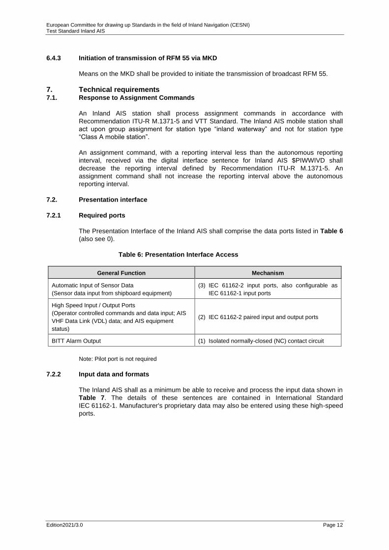
7.2.1 Required ports
The Presentation Interface of the Inland AIS shall comprise the data ports listed in Table 6
(also see 0).
Table 6: Presentation Interface Access
General Function Mechanism
Automatic Input of Sensor Data
(Sensor data input from shipboard equipment)
(3) IEC 61162-2 input ports, also configurable as
IEC 61162-1 input ports
High Speed Input / Output Ports
(Operator controlled commands and data input; AIS
VHF Data Link (VDL) data; and AIS equipment
status)
(2) IEC 61162-2 paired input and output ports
BITT Alarm Output (1) Isolated normally-closed (NC) contact circuit
Note: Pilot port is not required
7.2.2 Input data and formats
The Inland AIS shall as a minimum be able to receive and process the input data shown in
Table 7. The details of these sentences are contained in International Standard
IEC 61162-1. Manufacturer's proprietary data may also be entered using these high-speed
ports.

European Committee for drawing up Standards in the field of Inland Navigation (CESNI) Test Standard Inland AIS
Edition2021/3.0 Page 13
Table 7: AIS High-speed input data and formats
Data IEC 61162-1 Sentences
Normal Access - Parameter Entry
Voyage information:
Vessel type and cargo category
Navigational status
Draught, max. actual static
Destination
ETA date and time
Regional application flags
Reporting rate settings
Number of blue cones
air draught of ship
Number of assisting tugboat
Number of crew members on board
Number of passengers on board
Number of shipboard personnel on board
Convoy extensions
VSD - Voyage static data
EPV – Equipment property value
PIWWIVD – Inland Waterway voyage data
Station information:
Vessel name (administrator password protected)
Call sign (administrator password protected)
Antenna location
length and beam
ENI number (administrator password protected)
Inland vessel and convoy type
Quality of speed information
Quality of course information
Quality of heading information
SSD - Station static data
PIWWSSD – Inland Waterway static ship data
Initiate VHF Data-link Broadcasts
Safety messages ABM - Addressed Binary Message
BBM - Broadcast Binary Message
Binary messages ABM - Addressed Binary Message
BBM - Broadcast Binary Message
Interrogation Message AIR - AIS Interrogation Information
AIS Equipment - Parameter Entry
AIS VHF channel selection
AIS VHF power setting
AIS VHF channel bandwidth
Transmit/Receive mode control
MMSI
IMO number
Other AIS equipment controls
ACA - AIS Channel Assignment Message
EPV-Equipment property value (administrator password
protected)
EPV-Equipment property value (administrator password
protected)
EPV-Equipment property value (administrator password
protected)
BIIT Input
Alarm / indication acknowledgement ACK Acknowledgement message
Note: Information which is not marked with “administrator password protected” shall be accepted if no
administrator password is provided even if there is protected information in the same sentence.
In this case the protected information is ignored.

European Committee for drawing up Standards in the field of Inland Navigation (CESNI) Test Standard Inland AIS
Edition2021/3.0 Page 14
7.2.3 Output data and formats
In addition to the AIS Class A station, an Inland AIS station outputs PIWWSSD and
PIWWIVD sentences on the two high speed ports as response on a query.
Query sentences is used as defined in IEC 61162-1 with sentence formatters SSD and
IVD. On query for SSD the unit will respond with both an SSD sentence and a PIWWSSD
sentence.
8. Operational tests
8.1. Operating modes/capability
8.1.1 Interrogation response
8.1.1.1 Method of measurement
Set up standard test environment and operate EUT in autonomous mode. Apply an
interrogation message (message 15; EUT as destination) to the VDL for responses with
message 3, message 5 and slot offset set to defined value. Record transmitted messages
and frame structure.
8.1.1.2 Required results
Check that the EUT transmits the appropriate interrogation response message as
requested after defined slot offset. Confirm that the EUT transmits the response on the
same channel as where interrogation was received. Confirm that the EUT transmits
message 5 and “Inland ship static and voyage related data” RFM 10 using binary
broadcast message (message 8) to the VDL. Confirm that the “Inland ship static and
voyage related data” RFM 10 follows message 5 within 4 seconds. Confirm that ITDMA is
used if possible.
8.2. Reporting intervals
8.2.1 Static data reporting rates
8.2.1.1 Method of measurement
Set up standard test environment and operate EUT in autonomous mode.
a) Record the transmitted messages and check for static and voyage related data
(message 5 and RFM 10).
b) Change static and/or voyage related station data. Record the transmitted messages
and check for static and voyage related data (message 5).
European Committee for drawing up Standards in the field of Inland Navigation (CESNI) Test Standard Inland AIS
Edition2021/3.0 Page 15
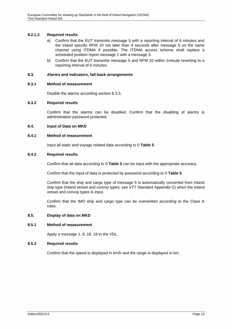
8.2.1.2 Required results
a) Confirm that the EUT transmits message 5 with a reporting interval of 6 minutes and
the inland specific RFM 10 not later than 4 seconds after message 5 on the same
channel using ITDMA if possible. The ITDMA access scheme shall replace a
scheduled position report message 1 with a message 3.
b) Confirm that the EUT transmits message 5 and RFM 10 within 1minute reverting to a
reporting interval of 6 minutes.
8.3. Alarms and indicators, fall-back arrangements
8.3.1 Method of measurement
Disable the alarms according section 6.3.3.
8.3.2 Required results
Confirm that the alarms can be disabled. Confirm that the disabling of alarms is
administration password protected.
8.4. Input of Data on MKD
8.4.1 Method of measurement
Input all static and voyage related data according to 0 Table 5.
8.4.2 Required results
Confirm that all data according to 0 Table 5 can be input with the appropriate accuracy.
Confirm that the input of data is protected by password according to 0 Table 5.
Confirm that the ship and cargo type of message 5 is automatically converted from Inland
ship type (Inland vessel and convoy types; see VTT Standard Appendix C) when the Inland
vessel and convoy types is input.
Confirm that the IMO ship and cargo type can be overwritten according to the Class A
rules.
8.5. Display of data on MKD
8.5.1 Method of measurement
Apply a message 1, 9, 18, 19 to the VDL.
8.5.2 Required results
Confirm that the speed is displayed in km/h and the range is displayed in km.

European Committee for drawing up Standards in the field of Inland Navigation (CESNI) Test Standard Inland AIS
Edition2021/3.0 Page 16
9. Specific tests of link layer
9.1. Group assignment
9.1.1 Assignment by $PIWWIVD
Group assignment commands have precedence of assignments by input via $PIWWIVD.
9.1.1.1 Method of measurement
Address the EUT with an AIS message 23 to bring the EUT in assigned mode. Record VDL
and verify the reaction of the EUT. Apply an assignment by $PIWWIVD input with a
different reporting interval.
9.1.1.2 Required results
Verify that the EUT ignores the assignment by input via $PIWWIVD.
9.1.2 Assignment by message 16
Messages which are addressed directly to an AIS Transponder have precedence of group
assignment commands and manual assignments. Following test shall verify the
assignment priority of these messages.
9.1.2.1 Method of measurement
Set up the standard test environment and operate EUT in autonomous mode. Input sensor
data to achieve a reporting interval of 10 seconds.
a) Address the EUT with an AIS message 16 to bring the EUT in assigned mode with a
reporting interval of 5 seconds. Record VDL and verify the reaction of the EUT.
b) Apply a message 23 with a reporting interval of 2 seconds. Construct message 23 in
that way that the EUT will be addressed by the message.
c) Apply a $PIWWIVD assignment input with a reporting interval of 2 seconds.
9.1.2.2 Required results
a) Verify that the reporting interval is 5 seconds.
b) Verify that the EUT ignores the command given by message 23.
c) Verify that the EUT ignores the assignment command given by $PIWWIVD.

European Committee for drawing up Standards in the field of Inland Navigation (CESNI) Test Standard Inland AIS
Edition2021/3.0 Page 17
9.1.3 Increased reporting interval assignment
9.1.3.1 Increased reporting interval assignment by $PIWWIVD
9.1.3.1.1 Method of measurement
Set up the standard test environment and operate EUT in autonomous mode.
a) Apply a $PIWWIVD assignment to the EUT with a reporting interval greater than the
autonomous reporting interval.
b) Apply a $PIWWIVD assignment to the EUT with a reporting interval shorter than the
autonomous reporting interval.
Record transmitted messages.
9.1.3.1.2 Required results
a) Confirm that the EUT transmits position reports with the autonomous reporting interval
in $PIWWIVD.
b) Verify that EUT switches to assigned mode and transmits position reports with
2 seconds reporting interval. Verify that EUT reverts to autonomous mode after
timeout period.
9.1.4 Addressing by station type
9.1.4.1 Method of measurement
Set up standard test environment and operate EUT in autonomous mode with a reporting
interval of 10 seconds.
a) Transmit a Group Assignment command (message 23) to the EUT (define geographic
region so that the EUT is inside this region). Set the reporting interval to 2 seconds
and the station type to 0 (all stations).
b) Transmit a Group Assignment command (message 23) to the EUT (define geographic
region so that the EUT is inside this region). Set the reporting interval to 2 seconds
and the station type to 1 (Class A), 2 (Class B), 3 (SAR aircraft), 4 (Class B SO), 5
(Class B CS).
c) Transmit a Group Assignment command (message 23) to the EUT (define geographic
region so that the EUT is inside this region). Set the reporting interval to 5 seconds
and the station type to 6 (Inland Waterway). Apply this message to the VDL again
within 4 minutes. Record VDL and check reaction of the EUT.
9.1.4.2 Required result
a) Verify that EUT switches to assigned mode and transmits position reports with
2 seconds reporting interval. Verify that EUT reverts to autonomous mode after
timeout period.
b) Verify that EUT declines message 23.
c) Verify that EUT switches to assigned mode and transmits position reports with
5 seconds reporting interval. Verify that EUT reverts to autonomous operation mode
after timeout period of second transmitted group assignment.

European Committee for drawing up Standards in the field of Inland Navigation (CESNI) Test Standard Inland AIS
Edition2021/3.0 Page 18
9.2. Inland AIS message formats
9.2.1 Received Inland specific messages
9.2.1.1 Method of measurement
Set up standard test environment and operate EUT in autonomous mode.
a) Apply following Inland specific messages using binary message (message 8) to the
VDL:
Inland ship static and voyage related data Inland specific RFM 10 (DAC 200 / FI 10);
Inland number of persons onboard Inland specific RFM 55 (DAC 200 / FI 55);
Number of persons on board International Function message 16 (DAC 001 / FI 16).
b) Apply following addressed Inland specific messages using binary message
(message 6; EUT as destination) to the VDL.
Inland number of persons onboard Inland specific RFM 55 (DAC 200 / FI 55);
Number of persons on board International Function message 16 (DAC 001 / FI 16).
c) Apply an addressed Inland specific message using addressed binary message
(message 6; other station as destination) to the VDL.
d) Apply position report (message 1, 2 or 3) with parameter “Blue Sign set” and static
and voyage related data (message 5) to the VDL.
Record transmitted messages and frame structure.
9.2.1.2 Required results
a) Confirm that EUT outputs the received message via the presentation interface
properly. If implemented confirm that EUT displays received Inland specific message
accordingly. Confirm that the content of RFM 10 is displayed according to Table 4.
b) Confirm that EUT outputs the received message via the presentation interface
properly. Check that EUT transmits the appropriate acknowledgement message for
addressed messages. If implemented confirm that EUT displays received Inland
specific message accordingly.
c) Confirm that the EUT does not output the message 6 (addressed to other station) on
the presentation interface. If implemented confirm that EUT does not display the
received Inland specific message addressed to other station as destination.
d) Confirm that EUT outputs the received message via the presentation interface
properly. If implemented confirm that EUT displays the information “Blue Sign set” only
when Inland ship static and voyage related data RFM 10 (using message 8) has been
received before.

European Committee for drawing up Standards in the field of Inland Navigation (CESNI) Test Standard Inland AIS
Edition2021/3.0 Page 19
9.2.2 Transmitted inland specific messages
Set up standard test environment and operate EUT in autonomous mode. Apply all static,
dynamic and voyage related data to the EUT (over MKD, $--SSD, $--VSD, $PIWWIVD and
$PIWWSSD). Record all messages on VDL and check the contents of the relevant
messages. For all sub-points make sure that values transmitted to the EUT by MKD or PI
sentences are stored in the EUT even after disconnecting the power supply. Examine VDL
messages of EUT and figure out if defined values are used.
9.2.2.1 Position report message 1, 2 or 3
Blue Sign information may be derived by a direct connected switch or by the regional bits
of the periodically received PI sentence ($--VSD). The presence of the direct connected
switch shall be made available by automatic means or manual configuration. Ensure that
Blue Sign information derived from direct connected switch has precedence of transferred
IEC 61162-1 commands (regional bits of $--VSD sentence).
9.2.2.1.1 Method of measurement
Set up standard test environment and operate EUT in autonomous mode.
a) Apply a valid VSD sentence with the regional application flag set to:
“Blue Sign not set” (0100bin),
“Blue Sign is set” (1000bin),
“Blue Sign information is not available” (0000bin).
b) Set the input data for Blue Sign information in VSD to invalid (e.g. wrong checksum).
c) Apply a valid VSD sentence with the regional application flag set to 2. Disconnect VSD
input for Blue Sign information.
d) Connect Blue Sign switch to EUT in a way that the Blue Sign value is set to 1 (= not
set).
e) Change Blue Sign value to 2 (= set) by direct connected switch to EUT.
f) Change Blue Sign value to 1 (= not set) by applying VSD sentence (regional bits of
VSD sentence) to EUT.
g) Disconnect Blue Sign switch from EUT in a way that Blue Sign value is set to 0 (= not
available).

European Committee for drawing up Standards in the field of Inland Navigation (CESNI) Test Standard Inland AIS
Edition2021/3.0 Page 20
9.2.2.1.2 Required results
a) Check the parameter Blue Sign in VDL message 1, 2, 3:
1 = not engaged in special manoeuvre (Blue Sign not set),
2 = engaged in special manoeuvre (Blue Sign set),
0 = not available.
Confirm that EUT transmits message 1 or 2 or 3 with Blue Sign value accordingly.
Confirm that EUT does not transmit message 5 for unchanged data derived from PI
sentence (VSD).
b) Confirm that EUT switches Blue Sign value to 0 (= not available) within 2 seconds
after invalid input (check PI Output, VDO sentence) and that EUT transmits message
1 or 2 or 3 with Blue Sign value 0 (= not available).
c) Confirm that EUT switches Blue Sign value to 0 (= not available) within 2 seconds
after invalid input (check PI Output, VDO sentence) and that EUT transmits message
1 or 2 or 3 with Blue Sign value 0 (= not available).
d) Confirm that EUT transmits message 1 or 2 or 3 with Blue Sign value 1 (= not set).
e) Confirm that EUT transmits message 1 or 2 or 3 with Blue Sign value 2 (= set).
f) Confirm that EUT ignores Blue Sign information derived from VSD sentence.
g) Confirm that EUT transmits message 1 or 2 or 3 with Blue Sign value 0 (= not
available).
9.2.2.2 Ship static and voyage related data (Message 5 and RFM 10)
9.2.2.2.1 Method of measurement
Operate EUT in autonomous mode and record messages on VDL.
a) Configure several relevant ship and convoy combinations (in minimum it shall be
tested for all extensions set to 0 (own ship only) and all extensions set to values not 0
and for internal and external position source).
b) Configure several Inland vessel and convoy types.
c) Configure ship and cargo type for message 5.
d) Configure draught in dm.
e) Switch off EUT by disconnecting power supply. Reconnect Power and record
messages on VDL.
9.2.2.2.2 Required results
a) Confirm that EUT transmits the correct A, B, C, D values rounded up in message 5
and correct length and beam in RFM 10 according to the calculations defined in
section 6.3.1 with the specified accuracy.
b) Confirm that EUT transmits the correct Inland vessel and convoy type in RFM 10 and
the converted ship and cargo type in message 5.

European Committee for drawing up Standards in the field of Inland Navigation (CESNI) Test Standard Inland AIS
Edition2021/3.0 Page 21
c) Confirm that EUT transmits the correct ship and cargo type in message 5.
d) Confirm that EUT transmits the correct draught in cm in RFM 10 and in dm rounded
up in message 5.
e) Confirm that the EUT transmits message 5 and RFM 10 with values unchanged.
9.2.2.3 Persons on board RFM 55 (DAC 200 / FI 55)
This message shall be used by inland vessels only, to send the number of persons on
Board to a competent authority in order to inform about the number of persons on board.
The message shall be sent with binary message 6 RFM 55 (DAC 200, FI 55).
9.2.2.3.1 Method of measurement
a) Initiate transmission of persons on board message as RFM 55 by MKD.
b) Initiate transmission of persons on board message as RFM 55 by ABM.
c) Initiate transmission of persons on board message as RFM 55 by BBM.
9.2.2.3.2 Required results
a) Confirm that EUT transmits AIS message 6 with proper content (check all numbers) as
RFM 55.
b) Confirm that EUT transmits AIS message 6 with proper content as RFM 55.
c) Confirm that EUT transmits AIS message 8 with proper content as RFM 55.
9.2.3 Transmit inland specific interrogation messages
9.2.3.1 Transmit an interrogation for a specific FM (IFM 2)
9.2.3.1.1 Method of measurement
Set up standard test environment and operate EUT in autonomous mode.
Apply an ABM sentence containing an IFM 2 (Interrogation for a specific FM) using binary
message 6 to request “Inland ship and voyage related data (RFM 10)”. Record transmitted
messages.
a) Send an IFM 2, request DAC = 200 and requested FI = 10.
b) Send an IFM 2, request DAC = 200 and requested FI = 55.
c) Send an IFM 2, request DAC = 303 and requested FI = 10.

European Committee for drawing up Standards in the field of Inland Navigation (CESNI) Test Standard Inland AIS
Edition2021/3.0 Page 22
9.2.3.1.2 Required results
Check that EUT reacts as follows:
a) Verify that EUT sends interrogation message on VDL using binary message 6 and that
DAC FI and requested DAC are correct;
b) Verify that EUT sends interrogation message on VDL using binary message 6 and that
DAC FI and requested DAC are correct;
c) Verify that EUT sends interrogation message on VDL using binary message 6 and that
DAC FI and requested DAC are correct.
9.2.4 Response to inland specific interrogation messages
9.2.4.1 Response to “Capability interrogation” (IFM 3) with “Capability reply” (IFM 4)
9.2.4.1.1 Method of measurement
Set up standard test environment and operate EUT in autonomous mode.
a) Apply an IFM 3 (Capability interrogation) using addressed binary message
(message 6) to the VDL with requested DAC = 200. Record transmitted messages.
b) Repeat the test with DAC = 303.
c) Repeat the test with DAC = 001.
9.2.4.1.2 Required results
a) Check that the EUT transmits the appropriate response “Capability reply” (IFM 4)
using addressed binary message (message 6) addressed to the interrogator. Check
the content of this message in accordance to the specification in Recommendation
ITU-R M.1371-5. Bit order of ´FI capability table´:
first sec. first sec. first sec. first sec. first sec.
FI 0 FI 1 FI 2 FI 62 FI 63
Verify that at least the DAC 200 / FI 10 and DAC 200 / FI 55 for Inland AIS are
included in the binary structure. Confirm that the EUT transmits the response on the
same channel as where the request was received.
b) Check that the EUT transmits the appropriate response “Capability reply” (IFM 4)
using addressed binary message (message 6) addressed to the interrogator. Check
the content of this message in accordance to the specification in Recommendation
ITU-R M.1371-5. Confirm that the EUT does respond with all values set to 0. Confirm
that the EUT transmits the response on the same channel as where the request was
received.
c) Check that the EUT transmits the appropriate response “Capability reply” (IFM 4)
using addressed binary message (message 6) addressed to the interrogator. Check
the content of this message in accordance to the specification in Recommendation
ITU-R M.1371-5.
Verify that at least the DAC 001 / FI 3 is included in the binary structure. Confirm that
the EUT transmits the response on the same channel as where the request was
received.

European Committee for drawing up Standards in the field of Inland Navigation (CESNI) Test Standard Inland AIS
Edition2021/3.0 Page 23
9.2.4.2 Response to interrogation for “Inland ship static and voyage related data” (RFM 10)
9.2.4.2.1 Method of measurement
Set up standard test environment and operate EUT in autonomous mode. Apply an IFM 2
(Interrogation for a specific FM) using binary message 6 to request “Inland ship and voyage
related data” (RFM 10) to the VDL. Record transmitted messages.
a) Request “Inland ship and voyage related data” (RFM 10) with DAC = 200, FI 10.
b) Request “Inland ship and voyage related data” (RFM 10) with DAC = 303, FI 10.
9.2.4.2.2 Required results
Check that EUT reacts as follows:
a) EUT shall respond to interrogation with “Inland ship and voyage related data”
(RFM 10) using binary message 6;
b) EUT shall not respond.
9.2.4.3 Response to interrogation for “Number of Persons on board” (RFM 55 and IFM 16)
9.2.4.3.1 Method of measurement
Set up standard test environment and operate EUT in autonomous mode.
Apply an International Function message IFM 2 (Interrogation for a specific FM) using
binary message 6 to request Inland number of persons onboard to the VDL. Record
transmitted messages.
a) Request “number of persons on board” with DAC = 200, FI 55.
b) Request “number of persons on board” with DAC = 303, FI 55.
9.2.4.3.2 Required results
Check that EUT reacts as follows:
a) Confirm that EUT transmits AIS message 6 with proper content (check all numbers) as
inland specific RFM 55;
b) EUT shall not respond.
10. High speed input
This test checks the configuration of the Inland AIS unit using the high speed input port.
10.1. Voyage data configuration
10.1.1 Method of measurement
a) Apply a VSD sentence with voyage related data.
b) Apply a PIWWIVD sentence with Inland specific voyage data.
c) Apply a VSD sentence with voyage related data with draught deviating from b.
d) Apply a query for VSD.

European Committee for drawing up Standards in the field of Inland Navigation (CESNI) Test Standard Inland AIS
Edition2021/3.0 Page 24
10.1.2 Required result
a) Confirm that all data are accepted with exception of the draught.
b) Confirm that all Inland specific voyage data are accepted with full resolution with EPV
sentence and IWWIVD sentence.
c) Confirm that the draught from VSD is ignored.
d) Confirm that a VSD and a PIWWIVD sentence are output with correct data.
10.2. Static data configuration
10.2.1 Method of measurement
a) Apply a PIWWSSD sentence with static data, no preceding SPW sentence.
b) Apply a PIWWSSD sentence with static data, preceding SPW sentence with incorrect
password.
c) Apply a PIWWSSD sentence with static data, preceding SPW sentence with correct
password.
d) Apply a SSD sentence with static data different to the currently stored values,
preceding SPW sentence with correct password.
e) Apply a query for SSD.
10.2.2 Required result
a) Confirm that the data which are protected according to Table 7 are not accepted.
Confirm that the other data are accepted.
b) Confirm that the data which are protected according to Table 7 are not accepted.
Confirm that the other data are accepted.
c) Confirm that all static data of the PIWWSSD sentence are accepted.
d) Confirm that the A, B, C, D values are ignored and all other static data of the SSD
sentence are accepted.
e) Confirm that a SSD and a PIWWSSD sentence are output with correct data and
accuracy.
11. Long Range functionality tests
Not mandatory for Inland AIS.

European Committee for drawing up Standards in the field of Inland Navigation (CESNI) Test Standard Inland AIS Annexes
Edition2021/3.0 Page 25
ANNEXES

European Committee for drawing up Standards in the field of Inland Navigation (CESNI) Test Standard Inland AIS Annexes
Edition2021/3.0 Page 26

European Committee for drawing up Standards in the field of Inland Navigation (CESNI) Test Standard Inland AIS Annex A
Edition2021/3.0 Page 27
Annex A: (informative) Block diagram of AIS
VHF
*1) The external keyboard/display may be e.g. a radar, ECDIS or dedicated devices. *2) The internal keyboard/display may be optionally
VHF Differential
[ITU 823] optional
IEC61162-2
IEC61162-2
IEC 61162-3
Differential [ITU 823-2]
IEC61162-2 Confi-gurable as IEC61162-1
TDMA Decoding
TDMA Decoding
DSC Decoding
(D)GNSS
Position Clock
sensors
Control
(external keyb.
and display *1)
(pilot/auxiliary
equipm.)
(long-range interface
optional)
TDMA Encoding
BIIT
Monitoring
RX for TDMA
RX for TDMA
RX for DSC
(CH 70)
TX
Power Supply
Alarm circuits (NC relay)
Power input
IEC61162-2
*2) keyboard/display
minimum keyboard/display
RX/TX Control
Blue sign input

European Committee for drawing up Standards in the field of Inland Navigation (CESNI) Test Standard Inland AIS Annex B
Edition2021/3.0 Page 28
Annex B: (normative) AIS Interface Overview
Sensor Inputs
CH1 61162-1
61162-2
CH2 61162-1
61162-2
CH3 61162-1
61162-2
Minimum required input sentences:
Position GNS, GLL, RMC int/ext*
SOG RMC, VBW, VTG int/ext*
COG RMC, VBW, VTG int/ext*
Heading HDT ext
Rate of Turn ROT ext
RAIM GBS ext
*for priorities see IEC 61993-2
Input / Output of AIS Data
CH5 aux. Display/ pilot port 61162-2
CH6 optional
61162-3
CH4 external
Display
61162-2
INPUT
manual data input:
Voyage
VSD, EPV and $PIWWIVD
Static
SSD, EPV and $PIWWSSD
VDL-messages:
ABM
BBM
AIR interrogation
Other:
ACA channel ass.
ACK alarm ack.
OUTPUT
VDL-messages:
VDM
(Data block of VDM representing
binary Data contents of VDL
messages)
Other:
VDO own ship data
ALR alarm status
ABK VDL ack.
TXT sensor status
ACA channel management
information
Long Range Port (optional)
DGNSS-Data Port
BIIT Output Port CH10 BIIT
NC relay
CH9 DGNSS
Data
823-2
CH8 Long
Range
61162-2 INPUT LRI, LRF OUTPUT LRF, LR1,2,3
Correction data information
CH11 Blue Sign

European Committee for drawing up Standards in the field of Inland Navigation (CESNI) Test Standard Inland AIS Annex C
Edition2021/3.0 Page 29
Annex C: (Normative) Additional PI port sentences for Inland AIS
C.1 Inland Waterway voyage data
$PIWWIVD,x,x,x,x.x,x.x,x,xxx,xxxx,xxx,x.x,x.x,x.x,x.x*hh<CR><LF>
field 1 2 3 4 5 6 7 8 9 10 11 12 13
Field Format Description
1 x See Recommendation ITU-R M.1371-5 message 23 for Reporting interval settings,
default setting: 0
2 x Number of blue cones: 0-3, 4=B-Flag, 5=default=unknown
3 x 0=not available=default, 1=loaded, 2=unloaded, rest not used
4 x.x Static draught of ship 0 to 20,00 meters, 0=unknown=default, rest not used
5 x.x Air draught of ship 0 to 40,00 meters, 0=unknown=default, rest not used
6 x Number of assisting tugboat 0-6, 7=default=unknown, rest not used
7 xxx Number of crew members on board 0 to 254, 255=unknown=default, rest not
8 xxxx Number of passengers on board 0 to 8190, 8191=unknown=default, rest not used
9 xxx Number of shipboard personnel on board 0 to 254, 255=unknown=default, rest not
used
10 x.x Convoy extension to bow in (meter.decimeter = resolution in dm)
11 x.x Convoy extension to stern in (meter.decimeter = resolution in dm)
12 x.x Convoy extension to port side in (meter.decimeter = resolution in dm)
13 x.x Convoy extension to starboard side in (meter.decimeter = resolution in dm)
In case of null fields, the corresponding configuration setting shall not be changed.

European Committee for drawing up Standards in the field of Inland Navigation (CESNI) Test Standard Inland AIS Annex C
Edition2021/3.0 Page 30
C.2 Inland Waterway Static Ship data
This sentence is used to change settings, which are not covered by SSD and VSD.
$PIWWSSD,cccccccc,xxxx,x.x,x.x,x,x,x,x.x,x.x,x.x,x.x*hh<CR><LF>
field 1 2 3 4 5 6 7 8 9 10 11
Field Format Description
1 cccccccc ENI number
2 xxxx Inland vessel and convoy type (see VTT Standard Appendix C)
3 x.x Length of ship 0 to 800,0 meter
4 x.x Beam of ship 0 to 100,0 meter
5 x Quality of speed information 1=high or 0=low
6 x Quality of course information 1=high or 0=low
7 x Quality of heading information 1=high or 0=low
8 x.x B value for internal reference position (distance reference point to stern)
9 x.x C value for internal reference position (distance reference point to port side)
10 x.x B value for external reference position (distance reference point to stern)
11 x.x C value for external reference position (distance reference point to port side)

European Committee for drawing up Standards in the field of Inland Navigation (CESNI) Test Standard Inland AIS Annex D
Edition2021/3.0 Page 31
BC
EC ED
LC
EB
EA
BS
LS
BI
AI
DI CI
Annex D: Ship dimensions
Figure 1: Parameters and the usage to calculate the dimensions
for both RFM 10 and message 5 Input parameters using IWWSSD: (own ship) Password protected BI (dm) and LS (dm) CI (dm) and BS (dm) Input parameters using SSD: (own ship) Password protected AI (=ASSD), BI (=BSSD), CI (=CSSD), DI (=DSSD) (dm) Input parameters using EPV and IWWIVD: (convoy extension) Not password protected EA (dm) EB (dm) EC (dm) ED (dm) Calculated internally: Using IWWSSD AI (dm) = LS - BI DI (dm) = BS - CI BC (dm) = BS + EC + ED LC (dm) = LS + EA + EB Using SSD LC (dm) = AI + EA + BI +EB BC (dm) = CI + EC + DI + ED A (m) = AI + EA (rounded upwards) B (m) = BI + EB (rounded upwards) C (m) = CI + EC (rounded upwards) D (m) = DI + ED (rounded upwards) Output Msg 5: A (m) B (m) C (m) D (m) Output RFM 10: LC (dm) BC (dm)
***