
Information Systems Systems Analysis and Design Advanced Higher 7170
63
Information Systems Systems Analysis and Design Advanced Higher 7170
-
Upload
independent -
Category
Documents
-
view
0 -
download
0
Transcript of Information Systems Systems Analysis and Design Advanced Higher 7170

Information SystemsSystems Analysis and Design
Advanced Higher
7170


Summer 2000
InformationSystems
Systems Analysis and DesignAdvanced Higher
Support Materials ������
HIGHER STILL
Information Systems: Systems Analysis and Design (AH) 1
CONTENTS
Section 1 Teacher/Lecturer Notes
Section 2 Student Notes
Section 3 Study Materials
Outcome 11 The Analysis and Design Cycle1.1 Introduction1.2 Analysis1.3 Design1.4 The Analysis and Design Cycle
Outcome 22 Analysing a Manual System2.1 Introduction2.2 Beltane Books: The Current System2.3 Analysing the Current System
Outcome 33 Designing a Computerised Information System3.1 System Specification3.2 Data Flow Diagram3.3 Data Dictionary3.4 File Structures

Information Systems: Systems Analysis and Design (AH) 2

Information Systems: Systems Analysis and Design (AH) 3
Section 1
Teacher/Lecturer Notes

Information Systems: Systems Analysis and Design (AH) 4

Information Systems: Systems Analysis and Design (AH) 5
AimThis unit introduces students to the theory and practice of systems analysis and design.They will learn how to describe the stages of the systems analysis and design cycle,analyse and document a simple manual information system and design a simplecomputerised information system.
Status of this teaching and learning packThese materials are for guidance only. The mandatory content of this unit is detailed inthe unit specification of the Arrangements document.
Target audienceMany students embarking on this unit are likely to have gained Higher InformationSystems or Higher Computing.
The unit may also be taken as a stand-alone unit in which case students should have alevel of knowledge which would have enabled them to achieve the Higher course in eitherComputing or Information Systems.
ProgressionThis unit forms part of the Advanced Higher course in Information Systems and mayprovide a suitable area of study for the Project at Advanced Higher.
Hardware and software resourcesNo specific hardware or software resources are required for this unit as all the necessarydocumentation can be completed by hand. If students wish to complete thedocumentation by computer, they will require access to a microcomputer running astandard word processing package, such as Microsoft Word, which provides basicgraphics capabilities.
Learning and teaching approachesThe pack concentrates on what the student should know and understand. It is designed togive students an understanding of the learning required for this unit.
It has not been written as a stand-alone open learning unit, but with limited guidance,students should be able to work through this unit for long spells on their own. After initialorientation students should be able to work independently through all three Outcomes,with your guidance to ensure that their work is focussed.
Students will require a folder in which to keep copies of their documentation.
Pathway through the unitIt is suggested that you provide a general introduction to the unit to ensure that studentsare aware of the tasks to be completed for each Outcome. The Outcomes should beaddressed in sequence.
Information Systems: Systems Analysis and Design (AH) 6
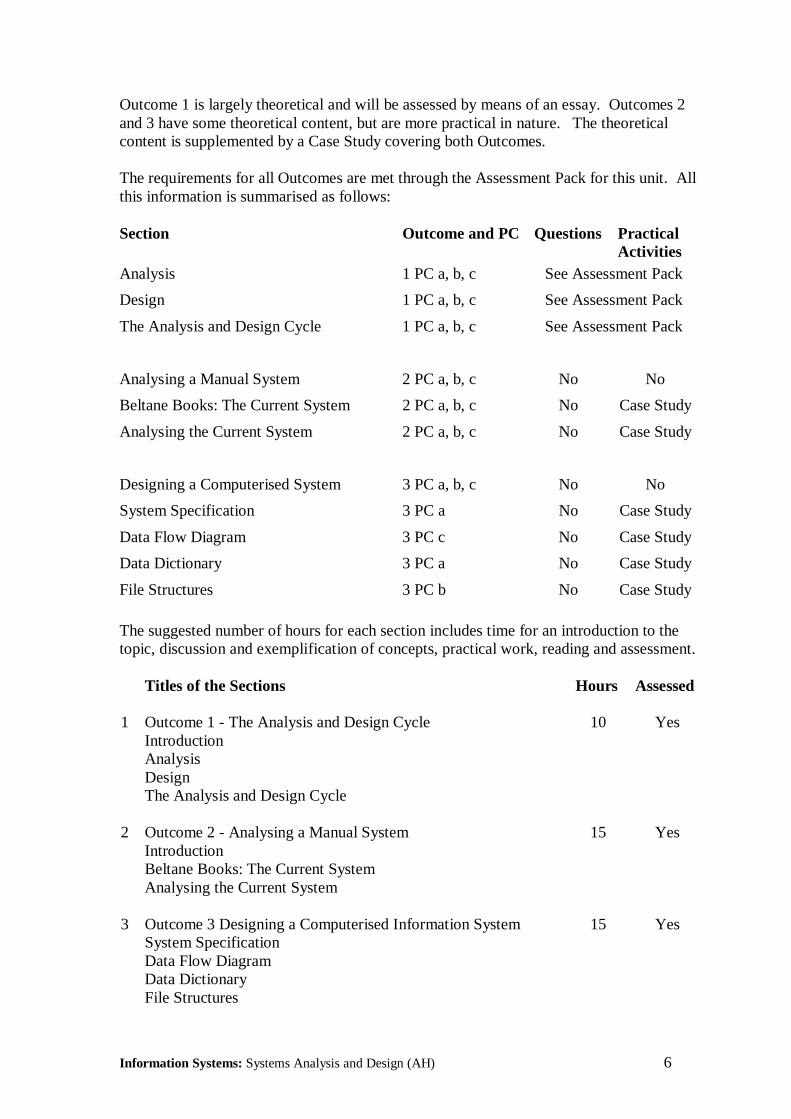
Outcome 1 is largely theoretical and will be assessed by means of an essay. Outcomes 2and 3 have some theoretical content, but are more practical in nature. The theoreticalcontent is supplemented by a Case Study covering both Outcomes.
The requirements for all Outcomes are met through the Assessment Pack for this unit. Allthis information is summarised as follows:
Section Outcome and PC Questions PracticalActivities
Analysis 1 PC a, b, c See Assessment Pack
Design 1 PC a, b, c See Assessment Pack
The Analysis and Design Cycle 1 PC a, b, c See Assessment Pack
Analysing a Manual System 2 PC a, b, c No No
Beltane Books: The Current System 2 PC a, b, c No Case Study
Analysing the Current System 2 PC a, b, c No Case Study
Designing a Computerised System 3 PC a, b, c No No
System Specification 3 PC a No Case Study
Data Flow Diagram 3 PC c No Case Study
Data Dictionary 3 PC a No Case Study
File Structures 3 PC b No Case Study
The suggested number of hours for each section includes time for an introduction to thetopic, discussion and exemplification of concepts, practical work, reading and assessment.
Titles of the Sections Hours Assessed
1 Outcome 1 - The Analysis and Design Cycle 10 YesIntroductionAnalysisDesignThe Analysis and Design Cycle
2 Outcome 2 - Analysing a Manual System 15 YesIntroductionBeltane Books: The Current SystemAnalysing the Current System
3 Outcome 3 Designing a Computerised Information System 15 YesSystem SpecificationData Flow DiagramData DictionaryFile Structures

Information Systems: Systems Analysis and Design (AH) 7
ReferencesMost books on Systems Analysis and Design relate to specific methodologies and containsignificantly more detail than required for this unit. However, the following may be ofsome assistance in providing additional information:
SSADM Version 4, Mike Goodland and Caroline SlaterMcGraw-Hill, 1995, £27.99, ISBN: 007709073X
An easy-to-read book which covers the basic concepts of systems analysis and design andwhy it should be carried out, through to the different stages of SSADM. Lots of helpfulexamples.
Systems Analysis and Design, Don Yeates, Maura Shields and David HelmyFinancial Times Prentice Hall, 1994, £26.99, ISBN: 0273600664
This book provides information on the activities involved in the analysis, design andimplementation of computer-based information systems. It includes an SSADM-basedcase study which puts the principles and techniques to practical use.
Structured Systems Analysis: Tools and Techniques, Chris Gane and T SarsonMcDonnell Douglas, 1977, ISBN: 0686376765
One of the first books on structured systems analysis and, after nearly 25 years, still one ofthe best. Excellent explanations of Data Flow Diagrams and Data Dictionaries.Unfortunately, this book was out-of-print at the time of writing, but you may still be ableto find one in a second-hand book shop or a library.

Information Systems: Systems Analysis and Design (AH) 8

Information Systems: Systems Analysis and Design (AH) 9
Section 2
Student Notes

Information Systems: Systems Analysis and Design (AH) 10
Information Systems: Systems Analysis and Design (AH) 11
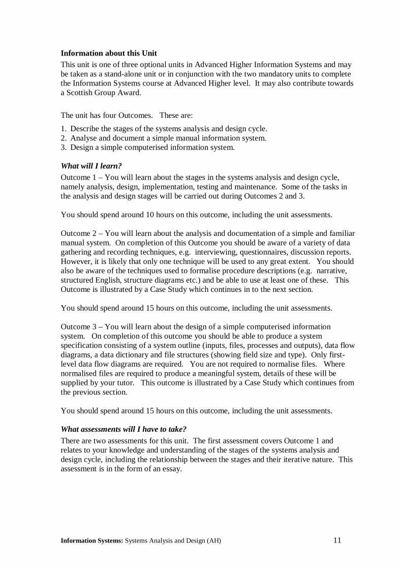
Information about this UnitThis unit is one of three optional units in Advanced Higher Information Systems and maybe taken as a stand-alone unit or in conjunction with the two mandatory units to completethe Information Systems course at Advanced Higher level. It may also contribute towardsa Scottish Group Award.
The unit has four Outcomes. These are:
1. Describe the stages of the systems analysis and design cycle.2. Analyse and document a simple manual information system.3. Design a simple computerised information system.
What will I learn?Outcome 1 – You will learn about the stages in the systems analysis and design cycle,namely analysis, design, implementation, testing and maintenance. Some of the tasks inthe analysis and design stages will be carried out during Outcomes 2 and 3.
You should spend around 10 hours on this outcome, including the unit assessments.
Outcome 2 – You will learn about the analysis and documentation of a simple and familiarmanual system. On completion of this Outcome you should be aware of a variety of datagathering and recording techniques, e.g. interviewing, questionnaires, discussion reports.However, it is likely that only one technique will be used to any great extent. You shouldalso be aware of the techniques used to formalise procedure descriptions (e.g. narrative,structured English, structure diagrams etc.) and be able to use at least one of these. ThisOutcome is illustrated by a Case Study which continues in to the next section.
You should spend around 15 hours on this outcome, including the unit assessments.
Outcome 3 – You will learn about the design of a simple computerised informationsystem. On completion of this outcome you should be able to produce a systemspecification consisting of a system outline (inputs, files, processes and outputs), data flowdiagrams, a data dictionary and file structures (showing field size and type). Only first-level data flow diagrams are required. You are not required to normalise files. Wherenormalised files are required to produce a meaningful system, details of these will besupplied by your tutor. This outcome is illustrated by a Case Study which continues fromthe previous section.
You should spend around 15 hours on this outcome, including the unit assessments.
What assessments will I have to take?
There are two assessments for this unit. The first assessment covers Outcome 1 andrelates to your knowledge and understanding of the stages of the systems analysis anddesign cycle, including the relationship between the stages and their iterative nature. Thisassessment is in the form of an essay.

Information Systems: Systems Analysis and Design (AH) 12
The second assessment covers Outcome 2, which involves the analysis and documentationof a simple manual information system, and Outcome 3, which involve the design of asimple computerised information system. You will be required to carry out a projectinvolving the analysis of an existing manual system and the design of a replacementcomputerised system.
The first assessment can be completed can early in the unit since the descriptions involvedin Outcome 1 will be covered during the initial stages of the unit. The second assessmentwill be carried out over an extended period of time during the remainder of the unit.
How often will I use a computer in this unit?You may not use one at all, as all the necessary documentation can be completed by hand.If you wish to complete the documentation by computer, you will require access to amicrocomputer running a standard word processing package, such as Microsoft Word,which provides basic graphics capabilities.
Where should I look for additional information?
Most books on Systems Analysis and Design relate to specific methodologies and containsignificantly more detail than required for this unit. However, the following may be ofsome assistance in providing additional information:
SSADM Version 4, Mike Goodland and Caroline SlaterMcGraw-Hill, 1995, £27.99, ISBN: 007709073X
An easy-to-read book which covers the basic concepts of systems analysis and design andwhy it should be carried out, through to the different stages of SSADM. Lots of helpfulexamples.
Systems Analysis and Design, Don Yeates, Maura Shields and David HelmyFinancial Times Prentice Hall, 1994, £26.99, ISBN: 0273600664
This book provides information on the activities involved in the analysis, design andimplementation of computer-based information systems. It includes an SSADM-basedcase study which puts the principles and techniques to practical use.
Structured Systems Analysis: Tools and Techniques, Chris Gane and T SarsonMcDonnell Douglas, 1977, ISBN: 0686376765
One of the first books on structured systems analysis and, after nearly 25 years, still one ofthe best. Excellent explanations of Data Flow Diagrams and Data Dictionaries.Unfortunately, this book was out-of-print at the time of writing, but you may still be ableto find one in a second-hand bookshop or a library.

Information Systems: Systems Analysis and Design (AH) 13
Section 3
Study Materials

Information Systems: Systems Analysis and Design (AH) 14
Information Systems: Systems Analysis and Design (AH) 15
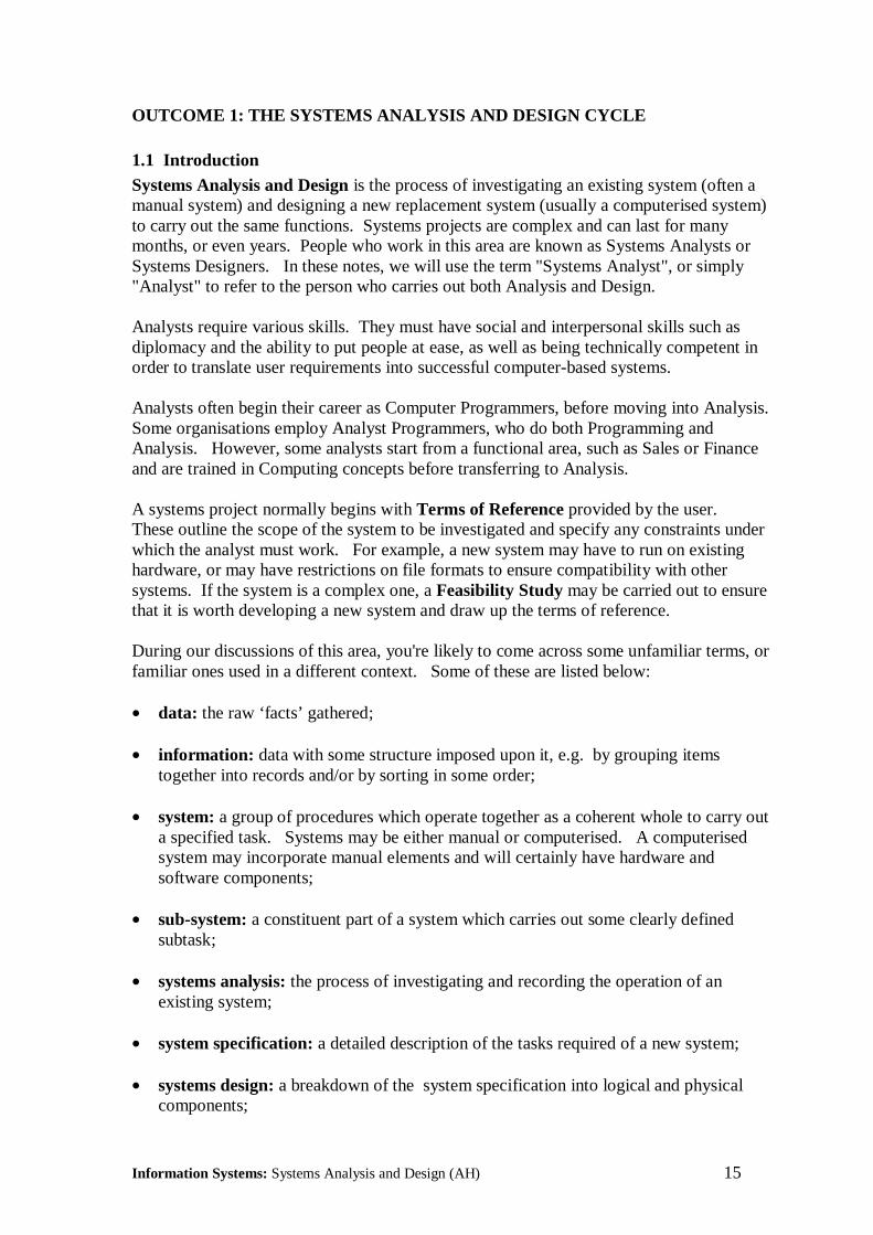
OUTCOME 1: THE SYSTEMS ANALYSIS AND DESIGN CYCLE
1.1 IntroductionSystems Analysis and Design is the process of investigating an existing system (often amanual system) and designing a new replacement system (usually a computerised system)to carry out the same functions. Systems projects are complex and can last for manymonths, or even years. People who work in this area are known as Systems Analysts orSystems Designers. In these notes, we will use the term "Systems Analyst", or simply"Analyst" to refer to the person who carries out both Analysis and Design.
Analysts require various skills. They must have social and interpersonal skills such asdiplomacy and the ability to put people at ease, as well as being technically competent inorder to translate user requirements into successful computer-based systems.
Analysts often begin their career as Computer Programmers, before moving into Analysis.Some organisations employ Analyst Programmers, who do both Programming andAnalysis. However, some analysts start from a functional area, such as Sales or Financeand are trained in Computing concepts before transferring to Analysis.
A systems project normally begins with Terms of Reference provided by the user.These outline the scope of the system to be investigated and specify any constraints underwhich the analyst must work. For example, a new system may have to run on existinghardware, or may have restrictions on file formats to ensure compatibility with othersystems. If the system is a complex one, a Feasibility Study may be carried out to ensurethat it is worth developing a new system and draw up the terms of reference.
During our discussions of this area, you're likely to come across some unfamiliar terms, orfamiliar ones used in a different context. Some of these are listed below:
• data: the raw ‘facts’ gathered;
• information: data with some structure imposed upon it, e.g. by grouping itemstogether into records and/or by sorting in some order;
• system: a group of procedures which operate together as a coherent whole to carry outa specified task. Systems may be either manual or computerised. A computerisedsystem may incorporate manual elements and will certainly have hardware andsoftware components;
• sub-system: a constituent part of a system which carries out some clearly definedsubtask;
• systems analysis: the process of investigating and recording the operation of anexisting system;
• system specification: a detailed description of the tasks required of a new system;
• systems design: a breakdown of the system specification into logical and physicalcomponents;
Information Systems: Systems Analysis and Design (AH) 16
• systems boundary: the limits of the system;
• interface: the connections between the system and its environment or other relatedsystems, e.g. the link between an order acceptance system and an invoicing system;
• environment: the area outwith the system boundary;
• information flow: the routes by which information passes between sub-systems orbetween a system and its environment.
A systems project can be divided up into the following stages:
Analysis
Once the scope of the study has been agreed, a detailed investigation is undertaken todetermine the operations carried out by the current system and the requirements for thenew system. This will involve speaking with the users of the current system andexamining all the paperwork involved.
DesignDesign is the process of specifying the new system. This details the tasks to be carriedout and the data to be input, output and stored on files. Initially a logical design isproduced, specifying the functions to be carried out by the new system without tying thesedown to specific hardware or software. Then a physical design is produced, givingprecise details of hardware, software, file formats etc.
ImplementationImplementation includes software development (programming) and the changeover to thenew system. This can take place all at once or in stages. Implementation also includestraining users in the operation of the new system.
TestingTesting includes program testing, to ensure that the individual programs work correctlyin isolation and system or integration testing to ensure that the programs work togethercorrectly as a complete system. The analyst carries out both these types of testing. Thefinal stage is acceptance testing, which is carried out by the user to ensure that the systemmeets the specified requirements.
MaintenanceMaintenance ids the process of amending a system after it is up and running. Thisincludes both ad-hoc amendments to deal with undiscovered bugs as well as plannedmaintenance to cope with changing circumstances within the organisation (e.g. additionof new product ranges) or the environment (e.g. changes in tax structure).
We will now look at each of these stages in a little more detail.
Information Systems: Systems Analysis and Design (AH) 17
1.2 AnalysisAnalysis provides the foundation for the remainder of the systems analysis and designcycle. During the analysis phase, the analyst investigates the existing system and beginsto form impressions of the new system. The principal task in the analysis phase is thegathering and analysis of information about the current system.
The systems analysis and design cycle does not necessarily progress in a linear fashion,with each completed leading directly the next phase. It is often necessary to go back to aprevious phase if continuing to the next phase would result in improper analysis, design orimplementation. It is common to return to the analysis phase several times beforecompleting the design phase, because these two are closely related. This process ofiteration and revision is normal in most systems projects.
1.2.1 Information Gathering
The most important source information is the end users of the current system, who areoften also the potential users of the new system. They may range from novices tohighly-skilled individuals. The information gathered from end users will be crucialduring the analysis and design phases. Later, the analyst will also discuss technicalaspects of the system with programmers, network engineers and other technical staff.
A secondary source of information for the analyst can be found in the existing paper workor documents within the organisation. Documents represent the formal information flowthrough the current system. The analyst must collect sample copies of all relevantdocuments, e.g. input forms, output documents, reports, invoices etc to understand howdata flows and is used in the current system. This information can be important in thesubsequent design of files for the new system.
All the information gathered by the analyst must be recorded in a suitable format. Mostorganisations have standards specifying how this should be done. This often amounts tothe use of a standard set of forms, similar to those you will use during this course.
1.2.2 Information Gathering TechniquesThe analyst will use a range of techniques to gather information about the current system.The most important are interviewing, questionnaires and observation.
Interviewing
Interviewing is the commonest and most effective technique. An interview is anexchange of information between the analyst and the end user. It is planned in advanceand has a specific purpose.
There are two basic types of questions: open ended and closed ended. Open-endedquestions are neutral and non-restrictive. They allow interviewees to answer questionsin any way they wish, and they encourage them to reveal information. For example:
‘How could the invoicing system could be improved?’

Information Systems: Systems Analysis and Design (AH) 18
However, this can lead to the interview being controlled by the interviewee's answersrather than the interviewer's questions. Open-ended questions can sometimes result in thedisclosure of irrelevant information.
Closed-ended questions are specific and provide the interviewer with greater controlover the interview. However, they achieve only what they ask and discourageinterviewees from opening up and revealing relevant information which the interviewerdid not anticipate. For example:
‘What part of the invoicing system takes up the most time?’
The interviewer must take care that closed-ended questions are not loaded or leading.
Questions can be sub-divided into two categories: primary and secondary; both can beopen or closed-ended. Primary Questions address a specific topic. SecondaryQuestions are follow-up questions designed to obtain more information than was given inresponse to a Primary question.
QuestionnairesQuestionnaires allow the analyst to collect information from a large number of people,possibly spread over several sites. Standardised question formats can yield more reliabledata than other fact-finding techniques, and wide distribution ensures that respondentsremain anonymous. This can lead to more honest responses.
However, questionnaires don't let the analyst see the expressions or reactions ofrespondents. Respondents may not complete questionnaires as a high-priority task. Ifeveryone doesn't reply, the respondents can become a self-selected group, which can leadto problems with data reliability.
Open-ended questionnaires allow people to express their feelings, opinions andexperiences or explore a problem. Closed-ended questionnaires provide greater controlby presenting respondents with specific responses to choose from. This format isexcellent for obtaining factual information.
Questionnaires are expensive to develop and distribute. Analysts must consider theobjectives of the questionnaire and determine what structure will be most useful andeasiest to understand. Questionnaires should be tested before being printed anddistributed.
Questionnaire recipients should be selected for the information they can provide. Theanalyst should make sure that they have the background and experience to enable them toanswer the questions.
ObservationObservation is another technique used to gather information by observing peopleperforming various aspects of their jobs. It allows the analyst to determine what is beingdone, how it is being done, who does it, when it is done, how long it takes, where it isdone and why it is done.
Information Systems: Systems Analysis and Design (AH) 19
Also, observation lets the analyst take part in procedures being performed by employees.With this hands-on approach, the analyst may find out that forms are poorly designed orthat insufficient time is allocated to a particular procedure. In addition, the analyst mayuncover better and quicker ways to carry out a procedure.
Consistency Checking
The analyst must check that information obtained from different sources is consistent. Ingeneral, information should be obtained from at least two sources to allow consistencychecks to be carried out. Any inconsistencies must be investigated. It is unlikely(although not unknown) that anyone will deliberately supply an analyst with wronginformation. However, different people do have different knowledge and differentmemories of events, so inconsistencies often occur.
1.2.3 Documenting the Current SystemOnce all the information regarding the current system has been collected, the analyst mustensure that the system is thoroughly documented. The analyst will have to identify all themajor components of the existing system, i.e. the sources and destinations of data, datastores, processes, subsystems and data flows. These will be recorded using one or moredata flow diagrams. Data flow diagrams are described briefly below. Severalexamples of their use are given in the Case Study which forms the next two sections ofthese notes.
The analyst will also have to describe the processes involved in the current system. Oneway of doing this is by a simple narrative, i.e. a few paragraphs of every day English.Other methods include the use of Structure Diagrams, a graphical technique derived fromstructured programming, or Structured English, a more rigorous form of English, which iswritten in a similar manner to a programming language. Both of these techniques aredescribed in more detail in the next section.
1.2.4 Requirements of the New System
Finally, the analyst will have to identify the requirements of the new system. In generalthe new system will be required to that the new system should be able to carry out thesame tasks as the existing system, but with improved efficiency. This is described ingreater detail in the next section.

Information Systems: Systems Analysis and Design (AH) 20
1.2.5 Data Flow DiagramsData flow diagrams (DFDs) were first introduced in the late 1970s by Gane and Sarsonand de Marco, and have since become a major tool for Systems Analysis and Design. Avariety of different notations are used, but they all serve the same basic purpose.
The symbols used in these notes are based on those recommended by the National Centrefor Information Technology (NCC). Templates of the symbols are readily available.This section introduces the basic concepts of DFDs. More detailed examples of their useare given in subsequent sections. DFDs show the movement of data or goods through asystem. They make use of five basic symbols:
Data Flows
A data flow is a route that allows data to travel from one location to another. It isrepresented by a line, with an arrowhead showing the direction of flow. Data can flowfrom a source to a process, from one process to another, or from a process to a data storeor destination. Each data flow should be given a unique descriptive title.
Physical Flows
A physical flow is a route which allows goods or materials to travel from one location toanother. It is represented by a heavier line (or sometimes a double line) with anarrowhead showing the direction of flow. Goods can flow from a source to a process,from one process to another, or from a process to a destination. Each physical flowshould be given a unique descriptive title.
Processes
Processes show actions or transformations carried out on data. They are represented by arectangle and should have an incoming data flow and an outgoing data flow.
Processes should also be given descriptive names, ideally in the form of a verb followedby an object, e.g. ‘calculate total price’. They are often numbered to aid identification.
Information Systems: Systems Analysis and Design (AH) 21
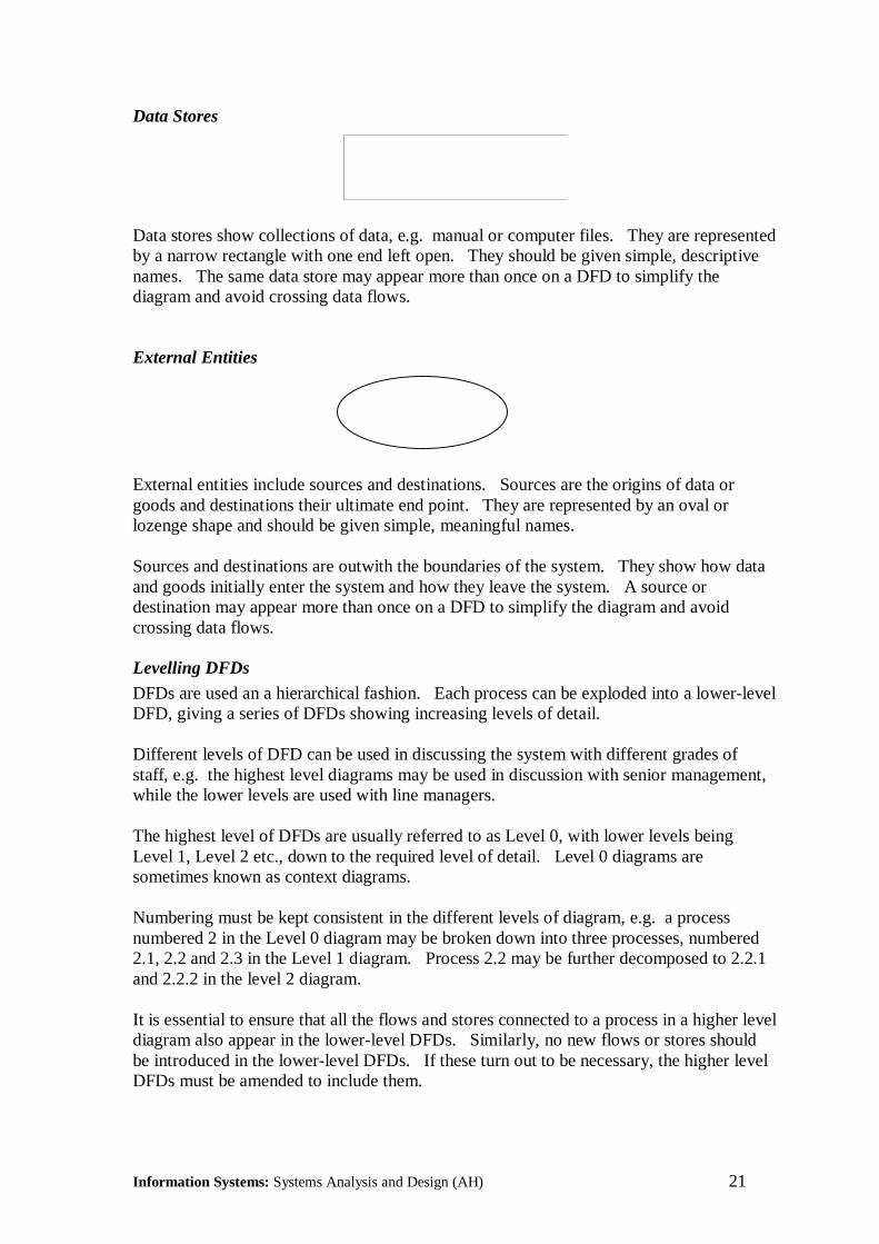
Data Stores
Data stores show collections of data, e.g. manual or computer files. They are representedby a narrow rectangle with one end left open. They should be given simple, descriptivenames. The same data store may appear more than once on a DFD to simplify thediagram and avoid crossing data flows.
External Entities
External entities include sources and destinations. Sources are the origins of data orgoods and destinations their ultimate end point. They are represented by an oval orlozenge shape and should be given simple, meaningful names.
Sources and destinations are outwith the boundaries of the system. They show how dataand goods initially enter the system and how they leave the system. A source ordestination may appear more than once on a DFD to simplify the diagram and avoidcrossing data flows.
Levelling DFDs
DFDs are used an a hierarchical fashion. Each process can be exploded into a lower-levelDFD, giving a series of DFDs showing increasing levels of detail.
Different levels of DFD can be used in discussing the system with different grades ofstaff, e.g. the highest level diagrams may be used in discussion with senior management,while the lower levels are used with line managers.
The highest level of DFDs are usually referred to as Level 0, with lower levels beingLevel 1, Level 2 etc., down to the required level of detail. Level 0 diagrams aresometimes known as context diagrams.
Numbering must be kept consistent in the different levels of diagram, e.g. a processnumbered 2 in the Level 0 diagram may be broken down into three processes, numbered2.1, 2.2 and 2.3 in the Level 1 diagram. Process 2.2 may be further decomposed to 2.2.1and 2.2.2 in the level 2 diagram.
It is essential to ensure that all the flows and stores connected to a process in a higher leveldiagram also appear in the lower-level DFDs. Similarly, no new flows or stores shouldbe introduced in the lower-level DFDs. If these turn out to be necessary, the higher levelDFDs must be amended to include them.

Information Systems: Systems Analysis and Design (AH) 22
Drawing DFDsStart off by trying to identify sources and sinks. These will indicate the boundaries of thesystem and provide an initial set of data flows - those which bring data into the system andthose which take data out of it.
Choose an input from a source or an output to a sink and insert a box where a process isrequired to transform data in some manner. Check whether all the required data is flowinginto the process to carry out the desired transformation and produce the required output - ifnot, you may have to add additional input data flows. DFDs can be useful in identifyingthe need for additional data items that were not obvious from a verbal description.
Do your initial drafts freehand with a pencil. Your first draft will probably be wrong andend up as a hopelessly tangled scribble. It normally takes at least three drafts before a DFD starts to make sense.
Most processes should access a store of some kind - if this is not the case, check carefullyfor mistakes or omissions.
DFDs are a useful modelling tool, which provides a clear indication of how data makes itsway through the system. However they lack the detail about data which is required at theSystems Design stage. This detail is provided by the Data Dictionary, which we will lookat next.

Information Systems: Systems Analysis and Design (AH) 23
1.3 DesignTwo levels of design are required, Initially a logical design is produced, specifying thefunctions to be carried out by the new system without tying these down to specifichardware or software. Then a physical design is produced, giving precise details ofhardware, software, file formats etc.
The Logical Design will include:
• Logical Data Flow Diagrams: showing what the new system will do in outline.These follow the same conventions as the data flow diagrams we used earlier.
• General Narrative: describing how the new system will operate;
• Data Dictionary: recording the new processes and data stores in the system;
• File Structure: showing how the data will be collected together into related files ortables.
1.3.1 Logical DFDsThese diagrams use the same drawing symbols and conventions as the data flow diagramswe used earlier to describe the current system.
Logical DFDs can have two types of data stores, manual data stores and computeriseddata stores. Manual data stores will contain physical objects such as stock, money orpaperwork, whereas the computerised data stores will contain the customer databases,stock records etc. used by the new system.
The functions shown in the logical data flow diagrams will reflect the procedures whichare carried out by the new system. Titles might include:
• input customer details
• print out reports
• update database
There may be more function boxes in the new system than there were in the currentsystem. Function boxes represent the main functions carried out by the new system.
1.3.2 Narrative Description
A narrative should be prepared, giving a general description of the operation of the newcomputerised system. It should include the paperwork which is to be completed and filed,the computer files and programs which are to be used, and the information which will bepassed between departments and to-from external entities.

Information Systems: Systems Analysis and Design (AH) 24
1.3.3 Data DictionaryDetails of all data items encountered during analysis and design must be accuratelyrecorded. Each item of data should be uniquely identified and defined. Information aboutdata items can usefully be collected together into a data dictionary.
No analyst can carry all the details of a system in his head, so records are vital. The datadictionary is an essential component of the analyst's record. The most important featuresof a data dictionary are completeness and consistency.
Contents of a Data Dictionary
• Data name: a unique meaningful name, e.g. Partno, Price, StockQuant etc.
• Description: a short description of the meaning of the data item, e.g. StockQuant =quantity in stock
• Valid Range: specifies the boundaries of the data, e.g. 1 - 99 or AA000 - ZZ999
• Storage format: how the data is stored, e.g. integer, real, alphanumeric, alphabetic
1.3.4 Input and Output RequirementsThese are descriptions which must be completed to describe every flow in or out of thesystem.
A description should be given for each of data flow in the required logical level 1 DFDwhich flow to or from an external entity. For each flow you should state:
Name of the flow
Type of flow, eg: physical flow (stock, money, people) computer printout screen information manual document
Data Contents, i.e. information which is conveyed by the flow, e.g. for an Invoiceinvoice number
date description amount

Information Systems: Systems Analysis and Design (AH) 25
1.3.5 File StructuresThese are the outline structures of the files which are set up to hold the information on thenew computer system.
The files which may be designed are program files used in Pascal or COBOL which youhave designed to be written, or Application Package files such as Database or Spreadsheet.
Any files should have the fieldname, the length of the field to hold the longest entry, andthe type of the field entry e.g. numeric, alphanumeric, character or logical.
A typical layout for a database file structure could be:
Customer Database
the files should be drawn with the headings and column details.
A short description of the purpose and use of each file should also be included.
1.3.6 ControlsIt is essential in every computer system that control is taken over the security of the data,procedures are in place for backup and security, and that there are measures to deal withsystem failures. The areas to be addressed include:
• Backup & Recovery
• Access to the System
• Archiving Policy
• Error Handling
• Audit Requirements
Field Name Type Lengthcust-no n 6surname c 20forename c 15street a 25town c 15county c 20postcode a 12
Information Systems: Systems Analysis and Design (AH) 26
1.3.7 ImplementationImplementation involves the actual writing of the software, followed by the replacementof the existing system by the new system. The Systems Implementation Plan gives adetailed description of how implementation will be achieved. It is usually preparedseveral weeks or even months in advance, depending on the complexity of the project.
Implementation involves co-ordination and scheduling of a number of activities and tasksperformed by an implementation team which might include: systems analysts,departmental managers, vendor representatives, users, programmers and technicians.
At this stage, the hardware for the system should have been selected and site preparationcommenced. When the equipment arrives everything should be ready for installation.
A programming team should be formed and should start by reviewing the designspecifications to ensure clear understanding before coding and testing start.
Training of users and other relevant personnel should begin.
Preparing the Site
If the hardware is PC based, only minimal site preparation should be required. Adequatespace should be provided for equipment and furniture. Appropriate wiring, lighting, andair conditioning should be installed to ensure a clean, workable environment.
Staff may require acoustic privacy panels, printer enclosures and ergonomically designedfurniture and workstations. These should comply with the current Health and SafetyRegulations, including the Display Screen Equipment Regulations (1992).
Training Personnel
No system can function effectively unless all users are properly trained. Trainingincreases staff expertise and facilitates acceptance of the new system - an important factorin a system's ultimate success. Three groups require training:
• technical staff who will operate and maintain the system;
• mainstream users who will interact with the system to perform tasks;
• indirect users who require to know what the system can do.
Training should begin early enough to be completed around the same time as the systembecomes operational. Training increases user confidence and minimises disruption duringearly stages of systems operation.
Training ranges from a brief tutorial showing one user how to perform a simple task totraining most of the users throughout the organisation for a major new system. A trainingschedule must be drawn up to make efficient use of resources. Training may be providedin-house or bought in from vendors or other outside suppliers.
Information Systems: Systems Analysis and Design (AH) 27
1.3.8 Systems DocumentationDocumentation is the written material that describes how a system works. It includesdescriptions of how software operates and the procedures users follow. Everyone agreesabout the need for good system documentation, but it is often neglected by those whoought to provide it. There are four main areas where documentation is required:
• User Documentation: tells users how to use the system and perform tasks. This maybe on-line or contained in a procedures manual. Documentation also tells users how tocomplete source documents and data entry screens, generate reports, and check thevalidity of output. It should accurately reflect what users learned during training.
• Systems Documentation: shows what the system can do. It is a communication toolfor keeping everyone informed about the design of the system and providesmanagement with an accurate basis for reviewing and evaluating the system design.
• Software Documentation: assists with system maintenance by describing the logicand functions of the software. This is useful once the system is operational andrequires updating or upgrading.
• Operations documentation: this gives the computer operators the information that isrequired to change files, disks etc. It contains key information and diagrams about theoperational aspects of the system.
1.3.9 Converting to the New System
Conversion is the process of changing from the current system to the new system. If thesoftware is straightforward and will run on the existing hardware, then conversion can berelatively simple. However, if the new system involves new software, a new databasemanagement system, new hardware and system software, new networks and significantchanges in procedures, conversion becomes very involved.
The following methods of systems conversion are used:• Direct Conversion: the new system is implemented at a stroke and the existing
system is discontinued. There can be no return to the old system. This method can bedangerous, but may be used where there is no existing system, or it is of little value.
• Parallel Conversion: both systems are run side-by-side for an agreed period. Thisgives some protection against the failure of the new system, since the output from theexisting system can always be used.
• Phased Conversion: the new system is implemented to a set timescale, graduallyreplacing the existing system. This avoids the risks associated with direct conversionand provides time for users to adjust to changes.
• Pilot Conversion: the new system is initially introduced in one part of anorganisation, e.g. a single branch or section. Once any teething problems have beenovercome it is introduced gradually throughout the rest of the organisation.

Information Systems: Systems Analysis and Design (AH) 28
1.3.10 Post-Implementation ReviewThe aim of systems developers is to produce systems which are within budget, on time,and meet user requirements. Unfortunately, this goal is not always achieved. A post-implementation review looks for ways of improving the efficiency and effectiveness of thenew system. It can provide information which will help in the development of futuresystems. The review usually happens a few months after the new system is introduced. Itcovers the following areas:
• systems factors: efficiency, effectiveness
• design components: input/output, hardware, software
• accuracy of estimates: operational timetables, costs/benefits
• support factors: resources, training
1.3.11 TestingAt least three levels of testing are required for a new system:
• Program Testing: this is normally carried out by the programmers who write thesystem. Each individual program is tested in isolation to ensure that it performsproperly, i.e. valid items of data are processed correctly and produce the right output,while invalid items of data are rejected with a meaningful error message.
• Integration Testing: this is usually carried out under the supervision of the systemsanalyst to ensure that all the programs making up the system work together correctly,i.e. the data output from one program can be used successfully as input data to thenext. This area is notorious for uncovering problems due to differing interpretations ofprogram specifications.
• Acceptance Testing: is carried out by the users, to ensure that the new system meetsuser requirements under operating conditions. The test group should include a sampleof those who will work with the new system. Acceptance testing is the last chance tomake changes before the software goes live.
Test Data
There are two different types of test data - live and artificial. Each has its own advantagesand disadvantages.
• Live Data: live test data is the data actually used by an organisation. An analyst mayask users to enter data from their normal activities. It can be difficult to obtain enoughlive data to test a system rigorously. Live data doesn't usually contain a highproportion of errors, so it doesn’t test all combinations of data which can enter thesystem.
• Artificial Data: artificial test data is created purely for testing purposes. It can begenerated to test all combinations of formats and values, including all possible errorconditions. This type of data can be often be produced by a test data generatorprogram which will test all the logic paths in the system.
Information Systems: Systems Analysis and Design (AH) 29
1.3.12 Maintaining the SystemOnce the new system has been implemented, the development phase of the life cycle iscomplete. The system now enters the maintenance phase of its life cycle. Both hardwareand software will require to be maintained throughout the operational life of the system.
The information obtained during the post-implementation review is used to perform initialmaintenance. After this, periodic reviews and user requests will be the principal sourcesof requests for maintenance.
After initial maintenance is carried out, the maintenance workload should decline.However, after some years, the number of maintenance requests is likely to rise,increasing the cost of maintenance and the effort involved. When a system becomes amajor problem to users, the whole cycle begins again and a new system is developed.
The cost of software maintenance is increasing steadily. Some organisations are nowestimated to spend 80% of their systems budget on maintenance. In extreme cases theentire budget can be spent in this area and no new systems are developed.
Types of Systems Maintenance
There are three main types of systems maintenance:
• Corrective Maintenance: involves the correction of design, coding, andimplementation errors which should have never occurred. It often involves an urgentor emergency situation which calls for immediate attention.
• Adaptive Maintenance: is carried out to cope with changes in the externalenvironment or meet new user requirements, e.g. changes in tax law may requireamendments to payroll software.
• Preventative maintenance: consists of periodic inspection of the system to anticipateproblems. As maintenance staff work with a system, they often uncover defects whichindicate potential problems. If these are not corrected, they might effect the efficiencyor maintainability of the system at some point in the future.
Maintaining HardwareHardware maintenance is an important element of any maintenance schedule. It isnormally preventative maintenance involving the repair, replacement or addition of partsand components to keep the hardware in working order.

Information Systems: Systems Analysis and Design (AH) 30
1.4 The Systems Analysis and Design CycleThe stages normally take place in a fixed sequence, as outlined in the previous sections.However, it is possible in some instances that information which comes to light at a laterstage can mean that previous stages require to be repeated. For instance, it may becomeapparent during the design stage that insufficient information is available about a certainprocess. This could lead to repetition of at least part of the analysis stage to find therequired information.
Maintenance requirements can often lead to a repeat of several previous stages. Forexample, a change in the format of telephone numbers could lead to changes in inputdesign, output design and file design, followed by implementation and testing.
The systems analysis and design cycle is often described as being iterative in nature. Thisis because it is always possible to backtrack to earlier stages and that stages can berepeated as often as required until all the objectives of the system have been achieved.

Information Systems: Systems Analysis and Design (AH) 31
OUTCOME 2: ANALYSING AND DOCUMENTING A MANUAL SYSTEM
2.1 IntroductionThis part of the course involves the analysis and documentation of a manual informationsystem. The system to be investigated will be simple and familiar e.g. systems for use in avideo rental shop or a record store. The case study we will use involves a book supplier,Beltane Books.
A variety of data gathering and recording techniques can be used, e.g. interviewing,questionnaires, discussion reports. However, it is likely that only one technique will beused to any great extent.
A number of techniques used to formalise procedure descriptions will be examined, e.g.narrative, structured English, structure diagrams etc. Once again, it is likely that only onetechnique will be used to any great extent.

Information Systems: Systems Analysis and Design (AH) 32
2.2 Beltane Books: The Current SystemBeltane Books is a small Mail Order bookseller, specialising in hard-to-find Scottishbooks. At any given time around 5000 different titles are held in stock. Stock Quantitiesvary form 100 for popular titles down to 5 for rarely requested titles. The current OrderProcessing System is as follows:
Order Entry
Most customers submit their orders on a standard Order Form (Doc1) which goes initiallyto the Order Entry department.
If the customer phones in an order, it is taken down by Order Entry staff on the standardOrder Form.
If a customer sends in an order in the form of a letter or fax, rather than the standard OrderForm, the details are transferred to an Order Form.
The Order Forms are then passed to the Order Processing Department.
Order ProcessingDetails of the books in stock are held on Book Cards (Doc 2), filed in Book Code order.
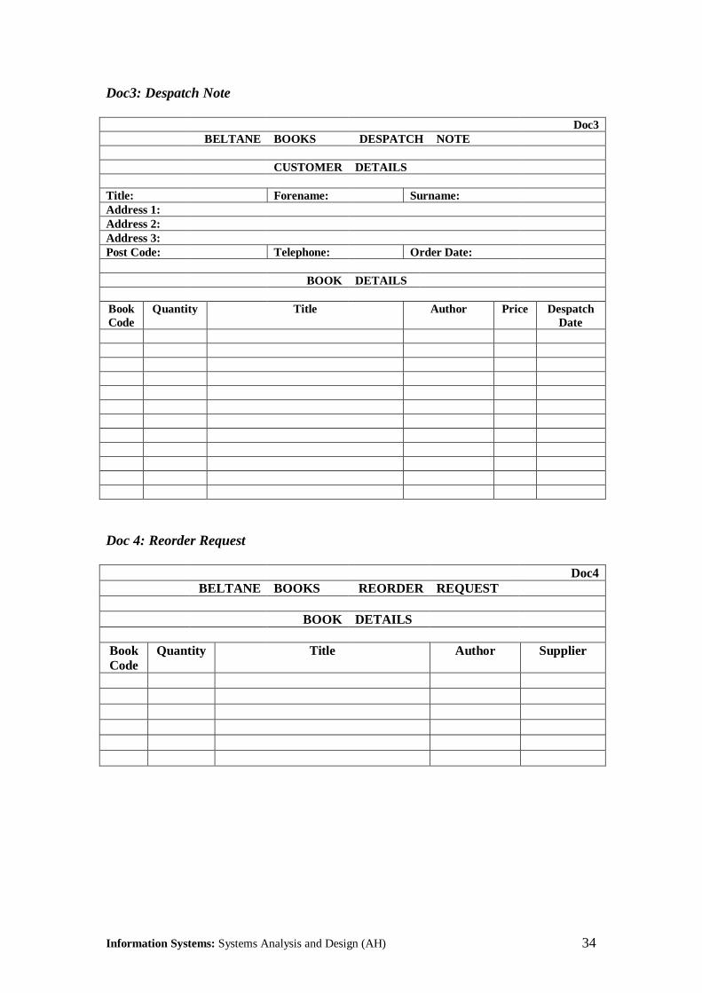
If a book is in stock, a Despatch Request (Doc3) is passed to the Despatch Department andthe quantity in stock on the Book Card is decreased by the quantity ordered.
If the quantity remaining in stock is less than the Reorder Level, a Reorder Request(Doc4) is sent to the Book Orders department.
If the book is not in stock, a Book Unavailable Note (Doc5) is sent to the Customer.
Despatch Department
When a Despatch Note arrives, the books are located, packed and posted off to thecustomer. The Despatch Date is marked on the Despatch Note, which is then passed to theAccounts Department to allow the customer to be invoiced.
Problem Areas
The company has now become overwhelmed with work and wishes to improve itsefficiency by computerising operations, starting with Order Processing. Your task is toinvestigate and record the operation of the existing Order Processing system and to designa computerised replacement system which can easily be extended to incorporate otheraspects of the company's activities.
You can assume that the company has an adequate accounting system in operation andyou need not bother with issues relating to the billing of customers.

Information Systems: Systems Analysis and Design (AH) 33
2.2 Sample Documents
Doc1: Order Form
Doc1BELTANE BOOKS ORDER FORM
CUSTOMER DETAILS
Title: Forename: Surname:Address 1:Address 2:Address 3:Post Code: Telephone: Order Date:
BOOK DETAILS
BookCode
Quantity Title Author Price
Doc2: Book Card
Doc2BELTANE BOOKS BOOK CARD
Book Code: Author:Title: Publisher:Date ofPublication:
ISBN:
Quantity in Stock: Reorder Level:Quantity OnOrder:
Date Ordered:
Wholesale Price: Retail Price:
Information Systems: Systems Analysis and Design (AH) 34
Doc3: Despatch Note
Doc3BELTANE BOOKS DESPATCH NOTE
CUSTOMER DETAILS
Title: Forename: Surname:Address 1:Address 2:Address 3:Post Code: Telephone: Order Date:
BOOK DETAILS
BookCode
Quantity Title Author Price DespatchDate
Doc 4: Reorder Request
Doc4BELTANE BOOKS REORDER REQUEST
BOOK DETAILS
BookCode
Quantity Title Author Supplier

Information Systems: Systems Analysis and Design (AH) 35
Doc5: Book Unavailable Note
Beltane Books Ltd,Lunasa Way,Edinburgh EF12 1BB
Tel: 0131 444 5567Fax: 0131 444 5578Email: [email protected]
<date>
<Customer Name><Address 1><Address 2><Address 3><Postcode>
Dear <Customer>
Thank you for your valued order. Unfortunately the undernoted books are no longeravailable. You may wish to resubmit your order after a couple of months to see if we havebeen able to obtain additional copies. Otherwise we suggest that you try a reputablesecond-hand bookseller if you still wish to obtain them.
BookCode
Quantity Title Author Price
Thank you for your continued custom.
Yours faithfully,
Colin GilchristOrder Processing Manager
Information Systems: Systems Analysis and Design (AH) 36
2.3 Analysing the Current SystemInformation GatheringMost of the information you need is already present in the Case Study on Beltane Bookspresented at the start of this section. If there is anything you are unsure about you shouldask your teacher for clarification.
Keep in mind that this is a slightly artificial situation. In the real world, the informationgiven in the case study would be obtained by the techniques described earlier. The mostuseful techniques would be interviewing and observation, since the organisation is toosmall for questionnaires to be of any real use.
Major Components of the Current System
Our first task is to identify the major components of the current system. These can bedivided up into six categories: external entities (sources of data or goods and destinationsof data or goods, data stores, data flows, physical flows, processes and subsystems.
External Entities
Sources: these are the places where data arises, outwith the system boundary. In this casethere is only one sources, the Customers who order books.
Destinations: where data or goods finally end up, outwith the system boundary.Customers are a destination, since books go to there. The Accounts Department is adestination, since details of the books supplied to customers are sent there. The BookOrders department is also a destination.
Data Stores
These are the places where data is stored, temporarily or permanently within the system.There is only one data store in this system, the Book File, consisting of the Book Cardswith details of the books held in stock.
Data Flows
There are a number of Data Flows in this system:
Customer Orders flow from Customers to Order Entry
Order Forms flow from Order Entry to Order Processing
Reorder Requests flow from Order Processing to Book Orders
Book Unavailable Notes flow from Order Processing to Customers
Despatch Notes flow from Order Processing to Despatch
Despatch Notes flow from Order Processing to Accounts
Physical Flows
There is only one physical flow in the system:
Books flow from Despatch to Customer

Information Systems: Systems Analysis and Design (AH) 37
ProcessesThere are 3 processes in the system:
Order EntryOrder ProcessingDespatch
Subsystems
There are two distinct subsystems in the current system:Order Entry and ProcessingDespatch
All the information gathered at this stage should be summarised on Proforma 1 (overleaf).
Information Systems: Systems Analysis and Design (AH) 38
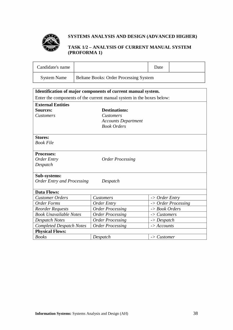
������SYSTEMS ANALYSIS AND DESIGN (ADVANCED HIGHER)
TASK 1/2 – ANALYSIS OF CURRENT MANUAL SYSTEM(PROFORMA 1)
Candidate's name Date
System Name Beltane Books: Order Processing System
Identification of major components of current manual system.Enter the components of the current manual system in the boxes below:
External EntitiesSources: Destinations:Customers Customers
Accounts DepartmentBook Orders
Stores:Book File
Processes:Order Entry Order ProcessingDespatch
Sub-systems:Order Entry and Processing Despatch
Data Flows:Customer Orders Customers -> Order EntryOrder Forms Order Entry -> Order ProcessingReorder Requests Order Processing -> Book OrdersBook Unavailable Notes Order Processing -> CustomersDespatch Notes Order Processing -> DespatchCompleted Despatch Notes Order Processing -> AccountsPhysical Flows:Books Despatch -> Customer
Information Systems: Systems Analysis and Design (AH) 39
Information Flows Between Major Subsystems.These have already been identified as follows:
Orders flow from Customers to Order Processing
(note that we have combined two data flows into one here, as bothtake place within the Order Entry and Processing subsystem)
Reorder Requests flow from Order Processing to Book Orders
Book Unavailable Notes flow from Order Processing to Customers
Despatch Notes flow from Order Processing to Despatch
Completed Despatch Notes flow from Despatch to Accounts
These data flows, plus the physical flow (Books flowing from Despatch to Customers)should be recorded on a data flow diagram using Proforma 2 (overleaf)
The Book File is referenced (and possibly updated) by Order Processing, so there is abi-directional data flow of Book Details.

Information Systems: Systems Analysis and Design (AH) 40
������SYSTEMS ANALYSIS AND DESIGN (ADVANCED HIGHER)
TASK 1/2 – ANALYSIS OF CURRENT MANUAL SYSTEM(PROFORMA 2)
Candidate's name Date
System Name Beltane Books: Order Processing System
Identification of information flows between major subsystemsDraw a data flow diagram showing the data flows between the major sub-systems of thecurrent manual system:
Book Book File Details Reorder Orders Requests
Despatch Notes Book Unavailable Notes
Completed Despatch Notes
Customers
OrderProcessing
Despatch
BookOrders
Accounts

Information Systems: Systems Analysis and Design (AH) 41
Assembly and Recording of InformationWe already know the contents of the only file:
Book File
Book Code AuthorTitle PublisherDate of Publication ISBNQuantity in Stock Reorder LevelQuantity On Order Date OrderedWholesale Price Retail Price
This information should be transferred to Proforma 3a (overleaf).We have also identified three processes:
Order EntryOrder ProcessingDespatch
Descriptions of these should be given on Proforma 3b (overleaf). In this instance we haveused Narrative Descriptions, but Structure Diagrams or Structured English could equallywell be used. These are described briefly below.
Structure DiagramsIt is sometimes useful to have a graphical representation of the structure of a process. Wecan diagrams known a structure charts. A problem can often be more readily understoodwhen it is broken down into a more concise and less complex format.
Structure charts are closely associated with a programming methodology known asJackson Structured Programming (JSP). JSP tends to be used in a data-processingenvironment, but its use can be extended to other systems. In this course we will lookonly at the structure diagram notation and ignore the other aspects of JSP.
Structure diagrams use the three fundamental programming constructs: sequence,repetition and selection.
SequenceA sequence is a group of actions which are carried out in a linear fashion, one after theother. In a structure diagram this is represented as follows:
A
B C D
This diagram shows module A, which calls modules B, C and D (in that sequence).
Information Systems: Systems Analysis and Design (AH) 42
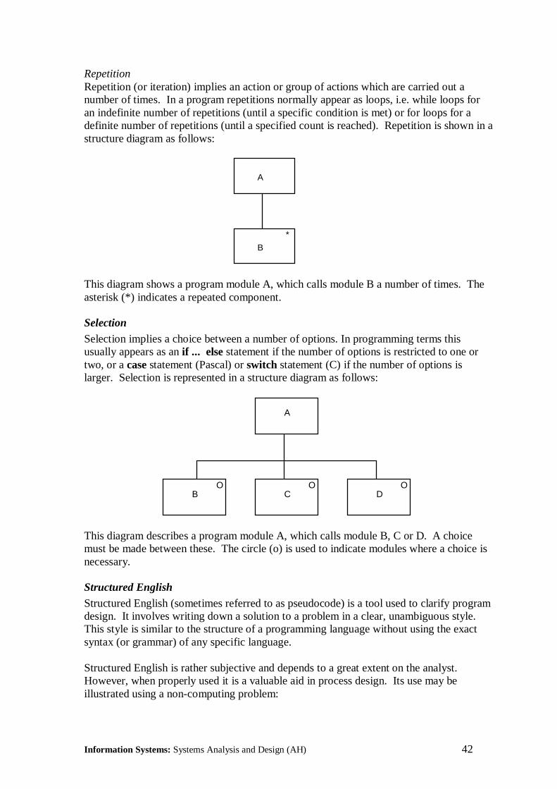
RepetitionRepetition (or iteration) implies an action or group of actions which are carried out anumber of times. In a program repetitions normally appear as loops, i.e. while loops foran indefinite number of repetitions (until a specific condition is met) or for loops for adefinite number of repetitions (until a specified count is reached). Repetition is shown in astructure diagram as follows:
A
B
*
This diagram shows a program module A, which calls module B a number of times. Theasterisk (*) indicates a repeated component.
Selection
Selection implies a choice between a number of options. In programming terms thisusually appears as an if ... else statement if the number of options is restricted to one ortwo, or a case statement (Pascal) or switch statement (C) if the number of options islarger. Selection is represented in a structure diagram as follows:
A
B C DO O O
This diagram describes a program module A, which calls module B, C or D. A choicemust be made between these. The circle (o) is used to indicate modules where a choice isnecessary.
Structured English
Structured English (sometimes referred to as pseudocode) is a tool used to clarify programdesign. It involves writing down a solution to a problem in a clear, unambiguous style.This style is similar to the structure of a programming language without using the exactsyntax (or grammar) of any specific language.
Structured English is rather subjective and depends to a great extent on the analyst.However, when properly used it is a valuable aid in process design. Its use may beillustrated using a non-computing problem:

Information Systems: Systems Analysis and Design (AH) 43
Everyday English‘If it is raining then I go to work by car and have lunch in the office, otherwise I walk towork, and have lunch in the park. Under both circumstances I go jogging afterwards.’
Structured Englishif it is raining then
go to work by carhave lunch in office
elsewalk to workhave lunch in park
endifgo jogging
Everyday English has a number of disadvantages as a method of expressing process logic:
• it is one dimensional (must start at beginning and proceed sequentially);
• it can be long-winded;
• there is no standard - everyone writes in their own style;
• it is ambiguous;
• it is difficult to maintain.

Information Systems: Systems Analysis and Design (AH) 44
Structured English, on the other hand, has a number of advantages:
• it uses only a limited subset of the English language;• it uses the structured programming constructs of sequence, selection and repetition;• it is less open to invalid interpretation since ‘standard’ words are used;• it uses fixed sentence structures;• it uses indentation to show nesting;• it uses endif, endfor and other similar constructs to assist the reader.
Structured English is not an exact science. Most analysts develop their own personalversion, usually related to the programming language they are most familiar with.
Information Systems: Systems Analysis and Design (AH) 45
������SYSTEMS ANALYSIS AND DESIGN (ADVANCED HIGHER)
TASK 1/2 – ANALYSIS OF CURRENT MANUAL SYSTEM(PROFORMA 3a)
Candidate's name Date
System Name Beltane Books: Order Processing System
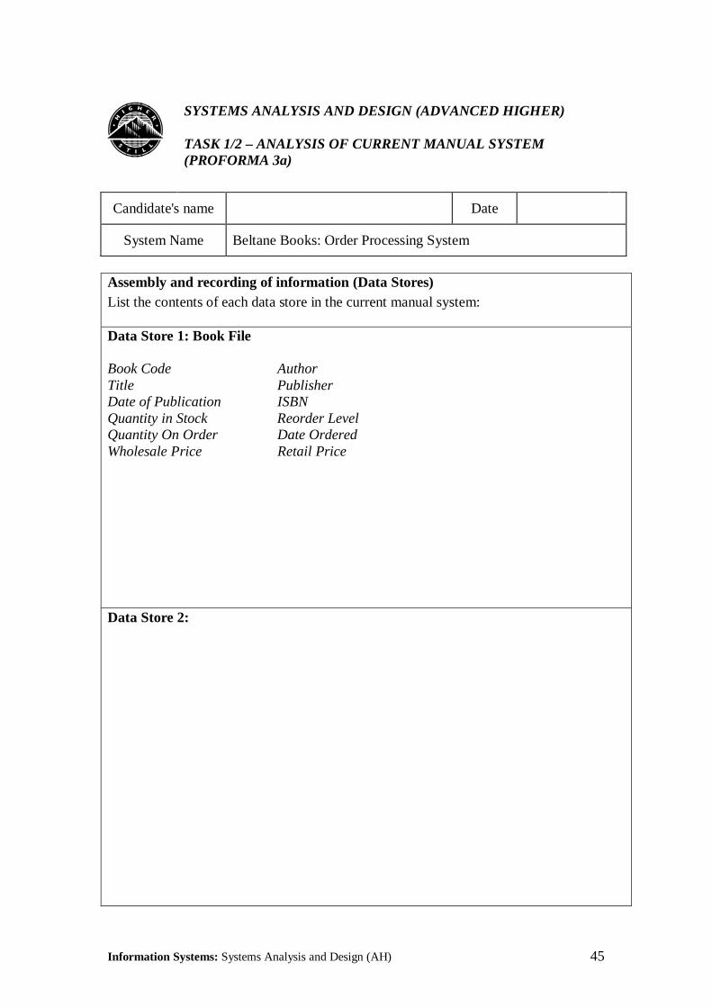
Assembly and recording of information (Data Stores)List the contents of each data store in the current manual system:
Data Store 1: Book File
Book Code AuthorTitle PublisherDate of Publication ISBNQuantity in Stock Reorder LevelQuantity On Order Date OrderedWholesale Price Retail Price
Data Store 2:

Information Systems: Systems Analysis and Design (AH) 46
������SYSTEMS ANALYSIS AND DESIGN (ADVANCED HIGHER)
TASK 1/2 – ANALYSIS OF CURRENT MANUAL SYSTEM(PROFORMA 3b)
Candidate's name Date
System Name Beltane Books: Order Processing System
Assembly and recording of information (Processes)Give a brief description of each process in the current manual system:
Process 1: Order Entry
Most customers submit their orders on a standard Order Form (Doc1). If the customerphones in an order, it is taken down on the standard Order Form.
The Order Forms are then passed to the Order Processing Department.
Process 2: Order Processing
Details of the books in stock are held on Book Cards (Doc 2), filed in Book Code order.
If a book is in stock, a Despatch Note (Doc3) is passed to the Despatch Department andthe quantity in stock on the Book Card is decreased by the quantity ordered.
If the quantity remaining in stock is less than the Reorder Level, a Reorder Request(Doc4) is sent to Book Orders.
If a book is not in stock a Book Unavailable Note (Doc5) is sent to the customer.
Information Systems: Systems Analysis and Design (AH) 47
������SYSTEMS ANALYSIS AND DESIGN (ADVANCED HIGHER)
TASK 1/2 – ANALYSIS OF CURRENT MANUAL SYSTEM(PROFORMA 3b)
Candidate's name Date
System Name Beltane Books: Order Processing System
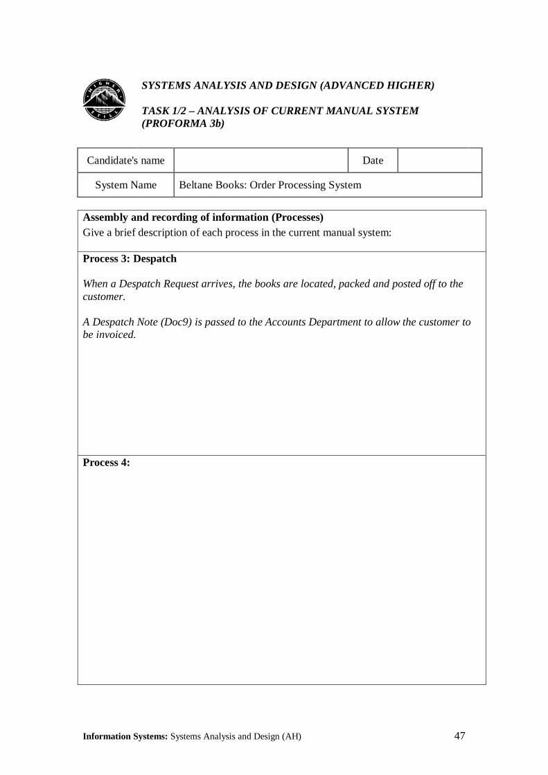
Assembly and recording of information (Processes)Give a brief description of each process in the current manual system:
Process 3: Despatch
When a Despatch Request arrives, the books are located, packed and posted off to thecustomer.
A Despatch Note (Doc9) is passed to the Accounts Department to allow the customer tobe invoiced.
Process 4:
Information Systems: Systems Analysis and Design (AH) 48
Identifying User RequirementsThe user requires that the new system should be able to carry out the same tasks as theexisting system, but with improved efficiency.
The system must be able to:
• Accept orders submitted by Customers on a standard Order Form, or by letter, fax, ortelephone;
• Fill Customer Orders, update the Book File and supply details of books to Despatch;
• Notify Book Orders of books requiring reordered;
• Notify Customer of unavailable books;
• Despatch books to customers;
• Notify Accounts Department of despatches to allow the customer to be invoiced.
This information should now be transferred to Proforma 4 (overleaf).
This completes the Systems Analysis component of the Case Study. We are now ready toproceed to Systems Design.

Information Systems: Systems Analysis and Design (AH) 49
������SYSTEMS ANALYSIS AND DESIGN (ADVANCED HIGHER)
TASK 1/2 – ANALYSIS OF CURRENT MANUAL SYSTEM(PROFORMA 4)
Candidate's name Date
System Name Beltane Books: Order Processing System
Identification of user requirementsList the user requirements for the new system:
User Requirements:
• Accept orders submitted by Customers on a standard Order Form, or by letter, fax, ortelephone;
• Fill Customer Orders, update the Book File and supply details of books to Despatch;
• Notify Book Orders of books requiring reordered;
• Notify Customer of unavailable books;
• Despatch books to customers;
• Notify Accounts Department of despatches to allow the customer to be invoiced.

Information Systems: Systems Analysis and Design (AH) 50

Information Systems: Systems Analysis and Design (AH) 51
OUTCOME 3: DESIGNING A COMPUTERISED INFORMATION SYSTEM
This part of the course involves the design of a computerised information system. Onceagain, the system considered should be simple and familiar. We will continue with theBeltane Books Case Study.
The system specification consists of a system outline (inputs, files, processes and outputs),data flow diagrams, a data dictionary and file structures (showing field size and type).Only first-level data flow diagrams are required.
Students are not required to normalise files. Where normalised files are required toproduce a meaningful system, details of these should be supplied by the tutor. Thesedetails should consist of a list of the data items to be included in each file. It should be leftto the student to determine the size and type of each data item.

Information Systems: Systems Analysis and Design (AH) 52
3.1 System SpecificationThe System Specification consists of a System Outline, Data Flow Diagrams and a DataDictionary. These are given overleaf on Proformas 1a, 1b and 1c. The file structures areshown on Proforma 2.
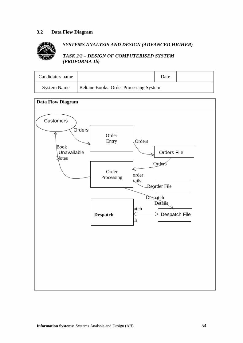
System OutlineAs with the manual system, the only Source of information is the Customers who submitBook Orders. The only Destination is the Customers who receive books. However, someof the Destinations shown in the manual system (e.g. Accounts Department and BookOrders) will eventually make use of information which is now stored in files. This takesplace outwith the boundaries of the Order Processing system.
The biggest change from the manual system is the number of Stores or files involved. Theonly file used in the manual system was the Book File. This continues to exist in thecomputer system and has virtually the same format (see Proforma 2b). This is read andupdated by the Order Processing process.
Customer details are now held on a Customer File (Proforma 2a). This is assumed to bemaintained outwith the Order Processing System. The Despatch process accesses this filein order to obtain address information to send books out to Customers.
Customer Orders are now written to an Orders File (Proforma2c). This is written by theOrder Entry process and will contain all orders, whether received as Order Forms or byletter, telephone or fax. It is read by the Order Processing process.
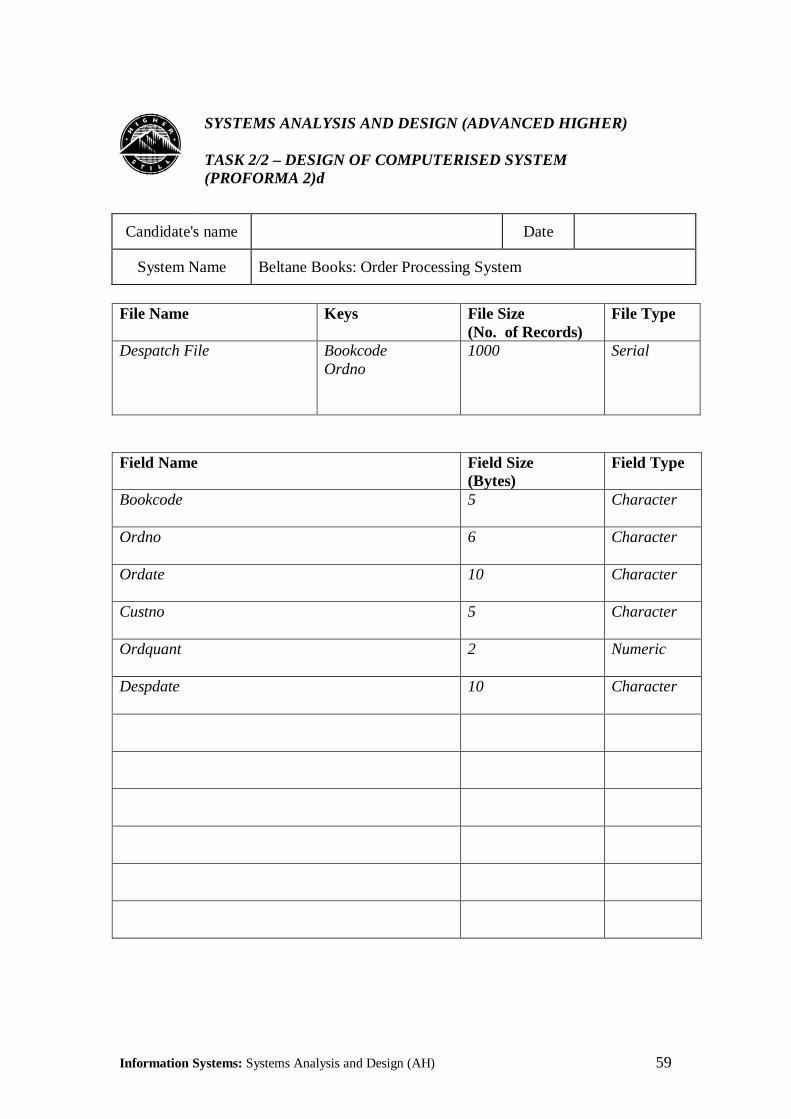
Details of the books to be despatched to customers are held on the Despatch File(Proforma 2d). This is almost identical in format to the Orders File, but has an additionalfield to hold the Despatch Date. It is written by the Orders Processing process.
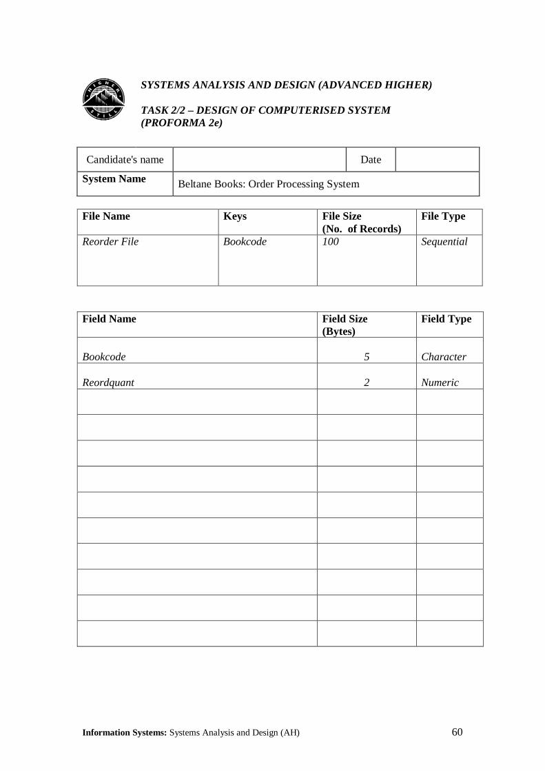
Details of books to be reordered are written to the Reorder File (Proforma 2e) by the OrderProcessing process. This information can be accessed by Book Orders who do the actualreordering, outwith the Order Processing system. Note: reordering of goods is anotoriously difficult process to automate. Requests must be examined manually to seewhether or not reordering is advisable. For example, if a book is declining in popularity, itmay be as well to cancel the reorder, or reduce the reorder quantity. On the other hand, ifa book is selling better than expected it may be useful to increase the reorder quantity.
There are three Processes in the new system:
Order Entry: writes all Orders (however received) to the Orders File.
Order Processing: checks whether book is in stock and if so, updates the Stock Quantityon the Book File and writes a record to the Despatch File. If the Stock Quantity dropsbelow the Reorder Level, a Reorder Request is written to the Reorder File.
Despatch: locates books, packs them and sends them to the customer. Updates theDespatch File with the Despatch Date. (This file can be used later to generate invoices,but this is outwith the boundary of the Order Processing system.)
Information Systems: Systems Analysis and Design (AH) 53
������SYSTEMS ANALYSIS AND DESIGN (ADVANCED HIGHER)
TASK 2/2 – DESIGN OF COMPUTERISED SYSTEM(PROFORMA 1a)
Candidate's name Date
System Name Beltane Books: Order Processing System
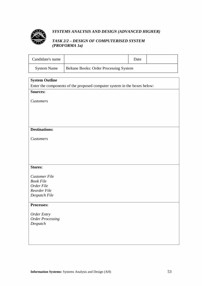
System OutlineEnter the components of the proposed computer system in the boxes below:
Sources:
Customers
Destinations:
Customers
Stores:
Customer FileBook FileOrder FileReorder FileDespatch File
Processes:
Order EntryOrder ProcessingDespatch
Information Systems: Systems Analysis and Design (AH) 54
3.2 Data Flow Diagram
������SYSTEMS ANALYSIS AND DESIGN (ADVANCED HIGHER)
TASK 2/2 – DESIGN OF COMPUTERISED SYSTEM(PROFORMA 1b)
Candidate's name Date
System Name Beltane Books: Order Processing System
Data Flow Diagram
Orders
Orders Book Unavailable Orders File Notes Orders
Reorder Details Reorder File
Despatch Details Despatch Despatch File Details
Customers
OrderEntry
OrderProcessing
Despatch
Information Systems: Systems Analysis and Design (AH) 55
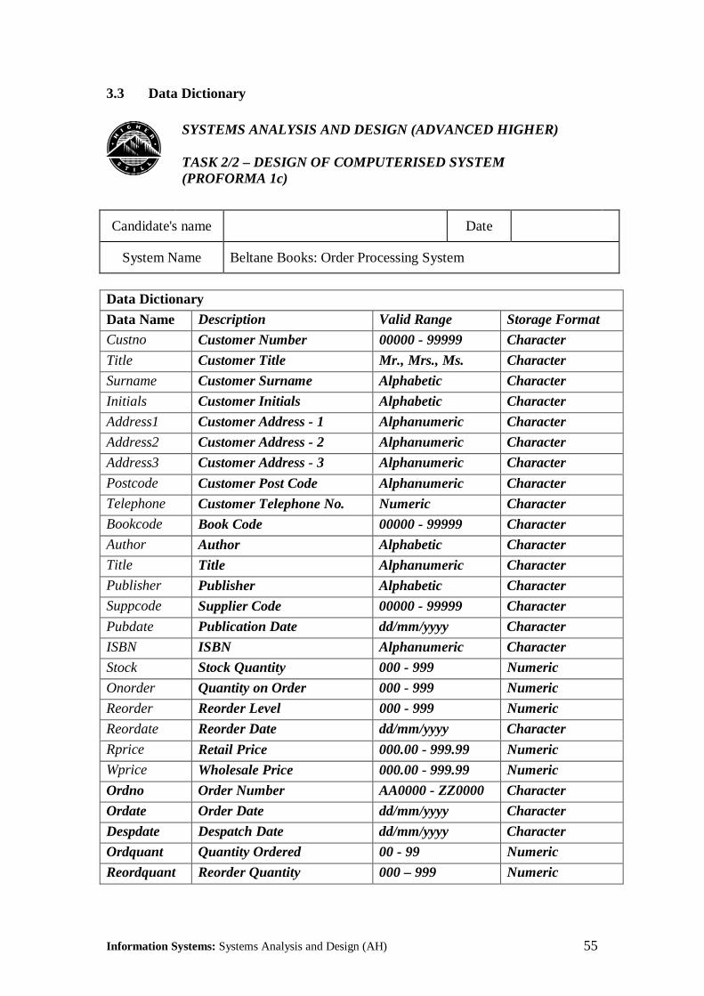
3.3 Data Dictionary
������SYSTEMS ANALYSIS AND DESIGN (ADVANCED HIGHER)
TASK 2/2 – DESIGN OF COMPUTERISED SYSTEM(PROFORMA 1c)
Candidate's name Date
System Name Beltane Books: Order Processing System
Data DictionaryData Name Description Valid Range Storage FormatCustno Customer Number 00000 - 99999 Character
Title Customer Title Mr., Mrs., Ms. Character
Surname Customer Surname Alphabetic Character
Initials Customer Initials Alphabetic Character
Address1 Customer Address - 1 Alphanumeric Character
Address2 Customer Address - 2 Alphanumeric Character
Address3 Customer Address - 3 Alphanumeric Character
Postcode Customer Post Code Alphanumeric CharacterTelephone Customer Telephone No. Numeric CharacterBookcode Book Code 00000 - 99999 CharacterAuthor Author Alphabetic CharacterTitle Title Alphanumeric CharacterPublisher Publisher Alphabetic CharacterSuppcode Supplier Code 00000 - 99999 Character
Pubdate Publication Date dd/mm/yyyy Character
ISBN ISBN Alphanumeric Character
Stock Stock Quantity 000 - 999 Numeric
Onorder Quantity on Order 000 - 999 Numeric
Reorder Reorder Level 000 - 999 Numeric
Reordate Reorder Date dd/mm/yyyy Character
Rprice Retail Price 000.00 - 999.99 NumericWprice Wholesale Price 000.00 - 999.99 Numeric
Ordno Order Number AA0000 - ZZ0000 Character
Ordate Order Date dd/mm/yyyy Character
Despdate Despatch Date dd/mm/yyyy Character
Ordquant Quantity Ordered 00 - 99 Numeric
Reordquant Reorder Quantity 000 – 999 Numeric
Information Systems: Systems Analysis and Design (AH) 56
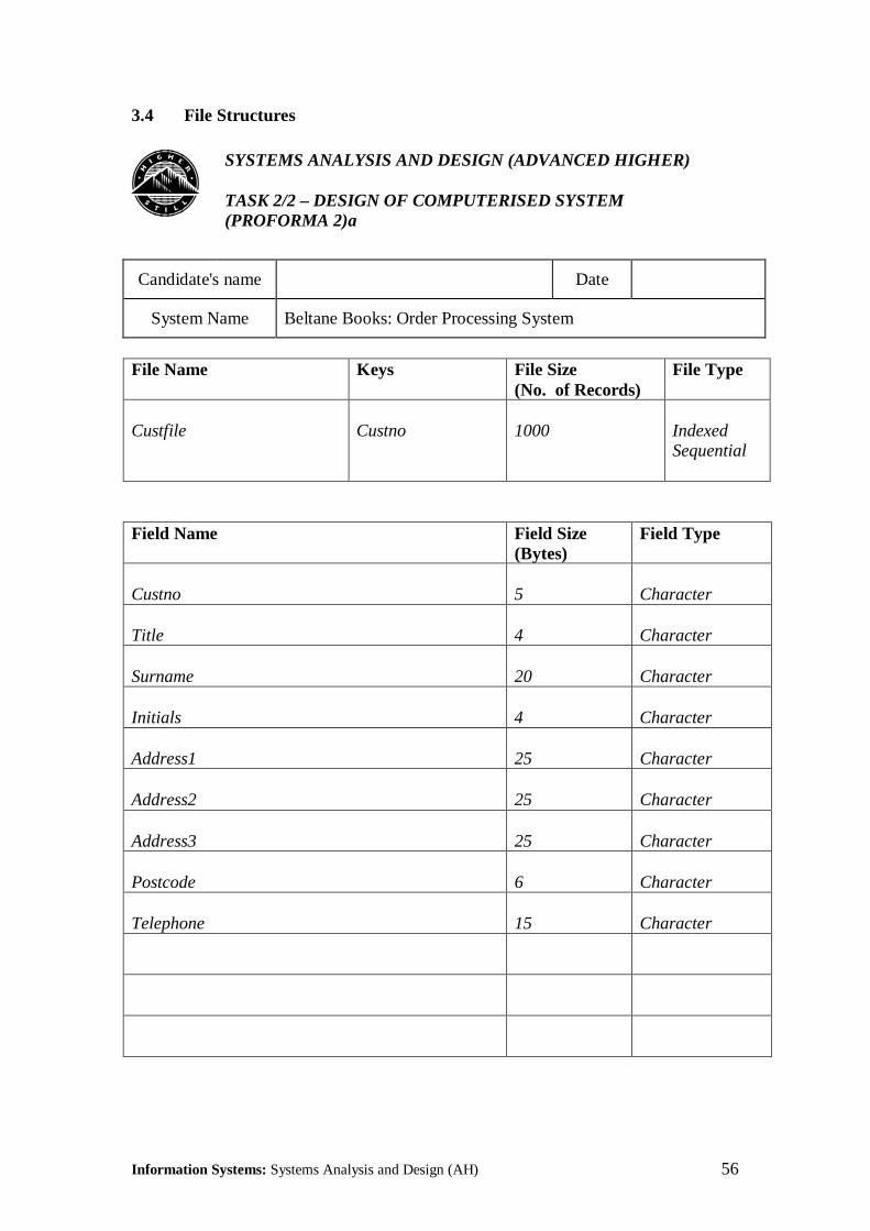
3.4 File Structures
������SYSTEMS ANALYSIS AND DESIGN (ADVANCED HIGHER)
TASK 2/2 – DESIGN OF COMPUTERISED SYSTEM(PROFORMA 2)a
Candidate's name Date
System Name Beltane Books: Order Processing System
File Name Keys File Size(No. of Records)
File Type
Custfile Custno 1000 IndexedSequential
Field Name Field Size(Bytes)
Field Type
Custno 5 Character
Title 4 Character
Surname 20 Character
Initials 4 Character
Address1 25 Character
Address2 25 Character
Address3 25 Character
Postcode 6 Character
Telephone 15 Character
Information Systems: Systems Analysis and Design (AH) 57
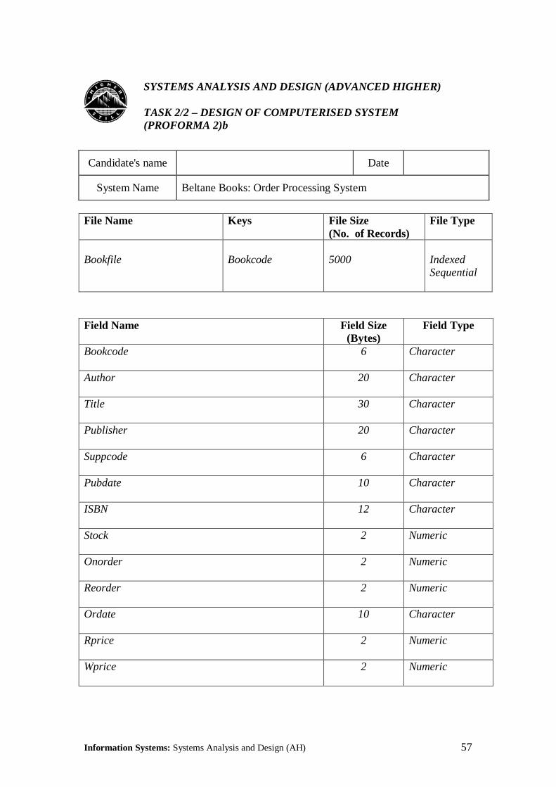
������SYSTEMS ANALYSIS AND DESIGN (ADVANCED HIGHER)
TASK 2/2 – DESIGN OF COMPUTERISED SYSTEM(PROFORMA 2)b
Candidate's name Date
System Name Beltane Books: Order Processing System
File Name Keys File Size(No. of Records)
File Type
Bookfile Bookcode 5000 IndexedSequential
Field Name Field Size(Bytes)
Field Type
Bookcode 6 Character
Author 20 Character
Title 30 Character
Publisher 20 Character
Suppcode 6 Character
Pubdate 10 Character
ISBN 12 Character
Stock 2 Numeric
Onorder 2 Numeric
Reorder 2 Numeric
Ordate 10 Character
Rprice 2 Numeric
Wprice 2 Numeric

Information Systems: Systems Analysis and Design (AH) 58
������SYSTEMS ANALYSIS AND DESIGN (ADVANCED HIGHER)
TASK 2/2 – DESIGN OF COMPUTERISED SYSTEM(PROFORMA 2)c
Candidate's name Date
System Name Beltane Books: Order Processing System
File Name Keys File Size(No. of Records)
File Type
Order File BookcodeOrdno
1000 Serial
Field Name Field Size(Bytes)
Field Type
Bookcode 5 Character
Ordno 6 Character
Ordate 10 Character
Custno 5 Character
Ordquant 2 Numeric
Information Systems: Systems Analysis and Design (AH) 59
������SYSTEMS ANALYSIS AND DESIGN (ADVANCED HIGHER)
TASK 2/2 – DESIGN OF COMPUTERISED SYSTEM(PROFORMA 2)d
Candidate's name Date
System Name Beltane Books: Order Processing System
File Name Keys File Size(No. of Records)
File Type
Despatch File BookcodeOrdno
1000 Serial
Field Name Field Size(Bytes)
Field Type
Bookcode 5 Character
Ordno 6 Character
Ordate 10 Character
Custno 5 Character
Ordquant 2 Numeric
Despdate 10 Character
Information Systems: Systems Analysis and Design (AH) 60
������SYSTEMS ANALYSIS AND DESIGN (ADVANCED HIGHER)
TASK 2/2 – DESIGN OF COMPUTERISED SYSTEM(PROFORMA 2e)
Candidate's name Date
System Name Beltane Books: Order Processing System
File Name Keys File Size(No. of Records)
File Type
Reorder File Bookcode 100 Sequential
Field Name Field Size(Bytes)
Field Type
Bookcode 5 Character
Reordquant 2 Numeric