Bridging advanced glycation end product, receptor for advanced glycation
Upload
khangminh22Category
view
2download
0
Software Modeling Advanced
ENTERPRISE ARCHITECT
User Guide Series
Author: Sparx Systems & Stephen Maguire
Date: 2022-06-29
Version: 16.0
CREATED WITH

Table of Contents
Information Engineering 7Getting Started 8Example Diagram 10Working with Data Model Types 11
Conceptual Data Model 12Entity Relationship Diagrams (ERDs) 13Logical Data Model 17Physical Data Models 18DDL Transformation 20
Creating and Managing Data Models 24Create a Data Model from a Model Pattern 25Create a Data Model Diagram 27
Example Data Model Diagram 29The Database Builder 30
Opening the Database Builder 32Working in the Database Builder 34Columns 38
Create Database Table Columns 39Delete Database Table Columns 41Reorder Database Table Columns 42
Constraints/Indexes 43Database Table Constraints/Indexes 44
Primary Keys 47Database Indexes 50Unique Constraints 53Foreign Keys 54Check Constraints 58Table Triggers 59
SQL Scratch Pad 61Database Compare 63Execute DDL 69
Database Objects 72Database Tables 73
Create a Database Table 75Database Table Columns 77
Create Database Table Columns 78Delete Database Table Columns 80Reorder Database Table Columns 81
Working with Database Table Properties 82Set the Database Type 83Set Database Table Owner/Schema 84Set MySQL Options 85Set Oracle Database Table Properties 86
Database Table Constraints/Indexes 87Primary Keys 90
Non Clustered Primary Keys 93Database Indexes 94

Unique Constraints 97Foreign Keys 98Check Constraints 102Table Triggers 103
Database Views 105Database Procedures 107Database Functions 109Database Sequences 111Database SQL Queries 113Create Operation Containers 115Oracle Packages 117Database Connections 118
Manage DBMS Options 121Data Types 123
Map Data Types Between DBMS Products 124DBMS Product Conversion for a Package 125Data Type Conversion For a Table 126Database Datatypes 127
MySQL Data Types 129Oracle Data Types 130
Data Modeling Settings 131Data Modeling Notations 132DDL Name Templates 137
Import Database Schema 139Generate Database Definition Language (DDL) 142
Generate DDL For Objects 143Edit DDL Templates 147DDL Template Syntax 149
DDL Templates 150Base Templates for DDL Generation 151Base Templates for Alter DDL Generation 154
DDL Macros 155Element Field Macros 156Column Field Macros 159Constraint Field Macros 160
DDL Function Macros 162DDL Property Macros 167DDL Options in Templates 173
DDL Limitations 176Supported Database Management Systems 178More Information 179
XML Schema ( XSD ) 180Getting Started 182Example Diagram 183The Schema Composer 184
Schema Composer Profiles 186Create a Schema Profile 188Schema Compositions 190
Class Diagrams 196Schema Analysis 198
Generate Schema 199

Select a Schema Profile 200Generate Schema File 202CIM Schema Guide 204NIEM Schema Guide 206UPCC Schema Guide 208
Model Compositions 209Generate a Model Subset (Transform) 211UML Profile for Core Components (UPCC) 213
Available Frameworks 216Install a Core Framework 219The Schema Importer 222Schema Composer Automation Integration 224Schema Composer Addin Integration 225Schema Composer Scripting Integration 226MDG Technologies - UML Profile Extensions 231
XSD Models 233Modeling XSD 234
XSD Diagrams 236Schema Package 237Global Element 239Local Element 241Global Attribute 243Local Attribute 245Attribute Group 247Complex Type 249Simple Type 251Group 253Any 255Any Attribute 257Union 259Model Group 261Enumeration 263
XML from Abstract Class Models 265Default UML to XSD Mappings 267
Generate XSD 269Generate Global Element 271
Import XSD 272Global Element and ComplexType 274
XSL Transforms 275Model an XSL Transformation 277Execute an XSL Transformation 279Debug an XSL Transformation 280
XML Validation 281XML Service Oriented Architecture 284
WSDL 285WSDL 1.1 Model Structure 286Model WSDL 288
WSDL Namespace 291WSDL Message 293
WSDL Message Part 295WSDL Port Type 297
WSDL Port Type Operation 299WSDL Binding 302
WSDL Binding Operation 304WSDL Service 307WSDL Document 309
Generate WSDL 311Import WSDL 313
SoaML 314SoaML Toolbox Pages 316
SOMF 2.1 319National Information Exchange Modeling (NIEM) 2.1 320National Information Exchange Modeling (NIEM) 327
UML Profile for NIEM 328Download the NIEM Reference Model 337
Creating a NIEM IEPD 338Customize Your IEPD Model 341NIEM IEPD Generation 345
Creating a NIEM Data Model 346Subsetting NIEM with the Schema Composer 348
Walk Through Examples 351Example NIEM Schema 355
Import NIEM XML Schema 363Geospatial Models 365
Getting Started 366ArcGIS Geodatabases 367
Example Diagram 368Exporting ArcGIS XML Workspaces 369Importing ArcGIS XML Workspaces 371
Geography Markup Language (GML) 373Example Diagram 374Modeling with GML 375
More Information 377

Software Modeling Advanced 29 June, 2022
(c) Sparx Systems 2022 Page 6 of 378 Created with Enterprise Architect

Software Modeling Advanced 29 June, 2022
Information Engineering
Design, Create and Manage Conceptual, Logical and Physical Data Models
The power of model-based system development is the ability to visualize, analyze and design all aspects of a system.Being able to view and manage information and data alongside other models of a system provides great clarity andreduces the chance of error. Enterprise Architect has extensive support for the data modeling discipline, ranging from therepresentation of information in a conceptual model right down to the generation of database objects. Whether you aregenerating database objects from the UML model or reverse engineering legacy DBMS into a model for analysis, thetool features will save time and valuable project resources.
This illustration shows the Database Builder Interface including DDL Generation and the Foreign Key dialog.
Enterprise Architect supports the modeling of information at the conceptual, logical and physical layers. Using a numberof standard features, these models can be interconnected, providing traceability. The logical and physical models can alsobe generated automatically using a fully customizable Transformation engine. Legacy systems can be imported, analyzedand compared using the handy reverse engineering facility.
In this topic you will learn how to use the feature rich toolset including the Database Builder to design, create, manage,visualize data including reverse and forward engineering of data models to live database.
The Database Builder tool can be used to create and maintain physical data models and can connect to a running DBMS,so you can therefore import, generate, compare and alter a live database.
(c) Sparx Systems 2022 Page 7 of 378 Created with Enterprise Architect

Software Modeling Advanced 29 June, 2022
Getting Started
Information Modelers, Data Modelers and Architects are responsible for creating models of an organization’sinformation that span multiple levels of abstraction, from conceptual through to logical and physical. The conceptualmodels are technology independent and can be used for discussions with business people and domain experts, allowingthe basic concepts in the domain to be represented, discussed and agreed upon. The logical model elaborates theconceptual model, adding more detail and precision but is still typically technology neutral, allowing InformationAnalysts to discuss and agree on logical structures. The physical model applies technology specific data to the modelsand allows engineers to discuss and agree on technology decisions in preparation for generation to a target environment,such as a database management system.
Selecting the Perspective
Enterprise Architect partitions the tool's extensive features into Perspectives, which ensures that you can focus on aspecific task and work with the tools you need without the distraction of other features. To work with the Data Modelingfeatures you first need to select one of these Perspectives:
<perspective name> > Database Engineering > Database Engineering
<perspective name> > Database Engineering > Entity Relationships
Setting the Perspective ensures that the Case Management Model and Notation diagrams, their tool boxes and otherfeatures of the Perspective will be available by default.
Example Diagram
An example diagram provides a visual introduction to the topic and allows you to see some of the important elementsand connectors that are created in specifying or describing the way a data model is defined including: Tables, Views,Procedures, Sequences, Functions.
Data Model Types
Information can be modeled at a number of level of abstraction starting with a conceptual model that is typically createdby or for business people, a Logical model which is used by business and systems analysts and a physical model which isthe concern of the technologists such as database engineers. In this topic you will learn how to manage all three levels ofinformation models.
Creating and Managing Data Models
In this topic you will learn how to work in detail using Enterprise Architect to manage your Physical Database schema.This includes the use of the Database Builder tool which allows you to interact with any number of live database throughan ODBC connection.
Import Database Schema
This topic will show you how to connect to a live database including Production, Test and Development systems andreverse engineer the database into a model creating Tables, Views, Procedures, Declarative Referential Integrity andmore. A diagram of the database is automatically created and the elements such as tables can be related to other elementsin the model including Conceptual and Logical Models, Programming classes tests and more.
(c) Sparx Systems 2022 Page 8 of 378 Created with Enterprise Architect

Software Modeling Advanced 29 June, 2022
Generate Database Definition Language (DDL)
In this topic you will learn how to harness the power of the data models by generating Database Definition Languagecode directly from the model. Enterprise Architect can generate code into a wide range of Database Managementsystems.
Supported Database Management Systems
Enterprise Architect has rich support for most of the main stream Database Management Systems (DBMS). This featureallows models from disparate systems to be compared either for code generation or for analysis by using the importfeature. This topic lists the supported DBMS and
More Information
This section provides useful links to other topics and resources that you might find useful when working with the DataModeling tool features.
(c) Sparx Systems 2022 Page 9 of 378 Created with Enterprise Architect

Software Modeling Advanced 29 June, 2022
Example Diagram
Using the Database engineering features of Enterprise Architect you can create rich models of the objects that make up adata model at any level of abstraction from Conceptual through Logical to Physical. These models are created by addingtables and other database objects from the toolbox or by reverse engineering and existing database into a model from arange of RDBMSs. A database diagram can contain Tables, VIews, Procedures, Sequences and Functions. TableColumns are annotated as Primary and Foreign Keys are modeled using specialized association relationships. In thisexample the user has created a simple physical data model of Customers and their Addresses and Orders.
Physical Data model showing Tables with Columns and Primary and Foreign Keys.
(c) Sparx Systems 2022 Page 10 of 378 Created with Enterprise Architect

Software Modeling Advanced 29 June, 2022
Working with Data Model Types
Enterprise Architect provides a number of features to assist in the process of creating models of information, includingthe ability to develop conceptual, logical and physical models and to be able to trace the underlying concepts between themodels. The physical models can be developed for a wide range of database systems, and forward and reverseengineering allows these models to be synchronized with live databases.
Data Models
Type Description
Conceptual Data Models Conceptual data models, also called Domain models, establish the basic conceptsand semantics of a given domain and help to communicate these to a wide audienceof stakeholders.
Conceptual models also serve as a common vocabulary during the analysis stagesof a project; they can be created in Enterprise Architect using Entity-Relationshipor UML Class models.
Logical Data Models Logical data models add further detail to conceptual model elements and refine thestructure of the domain; they can be defined using Entity-Relationship or UMLClass models.
One benefit of a Logical data model is that it provides a foundation on which tobase the Physical model and subsequent database implementation.
Entity-relationship modeling is an abstract and conceptual database modelingmethod, used to produce a schema or semantic data model of, for example, arelational database and its requirements, visualized in Entity-Relationship Diagrams(ERDs).
ERDs assist you in building conceptual data models through to generating DataDefinition Language (DDL) for the target DBMS.
A Logical model can be transformed to a Physical data model using a DDLTransformation.
Physical Data Models Physical data models in Enterprise Architect help you visualize your databasestructure and automatically derive the corresponding database schema; you useEnterprise Architect's UML Profile for Data Modeling specifically for this purpose.
The profile provides useful extensions of the UML standard that map databaseconcepts of Tables and relationships onto the UML concepts of Classes andAssociations; you can also model database columns, keys, constraints, indexes,triggers, referential integrity and other relational database features.
Because Enterprise Architect helps you visualize each type of data model in thesame repository, you can easily manage dependencies between each level ofabstraction to maximize traceability and verify completeness of systemimplementation.
(c) Sparx Systems 2022 Page 11 of 378 Created with Enterprise Architect

Software Modeling Advanced 29 June, 2022
Conceptual Data Model
A Conceptual data model is the most abstract form of data model. It is helpful for communicating ideas to a wide rangeof stakeholders because of its simplicity. Therefore platform-specific information, such as data types, indexes and keys,is omitted from a Conceptual data model. Other implementation details, such as procedures and interface definitions, arealso excluded.
This is an example of a Conceptual data model, rendered using two of the notations supported by Enterprise Architect.
Entity Relationship diagram showing a One-to-Many relationship
Using Entity-Relationship (ER) notation, we represent the data concepts 'Customers' and 'Customers Addresses' asEntities with a 1-to-many relationship between them. We can represent exactly the same semantic information usingUML Classes and Associations.
Unified Modeling Lnaguage diagram showing the same One-to_many Relationship
Whether you use UML or ER notation to represent data concepts in your project depends on the experience andpreferences of the stakeholders involved. The detailed structure of the data concepts illustrated in a Conceptual datamodel is defined by the Logical data model.
(c) Sparx Systems 2022 Page 12 of 378 Created with Enterprise Architect

Software Modeling Advanced 29 June, 2022
Entity Relationship Diagrams (ERDs)
According to the online Wikipedia:
An entity-relationship model (ERM) is an abstract and conceptual representation of data. Entity-relationship modeling isa database modeling method, used to produce a type of conceptual schema or semantic data model of a system, often arelational database, and its requirements in a top-down fashion. Diagrams created by this process are calledEntity-Relationship Diagrams, ER Diagrams, or ERDs.
Entity Relationship Diagrams in Enterprise Architect
Entity Relationship diagrams in Enterprise Architect are based on Chen's ERD building blocks: entities (tables) arerepresented as rectangles, attributes (columns) are represented as ellipses (joined to their entity) and relationshipsbetween the entities are represented as diamond-shape connectors.
ERD technology in Enterprise Architect assists you in every stage from building conceptual data models to generatingData Definition Language (DDL) for the target DBMS.
ERD and ERD Transformations
Enterprise Architect enables you to develop Entity Relationship diagrams quickly and simply, through use of an MDGTechnology integrated with the Enterprise Architect installer.
The Entity Relationship diagram facilities are provided in the form of:
An Entity Relationship diagram type, accessed through the 'New Diagram' dialog·An Entity Relationship Diagram page in the Diagram Toolbox·Entity Relationship element and relationship entries in the 'Toolbox Shortcut' menu and Quick Linker·
Enterprise Architect also provides transformation templates to transform Entity Relationship diagrams into DataModeling diagrams, and vice versa.
Entity Relationship Diagram Toolbox Page
You can access the 'Entity Relationship Diagram' page of the Diagram Toolbox by specifying 'Entity RelationshipDiagrams' in the Toolbox 'Find Toolbox Item' dialog
(c) Sparx Systems 2022 Page 13 of 378 Created with Enterprise Architect

Software Modeling Advanced 29 June, 2022
Entity is an object or concept that is uniquely identifiable; the property of 'Multiplicity' in the SourceRole and·TargetRole definitions for the Relationship connector can be used to define the cardinality of an Entity thatparticipates in this relationship
Attribute is a property of an entity or a relationship type·N-ary Association represents unary (many-to-many recursive) or ternary relationships and can also be used to·represent relationships that have attributes among the entities; the N-ary Association element should always be at thetarget end of a connector
Connector is a connector between an Entity and an Attribute, and between two Attributes·Relationship is a diamond-shape connector, representing the meaningful association among entities·Disjoint and Overlapping represent the relationships between the super-class Entity and the sub-class Entity·
A typical Entity Relationship diagram
(c) Sparx Systems 2022 Page 14 of 378 Created with Enterprise Architect

Software Modeling Advanced 29 June, 2022
Tagged Values
Some of the Entity Relationship diagram components can be modified by Tagged Values, as indicated:
Component Tagged Value / Notes
Entity isWeakEntity
Notes: If true, this entity is a weak entity.
Attribute attributeType
Notes: There are four valid options: 'normal', 'primary key', 'multi-valued' and'derived'
Attribute commonDataType
Notes: Defines the common data type for each attribute.
(c) Sparx Systems 2022 Page 15 of 378 Created with Enterprise Architect

Software Modeling Advanced 29 June, 2022
Attribute dbmsDataType
Notes: Defines the customized DBMS data type for each attribute. This option isonly available when the commonDataType tag is set to 'na'.
You must define the customized type first through the 'Settings > Reference Data >Settings > Database Datatypes' ribbon option.
N-ary Association isRecursive
Notes: If true, the N-ary Association represents the many-to-many recursiverelationship.
For one-to-many and one-to-one recursive relationships, we suggest using thenormal Relationship connector.
Sometimes you might want to limit the stretch of the diamond-shape Relationshipconnectors; simply pick a Relationship connector, right-click to display the contextmenu, and select the 'Bend Line at Cursor' option.
Relationship isWeak
Notes: If true, the Relationship is a weak relationship.
Disjoin
Overlapping
Participation
Notes: There are two valid options, 'partial' and 'total'.
Notes
Entity Relationship diagrams are supported in the Corporate, Unified and Ultimate Editions of Enterprise Architect·
(c) Sparx Systems 2022 Page 16 of 378 Created with Enterprise Architect

Software Modeling Advanced 29 June, 2022
Logical Data Model
Logical data models help to define the detailed structure of the data elements in a system and the relationships betweendata elements. They refine the data elements introduced by a Conceptual data model and form the basis of the Physicaldata model. In Enterprise Architect, a Logical data model is typically represented using the UML Class notation.
Example
The following diagram is a simple example of a Logical data model. The Logical Model adds detail to the ConceptualModel but without going to the level of specifying the Database Management System that will be used.
Conceptual Data Model with tables modeling Customers and their Addresses.
Note that the data elements 'Customers' and 'Customers Addresses' contain UML attributes; the names and generic datatypes to remain platform-independent. Platform-specific data types and other metadata that relate to a specific DBMSimplementation are defined by the Physical data model.
(c) Sparx Systems 2022 Page 17 of 378 Created with Enterprise Architect

Software Modeling Advanced 29 June, 2022
Physical Data Models
A Physical Data Model visually represents the structure of data as implemented by a relational database schema. Inaddition to providing a visual abstraction of the database structure, an important benefit of defining a Physical DataModel is that you can automatically derive the database schema from the model. This is possible due to the richness ofmetadata captured by a Physical Data Model and its close mapping to aspects of the database schema, such as databaseTables, columns, Primary Keys and Foreign Keys.
Example Data Model
This example shows a Physical Data Model that could be used to automatically generate a database schema. Each Tableis represented by a UML Class; Table columns, Primary Keys and Foreign Keys are modeled using UML attributes andoperations. This model demonstrates the use of the Information Engineering connector style.
Notation
The example model is defined using Enterprise Architect's UML Profile for Data Modeling; the relationship between theTables uses the default Information Engineering notation.
Information Engineering is one of three notations that Enterprise Architect supports to help Data Modelers identifycardinality in relationships. You can change the notation by selecting the 'Design > Diagram > Manage > Properties'ribbon option, clicking on the 'Connectors' page and selecting the required option in the 'Connector Notation' drop-downlist. You would most probably change the notation to IDEFX1, but the UML2.1 notation is also available.
Default DBMS
Prior to creating a Physical Data Model it is advisable for you to set the default DBMS for the project. Setting a defaultDBMS ensures that all new database elements that are created on diagrams are automatically assigned the defaultDBMS.
If the default DBMS is not set, new Tables are created without a DBMS assigned, this restricts Enterprise Architect'sability to model the physical objects correctly. For example Enterprise Architect is unable to determine the correct list ofdatatypes for columns.
You can set the default DBMS type using:
'Start > Appearance > Preferences > Preferences > Source Code Engineering > Code Editors', or·'Settings > Reference Data > Settings > Database Datatypes or·
(c) Sparx Systems 2022 Page 18 of 378 Created with Enterprise Architect

Software Modeling Advanced 29 June, 2022
'Develop > Data Modeling > Datatypes or·The second data entry field in the Code Generation Toolbar·
Note: When modeling via the Database Builder the default DBMS is defined at the model level (as a Tagged Value'DBMS' against the <<Database>> Package) instead of at the project level, thereby allowing for greater flexibility whenprojects involve multiple DBMSs.
(c) Sparx Systems 2022 Page 19 of 378 Created with Enterprise Architect

Software Modeling Advanced 29 June, 2022
DDL Transformation
The DDL transformation converts the logical model to a data model structured to conform to one of the supportedDBMSs. The target database type is determined by which DBMS is set as the default database in the model (see theDatabase Datatypes Help topic, 'Set As Default' option). The data model can then be used to automatically generateDDL statements to run in one of the system-supported database products.
The DDL transformation uses and demonstrates support in the intermediary language for a number of database-specificconcepts.
Concepts
Concept Effect
Table Mapped one-to-one onto Class elements.
'Many-to-many' relationships are supported by the transformation, creating Jointables.
Column Mapped one-to-one onto attributes.
Primary Key Lists all the columns involved so that they exist in the Class, and creates a PrimaryKey Method for them.
Foreign Key A special sort of connector, in which the Source and Target sections list all of thecolumns involved so that:
The columns exist·A matching Primary Key exists in the destination Class, and·The transformation creates the appropriate Foreign Key·
MDG Technology to customize default mappings
DDL transformations that target a new, user defined DBMS require an MDG Technology to map the PIM data types tothe new target DBMS.
To do this, create an MDG Technology .xml file named 'UserDBMS Types.xml', replacing UserDBMS with the name ofthe added DBMS. Place the file in the EA\MDGTechnologies folder. The contents of the MDG Technology file shouldhave this structure:
<MDG.Technology version="1.0">
<Documentation id="UserdataTypes" name="Userdata Types" version="1.0" notes="DB Type mapping forUserDBMS"/>
<CodeModules>
<CodeModule language="Userdata" notes="">
<CodeOptions>
<CodeOption name="DBTypeMapping-bigint">BIGINT</CodeOption>
<CodeOption name="DBTypeMapping-blob">BLOB</CodeOption>
<CodeOption name="DBTypeMapping-boolean">TINYINT</CodeOption>
(c) Sparx Systems 2022 Page 20 of 378 Created with Enterprise Architect

Software Modeling Advanced 29 June, 2022
<CodeOption name="DBTypeMapping-text">CLOB</CodeOption>
...
</CodeOptions>
</CodeModule>
</CodeModules>
</MDG.Technology>
As an example, 'text' is a Common Type (as listed in the 'Database Datatypes' dialog) that maps to a new DBMS's'CLOB' data type.
Notes
You can define DBMS-specific aspects not depicted in a Logical model, such as Stored Procedures, Triggers, Views·and Check Constraints, after the transformation; see the Physical Data Model Help topic
Example
The PIM elements
(c) Sparx Systems 2022 Page 21 of 378 Created with Enterprise Architect

Software Modeling Advanced 29 June, 2022
After transformation, become the PSM elements
Generalizations are handled by providing the child element with a Foreign Key to the parent element, as shown.Copy-down inheritance is not supported.
(c) Sparx Systems 2022 Page 22 of 378 Created with Enterprise Architect

Software Modeling Advanced 29 June, 2022
(c) Sparx Systems 2022 Page 23 of 378 Created with Enterprise Architect

Software Modeling Advanced 29 June, 2022
Creating and Managing Data Models
Enterprise Architect is a fully featured database modeling platform that enables the user to work with their Physical Datamodels at all stages, from design right through to the implementation of the live database, for a wide range of databasemanagement systems such as Microsoft SQL Server, Oracle, PostgreSQL and MySQL.
This figure shows the starter model wizard patterns for database design for a range of RDBMS.
(c) Sparx Systems 2022 Page 24 of 378 Created with Enterprise Architect

Software Modeling Advanced 29 June, 2022
Create a Data Model from a Model Pattern
The easiest way to create a Data Modeling workspace is to use the predefined Database Model Patterns, availablethrough the Model Wizard (Start Page 'Create from Pattern' tab). Enterprise Architect provides a Pattern for each DBMSsupported by the system.
Access
Display the Model Wizard (Start Page 'Create from Pattern' tab) using any of the methods outlined here.
In the Model Wizard, select the 'Database Engineering' Perspective.
Ribbon Design > Package > Model Wizard
Context Menu Right-click on Package | Add a Model Using Wizard
Keyboard Shortcuts Ctrl+Shift+M
Other Browser window caption bar menu | New Model from Pattern
Create a Data Model
Field/Button Action
Add to Package Displays the name of the selected root Package.
Technology Click on 'Database'.
Name If necessary, expand the Database Engineering group of Patterns.
Click on the checkbox against each Database Management System you aresupporting in the model.
All Click on this button to select the checkboxes for all Database Engineering modeltypes and the Entity Relationship diagram, to include them all in the model.
None Click on this button to clear all selected checkboxes so that you can re-selectcertain checkboxes individually.
OK Click on this button to add to the Browser window the Packages and diagram foreach Database Management System you are modeling.
What each Data Modeling Pattern provides
A summary diagram of the model·A Report Specification Artifact element (on the summary diagram) that can be used to quickly document the data·
(c) Sparx Systems 2022 Page 25 of 378 Created with Enterprise Architect

Software Modeling Advanced 29 June, 2022
model
A Package for each of the Logical and Physical models·Within the Physical Model Package, a predefined hierarchy of sub-Packages, one for each object type supported by·the DBMS being modeled (such as Tables, Views, Procedures and Functions); these automatically organize thedatabase objects as they are added
The DBMS type for the workspace·A default owner·A Data Modeling diagram in each Package with the connector notation set to IDEF1X·
Notes
Once a data modeling workspace has been created, you can begin to develop your model in one of two ways:· - Through the Database Builder, which is a purpose-built view that supports database modelers - Through the Browser window and diagrams, which is the traditional method that might suit users who are experienced UML modelers
(c) Sparx Systems 2022 Page 26 of 378 Created with Enterprise Architect
Software Modeling Advanced 29 June, 2022
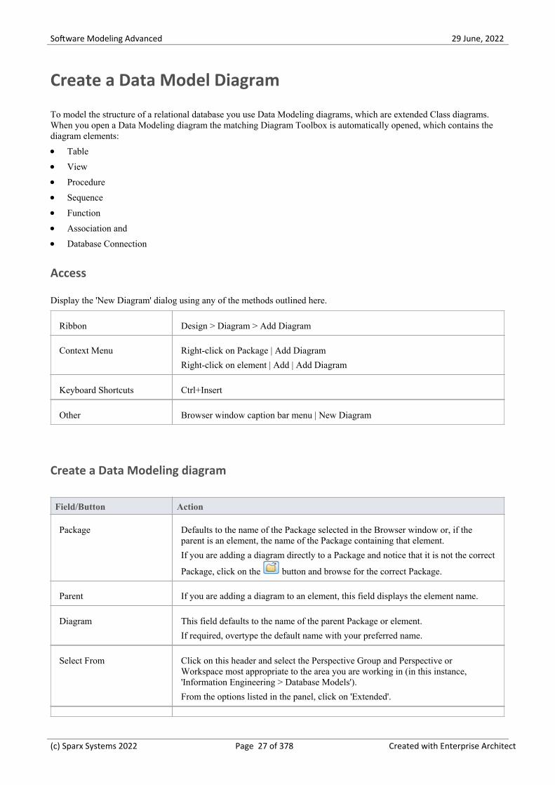
Create a Data Model Diagram
To model the structure of a relational database you use Data Modeling diagrams, which are extended Class diagrams.When you open a Data Modeling diagram the matching Diagram Toolbox is automatically opened, which contains thediagram elements:
Table·View·Procedure·Sequence·Function·Association and·Database Connection·
Access
Display the 'New Diagram' dialog using any of the methods outlined here.
Ribbon Design > Diagram > Add Diagram
Context Menu Right-click on Package | Add Diagram
Right-click on element | Add | Add Diagram
Keyboard Shortcuts Ctrl+Insert
Other Browser window caption bar menu | New Diagram
Create a Data Modeling diagram
Field/Button Action
Package Defaults to the name of the Package selected in the Browser window or, if theparent is an element, the name of the Package containing that element.
If you are adding a diagram directly to a Package and notice that it is not the correct
Package, click on the button and browse for the correct Package.
Parent If you are adding a diagram to an element, this field displays the element name.
Diagram This field defaults to the name of the parent Package or element.
If required, overtype the default name with your preferred name.
Select From Click on this header and select the Perspective Group and Perspective orWorkspace most appropriate to the area you are working in (in this instance,'Information Engineering > Database Models').
From the options listed in the panel, click on 'Extended'.
(c) Sparx Systems 2022 Page 27 of 378 Created with Enterprise Architect

Software Modeling Advanced 29 June, 2022
Diagram Types Click on 'Data Modeling'.
OK Click on this button to create the diagram.
The Diagram View displays the blank diagram, and the 'Data Modeling' pagesdisplay in the Diagram Toolbox.
Drag elements and connectors from the Toolbox onto your diagram, to create yourdata model.
Notes
The default diagram connector notation for all new diagrams is Information Engineering, although many data·modelers prefer the notation IDEF1X; to make this change select 'Design > Diagram > Manage > Properties >Connectors' and click on the required option in the 'Connector Notation' drop-down list
(c) Sparx Systems 2022 Page 28 of 378 Created with Enterprise Architect

Software Modeling Advanced 29 June, 2022
Example Data Model Diagram
This example of a Data Model diagram shows a data model of a bookstore warehousing system. The tables are modeledusing a stereotyped class with a compartment for Columns which displays the name and type of the Columns. Primaryand Foreign Keys are indicated by stereotypes on the columns. You can examine this model in greater detail in theExample model, installed with Enterprise Architect and available from the following ribbon location.
Start > Help > Help > Open the Example Model
Data modeling diagram with suppressed operation compartment showing tables connected to indicate foreign keyrelationships.
(c) Sparx Systems 2022 Page 29 of 378 Created with Enterprise Architect

Software Modeling Advanced 29 June, 2022
The Database Builder
The Database Builder is a tailored interface for the data modeler; all database-related modeling tasks can be performed ina single location. The interface and its related screens include only the information relevant to data modeling, therebystreamlining and simplifying the modeling process.
Access
Ribbon Develop > Data Modeling > Database Builder
Database Builder
This figure shows the Database Builder loaded with the 'Orders (postgres)' data model as it appears in the Examplemodel.
Overview
The interface of the Database Builder consists of:
A Tree of data models, listing all defined data models in the current repository·A 'Columns' tab through which you directly manage the Table columns·A 'Constraints/Indexes' tab for the direct management of Table constraints such as Primary Keys, Foreign Keys and·Indexes
An SQL Scratch Pad that you can use to run ad-hoc SQL queries against a live database·A 'Database Compare' tab that displays the results of comparisons between the data model and a live database·
(c) Sparx Systems 2022 Page 30 of 378 Created with Enterprise Architect

Software Modeling Advanced 29 June, 2022
An 'Execute DDL' tab on which you can execute generated DDL against a live database, instantly·
You can use the Database Builder to:
Create, edit and delete database objects (Tables, Views, Procedures, Sequences and Functions)·Create, edit and delete Table constraints (Primary Keys, Indexes, Unique Constraints, Check Constraints and·Triggers)
Create, edit and delete Table Foreign Keys·Reverse engineer database schema information·Generate DDL from a modeled database·Compare a live database schema with a modeled database·Execute generated DDL against a live database·Execute adhoc SQL statements against a live database·
Notes
The Database Builder is available in the Corporate, Unified and Ultimate Editions of Enterprise Architect·
(c) Sparx Systems 2022 Page 31 of 378 Created with Enterprise Architect
Software Modeling Advanced 29 June, 2022
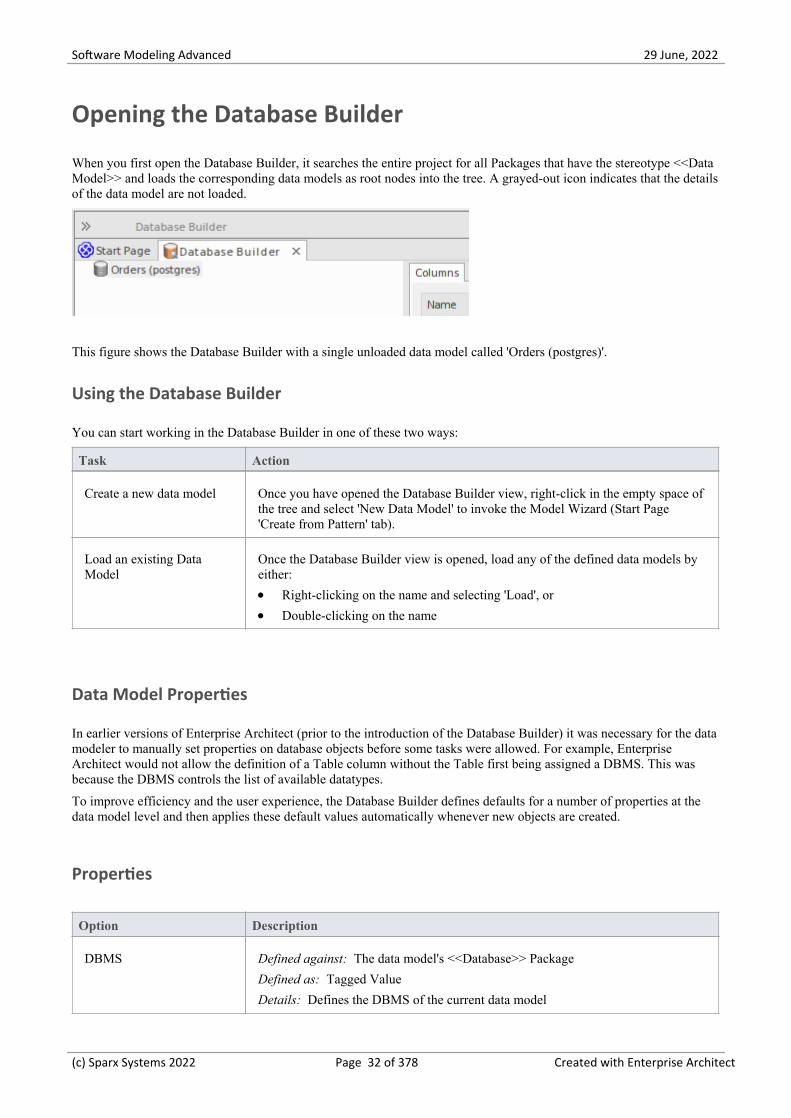
Opening the Database Builder
When you first open the Database Builder, it searches the entire project for all Packages that have the stereotype <<DataModel>> and loads the corresponding data models as root nodes into the tree. A grayed-out icon indicates that the detailsof the data model are not loaded.
This figure shows the Database Builder with a single unloaded data model called 'Orders (postgres)'.
Using the Database Builder
You can start working in the Database Builder in one of these two ways:
Task Action
Create a new data model Once you have opened the Database Builder view, right-click in the empty space ofthe tree and select 'New Data Model' to invoke the Model Wizard (Start Page'Create from Pattern' tab).
Load an existing DataModel
Once the Database Builder view is opened, load any of the defined data models byeither:
Right-clicking on the name and selecting 'Load', or·Double-clicking on the name·
Data Model Properties
In earlier versions of Enterprise Architect (prior to the introduction of the Database Builder) it was necessary for the datamodeler to manually set properties on database objects before some tasks were allowed. For example, EnterpriseArchitect would not allow the definition of a Table column without the Table first being assigned a DBMS. This wasbecause the DBMS controls the list of available datatypes.
To improve efficiency and the user experience, the Database Builder defines defaults for a number of properties at thedata model level and then applies these default values automatically whenever new objects are created.
Properties
Option Description
DBMS Defined against: The data model's <<Database>> Package
Defined as: Tagged Value
Details: Defines the DBMS of the current data model
(c) Sparx Systems 2022 Page 32 of 378 Created with Enterprise Architect

Software Modeling Advanced 29 June, 2022
Extra Information:
Controls which logical folders are shown for the current data model in the·Database Builder's tree
Controls what DBMS rules are applied during database comparisons·Is automatically assigned to every new database object created in the current·data model
DefaultOwner Defined against: The data model's <<Database>> Package
Defined as: Tagged Value
Details: Defines the default Owner for the current data model
Extra Information:
Is automatically assigned to every new database object created in the current·data model, if the DBMS supports owners/schemas
DefaultConnection Defined against: The data model's <<Database>> Package
Defined as: Tagged Value
Details: (Optional) the name of the default connection
Extra Information:
Whenever a data model is loaded, the 'DefaultConnection' property is checked;·if present, the Connection by that name is automatically made active
The database engineering model Patterns do not define a value for this·property, it is created or updated whenever a user sets a Connection as thedefault
Notes
If a data model is selected in the Browser window when the Database Builder is opened, that model's details will be·automatically loaded
(c) Sparx Systems 2022 Page 33 of 378 Created with Enterprise Architect

Software Modeling Advanced 29 June, 2022
Working in the Database Builder
When a data model is loaded, the Database Builder creates a set of logical folders, one for each object type supported bythe current DBMS. Each logical folder is populated with all objects of that type found in the data model's hierarchy ofPackages (as shown in the Browser window).
In this image the data model 'Orders (postgres)' shows logical folders for Tables, Views, Functions, Sequences, Queriesand Connections. It is worth noting there is no folder for 'Procedures' since PostgreSQL does not support databaseprocedures.
Available Actions in the Database Builder Tree
The majority of the Database Builder functions are accessible via context menus. Each object in the Tree has its own setof unique menu items based on its type and status. This table describes the available context menu items and identifieswhich objects they apply to.
Menu Option Applies to / Description
New data model Applies To: Blank Space
Description: Opens the Start Page 'Create from Pattern' tab (Model Wizard).
Refresh All Applies to: Blank Space
Description: Reloads the complete list of data models.
Load Applies to: Root Node
(c) Sparx Systems 2022 Page 34 of 378 Created with Enterprise Architect

Software Modeling Advanced 29 June, 2022
Description: Loads the full details of the data model.
Unload Applies to: Root Node
Description: Unloads the full details of the data model.
Import DB Schema Applies to: Loaded Root Node
Description: Opens the 'Import DB schema' dialog using the current activeconnection as the Live database source.
Generate DDL Applies to: Loaded Root Node, Folder, Table, View, Procedure, Function,Sequence, Package
Description: Opens the 'Generate DDL' dialog with the current object(s) selected.
Show Differences Applies to: Loaded Root Node, Folder, Table, View, Procedure, Function,Sequence
Description: Compares the selected objects to the current active connection.
Show Differences withOptions
Applies to: Loaded Root Node, Folder, Table, View, Procedure, Function,Sequence, Package
Description: Compares the selected objects to the current active connection andoptionally ignore some of the differences based on the specified compare options.
Manage DBMS Options Applies to: Loaded Root Node
Description: Opens the 'Manage DBMS Options' dialog, which can be used tochange the allocated DBMS and Owner of multiple objects.
View Record Count Applies to: Table, View
Description: Builds and runs a SELECT query (formatted to suit the element'sDBMS) to show the number of records in the selected Table or View.
If there is no active connection, you are prompted to select one.
View Top 100 Rows Applies to: Table, View
Description: Builds and runs a SELECT query (formatted to suit the element'sDBMS) to show the top 100 rows of the selected Table or View.
If there is no active connection, you are prompted to select one.
View Top 1000 Rows Applies to: Table, View
Description: Builds and runs a SELECT query (formatted to suit the element'sDBMS) to show the top 1000 rows of the selected Table or View.
If there is no active connection, you are prompted to select one.
View All Rows Applies to: Table, View
Description: Builds and runs a SELECT query (formatted to suit the element'sDBMS) to show all rows of the selected Table or View.
If there is no active connection, you are prompted to select one.
Properties Applies to: Loaded Root Node, Folder, Table, View, Procedure, Function,Sequence, Package, Connection
Description: Opens the standard 'Properties' dialog for the selected object.
Find in Project Browser Applies to: Loaded Root Node, Folder, Table, View, Procedure, Function,
(c) Sparx Systems 2022 Page 35 of 378 Created with Enterprise Architect

Software Modeling Advanced 29 June, 2022
Sequence, Package, SQL Query, Connection
Description: Finds the selected object in the Browser window.
Refresh Applies to: Loaded Root Node
Description: Reloads the details of the current loaded data model. This is necessarywhen objects are added, changed or deleted by other users or when the changes areperformed outside of the Database Builder.
Add new <type> Applies to: Folder, Table, View, Procedure, Function, Sequence, Package, SQLQuery, Connection
Description: Creates a new object of the specified type.
Clone <name> Applies to: Folder, Table, View, Procedure, Function, Sequence, Package, SQLQuery, Connection
Description: Makes a new copy of the selected object. When you select this option,a prompt displays on which you set the name and owner of the new object. ForTable objects, you can choose which existing constraints should be copied (and seta name for each one) along with which Foreign Keys should be copied. ForSQL-based objects, you can make any necessary changes to the SQL for the newelement.
Delete <name> Applies To: Table, View, Procedure, Function, Sequence, Package, SQL Query,Connection
Description: Permanently deletes the selected object from the repository.
Add new Foreign Key on<name>
Applies to: Table
Description: Creates a new relationship between the selected Table and anotherone, then shows the 'Foreign Key Constraint' screen for the new relationship.
SQL Object Properties Applies to: View, Procedure, Function, Sequence
Description: Opens the 'SQL Object Editor' screen.
Edit Applies to: SQL Query
Description: Loads the SQL (as defined in the selected element) into the SQLScratch Pad.
Run Applies to: SQL Query
Description: Loads the SQL in the SQL Scratch Pad and runs it.
If there is no active connection, you are prompted to select one.
Set as active DBConnection
Applies to: Connection
Description: Flags the selected Database Connection as the active one for thecurrent session.
Set as Default DBConnection
Applies to: Connection
Description: Flags the selected Database Connection as the active one each time thedata model is loaded.
DB Connection Properties Applies to: Connection
Description: Opens the 'Database Connection Properties' screen, to manage theconnection settings.
(c) Sparx Systems 2022 Page 36 of 378 Created with Enterprise Architect

Software Modeling Advanced 29 June, 2022
Create/Edit/Delete Database Objects
The pages listed in this section describe in detail how to use the Database Builder's interface to create and manipulatedatabase Tables; however, the process of creating and manipulating SQL-based database objects is documented in otherareas. See these topics for details:
Database Views·Database Procedures·Database Functions·Database Sequences·Database Connections·
Database Connections in the Database Builder
When performing certain tasks such as 'Compare' or 'Execute DDL', the Database Builder requires an active databaseconnection. Only one database connection can be made active (indicated by a colored 'Database Connection' icon, whilethe others are gray) at a given time. If a database connection is not currently active and you try to perform a task thatrequires one, the Database Builder performs one of these actions based on how many connections are defined:
0 Connections – prompts you to create a connection and, if successful, continues·1 Connection – sets it as active and continues·2 (or more) Connections – prompts you to select one and, if successful, continues·
(c) Sparx Systems 2022 Page 37 of 378 Created with Enterprise Architect

Software Modeling Advanced 29 June, 2022
Columns
Tables are the fundamental database object, and Columns (and their properties) are the most frequently modified Tablefeature updated and changed by data modelers, therefore the 'Columns' page is conveniently located as the first page ofthe Database Builder's interface.
Once a Table is selected in the Database Builder's tree, the 'Columns' page is populated with the currently defined list ofcolumns for that Table. The data modeler can then make changes to main column properties directly in the list or grid.As the data modeler selects individual columns in the list, the column's extended properties (and Comments) are shownimmediately under the list, allowing modification to these extended properties.
This figure show the Database Builder interface showing the tree of objects and the Columns tab showing the Columnsfor the selected table.
Notes
The 'Columns' page will only be populated when a Table item is selected in the Database Builder's tree·
(c) Sparx Systems 2022 Page 38 of 378 Created with Enterprise Architect

Software Modeling Advanced 29 June, 2022
Create Database Table Columns
A database Table column is represented in the UML Data Modeling Profile as an attribute with the <<column>>stereotype. For a selected Table, you can review the existing columns and create new columns, on the 'Columns' page ofthe Database Builder or on the 'Columns and Constraints' screen.
You can define column details directly on the list of columns on the 'Columns' tab. The changes are automatically savedas you complete each field. Some fields have certain restrictions on the data you can enter, as described here. The tabalso contains a 'Properties' panel and a 'Notes' field, which are populated with the existing information on the selectedcolumn. Each new column that you create is automatically assigned a set of default values and added to the bottom of thelist.
Access
Ribbon Develop > Data Modeling > Database Builder > Click on Table > Columns >Right-Click > Add new Column
Context Menu In diagram, right-click on required Table | Features | Columns | Right-Click | Addnew Column
Keyboard Shortcuts Select a table | F9 | Tab Key (to set input focus on the 'Columns' tab) | Ctrl+N
Create columns in a Table
Option Action
Name Overtype the default name with the appropriate column name text.
Type Click on the drop-down arrow and select the appropriate datatype for the column.
The available datatypes depend on the DBMS assigned to the parent Table.
Length (Optional) Some datatypes have a length component - for example, VARCHAR hasa length that defines the number of characters that can be stored. If the datatypedoes not have a length component, this field is disabled.
If the field is available and if you need to define a number of characters, type thevalue here.
Scale (Optional) Some datatypes have a scale component - for example, DECIMAL has ascale that defines the number of decimal places that can be held. If the datatypedoes not have a scale component, this field is disabled.
If the field is available and if you need to define a scale, type the value here.
PK Select the checkbox if the column is part of the Primary Key for this Table.
Not Null Select the checkbox if empty values are forbidden for this column.
The checkbox is disabled if the 'PK' checkbox is selected.
(c) Sparx Systems 2022 Page 39 of 378 Created with Enterprise Architect

Software Modeling Advanced 29 June, 2022
Alias If required for display and documentation purposes, type in an alternative name forthe field.
Initial Value If required, type in a value that can be used as a default value for this column.
Notes Type in any additional information necessary to document the column.
You can format the text using the Notes toolbar at the top of the field.
Column Properties
The appropriate properties for the Table's Database Management System automatically display in the 'Property' panel(expand the 'Column (<name>)' branch if they are not visible).
Property DBMS
Autonum (StartnumIncrement)
Oracle
MySQL
SQL Server
DB2
PostgreSQL
Notes: If you require an automatic numbering sequence, set this property to Trueand, if necessary, define the start number and increment.
Generated DB2
Notes: Set this additional property for auto numbering in DB2, to 'By Default' or'Always'.
NotForRep SQLServer
Notes: Set this property to True if you want to block replication.
Zerofill MySQL
Notes: Set this property to True or False to indicate if fields are zerofilled or not.
Unsigned MySQL
Notes: Set this property to True or False to indicate whether or not fields acceptunsigned numbers.
LengthType Oracle
Notes: Set this property to define the character semantics as 'None', 'Byte' or 'Char'.
(c) Sparx Systems 2022 Page 40 of 378 Created with Enterprise Architect

Software Modeling Advanced 29 June, 2022
Delete Database Table Columns
For a selected database Table, you can review the existing columns and delete any individual column, on the 'Columns'tab of the Columns and Constraints screen.
Access
Use one of the methods outlined here to display a list of columns for a table, then select a column and delete it.
When you select the 'Delete column '<name>'' option, if all validation rules are satisfied the column is immediatelydeleted.
Ribbon Develop > Data Modeling > Database Builder > Click on Table > Columns >Right-click on column name > Delete column <name>
Context Menu In diagram, right-click on required Table | Features | Columns | Right-click oncolumn name | Delete column <name>
Keyboard Shortcuts F9 | Use 'Up Arrow' or 'Down Arrow' to select a column | Ctrl+D
Notes
If the deleted database Table column is involved in any constraints it will automatically be removed from them·
(c) Sparx Systems 2022 Page 41 of 378 Created with Enterprise Architect

Software Modeling Advanced 29 June, 2022
Reorder Database Table Columns
If you have several columns defined in a database Table, you can change the order in which they are listed. The order inthe list is the order in which the columns appear in the generated DDL.
Access
Use one of the methods outlined here to display a list of columns for a Table, then select a column and reposition itwithin the list.
Ribbon Develop > Data Modeling > Database Builder > Click on Table
Context Menu In diagram, right-click on required Table | Features | Columns
Keyboard Shortcuts F9
Change the column order
Step Action
1 In the 'Columns' tab, click on the required column name in the list.
2 Right-click and select the:
'Move column <name> up' option (or press Ctrl+Up Arrow) to move the column up one position·'Move column <name> down' option (or press Ctrl+Down Arrow) to move the column down one·position
These options have an immediate effect both in the 'Columns' tab and on a diagram.
(c) Sparx Systems 2022 Page 42 of 378 Created with Enterprise Architect

Software Modeling Advanced 29 June, 2022
Constraints/Indexes
Tables are the fundamental database object, and Constraints and Indexes (and their properties) are the second mostfrequently modified Table feature updated and changed by data modelers, therefore the 'Constraints/indexes' page isconveniently located as the second page of the Database Builder's interface.
Once a Table is selected in the Database Builder's tree, the 'Constraints/Indexes' page is populated with the currentlydefined list of constraints and indexes for the selected Table. The data modeler can then make changes to main propertiesdirectly in the list. As the data modeler selects individual constraints or indexes in the list, the constraint's extendedproperties (and Comments) are shown immediately under the list, allowing modification of these extended properties.
This figure show the Database Builder interface showing the tree of objects and the Columns tab showing the Columnsfor the selected table.
Notes
The 'Constraints/Indexes' page will only be populated when a Table item in the Database Builder's tree is selected·
(c) Sparx Systems 2022 Page 43 of 378 Created with Enterprise Architect

Software Modeling Advanced 29 June, 2022
Database Table Constraints/Indexes
Within Enterprise Architect, Table Constraints and Indexes are modeled on the same screen; collectivity they are referredto as Constraints. Database Constraints define the conditions imposed on the behavior of a database Table. They include:
Primary Key - uniquely identifies a record in a Table, consisting of one or more columns·Index - improves the performance of retrieval and sort operations on Table data·Unique Constraints - a combination of values that uniquely identify a row in the Table·Foreign Key - a column (or collection of columns) that enforce a relationship between two Tables·Check Constraints - enforces domain integrity by limiting the values that are accepted by a column·Table Trigger - SQL or code automatically executed as a result of data in a Table being modified·
In Enterprise Architect, you can define and maintain Table Constraints using either the purpose-designed'Constraints/Indexes' page of the Database Builder or the Columns and Constraints screen.
Access
Ribbon Develop > Data Modeling > Database Builder > Click on Table name >Constraints/Indexes | Right-click | Add New Constraint
Context Menu In diagram | Right-click on Table | Features | Constraints/Indexes | Right-click |Add New Constraint
Keyboard Shortcuts Click on Table: F9 > Constraints/Indexes: Ctrl+N
Create a Constraint
The process of creating any of these constraint types is the same and is achieved in one of the ways described here.
Create a Constraint - Using the context menu or keyboard
Step Action
1 A new constraint is automatically created and assigned the default name constraint n (where n is acounter) and a 'Type' of 'index'.
Overtype the default name with your own constraint name.
2 If necessary, in the 'Type' field click on the drop-down arrow and select the appropriate constraint type.
3 If you prefer, type an alias for the constraint, in the 'Alias' field.
The 'Columns' field is read-only; it is populated with the columns that you assign to the 'InvolvedColumns' tab.
(c) Sparx Systems 2022 Page 44 of 378 Created with Enterprise Architect

Software Modeling Advanced 29 June, 2022
Create a Constraint - Overtype the template text
Step Action
1 On the 'Constraints/Indexes' tab for the selected Table, the list of constraints ends with the template textNew Constraint.
Overtype this text with the appropriate constraint name, and press the Enter key.
2 The new constraint is automatically created and assigned the default Type of index.
If necessary, in the 'Type' field click on the drop-down arrow and select the appropriate constraint type.
3 If you prefer, type an alias for the constraint, in the 'Alias' field.
The 'Columns' field is read-only; it is populated with the columns that you assign to the 'InvolvedColumns' tab.
Assign Columns to a Constraint
The constraint types of Primary Key, Foreign Key, Index and Unique all must have at least one column assigned to them;this defines the columns that are involved in the constraint.
Step Action
1 On the 'Constraints/Indexes' tab for the selected Table, click on the constraint to which you are assigningcolumns.
2 The 'Available Columns' panel lists all columns defined for the Table.
For each column to assign to the constraint, right-click on the column name and select 'Assign column<name>'.
The column name is transferred to the 'Assigned Columns' list.
Unassign Columns from a Constraint
Step Action
1 On the 'Constraints/Indexes' tab for the selected Table, click on the constraint from which you areunassigning columns.
2 In the 'Assigned Columns' list, right-click on the name of the column to unassign from the constraint andselect 'Unassign column <name>'.
The column name is transferred to the 'Available Columns' list.
Reorder the Assigned Columns in a Constraint
(c) Sparx Systems 2022 Page 45 of 378 Created with Enterprise Architect

Software Modeling Advanced 29 June, 2022
If you have a number of columns in the constraint, you can re-arrange the sequence by moving a selected column nameone place up or down the list at a time. To do this:
Right-click on the column name to move and select either:· - Move column '<name>' up (Ctrl+Up Arrow) or - Move column '<name>' down (Ctrl+Down Arrow)
Delete a constraint
To delete a constraint you no longer require, right-click on the constraint name in the list on the 'Constraints/Indexes' taband select the 'Delete constraint <name>' option. If all validation rules for the given constraint type are met, theconstraint is immediately removed from the repository along with all related relationships (if there are any).
(c) Sparx Systems 2022 Page 46 of 378 Created with Enterprise Architect

Software Modeling Advanced 29 June, 2022
Primary Keys
A Primary Key is a column (or set of columns) that uniquely identifies each record in a Table. A Table can have only onePrimary Key. Some DBMSs support additional properties of Primary Keys, such as Clustered or Fill Factor.
Access
Ribbon Develop > Data Modeling > Database Builder > Click on Table name
Context Menu In diagram | Right-click on Table | Features | Constraints/Indexes
Create a Primary Key
In Enterprise Architect you can create a Primary Key from either the 'Columns' tab or the 'Constraints/Indexes' tab. Ineither case, when you add a column to a Primary Key constraint, the column is automatically set to be 'Not Null'.Additionally any diagram (assuming the 'Show Qualifiers and Visibility Indicators' option is set) containing the Tableelement will show the 'PK' prefix against the column name. In this image, see the first column 'id: bigserial'.
Create a Primary Key - from the Columns tab
(c) Sparx Systems 2022 Page 47 of 378 Created with Enterprise Architect

Software Modeling Advanced 29 June, 2022
Step Action
1 Either:
In the Database Builder, click on a Table with one or more defined columns, and click on the·'Columns' tab, or
On a diagram, click on a Table and press F9 to display the 'Columns' tab·
2 For each column to include in the Primary Key, select the 'PK' checkbox.
If a Primary Key constraint is not previously defined for the current Table, the system will create a newconstraint using the Primary Key Name template.
Create a Primary Key - from the Constraints tab
Step Action
1 Either:
In the Database Builder, click on a Table with one or more defined columns, and click on the·'Constraints/Indexes' tab, or
On a diagram, click on a Table and press F10 to display the 'Constraints/Indexes' tab·
2 Overtype the New Constraint text with the Primary Key name, press the Enter key and click on the 'Type'field drop-down arrow, and select 'PK'.
3 Assign the required columns to the PK constraint.
4 Set the Primary Key's extended properties using the property panel.
Fill Factor is a numeric value between 0 and 100·Is Clustered is a Boolean value that determines the physical order of how the data is stored; for most·DBMSs the Is Clustered property defaults to True for Primary Keys
Remove columns from a Primary Key
You can remove columns from a Primary Key using either the 'Columns' tab or the 'Constraints/Indexes' tab.
Remove columns from a Primary Key - using the Columns tab
Step Action
1 Either:
In the Database Builder, click on the Table with the Primary Key, and click on the 'Columns' tab, or·On a diagram, click on a Table and press F9 to display the 'Columns' tab·
2 Against each column you want to remove from the Primary Key, deselect the 'PK' checkbox.
(c) Sparx Systems 2022 Page 48 of 378 Created with Enterprise Architect

Software Modeling Advanced 29 June, 2022
If you have removed all columns from the Primary Key constraint and the Primary Key is no longerneeded, it must be manually deleted.
Remove columns from a Primary Key - using the Constraints/Indexes tab
Step Action
1 Either:
In the Database Builder, click on the Table with the Primary Key, and click on the·'Constraints/Indexes' tab, or
On a diagram, click on a Table and press F10 to display the 'Constraints/Indexes' tab·
2 Unassign the columns on the PK constraint, as necessary.
Notes
Warning: Enterprise Architect assumes that Primary Key constraints have at least one column assigned to them;·however, Enterprise Architect does not enforce this rule during modelingIf DDL is generated for a Table whose Primary Key has no column assigned, that DDL will be invalid
(c) Sparx Systems 2022 Page 49 of 378 Created with Enterprise Architect

Software Modeling Advanced 29 June, 2022
Database Indexes
Database indexes are applied to Tables to improve the performance of data retrieval and sort operations. Multipleindexes can be defined against a Table; however, each index imposes overheads (in the form of processing time andstorage) on the database server to maintain them as information is added to and deleted from the Table
In Enterprise Architect an index is modeled as a stereotyped operation.
Some DBMSs support special types of index; Enterprise Architect defines these using additional properties such asfunction-based, clustered and fill-factor.
Access
Ribbon Develop > Data Modeling > Database Builder > Click on Table name >Constraints/Indexes
Context Menu In diagram | Right-click on Table | Features | Constraints/Indexes
Keyboard Shortcuts Click on Table: F9 > Constraints/Indexes
Work on an index
Step Action
1 On the 'Constraints/Indexes' tab for the Table, right-click and select 'Add new constraint'.
The new constraint is added with the default name 'constraint1' and the Type of 'index'.
(c) Sparx Systems 2022 Page 50 of 378 Created with Enterprise Architect

Software Modeling Advanced 29 June, 2022
Overtype the name with your preferred index name.
2 Assign the appropriate columns to the Index.
The 'Assigned Columns' list has an additional 'Order' field that specifies the order (Ascending orDescending) in which each assigned column is stored in the index. You can toggle the order for eachcolumn, as required.
Additionally, for MySQL indexes, a 'Len' field will be visible in which you can define Partial Indexes;that is, an index that uses the leading 'n' number of characters of a text based field. The 'Len' field takesonly whole number numeric values of between 0 and the column's defined length. A value of 0 (which isthe default) indicates that the entire column is to be indexed.
3 In the 'Property' panel, review the settings of the extended properties that are defined for the currentDBMS.
Additional Properties
Property Description
Is Unique (True / False) indicates whether the current index is a 'Unique Index'. A UniqueIndex ensures that the indexed column (or columns) does not contain duplicatevalues, thereby ensuring that each row has a unique value (or combination of valueswhen the index consists of multiple columns).
Is Clustered (True / False) indicates whether the current index is a 'Clustered Index'. With aclustered index, the rows of the table are physically stored in the same order as inthe index, therefore there can be only one clustered index per table. By default atable's Primary Key is clustered.
Not all DBMS's support clustered indexes, therefore the 'Is Clustered' Indexproperty will only be visible for DBMSs that support it.
Is Bitmap (True / False) indicates whether the current index is a 'Bitmap' index. Bitmapindexes are meant to be used on columns that have relatively few unique values(referred to as 'low cardinality' columns) and that physically consist of a bit array(commonly called bitmaps) for each unique value. Each of the arrays will have a bitfor each row in the table.
Consider this example: a bitmap index is created on a column called 'Gender',which has the options 'Male' or 'Female'. Physically, the index will consist of twobit arrays, one for 'Male' and one for 'Female'. The female bit array will have a 1 ineach bit where the matching row has the value 'Female'.
The 'Is Bitmap' and 'Is Unique' properties are mutually exclusive, and so the DDLgeneration will ignore the 'Is Unique' property when the 'Is Bitmap' property isTrue.
Bitmap Indexes are only supported by Oracle; therefore, this property is onlyvisible while modeling Oracle indexes.
Fill Factor A numeric value between 0 and 100, that defines the percentage of available spacethat should be used for data.
Not all DBMSs support fill factor, therefore the 'Fill Factor' index property willonly be visible for DBMSs that support it.
Functional-based A SQL statement that defines the function/statement that will be evaluated and the
(c) Sparx Systems 2022 Page 51 of 378 Created with Enterprise Architect

Software Modeling Advanced 29 June, 2022
results indexed; for example:
LOWER("field")
Not all DBMSs support functional-based indexes, therefore the 'Functional-based'Index property will only be visible for DBMSs that support them, such asPostgreSQL and Oracle.
Include Identifies a comma-separated list (CSV) of non-key Columns from the currenttable.
Not all DBMSs support the 'Include' property on indexes, therefore this propertywill only be visible for DBMSs that support it.
Notes
Warning: Enterprise Architect assumes that Indexes have at least one column assigned to them; however, Enterprise·Architect does not enforce this rule during modelingIf DDL is generated for a Table that has an Index defined without column(s) assigned, that DDL will be invalid,unless the index is functional-based
Any columns assigned to a functional-based index are ignored·
(c) Sparx Systems 2022 Page 52 of 378 Created with Enterprise Architect

Software Modeling Advanced 29 June, 2022
Unique Constraints
Unique Constraints enforce the 'uniqueness' of a set of fields in all rows of a Table, which means that no two rows in aTable can have the same values in the fields of a Unique Constraint. Unique Constraints are similar to Primary Keys (inthat they also enforce 'uniqueness') but the main difference is that a Table can have multiple Unique Constraints definedbut only one Primary Key.
Access
Ribbon Develop > Data Modeling > Database Builder > Click on Table name >Constraints/Indexes > Right-click > Add New Constraint
Context Menu In diagram or Browser window | Right-click on Table element | Features |Constraints/Indexes
Keyboard Shortcuts Click on Table: F9 > Constraints/Indexes: Ctrl+N
Create a Constraint
Step Action
1 On the 'Constraints/Indexes' tab, a new constraint is automatically created and assigned the defaultconstraint name and a 'Type' of index.
Overtype the constraint name with a name that identifies this as a unique constraint.
2 In the 'Type' field, change the value from 'index' to 'unique'.
Notes
Warning: Enterprise Architect assumes that Unique Constraints have at least one column assigned to them; however,·Enterprise Architect does not enforce this rule during modelingIf DDL is generated for a Table that has a unique constraint defined without column(s) assigned, that DDL will beinvalid
(c) Sparx Systems 2022 Page 53 of 378 Created with Enterprise Architect

Software Modeling Advanced 29 June, 2022
Foreign Keys
A Foreign Key defines a column (or a collection of columns) that enforces a relationship between two Tables. It is theresponsibility of the database server to enforce this relationship to ensure data integrity. The model definition of aForeign Key consists of a parent (primary) Table containing a unique set of data that is then referred to in a child(foreign) Table.
In Enterprise Architect, a Foreign Key is modeled with two different (but related) UML components:
A Foreign Key constraint (a UML operation with the stereotype of <<FK>>) stored on the child Table and·An Association connector (stereotype of <<FK>>) defining the relationship between the two Tables·
Create a Foreign Key
Although the definition of a Foreign Key can be complex, the Foreign Key Constraint screen simplifies the modeling ofForeign Keys. This screen is purpose-designed to help you select which constraint in the parent Table to use, and willautomatically match the child Table columns to those in the parent Table that are part of the constraint. Different aspectsof the process of developing a Foreign Key are described here separately for illustration, but the overall process shouldbe a smooth transition.
A number of conditions must be met before a Foreign Key definition can be saved:
Both Tables must have matching DBMSs defined·The parent Table must have at least one column·The parent Table must have a Primary Key, unique constraint or unique index defined·
Create a Foreign Key - using the Database Builder
Step Action
1 In the Database Builder tree, right-click on the child Table name and click on 'Add new Foreign Key on<table name>'.
A dialog displays listing all the possible parent Tables.
2 Double-click on the required parent Table name in the list or select it and click on the OK button.
The 'Foreign Key Constraint' screen displays.
Create a Foreign Key - using a relationship on a diagram
Step Action
1 In the Data Modeling diagram, locate the required child (Foreign Key) Table and parent (Primary Key)Table.
2 Select an Association connector in the 'Data Modeling' page of the Diagram Toolbox.
3 Click on the child Table and draw the connector to the parent Table.
(c) Sparx Systems 2022 Page 54 of 378 Created with Enterprise Architect

Software Modeling Advanced 29 June, 2022
4 If the Foreign Key Constraint screen has been set to display automatically when two Tables are joined, itdisplays now. Otherwise, either:
Double-click on the connector or·Right-click on the connector and select the 'Foreign Keys' option·
The Foreign Key Constraint screen displays.
The Foreign Key Constraint Screen
As an example this image shows the Foreign Key Constraint screen loaded with the details of'fk_customersaddresses_customers' (as defined in the Example model).
Option Action
Join on Constraint This combo box lists all defined constraints in the parent Table that could be usedas the basis of a Foreign Key. (These constraints can be Primary Keys, UniqueConstraints or Unique Indexes.)
The first constraint in the list is selected by default; if this is not the constraint youwant, select the correct constraint from the combo box.
When you select the constraint, its columns are automatically listed in the 'InvolvedColumns' panel, under the 'Parent: <tablename>' column.
Involved Columns This list is divided into two: the columns involved in the selected constraint arelisted on the left, and the child columns that are going to be paired to the parentcolumns are listed on the right.
When a constraint is selected (in the 'Join on constraint' field) the parent side isrefreshed to display all columns assigned to the selected constraint. On the childside the system will automatically attempt to match each parent column to one ofthe same name in the child Table. If the child Table does not have a column of thesame name, a new column of that name will be added to the list, flagged with (*) toindicate that a new column will be created in the Table.
However, if you want to force the pairing to an existing child Table column or a
(c) Sparx Systems 2022 Page 55 of 378 Created with Enterprise Architect

Software Modeling Advanced 29 June, 2022
new column with a different name, click on the column name field and either:
Type in the replacement name, or·Select an existing column (click on the drop-down arrow and select the name·from the list)
Name This field defines the name of the Foreign Key constraint, and defaults to a nameconstructed by the Foreign Key Name Template.
To change the name to something other than the default, simply overtype the value.
On Delete Select the action that should be taken on the data in the child Table when data in theparent is deleted, so as to maintain referential integrity.
On Update Select the action that should be taken on the data in the child Table when data in theparent is updated, so as to maintain referential integrity.
Parent Click on the drop-down arrow and select the cardinality of the parent Table in theForeign Key.
Child Click on the drop-down arrow and select the cardinality of the child Table in theForeign Key.
Create? If you want to create a Foreign Key Index at the same time as the Foreign Key, setthis property to True.
The name of the Foreign Key Index is controlled by the Foreign Key Indextemplate, and the generated name is shown in the 'Name' field underneath the'Create?' field.
Automatically show thisscreen when tables arejoined
(For diagrammatic modeling) Select this checkbox to automatically display thisscreen whenever an Association is created between two Tables.
Delete Click on this button to delete the currently selected existing (saved) Foreign Key.
A prompt is displayed to confirm the deletion (and the deletion of the Foreign KeyIndex, if one exists) - click on the Yes button.
Deleting a Foreign Key leaves an Association connector in place, which you caneither edit or delete (right-click and select 'Delete association: to <Table name>').
OK Click on this button to save the Foreign Key.
Examples
This example shows simple Foreign Keys in a diagram:
(c) Sparx Systems 2022 Page 56 of 378 Created with Enterprise Architect

Software Modeling Advanced 29 June, 2022
The same Foreign Key will be shown in the Database Builder's tree as a child node under the Table'customers.addresses'.
(c) Sparx Systems 2022 Page 57 of 378 Created with Enterprise Architect

Software Modeling Advanced 29 June, 2022
Check Constraints
A Check Constraint enforces domain integrity by limiting the values that are accepted by a column.
Access
Ribbon Develop > Data Modeling > Database Builder > Click on Table name >Constraints/Indexes > Right-click > Add New Constraint
Context Menu In diagram | Right-click on Table | Features | Constraints/Indexes | Right-click |Add New Constraint
Keyboard Shortcuts Click on Table: F9 > Constraints/Indexes: Ctrl+N
Create a Constraint
Step Action
1 On the 'Constraints/Indexes' tab of the Columns and Constraints screen, a new constraint is automaticallycreated and assigned the default constraint name and a 'Type' of index.
Overtype the constraint name with a name that identifies the constraint as a check constraint, such as'CHK_ColumnName' (the CHK_ prefix is optional).
2 In the 'Type' field, change the value from 'index' to 'check'.
3 In the 'Properties' panel for the Condition property, type the SQL statement that will be used as the CheckCondition; for example, column1 < 1000.
If the condition is long, click on the button to display a SQL editor (with syntax highlighting).
Delete a Check Constraint
If you do not want to keep a check constraint, either:
Right-click on it in the list and select 'Delete constraint <name>', or·Click on the item and press Ctrl+D·
The constraint is immediately deleted.
Notes
Any columns assigned to a check constraint are ignored·
(c) Sparx Systems 2022 Page 58 of 378 Created with Enterprise Architect

Software Modeling Advanced 29 June, 2022
Table Triggers
A Table trigger is SQL or code that is automatically executed as a result of data being modified in a database Table.Triggers are highly customizable and can be used in many different ways; for example, they could be used to stop certaindatabase activities from being performed during business hours, or to provide validation or perform deletions insecondary Tables when a record in the primary Table is deleted.
In Enterprise Architect, a Table trigger is modeled as a stereotyped operation and managed using the Table's 'Constraints'screen.
Access
Ribbon Develop > Data Modeling > Database Builder > Click on Table name >Constraints/Indexes | Right-click | Add New Constraint
Context Menu In diagram | Right-click on Table | Features | Constraints/Indexes | Right-click |Add New Constraint
Keyboard Shortcuts Click on Table: F9 > Constraints/Indexes: Ctrl+N
Create a Table Trigger
Step Action
1 On the 'Constraints/Indexes' tab, a new constraint is automatically created and assigned the defaultconstraint name and a 'Type' of index.
Overtype the constraint name with a name that identifies the constraint as a trigger, such asTRG_OnCustomerUpdate. (The TRG_ prefix is optional.)
2 In the 'Type' field, change the value from 'index' to 'trigger'.
3 In the 'Properties' panel for the Statement property, type in the complete SQL statement (includingCREATE TRIGGER) that will define the Trigger.
If the condition is long, click on the button to display a SQL editor (with syntax highlighting).
4 The properties Trigger Time and Trigger Event are currently information-only values and are not used inDDL generation.
Delete a Table Trigger
If you do not want to keep a trigger, either:
Right-click on it in the list and select 'Delete constraint <name>', or·Click on the item and press Ctrl+D·
The trigger is immediately deleted.
(c) Sparx Systems 2022 Page 59 of 378 Created with Enterprise Architect

Software Modeling Advanced 29 June, 2022
Notes
Any columns assigned to table triggers are ignored·
(c) Sparx Systems 2022 Page 60 of 378 Created with Enterprise Architect

Software Modeling Advanced 29 June, 2022
SQL Scratch Pad
The SQL Scratch Pad provides a mechanism to develop and run ad-hoc SQL Queries against a live database. While youdevelop your data model you might want to execute and test ad-hoc SQL Queries for a DDL script, or run enquiries onthe live database; all of this is possible within the Enterprise Architect Database Builder interface.
The SQL Scratch Pad requires the Database Builder to have a valid connection to a live database. This databaseconnection is shared between the 'SQL Scratch Pad', 'Database Compare' and 'Execute DDL' tabs of the DatabaseBuilder.
The Scratch Pad consists of:
A toolbar providing facilities for importing, saving, executing and clearing the SQL Queries·An editor panel in which you create or import the SQL Queries - this panel provides SQL-based syntax highlighting·for the current data model
A tabbed panel consisting of two pages, one to show the results of executing the Query and one to display any·messages generated during the execution
Access
Open the Database Builder window, then display the 'SQL Scratch Pad' tab.
Ribbon Develop > Data Modeling > Database Builder > SQL Scratch Pad
The Scratch Pad Toolbar
The functionality of each button on the Scratch Pad Toolbar is described in this table, working from left to right.
Button Action
Run SQL Executes the SQL Query currently shown in the Scratch Pad.
Check the 'Results' and 'Messages' tabs for the output of executing the Query.
New Clears the SQL Query editor fields so that you can enter a new query.
Open Loads an SQL Query from file.
A source file browser displays, defaulted to display SQL files. Click on the filename and on the Open button to display the file contents in the Scratch Pad.
Save to SQL Query Saves this SQL statement to the SQL Query object it came from.
Save to New SQL Query Creates a new SQL Query object and saves this statement to that object.
Save to File Saves the currently-displayed Query to the file it came from.
If you created the Query from scratch, a source file browser displays in which youtype the new file name and click on the Save button to save the Query.
Save to New File Saves the currently-displayed Query to a new .sql file.
(c) Sparx Systems 2022 Page 61 of 378 Created with Enterprise Architect

Software Modeling Advanced 29 June, 2022
A source file browser displays on which you type in the new file name and click onthe Save button to save the Query.
Clear Clears the contents of the Scratch Pad.
Any Query displayed in the Scratch Pad remains there until you either replace itwith another Query from file or you close the model.
Toggle Comment Applies the SQL comment characters '--' to the beginning of each selected line or, ifthe selected lines are already commented, removes the comment characters.Alternatively, press Ctrl+Shift+C.
Statement Separator Type in the character(s) to use to mark the end of each statement.
Help Displays the Help on the SQL Query Scratch Pad.
Query Description Displays a label providing a description of the current SQL, whether there arepending changes (indicated by a leading *), and the name of the loaded SQL Queryobject or Filename.
Notes
The SQL Scratch Pad does not manipulate your SQL in any way, so you must use the correct syntax for the current·DBMS
While the SQL Scratch Pad can execute multiple SQL statements, and the status and messages of each statement are·shown in the 'Messages' list, only the results of one SELECT statement can be shown in the 'Results' list at a time;all subsequent SELECT statements will be ignored
(c) Sparx Systems 2022 Page 62 of 378 Created with Enterprise Architect

Software Modeling Advanced 29 June, 2022
Database Compare
The 'Database Compare' tab provides a mechanism for comparing the current data model with a live database, andoptionally synchronizing any differences in either direction. Differences 'pushed' into a live database are performed using'Alter DDL' statements, while changes imported from the live database can be directly 'pulled' into the model.
The Database Compare functionality requires the Database Builder to have a valid connection to a live database. Thisdatabase connection is shared by the 'SQL Scratch Pad', 'Database Compare' and 'Execute DDL' tabs of the DatabaseBuilder.
Access
Open the Database Builder window, then display the 'Database Compare' tab.
Ribbon Develop > Data Modeling > Database Builder > Database Compare
The DDL Compare Tab
The 'Database Compare' tab has a number of controls, as described here.
Number & Name Description
(c) Sparx Systems 2022 Page 63 of 378 Created with Enterprise Architect

Software Modeling Advanced 29 June, 2022
1 Case Sensitive Click on this checkbox to make all comparisons of properties recognize differencesin letter-case in the property text.
2 Use Alias if Available Click on this checkbox to indicate that any defined aliases should be used instead ofobject names (at both object and column level).
3 Reset All Click on this button to set the 'Action' flag for all objects back to the default value.
4 Set Import All Click on this button to set the 'Action' flag of all detected differences to <====; thatis, update the model with the value(s) from the live database.
5 Set Synchronize All Click on this button to set the 'Action' flag of all detected differences to ====>; thatis, update the live database with the value(s) from the model.
6 Differences Review the list of objects found to have mis-matches between the model and thelive database. Selecting an item in this list will populate the 'Components' list.
(See the Differences List table for a detailed description of each column.)
7 Components Review this list of properties of the selected object that differ between the modeland the live database.
(See the Component List table for a detailed description of each column.)
8 Reset Click on this button to set the 'Action' flag for all properties of the current objectback to the default value.
9 Import from Live DB Click on this button to import all properties' values (with the 'Action' of <===) fromthe live database into the model.
10 Generate DDL Click on this button to generate the 'Alter DDL' statements for all objects with an'Action' of ====>, and send the statements to the 'Execute DDL' tab.
Differences List
Column Description
EA Displays the name of each object in the model that has one or more detecteddifferences. Blank values indicate that the object is missing in the model but existsin the live database.
Action Defaults to 'No Action' as the action to take considering this object's difference(s).Click on the drop-down arrow and select a specific action. The list of availableactions in the list will depend on whether or not the given object is paired in themodel and live database.
Paired objects
No Action - do not update the database or model with this change·===> - update the object in the database from the model·<=== - update the object in the model from the database·Customize - set the items to No Action prior to setting different actions on each·
(c) Sparx Systems 2022 Page 64 of 378 Created with Enterprise Architect

Software Modeling Advanced 29 June, 2022
item in the lower panel
Unpair - separate the paired objects so that they are not compared with each·other or updated from each other
Unpaired objects
Create <object name> - create the missing database object in the database or·model, as appropriate
Delete <object name> - delete the object from the model·Drop <object name> - delete the object from the database·Pair with <object name> - pair the object in the database with the named·(unpaired) object in the model, so that they are compared for differencesbetween them
The 'Action' fields in the 'Components List' (the lower panel) will be updated basedon the selection of this field.
For example, if the live database has a Table column 'Address1' and the modeldoesn't, setting the object 'Action' to '===>' (update the object in the database fromthe model) sets the column 'Item Action' to 'Drop Address1', which will remove thecolumn from the live database.
Live DB Shows the name of each object in the live database that has one or more detecteddifferences. Blank values indicate that the object exists in the model but is missingin the live database.
Count Shows the total number of detected differences for the object (and all of itscomponents) between the model and live database.
Component List
Column Description
Item Shows the component name or description for each detected difference. Thedifferences are grouped into three categories: Properties, Columns and Constraints,in a tree structure.
EA Shows the value of the given component as detected in the model. Blank valuesindicate that the value is missing in the model but exists in the live database.
Action Defaults to the action corresponding to the setting of the object 'Action' field in the'Differences' list, to indicate the action to take regarding the difference detected forthe component. Click on the drop-down arrow to select an alternative action; theavailable options in the list depend on the component's type and the detecteddifference.
No Action - do not update the database or model·===> - update the object in the live database from the model·<=== - update the object in the model from the live database·Add <item name> - create the missing item in the database or model, as·appropriate
Delete <item name> - delete the item from the model·Drop <item name> - delete the item from the live database·
(c) Sparx Systems 2022 Page 65 of 378 Created with Enterprise Architect

Software Modeling Advanced 29 June, 2022
Live DB Shows the value for the selected component in the live database. Blank valuesindicate that the value exists in the model but is missing in the live database.
Count Shows the number of differences between the model and the live database detectedin the selected component.
Working with the Database Comparison
Whenever you perform a comparison, Enterprise Architect reads the definition from both the live database and themodel, and then attempts to 'pair' each object from one source with the other, using its name (and schema, if relevant forthe current DBMS).
If a match is found, the object name is shown in both the 'EA' and 'Live DB' columns with a default action of 'No Action'.The 'Count' column indicates the total number of differences found for the object and its components or properties.
If a match is not found between the systems, the object name is shown in the source column (either 'EA' or 'Live DB')while the other column is blank. In this state it is possible to pair the object with an object of a different name; the'Action' dropdown list will present the available objects. If a new pairing is made the two objects' definitions arecompared for differences and the results are shown in the 'Components' list, with the default action of '====>' selected.
If you select an action at the object level, this will set the matching action for all of the object's components andproperties. However, if you select the 'Customize' action at the object level, you can determine a different action for eachcomponent.
As an example, both a column (tax_amount) and constraint (ck_customersordersitems_discount) were renamed in Table'public.customers_order_items' (in the Example model) and a database compare performed; this image shows thedifferences found:
In the image there is only one Table that had detected differences - 'public.customers_order_items'; selecting thispopulates the 'Components' list. From the detected results it can be determined that the data model contains a column(tax_amount2) and a check constraint (ck_customerordersitems_discount1) that the live database doesn't and in turn thelive database contains a column (tax_amount) and a check constraint (ck_customerordersitems_discount) that the datamodel doesn't.
(c) Sparx Systems 2022 Page 66 of 378 Created with Enterprise Architect

Software Modeling Advanced 29 June, 2022
Comparing with Options
The 'Compare with Options' functionality works in the same manner as for a direct comparison, except that you areprompted to choose which object/property comparisons should be performed. This enables you to ignore particulardifferences that are not of relevance at the current time.
These tables describe the different comparisons that can be enabled or disabled.
All Objects, Owner
Comparison Action
Owner Select to indicate that the 'Owner' property of all database objects should becompared, after the objects have been 'paired'.
Table Options
Option Action
Tables Select this parent option to enable all of the Table comparison options. Deselect todisable all the other options. You would then deselect or select specific options inthe list.
Table - ExtendedProperties
Select to indicate that extended properties of Tables (such as DB Version andTablespace) should be compared.
Table - Remarks Select to indicate that remarks applied to Tables should be compared.
Columns Select this parent option to enable all of the 'Column comparison' options. Deselectto disable all the other 'Column' options. You would then deselect or select specificoptions in the list.
Column - Type Select to indicate that the datatype name for the Table Columns should becompared.
Column - Size Select to indicate that the datatype size for the Table Columns should be compared.
Column - Default Value Select to indicate that the default values of the Table Columns should be compared.
Column - Position Select to indicate that the Table Column positions should be compared.
Column - Not Null Select to indicate that the not null property of the Table Columns should becompared.
Column - Auto Numbering Select to indicate that the autonumbering properties for the Table Columns shouldbe compared (such as AutoNum, StartNum and Increment).
Column - Unmatched Select to indicate that Table Columns that are unmatched between the model andthe live database should be compared. Typically these are columns that exist in one
(c) Sparx Systems 2022 Page 67 of 378 Created with Enterprise Architect

Software Modeling Advanced 29 June, 2022
Columns system but do not exist in the other.
Column - ExtendedProperties
Select to indicate that extended properties of Table Columns (such as Unsigned andZerofill) should be compared.
Column - Remarks Select to indicate that remarks applied to Table Columns should be compared.
Constraints Select this parent option to enable all of the 'Table Constraint comparison' options.Deselect to disable all the 'Table Constraint' options. You would then deselect orselect specific options in the list.
Constraint - Primary Keys Select to indicate that properties related to Primary Keys should be compared.
Constraint - Foreign Keys Select to indicate that properties related to Foreign Keys should be compared.
Constraint - Indexes Select to indicate that properties related to Indexes should be compared.
Constraint - UniqueConstraints
Select to indicate that properties related to Unique Constraints should be compared.
Constraint - CheckConstraints
Select to indicate that properties related to Check Constraints should be compared.
Constraint - Table Triggers Select to indicate that properties related to Table Triggers should be compared.
Constraint - UnmatchedConstraints
Select to indicate that Table Constraints that are unmatched between the model andthe live database should be compared. Typically these are constraints that exist inone system but do not exist in the other.
Constraints - ExtendedProperties
Select to indicate that extended properties of Table Constraints (such as Fill Factorand Clustered) should be compared.
Constraints - Remarks Select to indicate that remarks applied to Table Constraints should be compared.
Notes
The Database Compare functionality currently can perform comparisons on Table, View, Procedure, Function and·Sequence object types
(c) Sparx Systems 2022 Page 68 of 378 Created with Enterprise Architect

Software Modeling Advanced 29 June, 2022
Execute DDL
The 'Execute DDL' tab provides a mechanism to easily execute generated DDL statements against a live database, andprovides instant feedback on their success, all within the Enterprise Architect interface and without the need for otherproducts.
There are two different types of DDL statement that Enterprise Architect can generate and send to the 'Execute DDL' tab:
Create DDL statements, created by the Generate DDL screen, and·Alter DDL statements, created by the Database Compare window·
The Execute DDL functionality requires the Database Builder to have a valid connection to a live database. Thisdatabase connection is shared between the SQL Scratch Pad, Database Compare and 'Execute DDL' tabs of the DatabaseBuilder.
Access
Open the Database Builder window, then display the 'Execute DDL' tab.
Ribbon Develop > Data Modeling > Database Builder > Execute DDL
Execute the DDL
The 'Execute DDL' tab has these fields and buttons:
Field/Button Action
(c) Sparx Systems 2022 Page 69 of 378 Created with Enterprise Architect

Software Modeling Advanced 29 June, 2022
1 Execution Queue Lists the tasks (each with an associated DDL statement) that are yet to be executed.The list has three columns that specify the name of the object involved, the task andthe action being performed.
Selecting an item in the list will display the associated DDL statement (in the'Script' field) for the given task.
2 Script A text box with SQL syntax highlighting, showing the DDL statement for theselected task.
3 Save Click on this button to save all the individual DDL statements from both the'Execution Queue' and the 'Results List' into a single file.
4 Reset Failed Actions Click on this button to re-queue any failed or skipped tasks from the 'Results List' tothe bottom of the 'Execution Queue'.
5 Skip Click on this button to skip over the next task in the 'Execution Queue' and notexecute it. The task will be moved into the 'Results List' and not given a result.
When you click on the Reset Failed Actions button, skipped tasks are returned tothe Execution Queue along with any failed tasks.
6 Execute Click on this button to execute the next task in the 'Execution Queue'. The task isremoved from the top of the 'Execution Queue' and added to the end of the 'ResultsList' with the execution result.
7 Execute All Click on this button to execute all tasks in the 'Execution Queue'. When executionis complete, the 'Results List' will display the results of each individual task.
8 Results List Lists the executed tasks with the results of execution for each task. Selecting anitem in this list will display the DDL statement that was executed, in the 'Script'field.
Example
In the example used in the earlier section on Database Comparison (when a column and constraint were renamed), if thedefaults are used to 'push' the data model changes into the live database the Execute DDL screen is populated with thedetails shown here.
(c) Sparx Systems 2022 Page 70 of 378 Created with Enterprise Architect

Software Modeling Advanced 29 June, 2022
In summary, DDL is generated to drop both the old column and the old constraint (tasks 'Drop Column' and 'DropConstraint'), then the column and constraint are created with the new names (tasks 'Add Column' and 'Add Constraint')and finally each has their comments/remarks applied (tasks 'Add Constraint - Constraint Comment' and 'Add Column -Column Comment').
(c) Sparx Systems 2022 Page 71 of 378 Created with Enterprise Architect

Software Modeling Advanced 29 June, 2022
Database Objects
Whilst Tables are the fundamental components of a relational database and allow the definition of Columns, Data Types,Keys and Indexes, there are a number of other Objects that are important in RDBM systems including:
Views - a View represents the result-set of a pre-defined query; they are dynamically derived from the data stored in·one or more Tables (or other Views)
Procedures - a feature that some DBMS products implement to provide subroutines that can contain one or more·SQL statements to perform a specific task such as data validation, access control, or to reduce network trafficbetween clients and the DBMS servers
Functions - a feature that some DBMS products implement to provide a mechanism to extend the functionality of the·database server; each is a routine that can accept parameters, perform an action (such as a complex calculation) andreturn the result of that action as a value
Sequences - a feature that some DBMS products implement to provide a mechanism to generate unique values - the·Sequence ensures that each call to it returns a unique value
The UML itself does not specify how data modeling is performed, but Enterprise Architect has a fully integrated UMLprofile for data modeling and a range of features built in to the core product that will make data modeling easy.
The profile uses stereotypes and Tagged Values to extend standard UML elements into data modeling constructs. This isachieved by adding the database object stereotype to a UML Class; so that you would model:
Data Modeling diagrams as extended UML Class diagrams·Tables as UML Class objects with a stereotype of <<table>>·Views as UML Class objects with a stereotype of <<view>>·Procedures as UML Class objects with a stereotype of <<procedure>>·Functions as UML Class objects with a stereotype of <<function>>·Sequences as UML Class objects with a stereotype of <<dbsequence>>·
You can quickly create and configure all of these objects in your database model with Enterprise Architect.
(c) Sparx Systems 2022 Page 72 of 378 Created with Enterprise Architect

Software Modeling Advanced 29 June, 2022
Database Tables
Tables are the fundamental components of a relational database, representing multiple rows of structured data elements(referred to as Columns). Every individual item of data entered into a relational database is represented by a value in acolumn.
Enterprise Architect's UML Profile for Data Modeling represents:
Database Tables as UML Class objects with a stereotype of <<table>>·Table columns as UML attributes of a Table, with a stereotype of <<column>>·Primary Keys as UML operations/methods of a Table, with a stereotype of <<PK>>·Foreign Keys as UML operations/methods of a Table, with a stereotype of <<FK>>·Indexes as UML operations/methods of a Table, with a stereotype of <<index>>·Unique Constraints as UML operations/methods of a Table, with a stereotype of <<unique>>·Check Constraints as UML operations/methods of a Table, with a stereotype of <<check>>·Table Triggers as UML operations/methods of a Table, with a stereotype of <<trigger>>·
Enterprise Architect refers to all of the UML operations of a Table collectively as Constraints, hence the screen you useto maintain a Table's UML attributes and operations is called the Columns and Constraints screen.
Example
This simple example of a Physical Data Model diagram in Enterprise Architect consists of two Database Tablesrepresented by UML Classes, named customers and customer_addresses.
Each Table defines database columns, using UML attributes typed appropriately for the target DBMS (in this case,PostgreSQL).
Notes
The Table stereotype is denoted by the icon in the top-right corner of each Class (see the Data Modeling Notation·topic)
The Enterprise Architect maintenance screen for managing Table Columns doesn't allow you to change the attributes·stereotype, since <<column>> is the only valid option
It is possible to hide the <<column>> stereotype label shown in the example Tables (see the Data Modeling·Notation topic)
(c) Sparx Systems 2022 Page 73 of 378 Created with Enterprise Architect

Software Modeling Advanced 29 June, 2022
(c) Sparx Systems 2022 Page 74 of 378 Created with Enterprise Architect

Software Modeling Advanced 29 June, 2022
Create a Database Table
Fundamental to data modeling is the creation of Database Tables within the model. There are three ways to create aTable:
Within the Database Builder·On an open Data Model diagram·Using the Browser New Element option·
Add a Database Table with the Database Builder
Step Action
1 Open the Database Builder ('Develop > Data Modeling > Database Builder').
2 Load or create a Data model.
3 Right-click on the Tables Package and select 'Add New Table'.
4 Overtype the default name with the appropriate name for the Table, and press the Enter key.
5 Double-click on the Table element to define the Table properties.
Add a Database Table to a diagram
Step Action
1 Create and/or open a Data Modeling diagram.
2 Drag and drop the 'Table' toolbox icon onto the diagram.
(c) Sparx Systems 2022 Page 75 of 378 Created with Enterprise Architect
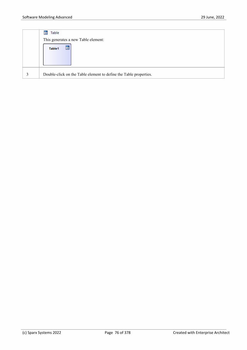
Software Modeling Advanced 29 June, 2022
This generates a new Table element:
3 Double-click on the Table element to define the Table properties.
(c) Sparx Systems 2022 Page 76 of 378 Created with Enterprise Architect

Software Modeling Advanced 29 June, 2022
Database Table Columns
In a relational database, a Table column (sometimes referred to as a field) stores a single data value of a particular type ineach row of the Table. Table columns can have various individual properties such as a default value or whether the fieldaccepts Null values.
A Database Table Column is represented in the UML Data Modeling Profile as a stereotyped attribute; that is, anattribute with the <<column>> stereotype. In Enterprise Architect you define and maintain Table Columns using thepurpose-designed 'Columns' page of the Database Builder, or the 'Columns and Constraints' dialog.
(c) Sparx Systems 2022 Page 77 of 378 Created with Enterprise Architect

Software Modeling Advanced 29 June, 2022
Create Database Table Columns
A database Table column is represented in the UML Data Modeling Profile as an attribute with the <<column>>stereotype. For a selected Table, you can review the existing columns and create new columns, on the 'Columns' page ofthe Database Builder or on the 'Columns and Constraints' screen.
You can define column details directly on the list of columns on the 'Columns' tab. The changes are automatically savedas you complete each field. Some fields have certain restrictions on the data you can enter, as described here. The tabalso contains a 'Properties' panel and a 'Notes' field, which are populated with the existing information on the selectedcolumn. Each new column that you create is automatically assigned a set of default values and added to the bottom of thelist.
Access
Ribbon Develop > Data Modeling > Database Builder > Click on Table > Columns >Right-Click > Add new Column
Context Menu In diagram, right-click on required Table | Features | Columns | Right-Click | Addnew Column
Keyboard Shortcuts Select a table | F9 | Tab Key (to set input focus on the 'Columns' tab) | Ctrl+N
Create columns in a Table
Option Action
Name Overtype the default name with the appropriate column name text.
Type Click on the drop-down arrow and select the appropriate datatype for the column.
The available datatypes depend on the DBMS assigned to the parent Table.
Length (Optional) Some datatypes have a length component - for example, VARCHAR hasa length that defines the number of characters that can be stored. If the datatypedoes not have a length component, this field is disabled.
If the field is available and if you need to define a number of characters, type thevalue here.
Scale (Optional) Some datatypes have a scale component - for example, DECIMAL has ascale that defines the number of decimal places that can be held. If the datatypedoes not have a scale component, this field is disabled.
If the field is available and if you need to define a scale, type the value here.
PK Select the checkbox if the column is part of the Primary Key for this Table.
Not Null Select the checkbox if empty values are forbidden for this column.
The checkbox is disabled if the 'PK' checkbox is selected.
(c) Sparx Systems 2022 Page 78 of 378 Created with Enterprise Architect

Software Modeling Advanced 29 June, 2022
Alias If required for display and documentation purposes, type in an alternative name forthe field.
Initial Value If required, type in a value that can be used as a default value for this column.
Notes Type in any additional information necessary to document the column.
You can format the text using the Notes toolbar at the top of the field.
Column Properties
The appropriate properties for the Table's Database Management System automatically display in the 'Property' panel(expand the 'Column (<name>)' branch if they are not visible).
Property DBMS
Autonum (StartnumIncrement)
Oracle
MySQL
SQL Server
DB2
PostgreSQL
Notes: If you require an automatic numbering sequence, set this property to Trueand, if necessary, define the start number and increment.
Generated DB2
Notes: Set this additional property for auto numbering in DB2, to 'By Default' or'Always'.
NotForRep SQLServer
Notes: Set this property to True if you want to block replication.
Zerofill MySQL
Notes: Set this property to True or False to indicate if fields are zerofilled or not.
Unsigned MySQL
Notes: Set this property to True or False to indicate whether or not fields acceptunsigned numbers.
LengthType Oracle
Notes: Set this property to define the character semantics as 'None', 'Byte' or 'Char'.
(c) Sparx Systems 2022 Page 79 of 378 Created with Enterprise Architect

Software Modeling Advanced 29 June, 2022
Delete Database Table Columns
For a selected database Table, you can review the existing columns and delete any individual column, on the 'Columns'tab of the Columns and Constraints screen.
Access
Use one of the methods outlined here to display a list of columns for a table, then select a column and delete it.
When you select the 'Delete column '<name>'' option, if all validation rules are satisfied the column is immediatelydeleted.
Ribbon Develop > Data Modeling > Database Builder > Click on Table > Columns >Right-click on column name > Delete column <name>
Context Menu In diagram, right-click on required Table | Features | Columns | Right-click oncolumn name | Delete column <name>
Keyboard Shortcuts F9 | Use 'Up Arrow' or 'Down Arrow' to select a column | Ctrl+D
Notes
If the deleted database Table column is involved in any constraints it will automatically be removed from them·
(c) Sparx Systems 2022 Page 80 of 378 Created with Enterprise Architect

Software Modeling Advanced 29 June, 2022
Reorder Database Table Columns
If you have several columns defined in a database Table, you can change the order in which they are listed. The order inthe list is the order in which the columns appear in the generated DDL.
Access
Use one of the methods outlined here to display a list of columns for a Table, then select a column and reposition itwithin the list.
Ribbon Develop > Data Modeling > Database Builder > Click on Table
Context Menu In diagram, right-click on required Table | Features | Columns
Keyboard Shortcuts F9
Change the column order
Step Action
1 In the 'Columns' tab, click on the required column name in the list.
2 Right-click and select the:
'Move column <name> up' option (or press Ctrl+Up Arrow) to move the column up one position·'Move column <name> down' option (or press Ctrl+Down Arrow) to move the column down one·position
These options have an immediate effect both in the 'Columns' tab and on a diagram.
(c) Sparx Systems 2022 Page 81 of 378 Created with Enterprise Architect

Software Modeling Advanced 29 June, 2022
Working with Database Table Properties
Once you have created a Database Table, you can review its properties and check that the DBMS and Owner values arecorrect. To display the 'Properties' dialog for a Table, either double-click on the Table name in the 'Database BuilderTables' Package or on the Table element on a diagram.
Important
A DBMS must be assigned to a Table before you can add columns in it. If you are using the Database Builder then theDBMS of the data model will be automatically applied to all new Tables; however, if you have added a Table by othermeans (such as working on a diagram) then this is a manual step.
Tasks
Once the Database Table properties are defined, you are ready to add columns.
Task
Set the database type for a Table - other than the Table name, the most important property to set for a DatabaseTable is the database type.
Set the database Table Owner - For some DBMSs all Tables must be assigned an Owner/Schema; in EnterpriseArchitect this property is defined as a Tagged Value with the name Owner.
Set extended options - some DBMSs have extended options that are only relevant to that DBMS. These extendedproperties are stored as Tagged Values.
Default DBMS
Prior to creating a Physical Data Model it is advisable for you to set the default DBMS, which will be automaticallyapplied to new database objects that you create outside of the Database Builder. You can set the default DBMS type inone of these ways:
Select 'Start > Appearance > Preferences > Preferences > Source Code Engineering > Code Editors', then set the·field 'Default Database'
Select 'Settings > Reference Data > Settings > Database Datatypes', then select a Product Name and select the 'Set as·Default' checkbox
Set the DBMS in the second field of the Code Generation Toolbar·
(c) Sparx Systems 2022 Page 82 of 378 Created with Enterprise Architect

Software Modeling Advanced 29 June, 2022
Set the Database Type
The most important property to set for a Database Table (after its name) is the database type or DBMS. The DBMS valueselected will control how Enterprise Architect will determine:
How the Table name will be shown (with or without an Owner)·What set of validation rules will be applied while database modeling·The data types that are available when creating columns,·What set of DDL templates will be used in DDL Generation·
Access
Select a Table in the Browser window or on a diagram then, using any of the methods outlined here, open the Table's'Properties' dialog, display the 'General' tab, then display the 'Main' child tab.
Ribbon Design > Element > Editors > Properties Dialog > General > Main
Context Menu Right-click on the Table element | Properties | Special Action | General | Main
Keyboard Shortcuts Shift+Enter | General | Main
Other Double-click on the Table element |General | Main
Options
Field/Button Action
Database Click on the drop-down button and select the required database type from the list.
Apply Click on the Apply button to save any pending changes.
OK Click on the OK button to save any pending changes and close the screen.
(c) Sparx Systems 2022 Page 83 of 378 Created with Enterprise Architect
Software Modeling Advanced 29 June, 2022
Set Database Table Owner/Schema
For some DBMSs all Tables must be assigned an Owner/Schema. In Enterprise Architect this property is physicallydefined as a Tagged Value with the name Owner. However, a special properties page is provided to help you easilymanage the Owner property.
Access
Select a Table in the Browser window or on a diagram then, using any of the methods outlined here, open the Table's'Properties' dialog, display the 'General' tab and display the 'Table Detail' child tab.
Ribbon Design > Element > Editors > Properties > << table >>
Context Menu Right-click on the Table element | Properties |Special Action > General > TableDetail
Keyboard Shortcuts Shift+Enter | General | Table Detail
Other Double-click on the Table element |'General' | 'Table Detail'
Set the Database Table owner
Step Action
1 In the 'Owner' field, type the name of the owner or schema of the Table.
(c) Sparx Systems 2022 Page 84 of 378 Created with Enterprise Architect

Software Modeling Advanced 29 June, 2022
Set MySQL Options
To make use of Foreign Keys in MySQL, you must declare the Database Table type as InnoDB.
Declare the Table type as InnoDB
Step Action
1 Add a Tagged Value named Type to the Table.
2 Set the 'Value' field to 'InnoDB'.
Generate DDL
When you generate DDL for this Table, the Table type is included in the SQL script.
To allow for later versions of MySQL, additional Table options that can be added in the same way include:
Tag Value (Example)
ENGINE InnoDB
CHARACTER SET latin1
CHARSET latin1
COLLATE latin1_german2_ci
(c) Sparx Systems 2022 Page 85 of 378 Created with Enterprise Architect

Software Modeling Advanced 29 June, 2022
Set Oracle Database Table Properties
To set additional Oracle Database Table properties, you use the Table's Tagged Values.
Set Properties
The same properties can be added to indexes and constraints, by highlighting the index or constraint Operation andadding the appropriate Tagged Values.
Step Action
1 Add one or more Tagged Values to the Table, using the names provided in the 'Property/Tag' column ofthe 'Properties' Table.
2 Specify the appropriate value for each tag.
Examples are provided in the 'Value' column of this Properties Table.
CACHE - NOCACHE·DBVERSION - 9.0.111·FREELISTS - 1·GRANT OWNER1 - SELECT·GRANT OWNER2 - DELETE, INSERT, SELECT, UPDATE·INITIAL - 65536·INITRANS - 1·LOGGING - LOGGING·MAXEXTENTS - 2147483645·MAXTRANS - 255·MINEXTENTS - 1·MONITORING - MONITORING·OWNER - OWNER1·PARALLEL - NOPARALLEL·PCTFREE - 10·PCTINCREASE - 0·PCTUSED - 0·SYNONYMS - PUBLIC:TABLE_PUB;OWNER2:TABLE_OWNER2·TABLESPACE - MY_TABLESPACE·TEMPORARY - YES·
(c) Sparx Systems 2022 Page 86 of 378 Created with Enterprise Architect

Software Modeling Advanced 29 June, 2022
Database Table Constraints/Indexes
Within Enterprise Architect, Table Constraints and Indexes are modeled on the same screen; collectivity they are referredto as Constraints. Database Constraints define the conditions imposed on the behavior of a database Table. They include:
Primary Key - uniquely identifies a record in a Table, consisting of one or more columns·Index - improves the performance of retrieval and sort operations on Table data·Unique Constraints - a combination of values that uniquely identify a row in the Table·Foreign Key - a column (or collection of columns) that enforce a relationship between two Tables·Check Constraints - enforces domain integrity by limiting the values that are accepted by a column·Table Trigger - SQL or code automatically executed as a result of data in a Table being modified·
In Enterprise Architect, you can define and maintain Table Constraints using either the purpose-designed'Constraints/Indexes' page of the Database Builder or the Columns and Constraints screen.
Access
Ribbon Develop > Data Modeling > Database Builder > Click on Table name >Constraints/Indexes | Right-click | Add New Constraint
Context Menu In diagram | Right-click on Table | Features | Constraints/Indexes | Right-click |Add New Constraint
Keyboard Shortcuts Click on Table: F9 > Constraints/Indexes: Ctrl+N
Create a Constraint
The process of creating any of these constraint types is the same and is achieved in one of the ways described here.
Create a Constraint - Using the context menu or keyboard
Step Action
1 A new constraint is automatically created and assigned the default name constraint n (where n is acounter) and a 'Type' of 'index'.
Overtype the default name with your own constraint name.
2 If necessary, in the 'Type' field click on the drop-down arrow and select the appropriate constraint type.
3 If you prefer, type an alias for the constraint, in the 'Alias' field.
The 'Columns' field is read-only; it is populated with the columns that you assign to the 'InvolvedColumns' tab.
(c) Sparx Systems 2022 Page 87 of 378 Created with Enterprise Architect

Software Modeling Advanced 29 June, 2022
Create a Constraint - Overtype the template text
Step Action
1 On the 'Constraints/Indexes' tab for the selected Table, the list of constraints ends with the template textNew Constraint.
Overtype this text with the appropriate constraint name, and press the Enter key.
2 The new constraint is automatically created and assigned the default Type of index.
If necessary, in the 'Type' field click on the drop-down arrow and select the appropriate constraint type.
3 If you prefer, type an alias for the constraint, in the 'Alias' field.
The 'Columns' field is read-only; it is populated with the columns that you assign to the 'InvolvedColumns' tab.
Assign Columns to a Constraint
The constraint types of Primary Key, Foreign Key, Index and Unique all must have at least one column assigned to them;this defines the columns that are involved in the constraint.
Step Action
1 On the 'Constraints/Indexes' tab for the selected Table, click on the constraint to which you are assigningcolumns.
2 The 'Available Columns' panel lists all columns defined for the Table.
For each column to assign to the constraint, right-click on the column name and select 'Assign column<name>'.
The column name is transferred to the 'Assigned Columns' list.
Unassign Columns from a Constraint
Step Action
1 On the 'Constraints/Indexes' tab for the selected Table, click on the constraint from which you areunassigning columns.
2 In the 'Assigned Columns' list, right-click on the name of the column to unassign from the constraint andselect 'Unassign column <name>'.
The column name is transferred to the 'Available Columns' list.
Reorder the Assigned Columns in a Constraint
(c) Sparx Systems 2022 Page 88 of 378 Created with Enterprise Architect

Software Modeling Advanced 29 June, 2022
If you have a number of columns in the constraint, you can re-arrange the sequence by moving a selected column nameone place up or down the list at a time. To do this:
Right-click on the column name to move and select either:· - Move column '<name>' up (Ctrl+Up Arrow) or - Move column '<name>' down (Ctrl+Down Arrow)
Delete a constraint
To delete a constraint you no longer require, right-click on the constraint name in the list on the 'Constraints/Indexes' taband select the 'Delete constraint <name>' option. If all validation rules for the given constraint type are met, theconstraint is immediately removed from the repository along with all related relationships (if there are any).
(c) Sparx Systems 2022 Page 89 of 378 Created with Enterprise Architect

Software Modeling Advanced 29 June, 2022
Primary Keys
A Primary Key is a column (or set of columns) that uniquely identifies each record in a Table. A Table can have only onePrimary Key. Some DBMSs support additional properties of Primary Keys, such as Clustered or Fill Factor.
Access
Ribbon Develop > Data Modeling > Database Builder > Click on Table name
Context Menu In diagram | Right-click on Table | Features | Constraints/Indexes
Create a Primary Key
In Enterprise Architect you can create a Primary Key from either the 'Columns' tab or the 'Constraints/Indexes' tab. Ineither case, when you add a column to a Primary Key constraint, the column is automatically set to be 'Not Null'.Additionally any diagram (assuming the 'Show Qualifiers and Visibility Indicators' option is set) containing the Tableelement will show the 'PK' prefix against the column name. In this image, see the first column 'id: bigserial'.
Create a Primary Key - from the Columns tab
(c) Sparx Systems 2022 Page 90 of 378 Created with Enterprise Architect

Software Modeling Advanced 29 June, 2022
Step Action
1 Either:
In the Database Builder, click on a Table with one or more defined columns, and click on the·'Columns' tab, or
On a diagram, click on a Table and press F9 to display the 'Columns' tab·
2 For each column to include in the Primary Key, select the 'PK' checkbox.
If a Primary Key constraint is not previously defined for the current Table, the system will create a newconstraint using the Primary Key Name template.
Create a Primary Key - from the Constraints tab
Step Action
1 Either:
In the Database Builder, click on a Table with one or more defined columns, and click on the·'Constraints/Indexes' tab, or
On a diagram, click on a Table and press F10 to display the 'Constraints/Indexes' tab·
2 Overtype the New Constraint text with the Primary Key name, press the Enter key and click on the 'Type'field drop-down arrow, and select 'PK'.
3 Assign the required columns to the PK constraint.
4 Set the Primary Key's extended properties using the property panel.
Fill Factor is a numeric value between 0 and 100·Is Clustered is a Boolean value that determines the physical order of how the data is stored; for most·DBMSs the Is Clustered property defaults to True for Primary Keys
Remove columns from a Primary Key
You can remove columns from a Primary Key using either the 'Columns' tab or the 'Constraints/Indexes' tab.
Remove columns from a Primary Key - using the Columns tab
Step Action
1 Either:
In the Database Builder, click on the Table with the Primary Key, and click on the 'Columns' tab, or·On a diagram, click on a Table and press F9 to display the 'Columns' tab·
2 Against each column you want to remove from the Primary Key, deselect the 'PK' checkbox.
(c) Sparx Systems 2022 Page 91 of 378 Created with Enterprise Architect

Software Modeling Advanced 29 June, 2022
If you have removed all columns from the Primary Key constraint and the Primary Key is no longerneeded, it must be manually deleted.
Remove columns from a Primary Key - using the Constraints/Indexes tab
Step Action
1 Either:
In the Database Builder, click on the Table with the Primary Key, and click on the·'Constraints/Indexes' tab, or
On a diagram, click on a Table and press F10 to display the 'Constraints/Indexes' tab·
2 Unassign the columns on the PK constraint, as necessary.
Notes
Warning: Enterprise Architect assumes that Primary Key constraints have at least one column assigned to them;·however, Enterprise Architect does not enforce this rule during modelingIf DDL is generated for a Table whose Primary Key has no column assigned, that DDL will be invalid
(c) Sparx Systems 2022 Page 92 of 378 Created with Enterprise Architect

Software Modeling Advanced 29 June, 2022
Non Clustered Primary Keys
When you create a Primary Key in some DBMSs (such as SQL Server or ASA), it is automatically created with the 'IsClustered' property set to True. Therefore when you model a Primary Key in an Enterprise Architect data model, thesame behavior occurs.
Clustered indexes provide improved performance for accessing the column(s) involved, by physically organizing the databy those columns. There can be only one clustered index per Table.
In some situations, you might be more interested in the performance of columns other than the ones assigned to thePrimary Key, and therefore you would need to change the default assignment so that the Primary Key is not clustered.
Access
Ribbon Develop > Data Modeling > Database Builder > Click on Table name >Constraints/Indexes
Context Menu In diagram or Browser window | Right-click on Table | Features |Constraints/Indexes
Keyboard Shortcuts Click on Table: F9 > Constraints/Indexes
Define Primary Key as non-clustered
Subsequently, you can model an index for the same Table as clustered.
Step Action
1 Highlight the existing Primary Key constraint.
The Primary Key properties display in the 'Property' panel.
2 For the Is Clustered property, in the 'Value' field click on the drop-down arrow and change the value toFalse.
(c) Sparx Systems 2022 Page 93 of 378 Created with Enterprise Architect

Software Modeling Advanced 29 June, 2022
Database Indexes
Database indexes are applied to Tables to improve the performance of data retrieval and sort operations. Multipleindexes can be defined against a Table; however, each index imposes overheads (in the form of processing time andstorage) on the database server to maintain them as information is added to and deleted from the Table
In Enterprise Architect an index is modeled as a stereotyped operation.
Some DBMSs support special types of index; Enterprise Architect defines these using additional properties such asfunction-based, clustered and fill-factor.
Access
Ribbon Develop > Data Modeling > Database Builder > Click on Table name >Constraints/Indexes
Context Menu In diagram | Right-click on Table | Features | Constraints/Indexes
Keyboard Shortcuts Click on Table: F9 > Constraints/Indexes
Work on an index
Step Action
1 On the 'Constraints/Indexes' tab for the Table, right-click and select 'Add new constraint'.
The new constraint is added with the default name 'constraint1' and the Type of 'index'.
(c) Sparx Systems 2022 Page 94 of 378 Created with Enterprise Architect

Software Modeling Advanced 29 June, 2022
Overtype the name with your preferred index name.
2 Assign the appropriate columns to the Index.
The 'Assigned Columns' list has an additional 'Order' field that specifies the order (Ascending orDescending) in which each assigned column is stored in the index. You can toggle the order for eachcolumn, as required.
Additionally, for MySQL indexes, a 'Len' field will be visible in which you can define Partial Indexes;that is, an index that uses the leading 'n' number of characters of a text based field. The 'Len' field takesonly whole number numeric values of between 0 and the column's defined length. A value of 0 (which isthe default) indicates that the entire column is to be indexed.
3 In the 'Property' panel, review the settings of the extended properties that are defined for the currentDBMS.
Additional Properties
Property Description
Is Unique (True / False) indicates whether the current index is a 'Unique Index'. A UniqueIndex ensures that the indexed column (or columns) does not contain duplicatevalues, thereby ensuring that each row has a unique value (or combination of valueswhen the index consists of multiple columns).
Is Clustered (True / False) indicates whether the current index is a 'Clustered Index'. With aclustered index, the rows of the table are physically stored in the same order as inthe index, therefore there can be only one clustered index per table. By default atable's Primary Key is clustered.
Not all DBMS's support clustered indexes, therefore the 'Is Clustered' Indexproperty will only be visible for DBMSs that support it.
Is Bitmap (True / False) indicates whether the current index is a 'Bitmap' index. Bitmapindexes are meant to be used on columns that have relatively few unique values(referred to as 'low cardinality' columns) and that physically consist of a bit array(commonly called bitmaps) for each unique value. Each of the arrays will have a bitfor each row in the table.
Consider this example: a bitmap index is created on a column called 'Gender',which has the options 'Male' or 'Female'. Physically, the index will consist of twobit arrays, one for 'Male' and one for 'Female'. The female bit array will have a 1 ineach bit where the matching row has the value 'Female'.
The 'Is Bitmap' and 'Is Unique' properties are mutually exclusive, and so the DDLgeneration will ignore the 'Is Unique' property when the 'Is Bitmap' property isTrue.
Bitmap Indexes are only supported by Oracle; therefore, this property is onlyvisible while modeling Oracle indexes.
Fill Factor A numeric value between 0 and 100, that defines the percentage of available spacethat should be used for data.
Not all DBMSs support fill factor, therefore the 'Fill Factor' index property willonly be visible for DBMSs that support it.
Functional-based A SQL statement that defines the function/statement that will be evaluated and the
(c) Sparx Systems 2022 Page 95 of 378 Created with Enterprise Architect

Software Modeling Advanced 29 June, 2022
results indexed; for example:
LOWER("field")
Not all DBMSs support functional-based indexes, therefore the 'Functional-based'Index property will only be visible for DBMSs that support them, such asPostgreSQL and Oracle.
Include Identifies a comma-separated list (CSV) of non-key Columns from the currenttable.
Not all DBMSs support the 'Include' property on indexes, therefore this propertywill only be visible for DBMSs that support it.
Notes
Warning: Enterprise Architect assumes that Indexes have at least one column assigned to them; however, Enterprise·Architect does not enforce this rule during modelingIf DDL is generated for a Table that has an Index defined without column(s) assigned, that DDL will be invalid,unless the index is functional-based
Any columns assigned to a functional-based index are ignored·
(c) Sparx Systems 2022 Page 96 of 378 Created with Enterprise Architect

Software Modeling Advanced 29 June, 2022
Unique Constraints
Unique Constraints enforce the 'uniqueness' of a set of fields in all rows of a Table, which means that no two rows in aTable can have the same values in the fields of a Unique Constraint. Unique Constraints are similar to Primary Keys (inthat they also enforce 'uniqueness') but the main difference is that a Table can have multiple Unique Constraints definedbut only one Primary Key.
Access
Ribbon Develop > Data Modeling > Database Builder > Click on Table name >Constraints/Indexes > Right-click > Add New Constraint
Context Menu In diagram or Browser window | Right-click on Table element | Features |Constraints/Indexes
Keyboard Shortcuts Click on Table: F9 > Constraints/Indexes: Ctrl+N
Create a Constraint
Step Action
1 On the 'Constraints/Indexes' tab, a new constraint is automatically created and assigned the defaultconstraint name and a 'Type' of index.
Overtype the constraint name with a name that identifies this as a unique constraint.
2 In the 'Type' field, change the value from 'index' to 'unique'.
Notes
Warning: Enterprise Architect assumes that Unique Constraints have at least one column assigned to them; however,·Enterprise Architect does not enforce this rule during modelingIf DDL is generated for a Table that has a unique constraint defined without column(s) assigned, that DDL will beinvalid
(c) Sparx Systems 2022 Page 97 of 378 Created with Enterprise Architect

Software Modeling Advanced 29 June, 2022
Foreign Keys
A Foreign Key defines a column (or a collection of columns) that enforces a relationship between two Tables. It is theresponsibility of the database server to enforce this relationship to ensure data integrity. The model definition of aForeign Key consists of a parent (primary) Table containing a unique set of data that is then referred to in a child(foreign) Table.
In Enterprise Architect, a Foreign Key is modeled with two different (but related) UML components:
A Foreign Key constraint (a UML operation with the stereotype of <<FK>>) stored on the child Table and·An Association connector (stereotype of <<FK>>) defining the relationship between the two Tables·
Create a Foreign Key
Although the definition of a Foreign Key can be complex, the Foreign Key Constraint screen simplifies the modeling ofForeign Keys. This screen is purpose-designed to help you select which constraint in the parent Table to use, and willautomatically match the child Table columns to those in the parent Table that are part of the constraint. Different aspectsof the process of developing a Foreign Key are described here separately for illustration, but the overall process shouldbe a smooth transition.
A number of conditions must be met before a Foreign Key definition can be saved:
Both Tables must have matching DBMSs defined·The parent Table must have at least one column·The parent Table must have a Primary Key, unique constraint or unique index defined·
Create a Foreign Key - using the Database Builder
Step Action
1 In the Database Builder tree, right-click on the child Table name and click on 'Add new Foreign Key on<table name>'.
A dialog displays listing all the possible parent Tables.
2 Double-click on the required parent Table name in the list or select it and click on the OK button.
The 'Foreign Key Constraint' screen displays.
Create a Foreign Key - using a relationship on a diagram
Step Action
1 In the Data Modeling diagram, locate the required child (Foreign Key) Table and parent (Primary Key)Table.
2 Select an Association connector in the 'Data Modeling' page of the Diagram Toolbox.
3 Click on the child Table and draw the connector to the parent Table.
(c) Sparx Systems 2022 Page 98 of 378 Created with Enterprise Architect

Software Modeling Advanced 29 June, 2022
4 If the Foreign Key Constraint screen has been set to display automatically when two Tables are joined, itdisplays now. Otherwise, either:
Double-click on the connector or·Right-click on the connector and select the 'Foreign Keys' option·
The Foreign Key Constraint screen displays.
The Foreign Key Constraint Screen
As an example this image shows the Foreign Key Constraint screen loaded with the details of'fk_customersaddresses_customers' (as defined in the Example model).
Option Action
Join on Constraint This combo box lists all defined constraints in the parent Table that could be usedas the basis of a Foreign Key. (These constraints can be Primary Keys, UniqueConstraints or Unique Indexes.)
The first constraint in the list is selected by default; if this is not the constraint youwant, select the correct constraint from the combo box.
When you select the constraint, its columns are automatically listed in the 'InvolvedColumns' panel, under the 'Parent: <tablename>' column.
Involved Columns This list is divided into two: the columns involved in the selected constraint arelisted on the left, and the child columns that are going to be paired to the parentcolumns are listed on the right.
When a constraint is selected (in the 'Join on constraint' field) the parent side isrefreshed to display all columns assigned to the selected constraint. On the childside the system will automatically attempt to match each parent column to one ofthe same name in the child Table. If the child Table does not have a column of thesame name, a new column of that name will be added to the list, flagged with (*) toindicate that a new column will be created in the Table.
However, if you want to force the pairing to an existing child Table column or a
(c) Sparx Systems 2022 Page 99 of 378 Created with Enterprise Architect

Software Modeling Advanced 29 June, 2022
new column with a different name, click on the column name field and either:
Type in the replacement name, or·Select an existing column (click on the drop-down arrow and select the name·from the list)
Name This field defines the name of the Foreign Key constraint, and defaults to a nameconstructed by the Foreign Key Name Template.
To change the name to something other than the default, simply overtype the value.
On Delete Select the action that should be taken on the data in the child Table when data in theparent is deleted, so as to maintain referential integrity.
On Update Select the action that should be taken on the data in the child Table when data in theparent is updated, so as to maintain referential integrity.
Parent Click on the drop-down arrow and select the cardinality of the parent Table in theForeign Key.
Child Click on the drop-down arrow and select the cardinality of the child Table in theForeign Key.
Create? If you want to create a Foreign Key Index at the same time as the Foreign Key, setthis property to True.
The name of the Foreign Key Index is controlled by the Foreign Key Indextemplate, and the generated name is shown in the 'Name' field underneath the'Create?' field.
Automatically show thisscreen when tables arejoined
(For diagrammatic modeling) Select this checkbox to automatically display thisscreen whenever an Association is created between two Tables.
Delete Click on this button to delete the currently selected existing (saved) Foreign Key.
A prompt is displayed to confirm the deletion (and the deletion of the Foreign KeyIndex, if one exists) - click on the Yes button.
Deleting a Foreign Key leaves an Association connector in place, which you caneither edit or delete (right-click and select 'Delete association: to <Table name>').
OK Click on this button to save the Foreign Key.
Examples
This example shows simple Foreign Keys in a diagram:
(c) Sparx Systems 2022 Page 100 of 378 Created with Enterprise Architect

Software Modeling Advanced 29 June, 2022
The same Foreign Key will be shown in the Database Builder's tree as a child node under the Table'customers.addresses'.
(c) Sparx Systems 2022 Page 101 of 378 Created with Enterprise Architect

Software Modeling Advanced 29 June, 2022
Check Constraints
A Check Constraint enforces domain integrity by limiting the values that are accepted by a column.
Access
Ribbon Develop > Data Modeling > Database Builder > Click on Table name >Constraints/Indexes > Right-click > Add New Constraint
Context Menu In diagram | Right-click on Table | Features | Constraints/Indexes | Right-click |Add New Constraint
Keyboard Shortcuts Click on Table: F9 > Constraints/Indexes: Ctrl+N
Create a Constraint
Step Action
1 On the 'Constraints/Indexes' tab of the Columns and Constraints screen, a new constraint is automaticallycreated and assigned the default constraint name and a 'Type' of index.
Overtype the constraint name with a name that identifies the constraint as a check constraint, such as'CHK_ColumnName' (the CHK_ prefix is optional).
2 In the 'Type' field, change the value from 'index' to 'check'.
3 In the 'Properties' panel for the Condition property, type the SQL statement that will be used as the CheckCondition; for example, column1 < 1000.
If the condition is long, click on the button to display a SQL editor (with syntax highlighting).
Delete a Check Constraint
If you do not want to keep a check constraint, either:
Right-click on it in the list and select 'Delete constraint <name>', or·Click on the item and press Ctrl+D·
The constraint is immediately deleted.
Notes
Any columns assigned to a check constraint are ignored·
(c) Sparx Systems 2022 Page 102 of 378 Created with Enterprise Architect

Software Modeling Advanced 29 June, 2022
Table Triggers
A Table trigger is SQL or code that is automatically executed as a result of data being modified in a database Table.Triggers are highly customizable and can be used in many different ways; for example, they could be used to stop certaindatabase activities from being performed during business hours, or to provide validation or perform deletions insecondary Tables when a record in the primary Table is deleted.
In Enterprise Architect, a Table trigger is modeled as a stereotyped operation and managed using the Table's 'Constraints'screen.
Access
Ribbon Develop > Data Modeling > Database Builder > Click on Table name >Constraints/Indexes | Right-click | Add New Constraint
Context Menu In diagram | Right-click on Table | Features | Constraints/Indexes | Right-click |Add New Constraint
Keyboard Shortcuts Click on Table: F9 > Constraints/Indexes: Ctrl+N
Create a Table Trigger
Step Action
1 On the 'Constraints/Indexes' tab, a new constraint is automatically created and assigned the defaultconstraint name and a 'Type' of index.
Overtype the constraint name with a name that identifies the constraint as a trigger, such asTRG_OnCustomerUpdate. (The TRG_ prefix is optional.)
2 In the 'Type' field, change the value from 'index' to 'trigger'.
3 In the 'Properties' panel for the Statement property, type in the complete SQL statement (includingCREATE TRIGGER) that will define the Trigger.
If the condition is long, click on the button to display a SQL editor (with syntax highlighting).
4 The properties Trigger Time and Trigger Event are currently information-only values and are not used inDDL generation.
Delete a Table Trigger
If you do not want to keep a trigger, either:
Right-click on it in the list and select 'Delete constraint <name>', or·Click on the item and press Ctrl+D·
The trigger is immediately deleted.
(c) Sparx Systems 2022 Page 103 of 378 Created with Enterprise Architect

Software Modeling Advanced 29 June, 2022
Notes
Any columns assigned to table triggers are ignored·
(c) Sparx Systems 2022 Page 104 of 378 Created with Enterprise Architect

Software Modeling Advanced 29 June, 2022
Database Views
A Database View represents the results of a pre-defined query. Unlike a Table, a View is dynamically derived from datain one or more Tables (or other Views). Enterprise Architect supports the definition of Views both with and without thisstatement:
"Create View {viewName} As" statement
The system will automatically add it dynamically (if missing) whenever DDL generation is performed. The advantage ofnot defining this statement is that when a view object is renamed the 'View Definition' property does not have to bemanually updated.
You can create a Database View either:
Within the Database Builder or·By dragging the 'View' icon from the Data Modeling Toolbox onto a diagram·
Add a Database View with the Database Builder
Step Action
1 Open the Database Builder.
2 Load or create a Data model.
3 Right-click on the 'Views' Package and select 'Add New View'.
4 Overtype the default name with the appropriate name for the View, and press the Enter key.
5 Double-click on the new View, or right-click on it and select 'SQL Object Properties'.
The 'SQL Object Editor' dialog displays.
Add a Database View to a diagram
Step Action
1 Open your Data Modeling diagram and, if necessary, display the 'Data Modeling' page of the Diagram
Toolbox (click on to display the 'Find Toolbox Item' dialog and specify 'Data Modeling').
2 Drag the 'View' icon onto the diagram.
This generates the View element:
3 Right-click on the new View element and select 'SQL Object Properties'.
(c) Sparx Systems 2022 Page 105 of 378 Created with Enterprise Architect

Software Modeling Advanced 29 June, 2022
The 'SQL Object Editor' dialog displays.
SQL Object Editor
The 'SQL Object Editor' dialog is shared by a number of SQL-based database objects (Views, Procedures, Functions andSequences); it helps the data modeler manage the various properties of the SQL-based object.
Option Action
Database If it has already been set, the default database type displays.
If the default has not been set, or you want to change the database type for thisView, click on the drop-down arrow and select the target DBMS to model.
Dependencies A list of objects that the current object depends on. The 'Dependencies' list shows:
Each Depends connector between this View and another Table or View·Any object names (specified as a CSV list) in the 'parents' Tagged Values·
Notes If necessary, type in a comment on the current View.
Definition Type the full SQL View definition. For releases of Enterprise Architect up to 12.1(Build 1227), this must include the CREATE_VIEW syntax as appropriate for thetarget DBMS (for later versions this is not needed). For example:
CREATE VIEW 'MyViewName' AS
[view definition]
The code editor provides Intelli-sense for basic SQL keywords, functions andnames of all objects in the current data model.
(c) Sparx Systems 2022 Page 106 of 378 Created with Enterprise Architect

Software Modeling Advanced 29 June, 2022
Database Procedures
Database Procedures (sometimes referred to as Stored Procedures or Procs) are subroutines that can contain one or moreSQL statements that perform a specific task. They can be used for data validation, access control, or to reduce networktraffic between clients and the DBMS servers. Extensive and complex business logic can be embedded into thesubroutine, thereby offering better performance.
Database Procedures are similar to Database Functions. The major difference is the way in which they are invoked -Database Functions can be used in the same way as for any other expression within SQL statements, whereas DatabaseProcedures must be invoked using the CALL or EXEC statement, depending on the DBMS.
In Enterprise Architect, Database Procedures can be modeled in one of two ways:
As individual objects (the default method) or·As operations in a container·
Functionally the two methods result in the same DDL being produced. The main difference is visual - by having severalOperations in one container, you have fewer elements and less clutter on the diagram.
Individual objects
Database Procedures modeled as individual objects are UML Classes with the stereotype «procedure»; you create theseeither:
Within the Database Builder or·By dragging the 'Procedure' icon from the Data Modeling Toolbox onto a diagram·
Add a Database Procedure using the Database Builder
Step Action
1 Open the Database Builder.
2 Load or create a Data model.
3 Right-click on the Procedures Package and select 'Add New Procedure'.
4 Overtype the default name with the appropriate name for the Procedure, and press the Enter key.
5 Double-click on the new Procedure, or right-click on it and select 'SQL Object Properties'.
The SQL Object Editor screen displays.
Add a Database Procedure to a diagram
Step Action
1 Open your Data Modeling diagram and, if necessary, display the 'Data Modeling' page of the Diagram
Toolbox (click on to display the 'Find Toolbox Item' dialog and specify 'Data Modeling').
(c) Sparx Systems 2022 Page 107 of 378 Created with Enterprise Architect

Software Modeling Advanced 29 June, 2022
2 Drag the 'Procedure' icon onto the diagram.
This generates the Procedure element:
3 Right-click on the new Procedure element and select 'SQL Object Properties'.
The SQL Object Editor screen displays.
SQL Object Editor
The 'SQL Object Editor' dialog is shared by a number of SQL-based database objects (Views, Procedures andFunctions); it helps you to manage the various properties of the SQL-based object.
Option Action
Database If it has already been set, the default database type displays.
If the default has not been set, or you want to change the database type for thisProcedure, click on the drop-down arrow and select the target DBMS to model.
Notes If necessary, type in a comment on the current Procedure.
Definition Type the full SQL Procedure definition, including the CREATE PROCEDUREsyntax.
The code editor provides Intelli-sense for basic SQL keywords, functions andnames of all objects in the current data model.
Operations in a Container
Database Procedures modeled as operations have a container object, this being a UML Class with the stereotype«procedures» (with an 's' on the end). Each Database Procedure is an operation with the stereotype «proc». The systemprovides a dedicated Maintenance window through which you can easily manage the Database Procedures defined asoperations.
(c) Sparx Systems 2022 Page 108 of 378 Created with Enterprise Architect

Software Modeling Advanced 29 June, 2022
Database Functions
Database Functions provide you with a mechanism to extend the functionality of the database server. A DatabaseFunction is a routine that accepts parameters, performs an action (such as a complex calculation) and returns the result ofthat action as a value. Depending on the Function, the return value can be either a single value or a result set.
Once created, a Database Function can be used as an expression in an SQL statement.
In Enterprise Architect, Database Functions can be modeled in one of two ways:
As individual objects (the default method) or·As Operations in a container·
Functionally the two methods result in the same DDL being produced. The main difference is visual - by having severalOperations in one container, you have fewer elements and less clutter on the diagram.
Individual objects
Database Functions modeled as individual objects are UML Classes with the stereotype «function»; you create theseeither:
Within the Database Builder or·By dragging the Function icon from the Data Modeling Toolbox onto a diagram·
Add a Database Function using the Database Builder
Step Action
1 Open the Database Builder.
2 Load or create a Data model.
3 Right-click on the Functions Package and select 'Add New Function'.
4 Overtype the default name with the appropriate name for the Function, and press the Enter key.
5 Double-click on the new Function, or right-click on it and select 'SQL Object Properties'.
The SQL Object Editor screen displays.
Add a Database Function to a diagram
Step Action
1 Open your Data Modeling diagram and, if necessary, display the 'Data Modeling' page of the Diagram
Toolbox (click on to display the 'Find Toolbox Item' dialog and specify 'Data Modeling').
2 Drag the 'Function' icon onto the diagram.
(c) Sparx Systems 2022 Page 109 of 378 Created with Enterprise Architect

Software Modeling Advanced 29 June, 2022
This generates the Function element:
3 Right-click on the new Function element and select 'SQL Object Properties'.
The SQL Object Editor screen displays.
SQL Object Editor
The 'SQL Object Editor' dialog is shared by a number of SQL-based database objects (Views, Procedures andFunctions); it helps you to manage the various properties of the SQL-based object.
Option Action
Database If it has already been set, the default database type displays.
If the default has not been set, or you want to change the database type for thisFunction, click on the drop-down arrow and select the target DBMS to model.
Notes If necessary, type in a comment on the current Function.
Definition Type the full SQL Function definition including the CREATE FUNCTION syntax.
The code editor provides Intelli-sense for basic SQL keywords, functions andnames of all objects in the current data model.
Operations in a Container
Database Functions modeled as operations have a container object, this being a UML Class with the stereotype«functions» (with an 's' on the end). Each Function is an operation with the stereotype «func». The system provides adedicated Maintenance window through which you can easily manage the Database Functions stored as operations.
(c) Sparx Systems 2022 Page 110 of 378 Created with Enterprise Architect

Software Modeling Advanced 29 June, 2022
Database Sequences
Sequences are a feature that some DBMS products implement to provide users with a mechanism to generate uniquevalues - the Sequence ensures that each call to it returns a unique value. This is particularly important when theSequence's result is used as a Primary Key. These can be generated with a schema for loading onto the DBMS server.
Sequences are provided so that database users are not forced to implement their own unique value generator. Not allDBMS products support Sequences; those that do not instead provide functionality for columns to be initialized with anincrementing value.
In Enterprise Architect, Sequences can be modeled in one of two ways:
As individual objects (the default method) or·As Operations in a container·
Functionally the two methods result in the same DDL being produced. The main difference is visual - by having severalOperations in one container, you have fewer elements and less clutter on the diagram.
Individual objects
Sequences modeled as individual objects are UML Classes with the stereotype «dbsequence»; you create these either:
Within the Database Builder or·By dragging the 'Sequence' icon from the 'Data Modeling' Toolbox pages onto a diagram·
Add a Database Sequence using the Database Builder
Step Action
1 Open the Database Builder.
2 Load or create a Data model.
3 Right-click on the Sequences Package and select 'Add New Sequence'.
4 Overtype the default name with the appropriate name for the Sequence, and press the Enter key.
5 Double-click on the new Sequence, or right-click on it and select 'SQL Object Properties'.
The 'SQL Object Editor' dialog displays.
Add a Database Sequence to a diagram
Step Action
1 Open your Data Modeling diagram and, if necessary, display the 'Data Modeling' page of the Diagram
Toolbox (click on to display the 'Find Toolbox Item' dialog and specify 'Data Modeling').
2 Drag the 'Sequence' icon onto the diagram.
(c) Sparx Systems 2022 Page 111 of 378 Created with Enterprise Architect

Software Modeling Advanced 29 June, 2022
This generates the Sequence element:
3 Right-click on the new Sequence element and select 'SQL Object Properties'.
The 'SQL Object Editor' dialog displays.
SQL Object Editor
The 'SQL Object Editor' dialog is shared by a number of SQL-based database objects (Views, Procedures andFunctions); it helps you to manage the various properties of the SQL-based object.
Option Action
Database If it has already been set, the default database type displays.
If the default has not been set, or you want to change the database type for thisSequence, click on the drop-down arrow and select the target DBMS to model.
Notes If necessary, type in a comment on the current Sequence.
Definition Type the full SQL Sequence definition including the CREATE SEQUENCEsyntax.
The code editor provides Intelli-sense for basic SQL keywords, functions andnames of all objects in the current data model.
Operations in a Container
Database Sequences modeled as operations have a container object, this being a UML Class with the stereotype«sequences» (with an 's' on the end). Each Sequence is an operation with the stereotype «sequ». The system provides adedicated Maintenance window through which the modeler can easily manage the Sequences defined as operations.
(c) Sparx Systems 2022 Page 112 of 378 Created with Enterprise Architect
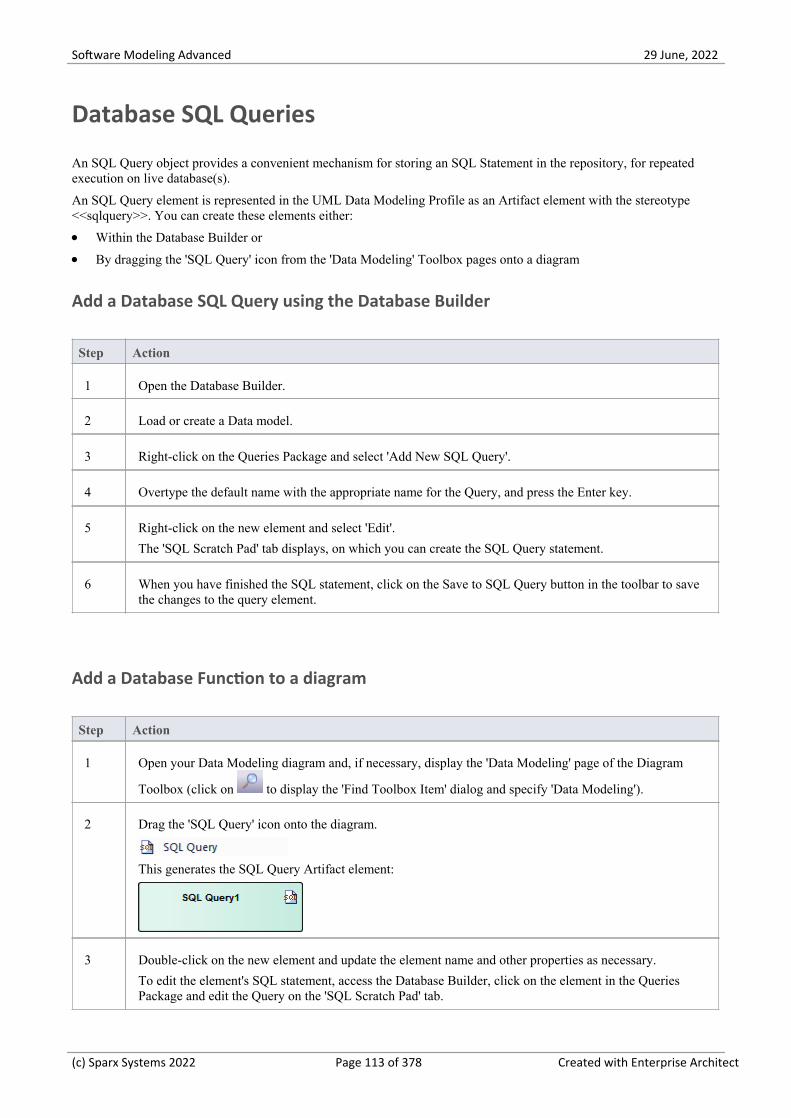
Software Modeling Advanced 29 June, 2022
Database SQL Queries
An SQL Query object provides a convenient mechanism for storing an SQL Statement in the repository, for repeatedexecution on live database(s).
An SQL Query element is represented in the UML Data Modeling Profile as an Artifact element with the stereotype<<sqlquery>>. You can create these elements either:
Within the Database Builder or·By dragging the 'SQL Query' icon from the 'Data Modeling' Toolbox pages onto a diagram·
Add a Database SQL Query using the Database Builder
Step Action
1 Open the Database Builder.
2 Load or create a Data model.
3 Right-click on the Queries Package and select 'Add New SQL Query'.
4 Overtype the default name with the appropriate name for the Query, and press the Enter key.
5 Right-click on the new element and select 'Edit'.
The 'SQL Scratch Pad' tab displays, on which you can create the SQL Query statement.
6 When you have finished the SQL statement, click on the Save to SQL Query button in the toolbar to savethe changes to the query element.
Add a Database Function to a diagram
Step Action
1 Open your Data Modeling diagram and, if necessary, display the 'Data Modeling' page of the Diagram
Toolbox (click on to display the 'Find Toolbox Item' dialog and specify 'Data Modeling').
2 Drag the 'SQL Query' icon onto the diagram.
This generates the SQL Query Artifact element:
3 Double-click on the new element and update the element name and other properties as necessary.
To edit the element's SQL statement, access the Database Builder, click on the element in the QueriesPackage and edit the Query on the 'SQL Scratch Pad' tab.
(c) Sparx Systems 2022 Page 113 of 378 Created with Enterprise Architect

Software Modeling Advanced 29 June, 2022
(c) Sparx Systems 2022 Page 114 of 378 Created with Enterprise Architect

Software Modeling Advanced 29 June, 2022
Create Operation Containers
Whilst the default method of modeling Database Functions, Procedures and Sequences is to create them as individualelements, you can also represent a number of each type of structure as operations of a container Class. You add astereotype to the Class, which specifies:
The type of data structure the Class will contain·The stereotype that will be automatically assigned to each operation created in the Class (for a given data structure,·the operations can only be of one stereotype)
Access
Toolbox Drag the 'Class' icon onto the diagram
Create the Container Class
Step Action
1 Right-click on the Class element on the diagram and select the 'Design > Element > Editors > PropertiesDialog' option.
The element 'Properties' dialog displays, showing the 'General' tab.
2 In the 'Name' field, type an appropriate name for the container.
3 In the 'Stereotype' field (in the table at the right edge of the dialog) type:
'functions' for a Database Function container·'procedures' for a Stored Procedure container·'sequences' for a Sequence container·
The 's' at the end of the stereotype name is important.
4 Click on the OK button to save the setting and close the dialog.
Create database structures as operations of the Class
Step Action
1 Click on the Class element on the diagram and press F10.
The 'Database <Structure> container: <Classname>' dialog displays.
2 Right-click in the 'Functions' ('Procedures' or 'Sequences') list and select 'Add New <structure>'.
(c) Sparx Systems 2022 Page 115 of 378 Created with Enterprise Architect

Software Modeling Advanced 29 June, 2022
3 In the 'Name' field, type an appropriate name for the operation, such as:
fn_WorkDays·sp_AddOrder or·seq_AddressID·
4 In the 'Notes' field type any supporting comments or explanation of the operation.
In the 'Function definition' field (or 'Procedure definition', or 'Sequence definition') type the appropriatetext.
5 Repeat steps 2 to 4 until you have defined all the operations you require.
6 Click on the list and then on the Close button to close the dialog and show the operations within the Classon the diagram and in the Browser window.
(c) Sparx Systems 2022 Page 116 of 378 Created with Enterprise Architect

Software Modeling Advanced 29 June, 2022
Oracle Packages
Oracle Packages are database objects that are unique to the Oracle DBMS. They are containers that grouplogically-related objects into a single definition. Packages have two parts - a specification and a body. The:
Specification section declares the various components·Body section provides the full definitions of the components·
The Package components can consist of Types, Variables, Constants, Exceptions, Cursors and subprograms.
In Enterprise Architect, an Oracle Package is modeled as a UML Class with a stereotype of <<package>>. It has twooperations:
Specification·Body·
For each of these operations the complete SQL syntax is contained in the 'Initial Code' field.
Create an Oracle Package
Step Action
1 Add a Class element to your data model.
2 Open the Properties window for the element and, in the 'Stereotype' field, type the value 'Package'.
3 Click on the element and press F10, to display the Features window at the 'Operations' page.
For the Package specification, press Ctrl+N and create an operation with the name 'Specification' and withno return type.
4 The Properties window displays the properties of the operation; click on the 'Code' tab and type the entirePackage specification into the text panel.
5 Return to the Features window at the 'Operations' page and, for the Package body, press Ctrl+N and createan operation with the name 'Body' and no return type.
6 On the Properties window, click on the 'Code' tab and type the entire Package body code into the textpanel.
(c) Sparx Systems 2022 Page 117 of 378 Created with Enterprise Architect

Software Modeling Advanced 29 June, 2022
Database Connections
A Database Connection object provides a convenient way of storing the connection details of a live database. EnterpriseArchitect supports the definition of a number of different connection types:
MS Access·Firebird·SQLite (introduced in Enterprise Architect v16)·Native Connection (introduced in Enterprise Architect v16), and·ODBC·
For file based connections (MS Access, Firebird and SQLite) you only have to specify the full path to the database files.For Native connections you will be prompted for the connection details of a database server. For connections of typeODBC you are prompted to select from the list of pre-defined ODBC DSNs on your machine.
Create a Database Connection Element
A Database Connection element is represented in the UML Data Modeling Profile as an Artifact element with thestereotype <<database connection>>. You create these either:
Within the Database Builder or·By dragging the 'Database Connection' icon from the 'Data Modeling' Toolbox pages onto a diagram·
Add a Database Connection Using the Database Builder
Step Action
1 Open the Database Builder.
2 Load or create a Data model.
3 Right-click on the Connections Package and select 'Add New DB Connection'.
4 Overtype the default name with the appropriate name for the Connection, and press the Enter key.
5 Double-click on the new Connection, or right-click on it and select 'DB Connection Properties'.
The 'Database Connection Properties' dialog displays.
Add a Database Connection to a Diagram
Step Action
1 Open your Data Modeling diagram and, if necessary, display the 'Data Modeling' page of the Diagram
Toolbox (click on to display the 'Find Toolbox Item' dialog and specify 'Data Modeling').
(c) Sparx Systems 2022 Page 118 of 378 Created with Enterprise Architect

Software Modeling Advanced 29 June, 2022
2 Drag the 'Database Connection' icon onto the diagram.
This generates the Database Connection element.
3 Double-click on the new element.
The 'Database Connection Properties' dialog displays.
Database Connection Properties
Option Action
DBMS Type Click on the radio button for the appropriate type:
MS Access file based database·Firebird file based database·SQLite file based database·Direct Native connection, or·ODBC based database·
The 'Save Password?' checkbox is only enabled for ODBC connection types, andindicates if Enterprise Architect should store the password for the selected ODBCDSN. The checkbox defaults to selected; that is, passwords are saved. While allconnection passwords are encrypted before being saved, there can be occasionswhen data modelers want to restrict access to only users that have the requiredpermissions.
Filename/DSN If you have selected a 'DBMS Type' of MS Access or Firebird, type in or browsefor the location and name of a physical file. If the file does not already exist it willbe created.
If you have selected a 'DBMS Type' of ODBC, type in or select a defined ODBCDSN. Depending on the DBMS, you might be prompted for other details such asserver, connection user ID and password.
Other Schemas This field acts as a schema filter to limit the number of objects returned byenquiries made against the ODBC connection. Entering a value in this field isparticularly important for Oracle databases to reduce the time it takes for makingconnections to the database, due to the large number of system objects.
If you need to enter multiple schemas to be filtered on, separate them with commas.
OK Click on this button to save the changes you have made.
Delete Connection
If a connection is no longer required, you can delete it as for any other element from the Database Builder, the Browserwindow or a diagram. Right-click on the element and select the corresponding 'Delete <element name>' option.
(c) Sparx Systems 2022 Page 119 of 378 Created with Enterprise Architect

Software Modeling Advanced 29 June, 2022
Notes
It is advisable that when working in a team environment (that is, multiple users sharing a single Enterprise Architect·repository) all ODBC based Database Connection objects are defined as 'DSN-less' so that the Database Connectionobject contains all necessary details and can therefore be shared between all users, although a Native Connectiondoes this and is easier to setup
The DBMS type of a Database Connection object cannot be changed once the initial selection has been saved·
(c) Sparx Systems 2022 Page 120 of 378 Created with Enterprise Architect

Software Modeling Advanced 29 June, 2022
Manage DBMS Options
Using the 'Manage DBMS Options' dialog, you can quickly change the DBMS Type and/or Owner of an individualdatabase object or several objects within an individual Package or Package hierarchy. You can also create bulk ForeignKey Indexes on all Foreign Keys that do not already have an index.
Access
Ribbon Design > Package > Manage > DBMS Options
Develop > Data Modeling > Database Builder > Right-click on the requireddatabase | Load | right-click on the root node | Manage DBMS Options
Options
Option Action
Package Displays the name of the Package in the Browser window that you are currently
working on. If necessary, click on the button and select a different Packageusing the Navigator window (a version of the 'Find Package' dialog).
Include Objects in ChildPackages
Select this checkbox to include all the database objects in all sub-Packages.Selecting or deselecting this control will immediately refresh the list of objects.
List of Objects This list control will display the names of all objects in the current Package (orPackage hierarchy) along with its allocated DBMS and owner. By default everyobject has its checkbox selected whenever the list is loaded or refreshed.
All Click on this button to select all deselected checkboxes in the 'List of Objects'.
None Click on this button to deselect all selected checkboxes in the 'List of Objects'.
Change DBMS Select this checkbox if you want to change the assigned DBMS of objects in thePackage. Provide values for the 'Current DBMS' and 'New DBMS' fields in order tocontinue. The 'Current DBMS' drop-down list includes the option '<All>', whichchanges several different DBMS values all to the new value.
Note: When performing this function, the data types of all Table columns areautomatically converted to the closest match for the selected DBMS; therefore, youshould perform a manual review of the data types after running the process.
Change Owner Select this checkbox if you want to change the Owner of the selected objects in the'List of Objects'. Specify the current Owner in the 'Current Owner' field in order tocontinue. Leaving the 'New Owner' field blank will remove the Owner property ofall selected objects.
Create Indexes on ForeignKeys
Select this checkbox to create an index on all Foreign Keys in the Package, whereone does not already exist.
(c) Sparx Systems 2022 Page 121 of 378 Created with Enterprise Architect

Software Modeling Advanced 29 June, 2022
OK Click on this button to start the update process. The button is disabled unless atleast one object in the list and one of the update options are selected.
(c) Sparx Systems 2022 Page 122 of 378 Created with Enterprise Architect

Software Modeling Advanced 29 June, 2022
Data Types
Every Table column that you define in your data model has a data type assigned that specifies the type of informationthat can be stored by the column. The available datatypes for a column are dependent on the selected DBMS for theTable, because each DBMS supports its own list of datatypes. Whilst each DBMS supports the same basic types, such asstring, whole or decimal numbers, each DBMS calls them by different names and have different properties.
Each Enterprise Architect repository contains the definitions of the core datatypes for a number of standard DBMSproducts. However, since data types vary from one DBMS product to another, and from one version of a product toanother, Enterprise Architect provides you with tools to:
Define new data types for a new version of your DBMS product·Define data types for a new, non-standard database product·Automatically convert data types from one defined DBMS product to another·Import and export datatypes between repositories·
(c) Sparx Systems 2022 Page 123 of 378 Created with Enterprise Architect

Software Modeling Advanced 29 June, 2022
Map Data Types Between DBMS Products
Whilst modeling physical data models provides a great deal of detail about all Tables and their columns, this level ofdetail does make it harder to change the target technology or platform. For example, after reverse engineering yourdatabase into a physical data model, you must remap the data types before generating the schema for the new DBMSproduct.
Enterprise Architect provides a set of default mappings for standard, supported DBMS products, to help you automatethe conversion process.
However, you might want to customize the default mappings to suit your specific project requirements, or where themapping of one data type to another is not currently defined. For example, in your migration from one DBMS platformto another, one of the platforms might be non-standard or otherwise not supported by Enterprise Architect.
Access
Ribbon Settings > Reference Data > Settings > Database Datatypes : Datatype Map
Database Data Types Mapping
Repeat this process for each of the data types to map.
Once you are satisfied with the data type mappings, you can convert either individual Tables or an entire Package ofTables to the new target DBMS product.
Field/Button Action
From Product Name Click on the drop-down arrow and select the DBMS product to map data typesfrom.
Defined Datatypes forDatabases
Displays all the defined data types for the product and, where appropriate, theirsizes and values.
Click on the data type to map - this must have a defined size unit and value.
The 'Datatype' and 'Common Type' fields under the 'From Product Name' fielddisplay this data type.
To Product Name Click on the drop-down arrow and select the DBMS product to map data types to.
The 'Datatype' and 'Common Type' fields under this field display the valuescorresponding to those in the fields for the 'From' product.
Size Click on the radio button for the appropriate size unit and type the default values inthe corresponding data fields.
Save Click on this button to save the mapping.
(c) Sparx Systems 2022 Page 124 of 378 Created with Enterprise Architect

Software Modeling Advanced 29 June, 2022
DBMS Product Conversion for a Package
Using the DBMS Package mapper, you can automatically convert a Package of database Tables from one supportedDBMS type to another supported DBMS type. You can also change the DBMS type for individual Tables.
If one of the DBMS types is non-standard or otherwise not supported by Enterprise Architect, you should check that themapping of datatypes from one DBMS type to the other has been defined.
Access
Ribbon Design > Package > Manage > DBMS Options
Develop > Data Modeling > Database Builder > Right-click on the requireddatabase | Load | right-click on the root node | Manage DBMS Options
Map the DBMS data types of a Package to the data types of another DBMS
Field/Button Action
Include Objects in ChildPackages
If there are objects in child Packages that also require changing, select thecheckbox.
Change DBMS Select the checkbox.
Current DBMS Click on the drop-down arrow and select the current DBMS.
New DBMS Click on the drop-down arrow and select the target DBMS.
OK Click on this button to map all Tables in the selected Packages to the new DBMS.
(c) Sparx Systems 2022 Page 125 of 378 Created with Enterprise Architect
Software Modeling Advanced 29 June, 2022
Data Type Conversion For a Table
Once a database schema has been set up on an Enterprise Architect diagram (either by importing through ODBC ormanually setting up the Tables), the DBMS can be changed to another type and the column datatypes are mappedaccordingly for each Table.
You might use this procedure if you have copied a small number of Tables into the project from elsewhere, but if youhave many Tables you can also convert all of them at once within their parent Package.
If one of the DBMS types is non-standard or otherwise not supported by Enterprise Architect, you should check that themapping of datatypes from one DBMS type to the other has been defined.
Map the DBMS type of a Table to another DBMS type
Step Action
1 Double-click on the Table element in a diagram.
The Table 'Properties' dialog displays, with the 'Database' field showing the current DBMS for this Table.
2 To map the datatypes to another DBMS, click on the 'Database' drop-down arrow and select the targetDBMS.
3 Click on the Apply button.
The datatypes are converted to match those of the new DBMS, and these are reflected in any DDLgenerated from this Table.
(c) Sparx Systems 2022 Page 126 of 378 Created with Enterprise Architect

Software Modeling Advanced 29 June, 2022
Database Datatypes
Using Enterprise Architect's 'Database Datatypes' dialog, you can add to the set of data types that are available for aparticular DBMS. You can:
Identify the DBMS in use and, if required, set this as the model default·Include any new data types that are supported by later versions of the DBMS and not yet included with Enterprise·Architect
Remove any previously-added data types that are no longer relevant·Add a new DBMS product and its built-in data types if, for example, you want to create a physical data model for a·DBMS product that is not yet supported natively by Enterprise Architect
Access
Ribbon Settings > Reference Data > Settings > Database Datatypes or
Develop > Data Modeling > Datatypes
Manage Datatypes
You can transport these database data types between Enterprise Architect models using the 'Export Reference Data' and'Import Reference Data' options.
Field/Button Action
Product Name Click on the drop-down arrow and select an existing DBMS.
Once a product is selected, all defined data types will be shown in the 'DefinedDatatypes for Databases' list.
Add Product If your DBMS is not listed, click on this button to add it.
An 'Input' prompt displays, in which you type the DBMS name; click on the OKbutton to add the name to the drop-down list.
Set as Default Select the checkbox to set the selected DBMS as the default for your databaseengineering and modeling.
Once you set the default database, when you create any new Table elements thedatabase type is automatically pre-set to this default.
You can also set the default database type in the second data entry field of the CodeGeneration toolbar.
New Click on this button to clear the data type fields on the dialog so that you can defineanother data type.
Datatype Type a name for the data type.
Size Select the appropriate radio button for the required size and, if appropriate, specifythe default and maximum values:
None – for data types without a size component, such as INT·
(c) Sparx Systems 2022 Page 127 of 378 Created with Enterprise Architect

Software Modeling Advanced 29 June, 2022
Length – for data types that require a single size that defines the Length, such·as VARCHAR(10)
Precision & Scale – for data types that require two numeric values, such as·DECIMAL(18,2)
Common Type Click on the drop-down arrow and select the generic name of each data type. This isused when a Table's DBMS is changed.
Save Click on the button to immediately save your data type to the repository (and add itto the 'Defined Datatypes for Databases' list).
Defined Datatypes forDatabases
This panel lists the data types currently defined for the selected DBMS, eithersystem-supplied or user-defined.
Delete Select a data type in the 'Defined Datatypes for Databases' list and click on thisbutton to remove the data type.
Datatype Map If you have changed the DBMS or technology for which you have defined the datatypes from or to an unsupported DBMS type, click on this button to define how toautomatically remap the data types to your new DBMS or technology.
(c) Sparx Systems 2022 Page 128 of 378 Created with Enterprise Architect

Software Modeling Advanced 29 June, 2022
MySQL Data Types
MySQL supports the ENUM and SET data types, which must be added to your Enterprise Architect model before youcan use them as the types for columns.
Access
Ribbon Settings > Reference Data > Settings > Database Datatypes
Add the ENUM and SET data types for MySQL
When using these data types later in a column's 'Initial' field, type the values as a comma-separated list, in the format:
('one','two','three')
If one value is the default, use the format:
('one','two','three') default 'three'
Step Action
1 The 'Database Datatypes' dialog displays.
2 In the 'Product Name' field select 'MySQL'.
3 Add the data types ENUM and SET.
(c) Sparx Systems 2022 Page 129 of 378 Created with Enterprise Architect

Software Modeling Advanced 29 June, 2022
Oracle Data Types
The Oracle data types NUMBER and VARCHAR have additional properties that you can model.
Access
Ribbon Settings > Reference Data > Settings > Database Datatypes
Data Types
Data Type Detail
NUMBER The NUMBER data type requires precision and scale properties.
The 'Precision' and 'Scale' fields are displayed on the 'Attributes' page of theFeatures window when the data type is set to NUMBER; if you enter informationinto these fields, it is displayed on your diagrams.
For example:
create NUMBER by setting 'Precision' = 0 and 'Scale' = 0
create NUMBER(8) by setting 'Precision' = 8 and 'Scale' = 0
create NUMBER(8,2) by setting 'Precision' = 8 and 'Scale' = 2
VARCHAR Oracle VARCHAR2(15 CHAR) and VARCHAR2(50 BYTE) data types can becreated by adding the Tagged Value LengthType with the value CHAR or BYTE.
(c) Sparx Systems 2022 Page 130 of 378 Created with Enterprise Architect

Software Modeling Advanced 29 June, 2022
Data Modeling Settings
Enterprise Architect provides data modeling settings that can be used to configure the way database systems are modeledin Enterprise Architect. These include the ability to define the data modeling language, which determines the way thatconnectors are displayed, and settings to configure the naming of Primary Keys, Foreign Keys and Indexes. The settingsare global and will affect any Enterprise Architect repository.
Access
Ribbon Start > Appearance > Preferences > Preferences > Source Code Engineering >Code Editors > DDL
DDL Editor
In this field you browse for the full execution file path and name of an external program that Enterprise Architect shoulduse to open files that are created by its Generate DDL functionality. If you leave this field empty, Enterprise Architectuses the default code editor.
Default Database
In this field you select the DBMS that will be automatically assigned to database objects that are created outside a DataModel workspace (see the Create a Data Model from Model Pattern Help topic).
MySQL Storage
In this field you select the default storage engine to be assigned to MySQL Tables; from MySQL v 5.5 onwards thedefault value is InnoDB.
(c) Sparx Systems 2022 Page 131 of 378 Created with Enterprise Architect

Software Modeling Advanced 29 June, 2022
Data Modeling Notations
Enterprise Architect supports numerous settings related to data modeling that can influence how database objects arerepresented on diagrams. These settings, and how they can affect the representation of database objects, are describedhere.
Settings
Setting Detail
Stereotype Icons Access: 'Design > Diagram > Manage > Properties > Elements : Use StereotypeIcons'
Default Value: True
Enterprise Architect provides a diagram-level setting for the display of stereotypedobjects. When the checkbox is selected, database objects on the diagram aredisplayed with an icon representing their stereotype instead of the stereotype name.
Show Data Model Owner Access: 'Design > Diagram > Manage > Properties > Elements : Show Data ModelOwner'
Default Value: True
The system provides a diagram-level setting for the display of Owners. When thecheckbox is selected, database objects on the current diagram will be displayedwith their full name '{Owner.}ObjectName'.
Show Column Details Access: 'Design > Diagram > Manage > Properties > Features : Show AttributeDetail'
Default Value: Name Only
The system provides a diagram-level setting for the display of Table column namesand datatypes. The available options are: 'Name Only' or 'Name and Type'.
(c) Sparx Systems 2022 Page 132 of 378 Created with Enterprise Architect

Software Modeling Advanced 29 June, 2022
Show Involved ColumnDetails
Access: 'Design > Diagram > Manage > Properties > Features | Show ParameterDetail'
Default Value: Type Only
The system provides a diagram-level setting for the display of columns involved ina Table constraint. The available options are: 'None', 'Type Only', 'Name Only' and'Full Details'.
In these examples, the Primary Key (PK) constraint 'PK_account' involves thecolumn 'accountID'.
(c) Sparx Systems 2022 Page 133 of 378 Created with Enterprise Architect

Software Modeling Advanced 29 June, 2022
Show Column Stereotype Access: Start > Application > Preferences > Preferences > Objects: Show<<column>> stereotype
Default Value: True
Enterprise Architect provides a global-level setting that controls whether or not the
(c) Sparx Systems 2022 Page 134 of 378 Created with Enterprise Architect

Software Modeling Advanced 29 June, 2022
<<column>> stereotype is displayed above each Table's columns. You cantherefore hide the stereotype if you prefer, considering that attributes with astereotype of <<column>> are the only valid option for Tables.
Connector Notation Access: 'Design > Diagram > Manage > Properties > Connectors : ConnectorNotation'
Default Value: UML 2.1
Enterprise Architect supports three diagram notations for data modeling:
UML 2.1 - the standard UML 2.1 notation for connectors·
Information Engineering - the Information Engineering (IE) connection style·
IDEF1X - the Integrated Definition Methods IDEF1X connection style·
(These are the same three connectors using the different notations.) The defaultnotation for the Data Modeling diagram is 'Information Engineering', whilst thedefault notation for models created from Database Engineering Patterns is'IDEF1X'.
(c) Sparx Systems 2022 Page 135 of 378 Created with Enterprise Architect

Software Modeling Advanced 29 June, 2022
(c) Sparx Systems 2022 Page 136 of 378 Created with Enterprise Architect

Software Modeling Advanced 29 June, 2022
DDL Name Templates
At various times during the process of data modeling, Enterprise Architect is required to automatically generate Tableconstraints. The naming standard for these generated constraints is defined in and applied by the DDL Name Templates,which you are free to change at any time. These Name templates are defined at repository level, so whenever they arechanged all users of the repository will use the new templates.
Access
Ribbon Settings > Model > Options > Source Code Engineering : DDL Name Templates
DDL Name Templates
Option Action
Primary Key Define the name template used when Primary Key constraints are created.
Unique Constraint Define the name template used when Unique Constraints are created.
Foreign Key Define the name template used when Foreign Key constraints are created.
Foreign Key Index Define the name template used when Foreign Key indexes are created.
Save Click on this button to save the name template(s) you have defined.
Template Macros
These recognized macros will be replaced by name text during the creation of a constraint name.
Macro Applies to
%tablename% Primary Key
Unique Constraint
Description: The string that is replaced by the Table's name.
%columnname% The string that is replaced by the constraint's column name(s).
%primarytablename% Foreign Key
Description: The string that is replaced by the primary (parent) Table's name.
%foreigntablename% The string that is replaced by the foreign (child) Table's name.
(c) Sparx Systems 2022 Page 137 of 378 Created with Enterprise Architect

Software Modeling Advanced 29 June, 2022
%foreignkeyname% Foreign Key Index
Description: The string that is replaced by the Foreign Key name.
(c) Sparx Systems 2022 Page 138 of 378 Created with Enterprise Architect

Software Modeling Advanced 29 June, 2022
Import Database Schema
The power of model-based engineering is the ability to visualize, analyze and design all aspects of a system. Being ableto view the database schemas alongside other models of a system provides great clarity and reduces the chance of error.Enterprise Architect can reverse engineer a DBMS schema and its objects into a model under a number of differentstandards, including UML, Information Engineering and IDEF 1X. A wide range of database objects are supportedincluding Tables, Views, Procedures, Functions and Sequences. Enterprise Architect achieves this by interrogating theDBMS's information schema and importing the definition into a UML objects. As modifications are made to the Livedatabase the changes can be synchronized into the model.
Once the schema is in Enterprise Architect, the database objects can be traced to other elements, ensuring the integrity ofdesign and architecture. When systems target multiple DBMSs, these can all be reverse engineered into a model andelements and datatypes can be compared between these models. The sophisticated reporting engine can produce highquality documentation, including data dictionaries, diagrams and relationships back to other models such as architectureand information requirements, and ultimately to business goals and drivers.
Database schema information can be imported via the Database Builder (recommended) or from the 'Develop' ribbon.
Import Database Schema
Step Action
1 Open the Database Builder (Develop > Data Modeling > Database Builder)
2 Load or create a Data Model.
3 Right-click on the loaded Data Model in the Database Builder and select 'Import DB schema' or·From the ribbon select 'Develop > Data Modeling > Import'·
The 'Import DB Schema' dialog displays, showing the details of the current active database connection.
The Import DB Schema dialog
Option Description
Database This field shows a description of the current Live connection, in the format:
dbms.database_server.database_name
If necessary, click on the button and, select an alternative connection.
Import to This field shows the target Package that the new objects will be saved to.
If you want to specify a different Package, click on the button and select analternative Package.
Only include objects fromSchema(s)
If the database type supports multiple schemas (such as SQL Server, Oracle,PostgreSQL and DB2 Express) you can filter objects to be retrieved from thedatabase by schema.
The available schemas are automatically listed in this panel. Select the checkboxagainst each schema to include in the import.
(You can click on the All button to select all the schemas, or the None button to
(c) Sparx Systems 2022 Page 139 of 378 Created with Enterprise Architect

Software Modeling Advanced 29 June, 2022
clear all selected checkboxes.)
If you suspect that the schema list might have changed since you loaded them, youcan refresh the list by clicking on the Reload Schemas button.
Name Filter The 'Name Filter:' field allows filtering of objects using SQL wildcards appropriateto the DBMS of the schema being imported.
For example, for Oracle:
LIKE 'A%' - list objects with a name starting with the letter 'A'·NOT LIKE '%\_%' ESCAPE '\' - list objects with a name that does not include·an underscore (_)
IN ('TABLE1','TABLE2') - list objects with names that are included in the·parentheses
NOT IN ('TABLE1','TABLE2') - list objects with names that are not included·in the parentheses
Note that only one filter can be entered. You cannot add a second filter using theAND clause.
Filtering is not available for MS Access
Filter Options The 'Filter Options' panel controls what object types and properties are read in fromthe database schema. Values changed on this screen are saved to the registry so thatthey are re-applied in the next work session. The available options are brieflydescribed here; select the checkbox against an option to activate it.
Tables
Tables - Select to import Tables·Table Primary Keys - Select to import Primary Key definitions on Tables·Table Foreign Keys - Select to import Foreign Key definitions on Tables·Table Indexes - Select to import Table Indexes·Unique Constraints - Select to import Unique Constraint definitions on Tables·Check Constraints - Select to import Check Constraint definitions on Tables·Table Triggers - Select to import Trigger definitions on Tables·Table Properties - Select to import extended Table properties·Constraint Properties - Select to import Constraint Properties for Tables·Length Semantics - Select to import length semantic definitions on Oracle·string columns
Objects
Views - Select to import Views·Procedures - Select to import Procedures· - As Operations - Select to import Procedures as operations (methods) of asingle Class; you can view and edit them through the Database object container 'Properties'dialog (the option defaults to unselected, where the selected items are imported as separate Classes)
Functions - Select to import Functions· - As Operations - Select to import Functions as operations (defaults tounselected)
Sequences - Select to import Sequences· - As Operations - Select to import Sequences as operations (defaults tounselected)
Package - Select to import Oracle Packages·Advanced
(c) Sparx Systems 2022 Page 140 of 378 Created with Enterprise Architect

Software Modeling Advanced 29 June, 2022
System Objects - Select to import system Tables, Views and other system·objects
Warning: With the 'As Operations' option for Procedures, Functions andSequences, if objects have been imported under one setting (selected or unselected)and then you change the setting and import further objects, the objects importedunder the first setting are removed.
Synchronization Select the appropriate radio button to indicate whether the existing Classes are to beupdated, or the database objects imported as new objects.
If you select the 'Synchronize existing classes' option, also select the appropriatecheckboxes to determine whether model comments, column default values and/orTable constraints are to be retained or overwritten with the comments, values andconstraints of the imported objects.
Import To Select the appropriate radio button to indicate whether to update the Package andcurrently-open data model diagrams, or just the Package.
If no diagrams are open, the 'Package Only' radio button defaults to selected and theoptions are disabled; if the open diagrams are in the selected Package, you canselect either option.
Import Click on this button to start the import.
The 'Select Database Objects to Import' dialog displays, listing all the databaseobjects found that match the selection criteria.
Select the checkbox against each schema (or object type) to automatically select allobjects in that group or to import each object individually.
Click on the All button to select all types and objects, or on the None button to clearall selected checkboxes.
When you have selected all the objects to import, click on the OK button tocontinue the import.
Notes
Within Windows, ODBC DSN can be defined for either 32 or 64 bit applications, therefore care must be taken to·ensure that all ODBC DSNs for Enterprise Architect's use are defined sharing the same architecture. This isparticular important from Enterprise Architect version 16 onwards because it is now available in both 32 and 64 bitversions. An alternative solution (and what Sparx Systems recommend) is to make use of Native connections, sincethey work for both architectures.
The ODBC connection should use the ODBC driver available from the DBMS vendor, such as MySQL's ODBC·driver for MySQL, and Oracle's ODBC driver for Oracle; drivers provided by third-party vendors are not supported,including the Microsoft ODBC driver for Oracle
You can import a suitable ODBC driver for SQLite from http://www.ch-werner.de/sqliteodbc/·Due to the limitations of SQLite, round tripping of SQLite Table and column comments is not possible; to retain·comments entered in an SQLite data model when importing from ODBC, deselect the 'Overwrite Object Comments'checkbox in the 'Synchronization' section of the 'Import DB Schema from ODBC Source' dialog
If setting up an ODBC connection for reverse engineering, the default settings are sufficient·The list of Data Modeling Data types is defined as static data (in each repository), so depending on the age of your·repository, there could be additional data types available from the 'Data Modeling Data Types' section of the'Resources' page on the Sparx Systems website
(c) Sparx Systems 2022 Page 141 of 378 Created with Enterprise Architect

Software Modeling Advanced 29 June, 2022
Generate Database Definition Language (DDL)
Once a physical model has been defined and the objects modeled, Enterprise Architect can generate Database DefinitionLanguage (DDL) for a variety of objects including database Tables, Views, Functions, Sequences and Procedures. This isa time saving mechanism and reduces the errors that can be introduced by doing this by hand in other tools. Forwardengineering is governed by a set of templates that define how UML constructs are converted to the objects in the targetedDBMS. Standard templates are provided for all supported DBMSs, and these can be edited to customize the way theDDL is generated. In the case that a DBMS is not supported out-of-the-box, a new set of templates can be created usingthe existing ones as a starting point and reference.
When forward engineering DDL, the output can be directed to a file (or a series of files, one for each object) or to theDDL execution engine. The execution engine allows you to execute the DDL immediately, targeting a live databasethrough the active connection. If you direct the output to a file you can execute the DDL against a live database later, atyour convenience. The generated files can be opened using the code editor, by selecting F12, Ctrl+E or Alt+7, allowingyou to view the DDL inside Enterprise Architect.
(c) Sparx Systems 2022 Page 142 of 378 Created with Enterprise Architect

Software Modeling Advanced 29 June, 2022
Generate DDL For Objects
As you create your database model, you can generate the DDL for an individual object, a Package of objects or thecomplete data model. The only difference is how you invoke the generate DDL process.
Access
Open the Database Builder window, then use the context menu and select 'Generate DDL'.
Ribbon Develop > Data Modeling > Database Builder > Click on an object, Package orData Model node : Generate DDL
Generate Tab
Field/Button Action
PackageClick on the button and browse for the Package for which you want togenerate DDL, using the Navigator window (a version of the 'Find Package' dialog).
(Note: This field might not be displayed in all situations.)
Include All Child Packages Select this checkbox to include the objects in sub-Packages in the 'Select Objects toGenerate' list.
Delete Target Files When objects are generated to single files, the full filename is stored with theobject, and displayed in the 'Target File' column of the 'Select Objects to Generate'list.
Click on this button to remove all the existing filenames and prompt for new ones.
Select Objects to Generate This field displays the list of objects that DDL will be generated for, in thedisplayed order. If you need to change this order to resolve object dependencies,
click on an object to move and click on the buttons to move that objectone position up or down in the sequence.
Select each object for which to generate DDL. Click on:
The All button to select every item·The None button to clear all selections·Each of several objects while you press Ctrl, to select a number of individual·objects
The first and last objects in a block while you press Shift, to select every object·in the block
Save Generated Order If you have changed the order in which the objects are listed, select the checkbox tosave the new sequence when you click on the Generate button.
Refresh Reload the list of objects, restoring each object to their previous positions (if objectpositions have been changed).
(c) Sparx Systems 2022 Page 143 of 378 Created with Enterprise Architect

Software Modeling Advanced 29 June, 2022
Single File Select this radio button if you want to save the generated DDL to a single file.
Click on the button to browse for the file path and file name.
Individual file for eachtable
Select this radio button if you want to save the DDL generated for each object to aseparate file.
When you click on the Generate button, the system prompts you for the target filename for each object in turn (if it is not specified already).
Generate to DDLExecution Engine
Select this radio button if you want to save the DDL to the execution engine (the'Execute DDL' tab of the Database Builder).
The DDL Execution Engine provides the facilities for executing the generated SQLscript and responding to errors in execution immediately, without having to createan external file and load it into another tool.
'Generate to DDL Execution Engine' is the default option if the Database Builder isopen.
Generate Click on this button to run the Generate DDL process with the options you haveselected.
View If you have generated the DDL to a single external file, click on this button to viewthe output.
By default Enterprise Architect uses the default code editor. However, you candefine an alternative default DDL editor on the 'Preferences' dialog ('Start >Application > Preferences > Preferences > Source Code Engineering > CodeEditors > DDL').
Close Click on this button to close the dialog. If you did not generate the DDL, this buttonalso abandons DDL generation for the object.
Options Tab
Set any of these flags to False if you do not want to take the action they initiate.
Group Options
Table Generation Options Tables - indicates that DDL for Table elements should be generated (*)
Primary Keys - indicates that DDL for Primary Keys should be generated ($)
Foreign Keys - indicates that DDL for Foreign Keys should be generated ($)
Indexes - indicates that DDL for Indexes should be generated ($)
Unique Constraints - indicates that DDL for Unique Constraints should begenerated ($)
Check Constraints - indicates that DDL for Check Constraints should begenerated ($)
Table Triggers - indicates that DDL for Table Triggers should be generated ($)
Table properties - indicates that DDL for extended table properties should begenerated ($)
Length Semantics - indicates that DDL for Oracle Length Semantic should begenerated ($)
(c) Sparx Systems 2022 Page 144 of 378 Created with Enterprise Architect

Software Modeling Advanced 29 June, 2022
Object Generation Options Views - indicates that DDL for View elements should be generated (*)
Procedures - indicates that DDL for Procedure elements should be generated (*)
Functions - indicates that DDL for Function elements should be generated (*)
Sequences - indicates that DDL for Sequence elements should be generated (*)
Packages - indicates that DDL for Oracle Packages elements should be generated(*)
Formatting Include pre/post queries - indicates that the generated DDL should include theSQL statements defined in the '_PreStatements' and '_PostStatements' SQL Queries
Include Owners - indicates that the generated DDL should include theschema/owner of all elements
Include Comments - indicates that the generated DDL should include anycomments
Include Header Comments - indicates that the generated DDL should include anyheader comments (#)
Include Object Comments - indicates that the generated DDL should include anyobject (such as Table or View) comments (#)
Include Column Comments - indicates that the generated DDL should include anycolumns comments (#)
Generate DROP statements - indicates that the generated DDL should include theDROP statement for objects
Use Database - indicates that the generated DDL should include a USE Databasestatement
Use Alias - indicates that the generated DDL makes use of any object or columnaliases
Separate Constraint from Table - indicates that the generated DDL should definethe creation of constraints as separate statements from the Table definition
Include NULL in column definitions - indicates that the generated DDL shouldapply the NULL keyword to each column definition that is defined as nullable; thatis, columns with their 'NOT NULL' flag unchecked (this option only applies to theDBMSs that support the 'NULL' syntax)
Notes
(*) - options with this mark will be automatically set to True if you have specified to generate DDL for an individual·element of that type; that is, if you select a Table and your 'Generate Table' option is False, Enterprise Architect willchange the option to True
($) - options with this mark will be disabled if the 'Tables' option is set to False·(#) - options with this mark will be disabled if the 'Include Comments' option is set to False·
In the Corporate, Unified and Ultimate Editions of Enterprise Architect, if security is enabled you must have·'Generate Source Code and DDL' permission to generate DDL
For a PostgreSQL database, you must set the 'Sequences' option to True to enable auto increment columns to be·created
If generating Oracle sequences, you must always set the 'Table Triggers' and 'Sequences' options to True, so that a·pre-insert trigger is generated to select the next sequence value to populate the column; also, in the columnproperties, set the 'AutoNum' property to True
You can edit the DDL templates that the system uses to generate the DDL; these are stored at the repository level so·
(c) Sparx Systems 2022 Page 145 of 378 Created with Enterprise Architect

Software Modeling Advanced 29 June, 2022
that all other users of the same repository will automatically use the updated templates
(c) Sparx Systems 2022 Page 146 of 378 Created with Enterprise Architect

Software Modeling Advanced 29 June, 2022
Edit DDL Templates
The DDL Template Editor provides the ability to change the templates that the system uses while generating DDL from adata model. It applies the facilities of the Common Code Editor, including Intelli-sense for the various macros. For moreinformation on Intelli-sense and the Common Code Editor, see the Editing Source Code Help topic.
Access
Ribbon Develop > Data Modeling > Templates
Select and Edit Templates
Option Action
Language Click on the drop-down arrow and select the database type (Database ManagementSystem).
New Database Click on this button to create a new set of templates for a non-standard DBMS.
The 'Input' dialog displays, on which you type the name of the new DBMS forwhich you are creating templates.
This updates the 'Language' field.
Template Displays the contents of the selected template, and provides the editor formodifying these contents.
Templates Lists the base DDL templates, Click on a template name to display and edit thetemplate contents; the name of the selected template is highlighted.
The 'Modified' field indicates whether you have modified the default templateoriginally supplied with the system.
Stereotype Overrides Lists any stereotyped templates that exist for the currently-selected base template.
The 'Modified' field indicates whether you have modified a default stereotypedtemplate.
Add New CustomTemplate
Click on this button to display the 'Create New Custom Template' dialog, on whichyou select the template type from a drop-down list, and type in a name for thetemplate.
The template type becomes a prefix for the name; for example:
Namespace_MyDDLTemplate
Add New StereotypedOverride
Select a base template and click on this button to display the 'New TemplateOverride' dialog for adding a stereotyped template for the selected template. Fromthe drop-down lists, select the Class and/or Feature stereotype for which to applythe override template.
Get Default Template Click on this button to refresh the editor display with the default version of the
(c) Sparx Systems 2022 Page 147 of 378 Created with Enterprise Architect

Software Modeling Advanced 29 June, 2022
selected template. (This does not delete the changed version of the template.)
Save Click on this button to overwrite the selected template with the updated contents ofthe Template panel.
Delete If you have overridden the selected template, click on this button to delete theoverridden template and replace it with the corresponding default DDL template.
Notes
User-modified and user-defined DDL Templates can be imported and exported as Reference Data (see the Sharing·Reference Data topic)
Any user-defined templates for a database type are listed in the 'Export Reference Data' dialog in the 'Code, DDL,·Transformation & CSV Templates' table, identified by the DBMS name with the suffix _DDL_Template - if nouser-defined templates exist for a DBMS, there is no entry for the DBMS in the dialog
You must also define any appropriate data types for the DBMS and, if exporting the templates as Reference Data,·you must export the 'Model Data Types - Code and DDL' table as well
(c) Sparx Systems 2022 Page 148 of 378 Created with Enterprise Architect

Software Modeling Advanced 29 June, 2022
DDL Template Syntax
DDL Templates are written using Enterprise Architect's Code Template Framework, but they have been extended tosupport DDL generation.
DDL Template Development
These aspects of DDL Template development are discussed in this section.
Aspect See also
DDL Templates DDL Templates
DDL Macros DDL Macros
DDL Function Macros DDL Function Macros
DDL Property Macros DDL Property Macros
DDL Options in Templates DDL Options in Templates
(c) Sparx Systems 2022 Page 149 of 378 Created with Enterprise Architect

Software Modeling Advanced 29 June, 2022
DDL Templates
The DDL Template Editor operates in the same way as the Code Template Editor, except that the DDL Template Editordisplays templates for DDL Generation and templates for Alter DDL Generation at the same time. The Alter DDLGeneration templates are shown at the bottom of the list, prefixed by 'DDL Diff'.
(c) Sparx Systems 2022 Page 150 of 378 Created with Enterprise Architect

Software Modeling Advanced 29 June, 2022
Base Templates for DDL Generation
The DDL Template Framework consists of a number of base templates for DDL Generation. Each base templategenerates a DDL statement (or a partial statement) for a particular aspect of the UML data model.
Templates
This table lists and briefly describes the base templates used for DDL generation.
Template Description
DDL Check Constraint Invoked by the DDL Table Constraint template to generate the Check Constraintstatements for a Table object.
DDL Column Comment Normally invoked by the DDL Create Table Extras template to generateCOMMENT ON statements (or equivalent) for each Table column.
DDL Column Definition Invoked by numerous templates to build the statement to create a single Tablecolumn, as it appears in the CREATE TABLE statement.
DDL Column Extras Normally invoked by the DDL Create Table Extras template to generate anyextended column properties for each Table column.
DDL Constraint ColumnName
Invoked by each of the constraint templates to retrieve the correctly formattedcolumn names involved in the current constraint.
DDL Constraint Comment Normally invoked by the DDL Create Table Extras template to generateCOMMENT ON statements (or equivalent) for each Table constraint.
DDL Create Foreign Keys Invoked by the DDL Create Table Constraints template to generate Foreign Keyconstraints for a Table object.
DDL Create Function Invoked by the DDL Script File template to generate the CREATE FUNCTIONstatement for a Function object.
DDL Create Package Invoked by the DDL Script File template to generate the CREATE PACKAGEstatements for a Package object (Oracle only).
DDL Create Procedure Invoked by the DDL Script File template to generate the CREATE PROCEDUREstatement for a Procedure object.
DDL Create Schema Currently not used.
DDL Create Sequence Invoked by the DDL Script File template to generate the CREATE SEQUENCEstatement for a Sequence object.
DDL Create Table Invoked by the DDL Script File template to generate the CREATE TABLEstatement for a Table object.
DDL Create TableConstraints
Invoked by the DDL Script File template to generate Table constraints and Indexesfor a Table object.
(c) Sparx Systems 2022 Page 151 of 378 Created with Enterprise Architect

Software Modeling Advanced 29 June, 2022
DDL Create Table Extras Invoked by the DDL Script File template to generate extended Table properties fora Table object.
DDL Create View Invoked by the DDL Script File template to generate the CREATE VIEW statementfor a View object.
DDL Data Type Invoked by the DDL Column Definition template to generate the correctlyformatted data type statement for a Table column.
DDL Drop Column Extras Invoked by the DDL Drop Table Extras template to generate any specialized dropstatements for column extended properties.
DDL Drop Foreign Keys Invoked by the DDL Script File template to generate the statements to DROP allForeign Keys for a Table object.
DDL Drop Function Invoked by the DDL Script File template to generate the DROP FUNCTIONstatement for a Function object.
DDL Drop Procedure Invoked by the DDL Script File template to generate the DROP PROCEDUREstatement for a Procedure object.
DDL Drop Sequence Invoked by the DDL Script File template to generate the DROP SEQUENCEstatement for a Sequence object.
DDL Drop Table Invoked by the DDL Script File template to generate the DROP TABLE statementfor a Table object.
DDL Drop Table Extras Invoked by the DDL Script File template to generate the statements to DROP allextended properties for a Table object.
DDL Drop View Invoked by the DDL Script File template to generate the DROP VIEW statementfor a View object.
DDL Foreign Constraint Invoked by the DDL Table Constraint template to generate the ADD FOREIGNKEY CONSTRAINT statements for a Table object.
DDL Grant Invoked by the DDL Create Table Extras template to generate the GRANTstatement for the current object (Oracle only).
DDL Index Invoked by the DDL Table Constraint template to generate the CREATE INDEXstatements for a Table object.
DDL Left Surround Used to define the character (or characters) used as the left-hand delimiter on thename of an object (or object component).
DDL Name Used by most templates to provide a common way of formatting the name of anobject (or object feature). This template accepts four parameters:
Object Location (values: EA or LIVE)·Object Type (values: OWNER, TABLE, VIEW, PROCEDURE, FUNCTION,·SEQUENCE, PACKAGE, COLUMN, CONSTRAINT,CONSTRAINT_COLUMN, REFERENCE_TABLE,REFERENCE_COLUMN)
Include Owner flag; controls if the name should be prefixed by the Owner·name (values: INCLUDE_OWNER or {blank})
(c) Sparx Systems 2022 Page 152 of 378 Created with Enterprise Architect

Software Modeling Advanced 29 June, 2022
Include Surround flag; controls if the name should be delimited by the left and·right surround characters (values: INCLUDE_SURROUND or {blank})
DDL Primary Constraint Invoked by the DDL Table Constraint template to generate the ADD PRIMARYKEY CONSTRAINT statement for a Table object.
DDL Reference ColumnName
Normally invoked by the DDL Name templates to retrieve the correctly formattedreference column names involved in a Foreign Key.
DDL Reference Definition Invoked by the DDL Foreign Constraint template to generate the ON DELETE/ONUPDATE statements for a Foreign Key constraint.
DDL Right Surround Used to define the character (or characters) used as the right-hand delimiter on thename of an object (or object component).
DDL Script File A top-level template to generate DDL; all other templates are invoked from thisone.
DDL Script Header Invoked by the DDL Script File template to add a header comment at the start ofeach DDL file.
DDL Script Separator Used by all templates that must include a statement separator in the generated DDL.
DDL Statement Term Used to define the character (or characters) used as the statement terminator. Forexample, semi-colon (';') for most DBMSs.
DDL Statement Term Alt Used to define the character (or characters) used as the alternative statementterminator. For example, some DBMSs must have the statement terminator changedin order to not cause problems with DDL statements generated for SQL-basedobjects, such as Views and Procedures.
DDL Synonym Invoked by the DDL Create Table Extras template to generate the CREATESYNONYMS statement (Oracle only).
DDL Table Constraint Invoked by the DDL Create Table Constraints template to generate the Tableconstraints and Indexes for each Table object, taking into account the generationoptions.
DDL Table LevelComment
Invoked by the DDL Create Table Extras template to generate COMMENT ONstatements (or the equivalent) for an object.
DDL Trigger Invoked by the DDL Table Constraint template to generate the CREATETRIGGER statements for a Table object.
DDL Unique Constraint Invoked by the DDL Table Constraint template to generate the ADD UNIQUECONSTRAINT statements for a Table object.
DDL Use Database Invoked by the DDL Script File template to include a USE DATABASE statementat the start of each DDL file.
(c) Sparx Systems 2022 Page 153 of 378 Created with Enterprise Architect

Software Modeling Advanced 29 June, 2022
Base Templates for Alter DDL Generation
The DDL Template Framework consists of a number of base templates for Alter DDL generation. Each base templategenerates DDL statement(s) based on the detected Action that must be undertaken to synchronize the data model and livedatabase.
Templates
This table lists and briefly describes the base templates used for Alter DDL generation.
Template Description
DDL Diff Column Invoked directly by Enterprise Architect for each Table Column difference that wasdetected.
DDL Diff Constraint Invoked directly by Enterprise Architect for each Table Constraint difference thatwas detected.
DDL Diff Table Invoked directly by Enterprise Architect for each Table difference that wasdetected.
DDL Diff View Invoked directly by Enterprise Architect for each View difference that wasdetected.
DDL Diff Procedure Invoked directly by Enterprise Architect for each Stored Procedure difference thatwas detected.
DDL Diff Function Invoked directly by Enterprise Architect for each Function difference that wasdetected.
DDL Diff Sequence Invoked directly by Enterprise Architect for each Sequence difference that wasdetected.
(c) Sparx Systems 2022 Page 154 of 378 Created with Enterprise Architect

Software Modeling Advanced 29 June, 2022
DDL Macros
Field substitution macros provide access to data from your model. In particular, they are used to access data fields from:
Database objects (such as Tables and Views)·Columns·Constraints·Constraint Columns·
Field substitution macros are named according to Camel casing. By convention, all DDL macros are prefixed with 'ddl'.
Macros that represent checkboxes or Boolean values return a string value of 'T' if the checkbox/boolean is true.Otherwise an empty string is returned.
Internal Field Macro - ddlAction
The ddlAction macro is an internal macro available in the 'Alter DDL' templates, providing direct access to EnterpriseArchitect's internal fields; it has no direct mapping to any stored data.
ddlAction represents the action that must be undertaken to synchronize the live database with the current repository. Forexample, 'Create Table', 'Drop Table' or 'Change Owner'.
(c) Sparx Systems 2022 Page 155 of 378 Created with Enterprise Architect

Software Modeling Advanced 29 June, 2022
Element Field Macros
This list identifies the macros that are available in DDL templates to access element-level fields, where (in EnterpriseArchitect) the fields are editable, such as 'Table Name' and 'Table Alias'.
ddlFunctionAlias
Function 'Properties' dialog: 'Main' tab: 'Alias' text field.
ddlFunctionName
Function 'Properties' dialog: 'Name' text field.
ddlOwner
{Table element} 'Properties' dialog: {element} 'Table Detail' tab: 'Owner' text field.
ddlPackageAlias
Package 'Properties' dialog: 'Main' tab: 'Alias' text field.
ddlPackageName
Package 'Properties' dialog: 'Name' text field.
ddlProcedureAlias
Procedure 'Properties' dialog: 'Main' tab: 'Alias' text field.
ddlProcedureName
Procedure 'Properties' dialog: 'Name' text field.
ddlSchemaFunctionName
The name of the Function element's definition read in from the live database.
ddlSchemaOwner
(c) Sparx Systems 2022 Page 156 of 378 Created with Enterprise Architect

Software Modeling Advanced 29 June, 2022
The 'Owner' property of the element's definition read in from the live database.
ddlSchemaProcedureName
The name of the Procedure element's definition read in from the live database.
ddlSchemaSequenceName
The name of the Sequence element's definition read in from the live database.
ddlSchemaTableName
The 'Table Name' property read in from the live database.
ddlSchemaViewName
The name of the View element's definition read in from the live database.
ddlSequenceAlias
Sequence 'Properties' dialog: 'Main' tab: 'Alias' text field.
ddlSequenceName
Sequence 'Properties' dialog: 'Name' text field.
ddlTableAlias
Table 'Properties' dialog: 'Main' tab: 'Alias' text field.
ddlTableDBMS
Table 'Properties' dialog: 'Main' tab: 'Database' drop down list field.
ddlTableLevelComment
Table 'Properties' dialog: 'Notes' text field.
(c) Sparx Systems 2022 Page 157 of 378 Created with Enterprise Architect

Software Modeling Advanced 29 June, 2022
ddlTableName
Table 'Properties' dialog: 'Name' text field.
ddlViewAlias
View 'Properties' dialog: 'Main' tab: 'Alias' text field.
ddlViewName
View 'Properties' dialog: 'Name' text field.
(c) Sparx Systems 2022 Page 158 of 378 Created with Enterprise Architect

Software Modeling Advanced 29 June, 2022
Column Field Macros
This list identifies the macros that are available in DDL templates to access column-related fields, where (in EnterpriseArchitect) the fields are editable, such as 'Column Name' and 'Column Alias'.
ddlColumnName
'Columns and Constraints' dialog: 'Column' tab: 'Name' cell.
ddlColumnAlias
'Columns and Constraints' dialog: 'Column' tab: 'Alias' cell.
ddlColumnComment
'Columns and Constraints' dialog: 'Column' tab: 'Notes' text field.
ddlSchemaColumnName
The Column Name property read in from the live database.
Note: This field is not editable directly in Enterprise Architect.
(c) Sparx Systems 2022 Page 159 of 378 Created with Enterprise Architect

Software Modeling Advanced 29 June, 2022
Constraint Field Macros
This table lists the macros that are available in DDL templates to access constraint-related fields, where (in EnterpriseArchitect) the fields are editable, such as 'Constraint Name' and 'Constraint Type'.
ddlConstraintAlias
'Columns and Constraints' dialog: 'Constraints' tab: 'Alias' cell.
ddlConstraintColumnAlias
'Columns and Constraints' dialog: 'Constraints' tab: 'Involved Columns: Assigned' list.
ddlConstraintColumnName
'Columns and Constraints' dialog: 'Constraints' tab: 'Involved Columns: Assigned' list.
ddlConstraintComment
'Columns and Constraints' dialog: 'Constraints' tab: 'Notes' text field.
ddlConstraintName
'Columns and Constraints' dialog: 'Constraints' tab: 'Name' cell.
ddlPKColumnCount
Only relevant if the current constraint has a type of Primary Key, this macro will return a count of assigned columns tothe Primary Key.
'Columns and Constraints' dialog: 'Constraints' tab: 'Involved Columns: Assigned' list.
ddlReferenceColumnAlias
Only relevant if the current constraint has a type of Foreign Key, this macro will return the column alias from thereference table.
'Columns and Constraints' dialog: 'Constraints' tab: 'Alias' cell.
ddlReferenceColumnName
Only relevant if the current constraint has a type of Foreign Key, this macro will return the column name from the
(c) Sparx Systems 2022 Page 160 of 378 Created with Enterprise Architect

Software Modeling Advanced 29 June, 2022
reference table.
Foreign Key 'Constraint' dialog: 'Involved Columns' list: 'Parent' column.
ddlReferenceTableAlias
Only relevant if the current constraint has a type of Foreign Key, this macro will return the reference table's alias.
Table 'Properties' dialog: 'Main' tab: 'Alias' text field.
ddlReferenceTableName
Only relevant if the current constraint has a type of Foreign Key, this macro will return the reference table's name.
Foreign Key 'Constraint' dialog: 'Involved Columns' list: 'Parent' column header.
ddlReferenceTableOwner
Only relevant if the current constraint has a type of Foreign Key, this macro will return the reference table's owner.
Foreign Key 'Constraint' dialog: 'Involved Columns' list: 'Parent' column header.
ddlSchemaConstraintColumnName
The column names involved in the current constraint read in from the live database.
Note: this field is not editable directly in Enterprise Architect.
ddlSchemaConstraintName
The Constraint Name property read in from the live database.
Note: this field is not editable directly in Enterprise Architect.
ddlSchemaConstraintType
The Constraint Type property read in from the live database.
Note: this field is not editable directly in Enterprise Architect.
(c) Sparx Systems 2022 Page 161 of 378 Created with Enterprise Architect

Software Modeling Advanced 29 June, 2022
DDL Function Macros
The DDL Function macros provide a convenient way of manipulating, retrieving or formatting element data relevant toDDL generation. These macros, along with the code function macros, are available to the DDL templates. Each Functionmacro returns a result string and is used in the same manner as a Code Template Function macro.
The available function macros are described here. All parameters have a type of String and are denoted by squarebrackets; that is: FUNCTION_NAME([param]).
DDL_DATATYPE_SIZE ([productName], [datatype])
Returns the fully formatted datatype of the current column in DDL syntax.
Parameters
productName - the current Table's assigned DBMS, such as SQL Server 2012, Oracle or PostgreSQL·datatype - the current column's datatype name, such as VARCHAR or INT·
Remarks
Within an Enterprise Architect Table column, datatypes are defined with a Length Type (0, 1 or 2) property thatinfluences the DDL syntax; this function macro takes the Length Type (and other factors) into consideration whenbuilding the return value.
DDL_GET_DEFINITION_PARAS ([definition])
Returns a string representation of the parameters from the supplied function/procedure definition.
Parameters
definition - the complete SQL definition of the procedure/function·Remarks
Some DBMSs (such as PostgreSQL) support multiple definitions of the same procedure/function name. The definitionsdiffer only in their parameter list, therefore to manipulate such objects the DDL must specify the name and parameters.This function macro gives the DDL templates the ability to extract the parameters so that they can then be used toidentify individual objects.
DDL_INCLUDE_SQLQUERY([objectName])
Returns the SQL statement defined in the SQLQuery object.
Parameters
objectName - the name of the SQL Query object defined in the current data model·Remarks
None.
DDL_INDEX_SORT([product],[columns])
Returns the sort order of a given index.
Parameters
product - the DBMS (currently, Firebird)·
(c) Sparx Systems 2022 Page 162 of 378 Created with Enterprise Architect

Software Modeling Advanced 29 June, 2022
columns - a CSV of column names involved in the index·Remarks
This macro currently only applies to Firebird indexes.
DDL_RESOLVE_NAME ([productName], [name], [leftSurround], [rightSurround])
Returns the supplied name delimited (with the supplied left and right characters) if the name is a reserved word for thecurrent DBMS.
Parameters
productName - the current Table's assigned DBMS, such as SQL Server 2012, Oracle or PostgreSQL·name - the object/column name·leftSurround - the left character of the pair used to surround the name; for example, single quote {'}·rightSurround - the right character of the pair used to surround the name; for example, single quote {'}·
Remarks
The DDL syntax of some DBMSs requires names that are reserved words to be delimited in a different manner; thisfunction macro can be used to safely format all names for DB2 and Firebird.
DDL_TABLE_TAGVALUE ([tagName])
Returns the value for the supplied tag name in the repository's version of the current Table.
Parameters
tagName - the tag item's name that is to be retrieved·Remarks
None.
EXECUTE_CURRENT ([objectName], [actionName], [priority])
Adds the return string from the current template to the Execution Engine's execution queue.
Parameters
objectName - the value that will be shown in the 'Object' column of the execution queue, which indicates the name·of the object being updated
actionName - the value that will be shown in the 'Action' column of the execution queue, which indicates the action·that resulted in the generation of this statement
priority - a numeric value that represents the priority of the statement; the higher the number, the lower in the queue·the statement is placed
Remarks
This function macro can be called at any point throughout the template, but will not execute until the end. Once thetemplate is complete, the DDL it has generated is sent to the execution queue.
This function macro has no effect if the user has elected to generate DDL to a file.
EXECUTE_STRING ([objectName], [actionName], [priority], [ddlStatement])
(c) Sparx Systems 2022 Page 163 of 378 Created with Enterprise Architect

Software Modeling Advanced 29 June, 2022
Adds the supplied DDL statement to the Execution Engine's execution queue.
Parameters
objectName - the value that will be shown in the 'Object' column of the execution queue, which indicates the name·of the object being updated
actionName - the value that will be shown in the 'Action' column of the execution queue, which indicates the action·that resulted in the generation of this statement
priority - a numeric value that represents the priority of the statement; the higher the number, the lower in the queue·the statement is placed
ddlStatement - a single DDL statement that performs the required action·Remarks
This function macro has no effect if the user has elected to generate DDL to a file.
EXIST_STRING ([ddlStatement])
Searches the Execution Engine's execution queue for the supplied DDL Statement and returns 'T' if the statement isfound.
Parameters
ddlStatement - a single DDL statement·Remarks
None.
GET_FIRST_SQL_KEYWORD([statement])
Returns the first keyword of the provided SQL statement.
Parameters
statement - the SQL statement·Remarks
None.
ODBC_TABLE_TAGVALUE ([tagName])
Returns the value for the supplied tag name in the live database's version of the current table.
Parameters
tagName - the tag item's name that is to be retrieved·Remarks
None.
PROCESS_DDL_SCRIPT ([type], [parameter2], [parameter3], [parameter4])
A generic function macro that returns a formatted string for a specific purpose.
Parameters
type - specifies the special action to be undertaken·
(c) Sparx Systems 2022 Page 164 of 378 Created with Enterprise Architect

Software Modeling Advanced 29 June, 2022
parameter2 - generic parameter 2, will have a different purpose for each type·parameter3 - generic parameter 3, will have a different purpose for each type·parameter4 - generic parameter 4, will have a different purpose for each type·
Remarks
For Oracle Synonyms use these parameters:
type = "SYNONYMS"·parameter2 = the table name; for example, TBL_EMPLOYEES·parameter3 = a delimited string of values, separated by semi-colons, specifying the synonym owner and name with·full colon between; for example, OE:EMPLOYEES;PUBLIC:PUB_EMPLOYEES;
parameter4 = the statement terminator·Return Result
Of the format:
CREATE SYNONYM OE.EMPLOYEES FOR TBL_EMPLOYEES;
CREATE PUBLIC SYNONYM PUB_EMPLOYEES FOR TBL_EMPLOYEES;
REMOVE_LAST_SEPARATOR ([ddlStatement], [separator])
Returns the supplied DDL statement with the last separator removed (if it exists).
Parameters
ddlStatement - a partial DDL statement·separator - the separator character that should be removed·
Remarks
When building a string that represents a DDL statement, it is common practice to append the separator character aftereach item; however, the separator is not required after the last item, so this function macro is provided to remove thetrailing separator.
REMOVE_STRING ([ddlStatement])
Removes the supplied DDL statement from the Execution Engine's execution queue.
Parameters
ddlStatement - a single DDL statement·Remarks
None.
SUPPRESS_EXECUTE_CURRENT ([boolean])
A function macro to enable/disable subsequent calls to EXECUTE_CURRENT.
Parameters
boolean - True or False·Remarks
The default state for this flag is False; that is, calls to EXECUTE_CURRENT are not ignored.
(c) Sparx Systems 2022 Page 165 of 378 Created with Enterprise Architect

Software Modeling Advanced 29 June, 2022
(c) Sparx Systems 2022 Page 166 of 378 Created with Enterprise Architect

Software Modeling Advanced 29 June, 2022
DDL Property Macros
The DDL Property macros provide a convenient way of retrieving element property values (that is, Tagged Values). Inthe scope of data modeling there are two groups of properties:
Internal properties (those that Enterprise Architect recognizes and uses in its compares) and·User-defined properties·
These property macros provide access to properties defined against the various elements. All property macros have thesame syntax, return a string and require the name of the property to be specified.
Syntax: propertyMacroName:"propertyName"
INTERNAL PROPERTIES
tableBoolProperty:"propertyName"
Returns a Boolean representation ("T" or "") of the value for the internal property in the repository's version of thecurrent Table.
Parameters
propertyName - the property name that is to be retrieved·Remarks
None.
tableProperty:"propertyName"
Returns the value for the internal property in the repository's version of the current Table.
Parameters
propertyName - the property name that is to be retrieved·Remarks
None.
columnProperty:"propertyName"
Returns the value for the internal property in the repository's version of the current Column.
Parameters
propertyName - the property name that is to be retrieved·Remarks
None.
columnBoolProperty:"propertyName"
Returns a Boolean representation ("T" or "") of the value for the internal property in the repository's version of the
(c) Sparx Systems 2022 Page 167 of 378 Created with Enterprise Architect

Software Modeling Advanced 29 June, 2022
current Column.
Parameters
propertyName - the property name that is to be retrieved·Remarks
None.
constraintProperty:"propertyName"
Returns the value for the internal property in the repository's version of the current Constraint.
Parameters
propertyName - the property name that is to be retrieved·Remarks
None.
constraintBoolProperty:"propertyName"
Returns a Boolean representation ("T" or "") of the value for the internal property in the repository's version of thecurrent Constraint.
Parameters
propertyName - the property name that is to be retrieved·Remarks
None.
constraintColumnProperty:"propertyName"
Returns the value for the internal property in the repository's version of the current Constraint Column.
Parameters
propertyName - the property name that is to be retrieved·Remarks
None.
constraintColumnBoolProperty:"propertyName"
Returns a Boolean representation ("T" or "") of the value for the internal property in the repository's version of thecurrent Constraint Column.
Parameters
propertyName - the property name that is to be retrieved·Remarks
None.
(c) Sparx Systems 2022 Page 168 of 378 Created with Enterprise Architect

Software Modeling Advanced 29 June, 2022
viewProperty:"propertyName"
Returns the value for the internal property in the repository's version of the current View.
Parameters
propertyName - the property name that is to be retrieved·Remarks
None.
procedureProperty:"propertyName"
Returns the value for the internal property in the repository's version of the current Procedure.
Parameters
propertyName - the property name that is to be retrieved·Remarks
None.
functionProperty:"propertyName"
Returns the value for the internal property in the repository's version of the current Function.
Parameters
propertyName - the property name that is to be retrieved·Remarks
None.
sequenceProperty:"propertyName"
Returns the value for the internal property in the repository's version of the current Sequence.
Parameters
propertyName - the property name that is to be retrieved·Remarks
None.
packageProperty:"propertyName"
Returns the value for the internal property in the repository's version of the current database Package.
Parameters
propertyName - the property name that is to be retrieved·Remarks
None.
(c) Sparx Systems 2022 Page 169 of 378 Created with Enterprise Architect

Software Modeling Advanced 29 June, 2022
odbcTableProperty:"propertyName"
Returns the value for the internal property in the ODBC's version of the current Table.
Parameters
propertyName - the property name that is to be retrieved·Remarks
None.
odbcConstraintProperty:"propertyName"
Returns the value for the internal property in the ODBC's version of the current Constraint.
Parameters
propertyName - the property name that is to be retrieved·Remarks
None.
USER DEFINED PROPERTIES
tableUserProperty:"propertyName"
Returns the value for the user-defined property in the repository's version of the current Table.
Parameters
propertyName - the property name that is to be retrieved·Remarks
None.
columnUserProperty:"propertyName"
Returns the value for the user-defined property in the repository's version of the current Column.
Parameters
propertyName - the property name that is to be retrieved·Remarks
None.
constraintUserProperty:"propertyName"
Returns the value for the user-defined property in the repository's version of the current Constraint.
Parameters
propertyName - the property name that is to be retrieved·
(c) Sparx Systems 2022 Page 170 of 378 Created with Enterprise Architect
Software Modeling Advanced 29 June, 2022
Remarks
None.
constraintColumnUserProperty:"propertyName"
Returns the value for the user-defined property in the repository's version of the current Constraint Column.
Parameters
propertyName - the property name that is to be retrieved·Remarks
None.
viewUserProperty:"propertyName"
Returns the value for the user-defined property in the repository's version of the current View.
Parameters
propertyName - the property name that is to be retrieved·Remarks
None.
procedureUserProperty:"propertyName"
Returns the value for the user-defined property in the repository's version of the current Procedure.
Parameters
propertyName - the property name that is to be retrieved·Remarks
None.
functionUserProperty:"propertyName"
Returns the value for the user-defined property in the repository's version of the current Function.
Parameters
propertyName - the property name that is to be retrieved·Remarks
None.
sequenceUserProperty:"propertyName"
Returns the value for the user-defined property in the repository's version of the current Sequence.
Parameters
propertyName - the property name that is to be retrieved·
(c) Sparx Systems 2022 Page 171 of 378 Created with Enterprise Architect

Software Modeling Advanced 29 June, 2022
Remarks
None.
(c) Sparx Systems 2022 Page 172 of 378 Created with Enterprise Architect

Software Modeling Advanced 29 June, 2022
DDL Options in Templates
The DDL Generation Options macros provide a convenient way for the DDL templates to access the generation options.
This list identifies and briefly describes each of the available option macros. Each option has a value of either 'T' for trueor an empty string for false.
ddlGenerateToExecuteEngine
Directs the generated DDL to the Execution Engine.
ddlOptionColumnComments
Include column comments in the generated DDL.
ddlOptionGenerateCheck
Include Check constraints in the generated DDL.
ddlOptionGenerateDrop
Include DROP statements in the generated DDL.
ddlOptionGenerateForeign
Include Foreign Keys in the generated DDL.
ddlOptionGenerateFunction
Include Functions in the generated DDL.
ddlOptionGenerateIndex
Include Indexes in the generated DDL.
ddlOptionGenerateLengthSemantic
(Oracle only) Include length semantics syntax on text columns in the generated DDL.
(c) Sparx Systems 2022 Page 173 of 378 Created with Enterprise Architect

Software Modeling Advanced 29 June, 2022
ddlOptionGenerateNullable
Include the keyword NULL against each column if it hasn't been flagged as a NOT NULL column in the generated DDL.
ddlOptionGeneratePackage
(Oracle only) Include Packages in the generated DDL.
ddlOptionGeneratePrimary
Include Primary Key constraints in the generated DDL.
ddlOptionGenerateProcedure
Include Procedures in the generated DDL.
ddlOptionGenerateSeparateConstraint
Generate Table constraints separately to the CREATE TABLE statement; that is, using an ALTER TABLE statement.
Note: Some DBMSs do not support separate constraints in all conditions.
ddlOptionGenerateSequence
Include Sequences in the generated DDL.
ddlOptionGenerateTable
Include Tables in the generated DDL.
ddlOptionGenerateTableProperty
Include extended properties on Tables in the generated DDL.
ddlOptionGenerateTrigger
Include Table Triggers in the generated DDL.
ddlOptionGenerateUnique
(c) Sparx Systems 2022 Page 174 of 378 Created with Enterprise Architect

Software Modeling Advanced 29 June, 2022
Include Unique Constraints in the generated DDL.
ddlOptionGenerateView
Include Views in the generated DDL.
ddlOptionHeaderComments
Include header comments in the generated DDL.
ddlOptionTableComments
Include Table comments in the generated DDL.
ddlOptionUseAlias
Use Aliases instead of Names for all objects (object components) as specified on the Generate DDL screen.
ddlOptionUseDatabaseName
Include the USE DATABASE statement at the beginning of each generated file.
ddlUseAlias
Use Aliases instead of Names for all objects (object components) as specified on the Database Builder 'DatabaseCompare' tab.
(c) Sparx Systems 2022 Page 175 of 378 Created with Enterprise Architect

Software Modeling Advanced 29 June, 2022
DDL Limitations
A fundamental feature of a Database Management System (DBMS) is to allow the definition of database objects via astructured language; this language is called DDL (for data definition language, or data description language). The DDLsyntax of each DBMS is unique. While there are common DDL statements and keywords across all DBMSs, there aredifferences that require each DBMS to have its own set of DDL templates within Enterprise Architect.
This page summarizes the main limitations for each of the supported Database Management Systems.
MS Access
Comments cannot be applied to (or changed in) Tables, Table Columns, Table Constraints or Views, therefore·Enterprise Architect ignores these differences
The CREATE TABLE statement does not support the definition of column defaults, therefore Enterprise Architect·excludes the Default definition from all generated DDL; however, it does highlight a Default difference in thecomparison logic
Generally object names in DDL can be enclosed in square brackets ([ ]) so that they can include spaces and other·non standard characters, however the CREATE VIEW DDL statement does not support the square bracket notation;the 'Create View' DDL template replaces all spaces with underscore ('_') characters
MySQL
Comments can only be applied to Indexes and Unique Constraints, when the MySQL version is greater than 5.5.3·Comments can only be applied to Indexes and Unique Constraints when they are created, therefore changing an·Index or Unique Constraint's comment causes the constraint to be dropped and recreated
Check Constraints are not supported; whilst the MySQL DDL engine can parse such statements, it simply ignores·them
Comments cannot be applied to (or changed in) Views, Procedures or Functions, therefore Enterprise Architect·ignores these differences
Oracle
Comments cannot be applied to (or changed in) Procedures, Sequences or Functions, therefore Enterprise Architect·ignores these differences
PostgreSQL
Currently Enterprise Architect does not support function parameters, therefore any statements (COMMENT ON or·DROP) that refer to a function by name will fail because they must use a combination of function name andparameters
SQL Lite
Constraints cannot be added to an existing Table; the Table must be dropped and created (including the new·Constraint in the Create statement)
Comments are not supported on any object type, therefore Enterprise Architect ignores all remark differences·
(c) Sparx Systems 2022 Page 176 of 378 Created with Enterprise Architect

Software Modeling Advanced 29 June, 2022
(c) Sparx Systems 2022 Page 177 of 378 Created with Enterprise Architect

Software Modeling Advanced 29 June, 2022
Supported Database Management Systems
Enterprise Architect has built in support for a comprehensive range of database management systems, but it also providesthe flexibility to extend the product to support other DBMSs. The DDL template editor can be used to define how togenerate DDL for an unsupported DBMS, the transformation templates can be used to define a new transformation to aphysical model for an unsupported DBMS, and new datatypes can be defined for an existing or new DBMS.
Enterprise Architect provides the modeling constructs and the ability to forward and reverse engineer a database schemafor these Database Management Systems:
DB2 (*)·Firebird·MS Access 97, 2000, 2003, 2007, 2013·MS SQL Server from 2005, all editions including Express and Azure SQL Database·MariaDB·MySQL v4, v5·Oracle from 9i (all editions)·PostgreSQL (including version 12)·SQLite·Informix (#)·Ingres (#)·InterBase (#)·Sybase Adaptive Server Anywhere (Sybase ASA) (#)·Sybase Adaptive Server Enterprise (Sybase ASE) (#)·
(*) - Only compatible for DB2 when hosted in Windows and Linux environments.
(#) - No further development will be undertaken on these DBMSs, as these products are not commonly used by theEnterprise Architect user base. This will allow Sparx Systems to concentrate its efforts on the other areas of Databasemodeling which are used extensively.
Notes
To perform data modeling for a particular DBMS, you must have the appropriate data types for that DBMS in your·repository; you can download the most up-to-date data definitions from the 'Resources' page of the Sparx Systemsweb site
(c) Sparx Systems 2022 Page 178 of 378 Created with Enterprise Architect

Software Modeling Advanced 29 June, 2022
More Information
Edition Information
The Database Builder is available in the Corporate, Unified and Ultimate Editions of Enterprise Architect.
(c) Sparx Systems 2022 Page 179 of 378 Created with Enterprise Architect

Software Modeling Advanced 29 June, 2022
XML Schema ( XSD )
Structural models in Enterprise Architect, especially Class models, are frequently used to define the meta-model of somedomain of interest. For example a meta-model can be defined using a Class model to rigidly define the objects, data,relationships and types that make up the domain of Geospatial information. Likewise, models can be (and are) built todescribe domains such as Water Management, Health, Retail, Insurance, Car Registration, Entertainment and manymore.
These models are extremely valuable and frequently represent a significant investment in time and money by eithercommercial or standards based organizations. An important part of realizing the benefit of these models, in particularwhere information must be exchanged between multiple parties, is in the definition of schema (often XSD based) thatcodify how a message should be formed to be conformant to the underlying meta-model. Traditionally, such messageschema are written by hand, based on the meta-model. This is generally a laborious and error prone exercise.
Enterprise Architect has a long history of being associated with the development of both commercial and standards basedmeta-models, and there are many examples of models defined in Enterprise Architect model files that are used to specifythe exact construction of an information domain of interest.
The Schema Composer in Enterprise Architect has been built to take maximum advantage of models stored in anEnterprise Architect model file or repository (or Cloud based server) by streamlining the conversion of modelinformation into schemas that comply with the naming standards and format of a variety of popular industrymeta-models. This approach drastically reduces the time taken to form a valid schema and eliminates human error intranscribing model information into schema text.
The current version of the Schema Composer supports XSD generation for a number of technologies, and in additionsupports the customization of output by integrating tightly with both the Automation Interface and the Add-Inframework. In this manner it is possible to use one of the schema generators supplied 'As-Is' or to write a customgenerator using JavaScript, or to go further and fully customize the process by writing a suitable Add-In in a language ofchoice.
In addition to the new Schema Composer, Enterprise Architect also supports the modeling of XSD and WSDLdefinitions using UML Profiles that support explicit modeling of the relevant types. This is sometimes necessary whenbuilding a complex XSD or WSDL from scratch and needing to have a fully worked out visual model of the finalschema. Note that as Enterprise Architect also supports the import of XSD documents, it is possible to produce a schemausing the Schema Composer, and then for documentation and visualization purposes (or even for further customization),import that schema back into either the current or a different model.
Additional topics included in the Schema Engineering section are devoted to the Meta Object Facility (MOF), theOntology Definition Metamodel (ODM) and the National Information Exchange Model (NIEM). The section on NIEMis quite extensive, as Enterprise Architect includes many features necessary to model and work with NIEM domains and
(c) Sparx Systems 2022 Page 180 of 378 Created with Enterprise Architect

Software Modeling Advanced 29 June, 2022
schema. As with some of the other technologies, there is in addition a downloadable version of the NIEM core as anEnterprise Architect model.
(c) Sparx Systems 2022 Page 181 of 378 Created with Enterprise Architect

Software Modeling Advanced 29 June, 2022
Getting Started
Selecting the Perspective
Enterprise Architect partitions the tool's extensive features into Perspectives, which ensures that you can focus on aspecific task and work with the tools you need without the distraction of other features. To work with the CaseManagement Model and Notation features you first need to select one of these Perspectives:
<perspective name> > Software Engineering > XML Schema or WSDL or XSLT
<perspective name> > Information Exchange > NIEM
Setting the Perspective ensures that the schema modeling diagrams, their tool boxes and other features of the Perspectivewill be available by default.
Example Diagram
The Schema Composer
XSD Models
XSL Transforms
XML Validation
XML Service Oriented Architecture
Meta Object Facility
(c) Sparx Systems 2022 Page 182 of 378 Created with Enterprise Architect

Software Modeling Advanced 29 June, 2022
Example Diagram
(c) Sparx Systems 2022 Page 183 of 378 Created with Enterprise Architect

Software Modeling Advanced 29 June, 2022
The Schema Composer
Seamlessly Model Schema Compliant Message Definitions in a SImple and Productive Tool
The Schema Composer is a versatile tool for quickly and easily defining a variety of formal schema from a model. Dueto the unique nature of the Schema Composer, it is not necessary to use a profile or stereotyped elements when buildingthe definition of an XSD (or other) document. This greatly enhances the re-usability of the underlying model and helpsalleviate the complexity that arises when dealing directly with XSD or other element types and restrictions.
Many industries have worked hard over the last decade to define shared meta-models specific to their industry, and it isthese models that now form the basis for contractual information sharing across organizations and across geographicborders. A typical usage scenario of the Schema Composer is in the creation of message definitions (schema) toexchange information between organizations, ensuring that such messages comply with the underlying meta-model thathas been adopted by the involved parties.
When information is shared between organizations, it is frequently the case that only a subset of the full meta-model isrequired, but it is essential that what is shared conforms precisely to the agreed meta-model. In this case the SchemaComposer is the perfect tool for deriving contractual schema based on sub-sets and restricted data sets that take a 'slice'through the meta-model as a whole.
The Schema Composer avoids the common 'pain points' of working with XSD and other schema languages directly:
There is no need to create a relatively complex XSD model composed of specific XSD elements, in addition to your·'normal' business and data models, to define the required data, its associations and references, and any restrictions orconditions
You do not need to understand how to use the XSD elements and apply the XSD naming rules and conventions to·correctly construct such models; formatting and naming rules as specified by the supported standards areautomatically taken care of
The Schema Composer greatly simplifies the process of creating standards compliant schema in a re-usable andaccessible manner. In this illustration, you can see how a simple Class diagram is used as the source for the SchemaComposer to generate XML Schema.
Schema Composer
Figure shows a Schema Composition for the Process Order domain in the Example model.
(c) Sparx Systems 2022 Page 184 of 378 Created with Enterprise Architect

Software Modeling Advanced 29 June, 2022
Access
Ribbon Develop > Schema Modeling > Schema Composer > Open Schema Composer
Benefits
The Schema Composer:
Operates on a Class model rather than an XML schema profile·Relieves you of the XSD-specific design and schema generation decisions, whilst still ensuring consistency across·the profile
Can operate on a generic Class model to provide generic XSD documents·Is most useful when operating on industry standard Class models that have specific domain based meaning·In most circumstances operates on a full model from which a subset of properties from selected Classes are drawn to·build specific messages, to communicate only what is necessary for the information to send or request
For standards such as NIEM, will generate a new sub-model as part of a broader NIEM compliant schema definition·Standards that the Schema Composer currently supports include:
The Common Information Model (CIM)·National Information Exchange Modeling (NIEM)·United Nations Center for Trade Facilitation and Electronic Business (UN/CEFACT) Modeling Methodology·(UMM), specifically the Naming and Design Rules (NDR) 2.1 and 3.0
Universal Business Language (UBL), specifically the Naming and Design Rules (NDR) 3.0·The Schema Composer also helps you to build a definition of the same message using different formats such as:
XSD·RDFS·JSON·
In addition the Schema Composer
Supports formats implemented using a custom Add-In that takes advantage of the Schema Composer automation·interface
Has built-in support for various serialization formats and styles used by different industry models·
Notes
The Schema Composer is supported in the Corporate, Unified and Ultimate Editions of Enterprise Architect
(c) Sparx Systems 2022 Page 185 of 378 Created with Enterprise Architect

Software Modeling Advanced 29 June, 2022
Schema Composer Profiles
Schema Composer profiles are the configuration files that describe the elements and restrictions that will make up aparticular schema or sub-model. Profiles are generally tied to a particular technology such as the Common InformationModel (CIM) or the UML Profile for Core Components (UPCC), and the interpretation of the material within the Profileand the nature of the schema or sub-model published will be dependent on the technology-specific generator used. WhileEnterprise Architect supports a number of technologies 'out of the box' (and more are planned), it is also possible tocustomize the process by taking advantage of the extensive automation interface in Enterprise Architect to leverage therich content of Schema Composer Profiles under your own terms, either in an Add-In or script.
Schema Profiles
A Schema Composer profile comes in two forms. Each form fulfills a particular system requirement - Schema generation(xsd, rdfs, json) and sub model creation. When you create a profile in the Schema Composer you choose which form touse based on your needs. A single profile in the Schema Composer can be used to either compose a schema, in itscommon forms, or create a UML sub-model from a core model.
Profile Types
Type Description
Model Transform A profile of this type is used to generate a sub-model from a core model.
Schema A profile of this type is used to generate a schema; typically an XSD schemarepresenting messages, but also other formats such as JSON object notation andresource descriptor formats.
Schema Composition Methodologies
National Information Exchange Model (NIEM)
Enterprise Architect provides a NIEM framework and Schema Composer for generation of sub-model and XMLschemas.
Common Information Model (CIM)
Enterprise Architect Schema Composer supports provides the CIM standard out of the box, for composition of CIMcompliant schema.
Universal Business Language (UBL)
Enterprise Architect provides a Universal Business Language framework, and the Schema Composer which provides the
(c) Sparx Systems 2022 Page 186 of 378 Created with Enterprise Architect

Software Modeling Advanced 29 June, 2022
UBL standard for schema generation.
Core Component Technical Specification (CCTS) UN/CEFACT
Enterprise Architect provides a UML Profile for Core Components framework and Schema Composer. The Composercan generate business components libraries from core component libraries and simplifies the composition / publication ofschema from message assemblies / business information entities.
Generic
Where a standard does not meet your requirements, the generic option provides a simpler choice for quick schemacomposition from your UML model. Typically you will model your own data library using UML Classes with attributes,associations, Aggregation and Inheritance. You can then use this model as the input to the Schema Composer.
EA Script Engine
Enterprise Architect provides a scripting engine that supports JavaScript, VBScript and JScript languages. The scriptingengine is also integrated with the Schema Composer. When generating a schema, either for a particular standard orgeneric scheme, a script can be employed to perform the operation on its own or as a supplement to the options providedby the standard.
EA Add-In
Enterprise Architect provides Add-In integration with the Schema Composer. An Add-In can participate in thegeneration of the sub model or schema by registering its interest with Enterprise Architect. The Add-In can provideoptions and alternatives to be listed in the 'Schema Generation' dialog, and will be invoked should its options be chosen.The Add-In can access the content of the profile using the Schema Composer automation interfaces.
(c) Sparx Systems 2022 Page 187 of 378 Created with Enterprise Architect

Software Modeling Advanced 29 June, 2022
Create a Schema Profile
A schema profile identifies the name, technology and content of the schema as a precursor to defining how the schema isgenerated. You can create and edit as many schema profiles as you need. Schema profiles are bound to a singletechnology and will either map to a generated schema or a sub-setting transform.
Access
Ribbon Develop > Schema Modeling > Schema Composer > Open Schema Composer
Creating a new Profile
If you are creating a schema for a particular technology, start by opening a model that has the required meta-modelloaded. Sparx Systems make a number of meta-models available when using the Model Wizard and/or the SparxRAS/Cloud services. Follow these steps to build a new Profile. With the Schema Composer displayed, click on the 'New'button and select the profile type, either Schema or Transform.
The New Profile Screen
Option Action
Schema Set Select the standard to use, or choose the 'Generic' option.
Namespace Depending on the standard you have selected this field might take an automaticvalue or remain blank. Provide a relevant namespace if blank. Refer to the nextsection for a description of how namespaces are managed in the Schema Composer.
(c) Sparx Systems 2022 Page 188 of 378 Created with Enterprise Architect

Software Modeling Advanced 29 June, 2022
Save profile To: Profiles can be stored in the file system or in the model. Profiles stored in the modelcan be shared with others, while file system profiles are private.
OK Click on this button to edit the new schema in the Composer.
Namespaces
When a new profile is created, you specify the target namespace and the namespace prefix. Schemas typically involvemultiple namespaces and the Schema Composer provides support for this within a single model. The scheme by whichnamespaces are identified is the presence of two specific properties on a Package. The properties are 'URI', whichspecifies the namespace, and 'Alias', which provides the namespace prefix. The properties can be present on theimmediate Package or a parent Package. When present, elements of the Class will take that namespace. Where nonamespace exists, Classes will take the target namespace specified when the profile was created.
Save the profile
Click the Update button to save the profile you have just created.
Notes
The process of creating and generating schema for NIEM has additional notes in the NIEM Help topic·The Schema Composer is supported in the Corporate, Unified and Ultimate Editions of Enterprise Architect·
(c) Sparx Systems 2022 Page 189 of 378 Created with Enterprise Architect

Software Modeling Advanced 29 June, 2022
Schema Compositions
A schema composition refers to a restricted set of elements taken from the model that together describe a unique entitythat has no equivalent in the model. Commonly, schema compositions are used to generate schema files such as XSDfiles. In contrast, model compositions are used to configure the material as the basis of a subset 'transform' - for examplewhen creating a NIEM model subset.
Define Schema Content
These steps walk you through the basic procedure of composing types in a Schema profile and show how you can restrictthe content of elements to meet the message requirements.
Add Classes
Drag the required Class elements from the Browser window into the 'Classes' panel. As you add a Class:
Its ancestry is listed in the 'Inheritance' section in the middle panel·Its attributes are listed under the 'Inheritance' section, with a blank checkbox against each one; Association and·Aggregation entries are named according to the role name on the connector
Its model structure path is shown underneath the 'Classes' panel·
Select Properties
(c) Sparx Systems 2022 Page 190 of 378 Created with Enterprise Architect

Software Modeling Advanced 29 June, 2022
Any time you select a Class in the 'Classes' list, its attributes and model ancestry are listed in the 'Attributes' list. Selectthe checkbox against each attribute to define the elements of this type. When chosen, the attribute's type is addedautomatically to the schema, appearing in the 'Classes' list and the 'Schema' panel to the right.
When an attribute is unchecked, the type is not automatically removed. Types can be removed using the Class contextmenu. It is worth noting that each time a Class is selected, all references to the Class are displayed in the status panel,enabling you to quickly review any Class usage.
Inheritance
If you favor or foresee a need for inheritance in the schema you are preparing, it would make sense to begin thecomposition with ancestors first, then re-use these as child Classes are added. The method is not set in stone. You canswitch from an inheritance model to an aggregated composition or vice-versa at any time. Here is a brief description ofthe provision of inheritance in the Schema Composer.
The Schema Composer offers flexibility in dealing with inheritance. For example, you can choose to aggregate selectedattributes from the Class and its parent, while choosing to inherit the grandparent. However, when you choose to useinheritance, you choose to inherit the restricted form of that type as well. When an ancestor is selected in this list, thegenerated XML schema would show an extension element identifying this ancestor. Only one ancestor can be selected.
Click on the Update button to validate and save your schema profile.
If there are any problems with the profile, they are identified in the status panel in the top right of the screen.
Redefined Types
One of the common issues with schema composition is the requirement to be able to vary a type description to meetvarious demands of the instances a schema describes. A vehicle, for example, might be described by its brand, model
(c) Sparx Systems 2022 Page 191 of 378 Created with Enterprise Architect

Software Modeling Advanced 29 June, 2022
and price by an element of a Truck type, but by its year, model and color by an element of a Sedan type. The issue is thatwe might only have one actual Vehicle Class at our disposal. To address this the Schema Composer allows you to clonethe Vehicle Class and give it another name. You can then assign this version of Vehicle to any property that has Vehicleas its type. The type created is only available within the domain of the schema - the model is untouched.
To create a new definition of a type, select the Class first in the 'Classes' list, then right-click on it and choose the'Redefine Type' option. Enter a unique name for this type and press the Enter key. You can then define or restrict thistype independently, the way you would for any Class.
Root elements
When the schema is generated, a single top level element representing the message is generated. The body or elements ofthis top level element are the Classes marked as root elements. The cardinality of these root elements can be adjusted. Tomark a Class as a root element or restrict its cardinality, right-click on the Class in the list and use these context menuoptions:
Set element as root - root elements form the body of the top level element representing the message / profile·Edit root element cardinality - set the minimum and maximum number of instances·Remove root attribute from element - removes the root mark from the Class·Remove the selected element - delete the selected element from the schema·Find in Project Browser - locate and highlight the element in the Browser window·
Property Restrictions
(c) Sparx Systems 2022 Page 192 of 378 Created with Enterprise Architect

Software Modeling Advanced 29 June, 2022
In the 'Attributes' list, right-click on a selected property and use the context menu to add, edit or remove a propertyrestriction. Use this feature to:
Modify the property cardinality·Redefine the type of the property·Enable and limit the choices available for this property·Mark a property to be emitted as an inline element definition·Mark a property to be emitted 'By Reference'·
Cardinality
The cardinality of a property can be further restricted from its model counterpart, but it cannot be less restrictive. Thecardinality can be changed for any root element Class and any Class property.
Type redefinition
When a Class is redefined within the Schema Composer it creates a new type. The new type is a clone of the original, buthas a name that is unique to the schema. A Payment enumeration type, for example, might be redefined as aCardPayment to better suit the schema purpose. The new type is a restriction of the original in that no new attributes canbe added to it. Other properties that share this type and be similarly restricted by specifying the new type in theirrestriction dialog. Redefined types such as sub types can be offered as additional choice elements in the restriction ofother properties.
Specializations
Where specializations of a property's type are present, those subtypes will be available in the 'Restriction' dialog. Whenmore than one specialization is selected, these will appear as choice elements in the schema. When only one is chosen,the property will exhibit this subtype in the schema.
(c) Sparx Systems 2022 Page 193 of 378 Created with Enterprise Architect

Software Modeling Advanced 29 June, 2022
Inline Elements
A property type will be emitted as an inline definition when this box is checked.
By Reference
A property will take the 'By reference' form when emitted in the schema. The 'By reference' form emits an inlinecomplexType that defines a single attribute named 'ref' of type 'string'.
Property Constraints - Facets
Facets are supported in the Schema Composer Generic Profile. The sources of facets are the Tagged Values on aproperty. Tagged Values are recognized as facets if they name a constraining facet from the XML Schema specification;JSON validation keywords are also recognized.
Constraining Facets from XML Schema:
length·minLength·maxLength·pattern·enumeration·whiteSpace·maxInclusive·maxExclusive·minExclusive·minInclusive·totalDigits·fractionDigits·
Validation keywords in JSON:
Number and integer· - multipleof - minimum - maximum - exclusiveMinimum - exclusiveMaximum
strings· - minLength - maxLength - pattern
arrays·
(c) Sparx Systems 2022 Page 194 of 378 Created with Enterprise Architect

Software Modeling Advanced 29 June, 2022
- minItems - maxItems - uniqueItems
(c) Sparx Systems 2022 Page 195 of 378 Created with Enterprise Architect

Software Modeling Advanced 29 June, 2022
Class Diagrams
The Schema Composer also supports the creation of simple XSD and other formats from generic UML Classes. This isparticularly useful when there is a need to export a Class definition in a generic manner for consumption by a script orweb based tool, for example.
Generating schema from Class diagram
Users who prefer to use a modeling approach in composition can also use the Schema Composer for the generation oftheir chosen format(s). Any Class diagram can be loaded into the Schema Composer. This image illustrates a messagecomposed using the UML Profile for Core Components, but it is not necessary for the message to be modeled accordingto a particular UML profile.
Loading the message into the Composer
The message is loaded into the Composer by selecting a Class on the diagram that represents the message and using itscontext menu to present the diagram as a schema in the Schema Composer. The selected Class will become the rootelement of the message and its relationships will shape the schema that is loaded.
This is the Class diagram loaded into the Schema Composer
(c) Sparx Systems 2022 Page 196 of 378 Created with Enterprise Architect

Software Modeling Advanced 29 June, 2022
(c) Sparx Systems 2022 Page 197 of 378 Created with Enterprise Architect

Software Modeling Advanced 29 June, 2022
Schema Analysis
Analysis on the go
The Schema Composer performs analysis of each type as it is added to the schema, and whenever the Class is selected.The System Output window will show how many, if any, references exist for the type, the number of times it is inheritedand other helpful information. This illustration shows a message detailing the elements that are referencing the selectedClass.
Validation on the go
The Schema Composer performs specific validation for a technology should one be assigned. This image showswarnings about missing Tagged Values for Classes in a schema built on the UN/CEFACT Core Components standard.
(c) Sparx Systems 2022 Page 198 of 378 Created with Enterprise Architect

Software Modeling Advanced 29 June, 2022
Generate Schema
Having designed a profile, at any stage, with a minimum of definitions and customizations, you can quickly and easilygenerate the schema or sub-model. Depending on the technology chosen and the profile type (schema or transform), theformats presented to you will vary. Note multiple formats can often be generated at once. And, of course, you can repeatthe process easily, as the composition evolves or after design changes to the model.
Access
Ribbon Develop > Schema Modeling > Schema Composer > Open Schema Composer :Generate
Notes
The Schema Composer is supported in the Corporate, Unified and Ultimate Editions of Enterprise Architect·
(c) Sparx Systems 2022 Page 199 of 378 Created with Enterprise Architect
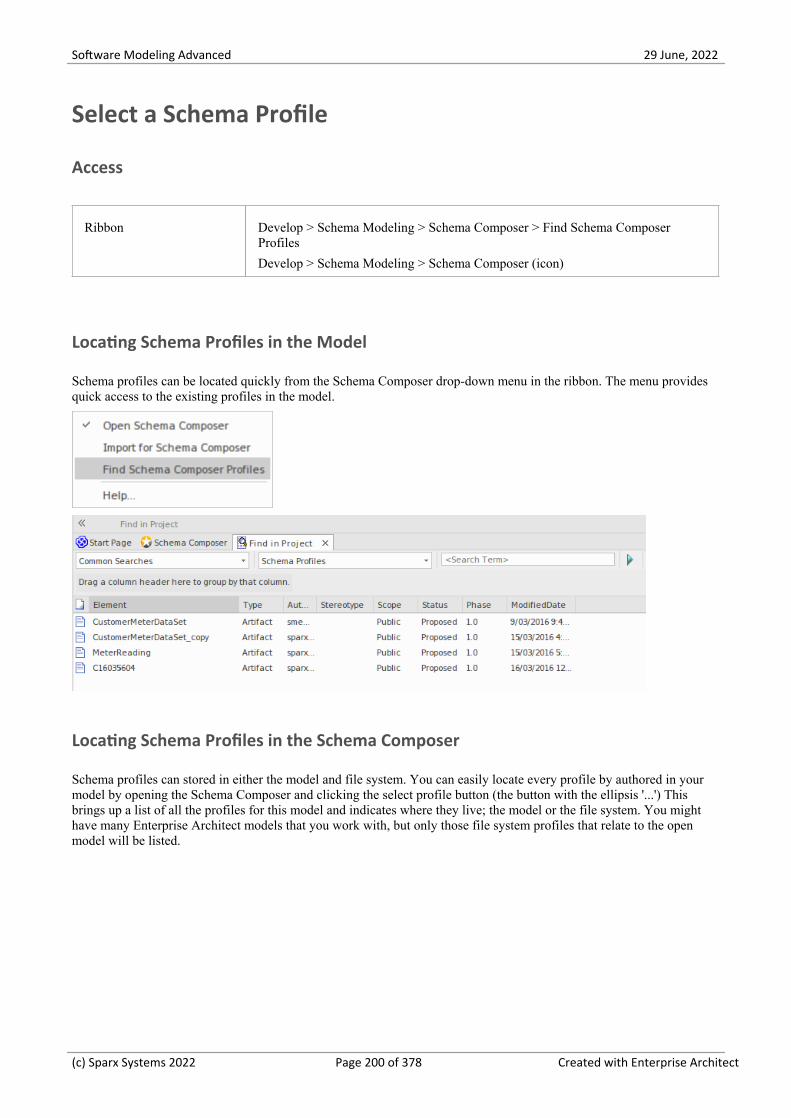
Software Modeling Advanced 29 June, 2022
Select a Schema Profile
Access
Ribbon Develop > Schema Modeling > Schema Composer > Find Schema ComposerProfiles
Develop > Schema Modeling > Schema Composer (icon)
Locating Schema Profiles in the Model
Schema profiles can be located quickly from the Schema Composer drop-down menu in the ribbon. The menu providesquick access to the existing profiles in the model.
Locating Schema Profiles in the Schema Composer
Schema profiles can stored in either the model and file system. You can easily locate every profile by authored in yourmodel by opening the Schema Composer and clicking the select profile button (the button with the ellipsis '...') Thisbrings up a list of all the profiles for this model and indicates where they live; the model or the file system. You mighthave many Enterprise Architect models that you work with, but only those file system profiles that relate to the openmodel will be listed.
(c) Sparx Systems 2022 Page 200 of 378 Created with Enterprise Architect

Software Modeling Advanced 29 June, 2022
(c) Sparx Systems 2022 Page 201 of 378 Created with Enterprise Architect

Software Modeling Advanced 29 June, 2022
Generate Schema File
Having defined a schema profile and added the necessary elements and restrictions, you can quickly and easily generatethe schema(s). XML schema generation is available in all technologies, but each technology might support additionalformats.
Access
Ribbon Develop > Schema Modeling > Schema Composer > Open Schema Composer :Generate
Schema Formats
Select the checkbox against each schema format to export.
Schema Format Details
CIM XML Schema (XSD)·Resource Description Framework Schema (RDFS)·Resource Description Framework Schema - Augmented (RDFS)·JavaScript Object Notation (JSON)·Execute Custom Script·
UN/CEFACT NDR 3.0 XML Schema (XSD)·Execute Custom Script·
UN/CEFACT NDR 2.1 XML Schema (XSD)·Execute Custom Script·
Generic XML Schema (XSD)·Resource Description Framework Schema (RDFS)·JavaScript Object Notation (JSON)·Execute Custom Script·
UBL 2.1 XML Schema (XSD)·Execute Custom Script·
Execute Custom Script Although the Schema Composer can generate schema for a number of recognizedstandards, it also features a scripting solution for those users who want control overthe format and medium of the schema. When you specify a script to the generator, itis referring to a language script such as JavaScript that exists in your model. Howand what the script produces is pretty much up to you. How the script accesses theschema in the Schema Composer is documented in the Schema Composer Scripting Integration.
(c) Sparx Systems 2022 Page 202 of 378 Created with Enterprise Architect

Software Modeling Advanced 29 June, 2022
Generate
Click on this button to generate the schema.
Use a file browser to locate and open the schema files.
Notes
You can edit and validate XML documents including XSD schema, using Enterprise Architect·You can set Enterprise Architect as the default document handler for XML documents·
(c) Sparx Systems 2022 Page 203 of 378 Created with Enterprise Architect

Software Modeling Advanced 29 June, 2022
CIM Schema Guide
This guide describes the creation and generation of a CIM compliant XML Schema.
Create a CIM message
Step Action
1 Display the Schema Composer.
2 Click 'New | Schema'.
3 Enter a unique name for this CIM schema (message).
4 Select the Common Information Model.
5 Drag the initial CIM Class(es) into the Class window that best represents the message. Set root elementsappropriately using the context menu.
6 If you want to compose this type using inheritance, select a single ancestor from the inheritance list.
7 Use the checkboxes on the attributes of each Class to define the set of properties that will describe thismessage or schema.
8 Apply restrictions to elements using the context menu on the property.
9 Click update to save the message.
10 Click the Generate button and choose the schema formats to export.
(c) Sparx Systems 2022 Page 204 of 378 Created with Enterprise Architect

Software Modeling Advanced 29 June, 2022
(c) Sparx Systems 2022 Page 205 of 378 Created with Enterprise Architect

Software Modeling Advanced 29 June, 2022
NIEM Schema Guide
Generation of schema for NIEM is accomplished on either an instance of a ModelPackageDescription Class (NIEM 3.0and above) or a «ModelPackageDescription» stereotyped component (NIEM 2.1). In either case a dialog is presented thatallows you to configure the schema produced.
Generate NIEM Schemas (NIEM 2.1)
Click on a component with a «ModelPackageDescription» stereotype and select one of these options:
Ribbon Specialize > Technologies > NIEM 2.1 > Generate NIEM 2.1 Schema or
(c) Sparx Systems 2022 Page 206 of 378 Created with Enterprise Architect

Software Modeling Advanced 29 June, 2022
Context Menu Right-click on the element | Specialize | NIEM 2.1 | Generate NIEM 2.1 Schema
Generate NIEM Schemas (NIEM 3.0 and above)
Click on any object instance of a ModelPackageDescription Class and select one of these options:
Ribbon Specialize > Technologies > NIEM > Generate NIEM Schema
Context Menu Right-click on the element | Specialize | NIEM | Generate NIEM Schema
(c) Sparx Systems 2022 Page 207 of 378 Created with Enterprise Architect

Software Modeling Advanced 29 June, 2022
UPCC Schema Guide
This guide describes the composition and generation of a UPCC compliant XML schema.
Creation of UPCC Schema
Step Action
1 Display the Schema Composer.
2 Click 'New | Schema'.
3 Enter a unique name for the schema.
4 Select the UPCC Naming and Design rules to use, from the list of standards.
5 Drag one or more <ABIE> components from a <BIE library> into the Class list.
6 Set the Class as a root element using the context menu.
7 Select required attributes (Referenced types are added to the schema).
8 Click on the Update button to save changes.
9 Click on the Generate button and select 'XML Schema'. Click on the OK button.
(c) Sparx Systems 2022 Page 208 of 378 Created with Enterprise Architect

Software Modeling Advanced 29 June, 2022
Model Compositions
The model composition feature of the Schema Composer is useful for creating a sub-model from a core model. This canbe as simple as generating a single business Package from a core Package (CDT library to BDT library transform inUN/CEFACT Core Components standard) or creating a complete sub-model from a large core model.
The enormity of such a task can be daunting and error prone; ensuring every type that is referenced by the sub-model isincluded by the sub-model, for example. The Schema Composer addresses this problem by automatically working out thedependencies and adding them to the schema for you where necessary.
Create Transform
Define Model Content
Content is added to the model by dropping Classes from the model on to the Schema Composer Class window andchoosing which properties to include. The resultant type can mirror the core type or a provide a simpler classification.When a property is included, the Schema Composer will check the property type and if the type is missing will add it tothe schema automatically.
Reference checking
When a property is excluded that was previously included in the schema and is no longer referenced, the property type isnot automatically removed. However, the Schema Composer will always show the number of references for a type if youselect it in the Class window. Types that show no references at all can easily be removed.
(c) Sparx Systems 2022 Page 209 of 378 Created with Enterprise Architect

Software Modeling Advanced 29 June, 2022
Summary
The process of composing a sub-model is summarized here:
Create a Schemer Composer Transform Profile1.
Create elements by dropping Classes from the model into the schema.2.
Include / exclude required properties.3.
Generate the sub model.4.
Access
Ribbon Develop > Schema Modeling > Schema Composer > Open Schema Composer :New > Transform
(c) Sparx Systems 2022 Page 210 of 378 Created with Enterprise Architect

Software Modeling Advanced 29 June, 2022
Generate a Model Subset (Transform)
Having defined the content of your sub-model or library and applied any restrictions, you can now generate the model.The model transforms that can be performed depend on the technology associated with the profile. Each technology andthe transforms it supports are listed here:
Access
Ribbon Develop > Schema Modeling > Schema Composer > Open Schema Composer :Generate
Model Transform
Select the model transform(s) to run.
Transform Option Description
NIEM NIEM Model Subset
This option will generate a NIEM Model Subset containing the schema describedby the profile.
When you click on the OK button, you will be prompted to select the targetPackage for creation of the subset. The <<Namespace>> Packages that make up thesubset will then be created at this location. If any of the subset Packages alreadyexist at this location, their content will be added to. All subset Packages will havethe 'defaultPurpose' Tagged Value set to 'subset'.
Execute custom script
A user defined language script such as JavaScript will be executed. The script canobtain access to the profile using the Schema Composer automation interfaces.
Generic Generic model Subset
You will be prompted for a target Package. This will be populated with the typesfrom the schema. If a qualifier is entered this will be applied to the Classesgenerated. Any restrictions in the schema will also be applied. Types that exist inthe target Package will be overwritten. New properties will be added. Types orproperties that exist in the target but that no longer exist in the profile will not beremoved by this process.
Execute custom script
A user defined language script such as JavaScript will be executed. The script canobtain access to the profile using the Schema Composer automation interfaces.
UN/CEFACT NDR 3.0 BDT Library
A Business Datatype Library will be populated from core datatypes listed in theprofile. Stereotypes will be transformed according to the CCTS specification. Thetypes could be more restricted than their core counterparts. Properties of datatypesthat exist will be overwritten. New properties and types will be added to the library.Types are matched by name and stereotype.
Types or properties that exist in the target but no longer exist in the profile will not
(c) Sparx Systems 2022 Page 211 of 378 Created with Enterprise Architect

Software Modeling Advanced 29 June, 2022
be removed by this process.
BIE Library
A Business Information Entity library will be populated from aggregated corecomponents. listed in the profile. Stereotypes will be transformed according to theCCTS specification. Properties of datatypes that exist will be overwritten. Newproperties and types will be added to the library. Types are matched by name andstereotype.
Types or properties that exist in the target but no longer exist in the profile will notbe removed by this process.
Execute custom script
A user-defined language script such as JavaScript will be executed. The script canaccess the profile using the Schema Composer automation interfaces.
UN/CEFACT NDR 2.1 UDT Library
Performs an unqualified copy of selected core datatypes to a UDT library.
QDT Library
A Qualified Business Datatype Library will be populated from core datatypes listedin the profile. The names of the resultant types will be qualified by the namedqualifier in the profile. Stereotypes will be transformed according to the CCTSspecification. Properties of datatypes that exist will be overwritten. New propertiesand types will be added to the library. Types are matched by name and stereotype.
BIE Library
A Business Information Entity library will be populated from aggregated corecomponents listed in the profile. Stereotypes will be transformed according to theCCTS specification. Properties of datatypes that exist will be overwritten. Newproperties and types will be added to the library. Types are matched by name andstereotype.
Execute custom script
A user-defined language script such as JavaScript will be executed. The script canobtain access to the profile using the Schema Composer automation interfaces.
Generate
Click on the OK button to generate the schema. When the generation is complete, the message Export of profile <name>completed displays.
You can then expand the Package in the Browser window to see the generated UML model.
Notes
The Schema Composer is supported in the Corporate, Unified and Ultimate Editions of Enterprise Architect·
(c) Sparx Systems 2022 Page 212 of 378 Created with Enterprise Architect

Software Modeling Advanced 29 June, 2022
UML Profile for Core Components (UPCC)
The UPCC framework provides core component and core data type libraries and is available to Enterprise Architect usersthrough the Model Wizard ('Create from Pattern' tab of the Start Page). Whether you model according to the UMMspecification, or want to leverage the advantages this standard brings, or have a compliance requirement, to model withthis technology you will require - as a minimum - a Business datatype library and a Business Information Entity library.The Schema Composer can generate these libraries for you.
This image shows a BDT library created from a UPCC Core CDT Library
Common Libraries
Libraries shared by both versions of the UML Profile for Core Components.
Library Description
CCLibrary The CCTS core component library.
CDTLibrary The CCTS core datatype library. It contains basic datatypes such as Amount, Code,Text and Graphic.
BIELibrary A Business library containing ABIE entities based on CCLibrary components. Theentities can be composed using the Schema Composer. These can also be modeledusing the UML modeling tools available for the technology.
DOCLibrary A Package typically used for the modeling of Message Assemblies. You cangenerate the schema for a Message Assembly by loading it into the SchemaComposer.-
UPCC Libraries
The UML Profile for Core Components is available in two versions, NDR 3.0 and NDR 2.1. Both profiles describe acommon set of libraries, with some differences, as described here:
NDR 3.0
(c) Sparx Systems 2022 Page 213 of 378 Created with Enterprise Architect

Software Modeling Advanced 29 June, 2022
Library Description
BDTLibrary A Business library containing BDT types based on CDTLibrary types. The SchemaComposer can be used to easily generate the content of a BDTLibrary from selectedtypes in the core library.
NDR 2.1
Library Description
UDTLibrary An unqualified datatype library. Basically a mirror of the CDTLibrary for use in abusiness context. The Schema Composer can be used to easily generate the contentof a UDTLibrary from selected types in the core library.
QDTLibrary A qualified datatype library. The library contains restricted types based on theCDTLibrary with qualified type names. The Schema Composer can easily generatethe content of a QDTLibrary from selected types in the core library.
UPCC Diagrams
The UML profile for Core Components uses UML Class diagrams for composition of components. There are howeverspecific toolboxes provided by the technology for each of its libraries.
UPCC Toolbox Pages
Common
In this notation, UPPCx represents the UPCC profile and x is the version of the NDR
Common Description
UPCCx - CCLibraryAbstract Syntax
UPCCx - DOCLibraryAbstract Syntax
(c) Sparx Systems 2022 Page 214 of 378 Created with Enterprise Architect

Software Modeling Advanced 29 June, 2022
UPCCx - CDTLibraryAbstract Syntax
UPCCx - BIELibraryAbstract Syntax
NDR 3.0
Library Syntax Description
UPCC - BDTLibraryAbstract Syntax
NDR 2.1
Library Syntax Description
UPCC - UDTLibraryAbstract Syntax
UPCC - QDTLibraryAbstract Syntax
(c) Sparx Systems 2022 Page 215 of 378 Created with Enterprise Architect

Software Modeling Advanced 29 June, 2022
Available Frameworks
Using the Enterprise Architect Model Wizard (Start Page 'Create from Pattern' tab) you can deploy any of theframeworks supported by the Schema Composer - such as NIEM, CIM and CCTS - to your model in minutes, providinga multi-featured UML medium for modeling in those technologies.
The frameworks are also available directly from the Sparx Systems Reusable Asset Service (via the Cloud Server 'CloudConnection' dialog and then 'Frameworks' on the Model Wizard).
Note: In addition to the custom frameworks such as CIM and NIEM, it is possible to use standard Class models torapidly build generic Schemas, so if you are not targeting a particular meta-model, it might be simplest to model yourdata in UML and use the resultant model as input to the Schema Composer.
National Information Exchange Model (NIEM)
This is the National Information Exchange Model published by the NIEM Program Management Office (PMO).
Enterprise Architect provides these resources for modeling in NIEM:
Provided Frameworks including NIEM core, NIEM domains, code lists and external schema adapters:· - NIEM 2.1 modeled using NIEM-UML 1.0 - NIEM 3.0 modeled using NIEM-UML 1.1 - NIEM 3.1 modeled using NIEM-UML 1.1 - NIEM 4.0 modeled using NIEM-UML 1.1
NIEM subset creation:· - The Schema Composer helps you create a subset of a NIEM conformant namespace
NIEM schema generation:· - Generation of complete NIEM IEPDs from a model Package description in either NIEM 2, NIEM 3 or NIEM 4 formats
Common Information Model (CIM)
This is the CIM specification published by International Electrotechnical Commission (IEC) Technical Committee 57.
Enterprise Architect provides these resources for modeling in CIM:
Schema Composition· - XML schema (XSD) - Resource Descriptor format (RDFS)
(c) Sparx Systems 2022 Page 216 of 378 Created with Enterprise Architect

Software Modeling Advanced 29 June, 2022
- Resource Descriptor augmented format - JavaScript Object notation (JSON) - Add-In integration - Scripting integration
Universal Business Language (UBL)
UBL is a CCTS implementation published by OASIS that is proving popular with European governments forconsolidating information exchange between agencies.
Enterprise Architect provides these resources for the composition of business documents using UBL:
UML Framework· - UBL 2.1 Main Document Libraries - UBL 2.1 Common Component Libraries
Business Document Composition· - Schema Composer for component composition - Schema Composer for document composition - Schema Composer for schema generation - Add-In integration - Scripting integration
Core Component Technical Specification (CCTS)
This is the CCTS specification published by UN/CEFACT.
Enterprise Architect provides these resources for modeling in CCTS:
UML Frameworks:· - UPCC 2.1 core component libraries - UPCC 3.0 core component libraries - UMM 2.0 business requirements, choreography and information views.
Business Component Library Creation / Management· - Schema Composer for ABIE and BDT composition - Add-In integration - Scripting integration
Business Component Schema Composition· - Schema Composer for XSD, JSON - Add-In integration - Scripting integration
Add-In Framework (Custom)
In addition to these methodologies, the Schema Composer integrates with the Enterprise Architect Automation Interfaceto support any individual or group in implementing their own. An Add-In that registers its interest to Enterprise Architectin offering Schema generation capabilities will have the opportunity to offer any of its products in the Schema ComposerGeneration tool.
Scripting Framework (Custom)
The Schema Composer also offers unconditional control over generation of schema for any profiles created with it. Bywriting their own script an author can access the definition of any schema and ultimately produce whatever documents
(c) Sparx Systems 2022 Page 217 of 378 Created with Enterprise Architect

Software Modeling Advanced 29 June, 2022
they want, in a format of their choosing.
(c) Sparx Systems 2022 Page 218 of 378 Created with Enterprise Architect

Software Modeling Advanced 29 June, 2022
Install a Core Framework
Enterprise Architect provides a rich and diverse range of modeling technologies including every standard listed in theSchema Composer. These frameworks are available as UML models and/or MDG Technologies using EnterpriseArchitect's Model Wizard (Start Page 'Create from Pattern' tab). The models themselves are also directly accessible fromEnterprise Architect's Reusable Asset Service.
Note: If you are modeling a generic solution and not directly using a core framework such as CIM or UBL, you do notneed to install a core framework/model. In that case you are best served creating a data model using simple UML Classeswith attributes.
Model Wizard
Access
Ribbon Design > Package > Model Wizard
Context Menu Right-click on Package | Add a Model using Wizard
Keyboard Shortcuts Ctrl+Shift+M
Other Browser window 'Hamburger' icon > New Model from Pattern
Note
You can limit the MDG Technologies to use by selecting the ribbon option: 'Specialize > Technologies > ManageTechnology'. Here you can see which technologies are currently enabled.
Import Model
(c) Sparx Systems 2022 Page 219 of 378 Created with Enterprise Architect

Software Modeling Advanced 29 June, 2022
Step Action
1 Display the Start Page 'Create from Pattern' tab (the Model Wizard).
2 Click on the <perspective name> button and select the required technology.
3 Highlight the Technology.
4 Select the Technology standards to import.
5 Clickon the Create Model(s) button to import the framework to your model.
Reusable Asset Service
Access
Ribbon Publish > Model Exchange > Reusable Assets
Import Model
Step Action
1 Connect to the Reusable Asset Service.
(c) Sparx Systems 2022 Page 220 of 378 Created with Enterprise Architect

Software Modeling Advanced 29 June, 2022
2 Choose from the available list of Repositories
3 Select the UML model Package
4 Click OK to import the selected Package to your model.
(c) Sparx Systems 2022 Page 221 of 378 Created with Enterprise Architect

Software Modeling Advanced 29 June, 2022
The Schema Importer
You can import Schemas compatible with the Schema Composer, into Enterprise Architect using the Schema Importer.The Schema Importer validates the Schema and creates a Schema type Schema Composer Profile upon successfulvalidation, that can be viewed directly in the Schema Composer.
Currently, you can use the Schema Importer to import these Schemas:
Common Information Model (CIM) specific XML Schema·Common Information Model (CIM) specific RDFS XML·
Access
Ribbon Develop > Schema Modeling > Schema Composer > Import for Schema Composer
Import a Schema using the Schema Importer
Option Action
Schema File Type the directory path and filename from which to import the Schema file.
Schema Set Select the type of Schema being imported.
Currently the Schema Importer supports importing CIM specific:
XML Schema and·RDFS XML·
Reference Package Select the Package containing the common elements specific to the schema set.
The Schema Importer will validate the elements in the Schema being importedagainst the elements in the reference Package.
View imported Schema inSchema Composer
Select this option to open the imported Profile in the Schema Composer.
Import Click on this button to start the import process.
(c) Sparx Systems 2022 Page 222 of 378 Created with Enterprise Architect

Software Modeling Advanced 29 June, 2022
Close Click on this button to close the 'Schema Importer' dialog.
Notes
The progress of import will be displayed in the System Output window·The Schema Composer will validate the Schema against the elements in the Reference Package before importing the·Schema; if validation fails, the Schema elements that fail validation will be displayed in the System Output windowand the import process will stop
Double-click on a validation error entry in the System Output Window to open the Schema in Enterprise Architect's·internal file editor and go to the source of the error
If validation succeeds, the 'New Schema Definition' dialog displays, through which you can save the imported·Profile in the file system or as an Artifact in the current model
(c) Sparx Systems 2022 Page 223 of 378 Created with Enterprise Architect

Software Modeling Advanced 29 June, 2022
Schema Composer Automation Integration
The Schema Composer can be accessed from the Enterprise Architect Automation Interface. A client (script or Add-In)can obtain access to the interface using the 'SchemaComposer' property of the 'Repository' object. This interface isavailable when a Schema Composer has a profile loaded.
(c) Sparx Systems 2022 Page 224 of 378 Created with Enterprise Architect

Software Modeling Advanced 29 June, 2022
Schema Composer Addin Integration
Enterprise Architect Add-Ins can integrate with the Schema Composer by providing alternatives to offer users for thegeneration of schemas and sub models.
(c) Sparx Systems 2022 Page 225 of 378 Created with Enterprise Architect

Software Modeling Advanced 29 June, 2022
Schema Composer Scripting Integration
Although the Schema Composer provides out-of-the-box schema composition based on a variety of populartechnologies, its scripting integration provides you with some flexibility in how you might go about implementing yourown requirements. There are three ways in which you might leverage scripting within the Schema Composer:
Provide custom schema generation using a scripting language·Provide custom model transformation using a scripting language·Provide custom stereotype mapping to any standard model transform (such as UPCC)·
Model Transformation by script
While the Schema Composer provides in-built transforms for various frameworks, you can always write your own, usingthe composition tools of the Composer to design the schema, then performing a custom transform with a hand craftedscript.
Schema Generation by script
When you select a message in the Schema Composer and click generate, you are presented with a number of exportformats. One of those choices is 'Execute custom script'
Schema Iteration Scripting Example
This example demonstrates accessing the Schema Composer in an Enterprise Architect script written in JavaScript. Thescript first obtains an interface to the Schema Composer and then traverses the schema, printing out the types and each of
(c) Sparx Systems 2022 Page 226 of 378 Created with Enterprise Architect

Software Modeling Advanced 29 June, 2022
its properties.
/*
* Script Name: Example Schema Composer Script
* Author: Sparx Systems
* Purpose: Demonstrate access to Schema Composer using automation and JavaScript
* Language: JavaScript
* Date: 2020
*/
function printType( xmlType, xmlns, uri)
{
var xmlProp as EA.SchemaProperty;
var xmlPropEnum as EA.SchemaPropEnum;
var xmlChoiceEnum1 as EA.SchemaTypeEnum;
var xmlChoiceEnum2 as EA.SchemaTypeEnum;
Session.Output("Type: " + xmlType.TypeName + " in namespace: " + xmlns + ":" + uri);
xmlPropEnum = xmlType.Properties;
if(xmlPropEnum)
{
xmlProp = xmlPropEnum.GetFirst();
while(xmlProp)
{
if(xmlType.IsEnumeration())
{
Session.Output(" " + xmlProp.Name);
}
else
{
var sPropDesc = xmlProp.Name;
sPropDesc += "::"
if(xmlProp.IsPrimitive())
sPropDesc += xmlProp.PrimitiveType;
else
sPropDesc += xmlProp.TypeName;
if(xmlProp.IsByReference())
{
sPropDesc += "(by reference)";
}
if(xmlProp.IsInline())
{
(c) Sparx Systems 2022 Page 227 of 378 Created with Enterprise Architect

Software Modeling Advanced 29 June, 2022
sPropDesc += "(inline)";
}
Session.Output(" " + sPropDesc + ", cardinality: " + xmlProp.Cardinality);
xmlChoiceEnum1 = xmlProp.Choices;
xmlChoiceEnum2 = xmlProp.SchemaChoices;
var count = xmlChoiceEnum1.GetCount() + xmlChoiceEnum2.GetCount();
if(count>1)
{
Session.Output(" choice of: ");
xmlChoice = xmlChoiceEnum1.GetFirst();
while(xmlChoice)
{
Session.Output(" " + xmlChoice.TypeName);
xmlChoice = xmlChoiceEnum1.GetNext();
}
xmlChoice = xmlChoiceEnum2.GetFirst();
while(xmlChoice)
{
Session.Output(" " + xmlChoice.TypeName);
xmlChoice = xmlChoiceEnum2.GetNext();
}
}
}
xmlProp = xmlPropEnum.GetNext();
}
}
}
function main()
{
var schema as EA.SchemaComposer;
var xmlType as EA.SchemaType;
var xmlTypeEnum as EA.SchemaTypeEnum;
var xmlNamespaceEnum as EA.SchemaNamespaceEnum;
var xmlNS as EA.SchemaNamespace;
// Get SchemaComposer
schema = Repository.SchemaComposer;
// print the namespace references
xmlNamespaceEnum = schema.Namespaces;
(c) Sparx Systems 2022 Page 228 of 378 Created with Enterprise Architect

Software Modeling Advanced 29 June, 2022
if(xmlNamespaceEnum)
{
xmlNS = xmlNamespaceEnum.GetFirst();
while(xmlNS)
{
Session.Output( "xmlns:" + xmlNS.Name + " URI=" + xmlNS.URI);
xmlNS = xmlNamespaceEnum.GetNext();
}
}
// Get Schema Types Enumerator
xmlTypeEnum = schema.SchemaTypes;
xmlType = xmlTypeEnum.GetFirst();
while(xmlType)
{
var xmlns = schema.GetNamespacePrefixForType( xmlType.TypeID );
uri = schema.GetNamespaceForPrefix(xmlns);
printType(xmlType, xmlns, uri);
xmlType = xmlTypeEnum.GetNext();
}
}
main();
Intelli-sense help in scripting
The Scripting editor in Enterprise Architect will help you write script that interacts with the Schema Composer, byproviding Intelli-sense on the properties and methods of its Automation Interface.
Stereotype mapping in Model Transformation
Stereotyping forms a large part of the MDG Technology approach. Individual UML profiles for an MDG Technology
(c) Sparx Systems 2022 Page 229 of 378 Created with Enterprise Architect

Software Modeling Advanced 29 June, 2022
define stereotypes to offer useful classifications for its elements. It is a common requirement when going from a coreframework to a business model or sub-domain to reassign the stereotype. When you work with a CCTS framework thebusiness components you generate have their stereotype automatically generated by Enterprise Architect according to amapping defined by the CCTS specification (ACC to ABIE, for example).
When you open or create a model transform profile in the Schema Composer you can specify a script to perform thismapping for you. The script can be selected from the Properties window.
The script can be written in either JavaScript, JScript or VBScript, and only has to implement this function (describedhere in JavaScript notation):
function TranslateStereotype(srcStereo)
{
var destStereo = srcStereo
if (srcStereo == "BDT")
{
destStereo = "My_BDT"
}
return destStereo;
}
(c) Sparx Systems 2022 Page 230 of 378 Created with Enterprise Architect

Software Modeling Advanced 29 June, 2022
MDG Technologies - UML Profile Extensions
The Schema Composer works with MDG technologies. The standards it uses for schema generation, other than Generic,are only meaningful for models that adhere to that framework. However, it is quite easy to extend an existing MDGTechnology. Make sure that elements authored in your business specific domain or sub-domain provide consistentlynamed metadata or 'Tagged Values'.
The Schema Composer supports extensions to UML profiles / frameworks through its scripting integration. When ascript is assigned in the Schema Composer, the transform process will invoke this script and ask it to translate keywords.These keywords are usually UML stereotypes. If a particular technology is associated with the profile, the SchemaComposer will invoke this function, passing it the name of the MDG Technology.
The script can return the input name, and no mapping will take place, or it can return the name of another MDGTechnology. When this occurs, the Schema Composer will again ask for the function to optionally map any UMLprofiles. Finally it will ask the script to translate the stereotypes from the core technology.
The result of the model transform would then be that any UML elements of the sub model will show the extendedTagged Values in addition to any core Tagged Values.
Example script that maps MDG Technology
function TranslateStereotype (stereo)
{
var newStereo = stereo;
if (stereo == "UPCC3")
{
newStereo = "XXX UPCC3"
}
return newStereo;
}
Example script that maps UML profile
function TranslateStereotype (stereo)
{
var newStereo = stereo;
if (stereo == "UPCC3 - BIE Library Abstract Syntax")
{
newStereo = "UPCC3 - BIE Library XXX Syntax"
}
return newStereo;
}
Example script that maps UML Stereotype
function TranslateStereotype (stereo)
{
(c) Sparx Systems 2022 Page 231 of 378 Created with Enterprise Architect

Software Modeling Advanced 29 June, 2022
var newStereo = stereo;
if (stereo == "ABIE")
{
newStereo = "XXX ABIE";
}
return newStereo;
}
(c) Sparx Systems 2022 Page 232 of 378 Created with Enterprise Architect

Software Modeling Advanced 29 June, 2022
XSD Models
XML Schema Definition (XSD), also known as XML Schema, is a World Wide Web Consortium (W3C) XMLtechnology that is used to specify the rules to which an XML document must adhere. XSD support is critical for thedevelopment of a complete Service Oriented Architecture (SOA), and the coupling of UML 2.5 and XML provides thenatural mechanism for specifying, constructing and deploying XML-based SOA artifacts within an organization.
The UML Profile for XSD specifies a set of stereotypes, Tagged Values and constraints that can be applied to the UMLmodel in order to change specific aspects of the resulting schema. Enterprise Architect provides native support for theXSD Profile through the XML Schema page of the Diagram Toolbox. The XSD Profile supported by EnterpriseArchitect is an adaptation of the profile defined in the publication Modeling XML Applications with UML.
Working with the XSD Profile through Enterprise Architect, you can rapidly model, forward engineer and reverseengineer XML Schema.
You can also quickly define and generate XSD and other schema using the Enterprise Architect Schema Composer.
(c) Sparx Systems 2022 Page 233 of 378 Created with Enterprise Architect

Software Modeling Advanced 29 June, 2022
Modeling XSD
You can model XML schemas at two levels, using UML Class diagrams that:
Have no XML schema-specific implementation details, to be generated directly by Enterprise Architect's Schema·Generator; the generator applies a set of default mappings to convert the abstract model Package to a W3C XMLSchema (XSD) file
Are refined with XML schema-specific definitions using the 'XML Schema' pages of the Diagram Toolbox, which·provides the structures of the UML profile for XSD
Model an XML Schema
Step Action
1 In the Browser window, create the top-level project structure you need (Model and Views), and click onthe appropriate View.
2 Click on the 'New Package' option in the Browser window header drop-down menu. The 'New ModelPackage' dialog displays.
3 In the 'Name' field type the name of the new Package, and select the 'Create diagram' radio button.
Click on the OK button. The 'New Diagram' dialog displays.
4 In the 'Name' field type the name of the new diagram.
In the 'Select From' panel select 'UML Structural', and in the 'Diagram Types' panel select 'Class'.
5 Click on the OK button. In the Browser window, double-click on the icon next to the new diagram's name;the diagram opens in the Diagram View, with the 'Class' pages displaying in the Diagram Toolbox.
At this point you can either:
Create a Class diagram using the Class Toolbox icons, or·Create a tailored XML Schema diagram using the 'XML Schema' pages of the Diagram Toolbox·(continue to step 6)
6Click on to display the 'Find Toolbox Item' dialog and specify 'XML Schema' to display the 'XMLSchema' Toolbox pages.
7 Click on the 'Schema' icon from the Toolbox and drag it into the Class diagram.
The 'XSD schema Properties' dialog displays.
Complete this dialog, and click on the OK button.
The 'New Diagram' dialog displays.
8 Again, in the 'Name' field type the name of the new diagram.
In the 'Select From' panel select 'UML Structural', and in the 'Diagram Types' panel select 'Class'.
Click on the OK button.
9 An XSDschema stereotyped Package is created in the Browser window and on the diagram, with a childClass diagram.
Double-click on the Package on the diagram to open the child Class diagram, and use the constructs from
(c) Sparx Systems 2022 Page 234 of 378 Created with Enterprise Architect

Software Modeling Advanced 29 June, 2022
the XML Schema Toolbox to model the XML Schema.
Notes
The UML attributes of the Classes map directly to XML elements or attributes·If you have modeled your XSD Schema as a straight Class diagram, you can define and generate schema from it·using the Schema Composer
Classes in an XML Schema model have no methods since there is no meaningful correspondence between Class·methods and XSD constructs
Modeling Restrictions - these XML Schema constructs cannot be modeled in Enterprise Architect:· - appinfo - field - key - keyref - notation - redefine - selector - substitutionGroup - unique
(c) Sparx Systems 2022 Page 235 of 378 Created with Enterprise Architect

Software Modeling Advanced 29 June, 2022
XSD Diagrams
This example diagram shows a Class diagram containing XSD-specific elements created using the 'XSD Schema' pagesof the Diagram Toolbox. The diagram models an employee records system.
(c) Sparx Systems 2022 Page 236 of 378 Created with Enterprise Architect

Software Modeling Advanced 29 June, 2022
Schema Package
An «XSDschema» stereotyped Package acts as a container for the XSD constructs, from which XML Schema can begenerated. All Classes in the Package are defined within one schema; the Schema element provides the defaultschema-wide settings. You can create an «XSDschema» Package by dragging the Schema icon from the XML SchemaToolbox and dropping it directly onto a diagram.
Toolbox Icon
Access
To display the XSD schema 'Properties' dialog for the selected «XSDschema» stereotyped Package, use one of themethods outlined here:
Ribbon Design > Package > Manage > Properties
Context Menu Right-click on «XSDschema» stereotyped Package | Properties
Other In Browser window, double-click on existing «XSDschema» stereotyped Package,or
Drag icon from toolbox onto diagram (this creates anew «XSDschema» stereotyped Package)
Define Properties
Field/Button Action
Schema Name If you do not want to use the default name of the schema Package, overtype it withanother name.
Target Namespace (Optional) Type in the target namespace for this Schema Package.
Prefix (Optional) Type in the abbreviated text to represent the Target Namespace.
Default Namespace (Optional) Type in the default namespace for all non-prefixed XSDelements andXSDattributes.
Schema FileType in or browse for (click on ) the file path where the XML Schema file forthis Package is to be generated.
XMLNS Identify the additional namespace or namespace-prefix pairs used in this SchemaPackage.
To add a namespace or namespace-prefix pair, click on the New button; to edit an
(c) Sparx Systems 2022 Page 237 of 378 Created with Enterprise Architect
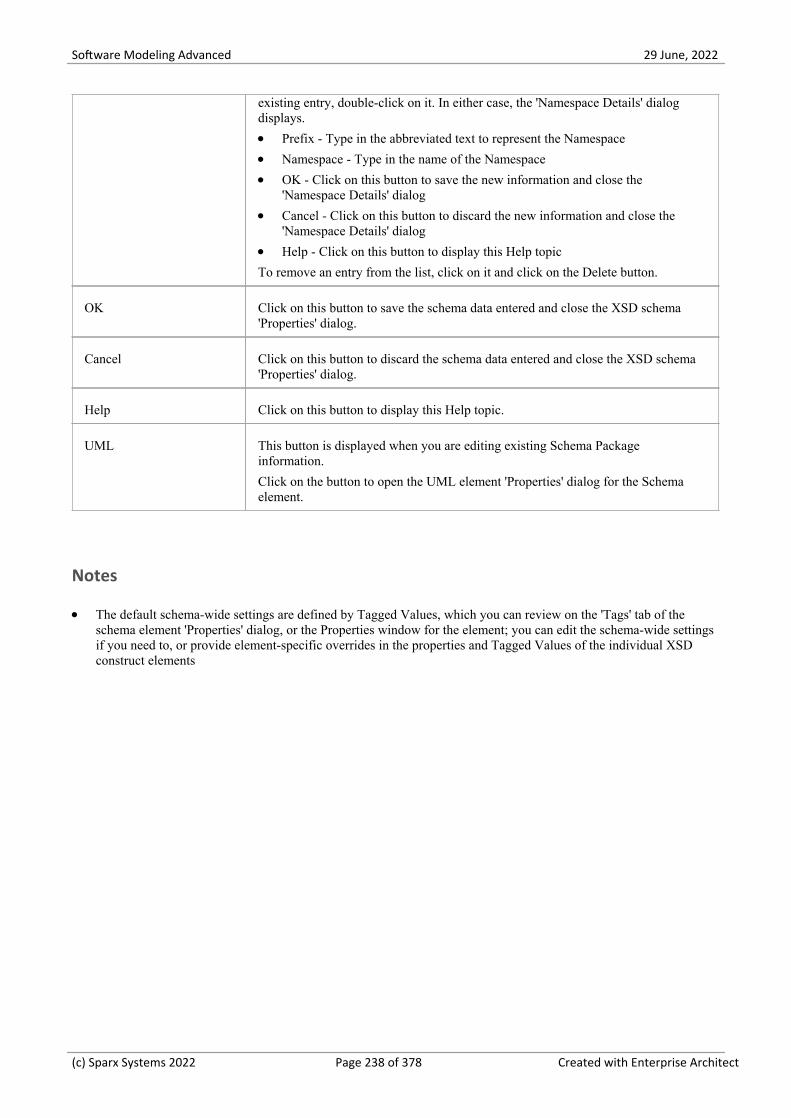
Software Modeling Advanced 29 June, 2022
existing entry, double-click on it. In either case, the 'Namespace Details' dialogdisplays.
Prefix - Type in the abbreviated text to represent the Namespace·Namespace - Type in the name of the Namespace·OK - Click on this button to save the new information and close the·'Namespace Details' dialog
Cancel - Click on this button to discard the new information and close the·'Namespace Details' dialog
Help - Click on this button to display this Help topic·To remove an entry from the list, click on it and click on the Delete button.
OK Click on this button to save the schema data entered and close the XSD schema'Properties' dialog.
Cancel Click on this button to discard the schema data entered and close the XSD schema'Properties' dialog.
Help Click on this button to display this Help topic.
UML This button is displayed when you are editing existing Schema Packageinformation.
Click on the button to open the UML element 'Properties' dialog for the Schemaelement.
Notes
The default schema-wide settings are defined by Tagged Values, which you can review on the 'Tags' tab of the·schema element 'Properties' dialog, or the Properties window for the element; you can edit the schema-wide settingsif you need to, or provide element-specific overrides in the properties and Tagged Values of the individual XSDconstruct elements
(c) Sparx Systems 2022 Page 238 of 378 Created with Enterprise Architect

Software Modeling Advanced 29 June, 2022
Global Element
An «XSDtopLevelElement» stereotyped Class acts as a XSD global element. You can create it by dragging the 'Element'icon from the XML Schema Toolbox and dropping it directly onto a diagram.
Toolbox Icon
Access
To display the 'XSD element Properties' dialog for the selected «XSDtopLevelElement» stereotyped Class, use one of themethods outlined here.
Ribbon Design > Element > Editors > Properties
Context Menu Right-click on «XSDtopLevelElement» stereotyped Class | Properties
Keyboard Shortcuts Alt+Enter
Other In Browser window, double-click on «XSDtopLevelElement» stereotyped Class, or
Drag icon from toolbox onto diagram (this creates anew «XSDtopLevelElement» stereotyped Class)
Define Properties
Field/Button Action
Name If you do not want to use the default name of the global element, overtype it withanother name.
Type Either:
Type the name of a data type, or·Click on the drop-down arrow and select an XSD built-in dataType from the·list, or
Click on the button and browse for an existing XSD classifier element, or·Select one of these two checkboxes·
Nested complexType Select this checkbox to create an XSDcomplexType as a child of this globalelement.
Nested simpleType Select this checkbox to create an XSDsimpleType as a child of this global element.
Value (Optional) If you have entered an XSD built-in data type in the 'Type' field, type in
(c) Sparx Systems 2022 Page 239 of 378 Created with Enterprise Architect

Software Modeling Advanced 29 June, 2022
a value.
Default Select this radio button to set the Value as a default value.
Fixed Select this radio button to set the Value as a fixed value.
Annotation (Optional) Type in any notes you need for this element.
OK Click on this button to save the element data entered and close the XSD element'Properties' dialog.
Cancel Click on this button to discard the element data entered and close the XSD element'Properties' dialog.
Help Click on this button to display this Help topic.
UML This button is displayed when you are editing existing XSD element information.
Click on the button to open the UML element 'Properties' dialog for the globalelement.
Notes
The fields 'Type', 'Nested complexType' and 'Nested simpleType' are mutually exclusive; selecting one disables the·others
The fields 'Nested complexType' and 'Nested simpleType' are available in the dialog only when creating a new·global element (and not when editing the global element)
A Global element:· - Cannot contain any UML attributes - Cannot be the source of an Association connector - Can be the target of an Association connector from a Complex Type Class or Group Class element - Cannot be the target of a Generalization connector - Can be the source of one Generalization connector to a Complex Type Class or Simple Type Class
(c) Sparx Systems 2022 Page 240 of 378 Created with Enterprise Architect

Software Modeling Advanced 29 June, 2022
Local Element
A Local element is an «XSDelement» stereotyped UML attribute that acts as a local XSD element. You can create it bydragging the 'Element' icon from the XML Schema Toolbox and dropping it onto an «XSDcomplexType» or«XSDgroup» stereotyped Class.
Toolbox Icon
Access
To display the 'XSD element Properties' dialog for the selected «XSDelement» stereotyped UML attribute, use one of themethods outlined here.
Ribbon With a specific «XSDelement» stereotyped attribute selected in a diagram:
Design > Element > Features > Attributes
Context Menu With a specific «XSDelement» stereotyped attribute selected in a diagram :
Right-click on attribute | View Properties
Keyboard Shortcuts With a specific «XSDelement» stereotyped attribute selected in a diagram :
F9
Other Double-click on «XSDelement» stereotyped attribute, or
Drag icon onto «XSDcomplexType» or«XSDgroup» stereotyped Class, (this creates a new «XSDelement» within theClass)
Define Properties
Field/Button Action
Name If you do not want to use the default name of the local element, overtype it withanother name.
Type Either:
Type the name of a data type, or·Click on the drop-down arrow and select an XSD built-in dataType from the·list, or
Click on the button and browse for an existing XSDcomplexType or·XSDsimpleType element as a classifier
Reference (Optional) Specify whether to use the ref attribute (instead of the type attribute) to
(c) Sparx Systems 2022 Page 241 of 378 Created with Enterprise Architect

Software Modeling Advanced 29 June, 2022
refer to the XSDcomplexType or XSDsimpleType element you selected in the'Type' field, in the generated XSD.
Value (Optional) If you have entered an XSD built-in data type in the 'Type' field, type ina value.
Default Select this radio button to set the Value as a default value.
Fixed Select this radio button to set the Value as a fixed value.
MinOccurs (Optional) Type the minimum number of times this element must occur in theClass.
Type '0' to indicate that the element is optional.
The default value is '1'.
MaxOccurs (Optional) Type the maximum number of times this element can occur in the Class.
Type unbounded to indicate that there is no limit to the number of times the elementcan occur.
The default value is 1.
Form (Optional) Click on the drop-down arrow and select whether or not to qualify theelement:
qualified - Use the Prefix defined in the Schema Package to qualify this·element
unqualified - Do not qualify this element·
Annotation (Optional) Type in any notes you need for this local element.
OK Click on this button to save the element data entered and close the XSD element'Properties' dialog.
Cancel Click on this button to discard the element data entered and close the XSD element'Properties' dialog.
Help Click on this button to display this Help topic.
UML This button is displayed when you are editing existing XSD element information.
Click on the button to open the attribute properties for the local element.
Notes
Only «Complex Type», «Group» and «Model Group» stereotyped elements can have this UML Attribute·
(c) Sparx Systems 2022 Page 242 of 378 Created with Enterprise Architect

Software Modeling Advanced 29 June, 2022
Global Attribute
A Global Attribute is an «XSDtopLevelAttribute» stereotyped Class. You can create it by dragging the 'Attribute' iconfrom the XML Schema Toolbox and dropping it directly onto a diagram.
Access
To display the 'XSD attribute Properties' dialog for the selected «XSDtopLevelAttribute» stereotyped element, use one ofthe methods outlined here.
Ribbon Design > Element > Editors > Properties
Context Menu Right-click on «XSDtopLevelAttribute» stereotyped element| Properties
Keyboard Shortcuts Alt+Enter
Other Double-click on «XSDtopLevelAttribute» stereotyped Class, or
Drag icon from toolbox and drop directly onto thediagram (this creates a new «XSDtopLevelAttribute» stereotyped Class)
Toolbox Icon
Define Properties
Field/Button Action
Name If you do not want to use the default name of the global attribute, overtype it withanother name.
Type Either:
Type the name of a data type, or·Click on the drop-down arrow and select an XSD built-in dataType from the·list, or
Click on the button and browse for an existing XSDsimpleType element·as a classifier
Alternatively, select the 'Nested simpleType' checkbox.
Nested simpleType Select this checkbox to create an XSDsimpleType element as a child of this globalattribute element.
Value (Optional) If you have selected an XSD built-in dataType in the 'Type' field, type ina value.
(c) Sparx Systems 2022 Page 243 of 378 Created with Enterprise Architect

Software Modeling Advanced 29 June, 2022
Default Select this radio button to set the 'Value' field as a default value.
Fixed Select this radio button to set the 'Value' field as a fixed value.
Form (Optional) Click on the drop-down arrow and select:
qualified to use any Prefix supplied on the Schema Package to qualify this·attribute, or
unqualified to show no qualifying prefix on the attribute name·
Annotation (Optional) Type in any notes you need for this attribute.
OK Click on this button to save the attribute data entered and close the XSD attribute'Properties' dialog.
Cancel Click on this button to discard the attribute data entered and close the XSD attribute'Properties' dialog.
Help Click on this button to display this Help topic.
UML This button is displayed when you are editing existing XSD element information.
Click on the button to open the UML element 'Properties' dialog for the globalattribute Class.
Notes
The field 'Nested simpleType' is available in the dialog only when creating a new global attribute (and not when·editing the global attribute)
The fields 'Type' and 'Nested simpleType' are mutually exclusive; selecting one disables the other·A Global attribute:· - Cannot contain any UML attributes - Cannot be the source of an Association connector - Can be the target of an Association connector from a Complex Type Class - Cannot be the target of a Generalization connector - Can be the source of one Generalization connector to a Simple Type Class
(c) Sparx Systems 2022 Page 244 of 378 Created with Enterprise Architect

Software Modeling Advanced 29 June, 2022
Local Attribute
A local attribute is an «XSDattribute» stereotyped UML attribute. You can create it by dragging the 'Attribute' icon fromthe XML Schema Toolbox and dropping it onto an «XSDcomplexType» or «XSDattributeGroup» stereotyped Class.
Toolbox Icon
Access
To display the 'XSD attribute Properties' dialog for the selected «XSDattribute» stereotyped UML attribute, use one ofthe methods outlined here.
Ribbon With a specific «XSDattribute» stereotyped UML attribute selected on a diagram:
Design > Element > Features > Attributes
Context Menu With a specific «XSDattribute» stereotyped UML attribute selected on a diagram:
Right-click on attribute | View Properties
Keyboard Shortcuts With a specific «XSDattribute» stereotyped UML attribute selected on a diagram:
F9
Other Double-click on the «XSDattribute» stereotyped UML attribute, or
Drag icon from the Toolbox and drop it onto an«XSDcomplexType» or «XSDattributeGroup» stereotyped Class (this creates a new«XSDattribute» stereotyped UML attribute)
Define Properties
Field/Button Action
Name If you do not want to use the default name of the local attribute, overtype it withanother name.
Type Either:
Type the name of a data type, or·Click on the drop-down arrow and select an XSD built-in dataType from the·list, or
Click on the button and browse for an existing XSDsimpleType element·as a classifier
Reference (Optional) Specify whether to use the ref attribute (instead of the type attribute) torefer to the XSDsimpleType element you selected in the 'Type' field, in the
(c) Sparx Systems 2022 Page 245 of 378 Created with Enterprise Architect

Software Modeling Advanced 29 June, 2022
generated XSD.
Value (Optional) If you have entered an XSD built-in data type in the 'Type' field, type ina value.
Default Select this radio button to set the Value as a default value.
Fixed Select this radio button to set the Value as a fixed value.
Form (Optional) Click on the drop-down arrow and select whether or not to qualify theattribute:
qualified - Use the Prefix defined in the Schema Package to qualify this·attribute
unqualified - Do not qualify this attribute·
Annotation (Optional) Type in any notes you need for this local attribute.
OK Click on this button to save the attribute data entered and close the XSD attribute'Properties' dialog.
Cancel Click on this button to discard the element data entered and close the XSD attribute'Properties' dialog.
Help Click on this button to display this Help topic.
UML This button is displayed when you are editing existing XSD attribute information.
Click on the button to open the attribute properties for the local attribute.
Notes
Only Complex Types and Attribute Groups can have this UML attribute·
(c) Sparx Systems 2022 Page 246 of 378 Created with Enterprise Architect

Software Modeling Advanced 29 June, 2022
Attribute Group
An Attribute Group Class is used to group a set of «XSDattribute» stereotyped UML attributes and Simple Type Classesthat can be referenced from an «XSDcomplexType» stereotyped Class. You can create it by dragging the 'AttributeGroup' icon from the XML Schema Toolbox and dropping it directly onto a diagram.
Toolbox Icon
Access
To display the 'XSD Attribute Group Properties' dialog for the selected «XSDattributeGroup» stereotyped Class, use oneof the methods outlined here.
Ribbon Design > Element > Editors > Properties
Context Menu Right-click on «XSDattributeGroup» stereotyped Class | Properties
Keyboard Shortcuts Alt+Enter
Other Double-click on «XSDattributeGroup» stereotyped Class, or
Drag icon from toolbox onto diagram (this creates anew «XSDattributeGroup» stereotyped Class)
Define Properties
Field/Button Action
Name If you do not want to use the default name of the Attribute Group, overtype it withanother name.
Annotation (Optional) Type in any notes you need for this Attribute Group.
OK Click on this button to save the attribute group data entered and close the XSDAttribute Group 'Properties' dialog.
Cancel Click on this button to discard the attribute group data entered and close the XSDAttribute Group 'Properties' dialog.
Help Click on this button to display this Help topic.
UML This button is displayed when you are editing existing XSD attribute groupinformation.
Click on the button to open the UML element 'Properties' dialog for the attribute
(c) Sparx Systems 2022 Page 247 of 378 Created with Enterprise Architect

Software Modeling Advanced 29 June, 2022
group.
Notes
An Attribute Group element:· - Cannot be the child of any other XSD Class - Can contain only «XSDattribute» stereotyped UML attributes and Simple Type Classes - Can be the source of an Association connector to another Attribute Group - Can be the target of an Association connector from a Complex Type Class - Cannot be the source or target of a Generalization connector
(c) Sparx Systems 2022 Page 248 of 378 Created with Enterprise Architect

Software Modeling Advanced 29 June, 2022
Complex Type
An «XSDcomplexType» stereotype is applied to a generic UML Class, to tailor the generation of a complexTypedefinition in the Schema. You can create an «XSDcomplexType» stereotyped Class by dragging the Complex Type iconfrom the XML Schema Toolbox and dropping it directly onto a diagram.
Toolbox Icon
Access
To display the 'XSD complexType Properties' dialog for the selected «XSDcomplexType» stereotyped Class, use one ofthe methods outlined here.
Ribbon Design > Element > Editors > Properties
Context Menu Right-click on «XSDcomplexType» stereotyped Class | Properties
Keyboard Shortcuts Alt+Enter
Other Double-click on «XSDcomplexType» stereotyped Class, or
Drag icon from toolbox onto diagram (this creates anew «XSDcomplexType» stereotyped Class)
Define Properties
Field/Button Action
Name If you do not want to use the default name of the complexType Class, overtype itwith another name.
Model Group Click on the down-arrow and select the option that defines how the child elementsof this complexType should occur in the Schema.
'sequence' - the child elements must occur in the specified order·'choice' - only one of the child elements can occur·'all' - the child elements can occur in any order·
MinOccurs (Optional) Type the minimum number of times this element must occur in theClass.
Type 0 to indicate that the element is optional.
The default value is 1.
MaxOccurs (Optional) Type the maximum number of times this element can occur in the Class.
(c) Sparx Systems 2022 Page 249 of 378 Created with Enterprise Architect

Software Modeling Advanced 29 June, 2022
Type unbounded to indicate that there is no limit to the number of times the elementcan occur.
The default value is 1.
Annotation (Optional) Type any notes you need for this element.
Abstract (Optional) Select this checkbox to use this complexType in an instance XML file.
Mixed (Optional) Select this checkbox to allow character data to display among the childelements.
OK Click on this button to save the complexType data entered and close the XSDcomplexType 'Properties' dialog.
Cancel Click on this button to discard the complexType data entered and close the XSDcomplexType 'Properties' dialog.
Help Click on this button to display this Help topic.
UML This button is displayed when you are editing existing XSD complexTypeinformation.
Click on the button to open the UML element 'Properties' dialog for thecomplexType Class.
Notes
A complexType can:· - Contain both XSDelement and XSDattribute stereotyped UML attributes - Contain other complexTypes as child elements - Be a child of a Global Element - Be the source of Association connectors to other complexTypes, Simple Types, Attribute Groups, Groups andModel Groups - Be the source of a maximum of one Generalization connector to either another complexType or a Simple TypeClass
(c) Sparx Systems 2022 Page 250 of 378 Created with Enterprise Architect

Software Modeling Advanced 29 June, 2022
Simple Type
An «XSDsimpleType» stereotype is applied to a generic UML Class, to tailor the generation of a simpleType definitionin the Schema. You can create an «XSDsimpleType» Class by dragging the Simple Type icon from the XML SchemaToolbox and dropping it directly onto a diagram.
Toolbox Icon
Access
To display the 'XSD simpleType Properties' dialog for the selected «XSDsimpleType» stereotyped Class, use one of themethods outlined here.
Ribbon Design > Element > Editors > Properties
Context Menu Right-click on «XSDsimpleType» stereotyped Class | Properties
Keyboard Shortcuts Alt+Enter
Other Double-click on «XSDsimpleType» stereotyped Class, or
Drag icon from toolbox onto diagram (this creates anew «XSDsimpleType» stereotyped Class)
Define Properties
Field/Button Action
Name If you do not want to use the default name of the simpleType element, overtype itwith another name.
Type Either:
Type the name of a data type, or·Click on the drop-down arrow and select an XSD built-in dataType from the·list, or
Click on the button and browse for an existing «XSDsimpleType»·element as a classifier
Restriction Select this radio button to restrict the value of this simpleType to that of theselected Type.
The various restrictions (facets) on the simpleType are available as Tagged Valueson this Class.
(c) Sparx Systems 2022 Page 251 of 378 Created with Enterprise Architect

Software Modeling Advanced 29 June, 2022
List Select this radio button to specify this simpleType as a list of values of the selectedType.
Annotation (Optional) Type any notes you need for this element.
OK Click on this button to save the simpleType data entered and close the XSDsimpleType 'Properties' dialog.
Cancel Click on this button to discard the simpleType data entered and close the XSDsimpleType 'Properties' dialog.
Help Click on this button to display this Help topic.
UML This button is displayed when you are editing existing XSD simpleTypeinformation.
Click on the button to open the UML element 'Properties' dialog for the simpleTypeClass.
Notes
A simpleType:·Cannot contain any «XSDelement» or «XSDattribute» stereotyped UML attributes·Cannot contain any child Classes·Cannot be the source of an Association connector·Can be the target of a Generalization connector·Can have at the most one Generalization connector to another simpleType Class·
(c) Sparx Systems 2022 Page 252 of 378 Created with Enterprise Architect

Software Modeling Advanced 29 June, 2022
Group
The Group Class is used to group a set of «XSDelement» stereotyped UML attributes, Complex Type Classes andSimple Type Classes that can be referenced from an «XSDcomplexType» Class. You can create this type of element bydragging the Group icon from the XML Schema Toolbox and dropping it directly onto a diagram.
Toolbox Icon
Access
To display the 'XSD group Properties' dialog for the selected «XSDgroup» stereotyped Class, use one of the methodsoutlined here.
Ribbon Design > Element > Editors > Properties
Context Menu Right-click on «XSDgroup» stereotyped Class | Properties
Keyboard Shortcuts Alt+Enter
Other Double-click on «XSDgroup» stereotyped Class, or
Drag icon from toolbox onto diagram (this creates anew «XSDgroup» stereotyped Class)
Define Properties
Field/Button Action
Name If you do not want to use the default name of the Group element, overtype it withanother name.
Model Group Click on the drop-down arrow and select the value that defines how the childelements of this group should occur in the Complex Type Class:
sequence - to specify that the child elements must occur in the specified order·choice - to specify that only one of the child elements can occur·all - to specify that the child elements can occur in any order·
Annotation (Optional) Type any notes you need for this element.
OK Click on this button to save the Group data entered and close the XSD group'Properties' dialog.
Cancel Click on this button to discard the Group data entered and close the XSD group
(c) Sparx Systems 2022 Page 253 of 378 Created with Enterprise Architect

Software Modeling Advanced 29 June, 2022
'Properties' dialog.
Help Click on this button to display this Help topic.
UML This button is displayed when you are editing existing XSD Group information.
Click on the button to open the UML element 'Properties' dialog for the GroupClass.
Notes
A Group element can:·Contain only «XSDelement» stereotyped UML attributes·Contain Complex Types and Simple Types as child elements·Be the source of Association connectors to other Complex Types, Simple Types and Groups·Be the target of an Association connector from a Complex Type element·Not be the source or target of a Generalization connector·
(c) Sparx Systems 2022 Page 254 of 378 Created with Enterprise Architect

Software Modeling Advanced 29 June, 2022
Any
An «XSDany» stereotyped Class allows a Complex Type Class to contain elements that are not specified in the SchemaPackage. You can create it by dragging the Any icon from the XML Schema Toolbox and dropping it directly onto adiagram.
Toolbox Icon
Access
To display the 'XSD any Properties' dialog for the selected «XSDany» stereotyped Class, use one of the methods outlinedhere.
Ribbon Design > Element > Editors > Properties
Context Menu Right-click on «XSDany» stereotyped Class | Properties
Keyboard Shortcuts Alt+Enter
Other Double-click on «XSDany» stereotyped Class, or
Drag icon from toolbox onto diagram (this creates anew «XSDany» stereotyped Class)
Define Properties
Field/Button Action
Name If you do not want to use the default name of the Any element, overtype it withanother name.
Namespace (Optional) Type the namespace to contain the elements that can be used in theComplex Type.
ProcessContents (Optional) Click on the drop-down arrow and select the value that defines how theXML Parser should validate these elements:
lax - to attempt to validate the elements against their Schema; no error is·flagged when the Schema cannot be obtained
skip - to skip validating the elements·strict - to validate the elements against their Schema and flag an error if the·Schema is unobtainable
Annotation (Optional) Type any notes you need for this element.
(c) Sparx Systems 2022 Page 255 of 378 Created with Enterprise Architect

Software Modeling Advanced 29 June, 2022
OK Click on this button to save the 'Any' element data entered and close the XSD Any'Properties' dialog.
Cancel Click on this button to discard the Any element data entered and close the XSDgroup 'Properties' dialog.
Help Click on this button to display this Help topic.
UML This button is displayed when you are editing existing «XSDany» elementinformation.
Click on the button to open the UML element 'Properties' dialog for the Any Class.
Notes
An Any Class:·Cannot contain any UML Attributes or child XSD Classes·Cannot be the child of any XSD Class·Cannot be the target of a Generalization connector·Cannot be the source of an Association or Generalization connector·Can be the target of Association connectors from Complex Types, Groups and Model Groups·Must be the target of at least one incoming Association connector·
(c) Sparx Systems 2022 Page 256 of 378 Created with Enterprise Architect

Software Modeling Advanced 29 June, 2022
Any Attribute
The «XSDany» stereotyped UML attribute allows a Complex Type element or an Attribute Group element to containattributes that are not specified in the Schema Package. You can create it by dragging the 'Any Attribute' icon from theXML Schema Toolbox and dropping it onto an «XSDcomplexType» or «XSDattributeGroup» stereotyped Class.
Toolbox Icon
Access
To display the 'XSD anyAttribute Properties' dialog for the selected «XSDany» stereotyped UML attribute, use one ofthe methods outlined here.
Ribbon With a specific «XSDany» stereotyped UML attribute selected on a diagram:
Design > Element > Features > Attributes
Context Menu With a specific «XSDany» stereotyped UML attribute selected on a diagram:
Right-click on attribute | View Properties
Keyboard Shortcuts With a specific «XSDany» stereotyped UML attribute selected on a diagram:
F9
Other Double-click on the «XSDany» stereotyped UML attribute, or
Drag icon from the Toolbox and drop it onto an«XSDcomplexType» or «XSDattributeGroup» stereotyped Class (this creates a new«XSDany» stereotyped UML attribute)
Define Properties
Field/Button Action
Name If you do not want to use the default name of the attribute, overtype it with anothername.
Namespace (Optional) Type the namespace to contain the attributes that can be used in theComplex Type or Attribute Group elements.
ProcessContents (Optional) Click on the drop-down arrow and select the value that defines how theXML Parser should validate these attributes:
lax - to attempt to validate the attributes against their Schema; no error is·flagged when the Schema cannot be obtained
skip - to skip validating the attributes·
(c) Sparx Systems 2022 Page 257 of 378 Created with Enterprise Architect

Software Modeling Advanced 29 June, 2022
strict - to validate the attributes against their Schema and flag an error if the·Schema is unobtainable
Annotation (Optional) Type any notes you need for this attribute.
OK Click on this button to save the attribute data entered and close the XSDanyAttribute 'Properties' dialog.
Cancel Click on this button to discard the attribute data entered and close the XSDanyAttribute 'Properties' dialog.
Help Click on this button to display this Help topic.
UML This button is displayed when you are editing existing «XSDany» attributeinformation.
Click on the button to open the attribute properties for the «XSDany» attribute.
Notes
Only Complex Type and Attribute Group elements can have this UML attribute·
(c) Sparx Systems 2022 Page 258 of 378 Created with Enterprise Architect

Software Modeling Advanced 29 June, 2022
Union
A Union Class is a Simple Type element that defines a collection of Simple Types. You can create it by dragging theUnion icon from the XML Schema Toolbox and dropping it directly on a diagram.
Toolbox Icon
Access
To display the 'XSD union Properties' dialog for the selected «XSDunion» stereotyped Class, use one of the methodsoutlined here.
Ribbon Design > Element > Editors > Properties
Context Menu Right-click on «XSDunion» stereotyped Class | Properties
Keyboard Shortcuts Alt+Enter
Other Double-click on «XSDunion» stereotyped Class, or
Drag icon from toolbox onto diagram (this creates anew «XSDunion» stereotyped Class)
Define Properties
Field/Button Action
Name If you do not want to use the default name of the Union, overtype it with anothername.
Member TypesClick on the button to display the 'XSD Union Members' dialog, and selectbuilt-in XSD datatypes and Simple Type elements to be members of the collection.
Choose - Instead of typing or selecting values in the 'Class Name' field, click·on this button to display the 'Select Classifier' browser and locate and select aSimple Type element; click on the OK button to close the browser andimmediately add the selected element to the 'Type Details' listThis option is generally used to specify objects that are in the same Package asthe Union element, but you can select objects in any other Package also
Add - Click on this button to add the data type or element specified in the·'Class Name' field to the 'Type Details' list
Accept classifier even if not in model - Select this checkbox to include·elements or data types that have been named but that are not present in thesame model Package as the Union element
Type Details - Review the list of selected elements or data types; if you intend·
(c) Sparx Systems 2022 Page 259 of 378 Created with Enterprise Architect

Software Modeling Advanced 29 June, 2022
to remove an object from the list, highlight it and click on the Delete Selectedbutton
Delete Selected - Click on this button to remove the currently-selected·Classifier from the 'Type Details' list
Close - Click on this button to close the 'XSD Union Members' dialog and to·list the selected elements and data types in the 'Member Types' field
Annotation (Optional) Type any notes you need for this element.
OK Click on this button to save the attribute data entered and close the XSD union'Properties' dialog.
Cancel Click on this button to discard the attribute data entered and close the XSD union'Properties' dialog.
Help Click on this button to display this Help topic.
UML This button is displayed when you are editing existing «XSDunion» elementinformation.
Click on the button to open the UML element 'Properties' dialog for the«XSDunion» element.
Notes
When you click on the Close button on the XSD union 'Properties' dialog, a Generalization connector is added to the·diagram from the XSD Union element to each of the member elements on the same diagram; any elements not onthe same diagram are listed in the top right corner of the XSD Union element
If the Member Types that are not on the same diagram as the Union element are not listed, select 'Start > Appearance·> Preferences > Preferences > Diagram > Behavior' and select the 'Show Hidden Parents' checkbox
A Union element:· - Cannot contain any child Classes - Cannot contain any «XSDelement» or «XSDattribute» stereotyped UML attributes - Cannot be the source of an Association connector - Can be the target of an Association connector from a Complex Type element - Can be the target of a Generalization connector from a Simple Type element
(c) Sparx Systems 2022 Page 260 of 378 Created with Enterprise Architect

Software Modeling Advanced 29 June, 2022
Model Group
You can create an «XSDsequence», «XSDchoice» or «XSDall» stereotyped Class by dragging the Model Group iconfrom the XML Schema Toolbox and dropping it directly onto a diagram.
An «XSDsequence» model group (the default model group type) is a container for the attributes and associations ownedby the Class. The model group is in turn added to the model groups of the Class's respective owners. Tagged Valuesspecified by owners of the Class persist through to the child elements of the model group; if memberNames areunqualified for a complexType, so are the children of this model group when added to that complexType.
Toolbox Icon
Access
To display the 'XSD Model Group Properties' dialog for the selected «XSDsequence», «XSDchoice» or «XSDall»stereotyped Class, use one of the methods outlined here.
Ribbon Design > Element > Editors > Properties
Context Menu Right-click on «XSDsequence», «XSDchoice» or «XSDall» stereotyped Class |Properties
Keyboard Shortcuts Alt+Enter
Other Double-click on «XSDsequence», «XSDchoice» or «XSDall» stereotyped·Class, or
Drag the icon from the Toolbox onto the·diagram (this creates a new Model Group element; you can choose from the«XSDsequence», «XSDchoice» or «XSDall» stereotypes, of which«XSDsequence» is the default)
Define Properties
Field/Button Action
Name If you do not want to use the default name of the Model Group, overtype it withanother name.
Model Group Click on the drop-down arrow and select the value that defines how the childelements of this group should occur in the Complex Type Class:
sequence - to specify that the child elements must occur in the specified order;·creates an «XSDsequence» stereotyped Class
choice - to specify that only one of the child elements can occur; creates an·«XSDchoice» stereotyped Class
(c) Sparx Systems 2022 Page 261 of 378 Created with Enterprise Architect

Software Modeling Advanced 29 June, 2022
all - to specify that the child elements can occur in any order; creates an·«XSDall» stereotyped Class
MinOccurs (Optional) Type the minimum number of times this element must occur in theClass.
Type 0 to indicate that the element is optional.
The default value is 1.
MaxOccurs (Optional) Type the maximum number of times this element can occur in the Class.
Type unbounded to indicate that there is no limit to the number of times the elementcan occur.
The default value is 1.
Annotation (Optional) Type any notes you need for this element.
OK Click on this button to save the Model Group data entered and close the XSDelement 'Properties' dialog.
Cancel Click on this button to discard the Model Group data entered and close the XSDelement 'Properties' dialog.
Help Click on this button to display this Help topic.
UML This button is displayed when you are editing existing Model Group elementinformation.
Click on the button to open the UML element 'Properties' dialog for the ModelGroup Class.
Notes
A Model Group:·Can contain only «XSDelement» stereotyped UML attributes·Can contain Complex Types and Simple Types as child elements·Can be the source of Association connectors to Complex Type, Simple Type, Group and Model Group elements·Must be the target of least one incoming Association connector from a Complex Type·Cannot be the source or target of a Generalization connector·
(c) Sparx Systems 2022 Page 262 of 378 Created with Enterprise Architect

Software Modeling Advanced 29 June, 2022
Enumeration
An Enumeration defines a list of acceptable values for the Class. You can create an Enumeration element by dragging theEnum icon from the XML Schema Toolbox and dropping it directly onto a diagram.
Toolbox Icon
Access
To display the 'XSD enumeration Properties' dialog for the selected «enumeration» stereotyped element, use one of themethods outlined here.
Ribbon Design > Element > Editors > Properties
Context Menu Right-click on «enumeration» stereotyped element | Properties
Keyboard Shortcuts Alt+Enter
Other Double-click on «enumeration» stereotyped element, or
Drag icon from toolbox and drop directly onto the diagram (this createsa new «enumeration» stereotyped element)
Define Properties
Field/Button Action
Name If you do not want to use the default name of the Enumeration, overtype it withanother name.
Type Either:
Type the name of a data type, or·Click on the drop-down arrow and select an XSD built-in dataType from the·list, or
Click on the button and browse for an existing XSDsimpleType element·
Values Type each of the values, separated by commas, for the selected Type.
These values are listed on the element as attributes.
Annotation (Optional) Type any notes you need for this element.
OK Click on this button to save the Enumeration element data entered and close theXSD enumeration 'Properties' dialog.
(c) Sparx Systems 2022 Page 263 of 378 Created with Enterprise Architect

Software Modeling Advanced 29 June, 2022
Cancel Click on this button to discard the Enumeration element data entered and close theXSD enumeration 'Properties' dialog.
Help Click on this button to display this Help topic.
UML This button is displayed when you are editing existing Enumeration elementinformation.
Click on the button to open the UML element 'Properties' dialog for theEnumeration Class.
Notes
An Enumeration:·Cannot contain any «XSDelement» or «XSDattribute» stereotyped UML attributes·Cannot contain any child Classes·Cannot be the source of an Association connector·Can be the target of a Generalization connector·Can have at most one Generalization connector to a Simple Type Class·
(c) Sparx Systems 2022 Page 264 of 378 Created with Enterprise Architect

Software Modeling Advanced 29 June, 2022
XML from Abstract Class Models
You can model XML schemas using only simple, abstract Class models. This makes it possible for an architect, forexample, to start working at a higher level of abstraction without concern for the implementation details of a Schema.Whilst such an abstract model can subsequently be refined using the 'XML Schema' pages of the Toolbox, it can be alsobe generated directly by Enterprise Architect's Schema Generator, in which case the Schema Generator applies a set ofdefault mappings to convert the abstract model to an XSD file.
Example
Structure Detail
Diagram This is a simple Class element version of the earlier Employee Details examplemodel. It does not use XSD-specific stereotypes or Tagged Values.
Schema This schema fragment can be generated from the example model:
<?xml version="1.0"?>
<xs:schema xmlns:xs="http://www.w3.org/2001/XMLSchema">
<xs:simpleType name="Status">
<xs:restriction base="xs:string">
<xs:enumeration value="Full-Time"/>
<xs:enumeration value="Part-Time"/>
<xs:enumeration value="Casual"/>
<xs:enumeration value="Contract"/>
</xs:restriction>
</xs:simpleType>
<xs:element name="Person" type="Person"/>
<xs:complexType name="Person">
<xs:sequence>
(c) Sparx Systems 2022 Page 265 of 378 Created with Enterprise Architect

Software Modeling Advanced 29 June, 2022
<xs:element name="firstName" type="xs:string"/>
<xs:element name="surName" type="xs:string"/>
<xs:element name="birthDate" type="xs:string"/>
<xs:element name="gender" type="xs:string"/>
<xs:element name="contactDetails" type="ContactInfo"/>
</xs:sequence>
</xs:complexType>
<xs:element name="Employee" type="Employee"/>
<xs:complexType name="Employee">
<xs:complexContent>
<xs:extension base="Person">
<xs:sequence>
<xs:element name="status" type="Status"/>
<xs:element name="jobTitle" type="xs:string"/>
<xs:element name="startDate" type="xs:date"/>
<xs:element name="department" type="xs:string"/>
</xs:sequence>
</xs:extension>
</xs:complexContent>
</xs:complexType>
<xs:element name="EmployeeRecords" type="EmployeeRecords"/>
<xs:complexType name="EmployeeRecords">
<xs:sequence>
<xs:element name="Employee" type="Employee" minOccurs="0"maxOccurs="unbounded"/>
</xs:sequence>
</xs:complexType>
<xs:element name="ContactInfo" type="ContactInfo"/>
<xs:complexType name="ContactInfo">
<xs:sequence>
<xs:element name="homePhone" type="xs:string"/>
<xs:element name="mobilePhone" type="xs:string"/>
<xs:element name="officePhone" type="xs:string"/>
<xs:element name="email" type="xs:string"/>
<xs:element name="streetAddress" type="xs:string"/>
</xs:sequence>
</xs:complexType>
</xs:schema>
(c) Sparx Systems 2022 Page 266 of 378 Created with Enterprise Architect

Software Modeling Advanced 29 June, 2022
Default UML to XSD Mappings
When you are defining simple schemas using abstract Class models, the Enterprise Architect Schema Generatortranslates the UML information to XSD using a default mapping of UML to XSD constructs. These defaults are alsoused by the Schema Generator to generate unstereotyped elements in an abstract model.
When you model XML Schema using the 'XML Schema' pages of the Diagram Toolbox, the stereotypes and TaggedValues of the Toolbox elements override the default mappings.
Constructs
UML Construct Default XSD Production Rules
Package A Schema element is generated for the target Package. If the target Packageincludes Classes from another Package, which has the Tagged ValuestargetNamespace and targetNamespacePrefix set, these are included as attributes ofthe Schema element.
In addition, an import or include element is created for each referenced Package:
An include element is used if the external Package shares the same·targetNamespace Tagged Value as the target Package
An import element is used where the targetNamespaces differ·
Class A root-level element declaration and complexType definition are generated. Theelement name and type are the same as the Class name. An XSD sequence ModelGroup is also generated, to contain UML attributes generated as elements.
Attribute An element is declared for each Class attribute. The element name is set to that ofthe UML attribute name. This is prefixed with the Class name to make the elementunique. The minOccurs and maxOccurs attributes are set to reflect the attributecardinality.
If the attribute refers to another Class, the element declaration is followed by acomplexType definition, which contains a reference to the appropriatecomplexType.
Association An element is declared for each Association owned by a Class. The element nameis set to that of the Association role. The minOccurs and maxOccurs attributesreflect the cardinality of the Association.
Generalization(Inheritance)
For single inheritances, an extension element is generated with the base attribute setto the base Class name. The UML attributes of the child Class are then appended toan XSDall Model Group within the extension element.
Enumeration A simpleType element is declared for the Enumeration with the name attribute setto the Enumeration name. A Restriction element is generated with base set to string.Each of the Enumeration attributes is appended to the Restriction element as XSDEnumeration elements with value set to the UML attribute name. Any typespecification for the UML attributes is ignored by the schema generator.
Notes
(c) Sparx Systems 2022 Page 267 of 378 Created with Enterprise Architect

Software Modeling Advanced 29 June, 2022
If left unspecified, the minOccurs and maxOccurs attributes default to 1·If the direction of the Association is unspecified, the owner is assumed to be the source·
(c) Sparx Systems 2022 Page 268 of 378 Created with Enterprise Architect

Software Modeling Advanced 29 June, 2022
Generate XSD
When you have developed your XML Schema model, either as an abstract Class model or a tailored XSD Class model,you can forward-engineer it into W3C XML Schema (XSD) files using the Generate XML Schema feature. As an XMLSchema corresponds to a UML Package in Enterprise Architect, XML Schema generation is a Package-level operation.
You define the location of the file into which the XML Schema is to be generated, in the Schema Package element inyour model.
Access
Ribbon Develop > Schema Modeling > Export XSD
Generate Schema files
Option Action
Encoding Either:
Click on the drop-down arrow and select the XML encoding scheme to use, or·Click on the Default button to apply the default encoding scheme (UTF-8)·
Generate global elementfor all globalComplexTypes ('Garden ofEden' style)
Selected by default to generate Schema in the Garden of Eden style, containing aglobal element.
Clear the checkbox if you want to omit the global element.
Generate XSD forReferenced Packages
Select the checkbox to generate Schema for Packages that are referenced by any ofthe Packages selected on this dialog.
Prompt when missingFilename
Select the checkbox to prompt, during Schema generation, for a filename for areferenced Package if the path into which to generate the Schema file is missing.
This option is not available if the 'Generate XSD for Referenced Packages' option isnot selected.
Use relative-path toreference XSDs (if'schemaLocation' tag isempty)
Select the checkbox to use a relative-path in the XSD import (or XSD include)statement when referencing external Packages, provided that the schemaLocationtag is empty on the referenced Packages.
You set the 'Schema File' field on the 'XSD Schema Properties' dialog (the element'Properties' dialog for a Schema element) for the referenced and referencingXSDschema stereotyped Packages, so that the relative-path is correctly determined.
Generate XSD for Childpackages
Select the checkbox to generate schema for child Packages of the selected Package,and then select either:
Include all packages - to list all child Packages under the parent Package in the·list box, or
Include <XSDschema> packages - to list only those Packages that have the·stereotype «XSDschema»
(c) Sparx Systems 2022 Page 269 of 378 Created with Enterprise Architect

Software Modeling Advanced 29 June, 2022
The list-box shows, for each Package, the Package name and the file path intowhich the schema file can be generated (if set).
To change the file path for a Package, double-click on the entry in the list-box andtype in or browse for the new file path in the prompt field.
If the Package has a filepath already set, its checkbox is selected by default, togenerate an XSD schema; if you do not want to generate an XSD schema from thatPackage, you can deselect the checkbox.
If you select the checkbox against a Package that does not have a filepath set, theprompt automatically displays for the filepath.
Generate Click on this button to generate the Schema for each of the Packages selected in thelist-box.
Close Click on this button to close the dialog, without saving your option selections.
View Schema Click on this button to view the generated Schema for a Package highlighted in thelist-box.
Progress Check the progress of Schema generation.
(c) Sparx Systems 2022 Page 270 of 378 Created with Enterprise Architect

Software Modeling Advanced 29 June, 2022
Generate Global Element
Enterprise Architect, by default, generates XML Schema in the Garden of Eden style. For every globalXSDcomplexType stereotyped Class, the system generates a global element.
Example
You can change the specified default behavior by de-selecting the 'Generate global element for all global ComplexTypes'checkbox on the 'Generate XML Schema' dialog. Then, the generated XSD no longer contains the global element; that is,it no longer has the lines:
<xs:element name="ContactInfo" type="ContactInfo"/> and·<xs:element name="Person" type="Person"/>·
(c) Sparx Systems 2022 Page 271 of 378 Created with Enterprise Architect

Software Modeling Advanced 29 June, 2022
Import XSD
To reverse engineer a W3C XML Schema (XSD) file to create or overwrite a Package of your UML Class model, youcan use the XML Schema Import facility.
Access
Ribbon Develop > Schema Modeling > Import XSD
Import Schema files
Option Action
Package Displays the name of the selected target Package.
DirectoryType in or browse for (click on ) the directory containing the source XSDfile(s).
Selected File(s) Lists the XML Schema(s) currently available for import.
To select a single file, click on it·To select several individual files Ctrl+click on each file·To select a range of files, press Shift and select the first and last file in the·range
Import global elementswith "Type" postfix
Select this checkbox to treat the global element and the ComplexType it is referringto as two separate entities.
Import referenced XMLSchema(s)
Select this checkbox to import any XML Schema that is being referenced by any ofthe files selected in the 'Selected File(s)' field.
Create Diagram for XMLSchema(s)
Select this checkbox to create a Class diagram under each imported XSDschemaPackage.
Import XSDElements/Attributes as
Select the appropriate radio button to indicate how the inline XSDelements andXSDattributes are to be imported into a Class, either as:
UML Associations or·UML attributes·
Import Click on this button to begin the XSD import.
Close Click on this button to close the dialog, without saving your option selections.
Progress Displays system messages indicating the progress of the Schema import.
On imports containing a large number of external references, it can be useful tocapture the progress messages to check exactly what has been imported. To do this,
(c) Sparx Systems 2022 Page 272 of 378 Created with Enterprise Architect

Software Modeling Advanced 29 June, 2022
right-click on the messages and:
Copy the selected messages to the clipboard (select the 'Copy Selected to·Clipboard' menu option)
Copy all the messages to the clipboard (select the 'Copy All to Clipboard' menu·option), or
Save all the messages to a file (select the 'Save to File' menu option)·
Notes
If an XML Schema file being imported already exists in the model, Enterprise Architect skips importing the file·References to XSD Primitive Types are always imported as UML attributes·References to XSD constructs in external Schema files are always imported as UML attributes·Enterprise Architect uses the schemaLocation attribute in the XSD Import and XSD Include elements of an XML·Schema to determine the dependencies between the files; this attribute must be set to a valid file path (and not aURL) for the dependent XML Schema(s) to be imported correctly
(c) Sparx Systems 2022 Page 273 of 378 Created with Enterprise Architect

Software Modeling Advanced 29 June, 2022
Global Element and ComplexType
Some XML Schemas have ComplexType elements with the same name as the referring global elements, but with thesuffix 'Type', as shown:
<xs:element name="Address" type="AddressType"/>
<xs:complexType name="AddressType">
<xs:sequence/>
</xs:complexType>
On XSD import, by default, Enterprise Architect treats this global element and its bounding ComplexType as a singleentity, and creates a single XSDcomplexType stereotyped Class with the same name as the global element, as shown:
You can change this default behavior by selecting the 'Import global elements with "Type" postfix' checkbox on the'Import XML Schema' dialog. When you select this option, the system treats the global element and the ComplexType itis referring to as two separate entities. For the example, the system creates an «XSDtopLevelElement» stereotyped Classfor the global element and an «XSDcomplexType» stereotyped Class for the ComplexType, connected as shown:
Notes
Enterprise Architect treats these two definitions as separate entities irrespective of whether the 'Import global·elements with "Type" postfix' checkbox is selected or unselected:
<xs:element name="HomeAddress" type="AddressType"/> <xs:complexType name="AddressType"> <xs:sequence/> </xs:complexType>
(c) Sparx Systems 2022 Page 274 of 378 Created with Enterprise Architect

Software Modeling Advanced 29 June, 2022
XSL Transforms
Model, Author and Execute XSLT Transforms and Stylesheets with XML Documents
Enterprise Architect provides facilities for modeling and executing XSL Transformations. XSLT is a technology that canbe used to convert XML input documents into other types of document. Stylesheets are the XSL components used totransform the content. Facilities include:
Specialized diagram and toolbox for modeling XSLT transformations·Specialized editor for Stylesheet authoring, debugging and execution.·XML document validation·XML Schema validation·
You model a transformation using the XML Transform diagram. On this diagram you can create xml documents andstylesheets, link them to a transformation (Activity) and then execute or debug the transformation. Inputs to the XSLTransform model are the XSLT and XML File Artifacts, which can be selected from the toolbox. These artifacts are mostcommonly created by dragging appropriate xml and xsl files on to the diagram. Output from the Transformation isdescribed using the Output Artifact. The progress and success/failure of the transformation is shown on the 'XSLT' tab ofthe System Output window.
Create the XML Transform Diagram
Step Action
1 In the Browser window, right-click on the appropriate Package and select the 'Add Diagram' option.
Artifact Elements in the XML Transformation Toolbox
Artifact Description
XML Transform The model reference for the transformation, providing inputs and optional outputs.Used to run or debug the transformation.
Inputs: XML File, XSLT
Outputs: Output Artifact (Optional)
2 In the 'New Diagram' dialog, type an appropriate diagram name in the 'Name' field(if necessary) and click on 'Extended' in the 'Select From' list and 'XML Transform'in the 'Diagram Types' list. Click on the OK button.
The new diagram opens, with the Diagram Toolbox showing the 'XMLTransformation' page.
XSLT Identifies the stylesheet to execute.
Inputs: N/A
Outputs: N/A
XML File Identifies the input document to transform.
Inputs: N/A
(c) Sparx Systems 2022 Page 275 of 378 Created with Enterprise Architect
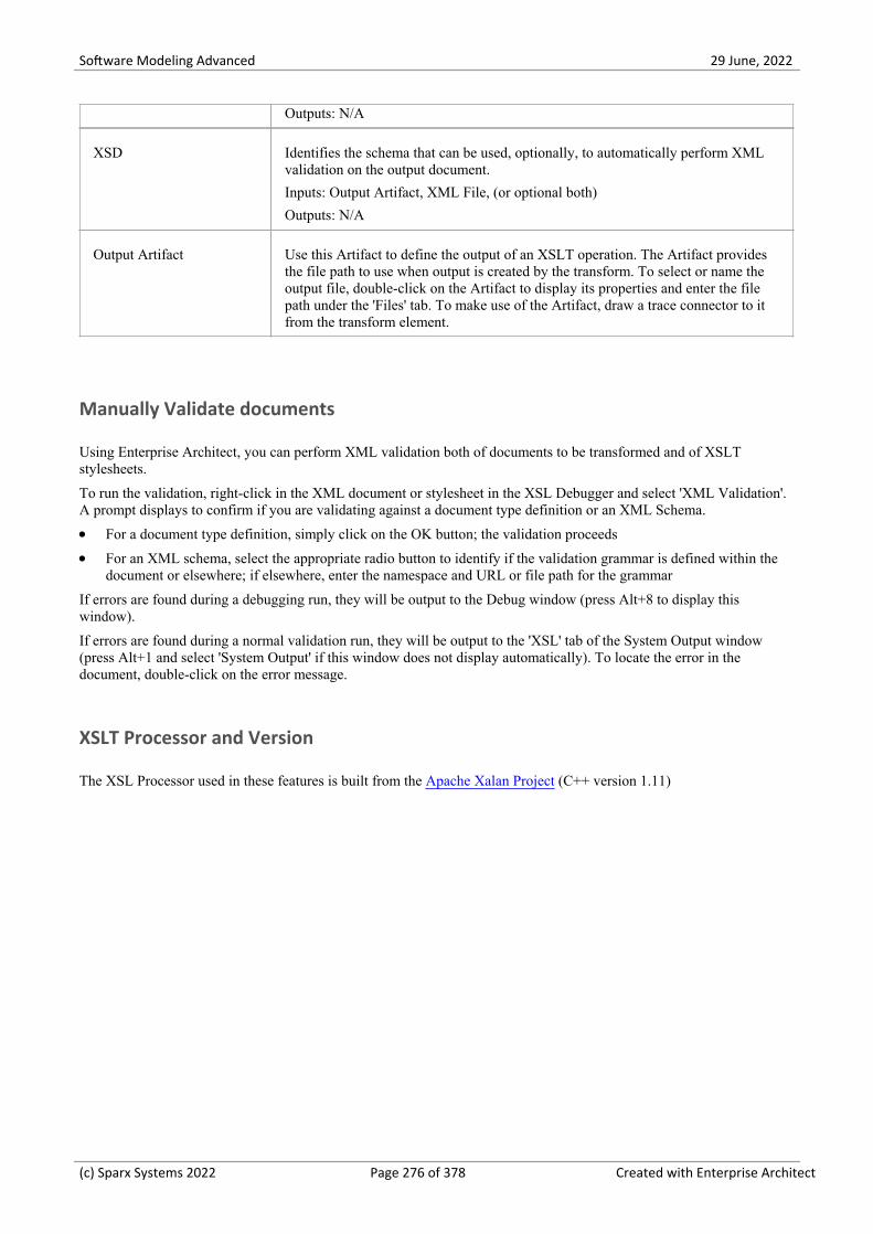
Software Modeling Advanced 29 June, 2022
Outputs: N/A
XSD Identifies the schema that can be used, optionally, to automatically perform XMLvalidation on the output document.
Inputs: Output Artifact, XML File, (or optional both)
Outputs: N/A
Output Artifact Use this Artifact to define the output of an XSLT operation. The Artifact providesthe file path to use when output is created by the transform. To select or name theoutput file, double-click on the Artifact to display its properties and enter the filepath under the 'Files' tab. To make use of the Artifact, draw a trace connector to itfrom the transform element.
Manually Validate documents
Using Enterprise Architect, you can perform XML validation both of documents to be transformed and of XSLTstylesheets.
To run the validation, right-click in the XML document or stylesheet in the XSL Debugger and select 'XML Validation'.A prompt displays to confirm if you are validating against a document type definition or an XML Schema.
For a document type definition, simply click on the OK button; the validation proceeds·For an XML schema, select the appropriate radio button to identify if the validation grammar is defined within the·document or elsewhere; if elsewhere, enter the namespace and URL or file path for the grammar
If errors are found during a debugging run, they will be output to the Debug window (press Alt+8 to display thiswindow).
If errors are found during a normal validation run, they will be output to the 'XSL' tab of the System Output window(press Alt+1 and select 'System Output' if this window does not display automatically). To locate the error in thedocument, double-click on the error message.
XSLT Processor and Version
The XSL Processor used in these features is built from the Apache Xalan Project (C++ version 1.11)
(c) Sparx Systems 2022 Page 276 of 378 Created with Enterprise Architect

Software Modeling Advanced 29 June, 2022
Model an XSL Transformation
When you model an XSL Transformation, you can either draw on files that already exist in your file system, or you cancreate the contents of the stylesheet and source within the model elements.
Model elements from existing files
This is the simplest and most common method for modeling transformations. When you drag a file on to the XMLTransform diagram, the appropriate Artifact element is generated for you. You can then use the Quick Linker to link thefile Artifact elements as inputs to the XML Transform element, using Trace connectors.
Optionally, you can:
Specify an alternative output location (file) by linking an XML File or Output Artifact to a Trace connector from the·XML Transform Artifact
Validate the output document by dragging an XSD schema file on to the diagram and connecting the resulting XSD·element to any Output Artifact of the XML Transform element
Step Action
1 Open your file browser and the XML Transform diagram.
2 In the file browser, click on the input file and drag it onto the XML Transform diagram.
A prompt displays to save the file as an:
External Artifact, where the XML File Artifact serves as a shortcut to the file in the file system·Internal Artifact, where the file content is read into the XML File Artifact and stored inside the·model; you would select this option to make the source file contents available to other users of themodel
3 Select the 'External Artifact' option.
An XML File Artifact element is generated for the input file.
4 In the file browser, click on the XSL stylesheet file and drag it onto the XML Transform diagram.
In response to the prompt, select the 'External Artifact' option.
An XSLT element is generated for the stylesheet file.
5 Drag the XML Transform icon from the Toolbox onto the diagram, to create an XML Transform Activityelement. If you prefer, give this element a new name.
6 Dragging the Trace icon from the 'Common' Toolbox page, create relationships between the:
Input XML file element and the transformation Activity element·XSLT Stylesheet file element and the transformation Activity element·
7 (Optional.)
If you want to capture the output in a file, locate the appropriate file in the file browser and drag it·onto the diagram to generate another File Artifact; link it to the XML Transform element with a Traceconnector
If you want to validate the output document, locate the XSD schema file in the file browser and drag·it on to the diagram to generate an XSD element; link this to the output File Artifact (or any OutputArtifact) of the Transform element
(c) Sparx Systems 2022 Page 277 of 378 Created with Enterprise Architect
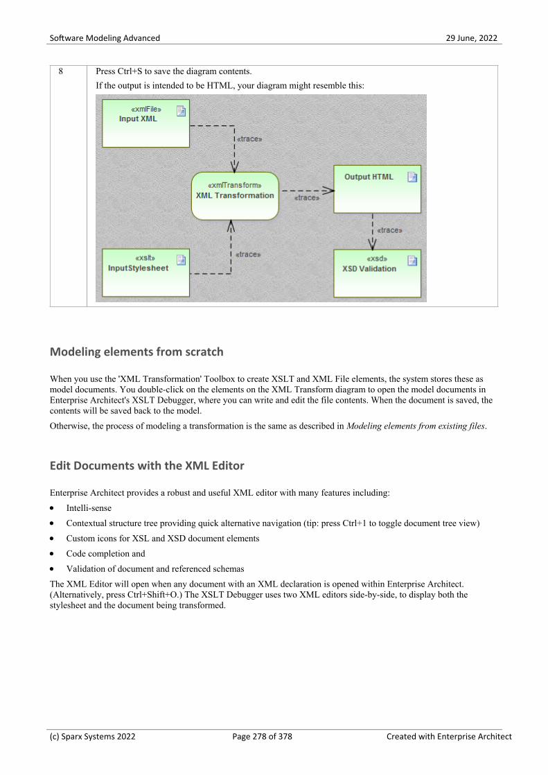
Software Modeling Advanced 29 June, 2022
8 Press Ctrl+S to save the diagram contents.
If the output is intended to be HTML, your diagram might resemble this:
Modeling elements from scratch
When you use the 'XML Transformation' Toolbox to create XSLT and XML File elements, the system stores these asmodel documents. You double-click on the elements on the XML Transform diagram to open the model documents inEnterprise Architect's XSLT Debugger, where you can write and edit the file contents. When the document is saved, thecontents will be saved back to the model.
Otherwise, the process of modeling a transformation is the same as described in Modeling elements from existing files.
Edit Documents with the XML Editor
Enterprise Architect provides a robust and useful XML editor with many features including:
Intelli-sense·Contextual structure tree providing quick alternative navigation (tip: press Ctrl+1 to toggle document tree view)·Custom icons for XSL and XSD document elements·Code completion and·Validation of document and referenced schemas·
The XML Editor will open when any document with an XML declaration is opened within Enterprise Architect.(Alternatively, press Ctrl+Shift+O.) The XSLT Debugger uses two XML editors side-by-side, to display both thestylesheet and the document being transformed.
(c) Sparx Systems 2022 Page 278 of 378 Created with Enterprise Architect

Software Modeling Advanced 29 June, 2022
Execute an XSL Transformation
After you have modeled an XSL Transformation, you can execute it directly from the model diagram. You can alsoperform the transformation directly from the XSL Stylesheet and input files.
Execute the Transformation From the Diagram
Step Action
1 On the XML Transform diagram, right-click on the XML Transform Activity element and select the 'RunXSL Transformation' option.
The XSLT Debugger view displays, showing the stylesheet (.xsl) file and XML document used in thetransformation.
The System Output window also displays, showing the error or success messages in the 'XSL' tab. (PressCtrl+Shift+8 if the System Output window does not display.)
If you have set up validation of the output, the System Output window also shows the validationcomments.
2 If you have directed the output to a file via an Output or File Artifact, press F12 to view the output.
(c) Sparx Systems 2022 Page 279 of 378 Created with Enterprise Architect

Software Modeling Advanced 29 June, 2022
Debug an XSL Transformation
When you use the XSLT debugger to run a transformation you can control the process and inspect the state of thetransformation using Enterprise Architect's debugger in combination with breakpoints. The XSLT Debugger provides aRun button and various Step buttons. You set breakpoints by clicking in the left margin of the stylesheet.
When a step completes or a breakpoint is encountered, the context of the transformation - including any parameters totemplate calls - can be viewed in the Locals window ('Execute > Windows > Local Variables'). You can also display theCall Stack ('Execute > Windows > Call Stack) to see how the current state of the transformation was reached.
Debug the Transformation
Step Action
1 On the XML Transform diagram, right-click on the XML Transform Activity element and select the'Debug XSL Transformation' option.
The XSLT Debugger view displays, showing the stylesheet (.xsl) file and XML document used in thetransformation, which is automatically initiated. The currently executing statement in the stylesheet ishighlighted.
Across the top of the view is a debugger toolbar, providing the normal debugging options to Start, Pause,Step Over, Step In, Step Out and Stop the debugging process. The final icon in the toolbar provides theoption of hiding or showing the '.xml source' tab in the view. You can use these buttons to repeat andcontrol the debugging process.
The System Output window also displays, showing the debugger progress messages on the 'XSLTTransformation' tab. (Press Alt+1 and select 'System Output' if the System Output window does notdisplay.)
Error messages are directed to the Debug window (press Alt+8). You can also use the Debug windowtoolbar buttons and options to control debugging of the XSL Transformation.
2 If necessary, select to display the Locals window and the Call Stack.
Click on the left margin of the XSLT Debugger stylesheet panel and set any Breakpoints you want to useto check processing.
3 Run the debugger again and examine the execution as indicated by the System Output window, CallStack, Locals window, and any other Debugger or Execution Analysis tools you want to apply.
(c) Sparx Systems 2022 Page 280 of 378 Created with Enterprise Architect

Software Modeling Advanced 29 June, 2022
XML Validation
Enterprise Architect provides validation of XML documents. Documents can be verified against XML schema or DataType Definitions (DTD). Validation is performed from within an Enterprise Architect editor using its context menu.Often an XML document will contain information relating to the schema that it conforms to. You can, however, chooseto override this, validating the document against any schema, either at a path on your local machine or at a URL. Thisexample demonstrates the use of the feature for a document that contains an incorrect attribute.
Access
Context Menu Accessible from context menu of any editor window displaying xml content.
Right-click in editor window and choose 'XML Validation'
XML Document Validation
Step Action
1 Open the XML document to be validated.
2 Use the editor context menu and select the 'XML Validation' option.
3 Select the grammar of choice from the available options:
XML Schema (default)·Data Type Definition·
4 Select the schema location. 'Defined in document' is selected by default. It is usual for an XML documentto specify the schemas that govern its content. To choose a different schema from that defined in thedocument, select 'External' and provide either a URL or a file path. Examples:
http://mydomain/myschema.xsd·c:\mydomain\myschema.xsd·
5 Click OK. The output of the validation will be displayed in the 'XML Validation' tab of the System Outputwindow.
XML Document Validation Example
(c) Sparx Systems 2022 Page 281 of 378 Created with Enterprise Architect

Software Modeling Advanced 29 June, 2022
Figure 1: The XML document with an invalid attribute value 'nyss'
In this example, the document describes a stock item that has an invalid exchange code 'nyss'. As can be seen from thisschema, the only valid values for the 'exchange' attribute are 'nyse', 'nasdaq' or 'ftsi'.
Figure 2: The XML Schema describing permitted stock exchange codes
(c) Sparx Systems 2022 Page 282 of 378 Created with Enterprise Architect

Software Modeling Advanced 29 June, 2022
This image shows the schema used in the validation. The declaration of a 'portfolio' element can be seen here to be madeup of one or more 'stock' elements. Each stock element in turn, requires an 'exchange' attribute naming a code for thestock exchange in question.
Figure 3: The 'XML validation' dialog naming a local schema file
This is the 'XML Validation' dialog. It is accessible from the context menu of any editor in Enterprise Architect thatholds XML content. Here you can select the schema to use in the validation. In the example the processor will validatethe document using a local schema file. This just happens to be the same schema named by the document, but it could beany schema (a development or later version of the schema for example).
Figure 4: The System Output window showing validation error
This image shows the results of the validation. The attribute value 'nyss' has been identified as being incorrect accordingto the enumeration described by the schema. Double-clicking the error will display the line of code in the editor where itcan easily be corrected.
(c) Sparx Systems 2022 Page 283 of 378 Created with Enterprise Architect

Software Modeling Advanced 29 June, 2022
XML Service Oriented Architecture
Model Organizations, Communities and Systems to Maximize Agility, Scale and Interoperability
Service Oriented Architecture (SOA) is an architectural paradigm for defining how people, organizations and systemsprovide and use services to achieve results.
A service is an offer of value to another through a well-defined interface, available to a community (which could be thegeneral public). A service results in work provided to one by another.
Service Oriented Architecture (SOA) is a way of organizing and understanding (representations of) organizations,communities and systems to maximize agility, scale and interoperability. The SOA approach is simple - people,organizations and systems provide services to each other. These services allow us to get something done without doing itourselves or even without knowing how to do it - enabling us to be more efficient and agile. Services also enable us tooffer our capabilities to others in exchange for some value - thus establishing a community, process or marketplace. TheSOA paradigm works equally well for integrating existing capabilities as for creating and integrating new capabilities.
(Derived from Service oriented architecture Modeling Language (SoaML) - Specification for the UML Profile andMetamodel for Services (UPMS) (OMG document ad/2008-11-01); pp. 25-26.)
In modeling and developing a complete Service Oriented Architecture in Enterprise Architect, you can work with any orall of:
XML Schema Definition (XSD), also known as XML Schema - an XML technology that is used to specify the rules·to which an XML document must adhere; Enterprise Architect provides a Schema Composer interface to help youmodel and generate XML schema
XSL Transformations to convert input documents into XML or other types of document using XSL stylesheets, for·which you use the XSLT Editor and Debugger for modeling and executing the transformations
Web Services Description Language 1.1 (WSDL) - a key XML-based language for describing web services·Service oriented architecture Modeling Language (SoaML) - a standard method of designing and modeling SOA·solutions using the Unified Modeling Language (UML)
Service-Oriented Modeling Framework (SOMF) - a service-oriented development life cycle methodology, offering a·number of modeling practices and disciplines that contribute to successful service-oriented life cycle managementand modeling
National Information Exchange Modeling (NIEM) - a common framework that is used to define how information·can be shared between systems, government agencies and departments
Meta-Object Facility (MOF) - an Object Management Group (OMG) standard developed as a meta-modeling·architecture to define the UML, and so provide a means to define the structure or abstract syntax of a language or ofdata
(c) Sparx Systems 2022 Page 284 of 378 Created with Enterprise Architect

Software Modeling Advanced 29 June, 2022
WSDL
Web Services Description Language 1.1 (WSDL) is a key XML-based, World Wide Web Consortium (W3C) languagefor describing web services. WSDL support is critical for the development of a complete Service Oriented Architecture(SOA), and the coupling of UML 2.5 and XML provides the natural mechanism for specifying, constructing anddeploying XML-based SOA artifacts within an organization.
Using Enterprise Architect, you can rapidly model, forward engineer and reverse engineer WSDL files.
(c) Sparx Systems 2022 Page 285 of 378 Created with Enterprise Architect

Software Modeling Advanced 29 June, 2022
WSDL 1.1 Model Structure
A Web Service Description Language (WSDL), under specification 1.1, is defined within a «WSDLnamespace»stereotyped Package, which represents the top-level container for the WSDL elements. Conceptually it maps to thetargetNamespace in a WSDL definition element.
When you create a WSDL model, Enterprise Architect creates the Namespace and provides a set of sub-Packages, eachcontaining a diagram on which to define the constituent elements of the model, with an Overview diagram to navigatebetween the sub-Packages. You work through the sub-Packages in sequence, to define the objects that are used by laterobjects, themselves called into still later objects.
WSDL Structure Development
WSDL Element Type Description
Types Defined in an XSD Schema, these are the XSD data types used by the web serviceand communicated by WSDL Messages; you drag «XSDelement»,«XSDsimpleType» and «XSDcomplexType» stereotyped elements onto the Typesdiagram from the 'XML Schema' page of the Diagram Toolbox.
Messages WSDL Messages identify the data being communicated by a web service. EachMessage element contains one or more Message Parts, which are attributes thateach identify an XSD data type being communicated.
Port Types WSDL Port Types are the essential core of the web service, defining the interfacesof the service. Each Port Type consists of a set of Port Type Operations, each ofwhich identifies an exchange of Messages (data input to and output from theinterface as that operation). The Port Type Operation can also identify Messagesacting as Fault indicators.
Bindings A Binding specifies the protocol and data format for the operations and messagesdefined for of a particular Port Type. Each «WSDLbinding » Class implements(realizes) the operations specified by the «WSDLportType» Interface - the PortType Operations in the Port Type element are automatically copied into the Bindingelement as Binding operations.
Services A WSDL Service defines a formal interface of the web service. It describes thecollection of Port Types that expose a particular Binding, having an Association toeach exposed Binding. It therefore encapsulates a set of the other data structures - ifnot all the data structures - defined in the model.
Documents WSDL Documents are represented by Components having the stereotype «WSDL».This is the element from which you generate the WSDL file.
You can create more than one Document to re-use the schema Types, Messages,Port Types, Bindings and Services of a Namespace across multiple physical WSDLdocuments, either in the same configuration or in different configurations.
Example
This figure shows an example WSDL namespace, OnlineBookstore PSM, which includes a single WSDL document,OnlineBookstore (at the bottom of the hierarchy).
(c) Sparx Systems 2022 Page 286 of 378 Created with Enterprise Architect

Software Modeling Advanced 29 June, 2022
Notes
You can also generate a WSDL Package structure from a UML Interface using the WSDL Model Transformation·
(c) Sparx Systems 2022 Page 287 of 378 Created with Enterprise Architect

Software Modeling Advanced 29 June, 2022
Model WSDL
You can quickly and easily model the elements in a Web Service Definition using the WSDL page of the DiagramToolbox. As a first step, you can create an example WSDL Package structure in the Browser window, using theNamespace icon from the WSDL page. You can use this example Package structure as a template for developing yourWSDL.
Create a new WSDL Package structure
Step Action
1 In the Browser window, create the top-level project structure you need (Model and Views), and click onthe appropriate View.
2 Click on the 'New Package' option in the Browser window header drop-down list.
The 'New Model Package' dialog displays.
3 In the 'Name' field type the name of the new Package, and select the 'Create Diagram' radio button.
4 Click on the OK button.
The 'New Diagram' dialog displays.
5 In the 'Name' field type the name of the new diagram.
In the 'Select From' panel select 'UML Structural', and in the 'Diagram Types' panel select 'Class'.
6 Click on the OK button.
In the Browser window, double-click on the icon next to the new diagram's name; the diagram opens inthe Diagram View, with the Class pages displaying in the Diagram Toolbox.
7In the Toolbox, click on to display the 'Find Toolbox Item' dialog and specify 'WSDL', then selectthe Toolbox page from the results.
The 'WSDL' Toolbox page displays.
8 Click on the 'Namespace' icon from the Toolbox and drag it into the Class diagram.
The 'WSDL Namespace Properties' dialog displays.
Type in a WSDL Package name and the URL of the Target Namespace. You can edit these values later.
9 Click on the OK button.
The sample «WSDLnamespace» stereotyped Package structure is created on the diagram, and the fullmodel structure is displayed, expanded, in the Browser window.
The model structure consists of these sub-Packages, with an Overview diagram to navigate between them:
Types: Contains the XSD types for the data communicated by the web service, on a Types diagram·Messages: Contains the WSDL Messages, modeled as UML Classes marked with the stereotype·«WSDLmessage»
PortTypes: Contains the WSDL Port Types, modeled as UML interfaces marked with the stereotype·«WSDLportType»
Bindings: Contains the WSDL Bindings, modeled as UML Classes that realize the PortTypes·Services: Contains the WSDL Services, modeled as UML interfaces with Associations to each·
(c) Sparx Systems 2022 Page 288 of 378 Created with Enterprise Architect

Software Modeling Advanced 29 June, 2022
exposed Binding
10 Model each of the WSDL constructs in their corresponding Packages.
Template WSDL Model - Diagram
The WSDLnamespace Package acts as a container for the WSDL structure.
Template WSDL Model - Browser Window Hierarchy
(c) Sparx Systems 2022 Page 289 of 378 Created with Enterprise Architect

Software Modeling Advanced 29 June, 2022
(c) Sparx Systems 2022 Page 290 of 378 Created with Enterprise Architect

Software Modeling Advanced 29 June, 2022
WSDL Namespace
A «WSDLnamespace» stereotyped Package represents the top-level container for the WSDL constructs in EnterpriseArchitect. You can create the Namespace Package by dragging the Namespace icon from the WSDL Toolbox page anddropping it directly onto a diagram.
Toolbox Icon
Access
To display the 'WSDL Namepace Properties' dialog for the selected «WSDLnamespace» stereotyped Package, use one ofthe methods outlined here.
Ribbon Design > Package > Manage > Properties
Context Menu Right-click on «WSDLnamespace» stereotyped Package | Properties
Other In Browser window, double-click on «WSDLnamespace» stereotyped Package, or
Drag icon from toolbox onto a diagram (this createsa new «WSDLnamespace» stereotyped Package)
Define Properties
Option Action
WSDL Package Name Type in the name of the WSDL Namespace Package element.
Target Namespace (Optional) Type in the URL for the WSDL Namespace Package.
OK Click on this button to save the values entered and close the WSDL Namespace'Properties' dialog.
If you have just created the Namespace, a new Package diagram opens containingthe sample template WSDL model.
Cancel Click on this button to discard the data entered and close the 'WSDL NamespaceProperties' dialog.
Help Click on this button to display this Help topic.
UML This button is displayed when you are editing existing WSDL Namespace elementinformation.
Click on the button to open the UML element 'Properties' dialog for the NamespacePackage element.
(c) Sparx Systems 2022 Page 291 of 378 Created with Enterprise Architect

Software Modeling Advanced 29 June, 2022
(c) Sparx Systems 2022 Page 292 of 378 Created with Enterprise Architect

Software Modeling Advanced 29 June, 2022
WSDL Message
A «WSDLmessage» stereotyped Class represents a WSDL Message and acts as a container for one or more WSDLMessage Parts. You can create WSDL Messages by dragging the Message icon from the WSDL Toolbox and dropping itdirectly onto the Messages diagram (under the Messages Package in the WSDL Package structure).
Toolbox Icon
Access
To display the 'WSDL Message' dialog for the selected «WSDLmessage» stereotyped Class, use one of the methodsoutlined here.
Ribbon Design > Element > Editors > Properties
Context Menu Right-click on «WSDLmessage» stereotyped Class| Properties
Keyboard Shortcuts Alt+Enter
Other Double-click on a «WSDLmessage» stereotyped Class, or
Drag icon from the toolbox and drop directly ontothe Messages diagram, under the Messages Package in the WSDL Packagestructure.
(This creates a new «WSDLmessage» stereotyped Class.)
Define Properties
Option Action
Name Type in the name of the WSDL Message.
Documentation (Optional) Type in any notes you need for this element.
OK Click on this button to save the data entered and close the WSDL Message dialog.
Cancel Click on this button to discard the data entered and close the 'WSDL Message'dialog.
Help Click on this button to display this Help topic.
UML This button is displayed when you are editing existing WSDL Message elementinformation.
Click on the button to open the UML Class 'Properties' dialog for the element.
(c) Sparx Systems 2022 Page 293 of 378 Created with Enterprise Architect

Software Modeling Advanced 29 June, 2022
Notes
WSDL Messages can only be created under the Messages Package in the WSDL Package structure·The name of the WSDL Message should be unique amongst all WSDL Messages within the WSDL·
(c) Sparx Systems 2022 Page 294 of 378 Created with Enterprise Architect

Software Modeling Advanced 29 June, 2022
WSDL Message Part
A WSDL Message Part is the segment of a WSDL Message that identifies the XSD data type of the data communicatedby the Message. If a Message communicates data of more than one data type, each data type is identified in a separateMessage Part.
In Enterprise Architect, a WSDL Message Part is represented by a UML attribute of the WSDL Message Class. You cancreate the Message Part attribute by dragging the 'Message Part' icon from the WSDL Toolbox and dropping it onto a«WSDLmessage» stereotyped Class.
Toolbox Icon
Access
To display the 'WSDL Message Part' dialog for the selected Message Part, use one of the methods outlined here.
Ribbon With a specific Message Part (attribute) selected within a WSDL Message on adiagram:
Design > Element > Features > Attributes
Context Menu With a specific Message Part (attribute) selected within a WSDL Message on adiagram:
Right-click on attribute | View Properties
Keyboard Shortcuts With a specific Message Part (attribute) selected within a WSDL Message on adiagram:
F9
Other Double-click on the Message Part (attribute) within the «WSDLmessage»stereotyped Class, or
Drag icon from toolbox and drop onto a«WSDLmessage» stereotyped Class (This creates a new Message Part (as anattribute) within the «WSDLmessage» stereotyped Class.)
Define Properties
Option Action
Name Type in the name of the WSDL Message Part attribute.
Type Either:
Type the name of a data type, or·Click on the drop-down arrow and select an XSD built-in dataType from the·
(c) Sparx Systems 2022 Page 295 of 378 Created with Enterprise Architect

Software Modeling Advanced 29 June, 2022
list, or
Click on the button and browse for an existing «XSDelement»,·«XSDcomplexType» or «XSDsimpleType» element as a classifier
The XSD Types can be defined in:
The Types Package under the WSDL Package Structure or·Any other Package in the model·
OK Click on this button to save the data entered and close the 'WSDL Message Part'dialog.
Cancel Click on this button to discard the data entered and close the 'WSDL Message Part'dialog.
Help Click on this button to display this Help topic.
UML This button is displayed when you are editing existing WSDL Message Partattribute information.
Click on the button to open the attribute properties for the Message Part.
Notes
WSDLmessage stereotyped Classes can effectively contain Message Part attributes only; if you add other attributes·to the Class element, they are re-cast as Message Parts
(c) Sparx Systems 2022 Page 296 of 378 Created with Enterprise Architect

Software Modeling Advanced 29 June, 2022
WSDL Port Type
A «WSDLportType» stereotyped Interface represents a WSDL PortType. It describes the operations exposed by theWSDL, acting as a container for one or more WSDL Port Type Operations. You can create a WSDL PortType elementby dragging the Port Type icon from the WSDL Toolbox and dropping it directly onto the PortTypes diagram (under thePortTypes Package in the WSDL Package structure).
Toolbox Icon
Access
To display the 'WSDL PortType' dialog for the selected «WSDLportType» stereotyped Interface, use one of the methodsoutlined here.
Ribbon Design > Element > Editors > Properties
Context Menu Right-click on «WSDLportType» stereotyped Interface| Properties
Keyboard Shortcuts Alt+Enter
Other Double-click on a «WSDLportType» stereotyped Interface, or·
Drag icon from the toolbox and drop directly·onto the PortTypes diagram, under the PortTypes Package in the WSDLPackage structure
(This creates a new «WSDLportType» stereotyped Interface.)
Define Properties
Option Action
Name Type in the name of the WSDL PortType.
Documentation (Optional) Type in any notes you need for this element.
OK Click on this button to save the data entered and close the WSDL PortType dialog.
Cancel Click on this button to discard the data entered and close the 'WSDL PortType'dialog.
Help Click on this button to display this Help topic.
UML This button is displayed when you are editing existing WSDL PortType elementinformation.
(c) Sparx Systems 2022 Page 297 of 378 Created with Enterprise Architect
Software Modeling Advanced 29 June, 2022
Click on the button to open the UML element 'Properties' dialog for the element.
Notes
WSDL PortTypes can only be created under the PortTypes Package in the WSDL Package structure·The name of the WSDL PortType should be unique amongst all the WSDL PortTypes within the WSDL·
(c) Sparx Systems 2022 Page 298 of 378 Created with Enterprise Architect

Software Modeling Advanced 29 June, 2022
WSDL Port Type Operation
A Port Type Operation identifies an exchange of Messages (data input to and output from the interface as an operation).The Port Type Operation can also identify Messages acting as Fault indicators.
In Enterprise Architect, a WSDL PortType Operation is represented by a UML Operation of the WSDL PortTypeInterface. You can create a PortType Operation by dragging the PortType Operation icon from the WSDL Toolbox anddropping it onto a «WSDLportType» stereotyped Interface.
Toolbox Icon
Access
To display the 'WSDL PortType Operation' dialog for the selected PortType Operation, use one of the methods outlinedhere.
Ribbon With a specific PortType Operation selected within a «WSDLportType» stereotypedInterface on a diagram:
Design > Element > Features > Operations
Context Menu With a specific PortType Operation selected within a «WSDLportType» stereotypedInterface on a diagram:
Right-click on attribute | View Properties
Keyboard Shortcuts With a specific PortType Operation selected within a «WSDLportType» stereotypedInterface on a diagram:
F10
Other Double-click on the PortType Operation within the «WSDLportType» stereotypedInterface, or
Drag icon from toolbox and drop onto a«WSDLportType» stereotyped Interface. (This creates a new PortType Operation(as a UML operation) within the «WSDLportType» stereotyped Interface.)
Define Properties
Option Action
Name Type in the name of the WSDL PortType Operation.
Documentation (Optional) Type in any notes you need for this operation.
Operation Type Click on the drop-down arrow and select one of the supported PortType Operationtypes:
(c) Sparx Systems 2022 Page 299 of 378 Created with Enterprise Architect

Software Modeling Advanced 29 June, 2022
OneWay·Request-Response·Solicit-Response·Notification·
Input This section is grayed out if you have selected Notification as the operation type.
Name - Defaults to a name that parallels theOperation Type. If you do not want·to use the default, type an alternative name for the input Message.
Message - Click on the drop-down arrow and select one of the WSDL·Messages previously created in theMessagePackage.
Documentation - (Optional) Type in any notes you need for this input Message.·
Output This section is grayed out if you have selected OneWay as the operation type.
Name - Defaults to a name that parallels theOperation Type. If you do not want·to use the default, type an alternative name for the output Message.
Message - Click on the drop-down arrow and select one of the WSDL·Messages previously created in theMessagePackage.
Documentation - (Optional) Type in any notes you need for this output·Message.
Faults Review the details of the WSDL Messages that can act as Faults.
Faults display in this list with the most recently-created at the top and the oldest atthe end. If more than four Fault Messages are defined, use the vertical scroll bar todisplay the rest of the list.
To add a Message, click on the New button. The 'WSDL PortType Operation Fault'dialog displays.
Name - Defaults to 'Fault<n>'; if you do not want to use the default, type an·alternative name for the fault Message
Message - Click on the drop-down arrow and select one of the WSDL·Messages previously created in the Message Package
Documentation - (Optional) Type in any notes you need for this fault Message·OK - Click on this button to save the data entered and close the 'WSDL·PortType Operation Fault' dialog
Cancel - Click on this button to discard the data entered and close the 'WSDL·PortType Operation Fault' dialog
Help - Click on this button to display this Help topic·To remove a Message from the list, click on it and click on the Delete button.
OK Click on this button to save the data entered and close the 'WSDL PortTypeOperation' dialog.
Cancel Click on this button to discard the data entered and close the 'WSDL PortTypeOperation' dialog.
Help Click on this button to display this Help topic.
UML This button is displayed when you are editing existing WSDL Port Type Operationinformation.
Click on the button to open the UML operation 'Properties' dialog for the element.
(c) Sparx Systems 2022 Page 300 of 378 Created with Enterprise Architect

Software Modeling Advanced 29 June, 2022
Notes
WSDL PortType Operations can only be contained by WSDL PortTypes·The name provided for an Input, Output or Fault Message in a PortType Operation must be unique amongst the·Input, Output and Fault Messages, respectively, across the WSDL PortType
In the UML operation 'Properties' dialog, the Messages identified as Input, Output and Fault can be examined as the·parameters of the operation
(c) Sparx Systems 2022 Page 301 of 378 Created with Enterprise Architect

Software Modeling Advanced 29 June, 2022
WSDL Binding
A WSDL Binding element implements the operations specified by a particular «WSDLportType» stereotyped Interfaceand describes the message format and protocol details for the operations and messages defined by this WSDL PortType.A WSDL Binding element is represented by a «WSDLbinding» stereotyped Class.
You create a WSDL Binding element by dragging the Binding icon from the WSDL Toolbox directly onto the Bindingsdiagram under the Bindings Package in the WSDL Package structure.
Toolbox Icon
Access
To display the 'WSDL Binding' dialog for the selected «WSDLbinding» stereotyped Class, use one of the methodsoutlined here.
Ribbon Design > Element > Editors > Properties
Context Menu Right-click on «WSDLbinding» stereotyped Class | Properties
Keyboard Shortcuts Alt+Enter
Other Double-click on a «WSDLbinding» stereotyped Class, or
Drag icon from the toolbox and drop directly ontothe Bindings diagram, under the Bindings Package in the WSDL Package structure.
(This creates a new «WSDLbinding» stereotyped Class.)
Define Properties
Option Action
Name Type in the name of the WSDL Binding element.
PortType Click on the drop-down arrow and select the WSDL PortType to be implementedby this WSDL Binding.
Protocol Click on the drop-down arrow and select the protocol for the transmission of theselected WSDL PortType's operations. The supported protocols are:
SOAP·HTTP·
Transport This field is disabled if you have selected the HTTP protocol.
Defaults to http://schemas.xmlsoap.org/soap/http.
(c) Sparx Systems 2022 Page 302 of 378 Created with Enterprise Architect

Software Modeling Advanced 29 June, 2022
If necessary, type in an alternative URL for the SOAP protocol.
Style This field is disabled if you have selected the HTTP protocol.
Click on the drop-down arrow and select the style of SOAP protocol.
Verb This field is disabled if you have selected the SOAP protocol.
Click on the drop-down arrow and select the appropriate HTTP verb. The supportedverbs are:
GET·POST·
Documentation (Optional) Type in any notes you need for this element.
OK Click on this button to save the data entered and close the 'WSDL Binding' dialog.
Cancel Click on this button to discard the data entered and close the 'WSDL Binding'dialog.
Help Click on this button to display this Help topic.
UML This button is displayed when you are editing existing WSDL Binding elementinformation.
Click on the button to open the UML element 'Properties' dialog for the element.
Notes
A WSDL Binding must implement a WSDL PortType; therefore, WSDL PortTypes should be defined before you·create WSDL Bindings
WSDL Bindings can only be created under the Bindings Package in the WSDL Package structure·The name of the WSDL Binding should be unique amongst all the WSDL Bindings within the WSDL·
(c) Sparx Systems 2022 Page 303 of 378 Created with Enterprise Architect

Software Modeling Advanced 29 June, 2022
WSDL Binding Operation
When you save a newly-created «WSDLbinding» stereotyped Class, the system:
Adds to the Binding diagram, the WSDL Port Type element implemented by the WSDL Binding.1.
Draws a Realization connector from the Binding to the PortType.2.
Automatically populates the Binding with all the UML operations from the PortType, as the WSDL Binding3.Operations.
Access
To display the 'WSDL Binding Operation Details' dialog for the selected Binding Operation, use one of the methodsoutlined here.
Ribbon With a specific Binding Operation selected within a «WSDLbinding» stereotypedClass on a diagram:
Design > Element > Features > Operations
Context Menu With a specific Binding Operation selected within a «WSDLbinding» stereotypedClass on a diagram:
Right-click on attribute | View Properties
Keyboard Shortcuts With a specific Binding Operation selected within a «WSDLbinding» stereotypedClass on a diagram:
F10
Other Double-click on the Binding Operation within the «WSDLbinding» stereotypedClass
Define Properties
Option Action
Operation Name Displays the name of the Operation copied from the WSDL PortType element.
The value in this field cannot be edited.
Action If the protocol of the parent WSDL Binding element was defined as HTTP, thisfield is grayed out.
Type in the SOAP Action header (URL) for this operation.
Style If the protocol of the parent WSDL Binding element was defined as HTTP, thisfield is grayed out.
Click on the drop-down arrow and select the SOAP style of the operation.
Location If the protocol of the parent WSDL Binding element was defined as SOAP, thisfield is grayed out.
Type in the relative URL of this Operation.
(c) Sparx Systems 2022 Page 304 of 378 Created with Enterprise Architect

Software Modeling Advanced 29 June, 2022
Documentation (Optional) Type in any notes you need for this operation.
Parameters Click on this button to define the parameters for this operation.
The 'WSDL Binding Operation Parameters' dialog displays, showing the names ofthe operation Input, Output and Faults. You cannot change these names.
Click on the Details button to specify the details for Input, Output and Faultoperation (Message) parameters. Note that the Details button in the:
Input section is disabled for the Notification Operation Type·Output section is disabled for the One-way Operation Type·Fault section is disabled if there are no Fault Messages·
Use - If the protocol of the parent WSDL Binding element was defined as·HTTP, this field is grayed out; click on the drop-down arrow and select theencoding that is to be used
Encoding Style - If the protocol of the parent WSDL Binding element was·defined as HTTP, this field is grayed out; if 'Use' is set to 'encoded', type in thestyle (URL) to apply
Namespace - If the protocol of the parent WSDL Binding element was defined·as HTTP, this field is grayed out; (Optional) type in the namespace
Parts - If the protocol of the parent WSDL Binding element was defined as·HTTP, this field is grayed out; this field is also not applicable to Faults -(Optional) type in the Message Part attributes that appear within the SOAPBody portion
Header - This field is not applicable to Faults; (Optional) type in the text of the·SOAP/HTTP Header
Documentation - (Optional) Type in any notes you need for this message·OK - Click on this button to save the data entered and close the 'WSDL·Binding Parameter Details' dialog
Cancel - Click on this button to discard the data entered and close the 'WSDL·Binding Parameter Details' dialog
Help - Click on this button to display this Help topic·
OK Click on this button to save the data entered and close the 'WSDL BindingOperation Details' dialog.
Cancel Click on this button to discard the data entered and close the 'WSDL BindingOperation Details' dialog.
Help Click on this button to display this Help topic.
UML This button is displayed when you are editing existing WSDL Binding Operationinformation.
Click on the button to open the UML operation 'Properties' dialog for the element.
Notes
If you subsequently change the WSDL Port Type operations, you can refresh the Binding Operations by deleting the·Realization connector and re-establishing it; the 'Overrides & Implementations' dialog displays, on which you select
(c) Sparx Systems 2022 Page 305 of 378 Created with Enterprise Architect

Software Modeling Advanced 29 June, 2022
the updated operations to establish
You can review the parameters of a Binding Operation by highlighting the operation in the diagram or Browser·window and expanding the entries in the Properties window
(c) Sparx Systems 2022 Page 306 of 378 Created with Enterprise Architect

Software Modeling Advanced 29 June, 2022
WSDL Service
A WSDL Service is represented by a «WSDLservice» stereotyped Interface; it describes a collection of Ports that exposea particular Binding. You can create a WSDL Service element by dragging the Service icon from the WSDL Toolbox anddropping it directly onto a diagram in the Services Package of your WSDL model.
When you save a newly-created «WSDLservice» stereotyped Interface, the system:
Adds the WSDL Binding elements exposed by the WSDL Service to the Service diagram.1.
Draws an Association connector from the Service element to each Binding element.2.
Labels each connector with the corresponding Port name.3.
Toolbox Icon
Access
To display the 'WSDL Service' dialog for the selected «WSDLservice» stereotyped Interface, use one of the methodsoutlined here.
Ribbon Design > Element > Editors > Properties
Context Menu Right-click on «WSDLservice» stereotyped Interface| Properties
Keyboard Shortcuts Alt+Enter
Other Double-click on a «WSDLservice» stereotyped Interface, or
Drag the icon from the toolbox and drop directlyonto the SampleService diagram, under the Services Package in the WSDL Packagestructure. (This creates a new «WSDLservice» stereotyped Interface.)
Define Properties
Option Action
Name Type in the name of the WSDL Service.
Documentation (Optional) Type in any notes you need for this element.
Ports Identify the Ports (or endpoints) for this WSDL Service.
To add a Port to the list, click on the New button. The 'WSDL Port' dialog displays.
Port Name - Type in the name of the Port·Binding - Click on the drop-down arrow and select a Binding element from the·list of all the WSDL Bindings created in theBindingsPackage
(c) Sparx Systems 2022 Page 307 of 378 Created with Enterprise Architect

Software Modeling Advanced 29 June, 2022
Location - Type in the URL for the Port·Documentation - (Optional) Type in any notes you need for this Port·OK - Click on this button to save the values entered and close the 'WSDL Port'·dialog
Cancel - Click on this button to discard the values entered and close the·'WSDL Port' dialog
Help - Click on this button to display this Help topic·The Ports are organized in the list with the most recent at the top and the oldest atthe end.
To remove an entry from the list, click on it and click on the Delete button.
OK Click on this button to save the data entered and close the WSDL Service dialog.
Cancel Click on this button to discard the data entered and close the 'WSDL Service'dialog.
Help Click on this button to display this Help topic.
UML This button is displayed when you are editing existing WSDL Service elementinformation.
Click on the button to open the UML element 'Properties' dialog for the element.
Notes
WSDL Services can only be created under the Service Package in the WSDL Package structure·The name of the WSDL Service should be unique amongst all the WSDL Services within the WSDL·
(c) Sparx Systems 2022 Page 308 of 378 Created with Enterprise Architect

Software Modeling Advanced 29 June, 2022
WSDL Document
A WSDL Document encapsulates a Web Service defined within the «WSDLnamespace» stereotyped Package, and is thesource from which the WSDL file is generated. It is represented by a «WSDL» stereotyped Component element as adirect child element of the «WSDLnamespace» stereotyped Package. You can have multiple WSDL Documents under asingle WSDL Namespace, to reuse and expose the WSDL Services for that namespace across multiple WSDLs.
One «WSDL» stereotyped Component element is automatically created when you create the Namespace Packagestructure. You can add further WSDL elements by dragging the WSDL icon from the WSDL Toolbox and dropping itdirectly onto the namespace Overview diagram.
Toolbox Icon
Access
To display the 'WSDL Document Properties' dialog for the selected «WSDL» stereotyped Component, use one of themethods outlined here.
Ribbon Design > Element > Editors > Properties
Context Menu Right-click on «WSDL» stereotyped Component | Properties
Keyboard Shortcuts Alt+Enter
Other Double-click on a «WSDL» stereotyped Component, or
Drag icon from the toolbox and drop directly ontothe Overview diagram, under the «WSDLnamespace» stereotyped Package in theWSDL Package structure. (This creates a new WSDL Document, represented by a«WSDL» stereotyped Component.)
Define Properties
Option Action
Name Type in the name of the WSDL document.
File Name Type the file path into which the WSDL 1.1 file is to be generated.
Documentation (Optional) Type in any notes you need for this element.
XMLNS Identify the additional namespace or namespace-prefix pairs used in this WSDLDocument.
To add a namespace or namespace-prefix pair, click on the New button; to edit anexisting entry, double-click on it. In either case, the 'Namespace Details' dialog
(c) Sparx Systems 2022 Page 309 of 378 Created with Enterprise Architect

Software Modeling Advanced 29 June, 2022
displays.
Prefix - Type in the abbreviated text to represent the Namespace·Namespace - Type in the name of the Namespace·OK - Click on this button to save the new information and close the·'Namespace Details' dialog
Cancel - Click on this button to discard the new information and close the·'Namespace Details' dialog
Help - Click on this button to display this Help topic·To remove an entry from the list, click on it and click on the Delete button.
Services Review the WSDL Services that exist in the Services Package.
Select the checkbox against the services to be included in the current WSDL file.
OK Click on this button to save the data entered and close the WSDL Document'Properties' dialog.
Cancel Click on this button to discard the data entered and close the 'WSDL DocumentProperties' dialog.
Help Click on this button to display this Help topic.
UML This button is displayed when you are editing existing WSDL Document elementinformation.
Click on the button to open the UML element 'Properties' dialog for the element.
(c) Sparx Systems 2022 Page 310 of 378 Created with Enterprise Architect

Software Modeling Advanced 29 June, 2022
Generate WSDL
If you have developed a WSDL model in UML, you can forward-engineer it into WSDL 1.1 files using the GenerateWSDL feature. This feature acts on either a «WSDLnamespace» stereotyped Package or a «WSDL» stereotypedComponent (Document), and generates any or all of the WSDL Components owned by the target «WSDLnamespace»structure.
Access
Ribbon Develop > Schema Modeling > Export WSDL
Generate WSDL 1.1 files
Option Action
WSDL Package Displays the name of the WSDL Namespace containing the source Component(s)from which the WSDL file is to be generated.
Encoding Either:
Click on the drop-down arrow and select the XML encoding scheme you need,·or
Click on the Default button to apply the default encoding scheme (UTF-8)·
Select Components ToGenerate
Click on the «WSDL» stereotyped Component(s) in the list for which the WSDLfile is to be generated.
To:
Select multiple individual Components use Ctrl+click·Select a range use Shift+click·Select all entries in the list click on the Select All button·Clear all entries in the list click on the Select None button·Provide a file path and name into which to generate the WSDL file for a·component, double-click on the component name; the 'Component File Name'dialog is displayed, see the table for a description
Generate Click on this button to generate the WSDL files for the selected «WSDL»stereotyped Components.
A message displays when the generation is complete; click on the OK button on themessage to close it.
View WSDL Click on this button to display the most recently generated WSDL.
Close Click on this button to close this dialog.
Help Click on this button to display this Help topic.
(c) Sparx Systems 2022 Page 311 of 378 Created with Enterprise Architect

Software Modeling Advanced 29 June, 2022
Progress Monitor the progress of the WSDL file generation.
Component File Name dialog
Field/Button Description
Name Displays the name of the selected «WSDL» stereotyped Component.
Prefix If multiple prefixes have been specified, click on the drop-down arrow and selectthe appropriate prefix for the WSDL Namespace.
File NameType in or browse for (click on ) the file path and name into which the WSDLfile is to be generated.
OK Click on this button to save the data entered and close the 'Component File Name'dialog.
Cancel Click on this button to discard the data entered and close the 'Component FileName' dialog.
Help Click on this button to display this Help topic.
Notes
You can also generate WSDL files through the Automation Interface·
(c) Sparx Systems 2022 Page 312 of 378 Created with Enterprise Architect

Software Modeling Advanced 29 June, 2022
Import WSDL
If you have WSDL 1.1 files external to Enterprise Architect that you want to reverse engineer into UML Class models,you can import them into the system using the WSDL Import facility.
Access
Browser window | Click on root Package to contain imported file, then:
Ribbon Develop > Schema Modeling > Import WSDL
Import a WSDL File
Option Action
Package Displays the name of the root Package under which the WSDL file is to beimported.
FilenameType in or browse for (click on ) the name and path of the WSDL file toimport.
Target Package Defaults to the name of the WSDL file being imported, as the name of the Packageto represent the imported file.
If you do not want to use the default name, type in a different name.
Import Click on this button to start the WSDL Import.
A message displays when the import is complete; click on the OK button on themessage to close it.
Close Click on this button to close this dialog.
Progress Monitor the progress of the WSDL Import.
Notes
Enterprise Architect cannot import a WSDL file that references WSDL constructs existing outside that file; if there·are referenced constructs in other files, combine all files into a single file and import that combined file
Example of an importable file: http://www.w3.org/TR/wsdl.html#_wsdl·Example of a non-importable file: http://www.w3.org/TR/wsdl.html#_style; attempts to import this file result in the·error message Cannot Import Split Files
(c) Sparx Systems 2022 Page 313 of 378 Created with Enterprise Architect

Software Modeling Advanced 29 June, 2022
SoaML
Service oriented architecture Modeling Language (SoaML) is a standard method of designing and modeling SOAsolutions using the Unified Modeling Language (UML).
This text is derived from Service oriented architecture Modeling Language (SoaML) - Specification for the UML Profileand Metamodel for Services (UPMS) (OMG document ad/2008-11-01); pp. 25-26:
"A service is an offer of value to another through a well-defined interface and available to a community (which may bethe general public). A service results in work provided to one by another."
"Service Oriented Architecture (SOA) is a way of organizing and understanding (representations of) organizations,communities and systems to maximize agility, scale and interoperability. The SOA approach is simple - people,organizations and systems provide services to each other. These services allow us to get something done without doing itourselves or even without knowing how to do it - enabling us to be more efficient and agile. Services also enable us tooffer our capabilities to others in exchange for some value - thus establishing a community, process or marketplace. TheSOA paradigm works equally well for integrating existing capabilities as for creating and integrating new capabilities."
"SOA ... is an architectural paradigm for defining how people, organizations and systems provide and use services toachieve results. SoaML ... provides a standard way to architect and model SOA solutions using the Unified ModelingLanguage (UML). The profile uses the built-in extension mechanisms of UML to define SOA concepts in terms ofexisting UML concepts."
"... the highest leverage of employing SOA comes from understanding a community, process or enterprise as a set ofinterrelated services and ... supporting that service oriented enterprise with service-enabled systems. SoaML enablesbusiness oriented and systems oriented services architectures to mutually and collaboratively support the enterprisemission. ... SoaML depends on Model Driven Architecture® (MDA®) to help map business and systems architectures,the design of the enterprise, to the technologies that support SOA, such as web services and CORBA®."
"For further information on the concepts of SoaML, see the specification document on the OMG website SoaMLdocument page."
SoaML in Enterprise Architect
In Enterprise Architect you can model services architectures quickly and simply through use of an MDG Technologyintegrated with the Enterprise Architect installer. The SoaML facilities are provided in the form of:
Two SoaML diagram types - SoaML Component diagram and SoaML Sequence diagram - accessed through the·'New Diagram' dialog
SoaML pages in the Diagram Toolbox·SoaML element and relationship entries in the 'Toolbox Shortcut' menu and Quick Linker·
Example SoaML Diagram
(c) Sparx Systems 2022 Page 314 of 378 Created with Enterprise Architect

Software Modeling Advanced 29 June, 2022
Notes
Service Oriented Architecture Modeling Language (SoaML) is supported in the Corporate, Unified and Ultimate·Editions of Enterprise Architect
(c) Sparx Systems 2022 Page 315 of 378 Created with Enterprise Architect

Software Modeling Advanced 29 June, 2022
SoaML Toolbox Pages
You can create the elements and relationships of the SoaML model using the 'SoaML' pages of the Diagram Toolbox.Each of the two SoaML diagram types has a separate set of pages, although the last five (SOA-specific) pages in the twosets are identical.
Access
RibbonDesign > Diagram > Toolbox : to display the 'Find Toolbox Item' dialog andspecify 'SoaML Component' or 'SoaML Sequence'
Keyboard ShortcutsCtrl+Shift+3 : > Specify 'SoaML Component' or 'SoaML Sequence' in the'Find Toolbox Item' dialog
OtherDiagram caption bar | Click the icon to display the Diagram Toolbox : >Specify 'SoaML Component' or 'SoaML Sequence' in the 'Find Toolbox Item'dialog
Toolbox Pages
SoaML Component Diagram Toolbox
(c) Sparx Systems 2022 Page 316 of 378 Created with Enterprise Architect

Software Modeling Advanced 29 June, 2022
SoaML Sequence Diagram Toolbox
(c) Sparx Systems 2022 Page 317 of 378 Created with Enterprise Architect

Software Modeling Advanced 29 June, 2022
(c) Sparx Systems 2022 Page 318 of 378 Created with Enterprise Architect

Software Modeling Advanced 29 June, 2022
SOMF 2.1
The Service-Oriented Modeling Framework (SOMF) is a service-oriented development life cycle methodology, offeringa number of modeling practices and disciplines that contribute to successful service-oriented life cycle management andmodeling. This text is derived from the extensive Wikipedia entry on Service Oriented Modeling:
'The Service-Oriented Modeling Framework (SOMF) has been proposed by author Michael Bell as a holistic andanthropomorphic modeling language for software development that employs disciplines and a universal language toprovide tactical and strategic solutions to enterprise problems. The term "holistic language" pertains to a modelinglanguage that can be employed to design any application, business and technological environment, either local ordistributed. This universality may include design of application-level and enterprise-level solutions, including SOAlandscapes or Cloud Computing environments. The term "anthropomorphic", on the other hand, affiliates the SOMFlanguage with intuitiveness of implementation and simplicity of usage.'
'SOMF ... illustrates the major elements that identify the “what to do” aspects of a service development scheme. Theseare the modeling pillars that will enable practitioners to craft an effective project plan and to identify the milestones of aservice-oriented initiative—either a small or large-scale business or a technological venture.'
SOMF in Enterprise Architect
In Enterprise Architect, SOMF 2.1 is implemented as a profile within an MDG Technology that is integrated with theEnterprise Architect installer. The SOMF 2.1 facilities are provided in the form of:
Eleven SOMF diagram types, accessed through the 'New Diagram' dialog:· - Conceptual - Analysis - Cloud Computing - Logical Design Relationship - Logical Design Composition - Business Integration - Conceptual Architecture - Asset Utilization - Transaction - Transaction Directory - Reference Architecture
SOMF pages in the Toolbox - Enterprise Architect includes several Toolbox pages of modeling structures for each·SOMF 2.1 diagram type, located through the Toolbox search facilities; these provide a wide breadth of SOMFmodeling capabilities
SOMF element and relationship entries in the Toolbox Shortcut menu and Quick Linker·
(c) Sparx Systems 2022 Page 319 of 378 Created with Enterprise Architect

Software Modeling Advanced 29 June, 2022
National Information Exchange Modeling (NIEM) 2.1
National Information Exchange Modeling (NIEM) provides a common framework that is used to define how informationcan be shared between systems, government agencies and departments. The NIEM UML Profile helps you to:
Create and develop UML-based Information Exchange Package Documentation (IEPD) models, either:· - Generating an IEPD from an Enterprise Architect Pattern to produce all necessary exchange files, static artifacts, metadata and catalog files, or - Using the Schema Composer to generate your own NIEM subset namespaces, automatically detecting inter-dependencies, and using the resulting subset schema to build your own IEPD
Create PIM, PSM and Model Package Description (MPD) diagrams, using the NIEM Toolbox pages·Import NIEM Reference Schema into your model·Generate NIEM Schema from your model·
Create a NIEM IEPD Model from a Pattern
The NIEM UML Profile provides a model Pattern from which to build IEPD models. You can apply this Pattern in yourNIEM project, using the Model Wizard.
In the Start Page 'Create from Pattern' tab (Model Wizard), select 'Information Exchange > NIEM' in the1.'<<perspective>>' field.
In the 'NIEM 3 and 4' list, scroll through the technologies and click on the required 'NIEM n.n Reference Model',2.then Ctrl+Click on the corresponding 'NIEM n IEPD Starter Model'.
Click on the Create Model(s) button.3.
The system generates a new model containing an IEPD Package (itself containing a PIM Package), and a NIEMReferenceModel Package. The Reference Model can take some time to download.
(c) Sparx Systems 2022 Page 320 of 378 Created with Enterprise Architect

Software Modeling Advanced 29 June, 2022
The IEPD Package contains a top-level Model Package Description (MPD) diagram (as shown), which contains theMPD Component and all the namespaces and files related to it.
(c) Sparx Systems 2022 Page 321 of 378 Created with Enterprise Architect

Software Modeling Advanced 29 June, 2022
The PIM Package consists of all the namespaces and subset namespaces for the IEPD. The relationships between thenamespaces and the MPD Component is shown in the MPD diagram. The MPD Component must import at least onenamespace for successful NIEM schema generation.
The NIEM ReferenceModel Package includes all the NIEM reference schema models for the selected NIEM version.
NIEM Diagrams
You can also create all of the appropriate diagrams from the NIEM diagram set and from the corresponding NIEMDiagram Toolbox pages. These diagrams are of three types:
NIEM Platform Independent Model (PIM) diagram·NIEM Platform Specific Model (PSM) diagram·NIEM Model Package Description (MPD) diagram·
The templates from which to develop these diagrams are available through the 'New Diagram' dialog.
NIEM Toolbox Pages
Each diagram type has its own page of elements and connectors in the Diagram Toolbox. The NIEM UML Profile alsoprovides a page of elements and connectors common to all three diagram types.
(c) Sparx Systems 2022 Page 322 of 378 Created with Enterprise Architect

Software Modeling Advanced 29 June, 2022
NIEM Model Package Description (MPD) Profile toolbox
NIEM Platform Independent Model Toolbox
NIEM Platform Specific Toolbox
NIEM Common Profile Toolbox
(c) Sparx Systems 2022 Page 323 of 378 Created with Enterprise Architect

Software Modeling Advanced 29 June, 2022
Import NIEM Reference Schema
Step Action
1 In the Browser window, right-click on the target Package and select the 'Specialize | NIEM 2.1 | ImportNIEM 2.1 Schema' menu option.
2 On the 'Import XML Schema' dialog, in the 'Directory' field, type in or browse for the directory containingthe schema to be imported, and select the .xsd schema files to import.
3 Under 'Import XSD Elements/Attributes as:' select the 'UML Attributes' radio button.
4 Click on the Import button. The NIEM model for the schema will be imported into the selected Package.
Generate NIEM Subset Namespaces
You can generate a subset namespace using the Enterprise Architect Schema Composer. This requires the NIEMReference Model to be available in the model, as it is part of the IEPD Model Pattern.
Step Action
(c) Sparx Systems 2022 Page 324 of 378 Created with Enterprise Architect

Software Modeling Advanced 29 June, 2022
1 Select the 'Develop > Schema Modeling > Schema Composer > Open Schema Composer' ribbon option.
2 Click on the New button to the right of the 'Profile' field.
The 'New Message' dialog displays.
3 In the 'Name' field, type the name of the subset, and in the 'Namespace' field type the http address of thenamespace.
4 In the 'Schema Set' field click on the drop-down arrow and select the 'National Information ExchangeModel (NIEM)' option.
5 In the 'Save In' panel, select the 'Model Artifact' radio button.
6Click on the icon and use the Navigator to select the namespace/information Model Package in IEPD| PIM, under which to generate the subset.
7 In the Browser window, open the NIEM ReferenceModel Package NIEM-core.
Drag the Activity from this Package onto the left hand column of the Schema Composer.
The attributes of this element are listed in the middle column of the Schema Composer.
8 Click on the checkbox for each of the attributes you require - for example, ActivityName andActivityDateRepresentation.
The corresponding Classes/NIEM object types are added to the left-hand column, whilst the right-handcolumn displays them as subset items.
9 Click on the Update button to save the subset profile.
The status of the subset items displays against the item name in the left hand column and in the panel atthe foot of the column.
10 Click on the Generate button.
The 'Schema Export' dialog displays.
11 Select the checkbox against the items to generate, in the 'Technologies' panel. 'NIEM Model Subset' mustbe selected.
12 Click on the Generate button and, on the 'Find Package' dialog, select the namespace/ information modelin which to generate the subset.
13 Click on the OK button, and on the second OK button. The subset model is generated.
NIEM Schema Generation
Once your NIEM IEPD model with its Extension information model, Exchange information model and Subsetinformation model is complete, you can generate schema from it.
Step Action
1 Right-click on the MPD Component, which imports the Exchange model, and select the 'Specialize|NIEM 2.1 | Generate NIEM 2.1 Schema' option.
(c) Sparx Systems 2022 Page 325 of 378 Created with Enterprise Architect

Software Modeling Advanced 29 June, 2022
The 'Generate NIEM MPD Schemas' dialog displays.
2 In the 'Directory' field, type or browse for the directory path into which to generate the schema.
3 In the 'NIEM Version' field, click on the drop-down arrow and select the NIEM version for which togenerate the schema.
The static MPD artifacts and common artifacts (Catalog, Metadata) that will be generated are listed in the'MPD Artifacts' panel, each with its relative path.
The 'Namespace Schema(s)' panel shows the schema files that will be generated for the informationmodels.
4 Click on the Generate button.
Once the generation has completed successfully, click on the View Schema button to access the catalogfile.
(c) Sparx Systems 2022 Page 326 of 378 Created with Enterprise Architect

Software Modeling Advanced 29 June, 2022
National Information Exchange Modeling (NIEM)
National Information Exchange Model (NIEM) provides a common framework that is used to define how informationcan be shared between systems, government agencies and organizations. Enterprise Architect's NIEM UML Profile helpsyou to:
Create and develop UML-based Information Exchange Package Documentation (IEPD) models, by providing starter·models, model Patterns and a number of toolboxes for creating IEPD models and schema models
Generate complete IEPDs from your IEPD model·Generate NIEM conformant schemas from your information models·Import NIEM Reference Schema into your model·Create NIEM subset namespaces, composed from elements of the NIEM Reference Schemas·Create PIM, PSM and Model Package Description (MPD) diagrams, using the NIEM Toolbox pages·
This illustration shows the NIEM 5.0 starter model, a Pattern provided as a part of NIEM in Enterprise Architect. (Seethe Creating a NIEM IEPD Help topic.)
(c) Sparx Systems 2022 Page 327 of 378 Created with Enterprise Architect

Software Modeling Advanced 29 June, 2022
UML Profile for NIEM
Enterprise Architect integrates with a UML Profile for NIEM (supporting NIEM 5, 4 and 3), along with a number ofmodel Patterns to help you get started in modeling your NIEM project.
The profile defines a collection of stereotypes for use in building NIEM models. It also defines three different diagramtypes: Model Package Description (MPD) diagram, Platform Independent Model (PIM) diagram and Platform SpecificModel (PSM) diagram. Each of these diagram types has corresponding Diagram Toolbox pages, from which you canselect items to add to your model by dropping them onto a diagram.
Access
Use any of the methods outlined here to display the Diagram Toolbox, then click on to display the 'Find ToolboxItem' dialog and specify 'NIEM 3.0 MPD' (or 'PIM' or 'PSM').
The Diagram Toolbox that corresponds to a particular diagram type becomes active whenever you open a diagram of thattype. However, you can also access any Diagram Toolbox at any time, using this method:
From the top of the Diagram Toolbox, click on to display the 'Find Toolbox Item' dialog and specify '<profile>·<toolbox>'
To reset the Toolbox to the default type for the current diagram, simply close then reopen the diagram.
Ribbon Design > Diagram > Toolbox
Keyboard Shortcuts Ctrl+Shift+3
Other Click the icon on the Diagram caption bar to display the Diagram Toolbox
Diagram Toolbox Pages
The NIEM Diagram Toolboxes provide quick access to the elements and connectors that you commonly use in aparticular type of diagram.
The MPD Diagram Toolbox is grouped into a number of separate pages: Model Patterns, Relationships, File Type Usageand Schema Document Usage. The PIM and PSM diagrams share a common Toolbox page, as well as each having theirown specific Toolbox page.
Common Toolbox Items
The NIEM Common Profile consists of stereotypes that are used in both the NIEM PIM Profile and the NIEM PSMProfile.
Icon Description
AdapterType A NIEM adapter type is a NIEM object type that adapts external components foruse within NIEM.
AssociationType A NIEM association type establishes a relationship between objects, along with theproperties of that relationship.
(c) Sparx Systems 2022 Page 328 of 378 Created with Enterprise Architect

Software Modeling Advanced 29 June, 2022
AssociationType A NIEM association type establishes a relationship between objects, along with theproperties of that relationship.
AugmentationType A NIEM augmentation type is a complex type that provides a reusable block of datathat can be added to object types or association types.
Choice A Choice Class groups a set of attributes whose values are mutually exclusive.
Documentation A Documentation comment is the data definition of the element that owns it.
Generalization A UML Generalization
List A List is a DataType whose values consist of a finite length (possibly empty)sequence of values of another DataType, which is the item type of the List.
LocalVocabulary Local vocabulary defines a set of domain specific terms or abbreviations that thencan be used in NIEM names and definitions.
LocalTerm The LocalTerm stereotype defines a domain-specific word, phrase, acronym, orother string of characters used in a LocalVocabulary.
MetadataApplication The «MetadataApplication» stereotype applies to a Usage between a«MetadataType» Class and either another «MetadataType» Class or a Property. Itrepresents a constraint on a NIEM «MetadataType» that limits the application ofthe NIEM «MetadataType» to specific schema types or schema elements.
MetadataType A NIEM metadata type describes data about data, that is, information that is notdescriptive of objects and their relationships, but is descriptive of the data itself.
Namespace A Namespace Package represents a NIEM namespace identified by a targetnamespace URI.
NIEMType A NIEMType is a Class that represents one of the specific semantic kinds of NIEMcomplex types (that is, types that can have attributive structure). NIEMType isabstract.
ObjectType A NIEM object type represents some kind of object: a thing with its own lifespanthat has some existence.
PrimitiveType The NIEM Primitive Type Library defines a predefined set of UML primitive typesto be used in NIEM-UML models. To insure integrity and consistency of the typesystem used at the PIM level with the generation of NIEM compliant schema, theprimitive types in this library are based on XML schema primitive types.
Property
PropertyHolder A PropertyHolder is a Class holding global Properties that are not the subject of anyspecific NIEM type.
Property declarations of this kind define the object type of the property withoutrestricting its use to a
specific type of subject.
References The References stereotype applies to a Realization between Properties, Classes or
(c) Sparx Systems 2022 Page 329 of 378 Created with Enterprise Architect

Software Modeling Advanced 29 June, 2022
Packages. It allows for Properties in one Class to be defined by reference toProperties in another class.
Representation The NIEM Representation Pattern, allows for a type to contain a representationelement, and the
various representations for that element type are in the substitution group for thatrepresentation element.
Restriction A Restriction Realization represents a relationship between two type definitions:the first is derived by restriction from the second.
Union A Union is a DataType whose value space is the union of one or more otherDataTypes, which are the member types of the Union.
UnionOf The UnionOf stereotype is applied to a Usage dependency, the client of which mustbe a Union DataType and the supplier of which must be a DataType that representsa legal union member type. A UnionOf dependency specifies that the supplierDataType is a member type of the client Union.
ValueRestriction
NIEM 3.0 MPD Toolbox
(c) Sparx Systems 2022 Page 330 of 378 Created with Enterprise Architect

Software Modeling Advanced 29 June, 2022
MPD Toolbox Items
The Model Package Description Profile comprises stereotypes and artifacts that are used to model NIEM MPDs.
Icon Description
Relationships
Dependency A UML Dependency relationship.
MPDRelationship The ModelPackageDescriptionRelationship stereotype applies to a Dependency thatrepresents a relationship between MPDs or between an MPD and another resource(such as a NIEM specification; as in the case of conforms-to).
Usage A UML usage relationship
(c) Sparx Systems 2022 Page 331 of 378 Created with Enterprise Architect

Software Modeling Advanced 29 June, 2022
QualifiedName The <<qualifiedName>> Usage connector is used to specify the Document Elementof an IEP.
To identify a Document Element of an IEP in UML:
Add an instance of IEPConformanceTargetType to the IEPConformanceTarget·slot of the ModelPackageDescription Artifact instance
Add a QualifiedNamesType instance to the ValidityConstraintWithContext slot·of the new IEPConformanceTargetType instance
Add a Usage with applied Stereotype «qualifiedName» where the client is the·new QualifedNamesType instance and the supplier is a Property representingan XSD Element
File Type Usage
FileType The <<FileType>> Usage connector is a data type for describing an MPD fileartifact. It is also the base type from which many other <<FileType>> Usageconnectors are derived.
ApplicationInfo The <<ApplicationInfo>> connector extends the <<FileType>> usage connector. Itis used to specify an MPD artifact that is used by a software tool (for example,import, export, input and output).
BusinessRulesArtifact The <<BusinessRulesArtifact>> connector extends the <<FileType>> usageconnector. It is used to specify an MPD artifact that contains business rules andconstraints on exchange content.
ConformanceAssertion The <<ConformanceAssertion>> connector extends the <<FileType>> usageconnector. It is used to specify an MPD artifact that represents a declaration that aNIEM IEPD is NIEM-conformant.
ConformanceReport The <<ConformanceReport>> connector extends the <<FileType>> usageconnector. It is used to specify an MPD artifact either auto-generated by aNIEM-aware software tool or manually prepared that checks NIEM conformanceand/or quality and renders a detailed report of results.
Documentation The <<Documentation>> connector extends the <<FileType>> usage connector. Itis used to specify an MPD artifact that is a form of explanatory documentation.
File The <<File>> connector extends the <<FileType>> usage connector. It is used tospecify a generic electronic file artifact in an MPD; a file stored on a computersystem.
IEPSampleXMLDocument The <<IEPSampleXMLDocument>> connector extends the <<FileType>> usageconnector. It is used to specify an example MPD instance XML document or IEPartifact.
MPDChangeLog The <<MPDChangeLog>> connector extends the <<FileType>> usage connector.It is used to specify an MPD artifact that contains a record of the MPD changes.
ReadMe The <<ReadMe>> connector extends the <<FileType>> usage connector. It is usedto specify an MPD read-me artifact.
RelaxNGSchema The <<RelaxNG>> connector extends the <<FileType>> usage connector. It isused to specify a RelaxNG schema.
(c) Sparx Systems 2022 Page 332 of 378 Created with Enterprise Architect

Software Modeling Advanced 29 June, 2022
RequiredFile The <<RequiredFile>> connector extends the <<FileType>> usage connector. It isused to specify an MPD file artifact that another artifact depends on and should notbe separated from.
SchematronSchema The <<SchematronSchema>> connector extends the <<FileType>> usageconnector. It is used to specify a Schematron schema document.
WantList The <<WantList>> connector extends the <<FileType>> usage connector. It isused to specify an MPD artifact that represents a NIEM schema subset and is usedas an import or export for the NIEM SSGT.
XMLCatalog The <<XMLCatalog>> connector extends the <<FileType>> usage connector. It isused to specify an MPD artifact that is an OASIS XML catalog.
Schema Document Usage
XMLSchemaDocument The <<XMLSchemaDocument>> connector extends the <<FileType>> usageconnector. It is used to specify an MPD artifact that is an XML schema document(that is, an XSD that is not necessarily a NIEM subset, extension, or referenceschema).
ExtensionSchemaDocument
The <<ExtensionSchemaDocument>> connector extends the<<XMLSchemaDocument>> usage connector. It is used to specify an MPD artifactthat is a NIEM extension schema document.
ExternalSchemaDocument The <<ExternalSchemaDocument>> connector extends the<<XMLSchemaDocument>> usage connector. It is used to specify an MPD artifactthat is a schema document external to NIEM.
ReferenceSchemaDocument
The <<ReferenceSchemaDocument>> connector extends the<<XMLSchemaDocument>> usage connector. It is used to specify an MPD artifactthat is a reference schema document (from a release, domain update, or coreupdate).
SubsetSchemaDocument The <<SubsetSchemaDocument>> connector extends the<<XMLSchemaDocument>> usage connector. It is used to specify an MPD artifactthat is a subset schema document.
NIEM 3.0 PIM Toolbox
(c) Sparx Systems 2022 Page 333 of 378 Created with Enterprise Architect

Software Modeling Advanced 29 June, 2022
PIM Toolbox Items
The NIEM PIM Profile comprises stereotypes that are used in NIEM PIMs but not NIEM PSMs.
Icon Description
Association A UML Association.
AssociationClass A UML Association Class.
(c) Sparx Systems 2022 Page 334 of 378 Created with Enterprise Architect

Software Modeling Advanced 29 June, 2022
Augments A stereotyped Realization connector, used to specify that one Class (the supplier)Augments another Class (the client).
InformationModel InformationModel is a stereotyped Package that provides a platform-independentperspective on the structure of information to be exchanged in NIEM messages. Itrepresents a NIEM namespace, but can also specify a default purpose, such assubset, exchange or extension.
RoleOf The RoleOf stereotype is applied to an AssociationEnd to specify the type of therole of the associated property.
RolePlayedBy A stereotyped Generalization connector specifying that the role played by instancesof the general Class will be the type of the special Class.
Subsets The Subsets connector is a stereotyped realization that specifies a subsetrelationship between a subset client (the derived element) and its reference supplier(the base element).
PSM Toolbox Items
The NIEM PSM Profile comprises stereotypes that are used in NIEM PSMs. These stereotypes need not be used with aNIEM PIM, but they can be in order to provide additional platform-specific markup.
Icon Description
XSDAnyProperty XSDAnyProperty stereotype represents a property that is unrestricted with respectto its type, which is implemented in XML Schema as the xs:any particle.
XSDDeclaration The XSDDeclaration stereotype is a specialization of the common Referencesstereotype.
XSDProperty An XSDProperty Property represents a NIEM property, which is implemented inXML Schema as either an attribute declaration and use or an element declarationand particle
XSDRepresentationRestriction
XSDRepresentationRestriction specifies a restriction on the representation in anXML schema of the values of a base DataType.
XSDSimpleContent The «XSDSimpleContent» stereotype represents a relationship between two typedefinitions: the first is a complex type definition with simple content, the second isa simple type.
NIEM 3.0 PSM Toolbox
(c) Sparx Systems 2022 Page 335 of 378 Created with Enterprise Architect

Software Modeling Advanced 29 June, 2022
(c) Sparx Systems 2022 Page 336 of 378 Created with Enterprise Architect

Software Modeling Advanced 29 June, 2022
Download the NIEM Reference Model
The NIEM 5 Reference Model is a UML representation of the content of the NIEM 5 Release Package XSD files.
It contains Packages representing NIEM-core, as well as the various Domain schemas included in the NIEM 5 release,their associated Codes lists and other associated Packages. The NIEM 5 reference model is available for download intoyour Enterprise Architect project, from the Sparx Systems Reusable Asset Server.
Earlier versions of NIEM reference models are also available for download from the Sparx Systems Reusable AssetServer.
Access
Display the Model Wizard (Start Page 'Create from Pattern' tab) using any of the methods outlined here.
In the Model Wizard, select the Information Exchange > NIEM Perspective and then select 'NIEM 3, 4 and 5'.
Select a Reference Model, MPD Types and Starter Model, as required.
Ribbon Design > Package > Model Wizard
Context Menu Right-click on Package | Add a Model Using Wizard
Keyboard Shortcuts Ctrl+Shift+M
Other Browser window caption bar menu | New Model from Pattern
(c) Sparx Systems 2022 Page 337 of 378 Created with Enterprise Architect

Software Modeling Advanced 29 June, 2022
Creating a NIEM IEPD
Enterprise Architect's NIEM profile provides a basic IEPD model as a starting point from which you can build your ownIEPD model.
You can add the IEPD starter model to your project using the Model Wizard ('Create from Pattern' tab of the Start Page).
The IEPD Starter Model Pattern, available from the Model Wizard.
This topic provides an overview of the steps required to create a new NIEM IEPD model in Enterprise Architect, and togenerate an IEPD from that model.
Creating a NIEM IEPD model and generating a NIEM IEPD
Steps Description
Create a new EnterpriseArchitect project
Launch Enterprise Architect and create a new project.
Click on the Start Page 'Create from Pattern' tab (Model Wizard).
Click on the <perspective name> button and select 'Information Exchange | NIEM'and expand the 'NIEM 3, 4 and 5' Perspective.
It is essential that your NIEM project contains the NIEM IEPD Types and at leastone of the NIEM Reference Models.
Select the 'NIEM 5.0 Reference Model' as well as 'NIEM 5 IEPD Types'.
Click on the Create Model(s) button to download and import the selected modelsinto your project.
(c) Sparx Systems 2022 Page 338 of 378 Created with Enterprise Architect

Software Modeling Advanced 29 June, 2022
Also available in the Model Wizard is a model pattern for a basic NIEM IEPD. Thisis intended as a starting point for your NIEM project.
Optionally, select the 'NIEM 5 IEPD Starter Model' and click on the CreateModel(s) button.
Create an IEPD model If you chose not to include the IEPD model in the previous step, you can createyour own model now.
In the Browser window, create a new Package or (View node) to hold your IEPDmodel.
Within the new Package, create a NIEM IEPD diagram.
You can add instances of the types available in the NIEM IEPD Types Package toyour diagram (and to your IEPD model), by dragging them onto your IEPDdiagram.
Use the Browser window to locate the Class types that you require, then press Ctrlas you drag the element into position on your diagram. The system prompts you tochoose an action; either:
Place a link to the Class on the diagram, or·Create and add a new instance specification of the Class·
For the IEPD model, you would generally use Object Instances.
To begin with, create an object instance of the IEPD Class. (As you will see shortly,you need an instance of the IEPD class to drive the generation of your IEPD.)
Customize your model The instance of the IEPD class carries information that identifies the IEPD. Thelinks between it and the various other model artifacts determine what is generated(and where it is generated to) when generating the schema files and catalog files.
Whether you choose to download the IEPD Starter Model, or create your own IEPDmodel by dragging instances from the Browser window, you must set values for theproperties of the Object instances that are appropriate to the model you are creating.This is achieved by setting the run-state properties of the various object instancesused in your IEPD model.
For detailed information on setting values for the IEPD instance objects, see theHelp topic Customize Your IEPD Model
Create your data model This is where you model the data that will be sent in your information exchangemessage.
In NIEM, this is typically modeled within Packages that have the<<InformationModel>> stereotype, representing the different namespaces used inthe model. These Packages typically include a NIEM-core Package that is a subsetof the NIEM-core Reference Model Package, and two extension Packages thatextend what is available from NIEM-core, one of which represents the exchangemessage.
Your project might also require subsets of other NIEM schemas, such as those fromthe Biometrics or EmergencyManagement domains.
For further information on creating data models, see the Help topics Creating aNIEM Data Model and Subsetting NIEM with the Schema Composer.
Generate the IEPD Your NIEM model does not have to be complete before you generate an IEPD fromit.
Generating the IEPD can be considered an iterative process. You might perform ageneration of just your namespace schemas before you have completed your IEPD,and before you have defined your conformance targets. You might generate with afully described IEPD instance and conformance targets before you have definedyour Information Models. You can continue to update your model and generate
(c) Sparx Systems 2022 Page 339 of 378 Created with Enterprise Architect

Software Modeling Advanced 29 June, 2022
your IEPD however you see fit.
To generate your IEPD, select the IEPD instance specification, either on thediagram or in the Browser window. Go to the 'Specialize' ribbon and select theoption 'Technologies > NIEM > Generate NIEM Schema'.
The Generate NIEM IEPD Schemas window opens.
This window lists the Namespace Schemas that are used in your model, and youcan select which of these to generate. You can also choose which of the NIEMinfrastructure schemas to include in the generation.
In this window you can also set the root directory for generation of the output files.
Once you have made your selection and specified the output folder, click on theGenerate button to commence generation of the IEPD.
For detailed information on the Generate NIEM IEPD Schemas window, see theHelp topic NIEM IEPD Generation.
Notes
ALL projects containing NIEM models must include the NIEM IEPD Types Package downloaded via the Start Page·'Create from Pattern' tab (Model Wizard); the IEPD instance is central to your NIEM modelThe instance and the relationships to <<InformationModel>> Packages and other artifacts are used to drive the IEPDGeneration; without an IEPD instance in your model, you will not be able to generate an IEPD
Usually, you must have at least one of the NIEM Reference Models imported into your project; the reference models·contain UML representations of the NIEM-core reference schema, as well as the many domain specific referenceschemas, which must be available in your project if you intend to create subset schemas using Enterprise Architect'sSchema Composer
(c) Sparx Systems 2022 Page 340 of 378 Created with Enterprise Architect

Software Modeling Advanced 29 June, 2022
Customize Your IEPD Model
Whether you choose to download the IEPD Starter Model, or create your own IEPD model by dragging instances fromthe Browser window, you must set values for the properties of the Object instances that are appropriate to the model youare creating. This is achieved by setting the run-state properties of the various object instances used in your IEPD model.
NIEM IEPD Types
The Package 'NIEM IEDP Types' contains definitions for the Class 'IEPD', as well as a number of other Classes. Theseother Classes are referenced as classifiers for attributes of the 'IEPD' Class. Relationships between the various Classesdefined in this Package can be viewed on the diagram 'NIEM-UML IEPD Types'.
The 'IEPD' Class has a number of attributes that are simple string types, as well as some attributes that are classified bytypes that are defined within the 'NIEM IEDP Types' Package.
Setting the Run-States of IEPD Objects
When setting the run state values for properties with simple types in the IEPD object, you can use the 'Set Run State'command. This can be accessed by right-clicking the Object on a diagram, then choosing 'Features | Set Run State...' (orby pressing Ctrl+Shift+R).
(c) Sparx Systems 2022 Page 341 of 378 Created with Enterprise Architect
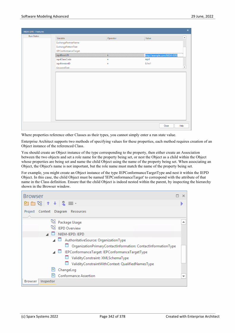
Software Modeling Advanced 29 June, 2022
Where properties reference other Classes as their types, you cannot simply enter a run state value.
Enterprise Architect supports two methods of specifying values for these properties, each method requires creation of anObject instance of the referenced Class.
You should create an Object instance of the type corresponding to the property, then either create an Associationbetween the two objects and set a role name for the property being set, or nest the Object as a child within the Objectwhose properties are being set and name the child Object using the name of the property being set. When associating anObject, the Object's name is not important, but the role name must match the name of the property being set.
For example, you might create an Object instance of the type IEPConformanceTargetType and nest it within the IEPDObject. In this case, the child Object must be named 'IEPConformanceTarget' to correspond with the attribute of thatname in the Class definition. Ensure that the child Object is indeed nested within the parent, by inspecting the hierarchyshown in the Browser window.
(c) Sparx Systems 2022 Page 342 of 378 Created with Enterprise Architect

Software Modeling Advanced 29 June, 2022
If using a role name on an Association, create the 'property' Object as a separate (non-nested) Object instance, then createan Association from the 'owner' to the 'object' and finally specify a role name for the target Object. For example, createan Association from the Model Package Description Object to an Object instance of IEPConformanceTargetType. Openthe 'Properties' dialog for the Association and name the role of the target as 'IEPConformanceTarget', to correspond tothe name of the attribute in the 'IEPD' Class. Again, in this scenario, the name of the Object itself is not important, itcould even be anonymous, but the role name must match the name of the attribute whose value you are setting.
Note that an IEPD Object might specify many IEPConformanceTargets. You must create an Object instance for each oneand each one must be named 'IEPConformanceTarget'.
(c) Sparx Systems 2022 Page 343 of 378 Created with Enterprise Architect

Software Modeling Advanced 29 June, 2022
Either of these techniques can then be used to set properties within the IEPConformanceTargetType Object. Forexample, to set the value of the ValidityConstraintWithContext attribute, create an Object instance of the ClassValidityConstraintWithContextType (which might be an instance of the derived type QualifiedNamesType) and eithername it and nest it, or associate it and name the role.
Modeling File Usage
File use can be modeled by adding Artifact elements to the diagram and linking with the required File Type Usageconnector from the toolbox.
The various filenames are generated into the IEPD's XML catalog files, using values that are specified in the Propertiesof the relevant Usage connectors.
(c) Sparx Systems 2022 Page 344 of 378 Created with Enterprise Architect

Software Modeling Advanced 29 June, 2022
NIEM IEPD Generation
Generating the IEPD can be considered an iterative process. You do not have to wait until your NIEM model is completebefore you generate an IEPD from it.
Your NIEM 'IEPD OVerview' diagram should contain an instance specification of an IEPD. The IEPD instance and itsrelationships to Conformance Target instances as well as other artifacts, is a representation of the IEPD catalog. Whenyou generate an IEPD from your model, Enterprise Architect will generate a catalog file and other artifacts, based on theitems in your IEPD model. It will also generate NIEM schemas for the <<InformationModel>> packages referenced byyour model. The result will be a collection of files output into the directory you specify for the generation process.
Steps for generating an IEPD
Step Action
1 Your NIEM IEPD diagram should contain an Instance Specification of an IEPD.
Select the IEPD instance, either on the diagram or in the Browser window.
2 From the 'Specialize' ribbon, choose the option 'Technologies > NIEM > Generate NIEM Schema'.
The 'Generate NIEM IEPD Schemas' dialog displays.
3 In the 'Directory' field, type or browse for the directory path into which to generate the IEPD.
4 The 'NIEM Version' field defaults to '5.0'. If generating a NIEM 3 or 4 IEPD, set this field to theappropriate value.
The 'IEPD Artifacts' panel lists the static IEPD Artifacts and common Artifacts (such as Structures andCatalog) used in this model, each with its relative path.
Select or deselect the checkboxes beside these items to generate or skip these items.
The 'Namespace Schema(s)' panel shows the schema files that will be generated for the informationmodels.
Select or deselect the checkbox beside a Namespace Schema to generate or skip that schema.
Select a Namespace Schema to display Package details for that schema.
5 Click on the Generate button.
Once the generation has completed successfully, clicking the View Schema button opens WindowsExplorer, showing the contents of the output directory used for generation. If the Catalog Artifact hasbeen deselected, then clicking the View Schema button will open an editor to view the schema fileassociated with the currently selected Namespace Package.
Notes
The output location of the schema file generated for a Package is specified by the 'pathURI' tag value on the Usage·connector that relates the Package to the IEPD instance specification; default values are set by the SchemaComposer when the subset Packages are created, but the values can be overridden by the user
(c) Sparx Systems 2022 Page 345 of 378 Created with Enterprise Architect

Software Modeling Advanced 29 June, 2022
Creating a NIEM Data Model
One of the underlying principles behind NIEM is re-use of a common reference vocabulary - a predefined set of dataelements and definitions used to define information exchanges. To this end, one of the core tasks in building a NIEMdata model is creating a subset of the NIEM reference schema. The goal is to model as much of your data exchange as ispractical, by re-using types and elements that are already defined in the NIEM reference model.
A NIEM data model usually consists of a number of Packages with the <<InformationModel>> stereotype applied.
Typically, a model will have one Package representing a NIEM-core subset schema, some other Packages representingsubsets of particular Domain schemas, and one or more Packages representing extension schemas. The extension schemaPackages provide those elements required by the model that are not available from the NIEM Reference Model. Often,the root element of the exchange message is separated from more general elements, and modeled in an extension schemaPackage dedicated to the specific exchange.
Steps for Creating a NIEM Data Model
Step Detail
Import the NIEMReference Model
Many of the activities involved in creating NIEM models, rely on using the NIEMReference Model. If you haven't already done so, import the Reference Model intoyour Enterprise Architect project before proceeding further.
For more information, see the Help topic Download the NIEM Reference Model.
Create a Subset of theNIEM-core ReferencePackage
There are a number of reasons for creating subsets of the NIEM namespaceschemas when creating NIEM IEPDs, but the two most important reasons are:
The reference schemas are very large; subsetting produces much smaller·schema files that, in turn, leads to faster validation of the schemas
Elements within the reference schemas are very loosely constrained; the·subsetting process allows modelers to impose much tighter constraints, such asrestricting cardinality and allowed values, to more closely reflect actualbusiness requirements
In Enterprise Architect, the subsetting process is performed using the SchemaComposer.
The Schema Composer allows the modeler to select the subset of required Classesfrom the source Package and, for each of the selected Classes, select a subset ofrequired attributes. The selected Classes with their reduced attribute sets are thencopied to a target Package. Most often the source Package will be the NIEM-corenamespace Package from the NIEM Reference Model. In this case, the targetPackage will also be a namespace Package named 'NIEM-core', but it will be partof your NIEM IEPD model.
Other namespace Packages from the Reference Model, such as the DomainPackages, can also be subsetted in the same way.
Use Enterprise Architect's Schema Composer tool to copy a subset of theNIEM-core reference Package to the NIEM-core subset Package that is part of yourIEPD model. The goal is to model as much of your data exchange as is practical, byre-using types and elements that are already defined in the NIEM-core ReferenceModel.
In cases where your model will also make use of NIEM Domain Packages, thissubsetting process should be repeated for each domain Package that you use.
For more information, see the Help topic Subsetting NIEM with the SchemaComposer.
(c) Sparx Systems 2022 Page 346 of 378 Created with Enterprise Architect

Software Modeling Advanced 29 June, 2022
Create Extension Packages When creating a NIEM data model, the aim is to model as much of your dataexchange as possible using types and elements from the NIEM Reference Model.What cannot be modeled by re-using existing NIEM elements is then modeled in'extension' namespace Packages, by creating new types and elements usingelements from the NIEM-UML profiles, with all types ultimately deriving fromXML schema primitive types.
Both the NIEM Starter Model (from the Model Wizard) and the IEPD StarterModel Pattern (from the Diagram Toolbox) provide <<InformationModel>>Packages in which to model the various schemas. Using PIM diagrams within thesePackages, you can build models of your different schemas, by adding elementsfrom the Diagram Toolbox.
It is suggested that you use the diagram in the 'exchange' Package, to assemble thehigh-level model of your exchange, using types and elements from other schemaPackages as required.
Most IEPDs require extension schemas to define specific types and properties thatare unique to the data exchange being defined. However, the NIEM model does notdefine specific message types or structures for assembling all of the objects in anexchange. It is therefore up to the creator of the IEPD to write an extension schemathat declares the root element and the basic structure of the messages. The rootelement of the exchange brings together all of the objects and associations definedin the exchange.
Whilst you are not required to create a separate schema to declare the root elementand basic structure of the message, it can be beneficial to separate message-specificextensions into an 'exchange' schema and more generic extensions into 'extension'schemas. Exchange schemas contain definitions that are unique to a message typeor group of message types. This generally includes only the root element and itstype and possibly some structural elements that form the basic framework of themessage.
Organizing schema elements into 'exchange' and generic 'extension' groupings alsooffers the possibility of sharing the more generic schema across multiple IEPDs,whereas the 'exchange' schema is usually specific to one particular IEPD. You canalso have multiple 'exchange' schemas in order to represent different message typesor groups of different message types.
(c) Sparx Systems 2022 Page 347 of 378 Created with Enterprise Architect

Software Modeling Advanced 29 June, 2022
Subsetting NIEM with the Schema Composer
Enterprise Architect's Schema Composer is a tool that can greatly simplify the process of creating subsets from theNIEM Reference Model namespace Packages.
Access
Use either of the methods outlined here to display the Schema Composer window and then display the 'New ModelTransform' dialog,
Enter a name for the new model transform, then from the 'Schema Set' drop-down list choose 'National InformationExchange Model (NIEM)'.
Save the profile as a Model Artifact within a suitable Package in your project (the root Package of your IEPD is suitable- then the Artifact will be easy to find).
Ribbon Develop > Schema Modeling > Schema Composer > Open Schema Composer :New > Model Transform
Creating a Subset Model
NIEM experts suggest that a good first step is to create a UML model of your XML exchange, as it allows you to captureyour business requirements without being unduly influenced by how things are done in NIEM.
Once you have a first draft of a UML model for your exchange, you can then begin to re-create that model using NIEM.
Initially, finding appropriate types and properties within the NIEM Reference Model can seem to be an impossible task.This will become much easier as you gain experience and familiarity with the content of the NIEM model.
Most of the NIEM types that you will commonly use, such as PersonType, OrganizationType, DocumentType orActivityType, have numerous attributes, of which you will generally require only a few. This is where subsettingbecomes useful.
If you are trying to model a person, using their name, address and birthdate, you would choose PersonType andAddressType from NIEM-core. From those types, select only the properties that you require for your model.
Where the selected properties reference other types, those types will be automatically added to the Schema Composer.
When you 'generate' your subset, Enterprise Architect creates the target schema Packages required by the subset, thencopies the selected types with their reduced attribute sets into the target Packages.
Further Refining Your Subset
Once you have created your subset, you can further refine it by making adjustments to the cardinalities of the propertieswithin the types or by restricting the allowed values of the properties.
To adjust the cardinality or restrict the permissible values of a property, select that property in the center pane of theSchema Composer, then right-click and choose 'Restrict this property'. The 'Property Restrictions' dialog is displayed,where you can adjust the cardinality or apply restrictions to the property as required.
Click on 'Update' to save the changes to your model transform profile, then click on 'Generate' to regenerate the subsetmodel with the restrictions applied.
NIEM subsetting is often an iterative process. Using the saved model transform profile, you can reload, update andregenerate your subset as you require, throughout the various stages of IEPD development.
(c) Sparx Systems 2022 Page 348 of 378 Created with Enterprise Architect

Software Modeling Advanced 29 June, 2022
Subsetting NIEM Using the Schema Composer
Step Action
1 Open the Schema Composer. (See Access: Ribbon)
2 Create a new Schema Composer profile.
Click on the New button and select 'Model Transform'.
In the dialog that opens, specify a name for the profile and select 'NIEM' in the 'Schema Set' field.
(The 'Namespace' field on this dialog is not used for NIEM, as NIEM uses Tagged Values on its ModelPackages to specify namespaces.)
Choose a location to save your new profile, then click on the OK button.
3 In the Browser window, locate the required types PersonType and AddressType, in the NIEM-corePackage of the Reference Model.
Drag and drop the required types from the Browser window onto the 'Classes' pane of the SchemaComposer.
4 Now select one of the types, say PersonType, in the Schema Composer's 'Classes' pane.
The full list of attributes for PersonType is shown in the 'Attributes' pane.
5 Use the checkboxes in the 'Attributes' list to select the attributes of 'PersonType' to use in your exchangemodel. In this case, select the checkboxes for 'PersonBirthDate' and 'PersonName'.
As you select these attributes, the Schema Composer automatically adds the types 'DateType' and'PersonNameType' to the list of Classes, as these types are referenced by the attributes you just selected.
6 Now select 'DateType' in the 'Classes' pane.
'DateType' has four attributes, DateAccuracyAbstract, DateAugmentationPoint,DateMarginOfErrorDuration and DateRepresentation. The first three of these attributes are date metadata- they do not hold a date value. The fourth, DateRepresentation, is an abstract attribute, so it does notdirectly hold date values either. It is used as a placeholder for the attribute that will ultimately hold thedate value.
The NIEM model commonly uses XML Schema abstract elements and substitution groups.
The abstract elements add some complexity to the creation of a subset, because you are required to addthe abstract element, as well as those elements that will be substituted in place of the abstract element.
For example, most date-related types contain the abstract element nc:DateRepresentation that can besubstituted by nc:Date, nc:DateTime, and so on.
7 Select the attribute DateType.DateRepresentation.
You will notice that another type, DateRepresentationPropertyHolder has been added to the 'Classes' list.
8 Select DateRepresentationPropertyHolder in the 'Classes' list.
The untyped attribute DateRepresentation is known as the 'head' of a substitution group. This attributemust be selected in the client of the substitution, DateType, as well as in the supplier of the substitution,DateRepresentationPropertyHolder. The attribute that is the head of the substitution group is pre-selectedfor you, so you only need to select the attribute that will eventually be substituted for DateRepresentationin DateType. Select the attribute Date:date - it will be used as the DateRepresentation that will actuallyhold a data value.
Where substitution groups are involved, it is a common mistake to simply add the abstract element
(c) Sparx Systems 2022 Page 349 of 378 Created with Enterprise Architect

Software Modeling Advanced 29 June, 2022
without also adding the substitutable element from the related PropertyHolder type.
9 Repeat the process for the PersonName attribute, by selecting PersonGivenName, PersonMiddleName andPersonSurName from the PersonNameType class.
10 To save your current selection of Classes and attributes to the profile you are creating, click on the Updatebutton.
This updates the profile with your current selection, allowing it to be reloaded at a later date if you need toperform further work on it. This facilitates an iterative process of creating the subset Package.
11 Now click on the 'Generate' option.
Choose 'NIEM Model Subset' in the 'Schema Export' dialog and click on the Generate button.
Navigate to the Package hierarchy containing the IEPD that you are building. Select the parent Packagethat will contain the subset packages, then click on the OK button.
12 The Classes you have selected in the Schema Composer will be copied to the target Packages, with justthe subset of attributes that you have selected.
Notes
Please read through each of the walk-through examples - each one contains important information·The Schema Composer functionality that supports NIEM development, assists in creating Subset Schemas; it does·not assist in producing Extension Schemas
(c) Sparx Systems 2022 Page 350 of 378 Created with Enterprise Architect

Software Modeling Advanced 29 June, 2022
Walk Through Examples
If you are new to using the Schema Composer for NIEM, please take the time to read through these examples. Eachexample contains important information that will help to ensure that your models use valid NIEM subsets, which willultimately produce valid XML schema files.
Example 1: Adding Classes and Selecting Attributes
This 'walk-through' example demonstrates how to use Enterprise Architect's Schema Composer to perform basicoperations of adding classes and selecting attributes to be included in a NIEM subset package.
Step Description
1 Open an Enterprise Architect project that contains the NIEM 5.0 Reference Model and also the NIEMIEPD Types.
If you don't have such a project, then open a new project and load the Reference Model and IEPD Types,using the Model Wizard (Start Page 'Create from Pattern' tab).
2 Using the Start Page 'Create from Pattern' tab (Model Wizard), add a fresh copy of the NIEM 5 IEPDStarter Model to your project.
You should rename the object instance 'NIEM-IEPD' to something more meaningful. When generatingthe IEPD, the name of this object instance is used to name the root folder in which the IEDP is created.
If you wish, rename the Package 'NIEM 5 Starter Model' to something more appropriate as well.
3 The starter model contains a Schema Composer artifact named 'Schema Composer profile - NIEM 5subset'. Locate this artifact in the Browser window, then double-click on it. This will open the SchemaComposer and load the profile 'Schema Composer profile - NIEM 5 subset'.
The lower part of the Schema Composer contains three columns. From left to right, they are labelled'Classes', 'Attributes' and 'Schema'.
4 Using the Browser window, locate the Package 'niem-core' in the NIEM 5.0 Reference Model.
Within that Package, locate the Class 'AircraftType'.
Drag and drop 'AircraftType' onto the left-hand column of the Schema Composer (labelled 'Classes').
You will notice that Classes 'ConveyanceType' and 'ItemType' are added automatically to the list ofClasses.
'ItemType' and 'ConveyanceType' are supertypes from which 'AircraftType' is derived.
5 Select AircraftType in the 'Classes' column.
You will notice that the center column, 'Attributes', displays the full list of attributes belonging to thisClass.
The attributes of the parent Classes are also listed.
To include an attribute in the subset schema, you simply place a checkmark beside it.
(You should choose only attributes of the Class that is currently selected in the 'Classes' list.
If you require attributes of a parent Class, select that Class, then select its attributes.)
Place a checkmark beside AircraftTailIdentification. The type of AircraftTailIdentification isIdentificationType.
Notice that IdentificationType has been added to the list of Classes.
Enterprise Architect automatically adds to the 'Classes' list, those classifiers that are referenced as types ofthe attributes you select.
(c) Sparx Systems 2022 Page 351 of 378 Created with Enterprise Architect

Software Modeling Advanced 29 June, 2022
6 Select the Class IdentificationType in the left-hand column of the Schema Composer.
In the center column, place a check mark beside the attribute IdentificationID. The type ofIdentificationID is 'string'. The type 'string' is a Primitive type - it is not added to the list of Classes.
7 Now, select the Class ConveyanceType in the left-hand column of the Schema Composer.
Place a check mark beside the attribute ConveyanceMotorizedIndicator.
The type 'boolean' is a Primitive type - it is not added to the list of Classes.
8 Select the Class ItemType in the left-hand column of the Schema Composer.
Place check marks beside the attributes ItemMakeName, ItemModelName and ItemModelYearDate.
The types ProperNameTextType and TextType are automatically added to the list of Classes. TextType isthe base Class for ProperNameTextType.
9 Click on the Update button to save the selected Classes and attributes to the profile, then click on theGenerate button.
In the window that opens, select 'NIEM Model Subset', then click on the Generate button.
You will be prompted to select a Package within which the subset model will be created. Typically, youwould choose the Package that is the parent of the Exchange schema Package. In the starter model, theexchange Package is named 'IEPD-Exchange' and its parent Package is named 'NIEM 5 Starter Model',although you might have renamed these earlier in step 2.
Select the Package 'NIEM 5 Starter Model', then click on the OK button.
Note: When creating more complex models, your subset might include Classes from several different<<InformationModel>> Packages. Enterprise Architect's Schema Composer will automatically create therequired target Packages and copy the Classes you are subsetting into the target Packages whose TaggedValue 'targetNamespace' matches that of the source Package from which the original Class was drawn.The subset <<InformationModel>> Packages will be created as children of the Package you choose as thegeneration target.
10 Once the generation is complete, expand the target <<InformationModel>> packages.
You will see the classes you selected with their reduced sets of attributes.
Example 2: Using Association Types
This 'walk-through' example demonstrates how to use Enterprise Architect's Schema Composer to add association typesand the types they reference, to your NIEM subset package.
Step Description
1 Open an Enterprise Architect project that contains the NIEM 5.0 Reference Model and also the NIEMIEPD Types.
If you don't have such a project, then open a new project and load the Reference Model and IEPD Typesusing the Model Wizard (Start Page 'Create from Pattern' tab).
2 Using the Model Wizard (Start Page 'Create from Pattern' tab) add a fresh copy of the NIEM 5 IEPDStarter Model to your project.
You should rename the object instance 'NIEM-IEPD' to something more meaningful. When generatingthe IEPD, the name of this object instance is used to name the root folder in which the IEDP is created.
If you wish, rename the Package 'NIEM 5 Starter Model' to something more appropriate as well.
3 The starter model contains a Schema Composer artifact named 'Schema Composer profile - NIEM 5
(c) Sparx Systems 2022 Page 352 of 378 Created with Enterprise Architect

Software Modeling Advanced 29 June, 2022
subset'. Locate this artifact in the Browser window, then double-click on it. This will open the SchemaComposer and load the profile 'Schema Composer profile - NIEM 5 subset'.
The lower part of the Schema Composer contains three columns. From left to right, they are labeled'Classes', 'Attributes' and 'Schema'.
4 Using the Browser window, locate the Package 'niem-core' in the NIEM 5.0 Reference Model.
Within that Package, locate the Class 'PersonLocationAssociationType'.
Drag and drop 'PersonLocationAssociationType' onto the left-hand column of the Schema Composer(labelled 'Classes').
You will notice that the center column 'Attributes' displays PersonLocationAssociationType.Attributesand also PersonLocationAssociationType.Associations.
Place check marks beside both of the associations, Location and Person.
The types LocationType and PersonType are automatically added to the Schema Composer's 'Classes' list.
5 The Class PersonLocationAssociationType is derived from the supertype 'nc:AssocationType', but in thiscase the supertype is not automatically added to the Classes list.
If you want to include any attributes of the supertype 'nc:AssociationType' in your generated subset, youmust add 'nc:AssociationType' to the Schema Composer's Class list manually, then select the requiredattributes.
If you don't want to specifically include attributes of 'nc:AssociationType', then there is no need to add itto the Classes list.
When the schema file is eventually generated from the subset Package, Enterprise Architect will generatean element and type definition for 'nc:AssociationType' if and when it is required, even if it is notexplicitly modeled.
6 Click on the Update button, then click on the Generate button.
In the window that opens, select 'NIEM Model Subset', then click on the Generate button.
You will be prompted to select a Package within which the subset model will be created. Typically, youwould choose the Package that is the parent of the Exchange schema Package. In the starter model, theexchange Package is named 'IEPD-Exchange' and its parent Package is named 'NIEM 5 Starter Model',although you might have renamed these earlier in step 2.
Select the Package 'NIEM 5 Starter Model', then click on the OK button.
7 Locate the <<InformationModel>> Package named 'niem-core' within the subset model. Create a NIEMPIM diagram within this Package, then drag and drop the three Classes in this Package onto the diagram.You will notice that the properties 'Person' and 'Location' are modeled as AssociationEnds on theAssociations between PersonLocationAssociationType and the types PersonType and LocationType.
Example 3: Using Substitution Groups and Property Holders
This 'walk-through' example demonstrates how to use Enterprise Architect's Schema Composer to correctly addsubstitution groups and property holders to your NIEM subset Package.
Step Description
1 Open an Enterprise Architect project that contains the NIEM 5.0 Reference Model and also the NIEMIEPD Types.
If you don't have such a project, then open a new project and load the Reference Model and IEPD Typesusing the Model Wizard.
(c) Sparx Systems 2022 Page 353 of 378 Created with Enterprise Architect

Software Modeling Advanced 29 June, 2022
2 Using the Start Page 'Create from Pattern' tab (Model Wizard), add a fresh copy of the NIEM 5 IEPDStarter Model to your project.
You should rename the object instance 'NIEM-IEPD' to something more meaningful. When generating theIEPD, the name of this object instance is used to name the root folder in which the IEDP is created.
If you wish, rename the Package 'NIEM 5 Starter Model' to something more appropriate as well.
3 The starter model contains a Schema Composer artifact named 'Schema Composer profile - NIEM 5subset'. Locate this artifact in the Browser window, then double-click on it. This will open the SchemaComposer and load the profile 'Schema Composer profile - NIEM 5 subset'.
The lower part of the Schema Composer contains three columns. From left to right, they are labeled'Classes', 'Attributes' and 'Schema'.
4 Using the Browser window, locate the Package 'niem-core' in the NIEM 5.0 Reference Model.
Within that Package, locate the Class 'AircraftType'.
Drag and drop 'AircraftType' onto the left-hand column of the Schema Composer (labeled 'Classes').
You will notice that the Classes ConveyanceType and ItemType are added automatically to the list ofClasses.
ItemType and ConveyanceType are supertypes from which AircraftType is derived.
5 Select the Class 'AircraftType' in the left-hand column of the Schema Composer.
In the center column, place a check mark beside the attribute AircraftWingColorAbstract (notice that thisattribute has no type specified).
The Class AircraftWingColorAbstractPropertyHolder is automatically added to the list of Classes.
6 Select the Class 'AircraftWingColorAbstractPropertyHolder' in the left-hand column. Notice that thisClass also has an attribute named 'AircraftWingColorAbstract' that has no type specified. This attribute ispre-selected for you - it should remain selected.
Simply place a check mark beside AircraftWingColorText.
7 In this case, the attribute AircraftWingColorAbstract is the head of the substitution group and provides theconnection between the client Class AircraftType and the supplier ClassAircraftWingColorAbstractPropertyHolder.
AircraftWingColorText is the actual attribute (of type TextType) that will be added to AircraftType.
8 Some PropertyHolder types will have several attributes - the substitution group head, plus a number ofothers. The attribute that is the head of the substitution group must always be selected in both the clientand the supplier Classes. Enterprise Architect pre-selects this attribute for you in the supplier Class (thePropertyHolder). You then only need to select the attribute(s) from the supplier that you want to substitutein place of the head of the substitution group.
(c) Sparx Systems 2022 Page 354 of 378 Created with Enterprise Architect

Software Modeling Advanced 29 June, 2022
Example NIEM Schema
This page provides an overview of defining a new NIEM compliant schema, from start to finish.
The framework Packages that are required for NIEM modeling have been described in previous topics. The ModelWizard (Start Page 'Create from Pattern' tab) also provides a Package that acts as a convenient starting point for definingyour IEPD. When this is imported to your model you will find diagrams containing instances of the IEPD types, with therun-state set to show the core properties that you are most likely to need to set.
This section describes the process of taking the sample IEPD from the Pattern, and creating a 'Hello World' stylemessage, where a request is made for a personalized message based on a facial image. The response will be the identityof the pictured person and a personalized message for them.
Import NIEM framework Packages
Modeling with NIEM in Enterprise Architect starts with the standard types defined by the NIEM Technical ArchitectureCommittee and the Object Management Group NIEM-UML specification, as described here. These are available fromour Reusable Asset Server and the Model Patterns wizard.
To import these into your model:
Open the Start Page 'Create from Pattern' tab (the Model Wizard)·Find the Perspective 'NIEM 3, 4 and 5'·Select the Packages required for your model·Click on the Create Model(s) button to import the selected patterns into your model.·
Note:
All NIEM 5 models require the NIEM IEPD Types Package as well as one of the NIEM Reference Model Packages·All NIEM 3 and 4 models require the NIEM MPD Types Package as well as one of the NIEM Reference Model·Packages
All NIEM 2.1 models require the NIEM 2.1 Reference Model Package but not an MPD Types Package, as the NIEM·2.1 MPD elements are available from the NIEM 2.1 MPD Diagram Toolbox
Component Details
NIEM Framework The power of NIEM comes primarily from the extensive library of types that youcan use to build your own schemas. Enterprise Architect provides complete NIEMframeworks for NIEM 5, as well as all versions of NIEM 3 and NIEM 4. Theseframeworks are all available from the Start Page 'Create from Pattern' tab (theModel Wizard).
This tutorial is using the NIEM 5.0 framework, so select that pattern for import.
IEPD Types fromNIEM-UML
A user-defined NIEM schema is built around an IEPD that defines, for consumersof the schema, how to use the various XSD files that are included and whatmessage types are being defined.
When modeling in UML, an IEPD is created using instances of a number of Classesdefined in the UML Profile. Enterprise Architect provides these Classes in aPackage that is available from the Start Page 'Create from Pattern' tab (the ModelWizard).
All NIEM 5 models will require these IEPD types, so select the 'NIEM 5 IEPDTypes' pattern for import.
(c) Sparx Systems 2022 Page 355 of 378 Created with Enterprise Architect

Software Modeling Advanced 29 June, 2022
Subset NIEM Namespaces
The Starter Model pattern includes a Schema Composer Artifact to use for specifying a subset. Double-click on it to openthe Schema Composer and begin the subsetting process.
We want our request message to send a facial image to be used for facial recognition. To do that, we need to subset theappropriate types from the Biometrics Package. Start by locating the type FaceImageType in the Domains\Biom Packagewithin the NIEM 5.0 Reference Model. Drag this type into the Schema Composer. The super-types from which this typeinherits are automatically added to the Schema Composer.
Our response message requires PersonType from the 'niem-core' Package. Drag this type onto the Schema Composer aswell.
This image shows the selection of a subset of the types and properties across a number of namespaces within the NIEM5.0 Reference Model:
Once the required types are selected, you can generate the subset. When prompted, select the parent Package into whichthe subset namespace Packages will be generated. After generation, the Classes in the subset Packages should resemblethis:
(c) Sparx Systems 2022 Page 356 of 378 Created with Enterprise Architect

Software Modeling Advanced 29 June, 2022
We can now create a NIEM PIM diagram and place all our subset Classes on that diagram, to produce something thatresembles this:
(c) Sparx Systems 2022 Page 357 of 378 Created with Enterprise Architect

Software Modeling Advanced 29 June, 2022
Create extension types
We will be defining two messages, a request and a response. For each of these messages, we need to define thedocument root elements. These will be modeled as extensions to the NIEM schema. Now that we have defined oursubset Packages we can define these document roots. Because we are only creating two simple document types, all that isneeded is a PropertyHolder and ObjectType for each message. The ObjectTypes link to the types we've selected from theNIEM framework, to describe the contents of each message as shown:
(c) Sparx Systems 2022 Page 358 of 378 Created with Enterprise Architect

Software Modeling Advanced 29 June, 2022
Customize the IEPD
The instance of the IEPD class carries information that identifies the IEPD and the links between it and the various othermodel artifacts determine what is generated (and where it is generated to) when generating the schema files and catalogfiles. The main points are described below.
Component Description
IEPD Metadata The top level object in the Pattern is an instance of the IEPD class. The name of theIEPD is the name of the Object itself. All other properties are in the Run-State ofthe object.
This figure shows how the IEPD might look after providing real information.
NIEM-UML recommends the last section of iepdBaseURI matches the name of theIEPD, and specifies that the iepdVersionID will be appended to the iepdBaseURI toproduce the generated iepdURI. This example follows that convention.
The Pattern defaults the value of iepdClassCode to 'iepd'. This means that the IEPDis intended to represent an Information Exchange Package Document (IEPD). Thisis the most common type of IEPD, and it is what we want to create, so it has been
(c) Sparx Systems 2022 Page 359 of 378 Created with Enterprise Architect

Software Modeling Advanced 29 June, 2022
left with the default value.
Defined Document Types An IEPD is expected to define one or more document types. Each one will be aninstance of IEPConformanceTargetType named 'IEPConformanceTarget'. Theprovided model Pattern already includes one of these, but we need a second one asshown here:
Note the instances of QualifiedNamesType, with the qualifiedName relationship toa PropertyHolder. This specifies that the top level of the document being describedwill be an element from one of the contained attributes. The section CreateExtension Packages in the topic Creating a NIEM Data Model describes how this isdefined.
Package Usage The relationships connecting the IEPD instance to the Information Models specifywhich schema files are to be generated with this IEPD. In this example we usetypes from two different NIEM namespaces. The sub-setting process has created anInformationModel Package for each, where the Namespace Tagged Values matchthe original, and the purpose is set to subset. We also created an extension Packagewhere we defined our own types and how the NIEM types will be used.
This figure shows how this looks:
The relationships used also specify how the Package is used and the relative path tothe schema defined by that Package.
Additional Files All IEPD Packages are expected by NIEM to contain - at a minimum - a change logand a readme, but there are several other types of Artifact that are also supported. InEnterprise Architect, each is defined using a stereotyped relationship to an Artifact.
(c) Sparx Systems 2022 Page 360 of 378 Created with Enterprise Architect

Software Modeling Advanced 29 June, 2022
As with the Package use, the relationship specifies where the file will be located.
In this image a ReadMe, ChangeLog and a sample document are described for eachof the document types. This will add information about those files to the targetcatalog file. The files will not be created by Enterprise Architect, and their contentis beyond the scope of this tutorial.
Generate IEPD
To generate your IEPD:
Select the IEPD instance specification, either on the diagram or in the Browser window.·From the 'Specialize' ribbon, select the option 'Technologies > NIEM > Generate NIEM Schema'·
(c) Sparx Systems 2022 Page 361 of 378 Created with Enterprise Architect

Software Modeling Advanced 29 June, 2022
The dialog shows the standard NIEM artifacts and the list of linked namespaces that can be generated as schemas. Set thetarget directory and click on the Generate button to create the modeled IEPD.
(c) Sparx Systems 2022 Page 362 of 378 Created with Enterprise Architect

Software Modeling Advanced 29 June, 2022
Import NIEM XML Schema
As well as generating NIEM schema in Enterprise Architect, you can import (reverse engineer) an externalNIEM-specific XML Schema file into your Enterprise Architect project as a UML model.
Access
Ribbon Specialize > Technologies > NIEM > Import NIEM Schema
Specialize > Technologies > NIEM 2.1 > Import NIEM 2.1 Schema
Context Menu In the Browser window:
Right-click Package | Specialize | NIEM | Import NIEM Schema
Right-click Package | Specialize | NIEM 2.1 | Import NIEM 2.1 Schema
Import a NIEM specific XML Schema
Option Action
Package Displays the name of the currently-selected Package in the Browser window, as thePackage into which to import the NIEM schema.
You can verify that you are using the appropriate Package by clicking on the button and checking the 'Navigator' dialog; select a different Package if necessary.
DirectoryClick on the button and browse for the directory containing the source NIEMSchema file(s). Click on each file to import, and then click on the browser Openbutton.
Selected File(s) Lists the XML Schema file(s) selected for import.
Import referenced XMLSchema(s)
Select this checkbox if you want to import any other XML Schema that isreferenced by any of the files listed in the 'Selected File(s)' field.
Skip Schema if Namespacein Model
Select this checkbox if you want to skip importing an XML Schema if it alreadyexists in the model.
Enterprise Architect will use the Schema namespace and name to determine if itexists in the Model.
Create Diagram for XMLSchema(s)
Select this checkbox to create a Class diagram (a NIEM PIM diagram) under eachimported Namespace Package.
Layout created Diagram (Enabled only if the 'Create Diagram for XML Schema(s)' option is selected.)
Select this checkbox to automatically lay out the created Class diagram(s).
Import Click on this button to start the import process.
The progress of the import is reported in the 'NIEM Importer' tab of the System
(c) Sparx Systems 2022 Page 363 of 378 Created with Enterprise Architect

Software Modeling Advanced 29 June, 2022
Output window. A message box also displays to indicate when the import iscomplete; click on the OK button to clear the message.
Close Click on this button to close the 'Schema Importer' dialog.
Help Click on this button to display this Help page.
Notes
Enterprise Architect uses the schemaLocation attribute in the XSD Import and XSD Include elements of an XML·Schema, to determine the dependencies between the files; this attribute must be set to a valid file path (and not aURL) for the dependent XML Schema(s) to be imported correctly
The 'Create Diagram for XML Schema(s)' option generates a diagram for each imported schema file, but displays·the diagrams only for the schema files specifically selected by the user; it does not display the diagram for areferenced schema file
If you import large schema files, it is recommended that you deselect the 'Create Diagram for XML Schema(s)'·option, as this considerably increases the time taken by the import
(c) Sparx Systems 2022 Page 364 of 378 Created with Enterprise Architect

Software Modeling Advanced 29 June, 2022
Geospatial Models
The popularity of the internet, the ever-present mobile phone and the prevalence of location-based services have resultedin almost everyone interacting with location-based information in some form in their daily lives. It has also becomecritical for governments and organizations to embrace this type of information as part of strategic decision making.Geospatial information can be modeled in Enterprise Architect and also integrated with other data to form a single andcomprehensive view of information not possible in other tools.
Enterprise Architect, through the use of MDG Technologies, supports the Geography Markup Language (GML)application schemas and the modeling of ArcGIS geodatabases. The information precursors to these models - such ascommunity conceptual models - can also be modeled, and traceability can be used to connect the models together.
Modeling Tools
Tool Description
ArcGIS Profile Enterprise Architect supports the design of geodatabases for the ArcGIS 10.0 suiteof tools developed by Esri Inc.
Geography MarkupLanguage
Geography Markup Language (GML) in Enterprise Architect is the implementationof the Open Geospatial Consortium's Geography Markup Language 3.3, whichprovides an XML grammar for geographical feature modeling capabilities withinEnterprise Architect.
(c) Sparx Systems 2022 Page 365 of 378 Created with Enterprise Architect

Software Modeling Advanced 29 June, 2022
Getting Started
Enterprise Architect partitions the tools extensive features into perspectives this ensures that you can focus on a specifictask and work with the tools you need without the distraction of other features. To work with the ArcGIS Geodatabasesor Geography Markup Language features you first need to select the following perspectives:
Database Engineering > ArcGIS
Information Exchange > Geographic GML
Setting the perspective ensures that the ArcGIS Geodatabases and Geography Markup Language diagrams and their toolboxes and other features of the perspective will be available by default.
ArcGIS Geodatabases
Using the ArcGIS features in Enterprise Architect you can visualize geodatabases with ease. This allows you to unifyteams working in traditional software centric and engineering systems with your geospatial teams defining features anddomains. Teams defining the strategy business rules and requirements for a system or the components that deliver thesystem functionality can share models with the geospatial teams creating an integrated model that will help withintegration and risk reduction.
Geography Markup Language (GML)
Using the Geography Markup Language (GML) facility you can model organization or community based applicationschemas. The models can be used to show the relationship between Features and these elements in turn can contain anynumber of Properties that qualify their characteristics. These can be based on defined Types, DataTypes, CodeLIsts orEnumerations.
(c) Sparx Systems 2022 Page 366 of 378 Created with Enterprise Architect

Software Modeling Advanced 29 June, 2022
ArcGIS Geodatabases
Exchange, Model and Visualize ArcGIS Geodatabases
Enterprise Architect supports the import and export of ArcGIS geodatabases, allowing you to visualize Features andDomains within this multi-featured collaboration platform. In the recent past there has been a separation of thedisciplines between system software development and geospatial development. In this age of social architecture anddigital disruption almost every project and endeavor requires some aspect of location information, from simple deliveryservices to agricultural, mining, exploration, weather, real estate and disaster recovery systems.
Package diagram showing a Navigation Cell and a Package containing Features Domains and a Geospatial Reference
The ArcGIS system, developed by Esri, supports the development and management of geodatabases. As it is for otherdatabases, it is useful to model the design of a geodatabase using a standard notation such as UML. You can performsuch modeling in Enterprise Architect, using the UML profile for ArcGIS. Once you have modeled an ArcGIS schema inEnterprise Architect, you can export the model to ArcGIS as an XML Workspace document. You can also visualize anexisting ArcGIS geodatabase schema, by importing the ArcGIS XML Workspace document into Enterprise Architect.
(c) Sparx Systems 2022 Page 367 of 378 Created with Enterprise Architect

Software Modeling Advanced 29 June, 2022
Example Diagram
ArcGIS diagrams allow you to visualize the geographic features, domains and other elements that make up a geodatabaseschema. In this example a Building has been sub-typed as a house, the house in turn is sub-typed based on the materialtype. The subtypes of the House references a Coded Value Domain also presented in the diagram with two Domain CodeValues:
Brick·WeatherBoard·
A Smart Meter is associated with the house. The House is a type of Building and the Building contains the property ofStreet Address
(c) Sparx Systems 2022 Page 368 of 378 Created with Enterprise Architect

Software Modeling Advanced 29 June, 2022
Exporting ArcGIS XML Workspaces
When you have modeled your Geodatabase Workspace XML Document (containing the ArcGIS schema), you canexport it to an external directory (using the Publish Model Package facility), from which you can then import it to theEsri ArcCatalog.
Access
Click on an ArcGIS stereotyped Package (your ArcGIS Workspace Package) in the Browser window.
Ribbon Specialize > Technologies > ArcGIS > Export to ArcGIS Workspace XML or
Publish > Model Exchange > Publish As...
Context Menu Right-click on Package | Specialize | ArcGIS | Export to ArcGIS Workspace XML
Keyboard Shortcuts Ctrl+Alt+E : Publish
Export the Workspace
Option Action
Root Package Display the name of the selected ArcGIS Workspace Package.
Filename Type in or browse for the file path into which the XML file is to be generated.
XML Type Select 'ArcGIS' as the XML/XMI version to export the Package to.
Format XML Output Format the output into readable XML (this takes a few more seconds at the end ofthe run).
Write Log File Write a log of the export activity (recommended).
The log file is saved to the directory into which the XML file is exported.
View XML Click on this button to view the exported XML file.
Export Click on this button to initiate the XML export.
Close Click on this button to close this dialog.
Progress Observe the progress of the XML export.
Notes
ArcGIS is available in the Professional, Corporate, Unified and Ultimate Editions of Enterprise Architect·
(c) Sparx Systems 2022 Page 369 of 378 Created with Enterprise Architect

Software Modeling Advanced 29 June, 2022
In the Corporate, Unified and Ultimate Editions of Enterprise Architect, if security is enabled you must have 'Export·XMI' permission to export to XML
Before exporting your model to an ArcGIS schema, you must define at least one Spatial Reference element; Spatial·Reference elements are referred to by other schema elements via a dynamically linked Tagged Value, namedSpatialReference
The DefaultSpatialReference tag on an ArcGIS Package is used to specify a Spatial Reference that can be applied to·all Feature Datasets and Feature Classes in the workspace; therefore, you do not need to apply a Spatial Referenceelement to each Feature Dataset or Feature Class
If you do not reference a Spatial Reference Class from any Feature Dataset or Feature Class in your ArcGIS model,·Enterprise Architect by default will generate an XML schema with Unknown type of Spatial Reference for theseelements
(c) Sparx Systems 2022 Page 370 of 378 Created with Enterprise Architect
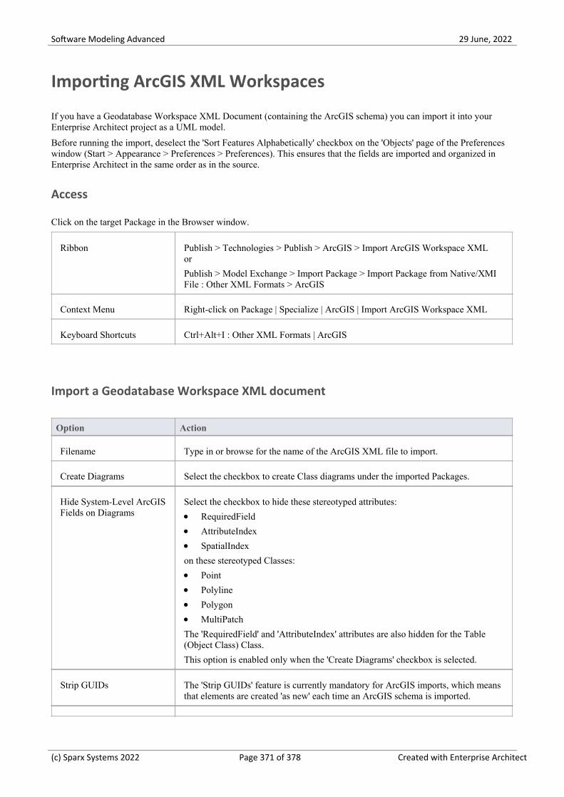
Software Modeling Advanced 29 June, 2022
Importing ArcGIS XML Workspaces
If you have a Geodatabase Workspace XML Document (containing the ArcGIS schema) you can import it into yourEnterprise Architect project as a UML model.
Before running the import, deselect the 'Sort Features Alphabetically' checkbox on the 'Objects' page of the Preferenceswindow (Start > Appearance > Preferences > Preferences). This ensures that the fields are imported and organized inEnterprise Architect in the same order as in the source.
Access
Click on the target Package in the Browser window.
Ribbon Publish > Technologies > Publish > ArcGIS > Import ArcGIS Workspace XMLor
Publish > Model Exchange > Import Package > Import Package from Native/XMIFile : Other XML Formats > ArcGIS
Context Menu Right-click on Package | Specialize | ArcGIS | Import ArcGIS Workspace XML
Keyboard Shortcuts Ctrl+Alt+I : Other XML Formats | ArcGIS
Import a Geodatabase Workspace XML document
Option Action
Filename Type in or browse for the name of the ArcGIS XML file to import.
Create Diagrams Select the checkbox to create Class diagrams under the imported Packages.
Hide System-Level ArcGISFields on Diagrams
Select the checkbox to hide these stereotyped attributes:
RequiredField·AttributeIndex·SpatialIndex·
on these stereotyped Classes:
Point·Polyline·Polygon·MultiPatch·
The 'RequiredField' and 'AttributeIndex' attributes are also hidden for the Table(Object Class) Class.
This option is enabled only when the 'Create Diagrams' checkbox is selected.
Strip GUIDs The 'Strip GUIDs' feature is currently mandatory for ArcGIS imports, which meansthat elements are created 'as new' each time an ArcGIS schema is imported.
(c) Sparx Systems 2022 Page 371 of 378 Created with Enterprise Architect

Software Modeling Advanced 29 June, 2022
Write Log File Select the checkbox to write a log of import activity (recommended).
The log file is saved in the directory from which the file is being imported, with thesame name as the imported file plus the suffix _import.log.
View XML Click on this button to view the XML before import.
Import Click on this button to import the ArcGIS XML file.
Close Click on this button to close this dialog.
Help Click on this button to display this Help page.
Import Progress This field indicates the progress of the import.
Notes
ArcGIS is available in the Professional, Corporate, Unified and Ultimate Editions of Enterprise Architect·
(c) Sparx Systems 2022 Page 372 of 378 Created with Enterprise Architect

Software Modeling Advanced 29 June, 2022
Geography Markup Language (GML)
Model Geographic Features and Generate Application Schemas
You can create expressive and collaborative models of the important features in your domain and use these to generateGeography Markup Language (GML) compliant application schemas that can be consumed by other applications. Manyof the disruptive forces and technologies that have changed the way we interact with each other and the world we inhabit,involve geographic locations and features. We drive along roads and stop at lookouts to view coastal features orcityscapes, we travel abroad to view monuments and buildings such as churches and museums, we rely on wind farms forenergy and we take off and land at airports to name a few. You can model any geographic features of interest usingEnterprise Architect's implementation of the Geography Markup Language which is fundamental for geographicinformation systems as well as its use as an open interchange format for geographic transactions on the Internet.
GML Model of roads showing two Features with properties that access two Data Types and Enumerations
GML for Enterprise Architect is an implementation of the Open Geospatial Consortium's Geography Markup Language(GML) 3.3 , which provides an XML grammar for geographical feature modeling capabilities within Enterprise Architectat or later than Release 10.
Through GML, you can:
Apply a UML Profile for the Geography Markup Language (GML) 3.3·Make use of customized diagram types and toolbox pages, for convenient access to elements and relationships to·model geographical features effectively
Generate GML Application Schema files·
(c) Sparx Systems 2022 Page 373 of 378 Created with Enterprise Architect

Software Modeling Advanced 29 June, 2022
Example Diagram
Using the Geography Markup Language (GML) facility you can model organization or community based applicationschemas. The models can be used to show the relationship between Features Types that contain any number of Propertiesthat qualify their characteristics. These can be based on defined Types, Data Types, Code Lists or Enumerations. Youcan collaborate with other geospatial colleagues or with people working in traditional systems implementations indisciplines that manage artifacts including: Strategies, Goals, Requirements, Data Models, Software Models,Deployment Descriptions and more.
(c) Sparx Systems 2022 Page 374 of 378 Created with Enterprise Architect

Software Modeling Advanced 29 June, 2022
Modeling with GML
You can create GML models using the comprehensive diagramming and modeling facilities in Enterprise Architect. Firstyou need to select the GML or Information Exchange Perspective. Perspectives are a useful focusing tool facility thatensure you remain focused and can concentrate on GML modeling.
Perspective menu - GML Perspective Selection
This activates the UML Profile for GML, allowing you to create models with elements and connectors that describe yourorganization or community domains.
Access
Ribbon Specialize > Technologies > GML
Context Menu Right-click on Package | Specialize | GML
Features
Feature Detail
Profile Support You can develop GML constructs quickly and simply, through use of the built-inGML facilities provided in the form of:
A GML diagram type, accessed through the 'New Diagram' dialog·GML pages in the Diagram Toolbox that map GML concepts to appropriately·stereotyped UML elements
GML element and relationship entries in the 'Toolbox Shortcut Menu' and·'Quick Linker'
GML Toolbox Page The GML Toolbox pages contain elements and connectors to model geographicalfeatures effectively.
UML Classes from ISO (Optional) You can download the UML Classes implemented in ISO/TC 211 as an
(c) Sparx Systems 2022 Page 375 of 378 Created with Enterprise Architect

Software Modeling Advanced 29 June, 2022
XMI file, then import the XMI file into Enterprise Architect as a Packagecontaining diagrams and standard UML Classes, which you can reuse in yourmodel.
Not all UML Classes implemented in ISO/TC 211 have a corresponding·mapping in GML; the Classes that have a mapping (as specified in the GML3.2.1 specification) are specified in the configurable fileGMLClassMapping.xml in the 'Sparx Systems > EA > Config > GML' folder
The Namespace information for these Classes is specified in the configurable·file GMLNamespaces.xml in the 'Sparx Systems > EA > Config > GML folder'
GML Application SchemaGeneration
Any model you create using GML in Enterprise Architect can be exported as aGML Application Schema.
Using the configurable file GMLStereotypes.xml in the 'Sparx Systems > EA >Config > GML' folder, you can specify aliases for the standard GML stereotypes.The GML Application Schema Generator will also consider these aliases duringSchema generation.
Notes
GML is available in the Professional, Corporate, Unified and Ultimate Editions of Enterprise Architect·
(c) Sparx Systems 2022 Page 376 of 378 Created with Enterprise Architect

Software Modeling Advanced 29 June, 2022
More Information
Geospatial modeling can be explored in more detail by accessing the following two topics:
ArcGIS Geodatabases
Geography Markup Language (GML)
(c) Sparx Systems 2022 Page 377 of 378 Created with Enterprise Architect

Software Modeling Advanced 29 June, 2022
(c) Sparx Systems 2022 Page 378 of 378 Created with Enterprise Architect
Copyright © 2022 FDOKUMEN