Influence of substrate microstructure and surface finish ... - DiVA
27
Influence of substrate microstructure and surface finish on cracking and delamination response of TiN-coated cemented carbides Jing Yang, Magnus Odén, M. P. Johansson-Joesaar and L. Llanes Linköping University Post Print N.B.: When citing this work, cite the original article. Original Publication: Jing Yang, Magnus Odén, M. P. Johansson-Joesaar and L. Llanes, Influence of substrate microstructure and surface finish on cracking and delamination response of TiN-coated cemented carbides, 2016, Wear, (352-353), 102-111. http://dx.doi.org/10.1016/j.wear.2016.02.004 Copyright: Elsevier http://www.elsevier.com/ Postprint available at: Linköping University Electronic Press http://urn.kb.se/resolve?urn=urn:nbn:se:liu:diva-127252
-
Upload
khangminh22 -
Category
Documents
-
view
2 -
download
0
Transcript of Influence of substrate microstructure and surface finish ... - DiVA

Influence of substrate microstructure and
surface finish on cracking and delamination
response of TiN-coated cemented carbides
Jing Yang, Magnus Odén, M. P. Johansson-Joesaar and L. Llanes
Linköping University Post Print
N.B.: When citing this work, cite the original article.
Original Publication:
Jing Yang, Magnus Odén, M. P. Johansson-Joesaar and L. Llanes, Influence of substrate
microstructure and surface finish on cracking and delamination response of TiN-coated
cemented carbides, 2016, Wear, (352-353), 102-111.
http://dx.doi.org/10.1016/j.wear.2016.02.004
Copyright: Elsevier
http://www.elsevier.com/
Postprint available at: Linköping University Electronic Press
http://urn.kb.se/resolve?urn=urn:nbn:se:liu:diva-127252

1
Influence of substrate microstructure and surface finish on cracking
and delamination response of TiN-coated cemented carbides
J. Yang*1,2, M. Odén2,
M.P. Johansson-Jõesaar2,4 and L. Llanes1,3 1 CIEFMA - Departament de Ciència dels Materials i Engenyeria Metal⋅ lúrgica, ETSEIB, Universitat Politècnica
de Catalunya, Barcelona 08028, Spain 2 Nanostructured Materials, Department of Physics, Chemistry, and Biology (IFM), Linköping University,
Linköping 58183, Sweden 3 CRnE – Center for Research on Nanoengineering, Universitat Politècnica de Catalunya, Barcelona 08028, Spain
4 SECO Tools AB, Fagersta 73782, Sweden
* Corresponding author: [email protected] / [email protected]
Abstract
The cracking and delamination of TiN-coated hardmetals (WC-Co cemented carbides) when
subjected to Brale indentation were studied. Experimental variables were substrate microstructure
related to low (6%wt. Co) and medium (13%wt. Co) binder content, and surface finishes associated
with grinding and polishing stages before film deposition. Brale indentation tests were conducted
on both coated and uncoated hardmetals. Emphasis has been placed on assessing substrate
microstructure and subsurface finish effects on load levels at which cracking and delamination
phenomena emerge, the type of cracking pattern developed, and how fracture mechanisms evolve
with increasing load. It is found that polished and coated hardmetals are more brittle (radial
cracking) and the adhesion strength (coating delamination) diminishes with decreasing binder
content. Such a response is discussed on the basis of the influence of intrinsic hardness/brittleness
of the hardmetal substrate on both cracking at the subsurface level and effective stress state,
particularly regarding changes in shear stress component. Grinding promotes delamination
compared to the polished condition, but strongly inhibits radial cracking. This is a result of the
interaction between elastic-plastic deformation imposed during indentation and several grinding-
induced effects: remnant compressive stress field, pronounced surface texture and microcracking

2
within a thin altered subsurface layer. As a consequence, coating spallation prevails over radial
cracking as the main mechanism for energy dissipation in ground and coated hardmetals.
Keywords: coated hardmetal; Brale indentation technique; cracking; delamination; substrate
microstructure; substrate surface finish; grinding.

3
1. Introduction
WC-Co cemented carbides, often simply termed as hardmetals, belong to a class of composite
materials in which hard particles are bound together by a soft and ductile metal binder. This
microstructure assembly yields an extraordinary combination of mechanical properties and
tribological response, allowing the use of these materials in a wide range of applications:
machining, mining, rock drilling, and structural components, among others [1]. Within this
context, the role of cemented carbides in metal cutting and forming operations is remarkable, the
corresponding tools being here subjected to a complex state of loading (mechanical contact, wear,
fatigue, impact, etc.) that determines their lifetime. At the same time, the need to extend the
lifetime of such tools to meet stringent shaping requirements, has led to hardmetals with different
ceramic coatings. Deposition of ceramic films on cemented carbides improves tool life as they
offer high hardness, oxidation and wear resistance, thermal stability, diffusion barrier properties,
and in some cases low friction [2]. The introduction of tool coatings enhances the quality of the
shaped products at reduced production costs, typically, also with an improved sustainability of the
machining process [3].
Indentation testing provides an apparently simple method for studying surface-related mechanical
properties for coatings, surface-modified layers and even bulk materials. For hard coated systems,
it has extended use in industry as quick and convenient means of obtaining a qualitative indication
of “practical adhesion” [4,5]. To facilitate its use in a production environment, it is commonly
implemented by employing a simple diamond cone-shape Brale indenter [6]. Furthermore, in the
case that applied load is 150 kgf, it becomes the well-known Rockwell C test and it is used as
destructive quality test prescribed by VDI 398 and DIN CEN/TS 1071-8 standards [7,8]. Here
mechanical testing is combined with microscopic (100X) observation of the cracking/delamination
pattern around the resulting imprint, followed by direct comparison with a chart of acceptable and
unacceptable results.
Despite the widespread use of indentation techniques for assessment of the practical adhesion of
hardmetal coated systems, it has mainly been used to study the influence of coating characteristics,
4
i.e. chemical nature, layer architecture, deposition route, crystallographic and microstructural
texture, etc. (e.g. Refs. [6, 9-17]). However, the effective performance of coated hardmetal tools
depends not only on the intrinsic properties of the deposited coating but also on those of the
underlying substrate where the subsurface integrity is affected by the geometry shaping stage (e.g.
abrasive removal of material) [18-21]. In this regard, knowledge about substrate-related effects, in
terms of either microstructure or surface finish, on the indentation response of coated hardmetals
is quite limited [22-28].
Within the above framework, it is the objective of this investigation to assess the influence of
substrate microstructure and grinding-induced surface finish on the cracking and delamination
scenario exhibited by TiN-coated hardmetals when subjected to Brale indentation. Two hardmetal
grades with different binder content are studied. A ground variant is compared to a mirror-like
polished one, the latter used here as reference condition. It is well-established that thermal and
mechanical loads in grinding of hardmetal tools induce surface integrity alterations [21, 28-41].
Accordingly, surface topography, subsurface damage and effective residual stress state of the
hardmetal substrate, both prior and after coating deposition, were characterized. Furthermore,
aiming for better understanding the mechanical integrity of the coated systems under indentation,
the experimental study was also conducted on the uncoated hardmetals under consideration.

5
2. Experimental materials and procedures
The substrates studied in this work correspond to two WC-Co cemented carbides with different
binder (Co) content: 6 %wt. and 13 %wt., but alike fine grain carbides. They are here referred to as
6F and 13F respectively. Nominal chemical composition, mean carbide grain size, as well as
hardness and fracture toughness values for the hardmetal grades investigated are listed in Table 1
[42]. Hardness was measured using a 30 kgf (294 N) Vickers pyramidal diamond indentation.
Toughness measurement was conducted through three-point bending test of Chevron-notched
specimens. Experimental details regarding microstructural, hardness and toughness
characterization of the substrate materials are given in Ref. [42].
Ground (G) and mirror shine polished (P) were the two surface finish variants investigated. Plane
surface grinding was performed using commercial diamond abrasive wheel and coolant, the latter
for preventing heat generation. Grinding conditions were the same for both hardmetal substrates
studied, regardless of the different hardness and toughness exhibited by them. Polishing was done
following a three-step material removal sequence using diamond-containing disks, diamond
suspensions (final grit size 3 m), and finishing with a suspension of 45 nm colloidal silica
particles. Hardmetal substrates were TiN coated using an industrial scale reactive cathodic arc
evaporation system (MZR323, Sulzer Metaplas). All substrates were mounted at the same height
Table 1. Mean and standard values for basic microstructural and mechanical parameters for the
cemented carbides (WC-Co) studied [42].
Hardmetal
grade
Nominal binder
content
(% wt. Co)
Mean WC
grain size
(μm)
Hardness
HV30
(GPa)
Fracture
toughness
(MPa√m)
6F 6 0.70 17.8 9.4
13F 13 0.67 14.8 11.2

6
on a rotating drum fixture. TiN films were reactively grown from pure Ti cathodes in a 2 Pa
nitrogen atmosphere, using a substrate bias of -50 V and a substrate temperature of 450 °C. Prior
to deposition, the substrates were ultrasonically cleaned in an alkali solution and alcohol, followed
by sputtering with ~500 eV Ar-ions. The base pressure of the deposition system was 2.0 x 10⁻³ Pa.
Coatings were found to be dense and uniform (3 m in thickness) with fine-grained columnar
structures, and to exhibit an intrinsic hardness of 28 GPa and residual compressive stress of about
3.3 GPa, independent of substrate microstructure and surface finish [40,41].
Surface integrity of the coated systems, prior to any indentation testing, was characterized in terms
of roughness, residual stresses (prior and after coating deposition), and damage at the subsurface
level. Surface roughness was measured by employing a stylus type, surface texture measuring
system (Surftest SV512, Mitutoyo). Roughness parameters Ra (arithmetic deviation from the mean
line through the complete profile) and Ry (maximum profile depth) were recorded for both surface
finish variants, G and P, before (uncoated) and after coating (the latter including previous ion
etching stage). Surface residual stresses were determined by X-ray diffraction (XRD) using a
Panalytical Empyrean four-circle diffractometer. Cu-Kα radiation source was employed and the
sin2ψ method was applied. Detailed information regarding experimental data collection and
subsequent analysis is given elsewhere [39-41]. Nevertheless, it should be highlighted that only
data from WC-phase was used for residual stress assessment at the surface of the hardmetal
substrate. Main reason for it was that diffraction peaks from the metallic binder phase were weak
and broad due to its relatively low content. Moreover, according to literature reports using both
XRD and neutron diffraction [43,44], baseline values in the range from -100 to -500 MPa may be
expected for the WC phase, even in the mirror polished reference condition. These correspond to
residual microstresses that arise in cemented carbides between the metallic and ceramic phases,
upon cooling from liquid or solid phase sintering temperatures [45]. Finally, changes in the
microstructural and damage scenario at both surface and subsurface levels were examined by
means of field emission scanning electron microscopy (FESEM), employing a JEOL JSM-7001F
equipment. Cross-sectional specimens were prepared by focused ion beam (FIB) milling, using a
dual beam Workstation (Zeiss Neon 40).

7
Indentation behavior for all four coated specimen combinations of hardmetal substrate and surface
finish variant were evaluated. It was carried out using a diamond cone-shape Brale indenter (tip
radius of 0.2 mm and angle of spherical head of 120º) at discrete applied loads over a range of
294-490 N. The used range of applied load was chosen because it induced clear plastic deformation
within the hardmetal substrate, with indentation depths higher than 12 microns, i.e. much deeper
than thickness of the subsurface layer altered by grinding-induced effects. At least three
indentations were done per testing condition. Post-indentation deformation, cracking and
delamination response was carefully examined by means of FESEM. Aiming to understand the
different cracking and delamination responses, additional indentation tests were conducted on
uncoated hardmetal substrates under similar applied loads.
3. Results and discussion
3.1 Surface integrity of coated hardmetals: grinding and substrate microstructure effects.
The influence of surface pre-treatment, e.g., grinding and coating stages on roughness, subsurface
integrity and residual stress state for the 13F grade has been described elsewhere [40,41]. The
surface integrity scenario for the 6F hardmetal grade was studied here and it was found to be
qualitatively alike to the 13F grade. Main findings on grinding and substrate microstructure effects
on surface integrity are now summarized.
Table 2. Roughness parameters (Ra and Ry) associated with substrate surface conditions both
prior and post coating deposition, for the 6F and 13F grades, respectively.
Condition
Substrate
surface
finish
6F 13F
Ra (μm) Ry (μm) Ra (μm) Ry (μm)
Uncoated Coated Uncoated Coated Uncoated Coated Uncoated Coated
G Ground 0.09±0.01 0.16±0.04 0.50±0.05 0.99±0.30 0.20±0.07 0.25±0.05 1.05±0.35 1.72±0.30
P Polished 0.01±0.01 0.17±0.03 0.08±0.01 0.99±0.18 0.01±0.01 0.27±0.05 0.11±0.04 1.54±0.20

8
First, roughness is strongly affected by grinding, resulting in Ra and Ry values one order of
magnitude higher than those obtained after polishing (Table 2). Moreover, film deposition yields
an increase of the roughness values for P specimens up to levels similar to those assessed after
grinding. The main reason for the increased roughness is the presence of protruding surface
asperities caused by deposition of macroparticles during TiN coating growth and typical for
cathodic arc evaporation technique [46]. However, grinding effects on surface roughness is less
pronounced for the 6F grade. As it is listed in Table 2, it is clear that roughness values attained for
G specimens of 6F grade are lower than for those of 13F one. Second, grinding effects at the
surface level are also evidenced in terms of topographic texture, this being directly associated with
Figure 1. Cross-sectional SEM subsurface images obtained perpendicular to the grinding marks
of (a) uncoated 13F grade, (b) uncoated 6F grade and (c) coated 6F grade hardmetals with ground
substrate surface finish. Grinding-induced damages are marked with arrows.

9
Table 3. Pre- and post-deposition residual substrate surface stresses values for 6F and 13F grades
vs. surface finish G and P conditions.
Surface finish Residual stresses (MPa)
6F 13F
G -1611±58 -1824±89
P -78±11 -133±40
G+Coat -1139±60 -1071±24
P+Coat -54±1 -59±15
unidirectional groove-like features induced by the relative movement of the grinding wheel with
respect to the hardmetal substrate. Such surface texture is still clearly visible in the coated
specimens for both grades. Third, grinding induces microstructural alterations within a subsurface
layer of about 1 micron in depth. There, pulverized and/or microcracked carbides embedded in a
heavily deformed (and smeared) metal binder are discerned for 13F grade (Figure 1a). Compared
to ground 13F grade, FESEM inspection of FIB milled cross-sections in ground 6F grade indicates
that the altered subsurface layer seems to be thinner, and damage is exclusively discerned in terms
of microcracking, running through either binder or carbides (Figure 1b). Subsequent ion etching
stage prior to coating reduces the thickness of the affected subsurface layer in coated G specimens
(Figure 1c). Fourth, high compressive residual stresses are induced by grinding at the subsurface
level. They are remarkably high at the surface of the ground hardmetal. In the case of coated
specimens, compressive residual stresses close to the interface between the substrate and the
coating are found to be one order of magnitude higher than the residual microstresses assessed for
the coated P substrates (Table 3). However, they are reduced to nearly half those measured in the
surface of uncoated ground hardmetal. Such a difference must be ascribed to the combined effect
from removal of highly stressed material during ion etching and stress annihilation by thermal
annealing during subsequent coating deposition [35,37,38]. Very interesting, the level of
compressive residual stresses induced by imposed grinding operation, measured at both the surface
of ground substrate and close to the interface between substrate and coating in coated specimens
(Table 3), was independent of the hardmetal substrate. Concerning the stress profile, it was found

10
previously for 13F grade that residual stresses decrease to baseline values at depths of about 10-
12 microns, i.e. well beyond the thickness estimated for the deformed/damaged layer [39]. It is
possible that similar statement would not apply for 6F grade (i.e. thickness of the affected
subsurface layer). Nevertheless, evaluation of changes on residual stresses as a function of depth
was beyond the scope of the present investigation.
The distinct surface topography and subsurface integrity of ground 6F and 13F samples should be
related to the fact that material removal was done under the same grinding conditions, i.e. less
material is affected for this harder and more brittle grade. Finally, it should be highlighted that
density, morphology and intrinsic residual stresses of the TiN film deposited was found to be,
through FESEM inspection and XRD analysis, independent of hardmetal substrate microstructure
and surface finish.
3.2 Indentation response
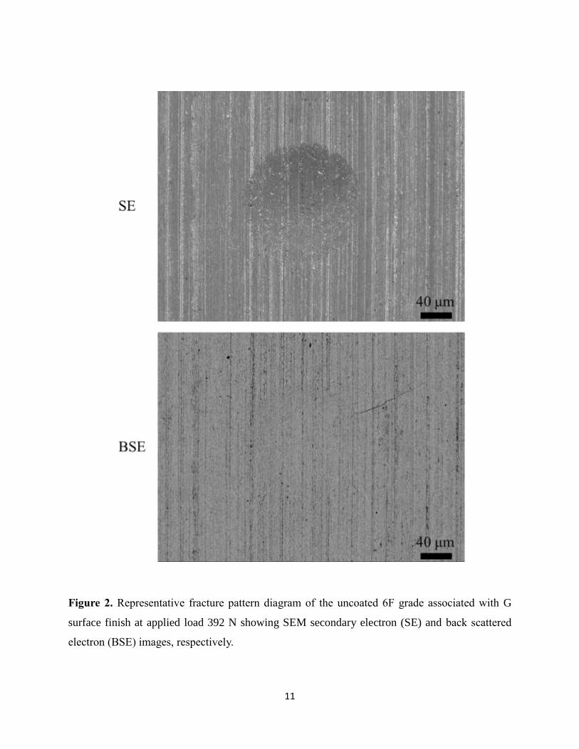
Figure 2 shows a representative fracture pattern diagram of 6F grade associated with G surface
finish at applied load 392 N, inspected by means of FESEM under both secondary electron (SE)
and back scattered electron (BSE) modes, respectively. The deformation, i.e., residual imprints is
better imaged in SE mode while the cracking pattern in BSE mode. Considering that the main
interest of this study focuses on cracking/delamination phenomena, BSE images will be used for
presenting the results.
Figure 3 shows the deformation and fracture pattern diagram for all the coated systems, resulting
from the application of three defined normal indentation load levels: 294 N, 392 N and 490N. In
all the cases, as load is increased irreversible deformation is first induced, then radial cracks are
generated around the contact area, and finally spallation due to propagation of lateral cracks at the
substrate/coating interface takes place [10,47]. However, the load level at which cracking and
delamination phenomena emerge, the type of cracking pattern developed, and how both fracture
11
Figure 2. Representative fracture pattern diagram of the uncoated 6F grade associated with G
surface finish at applied load 392 N showing SEM secondary electron (SE) and back scattered
electron (BSE) images, respectively.

12
Figure 3. Indentation fracture patterns (BSE images) for the coated 6F and 13F grade hardmetals
vs. the P and G surface finish conditions associated with indentation load levels of 294 N, 392 N
and 490N, respectively.

13
mechanisms evolve with increasing load, are clearly dependent on the substrate microstructure and
surface finish, which is discussed below.
3.2.1 Substrate microstructure effects
The influence of substrate microstructure on the indentation adhesion behavior of the coated
systems is analyzed by direct comparison between 6F and 13F grades, both under the reference P
surface finish. From Figure 3, it is clear that 6F coated hardmetal exhibits few but well-defined
and long radial cracks emanating from the contact edge, opposite to a large number of small and
homogeneously distributed fissures for the 13F substrate. The differences are relevant considering
not only crack pattern but also the load level for their emergence. In this regard, cracks are already
observed at load level of 294 N for 6F grade whereas an applied load of 392 N is required for
discerning any fracture feature in the 13F one. Similar trends are also seen for the critical load for
delamination, and when transition from partial to spread spalling occurred. This points towards a
more brittle character as well as lower indentation adhesion strength for the 6F coated system.
Taking into account that the TiN film deposited on both hardmetal substrates is not an experimental
variable in this study, the differences observed must be rationalized on the basis of substrate
microstructural effects. Within this context, two separate factors may be recalled: an intrinsic one
related to brittleness/hardness of the substrate itself and an extrinsic one associated with how shear
stresses generated during loading/unloading under elastic-plastic conditions may change due to the
effective yield strength (hardness) of the substrate.
Aiming to understand the intrinsic influence of substrate brittleness/hardness on the indentation
response of coated hardmetals, nude polished substrates were indented under similar testing
conditions. Corresponding indentation fracture patterns are shown in Figure 4. Besides a smaller
residual impression (expected from hardness differences), the higher brittleness exhibited by the
grade with low binder content yields a well-defined and quite localized cracking pattern, similar
to the one already appreciated in the corresponding coated system. Experimental evidence of the
intimate correlation between radial cracks discerned at the coating surface and those previously
induced (under unloading) at the hardmetal subsurface are provided by detailed FESEM inspection

14
Figure 4. Indentation fracture patterns (BSE images) of the uncoated 6F and 13F grades
hardmetals, corresponding to the polished surface finish condition, associated with the indentation
load levels of 294 N, 392 N and 490N, respectively.
of delaminated areas (e.g. Figure 5). Hence, substrate brittleness may be stated as critical for
understanding the distinct cracking response observed in the coated hardmetal systems.
Concerning earlier delamination observed for the harder 6F grade, as compared to the 13F one, it
should be highlighted that during elastic-plastic indentation, the effective stress state within the
coating, at the coating/subsurface interface and in the substrate just beneath the layer interface, are
dependent on several factors [47-49]. Among them, coating thickness and yield strength,
interfacial strength and substrate yield strength may be highlighted. Considering that the as-
deposited films not only exhibit the same properties but also is firmly attached to the substrate for
all the systems studied [40], interfacial shear stresses developed during or after unloading are
expected to increase with substrate yield strength [47]. Accordingly, critical normal load for

15
Figure 5. High magnification SEM images of the delaminated area for the coated 6F grade with
polished substrate, indented at 490 N.
adhesive failure should decrease with increasing substrate hardness. This is in agreement with the
experimental findings of this investigation.
3.2.2 Substrate surface finish effects
From Figure 3, the influence of substrate grinding on the indentation response of the coated
hardmetals studied may be described by two relevant observations, compared to the reference P
condition: (1) emergence of delamination phenomena at lower applied loads; and (2) pronounced
inhibition of radial cracking features. Very interesting, such surface finish effects are independent
of substrate microstructure. Also when comparing adhesion response exhibited by G samples
between 6F and 13F grades in terms of critical load for the onset and evolution of coating
spallation, it follows similar trends discerned for the P specimens that earlier and more pronounced
delamination for the harder grade. Here, the grinding influenced behavior should be related to

16
Figure 6. Indentation fracture patterns (BSE images) for the uncoated 6F and 13F grades
hardmetals, corresponding to the ground surface finish condition, associated with the indentation
load levels of 294 N, 392 N and 490N, respectively.
intrinsic factors associated with grinding-induced changes as well as extrinsic factors related to
changes in effective stress state and how they affect the prevalence of cracking or delamination
phenomena.
Following the approach described in the previous section, Brale indentation tests were also
conducted on uncoated ground hardmetals, aiming to get information on the individual influence
of grinding-induced changes within the substrate subsurface. The corresponding fracture pattern
diagrams are shown in Figure 6. The observed deformation/cracking response of the coated G
specimens is a direct consequence of the grinding-induced changes within the substrate.
Particularly, total or partial inhibition of radial cracks for 13F and 6F grades, respectively,
compared to scenario described for coated P samples, should be ascribed to the effect of relatively

17
high compressive stresses induced by grinding at the surface of the hardmetals studied [41].
Nevertheless, their influence on the overall deformation is most likely not observed through the
indentation residual imprint area (hardness) because these residual stresses exhibit a maximum
value between 1 and 2 GPa at the substrate surface which is much lower than the actual substrate
hardness (see Table 1). Moreover, they are decreasing to baseline values throughout a very thin
subsurface region between 10-12 microns in thickness [39] and hence thinner than the residual
imprint depth (i.e. between 12-19 microns). These findings and corresponding analysis are
supported by our recent results on enhanced contact damage resistance, in terms of both critical
load for crack emergence and subsequent damage evolution, associated with substrate grinding
effects [42].
Unlike the beneficial influence of grinding on cracking, it appears to be detrimental for the
adhesion strength of coated hardmetals. Considering that the film properties for all the coated
specimens are the same, the different adhesion properties of the coated systems should be related
to several factors operative at the interface and just beneath surface. In this regard, inhibition of
radial cracking may translate into nucleation of lateral cracks, and their subsequent propagation
through either the interface [6,9,50] or the microcracked subsurface region, as the most effective
mechanisms for dissipating the energy stored during elastic-plastic indentation. Furthermore, a
lower critical load for early film decohesion and subsequent wider delamination could also be
expected for G coated specimens, as compared to the reference P specimens, as a consequence of
surface topography effects as well as interaction with microcracks already introduced during
grinding (Figure 1).
Regarding surface texture, the role of an uneven interface on the adhesion behavior of coated
systems is complex [51]. On one hand, it can work as an interlocking pin that would enhance the
interfacial adhesion. On the other hand, it could decrease adhesion strength because the existing
geometrical discontinuities may act as stress concentrators and surface unevenness could induce
the existence of stresses normal to the coating/substrate interface [52]. According to the findings
of this investigation, it seems that unidirectional grinding-groove like features would be more
detrimental than beneficial, concerning adhesion strength. The fact that spreading of delamination

18
Figure 7. Inclined view under SE mode of the coated 6F grade hardmetal with the substrate
surface finish: (a) P and (b) G, respectively.
with increasing applied load in coated G samples shows film flaking locally aligned with the
referred grinding marks, different from the uniform quasi-circular spallation observed in the coated
P specimens (e.g. Figure 7), supports the above statement.

19
Figure 8. Peeling off quasi-detached coating flakes from an indentation imprint on a coated 6F
grade specimen using a carbon tape: (a) top view of the indentation crater after being peeled off
and (b) the reverse side of some peeled off coating flakes attached to the carbon tape. The bottom
two images (c) and (d) are the enlarged views of the dash and solid squares indicated in the image
(b), respectively. Note that the coating flakes may move during the peeling off and sample
preparation process, leading to the Figure 8a and b images may not be overlapped to each other.
20
Grinding-induced pre-existing microcracking has been postulated as a key factor for explaining
the less localized damage scenario found on ground and coated specimens, as compared to the
reference polished and coated condition, under monotonic contact loading [41]. Accordingly, their
synergic interaction with a pronounced surface texture resulting from grinding (and a
superimposed remnant compressive stress field) could be another critical factor for promoting
coating spallation as an effective mechanism of energy dissipation during or after unloading the
indenter. Indeed, if this was the case, the delamination phenomena observed should rather be the
combined result of two different failure micromechanisms: pure adhesive coating decohesion and
cohesive detachment (through lateral crack extension) at the substrate subsurface just beneath the
interface. Aiming to gather information on the operative failure micromechanisms, quasi-detached
coating flakes were peeled off from some indentation imprints using a carbon tape, so that
corresponding back sides could be inspected. Figure 8 shows the indentation crater after being
peeled off (Figure 8a) and the back side of some film flakes peeled off from a ground and coated
6F specimen (Figure 8b). Enlarged views of specific regions from the reverse side of coating
flakes (Figures 8c and 8d) show interesting (and different) features, depending on the location
from where flakes were taken. Hence, it is found that they are relatively clean from WC particles
(bright contrast) for delamination taken place within the indentation contact quasi-circular area
(Figure 8c). However, this is not the case when inspecting the back side of flakes adjacent to
grinding-grooves outside the indentation imprint. There, aligned and continuous tracks of WC
particles (Figure 8d) are neatly appreciated, pointing out the relevance of above discussed factors
(i.e. surface texture, subsurface microcracking and effective stress state underneath the imprint)
for inducing early and extensive coating delamination, both adhesive and cohesive, in ground and
coated specimens.
Conclusions
The influence of substrate microstructure (6F and 13F grades) and surface finish (G and P variants)
on the cracking and delamination scenario exhibited by TiN-coated hardmetals when subjected to
indentation using a diamond cone-shape Brale indenter has been studied. The following
conclusions may be drawn:

21
1) Brale indentation technique, a simple and practical method widely used for assessing
adhesion of hard coated systems, is proposed and validated as an effective testing route for
evaluation of substrate microstructure (low and medium binder content of fine-grained
grades) and surface finish (ground as compared to polished to mirror-like finish) effects on
the indentation response of coated hardmetals.
2) Deformation and fracture patterns induced by Brale indentation is qualitatively similar in
all the coated hardmetal systems studied: as load is increased, irreversible deformation,
radial cracking, and finally spallation are sequentially evidenced. However, the load level
at which cracking and delamination phenomena emerge, the type of cracking pattern
developed, and how both fracture mechanisms evolve with increasing load are clearly
dependent on the substrate microstructure and surface finish.
3) Polished and coated hardmetals exhibit higher level of brittleness (radial cracking) and
lower adhesion strength (coating delamination) as binder content of the fine-grained
substrate decreases. Such a microstructural effect is related to brittleness/hardness of the
substrate itself (as discerned under Brale indentation testing of uncoated substrates) and
the direct relationship between substrate yield strength and effective shear stresses
generated at the coating/substrate interface during loading/unloading under elastic-plastic
conditions.
4) Relevant grinding effects on the indentation response of the coated hardmetals are assessed
in terms of emergence of delamination at lower applied loads than for the reference P
condition, and pronounced inhibition of radial cracking. These surface finish effects are
evidenced for the two hardmetal grades studied. Moreover, in both cases, G specimens
follow similar trends observed for P ones, in terms of critical loads for show up and
evolution of film spalling.
5) Hindering of radial cracking after indentation of ground and coated hardmetals is analyzed
in terms of the synergic interaction between elastic-plastic deformation imposed and
several grinding-induced effects: remnant compressive stress field, pronounced surface

22
texture and microcracking within a thin altered subsurface layer. As a consequence, coating
spallation becomes the most effective mechanism for energy dissipation for this surface
finish variant, taking place by combining two different failure micromechanisms: pure
adhesive coating decohesion and cohesive detachment at the substrate surface just beneath
the interface.
Acknowledgements
Funding for this investigation was partly supplied by the Spanish MINECO (Grant No. MAT 2012-
34602). One of the authors (J.Y.) acknowledges funding received through Erasmus Mundus joint
European Doctoral Programme DocMASE. Research work was conducted within a cooperative
effort among SECO Tools AB, Linköping University and Universitat Politècnica de Catalunya.
References
[1] Prakash L. Fundamentals and general applications of hardmetals. In: Sarin VK, Mari D,
Llanes L. (Vol. eds.), Comprehensive Hard Materials. Oxford: Elsevier 2014; Vol. 1, Ch.
1.02, p. 29-90.
[2] Mitterer C. PVD and CVD hard coatings. In: Sarin VK, Llanes L, Mari D (Vol. eds.),
Comprehensive Hard Materials. Oxford: Elsevier 2014; Vol. 2, Ch. 2.16, p. 449-67.
[3] Klocke F, Döbbeler B, Binder M, Kramer N, Grüter R, Lung D. Ecological evaluation of
PVD and CVD coating systems in metal cutting processes. In: Seliger G (Ed.). Proceedings
11th Global Conference on Sustainable Manufacturing (GCSM). Berlin: Universitätsverlag
der TU Berlin 2013; Paper 12.3, p. 381-7.
[4] Mittal KL, in: Mittal KL (Ed.), Adhesion Measurement of Thin Films, Thick Films and Bulk
Coatings, STP No. 640. Philadelphia: ASTM 1978; p. 5-17.
[5] Holmberg K, Matthews A. Coatings Tribology — Properties, Techniques and Applications
in Surface Engineering, 2nd Edition, Tribology and Interface Engineering Series, Nº 56.
Amsterdam: Elsevier Science B.V. 2009; p. 319-61.
[6] Mehrotra PK, Quinto DT. Techniques for evaluating mechanical properties of hard coatings.
Journal of Vaccum Science and Technology A 1985;3:2401-5.
[7] Verein Deutscher Ingenieure Normen, VDI 3198, VDI-Verlag, Dusseldorf, Germany 1991

23
[8] DIN CEN/TS 1071-8 Advanced technical ceramics - Methods of test for ceramic coatings -
Part 8: Rockwell indentation test for evaluation of adhesion; German version CEN/TS 1071-
8:2004
[9] Jindal PC, Quinto DT, Wolfe GJ. Adhesion measurements of chemically vapour deposited
and physically vapour deposited hard coatings on WC–Co substrates. Thin Solid Films.
1987;154: 361-75.
[10] Diao DF, Kato K, Hokkirigawa K. Fracture mechanisms of ceramic coatings in indentation.
Transactions ASME Journal of Tribology 1994:116;860-9.
[11] Heinke W, Leyland A, Matthews A, Berg G, Friedrich C, Broszeit E. Evaluation of PVD
nitride coatings, using impact, scratch and Rockwell-C adhesion tests. Thin Solid Films.
1995;270:431-8.
[12] Ollendorf H, Schneider D. A comparative study of adhesion test methods for hard coatings.
Surface and Coatings Technology. 1999;113:86-102.
[13] Vidakis N, Antoniadis A, Bilalis N. The VDI 3198 indentation test evaluation of a reliable
qualitative control for layered compounds. Journal of Materials Processing Technology.
2003;143–144:481-5.
[14] Hollstein F, Wiedemann R, Scholz J. Characteristics of PVD-coatings on AZ31hp magnesium
alloys. Surface and Coatings Technology. 2003;162:261-8.
[15] Chen L, Du Y, Yin F, Li J. Mechanical properties of (Ti, Al)N monolayer and TiN/(Ti, Al)N
multilayer coatings. International Journal of Refractory Metals and Hard Materials.
2007;25:72-6.
[16] Horiuchi T, Yoshida K, Kano M, Kumagai M, Suzuki T. Evaluation of adhesion and wear
resistance of DLC films deposited by various methods. Plasma Processes and Polymers.
2009;6:410-6.
[17] Wang CT, Escudeiro A, Polcar T, Cavaleiro A, Wood RJK, Gao N, Langdon TG. Indentation
and scratch testing of DLC-Zr coatings on ultrafine-grained titanium processed by high-
pressure torsion. Wear 2013;306: 304-10.
[18] Hogmark S, Hedenqvist P, Jacobson S. Tribological properties of thin hard coatings: demands
and evaluation. Surface and Coatings Technology. 1997;90:247-57.
[19] Matthews A, Leyland A, Holmberg K, Ronkainen H. Design aspects for advanced tribological
surface coatings. Surface and Coatings Technology. 1998;100-101:1-6.

24
[20] Holmberg K, Matthews A, Ronkainen H. Coatings tribology — contact mechanisms and
surface design. Tribology International. 1998;31: 107-20.
[21] Bouzakis KD, Michailidis N, Skordaris G, Bouzakis E, Biermann D, M'Saoubi R. Cutting
with coated tools: coating technologies, characterization methods and performance
optimization. CIRP Annals - Manufacturing Technology. 2012;61:703-23.
[22] Tönshoff HK, Blawit C, Rie KT, Gebauer A. Effects of surface properties on coating adhesion
and wear behaviour of PACVD-coated cermets in interrupted cutting. Surface and Coatings
Technology. 1997;97:224-31.
[23] Bouzakis KD, Michailidis N, Hadjiyiannis S, Efstathiou K, Pavlidou E, Erkens G, et al.
Improvement of PVD coated inserts cutting performance, through appropriate mechanical
treatments of substrate and coating surface. Surface and Coatings Technology. 2001;146–
147:443-50.
[24] Polini R. Chemically vapour deposition diamond coatings on cemented tungsten carbides:
substrate pretreatments, adhesion and cutting performance. Thin Solid Films. 2006;515:4-13.
[25] Casas B, Anglada M, Sarin VK, Llanes L. TiN coating on an electrical discharge machined
WC-Co hardmetal: surface integrity effects on indentation adhesion response. Journal of
Materials Science. 2006;41:5213-9
[26] Polini R, Delogu M, Marcheselli G. Adherent diamond coatings on cemented tungsten carbide
substrates with new Fe/Ni/Co binder phase. Thin Solid Films. 2006;494:133-140
[27] Arroyo JM, Diniz AE, de Lima MSF. Wear performance of laser precoating treated cemented
carbide milling tools. Wear. 2010;268:1329-36.
[28] Denkena B, Köhler J, Breidenstein B, Abrão AM, Ventura CEH. Influence of the cutting edge
preparation method on characteristics and performance of PVD coated carbide inserts in hard
turning. Surface and Coatings Technology. 2014;254:447-5.
[29] Knotek O, Löffler F, Krämer G. Substrate- and interface-related influences on the
performance of arc-physical-vapour-deposition-coated cemented carbides in interrupted-cut
machining. Surface and Coatings Technology. 1992;54–55:476-81.
[30] Tönshoff HK, Karpuschewski B, Mohlfeld A, Seegers H. Influence of subsurface properties
on the adhesion strength of sputtered hard coatings. Surface and Coatings Technology.
1999;116–119:524-9.

25
[31] Hegeman JBJW, De Hosson JTM, de With G. Grinding of WC–Co hardmetals. Wear.
2001;248:187-96.
[32] Tönshoff HK, Seegers H. X-ray diffraction characterization of pre-treated cemented carbides
for optimizing adhesion strength of sputtered hard coatings. Surface and Coatings
Technology. 2001;142–144:1100-4.
[33] Byrne G, Dornfeld D, Denkena B. Advancing cutting technology. CIRP Annals -
Manufacturing Technology. 2003;52:483-507.
[34] Denkena B, Spengler C. Influence of different grinding processes on surface and subsurface
characteristics of carbide tools. Key Engineering Materials. 2004;257-258:195-200.
[35] Denkena B, Breidenstein B. Influence of the residual stress state on cohesive damage of PVD-
coated carbide cutting tools. Advanced Engineering Materials. 2008;10:613-6.
[36] Merklein M, Andreas K, Engel U. Influence of machining process on residual stresses in the
surface of cemented carbides. Procedia Engineering. 2011;19:252-7.
[37] Denkena B, Breidenstein B. Residual stress distribution in PVD-coated carbide cutting tools:
Origin of cohesive damage. Tribology in Industry. 2012;34:158-65.
[38] Breidenstein B, Denkena B. Significance of residual stress in PVD-coated carbide cutting
tools. CIRP Annals - Manufacturing Technology. 2013;62:67-70.
[39] Yang J, Odén M, Johansson-Jõesaar MP, Llanes L. Grinding effects on surface integrity and
mechanical strength of WC-Co cemented carbides. Procedia CIRP. 2014;13:257-63.
[40] Yang J, Roa JJ, Odén M, Johansson-Jõesaar MP, Esteve J, Llanes L. Substrate surface finish
effects on scratch resistance and failure mechanisms of TiN-coated hardmetals. Surface and
Coatings Technology. 2015;265:174-84.
[41] Yang J, García Marro F, Trifonov T, Odén M, Johansson-Jõesaar MP, Llanes L Contact
damage resistance of TiN-coated hardmetals: Beneficial effects associated with substrate
grinding. Surface and Coatings Technology. 2015; 275:133-41.
[42] Sheikh S, M'Saoubi R, Flasar P, Schwind M, Persson T, Yang J, Llanes L. Fracture toughness
of cemented carbides: testing method and microstructural effects. International Journal of
Refractory Metals and Hard Materials. 2015;49:153-60.
[43] Mari D, Krawitz AD, Richardson JW, Benoit W. Residual stress in WC-Co measured by
neutron diffraction. Materials Science and Engineering: A. 1996;209:197-205.

26
[44] Larsson C, Odén M. X-ray diffraction determination of residual stresses in functionally graded
WC–Co composites. International Journal of Refractory Metals and Hard Materials.
2004;22:177-84.
[45] Krawitz AD, Drake EF. Residual stresses in cemented carbides – An overview. International
Journal of Refractory Metals and Hard Materials. 2015;49:27-35.
[46] Anders A. Approaches to rid cathodic arc plasmas of macro- and nanoparticles: a review.
Surface and Coatings Technology. 1999;120–121:319-30.
[47] Larsson M, Olsson M, Hedenqvist P, Hogmark S. Mechanisms of coating failure as
demonstrated by scratch and indentation testing of TiN coated HSS. Surface Engineering.
2000;16:436-44.
[48] Johnson KL. Contact Mechanics. Cambridge: Cambridge University Press 1987.
[49] Yuan F, Hayashi K. Influence of grain size of the alumina coating on crack initiation in
indentation. Wear. 1999;225-229:83-9.
[50] Chang SS, Marshall DB, Evans AG. A simple method for adhesion measurements. In: Pask
JA, Evans AG (Eds.). Surfaces and Interfaces in Ceramics and Ceramic-Metal Systems. New
York: Plenum 1981: Vol. 14, p. 603-17.
[51] Strawbridge A, Evans HE. Mechanical failure of thin brittle coatings. Engineering Failure
Analysis. 1995;2:85-103.
[52] Evans AG, Crumley GB, Demaray RE. On the mechanical behavior of brittle coatings and
layers. Oxidation of Metals. 1983;20:193-216.