Influence of SiC reinforcement particles on the tribocorrosion behaviour of Al-SiCp FGMs in 0.05M...
31
This is where the paper number, author and title should go 1 1 2 3 4 Influence of SiC reinforcement particles on the tribocorrosion 5 behaviour of Al-SiC p FGM’s in 0.05M NaCl solution 6 7 8 A. C. Vieira 1* , L.A. Rocha 1 , S. Mischler 2 9 1 Centre for Mechanical and Materials Technologies (CT2M) and Department of Mechanical Engineering, University of Minho, Azurém, 10 4800-058 Guimarães, Portugal 11 2 Ecole Polytechnique Fédérale de Lausanne (EPFL), Tribology and Interface Chemistry Group, 1015 Lausanne, Switzerland 12 13 Received Date Line (to be inserted by Production) (8 pt) 14 15 16 Abstract 17 18 The main aim of this work was to study and understand the influence of SiC particles on the corrosion and 19 tribocorrosion of Al matrix composite materials. For that, Al-SiC p functionally graded composites were produced 20 by centrifugal casting and different SiC p contents were achieved. Their mechanical properties were improved by 21 age-hardening heat-treatments. The tribocorrosion behaviour was studied in 0.05M NaCl solutions using a 22 reciprocating motion tribometer involving an alumina ball sliding against the Al based samples. Above critical 23 SiC particles content the matrix alloy surface was found protected against wear by SiC particles protruding from 24 the surface. Below this threshold content, the SiC reinforcement was inefficient and the wear rate of the composite 25 was the same as the non reinforced alloy. 26 27 Keywords: Al alloy/SiC p composites, FGM, tribocorrosion 28 29 30 1. Introduction 31 32 A functional graded material (FGM) can be defined as a material with two or more phases, 33 which varies in some spatial direction its composition and/or microstructure. The concept of 34 *Correspondig author. Tel.: +351 253 510 220; fax: +351 253 516 007. E-mail address: [email protected] (Ana Catarina Vieira) Confidential: not for distribution. Submitted to IOP Publishing for peer review 7 March 2011
-
Upload
independent -
Category
Documents
-
view
0 -
download
0
Transcript of Influence of SiC reinforcement particles on the tribocorrosion behaviour of Al-SiCp FGMs in 0.05M...
This is where the paper number, author and title should go 1
1
2
3
4
Influence of SiC reinforcement particles on the tribocorrosion5
behaviour of Al-SiCp FGM’s in 0.05M NaCl solution6
78
A. C. Vieira1*, L.A. Rocha1, S. Mischler291 Centre for Mechanical and Materials Technologies (CT2M) and Department of Mechanical Engineering, University of Minho, Azurém,10
4800-058 Guimarães, Portugal112 Ecole Polytechnique Fédérale de Lausanne (EPFL), Tribology and Interface Chemistry Group, 1015 Lausanne, Switzerland12
13Received Date Line (to be inserted by Production) (8 pt)14
1516
Abstract17
18
The main aim of this work was to study and understand the influence of SiC particles on the corrosion and19
tribocorrosion of Al matrix composite materials. For that, Al-SiCp functionally graded composites were produced20
by centrifugal casting and different SiCp contents were achieved. Their mechanical properties were improved by21
age-hardening heat-treatments. The tribocorrosion behaviour was studied in 0.05M NaCl solutions using a22
reciprocating motion tribometer involving an alumina ball sliding against the Al based samples. Above critical23
SiC particles content the matrix alloy surface was found protected against wear by SiC particles protruding from24
the surface. Below this threshold content, the SiC reinforcement was inefficient and the wear rate of the composite25
was the same as the non reinforced alloy.26
27
Keywords: Al alloy/SiCp composites, FGM, tribocorrosion28
2930
1. Introduction31
32
A functional graded material (FGM) can be defined as a material with two or more phases,33
which varies in some spatial direction its composition and/or microstructure. The concept of34
*Correspondig author. Tel.: +351 253 510 220; fax: +351 253 516 007.E-mail address: [email protected] (Ana Catarina Vieira)
Confidential: not for distribution. Submitted to IOP Publishing for peer review 7 March 2011

This is where the paper number, author and title should go 2
composite material may be used to design FGM´s, taking benefit of an inhomogeneous1
distribution of the reinforcing phase (metallic, ceramic or polymeric) resulting in an2
improvement of mechanical, thermal, electromagnetic, biochemical or biomechanical3
properties [1, 2-7]. For instances, by using centrifugal casting, SiC particles can be dispersed in4
an Al-based matrix with a graded distribution originating an Al-SiCp FGM [8,9]. Therefore, it5
is possible to combine surface hardness and high wear resistance with high bulk toughness6
[10].7
In fact, Al-SiCp FGM’s, have shown a great potential for several industries [10,11], being8
their major applications in electronic packaging industry, brake rotor assemblies or pistons9
rings in automotive industries and turbine components or rocket nozzles (relatively high-10
temperature environments) for advanced aircrafts and aerospace vehicles [1,12-15].11
Because of the relatively good corrosion properties of aluminium, Al-SiCp FGM’s are12
candidate materials for tribocorrosion applications were contact is exposed to the combined13
degradation by wear and corrosion. Examples of such tribocorrosion applications are chemical14
pumps, piston rings, cylinder walls and components in marine structures [16-18]. However,15
relatively little is known about the corrosion and tribocorrosion behaviour of aluminium based16
FGM’s.17
The reinforcement by SiC particles can influence the corrosion behaviour of the Al matrix.18
Preferential attack at the reinforcement/matrix interface (due to Al4C3 formation at the19
interface), creation of local cathodes on conductive SiC catalysing the reduction of oxygen20
and/or modifications of the matrix alloy microstructure (alteration of the size and distribution21
of intermetallic phases) during composite production were phenomena reported in the literature22
as having influence on the corrosion resistance of Al-SiCp composites [16,19,20]. Clearly,23
these effects are highly dependent on the nature of the matrix Al alloy, on the SiC particles and24
on the heat treatments.25
Also, the tribocorrosion behaviour of the material appears to be determined by the area26
fraction of reinforcement, particle mean size and tribological testing parameters. A. Velhinho27
et al [11] investigated the tribocorrosion behaviour of Al-SiCp functionally graded composites28
against cast iron pins in water using a unidirectional pin on disk tribometer. Two volume29
fractions (12.6 and 35.7%) of SiC particles with median size of 118 µm were considered.30
Those authors reported that the presence of water facilitated catastrophic SiC particle pull-out,31
This is where the paper number, author and title should go 3
and therefore significantly increased wear. Indeed, higher volume fractions of SiC particles1
were found to cause larger wear. On the other hand, J.R. Gomes et al [21] also studied Al-SiCp2
functionally graded composites but using different experimental conditions: reciprocating3
sliding and a normal load of 10N. Tests were conducted by using cast iron pins counterfaces in4
a 3% NaCl solution and SiC particles area fraction varying between 25.8% and 33.4%. In this5
case, the wear rate of the composites was not significantly affected by the presence of the6
aqueous solution. In contrast to Velhinho et al [11] results, higher amounts of reinforcement7
lead to lower wear rates. This behaviour was attributed to the capability of the SiC particles to8
anchor protective tribolayers and to their load-supporting effect allowing the protection of the9
Al matrix, contributing to a lower total wear of the composite material.10
C.-K. Fang et al [16] studied the synergistic effects of wear and corrosion for Al2O311
particulate–reinforced 6061 Al matrix composites and postulated that, although the12
incorporation of reinforcement was detrimental to the corrosion resistance of the material, its13
influence on wear-corrosion was favourable. Therefore there is still a need for a mechanistic14
understanding of the involved phenomena.15
This study aim was to gain a better understanding of the tribocorrosion mechanisms of Al-16
SiCp functionally graded composites. For this a model system consisting in Al-SiCp samples17
sliding against inert alumina balls in 0.05M NaCl was investigated. Aluminium matrix18
composites materials with a gradient in SiC content were fabricated using centrifugal casting.19
Samples of different SiC contents were obtained by machining the composite ingots in20
different locations. Heat treatments were carried out in order to improve the mechanical21
properties of the matrix. The corrosion mechanisms were evaluated using immersion and22
electrochemical techniques. During tribocorrosion the OCP was recorded in order to gain23
information on the prevailing mechanisms.24
25
2. Experimental details26
2.1 Materials27
28
A non-commercial Al-10Si-4.5Cu-2Mg (wt. %) was selected as matrix of the composite.29
The alloy was home-developed in order to present specific properties, such as good castability30
(by adding Si), heat-treatment capability (by adding Cu) and good wettability (by adding Mg).31
This is where the paper number, author and title should go 4
As reinforcement, SiC particles with 37.6 µm as grain size distribution (10% of volumetric1
fraction) were selected. The functionally graded materials (FGM) were processed by2
centrifugal casting, using radial geometry, with 1500 rpm centrifugal speed.3
Two different post-processing age hardening heat-treatments were made: solution treatment4
at 500 ⁰C (2h and 8h), followed by quenching, plus an artificial aging at 160 ⁰C during 5125
min. The solution treatments were made in air, in tubular furnace, while the artificial aging was6
made in a thermostatic silicone bath (Model Haake F6).7
In this paper the samples solution treated during 2h were identified as FGM-S2h while the8
samples solution treated during 8h were identified as FGM-S8h. To use as reference, a non9
heat-treated sample was also studied and was identified as FGM-NHT.10
The FGM microstructure was characterised using XRD (Cu Kα radiation, continuous Bragg11
Brentano mode, scan step size of 0.02⁰, Bruker D8 Discover equipment), SEM/EDS (Nano-12
SEM FEI Nova 200), and optical microscopy.13
The particle area fraction was estimated by image analysis. For that, 25 to 30 images were14
acquired in an optical microscope and subsequently analysed with computer aided image15
analysis (Image tool 3.0).16
Macro Vickers hardness measurements (30 Kg, 20s dwell time) were performed on all17
samples.18
19
2.2 Corrosion tests20
21
The samples were machined from the centrifugal cast-ring, in order to test the most exterior22
zone of the ring. Previous to each corrosion test, the samples were wet-polished up to 120023
mesh in SiC abrasive paper.24
The electrochemical solution used was 0.05M NaCl (pH = 6.2). The pH was measured25
before and after the corrosion tests. No variation in the pH was detected during the tests.26
Two types of tests were carried out: immersion tests (to characterize localized corrosion27
mechanisms) and potentiodynamic polarization measurements (polarization curves). In the first28
tests, the samples were immersed in the solution (open circuit conditions) during 30 min and29
afterwards the corroded samples were analysed by SEM. Regarding the polarization curves, a30
This is where the paper number, author and title should go 5
potential sweep rate of 0.5 mV/s in the noble direction (starting from cathodic values) was1
used. The samples were stabilized in the solutions during 1h before these measurements. A2
three-electrode electrochemical cell configuration integrating a standard double wall glass cell3
was used: a standard calomel reference electrode (SCE), a Pt counter electrode and the FGM4
samples connected as working electrode (WE) to the potentiostat (Autolab PGSTAT 30 under5
GPES software). In this paper, all potentials are given with respect to SCE.6
7
2.3 Tribocorrosion tests8
9
Disks were machined from the most exterior part of the centrifugal cast-ring, with ∅ = 2010
mm (+/- 0.1 mm) and 5 mm (+/- 0.1) thick. Previous to each test, the samples were polished11
down to 3 µm diamond spray (from Struers). The surface roughness (Ra) was measured after12
polishing. Ra was of 0.21 ± 0.07 µm in the FGM samples. Ra values of the unreinforced13
centrifuged Al matrix was of 0.04 ± 0.01 µm.14
The tribocorrosion experiments were performed using the solution described above. The pH15
was evaluated before and after tribocorrosion tests to verify that no changes occurred during16
rubbing. The tests were done at OCP conditions in a reciprocating ball-on-plate tribometer17
(ball sliding against a stationary working electrode), with 1Hz frequency, 4 mm stroke length,18
11.4 mm/s as sliding velocity and 4N as normal applied load (at approximately 22 ºC and19
relative humidity of 40%). The counterbody was an alumina ball (∅ = 6 mm). Details on the20
tribometer used in the present study can be found elsewhere [22,23].21
An electrochemical cell was mounted on the tribometer with a three electrodes22
configuration. The FGM sample was connected to a Wenking LB 95 L potentiostat as working23
electrode. A Pt counter electrode and a standard calomel reference electrode completed the24
electrochemical set-up.25
The profiles of the wear tracks were quantified using non-contact scanning laser26
profilometry (UBM Telefokus instrument). Three profiles across the wear track for each27
sample were measured. The wear volume was calculated by multiplying the depth mean values28
by the track’s length (4 mm) and by the width.29
This is where the paper number, author and title should go 6
The worn surfaces were analysed by SEM/EDS. EDS spectra were obtained under an1
acceleration voltage of 15 KeV. The SEM/EDS equipment used were a Nano-SEM model –2
FEI Nova 200.3
4
3. Results5
3.1 Materials microstructural characterization6
7
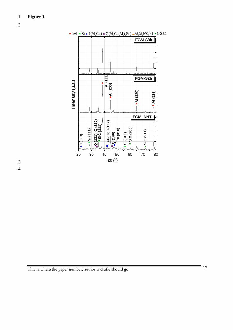
The FGM-NHT, FGM-S2h and FGM-S8h microstructural characterization was made by8
XRD and SEM, previous to corrosion and tribocorrosion tests. From the XRD pattern,9
presented in Figure 1, FGM-NHT, FGM-S2h and FGM-S8h samples presented the same10
phases: α-Al, Si, θ (Al2Cu), Q (Al4Cu2Mg8Si7), π (Al8Si6Mg3Fe) and SiC. The first five phases11
were from the Al-matrix [24], being SiC the reinforcement phase.12
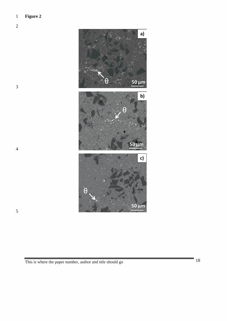
The microstructures of FGM-NHT, FGM-S2h and FGM-S8h are presented in Figure 2. No13
significant differences can be observed between the samples, being the only dissimilarity14
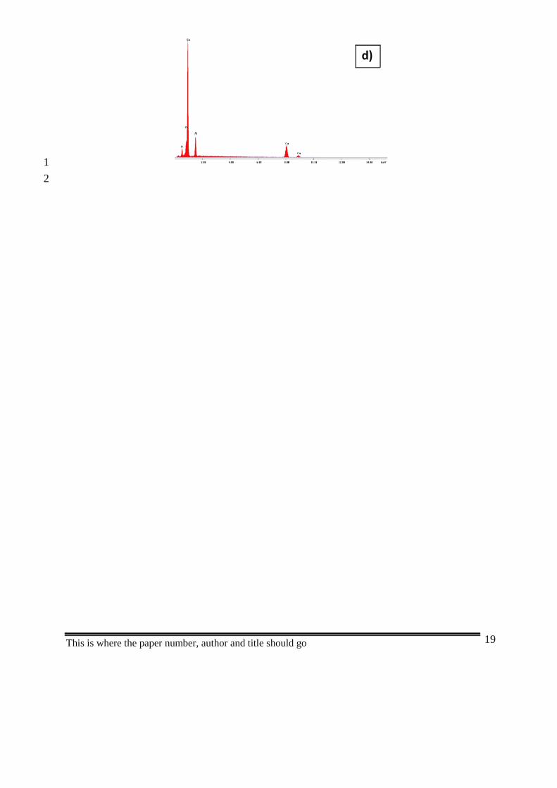
related with the whitest phase identified by EDS as the Cu-rich phase θ-Al2Cu [24]. In Figure15
2d) an EDS spectra obtained on the θ-Al2Cu phases from the FGM-NHT sample is presented,16
confirming the presence of Al and Cu. Similar spectra were obtained in FGM-S2h and FGM-17
S8h samples. The heat treatment on the FGM samples leads to more fine and dispersed Cu-rich18
phases. From our previous work [24], the distribution and size of the Q-Al4Cu2Mg8Si7 and the19
π-Al8Si6Mg3Fe phases on Al matrix alloys was shown to be not affected by the heat-20
treatments. On the other hand, the θ-Al2Cu and Si phases becomes more fine and dispersed21
after the heat-treatment, being the decrease in size of the θ-Al2Cu phase confirmed by image22
analysis.23
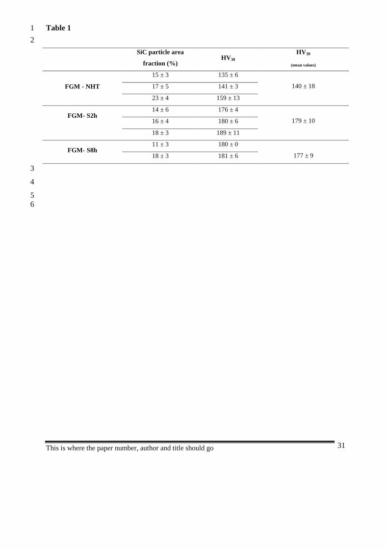
24Table 1 lists the SiC particle area fraction as determined by image analysis. The hardness25
values of each sample are also presented in Table 1. Hardness increases with increasing SiC26
particle area fraction. This correlation was already reported in previous works [10,25].27
Regarding the hardness mean values presented in Table 1, the lower hardness values were28
obtained in FGM-NHT (samples without heat-treatment), while the highest values were29
obtained with the FGM-S2h and FGM-S8h heat-treated samples.30
31

This is where the paper number, author and title should go 7
3.2 Corrosion behaviour1
2
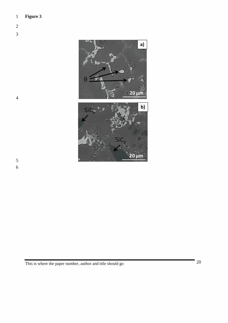
The surface morphology of FGM-NHT sample, after immersion tests, is presented in Figure3
3. There is preferential dissolution of the Al matrix around the θ-Al2Cu phases (Figure 3a), by4
the formation of a galvanic couple between the Cu-rich phases (preferential cathodes) and the5
surrounding Al matrix (preferential anodes). This mechanism was confirmed as the main6
corrosion mechanism presented in the Al alloy matrix [24]. From Figure 3b), no preferential7
attack at the reinforcement/matrix interface as well as preferential dissolution of Al matrix8
around the SiC reinforcement particle can be noticed. Therefore, no effect of SiC9
reinforcement particles on the corrosion mechanisms can be suggested. This shows that SiC10
reinforcement does not alter, in the present conditions, the corrosion mechanisms of these Al11
alloys. Similar behaviour was observed in FGM-S2h and FGM-S8h samples when immersed in12
NaCl solution.13
Figure 4 presents the potentiodynamic polarisation curves of the FGM samples in NaCl14
solution. For comparison, the polarization curve obtained with unreinforced Al matrix (without15
SiC reinforcement particles) is also presented. The reproducibility of the tests being very good,16
only one curve per condition was plotted. No significant differences can be detected between17
the different samples. Ecorr is similar to all the samples (≈ -0.60V). Therefore, in NaCl solution,18
apparently, neither the presence of SiC particles nor the heat-treatment does significantly19
influence the corrosion behaviour of the material.20
21
3.3 Tribocorrosion behaviour22
23
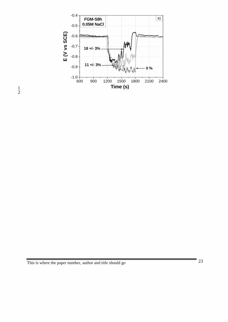
The evolution of the open circuit potential (OCP) with time during tribocorrosion testing of24
FGM-NHT, FGM-S2h and FGM-S8h samples of different SiC particle contents are presented25
in Figure 5a), Figure 5b) and Figure 5c), respectively. Each test was identified in accordance26
with the SiC particle area fraction value presented on the tested sample surface. For27
comparison, the results obtained with unreinforced Al matrix samples (without SiCp and28
identified in the figures with 0%) are also presented. Before rubbing, the corrosion potential29
values are similar in all the samples (approximately -0.6V). The OCP decreases when rubbing30
This is where the paper number, author and title should go 8
starts. This behaviour is usually attributed to the breaking of the passive film on the wear track1
area by the abrading alumina ball [17, 26-28]. Once rubbing stops depassivation ceases and the2
potential recovers its initial value.3
During rubbing, between 1200s and 1800s, samples without SiC and samples with lower4
SiC particles area fraction values, have OCP values in the range of -0.9V to -1.0V. This trend5
indicates that during rubbing, the material surface in being constantly depassivated. However,6
for higher SiC particles area fraction values (for instances, 23 ± 4 % in Figure 5a), after the7
initial cathodic shift, the OCP recovers during rubbing reaching the value observed before8
sliding, suggesting that repassivation of the sample surface occurred during rubbing.9
In case of repassivation occurring during rubbing, a correlation between the evolution of10
OCP and friction coefficient with time was observed (Figure 6a), where negative peaks in OCP11
corresponds to positive peaks in friction coefficient. When repassivation did not occur during12
rubbing, the coefficient of friction attained more stable values within short time (Figure 6b).13
This behaviour was observed systematically in heat-treated samples as well on the non heat-14
treated material.15
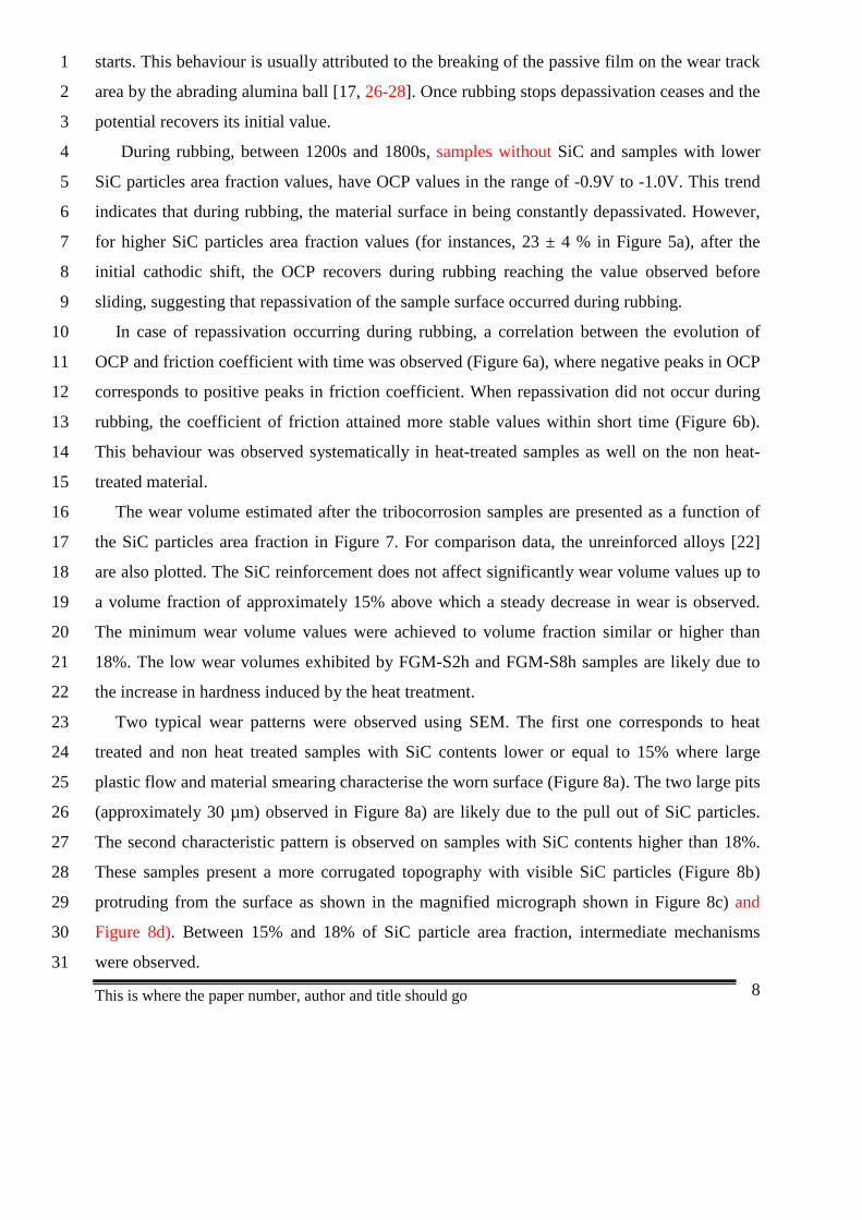
The wear volume estimated after the tribocorrosion samples are presented as a function of16
the SiC particles area fraction in Figure 7. For comparison data, the unreinforced alloys [22]17
are also plotted. The SiC reinforcement does not affect significantly wear volume values up to18
a volume fraction of approximately 15% above which a steady decrease in wear is observed.19
The minimum wear volume values were achieved to volume fraction similar or higher than20
18%. The low wear volumes exhibited by FGM-S2h and FGM-S8h samples are likely due to21
the increase in hardness induced by the heat treatment.22
Two typical wear patterns were observed using SEM. The first one corresponds to heat23
treated and non heat treated samples with SiC contents lower or equal to 15% where large24
plastic flow and material smearing characterise the worn surface (Figure 8a). The two large pits25
(approximately 30 µm) observed in Figure 8a) are likely due to the pull out of SiC particles.26
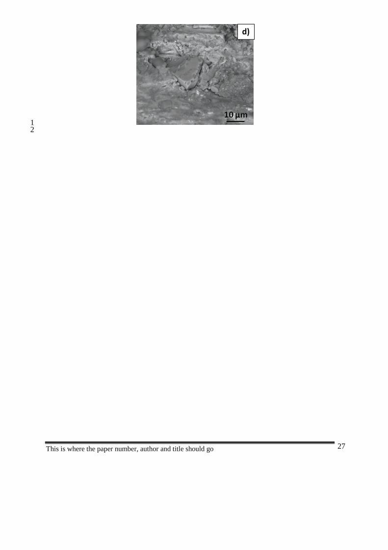
The second characteristic pattern is observed on samples with SiC contents higher than 18%.27
These samples present a more corrugated topography with visible SiC particles (Figure 8b)28
protruding from the surface as shown in the magnified micrograph shown in Figure 8c) and29
Figure 8d). Between 15% and 18% of SiC particle area fraction, intermediate mechanisms30
were observed.31
This is where the paper number, author and title should go 9
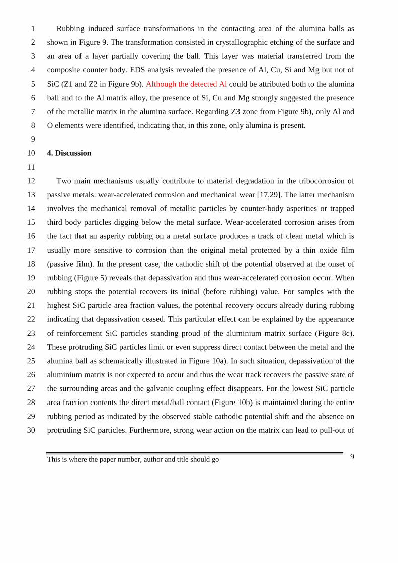
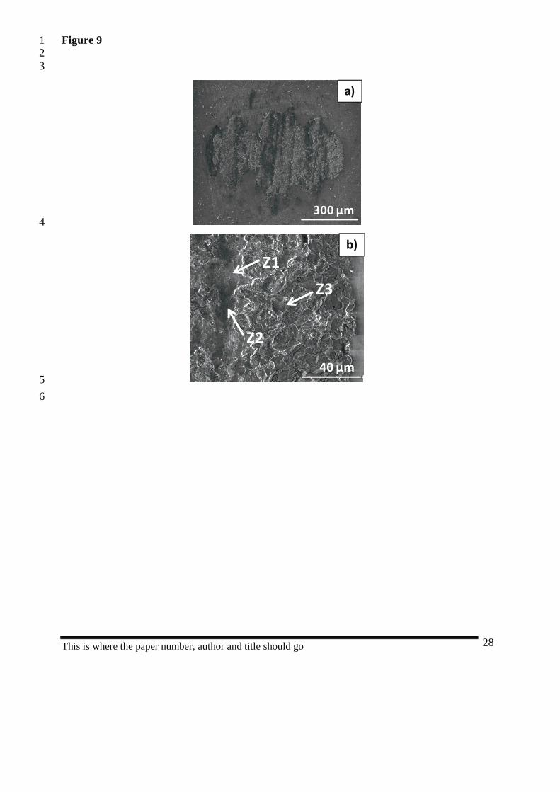
Rubbing induced surface transformations in the contacting area of the alumina balls as1
shown in Figure 9. The transformation consisted in crystallographic etching of the surface and2
an area of a layer partially covering the ball. This layer was material transferred from the3
composite counter body. EDS analysis revealed the presence of Al, Cu, Si and Mg but not of4
SiC (Z1 and Z2 in Figure 9b). Although the detected Al could be attributed both to the alumina5
ball and to the Al matrix alloy, the presence of Si, Cu and Mg strongly suggested the presence6
of the metallic matrix in the alumina surface. Regarding Z3 zone from Figure 9b), only Al and7
O elements were identified, indicating that, in this zone, only alumina is present.8
9
4. Discussion10
11
Two main mechanisms usually contribute to material degradation in the tribocorrosion of12
passive metals: wear-accelerated corrosion and mechanical wear [17,29]. The latter mechanism13
involves the mechanical removal of metallic particles by counter-body asperities or trapped14
third body particles digging below the metal surface. Wear-accelerated corrosion arises from15
the fact that an asperity rubbing on a metal surface produces a track of clean metal which is16
usually more sensitive to corrosion than the original metal protected by a thin oxide film17
(passive film). In the present case, the cathodic shift of the potential observed at the onset of18
rubbing (Figure 5) reveals that depassivation and thus wear-accelerated corrosion occur. When19
rubbing stops the potential recovers its initial (before rubbing) value. For samples with the20
highest SiC particle area fraction values, the potential recovery occurs already during rubbing21
indicating that depassivation ceased. This particular effect can be explained by the appearance22
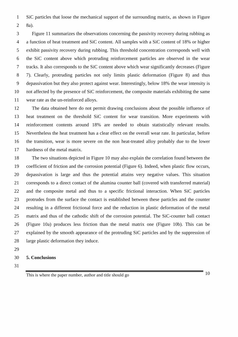
of reinforcement SiC particles standing proud of the aluminium matrix surface (Figure 8c).23
These protruding SiC particles limit or even suppress direct contact between the metal and the24
alumina ball as schematically illustrated in Figure 10a). In such situation, depassivation of the25
aluminium matrix is not expected to occur and thus the wear track recovers the passive state of26
the surrounding areas and the galvanic coupling effect disappears. For the lowest SiC particle27
area fraction contents the direct metal/ball contact (Figure 10b) is maintained during the entire28
rubbing period as indicated by the observed stable cathodic potential shift and the absence on29
protruding SiC particles. Furthermore, strong wear action on the matrix can lead to pull-out of30
This is where the paper number, author and title should go 10
SiC particles that loose the mechanical support of the surrounding matrix, as shown in Figure1
8a).2
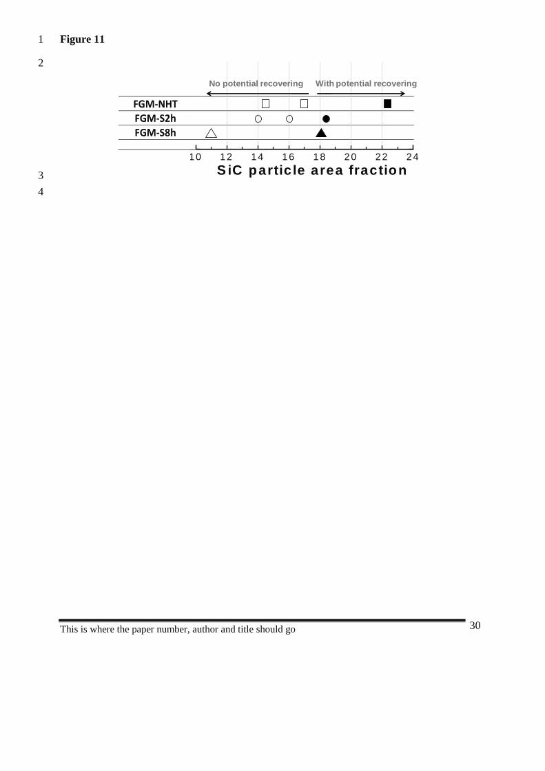
Figure 11 summarizes the observations concerning the passivity recovery during rubbing as3
a function of heat treatment and SiC content. All samples with a SiC content of 18% or higher4
exhibit passivity recovery during rubbing. This threshold concentration corresponds well with5
the SiC content above which protruding reinforcement particles are observed in the wear6
tracks. It also corresponds to the SiC content above which wear significantly decreases (Figure7
7). Clearly, protruding particles not only limits plastic deformation (Figure 8) and thus8
depassivation but they also protect against wear. Interestingly, below 18% the wear intensity is9
not affected by the presence of SiC reinforcement, the composite materials exhibiting the same10
wear rate as the un-reinforced alloys.11
The data obtained here do not permit drawing conclusions about the possible influence of12
heat treatment on the threshold SiC content for wear transition. More experiments with13
reinforcement contents around 18% are needed to obtain statistically relevant results.14
Nevertheless the heat treatment has a clear effect on the overall wear rate. In particular, before15
the transition, wear is more severe on the non heat-treated alloy probably due to the lower16
hardness of the metal matrix.17
The two situations depicted in Figure 10 may also explain the correlation found between the18
coefficient of friction and the corrosion potential (Figure 6). Indeed, when plastic flow occurs,19
depassivation is large and thus the potential attains very negative values. This situation20
corresponds to a direct contact of the alumina counter ball (covered with transferred material)21
and the composite metal and thus to a specific frictional interaction. When SiC particles22
protrudes from the surface the contact is established between these particles and the counter23
resulting in a different frictional force and the reduction in plastic deformation of the metal24
matrix and thus of the cathodic shift of the corrosion potential. The SiC-counter ball contact25
(Figure 10a) produces less friction than the metal matrix one (Figure 10b). This can be26
explained by the smooth appearance of the protruding SiC particles and by the suppression of27
large plastic deformation they induce.28
29
5. Conclusions30
31
This is where the paper number, author and title should go 11
The corrosion and tribocorrosion behavior of Al-SiCp FGM’s in 0.05M NaCl was1
investigated using samples obtained by centrifugal casting and therefore, presenting different2
SiC contents in the most exterior part of the tested surfaces. The conclusions of this study are:3
- The introduction of SiC particles and heat-treatments do not affect the corrosion4
behavior of the composite materials. The polarization curves follow similar trends with5
or without reinforcement particles.6
- Two tribocorrosion mechanisms observed were depending on SiCp content: above 18%7
the SiC particles were found protruding from the surface and thus protecting the8
surrounding metal matrix against wear and wear accelerated corrosion. Below 18% the9
SiC particles had no effect on wear and generalized plastic flow, larger wear and wear10
accelerated corrosion characterized the FGM’s wearing surfaces.11
12
Acknowledgements13
The research team was financially supported by the Portuguese Foundation for Science and14
Technology (FCT – Portugal) under a PhD scholarship (SFRH / BD / 27911 / 2006). The15
authors thank also to Dr.ª Edith Ariza (University of Minho) and Pierre Mettraux (EPFL) for16
SEM analysis.17
18
References19
[1] M.M. Gasik, Industrial applications of FGM solutions, Materials Science Forum, 42320
(2003) 17-22.21
[2] T. Ogawa, Y. Watanabe, H. Sato, I. Kim, Y. Fukui, Theoretical study on fabrication of22
functionally graded material with density gradient by a centrifugal solid-particle method,23
Composites Part A: Applied Science and Manufacturing, 37 (2006) 2194-2200.24
[3] N.B. Duque, Z.H. Melgarejo, O.M. Suarez, Functionally graded aluminum matrix25
composites produced by centrifugal casting, Materials Characterization 55 (2005) 167-171.26
[4] S. El-Hadad, H. Sato, E. Miura-Fujiwara, Y. Watanabe, Fabrication of Al-Al3Ti/Ti3Al27
functionally graded materials under a centrifugal force - Review, Materials, 3 (2010) 4639-28
4656.29
This is where the paper number, author and title should go 12
[5] D. Lin, Q. Li, W. Li, S. Zhou, M.V. Swain, Design optimization of functionally graded1
dental implant for bone remodeling, Composites: Part B 40 (2009) 668–675.2
[6] F. Watari, A. Yokoyama, M. Omori, T. Hirai, H. Kondo, M. Uo, T. Kawasaki,3
Biocompatibility of materials and development to functionally graded implant for bio-medical4
application, Composites Science and Technology 64 (2004) 893-908.5
[7] H. Hassanin, K. Jiang, Functionally graded microceramic components, Microelectronic6
Engineering 87 (2010) 1610-1613.7
[8] Y. Watanabe, A. Kawamoto, K. Matsuda, Particle size distributions in functionally graded8
materials fabricated by the centrifugal solid-particle method, Composites Science and9
Technology 62 (2002) 881-888.10
[9] Y. Watanabe, N. Yamanaka, Y. Fukui, Control of composition gradient in a metal ceramic11
functionally graded material manufactured by the centrifugal method, Composites Part A 29A12
(1998) 595-601.13
[10] A.C. Vieira, P.D. Sequeira, J.R. Gomes, L.A. Rocha, Dry sliding wear of Al alloy/SiCp14
functionally graded composites: Influence of processing conditions, Wear 267 (2009) 585-592.15
[11] A. Velhinho, J. D. Botas, E. Ariza, J.R. Gomes, L. A. Rocha, Tribocorrosion Studies in16
Centrifugally Cast Al-matrix SiCp-reinforced Functionally Graded Composites, Materials17
Science Forum 456 (2004) 871-875.18
[12] J.W. Gao, C.Y. Wang, Modeling the solidification of functionally graded materials by19
centrifugal casting, Materials Science and Engineering A292 (2000) 207-215.20
[13] S. Uemura, The activities of FGM on new applications, Materials Science Forum, 42321
(2003) 1-10.22
[14] L.L. Mishnaevsky Jr., Functionally gradient metal matrix composites: Numerical analysis23
of the microstructure–strength relationships, Composites Science and Technology, 66 (2006)24
1873-1887.25
[15] Y. Miyamoto, W.A. Kaysser, B.H. Rabin, A. Kawasaki, R.G. Ford, Functionally graded26
materials: Design, processing and applications, Kluwer Academic Publishers, 1999.27
[16] C.-K. Fang, C.C. Huang, and T.H. Chuang, Synergistic effects of wear and corrosion for28
Al2O3 particulate–reinforced 6061 aluminium matrix composites, Metallurgical and Materials29
Transactions, 30A (1999) 643.30
This is where the paper number, author and title should go 13
[17] S. Mischler, Triboelectrochemical techniques and interpretation methods in1
tribocorrosion: A comparative evaluation, Tribology International 41 (2008) 573-583.2
[18] D. Landolt, S. Mischler, M. Stemp, Electrochemical methods in tribocorrosion: a critical3
appraisal, Electrochimica Acta 46 (2001) 3913-3929.4
[19] M. Montoya-Dávila, M.I. Pech-Canul, M.A. Pech-Canul, Effect of SiCp multimodal5
distribution on pitting behaviour of Al/SiCp composites prepared by reactive infiltration,6
Powder Technology 195 (2009) 196-202.7
[20] A. Pardo, M.C. Merino, S. Merino, F. Viejo, M. Carboneras, R. Arrabal, Influence of8
reinforcement proportion and matrix composition on pitting corrosion behaviour of cast9
aluminium matrix composites (A3xx.x/SiCp), Corrosion Science 47 (2005) 1750-1764.10
[21] J.R. Gomes, A.R. Ribeiro, A.C. Vieira, A.S. Miranda and L.A. Rocha, Wear mechanisms11
in functionally graded aluminium matrix composites: Effect of the presence of an aqueous12
solution, Materials Science Forum 493 (2005) 33-38.13
[22] A.C. Vieira, L.A. Rocha, S. Mischler, Mechanical and electrochemical deterioration14
mechanisms in the tribocorrosion of Al alloys in NaCl and in NaNO3 solutions, Accepted in15
Corrosion science (2010).16
[23] J. Stojadinovic, D. Bouvet, M. Declercq, S. Mischler, Effect of electrode potential on the17
tribocorrosion of tungsten, Tribology International 42 (2009) 575-58.18
[24] A.C. Vieira, A.M. Pinto, L.A. Rocha, S. Mischler, Effect of Al2Cu precipitates size and19
mass transport on the polarization behavior of age-hardened Al-Si-Cu-Mg alloys in 0.05 M20
NaCl, Electrochim. Acta (2011) doi:10.1016/j.electacta.2011.02.044.21
[25] D.P. Mondal, S. Das, High stress abrasive wear behavior of aluminum hard particle22
composites: Effect of experimental parameters, particle size and volume fraction, Tribology23
International 39 (2006) 470-478.24
[26] P. Ponthiaux, F. Wenger, D. Drees, J.P. Celis, Electrochemical techniques for studying25
tribocorrosion processes, Wear 256 (2004) 459-468.26
[27] D.E. Taylor, R.B. Waterhouse, An electrochemical investigation on fretting corrosion of a27
number of pure metals in 0.5M sodium chloride, Corrosion Science 14 (1974) 111-122.28
[28] B. Bethune, R.B. Waterhouse, Electrochemical studies of fretting corrosion, Wear 1229
(1968) 27-34.30
[29] D. Landolt, Corrosion and Surfaces Chemistry of Metals, 1st ed., EPFL Press, 2007.31
This is where the paper number, author and title should go 14
List of Figures:1
2
Figure 1. XRD patterns obtained in the Al-SiCp FGM-NHT, FGM-S2h and FGM-S8h3
samples.4
5
Figure 2. SEM micrographs obtained in backscattering electron mode (BE mode) of: a) FGM-6
NHT; b) FGM-S2h; c) FGM-S8h; d) EDS spectra obtained on the θ phases presented in FGM-7
NHT sample.8
9
Figure 3. SEM micrographs obtained in FGM-NHT sample after immersion tests of 30 min in10
0.05M NaCl solution (backscattering electron mode): a) Identification of θ-Al2Cu phases; b)11
Identification of SiC particles. Similar micrographs were identified in FGM-S2h and in FGM-12
S8h samples.13
14
Figure 4. Polarisation curves of FGM-NHT, FGM-S2h, FGM-S8h and unreinforced Al matrix15
samples, in 0.05M NaCl solution.16
17
Figure 5. Corrosion potential evolution with time during the tribocorrosion tests in: a) FGM-18
NHT; b) FGM-S2h; c) FGM-S8h samples tested in 0.05M NaCl solution. Each test is19
identified in accordance with the SiC particle area fraction value presented on the sample20
surface.21
22
Figure 6. Friction coefficient and corrosion potential evolution during the tribocorrosion tests23
in 0.05M NaCl, for: a) FGM-NHT with 23 ± 4% SiC; b) FGM-S2h with 14 ± 6% SiC;24
25
Figure 7: Relation between the wear volume values measured after tribocorrosion tests and the26
SiC particle area fraction values of FGM-NHT, FGM-S2h and FGM-S8h samples in 0.05M27
NaCl.28
29

This is where the paper number, author and title should go 15
Figure 8. SEM micrographs obtained after the tribocorrosion tests in 0.05M NaCl solution in1
the wear track of FGM-NHT sample with: a) SiCp particle area fraction of 15 ± 3% obtained in2
secondary electron mode (SE mode); b) SiCp particle area fraction of 23 ± 4%, (SE mode); c)3
and d) SiCp particle area fraction of 23 ± 4%, (BE mode; 40º tilted).4
5
Figure 9: SEM micrographs obtained in the alumina counterbody after the tribocorrosion tests6
in 0.05M NaCl tested with the FGM-NHT sample (SE mode).7
8
Figure 10: Schematic representation of two wear mechanisms suggested: a) Mechanical9
contact between the protruded SiC reinforcement particles and the Al2O3 counterbody; b)10
Mechanical contact between the Al matrix and the Al2O3 counterbody.11
12
Figure 11: Relation between the potential values measured 100s before stopping rubbing (at13
1700s) and the SiC particle area fraction values of FGM-NHT, FGM-S2h and FGM-S8h14
samples tested in 0.05M NaCl. Black symbols represent the situation where potential recover15
during rubbing was observed.16
17
This is where the paper number, author and title should go 16
List of Tables:1
2
Table 1. Characterization of the samples tested in the tribocorrosion tests in 0.05M NaCl3
solution, regarding the SiC particle area fraction on the surface sample and macro Vickers4
hardness (HV30).5
6
7
This is where the paper number, author and title should go 17
Figure 1.1
2
20 30 40 50 60 70 80
θ(1
10)
Q(1
40)
θ(4
20);
θ(1
12)
Al(
111)
Si(
111)
SiC
(111
)Q
(121
);Q
(130
)
θ(3
10)
SiC
(200
)
SiC
(311
)
Al(
311)
Si(
311)
Al(
320)
Al(
200)
FGM-S2hIn
ten
sity
(u.a
.)
2θ (o)
FGM-S8h
FGM- NHT
β-SiCQ(Al4Cu
2Mg
8Si
7)θ(Al
2Cu)SiαAl Al
8Si
6Mg
3Fe
3
4
This is where the paper number, author and title should go 18
Figure 21
2
50 µm
a)
θ3
50 µm
b)
θ
4
50 µm
c)
θ
5
This is where the paper number, author and title should go 19
d)
1
2
This is where the paper number, author and title should go 20
Figure 31
2
3
20 µm
a)
θ
4
SiCp
SiCp
20 µm
b)
5
6

This is where the paper number, author and title should go 21
Figure 41
2
-0.8 -0.7 -0.6 -0.5 -0.4 -0.31E-4
1E-3
0.01
0.1
1
100.05M NaCl
i(m
A/c
m2 )
E (V vs SCE)
FGM-NHTFGM-S2hFGM-S8hUnreinforced Al-matrix
3
4

This is where the paper number, author and title should go 22
Figure 51
2
600 900 1200 1500 1800 2100 2400-1.0
-0.9
-0.8
-0.7
-0.6
-0.5
-0.4
0 %
17 +/- 5%
a)FGM-NHT0.05M NaCl
E(V
vsS
CE
)
Time (s)
23 +/- 4%
15 +/- 3%
345
600 900 1200 1500 1800 2100 2400-1.0
-0.9
-0.8
-0.7
-0.6
-0.5
-0.4b)FGM-S2h
0.05M NaCl
E(V
vsS
CE
)
Time (s)
18 +/- 3%
16 +/- 4%
14 +/- 6% 0 %
67
This is where the paper number, author and title should go 23
600 900 1200 1500 1800 2100 2400-1.0
-0.9
-0.8
-0.7
-0.6
-0.5
-0.4c)
Time (s)
FGM-S8h0.05M NaCl
E(V
vsS
CE
)
18 +/- 3%
11 +/- 3%0 %
12

This is where the paper number, author and title should go 24
Figure 61
2
3
600 900 1200 1500 1800 2100 2400-1.0
-0.9
-0.8
-0.7
-0.6
-0.5
-0.4SiC area fraction = 23 +/- 4 %
Time (s)
Frictio
nC
oefficien
tE
(Vvs
SC
E)
0.0
0.1
0.2
0.3
0.4
0.5
0.6
0.7
0.8a)
4
5
600 900 1200 1500 1800 2100 2400-1.0
-0.9
-0.8
-0.7
-0.6
-0.5
-0.4
Time (s)
Frictio
nC
oefficien
t
SiC area fraction = 14 +/- 6 %
E(V
vsS
CE
)
0.0
0.1
0.2
0.3
0.4
0.5
0.6
0.7
0.8b)
6
7

This is where the paper number, author and title should go 25
Figure 71
23
0 3 6 9 12 15 18 21 240.000
0.007
0.014
0.021
0.028
0.035
0.042
SiC particle area fraction
Wea
rvo
lum
e(m
m3 )
FGM-NHTFGM-S2hFGM-S8h
45

This is where the paper number, author and title should go 26
Figure 81
a)
50 µm23
b)
50 µm 4
5
10 µm
c)
67
This is where the paper number, author and title should go 27
300 µm
10 µm
d)
12
This is where the paper number, author and title should go 28
Figure 9123
a)
300 µm4
Z1b)
40 µm
Z2
Z3
5
6

This is where the paper number, author and title should go 29
Figure 101
2
Al2O3
SiC
ProtectiveFilm
(a)
(b)
34
This is where the paper number, author and title should go 30
Figure 111
2
FGM-NHT FGM-S2hFGM-S8h
10 12 14 16 18 20 22 24
S iC partic le area fraction
No potential recovering With potential recovering
3
4
This is where the paper number, author and title should go 31
Table 11
2
SiC particle area
fraction (%)HV30
HV30
(mean values)
FGM - NHT
15 ± 3 135 ± 6
140 ± 1817 ± 5 141 ± 3
23 ± 4 159 ± 13
FGM- S2h14 ± 6 176 ± 4
179 ± 1016 ± 4 180 ± 6
18 ± 3 189 ± 11
FGM- S8h11 ± 3 180 ± 0
177 ± 918 ± 3 181 ± 6
3
4
56