Influence of high dose irradiation on core structural and fuel ...
252
IAEA-TECDOC-1039 XA9848036 _. Influence of high dose irradiation on core structural and fuel materials in advanced reactors Proceedings of a Technical Committee meeting held in Obninsk, Russian Federation, 16-19 June 1997 INTERNATIONAL ATOMIC ENERGY AGENCY 29-45
-
Upload
khangminh22 -
Category
Documents
-
view
4 -
download
0
Transcript of Influence of high dose irradiation on core structural and fuel ...

IAEA-TECDOC-1039 XA9848036 _.
Influence of high dose irradiation oncore structural and fuel materials in
advanced reactorsProceedings of a Technical Committee meeting
held in Obninsk, Russian Federation, 16-19 June 1997
INTERNATIONAL ATOMIC ENERGY AGENCY
29-45

The originating Section of this publication in the IAEA was:
Nuclear Power Technology Development SectionInternational Atomic Energy Agency
Wagramer Strasse 5P.O. Box 100
A-1400 Vienna, Austria
INFLUENCE OF HIGH DOSE IRRADIATION ON CORE STRUCTURALAND FUEL MATERIALS IN ADVANCED REACTORS
IAEA, VIENNA, 1998IAEA-TECDOC-1039
ISSN 1011-4289
©IAEA, 1998
Printed by the IAEA in AustriaAugust 1998

The IAEA does not normally maintain stocks of reports in this series.However, microfiche copies of these reports can be obtained from
IN IS ClearinghouseInternational Atomic Energy AgencyWagramerstrasse 5P.O. Box 100A-1400 Vienna, Austria
Orders should be accompanied by prepayment of Austrian Schillings 100,-in the form of a cheque or in the form of IAEA microfiche service couponswhich may be ordered separately from the IN IS Clearinghouse.

FOREWORD
The IAEA's International Working Group on Fast Reactors (IWGFR) periodicallyorganizes meetings to discuss and review important aspects of fast reactor technology. Thefifth meeting in the series, held in Obninsk, Russian Federation, 16-19 June 1997, wasdevoted to the influence of high dose irradiation on the mechanical properties of reactorcore structural and fuel materials.
The IAEA wishes to thank all the participants of the Technical Committee meetingfor their valuable contributions, especially the Chairman L. Zabudko. The IAEA officerresponsible for this work is A. Rinejski of the Division of Nuclear Power.

EDITORIAL NOTE
In preparing this publication for press, staff of the IAEA have made up the pages from theoriginal manuscripts as submitted by the authors. The views expressed do not necessarily reflectthose of the IAEA, the governments of the nominating Member States or the nominatingorganizations.
Throughout the text names of Member States are retained as they were when the text wascompiled.
The use of particular designations of countries or territories does not imply any judgement bythe publisher, the IAEA, as to the legal status of such countries or territories, of their authoritiesand institutions or of the delimitation of their boundaries.
The mention of names of specific companies or products (whether or not indicated asregistered) does not imply any intention to infringe proprietary rights, nor should it be construedas an endorsement or recommendation on the part of the IAEA.
The authors are responsible for having obtained the necessary permission for the IAEA toreproduce, translate or use material from sources already protected by copyrights.

CONTENTS
SUMMARY . . . . . . . . . . . . . . . . . . . . . . . . . . . . . . . . . . . . . . . . . . . . . . . . . . . . . . . . . . . . . . 1
Current status of studies on FR fuel and structural materials in the Russian Federation ... 7V.M. Poplavsky, L.M. Zabudko
Neutron irradiation effects in fusion or spallation structural materials:Some recent insights related to neutron spectra . . . . . . . . . . . . . . . . . . . . . . . . . . . . . . . 15
F.A. Garner, L.R. GreenwoodStatus and possibility of fuel and structural materials experimental irradiation in
BN-600 reactor. Stages of BN-600 reactor core d e v e l o p m e n t . . . . . . . . . . . . . . . . . . . . . . 37B.A. Vasiljev, A.I. Zinovjev, A.I. Staroverov,V.V. Maltsev, A.N. Ogorodov
Performance of FBTR mixed carbide fuel . . . . . . . . . . . . . . . . . . . . . . . . . . . . . . . . . . . . . . . 475. Govindarajan, P. Puthiyavinayagam, S. Clement Ravi Chandar,S.C. Chetal, S.B. Bhoje
Post-irradiation examination of mixed (Pu, U)C fuels irradiated in thefast breeder reactor . . . . . . . . . . . . . . . . . . . . . . . . . . . . . . . . . . . . . . . . . . . . . . . . . . . . . . . 57R. Baldev, K. V. Kasiviswanathan, V. Venugopal, N. G. Muralidharan,A. Ramabathiran, N. Raghu, J. Joseph, S. Kurien, B. Venkataraman,M. T. Shyamsunder, S. Murugan, K.A. Gopal, P. V. Kumar, P. Kalyanasundaram
Development of vibropac MOX fuel pins serviceable up to superhigh burnups . . . . . . . . . . 69A.A. Mayorshin, G.I. Gadzhiev, V.A. Kisly, O. V. Skiba, V.A. Tzykanov
Assemblies and fuel pin behaviour under irradiation in FBR BN-350 . . . . . . . . . . . . . . . . . 93V.N. Karaulov, A.P. Blynski, I.L. Yakovlev, E.V. Kononova
In-pile tests and post-reactor investigations of fuel pins with U-Pu fuel . . . . . . . . . . . . . . . . 107L.I. Moseev, A.N. Vorobyev, L.M. Zabudko, B.S. Kiryanov, S.I. Porollo,S. V. Shulepin, S.A. Antipov, T.S. Menshikova
Inner wall attack and its inhibition method for FBR fuel pin cladding at high burnup . . . . . 119Xu Yongli, Long Bin, Li Jingang, Wan Maying
Material properties of a high-dose irradiated martensitic wrapper: Steel 1.4914 . . . . . . . . . 129E. Materna-Morris, K. Ehrlich
The performance of type EP-450 ferritic-martensitic steel underneutron irradiation at low temperatures . . . . . . . . . . . . . . . . . . . . . . . . . . . . . . . . . . . . . . 139V.S. Khabarov, A.M. Dvoriashin, S.I. Porollo
Post-irradiation examination of Ti or Nb stabilized austenitic steels irradiated asBN-600 reactor fuel pin claddings up to 87 dpa . . . . . . . . . . . . . . . . . . . . . . . . . . . . . . . . 145S.I. Porollo, A.N. Vorobyev, S.V. Shulepin
Influence of swelling and creep data on PFBR core design . . . . . . . . . . . . . . . . . . . . . . . . . . 153P. Puthiyavinayagam, S. Gopal, S.J. Winston, S. Govindaraj an,S.C. Chetal, S.B.Bhoje
Development of martensitic steels for high neutron damage applications . . . . . . . . . . . . . . 169D.S. Gelles
Irradiation creep of austenitic steels irradiated up to high fluence in theBOR-60 reactor . . . . . . . . . . . . . . . . . . . . . . . . . . . . . . . . . . . . . . . . . . . . . . . . . . . . . . . . . 179V.S. Neustroev, V.K. Shamardin
Influence of high dose irradiation on structure and fracture of theC0.1-Crl6-Nil5-Mo3-Nb steel . . . . . . . . . . . . . . . . . . . . . . . . . . . . . . . . . . . . . . . . . . . . 189S.A. Averin, A. V. Kozlov, E.N. Shcherbakov

Variability of irradiation creep and swelling of HT9 irradiated tohigh neutron fluence at 400-600°C . . . . . . . . . . . . . . . . . . . . . . . . . . . . . . . . . . . . . . . . . 197M.B. Toloczko, F.A. Garner
A problem to determine short term mechanical properties changes of ferrite-martensiteand austenitic steels as materials of fuel assembly of fast reactors underhigh dose neutron irradiation . . . . . . . . . . . . . . . . . . . . . . . . . . . . . . . . . . . . . . . . . . . . . . 211A. V. Kozlov, A.S. Aver in, S. V. Brushkova, G. V. Kalashnic
Swelling and in-pile creep of neutron irradiated 15Crl5NiTi austenitic steels in thetemperature range of 400 to 600° C . . . . . . . . . . . . . . . . . . . . . . . . . . . . . . . . . . . . . . . . . 223R. Hubner, K. Ehrlich
In-pile strength of austenitic steels for fast reactors fuel pin cladding . . . . . . . . . . . . . . . . . . 231V. V. Popov
A re-evaluation of helium/dpa and hydrogen/dpa ratios for fast reactor andthermal reactor data used in fission-fusion correlations . . . . . . . . . . . . . . . . . . . . . . . . . 239F.A. Garner, L.R. Greenwood, B.M. Oliver
LIST OF PARTICIPANTS . . . . . . . . . . . . . . . . . . . . . . . . . . . . . . . . . . . . . . . . . . . . . . . . . 251

SUMMARY
1. FUEL MATERIALS
Over 40 years of intensive multinational development, considerable experience withhighly irradiated MOX fuel has been accumulated. In Europe, about 8000 fuel pins havereached burnup values of 15 at.%. Some experimental pins have attained burnup levels of 23.5at.% in PFR and 16.9 at.% in PHENIX. More than 4000 fuel pins with pellet MOX fuel wereirradiated in BN-350 and BN-600. The maximum burnup in BN-600 is -12 at.%. Experienceis being acquired with MOX fuel with high Pu content for its use as actinide burner. From theirradiation results obtained from BOR-60, BN-350, and BN-600, it may be concluded thatthere are no significant differences in performance among UO2, PuO2 and MOX fuels, butadditional experimental support for such a conclusion is required.
In addition, MOX fuel has been studied in vibro-packed form in The RussianFederation and in the United Kingdom, where vibro-packed fuel was used extensively inDFR, principally in granular form at very high burnup levels, often in excess of 20 at.%.While this fuel was found to give satisfactory performance at reference ratings up to 450-500W/cm, its use at high ratings in excess of 500 W/cm was often associated with abnormallyhigh cladding corrosion rates. The latter were attributed to loss of fuel stability at high powerratings, and a parametric study of the data failed to reveal any sensitivity to O/M ratio, cladcomposition or Pu content. After the repetition of these observations in PFR vibro fuel, theUK abandoned further development of this fuel type in favour of the use of annular MOXpellet fuel, which was eventually taken successfully to burnups in excess of 23% in PFR, withno problems being attributed to the fuel itself. Their excellent performance allowed highirradiation exposures of advanced cladding material and wrappers.
In The Russian Federation, for BOR-60 applications, techniques have been found tomaintain stable MOX vibro-packed fuel densities and to reduce the O/M ratios in this fueltype — two features identified as contributing to high cladding corrosion values — primarilythrough the use of uranium getter. Use of these modifications has allowed some vibro-packedfuel pins, clad in ferritic-martensitic material, to reach record burnups of about 35 at.% over a10 year period, with ratings of-450 W/cm at the start of irradiation. This performance mustbe maintained when the fuel is exposed under commercial conditions at high flux/ratings.
In India, the use of mixed carbide fuel with 70 at.% PuC used as driver fuel for FBTRMark 1 cores will continue, following the successful operation of FBTR Mark 1 carbide fuelto 30 000 MW-d/t without fuel failure. The post-irradiation examinations of this fuel indicatesthat exposure could be comfortably increased to 50 000 MWd/t, with linear ratings as high as400 W/cm. However, the MOX fuel for India's prototype fast reactor will be used with apower output of 500 MWe.
Work on high burnup fuel in the United States of America was terminated when theLMR programme was discontinued.
2. STRUCTURAL MATERIALS
The primary limitation for attainment of high burnup is associated with the integrity ofthe cladding, and not with any inherent properties of the fuel. When the cladding is breached
1

to allow release of fission gas and solid isotopes, as well as fuel to the reactor coolant, thisrequires further burnup to be terminated. A number of persistent themes have emerged ascommon observations and developments in all countries. Each of these themes are presentedseparately in the following sections.
2.1 Variability of response in nominally similar materials and environments
There was often a great difference in the amount of data scatter from various types ofexperimental sources. With a single, well controlled variable, the data scatter was minimal andthe fundamental dependences were easy to identify and model. In other data collections fromreal operating components there was often a wide amount of scatter that sometimes precludedthe definite identification of the principle variables and degradation mechanisms responsiblefor the response to the irradiation environment. While the results of the controlled singlevariable experiments can be used to help analyse such complex data fields, the origin of suchlarge scatteris uncertain.
Many of the simultaneously contributing processes involved in fuel pin evolution areinherently stochastic in nature and cannot be defined with precision. Crack propagation andcorrosion fit this description. Second, there are large spatial and temporal variations in allimportant environmental variables across each structural and fuel component, and alsobetween components. Therefore, a complex interaction in stress and other variables arisesbetween each of the components in any given structural ensemble. Results of analysis of BN-350 creep and swelling data have been interpreted in the light of such variations. It may benoted that the larger amount of data scatter often was directly correlated to the variability ofmicrostructure and microchemistry in the steels arising from insufficiently well controlledproduction processes.
A major conclusion is that the highest priority be given to development of both stringentmaterial specifications and production process control.
2.2 Paths toward improved structural material
With one significant exception, most countries are following one or both branchedpaths in the development of improved materials. On the first branch, the attempt is beingmade to extend the duration of the incubation period of void swelling in low nickel (<18 %)austenitic steel. In all countries with such programmes this approach has resulted insignificant delay of the onset of swelling, often to doses on the order of 80-100 dpa(displacement per atom). Given the inherent phase instability of these steels under irradiation,such an approach entails some uncertainty, since the microchemical and microstructuralevolution is often found to be very sensitive to details of reactor operational histories, not allaspects of which can always be anticipated. Once the transient regime of swelling isterminated, austenitic steels have the potential to swell at ~1 %/dpa and failure arising fromswelling-related problems.
The second branch of material development has often been pursued simultaneouslywith the first branch in many countries and relies on the significantly lower swelling rateinherent in ferritic and ferritic/martensitic alloys. In this path, the major limiting property nowbecomes radiation-induced embrittlement rather than void swelling.

In both branches, the major focus of research and development activity has been thedevelopment and maintenance of stable phases and microstructures, a requirement that hasbeen found to be strongly associated with maintenance of desirable properties. There is someconcern that incompatibility might develop at very high burnup if austenitic cladding is to beincluded in a martensitic or ferritic-martensitic wrapper.
The single most significant exception to these two branches was that of the use of thehigh nickel Nimonic PE16 alloy in the UK. Based on a long prior history with this alloy, theUK fortunately found a microstructurally-stable, swelling resistant alloy early in its materialdevelopment effort. In the UK. this material and its production have been optomized, and veryhigh burnup (-25%) levels have been achieved with very low failure rates at dosesapproaching ~150dpa.
2.3 Voids
Once the void swelling value reaches levels in excess of several per cent, it dominatesnot only the dimensional stability, but controls the creep rate, phase stability, embrittlementcharacteristics and, to a lesser extent, properties such as elastic modules, and the thermal andelectrical conductivity. Some investigations have shown that the electrical conductivity couldbe used to measure the void swelling. It mat be condused that deviations of the resistancechange from the theoretically predicted values could be used to estimate the microchemicalcontributions to resistivity change as well.
Most significantly, the primary concern resulting from void swelling was that of voidrelated extreme embrittlement or EES. In many cases the life-limiting factor for fuel pins andother structural components was the EES phenomenon. The EES is most likely also going tobe a major end-of-life concern for austenitic near core internal components. It has been shownthat the irradiation creep of martensitic steels is lower than that of austenitic steels, primarilydue to the lower swelling rate of these steels. The creep-swelling relationship, however,appears to be independent of the differences in the crystal structure.
2.4. Environmental interactions with EES
A number of investigations have been devoted to the deleterious influence of corrosionand intergranular attack resulting from fission products that accumulate during high neutronexposure. A Chinese study explored such effect in a simulated environment. Russian studieshave shown that such attack would provide extreme cracks on the inner surface of cladding,and that these cracks can initiate the EES failure mechanism. It has been of particular concernwhether such corrosion attack problems would accelerate at higher burnup levels.
2.5. Inherent superiority of martensitic steels
A number of investigations have concentrated on the performance of ferritic-martensitic steels. Although the compositional paths taken in such development varied fromcountry to country, the performance of high dpa dose was generally superior to that ofaustenitic steels. However, there are several qualifications to this statement. First such steelsmust be limited to somewhat lower temperature ranges since their strength falls off strongly athigh temperatures. The "Achilles heel" of martensitic steels is the development of large shiftsin ductile to brittle transition temperature at lower irradiation temperatures. This can be

partially avoided by the use of a higher inlet temperature, but in BN-350 such steel has servedvery well in spite of the low inlet temperature. One study showed that in one such steel therewas an initial period in which the steel was most brittle and then some recovery ensued athigher exposure. This behaviour suggests that the steel is not completely phase-stable underirradiation. Smaller levels of instability have been observed in other austenitic steels. In termsof actual demonstrated performance however, martensitic steels are clearly the superior pathto high dpa exposure
2.6. Technique development
Innovative ways to assess the performance of fuel pins are continually beingdeveloped. Studies have explored the limits of currently available techniques to adequatelypredict such performance.
The study of the influence of high dose irradiation on performance of reactor materialsmust also be developed in terms of such fundamental processes as evolution of microstructureand radiation defects in materials. Experimental validations must be supported byfundamental investigations to provide the proper understanding of the material performance.
3. USE OF FAST REACTOR DATA FOR OTHER REACTOR CONCEPTS
Fast reactor data have provided and will continue to provide most of the high dosedata that can be applied to light water power reactors, fusion reactors and accelerator- drivenspallation neutron devices. Combined with data from some high flux thermal test reactors,such as SM-2 and HFIR. these data must form the bases of predictions for the other reactorsystems.
In some cases, the data from fast reactors can be directly applied to the other systems,but in general the differences in neutron flux-spectra must be considered and someadjustments must be made prior to the application of the data to the new environment. Themost important features of such "translations'5 involve solid and gaseous transmutationproducts and related differences in the displacement rate.
Given the continuing trend of experimental reactor shutdowns world-wide (EBR-II.FFTF, RAPSODIE, DFR, PFR, KNK-2, etc.), it is particularly important that currentoperation of reactor facilities be maintained, and that their irradiation services be madeavailable to these other reactor programmes.
4. CONCLUSIONS
1. Within the span of 40 years of intensive multinational development, great experienceon fast reactor MOX fuel pins has been accumulated.
2. It is apparent that the cladding, rather than the fuel or the wrapper material, providesthe greatest potential limitation to reaching high dpa levels, and thereby hinders high fuelburnup. The major degradation problems are void swelling for austenitic and, to a lesserextent, embrittlement at low temperatures for martensitic and ferritic-martensitic steels. Themaintenance of desirable properties is directly coupled with maintaining a stablemicrostructure against the action of neutron induced displacements. The most important

requirements for such stability are well-defined specifications and well-controlled productionmethods.
3. There are three paths to achievement of high fuel burnup: (1) low nickel austeniticsteel; (2) martensitic and ferritic-martensitic alloys, and (3) high nickel nimonic PEI6 alloy.Of these, the lower-nickel austenitics are inherently unstable during irradiation, and eventuallymust swell. If fuel burnups of >20% are to be achieved in fast reactors, the combination ofaustenitic cladding and the use of one of the other two swelling resistant materials forwrappers may pose a problem.
NEXT PAGE(S)left BLANK

CURRENT STATUS OF STUDIES ON FR FUEL ANDSTRUCTURAL MATERIALS IN THE RUSSIAN FEDERATION
V.M. POPLAVSKY, L.M. ZABUDKOInstitute of Physics and Power Engineering, XA9848037Obninsk, Russian Federation
Abstract
Review is made on the principle factors which restrict the BN fuel life time: dimensionalchanges of wrappers and cladding due to steel swelling and irradiation creep; fuel-claddingmechanical and chemical interaction, fuel mass transfer, deterioration of mechanical properties ofcladding steel under irradiation. The information on the programs of structural materialsdevelopment is given. The main results on the advanced BN fuel development are presented.
1. The main limiting features of life time of fuel elements with oxide fuel
Calculational investigations confirmed by the BN reactor operational experience allow thefollowing principle factors affecting the endurance reliability of fuel elements and sub-assemblies(SA) in general, to be recognized:- a strong dimensional change of SAs elements in the result of steel swelling and irradiation creep;- processes which occur inside fuel elements (mechanical and chemical interaction of fuel withcladding, fission gas pressure, fuel mass transfer).
1.1. Dimensional changes of the SA wrapper and fuel pin cladding
Swelling and irradiation creep of wrapper materials result in wrapper elongation, increase ofcross-sectional dimensions, changes in a cross-section shape, SA bending and thus, in significantcontact interacting forces. At the initial stage of BN-350 and BN-600 reactors operation the limits infuel bum-up were related to these very dimensional changes of wrappers made of steel 16Cr-IINi-3Mo in its austenitized state. After the wrapper steel had been replaced with steel 16Cr-IINi-3Mo inits cold-worked state the maximum fuel burn-up in the BN-600 reactor achieved 8,3 % h.a.According to the results calculated analysis based on post irradiation measurements of the wrappergeometry in cooling ponds as well as some measurements of SA removal forces in the course ofrefuelling the wrapper changes didn't make any effect on the bum-up restriction in the BN-600 core,at least under the values of 9,5 -10at.%. However it was definitely decided to replace the previoussteel with the steel of ferritic-martensitic type, EP-450. Thus solving the problem of wrapperdeformation even at higher burn-up values. Nowadays the third type of the core is implemented inthe BN-600 reactor with SAs' wrapper made of the EP-450 steel.
The mechanical interaction between the fuel bundle and the wrapper is one of the mostserious reasons for a high burn-up restriction until refractory low-swelling cladding steels arecreated. In order to decrease contact forces between fuel pins with a wire spacer some designchanges are possible. They are related to a certain change in a wire pitch as well as in a relativediameter of a wire spacer.Iit is possible also to reduce the wrapper rigidity by making its wallthinner. However all these measures proved to be inefficient.
Besides the problem of mechanical interaction of fuel pin bundle and wrapper the severedegradation (loss of strength and ductility ) of cladding mechanical properties was observed for fuelpins with maximum dose higher than 75 - 80 dpa when the cladding deformation was 4 - 7%. Theonly way-to solve these two problems is to develop low-swelling cladding steel.

1.2. In-fiiel pin processes
1.2.1. In the BN-600 core of the first loading type, to be more precise, in the zone of highenrichment actually each run resulted in unsealed fuel pins in terms of gas and delayed neutronsignals when the burn-up values exceeded 5,5 -6 at.% . The work on finding out the reasons for lossof tightness in fuel pins of the high enrichment zone (HEZ) consisted in a calculated analysis of theimpact of operational conditions on fuel pins strength, a post-reactor study of fuel pins in the hot celllaboratory, an analysis of the results obtained. The main specific feature for the HEZ SAs, incontrast to SAs of the low enrichment zone (LEZ), was their scheduled reshuffling after each run inthe direction closer to the center of the core with their rotation by 180°. At that very time fuelelements were subjected to a certain power ramp which caused additional mechanical interactionbetween fuel and cladding in the course of reactor coming up to power. Besides it turned out that inmany fuel elements of the HEZ SAs there was mass transfer in the form of a fuel column rupturethus resulting in the enchanced aggressive fission yield and corrosion cracking of cladding understress. We carried out the analysis and saw that there is a direct relationship between fuel columnruptures, initial linear rating (before reshuffling) ,power ramp and probability of fuel element failure.The following conclusions were made:
- if maximum linear rating before reshuffling was less than 400 - 410 W/cm , SAs reshuffling androtation are allowable only if power ramp is less than 50 W/cm,- if initial linear rating was high enough ( more than 400 - 410 W/cm) , SAs reshuffling isallowable even in the case when power ramp is up to 80 - 90 W/cm.
With the aim to eliminate unsealed fuel pins in the BN-600 core certain measures weretaken. The organizations OKBM ( N.Novgorod), VNIINM (Moscow), IPPE (Obninsk) and BN-600participated in the work.First of all, the practice of SA reshuffling and rotation accompanied by apower ramp was ruled out. Though the analysis of reasons for loss of tightness didn't reveal adefinite impact of high linear power values (q, = 540 W/cm) on fuel pins loss of tightness, thedecision was taken to decrease the maximum value of linear power. In this case the foreignexperience was taken into consideration. In order to create more beneficial conditions for fueloperation three zones of enrichment were introduced instead of the previous two ones to flattenpower density field. And finally, structural materials used for wrappers and clads were changed foraustenitic steel in its cold-worked state, thus increasing burn-up. So in the core of the second loadingtype loss of fuel pins tightness was eliminated.
1.2.2. According to the numerous calculated and experimental investigations, in case of noreshuffling which can result in fuel mass transfer and power ramp, by choosing a proper value of thesmeared density it is possible to avoid considerable increase in clad damage caused by themechanical impact of the fuel up to the burn-up value of 20 at.% with allowance for the scheduledtransient conditions.
To hold the clad integrity in the hottest cross-sections under the fission-gas conditions is amore complicated task at high bum-up levels. In this case the approach consists in development ofhigh-temperature strength steel types and optimization of a fuel element design (increase in a cladwall thickness and extension of gas plenum sizes). However as the high burn-up core physicsrequires reduction in its steel fraction, there is no definite opinion on the most optimum ratio of acladding wall thickness and its diameter. Everything will be determined by the progress indevelopment of low-swelling types of steel with high level of high-temperature strength.

It is reasonable to increase the clad wall thickness even from the point of view of resistanceto cladding corrosion often happened on its fuel side. The post-reactor study of BN-600 fuel pinswith uranium oxide as a fuel performed in the hot-cell laboratory of the IPPE showed aninsignificant value of the clad corrosion damage. For instance, for fuel elements irradiated up to thebum-up of 11 at.% . (irradiation dose of 87,5 dpa) the corrosion depth didn't exceed 30 um, theinteraction nature was intercrystalline. There was no notice of any relationship between the depth ofcorrosion interaction and fuel bum-up (with the values equal to 7,4- 1 l,8at.% ). As for the results ofinvestigations of pins with MOX fuel irradiated in BN-350 and BOR-60 (the maximum bum-upvalue was 12,6 at.%), they showed a more serious corrosion damage of cladding (up to 100 um). Inall the cases clads were made of austenitic steel. Additional investigations are necessary to confirmthe feasibility to achieve the burn-up of 20 at.% from the point of view of corrosion damage ofcladding with MOX fuel.
2. The main trends of improvement of fuel clad and SA wrapper structural materials
2.1. In 1987 the first comprehensive program on the development of structural materials wasimplemented III. It was performed under the supervision of the R&D Institute of Inorganic Materials(VNIINM), Moscow. The principle goal of the Program consisted in choosing of materials for coreswith the maximum burn-up of 10 at.% of the BN-350 and BN-600 reactors. Their chemicalcomposition is presented in Table 1.
Table 1. Chemical composition of the materials for BN-350 and BN-600 standard SAs.
Steel type
ChS-68 CW(cladding)
EP-450 (wrapper)
N
0,05-0,08
0,1-0,15
Si
0,3-0,6
0,6
Mn
1,3-2,0
0,6
P
0,45-0<3
0,03
Cr
15-16,5
12-14
Ni
14-15,5
0,3
Mo
1,9-2,5
1,2-1,8
Nb
-
0,25-0,55
Ti
0,2-0,3
A
0,001-0,005
0,004
Since 1992 the materials indicated in Table I are adopted as standard in the cores of thesereactors.
By now more than 400 SAs with the EP-450 steel wrapper have been irradiated inthe BN-600 reactor. The swelling and irradiation creep of the steel was investigated usingstatistical analisys of dimensional measurements conducted on spent subassembly wrapperslocated in the storage pool after irradiation in the BN-600 reactor.We analysed the resultsof wrappers geometry measurements which were carrried out on the BN-600 reactor withspent SA ( 50 SAs).The following results were obtained on irradiation creep data of EP-450steel:- the creep modulus increases in the temperature range of 480 - 490 C, that can beexplained by a superposition of thermal creep deformation upon the irradiation creepdeformation;- the mean value of the modulus is equal to 0.25x10"6(MPaxdpa)"1 , the maximum modulusvalue is equal to B=(Q.l-\}x\V*( MPaxdpa)'1 (in the temperature range of T< 480C);- there is some trend to an irradiation creep modulus increase at 7= 350 C.The following results were obtained on EP-450 swelling:- very smooth temperature dependence of steel swelling,- the dose dependence of swelling is rather low at M).004%/ dpa.

The results of post-irradiation study of EP-450 wrappers confirmed its high irradiation stability.
In accordance with a special decisions in the BN-600 more than 27 000 fuel pins with ChS -68 CW cladding have been irradiated up to maximum bum-up more than 10 at.% , more than 2500fuel pins reached doses more than 80 dpa ( the maximum dose of 93,7 dpa). The irradiationpreformance of all fuel pins was good enough, but PIE revealed high swelling of cladding steel anddegradation of cladding mechanical properties.
2.2. The second comprehensive program includes several trends of the development of newstructural materials for cladding with the aim to achieve 15% h.a. They are as follows:- further improvement of austenitic stainless steel in order to increase its strength and to decrease itsswelling by means of optimization of dope composition; improvement of metallurgical andtechnological processes,- improvement of ferritic-martensitic steel with the aim to be used in cladding,- development of ODS ferritic-martensitic steels, with satisfactory strength properties at thetemperatures of 700 °C.
As it was mentioned earlier, austenitic steel swelling which results in thermomechanicalinteraction with a non-swelling wrapper can become an insuperable obstacle in achieving the bum-up higher than 15at.% . One of the principle ways to solve this problem consists in using ferritic-martensitic steel for cladding as well. By now two SAs (127 fuel pins in each, uranium dioxide as afuel) have been irradiated in the BN-350 reactor, with the maximum burn-up being 12 at.% and themaximum dose of 45 dpa. In the BOR-60 reactor 13 SAs have been irradiated (each contains 37 fuelpins with a vibro-compact MOX fuel) with the maximum bum-up of 15- 26 at.% and the maximumdose up to 144 dpa. The maximum fuel burn-up achieved in experimental fuel pins in dismountablesubassembly is 30.3 at% . In both reactors the initial temperatures of cladding were rather high forthe steel of this type (680 - 700°C). The results of irradiation and PIE are positive.
In accordance with this program another group of fuel pins with their clads made of steelEP-450 has been prepared to be irradiated in the BN-600 reactor. 5 Sas with EP-450 cladding pis inouter row of assembly were loaded in the core in 1996. Additional experimental verification of thesteel corrosion and high-temperature strength is required, with the steel being irradiated at themaximum clad temperatures of 680 - 690 °C under the conditions of a power reactor.
For a number of years the work on the technology and investigation of a set of properties ofthe ODS steel as advanced cladding materials for BN reactor fuel element is being performed in theInstitute of Physics and Power Engineering. A considerable amount of work has been carried out ondevelopment and investigation of the model ODS steel based on steel 13Cr-2Mo. The effect of thissteel alloying with vanadium, titanium, aluminium, tungsten, niobium has been studied. Oxides ofyttrium, titanium, calcium were used as hardening particles.
The transition from the ODS steel with its ferritic structure to the steel with a two-phaseferritic-martensitic structure is of great interest. Based on new developments of the ODS steeltechnology steel samples with the ferrite content of 40 - 60% were obtained. Nowadays steel 12Cr-2Mo-Nb-B-P-Y203 (CaO) accepted as the basic one. The samples of this steel were irradiated inBR-10 at temperatures of about 700 C in order to investigate their high-temperature strength . Nowthe PIE of samples is under way.
10

3. Development of fuel materials
At present two reactors, BN-350 and BN-600 operate with a uranium oxide fuel, the MOXvibro-compact fuel is used in the BOR-60 reactor and uranium nitride is used as a fuel in the BR-IOreactor.
3.1. MOX-fuelA special program of work has been developed and implemented with an aim to introduce
the MOX fuel. The BN-800 core has been designed on the basis of the MOX fuel since the verybeginning. As for the MOX-fuelled BN-600 core its improved design is under development now.Two technologies were suggested and are supported for the MOX-fuel fabrication, a pellettechnology and a vibro-compact one. The information on SAs with the MOX fuel is given in table 2.
Table 2. MOX-fuelled SAs irradiated in the BN-350, BN-600 and BOR-60 reactors (end of 1996).
Reactors
BOR-60
BN-350BN-600
Number of SAs
350(vibropack fuel)10 (pellet fuel)14 (pellet )/2(vibro)6(vibropack fuel)12 (pellet fuel)
Max bum-up % h.a.
30.316.710.8/7.29.611.8
Max dose, dpa
=1608765/4376,780.7
3.2. Carbide and nitride fuelsThe experimental study of the carbide fuel was started in the BR-5 reactor. The core with
uranium monocarbide was in operation from 1965 to 1971. The maximum burn-up amounted to6.2at% .
Now the second loading of BR-10 core with uranium mononitride fuel is under operation,the maximum bum-up - 8 at%. In first mononitride fuel loading several fuel pins were successfullyirradiated up to 9at.%. This time a special decision is preparing to increase maximum burn-up up to10at.%.
In the BOR-60 6 subassemblies with UC, UNC, UPuC were irradiated up 10 at.% .Successful tests confirmed the feasibility to achieve 10at.% in He-bonded fuel elements with carbo-nitride fuel /2,3/.
3.3. Fuels for fast reactor - actinide burner
In Russia extensive study on fast reactor cores which can efficiently burn plutoniumand minor actinides is under way in order to demonstrate the possibility of actinideutilization in BN-600 and BN-800 reactors. Technological study on development andfabrication of MOX fuel with high Pu content and fuels without Pu content (inert matrixfuels) are carried out.
3.3.1. MOX with high Pu content
First experience with high Pu content oxide fuel ( 100%) was obtained in BR-10where two core loadings with PuO2 were irradiated . The results of PIE on PuO2 fuel rods
11

performed which were irradiated up to 12 at.% and traditional MOX fuel rods which wereirradiated in BOR-60, BN-350 and BN-600 reactors allowed to make the followingconclusions on irradiation behavior of high Pu oxide fuel/4/.- There is no difference between PuC>2 or UCh or MOX fuels for swelling, gas release,fission products behavior, microstructural changes.These properties changes depend on fuelbum-up and temperature.- Fuel cladding interaction increases with the Pu content increase. The lowering of the initialO/M ratio in the PuC>2 fuel and the utilization of improved cladding steel could propablydecrease cladding corrosion damage to the level of UC>2 fuel pins. But this conclusion needsto be confirmed by experiments.
One experimental subassembly (19 pins) with 40% Pu was irradiated in BOR-60 up to4.7at.% 161. The fuel pins were fabricated using vibropac technology. The specific feature of theirradiation behavior of fuel pins is its increased concentration of Pu in the periphery of fuel inmiddle plane that caused the corrosion damage of the inner cladding surface to the depth of70mm. It should be noted that this vibropac fuel had low value of O/M ratio (1.94 - 1.95).
Beginning on 1994 the laboratory study on MOX fuel with 45% Pu fabrication iscarried out in the VNIINM, Moscow. The fabrication techniques of chemicalcoprecipitation and mechanical mixing of oxide powders are studied 151. It is shown that asfor mechanical mixed so for coprecipitated powder it is possible to obtain the homogeneousfuel from powder and the solid solution after the sintering. The pellet solubility of fuel wasstudied also. Now 4 fuel pins are manufactured to be irradiated together with 4 vibropackedMOX fuel ( with 45% Pu also ) in BOR-60.
In conclusion, there is hope on available irradiation results, that there is no principaldifference in irradaiation behavior of MOX fuel with high Pu content. However the performancehas to be confirmed at higher bum-up levels on a larger statistics mainly in respect of corrosionbehavior. Some new decisions in fuel design ( particularly, large pellet central hole) has to beconfirmed also.
3.3.2. Inert matrix fuelsUse of Pu without U fuel allows the higher Pu consumption rates to be reached. In fuel
pin manufacturing, the use of such materials is still a highly innovative concept. Basic research isbeing conducted on this subject and consideration is being given to ways of identifying allpotential and promising uses of the concept.
The development of the PuO2+MgO fuel is carried out in the EPPE, Obninsk /8/. At thefirst stage the work was carried out with Th and U, as simulators.The chemical precipitationtechniques was used. The most optimum parameters of fabrication process were chosen. Thefollowing out-of-pile properties have been studied:-homogeneousity of UO2 distribution,-hardness, ultimate strentgh-thermal conductivity, melting temperature- fuel-matrix-clad interaction, phase changing.Several pellets were reprocessed, the optimum solution parameters have been determined. Twofuel pins were fabricated for the BR-10 irradiation, the loading is expected to be in the nearestreactor shut-down.Several pellets of Pu02+MgO have been fabricated using the same techniques .
12

One of the principal criterion of fuel with inert matrix its reprocessing ability. From thispoint of view solid solutions of plutonium carbides, plutonium nitrides and inert matrix ZrC, ZrNare seems to be the best candidates.Two synthesis processes of UC-ZrC and PuC+ZrC were developed in VNHNM, Moscow 111:-from initial metals,-from the initial oxides.Using these techniques the following fuels were fabricated and irradiated in the BOR-60 reactor:-56%UC +44%ZrC, 55% PuC+45%ZrC for the core region,-15%UC +85%ZrC for the blanket region
The subassembly with 19 fuel pins was irradiated in the BOR-60 , 7 fuel pins contained55%PuC+45%ZrC fuel, 12 fuel pins contained 56%UC+44%ZrC. Irradiation parameters areshown in Table 3.
Table 3. Irradiation parameters of inert matrix fuel in BOR-60
Parameter ValueMax.bum-up,% at.
-2Max.fluence,cm ,EX).lMevMax. linear rating,kW/m
8.
4.43*1040.2
22
Max clad temperature, C „. __635^25
All fuel pins were intact.The principal PIE results of inert matrix fuel are the following:
-no deformation of cladding ( measurement error ±0.01 mm),- gas release from the fuel less than 2%,-fuel swelling is equal to 1% per 1% of fuel burn-up,-the fine-grain structure and round-form voids uniformly distributed over fuel volume (as for theunirradiated fuel),-instead of initial two phases only one phase was observed , which seems to be rather favourablefactor for fuel performance,-homogeneous distribution of Pu,-local carburization of cladding only in the upper part of pins.
Technological research on synthesis of solid solution of UN+ZrN from initial oxides andfabrication of fuel columns with different density , shape and size was performed also. Theproperties of PuC+ZrC are close to the properties of PuN+ZrN solid solution. This fact andexisting experience of UN+ZrN fabrication proved the feasibility of carbothermal synthesis ofPuN +ZrN from the initial oxides. The feasibility of fabrication of UN+ZrN, PuN+ZrN solidsolution from the initial metals was demonstrated also.
Today the PuC^+MgO and PuN+ZrN fuels are preparing for the irradiation in the BOR-60 reactor in dismountable subassembly.
In conclusion, even if small irradiation experience with inert matrix fuel allows to hopethat irradiation behavior of some fuel types with inert matrix will be satisfactory numerous studywill be neede to check this concept.
13

REFERENCES
[1] F.G.Reshetnikov, Yu.K.Bibilashvili, et al. Development of structural materials andproblem of increasing fuel burn-up. Proc. of Int.Conf.on Fast Reactors and RelatedFuel Cycles, 1991, Kyoto, Japan, v.l, p.7.6-1.
[2] V.M.Murogov, V.M.Poplavski, L.M.Zabudko. Fast reactor endurance reliability andexperience of fuel element and subassembly operation in Russia. Proc. of anAdvisory Group meeting, Vienna, December 1994.
[3] A.A.Mayorshin , Yu.K.Bibilashvili L.M.Zabudko et al. Use of carbide - nitride fuelin the USSR : a review. Proc. of IAEA TCM, Vienna, 1987.
[4] V.M.Poplavski, L.M.Zabudko, L.I.Moseev et al. Some results on development,irradiation and post-irradiation examination of fuels for fast reactor - actinide burner.Proc. of IAEA TCM, Vienna, November 1995.
[5] F.G.Reshetnikov, S.A.Antipov, V.A.Astafjev et al.Proc. of Int.Conf.on Evaluationof Emerging Nuclear Fuel Cycle Systems, Global 1995, Sept. 1995, France, p.320.
[6] A. A. Mayor shin, G.I.Gadzhiev, V.A.Kisly et al. Proc. of Int.Conf.on Evaluation ofEmerging Nuclear Fuel Cycle Systems, Global 1995, Sept. 1995, France, p.1417.
[7] B.D.Rogozkin, N.M.Stepennova, Yu.E.Fedorov et al. IAEA TCM on Research ofFuel Aimed at Low Fission Gas Release, Moscow, Oct. 1996.
[8] I.S.Kurina, N.N.Schevchenko et al. .IAEA TCM on Research of Fuel Aimed at LowFission Gas Release, Moscow, Oct. 1996.
14

NEUTRON IRRADIATION EFFECTS IN FUSION OR XA9848038SPALLATION STRUCTURAL MATERIALS:SOME RECENT INSIGHTS RELATED TO NEUTRON SPECTRA
F A GARNER, L R GREENWOODPacific Northwest National Laboratory.Richland. WA, USA
Abstract
A review is presented of recent insights on the role of transmutation in the development of radiation-inducedchanges in dimension or radiation-induced changes in physical or mechanical properties It is shown that, in somematenals and some neutron spectra, transmutation can significantly affect or even dominate a given property changeprocess When the process under study is also sensitive to displacement rate, and especially if it involves radiation-induced segregation and precipitation, it becomes much more difficult to separate the transmutation and displacementrate dependencies This complicates the application of data derived from ' surrogate" spectra to predictions in otherflux-spectra environments It is also shown in this paper that one must be sensitive to the impact of previously-ignored"small" variations in neutron spectra within a given reactor In some matenals these small variations have majorconsequences
1 INTRODUCTION
As the fusion matenals program continues to investigate the response of various candidate matenalsto neutron irradiation, it becomes increasingly more obvious that additional attention must be paid to theconsequences of differences in neutron flux and spectra, especially in situations where transmutation exertsa significant influence
A similar realization has developed recently in the various spallation neutron programs currentlyunder consideration[l] Whereas the elemental and isotopic changes induced by neutron absorption arewell-defined, transmutation caused by collisions with very high energy (~ 1 GeV) protons and/or the resultantspallation neutrons produces a complex shower of all possible isotopic species of lesser mass than theoriginal These new isotopes in turn are subject to both radioactive decay and further transmutation Thus,accelerator-dnven spallation devices will produce changes in matenal composition and changes in behaviorthat are correspondingly harder to analyze or predict
If a given radiation damage process is sensitive to both displacement rate and transmutation-inducedor spallauon-mduced compositional changes, then it may be difficult to identify and separate the individualeffects of these two variables If the transmutant or its precursor also tends to segregate via a flux-dependentprocess, then additional complexity arises in the translation of data generated in the "surrogate" spectra toproduce predictions for the fusion or spallation application
The problem lies not only in translating data from one reactor spectra to another, but has also beenfound to sometimes affect the interpretation of data collected from various locations in a given reactor This
15

latter concern arises because differences in displacement rate across a reactor core are usually accompaniedby spectral variations, which in some alloys are large enough that they can exert a strong influence ontransmutation rates per neutron. In stainless and fenitic steels irradiated in fast reactors it was possible toignore such "minor" variations in spectra, providing the damage was expressed in displacements per atomor "dpa".
Whereas stainless and fenitic steels irradiated in fast reactor spectra experience a relatively smallamount of transmutation to solid and gaseous species, the shift to other spectral environments and othermaterials has led to the realization that solid transmutation products in particular must be studied in moredepth, even in fast reactors for some materials of current interest.
This paper addresses some of the recent insights on the impact of both solid and gaseoustransmutation products, focusing on a number of material groups that exhibit a strong transmutant responseto variations in neutron spectra. Some fraction of this material was reviewed earlier in ref. 2.
With a few exceptions, this paper will not focus on the isotopic details of the various transmutationprocesses, but will focus only on the chemical and physical consequences of the resultant elemental changes.The isotopic details are contained in the various references cited, however. Solid transmutants will bediscussed first, followed by gaseous transmutants.
2. Mo-Re ALLOYS
Molybdenum and its alloys, especially those of the Mo-Re system, have been proposed as potentialfusion candidates because of their inherently high melting point and strength, room temperature fabricability,and possession of an acceptable match with the coefficients of thermal expansion of carbon andtungsten [3,4].
Garner, Greenwood and Edwards have shown that Mo-Re alloys will strongly transmute to Mo-Re-Os-Ru-Tc alloys even in the FFTF fast reactor spectra[5,6]. The most important and initially surprisingobservation of this work is that the transmutation rate per dpa changes strongly across the fast reactor core,as shown in Figures 1 and 2. If transmutation-sensitive data for different irradiation temperatures or differentdpa levels are derived from different core positions, this can introduce an uncontrolled and highly synergisticvariable into the data analysis.
Even more significantly, the transmutation rate of Re is an especially strong function of the thermalneutron fluence, and in highly-thermalized neutron spectra can lead to the near-total replacement of rheniumwith osmium, as shown in Figure 3 for the HFTR reactor. The correlation of data from different test reactorsand the extrapolation of such correlations to fusion-relevant spectra is obviously more difficult under suchconditions.
16

40 60dpa (Fe)
FIGURE 1. Predictions of technetium and ruthe-nium formation in pure molybdenum during irradi-ation in FFTF at the core midplane and the centerof the below-core basket [5].
FIGURE 2. Prediction of osmium formation inrhenium during irradiation in FFTF at the coremidplane and the center of the below-core basket[5].
Re — Os and W
FIGURE 3. Transmutation of rhenium to osmiumin various irradiation facilities. Production of tung-sten is also shown for the STARFIRE fusionconcept; however, tungsten production is negligiblein HFIR and FFTF [6].
1.5
1.0
0.5
c 0a>a0)0.
o
- Tungsten atFFTF Midplane
6 -
4 -
Tungsten in FFTFBelow Core (-66 cm)
200 400 600 800 1000Time Days
FIGURE 4. Predicted formation of rheniumand osmium from pure tungsten irradiated inFFTF at both the core midplane and below-core basket positions [6].
17

An additional level of complexity arises from the fact that both Re and Os segregate very stronglyduring irradiation of Mo-Re alloys. The tendency toward radiation-driven segregation is so pronounced thatthe equilibrium bcc chi-phase is completely bypassed in Mo-41Re, leading to the formation of a very highdensity of thin platelets. These platelets are a hexagonal phase, consisting almost entirely of Re and Os[5,7].Separation of the influence of displacement rate and transmutation rate is thus even more difficult. Thisproblem may be only of academic interest, however, since one consequence of such segregation is a strongembrittlement, that probably disqualifies Mo-Re alloys for most uses in nuclear systems. For instance,studies by Gorynin et al. [8] and Fabritsiev et. al.[9] have shown that relatively low levels of irradiation inthe SM-2 mixed spectrum reactor lead to a severe embrittlement and also to a strong loss of electricalconductivity in a wide range of Mo-Re alloys. Hasegawa et. al. showed that, after irradiation of Mo-5Re inFFTF to 7-34 dpa, it was possible to see the encroaching impact of radiation-induced precipitation onductility even at that low level of Re[10].
3. TUNGSTEN AND TUNGSTEN-CONTAINING ALLOYS
Tungsten is cuirently being used as a substitute for molybdenum in "low-activation" ferriticsteels[ll-13]. Pure W or W-Re alloys have also been suggested for plasma-facing components[14,15]. Amaterial produced with a copper matrix reinforced with thin tungsten wires has been irradiated in FFTF aspart of a study of potential high heat flux materials[16]. Porous tungsten impregnated with copper is plannedfor irradiation in HFIR[17] and has been proposed as a material for Tokomak divertor plates[18].
However, low-activation does not imply low-transmutation. All of the various transmutant-relatedproblems discussed earlier for Re are even more pronounced for W, which first transmutes to Re and thento Os, as shown in Figures 4 and 5. Note the large differences in transmutation rate per dpa that exist intypical test positions in FFTF. At only 20 dpa in the HFIR mixed spectrum reactor, 30% of the W willtransmute to Re and C:, ^T'^trating the strong sensitivity of W to thermal neutrons[6].
In some design studies such transmutation is thought to be beneficial, since Re additions to W beforeirradiation actually improve strength, ductility, recrystallization resistance and machinability, as reviewedin ref. 19. This expectation is judged by the authors of this paper to be rather optimistic, however, since mostof the available irradiation data on W and its alloys were developed in fast reactors, (as reviewed in ref. 20)where the impact of transmutation is relatively smaller. Two studies have directly addressed the effects oftransmutation due to thermal neutrons [8,21] and focused on resultant losses in ductility.
Gamer and Megusar reported that dynamically-compacted tungsten densified 2-3% during fastreactor irradiation to 32-60 dpa in the range 423-600 °C [22]. They noted that while such densification mayhave reflected only a recovery of original porosity, it may have also involved the strong role of transmutation.More importantly, the specimens were found to have become exceptionally brittle during irradiation, whichmight also arise in part from the influence of transmutation.
No data are known to the authors on the possible role of segregation or precipitation of Re and Osin W alloys, but parallels drawn to the observed behavior of Mo-Re-Os alloys are suggestive of thepossibility.
18

4. COPPER, COPPER ALLOYS AND COPPER-BASED BRAZES
Copper alloys have been proposed for service as high-heat flux components in fusion reactorsprimarily because of their high thermal conductivity, even though copper is not low-activation in nature[23-25]. Since the electrical conductivity is easier to measure than the thermal conductivity, most experimentalstudies on highly radioactive copper alloys focus on electrical conductivity measurements. Since the twoconductivities are related, it is possible to make predictions of the thermal conductivity.
Transmutation of Cu forms relatively large amounts of Ni and Zn, and smaller amounts of cobalt,all of which strongly decrease the electrical and thermal conduct!vity[26-32]. On a per atom basis, nickelhas the strongest effect. Unfortunately, the Ni/Zn ratio increases at the very high neutron energiescharacteristic effusion spectra[27] such that fast reactor data underestimate the conductivity loss for fusionapplication.
30
20
10
Tungsten in HFIR
100 200Time, days
300 400
300 400 500Time, days
700 800
FIGURE 5. Predicted formation of rhenium andosmium irradiated in (a) the PTP position of HFIRat 85 MW, and (b) the first wall position of STAR-FIRE at 3.8 MW/m2 [6]. Note that the relativeamounts of osmium and rhenium are reversed inthe two reactors after 100 days.
100
80
60Swelling
% 40
20
100 rtr
411-430°CPure Cu
Cu-SNi
0.5% / dpa
Pure Copper529°C
411-430°C
50 100 150Displacements per Atom
200
FIGURE 6. Nickel introduced as either an alloy oras a transmutant does not appear to affect thesteady-state swelling behavior observed in FFTF,but both voids and transmutants (Ni, Zn, Co) leadto a decrease in the electrical conductivity [29].Void swelling is less at 520°C.
19
Interestingly, however, the substantial addition of Ni, and presumably Zn, does not affect the steady-state swelling rate of Cu at ~400°C, as shown in Figure 6, which also shows the irradiation-induced decreasein electrical conductivity Voids also contribute to the decrease in thermal and electrical conductivities,however
Once again there is a substantial variation of transmutation rates for copper, both within and betweenreactors, significantly complicating the application to fusion spectra of data developed from surrogate spectraEdwards, Gamer and Greenwood[31] have shown, however, that it is possible to separate the influence ofvoids and transmutants on the electncal conductivity of pure copper This separation allows the predictionof conductivity losses in other spectra if it can be assumed that the swelling rate of copper is largelyinsensitive to Ni and Zn concentration, and if it can also be assumed that segregation plays no role m eitherthe void growth or the conductivity change
Muroga and Garner showed that transmutant nickel segregates to void surfaces in pure copper butzinc does not[33] In another study Muroga and coworkers showed a similar behavior at gram boundariesduring electron irradiation of Cu-Ni and Cu-Ni-Zn alloys[34] No precipitation occurred as a consequenceof this irradiation-induced redistribution, and it therefore appears appropriate to assume that segregation hasno net consequences on the change in either electncal or thermal conductivity of pure copper
Pure copper is a relatively simple system, however, and the potential exists for more complicatedinteractions between transmutation, segregation and precipitation in more complex alloys For example,Edwards, Garner and Grant have shown that HfO2 dispersoids in a copper powder-metallurgy alloy absorbtransmutant nickel as the irradiation proceeds[35] This continuous absorption fortuitously causes a plateauto develop in the electncal conductivity, while the conductivity of other dispersion-hardened alloys continuesto decline, as shown m Figure 7a The HfO2 dispersoids also are affected by displacive radiation, with thelarger particles slowly shnnkmg, and a new population of thin crystalline platelets of HfO2 forming in thealloy matnx This once again demonstrates that radiation-induced segregation and precipitation reactionscan have a significant impact on a matenal's response to transmutation
Other transmutation-sensitive examples can easily be found in the copper alloy systems descnbedin references 28-30 For example, when considenng the relative response of Cu-2Be and Cu-1 8Ni-0 3Be,it is important to remember that the purpose of the nickel in the latter alloy was to more effectively precipitatethe beryllium, thereby requmng less Be for a given strength level and also yielding a higher conductivitymatnx Transmutation of Cu to Ni will therefore dnve Be from solution In Cu-2Be the initially rather lowconductivity at such high Be levels is increased slightly dunng irradiation but quickly reaches a plateau asshown in Figure 7b[29] This plateau is thought to arise from the formation of (Cu,Ni,Co)Be berylhdeprecipitates Segregation and precipitation thus balance the concurrent effects of nickel transmutants andBe removal This alloy does not swell significantly
In Cu-1 8Ni-0 3Be most, but not all, of the Be was already out of solution before irradiation, and thefull influence of both void swelling and transmutants in solution reduces the conductivity from its initiallymuch higher value Depending on the preirradiation heat treatment, the action of radiation-inducedsegregation can initially increase the conductivity somewhat, as also shown in Figure 7b
20

Copper-based brazes usually contain one or more of Ag, Au, Sn, Ni and Ti. As shown in Figure 8,Au and Ag quickly transmute to Hg and Cd respectively, exhibiting once again a strong sensitivity todifferences in neutron spectra both within and between reactors[36]. An irradiation program initiated byGamer, Hamilton and Edwards to study the influence of irradiation on brazes was conducted in the FFTFfast reactor[37,38]. In examination of specimens from this experiment it was demonstrated that the combinedeffects of transmutation, diffusion, segregation and displacement damage in fast reactors can have a stronginfluence on braze microstructure, strength and integrity, and in some cases, can disqualify some brazes fornuclear applications[38]. In a highly thermalized spectra the impact would have been even stronger. InHFIR, for instance, the loss of gold proceeds at a rate of ~ 13% per month [3 9].
. D CUAI20 20% CWA CuAI25 50% CWo CuAI15 + B AnnealedV CuA!25 50% CW + Welded
i_____I_____I
40
20
D ODS-1A ODS-2 (TEN! Disks)O QDS-3
- VQDS-4___I_____i_____
100 -
,HTA
IACS
Generation 1Generation 2
20/fY HTA & HTB Cu-2Be
0 50 100 150Displacements per Atom
200
0 50 100 150 200Displacements per Atom
FIGURE 7. (a) Electrical conductivity of mechanically-alloyed copper alloys irradiated in FFTF [30].Most dispersion-strengthened alloys, with the exception of Cu-Hf2, continue to decline in conductivityas the irradiation proceeds; (b) comparison of conductivity changes of CuNiBe and CuBe alloys irradi-ated in several heat treat conditions in FFTF [29].
21

5. ALUMINUM AND ITS ALLOYS
While Al has not been considered for many fusion applications, its alloys are candidate materials forsome components in spallation systems. The swelling, phase stability and mechanical properties ofaluminum alloys irradiated in HFIR have been shown by Farrell to be very sensitive to both their originalsolute content and transmutation-produced silicon, the latter reaching 7.1% at 270 dpa[40]. Figure 9 showsthe pronounced effect of the original and subsequent solute content on void swelling. Evolution ofmechanical properties was shown to be particularly sensitive to the level of transmutation-produced silicon.
/Cd FFTFBelow Core
Au to Hg
Midplane
0 10 20 30 40 50 60 70 80
dpa
100
dpa
FIGURE 8. Production of mercury and cad-mium from gold and silver in FFTF at the mid-plane and at -66 cm. which is the middle of thebelow-core basket in MOTA. and the FTP andRB *• positions in HFIR [36].
100
1 0
DENSITYCHANGE
0.1
55°CD -
102* io« 10" 10"FLUENCE. nm-2 (E>0 1 M«V)
FIGURE 9. Swelling of aluminum and alumi-num alloy 6061-T6 during irradiation in HFIRat 55°C [40]. Alloy 6061-T6 contains 1.0 wt%Mg and 0.6 wt% Si. Additional silicon formscontinuously by transmutation as shown on thelower right.
FIGURE 10. Silicon coated cavities and siliconprecipitates observed by Farrell in 1100 gradealuminum after irradiation at 55°C for threeyears in HFIR [40].
22

Since silicon is insoluble in aluminum, it precipitates out as discrete particles and also as shells on radiation-induced voids, as shown in Figure 10. It is probably reasonable to assume that such coatings must influencethe growth rate of voids. These considerations introduce an additional level of complexity into theinterpretation and extrapolation of the data, since the rate of silicon formation is determined by the thermal-to-fast neutron flux ratio, but the segregation rate is probably dependent only on the fast flux. Heliumproduction, which may be important for void formation in aluminum, also arises only from the fast flux.These various factors have shown by Weeks and coworkers to lead to significant differences in hardeningin the HFIR and HFBR reactors[41], as well as differences arising from spectral variations within HFBR,as shown in Figure 11.
6. VANADIUM AND ITS ALLOYS
Once again, a "low-activation" material, namely vanadium, is shown not to imply low- transmutation.Ohnuki, Garner and their coworkers have shown that there are significant consequences to the fusion-relevanttesting of vanadium alloys in surrogate spectra[6, 42-45]. Again, here is a neutron-induced transmutationreaction (producing Cr from V) that is strongly spectra-sensitive (Figure 12). The situation is furthercomplicated in that there is a smaller reverse reaction (Cr to V) reaction with different spectral sensitivity.In addition, the fusion-relevant (n,2n) reaction producing V from Cr is quite different in response from the(n,y) reaction with thermal neutrons.
Chromium not only segregates at microstructural sinks but participates in a variety of precipitationreactions involving other alloying elements such as Ti. When a large amount of transmutant Cr is formedand significant segregation occurs near grain boundaries, a unique form of transmutation-inducedembrittlement occurs, as shown in Figure 13, in which every grain boundary becomes a preexisting crack,leading to failure for even the smallest physical insult[42,43]. Part of the failure mechanism appears to beassociated with the relatively strong but opposite influences of Cr and Ti on the lattice parameter of vanadiumalloys [44].
The void swelling of vanadium is also very sensitive to small amounts of chromium, such thatsignificant transmutation to chromium converts a relatively slow swelling, pure metal into a high swellingalloy[44,45]. Figure 14 shows the strong impact of small preirradiation additions of chromium on theswelling of vanadium in FFTF[44].
7. STAINLESS STEELS
In earlier publications it was shown that the major solid transmutation reactions that occur instainless steels were of no significant consequence in fast reactor spectra and were of only minor consequencein highly thermalized reactor spectra[46,47]. The near-total loss of the minor alloying element Mn by (n,y)reactions in HFIR was thought not to affect void swelling, although the conclusion was actually based on thebehavior of a range of Mn-modified variants of 316 steel studied in the EBR-II fast reactor[46]. The slower
23

800 -
600
TensileStrength
MPa 400
200-
0
0.4
0 1 2 3
Thermal Fluence, n cm4x1023
-2
FIGURE 11. Influence of thermal-to-fast (T/F) neutron ratio on evolutionof tensile strength of 6061-T6 alumi-num irradiated at 50°C [41].
Midplane
V to Cr in FFTF
0 10 20 30 40 50
FIGURE 12. Calculated transmutationrates for pure vanadium irradiated in vari-ous neutron spectra [6].
77dpa
20 40 60 80 100
Displacements per Atom0 5 1 0 1 5 2 0
Weight Percent Chromium
FIGURE 14. Compilation of neutron-induced swellingdata of V-Cr alloys irradiated in FFTF-MOTA at 873 K(600°C), showing the largest influence on swelling at lowchromium levels [44].
FIGURE 13. (a) Fracture surface of a V-lOTi-INi TEM disk irradiated in HFIR to 30 dpa at 500°C. Thedisk was broken by hand with two tweezers. Preexisting cracks were found to surround every grain onboth specimen surfaces, as shown in (b) for another partially electropolished disk. Note that cracks prop-agate easily into the polished area. These cracks arose from transmutation to form 22% Cr, followed bysegregation of both Cr and Ti to grain boundaries. The fracture mode is intergranular in nature for thedepth of one grain and transgranular beyond one grain depth [43].
24

tendency in fusion spectra to increase Mn content by (n,p) and (n,2n) reactions was also thought to be of noreal consequence.
The formation in HFIR of small amounts of V from Cr in stainless steels was found by Brager andGarner[47] to be balanced by segregation of the V into various carbide phases that form in irradiated steel,once again demonstrating the role of segregation. Therefore, it has been generally assumed that stainlesssteels are not directly sensitive to V and Mn solid transmutants, although such a conclusion is only strictlyapplicable to void swelling and not to other possible damage mechanisms.
The possibility of transmutation having some significant effect on stainless steels has recently beenrevisited, however. In addition to gaseous transmutations discussed in the next section, several significantnew insights on solid transmutation have arisen. Whereas Mn is usually a minor element (1-2%) in stainlesssteels (used primarily to remove sulphur and other troublesome trace solutes from the alloy matrix), there wasfor some years a large effort directed toward the development of "low activation" steels, in which Ni was tobe replaced by Mn[48,49]. Some of these alloys were also strengthened with W and V. Although the Mncontent will increase in fusion-relevant neutron spectra, the presence of thermal neutrons in test reactors cancause a very strong depletion of manganese. In HFIR -80% of the original manganese is removed by 80dpa[46]. In light water power reactors the thermal-to-fast neutron ratio is lower by a factor of ~4, and theloss of Mn in a pressurized water reactor baffle bolt has been calculated by the authors to be -46% at 100dpa. There would also be large reductions in W and V contents of such alloys.
Since it is now known that radiation-induced segregation of Mn away from microstructural sinkspredisposes austenitic Fe-Cr-Mn base alloys to a pronounced instability toward ferrite and sigma phaseformation[50-55], further transmutation-induced reductions in manganese content are seen to be verycounterproductive, leading to largely ferritic alloys after irradiation. This sensitivity to transmutationprecludes the confident testing of Fe-Cr-Mn alloys in highly thermalized spectra such as found in HFIR.
Chung, Sanecki, and Garner have recently explored the possibility that MnS precipitates might beunstable and slowly dissolve under irradiation, especially in highly thermalized spectra, and thereby releaseS, F and other deleterious trace elements back into the alloy matrix[56]. Such a release of trace elementswould arise from a combination of Mn to Fe transmutation, cascade mixing at the precipitate interface, andthe inverse Kirkendall effect acting as a pump to export Mn away from the precipitate. Chung and coworkersdemonstrated that such an indirect consequence of transmutation and inverse segregation indeed occurs in304 and 316 stainless steels irradiated in a boiling water reactor. They postulated that this instability mightin part contribute to the phenomenon of irradiation assisted stress corrosion cracking.
8. REDUCED ACTIVATION FERRTTIC STEELS
As noted earlier, a number of national programs were initiated to develop a low activation ferriticalloy for fusion application[ll-13], with most of the current effort being conducted in an international
25

program[57]. All of these programs have one feature in common, however. All candidate alloys have hadMo replaced with W, Ta and V in varying amounts, all of which are elements that transmute strongly.Tantalum transmutes to W and Hf[58], both of which are also subject to strong transmutation.
One of these alloys, F82H, has been irradiated in HFIR[59] and comparisons have been made withFFTF data[57]. It should be expected, however, that results from the two reactors are not strictly comparabledue to the large differences in transmutation.
9. GASEOUS TRANSMUTANTS
Most early attention on gas effects in the fusion community has been addressed toward heliumproduction in materials, but emphasis has been progressively shifting to focus also on hydrogen productionand transport, and potential interactions of hydrogen with helium.
Early helium-oriented studies in steels focused on the (n,a) reactions occurring only at high neutronenergies, as shown in Figure 15. It was later recognized that much more helium could be produced by thetwo-step 58Ni(n,y) 59Ni(n,a) 56Fe reaction sequence [60], which operates at much lower neutron energies, asdemonstrated in Figure 16. Note in each case, however, that nickel is the major contributor to heliumproduction in Fe-Cr-Ni base alloys. Garner and coworkers have recently demonstrated in several fast reactorsthat the measured helium concentration indeed scales directly with the nickel content, independent of thespectral balance of the high energy and low energy contributions [61,62]. Note also in Figure 16 that thereis a 59Ni(n,y) reaction producing ^Ni whose cross-section is significantly larger than that of the59Ni (n,ct)reaction, and a somewhat smaller cross-section for the 59Ni(n,p) reaction that produces hydrogen. As shownin Figure 17 these three reactions, as well as the (n,y) reactions with 58Ni and ̂ Ni, operate to produce adramatic time-dependent evolution in the balance of nickel isotopes.
As shown in Figure 18, nickel in Fe-Cr-Ni alloys is also the major source of hydrogen via a varietyof reactions at neutron energies above ~ 1 MeV. Generally overlooked, however, has been the generationof hydrogen via the 59Ni(n,p) reaction. Greenwood and Garner have shown that in highly thermalizedneutron spectra this contribution cannot be overlooked[61,63]. There is approximately one hydrogen atomproduced by this reaction for every six helium atoms produced from 59Ni.
Due to the different high energy thresholds (-1 MeV vs. ~6 MeV), the (n,p) reactions occurring fromfast neutrons in Fe-Cr-Ni alloys initially produce hydrogen at higher rates than the helium-producing (n,cc)reactions. As the 59Ni inventory builds up in mixed neutron spectra, however, the production rates of bothgases increase, but helium eventually surpasses the hydrogen in generation rate, as demonstrated in Figure19. When the thermal-to-fast neutron ratio is much larger, however, it is possible to pass over the peak inthe 59Ni concentration shown in Figure 17. In such cases the rates of gas production eventually decline, butonly after very large levels of gas have been generated, as shown in Figure 20.
26

CrossSection
(barns)
0.14
0.12
0 1 0
003
006
004 -
002 -
4 6 8 10 20
Energy (MeV)
FIGURE 15. Cross sections for (n,a) reactionsas a function of neutron energy for commonelements used in structural steels.
10"* 10** 10"* I0~* 10~* 10"4 10'1 II
Neutron Energy, MeV
-<«10->10- t10-'lO-410"stO-4lO- l10- !10-1 10" 10' 10*
Neutron Energy, MeV
FIGURE 16. (top) Cross section for produc-tion of 59Ni from naturally occuring 5^Ni.(bottom) Cross sections for production via 59Niof hydrogen (n,p), helium (n,a), and stable 60Ni
1.6
1.2
Ratio toInitialValue 0.8
0.4
0.010* 1022 1023
10•2
24
Thermal Fluence, ncmFIGURE 17. Isotopic alteration of majornickel isotopes during thermal neutronirradiation. 58Ni and 60Ni are naturally occur-ring isotopes, but 59Ni is only formed bytransmutation.
5 10 15
Neutron Energy, MeV
FIGURE 18. Cross sections for (n,p) reactions as afunction of neutron energy for common elementsused in structural steels.
27

2000
1500an.P,a 1000
PWR - Baffle Bolt
20 so (00 120
dpa
FIGURE 19. Helium and hydrogen generatedin 316 stainless steel when subjected to thePWR baffle bolt spectrum. The initially slowerrate of helium production compared to that ofhydrogen arises from high energy neutroninteractions. The slow buildup of 59Ni eventu-ally leads to a higher production rate of bothhelium and hydrogen arising from low energyneutrons, but helium eventually passeshydrogen.
250
200
150-Hydrogenwt. ppm
100 -
50 -
Matsuokaand Coworker's, 1996/PWR-RCCA data
Jacobs, 1987BWR data
1014 1018 1019 1020 1021 1022 10"Fluence, n <c m'2 (E> 1.0 MeV)
FIGURE 21. Comparison of residual hydrogenlevels measured by Jacobs [65] in type 304stainless steel irradiated in hardware from fivedifferent BWRs and that of Matsuoka andcoworkers [66] in RCCA cladding irradiatedjust above the top of a PWR core.
dpa
FIGURE 20. Hydrogen and helium productionare shown as a function of dpa for the PTB andRB* positions in HFIR. Note the reversal inrelative importance between the two positions.The RB* position has a hafnium liner to reducethe thermal neutron population.
100
EQ.Q.10 10 -<DX
Measured
Predictedfrom highenergy(n, a) events
0 2 4 6 £Fluence.xl 022n/cm2
FIGURE 22. Measured vs. predicted heliumproduction in copper vs. thermal fluence [78].The calculation assumes a thermal to fast ratioof 1.2.
20 30dpa (Fe)
FIGURE 23. Helium production rates of cop-per and its two major transmutants, calculatedfor HFIR-PTP position.
28

It is normally assumed that while helium is insoluble in all metals of interest and also relativelyimmobile, hydrogen is quite mobile in metals and cannot build up to any significant fraction of theconcentrations than can be reached by helium. While this conclusion was quite reasonable for fast reactorsoperating at temperatures in the range 400-650°C, there is a growing concern by the authors of this paperthat hydrogen may be able to accumulate in metals under some reactor-relevant conditions. These conditionsare high levels of concurrent helium and hydrogen generation, such as arises from large inventories of 59Niin highly-thermalized neutron spectra, and low temperatures (<350°C) characteristic of water cooled reactors.It is felt that under these conditions, hydrogen diffusion can be retarded enough by the high microstructuraldensities characteristic of these temperatures and may be stored as H2 in small bubbles initially nucleated byhelium. Garner has proposed that such a mechanism may act to cause voids to form at very low temperatures(250-350°C) in high nickel alloys irradiated in light water reactors[64].
Possible evidence for helium-hydrogen interactions in cavities may have been provided by Matsuokaand coworkers[65]. Whereas Jacobs [66] had previously shown that residual hydrogen measurements in 304stainless steel were relatively independent of both fast neutron flux and fluence at 10-30 wppm in BWRirradiation to <4 x 10²¹ n cm"2 (E>1.0 MeV), Matsuoka showed that irradiation of RCCA (a strong thermalneutron absorber in a safety rod cluster) cladding in a PWR to ~ 1022 n cm"2 (E>1.0 MeV) sometimes yieldedvery large residual hydrogen levels at positions close to the core. The apparent large scatter in Matsuoka'sdata shown in Figure 21 is most probably a reflection of the very large fluctuations in thermal-to-fast neutronratio that exist just above the core and around the RCCA absorber rods. While the range of hydrogenconcentrations is very large, it was also found by Matsuoka to be very reproducible for a given position onthe RCCA.
In the 1021 -1022 n crrf (E>1.0 MeV) range the5 Ni concentration is most likely beginning todominate both the hydrogen and helium generation. Note that Matsuoka's data are plotted vs. fast fluence,which does not reflect the degree of 59Ni formation. The authors of this paper note that the highest levels ofhydrogen found by Matsuoka appear to reside in the region of highest thermal-to-fast ratio. The highretention levels of hydrogen in Matsuoka's experiment may reflect an increased level of trapping in smallhelium bubbles or possibly even voids that were stimulated to form by the high levels of both helium andhydrogen.
It is particularly important to emphasize that alloys containing much higher levels of nickel, such asthe Inconels and Hastelloys, will generate proportionally higher levels of both hydrogen and helium, andtherefore may be much more susceptible to problems arising from the action of gaseous transmutationproducts.
The S9Ni(n,cc) reaction is highly exothermic compared to most nuclear reactions. It involves a verylarge energy release of -5.1 MeV, shared between the helium atom and the 56Fe atom at 4.76 MeV and 340KeV, respectively. The 340 KeV recoil is much larger than the average neutron-induced energy transfer toatoms resulting from fast neutron collisions. While the helium atom loses most of its energy via electronic
29

processes that produce only 62 displacements on the average, the highly energetic recoiling 5sFe atom losesmuch of its energy via nuclear interactions and creates 1701 displacements on the average[67]. Greenwoodand Garner have recently noted that the (n,p) and (n,y) reactions of 59Ni are also exothermic in nature, butonly contribute an additional 3% to the atomic displacement process [63].
In some spectra this enhanced damage process can also lead to a substantial increase in displacementrate over that calculated using the internationally-accepted NRT displacement model. It should be noted thatthis damage contribution increases directly with nickel content of the alloy. While pure nickel in the veryhighly thermalized (1:1) HFIR reactor will experience an enhanced displacement rate that is almost twicethat predicted by the standard NRT dpa model, AISI 316 stainless steel in the PWR baffle bolt positionexperiences an enhancement of only several percent. This enhanced dpa contribution might be significantfor nickel-base alloys irradiated at higher thermal-to-fast ratios, however.
One of the most difficult processes to study during neutron irradiation is the separate and possiblysynergistic effects of helium and displacement damage. The major problem is that it is very difficult toconduct a truly one-variable experiment for helium. Almost all techniques employed to study heliumintroduce some other concurrent variable, or are subject to unavoidable variations in neutron flux-spectra andreactor history.
Recently, however, a truly one-variable approach has evolved that has yielded very successful resultsin both austenitic and ferritic alloys. As reviewed by Odette, one can alter the isotopic balance of isotopesin nickel to produce varying amounts of helium production[68]. In fast reactor spectra, the side-by-sideirradiation of specimens that are doped with 59Ni and specimens that are not doped yields a very successfulone-variable helium effects experiment. A series of papers on this subject by Garner and coworkers haveshown that the influence of helium on microstructure, void swelling and tensile properties of model austeniticsteels is very much smaller than previously anticipated. This experimental series is summarized in ref. [69].
For highly thermalized spectra it is better to alter the 58Ni/60Ni ratio and also add 59Ni to achieve arange of helium production schedules. Gelles, Hankin and Hamilton recently reported the results of a teston ferritic alloys irradiated in HFIR[70]. They demonstrated that when Fe-12Cr and Fe-12Cr-1.5Ni, thelatter with three different isotopic mixtures for the nickel, were irradiated side by the side, the resultantchanges in shear tensile properties and microstructures were mostly dependent on the mere presence ofnickel, rather than being significantly dependent on the helium generation rate.
In retrospect, this conclusion is not unexpected, since two earlier ion bombardment studies byJohnston et al. on Fe-Cr binaries[71] and Ayrault et al. on HT-9[72] demonstrated that addition of 2% nickelas a chemical additive changed the swelling behavior more than did additions of helium. Kleuh andcoworkers have irradiated in HFIR several ferritic alloys, both doped and undoped with natural nickel, tohopefully simulate the effects of helium on microstructural evolution and mechanical properties[73-75].Gelles, however, has argued that these experiments cannot be used to convincingly demonstrate the role of
30

helium but only demonstrate that nickel itself dictates the final results. Based on the results from his isotopictailoring studies, it appears that Gelles is most likely correct[76,77].
There is another possible isotopic doping procedure that can be used for copper alloys. It is not asdramatic as that of the 58Ni - 59Ni sequence, however, because an extra step is required. This is the 63Cu(n,y)64CU(P) 64Zn(n,y)65Zn(n,a)62Ni sequence, which in highly thermalized spectra can produce much morehelium than would be produced from (n,a) fast neutron reactions, as demonstrated in Figure 22.
By predoping alloys with Zn, a natural transmutant, it might be possible to produce higher levels ofhelium by skipping over the first two steps in the isotopic chain. There is another approach that would beeven more effective, however. Since both nickel and zinc are transmutants in copper, and nickel generateseven more helium (and hydrogen) per atom than does zinc, as shown in Figure 23, it might be possible todevelop a suitable matrix of Cu-Ni-Zn alloys, and then irradiate one set without shielding against thermalneutrons and another set with shielding. If the nickel was isotopically altered, this would also provideadditional flexibility in helium and hydrogen generation schedules. Such an experiment might castsignificant light on the separate and possibly synergistic effects of solid and gaseous transmutants in copperalloys.
10. PHASE STABILITY CONSIDERATIONS
If the stability of a given precipitate is sensitive to both displacement rate and alloy composition, itsexistence in a given radiation environment can depend on transmutation and displacement rate, asdemonstrated earlier for the Mo-Re and Al-Si systems, where new elements are produced during irradiation.If, however, an existing element is removed by transmutation during irradiation, a precipitate can disappearif the composition drops below the solubility limit characteristic of the particular displacement rate. Platovand Pletnev[79] have developed the general formulism for this situation and then applied it to the two phasealloy Al-0.058% Sc containing ScAl3 precipitates. They show that in a fusion neutron spectrum the burnoutof scandium, occurring by a high energy (n, 2n) reaction, would lead to complete dissolution of theprecipitates by 5 x lO^n cm"2. While this is a rather high exposure, it is expected that alloy systems sensitiveto transmutation via thermal or epithermal neutrons might lead to dissolution at much lesser exposures.
11. CONCLUSIONS
It now appears that transmutation to either solid or gaseous products must be considered as a strongpotential contributor to any radiation-induced damage process. Not only might transmutation rates per dpavary between reactors, but for some materials and damage processes, the usually-ignored spectral variationswithin a reactor core might be significant. When flux-driven processes involving segregation or precipitationoccur, the need to identify and separate the effects of transmutation and displacement rate becomes evenmore important.
31
REFERENCES
[I] F. A. Garner and W. F. Sommer, "Radiation Damage Issues in Accelerator-Driven SpallationNeutron Systems", Proceedings of 2nd Inter. Conf. on Accelerator-Driven TransmutationTechnologies and Applications, Kalmar, Sweden, 1996, in press.
[2] F. A. Garner and L. R. Greenwood, Mater. Trans. JIM, 34 (1993) 985.
[3] G. M. Kalinin, J. Nucl. Mater. 179-181 (1991) 1193.
[4] V. V. Rybin and D. L. Smith, J. Nucl. Mater. 191-194 (1992) 30.
[5] F. A. Garner, L. R. Greenwood and D. J. Edwards, J. Nucl. Mater. 212-125 (1994) 426.
[6] L. R. Greenwood and F. A. Garner, J. Nucl. Mater., 212-215 (1994) 635.
[7] D. J. Edwards, F. A. Garner and D. S. Gelles, J. Nucl. Mater., in press.
[8] I. V. Gorynin, V. A. Ignatov, V. V. Rybin, S. A. Fabritsiev, V. A. Kazakov, V. P. Chakin, V. A.Tsykanov, V. R. Barabash and Y. G. Prokofyev, J. Nucl. Mater. 191-194 (1992) 421.
[9] S. A. Fabritsiev, V. A. Gosudarenkova, V. A. Potapova, V. V. Rybin, L. S. Kosachev, V. P. Chakin,A. S. Pokrovsky and V. R. Barabash, J. Nucl. Mater. 191-194 (1992) 426.
[10] A. Hasegawa, K. Abe, M. Satou, and C. Namba, J. Nucl. Mater. 225 (1995) 259.
[II] D. S. Gelles, Reduced Activation Materials for Fusion Reactors, ASTM STP 1047, AmericanSociety for Testing and Materials, 1990, p. 113.
[12] F. Abe, T. Noda, H. Araki and M. Okada, Reduced Activation Materials for Fusion Reactors, ASTMSTP 1047, American Society for Testing and Materials, 1990, p. 130.
[13] R. Kleuh and P. J. Maziasz, Reduced Activation Materials for Fusion Reactors, ASTM STP 1047,American Society for Testing and Materials, 1990, p. 140.
[14] A. Tobin, J. Nucl. Mater. 85-86 (1979) 197.
[15] D. Murphy, S. Warren and G. J. Butterworth, Fusion Eng. Des. 22 (1993) 379.
[16] F. A. Gamer, M. L. Hamilton, D. J. Edwards, B. N. Singh, J. F. Stubbins, T. Shikama, S. J. Zinkleand P. Samal, Fusion Reactor Materials Semiannual Progress Report DOE/ER-0313/10, 1991, 186.
[17] I. Smid, K. Satoh, M. Akiba, M. Araki, M. Dairaku, E. Kny, K. Nakamura, S. Suzuki and K.Yokoyama, presented at ICFRM-6, 1993, in Stresa, Italy.
[18] L. N. Bystrov, L. I. Ivanov, V. I. Markushev, S. A. Maslyaev, K. B. Povarova, M. E. Reznitskii, Yu.O. Tolstobrov and A. B. Tsepelev, Fiz. Khim. Obrab. Mater. 4 (1991) 38.
[19] I. Smid, H. D. Pacher, G. Vieder, U. Mszanowski, Y. Igitkhanov, G. Janeschitz, J. Schlosser and L.Plochl, J. Nucl. Mater. 233-237 (1966) 701.
32

[20] H. Ullmaier and F. Carsughi, Nucl. Instr. and Meth. in Physics Res. B, 101 (1995) 406.
[21] F. D. Kingsbury and J. Moteff, Effects of Radiation on Structural Metals, ASTM STP 426,American Society for Testing and Materials, (1967) p. 512.
[22] F. A. Gamer and J. Megusar, Fusion Reactor Materials Semiannual Progress Report for periodending Sept. 30, 1993, DOE/ER-0313/15, p. 201.
[23] H. R. Brager, H. L. Heinisch and F. A. Garner, J. Nucl. Mater. 133 & 134 (1985) 676.
[24] R. W. Conn, V. A. Chuyanov, N. Inoue and D. R. Sweetman, Sci. Am. (April 1992) 103.
[25] G. Vieider, A. Cardella, M. Akiba, R. Matera and R. Watson, Fusion Eng. Des. 16 (1991) 23.
[26] H. M. Frost and J. C. Kennedy, J. Nucl. Mater. 141-143 (1986) 169.
[27] F. A. Garner, H. L. Heinisch, R. L. Simons and F. M. Mann, Rad. Eff. and Defects in Solids, 113(1990)229.
[28] F. A. Gamer, H. R. Brager and K. R. Anderson, J. Nucl. Mater. 179-181 (1991) 250.
[29] F. A. Garner, M. L. Hamilton, T. Shikama, D. J. Edwards and J. W. Newkirk, J. Nucl. Mater., 191-194(1992)386.
[30] D. J. Edwards, K. R. Anderson, F. A. Gamer, M. L. Hamilton, J. F. Stubbins and A. S. Kumar, J.Nucl. Mater., 191-194 (1992) 416.
[31] D. J. Edwards, F. A. Garner and L. R. Greenwood, J. Nucl. Mater., 212-215 (1994) 404.
[32] S. A. Fabritsiev, A. S. Pokrovsky, S. J. Zinkle, A. F. Rowcliffe, D. J. Edwards, F. A. Garner, V. A.Sandakov, B. N. Singh and V. R. Barabash, J. Nucl. Mater., 233-237 (1996) 526.
[33] T. Muroga and F. A. Garner, J. Nucl. Mater. 207 (1993) 327.
[34] T. Muroga, E. Ishimaru, and N. Yoshida, Proc. 16th Inter. Symp. on Effects of Radiation onMaterials, ASTM STP 1175, American Society for Testing and Materials, (1993) p. 1013.
[35] D. J. Edwards, F. A. Garner and D. J. Grant, to be submitted to J. Nucl. Mater., also "The Propertiesand Microstructure of Neutron Irradiated, Oxide Dispersion Strengthened Copper Alloys", Ph.D.Dissertation, University of Missouri-Rolla, 1993.
[36] F. A. Gamer, L. R. Greenwood and D. J. Edwards, Fusion Reactor Materials Semiannual ProgressReport for period ending March 31, 1994, DOE/ER-0313/16, p. 47.
[37] F. A. Garner, M. L. Hamilton, D. J. Edwards, B. N. Singh, J. F. Stubbins, T. Shikama and S. J.Zinkle, Fusion Reactor Materials Semiannual Progress Report for Period Ending March 31, 1991,DOE/ER-0313/10,p. 186.
[38] D. J. Edwards, M. L. Hamilton, F. A. Gamer and J. D. Troxell, to be published in Proceedings of18th Inter. Symp. on Effects of Radiation on Materials, ASTM STP 1325, American Society forTesting and Materials; also in DOE/ER-0313/18, p. 299.
33

[39] L. R. Greenwood, J. Nucl. Mater. 216 (1994) 29.
[40] K. Farrell, Dimensional Stability and Mechanical Behavior of Irradiated Metals and Alloys, Brit.Nucl. Eng. Soc. London, 1983, Vol. 1, p. 73.
[41] J. R. Weeks, C. J. Czajkowski, and K. Farrell, Effects of Radiation on Materials: 16th Inter. Symp.ASTM STP 1175, American Society for Testing and Materials, 1993, p. 1168.
[42] S. Ohnuki, H. Takahashi, K. Shiba, A. Hishinuma, J. E. Pawel and F. A. Garner, J. Nucl. Mater. 218(1995)217.
[43] S. Ohnuki, H. Takahashi, F. A. Garner, J. E. Pawel, K. Shiba and A. Hishinuma, J. Nucl. Mater.233-237(1996)411.
[44] F. A. Gamer, L. R. Greenwood, B. A. Loomis, S. Ohnuki and N. Sekimura, J. Nucl. Mater. 233-237(1996)406.
[45] F. A. Gamer, D. S. Gelles, H. Takahashi, S. Ohnuki, H. Kinoshita and B. A. Loomis, J. Nucl. Mater.191-194(1992)948.
[46] J. F. Bates, F. A. Garner and F. M. Mann, J. Nucl. Mater. 103-104, 999 (1981).
[47] H. R. Brager and F. A. Garner, J. Nucl. Mater. 117 (1983) 159.
[48] R. L. Klueh and P. J. Maziasz, Reduced Activation Materials for Fusion Reactors, ASTM STP 1047,American Society for Testing and Materials, 1990, p. 7.
[49] F. A. Gamer and J. M. McCarthy, Reduced Activation Materials for Fusion Reactors, ASTM STP1047, American Society for Testing and Materials, 1990, p. 19.
[50] F. A. Garner, H. R. Brager, D. S. Gelles and J. M. McCarthy, J. Nucl. Mater. 148 (1987) 294.
[51] F. A. Garner, F. Abe and T. Noda, J. Nucl. Mater. 155-157 (1988) 870.
[52] J. M. McCarthy and F. A. Garner, J. Nucl. Mater. 155-157 (1988) 877.
[53] J. M. McCarthy, J. Nucl. Mater. 179-181 (1991) 626.
[54] F. A. Garner, H. R. Brager and H. Takahashi, J. Nucl. Mater. 179-181 (1991) 633.
[55] K. Miyahara, F. A. Garner and Y. Hosoi, J. Nucl. Mater. 191-194 (1992) 1198.
[56] H. M. Chung, J. E. Sanecki and F. A. Gamer, Effects of Radiation on Materials: 18th Inter. Symp.,ASTM STP 1325, American Society for Testing and Materials, in press.
[57] A. Kohyama, A. Hishinuma, D. S. Gelles, R. L. Kleuh, W. Dietz and K. Ehrlich, J. Nucl. Mater.233-237(1996)138.
[58] C. B. A. Forty, G. J. Butterworth and J.-Ch. Sublet, J. Nucl. Mater. 212-215 (1994) 640.
34
[59] D. J. Alexander, J. E. Pawel, M. L. Grossbeck, A. F. Rowcliffe and K. Shiba, Effects of Radiationon Materials: 17th Inter. Symp., ASTM STP 1270, American Society for Testing and Materials,1996, p. 945.
[60] L. R. Greenwood, D. W. Kneff, R. P. Skowronski and F. M. Mann, J. Nucl. Mater. 122-123 (1984)1002.
[61] F. A. Gamer, L. R. Greenwood and B. M. Oliver, Effects of Radiation on Materials: 18th Inter.Symp. ASTM STP 1325, American Society for Testing and Materials, in press.
[62] L. R. Greenwood, F. A. Gamer and B. M. Oliver, J. Nucl. Mater. 212-215 (1994) 492.
[63] L. R. Greenwood and F. A. Garner, J. Nucl. Mater. 233-237 (1996) 1530.
[64] F. A. Gamer, Proc. of Inter. Workshop on Defect Production, Accumulation and MaterialsPerformance in Irradiation Environments, Davos, Switzerland, Oct. 2-8, 1996, in press.
[65] T. Matsuoka, T. Yonezawa, K. Nakamura, H. Myojin, J. Shimizu and T. Nagata, "Life TimeEstimation of Cladding Tube Cracking by Absorber Swelling of PWR RCCA Rodlets", 1996, proc.of ICONE-4, to be published.
[66] A. J. Jacobs, Influence of Radiation on Material Properties: I3th Inter. Symp. (Part E), ASTM STP956, American Society for Testing and Materials, 1987, p. 239.
[67] L. R. Greenwood, J. of Nucl. Mater., 115 (1983) 137.
[68] G. R. Odette, J. Nucl. Mater. 141-143 (1986) 1011.
[69] F. A. Garner, M. L. Hamilton, L. R. Greenwood, J. F. Stubbins and B. M. Oliver, Effects ofRadiation on Materials: 16th Inter. Symp., ASTM STP 1175, American Society for Testing andMaterials, 1993,921.
[70] D. S. Gelles, G. L. Hankin and M. L. Hamilton, Proc. of Inter. Workshop on Defect Production,Accumulation and Materials Performance in Irradiation Environments, Davos, Switzerland, Oct. 2-8,1996, in press.
[71] W. G. Johnston, T. Lauritzen, J. H. Rosolowski and A. M. Turkalo, Effects of Radiation onMaterials: Eleventh Conference, ASTM STP 782, American Society for Testing and Materials,1982, p. 809.
[72] G. Ayrault, Damage Analysis and Fundamental Studies Quarterly Progress Report, Oct.-Dec. 1981,DOE/ER-0046/8, vol. 1, 1982, p. 182.
[73] R. L. Klueh and D. J. Alexander, J. Nucl. Mater. 218 (1995) 151.
[74] R. L. Klueh and D. J. Alexander, J. Nucl. Mater. 187 (1992) 60.
[75] R. L. Klueh, J. M. Vitek, W. R. Corwin and D. J. Alexander, J. Nucl. Mater. 155-157 (1988) 973.
[76] D. S. Gelles, J. Nucl. Mater. 230 (1996) 187.
35
[77] D. S. Gelles, Proc. 18th Inter. Symp. on Effects of Radiation on Materials, ASTM STP 1325,American Society for Testing and Materials, in press.
[78] D. W. Kneff, L. R. Greenwood, B. M. Oliver, R. P. Skowronski, and E. L. Callis, Rad. Effects 93(1986)217.
[79] Yu. M. Platov and M. N. Pletnev, J. Nucl. Mater. 211 (1994) 95-100.
36

STATUS AND POSSIBILITY OF FUEL AND STRUCTURALMATERIALS EXPERIMENTAL IRRADIATION IN BN-600 REACTOR.STAGES OF BN-600 REACTOR CORE DEVELOPMENT
B.A. VASILJEV, A.I. ZINOVJEV, A.I. STAROVEROVExperimental Machine Building Bureau, XA9848039Nizhny Novgorod
V.V. MALTSEV, A.N. OGORODOVNPP BN-600,Zarechny
Russian Federation
Abstract
The results of the irradiation of standard and experimental fuel subassemblies (SA) in BN-600 reactor are presented. The prospects of further tests on experimental SAs and on standardS As up to 12 % h.a. burnup and damage doses > 90 dpa are also analyzed.
1. INTRODUCTION
The BN-600 reactor ( Fig.l ) was put into operation as the 3rd power unit ofBeloyarskaya NPP. The mean load factor was 0.69 to 0.74 for a period of 17 years operationwithout taking account of the 2 year period spent in commissioning .
Pertaining to BN-600 reactor the following three cores were developed and subsequentlyinstalled:
since 1980-1986 - initial core (type 1);since 1986-1991 - core of 1st modernisation (type M);since 1991 - core of 2nd modernisation (type Ml) (Fig.2).At present the following fuel SAs ( Fig.3) irradiation parameters are attained in BN-600
reactor with Ml core: maximum fuel burnup (Bmax) - 10 % h.a., maximum damage dose (Dmax)- 75 dpa, SAs lifetime - 480 effective full power days (efpd). Austenitic cold-worked (CW) steelChS-68 and ferritic steel EP-450 are used as the structural materials for cladding and forwrapper, respectively.
During the reactor operation with Ml core, one or two cases of loss of SAs leak-tightnesswere observed and the load factor was 0.77.
Further transition of BN-600 reactor to a core of 3rd modernisation (M2) is planned withthe existing structural materials.
Irradiation parameters: Bmax -11.3 % h.a., Dmax - 84 dpa, SAs lifetime- 540 efpd.
2. RESULTS OF BN-600 REACTOR Ml CORE STANDARD SAs IRRADIATION
Within a programme of experimental confirmation of engineering decisions and neutroniccharacteristics of the M2 core project, tests of about 35 thousand standard fuel elements (FEs) forincreased lifetime were carried out starting from 27th to 34th reactor runs. The followingparameters were attained: Bmax - 12 % h.a. (for SAs of high enrichment zone ), Dmax - 94 dpa(for SAs of low enrichment zone ). The following parameters were attained for a lot of standardSAs: Bmax - 9.5 % h.a. (depending on fuel enrichment), Dmax - 75-80 dpa, SAs lifetime -540 efpd. Practically all FEs remained leak-tight.
37

Fig 1 - BN-600 reactor
38

In total, about 37 thousand FEs have been successfully operated and about 3 thousand ofthem accumulated damage dose of more than 80 dpa.
It is planned to uoirv out additional testing of standard SAs for increased lifetime up to540 efpd within 36th, 37th and 38th runs.
3. RESULTS OF EXPERIMENTAL SAs VMTHMOX FUEL IRRADIATION INBN-600 REACTOR
From the 20th (1988) to the start of the 36th (Juno 1997) runs. 6 experimental SAs v.ithvibrocompacted MOX fuel and 18 experimental SAs with pelletized MOX fuel containingPlutonium with a low Pu-240 content were tested in BN-600 reactor.
Proceeding from the minimisation of power perturbation in the core and additional marginof reactivity inserted when installing the experimental SAs with MOX fuel into uranium core, theexperimental SAs were placed at the periphery of low and medium enrichment zones with a pitchnot less than two positions and in a number not more than 12 SAs (12 experimental SAs were inthe core within 27th run).
All experimental SAs tested had upper and lower axial blankets. Austenitic steelsChS-68 CW , EP- 172 CW and ferritic steel EP-450 were used as structural materials for claddingand for wrapper, respectively.
The following irradiation parameters were reached:for SAs with vibrocompacted MOX fuel:Bmax - 10.9% h.a.. Dmax - 79 dpa. SAs operation time is 510 efpd ;for S ̂ with pclletized MOX fuel :Bmax - 11-11.8 % h.a.. Dmax 75-81 dpa, SAs operation time - 540 efpd.
There are no claims on experimental SAs performance, all FEs remained leak-tight.
At present two experimental SAs with pelletized MOX fuel are installed in the reactor tobe tested from the begining of the 36th run.
After accepting in 1992 for the BN-800 reactor to have a core with zero sodium voidreactivity effect as standard . an experimental SA was developed modelling to the optimum extent(in BN-600 reactor conditions) the BN-800 standard SA operation conditions: experimental SAwrapper size - 94.5 x 2 mrn. FE size - 6.6 x 0.4 mm; boron carbide and steel elements instead ofupper xxial blanket.
In addition, new experimental SAs with pelletized MOX fuel were developed like those ofBN-600 reactor standard SA and intended for substantiation of technical and engineering decisionsmade for the proposed BN-600 "hybrid" core with uranium and MOX fuel,
The experimental SAs described above (of BN-800 SAs and of new experimental SAswith pelletized MOX fuel) are planned to be installed in the reactor for irradiation in 1998 - 1999.
39

4. PROSPECTIVE REVIEW OF TESTS PLANNED IN BN-600 REACTOR
For assuring further increase of SAs lifetime (Bmax - 12% h.a. and Dmax > 90 dpa) it isnecessary to use new structural materials with increased irradiation stability for FE claddings. It isnecessitated by the need to reduce the mechanical interaction between the swelling FE bundle andthe wrapper, which now is the main factor limiting the fuel bumup.
At present work on this problem is being carried out in several areas.
1). Low swelling ferritic steel EP-450. used for standard SAs wrappers, will be used for FEcladdings.
An experimental SA with FE bundle of EP-450 steel is planned to be tested in 1998-1999.The experimental SA is similar to a standard SA and differs only in the FE size: 6.9 x 0.55 mm(previous one was 6.9 x 0.4 mm). It is expected to attain the following irradiation parameters:Bmax - 13.8 % h.a., E>max - 100 dpa, SAs irradiation time - 4 runs.
5 experimental SAs with a "hybrid" FE bundle were installed in the reactor for testingwithin 36 run.
2). It is planned to use prospective cold-worked austenitic steels of increased irradiationstability as structural materials:
a) steel ChS-68 CW with increased phosphorus content;b) steel EK-164 with optimised proportion of chrome, nickel and alloying additions.
It is expected that the use of these steels for FEs claddings will allow the followingparameters to be attained: Bmax - 12-15 % h.a., Dmax - 90-120 dpa.
At present these steels are going through the stage of industrial implementation inmetallurgical and tube production. Irradiation of experimental SAs with FEs of these steels isplanned for 1998-1999.
3). Improved steels ChS-68 CW and EP-172 CW with optimised fabrication technologyare used as structural materials for FEs claddings.
Experimental SAs are developed with improved cladding steels ChS-68 CW andEP-172 CW that are structurally similar to standard SAs and differing in the FE size:6.8 x 0.5 mm ( previous one was 6.9 x 0.4 mm). Now, 6 SAs of this type are installed in the
reactor.
It is expected that the use of these steels for FEs claddings will allow the followingparameters to be attained: Bmax - 13.8 % h.a., Dmax - 90 dpa, irradiation time - 4 runs.
Along with the development of new experimental SAs for the BN-600 reactor, anexperimental irradiation device (ID) for testing individual experimental FEs to high burnups(to 20% h.a.) and a material testing assembly (MTA) for testing samples of prospective materialsto high damage doses (150 dpa) have been developed (Fig.4,5).
The ID and MTA are similar and were developed on the basis of a standard SA whichinstead of having central FEs (31 in number) has a hexagonal channel along the entire FE bundleheight. Into the channel, through a specially designed SA head, a removable container shaped as a
40

136 SAs of inner core94 SAs of intermediate core
139 SAs of outer core
6 161 SAs of inner radial blanket
217 SAs of outer radial blanket
6 emergency protection rods
19 shim rods
2 control rods
2 neutron sources163 m-vessel storage cells
0 19 steel shield SAs
[^) 8 service positions
Fig 2 - BN-600 core layout ( type Ml
41
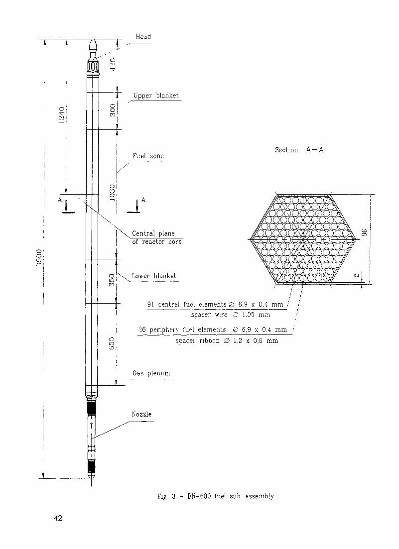
Head
J_i Upper blanket
oiCO1
Fuel zoneSection A-A
JA
Central planeI of reactor core
oLO
Lower blanket
9 1 central fuel elements 0 6,9 x 0.4 mm / /spacer wire C 1.05 mm '
36 periphery fuel elements 0 6,9 x 0,4 mm 'spacer ribbon 0 1,3 x 0,6 mm
Gas plenum
Fig 3 - BN-600 fuel sub-assembly
42

i r
§1
1.C\J
\
Removable container
Experimental irradiationdevice
Section A-A
397 experimental fuel elements 032
A
Central planeof reactor core
96 fuel elements 0 6 9 x 0,4 mm
Fig 4 - Experimental irradiation device with removable container
43

TRemovable container
Material testing
Location of materialsamples
7 elements with material
Section A —A
Central planeof reactor core
96 tuel elements G 6 9 \ 0 4 mm
Fig 5 - Material testing assembly with removable container
44

tube provided with a head and plug is installed. Structural material of the channel and container issteel EP-450.
The hexagonal channel and the container have openings for cooling the assembly (ED orMTA). The container together with ED (or MTA) are of the same geometry as that of standard SAand. so, can be handled using the standard reactor refuelling path.
The ED and MTA design allows remote removal of the container under the protection ofinert gas or under the sodium layer (in a spent fuel drum) from the irradiated assembly and itsinsertion into a "fresh" assembly for continued irradiation.
The ED container can hold up to 7 experimental full-scale FEs. The container head andplug have mesh filters for limiting the possible escape of fuel particles beyond the containerboundary.
Depending on MTA type, the MTA with container allows the testing of 8 to 49 samples ofstructural materials (plate-type, tubular, pressure loaded or non-loaded) in a wide range oftemperatures up to 700°C. For assuring stable temperature conditions during irradiation , theMTAs are arranged in the central core positions remote from the absorber rods.
Due to the possibility of continuing the irradiation of the removable container in "fresh"assemblies at ED and MTAs irradiation time within three runs, the container of each assembly canbe irradiated for six runs. The following irradiation parameters are planned for this case:
- for container of ED: Bmax - 15-20 % h.a., Dmax - 150 dpa;- for container of MTA: Dmax - 150 dpa.
5. CONCLUSION
Since the start of operation three cores (1st type, M and Ml) were subsequently installed inBN-600 reactor. As a further step it is planned to install the 4th M2 core with maximum fuelburnup of 11.3 % h.a.
In the BN-600 reactor, tests are carried out to increase the lifetime of BN-600 standardSAs and to irradiate experimental SAs with MOX fuel in support of BN-600 and BN-800 coreprojects using MOX fuel.
Now the main direction for increasing the lifetime of SAs and fuel burnup is thedevelopment and study of new structural materials with increased irradiation stability for FEscladdings. Materials for future consideration in Russia are steel EP-450, steel ChS-68 CW withincreased phosphorus content, steel EK-164 and improved steels ChS-68 CW and EP-172 CW.
For BN-600 reactor an irradiation device (ED) and a material testing assembly (MTA) aredeveloped with a removable container allowing irradiation of prospective fuel compositions (toburnup of 15-20 % h.a.) and of structural materials (to a damage dose of 150 dpa at a temperatureofupto700°C).
HEKTSoft ELAMJC 4c
»-•» »> *u -. . » *..,, -.-, .. .— _ - _ . _ _ _ _ ._ Q T*S

PERFORMANCE OF FBTR MIXED CARBIDE FUEL XA9848040
S GOVINDARAJAN, P. PUTHIYAVINAYAGAM,S. CLEMENT RAVI CHANDAR, S.C. CHETAL, S.B. BHOJEIndira Gandhi Centre for Atomic Research,Kalpakkam, India
Abstract
Mixed carbide fuel of 70% PuC content is being used as driver fuel in the Fast Breeder Test Reactor(FBTR) for the first time in the world When it was first proposed for FBTR small core, its performance potentialhad to be assessed based upon extrapolated data High Pu content of the fuel reduces the thermal conductivity andmelting point Also, small diameter of FBTR fuel results in high heat flux at fuel-clad gap A conservative initialestimate limited the linear power to 250 W/cm and the burnup to 25,000 MWd/L Subsequently, detailed analyseswere performed v> ith the use of measured as well as data from literature Based on this, the linear power has beenupgraded to 320 W/cm Also analyses indicate that the fuel is capable of sustaining a peak bumup of 50,000 MWd/tRecently, the central fuel subassembly was unloaded for post irradiation examination (PIE) after the initial targetburnup of 25.000 MWd/t Preliminary results from PIE indicate that the analysis is well supported by the results
1. INTRODUCTION
The Mark I small carbide core of the Fast Breeder Test Reactor (FBTR) employs mixed(U-Pu)C of 70% PuC composition. At the time of installation of the core, the targets set for thefuel were 250 W/cm for peak linear heat rating and 25,000 MWd/t for peak fuel bumup. Thesetargets were revised after rigorous analysis to 320 W/cm and 50,000 MWd/t respectively. Thefuel has reached a peak burnup of 30.000 MWd/t so far without any fuel failure. The centralsubassembly of the core was discharged after a burnup of 25,000 MWd/t for post-irradiationexamination (PIE). This paper discusses the details of analysis carried out to upgrade theperformance targets of the fuel and also compares the swelling data obtained from PIE with thedata used for analysis. The design specification for the Mark I core fuel is given in Table I.
2. LINEAR HEAT RATING
The design criteria followed in fixing the allowable operating heat rating of the fuel isthat there should be a margin of atleast 15% between operating linear heat rating and the safety-limit. The safety limit is defined as the rating at which incipient melting occurs after taking intoaccount all uncertainties in properties, operation etc. It is also to be ensured that the overpowertrip threshold is set well within safety limit to take care of overshoot under transients. This designapproach is illustrated in Fig. 1.
The data used for determining safety limits of the fuel is given in Table II. Maximumuncertainty in determining safety limit is caused by the fuel-clad gap conductance. Because ofthe tolerances specified on clad O.D., clad thickness and pellet diameter, the cold diametral gapvaries over the range of 0.06 - 0.30 mm for fresh fuel. The gap conductance also varies with thelinear heat rating because of temperature dependence of hot gap and thermal conductivity ofhelium. In reality, there could be restructuring of fuel in the reactor due to cracks developingowing to thermal stress and this could reduce the gap to some extent.
47

NOMINAL MELTING HEAT RATING (570 W/CM)
Margin for ^ncer~cunTies n physiccu
ana operating parametersC-53X)
DESiGN SAFETV LIMIT (373 W/CM)
Margin for over power transient (-16%)
ALLOWABLE PEAK LINEAR HEAT RATING (321 W/CM)
FIG Design approach for allowable heat rating.
TABLE I. DESIGN SPECIFICATION FOR MARK I CORE FUEL
Fuel
PuC content
M2C3 content
Clad OD
Clad thickness
Pellet diameter
Pellet density
Smeared density
(U - Pu) C
70 w/0
6 - 1 2 w/o
5.1 mm
0.37 mm
4.18mm
90%ofT.D.
83% of T.D
48

a) OUT- PILE TEST (320 W/cm) b) PIE MICROGRAPH (300 W/cm, 25000 MWd/t)
FIG. 2. View of fuel cross section.
sua«ssv LOCA-OH NOCHANNEL «AX -£UP'"CV
R (HW)
Si 4«<Al.ySE3
F/G. 3. FBTK mark I core configuration.
49

Out-pile tests were carried out in the Radiochemistry laboratory at the Indira GandhiCentre for Atomic Research to understand the thermal behaviour of the fuel. The fuelspecimens were heated by electrical resistance heating upto a rating of 500 W/cm in the set up.The cross section of the fuel at a rating of 320 W/cm is shown in Fig.2. For comparison, the crosssection showing the microstructure obtained by PIE is also shown adjacently.
The theoretical analysis without taking into account restructuring gave a design safetylimit of 373 W/cm on linear powrer for fresh fuel and a value of 800 W/cm for fuel fully incontact with clad and reaching a saturated value of gap conductance of 1.5 W/cnr-K. With thissafety limit, the operating heat rating was limited to 320 W/cm for the Mark I core fresh fuel. Asthe linear heat rating has significant influence on the burnup of fuel, both in free swelling phaseand the Fuel Clad Mechanical Interaction (FCMI) phase, it was decided to keep the linear heatrating at 320 W/cm itself, till some data on the swelling rate of fuel is obtained.
3. BURNUP
Since carbide fuel of this composition is being used for the first time in the world, thereare no data available on the burnup capability of this fuel. In the analysis for the estimation offuel capability in terms of its achievable burnup at a given linear power, swelling and thermaland irradiation creep of both the fuel and the clad play important roles. The unavailability of dataon swelling and creep of the FBTR fuel composition enhances the uncertainty of predictions. Anattempt has however been made based on data available for other mixed carbide fuels. Most ofthe data available for carbide fuel in the open literature are only for the standard mixed carbidefuel containing 15-20% PuC. Hence all the data concerning the fuel material have been suitablymodified and adopted for FBTR fuel. Also data on clad irradiation creep available in theliterature is used in the analysis. For thermal creep and out-pile rupture life of clad material thedata generated in-house [1] have been considered along with those published in the literature.The analysis covers the entire core as linear power varies both radially and axially in the core.
The analysis was carried out for both nominal and hotspot conditions. The attainableburnup values for the maximum rated fuel pin of all the subassemblies are presented. The MarkI core configuration is shown in Fig.3. The subassembly ring number, its serial number, thermalpower and maximum channel temperature are shown in the same figure. There are 10subassemblies having a distinct combination of thermal power and coolant channel temperaturefor which analysis has been carried out and they are indicated by a circle mark in the same figureand these assemblies are representatives of the entire core.
3.1. Fuel Material Properties
The properties involved in the analysis are thermal conductivity, melting point,coefficient of linear thermal expansion, volumetric swelling rate, thermal and irradiation creeprate etc. The melting point and mean coefficient of thermal expansion are measured/estimatedto be 2100 K and 11.2xlO"6 respectively [2]. The average thermal conductivity correspondingto the smeared density of 83% is 10.575 W/m-K which is derived from the measured data [3].The swelling rate is a strong function of fuel centre temperature and literature data is for standardmixed carbide fuel [4]. The melting point of the standard mixed carbide fuel is reported as 2743K. The temperature data points in the available literature on swelling of reference fuel werenormalised, using the ratio of melting points, in order to get the temperature data points forFBTR fuel. The percentage volumetric swelling rate for the FBTR fuel as a function of fuelcentre temperature, derived by the above procedure, is shown in Fig.4. The equation for thermal
50
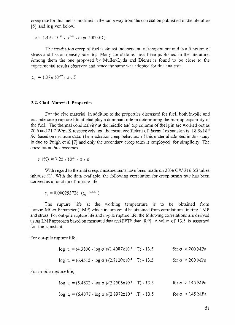
creep rate for this fuel is modified in the same way from the correlation published in the literature[5] and is given below.
e t= 1.49x 10'°xa :44xexp(-50000/T)
The irradiation creep of fuel is almost independent of temperature and is a function ofstress and fission density rate [6]. Many correlations have been published in the literature.Among them the one proposed by Muiler-Lyda and Dienst is found to be close to theexperimental results observed and hence the same was adopted for this analysis.
e, = 1 . 3 7 x l O - 2 7 x a x F
3.2. Clad Material Properties
For the clad material, in addition to the properties discussed for fuel, both in-pile andout-pile creep rupture life of clad play a dominant role in determining the bumup capability ofthe fuel. The thermal conductivity at the middle and top column of fuel pin are worked out as20.6 and 21.7 W/m-K respectively and the mean coefficient of thermal expansion is 18.5xlO~6
/K based on in-house data. The irradiation creep behaviour of this material adopted in this study-is due to Puigh et al [7] and only the secondary creep term is employed for simplicity. Thecorrelation thus becomes
e,(%) =7.25x lO'4 xox <f>
With regard to thermal creep, measurements have been made on 20% CW 316 SS tubesinhouse [1]. With the data available, the following correlation for creep strain rate has beenderived as a function of rupture life.
e, = 0.000293728 (t r o '5 3 6 8 7)
The rupture life at the working temperature is to be obtained fromLarson-Miller-Parameter (LMP) which in turn could be obtained from correlations linking LMPand stress. For out-pile rupture life and in-pile rupture life, the following correlations are derivedusing LMP approach based on measured data and FFTF data [8,9]. A value of 13.5 is assumedfor the constant.
For out-pile rupture life,
log tr = (4.3800 - log a )/(1.4087xlO-4 . T) - 13.5 for a > 200 MPa
log tr = (6.4515-log a )/(2.8120xlO-4 . T)-13.5 forcr < 200 MPa
For in-pile rupture life,
log tr = (5.4832 - log a )/(2.2506xlQ-4 . T) - 13.5 for a > 145 MPa
log tr = (6.4377 - log a )/(2.8972xlO'4 .T) - 13.5 for a < 145 MPa
51

3.3. Analytical Modelling
This study pertains only to the steady-state operation of the fuel. The calculation ofattainable burnup is carried out for fuel pin at two axial locations viz., fuel column middle andtop. The analysis is carried out for a peak linear heat rating of 320 W/cm. The various hot spotfactors are given in the following table and they are assumed to be same for all SA. Various dataused in the analysis such as radial power factors, average linear power and the linear power atthe fuel middle and top column positions for all SA are given in the table below. Clad wastagedue to sodium corrosion is negligible for reactor grade sodium.
HOT SPOT FACTORS:SA
1 -10
Fuel
1.3077
Fuel-Clad gap
1.1924
Clad
1.3131
Film
1.5749
Coolant
1.1795
DATA FOR ANALYSIS:
Sl.no SA Radiallocation power factor
Linear power (W/cm)
Average Fuel middle Fuel top
12
3
4
5
6
7
8
9
10
00-00
01-01
02-04
02-03
02-02
02-01
02-07
02-06
02-05
03-01
1.0035
1.0142
1.0269
1.0249
1.0269
1.0249
1.0249
1.0269
1.0249
1.0072
278.7
267.6
239.4
247.7
239.4
247.7
247.7
239.4
247.7
224.2
320.0
310.5
281.3
290.5
281.3
290.5
290.5
281.3
290.5
258.4
214.2
207.9
188.3
194.5
188.3
194.5
194.5
188.3
194.5
173.0
The analysis is divided into two phases. In each phase different phenomena dominate andthe total achievable bumup is the sum of the two. The first phase is known as free swelling phasein which the initial gap provided between clad and fuel pellet closes on account of fuel swellingdue to irradiation. The achievable burnup in this is governed by linear power. Among the dataneeded for finding the temperature distribution, the gap conductance is an important one and itvaries with the fuel-clad gap. As the fuel burns, the fuel swells and hence the gap reduces. Onaccount of improvement in the gap conductance, the temperature drop in the gap too decreaseswhich in turn reduces the fuel centre temperature. Gap conductance keeps on increasing as theburnup proceeds and reaches a steady-state value as the fuel-clad contact occurs. The time takento reach this point determines the attainable burnup in the free swelling phase. For finding thetemperature distribution, the fuel pellet is modelled as a set of concentric cylinders.
52

TABLE II. DATA FOR DETERMINING LINEAR RATING
Specific Heat of Sodium
Thermal Conductivity of Sodium
Thermal Conductivity of SS 316 clad
Thermal Conductivity of fuel
Film Heat Transfer coefficient betweenSodium and Clad
Fuel Thermal expansion coefficient
Clad Thermal expansion coefficient
Porosity correction factor
Density of fuel
Melting point of fuel
1266 J / k g - K
64.9 W/ m - K
2 1 . 0 W / m - K
6.253-2.8604 x 10 " JT(K)H 1.879x 10'6T2 + l .I559x 10"18 T3
W / m - K- 4.55618 x l O ' 1 2 T4
120000 W / m - K
6.95 x 10"6 +5x 10"9 T (K)-0.1134 x l O ' 1 1 T 2 /K
1.789x10° + 2.398 x 10 ~9 T (K)- 3.269 x 10 ~13 T2 /K
( 1 - P ) / ( 1 + P )P - porosity factor
92 % T.D.
2123 K( 1850 °C)
The second phase of the analysis is known as Fuel-Clad Mechanical Interaction phase(FCMI). In this phase, once the pellet and clad make physical contact with each other, anyfurther swelling of fuel exerts pressure on clad. This pressure is exerted on both fuel and cladresulting in various stresses on these components. Under the influence of these stresses both fueland clad start creeping. FCMI pressure goes on increasing till a steady state equilibrium isattained between fuel swelling, clad creep and fuel creep. The steady-state value of gapconductance is assumed to be 1.5 W/cm2 /K. The swelling rate of fuel becomes a constant whenthe gap conductance saturates at the steady-state value. The life of the fuel pin achievable inFCMI phase depends on creep rupture life of clad corresponding to the FCMI steady-statepressure.
The attainable burnup in FCMI phase is mainly governed by creep rupture life of cladwhich in turn depends on the clad midwall temperature. In some cases where the clad stressesare very low, the rupture life would obviously be very high. However, there is a physicallimitation to the creep of fuel as dictated by the available porosity in the fuel. Hence in such caseswhere stresses are low, the burnup is governed by the available space. For finding the stressesin the clad, the clad is modelled as a thin cylinder. The fuel pellet is modelled as a solid thickcylinder. For the fuel pellet, various properties used in the analysis are derived for a volumeaveraged temperature.
53

Ul
TABLE III . ATTAINABLE BURNUP
SA LOCATION
TOP OF FUEL COLUMN
Nominal tempeiature
00-00 01-01 02-04
Hot spot temperatuie
02-03 03-01 00-00 01-01 02-04 02-05 03-01
Linear PowerClad midwall tempFuel centre tempFree swell burnupFCMI burnupTotal burnupClad stress - FCMIAllowable stress
MIDDLE OF FUEL
Linear powerClad midwall tempFuel centre tempFree swell burnupFCMI bumupTotal burnupClad stress - FCMIAllowable stress
W/CmdegCdegCMWd/KgMWd/KgMWd/KgMPaMPa
COLUMN
W/CmdegCdegCMWd/KgMWd/KgMWd/KgMPaMPa
21425334811 2
48 1206687
2407311 2
320045408699334352686
28624676
2079521 7791 3
50630 881 4
24723399
310 54474851 035636 171 7
291 44750
1883511 6755 8
55 841 5973
2468364 8
281 3440 1805 7
41 7385802
285 14832
194 551637684
540385925
2466353 3
2905443 28207396377111,
290 14798
173 0511 97362596428
1024241 23640
258443867744463403866
273 24850
2 1 4 25767928 0
38 123 261 3
16052704
3200486 1
1012222724 5472
1 1 5 64273
20795627903 6
41 21 6 357 5
193 1281 1
310 5478 1988625026651 6
14274405
188355028590472129602
2 1 1 02907
281 34687931 1
31 8302620
2242451 1
194 555598748
45 2126579
21232863
290 5472 59500
29 5289584
19604468
173 05502833 9
51 11 1 6627
22202907
25844662891 0
37 5334709
267 8453 9

600 1000 1400 1800 2200 2600100 ii ii ;n : i|i in 11 i ' i p m r i M i | i i i . I M . I ,i IM ii MIJ 100
80 - No r mo I t s e d: Swe I h In g Low
60
40
20
No n -NorJnol I s e dSue I I In gf Low
60
40
20
0 nmiMi l l . - I ITMIMI iL jZba
600 1000 1400 1800 2200 2600
Fuel Centre Temp.(K)
FIG. 4. Fuel Swelling Rate
0.0 0.1 0.2 0.3
I-cf
oe*̂»to
12
11 -
10 -
8 -
7 -
6
5
4
2
1
0
fiormatisttiSwftiing Law
?f on—normalised.Swelling Law.
PIE Re suI ts
0 . 0 0 . 1 0 . 2 0 . 3
.Fuel— clad cold <iia.ga.p,mm
FIG. 5. Elongation of fuel pellet stack length.
3.4. Burnup estimates
The attainable burnup for Mark I core fuel of FBTR have been estimated for the entirecore for a peak linear heat rating of 320 W/cm in order to consider the enhancement of burnup.The results are given at two axial locations viz. fuel column top and middle at both nominal andhot spot temperature conditions. The attainable burnup values for nominal temperatureconditions and hot spot temperature conditions are presented in Table III. The study shows thatburnup attainable at the fuel middle column is the limiting one for nominal temperatureconditions. But under hot spot temperature conditions, for subassemblies in ring 2 and beyond,the burnup attainable at fuel top column appears to be the limiting one. The total attainable
55

burn up is well above 50,000 MWd/t for all the SA under both nominal as well as hot spotconditions except in the case of central subassembly in hot spot condition where it is 47.200MWd't
4. FREE SWELLING RATE
As earlier mentioned , the free swelling rate of the fuel has been derived from the dataon (U-20%Pu)C fuel. Recentl} PIE carried out on the central SA removed from the FBTR afterit had reached a burnup of 25.000 MWd/t has given data on the length increase in the pelletstacks of nine pins. This data has been compared with the expected stack elongation. Theswelling of fuel as calculated using the data on (U-20%Pu)C fuel (non-normalised) and that usingthe normalised data are plotted in Fig.5. It appears that the data on (U-20%Pu)C is directlyapplicable for the FBTR fuel.
5. CONCLUSION
The performance of FBTR Mark I core carbide fuel is good. Based on the analyses carriedout, its linear heat rating has been raised from 250 W/cm to 320 W/cm and the fuel has seen apeak burnup of 30,000 MWd/t so far without any fuel failure. PIE performed on the central SAremoved from the core after the initial target burnup of 25.000 MWd/t reveals that the Pu richcarbide fuel swelling beha\iour is more or less the same as the (U-20%Pu)C fuel. The targetburnup is enhanced to 50,000 MWd/t based on the estimates. Further enhancement of linear heatrating upto 400 W7cm will be considered.
REFERENCES
[1] MATHEW, M. D.. et al., Creep rupture properties of solution annealed and cold worked type316 stainless steel cladding tubes, IGC-117. 1990.
[2] SENGUPTA, A. K., et al., Melting temperature of mixed carbide fuel for FBTR, Seminaron Fast Reactor Fuel Cycle, Kalpakkam. 1986.
[3] GANGULY. C.. Communication on observed Thermal conductivity data, Ref. No.RMD/01.6.4)793/105. BARC.
[4] MIKAILOFF. H., L'element combustible carbure a joint helium pour la filiere a neutronsrapides: problems poses par le gonflement du combustible, BIST 196 (1974).
[5] PREUSSER. T., Modelling of carbide fuel rods. Nucl. Tech. 57 (1982) pp 343-371.[6] MULLER-LYDA, I., DIENST. W., A measurement of the irradiation induced creep of
mixed carbide nuclear fuel. Journal of Nuclear Materials 90 (1980) pp 232-239.[7] PUIGH. R. J., et al., An in-reactor creep correlation for 20% cold worked AISI 316
stainless steel, Proc. Symp. on Effects of radiation on materials. Scottsdale, June 1982(ASTMSTP 782, pp 108-121).
[8] PUIGH, R. J., HAMILTON, M.L.. In-Reactor creep rupture behaviour of the D9 and 316alloys. ASTM STP 956, pp 22-29.
[9] LOVELL, A. J. ,et al., In-Reactor creep rupture of 20% CW AISI 316 stainless steel.Journal of Material Science. 16 (1981) pp 870-876.
56

POST-IRRADIATION EXAMINATION OF MIXED (Pu, U)C FUELSIRRADIATED IN THE FAST BREEDER REACTOR
R. BALDEV, K.V. KASIVISWANATHAN, V. VENUGOPAL,N.G. MURALIDHARAN, A. RAMABATHIRAN, N. RAGHU, J. JOSEPH,S. KURJEN, B. VENKATARAMAN, M.T. SHYAMSUNDER,S. MURUGAN, K.A. GOPAL, P.V. KUMAR, P. KALYANASUNDARAMMetallurgy and Materials Group,Indira Gandhi Centre for Atomic Research,Kalpakkam, India XA9848041
Abstract
The Fast Breeder Test Reactor (FBTR) at Indira Gandhi Centre lor Atomic Research(IGCAR), Kalpakkam, India, using mixed (Pu,U)C fuel has completed eleven years ofoperation. One fuel subassembly which has seen more than 25,000 MWd/t burn-up has beendischarged from this reactor taken up for post-irradiation examination. The PIE carried out onthis fuel subassembly has established that the fuel has performed satisfactorily and it iscapable of being taken to higher levels of bum-up and linear heat ratings. The facilities availablefor PIE of advanced fuels and the PIE work carried out are discussed in detail in this paper.
1. INTRODUCTION
The Fast Breeder Test Reactor (FBTR) with a small core, using mixedplutonium-uranium carbide (70% PuC, 30% UC) as it's driver fuel, has achieved a maximumpower of 10.5 MWt, and the fuel has seen apeak linear heat rating of 320 W/cm. This fuelhas so far achieved more than 30,000 MWd/t burn-up, without any failure.
Post-Irradiation Examination (PIE) was carried out on a fuel subassembly dischargedfrom the reactor, after reaching a burn-up of more than 25,000 MWd/t. In addition, PIEexcluding metallography has been carried out on four experimental fuel pins irradiated inFBTR. These fuel pins contain fuels with the present core composition as well as theproposed expanded core composition (55% PuC, 45% UC). The irradiation experiments areundertaken to understand the beginning of life performance of these fuels, compare theperformance of the fuel compositions of the present core and of the proposed expanded core.This paper discusses in detail the PIE done on the driver fuel discharged after 25,000 Mwd/tburn up. Results of PIE on experimental fuel pins irradiated in FBTR are also briefly touchedupon. A brief description of the PIE facilities for metallurgical examinations atRadiometallurgy Laboratory (RML), IGCAR is also given in this paper.
2. DESCRIPTION OF PIE FACILITY
PIE facilities at RML, IGCAR can remotely handle and examine highly irradiatedadvanced fuels in the inert gas (nitrogen) atmosphere hot cells where the temperature, pressureand cell atmosphere are closely monitored and controlled. The PIE facilities consist of sevenconcrete shielded hot cells and a few lead shielded cells. The concrete shielded hot cells havewalls made of high density concrete (density 3.5 gm/cc, wall thickness 1200mm), and the leadshielded cells have walls of lead (250/200mm thick). The hot cells are equipped with
57

FIG 1 A view of the operating area of the hot cells
master-slave-manipulators for carrying out operations in the hot cells. The cells are alsoequipped with power manipulators for handling loads up to 50 kg, and in-cell cranes forhandling heavier loads up to one tonne. Lead glass windows are provided on the cell wall forviewing into the cells. These concrete shielded hot cells are designed to handle irradiatedmaterial with radioactivity up to 3.7X10⁷ GBq. and the lead cells up to 3.7X10⁴ GBq.Fig.l shows a view of the operating area of the hot cells.
The hot cells have a high purity nitrogen gas atmosphere, with provisions forchanging over to air atmosphere during examinations when inert atmosphere is not requiredor during man entry into the cells. This recirculatory nitrogen gas system with provisions forcooling, filtration and purification, maintains the hot cells at a negative pressure (-25mmwater column nominal), and at very low levels of moisture and oxygen.
A remotely operated trolley, mounted with a shielded flask is used for the transport ofplutonium rich fuel subassemblies and irradiated objects from FBTR to RML. A VerticalTransfer System installed in the hot cell floor is used for transfer of irradiated subassembliesfrom this shielded flask into the hot cell. It has a vertical double door alpha-tight transfersystem (150mm diameter), specially adapted for this purpose.
A horizontal transfer system installed in the RML hot cell wall is used for transferringdismantled irradiated fuel and structural materials from RML to other laboratories forradiochemical analysis, reprocessing or waste disposal. The horizontal transfer system alsois a double door alpha-tight transfer system (270mm diameter).
RML hot cells have state-of-the-art techniques for metallurgical examination of theirradiated materials. The PIE techniques cover a wide spectrum of examination methods,nondestructive as well as destructive. The techniques have been chosen to extract maximuminformation with reliability and accuracy. The details of in-cell equipments and other PIEfacilities are described below.
58

The sodium removal system provided in the hot cell consists of a leak-tight chamberto house the subassembly and two tanks containing ethanol, which is used as a cleaning fluid,with provision for pumping the liquid from one tank to the other through the chamber, usingcompressed nitrogen. This system is used to remove the residual deposits of sodium from theexternal as well as internal surfaces of the subassemblies.
A remotely operated CNC drilling and milling machine provided in the hot cell isused to dismantle the subassembly without damaging the fuel pins. It can also machinetensile test specimens from the wrapper material of the subassembly. It has an inductivetype probe attached to it, to facilitate dimensional measurements of the subassembly, with anaccuracy of ±20 microns.
A 30 kW(Th) swimming pool type reactor (KAMINI) installed below the hot cells,provides the neutron beam required for taking the neutron radiography of the fuelsubassemblies and fuel pins. The reactor is capable of giving a collimated neutron beam offlux 107 n/sq.cm/sec at the radiography site. A precise positioning and indexing mechanism(0.5 degree steps) facilitate neutron tomography of fuel pins and fuel subassemblies.Pin-to-pin spacing, plutonium redistribution, depletion of boron in the control rods etc. can bestudied using this system.
Leak testing of the fuel pins are being carried out using a glycol leak test system, witha sensitivity of 100 microns through hole.
Diameter measurements of the fuel pins are done on a profilometer which hasprovisions for holding the pin vertically and to move a carriage holding two LVDTs(accuracy of measurement +2 urn) against the pins in diametrically opposite directions toscan the diameter along the length of the fuel pins. Data acquired through a computer gives thediametrical profile of the fuel pins.
Eddy current testing (ECT) of the fuel pins is done with the pin held vertically andby moving the encircling ECT probe along the length of the pins. A PC based dataacquisition system is used and the results are compared with those from calibrated pinshaving known defects in the clad tube. ECT can detect abnormalities on the cladding tube aswell as on the cladding tube-fuel pellet interface (sensitivity 7% wall thickness).
A 420-KV industrial X-ray machine is used to radiograph the fuel pins. This techniqueis complimentary to the neutron radiography technique. Special techniques have beendeveloped to get the desired sensitivity by reducing the effect of fogging of film due to gammarays from the pins. Radiographs are studied using image enhancement techniques.Dimensional measurements are made from the radiographs applying suitable correctionfactors, to get information such as pin diameter, pellet-clad-gap, pellet-to-pellet gap, stacklength, spring compression etc. (accuracy of measurements in the radial direction of pinsis (0.05mm, and hi the axial direction of the pins is (0.5mm). X-radiography can also revealchipping of pellets, major clad defects etc.
A micro gamma scanning system is provided to evaluate the fissile column length,distribution of fission products and burn-up. This system consists of a bench with steppermotor controlled X,Y movements and rotation for positioning the fuel pin with respectto any of the four collimators which are provided in a turret mechanism. The turret brings
59

the required collimator in line with the fuel pin and the detector positioned outside the hotcell. This facilitates measurement of gamma spectrums, in the radial as well as axialdirection of the fuel pins using the detector and multichannel analyser combination.
The metallographic specimen preparation and examination facilities include a fuel pinsectioning device, a vacuum impregnation system to impregnate the fuel pin with a liquid epoxyresin in order to immobilize the fuel column inside the clad tube before sectioning, remotemounting of specimens, polishing, etching and replica making arrangements, and ametallograph for taking metallographic pictures of the cut sections of the fuel pins. Themetallographic pictures are subjected to image processing to evaluate the metallographicstructures.
A mechanical testing facility is being established to evaluate the mechanical propertiesof the cladding tube as well as structural materials. This includes tensile testing, miniaturespecimen testing, dynamic testing and burst testing.
3. PIE OF FBTR FUEL SUBASSEMBLY
The central fuel subassembly from FBTR with the following irradiation data wasdischarged in July 1996 and taken up for PIE.
TABLE I. IRRADIATION DATA OF FUEL SUBASSEMBLY
Total burn-up : 25,036 MWd/tPeak linear heat rating : 320 W/cmPeak power :10.5MWtFuel theoretical density : 90%Fuel smear density :83%Type of bond :HeliumGeometryouter diameter of pin : 5.1 mminner diameter of pin : 4.36mmeffective stack length : 321 mm
Visual examination of the fuel subassembly before sodium cleaning did not show anycorrosion or surface defects. The subassembly was washed in the alcohol recirculatory systemto remove the residual sodium deposits from the external as well as internal surfaces of thesubassembly. The shining appearance of the hexagonal sheath after cleaning indicated thatexcellent purity of sodium has been maintained in the reactor. Fig.2 shows a view of thesubassembly kept on the visual examination bench.
60

FIG.2 A view of fuel subassembly on visual examination bench
Dimensional measurements on the fuel subassembly indicated that the hexagonal sheathin the fuel region of the subassembly did not have any swelling or bulging. The widthacross-flat of the hexagonal sheath was found to be generally within the original limits oftolerances. Fig.3 shows a view of the fuel subassembly held on the work table of the CNC.machine. Fig.4 shows an image of the subassembly reconstructed using the numerousdimensional measurements carried out along it's entire length, using the machine.
The subassembly was dismantled using the CNC remote milling and drilling machine.Fuel pins extracted from the assembly, did not show any corrosion or deformation on visualexamination. However, the central fuel stack regions of the clad appeared coloured due to the
SSSSECCfi
FIG. 3. A view of fuel subassembly during dimensionalmeasurements
61

FIG.4. Reconstructed view of the fuel subassembly
effect of temperature. Fig.5 shows a view of the dismantled pins stacked in a rack. Glycolleak testing of the fuel pins did not indicate any identifiable leaks. Nine fuel pins which lie ina line on the cross section of the subassembly as indicated in Fig.6 were selected for furtherdetailed examinations.
Diameter and length measurements carried out on nine pins indicated that thediameters and lengths are generally within the original limits of tolerance and that there is noclad deformation. Fig.7 shows a typical diameter profile of the fuel pins.
FIG. 5. A view of the fuel pins dismantled from the subassembly
62

FIG. 6. Sketch showing cross section of fuel subassembly indicating pins selected for detailedexaminations.
Eddy current testing of the fuel pins did not indicate any surface defect orabnormality on the clad tube. Analysis of signals indicated that the spring support inside thepins was touching the clad and that this location was varying for the nine pins. The accuracyof location is within +2mm. The location of spring support determined using ECT indicatedthat the pellet stack length have increased due to swelling of the fuel. These results correlatewell with that of X-radiography which followed ECT. Fig. 8 shows a typical ECT output.
.02-2DIAMETER PROFILE OF CENTRAL FUE^ DIN
/•S2-2/O'A 'uPPER LiMi"
cz:c.
5Q8G~ /OIA-LOWER LliVlT/
50&0_
50 100 "50 2'00 250 ^00 350 ^00 '^50 500DISTANCE (m-n)
F/G. 7. Typical diameter profile of a fuel pin
63

1500F = 350KHz
500-ot
-SOOp-1000^-15001
500 1000 1500 2000 2500
TIME
FIG. 8 Eddy current signal output ofatypical fuel pin
X-radiography of the fuel pins revealed that the pellet-clad gap and the pellet-to-pelletgaps are too small to be measured. Original pellet-clad gaps were in the range 0.110mm to0.250mm. An increase in fuel stack length was noticed. This varies from 2.17mm to 5.35mm(0.68% to 1.67%). This is in agreement with the eddy current test results which detected
3-r\
o-f ~~to 7
i i
1 2 3 ^ 5
FIG 9. Chart showing increase in fuel stack lengths estimated using x-radiography
64

the variation in the location of the spring support. No gross abnormalities wereobserved.Fig.9 shows the variation in stack length measured from X-radiographs for the nineselected pins.
Two of the pins showing a stack length increase of 0.825% and 1.67% were taken upfor carrying out sectioning and metallography. Fig. 10 shows the metallographic pictures ofthe cut sections of fuel. Fig.l 1 shows photo micrographs of etched structure of the fuel at asection at the centre of the fissile column. An etched structure of as fabricated fuel is alsoincluded in this figure. The results of metallographic examinations revealed the following.
(1) The fuel was seen to have several cracks in the cut section taken at the centre of thefuel column, whereas at the end, the extent of cracking was relatively less. The etchedstructure of the fuel cross section did not indicate any evidence of restructuring (fig.l 1).
(2) The fuel-clad gap was seen to be closing due to cracking, as well as swelling of thefuel. The fuel clad gap was less at the centre of the fuel column, compared to theend, as expected.
The swelling rate of the fuel is a strong function of the fuel centerline temperature. Themetallographic results show that the fuel is cracking, facilitating early closure of the fuel cladgap, resulting in reduction of the fuel centre line temperature. The swelling rate of carbide fuelsof a different composition (8% PuC , 92% UC) as a function of fuel centerline temperature hasbeen reported by Mikailoff [1]. Since swelling data for FBTR fuel composition (70% PuC, 30%UC) is not known, a modified swelling rate has been arrived at for this fuel, after normalisationusing ratios of melting points of the two fuel compositions [2]. The two swelling rates arecompared in Fig. 12. From fig. 12 it can be seen that the swelling rate is very low at centre linetemperature of about 1300 K for FBTR fuel composition. The average swelling rate estimatedfrom X-radiography results of the nine pins, as well as measured from the metallographic cross-sections, is approximately 1.2% per atom percent burnup, which indicates that the swelling rate forFBTR fuel has been lower than the predicted values shown in Fig. 12. Hence the PIE results shows thatthe linear heat rating can be safely increased for this fuel to 400 w/cm. The presence of fuel clad gap seenin the metallographic cross sections (Fig.10) as well as the gap available in the fuel due to cracks, indicatethat, space is still available to accommodate further swelling of the fuel. Hence it can be also concludedthat the fuel can be safely taken to higher levels of burnup say 50,000 Mwd/t.
In addition to the driver fuel subassembly PIE four experimental fuel pins, irradiated to very lowlevel of burn up (15 to 25 effective full power days) in the reactor is also being carried out. These fuelpins were having the same geometry of the driver fuel pins and were irradiated in a special capsuleassembled in carried assembly. The pins had pellets both 70% PuC 30%UC (driver fuel composition) and55% PuC 45%UC composition thought for an expanded core configuration, stacked in separately, withan insulation pellet (UC) in between. The results of PIE carried out so far indicates satisfactoryperformance of these pins.
65

(a) Centre of fissile column, 300 W/cm,25,000 MWd/t (b) Top of fissile column, 2 JO W/cm,
18,000 MWd/t
(c ) Centre of fissile column, 300 W/cm,25,OOOMWd/t
(d) Top of fissile column, 210 W/cm,18,000 MWd/t
FIG. 10. Photomicrographs of cut cross sections of fuel pins. Figs, a & b show the cross sections at themiddle and end of fuel column for pin number 3 and Figs, c & d for pin number 7 respectively (refer fig.no. 6)
66

wm^mf̂ */-̂ *;£l,% ;̂|
FIG.ll. Photo micrographs showing etched structure of the irradiated and a typical unirradiated fuel.
67

100-
600 1000 1400 1800 2200
FUEL CENTRE TEMP. (K)
2600
FIG. 12. Free swelling of mixed carbide fuels as a function of centre line temperature
4. CONCLUSION
The performance of the carbide fuel chosen as driver fuel for FBTR has been found to beexcellent with no indication of fuel failure up to 30,000 Mwd/t of burn up. Detailed PIE carried out onthe fuel which has seen burn up in excess of 25,000 Mwd/t did not also reveal any abnormalities. The fuelclad gap was seen to be closing, due to cracking of the fuel. However, marginal fuel clad gap in the rangeof 10 to 20 |u.m is seen to be still existing in addition to gaps available in the fuel due to cracks, toaccommodate further swelling. These results clearly indicate that the fuel can be safely taken to higherlevels of burnups and higher linear heat ratings.
ACKNOWLEDGEMENTS
The authors are thankful to Dr. Placid Rodriguez, Director, IGCAR for his constantencouragements and support. Authors also gratefully acknowledge the keen interest shown by Shri S.B.Bhoje, Director, Reactor Group, IGCAR. The authors are also thankful to various colleagues atRadiometallurgy Division, Bhabha Atomic Research Centre, Mumbai where the fuel was fabricated, forgiving many useful data. The contributions of number of colleagues of Reactor Operations Division,IGCAR and Nuclear Systems Division, IGCAR are also gratefully acknowledged.
REFERENCES
[1] MAIKAILOFF, H., L'element combustible carbure a joint helium pour la filliere a neutronsrapides: problems poses par le gonflement du combustible, BIST 196 (1974).
[2] GOVINDRAJAN, S., Attainable linear power and burnup of the mixed carbide fuel for FBTR,Internal Report, FBTR/FRG/3141 l/DN/21
68

DEVELOPMENT OF VIBROPAC MOX FUEL PINS XA9848042SERVICEABLE UP TP SUPERHIGH BURNUPS
A.A. MAYORSHIN, G.I. GADZHIEV,V.A. KISLY, O.V. SKIBA, V.A. TZYKANOVResearch Institute of Atomic Reactors,Dimitrovgrad, Russian Federation
Abstract
The main results on investigations of fast reactor fuel pins with (UPu)C>2 vibropac fuel tosubstantiate their serviceability up to the super-high burnups are presented. The BOR-60 reactor fuelpins radiation behaviour in stationary, transient and designed emergency conditions has beendetermined from the fuel pins dimensional stability analysis having regard to the results ofinvestigation fuel and cladding swelling as well as estimations of fuel and cladding thermal-mechanical and physico-chemical interactions. It is shown that the change of the outer diameter isminimum in fuel pins with VMOX fuel with a getter-metallic uranium powder and ferrito-martensitesteel cladding, and the corrosion damage of the cladding inner surface is absent up to 26% h.a. Theexperiments with over-heating of the irradiated fuel pins cladding up to 850°C did not lead to anychanges in pins integrity. The availability of the periphery area of the vibropac fuel core initialstructure provides the minimum level of the thermal-mechanical stress at transient conditions ofreactor operation.
Introduction
The most efficient way for improving the technique andeconomical characteristics of fast reactors fuel cycle is theincrease of fuel burnup.
According to the estimations to compensate the high cost offast reactor fuel component the maximum burnup must make up 20+25% h.a. When solving this task two problems are the mostsignificant:
- choice cf structural materials for fuel pins cladding andfuel assembly wrappers, possessing necessary level of heat-ressistance and an acceptable value of radiation swelling;
- provision of the minimum physical-chemical and thermal-mechanical effect of fuel column on cladding.
To realize this problems among the well-known grates ofsteels preference apparently should be given to ferrito-martensite class materials which demonstrate rather high sizestability at moderate temperature levels of the cladding. Asappears from the data of fig.l where there is presented thedependence of the main cladding materials swelling on fluence,the best characteristics shows the American steel HT-9 [1,2].
69

Irradiation Temp400~620°C
ModifiedSUS316(PNC316)
Commercial SLJS316
El-847
10 20f\
Neutron fluence (n/cm , E > 0.1 MeV)
Fig 1. Swelling of structural materials for FBR fuel pins.EP-450 = Crl3Mo2NbVB,El-847 = Crl6Nil5Mo3Nb,ChS-68 = Crl6Nil5Mo2Mn2TiBV,Eml2 = CrlOMo2Mn,HT9=Crl2Mol.
3 0 X 1 0
5 /D, rel.unit
0.08
0.07
0.06
0.05
0.04
FFTFPFR
BOR-60
FFTFBN^SOt)(project)
PhenixBN-800
BN-600
5.5 6.0 6.5 7.0 7.5D, mm
FIG. 2. Dependence the cladding relative thickness vs fuel pin diameter.
70

60
SO
40
30
20
10
M > 7 % getterO < 7 % getter
0 1 Z 3 4 5 6 7 S 9 10 11 12 13 14 15 16 17 18 19 20 21 22 23 24 25 26
B urnup, % h.a.
F/G 3 FA distribution of the BOR-60 reactor versus burnup(wrapper CrlSNilO, cladding Crl6NH5Mo3Nb)
As for the problem of thermal-mechanical effect of the fuelcolumn on cladding with minimum chemical interaction of U-Puoxicte fuel and cladding, then to increase the fuel size stabilityin the case of pellet fuel, the main accent is done on thecladding thickness increase, fig.2 [3,4] (FFTF, El-9 cladding,burnup - 23,8 °0, a/d = 0,56/6,86 mm; PFR, cladding PE-16, burnup- 21,0 ?, o/d = 0,38/5,84 mm; BN-600, tnere is scheduled thecladding transfer from 6,9 x 0,55 mm of diameter and wallthickness) . It is anticipated that the increase of claddingstructural stength at the expense of its thickness increase 100pirn on the average, allows to minimise the corrosion factoreffect.
For the last 15 years in RIAR in the range of the closedfuel cycle, based on the use of dry methods for nuclear fuelperfomed the intensive investigations on the creation of fuel pindesign, adapted to the automated remotely-controlledtechnological process and possessing nigh operating
71

Table 1.1
Granulated Fuel UPuO^ Features
P a r a m e t e r
Particle density, g/cm3
Fraction numberoee
Panicle size, mm
Smear density, g/cm3
- fuel pin of FBR- fuel pin of PWR
Content massy PuC>2, %1 Isotope mass fraction, %
238pu
239Pu
240Pu
241Pu
242Pu
Enrichment UO2, %
V a l u e
10,7- 10,8
5
-1,00 + 0,63
-0,63 + 0,40-0,40 + 0,25-0,25 +0,10
-0,10
9, 1 , 0,2
9,6 , 0,2
°30
0,2 + 1,7
64,0 - 98,53,3-21,5
0,4 - 9,0
0,2 - 4,0
45-90 1
Table 1.2
Produaion of Granulated Fuel
Type of facility
Granulated UO2 fuelFacility
Granulated UPuO2
Pilot plant (Granulated
Fuel Facility)
Fuel
UO2UO2
PuO22UPuO2UPuO2UPuO2
UO2
UO2UO2UO2
UPuO2UPuO2UPuO2
Quanti- ty
900365
100550
7570
120535330374
325277
300
Period
1976+1983
1983
1980+1982
1983-1987
19841987"
19881988-1989
1989-1994
19931989-1992
1989-19921990
Reactor
BOR-60BN-350
BOR-60BOR-60BN-350BN-600
BN-600RPT-10BOR-60BN-350BOR-60
FPSBN-600
72
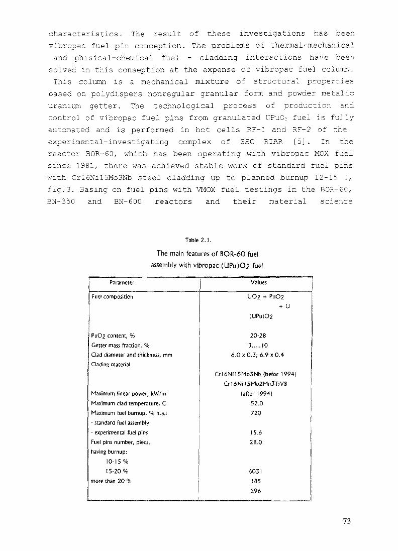
characteristics. The result of these investigations has beenvibropac fuel pin conception. The problems of thermal-mechanicaland phisical-chemical fuel - cladding interactions have been
solved in this conseption at the expense of vibropac fuel column.This column is a mechanical mixture of structural properties
based on poiydispers nonregular granular form and powder metalicuranium getter. The technological process of production andcontrol of vibropac fuel pins from granulated UPuO: fuel is fully-automated and is performed in hot cells RF-1 and RF-2 of theexperimental-investigating complex of SSC RIAR [5]. In thereactor BOR-60, which has been operating with vibropac MOX fuelsince 1981, there was achieved stable work of standard fuel pinswith Crl6Nil5Mo3Nb steel cladding up to planned burnup 12-15 i,fig.3. Basing on fuel pins with VMOX fuel testings in the BOR-60,BN-350 and BN-600 reactors and their material science
Table 2.!.
The main features of BOR-60 fuelassembly with vibropac (UPu)O2 fuel
Parameter Values
Fuel composition
PuO2 content, %Getter mass fraction, %Clad diameter and thickness, mmClading material
Maximum linear power, kW/mMaximum clad temperature, CMaximum fuel burnup, % h.a.:- standard fuel assembly- experimental fuel pinsFuel pins number, piecs,having burnup:
10-15%15-20%
more than 20 %
UO2 + PuO2+ U
(UPu)O2
20-283.....10
6.0x0.3; 6.9x0.4
Crl6Ni15Mo3Nb (befor 1994)Cr16Ni15Mo2Mn3TiVB
(after 1994)52.0720
15.628.0
6031185296
73

Table 2.2
Test Conditions in the BOR-60Vibropacked Fuel Elements withPromising Cladding Materials.
Cladding Material
Cr16Ni15Mo3NbB
Crl6Ni15Mo3NbB + C
Cr15NM6Mo23MnT-1VB
Cr20Ni45Mo23MnT-iVB
Cr20Ni45Mo4B + Y
Cr20Ni45Mo4NbBZr
CrI3Mo2NbVB
Crl5Ni16Mo-3MnTiNb
Numberof thepins
214
10
993
37
37
443
74
19
Heat ra-te,
kW/m
44
37
49
Tempe-rature
cladding,°C
Fluens,lo22Cm-2
610 24,3
660
710
37 660
40
48
46
45
1U
15,6
12,1i
690
690
670
680^
10,6
28,2
3,3
10,2
Burnup,% h.a.
21,6
9,9
- 16
9,9
12,9
-28
4,3
11,6
investigations there was created and varified the calculatedprogram "VICOND" to predict their serviceability.
In this report there are presented the main investigationresults for the progress of fuel pins with VMOX fuel program,referred to the super-high burnups achievement and substantialityof their seviceability in emergency conditions of reactoroperation.
1. Granulated Fuel Features
The polydispers granulate obtained in the result of cathodedeposite crushing after pyroelectrochemical reprocessing ofnuclear fuel in malten salts on the base of alkali metalchlorides [6]. The main granulate characterictics and itsoperating time are presented in tables 1.1 and 1.2 respectively.
74

To realize the investigation programs, including Puutilization, the experiments on obtaining granulate fuel withhigher power Pu content were also carried out:
- 3,5 kg with 40 % of Pu02 content (for testing in BOR-60reactor)/
- 0,2 kg with 56 % of Pu02 content (for technologicalinvestigations);
- C, 2 kg 70 % of Pu02 (for technological investigations).The quality of granulate with high Pu content practically
did not differ from the standard one.
2. The Desing of the Fuel Vibropac Oxide Fuel (VMOX)for Fast Reactor
The design of the fuel pin with VMOX fuel for fast reactoris presented on fig. 2.1, the main technological and operatingparameters of the BOR-60 reactor fuel pin are in table 2.1.The base design of the fuel pin with VMOX fuel includs side areasof the blanket consisting of depleted or natural U02 isotopecontent pellets and U or U-Pu oxide vibropac fuel core. As thefuel pin design allows the avaiability of the compensation
8
Dimensions, mmPos.
12345678
DesignationFuel columnLower blanketUpper blanketSupporting bushingHolderCladdingLower end plugUpper end plug
REACTOR
BOR-60
BN-350
BN-600
A
100
—
350
B
450
1060
950
C
150
400
350
D
1083
1790
2400
FIG. 2.1. The fast reactor fuel pin with vibropac [UPu}O2 fuel.
75

V
FIG 3 1 Microstructure of UPuO2 vibropacfuel with burnup 26% ofh.a.
76

volume in the fuel column is separated from the pellets of theclanket side area by gas-permeable element, preventing fromgranulate spill into the compensation volume when vibropacking.
Practically all the steels of different classes developeafor fast reacors have been tested as the experimental fuel pinscladding material (Table 2.1).
More than 27000 of fuel pins have been produced during thewhole period of accomplishing the complex program on fuel pinswitn VMOX fuel development (Table 2.3) .
3. The Main Results of Tests and Investigations of Fuel Pinswith VMOX Fuel
3.1. Fuel Pins Serviceability in Basic Conditions
The main factors influencing characteristics of fuel pinsserviceability when reactor operates in statianary conditionsare: fission gas products pressure, swelling fuel pressure andfuel - cladding chemical interaction as a result of format-tor,corrosive fission gas products and oxygen, disengaged at U and Pafission.
The analysis of fuel pins with vibropac MOX fuelserviceability has shown [7,9], that:
- the use of fuel composition with the addition of a getter- meralic uranium powder in the amount of 3-10 I mass allowedcompletely eliminated corrosion processes, induced by thepresence of fission products such as Cs, I and processingimpurities as Cl, F, CO.. This fact practically removes theburnup limit because of physical-chemical fuel-claddinginteraction. In none of the investigated fuel pin cross-sectionsup to 26 o burnup there were found any corrosion damage of thecladding inner surface, fig.3.1;
- the outlet of fission gas products from the oxide fuelunder cladding at standard operation conditions of fast reactorfuel pins averages 50-70 o and practically does not depend on thetype of fuel composition;
- the change of the fuel pin cladding diameter is induced ingeneral by swelling of structural material. The contribution ofinelastic deformation did not exceed 0,5 %. The change of the
77
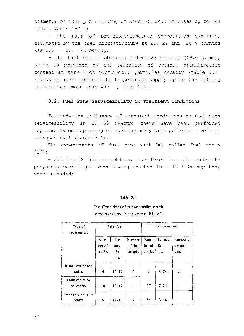
diameter of fuel pin cladding of steel Crl3Mo2 at doses up to 144a.p.a. was ~ 1-2 1;
the rare of pre-stoichiometric composition swelling,estimated by the fael microstructure at 21, 24 and 26 °0 burnupswas 0,6 +- C, 1 o/o burnup.
- the fuel column abnormal effective density (>9,0 g/cnr) ,/</n_ch is providea by the selection of optimal granulametriccontent at very hich pictometnc particles density (table 1.1,a_lcws to nave sufficiante temperature supply up to the meltingtemperature (more tnan 400 , (fig.3.2).
3.2. Fuel Pins Serviceability in Transient Conditions
To study the influence of transient conditions on fuel pinsserviceability in BOR-60 reactor there nave been performedexperiments on replacing of fuel assembly with pellets as well asvibropac fuel (table 3.1).
The experiments of fuel pins with U02 pellet fuel shown[10] :
- all the 18 fuel assemblies, transferee from the centre toperyphery were tight when having reached 10 - 12 ° burnup tneywere unloaded/-
Table 3.1Test Conditions of Subassemblies whichwere transfered in the core of BJR-60
Type ofthe transfere
In the limit of oneradius
From centre toperyphery
From peryphery tocentre
Pellet fuel
Num-ber of
the SA
4
18
4
Bur-
nup,%
h.a.
10-12
10-12
12-17
Numberof the
un-tight
2
3
Vibropac fuel
Num-ber oftheSA
9
23
31
Bur-nup,%h.a.
8-24
7-22
8-18
Number ofthe un-tight
2
-
78

2800
o 2600
Fuel density, g/cm
.F/G 3 2 Maximum fuel temperature versus the density of vibropac core and fuel elementlinear power
1 - q =35 kW/rn,
2 - qj = 50 kW/m,
3 - qi = 45 kW/m,
I——j- permissible range of the densitychange
79

"*•* 1•a 3s
0)H
0
a
15 0 15Distance from grain boundary, mem
FIG 3 3 Corrosion of the cladding (Cr20Ni45Mo4Nb):a - macrostructure, xlOO;b - distribution of Te.
80

- when one fuel assembly was transferee! from the fourth row~o tne sixth one and then back it remained tight;
- four fuel assemblies were transfered in tne limit of oneradius, where they were installed, two of them turned out to beuntignt;
- four fuel assemblies were transfered from periphery rowsto the centre and three of them turned out to be untight. Twofuel assemblies of this serie have been studied (Table 3.2).
The reasons of cladding untightness of these fuelassemblies, for which tne liner power excess was up to 36 > ofthe initial level were investigated.The investigations have shownthe availability of considerable intergrains corrosion with
great Te and also Cs content on the corroded grain boundaries,fig.3.3. This type of corrosion was observed on cross-sectionswith the maximum temperature of fuel pin core surface. Theuntightness of two fuel pins with vibropac fuel at 20 and 24 °burnup (one from each assembly) was not connected with the changeof power since it was detected two campaigns after fuel elementstransfer. As the material science investigation have shown theuntightness was caused by the exhaustion of cladding materialresource character istics due to its excessive radiation swellingar.a creep.
Parameters of 11 standard fuel assemblies with vibropacfuel, which were transfered from periphery to the central rowsare presented in table 3.3. The transferes in tne reactor corewitn the power increase up to 80 °c do not influence on thevibropac fuel pins serviceability. This fact testifies that thelowed temperature of the periphery layer does not allow tellurium
Table 3.2Tests Conditions Examinated
Subassemblies of theBOR-60 with Pellet UO2 Fuel
Numberof the
SA
A-613
fl-30
Cladding Material
Crl6Nil5Mo3NbB
Cr20Ni45Mo4Nb
Burnup, %h.a
12,6
16,9
Claddingtempera-
ture,
670
700
Heat rate,kW/m
37-46
31-49
81

Table 3.3
Tests Conditions of the Subassemblies with Vibropac Fuel, with weretransfered in the core of the BOR-60
' Num-ber oftheSA
Bur-
nup,%h.a.
Heatrate,kW/m
1-215 8,1 131i-220I A- 31
IA-44
, 1A-50
IA-52
13,012,812,011,5
11,9IA-53 j 12,1iA-55lA-56lA-57IA-59IA-60lA-65lA-66iA-71
1A-72IA-77
1 1,2
12,512,711,711,7
11,5
11,513,9
11,712,7
1 112 1 1169136170143
Changeof therow
6 -*• 1 60
6 ^ 2
5 - ^ 2
5 ^ 2
5 -» 1
6 ^ 31 76 ' 6 -> 1174 5 _ > |1721551541571831 13158118
6->2
5-* 15 -> 15 -> 1
5 -> 15 -» 1
5 -»26 ->4
Heat rate, kW/m
initi-al finish
202224264
333335475
3 1 1 480350 486312 ; 486279
288320289351350356332
422
464494461506504
513515
330 443354 512293 411
State ofSA
herm.herm.herm.herm.
herm.herm.herm.herm.herm.herm.herm.hermherm.herm.herm.herm.herm.
"to reach" cladding and the presence of the initial structure ofthis layer provides "soft" thermo-mechanical fuel column effecton cladding at transient conditions. The typical vibropac fuelstructure, perfect from the point of view of minimum thermo-mechanical effect on cladding, is presented in fig.3.4.
3.3. Serviceability of Fuel Pinsat Cladding Overheating
Two types of experiment have been perfomed: in-pile, whenthe claddings had high temperature and after irradiation - tostudy the reliability of pins at emergency over-heatings.
The main parameters of the experiments are presented intable 3.4.
The post-irradiation examinations of the cladding of fuelpins with pellet fuel from OP-25 assembly have shown matrix and
82

b)
I L0
"2 0.5
0
•* * !"!!"!•!••
!iii;i
ill
5 4
/ y\4xp
_ — -^. — ~_-̂ L.h•
111illwill
-1.0
0.5
0
2000
ue1500
IH
1000
5000
Radius of fuel pin, relunit
FIG. 3.4. Behaviour ofTc in (he vibropac (a) and pellet (b) fuel:1,4 - temperature and Te distribution in the basic regime;2,5 - temperature and Te distribution at 20 % power ramp;
3 - initial temperature of Te vaporization (990oC).
2000
P•t
1500 I
H1000
500
ooU)

Table 3.4
Tests Conditions of the BOR-60 Subassemblies under Ylgher Parameters
Numberof the SA
TT-25
TA-35
IA-73
TA-115
Materials
Fuel
UO2pellet
UPuO2
Cladding
Burnup,% h.a.
Heacrate,
Cladding | Postreactor tests con-temperatu- ditions
kW/m re,°C
Cr13Mo2NbVB 12,6 44,4 740
Crl6Ni15Mo3Nb 5,4 60,0 740
Iclad. —tmin
Depth ofthe cor-
rosion, mkm
1 200
'vibro \
UPuO2 Cr15Ni15Mo3Nb
vibro
UPuO2vibro
Cr13Mo2NbVP
7,0
21,0
40,1!
661 850 90
48,2 687 850 90
intergranular corrosion in the upper sections of the column part,caused by cesium and iodine interaction. A large amount oftellurium was also observed in the interaction products. Theresults obtained testify that high temperature of the cladding ofpellet fuel pin causing high temperature of the column peripheryzone influences greatly on the tellurium radial distribution andthus on its with cladding interaction. The irradiation of fuelpins with a vibropac UPu02 + U (10 % mass) fuel composition undervery hard conditions (Qi up to 60 kW/m, TclciC. = 740 °C) did notinvolve any chemical fuel-cladding interaction. The same resultwas obtained when fuel pins with vibropac UPu02+U fuel irradiatedin BOR-60 reactor up to 21 % burnup were heated up to 800-850°Cfor 1-1,5 hour not in reactor. At these testing conditions alsothere were not found any evidence of corrosion damage of theinner cladding surface.
3.4. Serviceability of Fuel Pins with HighPlutonium Content.
To study radiation aspects of plutonium utilisation therewas developed the granulate production technology and werefabricated experimental fuel pins with UPuO;+U fuel compositioncontaining 40°c of Pu. The fuel assembly was tested in the BOR-60
84

reactor up to 4,7 % burnup at maximum linear rate 46 kW/m andcladding temperature up to 650 °C [11] .
Plutonium isotope composition, % : 238; 239; 240; 241; 242 =0,5; 71; 19; 7,5; 2,0 , U-235 enrichment was 64,5.
Post-irradiation material science examinations showed thatthe radiation behaviour peculiarity of the fuel pin with ~ 40 IPu content is the increase of its concentration on periphery inthe central maximum liner rate part of the column. This becamethe reason of cladding frontal corrosion damidge 70mm depth insome fuel pins. There were not founded chemical fuel-claddinginteraction in the high-temperature part. Taking into account theimportance of this problem,additional testings and investigationson parameters optimisation and fuel column initialcharacteristics up to superhigh burnups are scheduled.
3.5. The BOR-60 Reactor Fuel Pins toStudy Superhigh Burnups
Successful tests of standard fuel pins with Crl6Nil5Mo3Nbsteel cladding and CrlSNilOTi steel wrapper tube up to 151 h.a.burnup, solution of the thermal-mechanical and physical-chemicalvibropac fuel pin core-cladding interaction allowed to begin zorealise qualitatively new stage - the study of the limit burnup
Table 3.5.
Program to Achieve Super High Burnups and DamageDoses in the BOR-60
No
1
3
2
3
- M ————— -1 -•• -• — • —Material
Fuel pin cladding
Cr13Mo2NbVB
Cr13Mo2NbVB
Cr16Ni15Mo3VBc.w.Cr13Mo2NbVB
FA Wrapper
Cr13Mo2N-
bVB
Cr13Mo2N-bVB
Number
of fuelpins
185
74
6*
— ..,_., —— _-., . ——— ———————————————
Burnup(forecast), % h.a.
1995
2 : 3
19. ..24
26
28 (155
dpa)
4
1
29...31
1996
1 2
24.. .29
33
3 4
35 (190
dpa)
* Refabricated fuel pins having the burnup from 21 to 26 % of h.a. in dismountable FAs
85

FIG 3 5 Macrostructure of the central cross-section of the BN-600 fuel pin (x25)
and dose characteristics of fuel pins and structural materials.The program of experiments on the base of standard design as wellas on the base of the BOR-60 reactor dismountable fuel assemblywas developed for this purpose. The program provides testings ofstandard fuel assemblies with promissing structural materials andadditional irradiation of refabricated fuel pins in adismountable assembly (Table 3.5).
The results of cladding materials swelling (see Fig.l)illustrate the best size stability of ferrito-martensite steels,
86

PFR (21.7%)Rapsodia (21%)
1980 1984 1988 1992 1996 2000YearsFIG. 3.6. Burnup achievements in UPuO2fuel in fast breeder reactors.
Crl3Mo2NbVB Russian steel in particular. That is why the mainemphasis was given to ferrito-martensite steels, despide the factof their ralatively low heat-resistance in the experiments onachieving super-high burnups of vibropac oxide fuel. Data are asof May,1995 when there was achieved the world record burnup 28%on the experimental fuel pins with Crl3Mo2NbVB steel cladding inthe reactor BOR-60, (Fig. 3.5). The tests of these fuel pins arecontinued.
The post-irradiation examination of the BOR-60 reactor fuelpin claddings with 21.0; 24.4 and 26.Oo burnup fully confirmedthe technical solutions of the design and promissing estimationsof their serviceability, carried out by "VICOND" program. In noneof the investigated cross-sections there were found anyindications of the fuel-cladding chemical interaction. Typicalmacrostructures of the irradiated vibropacked fuel column at
87

FIG. 3.7. Macrostructure of the vibropac fuel column
a) initialc) 21% burnupe) 24% burnup, upper A. C.
b) 12% burnupd) 24% burnup, center A. C.f) 26% burnup, center A. C.
88

239Pu+241Pu240Pu+242Pu
3.1
3.0
2.9
2.8
2.7
2.6
2.5
2.4
2.3
2.2
2.1
2.050 100 150 200 250
B, kg/t (U+Pu)
FIG. 3.8. Dependence of ratio even and odd Pu isotopes change vs burnup.
103r
2Pu
0 200100 150B, kg/t (U+Pu)
FIG. 3.9. Content of the Pu isotopes as a function of burnup.
250
89

1 0 _ _ _ _ _ _ _ —————————— ___. ______ ,., 2.41,Am
ffu
OD_*
u
i n-i10
10" _-IL
lO'30 50 100 150 200 250
B, kg/t (U+Pu)
FIG. 3.10. Content of MA as a function ofburnup.
different burnup are shown in Fig.3.6. The analysis of stressed-strained state of the fuel pin claddings of fuel assemblies withmore than 20% burnup, estimation of their mechanicalcharacteristics have given possibility to plan furtherexperiments on fuel pins of this very design for achieving morehigh burnups. The radiochemical analysis of the UPu02 fuelisotope composition, irradiated up to 21.0° h.a. burnup allowednot only to precise the calculated values of the fuel burnup, butto estimate kinetics of content changes of the main isotopespresented in Fig. 3.7 - 3.9. In Fig. 3.7 there is seen a cleartendency for decreasing even and odd Pu isotopes correlation duero burnup in the BOR-60 reactor spectrum and for increasingcurium isotopes consentration. All these data in combination withthe next radiochemical investigations of fuel isotope contentwith 26% burnup, which are carried out now will allow to precise
90

the programs for calculation the mlnor-actinides transmutation inthe BOR-60 reactor spectrum.
CONCLUSIONLarge-scale testing of the BOR-60 reactor fuel pins with
vibropac uranium-plutonium oxide fuel confirmed high operationcharacteristics of these fuel pins in standard and transientconditions, as well as in experiments with cladding overheating.The addition of a getter - metallic uranium powder to the fuelcomposition allowed to suppress completely physical-chemicalfuel-cladding interaction and eliminate the burnup due to thisfactor.
Considering the shown advantages and successful tests of fuelpins with vibropac MOX fuel and Crl3Mo2NbVB steel claddings inthe BOR-60 reactor up to 281 burnup there are planned tests ofsimilar fuel pins with UPu02 + U fuel in the BN-600 reactor.
REFERENCES
1. R.D.Legget, L.C.Walters "Status of LMR fuel development in the United States ofAmerica" j.Nucl.Mat., 204(1993) 23-32.
2. MKatsuragawa, H.Kashihara, M.Akebi "Status of liqiud metal fast breeder reactor fueldevelopment in japan" J.Nucl.Mat., 204( 1993) 14-22.
3. R.B.Baker et al "Status of fuel blanket and absorber testing in the fast flux test factility"J.Nucl.Mat., 204( 1993) 109-118.
4. CBrown, A.Languille, G.Muchling "Status of LMR fuel development in Europe"J.Nucl.Mat., 204(1993) 33-38.
5. O.V.Skiba, A.A.Mayorshin et al "Development and Operation Experience of the PilotPlant for Fuel Pin and Subassembly Production Based on Vibropac Uranium-PlutoniumFuel"
/Proc.lnt.Conference on Fast Reactors and Related Fuel Cycles,October 28-November 1, 1991, Kyoto, japan, N2, R15-4.
91

6. O.V.Skiba, Yu.P.Savochkin et al "Technology of Pyroelectrochimica! Reprocessing andProduction of Nuclear fuel"/ Proc.lnt.Confemce on Future Nuclear Systems: Emerging FuelCycles and Waste Disposal Options Global - 93, September 12-17, 1993, Seatle,
WA. ANS 1993, r.z.p. 1344-1350.
7. R.Herbig, O.V.Skiba, A.A.Mayorshin et al "Vibrocompacted Fuel for the Siquid MetalReactor BOR-60" J.Nucl.Mat. 204(1993) 93-104.
8. A.A.Mayorshin, A.A.Petukhov et al "Development af Vibropac Oxide Fuel Elementfor Fast Reactor"/ Int.Conference Global-93. Seatle, USA, September 12-17, 1993.
9. A.A.Mayorschin, V.A.Tzykanov et al. "The Features of Radiation Behavior of FuelElements with Vibropac MOX Fuel", Proc.lnt. Conference, Alushta, May 22-25, 1990,v.4, pp. 90-97.
10. V.K.Shamardin, F.N.Kryukov at al. "Effect of Tellur on Corrosion of Fuel Pin Clads forFast Breeder Reactor" Preprint, RIAR-8(791), Dimitrovgrad, 1990.
11. A.A.Mayorshin, O.V.Skiba et al "Production and irradiation of UPuO2 fuel with 40%of Pu in BOR-60. Vibrotechnology application for utilization of Plutonium and MinorActinides"/ Int. CAPRA Seminar, Karlsruhe, September 21-22,1994.
92

ASSEMBLIES AND FUEL PIN BEHAVIOUR UNDER XA9848043IRRADIATION IN FBR BN-350
V.N. KARAULOV, A.P. BLYNSKI,I.L. YAKOVLEV, E.V. KONONOVAMangyshlak Atomic Energy Complex, Aktau,Kazakhstan
Abstract
The efficiency of all types of assemblies and fuel pins of the reactor BN-350 is in detailconsidered. The factors limiting the efficiency are indicated. The behaviour of assemblies withstainless steels ducts is studied. It is shown that the efficiency is restricted in this case by shapeand dimensional changes of hexagonal ducts due to radiation swelling and radiation creep ofstructural materials. The problem of dimensional changes of ducts was solved for cores of reactorsBN-350 and BN-600 after testing in BN-350 of experimental assemblies with ducts made offerritic-martensitic steel 12Crl3Mo2NbVB.
For fuel pins of the second type of loading with clad made of stainless steelOCrl6Nil5Mo3Nb the efficiency is limited by bumup of 13% h.a. and damage dose of 90 dpa.
To increase the burnup the core of the BN-350 is supplied by assemblies of modernizedtype with pins having a large gas plenum and clad made of the stainless steelOCrl6Nil5Mo2Mn2TiVB that has a good resistance to irradiation.
The efficiency of fuel pins of modernized assemblies in the reactor BN-350 core conditionsis provided up to 15% h.a. and damage dose 105 dpa.
1. INTRODUCTION
The liquid metal cooled reactor BN-350 is located on West of Kazakstan and morethan 20 years is successfully operated since 1973. The reliable and safe operation ofreactor is in many respects obliged not only to knowledge of behaviour of elements of thecore (assemblies, fuel pins, control rods, guided tubes), development of criteria of theirserviceability in the core, but also to development and introduction in practice ofappropriate methods and means of the control and researches. Under serviceability in thiscase is understood:
- Absence of melting of fuel;
Existing of assemblies, pins, control rods and guided tubes deformations, notinterfering to normal heat release by work in the core and not leading to someproblems at realization of handling operations;
- Preservation of integrity and continuity of structural elements.
A circle of the phenomena, responsible for serviceability of elements of the core offast reactor is rather well established at present:
- Radiation change of shape of elements because of radiation swelling and radiationcreep of materials;
Swelling and gas release in fuel and absorbing compositions;
93
- Hardening and brittleness of structure materials under irradiation;
- Corrosion affection of pins cladding by fission products on the part of nuclear fuel.
Study of these phenomena in conditions of reactor BN-350, the establishment ofcriteria of serviceability is urgent and has practical and scientific interest. Thecharacteristics of fuel assemblies of reactor BN-350 is submitted in Table 1.
2. METHODS AND MEANS OF RESEARCH OF SERVICEABILITY
On reactor a complex of hot cells equipped for dismantling techniques and devicesfor research of serviceability of assemblies, control rods and guiding tubes by non-destructive and destructive methods is introduced. The application was found by thefollowing methods:
Visual and measuring control (profilometry and wall thickness measurement);
- Radiography of spent elements of the core with the help of betatron;
- Gamma-spectrometry of pins;
- Control of electroresistance of cladding;
- Control of tightness of pins cladding on availability of gaseous fission products, forexample Kr-85;
- Definition of a location of defects in cladding;
- Measurement of density of steel on samples by a hydrostatic method.
The destructive tests are carried out on samples, cut out of irradiated elements, byuniversal test machine with maximum load up to 10 tons in temperature range (20-1000)°C. The machine does the following kinds of tests: tensile - compression, bend, low cyclefatigue and short-term creep.
At service life tests of assemblies in reactor are used in-pile systems, enabling toreceive the primary information on condition of assemblies: failed fuel detection system,including gaseous fission products monitoring system and delayed neutrons monitoringsystem. Measurement of elongation of assemblies depended on radiation swelling iscarried out with the help of the charge gear, enabling to conduct readout with accuracy ±1,5 mm. After discharge from the reactor elongation of assemblies is measured in the hotcell with accuracy ±0,1 mm. Measurement of a force extraction of assemblies is carriedout by system, mounted on the charge machine.
3. FUEL ASSEMBLIES BEHAVIOUR
As already was marked the primary information on behaviour of assemblies hasbeen received directly in reactor on data of location of the charge machine during load-discharge works (relative to registration point). Hereinafter this information was specifiedand supplemented by measurements of elongation of assemblies in the hot cell. Such datafor assemblies with wrappers made of steels 12-18Cr-10Ni-Ti annealed, 08-16Cr-llNi-
94

32
=24-J
• 12-13Cr-2Mo-N>V-B•08-16Cr-llN-3Moc.w.• 08-I6G-1 lM-3Mo annealed
12-18Cr-10M-Ti annealed• 10-17Cr-13M-2Mo-Ti c.w.
!c
4
0
x .' X/
0 25 50 75
Damage dose, dpa
Rg.l. BN-350 assemblies elongation due to swelling of hexagonal ducts
3Mo annealed, 08-16Cr-llNi-3Mo c.w., 10-17Cr-13Ni-2Mo-Ti c.w., 12-13Cr-2Mo-Nb-V-B and 05-12Cr-2Ni-Mo are submitted in Fig. 1.
From submitted data increase of resistance of ducts of assemblies to radiation iswell visible for ferritic-martensitic steels in comparison with austenitic steels.Serviceability of assemblies on elongation is determined by an ability of loading gears ofreactor BN-350 and is limited by size of 25 mm. Practical application of knowledge onelongation of assemblies has been found on reactor by work with swelling ducts, whenelongation of assemblies is perceived by the operator of reactor by its installation in cellof the core as a non-placing. And if "non-placing" of assembly is in consent withswelling, was accepted, that the assembly in cell of the core is normal installed, thatexcluded operation of jacking down force applying. The researches on radiationdeformation of ducts of assemblies on reactor are carried out since December 1974, whenon ducts made of stainless steel 12-18Cr-10Ni-Ti annealed was for the first time foundout ovalization of sides because of radiation creep of material. In accordance withincrease of capacity of reactor the contribution in radiation deformation of assembliesducts has become greater due to radiation swelling. Non-uniform swelling of sidesresulted in bends and twisting of ducts. For 08-16Cr-llNi-3Mo steel ducts a sag achieved~ (15 ± 1) mm, and twist -1°. The most important phenomenon which has determined aserviceability of austenitic steels ducts has become dimensions changing. Typicalcharacter of such changing is submitted in Fig. 2. The danger of size changing and bendsresides in a jam of assemblies in the core after taking up a technological gap and becauseof occurrence of contact forces. The exception of jam was conducted on criterion ofallowable shape changing. In this case for the core of BN-350 it is recommended toorganize the program of charging so that total change of the size of next assemblies donot exceed size, equal to two technological gaps, i.e.:
AS + A S ' < 2 A (1)
where
A = 2 MM is the size of a technological gap for the core of BN-350.
95

a)
b)
Creep
Swelling
Core center
Fig.2. Ducts size changes:a - transversal; b - longitudinal
96
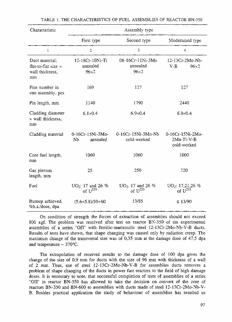
TABLE 1. THE CHARACTERISTICS OF FUEL ASSEMBLIES OF REACTOR BN-350
Characteristic
1
Duct material;flat-to-flat size xwall thickness,mm
First type
2
12-18Cr-lONi-Tiannealed
96x2
Assembly type
Second type
3
08-16Cr-llNi-3Moannealed
96x2
Modernized type
4
12-13Cr-2Mo-Nb-V-B 96x2
Pins number inone assembly, pcs
Pin length, mm
Cladding diameterx wall thickness,mm
Cladding material
Core fuel length,mm
Gas plenumlength, mm
Fuel
Burnup achieved,%h.a./dose, dpa
169
1140
6.1x0.4
0-l6Cr-15Ni-3Mo-Nb annealed
1060
25
UO2: 17 and 26 %of U235
(5.6-5.8)750-60
127
1790
6.9x0.4
127
2440
6.9x0.4
0-l6Cr-15Ni-3Mo-Nb 0-16Cr-15Ni-2Mo-cold-worked 2Mn-Ti-V-B
cold-worked
1060
250
UO2; 17 and 26 %•235
1000
720
UO2: 17,21,26 %o f U
13/85
235of U
< 13/90
On condition of strength the forces of extraction of assemblies should not exceed800 Kgf. The problem was resolved after test on reactor BN-350 of six experimentalassemblies of a series "Oil" with ferritic-martensitic steel 12-13Cr-2Mo-Nb-V-B ducts.Results of tests have shown, that shape changing was caused only by radiation creep. Themaximum change of the transversal size was of 0,35 mm at the damage dose of 47,5 dpaand temperature ~ 370°C.
The extrapolation of received results to the damage dose of 100 dpa gives thechange of the size of 0,9 mm for ducts with the size of 96 mm with thickness of a wallof 2 mm. Thus, use of steel 12-13Cr-2Mo-Nb-V-B for assemblies ducts removes aproblem of shape changing of the ducts in power fast reactors to the field of high damagedoses. It is necessary to note, that successful completion of tests of assemblies of a series"OH" in reactor BN-350 has allowed to take the decision on convert of the core ofreactors BN-350 and BN-600 to assemblies with ducts made of steel 12-13Cr-2Mo-Nb-V-B. Besides practical application the study of behaviour of assemblies has resulted us
97

together with IPPE (Obninsk, Russia) in development of methods and means ofinvestigation of radiation creep and swelling of steels depending on data of shape changeof ducts of assemblies. It was shown, that the general change of the size is equal tochange of the cross size on account of radiation swelling and bends of opposite sides onaccount of radiation creep under pressure of the coolant. Was proved, that the bends ofsides are proportional to a damage dose and load from pressure of the coolant. It hasallowed with use of the decision of a task of creep of a side of the duct, to do anestimation of the module of radiation creep for number of steels. Such data are shown inTable 2. Weak dependence of the radiation creep module from temperature in investigatedtemperature intervals is marked.
TABLE 2. THE MODULE OF RADIATION CREEP FOR SOME STEELS
Duct material
1
12-18Cr-10Ni-Ti, annealed
08-16Cr-llNi-3Mo, annealed
08-16Cr-llNi-3Mo, cold-worked
12-13Cr-2Mo-Nb-V-B
05-12Cr-2Ni-Mo
10-17Cr-13Ni-2Mo-Mn, cold-worked
B-106,[MPa-dpa]'1
2
1-^7
1.24-3.5
1.24-2.5
0.4±0.06
0.84-1.2
2.34-4.0
Temperature,°C
3
290-530
290-570
290-510
290-540
290-540
290-550
ktmax,dpa
4
56
60
60
90
70
81
Is shown, that swelling of austenitic stainless steels can be rather reliably describedby dependence of a kind:
AV - A(kt-t)mch- 4---}IT T Jv
Where
AV is the volumetric swelling of a material (%),V
kt is the neutron damage dose (dpa),
T is the incubation dose (dpa),
A,B are the constants,
T is the irradiation temperature (K),
Tm is the maximum temperature of peak swelling (K),
m is the power index.
98
(2)

In particular, for the steels 12-18Cr-10Ni-Ti annealed and 08-16Cr-llNi3Moannealed are ascertained the exponent laws of dependence of swelling from irradiationdose with power indexes of 2,0 ± 0,2 and 2,4 ± 0,4 accordingly. For these steels is foundout one peak of swelling with temperature maximum of 743 K for steel 12-18Cr-10Ni-Tiand 723 K for steel 08-16Cr-llNi3Mo. For cold worked steels is found, that independence (2) m is equal to 1.
4. The pins behaviour
The linear thermal rate in fuel pins of the reactor BN-350, as a rule, did not exceed450 W/cm, temperature of cladding did not exceed 700°C.
Under these conditions the nuclear fuel UO2 behaves by an usual image:
- In fuel three-zoned structure is formed;
- Swelling of fuel makes (1,0-^1,5) % on I % burnup;
- At density of fission ~ 1013 cm"3-s, typical for BN-350, the fuel is subjected toradiation creep.
The radiography of pins reached burnup of ~ 13 % h.a. (assembly II-8) hasconfirmed preservation of the form of fuel pellets and absence of melting. As have shownestimations, a tense condition of cladding is defined by the following factors:
- pressure of gas fission products (GFP);
- fuel-cladding interaction (FCI);
- bundle-duct interaction (BDI);
- thinning of cladding because of corrosion affection by fission products.
For pins of the first and second types a determining stress is a stress by pressure ofGFP.
For pins of a modernized type the account of a pressure from BDI and FCI isnecessary. Experimental data on GFP pressure for pins of the reactor BN-350 aresubmitted in Fig. 3. The drop of GFP pressure at transition from pins of the first typewith a small gas plenum to pins with a large gas plenum is well noticeable.
Typical character of radiation shape change of the pins of BN-350 (assembly II-17with pins of the second type) is submitted in Figs. 4 and 5. The ovalization of claddingreaches (0,4-0,5) mm and is the result of mechanical interaction between bundle and ductdue to radiation creep of cladding (austenitic stainless steel (0-16Cr-15Ni-3Mo-Nb coldworked) under action of contact forces. The degree of ovalization from the acting factorscan be calculated under formula:
D'-D-=1J-B(T).(k,-^-| (3)
99

Where
Pk
B(T)
(kt - t)
D
6
b= 1.
is the ovalization,
is the contact force (MPa),
is the radiation creep module (MPaxdpa)" ,
is the dose (dpa),
is the diameter (m),
is the cladding thickness (m),
The f irst t j p cThe second t y p e
~ The m o d e r n i s e d t y p e
s-<?*•
/ s
10B u r n u p P, % h .a .
Fig.3. Gas fission products pressure under cladding for different types of pins of BN-350
100
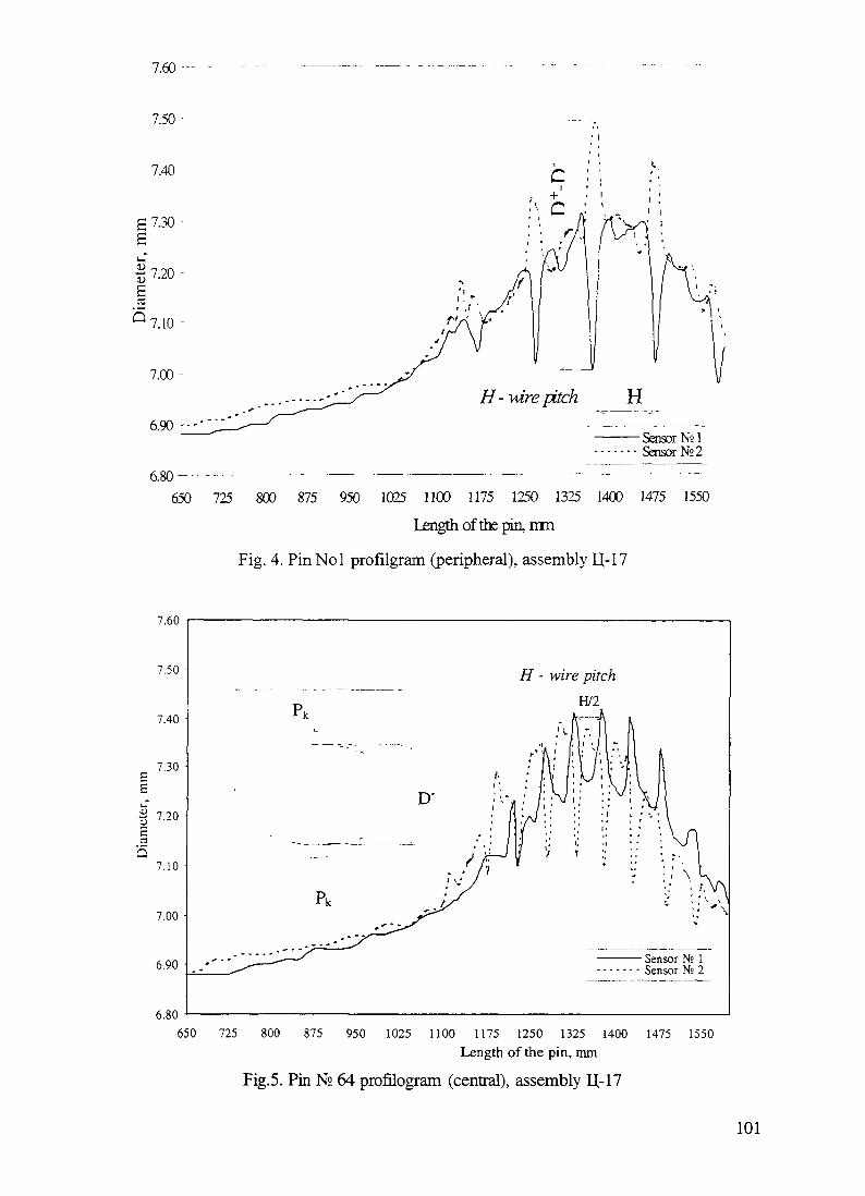
7.60 •-—
7.50
7.40
P7.30-£
1 7-20 -£»\>
5 7.10-
7.00-
6.90 --
6.80 - -650
Sensor N21Sensor N° 2
725 800 875 950 1025 1100 1175 1250 1325 1400 1475 1550
Length of the pin, mm
Fig. 4. PinNol profilgram (peripheral), assembly IJ-17
7.60
7.50
6.80650 725 800 875 950 1025 1100 1175 1250 1325 1400 1475 1550
Length of the pin, mm
Fig.5. Pin N° 64 profilogram (central), assembly IJ-17
101
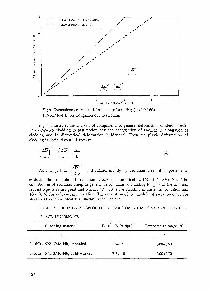
0-16Cr-15Ni-3Mo-Nb annealed
- - - - 0-16Cr-15Ni-3Mo-Nb c.w.
0 1 2 3 4 5Pins elongation A ///, %
Fig.6. Dependence of mean deformation of cladding (steel 0-16Cr-15Ni-3Mo-Nb) on elongation due to swelling
Fig. 6 illustrates the analysis of components of general deformation of steel 0-16Cr-15Ni-3Mo-Nb cladding in assumption, that the contribution of swelling in elongation ofcladding and in diametrical deformation is identical. Then the plastic deformation ofcladding is defined as a difference:
AD) ALD
(4)
Assuming, that —— is stipulated mainly by radiation creep it is possible to
evaluate the module of radiation creep of the steel 0-16Cr-15Ni-3Mo-Nb. Thecontribution of radiation creep to general deformation of cladding for pins of the first andsecond type is rather great and reaches 40 - 50 % for cladding in austenitic condition and10 - 20 % for cold-worked cladding. The estimation of the module of radiation creep forsteel 0-16Cr-15Ni-3Mo-Nb is shown in the Table 3.
TABLE 3. THE ESTIMATION OF THE MODULE OF RADIATION CREEP FOR STEEL
0-16CR-15NI-3MO-NB
Cladding material
1
B-106, [MPa-dpa]-1
2
Temperature range, °C
3
0-16Cr-15Ni-3Mo-Nb, annealed
0-16Cr-15Ni-3Mo-Nb, cold-worked
7-5-12
2.5-54.0
300-550
300-550
102

As already was specified above, for cladding of pins of the first and second typesmade of 0-16Cr-15Ni-3Mo-Nb the principal stress is the stress of GFP pressure.
Level of stress reaches in pins at the end of work the value of (100 - 120) MPa. Asshow experimental data of profilometry of the cladding of pins of the second typedeformation reaches values of ~ 6 - 14 % (assembly OFI-4) for cladding of steel 0-1 6Cr-15Ni-3Mo-Nb annealed and 7 % for cladding of steel 0-16Cr-15Ni-3Mo-Nb c.w.(assembly U-17). Thus in indicated assemblies a destruction of cladding was notobserved. In too time as have shown mechanical tests of a material of cladding aplasticity of steel is close to zero in places with maximum of shape and dimensionschanges. It testifies to exhaustion of life time of pins of the second type with claddingmade of steel 0-16Cr-15Ni-3Mo-Nb c.w. by reaching them of 13 % h.a of burnup anddamage dose ~ 90 dpa. The analysis of serviceability of pins of the second type oncriterion of creep rapture strength also confirms exhaustion of serviceability of claddingof steel 0-16Cr-15Ni-3Mo-Nb c.w. by dose 90 dpa and burnup -13 % h.a.
Now the core of the reactor is converted to assemblies of a modernized type withincreased gas plenum and low pressure of GFP. Moreover for cladding of pins the steel0-16Cr-15Ni-2Mo-2Mn-Ti-V-B c.w. with higher resistance to irradiation is applied. Allthis permits to hope to have in reactor BN-350 burnup- 15 % h.a. (dose ~ 105 dpa).
For the assembly of the reactor BN-350 with 0-16Cr-15Ni-3Mo-Nb steel claddingtook place cases of reaching by fuel pins of a limiting condition on serviceability: 5,8 %h.a. for cladding of fuel pins of the first type and by 13 % h.a. for cladding of fuel pinsof the second type.
As show settlement estimations of stress in cladding, basic contribution to an intensecondition of cladding of fuel pins both first, and second type gives a pressure from gasfission products and consequently it is possible to assume, that the law of change ofpressure from a burnup will be close to linear since pressure of fission gas release undercladding accrues under the linear law.
In this case the stress divided by burnup during work of fuel pins will be practicallyat the same level. Then if to put, that the time of work of fuel pins in a reactor coincideswith time of reaching by them of a limiting condition, construction of parametricaldependence of creep rapture strength of cladding of fuel pins is possible, namely:
Ig - LMP (5)
Where
is the stress normalized on a burnup (MPa/% h.a.),
LMP is the Larson-Miller parameter = T (13,5+lg tr),
T is the maximum temperature of cladding (K),
Tr is the time before destruction (hours).
Such dependence for cladding of fuel pins for steel 0-16Cr-15Ni-3Mo-Nb issubmitted in fig. 7. The time before destruction can be designed under the formula:
103

4,24-t, =
2.03-1Q-4T-13,5 (6)
Presence of the given dependence for cladding of fuel pins of a reactor BN-350testifies that a major factor of going out of fuel pins BN-350 is exhaustion of creeprapture strength of cladding (steel 0-16Cr-15Ni-3Mo-Nb) under irradiation.
1 3
1 2
1 1
1
0 9
.2 08^£ 07
S. 0655.^ 05
0 4
03
02
0 1 |
0
so
n Assembly A-89, T (reactor BOR-60)
- Stress by GFP with corrosion account----- "Soft bundle"- — - — Stress bv GFP with BDI
1 4 1 5 1 6 1 7LMP-1CT4
Fig.7. Creep rapture strength of BN-350 pins cladding (steel 0-16Cr-15Ni-3Mo-Nb)
The received dependence allows to estimate time before destruction of cladding offuel pins in reactor and is used at an estimation of serviceability of fuel pins of thesecond type (steel 0-16Cr-15Ni-3Mo-Nb).
5. Conclusion
5.1. The reliable and safe work of reactor BN-350 was provided on extent morethan 20 years by study of behaviour of assemblies and pins under irradiation. For that atthe reactor has been built a complex of hot cells with appropriate methods and means ofresearch of serviceability of assemblies.
5.2. Behaviour of assemblies with cladding made of number of austenitic steels isinvestigated. Is shown, that in this case serviceability of assemblies is limited by radiationchanges of shape and dimensions of hexagonal ducts because of swelling and radiationcreep of constructional materials. The problem of radiation changes of shape anddimensions was resolved for cores of reactors BN-350 and BN-600 after testing onreactor BN-350 of experimental assemblies with cladding of ferritic-martensitic steel 12-13Cr-2Mo-Nb-V-B.
104

5.3. Serviceability of pins of reactor is limited by:
- Pressure of GFP of fuel,
- Interaction of fuel with cladding,
- Mechanical interaction of bundle with duct,
- Corrosion affecting by GFP of fuel.
For pins of the second type with steel 0-16Cr-15Ni-3Mo-Nb c.w. cladding of theserviceability is exhausted by burnup 13 % h.a. and damage dose 90 dpa.
5.4. For increasing of burnup the reactor BN-350 is converted to assemblies ofmodernized type with large gas plenum and cladding made of a new steel 0-16Cr-15Ni-2Mo-2Mn-Ti-V-B c.w. with higher resistance to irradiation.
It is expected that the serviceability of pins of modernized type will be provided upto 15% h.a (dose 105 dpa).
5.5. Analysis of serviceability of fuel pins of a reactor BN-350 allows to make aconclusion that the main cause of going out of fuel pins is reaching of cladding (steel 0-16Cr-15Ni-3Mo-Nb) creep rapture strength under irradiation.
REFERENCES[1]. V.N.KARAULOV, T.G.SHKOL'NIK. "Study of swelling and radiation creep of
constructional materials of ducts of the reactor BN -350 by results of their deformation."Radiation material study. V.8, (Transactions of International conference on radiationmaterial study, Alushta, on May 22-25, 1990) Har'kov (1991) 132-143.
[2]. V.N.KARAULOV et al. "Development of radiation stable corrosion-proof steelsfor ducts of subassemblies of fast reactors." Radiation material study. (Transactions ofInternational conference on radiation material study, Alushta, on May 22-25, 1990) V.3,Har'kov (1990) 43-48.
[3]. V.N.KARAULOV. "Behaviour of cladding of fuel pins of fast reactor BN -350in conditions of mechanical interaction of fuel pins bundle with duct of subassembly."Researches of constructional materials of elements of cores of fast sodium reactors:[Transactions of scientific works]. Ekaterinburg. (1994) 177-188.
[4]. L.M.ZABUD'KO, JU.I.LIHACHEV, A.A.PROSHKIN. "Serviceability of asubassembly of fast reactors." M., Energoatomizdat, (1988) 168 pp.
[5]. I.S.GOLOVNIN, L.M.ZABUD'KO, V.N.KARAULOV et al. "The analysis ofdata on deformation of subassemblies of a reactor BN-600." Safety and reliability ofoperation of atomic power stations with fast reactors. Part II, Sverdlovsk, (1986) 25-80.
[6]. V.S.NEUSTROEV, V.N.GOLOVANOV, V.K.SHAMARDIN. "Radiationembrittlement of materials of subassemblies in a temperature interval of a maximum of aswelling." Atomic energy, V.69, Ser.4, October 1990, p.223-226.
[7]. A.A.PROSHKIN et al. "The analysis of experimental data about change of theform of subassemblies of fast reactors." Atomic energy, V.50, Ser.l, January 1981, p. 13-17.
105

IN-PILE TESTS AND POST-REACTOR INVESTIGATIONS OfFUEL PINS WITH U-Pu FUEL
I IHII I I I I I -L.I. MOSEEV, A.N. VOROBYEV, L.M. ZABUDKO, XA9848044B.S. KIRYANOV, S.I. POROLLO, S.V. SHULEPINState Scientific Center, Institute of Physics and Power Engineering,Obninsk
S.A. ANTIPOV, T.S. MENSHIKOVAInstitute of Inorganic Materials, Moscow
Russian Federation
Abstract
Resulting of testing experimental fuel subassemblies with oxide uranium-plutonium fuel and data of fuel pininvestigations at the IPPE hot laboratory have been presented. MOX and UOX fuels behaviour under irradiationare compared.
1. INTRODUCTION
The present-day concepts of fast neutron power reactors include the use of U-Pu oxide fuelas a fissile material. Radiation stability of MOX fuel widely used in the Western countries withup to 20% content of plutonium has been studied well enough, including the fuel compatibilitywith cladding materials, problems of reprocessing, etc. The use of fast reactors as facilities forutilization of weapons-grade plutonium suggests a changeover to fuel with a higher content ofPu (40% and more) and requires an additional information on radiation behavior of fuel of thiskind. Obviously, post-radiation investigations of MOX fuel still remain actual. Reactors BN-600 and BN-350 operated in Russia and Kazakhstan are fueled with UO2 pellets as a standardfuel. However, to substantiate the serviceability of subassemblies of BN-800 supposed to befueled with MOX, a series of experimental subassemblies with U-Pu oxide pellet fuel fabricatedby various technologies was irradiated in reactors BOR-60, BN-350, and BN-600. Thesubassemblies were subjected to non-destructive analysis (NDA) in hot cells of reactors BN-350and BN-600 and at the hot laboratory of NIIAR1 after irradiation to various burn-up levels anddamaging doses. Some of the fuel pins were sent to the IPPE hot laboratory for detailedmaterial studies.
The following issues were studied at the IPPE hot cell laboratory:• release of gas and volatile fission products from the nuclear fuel under the fuel pin claddings,
and effect of factors such as fuel fabrication technology (UnPum)Ox, burn-up, temperature,and the O\M ratio on this release;
• redistribution of plutonium, fission products, and oxygen along the fuel column radius andheight, as dependent on the burn-up and initial structure of pellets;
• interaction of chemically active fission products and nuclear fuel with the fuel pin claddingmaterials, and effect of various factors on the interaction: temperature, oxygen coefficient,steel composition and its state;
• change of homogenicity of solid solution of (UnPum)Ox in the course of irradiation;The report presents principle results of these investigations.
1 R&D Institute of Nuclear Reactors, Dimitrovgrad
107

TABLE 1 DESIGHN AND IRRADIATION PARAMETERS OF FUEL PINS
S/A parametersReactor,
S/ANo
BN-3502
BN-3504
BN-3509
BN-350C-ll
BOR-60NIM-1
BOR-60NTM2
BOR-60PG
BOR-60PKG
BOR-60PKK
BOR-60PKG
U/Puratio
079/0 2 10697031079/021
08/02
08/02
08/02
085/0 1508/02
08/02
08/02
069/031
Cladding material
Crl5Nil6Mo3NbAustemzation
Crl5V16Mo3NbAustemzation
Crl5Nil6Mo3NbAusteruzation
Crl5Nil6Mo3NbBCold Work
PE-16
PE-16
Crl5Nil6Mo3NbAustemzation
Crl5Nil6Mo3NbCold Work
Crl5Nil6Mo3NbBCold Work
Crl5Nil6Mo3NbAustemzation
Technological parametersTechno-log> offuel
Mix
Chem coprecip
Mix
Mix
Mix
Mix
Mix
MixPlazmo-chemMix
Mixzol-gelMix
Densityg/cm3
102
102
104105106104104102
102
102
10410410 1
103103100-1025
O/M
200
200
1 981 99198197197197
201
201
197200199
1991 99199-201
Irradiation parametersBurnup%ha
495
495
490490490495495970
12 10
12 10
12601260740
1080108074
QikW/
m37
35-42424242454549
42
44
494950
444449
1 max' 1 nun(°C)for
cladding479/360
579/447
450/380560/380600/380580/350490/350580/340
640/360
708/360
470/370590/370
565/340
648/380470/380697/565
Dosedpa
28
28
282828656562
58
58
434331
656531
TABLE 2 DEPTH OF CORROSION IN FUEL PIN CLADDINGS
Reactor,pin s materials
BN-350(Uo'9Pu<J2l)Ol9720Crl6Nil5Mo3Nb
Austeruzation
BN-350,(U08Puo2)0,9-
Crl6Nil5Mo3NbBCold WorkBOR-60
(U08PUo2Pl9720
Crl6Nil5Mo3NbAustemzation
BOR-60,(U08PUo2Pl99
Crl6Nil5Mo3NbBCold Work 20%
BN-600UO2
Crl6Nil5Mo3NbBCold Work 20%
BN-600U02
Crl6Nil5Mo3NbBCold Work 20%
Burn-up
% h a495495132132490490970970
126126
108108
893
107
Temperatureof cladding
°C479579440570450560490580
470590
470648
560
530
O/M
2 02 01971971981 991971 97
19720
199199
2 0
20
QukW/m
3742434342424949
4949
4444
36 1
405
Peak depth of corrosion (im
1-2420620293269
1269
2-328
30
65
108

2 IN-PILE TESTS OF FUEL SUBASSEMBLIES WITH MIXED OXIDE FUEL IN BN-350AND BN-600 REACTORS
The tests of 14 full-scale fuel subassemblies with MOX fuel in BN-350 have beencompleted All fuel pins in experimental subassemblies prove to retain their tightness afterirradiation to various burn-up levels The maximum burn-up and damage dose for the first 10subassemblies (N Nl-10) loaded into the BN-350 core in 1982 appeared to be limited by a highshape change of hexagonal wrappers fabricated from steel OX16H11M3 (MTO) Maximumburn-up of various different subassemblies amounted to 4 5 - 5 0% h a, damage dose -30-35dpa In the next set of four subassemblies, more radiation-resistant steels were used as claddingmaterials of fuel pins
12 subassemblies with uranium-plutonium fuel have been irradiated in reactor BN-600 Thefirst eight subassemblies were tested during the three micro-runs up to the burn-up level of 10 0-105% ha (maximum damage dose - 70-71 dpa) The other four subassemblies have beenirradiated during four micro-runs up to the burn-up level of 110-11 8% ha (maximumdamaging dose - 80 7 dpa) Three subassemblies were investigated at Beloyarsk NPP hot cellsusing NDA Preliminary post-reactor investigations have shown that the subassemblies are in agood condition 12 subassemblies with pelleted uranium-plutonium oxide fuel are being underirradiation in the BN-600 core
3 INITIAL CHARACTERISTICS OF FUEL PINS AND TEST CONDITIONS
A mixed oxide fuel was used for the fabrication of fuel pellets (UnPm)Ox produced byvarious technologies from mechanical mixture of uranium and plutonium oxides, chemical co-precipitation, plasmochemical method, sol-gel process, etc The various compositions of fueltested are 15, 20, 21, and 31% Pu mass Oxygen coefficient in the nuclear fuel varied from 1 97to 2 01 The fuel pellets were used with external diameter of 5 9 mm, internal channel diameter -1 7 mm, density of 10 0-10 6 g/cmj The nuclear fuel pellets were inserted into cladding tubesmade from the high nickel alloy PE-16 (43% Ni) stainless steel OX16H15M3B (El-847) insolution-treated condition and austenitic stainless steel OX16H15M3BP (EP-172), 20% cold-worked The fuel pin cladding diameter is 6 9 mm, the wall thickness is 0 4 mm The data onfuel pins fabrication and operation conditions are shown in Table 1 Fig 1 shows the structure
——— 58Blanket! Gas plenum
350
Core midplane
Type of fuel: (Uo.8Puo2)O2 (pellets)Cladding material: Crl6Nil5Mo3NbB (20% c.w.)
Fig. 1. BN-350 reactor fuel pin design
109

6 90
S,85
-53C "530
550
Distance from core midplane, mm
Fig. 2. Fuel pin cladding profiles (BN-350 reactor, Type El-847 SS, burn up of
110

e !s •
,
S03o
6e?x A3 t̂ cr
Blanket
-265HM3 A3
^5!T~
Gas plenum
Distance from core midplane, mm
Fig. 3. Total gamma activity profile for fuel pin (S/A C-11, BN-350 reactor).

/' j
'r
*—C3o
Top5W
Bottom
Distance from core midplane, mm
Fig. 4. Cs-137 gamma-activity profile for fuel pins (S/A C-11, BN-350 reactor).
112

90
75
60
*~ 4Sv, ^° r~
30 -
15 -
4 6 S 10
Burn-up, % h.a.
12 14
Fig. 5. Gas release from UO2 and (UnPum)Ox fuel as a function of burn-ap (x - UO2,•-UPuO2 , n
of fuel pins with uranium-plutonium nuclear fuel tested in BN-350 reactor. The fuel pins havebeen assembled in a hexagonal wrapper tube of 96 mm in flat-to-flat size. Each subassemblycontains 127 fuel pins. The fuel pins were spaced using a wire of 1.5 mm in diameter for thecentral bundle and 1.3 x 0.6 mm - for the peripheral fuel pins. To lower a non-uniformity of fuelpins temperature in a peripheral areas, displacers of 2 mm in diameter were installed along thefacets of a wrapper tube.
4. RESULTS FOR FUEL PINS
4.1. Appearance of fuel pins
An inspection of fuel pins in a hot cell using a binocular did not reveal visible defects oncladding outer surfaces. The spacing wire was closely adjacent to the pin surface. After theremoval of oxidized coolant residues, the fuel pin surfaces were of frosted-silvery color.
4.2. Fuel pin diameter measurements
Outer diameters of fuel pins were measured using a distant profile meter, six profilogramsbeing taken for each fuel pin rotated clock-wise, at every 30 degrees.
113

Figure 2 shows the results of fuel pin diameter measurements for the subassembly C-l 1irradiated in reactor BN-350 A maximum diameter increase was observed for central parts ofreactor core (cladding temperature of 440-470 ° C) in the region where the neutron flux ismaximal Diameter of fuel pins with claddings made from steel OX16H15M3B (SA) near thecore midplane increased from 3 6% to 4 3% as compared with the initial one Diameter of fuelpins with claddings of type OX16H15M3BR (20% CW) stainless steel changed byapproximately 1 8% From a comparison of fuel pin diameters in case of oxide uranium-plutonium fuel and oxide uranium one after irradiation in the reactor BN-350 it follows that theincrease of fuel pin diameter is determined by the type (different types of steel, high nickel alloy)and condition (solution-treated, cold worked) of cladding tubes, and does not depend on thetype of fuel used As it has been shown by electron microscopy and density measurements ofcladding swelling, the increase of cladding diameters is due to void swelling
4.3. Axial profile of radionuclides
The axial profile of fission product distribution was obtained by the registration of y-radiation intensity by continuous pulling the fuel pins in front of a collimated detector. Figures 3and 4 show typical scannograms of total y-activity and that of one of fission products (Cs-137) in fuel pins with the oxide uranium-plutonium fuel Solid fission products, such as Zr-95,are distributed proportionally to the linear power of the fuel pin, that is similar to an oxideuranium nuclear fuel, i e , no migration of fission products along the fuel pin height is observed
4.4. Release of gas fission products (GFP) from nuclear fuel
Figure 5 shows the GFP release into the fuel pin internal space versus the fuel burn-up afterirradiation in the reactors BN-350 and BOR-60 It is evident from the figure that with theincrease of burn-up exceeding 3% h a, GFP release increases sharply The same figure showsfor comparison the relationship of GFP release from uranium dioxide irradiated in the BN-350Evidently, the release levels from both types of nuclear fuel are approximately similar, andreach -95% of GFPs accumulated in fuel at burn-up levels above 10% h a
Major components of a gas in fuel pins are krypton, xenon, and helium (E ~ 90%) Arelease of GFP from nuclear fuel along with a burn-up level depends on the fuel fabricationtechnology, on fuel composition, and its oxygen coefficient At similar other conditions, lessGFP is released from nuclear fuel subjected to a chemical co-precipitation Release of GFPfrom nuclear fuel with O/M>2 is smaller than that from fuel with O/M<2 Also, more GFP isretained in nuclear fuel of a smaller density, evidently due to the relationship between closed andopen porosities With the increase of linear porosity value, GFP release from nuclear fuelincreases by 15-20%
4.5. Fuel microstructure
According to data of a metallographic analysis, the mixed uranium-plutonium pellet fuel hasa specific three-zone structure consisting of an area of columnar grains, equiaxial grains, and aperipheral area of the initial microstructure The relationship between sizes of these zones isdetermined mainly by the value of linear power in fuel pin cross-sections studied Theirradiated fuel had numerous fractures, mainly radially oriented. The outer diameter of fuelpellets in the region of the core midplane increased to 0.6-1.2% at maximum bum-up due to fuelswelling Diameter of the central pellet hole increased by 15-10% (core center). The central hole
114

Fig. 6. Alpha radiography of MOX-pellet cross-section after irradiation in BN-350reactor.
-300 _
-400 _
o
-500 -
-600
-7000 0,5
Radius, mm1,0
Fig. 7. Radial distribution of O/M in MOX-fuel pellet after irradiation in theBN-350 reactor.
115

-400
cs-: -occ
r-jOO
•600
Unirr. O/M = 1.98
Unirr. O/M = 1.97
I
0 4 6 8Burn-up, % h.a.
10 14
Fig. 8. MOX-fuel O/M as a function of burn-up.
shape in different cross-sections varies from a circle to ellipse, which, evidently, may be due tothe temperature non-uniformity. In most cases the gap between fuel and fuel pin cladding isfilled with fission products. In the peripheral zone of pellets fabricated from a mechanicalmixture of oxides phases of UC>2 and PuO2 remaining from the primary fuel are observed. In thecolumnar zone such phases are absent. A fuel fabricated by the sol-gel technology appears to bemore homogenous after irradiation. Only phases consisting of fission products are present in thematerial structure.
4.6. Radial plutonium distribution
An enrichment of Pu in the zone of columnar grains near the central pellet hole (15-20%compared to the initial value, see Fig. 6) is observed in the fuel made from mechanical mixtureof U and Pu oxides with O/M ratio of 2.001. In a more homogenous fuel, the enrichment in Puapproaches 2-7%. The extent of Pu re-distribution depends on O/M ratio. The smaller is O/Mfor the fuel, the less significant is the enrichment in Pu for the central part of pellets. Nodistribution of Pu is observed along the fuel axis.
4.7 Chemical potential of oxygen in the fuel
The depth of chemical interaction between fuel and fuel pin cladding, as well as theradiation stability of the fuel itself depend on the chemical potential of oxygen as a function ofO/M ratio. A radial re-distribution of oxygen takes place during of irradiation of U-Pu oxidefuel as depending on the initial O/M value. The relationships found are shown in Figures 7-8.
116

c)Fex80Q X900
Fig. 9. Back-scattering electron image of corrosion in fuel pin cladding near cross-section +215 mm from core midplane (inner surface) (a), Cr and Te contentdistributions (b), Cs and Fe content distributions ( c ), Ni, Pd and I contentdistributions (d), x 800.
With the increase of both the O/M ratio and burn-up in the fuel, -AG 02 increases in the nuclearfuel, especially in outer parts of fuel pellets with holes In nuclear fuel with the initial ratio of0/M>1 97 at burn-ups more than 5% h a in the peripheral zones of pellets -AGo2 exceeds -AGo2 forC^Oj, which corresponds to an enhanced corrosion of fuel pin claddings
No re-distribution of oxygen along the active part of fuel pin was observed Radial re-distribution of oxygen in a nuclear fuel occurs mainly in central parts of fuel pins with maximumlinear rate
4.8. Chemical interaction of cladding with fuel and fission products
Table 2 shows data on the corrosion depth in fuel pin claddings made from austeniticsteels For the same type of steel, depth of the chemical interaction with fission products
117

increases with increasing of burn-up level, temperature, linear power, and initial O/M ratio. Inthe case when the fuel pin cladding temperature is below 500 °C, burn-up is less than 3% h.a.,O/M<1.97, the corrosion is insignificant (1-3 fam). A fuel pin damage character is matrix andintergranular, with microcracks formed. Figure 9 shows a typical character of corrosion in fuelpin cladding with mixed uranium-plutonium fuel and also the distribution of some fissionproducts in the corrosion layer. Under similar conditions, oxide uranium-plutonium fuel in theform of pellets with holes is in fact similar to the uranium dioxide in its compatibility withcladding manufactured from the type OX16H15M3BR (20% CW) stainless steel.
4.9. Microstructure and mechanical properties of fuel pin cladding material
Micro structure and mechanical properties of cladding materials in fuel pins with mixedoxide fuel were similar to those in pins with uranium fuel for close irradiation conditions.
5. CONCLUSION
On the whole, results of the complex study carried out lead to a conclusion that fuel pinswith oxide uranium-plutonium fuel in pellets with holes after irradiation to maximum burn-up of-12% h.a. have a satisfactory performance. In many aspects, the behavior of uranium-plutoniumfuel under irradiation is similar to uranium dioxide fuel. It is necessary only to upgrade thetechnology of solid solution fabrication (UnPm)Ox, making it more homogenous.
118

INNER WALL ATTACK AND ITS INHIBITION METHOD FORFBR FUEL PIN CLADDING AT HIGH BURNUP
XU YONGLI, LONG BIN, LI JINGANG, WAN JIAYING XA9848045China Institute of Atomic Energy,Beijing. China
Abstract
The inner wall attack of the modified 316-Ti S S cladding tubes manufactured in Chinaused FBR at lOat % burnup was investigated by means of the out of pile simulation tests Theinner surface morphologies of the cladding tubes attacked by fission products Cs,Te,I and Se at700'C under lower and high oxygen potentials were observed respectively, and the depth ofattack was also measured The burst strength, maximum circum expansion and the appearancesof fracture were measured and observed respectively for the cladding tubes attacked by fissionproducts Based on the mechanism of FBR fuel cladding chemical interaction (FCCI), Cr,Zrand Nb were used as the oxygen absorbers respectively, in order to inhibit the inner wall attackof the cladding tubes The corrosion morphologies and depth, the penetration depth of thefission products in the inner surface of the cladding tubes were detected The inhibitioneffectiveness of the oxygen absorbers for the inner wall attack of the cladding tubes wasevaluated
l.INTRODUCTION
A number of the in pile irradiation tests of the oxide fuel pins have indicated that the attackdepth of the cladding inner wall caused by fuel cladding chemical interaction (FCCI) at highburnup will exceed greatly the corrosion margin for fuel pin cladding design, the maximum attackdepth is nearly 150" m, and there are three kinds of essential attack morphologies on the innersurface of claddingH-5]. As all know, both descreasing in the thickness and local intergranularattack will degrade the mechanical properties and limit the life time of the cladding tube.Therefore,the inner wall attack and its inhibition method should be given more attention for the FBR fuel pindesign used at high burnup.
The purpose of this paper is to describe primarily the inner wall attack characteristics causedby fission products for the modified 316-Ti S.S. cladding tubes manufactured in China, in order toprovide the information for in pile irradiation tests of the domestic cladding in the near future andto investigate the possibility of the inhibition of inner wall attack for the fuel pin cladding tubesused at high burnup.
2.EXPERIMENTAL
Three kinds of 316-Ti S.S. tubes $ 6 X 0.4mm manufactured in China were used as thespecimens in this investigation.
Their composition are listed in table 1. The Cr/Cr2C>3 and Ni/NiO were used as oxygen bufferrespectively, to establish the different oxygen potential.
Cs,I,Te and Se mixture was used as the simulation fission products, and their quantitiescorrespond to those generated when the burnup reaches 10at.% c' ].
The buffer and Te, I, Se mixture were loaded into the cladding tubes through a Kovar tube,anddegased under vacuum. For the specimens used to investigate the inhibition effectiveness of the
TABLE 1 CHEMICAL COMPOSITION OFSpecimens
I11III
C0070040066
Cr14971681708
Ni15.231251275
Mo1 203 17225
Mn0731.67I 37
316-TI S.S. TUBESElements
Si0680.73067
Ti045063068
P
00160.028
S
000780016
B006
(wt.%)C W (%)
Febalancebalancebalance
153015
119

velding
Kovar tube
buffer and simulation fisMon products wixture
FIG.l Profile of the prepared cladding tube specimen
inner wall attack, Cr, Zr and Nb powder were loaded respectively into the cladding tubes togetherwith the Ni/NiO buffer and the fission products. Their quantity corresponds to the oxygen absorbercoating 25 u m thick on the surface of the fuel pellet (05.1 Xhigh 100mm). Then Cs was injectedquantitatively into the cladding tubes by a microinjector in a glove box with high purity inert gas(H2O<10ppm, C>2<5ppm), the tubes were welded first and afterwards by a cold welding pliersand argon arc for sealing.The prepared specimens (Fig.l) were installed into a capsule with Ar andannealed in a furnace at 700°C for 120h. The specimens attacked by fission products at lower andhigh oxyen potentials were connected respectively with a burst machine to measure their burststrength and maximum circum expansion.
3.RESULTS AND DISCUSSION
3.1 Attack characteristics
3.1.1 The attack under lower oxygen potential
The equilibrium oxygen potential established by Cr/Cr2C>3 at 700 °C is near the level of theoxydation threshold of Cr in stainless steel. Most of the inner surface of 316-Ti cladding tubes havenot been attacked by the fission products under this oxygen potential. The shallow intergranularattack (IGA) is observed only at local surface of the specimens (Fig.2). Their maximum IGA depthis less than 28 u m. EDAX demonstrates that there are no Cs and Te penetration on the inner surfaceof the cladding tubes.
Thermodynamics investigations of fission produots[l>6,7] indicate that the reactive fissionproducts Cs, I, Te and Se react with each other to some extent and form the stable Cs2Te, Cs2Seand Csl at lower oxygen potential. The formation of these cesium compounds makes the attack ofsingle fission products to stainless steel reduce. A little or no reaction occurs between Cr2C>3 andCs under this oxygen potentiall7].
*,
(c)(b)
FIG.2 Shallow intergranular attack under lower oxygen potential with(a)cladding tube I (b)cladding tube II (c)cladding tube III
120

3.1.2 The attack under high oxygen potential
The matrix erosive attack and IGA occur simultaneously under high oxygen potentialestablished by Ni/NiO buffer. The cladding inner surface appears to be dissolved by fissionproducts, and the grains of matrix are stripped due to IGA and oxidative attack. The attacked zoneon local inner surface appears to be "Ulcer" (Fig.3). In this case, the maximum attack depth isabout l O O u m.
Face-scanning indicates that the erosion zone consists of rich Cr/depleted Ni and richNi/depieted Cr layers alternatively (Fig.4). EDAX demonstrats that rich Cr is always accompaniedby Te and Cs. It can be seen from Fig.5 that the attack depth is approximatly proportional todepletion of Cr, Ni and the penetration depth of Cs and Te in the inner surface of the cladding.
Under high oxygen potential, Csl and the cesium chalcogenides are no longer stablethermodynamically, but cesium chromate become stableH'6-8] Therefore, the "Ulcer" erosion mayresult from the reactions of Cs and Te with cladding. The reactions can be expressed respectively asfollowing[6>7,9]:
(1)(2)(3)(4)(5)
Due to the reaction of Cs with cladding, the partial potential of Cs is reduced and Te activity isincreased, the reaction of Te with cladding occurs asf8,10]: 2Cr+3Te-» Cr2Te3 (6)
> CsxCrC>4 (x=2,3,4)2xCs+2C<2 +FeCr2G>4H" 2CsxCrO4+FexCs+Cr+2C>2-» CsxCrC>4l/23Cr23C6+xCs+C>2-» CsxCrC»4+6/23C6C+23Cr-»
(a) (c)
FIG.3 Erosive attack under high oxygen potential with Ni/NiO(a)cladding tube I (b)cladding tube II (c)cladding tube HI
(c)
FIG.4 Distribution of Fe,Ni and Cr in attacked zone(a)Fe (b)Cr (c)Ni
121

100 -
- 60 -
Q 40 -
20 -
M Ni.Cr depletion
Ni
Cr
-
rl/•/L
/
/
^e 1 Maximum attack depth
Te.Cs penetration
Cs
"ATeCs
Ni/NiO Cr/CrOOxygen buffer
FIG.5 Maximum attack, Te,Cs penetration and Ni,Cr depletion depth
On the other hand, Te and Se penetrate along the grain boundary of cladding, and induce theembrittlement of the grain boundary. When oxygen potential is high enough, cesium chalcogenidesreact also with the composition elements of cladding as following!^]:
Cs2Te+Cr2+(Fe,Ni,Cr)O2-> CsxCrC>4+(Fe,Ni)Te (7)In this case, the stripping of matrix grain becomes severe.
3.2 Burst strength and circum expansion
Fuel pin cladding suffers the stress due to the internal pressure increasing and the mechanicalinteraction between cladding and pellets at high burnup. On the other hand, the cladding is alsoweakened by internal fission products attack. Therefore, it is necessary to understand themechanical properties change of the cladding after fission products attack. Many tests about thistopic have been performed in other countriesH 1-17]. In this paper, the burst strength and maximumcircum expansion of the cladding tubes I and II were measured, the results are shown in table2 N Fig.6 and Fig.7.
It can be seen from table 2 that the strength of cladding tube II is degradated and his circumexpansion is improved at lower oxygen potential as compared with those of cold work tubes. Itmay result mainly from annealing effect. Comparing with those of annealing tubes, the burststrength of attacked cladding tubes seems to be no many change, and their circum expansion areslightly low. For cladding tube I attacked under lower oxygen potential, the strength and circumexpansion are degraded slightly. The burst strength and circum expansion have not been obtainedfor the cladding tubes attacked under high oxygen potential, because they breacked down before themeasurements were completed.The appearances of fracture for the cladding tubes I and II attacked under lower and highoxygen potentials are shown in Fig.6. It can be seen that the appearance of fracture is intergranularbrittle for the attacked cladding tubes under high oxygen potential, while the tenacious is for thoseof the annealing and lower oxygen potential.
The axial sections of the bursted cladding tubes are shown in Fig.7. The bursted cladding tubesare shown in Fig.8.
The inner surface is nearly no change for the cladding tubes attacked under lower oxygenpotential, the stripping of matrix grain caused by IGA is for those attacked under high oxygenpotential. It is clear that the grain boundaries embrittlement is resulted from the fission productsattack under high oxygen potential.The Cs and Te penetration in the brocken grain boundarieswhich is shown in Fig.5 is another evidence for this.This phenomen may be the liguid metalembrittlement which has been described in many papers[10>13,14,18.19]
122

. ±i%» j>^:~ tjr-r *snr-rS*5> af
FIG.6 Appearances of fracture for the cladding tube(a)original cladding tube I(b)attacked cladding tube I under lower oxygen potential(c)original cladding tube II(d)annealed cladding tube II(e)attacked cladding tube II under lower oxygen potential(f)attacked cladding tube II under high oxygen potential
FIG.7 Axial section of the bursted cladding tube(a)attacked under lower oxygen potential(b)attacked under high oxygen potential
II
123

TABLE 2
FIG.8 Bursted cladding tubes
BURST STRENGTH AND CIRCULAR EXPANSION OF316-TI CLADDING TUBESO)
Specimens class
15%c.w.
Burst strength(MPa)single685.1684.8684.7
average
684.9
Circular expansion(%)single24.6729.8729.89
average
28.14
cladding tube I attacked under testedconditions with
attacked under testedconditions with Ni/NiO
673.9 65.17 24.15629.4 27.12breack down before the burst testcompletion
25.64
30%c.w.
cladding tube II above conditions +700 °Cannealing 120h
attacked nder testedconditions with Cr/Cr2O3
attacked under testedconditions with Ni/NiO
975.0975.0 975.0975.0637.0715.0 684.7702.0669.5682.5 697.7741.0breack down beforecompletion
6.426.166.42—
14.1219.4312.2616.77
—the burst test
6.33
16.78
14.52
( l )At room temperature
3.3 Inhibition effectiveness of the oxygen absorbers in the inner wall attack of the claddingtubes
It is well known that the oxygen activity in the gap between cladding and fuel pellet is a veryimportant factor for inner wall attack of the cladding tube at high burnup. With increasing ofoxygen potential, the attack on cladding tube inner wall becomes severe. There are two ways toreduce the oxygen activity[20]; one is to reduce the initial O/M ratio of the fuel, another is addingof the oxygen absorber in the pin. Lower O/M ratio may lead to decreasing of thethermoconductivity of fuel pellets and increasing the melting probability of the pellets, so adding ofthe oxygen absorber should be an effective method.
Based on the mechanism of FCCI, Cr, Zr and Nb were selected as the inhibitor respectivery inthis investigation. The attack morphologies and depth, the penetration depth of the fission productsin the inner surface of the cladding tubes were detected.
3.3.1 Attack morphologies and depth
The attack morphologies of the cladding tubes containing Cr, Zr and Nb are respectivelyshown in Fig.9(a) —(c). There is severe erosion on the inner surface of the cladding tubes without
124

(a) (b) (c)
IIFIG.9 Inner wall morphologies of the cladding tubeattacked under high oxygen potential
(a)with inhibiter Cr (b)with inhibiter Zr (c)with inhibiter Nb
Maximum interaction depth
Maximum mtergranular attack depth
M Stripping thickness
non inhibitor
FIG.10 Inner wall attack depth of cladding tubewith and without inhibitor
II
inhibitor (see Fig.3 (b)). For the cladding tubes with Cr inhibitor, there is also IGA and erosion(Fig.9 (a)), but the depth is more less than that without inhibitor. For the cladding tubes containinginhibitor Zr, a little erosion was observed, the attack depth is less than that with inhibiltor Cr (Fig.9(b)). Neither erosion nor grain stripping (Fig.9 (c)) was observed, but a little IGA was onlyobserved for the cladding tubes with inhibitor Nb. The inner wall attack depth of the cladding tubeswith and without inhibitor is shown in Fig. 10.
3.3.2 Fission products penetration
The tellurium penetration along the grain boundary of the cladding inner wall was detected byEPMA and EDAX, and the results are shown in Fig.l 1 and Fig. 12. It is clear that the Te penetrationdepth and its content reduce orderly with adding of Cr, Zr, Nb inhibitor respectively (Fig. 11).EDAX diagram (Fig.12) shows that the peaks of Cr and Te are reduced orderly with adding of Cr,Zr, Nb respectively, and almost no tellurium was detected in the attack area of the cladding innersurface containing inhibitor Nb. A little cesium was detected by EDAX in the grain boundaries ofthe attacked area for the cladding tubes which containing Cr, Zr and Nb respectively. On the otherhand, in the presence of inhibitor Cr, the Cr content in attacked area increases obviously, and in thepresence of the inhibitor of Zr and Nb, Zr and Nb were found by EPMA separatly in attacked grainboundaries (table 3). It can be inferred from table 3 and table 4PU22] that the oxygen reacts withinhibitor in the cladding tubes at first, to form the Cr2O3, ZK>2 and Nb2Os respectively, at themeantime, CsxCrO4 and some Cs-Zr-O and Cs-Nb-O compounds may formed in the attacked grainboundaries, then the surplus oxygen participats the attack of fission products to cladding tubes.
125

Mereover, with oxygen absorber is loaded into cladding tubes, oxygen activity is descreased. andthe stability of cecium compounds (such as Cs2Te) increased. In this case, the activity of telluriumis dropped, and the attack of Te to the grain bounderies of cladding is decreased.
TABLE 3 THE CONTENTS OF Cr,Zr AND Nb IN ATTACK GRAIN BOUNDARIESOxygen absorber
CrContert(%)
Zr NbCrZrNb
23.211119.590818.2353
0.00000.66230.0000 0.1695
TABLE 4 THE STANDARD FREE ENTHALPY FOR FORMATION OFand
Oxide mol'1) AG973K(kJCr203
0'Zr02
(2J
Nb2O5a
CS2O
-695.18-1016.12-1751.95
-578.26-891.87
-1475.33-310®
®A G" =-746800+173.2 • T(J • mol-!)[21]
©AG" =-1071000+184.1 • T(J • mol'ty21]©A G" =-446200+97.56 • T(cal • mol'1)!22]©at 1000Kf9]
200 -
_. 1 50 -
I,
I 1 00oou
050
000
O non inhibitor
• inhibitor Crx inhibitor Zr+• inhibitor Nb
0 10 20 30' 40 50 60Distance from surface ( u m)
FIG. 11 Te penetration in attacked grain boundaries of cladding II
Cr Zr
>Kal
iCrKol
Nb
FIG. 12 EDAX diagram in attacked area of cladding tube II
126

4.CONCLUSION
(1)For the 316-Ti S.S. cladding tubes attacked by fission products Cs, Te, I and Se at 10at.%burnup and 700°C, the shallow intergranular attack or a negligible corrosion under lower oxyenpotential with Cr/Cr2O3 buffer and the serious erosive attack under high oxygen potential withNi/NiO buffer were observed. The attack depth for the former is less than 28 u m, but about 100 u mis for the later.
(2)The degradations of strength and toughness for attacked tubes under high oxygen potentialare considerably larger than that under lower oxygen potential. The appearance of fracture isintergranular brittle for the attacked cladding tubes under high oxygen potential, while the tenaciousunder lower oxygen potential.
(3)The oxygen absorbers inhibit significantely the inner wall attack of 316-Ti S.S. claddingtubes with the order of the inhibition effectiveness Nb>Zr>Cr. The niobium may become aneffective inhibitor for the erosive and intergranular attack of fission products to FBR fuel pincladding at high burnup.
REFERENCES
[I] O.Gotzman, P.Hofman and F.thummlerJ.Nucl.Mater.52( 1974)33
[2] L.A.Lawrence and J.W.JostTrans. Am. Nucl. Soc. 36(1981)211
[3] L.A.LawrenceTrans. Am. Nucl. Soc, 32,(1979)249
[4] M.G.Adamson, E.A.Aitken,S.K.Evans,W.MccarthyUS GEAP-14075 (Dec. 1976)
[5] M.G.AdamsonTechnical Committee Meeting On Fule And Cladding InteractionIWGFR-16,Tokyo,Japan.l977. pi80
[6] M.G.AdamsonTechnical Committee Meeting On Fule And Cladding InteractionIWGFR-16, Tokyo,Japan. 1977. p!08
[7] M.G.Bradury, S.Pickering, W.H.WhitiowTechnical Committee Meeting On Fule And Cladding InteractionIWGFR-16, Tokyo,Japan.l977.p51
[8] O.GotzmannReport of Int. Conf. On Fast Reactor core And Fuel Structural Behaviour(BNES, London, 1990)
[9] C.T.Walker, S.PickeringNucl. Technol.42-43(1979)207
[10] M.G.Adamson.E.A.AitkenJ.Nucl.Mater.l32(1985)160
[ I I ] O.GotzmannTechnical Committee Meeting On Fule And Cladding InteractionIWGFR-16,Tokyo,Japan. 1977.p37
[12] L.Schafer,P.HofmannJ.Nucl. Mater. 115(1983) 169
[13] O.Gotzmunn, O.HofmannJ.Nucl.Mater.59 —60(1976)194
[14] M.Koizumi,H.Furuya, S.Nagai.H.KawamataTechnical Committee Meeting On Fule And Cladding InteractionIWGFR-16,Tokyo,Japan. 1977.p73
[ 15] D.R.Duncan,N.F.Panayotou,E.L. WoodTrans.Am.NucI.Soc.38(1981)265.
127

[16] C.W.Hunten,G.D.JohnsonInt. Conf.On Fast Breeder Reactor Fuel Performance ANS.Monterey, California,1979.p478
[17] S.Vaidyanathan,M.G.AdmsonTrans.Am.Nucl.Soc.38(1981)262
[18] M.G.AdamsonMetal Trans.l7A( 1986)2090
[19] J.A.Hemsworth,M.G.Nicholas, R.M.CrispinJ.Mater.Sci.25(1990)5248
[20] E.T.Weber,L.A.Lawrenc and C.N.Wilson(HEDL),M.G.Adamson(GE)Proc.Int.Conf. Fast Breeder Reactor,Monterey California, 1979.p445
[21] Cheng Lanzheng,Zhang Yanhao((Physics and Chemistry)) by Shanghai Science Techology Press,Appendix 111,1988
[22] Yei Tianlun((Metallurgy ThermodynamicaO) Zhongnan Engineering College press,Appendix9, 1987
128

MATERIAL PROPERTIES OF A HIGH-DOSE IRRADIATED XA9848046MARTENSITIC WRAPPER: STEEL 1.4914
E. MATERNA-MORRIS, K. EHRLICHForschungszentrum Karlsruhe,Institut fur Materialforschung,Karlsruhe, Germany
AbstractThe post-irradiation examinations of a wrapper made of martensrtic X18CrMoVNbl2 1 steel
were performed after a two years operation in the French fast breeder reactor PHENIX A maxinuumdose of 105 dpa^-RT was accumulated Particular attention was paid to the welds connecting the marten-sitic wrapper material with the austemtic (AISI 316) top and bottom sleeves Another area of impor-tance was that of the highest dose in the center of the wrapper The irradiation temperature vaned from380 °C entry temperature of the sodium at the foot of the wrapper up to the top of the wrapper withabout 630 °C
The umrradiated reference material showed a typical increase in ductility with higher tempera-ture During welding, the material lost plasticity The structure of the material was investigated and theirradiation induced nucrostructure exhibited characteristic features dependent on irradiation temperatureand doses In the lower part of the wrapper the formation of fine coherent a' -precipitates with a highconcentration was detected The material received an increase in strength In the centre of the wrappervoids and bubbles could be observed, but they did hardly influence the mechanical behaviour Themeasured swelling attained a value of max 0 05% Towards higher temperatures the voids disappearedand the density of bubbles increased The effects of sodium corrosion showed a minimum influence tothe tensile strength in the lower welded seam
1 INTRODUCTION
Within the EFR (European Fast Breeder Reactor) project in collaboration with theCentre d'Etudes Nucleaires de Cadarache and members of the German-Belgian AGT 1 work-ing group, a program of irradiation and post-irradiation examinations was performed Amartensitic wrapper was inserted into the French PHENIX reactor The examinations wereaimed to check the wrapper for impacts of irradiation on the service life and integrity Complexmechanical tests and structural analyses were carried out in order to determine the materialbehaviour following two years of irradiation at the PHENIX reactor During 719 EFPD(Equivalent Full Power Days) a maximum dose of 105 dpaNRt (Displacements per atom) wasaccumulated in the centre of the wrapper The irradiation temperature varied from 380 °Centry temperature of the sodium at the foot of the wrapper up to the top of the wrapper withabout 630°C [1] The investigations of the wrapper showed the material behaviour after non-destructive tests, including tensile, creep and Charpy-V-notched impact tests and themicrostructure, corrosion and fracture behaviour All these tests were performed with basematerial as well as with welds, at room temperature and at the different reactor temperatures
2 EXPERIMENTAL PROCEDURE
2.1. Wrapper Material
The wrapper material was a delta-ferrite free melt based on the 1 4914 steel specifica-tion, see table 1 The carbon content was low and the nitrogen was strongly reduced to achievea low transition temperature to brittle fracture (DBTT) [2-4] A wrapper tube, a hexagonalpipe of 2 50 m length having an inner gap width of 116 9 and a wall thickness of 3 4 mm wasmanufactured The wrapper was produced by means of hot extrusion, cold pilger rolling, cold
129

TABLE 1 CHEMICAL COMPOSITION OF THE ALLOYS [wt %]
Elements
CSiMnPSCrNiMoVNbAlN2ppmCuB ppmFe
1 4914,Wrapper Material
0 17031064
000500051045087056025020
004630
001020
balance
AISI316
00400321 30
00240009163012 17264
<001420032
10balance
INCONEL 82
00460213 03
0003000819 137092
001
balance
SNR-Specification
0 16-0 18025-0350 60-0 80
max 0 008max 0 008102-1070 75-0 950 45-0 650 20-0 30010-025003-0 10max 100max 100max 15balance
drawing with intermediate annealing and a final heat treatment of 0 5 h at 1075°C and 2 h at700°C The wrapper sleeves were made of AISI 316 and connect the massive parts on the topand bottom of the wrapper Both sleeves are welded to the wrapper by TIG (Tungsten-inertgas) welding INCONEL 82 wire was applied as filler material After the welding of thesleeves, the welded joint was subjected to stress free annealing of 30 min at 700°C A surveyof the chemical composition of the alloys used is given in Table 1
2.2. Reactor Irradiation
The 1 4914 wrapper was inserted into the PHENIX reactor core in France The irradia-tion period corresponds to a total of 719 full power days of operation under irradiation andtemperature Over this period, a dose of about 105 dpa>jRT was attained During the irradiation,the wrapper was exposed to a temperature gradient between the sodium coolant inlet tempera-ture into the wrapper of about 380°C and the outlet temperature of about 630°C at the top ofthe wrapper [5]
2.3. Sample Preparation, Methods of Inspection and Mechanical Tests
From the hexagonal wrapper six segments were removed according to the sectioningplan for the post-irradiation examinations, Figure 1 They were taken from the most importantareas of the wrapper and contained the welds and interesting fluence and temperature positionsof the base material
The segments were investigated by means of non-destructive methods to detect surfacecracks by colour penetration tests or cavities in the welds by radioscopy Tensile, creep andCharpy-V-notched impact samples were prepared and tested The samples were cut parallel tothe rolling direction of the wrapper and the thickness was reduced to 2 5 mm depending on theconvex buckling of the welding seam The tests were performed on a static mechanical tensiletesting machine with a strain rate of 1% min"1 Some tensile tests were repeated with theoriginal wall thickness of the wrapper The tensile samples taken from the foot or the top ofthe wrapper had the welded joint in the centre of the gauge length
The notches of the welded impact specimens were cut in the HAZ (Heat effected zone)of the martensitic steel All impact samples were designed as a quarter ISO-V-sample and
130

Irradiation Rel. FluenceTemperature Values
[°C] of OW [%]1
1 i
[
_±1 '
1
, 1
'
1
1 1
1
i. . -i
16.1
I
5
4
i3
! ;
n
t
=
-1050 x. —— x - flli>IJI°
100 NliiM ~630 (D 10%^-950 ^ —— ̂ _ I49M
i
-450 550
m N.1 (5) 50%
^250 U J 530
-50' r^-_ -^1 4ftfl _ 4 rtrt o/ ^
-j-80 iv-fl 43° ̂200 3 ^ 50%
-̂ 450 ^ ^ 39°
-800* r^-^ /i
'00 ^380 ^ 10%-900 ^ —— Vh^
t
_1300 £~^ -14914
100 Ny=^ 38° d) 10 /0
-1400 ^ —— ̂ — A|si316
FIG 1 Sectioning plan of the wrapper
tested with a 15 J pendulum impact hammer The impact tests were conducted in the instru-mented mode, i e a force versus bending curve of the respective specimen was recorded witheach test
Creep tests were also carried out with the flat specimens which had been fitted to in-ductive displacement transducer pairs to detect creep development Creep development wasrecorded continuously by a tension-time-recorder Three thermocouples distributed over thelength of the specimens measured the test temperature and controlled the 3-zone furnace Thetest stress was applied by means of a lever system employing weight plates
All these examinations were performed with the unirradiated and irradiated as well aswith welded unirradiated and irradiated welded wrapper material at RT (Room temperature)and at different reactor temperatures
2.4. Investigations of Fractures, Corrosion and Microstructure
The fracture behaviour of the wrapper material was investigated by analysing the fracturesurfaces and the microstructure of the material The wrapper surfaces were checked onmaterial excavation or sodium corrosion The structures and surfaces were investigated bylight-, scanning- and transmission electron microscopy methods EDX (Energy dispersive x-rays analysis) or WDX (Wave length dispersive analysis) were used to analyse the chemicalcomposition of the material and particles The irradiation induced swelling of the material was
131

determined by means of immersion density measurement. A further method was to count thevoids in the material by transmission electron microscopy.
3 EXPERIMENTAL RESULTS
3.1. Non-destructive Investigations
Compared to the unirradiated wrapper, no macroscopic changes in dimension could befound, a deformation of the component was not observed. The wall thickness was found to bewithin the tolerance range of 3 4 ± 0.35 mm. The inner and the outer surfaces were investi-gated in particular for sodium corrosion Schlieren arrangements were encountered on the in-ner surfaces, especially in segment 5. This is a sign of desoxidation of the metal surface bysodium
3.2. Impact Tests
The impact tests were carried out in a test temperature range between -180°C and+450°C The impact energy was measured and plotted in impact energy curves to determinethe DBTT and the USE (Upper shelf energy), as represented in figure 2 and Table 2.
unirradiated •
RT
CD 380°C 10dpa weld380°C 10 dpa wrapper mat.410'C 50 dpa wrapper mat.480'C 105 dpa wrapper mat.540'C 50 dpa wrapper mat.630"C 10 dpa weld
-100 0 100 200 300Test Temperature [°C]
400 500
FIG. 2. Impact energy curves as a function of test temperature.
TABLE 2 IMPACT DATA OF THE WRAPPER MATERIAL
WrapperMaterial
ConditionsSteel 1.4914Steel 1.4914Steel 1.4914Steel 1.4914
WeldWeld
Steel 1.4914Steel 1.4914Steel 1.4914Steel 1.4914
Weld
Aging
[°C]-
400°C/719 d500°C/719 d600°C/719 d
-------
Dose
[dpa]-----
1010501055010
IrradiationTemperature
[°C]-----
380380410480540630
DBTT
[°C]100±20
-80-80-80
-80±20-65+15-60±5
-35±10-40±10-80±5-55±20
USE at300 °C
PI30±2.5
273228
35±2242323222618
EnergyatRT
m2633312832221919192216
132

For the irradiated matenal a decrease of upper shelf was generally observed and the reductionof upper shelf energy is temperature and fluence dependent The welded samples from the topof the wrapper had a reduction of approximate!) 50% It is the weakest part of the wrapperThe DBTT was hardly influenced The highest DBTT was found at -35°C [6]
3.3. Tensile Tests
In figures 3-5 the yield and ultimate tensile strength data of the reference heat are plottedand show a nearly linear decrease with increasing test temperature For wrapper samples irra-diated between 380 - 430°C and tested at 400°C a moderate increase in both properties is
—o—
OAD
Steel 1 4914Steel 1 4914 irradiated at ^80 °CSteel 1 4914 irradiated at 430 °CSteel 1 4914 irradiated at 480 °CSteel 1 4914 irradiated at D50 °CWeldWeld irradiated at 380 CWeld, irradiated at 630 'C
400 500 600Test Temperature [°C]
FIG 3 The yield strenght,
300 -
400 S (X) 6(X)
Test Temperature [°C]
FIG 4 The tensile strenght,133

35
30
25
20
15
10
—o—
oAD
_T_________________I
Steel 1 491-4Steel 1 4914 irradiated at 380 °CSteel 1 4914 irradiated at 430 °CSteel 1 4914 irradiated at 480 °CSteel 1 4914 irradiated at 550 °CWeldWeld irradiated at 380 °CWeld, irradiated at 630 °C
400 500 600Test Temperature [°C]FIG 5 The total elongation
observed From the accumulated neutron fluence varying between 10 and 105 dpa>jRT it can beconcluded that the temperature and fluence dependence of radiation hardening is small, well inaccordance with previous results [7] Correspondingly, the total elongation is reduced Forwrapper samples irradiated at 480°C and above and tested at about the same temperature noinfluence on strength properties, but a stronger reduction of total elongation was observed.
The unirradiated tensile properties of the welds show a much lower strength level and asmall temperature dependence indicating different material composition Also the effect of ir-radiation is different compared to the martensitic wrapper material
The most results of the tensile tests with the original wrapper thickness were found in thesame scatter band as the samples with the reduced wall thickness But the tests of the lowerwelded seam showed a reduction yield strength (about 30%) compared with the reduced sam-ple thickness
3.4. Creep Rupture Tests
Creep tests of the base and welded materials were performed at 600°C The results of thebase material, of welds and irradiated wrapper material are in the same scatter band, figure 6
3.5. Microstructure, Fracture and Corrosion
The fracture behaviour of the base metal during tensile tests was not strongly influencedby the irradiation The fracture mode was ductile In the welded samples, the material separa-tion took place in the melting zone at 380°C, and at 600°C between the martensitic base mate-rial and the martensitic HAZ, figure 7 The same fracture behaviour could be found in the bro-ken creep samples
The crack propagation of the impact samples were investigated in all welded samplesUnirradiated and irradiated samples in the region of DBTT and lower test temperatures wereseparated in the HAZ of the steel 1 4914 At higher test temperatures or in the region of USEthe samples were broken in the melting zone The fracture started behind the notch in theHAZ, then the cracks proceeded into the melting zone
134

1000
100T3§•J
10
Test Temperature 600 °C—•—Steel 1.4914—•- Weld—A— Weld irradiated at 630 °C
100 1000
Creep Rupture Time [h]FIG 6 Creep strength depending on time, tested at 600 °C
10000
The welds of the wrapper material were a connection of different materials Martensitic andaustenitic steel were welded Between the steels the melting zone occurred The melting zonewas a two-phase (fcc/bcc) dendritic structure of austenite and ferrite in a fine distributionThe HAZ was developed with coarse grains and coarse precipitates a further formation offerrite grains was found in the HAZ of the martensitic steel, near the transition to the meltingzone In the upper weld, more ferrite was found than in the lower
FIG 7 Metallographic cut through the ruptured tensile sampleA) Lower weld (380°C) fracture in the melting zone andB) upper weld (630°C) fracture in the HAZ of martensite
135

FIG. 8. Lower weld: A) Caverns in the melted zone.B) grain structure in the HAZ of the martensite.
On the surfaces of the welded seams some influences of the sodium could be detected.Ni-rich regions were washed out and small caverns occurred with a diameter up to 25 {j,m,figure 8. In the HAZ of the martensite the grain boundaries have been exposed.
By means of transmission electron microscopy, the effects of neutron irradiation on thematerial could be made visible; figure 9. In the temperature range of 380°C up to about 410°C,irradiation-induced coherent a'-precipitates with a density of 2xl015 cm"3 were formed in themartensitic laths. Void formation took place in the range of the highest dose at temperaturesfrom 400°C up to 480°C. Counting of the voids yielded a maximum swelling of 0.05% in thehigh-dose range This low value could be confirmed by immersion density measurements, too.At higher temperatures (>430°C) He bubbles were observed at dislocations and subgrainboundaries. In the upper heat-affected zone the He bubbles were distributed homogeneously inthe matrix, but with considerably increased concentration of about 3.5xl017 cm"3 towards theregions of lower temperature, where the He bubbles were mainly found in subgrain boundariesor dislocations.
4 MATERIAL BEHAVIOUR
4.1. Wrapper Material
Radiation hardening by coherent a'-precipitates was observed in the temperature rangeof 380 to 430°C. Strengthening of the material occurred in connection with the reduction oftensile ductility as observed in the total elongation. In the central position of the wrapper at105 dpaxRT no influence of irradiation could be observed. The void formation and the He bub-bles are negligible. A remarkable excavation by sodium was not found. Comparable tests withthe same steel were carried out in a sodium loop at 570°C and a excavation was measured ofabout 1 um/a [8].
The impact tests showed a small reduction of USE without any influence on ADBTT af-ter the reactor irradiation.
136

FIG 9 Microstructure after irradiationA) Coherent precipitates at about 400°C,B) formation of voids at about 500°C,C) He bubbles at about 630°C
4.2. Welded Material
During the mechanical tests the samples failed in the weakest material In the lower weld,irradiated at 380°C, the separation during tensile tests took place in the melting zone, near thetransition to the martensite, as in the unirradiated material
Nearly the same tensile values were attained at the higher irradiation temperature, at630°C, but, the fracture appeared in the martensitic material The separation took place in thetransition between HAZ and unaffected wrapper material In the HAZ of the martensite a highconcentration of He bubbles was observed It led to a small strengthening
The crack formation during impact test was different, too In the region of DBTT thecrack was observed in the HAZ of the martensitic steel near the transition to the melting zoneand through the ferrite grains At higher test temperatures in the upper shelf the fracture pro-gressed through the melting zone
Creep tests of the base wrapper material were performed at 550°C and 600°C The longterm behaviour of martensitic material or welds is not influenced by irradiation All values arein the same scatter band The separation of the welds took place in the HAZ at 600°C test tem-perature
137

The sodium washed out the Ni-rich regions in the welded seams and exposed the grainstructure in the HAZ of the martensite in the lower as well as in the upper weld The small ten-dency to a lower strength of tensile tests with the original wall thickness can be influence bythe caverns which are like micro notches on the material surface
5 SUMMARY
The martensitic 10% Cr-steel showed good mechanical properties as wrapper materialafter an irradiation period of about two years reactor operation, especially in the regions ofhigh neutron fluence Down to the handling temperature the material always had a ductilefracture behaviour [6, 9]
REFERENCES
[1] MATERNA-MORRIS E , PETERSEN C , RIETH M , ROMER O , SCfflRRA M ,EHRLICH K , Proc of EUROMAT 96 Top Conf on Materials and Nuclear Power,Bournemouth, UK (1996) 273
[2] ANDERKO K , DAVID K , OHLY W , SCfflRRA M., WASSILEW C , Proc TopConf on Ferritic Alloys for Use in Nuclear Energy Technologies, Snowbird, USA(1983)229
[3] SCHTRRA M, KfK 3640, August 1984, Kernforschungszentrum Karlsruhe, Germany[4] MATERNA-MORRIS E , SCfflRRA M , EHRLICH K , Proc Int Conf Materials
for Nuclear Reactor Core Applications, Bristol, UK (1987) 263[5] BERGMANN H -J , AbschluBbericht EA 22 121 06, Bericht Nr KWU S541/92/0023,
Oktober 1992, Bergisch Gladbach 1, Germany[6] RTETH M , DAFFENER B , RJDES H , ROMER 0 , KfK 5264, August 1994, Kernfor-
schungszentrum Karlsruhe, Germany[7] WASSILEW C , HERSCHBACH K , MATERNA-MORRIS E , EHRLICH K , Proc
Top Conf on Ferritic Alloys for Use in Nuclear Energy Technologies, Snowbird, USA(1983)607
[8] GARCIA A M , ESPIGARES M M , ARROYO J , BORGSTEDT U H , Liquid MetalEngineering and Technology, Vol 1, Brit Nucl Energy Soc , London, 1984, 223-227
[9] MATERNA-MORRIS E, et al Will be published in FZKA 5660, ForschungszentrumKarlsruhe, Germany
138

THE PERFORMANCE OF TYPE EP-450 FERRITIC-MARTENSITICSTEEL UNDER NEUTRON IRRADIATION AT LOW TEMPERATURES
V S KHABAROV, A M DVORIASHIN. S.I POROLLOInstitute of Physics and Power Engineering, State Scientific Center, XA9848047Obninsk, Russian Federation
AbstractUp-to-date structural materials for fast breeder reactor core applications must have a high irradiation
performance at large displacement doses (up to 100 dpa and more) achieved at high burn-up (12-15%) in thefuel Type 13Cr2MoNbVB (EP-450) ferrmc-martensiuc steel used as the material of hexagonal wrappers in theBN-600 and BN-350 fast reactors exhibits a high resistance to swelling It is known, however, that the steel isprone to an embnttlement at low irradiation temperatures Eight hexagonal wrappers irradiated in the BN-600and BN-350 reactors up to 85-90 dpa have been investigated, and data on tensile and impact properties havebeen obtained Central parts of the wrappers irradiated up to higher damage doses than others exhibitedsatisfactory tensile properties, i e at high neutron dose, at temperatures in the range from 450 to 500°C, thereis no severe degradation of tensile and impact properties For these irradiation temperatures, mechanicalproperties of femuc-martensiuc steels depend only slightly on damage dose as compared to a low temperatureneutron irradiation (<350°C) The highest levels of strengthening and embnttlement in the steel were observedafter irradiation at 320°C At high doses the performance of the femtic-martensitic steel EP-450 in a fastreactor will be limited at low temperatures TEM-study data on the microstructure of irradiated wrappermaterial are presented
1 INTRODUCTION
An achievement of a high burn-up levels in nuclear fuel in fast reactors is considered as an importantcommercial objective However, an increase of burn-up is restricted to irradiation performance ofstructural and fuel materials In particular, various dimensional and structural changes can occur as aresult of swelling, creep or embnttlement of structural materials at high damage doses of neutronirradiation To minimize the dimensional changes in hexagonal wrappers at high dpa, ferntic-martensitic steels Type HT-9 (in USA) and EP-450 (in Russia) have been chosen as a wrappermaterial However, a successful application of femtic-martensitic steels in fast reactor cores at highburn-up levels (12-15%) is limited by irradiation embnttlement at temperatures lower than 400°C[1,2]
In this paper experimental data on tensile and impact properties of the wrapper matenal (ferntic-martensitic steel EP-450) irradiated in the BN-600 and BN-350 reactors are presented
2 EXPERIMENTAL PROCEDURES
The chemical composition and final heat treatment of Type EP-450 steel used as a wrapper matenalin the BN-600 and BN-350 fast reactors are given in Table 1
TABLE 1 CHEMICAL COMPOSITION AND HEAT TREATMENT OF TYPE EP-450 STEEL (wt %)
C Si Mn S P Cr Ni Nb Mo010-015 <05 <08 <0015 <0 025 110-135 005-030 03-06 12-1
V B Fe0 1-0 3 0 004 Balance
Normalization (1050-1100°C), tempering (720°C) 45-60 nun
After the heat treatment the microstructure consists of femte and tempered martensite grains with1 1 ratio Tensile and impact specimens machined from eight wrappers irradiated in the BN-600 andBN-350 reactors have been tested Wrappers are hexagonal tubes with flat-to-flat size of 96 mm and
139

width of wall of 2 mm Specimens with gauge sizes of 12 x 2 x 2 mm were cut in longitudinal andtransversal directions Irradiation parameters for the wrappers are given in Table 2 In additionirradiation parameters for every set of specimens are shown in figures together with test results
Tensile specimens were tested at strain rate of 1 4 x 10³ s' at several test temperatures in therange from room to irradiation temperature using remote tensile machine
U-notch (2 mm depth, 1 mm radius) impact specimens with sizes of 50 x 8 x 2 mm were tested attemperatures from 25 to 300°C, using a pendulum machine The ductile-to-bnrtle transition temperature(DBTT) was determined as the temperature corresponding to the average energy in DBT range
A part of specimens was TEM-analjzed in a JEM-100CX electron microscope
TABLE 2 IRRADIATION PARAMETERS
Wrappers
OP-3OP-4C-6
C-llC-63S-109S-1120841
Reactor
BN-350BN-350BN-350BN-600BN-600BN-600BN-600BN-600
Peak damagedose,dpa47479161
8758686
865
Irradiationtemperaturerange, °C280-520280-520280-455345-545355-535360-560350-560360-590
2 RESULTS
2.1. Tensile tests
The tensile properties of specimens machined from the S-l 12 subassembly's wrapper irradiated inthe BN-600 reactor are shown in Figs 1 and 2 as ultimate strength and total elongation profiles alongthe wrapper These profiles are similar to ones for other seven wrappers investigated It is seen thatmaximal strength and minimal ductility were measured for specimens cut from the lower parts of thewrapper (close to the core bottom) For specimens cut from the upper parts of the wrapper, changes ofstrength and ductility were smaller in spite of much higher damage doses It seems that the irradiationtemperature is the most significant irradiation parameter affecting the irradiation strengthening andembnttlement
The largest effect of dose on the tensile properties was observed for low temperatures (<400°C)For specimens cut from lower (BN-600) and middle (BN-350) parts of wrappers and irradiated at 340-360 dpa, the dose dependence of ultimate strength is shown in Fig 3 It is seen that the increment ofultimate strength reaches a maximum at 30-40 dpa and then begins to decrease Data on yield stressincrement at room test temperature in the dose range from 2 to 20-25 dpa can be fitted by the followingequation
Aay , MPa = 300 x (dpa) 0 2
The transversal specimens have demonstrated more severe embnttlement as compared with thelongitudinal specimens because grains in the steel were stretched along the wrapper axis Therefore,data for transversal specimens were used for a conservative evaluation of the steel irradiationperformance It were transversal specimens cut from lower part of S-112 wrapper (Tm= 350-370°C, D= 35-40 dpa, Ttest = 300-400°C) which demonstrated ml ductility at tensile tests Severe embnttlementin the C-6 wrapper matenal irradiated in the BN-350 reactor at 280-345°C to damage doses in range
140

1300 -J
355
1200-O
CL1 100 -
> 1 000 -
900-
_e5
800
600
,rradiot'oi te-noera'.ure, °C
355 380 420
bottom
-1000 -800 -600 -400 -200
470
to 3
200 400 600istance from micolcne,
•ooc
Fig. 1. Ultimate strength profile for the S — 1 1 2 SAwrapper material tested at room iemperature
201-jHi—i
15-
c_o „oen
C-
o-1
355
Irradiation temperature, °C
365 380 420 ^7
bottom Mdolan too
\
-1200-1000-800-600-400-200 0 200 400 6QO 800 1000Distance from midplane, mm
Fig. 2. Total (*) and uniform (x) elongation profilefor the S — 1 1 2 SA wrapper material tested at room temperature
141

0 10 20 30 40 50 60 70 80 90Damage dose, dpa
Fig. 3. Effect of damage dose on ultimate strength of the EP —450steel used as a wrapper material and neutron-irradiated at 350-365°C.
20
0 ' 1 0 20 ' 30 ' 40 50 ' 60 ' 70 80 90Damage dose, dpa
Fig. 4. Effect of damage dose on USE of the EP-450 steel used as•wrapper material in subassemblies and irradiated at 350-365°C.
142

220-r-200^180J
160-140H
-i1 20
78
23auu-80:
60:40-20:
n
9 V 8?19 Of § tiZ
2 o \\ 89X^ 36
^~~~~^~~— 0
250 300 350 400Irradiation temperature,
450C
Fig. 5. Effect of irradiation on DBTT of the EP-450 steel used asa material in the C-6 subassembly wrapper in the BN—350 reactor.Numbers near points stand for dpa.
from 1.5 to 68 dpa was also observed in low temperature tests (Tt=st= 25, 100. 150°C). But. brittlestrength values for this material are rather high (US = 800-1215 MPa).
One-hour annealing experiments showed that low ductility began to recover at 450°C. A completerecovery of the ductility to a level corresponding to aged steel condition was observed after annealing at550°C.
2.2. Impact tests
Low temperature neutron irradiation resulted in an increase of the DBTT and decrease of the uppershelf energy (USE) both of which are dependent on irradiation temperature and damage dose. Amaximum of DBTT (+180°C) and a minimum of USE (30-40 J/cm2) values have been observed forspecimens irradiated at 310-320°C to 60-80 dpa (Fig. 4, 5). At higher irradiation temperatures, theDBTT was lower despite of high doses of 82-89 dpa.
In one-hour annealing experiments the impact energy recovered to USE > 120 x 104 J/m2.
2.3. Microstructure
Main features of the irradiation-induced microstructure in EP-450 steel are voids, dislocation loops,dislocations, precipitates of a'- and M2X phases [3]. The irradiation temperature ranges of theirformation are shown in Table 3.
TABLE 3. IRRADIATION-INDUCED MICROSTRUCTURAL FEATURES AND IRRADIATIONTEMPERATURE RANGES OF THEIR EXISTENCE IN THE EP-450 STEEL.
FeatureDislocation loopsa"-phaseVoidsX.-phase precipitatesM2X precipitates
Irradiation temperature.285-520285-510285-520460-590460-690
°C
143

It is known that femtic-martensitic steel are high resistant to void swelling The maximum ofswelling in the EP-450 steel was observed at the irradiation temperature of 420°C The largest swelling(0 4%) was measured for the wrapper material irradiated to 90 dpa at 350°C in the BN-350 reactor
Using data on microstructure and tensile properties measured the barrier strength constants weredetermined as a^p = 1 3 8 for dislocation loops, <Xv01d = 0 3-2 0 for voids and Op = 0 1-0 3 forprecipitates One can conclude, that the strengthening is mainly caused by dislocation loops
At damage doses higher than 40 dpa a transformation of dislocation loops into a high densitvdislocation network are likely to be a main reason of irradiation softening and irradiation-inducedrecovery of embnttlement [4]
3 SUMMARY
Post-irradiation tensile tests and TEM-examinations showed that the femtic-martensitic steel EP-450 has a high swelling resistance and has a high strength at irradiation to high doses (90 dpa) Themost favorable temperature range for their applications seems to be 400-550°C No restrictions for theperformance of the steel as a wrapper or cladding material have been met at such temperatures so far
However, femtic-martensitic steels have a tendency to a low temperature irradiation embnttlementof both the ductility and upper shelf energy decrease and DBTT increases These phenomena occur inthe materials at lower irradiation temperatures (TOT < 380-400°C) eg in lower parts of a fuel corewhere damage dose didn't exceed a half of the peak dose From test results it follows that at lowtemperatures the irradiation embnttlement occurs mostly at damage doses of 10-40 dpa So, aperformance of femtic-martensitic steels at high neutron doses can be mainly restricted by thedegradation of tensile and impact properties at low temperatures (<400°C) and low damage doses (ID-40 dpa) irradiation At higher damage doses a problem of embnttlement in the lower part of fuel corebecomes to be less severe As for the central and the upper parts of wrapper, the irradiation hardeningand embnttlement are not significant
Thus, the 12%Cr-steels widely used in fast reactors as a structural matenal of hexagonal wrappersdemonstrate a high dimension stability and acceptable performance at high irradiation doses in theirradiation temperature range of 400-5 5 0°C
REFERENCES
[1] KHABAROV, V S , et al, "Mechanical properties and microstructure of neutron-irradiated fernticmartensitic steel used as wrapper matenal for the BN-350 and BN-600 fast reactors", Fast ReactorCore and Fuel Structural Behaviour (Proc of Int Conf BNES, Inverness, UK, 4-6 June 1990),BNES, London (1990) 263-267
[2] POVSTYANKO, A V, et al, "The results of post-reactor examinations of steels and alloysirradiated to high damage doses" (Proc of Int Conf on Radiation Matenal Science, Alushta, May22-25), Vol 3, Kharkov (1990) 94-107
[3] DVORIASFflN, A M , et al, "The effect of neutron irradiation on the microstructure and tensileproperties of !Crl3Mo2NbVB steel", Effects of Radiation in Matenals (Proc 15th InternationalSymposium), ASTM STP 1125 (REStoller, A S Kumar, and D S Gelles, Eds), ASTMPhiladelphia (1992) 1180-1189
[4] KHABAROV, V S, et al, "Microstructure, irradiation hardening and embnttlement of13Cr2MoNbVB femtic-martensitic steel after neutron irradiation at low temperatures", JoumofNucl Mater v 233-237 (1996) 236-239
144

POST-IRRADIATION EXAMINATION OF Ti OR Nb STABILIZEDAUSTENITIC STEELS IRRADIATED AS BN-600 REACTOR FUELPIN CLADDINGS UP TO 87 dpa
S.I. POROLLO, A.N. VOROBYEV, S.V. SHULEPIN XA9848048Institute of Physics and Power Engineering, State Scientific Center,Obninsk, Russian Federation
Abstract
The results of postirradiation study of fuel pins with claddings fabricated from the I6Cr-15Ni-3Mo-Nb (El-847),16Cr-15Ni-3Mo-Nb-B (EP-172) and 16Cr-15Ni-2Mo-Ti-V-B (ChS-68) austenitic stainless steels in 20% cold-workcondition are given. All fuel pins after irradiation in the BN-600 reactor to peak burn up of 11.6 % (displacement dose of83 dpa) and remained its tightness. At the same time, a number of fuel pins have failed during low-load handling in hotcells. Tensile mechanical tests revealed a drastic decrease in strength and a severe embrittlement of the cladding materialtaken from some parts of fuel pins. For these parts numerous deep microcracks at the inner surface of pin cladding havebeen observed. Locations of the maximum cladding property degradation coincides with locations of the peak diameterincrease and peak swelling. The effects of high swelling and radiation-induced segregation on mechanical properties andcorrosion resistance of the fuel pin cladding are discussed.
1. INTRODUCTION
For improving the economy of LMRs one needs in structural materials, which can withstand in the reactorcore environment for neutron irradiation to peak burn up of 15-20 % h.a. and displacement doses of 180-200 dpa .The use the Type EP-450 ferritic-martensitic steel as a wrapper material in the BN-600 fast reactor guarantees ahigh performance of subassemblies. In contrast, the problem with the fuel pin cladding materials is not sofavorable. The Ti or Nb stabilized austenitic stainless steels (ChS-68 and EP-172) , which are now used as thereference fuel pin cladding material in the BN-600 reactor retain its performance at bum up level less than 10-12 %h.a. and displacement dose of 90 dpa. Some alternative materials such as ferritic-martensitic steels or high-nickelalloys are being not used as a cladding material for different reasons. At the same time, the operation experiencefor Western LMR shows that fuel pins with the claddings fabricated from austenitic stainless steels may be inservice to a damage level of- 150 dpa. The development of new advanced stainless steels for clad applications inthe BN-600 and BN-800 reactors requires the determination of main factors which responsible for the irradiation-induced degradation of steel properties. This goal may be reached only if the detailed post-irradiation study of highirradiated pins is to be continued.
2. FAILURE MODE OF BN-600 REACTOR FUEL PINS UNDER HIGH DOSE IRRADIATION
The former concepts on the operation conditions of fuel pins in the LMR suggest that the main propertieswhich limit life-time of fuel pins are long-term mechanical properties of cladding materials at temperatures above500°C and fuel fission products attack resulting in thinning of clad in the top parts of fuel pins. On theseassumptions some requirements are being imposed on high temperature mechanical strength and corrosionresistance of cladding material.
The post-irradiation experience for BN-350 and BN-600 reactors pins (the total number of pins investigatedin EPPI hot lab exceeds 100) showed that the character of pin failure is different. The region of severe degradationof cladding properties is located in lower parts of pins that corresponds to irradiation temperatures around 450°C.The observed character of failure is irrespective of the austenitic steel type. Fig. 1 shows an example of themechanical property degradation in the pin cladding made from ChS-68 type steel for three subassembliesirradiated to different fuel bum-up levels.
The decrease of strength characteristics of claddings results in the fuel pin failure during low-load handling ofthe pins in hot cells. It should be noted that initially all pins irradiated were tight. A metallographic examination
145

Irradiation temperature, °C350 450 550 350 450 550 350 450 550
TE,
-400 -200 0 200 400 -400 -200 0 200 400-400 -200 0 200 400
Distance from core midplane, mm
Fig. 1 Axial profiles of the ultimate strength (US) and total elongation (TE) for BN-600 reactor pin claddings (ChS-68 20% c w )
5
4-owrt
V 9 _-+J /-0)aCO
- rH
« 1 H
0
ChS-68 c.w.Dimension dataTEM data
50 60 70 80Damage dose, dpa
90
Fig 2 The peak diameter increase of 20 c w ChS-68 SS cladding versus displacement dose.
146

01-_
oT 67cd
o -Jfi- 4^
0)
EP-172 c.w.
O40
**
*
%** **̂
50 60 70Damage dose, dpa
80
Fig 3 The peak diameter increase of 20 c w EP-172 SS cladding versus displacement dose
0.4 -
S03>O
0.0
ChS-68 c.w. steel
o
o
o
00o
o o
o
o
o
o
0 1 2 3Diameter increace, s
4
Fig 4 The peak ovalization of 20%c w ChS-68 SS claddings versus peak diameter increase
147

Max
depth
of
p
en
etr
atio
n,
/j. m
NJ
en
\i c
D 01
o
en
c
-
O - ChS-68 cw* - EP-172 cwD - El-847 cw
*
D
*
*O
* I——— € ————— >WB ——DO CBP rrn ^ o >
J00 SCH (
D
D———— * ——————————
CHDO
tP S
:D 3 QdSBt: (33
D *— i — i — i — i — i — i — i — i — i —
350 450 550Temperature, °C
650
Fig 5 Temperature dependence of the depth of corrosion in BN-600 fuel pin claddings
50
O - ChS-68 c.w* - EP-172 c.w.D - El-847 c.w.
2 4 6Diameter increase,
Fig 6 Depth of comnfo ifta function ef p|X^iameter increase for BN-600 fuel pin claddings
148

and stud}, of cladding inner surfaces by SEM method has revealed numerous microcracks in fuel pin cross-sections\\here the severe degradation of cladding mechanical properties occurred In most cases the microcracks had axialorientation and mtergranular propagation mode
An analysis of experimental data has showed that the pins failed when the diameter increase of the claddingexceeded some value (-3%) At the same time for pins having the peak diameter increase less than 3% thedegradation of both the ultimate strength and ductilit> have not been observed Besides, the location of themaximum cladding property degradation coincides with the peak diameter increase region The dose dependence 01the peak diameter increase in fuel pin claddings made from ChS-68 (20%c w ) and EP-172 (20% c w) steels areshown in Figs 2 and 3, respectively It is seen from the figures that the diameter increase up to -50 dpa isnegligible The rate of the diameter change increases with damage dose increasing and for some pins the peakdiameter increment exceeds 7% The pins diameter increase result in the cladding ovahzation caused b> themechanical interaction between pins The ovahzation increases with dose increasing and reaches the peak values of0 4 mm and more (Fig 4) Immersion density and TEM measurements have showed that the largest contribution topin diameter change was made b> the void swelling m cladding materials, but not b\ the creep deformation process
Thus, there is a clear interrelation between swelling and degradation of properties in fuel pin claddings
3 EFFECT OF SWELLING ON FUEL PIN PERFORMANCE
3.1. Fuel pin cladding embrittlement
Measurements of mechanical properties for irradiated pm claddings have revealed that a severeembnttlement of steels is observed when the level of swelling in cladding exceeds 10-15% A similar phenomenonwas also observed for hexagonal wrappers and test specimens In this case an mtergranular fracture mode with thehigh number density of voids on the fracture surface were found The reason of embrittlement in stainless steels hasnot been understood so far, but most of the results indicate that this embnttlement is to be related to the radiation-induced segregation of steel components at point defect sinks A TEM-exammation of fuel pin cladding with largeswelling (>10%) showed that in addition to irradiation defects (voids, dislocations) and phase precipitates theplanar spread defects have been observed The defects give some extra reflections in the microdifrraction patternFrom a preliminary analysis of dark field micrographs and corresponding selected areas diffraction patterns itfollows that most probably these defects are the martensite phase It should be noted that the martensite has not befound in unfailed parts of TEM-specimens So, if a deformation at room temperature is absent, the martensitephase did not form It is well known that the martensite phase is a very brittle and its formation in the vicinity of acrack may explain the nil ductility of heavy swelled stainless steels The martensite formation in its turn can berelated to the Ni segregation at void surfaces, to a lower Ni content in the mtervoid space and hence to a lowmatrix resistance to y-ct transformation
3.2. Deterioration of pin cladding corrosion resistance
The inner cladding attack at lower part of fuel pins (Tin<500°C) reveals itself as a mtergranular corrosion upto depth of 40 jim and the formation of microcracks having lengths more than 100 ujn The temperaturedependence of corrosion depth is shown in Fig 5 One can see, that a noticeable cladding attack begins even atirradiation temperature of 400°C The corrosion depths in the temperature range from 440 to 480°C are 20 umand higher Besides, there is some interrelation between the depth of corrosion attack and the pin diameter increase(Fig 6) In corrosion zones, at grain boundaries the ratio of the most aggressive fission products , Cs and Te,changes in fervor of Te
Since the character of both the rrucrocrack propagation and corrosion are mtergranular, one could expectthat one of the factors which lower the corrosion resistance of steels is a change of gram boundary state It isknown that the corrosion resistance of stainless steels depends on Cr content and in the cases when the Cr contentdrops below a certain value the rate of corrosion increases sharply The TEM-studv of irradiated steels revealedvoid denuded zones up to 2000-3 000A in width at grain boundaries Along with microstructural changes a changeof steel chemical composition occurs in void denuded zones as a result of the radiation-induced segregation As forthe corrosion resistance of steels, a decrease of Cr content is of primary importance [3] By appearance themicrocrack surfaces containing no voids one can conclude that the microcracks propagate through the void denudedzones, where the Cr content is less than in matrix
149

Max JD/D
/ ^ r< "s £, ̂ •? ^ ^ ^ :r ^ _ O P ^ " ^ ~ 1 ̂ P CO ^ c^^— ^ ^ u — o o ^ — -j ^ ~ — _ ~> >~ z. u ^ o^ — ^ '^ — ̂ >j >.j ^,_,Distance from core midplane mm
Fig 7 Axial distribution of the maximal length of microcracks for fuel pin irradiated to burn-up of 11 6% h a (ChS-68 20% c w )
Another significant circumstance which enhances the cladding corrosion rate is increase of Te content in thegap between the cladding and fuel pellets A larger content of Te can result from a higher fuel pellet temperature,when the gap between cladding and fuel becomes to be larger An elevation of fuel temperature in pin cross-sections with maximal diameter increase is confirmed by an observation of zones of long columnar grains thewidth of which is comparable or exceeds the width of columnar gram zones in the core midplane cross-section
3.3. New sources of stress in pin cross-sections of high cladding swelling
From an analysis of possible sources of stress in fuel pin claddings it follows that some additional stressescan anse in the pin cross-sections where the clad material swelled significantly These stresses result from swellinggradient through cladding wall and from a pin-to-pin mechanical interaction Both the level and sign of the stressesvary along the pm length and depend on the cladding wall thickness The mechanical interaction between fuel pinsresults in an ovalization of pin claddings The ovality of central pins oscillated, the distance between the neighbourmaxima being 17 mm For cross-sections of maximal ovalization one can expect the peak stresses resulting frompin mechanical interaction as well as a non-uniform microcracks distribution along cladding penmeterMicrocracks of a maximal length should be observed on two opposite sides of the penmeter
Stresses resulting from a swelling gradient through the cladding wall vary along the pm in other way For thefuel pin cross-sections, in which the irradiation temperature of middle cladding layer is lower than the peak swellingtemperature (below the pm cross-section of the peak diameter increase) such stresses at inner surface of claddingare compressive And on the contrary, in a cladding cross-section of more high temperature, inner layers ofcladding are to be tensile Microcracks distribution along cladding penmeter and along pin axis have beeninvestigated for a pin from the B-163 subassembly The measured peak diameter increase for this pin is 5 4% andcorresponds to the cross-section located at 160 mm below the core midplane The axial distribution of maximalmicrocrack lengths for the fuel pin is shown in Fig 7 This figure shows that the maximal length of microcracks mthe region extending from -300 mm to -160 mm from core midplane is about 30 urn A sharp nse of length up to80 um was observed in the region above the pin cross-section of highest diameter increase and then decreasedsmoothly to upper parts of the pin A substantial non-uniformity in microcracks lengths along cladding perimeterhas not been found This mean s that Fig 7 proves the existence of a certain interrelation between the corrosionprocess and swelling phenomenon in claddings
150

Coming back to the question of the pin failure dunng post-irradiation handling , two important points shouldbe noted Firstl). the martensite formation dunng the clad deformation occurs more easily when the temperaturedrops from irradiation one to the room temperature, and hence, a brittle fracture of cladding at room temperaturebecomes to be more probable Secondly, dunng the reactor shut down, thermal stresses in pin claddings anse Thelevel of thermal stresses are similar to the those in cladding dunng the reactor start up But in contrast to the initialpenod of irradiation, when the thermal stresses can be reduced due to irradiation creep, the thermal stresses ansmgdunng the reactor shut down have no possibility to relax These stresses are added to existing ones and ma\ resultin the pin failure in the course of pin handling in hot cells The experience obtained for specimens cut from pmcladding having a large diametral swelling indicates that the cladding begin to fail in the regions near core midplaneand below it Specimens from upper parts of irradiated pm claddings were cut without an\ failure
4 CONCLUSIONS
1 From the results of the post-irradiation study of BN-600 reactor fuel pins follows that the largest degradationof pm cladding properties took place m cross-sections of maximal fuel pin diameter increase In these cross-sections the ml ductility and numerous microcracks at inner cladding surface were observed2 The factors which lead to a degradation of pm cladding properties (the cladding embnttlement, detenoration ofcorrosion resistance, the additional stresses formation) are to be related to void swelling in cladding matenals aswell as to radiation-induced segregation3 The pin failure dunng low-load handling in hot cells is caused by internal stresses formed in the pm claddingdunng irradiation and at a reactor shut-down
REFERENCES
[1] BROWN, C , at al, "Cladding and wrapper development for fast breeder reactor high performance "(Proc of Inter Conf on Fast Reactor and Related Fuel Cycles, Kyoby, Japan), (1991), p 7 5-1
[2] GUDREMON, E Special Steels Moscow, "Metallurgy", (1966)[3] KENIK, E A, at al, "Radiation-induced grain boundary segregation and sensitization of a neutron
irradiated austenitic stainless steel" -J Nucl Mater, 183 (1991)145-153
151

INFLUENCE OF SWELLING AND CREEP DATA ON VAOQ^O^OPFBR CORE DESIGN XA9848049
P. PUTHIYAVINAYAGAM, S. GOPAL, S.J. WINSTON,S. GOVINDARAJAN. S.C. CHETAL, S.B. BHOJEReactor Group, Indira Gandhi Centre for Atomic Research,Kalpakkam. India
Abstract
For the 500 MWe Prototype Fast Breeder Reactor (PFBR). 20% CW D9 has been chosen as the materialfor fuel clad and wrapper A peak burnup of 100,000 MWd/t is targeted for the fuel While experimental data onirradiation behaviour of this material will be generated by irradiation in the test reactor FBTR, presently inoperation, correlations have been derived from data available in literature for neutron induced void swelling andcreep The derived data has been used in assessing the deformation in hexagonal wrapper and clad and foroptimising core restraint system design This paper presents results of sensitivity studies carried out in respect ofthe above data The parameters considered are hexcan dilation, differential deformation between hexcan and pinbundle and core deformation parameters. It is observed that the fluence parameter has the highest influence on thedesign parameters
1. INTRODUCTION
The choice of structural materials for the core components of a fast reactor is veryimportant from the point of view of fuel performance and economics. As the core materials workin a hostile environment of high temperature and high neutron irradiation, they should possessgood mechanical and radiation resistant properties apart from good physical properties. Thechoice of suitable materials for clad and wrapper hold the key for high burnup potential of thefuel. Austenitic stainless steels of various grades have been the universal choice for fast reactorcore components. Primarily, their moderate to good resistance to fast neutron radiation induceddeformation was responsible for its selection. Various grades of austenitic SS have evolved overthe past three decades to meet the increasing design demands. The evolution originated from theconventional solution annealed 304/316 to cold worked Ti stabilized/modified varieties tosatisfy the ever increasing fuel burnup target. Of late, more attention is being paid to the use offerritic steel for hexagonal wrapper tubes while it has some limitations for use as fuel clad tubes.
For the 500 MWe, mixed oxide fuelled Indian Prototype Fast Breeder Reactor (PFBR).presently at an advanced stage of design, 20 % CW D9 has been chosen for both fuel clad andwrapper. A peak burnup of 100,000 MWd/t is targeted for the fuel. Analysis of core and fuelsubassembly (SA) require data on the behaviour of core materials under the influence of hightemperature and high irradiation. Further, detailed fuel pin modelling studies have to be carriedout to assess the performance of fuel pin which require data on fuel material apart from the dataon structural material. It is planned to get experimental data on irradiation behaviour of the20 % CW D9 material through in-pile tests in FBTR, a test reactor presently in operation.However, in order to proceed with the design studies and analyses, correlations have beenderived for 20 % CW D9 from the data available in open literature for the most importantproperties such as void swelling and irradiation creep.
In this paper, the attention is focussed only on the core behaviour, fuel SA behaviour andimplications of core structural material properties on them. The data derived for 20 % CW D9have been used in assessing the deformation in hexagonal wrapper and optimising core restraint
153

system design. Since the data is derived from open literature, some variations are bound to bethere and hence studies were conducted to assess the influence of swelling and creep data onsome of the important core design parameters. The parameters considered are wrapper dilation,differential deformation between wrapper and pin bundle, core SA deformation due to bowing,and extraction force required for unloading the spent fuel SA. For these studies, computer codesdeveloped in-house are used. This paper presents the results of the studies carried out.
2. DATA FOR STRUCTURAL MATERIAL
The swelling and creep data for 20 % CW D9. either derived/adopted from literature, arepresented in this section.
2.1. Void Swelling Data
The general swelling behaviour of austenitic steel is shown in Fig.l. The swelling rateattains a steady state value beyond a point called the incubation fluence and there is a minimumthreshold fluence upto which swelling of the material does not occur. This threshold value isdependent on the temperature. Published papers report that the steady state swelling occursapproximately at 2% swelling for D9 material [1]. The steady state swelling rate beyondincubation dose is reported to be approximately 1% per dpa for all austenitic SS materials inseveral papers [2. 3, 4, 5]. However, French data obtained from Phenix irradiation suggest thatthis rate is found to be much smaller.
For the D9 material, the correlation for swelling is derived by approximating the swellingcurve as forming three linear regions. Between Fth (thresholdfluence} and Fcu, (curvature fluence)it is called the threshold region, between Fcu, and Fm (incubation fluence) it is called the curvatureregion and beyond Fm it is called the stead}' state region. The swelling rate in the respectiveregions are called threshold rate (Rth ), curvature rate (Rc u) and steady state rate (R, ). Theswelling value corresponding to the beginning of curvature region is called curvature swelling(Scu). All the parameters are dependent on the temperature of operation. For this study, theparameters assumed at various temperature points are given in Table -1. Swelling of the materialat any fluence and temperature is obtained by interpolating these parameters. Swelling at startof steady state region is assumed as 2 %. From table -I, the swelling of D9 material is calculatedusing the following form of correlation.
% AV/V = A* + R* . [ F - F*]
where A*, R*. F* are constants denoting the % swelling, rate of swelling and the fluence at therespective regions. 'F' is the actual fluence seen by the material. The above constants are asfollows for the different swelling regions.
Region
Parameter
F*
R*
A*
Threshold region
F*
R , h
0.0
Curvature region Steady state
F c u F,n
R ~DCU K 1
S 90O cu ^-U
region
154

TABLE I. SWELLING DATA
TEMP°C
380
460
500
540
600
F t hdpa
28.20
48.75
58.80
68.78
82.40
Feudpa
28.20
55.00
71.75
81.22
86.25
*• ndpa
28.20
64.35
81.96
90.87
93.50
scudpa
1.070
0.660
0.451
0.482
0.530
R,% / dpa
0.0
0.2128
0.3937
0.1889
00
R:h% ' dpa
0.0
0.1056
0.0348
0.0387
0.1218
RCJ% / dpa
0.0
0.1433
0.1517
0.1574
0.2178
Rth -THRESHOLD RATE (••'«/dpa'
^cu - C U R V A T U R E R A T E CV./dpa)
R . -S "ADY S T A T E 9 A T E 'Vo/Ss
''^- T H R E S H O L D F L U E N C c ( a p a )
•~cu - C U R V A T U R E F L U E N C E l d p a •c n -'NC'JBA'ION FLUENCEIopa)
Scu - C U R V A T U R E SWELL:NG:VO) .
Rcu Pin
FLUENCE IK <ipa
F/g. 7. GENERAL SWELLING BEHAVIOUR OF AUSTENITIC-SS
155

SYMBOL
o®*o©©$®s•©©
TYPE OF SUBASSEMBLY
FUEL (INNER)FUEL (OUTER)
CONTROL & SAFE TY ROD
DIVERSE SAFETY RODBLANKET
STEEL REFLECTOR (INNER)
B4C SHIELDING (INNER)
STORAGE LOCATION
RESERVE STORAGE LOCATION
ENRICHED BORON SHIELDING
STEEL SHIELDING (OUTER)
B4C SHIELDING (OUTER)
TOTAL
No.
8596
09
03
186
72
69
7524
56
180
903
1758
MASS PERSUBASSY. IN Kg
245
245
200
200320
355
185
245
355
185
330
265
Fig. 2. PFBR CORE CONFIGURATION
156

2.2. Creep Data
French data suggests the following correlation [1] for use in estimating the creep strainof D9 material. While many different correlations are found in literature, the French correlationis found to be simple to use and on comparison with other correlations and reported experimentalvalues, it is found to be conservative. The correlation used for creep strain is as follows.
e = A <j <(>t
where. A = 3.0 x 10'6
3. DETAILS OF STUDY
The correlations used for swelling and creep are given in the previous section. Since theyare derived from literature, there could be variations in their predictions. Any variation in theproperty alters the core and S A behaviour. A variation of ± 20% is imposed on these propertiesand their component parameters and the analysis is carried out for all possible combinations ofthem. The parameters subjected to ± 20% variation are creep rate, steady-state swelling rate,threshold fluence and incubation fluence. No variation is imposed on the other swellingparameters such as curvature swelling, threshold and curvature swelling rates as they are not veryimportant in determining the material swelling. The results of the study are presented in thefollowing sections.
For PFBR core restraint system, naturally restrained core concept is chosen. The coreconfiguration is shown in Fig.2. The fuel SA is of 4500 mm length. Hexagonal outer widthacross flats of wrapper tube is 131.3 mm. The wrapper thickness is 3.2 mm. The grid plate pitchis 135.0 mm. Fuel SA has one restraint pad at 150 mm above the active core top level. Thisabove core load pad (ACLP) is at an axial level 2450 mm above the top of the grid plate. InterSA gap at ACLP is 0.3 mm and it is 3.7 mm at the top of SA. The coolant pressure at entry andexit points of pin bundle are 0.6 MPa and 0.2 MPa respectively. The core inlet and outlettemperatures are 670 K and 820 K respectively. The maximum linear power rating of fuel pinis 450 W/cm.
3.1. Wrapper Dilation
The wrapper dilation is calculated using a simple expression derived from an approximatetheory [6]. This method is considered adequate for the present purpose. The mathematicalexpression for the increase in width across flats of wrapper due to swelling and creep dilation isas follows.
AW = W, x / (W, + 5%) + ( W, + 2 t ) V / 3 0 0
Here, W, is the inside width across flats of the wrapper, t is the wrapper thickness andV is the percentage volumetric swelling, % is given by
X = 0.00695. K. P. W , 4 / t 3
157

where P is the coolant pressure and K is the irradiation induced creep strain for unit stress forgiven neutron fluence. For all the combinations of swelling and creep parameters as mentionedearlier, the % change in SA maximum dilation from the reference dilation value, correspondingto nominal properties, are given in Table - II. The percentage variation in SA dilation as afunction of fluence factor and creep factor are plotted in Fig. 3 and 4 respectively. From thefigures it can be seen that, for the same creep rate factor, the threshold fluence and incubationfluence are very sensitive parameters while the steady state swelling rate parameter is lesssensitive. For ± 20 % variation in the fluence parameters, the average range of variation in themaximum dilation is about 50 % whereas it is only about 10 % for the swelling rate parameter.For the same swelling rate parameter, again the fluence parameter is highly sensitive with 48 %variation in dilation whereas the creep rate parameter is moderately sensitive with about 22 %variation.
3.2. Differential Swelling of Clad and Wrapper
The fuel clad and wrapper operate at different temperatures leading to differentialswelling in wrapper and pin bundle. As a consequence of differential swelling, the coolant flowthrough a SA varies for a given pressure drop across the pin bundle over the in-pile residencetime of the S A. In case the bundle swells more, another problem of concern will be bundle-wrapper mechanical interaction. In this paper, only the problem of flow variation in themaximum rated fuel S A due to differential swelling between clad and wrapper is considered. Inthis analysis, the temperature of the coolant is assumed to be uniform across the subassembly.The linear power rating of fuel pin is assumed constant throughout its life. Deformation in cladand wrapper due to thermal expansion, thermal creep and irradiation creep are not accounted forin this study. The general design features of fuel SA are given below.
power from max. rated SA 8.2 MWtnominal flow through max. rated SA 36.0 kgpin bundle pressure drop 50 m of Namax. fast neutron flux 5.33x10 I5 n/cm2 -scoolant AT through max. rated SA 170 K
The results are presented in Table - III. The variation in coolant flow through the SA isplotted as a function effluence parameter in Fig.5. The wrapper swelling as a function effluencefactor is plotted in Fig.6. From the results, it is observed that the flow is increasing as a resultof differential swelling. With regard to influence of properties, again fluence parameter is seento be more influential and the swelling rate parameter is marginally less sensitive. For + 20 %variation in fluence parameter, the flow variation is about 1 %. The clad swelling varies in therange from 0.7 % to 6 % and wrapper swelling varies in the range from 2.7 % to 8.5 %. Due toswelling rate parameter variation, the flow variation is about 0.3 to 0.5 % and the range of cladswelling is 0.8 - 1.2 % and wrapper swelling is 0.5 - 1.3 %.
3.3. Core deformation
Bowing analysis was performed with the use of 3-D bowing analysis computer code'MABOW. This code has been verified and validated against international computer codes undera Co-ordinated Research Program (CRP) of IAEA-IWGFR [7]. The performance parametersconsidered for the study are maximum SA bowing deflection, deflection at control rod SAposition and maximum extraction force required to unload a spent fuel SA. All these values arecomputed for the target burnup of 100,000 MWd/t. The dose corresponding to this burnup works
158

TABLE II. % CHANGE IN MAX. SA DILATION
Creep rate factor Sw. rate factor Fluence factor
1.0 1.2 1.2
1.0
0.8
1.0 1.2
1.0
0.8
0.8 1.2
1.0
O.S
0.8 1.0 12
1.0
0.8
1.2 1.0 1.2
1.0
0.8
% change in dilation
-21 .0
4.1
3".4
-21.0
0.0
27.6
-21.0
-3.9
17.8
-32.2
-11.3
16.5
-10.5
10.6
38.1
TABLE III. FLOW VARIATION DUE TO DIFFERENTIAL SWELLING
Sw. rate factor Fluence factor
1.0 0.8
1.0
1.2
0.8 0.8
1.0
1.2
1.2 0.8
1.0
1.2
% flow variation
-1.81
-1.49
-0.88
-1.54
-1.33
-0.86
-2.07
-1.65
-0.91
wrapper swelling
8.5
4.79
2.71
7.2
4.24
2.57
9.8
5.35
2.85
clad swelling
6.04i ?->
0.766
5.23
2.18
0.766
6.85
2.26
0.766
159

a£tf
I
a.e 0.9 1.0 1.1 1.2-40
Fig.3: WRAPPER DILATION( S w . r a t a Factor C o n s t a n t )
1 .3 1 .220
10
0.8 1.0 1.2
Creep Factorf TVT^ A TJ T5 El D n J"^ A ^T^Tf} \Tf rr JAAffiL ti DLLA11C//V
( F l u e n c s Factor C o n s t a n t )
160

0.8 i .0 1.2
IeI
3.0
2.5 -
2.0 -
1.5 -
1 .0 -
0.50.E 1 .0
Fluence Factor
Fig. 5. FLOW VARIATION
3.0
- 2.5
- 2.0
- 1 .5
- 1.0
3.51.2
3.8 1.0 1.2
I
X
0 I I I I 1 I I I . I I I I I I 1 I I I I I ! I I I I I I I 1 . I I I I I I I I I I 0
Ftucnce /"actor
Fig:6 WRAPPER SWELLING
161

TABLE IV. CORE DEFORMATION
A) CREEP RATE PARAMETERSWELLING RATE PARAMETER
PARAMETER
Max.SA defln, mm
CR defln. mm
Extrac. force. N
1.01.0
FLUENCE PARAMETER
0.8 1.0
21.497 18.115
15.265 11.199
2735 1146
B) CREEP RATE PARAMETERSWELLING RATE PARAMETER
PARAMETER
Max.SA defln, mm
CR defln, mm
Extrac. force, N
1.2
13.048
8.858
825
1.00.8
FLUENCE PARAMETER
0.8 1.0
21.082 18.071
13.733 10.737
2602 1137
C) CREEP RATE PARAMETERSWELLING RATE PARAMETER
PARAMETER
Max.SA defln. mm
CR defln, mm
Extrac. force, N
1.2
13.048
8.858
807
1.01.2
FLUENCE PARAMETER
0.8 1.0
21.887 18.16
16.665 11.647
2871 1154
1.2
13.048
8.858
836
% VARIATION
18.6 to -28.0
36.0 to -21.0
139 to -28.0
% VARIATION
16.7 to -27.8
27.9 to -17.5
129 to -29.0
% VARIATION
20.5 to -28.1
43.1 to -23.9
148 to -27.6
162

TABLE V. CORE DEFORMATION
A) CREEP RATE PARAMETERFLUENCE PARAMETER
PARAMETER SWELLING
0.8
Max.SAdefln, mm 18.071
CRdefln. mm 10.737
Extrac. force, N 1137
B) CREEP RATE PARAMETERFLUENCE PARAMETER
PARAMETER SWELLING
0.8
Max.SAdefln. mm 21.082
CRdefln. mm 13.733
Extrac. force, N 2602
C) CREEP RATE PARAMETERFLUENCE PARAMETER
PARAMETER SWELLING
0.8
Max.SAdefln, mm 13.048
CR defln, mm 8.858
Extrac. force, N 836
RATE
1.0
18.115
11.199
1146
RATE
1.0
21.497
15.265
2735
1.01.0
PARAMETER
1.2
18.16
11.647
1154
1.00.8
PARAMETER
1.2
21.887
16.665
2871
1.01.2
RATE PARAMETER
1.0
13.048
8.858
825
1.2
13.048
8.858
836
AVERAGE %VARIATION
0.24
4.0
0.7
AVERAGE %VARIATION
1.8
9.6
5.0
AVERAGE %VARIATION
0.0
0.0
1.5
163

TABLE VI. CORE DEFORMATION
A) SWELLING RATE PARAMETER = 1.0FLUENCE PARAMETER
PARAMETER CREEP
0.8
Max.SAdefln, mm 18.401
CRdefln. mm 11.384
Extrac. force, N 1168
1.0
RATE PARAMETER
1.0 1.2
18.115 17.840
11.199 11.033
1146 1128
AVERAGE %VARIATION
1.57
1.65
1.92
B) SWELLING RATE PARAMETER = 1.0FLUENCE PARAMETER
PARAMETER CREEP
0.8
Max.SAdefln, mm 21.994
CRdefln, mm 15.647
Extrac. force. N 2913
0.8
RATE PARAMETER
1.0 1.2
21.497 20.997
15.265 14.953
2735 2580
AVERAGE %VARIATION
2.3
2.3
6.15
C) SWELLING RATE PARAMETER = 1.0FLUENCE PARAMETER
PARAMETER CREEP
0.8
Max.SAdefln, mm 13.227
CRdefln, mm 8.945
Extrac. force, N 830
1.2
RATE PARAMETER
1.0 1.2
13.048 12.911
8.858 8.777
825 810
AVERAGE %VARIATION
1.21
0.95
1.20
164

o£
0.8 1.0 1 .2
Fluence FactorFig. 7. BOWING PARAMETERS
( S w . r a t a Factor C o n s t a n t )( C r o a p Factor C o n s t a n t )
15 15
O
0HI
*K
^ 10
c
a 1.0 1 .;
. \ iMcx.SA D.n .c t ton
~ Mox .C.R.Dafl «ct Ion ]
/ Mox.hof td l Ing Loadc / / __ ;___ — — * — —
• :
2oaaa
fe;•rf
1500 _=
?I•a1
1000 *"
cana.e 1.0 1.2
Rate FactorFig.8 BOWING PARAMETERS
(Fluence Factor constant)(Creep Factor constant)
165

0.8
o
10 ^3.S
•^—^ 10001 .0 ' .2
creep factorFig.9 BOWING PARAMETERS
(Rate Factor constant)(Fluence Factor constant)
out to 80 dpa and the residence time of the maximum rated SA works out to 515 days (EFPD).For this analysis, 60° sector of the core was considered. The results are presented here forvarious combinations of creep rate, fluence and swelling rate parameters.
For the same nominal creep rate, the performance parameters as a function effluenceparameter are given in Table - IV for various swelling rate parameters. The results for thenominal swelling rate alone are plotted in Fig.7. In this figure, all the bowing performanceparameters as a function effluence parameter are graphically represented.
For the same nominal creep rate, the performance parameters as a function of swellingrate parameter are given in Table - V for various fluence parameters. The results for thenominal fluence parameter alone are plotted in Fig. 8.
For the same swelling rate parameter, the performance parameters as a function of creeprate parameter are given in Table - VI for various fluence parameters. The results for thenominal fluence parameter alone are plotted in Fig.9.
From the results presented it is observed that the fluence parameter has the largestinfluence compared to swelling rate and creep rate.
4. CONCLUSION
It is observed from the results presented that threshold fluence and incubation fluence arethe most important parameters in the structural material swelling behaviour. Steady-stateswelling rate parameter and creep rate are found to be comparatively less effective. Analysis ofthe results with respect to wrapper dilation, differential deformation between clad and wrapperand bowing performance conform to the above mentioned observation. In the in-pileexperiments to measure swelling data, more attention should be directed towards fluenceparameters. Similiarly material development should be in the direction of delaying the onset ofswelling.
166

REFERENCES
[1] SERAN, et al., Behaviour under neutron irradiation of the 15-15 Ti and EM10 steels usedas standard material of the Phenix fuel subassembly, ASTM STP 1125.
[2] GARNER, BRAGER, The influence of Mo, Si, P, C, Ti, Cr, Zr and various trace elementson the neutron induced swelling of AISI SS 316, JNM 155-157.
[3] GARNER, BRAGER, Swelling of austenitic Fe-Cr-Ni ternary alloys during fast neutronsirradiation, ASTM-STP-870.
[4] MAKENAS, Swelling of 20% CW SS 316 fuel pin cladding and ducts, ASTM-STP-870.[5] GARNER, et al., Recent insights on the swelling and creep of irradiated austenitic alloys,
JNM- 122.[6] CHARAK, I. et al., The effect of coolant temperature on estimates of fast reactor inter
subassembly spacing, 21 st meeting of AN, New Orleans, Louisiana, June 1975.[7] IAEA-IWGFR Co-ordinated Research Program on "Inter comparison of LMFBR Core
Mechanics Codes", 1986-1989.
K2XT55; 3 •'.'••:-.,.,.. ,-„..,.:, 167
DEVELOPMENT OF MARTENSITIC STEELS FOR XA9848050HIGH NEUTRON DAMAGE APPLICATIONS
D.S. GELLES*Battelle Pacific Northwest National Laboratory,Richland, WA, USA
Presented by F.A. Garner
Abstract
Martensitic stainless steels have been developed for both in-coreapplications in advanced liquid metal fast breeder reactors (LMFBR) and for firstwall and structural materials applications for commercial fusion reactors. Itcan now be shown that these steels can be expected to maintain properties tolevels as high as 175 or 200 dpa, respectively. The 12Cr-lMo-0.5W-0.2C alloy HT-9 has been extensively tested for LMFBR applications and shown to resistradiation damage, providing a creep and swelling resistant alternative toaustenitic steels. Degradation of fracture toughness and Charpy impactproperties have been observed, but properties are sufficient to provide reliableservice. In comparison, alloys with lower chromium contents are found todecarburize in contact with liquid sodium and are therefore not recommended.Tungsten stabilized martensitic stainless steels have appropriate properties forfusion applications. Radioactivity levels are benign less than 500 years afterservice, radiation damage resistance is excellent, including impact properties,and swelling is modest. This report describes the history of the developmenteffort.
1. INTRODUCTIONA nuclear energy option has only been available to mankind for one
generation; therefore, materials development for nuclear energy applications hasbeen a modern effort. Nuclear energy involves large investments of resources forindividual plants and is politically controlled for nuclear non-proliferationreasons, thereby assuring major government involvement, so that sufficientfunding has been available to optimize the materials used in these systems withinlarge research and development programs. Many programs have been operated todevelop new or improve materials for nuclear reactor systems. The objective ofthis paper is to describe two of those programs that have been concerned withferrous metallurgy. The author has been directly involved with both liquid metalfast breeder reactor cladding and duct materials development, and fusion reactorstructural materials development. The progress made in both programs is directlypertinent to materials selection for an advanced fast reactor core structure.
Staff Engineer, Battelle Pacific Northwest National Laboratory,Richland, WA 99352, USA. Battelle Pacific Northwest National Laboratory isoperated for the U.S. Department of Energy by Battelle Memorial Instituteunder Contract DE-AC06-76RLO 1830.
169

2. REACTOR SYSTEMSThe nuclear reactor systems that have been developed based on fission
technology can be classified as a function of cooling system parameters.Coolants have included water, liquid metal, and gas as heat transfer media sothat restrictions on operating temperatures were 100 to 250°C, 350 to 700°C, andup to 900°C, respectively. Consequently, ferrous metals were often the materialsof choice for water and l i q u i d metal technology, but nickel-based metals and hightemperature materials were often required for high temperature gas-cooledreactors. Fusion reactor systems cannot be classified so straightforwardly.System designs are not yet well defined, but several design studies haverecommended ferrous metals for structural components based on either water orliquid metal coolant systems, so ferrous metals are also being developed forfusion applications. To provide the basis for discussion of the ferrous alloydevelopment programs associated with the nuclear reactor systems, the reactorsystems will first be described with particular emphasis on application offerrous metallurgy.
2.1 Liquid metal-cooled systemsSeveral liquid metal-cooled reactors (LMRs) have been built primarily as
breeder reactor prototypes, but no commercial design is yet in full-scaleproduction. Reactor systems are generally sodium cooled and use stainless steelfuel cladding, piping, and welded reactor pressure vessels. Some components arefabricated from high nickel alloys for neutronic considerations. However, earlyoperation showed that austenitic stainless steels were susceptible to a form ofradiation damage called swelling that resulted in gross dimensional instabilityin in-core structural components that could limit the life of those components.
2.2 Fusion ReactorsControl of a fusion reaction for power generation is not yet possible.
Several design concepts have been proposed, but the physics of controlled fusionpower have yet to be demonstrated. Most systems involve control of a hightemperature plasma using magnetic fields, so that designs have generally requireda structural barrier or first wall to contain the plasma under high vacuumconditions. Most designs have considered either austenitic or martensitic steelsfor first wall applications, although alternate materials such as vanadium alloysand silicon carbide composites are also under consideration. Materialsdevelopment for fusion systems has been a world-wide effort. It has been notedthat one inherent advantage of fusion in comparison with fission is therelatively short radioactive lifetimes of the reaction products, and the efforthas shifted to develop low activation structural materials so that, after reactordecommissioning, waste storage is minimized, and the reactor and its site can bereturned to other uses.
170

3. VOID SWELLING RESISTANCE
Prior to 1974, the undisputed materials choice for LMR structuralcomponents was AISI 316, an austenitic stainless steel in the 17% Cr range with13% Ni and 2% Mo. The choice was based on good high temperature properties,excellent corrosion resistance and ease of fabrication and welding. That choicewas first challenged following the observation that AISI 316 developed cavitiesduring neutron irradiation, indicating a volumetric expansion of the material,now called swelling [1]. Swelling and its associated phenomenon, irradiationcreep, proved to be the life-limiting factors in the application of AISI 316 forLMR fuel cladding. The discovery that cold working to the level of about 20%delayed the development of swelling [2] allowed interim use of AISI 316. Inabout 1974, efforts began around the world to find a replacement alloy in orderto permit optimization of fast breeder reactor systems [3].
These programs took as their missions the testing of alternative alloys forfast breeder reactor structural applications. The major goal was to reduce thetendency for irradiation induced swelling, but, at the same time, other materialsproperties such as creep, rupture strength, and postirradiation tensile strengthwere measured. A wide range of alloys was investigated including austenitic,ferritic and martensitic steels, nickel-based superalloys, and molybdenum- andniobium-based alloys. The primary candidates were titanium-stabilized austeniticsteels and precipitation-strengthened superalloys. Martensitic steels wereincluded initially as a low priority option based on observations of swellinginhibition in the ferrite phase of a ferritic/austenitic dual phase steel [4].The original observation is reproduced in Figure 1. As it became apparent thattitanium stabilization only delayed the onset of swelling [5-7] and precipitationstrengthening led to severe postirradiation embrittlement [8-9], the suitabilityof ferritic/martensitic alloys became more apparent.
Ferritic/martensitic alloys are now finding expanded application in fastbreeder reactor systems as substitutes for austenitic steels. Two martensiticalloys are of greatest interest in the United States. Sandvik HT-9 is a 12% Cr,1% Mo, 0.2% C alloy containing intentional additions of W and V. ASTMdesignation T91 is a modified 9% Cr alloy with 1% Mo, 0.1% C, 0.25% V, 0.1% Nb,0.05% N. More complete compositional information is given in Table 1. Bothalloys were developed for high temperature applications where the corrosionresistance inherent in austenitic stainless steels was not required. The hightemperature mechanical properties of these alloys are similar, with the highercarbon and chromium additions of HT-9 balanced by careful control of vanadium,niobium, and carbon additions in T91. However, T91 has inherently betterresistance to irradiation embrittlement at about 350°C [10], whereas HT-9 hasbetter corrosion and swelling resistance and provides better resistance toirradiation embrittlement at 60°C [11].
The most significant consequence of these alloy development programs hasbeen the application of HT-9 to most of the internal components in the U.S.experimental liquid metal-cooled test reactor, Fast Flux Test Facility (FFTF)located in Richland, WA [14], and the expected application of similar steels inEuropean plants [15]. For FFTF, both fuel cladding and duct work which contains
171

the cl added fuel have beenManufactured from HT-9 by cold tubedrawing operations. As the ductgeometry requires a hexagonal crosssection, manufacture requireddevelopment of hexagonal drawingoperations for a martensitic steelwith a ductile-brittle transitiontemperature (DBTT) at about roomtemperature. The transition fromaustenitic to martensitic stainlesssteel has dictated reduced operatingtemperatures in FFTF and consequentiallowering of the power of the reactorfrom 400 to 300 MW in return for moreefficient fuel cycle performance.
More recently, independentdesign efforts for the Power ReactorInherently Safe Module (PRISM) andSodium Advanced Fast Reactor (SAFR)systems have also recommended the useof HT-9 for in-core structuralcomponents [16,17]. In both cases,HT-9 was chosen for in-core structuralapplications to improve fuel cycleeconomy. Fuel recycling is
Figure 1. Voids in IN-744, a duplexaustenite/ferrite alloy showing thatvoid swelling is limited to facecentered cubic (F) grains, asoriginally published by Harkness,Kestel and Okamota in Reference 4.
anticipated only every 4 years to dosesor 170 dpa for PRISM and 3.5 x 10²³ nare not expected to remain serviceable to such high doses.
as high as 3.4 x 10² or 175 dpa for SAFR.
23 n/cnf (E>0.1MeV)Austenitic steels
Table 1. Chemical Analysis of Martensitic Steels Used for Nuclear Systems in theUnited States.
ElementCarbonChromiumMolybdenumManganeseSiliconNickelTungstenVanadiumNiobiumPhosphorusSulfurAluminumNitrogen
Content, wt%HT-9 [12] T91 [13]0.2011.51.00.60.40.50.50.3not spec.0.030 max0.020 maxnot spec,not spec.
0.08-0.128.00-9.500.85-1.050.30-0.600.20-0.500.40 maxnot spec.0.18-0.250.06-0.100.020 max0.010 max0.04 max0.030-0.070
172

4. MATERIALS DEVELOPMENT FOR FUSIONConcurrent with LMR materials development, an effort has evolved to develop
materials for fusion reactor applications. There are similarities between theirradiation environments of a fusion first wall and fast reactor in-corecomponents. As a result, development of fusion first wall materials has closelyparallelled the LMR effort. Materials development for fusion was initiated inthe U.S. in 1978, with similar efforts in Europe and Japan. As originallydefined for the U.S. program, materials development concentrated on four classesof materials: austenitic alloys, higher strength Fe-Ni-Cr alloys,refractory/reactive alloys, and innovative concepts [18]. However, in part basedon the encouraging results being obtained by the fast reactor effort, a fifthclass of ferritic steels was added by late 1979 [19].
Over the last fifteen years, the attractiveness of ferritic steels forfirst wall applications has steadily increased. A major concern, the effect ofextremely high electromagnetic fields on a ferromagnetic structure, wasalleviated when it was realized that a ferromagnetic material would behaveparamagnetically in an extremely strong electromagnetic field [20-21]. Thestatus of martensitic steels for fusion applications can best be measured basedon the recommendations of fusion design studies. The five most recent designstudies all seriously consider HT-9 [22-26], ranking it second in comparisoneither with an austenitic steel or with a vanadium alloy for water-cooled Tokamakdesigns and, in the case of Tandem Mirror designs, ranking HT-9 first [24] or ona par with a vanadium alloy [25]. These design studies are particularly notablebecause, for the water-cooled designs (a very inefficient concept), martensiticsteels must be operated at temperatures where very little data is available andwhere the material is not expected to behave well, whereas higher temperaturedesigns will be more efficient and operate in a regime where martensitic steelscan be expected to out-perform austenitic steels.
Therefore, martensitic steels have become or are becoming the materials ofchoice for high neutron damage irradiation environments. In order to reach thisstatus, it has been necessary to compile materials property data bases, includingirradiation response. This has been done both for LMRs [27] and for fusionsystems [28] applications.4.1 Low Activation Structural Materials
Laboratories in Japan, Europe, the USSR, and the U.S. are each designing,fabricating, and testing low activation alloys for fusion reactor structuralmaterials that would satisfy regulations for near surface disposal of radioactivewaste. A call for development of such alloys in the U.S. originated with theU.S. Department of Energy (DOE) Panel on Low Activation. Materials for FusionApplications [29]. The panel noted that "lower activation materials for fusionreactors are technically possible, may be important to the public acceptance offusion energy, and should be a main goal of the fusion program." The elementadditions that must be carefully controlled are Cu, Ni, Mo, Nb, and N, with Nbrepresenting the most severe restriction [30-34]. For near surface disposal offerritic or martensitic steels, only minor changes in composition appear to be
173

required, whereas for austenitic steels, a substitute for nickel must be found.Alternately, isotopic tailoring could provide equivalent performance. Forexample, HT-9, a 12Cr martensitic steel under study for fusion applications,could be made acceptable if Mo additions were isotopically tailored to remove theunwanted isotope 2Mo [35].
The alloy compositions being considered for low activation ferritic ormartensitic steels are based on two commercially important alloy classes:2-1/4O steels and the super 9 to 12Cr steels. The former is in fact a bainiticclass and the latter a martensitic class. Both of these steels contain Mo atlevels of about 1%. Therefore, design of low activation alternatives requiressubstitution for Mo. Leading candidates are W and V, with consideration givenfor using Ta as a substitute for Nb. In order to obtain a fully martensitic 12Crsteel without additions of Ni, austenite stabilizing additions must be included.Thus far, Mn and C have been considered. Therefore, three classes of lowactivation ferritic/martensitic alloys are possible: low chromium bainiticalloys, 7 to 9Cr martensitic alloys, and 12Cr stabilized martensitic alloys. Thealloy compositions which have been considered have been published elsewhere [36].The 7 to 9Cr alloy class and the 12Cr alloy class are about equal in size and thesmallest group is the 2Cr range. In each class, each of the alloying approacheshave been tried: W substituted for Mo, V substituted for Mo, and small additionsof Ta substituted for Nb (except for Ta additions to 2Cr alloys). However, inmany cases, the higher Cr alloys were found to be duplex martensitic/deltaferritic and therefore further changes in compositional specification wereneeded.
Therefore, a broad range of low activation ferritic alloys are possible.Low activation bainitic alloys in the Fe-2Cr composition range, martensiticalloys in the Fe-7 to 9Cr range and stabilized martensitic alloys in the Fe-12Crrange have been successfully fabricated and are undergoing testing on aninternational level. However, it is found that irradiation significantlydegrades the properties of bainitic and stabilized martensitic alloys [36].Bainitic alloys develop severe hardening due to irradiation-induced precipitationat temperatures below 450°C [36-38] and extreme softening due to carbidecoarsening at temperatures above 500°C [36]. Stabilized martensitic alloys whichrely on manganese additions to provide a fully martensitic microstructure areembrittled at grain boundaries following irradiation, leading to severedegradation of impact properties. Furthermore, in a fusion environment,transmutation of manganese from iron will occur, producing about l%Mn followingirradiation to 200 dpa [39]. The most promising composition regime appears tobe the 7 to 9Cr range with tungsten additions in the 2% range, where hightemperature mechanical properties and microstructural stability are retained [36]and impact properties are relatively unaffected by irradiation [36,40,41]. Thehigher void swelling behavior observed in these alloys is not expected to be amajor problem, as demonstrated by recent results to doses of 200 dpa [42-44].
4.2 Issues remainingIssues remaining before martensitic steel is acceptable for fusion
applications are 1) an engineering data base is needed and 2) it must bedetermined if the consequences of helium generation will be significant.
174

An international effort has been instituted under International EnergyAgency (IEA) auspices to develop an engineering data base for low activationmartensitic steels [45]. The IEA Working Group on Ferritic/Martensitic Steelshas held a series of meetings to collaborate on testing two 5 ton heats of F82H,a 1 ton heat of JLF-1 and smaller experimental heats similar in composition toJLF-1. The steels were manufactured in Japan and have been made available forinternational testing. Testing will include material characterization, baseproperty mechanical testing, weld property mechanical testing and the effect ofirradiation on mechanical properties. The working group includes representativesfrom Japan, the European Community, Switzerland and the United States.
Helium will be generated in a fusion machine at a rate which is difficultto simulate with presently available irradiation techniques. A data base hasbeen generated using alloys HT-9 and T91 with intentional nickel additions inorder to provide suitable helium levels using a mixed spectrum reactor [46]. Thedata are presented in Figure 2 showing behavior following irradiation at 50, 300and 400°C. When interpreted from the point of view of a helium effect, this database demonstrates, for irradiation at 400°C, that a shift in ductile to brittletransition temperature (DBTT) using Charpy impact testing is on the order of350°C at helium levels of 400 appm and indicates for levels expected in a fusiondevice (on the order of 1000 appm He), that the shift in DBTT will be greaterthan 500°C [47]. If helium has such a strong effect, ferritic alloys cannot beused for fusion applications. However, it is possible to interpret the availabledata base from a different point of view, that of precipitation hardening due tothe presence of nickel [47]. Experiments are in progress intended to providemore understanding on this problem and recent results confirm precipitationhardening due to the presence of nickel [48,49]. However, the effect of heliumon mechanical properties is a difficult problem to verify because no facility nowexists providing fusion neutrons to adequate doses. The answer to this questionmay have to await the availability of a 14 MeV neutron source.
50°C (a)
c 1DQ
m T91+2NI
T HT9*2NI
v * MT$*1NI
, ; 3oo°c (b)
c 'atoc 200 -c
" ISO -
100 -,«
50 -
150 200Htlium Content (ippm)
0 50 100 150 200 250 300 350 400
Htlium Conlvnl (appm)0 100 ZOO 300 400 500 600 700 800 9001OCO '200
mltum ConMnl (appm)
Figure 2. Interpretation of the Ductile-to-Brittle-Transition-Temperatureresults as a helium effect, for Martensitic steels containing nickelirradiated in HFIR, from reference 47, for irradiation at a) 50°C, b)300°C and c) 390-400°C.
175

5. CONCLUSIONS
Martensitic stainless steels have been developed for both in-coreapplications in advanced liquid metal fast breeder reactors and for first walland structural materials applications for commercial fusion reactors.
HT-9 has been extensively tested for LMFBR applications and shown to resistradiation damage, providing a creep and swelling resistant alternative toaustenitic steels. Degradation of fracture toughness and Charpy impactproperties have been observed, but properties are sufficient to provide reliableservice. In comparison, alloys with lower chromium contents are found todecarburize in contact with li q u i d sodium and are therefore not recommended.
Tungsten stabilized martensitic stainless steels have appropriateproperties for fusion applications. Radioactivity levels are benign less than500 years after service, radiation damage resistance is excellent, includingimpact properties, and swelling is modest.
It can now be shown that these steels can be expected to maintainproperties to levels as high as 175 dpa for LMFBR applications or 200 dpa forfusion applications. Efforts on fusion materials development continue in orderto provide an engineering data base and to resolve issues concerning heliumembrittlement.
These development efforts indicate that use of a tungsten stabilizedmartensitic steel can be expected to provide an optimum structural material foran advanced fast reactor providing that swelling and liquid metal compatibilityare satisfactory.
REFERENCES
[1] CAWTHORNE C, FULTON EJ, Nature 216 (1967) 515.[2] STRAALSUND JL, BRAGER HR, HOLMES JJ, in 'Radiation-Induced Voids in
Metals', CONF-710601 (1972) 142.[3] See Session 1 in 'Radiation Effects in Breeder Reactor Structural
Materials' Metallurgical Society of AIME (New York) 1977.[4] HARKNESS SD, KESTEL, BJ OKAMOTO P, IBID 2, 334.[5] GARNER FA, BRAGER HR, PUIGH RJ, J Nucl Mater 133&4 (1985) 535.[6] SERAN JL, LENAOUR L, GROSJEAN P, HUGON MP, CARTERET Y, MAILLARD A, in
'Effects of Radiation on Materials: 12th International Symposium' ASTM STP870 (Philadelphia, 1985) 233.
[7] PUIGH RJ, GARNER FA, in 'Radiation-Induced Changes in Microstructure: 13thInternational Symposium' (Part 1) ASTM STP 955 (Philadelphia, 1987) 154.
[8] BAJAJ R, et al, in 'Effects of Radiation on Materials: 10th Conference',ASTM STP 725 (Philadelphia, 1981) 326.
[9] YANG WJS, GELLES DS, STRAALSUND JL, BAJAJ R, J Nucl Mater 132 (1985) 249.
176

[10] HU WL, GELLES DS, in IBID 7, 83.[11] W. L. HU WL, AND D. S. GELLES DS, in 'Effects of Radiation on Materials:
14th Internationa] Symposium', V 2, ASTM STP 1046 (Philadelphia, 1990)453.
[12] Sandvik HT-9 data sheet S-1,720-ENG, May 1981.[13] SIKKA VK, in 'Proceedings of Topical Conference on Ferritic Alloys for use
in Nuclear Energy Technologies', Metallurgical Society of AIME (New York,1984) 317.
[14] LOVELL AJ, FOX AL, SUTHERLAND WH, HECHT SL, in 'International Conferenceon Reliable Fuels for Liquid Metal Reactors', ANS (1987) 3-25.
[15] BAGLEY KQ, LITTLE EA, LEVY V, ALAMO A, EHRICH K, ANDERKO K, CALZA BINI A,in 'Materials for Nuclear Reactor Core Applications', Vol. 2, BNES(London, 1988) 37.
[16] TIPPETS FE, SALERNO LN, BOARDMAN CE, KWANT W, MURATA RE, SNYDER CR, ProcAmer Power Council, 49 (1987) 874-883 or Vaidyanathan S, Murata RE, ibidRef. 32, 1-43.
[17] BOST DS, FELTEN LD, ibid Ref. 32, 1-61.[18] 'The Fusion Reactor Materials Program Plan', Section 1, Alloy Development
for Irradiation Performance, DOE/ET-0032/1, July 1978.[19] 'Alloy Development for Irradiation Performance Quarterly Progress Reports'
beginning with the period ending December 31, 1979, DOE/ER-0045/1-16.[20] ROSENWASSER SN, MILLER P, DALESSANDRO JA, RAWLS JM, TOFFOLO WE, CHEN W, J
Nucl Mater 85-6 (1979) 177.[21] ATTAYA H, KULCINSKI GL, WOLFER WG, J Nucl Mater 122-3 (1984) 96.[22] 'Starfire, A Commercial Tokamak Fusion Power Plant Study', ANL/FPP-80-1,
VI, (1980) 10-232.[23] 'A Demonstration Tokamak Power Plant Study', ANL/Fpp/82-1, (1982) 2-3.[24] 'MARS Mirror Advanced Reactor Study Final Report', Volume 1-B, UCRL-53480,
(1984) 12-9.[25] 'Blanket Comparison and Selection Study', Final Report, ANL/FPP-84-1
(1984) 7.3.[26] 'Modeling, Analysis & Experiments for Fusion Nuclear Technology', FNT
Progress Report: Modeling and FINESSE (1987) 1021.[27] STRAALSUND JL, AND GELLES DS, oral presentation, ibid 13, HEDL-SA-2771,
May 1983.[28] GELLES DS, J Nucl Mater 149 (1987) 192.[29] 'Report of the DOE Panel on Low Activation Materials for Fusion
Applications', Conn RW, Panel Chairman, UCLA/PPG-728, June 1983.[30] DORAN DG, ROWCLIFFE AF, MANN FM, J Nucl Mater 141-3 (1986) 1074.[31] JARVIS ON, 'Low-Activity Materials Reuse and Disposal', AERE - R 10860,
(1983).[32] PONTI C, Fusion Tech 13 (1988) 157.[33] BUTTERWORTH GJ, GIANCARLI L, J Nucl Mater 155-7 (1988) 575.[34] EHRLICH K, CIERJACKS SW, KELZENBERG S, MOSLANG A, in 'Effects of Radiation
on Materials: 17th International Symposium', ASTM STP 1270 (W.Conshohocken, 1996) 1109.
[35] GORDON JD, THOMSON JJ, SUCHARD SN, 'Isotopically Tailored HT-9 Steel forRadioactive Waste Management', TRW-FRE-001, (1983).
[36] GELLES DS, in 'Reduced Activation Materials for Fusion Reactors', ASTM STP1047, (Philadelphia, 1990) 113.
177

[37] KLUEH RL, MAZIASZ PJ, in IBID 36, 140.[38] KOHYAMA A, in 'The Proceedings of the IEA Working Group Meeting on
Ferritic/Martensitic Steels', ORNL/M-3777 (1994).[39] MANN FM, "Transmutation of Alloys in MFE Facilities as Calculated by
REAC", HEDL-TME 81-37, August 1982.[40] KLUEH RL, ALEXANDER DJ, J Nucl Mater 233-237 (1996) 336.[41] RIETH M, "Irradiation Project MANITU, Results of first 0.8 dpa
irradiation," presented at the IEA Working Group Meeting on FerriticSteels, Baden, Switzerland, 19-20 September 1995, and in J Nucl Mater233-237 (1996) 351
[421[43][44][45][46][47][48]
GELLES DS, J Nucl Mater 212-5 (1994) 714.GELLES DS. J Nucl Mater 225 (1995) 163.GELLES DS, IBID 40.KOHYAMA A, etal . , IBID 40.KLUEH RL, ALEXANDER DJ, J Nucl Mater 218 (1995) 151.GELLES DS, J Nucl Mater 230 (1996) 187.GELLES DS, to be published in the proceedings 'EffectsMaterials: 18th International Symposium' in ASTM STP 1325
of Radiation onand abbreviated
in 'Fusion Materials DOE/ER-0313/ 20.[49] GELLES DS, HANKIN, GL AND HAMILTON, ML, to be published in the Proceedings
of the International Workshop on Defect Production, Accumulation &Materials Performance, in J Nucl Mater.
178
XA9848051IRRADIATION CREEP OF AUSTENITIC STEELSIRRADIATED UP TO HIGH FLUENCE IN THE BOR-60 REACTOR
V.S. NEUSTROEV, V.K. SHAMARDINSSC RF Research Institute of Atomic Reactors,Dimitrovgrad. Russian Federation
Abstract
This gas-pressurized tube experiment was conducted in Row 6 of the BOR-60 reactor. Therate of damage dose was varied with the height of specimen from 3 to 6*10"7 dpa/sec. During11 years of irradiation the maximum neutron fluence was 21.8*102<s m"2 E>0.1 MeV (100 dpa).Each tube was 200 mm long, 6.0 or 6.9 mm inner diameter and 0.3 or 0.4 mm thick. It wasspecified seven values of stress varied from 0 to 320 MPa at irradiation temperature -420 °C.During reloading the tubes were taken out of the reactor to measure their deformation.
The swelling rate of nondepressurized specimens on the basis of 16Cr -15Ni -3Mo-Nbsteel was decreased with increasing the carbon and boron content under irradiation up tofluence 21.8*1026m~2 (E>0.1 MeV) at temperature 420 °C.
The rate of irradiation creep on investigated steels was rather exactly defined by theequation s/a=B(a)=B0+D*S, at the values of Bo and D coefficients I'HO"6 (MPa*dpa)"1 and(0.3-1.02)*10~2 MPa"1, respectively. The coefficients are in well agreement with similarcoeffiecients of another steels attributed to austenitic type.
1. INTRODUCTION
Most investigations of irradiation-induced creep on steels and its interrelation with swellingwas studied with gas-pressurized tubes made of non-stabilized or titanium-stabilized Type AISI316, AISI 304L, PCA austenitic steels [1-4, 8-12, 14, 15]. All efforts of our investigators werefocused on the study of creep in niobium-stabilized austenitic steels [5-17, 13, 16].
The present work highlights the analysis of creep and its interrelation with swelling of16Cr-15Ni-3Mo-Nb austenitic steels specified by carbon and boron content irradiated up tohigh neutron fluences in the BOR-60 reactor.
2. EXPERIMENTAL DETAILS
This gas-pressurized tube experiment was conducted in Row 6 of the BOR-60 reactor.The rate of damage dose was varied with the height of specimen from 3 to 6*10"7 dpa/sec.During 11 years of irradiation the maximum neutron fluence was 21.8*1026 m"2 E>0.1 MeV(100 dpa). Each tube was 200 mm long, 6.0 or 6.9 mm inner diameter and 0.3 or 0.4 mmthick. It was specified seven values of stress varied from 0 to 320 MPa at irradiationtemperature -420 °C. During reloading the tubes were taken out of the reactor to measure theirdeformation. The analysis of deformation kinetics against dose of gas-pressurized specimenswas carried out on the basis of 16Cr-15Ni-3Mo-Nb-B steel (Tab.l).
179

Table 1
Chemical composition of annealed austenitic steel, mass %
Type
0.046C-16Cr-15Ni-3Mo-Nb
0.06C-16Cr-15Ni-3Mo-Nb-B
0.006C-16Cr-15Ni-3Mo-Nb
C0,046
0.06
0.006
Cr
15.8
15.6
15.5
Ni
15.3
15.0
15.2
Mn0.54
0.65
0.5
Mo
2.8
2.6
2.5
Si0.43
0.36
0.32
Nb
0.6
0.84
0.65
P
0.012
0.01
0.008
S
0.009
0.010
0.006
B-
0.006
-
The finale heat treatment of all steels was vacuum austenization at 1100 °C. Inmeasurement of diameter the error was ±0.01 mm. Some results of steel investigation at lessneutron fluence were given in earlier works [13, 16].
3.RESULTS
Figure 1 and 2 shows the dependence of maximum, complete deformation in 0.046C-16Cr-15Ni-3Mo-Nb and 0.006C-16Cr-15Ni-3Mo-Nb steels on fast neutron fluence and stress.In this case the maximum complete deformation is responsible for irradiation swelling andcreep. As a rule, the deformation dependence of steels on neutron fluence is linear. Thedeformation creep of steel specimens irradiated up to neutron fluence of 21.8* 1026 m"2 (E>0.1MeV) at 420 °C does not practically dependent on carbon content. Creep-stress dependencewas shown to have some anomaly along with usual deformation increasing with growing ofstress. There was observed some decreasing of the creep deformation with increasing stress inthe intermediate range (100-150 MPa) at 140 MPa for Type 0.046C-16Cr-15Ni-3Mo-Nb andat 120 MPa for Type 0.006C-16Cr-15Ni-3Mo-Nb, respectively (Fig.2).
The creep-stress dependence on fluence for three steels different in carbon and boroncontent are presented in Fig.3. The deformation of boron-containing steel 0.06C-16Cr-15Ni-3Mo-Nb-B is considerably less than that of two steels (0.046C-16Cr-15Ni-3Mo-Nb and0.006C-16Cr-15Ni-3Mo-Nb) available the different carbon content.
The swelling-fluence dependence was also obtained for three steels when studying thespecimens without stress (Fig.4). The rate of swelling for specimen without stress attemperature 420 °C is follows:
0.012 Wdpa (Type 0.06C-16Cr-15Ni-3Mo-Nb-B),0.034 %/dpa (Type 0.046C-16Cr-15Ni-3Mo-Nb),0.052 Wdpa (Type 0.006C-16Cr-15Ni-3Mo-Nb).
4. DISCUSSION
In study of irradiation-induced creep in the temperature range of swelling, the pressurizeddeformation of specimens is usually is defined by an equation of the form
180

e/a = B ( o ) = B0 + D~S, (1)
where s - unsteady state (current) creep,a - effective stress ;o=V2/2 a0),B(a) -unsteady state (current) creep coefficientB0 - swelling undependent creep coefficientD - pair coefficient of swelling and creep correlation.S - current swelling rate [1-4, 8-12, 16].
The results of creep for the austenitic type of steels showed that the creep process isdefined by the equation (1) available poorly changed coefficients Bo and D in spite of complexcharacter of variation in the current creep coefficient with fluence [8,14]. For example, for theaustenitic type of steels the coefficient B0 is equal to about 1*10"* (MPa*dpa)"1, while thecoefficient D is changing in the interval (0.6-1.0)*10~2 MPa"1.
The measurement of deformation creep on steels allowed to plot the creep module as afactor of fluence (Fig. 5-7). One can see that the averaged module value is equal to about 1*10"*(MPa*dpa)"1 at zero fluence and the range of stress from 80 to 160 MPa for all three steels.However at neutron fluence 1.55*10* m"2 when the swelling rate is steel equal to zero, thecreep module B0 for different steel is equal to:
0.06C-16Cr-15Ni-3Mo-Nb-B - 1.0*10^ (MPa*dpa)"1 (at 136 MPa),0.046C-16Cr-15Ni-3Mo-Nb - 1.7*10* (MPa*dpa)"J (at 80-160 MPa),0.006C-16Cr-15Ni-3Mo-Nb - 1.4*10^ (MPa*dpa)"1 (at 80-160 MPa).
Particular emphasis should be placed upon the dependence of creep modules of 0.046C-16Cr-15Ni-3Mo-Nb and 0.006C-16Cr-15Ni-3Mo-Nb steel on neutron fluence in the beginningpart (Fig. 6). At the first moment of irradiation the creep module is rather high in steels ofdifferent carbon content at the high stress value 320 MPa, the steel with larger carbon content isspecified by the more high module. With increasing of fluence the module decreases reachingthe values specific to other stresses. The low values of initial yield limit for steel free of boronand high relative stress result in high creep module in the beginning of irradiation. At high stressthere is observed a fast rebuilding of dislocation structure, sharp increase of dislocationconcentration and material strenthening. After the neutron fluence 9*1026 m"2 the characteristicsof strength became uniform in specimens with the different stress and for this reason themodules of creep take the closely spaced values.
The obtained results of the creep modulus allow us to determine the coefficients of paircorrelation of swelling and creep D. For steels it became equal to:
0.06C-16Cr-15Ni-3Mo-Nb-B - 1.02*10'2MPa'1 (136 MPa)0.046C-16Cr-15Ni-3Mo-Nb - 0.47* 10'2MPa'1 (140 MPa)
and 0.65*10'2 MPa1 (80-160 MPa),0.006C-16Cr-15Ni-3Mo-Nb - 0.33*10'2MPa1 (140 MPa)
and 0.44*10"2 MPa'1 (80-160 MPa).
The values of coefficients Bo and D obtained for BOR-60 reactor irradiated steels on thebasis of 16Cr-15Ni-3Mo-Nb with different carbon and boron content (0.33-1.02)*10'2 MPa"1
were seen to be in well agreement with the coefficients determined for Type AISI 316, AISI304L, PCA austenitic steels in the various structural compositions [8-12, 14,15].
181

C^o"-C
CS
16-
12-
8-
4-
D - 0 MPa* - 80 MPa4-120 MPa• -140 MPa+ -160 MPaB- 320 MPa
s+*OSE
0*0
•1CI D
-
12-_
8-
/g— -̂ 1̂ a a "5 10 15 20 2
D - 0 MPa* - 80 MPa* - 120 MPa• - 160 MPa , '+ - 200 MPa x""a- 320 MPa / ^*
4-
0 5 10 15_Neutron fluence (E>0.1MeV)
20^ 251026, m"2
Fig 1 Creep deformation on austenized steels 0 046C-16Cr-15Ni-3Mo-Nb (a) and0 006C-16Cr-15Ni-3Mo-Nb (b) as a function of fast neutron fluence
182

.cp
'K>
P O
o o O\'
>o! 9
e•7
- »
^ ffi
Def
orm
atio
n, %
D
efor
mat
ion,
%
E °
5-2 i

r_ - 0.06C-16Cr-15Ni-3Mo-Nb-B• - 0.046C-16Cr-15Ni-3Mo-Nb* - 0.006C-16Cr-15Ni-3Mo-Nb
05S
2-
0 5 10 15 20 25
Neutron fluence (E>0.1MeV) * 1026, m'2
Fig. 3 Creep deformation of austenized steels on the base of 16Cr-15Ni-3Mo-Nbagainst fast neutron fluence.
D - 0.06C-16Cr-15Ni-3Mo-Nb-B• - 0.046C-16Cr-15Ni-3Mo-Nb
- *- 0.046C-16Cr-15Ni-3Mo-NbA - 0.006C-16Cr-15Ni-3Mo-Nb
4-
^--ni- ;/*'
,A ' ''
2- ,it
0 5 10 15 20 25Neutron fluence (E>0.1MeV) * 1026, m"2
Fig.4. Swelling of austenized steels on the base of 16Cr-15Ni-3Mo-Nbagainst fast neutron fluence
184

6——ai.j
4-
T3 • * ^ "
* , * +
1 2M !•V | .
SO +
0 ^*CQ o —————————————————————£ 0 5 10 15
^™ P•^ Q '
T50S -jCL
D - 80 MPa* - 100 MPa* - 120 MPa• - 140 MPa+ - 160 MPasi -320 MPa
i '
20 25
+ +aa> 4.4 - a
* • *i D - 80 MPa
2J f *- 100 MPa* • A - 120 MPa
_ n • -160 MPa+ - 200 MPaEI - 320 MPa
0 5 10 15
Neutron fluence (E>0.1MeV)20
* 1026, m25-2
Fig 5 Creep modulus of austenized steels 0 046C-16Cr-15Ni-3Mo-Nb (a) and0 006C-16Cr-15Ni-3Mo-Nb (b) as a function of fast neutron fluence
185

Q.T3*
CB0.046 % C
o_
T5O£o,£ 0-
- +
0 5 10 15 20 25
Neutron fluence (E>0.1MeV) * 1026, m'2
Fig 6 Creep modulus of austenized steels 0 046C-16Cr-15Ni-3Mo-Nb (+ H *) and0.006C-16Cr-15Ni-3Mo-Nb (I H •) as a function of fast neutron fluenceat various stresses.
• 61————————————————————CL D - 0.06C-16Cr-15Ni-3Mo-Nb-B
*O • . 0.046C-16Cr-15Ni-3Mo-Nb« " * - 0.006C-16Cr-15Ni-3Mo-Nb
^ 4-° ^'" ~-»-i:^ ^^ ^——*^•3C "̂ ^B ^_i_^----Tv
n • ;*———-'
o£Q.
Jr 0-0 5 10 15 20 25
Neutron fluence (E>0.1MeV) * 1026, m'2
Fig.7. Creep modulus of austenized steels on the base of 16Cr-15Ni-3Mo-Nbdifferent with carbon and boron content as a function of fast neutrons
186

5. CONCLUSION
On the beginning stage of specimens irradiation with high stress and low initial strength itwas observed the abnormal increasing of the creep module against the content of carbon.
The swelling rate of nondepressurized specimens on the basis of 16Cr -15Ni -3Mo-Nbsteel was decreased with increasing the carbon and boron content under irradiation up tofluence 21.8*1026m"' (E>0.1 MeV) at temperature 420 °C.
The rate of irradiation creep on investigated steels was rather exactly defined by theequation (1) at the values of Bo and D coefficients 1*10"6 (MPa*dpa)'1 and (0.3-1.02)*10~:
MPa"1, respectively. The coefficients are in well agreement with similar coeffiecients of anothersteels attributed to austenitic type.
REFERENCES
[1] EHRLJH K. Irradiation creep and interrelation with swelling in austenitic stainlesssteels,/Journal of Nuclear Materials, 1981, v.100, pp.149-153.
[2] J.P.FOSTER, W.G.WOLFER, A.BIANCHERIA AND A.BOLTAX, in ProceedingsEuropean Conference on Irradiation Embrittlement and Creep in Fuel Cladding and CoreComponents, London, 1972, p. 273.
[3] HJ.BERGMANN, D.HAAS AND K.HERSCBACH, in Proceedings InternationalConference on Radiation Effects in Breeder Reactor Structural Materials, Scottsdale, AZ,1977, p.241.
[4] J.STRAALSUND "Irradiation Creep in Breeder Reactor Materials" in ProceedingsInternational Conference on Radiation effects in Breeder Reactor Structural Materials,Scottsdale, AZ, 1977, p. 191.
[5] KRASNOSELOVV.A.. KOLESNIKOV A.N., PROKHOROV V.I., OSTROVSKY Z.E..GOLUBENKO A.V., NEUSTROEV V.S. Eksperimentlanye issledovania radiatsionno>polzuchesti nerdhaveyustchih staley // Preprint RIAR - 16(469)- Dimitrovgrad, 1981, 28c.
[6] TSYKANOV V.A., RESHETNIKOV F.G.. SHAMARDIN V.K. i dr. Radiatsyonnyeissledovaniya konstruktsionnyx materialov, obluchehhyx v reaktore BOR-60//Voprocyatomnoy nauki i texniki. Ser.:Atomnoe materialovedenie, 1985, Vyp.l(18), s.45-53.
[7] SHAMARDIN V.K., NEUSTROEV V.S., GOLOVANOV V.N. et al "Irradiation Creepand Swelling of 16Cr-15Ni-3Mo-Nb and its modification 16Cr-15Ni-3Mo-Nb-B Steel"-ineffects of Radiation on Materials: 14* International Symposium (V.2), N.H.Packan,R.E.Stoller and A.S.Kumar ets., ASTM STP 1046. American Society for Testing andMaterials, Philadelphia, 1990, pp.753-765.
[8] F. A.GARNER AND D.L.PORTER, Journal of Nuclear Materials, 1987, v.148, p.279.
[9] F.A.GARNER AND D.L.PORTER, Journal of Nuclear Materials, 1988, v. 155-157,p. 1006.
187

110] D.L.POR1ER AND F.A.GARNER, Journal of nuclear Materials, 1988, v.155-157,p. 1006.
[11] F.A.GARNER, D.L.PORTER AND G.D.IIUDMAN in Radiation Material Science(Proceedings of the International Conference on Radiation Material Science. Alushta. Ma}'22-25, 1990), v.l, Kharkov, 1990, p.68.
[12] F.A.GARNER AND PJ.PUIGH, in Proceedings International Conference on RadiationEffects in breader Reactor Structural Materials, Scottsdale. AZ 1977,p.75.
[13] NEUSTROEY V.S.. SHAMARDIN V.K.. OZFflGOV L.S. Vlijanie naprjahzenija naradiatsionnuyu polzuchest i raspukhanie stali tipa 16Cr-15Ni-3Mo-Nb ' Voprosy atomnoynauki i tekhniki. Ser.iFizika radiatsionnykh povrehzdeniy i reaktomoe materialovedenie,!990.Vyp.l(52).C.20-25.
[14] PORTER D.L., WOOD EX., GARNER F.A. "Influence of ThermomechanicalTreatment and Environmental Flistory on Creep, Swelling and Embrittlement of AISI 316at 400 °C and 130 dpa" in Effects of Radiation on Materials: 14th InternationalSjmposium, ASTM STP 1046, (V.2), N.H.Packan, R.E.StoIler, and A.S.Kumar, Eds.,American Society for Testing and Materials, Philadelphia, 1990, pp.551-569.
[15] K.HERSCHBACH, W.SCHNEEDER AND H.J.BERGMANN "Swelling and In-PileCreep Behavior of Some 15Crl5NiTi Stainless Steel in the Temperature Range 400 to 600C" in Effects of Radiation on Materials: 14th International Symposium, ASTM STP 1046.(V.2), N.H.Packan, R.E.StoIler, and A.S.Kumar, Eds., American Society for Testing andMaterials, Philadelphia, 1990, pp.570-587.
[16] NEUSTROEV V.S., SHAMARDIN V.K. "Radiation Creep and Swelling of Austenitic16Cr-15Ni-3Mo-Nb Steel Irradiated in the Reactor BOR-60 at 350 and 420 C. effects ofRadiation on Materials: 16th International Symposium, ASTM STP 1175, A.S.Kumur,R.K.Nanstad, and E.A.Little, etc.. American Society for Testing and Materials,Philadelphia, 1993, p.816-823.
188

INFLUENCE OF HIGH DOSE IRRADIATION ON STRUCTUREAND FRACTURE OF THE C0.1-Crl6-Nil5-Mo3-Nb STEEL
S.A. AVERJN, A.V. KOZLOV, E.N. SHCHERBAKOVSB RDIPE, Zarechny,Russian Federation
XA9848052
Abstract
Structure evolution of the stainless steel C0.1-Crl6-Nil5-Mo3-Nb in the austeniticstate was investigated by the methods of both optics and electron microscopy and electricresistance after its irradiation up to 46 dpa in the BN-350 reactor. The influence of suchstructural changes on plasticity and character of steel damage at post-irradiation bending testwas studied. It was shown that, radiation swelling is the most important structure factordetermined physical and mechanical properties of the steel. We determined a quantitativeestimate of temperature and irradiation damage dose dependence of both sizes and radiationvoid density. It was settled that, electric resistance of the steel is determine first of all byswelling value. Influence of other structural changes of the steel (depended on temperature)on electric resistance value was revealed. Plasticity and damage of the steel are determinedby radiation void conditions at post-irradiation tests. Damage is occurred on mechanism ofvoid growth and fusion. Estimation of critical swelling and critical void size, when suddendrop of the steel is occurred, was done.
1. INTRODUCTION
Multiple structure changes ocure in materials under neutron irradiation. Structureevolution in steels results in essential changes of their properties. Along with that, radiationembrittiement of austenitic stainless steels proceeds after high dose irradiation. However,experimental data on the interaction of radiation embrittiement with quantitative structureparameters of steel are still insufficient.
2. EXPERIMENTAL DATE
Our paper is focused on the structure evolution in C0.1-Crl6-Nil5-Mo3-Nb stainlesssteel in an austenitized state after irradiation to the maximum dose damage 46 dpa in thereactor BN-350. The effect of structure changes on plasticity and damage behaviour of thesteel were stadied in post-reactor bend tests.
Cylinder samples of the diameter 1mm and length 20mm were made of spacing wireof fuel assemblies. The parameters of samples irradiation are shown in a table.
TableN° of a sample
Tirr., °CD, dpa
6595 ±2040
5580 ±2046
4560 ±2045.5
3530 ±2043
2495 ±20
35
1440 ±1032
0335+10
28
A microstructure of the samples was investigated in an transmission electronmicroscope (TEM). Quantitative parameters of radiation porosity were being determinedbased on methods described in [1,2]. Radiation swelling was revealed from the data onsamples density measurement by the method of hidrostating weighing (HSW) and the resultsof quantitative TEM. Electrical impedance was determined by a comparison of voltagedecrease in a reference sample and a measurement one. A relative error in a sample's
189

Fig.l. Microstructure of the C0.1-Crl6-Nil5-Mo3-Nb after its irradiation:a - Tir = 440 °C, D = 46 dpa; 6 - Tir = 530 °C, D = 43 dpa.
190

0 . 6W . w
0 . 4C
<I"v.
Hc0 . 2
P
\1
0
0.6 —
0 . 4cJ~x.
Kc0 . 2
n
.
•
—
0
0.6 . —
0 . 4C}»v.
Hc0 . 2
•
•
0 —0
_r
r~
T=440°CD=46 dpa
•
0 . 4C\
Ha0 . 2
n
—
50 100 150 0D, nm
, ,. . r, /-
T=530°CD=43dpa
\. '^_
0 . 4C\
HC
0.2
.
•
•••
^^
J50 100 150 o
D, nm
n /"T=580°CD=32dpa
A.0 . 4
C
r̂i
C0 . 2
n
•
•
50 . 100 150 0D, nm
|J
h50
D,
r^50
D,
/I50
D,
3=4 5 f 5aca
•
100 150nm
7=56C°CD=35cpa
1̂00 150nm
T=595°CD=2Scpa
SJ-L100 150
nm
Fig.2. Hystographic patterns of radiation voids distribution in the C0.1-Crl6-Nil5-Mo3-Nbsteel depending on irradiation temperature and damage dose
191
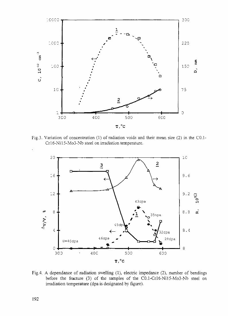
10000
1000
100
u10
- - -n.
30(
225
150
75
300 400 500 600T,°C
Fig.3. Variation of concentration (1) of radiation voids and their mean size (2) in the CO.l-Crl6-Nil5-Mo3-Nb steel on irradiation temperature.
10
9. 6
9 - 2
8 . 8
300 400 500 600
T,°C
Fig.4. A dependance of radiation swelling (1), electric impedance (2), number of bendingsbefore the fracture (3) of the samples of the C0.1-Crl6-Nil5-Mo3-Nb steel onirradiation temperature (dpa is designated by figure).
192

0.01
0.0098
0.0096
0.0092
Av/v,%
Fig.5. A dependance of electric impedance of the samples of the C0.1-Crl6-Nil5-Mo3-Nbsteel on radiation swelling.
__ a low temperature branch of swelling, Tirr.<530°C—— a high temperature branch of swelling. Tirr.>530°C
impedance measurement does not exceed ±0.1%. Plasticity was determined in bend testswhen a number of bendings prior to damage were registered. The bend tests complied withthe standart GOST 14019-80. Damage surface morphology was studied in a scanningelectron microscope. Fracture were quantiivery analysed by the method in Ref.[3].
At low irradiation temperatures (< 350 °C) high density of radiation defects in theform of clasters ("black dots"), dislocation loops and lengths of dislocations are observed inthe steel structure. When the radiation temperature increases radiation voids appear (fig.l.a),their sizes and concentration grow (figs 2 and 3) and their form acquires more regularcristallographic faceting (fig.l.b). Maximum concentration of voids corresponds to thetemperature of about 500 °C. The density of dislocation loops and clasters decrease and then-sizes grow simultaneously with the temperature increase. At the temperature of 500 °C"black dots" and small dislocation loops are absent though a noticable amount of secondphases emerges and their size and density grow with temperature increase. X-ray phaseanalysis revealed precipitation of second phases of, at least, tree types and some of them areferromagnetic.
Materials swelling depends on irradiation temperature and damage dose, the data onsteel swelling depending on temperature are shown in fig. 4. These swelling values,determined by different methods, are in good agreement. The maximum swelling valuecorresponds to the irradiation temperature of 530 °C and damage dose of 43 dpa.
A variation ov electric impedance of the tested samples after being exposed to highdose correlates with the swelling data (fig. 4). At first approximation this variation can bedescribed through swelling (fig. 5). However when swelling values are the same at low andhigh temperature branches of the plot the electric impedance values are different. Perhaps, itcan be attributed to the changes in material's matrix condition due to the changes of densityand sizes of precipitations, dislocation loops and clusters.
193

Fig.6. Fracture of the C0.1-Crl6-Nil5-Mo3-Nb after its bend tests:a - Tir = 440 °C, D = 46 dpa;b,c,d - Tir = 560 °C, D = 35 dpa.
194

10000
1000
100
10300 400 500 600
T,°C
Fig.7. Variation of mean distance between the microcups on sample fracture (1) and thatbetween the radiation voids (2) depending on irradiation temprature
600
400 --
200
r" ^Sf i
t *̂\ -y1 p.7
?00 400 600nm
Fig.8. A dependance of mean distance between the microcups on sample fracture on thatbetween the radiation voids of the size more than 45 nm.
195

A number of bendings before the damage, which characterises the plasticity, dependon swelling (fig.4). The higher swelling is lower is the steel plasticity. Minimum plasticity isobserved within the irradiation temperatures of 530 °C to 580 °C. Fractographs showsufficient plasticity of the steel, which can stand 17 bendings, and a transcrystalline viscousdamage with a formation of a typical cup fracture (fig.6.a) if post-irradiation steel does notcontain voids or their size does not exceed 45 nm (samples # 5 and 6). The precapitation ofthe size 0.4 (jm can be seen at the bottom of some cups.
The damage is brittle and transcrystalline (fig.6c and 6d) in all other samples, whichhave swelling more than 1% and substantial concentration of voids of the size more than45nm. The topography of such a fracture at medium magnification (fig.6c) is characterisedby flat areas, peacks of cleavage and shallow cups. This damage looks like a quasicleavagewhich is distinguished for such details of surface fracture [4]. The investigation withmagnification of 15,000 times revealed microcups (fig.6e) covering the entire surface of thefracture. They are the traces of microvoids along which the damage proceeds. An averagedistance between this cups is longer than that between voids in a steel (fig. 7). The analysisrevealed that this distance corresponded to the distance between the voids, which had the sizemore than 45 nm (fig. 8). Therefore nuclei of microvoids are radiation voids of the size morethan 45 nm.
Thus, radiation swelling is a dominating effect in changing the properties of stainlesssteels. Herewith a material's plasticity will depend on both swelling amount and radiationvoids concentration and size. 45 nm is the critical size for C0.1-Crl6-Nil5-Mo3-Nb steelwhen its plasticity decreases dramatically in the tests at room temperature.
3. CONCLUSION
A quantitative estimate of temperature and irradiation damage dose influence on bothsizes and radiation void density was determined. It was shown that radiation swelling is themost important structure factor determined physical and mechanical properties of the steel. Itwas settled that electric resistance of the steel is determine first of all by swelling value/Influence of other structural changes of the steel (dependent on temperatures) on electricresistance value was revealed. Plasticity and fracture of the steel are determined by radiationvoid conditions at post-irradiation tests. Fracture occur on mechanism of void growth andfusion. Estimation of critical swelling (>1 %) and critical void size (>45 nm), when suddendrop plasticity of the steel occur, was done.
REFERENCES
1. SaltikovS.A. Stereometric metalography. M.Mellurgy, 1976. 272 p.2. Chernjavsky K.S. Stereology Metlloknoulige. M.: Metllurgical, 1977. 280 p.3. Chermant J.L., Coster M. Fractographie guantitative.-"Cercle d'etudes des metaux"
Bulletin , 1978, t.14, N3, p.93-146.4. Fractography & atlas of fractogramm:. E.A.Shur: with. M.L.Bemstein. M.
Metallurgical, 1982.
196

VARIABILITY OF IRRADIATION CREEP AND SWELLING OFHT9 IRRADIATED TO HIGH NEUTRON FLUENCE AT 400- 600°C
M.B. TOLOCZKO, F.A. GARNERPacific Northwest National Laboratory, ''"""""" XA9848053Richland, WA;USA
Abstract
Four tube-sets constructed from a combination of three lots of HT9 and two heat-treatmentswere examined after irradiation in FFTF-MOTA at four different temperatures between 400 and600°C. Diametral measurements indicated that small amounts of swelling occurred at 400°C, withthe magnitude of the swelling varying from tube-set to tube-set. At 495, 550, and 600°C, noindications of swelling were observed. Over a limited stress range that decreased with increasingirradiation temperature, the irradiation creep was found to be proportional to the stress level andmirrored the swelling behavior, confirming the B0 -t- D S creep model. The creep compliance, B0,appears to be about half of that observed in austenitic steels, whereas the creep-swelling couplingcoefficient, D, appears to be comparable to that of austenitics. At the highest stress levels examined,the value of the stress exponent became much greater than 1.0. Higher irradiation temperaturesresulted in creep behavior with pronounced thermal creep characteristics: a primary creep transientwas observed at the three higher irradiation temperatures and increased in magnitude with increasingirradiation temperature, while a stress exponent between 1.0 and 2.0 was observed at 550°C.
1. BACKGROUND
Irradiation creep data on ferritic/martensitic steels are very time-consuming and expensive toobtain for proposed fusion-relevant applications. An extensive analysis of unpublished creep datafrom various other reactor programs is therefore in progress to characterize the irradiation creep offerritic/martensitic alloys as a class and also to develop a methodology for applying such data tofusion design applications.
In the current study, the deformation behavior of similar tube-sets of HT9 irradiated in theMaterials Open Test Assembly in the Fast Flux Test Facility (FFTF-MOTA) are presented andanalyzed. As part of the qualification process for the U.S. Liquid Metal Reactor (LMR) materialsprogram, a series of production variants of HT9 were irradiated in FFTF-MOTA in a variety ofspecimen types. This paper addresses the irradiation creep and swelling behavior of four nominallysimilar tube-sets constructed from HT9. One of these tube-sets was the FFTF Core DemonstrationExperiment (CDE) heat of HT9 which exhibited significantly lower swelling and irradiation creepthan observed in austenitic steels [1-3]. Data on two of these tube-sets at 400° C were presented in anearlier paper [4]. This paper contains data derived at four irradiation temperatures between 400 and600°C.
2. EXPERIMENTAL DETAILS
The compositions of these four steels, designated HT9-1, HT9-2, HT9-3, and HT9-5respectively, are shown in Table 1 and are quite similar. The first two were subjected to the sameheat treatment; 1038°C/5 min/air cool, followed by 760°C/30 min/air cool. The second two weresubjected to a slightly different treatment; 1100°C/2 min/air cool, followed by 650°C/2 h/air cool. Alltubes were helium pressurized, and except for the HT9-5 tubes, were 0.457 cm outer diameter, 0.020cm wall thickness and 2.24 cm length. HT9-5 tubes were larger with 0.686 cm outer diameter, 0.055
197

cm wall thickness, and 2 82 cm length Based on the results of earlier studies, there should be nosignificant influence of size differences [5]
At the end of each MOTA irradiation cycle, the tubes were discharged from the reactor, andprior to reinsertion into a new MOTA, diameter measurements were made using laser profilometry[6] The non-creep (volumetric) component of strain was assumed to be three times the diameterstrain of the stress-free tube Outer wall creep strains were found by subtracting the diameter changeof the stress-free tube, and the outer wall strain was converted to midwall strain using a multiplicativefactor that is dependent on initial tube dimensions All tubes in a given tube-set were irradiated side-by-side in each MOTA in order to minimize the influence of extraneous variables
Depending on the individual tube-set and irradiation temperature, from three to sevensuccessive diameter measurements (at different fluences) were acquired at various hoop stress levels,ranging from 0 MPa to an upper level determined by the irradiation temperature The upper levelranges from 200 MPa at 400°C to only 15 MPa at 600°C Irradiation temperatures varied somewhat(e g 384°C - 427°C in the 400°C irradiation series) from one MOTA to the next, but during any oneirradiation interval, the temperature was actively controlled within ±5°C of the nominal temperatureTable 2 presents the nominal temperatures and accumulated displacement levels for each irradiationinterval In the case of HT9-2, there were two separate sets of irradiations carried out at 495 and550°C One set started early in the MOTA series and another started much later m the series (Eachseparate MOTA increment spanned a 1 year period ) The two series, designated as "early" and "late",can be used to demonstrate the relative reproducibility of the creep behavior.
3 RESULTS
Only at the 400°C irradiation temperature were there any significant strains in theunpressunzed tubes It is presumed that these non-creep strains consist of contributions from bothphase-related strains and void swelling strains The non-creep strains at 400°C are shown in Fig 1and, assuming an isotropic distribution of strain, are calculated by multiplying the observed diameterchange of a stress-free tube by a factor of three Although the strains are not very large, there issignificant variation in both magnitude and behavior between the four tube-sets HT9-1, 2, and 3exhibit a small amount of transient dilation followed by a plateau and then a regime of steady-statedilation HT9-5 initially exhibits contraction, implying an increase in density, and then graduallybegins to increase but never reaching a positive level of strain
Figs 2a and 2b present the total strains and the calculated midwall creep strains for the tubesirradiated at 400°C The data are well behaved as is typical of the MOTA irradiation andmeasurement procedure The total strain behavior mirrors the variations in the non-creep strains
TABLE 1 Composition of alloys in weight percent
AlloyHT9-1HT9-2,3HT9-5AlloyHT9-1HT9-2,3HT9-5
FeBalBalBalSi021028029
Cr11811 811 8C021017021
Ni051057060Ti<001<001
Mo1030941 06Al003005001
Mn050054062S000300030002
V0330.24033P000800070011
W0.520520.52N00060006
198

between tube-sets, and the creep strains are directly proportional to the hoop stress level up to a break-away stress, beyond which the stress exponent is much greater than 1.0. With the exception of theCDE heat, the break-away stress appears to be somewhere between 140 and 200 MPa. Table 3presents the range of creep coefficients derived from these data, assuming that the stress normalizedcreep rate obeys the B0 + D S creep model often used to describe the creep behavior of austeniticsteels, where B0 and D are typically -1.0 x 10'6 MPa-1 dpa-1 and D -0.6 X 1Q-2 MPa-1. respectively[7-9].
TABLE 2. Nominal temperatures and displacement levels for each irradiation series.
HT9-l,HT9-2MOTA1AIB1CIDIEIF1GHT9-3MOTA1CIDIEIF1GHT9-5MOTAIDIEIFHT9-1.HT9-2MOTA1AIB1CHT9-2 (late)MOTAIEIF1G2B
400°C NominalTemperature, °C427401396386384386384400°C NominalTemperature, °C396386384386384400°C NominalTemperature, °C404414405495 °C NominalTemperature, °C494490490495°C NominalTemperature, °C494494495495
Dose, dpaIncremental30.113.130.822.529.122.017.4
Total30.143.274.096.5125.6147.6165.0
Dose, dpaIncremental28.222.529.122.017.4
Total28.250.779.8101.8119.2
Dose, dpaIncremental28.336.936.8
Total28.365.2102.0
Dose, dpaIncremental29.010.625.0
Total29.039.664.6
Dose, dpaIncremental20.121.517.013.0
Total20.141.658.671.6
199

TABLE 2. Continued.
HT9-5MOTAIEIF1GHT9-2 (early)MOTA1AIB1CHT9-2 (late)MOTAIEIF1GHT9-5MOTAIEIF1GHT9-1MOTA1AIB1C
495°C NominalTemperature, °C494494495 ^550°C NominalTemperature, °C547548550550°C NominalTemperature, °C549550550550° NominalTemperature, °C549550550600°C NominalTemperature, °C603600605
Dose, dpaIncremental26.0, 26.023.8, 26.219.0,21.3
Total26.0, 26.049.8, 52.268.8, 73.5
Dose, dpaIncremental33.213.942.3
Total33.247.189.4
Dose, dpaIncremental43.740.437.1
Total43.784.1121.2
Dose, dpaIncremental43.440.035.6
Total43.483.4119.0
Dose, dpaIncremental28.915.640.1
Total28.944.584.6
1 r0.8-
0.6volumetricswelling 0.4 r
0.2,-
0'̂
-0.2
Heat 2
T
Heat 1
HeatS
Heat 5 (CDE) -,—a '
0 50 100 150 0 50 100 150 200dpa
FIGURE 1. Variability observed after stress-free irradiation of four HT9 tube sets at ~400°C.
200

3.5,-
2.5
1.5J-
0.5L
diametralstrain 3.5
Heat i !* 200 Heat 31
200 MPai1006 60
Heat 2 / 200 • Heat 5 (CDE)140^
200100
150 225
0.02
0.015'-
0.01
0.005midwall strain/
hoop stress o%/MPa
0.015
0.01
0.005
Heat 1 „ 200 , Heat 3^ 140_E -30^'60
200 MPff100 !6030
150 225
(B)
FIGURE 2. (A) Diametral strains and (B) stress-normalized midwall creep strains observed invarious HT9 heats during irradiation at ~400°C.
Figs. 3a and 3b present the data for the 495°C irradiation series. No indications of swellingwere observed in the stress-free condition. There are only minor variations in creep characteristicsbetween tube-sets where valid comparisons at identical stress levels could be made. The creepbehavior of HT9-2 in the "early" and "late" series is also comparable for identical stress levels. Once
201

again there is an indication of a break-away stress level which varies slightly with tube-set. Unlike thebehavior at 400°C, a primary creep transient was observed at 495°C. The B0 creep coefficients shownin Table 3 are comparable to those observed at 400°C. Once again the CDE heat exhibits the bestoverall behavior.
D . 3 i
Heat 1 ,2.5-
E9
1.5- /
0.5^/T^diametral cr— ̂ =^6 i
strain 3.5
i is217 Heat 2 (Late)
~
, „ -- 140 MPa-7 152 100i 109 60
65 - - - -e- a 30"o :" o
1
% Heat 2 (Early) Heat 5 (CDE)2.5- >
«-/C-0 51 ———— ! ——0 40
0.02 ——————
7 200
- 140 -100
100 _ s60
'o, o80 0 40 80 120
dp a
(A)
1
. Heat 1 9 1 7 Heat 2 (Late)0.015 r / - -|
0.01- a''/
0.005- /„$£midwall strain/ -Xip8^
hoop stress OE*^— — ———%/MPa Heat 2 (]
0.015 -i /
0.01 \ /
0.005 \ / ^f\ rb^^ \
0 40
_^
,152 140 MPa1 109 10033 : j*f£^ir^&%- 15
\ f ^ 6 0^ j
Early) Heat 5 (CDE)7 200
_ _140
100 100* 60 ~ _c| 30 -30 <z^^ 60
~^~^ , 1580 0 40 80 120
dp a
(B)
FIGURE 3. (A) Diametral strains and (B) stress-normalized midwall creep strains observed invarious HT9 heats during irradiation at ~495°C.
202

diametralstrain
%
3.5
l - 5 h
Heat 2 (Early) ! Heat 5 (CDE)
lOOMPa60
2.5-
1 . 5 r
Heat 2 (Late)/S200
40 80 120 160
0.02
0.005midwall strain/
hoop stress Q%/MPa
0 40 80 120 160dpa
(B)
FIGURE 4. (A) Diametral strains and (B) stress-normalized midwall creep strains observed invarious HT9 heats during irradiation at ~550°C.
Figs. 4a and 4b presents the data for the 550°C irradiation series. There is no obvious stress-free swelling, the variability in creep is a little more pronounced, and there is some evidence ofvariation in creep between the "early" and "late" irradiation series. The primary creep transient ismore pronounced, and the stress exponent is clearly above 1.0 for hoop stresses >30 MPa. For
203

stresses < 30 MPa, the strain rate appears to be proportional to the stress, and B0 was calculated torange from 0.3 - 0.6 x 10"6 MPa-1 dpa-1 as reported in Table 3.
At 600°C only data on HT9-1 were available. As shown in Figs. 5a and 5b, even at very lowstress levels of < 15 MPa, the primary transient is quite pronounced. However, the post-transientcreep is linear with stress in this stress range (parallel slopes in Fig. 5b). and the measured creepcompliance is somewhat larger than observed at lower temperatures, ranging from 1.1 to 1.7 x 10'6MPa-1 dpa-1.
diametralstrain
3.5
2.5 -
1.51-
0.5
Heat 1
.-A - - - - - - - A 15 MPa !—*——————oio 1
40 80dpa
(A)
0.06 i-
midwall strain/ 0.04hoop stress
%/MPa
0.02 -
FIGURE 5. (A) Diametral strains and (B) stress-normalized midwall creep stains observed in HT9-1 during irradiation at ~600°C.
204

TABLE 3. Creep coefficients of HT9 at 400, 495, 550 and 600°C.
s / a = B0 + DSTemp.
°C400400400400
495495495495
550550550
600
Steel
HT9-1HT9-2HT9-3HT9-5
HT9-1HT9-2 (early)HT9-2 (late)HT9-5
HT9-2 (early)HT9-2 (late)HT9-5
HT9-1
BO
MPa-1 dpa-'0.9- l .Ox 10-6*0.8- l .Ox lO-6
0.5 - 0.7 x lO-6
0.5 - 0.7 x 10⁻⁶
0.8- 1.5x 10-60.5 - 0.7 x lO-6
0.3 - 0.6 x lO-6
0.4- 0.5 x 10⁻⁶
0.5 x 10-60.3 - 0.4 x 10-60.5 - 0.6 x lO-6
1.1 - 1.7 x 10⁻⁶
D
MPa-1
0.5- 1.1 x lO-2*0.5-0.6x10-20.4- l .Ox lO-2
no swelling
no swellingno swellingno swellingno swelling
no swellingno swellingno swelling
no swelling
Stress Range
MPato 140to 200to 100to 200
to 150to 100to 140to 140
to 30to 30to 30
to 15
The variation in B0 and D values reflects a range of values accumulated from a measurement ateach stress level.
4. DISCUSSION
Void swelling of HT9 has been was clearly observed by electron microscopy in a prior studyof irradiation creep and swelling of the fusion heat of HT9 at ~400°C [10] and, with the exception ofHT9-5, can be inferred from the diametral changes of the stress-free tubes irradiated at ~400°C in thecurrent experiment. HT9 swells very little or not at all over the range 400-600°C in the currentexperiment, but measuring small amounts of swelling via diameter measurement is confounded bydiameter changes induced by segregation and phase changes. In HT9-5, the diameter change of thestress-free tube was negative over the whole dose range, and for creep coefficient calculations, it wasassumed that HT9-5 did not swell at this temperature. The upturn in strain in the latter portion of theHT9-5 irradiation may signal the possibility of swelling, however. The variability of swelling seen inthe various tube-sets demonstrates that the onset of swelling responds to minor processing andcompositional differences that are as yet undefined and uncontrolled.
Depending on irradiation temperature and stress, the measured creep possesses characteristicsof both irradiation creep and thermal creep. At lower temperatures and lower stresses, classic B0 +D S irradiation creep dominates, while at higher temperatures and stresses, thermal creep dominates.Over a limited range of stresses at 400°C, the stress exponent is 1.0, and the stress-normalized creeprate follows the well known B0 + D S creep-swelling relationship. However, at higher stresses, thestress exponent becomes much greater than 1.0, which is thought to indicate a change in creepmechanism. As will be discussed shortly, it is believed that this latter mechanism is an irradiationcontrolled climb-glide mechanism. As the temperature is increased, the range of stresses decreasesover which classic irradiation creep dominates. At 495°C, the first thermal creep characteristic toappear is a primary creep transient. This transient appears in all stress levels examined at thistemperature. However, even in this transient regime, the stress exponent is still 1.0. As shown in
205

Fig 3, the transition to the high stress (n>l) creep mechanism is apparent at the higher stresses. Themechanism is again thought to be an irradiation controlled climb-glide mechanism. At 550°C,thermal creep characteristics are yet more apparent Unlike the tubes irradiated at 495°C, the creepmeasured at 550°C is described by a stress exponent l<n<2 over a similar range of stresses. Thisstress exponent is consistent with thermal creep m HT9 at this temperature and range of stresses [11]At 550°C. the transition to high stress creep mechanism was observed, but because of the increasingdominance of thermal creep at the lower stresses, the controlling mechanism is not obvious At600°C, it appears that there are strong contributions from both thermal and irradiation creep over therange of stresses examined A large primary creep transient was observed, indicative of thermalcreep The post-transient creep rate was linear v, ith stress, consistent with a SIPA type mechanism ora thermal diffusional creep mechanism For the stresses examined at 600°C, a transition to an n>lcreep mechanism was not observed, perhaps due to the very low levels (<15 MPa) of stressemployed
In an earlier report, the creep response of the fusion heats of HT9 and 9Cr-lMo waspresented after irradiation to -208 dpa at temperatures ranging from 403 to 433°C m FFTF-MOTA[10] While the fusion heat of 9Cr-lMo was well described by the B0 + DS creep-swellingrelationship over a limited stress range, the fusion heat of HT9 did not exhibit such behavior asshown in Fig 6 In particular, the apparent creep response was non-linear with stress over the wholestress range which is similar to the stress range used for pressurized tubes irradiated at ~400°C m thecurrent experiment The observed non-linear response to stress was thought to be due, in part, to thestress-enhanced sv, ellmg measured in the fusion heat of HT9 at this irradiation temperature as shownin Fig 7 (Minimal stress-enhanced swelling was observed in the fusion heat of 9Cr-lMo ) Unlikethe fusion heat of HT9, creep measurements of the various HT9 tube-sets in the current experimentsupport the e/a = B0 + DS creep-swelling relationship over stress ranges similar to that for thefusion heat of HT9. suggesting some difference m microstructural evolution between HT9-fusion andthese steels Stress-enhanced swelling measurements were not performed on the present steels
As the non-destructive diametral measurement technique used m both experiments cannotdetect stress-enhanced swelling, any additional swelling due to stress cannot be distinguished fromtrue creep and is therefore included as a creep contribution This can sometimes result in misleadingconclusions about the creep-swelling relationship if the stress-enhancement of swelling is large, such
35 xlO
midwall strain/ 20hoop stress
%/MPa 15
300
FIGURE 6 Stress-normalized midwall creep strains for the fusion heat of HT9 and 9Cr-lMo at~400°C, ignoring stress enhancement of swelling [10]
206

swelling
9Cr-lMo
100 200 0 100stress, MPa
200 300
FIGURE 7. Swelling measured by density change for small segments of individual tubes at 208dpa. showing stress enhancement of swelling [10].
as may be the cause of non-linear creep response of the fusion heat of HT9. It is also possible thatthe grain, precipitate, or dislocation microstructures may not be stable and thereby contribute to a non-linear response to stress.
The difference in behavior between HT9 fusion heat and the current heats may be due to thefact that the heat treatment was different in one significant aspect. The fusion heat was subjected to1050°C/5 min/air cool followed by 760°C/2.5 hrs/air cool. The second part of the heat treatment isthus much more likely to initiate dislocation and phase changes than the 760°C/30 min and 65072 hrtreatments employed in the current study.
Using a stress exponent of n = 1.0 as the defining criterion, "classic" irradiation creep wasfound at all temperatures, but only over limited stress ranges that decreased with increasingtemperature. The creep coefficient B0 was on the average a little lower (-50%) than that typicallyobserved for austenitic steel, but the creep-swelling coupling coefficient, D, appeared to becomparable to that of austenitic steels. In two earlier studies, one on 9Cr-lMo at 400°C and anotheron EM10 at 400-480°C, the creep compliance was measured to be -0.5 x 10'6 [7] and -0.4 x 10'6MPa-1 dpa-1, [12] respectively. Thus far, it appears that in general the B0 component of creep inmartensitic steels is about one half that found in austenitic steels. The creep-swelling couplingcoefficient, however, appears to be independent of crystal structure, at least in iron-base steels.
The creep measurements at 400°C (and 495 and 550°C) also indicate another clear trend. Atsome break-away stress, the stress exponent becomes much greater than 1.0. The break-away stressappears to be between 150 and 200 MPa (effective stress). Similar irradiation creep behavior hasbeen observed in HT9 irradiated by Grossbeck in ORR/HFIR at ~400°C where a transition to a high-stress exponent was observed in the range 150-200 MPa (effective stress) [13]. At 400°C, the flowstress of annealed low alloy ferritic steels is between 200-300 MPa [14], and the change in stressexponent is thought to be consistent with a change from a climb-only creep mechanism (SIPA-ADfor instance [15,16]) to a climb-glide creep mechanism [17]. At this temperature, the climbcomponent is thought to be an irradiation controlled mechanism rather than a thermal mechanism.This conclusion was deduced, in part, from comparison of the break-away stress under irradiation tothe break-away stress under thermal aging conditions. In an experiment by Chin [10], where HT9pressurized tubes were aged at temperatures ranging from 425 to 600°C, a transition from a low-
207

stress exponent to a high-stress exponent at an aging temperature ~480°C was near 280 MPa(effective stress) Extrapolation of his work to lower aging temperatures suggests a break-awaystress greater than 300 MPa (effective stress) at ~400°C which is markedly greater than the break-away stress observed in this experiment at ~400°C
5 CONCLUSIONS
The \ oid swelling observed in four separate tube-sets of HT9 is somewhat sensitive toproduction variables that are as yet unidentified and controlled The swelling levels are low, however,compared to austemtic steels In the temperature range of 400-600°C a gradual transition in theirradiation creep mechanism appears to occur with increasing irradiation temperature, shifting fromclassic irradiation creep to thermal creep as the irradiation temperature increases At high stresses,
the irradiation creep mechanism appears to shift from a climb-only mechanism to a climb-glidemechanism with the climb rate driven by irradiation Where classic irradiation creep is found, theswelling-creep coupling coefficient appears to be identical to that of austemtic steels The creepcompliance, however, appears to be approximately one-half that of austenitics
REFERENCES
[I] Ethndge, J L . and Walter, A E, 'Core Demonstration Experiment A Liquid Metal ReactorCore Demonstration Experiment Using HT9 , Transactions ANS, 60 (1989), pp 286-287
[2] Bridges A E . Walter, A E , Leggett, R D , Baker, R B . and Gneitmg, B C , AdvancedLiquid Metal Reactor Fuel and Blanket Designs Using HT9', Proc Int Conf Fast Reactor andRelated Fuel Cycles, Kyoto, Japan, Vol II, Atomic Energy Society of Japan, 1991 ppPI 21 1 -PI 21 10
[3] Baker, R B , Bard, F E , Leggett, R D , and Pitner, A L , Status of Fuel, Blanket, andAbsorber Testing in the Fast Flux Test Facility , Journal of Nuclear Materials, 204 (1993), pp109-118
[4] Toloczko, M B . and Garner, F A , ' Irradiation Creep and Void Swelling of Two LMR Heatsof HT9 at ~400°C and 165 dpa , Journal of Nuclear Materials, in press
[5] Garner, F A , Hamilton, M L , Puigh, R J , Eiholzer, C R , Duncan, D R , Toloczko, M B ,and Kumar, A S , ' The Influence of specimen Size on Measurement of Thermal or IrradiationCreep in Pressurized Tubes', Effects of Radiation on Materials 16th InternationalSymposium, ASTM STP 1175, American Society for Testing and Materials, Philadelphia(1993), pp 631-645
[6] Gilbert, E R , and Chin, B A , Irradiated Materials Measurement Technology", Effects ofRadiation on Materials, 10th Conference, ASTM STP 725, American Society for Testing andMaterials, Philadelphia (1981), pp 665-679
[7] Toloczko, M B , Garner, F A , and Eiholzer, C R , Determination of the Creep Complianceand Creep-Swelling Coupling Coefficient for Neutron Irradiated Titanium-Modified StainlessSteels at ~400°C', Journal of Nuclear Materials, 191-194 (1992), pp 803-807
[8] Toloczko, M B , and Garner, F A , "Relationship Between Swelling and Irradiation Creep inCold-worked PCA Stainless Steel Irradiated to -178 dpa at ~400°C", Journal of NuclearMaterials, 212-215 (1994), pp 509-513
[9] Garner, F A , and Porter, D L , ' Irradiation Creep and Swelling of AISI 316 Exposures of130 dpa at 385-400°C", Journal of Nuclear Materials, 155-157 (1988), pp 1006-1013
[ 10] Toloczko, M B , Garner, F A , and Eiholzer, C R , 'Irradiation Creep and Swelling of the USFusion heats of HT9 and 9Cr-lMo to 208 dpa at ~400°C , Journal of Nuclear Materials, 212-215 (1994), pp 604-607
[ I I ] Chin, B A , 'An Analysis of the Creep Properties of a 12Cr-lMoWV Steel", ProceedingsTopical Conference on Ferntic Alloys for Use in Nuclear Energy Technologies, TheMetallurgical Society of AIME (1983), pp 593-599
208

[12] Seran, J. L., Levy, V. Dubuisson, P., Gilbon D., Maillard, A.. Fissolo, A., Touron, H.,Cauvin, R., Chalony, A., and Le Boulbin, E., "Behavior Under Neutron Irradiation of the 15-15Ti and EM10 Steels Used as Standard Materials of the Phenix Fuel Subassembly", Effectsof Radiation on Materials, 15th International Symposium, ASTM STP 1125, AmericanSociety for Testing and Materials, Philadelphia (1992), pp. 1209-1233.
[13] Grossbeck, M. L., Gibson, L. T., and Ditsukawa, S., "Irradiation Creep at Temperatures of400°C and Below for Application to Near Term Fusion Devices", Effects of Radiation onMaterials: 18th International Symposium, ASTM STP 1325, American Society for Testingand Materials. Philadelphia (1997), in press.
[14] Metals Handbook, 10th Edition, 1, (1990), pp. 617-652.[15] Woo, C. H., "Irradiation Creep Due to Elastodiffusion", Journal of Nuclear Materials, 120
(1984), pp. 55-64.[16] Woo, C. H., "Theory of Irradiation Deformation in Non-Cubic Metals: Effects of Anisotropic
Diffusion", Journal of Nuclear Materials, 159 (1988), pp. 237-256.[17] Matthews, J. R., and Finnis, M. W., "Irradiation Creep Models - an Overview", Journal of
Nuclear Materials, 159 (1988), pp. 257-285.
NEXTleft BLANK 209

A PROBLEM TO DETERMINE SHORT TERM MECHANICALPROPERTIES CHANGES OF FERRITE-MARTENSITE ANDAUSTENITIC STEELS AS MATERIALS OF FUEL ASSEMBLY OFFAST REACTORS UNDER HIGH DOSE NEUTRON IRRADIATION
A.V. KOZLOV, A.S. AVERIN, S.V. BRUSHKOVASB RDIPE, Zarechny, Sverdlovsk XA9848054
G.V. KALASHNICARSRJIM, Moscow
Russian Federation
Abstract
The results of mechanical tests of flat and ring-shaped samples of two ferrite-martensite steels C0.1-Crl3-Mo2-Nb-V-W and C0.1-Crl2-Mo-Nb-V-W- irradiated todifferent damage doses (up to 100 dpa) have been performed in this work. It have beenshown mat values of plasticity and strength characteristics determined on this sample typesare different. Specific elongation takes the values 8 - 1 2 % for the flat samples, at the sametime, t takes the values 1 - 3 % for the ring-shaped samples at room temperature. Acharacter of fluence dependence of mechanical properties is identical. The steels showviscous damage in all tests. Samples of fuel pin cladding fabricated from the austenitic steelC0.1-Crl6-Nil5-Mo3 were also investigated after mere working out in BN-600 reactor up to76 dpa. Ring-shaped samples were tested at standard single-axle tension. Tube samples weretested by internal pressure of solid filler. All samples were fabricated from one and the samesection, mechanical properties obtained are different. Specific elongation of the brittlestsection of fuel pin was 0 - 0.9 % for the ring-shaped samples and 2 - 7 % for the tubesamples at room temperature. Fractographic investigations were carried out on the samplesafter mechanical tests. Possible reasons of such difference have been discussed in the work.
INVESTIGATIONS of FLAT and RING - SHAPED SAMPLES of theC0.1-Crl3-Mo2-Nb-V-W STEEL.
Investigations of high dose irradiation influence on mechanical properties of the CO.l-Crl3-Mo2-Nb-V-W steel were carried out on samples of two material assemblies irradiated inthe BN - 600 reactor [1]. Flat samples were irradiated to 54.7 - 75.2 dpa at 385 °C - 450 °C.Ring - shaped samples were fabricated from case pipe with the 22. mm dia. The gauge of thematerial assembly irradiated up to 94 - 10$ dpa in the reactor at 425 °C - 500 °C is 1 mm. Post- irradiation short - term mechanical properties were carried out in the temperature range 20°C - 500 °C. Both irradiated and non - irradiated samples were tested. Test temperaturedependence from strength and plasticity characteristics of flat samples are shown in Fig. 1.The same dependence for the ring - shaped samples are shown in Fig. 2.
Comparison of samples properties in initial state is shown that the flat samples haveyield limit slightly higher (on ~ 60 MPa) than ring - shaped samples have. It allows to expectmore lower values of plasticity properties for the flat samples than for the ring - shapedsamples. Really, total specific elongation has the values 15 % - 20 % , uniform specificelongation has the values 9 % - 12 %. The ring - shaped samples has the following values ofsuch characteristics: 12 % - 15 % and 6 % - 9 % accordingly. One can see, that tests of the
211

900
04
300
Strength characteristics of theC0.1-Crl3-Mo2-Nb-V-W (flat samples)
-Ultimate strength(initial)
-Yield strength(initial)T=385C,D=54.7dpa
T=430C,D=75.2dpa
T=450C,D=68.4dpa
200 o 400 600m up•••test. ' ^
30
20
CO10
Plasticity characteristics of theCO . l-Cr!3-Mo3-Nb-V-W ( —————Total elongation
(initial)-Uniform elongation(initial)T=385C,D=54.7dpa
T=430C,D=75.2dpa
T=450C,D=68.4dpa
200 Q 400T C•••test, i *•*
600
FIG.l
212

1200
900
Plasticity characteristics of theC0.1-Crl3-Mo2-Nb-V-W steel (ring-shaped
samples)————— Ultimate strength
(initial)- - - - - -Yield strength
(initial)• T=425C,D=99dpa
T=450C,D=108dpa
200 400 600
T=470C,D=108dpa
nA T=490C,D=101dpa
AX T=500C,D=94dpaX
Plasticity characteristics of theCO.l-Cr!3-Mo2-Nb-V-W (ring-shaped samples)
30
20
10
200•test. , c
400 60'
Total elongation(initial)-Uniform elongation(initial)T=425C,D=99dpa
+ T=450C,D=108dpa
O
• T=470C,D=108dpa
D
A 1=4900,D=101dpa
A
X T=500C,D=94dpa
X
FIG. 2
213
ring - shaped samples have more lower values (on 3 % - 5 %) of plasticity properties than testsof the flat samples have. Ring stretching occur at first state during ring samples tests. The ringtakes ellipse form and subjected by plasticity deformation on the state. The deformation isn'tfixed on test diagram.
Strength characteristics of the both type samples are became practically identical.Minimum value of the plasticity properties is reached at 400 °C, at the same time specificelongation of the flat samples takes the value 9 % - 12 %. the ring - shaped samples 1% - 3 %.The difference of the plasticity characteristics between the flat and ring - shaped samples areobtained higher damage dose (on 3 times). The steel shows viscous damage in all tests.
INVESTIGATIONS of RING - SHAPED and TUBE SAMPLESof the Crl5-Nil6-Mo3 STEEL.
Considerably more extensive data are accumulated during mechanical tests of the ring- shaped samples fabricated from austenitic steels for materials of fuel assembliesafter their exploitation up to arriving of high burning up (leading to damage dose 70 - 94 dpaof cladding materials) at the BN - 600 reactor core [2]. It was happened the situation whencladding of fuel element had parts which showed zero plasticity during tests when damagedose was more than 76 dpa. at the same time fuel element kept tightness up to the 94 dpa.Therefore, it is difficult to use the results of mechanical tests of the ring - shaped samplesfabricated from the fuel elements after their exploitation in the reactor to predict safety-operating life of fuel elements. There are two reasons for it. Values of plasticity characteristicsobtained during tests of the ring - shaped samples are lower than true (see part 2). Stress -deformation states during exploitation and at single - axle elongation of the ring - shapedsamples are differed. More exactly, the stress - deformation state arising during exploitation isimitated during tests of tubes by internal pressure. Usually pressure is created by liquid or gasmedium during the same tests. It is hard to carry out such tests under hot cell conditions onsamples fabricated by remote - control method from irradiated fuel element. It is connectedwith the following difficulties: to remove fuel from long fuel element samples and topressurized a supply unit of liquid or gas medium inside short tube samples fabricated fromfuel element cladding by remote - control method.
Technique to test samples from thin - walled tubes with small diameter by internalpressure of solid filler was developed in the SB RDIPE [3]. It is possible both to measuredspecific elongation directly with the help of the technique and to calculate uniform specificelongation, internal pressure of solid filler on sample wall (when fracture have occurred) andtangential stress in a damage area cladding using solid filler compression diagram inapproximation of elasticity and plastic deformation theories.
Verification tests of tube and ring - shaped samples fabricated from cladding tubes ofCrl6-Nil5-M3 steel fuel elements irradiated up to 75.7 dpa in the BN - 600 reactor wrerecarried out using the technique. The ring - shaped samples with the height 3 mm and the tubesamples with the length 15 mm are fabricated both from one and the same tube sections andfrom non - irradiated tubes. The samples are used at room temperature and at 400 °C.
Test results of the tube and ring - shaped samples are shown in tables 1 and 2. One cansee, that specific elongation is higher on the tube samples than on the ring - shaped samples.In particular, minimum value of specific elongation is equal to 0 using test results of the ring -shaped samples at a section of the fuel element located on ~ 400 mm higher than the corebottom (CB). The specific elongation of the tube samples has the value -3.5 % in the samearea. Comparison of strength characteristics shows that ultimate strength of the ring - shaped
214

.Table IInvestigation results of ring-shaped specimens madeof the fuel element cladding after their exploitation
in'the BN-600 reactor at room temperature.
Coordinatesfrom core bottomnon- irradiationgauze cavity
390470515820870915
8U/ %
14 .09.70.00.90.65.04.05.0
6t, %
19.016.60.00.90.67.54.05.9
R0,2, MPa
761772261713716602641665
RB, MPa
9971056261810779879854855
Table 2Investigation results of tube specimens made of
the fuel element cladding after their exploitation in theBN-600 reactor at room temperature.
Coordinatesfrom core bottomnon- irradiationgauze cavity
390 '470515820870915
Su, %
982245711
St, %
2237367121024
p, MPa
5332524848414633
Rf, MPa
511340426408391358399313
Table 3Investigation results of ring-shaped specimens madeof the fuel element cladding after their exploitation
in the BN-600 reactor at 400 °C.
Coordinatesfrom core bottom
non-irradiationgauze cavity
39047051582087015
8U, %
4.04.70.00.30.62.20.92.2
8t, %
10.37.8•o.o0.30.62.20.92.2
Ro.2, MPa
584717151468429493569463
RB, MPa
724877151468517601598645
215

Table 4Investigation results of tube specimens made of
the fuel element cladding after exploitation in theBN-600 reactor at 400 °C.
Coordinatesfrom core bottom
gauze cavity390470820870915
8U, %
1122554
6t, %
31349209
p, MPa
274648343335
Rf, MPa
303380382278320283
samples both for material of initial state and for most fuel element sections are considerablyhigher than values of tangential stress (*hen fracture of the tube samples have occurred). Asection with minimum plasticity is expulsion where the ring - shaped samples are fractured atconsiderably lower stress. The causes of such differences are the following: fracture (duringsingle - axle extension of rings) occur mainly by shear in area of main tangential stresses. Atthe same time shear component are absent, at least, up to the time while barrel - shaped Glisterwilln't occur. Therefore, comparison of stress (when fracture have occurred) with shearcomponent of fracture stress of the ring - shaped samples will be more correct. Dependence offuel element section state in the core from strength characteristics for both type of tests areshown in Fig. 3. One can see, that shear component of ultimate strength is close to the valueof tangential stress of the tube samples fracture on all range of the fuel element, with theexception of area with the coordinates 400 mm - 500 mm from the core bottom where ringsfracture occur at considerably lower shear stresses. View of the tube samples from the brittlestarea and from area with high plasticity (the core top) are shown in Fig. 4.
As test results show, both dependence of mechanical properties from fuel elementposition has analogous character and strength properties relationship obtained on the tube andring - shaped samples is .close at 400 °C (see Table 3 & 4). The fuel element cladding keptplasticity at 400 °C during tests of the tube samples. The minimum value of plasticity is 2.5%. At the same time the ring - shaped samples have zero plasticity. Plasticity characteristics ofthe ring - shaped samples are decreased (in 2 times) at 400 °C in comparison with tests atroom temperature. The tube samples have close value of specific elongation at the bothtemperatures, Fig 5. View of the tube samples are shown in Fig. 6 after their tests at 400 °C.
CONCLUSIONS
Carried out investigations results show that tests of the ring - shaped samplesirradiated up to high fluence don't give sufficient information to predict residual operating life- time of the fuel elements. More correct information may be obtained from the flat samplesexpansion tests. However, in order to carry out the tests it is necessary to irradiate materialassemblies. It requires additional expenditures. Mechanical properties obtained from that testsdon't completely reflect fuel element cladding behavior, so far as stress - deformation state isrealized there. The most close to real conditions plasticity characteristics are obtained during
216

Strength characteristics of the fuel element claddingfor tube and ring-shaped specimens at 20 C.
600 -r
450 • •
300-•
150--
-ft- -f- -t--500 -250 0 250 500 750 1000
Coordinates from core bottom, mm
• R f t u b e b .
Rsh ring s.
Plastisity characteristics of the fuel element claddingfor ring-shaped and tube samples at 20 °C.
40-r
BA
3 0 - -
2 0 - -
1 0 - -
-e-
rmg s.
•tube s.
-500 -250 0 250 500 750Coordinates from core bottom, mm
1000
FIG. 3
217

, _ , . .
1'1 ' " - * 1 1 "
Fig.4. Tube specimens appearance after their research byinternal pressure at 20 °C:
a - the specimen from near core center;b - the specimen from core top.
218

Strength characteristics of the fuel element claddingfor ring-shaped and tube specimens at 400 C.
r-
500-r
400- •
300- •
200- •
100- •
-e-
Rsh r ings
•Rf tubes
-500 -250 0 250 500 750 1000
Coordinates from core bottom, mm
Plastisity characteristics of the fuel element claddingfor ring-shaped and tube specimens at 400 C.
-500
40 T
30- -
20 -•
10 ••
_ _ - - .-AIA
-250 0 250 500 750 1000Coordinates from core bottom, mm
ring s
•tubes
FIG. 5
219

Fig.6. Tube specimens appearance after their research by internalpressure at 400 °C:
a - the specimen from near core center;b - the specimen from core top.
220

tests of the tube samples fabricated from the fuel elements by internal pressure. But strengthcharacteristics obtained aren't standard mechanical properties (which designers use), such asultimate strength and conventional yielt limit, while the characteristics show ultimatepressures and maximum tangential stresses in the fuel element cladding acceptable duringexploitation. Probably, it is.suitable now to combine the following techniques: tests of thering - shaped samples at single - axle expansion and tests of the tube samples by internalpressure carried out in the real fuel elements after their exploitation in commercial reactors. Inorder to use data obtained correctly it is necessary to carry out fractographic investigation.
REFERENCES
[1] S.A. Averin, A.V. Kozlov. V.A. Tsigvintsev, E.N. Ushakova. E.A. Medvedeva.The fourth interbranch conference on irradiation material science. Dimitrovgrad.1995. abstracts, p. 117.
[2] S.A. Averin. A.V. Kozlov, E.A. Medvedeva, Investigation of structural material ofcore elements of fast natrium reactor, RAS UrD, Ecaterinburg, 1994. p. 160.
[3] E.A. Kinerv. A.V. Kozlov, A.V. Agopyan, G.V. Kalashnic. O.S. Korostin.30 - anniversary of IVV - Complex, abstracts, 1996, p 107.
[4] A.V. Kozlov. S.A. Averin, L.P. Sinelnikov, A.P. Isakov, Yu. G. Kuznetsov. Thefourth interbranch conference on irradiation material science. Dimitrovgrad.1995. abstracts, p. 187.
[5] A.V. Kozlov. S.A. Averin, E.N. Shcherbakov, 30 - anniversary of IVV - Complex,abstracts, 1996. p 104.
221

SWELLING AND IN-PILE CREEP OF NEUTRON IRRADIATEDISCrlSNiTi AUSTENITIC STEELS IN THE TEMPERATURE RANGEOF 400 TO 600°C
R. HUBNER, K. EHRLICH "'" XA9848055Institut fur Materialforschung,Forschungszentrum Karlsruhe,Karlsruhe, Germany
Presented by E. Materna-Morris
Abstract
A pressurized tube experiment was carried out in the Prototype Fast Reactor (PFR) at Dounreay in orderto determine swelling, stress-induced swelling and in-pile creep of different austenitic steels. The tubes weremade out of different heats of the commercial German austenitic steel DIN 1.4970 and a number of modelplain Fe-15Cr-15Ni stainless steels. Special attention was paid on the influence of minor alloying elements likeSi, Ti, degree of Ti/C relation and others. The maximum doses achieved are 106 dpaNRT at 420°C, 81 dpaNRT at500°C and 61 dpauRT at 600°C. The hoop stresses of the pressurized tubes were 0, 60 and 120 MPa at allirradiation temperatures. The length and diameter changes of the pressurized capsules have been determined atup to four intermediate stages and after irradiation. Post irradiation examinations by immersion densitymeasurements and transmission electron microscopy (TEM) are partially done.
All alloys exhibited the highest swelling values at 420°C and nearly ne swelling at 600°C. Themeasurements show the large effect of the minor alloying elements upon swelling and in-pile creep. Themaximum swelling suppression is achieved for DIN 1.4970 through a high Si-content and anunderstoichiometric Ti/C relation (understabilization). This yields linear swelling of 1.9% after 106 dpa>jRT at420°C. The formerly observed intercorrelation between swelling and in-pile creep is confirmed up to 106dpaNRT- It can be described by an equation consisting of a SIPA term (stress induced preferential absorption)and an intercorrelation term similar to the I-creep proposed by Gittus. The estimates of the stress-inducedswelling using the Soderberg theorem and the length measurements are compared with the immersion densitymeasurements and results by TEM. The immersion density measurements agree rather good with the lengthmeasurements. The stress-induced linear swelling can reach values of 0.8% at 100 dpaMRT and 120 MPa hoopstress. The measurements show an effect of the minor alloying elements on stress-induced swelling similar tothe effect on stress-free swelling.
1. INTRODUCTION
The burn-up of a fuel element in a Fast Breeder Reactor is limited by volume swellingand in-pile creep. The improvement of these properties is therefore highly recommended. It iswidely accepted that a proper choice of thermo-mechanical treatment and minor alloyingelements can be very beneficial. Therefore an irradiation program was initiated some time agoto study the influence of important minor alloying elements on swelling and in-pile creep. Thisprogram named PFR-M2 was carried out in the British PFR reactor. First results have alreadybeen presented previously [1,2]. After the end of the irradiation the post irradiationexaminations have started. First results will be presented for four heats of the Germanaustenitic steel DIN 1.4970.
2. EXPERIMENTAL PROCEDURE
Pressurized capsules were fabricated from 6.0 by 0.38 mm cladding material with acladding section length of 25.5 mm; the total length of the finished capsules amounts to28.5 mm including the endplugs, which were resistance-welded to the sections. Argon wasused as the filling gas instead of helium gas normally employed in order to achieve a greaterweight loss in case of blow out. The filling pressure at room temperature was chosen to yieldthree different hoop stresses at the irradiation temperature. These were 0, 60 and 120 MPa.
223

The hoop stresses are calculated according to the thin-wall formula with correction to theideal gas law as proposed by L'Air Liquide [3]
The capsules were irradiated in the British Prototype Fast Reactor (PFR) in Dounreay incontact with the reactor sodium The three irradiation temperatures were nominal 420, 500and 600°C At certain intervals the samples were withdrawn from the reactor for inspectionsTheir diameter and length were measured with a 2o accuracy of ± 2um Additionally theweight of the capsules was determined This reveals the pressure loss of some samples withvery fine cracks, which are hardly detected during normal handling in the hot cells Theaccumulated doses achieved at the time of the intermediate measurements are given in Table IThe dose is calculated for Fe according to the so-called NRT-model
Four compositional variations of the commercial German 15Crl5NiTi austenite DIN1 4970 were examined These variations are identified as B-, I-, K- and L-lot The B-lot is alow-Si bearing melt, whereas the K- L- and I-lot are made from high Si bearing melts The K-and the L-lot stem from the same heats and differ only by a slightly different solution annealingtemperature The I-lot has a lower Ti-content which results in an understabilized conditionThe chemical composition is summarized in Table II
Only the one-dimensional length and diameter strains were determined in thisexperiment
D-D0 AD , L-L0 AL mSD =———- =—— and £L =——- = —— (!)D0 DO L0 L0
Therefore swelling in this paper means linear swelling which amounts to one third ofvolume swelling According to the Soderberg theorem [4,5] the length changes originatesolely from swelling as long as no other effects like texture effects occur The diameterincrease of a pressurized tube is then the sum of swelling plus the true creep strain, i e thevolume conservative strain The true or total swelling is therefore defined as
) (2)
The total swelling is the sum of the stress-free swelling and the stress-induced swelling
elnie>,(o) = e1(a=0) + 8s(o) (3)
TABLE I MAXIMUM ACCUMULATED DOSE AT THE INTERMEDIATE MEASUREMENTSIrradiation
temperature[°C]420500600
1131214
Accumulated dose [dpaNRT]at measurement No
2 3 4514027
746040
928161
5106
TABLE H. COMPOSITION OF THE DIN 1 4970 LOTS (wt%)a
AlloyB-lotK-lotL-lotI-lot
C0,0830,0860,0860,089
Si0,420,990,961,01
Mn1,601,601,641,16
Cr14,9215,0615,1515,15
Ni14,7314,8614,9015,00
Mo1,191,461,461,45
Ti0,470,490,500,31
1 Thermo-mechamcal treatment 1100°C SA + 20% CW, except L-lot. 1120°C SA + 20% CW
224

With the stress-free swelling being the dimensional changes of a stress-free tube:
(4)
The total diametrical strain of a pressurized tube then is the sum of all creep andswelling strains:
c(a) (5)
A problem arises for the length measurements. Ideally the length change should equalthe amount of swelling. However the influence of the heat-affected zone and the endplugs, fortechnical reasons all fabricated from the same heat of DIN 1.4970, disturbs the lengthmeasurements. Assuming that these influences are the same for both a stressed and anunstressed sample, the stress-induced swelling is determined as the difference of the lengthincrease of these samples:
, - AL, , AL, xs,(a)=—(o)-—(a=0) (6)
This method should also eliminate axial effects which might be caused by textureinduced by the cold drawing.
When the stress-induced induced swelling could not be determined experimentally, thecreep strain is defined without regard to the stress-induced swelling. It is called apparent creepas a distinction to the true creep:
After the irradiation the tubes are cut into pieces and the density change Ap/p0 isdetermined by immersion density measurements. From these pieces the samples for thetransmission electronmicroscope (TEM) are made. The evaluation of the void diameter andthe void concentration yields the volume swelling AV/V. This value is not very reliable, sincethe determination of the TEM-sample thickness is rather inaccurate.
.4970, OMPa, 420°CB-lotK-lotL-lot-lot
FIG.
20 40 60 80 100 120 ~'~ 0 20 40 60
Dose [dpaNRT] Dose [dpaNRT]
1. Dose dependence of stress-free swelling for DIN 1.4970 (a) 420°C (b) 500°C.
80
225

DIN 1 4970, B-lot, 0 MPa
i — i 20)O)creO ,
EreQ °
DIN 1 4970, Mot, 0 MPa (b)
420°C
SQQ'C
60 80 100 1200 20 40 60 80 100 120 0 20 40
Dose [dpaNRT] Dose [dpaNRT]FIG 2 Dose dependence of stress-free swelling at different temperature (a) B-lot (b) I-lot
d average void diameter, c average void concentration
3 RESULTS
3.1. Stress free swelling
The stress-free swelling has been determined as the diameter change of the stress-freetubes Figure 1 shows this diameter change for the 4 lots of DIN 1 4970 as a function of doseat 420 and 500°C It can be seen, that the low Si bearing B-lot shows the highest swelling Itwas therefore already withdrawn after the third irradiation campaign The high Si bearing K-and L-lot show an intermediate swelling The slightly different solution annealing temperatureshows no influence on swelling The lowest swelling exhibits the high Si and low Ti bearingI-lot This is in accordance with the results published earlier [2] on model alloys Mosteffective in suppressing swelling is the addition of Si The effect of Ti depends on the C-content Most effective is understabilization
The influence of the temperature is shown in Figure 2 for the high and the low swellinglots B and I The results for the K- and the L-lot are similar It can be seen that the swellingdecreases with increasing temperature At 600°C there is no swelling detectable up to61 dpaNRT for all lots The TEM-analysis of the high swelling B-lot shows that the averagevoid diameter at 500°C is about twice that at 420°C, but the void concentration is nearly 20times lower
Some stress-free samples of the B-lot have been irradiated at different reactor positions,so that they experienced different flux The results of the stress-free swelling of these samplesare shown in Figure 3 It can be seen that the swelling is increasing with decreasing flux Theanalysis of these data is hampered by the uncertainty of the flux determination at low fluxAlso an experimental artifact cannot be excluded
DIN 1.4970, B-lot0 MPa, 420°C, o = 6 6 x 10¹⁵n/cm2s
.—•—100%—•— 59 %—A— 55 %—T— 30 %
20 40 60Dose [dpaNRT]
FIG 3 Dose dependence of stress-free swelling for DIN 1 4970 B-lot at different flux levels (in %)
226

DIN1 4970, 420°C, 91 dpaNRT
• K-iotDIN 1 4970, 420°C, 120 MPa-•—B-iot-•— K-lot-A- L-lol-V— l-lot
60 12020 40 60vs
Dose [dpaNRT] Hoop stress [MPa]
FIG 4 Stress-induced swelling at 420°Cfor DIN I 4970 (a) dose dependence (b) stress dependence
3.2. Stress induced swelling
The stress-induced swelling has been determined by length measurement at intermediatedoses and by immersion density measurement and TEM-analysis at the end of the irradiationThe results of the length measurements have already been published [1,2] They can besummarized as follows" The amounts of stress-induced and stress-free swelling show nostrong interdependence Especially the stress-induced swelling exhibits no strong variationdespite the large differences in stress-free swelling. This can be seen in Figure 4aNevertheless, the ranking according to the swelling resistance is preserved. Astonishing is thedifference of stress-induced swelling between the K- and the L-lot, which differ only in aslightly different solution annealing temperature and show no difference in stress-free swellingand in-pile creep As can be seen in Figure 4b the stress dependence is somewhat linear, butbecause of the data scatter no firm statement can be made
The immersion density measurements made after the irradiation confirm the results ofthe length measurements The stressed samples show a higher density change than theunstressed ones To compare the results of the different methods the volume change iscalculated out of the density change The swelling is assumed as one third of the volumechange The stress-induced swelling is then the difference of the swelling of an stressed and anunstressed sample The results of the I- and the K-lot are plotted in Figure 5 The agreement issimilar for the other lots
2_i
|0,4
15io 0,3
CO0)jr 0.2•oCD0 0,1
•occo 0,0CO<u
. DIN 1 4970, l-lot, 420°C (a).
. length measurements 120 MPa
immersion density measurements ^*' D O / n •
/ / ^
/• ————— • •/ //" 60 MPa
/ - -— ~~ '
/^^_ __ _ ,j^^
i 1 , 1 , 1 . 1 , 1 ,J= 0 20 40 60 80 100 12\JJ
^p l,v
C0,8
W 0,6
(0cu.£ 0,4•o1)^ 0,2
co 0,0COCD
DIN 1 4970, K-lot, 420°C. length measurements
__ M __ __ £ __
immersion density measurements' D O
^
//:/̂^^^
(b).,o
120 MPa /
•^
"^"^0
60 MPa '
i < i i i iCO 20 40 60 80
Dose [dpaNRT] Dose [dpaNRT]FIG. 5 Dose dependence of stress-induced swelling at 420°C (a) I-lot (b) K-lot
100 120
227

20 30 40
Void Diameter [nm]FIG. 6 Influence of stress on void structure at 420°Cfor DIN 1 4970 I-lot
There are two different mechanisms which could yield a higher swelling in the presenceof stress [6]. On the one hand the stress can enhance the void growth. This would lead tobigger voids in a stressed sample compared to an unstressed one. On the other hand the stresscan accelerate the void nucleation This would lead to a higher void concentrationMathematically these effects can be described as follows (AV/Vo: volume change, any'hydrostatic stress)
AVVn
A V /—— (ahy
AN /=0)x( l (8)
AV AV' hy (9)
Because of the great data scatter, the experimental data can be described with bothformulas. The average values of the constants are:
I-lot:K-lot
. = 4 ± 2 x l O ~ 3 MJfa ' B = 1 5 ± U 5 x
. = 6±3xlO~ 3 MPa- ' B = 3 ±1x10'10-* MPa~'MPa'1
Until now only the samples of the I-lot have been examined in the TEM. The results areplotted in Figure 6. The averaged values of the void diameter d and the void concentration care summarized in Table III AV/V is the resultant volume swelling.
The effect of stress on the void structure is not straight forward The 60 MPa samplecontains bigger voids with a lower concentration than the unstressed sample. This results in ahigher volume swelling Increasing the stress up to 120 MPa increases the void concentrationbut results in a similar void diameter than the 60 MPa sample Nevertheless the mechanism ofaccelerated void nucleation which yields a higher void concentration can be excluded.
TABLE III. AVERAGE VOID DIAMETER d AND VOID CONCENTRATION c OF DIN 1.4970,I-LOT
a [MPa] d [nm] c [1013 AV/V [%]0
60120
252727
3.83.237
4.44.95.6
228

3.3. In-pile creep
In the earlier publications on this project [1,2] a linear correlation could be establishedbetween the total swelling and the true in-pile creep as well as between the stress-free swellingand the apparent creep at 420°C. This relation was applicable for both stresses used in thisexperiment The stress-free swelling and the apparent creep correlation was of the form [2]
e.pp«»t.e (°><&t) = SIPA x a x <Dt + 1C x es(a = 0, Ot) x an (10)
where
SEP A = 2.5 x 10⁻⁶ (dpaNRT MPa)'1C ^ l O x l On =1.5Ot is the dose in
The first term was formulated according to the theory of stress-induced preferentialabsorption [7] While the second term was formulated according to the so-called I-creepmodel proposed by Gittus [8] However this model postulates a linear stress dependence,while the results on the total swelling and the true in-pile creep can only be fitted with a stressexponent of 1 5 [1]. The constants SEP A and 1C have been determined with the experimentaldata available after the fourth intermediate measurement which means a maximum dose of90
In Figure 7 the observed values of apparent creep are compared with the valuescalculated according to Equation (10) and the corresponding constants The new resultsobtained after the last irradiation campaign with a maximum dose of 1 06 dpaNRT are plotted ashollow symbols It can be seen that these data can be described rather good with the equationand the constants obtained for a maximum dose of 90
_o™ ->L) 3
DIN 1 4970, all heats420°C, 60and120MPa
• max 90 dpaNRT
o l06dpaNRT
1 2 3 4 5 6 7
Creep, measured [%]FIG. 7. Comparison of all experimentally measured and according to Equation (10) calculated in-
pile creep strains for DIN 1.4970 at 420°C.
229

4. SUMMARY
The results from this experiment can be summarized as follows:
- The stress-free swelling is strongly affected by minor alloying elements. The best resultsare obtained with a high Si-content and a slightly understabilization with Ti.
- The swelling decreases with increasing temperature. This is caused by a stronglydecreasing void concentration, which exceeds the increasing void diameter. At 600°C noswelling is observed up to 61 dpaNRiThe effect of stress-induced swelling is confirmed by immersion density measurementsand TEM-analysis. The effect of stress on the void structure is rather complicated, butthe accelerated void nucleation can be excluded as the basic mechanism.The correlation between swelling and in-pile creep found earlier can be expanded up to106 dpaNRT. The in-pile creep can be described by a two term equation which adds theSIP A effect and a term similar to the I-creep model but with a stress exponent of 1.5.
REFERENCES
[1] HERSCHBACH, K., SCHNEIDER, W., BERGMANN, H.-J., ,,Swelling and in-pilecreep behaviour of some 15Crl5NiTi stainless steels in the temperature range 400 to600°C", Effects of Radiation on Materials: 14th International Symposium (Vol. II),ASTM STP 1046 (1990) 570-587
[2] HERSCHBACH, K., SCHNEIDER, W., EHRLICH, K., ,,Effects of minor alloyingelements upon swelling and in-pile creep in model plain Fe-15Cr-15Ni stainless steelsand in commercial DIN 1.4970 alloys", J. Nucl. Mater. 203 (1993) 233-248
[3] L'AIR LIQUTDE, Division Scientifique, Encyclopedie des Gaz - Gas EncyclopaedicElsevier, Amsterdam, New York (1976) 92 pp.
[4] SODERBERG, C. R.; interpretation of creep tests on tubes", Transactions of ASME63(1941)737-748
[5] NORTON, F. H., SODERBERG, C. R., ,,Report on tubular creep tests", Transactionsof ASME 64 (1942) 769-777
[6] HERSCHBACH, K., SCHNEIDER, W., EHRLICH, K., ,,BestrahlungsinduziertesKriechen und Schwellen des austenitischen Werkstoffes Nr. 1.4981 zwischen 400 und500°C (RTPCEX I)", J. Nucl. Mater. 101 (1981) 326-335
[7] HEALD, P. T., SPEIGHT, M. V., ,,Steady-state irradiation creep", Phil. Mag. 29(1974) 1075-1080
[8] GITTUS, J. H., ,,Theory of dislocation-creep due to the frenkel defects or interstitialciesproduced by the bombardment with energetic particles", Phil. Mag. 25 (1972) 345-354
230

IN-PILE STRENGTH OF AUSTENITIC STEELS FOR XA9848056FAST REACTORS FUEL PIN CLADDING
V.V. POPOVInstitute of Physics and Power Engineering, State Scientific Center.Obninsk, Russian Federation
Abstract
The mam mechanism of deformation of a fast reactor fuel pin clad under loading is in-pile creepDepending upon the value of stress and temperature in a clad, two mechanisms of deformation ma\ berealized intergranular creep and intragranular dislocation creep, respectivel> at low stresses and at higherstresses Intergranular creep is accompanied either by formation of growth of pores along grain boundaries(at TOT > 0 5 Tmdt) or bv arising and development of cracks at grain triad joints (at higher temperatures)Formation of pores and cracks occurs as the stress exceeds a certain threshold value The level of failurestresses in the course of reactor operation has been computed in relation to behaviour of an austemtic steelas a fuel pin clad material
Strength analysis of fast reactor (FR) fuel pins requires knowing of in-pile mechanical propertiesof fuel pin cladding material and their description in the form of functional relationships to loadingand irradiation parameters. Along the length of a fuel pin the cladding temperature varies in a ratherlarge range For example, if at the coolant inlet into a fuel assembly the cladding is heated up to~350°C, then at the outlet it may have a temperature close to 700°C
The main mechanism of fuel pin clad deformation under loading is in-pile creep In-pile experimentsshow [1] that dependence of clad material creep rate eCT ( austenitic steel)on irradiation temperature ( T^) has two characteristic regions ( see Fig 1)
At T«r>0,5 TmA (let us call it region I; Tmea - melting temperature) a strong dependence of creep rareon irradiation temperature can be observed At T,n<0,5 Traett ( region II) this dependence issufficiently weaker
The dependence of in-pile creep rate on irradiation temperature may be well descnbed by the law ofArrhenius
exp -kT.,
exp - _Qn_kT (1)
Here Qj and Q2 are activation energies of creep process in regions I and H and k - the Boltzmannconstant
In-pile investigations of influence of the stiessed state in fuel pin clad on creep rate show [1],[2].that depending upon the stressed state level in a cladding two mechanisms of deformation may berealized (see Fig 2,3)
a) At o<ay ( Tmelt,<I>) the cladding deformation occurs by slipping along the grain boundaries; hereO is the fluence of neutrons with E>0,1 MeV, ay - cladding material's limit of elasticity. In thiscase the dependence
O (2)takes place.
231

IK]923 823 766 723 573
En 58 BAISI 316AISI 316 TiAISI 321 —I
1,0 1,1 1.2 1.3 U 1.5 1.6 1.7
1/T.1CT3
Fig. 1. Dependence of creep rate on testing temperature
b) At o>Gy( TBJ,®) the cladding deformation is realized through the mechanism of intragranulardislocation creep, for which the dependence
(3)
is valid.
If fuel pin cladding deformation is realized through the mechanism of slipping along grainboundaries, one may expect the intergranular nature of cladding failure under insignificantdeformation.
Deformation of fuel rod cladding at the expense of intragranular dislocation creep can causeintragranular failure of clad under significant deformation.
Two mechanisms of creep intergranular failure are possible [3]:1) arising of pores along grain boundaries, their growth and coalescence leading to cracking:
232

IT•
•to
50 100 200 300 400
Fig.2. Dependence of irradiation induced creep rate of
1.4970 steel on testing stress
233

1010101010
100 200 300 400 500
Fig.3. Dependence of creep rate on stress for steel ofCr16Ni15Mo3Nbtype
— ——— -ft____r*' '!. t i ^n_ I ~—
I . I I I I / I I I I __,_ I_. I ,_J .1_I I I I
Fig. 4. High temperature of strength 1.4970 steel
234

2) arising of cracks at joints of grain triads, their growth along boundaries and confluence ofcracks formed at different and not very distant joints of grain triads.
The first mechanism may be realized mainly at T^O^ Tmcjt, i.e. in the region I of a fuel pincladding. Nucleation and growth of pores at grain boundaries occur under the stress
o>acpor , (4)
acpor is a stress required for formation of a pore under given conditions of irradiation.
Realization of the second mechanism is most probable in the region n of a fuel pin cladding, asat lower temperatures of cladding it is easier to create the required stress concentration at a joint ofa grain triad, which is necessary for crack formation, without softening action of grain plasticdeformation. This plastic deformation is hindered by hardening effect of irradiation on claddingmaterial at low temperatures. Arising of a crack and its growth from a joint of a grain triad occurs ata stress
cv>accr . (5)
here oc" is a stress required for crack formation at a joint of a grain triad under given conditions ofirradiation. The level of stresses ac
CT is considerably higher than that of acpor.
Intergranular creep failure has been investigated in details,-see, e.g., [3). It may be represented as aprocess of nucleation of voids in a grain, their growth and coalescence, which lead, as a result ofplastic stability loss, to narrowing of partitions, separating them, and, after all, to rupture of thesepartitions.
As an example of relation between the mechanism of deformation and mechanism of failure let usconsider the behavior of austenitic steel 1.4970 under stress at the temperature 720°C, seeFig. 2, 4.
As one can see in Fig.2, transition from dislocational intragranular creep to intergranular creepoccurs under the stress o«130MPa. Results relating to in-pile long-term strength and given inFig. 4 show that transition from intergranular failure to Lntergranular one occurs under the stressa»130 MPa, too, and the mechanism of creep determines the nature of material's failure.It can be seen in Fig. 4 that the value of limit stress under which pores still arise at grainboundaries may be taken equal to ac
por ~ 40 MPa. At lower values of stress , a<acpor, it is difficult,
in a reasonable period of time, to achieve failure of fuel pin cladding material.
The value of the plenum volume in a FR fuel pin has been chosen in such a manner that afterhigp burn-ups of fuel ( B ~ 15% of heavy atoms) stresses in a fuel pin cladding causedby pressure of gaseous fission products will not exceed a ~ 100 - 120 MPa. Thus a fuel pincladding operates all the time under conditions of in-pile creep, ensuring the intergranular nature ofdeformation throughout the entire temperature range along a fuel pin.
•
Creep rate of cladding material, eCR , is a function of stress in cladding, a, cladding temperature,•
TC|, and rate of damage dose, k . If a cladding of a FR fuel pin is loaded by the swelling fuel (afterclosing of fuel-cladding gap), the deformation rate of cladding under creep conditions is a functionof fuel swelling rate
£ci=f(S) (6)•
here S is fuel swelling rate.
Stress in a fuel pin cladding will be determined in this case from the equation:• •
• (7)
235

••to
I..c.
•U)
8
6
8
6
10'
86
£,. ̂ K
N mm20 50 100 200 300 400
Fig.5. Dependence of irradiation induced creep rateof Cr16Ni15Mo3Nb type on testing stress.
236

Time to failure ( t f) with intergranular nature of material deformation under creep conditions isusually calculated according to Monkman-Grant relationship [3]
e c R =C . (8)
Here m and C are certain constants, tf - time to failure, ECR - steady creep rate of a material underthe action of maximal applied stress a.
Consider now an example of FR fuel pin strength analysis. Data on conditions of claddingirradiation are given in Table 1.
Table 1___ ________________FR fuel pin irradiation conditions._________________
Top plane Center plane I Bottom plane1 Irradiation temperature. Tci, °C 650 500Rate of damaging dose
accumulation, K, dpa/h 3,3-10'3 6,5-10':
350
3.3-10'-
Stress in fuel pin cladding, a,MPa:at Bm" = 10% h.a. 40atBmK= 15 %h.a. ; 65
j 40! 65
4065
The analysis of austenitic steels' fracture [1], [2] made it possible to estimate the dependence ofcladding material austenitic steel of Crl6Nil5Mo3Nb type rate on applied stress, as well as valuesof constants m and C in relationship (8) at T=650 °C :
ms2, C=6-10'7 .Analysis of strength in the top plane of the cladding has been carried out for the time interval from(=11520 h to t=17280 h ( maximal swelling, Braax, from 10 % h.a. to 15 % h.a.), i.e. At=5700 h. Inthis period of time the growth of pores at grain boundaries under creep conditions begins, as
°r. Determination of cladding creep rate has been carried out in accordance with Fig. 5
At the creep rate which is characteristic for stresses varying from o=40 MPa to a=65 MPa, the timeto cladding failure, according to Fig. 5, is tp=2,4-104>At=5760 h.
Thus in the top plane of cladding there will be no failure during At=5700h. As in the central andbottom planes of a fuel pin the creep rate is still less than in the uppermost section, there will be nofailure owing to pressure of gaseous fission products, too. If in the considered time interval At a fuelpin cladding will be loaded isotropically by swelling fuel (UO2), then cladding deformation rate willbe determined as:
• 1 •8 =TS - (9)
In the top and bottom planes sections of a fuel rod S =4.35-10'*, ed6. In the central
plane S= 8.7-lO^h"1. ec = 2,9-10"*. Such rates of a deformation of a cladding cause in it thestresses in the tjp plane a~ 80 MPa.
Thus the main loading factor for the upper planes of a fuel rod cladding is the pressure of gaseousfission products. For the central planes loading by this pressure and loading by fuel swelling arealmost the same. For the lower planes loading of cladding by swelling fuel is more dangerous, butthe level of stress a- 80 MPa is not sufficiently high for formation of wedge-like cracks at joints ofgrain triads under creep condition.
237

REFERENCES
1. C.Wassilew "Bestrahlungsinduziertes Knechen und Schwellen-Experimentelle Ergebnisse.Phanomenologische Modelle und Modellegjeichungen fur Metalle".- KFK 4668 November 1989Karlsruhe.2. A.Ya. Rogosyanov, V.K. Gorbato\;. B.V. Samsonov "Creep of Irradiated AusteniticCrl6Nil5Mo3Xb Steels at Temperatures 300-700°C". -Proceedings of the International Conferenceon Radiation Materials Science, v.8 1990. p.3-6.3. J.Cadec. Polzuchest i metallicheskh materialov. - Moskvva. "Mir". 1987.4. K.Miller. Polzuchest i razrusheniye. - Moskva. Metallurgrya, 1986.
0
238

A RE-EVALUATION OF HELIUM/dpa AND HYDROGEN/dpa RATIOSFOR FAST REACTOR AND THERMAL REACTOR DATA USEDIN FISSION-FUSION CORRELATIONS
F.A. GARNER, L.R. GREENWOOD•Pacific Northwest National Laboratory,Richland, Washington
B.M. OLIVERRockwell International,Canoga Park, California
United States of America
Abstract
The 59Ni isotope produced by the 58Ni (n,y) reaction has three highly exothermic reactions,(n,a), (n,p), and (n,y). These reactions contribute to the displacement damage and two of them cangenerate significant amounts of helium and hydrogen. The production of helium in EBR-II at highneutron exposure has been measured and found not to include a significant contribution from 59Ni inthose core volumes where most material's data were generated. This is in contrast to a significant59Ni contribution that occurs in the softer below-core areas of FFTF. The often overlooked 59Nicontribution to hydrogen generation is of particular importance when considering neutron spectrawith a substantial thermal neutron component, however. Inclusion of the (n,p) and (n,y) recoil eventsin the dpa damage calculations requires only a 3% correction to the previously published value,indicating that most of the damage arises from the (n,oc) reaction.
1. BACKGROUND
Both helium and hydrogen generated in structural steels by neutron-induced transmutation arereceiving renewed attention in both the light water reactor and fusion reactor materials communities.This increased attention is due to the relatively recent discovery that the levels of both gases can bevery high for some long-lived components near the core of pressurized water reactors [1,2] and alsodue to the current focus of the International Thermonuclear Experimental Reactor (ITER) effort onwater-cooled designs. Thus, for both ITER and light water reactors, the lower temperatures involvedpresent the possibility that hydrogen may tend to accumulate rather than migrate out of typicalstainless steels used in their construction. There are also some indications that hydrogen may exert astronger effect in the presence of large amounts of helium [3-5], possibly by storage as H2 in voidsand bubbles.
It has been generally accepted that the generation rates of these gases per dpa will besignificantly different between fast reactors where most of the irradiation performance data aregenerated and fusion reactors, which will have much higher initial rates of gas generation. Studiesconducted in FFTF-MOTA, however, have shown that the gap between fast reactor and fusion ratesfor helium production progressively closes as 59Ni is formed and produces helium via a (n,a)reaction, as shown in Fig. 1, especially for irradiations conducted in the core-edge or out-of-corelocations [6]. A very significant portion of FFTF irradiations to high neutron exposure was conductedin the below-core basket, where the helium generation rate strongly increases with fluence. Since the59Ni isotope also has a strong (n,p) cross-section, this means that both the He/dpa and H/dpa ratioswill increase with continuing exposure in these near-edge and below-core regions.
Much of the earlier irradiation data was generated in fast reactors such as EBR-II and DFR,which have maximum values of mean neutron energy on the order of 0.8 MeV compared to that inFFTF of -0.5 MeV. This difference arises from the use of metal fuel in EBR-II and DFR, as
239

opposed to oxide fuel in FFTF. Therefore, the neutron spectra in EBR-II is not as soft as that inFFTF and will produce lower levels of 59Ni. Also, the out-of-core regions of the EBR-II reactorwere not used as extensively as those of FFTF. It was considered prudent, however, toexperimentally determine whether the helium/dpa ratio assumed for EBR-II and DFR experimentsincreased at higher exposure levels in a manner similar to that of FFTF.
This paper will concentrate on three related topics. The first is an experimental determinationof helium/dpa ratios across the core of EBR-II. The second topic is a reassessment of the hydrogengeneration rate to include the contribution of the 59Ni (n,p) reaction, and the third topic is areassessment of the consequences of the (n,a), (n,p), and (n,y) cross sections of 59Ni on the atomicdisplacement rate.
2. HELIUM MEASUREMENTS AT HIGH NEUTRON EXPOSURE IN EBR-II
Table 1 shows the irradiation conditions chosen, covering eight axial positions from asequential irradiation in first the AA-7 and then the AA-1 experiments in Row 2 of EBR-II. TheAA-7 portion of this experiment was used earlier to determine the dependence of void swelling in Fe-Cr-Ni ternary alloys on dpa, irradiation temperature and composition [7,8].
It is important to note that not only does the neutron flux vary significantly over the smallEBR-II core, but the spectral environment also softens as the core edge is approached. Fig. 2 showsthe dpa level produced per fast neutron, when energies are measured above 0.1 MeV.
averagehelium
generationrate
appm Hedpa
1.2
1.0
0.8
0.6
0.4
0.2
0.0
Fe-15Cr-25Ni365°C, belowcore basket
495°C
level 1
490°C (R), level 6465°C, level 8
0 10 20 30
dpa40 50 60
FIGURE 1. Measured helium generation rates for ternary Fe-15Cr-25Ni specimens irradiated invarious positions in the FFTF reactor, averaged over the full duration of the various discharges of theexperiment, demonstrating the strong effect of 59Ni burn-in [15]. The levels refer to variouselevations in the Materials Open Test Assembly (MOTA).
240

TABLE 1. Irradiation Conditions for Fe-15Cr-XNi Alloys in EBR-II*.
Temperature°C454482538650593510427400
dpa+
7610112113013112510882
Nominal Nickel Levels, wt%15
X
XX
45
XXXXXXXX
75
X
XX
* The relative position in the table also represents the relative axial position in the core, from top tobottom of the irradiation pin.
+ The dpa level chosen represents that calculated for the center of the packet. For the top and bottompackets, this introduces some uncertainty arising from the strong gradients of flux and spectrum atthe core edges.
Specimens chosen for helium measurement were Fe-15.OCr-45.3Ni (wt%) at all eight coreaxial locations. In addition, Fe-15.6Cr-15.7Ni and Fe-14.6Cr-75.1Ni were also measured, but only atthree of the four locations in the bottom half of the core. The latter were added to check that nickel isindeed the dominant source of both high energy (>6 MeV) threshold reactions and low energy (59Ni)reactions. The helium measurements were made using isotopic mass dilution with very highaccuracy [9,10].
55
50
dpa1023
45
40
this positionnot used forFe-Cr-Ni alloys
-30 -20 -10 0 10 20 30
axial position, cm
FIGURE 2. Displacements per dpa calculated for Row 2 of EBR-II.
241

Fig. 3 presents the dependence of helium content on nickel level for the three axial positionswhere all three alloys were measured. It is clear that helium increases linearly with nickel content atall three dpa levels. The irradiation temperature is not relevant to this determination. When all dataare normalized to 15.5% nickel (Fig. 4), it appears that there is a slight increase as one goes from theinside of the core (593°C) toward the outside (400°C). This difference is very small and may reflectonly a very slight action of the 59Ni contribution to increase the helium as the high energy reactionsinvolving all three elements (Ni, Fe and Cr) decline as the spectrum softens toward the core edge.
Fig. 5 shows the helium/dpa ratio calculated as a function of core position. With oneexception at 400°C, this ratio equals 0.81 ±0.02 appm He/dpa. The 400°C capsule straddles the lowercore boundary and experiences a strong flux gradient along its length. Since the exact placement ofthe individual specimens in the packet cannot be determined, it may be that the dpa assignment for themeasured specimen is too high, thereby producing an artificially lower helium/dpa ratio.
If the dpa levels are accepted without question and the data are plotted vs. dpa, as in Fig. 6a,an apparent intercept of -16 dpa is found, followed by a steady-state helium/dpa rate of 0.94appm/dpa. Such a plot implies that 59Ni is playing a significant role, with the intercept reflecting thedelay required to breed the 59Ni. In Fig. 6b, however, the 400°C datum is ignored and the dataextrapolate back to the origin with a slope of 0.81 appm/dpa.
In order to determine whether Fig. 6a or 6b presents the correct interpretation, anothercalculation was performed using dosimetry measurements performed on activation foils irradiated to~ 11 dpa in Row 3 of EBR-II. Fig. 7 shows that over the bottom half of the core the calculatedhelium/dpa ratio for Fe-15.OCr-45.3Ni varies only from 0.81 to 0.89, including both high energythreshold contributions and 59Ni contributions. This implies that Fig. 6b is the correct interpretation.
cappm
200
150
100 \-
50 -
593°C131 dpa
427°C108 dpa
400°C82 dpa
0 20 40 60 80 100
wt% nickel
FIGURE 3. Dependence of helium generation on nickel content for Fe-15Cr-XNi alloys at threepositions in EBR-II.
242

43 -
400°C<x• jzf 427°C
o-' 593°C
heliumratio
predicted behaviorwithin EBR-II core
0 20 40 60 80 100
wt% nickel
FIGURE 4. Dependence of helium generation on nickel content for Fe-15Cr-Ni alloys normalized to15.7% nickel.
0.90
0.85 -
appm Heper dpa
0.80 - 427oC
0.75 H
0.70 -
0.65
Fe-15.OCr-45.3Ni
bottom mid-core top
FIGURE 5. Measured helium/dpa ratios for Fe-15Cr-45.3Ni as a function of axial position.
243

appmhelium
120
100 -
80 r
60
40 ^
20
0
100 -
80
60
40
20
Fe-15.OCr-45.3Ni
slope of 0.94appm He/dpa
intercept of-16 dpa
(A)
slope of 0.81appm He/dpa
0 20 40 60 80 100 120 140
dpa
FIGURE 6. Two interpretations of the data, depending on whether the 400°C datum is included.
Table 2 shows the calculated contribution of both helium contributions at three positions forFe-15Cr-45Ni at 60 dpa. It is obvious that the 59Ni contribution at high fluence levels is onlysignificant far from the core where the mean neutron energies are comparable to those studied in the59Ni-doping experiments conducted in FFTF [6]. No significant amount of irradiation performancedata was generated outside the EBR-II core at such distances, however.
Based on the above data and calculations, it appears that it is not necessary to reconsider anyconclusions regarding helium effects based on data generated in EBR-II.
244

TABLE 2. Helium Generation Calculated for Fe-15Cr-45Ni irradiated in EBR-II to 60 dpa*
Height**-15.0cm#
-4.3 cm+37.5 cm
Fast Neutron Contribution48.7 appm51.821.3
59Ni Contribution0.75 appm0.17
10.5
* Calculations based on dosimetry measurements at 11 dpa in Row 3** Measured from core center* -15.0 cm is the core bottom, +15.0 is the core top.
3. HYDROGEN AND HELIUM GENERATION
At low neutron fluences in most materials and neutron spectra, hydrogen and helium aregenerated solely by fast neutron (n,p) and (n,oc) reactions. Since (n,p) reactions have lower fastneutron thresholds (1-2 MeV) than (n,a) reactions (4-6 MeV) in most materials, hydrogenproduction is typically much larger than helium production. In mixed-spectrum reactors, the well-known 5^Ni (n,y) 59Ni(n,oc) 5^Fe reaction sequence has been used to simulate fusion-relevanthelium-to-dpa generation rates in nickel-bearing alloys [1]. The reaction cross sections, the formulafor calculating the helium generation, and the experimental verification in mixed-spectrum reactorshave been published previously [11,12]. However, it has generally been overlooked that thecompeting 59Ni(n,p) 59Co reaction will also lead to significant increases in the hydrogen generation.The thermal neutron cross sections for the 59Ni(n,p) and (n,cc) reactions are 2.0 and 12.3 b,respectively, thus leading to about one hydrogen atom for every six helium atoms produced. The
1.2
appm heliumper dpa
0.8
0.6
0.4 -
0.2 -
0
Fe-15.OCr-45.3Ni
bottomof core
calculations based on jdosimetry for 11 dpa -jmaximum exposure
-20 -10 0 10 20 30 40
height, cm
FIGURE 7. Calculated helium/dpa ratios for Fe-15.OCr-45.3Ni based on dosimetry data from Row3ofEBR-IIat 11 dpa.
245

energy-dependent (n,p), (n,a), and (n,y) reaction cross sections for 59Ni are shown in Fig. 8. Thelarge resonance near 0.3 keV produces significant hydrogen and helium at epithermal energies,resulting in enhanced helium and hydrogen production in fast reactors.
The formula for calculating the hydrogen production from this two-step reaction is, asfollows:
_ a 0pe———— ~T —————
-CTy<f)t oyape-Gv<}>tN(H)
N0(58Ni) OT (ay-0T) (ay-aT)0T
where N(H) is the number of hydrogen atoms produced, N0(59Ni) is the initial number of 58Niatoms, 0X refers to the cross sections for the 59Ni(n,p), 59Ni(n, total absorption), and 58Ni(n,y)reactions as indicated by the subscript, (j) is the neutron flux, and t is the irradiation time. In a reactorneutron spectrum, the cross sections must be averaged over the entire neutron spectrum and the fluxused in the equation is the sum over all neutron energies. To determine the hydrogen content innatural nickel, the ratio of hydrogen to ^Ni atoms must be further multiplied times the abundance of58Ni of 0.683. and in alloys the nickel content must also be included. It is also important to note thatthe net hydrogen and helium production in nickel-bearing materials must further take account of thefast (n,p) and (n,oc) reactions which will dominate gas production at low neutron fluences. Note thatthe 59Ni cross sections reverse in Fig. 8 such that at higher neutron energies hydrogen production ismuch more likely than helium production, as is the case with the stable nickel isotopes.
The above equation predicts that if the neutron spectrum contains a significant thermalcomponent, then 58Ni will be rapidly converted to 59Ni and that hydrogen and helium willsubsequently be produced in a non-linear fashion due to the time required for the in-growth of 59Ni.At neutron fluences less than 1020 n/cm2, the equations can be simplified so that the hydrogen andhelium generation are approximately equal to 4.49 x 10"48 cm2 and 2.76 x 10'47 cm2 times the squareof the thermal neutron fluence, respectively, using cross sections from Ref. [13].
103 r
cross sectionbarns
10
10'
10'
10 10-6 1Q-4 1Q-2
neutron energy, MeV
FIGURE 8. Neutron cross sections for the (n,y), (n,a) and (n,p) reactions of 59Ni.
246

Depending on the neutron spectrum, the 59Ni contribution to helium generation can be verylarge or very small. The largest contributions will be in mixed spectra reactors such as the High FluxIsotope Reactor (HFIR) or light water power-generating reactors, as shown in Figs. 9 and 10. Thethermal-to-fast neutron ratios for these cases are ~2:1 (FTP) and -0.2:1, respectively.
4. DAMAGE MECHANISMS AND RECOIL EFFECTS
The 59Ni(n,p) and (n,oc) reactions are very exothermic, producing both charged particles andheavy atomic recoils which lead to radiation damage. At thermal neutron energies, the (n,p) reactionproduces a 1.824 MeV proton and a 0.031 MeV 59Co recoil atom, whereas the (n,oc) reactionproduces a 4.757 MeV alpha and a 0.340 MeV 56Fe recoil atom. The displacements per atomproduced by these reactions can be calculated using the Lindhard energy partition between electronicand nuclear stopping reactions, and assuming the secondary atomic displacements are given by 0.8Tcjam/2Eci, where T^am is the nuclear stopping energy and Edarn is the energy required to displace anatom, which is 40 eV for nickel. The 59Ni(n,y) reaction will also produce a small amount ofdisplacement damage, since the value of T(jam is 0.491 keV for this reaction [14]. In a previouspublication [12] it was shown that the net displacements per atom (dpa) caused by the 59Ni(n,oc)reaction equals 1 dpa for every 567 appm of helium. However, this analysis did not include theweaker contributions of the (n,p) and (n,y) reactions. Each helium reaction leads to 1762displacements, whereas the hydrogen and gamma reactions produce 222 and 4.9 displacements,respectively. Weighing by the respective cross sections, all reactions operating on 59Ni result in thecorrected relationship of 1 dpa for every 548 appm of helium, a net increase in damage of 3.5%. The
appm
10°
dpa
FIGURE 9. Hydrogen and helium production for the Peripheral Target Position (PTP) and RotatingBlanket (RB) positions of HFIR [2]. The late-term decrease in generation rates reflects theprogressive burn-out of both 58Ni and 59Ni in the highly thermalized neutron spectra. The RBposition has a thermal shield which decreases the 59Ni production, reversing the balance between Heand H generation compared to that of the PTP position.
247

appmgas
2000
1500 -
1000
500 i-
80 100 120
FIGURE 10 Helium and hydrogen production for the mid-core baffle bolt position of a typicalpressurized v- ater reactor [2]
equivalent damage ratio for hydrogen is 1 dpa for every 90 appm of hydrogen The above values arecalculated for a thermal neutron spectrum Energies and displacements will increase somewhat forfast neutron reactions with 59Ni, however, these effects are generally small due to the much lowerfast neutron cross sections and the very exothermic nature of the reactions
The alpha and proton recoils from the 59Ni reactions have ranges of 9 5 and 157 |j,m,respectively, in stainless steel from interactions with thermal neutrons Since these ranges greatlyexceed the scales of both radiation-induced segregation and microstructural mter-smk distances, thereis little measurable influence of nickel segregation on the distribution of either transmutant gas atom,except near surfaces where energetic recoils out of the specimen may cause some depletion
5 CONCLUSIONS
Although the helium/dpa ratios tend to increase due to the progressive build-up of 59Ni in thespectrally-softer regions of FFTF, especially in the below-core basket, a similar process does notcontribute significantly in those regions of EBR-II where most high fluence experiments wereconducted
When calculating the hydrogen generated concurrently with helium, however, one must takeinto account the often overlooked 59Ni (n,p) production contribution, which can be particularly strongin mixed spectra reactors with strong thermal neutron populations Inclusion of the 59Ni (n,p) and (n,y) contributions to the displacement rate with that of 59Ni (n,a) requires only a small correction(-3 5%) The combined exothermic contributions of the three 59Ni reactions contributes 1 dpa forevery 548 appm of helium, compared to 1 dpa per 567 appm of helium calculated earlier withouttaking the (n,p) and (n,y) reactions into account
248

REFERENCES
[I] Garner, F, A., Greenwood, L. R., and Harrod, D. L., "Potential High Fluence Response ofPressure Vessel Internals Constructed from Austenitic Steels", Proceedings Sixth InternationalSymposium on Environmental Degradation in Nuclear Power Systems, Water Reactors, SanDiego, CA (1993) pp. 783-790.
[2] Greenwood, L. R., and Garner, F. A., "Hydrogen Generation Arising from the 59Ni (n,p)reaction and its Impact on Fission-Fusion Correlations", Journal of Nuclear Materials, in press.
[3] Abramov, E., Solovioff, G., and Eliezer, D.. Journal of Nuclear Materials, 212-215 (1994) pp.1406-1410.
[4] Kiranov, V. V., Musina, M. V., and Rybin, V. V., Journal of Nuclear Materials, 191-194(1992) pp. 1318-1322.
[5] Zuluzhnii, A., Kopytyn, V., and Pestretrov, S., Proceedings of All-Union Conference onRadiation Effects on TNR Materials, 2, CRISM (1990) p. 216.
[6] Garner, F. A., Hamilton, M. L., Greenwood, L. R., Stubbins, J. F., and Oliver, B. M., Effectsof Radiation on Materials: 16th International Symposium, ASTM STP 1175, American Societyfor Testing and Materials, Philadelphia (1993) pp. 921-939.
[7] Garner, F. A., and Brager, H. R., Effects of Radiation on Materials: 12th InternationalSymposium, ASTM STP 970, American Society for Testing and Materials, Philadelphia(1985) pp. 187-201.
[8] Garner, F. A. and Kumar, A. S., Radiation-Induced Changes in Microstructure: 13th,International Symposium (Part 1), ASTM STP 955, American Society for Testing andMaterials, Philadelphia (1987) pp. 289-314.
[9] Farrar IV, H. and Oliver, B. M., Journal of Vacuum Science Technology, A4 (1986) p. 1740.[10] Oliver, B. M., Bradley, J. G. and Farrar IV, H., Geochimica et Cosmochimica Acta, 48 (1984)
p. 1759.[ I I ] Greenwood, L. R., Kneff, D. W., Skoronski, R. P., and Mann, F. M., Journal of Nuclear
Materials, 122-123 (1984) pp. 1002-1006.[12] Greenwood, L. R., Journal of Nuclear Materials, 116 (1983) p. 137.[13] Mughabghab, S. F., Divadeenam, M. and Holden, N. Z., Neutron Cross Sections, Academic
Press (1981).[14] Greenwood, L. R., and Smither, R. K., ANL/FPP/TM-197, Argonne National Laboratory
(1985).[15] Greenwood, L. R., Garner, F. A., and Oliver, B. M., Journal of Nuclear Materials, 212-215
(1994) pp. 492-497.
249

LIST OF PARTICIPANTS
Abonneau, E.
Averin. S.
Bailie, J.
Baldev, R.
Buksha, Yu.
Fisher, S.
Garner, F
Govindarajan, S.
loltukhovski, A.
Karaulov, V.
Khabarov, V.
Kisly, V.
NOVATOM/FRAMATOM10 rue Juliette Recamier,F-69006 Lyon, France
Reseach and Development Institute ofPower Engineering, Sverdlovsk Branch,SB RDIPE 624051 Zarechny, Sverdlovsk Region,Russian Federation
British Nuclear Fuels Pic,Sellafield, Seascale, Cumbria,United Kingdom
Indira Gandhi Centre for Atomic Research,Kalpakkam 603102, Tamil Nadu,India
State Scientific Centre Institute of Physics and PowerEngineering, 1 Bondarenko Sq., Obninsk,Kaluga Region, 249020, Russian Federation
British Nuclear Fuels Pic, SellafieldSeascale, Cumbria,United Kingdom
Pacific Northwest National LaboratoryBattelle Boulevard, P.O. Box 999, P8-15Richland, Washington 99352,United States of America
Indira Gandhi Centre for Atomic ResearchKalpakkam 603102, Tamil Nadu, India
Scientific and Research Institute of InorganicMaterials, (VNIINM), 5 Rogov str., Moscow,123060, Russian Federation
MAEC, NPP BN-350, 466200 Aktau,Kazakhstan
State Scientific Centre Institute of Physics and PowerEngineering, 1 Bondarenko Sq., Obninsk, KalugaRegion, 249020, Russian Federation
Research Institute of Atomic Reactors,Dimitrovgrad, 433510,Russian Federation
251

Kochetkov, L.
Konobeev, Yu.
Kozlov, A.
Kuznetsov, V.
Materna-Morris. E.I.
Mitrofanova. N.
Moseev, L.
Neustroev V.
Poplavsky V.
Popov V.
Porollo. S.
Rinejski, A.
State Scientific Centre Institute of Physics and PowerEngineering, 1 Bondarenko Sq., Obninsk,Kaluga Region, 249020, Russian Federation
State Scientific Centre Institute of Physics and PowerEngineering, 1 Bondarenko Sq.. Obninsk.Kaluga Region, 249020, Russian Federation
Reseach and Development Institute ofPower Engineering, Sverdlovsk Branch,SB RDIPE 624051 Zarechny, Sverdlovsk Region,Russian Federation
Scientific and Research Institute of InorganicMaterials, (VNIINM), 5 Rogov str.. Moscow,123060, Russian Federation
Forschungszentrum Karlsruhe,Postfach 3640, D-76021 Karlsruhe,Germany
Scientific and Research Institute of InorganicMaterials, (VNIINM), 5 Rogov str., Moscow,123060, Russian Federation
State Scientific Centre Institute of Physics and PowerEngineering, 1 Bondarenko Sq., Obninsk,Kaluga Region, 249020, Russian Federation
Research Institute of Atomic Reactors,Dimitrovgrad, 433510,Russian Federation
State Scientific Centre Institute of Physics andPower Engineering, 1 Bondarenko Sq., Obninsk,Kaluga Region, 249020, Russian Federation
State Scientific Centre Institute of Physics andPower Engineering, 1 Bondarenko Sq., Obninsk.Kaluga Region, 249020, Russian Federation
State Scientific Centre Institute of Physics andPower Engineering, 1 Bondarenko Sq., Obninsk,Kaluga Region, 249020, Russian Federation
International Atomic Energy Agency,Wagramer Strasse - 5, P.O. Box 100,A-1400 Vienna, Austria
252

Staroverov, A.
Tchuev. V.
Troyanov. V.
Voevodin V.
Xu Yongli
Yarovitsin, V.
Zabudko, L.
Experimental Machine Building Bureau (OKBM),603603 Nizhny Novgorod-74, Russian Federation
NPP BN-600,624 051 Zarechny, Sverdlovsk Region,Russian Federation
State Scientific Centre Institute of Physics and PowerEngineering, 1 Bondarenko Sq., Obninsk, KalugaRegion, 249020, Russian Federation
National Science Centre Institute of Physics andTechnology, Kharkov. Ukraine
China Institute of Atomic EnergyP.O. Box 275 (53), Beijing, 102413, China
State Scientific Centre Institute of Physics and PowerEngineering, 1 Bondarenko Sq., Obninsk,Kaluga Region, 249020, Russian Federation
State Scientific Centre Institute of Physics and PowerEngineering, 1 Bondarenko Sq., Obninsk, KalugaRegion, 249020, Russian Federation
253