Scanning Beam Dose Delivery - PTCOG
41
Scanning Beam Dose Delivery Prof. Dr. Thomas Haberer Scientific-technical Director Heidelberg Iontherapy Center
-
Upload
khangminh22 -
Category
Documents
-
view
0 -
download
0
Transcript of Scanning Beam Dose Delivery - PTCOG

Scanning Beam Dose Delivery
Prof. Dr. Thomas HabererScientific-technical Director
Heidelberg Iontherapy Center

Th. Haberer, Heidelberg Iontherapy Center
Outline
• Situation/Rationale• Standard (passive) dose delivery• Semi-active dose delivery• Beamscanning• Implementation@HIT

Th. Haberer, Heidelberg Iontherapy Center
Situation
• 2/3 patients suffer from a local disease at the time of diagnosis
• In 18% local treatmentmodalities fail => 280.000 deaths/year in the EC
• Protons and ions havethe potential to cure30.000 patients/year in the EC
relevance of local tumor control(EC-study 1991)

Th. Haberer, Heidelberg Iontherapy Center
Rationale / Physics• Advantageous physical characteristics:
inverted depth-dose distribution

Th. Haberer, Heidelberg Iontherapy Center
Rationale / Physics• Advantageous physical
characteristics: small lateral scattering

Th. Haberer, Heidelberg Iontherapy Center
GoalThe key element to improve the clinical
outcome is local control!
entrance channel:• low physical dose• low rel. biol. effiency
tumour:• high physical dose• high rel. biol. effiency

Th. Haberer, Heidelberg Iontherapy Center
Standard Approach
• Facilities being built at existing researchaccelerators
• Fixed energy machineswith moderate flexibility(if at all)
• Dose delivery not tumor-conform

Th. Haberer, Heidelberg Iontherapy Center
Passive Dose Delivery

Th. Haberer, Heidelberg Iontherapy Center
Passive / Longitudinal Spread• Passive static
longitudinal spreadingvia ridge filterorrotating wheels
• spares the distaledge at theexpense of theproximal(dose pull-back)

Th. Haberer, Heidelberg Iontherapy Center
Passive / System + Dose Distr.typical set-up(Tsukuba) Distal edge shaping using a bolus
pulls dose back into healthy tissue
Th. Haberer, Heidelberg Iontherapy Center
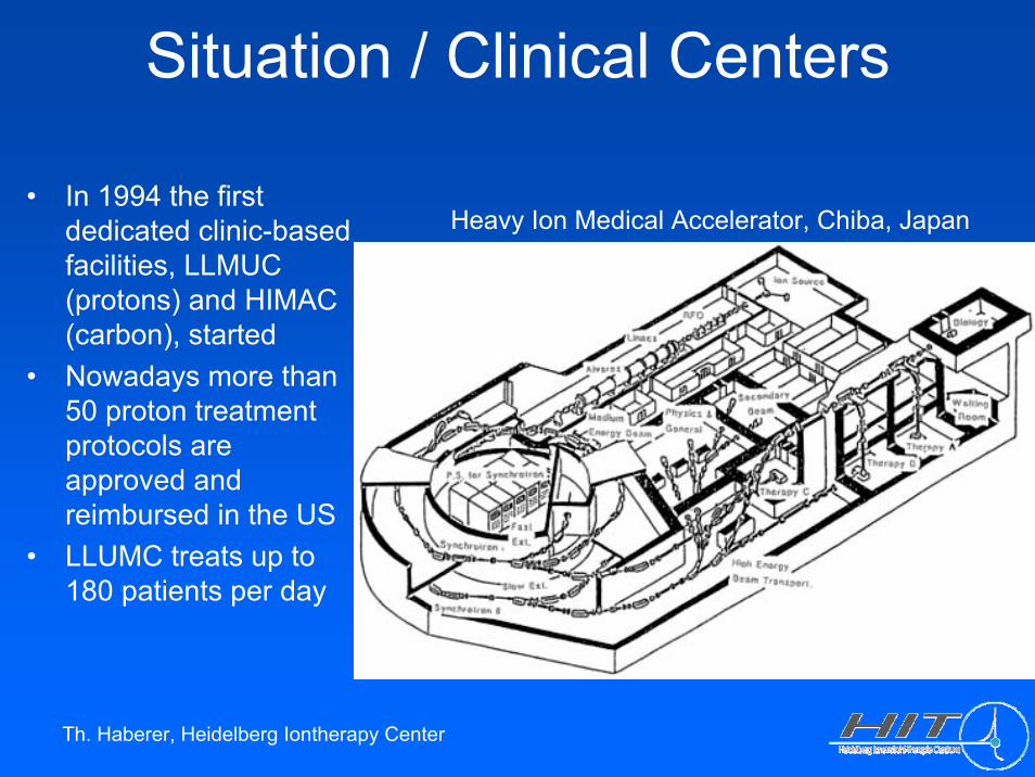
Situation / Clinical Centers
• In 1994 the firstdedicated clinic-basedfacilities, LLMUC (protons) and HIMAC (carbon), started
• Nowadays more than50 proton treatmentprotocols areapproved and reimbursed in the US
• LLUMC treats up to 180 patients per day
Heavy Ion Medical Accelerator, Chiba, Japan
Th. Haberer, Heidelberg Iontherapy Center
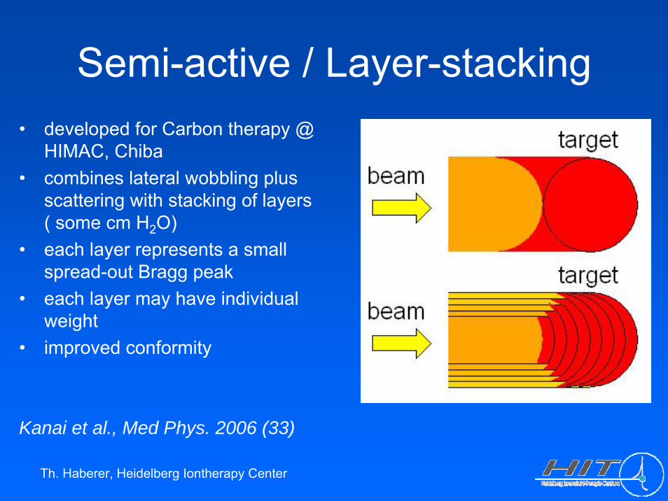
Semi-active / Layer-stacking• developed for Carbon therapy @
HIMAC, Chiba• combines lateral wobbling plus
scattering with stacking of layers( some cm H2O)
• each layer represents a smallspread-out Bragg peak
• each layer may have individualweight
• improved conformity
Kanai et al., Med Phys. 2006 (33)

Th. Haberer, Heidelberg Iontherapy Center
Semi-active / Layer-stacking

Th. Haberer, Heidelberg Iontherapy Center
Semi-active / Layer-stacking
wedge-shaped dose distribution
Th. Haberer, Heidelberg Iontherapy Center
Active Dose DeliveryThe basic idea:
Dissect the treatment volumeinto thousands of voxels. Usesmall pencil beams with a spatial resolution of a few mm to fill each voxel with a pre-calculated amount of stoppingparticles taking into accountthe underlying physical and biological interactions.
=> Extreme intensitymodulation
The inverse approach:
Dose distributions of utmosttumor conformity can beproduced by superimposingmany thousands Bragg-peaksin 3D. Sophisticated requirementsconcerning the beam delivery system, the accelerator, thetreatment planning, QA, ... result from this approach.
Th. Haberer, Heidelberg Iontherapy Center
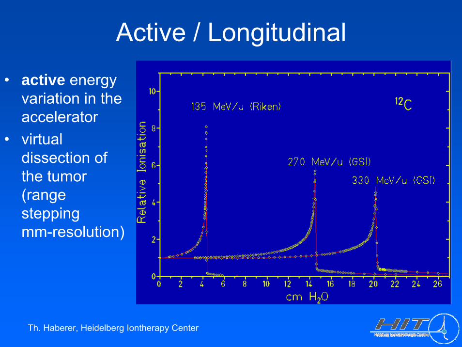
Active / Longitudinal
• active energyvariation in theaccelerator
• virtualdissection of the tumor(rangesteppingmm-resolution)
Th. Haberer, Heidelberg Iontherapy Center
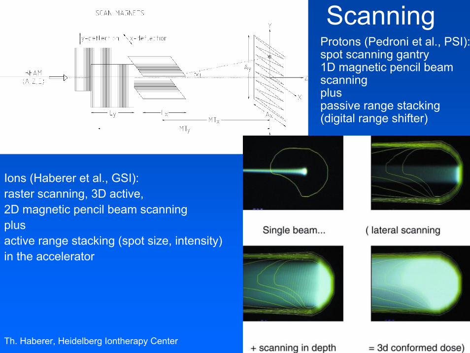
Scanning
Ions (Haberer et al., GSI): raster scanning, 3D active,2D magnetic pencil beam scanningplusactive range stacking (spot size, intensity)in the accelerator
• Protons (Pedroni et al., PSI): spot scanning gantry1D magnetic pencil beamscanningplus passive range stacking(digital range shifter)

Th. Haberer, Heidelberg Iontherapy Center
Active / Lateral• superpositioning of gaussian
beam spots, statistics 103 particles
105 particles

Th. Haberer, Heidelberg Iontherapy Center
Active / Lateral• 2d superpositioning,
step sizeand beam spot size

Th. Haberer, Heidelberg Iontherapy Center
Active / Lateral
• homogeneityof fluencedistributions
geometry statistics

Rasterscan Method
scanning offocussedion beamsin fastdipole magnets
active variationof the energy,focus andintensity in theaccelerator andbeam lines
Haberer et al., NIM A , 1993
Th. Haberer, Heidelberg Iontherapy Center
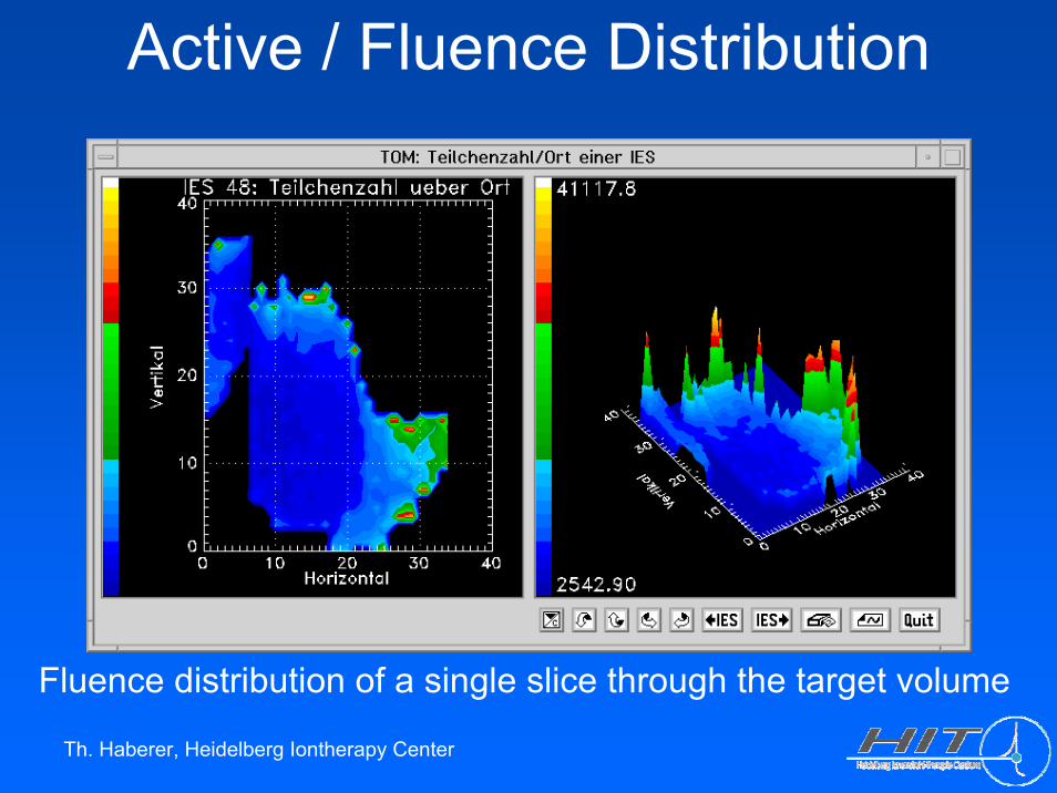
Active / Fluence Distribution
Fluence distribution of a single slice through the target volume
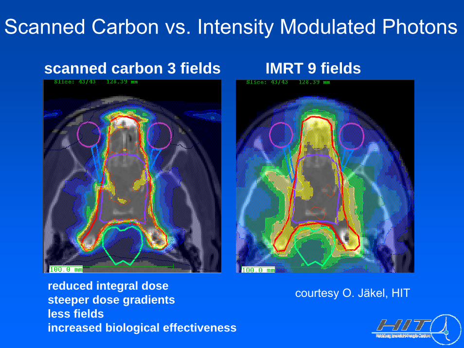
Scanned Carbon vs. Intensity Modulated Photons
scanned carbon 3 fields IMRT 9 fields
reduced integral dosesteeper dose gradientsless fieldsincreased biological effectiveness
courtesy O. Jäkel, HIT
Th. Haberer, Heidelberg Iontherapy Center
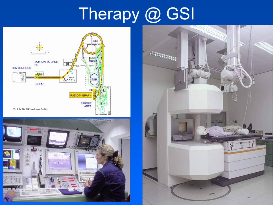
Therapy @ GSI

Th. Haberer, Heidelberg Ion Therapy Center
Key Developments @ GSI
• Scanning-ready pencil beam library (25.000 combinations): 253 energies (1mm range steps) x 7 spot sizes x 15 intensity steps
• Rasterscan method incl. approved controls and safety• Beammonitors follow the scanned beams (v <= 40 m/s) in real-time• Biological interactionmodel (LEM) based on 25 years of
radiobiological research• Physical beam transportmodel• Planningsystem TRiP• In-beam Positron Emission Tomography• QA system• Prototype of the scanning ion gantry

Th. Haberer, Heidelberg Iontherapy Center
Heidelberg Ion Therapy Center• compact design• full clinical integration• rasterscanning only• low-LET modality:
Protons (later He)• high-LET modality:
Carbon (Oxygen)• ion selection within
minutes• world-wide first scanning
ion gantry• > 1000 patients/year
> 15.000 fractions/year
Th. Haberer, Heidelberg Ion Therapy Center
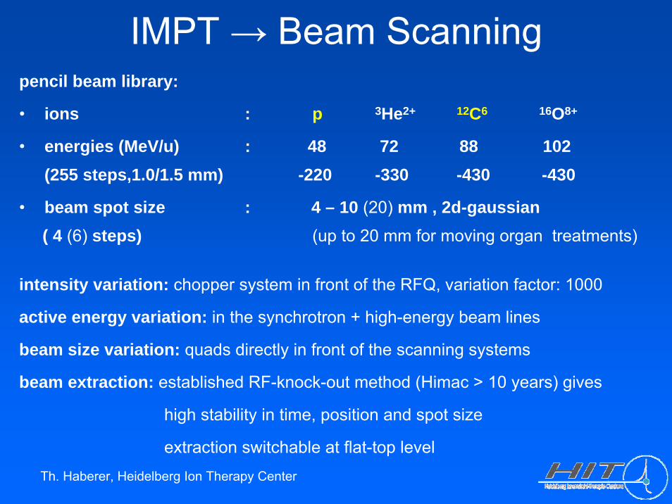
pencil beam library:
• ions : p 3He2+ 12C6 16O8+
• energies (MeV/u) : 48 72 88 102(255 steps,1.0/1.5 mm) -220 -330 -430 -430
• beam spot size : 4 – 10 (20) mm , 2d-gaussian( 4 (6) steps) (up to 20 mm for moving organ treatments)
intensity variation: chopper system in front of the RFQ, variation factor: 1000
active energy variation: in the synchrotron + high-energy beam lines
beam size variation: quads directly in front of the scanning systems
beam extraction: established RF-knock-out method (Himac > 10 years) gives
high stability in time, position and spot size
extraction switchable at flat-top level
IMPT → Beam Scanning
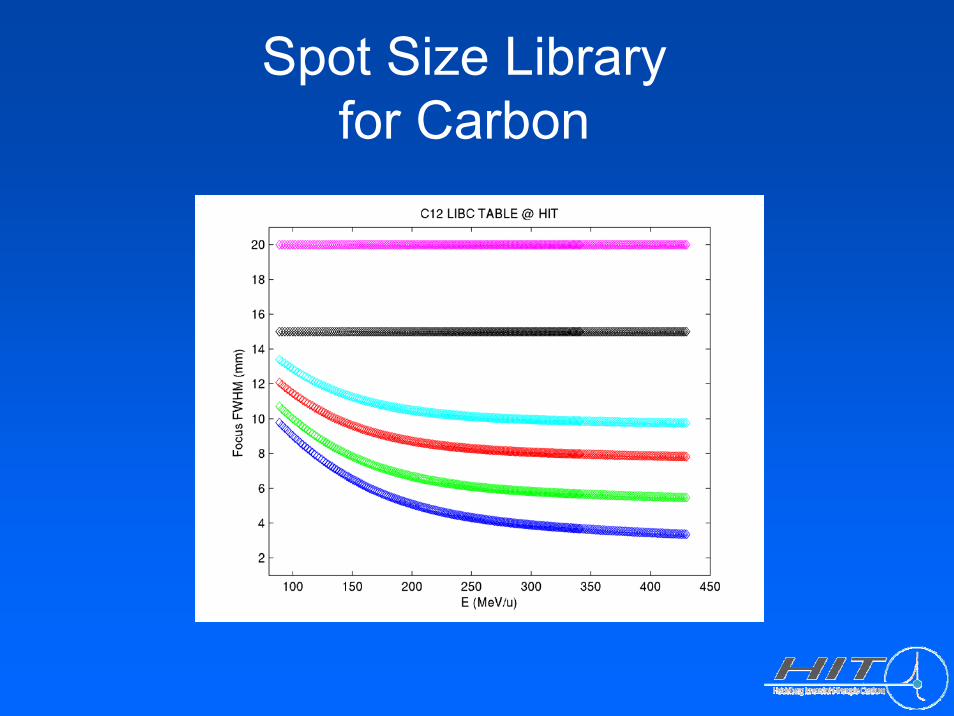
Spot Size Libraryfor Carbon

Treatment Planning System
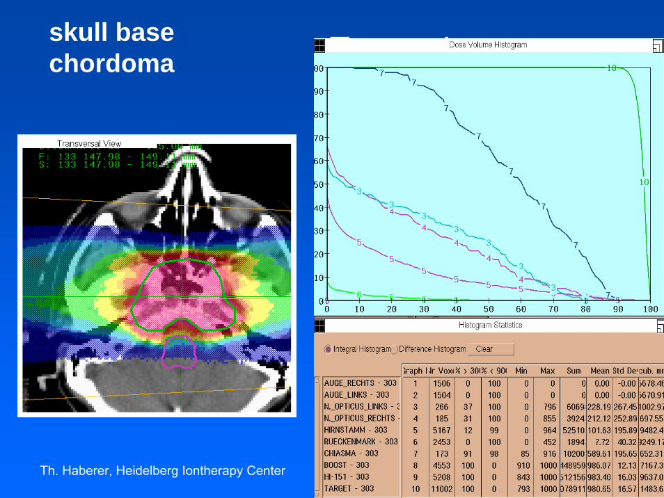
skull base chordoma, fraction sequence for 2 proton plansPlan1_CTV_P 50 GyE + Plan2_GTV_P 24 GyE

Th. Haberer, Heidelberg Iontherapy Center
HIT Scanning Beam Nozzle

Commissioning
commissioning result, Protons @ H1:3d dose delivery vs. treatment planning24 thimble-type ICs in a water phantom, standard deviation 2.2 % QA Table Top with Water Phantom
Th. Haberer, Heidelberg Iontherapy Center
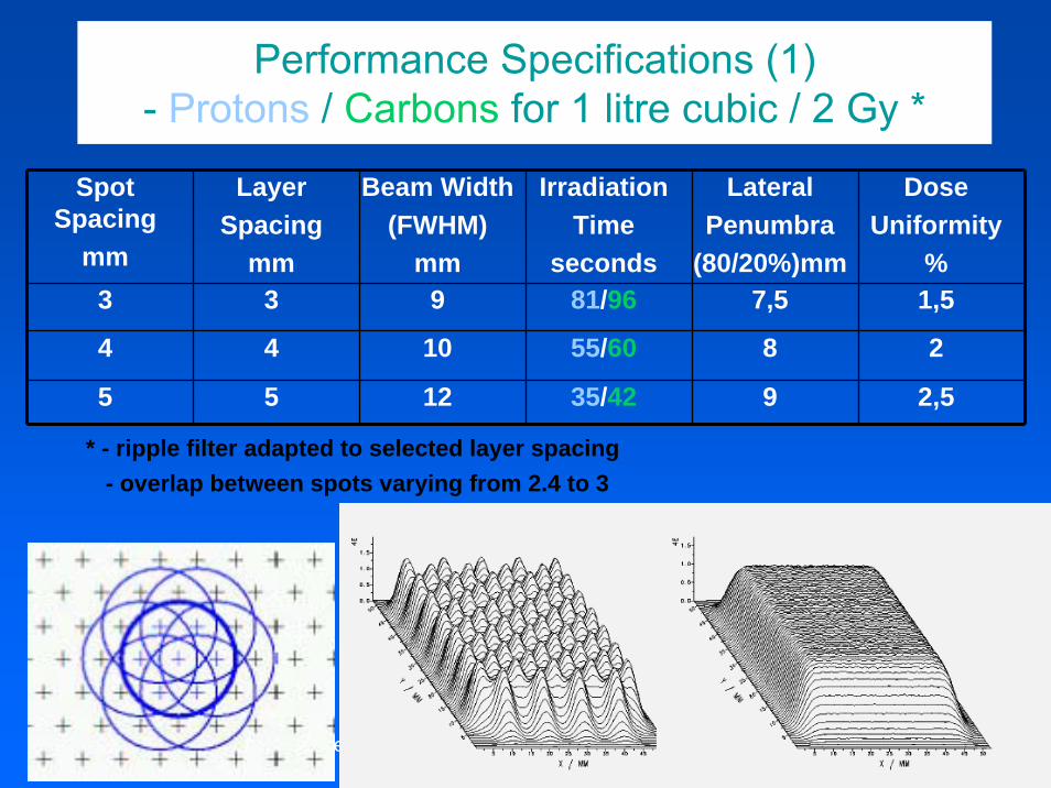
Performance Specifications (1)- Protons / Carbons for 1 litre cubic / 2 Gy *
Spot Spacing
mm
LayerSpacing
mm
Beam Width(FWHM)
mm
IrradiationTime
seconds
LateralPenumbra
(80/20%)mm
DoseUniformity
%3 3 9 81/96 7,5 1,5
4 4 10 55/60 8 2
5 5 12 35/42 9 2,5
* - ripple filter adapted to selected layer spacing- overlap between spots varying from 2.4 to 3

Th. Haberer, Heidelberg Iontherapy Center
Performance Specifications (2)- Clinical Case Examples for Protons / Carbons
„skull base chordoma“Spot
Spacingmm
LayerSpacing
mm
BeamWidth
(FWHM)
Energies/Positions
IrradiationTimesec.
LateralPenumbra(80/20%)
mm
DoseUniformity
%
2 3 5 35/8200 63 4.9 2.42 3 6 35/8200 44 5.8 1.7
* typical GSI parameters: - ripple filter 3 mm- overlap between spots 3- 1 of 2 fields- dose/ field : 1 Gy- volume: 300 ccm
Th. Haberer, Heidelberg Iontherapy Center
Example:Skull basechordoma
skull basechordoma
Th. Haberer, Heidelberg Iontherapy Center Th. Haberer
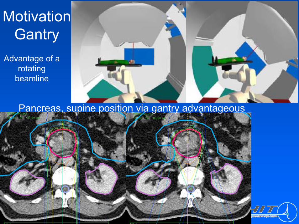
Motivation Gantry
Advantage of a rotating
beamline
Pancreas, supine position via gantry advantageous

Th. Haberer, Heidelberg Iontherapy Center
Gantry 1 / PSI

Th. Haberer, Heidelberg Iontherapy Center
Gantry 2 / PSI

Th. Haberer, Heidelberg Iontherapy Center
Design for HIT
MT Aerospace
• isocentric barrel-type
• world-wide firstion gantry
• 2D beam scanningupstream to finalbending, almostparallel due to edgefocussing
• ± 180o rotation3o / second
• 13m diameter25m length570 to rotating(145 to magnets)
MT Aerospace

Th. Haberer, Heidelberg Iontherapy Center
Gantry / Medtech

Interplay scanned beam - moving targetstationary target – scanned beam moving target – scanned beam
beam
film
patie
nt(c
alcu
latio
n)fil
m(e
xper
imen
tal)
courtesy C.Bert, GSI

Thank you for your attention !
(Intensity modulated raster scan, 12C at 430 Mev/u, October 15th 2007)