Influence of Cable Lengths on EMI Emissions of a DC/DC Converter ...
6
HAL Id: hal-03260269 https://hal.archives-ouvertes.fr/hal-03260269 Submitted on 14 Oct 2021 HAL is a multi-disciplinary open access archive for the deposit and dissemination of sci- entific research documents, whether they are pub- lished or not. The documents may come from teaching and research institutions in France or abroad, or from public or private research centers. L’archive ouverte pluridisciplinaire HAL, est destinée au dépôt et à la diffusion de documents scientifiques de niveau recherche, publiés ou non, émanant des établissements d’enseignement et de recherche français ou étrangers, des laboratoires publics ou privés. Influence of Cable Lengths on EMI Emissions of a DC/DC Converter Influence of Cable Lengths on EMI Emissions of a DC/DC Converter Baghdadi Benazza, Abdelber Bendaoud, Jean-Luc Schanen To cite this version: Baghdadi Benazza, Abdelber Bendaoud, Jean-Luc Schanen. Influence of Cable Lengths on EMI Emissions of a DC/DC Converter Influence of Cable Lengths on EMI Emissions of a DC/DC Converter. Modelling, Measurement and Control A, 2020, 93 (1-4), pp.26–30. 10.18280/mmc_a.931-404. hal- 03260269
-
Upload
khangminh22 -
Category
Documents
-
view
1 -
download
0
Transcript of Influence of Cable Lengths on EMI Emissions of a DC/DC Converter ...
HAL Id: hal-03260269https://hal.archives-ouvertes.fr/hal-03260269
Submitted on 14 Oct 2021
HAL is a multi-disciplinary open accessarchive for the deposit and dissemination of sci-entific research documents, whether they are pub-lished or not. The documents may come fromteaching and research institutions in France orabroad, or from public or private research centers.
L’archive ouverte pluridisciplinaire HAL, estdestinée au dépôt et à la diffusion de documentsscientifiques de niveau recherche, publiés ou non,émanant des établissements d’enseignement et derecherche français ou étrangers, des laboratoirespublics ou privés.
Influence of Cable Lengths on EMI Emissions of aDC/DC Converter Influence of Cable Lengths on EMI
Emissions of a DC/DC ConverterBaghdadi Benazza, Abdelber Bendaoud, Jean-Luc Schanen
To cite this version:Baghdadi Benazza, Abdelber Bendaoud, Jean-Luc Schanen. Influence of Cable Lengths on EMIEmissions of a DC/DC Converter Influence of Cable Lengths on EMI Emissions of a DC/DC Converter.Modelling, Measurement and Control A, 2020, 93 (1-4), pp.26–30. �10.18280/mmc_a.931-404�. �hal-03260269�
Influence of Cable Lengths on EMI Emissions of a DC/DC Converter
Baghdadi Benazza1,2*, Abdelber Bendaoud2, Jean-Luc Schanen3
1 Laboratory of Applications of Plasma, Electrostatics and Electromagnetic Compatibility (APELEC), Djillali Liabès
University of Sidi Bel-Abbès, Sidi Bel-Abbés 22000, Algeria 2 Electrical Engineering Department, University Center Belhadj Bouchaib of Ain Temouchent, Ain Temouchent 46000, Algeria 3 G2Elab, CNRS, G-INP (Inst. of Eng. Univ Grenoble Alps), University of Grenoble Alpes, Grenoble 38000, France
Corresponding Author Email: [email protected]
https://doi.org/10.18280/mmc_a.931-404
ABSTRACT
Received: 26 February 2019
Accepted: 16 September 2020
The aim of this study is to evaluate the influence of the position of a DC/DC static
converter between a source and a load with regard to the conducted EMC emissions
measured on the source. An experimental model was established through the analysis
of relevant stresses, such as the variation in the lengths of the source-converter,
converter-load cables and the impact of the shield connection. Through this study, it
was observed that the circuit was sensitive to too large variations in the capacities of
common mode and of the link, and the results obtained make it possible to confirm
the reality of the electromagnetic pollution of the static DC/DC converter "Buck" as
a function of connections. The results of this research can be used in DC/DC
network designs based on buck converters.
Keywords:
EMC in the field of power electronics,
Electromagnetic disturbances, LISN, shielding,
common mode, differential mode, Buck chopper
1. INTRODUCTION
In recent years, the increase in equipment in automobiles
and the need to reduce fuel consumption has led to the search
for a less mechanical and more electric automobile.
To this end, the distribution of controls has become more
and more electric and as a result a large number of static
power converters are present.
Given this high proportion of converters based on the
semiconductors used operate at higher and higher
frequencies, this generates very restrictive electromagnetic
disturbances.
These disruptions, which are part of the problems of
electromagnetic compatibility (EMC) [1], are attracting more
and more the attention of manufacturers, especially in the
automotive field, which orients a more electric generation
[2].
The generation of electromagnetic disturbances requires
the implementation of an electrical model of electromagnetic
compatibility based on power converters composed of
semiconductors [3].
A set of environmental testing procedures to ensure that all
equipment inside the automobile does not generate
electromagnetic interference that compromises the operation
of the equipment itself and those in its vicinity.
A circuit model for electromagnetic interference (EMI) of
a DC-DC converter has been proposed.
The aim of this article is to use this generic circuit in order
to place an experimental analysis approach of the
disturbances emitted by DC/DC converters ("Buck"
choppers) positioned, by two-wire cables between an LISN
and the load. Therefore, it will be necessary to be able to identify the parameters of this circuit. This study is part of
the electric power networks embedded complex in a car [4-
9].
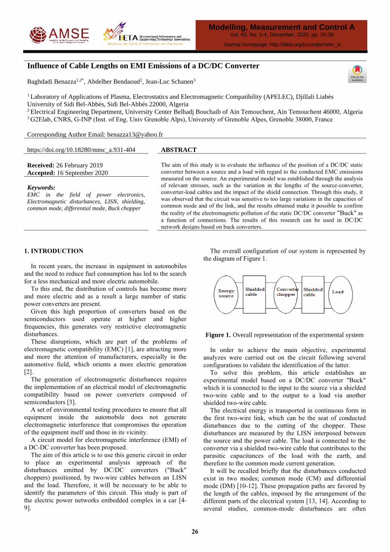
The overall configuration of our system is represented by
the diagram of Figure 1.
Figure 1. Overall representation of the experimental system
In order to achieve the main objective, experimental
analyzes were carried out on the circuit following several
configurations to validate the identification of the latter.
To solve this problem, this article establishes an
experimental model based on a DC/DC converter "Buck"
which it is connected to the input to the source via a shielded
two-wire cable and to the output to a load via another
shielded two-wire cable.
The electrical energy is transported in continuous form in
the first two-wire link, which can be the seat of conducted
disturbances due to the cutting of the chopper. These
disturbances are measured by the LISN interposed between
the source and the power cable. The load is connected to the
converter via a shielded two-wire cable that contributes to the
parasitic capacitances of the load with the earth, and
therefore to the common mode current generation.
It will be recalled briefly that the disturbances conducted
exist in two modes; common mode (CM) and differential
mode (DM) [10-12]. These propagation paths are favored by
the length of the cables, imposed by the arrangement of the
different parts of the electrical system [13, 14]. According to
several studies, common-mode disturbances are often
Modelling, Measurement and Control A Vol. 93, No. 1-4, December, 2020, pp. 26-30
Journal homepage: http://iieta.org/journals/mmc_a
26
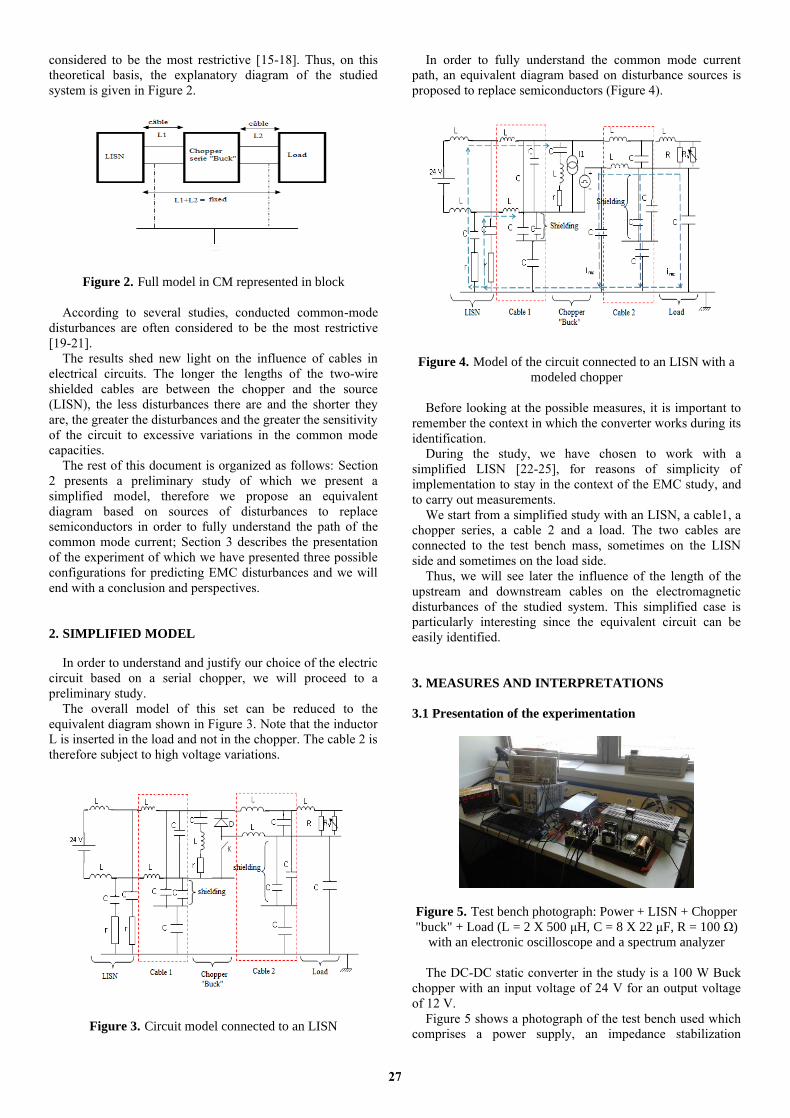
considered to be the most restrictive [15-18]. Thus, on this
theoretical basis, the explanatory diagram of the studied
system is given in Figure 2.
Figure 2. Full model in CM represented in block
According to several studies, conducted common-mode
disturbances are often considered to be the most restrictive
[19-21].
The results shed new light on the influence of cables in
electrical circuits. The longer the lengths of the two-wire
shielded cables are between the chopper and the source
(LISN), the less disturbances there are and the shorter they
are, the greater the disturbances and the greater the sensitivity
of the circuit to excessive variations in the common mode
capacities.
The rest of this document is organized as follows: Section
2 presents a preliminary study of which we present a
simplified model, therefore we propose an equivalent
diagram based on sources of disturbances to replace
semiconductors in order to fully understand the path of the
common mode current; Section 3 describes the presentation
of the experiment of which we have presented three possible
configurations for predicting EMC disturbances and we will
end with a conclusion and perspectives.
2. SIMPLIFIED MODEL
In order to understand and justify our choice of the electric
circuit based on a serial chopper, we will proceed to a
preliminary study.
The overall model of this set can be reduced to the
equivalent diagram shown in Figure 3. Note that the inductor
L is inserted in the load and not in the chopper. The cable 2 is
therefore subject to high voltage variations.
Figure 3. Circuit model connected to an LISN
In order to fully understand the common mode current
path, an equivalent diagram based on disturbance sources is
proposed to replace semiconductors (Figure 4).
Figure 4. Model of the circuit connected to an LISN with a
modeled chopper
Before looking at the possible measures, it is important to
remember the context in which the converter works during its
identification.
During the study, we have chosen to work with a
simplified LISN [22-25], for reasons of simplicity of
implementation to stay in the context of the EMC study, and
to carry out measurements.
We start from a simplified study with an LISN, a cable1, a
chopper series, a cable 2 and a load. The two cables are
connected to the test bench mass, sometimes on the LISN
side and sometimes on the load side.
Thus, we will see later the influence of the length of the
upstream and downstream cables on the electromagnetic
disturbances of the studied system. This simplified case is
particularly interesting since the equivalent circuit can be
easily identified.
3. MEASURES AND INTERPRETATIONS
3.1 Presentation of the experimentation
Figure 5. Test bench photograph: Power + LISN + Chopper
"buck" + Load (L = 2 X 500 μH, C = 8 X 22 μF, R = 100 Ω)
with an electronic oscilloscope and a spectrum analyzer
The DC-DC static converter in the study is a 100 W Buck
chopper with an input voltage of 24 V for an output voltage
of 12 V.
Figure 5 shows a photograph of the test bench used which
comprises a power supply, an impedance stabilization
27
network (LISN), a "buck" chopper and a load (L = 2 × 500
μH, C = 8 × 22 μF, R = 100 Ω). An electronic oscilloscope
and a spectrum analyzer were used for the measurements.
The Buck chopper is connected as input to an LISN via a
two-wire shielded link (cable 1 of length L1-1) and output on
a fixed load via another shielded two-wire link (cable 2 of
length L2-2). (Table 1).
Table 1 shows the different lengths of the two-wire
shielded cables used.
Table 1. Core length values
Length LISN side Load side
Cable 1 Cable 2
L1-1 5 m
X 2.5 m
L2-2 X 5 m
2.5 m
Tests have also been done by either connecting the
shielding of the cables or not to the plan of mass.
To visualize all temporal and frequency responses, an
electronic oscilloscope and a spectrum analyzer were
respectively used (Figure 6). Only the frequency responses
will be presented in this study.
Figure 6. Block diagram of the manipulation
3.2 EMC disturbance prediction
To see the difference between the different results, we
superimpose the two configurations as follows:
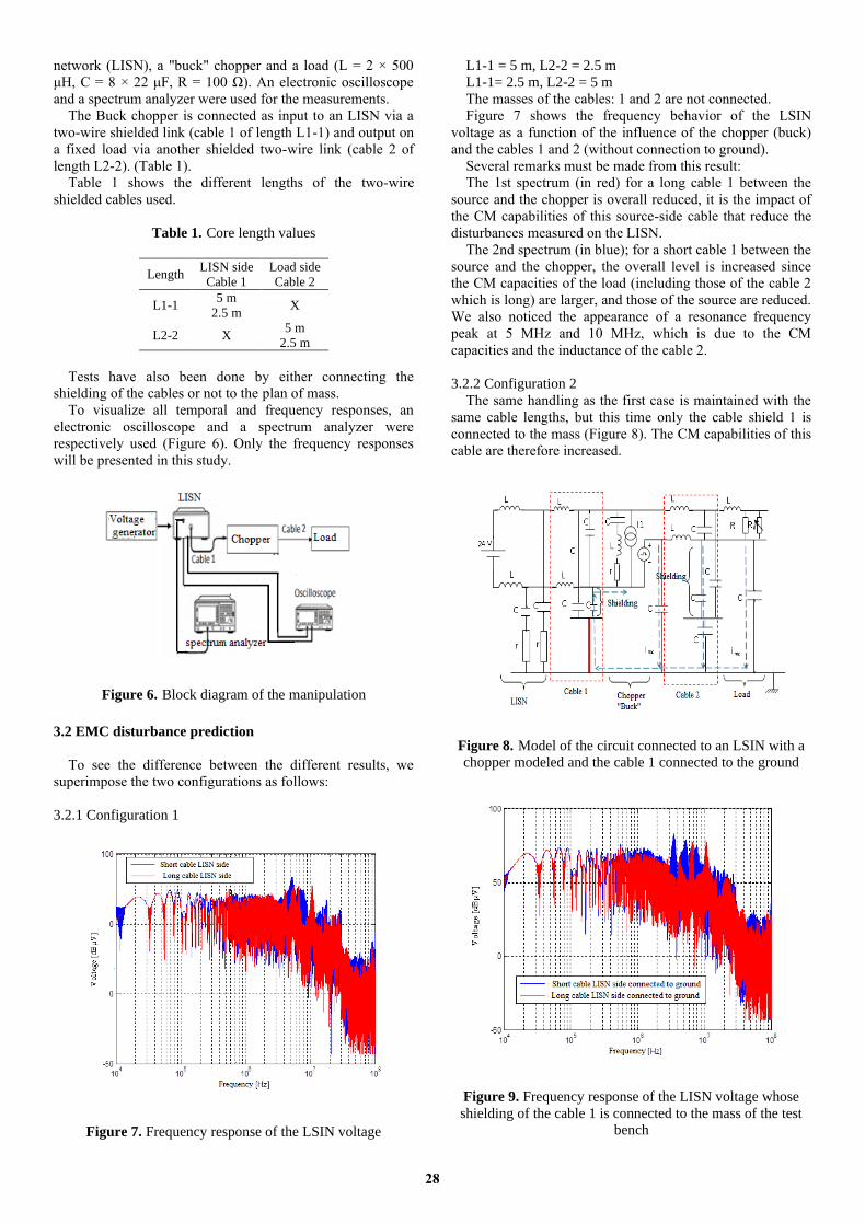
3.2.1 Configuration 1
Figure 7. Frequency response of the LSIN voltage
L1-1 = 5 m, L2-2 = 2.5 m
L1-1= 2.5 m, L2-2 = 5 m
The masses of the cables: 1 and 2 are not connected.
Figure 7 shows the frequency behavior of the LSIN
voltage as a function of the influence of the chopper (buck)
and the cables 1 and 2 (without connection to ground).
Several remarks must be made from this result:
The 1st spectrum (in red) for a long cable 1 between the
source and the chopper is overall reduced, it is the impact of
the CM capabilities of this source-side cable that reduce the
disturbances measured on the LISN.
The 2nd spectrum (in blue); for a short cable 1 between the
source and the chopper, the overall level is increased since
the CM capacities of the load (including those of the cable 2
which is long) are larger, and those of the source are reduced.
We also noticed the appearance of a resonance frequency
peak at 5 MHz and 10 MHz, which is due to the CM
capacities and the inductance of the cable 2.
3.2.2 Configuration 2
The same handling as the first case is maintained with the
same cable lengths, but this time only the cable shield 1 is
connected to the mass (Figure 8). The CM capabilities of this
cable are therefore increased.
Figure 8. Model of the circuit connected to an LSIN with a
chopper modeled and the cable 1 connected to the ground
Figure 9. Frequency response of the LISN voltage whose
shielding of the cable 1 is connected to the mass of the test
bench
28

Figure 9 shows the frequency response of the LSIN
voltage as a function of the influence of the chopper (buck)
and the shielded two-wire cables whose shielding of the cable
1 is connected to ground.
We see that for the 1st spectrum (in red), for a long cable1
between the source and the chopper, is reduced as compared
to the 1st case which confirms the positive impact of CM
capabilities.
For the second spectrum (in blue), it is noted that the
increase in the length of the cable 2 generates an increase in
common mode capabilities and therefore the spectrum. There
is also a reduction in the frequency of resonance peaks due to
this increase in CM capabilities.
3.2.3 Configuration 3
The same handling as the first case is maintained with the
same lengths of the cables, but this time the shields of the
two cables 1 and 2 are connected to the mass of the test stand
(Figure 10).
Figure 10. Model of the circuit connected to an LISN with a
chopper modeled and the two cables 1 and 2 connected to
ground
Figure 11 shows the frequency response of the LISN
voltage whose shielding of the two cables 1 and 2 is
connected to ground
Figure 11. Frequency response of the LISN voltage whose
shielding of the two cables1 and 2 is connected to ground
The 1st spectrum (in red) for a long cable1 between the
source and the chopper is reduced compared to the 1st and
2nd cases. This is the most favorable case since the common
mode capacities are maximum. In addition, the disturbances
are directly replugged by the shields of the two cables
connected to the mass and no longer pass through the LISN.
Thus, the more cable 1 is long, the more resonance peak is
reduced to 5 MHz.
The influence of the mass with respect to the
electromagnetic disturbances is perfectly distinguished, from
which the cable 1 acts as CM filtering, whereas the cable 2
emits disturbances in CM.
4. CONCLUSION
The objective of this work was to understand how and why
the connecting cables between the LISN source and the DC-
DC static converter have an influence on the EMC
disturbances and how to minimize them. The longer the
length of the two-core shielded cables between the chopper
and the source (LISN), the less disturbances there are and the
shorter they are the more disturbances are important.
The cable between the power supply and the converter has
a role of filtering in CM, while the cable between the chopper
and the load emits disturbances in CM, the longer it is the
more there are strong transmissions of common mode.
Thus we have seen in our example that the circuit was
sensitive to too large variations in common mode capabilities
and link. As a result, the cables were connected to the ground
and the effect of the latter on the minimization of the IEM
was seen.
The results obtained make it possible to confirm the reality
of the electromagnetic pollution of the DC/DC "Buck" static
converter as a function of the connections.
In terms of perspectives, it seems essential to carry out the
study of a DC/DC network made up of converters which
have been studied in simulation in a circuit under other forms
of links (single-wire, twisted, etc.) with new conductive
materials.
ACKNOWLEDGMENT
The authors are very grateful to Prof. Jean Luc. Schanen
for his contribution to this experimental work and to facilate
their task. This work was carried out in the polytechnic
institute of Grenoble, electrical engineering laboratory G2E
lab- University of Grenoble, France. It falls within the
framework of training awarded to the first author for his
doctoral thesis.
REFERENCES
[1] Payami, S., Behera, R.K., Iqbal, A., Al-Ammari, R.
(2015). Common-mode voltage and vibration mitigation
of a five-phase three-level NPC inverter-fed induction
motor drive system. IEEE Journal of Emerging and
Selected Topics in Power Electronics, 3(2): 349-361.
https://doi.org/10.1109/JESTPE.2014.2313153
[2] Merabet, B., Vollaire, C., Sartori, C., Jettanasen, C.
(2007). EMC of variable-speed drive systems in
aeroplanes. 2EMC of IEEE Symposium on Embedded
29
EMC, Rouen, France.
[3] Toure, B.B. (2012). Modélisation haute fréquence des
variateurs de vitesse pour aéronefs: Contribution au
dimensionnement et à l’optimisation de filtres CEM.
Thèse de doct. Grenoble - France: Université Grenoble
Alpes.
[4] Messaoudi, M., Videt, A., Idir, N., Boulharts, H., Vang,
H. (2014). Modeling the residual common-mode
voltage generated by 3-phase inverters with
simultaneous-switching PWM strategies. 2014 IEEE
Vehicle Power and Propulsion Conference (VPPC),
Coimbra, pp. 1-6.
http://dx.doi.org/10.1109/VPPC.2014.7007103
[5] Frantz, G. (2015). Approche système pour l’etude de la
compatibilité électromagnétique des réseaux embarques.
Thèse de Doctorat, Energie électrique. Université
Grenoble Alpes. Français.
[6] Huynh, H.A., Joo, S., Kim, S. (2016). An experimental
study of EMI reduction of DC-DC converter with
frequency hopping technique. In Proceedings of the
Electrical Design of Advanced Packaging and Systems,
Honolulu, HI, USA, pp. 107-109.
[7] Lu, N.J., Hredzak, B. (2018). Current ripple reduction
for photovoltaic powered single-phase buck-boost
differential inverter under nonlinear loads. 2018 7th
International Conference on Renewable Energy
Research and Applications (ICRERA), Paris, France, pp.
544-548.
http://dx.doi.org/10.1109/ICRERA.2018.8566746
[8] Chikhi, N., Bendaoud, A., Slimani, H., Benazza, B.,
Miloudi, H. (2015). Génération des perturbations dans
un hacheur et identification des chemins de propagation
vers le réseau électrique. 9ème Conférence sur le Génie
Electrique EMP, Bordj El Bahri, Alger.
[9] Benazza, B., Bendaoud, A., Reineix, A., Dafif, O.,
Slimani, H. (2019). Experimental study of the behaviour
of the crosstalk of shielded or untwisted-pair cables in
high frequency. Serbian Journal of Electrical
Engineering, 16(3): 311-324.
https://doi.org/10.2298/SJEE1903311B
[10] Brovont, A., Cuzner, R. (2018). Modeling common-
mode circulating currents in paralleled non-isolated DC-
DC converter-based systems. 2018 IEEE Energy
Conversion Congress and Exposition (ECCE), Portland,
pp. 4187-4194.
http://dx.doi.org/10.1109/ECCE.2018.8558277
[11] Brovont, A.D., Cuzner, R.M. (2018). DM and CM
modeling of non-isolated buck converters for EMI filter
design. 2018 IEEE Transportation Electrification
Conference and Expo (ITEC), Long Beach, CA, USA,
pp. 140-145.
http://dx.doi.org/10.1109/ITEC.2018.8450232
[12] Benhadda, N., Bendaoud, A., Chikhi, N. (2018). A
conducted EMI noise prediction in DC/DC converter
using a frequency-domain approach. Elektrotehniški
Vestnik Journal, 85(3): 103-108.
[13] Durier, A., Marot, C., Crepel, O. (2013). Using the EM
simulation tools to predict the Conducted Emissions
level of a DC/DC boost converter: Introducing EBEM-
CE model. 2013 9th International Workshop on
Electromagnetic Compatibility of Integrated Circuits
(EMC Compo), Nara, pp. 152-157.
https://doi.org/10.1109/EMCCompo.2013.6735191
[14] Miloudi, H., Bendaoud, A., Miloudi, M. (2017). A
method for modeling a common-mode impedance for
the AC motor. Elektrotehniški Vestnik Journal, 84(5):
241-246.
[15] Costa, F., Vollaire, C., Meuret, R. (2005). Modeling of
conducted common mode perturbations in variable-
speed drive systems. IEEE Transactions on
Electromagnetic Compatibility, 47(4): 1012-1021.
http://dx.doi.org/10.1109/TEMC.2005.857365
[16] Zhu, N., Xu, D, Wu, B., Zargari, N.R., Kazerani, M.,
Liu, F. (2013). Common-mode voltage reduction
methods for current-source converters in medium-
voltage drives. IEEE Transactions on Power Electronics,
28(2): 995-1006.
https://doi.org/10.1109/TPEL.2012.2201174
[17] Slimani, H., Bendaoud, A., Reguig, A., Benazza, B.,
Reineix, A., Dafif, O. (2016). Experimental study of
coupling between an electromagnetic wave and
transmission lines in a GTEM cell. Journal of Electrical
Engineering, 16(1): 195-203.
[18] Meynard, T., Cougo, B., Brandelero, J. (2013). Design
of differential mode filters for two-level and multicell
converters. IEEE 11th International Workshop of
Electronics, Control, Measurement, Signals and their
application to Mechatronics (ECMSM), Toulouse, pp.
1-6. http://dx.doi.org/10.1109/ECMSM.2013.6648963
[19] Zhai, L., Zhang, T., Cao, Y., Yang,S.P., Kavuma, S.,
Feng, H.Y. (2018). Conducted EMI prediction and
mitigation strategy based on transfer function for a
high-low voltage DC-DC converter in electric vehicle.
Energies, 11(5): 1028.
https://doi.org/10.3390/en11051028
[20] Pignari, S.A., Orlandi, A. (2003). Long cable effects on
conducted emissions levels. IEEE Transactions on
Electromagnetic Compatibility, 45(1): 43-54.
https://doi.org/10.1109/TEMC.2002.808023.
[21] Zhai, L., Zhang, X.Y., Bondarenko, N., Loken, D., Van
Doren, T.P., Beetner, D.G. (2016). Mitigation emission
strategy based on resonances from a power inverter
system in electric vehicles. Energies, 9(6): 419.
http://dx.doi.org/10.3390/en9060419
[22] Taki, J., Robert, F., Bensetti, M., Dessante, P., Sadarnac,
D. (2016). Modélisations orientées CEM d’un
convertisseur de puissance pour une optimisation multi-
physique. Symposium de Génie Electrique, Grenoble,
France.
[23] Bodo, N., Jones, M., Levi, E. (2014). A space vector
PWM with common-mode voltage elimination for
open-end winding five-phase drives with a single DC
supply. IEEE Transactions on Industrial Electronics,
61(5): 2197-2207.
http://dx.doi.org/10.1109/TIE.2013.2272273
[24] Miloudi, H., Bendaoud, A., Miloudi, M., Tounsi, F.
(2014). Long cable effect on the electromagnetic
perturbation génerated by three phase inverter-fed-
motor drives. The 3rd international conference on
information processing and electrical engineering,
ICIPEE, Tebessa,14: 24-25.
[25] Chu, Y.B., Wang, S. (2015). A generalized common-
mode current cancelation approach for power converters.
IEEE Transactions on Industrial Electronics, 62(7):
4130-4140. https://doi.org/10.1109/TIE.2014.2387335
30