
Switchable Fresnel lens using polymer-stabilized liquid crystals
Upload
independentCategory
view
0download
0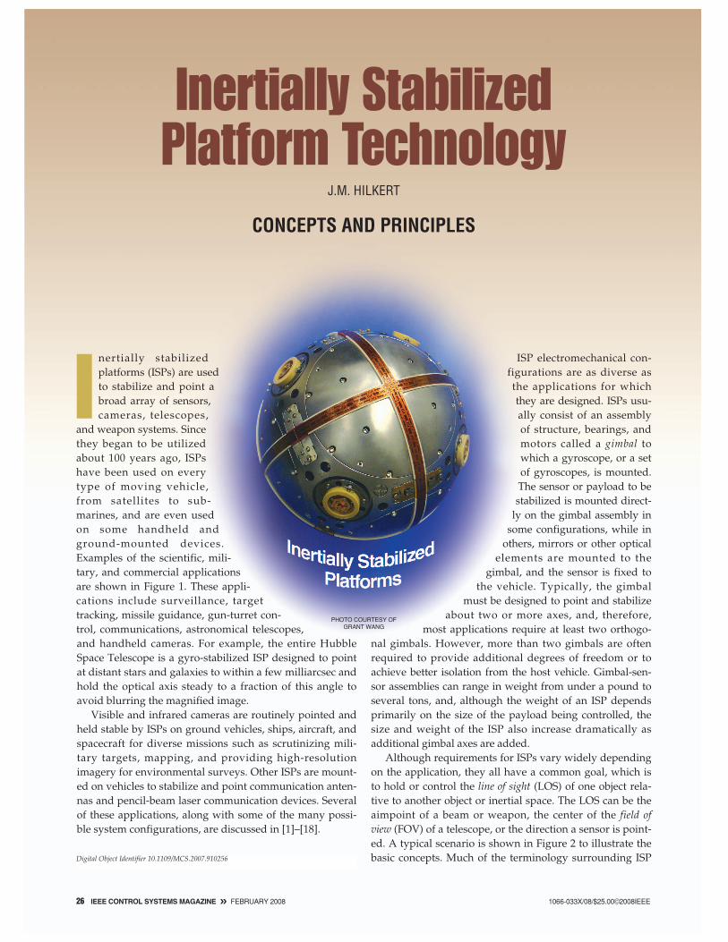
Inertially stabilizedplatforms (ISPs) are usedto stabilize and point abroad array of sensors,cameras, telescopes,
and weapon systems. Sincethey began to be utilizedabout 100 years ago, ISPshave been used on everytype of moving vehicle,from satellites to sub-marines, and are even usedon some handheld andground-mounted devices.Examples of the scientific, mili-tary, and commercial applicationsare shown in Figure 1. These appli-cations include surveillance, targettracking, missile guidance, gun-turret con-trol, communications, astronomical telescopes,and handheld cameras. For example, the entire HubbleSpace Telescope is a gyro-stabilized ISP designed to pointat distant stars and galaxies to within a few milliarcsec andhold the optical axis steady to a fraction of this angle toavoid blurring the magnified image.
Visible and infrared cameras are routinely pointed andheld stable by ISPs on ground vehicles, ships, aircraft, andspacecraft for diverse missions such as scrutinizing mili-tary targets, mapping, and providing high-resolutionimagery for environmental surveys. Other ISPs are mount-ed on vehicles to stabilize and point communication anten-nas and pencil-beam laser communication devices. Severalof these applications, along with some of the many possi-ble system configurations, are discussed in [1]–[18].
ISP electromechanical con-figurations are as diverse asthe applications for whichthey are designed. ISPs usu-ally consist of an assemblyof structure, bearings, andmotors called a gimbal towhich a gyroscope, or a setof gyroscopes, is mounted.The sensor or payload to bestabilized is mounted direct-
ly on the gimbal assembly insome configurations, while in
others, mirrors or other opticalelements are mounted to the
gimbal, and the sensor is fixed tothe vehicle. Typically, the gimbal
must be designed to point and stabilizeabout two or more axes, and, therefore,
most applications require at least two orthogo-nal gimbals. However, more than two gimbals are oftenrequired to provide additional degrees of freedom or toachieve better isolation from the host vehicle. Gimbal-sen-sor assemblies can range in weight from under a pound toseveral tons, and, although the weight of an ISP dependsprimarily on the size of the payload being controlled, thesize and weight of the ISP also increase dramatically asadditional gimbal axes are added.
Although requirements for ISPs vary widely dependingon the application, they all have a common goal, which isto hold or control the line of sight (LOS) of one object rela-tive to another object or inertial space. The LOS can be theaimpoint of a beam or weapon, the center of the field ofview (FOV) of a telescope, or the direction a sensor is point-ed. A typical scenario is shown in Figure 2 to illustrate thebasic concepts. Much of the terminology surrounding ISP
Inertially StabilizedPlatform Technology
J.M. HILKERT
CONCEPTS AND PRINCIPLES
Digital Object Identifier 10.1109/MCS.2007.910256
26 IEEE CONTROL SYSTEMS MAGAZINE » FEBRUARY 2008 1066-033X/08/$25.00©2008IEEE
PHOTO COURTESY OF GRANT WANG

technology has evolved over the years. For example, agimbal was originally thought of specifically as a concen-tric set of rings suspended on bearings, whereas, today, theterm gimbal can refer to most any type of mechanism thatallows the LOS of a stabilized object to be rotated and con-trolled. Likewise, gyro or gyroscope, terms once reserved todescribe a particular spinning wheel device, are now com-monly used to describe any instrument or device that mea-sures rotational motion in inertial space.
In its most primitive form, an ISP attempts only to pre-vent the stabilized object from rotating in inertial spaceand therefore does not necessarily hold a fixed LOS to atarget or object moving relative to it. However, with theexception of a few navigation or scientific applications, themotion that must be controlled is the motion between twoobjects, often moving relative to each other. Using Figure 2as an example, the components of motion and apparentmotion of the LOS between two moving objects candescribed by
ω target/FOV︸ ︷︷ ︸
Total motion of thetarget in the sensor
FOV
= VT⊥/R −Vi⊥/R︸ ︷︷ ︸
Parallactic motioncaused by
target and sensor motionperpendicular to the LOS
+ ωM︸︷︷︸
Apparent motioncaused by
media distortion
− ωi︸︷︷︸
Inertial rotationof the sensor
. (1)
Parallactic motion of the aim point or of the image inthe FOV, which is present whenever the target or sensorhas a velocity component perpendicular to the LOS,requires that a pointing or tracking system be used in con-junction with the ISP. When the target motion is arbitraryor unknown, automatic radar or imaging trackers are nec-essary, but when the target has a known fixed location,some pointing systems use navigation sensors to removethe parallactic motion. Apparent motion caused by medi-um distortion, such as atmospheric scintillation, is farmore difficult to deal with. Typically, these componentsare either accepted as inevitable in the motion error budgetor, when not acceptable, they must be dealt with usingspecial techniques such as adaptive optics [3].
RequirementsIn general, it is not sufficient to simply prevent the sensorfrom rotating in inertial space, but rather, the sensor mustbe controlled in a specific manner depending on what the
sensor system is attempting to accomplish. For example, asillustrated in Figure 2, if the primary purpose of the sys-tem is to obtain a clear image of the target, it may suffice tohold the image steady within the sensor FOV without con-cern for the specific aimpoint. If, however, a beam, such asa laser rangefinder, is to be directed at the target, thenholding the target precisely at the center of the FOV maybe critical, while small amounts of high-frequency rotationor jitter might be inconsequential. For other systems, boththe aimpoint and jitter must be controlled. Thus, therequirements for an ISP system depend on many factors
FEBRUARY 2008 « IEEE CONTROL SYSTEMS MAGAZINE 27
FIGURE 1 Applications of inertially stabilized platforms. Inertially sta-bilized platforms (ISPs) are used in just about every type of movingvehicle as well as some handheld and ground-mounted applica-tions. The Hubble Space Telescope shown in the upper left pointsat distant stars and galaxies with an accuracy of better than 10 milli-arcsec, which is equivalent to looking at a dime from 200 mi [1]. Mili-tary systems, such as the ones shown in the bottom right and left,commonly use multiple ISPs to control the targeting, or tracking,system as well as the weapon aimpoint. Commercial applications ofISPs, such as the handheld camera shown in the upper right, havebeen made possible in the last decade by the development of small,low-cost gyros. [Photos courtesy of (top left) NASA/Space Tele-scope Science Institute, (top right) Konica-Minolta, (bottom left)General Dynamics, and (bottom right) U.S. Air Force.]
FIGURE 2 A typical inertially stabilized-platform (ISP) application.Many applications use ISPs to hold a line of sight (LOS) stationary.For beam- and weapon-pointing applications, the LOS is the aim-point, whereas, for radars and electro-optical sensors, the LOS isdefined by the field-of-view (FOV) of the sensor, where the motionof the target in the FOV is of interest. Although most applicationsrequire that only the two axes orthogonal to the LOS be controlled,some applications require control about all three axes.
FOV
ISP
TargetVT
VT
Vi
Vi
ωi
LOS
RMedium

but are primarily determined by the characteristics of thedevice being stabilized. Various system requirements canbe found in [19]–[25].
Requirements for an imaging system, for example, aredriven by the resolution and integration time of the imag-ing sensor, whereas the requirements for a beam-pointingsystem or a weapon system may be driven more by point-ing accuracy or the native accuracy of the weapon ratherthan by resolution considerations. For imaging systems, itis not uncommon to have stabilization requirements thatare specified as a fraction of a resolution element over thesensor integration time period, which can easily translateto a fraction of a microradian for astronomical telescopesand high-resolution surveillance devices [1], [7], [24]. Incontrast, devices such as handheld cameras and communi-cation antennas may require stabilization performanceonly in the milliradians.
Typical LOS Control ConfigurationAlthough the primary purpose of an ISP is to control therotation of a sensor or object in inertial space, an ISP is typ-ically employed as the basic element of a complex pointingor tracking system. Specifically, the ISP is designed to con-trol only the last component of motion on the right-hand
side of (1). When integrated into a control system withtracking or pointing sensors as in Figure 2, however, iner-tial rotation is controlled such that the total motion of thetarget image in the FOV can be controlled. The block dia-gram in Figure 3 represents one axis of a generic ISP con-trol system configuration that includes a tracking mode, ageo-pointing mode, and a joystick mode to allow a humanoperator to point or slew the LOS. Typically, the ISP con-trol system is configured as a high-bandwidth rate loopinside a lower bandwith pointing or tracking positionloop. Thus, the ISP might be viewed as a means for remov-ing high-frequency disturbances and controlling the LOS,whereas the pointing and tracking loops have the task ofremoving the lower frequency parallatic motion and per-haps any bias or drift in the ISP rate loop.
In this article, we concentrate only on the ISP portion ofsystems such as the one depicted in Figure 3. First we con-sider an idealized single-axis system to establish the basicprinciples of operation. Next, we consider some of themore complex and less intuitive effects that must be dealtwith, followed by a brief introduction to some alternativesolutions to particular problems that are commonlyencountered. Finally, we consider the technical skills thatare common to most successful ISP design teams.
28 IEEE CONTROL SYSTEMS MAGAZINE » FEBRUARY 2008
FIGURE 3 A typical integrated inertially stabilized platform (ISP) block diagram. ISPs are commonly integrated into tracking or pointing sys-tems as shown here. The ISP is designed to remove the effects of disturbances and provide a basis for controlling the line of sight (LOS) inresponse to inputs from the tracking and pointing systems. The ISP is thus often configured as a rate loop inside the tracking or pointingposition loop used to point the LOS at a target or in a prescribed direction.
Linear and RotaryDynamic Environment
Lin VibPSDs
Base Motion
INS / GPSAttitudePosition / Vel
Parallactic LateralTarget-to-Sensor
Motion
Rot PSDsandRigid BodyMotion
Vibration lsolation/Mounting Structure
ISP Multi-Axis Gimbal
Controller
DisturbanceTorques
Actuator/Amp
GYROs
Base Motion
LOS Commands
LOS Commands
Measured Glmbal Angles
GimbalDynamics Gimbal
Kinematics
Gimbal Angles
Gyros
Pointing / ScanControl
Computer
ModeSwitch
Fixed TargetCoordinates (XYZ)
Human Operatorand Joystick
Target-to-Sensor Lateral Motion
Target Motion in FOVImage Sensorand Autotracker
LOSGim AngTransducers
Gim Angs
LOSISP LOS Motion
CompensationDevice(IMC)+
−
+−
−+
SOME BASIC PRINCIPLESAlthough many approaches are available for stabilizingthe LOS of an object so that it doesn’t rotate relative toinertial space, perhaps the most straightforward and mostcommon approach is mass stabilization. This term applies toan ISP designed such that its LOS tends to remain station-ary with respect to an inertial reference frame when thebase on which it is mounted is rotated, whether or not agyro or control system is utilized. The principle of massstabilization is essentially an acknowledgment of New-ton’s first and second laws of motion. Newton’s first lawapplied to rotational motion asserts that a body does notaccelerate with respect to an inertial frame unless a torqueis applied. Furthermore, Newton’s second law establishesthat if a net torque T is applied to a homogenous rigidmass having a moment of inertia J, then the body developsan angular acceleration α according to
T = Jα. (2)
Therefore, in principle, all that is required to prevent anobject from rotating with respect to inertial space is toensure that the applied torque is zero. However, despitecareful electromechanical design, numerous sources oftorque disturbances can act on a real mechanism causingexcessive motion or jitter of the LOS. Also, a means forcontrolling the object so that it can be rotated in responseto command inputs is usually required. Therefore, rate ordisplacement gyros are typically attached to the object tomeasure the inertial rotation about the axes that requirestabilization and control. The gyro is used in a closed-loopservo system to counteract the disturbances and, at thesame time, allow the object to be controlled from externalcommand inputs.
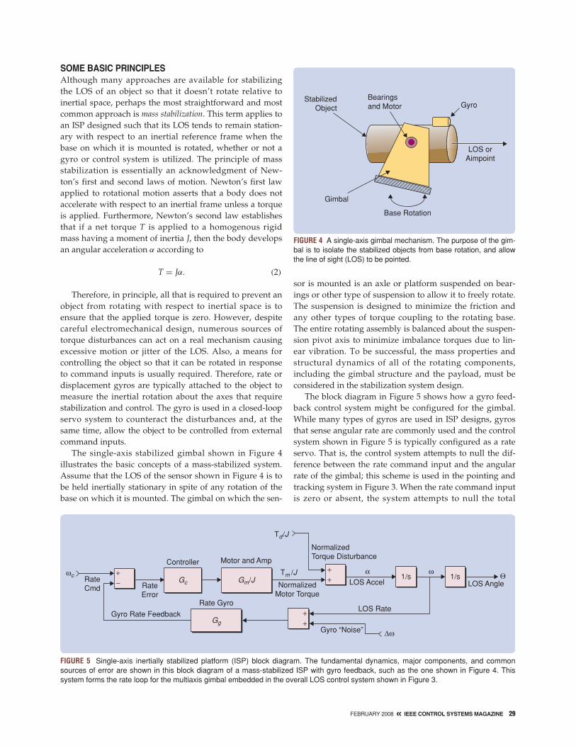
The single-axis stabilized gimbal shown in Figure 4illustrates the basic concepts of a mass-stabilized system.Assume that the LOS of the sensor shown in Figure 4 is tobe held inertially stationary in spite of any rotation of thebase on which it is mounted. The gimbal on which the sen-
sor is mounted is an axle or platform suspended on bear-ings or other type of suspension to allow it to freely rotate.The suspension is designed to minimize the friction andany other types of torque coupling to the rotating base.The entire rotating assembly is balanced about the suspen-sion pivot axis to minimize imbalance torques due to lin-ear vibration. To be successful, the mass properties andstructural dynamics of all of the rotating components,including the gimbal structure and the payload, must beconsidered in the stabilization system design.
The block diagram in Figure 5 shows how a gyro feed-back control system might be configured for the gimbal.While many types of gyros are used in ISP designs, gyrosthat sense angular rate are commonly used and the controlsystem shown in Figure 5 is typically configured as a rateservo. That is, the control system attempts to null the dif-ference between the rate command input and the angularrate of the gimbal; this scheme is used in the pointing andtracking system in Figure 3. When the rate command inputis zero or absent, the system attempts to null the total
FEBRUARY 2008 « IEEE CONTROL SYSTEMS MAGAZINE 29
FIGURE 4 A single-axis gimbal mechanism. The purpose of the gim-bal is to isolate the stabilized objects from base rotation, and allowthe line of sight (LOS) to be pointed.
StabilizedObject
Bearingsand Motor Gyro
Base Rotation
Gimbal
LOS orAimpoint
FIGURE 5 Single-axis inertially stabilized platform (ISP) block diagram. The fundamental dynamics, major components, and commonsources of error are shown in this block diagram of a mass-stabilized ISP with gyro feedback, such as the one shown in Figure 4. Thissystem forms the rate loop for the multiaxis gimbal embedded in the overall LOS control system shown in Figure 3.
RateCmd Rate
Error
Gyro Rate Feedback
Gc
Rate Gyro
Gg
Controller Motor and Amp
Td/J
Tm /JGm/J
NormalizedTorque Disturbance
NormalizedMotor Torque
LOS Accel
LOS Rate
Gyro “Noise”
1/s1/sLOS Angle
+−
++
++
ωcα ω Θ
Δω

torque applied to the gimbal, which requires that theclosed-loop control system generate a control torque at themotor that is equal and opposite to the net disturbancetorque. The net torque T in Figure 5 is normalized bydividing by the inertia J, which effectively converts thesystem dynamics to a kinematic analysis. Disturbance andmotor torques are often normalized to T/J in many aspectsof ISP design to help make decisions before completedesign details are available and also to draw conclusionsapplicable to a class of systems.
The Role of BandwidthWhile the response characteristics and transfer functionsfor a realistic system can be complicated, understandingthe properties of an idealized system can provide valuableinsight into the basic principles of operation and sensitivi-ties to disturbances and errors. The most indicative singleparameter that predicts how well a control system can fol-low command inputs and how well it can compensate fordisturbance torques is the closed-loop bandwidth. Althoughseveral definitions of bandwidth are available, one conve-nient definition is the frequency at which the closed-loopfrequency response falls to 0.707 of its dc value. The abilityto follow a command input constitutes the commandtracking or following performance. The rate-command fol-lowing error is reduced by a factor that is approximatelyproportional to the closed-loop bandwidth at low frequen-cies as shown in Figure 6, which shows the ratio of therate-following error to the rate-command input versus fre-quency. The closed-loop bandwidth, which also deter-
mines the disturbance rejection ratio θ/(T/J), can be usedto estimate the LOS angular motion θ due to the net distur-bance torque. Figure 7 shows that, for a typical type-II con-trol system design, the torque disturbance-rejection ratio isapproximately proportional to the squared inverse of theclosed-loop bandwidth for disturbances whose frequencycontent is below the closed-loop bandwidth. For higherfrequency disturbances, the rejection characteristics of thesystem are governed by (2) as if no loop were present [7],[14], [26]–[28].
The loop bandwidth is usually determined by a combi-nation of the specific control system design and thedynamic characteristics of the various components in theloop, such as the gyroscope and the actuator, as well asthe torsional response of the structure discussed in “Struc-tural Interactions.” The fundamental bandwidth limit isusually determined by structural resonances in large sys-tems but is often determined more by the dynamics of thegyroscope or actuator in small systems. In all cases,obtaining optimal performance involves understandingthe component dynamics as well as their noise and errorcharacteristics.
The discussion and conclusions above, including figures6 and 7, demonstrate the general characteristics and basicdesign goals of an ISP control system. However, it shouldbe pointed out that the specific characteristics shown arefor an idealized system using a simple proportional-plus-integral series compensator or control algorithm assumingno interactive structural resonances or other complications.While this type of control system is common even in many
FIGURE 6 Command-following frequency response for a typical type IIproportional-plus-integral control system. The ability of an inertiallystabilized platform to faithfully follow a command is indicated by thecontrol system bandwith fc . The ratio of the rate error to the rate com-mand, shown by the dotted line, increases with the square of the fre-quency to approximately one at the loop bandwidth. Attenuation ofthe following error at frequencies below the loop bandwidth is thusenhanced by a factor approximately proportional to the loop band-width as the error curve moves to the right with increasing bandwidth.
5
10−1 100
f /fc
101−20
−15
−10
−5
0
θo
θi
LOS Rate/LOS CommandRate Error/Rate Command
FIGURE 7 Torque disturbance frequency response. With a type-IIfeedback control loop, the gyro feedback provides disturbancerejection proportional to the inverse of the square of the loopbandwidth at frequencies below the loop bandwidth. With no loopfeedback, the system responds to torque disturbances accordingto Newton’s second law. At frequencies above the loop band-width, the torque disturbance attenuation is the same as if noloop were present.
ImprovedRegion
Log Frequency, f (Hz)
fc
1
(2πf )2
1
(2πfc)2
≈
θTd /J
Log
Type II GyroFeedback Control
No Feedback Control (T= Jα)
30 IEEE CONTROL SYSTEMS MAGAZINE » FEBRUARY 2008

FEBRUARY 2008 « IEEE CONTROL SYSTEMS MAGAZINE 31
Structural Interactions
Structural aspects of ISP design can be the most challenging part
of the design effort and can easily dominate the performance.
Structural design interacts with an ISP system as three separate
and distinct effects. Since these effects impact different aspects of
the design, they are sometimes either confused with one another
or, worse, ignored altogether until prob-
lems arise. First we review the basic
nature of structural dynamics and analysis
techniques and then consider the effects
mentioned above.
The structural dynamics of an ISP
involve all of the components attached to
the system including the structural char-
acteristics of the payload as well as the
gimbal and support structure. Because
objects that require stabilization, such as
optical sights, antennas, and weapons,
tend to be geometrically and structurally
complex, the structural dynamics of these
objects combined with the gimbal sys-
tems are usually also complex, consisting
of essentially an unlimited number of
interactive modes of response. A struc-
tural mode can be thought of as a shape
(see Figure S1) and a frequency at which
a structural shape resonates. While the
shape and frequency of a mode are pri-
marily a function of the structural stiff-
ness, damping and mass distribution, the
amplitude of the response depends on
the amplitude and spectrum of the vibra-
tion input or force causing the mode to respond.
THE NATURE OF STRUCTURAL DYNAMICS
Figure S1 shows the first few bending and torsional modes in a
beam structure. The first bending mode, or resonance, is excited by
a force or motion input acting on the beam at the frequency of the
first bending mode. While all modes respond to inputs at any fre-
quency, the response is particularly pronounced when the forcing
frequency coincides with a modal frequency. As the frequency
increases, the second bending mode responds and so on indefinite-
ly. When the excitation consists of a wideband spectrum, many
modes are excited simultaneously. If a torque acts on the beam, the
torsional modes respond in the same manner, as shown. If the
beam is not symmetrical, as is the case with most real structures, a
combination of bending and torsional modes can be excited with
either a force or torque acting anywhere on the beam.
The frequency response defines the ratio of the amplitude and
phase of the response at a particular point and direction on the
structure as a function of frequency to the amplitude of the forcing
function at another point and direction. A transfer function can be
defined, for example, for the rotation at a point on the gimbal in
response to a force or displacement input at another point. A typi-
cal structural frequency response is shown in Figure S2 [S1]–[S3].
The frequency response shows all of the modes, including bend-
ing and torsional, that participate at that particular point and in the
direction of interest. The peaks indicate the resonant frequencies for
a point on the structure, whereas the valleys, commonly called
antiresonances, show the frequencies at which little or no response
occurs at that particular point on the struc-
ture. The amplitude of the frequency
response at each modal frequency
depends on the damping in the structure
and how much that mode participates in
the response to the excitation. Typically,
metallic structural materials have low
damping and resonant amplification of
15–25 is not uncommon. Thus, if an ISP
system is vibrated at 1 g and the vibration
input spectrum coincides with the frequen-
cy of a resonant mode, then response
accelerations of 15–25 g can be expected.
Finite element analysis can be used
to accurately estimate the various trans-
fer functions and responses of a structur-
al design. Typically, these analyses are
iterated as necessary, along with appro-
priate modifications to the mechanical
design, until a satisfactory design is
achieved. If the structure, or some portion
of it, already exists, the analysis can be
augmented with experimental modal test-
ing, which can provide guidance as to
where modifications might be needed
[S3]–[S6]. Usually, the above methods
are followed by vibration testing to verify the performance. Whether
analytical, experimental, or a combination of methods are used,
however, a critical requirement is that realistic forcing functions are
used to assess the structure. Ideally, this assessment must include
FIGURE S1 Structural modes. A mode isdefined by a shape and a frequency. All struc-tural assemblies exhibit an unlimited number ofresonant modes. This example shows the firsttwo bending modes and the first torsional modein a beam. The response amplitude of a modedepends on the amplitude, frequency, andlocation of the forces or torques applied to thestructure.
First Torsional Mode
Second Bending Mode
First Bending Mode
FIGURE S2 Typical structural transfer function. This structural trans-fer function shows the angular acceleration response to a torqueexcitation truncated to the first few resonances and antiresonances.Resonances in structures, which commonly have amplifications of20 or more, are a major concern in the control system for ISPs.
Log Frequency (Hz)
First Torsional Anti-Resonance
First Torsional Resonance
1J
LogTθ
32 IEEE CONTROL SYSTEMS MAGAZINE » FEBRUARY 2008
the complete six-degree-of-freedom (6DOF) translational and rota-
tional dynamic environment that the system is to operate in. The
failure of many ISP designs to operate as intended can often be
traced back to either an inadequate assessment of the dynamic
6DOF operating environment or a misunderstanding of how to
interpret and apply the structural results.
We now discuss the categories of structural considerations
that apply to most ISP system designs. The separate categories
require that different transfer functions and responses be consid-
ered, each of which have different effects on the system.
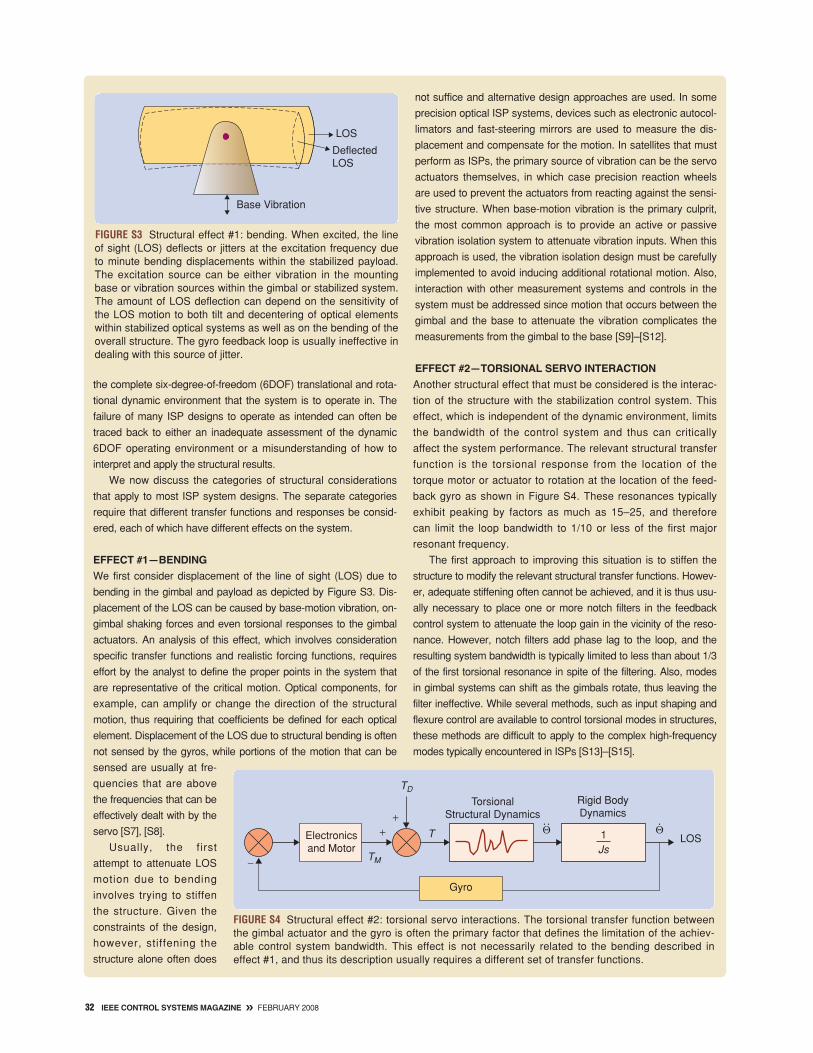
EFFECT #1—BENDING
We first consider displacement of the line of sight (LOS) due to
bending in the gimbal and payload as depicted by Figure S3. Dis-
placement of the LOS can be caused by base-motion vibration, on-
gimbal shaking forces and even torsional responses to the gimbal
actuators. An analysis of this effect, which involves consideration
specific transfer functions and realistic forcing functions, requires
effort by the analyst to define the proper points in the system that
are representative of the critical motion. Optical components, for
example, can amplify or change the direction of the structural
motion, thus requiring that coefficients be defined for each optical
element. Displacement of the LOS due to structural bending is often
not sensed by the gyros, while portions of the motion that can be
sensed are usually at fre-
quencies that are above
the frequencies that can be
effectively dealt with by the
servo [S7], [S8].
Usually, the first
attempt to attenuate LOS
motion due to bending
involves trying to stiffen
the structure. Given the
constraints of the design,
however, stiffening the
structure alone often does
not suffice and alternative design approaches are used. In some
precision optical ISP systems, devices such as electronic autocol-
limators and fast-steering mirrors are used to measure the dis-
placement and compensate for the motion. In satellites that must
perform as ISPs, the primary source of vibration can be the servo
actuators themselves, in which case precision reaction wheels
are used to prevent the actuators from reacting against the sensi-
tive structure. When base-motion vibration is the primary culprit,
the most common approach is to provide an active or passive
vibration isolation system to attenuate vibration inputs. When this
approach is used, the vibration isolation design must be carefully
implemented to avoid inducing additional rotational motion. Also,
interaction with other measurement systems and controls in the
system must be addressed since motion that occurs between the
gimbal and the base to attenuate the vibration complicates the
measurements from the gimbal to the base [S9]–[S12].
EFFECT #2—TORSIONAL SERVO INTERACTION
Another structural effect that must be considered is the interac-
tion of the structure with the stabilization control system. This
effect, which is independent of the dynamic environment, limits
the bandwidth of the control system and thus can critically
affect the system performance. The relevant structural transfer
function is the torsional response from the location of the
torque motor or actuator to rotation at the location of the feed-
back gyro as shown in Figure S4. These resonances typically
exhibit peaking by factors as much as 15–25, and therefore
can limit the loop bandwidth to 1/10 or less of the first major
resonant frequency.
The first approach to improving this situation is to stiffen the
structure to modify the relevant structural transfer functions. Howev-
er, adequate stiffening often cannot be achieved, and it is thus usu-
ally necessary to place one or more notch filters in the feedback
control system to attenuate the loop gain in the vicinity of the reso-
nance. However, notch filters add phase lag to the loop, and the
resulting system bandwidth is typically limited to less than about 1/3
of the first torsional resonance in spite of the filtering. Also, modes
in gimbal systems can shift as the gimbals rotate, thus leaving the
filter ineffective. While several methods, such as input shaping and
flexure control are available to control torsional modes in structures,
these methods are difficult to apply to the complex high-frequency
modes typically encountered in ISPs [S13]–[S15].
FIGURE S3 Structural effect #1: bending. When excited, the lineof sight (LOS) deflects or jitters at the excitation frequency dueto minute bending displacements within the stabilized payload.The excitation source can be either vibration in the mountingbase or vibration sources within the gimbal or stabilized system.The amount of LOS deflection can depend on the sensitivity ofthe LOS motion to both tilt and decentering of optical elementswithin stabilized optical systems as well as on the bending of theoverall structure. The gyro feedback loop is usually ineffective indealing with this source of jitter.
Base Vibration
LOS
DeflectedLOS
FIGURE S4 Structural effect #2: torsional servo interactions. The torsional transfer function betweenthe gimbal actuator and the gyro is often the primary factor that defines the limitation of the achiev-able control system bandwidth. This effect is not necessarily related to the bending described ineffect #1, and thus its description usually requires a different set of transfer functions.
Electronicsand Motor
TorsionalStructural Dynamics
TM
TD
T+
−
+Rigid BodyDynamics
LOSJs1Θ Θ
Gyro

FEBRUARY 2008 « IEEE CONTROL SYSTEMS MAGAZINE 33
EFFECT #3—MOUNTING
COMPLIANCE INTERACTION
The last structural effect, which
involves the interaction of the control
system with the structure on which it is
mounted, is similar to the previous
effect except that it does not necessar-
ily impact the design or performance
of the inertial stabilization control sys-
tem. This effect can, however, severe-
ly limit the bandwidth of any
positioning or pointing system that
relies on feedback from a sensor mea-
suring relative motion between the
gimbal and the base structure. Figure
S5 shows that the gimbal actuators
react against the structure they are
mounted on which causes them to
deflect and which is sensed by the
gimbal transducers. This interaction
can be pronounced if the system is
mounted on vibration isolators or a
flexible mounting structure.
Methods for improving the
effects of this interaction include
stiffening the torsional response of the mounting structure, adding
mass to the stationary gimbal structure, and employing notch fil-
ters in the pointing servo system. If isolators are the reason for the
flexibility, the isolators can sometimes be positioned to increase
the torsional resonant frequency of the system while maintaining
the low lateral frequencies required for isolation. Another tech-
nique that may be applicable to precision ground-mounted sys-
tems is to use a gyro in combination or blended with a relative
motion gimbal transducer to provide feedback [S16]–[S17].
REFERENCES
[S1] E. Rivin, Stiffness and Damping in Mechanical Design. New
York: Marcel Dekker,1999.
[S2] J. Spanos, “Control-structure interaction in precision pointing
servo loops,” AIAA J. Guid., vol. 12, no. 2, pp. 256–263, 1988.
[S3] NASA Finite Element Modeling Continuous Improvement Web-
site, www.femci.gsfc.nasa.gov/femcibook.html
[S4] G. Lang, “Experimental FEA,” Sound Vib., vol. 39, pp. 12–21,
Jan. 2005.
[S5] P. Avitabile, J. Teutsch, K. Weech, D. Smith, G. Gwaltney, and
M. Sheehan, “Modal and operating characterization of an optical
telescope,” Sound Vib., vol. 35, pp. 20–28, June 2001.
[S6] K. Doyle, V. Genberg, and G. Michels, Integrated Optomechan-
ical Analysis. Bellingham, WA: SPIE, 2002.
[S7] D. Redding and W. Breckenridge, “Optical modeling for dynam-
ics and control analysis,” AIAA J. Guid., vol. 14, no. 5, pp.
1021–1032, 1991.
[S8] J. DeBruin and D. Johnson, “Derivation of structural influence
coefficients for long-focus imaging optical systems,” Proc. SPIE, vol.
2263, pp. 341–368, 1994.
[S9] P. Dahl, “Inertial beam aignment sensor and a simplified applica-
tion,” in Proc. AIAA Guidance, Navigation, Control Conf. Exhibit, Mon-
terey, CA, AIAA paper 2002–5002, Aug. 2002.
[S10] E. Teague, J. How, and B. Parkinson “Control of flexible struc-
tures using GPS: Methods and experimental results,” AIAA J. Guid.,
vol. 21, no. 5, pp. 673–683, 1998.
[S11] B. Wie, “Experimental demonstration of a classical approach
to flexible structure control,” AIAA J. Guid. Control Dyn., vol. 15, no.
6, pp. 1327–1333, 1992.
[S12] E. Flint, M. Evert, E. Anderson, and P. Flannery, “Active/pas-
sive counter-force vibration control and isolation systems,” in Proc.
IEEE 2000 Aerospace Conf., paper #432, Big Sky, MT, Mar. 2000,
pp. 19–25.
[S13] C. Liu and R. Forward, “Electronic damping of resonance in
gimbal structures,” in Proc. AIAA/ASME/ASCE/AHS 22nd Structures
Structual Dynamics Materials Conf., paper #81-0556, Atlanta, GA,
1981.
[S14] J. Yocum and L. Slafer, “Control system design in the pres-
ence of severe structural dynamics interactions,” AIAA J. Guid. Con-
trol Dyn., vol. 1, no. 2, pp. 109–116, 1978.
[S15] G. Balas and P. Young, “Control design for variations in struc-
tural natural frequencies,” AIAA J.Guid. Control Dyn., vol. 18, no. 2,
pp. 325–332, 1995.
[S16] A. Butterfield and S. Woodard, “Measured spacecraft instru-
ment and structural interactions,” AIAA J. Spacecraft Rockets, vol.
33, no. 4, pp. 556–562, 1996.
[S17] D. Griffiths, A. Aubert, E. Green, and J. Ding, “A technique
for relating vehicle structural modes to stiffness as determined in
static determinate tests,” in Proc. SAE, Grand Traverse, MI,
2003-01-1716, 2001.
FIGURE S5 Structural effect #3: Servo interactions with the mounting structure. Pointing sys-tems or other servo modes that use relative measurement transducers, such as resolvers,tachometers, or encoders, can interact with the structure on which the system is mounted,thus causing instability in the control system. This effect is caused by the reactions of the gim-bal actuators, which act against the base structure and depend on the effective mass andstiffness of the mounting structure. Systems mounted on vibration isolators are particularlysusceptible to this interaction. Gyro feedback loops are not inherently affected by this effectsince they do not depend on the relative motion between the gimbal and the base.
GimbalInertia
MountInertia
MountStiffness
and Damping
K, D
IM
Ig
TM
−TMReactionTorque
Mount Structural Reaction
Ideal TachometerSignal
Servo
Motor Torque
RigidGimbal
Ig
1
s1
−1
ΘT
Θg
Θs
ΘT
s2
IMs2 + Ds + KM
+ −
34 IEEE CONTROL SYSTEMS MAGAZINE » FEBRUARY 2008
high performance ISPs, much better disturbance rejectionand command following performance can be achieved withmore complicated control algorithms using, for example,state variable feedback, adaptive techniques, and distur-bance observer designs [29]–[33].
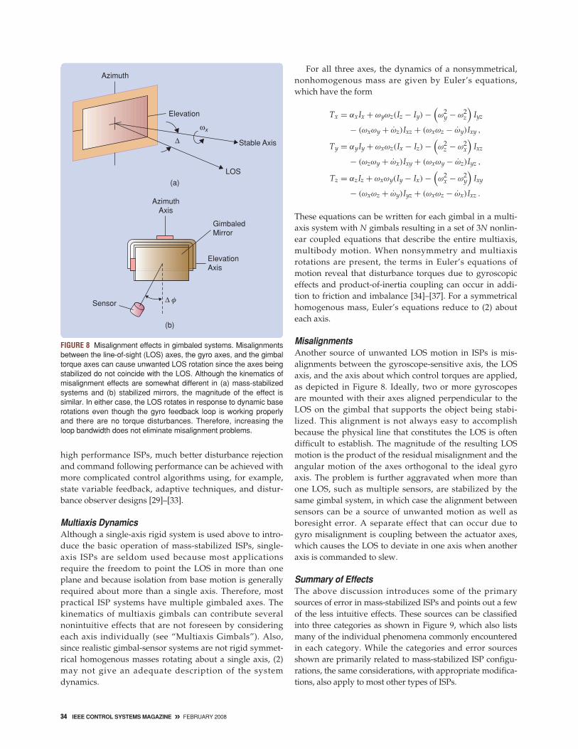
Multiaxis DynamicsAlthough a single-axis rigid system is used above to intro-duce the basic operation of mass-stabilized ISPs, single-axis ISPs are seldom used because most applicationsrequire the freedom to point the LOS in more than oneplane and because isolation from base motion is generallyrequired about more than a single axis. Therefore, mostpractical ISP systems have multiple gimbaled axes. Thekinematics of multiaxis gimbals can contribute severalnonintuitive effects that are not foreseen by consideringeach axis individually (see “Multiaxis Gimbals”). Also,since realistic gimbal-sensor systems are not rigid symmet-rical homogenous masses rotating about a single axis, (2)may not give an adequate description of the systemdynamics.
For all three axes, the dynamics of a nonsymmetrical,nonhomogenous mass are given by Euler’s equations,which have the form
Tx = αxIx + ωyωz(Iz − Iy) −(ω2
y − ω2z
)Iyz
− (ωxωy + ω̇z)Ixz + (ωxωz − ω̇y)Ixy ,
Ty = αyIy + ωxωz(Ix − Iz) −(ω2
z − ω2x
)Ixz
− (ωzωy + ω̇x)Ixy + (ωxωy − ω̇z)Iyz ,
Tz = αzIz + ωxωy(Iy − Ix) −(ω2
x − ω2y
)Ixy
− (ωxωz + ω̇y)Iyz + (ωxωz − ω̇x)Ixz .
These equations can be written for each gimbal in a multi-axis system with N gimbals resulting in a set of 3N nonlin-ear coupled equations that describe the entire multiaxis,multibody motion. When nonsymmetry and multiaxisrotations are present, the terms in Euler’s equations ofmotion reveal that disturbance torques due to gyroscopiceffects and product-of-inertia coupling can occur in addi-tion to friction and imbalance [34]–[37]. For a symmetricalhomogenous mass, Euler’s equations reduce to (2) abouteach axis.
MisalignmentsAnother source of unwanted LOS motion in ISPs is mis-alignments between the gyroscope-sensitive axis, the LOSaxis, and the axis about which control torques are applied,as depicted in Figure 8. Ideally, two or more gyroscopesare mounted with their axes aligned perpendicular to theLOS on the gimbal that supports the object being stabi-lized. This alignment is not always easy to accomplishbecause the physical line that constitutes the LOS is oftendifficult to establish. The magnitude of the resulting LOSmotion is the product of the residual misalignment and theangular motion of the axes orthogonal to the ideal gyroaxis. The problem is further aggravated when more thanone LOS, such as multiple sensors, are stabilized by thesame gimbal system, in which case the alignment betweensensors can be a source of unwanted motion as well asboresight error. A separate effect that can occur due togyro misalignment is coupling between the actuator axes,which causes the LOS to deviate in one axis when anotheraxis is commanded to slew.
Summary of EffectsThe above discussion introduces some of the primarysources of error in mass-stabilized ISPs and points out a fewof the less intuitive effects. These sources can be classifiedinto three categories as shown in Figure 9, which also listsmany of the individual phenomena commonly encounteredin each category. While the categories and error sourcesshown are primarily related to mass-stabilized ISP configu-rations, the same considerations, with appropriate modifica-tions, also apply to most other types of ISPs.
FIGURE 8 Misalignment effects in gimbaled systems. Misalignmentsbetween the line-of-sight (LOS) axes, the gyro axes, and the gimbaltorque axes can cause unwanted LOS rotation since the axes beingstabilized do not coincide with the LOS. Although the kinematics ofmisalignment effects are somewhat different in (a) mass-stabilizedsystems and (b) stabilized mirrors, the magnitude of the effect issimilar. In either case, the LOS rotates in response to dynamic baserotations even though the gyro feedback loop is working properlyand there are no torque disturbances. Therefore, increasing theloop bandwidth does not eliminate misalignment problems.
(a)
Azimuth
Elevation
LOS
Stable AxisΔ
(b)
AzimuthAxis
Sensor
ElevationAxis
GimbaledMirror
Δ φ
ωx

ALTERNATIVE STABILIZATION TECHNIQUES
Momentum Wheel StabilizationThe mass-stabilized ISP configuration discussed above uti-lizes instrument gyros, which are self-contained measure-ment systems that output an electrical signal proportionalto the angular motion about the gyro’s sensitive axis. How-ever, long before instrument gyros became available, spin-ning wheels were attached directly to torpedoes, ships, andother vehicles to provide stabilization, in which case theentire vehicle or object it is attached to effectively becomesan ISP as shown in Figure 10. While the large spinningmasses required in these applications have since beenreplaced by actuators controlled in closed loop using small-er, less expensive, instrument gyros, the direct stabilizationapproach is still used in some missile seekers as well as tostabilize and control satellites [38]–[41]. When used in thismanner, the spinning mass devices are referred to asmomentum wheels or control-moment gyros and, even thoughall of the principles of mass-stabilization apply, these sys-tems are often referred to as momentum-wheel-stabilizedsystems to distinguish them from mass-stabilized systems,which utilize instrument gyros in closed loop.
FIGURE 10 Momentum wheel stabilization. In this approach, a vehi-cle or object is held steady by the stabilizing nature of a spinningmass so that the vehicle or object to which it is attached effectivelybecomes an inertially stabilized platform. While most ship stabilizerssuch as the one shown, which was installed on the USS Hendersonin 1917, have since been replaced with instrument gyros that controlfin actuators, the momentum wheel approach is still used by somemissile seekers as well as by many satellite attitude control sys-tems. (Photo courtesy of U.S. Naval Historical Center.)
FIGURE 9 Causes of inertial rotation of the line of sight (LOS). All causes of inertial rotation of the LOS of a stabilized platform can be tracedto either a torque disturbance, flexibility in the system, or an erroneous input to the gimbal actuators.
Inertial Rotationof the LOS
Friction
KinematicCoupling
AerodynamicTorques
GyroscopicTorques
DynamicImbalance
OnboardShaking Forces
Actuator and GearReactions
MagneticCogging
Cable andSpring Torques
Imbalance Bending
Optical ComponentDisplacements
Aniso-ElasticEffects
Gyro and SensorNoise
LOS and GyroMisalignment
Quantization
Electronic Hysteresisand Noise
TorqueDisturbances
StructuralFlexibility
ErroneousTorque Equivalent
Inputs
FEBRUARY 2008 « IEEE CONTROL SYSTEMS MAGAZINE 35

Feedforward TechniquesAn alternative to the common feedback configuration dis-cussed above is the feedforward or strapdown configuration,which is effective in many applications. This approach isused when the required corrective motion does not coincidewith the LOS being stabilized, and therefore there is nophysical place to mount a feedback gyro, a situation com-monly encountered in stabilized-mirrors or when an object,such as a small commercial camera, is to be stabilized andthere is physically not enough room to mount the gyro onthe gimbal. In this approach, an estimate of the LOS motionis constructed from base-mounted or strapdown gyros anda feedforward relative-motion transducer, such as a resolveror encoder, that measures the motion between the correctiveelement (such as a gimbal) and the base or vehicle to whichit is attached [42], [43]. The measured relative motion, whichmay be either rotary or linear, relates the motion of the cor-rective element to an equivalent LOS rotation. With theseconsiderations, the general form of the equation definingthe feedforward control scheme is given by
θ los︸︷︷︸
reconstructedLOS signal
= θ base︸ ︷︷ ︸
base-mountedstrapdown gyro
+ θ gimbal/base︸ ︷︷ ︸
relative motionfeedforward transducer
. (3)
The feedforward strapdown system is designed similar-ly to those with feedback gyros mounted on the gimbalexcept that the control loop is now closed on the estimatedLOS signal as shown in Figure 11. Unlike the feedbackapproach, the strapdown gyro is not driven to null by thefeedback loop and therefore must provide an accurate
FIGURE 11 The feedforward approach. When gyros cannot be mounted to provide a direct measurement of the line-of-sight (LOS) motion, a combination of sensors can often be used to reconstructed a signal that can then be used to controlthe LOS motion. This approach is called feedforward because the gyro output, which now measures the base motion, isfed forward to the loop similar to an input command and thus is not embedded in a feedback loop.
RateCommand
+−
++
+−
ErrorController
Relative MotionTransducer
StrapdownGyro Base Motion
ActuatorLOS
ReconstructedLOS
FIGURE 12 Two commercial applications. (a) The antishake cam-era removes the effect of camera rotation by using a linear actua-tor to move the CCD detector so that it stays centered on theimage. In the fluid lens concept (b), the lens is deformed by anactuator to redirect the line of sight (LOS) based on the output of agyro. The Dynalens, based on this concept, was successfullyincorporated into movie cameras, binoculars, and other instru-ments. This invention won Juan De La Cierva an Oscar in 1969for best technical innovation.
CCD and Linear Actuator
Anti-Shake Camera
Fluid Lens
(a)
(b)
Fluid Lens Bellows
36 IEEE CONTROL SYSTEMS MAGAZINE » FEBRUARY 2008
FEBRUARY 2008 « IEEE CONTROL SYSTEMS MAGAZINE 37
measurement over the entire range of motion of the baserather than just provide adequate sensitivity around thenull point. This arrangement requires a gyro with a moreaccurate scale factor and higher dynamic range than thecase in which the gyro is in the feedback loop. In addition,the error characteristics and dynamics of the relative-motion transducer, required to implement the approach,become a primary source of error in the LOS control.
An example of a feedforward system is shown inFigure 12(a), where the motion of the camera body is mea-sured by a pair of gyros attached to the camera body, anda linear mechanism is used to move the light-sensitiveCCD detector. The motion of the detector is controlled bya linear actuator and a linear transducer such that theimage remains stationary on the detector in the presenceof camera body rotation. Since the motion of the detectorrequired to compensate for rotation of the camera is trans-lational, rather than rotational, there is no suitable place toattach a feedback gyro, and therefore the feedforwardestimate implied by (3) is constructed using gyros mount-ed on the camera body and linear transducers that mea-sure the relative detector motion. These devices canachieve a reduction in apparent motion by a factor ofthree or better using small inexpensive solid-state gyros.
Another feedforward application is the fluid lens con-cept, which has been successfully used in stabilized binocu-lars and movie cameras. In this case, a fluid-filled lens isdeformed by an actuator as shown in Figure 12(b) to achievethe desired deflection of the LOS. In both of these cases, (3)must be modified to reflect the translational-to-rotationalkinematics that relate the linear motion of the corrective ele-ment to the LOS rotational motion. While these examplesinvolve moderately low-performance commercial applica-tions, the feedforward concept is routinely applied to high-performance applications such as mirror-stabilized systems,discussed in the following paragraph, as well.
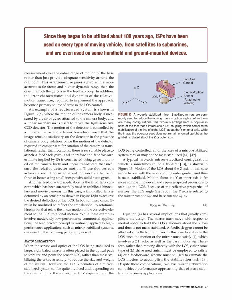
Mirror StabilizationWhen the sensor and optics of the LOS being stabilized islarge, a gimbaled mirror is often placed in the optical pathto stabilize and point the sensor LOS, rather than mass sta-bilizing the entire assembly, to reduce the size and weightof the system. However, the LOS kinematics of a mirror-stabilized system can be quite involved and, depending onthe orientation of the mirror, the FOV required, and the
LOS being controlled, all of the axes of a mirror-stabilizedsystem may or may not be mass stabilized [44]–[49].
A typical two-axis mirror-stabilized configuration,which is sometimes called a heliostat [13], is shown in Figure 13. Motion of the LOS about the Z axis in this caseis one to one with the motion of the outer gimbal, and thusis mass stabilized. Motion about the Y or inner axis is farmore complex, however, and requires special provisions tostabilize the LOS. Because of the reflective properties ofmirrors, the LOS angle θLOS about the Y axis is related tothe mirror rotation θM and base rotation θB by
θLOS = 2θM − θB. (4)
Equation (4) has several implications that greatly com-plicate the design. The mirror must move with respect toinertial space to hold the LOS stationary about the Y axisand thus is not mass stabilized. A feedback gyro cannot beattached directly to the mirror in this axis to stabilize theLOS since the motion of the mirror must satisfy (4), whichinvolves a 2:1 factor as well as the base motion θB. There-fore, rather than moving directly with the LOS, either sometype of 2:1 drive mechanism must be employed to satisfy(4) or a feedforward scheme must be used to estimate theLOS motion to accomplish the stabilization task [49].Despite these complications, two-axis mirror stabilizationcan achieve performance approaching that of mass stabi-lization in many applications.
FIGURE 13 A two-axis stabilized mirror. Stabilized mirrors are com-monly used to reduce the moving mass in optical sights. While thereare many configurations, this two-axis arrangement is popular inspite of the fact that it introduces a 2:1 coupling, which complicatesstabilization of the line of sight (LOS) about the Y or inner axis, whilethe image the operator sees does not remain oriented upright as thegimbal is rotated about the Z or outer axis.
Z
X Y
LOS
Two-AxisGimbal
Electro-OpticalSensor(Attached toVehicle)
Since they began to be utilized about 100 years ago, ISPs have been
used on every type of moving vehicle, from satellites to submarines,
and are even used on some handheld and ground-mounted devices.
AUGMENTATION AND ENHANCEMENT TECHNIQUESVarious schemes are used to augment or improve the perfor-mance of the stabilization methods described above. Theseschemes, which include both electromechanical and softwaretechniques, are particularly effective when the stabilizedobject is an electro-optical sensor, such as a camera, laser, orradar. A few of these approaches are reviewed below.
Redundant GimbalsThe redundant gimbal configuration shown in Figure 14 isquite common and has several benefits. In this concept, theinner precision gimbal is mass stabilized, and the outercoarse gimbal is driven in closed loop to follow the innergimbal, as shown in Figure 15. The gyros for this configu-ration are usually mounted on the fine inner gimbal butcan be mounted on the outer gimbal using feedforwardtechniques with the appropriate number and orientationof the gyros, depending on the specific gimbal configura-tion. One benefit of the redundant gimbal approach,regardless of gyro placement, is that the outer gimbal
Multiaxis Gimbals
Single-axis gimbals are useful for introducing some of the funda-
mental issues of ISP design but, unfortunately, are not typically
realistic. Most systems require at least two orthogonal stabilized
axes to achieve isolation from base motion and to achieve the
pointing field-of-regard dictated by the application. For most applica-
tions, it suffices to control only the motion about the two axes
orthogonal to the LOS. This statement applies to most beam point-
ing and weapon systems as well as for many imaging systems.
However, when orientation of the image is relevant or when rotation
of the image about the LOS causes excessive motion at the periph-
ery of the FOV, then a third axis of control must be implemented. In
either case, two gyros mounted orthogonal to the LOS are required.
These sensors are normally mounted on the innermost gimbal or
on the gimbal whose LOS is to be stabilized as shown in Figure S6.
When the gyros cannot be mounted on the innermost gimbal
orthogonal to the LOS or when LOS control is required about all
three axes, three orthogonal gyros are required to provide sufficient
information to stabilize the LOS [S18], [S19].
Deciding how many gimbals are required is a tradeoff between
the system requirements and the additional size, weight, cost, and
structural flexibility inherent with additional gimbals. The decision is
usually made to use as few gimbals as possible. However, kine-
matic phenomena, such as kinematic coupling and gimbal lock,
can also influence the suitability and performance of a multiaxis
gimbal, and therefore must be included in the configuration trade-
offs and any subsequent simulation or analysis of the gimbal sys-
tem. We now review techniques for analyzing gimbal kinematics
and then consider a two-axis gimbal example that provides insight
into many issues common to all multiaxis gimbals. Also, two-axis
gimbals are perhaps the most common among all of the various
applications because two orthogonal axes are the minimum
required to point in any direction in three-dimensional space.
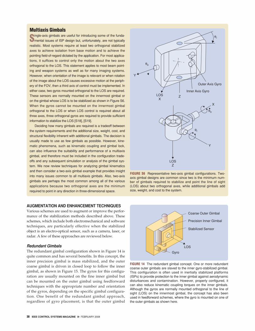
FIGURE S6 Representative two-axis gimbal configurations. Two-axis gimbal designs are common since two is the minimum num-ber of gimbals required to stabilize and point the line of sight(LOS) about two orthogonal axes, while additional gimbals addsize, weight, and cost to the system.
Y
θi
θo
LOSX
Z
Inner Axis Gyro
Outer Axis Gyro
θi
θo
LOSZ
Y
X
FIGURE 14 The redundant gimbal concept. One or more redundantcoarse outer gimbals are slaved to the inner gyro-stabilized gimbal.This configuration is often used in inertially stabilized platforms(ISPs) to provide protection to the inner gimbal against aerodynamicdisturbances and contamination. However, properly configured, itcan also reduce kinematic coupling torques on the inner gimbals.Although the gyros are normally mounted orthogonal to the line ofsight (LOS) on the innermost gimbal, the concept has also beenused in feedforward schemes, where the gyro is mounted on one ofthe outer gimbals as shown here.
Gyro
LOS
Stabilized Sensor
Precision Inner Gimbal
Coarse Outer Gimbal
38 IEEE CONTROL SYSTEMS MAGAZINE » FEBRUARY 2008

Analyzing the kinematics of a multiaxis gimbal is facilitated using
Euler transforms to transform a vector from one reference frame into
a second that is rotated with respect to the first. An Euler transform is
defined by V = Ev , where v is the vector in the first frame, V is the
vector in the second frame, and E is an Euler matrix, which is a
matrix of direction cosines that describe the rotation from the first
frame to the second. The technique can be used with any right-hand-
ed orthogonal vector such as position or angular velocity, but it should
be emphasized that angular displacements are not vectors and can-
not be transformed using these techniques. Any sequence of orthog-
onal rotations can be analyzed by selecting the corresponding
sequence of Euler matrices, taking care to multiply them in the proper
order depending on the physical gimbal order [S20]–[S24]. The three
Euler matrices about the X, Y, and Z axes, respectively, are
EX (ϕ) =[ 1 0 0
0 Cϕ Sϕ
0 −Sϕ Cϕ
]︸ ︷︷ ︸rotation about X
, EY (θ) =[ Cθ 0 −Sθ
0 1 0Sθ 0 Cθ
]︸ ︷︷ ︸rotation about Y
,
EZ (�) =[ C� S� 0
−S� C� 00 0 1
]︸ ︷︷ ︸
rotation about Z
,
where S and C denote sine and cosine, respectively.
To illustrate the transformation process, consider a two-axis
az-el gimbal mounted on an aircraft as shown in Figure S7 with
the gimbal X axis nominally aligned with the aircraft X axis. We
wish to determine the inertial rates that each gimbal must have
to hold the LOS stable given the aircraft angular rates P, Q,
and R about the aircraft X, Y, and Z axes, respectively. In this
case, the LOS is considered to be stable if the motion is
removed from the two axes orthogonal to the LOS. Motion
about the third axis X about the LOS cannot be removed with a
two-axis gimbal.
FIGURE S7 A two-axis gimbal application. An az-el gimbal isattached to an aircraft with two gyros mounted on the inner (EL)axis orthogonal to the line of sight (LOS). The aircraft angularrates are P, Q, and R about the X, Y, and Z axes of the aircraft,respectively.
LOS ψa
AZ
Gyros
EL
Outer GimbalInner Gimbal
Xa
Ya
Za
Θo
P
Q
R
FEBRUARY 2008 « IEEE CONTROL SYSTEMS MAGAZINE 39
FIGURE 15 Redundant gimbal servo block diagram. The coarse outer gimbal servo is configured to follow the fine-stabilized inner gimbal.This configuration is commonly used when an outer windshroud is required to protect the inner stabilized gimbal from aerodynamic torques.A similar servo configuration is sometimes used when the inner gimbal or servo is configured as an image motion-compensation system.
Rate Cmd
Stabilized GimbalController
RateError
Rate Gyro
Gc Gm/Js
Inner Gimbal
LOS Angle
Gg
Gf
Following ServoOuter Gimbal
Rel. MotionTransducer
1/s
1/sFollowing Angle
Gyro Rate Feedback
Motor/Ampand Gimbal
+−
+−

40 IEEE CONTROL SYSTEMS MAGAZINE » FEBRUARY 2008
can be configured to shield the inner gimbal from aero-dynamic disturbances. Also, seals necessary to keep outrain or contaminants are incorporated in the outer gim-bal, thus allowing the inner gimbal to be designed withonly the friction from its suspension. This approach,however, has another benefit that may be more subtle,namely, that the redundant gimbal design can be used toreduce kinematic-coupling disturbances (see “MultiaxisGimbals”) in two-axis gimbals. Properly configured, the
inner gimbals are never displaced more than a fewdegrees relative to each other, and, therefore, the largekinematic-coupling torques are borne by the outer gim-bal. Thus, the effect of the torques on the fine inner gim-bal is attenuated.
Image Motion CompensationFigure 16 shows an entirely different electromechanicalaugmentation technique, which can achieve extremely
Using the Euler matrix for rotation about the Z axis for the gim-
bal order shown, the outer gimbal rates are written in terms of the
body rates P, Q, and R as
[ωox
ωoy
ωoz
]=
[ C� S� 0−S� C� 0
0 0 1
][ PQ
R + �̇
]
=[ PC� + QS�
−PS� + QC�
R + �̇
], (S1)
where the relative gimbal rate �̇ is added to the vehicle rate to
account for gimbal rotation. Similarly, the inner gimbal rates are
given by
[ωix
ωiy
ωiz
]=
[ Cθ 0 −Sθ
0 1 0Sθ 0 Cθ
][ωox
ωoy + θ̇
ωoz
]
=[ Cθ(PC� + QS�) − Sθ(R + �̇)
−PS� + QC� + θ̇
Sθ(PC� + QS�) + Cθ(R + �̇)
]. (S2)
To stabilize the inner gimbal LOS about the Y and Z axes, the
control system attempts to drive the inner gimbal inertial rates ωiy
and ωiz to zero, which, from (S2), requires that the relative gimbal
rates satisfy
θ̇ = PS � − QC � (S3)
FIGURE S8 Outer (AZ-�) axis stabilization control system with kinematics for the gimbal shown in Figure S7. With the exception of thesecant gain correction, the sine and cosine functions are natural kinematics, typical of all two-axis gimbals, which couple the body rates,P, Q, and R into the outer gimbal dynamics. As shown, the gyro senses all of the kinematics, and attempts to hold the line of sight(LOS) steady in spite of the kinematic coupling torques. The secant gain is an electronic correction, which is sometimes used to com-pensate for the natural cosine function that occurs in the loop. However, the secant correction compensates only for the gain change inthe loop, and does not compensate for the kinematic coupling torques seen by the outer gimbal.
Cos(ψ)
Cos(θ)
Sin(ψ)
Sin(θ)
Gg
Gm/JGc 1/JS+−
−+
+ +
++Cos(θ)
1ωCmd
RateCmd Rate
Error
Controller
Secant GainCorrection
Motor/Amp
GimbalInertia
Outer GimbalRelative Rate
R
ψ
ωoz
OuterGimbal
Inertial Rate
ωiz
Z Axis GyroInner Gimbal Z Axis Inertial Rate (LOS Rate)
P Q
FEBRUARY 2008 « IEEE CONTROL SYSTEMS MAGAZINE 41
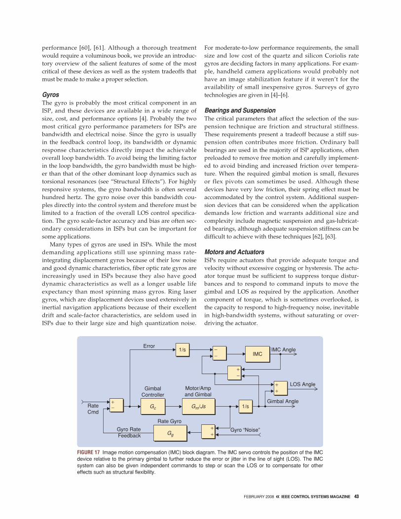
precise stabilization. In this approach, the residual stabi-lization error in a conventional mass-stabilized or mirror-stabilized system is further reduced by incorporating asecondary pointing mechanism such as a fast-steering mir-ror (FSM) at a point in the optical path where the ray bun-dle has a small diameter. This location in the optical path iscritical because the FSM design relies on small size to
achieve high bandwidth and precision over a small angu-lar range. Typically, stabilization is augmented by drivingthe FSM as shown in Figure 17, where the residual gimbalgyro error signal is used as a command input to the FSMfeedforward loop [50]–[52]. In addition to improving stabi-lization, IMC mechanisms are also used to achieve thehighspeed step-and-stare scan profiles discussed below.
and
�̇ = −T θ(PC � + QS �) − R . (S4)
By using these relative gimbal rates along with (S1) and (S2), it fol-
lows that the LOS is held stable if the inertial rates of the inner and
outer gimbals are given by
ωiy = 0 (S5)
and
ωoz = R + �̇ = −T θ(PC � + QS �). (S6)
Equations (S5) and (S6) show that the inner gimbal remains
mass stabilized and does not need to move in space to stabilize
the LOS. However, the outer gimbal must move to stabilize the
LOS and the amount of motion required increases with the tan-
gent of the inner gimbal angle. This result, known as kinematic
coupling, affects all two-axis gimbals and culminates in complete
loss of control, or gimbal lock, as the inner gimbal angle θ
approaches 90◦. At angles less than 90◦, the gimbal can be con-
trolled if enough motor torque is available, but kinematic coupling
degrades the stabilization performance because any requirement
to accelerate the gimbal in inertial space has the same effect on
the apparent motion of LOS as a torque disturbance acting in the
opposite direction. In other words, adequate torque must be pro-
vided by the outer gimbal motors to avoid complete loss of con-
trol, but the kinematic coupling still acts like any other torque
disturbance and causes unwanted LOS motion.
Now consider what happens as θ approaches 90◦ in Figure S7.
The outer gimbal motor and rotating axis are now aligned with the
LOS and thus are orthogonal to the gyro-sensitive axis. Therefore, the
LOS motion is no longer sensed in this axis and no amount of motor
torque can provide any correction, which constitutes gimbal lock.
A block diagram of the outer gimbal control system including
the kinematics described above included is shown in Figure S8.
The secant gain correction shown is added to cancel the cosine
introduced by the kinematics. However, while the secant gain cor-
rection maintains a constant loop gain as the gimbal angle
changes which keeps the control system gain from changing with
gimbal angle, this technique cannot counteract the disturbance
effects of kinematic coupling or prevent gimbal lock.
While feedforward approaches have been employed to
counter kinematic coupling, the most common solution to both
kinematic coupling and gimbal lock is to add additional gimbals.
The system tradeoff, however, involves the additional size,
weight, and structural flexibility attendant with each gimbal axis
added. Surveys and discussions of different gimbal arrangements
can be found in [S18] and [S26]–[S28].
REFERENCES
[S18] M. Masten, “Inertially stabilized platforms for imaging optical
systems” IEEE CSM , vol. 28, no. 1, pp. 47–64, 2008.
[S19] J. Wicker, T. Yang, J. Ly, R. Wong, P. Dahl, and R. Rogers,
“Low Cost Spacecraft Disturbance Rejection via Sensor Matching
for Off-Gimbal Precision Pointing System,” AIAA J. Guidance,
2003, AIAA-2003-5827.
[S20] J. Kuipers, Quaternions and Rotation Sequences, Princeton
University Press, 1999.
[S21] G Minkler and J. Minkler, Aerospace Coordinate Systems
and Transformations, Magellan, 1990.
[S22] R. Pio, “Error Analysis of Euler Angle Transformations,”
AIAA J. Guidance, AIAA 0001-1452, vol. 11, no. 6, pp. 871–875,
1973.
[S23] J. Hilkert, “Kinematic Algorithms for Line-of-Sight Pointing
and Scanning using INS/GPS Position and Velocity Information,”
SPIE Proceedings, vol. 5810, pp. 11–22, Paper 5810-03, Mar.
2005.
[S24] J. Royalty, “Method to decouple mechanically coupled gim-
bal control systems,” SPIE Proceedings, vol. 5810, pp. 11–23,
2005.
[S25] W. Casey and D. Phinney, “Representative Pointed Optics
and Associated Gimbal Characteristics,” SPIE Proceedings, vol.
887, pp. 116–123, 1988.
[S26] M. Masten and L. Stockum, Precision Stabilization and
Tracking Systems for Acquisition, Pointing and Control Applica-
tions, SPIE Milestone Series, vol. 123, SPIE Optical Engineering
Press, 1996.
[S27] G. Gerson and A. Rue, “Tracking systems” Chapter 22, The
Infrared Handbook, Wolfe, W.L. and Zissis, G.J., Editors, Depart-
ment of the Navy, Washington, D.C., 1989.
[S28] E. Flint and E. Anderson, “Multi-degree of freedom parallel
actuation system architectures for motion control,” Proc. AIAA
Space 2001 Conference, Albuquerque, NM, in 2001, AIAA
2001-4750.

Electronic and Software Augmentation TechniquesThe above IMC concepts rely on electromechanical devices.However, over the last decade or so, signal processingspeed has increased such that an inertial stabilization sys-tem can be augmented by software techniques, often in realtime. Several system concepts are available, some of whichmake use of the image motion, while others attempt toremove its effects. While the algorithms used in these sys-tems differ in detail, they all correlate information gatheredat one instant to information gathered at another instant toeither remove the effects of the motion between instants,stitch together a larger image, or, in some cases, provide acombination of the two functions.
Deblurring algorithms attempt to remove the effects ofimage motion from one frame to the next. Some of thesesystems work in conjunction with the gimbal control sys-tem by using the gyros or other available sensors such asnavigation system information to reconstruct the de-blurred image. Alternative approaches that rely only onframe-to-frame image correlation are fundamentallybandwidth limited by the imaging system frame rate[53]–[56].
Examples of systems that stitch or blend informationto achieve high resolution and a large FOV include stepand stare or scanning electro-optical systems, whichoperate similarly to synthetic aperture radar (SAR) [57].The scan direction and velocity can be controlled bymeans of the gimbal or determined solely by the vehiclemotion as illustrated in Figure 18. When the scan profileis determined by the vehicle motion, sensors that mea-sure the vehicle motion are used by the processing algo-rithm to provide software stabil ization to theinformation collected, which is the approach is taken bymany SAR systems. The step-and-stare concept, shownin Figure 18(c), uses the gimbal or an FSM to step orscan the LOS of an electro-optical sensor in a patternover a target [58], [59]. The step-and-stare system pausesat each step to let the sensor integrate the image energy.The separate images are then stitched together to form alarger image called a mosaic. Thus the system basically
trades resolution for time since it takes more time to col-lect the necessary smaller high-resolution images than itwould to take one large image with a low-resolutionsystem. However, the effectively higher resolution alsorequires good stabilization while the sensor is integrat-ing the energy at each step. The distance moved by theLOS between each step does not necessarily have to behighly accurate but must ensure overlap betweenframes so that the software can correlate the image andstitch a complete image together.
ISP COMPONENTS AND DESIGN TRADEOFFSMost ISP systems require gyros, some type of suspensiondevice such as bearings, motors, or actuators, relative-motion transducers, and additional electromechanical com-ponents. The characteristics of available devices can be a keyfactor in the system configuration and subsequent
FIGURE 16 Image motion compensation (IMC). IMC techniques areoften used to improve performance or to step or scan the line ofsight (LOS) with higher dynamic motion profiles than the primarystabilization system is capable of providing. Fast-steering mirrorsare used in IMC configurations with both (a) mirror-stabilized and (b)mass-stabilized systems as shown. IMC is also used to compensatefor structural flexibility in the gimbal and optical system.
StabilizedMirror
Fast-SteeringMirror
Scene
Optics
(a)
Detector
(b)
Gyro
Stabilized Sensor
LOS
IMC Mechanism
Coarse Outer Gimbal
Requirements for ISPs vary widely,
but they all have the common goal of
holding or controlling the line of sight
of one object relative to another object
or inertial space.
42 IEEE CONTROL SYSTEMS MAGAZINE » FEBRUARY 2008
performance [60], [61]. Although a thorough treatmentwould require a voluminous book, we provide an introduc-tory overview of the salient features of some of the mostcritical of these devices as well as the system tradeoffs thatmust be made to make a proper selection.
GyrosThe gyro is probably the most critical component in anISP, and these devices are available in a wide range ofsize, cost, and performance options [4]. Probably the twomost critical gyro performance parameters for ISPs arebandwidth and electrical noise. Since the gyro is usuallyin the feedback control loop, its bandwidth or dynamicresponse characteristics directly impact the achievableoverall loop bandwidth. To avoid being the limiting factorin the loop bandwidth, the gyro bandwidth must be high-er than that of the other dominant loop dynamics such astorsional resonances (see “Structural Effects”). For highlyresponsive systems, the gyro bandwidth is often severalhundred hertz. The gyro noise over this bandwidth cou-ples directly into the control system and therefore must belimited to a fraction of the overall LOS control specifica-tion. The gyro scale-factor accuracy and bias are often sec-ondary considerations in ISPs but can be important forsome applications.
Many types of gyros are used in ISPs. While the mostdemanding applications still use spinning mass rate-integrating displacement gyros because of their low noiseand good dynamic characteristics, fiber optic rate gyros areincreasingly used in ISPs because they also have gooddynamic characteristics as well as a longer usable lifeexpectancy than most spinning mass gyros. Ring lasergyros, which are displacement devices used extensively ininertial navigation applications because of their excellentdrift and scale-factor characteristics, are seldom used inISPs due to their large size and high quantization noise.
For moderate-to-low performance requirements, the smallsize and low cost of the quartz and silicon Coriolis rategyros are deciding factors in many applications. For exam-ple, handheld camera applications would probably nothave an image stabilization feature if it weren’t for theavailability of small inexpensive gyros. Surveys of gyrotechnologies are given in [4]–[6].
Bearings and SuspensionThe critical parameters that affect the selection of the sus-pension technique are friction and structural stiffness.These requirements present a tradeoff because a stiff sus-pension often contributes more friction. Ordinary ballbearings are used in the majority of ISP applications, oftenpreloaded to remove free motion and carefully implement-ed to avoid binding and increased friction over tempera-ture. When the required gimbal motion is small, flexuresor flex pivots can sometimes be used. Although thesedevices have very low friction, their spring effect must beaccommodated by the control system. Additional suspen-sion devices that can be considered when the applicationdemands low friction and warrants additional size andcomplexity include magnetic suspension and gas-lubricat-ed bearings, although adequate suspension stiffness can bedifficult to achieve with these techniques [62], [63].
Motors and ActuatorsISPs require actuators that provide adequate torque andvelocity without excessive cogging or hysteresis. The actu-ator torque must be sufficient to suppress torque distur-bances and to respond to command inputs to move thegimbal and LOS as required by the application. Anothercomponent of torque, which is sometimes overlooked, isthe capacity to respond to high-frequency noise, inevitablein high-bandwidth systems, without saturating or over-driving the actuator.
FIGURE 17 Image motion compensation (IMC) block diagram. The IMC servo controls the position of the IMCdevice relative to the primary gimbal to further reduce the error or jitter in the line of sight (LOS). The IMCsystem can also be given independent commands to step or scan the LOS or to compensate for othereffects such as structural flexibility.
+−
−−
++
+−
++
Error1/s
1/s
IMCIMC Angle
LOS Angle
Gimbal Angle
Gyro “Noise”Gg
Gc Gm/Js
Rate Gyro
Gyro Rate Feedback
RateCmd
GimbalController
Motor/Ampand Gimbal
FEBRUARY 2008 « IEEE CONTROL SYSTEMS MAGAZINE 43

Since the maximum required velocity of an ISP isusually low, rarely exceeding 100º/s, gearing can be con-sidered in an attempt to reduce the size and weight ofthe actuator, particularly when the torque requirementsare demanding. For systems having low angular dis-placement requirements, steel bands are sometimesused to achieve a transmission ratio while avoiding the
backlash and indexing anomalies characteristic of gearteeth. However, there are several other disadvantages ofgearing in ISPs. Regardless of what mechanism is usedto achieve the gear ratio, the reaction torques from ageared actuator constitute an equivalent torque distur-bance that can degrade stabilization performance. Also,most gearing arrangements inevitably introduce addi-tional friction and torsional resonances in the system,and therefore direct drive actuators are preferred inmost cases except when practical configuration issuesdictate otherwise.
Probably the most commonly used direct-drive actua-tors are permanent magnet dc torque motors wound witha high pole count to achieve high torque at low speeds.Voice-coil motors and similar limited motion permanentmagnet dc devices are ideally suited for limited rotationapplications because they are simple to control, havealmost no cogging, and usually have characteristicresponse time constants of less than a millisecond.
Relative-Motion TransducersIn addition to inertial sensors, ISPs usually requirerelative-motion transducers, sometimes referred to asgimbal pickoff sensors, to measure the displacementbetween gimbals and between the gimbal and its base.These measurements are required for pointing the gimbalrelative to the base and also to determine where the LOSis pointed. Also, in feedforward configurations, relativemotion transducers may be part of the fundamental stabi-lization as discussed above. Accuracy and resolution arethe basic performance parameters that must be traded offagainst size and cost. Accuracy is required, for example,to control the aim point of an ISP when used in a pointingloop configuration, whereas resolution is significantwhen LOS stability or aimpoint jitter is impacted by thetransducer.
With all relative measurement devices, accuracy isinfluenced by mounting eccentricity and other mechanicalinterface tolerances, whereas resolution is determined pri-marily by the device itself and electronic interfaces such asconverters and analog signal noise. Accurately measuringover a small angular displacement is easier and there aremore transducer options available than for measuring overan extended displacement. For applications where mea-surement over more than a few degrees is required, induc-tive devices such as multiwound resolvers andinductosyns are traditionally used in gimbals because theyare rugged and, when properly implemented, can achievearc-second accuracies since the multiple windings tend toaverage the effects of eccentricity. These devices alsoachieve good resolution limited primarily by analog-to-digital converters and electrical noise levels.
In the past decade, incremental encoders that canachieve sub-μrad resolution by interpolation of the analogdetector signals have been developed. These devices are
FIGURE 19 The design team. The design and development of an iner-tially stabilized platform usually requires all of the engineering functionsshown along with close coordination with other subsystem teams,such as the sensor-optics design team shown in the dashed circle.
ElectronicsDesign
SoftwareDesign
MechanismDesign
Sensor/OpticsDesign
SystemSimulation
StructuralAnalysis
SystemsEngineering
FIGURE 18 Typical scan patterns. The line of sight (LOS) can becontrolled relative to a moving vehicle or relative to a geographi-cally fixed feature to collect energy or data for various types ofsensors. Often, several small high-resolution images are com-bined or stitched together to form a larger image, thus creating asynthetic aperture effect. The scan pattern is determined by thevehicle motion with the (a) pushbroom scan but can be (b) con-trolled to provide some other pattern or (c) stepped in a predeter-mined sequence.
PushbroomScan
(a)
ControlledScan
(b)
Step andStare
(b)
44 IEEE CONTROL SYSTEMS MAGAZINE » FEBRUARY 2008

inherently smaller than inductive devices. However,achieving arc-second accuracies from an encoder requiresspecial mounting or multiple read-heads to average themounting eccentricity. Encoders also have a somewhatbetter dynamic response than inductive devices, whoseeffective bandwidth is generally limited to about a tenthof their excitation frequency. Calibration of the measure-ment system, once the device is mounted, is also an optionthat can be used to achieve a given accuracy requirementwith either encoders or inductive devices but requiresadequate repeatability and cannot be used to improve res-olution [47].
Rotating Electrical InterfacesAnother issue that must be addressed in ISP design is howto best traverse rotating interfaces with electrical powerand signals without adding excessive friction and cabletorques to the mechanism. For limited angle requirements,this function is often accomplished with flexible cables thatare allowed enough freedom to flex at the interface. Forextended angular travel, however, twist capsules and sliprings are often required. The twist capsule, which is a self-contained flex cable assembly specially designed to havelow friction and spring torque, has an extended, but con-strained, angular travel. A slip ring, on the other hand, is aset of conducting rings with brushes that allows unlimitedrotation but adds size and cost to the design. When the cir-cuits that traverse the gimbal interface consist entirely ofsignals, rather than power circuits, compact fiber-optic sliprings can be considered instead of brushes.
CONCLUSIONSWe introduced some of the basic principles, techniques,and key design issues common to ISPs used in manydiverse scientific, military, and commercial applications,and we touched on some of the less intuitive effects thatmust be dealt with. Many of these effects can influence theinitial configuration of the system as well as design detailslater in the design process. The successful design of an ISPusually requires a multidisciplinary design team such asthe one depicted in Figure 19. The design of an ISP mustoften be closely coordinated with that of other major sub-systems such as the primary sensor and the optics.
The role of the systems engineer in the design process isperhaps the most critical because other members of theteam may not be aware of the consequences of many of theeffects discussed above. For example, the structural analystmight provide a dynamic analysis of the structure in thesystem but he or she would probably not be expected tofully understand the interaction of the structure with thecontrol system. Thus, it is usually up to the systems engi-neer to understand the more subtle effects along with thesystem requirements and communicate to other teammembers how these requirements relate to specific hard-ware and software requirements.
A final comment regarding a critical aspect of the ISPdesign process is the need to understand the dynamicenvironment. Both the rigid body motion of the host vehi-cle as well as the frequency spectrum of the rotational andtranslational motion that the system must operate and themotion of intended targets can impact many decisions inthe design process, including the system kinematics anddynamics, structural design, component selection, andeven the basic system configuration. All too often, thisinformation is either not utilized or difficult to acquire, pri-marily because its effects are not well understood. Howev-er, the aggressive acquisition of a complete understandingof the full spectrum of rotational and translational operat-ing environment is perhaps one of the most effective risk-mitigation measures that an ISP design project can take.
REFERENCES[1] G. Beals, R. Crum, H. Dougherty, D. Hegel, J. Kelley, and J. Rodden,“Hubble Space Telescope precision pointing control system,” AIAA J. Guid.,vol. 11, no. 2, pp. 119-123, Mar.-Apr. 1988. [2] J. Wertz, Spacecraft Attitude Determination and Control. Norwell, MA:Kluwer, 1999.[3] S. Teare and S. Restaino, Introduction to Image Stabilization. Bellingham,WA: SPIE, 2006. [4] D. Titterton and J. Weston, Strapdown Inertial Technology, (AIAA Progressin Astronautics and Aeronautics Series 207), 2nd ed. Reston, VA: AmericanInstitute of Aeronautics and Astronautics, and Stevenage: U.K.: IET, 2004. [5] A. Lawrence, Modern Inertial Technology. New York: Springer-Verlag, 1998.[6] S. Merhav, Aerospace Sensors Systems and Applications. New York:Springer-Verlag, 1996.[7] M. Masten, “Inertially stabilized platforms for imaging optical systems,”IEEE Contr. Syst. Mag., vol. 28, no. 1, pp. 47–64, 2008. [8] J. DeBruin, “Control systems for mobile satcom antennas,” IEEE Contr.Syst. Mag., vol. 28, no. 1, pp. 87–101, 2008. [9] M. Masten, and L. Stockum, Precision Stabilization and Tracking Systems forAcquisition, Pointing and Control Applications, (SPIE Milestone Series), vol.123, Bellingham, WA: SPIE, 1996.[10] W. Casey and D. Phinney, “Representative pointed optics and associat-ed gimbal characteristics,” Proc. SPIE, vol. 887, pp. 116–123, 1988. [11] E. Flint and E. Anderson, “Multi-degree of freedom parallel actuationsystem architectures for motion control,” in Proc. AIAA Space Conf., Albu-querque, NM, 2001, AIAA Paper 2001–4750, pp. 1-16. [12] R. Laskin and S. Sirlin, “Future payload isolation and pointing system technology,” AIAA J. Guid. Control Dyn., vol. 9, no. 4, pp. 469–477, 1986.[13] G. Gerson and A. Rue, “Tracking systems” in The Infrared Handbook, W. L. Wolf and G.J. Zissis, Eds. Dept. Navy: Washington, D.C., 1989, ch. 22.[14] M. Masten and J. Hilkert, “Electromechanical system configuration forpointing, tracking, and stabilization applications,” Proc. SPIE, vol. 779, pp 75–87, 1987. [15] J. Ortega, “Gunfire performance of stabilized electro-optical sights,”Proc. SPIE, vol. 3692, pp 74–83, Apr. 1999.[16] L. Stockum, L.A., E. Burge, and G. Plunk, “Electro-mechanical designfor precision pointing and tracking systems,” Proc. SPIE, vol. 779, pp.66–74, 1987. [17] M. Algrain and R. Powers, “Line-of-sight pointing accuracy-stabilityanalysis and computer simulation for small spacecraft,” Proc. SPIE, vol. 2739,pp 62–76, 1996.[18] M. Guelman, A. Kogan, A. Kazarian, A. Livine, M. Orenstien, H.Michalik, and S. Arnon, “Acquisition and pointing control for inter-satellitelaser communications,” IEEE Trans. Aerosp. Electron. Syst., vol. 40, no. 4, pp.1239–1249, Oct. 2004.[19] J. Medbery and L. Germann, “Specification of precision optical pointingsystems,” Proc. SPIE, vol. 1489, pp 163–176, 1991.
FEBRUARY 2008 « IEEE CONTROL SYSTEMS MAGAZINE 45

[20] R. Driggers, M. Kelly, and P. Cox, “National imagery interpretation rat-ing system (NIIRS) and the probabilities of detection, recognition andidentification,” Proc. SPIE, vol. 2743, pp 349–360, 1996. [21] J. Fisk and A. Rue, “Confidence limits for the pointing error of gimbaledsensors,” IEEE Trans. Aerosp. Electron. Syst., vol. AES-2, no. 6, pp. 648–654, 1966.[22] J. Hilkert, M. Bowen, and J. Wang, “Specifications for image stabiliza-tion systems,” Proc. SPIE, vol. 1498, pp. 24–38, 1991.[23] C. Chen and C. Gardner, “Impact of random pointing and trackingerrors on the design of coherent and incoherent optical intersatellite com-munication links,” IEEE Trans. Commun., vol. 37, no. 3, pp. 252–260, Mar.1989.[24] K. Gendreau, J. Leitner, L. Markley, W. Cash, and A. Shipley, “Require-ments and options for a stable inertial reference frame for a 100 μarcsecond imaging telescope,” Proc. SPIE, vol. 4852, 2003. [25] G. Downey, “Electro-optical tracking considerations II,” Proc. SPIE, vol.5082, pp. 139–153, 2003. [26] B. Lurie, A. Ghavimi, F. Hadaegh, and E. Mettler, “System architecturetrades using Bode-step control design,” AIAA J. Guid. Control Dyn., vol. 25,no. 2, pp. 309-315, Mar.–Apr. 2002. [27] M. Algrain, “High-bandwidth attitude jitter determination for pointingand tracking systems,” SPIE Opt. Eng., vol. 36, no. 7, pp. 2092–2100, July1997.[28] N. Goodzeit and M. Phan, “System and disturbance identification forfeedforward and feedback control applications,” AIAA J. Guid. Control Dyn.,vol. 23, no. 2, pp. 260–268, 2000.[29] J. Hilkert and D. Hullender, “Adaptive control system techniquesapplied to inertial stabilization systems,” Proc. SPIE, vol. 1304, pp. 190–206, 1990. [30] B. Li, D. Hullender, and M. Direnzo, “Nonlinear induced disturbancerejection in inertial stabilization systems,” IEEE Trans. Contr. Syst. Technol.,vol. 6, no. 3, pp. 421-427, May 1998. [31] B. Li and D. Hullender, “A self-tuning controller for nonlinear inertialstabilization systems,” IEEE J. Contr. Syst. Technol., vol. 6, no. 3, pp. 428-439,May 1998. [32] H. Olsson, K. Astrom, C. Canudas de Wit, M. Gafvert, and P. Lischinsky,“Friction models and friction compensation,” Eur. J. Control, vol 4, pp.176–195, Dec. 1998. [33] C. Johnson, “Disturbance-accommodating control: An overview,” inProc. American Control Conf., Seattle, WA, 1986, pp. 527–536.[34] R. Broucke, “Equations of motion of a rotating rigid body,” AIAA J.Guid. Control Dyn., vol. 13, no. 6 , pp. 1150–1152, 1990.[35] J. Royalty, “Method to decouple mechanically coupled gimbal controlsystems,” Proc. SPIE, vol. 5810, pp. 11–23, 2005. [36] W. Jerkovsky, “The structure of multibody dynamics equations,” AIAAJ. Guid. Control Dyn., vol. 1, no. 3, pp. 173–182, 1978. [37] J. DeBruin and D. Johnson, “Line-of-sight reference frames: A unifiedapproach to plane-mirror kinematics,” Proc. SPIE, vol. 1697, pp. 111–129, 1992. [38] A. Or, R. Wong, R. Atmadja, and J. Ly, “Performance evaluation of aprecision pointing payload,” in Proc. AIAA Guidance, Navigation, ControlConf. Exhibit, Monterey, CA, Aug. 5–8, 2002, AIAA Paper 2002-5000. [39] M. Sidi, Spacecraft Dynamics & Control. Cambridge, MA: CambridgeUniv. Press, 1997.[40] C. Heiberg, D. Bailey, and B. Wie, “Precision spacecraft pointing usingsingle-Gimbal control moment gyroscopes with disturbance,” AIAA J. Guid.Control Dyn., vol. 23, no. 1, pp. 77–85, 2000.[41] B. Waggoner, “A comparison of gyroscope digital models for an electro-optical/infrared guided missile simulation,” Naval Surface WarfareCenter, Crane, IN, NSWCCR/RDTR-03/12, Feb. 2003 [Online]. Available:http://stinet.dtic.mil/[42] J. DeBruin, J. Royalty, M. Wand, and E. Allen, “Feedforward stabiliza-tion testbed,” Proc. SPIE, vol. 2739, pp. 204–214, 1996. [43] J. Wicker, T. Yang, J. Ly, R. Wong, P. Dahl, and R. Rogers, “Low costspacecraft disturbance rejection via sensor matching for off-gimbal precisionpointing system,” in Proc. AIAA Guidance, Control, Dynamics Conf. Exhibit,Austin, Texas, 2003, AIAA Paper 2003-5827. [44] J. Polasek “Matrix analysis of gimbaled mirrors and prisms,” J. Opt. Soc.Amer., vol. 57, no. 10, Oct. 1967. [45] D.C. Redding and W.G. Breckenridge, “Optical modeling for dynamicsand control analysis,” AIAA J. Guid. Control Dyn., vol. 14, no. 5, pp.1021–1032, 1991.[46] J.C. DeBruin, “Derivation of line-of-sight stabilization equations for gim-baled-mirror optical systems,” Proc. SPIE, vol. 1543, pp. 236–247, 1992.
[47] R. Galetti, S. Baugh, D. Gonzales, E. Herman, and M. Nixon, “Theimplementation of an incremental encoder for sub-microradian measure-ment of gimbal pointing angles,” Proc. SPIE, vol. 3706, pp. 274–287, 1999.[48] J. Royalty, “Development of kinematics for gimballed mirror systems,”Proc. SPIE, vol. 1304, pp. 262–274, 1990. [49] J. Hilkert, “A comparison of inertial line-of-sight stabilization techniquesusing mirrors,” Proc. SPIE, paper 5403-02, pp. 13–22, Mar. 2004. [50] J. Zaremba, “A biaxial fast steering mirror for precision optical pointingsystems,” in Proc. AIAA Control Conf., paper AIAA-1988-4108, 1988, pp.471–478.[51] S. Jenkins and J. Hilkert, “Line-of-sight stabilization using imagemotion compensation,” Proc. SPIE, Acquisition, Tracking, and Pointing III, vol.1111, pp. 98–115, 1989. [52] J. Medbery and L. Germann, “The 6 degree-of-freedom (DOF)magnetically-suspended fine-steering mirror,” Proc. SPIE, vol. 1482, pp.397–405, 1991.[53] D. Droege, “Electronic image stabilization based on the spatial intensitygradient,” Proc. SPIE, vol. 6238, pp. 1-11, 2006. [54] A. Litvin, J. Konrad, and W. Karl, “Probabilistic video stabilization usingKalman filtering and mosaicking,” Proc. SPIE, vol. 5022, pp. 663–674, 2003. [55] J. Schuler, D. Scribner, J. Howard, and P. Warren, “TARID—Super reso-lution imagery from multi-frame sequences with random motion,” Proc.SPIE, vol. 4719, 2003.[56] S. Balakirsky and R. Chellappa, “Performance characterization of imagestabilization algorithms,” Real-Time Imaging, vol. 2, no. 5, pp. 297–313, 1996.[57] D. Wehner, High-Resolution Radar, 2nd ed. Norwood, MA: ArtechHouse, 1994.[58] J. Hilkert, “Kinematic algorithms for line-of-sight pointing and scanningusing INS/GPS position and velocity information,” Proc. SPIE, vol. 5810, pp.11–22, paper 5810-03, Mar. 2005.[59] D. Crabtree, “Velocity profiling in linear and rotational systems,” Proc.SPIE, vol. 1482, pp. 458–472, 1991. [60] J. Kimbrell and D. Greenwald, “Deterministic errors in pointing andtracking systems II—Identification and correlation of dynamic errors,” Proc.SPIE, vol. 1482, pp. 415–424, 1991. [61] J. Fisk and A. Rue, “Confidence limits for the pointing error of gimbaledsensors,” IEEE Trans. Aerosp. Electron. Syst., vol. AES-2, no. 6, pp. 648–654,1966.[62] Z. Ren and L. Stephens, “Laser pointing and tracking using a completelyelectromagnetically suspended precision actuator,” AIAA J. Guid. ControlDyn., vol. 29, no. 5, pp. 1235–1239, 2006.[63] S. Joshi, “Analysis of a magnetically suspended, high-performanceinstrument pointing system,” AIAA J. Guid. Control Dyn., vol. 1, no. 2, pp.150–158, 1978.
AUTHOR INFORMATIONJ.M. Hilkert ([email protected]), president of Alpha-Theta Technologies, has designed more than 25 precisioninertially stabilized pointing and tracking systems formajor defense contractors and the U.S. government. Priorto founding Alpha-Theta Technologies in 1994, he workedfor Texas Instruments Defense Systems (now Raytheon)for over 20 years, where he designed stabilized gimbalsfor surveillance, targeting, and missile guidance systemsand later managed the Control Systems TechnologyCenter. He received the B.S.M.E. and M.S.M.E. degreesfrom Mississippi State University and the doctor of engi-neering degree from Southern Methodist University. He isa member of ASME, AIAA, and SPIE, a registered profes-sional engineer, and an adjunct professor in electricalengineering at the University of Texas at Dallas. He can becontacted at Alpha-Theta Technologies, PO Box 850367,Richardson, TX 75085 USA.
46 IEEE CONTROL SYSTEMS MAGAZINE » FEBRUARY 2008
Copyright © 2022 FDOKUMEN