INDUSTRIAL STERILIZATION INDUSTR STERILIZA
92
Process Optimization and Modality Changes INDUSTRIAL STERILIZATION Advancing Safety in Health Technology Process Optimization and Modality Changes INDUSTRIAL STERILIZATION Advancing Safety in Health Technology © Copyright AAMI 2020. Single user license only. Copying, networking, and distribution prohibited.
-
Upload
khangminh22 -
Category
Documents
-
view
0 -
download
0
Transcript of INDUSTRIAL STERILIZATION INDUSTR STERILIZA

AA
MI IN
DU
ST
RIA
L ST
ER
ILIZA
TIO
N: P
RO
CE
SS O
PT
IMIZ
AT
ION
AN
D M
OD
ALIT
Y C
HA
NG
ES
Sum
mer 2020
Process Optimization and Modality Changes
INDUSTRIAL STERILIZATION
Advancing Safety in Health Technology
Ethylene Oxide Sterilization for Medical Devices
August 25 - 28 | VirtualOctober 12 - 14 | Virtual
Participants experienced in working with an established ethylene oxide sterilization process come together to examine new challenges to ensure continued effectiveness.
aami.org/training/sterilization
Industrial Sterilization
Radiation Sterilization for Medical Devices
October 6 - 9 | Virtual
Explore the latest sterilization technologies, methods, standards, FDA requirements, designs, and product release decisions, as well as how to apply sterilization meet requirements during product design.
October 27 - 30 | Virtual
Understand the FDA's expectations regarding successful submissions and inspections, recalls, problem solving, and risk avoidance, as well as the principles of radiation sterilization and 11137 series of radiation sterilization standards.
Fall 2020: STERILIZATION
AA
MI IN
DU
ST
RIA
L ST
ER
ILIZA
TIO
N: P
RO
CE
SS O
PT
IMIZ
AT
ION
AN
D M
OD
ALIT
Y C
HA
NG
ES
Sum
mer 2020
Process Optimization and Modality Changes
INDUSTRIAL STERILIZATION
Advancing Safety in Health Technology
© Copyright AAMI 2020. Single user license only. Copying, networking, and distribution prohibited.

AAMI TIR97:2019Principles for medical device security—Postmarket risk management for device manufacturers
This technical information report provides guidance on methods to perform postmarket security risk management for a medical device in the context of the Safety Risk Management process required by ISO 14971. This TIR is intended to be used in conjunction with AAMI TIR57:2016.
For more information, visit aami.org/store
AAMI AAMI AAMI AAMI AAMI AAMI AAMI AAMI AAMI AAMI AAMI AAMI AAMI AAMI AAMI AAMI AAMI AAMI AAMI AAMI AAMI AAMI AAMI AAMI AAMI AAMI AAMI AAMI AAMI AAMI AAMI AAMI AAMI AAMI AAMI AAMI AAMI AAMI AAMI AAMI AAMI AAMI AAMI AAMI TIR97:2019TIR97:2019TIR97:2019TIR97:2019TIR97:2019TIR97:2019TIR97:2019TIR97:2019TIR97:2019TIR97:2019TIR97:2019TIR97:2019TIR97:2019TIR97:2019TIR97:2019TIR97:2019TIR97:2019TIR97:2019TIR97:2019TIR97:2019TIR97:2019TIR97:2019TIR97:2019TIR97:2019TIR97:2019TIR97:2019TIR97:2019TIR97:2019TIR97:2019TIR97:2019TIR97:2019TIR97:2019TIR97:2019TIR97:2019TIR97:2019TIR97:2019TIR97:2019TIR97:2019TIR97:2019TIR97:2019TIR97:2019Principles for medical device security—Principles for medical device security—Principles for medical device security—Principles for medical device security—Principles for medical device security—Principles for medical device security—Principles for medical device security—Principles for medical device security—Principles for medical device security—Principles for medical device security—Principles for medical device security—Principles for medical device security—Principles for medical device security—Principles for medical device security—Principles for medical device security—Principles for medical device security—Principles for medical device security—Principles for medical device security—Principles for medical device security—Principles for medical device security—Principles for medical device security—Principles for medical device security—Principles for medical device security—Principles for medical device security—Principles for medical device security—Principles for medical device security—Principles for medical device security—Principles for medical device security—Principles for medical device security—Principles for medical device security—Principles for medical device security—Principles for medical device security—Principles for medical device security—Principles for medical device security—Principles for medical device security—Principles for medical device security—Principles for medical device security—Principles for medical device security—Principles for medical device security—Principles for medical device security—Principles for medical device security—Principles for medical device security—Principles for medical device security—Principles for medical device security—Principles for medical device security—Principles for medical device security—Principles for medical device security—Principles for medical device security—Principles for medical device security—Principles for medical device security—Principles for medical device security—Principles for medical device security—Principles for medical device security—Principles for medical device security—Principles for medical device security—Principles for medical device security—Principles for medical device security—Principles for medical device security—Principles for medical device security—Principles for medical device security—Principles for medical device security—Principles for medical device security—Principles for medical device security—Principles for medical device security—Principles for medical device security—Principles for medical device security—Principles for medical device security—Principles for medical device security—Principles for medical device security—Principles for medical device security—Principles for medical device security—Principles for medical device security—Principles for medical device security—Principles for medical device security—Principles for medical device security—Principles for medical device security—Principles for medical device security—Postmarket risk management for Postmarket risk management for Postmarket risk management for Postmarket risk management for Postmarket risk management for Postmarket risk management for Postmarket risk management for Postmarket risk management for Postmarket risk management for Postmarket risk management for Postmarket risk management for Postmarket risk management for Postmarket risk management for Postmarket risk management for Postmarket risk management for Postmarket risk management for Postmarket risk management for Postmarket risk management for Postmarket risk management for Postmarket risk management for Postmarket risk management for Postmarket risk management for Postmarket risk management for Postmarket risk management for Postmarket risk management for Postmarket risk management for Postmarket risk management for Postmarket risk management for Postmarket risk management for Postmarket risk management for Postmarket risk management for Postmarket risk management for Postmarket risk management for Postmarket risk management for Postmarket risk management for Postmarket risk management for Postmarket risk management for Postmarket risk management for Postmarket risk management for Postmarket risk management for Postmarket risk management for Postmarket risk management for Postmarket risk management for Postmarket risk management for Postmarket risk management for Postmarket risk management for Postmarket risk management for Postmarket risk management for Postmarket risk management for Postmarket risk management for Postmarket risk management for Postmarket risk management for Postmarket risk management for Postmarket risk management for Postmarket risk management for Postmarket risk management for Postmarket risk management for Postmarket risk management for Postmarket risk management for Postmarket risk management for Postmarket risk management for Postmarket risk management for Postmarket risk management for Postmarket risk management for Postmarket risk management for Postmarket risk management for Postmarket risk management for Postmarket risk management for Postmarket risk management for Postmarket risk management for Postmarket risk management for Postmarket risk management for Postmarket risk management for device manufacturersdevice manufacturersdevice manufacturersdevice manufacturersdevice manufacturersdevice manufacturersdevice manufacturersdevice manufacturersdevice manufacturersdevice manufacturersdevice manufacturersdevice manufacturersdevice manufacturersdevice manufacturersdevice manufacturersdevice manufacturersdevice manufacturersdevice manufacturersdevice manufacturersdevice manufacturersdevice manufacturersdevice manufacturersdevice manufacturersdevice manufacturersdevice manufacturersdevice manufacturersdevice manufacturersdevice manufacturersdevice manufacturersdevice manufacturersdevice manufacturersdevice manufacturersdevice manufacturersdevice manufacturersdevice manufacturersdevice manufacturersdevice manufacturersdevice manufacturersdevice manufacturersdevice manufacturersdevice manufacturersdevice manufacturersdevice manufacturersdevice manufacturers
This technical information report provides guidance on methods to This technical information report provides guidance on methods to This technical information report provides guidance on methods to This technical information report provides guidance on methods to This technical information report provides guidance on methods to This technical information report provides guidance on methods to This technical information report provides guidance on methods to This technical information report provides guidance on methods to This technical information report provides guidance on methods to This technical information report provides guidance on methods to This technical information report provides guidance on methods to This technical information report provides guidance on methods to This technical information report provides guidance on methods to This technical information report provides guidance on methods to This technical information report provides guidance on methods to This technical information report provides guidance on methods to This technical information report provides guidance on methods to This technical information report provides guidance on methods to This technical information report provides guidance on methods to This technical information report provides guidance on methods to This technical information report provides guidance on methods to This technical information report provides guidance on methods to This technical information report provides guidance on methods to This technical information report provides guidance on methods to This technical information report provides guidance on methods to This technical information report provides guidance on methods to This technical information report provides guidance on methods to This technical information report provides guidance on methods to This technical information report provides guidance on methods to This technical information report provides guidance on methods to perform postmarket security risk management for a medical device perform postmarket security risk management for a medical device perform postmarket security risk management for a medical device perform postmarket security risk management for a medical device perform postmarket security risk management for a medical device perform postmarket security risk management for a medical device perform postmarket security risk management for a medical device perform postmarket security risk management for a medical device perform postmarket security risk management for a medical device perform postmarket security risk management for a medical device perform postmarket security risk management for a medical device perform postmarket security risk management for a medical device perform postmarket security risk management for a medical device perform postmarket security risk management for a medical device perform postmarket security risk management for a medical device perform postmarket security risk management for a medical device perform postmarket security risk management for a medical device perform postmarket security risk management for a medical device perform postmarket security risk management for a medical device in the context of the Safety Risk Management process required by in the context of the Safety Risk Management process required by in the context of the Safety Risk Management process required by in the context of the Safety Risk Management process required by in the context of the Safety Risk Management process required by in the context of the Safety Risk Management process required by in the context of the Safety Risk Management process required by in the context of the Safety Risk Management process required by in the context of the Safety Risk Management process required by in the context of the Safety Risk Management process required by in the context of the Safety Risk Management process required by ISO 14971. This TIR is intended to be used in conjunction with AAMI ISO 14971. This TIR is intended to be used in conjunction with AAMI ISO 14971. This TIR is intended to be used in conjunction with AAMI ISO 14971. This TIR is intended to be used in conjunction with AAMI ISO 14971. This TIR is intended to be used in conjunction with AAMI ISO 14971. This TIR is intended to be used in conjunction with AAMI ISO 14971. This TIR is intended to be used in conjunction with AAMI ISO 14971. This TIR is intended to be used in conjunction with AAMI ISO 14971. This TIR is intended to be used in conjunction with AAMI TIR57:2016.TIR57:2016.
For more information, visit For more information, visit For more information, visit For more information, visit For more information, visit For more information, visit For more information, visit For more information, visit For more information, visit For more information, visit For more information, visit For more information, visit For more information, visit
Advancing Safety in Health Technologywww.aami.org
© Copyright AAMI 2020. Single user license only. Copying, networking, and distribution prohibited.

www.aami.org 1
3 IntroductionEmily Craven, Andre Tuggles,
and Jami McLaren
4 ForewordJoyce M. Hansen
FEATURES
6 Medical Device Sterilization Modality Selection Decision ProcessJami McLaren
15 The Case for Qualifying More Than One Sterilization ModalityVu Le and Andre Tuggles
23 X-ray: An Effective PhotonBrian McEvoy, Hervé Michel,
Daniel Howell, and Philip Roxby
31 Optimizing the Gamma ProcessChris Howard
40 Use of Overkill Half-Cycle Qualification Data to Support Reduction of Exposure Time in Validated Ethylene Oxide Sterilization CyclesScott Weiss, Phil Cogdill,
and Joyce M. Hansen
45 Radiation Sterilization: Dose Is DoseJoyce M. Hansen, Niki Fidopiastis,
Trabue Bryans, Michelle Luebke,
and Terri Rymer
53 Radiation Process Control: Product Dose vs. Process DoseJohn R. Logar and Emily Craven
64 Radiation Dose Audit Failures: Truth and ConsequencesTrabue Bryans, Lisa Foster,
Kimberly Patton, and Joyce M. Hansen
74 Vaporized Hydrogen Peroxide: A Well-Known Technology with a New ApplicationBrian McEvoy and Randal Eveland
80 Flexible Endoscopes: Terminal Sterilization and Impact to Patient SafetyAlpa Patel and Nupur Jain
84 EU Medical Device Labeling Regulation and the Unintended Consequence on Sterilized Product, the Environment, and the Health and Safety of PeoplePhil Cogdill, Dan Green,
Jennen Peterson, John Williams,
Emma Messman, Carlos Taira,
and Suzanne Butler
Summer 2020
IN THIS ISSUE
AAMI President Robert D. Jensen
Editor in Chief Gavin Stern
Managing Editor Melissa Coates
Graphic Designers Ruth Moyer Marielyn Cobero
Copy Editor Barbara Saxton
Editorial BoardEmily Craven Boston Scientific
Joyce M. Hansen Johnson & Johnson
Jami McLaren Boston Scientific
Jeffery Nelson Nelson Labs
Andre Tuggles Johnson & Johnson
Industrial Sterilization: Process Optimization and Modality Changes is a supplement to Biomedical Instrumentation & Technology (ISSN 0899-8205) and is published by the Association for the Advancement of Medical Instrumentation (AAMI), 901 N. Glebe Rd., Suite 300, Arlington, VA 22203. © 2020, Association for the Advancement of Medical Instrumentation. Publishing services provided by Allen Press.
Membership: AAMI members receive a complimentary subscription. Contact AAMI membership at 800-332-2264, ext. 1214.
Editorial: Visit www.aami.org/BIT for complete author guidelines.
Advertising information: Visit www.aami.org/advertising.
Mention of any commercial product, process, or service by trade name, trademark, manufacturer, or otherwise in Industrial Sterilization: Process Optimization and Modality Changes does not constitute or imply an endorsement or recommendation by AAMI. The views and opinions of the authors in Industrial Sterilization: Process Optimization and Modality Changes do not state or reflect the opinion of AAMI.
Index, Archive: Biomedical Instrumentation & Technology is indexed, archived, or listed by the following: CINAHL Info Systems, Crossref, DeepDyve, Ebsco, Embase, Index Medicus, PubMed/Medline, Referativnyi Zhurnal, and Thomson Reuters.
Photocopies: Authorization to photocopy items for internal or personal use, or the internal or personal use of specific clients, is granted by Allen Press, Inc. for libraries and other users registered with the Copyright Clearance Center (CCC) Transaction Reporting Service, 222 Rosewood Drive, Danvers, MA 01923.
Visit AAMI on the web at www.aami.org.
© Copyright AAMI 2020. Single user license only. Copying, networking, and distribution prohibited.

2 Industrial Sterilization: Process Optimization and Modality Changes Summer 2020
AAMI thanks the following organizations for their support in promoting Industrial Sterilization: Process Optimization and Modality Changes.
BD is one of the largest global medical technology companies in the world and is advancing the world of health by improving medical discovery, diagnostics and the delivery of care. BD helps customers enhance outcomes, lower costs, increase efficiencies, improve safety and expand access to health care. www.bd.com
Boston Scientific transforms lives through innovative medical solutions that improve the health of patients. As a global medical technology leader, we advance science for life by providing a broad range of solutions that address unmet patient needs and reduce the cost of healthcare. www.bostonscientific.com
The global Microbiological Quality & Sterility Assurance community has used the forum of the Kilmer community for over 40 years to share innovations and collaborate across the healthcare industry including academia and regulatory agencies. Passion for Patients Driving Collaborative Innovation
Medtronic plc, headquartered in Dublin, Ireland, is among the world’s largest medical technology, services, and solutions companies—alleviating pain, restoring health, and extending life for millions of people. The company is focused on collaborating with stakeholders around the world to take healthcare Further, Together. www.medtronic.com
Nordion, a Sotera Health company, is a leading provider of medical gamma technologies used for the prevention and treatment of disease and infection and is committed to their mission, Safeguarding Global Health™ with every critical isotope they supply. www.nordion.com.
STERIS Applied Sterilization Technologies provides contract sterilization, laboratory testing, and product and packaging testing services to manufacturers of medical devices and pharmaceuticals. Through our global network of facilities, we provide a technology-neutral offering including electron beam, gamma, ethylene oxide, and X-ray technologies. www.steris-ast.com
WuXi AppTec Medical Device Testing is a comprehensive and integrated testing platform for medical devices, tailored to suit particular needs at every stage of product development. Our facilities in Atlanta, St. Paul and Suzhou are US FDA registered and ISO accredited. www.wuxiapptec.com
Summer 2020
SUPPORTING ORGANIZATIONS
© Copyright AAMI 2020. Single user license only. Copying, networking, and distribution prohibited.

www.aami.org 3
“How do we simplify sterilization modality changes and process optimization?” This question was the catalyst for a year-long collaboration that started with a small team of sterility assurance professionals and eventually grew to include the entire Kilmer Sterility Assurance Community.
As coleaders in answering this question, our first job was to bring together a team of individuals with the diversity of technical backgrounds necessary to seed our collaboration with great ideas and information. We recruited experts in established and novel sterilization modalities, reusable device processing, regulatory affairs, and microbiology. These individuals represent medical device manufacturers, contract sterilization service providers, contract labs, and regulators. The team goal was not only to find answers to the questions we were asked, but also to find a way to make this information more widely available to the entire industry.
Our official “Collaboration Event” was hosted at the AAMI headquarters in Arlington, VA in May 2019. During this two-day meeting, we worked together to define the scope of what we wanted to accomplish through friendly debate and structured information gathering. The group came out with four distinct challenge questions:1. What is the source or reason for resistance to changing
modalities and/or optimizing sterilization processes? What tools, resources, etc. are needed to assist in overcoming the resistance to change?
2. What is the barrier to accept or adopt novel sterilization methods? What tools or information might we gather to assist in a transition to a novel sterilization method?
3. How do we efficiently use the capacity that is available for gamma and ethylene oxide (EO) sterilization processing?
4. What tools or resources are needed to assist with a transi-tion from gamma or EO to other modalities?
During the Kilmer Conference in June 2019, we presented the same four questions to the conference participants. Once we gathered responses from the larger group, the team worked to consolidate and analyze the input from the original team meeting in Arlington and the input from the conference participants. The team identified several items that would support changes needed in the industry; these items include targeted publications, training/education opportunities, tools for information sharing, and better guidance on existing standards and regulations.
We are therefore very pleased to have worked with AAMI to present this publication of invited articles on topics that can provide guidance and insight into process optimization and modality changes. This is the first step in many to help answer these important questions.
Emily Craven (Mevex), Andre Tuggles (Johnson & Johnson), Jami McLaren (Boston Scientific)
Kilmer Conference Collaboration Event Cochairs
Special thanks to the collaboration team:
Arlington event: Phil Cogdill (Medtronic), Bart Croonenborghs (Sterigenics), Melissa Escobedo (Johnson & Johnson), Tony Faucette (BD), Nupur Jain (Intuitive Surgical), Vu Le (Abbott), Brian McEvoy (STERIS), George Ngatha (Food and Drug Administration), Neville Niessen (Baxter), Patrick Weixel (Food and Drug Administration). Thanks also to Martell Winters (Nelson Labs), for his role as team scribe.
Expanded team participants: Alpa Patel (Nelson Labs), John Williams (Medtronic)
Introduction
Pictured left to right are Martell Winters, Brian McEvoy, Andre Tuggles, Pat Weixel, Emily Craven, Jami McLaren, Melissa Escobedo, Phil Cogdill, Tony Faucette, Vu Le, and George Ngatha. Additional phone participants who are not pictured include Nupur Jain, Neville Neissen, and Bart Croonenborghs.
© Copyright AAMI 2020. Single user license only. Copying, networking, and distribution prohibited.

4 Industrial Sterilization: Process Optimization and Modality Changes Summer 2020
Members of the sterility assurance community come from a wide variety of backgrounds with a shared passion to safeguard and improve the quality of life for our patients, custom-ers, and consumers. When we look at the future of sterility assurance, we see a very different landscape for healthcare products (e.g., medical devices, pharmaceuticals, combination products). The availability of new, more powerful technologies will allow for more effective and efficient processes. The fast evolution of healthcare products (e.g., individualized care products and products that are 3D printed in a supply chain) will allow our industry to address unmet patient, customer, or consumer needs. Our current strategies for assuring sterility through aseptic processing or terminal sterilization may no longer be fit for the purpose, and this will change how we deliver healthcare in the future.
The 2019 Kilmer Conference theme, Collaborate to Innovate, was intended to accelerate and facilitate an enhanced way of solving the issues that the sterility assurance community needs to overcome for the products of today and the future. To define the needs of the community, we asked participants prior to the conference to complete two surveys—the first to identify current industry challenges, and the second to prioritize them. The surveys resulted in the following top priorities:1. Regulatory: How do I balance sterility assurance innovation and regulatory risk?2. Sterilization: How do I streamline the move from ethylene oxide/gamma to E-beam/X-ray?
(How do we simplify sterilization modality changes and process optimization?)3. Rapid microbiology: How do I move from a traditional test to a rapid microbiological test
and what barriers do I need to overcome?4. Product process analytical technologies(PATs): What PATs would eliminate the need for
finish product testing?5. Process PATs: What PATs would allow for real-time (in-process) environmental
monitoring?6. Sterilization technology: How do I learn from others in the industry about alternative
sterilization technologies (nontraditional) and how to benefit from them?As a way to demonstrate how—as a community—we might collaborate to innovate on
these topics, we initiated “Kilmer Collaboration Events” prior to the conference. The teams assembled were based upon the topics, a mix of individuals with different backgrounds and competencies, and volunteers identified during the survey process. The initial teams assem-bled were tasked to address the two highest priorities. The collaboration teams met and identified opportunities to publish the concepts and ideas that will establish the foundation for future innovation.
Industrial Sterilization: Process Optimization and Modality Changes includes some of these ideas for publication by the Collaboration Event Team and focuses on simplifying the move from one sterilization modality to another and optimization of current sterilization pro-cesses, as well as other important research from the field.
During the 2019 Kilmer Conference, the community continued the conversation and explored how together we may Collaborate to Innovate for current and future products, and how collaboration across the industry adds value. We defined innovation as “executing an idea that addresses a specific challenge and achieves value for both the company and cus-tomer.” We imbedded innovation into our community definition of collaboration, which is “a diversified team working together inside and outside a company with the purpose of executing an idea by addressing a specific challenge and creating value for patients/custom-ers/consumers and our companies while leveraging technology for effective interactions in the virtual and physical space.”
Foreword
© Copyright AAMI 2020. Single user license only. Copying, networking, and distribution prohibited.

www.aami.org 5
To share our passion for what we do and help explain why we are passionate about “collab-orate to innovate” for current and future products, we decided to use the conference as a means to create a tagline. This tagline provides a tool that everyone can use to promote a unified passion for working together to innovate for the future. During the conference, the community collaborated “real time” via crowdsourcing technology to identify themes for our tagline, and to create an industry tagline that we all can use.
The Kilmer 2019 Conference Industry Advisory Board (IAB) is pleased to share that new tagline for the community:
Please feel free to use this tagline to express the passion we share as an industry. Use it as a tool to start a conversation on why we are collaborative: about the end-to-end support we provide our supply chains, for new product development activities, and for connections with our customers. Use it on your e-mails, presentations, and communications to share with others our clear and compelling vision for what we do each and every day.
Collaboration among industry, academia, contract suppliers, regulatory authorities, and professional associations is key to innovation. To support this means of collaboration across the community, we are continuing to sponsor additional Kilmer Collaboration Events and recently initiated teams to work on the two PAT topics identified. Together we have the ability to support the development and manufacture of products that help improve the lives of the patients, customers, and consumers.
Joyce M. HansenChair, 2019 Kilmer Conference
Industry Advisory Board members:
Gabriele Gori, GSK VaccinesEamonn Hoxey, E V Hoxey LtdRobert D. Jensen, AAMIRichard Johnson, Parenteral Drug AssociationByron Lambert, Abbott LaboratoriesJohn Logar, Johnson & JohnsonJeff Nelson, Nelson Laboratories, LLCWalt Rosebrough, STERISMike Scholla, retired
© Copyright AAMI 2020. Single user license only. Copying, networking, and distribution prohibited.

6 Industrial Sterilization: Process Optimization and Modality Changes Summer 2020
FEATURE
AbstractSelection of an appropriate sterilization modality requires an understanding of certain key aspects of the product under consideration. Primary aspects to be considered include understanding of the product’s intended use and details of the product design. This article reviews these primary considerations for sterilization modality selection and demonstrates the sterilization modality selection process through several example case studies.
The process of choosing a sterilization modality for a medical device is an important element of development of the product, and an important aspect of an effective and efficient end-to-end sterility assurance process. Choosing a nonoptimal sterilization modality can lead to several problems, including failure to ensure adequate prod-uct/device/drug or biological component sterilization that could result in harm to patients. Compromised functionality may also occur, which could negatively impact the ability of the device/drug or biological component to deliver the desired clinical outcomes or therapy. Nonoptimal steriliza-tion processes could also involve complex validations, which could translate to wasted resources and delays in product launches. All of these issues could lead to extended, expensive regulatory review and potential nonacceptance in various regions.
This article explores the main considera-tions for selecting a sterilization modality and demonstrates the modality selection process through various examples. More detailed considerations of sterilization modality selection—including specific details of product design, logistical, and safety concerns of various modalities, speed to market, and economic considerations—are left to a future publication.
To optimize development time and costs, sterilization modalities contained in the Food and Drug Administration (FDA)
guidance titled Submission and Review of Sterility Information in Premarket Notification (510(k)) Submissions for Devices Labeled as Sterile1 are highly recommended. These modalities include established Category A (dry heat, ethylene oxide, moist heat, and radiation), established Category B (hydrogen peroxide, ozone, and flexible bag systems), and novel sterilization modalities, such as vaporized peracetic acid, high-intensity or pulsed light, microwave radiation, sound waves, and ultraviolet light. Considering the advent of more complex products and combination products, new novel sterilization modalities and the combination of steriliza-tion technologies may need to be considered.
Understanding Intended Use of DeviceSeveral key considerations must be evaluated when selecting a sterilization modality. The first question that must be asked is “How is this product used?” Understanding the intended use of the product, and how it comes into contact with a patient, deter-mines whether or not the product requires sterilization. This determination is based on the risk of transmission of infection from the device under consideration. For example, a product that only comes into contact with uncompromised skin, such as a skin electrode or stethoscope, are classified as noncritical and may not require sterilization, but may only need validated processes for cleaning and disinfection.2 A product that comes into contact with the bloodstream or other sterile areas of the body requires sterilization.2
Understanding Product Design and Key Device SensitivitiesDetailed understanding of the product materials and design features is necessary to enable selection of an appropriate steriliza-tion modality. Conditions present in various sterilization modalities can negatively impact product and packaging functionality;
About the Author
Jami McLaren, PhD, is principal sterilization scientist at Boston Scientific in Maple Grove, MN. Email:
Medical Device Sterilization Modality Selection Decision ProcessJami McLaren
© Copyright AAMI 2020. Single user license only. Copying, networking, and distribution prohibited.
www.aami.org 7
FEATURE
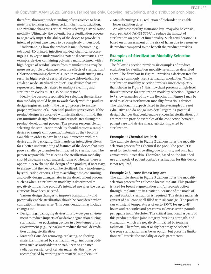
therefore, thorough understanding of sensitivities to heat, moisture, ionizing radiation, certain chemicals, oxidation, and pressure changes is critical when selecting a sterilization modality. Ultimately, the potential for a sterilization process to negatively impact the ability of the device to provide its intended patient care needs to be completely understood.
Understanding how the product is manufactured (e.g., extruded, 3D printed, injection molded, chemical process-ing) is also key to understanding potential sensitivities. For example, devices containing polymers manufactured with a high degree of residual stress from manufacturing may be more susceptible to damage from the effects of sterilization.3 Chlorine-containing chemicals used in manufacturing may result in high levels of residual ethylene chlorohydrin for ethylene oxide–sterilized products. For devices that are reprocessed, impacts related to multiple cleaning and sterilization cycles must also be understood.
Ideally, the person responsible for selecting the steriliza-tion modality should begin to work closely with the product design engineers early in the design process to ensure proper evaluation of all potential product sensitivities. If the product design is conceived with sterilization in mind, this can minimize design failures and rework later during the product development process. The person responsible for selecting the sterilization modality should request a sample device or sample components/materials as they become available in order to have hands-on interaction with the device and its packaging. This hands-on interaction allows for a better understanding of features of the device that may pose a challenge to and/or be impacted by sterilization. The person responsible for selecting the sterilization modality should also gain a clear understanding of whether there is opportunity to change the design of the product, if necessary, to ensure that the device can be sterilized. Early involvement by sterilization experts is key to avoiding time-consuming and costly design changes later in the development process, such as when a sterilization modality is determined to negatively impact the product’s intended use after the design elements have been selected.
Various design changes to improve compatibility and potentially enable sterilization should be considered when compatibility issues arise. This consideration may include changes in:• Design: E.g., packaging devices in a low-oxygen environ-
ment to reduce impacts of oxidative degradation during sterilization, or packaging devices in a low-temperature environment (e.g., ice packs) to reduce thermal degrada-tion during sterilization.
• Material: Consider removing, replacing, or altering materials impacted by sterilization (e.g., including addi-tives such as antioxidants or stabilizers to enhance radiation resistance of certain materials; this may be accomplished by working with material suppliers).4–6
• Manufacturing: E.g., reduction of bioburden to enable lower radiation dose.An alternate sterility assurance level may also be consid-
ered, per AAMI/ANSI ST67,7 to reduce the impact of sterilization on product functionality. Such consideration is based on an assessment of the risk of harm due to a nonster-ile product compared to the benefit the product provides.
Examples of Sterilization Modality Selection ProcessThe following section provides six examples of product evaluation for sterilization modality selection as described above. The flowchart in Figure 1 provides a decision tree for choosing commonly used sterilization modalities. While sterilization modality selection involves more complexity than shown in Figure 1, this flowchart presents a high-level thought process for sterilization modality selection. Figures 2 to 7 show examples of how the flowchart in Figure 1 may be used to select a sterilization modality for various devices. The functionality aspects listed in these examples are not exhaustive and do not go into detail regarding potential design changes that could enable successful sterilization, but are meant to provide examples of the connection between patient care and device characteristics impacted by sterilization.
Example 1: Chemical Ice PackThe example shown in Figure 2 demonstrates the modality selection process for a chemical ice pack. The product is used for treatment of swelling due to injury, and only has contact with intact skin. Therefore, based on the intended use and mode of patient contact, sterilization for this device is not required.
Example 2: Silicone Breast ImplantThe example shown in Figure 3 demonstrates the modality selection process for a silicone breast implant. This product is used for breast augmentation and/or reconstruction through implantation in a patient. Because of the mode of patient contact, sterilization is required. The device materials consist of a silicone shell filled with silicone gel. The product can withstand temperatures of up to 250°C for up to 48 hours and can withstand pressures as low as seven pounds per square inch (absolute). The critical functional aspects of this product include joint integrity, breaking strength, and elongation, which are negatively impacted by ionizing radiation. Therefore, moist or dry heat may be selected. Gaseous sterilization may be an option, but pressure limita-tions will restrict the modality or cycle parameters.
© Copyright AAMI 2020. Single user license only. Copying, networking, and distribution prohibited.

8 Industrial Sterilization: Process Optimization and Modality Changes Summer 2020
FEATURE
Figure 1. Illustration of high-level sterilization modality selection process.
Start
Is the product intended to be
sterile?NoStop here
Yes
Is product resistant to high
temperature?Yes
Is product resistant to high
humidity?NoDry heat
possible
Yes
Moist heat possible
Or
Is product resistant to
ionizing radia�on?
Or
Can sterility be achieved through
gaseous steriliza�on
(ethylene oxide or other)?
YesIonizing
radia�on possible
YesGaseous
steriliza�on possible
Redesign product
Is asep�c processing feasible?
Use asep�c processing
No
No
Yes
© Copyright AAMI 2020. Single user license only. Copying, networking, and distribution prohibited.

www.aami.org 9
FEATURE
Figure 3. Example sterilization modality selection process for silicone breast implant.
Start
Is the product intended to be
sterile?
Yes
Is product resistant to high
temperature?Yes
Is product resistant to high
humidity?
Yes
Moist heat possible
Product descrip�on: Silicone-filled breast implant for breast augmentaon/reconstrucon
Mode of pa�ent contact: Implanted
Steriliza�on required
Materials: Silicone shell and silicone gel
Product is resistant to high heat and humidity (can withstand up
to 250°C for 48 hours);product does not maintain
funconality in ionizing radiaon
Possible modali�es: Moist heat, dry heat, gas (some
pressure limitaons)
Is product resistant to
ionizing radia�on?
Can sterility be achieved through
gaseous steriliza�on
(ethylene oxide or other)?
Gaseous steriliza�on
possible
Yes
No
Yes
Figure 2. Example sterilization modality selection process for chemical ice pack.
Start
Is the product intended to be
sterile?NoStop here
Product descrip�on: Chemical ice patch (flexible bag of
reagents that react endothermically to cool)
Mode of pa�ent contact: Indirect contact to injured area
to relieve swelling
Steriliza�on not necessary
© Copyright AAMI 2020. Single user license only. Copying, networking, and distribution prohibited.

10 Industrial Sterilization: Process Optimization and Modality Changes Summer 2020
FEATURE
Example 3: Ureteral StentThe example shown in Figure 4 demonstrates the modality selection process for a ureteral stent and delivery system. This product is delivered through the urethra and bladder and implanted in the ureter to maintain flow of urine between the kidney and bladder. Key requirements of this device include flexibility and lubricity to enable navigation of the stent and delivery system through the relevant anatomy. The stent portion of this device is implanted within a patient’s ureter, thus requiring sterilization. The stent delivery system also requires sterilization as it is used to place the stent within the ureter. The product materials
include three polymers and a hydrophilic coating. Moist or dry heat sterilization is not possible, as polymers comprising the device experience softening at temperatures above approximately 50°C, and the coating functionality is nega-tively impacted by high humidity. Radiation sterilization is not possible because of the risk that the polypropylene component flexibility will be negatively impacted at the radiation doses of 25 kGy to 50 kGy typically used in medical device sterilization.3 Ethylene oxide sterilization is selected as a suitable method, with temperature and humidity condi-tions confirmed not to impact product functionality.
Figure 4. Example sterilization modality selection process for ureteral stent.
Start
Is the product intended to be
sterile?
Yes
Is product resistant to high
temperature?
No
Is product resistant to
ionizing radia�on?
No
Can sterility be achieved through
gaseous steriliza�on
(ethylene oxide or other)?
YesUse gaseous steriliza�on
Product descrip�on: Polymer implant used to maintain lumen
of ureter, implant delivery system
Key aspects of func�onality: Flexibility, lubricity
Mode of pa�ent contact: Stent is implanted; delivery system
goes through urethra, bladder, and into ureter
Steriliza�on required
Materials: Ethylene vinyl acetate, thermoplas�c
polyurethane, polypropylene, hydrophilic coa�ng
Product materials impacted at temperatures as low as 49°C;
coa�ng impacted by high humidity = moist/dry heat not
acceptable
Polypropylene at risk of being impacted at radia�on doses experienced in steriliza�on =
radia�on not acceptable
Selected modality: Gas steriliza�on (ethylene oxide),
with careful assessment of product temperature in cycle
© Copyright AAMI 2020. Single user license only. Copying, networking, and distribution prohibited.

www.aami.org 11
FEATURE
Example 4: Prefilled Vaccine Syringe The example flowchart for a prefilled vaccine syringe is illustrated in Figure 5. Because the vaccine is intended for parenteral use, product sterility of both the syringe and contained vaccine is a strict requirement. While the materi-als of the syringe components could withstand various sterilization modalities, the prefilled vaccine syringe in its final configuration could not undergo a terminal sterilization
process because all the terminal sterilization modalities (heat, ionizing radiation, gas) would negatively impact the quality of the vaccine. Heat and ionizing radiation, for instance, could cause degradation of the drug substance. Gaseous sterilization would not be able to penetrate the prefilled syringe. As a result, aseptic processing is the sole viable option to reach a sterile product.
Figure 5. Example sterilization modality selection process for prefilled vaccine syringe.
Start
Is the product intended to be
sterile?
Yes
Is product resistant to high
temperature?
No
Is product resistant to
ionizing radia�on?
No
Can sterility be achieved through
gaseous steriliza�on
(ethylene oxide or other)?
Product descrip�on: Vaccine in filled syringe is intended for parenteral
inocula�on, steriliza�on is required
Product sensi�vi�es:Heat, ionizing radia�on, and
sterilizing gas nega�vely impact the safety, purity, and/or potency of the vaccine;
addi�onally, gas cannot contact the drug
Asep�c processing required
Is asep�c processing feasible?
Yes Use asep�c processing
No
© Copyright AAMI 2020. Single user license only. Copying, networking, and distribution prohibited.
12 Industrial Sterilization: Process Optimization and Modality Changes Summer 2020
FEATURE
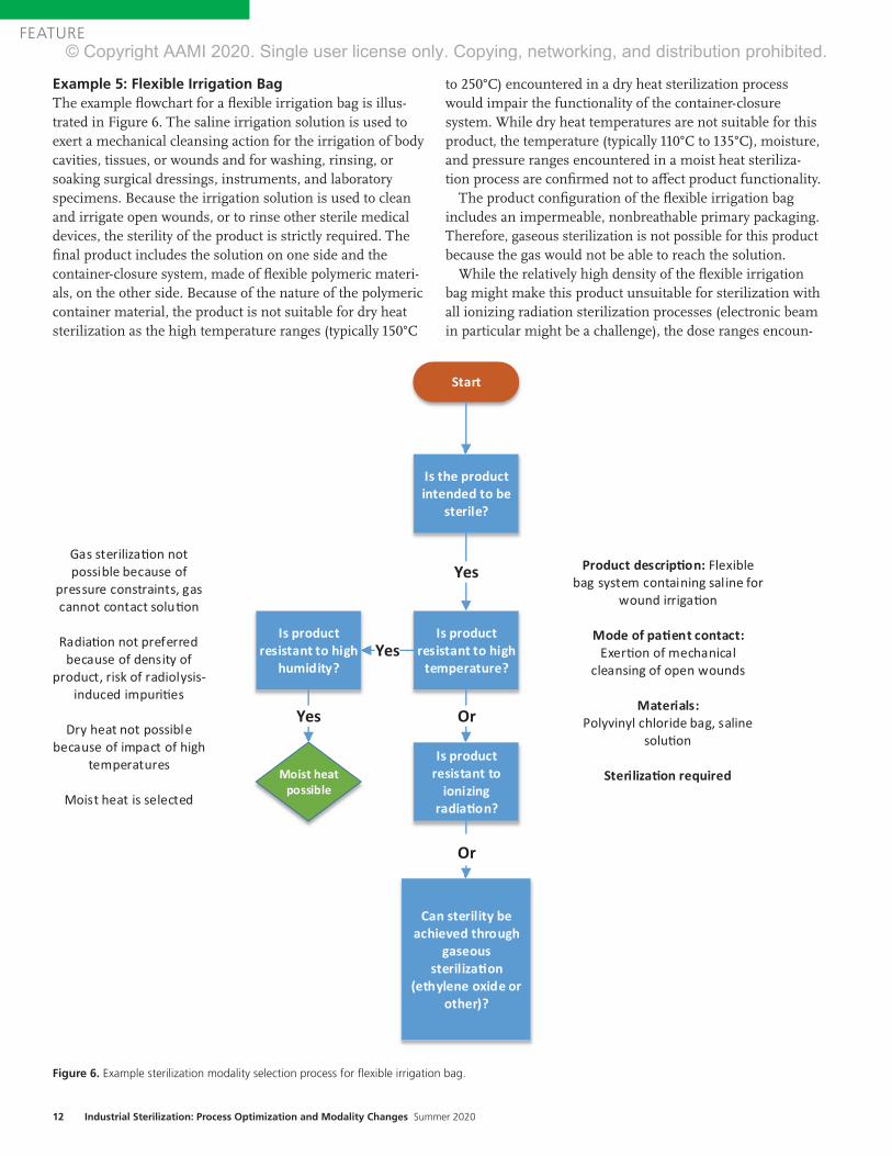
Example 5: Flexible Irrigation Bag The example flowchart for a flexible irrigation bag is illus-trated in Figure 6. The saline irrigation solution is used to exert a mechanical cleansing action for the irrigation of body cavities, tissues, or wounds and for washing, rinsing, or soaking surgical dressings, instruments, and laboratory specimens. Because the irrigation solution is used to clean and irrigate open wounds, or to rinse other sterile medical devices, the sterility of the product is strictly required. The final product includes the solution on one side and the container-closure system, made of flexible polymeric materi-als, on the other side. Because of the nature of the polymeric container material, the product is not suitable for dry heat sterilization as the high temperature ranges (typically 150°C
to 250°C) encountered in a dry heat sterilization process would impair the functionality of the container-closure system. While dry heat temperatures are not suitable for this product, the temperature (typically 110°C to 135°C), moisture, and pressure ranges encountered in a moist heat steriliza-tion process are confirmed not to affect product functionality.
The product configuration of the flexible irrigation bag includes an impermeable, nonbreathable primary packaging. Therefore, gaseous sterilization is not possible for this product because the gas would not be able to reach the solution.
While the relatively high density of the flexible irrigation bag might make this product unsuitable for sterilization with all ionizing radiation sterilization processes (electronic beam in particular might be a challenge), the dose ranges encoun-
Figure 6. Example sterilization modality selection process for flexible irrigation bag.
Start
Is the product intended to be
sterile?
Is product resistant to high
temperature?Yes
Is product resistant to high
humidity?
Yes
Moist heatpossible
Or
Is product resistant to
ionizing radia�on?
Or
Can sterility be achieved through
gaseous steriliza�on
(ethylene oxide or other)?
Yes Product descrip�on: Flexible bag system containing saline for
wound irrigaon
Mode of pa�ent contact: Exeron of mechanical
cleansing of open wounds
Materials:Polyvinyl chloride bag, saline
soluon
Steriliza�on required
Gas sterilizaon not possible because of
pressure constraints, gas cannot contact soluon
Radiaon not preferred because of density of
product, risk of radiolysis-induced impuries
Dry heat not possible because of impact of high
temperatures
Moist heat is selected
© Copyright AAMI 2020. Single user license only. Copying, networking, and distribution prohibited.
www.aami.org 13
FEATURE
tered in various ionizing sterilization processes are suitable for the polyvinyl chloride container material and the saline solution. An ionizing radiation sterilization process such as gamma or X-ray could be selected for the sterilization of the flexible irrigation solution bag. While both moist heat and ionizing radiation modalities provide the same level of sterility assurance, sterilization by heat has a lower risk for impacting the materials (e.g., moist heat does not introduce radiolysis impurities). For these reasons, moist heat is given priority over ionizing radiation in the decision process.
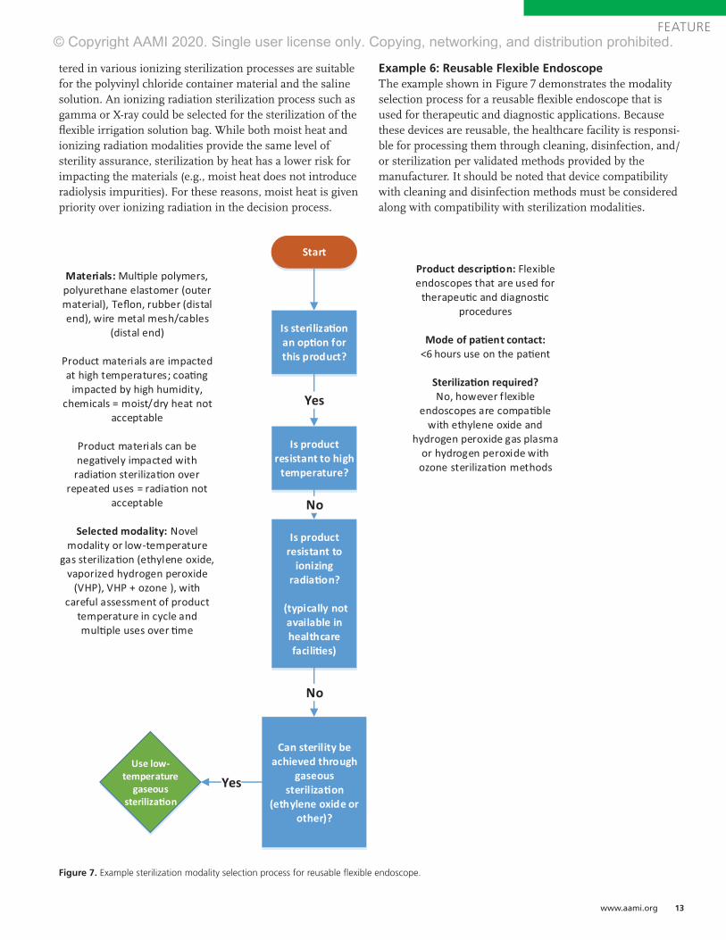
Example 6: Reusable Flexible EndoscopeThe example shown in Figure 7 demonstrates the modality selection process for a reusable flexible endoscope that is used for therapeutic and diagnostic applications. Because these devices are reusable, the healthcare facility is responsi-ble for processing them through cleaning, disinfection, and/or sterilization per validated methods provided by the manufacturer. It should be noted that device compatibility with cleaning and disinfection methods must be considered along with compatibility with sterilization modalities.
Figure 7. Example sterilization modality selection process for reusable flexible endoscope.
Start
Is steriliza�on an op�on for this product?
Yes
Is product resistant to high
temperature?
No
Is product resistant to
ionizing radia�on?
(typically not available in healthcare facili�es)
No
Can sterility be achieved through
gaseous steriliza�on
(ethylene oxide or other)?
YesUse low-
temperature gaseous
steriliza�on
Product descrip�on: Flexible endoscopes that are used for
therapeu�c and diagnos�c procedures
Mode of pa�ent contact: <6 hours use on the pa�ent
Steriliza�on required?No, however flexible
endoscopes are compa�ble with ethylene oxide and
hydrogen peroxide gas plasma or hydrogen peroxide with
ozone steriliza�on methods
Materials: Mul�ple polymers, polyurethane elastomer (outer material), Teflon, rubber (distal end), wire metal mesh/cables
(distal end)
Product materials are impacted at high temperatures; coa�ng
impacted by high humidity, chemicals = moist/dry heat not
acceptable
Product materials can be nega�vely impacted with
radia�on steriliza�on over repeated uses = radia�on not
acceptable
Selected modality: Novel modality or low-temperature
gas steriliza�on (ethylene oxide, vaporized hydrogen peroxide
(VHP), VHP + ozone ), with careful assessment of product
temperature in cycle and mul�ple uses over �me
© Copyright AAMI 2020. Single user license only. Copying, networking, and distribution prohibited.
14 Industrial Sterilization: Process Optimization and Modality Changes Summer 2020
FEATURE
As flexible endoscopes contact nonsterile pathways such as the mouth, throat, and colon, sterilization is not strictly required, and cleaning and high-level disinfection may be acceptable. However, the classification of these devices is a subject of ongoing debate. Because of the potential for exposure to blood and tissue during critical applications, sterilization may be pursued for these devices. If sterilization is selected over disinfection, only low-temperature gas sterilization methods are possible (including ethylene oxide, vaporized hydrogen peroxide, and vaporized hydrogen peroxide with ozone) because these devices are tempera-ture sensitive. Radiation sterilization typically is not available for sterilizing reusable devices in healthcare settings.
Each low-temperature gas modality presents potential issues for sterilization of reusable flexible endoscopes. Ethylene oxide is not commonly used for reusable devices because of relatively long cycle times, safety concerns around sterilant residuals left on the device, and material compatibility issues resulting in loss of required device flexibil-ity.8 Vaporized hydrogen peroxide methods present material compatibility problems with flexible endoscopes after several reprocess-ing cycles; so, while these methods may be an option, the number of times a device is reprocessed may be limited. Therefore, there is a need to explore additional, potentially novel, sterilization modalities or changes in device design in order to improve material compatibility if sterilization is to be pursued.
ConclusionThe ability of a medical device to provide its intended patient care—including the intended use and functional requirements of the device—is the foundation for all deci-sions concerning sterilization modality selection. It is therefore critical to gain a detailed understanding of how the product interacts with the patient, as well as how the sterilization modality will interact with the product. Understanding key elements of the product design, such as details of the materials and design configuration, is critical in making this assessment.
AcknowledgmentsThe author thanks Andre Tuggles, Emily Craven, Phil Cogdil, Vu Le, Patrick Weixel, Alpa Patel, George Ngatha, Neville Niessen, Melissa Escobeda, Brian McEvoy, Joyce M.Hansen, and Jeff Nelson for their contribu-tions to this article.
References1. Department of Health & Human Services, Food
and Drug Administration. Submission and Review
of Sterility Information in Premarket Notification
(510(k)) Submissions for Devices Labeled as Sterile.
2016.
2. Department of Health & Human Services, Food
and Drug Administration. Reprocessing Medical
Devices in Healthcare Settings: Validation Methods
and Labeling. 2015.
3. AAMI TIR17:2017. Compatibility of Materials
Subject to Sterilization. Arlington, VA: Association
for the Advancement of Medical Instrumentation.
4. Hemmerich KJ. Polymer Materials Selection
for Radiation Sterilized Products. Available at:
https://www.mddionline.com/polymer-materials-
selection-radiation-sterilized-products. Accessed
May 30, 2020.
5. Zaharescu T, Jipa S, Henderson D, Kappel W,
Maris DA, Maris M. Thermal and Radiation
Resistance of Stabilized LDPE. Radiation Physics
and Chemistry. 2010;79:375–378.
6. Yoshinobu I, Hiroshi N, Shigehiko T, Yoichi Y,
Seiichi T. Radiation Grafting of Styrene onto
Polyethylene. Radiation Physics and Chemistry.
2001;62(1):83–88.
7. ANSI/AAMI ST67:2011/(R)2017. Sterilization of
health care products—Requirements and guidance
for selecting a sterility assurance level (SAL)for
products labeled ‘sterile.’ Arlington, VA: Association
for the Advancement of Medical Instrumentation.
8. Department of Health & Human Services,
Food and Drug Administration. Reducing the
Risk of Infection from Reprocessed Duodenoscopes,
Executive Summary of the meeting of the
General Hospital and Personal Use Devices Panel
of the Medical Devices Advisory Committee.
2019.
© Copyright AAMI 2020. Single user license only. Copying, networking, and distribution prohibited.

www.aami.org 15
FEATURE
AbstractDue to its complexity, sterilization has been perceived by some professionals who lack sterility assurance expertise as a “black box” process. Historically, medical device manufacturers have selected one of the available industrial steriliza-tion options: dry heat, moist heat, gamma, or ethylene oxide (EO). The preselection of a sterilization modality (method) typically is made without understanding its impact based on qualified sterilization processes for existing products, capability, or resources required for the specific processes. Early engagement with sterilization subject matter experts (SMEs) can redirect the decision to preselect a legacy modality and help foster innovation and operational agility. Recent focus on supply chain flexibility and sustainability by the medical device industry has been affected by concerns surrounding cobalt-60 shortages and EO emissions. These factors drive the need for early involvement with sterility assurance SMEs in the product development process and the exploration of multiple sterilization modalities. This article highlights the importance of exploring multiple sterilization modalities during the product development stage to support sustainable business continuity plans.
Typical Approach of Medical Device CompaniesThe International Irradiation Association (iia) has estimated that contract sterilization volume is distributed at approximately 40.5% gamma, 4.5% electron beam (E-beam), 50% ethylene oxide (EO), and 5% via a variety of modalities (e.g., steam, X-ray).1 Sterilization modalities are not selected by happenstance; one can expect that a medical device com-pany is using a sterilization modality that is compatible with the material of composition, product configuration, and packaging configuration for a given healthcare product, in order to meet regulatory requirements.
When evaluating sterilization modalities for a line extension, new product develop-
ment, or business continuity plan (BCP), it is practical for these same companies to look at the modality they are most familiar with or a modality that is already used for similar products in the industry. Therefore, for product development, a speed-to-market approach typically will utilize a sterilization modality already in use. This will reduce the time for validation and follow a known regulatory pathway. BCP approaches may include qualifying a cycle in more than one sterilization chamber at the same site, validating their established process at an alternate sterilization site(s), or qualifying and approving another vendor to deliver their process. In addition, a company may qualify a sterilization process to be performed two or three times as a BCP approach.
Material selection and product configura-tion often are the drivers for modality selection. Due to an extensive history of well-characterized effects on materials with EO and gamma, as well as the dominance of both modalities in relation to contract sterilization volumes (90.5% per iia report1), stakeholders may make the incorrect assumption that EO and gamma are the only available sterilization modalities that can be used for their products. Considering these factors, new product development teams within companies may perceive the advantage of selecting EO or gamma to be greater than any benefits gained from using an alternate modality as a primary mode of sterilization or using an alternate modality as part of business continuity planning.
Influences on Changing Typical ApproachSeveral initiatives in the industry indicate an increased interest in exploring novel sterili-zation technologies. One driver is innovation surrounding additional combination prod-ucts that may introduce new drugs, biologics, or materials that are sensitive to heat, moisture, and oxidation.2 These
About the Authors
Vu Le, BS, is a manufacturing engineering manager at Abbott Laboratories in Temecula, CA.
Email: [email protected]
Andre Tuggles, BS, MBA, is a principal sterilization scientist at Johnson & Johnson in
Somerville, NJ. Email: [email protected]
The Case for Qualifying More Than One Sterilization ModalityVu Le and Andre Tuggles
© Copyright AAMI 2020. Single user license only. Copying, networking, and distribution prohibited.

16 Industrial Sterilization: Process Optimization and Modality Changes Summer 2020
FEATURE
innovative products introduce material compatibility challenges with widely used sterilization modalities. AAMI TIR17, Compatibility of materials subject to steriliza-tion, was updated in 2017 to include guidance on, for example, vaporized peracetic acid, liquid peracetic acid, and nitrogen dioxide sterilization modalities.3 In addition, the International Organization for Standardiza-tion (ISO) working group (WG) 16 is developing ISO/CD 22441, Sterilization of health care products—Low temperature vaporized hydrogen peroxide—Requirements for the development, validation and routine control of a sterilization process for medical devices. These initiatives are not happening in isolation; rather, they are influenced by the demands of the industry and the growing pressures facing current sterilization modalities.
EO is used worldwide to sterilize medical devices and has an established history of effectiveness. In the United States, regula-tory changes have been proposed at both the national and state levels to reduce EO emissions, including efforts by the Environ-mental Protection Agency (EPA)4 and Texas Commission on Environmental Quality.5 As directed by the Illinois Environmental Protection Agency, multiple sterilization facilities were temporarily closed in 2019 because of issues with EO emissions.6 Also in 2019, the Food and Drug Administration (FDA) introduced a challenge focused on finding ways to reduce EO emissions.7
Potential changes to EPA regulations and the FDA’s challenge to reduce EO emissions have prompted contract sterilizers and medical device manufacturers that perform sterilization in-house to evaluate improve-ments to their EO emission controls systems and explore ways of optimizing their pro-cesses to reduce the amount of EO used. The FDA also issued a challenge related to identifying new sterilization methods and technologies.8 Although the device industry may have developed the impression that selecting only “traditional” sterilization modalities (i.e., EO, gamma, E-beam, moist heat, dry heat) would be accepted by regula-tors, the FDA’s challenge clearly indicated its willingness to review alternate sterilization modalities.
The absence of capacity, or limited capac-ity, at a contract sterilizer can have a significant impact on the industrial steriliza-tion network. For example, multiple site closures in the United States in 2019 had a direct impact on the industrial EO steriliza-tion network, as it reduced the available capacity to sterilize medical devices.6 The closure of contract sites prompted a series of disruptions that led medical device manufac-turers to discontinue production, immediately validate at a new location, or activate their BCP to continue supplying product to customers.
In cases where validation was required, the supply of medical devices was affected because validation efforts can take several weeks or even months depending on the availability of sterilization equipment, resources to execute the validation, and incubation times for the microbiological quality testing needed for validation. In the event that a medical device manufacturer determines that it must validate at an alternate supplier for contract sterilization services, one would expect the company to review its approved supplier network, thereby avoiding the necessary time and resources required to qualify a new supplier. Closures of contract sites also bring inherent challenges at the remaining contract sites, as the influx of additional customers can have a direct impact on the turnaround time for previously existing customers. For a medical device manufacturer that previously validated a secondary site for business continuity planning, that secondary site becomes the primary sterilization site and the manufacturer must now develop a backup to this new primary sterilization site.
Gamma sterilization is considered effec-tive and reliable and is conducted by a large network of facilities worldwide. However, gamma sterilization has faced challenges in the sourcing of cobalt-60 (Co-60), as described in the 2019 report from the iia.9 In addition to shortages, Co-60 poses safety and security risks, as reported by the Interna-tional Atomic Energy Agency.10
The perpetually increasing market for medical devices has burdened the available gamma sterilization capacity. For example,
© Copyright AAMI 2020. Single user license only. Copying, networking, and distribution prohibited.

www.aami.org 17
FEATURE
data presented at the 2019 International Meeting on Radiation Processing provided an estimated average compound annual growth rate of 5% for Europe and Asia across EO, gamma, E-beam, and X-ray modalities.9 E-beam is a good complement to gamma but has inherent limitations with penetra-tion related to high-density products. X-ray is known to have a penetration capability comparable with gamma, and approximately five facilities worldwide offer industrial X-ray sterilization services. In addition, expansion projects have been announced recently, with more X-ray sterilization facilities under construction in North America, Europe, and Asia.
Shortages of available EO sites and Co-60 have placed challenges on the supply chain and, in turn, affected healthcare delivery organizations (HDOs) and other users of medical devices. Given this situation, the manufacturing of additional products might
provide a buffer for the additional time needed to deliver products to HDOs (i.e., to accommodate increased processing time). If this action is taken, the healthcare industry also must be aware of the burden that an influx of additional product would place on the available sterilization capacity. Therefore, the question becomes: “Is the supply chain prepared for a disruption?”
Shifting all products from a primary to a backup sterilization site does not imply that product volume (cubic footage) can be processed in the same amount of time. A change from one sterilization site to another also affects regulatory agencies. Does the regulatory agency have the capacity to handle the influx of submissions with a sudden disruption in network capacity? This change is not instantaneous and involves an added layer of complexity within the supply chain to manage product distribution as regulatory approval is obtained in different markets.
Waiting to explore an alternate sterilization modality at the time of need could result in supply chain issues that, in turn, could affect healthcare facility access to medical devices. The time it takes to react to a disruption could come at the cost of patient care.
© Copyright AAMI 2020. Single user license only. Copying, networking, and distribution prohibited.
18 Industrial Sterilization: Process Optimization and Modality Changes Summer 2020
FEATURE
Overcoming Challenges, Seizing OpportunitiesIf bias is removed related to designing a product for sterilization, what approach should be taken? A product development team could move the exploration of multiple sterilization modalities to earlier in the design control/product design process. Following product launch, product develop-ment resources to support exploration of alternate sterilization modalities might be limited due to availability. Depending on the state of product inventory, waiting to explore an alternate sterilization modality at the time of need could result in supply issues and, therefore, affect access to medical devices by health professionals and patients. The time it takes to react to a disruption could come at the cost of patient care.
The current challenges could be overcome in a variety of ways. The evaluation/develop-ment of multiple sterilization modalities could occur during the product design phase or after the product is available in the market. (These options are further explored below.) The timing for addressing the exploration of modalities might depend on the number and types of products (e.g., device classification) already in the market, as well as the number of new products envisioned to be developed in the future. If the process is designed to speed products to market, a company might choose to address the development of one sterilization modal-ity during product design and commit resources to developing an additional sterilization modality after the product reaches market.
However, if a company has potential products in its pipeline that might be incompatible with current sterilization modalities, the initial exploratory studies evaluating additional sterilization modalities should occur as part of the research-and-development (R&D) process. If alternate sterilization modalities are evaluated during
the R&D process, a body of knowledge would be available to support future products.
Having more than one sterilization modality option will provide a medical device company with flexibility when responding to industry capacity constraints and future product needs. Validating multiple modali-ties allows a company to be agile and dynamic, helping it deliver products quickly to customers and respond to current and future challenges. It also can help expand a company’s materials compatibility database, which may speed up material selection during product development.
Scenarios for Validating More Than One ModalityKeeping an open mind and eliminating sterilization modality bias when selecting the path forward may not be common practice. Biases often can direct an organization down the path of least resistance, resulting in short-term gains but limited long-term benefits. The following two scenarios describe the benefits of exploring multiple modalities (1) during new product develop-ment and (2) for a predicate device with a preselected modality.
Scenario 1: New Product DevelopmentThe FDA guidance on design controls contains common phases, such as design planning, design verification, and design validation. The selection of sterilization modality and validation was included in a list of examples to be considered as part of design inputs.11 Value can be added by involving sterilization subject matter experts (SMEs) at the onset of the design phase. Sterilization SME input can help expand the options of available and compatible modali-ties. For example, materials that have detrimental effects resulting from steriliza-tion conditions during design verification may force manufacturers to adjust steriliza-tion parameters, such as using a relatively low maximum acceptable dose to accommo-date product specifications. This can limit processing range, cause inefficient loading configurations, or restrict resterilization capabilities.
This scenario considers sterilization modality selection during the development
Biases often can direct an organization down the path of least resistance, resulting in short-term gains but limited long-term benefits.
© Copyright AAMI 2020. Single user license only. Copying, networking, and distribution prohibited.

www.aami.org 19
FEATURE
of a new product. Early collaboration can help make the connections between the materials selected and their respective product functionality requirements, thereby eliminating certain options immediately. A product that is not heat or moisture sensitive may be compatible with dry heat, moist heat, gaseous sterilants (e.g. EO, vaporized hydrogen peroxide, nitrogen dioxide), and even radiation. A product that is not prone to radiation degradation may work with either gamma, E-beam, or X-ray.
Most of this work can be outlined with a sterilization SME up front to minimize validation efforts following product launch. Speed to market commonly is a high priority. Therefore, one may select and establish one method as the primary mode and explore an alternate method in parallel as a backup. When engaged early, the sterilization SME can provide valuable insight, including material selection recommendations, package design recommendations, and recommendations that allow for supply chain optimization.
Material selection recommendations. Based on information available in TIR17, peer-reviewed articles, and experience, a sterilization SME can combine his/her understanding of product functionality and knowledge of the sterilization processes to identify the optimal material for a robust product design. For example, a predeter-mined radiation dose may be used to cross- link a polymer used in a device for which the functional requirement is tensile strength. A heated sterilization process (e.g., dry heat, EO) may enhance the performance of a component by further curing of an adhesive.
The selection of materials should not be focused solely on the functionality of the materials. How the materials will respond to the sterilization modality in the final finished design should also be considered. Function-ality of materials might change based on the extrusion properties for plastics and the specific heat of metals. Product functionality is tested following initial exposure to the sterilization process and following a shelf-life study that might incorporate accelerated aging studies. However, initial exploratory studies may direct product design engineers in the appropriate direction prior to finaliz-ing the materials selected.
Package design recommendations. Equipped with an understanding of the available sterilization modalities, a steriliza-tion SME can provide packaging material and configuration recommendations com-patible with the selected modality or multiple sterilization modalities. If the product requires nonporous packaging to maintain product integrity or moisture, a sterilization modality that does not require porosity for access of the sterilant to the product should be explored (e.g., radiation). If the product requires a tray for the presentation of the product to the operating field, final packag-ing design should be developed with sterilization in mind. As with product materials, the selection of appropriate packaging designs and materials can limit or expand the options that might be explored for sterilization modalities. The use of initial exploratory studies might support the selection of multiple sterilization modalities.
Considerations for supply chain. A sterilization SME can determine the appro-priate sterilization modalities that might be selected with an understanding of the future anticipated product volume, product/packaging materials and designs, and results of initial exploratory studies. This informa-tion may also provide the data needed to decide between internal sterilization and external contract sterilization services. If internal sterilization is selected, the current internal capacity can be compared with the time to procure, install, and validate addi-tional sterilization equipment. If internal sterilization is selected and capacity is constrained, external contract sterilization might be used while additional equipment capacity is installed. If external sterilization is selected, the options for contract steriliza-tion can be evaluated for location, capacity, and compatibility. This would allow for multiple sites to be selected for validation and provide the BCP necessary for the chosen sterilization modalities.
Early collaboration can help make the connections between the materials selected and their respective product functionality requirements, thereby eliminating certain options immediately.
© Copyright AAMI 2020. Single user license only. Copying, networking, and distribution prohibited.
20 Industrial Sterilization: Process Optimization and Modality Changes Summer 2020
FEATURE
Scenario 2: Predicate DeviceValidating a secondary sterilization modality may not be feasible because of a product’s materials of construction, because of the need for getting a new product to market quickly, or if a product (or product line) has been on the market for a long period of time and the original validation was conducted using only one sterilization modality.
Evaluating alternate sterilization modali-ties may indicate the need to change materials of construction or include additives to the materials to allow for the use of an alternate sterilization method. For example, adding antioxidants to plastics might allow a radiation sterilization method to be used. However, several products might not allow for a secondary modality and may require business continuity planning of the single sterilization modality. If the product is a legacy product or if a secondary sterilization modality was not evaluated during the product development phase because of a need to reach market quickly, this testing can be conducted as part of the product’s life cycle management and may/may not require changes to support an alternate sterilization modality.
This scenario considers a portfolio of legacy products that were previously vali-dated using only one sterilization modality: gamma. Products that have a legacy of being qualified using gamma might have a conven-ient pathway for qualifying a secondary radiation modality, such as converting to X-ray and/or E-beam. For this scenario, two areas need to be considered: the microbio-logical qualification and the physical/process qualification. The validation of a second radiation modality can be straightforward if the sterilization dose and the maximum acceptable dose allowed (i.e., validated dose range) remain the same and if one satisfies certain conditions following guidance provided in ANSI/AAMI/ISO 11137-1:2006/(R)2015.12
For the sterilization dose (microbiological qualification), a successful repeat of the verification dose experiment with the new radiation modality might be the extent of additional work required for transferring the sterilization dose from one radiation modal-ity to the second radiation modality. For the maximum acceptable dose allowed, the testing to support this portion of the qualifi-cation might require considerably more work, as it deals with material compatibility. The primary area of concern could be the potential impact on product materials if the doses that might be observed during routine sterilization with X-ray or E-beam exceed those approved for gamma. However, testing may be minimized if the doses observed during routine sterilization can be main-tained below the qualified maximum dose for gamma processing. Product packaging and product loading patterns might be adjusted to allow for processing within the validated dose range.
For this example, the selection of a secondary radiation modality might be easily qualified for X-ray. X-ray has similar penetra-tion capability to gamma, which may support maintaining the current load configuration (as presented during routine sterilization processing). Minimal qualifications are required when transferring from a low-dose rate (e.g., gamma) to high-dose rate (e.g., E-beam), as described in 11137-1 when considering the transfer of maximum acceptable dose between radiation sources.12 The AAMI sterilization standards WG 2 is drafting TIR104, which will provide addi-tional guidance on converting radiation technologies.
Considerations for supply chain. For this scenario, given his/her understanding of the future anticipated product volume and additional testing of alternate radiation sterilization modalities (e.g., X-ray, E-beam), a sterilization SME can determine the secondary sterilization modality that might be selected. Qualifying E-beam or X-ray sterilization as a second modality opens the possibility for in-house sterilization. The decision to select E-beam or X-ray will rely on volume, product density, and loading configuration. In-house sterilization can be the new primary source, with gamma as
Evaluating alternate sterilization modalities may indicate the need to change materials of construction or include additives to the materials to allow for the use of an alternate sterilization method.
© Copyright AAMI 2020. Single user license only. Copying, networking, and distribution prohibited.

www.aami.org 21
FEATURE
backup, thereby allowing for just-in-time sterilization, reduced turnaround time, and a decrease in product inventory.
When selecting external contract services, factors that should be considered include vendor competency in managing complex equipment and speed to market (utilizing existing infrastructure).
ConclusionFor product supply chain sustainability, more than one sterilization modality should be validated for products that are compatible with multiple modalities. The validation of more than one sterilization modality will provide medical device companies with flexibility when responding to high product demand and sterilization supply chain interruptions. A BCP that includes validating and maintaining validation of both steriliza-tion modalities should be considered. In addition, the BCP also should take into account the potential to validate multiple sterilization sites for supply chain flexibility. For products designed to allow for multiple sterilization modalities, the BCP becomes more robust and allows for constructive conversations regarding turnaround time, processing flexibility, and resources. These advantages are possible with a best-in-class sterilization program that allows for steriliza-tion SME engagement in the early stages of product development.
References1. Gamma Industry Processing Alliance,
International Irradiation Association. A
Comparison of Gamma, E-beam, X-ray and Ethylene
Oxide Technologies for the Industrial Sterilization
of Medical Devices and Healthcare Products. http://
iiaglobal.com/wp-content/uploads/2018/01/
White-Paper-Comparison-Gamma-Eb-Xray-and-
EO-for-Sterilisation.pdf. Accessed June 28, 2020.
2. Lambert BJ, Lam S, Hansen JM, Bryans
TD (Eds.). Assurance of Sterility for Sensitive
Combination Products and Materials: New
Paradigms to Bring Innovative Healthcare Products
to Patients. 1st ed. Cambridge, MA: Academic
Press; 2019.
3. AAMI TIR17:2017. Compatibility of materials
subject to sterilization. Arlington, VA: Association
for the Advancement of Medical Instrumentation.
4. Environmental Protection Agency. EPA Moves
Forward on Suite of Actions to Address Ethylene
Oxide. www.epa.gov/newsreleases/epa-moves-
forward-suite-actions-address-ethylene-oxide.
Accessed April 20, 2020.
5. Haney JT Jr, Lange SS, Jenkins A, Myers JL.
Ethylene Oxide Carcinogenic Dose Response
Assessment. www.tceq.texas.gov/assets/
public/implementation/tox/dsd/final/eto.pdf.
Accessed June 28, 2020.
6. Illinois Environmental Protection Agency.
Illinois EPA information on Ethylene Oxide.
www2.illinois.gov/epa/topics/community-
relations/sites/ethylene-oxide/Pages/default.aspx.
Accessed April 20, 2020.
7. Food and Drug Administration. FDA Innovation
Challenge 2: Reduce Ethylene Oxide Emissions.
www.fda.gov/medical-devices/general-hospital-
devices-and-supplies/fda-innovation-challenge-
2-reduce-ethylene-oxide-emissions. Accessed
April 20, 2020.
8. Food and Drug Administration. FDA Innovation
Challenge 1: Identify New Sterilization Methods
and Technologies. www.fda.gov/medical-devices/
general-hospital-devices-and-supplies/fda-
innovation-challenge-1-identify-new-sterilization-
methods-and-technologies. Accessed April 20,
2020.
9. International Irradiation Association. IMRP
Report: The Business and Science of Radiation
Processing in 2019. https://iiaglobal.com/news/
imrp-report-the-business-and-science-of-
radiation-processing-in-2019. Accessed April 20,
2020.
10. International Atomic Energy Agency. IAEA
Helps Remove Highly Radioactive Material from
Five South American Countries. www.iaea.org/
newscenter/pressreleases/iaea-helps-remove-
highly-radioactive-material-from-five-south-
american-countries. Accessed June 19, 2020.
11. Tartal J. Design Controls. www.fda.gov/
media/116762/download. Accessed April 20, 2020.
12. ANSI/AAMI/ISO 11137-1:2006/(R)2015.
Sterilization of health care products—Radiation—
Part 1: Requirements for development, validation,
and routine control of a sterilization process for
medical devices. Arlington, VA: Association for the
Advancement of Medical Instrumentation.
© Copyright AAMI 2020. Single user license only. Copying, networking, and distribution prohibited.

© Copyright AAMI 2020. Single user license only. Copying, networking, and distribution prohibited.

www.aami.org 23
FEATURE
AbstractFollowing years of discussion and debate regarding the economics of X-ray radiation for sterilization of healthcare products, the benefits of the technology are now being realized. X-ray, like gamma radiation, is a process whereby energic photons penetrate to sterilize medical devices. Compared to gamma, photons in the bremsstrahlung spectrum from X-ray radiation allow for improved dose uniformity ratio, higher dose rates, and shorter process time, which provide additional opportunities for sterilization process enhancement. Such improvements may be realized in a number of ways: 1) economic, where more products may be processed on a carrier; 2) improved dose range fit; and/or 3) wider material compatibility. Despite noted benefits, X-ray sterilization has not yet been widely accepted and currently accounts for less than 5% of the contract sterilization market. This article brings X-ray sterilization into focus by sharing knowledge and experience gained over the past 10 years at the STERIS Däniken site, with an aim to identify opportunities for future medical device sterilization.
Radiation sterilization of medical products was first explored in the late 1940s, with production processing commencing in 1957 by Ethicon, Inc using a 7 MeV–, 5 kW–elec-tron beam (E-beam).1 By the mid 1960s, the use of cobalt-60 radiation sources was prevalent. By the mid 1970s, the use of E-beam was again explored as an alternative to isotope processing, and in 2017 E-beam accounted for 15% of medical device process-ing in the U.S.2 Today, while a significant reliance remains on gamma, a pressing need for a viable alternative is recognized to address concerns regarding cobalt supply and radioactive source security.3 One of the key advantages to gamma irradiation is that it is highly effective at treating a wide variety of products and package configurations with varying densities. Therefore, a viable alterna-tive should also demonstrate similar characteristics. Alternatives to isotope radiation come in the form of accelera-
tor-based radiation, such as E-beam and X-ray. With a long history of use, E-beam is an excellent modality choice but is limited by the depth of penetration of the electrons, and does not always offer a suitable alternative to large-volume, cobalt-based processes. On the other hand, high-energy X-rays are more penetrating (than E-beam) and therefore offer a viable alternative to gamma radiation.4 When considering a change of the steriliza-tion source (e.g., from gamma to X-ray), key processing parameters (e.g., temperature, dose rate, incremental dose process, maxi-mum dose) must be evaluated, as they may differ significantly. Therefore, a better understanding of the X-ray irradiation process for sterilization of medical devices could create wider acceptance of the technol-ogy and facilitate transitioning from gamma to X-ray. The aim of this article is to share experience from the first large-scale medical device X-ray sterilization at STERIS Däniken (Switzerland). The experience gained processing a wide array of materials and devices over the past 10 years can help inform potential users of the benefits and opportunities of X-ray processing.
Opportunities with X-ray
Photon-to-Photon TechnologyFrom the early work of Wilhelm Roentgen in 1895 at his laboratory in University of Würzburg, X-rays have been widely applied in medical and industrial diagnostic instru-ments because of their unique properties.5 Bremsstrahlung X-rays are emitted when energic electrons generated by an E-beam source strike a target material and are deflected by the atomic nuclei in the mate-rial. The X-ray intensity increases with the E-beam current, the kinetic energy of the electrons, and the atomic number of the target material.1 In healthcare sterilization, radiation energies in the range of 3–7 MeV and beam powers in the range of 100–700 kW are needed to provide an alternative to gamma irradiation. These elevated power
About the Authors
Brian McEvoy, BSc, MBA, is senior director global technologies at STERIS in Tullamore,
Ireland. Email: [email protected]
Hervé Michel, BSc, is director of radiation technology at STERIS in Däniken, Switzerland.
Email: [email protected]
Daniel Howell, BSc, is European RTC & UK laboratory operations manager at STERIS in
Yorkshire, UK. Email: [email protected]
Philip Roxby, BEng, is technical services manager at STERIS in Galway, Ireland. Email: [email protected]
X-ray: An Effective PhotonBrian McEvoy, Hervé Michel, Daniel Howell, and Philip Roxby
© Copyright AAMI 2020. Single user license only. Copying, networking, and distribution prohibited.

24 Industrial Sterilization: Process Optimization and Modality Changes Summer 2020
FEATURE
levels must be used to compensate for the inefficiency of the conversion from electron to photon: Typical conversion efficiency for a 7 MeV machine using tantalum target material would be approximately 12%.1,8 While X-ray suffers from conversion inefficiency, the angular distribution of X-rays in the forward direction versus the isotropic field of gamma, coupled with higher dose rates, compensate to make X-ray a viable alternative.1 In the context of equipment and facility design with regard to accelerator-based technology, there is ample documentation in the literature,1,3,4,6 and X-ray equipment configurations are currently available from a number of suppliers including CGN Dasheng, IBA, and Mevex.
One of the benefits of transitioning from gamma radiation to X-ray is that with both sources photons are used to deliver the dose to product. However, gamma and X-ray processes produce those photons in different ways: cobalt-60 decays into a stable nickel-60 isotope and emits two wavelengths of high-energy gamma-rays (1.17 and 1.33 MeV),7 whereas X-rays are produced by striking a metal target with the E-beam from an accelerator.1 Figure 1 illustrates the spec-trum of photon energies for an X-ray irradiator of 5–10 MeV, with the peak energy occurring at approximately 0.3 MeV. In terms of energy deposition and high penetration capabilities, X-ray photons behave nearly identically to photons from gamma sources, even with the variance in energy.8 Advanta-geously, in an X-ray radiation field, the majority of photons propagate from the converter in the same general direction as the incident electrons. As shown in Figure 2, the intensity of the X-ray photons increases with the energy and when the polar angle decreases.1 The directionality of the photons perpendicular to the product surface has the effect of optimizing the photon capture rate relative to the more isotropic gamma rays from cobalt-60.
TemperatureTemperature has a significant effect on polymeric material properties, often observed with accelerated aging studies. Excess energy from radiation processing increases the temperature of the treated material. However, the mecha-nism by which heat is imparted varies by radiation process. The importance of the radiation field is highlighted when one examines temperature differences experienced by products treated with both gamma and X-ray.
Because of the directionality of the photons in X-ray radiation processes and the design of the target used to convert the electron to photon, the X-ray radiation field surface is smaller than the radiation field resulting from a gamma source rack. Therefore, the dose is efficiently delivered to products only when they are in front of the X-ray target. In gamma processes, products receive dose from the time they enter the process radiation chamber until the time they exit. Furthermore, an incremental or multiple-pass process versus continuous process may also have an influ-ence on how the dose is delivered, and subsequently how product properties may be impacted. High-power X-ray irradiators are often an incremental design, which means that the total dose is given in multiple passes in front of the X-ray source. As a consequence, the product will be exposed to different temperatures than in a gamma process, where the product spends a few hours in the radiation room, usually at high temperatures (> 45°C). Additionally, a temper-ature rise associated with the total dose received will also impact the temperature of the product. For example, a comparison made at the Däniken facility between a gamma irradiator (average dose rate ~ 3 kGy/h) and an X-ray irradia-tor (7 MeV, 560 kW; average dose rate ~ 250 kGy/h) demonstrated that the difference between the start and end temperature is approximately 22°C and 11°C, respectively, at
Figure 1. Energy spectra of X-ray photons generated by bremsstrahlung on a tantalum target with electron of 5 and 7 MeV (right) in comparison with gamma energy spectrum (left). Image on right reprinted from Radiation Physics and Chemistry, 57, Meissner J, Abs M, Cleland MR, Herer AS, Jongen Y, Kuntz F, Strasser A. X-ray treatment at 5 MeV and above, 647–651, 2000, with permission from Elsevier.
© Copyright AAMI 2020. Single user license only. Copying, networking, and distribution prohibited.
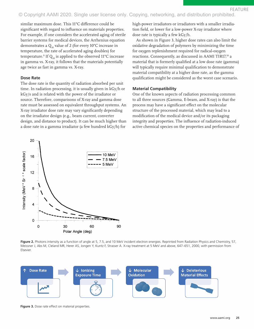
www.aami.org 25
FEATURE
similar maximum dose. This 11°C difference could be significant with regard to influence on materials properties. For example, if one considers the accelerated aging of sterile barrier systems for medical devices, the Arrhenius equation demonstrates a Q
10 value of 2 (for every 10°C increase in
temperature, the rate of accelerated aging doubles) for temperature.9 If Q
10 is applied to the observed 11°C increase
in gamma vs. X-ray, it follows that the materials potentially age twice as fast in gamma vs. X-ray.
Dose RateThe dose rate is the quantity of radiation absorbed per unit time. In radiation processing, it is usually given in kGy/h or kGy/s and is related with the power of the irradiator or source. Therefore, comparisons of X-ray and gamma dose rate must be assessed on equivalent throughput systems. An X-ray irradiator dose rate may vary significantly depending on the irradiator design (e.g., beam current, converter design, and distance to product). It can be much higher than a dose rate in a gamma irradiator (a few hundred kGy/h) for
high-power irradiators or irradiators with a smaller irradia-tion field, or lower for a low-power X-ray irradiator where dose rate is typically a few kGy/h.
As shown in Figure 3, higher dose rates can also limit the oxidative degradation of polymers by minimizing the time for oxygen replenishment required for radical-oxygen reactions. Consequently, as discussed in AAMI TIR17,10 a material that is formerly qualified at a low dose rate (gamma) will typically require minimal qualification to demonstrate material compatibility at a higher dose rate, as the gamma qualification might be considered as the worst case scenario.
Material Compatibility One of the known aspects of radiation processing common to all three sources (Gamma, E-beam, and X-ray) is that the process may have a significant effect on the molecular structure of the processed material, which may lead to a modification of the medical device and/or its packaging integrity and properties. The influence of radiation-induced active chemical species on the properties and performance of
Figure 2. Photons intensity as a function of angle at 5, 7.5, and 10 MeV incident electron energies. Reprinted from Radiation Physics and Chemistry, 57, Meissner J, Abs M, Cleland MR, Herer AS, Jongen Y, Kuntz F, Strasser A. X-ray treatment at 5 MeV and above, 647–651, 2000, with permission from Elsevier.
Figure 3. Dose rate effect on material properties.
© Copyright AAMI 2020. Single user license only. Copying, networking, and distribution prohibited.
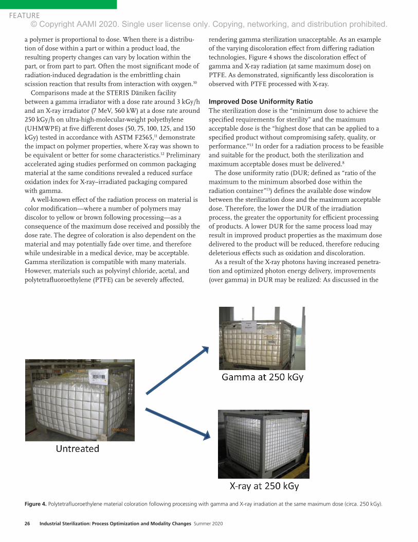
26 Industrial Sterilization: Process Optimization and Modality Changes Summer 2020
FEATURE
a polymer is proportional to dose. When there is a distribu-tion of dose within a part or within a product load, the resulting property changes can vary by location within the part, or from part to part. Often the most significant mode of radiation-induced degradation is the embrittling chain scission reaction that results from interaction with oxygen.10
Comparisons made at the STERIS Däniken facility between a gamma irradiator with a dose rate around 3 kGy/h and an X-ray irradiator (7 MeV, 560 kW) at a dose rate around 250 kGy/h on ultra-high-molecular-weight polyethylene (UHMWPE) at five different doses (50, 75, 100, 125, and 150 kGy) tested in accordance with ASTM F2565,11 demonstrate the impact on polymer properties, where X-ray was shown to be equivalent or better for some characteristics.12 Preliminary accelerated aging studies performed on common packaging material at the same conditions revealed a reduced surface oxidation index for X-ray–irradiated packaging compared with gamma.
A well-known effect of the radiation process on material is color modification—where a number of polymers may discolor to yellow or brown following processing—as a consequence of the maximum dose received and possibly the dose rate. The degree of coloration is also dependent on the material and may potentially fade over time, and therefore while undesirable in a medical device, may be acceptable. Gamma sterilization is compatible with many materials. However, materials such as polyvinyl chloride, acetal, and polytetrafluoroethylene (PTFE) can be severely affected,
rendering gamma sterilization unacceptable. As an example of the varying discoloration effect from differing radiation technologies, Figure 4 shows the discoloration effect of gamma and X-ray radiation (at same maximum dose) on PTFE. As demonstrated, significantly less discoloration is observed with PTFE processed with X-ray.
Improved Dose Uniformity RatioThe sterilization dose is the “minimum dose to achieve the specified requirements for sterility” and the maximum acceptable dose is the “highest dose that can be applied to a specified product without compromising safety, quality, or performance.”13 In order for a radiation process to be feasible and suitable for the product, both the sterilization and maximum acceptable doses must be delivered.8
The dose uniformity ratio (DUR; defined as “ratio of the maximum to the minimum absorbed dose within the radiation container”13) defines the available dose window between the sterilization dose and the maximum acceptable dose. Therefore, the lower the DUR of the irradiation process, the greater the opportunity for efficient processing of products. A lower DUR for the same process load may result in improved product properties as the maximum dose delivered to the product will be reduced, therefore reducing deleterious effects such as oxidation and discoloration.
As a result of the X-ray photons having increased penetra-tion and optimized photon energy delivery, improvements (over gamma) in DUR may be realized: As discussed in the
Figure 4. Polytetrafluoroethylene material coloration following processing with gamma and X-ray irradiation at the same maximum dose (circa. 250 kGy).
© Copyright AAMI 2020. Single user license only. Copying, networking, and distribution prohibited.

www.aami.org 27
FEATURE
Temperature section above, even with many lower-energy photons, bremsstrahlung photons from a 5.0-MeV E-beam penetrate slightly more than the radiation from a large-area source of gamma rays.4 This greater penetration is partly due to the higher energy photons in the bremsstrahlung spectrum and partly due to the angular distribution. X-ray systems have a directive beam of photons concentrated in the direction of the product, optimizing the photon capture rate. In contrast, the nearly isotropic radiation in an industrial gamma-ray facility has a wide angular distribution. Consequently, much of the gamma-ray emission is more divergent than a high-energy bremsstrahlung beam and enters the products at larger angles from the perpendicular direction. The outcome of this with regard to DUR performance is exempli-fied in the following examples observed at STERIS Däniken.
Operational Qualification ComparisonAs shown in Figure 5, performance of operational qualifica-tion (OQ) of gamma and X-ray irradiators with identical product density and process load show a significant gain in DUR for X-ray. As an example of how to use this graphic, for a pallet of medical device of density 0.25 g/cm3, and a minimal dose of 25 kGy, the maximum dose received by the process load (pallet of 1.0 m × 1.2 m × 1.8 m = 2.2 m3) would be:
Gamma: 25 × 1.65 = ~ 42 kGyX-ray: 25 × 1.45 = ~ 37 kGy
DUR is improved by 14% with X-ray. Such a reduction could be significant, especially with a polymer that might have marginal compatibility with radiation processing. Specifically, if one considers this example in conjunction with Figure 6, four polymers that would not be compatible with gamma potentially become available for X-ray. This is very much in line with expectations as summarized by Grégoire et al.14 where “technical advantages of higher energies are better power utilization, reduced treatment time and improved dose uniformity” resulting in the benefits of throughput speed, reduced costs, and improved product quality.
Performance Qualification ComparisonImproved DUR observed during OQ has been verified throughout performance qualification (PQ) studies on actual product configurations. Case studies below show the differ-ence found on the same configuration when processing with gamma and X-ray at Däniken. These case studies demon-strate how an improvement in DUR can yield additional benefits to product processing, including more precise dose delivery, reduction in product temperature, and improved product throughput.
Figure 5. Dose uniformity ratio (DUR) as a function of density (g/cm3) for Däniken X-ray and gamma pallet irradiator.
© Copyright AAMI 2020. Single user license only. Copying, networking, and distribution prohibited.

28 Industrial Sterilization: Process Optimization and Modality Changes Summer 2020
FEATURE
Case study 1: Precise dose for product testing. Per Figure 7, using a uniform configuration of UHMWPE, an 8% reduc-tion in DUR was observed by moving from gamma to X-ray. With improved DUR, the dose could be delivered to the product more precisely.
Case study 2: Temperature sensitive product. In another example, where a temperature-sensitive product was evalu-ated, a DUR improvement from 1.47 to 1.22 was observed by moving process from gamma to X-ray. This lower DUR
Figure 7. Gamma and X-ray DUR results from the treatment of UHMWPE at target doses of 50 to 150kGy. Abbreviations used: DUR, dose uniformity ratio; UHMWPE, ultra-high-molecular-weight polyethylene.
Figure 6. Relative radiation stability of medical polymer “families.” Adapted from AAMI TIR17.10
© Copyright AAMI 2020. Single user license only. Copying, networking, and distribution prohibited.

www.aami.org 29
FEATURE
(lower maximum dose = less energy absorbed by the product = lower temperature increase) coupled with a higher dose rate resulted in reduced processing time and product temperature.
Case study 3: Increase of process load volume. As shown in Figure 8, improved DUR results in more product being processed on the processing unit: In this case, the volume of product per pallet can be more than doubled.
Processing FlexibilityMany gamma facilities operate “shuffle and dwell” opera-tions where the dwell period is a factor of the amount of cobalt present and of the density of the products within the irradiator. In such an operation, products of similar density and dose requirements may be batched to achieve the desired result. Also, the transition effect from one density to another may need to be taken into account. As a consquence, scheduling limitations may be experienced. As explained in other sections of this article, X-ray processing, having the benefit of being incremental and working over a reduced treatment area, results in no significant impact on the pallets neighboring the processed pallet. Consequently, pallets of both different densities and target doses can be processed simultaneously, offering improved flexibility over gamma.
Future Opportunities with X-ray As described in this article, experience thus far with industri-al-scale X-ray radiation of healthcare products and materials has yielded some very promising outcomes. For example, as dose uniformity is improved, maximum dose is lowered, resulting in 1) improved economics as more individual products are processed on the processing unit; 2) improve-ment in processing efficiency and supply chain as more products are processed more quickly; 3) greater material
compatibility as lower maximum doses achieve the same requirement of sterility assurance; and 4) improved product outcomes with reduction in temperature during processing. Furthermore, the levels of oxidation observed with X-ray appear improved compared to those seen in gamma at the same dose levels.
As highlighted by Plaček & Bartoníček,15 the oxidation of polymeric materials is “strongly influenced by the atmos-phere in which they are irradiated,” such that the radiation dose required for reaching a particular level of degradation changes with the dose rate. The authors observed that the rate of oxygen diffusion at higher dose rates is insufficient to support the oxidation reactions, contrary to that observed at lower dose rates.15 Impacts such as these require further in-depth investigation. Such investigative work will continue to inform and impart knowledge and further develop the understanding summarized in Table 1.
As suppliers of X-ray irradiators bring innovations and design concepts to the market, the variances in product flow, energy, power, and dose rate must be understood and evaluated. Regardless of such variances, the opportunity to provide a viable, efficient, and economical alternative to gamma radiation is a reality. This will help address the concerns regarding cobalt supply, transportation, and security highlighted previously.3
AcknowledgmentsThe authors thank Emily Craven, cochair of AAMI ST/WG2 on Radiation Sterilization for her valuable review and input to this article. The authors also thank the Kilmer Collabora-tion Modalities group for the collaborative efforts considering and exploring how additional sterilization modalities may be deployed and adopted by the healthcare products manufac-turing industry, for the benefit of patient care.
Figure 7. Gamma and X-ray DUR results from the treatment of UHMWPE at target doses of 50 to 150kGy. Abbreviations used: DUR, dose uniformity ratio; UHMWPE, ultra-high-molecular-weight polyethylene.
Figure 8. Example of gamma and X-ray pallet configuration. Because of improved dose uniformity ratio (DUR), a higher volume of product per pallet can be processed with X-ray. Final pallet configurations in gamma and X-ray achieved similar DURs of 1.18 and 1.21, respectively.
© Copyright AAMI 2020. Single user license only. Copying, networking, and distribution prohibited.

30 Industrial Sterilization: Process Optimization and Modality Changes Summer 2020
FEATURE
References1. Cleland MR. Electron beam materials irradiators. In: Hamm ME,
Hamm RW, Eds. Industrial Accelerators and Their Applications.
Singapore: World Scientific Publishing Co Pte Ltd; 2012:87–138.
2. IAEA 1967. Radiosterilization of medical products, pharmaceutical
and biopharmaceuticals. Vienna: International Atomic Energy
Agency.
3. Kroc TK, Thangaraj JCT, Penning RT, Kephart RD. Accelerator-
driven Medical Sterilization to Replace Co-60 Sources. Fermi
National Accelerator Laboratory: 2017. https://lss.fnal.gov/
archive/2017/pub/fermilab-pub-17-314-di.pdf. Accessed June 4, 2020.
4. Cleland MR, Stichelbaut F. Radiation processing with high-energy
X-rays. Radiation Physics and Chemistry. 2013;(84):91–99.
5. IAEA 2008. Trends in radiation sterilization of health care products.
Vienna: International Atomic Energy Agency.
6. Gamma Irradiation Processing Alliance and International
Irradiation Association. A Comparison of Gamma, E-beam, X-ray
and Ethylene Oxide Technologies for the Industrial Sterilization
of Medical Devices and Healthcare Products. 2017. http://iiaglobal.
com/wp-content/uploads/2018/01/White-Paper-Comparison-
Gamma-Eb-Xray-and-EO-for-Sterilisation.pdf. Accessed June 4, 2020.
7. Meissner J, Abs M, Cleland MR, et al. X-ray treatment at 5 MeV and
above. Radiation Physics and Chemistry. 2000;(57):647–651.
8. Lambert BJ, Mendelson TA, Craven MD. Radiation and ethylene
oxide terminal sterilization experiences with drug eluting stent
products. AAPS PharmSciTech 2011;12(4):1116–1126.
9. ASTM F1980-16:2016. Standard Guide for Accelerated Aging of
Sterile Barrier Systems for Medical Devices. West Conshohocken, PA:
ASTM International.
10. AAMI TIR17:2017. Compatibility of materials subject to sterilization.
Arlington, VA: Association for the Advancement of Medical
Instrumentation.
11. ASTM F2565. Standard Guide for Extensively Irradiation-Crosslinked
Ultra-High Molecular Weight Polyethylene Fabricated Forms for
Surgical Implant Applications. West Conshohocken, PA: ASTM
International.
12. Michel H, Hartmann H. Qualification of the properties of Highly
Crosslinked UHMWPE, to be routinely processed with a 7 MeV
X-Ray irradiator. Paper presented at International Meeting on
radiation Processing (IMRP) 7–10 Nov 2016, Vancouver (CA) and at
Ionizing Radiation and Polymers Symposium (IRAP) 25–30 Sept 2016.
13. ISO 11139:2018. Sterilization of health care products—Vocabulary of
terms used in sterilization and related equipment and process standards.
Geneva: International Organization for Standardization.
14. Grégoire O, Cleland MR, Mittendorfer J, Vander Donckt M,
Meissner J. Radiological safety of medical devices sterilized with
X-rays at 7.5 MeV. Radiation Physics and Chemistry. 2003;67(2):149–167.
15. Plaček V, Bartoníček B. The dose rate effect and the homogeneity
of radio-oxidation of plastics. Nuclear Instruments and Methods in
Physics Research, Section B: Beam Interactions with Materials and
Atoms. 2001;185(1–4):355–359.
Gamma E-beam X-ray
Mode of action Isotropic photons; Average energy 1.25 MeV
Electron; Typically, 10 MeV energy
Photons with almost the same direction; 90% of photon energy approximately 0.3 MeV
Largest processing unit Pallets or boxes Boxes Pallets or boxes
Dose uniformity ratio Typical dose range achievable for medical device density 25–40 kGy; Ideal: 25–50 kGy
Typical minimal dose range achievable need for medical device density 25–50 kGy; Ideal 25–60 kGy
Typical dose range achievable for medical device density 25–35 kGy; Ideal: 25–40 kGy
Dose rate A few kGy/h A few 1000 kGy/h A few kGy/h to a few hundred of kGy/h
Temperature Depend on design and cobalt activity Typically, maximum temperature can go to 45°C–50°C
Depends on power Typically, maximum temperature can go to 50°C
Depend on power and design Typically, maximum temperature can go to 35°C–40°C
Table 1. Summary of differences between radiation sources and applicability to sterilization of medical devices.
© Copyright AAMI 2020. Single user license only. Copying, networking, and distribution prohibited.

www.aami.org 31
FEATURE
AbstractThis article will discuss opportunities to improve the efficiency of cobalt-60 (Co-60) utilization within a gamma irradiator. It will show how redistributing the Co-60 within the source rack may lead to improved throughput or dose uniformity within a product. It presents examples of modifications to the equipment within the source pass; these include reduction in the carrier wall thickness and changes to the product stack size. It will discuss the process of schedul-ing and present ideas of how to optimize both the order of the products and transitions between the products to maximize process efficiencies.
Gamma irradiators, employing cobalt-60 (Co-60) as a radiation source, have been used for more than 50 years to sterilize medical devices. Approximately 40% of single-use medical devices are sterilized using gamma irradiation.1 One of the main objectives for most gamma irradiators is to process as large a volume of as many different types of
products as possible, while safely achieving the dose requirements of the product. Improving the efficiency of the gamma irradiation process allows more products to be irradiated with the same amount of Co-60. This is especially important as many gamma irradiators are near design capacity and there is a high demand for sterilization services.
A gamma irradiator comprises three main components, each of which can be optimized: 1. Co-60 source2. Product container (tote, carrier, pallet)3. Product irradiation path
An example of a gamma irradiator is provided in Figure 1.
Gamma irradiators must consider effi-ciency in many areas, such as cobalt efficiency, packing efficiency, and scheduling efficiency. Each of these poses its own challenges and requires operational changes to achieve, but in the case of most gamma irradiators there is room to increase efficiency
About the Author
Chris Howard, PhD, is senior radiation physicist at Nordion in Ottawa, ON, Canada. Email:
Optimizing the Gamma ProcessChris Howard
Figure 1. Image of an example gamma irradiator. © 2020 Nordion (Canada) Inc. All rights reserved.
© Copyright AAMI 2020. Single user license only. Copying, networking, and distribution prohibited.
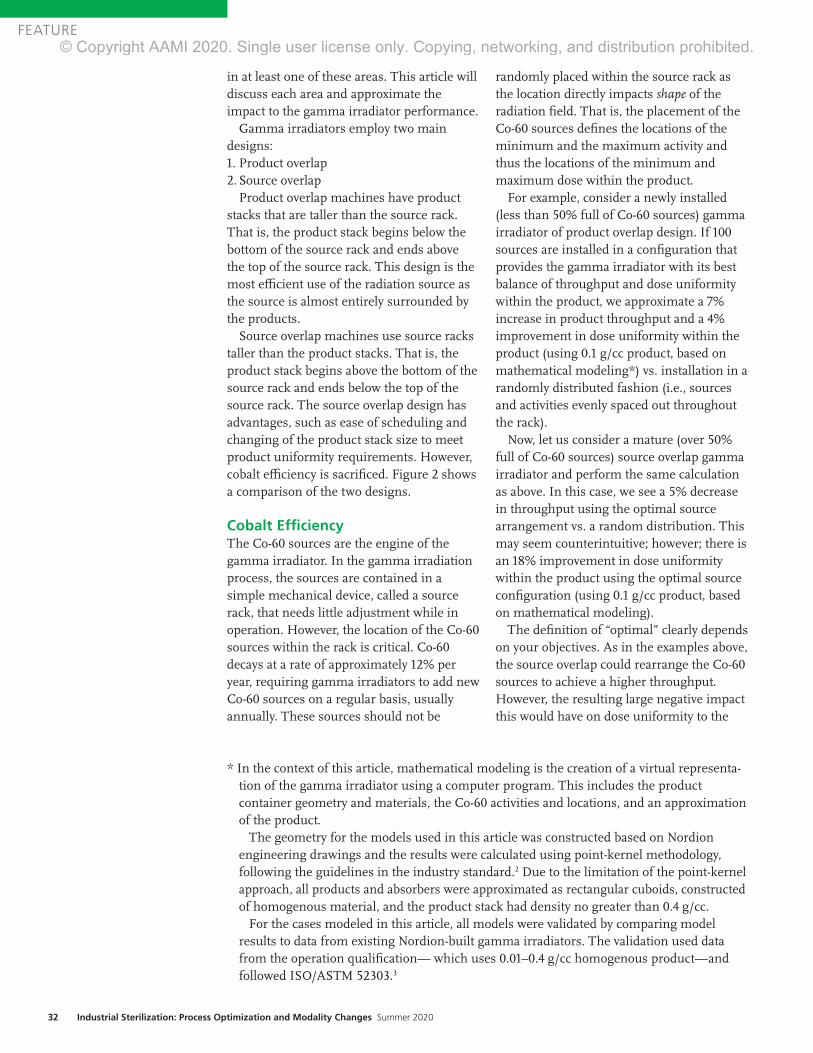
32 Industrial Sterilization: Process Optimization and Modality Changes Summer 2020
FEATURE
in at least one of these areas. This article will discuss each area and approximate the impact to the gamma irradiator performance.
Gamma irradiators employ two main designs:1. Product overlap2. Source overlap
Product overlap machines have product stacks that are taller than the source rack. That is, the product stack begins below the bottom of the source rack and ends above the top of the source rack. This design is the most efficient use of the radiation source as the source is almost entirely surrounded by the products.
Source overlap machines use source racks taller than the product stacks. That is, the product stack begins above the bottom of the source rack and ends below the top of the source rack. The source overlap design has advantages, such as ease of scheduling and changing of the product stack size to meet product uniformity requirements. However, cobalt efficiency is sacrificed. Figure 2 shows a comparison of the two designs.
Cobalt Efficiency The Co-60 sources are the engine of the gamma irradiator. In the gamma irradiation process, the sources are contained in a simple mechanical device, called a source rack, that needs little adjustment while in operation. However, the location of the Co-60 sources within the rack is critical. Co-60 decays at a rate of approximately 12% per year, requiring gamma irradiators to add new Co-60 sources on a regular basis, usually annually. These sources should not be
randomly placed within the source rack as the location directly impacts shape of the radiation field. That is, the placement of the Co-60 sources defines the locations of the minimum and the maximum activity and thus the locations of the minimum and maximum dose within the product.
For example, consider a newly installed (less than 50% full of Co-60 sources) gamma irradiator of product overlap design. If 100 sources are installed in a configuration that provides the gamma irradiator with its best balance of throughput and dose uniformity within the product, we approximate a 7% increase in product throughput and a 4% improvement in dose uniformity within the product (using 0.1 g/cc product, based on mathematical modeling*) vs. installation in a randomly distributed fashion (i.e., sources and activities evenly spaced out throughout the rack).
Now, let us consider a mature (over 50% full of Co-60 sources) source overlap gamma irradiator and perform the same calculation as above. In this case, we see a 5% decrease in throughput using the optimal source arrangement vs. a random distribution. This may seem counterintuitive; however; there is an 18% improvement in dose uniformity within the product using the optimal source configuration (using 0.1 g/cc product, based on mathematical modeling).
The definition of “optimal” clearly depends on your objectives. As in the examples above, the source overlap could rearrange the Co-60 sources to achieve a higher throughput. However, the resulting large negative impact this would have on dose uniformity to the
* In the context of this article, mathematical modeling is the creation of a virtual representa-tion of the gamma irradiator using a computer program. This includes the product container geometry and materials, the Co-60 activities and locations, and an approximation of the product.
The geometry for the models used in this article was constructed based on Nordion engineering drawings and the results were calculated using point-kernel methodology, following the guidelines in the industry standard.2 Due to the limitation of the point-kernel approach, all products and absorbers were approximated as rectangular cuboids, constructed of homogenous material, and the product stack had density no greater than 0.4 g/cc.
For the cases modeled in this article, all models were validated by comparing model results to data from existing Nordion-built gamma irradiators. The validation used data from the operation qualification— which uses 0.01–0.4 g/cc homogenous product—and followed ISO/ASTM 52303.3
© Copyright AAMI 2020. Single user license only. Copying, networking, and distribution prohibited.

www.aami.org 33
FEATURE
product is undesirable and, in most cases, prevents most products from being irradi-ated. The optimal locations of the cobalt sources are either determined through exper-iment (experience) or can be predicted through mathematical modeling.
To calculate the possible dose distributions within a given product, and thus throughput and dose uniformity within the product, mathematical modeling can be used. Using a “design of experiments” (DoE) methodology, many cases can be tested and sorted to determine the optimal case for a given gamma irradiator.
The most common design to hold Co-60 sources is a planar source rack. This rack is made up of rows and columns. To create a DoE for this type of source design, the
amount of cobalt in each given region (module) is defined. The activity in a given row or column is defined by the percent of total activity. The amount of activity in a given module is the percent activity in the row multiplied by the percent activity in a column. To create the DoE, the amount of activity in each row is varied and the throughput and dose uniformity within the product (dose uniformity ratio; DUR) is calculated. The results can then be sorted to determine the optimal activity distribution in each module. Once the optimal distribution is determined, this can be used as an input to plan the Co-60 source installation.
Figure 3 shows a generalized example of a DoE where each row, R, is varied (R-xy – R-xy), where x is the experiment number and y is
Figure 2. Source overlap (left) and product overlap (right). © 2020 Nordion (Canada) Inc. All rights reserved.
Figure 3. Generalized DoE for Co-60 activity for a given module. © 2020 Nordion (Canada) Inc. All rights reserved. Abbreviation used: DUR, dose uniformity ratio.
© Copyright AAMI 2020. Single user license only. Copying, networking, and distribution prohibited.

34 Industrial Sterilization: Process Optimization and Modality Changes Summer 2020
FEATURE
Figure 4. Product tote. © 2020 Nordion (Canada) Inc. All rights reserved.
Figure 5. Product carrier. © 2020 Nordion (Canada) Inc. All rights reserved.
Figure 6. Slave pallet, pallet, and product stack. © 2020 Nordion (Canada) Inc. All rights reserved.
the row number. For example, R-46 is the amount of activity in row 6 in experiment 4. This exercise can be repeated for each column as well. For scale, there can be thousands of experiments that need to be run (i.e., there are thousands of possible combinations of how to distribute the cobalt within the rack). There are even more possible combinations if we do not first limit to pragmatic distributions.
Product Container EfficiencyThe product container transports the product from the storage area into the source pass. There are three common containers:1. Tote—Usually an aluminum or cardboard
box that sits on a conveyor and is pushed into the source pass (Figure 4).
2. Carrier—An aluminum box, larger than a tote, that hangs from an overhead rail and has a keel on the bottom (Figure 5). This rail is used to guide the carrier into the source pass, where the carrier bottom is secured into a keel guide.
3. Pallet—Used for standard U.S. or European pallets where the product is stacked and secured, often with shrink wrap. The pallet is placed onto a slave pallet, which is on a conveyor. The slave pallet guides the product along the irradiation path (Figure 6).Each of the containers ensures that the
product is placed into a reproducible posi-tion relative to the source rack. Given that
the product container guides the product, any modification to the container has an influence on the dose to the product.
Source-to-Product DistanceThe product container places the product within the source pass (Figure 1). Modifying the position of the product container requires substantial effort but has a large influence on the dose rate and dose uniform-ity within the product.
In general, dose uniformity degrades as you move closer to the source rack, as variation in the individual Co-60 sources and product placement becomes more evident. Likewise, moving the product away from the sources smooths out any variations, allows a more uniform radiation field, and improves dose uniformity within the product.
However, the opposite is true with the dose rate: As you move closer to the source, the radiation field becomes more intense. The higher dose rate allows the product to reach its minimum required dose faster, resulting in more products moving through the gamma irradiator (i.e., higher throughput). Figure 7 shows that as the product is moved further away from the rack (to the right on the x-axis), the throughput (blue) drops. It also shows that the uniformity (red); that is, the dose distribution within the product gets smaller, meaning more uniform.
© Copyright AAMI 2020. Single user license only. Copying, networking, and distribution prohibited.

www.aami.org 35
FEATURE
Product Overlap vs. Source OverlapThe product overlap design uses Co-60 more efficiently; however, in general, optimizing the order of the product to be irradiated is more difficult with this design. The source overlap design is more flexible regarding the order in which products can be irradiated. Each of these designs can be seen in Figure 2.
A mathematical model was created for each design type (product overlap vs. source overlap) with equal Co-60 activity; each was deemed to have an optimal Co-60 distribu-tion. For all common product densities used in gamma irradiators, the product overlap design was calculated to be approximately twice as efficient in terms of throughput and provide 3%–15% better uniformity, for densities 0.1–0.4 g/cc, respectively.
However, to achieve these gains, the source pass equipment must be replaced. This means that the single-level product
container (typically a hanging carrier) must be removed or modified to have two levels. For example, a shelf could be added to the carrier. Then, a product interchange would need to be added to move the product between the top and bottom levels. A new installation qualification, operation qualifica-tion, and performance qualification (PQ) need to be completed after a modification of this magnitude. This includes determining new product load configurations throughout the PQ process. While large gains in perfor-mance could be achieved, the cost and time lost for the work would be significant.
Mechanical Limitations Most gamma irradiators operate through a “shuffle and dwell” design, meaning the product container dwells (is stationary) in one position for a given time and then shuffles to the next location. The cycle time
Figure 7. Size of throughput and uniformity change due to the source-to-product distance. © 2020 Nordion (Canada) Inc. All rights reserved. Abbreviation used: DUR, dose uniformity ratio.
© Copyright AAMI 2020. Single user license only. Copying, networking, and distribution prohibited.
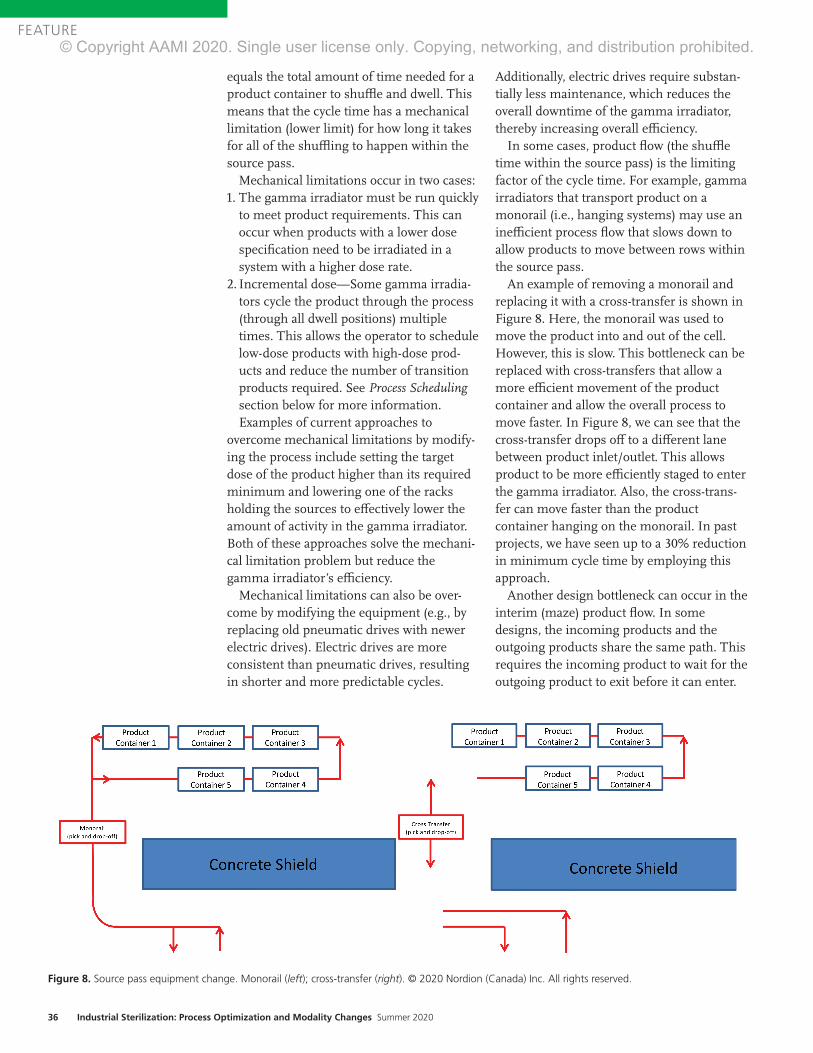
36 Industrial Sterilization: Process Optimization and Modality Changes Summer 2020
FEATURE
equals the total amount of time needed for a product container to shuffl e and dwell. This means that the cycle time has a mechanical limitation (lower limit) for how long it takes for all of the shuffl ing to happen within the source pass.
Mechanical limitations occur in two cases:1. The gamma irradiator must be run quickly
to meet product requirements. This can occur when products with a lower dose specifi cation need to be irradiated in a system with a higher dose rate.
2. Incremental dose—Some gamma irradia-tors cycle the product through the process (through all dwell positions) multiple times. This allows the operator to schedule low-dose products with high-dose prod-ucts and reduce the number of transition products required. See Process Schedulingsection below for more information. Examples of current approaches to
overcome mechanical limitations by modify-ing the process include setting the target dose of the product higher than its required minimum and lowering one of the racks holding the sources to eff ectively lower the amount of activity in the gamma irradiator. Both of these approaches solve the mechani-cal limitation problem but reduce the gamma irradiator’s effi ciency.
Mechanical limitations can also be over-come by modifying the equipment (e.g., by replacing old pneumatic drives with newer electric drives). Electric drives are more consistent than pneumatic drives, resulting in shorter and more predictable cycles.
Additionally, electric drives require substan-tially less maintenance, which reduces the overall downtime of the gamma irradiator, thereby increasing overall effi ciency.
In some cases, product fl ow (the shuffl e time within the source pass) is the limiting factor of the cycle time. For example, gamma irradiators that transport product on a monorail (i.e., hanging systems) may use an ineffi cient process fl ow that slows down to allow products to move between rows within the source pass.
An example of removing a monorail and replacing it with a cross-transfer is shown in Figure 8. Here, the monorail was used to move the product into and out of the cell. However, this is slow. This bottleneck can be replaced with cross-transfers that allow a more effi cient movement of the product container and allow the overall process to move faster. In Figure 8, we can see that the cross-transfer drops off to a diff erent lane between product inlet/outlet. This allows product to be more effi ciently staged to enter the gamma irradiator. Also, the cross-trans-fer can move faster than the product container hanging on the monorail. In past projects, we have seen up to a 30% reduction in minimum cycle time by employing this approach.
Another design bottleneck can occur in the interim (maze) product fl ow. In some designs, the incoming products and the outgoing products share the same path. This requires the incoming product to wait for the outgoing product to exit before it can enter.
Figure 8. Source pass equipment change. Monorail (left); cross-transfer (right). © 2020 Nordion (Canada) Inc. All rights reserved.Safeguarding Global HealthTM
For more than 50 years, Nordion has provided Cobalt-60 for the safe and e�icient sterilization of single use medical devices.Today, gamma sterilization accounts for nearly 40% of global medical device sterilization. Nordion’s unparalleled expertise, robust supply chain and global reach enables our customers to quickly and reliably perform this critical step in safeguarding global health. Through ongoing innovation and collaboration with our global supply partners, we are commi�ed to ensuring Cobalt supply for the gamma processing industry. That means protecting patients and the healthcare industry for another 50 years.
with every Cobal-60 source we supply. nordion.com
© Copyright AAMI 2020. Single user license only. Copying, networking, and distribution prohibited.

Safeguarding Global HealthTM
For more than 50 years, Nordion has provided
of single use medical devices.Today, gamma sterilization accounts for nearly 40% of global medical device sterilization. Nordion’s unparalleled expertise, robust supply chain and global reach enables our customers to quickly and reliably perform this critical step in safeguarding global health. Through ongoing
Cobalt supply for the gamma processing industry. That means protecting patients and the healthcare industry for another 50 years.
with every Cobalt-60 source we supply. nordion.com
© Copyright AAMI 2020. Single user license only. Copying, networking, and distribution prohibited.
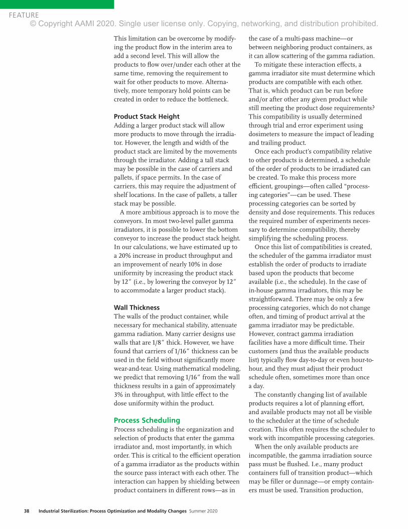
38 Industrial Sterilization: Process Optimization and Modality Changes Summer 2020
FEATURE
This limitation can be overcome by modify-ing the product flow in the interim area to add a second level. This will allow the products to flow over/under each other at the same time, removing the requirement to wait for other products to move. Alterna-tively, more temporary hold points can be created in order to reduce the bottleneck.
Product Stack Height Adding a larger product stack will allow more products to move through the irradia-tor. However, the length and width of the product stack are limited by the movements through the irradiator. Adding a tall stack may be possible in the case of carriers and pallets, if space permits. In the case of carriers, this may require the adjustment of shelf locations. In the case of pallets, a taller stack may be possible.
A more ambitious approach is to move the conveyors. In most two-level pallet gamma irradiators, it is possible to lower the bottom conveyor to increase the product stack height. In our calculations, we have estimated up to a 20% increase in product throughput and an improvement of nearly 10% in dose uniformity by increasing the product stack by 12” (i.e., by lowering the conveyor by 12” to accommodate a larger product stack).
Wall ThicknessThe walls of the product container, while necessary for mechanical stability, attenuate gamma radiation. Many carrier designs use walls that are 1/8” thick. However, we have found that carriers of 1/16” thickness can be used in the field without significantly more wear-and-tear. Using mathematical modeling, we predict that removing 1/16” from the wall thickness results in a gain of approximately 3% in throughput, with little effect to the dose uniformity within the product.
Process SchedulingProcess scheduling is the organization and selection of products that enter the gamma irradiator and, most importantly, in which order. This is critical to the efficient operation of a gamma irradiator as the products within the source pass interact with each other. The interaction can happen by shielding between product containers in different rows—as in
the case of a multi-pass machine—or between neighboring product containers, as it can allow scattering of the gamma radiation.
To mitigate these interaction effects, a gamma irradiator site must determine which products are compatible with each other. That is, which product can be run before and/or after other any given product while still meeting the product dose requirements? This compatibility is usually determined through trial and error experiment using dosimeters to measure the impact of leading and trailing product.
Once each product’s compatibility relative to other products is determined, a schedule of the order of products to be irradiated can be created. To make this process more efficient, groupings—often called “process-ing categories”—can be used. These processing categories can be sorted by density and dose requirements. This reduces the required number of experiments neces-sary to determine compatibility, thereby simplifying the scheduling process.
Once this list of compatibilities is created, the scheduler of the gamma irradiator must establish the order of products to irradiate based upon the products that become available (i.e., the schedule). In the case of in-house gamma irradiators, this may be straightforward. There may be only a few processing categories, which do not change often, and timing of product arrival at the gamma irradiator may be predictable. However, contract gamma irradiation facilities have a more difficult time. Their customers (and thus the available products list) typically flow day-to-day or even hour-to-hour, and they must adjust their product schedule often, sometimes more than once a day.
The constantly changing list of available products requires a lot of planning effort, and available products may not all be visible to the scheduler at the time of schedule creation. This often requires the scheduler to work with incompatible processing categories.
When the only available products are incompatible, the gamma irradiation source pass must be flushed. I.e., many product containers full of transition product—which may be filler or dunnage—or empty contain-ers must be used. Transition production,
© Copyright AAMI 2020. Single user license only. Copying, networking, and distribution prohibited.

www.aami.org 39
FEATURE
Area of improvement Throughput increase
Cobalt loading 7% @ 0.1 g/cc
Source-to-product 12% @ 0.2 g/cc
Product stack height 20% for 12”
Wall thickness 3% per 1/16”
Scheduling 5–15%
Table 1. Summary of potential efficiencies.
particularly “empties,” are normally of low or no value to the gamma irradiator facility.
This transition product can have a large effect on the efficiency of a gamma irradiator. A typical gamma irradiator loses 5%–15% of its throughput due to scheduling ineffi-ciency. The best way to reduce the amount of transition time is to use a scheduler with many years of experience, who has determined the optimum setup rules and who executes to those rules perfectly every time. As the number of products and dose ranges increase, optimal scheduling becomes nearly impossible for a person to accomplish. The only way to guarantee optimal scheduling is to automate the schedul-ing process. An automated scheduling process would have access to all of the available products and rules, allowing it to optimally sort the products to reduce the required transition phases.
A further optimization to the scheduling process is to reduce the required amount of experiments to determine compatibility. This can be accomplished through a validated mathematical model that imports the product geometries, material, and dose requirements. The compatibility experi-ments can then be run virtually and used to create the rules that are fed back to the scheduler.
Combining an automated scheduler and mathematical modeling would allow nearly real-time addition of new products to the gamma irradiation process.
SummaryThis article has outlined many areas of possible improve-ment in the efficiency of gamma irradiators. Some of these may be straightforward to implement, while others would be a significant investment in time and cost. The performance due to modifications in each of these areas is dependent on the design of each irradiator and the product that is being irradiated.
All of the situations discussed present ideas to improve the gamma irradiation process. However, it should be noted that any change may have a tradeoff that should be considered. For example, if a product container is made too thin, wear-and-tear will become a problem; rearranging the cobalt distribution may improve the throughput but will usually negatively impact the product dose uniformity; and more
efficient scheduling is less versatile (cannot react easily to quick turnaround products).
Table 1 presents an overview of the results of this article for the potential increase in performance. However, it should be cautioned that throughput is negatively correlated with dose uniformity. That is, an improvement in throughput often results in degraded dose uniformity.
To put some of the results into perspective, a mid-size gamma irradiator could have 3 MCi. A site that is able to improve its efficiency by 3% could process the same amount of material while saving 90,000 Ci. Another way to see the gains would be to look at a 4-pass carrier design with 3 MCi, which can process approximately 700,000 cubic feet of material per year. An efficiency gain of 3% means that it can process an extra 21,000 cubic feet per year, which yields an extra 1,700 carriers per year.
Acknowledgments The author thanks the Nordion Engineering Team for helping to identify examples to be included based on past work, and for reading this article to ensure accuracy and consistency. The author also thanks the Nordion Design Office for creating great figures on short notice.
References1. International Irradiation Association. Factsheet: Beneficial Uses
of Cobalt-60. http://iiaglobal.com/wp-content/uploads/2018/01/
Factsheet_Cobalt_60.pdf. Accessed May 20, 2020.
2. ASTM E2232-16. Standard Guide for Selection and Use of
Mathematical Methods for Calculating Absorbed Dose in Radiation
Processing Applications. West Conshohocken, PA: ASTM
International.
3. ISO/ASTM 52303:2015. Guide for Absorbed-Dose Mapping in
Radiation Processing Facilities. West Conshohocken, PA: ASTM
International.
© Copyright AAMI 2020. Single user license only. Copying, networking, and distribution prohibited.

40 Industrial Sterilization: Process Optimization and Modality Changes Summer 2020
FEATURE
AbstractThis article details the evaluation conducted for the potential to reduce ethylene oxide (EO) exposure times using data from currently validated EO sterilization cycles. The candidate cycles used the overkill half-cycle approach detailed in Annex B of ANSI/AAMI/ISO 11135:2014. The overkill half-cycle approach is conservative and has been the method of choice with medical device manufacturers because of its ease of understanding. The analysis presented provides an understanding of the extent of this conservative nature. Based on the analysis, exposure time can be reduced and rapidly implemented. The reduction in the exposure time may improve the product EO residuals and allow for additional time for the EO processing chamber to be utilized and/or for additional off-gassing for the product, if needed.
A cross-industry collaboration team was formed during the 2019 Kilmer Conference to address the growing demand to reduce ethylene oxide (EO) consumption. Shortly after the Kilmer Conference, the Food and Drug Administration (FDA) further chal-lenged the industry to innovate on reduction of EO use and emissions. This FDA chal-lenge gave further emphasis to the need to develop an approach that could be aligned on by the collaboration team with the intent to further share the approach with the industry.
The majority of EO cycles used for medical device sterilization have been validated based on the overkill half-cycle approach in accord-ance with ANSI/AAMI/ISO 11135:2014.1 However, this approach provides a very conservative overestimate of the sterility assurance level (SAL), often providing a sterilization cycle that is longer than required to meet a 10–6 SAL.
The overkill half-cycle approach requires the use of a microbiological challenge that typically is more resistant than the product or component bioburden. In addition, the starting population is well above the normal product or component bioburden level. The microbiological challenge ordinarily used is the Bacillus atrophaeus spore, which is the standard industry challenge for EO sterilization.2
Generally, the microbiological challenge organism is inoculated in the most challeng-ing location to sterilize within the product, yielding what is referred to as a process challenge device (PCD). During qualification studies, PCDs are spread throughout the sterilization chamber load to include the most difficult-to-sterilize chamber location. The overkill half-cycle approach is validated by executing a series of sterilization pro-cesses to demonstrate inactivation of the PCD (i.e., where no growth of the PCD is observed following exposure). This process is referred to as the microbiological perfor-mance qualification (MPQ). The exposure time that delivers these conditions is then at least doubled to determine the production sterilization exposure time. The half cycle usually gives > 6-log population reduction and doubling the half-cycle time will provide > 12-log reduction; therefore, the method is called the overkill half-cycle approach.
The conservative overestimate of the SAL is due to the requirement to have no growth of the PCDs during the half-cycle exposure. The sterilization chamber volume that is being qualified dictates the number of PCDs that are required (typically a minimum of 10 PCDs) that exhibit no growth of the PCDs in the half cycle and that will provide a mini-mum SAL of 10–1 to 10–2 (i.e., less than one in 10 or less than one in 100, respectively).
Use of Overkill Half-Cycle Qualification Data to Support Reduction of Exposure Time in Validated Ethylene Oxide Sterilization CyclesScott Weiss, Phil Cogdill, and Joyce M. Hansen
About the Authors
Scott Weiss is director of industrial microbiology at Johnson & Johnson in Raritan, NJ.
Email: [email protected]
Phil Cogdill is senior director of quality, sterilization, and microbiology at Medtronic in Boulder, CO.
Email: [email protected]
Joyce M. Hansen is vice president of microbiological quality & sterility assurance at Johnson &
Johnson in Raritan, NJ. Email: [email protected]
© Copyright AAMI 2020. Single user license only. Copying, networking, and distribution prohibited.

www.aami.org 41
FEATURE
For example, if a minimum of 35 PCDs were selected due to the usable chamber volume and zero positives were observed following half-cycle exposure, then a SAL of approxi-mately 10–1.5 is demonstrated using a conservative D-value with the assumption of one positive PCD.
11135 Annex B, section B.1.2.b. provides another qualification approach for calcula-tion of the EO exposure time for a routine production cycle. This qualification method, called the cycle calculation approach, uses data collected over a series of sublethal cycles to establish the PCD decimal reduction value (D-value; i.e., a resistance value for steriliza-tion effectiveness). Sublethal cycles are exposure conditions where some of the PCDs are expected to be positive for growth while others are expected to be negative for growth. Using the PCD positives, an esti-mated PCD D-value can be determined. This estimated PCD D-value is then utilized to determine the routine production cycle parameters, providing the process parame-ters that will deliver the desired SAL.
The analysis presented in this article uses both the data obtained from the overkill half-cycle approach and the foundations of the cycle calculation approach to determine new EO exposure time parameters. Data obtained from the overkill half-cycle qualifi-cation allows for a conservative estimate of the PCD D-value. The D-value is considered conservative as one must assume one positive-growth when zero positives were observed from the PCDs following exposure to the overkill half-cycle.
Following load conditioning (e.g., humidi-fication), cycle lethality occurs upon injection of the sterilant into the chamber and contin-ues through the entire process. An equation established by Mosley et al.3 can be used to calculate the equivalent exposure time (U) for an EO sterilization process, taking into consideration the lethality achieved during gas injection through exposure and the gas evacuation phases. Data obtained in the overkill half-cycle MPQ and calculation of equivalent exposure time will allow a more accurate understanding of the delivered cycle lethality.
Using the equivalent exposure calculation U from the overkill half-cycle MPQ data and
data from routine production cycles, the EO exposure time parameters can be deter-mined to more accurately define the EO exposure time required to deliver the desired SAL. Given that medical device companies already have this data, a more accurate EO exposure cycle time can be a determined and documented. The documented analysis for the more accurate EO exposure time can be used to support regulatory submission.
AnalysisBefore beginning the evaluation of cycle data, the following prerequisites exist to ensure proper analysis and associated conclusions:1. The cycles under evaluation must have
been validated in accordance with the overkill half-cycle method per require-ments in 11135.
2. The relationship between the product bioburden and the PCD must be under-stood. Relative resistance and bioburden quantity must be less than that of the PCD as previously defined.
3. The bioburden program for the product families associated with the sterilization cycle must be stable, with historical data to demonstrate maintenance of bioburden quantity and resistance.
4. The cycle stability during the gas injection and postexposure washes must be demon-strated. The analysis includes the time from the initiation of EO gas injection, through any inert gas injection (if used) prior to the start of the EO dwell phase, the exposure time, and the postexposure washes. It should be noted that variability in the time and rate of injection and wash phases will have to be considered to establish worst-case conditions.
The analysis presented in this article uses both the data obtained from the overkill half-cycle approach and the foundations of the cycle calculation approach to determine new EO exposure time parameters.
© Copyright AAMI 2020. Single user license only. Copying, networking, and distribution prohibited.

42 Industrial Sterilization: Process Optimization and Modality Changes Summer 2020
FEATURE
Evaluation of four different EO sterilization cycles from four different medical device companies was performed for calculating equivalent exposure time. The approach used the Mosely et al. equation for calculating equivalent exposure time.
In Table 1, the reference EO concentration (Cref
) was derived from the overkill half-cycle MPQ data. The EO concentration calculations include total partial pressure of EO injected into the chamber and use the average chamber temperature from the MPQ cycle documentation. The reference gas concentration was calculated using the follow-ing formula:
The reference temperature (Tref
) was also based on the average chamber temperature from the MPQ documenta-tion. The rationale for using these data as the reference values for the formula is that the MPQ runs are conducted at lower temperatures and partial pressure of EO when com-pared to the routine production cycles. Using the MPQ data to set the reference values adds to the conservative nature of the evaluation.
The EO concentration (Ci) and temperature (T
i) come
from the run record data. Ci represents the calculated EO
concentration for that time stamp entry. Ti represents the
average chamber temperature for that same time stamp entry. Each time stamp entry on the run record correlates to a new C
i and T
i used in the equation.
D-values were calculated for each cycle using the MPQ data. As previously mentioned, all PCDs were negative for growth in the MPQ cycles, therefore a single positive PCD was assumed in order to calculate an estimated D-value
using the Stumbo-Murphy-Cochran Procedure4 with the following formula:
Using the D-value (DT) and the equivalent exposure time
(U) obtained from the previous calculations, a spore log reduction (SLR) was determined using the following formula:
Of the three overkill half-cycle MPQ documentation, the MPQ half cycle with the longest equivalent exposure time was used for the analysis in Table 1. This was selected as the longer equivalent exposure time results in a longer estimated D-value (i.e., minutes). A longer estimated D-value equates to a conservative estimate of the PCD resistance, and therefore provides a conservative estimate of the SAL based on exposure time.
Data from a typical routine production cycle was used in the establishment of the routine process SAL. SLR value was used along with the microbiological challenge population (N
0) to calculate the production cycle SAL.
Data in Table 1 represents the time from EO charge through the end of the process.
It should be noted that Cycle A has a longer equivalent exposure time than the actual run time for the production cycle. This happens as the production cycle uses a higher partial pressure of EO than that used during the MPQ cycle. Since the EO reference concentration is derived from the MPQ cycles, the higher EO concentration in the production cycle equates a longer equivalent exposure time for each time stamp during EO dwell. When accumulated throughout the
U = ∑ (anti log(log tT + (Ti – Tref))
Ui = equivalent exposure time for a given time interval
tT = time interval (t) at temperature (T)
z = z-value (30°C)
Ti = temperature
Tref = reference temperature
Ci = EO concentration
Cref = reference EO concentration
1__z
Ci___Cref
n
i =1
Cref = n*(PEO)/R*(Tref + 273)
n = 44,000 mg/mole (molecular weight of EO)
PEO = partial pressure of EO in chamber after injection
R = 62.361 mmHg-L/gm-mole-Kelvin
Tref = reference temperature (converted to Kelvin)
DT = ___________________
DT = D-value
Ui = total equivalent exposure
N0 = initial population
ni = number of units tested
ri = number of units sterile
Ui
log10N0 – log10�ln� ��ni__ri
SLR = U /DT
Note: This formula is a derived from the SLR formula in ANSI/AAMI/ISO 11138-7:2019.4
SAL = 10�Log(N0) – SLR�
Note: This formula is derived from the SAL formula in 11138-7. MPQ SAL is derived from MPQ data for U, N0, and DT. Routine production SAL is derived from MPQ N0 and DT, and routine production cycle U.
© Copyright AAMI 2020. Single user license only. Copying, networking, and distribution prohibited.
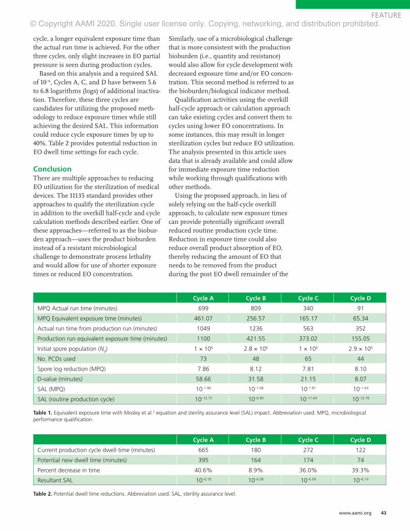
www.aami.org 43
FEATURE
cycle, a longer equivalent exposure time than the actual run time is achieved. For the other three cycles, only slight increases in EO partial pressure is seen during production cycles.
Based on this analysis and a required SAL of 10–6, Cycles A, C, and D have between 5.6 to 6.8 logarithms (logs) of additional inactiva-tion. Therefore, these three cycles are candidates for utilizing the proposed meth-odology to reduce exposure times while still achieving the desired SAL. This information could reduce cycle exposure times by up to 40%. Table 2 provides potential reduction in EO dwell time settings for each cycle.
ConclusionThere are multiple approaches to reducing EO utilization for the sterilization of medical devices. The 11135 standard provides other approaches to qualify the sterilization cycle in addition to the overkill half-cycle and cycle calculation methods described earlier. One of these approaches—referred to as the biobur-den approach—uses the product bioburden instead of a resistant microbiological challenge to demonstrate process lethality and would allow for use of shorter exposure times or reduced EO concentration.
Similarly, use of a microbiological challenge that is more consistent with the production bioburden (i.e., quantity and resistance) would also allow for cycle development with decreased exposure time and/or EO concen-tration. This second method is referred to as the bioburden/biological indicator method.
Qualification activities using the overkill half-cycle approach or calculation approach can take existing cycles and convert them to cycles using lower EO concentrations. In some instances, this may result in longer sterilization cycles but reduce EO utilization. The analysis presented in this article uses data that is already available and could allow for immediate exposure time reduction while working through qualifications with other methods.
Using the proposed approach, in lieu of solely relying on the half-cycle overkill approach, to calculate new exposure times can provide potentially significant overall reduced routine production cycle time. Reduction in exposure time could also reduce overall product absorption of EO, thereby reducing the amount of EO that needs to be removed from the product during the post EO dwell remainder of the
Cycle A Cycle B Cycle C Cycle D
Current production cycle dwell time (minutes) 665 180 272 122
Potential new dwell time (minutes) 395 164 174 74
Percent decrease in time 40.6% 8.9% 36.0% 39.3%
Resultant SAL 10–6.18 10–6.08 10–6.04 10–6.14
Table 2. Potential dwell time reductions. Abbreviation used: SAL, sterility assurance level.
Cycle A Cycle B Cycle C Cycle D
MPQ Actual run time (minutes) 699 809 340 91
MPQ Equivalent exposure time (minutes) 461.07 256.57 165.17 65.34
Actual run time from production run (minutes) 1049 1236 563 352
Production run equivalent exposure time (minutes) 1100 421.55 373.02 155.05
Initial spore population (N0) 1 × 10⁶ 2.8 × 10⁶ 1 × 10⁶ 2.9 × 10⁶
No. PCDs used 73 48 65 44
Spore log reduction (MPQ) 7.86 8.12 7.81 8.10
D-value (minutes) 58.66 31.58 21.15 8.07
SAL (MPQ) 10–1.86 10–1.68 10–1.81 10–1.64
SAL (routine production cycle) 10–12.75 10–6.90 10–11.64 10–12.76
Table 1. Equivalent exposure time with Mosley et al.3 equation and sterility assurance level (SAL) impact. Abbreviation used: MPQ, microbiological performance qualification.
© Copyright AAMI 2020. Single user license only. Copying, networking, and distribution prohibited.

44 Industrial Sterilization: Process Optimization and Modality Changes Summer 2020
FEATURE
process. In addition, the reduced cycle exposure time could allow for additional evacuations to remove additional EO residu-als from the product or provide for more EO processing capacity. This will help the medical device industry to ensure that hospitals, healthcare providers, and patients have access to medical devices that are safely and eff ectively sterilized.
AcknowledgmentsThe authors thank Byron Lambert (Abbott), Christophe Deneux, and Tony Faucette (BD) for their contributions to the development of this article. The team also thanks AdvaMed for hosting this cross-industry collaboration under their research and development auspices.
References1. ANSI/AAMI/ISO 11135:2014, Sterilization
of health care products—Ethylene oxide—
Requirements for the development, validation and
routine control of a sterilization process for medical
devices. Arlington, VA: Association for the
Advancement of Medical Instrumentation.
2. ANSI/AAMI/ISO 11138-2:2017, Sterilization
of health care products—Biological indicators—
Part 2: Biological indicators for the ethylene oxide
sterilization process. Arlington, VA: Association for
the Advancement of Medical Instrumentation.
3. Mosley GA, Gillis JR, Whitbourne JE. Calculating
Equivalent Time for Use in Determining
the Lethality of EtO Sterilization Processes.
MDDI February 2002. www.mddionline.com/
calculating-equivalent-time-use-determining-
lethality-eto-sterilization-processes. Accessed
May 29, 2020.
4. ANSI/AAMI/ISO 11138-7:2019, Sterilization of
health care products—Biological indicators—Part
7: Guidance for the selection, use and interpretation
of results. Arlington, VA: Association for the
Advancement of Medical Instrumentation.
www.aami.orgApp coming soon!For complete details, visit www.aami.org/eSubscription.
An eSubscription allows multiple individuals across your enterprise to easily access standards. Whether you need a particular set of standards—such as sterilization—or a wide range, you can choose a plan that meets your organization’s needs.
AAMI eSubscriptionThe Easier Way to Access Standards
Get faster access and user-friendly features!CURRENT—Reaffirmed and new standards are regularly added, ensuring you have the latest documents.
SEARCHABLE—Documents are searchable by name, title, or specific term or phrase across the entire collection.
ACCESSIBLE AND RESPONSIVE—Content is viewable on desktop, tablet, and mobile devices.
INTERACTIVE—Bookmark content and share comments with colleagues across your organization.
© Copyright AAMI 2020. Single user license only. Copying, networking, and distribution prohibited.

www.aami.org 45
FEATURE
AbstractIn the radiation sterilization arena, the question often arises as to whether radiation resistance of microorganisms might be affected by the energy level of the radiation source and the rate of the dose delivered (kGy/time). The basis for the question is if the microbial lethality is affected by the radiation energy level and/or the rate the dose is delivered, then the ability to transfer dose among different radiation sources could be challenged. This study addressed that question by performing a microbial inactivation study using two radiation sources (gamma and electron beam [E-beam]), two microbial challenges (natural product bioburden and biological indicators), and four dose rates delivered by three energy levels (1.17 MeV [gamma], 1.33 MeV [gamma], and 10 MeV [high-energy E-beam]). Based on analysis of the data, no significant differences were seen in the rate of microbial lethality across the range of radiation energies evaluated. In summary, as long as proof exists that the specified dose is delivered, dose is dose.
Radiation is a scientific term that describes transmitting energy through space. This term includes microwaves, ultraviolet, electron beam (E-beam), gamma, and X-rays. However, ionizing radiation (i.e., gamma rays, X-rays, E-beam) typically is used to terminally sterilize product. With the expansion of the use of E-beam and X-rays, the potential impact on microbial inactiva-tion associated with sterilization of medical devices has been a point of discussion during recent updates of industry standards.
Radiation sterilization relies on ionizing radiation to inactivate microorganisms. Absorption of a sufficient amount of radiation will negatively affect the microorganism’s ability to reproduce. The interaction of the ionizing energy with matter is key to this process. All ionizing radiation modalities are capable of sterilization. The question is whether the same dose delivered by these modalities is equal in its ability to inactivate microorganisms.
Previous articles have reported conflicting results when comparing radiation resistance for different radiation modalities. When reviewing the details for the procedures used for these published results, the primary issues that might affect the results and conclusions were difficulty in appropriate delivery (i.e., narrow dose ranges) and accurate measurement of the radiation process. In addition, some studies had questionable methods for process validation and preparation of the test articles.
DesignThis study evaluated the gamma and E-beam radiation resistance of microorganisms using two microbial challenges: (1) natural product bioburden on a nonwoven cellulosic material (bandage) and (2) biological indica-tor (BI) using paper carriers inoculated with Bacillus pumilus spores (106 population).
The bandage evaluated in this study was selected because of its previously character-ized bioburden population. The number of production batches, product sample size, and incremental doses selected to evaluate the bandage material match the require-ments in Method 2A (per ANSI/AAMI/ISO 11137-2:2013/(R)2019).1 Method 2A does not require that product bioburden be performed to determine the sterilization dose; however, for the purposes of this study, product testing was performed to demonstrate stability of the bioburden over the time of the test period, and the sample size was selected to match the requirements detailed in ANSI/AAMI/ISO 11737-1:2018.2 Rather than determining the sterilization dose, this study was designed to compare the microbial lethality; therefore, only the incremental doses were performed.
The B. pumilus spore was selected as a test article to provide a positive control to demonstrate microbial lethality. The number of BI lots and incremental doses were selected to match the requirements for Method 2A. As BIs are manufactured to provide a consistent spore population, the
Radiation Sterilization: Dose Is DoseJoyce M. Hansen, Niki Fidopiastis, Trabue Bryans, Michelle Luebke, and Terri Rymer
About the Authors
Joyce M. Hansen is vice president of microbiological quality and sterility assurance at Johnson &
Johnson in Raritan, NJ. Email: [email protected]
Niki Fidopiastis, RM(NRCM), is a manager of laboratory services and sterility assurance at North
American Science Associates, Inc., in Irvine, CA. Email: [email protected]
Trabue Bryans is president of BryKor LLC in Marietta, GA. Email: [email protected]
Michelle Luebke, MT(ASCP), is a research scientist at Baxter Healthcare Corporation in
Round Lake, IL. Email: [email protected]
Terri Rymer is a research scientist at Baxter Healthcare Corporation in Round Lake, IL. Email: terri_
© Copyright AAMI 2020. Single user license only. Copying, networking, and distribution prohibited.

46 Industrial Sterilization: Process Optimization and Modality Changes Summer 2020
FEATURE
sample size selected for BI testing was reduced from the requirements for Method 2A. In addition, the number of incremental doses was reduced due to the known resistance of the B. pumilus spore. The stability of the BI over the time of the test period was demonstrated using population counts prior to and following testing. This species was selected based on its demonstrated, consistent response to radiation, due to a higher radiation resistance than other Bacillus species. It is important to note that the use of a spore challenge model for validation of a product sterilization dose is not recommended (11137-1, sections 1.2.3 and A.1.2.3).3
The range of radiation dose rates and energies selected for this study are typical of those that might be utilized during verification testing or routine sterilization processing. The radiation resistances of the test articles were assessed using gamma radiation (emits two rays with energies of 1.17 and 1.33 MeV) delivered at two separate dose rates (0.37 and 12.9 kGy/h) and E-beam radiation (10 MeV) delivered at two separate dose rates (3,100 and 36,000 kGy/h).
MethodsThe test articles consisting of nonwoven cellulosic bandages (2 × 3.5 inches) from each of three batches were individually packaged in pouches, and B. pumilus (ATCC 27142) BI paper carriers from each of three lots were individually packaged in pouches. All test articles were submitted for irradiation.
Test articles were irradiated together for each of the doses selected. Twenty bandages from each of three batches and five BIs from each of three lots were irradiated together. The bandages were irradiated at nine incremental doses (2, 4, 6, 8, 10, 12, 14, 16, and 18 kGy), and the BIs were irradiated at six incremental doses (2, 4, 6, 8, 10, and 12 kGy). Each of the incremental doses was delivered using four dose rates: (1) gamma radiation at a dose rate of 0.37 kGy/h, (2) gamma radiation at a dose rate of 12.9 kGy/h, (3) E-beam radiation at a dose rate of 3,100 kGy/h, and (4) E-beam radiation at a dose rate of 36,000 kGy/h.
For consistent measurement of the irradiation doses, a common dosimetry system was used. The irradiation dose delivered was measured using FWT-60 radiochromic film dosimeters (Far West Technology, Santa Ana, CA). During several of the irradiation runs, alanine reference dosimeters from the National Physical Laboratory (Middlesex, UK) were placed side-by-side with the FWT-60 film dosimeters to verify the traceability of the Far West Technology films.
After irradiation, all test articles were returned to the laboratory for testing. A test of sterility was conducted on each bandage by aseptic transfer into a container of sterile soybean casein digest (SCD) broth. The SCD containers were incubated at 28 to 32°C for 14 days per 11137-2.1 The containers were periodically examined and the results documented as the number of units positive for growth/total number of units tested. A population count was conducted on each BI by
aseptic transfer to a test tube containing 10 mL sterile water, and the paper carrier was homogenized using a sterile pestle. The BI suspensions were serially diluted in sterile water to obtain concentrations of approximately 30 to 300 colony- forming units (CFU) per milliliter. Pour plates were prepared using molten SCD agar and incubated at 30 to 35°C for three to five days. Upon completion of incubation, the plates were enumerated and the surviving populations documented.
Population ControlsThe microbial populations present on the bandage material (i.e., bioburden) and BI paper carriers were determined preceding and subsequent to completion of radiation processing to demonstrate population stability of the test articles throughout the test period.
The bioburden population present on nonirradiated bandages was determined using a validated bioburden recovery procedure, where 10 samples from each of three batches of bandages were tested. Each bandage was immersed in sterile diluent and placed on a shaker table. The diluent with test samples were shaken at approximately 450 rpm for 15 minutes. Serial dilutions were performed from the recovery fluid using sterile water to obtain concen-trations of approximately 30 to 300 CFU/mL. Pour plates were prepared using molten SCD agar and incubated at 20 to 25°C for three days, followed by incubation at 30 to 35°C for two days. Upon completion of incubation, the plates were enumerated and the initial bioburden populations docu-mented for each batch of bandages (Table 1).
The population counts on nonirradiated BIs were deter-mined from five BIs from each of the three lots of test articles. Each BI was aseptically transferred to a sterile blender jar containing 100 mL sterile water and homoge-nized for one minute. The contents of each blender jar were serially diluted using sterile water to obtain concentrations of approximately 30 to 300 CFU/mL. The dilution tubes then were exposed to a heat shock at 80°C for 10 minutes. Pour plates were prepared using molten SCD agar and incubated at 30 to 35°C for two to three days. Upon completion of incubation, the plates were enumerated and the populations documented (Table 2).
Test of Sterility Negative System ControlsNegative controls were conducted to demonstrate that positive tests of sterility observed were attributed to the product tested and not due to testing and/or laboratory issues.
Ten or 20 bandages irradiated at 50 kGy or greater were tested each day using the same methods applied for the test articles to confirm the aseptic technique of the technicians performing the product tests of sterility for the Method 2A incremental doses. A total of 200 samples were tested for the two tests of sterility teams, and zero positive product tests of sterility were observed for the negative controls.
© Copyright AAMI 2020. Single user license only. Copying, networking, and distribution prohibited.

www.aami.org 47
FEATURE
Bioburden population recovered (CFU/test article)
Batch 1 Batch 2 Batch 3
Beginning of testing
End of testing
Beginning of testing
End of testing
Beginning of testing
End of testing
Test article no.
1 2.7 × 10⁴ 1.9 × 10⁴ 3.7 × 10⁴ 5.2 × 10³ 2.0 × 10⁴ 1.1 × 10⁴
2 2.3 × 10⁴ 1.3 × 10⁴ 1.7 × 10⁴ 5.1 × 10³ 2.3 × 10⁴ 3.1 × 10⁴
3 4.0 × 10⁴ 1.9 × 10⁴ 2.1 × 10⁴ 1.5 × 10⁴ 3.2 × 10⁴ 3.8 × 10⁴
4 9.9 × 10³ 1.1 × 10⁴ 3.8 × 10³ 1.8 × 10⁴ 2.8 × 10⁴ 3.1 × 10⁴
5 1.7 × 10⁴ 5.6 × 10⁴ 3.4 × 10³ 1.2 × 10⁴ 3.5 × 10⁴ 3.3 × 10⁴
6 2.0 × 10⁴ 2.1 × 10⁵ 2.8 × 10⁴ 3.4 × 10³ 2.7 × 10⁴ 9.9 × 10⁴
7 1.2 × 10⁴ 5.9 × 10³ 3.7 × 10⁴ 1.5 × 10⁴ 4.3 × 10⁴ 1.1 × 10⁵
8 4.0 × 10⁴ 1.0 × 10⁴ 4.6 × 10⁴ 6.7 × 10⁴ 4.1 × 10⁴ 5.3 × 10⁴
9 2.0 × 10⁴ 1.3 × 10⁴ 1.4 × 10⁴ 8.8 × 10³ 2.3 × 10⁴ 4.4 × 10⁴
10 1.8 × 10⁴ 3.6 × 10⁴ 5.8 × 10⁴ 1.2 × 10⁴ 2.5 × 10⁴ 8.2 × 10³
Average bioburden* 2.3 × 10⁴ 3.9 × 10⁴ 2.7 × 10⁴ 1.6 × 10⁴ 3.0 × 10⁴ 4.6 × 10⁴
Correction factor† 1.8 1.8 1.8 1.8 1.8 1.8
Corrected average bioburden‡
4.1 × 10⁴ 7.0 × 10⁴ 4.9 × 10⁴ 2.9 × 10⁴ 5.4 × 10⁴ 8.3 × 10⁴
Corrected bioburden range
1.8 × 10⁴ to 7.2 × 10⁴
1.1 × 10⁴ to 3.8 × 10⁵
6.1 × 10³ to 1.0 × 10⁵
6.1 × 10³ to 1.2 × 10⁵
3.6 × 10⁴ to 7.7 × 10⁴
1.5 × 10⁴ to 2.0 × 10⁵
Log10
corrected average bioburden
4.6 4.8 4.7 4.5 4.7 4.9
Log10
population change over test period
+0.2 –0.2 +0.2
Negative control bioburden study
Control no. 1-0, control no. 2-0
Control no. 1-0, control no. 2-0
Control no. 1-0, control no. 2-0
Control no. 1-0, control no. 2-0
Control no. 1-0, control no. 2-0
Control no. 1-1, control no. 2-0
Table 1. Bioburden population on nonwoven cellulosic bandages at the beginning and end of testing. *Average bioburden = ∑ bioburden populations for test articles 1-10/10. †Correction factor is calculated to be 1.8 in the bioburden recovery validation. ‡Corrected average bioburden = (average bioburden) × (correction factor).
Method SuitabilityMethod suitability testing was performed to verify that the bandage and BI paper carrier materials did not alter the growth-promoting properties of the culture media to the extent of preventing or inhibiting outgrowth of microorgan-isms, if present on the test articles.
Six bandages were irradiated at 50 kGy or greater and each immersed into a tube of sterile SCD broth. Duplicate broth tubes were inoculated with not more than 100 CFU each of the following microorganisms: Bacillus subtilis ATCC 6633, Candida albicans ATCC 10231, or Aspergillus niger ATCC 16404.4 The broth tubes were incubated at 28 to 32°C for a maximum of seven days and examined for turbidity (Table 3).
Five B. pumilus BIs were irradiated at 50 kGy or greater, immersed into tubes of sterile water, and homogenized using sterile pestles. Each tube was inoculated with 10 to 100 CFU of B. pumilus ATCC 27142 spores, and the entire
contents of each tube were pour plated using molten SCD agar. The plates were incubated at 30 to 35°C for a maximum of three days and enumerated (Table 4).
Results and Discussion
BandagesThe product bioburden data demonstrate that the population remained stable over the course of the study (Table 1), and therefore, no impact to the resistance analysis occurred as a result of die-off of bioburden organisms.
The first no positive (FNP) dose, first fraction positive (FFP) dose, difference between FNP and FFP doses, and DS kGy (results and calculations from the Method 2A experiment) are provided in Table 5, and the d* kGy values (an initial estimate of the dose required to achieve a sterility assurance level (SAL) of 10–2 for an individual product batch) for the four dose rates evaluated are provided in Table 6.
© Copyright AAMI 2020. Single user license only. Copying, networking, and distribution prohibited.

48 Industrial Sterilization: Process Optimization and Modality Changes Summer 2020
FEATURE
BI Population recovered (CFU/BI)
BI Lot no. Control article no. Beginning of testing End of testing Δ*
1 1 1.4 × 10⁶ 2.0 × 10⁶
2 2.2 × 10⁶ 1.8 × 10⁶
3 1.4 × 10⁶ 1.7 × 10⁶
4 1.5 × 10⁶ 1.9 × 10⁶
5 1.6 × 10⁶ 1.9 × 10⁶
Average 1.6 × 10⁶ 1.9 × 10⁶
Range 1.4 × 10⁶ to 2.2 × 10⁶ 1.7 × 10⁶ to 2.0 × 10⁶
Log10
average 6.2 6.3 +0.1
2 1 2.8 × 10⁶ 4.3 × 10⁶
2 3.8 × 10⁶ 2.9 × 10⁶
3 2.7 × 10⁶ 4.2 × 10⁶
4 2.6 × 10⁶ 3.5 × 10⁶
5 3.6 × 10⁶ 3.2 × 10⁶
Average 3.1 × 10⁶ 3.6 × 10⁶
Range 2.6 × 10⁶ to 3.8 × 10⁶ 2.9 × 10⁶ to 4.3 × 10⁶
Log10
average 6.5 6.6 +0.1
3 1 2.7 × 10⁶ 4.3 × 10⁶
2 3.8 × 10⁶ 4.8 × 10⁶
3 3.4 × 10⁶ 3.6 × 10⁶
4 2.6 × 10⁶ 5.2 × 10⁶
5 3.3 × 10⁶ 4.4 × 10⁶
Average 3.2 4.5 × 10⁶
Range 2.6 × 10⁶ to 3.8 × 10⁶ 3.6 × 10⁶ to 5.2 × 10⁶
Log10
average 6.5 6.7 +0.2
Table 2. Bacillus pumilus biological indicator population counts at the beginning and end of testing. *Δ = log of average population (end of testing) – log of average population (beginning of testing). Abbreviations used: BI, biological indicator; CFU, colony-forming unit.
Challenge organism Inoculum population count (CFU) No. positive/no. tested
Bacillus subtilis ATCC 6633 2.5 × 101 2/2
Candida albicans ATCC 10231 1.7 × 101 2/2
Aspergillus niger ATCC 16404 2.3 × 101 2/2
Negative control articles NA 0/2
Table 3. Method suitability test results for nonwoven cellulosic bandages. Abbreviations used: CFU, colony-forming unit; NA, not applicable.
Average recovery per article (CFU)
BI article no.
1 8.7 × 101
2 9.0 × 101
3 8.8 × 101
4 6.8 × 101
Positive control articles 8.7 × 101
Negative control articles 0 positive/4 tested
Table 4. Method suitability test results for Bacillus pumilus. Abbreviations used: BI, biological indicator; CFU, colony-forming unit.
AAMI TIR76:2020Sterilization of health care products—Radiation—Substantiation of a selected sterilization dose at a specified sterility assurance level: Method VDmaxSD-S
COMING SOON!
AAMI TIR12:2020Designing, testing and labeling reusable medical devices for processing in health care facilities: A guide for medical device manufacturers
For more information, visit aami.org/store
Advancing Safety in Health Technologywww.aami.org
© Copyright AAMI 2020. Single user license only. Copying, networking, and distribution prohibited.

AAMI TIR76:2020Sterilization of health care products—Radiation—Substantiation of a selected sterilization dose at a specified sterility assurance level: Method VDmaxSD-S
COMING SOON!
AAMI TIR12:2020Designing, testing and labeling reusable medical devices for processing in health care facilities: A guide for medical device manufacturers
AAMI AAMI AAMI AAMI AAMI AAMI AAMI AAMI AAMI AAMI AAMI AAMI AAMI AAMI AAMI AAMI AAMI AAMI AAMI AAMI AAMI AAMI AAMI AAMI AAMI TIR76:2020TIR76:2020TIR76:2020TIR76:2020TIR76:2020TIR76:2020TIR76:2020TIR76:2020TIR76:2020TIR76:2020TIR76:2020TIR76:2020TIR76:2020TIR76:2020TIR76:2020TIR76:2020TIR76:2020TIR76:2020TIR76:2020TIR76:2020TIR76:2020TIR76:2020TIR76:2020TIR76:2020TIR76:2020TIR76:2020TIR76:2020TIR76:2020TIR76:2020TIR76:2020TIR76:2020TIR76:2020TIR76:2020TIR76:2020TIR76:2020TIR76:2020TIR76:2020TIR76:2020TIR76:2020TIR76:2020TIR76:2020TIR76:2020TIR76:2020TIR76:2020TIR76:2020TIR76:2020TIR76:2020TIR76:2020TIR76:2020TIR76:2020TIR76:2020TIR76:2020TIR76:2020TIR76:2020TIR76:2020TIR76:2020TIR76:2020TIR76:2020TIR76:2020TIR76:2020TIR76:2020TIR76:2020TIR76:2020TIR76:2020TIR76:2020TIR76:2020TIR76:2020TIR76:2020Sterilization of health care products—Radiation—Sterilization of health care products—Radiation—Sterilization of health care products—Radiation—Sterilization of health care products—Radiation—Sterilization of health care products—Radiation—Sterilization of health care products—Radiation—Sterilization of health care products—Radiation—Sterilization of health care products—Radiation—Sterilization of health care products—Radiation—Sterilization of health care products—Radiation—Sterilization of health care products—Radiation—Sterilization of health care products—Radiation—Sterilization of health care products—Radiation—Sterilization of health care products—Radiation—Sterilization of health care products—Radiation—Sterilization of health care products—Radiation—Sterilization of health care products—Radiation—Sterilization of health care products—Radiation—Sterilization of health care products—Radiation—Sterilization of health care products—Radiation—Sterilization of health care products—Radiation—Sterilization of health care products—Radiation—Sterilization of health care products—Radiation—Sterilization of health care products—Radiation—Sterilization of health care products—Radiation—Sterilization of health care products—Radiation—Sterilization of health care products—Radiation—Sterilization of health care products—Radiation—Sterilization of health care products—Radiation—Sterilization of health care products—Radiation—Sterilization of health care products—Radiation—Sterilization of health care products—Radiation—Sterilization of health care products—Radiation—Sterilization of health care products—Radiation—Sterilization of health care products—Radiation—Sterilization of health care products—Radiation—Sterilization of health care products—Radiation—Sterilization of health care products—Radiation—Sterilization of health care products—Radiation—Sterilization of health care products—Radiation—Sterilization of health care products—Radiation—Sterilization of health care products—Radiation—Sterilization of health care products—Radiation—Sterilization of health care products—Radiation—Sterilization of health care products—Radiation—Sterilization of health care products—Radiation—Sterilization of health care products—Radiation—Sterilization of health care products—Radiation—Sterilization of health care products—Radiation—Sterilization of health care products—Radiation—Sterilization of health care products—Radiation—Sterilization of health care products—Radiation—Sterilization of health care products—Radiation—Sterilization of health care products—Radiation—Substantiation of a selected sterilization dose at a Substantiation of a selected sterilization dose at a Substantiation of a selected sterilization dose at a Substantiation of a selected sterilization dose at a Substantiation of a selected sterilization dose at a Substantiation of a selected sterilization dose at a Substantiation of a selected sterilization dose at a Substantiation of a selected sterilization dose at a Substantiation of a selected sterilization dose at a Substantiation of a selected sterilization dose at a Substantiation of a selected sterilization dose at a Substantiation of a selected sterilization dose at a Substantiation of a selected sterilization dose at a Substantiation of a selected sterilization dose at a Substantiation of a selected sterilization dose at a Substantiation of a selected sterilization dose at a Substantiation of a selected sterilization dose at a Substantiation of a selected sterilization dose at a Substantiation of a selected sterilization dose at a Substantiation of a selected sterilization dose at a Substantiation of a selected sterilization dose at a Substantiation of a selected sterilization dose at a Substantiation of a selected sterilization dose at a Substantiation of a selected sterilization dose at a Substantiation of a selected sterilization dose at a Substantiation of a selected sterilization dose at a Substantiation of a selected sterilization dose at a Substantiation of a selected sterilization dose at a Substantiation of a selected sterilization dose at a Substantiation of a selected sterilization dose at a Substantiation of a selected sterilization dose at a Substantiation of a selected sterilization dose at a Substantiation of a selected sterilization dose at a Substantiation of a selected sterilization dose at a Substantiation of a selected sterilization dose at a Substantiation of a selected sterilization dose at a Substantiation of a selected sterilization dose at a Substantiation of a selected sterilization dose at a Substantiation of a selected sterilization dose at a Substantiation of a selected sterilization dose at a Substantiation of a selected sterilization dose at a Substantiation of a selected sterilization dose at a Substantiation of a selected sterilization dose at a Substantiation of a selected sterilization dose at a Substantiation of a selected sterilization dose at a Substantiation of a selected sterilization dose at a Substantiation of a selected sterilization dose at a Substantiation of a selected sterilization dose at a Substantiation of a selected sterilization dose at a Substantiation of a selected sterilization dose at a Substantiation of a selected sterilization dose at a Substantiation of a selected sterilization dose at a Substantiation of a selected sterilization dose at a Substantiation of a selected sterilization dose at a Substantiation of a selected sterilization dose at a Substantiation of a selected sterilization dose at a Substantiation of a selected sterilization dose at a Substantiation of a selected sterilization dose at a Substantiation of a selected sterilization dose at a Substantiation of a selected sterilization dose at a specified sterility assurance level: Method VDmaxSD-Sspecified sterility assurance level: Method VDmaxSD-Sspecified sterility assurance level: Method VDmaxSD-Sspecified sterility assurance level: Method VDmaxSD-Sspecified sterility assurance level: Method VDmaxSD-Sspecified sterility assurance level: Method VDmaxSD-Sspecified sterility assurance level: Method VDmaxSD-Sspecified sterility assurance level: Method VDmaxSD-Sspecified sterility assurance level: Method VDmaxSD-Sspecified sterility assurance level: Method VDmaxSD-Sspecified sterility assurance level: Method VDmaxSD-Sspecified sterility assurance level: Method VDmaxSD-Sspecified sterility assurance level: Method VDmaxSD-Sspecified sterility assurance level: Method VDmaxSD-Sspecified sterility assurance level: Method VDmaxSD-Sspecified sterility assurance level: Method VDmaxSD-Sspecified sterility assurance level: Method VDmaxSD-Sspecified sterility assurance level: Method VDmaxSD-Sspecified sterility assurance level: Method VDmaxSD-Sspecified sterility assurance level: Method VDmaxSD-Sspecified sterility assurance level: Method VDmaxSD-Sspecified sterility assurance level: Method VDmaxSD-Sspecified sterility assurance level: Method VDmaxSD-Sspecified sterility assurance level: Method VDmaxSD-Sspecified sterility assurance level: Method VDmaxSD-Sspecified sterility assurance level: Method VDmaxSD-Sspecified sterility assurance level: Method VDmaxSD-Sspecified sterility assurance level: Method VDmaxSD-Sspecified sterility assurance level: Method VDmaxSD-Sspecified sterility assurance level: Method VDmaxSD-Sspecified sterility assurance level: Method VDmaxSD-Sspecified sterility assurance level: Method VDmaxSD-Sspecified sterility assurance level: Method VDmaxSD-Sspecified sterility assurance level: Method VDmaxSD-Sspecified sterility assurance level: Method VDmaxSD-Sspecified sterility assurance level: Method VDmaxSD-Sspecified sterility assurance level: Method VDmaxSD-Sspecified sterility assurance level: Method VDmaxSD-Sspecified sterility assurance level: Method VDmaxSD-Sspecified sterility assurance level: Method VDmaxSD-Sspecified sterility assurance level: Method VDmaxSD-Sspecified sterility assurance level: Method VDmaxSD-Sspecified sterility assurance level: Method VDmaxSD-Sspecified sterility assurance level: Method VDmaxSD-Sspecified sterility assurance level: Method VDmaxSD-Sspecified sterility assurance level: Method VDmaxSD-Sspecified sterility assurance level: Method VDmaxSD-Sspecified sterility assurance level: Method VDmaxSD-Sspecified sterility assurance level: Method VDmaxSD-Sspecified sterility assurance level: Method VDmaxSD-Sspecified sterility assurance level: Method VDmaxSD-Sspecified sterility assurance level: Method VDmaxSD-Sspecified sterility assurance level: Method VDmaxSD-Sspecified sterility assurance level: Method VDmaxSD-Sspecified sterility assurance level: Method VDmaxSD-Sspecified sterility assurance level: Method VDmaxSD-Sspecified sterility assurance level: Method VDmaxSD-Sspecified sterility assurance level: Method VDmaxSD-Sspecified sterility assurance level: Method VDmaxSD-Sspecified sterility assurance level: Method VDmaxSD-Sspecified sterility assurance level: Method VDmaxSD-S
COMING SOON!COMING SOON!COMING SOON!COMING SOON!COMING SOON!COMING SOON!COMING SOON!COMING SOON!COMING SOON!COMING SOON!COMING SOON!COMING SOON!COMING SOON!COMING SOON!COMING SOON!COMING SOON!COMING SOON!COMING SOON!COMING SOON!COMING SOON!COMING SOON!COMING SOON!COMING SOON!COMING SOON!COMING SOON!COMING SOON!COMING SOON!COMING SOON!COMING SOON!COMING SOON!COMING SOON!COMING SOON!COMING SOON!COMING SOON!COMING SOON!COMING SOON!COMING SOON!COMING SOON!COMING SOON!COMING SOON!COMING SOON!COMING SOON!COMING SOON!COMING SOON!COMING SOON!COMING SOON!COMING SOON!COMING SOON!COMING SOON!COMING SOON!COMING SOON!COMING SOON!COMING SOON!COMING SOON!COMING SOON!COMING SOON!
AAMI AAMI AAMI AAMI AAMI AAMI AAMI AAMI AAMI AAMI AAMI AAMI AAMI AAMI AAMI AAMI AAMI AAMI AAMI AAMI AAMI AAMI AAMI AAMI AAMI AAMI AAMI AAMI AAMI AAMI AAMI AAMI AAMI AAMI AAMI AAMI AAMI AAMI AAMI AAMI AAMI AAMI AAMI AAMI AAMI AAMI AAMI AAMI AAMI AAMI AAMI AAMI AAMI AAMI AAMI AAMI AAMI AAMI AAMI TIR12:2020TIR12:2020TIR12:2020TIR12:2020TIR12:2020TIR12:2020TIR12:2020TIR12:2020TIR12:2020TIR12:2020TIR12:2020TIR12:2020TIR12:2020TIR12:2020TIR12:2020TIR12:2020TIR12:2020TIR12:2020TIR12:2020TIR12:2020TIR12:2020TIR12:2020TIR12:2020TIR12:2020TIR12:2020Designing, testing and labeling reusable medical Designing, testing and labeling reusable medical Designing, testing and labeling reusable medical Designing, testing and labeling reusable medical Designing, testing and labeling reusable medical Designing, testing and labeling reusable medical Designing, testing and labeling reusable medical Designing, testing and labeling reusable medical Designing, testing and labeling reusable medical Designing, testing and labeling reusable medical Designing, testing and labeling reusable medical Designing, testing and labeling reusable medical Designing, testing and labeling reusable medical devices for processing in health care facilities: A devices for processing in health care facilities: A devices for processing in health care facilities: A devices for processing in health care facilities: A devices for processing in health care facilities: A devices for processing in health care facilities: A devices for processing in health care facilities: A devices for processing in health care facilities: A devices for processing in health care facilities: A devices for processing in health care facilities: A devices for processing in health care facilities: A devices for processing in health care facilities: A devices for processing in health care facilities: A devices for processing in health care facilities: A devices for processing in health care facilities: A devices for processing in health care facilities: A guide for medical device manufacturersguide for medical device manufacturersguide for medical device manufacturersguide for medical device manufacturersguide for medical device manufacturersguide for medical device manufacturersguide for medical device manufacturersguide for medical device manufacturersguide for medical device manufacturersguide for medical device manufacturersguide for medical device manufacturersguide for medical device manufacturersguide for medical device manufacturersguide for medical device manufacturers
For more information, visit aami.org/store
Advancing Safety in Health Technologywww.aami.org
© Copyright AAMI 2020. Single user license only. Copying, networking, and distribution prohibited.

50 Industrial Sterilization: Process Optimization and Modality Changes Summer 2020
FEATURE
The DS kGy is an estimate of the dose required to inacti-vate 90% of the organisms surviving a 10–2 SAL dose (i.e., verification dose experiment). This provides an estimate of the most resistant portion of the product bioburden and is an estimate using a composite of the three batches tested for each of the four dose rates. As the study design was not intended to determine a sterilization dose, the verification dose experiment was not conducted. Therefore, the calcula-tion for DS kGy was conducted using the following assumptions: D**kGy = DD*kGy; CD* = 2+/100; and FNP = DD*kGy. No difference in DS kGy values (Table 5) can be observed over the 5-log difference in dose rates across the two radiation source types (gamma and E-beam).
A further evaluation was conducted by reviewing the d* kGy data for each individual product batch (Table 6) using an analysis of variance (ANOVA) statistical technique (Figure 1). The analysis included a Tukey comparison (95% confidence) of values and this comparison indicates there is no signifi-cant difference in d* kGy values for the bandage material that could be detected over a 5-log difference in dose rates across the two radiation source types (gamma and E-beam).
BIsThe BI population count data demonstrate stability over the course of the study (Table 2), and therefore, no impact to the resistance analysis occurred due to the stability of the BI population.
The D10
values (radiation dose required to reduce a micro-bial population by 90%) for the B. pumilus BIs irradiated using two irradiation sources (gamma and E-beam) and four dose rates (0.37, 12.9, 3,100, and 36,000 kGy/h) were calcu-lated using linear regression and are reported in Table 7. The data were analyzed using an ANOVA statistical technique (Figure 2). The analysis indicated that no significant differ-ence (95% confidence) in the D
10 values existed for the
B. pumilus BIs that could be detected over a 5-log difference in dose rates across the two radiation source types (gamma and E-beam).
ConclusionBased on the analysis of the data, no significant differences could be detected in the rate of microbial lethality across the 5-log difference in dose rates evaluated for the natural product bioburden or the BIs across the two radiation source types (gamma and E-beam).
This data indicate that the radiation resistance of microor-ganisms is not affected by any slight differences in energy levels and dose rates of the radiation sources typically used by sterilization facilities. Because of this, it can be concluded that the sterilization and verification doses can be safely transferred between modes of irradiation, as well as irradia-tion facilities, without requiring proof of equivalent microbial inactivation. As long as proof exists that the specified dose is delivered, dose is dose.
Type of irradiationDose rate (kGy/h)
FNP* (kGy)
FFP† (kGy)
FNP minus FFP‡ (kGy) DS kGy§
Gamma 0.37 17.5 6.1 11.4 4.6
12.9 16.4 6.5 9.9 4.0
E-beam 3,100 18.6 6.2 12.4 5.0
36,000 19.3 8.0 11.3 4.5
Table 5. Nonwoven cellulosic bandages, Method 2A, first no positive (FNP), first fraction positive (FFP), FNP minus FFP, and DS kGy. *FNP is an estimate of the dose at which only one sample of 100 irradiated samples is expected to be nonsterile. †FFP is an estimate of the dose at which only one sample of 20 irradiated samples will be nonsterile. ‡FNP minus FFP is a portion of the formula to determine DS, where (FNP – FFP) is less than 10 kGy, the formula is DS = 2 + 0.2(FNP – FFP), and where (FNP – FFP) is greater than or equal to 10 kGy, the formula is DS = 0.4(FNP – FFP). §DS kGy is an estimate of the dose required to inactivate 90% of the organisms surviving the verification dose (estimated 10–2 SAL). For the purposes of this study, the sterilization dose was not established. Therefore, the calculation for DS kGy was conducted using the following assumptions: D**kGy = DD*kGy, CD* = 2+/100, and FNP = DD*kGy, where D**kGy is the initial estimate of dose required achieve a SAL of 10–2, DD* is the actual dose delivered to the 100 samples for the verification dose experiment, and CD* is the number of positive tests of sterility from samples exposed to the verification dose.
d* kGy
Dose rate (kGy/h) 0.37 12.9 3,100 36,000
Bandage batch no.
1 17.5 20.0 18.6 20.0
2 10.2 12.6 12.1 19.3
3 12.0 16.4 18.6 19.3
Table 6. Nonwoven cellulosic bandages, Method 2A, and d* kGy values (an initial estimate of the dose required to achieve a sterility assurance level of 1 × 10⁻² for an individual product batch).
© Copyright AAMI 2020. Single user license only. Copying, networking, and distribution prohibited.

www.aami.org 51
FEATURE
Summary Groups Count Sum Average Variance
0.37 3 39.7 13.23333 14.4633312.9 3 49 16.33333 13.693333,100 3 49.3 16.43333 14.08333
36,000 3 58.6 19.53333 0.163333
ANOVASource of Varia�on SS df MS F P F critBetween groups 59.55 3 19.85 1.872494 0.212594 4.066181Within groups 84.80667 8 10.60083
Total 144.3567 11
Tukey Mul�ple Comparison (95% Confidence)Groups No. Mean Grouping36,000 kGy/h 3 19.53 A3,100 kGy/h 3 16.43 A12.9 kGy/h 3 16.33 A0.37 kGy/h 3 13.23 A
Figure 1. Statistical analysis for nonwoven cellulosic bandages using analysis of variance (ANOVA) to compare d* kGy values between different dose rates. Analysis was performed using data from Table 6. *ANOVA for D value (kGy) using adjusted sum of squares (SS) for tests. †S = 3.25589, R2 = 41.25%, R2 (adj) = 19.22%. ‡Grouping information using Tukey method and 95.0% confidence. Means that do not share a letter are significantly different. Abbreviations used: df, degrees of freedom; MS, mean squares.
Dose rate (kGy/h) BI Lot no. D10 Values (kGy)
0.37 1 1.3
2 1.2
3 1.3
12.9 1 1.4
2 1.3
3 1.5
3,100 1 1.4
2 1.3
3 1.4
36,000 1 1.3
2 1.2
3 1.2
Table 7. Bacillus pumilus biological indicator (BI) radiation resistance values calculated using linear regression. D10
values were calculated using the average starting population and average surviving population for each of four incremental doses (0, 2, 4, 6, and 8 kGy) using the actual dose delivered to each sample set.
© Copyright AAMI 2020. Single user license only. Copying, networking, and distribution prohibited.

52 Industrial Sterilization: Process Optimization and Modality Changes Summer 2020
FEATURE
AcknowledgmentsThe authors thank the supporting companies and individuals involved in performing the testing. The companies included Baxter Healthcare Corporation (Round Lake, IL; product and testing), Sterigenics International, Inc. (Corona, CA; gamma irradiation), Titan Scan Technologies (San Diego, CA; E-beam irradiation), Far West Technology (Santa Ana, CA; FWT-60 radiochromic film dosimeters), and National Physical Laboratory (Middlesex, UK; alanine dosimeters). Note: Company names are as represented at the time of study collaboration.
References1. ANSI/AAMI/ISO 11137-2:2013/(R)2019.
Sterilization of health care products—Radiation—
Part 2: Establishing the sterilization dose. Arlington,
VA: Association for the Advancement of Medical
Instrumentation.
2. ANSI/AAMI/ISO 11737-1:2018. Sterilization
of health care products—Microbiological
methods—Part 1: Determination of a population
of microorganisms on products. Arlington, VA:
Association for the Advancement of Medical
Instrumentation.
3. ANSI/AAMI/ISO 11137-1:2006/(R)2015.
Sterilization of health care products—Radiation—
Part 1: Requirements for development, validation,
and routine control of a sterilization process for
medical devices. Arlington, VA: Association for the
Advancement of Medical Instrumentation.
4. United States Pharmacopeia. USP<71> Sterility
Tests. www.usp.org/sites/default/files/usp/
document/harmonization/gen-method/q11_pf_
ira_34_6_2008.pdf. Accessed June 9, 2020.
ANOVA: Single Factor
Summary Groups Count Sum Average Variance
0.37 3 3.8 1.266667 0.00333312.9 3 4.2 1.4 0.01
3,100 3 4.1 1.366667 0.00333336,000 3 3.7 1.233333 0.003333
ANOVASource of Varia�on SS df MS F P F critBetween groups 0.056667 3 0.018889 3.777778 0.058939 4.066181Within groups 0.04 8 0.005
Total 0.096667 11
Figure 2. Statistical analysis for biological indicators using analysis of variance (ANOVA) to compare D10
values between different dose rates. Analysis was performed using data from Table 7. Abbreviations used: df, degrees of freedom; MS, mean squares; SS, sum of squares.
© Copyright AAMI 2020. Single user license only. Copying, networking, and distribution prohibited.

www.aami.org 53
FEATURE
AbstractThe requirements for the irradiation of health-care products have been well established and implemented across the globe for several decades. The ISO 11137 series of standards gives the user the road map for designing a radiation process that will routinely deliver the required sterility assurance level so that product consistently meets specifications. The latest addition to the ISO 11137 series of standards should provide much-needed guidance around establishing a highly reproducible process based on a statistical analysis of the validated state of control. Most industries refer to this as “process control.”
What is process control?Process control is “activities involved in ensuring a process is predictable, stable, and consistently operating at the target level of performance with only normal variation.”1 Are radiation processes used for the steriliza-tion of healthcare products predictable, stable, and consistently operating at a target level of performance?
To determine whether a radiation process is stable and predictable, it is essential to first understand all components of the process that can have a direct impact on the output of the process. For this application, the primary output of the process is the delivered dose to product.
Three main components are critical to process control for a radiation process—the product, the dose measurement system (dosimetry), and the irradiator (including product conveyance or exposure to the radiation source). Each of these inputs operate independently, but each can have a direct impact on the outcome of the process and therefore must be well characterized, separately and in combination.
Radiation Process Components
ProductThe product is the first component critical to process control. Characterizing the product and packaging is referred to as “product definition.” Items addressed in the product definition should include: a) the density (typically expressed as g/cc), b) orientation within the primary, secondary, and tertiary packaging, and c) other items included in the package that might impact the overall density (e.g., instructions for use documents and trays or bindings that hold product in desired orientation). These items may have an impact on the absorption of dose during a radiation process.
This product definition—in conjunction with a defined loading pattern within the irradiation container or on the conveyor, including the way it is presented to the radiation source—is called a “loading configuration.” The product definition and loading configuration are both critical for radiation process control.
Dosimetry SystemThe measurement system is the second critical component that can impact the radiation process control. Dosimetry is the primary measurement system used to determine the amount of radiation dose absorbed by the product or process loading configuration. Absorbed dose is measured through a dosimetry system that is calibrated and traceable to a national standard of absorbed dose. The process for calibrating a dosimetry system, as defined by ISO/ASTM 51261,2 characterizes the uncertainties associ-ated with the response and measurement of a dosimeter as they relate to the true esti-mate of dose. All measurements have an associated uncertainty and the magnitude of the measurement uncertainty is important for assessing the quality of the results of the measurement system (see ISO/ASTM 517073).
About the Authors
John R. Logar is senior director, aseptic processing and terminal sterilization at Johnson &
Johnson in Raritan, NJ. Email: [email protected]
Emily Craven is senior associate at Mevex in Ottawa, ON, Canada. Email: [email protected]
Radiation Process Control: Product Dose vs. Process DoseJohn R. Logar and Emily Craven
© Copyright AAMI 2020. Single user license only. Copying, networking, and distribution prohibited.

54 Industrial Sterilization: Process Optimization and Modality Changes Summer 2020
FEATURE
Thus, a calibrated dosimetry system provides the best measurement of absorbed dose and, therefore, values from dose measurements should not be corrected by associated measurement uncertainty (see ISO 11137-3: 2017, section 4.1.3).4
Dosimetry systems have several compo-nents of uncertainty that may manifest during routine radiation processing (i.e., uncertainties due to dose rate or tempera-ture) and must be characterized for the conditions of use.
IrradiatorThe overall reproducibility of the irradiator is the final critical component for process control. An irradiator delivers the dose to products and has several critical components (e.g., source, conveyance, irradiation path-ways, etc.) that also must be characterized to determine the appropriate processing parameters and conditions for processing a product. This process characterization, or operational qualification, requires the operator to understand the processing limits, expected variability (common cause variabil-ity), and overall reproducibility of the radiation process. This characterization uses a calibrated dosimetry system to measure the process output; therefore, the user must be careful not to confuse measurement system uncertainty with radiation process variability and vice versa. A lack of understanding of the sources of variability and whether they manifest during the process may lead to dou-ble counting in the assessment of process variability.
Radiation Process ControlRoutine dosimetry is used to determine whether a radiation process is predictable, stable, and consistently operating at the target level of performance. Dosimeters are placed at defined locations within irradiation containers at predefined frequencies, and measured to evaluate whether the qualified process delivered the predicted range of absorbed dose for a predetermined loading configuration. A term that is typically used for a radiation process is target dose. This is the dose that the radiation process parame-ters are set to deliver at a specified monitoring location. If the irradiator oper-
ates as expected and the resulting measured dose is within the predicted limits of the target dose, the process can then be consid-ered in control. The measured doses are used as a means for determining process acceptance and releasing the product. This is referred to as “dosimetric release.”
Radiation Processing MeasurementsThe analysis of a routine monitoring dosimeter(s) can be used to indirectly determine whether a product has received the required sterilization dose without exceeding the maximum acceptable dose determined for that product. The purpose of the new ISO/TS 11137-45 standard is to provide guidance on how to analyze and interpret this measurement.
A single, routine dosimeter measurement in isolation can be interpreted several ways. Repeated measurements provide some information on the range of doses that can be expected over time. Routine dose meas-urement made in the context of a desired target dose range provides information on whether the process is in a state of control. In industrial radiation sterilization, the interpretation of these individual dose measurements in relation to product is used to set up target doses and establish and monitor an ongoing radiation process. There is potential for confusion due to variations that are observed and whether they are related to what is going on in the product.
ISO/TS 11137-4 provides information on the sources of variation that may contribute to the range of doses seen during a routine process (Figure 1). These sources relate to both the process itself as well as our ability to measure the process.
Process VariationVariation is caused both by things we actively control and things that are beyond our control, and can be anticipated (i.e., common cause) or unanticipated (i.e., special cause). The factors that affect the output of a radiation process will depend on whether it is gamma, electron beam, or X-ray, but ultimately, three factors are at play:• The intensity of the radiation activity or
energy (the activity of the source or the power of the beam) © 2020 Boston Scientific Corporation and its affiliates. All rights reserved.
CORP-421303-AA JUL2020
An uncompromising pursuit of excellence. An unwavering focus on solutions
that will make the most difference for patients. Intently listening and collaborat-
ing side-by-side with clinicians to understand their most complex problems.
These are the principles for every product, solution and relationship we build.
It’s what we do every day to advance science for patients, for life.
To learn more about what it takes to advance science for life,
visit www.bostonscientific.com
That’s the difference between making devices and making progress.
IT TAKES IMAGINATION TO MAKE SCIENCE MORE GROUNDBREAKING.
© Copyright AAMI 2020. Single user license only. Copying, networking, and distribution prohibited.

© 2020 Boston Scientific Corporation and its affiliates. All rights reserved.CORP-421303-AA JUL2020
An uncompromising pursuit of excellence. An unwavering focus on solutions
that will make the most difference for patients. Intently listening and collaborat-
ing side-by-side with clinicians to understand their most complex problems.
These are the principles for every product, solution and relationship we build.
It’s what we do every day to advance science for patients, for life.
To learn more about what it takes to advance science for life,
visit www.bostonscientific.com
That’s the difference between making devices and making progress.
IT TAKES IMAGINATION TO MAKE SCIENCE MORE GROUNDBREAKING.
© Copyright AAMI 2020. Single user license only. Copying, networking, and distribution prohibited.

56 Industrial Sterilization: Process Optimization and Modality Changes Summer 2020
FEATURE
• The distribution of the radiation (the shape of a scanned beam or placement of sources)
• The path of exposure of the product to the source of radiation (conveyor speed or shuffle and dwell timing and positions)Based on these factors, key parameters can
be identified that have a direct effect on dose to product if they are varied during the radiation process.
ISO/TS 11137-4 Table 2 provides a list of process parameters that are critical to radiation sterilization, the effect of the variation of these parameters, and how they are monitored as part of the process. The table provides a starting point for guidance on monitoring process parameters, in addition to dosimetry, to ascertain that product has been processed according to the specifications stipulated in ISO 11137-1:2006/(R)2015, A.10.6.6
Measurement UncertaintyThere are components of measurement uncertainty that will contribute to variability seen in a routine dosimetry measurement. These include variability inherent in the
measurement of dose due to the equipment used to measure it or the dosimeter itself, and variations in the dosimeter placement or products surrounding it.
Additional components of measurement uncertainty may or may not be apparent, including components relating to calibration, as well as influence quantities such as temperature, which may only be observed seasonally.
Establishing Radiation Process ParametersMinimum and maximum doses to product for the process and their expected variation are determined through replicate direct dose measurements made during process qualifi-cation (e.g., product dose mapping). A radiation process can be established based on these dose measurements. Each measure-ment of dose made during dose mapping is made with a calibrated dosimetry system and a known level of uncertainty.
In order to determine appropriate process-ing parameters, the variations determined from the dose mapping data are used in
Figure 1. Components of process variability (σprocess
). ©ISO. This material is adapted from ISO/TS 11137-4:2020, with permission of the American National Standards Institute (ANSI) on behalf of the International Organization for Standardization. All rights reserved.
© Copyright AAMI 2020. Single user license only. Copying, networking, and distribution prohibited.

www.aami.org 57
FEATURE
conjunction with other information on expected variability to establish minimum and maximum process dose targets designed to verify that a process is in control. ISO/TS 11137-4 describes the following three differ-ent approaches that may be used based on the level of information that the operator has about the overall process.
First, in a new site, where there is little to no operating history, components of uncer-tainty may be estimated based on known or calculated values to account for unknown factors that could contribute to overall process variability. For example, machine variability for an electron-based system may be added to the observed variability from dose mapping if it is not known how this may vary over time. Additional uncertainties can also be added to account for shifts in calibration or to accommodate a wide range of applicable temperatures or other environ-mental changes that could happen. This is a conservative approach and assumes that all these components add in quadrature. It is anticipated that this starting point is refined over time as more operational history with the system is gained.
Second, at a site that has been operating for years, the variation observed during dose mapping can be compared with past data to see whether a standard process buffer (i.e., level of variation) can be used to set up the range of processing parameters. This is most useful at sites that have a well-documented history of operation and products with dose requirements that allow for this approach, which may also be conservative.
A third method is to design the dose mapping study in such a way that it fully captures both the expected variation of the process—whether it be through additional replicates or replicates made over long time intervals—and the extremes that are expected to be encountered in normal processing. This measured variability, along with any additional variability or uncertainty expected to occur, may then be used to set the targets. The goal is to make an accurate estimate of the true variability of the system.
Additional components related to special causes may be added to account for foreseea-ble events such as process interrupts or transitions between different products.
Dose MeasurementDuring routine processing, the dosimeter locations representing the loading configura-tion minimum and maximum dose zones may or may not be accessible. In the case where these locations are accessible, process monitoring is straightforward as the routine dose measurement provides a direct meas-urement that dose specifications are being met. When direct measurements are not available, a routine monitoring location can be used to determine whether the output of a process was delivered as expected or to calculate an indirect measurement of dose to the product.
One of the purposes of the ISO/TS 11137-4 document is to consider how to interpret the routine monitoring location dose results. There are two methods of interpreting this value: 1) as an indirect measurement of minimum and maximum dose to product, or 2) as a monitor to verify the process ran as expected.
Measurement of Product DoseWhen routine monitoring dose measure-ments are used as an indirect measurement of the minimum and maximum dose, there is additional uncertainty associated with the indirect measurement, including the uncertainty associated with the ratio calcula-tion and use of a ratio to make the indirect dose measurement.
The use of a ratio to make this calculation based on a few measurements assumes that the normal variations seen at the routine monitoring position correspond to the same variations seen in dose to product. Often, variation seen in monitoring dosimetry is caused by factors that do not include actual changes to the process, including normal dosimeter variation, environmental influ-ences, and positioning. Even when variations in the monitoring dosimeter are process related (e.g., due to normal variation in dose delivery or conveyance), this does not mean that they are covariant with variations at the maximum or minimum dose to the product.
Therefore, when a maximum or minimum dose is calculated from a routine dose measurement, the uncertainty associated with this calculated measurement needs to account for the extremes in the relationships.
© Copyright AAMI 2020. Single user license only. Copying, networking, and distribution prohibited.

58 Industrial Sterilization: Process Optimization and Modality Changes Summer 2020
FEATURE
Therefore, when the uncertainty associated with this indirect measurement is used to establish process parameters, which ensures that the minimum and maximum doses to the product are achieved, the process can become extremely conservative and restrictive.
There is nothing wrong with an approach that is conservative and provides a high level of confidence; however, when you have tight process specifications or where there is a requirement to optimize a process, there is an equally acceptable alternative.
Measurement of Process DoseRoutine dose measurements can also be used as a process monitor where the expected variation of the routine dose measurement can be utilized to determine whether a process ran as expected, is in a state of control, and delivers the specified product dose. When interpreting the repli-cate dose measurements made during the process qualification, rather than looking at the ratios of the individual measurements of dose, a probability distribution function asso-ciated with measurements of routine, maximum, and minimum doses can be developed to establish a predictable range of expected dose measurements for a given set of process parameters.
The measured dose in routine processing becomes a verification that the process ran as
expected rather than a means to calculate an indirect measurement of maximum or minimum product dose.
Case Study: Product Dose Measurement vs. Process Dose MeasurementThe following is an example of data from a performance qualification study (i.e., dose mapping) needed to establish routine radiation processing parameters for a medical device. The data (Table 1) represents the variation that is expected (i.e., common cause or planned variation) during routine processing. The data was evaluated to determine minimum and maximum routine dosimetry locations and to establish the base-line expectations for the radiation process (Figure 2).
Product Dose MeasurementDuring routine processing, a reference dose location—which is neither the minimum nor maximum dose location—will be monitored and measured. A calculation of the dose to product (indirect measurement) will be made using reference dose ratios (including their uncertainty) and the refer-ence location dose measurement to determine conformance to the product specifications.
The reference ratios, along with other components of variability and uncertainty, are
Table 1. Sample product dose mapping results.
© Copyright AAMI 2020. Single user license only. Copying, networking, and distribution prohibited.

www.aami.org 59
FEATURE
then used to evaluate and establish process target doses that will ensure a process can routinely deliver the required minimum and maximum doses to the product.
Minimum dose reference ratio (k=2) = average - (2σ) = 0.86 - (2 × 0.023) = 0.814
Maximum dose reference ratio (k=2) = average + (2σ) = 1.11 + (2 × 0.021) = 1.152
In this example, a coverage factor (k) of 2, representing a 95% confidence for a two-sided distribution, was used. The expected range of maximum, minimum, and moni-toring doses for this process are shown in Figure 3.
The indirect measurement considers the largest potential uncertainty that may have occurred in the ratio and applies it in each indirect measurement, whether it occurred or not. The resultant calculations are used to determine whether the processed product meets the product specifications:
Figure 3. Expected probability distribution functions for the sample process when measuring product dose. Abbreviation used: Spec, specification.
Figure 2. Graphical display of sample dose mapping results.
© Copyright AAMI 2020. Single user license only. Copying, networking, and distribution prohibited.

60 Industrial Sterilization: Process Optimization and Modality Changes Summer 2020
FEATURE
These calculations are used to: a) set a process target dose, b) determine whether your process is capable; and c) evaluate routine processing runs and determine acceptance for release. In the example, the target dose of 31.0 kGy yields an acceptable product dose. This target dose can then be adjusted to determine the appropriate target dose processing range.
Process Dose Measurement Using the same data set, another acceptable means of determining whether your product met its acceptance criteria is to verify the process ran as expected and was under a state of control. In evaluating the output of a
process, a statistical analysis of various parameters from the process can provide a high degree of confidence the radiation process was executed as planned. For this example, the process establishment utilized five replicate process runs, and the dose delivered to product (the absolute minimum and absolute maximum) and a routine monitoring location were monitored. The variability in the dose measurements was assessed and an expected range of doses from future processing runs (under the same process conditions) can be predicted and establishes the baseline for determining whether the process is reproducible and repeatable.
Product specifications: 25–40 kGy
Routine monitoring dose: 31.0 kGy
Minimum product dose = routine monitoring dose × minimum dose reference ratio
= 31.0 × 0.814 = 25.2 kGy
Maximum product dose = routine monitoring dose × maximum dose reference ratio
= 31.0 × 1.152 = 35.7 kGy
Product conformance: minimum dose = 25.2 kGy (> 25.0 kGy) and
maximum dose = 35.7 kGy (< 40 kGy)
= product is acceptable
Expected range minimum dose (k=2) = average – (2σ) = 27.8 – (2 × 0.239) = 27.3 kGy
average + (2σ) = 27.8 + (2 × 0.239) = 28.3 kGy
Expected range maximum dose (k=2) = average – (2σ) = 36.2 – (2 × 0.274) = 35.7 kGy
average + (2σ) = 36.2 + (2 × 0.274) = 36.7 kGy
Expected range monitoring dose (k=2) = average – (2σ) = 32.5 – (2 × 0.770) = 31.0 kGy
average + (2σ) = 32.5 + (2 × 0.770) = 34.0 kGy
© Copyright AAMI 2020. Single user license only. Copying, networking, and distribution prohibited.

www.aami.org 61
FEATURE
Again, a coverage factor (k) of 2, represent-ing a 95% confidence for a two-sided distribution, was used.
This statistical evaluation can then be used to establish a process target that in turn ensures the product doses are within specification. The expected ranges of maximum, minimum, and monitoring doses for this process are shown in Figure 4.
Process measurement considers the largest potential variability that may occur in each of the three measured locations and establishes a range of predictable doses based on the variability associated with each independent location. The resultant calcula-tions are used to determine whether the process ran as expected and in turn, whether the product met its dose specifications. In this case a target dose between 28.4 kGy and 36.6 kGy can be selected.
Product specifications: 25–40 kGy
Processing target dose: 32.5 kGy
Process monitoring: no special cause variations occurred during processing
Direct measurement of the routine monitoring dose: 32.0 kGy
Expected routine monitoring dose range: 31.0–34.0 kGy
Process conformance: Routine monitoring dose (direct measurement) is within the predicted range for that location, indicating the process delivered an expected dose at the monitoring location, and verifying the process ran as expected and is in a state of control.
Product conformance: As a result of the processing being in a state of control, the qualified process predicts a product dose equal to or greater than 27.3 kGy (lowest dose in the predicted range for minimum dose) and product dose equal to or less than 36.7 kGy (highest dose in the predicted range for maximum dose) will be achieved. Thus, the product is acceptable.
Figure 4. Expected probability distribution functions for the sample process when measuring process dose. Abbreviations used: PDF, probability distribution function; Spec, specification.
© Copyright AAMI 2020. Single user license only. Copying, networking, and distribution prohibited.
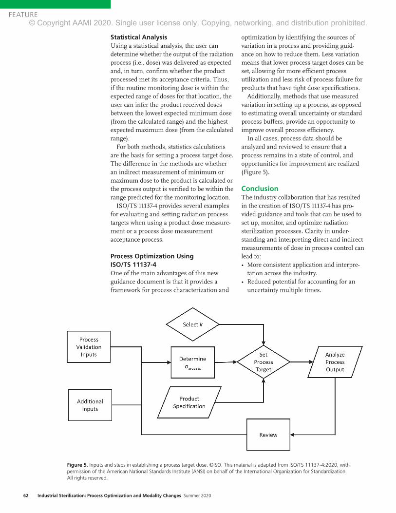
62 Industrial Sterilization: Process Optimization and Modality Changes Summer 2020
FEATURE
Statistical AnalysisUsing a statistical analysis, the user can determine whether the output of the radiation process (i.e., dose) was delivered as expected and, in turn, confirm whether the product processed met its acceptance criteria. Thus, if the routine monitoring dose is within the expected range of doses for that location, the user can infer the product received doses between the lowest expected minimum dose (from the calculated range) and the highest expected maximum dose (from the calculated range).
For both methods, statistics calculations are the basis for setting a process target dose. The difference in the methods are whether an indirect measurement of minimum or maximum dose to the product is calculated or the process output is verified to be within the range predicted for the monitoring location.
ISO/TS 11137-4 provides several examples for evaluating and setting radiation process targets when using a product dose measure-ment or a process dose measurement acceptance process.
Process Optimization Using ISO/TS 11137-4One of the main advantages of this new guidance document is that it provides a framework for process characterization and
optimization by identifying the sources of variation in a process and providing guid-ance on how to reduce them. Less variation means that lower process target doses can be set, allowing for more efficient process utilization and less risk of process failure for products that have tight dose specifications.
Additionally, methods that use measured variation in setting up a process, as opposed to estimating overall uncertainty or standard process buffers, provide an opportunity to improve overall process efficiency.
In all cases, process data should be analyzed and reviewed to ensure that a process remains in a state of control, and opportunities for improvement are realized (Figure 5).
ConclusionThe industry collaboration that has resulted in the creation of ISO/TS 11137-4 has pro-vided guidance and tools that can be used to set up, monitor, and optimize radiation sterilization processes. Clarity in under-standing and interpreting direct and indirect measurements of dose in process control can lead to: • More consistent application and interpre-
tation across the industry. • Reduced potential for accounting for an
uncertainty multiple times.
Figure 5. Inputs and steps in establishing a process target dose. ©ISO. This material is adapted from ISO/TS 11137-4:2020, with permission of the American National Standards Institute (ANSI) on behalf of the International Organization for Standardization. All rights reserved.
© Copyright AAMI 2020. Single user license only. Copying, networking, and distribution prohibited.

www.aami.org 63
FEATURE
• Options to choose the process control approach based on the amount of information known about the irradiator.
• The ability to accommodate innovative products that may require a tighter dose range.The use of process measurements provides an acceptable
alternative to traditional methods that require an indirect or direct measurement of minimum and maximum dose as a measure of conformance. Identifying sources of variability provides an avenue to improve and optimize these processes. Either method described in this article provides the accept-able dose range for the product to meet its specification, but there are advantages of the process dose approach for the industry utilizing ISO/TS 11137-4. Overall, this new guidance document can be used to broaden the application of radiation sterilization for products with challenging dose specifica-tions and allow more efficient operation for irradiators.
References1. WebFinance Inc. Definition of “process control.” www.business
dictionary.com/definition/process-control.html. Accessed June 5,
2020.
2. ISO/ASTM 51261:2013. Practice for calibration of routine dosimetry
systems for radiation processing. Geneva: International Organization
for Standardization.
3. ISO/ASTM 51707:2015. Guide for estimation of measurement
uncertainty in dosimetry for radiation processing. Geneva: International
Organization for Standardization.
4. ANSI/AAMI/ISO 11137-3:2017. Sterilization of health care products—
Radiation—Part 3: Guidance on dosimetric aspects of development,
validation and routine control. Arlington, VA: Association for the
Advancement of Medical Instrumentation.
5. ISO/TS 11137-4:2020. Sterilization of health care products—
Radiation—Part 4: Guidance on process control. Geneva: International
Organization for Standardization.
6. ANSI/AAMI/ISO 11137-1:2006/(R)2015 & A1:2013 & A2:2019.
Sterilization of health care products—Radiation—Part 1: Requirements
for development, validation, and routine control of a sterilization process
for medical devices. Arlington, VA: Association for the Advancement
of Medical Instrumentation.
Advancing Safety in Health Technologywww.aami.org
AAMI ConnectYour one-stop shop for online discussion groups!
• Connect with healthcare technology professionals from around the globe.
• Have a question? Get it answered here!• Share resources.• Participate in discussions on key issues.
COMMUNITIES YOU CAN JOIN:• AAMI Members• Educators• HTM• Students and young professionals
To find out more about AAMI Connect, visit www.aami.org/connect.
© Copyright AAMI 2020. Single user license only. Copying, networking, and distribution prohibited.

64 Industrial Sterilization: Process Optimization and Modality Changes Summer 2020
FEATURE
AbstractThe validation of a radiation sterilization dose involves an initial sterilization dose determina-tion as well as maintenance of that sterilization dose. The procedures for maintenance of the sterilization dose typically include the periodic use of two types of tests: bioburden and dose audits. The details for the procedures are outlined in the ISO radiation sterilization standards. These documents also provide guidelines for recommended actions in response to the results of the two tests. The results for the dose audit are based on the number of positive tests of sterility (TOS) for products that have been irradiated at a verification or experimental dose. When the dose audit yields TOS positives, it is often thought that they indicate a steriliza-tion failure and nonsterile product. The belief that any TOS positive is a failure is an incorrect assumption because of the statistical basis used for the determination of the sterilization dose. This article will outline the truth of what dose audit TOS positives mean in terms of the sterility assurance of product, as well as the consequences of TOS positives.
The validation of terminal sterilization using radiation involves the establishment of an initial sterilization dose as well as routine maintenance of that sterilization dose. The procedures for routine maintenance, typically carried out by performing biobur-den and periodic dose audits, are outlined in the ANSI/AAMI/ISO 11137 series of stand-ards1,2 as well as ANSI/AAMI/ISO TIR13004.3 The methods defined in these documents have been successfully used for several decades to determine and maintain steriliza-tion doses. These documents provide guidelines for recommended actions based on the number of positive tests of sterility (TOS) from a dose audit. Although some wording and instructions have been modi-fied slightly over the years to provide additional clarification, the general actions to be taken have remained the same through-
out the revision history of the standards.The terms implied throughout the radia-
tion sterilization documents for the TOS outcomes of the verification experiment performed during a dose audit are “accept-able verification” and “unacceptable verification,” although one clause is titled “Failure of a sterilization dose audit.”2,3 In the strictest sense, the term “failure” should not apply to the initial positives in a TOS but should only apply when those positives are determined to be true survivors of the verification dose and exceed the acceptable limits described in the standards. However, the terms widely used in the healthcare product industry are “pass” and “fail” of the dose audit based on positive TOS results. For this discussion, and to be more in keeping with industry understanding, the indus-try-accepted terms of “pass” and “fail” will be used here, as well as the terms “acceptable” and “unacceptable.”
When failure of a dose audit occurs, many companies typically assume the TOS posi-tives are indicative of a catastrophic failure. The natural inclination is to assume the dose audit is directly evaluating the routinely sterilized product and, consequently, to assume a failed dose audit means that the fully processed product has also “failed” or is nonsterile. The belief that dose audit posi-tives or failures mean fully sterilized product is nonsterile is absolutely not true. This article will outline the truth of what a dose audit failure means in terms of the sterility and sterility assurance of the product. In addition, it will explore the consequences of a dose audit failure on the sterilized product associated with it.
The dose audit TOS results are reported as the number of positives in a set of samples, typically 100 samples for Method 1 and Method 2 and 10 samples for VD
max—the
most widely used dose determination methods. The number of TOS positives determines the action to be taken. In all
About the Authors
Trabue Bryans is president at BryKor LLC in Marietta, GA. Email: [email protected]
Lisa Foster is principal at Adiuvo QS & SA Consulting in Fairhope, AL. Email: lisafoster@sterilization
consulting.net
Kimberly Patton is WW sterilization program manager, corporate global sterility assurance
at BD in Sumter, SC. Email: [email protected]
Joyce M. Hansen is vice president of microbiological quality & sterility assurance at Johnson &
Johnson in Raritan, NJ. Email: [email protected]
Radiation Dose Audit Failures: Truth and ConsequencesTrabue Bryans, Lisa Foster, Kimberly Patton, and Joyce M. Hansen
© Copyright AAMI 2020. Single user license only. Copying, networking, and distribution prohibited.
www.aami.org 65
FEATURE
radiation sterilization dose audits, one positive TOS for 10 samples and 2 positive TOS for 100 samples are acceptable, and these results confirm the validity of the sterilization dose for the specified sterility assurance level (SAL). Although a positive TOS is acceptable and expected, sometimes any TOS positive will be wrongly viewed as unacceptable or in a negative context. This is tied to the misconception that the verifica-tion TOS positive is somehow directly reflective of the sterility of fully sterilized product. It is also tied to the misconception that the verification test of sterility is the same as a lot release test for sterility. The verification dose is intended to provide a 10–1 to 10–2 SAL (sometimes referred to as “sublethal”), and therefore one or two positives in the set of samples is considered a statistically acceptable outcome of the experiment and should never be viewed as an indication of a problem with the product.
When the number of TOS positives exceeds the specified level for acceptability, different actions are to be taken, depending on the number of positives. For Methods 1 and 2, a repeat test is called for, based on the number of initial TOS positives. The initial test in this case is not considered a dose audit failure and might only indicate that the results fall slightly outside statistical accepta-bility, with the repeat test potentially confirming that fact. When using VD
max, the
repeat test is called a “confirmatory test.” (Note that a VD
max document currently under
development will not include the “confirma-tory test” term). Again, the initial test in itself is not considered a dose audit failure, and, as with Methods 1 and 2, might only indicate that the results fall slightly outside statistical acceptability. The outcome of the confirmatory test will determine whether the dose audit should be considered passing or failing. These two situations outlined for Method 1, Method 2 and VD
max will be
referred to as “repeat/confirmatory” tests in the remainder of this article. In the case of a repeat/confirmatory test, the additional results will confirm whether the initial test was a statistical expectation, and whether the sterilization dose continues to be valid. Hence, positive TOS results that call for repeat/confirmatory tests are not “failures”
and should not be referred to as such.Apart from this scenario of a repeat/
confirmatory test, a certain number of TOS positives in the initial dose audit is consid-ered failing and will call for augmentation of the sterilization dose (increase in steriliza-tion dose to address the number of positives observed) or cessation of sterilization for products impacted, while corrective action is taken and the sterilization dose is reestab-lished. Each dose determination method specifies those criteria and the correspond-ing actions. For this discussion, only those outcomes that indicate a confirmed dose audit failure will be addressed—not out-comes prior to completion of a repeat/confirmatory test, or outcomes of an accept-able repeat/confirmatory test.
It should be noted that the truths and the consequences to follow are not relevant for a situation where there is a gross dose audit failure due to an extremely high or out-of-control bioburden, or an excessive number of TOS positives (i.e., a number beyond that which calls for augmentation). In these situa-tions, the principles presented here do not apply and, based on the actual failure situation, there might be a significant impact to the sterility of the product because of total loss of control of the manufacturing process.
Truth
Sterility and SafetyThe first truth about dose audit failures is that there should not be an immediate assumption that fully sterilized product is nonsterile or not safe for use simply because there are TOS positives after exposure to the verification dose. The incorrect assumption by many companies is that a failing number of TOS positives means that product that has been fully processed is nonsterile. This is incorrect, in that the TOS positives were based on irradiation at a verification dose, which is a much lower dose than that used for sterilization and realistically is expected to result in one or more TOS positives
...positive TOS results that call for repeat/confirmatory tests are not “failures”...
© Copyright AAMI 2020. Single user license only. Copying, networking, and distribution prohibited.
66 Industrial Sterilization: Process Optimization and Modality Changes Summer 2020
FEATURE
(e.g., one positive out of ten tested demon-strates a 10–1 SAL). The verification dose is set for the purpose of experimenting at a 10–1 or 10–2 SAL, not at the 10–6 or other SALs used for full sterilization. Therefore, verifica-tion dose positives arise from a 10–1 to 10–2 SAL dose that statistically can result in positives, and not from a full sterilization dose where the expectation of a positive is, for example, one in one million (i.e., 10–6 SAL).
One cannot compare the safety of product that has been irradiated at a one in one million probability of a viable microorgan-ism to that of product irradiated at a one in ten or one in one hundred probability of a viable microorganism. The failed dose audit might indicate that the calculated SAL of the fully processed product is not exactly at 10–6, but, if calculations are performed based on D-values, it is most often shown that the SAL is only slightly different than that claimed. Therefore, even if the SAL of the sterilized product is slightly different than a claimed SAL of 10–6, the SAL might be only some-thing such as 10–5.8, a probability of a viable microorganisms of about one in six hundred fifty thousand, which is certainly not a level that can be called nonsterile as far as patient safety is concerned.4 In ANSI/AAMI ST67, there are SALs other than 10–6 that are recognized as “sterile,” such as 10–3, 10–4 and 10–5, which are acceptable based on certain criteria.5 Because of this, the issue is not whether the fully processed product is sterile—it is sterile as far as patient safety is concerned. The primary concern relates to a compliance perspective in demonstrating the label claim, as explained further.
TOS False Positive RateAn important truth about a dose audit failure is that there should not be an automatic assumption that all TOS positives are true survivors of the verification dose. It is also possible that a TOS positive is the result of postprocessing contamination. Postprocess-
ing contamination is a significant factor in the potential for a sterility test positive, and the aspects that can contribute to this factor need to be recognized.
The probability of lab contamination in a sterility test—resulting in false positives—is a valid concern.6 In published information, the false positive rate varies, but can be as high as 0.5%, depending on the level of environmental control and the competency of the lab. Issues such as product design, fatigue, the test environment, manipulation, materials, technician error, and incubation conditions all come into play in evaluating the likelihood of contamination. Labs that are not set up for strict aseptic practices for sterility testing, such as the sterility test isolator practices used in the pharmaceutical industry, will likely have higher contamina-tion rates. This expected laboratory contamination rate is one reason sterility testing of terminally sterilized product is not recommended.6 There is even a likelihood that contamination will occur during the incubation process, where container integrity may be an issue during incubation and sample examination.
Postprocessing contamination can include more than just lab contamination—it can be essentially anything that happens to the test samples from the time the product exits the irradiation process all the way through the final examination of containers in the testing process. Of utmost importance is the package that maintains the sterility of the samples. A breach in the package integrity—either a pre-existing issue or unknown/undetected damage—could also negate the results of the TOS, especially considering the handling and stresses involved in shipping (e.g., samples are frequently packaged in material other than what is validated for the finished product).
Probability of Dose Audit FailuresAnother truth about dose audit failures is the statistical probability that one in approxi-mately 11 or 12 dose audits will have results that fall outside the acceptable number of TOS positives, even if the bioburden has not changed.7 Dose determination is based on statistical probabilities, as previously dis-cussed, such as the likelihood of survival of
The probability of lab contamination in a sterility test—resulting in false positives—is a valid concern.
HELPING DELIVER BETTER OUTCOMES. A more efficient lab can lead to faster results, which in turn can improve patient outcomes. Across the healthcare continuum, BD combines advanced automation with fully integrated products, expertise from pre- to post-analysis, and sophisticated informatics to streamline lab workflows and accelerate turnaround times for accurate results. This also helps measurably drive down costs across the entire lab for chemistry, microbiology, molecular and clinical flow cytometry. From discovery to the delivery of care, this is the difference of an exceptionally broad portfolio of BD solutions, insights and global partnerships. Discover the diagnostic difference one company can make. Discover the new BD.
BD and the BD Logo are trademarks of Becton, Dickinson and Company. © 2020 BD. All rights reserved. 5095 (0720)
Learn more about the Difference of One at bd.com
© Copyright AAMI 2020. Single user license only. Copying, networking, and distribution prohibited.

68 Industrial Sterilization: Process Optimization and Modality Changes Summer 2020
FEATURE
one in one million viable microorganisms. Based on the probabilities of occurrence of numbers of positives presented in the 11137 series dose determination methods, there is around a 92% probability that there will be the acceptable number of positives, which leaves about an 8% probability that the number of TOS positives will not be accept-able, according to the interpretation criteria. This is the basis for the repeat or confirma-tory options in dose audits.
In real life terms, for quarterly dose audits, this probability of unacceptable results can happen at any time during the course of performing dose audits—not only after the 11th or 12th dose audit. This is one reason why the repeat/confirmatory option is specified—to demonstrate whether or not the failure was within the probability of occurrence. If this truth is known and understood, it should prevent a company from jumping to the wrong conclusion about the meaning of unacceptable results. For this truth, the assumed failure should be assessed in light of it potentially being a statistical probability, and therefore actions should be focused on determining this and demonstrating that the product is in a state of control, rather than only taking remedial actions for a problem that might not exist.
Processed LoadsThe next truth about a dose audit failure is that, where there is a possibility of not achieving the specific SAL claimed, that possibility only pertains to one small portion of a sterilization load. For this discussion we will assume a 10–6 SAL. In all radiation sterilization a dose range will be delivered, which is typically the sterilization dose plus, for example, 10–20 kGy, such as 20–32 kGy or 25–40 kGy. A dose range is specified because, due to the physics of the irradiation process, the exact dose cannot be delivered throughout the product itself or the product configuration. The selected SAL, such as 10–6, corresponds to the sterilization (lowest) dose, whereas all the higher doses in the
dose range will translate into SALs exceeding the SAL for the sterilization dose. Therefore, the vast majority of a given sterilization load will possess SALs ranging from 10–6 to 10–9 or 10–10. This fact demonstrates the truth that the vast majority of a sterilization load will have received the intended SAL of 10–6, because a slight change in SALs of 10–7, 10–8, or 10–9 will not approach that of 10–6. This is the reason that the majority of a sterilization load will achieve the designated SAL, leaving only a portion of the load—in the minimum dose zones—where the SAL might have been affected.8
Sterilization Dose vs. Minimum Delivered DoseA final truth is that, in many cases, the minimum sterilization dose delivered to the product load is higher than the sterilization dose that was determined (validated or substantiated). For instance, if a 25 kGy sterilization dose is substantiated, the routine sterilization process might show that previous loads received minimum doses higher than 25 kGy, such as 26 or 27 kGy. In these cases, for a dose audit failure, the truth is that there is potentially no impact to achieving the corresponding 10–6 SAL, because the minimum dose of 25 kGy was always exceeded, and therefore it could be demonstrated by calculations that the 10–6 SAL was always achieved.
Calculations for D-value and SAL based on bioburden and radiation dose can show that, for example, 25.5 kGy provides a 10–6.3 SAL, in which case a slight change in that SAL due to a true dose audit failure still would mean the SAL of 10–6 was achieved. A series of calculations can be performed for each load to definitively show what the theoretical SAL is, based on bioburden data coupled with the minimum delivered dose for each load. Depending on the circumstances, it is often appropriate to specify a minimum dose to the sterilization site that exceeds the validated minimum dose. If it is possible to specify the dose range for sterilization as a minimum dose slightly above the dose that was determined (e.g. 26–40 kGy versus 25–40 kGy), this could become the critical factor in defense of the nonimpact of a dose audit failure.
...the vast majority of a given sterilization load will possess SALs ranging from 10–6 to 10–9 or 10–10.
© Copyright AAMI 2020. Single user license only. Copying, networking, and distribution prohibited.

www.aami.org 69
FEATURE
ConsequencesUnderstanding the truth about dose audit failures is critical to understanding the consequences of a dose audit failure. As previously explained, a dose audit failure is not automatically an indication of nonsterile product in current or previous sterilization runs. Nor is a dose audit failure automati-cally a recall situation. The consequences of a dose audit failure depend entirely on a) the magnitude of the failure, b) the increase or change in bioburden numbers and types, and c) the actual sterilization (minimum) dose that has been delivered to the processed product.
In facing a dose audit failure, the first and foremost question to address that will dictate consequences is: Is it truly a failure or is there some other reason for the TOS positives? The likelihood of the TOS being invalid is often higher than typically assumed, and it can be attributed to many things—manufac-turing, handling, packaging, shipping, or testing.9 Before taking dose audit failure actions, one should always determine whether the failure has a reason for invalidation.
There are three central questions to ask while conducting an investigation into a dose audit failure: 1. Is this the result of a statistical expectation,
in which a retest/confirmatory test is performed?
2. Is this the result of an invalid experiment (nonrepresentative samples, incorrect dose delivery, contaminated media, breach of test container integrity, etc.) where the test experiment should be invalidated and a new experiment performed?
3. Is this a true failure due to a change in product bioburden, where augmentation or reestablishment of the sterilization dose is required?An initial step in the investigation requires
identification of the positive microorganisms from the TOS, which can go a long way in concluding whether there is a true failure. For example, a microorganism with very low resistance to radiation (e.g., Staphylococcus sp.) should be questioned more than a microorganism known to have a higher resistance to radiation (e.g., Bacillus sp.). Concurrently there should be an investiga-tion into the laboratory, manufacturing and
packaging processes, sterilization, and postprocess handling. Improper manufac-turing of samples (components, handling, or packaging related only to the verification samples) can cause a dose audit failure that is related only to the samples made for the dose audit. Packaging can be compro-mised—either during the process or after—and this can lead to contamination of the samples after irradiation at the verifica-tion dose. For products that promote growth, a delay in irradiation of the samples that extends the irradiation time of routine product could result in continued growth of microorganisms in the samples that typically would not be present, based on the standard time to irradiation. Each of these deficiencies might only be related to the dose audit samples and not necessarily the routine product. Contamination can occur during test preparation, execution, and incubation. The test of sterility is not infallible, and the occurrence of contamination should always be considered.
The information gathered from the investigation will lead to one of two actions: 1) the performance of a new verification test due to invalidation of the TOS based on an identified root cause or 2) the pursuit of actions dictated by the number and identifi-cation of TOS positives, assuming they are true survivors of the verification dose. The first action does not qualify as a consequence because it is not a dose audit failure at this point. The second action indicates a true dose audit failure has occurred; therefore, several consequences might apply.
The following consequences apply only to true dose audit failures for which a prelimi-nary investigation rules out any cause for invalidation.
Dose Going ForwardFor a true dose audit failure, the first conse-quence one must consider is the sterilization dose going forward. The 11137 and TIR13004 guidelines indicate whether the sterilization dose should be augmented and by how
Understanding the truth about dose audit failures is critical to understanding the consequences of a dose audit failure.
© Copyright AAMI 2020. Single user license only. Copying, networking, and distribution prohibited.

70 Industrial Sterilization: Process Optimization and Modality Changes Summer 2020
FEATURE
much, or whether sterilization must be halted and a new dose reestablished. The radiation guidelines for how to proceed in this case are straightforward. For augmenta-tion, the calculations are outlined based on the number of TOS positives, and the augmented dose is to be continued until either the underlying issue is resolved or the dose is reestablished. For results that indicate cessation of sterilization, dose reestablishment must be pursued immedi-ately for sterilization to resume.
Dose in RetrospectIn addition to the sterilization dose going forward, another consequence is the sterili-zation of batches prior to the dose audit failure. The 11137-2 guidelines specify that one must consider the validity of the sterili-zation dose in retrospect. In essence, this means considering the validity of the sterilization dose for the product that was sterilized since the previous passing dose audit. The guidelines state that “...the effect of processing product at the sterilization dose that has failed sterilization dose audit on the achievement of the specified SAL for previously processed batches of product shall be considered and a risk assessment under-taken on their suitability for use.”2 Depending on the data available, such as minimum delivered doses, bioburden determinations, and dose mapping, the consideration and the risk assessment might be simple.
In performing a risk assessment, one would initially document the product batches under review—as well as the minimum dose delivered to these batches during sterilization—and compare these data with the calculated augmentation dose, where appropriate. Many of the batches may have already met the augmented dose, depending on the target dose determined by the sterilizer and the actual delivered dose reported. For example, a product might have a sterilization dose of 15 kGy, with a mini-mum specified dose of 15.5 kGy for irradiation, and an actual delivered mini-
mum dose of 15.7 kGy for all loads under review. For loads that indicate an augmented dose is required, it may be determined upon review that the augmented dose was already achieved in routine processing, because the calculated augmented dose was actually achieved for all batches processed at the minimum delivered dose. Where the augmented dose was not achieved for certain loads, a calculation of the theoretical SAL might be appropriate to determine how different the calculated SAL is from the designated SAL.
Once a theoretical SAL range has been determined for each batch of product using minimum dose delivered and maximum dose delivered, then the percentage of product at the minimum dose, intermediate doses, and maximum dose can be evaluated through the product dose mapping per-formed during performance qualification. Armed with this information, a company can then assess if any product is at risk and how significant that risk might be, based on the calculated SAL for minimum dose locations, as well as the percent of product that might not meet the SAL claim, if applicable. In these calculations, if the bioburden has changed, the D-value of the population and the calculation of SAL as indicated above might not be appropriate. However, a change in bioburden would naturally be assessed, initially, as a critical factor in the overall investigation.
There will be cases where sterilized product might be augmented, as specified in the 11137 series and TIR13004. A company must assess whether this is a possibility based on several factors, such as time elapsed since sterilization and whether the additional dose will result in exceeding the maximum dose for the product. Based on the findings laid out above and product use, a company should assess the risk to patient and determine what, if any, action is war-ranted. The considerations discussed should be undertaken with technical experts either within the company or contracted when determining the path forward.
Impact to Product FamilyA final consequence that must be considered for a true dose audit failure is the impact to
In essence, this means considering the validity of the sterilization dose for the product that was sterilized since the previous passing dose audit.
© Copyright AAMI 2020. Single user license only. Copying, networking, and distribution prohibited.

www.aami.org 71
FEATURE
other product in the family. The ISO 11137-2 standard states that in the event of a dose audit failure “…all members of that family shall be considered to be affected.”2,3 There-fore, actions taken for the dose audit failure—augmentation, dose reestablish-ment, or cessation of sterilization—will have to apply to all members of the family. Considering the many variables that could apply to a family, it would be impossible to cover all potential approaches here. Suffice it to say that there are several options for separating out certain family members or sub-groups and confirming the validity of a sterilization dose for those members or sub-groups apart from the product in the
dose audit failure. The same level of scrutiny and assessment must be applied to all members of the product family. Additionally, if a root cause is determined that could be systemic, assessment across product families might be warranted.
SummaryTable 1 is a summary of the preceding sections concerning truths and conse-quences of dose audit failures.
ConclusionIn conclusion, for a confirmed dose audit failure there are several truths and several consequences. The truths are that: a) product
Dose audit TOS PositivesVerification experiment Truth Action Consequence
Method 1 or 2 (10–2) 0, 1, or 2 Valid Acceptable
Pass
No further action No
Method 1 or 2 (10–2) > 2 Invalid Unacceptable
Not a failure
Repeat verification test No
Method 1 or 2 (10–2) 3 or 4 Valid Unacceptable
Not a failure
Inconclusive
Augment dose
Repeat verification test
No
Method 1 or 2 (10–2) 5–15 Valid Unacceptable
Dose audit failure
Augment dose
Reestablish dose
Assess previous batches
Yes
Method 1 or 2 (10–2) > 15 Valid Unacceptable
Dose audit failure
Stop sterilization
Reestablish dose
Assess previous batches
Yes
VDmax
(10–1) 0, or 1 Valid Acceptable
Pass
No further action No
VDmax
(10–1) ≥ 2 Invalid Unacceptable
Not a failure
Repeat verification experiment
No
VDmax
(10–1) 2 Valid Unacceptable
Not a failure
Inconclusive
Perform confirmatory test No
VDmax
(10–1) 3–6 Valid Unacceptable Dose audit failure
Augment dose
Reestablish dose
Assess previous batches
Yes
VDmax
(10–1) > 6 Valid Unacceptable Dose audit failure
Stop sterilization
Reestablish dose
Assess previous batches
Yes
Table 1. Summary of dose audit truths and consequences. Abbreviation used: TOS, tests of sterility.
© Copyright AAMI 2020. Single user license only. Copying, networking, and distribution prohibited.

72 Industrial Sterilization: Process Optimization and Modality Changes Summer 2020
FEATURE
that is processed at the full sterilization dose is sterile as far as it concerns patient safety—an individual product in a portion of the load might simply not possess exactly the desig-nated SAL; b) there is a potential that the TOS positives are not true survivors of the verification dose; c) only a small portion of a sterilization load might be affected by the question of SAL, because the load always receives a dose range; d) there is a statistical probability that there will be a dose audit failure over time; and e) the actual delivered dose for sterilized product—versus the validated sterilization dose—might show that the product does possess the designated SAL.
The real consequences of a confirmed dose audit failure are that a) the sterilization dose going forward must be considered, augmented if required, and guidelines for reestablishment followed; b) the sterilization dose in retrospect must be considered and a risk analysis performed; and c) the impact to and subsequent action for other product in a family must be considered.
The overarching fact is that having positives in a dose audit test of sterility does not automatically mean product that has received the full sterilization dose is nonster-ile or unsafe for use. In many cases, those sterilized products possess an acceptable SAL where patient safety is concerned.
References1. ANSI/AAMI/ISO 11137-1:2006/(R)2015 & A1:2013
& A2:2019 (Consolidated Text), Sterilization
of health care products—Radiation—Part 2:
Establishing the sterilization dose. Arlington, VA:
Association for the Advancement of Medical
Instrumentation.
2. ANSI/AAMI/ISO 11137-2:2013/(R)2019,
Sterilization of health care products—Radiation—
Part 1: Requirements for development, validation
and routine control of a sterilization process for
medical devices. Arlington, VA: Association for the
Advancement of Medical Instrumentation.
3. ANSI/AAMI/ISO TIR13004:2013, Sterilization of
health care products—Radiation—Substantiation
of a selected sterilization dose: Method VDmaxSD.
Arlington, VA: Association for the Advancement
of Medical Instrumentation.
4. Srun SW, Nissen BJ, Bryans TD, Bonjean M.
Medical device SALs and surgical site infections:
A mathematical model. Biomed Instrum Technol.
2012;46(3):230–7.
5. ANSI/AAMI ST67:2019, Sterilization of health care
products—Requirements and guidance for selecting
a sterility assurance level (SAL) for products labeled
“sterile”. Arlington, VA: Association for the
Advancement of Medical Instrumentation.
6. Daniell E, Bryans T, Darnell K, et al. Product
sterility testing…to test or not to test? That is the
question. Biomed Instrum Technol. 2016;50(suppl.
3):35–43.
7. Herring C. Dose audit failures and dose
augmentation. Radiation Physics and Chemistry.
1999;54(1)77–81.
8. Logar JR. Exploring the probability of a device
being nonsterile following irradiation. Biomed
Instrum Technol. 2019;53(suppl. 2)43–48.
9. Hansen J, et al. Investigating AAMI Radiation
Audit Results. MD&DI. May 1994.
NAVIGATING CHANGES—TOGETHER.From MDR to ISO 10993 and beyond, the regulatory landscape is constantly evolving. Learn how we bring a robust approach, active leadership and strategic partnership to every medical device product we test, with our exceptional line of services in:
• Consulting• Testing• Manufacturing
Start the conversation. Visit medicaldevice.wuxiapptec.comMedical Device Testing
© Copyright AAMI 2020. Single user license only. Copying, networking, and distribution prohibited.
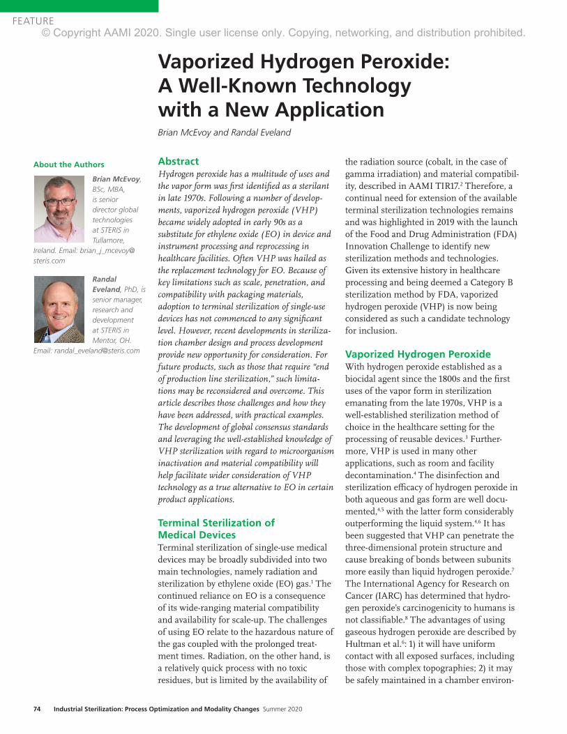
74 Industrial Sterilization: Process Optimization and Modality Changes Summer 2020
FEATURE
AbstractHydrogen peroxide has a multitude of uses and the vapor form was first identified as a sterilant in late 1970s. Following a number of develop-ments, vaporized hydrogen peroxide (VHP) became widely adopted in early 90s as a substitute for ethylene oxide (EO) in device and instrument processing and reprocessing in healthcare facilities. Often VHP was hailed as the replacement technology for EO. Because of key limitations such as scale, penetration, and compatibility with packaging materials, adoption to terminal sterilization of single-use devices has not commenced to any significant level. However, recent developments in steriliza-tion chamber design and process development provide new opportunity for consideration. For future products, such as those that require “end of production line sterilization,” such limita-tions may be reconsidered and overcome. This article describes those challenges and how they have been addressed, with practical examples. The development of global consensus standards and leveraging the well-established knowledge of VHP sterilization with regard to microorganism inactivation and material compatibility will help facilitate wider consideration of VHP technology as a true alternative to EO in certain product applications.
Terminal Sterilization of Medical DevicesTerminal sterilization of single-use medical devices may be broadly subdivided into two main technologies, namely radiation and sterilization by ethylene oxide (EO) gas.1 The continued reliance on EO is a consequence of its wide-ranging material compatibility and availability for scale-up. The challenges of using EO relate to the hazardous nature of the gas coupled with the prolonged treat-ment times. Radiation, on the other hand, is a relatively quick process with no toxic residues, but is limited by the availability of
the radiation source (cobalt, in the case of gamma irradiation) and material compatibil-ity, described in AAMI TIR17.2 Therefore, a continual need for extension of the available terminal sterilization technologies remains and was highlighted in 2019 with the launch of the Food and Drug Administration (FDA) Innovation Challenge to identify new sterilization methods and technologies. Given its extensive history in healthcare processing and being deemed a Category B sterilization method by FDA, vaporized hydrogen peroxide (VHP) is now being considered as such a candidate technology for inclusion.
Vaporized Hydrogen PeroxideWith hydrogen peroxide established as a biocidal agent since the 1800s and the first uses of the vapor form in sterilization emanating from the late 1970s, VHP is a well-established sterilization method of choice in the healthcare setting for the processing of reusable devices.3 Further-more, VHP is used in many other applications, such as room and facility decontamination.4 The disinfection and sterilization efficacy of hydrogen peroxide in both aqueous and gas form are well docu-mented,4,5 with the latter form considerably outperforming the liquid system.4,6 It has been suggested that VHP can penetrate the three-dimensional protein structure and cause breaking of bonds between subunits more easily than liquid hydrogen peroxide.7 The International Agency for Research on Cancer (IARC) has determined that hydro-gen peroxide’s carcinogenicity to humans is not classifiable.8 The advantages of using gaseous hydrogen peroxide are described by Hultman et al.6: 1) it will have uniform contact with all exposed surfaces, including those with complex topographies; 2) it may be safely maintained in a chamber environ-
Vaporized Hydrogen Peroxide: A Well-Known Technology with a New ApplicationBrian McEvoy and Randal Eveland
About the Authors
Brian McEvoy, BSc, MBA, is senior director global technologies at STERIS in Tullamore,
Ireland. Email: [email protected]
Randal Eveland, PhD, is senior manager, research and development at STERIS in Mentor, OH.
Email: [email protected]
© Copyright AAMI 2020. Single user license only. Copying, networking, and distribution prohibited.

www.aami.org 75
FEATURE
Figure 1. Industrial vaporized hydrogen peroxide sterilization chamber. Courtesy of STERIS.
ment; and 3) it may be efficiently and quickly removed from a chamber. Hydrogen peroxide is a strong oxidizing agent, having multiple targets within a cell as well as in almost every biomolecule: it can react strongly with thiol groups in enzymes and proteins, DNA, and the bacterial cell membrane.9
Such a strong oxidizing agent can cause the formation of radicals such as ferryl radical, which is formed from DNA-associ-ated iron and has an important role in DNA oxidation.9 As highlighted by the work of researchers such as Young and Setlow,10 Fichet et al.,11 and Setlow,12 the site of microbial inactivation by VHP appears to reside at the inner membrane.
Industrial-Scale VHPIndustrial VHP sterilization chambers (Figure 1) are typically one-half to four pallets (35–280 ft3). This is in contrast with large EO chambers, often ranging from 1,000 ft3 to 2,200 ft3. A distinct advantage with VHP sterilizers, however, is the minimal require-ment for supplies and services: water, compressed air, electricity, and sterilant. This allows equipment to be supplied on a single skid and installed with ease, which may be advantageous for ‘in-line’ applications. Equipment may be commissioned and validated in a manner similar to a steam or EO sterilizer.
Limitations of VHP and the Role for Process DesignAs VHP offers a number of distinct advantages, including material compatibility (as highlighted in AAMI TIR17 and Table 1 of this article), efficacious microbial inactivation, and lack of toxic residues, it does present some limitations that must be considered and addressed, namely: 1) material compatibility; 2) packaging; 3) equipment scale and throughput capability; and 4) surface penetration. Strategies to address such limitations may be summarized as follows.
Material CompatibilityVHP has a wide range of material compati-bility but is limited whereby a small subset of materials must be excluded due to absorption and decomposition of the vapor. Liquids, powders, and cellulose materials are not compatible with the process.5
PackagingPackaging for VHP sterilization needs to be compatible with the sterilant and allow for diffusion of the sterilant to the medical device. Packaging materials that prevent VHP from reaching the devices (e.g., foil pouches) should not be used; however, the external surfaces of the material such as glass (e.g., a liquid-containing ampoule) will
© Copyright AAMI 2020. Single user license only. Copying, networking, and distribution prohibited.
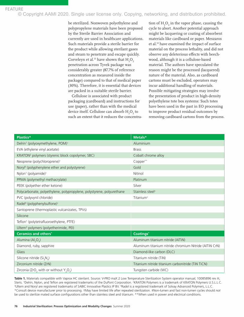
76 Industrial Sterilization: Process Optimization and Modality Changes Summer 2020
FEATURE
be sterilized. Nonwoven polyethylene and polypropylene materials have been proposed by the Sterile Barrier Association and currently are used in healthcare applications. Such materials provide a sterile barrier for the product while allowing sterilant gases and steam to penetrate and escape quickly. Corveleyn et al.13 have shown that H
2O
2
penetration across Tyvek package was considerably greater (87.7% of reference concentration as measured inside the package) compared to that of medical paper (30%). Therefore, it is essential that devices are packed in a suitable sterile barrier.
Cellulose is associated with product packaging (cardboard) and instructions for use (paper), rather than with the medical device itself. Cellulose can absorb H
2O
2 to
such an extent that it reduces the concentra-
tion of H2O
2 in the vapor phase, causing the
cycle to abort. Another potential approach might be lacquering or coating of absorbent materials like cardboard or paper. Meszaros et al.14 have examined the impact of surface material on the process lethality, and did not observe any deleterious effects with beech-wood, although it is a cellulose-based material. The authors have speculated the reason might be the processed (lacquered) nature of the material. Also, as cardboard cartons must be excluded, operators may incur additional handling of materials. Possible mitigating strategies may involve the presentation of product in high-density polyethylene tote box systems: Such totes have been used in the past in EO processing to improve product residual outcomes by removing cardboard cartons from the process.
Plastics* Metals*
Delrin1 (polyoxymethylene, POM)† Aluminium
EVA (ethylene vinyl acetate) Brass
KRATON2 polymers (styrenic block copolymer, SBC) Cobalt chrome alloy
Neoprene (polychloroprene)† Copper**
Noryl3 (polyphenylene ether and polystyrene) Gold
Nylon1 (polyamide)† Nitinol
PPMA (polymethyl methacrylate) Platinum
PEEK (polyether ether ketone) Silver
Polycarbonate, polyethylene, polypropylene, polystyrene, polyurethane Stainless steel‡
PVC (polyvynil chloride) Titanium‡
Radel4 (polyphenylsulfone)†
Santoprene (thermoplastic vulcanizates, TPVs)
Silicone
Teflon1 (polytetrafluoroethylene, PTFE)
Ultem3 polymers (polyetherimide, PEI)
Ceramics and others* Coatings*
Alumina (Al2O
3) Aluminum titanium nitride (AlTiN)
Diamond, ruby, sapphire Aluminum titanium nitride chromium Nitride (AlTiN CrN)
Glass Diamond-like carbon (DLC)
Silicone nitride (Si3N
4) Titanium nitride (TiN)
Zirconium nitride (ZrN) Titanium nitride titanium carbonitride (TiN TiCN)
Zirconia (ZrO2 with or without Y
2O
3) Tungsten carbide (WC)
Table 1. Materials compatible with Vaprox HC sterilant. Source: V-PRO maX 2 Low Temperature Sterilization System operator manual; 10085896 rev A; Steris. ¹Delrin, Nylon, and Teflon are registered trademarks of the DuPont Corporation. 2KRATON Polymers is a trademark of KRATON Polymers U.S.L.L.C. 3Ultem and Noryl are registered trademarks of SABIC Innovative Plastics IP BV. 4Radel is a registered trademark of Solvay Advanced Polymers, L.L.C. *Consult device manufacturer prior to processing. †May have limited life after repeated sterilization. ‡Non-lumen and fast non-lumen cycles should not be used to sterilize mated surface configurations other than stainless steel and titanium. **When used in power and electrical conditions.
© Copyright AAMI 2020. Single user license only. Copying, networking, and distribution prohibited.

www.aami.org 77
FEATURE
Equipment Scale and Throughput CapacityAs already described, VHP sterilizers lack large volume scale compared to EO sterilizers. However, VHP has the advantage of quicker and more efficient processing that goes some way to addressing this limitation of scale. Consequently, chamber size—coupled with additional handling requirements to exclude packaging materials—would render VHP most suitable for specific niche applications, typically at the end of production line applications. For deployment into contract sterilization offerings, supply chains must be designed to streamline product flow and handling.
Surface PenetrationThere are many different VHP sterilization processes used in the various commercial sterilizers available today, but all these processes follow a similar three-phase pattern (Figure 2): preconditioning, steriliza-tion, and aeration. First, a deep vacuum is pulled to remove air and humidity from the load and to create an environment for injecting VHP to a maximum level while not reaching the saturation point at which condensation will occur. The importance of
this step is highlighted in a study performed by Hultman et al.,6 where a drop in a maxi-mum H
2O
2 concentration from 2,148 to 1,805
mg/L has been reported, as moisture content goes from 0% to 10%. In the second phase, usually a 35% liquid H
2O
2 (w/v; pH~3) is
vaporized at over 100°C and the vapor is injected into the chamber in the form of pulses to reach a final concentration of 1–2mg/L. Following sterilant exposure, vacuum is applied and product is washed using either air or steam or a combination of both to remove sterilant. Process parame-ters—predominantly pressure, temperature, humidity, and exposure time—can be optimized to design high-performing cycles and ensure penetration to the desired surfaces for sterilization. In lumen devices, residual air may impede vapor penetration and therefore cycle design should consider critical parameters including vacuum depth, sterilant concentration, and exposure time.
While there was previously concern about hydrogen peroxide penetration and steriliza-tion within long narrow lumens, stainless steel and flexible lumens (e.g., flexible endoscopes) are now sterilized by subatmos-pheric VHP systems in healthcare.
Figure 2. Three-phase pattern for vaporized hydrogen peroxide (VHP) sterilization. Courtesy of STERIS.
© Copyright AAMI 2020. Single user license only. Copying, networking, and distribution prohibited.

78 Industrial Sterilization: Process Optimization and Modality Changes Summer 2020
FEATURE
Validation of VHP ProcessesCurrently, there is no international standard that provides performance requirements for biological indicators for VHP sterilization processes. The process is therefore charac-terized in accordance with ANSI/AAMI/ISO 14937:2009/(R)2013,16 which states that a microorganism of known high resistance can be used to demonstrate the microbial effectiveness of the sterilizing agent. In the U.S., the FDA regulates biological indicators used in healthcare facilities and has a set of testing requirements for the clearance of VHP biological indicators in the U.S. market.
While FDA 510(k) regulations17 require the use of G. stearothermophilus in the hospital setting as the most resistant organism, the 14937 standard—which is appropriate for medical device terminal sterilization applica-tions—requires the consideration of product bioburden and standard resistances, and recommends use of a biological indicator of known high resistance, similar to that as defined for EO sterilization in accordance with ANSI/AAMI/ISO 11135:2014,18 where Bacillus atrophaeus is the reference micro- organism. It is known that G. stearothermo-philus is more resistant to vapor, whereas B. atrophaeus is more resistant when sub-jected to liquid hydrogen peroxide.19 Selection of a biological indicator to chal-lenge the process is an important step, as it consequently quantifies the microbicidal inactivation of the process and therefore the process outcomes (sterility assurance and material effects). The validation process detailed in the 14937 standard is a familiar and accepted process, as it is very much aligned to that for EO gas sterilization18 where an overkill half-cycle approach is often adopted. Like EO validation, alternative approaches to validation are also available and may be appropriate if one is to consider a more targeted process with less overpro-cessing.
EO processing solicits wide acceptance from industry as it is a known, trusted technology with a long history of use. Furthermore, by nature of having its own international consensus standard (ISO 11135) recognized by the FDA, it has Category A status. VHP has Category B status, given its
long history in healthcare and available body of knowledge. In 2017, a new work item was proposed to the International Organization for Standardization for the creation of a process standard for VHP sterilization. This proposal was duly accepted and a working group (WG16) formed under Technical Committee 198 (responsible for steriliza-tion). This committee has commenced work on the draft standard, ISO/CD 22441. Similarly, in Europe work is underway by CEN TC102 WG6 to develop an equipment standard (prEN 17180) similar to EN 1422 (applicable to EO sterilizers). Once complete, both standards would provide normative references and guidance for both equipment and the sterilization processes provided by such equipment in both healthcare and industrial settings.
ConclusionExamination of current and past applications shows VHP sterilization to be an efficacious, material-friendly, and useful sterilization technology. There are limitations with every sterilization technology (described in parentheses): steam (high temperature), EO (residues), E-beam (poor penetration), gamma/X-ray (material compatibility limitations). VHP too has limitations. However, such limitations are to be consid-ered and innovations provided to increase the adoption of the technology. Expectations for future adoption as a technology for terminal sterilization of single-use medical devices may be founded on 1) compatability with a wide range of materials, including polymers, sensors and electronics, metals, and electrical components; 2) operating temperatures typically lower than EO processing; and 3) ready deployment of self-contained sterilization equipment. Therefore, temperature-sensitive products, sensor/electronic combination products, or those requiring sterilization at source of manufacture (e.g., 3D printed products) may be excellent candidates for such a steriliza-tion solution.
The proliferation of any technology in medical device sterilization is predisposed to its acceptance by those who require steriliza-tion for their manufactured devices. With continued focus, investigation, and dissemi-
© Copyright AAMI 2020. Single user license only. Copying, networking, and distribution prohibited.

www.aami.org 79
FEATURE
nation of knowledge and experience, the possibilities VHP adds to the technology portfolio available to manufacturers can be realized. As projects are completed with a diverse range of products, experience and knowledge are gained that may be shared in future publications.
AcknowledgmentsThe authors thank and acknowledge the Kilmer Collabora-tion Modalities group for the cooperative efforts considering and exploring how additional sterilization modalities may be deployed and adopted by the healthcare products manufac-turing industry, for the benefit of patient care.
References1. Gamma Irradiation Processing Alliance, International Irradiation
Association. A Comparison of Gamma, E-beam, X-ray and Ethylene
Oxide Technologies for the Industrial Sterilization of Medical
Devices and Healthcare Products. 2017. http://iiaglobal.com/wp-
content/uploads/2018/01/White-Paper-Comparison-Gamma-Eb-
Xray-and-EO-for-Sterilisation.pdf. Accesed June 2, 2020.
2. AAMI TIR17:2017. Compatibility of materials subject to sterilization.
Arlington, VA: Association for Advancement of Medical
Instrumentation.
3. McEvoy B, Rowan NJ. Terminal sterilization of medical devices
using vaporized hydrogen peroxide: a review of current methods and
emerging opportunities. J Appl Microbiol. 2019;127(5):1403–20.
4. McDonnell G. The Use of Hydrogen Peroxide for Disinfection and
Sterilization Applications. In: Rappoport Z, Ed. PATAI’S Chemistry
of Functional Groups. John Wiley and Sons; 2014.
5. Block SS. Peroxygen Compounds. In: Block SS, Ed. Disinfection,
Sterilization and Preservation. Philadelphia: Lea & Febiger; 1991:167–
81.
6. Hultman C, Hill A, McDonnell G. The physical chemistry of
decontamination with gaseous hydrogen peroxide. Pharmaceutical
Engineering. 2007;27(1):22–32.
7. Finnegan M, Linley E, Denyer SP, McDonnell G, Simons C, Maillard
JY. Mode of action of hydrogen peroxide and other oxidizing agents:
Differences between liquid and gas forms. J Antimicrob Chemother.
2010;65(10):2108–15.
8. IARC Working Group on the Evaluation of Carcinogenic Risks to
Humans, International Agency for Research on Cancer.
Re-Evaluation of Some Organic Chemicals, Hydrazine and Hydrogen
Peroxide. 1999 World Health Organization, International Agency for
Research on Cancer.
9. Linley E, Denyer SP, McDonnell G, Simons C, Maillard JY.
Use of hydrogen peroxide as a biocide: New consideration of
its mechanisms of biocidal action. J Antimicrob Chemother.
2012;67(7):1589–96.
10. Young SB, Setlow P. Mechanisms of killing of Bacillus subtilis spores
by Decon and Oxone, two general decontaminants for biological
agents. Journal of Applied Microbiology. 2004;96(2):289–301.
11. Fichet G, Antloga K, Comoy E, Deslys JP, McDonnell G. Prion
inactivation using a new gaseous hydrogen peroxide sterilisation
process. J Hosp Infect. 2007;67:278–86.
12. Setlow P. Summer meeting 2013—when the sleepers wake:
The germination of spores of Bacillus species. J Appl Microbiol.
2013;115(6):1251–68.
13. Corveleyn S, Vandenbossche GMR, Remon JP. Near-infrared (NIR)
monitoring of H2O
2 vapor concentration during vapor hydrogen
peroxide (VHP) sterilisation. Pharm Res. 1997;14(3):294–98.
14. Meszaros JE, Antloga K, Justi C, Plesnicher C, McDonnell G. Area
Fumigation with Hydrogen Peroxide Vapor. Applied Biosafety.
2005;10(2):91–100.
15. McDonnell G, Sheard D. A Practical Guide to Decontamination in
Healthcare. West Sussex: Wiley Blackwell Publishers, John Wiley &
Sons, 2012.
16. ANSI/AAMI/ISO 14937:2009/(R)2013. Sterilization of health care
products—General requirements for characterization of a sterilizing
agent and the development, validation and routine control of a
sterilization process for medical devices. Arlington, VA: Association for
the Advancement of Medical Instrumentation.
17. Food and Drug Administration. Biological Indicator (BI) Premarket
Notification [510(k)] Submissions. October 4, 2007. https://www.fda.
gov/media/71134/download. Accessed March 30, 2020.
18. ANSI/AAMI/ISO 11135:2014. Sterilization of health care products—
Ethylene oxide—Requirements for development, validation and routine
control of a sterilization process for medical devices. Arlington, VA:
Association for the Advancement of Medical Instrumentation.
19. McDonnell G. Chemical Sterilization. In: McDonnell G, Ed.
Antisepsis, Disinfection and Sterilization: Types, Action and Resistance.
Washington: ASM Press; 2007:191–216.
© Copyright AAMI 2020. Single user license only. Copying, networking, and distribution prohibited.

80 Industrial Sterilization: Process Optimization and Modality Changes Summer 2020
FEATURE
AbstractFlexible endoscopes are implicated in deaths from healthcare-associated infections (HAIs), in particular antibiotic-resistant infections. This article analyzes whether terminal sterilization should be required as part of endoscope repro-cessing to reduce or eliminate HAIs and thus improve patient safety. Reusable flexible endoscopes are processed to make them ready for clinical use by the processing department of the healthcare facility. Unlike most critical and semicritical medical devices, the final step of processing an endoscope is high-level disinfection and not terminal sterilization. This is because most flexible endoscopes come in contact with mucosal membranes (versus contact with direct blood stream) and cannot withstand steriliza-tion. However, sterilization currently is performed by a small number of U.S. healthcare facilities on reusable flexible endoscopes with the belief that they are safer for use compared to flexible endoscopes that are high-level disin-fected. Based on the analysis in this article, terminal sterilization is not a required or necessary step to eliminate HAIs.
The processing department of a healthcare facility is responsible for cleaning, disinfec-tion, and sterilization of applicable medical devices to ensure they are ready for use on the next patient. To perform these processes, the department follows the instructions for use (IFU) provided by the medical device manufacturer. Medical device manufacturers are required to validate each process listed in the IFU that will make an applicable medical device ready for clinical use. The design and clinical use of the reusable medical device determines which processes are required to be listed in the IFU to reduce the risk of infection.
To analyze the risk of infection, the Spaulding classification is used. This classification groups medical devices into
three categories: critical, semicritical, and noncritical. Flexible endoscopes are catego-rized as semicritical devices, as they come into contact with mucosal membranes and do not penetrate tissue or enter sterile areas of the body cavity. However, the accessories that are used with flexible endoscopes (e.g., biopsy needles) are critical devices, as they enter blood streams and sterile areas of the body. Semicritical devices are required to be sterilized, unless the device cannot with-stand sterilization. If the device cannot withstand sterilization, disinfection is required. Most flexible endoscopes cannot withstand multiple cycles of sterilization because of their unique design and materi-als. To reduce the risk of infection, flexible endoscopes are high-level disinfected, which is a process that kills viruses, mycobacteria, fungi, and vegetative bacteria, but not necessarily large numbers of resistant bacterial spores. High-level disinfection (HLD) is typically demonstrated through a log reduction of microorganisms that are used for the evaluation. For example, for HLD validation the process should be able to demonstrate at least a 6-log reduction of a Mycobacterium species.
For flexible endoscopes, reprocessing starts at the point of use. Once the endo-scopes are cleaned at the point of use, they are transported to the processing department for further decontamination. Usually, the first step in the decontamination room is to leak test the endoscope. If the endoscope passes the leak test, it can then be decontam-inated. The next phase is cleaning, which removes organic matter from the device to the extent necessary for further processing. Flexible endoscopes can be cleaned using automated or manual cleaning. Automated cleaning is done in an automated endoscope reprocessor (AER), which is designed to clean, high-level disinfect, and dry flexible
About the Authors
Alpa Patel is principal scientist at Nelson Laboratories, LLC in Salt Lake City, UT. Email: apatel@
nelsonlabs.com
Nupur Jain is director of device reprocessing and sterilization at Intuitive Surgical Inc. in Sunnyvale, CA. Email:
Flexible Endoscopes: Terminal Sterilization and Impact to Patient SafetyAlpa Patel and Nupur Jain
© Copyright AAMI 2020. Single user license only. Copying, networking, and distribution prohibited.

www.aami.org 81
FEATURE
endoscopes. AERs are commonly used to reprocess flexible endoscopes and require Food and Drug Administration (FDA) approval before they are marketed. If the flexible endoscope is manually cleaned, it is then disinfected, rinsed with critical/treated water, and dried in drying cabinets.
Few healthcare facilities will then sterilize flexible endoscopes using liquid chemical sterilization. While liquid chemicals tend to be more compatible with the materials of the endoscope, the device cannot be packaged prior to sterilization. With no sterile barrier, the flexible endoscopes need to be used immediately or reprocessed again before use. Not only is reprocessing an unused medical device wasteful for a healthcare facility, it also degrades the materials of a flexible endoscope. Other sterilization methods available for flexible endoscopes include ethylene oxide (EO; either at the healthcare facility or an industrial sterilizer), vaporized hydrogen peroxide, or hydrogen peroxide gas plasma. These methods allow for packaging the device prior to steriliza-tion. Therefore, these terminally sterilized flexible endoscopes can be stored without requiring reprocessing again before use.
Analysis Healthcare-associated infections (HAIs) related to contaminated flexible endoscopes are an increasing concern in recent years, not only because of the high volume of HAIs but also because of the death rate associated with antibiotic-resistant infections. A recent study from John Hopkins University reviewed more than 2.3 million patients in six states and reported that the infection risk is as follows1: • Colonoscopy—about one patient per 1,000
surgeries• Upper gastrointestinal endoscopy—about
three patients per 1,000 surgeries• Cystoscopy—about four patients per 1,000
surgeries• Bronchoscopy—about 15.6 patients per
1,000 surgeries Furthermore, a review of the FDA’s
Medical Device Reports shows that there were 79 deaths from January 2015 to July 2019 resulting from the use of contaminated duodenoscopes.2
The high HAIs associated with duodeno-scopes, bronchoscopes, and colonoscopes relate to the challenges that these devices add to the decontamination process at a healthcare facility. These devices have difficult-to-clean areas and their complex design does not allow for visualization of these areas during decontamination. Fur-thermore, these difficult-to-clean areas are not always highlighted in the IFU as loca-tions that require attention. As the devices are repeatedly used and reprocessed, there could be an impact to their service life: Wear and tear (e.g., scratches) on the devices make the device make more difficult to clean. Also, these flexible endoscopes are sometimes serviced at third-party vendors, who may add new materials or parts that make these devices more difficult to clean and bring the cleaning validation into question.
The inherent design of flexible endoscopes is not the only reason they are difficult to reprocess. Other contributing factors are the healthcare facility’s environment and the processing department: There is a lack of knowledge and sufficient training needed for those responsible for reprocessing endo-scopes.3 These devices require multiple decontamination steps that can be difficult to follow. Some of the processing departments do not have the appropriate equipment (e.g., brushes, water, light, AERs, connectors, inspection tools, containers, etc.) to perform processing. Malfunctioning AERs are an added challenge to the decontamination process of flexible endoscopes.4 In the working group of ANSI/AAMI ST91, Flexible and semi-rigid endoscope processing in health care facilities, contaminated equipment was one of the items that was identified as a challenge to decontaminating flexible endoscopes (e.g., contaminated drying cabinets can contribute additional infection risk to the flexible endoscopes during storage). Damaged and compromised flexible endoscopes can harbor microorgan-
The high HAIs associated with duodenoscopes, bronchoscopes, and colonoscopes relate to the challenges that these devices add to the decontamination process at a healthcare facility.
© Copyright AAMI 2020. Single user license only. Copying, networking, and distribution prohibited.

82 Industrial Sterilization: Process Optimization and Modality Changes Summer 2020
FEATURE
isms and be more difficult to clean. Furthermore, some healthcare facilities do not have the means to verify their decontam-ination process (e.g., inspection via a borescope or surveillance program) to determine whether the endoscope is contam-inated prior to use.
Currently, no low-temperature sterilizers have been cleared with duodenoscopes claims except for EO sterilizers. However, it has been noted that low-temperature sterilizers reportedly reduce the use life of duodenoscopes because of damage to duodenoscope materials because of mainte-nance and monitoring requirements.5
Each task in the decontamination process requires adequate attention and awareness to ensure patient safety. While terminal sterilization would allow for storage and transportation of a sterile flexible endoscope, it is believed that the reduction in HAIs would be small. This is because terminal sterilization would only impact the microor-ganisms acquired after cleaning. If the design or cleanability of an endoscope and the processing department’s environment are not changed, terminal sterilization will fail because dirty endoscopes cannot be sterilized effectively.6
A review of the microorganisms on the flexible endoscopes after clinical use was conducted to assess the bioburden load before and after cleaning. Rutala and Weber showed that the average bioburden levels on flexible gastrointestinal endoscopes after clinical use were estimated to be around 107 CFU/mL, and after cleaning dropped to 102 CFU/mL.7 While the purpose of cleaning is not to reduce bioburden, it is understood that cleaning reduces bioburden and pro-vides an additional benefit to the next step in the process.
Most of the microorganisms linked with infections through contaminated endoscopes (duodenoscopes) are high-concern organisms.2 These are defined as organisms that are more often associated with diseases. Examples of high-concern organisms include gram-negative rods (e.g., Escherichia coli, Klebsiella pneumoniae, or other
Enterobacteriaceae, as well as Pseudomonas aeruginosa); gram-positive organisms including Staphylococcus aureus, Beta-hemolytic Streptococcus, Enterococcus species; and yeasts. This definition is specified in the duodenoscope surveillance sampling and culturing protocol written by FDA and other affiliates.8
Opportunist organisms such as Pseudomonas aeruginosa, Klebsiella pneumoniae, and Escherichia coli are common sources of HAIs; however, they easily can be destroyed through HLD. During the HLD validation process, endoscopes are inoculated with a Mycobacterium species at a concentration of > 1.0 × 10⁶ CFU per test site. A 6-log reduction for each test site shows the efficacy of the process. The challenge organism is considered to be a more resistant organism for HLD processes compared to the microorganisms most commonly seen with HAIs, thus demonstrating that HLD (if performed correctly) is sufficient to ensure patient safety and that terminal sterilization is not required.
Discussion and ConclusionTerminal sterilization is not required or necessary to eliminate HAIs associated with contaminated flexible endoscopes. These HAIs occur because flexible endoscopes place additional challenges on the decontam-ination process at healthcare facilities. Residual contamination from previous processing steps (cleaning, disinfection) can affect the efficacy of the sterilization process. Furthermore, the risk of infection will not be minimized by sterilization because of the clinical use of the flexible endoscope. Current guidelines continue to recommend thorough cleaning and HLD for endoscopes, in part because of the challenges (e.g., availability, incompatibility of materials) of sterilization methods. Continuous improve-ment efforts (e.g., emphasis on cleaning, HLD, drying, and surveillance programs) from the healthcare facilities and the medical device manufacturer will help reduce HAIs and thus improve patient safety.
© Copyright AAMI 2020. Single user license only. Copying, networking, and distribution prohibited.

www.aami.org 83
FEATURE
Further ReadingAAMI TIR12:2010, Designing, testing, and labeling reusable medical devices for reprocessing in health care facilities: A guide for medical device manufacturers. Arlington, VA: Associa-tion for the Advancement of Medical Instrumentation.
ANSI/AAMI ST91:2015, Flexible and semi-rigid endoscope reprocessing in health care facilities. Arlington, VA: Association for the Advancement of Medical Instrumentation.
Centers for Disease Control and Prevention. Duodenoscope Surveillance Sampling & Culturing Protocol: Reducing the Risks of Infection. www.fda.gov/media/111081/download. Accessed May 26, 2020.
Hamed M, Shamseya M, Naeem Dafa Alah I, Sawaf G. Estimation of average bioburden values of flexible gastrointestinal endoscopes after clinical use and cleaning: Assessment of the efficiency of cleaning process. Alexan-dria Journal of Medicine. 2015;51(2):95–103.
International Association of Healthcare Central Service Materiel Management. Endoscope Reprocessing Manual, 1st Edition. Chicago: IAHCSMM, 2017.
Ofstead CL, Heymann OL, Quick MR, et al. The effectiveness of sterilization for flexible ureteroscopes: A real-world study. Am J Infect Control. 2017;45(8):888–895.
Ofstead CL, Heymann OL, Quick MR, et al. Residual moisture and waterborne patho-gens inside flexible endoscopes: Evidence from a multisite study of endoscope drying. Am J Infect Control. 2018;46(6):689–96.
SGNA Practice Committee. Standards of infection prevention in the gastroenterol-ogy setting. Chicago: Society of Gastroenterology Nurses and Associates, 2015. www.sgna.org/Portals/0/Education/PDF/Standards-Guidelines/Standard%20of%20Infection%20Prevention_FINAL.pdf. Accessed May 26, 2020.
References1. Worcester S. Endoscopy-related infections found
higher than expected, prophylaxis overused. www.
the-hospitalist.org/hospitalist/article/178258/
healthcare-acquired-infections/endoscopy-
related-infections-found-higher. Accessed May
27, 2020.
2. Food and Drug Administration. FDA Executive
Summary: Reducing the Risk of Infection from
Reprocessed Duodenoscopes. www.fda.gov/
media/132187/download. Accessed May 12, 2020.
3. SGNA Practice Committee. Standards of
infection prevention in the gastroenterology
setting. Chicago: Society of Gastroenterology
Nurses and Associates, 2015. www.sgna.org/
Portals/0/Education/PDF/Standards-Guidelines/
Standard%20of%20Infection%20Prevention_
FINAL.pdf. Accessed May 26, 2020.
4. Kenters N, Huijskens EGW, Meier C, Voss A.
Infectious diseases linked to cross-contamination
of flexible endoscopes. Endosc Int Open.
2015;3(4):E259–E265.
5. Molloy-Simard V, Lemyre JL, Martel K,
Catalone BJ, Elevating the standard of
endoscope processing: Terminal sterilization of
duodenoscopes using a hydrogen peroxide-ozone
sterilizer. Am J Infect Control. 2019;47(3):243–50.
6. Alfa MJ, Degagne P, Olson N. Worst-case soiling
levels for patient-used flexible endoscopes
before and after cleaning. Am J Infect Control.
1999;27(5):392–401.
7. Rutala WA, Weber DJ. Gastrointestinal
endoscopes: A need to shift from disinfection to
sterilization? JAMA 2014;312(14):1405–6.
8. Food and Drug Administration. Infections
Associated with Reprocessed Duodenoscopes.
www.fda.gov/medical-devices/reprocessing-
reusable-medical-devices/infections-associated-
reprocessed-duodenoscopes. Accessed May 12,
2020.
© Copyright AAMI 2020. Single user license only. Copying, networking, and distribution prohibited.

84 Industrial Sterilization: Process Optimization and Modality Changes Summer 2020
FEATURE
IntroductionThe new European Union Medical Device Regulation (EU MDR) came into force in 2017 and following a three-year transition period, all the requirements were to be officially implemented by May 26, 2020.*,1 Based upon the amendment that was published in the Official Journal of the European Union on April 24, 2020,2 May 26, 2021 is now the official date of full application of the MDR, which delays the start date by one year. All medical device manufacturers selling products in the EU must prepare to meet the terms of this regulation by the deadline.
There are many new guidelines manufac-turers must follow before they can get their medical devices onto the market and the requirements for medical device instructions for use (IFU) are also impacted by the new language requirements. While individual EU states previously chose their own selection of languages, the new EU MDR stipulates that medical device content must be available in all 24 official languages to meet the needs of all EU members.
The consequence of this requirement is that the size of the IFU will increase in accordance with the number of languages. If a current IFU has eight languages, it will increase by 16 languages, thereby increasing the size and volume of material in packaging.
The increased IFU content and resulting change in the volume, density, and overall configuration of the package or sterilization load on a pallet will negatively impact the most commonly used sterilization methods.
The amount of cellulosic material in a sterilization cycle will impact the density, the sterilant absorption characteristics, and the lethality of the process.
For radiation, the increase in size of the IFU will most certainly result in larger dose uniformity ratio (the ratio of the maximum dose divided by the minimum dose across the sterilization load), therefore requiring additional dose distribution studies to ensure the process will meet the minimum and maximum dose requirements.3 This increased dose uniformity ratio may make routine radiation processing more difficult as it may require a significant change to how the products are presented to the radiation source.
For ethylene oxide (EO), the increase in size of the IFU may impact the ability of the gas to penetrate the load and negatively affect the sterility of the products. Therefore, the amount of gas required to fill the sterili-zation load to achieve the same lethality will have to be increased because of the absorp-tion of the gas by the IFU. The additional gas will result in an increase of EO residuals4 that need to be aerated before the product can be used on a patient. This also means more EO gas will need to be eliminated from the sterilization chamber and the steriliza-tion facility before the load can safely be handled by people for distribution to health-care facilities.5
Currently, EO is used to sterilize roughly half of all medical devices in the world,6 but health concerns have put it under scrutiny. With its future in question, medical device
About the Authors
Phil Cogdill is senior director of quality, sterilization, and microbiology at Medtronic in Boulder, CO.
Email: [email protected]
Dan Green is director of packaging engineering at Medtronic in Bristol, CT. Email: daniel.h.green@
medtronic.com
Jennen Peterson is senior program manager, global eManuals at Medtronic in San Clemente, CA. Email:
John Williams is sterility assurance director at Medtronic in Minneapolis, MN. Email: john.a.williams@
medtronic.com
EU Medical Device Labeling Regulation and the Unintended Consequence on Sterilized Product, the Environment, and the Health and Safety of PeoplePhil Cogdill, Dan Green, Jennen Peterson, John Williams, Emma Messman,
Carlos Taira, and Suzanne Butler
* The European Medical Devices Regulation 2017/745 (MDR) came into force on May 25, 2017 to replace the two Directives 93/42/EEC (MDD) and 90/385 EEC (AIMDD) by May 26, 2020.
© Copyright AAMI 2020. Single user license only. Copying, networking, and distribution prohibited.

www.aami.org 85
FEATURE
manufacturers, contract sterilizers, and regulators are working to reduce the amount of EO used in sterilization to ensure its sustainability. The significant increase in IFU size runs directly counter to this effort and will increase the amount of EO used to sterilize medical devices worldwide to meet the necessary sterility assurance level, potentially increasing EO fugitive emissions to the environment and negatively impacting worker health and safety.
Case StudyWe will review the impact of this change on four different medical devices to help better understand what impact this change will have on the package and sterilization load.
As we can see from Table 1, the impact may be very small (only 2.3% change in pallet weight), or it may be very large (a 71.1% change in pallet weight).
Figure 1 illustrates the effect of the additional paper. An IFU accompanies the product in each individual product package. There are 170 individual unit boxes per distribution case and there are 16 distribu-tion cases per pallet. This means each pallet contains 2,720 IFUs. Considering a threefold increase in IFU size, the new total IFU weight will be 277 kg per pallet. This is a 185-kg increase in IFU paper when com-pared to the current state of a sterilizer pallet and requires a larger pallet volume.
Adding a significant amount of weight in the packaging system can also have an adverse effect in the packaging system design since this represents an additional 11.5 kg per distribution case.
Potential changes to the packaging system may modify the pallet configuration and require the use of stronger distribution cases that will further increase the paper content per sterilization load.
Because of the increased absorption characteristics of cellulosic material, this change in pallet configuration is directly related to the increase in cellulosic material needed for IFUs to meet the new the language requirement. If a sterilization process uses EO gas to sterilize a load with the current IFU, and now the load has 185 kg more weight in cellulosic materials, the amount of EO gas used to sterilize that load is estimated to be more than double the previous amount of EO gas needed. The ster-ilization cycle would need to be revalidated for the substantial change in the configura-tion of the sterilization load. This will add significant time to the validation process and strain the already limited EO capacity, and will also require regulatory approval—which adds more time to any updates required. In addition, the EO residuals for the product that are in that load will require revalidation to ensure compliance with the ISO 10993-7 requirements.7
Description of change
a bc
d c / d x 100a x b
Weight increase per IFU
Total # IFU per sterilizer pallet
Pallet weight increase due to increased IFU
Current pallet weight with existing IFU
Pallet weight percent
increase due to increased IFU
One-page map fold pamphlet to two-page map fold pamphlet
29 gm 270 7.8 kg 220 kg 3.6%
Two-page pamphlet to 32-page book
55 gm 96 5.3 kg 234 kg 2.3%
Booklet increase from 44 pages to 145 pages; increase from 10 languages to 33 languages
103 gm 320 32.9 kg 85 kg 38.7%
Booklet increase from 20 pages to 44 pages; increase from eight languages to 20 languages
68 gm 2,720 184.9 kg 260 kg 71.1%
Table 1. Examples of instructions for use (IFU) size increase in medical devices.
Emma Messman is associate packaging engineer at Medtronic in North Haven, CT.
Email: [email protected]
Carlos Taira is program manager, package engineering at Medtronic in Mansfield, MA. Email:
Suzanne Butler is EMEA senior microbiology & sterilization manager at Medtronic in Galway, Ireland.
Email: [email protected]
© Copyright AAMI 2020. Single user license only. Copying, networking, and distribution prohibited.

BETTER OUTCOMES, BETTER VALUE. IT’S ACHIEVABLE.Because we all do better when the patient and the healthcare system do better.
Can innovation lower the overall cost of healthcare? We think so. That’s why every device, therapy, and service we offer has twopriorities in mind: improving patient outcomes and providing more overall value to the healthcare system. This means devices that reduce complications, minimally invasive therapies that shorten or eliminate hospital stays, services that improve how care is delivered, and more.
LET’S PUT THE VALUE INTO VALUE-BASED HEALTHCARE —TOGETHER.medtronic.com/transforminghealthcare
UC201906155 EN © 2020 Medtronic. Minneapolis, MN. All Rights Reserved. Printed in USA. 07/2020
© Copyright AAMI 2020. Single user license only. Copying, networking, and distribution prohibited.

www.aami.org 87
FEATURE
Depending on the number of sterilization loads processed each year, this would add a significant amount of EO into the environ-ment with no added benefit to the sterilization or safety of the product to the patient.
DiscussionIn accordance with regulations (e.g., EU Regulation 207/20128 and FDA Blue Book), medical device instructions can be provided in digital format (eIFU). However, some professional use devices are excluded from the regulation, including non-implantables, accessories that can be used for multiple purposes beyond implantation, movable capital equipment, patient materials, ablation devices, instruments not used for program-ming, temporary leads, and devices with a high risk of off-label use. This remains one of the primary challenges with overcoming the EO sterilization load burden increase that the device industry faces with new MDR compliance requirements. While the EU MDR doesn’t require eIFU, it does make it a permissible form of distribution to all member states; therefore, one could argue that it should be a requirement for them to accept eIFU.
Instead of allowing member states to require physical IFUs, the European Com-mission should expand the existing eIFU Regulation 207/2012 to include all medical devices and allow organizations the opportu-nity to leverage eIFUs as a distribution method, if desired. This green alternative would help drive down the amount of EO gas used and help reduce the amount of paper
being placed in our waste streams, as well as promote compliance without extensive time- consuming and capacity-limiting validation.
Digital instructions for medical devices make sense for several reasons:• They provide the timeliest delivery of the
latest version of an IFU, assuring that the customer always has the most updated information.
• Ease of accessibility makes viewing an IFU a capability from a variety of electronics: a phone, tablet, or a laptop, which makes it a convenient alternative for healthcare providers and field personnel who often may not be in an office setting with access to a paper copy.
• They are a more effective communication tool, leading to improved customer satisfaction.
• When digital instructions replace printed instructions, they allow manufacturers to reduce the waste stream for EO gas usage and the amount of paper used.
• The digital IFU also allows ongoing enhancement of instructions in the future without extensive and time-consuming validation that strains the market and timeline for compliance.
ConclusionThe unintended consequences of the increased languages for paper IFUs are significant and can impact the radiation and EO sterilization processes, add paper into the waste stream, and increase the potential for exposure to EO gas for people handling the product post sterilization.
Figure 1. Impact on pallet volume of new European Union Medical Device Regulation for instructions for use.
The digital IFU also allows ongoing enhancement of instructions in the future without extensive and time-consuming validation that strains the market and timeline for compliance.
BETTER OUTCOMES, BETTER VALUE. IT’S ACHIEVABLE.Because we all do better when the patient and the healthcare system do better.
Can innovation lower the overall cost of healthcare? We think so. That’s why every device, therapy, and
priorities in mind: improving patient outcomes and providing more overall value to the healthcare system. This means devices that reduce complications, minimally invasive therapies that shorten or eliminate hospital stays, services that improve how care is delivered, and more.
LET’S PUT THE VALUE INTO VALUE-BASED HEALTHCARE —TOGETHER.medtronic.com/transforminghealthcare
UC201906155 EN © 2020 Medtronic. Minneapolis, MN. All Rights Reserved. Printed in USA. 07/2020
© Copyright AAMI 2020. Single user license only. Copying, networking, and distribution prohibited.
88 Industrial Sterilization: Process Optimization and Modality Changes Summer 2020
FEATURE
The time to make this change is now, whenmedical device companies are required to increase the number of languages for IFUs to ensure the safe use of their products. Today these instructions are commonly provided in printed format in the package with the medicaldevice because the current EU eIFU regulationexcludes a great number of medical devices from being in scope for eIFU eligibility.
As we consider as an industry where to go from here, a couple of key opportunities stand out. First, we should engage with those geographies that are amiable and engaged with pursuing eIFU adoption for a signifi -cant portion of products in the medical device industry. Part of this objective specifi -cally includes geographies where there is a specifi c language requirement for a single country, and where eliminating the need for that language in paper reduces the size of theIFU. However, one of the primary barriers for many of these geographic regions is accessibility to the internet and capability to obtain an electronic copy of an IFU.
Organizations should be open to explor-ing other packaging confi gurations (e.g., pack-to-ship where eIFUs are unavailable), signifi cantly reducing package and operational elements. Another opportunity may also be to engage with geographies and determine whether it is possible to supply healthcare providers and hospitals with a paper copy of an IFU upon fi rst order of a product, then fulfi ll subsequent orders with eIFUs.
The second primary opportunity lies in expanding the scope of existing eIFU regulations for geographies that have current device restrictions. As an industry, there is tremendous opportunity for us to provide riskassessments in geographical areas where the internet is an easily accessible and highly reliable method of information, and leverage expansion on the scope of devices eligible for eIFU. It is also possible to consider a hybrid alternative where the customer could select the media for their IFU—paper or electronic—much like many vendors allow a customer to choose whether or not they would like to receive a paper or electronic receipt.
These ideas are easily put down into text, but are more diffi cult to actualize. However, as a community, we can come together to enact broader change on a global scale.
References1. Regulation (EU) 2017/745 of the European
parliament and of the Council of 5 April 2017 on
medical devices, amending Directive 2001/83/EC,
Regulation (EC) No 178/2002 and Regulation (EC)
No 1223/2009 and repealing Council Directives
90/385/EEC and 93/42/EEC. https://eur-lex.
europa.eu/legal-content/EN/TXT/
PDF/?uri=CELEX:32017R0745. Accessed June 10,
2020.
2. Regulation (EU) 2020/561 of the European
Parliament and of the Council of 23 April 2020
amending Regulation (EU) 2017/745 on medical
devices, as regards the dates of application of
certain of its provisions. https://eur-lex.europa.
eu/eli/reg/2020/561/oj. Accessed June 10, 2020.
3. Panel on Gamma & Electron Irradiation. Guide
on the establishment of the maximum acceptable
dose (Dmax,acc) for a product, October 2016.
www.irradiationpanel.org/guides. Accessed
June 12, 2020.
4. Lucas AD, Merritt K, Hitchins VH, et al. (2003).
Residual ethylene oxide in medical devices and
device material. Journal of biomedical materials
research. J Biomed Mater Res B Appl Biomater.
2003;66(2):548–52.
5. STERIS Applied Sterilization Technologies.
Overview of Ethylene Oxide (EO or EtO)
Residuals; TechTip 36, 05/16, Rev 2.
www.steris-ast.com/techtip/overview-ethylene-
oxide-residuals. Accessed June 12, 2020.
6. Gamma Industry Processing Alliance and
International Irradiation Association. A
Comparison of Gamma, E-beam, X-ray and
Ethylene Oxide Technologies for the Industrial
Sterilization of Medical Devices and Healthcare
Products; August 31, 2017. http://iiaglobal.com/
wp-content/uploads/2018/01/White-Paper-
Comparison-Gamma-Eb-Xray-and-EO-for-
Sterilisation.pdf. Accessed June 12, 2020.
7. ANSI/AAMI/ISO 10993-7:2008/(R)2012, Biological
evaluation of medical devices—Part 7: Ethylene
oxide sterilization residuals. Arlington, VA:
Association for the Advancement of Medical
Instrumentation.
8. Commission Regulation (EU) No 207/2012
of 9 March 2012 on electronic instructions
for use of medical devices. https://eur-
lex.europa.eu/LexUriServ/LexUriServ.
do?uri=OJ:L:2012:072:0028:0031:EN:PDF.
Accessed June 12, 2020.
The time to make this change is now, when medical device companies are required to increase the number of languages for IFUs to ensure the safe use of their products.
AAMI TIR97:2019Principles for medical device security—Postmarket risk management for device manufacturers
This technical information report provides guidance on methods to perform postmarket security risk management for a medical device in the context of the Safety Risk Management process required by ISO 14971. This TIR is intended to be used in conjunction with AAMI TIR57:2016.
For more information, visit aami.org/store
Advancing Safety in Health Technologywww.aami.org
© Copyright AAMI 2020. Single user license only. Copying, networking, and distribution prohibited.

AAMI TIR97:2019Principles for medical device security—Postmarket risk management for device manufacturers
This technical information report provides guidance on methods to perform postmarket security risk management for a medical device in the context of the Safety Risk Management process required by ISO 14971. This TIR is intended to be used in conjunction with AAMI TIR57:2016.
For more information, visit aami.org/store
AAMI AAMI AAMI AAMI AAMI AAMI AAMI AAMI AAMI AAMI AAMI AAMI AAMI AAMI AAMI AAMI AAMI AAMI AAMI AAMI AAMI AAMI AAMI AAMI AAMI AAMI AAMI AAMI AAMI AAMI AAMI AAMI AAMI AAMI AAMI AAMI AAMI AAMI AAMI AAMI AAMI AAMI AAMI AAMI TIR97:2019TIR97:2019TIR97:2019TIR97:2019TIR97:2019TIR97:2019TIR97:2019TIR97:2019TIR97:2019TIR97:2019TIR97:2019TIR97:2019TIR97:2019TIR97:2019TIR97:2019TIR97:2019TIR97:2019TIR97:2019TIR97:2019TIR97:2019TIR97:2019TIR97:2019TIR97:2019TIR97:2019TIR97:2019TIR97:2019TIR97:2019TIR97:2019TIR97:2019TIR97:2019TIR97:2019TIR97:2019TIR97:2019TIR97:2019TIR97:2019TIR97:2019TIR97:2019TIR97:2019TIR97:2019TIR97:2019TIR97:2019Principles for medical device security—Principles for medical device security—Principles for medical device security—Principles for medical device security—Principles for medical device security—Principles for medical device security—Principles for medical device security—Principles for medical device security—Principles for medical device security—Principles for medical device security—Principles for medical device security—Principles for medical device security—Principles for medical device security—Principles for medical device security—Principles for medical device security—Principles for medical device security—Principles for medical device security—Principles for medical device security—Principles for medical device security—Principles for medical device security—Principles for medical device security—Principles for medical device security—Principles for medical device security—Principles for medical device security—Principles for medical device security—Principles for medical device security—Principles for medical device security—Principles for medical device security—Principles for medical device security—Principles for medical device security—Principles for medical device security—Principles for medical device security—Principles for medical device security—Principles for medical device security—Principles for medical device security—Principles for medical device security—Principles for medical device security—Principles for medical device security—Principles for medical device security—Principles for medical device security—Principles for medical device security—Principles for medical device security—Principles for medical device security—Principles for medical device security—Principles for medical device security—Principles for medical device security—Principles for medical device security—Principles for medical device security—Principles for medical device security—Principles for medical device security—Principles for medical device security—Principles for medical device security—Principles for medical device security—Principles for medical device security—Principles for medical device security—Principles for medical device security—Principles for medical device security—Principles for medical device security—Principles for medical device security—Principles for medical device security—Principles for medical device security—Principles for medical device security—Principles for medical device security—Principles for medical device security—Principles for medical device security—Principles for medical device security—Principles for medical device security—Principles for medical device security—Principles for medical device security—Principles for medical device security—Principles for medical device security—Principles for medical device security—Principles for medical device security—Principles for medical device security—Principles for medical device security—Principles for medical device security—Principles for medical device security—Postmarket risk management for Postmarket risk management for Postmarket risk management for Postmarket risk management for Postmarket risk management for Postmarket risk management for Postmarket risk management for Postmarket risk management for Postmarket risk management for Postmarket risk management for Postmarket risk management for Postmarket risk management for Postmarket risk management for Postmarket risk management for Postmarket risk management for Postmarket risk management for Postmarket risk management for Postmarket risk management for Postmarket risk management for Postmarket risk management for Postmarket risk management for Postmarket risk management for Postmarket risk management for Postmarket risk management for Postmarket risk management for Postmarket risk management for Postmarket risk management for Postmarket risk management for Postmarket risk management for Postmarket risk management for Postmarket risk management for Postmarket risk management for Postmarket risk management for Postmarket risk management for Postmarket risk management for Postmarket risk management for Postmarket risk management for Postmarket risk management for Postmarket risk management for Postmarket risk management for Postmarket risk management for Postmarket risk management for Postmarket risk management for Postmarket risk management for Postmarket risk management for Postmarket risk management for Postmarket risk management for Postmarket risk management for Postmarket risk management for Postmarket risk management for Postmarket risk management for Postmarket risk management for Postmarket risk management for Postmarket risk management for Postmarket risk management for Postmarket risk management for Postmarket risk management for Postmarket risk management for Postmarket risk management for Postmarket risk management for Postmarket risk management for Postmarket risk management for Postmarket risk management for Postmarket risk management for Postmarket risk management for Postmarket risk management for Postmarket risk management for Postmarket risk management for Postmarket risk management for Postmarket risk management for Postmarket risk management for Postmarket risk management for Postmarket risk management for device manufacturersdevice manufacturersdevice manufacturersdevice manufacturersdevice manufacturersdevice manufacturersdevice manufacturersdevice manufacturersdevice manufacturersdevice manufacturersdevice manufacturersdevice manufacturersdevice manufacturersdevice manufacturersdevice manufacturersdevice manufacturersdevice manufacturersdevice manufacturersdevice manufacturersdevice manufacturersdevice manufacturersdevice manufacturersdevice manufacturersdevice manufacturersdevice manufacturersdevice manufacturersdevice manufacturersdevice manufacturersdevice manufacturersdevice manufacturersdevice manufacturersdevice manufacturersdevice manufacturersdevice manufacturersdevice manufacturersdevice manufacturersdevice manufacturersdevice manufacturersdevice manufacturersdevice manufacturersdevice manufacturersdevice manufacturersdevice manufacturersdevice manufacturers
This technical information report provides guidance on methods to This technical information report provides guidance on methods to This technical information report provides guidance on methods to This technical information report provides guidance on methods to This technical information report provides guidance on methods to This technical information report provides guidance on methods to This technical information report provides guidance on methods to This technical information report provides guidance on methods to This technical information report provides guidance on methods to This technical information report provides guidance on methods to This technical information report provides guidance on methods to This technical information report provides guidance on methods to This technical information report provides guidance on methods to This technical information report provides guidance on methods to This technical information report provides guidance on methods to This technical information report provides guidance on methods to This technical information report provides guidance on methods to This technical information report provides guidance on methods to This technical information report provides guidance on methods to This technical information report provides guidance on methods to This technical information report provides guidance on methods to This technical information report provides guidance on methods to This technical information report provides guidance on methods to This technical information report provides guidance on methods to This technical information report provides guidance on methods to This technical information report provides guidance on methods to This technical information report provides guidance on methods to This technical information report provides guidance on methods to This technical information report provides guidance on methods to This technical information report provides guidance on methods to perform postmarket security risk management for a medical device perform postmarket security risk management for a medical device perform postmarket security risk management for a medical device perform postmarket security risk management for a medical device perform postmarket security risk management for a medical device perform postmarket security risk management for a medical device perform postmarket security risk management for a medical device perform postmarket security risk management for a medical device perform postmarket security risk management for a medical device perform postmarket security risk management for a medical device perform postmarket security risk management for a medical device perform postmarket security risk management for a medical device perform postmarket security risk management for a medical device perform postmarket security risk management for a medical device perform postmarket security risk management for a medical device perform postmarket security risk management for a medical device perform postmarket security risk management for a medical device perform postmarket security risk management for a medical device perform postmarket security risk management for a medical device in the context of the Safety Risk Management process required by in the context of the Safety Risk Management process required by in the context of the Safety Risk Management process required by in the context of the Safety Risk Management process required by in the context of the Safety Risk Management process required by in the context of the Safety Risk Management process required by in the context of the Safety Risk Management process required by in the context of the Safety Risk Management process required by in the context of the Safety Risk Management process required by in the context of the Safety Risk Management process required by in the context of the Safety Risk Management process required by ISO 14971. This TIR is intended to be used in conjunction with AAMI ISO 14971. This TIR is intended to be used in conjunction with AAMI ISO 14971. This TIR is intended to be used in conjunction with AAMI ISO 14971. This TIR is intended to be used in conjunction with AAMI ISO 14971. This TIR is intended to be used in conjunction with AAMI ISO 14971. This TIR is intended to be used in conjunction with AAMI ISO 14971. This TIR is intended to be used in conjunction with AAMI ISO 14971. This TIR is intended to be used in conjunction with AAMI ISO 14971. This TIR is intended to be used in conjunction with AAMI TIR57:2016.TIR57:2016.
For more information, visit For more information, visit For more information, visit For more information, visit For more information, visit For more information, visit For more information, visit For more information, visit For more information, visit For more information, visit For more information, visit For more information, visit For more information, visit
Advancing Safety in Health Technologywww.aami.org
© Copyright AAMI 2020. Single user license only. Copying, networking, and distribution prohibited.

AA
MI IN
DU
ST
RIA
L ST
ER
ILIZA
TIO
N: P
RO
CE
SS O
PT
IMIZ
AT
ION
AN
D M
OD
ALIT
Y C
HA
NG
ES
Sum
mer 2020
Process Optimization and Modality Changes
INDUSTRIAL STERILIZATION
Advancing Safety in Health Technology
Ethylene Oxide Sterilization for Medical Devices
August 25 - 28 | VirtualOctober 12 - 14 | Virtual
Participants experienced in working with an established ethylene oxide sterilization process come together to examine new challenges to ensure continued effectiveness.
aami.org/training/sterilization
Industrial Sterilization
Radiation Sterilization for Medical Devices
October 6 - 9 | Virtual
Explore the latest sterilization technologies, methods, standards, FDA requirements, designs, and product release decisions, as well as how to apply sterilization meet requirements during product design.
October 27 - 30 | Virtual
Understand the FDA's expectations regarding successful submissions and inspections, recalls, problem solving, and risk avoidance, as well as the principles of radiation sterilization and 11137 series of radiation sterilization standards.
Fall 2020: STERILIZATION
AA
MI IN
DU
ST
RIA
L ST
ER
ILIZA
TIO
N: P
RO
CE
SS O
PT
IMIZ
AT
ION
AN
D M
OD
ALIT
Y C
HA
NG
ES
Sum
mer 2020
Process Optimization and Modality Changes
INDUSTRIAL STERILIZATION
Advancing Safety in Health Technology
© Copyright AAMI 2020. Single user license only. Copying, networking, and distribution prohibited.