INDUSTRIAL HEAT TRACING PRODUCTS & SERVICES
295
INDUSTRIAL HEAT TRACING PRODUCTS & SERVICES INDUSTRIAL HEAT TRACING SOLUTIONS WWW.PENTAIRTHERMAL.COM IEC / ATEX
-
Upload
khangminh22 -
Category
Documents
-
view
1 -
download
0
Transcript of INDUSTRIAL HEAT TRACING PRODUCTS & SERVICES

EUROPE, MIDDLE EAST, AFRICA Tel: +32.16.213.511Fax: [email protected]
BELGIË / BELGIQUETel. +32 16 21 35 02Fax +32 16 21 36 [email protected]
BULGARIATel./fax +359 56 86 68 86fax +359 56 86 68 [email protected]
ČESKÁ REPUBLIKATel. +420 241 009 215Fax +420 241 009 [email protected]
DANMARKTel. +45 70 11 04 00Fax +45 70 11 04 [email protected]
DEUTSCHLANDTel. 0800 1818205Fax 0800 [email protected]
ESPAÑATel. +34 902 125 307Fax +34 91 640 29 [email protected]
FRANCETél. 0800 906045Fax 0800 [email protected]
HRVATSKATel. +385 1 605 01 88Fax +385 1 605 01 88 [email protected]
ITALIATel. +39 02 577 61 51Fax +39 02 577 61 55 [email protected]
LIETUVA/LATVIJA/EESTITel. +370 5 2136633Fax +370 5 [email protected]
MAGYARORSZÁGTel. +36 1 253 7617Fax +36 1 253 [email protected]
NEDERLANDTel. 0800 0224978Fax 0800 [email protected]
NORGETel. +47 66 81 79 90Fax +47 66 80 83 [email protected]
ÖSTERREICHTel. 0800 297410Fax 0800 [email protected]
POLSKATel. +48 22 331 29 50Fax +48 22 331 29 51 [email protected]
REPUBLIC OF KAZAKHSTANTel. +7 495 926 18 85Fax +7 495 926 18 86 [email protected]
РОССИЯТел. +7 495 926 18 85Факс +7 495 926 18 [email protected]
SERBIA AND MONTENEGROTel. +381 230 401 770Fax +381 230 401 [email protected]
SCHWEIZ / SUISSETel. 0800 551308Fax 0800 [email protected]
SUOMIPuh. 0800 11 67 99Telekopio 0800 11 86 [email protected]
SVERIGETel. +46 31 335 58 00Fax +46 31 335 58 [email protected]
TÜRKIYETel. +90 530 977 64 67Fax +32 16 21 36 [email protected]
UNITED KINGDOMTel. 0800 969013Fax 0800 [email protected]
INDUSTRIAL HEAT TRACING PRODUCTS & SERVICESINDUSTRIAL HEAT TRACING SOLUTIONS WWW.PENTAIRTHERMAL.COMEN-IndustrialHeatTracingEMEA-SB-DOC2210 Rev4INDUSTRIAL HEAT TRACING SOLUTIONS
INDUSTRIAL HEAT TRACING PRODUCTS & SERVICESIEC / ATEX
Pentair, AMC, BTV, DigiTrace, DigiTrace logo, DigiTrace Supervisor, HBTV, HQTV, HTPG, HTPI, HXTV, JBM, JBS, KTV, LBTV, NGC, PetroTrace, PLI, Pyrotenax, Pyrotenax logo, QTVR, RayClic, RaySol, RayStat, RHS, RMM2, SC, SHC, ShowerGuard, SLBTV, STS, Trac-Loc, Trac Calc, TraceCalc Net, TraceCalc Net logo, TraceCalc Pro logo, Tracer, Tracer logo, TraceTek, TraceTek logo, VLBTV, VLKTV, VPL, We manage the heat you need and XTV are owned by Pentair or its global affiliates. All other trademarks are the property of their respective owners.
© 2001-2015 Pentair.
WWW.PENTAIRTHERMAL.COM
IEC / ATEX


WE MANAGE THE HEAT YOU NEED
TABLE OF CONTENTS
INTRODUCTION AND CAPABILITIES 4
PRODUCT TECHNOLOGIES
Parallel heating systems Introduction 14
Product overview 22
Polymer Insulated (PI) series heating systems Introduction 32
Product overview 36
Mineral Insulated (MI) series heating systems Introduction 42 Product overview 48
Control and monitoring systems Introduction 56 Product overview 63
SPECIAL APPLICATIONS AND SYSTEMS
Trac-Loc insulation systems for pipes and tanks 70
Frost heave prevention for storage tanks 72
STS–Skin-effect Heat-Tracing Systems for long transfer lines 74
Leak detection systems 76
PRODUCT DATASHEETS - OVERVIEW
Overview 80

As the world’s largest provider of complete electrical heat management systems, primarily for the general process, oil and gas, chemical, and power generation industries, Pentair provides innovative products and turnkey solutions under market-leading brands—Raychem and Tracer. Our premiere turnkey solutions include full life cycle support—ranging from front-end engineering and installation to maintenance and operation services. Our global experience and office presence in 50 countries uniquely position us to manage the heat needed for projects of any size and scope.
As the inventor of self-regulating heat tracing, our Raychem brand is recognized for technical leadership in the industries we serve. Raychem cable delivers the appropriate amount of heat exactly when and where it is needed, adjusting the output produced in response to ambient and process conditions, making it ideal for heat management systems. Since inventing the technology, Pentair has sold over 1.6 billion feet (500,000 km) of Raychem brand self-regulating cable.
In addition to the self-regulating heat-tracing technology, we also provide parallel constant wattage cables, series polymer insulated cables and series mineral insulated cables for a full range of temperature needs.
The Pyrotenax brand of mineral insulated heating cables and wiring have led the industry for more than 75 years. Able to withstand extreme, harsh environments, Pyrotenax heat-tracing cables provide the most reliable solution for high-temperature applications. Recently rebranded to Raychem, these cables perfectly reflect the superior reliability that comes with this product brand. Recently rebranded to Raychem, these cables perfectly reflect the superior reliability that comes with this product brand.
Raychem control & monitoring products (previously known under the DigiTrace brand) represent the industry's most complete range of dedicated heat-tracing control and monitoring systems, from simple thermostats to advanced networked systems, with easy-to-use interface technologies that put information and programming at your fingertips.
Our Tracer Turnkey Solutions Team is widely regarded as the premiere provider of industrial turnkey heat-tracing solutions. With our full suite of services, from front-end engineering and installation to maintenance and operation services, we are capable of handling heat-tracing projects of any size and scope. By focusing on safety and utilizing time-tested methods and solutions, our heat-tracing designs and installations are timely, thorough, and cost-effective.
POLE TO POLE, ONE RELIABLE PARTNER IN HEAT TRACING
INDUSTRIAL HEAT TRACING SOLUTIONS
THE HEART OF OUR SOLUTIONS

11INDUSTRIAL HEAT TRACING SOLUTIONS
WE MANAGE THE HEAT YOU NEED
BEFORE YOU BUY, WEIGH THE FACTS
• Widest range of heat-tracing technologies for any application
• Continuous innovation of our products and services
• Advanced line of control and monitoring systems
• Highest excellence in operations with major logistic hubs and customer service centers worldwide
• Global company with local presence—more than 2,500 employees in over 85 locations
We are the leading full-service integrator for heat management systems offering project services for complete construction, project management and maintenance and we provide total care in heat tracing.

22 INDUSTRIAL HEAT TRACING SOLUTIONS
An electrical heat-tracing system is much more than just the heating cable. Pentair provides a complete system including the transformer, control and monitoring panels, power connections, heating cable, end terminations, and related accessories. We manage the heat you need - from pipe freeze protection, or process temperature maintenance, to process heat-up applications.
Electric Heat-Traced Pipe
A typical cross section of an electrically heat-traced pipe.
Lighted End Seal
Remote configuration and monitoring with Pentair's supervisory software
Power Connection
RTD Temperature Measurement separate wiring run to panel (shown)
Transformer
Control and Monitoring Panel (may include circuit breakers, controllers and alarm management)
Insulation Systems
Heating Cable
CladdingFluid
Insulation
Heating Cable
ELECTRIC HEAT-TRACING SYSTEMS
Note: The illustrations on these pages do not necessarily depict actual applications and installations.

33INDUSTRIAL HEAT TRACING SOLUTIONS
Heat Tracing Turnkey Solutions Control and Monitoring
Fire-Rated Wiring Products
3D Plant Modeling
A RICH HISTORY IN INNOVATIONS
2008TRACERLYNXHMS Software
PYROTENAX PyroFLX
Connector
2000PETROTRACE
Downhole Heating
RAYCHEM Power-Limiting Technology
(VPL)
1957CHEMELEX
Cut-to-Length Heater
1982MONITRACE
GF and Current Monitoring
1971
RAYCHEMSelf-Regulating Heating Cable 1983
TRACERTurnkey Solutions
1986
Offshore De-Icing
2011
DIGITRACE* NGC-40 Control
& Monitoring
DIGITRACE* NGC-30 Control
& Monitoring
1984
TRACETEKLeak Detection
TODAY1937
1940
1950
1960
1970
1980
1990
2000
2010
1985 TRACECALC
Design Software
2012
20071937
PYROTENAX*MI Heating Cable
*rebranded to RAYCHEM
Pentair offers the industry’s most complete line of heat-tracing product technologies to meet every need—for everything from pipe freeze protection to high temperature process maintenance. We provide solutions that cover a wide range of temperature and length requirements for any application.
PRODUCT TECHNOLOGY PORTFOLIO
SeriesMineral Insulated (MI)
Skin-Effect TracingSystem (STS)
SeriesPolymer Insulated Heaters
Power-Limiting andConstant WattageZone Heaters
ParallelSelf-RegulatingHeaters
20(68)
0 50(164)
150(492)
250(820)
343(1125)
400(1312)
500(1640)
700(2297)
1000(3281)
1500(4921)
2000(6562)
2500(8202)
3658(12000)
25 kms.(15 miles)
40(104)
60(140)
80(176)
Mai
ntai
n Te
mpe
ratu
re
°C (°
F)
Circuit Lengthsm (ft)
100(212)
120(248)
140(284)
160(320)
180(356)
200(392)
220(428)
240(464)
550(1022)

44 INDUSTRIAL HEAT TRACING SOLUTIONS
FLUOROPOLYMER OUTER JACKET
FLUOROPOLYMER INNER JACKET
BUS WIRE CONNECTION
CLEAR JACKET
NICKEL-PLATED BUS WIRES
METAL BRAIDPOWER-LIMITINGHEATING ELEMENT
FIBERGLASS YARN
PTC ALLOY
INNOVATIVE HEAT-TRACING SYSTEMS
The Raychem Power-Limiting (VPL) heater is based on a coiled resistor alloy heating element wrapped around two parallel bus wires. The resistance of this heating element increases as its temperature increases, creating a positive temperature coefficient (PTC) effect. VPL can be used for high power output and /or high temperature exposure requirements which can reduce the number of heating cable runs required.Applications include: all industrial applications with a need for high maintain or high continuous exposure temperatures.
POWER-LIMITING TECHNOLOGY (VPL)
SELF-REGULATING TECHNOLOGY
Bus wire
BTV and QTVRheating cableshave a similarconstruction.
XTV and KTVheating cables havea fiber-wrapconstructionthat can easilybe cut backfor powerconnection andtermination.
Self-regulating
conductive-core
Insulatingjacket
Braidedshield and
outer jacket
Bus wire
Self-regulatingconductive
fiberInsulating
jacket
Braidedshield and
outer jacket
How it works:
Cold Pipe: In response to cold, the core or fiber
contracts micro-scopically opening
up electrical paths.
Warm Pipe: In response to
warmth, the core or fiber begins to
expand microscopically
disrupting the electrical paths.
Hot Pipe: The core or fiber expands
enough to disrupt almost all of the electrical paths.
Raychem revolutionized the heat-tracing industry when it invented self-regulating heater technology over 40 years ago. Self-regulating heating cables incorporate a heating element made of polymer mixed with conductive carbon black. This special formulation of materials creates an electrical path for conducting current between the parallel bus wires along the entire cable length. In each heating cable, the number of electrical paths between the bus wires changes in response to temperature fluctuations, allowing for more uniform temperatures. Additionally, the ability to cut-to-length on site allow for easy installation.
Applications include: freeze protection, temperature maintenance, viscosity control, or anti-condensation for any process in pipes, tanks or vessels.

55INDUSTRIAL HEAT TRACING SOLUTIONS
The Pyrotenax brand has been synonymous with the production of the highest quality mineral insulated (MI) systems for decades. Now rebranded to Raychem, these heating systems provide the optimum solution when extreme high power outputs and temperatures are required.Applications include: industrial processes with a need for very high maintain temperatures (<600°C) or extreme exposure temperatures (<1000°C).
The Raychem STS system is versatile engineered heat management system configured to deliver heat for medium to long pipelines with circuit lengths up to 25 kilometers/15 miles.Applications include: temperature maintenance in material transfer lines, snow and ice melting, tank foundation heating, and subsea transfer lines.
Raychem connection kits are rugged, resist corrosion, take less time to install, have fewer parts and permit visible monitoring status of power and continuity.
• One range of connection kits for all Raychem self-regulating cables.
• An integral part of the complete hazardous area system approval.
• Unique Raychem cold-applied core sealer (patented technology) allows connection without the use and required curing time of RTV silicone.
• Spacious boxes with front access, reliable spring type terminals and captive lid screws for fast installation.
ADVANCED CONNECTION KITS
MINERAL INSULATED TECHNOLOGY (MI)
SKIN-EFFECT HEAT-TRACING TECHNOLOGY (STS)
SEAMLESSMETAL SHEATH
MAGNESIUMOXIDE INSULATION
SOLIDCONDUCTORS
RTD’S(Resistance Temperature Detectors)
TRANSFORMER
HEAT TUBE
HIGH TEMPERATURE STS WIRE
POWER CONNECTION BOX
CARRIER PIPE
TERMINATION BOX
PULL / SPLICE BOX
TEMPERATURE CONTROL & MONITORING PANEL

66 INDUSTRIAL HEAT TRACING SOLUTIONS
CONTROL AND MONITORING SYSTEMS
Many aspects can influence the selection of the control and monitoring system for each project and application. The most effective solutions are often a blend of various combined technologies to achieve a balance between total installed costs (TIC), total operating cost (TOC) and long-term benefits associ-ated with the entire heat management system, during the life of the plant.
Pentair offers a wide range of control and monitoring systems that provide scalable solutions from the most proven and economical simple mechanical thermostats to the very latest innovations in local control and central monitor-ing systems.
FEATURES• Most comprehensive product
line to cover single circuit and multi-circuit applications
• Advanced monitoring and diagnostic capabilities
• Modular systems including single point architecture for maximum reliability
• State-of-the-art touch screen user interface
• Multiple RTD capabilities- versatile system for critical applications
• Capable of switching up to 690 V and 60 A current ratings to reduce power distribution costs
• Value-added accessories to provide significant cost savings
Pentair's supervisory software is an integrated configuration and monitoring software for the NGC system family. It provides the capability to remotely configure the control systems, monitor status, alarms and other advanced features such as data logging and trending reports for a heat-tracing system.
Supervisory Software
User Interface
Raychem* NGC
Raychem* NGC-30 is an advanced electronic multipoint control, moni-toring and power distribution system for industrial heat-tracing applica-tions for up to 260 circuits.
Raychem* NGC-40 is an advanced modular control, monitoring and power distribution system whose sin-gle control module per heat tracing circuit provides the highest reliability architecture for your heat-tracing application.
RAYCHEM* NGC-30 AND NGC-40
SUPERVISOR SOFTWARE
*Previously branded DIGITRACE

77INDUSTRIAL HEAT TRACING SOLUTIONS
SPECIALIZED ENGINEERED SYSTEMS
PETROTRACE DOWNHOLE HEATING SYSTEMS
TRAC-LOC TANK INSULATION SYSTEM
TRACETEK LEAK DETECTION SYSTEMS
For over 20 years, oil companies around the world have relied on PetroTrace downhole heating systems as an Enhanced Oil Recovery and Flow Assurance tool to increase production, reduce total cost, and provide an environment friendly solution.
PetroTrace Downhole Heating systems utilize electro-thermal heating technologies to raise the oil temperature and reduce its viscosity for Enhanced Oil Recovery applications, and to mitigate the risk of wax or hydrate formation in the production tube for Flow Assurance applications.
The Trac-Loc system is a thermally efficient and cost effective solution to help reduce a customer’s total installed and operating cost. The system is virtually maintenance free, structurally superior and provides lower insulation cost than conventional insulation methods. Trac-Loc is ideal for large, flat-bottomed tanks used for storage of materials that are sensitive to temperature fluctuations and require a covering of insulation and jacketing to reduce heat loss or gain. With its unique design, panel construction and installation techniques, Trac-Loc is provided as a complete installed heat management system.
TraceTek reliable liquid leak detection systems, with sensor cables and monitoring systems for hydrocarbon and environmental applications, lets you detect and pinpoint the source of a leak, allowing you to take corrective action before an incident becomes a “news story”. Rely on TraceTek leak detection systems for greater protection of your tank farms, airfields, pipelines, refueling ports and refineries—and ultimately, the protection of the environment and your reputation.

88 INDUSTRIAL HEAT TRACING SOLUTIONS
1
1
512
2
10
15
14
11
10
15
INDUSTRIAL HEAT TRACING SOLUTIONSPENTAIR PROVIDES SOLUTIONS TO A WIDE RANGE OF INDUSTRIAL MARKETS, PRIMARILY FOR THE OIL AND GAS, POWER GENERATION, TRANSPORT AND STORAGE, AND (PETRO-) CHEMICAL INDUSTRIES.
1 4 7
8
9
5
6
2
3
Anti-icing & de-icing
Heating of subsea transfer lines
Frost heave prevention of cryogenic LNG tanks
Long line heating with STS skin effect systems & pre-insulated pipes
Leak detection with TraceTek detection systems
Tank insulation with Trac-Loc vertical lock seam systems
Oilfield Services with Raychem PetroTrace Electric Downhole Heating systems
Tank heating
Process temperature maintenance

99INDUSTRIAL HEAT TRACING SOLUTIONS
12
9
13
3
45
8
107
6
10 13
14
15
11
12
Pipe freeze protection
Pre-traced, pre-insulated tubing for instrumentation & sample lines
Advanced Control & Monitoring systems
Power distribution
Flow assurance with PetroTrace Electric Downhole heating systems
Fire & performance wiring

1010 INDUSTRIAL HEAT TRACING SOLUTIONS
A Heat Management System is an engineered system designed to maintain or protect process piping, equipment, vessels and instruments at predetermined temperatures and within defined design criteria.
Warm Pipe Warranty
By allowing Pentair to handle all of the engineering, design, and construction of your heat-tracing system, we can provide you with a Warm Pipe Warranty, ensuring that the system operates as specified.
Safety
Safety is our number one concern. We are recognized as a leader in the industry in safety performance by consistently challenging the norm through safety innovations including training and motivational programs.
Committed to safety through proactive safety management techniques.
WARM PIPE
WA R R A N T Y
Detailed Engineering
Our experienced engineers apply product and optimization strategies to design a heat man-
agement system which meets your specific requirements at the lowest possible cost.
Front End Planning
Engaging Pentair early in the planning process allows us to help you make decisions
which can reduce overall installed cost of the heat management system.
Post Installation
Services and Maintenance
Providing regular heat management system audits or implementing a maintenance
agreement, Pentair provides you with the security of having your system regularly
evaluated by experts in the heat-tracing industry, allowing timely
resolution of potential system problems.
TURNKEYSOLUTIONS

1111INDUSTRIAL HEAT TRACING SOLUTIONS
Site Services
Using our site services allows you to maintain a single point of responsibility
and accountability through the entire instal-lation process. This ensures continuity of
project knowledge from engineering through start-up. We can manage all the necessary
services you need:
Engineering, Procurement, Con-struction and Construction Management, Quality As-
surance.
Installation and Construction
Our construction teams are fully trained and experienced in heat-tracing installation techniques. Leverage our expertise to en-sure timely and correct installation of your
heat management system components, insulation and cladding.
Procurement
Pentair will manage all materials procure-ment and fabrication activities making sure
the right materials get to the right work location at the right time.
Quality Assurance/Quality Control
Our quality management system addresses all processes including the design, supply, installation, and commissioning to ensure your Heat Management System is operat-
ing as intended.
Commissioning
Our commissioning services ensure that the heat management system is operating as expected. This includes full system audits, programming and set up of control panels
and operational checks.

1212 INDUSTRIAL HEAT TRACING SOLUTIONS
APPROVALS AND WARRANTY
Pentair's range of Raychem heating systems are tested to the most stringent industry standards to ensure maximum reliability and performance for our customers. They are approved and certified for use in nonhazardous and hazardous locations by the major agencies including FM, CSA, UL, PTB, Baseefa, NEPSI, DNV, ABS and many more.
As an endorsement of our product quality and our commitment to providing customer value and peace of mind, a 10-Year extended product warranty program is available. Visit our website for more information.
By allowing Pentair to handle all of the engineering, design, and construc tion of your heat-tracing system, we can provide you with a Warm Pipe Warranty, ensuring that the system operates as specified.
GLOBAL APPROVALS
WARRANTY
WARM PIPE
WA R R A N T Y

1313INDUSTRIAL HEAT TRACING SOLUTIONS
Our website provides all the latest tools and information you need to design, select, and purchase a complete heat-tracing system. Use our web-based program, or download design software to help you with your projects.
Browse and find the most up-to-date product brochures, data sheets and installation instructions.
On our frequently asked questions and answers (FAQ) page, you’ll find questions broken down by markets and product lines. If your question does not appear, simply submit a new question.
A Pentair technical expert will answer your question.
Save time with TraceCalc Pro. This software provides complete heat-tracing designs for pipes, tanks and vessels in a fraction of the time needed for manual design.
TraceCalc Net is an on-line tool that walks you through heat-tracing design in three simple steps:
• Finding the right products for your application
• Choosing quantities for a complete bill of materials
• Selecting optional control and monitoring systems
WEB SERVICES AND SOFTWARE
DESIGN SOFTWARE
ON-LINE TECHNICAL SUPPORT
VISIT WWW.PENTAIRTHERMAL.COM

1414 INDUSTRIAL HEAT TRACING SOLUTIONS
INNOVATIONSince the invention of Raychem self-regulating technology that revolutionised the industry, Pentair customers worldwide have benefited from constant developments and new product innovations that have enabled the use of parallel heating systems on an ever wider variety of industrial applications.
They’ve gained through the simpler, more efficient installation of unique fibre-wrap constructions; benefited from the higher power and higher exposure temperature resistance of power limiting technology, with the continuing reassurance that the systems they install contain the in-dustry’s most advanced technologies for parallel heating systems.
Completed by a full range of com-ponents design for easy installation and lowest maintenance, parallel heating systems provide the most flexible solution for any project. Changes between the engineering stage and the construction can be best accommodated with their cut-to-length feature and easy redesign.
PARALLEL HEATING SYSTEMS

2008 IECEx approvals for entire range
1515INDUSTRIAL HEAT TRACING SOLUTIONS
1970s Invention of self-regulating technology 1980s
Introduction of self-regulating fibre technology for high tem-perature and steam cleaning1990s
Enhanced version of monolithic cables with QTVR family
2006Introduction of Raychem FxT, an economic constant wattage system with a highly reliable round heating cable construction
2014Raychem XTV and KTV range with exposure temperature 250°C
2000 Introduction of power limiting technology for higher temperatures and high power output at elevated temperatures
1997 Full range of cold applied components for easy installation and lowest maintenance
From the inventor of self-regulating technology and with a installed base exceeding 500,000 km, Raychem self-regulating systems offer a proven and most reliable solution.

1616 INDUSTRIAL HEAT TRACING SOLUTIONS
XTV and KTVheating cablesfeature a fibre-wrapconstructionthat can easilybe cut backfor powerconnection andtermination.
Copperconductor
Self- regulatingconductive
fibre
Insulatingjacket
Braidedtin-copper
shield
Insulatingouter
jacket
SELF-REGULATING TECHNOLOGY
CONSTRUCTIONThe most forgiving of all existing heat-tracing technolo-gies, self-regulating heating cables incorporate a heating element made of polymers mixed with conductive carbon black. This special blend of materials extruded between the conductors creates electrical resistive paths. The number of electrical paths changes in response to tem-perature fluctuations.
HOW IT WORKSAs the temperature surrounding the cable decreases, the conductive core contracts on a microscopical level, decreasing the electrical resistance and creating numer-ous electrical paths between the conductors. Current flows along these paths to warm the core.
As the temperature rises, the core expands on a micro-scopical level, increasing electrical resistance and decreasing the number of electrical paths.
As a result, the heating cable can be overlapped several times without risk of degradation, since the power is greatly reduced at high temperatures.
From the inventor of self-regulating technology and with installed base output exceeding 500,000 km, Raychem self-regulating systems offer a proven and most reliable solution.
Operating to voltages up to 277 V, the wide range of self-regulating products can provide:
Temperature maintenance up to 150°C
Exposure temperature up to 250°C
Circuit lengths up to 245 m
Temperature (°C)
W/m
Temperature (°C)
W/m
L
NPE
INTRODUCTION
BTV and QTVRheating cablesshare a similarconstruction asillustrated at right.
Copperconductor
Self- regulating
conductive- core heating
element
Insulatingjacket
Braidedtin-copper
shield
Insulatingouter
jacket
L
NPE

1717INDUSTRIAL HEAT TRACING SOLUTIONS
EASY INSTALLATIONSelf-regulating heating cables may be cut-to-length on-site and can be overlapped multiple times at valves, flanges and instruments without the risk of local overheating.
MORE UNIFORM TEMPERATURESBecause the heater senses and responds to actual conditions along the pipe, the system accommodates variations due to static fluid and differing elevations.
PREDICTED MAXIMUM GENERATED TEMPERATURESRaychem self-regulating heating cables offer unconditional T-ratings as specified by European norm EN 60079-30-1 (no requirement for sheath temperature calculations/controls).
When designed properly, the process medium won’t exceed a certain temperature even when temperature controls fail.
BENEFITS
APPLICATIONSAny process in pipes, tanks or vessels for freeze protection, temperature maintenance, viscosity control, or anti-condensation. Typical industries include:• Oil and gas (exploration, production, refining, distribution)• Chemical and petrochemical• Pharmaceutical and healthcare• Power (bio-diesel, solar, hydro...)• General industries

1818 INDUSTRIAL HEAT TRACING SOLUTIONS
A NEED FOR HIGH POWER OR HIGH TEMPERATURE EXPOSURE?
POWER-LIMITING TECHNOLOGY
Power-limiting heating cables (VPL) can be used for freeze protection and process temperature maintenance requiring high power output and/or high temperature exposure.
Operating to voltages up to 480 V, power-limiting heating cables can provide:
Temperature maintenance up to 235°C
Exposure temperature up to 260°C
Circuit lengths up to 450 m
CONSTRUCTIONPower-limiting cables are formed by a coiled resistor alloy heating element wrapped around two parallel conductors. At a fixed distance the insulation is removed from one of the conductors and the process is repeated, removing the insulation from the other conductor. The distance between contact points forms the heating zone length.
HOW IT WORKSThe positive temperature coefficient (PTC) of the alloy resistor heating element allows an adaptation of power in relation to the temperature of the system on which the heating cable is installed.
As the temperature surrounding the cable decreases, the resistance of the heating element reduces, resulting in an increase of power output. As the temperature rises, this resistance increases generating a limitation of the power output.
This effect allows the power-limiting cable to be over-lapped once, since the power-output of the heating ele-ment is reduced at cross-over points.
W/m
Temperature (°C)
Nickel-platedbus wires
Fluoropolymerinner jacket
Bus wireconnection
Clear jacket
Metalbraid
Fluoropolymerouter jacket
L
NPE

1919INDUSTRIAL HEAT TRACING SOLUTIONS
REDUCED HEATING CABLE QUANTITYPower-limiting heating cables provide high power-output at elevated temperatures which can reduce the number of heating cable runs required.
LOWER START-UP CURRENTThe relatively flat power temperature curve ensures a lower start-up current.
LONGER CIRCUIT LENGTHSWhen operating at higher voltages, the maximum circuit lengths increase and therefore the number of circuits and use of junction boxes, power cables and other components can be reduced.
EASY INSTALLATIONPower-limiting heating cables may be cut-to-length on-site according to heating zone length and can be overlapped once at valves, flanges and instruments without the risk of local overheating.
LIMITED MAXIMUM GENERATED TEMPERATURESBy their specific power-limiting technology, Raychem VPL heating cables offer the possibility of stabilised design T-ratings as specified by European norm EN 60079-30-2.
BENEFITS
APPLICATIONSTypical applications include needs for high maintain temperatures or continuous high exposure temperatures in all industrial applications.

2020 INDUSTRIAL HEAT TRACING SOLUTIONS
CONSTANT WATTAGE TECHNOLOGY
CONSTRUCTIONConstant wattage cables are formed by a Ni-Chrome resistor heating element wrapped around two parallel conductors. At a fixed distance the insulation is removed from one of the conductors and the process is repeated, removing the insulation from the other conductor. The distance between contact points forms the heating zone length.
HOW IT WORKSThis construction, with heating zones, generates a con-stant power on the entire length of the cable. As a result, surrounding temperature does not influence this power output, which remains constant.
Several standard ranges of power output are achieved during manufacturing by adaptation of heating element resistance and heating zone length.
Due to their mode of heat emission, constant wattage parallel heating cables cannot be overlapped as this could lead to a local degradation of the cable.
W/m
Temperature (°C)
Constant wattage products are high-quality general-purpose heating cables that can be used for a wide variety of applications.
Operating to voltages up to 415 V, constant wattage heating cables can provide:
Temperature maintenance up to 230°C
Exposure temperatures up to 260°C
Circuit lengths up to 330 m
A NEED FOR HIGH POWER OR TEMPERATURE EXPOSURE?
Nickel- plated
bus wires
Nickel- plated
copper braidInsulationtape PTFE
Conductorconnection
ElectricalInsulation PTFE
Insulationstranding
PTFE
Heatingelement
InsulationPFA clear
Insulationtape PTFE
Outer jacketPFA
L
NPE

2121INDUSTRIAL HEAT TRACING SOLUTIONS
APPLICATIONS Simple piping systems, equipment where temperature control systems can easily be implemented in association with heating cables.
EASY INSTALLATIONRaychem constant-wattage zone heating cables with their unique round construction ensure a high flexibility of installation and limit risks of local overlapping at valves, flanges or other pipe fittings.
ECONOMICAL SOLUTIONIncreased range of temperature exposure while maintaining the benefits of cut-to-lengths cables.
REDUCED NUMBER OF HEATING CIRCUITSDue to the lower start-up current, the number of circuits or rating of circuit breakers can be reduced compared to self-regulating or power-limiting technologies.
BENEFITS

2222 INDUSTRIAL HEAT TRACING SOLUTIONS
END-SEAL E-100-E
HEATING CABLE TO HEATING CABLE SPLICE S-150
JUNCTION BOX JBS-100-L-E FOR POWER CONNECTION
GLASS FIBRE FIXING TAPE
TYPICAL CONFIGURATION FOR RAYCHEM SELF-REGULATING OR POWER-LIMITING HEATING SYSTEMS

2323INDUSTRIAL HEAT TRACING SOLUTIONS
SELF-REGULATING AND POWER-LIMITING HEATING CABLES
BTV
The Raychem BTV range of self-regulating heating cables is mainly used for frost protection of pipes and vessels but can also be used to maintain processes up to 65°C. These heating cables are available in two different outer jacket materials. The polyolefin outer jackets (-CR) are suitable for use in areas where the cables will only be exposed to mild inorganic solutions whereas the fluoropolymer outer jackets (-CT) offer a high general chemical resistance.The products are approved for use in hazardous areas Zone 1, Zone 2 (Gas), Zone 21 and Zone 22 (Dust) and have an absolute temperature classification of T6 in accordance with European Standard EN 60079-30-1.
QTVR
The Raychem QTVR range of self-regulating heating cables is mainly used for frost protection of pipes and vessels requiring a higher power output than the BTV heating cables can supply. They can also be used to maintain processes up to 110°C. These heating cables all have fluoropolymer outer jackets offering a high chemical resistance.The products are approved for use in hazardous areas Zone 1, Zone 2 (Gas), Zone 21 and Zone 22 (Dust) and have an absolute temperature classification of T4 in accordance with European Standard EN 60079-30-1.
XTV
The Raychem XTV range of self-regulating heating cables is used for frost protection of pipes and vessels that require steam cleaning. They can also be used to maintain processes up to 121°C. These heating cables all have fluoropolymer outer jackets offering a high chemical resistance.The products are approved for use in hazardous areas Zone 1, Zone 2 (Gas), Zone 21 and Zone 22 (Dust) and have an absolute temperature classification of T3 (except 20XTV2-CT-T2) in accordance with European Standard EN 60079-30-1.
KTV
The Raychem KTV range of self-regulating heating cables is mainly used for frost protection of pipes and vessels that require steam cleaning . They can also be used to maintain processes up to 150°C. These heating cables all have fluoropolymer outer jackets offering a high chemical resistance.The products are approved for use in hazardous areas Zone 1, Zone 2 (Gas), Zone 21 and Zone 22 (Dust) and have an absolute temperature classification of T2 in accordance with European Standard EN 60079-30-1.
VPL
The Raychem VPL range of power-limiting heating cables is mainly used for temperature maintenance of processes and offers the advantage of a high power output at high temperatures which can reduce the number of heating cables required. They can also be used for frost protection of pipes and vessels that require steam cleaning. These heating cables all have fluoropolymer outer jackets offering a high chemical resistance. The VPL products are available in various voltages, 110 Vac, 230 Vac and 480 Vac. The 480 V version offers the further advantage of long circuit lengths potentially reducing the number of supply points required.The products are approved for use in hazardous areas Zone 1, Zone 2 (Gas), Zone 21 and Zone 22 (Dust). Unlike the self-regulating heating cables the T-classification for these products has to be calculated and will depend on the design conditions, this may also result in the need to use a safety temperature limiter.

2424 INDUSTRIAL HEAT TRACING SOLUTIONS
JBS-100-E
Cold applied integrated power connection for 1 heating cable. One power cable gland included. Suitable for use with all Raychem industrial self-regulating or power-limiting heating cables in hazardous and non-hazardous areas. Requires 1 pipe strap, to be ordered separately.
JBS-100-EP
Cold applied integrated power connection for 1 heating cable. Includes earth plate and earth stud for use with armoured cables. Suitable for use with all Raychem industrial self-regulating or power-limiting heating cables in hazardous and non-hazardous areas. Requires 1 pipe strap and 1 metal power cable gland to be ordered separately.
JBM-100-E
Cold applied integrated power connection for up to 3 heating cables. May also be used for tee and splice connections. One power cable gland included. Suitable for use with all Raychem industrial self-regulating or power-limiting heating cables in hazardous and non-hazardous areas. Requires 2 pipe straps, to be ordered separately.
JBM-100-EP
Cold applied integrated power connection for up to 3 heating cables. Includes earth plate and earth stud for use with armoured cables. May also be used for tee and splice connections. Suitable for use with all Raychem industrial self-regulating or power-limiting heating cables in hazardous and non-hazardous areas. Requires 2 pipe straps and 1 metal power cable gland, to be ordered separately.
JB-82AC 660 V
IP65
Do not open while energised
Nicht unter Spannung öffnen
Ne pas ouvrir sous tension
JB-82
The JB-82 is a standard, non-hazardous polycarbonate junction box. Up to four heating cables or three heating cables and the appropriate size power cable can be accommodated through the four entries and connected to the rail mounted terminals
COMPONENTS AND ACCESSORIES
®
JBU-100-E
This junction box provides four M25 threaded entries, stopping plugs and one plastic power cable gland. Suitable for use with all Raychem industrial self-regulating or power-limiting heating cables in hazardous and non-hazardous areas. Connection kits (M25), insulation entry kits and support bracket have to be ordered separately.
Also available with a green light for basic monitoring.
JBU-100-EP
This junction box provides four M25 threaded entries, an earthing plate and an external earth stud. It is designed for use with armoured power cables and metal glands. Suitable for use with all Raychem industrial self-regulating or power-limiting heating cables in hazardous and non-hazardous areas.
Metal power cable gland, connection kits (M25), insulation entry kits and support bracket have to be ordered separately.
Also available with a green light for basic monitoring.

2525INDUSTRIAL HEAT TRACING SOLUTIONS
C25-100
These cold applied connection kits are designed for terminating all Raychem self-regulating and power-limiting industrial parallel heating cables to a junction box with an internal earth plate, whilst maintaining electrical insulation of the heating cable conductors and core. These kits are made from brass, but are also available in a nickel plated version
C25-21
This hot applied connection kit is designed for terminating all Raychem self-regulating and power-limiting industrial parallel heating cables to a junction box in hazardous and non-hazardous areas, whilst maintaining electrical insulation of the heating cable conductors and core.
C25-100-METAL AND C3/4-100-METAL
These cold applied connection kits are designed for terminating all Raychem self-regulating and power-limiting industrial parallel heating cables to a junction box with an internal earth plate, whilst maintaining electrical insulation of the heating cable conductors and core. These kits are made from brass, but are also available in a nickel plated version
C-150-E
Cold applied low profile power connection for one heating cable for use in hazardous and non-hazardous areas. Maximum load of 25 A. Suitable for non-armoured power cables up to 2.5 mm2 with stranded copper conductors C-150-E is used as a connection kit:
- Where connection to a junction box is difficult e.g. because of space limitations on instrument lines or loading arms - Where installation of under insulation components is preferred as a cost effective alternative for JBS-100-E on short lines - The kit is not suitable for use with VPL heating cables.
CCON2X-C.. AND ACCESSORIES
Conduit system for additional mechanical protection of accessories self-regulating and power-limiting heating cables when using off-pipe mounted junction boxes. Designed to allow for usage in hazardous areas and to provide additional mechanical protection of heating cables between the junction box and entry into the insulation. The conduit system is available in different materials for different temperatures and fully supported with all required accessories for different connection methods.
IEK-25-PIPE/IEK-25-04
Insulation entry kits for pipes, tanks and vessels usable for IEK-25-04 heating and power cables with outside diameter in the range of 8 - 17 mm. The IEK-25-PIPE has a high temperature stand that can be fixed to the pipe whereas the IEK-25-04 is mounted on the cladding.

2626 INDUSTRIAL HEAT TRACING SOLUTIONS
T-100
Cold applied kit for making tee or splice connections with crimps, above the insulation in hazardous and non-hazardous areas. Requires 2 pipe straps, to be ordered separately.
Required crimp tool, reference: T-100-CT Suitable for use with all Raychem industrial self-regulating or power-limiting heating cables.
S-150
Cold applied low profile splice kit for making splice connections with terminals under the insulation in hazardous and non-hazardous areas. Not suitable for use with VPL heating cables
S-19/S-21/S-69
Hot applied under insulation splice kits for use in hazardous and non-hazardous areas. S-19 is for use with BTV heating cables, S-21 is for use with QTVR heating cables and the S-69 is for use with XTV and KTV heating cables.
E-100-E
Cold applied mechanical end seal for use in hazardous and non-hazardous areas, above insulation for easy access for testing. Requires 1 pipe strap, to be ordered separately. Suitable for use with all Raychem industrial self-regulating or power-limiting heating cables.
E-100-L-E
Cold applied mechanical end seal with green LED light module for use in in hazardous and non-hazardous areas, above insulation for easy access for testing. Requires 1 pipe strap, to be ordered separately. Suitable for use with all Raychem industrial self-regulating or power-limiting heating cables.
E-150
Cold applied low profile end seal for use in hazardous and non-hazardous areas. Not suitable for use with VPL heating cables.
E-06/ E-19/ E-50
Hot applied under insulation end-seal kits for use in hazardous and non-hazardous areas. E-06 is for use with BTV and QTVR heating cables, the E-19 is for use with XTV and KTV heating cables and the E-50 is for use with the VPL heating cables.

2727INDUSTRIAL HEAT TRACING SOLUTIONS
C-150-PC
3-core flexible power cable for connection to C-150-E. 3 x 2.5 mm2, silicone insulation, temperature range: –40°C to +180°C, short term: 215°C
LAB-I-01
Self-adhesive warning label: For proper marking of electrical heat-tracing systems. One label per 5 m of traced pipe. Also available in other languages.
LAB-I-35
Self-adhesive warning label stabilised design for VPL, English, French and German.
GT-66 AND GS-54
GT-66: Glass fibre fixing tape for polymer insulated heating cables on pipes. Not suitable for use on stainless steel pipes. 20 m/roll, width: 12 mm.
GT-54: Glass fibre fixing tape for polymer insulated heating cables on stainless steel pipes. Low halogen, 16 m/roll, width: 12 mm.
ATE-180
Aluminium adhesive tape, low halogen, for polymer insulated cables on tanks and pipes. Min. recommended installation temperature: 0°C. 55 m/roll, width: 63.5 mm
G-02
Silicone rubber sleeve, mechanically protects heating cables on edges, flanges, insulation cladding and end plates. Cut-to-length on-site. 1 m long. Temperature resistant up to 215°C.
Inner
Outer
.02"
.045"
STRIPPING-TOOL-SR-CABLEStripping tool designed for use with BTV, QTVR, XTV and KTV self-regulating heating cable.

2828 INDUSTRIAL HEAT TRACING SOLUTIONS
TYPICAL CONFIGURATION FOR RAYCHEM CONSTANT WATTAGE PARALLEL CIRCUIT HEATING SYSTEMS
JUNCTION BOX JB-EX-20
SUPPORT BRACKET SB-100
CONNECTION KIT C20-01-F
CIRCUIT IDENTIFICATION LABEL LAB-EX-FXT
HEATING CABLE FMT OR FHT
END SEAL E-150-F
HEATING CABLE TO HEATING CABLE SPLICE CS-150-F

2929INDUSTRIAL HEAT TRACING SOLUTIONS
COMPONENTS AND ACCESSORIES
PARALLEL CONSTANT WATTAGE HEATING CABLES
FMT
The Raychem FMT range of constant wattage parallel cables is used for frost protection of pipes and vessels that are subject to steam cleaning but can also be used to maintain processes up to 150°C. They can withstand up to 200°C power-off. These heating cables all have fluoropolymer outer jackets offering a high chemical resistance.
The products are approved for use in hazardous areas Zone 1, Zone 2 (Gas), Zone 21 and Zone 22 (Dust). Unlike the self-regulating heating cables the T-classification for these products has to be calculated and will depend on the design conditions, this may also result in the need to use a safety temperature limiter.
FHT
The Raychem FHT range of constant wattage parallel cables is used for frost protection of pipes and vessels that are subject to steam cleaning but can also be used to maintain processes up to 230°C. They can withstand up to 260°C power-off. These heating cables all have fluoropolymer outer jackets offering a high chemical resistance.
The FHT products are available in two voltages, 230 Vac and 400 Vac. The 400 Vac version offers the advantage of long circuit lengths potentially reducing the number of supply points required.
The products are approved for use in hazardous areas Zone 1, Zone 2 (Gas), Zone 21 and Zone 22 (Dust). Unlike the self-regulating heating cables the T-classification for these products has to be calculated and will depend on the design conditions, this may also result in the need to use a safety temperature limiter.
C20-01-F
Hot applied connection kit designed for terminating Raychem FMT and FHT heating cables to a junction box, whilst maintaining electrical insulation of the heating cable. Uses a M20 plastic gland. Approved for use in hazardous areas.
C20-02-F
Hot applied connection kit designed for terminating Raychem FMT and FHT heating cables to a junction box with an internal earth plate, whilst maintaining electrical insulation of the heating cable.
Uses a M20 metal gland. Requires crimp tool C20-02-CT. Not approved for use in hazardous areas.

3030 INDUSTRIAL HEAT TRACING SOLUTIONS
JB-EX-20
Junction box, 3 x M20 entries and 1 x M25 with power cable gland, approved for use in hazardous areas. For use with C20-01-F connection kits.
Also available with internal earth plate and earth stud for use with armored power cables, order reference: JB-EX-20-EP (not shown).
JB-82AC 660 V
IP65
Do not open while energised
Nicht unter Spannung öffnen
Ne pas ouvrir sous tension
JB-82
The JB-82 is a standard, non-hazardous polycarbonate junction box. Up to four heating cables or three heating cables and the appropriate size power cable can be accommodated through the four entries and connected to the rail mounted terminals.
HWA-PLUG-M20
Stopping plug EX e (M20), polyamide, spare part for various EXe junction boxes.
IEK-25-PIPE/IEK-25-04
Insulation entry kits for pipes, tanks and vessels usable for and IEK-25-04 heating and power cables with outside diameter in the range of 8-17 mm. The IEK-25-PIPE has a high temperature stand that can be fixed to the pipe whereas the IEK-25-04 is mounted on the cladding.
CS-150-F
Cold-applied under insulation splice for Raychem FMT and FHT heating cables. Maximum continuous exposure temperature 180°C. Uses a PTFE housing filled with silicone for electrical and mechanical sealing. Approved for use in hazardous areas.
E-50-F
Hot-applied under insulation end seal for Raychem FMT and FHT heating cables. Uses high temperature heat shrink sleeves for electrical and mechanical sealing. Approved for use in hazardous areas (no picture shown).
E-150-F
Cold-applied under insulation end seal for Raychem FMT and FHT heating cables. Maximum continuous exposure temperature 180°C. Uses a PTFE housing filled with silicone for electrical and mechanical sealing. Approved for use in hazardous areas.
C20-02-CT
Crimp tool for braid connection on Raychem FMT and FHT heating cables. Only required when using C20-02-F connection kits.

3131INDUSTRIAL HEAT TRACING SOLUTIONS
LAB-I-01
Self adhesive warning label: For proper marking of electrical heat-tracing systems. One label per 5 m of traced pipe. Also available in other languages,
LAB-EX-FXT
Circuit identification label for use in hazardous areas.
GT-66 + GS-54
GT-66: Glass fibre fixing tape for polymer insulated heating cables on pipes. Not suitable for use on stainless steel pipes. 20 m/roll, width: 12 mm
GS-54: Glass fibre fixing tape for polymer insulated heating cables on stainless steel pipes. Low halogen, 16 m/roll, width: 12 mm.
ATE-180
Aluminium adhesive tape, low halogen, for polymer insulated cables on tanks and pipes. Min. recommended installation temperature: 0°C, 55 m/roll, width: 63.5 mm.
G-02
Silicone rubber sleeve, mechanically protects heating cables on edges, flanges, insulation cladding and end plates. Cut-to-length on-site. 1 m long. Temperature resistant up to 215°C.
HARD-SPACER-
Pre-punched stainless steel strap, which allows fixed distances, SS-25MM-25M when heating cables are attached to surfaces of bigger pipes and vessels. Punch interval: 25 mm, length: 25 m.

3232 INDUSTRIAL HEAT TRACING SOLUTIONS
INNOVATIONSince Pentair first introduced its high-performance XPI series heating cable in collaboration with Hew-Kabel (Germany), its customers have been able to take advantage of a series of innovative product developments that have made these systems yet simpler, more versatile and economical to use.
The development of XPI cables provided customers with highest quality series heating systems featuring higher temperature and power ratings than ever before.
They also benefited from improved flexibility of maintenance, through the development of a fully compatible range of components which also simplified circuit assembly. XPI heat-
ing cables were further developed, with an even more robust construc-tion allowing easier termination and customers were able to select from a wider range of options where high impact resistance is vital. Raychem XPI (previously branded HEW-THERM) meets the highest standards for Polymer Insulated (PI) series heating cables.
POLYMER INSULATED (PI) SERIES HEATING SYSTEMSPreviously branded HEW-THERM
2003 Joint development of XPI heating system with Hew-Kabel 2006
Improved construction of XPI, development of XPI-NH & XPI-S
2014 HEW-THERM products rebranded to RAYCHEM
2011 IECEx approvals for entire range

Temperature maintenance of fluid storage vessels with Raychem XPI tracing cable.
Complete and fully certified heat- tracing solution with easy-to-install connection system for long transfer lines.
3333INDUSTRIAL HEAT TRACING SOLUTIONS

3434 INDUSTRIAL HEAT TRACING SOLUTIONS
W/m
Temperature (°C)
CONSTRUCTIONThe stranded high temperature conductor is nickel plated to ensure a long life at elevated temperatures in corrosive environments. It is electrically isolated using an innovative sandwich construction of selected high-temperature fluoropolymers. A braid of nickel plated copper strands provides extra mechanical protection as well as a low Ohmic resistance earth path. A final PTFE jacket ensures optimum chemical resistance and highest temperature withstand capabilities.
HOW IT WORKSHeat is generated in the central conductor through the principle of Ohmic resistance heating. A variety of conductor materials is used, depending on the specific resistance requirements.
Power output and temperature of a PI series heating system depend on the specific application. Design pa-rameters including type/resistance used, circuit length, applied voltage and electrical configuration directly influence the performance of the heating system. Design and product selection should be carried out by qualified personnel using appropriate design software. Any change to these parameters can be critical and requires a re-validation of the design.
Resistanceheating
conductorInner jacket PTFE/
high temp. fluororpolymer
Protective braid of nickelplated copper strands
Outer jacket PTFE
L
NPE
PE
The most proven and reliable range of Raychem XPI heating systems is the industry-preferred solution when circuit lengths exceed the ratings of parallel heating cables and the number of power supply points is a constraint.
Operating to voltages up to 750 V
Temperature maintenance up to 200°C
Exposure temperatures up to 300°C
Circuit lengths up to 5 kilometres
POLYMER INSULATED (PI) SERIES CONSTANT WATT TECHNOLOGY
INTRODUCTION
Previously branded HEW-THERM

3535INDUSTRIAL HEAT TRACING SOLUTIONS
APPLICATIONSPI heating systems can be used for applications involving maintain temperatures up to 200°C and exposure temperatures up to 300°C. Maximised circuit lengths can significantly reduce the total installed cost.
LARGE VARIETY OF RESISTANCESRaychem XPI heating cables are available in a very wide resistance range to meet the requirements of the broadest range of applications.
EASY TERMINATION ON-SITEThey can easily be terminated in the field. The fabrication method keeps the cables very flexible and allows for easy stripping while printed metre marks facilitate on-site handling.
MAXIMUM CHEMICAL RESISTANCE OF PTFEThe use of PTFE provides maximum chemical resistance and ensures the highest lifetime insulation resistance over the entire temperature.
BENEFITS
REFINERIES NATURAL GAS PLANTS GENERAL INDUSTRIAL FACILITIESCrude oil gathering lines (viscosity control)
Natural gas lines (condensation prevention)
Tank farms
Off-site crude oil lines Sulphur lines (viscosity control & melting)
Storage facilities
Fuel oil lines Transfer lines Bitumen linesSulphur lines (viscosity control & melting)
Caustic soda lines Product transfer lines
Transfer lines Waste water lines Frost protection of long transfer linesCaustic soda lines Waste water lines

3636 INDUSTRIAL HEAT TRACING SOLUTIONS
TYPICAL CONFIGURATIONS FOR RAYCHEM PI HEATING SYSTEMS
SINGLE LOOP DIRECTLY CONNECTED WITH FLEXIBLE POWER CABLE
CS-150-UNI-PI: HOT-COLD SPLICE WITH 1 HEATING CABLE
PI HEATING CABLE
CS-150-UNI-PI: HOT-HOT SPLICE (OPTIONAL)
PI HEATING CABLE
CS-150-UNI-PI: HOT-COLD SPLICE WITH 2 HEATING CABLES + 1 POWER CABLE
JUNCTION BOX
CIRCUIT IDENTIFICATION LABEL, MANDATORY IN HAZARDOUS AREAS
PI COLD LEAD CABLE
IEK-20-PI INSULATION ENTRY KIT
JUNCTION BOX
CIRCUIT IDENTIFICATION LABEL, MANDATORY IN HAZARDOUS AREAS
C-150-PC POWER CABLE
IEK-20-PI INSULATION ENTRY KIT
SINGLE LOOP WITH COLD LEAD
Previously branded HEW-THERM

3737INDUSTRIAL HEAT TRACING SOLUTIONS
COMPONENTS AND ACCESSORIES
HEATING CABLES
XPI-NH
Raychem PI series heating cable for use in non-hazardous areas. The heating cable can be used for temperatures up to 260°C and provides the highest chemical resistance and good mechanical strength, particularly at elevated temperatures.
XPI
Raychem PI series heating cable for use in hazardous areas (gas and dust environments). The heating cable can be used for temperatures up to 260°C with an intermittent exposure up to 300°C. The inner insulation layer consists of a sandwich construction of high temperature fluoropolymers and PTFE and the outer jacket is made of PTFE, providing a highly flexible, easy to terminate robust heating cable with the highest chemical resistance and excellent mechanical strength (4 J impact resistance), particularly at elevated temperatures.
XPI-S
Raychem PI series heating cable for use in hazardous areas (gas and dust environments). The heating cable can be used for temperatures up to 260°C with an intermittent exposure up to 300°C. The inner insulation layer consists of an extra thick sandwich construction of high temperature fluoropolymers and PTFE and the outer jacket is made of PTFE, providing a highly flexible, easy to terminate very robust heating cable with the highest chemical resistance and most excellent mechanical strength (7 J impact resistance), particularly at elevated temperatures.
Pentair offers Polymer Insulated heating cables in a very wide range of resistances as well as a complete range of components and accessories to build a complete heat-tracing system. All components are fully compatible across the three types and entire range of resistances.
CS-150-UNI-PI
Universal under insulation connection kit for PI heating cables. Approved for use in hazardous areas, cold applied, using screw terminals.For the splicing and the connection of PI heating cables to cold leads (max 32A) or a 3-core flexible power cable (max 25A).Glands (M20) and appropriate insulation entry kits need to be ordered separately.
CS-150-2.5-PI
Under insulation splice/connection kit for PI heating cables. Approved for use in hazardous areas, silicone filled, using crimp connectors.For the splicing and the connection of PI heating cables to cold leads with a maximum cross section of 2.5 mm2. Glands (M20) and appropriate insulation entry kits as well as the conductor crimp, need to be ordered separately.
CS-150-6-PI
Under insulation splice/connection kit for PI heating cables. Approved for use in hazardous areas, silicone filled, using crimp connectors. For the splicing and the connection of PI heating cables to cold leads with a cross section from 4 to 6 mm2. Glands (M20) and appropriate insulation entry kits as well as the conductor crimp, need to be ordered separately.

3838 INDUSTRIAL HEAT TRACING SOLUTIONS
CS-150-25-PI
Under insulation splice/connection kit for PI heating cables. Approved for use in hazardous areas, silicone filled, using crimp connectors.For the splicing and the connection of PI heating cables to cold leads with a cross section from 10 to 25 mm2. Glands (M20) and appropriate insulation entry kits as well as the conductor crimp, need to be ordered separately.
CS20-2.5-PI-NH
Non hazardous area under insulation splice/connection kit for PI heating cables. For use in non-hazardous areas only. Heat shrink technology, using crimp connectors. For the splicing and the connection of PI heating cables to cold leads with a maximum cross section of 2.5 mm2. Kit includes material for connection of two cold leads and a dual hole grommet/gland (M20).
CCON2X.. AND ACCESSORIES
Conduit system for additional mechanical protection of PI heating cables. Designed to allow for usage in hazardous areas and to provide an additional mechanical protection of heating cables or cold lead cables between the junction box and entry into the insulation. Conduit system available in different materials for different temperatures and fully supported with all required accessories for different set ups.
IEK-20-PI
Insulation entry kit for two PI cold leads. Includes two cable glands (M20) with mounting plates. Diameter range: 5-13 mm.
JB-EX-20 (-EP)
Junction box, 3 x M20 entries and 1 x M25 with gland, approved for use in hazardous areas. Typical use as power-box for PI/MI heating cables. Also available with earth plate (reference JB-EX-20-EP).
JB-EX-21
Junction box, 6 x M20 and 1 x M32 entries for use in hazardous areas.Power cable gland (M32) must be purchased separately. Typical use as power-, splice- and end-box for 3-phase systems with PI/MI heating cables.
JB-EX-21/35MM2
High load junction box, 6 x M20 and 1 x M40 entries, approved for use in hazardous areas.Power cable gland (M40) must be purchased separately.Typical use as power-, splice- and end-box for 3-phase systems with PI/MI heating cables.

3939INDUSTRIAL HEAT TRACING SOLUTIONS
JB-82
Junction box, 4 x M20/M25 pre-punched holes and M25 cable gland for use in non-hazardous areas.
C-150-PC
3-core flexible power cable for connection to CS-150-UNI-PI, 3 x 2.5 mm2, silicone insulation, temperature range: –40°C to +180°C, short term: 215°C.
GL-44-M20-KIT
Cable gland Ex e (M20), polyamide, for use with PI cables with a diameter range of 5 - 13 mm. Also includes green/yellow sleeve (80 mm) for braid.
GL-45-M32
Cable gland Ex e (M32), polyamide, for use with power cables with a diameter range of 12 - 21 mm.
GL-51-M40
Cable gland Ex e (M40), polyamide, for use with power cables with a diameter range of 17 - 28 mm.
HWA-PLUG-M20-EXE-PLASTICStopping plug Ex e (M20), polyamide, spare part for various junction boxes.
........................................................................................
/ ................................................
........................................................................
/ .............................................
/ ...........................................
................................................................................
....................................................................................
x ............................................................................
x ...........................................................................
........................................................
.........................................................................
x .......................................................................
..............................................................................
PI-LABEL-EX
Circuit identification label for PI heating cables, aluminium, required for marking in hazardous area applications, includes cable tie.
PI-LABEL-NH
Circuit identification label for PI heating cables, aluminium, strongly recommended for marking in non-hazardous area applications, includes cable tie.
LAB-I-01
Self adhesive warning label: For proper marking of electric heat-tracing systems. One label per 5 m of traced pipe.

4040 INDUSTRIAL HEAT TRACING SOLUTIONS
GT-66 AND GS-54
GT-66: Glass fibre fixing tape for polymer insulated heating cables on pipes. Not to be used on stainless steel. 20 m/roll, width: 12 mm.GS-54: Glass fibre fixing tape for polymer insulated heating cables on stainless steel pipes. 16 m/roll, width: 12 mm.
ATE-180
Aluminum adhesive tape, for polymer insulated cables on tanks and pipes, including stainless steel. 55 m/roll, width: 63.5 mm.
HWA-METAL-MESH-SS-50MM-10M
Stainless steel mesh for fixing heating cables on valves, pumps or other odd-shaped surfaces. This mesh provides optimum contact and heat transfer between heating cables and heated equipment and can be used for exposure temperatures of up to 400°C.10 m/roll, width: 50 mm.
G-02
Silicone rubber sleeve, mechanically protects heating cables on edges, flanges, insulation cladding. Cut-to-length on-site. 1 m long, temperature resistant up to 215°C.
HWA-PI-FIX-SS-XMM-10MStainless steel clip band to attach polymer insulated series heating cables to pipes. Clips at regular distances to allow for even heater spacing. Band available in two sizes for different diameter ranges.
Rolls of 10 m.
HARD-SPACER-SS-25MM-25M
Pre-punched stainless steel strap, which allows fixed distances, when heating cables are attached to surfaces of bigger pipes and vessels.
Punch interval: 25 mm, length: 25 m.
HWA-WAGO-PHASE
Phase/neutral terminal (Ex e), spare part for various junction boxes, max. 10 mm2 solid/stranded.
HWA-WAGO-EARTH
Earth terminal (Ex e), spare part for various junction boxes, max. 10 mm2 solid/stranded.
HWA-WAGO-ENDPLATE
End plate for terminals HWA-WAGO-…, 10 mm2 terminals, spare part.
HWA-WAGO-JUMPER
Jumper to bridge terminals HWA-WAGO-…, 10 mm2 terminals, spare part.

4141INDUSTRIAL HEAT TRACING SOLUTIONS
TEMPERATURE CONTROLS
See control and monitoring product range.
SPECIAL TOOLS
PI-TOOL-SET-01
Metal toolbox containing a mechanical crimp tool, crimping dies and the crimps required for the connection of PI heating cables and cold leads in conjunction with the connection/splice kit type CS-150-2.5-PI (cross section up to 2.5 mm2). This tool is required for a reliable connection and is also recommended for maintenance purposes.
PI-TOOL-SET-02
Metal toolbox containing a hydraulic crimp tool, crimping dies and the crimps required for the connection of PI heating cables and cold leads in conjunction with the connection/splice kits type CS-150-6-PI (cross section 4 - 6 mm2) and CS-150-25-PI (cross section 10 - 25 mm2). This tool is required for a reliable connection and is also recommended for maintenance purposes.
CW-CT-KIT
Crimp tool with dies for installation of crimps for the connection/splice kits type: CS-20-2.5-PI-NH.
CW-CT-DIE
Spare set of dies for crimp tool CW-CT-KIT and crimps of 2.5 mm2.
CV-1983-220V-3060W
High power heat gun for heat shrink based components. Power output: 3 kW.

2015 IECEx approvals for entire range
4242 INDUSTRIAL HEAT TRACING SOLUTIONS
INNOVATIONIndustries worldwide have been benefiting from the unique high- performance capabilities of Raychem MI heating cables for over 75 years. Over the past decade Pentair customers have been able to take advantage of a range of innova-tive developments that have further enhanced the flexibility, reliability and cost-effectiveness of these industry-leading systems.
Alloy 825 sheathed MI heating cables exceed by far the corrosion resist-ance of standard materials and are most suitable for heat-tracing applications. The introduction of dual conductor heating cables offers economic advantages in particular for shorter circuits, as it requires only half of the length of the heating cable.
Laser welded joints give customers the assurance of the highest integ-rity and reliability in their heating systems even at highest tempera-tures and wattages.
MINERAL INSULATED (MI) SERIES HEATING SYSTEMS Previously branded Pyrotenax
2003/04 Introduction of Alloy 825 sheath material and dual conductor elements 2014
PYROTENAX products rebranded to RAYCHEM
2005 Introduction of laser welding capabilities

4343INDUSTRIAL HEAT TRACING SOLUTIONS
The installation of MI heating units requires adequate training and sufficient experience. In particular for hazardous area applications, factory termination of the MI heating units is strongly recommended. Our Tracer team is widely regarded as the premiere provider of industrial turnkey heat-tracing solutions. With our full suite of services, from front-end engineering and installation to maintenance and operation services, we are capable of handling heat-tracing projects of any size and scope.

4444 INDUSTRIAL HEAT TRACING SOLUTIONS
CONSTRUCTIONRaychem MI heating cables consist of one (single core) or two (dual core) conductors embedded in a highly dielectric magnesium oxide insulation surrounded by a seamless metal sheath. The cables are terminated at the extremities with a non-heating section and seal.
Heating elements are manufactured by brazing the heat-ing cable with a cold lead, either on-site or at the factory.
HOW IT WORKSHeat is generated in the conductor(s) through the prin-ciple of Ohmic resistance heating (Joule effect). A variety of central conductor materials is used, depending on the specific resistance requirements.
Power output and temperatures of a MI series heating system depend on the specific application. Design pa-rameters including type/resistance used, circuit length, applied voltage and electrical configuration directly influ-ence the performance of the heating system. Design and product selection has to be carried out by qualified per-sonnel using appropriate software. Any change to these parameters can be critical and require a re-validation of the design.
W/m
Temperature (°C)
W/m
Temperature (°C)
L
NPE
PE
L
NPE
Conductor
Magnesiumoxide insulation
Metal sheath
Heating conductor
Magnesiumoxide insulation
Metal sheath(different options)
Raychem MI heating systems provide the optimum solution when power outputs and/or temperatures exceed the limits of any polymeric heating cables.
Operating to voltages up to 600 V
Temperature maintenance up to 600°C
Exposure temperatures up to 1000°C
Circuit lengths up to several kilometres
MINERAL INSULATED (MI) SERIES CONSTANT WATT TECHNOLOGY
INTRODUCTION
Previously branded Pyrotenax

4545INDUSTRIAL HEAT TRACING SOLUTIONS
APPLICATIONSTypical applications include needs for very high maintain temperatures or continuous very high exposure temperatures.
LARGE VARIETY OF SHEATH MATERIALS AND RESISTANCESThe extended range of sheath materials ensures that you will find the product which will fit your particular applications perfectly considering temperature withstand capabilities, desired power output as well as corrosion resistance. The wide range of resistances will allow you to design the right heating circuit based on your pipe length or equipment dimensions.
ADAPTABLE TO ALL SPECIFIC APPLICATIONSDifferent available constructions and termination styles allow for a wide range of applications including small instrument lines exposed up to very high temperature to long transfer lines or even specific equipment shapes. High power output provides the solution for melting or vaporizing processes.
FACTORY TERMINATED ELEMENTS (OPTIONAL WITH LASER WELDING) FOR ENHANCED RELIABILITYFactory-terminated and fully tested units guarantee a consistently high level of qual-ity, providing significant saving on installation time and eliminating risk of re-work in the field. Pentair also offers the possibility to have the joints assembled by laser welding. This technology, which is available for all stainless steel, Inconel 600 and Al-loy 825 cables (single and dual core), allows maximum control of the welding process to result in a very high quality and extremely reliable joint with superior temperature ratings compared to hand-crafted silver solder joints.
BENEFITS
REFINING CRUDE DISTILLATION (PETRO-) CHEMICAL POWER GENERATION GENERALHydrocracking Phtalic anhydride High-pressure feedwater Condensation prevention
in filtersCoking Benzene/Styrene Blowdown lines Phase changes
(melting,vaporizing)Wax Polypropylene Instrument lines SaltsSulphur Polyethylene Stream lines ReactorsAsphalt Chlorine/Glycol De-aerator lines Nuclear industryBitumen Acrylic & adipic acids High-pressure condensate Heavy residue Dimethyl terephthalate Gas condensate prevention Synthetic fiber components

4646 INDUSTRIAL HEAT TRACING SOLUTIONS
CHARACTERISTICS OF RAYCHEM MI CABLES
The cables are terminated at the extremities with a non-heating section and seal, a so called ‘cold lead’. The connections and seals are critical factors for safe and reliable operation. Although on-site terminations are possible, they can only be executed by personnel experienced and trained in brazing tech-niques. Raychem MI heating systems can be supplied as factory-terminated and tested units to guarantee a consistently high level of quality. (see Figure 1).
Stainless Steel, Inconel 600 and Alloy 825 MI heating cables can be laser-welded. This creates connections of the highest reliability and enables them to be used at higher temperatures and/or loadings.
Heating cables with Alloy 825 sheath are also available in a dual conductor version, which offers a significant technical advantage when space is limited or when high resistances are required, such as for high temperature instru-mentation lines or short branches. They also significantly reduce installation times, as only half of the length of the heating cable is required (see Figure 2).
Our unique design software TraceCalc Pro provide support for simplifying the design and selection process.
Due to their particular construc-tion, based on a resistive heating element and metallic sheath ma-terial, the design of an application and selection of a relevant heating cable follows some specific rules:
• Evaluation of corrosive agents potentially existing in the environment in order to check compatibility of heating cable outer sheath (see table 1).
• Estimation of maximum sheath temperature and maximum output based on cable family and methodology of fabricat-ing elements, brazing or laser welding (see table 2).
• Determination of the actual output power based on applied voltage, length and resistance of heating elements.
Figure 2
MI heating unit type D (dual conductor)
Laser Welding
WeldedEnd Cap
Heating Cable
WeldedHot-ColdJoint
Cold Lead
Cable Gland
PE + Conductor
Figure 1
MI heating unit type B (single conductor)
Laser Welding
Heating Cable
WeldedHot-ColdJoint
WeldedHot-ColdJoint
Cold Lead
Cold Lead
Cable Gland
Cable Gland
PE + Conductor
PE + Conductor
Previously branded Pyrotenax

4747INDUSTRIAL HEAT TRACING SOLUTIONS
Table 1
MI HEATING CABLE TYPE SU
LPH
UR
IC A
CID
HYD
RO
CHLO
RIC
ACI
D
HYD
RO
FLU
OR
IC A
CID
PHO
SPH
OR
IC A
CID
NIT
RIC
ACI
D
OR
GAN
IC A
CID
S
ALK
ALI
S
SALT
S
SEA
WAT
ER
CHLO
RID
ES
HCC NR NR A A NR A A X NR X
HCCH GE GE A A A NR A A A A
HDC/HDF NR X X X X X X X GE GE
HSQ NR NR NR NR X GE A A NR NR
HIQ X X A X X GE GE GE A GE
HAx GE GE GE GE GE GE GE GE GE GE
GE Good to excellent A Acceptable X Check for specific data NR Not recommended
This table gives an indication of the corrosion resistance of the available sheath materials against different corrosive agents.
Table 2
MI HEATING CABLE REFERENCE
SHEATH MATERIAL
MAX. SHEATH TEMPERATURE
MAX. TYPICAL (1)
POWER OUTPUTHCC (*) Copper (*optional additional
sheath “H” for HDEP )200°C (limited to 80°C with HDPE)
50 W/m
HDC/HDF Cupro-Nickel (70/30) 400°C 70 W/mHSQ Stainless Steel 321 450°C
(750°C with laser welded joints)150 W/m
HIQ Inconel 600 450°C (750°C with laser welded joints)
300 W/m
HAx Alloy 825 450°C (750°C with laser welded joints)
270 W/m
(*)Corrosion resistance data is dependent on temperature and concentration (1) Typical value, allowed max. power output dependent on the application. Consult Pentair for more information.

4848 INDUSTRIAL HEAT TRACING SOLUTIONS
SYSTEMS WITH SINGLE CONDUCTOR
TYPICAL CONFIGURATION FOR RAYCHEM MI HEATING CABLE SYSTEMS
MI COLD LEAD CABLE (SINGLE CONDUCTOR)
LOOP OF MI HEATING CABLE (SINGLE CONDUCTOR)
JUNCTION BOX JB-EX-20 OR OTHERS DEPENDING ON APPLICATION
MI COLD LEAD CABLE (DUAL CONDUCTOR)
JUNCTION BOX JB-EX-20 OR OTHERS DEPENDING ON APPLICATION
CIRCUIT IDENTIFICATION TAG
(INCLUDED WITH HEATING UNIT)
END CAP
DUAL CONDUCTOR MI HEATING CABLE
SYSTEMS WITH DUAL CONDUCTOR
HOT-COLD JOINT
HOT-COLD JOINT
CIRCUIT IDENTIFICATION TAG
(INCLUDED WITH HEATING UNIT)
Previously branded Pyrotenax

4949INDUSTRIAL HEAT TRACING SOLUTIONS
HEATING CABLES
HCH/HCC
Copper sheathed MI cable approved for use in hazardous areas (gas and dust environments). The maximum exposure temperature s is 200°C and the typical maximum load is 50 W/m*. Copper cables are also available with an over-sheath in HDPE (max. 80°C) or FEP (max. 200°C) for enhanced corrosion protection.
HDF/HDC
Cupro-nickel (70/30) sheathed MI cable approved for use in hazardous areas (gas and dust environments). The maximum exposure temperature is 400°C and the typical maximum load is 70 W/m*.
HSQ
Stainless steel (321) sheathed Mineral Series (MI) heating cable approved for use in hazardous areas (gas and dust environments). The maximum exposure temperature is dependent on the technology used for the hot-cold joint assembly. Silver solder joints allow for exposure temperatures up to 450°C while laser welded joints can withstand 600°C. The typical maximum load is 150 W/m*.
HAx
Alloy 825 sheathed MI cable approved for use in hazardous areas (gas and dust environments) are available in both single and dual conductor versions. Dual conductor heating cables are available for voltage ratings of 300 Vac (HAx2M) and 600 Vac (HAx2N). The maximum exposure temperature is dependent on the technology used for the hot-cold joint (and end cap) assembly.
Silver solder joints (and end caps) allow for exposure temperature up to 550°C while laser welded joints (and end caps) can withstand 650°C. The typical maximum load for single conductor cables is 210 W/m while dual conductors can be powered up to 270 W/m*.
HIQ
Inconel 600 sheathed MI cable approved for use in hazardous areas (gas and dust environments). The maximum exposure temperature is dependent on the technology used for the hot-cold joint assembly. Silver solder joints allow for exposure temperature up to 450°C while laser welded joints can withstand 600°C. The typical maximum load is 300 W/m*.
* Typical power output dependent on the application and cable construction. Higher power outputs and/or higher exposure temperatures are possible. Contact Pentair for more information.

5050 INDUSTRIAL HEAT TRACING SOLUTIONS
JUNCTION BOXES
JB-EX-20 (-EP)
Junction box, 3 x M20 entries and 1 x M25 with gland, approved for use in hazardous areas. Typical use as power-box for PI/MI heating cables. Also available with earth plate (reference JB-EX-20-EP).
JB-EX-21
Junction box, 6 x M20 and 1 x M32 entries for use in hazardous areas. Power cable gland (M32) must be purchased separately. Typical use as power-, splice- and end-box for 3-phase systems with PI/MI heating cables.
JB-EX-21/35MM2
High load junction box, 6 x M20 and 1 x M40 entries, approved for use in hazardous areas. Power cable gland (M40) must be purchased separately.Typical use as power-, splice- and end-box for 3-phase systems with PI/MI heating cables.
JB-EX-25/35MM2
High load junction box, 6 x M25 and 1 x M40 entries, approved for use in hazardous areas. Power cable gland (M40) must be purchased separately. Typical use as power-, splice- and end-box for 3-phase systems with MI heating cables.
JB-EX-32/35MM2
High load junction box, 3 x M32 and 1 x M40 entries, approved for use in hazardous areas. Power cable gland (M40) must be purchased separately. Typical use as power-, splice- and end-box for 3-phase systems with MI heating cables, in particular for dual conductor heating elements.
GL-45-M32
Cable gland Ex e (M32), polyamide, for use with power cables with a diameter range of 12 - 21 mm.
GL-51-M40
Cable gland Ex e (M40), polyamide, for use with power cables with a diameter range of 17 - 28 mm.

5151INDUSTRIAL HEAT TRACING SOLUTIONS
HWA-PLUG-M20-EXE-PLASTIC
Stopping plug Ex e (M20), polyamide, spare part for various junction boxes.
HWA-WAGO-PHASE
Phase/neutral terminal (Ex e), spare part for various junction boxes, max. 10 mm2 solid/stranded.
HWA-WAGO-EARTH
Earth terminal (Ex e), spare part for various junction boxes, max. 10 mm2 solid/stranded.
HWA-WAGO-ENDPLATE
End plate for terminals HWA-WAGO-…, 10 mm2 terminals, spare part.
HWA-WAGO-JUMPER
Jumper to bridge terminals HWA-WAGO-…, 10 mm2 terminals, spare part.
FIXING/INSTALLATION MATERIALS
HARD-SPACER-SS-25MM-25M
Pre-punched strap in stainless steel, which controls spacing distances when heating cables are attached to surfaces of bigger pipes and vessels. Punch interval: 25 mm.
AVAILABLE PIPE STRAPS
Stainless steel pipe straps for holding MI cable onto pipe. Tighten with pliers.Allow one strap per 30 cm of pipe
SNLS
Plain stainless steel banding/strip for holding MI cables in place on pipes. 30 m roll. Secured with buckles.
PART NO. PIPE DIAMETER PACKING QTYPB 125 to 1 ¼" (32 mm) 50 pc
PB 300 1 ½" to 3" (38 - 75 mm) 35 pc
PB 600 3 ½" to 6" (89 - 150 mm) 25 pc
PB 1000 6" to 10" (150 - 250 mm) 1 pc
PB 1200 to 12" (300 mm) 1pc
PB 2400 to 24" (600 mm) 1pc
PB 3600 to 36" (900 mm) 1pc

5252 INDUSTRIAL HEAT TRACING SOLUTIONS
SNLK
Stainless steel buckles for use with metal banding strip type SNLS.
RMI-TW
Tie wire for fastening steel heating cables on pipes. Especially suitable for irregular shaped objects such as pumps, valves, flanges. Supplied in 50 m reels.Do not use with copper or cupro nickel sheathed heating cables; use straps wherever possible.
ALLOWANCES FOR TIE WIRE AND BANDING ON PIPES.
Pipe Size (mm) 25 40 50 100 150 200 250 300 350 400 450 500 600 750 900 1200
Required length (m) per m of pipe 0.8 1.1 1.2 1.6 2.1 2.8 3.5 4.2 4.6 5.2 5.9 6.5 7.9 9.8 11.8 15.7
FT-19/FT-20
Zinc-plated metal mesh (FT-19) or stainless steel metal mesh (FT-20) for holding MI heating cables in place on pipes, tanks or other equipment. Supplied in 25 m rolls (approx. width 1 m).
HWA-MESH-SS-50MM-10M
Self adhesive warning label: For proper marking of electrical trace heating systems. One label per 5 m of traced pipe. Attach to outside of thermal insulation weather barrier on both sides of pipe and also at equipment such as valves, pumps requiring periodic maintenance.
WARNING LABELS
TEMPERATURE CONTROLS
LAB-I-01
Self adhesive warning label: For proper marking of electrical trace heating systems. One label per 5 m of traced pipe. Attach to outside of thermal insulation on both sides of pipe and also at equipment such as valves, pumps requiring periodic maintenance.
See control and monitoring product range.

5353INDUSTRIAL HEAT TRACING SOLUTIONS
TYPICAL TERMINATION OF MI HEATING CABLE
BRAZED HOT/COLD JOINT (FACTORY TERMINATED; CAN ALSO BE LASER WELDED)
MI COLD LEAD CABLE
GLAND
POTTED SEAL
CONDUCTOR WIRE SLEEVE
EARTH WIRE SLEEVE
EARTH WIRECONDUCTOR WIRE
HEATING CABLE
The termination of MI heating units requires adequate training and sufficient experience. In particular for hazardous area applications, factory termination of the MI heating units is strongly recommended.
For possible combinations and detailed order information of glands, seals, joints and other accessories also refer to datasheet for MI Termination Accessories (reference DOC-606), or contact Pentair
PRE-TERMINATED MI DOUBLE COLD ENDS
To facilitate occasional on-site termination and eventual repairs, Pentair offers Pre-terminated MI double Cold Ends (PCE).The standard PCEs consist of 4m of cold lead cable of the appropriate type which ends are pre-terminated with a factory seal, gland assembly and insulated flexible tails. The use of Pre-terminated Cold Ends (PCE) significantly increases the reliability of field-termination and repairs of cold leads since they are fully factory tested and assembled in a controlled manufacturing environment. A PCE with a single conductor cable includes two terminations, sufficient for the termination of an MI heating unit type B. A PCE with dual conductor cable includes two terminations, sufficient for the termination of two MI heating unit type D or for one MI heating unit type E. Any ingress of moisture is minimized, if the PCE is cut (typically in the middle) just before the connection to a heating cable. Unused ends can be sealed for storage using wax or other appropriate sealing methods. More details on the available types can be found in MI Termination Accessories (reference DOC-606).
GLANDS, SEALS, JOINTS, FERRULES
RGM
Metric brass glands are standard.
RLM20
M20 brass lock nuts for securing glands
RLM25
M25 brass lock nuts for securing glands.
SATP20
Fibre washers for glands, M20
SATP25
Fibre washers for glands, M25

5454 INDUSTRIAL HEAT TRACING SOLUTIONS
RHG20
M20 gland shrouds for enhanced gland protection
RHG25
M25 gland shrouds for enhanced gland protection
RPAL/RPSL
Hazardous and ordinary area seals are supplied with 300 mm tails including earth tail.
SJK..
Joint types SJK are made of brass, types SJKAS are made of stainless steel.
SJK..-PILOT-...
Universal hot/cold or hot/hot joint for brazed connection of MI heating cables and/or cold leads. Universal joints have two pilot holes (one for the joint body and one for the joint bush) that must be drilled to match the exact diameter of the heating cable and/or cold lead during the termination operation or field repair. Joint types SJK are made of brass, types SJKAS are made of stainless steel.
The preferred solution to join two heating cables includes a short section of cold lead joined between the two MI heating cables with two hot/cold joints.
SPOT-PILOT
End cap for the termination of dual conductor MI heating cables. The end caps have a pilot hole that must be drilled to match the exact diameter of the heating cable during the termination operation. End cap types SPOT are made of brass, types SPOTAS are made of stainless steel.
SJK...F
Ferrules (copper) for reliable connection of MI conductors in hot/cold joints.
SABAG13 Silver solder for brazed joints, use for conductor
SABAG14 Silver solder for brazed joints, use for joint body
SABF Brazing flux (250g)
SMP-300 Magnesium oxide powder (250g)
RMX Grey potting compound
FABRICATION CONSUMABLES

5555INDUSTRIAL HEAT TRACING SOLUTIONS
TOOLS
ZSU
Large stripping tool – all cable sizes, spare blades ZSUB. For Copper and Cupro-Nickel cables.
ZSUS
Small stripping tool – cable ∅ < 9 mm, spare blades ZSUSB. For Copper and Cupro-Nickel cables
ZR
Ringing tool for cable ∅ < 9 mm.
ZPM20, ZPM25
Potting tool, ensures quick and accurate screwing on of the brass pot and is used in conjunction with the appropriate RGM cable gland (M20 or M25).
ZDC20, ZDC25
Crimping tool for 20 and 25 mm seals.

5656 INDUSTRIAL HEAT TRACING SOLUTIONS
INNOVATIONSince the introduction of the MoniTrace 200 multi-circuit network system back in the last millen-nium, Pentair has continued to lead the field in advanced control and monitoring technology. Ground fault and line current monitoring and
alarms have made systems safer and reduced costs.
The ability to combine local and cen-tral control systems has enabled the optimisation of total installation and total operating costs.
The introduction and continuous development of our innovative Raychem NGC family, its associated software and touch-screen technol-ogy keeps us at the forefront of control and monitoring for industrial heat-tracing applications.
1995 MoniTrace 200 multi-circuit, networkable heat-tracing control and monitoring with PASC, line sensing etc.
CONTROL AND MONITORING SYSTEMS
2008 DigiTrace* NGC-20-C-E first fully integrated EEx heat-tracing controller featuring “local control-central monitoring”.
2006DigiTrace* NGC-30 adds a touchscreen and full integration with DigiTrace Supervisory Software.
2008 DigiTrace* NGC-20-CL-E first EEx SIL2 heat-tracing safety limiter.
2011DigiTrace* NGC-40 Advanced panel mounted modular control, monitor-ing and power distribution system with a single control module per heat-tracing circuit architecture.
Previously branded DigiTrace
2014 DigiTrace products rebranded to RAYCHEM
*rebranded to RAYCHEM

5757INDUSTRIAL HEAT TRACING SOLUTIONS
Discover the Raychem world that will change your vision on electrical heat tracing controls

5858 INDUSTRIAL HEAT TRACING SOLUTIONS
The Raychem product range com-pletes Pentair offering with a wide range of various systems for the control and monitoring particularly suited to electric heat-tracing (EHT) applications. Raychem control and monitoring systems encompass products that range from most proven and economical simple mechanical thermostats to the very latest innovations in local control and central monitoring systems.
Many aspects can influence the selection of the most appropriate control and monitoring solution for each project and application. The most effective solutions are most often a blend of various combined technologies to achieve a balance between total installed costs (TIC) and long-term benefits
associated with the entire heat management system, total operat-ing cost (TOC), during the life of the plant.
A VARIETY OF SYSTEMS TO SERVE YOUR PARTICULAR NEEDS...
Previously branded DigiTrace

5959INDUSTRIAL HEAT TRACING SOLUTIONS
Each of our control systems provides its own level of technical features and benefits, depending on the process requirements and the number of circuits.
The objective of control in electrical heat-tracing can be:
Applied to fluids that must be kept above a minimum temperature - typically 5°C – e.g. for water lines and where moderate overheating of the fluid is not a major concern.
Appropriate when the process tem-perature must be controlled within a moderate range. This is generally used for viscosity control to keep process fluids such as fuel oil flow-ing.
Applied to fluids that must be kept within a narrow temperature range to maintain viscosity and prevent fluid or pipe degradation. Typical examples include sulphur and acrylic acid lines.
WHAT YOU SHOULD CONSIDER BEFORE SELECTING YOUR SYSTEM
CHOOSE THE OBJECTIVE FOR YOUR CONTROL SYSTEMS
FROST PROTECTION BROAD TEMPERATURE MAINTENANCE
NARROW TEMPERATURE MAINTENANCE

6060 INDUSTRIAL HEAT TRACING SOLUTIONS
The choice of the controller depends on whether the system is required to be controlled on the basis of ambi-ent or pipe/equipment surface temperature, which is dependent on the process requirements and, possibly, the equipment limitations.
There are three methods of control for EHT systems.
WHAT YOU SHOULD CONSIDER BEFORE SELECTING YOUR SYSTEM
Power
Time
PIPE INSULATION
Uses a simple on-off algorithm based on ambient tem-perature. It is more energy efficient than just self-regulat-ing control because the heating circuit is energised only when the temperature descend below the set point.
The control device can be either a mechanical thermostat or an electronic controller. Ambient thermostats are gen-erally sufficiently accurate and reliable to provide an eco-nomical solution for most frost-protection applications.
AMBIENT SENSING CONTROL
Frost Protection
SELECT THE APPROPRIATE METHOD OF CONTROL
Previously branded DigiTrace

6161INDUSTRIAL HEAT TRACING SOLUTIONS
PowerPower
Time Time
Uses an electronic controller that senses ambient tem-perature and continuously matches the heat input to the predicted heat loss that occurs due to changing ambient conditions.
A pre-programmed algorithm calculates the cycle time that the heating circuits will be energised to maintain the desired temperature. PASC is suitable for all broad temperature-control and many narrow temperature-control applications. Compared to line sensing, the use of PASC can significantly reduce the number of circuits, as flow paths don’t need consideration and can help reducing total installed cost of a project whilst reducing energy consumption.
Is based on the pipe/equipment temperature. With this option, each flow path has a separate circuit controlled by a mechanical line-sensing thermostat or electronic controller. The control unit turns on the heating circuit when the pipe temperature descend below the desired maintain temperature.
Line sensing offers the most accurate control for narrow temperature band applications. Total installed cost of line sensing systems can be con-siderably higher than systems based on ambient tem-perature, as the average circuit length of the EHT system is typically significantly lower based on pipe lengths and possible flow paths.
PROPORTIONAL AMBIENT SENSING CONTROL (PASC)
LINE SENSING CONTROL
PIPE INSULATION PIPE INSULATION
Broad Temperature Maintenance
Narrow Temperature Maintenance

6262 INDUSTRIAL HEAT TRACING SOLUTIONS
An overarching control and monitoring philosophy must be established for a project before any products can be selected. Types and methods of control and monitoring need to be chosen based on various aspects:
• Process requirements (temperatures, flow path considerations, alarm requirements, upset conditions)
• Maintenance strategy (simplicity, local or central monitoring, location of installation)
• Power distribution parameters (location of panels, substations, cabling requirements)
• Economical considerations (optimisation of TIC, TOC)
It is also worth considering incorporating a variety of monitoring options into the system design. The use of monitoring of the circuit integrity increases the overall system reliability as failures in the heating and power distribution systems can be reported to operations and maintenance personnel locally or at a central location.
DETERMINE THE CONTROL AND MONITORING PHILOSOPHY
LC LC C-M C-CM
LOCAL CONTROLS LOCAL CONTROLS WITH CENTRAL MONITORING
CENTRAL CONTROLS AND MONITORING
There are 3 main philosophies, each with it's advantages and limitations:
Previously branded DigiTrace

6363INDUSTRIAL HEAT TRACING SOLUTIONS
Raychem Mechanical thermostats are based on the bulb and capillary principle and are used for frost protection or temperature maintenance with a relatively narrow temperature band.
BENEFITS
Easy installation and commissioning
Low installation cost
Relatively accurate control
They are limited by: No temperature monitoring, imprecise setpoint setting, no maintenance information available , limited temperature range
SELECT YOUR SYSTEM - FOR LOWEST INSTALLATION COST
LOCAL CONTROL
Raychem Electronic thermostats measure temperature through an elec-tronic circuit wired to a temperature sensor. More sophisticated models offer additional features such as a temperature display, high/low temperature alarms or proportional ambient sensing control. They are mainly used for temperature maintenance requiring a narrow temperature band.
BENEFITSEasy installation and commissioning
Low installation cost
Accurate control
Sensor leads can be extended
They are limited by: Monitoring capabilities only in the field, no maintenance information centrally available, so maintenance can only be carried out reac-tively
This employs locally-mounted thermostats that are installed in the field and typically directly switch the heat-tracing circuit. It offers the lowest installation cost but is limited in its applicability and makes a minimal contribution to lowering total operational costs (TOC). The cost and complexity of maintenance for this philosophy is high unless it is combined with the possibility of central monitoring.
There are mechanical and electronic options, depending on process requirements, each of which offers models for use in both hazardous and non-hazardous areas.

6464 INDUSTRIAL HEAT TRACING SOLUTIONS
SELECT YOUR SYSTEM - FOR INCREASED RELIABILITY, MINIMISED CABLING AND REDUCED TOTAL OPERATING COST
Advanced field-mounted controllers offer the option for direct switch-ing locally in the field with the monitoring and configuration capabilities of a centralised control system. The controllers communicate via a bus system to a central location and can be configured and monitored in the field, via a hand-held device or remotely, via a touch-screen user interface and supervisory software.
This control and monitoring philosophy offers advantages for critical processes, small pipe networks and for high hold-temperature applica-tions by minimising cabling costs, reducing total operating cost and the project schedule by standardising panel design.
BENEFITS• Increased reliability, by permanent supervision of the integrity of the
circuits.
• Cost savings, by reduction of power cabling, RTD wiring and simplified power distribution.
• Easier to install. By making direct heater connections you can reduce field junction boxes, lowering power cable cost, installation time and maintenance.
• Efficient process follow-up, by monitoring & alarming of temperatures, ground-fault currents, operating currents and voltages.
• Increased personnel safety and simplified maintenance, by detailed problem reporting and accurate history logs.
• Simplified maintenance activities with hand held device (= monitoring of the heat-tracing system in the field without opening the control unit)
LOCAL CONTROL - CENTRAL MONITORING
Raychem NGC-20
Previously branded DigiTrace

6565INDUSTRIAL HEAT TRACING SOLUTIONS
CENTRAL CONTROL - CENTRAL MONITORING
SELECT YOUR SYSTEM - FOR ASSURED RELIABILITY AND REDUCED TOTAL OPERATING COST
Central control and monitoring systems are typically installed in panels where they provide control and monitoring for several heat-tracing circuits or groups of circuits at the same time. They offer advanced features like measuring ground-fault levels, operating currents and provide a wealth of other maintenance-related information.
Pentair has a family of panel controllers with advanced control and monitoring capabilities specifically designed to meet the demands of industrial heat management systems. The controllers can be installed in any combination to deliver an optimised system for specific applica-tions.
BENEFITS• Increased reliability, by permanent supervision of the integrity of the circuits.
• Highest control flexibility via 1-phase or 3-phase controllers
• Highest safety integrity level with the intelligent SIL 2 safety temperature limiter
• Cost savings, by reduction of power cabling, RTD wiring and simplified power distribution.
• Efficient process follow-up, by monitoring & alarming of temperatures, ground-fault currents, operating currents and voltages.
• Full heat-tracing control via dedicated temperature, power and current control algorithms
• Increased personnel safety and simplified maintenance, by detailed problem reporting and accurate history logs. Raychem NGC-40 panel

6666 INDUSTRIAL HEAT TRACING SOLUTIONS
Where permanent monitoring of a heat-tracing circuit’s integrity is required, the initial selection can be made from the advanced Raychem controllers table.
CAPABILITIES
RAYCHEM NGC-20
RAYCHEM NGC-30
RAYCHEM NGC-40
RAYCHEM HTC-915
RAYCHEM TCONTROL-CONT-03
RAYCHEM TCON-CSD/20
LOCATION OF CONTROLLER
Panel mounted x x x x x
Field mounted x
Hazardous area x
Control
Ambient sensing x x x x x x
PASC x x x x
Line sensing x x x x x x
Proportional x x x
Safety temperature limiter x *2 x *2 x
Adaptive current control x x
MONITORING
Ambient temp x x x x x
Pipe temp x x x x x x
Ground fault x x x x
1-phase current measurement x x x x
3-phase current measurement x
Voltage x x x
COMMUNICATION
Local display x x x x x x
Hand held wireless x
Remote display x x x
Supervisor software x x x x
DCS integration x x x x
Temperature range controller –80°C +700°C
–73°C +482°C
–80°C +700°C
–60°C +570°C
–200°C +2400°C
–200°C +500°C
Temperature range limiter–60°C
+599°C - +50°C +500°C
–20°C +450°C
(T1 to T6)
NUMBER OF CIRCUITS PER CONTROLLER
1 circuit/controller x x x x x x
>1 circuit/controller x x
*2: SIL2 certified
SELECTION CHARTS
Previously branded DigiTrace

6767INDUSTRIAL HEAT TRACING SOLUTIONS
The controller selection table presents an overview of all basic product information enabling you to select the products that match your chosen control method and control philosophy.
NAME FIEL
D/P
AN
EL
MEC
HA
NIC
AL/
EL
ECTR
ON
IC
HA
ZAR
DO
US/
N
ON
-HA
ZAR
DO
US
LIN
E SE
NSI
NG
PASC
AM
BIE
NT
CON
TRO
LLER
TE
MPE
RAT
UR
E
SETT
ING
SEN
SOR
EX
POSU
RE
TE
MPE
RAT
UR
E
LIM
ITER
TE
MPE
RAT
UR
E
SETT
ING
LIM
ITER
SEN
SOR
EX
POSU
RE
TE
MPE
RAT
UR
E
T-M-10-S/0+50C Field Mech. Non-Haz. * * 0°C +50°C –40°C +60°C
T-M-10-S/0+200C Field Mech. Non-Haz. * 0°C +200°C –20°C +230°C
T-M-10-S/+50+300C Field Mech. Non-Haz. * 50°C +300°C –20°C +345°C
T-M-20-S/0+50C Field Mech. Non-Haz. * 0°C +50°C –40°C +60°C +20°C +150°C –40°C +170°C
T-M-20-S/0+200C Field Mech. Non-Haz. * 0°C +200°C –20°C +230°C +130°C +200°C –20°C +230°C
T-M-20-S/+50+300C Field Mech. Non-Haz. * +50°C +300°C –20°C +345°C +20°C +400°C –40°C +500°C
AT-TS-13 Field Elec. Non-Haz. * * -5°C +15°C –20°C +80°C
AT-TS-14 Field Elec. Non-Haz. * 0°C +120°C 0°C +160°C
RAYSTAT-ECO-10 Field Elec. Non-Haz. * 0°C +30°C –40°C +150°C
RAYSTAT-CONTROL-10 Field Elec. Non-Haz. * 0°C +150°C –40°C +150°C
RAYSTAT-EX-02 Field Mech. Haz. * –4°C +163°C –50°C +215°C
RAYSTAT-EX-03 Field Elec. Haz. * 0°C +499°C –50°C +585°C
RAYSTAT-EX-04 Field Elec. Haz. * 0°C +49°C
ETS-05-L2-E Field Elec. Haz. * * 0°C +199°C
ETS-05-H2-E Field Elec. Haz. * * 0°C +499°C –50°C +585°C
T-M-20-S/+0+200C/EX Field Mech. Haz. * +0°C +200°C –40°C +230°C +50°C +300°C –40°C +345°C
T-M-20-S/+50+300C/EX Field Mech. Haz. * +50°C +300°C –40°C +345°C +50°C +300°C –40°C +345°C
Raychem NGC-20-C-E Field Elec. Haz. * * * –80°C +700°C (*1)
Raychem NGC-20-CL-E Field Elec. Haz. * * * –80°C +700°C (*1) –60°C +599°C (*2) (*1)
Raychem NGC-30 Panel Elec. Haz. (*3) * * * –73°C +482°C (*1)
Raychem NGC-40 Panel Elec. Haz. (*3) * * * –80°C +700°C (*1) –50°C +500°C (*2)
Raychem HTC-915 Panel Elec. Haz. (*3) * * * –60°C +570°C (*1) –20°C +450°C (*1)
TCONTROL-CONT-03 Panel Elec. Haz. (*3) * * –200°C +2400°C (*1)
TCON-CSD/20 Panel Elec. Haz. (*3) * * –200°C +500°C (*1)
*1: Sensor dependent | *2: SIL2 certified | *3: in combination with hazardous area approved sensor Mech.: Mechanical | Elec.: Electronic | Non-Haz.: Non-Hazardous | Haz.: Hazardous

6868 INDUSTRIAL HEAT TRACING SOLUTIONS

6969INDUSTRIAL HEAT TRACING SOLUTIONS
SPECIAL APPLICATIONS AND SYSTEMS
Trac-Loc insulation systems for pipes and tanks 70
Frost heave prevention for storage tanks 72
STS–Skin-effect Heat-Tracing Systems for long transfer lines 74
Leak detection systems 76

7070 INDUSTRIAL HEAT TRACING SOLUTIONS
THERMAL INSULATION FOR PIPES AND TANKS
No need for scaffolding and less required manpower in the field provides the basis for compressed schedule and improved safety records.
TRAC-LOC THERMAL INSULATION SYSTEMS PROVIDE HIGHER LEVEL OF PROTECTION FOR LARGE STORAGE TANKS AND LONG TRANSFER LINES
BENEFITSSafe and cost effectiveEliminating the need for scaffolding results in a lower installed cost, less time spent on the construction site, and improved safety records.
Superior structureUnique interlocking seams and closed cell insulation material structure provide a high rigidity, reduce moisture ingress and therefore minimise under –insulation corrosion.
High energy savings By using non-fibrous materials with closed cell structure the thermal insulation is superior and energy costs can be reduced drastically.
Maintenance freeInterlocking panels eliminate the use of external horizontal bands that require maintenance over time. Screws are not required, so jacket penetra-tions are eliminated.
Unique design Trac-Loc panels offer a wide range of colors for a clean finished look.
TRAC-LOC FOR TANKS
Vertical lock-seam innovative insulation systems.
The Trac-Loc advanced interlock panel system consists of prefabricated pan-els of insulation and jacketing material.
These panels, fabricated to the height of the storage tank, include mating seams that are mechanically joined (folded).
This innovative seam creates a homogenous jacket that not only secures the panels to the storage tank, but also reduces moisture ingress, has superior bend resistance, and has inherent expansion and contraction properties.
When time comes to propose innovative solutions for thermal insulating systems, Pentair 50 years of continuous innovation sets the standard. Trac-Loc for tanks and Trac-Loc for pipes are advanced thermal insulation solu-tions dedicated to large storage tanks and transfer piping systems.
TRAC-LOC

7171INDUSTRIAL HEAT TRACING SOLUTIONS
Pipe supports installed over the cladding guarantee uniform thermal profile along the entire pipe length.
BENEFITSImproved project schedule By pre-fabricating the insulation on pipes the time on the construction site can be reduced drastically.
Improved safety recordsBy shifting the insulation works to a professional workshop, the operations on the construction site are reduced.
Superior structure Multi-layer thermal insulation system with high temperature inner layer, load bearing out layer, and UV resistant out jacket. Engineered pipe supports, guide plates and anchors.
Uniform thermal profileThe rigid insulation structure allows the support brackets to be mounted on the outer cladding. This eliminates local thermal losses and moisture ingress.
Long life By using superior closed cell insulation and unique seaming of the pipe sections moisture ingress is reduced drastically and internal corrosion can be eliminated. This guarantees a longer life of your equipment.
TRAC-LOC FOR PIPES
Pre-traced pre-insulated piping systems for transfer lines of sensitive products.
When the worst conditions are to be considered, you need to rely on one sys-tem which will protect your investment. Transfer pipelines are vital to trans-port your high value products from manufacturing plants to export facilities. Trac-Loc provides the level of protection you are looking for.
A seaming machine creates a continuous casing into which is slid the product pipe equipped with heat-tracing tubes. Injection of last developed PIR foams creates the necessary thermal barrier to limit heat losses. Robustness of external cladding and density of foam allow clamping of pipe support brackets on the outer casing. Therefore no water ingress can occur.

7272 INDUSTRIAL HEAT TRACING SOLUTIONS
FROST HEAVE PREVENTION OF CRYOGENIC STORAGE TANKS
Pentair is the unquestionable leader in electrical heat-tracing systems. Since the 1970’s Pentair has been involved in the frost heave prevention (FHP) of cryogenic storage tanks and was the pioneer in using self-regulating heating cable.
Viability of electrical heating cables in frost heave prevention applications of cryogenic tanks highlights the necessity using a design software, taking into account not only the thermodynamic model of heat transfer for these tanks, but also the specific be-haviour of each type of heating cable technology and their related output curves within conduits buried in concrete.
Every LNG system that is evaluated has an infinite num-ber of equations that define it. Making logical assump-tions allows a designer to determine the likely reaction of a system. The closer the system is to reality, the more equations that define it. Pentair design tools includes from 2D steady state analysis up to 3D finite element analysis transient analysis.
Thirty years experience creates the ground for evolution of heating products in order to adapt solutions to each specific client requirements. Depending on each applica-tion, numerous solutions can be evaluated based on the main three technologies that Pentair proposes:
• Self-regulating heating system FHP
• Constant wattage zone heaters type FHP-C
• Skin effect heating system type STS
In addition offers a broad range of control and monitor-ing systems, from simple thermostats to state of the art Pentair proposes also several solutions for temperature control systems and heat management systems. This starts from the single point single measure up to full electrical power controlsand monitoring multiple points field bus based Raychem NGC systems.
Our design capabilities cover heat calculations, power distribution design, temperature control definition, etc. Documentation can cover a large field of requirements from the supply of data sheets up to a full manufacturer dossier dedicated to engineering contracting houses.
Services capabilities can include installation supervision, pre-commissioning, commissioning, start-up services but also full EPC scope of works from panelboard in sub-station to heating cable end caps on-site.

7373INDUSTRIAL HEAT TRACING SOLUTIONS
Embedded heating elements
131195310–3 7
Thermal profile for conditions 2D FEA with 82% duty cycle
Embeddedconduit
Heatingelement

7474 INDUSTRIAL HEAT TRACING SOLUTIONS
STS - SKIN-EFFECT TRACING SYSTEM
STS SYSTEMS CAN BE DESIGNED FOR:• Circuit lengths up to 25 kilometers (15 miles)
• Power outputs up to 150 W/m (49.2 W/ft)
• Maintain temperatures up to 200°C (392°F)
• Exposure temperatures up to 250°C (482°F)
Longline capabilityCircuit lengths up to 25 kilometers (15 miles) from a single power source.
FlexibilityIdeal for either factory fabricated, pre-insulated or field installed system.
Maintainable Pull/splice boxes simplify access to the system without disturbing insulation.
Safe Fully grounded system with zero electrical potential on pipe surfaces.
Rugged and reliable Entire circuit is encapsulated within rugged heat tubes and steel boxes.
Accurate control A closed loop control system includes redundant tem-perature sensing.
Engineered Systems are custom engineered in accordance with ANSI/IEEE 844, NEC 426/427 and plant standards.
Simulation studies Temperature profile plotting capability.
Computerised design Runaway temperature, dynamic static heat-up/cool-down calculations available.
WHY STS?
The Raychem STS System is a versatile engineered heat management system configured to deliver heat for medium to long pipelines.
Applications include: material transfer lines, snow and ice melting, tank foundation heating, subsea transfer lines and prefabricated, pre-insulated lines. The industry leader in offering single source responsibility in heat management, Pentair and the Raychem brand are uniquely qualified to offer Skin-Effect Systems that combine system engineered expertise with proven procurement/construction capabilities.

7575INDUSTRIAL HEAT TRACING SOLUTIONS
STS TECHNOLOGYThe Raychem STS System consists of a thermally rated, electrically insulated wire installed inside a fer-romagnetic heat tube. The insulated wire is connected to the heat tube at the end termination, and an AC voltage source is connected between the heat tube and insulated wire at the power connection. AC current flows down the wire, returning on the inside surface of the tube.
The STS system is electrically safe and produces heat in the ferromag-netic tube through the effects of two well-known electrical phenomena: Skin Effect and Proximity Effect. These phenomena cause the current flowing in the heat tube to be con-centrated on the inner surface; the current concentration is so complete there is virtually no measurable voltage on the outer wall of the heat tube. Heat is also generated due to the resistance of the heat tube and STS wire, and through eddy currents and hysteresis in the heat tube. Since the heat tube is attached to the process pipe and completely within the thermal insulation system, heat is efficiently transferred into the process pipe.
Circuit lengths are determined by a combination of cable size, cable volt-age, temperature rating, heat tube size and attachment method. It is feasible to heat up to 25 kilometers (15 miles) from a single source using supply voltages approaching 5,000 volts. With the cable inside the tube and pull/splice boxes located along
the line, any field modifications, cable replacements, troubleshooting, etc... becomes very simple. All can be accomplished without disturbing the insulation.
These systems can be provided as a pre-fabricated and pre-insulated pip-ing system in which the steel tube is factory attached to the carrier pipe.
AC VOLTS(Outside surface to earth)
AC VOLTS(Inside surface to conductor)
HEAT TUBE (with insulated wire inside)
CARRIER PIPE
FLUID
THERMAL INSULATION
CONTROL PANEL
POWER SOURCE FIBER OPTICEND BOX
END TERMINATION BOX (TYPICAL X2)
POWER CONNECTION BOX(TYPICAL X2)
FIBER OPTIC SPLICE BOX
RTDs
FIBER OPTIC DTS/LEAK DETECTION
FIBER OPTIC TUBE
COMPOSITE THERMAL INSULATION AND CLADDING
HEAT TUBE(TYPICAL X2)
TRANSFORMER

LEAK DETECTION AND LOCATION SYSTEM
GOOD REASONS TO SELECT A TRACETEK LEAK DETECTION SYSTEM
• Reliable and accurate fluid leak detection sensors for water, petroleum and acids - as used in thousands of installations worldwide
• Digital signals that provide local, networked and remote alarms and diagnostics
• Modular system so that simple or complex systems can be configured and allow for future expansion
TraceTek leak detection sensors: more than a sensing system, a complete solution to provide peace of mind in critical applications.
7676 INDUSTRIAL HEAT TRACING SOLUTIONS
TRACETEK LEAK DETECTION for industrial, commercial and heritage applications
Detect a spill, locate the source of the leak and take corrective action before an incident becomes a “news story”. The key is quick detection and accurate loca-tion at the source of the leak. TraceTek sensor cable and monitoring systems make it possible. If your busi-ness involves the transportation, storage, processing or consumption of hazardous fluids, the possibility of a leak must be considered. Whether your concern is gasoline, jet fuel, diesel, crude oil, acids, bases, contaminated water or any other hazardous liquid, TraceTek can provide a leak detection system tailored to your needs. TraceTek leak detection systems can detect and pinpoint the source of a leak to help you take decisive action long before the spill can ruin your reputation.
TRACETEK

Tens of thousands of TraceTek systems have been installed over the years in a variety of leak detection applications ranging from water detection in commercial buildings to hazardous fluid monitoring to leak detection for fuel storage and transportation systems. The versatility of the TraceTek technol-ogy lends itself to customised designs that detect and locate liquid leaks and spills before equipment or environmental damage becomes significant. Whether it’s a matter of personnel safety, the need for 24/7 reliability, or avoiding expensive environmental clean-up costs and penalties, the TraceTek system can be a key element of your facility operating and security systems.
7777INDUSTRIAL HEAT TRACING SOLUTIONS

7878 INDUSTRIAL HEAT TRACING SOLUTIONS

7979INDUSTRIAL HEAT TRACING SOLUTIONS
PRODUCT DATASHEETS
Heating cables
Components
Control and monitoring
Accessories

80 INDUSTRIAL HEAT TRACING SOLUTIONS
Contents
Heating Cables 82
Self-regulating heating cables Maintain temperatures up to 65°C BTV 84Maintain temperatures up to 110°C QTVR 86Maintain temperatures up to 121°C XTV 88Maintain temperatures up to 150°C KTV 91
Power limiting heating cables Maintain temperatures up to 230°C VPL 94
Constant wattage parallel circuit heating cablesMaintain temperatures up to 150°C FMT 97Maintain temperatures up to 230°C FHT 97
Polymer insulated (PI) series heating cables PI-series heating cable (PTFE) XPI-NH 99PI-series heating cable (PTFE, 4 Joule) XPI 102PI-series heating cable (PTFE reinforced, 7 Joule) XPI-S 105
Mineral insulated (MI) series heating cables MI copper sheathed heating cable HCH/HCC 108MI cupro-nickel sheathed heating cable HDF/HDC 111MI stainless steel sheathed heating cable HSQ 113MI Alloy 825 sheathed heating cable HAx 115MI inconel sheathed heating cable HIQ 119MI heating systems - MI heating cables MI heating cables 121
Components Component overview of self-regulating and power-limiting heating cable system 125
Power connections
Integrated
Single-entry power connection with junction box JBS-100 126Multiple entry power/tee connection with junction box JBM-100 129
Modular
Junction box for modular system JBU-100 132Junction box JB-82 135Multi purpose junction box JB-EX-20 and JB-EX-20-EP 137Multi purpose junction box JB-EX-21 140Multi purpose junction box JB-EX-21/35MM2 142Multi purpose junction box JB-EX-25/35MM2 145Multi purpose junction box JB-EX-32/35MM2 148Marshalling box JB-MB-25/16MM2 151 Marshalling box JB-MB-26/16MM2 151Cold applied connection kit C25-100 154Heat shrink connection kit C25-21 155Cold applied conduit connection kit CCON25-100 156Metal connection kit, cold applied C25-100-METAL 158 Metal connection kit, cold applied C3/4-100-METAL 158Low profile power connection, cold applied C-150-E 160Cold applied low profile power connection CS-150-UNI-PI 162Cold applied connection and splice kit for PI heating cables CS-150-xx-PI 165Cold applied conduit connection kit for PI heating cables CCON20-100-PI 167Heat-shrink connection or splice kit for PI heating cables CS20-2.5-PI-NH 169
Splices and tees Under insulation low profile splice, cold applied S-150 170Under insulation in-line splice kit, heat-shrink S-19 / S-21 / S-69 172Above insulation splice or tee connection kit, cold applied T-100 174

81INDUSTRIAL HEAT TRACING SOLUTIONS
Contents
End seals Above insulation end seal, cold applied E-100-E / E-100-L-E 176Under insulation low profile end seal, cold applied E-150 180Under insulation end seal kits, heat-shrink E-06 / E-19 / E-50 182Conduit for protection of heating cables CCON2x-C… 183Insulation entry kit IEK-25-PIPE / IEK-25-04 185Insulation entry kit IEK-20-PI / IEK-25-06 187
Control & Monitoring
Thermostats Surface sensing, mechanical RAYSTAT-EX-02 188Surface sensing, electronic RAYSTAT-EX-03 191Ambient sensing, electronic RAYSTAT-EX-04 191 Surface sensing, electronic ETS-05 193Surface sensing, electronic AT-TS-13 and AT-TS-14 196Ambient sensing, electronic RAYSTAT-ECO-10 199Surface sensing, electronic RAYSTAT-CONTROL-10 203Surface sensing T-M-10-S 206Surface sensing with limiter T-M-20-S 209Surface sensing, mechanical controller & limiter T-M-20-S/+0+200C/EX 212Surface sensing, mechanical controller & limiter T-M-20-S/+50+300C/EX 212
Panel mount single-circuit electronic controllers Single-circuit electronic temperature controller TCONTROL-CONT-03 215DIN rail mountable electronic thermostat with display TCON-CSD/20 218Heat-tracing control system HTC-915-CONT 220Temperature limiter HTC-915-LIM 224
Multi-circuit electronic control and monitoring systems Field mounted Electronic heat-tracing control unit with central monitoring NGC-20-C-E and NGC-20-CL-E 227Panel mounted heat-tracing control, monitoring and power distribution system NGC-30 232Panel mounted advanced modular heat-tracing control, monitoring and power distribution system NGC-40 238
Controllers Remote monitoring modules (RMM2) No enclosure MONI-RMM2-E 243 With hazardous area enclosure MONI-RMM2-EX-E 243Remote modules for control (RMC) Base unit MONI-RMC-BASE 246 2-channel relay output MONI-RMC-2RO 245 2-channel digital input MONI-RMC-2DI 246Configuration and Monitoring Assistant (CMA) NGC-CMA-EX and NGC-CMA-NH 249Heat-tracing controller configuration and monitoring software Supervisor 251
Sensors Temperature sensor for non-hazardous area MONI-PT100-NH 254Temperature sensor for hazardous areas MONI-PT100-EXE 256Ambient sensing temperature sensor for hazardous area (PT100) MONI-PT100-EXE-AMB 258Temperature sensor with transmitter 4/20 mA MONI-PT100-4/20MA 259Temperature sensor with M16 gland MONI-PT100-260/2 261Temperature sensor without enclosure MONI-PT100-EXE-SENSOR 262RS485 Communication cables RS485-WIRE 263
Raychem Control, Monitoring and Power Distribution panels 265
Accessories Support brackets, labels, pipe straps, spacer, fixing tapes, glands, adaptors and more 272Self-regulating heating cable stripping tool STRIPPING-TOOL-SR-CABLE 282Toolbox for electrical connection system for PI heating cables PI-TOOL-SET-xx 283 Accessories for the termination of MI heating units 286Hand held cable fault locator DET-4000 289

82 INDUSTRIAL HEAT TRACING SOLUTIONS
50 100 150 200 250 300 350 400 450 500 550 600
Typical maintain temperature range (°C) Technology Temperatureclassification
T Class design method
Preferred control method Chemical exposure
Mechanical resistance
Typical pipe length range (m)
Max. exposure temperature (°C) Continuous power on Power off
Product
BTV
QTVR
XTV
KTV
VPL
FMT
FHT
XPI-NH
XPI
HCHH/HCCH (HDPE)
HCH/HCC
HDF/HDC
HSQ
HAx
HIQ
STS
Parallel self-regulatingField-terminated
Parallel self-regulatingField-terminated
Parallel self-regulatingField-terminated
Parallel self-regulatingField-terminated
Parallel power-limitingField-terminated
Parallel Constant Wattage ZoneField-terminated
Parallel Constant Wattage ZoneField-terminated
Mineral Insulated (MI) Series,Constant Wattage Factory-terminated
Mineral Insulated (MI) Series,Constant Wattage Factory-terminated
Mineral Insulated (MI) Series,Constant Wattage Factory-terminated
Mineral Insulated (MI) Series,Constant Wattage Factory-terminated
Mineral Insulated (MI) Series,Constant Wattage Factory-terminated
Mineral Insulated (MI) Series,Constant Wattage Factory-terminated
Skin-effect Tracing System STS Engineered Product
0 - 400
0 - 400
0 - 400
0 - 400
0 - 450
0 - 400
0 - 450
Up to 5000
Up to 5000
Up to 5000
Up to 5000
Up to 5000
Up to 2500
Up to 500
Up to 5000
Up to 500
400 - 30.000
65
110
121
150
260
200
260
260
260
260
80
200
400
700
700
1000
250
T6
T4
T2-T3 *T4
T2 **T3-T4
T2-T4
T2-T4
T3-T6
T1-T6
T1-T6
T1-T6
T1-T6
T2-T6
T6
Ordinary only
XPI-S
Polymer Insulated (PI) Series, Constant Wattage Field-terminated
Polymer Insulated (PI) Series,Constant Wattage Field-terminated
Polymer Insulated (PI) Series,Constant Wattage Field-terminated T2-T6
T2-T6
T2-T4
Unc
ondi
tion
al
Sta
bilis
ed d
esig
n
No
cont
rol
Org
anic
Non
e
Nor
mal
Hig
h
Am
bien
t se
nsin
g
Bro
ad t
empe
ratu
rera
nge
(+/–
10
°C)
Tigh
t te
mpe
ratu
reco
ntro
l (+/
–3°C
)
Use
of
tem
pera
ture
lim
iter
450
550
600
*Stabilised design, T2-T3 -> unconditional/ **Stabilised design, T2 -> unconditional
65
110
121
150
230
125
200
160
200
40
200
250
150
120
Product/Technology - Selection table

83INDUSTRIAL HEAT TRACING SOLUTIONS
50 100 150 200 250 300 350 400 450 500 550 600
Typical maintain temperature range (°C) Technology Temperatureclassification
T Class design method
Preferred control method Chemical exposure
Mechanical resistance
Typical pipe length range (m)
Max. exposure temperature (°C) Continuous power on Power off
Product
BTV
QTVR
XTV
KTV
VPL
FMT
FHT
XPI-NH
XPI
HCHH/HCCH (HDPE)
HCH/HCC
HDF/HDC
HSQ
HAx
HIQ
STS
Parallel self-regulatingField-terminated
Parallel self-regulatingField-terminated
Parallel self-regulatingField-terminated
Parallel self-regulatingField-terminated
Parallel power-limitingField-terminated
Parallel Constant Wattage ZoneField-terminated
Parallel Constant Wattage ZoneField-terminated
Mineral Insulated (MI) Series,Constant Wattage Factory-terminated
Mineral Insulated (MI) Series,Constant Wattage Factory-terminated
Mineral Insulated (MI) Series,Constant Wattage Factory-terminated
Mineral Insulated (MI) Series,Constant Wattage Factory-terminated
Mineral Insulated (MI) Series,Constant Wattage Factory-terminated
Mineral Insulated (MI) Series,Constant Wattage Factory-terminated
Skin-effect Tracing System STS Engineered Product
0 - 400
0 - 400
0 - 400
0 - 400
0 - 450
0 - 400
0 - 450
Up to 5000
Up to 5000
Up to 5000
Up to 5000
Up to 5000
Up to 2500
Up to 500
Up to 5000
Up to 500
400 - 30.000
65
110
121
150
260
200
260
260
260
260
80
200
400
700
700
1000
250
T6
T4
T2-T3 *T4
T2 **T3-T4
T2-T4
T2-T4
T3-T6
T1-T6
T1-T6
T1-T6
T1-T6
T2-T6
T6
Ordinary only
XPI-S
Polymer Insulated (PI) Series, Constant Wattage Field-terminated
Polymer Insulated (PI) Series,Constant Wattage Field-terminated
Polymer Insulated (PI) Series,Constant Wattage Field-terminated T2-T6
T2-T6
T2-T4
Unc
ondi
tion
al
Sta
bilis
ed d
esig
n
No
cont
rol
Org
anic
Non
e
Nor
mal
Hig
h
Am
bien
t se
nsin
g
Bro
ad t
empe
ratu
rera
nge
(+/–
10
°C)
Tigh
t te
mpe
ratu
reco
ntro
l (+/
–3°C
)
Use
of
tem
pera
ture
lim
iter
450
550
600
*Stabilised design, T2-T3 -> unconditional/ **Stabilised design, T2 -> unconditional
65
110
121
150
230
125
200
160
200
40
200
250
150
120
Product/Technology - Selection table

SELF-REGULATING HEATING CABLEBTV
EN-RaychemBTV-DS-DOC2210 Rev484 INDUSTRIAL HEAT TRACING SOLUTIONS
Electrical heat-tracing for frost protection without steam cleaning.The BTV-family of self-regulating, parallel circuit heating cables is used for frost protection of pipes and vessels. It can also be used for process temperature maintenance up to 65°C.
HEATING CABLE CONSTRUCTION
1.3 mm2 nickel plated copper conductors
Fluoropolymer outer jacket (-CT) or modified polyolefin outer jacket (-CR)
Modified polyolefin insulation
Self-regulating conductive core
Tinned copper braid (Max. resistance 0.010 Ω/m)
APPLICATIONArea classification Hazardous, Zone 1, Zone 2 (Gas), Zone 21, Zone 22 (Dust)
OrdinaryTraced surface type Carbon steel
Stainless steelPlastic Painted or unpainted metal
Chemical resistance For organic corrosives: use -CT (fluoropolymer outer jacket)For mild inorganic solutions: use -CR (modified polyolefin outer jacket)For aggressive organics and corrosives consult your local Pentair representative
SUPPLY VOLTAGE230 Vac (Contact your local Pentair representative for data on other voltages)
APPROVALSThe BTV heating cables are approved for use in hazardous areas by PTB and Baseefa Ltd.PTB 09 ATEX 1115 X & Baseefa06ATEX0183X
II 2 G Ex e II T6 & II 2 D Ex tD A21 IP66 T80°C IECEx PTB 09.0056X & IECEx BAS 06.0043XEx e II T6 & Ex tD A21 IP66 T80°CThe BTV heating cables are approved by DNV for use on ships and mobile offshore units. DNV Certificate No. E-11564 (Russia, Kazakhstan, Belarus) For other countries contact your local Pentair representative.

BTV
85EN-RaychemBTV-DS-DOC2210 Rev4INDUSTRIAL HEAT TRACING SOLUTIONS
SPECIFICATIONSMaximum maintain or continuous exposure temperature (power on/off)
65°C
Maximum intermittent exposure temperature (power on/off)
85°C Maximum cumulative exposure 1000 hours
Temperature classification T6Minimum installation temperature –60°CMinimum bend radius at 20°C: 13 mm
at –60°C: 35 mm
THERMAL OUTPUT RATING
Nominal power output at 230 Vac on insulated steel pipes
3BTV2-CR 3BTV2-CT
5BTV2-CR 5BTV2-CT
8BTV-2-CR 8BTV-2-CT
10BTV2-CR 10BTV2-CT
Nominal power output (W/m at 10°C) 9 16 25 29
PRODUCT DIMENSIONS (NOMINAL) AND WEIGHTThickness (mm) 5.5 5.5 5.5 5.5Width (mm) 10.5 10.5 15.4 15.4Weight (g/m) 110 110 153 153
MAXIMUM CIRCUIT LENGTH BASED ON TYPE ‘C’ CIRCUIT BREAKERS ACCORDING TO EN 60898
Electrical protection sizing
Start-up temperature Maximum heating cable length per circuit (m)
16 A–20°C 155 110 70 45+10°C 200 160 110 65
20 A–20°C 195 140 90 55+10°C 200 160 125 85
25 A–20°C 200 160 110 70+10°C 200 160 125 105
32 A–20°C 200 160 125 90
+10°C 200 160 125 110
The above numbers are for circuit length estimation only. For more detailed information please use the Pentair TraceCalc software or Contact your local Pentair representative. Pentair requires the use of a 30 mA residual current device to provide maximum safety and protection from fire. Where design results in higher leakage current, the preferred trip level for adjustable devices is 30 mA above any inherent capacitive leakage characteristic of the heater as specified by the trace heater supplier or alternatively, the next common available trip level for non adjustable devices, with a maximum of 300 mA. All safety aspects need to be proven.
ORDERING DETAILSPart description 3BTV2-CR 5BTV2-CR 8BTV-2-CR 10BTV2-CRPart No. 914279-000 414809-000 479821-000 677245-000Part description 3BTV2-CT 5BTV2-CT 8BTV-2-CT 10BTV2-CTPart No. 469145-000 487509-000 008633-000 567513-000
COMPONENTS
Pentair offers a full range of components for power connections, splices and end seals. These components must be used to ensure proper functioning of the product and compliance with electrical requirements.
40
30
20
10
0 10 20 30 40 50 60 70
A
B
C
D
W/m
Pipe temperature (°C)
A 10BTV2-CT 10BTV2-CRB 8BTV-2-CT 8BTV-2-CRC 5BTV2-CT 5BTV2-CRD 3BTV2-CT 3BTV2-CR

SELF-REGULATING HEATING CABLEQTVR
EN-RaychemQTVR-DS-DOC2210 Rev486 INDUSTRIAL HEAT TRACING SOLUTIONS
Electrical heat-tracing for process temperature maintenance applications up to 110°C which are not subject to steam cleaning.
The QTVR family of self-regulating, parallel circuit heating cables is used for process temperature main te nance of pipes and vessels.
It can also be used for frost protection of large pipes and for applications requiring medium tem per a ture exposure capability.
HEATING CABLE CONSTRUCTION
Fluoropolymer outer jacket
1.4 mm2 nickel plated copper conductors (10 and 15QTVR2-CT)2.3 mm2 nickel plated copper conductors (20QTVR2-CT)
Fluoropolymer insulation
Self-regulating conductive core
Tinned copper braid (max. resistance 0.010 Ω/m)
APPLICATIONArea classification Hazardous, Zone 1, Zone 2 (Gas), Zone 21, Zone 22 (Dust)
OrdinaryTraced surface type Carbon steel
Stainless steel Painted or unpainted metal
Chemical resistance Organics and corrosives For aggressive organics and corrosives consult your local Pentair representative
SUPPLY VOLTAGE 230 Vac (Contact your local Pentair representative for data on other voltages)
APPROVALSThe QTVR heating cables are approved for use in hazardous areas by PTB and Baseefa Ltd.PTB 09 ATEX 1116 X & Baseefa06ATEX0185X
II 2G Ex e II T4 & II 2D Ex tD A21 IP66 T130°C IECEx PTB 09.0057X & IECEx BAS 06.0045XEx e II T4 & Ex tD A21 IP66 T130°C The QTVR heating cables are approved by DNV for use on ships and mobile offshore units. DNV Certificate No. E-11564
(Russia, Kazakhstan, Belarus) For other countries contact your local Pentair representative.

QTVR
87EN-RaychemQTVR-DS-DOC2210 Rev4INDUSTRIAL HEAT TRACING SOLUTIONS
SPECIFICATIONSMaximum maintain or continuous exposure temperature (power on/off)
110°C
Maximum intermittent exposure temperature (power on/off)
110°C
Temperature classification T4Minimum installation temperature –60°CMinimum bend radius at 20°C: 13 mm
at –60°C: 35 mm
THERMAL OUTPUT RATING
Nominal power output at 230 Vac on insulated steel pipes
10QTVR2-CT 15QTVR2-CT 20QTVR2-CTNominal power output (W/m at 10°C) 38 51 64
PRODUCT DIMENSIONS (NOMINAL) AND WEIGHTThickness (mm) 4.5 4.5 5.1Width (mm) 11.8 11.8 14.0Weight (g/m) 126 126 180
MAXIMUM CIRCUIT LENGTH BASED ON TYPE ‘C’ CIRCUIT BREAKERS ACCORDING TO EN 60898
Electrical protection sizing
Start-up temperature Maximum heating cable length per circuit (m)
16 A –20°C 65 63 47+10°C 80 63 47
25 A–20°C 95 75 60+10°C 115 95 75
32 A–20°C 115 100 75+10°C 115 100 95
40 A–20°C 115 100 95+10°C 115 100 115
The above numbers are for circuit length estimation only. For more detailed information please use the Pentair TraceCalc software or contact your local Pentair representative. Pentair requires the use of a 30 mA residual current device to provide maximum safety and protection from fire.Where design results in higher leakage current, the preferred trip level for adjustable devices is 30 mA above any inherent capacitive leakage characteristic of the heater as specified by the trace heater supplier or alternatively, the next common available trip level for non adjustable devices, with a maximum of 300 mA. All safety aspects need to be proven.
ORDERING DETAILSPart description 10QTVR2-CT 15QTVR2-CT 20QTVR2-CTPart No. 391991-000 040615-000 988967-000
COMPONENTSPentair offers a full range of components for power connections, splices and end seals. These components must be used to ensure proper functioning of the product and compliance with electrical requirements.
80
70
60
50
40
20
10
30
0 20 40 60 80 100 120
A
B
C
W/m
Pipe temperature (°C)
A 20QTVR2-CTB 15QTVR2-CTC 10QTVR2-CT

SELF-REGULATING HEATING CABLEXTV
88 EN-RaychemXTV-DS-DOC2210 Rev4 INDUSTRIAL HEAT TRACING SOLUTIONS
Electrical heat-tracing for process temperature maintenance applications up to 121°C which may be subject to steam cleaning.
The XTV family of self-regulating, parallel circuit heating cables is used for process temperature maintenance of pipes and vessels.
It can also be used for frost protection of large pipes and for applications requiring high temperature exposure capability.
HEATING CABLE CONSTRUCTION
2.3 mm2 nickel plated copper conductors
High temperature fluoropolymer outer jacket
Tinned copper braid (Max. resistance 0.010 Ω/m)
High temperature fluoropolymer in su la tion
Self-regulating conductive fibres
Spacer
APPLICATIONArea classification Hazardous, Zone 1, Zone 2 (Gas), Zone 21, Zone 22 (Dust)
OrdinaryTraced surface type Carbon steel
Stainless steelPainted or unpainted metal
Chemical resistance Organics and corrosivesFor aggressive organics and corrosives consult your local Pentair representative
SUPPLY VOLTAGE230 Vac (Contact your local Pentair representative for data on other voltages)
APPROVALSThe XTV heating cables are approved for use in hazardous areas by PTB and Baseefa Ltd. PTB 09 ATEX 1118 X & Baseefa06ATEX0184X
II 2G Ex e II T* & II 2D Ex tD A21 IP66 T*IECEx PTB 09.0059X & IECEx BAS 06.0044XEx e II T* & Ex tD A21 IP66 T**See approval schedule
The XTV heating cables are approved by DNV for use on ships and mobile offshore units. DNV Certificate No. E-11565
(or Russia, Kazakhstan, Belarus) For other countries contact your local Pentair representative.

XTV
89EN-RaychemXTV-DS-DOC2210 Rev4INDUSTRIAL HEAT TRACING SOLUTIONS
SPECIFICATIONSMaximum maintain or continuous exposure temperature (power on)
121°C
Maximum intermittent exposure temperature (power on/off)
250°C (*) Maximum cumulative exposure 1000 hours(*) The 250°C rating applies to all products printed "MAX INTERMITTENT EXPOSURE 250C".
Temperature classification T2: 20XTV2-CT-T2 T3: 4XTV2-CT-T3, 8XTV2-CT-T3, 12XTV2-CT-T3, 15XTV2-CT-T3
Based on systems approach* T3-T6*Raychem XTV heat-tracing cables are approved for the listed temperature classifications by using the principles of stabilized design (as per system classification approach) or the use of a temperature limiting device. Use TraceCalc design software or contact Pentair.
Minimum installation temperature –60°CMinimum bend radius at 20°C: 13 mm
at –60°C: 51 mm
THERMAL OUTPUT RATINGNominal power output at 230 Vac on insulated steel pipes
4XTV2-CT-T3 8XTV2-CT-T3 12XTV2-CT-T3 15XTV2-CT-T3 20XTV2-CT-T2
Nominal power output (W/m at 10°C) 12 25 38 47 63
PRODUCT DIMENSIONS (NOMINAL) AND WEIGHTThickness (mm) 7.2 7.2 7.2 7.2 7.2Width (mm) 11.7 11.7 11.7 11.7 11.7Weight (g/m) 170 170 170 170 170
MAXIMUM CIRCUIT LENGTH BASED ON TYPE ‘C’ CIRCUIT BREAKERS ACCORDING TO EN 60898
Electrical protection sizing
Start-up temperature Maximum heating cable length per circuit (m)
16 A –20°C 145 90 65 55 40+10°C 170 105 75 60 45
25 A –20°C 225 145 105 85 65+10°C 245 165 120 95 70
32 A –20°C 245 175 135 105 80+10°C 245 175 140 125 90
40 A –20°C 245 175 140 135 110+10°C 245 175 140 135 110
The above numbers are for circuit length estimation only. For more detailed information please use the Pentair TraceCalc software or Contact your local Pentair representative. Pentair requires the use of a 30 mA residual current device to provide maximum safety and protection from fire. Where design results in higher leakage current, the preferred trip level for adjustable devices is 30 mA above any inherent capacitive leakage characteristic of the heater as specified by the trace heater supplier or alternatively, the next common available trip level for non adjustable devices, with a maximum of 300 mA. All safety aspects need to be proven.
A 20XTV2-CT-T2B 15XTV2-CT-T3C 12XTV2-CT-T3D 8XTV2-CT-T3E 4XTV2-CT-T3
0 20 40 60 80 100 120
80
70
60
50
40
20
10
30C
D
E
B
A
Pipe temperature (°C)
W/m

XTV
90 EN-RaychemXTV-DS-DOC2210 Rev4 INDUSTRIAL HEAT TRACING SOLUTIONS
ORDERING DETAILSPart description 4XTV2-CT-T3 8XTV2-CT-T3 12XTV2-CT-T3 15XTV2-CT-T3 20XTV2-CT-T2Part No. P000001667 P000001670 P000001673 P000001675 P000001677
COMPONENTSPentair offers a full range of com po nents for power connections, splices and end seals. These components must be used to ensure proper func tion ing of the product and com pli ance with electrical requirements.

91EN-RaychemKTV-DS-DOC2210 Rev4
SELF-REGULATING HEATING CABLEKTV
INDUSTRIAL HEAT TRACING SOLUTIONS
Electrical heat-tracing for process temperature main te nance applications up to 150°C which may be subject to steam cleaning.
The KTV family of self-regulating, parallel circuit heating cables is used for process temperature main te nance of pipes and vessels.
It can also be used for frost protection of large pipes and for ap pli ca tions requiring high temperature exposure capability.
HEATING CABLE CONSTRUCTION
2.3 mm2 nickel plated copper conductors
High temperature fluoropolymer outer jacket
Tinned copper braid(Max. resistance 0.007 Ω/m)
High temperature fluoropolymer in su la tion
Self-regulating conductive fibres
Spacer
APPLICATION Area classification Hazardous, Zone 1, Zone 2 (Gas), Zone 21, Zone 22 (Dust)
OrdinaryTraced surface type Carbon steel
Stainless steel Painted or unpainted metal
Chemical resistance Organics and corrosives For aggressive organics and corrosives consult your local Pentair representative
SUPPLY VOLTAGE 230 Vac (Contact your local Pentair representative for data on other voltages)
APPROVALS
The KTV heating cables are approved for use in hazardous areas by PTB and Baseefa Ltd.PTB 09 ATEX 1117 X & Baseefa06ATEX0186X
II 2G Ex e II 226°C (T2) & II 2D Ex tD A21 IP66 T226°CIECEx PTB 09.0058X & IECEx BAS 06.0046XEx e II 226°C (T2) & Ex tD A21 IP66 T226°C
The KTV heating cables are approved by DNV for use on ships and mobile off shore units. DNV Certificate No. E-11565
For Russia, Kazakhstan, Belarus. For other countries contact your local Pentair representative.

KTV
EN-RaychemKTV-DS-DOC2210 Rev492 INDUSTRIAL HEAT TRACING SOLUTIONS
SPECIFICATIONSMaximum maintain or continuous exposure temperature (power on)
150°C
Maximum intermittent exposure temperature (power on/off)
250°C (*) Maximum cumulative exposure 1000 hours(*) The 250°C rating applies to all products printed "MAX INTERMITTENT EXPOSURE 250C".
Temperature classification T2Based on systems approach* T3-T6
*Raychem KTV heat-tracing cables are approved for the listed temperature classifications by using the principles of stabilized design (as per system classification approach) or the use of a temperature limiting device. Use TraceCalc design software or contact Pentair.
Minimum installation temperature –60°CMinimum bend radius at 20°C: 26 mm
at –60°C: 51 mm
THERMAL OUTPUT RATING Nominal power output at 230 Vac on insulated steel pipes
5KTV2-CT 8KTV2-CT 15KTV2-CT 20KTV2-CTNominal power output (W/m at 10°C) 16 25 47 66
PRODUCT DIMENSIONS (NOMINAL) AND WEIGHTThickness (mm) 7.6 7.6 7.6 7.6Width (mm) 13.3 13.3 13.3 13.3Weight (g/m) 250 250 250 250
MAXIMUM CIRCUIT LENGTH BASED ON TYPE ‘C’ CIRCUIT BREAKERS ACCORDING TO EN 60898
Electrical protection sizing
Start-up temperature Maximum heating cable length per circuit (m)
16 A –20°C 130 95 60 40+10°C 145 105 65 45
25 A –20°C 205 150 90 65+10°C 230 165 100 75
32 A –20°C 230 180 115 85+10°C 230 180 130 95
40 A –20°C 230 180 130 105+10°C 230 180 130 110
The above numbers are for circuit length estimation only. For more detailed information please use the Pentair TraceCalc software or contact your local Pentair representative. Pentair requires the use of a 30 mA residual current device to provide maximum safety and protection from fire. Where design results in higher leakage current, the preferred trip level for adjustable devices is 30 mA above any inherent capacitive leakage characteristic of the heater as specified by the trace heater supplier or alternatively, the next common available trip level for non adjustable devices, with a maximum of 300 mA. All safety aspects need to be proven.
0 20 40 60 80 100 120 140 160
80
70
60
50
40
20
10
30
A
B
C
D
W/m
Pipe temperature (°C)
A 20KTV2-CTB 15KTV2-CTC 8KTV2-CTD 5KTV2-CT

KTV
93EN-RaychemKTV-DS-DOC2210 Rev4INDUSTRIAL HEAT TRACING SOLUTIONS
ORDERING DETAILSPart description 5KTV2-CT 8KTV2-CT 15KTV2-CT 20KTV2-CTPart No. P000001679 P000001681 P000001683 P000001685
COMPONENTS Pentair offers a full range of components for power connections, splices and end seals. These components must be used to ensure proper functioning of the product and compliance with electrical requirements.

HIGH-TEMPERATURE POWER-LIMITING HEATING CABLEVPL
EN-RaychemVPL-DS-DOC2210 Rev494 INDUSTRIAL HEAT TRACING SOLUTIONS
VPL is a family of power limiting heating cables designed for pipe and equipment heat-tracing in industrial applications.
VPL can be used for frost protection and process temperature maintenance requiring high power output and/or high temperature exposure. VPL can provide process temperature maintenance up to 235°C (depending on cable type) and can withstand routine steam purges and temperature exposure to 260°C with power off.
Power-limiting cables are parallel heaters formed by a coiled resistor alloy heating element wrapped around two parallel conductors. The distance between conductor contact points forms the heating zone length. This parallel construction allows it to be cut-to-length and terminated on-site. The power output of VPL heating cables decreases with increasing temperature. VPL heating cables can be overlapped once. The relatively flat power temperature curve of VPL ensures a low start-up current and high output at elevated temperatures. VPL cables are approved for use in hazardous areas. Approvals are listed below.
HEATING CABLE CONSTRUCTION
3.3 mm2 nickel plated copper conductors
Nickel plated copper braid
Power-limiting heating element
Conductor connectionWhite jacket
High temperature fluoropolymer inner jacket
High temperature fluopolymer conductor insulation
High temperature fluopolymer conductor insulation
APPLICATIONArea classification Hazardous, Zone 1, Zone 2 (Gas), Zone 21, Zone 22 (Dust) OrdinaryTraced surface type Carbon steel
Stainless steel Painted or unpainted metal
Chemical resistance Organics and corrosives For aggressive organics and corrosives consult your local Pentair representative
SUPPLY VOLTAGEVPL2: 208-277 Vac VPL4: 400-480 Vac
APPROVALSThe VPL heating cables are approved for use in hazardous areas by Baseefa Ltd.Baseefa06ATEX0188X & IECExBAS06.0048X
II 2GD & Exe II T* (see schedule) Ex tD A21 IP66 Ex e II T* (see schedule) Ex tD A21 IP66*By design. Temperature classification (T-rating) has to be established by using the principles of stabilized design or the use of a temperature limiting device. Use TraceCalc design software or contact Pentair.The VPL heating cables are approved by DNV for use on ships and mobile off-shore units. DNV Certificate No. E-11181
(Russia, Kazakhstan, Belarus) For other countries contact your local Pentair representative.

VPL
95EN-RaychemVPL-DS-DOC2210 Rev4INDUSTRIAL HEAT TRACING SOLUTIONS
SPECIFICATIONS
Maximum maintain or continuous exposure temperature (power on)
Cable 208 V 230 V 254 V 277 V 400 V 480 V5VPL2-CT 235°C 230°C 225°C 225°C – –
10VPL2-CT 220°C 210°C 200°C 195°C – –15VPL2-CT 200°C 180°C 145°C 105°C – –20VPL2-CT 150°C 150°C – – – –5VPL4-CT – – – – 230°C 230°C
10VPL4-CT – – – – 215°C 205°C15VPL4-CT – – – – 195°C 160°C20VPL4-CT – – – – 150°C 150°C
Maximum continuous exposure temperature (power off) 260°C
Temperature classification To be established using the principles of stabilized design or the use of a temperature limiting device. Use TraceCalc design software or contact Pentair for assistance.
Minimum installation temperature –60°C
Minimum bend radius at –60°C: 20 mm | at +20°C: 20 mm
Minimum clearance 15mm
THERMAL OUTPUT RATINGNominal power output rating on insulated steel pipes at 240 V and 480 V (power output of VPL4 at 400 V will be lower)
To choose the correct heating cable for your application use the TraceCalc design soft ware.
ADJUSTMENT FACTORS
5VPL2-CT 10VPL2-CT 15VPL2-CT 20VPL2-CT254 V Power output 1.20 1.19 1.19 Not allowed
Circuit length 1.05 1.04 1.04 Not allowed277 V Power output 1.30 1.28 1.26 Not allowed
Circuit length 1.13 1.11 1.09 Not allowed5VPL4-CT 10VPL4-CT 15VPL4-CT 20VPL4-CT
400 V Power output 0.72 0.73 0.74 0.75Circuit length 0.86 0.87 0.89 0.90
Nominal power output (W/m at 10°C) 5VPLx-CT 10VPLx-CT 15VPLx-CT 20VPLx-CTVPL2 at 230 V 15 30 45 61VPL2 at 240 V/VPL4 at 480 V 16 33 49 65VPL4 at 400 V 12 24 36 49
PRODUCT DIMENSIONS (NOMINAL) AND WEIGHTThickness (mm) 7.9 7.9 7.9 7.9Width (mm) 11.7 11.7 11.7 11.7
Nominal cold lead/ heating zone length (m)
1.2 (VPL2) 0.9 (VPL2) 0.6 (VPL2) 0.5 (VPL2)2.4 (VPL4) 1.7 (VPL4) 1.3 (VPL4) 1.1 (VPL4)
Weight (g/m) 200 200 200 200
Pipe temperature (°C)
Thermal Output Rating - 230V
Pipe Temperature (Deg C)
W/m
0 20 40 60 80 100 120 140 160
80
70
60
50
40
20
10
30
A
B
C
D
180 200 220 2400
A 20VPL-CTB 15VPL-CTC 10VPL-CTD 5VPL-CT

VPL
EN-RaychemVPL-DS-DOC2210 Rev496 INDUSTRIAL HEAT TRACING SOLUTIONS
MAXIMUM CIRCUIT LENGTH BASED ON TYPE ‘C’ CIRCUIT BREAKERS ACCORDING TO EN 60898
VPL2 at 230 V 5VPL2-CT 10VPL2-CT 15VPL2-CT 20VPL2-CT
Electrical protection sizing
Start-up temperature Maximum heating cable length per circuit (m) at 230 Vac
16 A –20°C 195 100 70 50+10°C 215 110 75 55
25 A –20°C 220* 155* 105 80+10°C 220* 155* 115 85
32 A –20°C 220* 155* 130* 100+10°C 220* 155* 130* 110*
40 A –20°C 220* 155* 130* 110*+10°C 220* 155* 130* 110*
VPL4 at 480 V and 400 V 5VPL4-CT 10VPL4-CT 15VPL4-CT 20VPL4-CT
Electrical protection sizing
Start-up temperature
Maximum heating cable length per circuit (m) at 480 Vac and (at 400 Vac)
16 A –20°C 390 (335) 195 (170) 130 (115) 100 (90)+10°C 425 (365) 210 (185) 140 (125) 105 (95)
25 A –20°C 450* (450) 310 (265) 205 (185) 155 (140)+10°C 450* (450) 320* (290) 220 (195) 165 (150)
32 A –20°C 450* (450) 320* (320) 260* (235) 200 (180)+10°C 450* (450) 320* (320) 260* (250) 210 (190)
40 A –20°C 450* (450) 320* (320) 260* (260) 225* (225)+10°C 450* (450) 320* (320) 260* (260) 225* (225)
*The maximum heating cable length must not exceed these values, even when voltage adjustment factors are used.The above numbers are for circuit length estimation only. For more detailed information please use the Pentair TraceCalc software or contact your local Pentair representative. Pentair requires the use of a 30 mA residual current device to provide maximum safety and protection from fire.Where design results in higher leakage current, the preferred trip level for adjustable devices is 30 mA above any inherent capacitive leakage characteristic of the heater as specified by the trace heater supplier or alternatively, the next common available trip level for non adjustable devices, with a maximum of 300 mA. All safety aspects need to be proven.
ORDERING DETAILSPart description 5VPL2-CT 10VPL2-CT 15VPL2-CT 20VPL2-CTPart No. 451828-000 892652-000 068380-000 589252-000Part description 5VPL4-CT 10VPL4-CT 15VPL4-CT 20VPL4-CTPart No. P000000678 P000000679 P000000680 P000000681
COMPONENTS Pentair offers a full range of components for power connections, splices and end seals. These components must be used to ensure proper functioning of the product and compliance with electrical requirements.

97EN-RaychemFMTFHT-DS-DOC2210 Rev4
CONSTANT WATTAGE PARALLEL CIRCUIT HEATING CABLEFMT AND FHT
INDUSTRIAL HEAT TRACING SOLUTIONS
FMT and FHT are constant wattage parallel circuit heating cables designed for pipe and equipment heat-tracing in industrial applications. This family offers an economical alternative to our self-regulating heating cables but requires more skill for installation and also requires more advanced control and monitoring systems. Its unique round geometry provides excellent flexibility during installation as it allows for bending in every direction. The heating element which is the most fragile part of any constant wattage parallel circuit heating cable is protected by a PTFE insulation tape that eliminates shear stresses during flexing and also acts as a shock absorber, thereby providing a high level of protection. The heating cables can be used for frost protection and process temperature maintenance requiring high power output. The heating cables are zone parallel heaters constructed from a heating element wrapped around two parallel conductors. The distance between conductor contact points forms the heating zone length. The parallel construction allows it to be cut-to-length and terminated in the field. FMT heating cables can withstand routine steam purges and temperature exposure to 200°C power off. They can be used to maintain temperatures up to 150°C (depending on cable type) and are only available in a 230 Vac version.
HEATING CABLE CONSTRUCTION
2 x 1.5 mm2 conductors
Outer jacket FEP (FMT) or PFA (FHT)
Insulation tape PTFE
Nickel-plated copper braid (< 18.2 Ohm/km braid resistance)
Insulation FEP (FMT) or PFA (FHT)
Insulation tape PTFE
Heating element
Conductor connection
Electrical Insulation PTFE
Insulation stranding PTFE
APPLICATION Area classification Hazardous, Zone 1, Zone 2 (Gas), Zone 21, Zone 22 (Dust)
OrdinaryTraced surface type Carbon steel, Stainless steel,
Painted or unpainted metalChemical resistance Organics and corrosives
For aggressive organics and corrosives consult your local Pentair representative
APPROVALSThe FMT and FHT heating cables are approved for use in hazardous areas by Baseefa Ltd.Baseefa08ATEX0050X & IECEx BAS 08.0019X
II 2GD Ex e II T* (See Schedule) Ex tD A21 IP66 Ex e II T* (See Schedule) Ex tD A21 IP66*By design. Temperature classification (T-rating) has to be established by using the principles of stabilised design or the use of a temperature limiting device. Use TraceCalc design software or contact Pentair.
(Russia, Kazakhstan, Belarus) For other countries contact your local Pentair representative.
FHT heating cables can withstand routine steam purges and temperature exposure to 260°C power off. They can be used to maintain temperatures up to 230°C (depending on cable type) and are available for 230 Vac and 400 Vac supplies. The 400 Vac version offers a further advantage of long circuit lengths reducing the cost of the electrical installation.

FMT AND FHT
EN-RaychemFMTFHT-DS-DOC2210 Rev498 INDUSTRIAL HEAT TRACING SOLUTIONS
SPECIFICATIONS FMT2 FHT2 FHT4Supply voltage 190 - 277 Vac 190 - 277 Vac 385 - 415 VacMaximum continuous exposure temperature (power off)
200°C 260°C 260°C
Cold lead/heating zone length 1.5 m 1.5 m 2.5 mMinimum installation temperature –40°C –60°C –60°CSize ∅ 7.5 mm ∅ 7.5 mm ∅ 7.5 mmMinimum bend radius 25 mm 25 mm 25 mmMinimum clearance 50 mm 50 mm 50 mmColour White Green Violet
MAXIMUM CIRCUIT LENGTHS TABLE IN METERS
Maximum circuit length based on 16 A type ‘C’ circuit breakers according to EN 60898. The use of larger circuit breaker sizes (up to 40 A) is permitted provided that the lengths of individual continuous lengths do not exceed the numbers below.
Voltage/Heating cable 10FxT2 20FxT2 30FxT2 40FHT2 10FHT4 20FHT4 30FHT4230 Vac 200 150 120 85 - - -400 Vac - - - - 330 235 190
The above numbers are for circuit length estimation only. For more detailed information please use the Pentair TraceCalc software or contact your local Pentair representative. Pentair requires the use of a 30 mA residual current device to provide maximum safety and protection from fire.Where design results in higher leakage current, the preferred trip level for adjustable devices is 30 mA above any inherent capacitive leakage characteristic of the heater as specified by the trace heater supplier or alternatively, the next common available trip level for non adjustable devices, with a maximum of 300 mA. All safety aspects need to be proven.
HAZARDOUS AREA DESIGN TABLES
(for other voltages or non-hazardous areas use TraceCalc Pro or contact Pentair representative)The shaded temperature values listed in the table below represent the maximum design surface temperature permitted for a work piece for temperature classification T6, T5, T4, T3 and 260°C (FHT only). Minimum clearance: 50 mm
Temperature classification
Heating Cable Voltage (Vac)
Nominal Power output (W/m)
Max.Power Output (W/m)
T6 (85°C)
T5 (100°C)
T4 (135°C)
T3 (200°C)
T2 (260°C)
10FxT2-CT 230 10 12.7 8°C 26°C 69°C 147°C 225°C20FxT2-CT 230 20 25.5 - - 19°C 109°C 200°C30FxT2-CT 230 30 38.2 - - - 65°C 169°C40FHT2-CT 230 40 51.0 - - - 8°C 131°C10FHT4-CT 400 10 12.7 30°C 48°C 90°C 169°C 247°C20FHT4-CT 400 20 25.5 - - 30°C 121°C 212°C30FHT4-CT 400 30 38.2 - - - 95°C 195°C
FxT2-CT 230 Vac 254 Vac 277 Vac 385 Vac 400 Vac 415 VacCircuit length 1.00 1.00 1.00 - - -Power output 1.00 1.22 1.45 - - -FHT4-CTCircuit length - - - 1.00 1.00 1.00Power output - - - 0.93 1.00 1.08
ORDERING DETAILS Part description & Part No. Part description & Part No. Part description & Part No.10FMT2-CT: 1244-006057 10FHT2-CT: 1244-006060 10FHT4-CT: 1244-00606420FMT2-CT: 1244-006058 20FHT2-CT: 1244-006061 20FHT4-CT: 1244-00606530FMT2-CT: 1244-006059 30FHT2-CT: 1244-006062 30FHT4-CT: 1244-006066
40FHT2-CT: 1244-006063

99
XPI-NHPOLYMER INSULATED (PI) SERIES RESISTANCE HEATING CABLE FOR USE IN NON-HAZARDOUS AREAS
INDUSTRIAL HEAT TRACING SOLUTIONS EN-RaychemXPINH-DS-DOC2210 Rev3
XPI-NH is a polymer insulated (PI) series heating cable, for use in non-hazardous areas. It has been designed for use in freeze protection and temperature maintenance applications of pipes, tanks and other equipment. XPI-NH offers an economical solution for a wide variety of heat-tracing applications in non-hazardous areas, in particular for pipe lengths beyond the maximum circuit lengths of parallel heating cables.
The selection of PTFE for the inner and outer insulation makes XPI-NH a safe and reliable product. It provides highest chemical withstand and good mechanical strength, in particular at elevated temperatures.
XPI-NH heating cables can be used for temperatures up to 260°C. The heating cable is easy to install and has printed meter-marks. Pentair Thermal Management offers XPI-NH heating cables in a very wide range of resistances, starting from 0.8 Ω/km up to 8000 Ω/km as well as a complete range of components for connection and splicing of the cables.
Outer jacket PTFE
High temperature resistance heating conductor
Inner jacket PTFE
Protective braid of nickel plated copper strands (max. 18 Ω/km)
HEATING CABLE CONSTRUCTION
APPLICATIONArea classification Ordinary areasChemical resistance Organics and corrosives
TECHNICAL DATAMax. exposure temperature 260°C (power off, continuous)Min. installation temperature –60°CMin. bend radius 2.5 x cable diameter at –25°C
6 x cable diameter at –60°CMin. clearance 20 mm between heating cablesMax. power output 25 W/m (typical value, depending on application)Nominal voltage Up to 300/500 Vac (U0/U)

XPI-NH
100 INDUSTRIAL HEAT TRACING SOLUTIONS EN-RaychemXPINH-DS-DOC2210 Rev3
XPI-NH HEATING CABLE REFERENCES
Order Reference
Nominal resistance [Ω/km @ 20°C]
Temp. coefficient [x 10-3/ K]
Outer diameter [mm nom.]
Nom. weight [kg/km]
Part Number PN
XPI-NH-0.8 0.8 4.3 11.5 388 1244-003083XPI-NH-1.1 1.1 4.3 9.7 284 1244-003084XPI-NH-1.8 1.8 4.3 8.2 196 1244-003085XPI-NH-2.9 2.9 4.3 6.5 127 1244-003086XPI-NH-4.4 4.4 4.3 5.5 89 1244-003087XPI-NH-7 7.0 4.3 4.9 65 1244-003088XPI-NH-10 10.0 4.3 4.4 52 1244-003089XPI-NH-11.7 11.7 4.3 4.2 48 1244-003090XPI-NH-15 15.0 4.3 4.1 44 1244-003091XPI-NH-17.8 17.8 4.3 3.9 42 1244-003092XPI-NH-25 25.0 3.0 3.9 42 1244-003093XPI-NH-31.5 31.5 1.3 4.3 50 1244-003094XPI-NH-50 50 1.3 3.9 42 1244-003095XPI-NH-65 65 1.3 3.8 38 1244-003096XPI-NH-80 80 0.7 4.1 44 1244-003097XPI-NH-100 100 0.4 4.2 48 1244-003098XPI-NH-150 150 0.4 3.9 42 1244-003099XPI-NH-180 180 0.33 3.7 36 1244-003100XPI-NH-200 200 0.40 3.8 38 1244-003101XPI-NH-320 320 0.18 3.9 40 1244-003102XPI-NH-380 380 0.18 3.8 38 1244-003103XPI-NH-480 480 0.18 3.7 36 1244-003104XPI-NH-600 600 0.18 3.5 34 1244-003105XPI-NH-700 700 0.18 3.5 32 1244-003106XPI-NH-810 810 0.04 3.6 35 1244-003107XPI-NH-1000 1000 0.04 3.5 34 1244-003108XPI-NH-1440 1440 0.04 3.4 31 1244-003109XPI-NH-1750 1750 0.04 3.4 30 1244-003110XPI-NH-2000 2000 0.35 3.6 34 1244-003111XPI-NH-3000 3000 0.35 3.4 31 1244-003112XPI-NH-4000 4000 0.35 3.4 30 1244-003113XPI-NH-4400 4400 0.1 3.4 30 1244-003114XPI-NH-5160 5160 0.1 3.4 30 1244-003115XPI-NH-5600 5600 0.1 3.4 30 1244-003116XPI-NH-7000 7000 0.1 3.4 30 1244-003117XPI-NH-8000 8000 0.1 3.4 30 1244-003118
Resistance tolerance: +10/–5% In particular for cables < 31.5 Ω/km the resistance of the conductor materials is a function of temperature and the change must be considered for design purposes.

XPI-NH
101INDUSTRIAL HEAT TRACING SOLUTIONS EN-RaychemXPINH-DS-DOC2210 Rev3
RECOMMENDED COLD LEAD CABLES FOR XPI-NH (cold lead cables from XPI-S can be used alternatively)
Nom. cross section [mm]
Current rating [A]
Outer diameter [mm nom.]
Nominal resistance [Ω/km @ 20°C]
Temperature coefficient [x 10-3 /K]
Order reference
Part number PN
2.5 32 5.5 7.0 4.3 XPI-7 1244-0002034 42 6.1 4.4 4.3 XPI-4.4 1244-0001906 54 6.9 2.9 4.3 XPI-2.9 1244-000202
10 73 8.6 1.8 4.3 XPI-1.8 1244-00018216 98 10.1 1.1 4.3 XPI-1.1 1244-00020125 129 11.9 0.8 4.3 XPI-0.8 1244-000189
Notes: Delivery length depends on type of resistance and is limited by max. weight of 120 kg/spool, respectively 1000 m/run. To ensure practical and safe on-site handling, it is strongly recommended to limit spool lengths to 25 - 30 kg. Not all resistances are standard items and as such may not be in stock. Contact Pentair Thermal Management to confirm lead time. Pentair Thermal Management requires the use of a 30 mA residual current device to provide maximum safety and protection from fire.
Where design results in higher leakage current, the preferred trip level for adjustable devices is 30 mA above any inherent capacitive leakage characteristic of the heater as specified by the trace heater supplier or alternatively, the next common available trip level for non adjustable devices, with a maximum of 300 mA. All safety aspects need to be proven.

XPIPOLYMER INSULATED (PI) SERIES RESISTANCE HEATING CABLE
102 INDUSTRIAL HEAT TRACING SOLUTIONS EN-RaychemXPI-DS-DOC2210 Rev4
XPI is a polymer insulated (PI) series heating cable, suitable for use in hazardous areas. It has been designed for use in freeze protection and temperature maintenance applications of pipes, tanks and other equipment. XPI offers an economical solution for a wide variety of heat-tracing applications, in particular for pipe lengths beyond the maximum circuit lengths of parallel heating cables.
The inner insulation is a sandwich construction of high temperature fluoropolymer and PTFE, the outer insulation is made of PTFE. This unique construction is very easy to terminate, highly flexible and makes XPI a very safe and reliable product. It provides highest chemical withstand and excellent mechanical strength, in particular at elevated temperatures.
XPI heating cables can be used for temperatures up to 260°C (continuous) and 300°C (intermittent short-term exposure). XPI is easy to install and has printed meter-marks. Pentair offers XPI heating cables in a very wide range of resistances, starting from 0.8 Ω/km up to 8000 Ω/km as well as a complete range of components for connection and splicing of the cables.
Outer jacket PTFE
High temperature resistance heating conductor
Inner jacket PTFE/high temperature fluoropolymer sandwich
Protective braid of nickel plated copper strands (max. 18 Ω/km)
HEATING CABLE CONSTRUCTION
APPLICATIONArea classification Hazardous area, Zone 1 or Zone 2 (Gas) or Zone 21 or Zone 22 (Dust)
Ordinary areaChemical resistance Organic and inorganic corrosives
APPROVALSSystem (heating units) PTB 08 ATEX 1102X
II 2G/D Ex e II T2...T6 / Ex tD A21 IP65 T290...T80°CIECEx PTB 08.0051XEx II 2G/D Ex e II T2...T6 / Ex tD A21 IP65 T290...T80°C
Bulk cable PTB 08 ATEX 1088 U II 2G/D Ex e II / Ex tD A21
IECEx PTB 08.0049 UEx II 2G/D Ex e II / Ex tD A21.
Temperature classification (T-rating) has to be established by using the principles of stabilised design or the use of a temperature limiting device. Use TraceCalc design software or contact Pentair.
(Russia, Kazakhstan, Belarus) For other countries contact your local Pentair representative.

XPI
103INDUSTRIAL HEAT TRACING SOLUTIONS EN-RaychemXPI-DS-DOC2210 Rev4
XPI HEATING CABLE REFERENCES
Order Reference Nominal resistance [Ω/km @ 20°C]
Temp. coefficient [x 10-3/ K]
Outer diameter [mm nom.]
Nom. weight [kg/km]
Part Number PN
XPI-0.8 0.8 4.3 11.9 404 1244-000189XPI-1.1 1.1 4.3 10.1 306 1244-000201XPI-1.8 1.8 4.3 8.6 208 1244-000182XPI-2.9 2.9 4.3 6.9 143 1244-000202XPI-4.4 4.4 4.3 6.1 112 1244-000190XPI-7 7.0 4.3 5.5 83 1244-000203XPI-10 10.0 4.3 5.4 76 1244-000204XPI-11.7 11.7 4.3 5.2 65 1244-000183XPI-15 15.0 4.3 5.1 61 1244-000191XPI-17.8 17.8 4.3 4.9 57 1244-000178XPI-25 25.0 3.0 4.9 57 1244-000192XPI-31.5 31.5 1.3 5.3 67 1244-000205XPI-50 50 1.3 4.9 57 1244-000184XPI-65 65 1.3 4.8 53 1244-000206XPI-80 80 0.7 5.1 61 1244-000193XPI-100 100 0.4 5.2 67 1244-000207XPI-150 150 0.4 4.9 57 1244-000185XPI-180 180 0.33 4.7 51 1244-000194XPI-200 200 0.40 4.8 53 1244-000195XPI-320 320 0.18 4.9 56 1244-000653XPI-380 380 0.18 4.8 53 1244-000180XPI-480 480 0.18 4.7 51 1244-000208XPI-600 600 0.18 4.5 48 1244-000196XPI-700 700 0.18 4.5 46 1244-000186XPI-810 810 0.04 4.6 50 1244-000209XPI-1000 1000 0.04 4.5 48 1244-000197XPI-1440 1440 0.04 4.4 45 1244-000211XPI-1750 1750 0.04 4.3 43 1244-000198XPI-2000 2000 0.35 4.6 49 1244-000187XPI-3000 3000 0.35 4.4 45 1244-000212XPI-4000 4000 0.35 4.2 42 1244-000199XPI-4400 4400 0.1 4.3 43 1244-000181XPI-5160 5160 0.1 4.3 42 1244-000654XPI-5600 5600 0.1 4.2 41 1244-000188XPI-7000 7000 0.1 4.2 40 1244-000213XPI-8000 8000 0.1 4.1 40 1244-000200
Resistance tolerance: +10/–5%. In particular for cables < 31.5 Ω/km the resistance of the conductor materials is a function of temperature and the change must be considered for design purposes.
TECHNICAL DATAMax. exposure temperature 260°C (power off, continuous), 300°C (power off, intermittent for max 1000 h)Min. installation temperature –70°C Min. bending radius at –70°C 2.5 x cable diameter for cable diameter ≤ 6 mm
6 x cable diameter for cable diameter > 6 mmMax. power output 35 W/m (typical value, depending on application)Nominal voltage Up to 450/750 Vac (U0/U)Min. impact resistance 4 Joule (as per EN 60079-30-1) Min. clearance 20 mm between heating cables

XPI
104 INDUSTRIAL HEAT TRACING SOLUTIONS EN-RaychemXPI-DS-DOC2210 Rev4
RECOMMENDED COLD LEAD CABLES FOR XPI (cold lead cables from XPI-S can be used alternatively)
Nom. cross section [mm2]
Current rating [A]
Outer diameter [mm nom.]
Nominal resistance [Ω/km @ 20°C]
Temperature coefficient [x 10-3 /K]
Order reference
Part number PN
2.5 32 5.5 7.0 4.3 XPI-7 1244-0002034 42 6.1 4.4 4.3 XPI-4.4 1244-0001906 54 6.9 2.9 4.3 XPI-2.9 1244-000202
10 73 8.6 1.8 4.3 XPI-1.8 1244-00018216 98 10.1 1.1 4.3 XPI-1.1 1244-00020125 129 11.9 0.8 4.3 XPI-0.8 1244-000189
Notes: Delivery length depends on type of resistance and is limited by max. weight of 120 kg/spool, respectively 1000 m/run. To ensure practical and safe on-site handling, it is strongly recommended to limit spool lengths to 25 - 30 kg.Not all resistances are standard items and as such may not be in stock. Contact Pentair to confirm lead time. Pentair requires the use of a 30 mA residual current device to provide maximum safety and protection from fire.
Where design results in higher leakage current, the preferred trip level for adjustable devices is 30 mA above any inherent capacitive leakage characteristic of the heater as specified by the trace heater supplier or alternatively, the next common available trip level for non adjustable devices, with a maximum of 300 mA. All safety aspects need to be proven.

105
XPI-SPOLYMER INSULATED (PI) SERIES RESISTANCE HEATING CABLE
INDUSTRIAL HEAT TRACING SOLUTIONS EN-RaychemXPIS-DS-DOC2210 Rev4
XPI-S is a polymer insulated (PI) series heating cable, suitable for use in hazardous areas. It has been designed for use in freeze protection and temperature maintenance applications of pipes, tanks and other equipment. XPI-S is a re-enforced version of XPI, particularly suitable for areas with high demands on mechanical abuse of the heating cable. XPI-S offers an economical solution for a wide variety of heat-tracing applications, in particular for pipe lengths beyond the maximum circuit lengths of parallel heating cables (e.g. 250 m).
The inner insulation is a sandwich construction of high temperature fluoropolymer and PTFE, the outer insulation is made of PTFE. This unique construction is very easy to terminate, highly flexible and makes XPI a very safe and reliable product. It provides highest chemical withstand and most excellent mechanical strength, in particular at elevated temperatures.
XPI-S heating cables can be used for temperatures up to 260°C (continuous) and 300°C (intermittent short-term exposure). XPI-S is easy to install and has printed meter-marks. Pentair offers XPI-S heating cables in a very wide range of resistances, starting from 0.8 Ω/km up to 8000 Ω/km as well as a complete range of components for connection and splicing of the cables.
Outer jacket PTFE
High temperature resistance heating conductor
Inner jacket PTFE/high temperature fluoropolymer sandwich
Protective braid of nickel plated copper strands (max. 18 Ω/km)
HEATING CABLE CONSTRUCTION
APPLICATIONArea classification Hazardous area, Zone 1 or Zone 2 (Gas) or Zone 21 or Zone 22 (Dust) Ordinary areaChemical resistance Organic and inorganic corrosives
APPROVALSSystem (heating units) System (heating units) PTB 08 ATEX 1102X
II 2G/D Ex e II T2...T6 / Ex tD A21 IP65 T290...T80°CIECEx PTB 08.0051XEx II 2G/D Ex e II T2...T6 / Ex tD A21 IP65 T290...T80°C
Bulk cable PTB 08 ATEX 1088 U II 2G/D Ex e II / Ex tD A21
IECEx PTB 08.0049 UEx II 2G/D Ex e II / Ex tD A21Temperature classification (T-rating) has to be established by using the principles of stabilised design or the use of a temperature limiting device. Use TraceCalc design software or contact Pentair.
(Russia, Kazakhstan, Belarus) For other countries contact your local Pentair representative.

XPI-S
106 INDUSTRIAL HEAT TRACING SOLUTIONS EN-RaychemXPIS-DS-DOC2210 Rev4
TECHNICAL DATAMax. exposure temperature 260°C (power of, continuous), 300°C (power off, intermittent for max 1000 h)Min. installation temperature –70°C Min. bending radius at –70°C 2.5 x cable diameter for cable diameter ≤ 6 mm
6 x cable diameter for cable diameter > 6 mmMax. power output 35 W/m (typical value, depending on application)Nominal voltage Up to 450/750 Vac (U0/U)Min. impact resistance 7 Joule (as per EN 60079-30-1) Min. clearance 20 mm between heating cables
XPI-S HEATING CABLE REFERENCES
Order Reference
Nominal resistance [Ω/km @ 20°C]
Temp. coefficient [x 10-3/ K]
Outer diameter [mm nom.]
Nom. weight [kg/km]
Part Number PN
XPI-S-0.8 0.8 4.3 11.9 405 1244-003047XPI-S-1.1 1.1 4.3 10.1 307 1244-003048XPI-S-1.8 1.8 4.3 8.6 209 1244-003049XPI-S-2.9 2.9 4.3 7.1 149 1244-003050XPI-S-4.4 4.4 4.3 6.5 116 1244-003051XPI-S-7 7.0 4.3 5.9 88 1244-003052XPI-S-10 10.0 4.3 5.8 84 1244-003053XPI-S-11.7 11.7 4.3 5.6 76 1244-003054XPI-S-15 15.0 4.3 5.5 71 1244-003055XPI-S-17.8 17.8 4.3 5.3 68 1244-003056XPI-S-25 25.0 3.0 5.5 72 1244-003057XPI-S-31.5 31.5 1.3 5.9 82 1244-003058XPI-S-50 50 1.3 5.5 72 1244-003059XPI-S-65 65 1.3 5.4 66 1244-003060XPI-S-80 80 0.7 5.7 75 1244-003061XPI-S-100 100 0.4 5.8 79 1244-003062XPI-S-150 150 0.4 5.8 78 1244-003063XPI-S-180 180 0.33 5.6 71 1244-003064XPI-S-200 200 0.40 5.7 72 1244-003065XPI-S-320 320 0.18 5.8 76 1244-003066XPI-S-380 380 0.18 5.7 73 1244-003067XPI-S-480 480 0.18 5.6 70 1244-003068XPI-S-600 600 0.18 5.4 67 1244-003069XPI-S-700 700 0.18 5.4 65 1244-003070XPI-S-810 810 0.04 5.5 69 1244-003071XPI-S-1000 1000 0.04 5.4 67 1244-003072XPI-S-1440 1440 0.04 5.6 69 1244-003073XPI-S-1750 1750 0.04 5.5 67 1244-003074XPI-S-2000 2000 0.35 5.8 74 1244-003075XPI-S-3000 3000 0.35 5.6 69 1244-003076XPI-S-4000 4000 0.35 5.4 65 1244-003077XPI-S-4400 4400 0.1 5.5 66 1244-003078XPI-S-5160 5160 0.1 5.5 66 1244-003079XPI-S-5600 5600 0.1 5.4 63 1244-003080XPI-S-7000 7000 0.1 5.4 61 1244-003081XPI-S-8000 8000 0.1 5.3 60 1244-003082
Resistance tolerance: +10/–5%. In particular for cables < 31.5 Ω/km the resistance of the conductor materials is a function of temperature and the change must be considered for design purposes.

XPI-S
107INDUSTRIAL HEAT TRACING SOLUTIONS EN-RaychemXPIS-DS-DOC2210 Rev4
RECOMMENDED COLD LEAD CABLES FOR XPI-S
Nom. cross section [mm2]
Current rating [A]
Outer diameter [mm nom.]
Nominal resistance
[Ω/km @ 20°C]
Temperature coefficient [x10-3/K]
Order reference
Part number PN
2.5 32 5.9 7.0 4.3 XPI-S-7 1244-0030524 42 6.5 4.4 4.3 XPI-S-4.4 1244-z0030516 54 7.1 2.9 4.3 XPI-S-2.9 1244-003050
10 73 8.6 1.8 4.3 XPI-S-1.8 1244-00304916 98 10.1 1.1 4.3 XPI-S-1.1 1244-00304825 129 11.9 0.8 4.3 XPI-S-0.8 1244-003047
Notes: Delivery length depends on type of resistance and is limited by max. weight of 120 kg/spool, respectively 1000 m/run. To ensure practical and safe on-site handling, it is strongly recommended to limit spool lengths to 25 - 30kg. Not all resistances are standard items and as such may not be in stock. Contact Pentair to confirm lead time.
Pentair requires the use of a 30 mA residual current device to provide maximum safety and protection from fire.
Where design results in higher leakage current, the preferred trip level for adjustable devices is 30 mA above any inherent capacitive leakage characteristic of the heater as specified by the trace heater supplier or alternatively, the next common available trip level for non adjustable devices, with a maximum of 300 mA. All safety aspects need to be proven.

HCH/HCCMINERAL INSULATED (MI) COPPER SHEATHED HEATING CABLE
EN-RaychemHCHHCC-DS-DOC2210 Rev4 INDUSTRIAL HEAT TRACING SOLUTIONS108
Raychem HCH/HCC mineral insulated (MI) Copper series heating cables are suited for use in hazardous areas. They are extensively used in a wide variety of industrial heat-tracing applications, such as long line heating or condensation prevention at low temperatures, and domestic applications, such as under floor or road and ramp heating applications. The copper heating cables with copper conductors (HCC) are available in very low resistances to allow for long line applications with a limited amount of supply points when the maximum operating sheath temperature does not exceed 200°C. The typical maximum power output goes up to 50 W/m. Optionally they are offered with an HDPE (High Density Polyethylene) over-sheath for enhanced corrosion protection up to 80°C, usually applied when buried in concrete. For temperatures in excess of 80°C, an FEP (Fluorinated Ethylene Propylene) over-sheath is available which can be used up to a maximum temperature of 200°C. The heating cables are offered as bulk cable as well as factory-terminated heating units to ensure optimum quality of the connections. The offering is completed with a full range of components for installation, connection and splicing of the heating cables.
APPLICATIONArea classification Hazardous areas*, Zone 1 or Zone 2 (Gas) or Zone 21 or Zone 22 (Dust)
Ordinary areas *cable types HCH1L2000 and HCH1L1250 can only be used in ordinary areas
APPROVALSSystem (heating units) Baseefa02ATEX0046X
II 2GD Ex e II T6 to T3 Ex tD A21 IP6X Actual T class temperature determined by design
Bulk cable Baseefa02ATEX0045U II 2G Ex e II
(Russia, Kazakhstan, Belarus) For other countries contact your local Pentair representative.
TYPICAL CABLE CONSTRUCTIONS
Copper sheath
Magnesium oxide insulation
FEP oversheath
Copper or copper alloy conductor
Magnesium oxide insulation
Copper sheath
Copper or copper alloy conductor
Copper sheath
Magnesium oxide insulation
HDPE oversheath
Copper or copper alloy conductor

HCH/HCC
EN-RaychemHCHHCC-DS-DOC2210 Rev4INDUSTRIAL HEAT TRACING SOLUTIONS 109
TECHNICAL DATACable sheath material CopperConductor material Copper (HCC) or Copper Alloy (HCH)Max. exposure temperature 200°C**Min. installation temperature –60°CMin. bending radius 6 x outer diameter at –60°CMax. supply voltage and power Voltage (U0/U) Max. power output*
300/500 Vac 50 W/m*typical value, depending on application
Earth leakage 3 mA/100 m (nominal at 20°C, 230Vac, 50 - 60Hz)Min. cable spacing 25 mm for hazardous areas** Note: Cables available with optional additional oversheath for corrosion protection: – HDPE (Max Sheath temp 80°C) – add H to ref. (ie. HCHH….) – FEP (Max Sheath temp 200°C) – add P to ref. (ie. HCHP….) For HDPE add 1.8 mm to cable OD. For FEP details available upon request.
MI SERIES HEATING CABLES HCH/HCC
Order Reference
Nominal resistance (Ω/km @ 20°C)
Outer diameter (mm)
Temp. coefficient (x 10-3/K)
Max. coil length [m]
Nom.weight (kg/km)
HCH1L2000(1) 2000 2.8 0.4 1200 31HCH1L1250(1) 1250 2.8 0.4 1200 32HCH1M800 800 3.5 0.4 900 50HCH1M630 630 4.0 0.4 1100 65HCH1M450 450 4.0 0.4 1000 67HCH1M315 315 4.3 0.4 1000 77HCH1M220 220 4.5 0.4 1000 85HCH1M140 140 4.9 0.4 1000 102HCH1M100 100 5.2 0.4 800 125HCC1M63 63 3.2 3.9 2000 41HCC1M40 40 3.4 3.9 2000 46HCC1M25 25 3.7 3.9 1600 56HCC1M17 17 4.6 3.9 500 85HCC1M11 11 4.9 3.9 500 98HCC1M7 7 5.3 3.9 400 118HCC1M4 4 5.9 3.9 800 150HCC1M2.87 2.87 6.4 3.9 650 170HCC1M1.72 1.72 7.3 3.9 500 235HCC1M1.08 1.08 8.3 3.9 400 326
Resistance tolerance: ±10%(1) Not approved for hazardous areas, maximum 300 Vac.

HCH/HCC
EN-RaychemHCHHCC-DS-DOC2210 Rev4 INDUSTRIAL HEAT TRACING SOLUTIONS110
RECOMMENDED COLD LEADS FOR HCH/HCC MI SERIES HEATING CABLES
Nom. cross section [mm2] Order reference Max. current
(design B)Outer diameter
(mm)Standard gland size
2.5 CC1H2.5 34 5.3 M206 CC1H6 57 6.4 M20
10 CC1H10 77 7.3 M2516 CC1H16 102 8.3 M2525 CC1H25 133 9.6 M3235 CC1H35 163 10.7 M32
Brass glands are standard on all heating units. Other materials are possible, contact Pentair for more information.
CHEMICAL RESISTANCE
Sheath Material
Maximum Cable Sheath Temp (°C) Description Su
lphu
ric
Acid
Hyd
ro-c
hlor
ic A
cid
Hyd
ro-fl
uori
c Ac
id
Alka
lis
Phos
phor
ic A
cid
Sea
Wat
er
Nitr
ic A
cid
Chlo
ride
Org
anic
Aci
d
Copper-HDPE 80 Copper with high density polyethylene oversheath GE GE A A A NR A A
Copper 200 Copper NR NR A A NR A A NR X
Copper-FEP 200 Copper with fluorinated ethylene propylene oversheath GE GE A A A A A GE GE
Note: NR Not recommended, A acceptable, GE Good to excellent, X Check for specific data.Corrosion resistance data is dependent on temperature and concentration.
Delivery length of bulk cable on coil depends on type of resistance and is limited by max. coil length as indicated in the table on top. Factory terminated elements are limited by a max. weight of 50kg, however to ensure practical and safe on-site handling, it is strongly recommended to limit element lengths to 25 - 30kg. Not all resistances are standard items and as such may not be in stock.
Contact Pentair to confirm lead time. Pentair requires the use of a 30 mA residual current device to provide maximum safety and protection from fire.
Where design results in higher leakage current, the preferred trip level for adjustable devices is 30 mA above any inherent capacitive leakage characteristic of the heater as specified by the trace heater supplier or alternatively, the next common available trip level for non adjustable devices, with a maximum of 300 mA. All safety aspects need to be proven.
Also refer to the components section for more details on heating units, accessories and nomenclatures.

111EN-RaychemHDFHDC-DS-DOC2210 Rev4
HDF/HDCMINERAL INSULATED CUPRO-NICKEL SHEATHED HEATING CABLE
INDUSTRIAL HEAT TRACING SOLUTIONS
TYPICAL CABLE CONSTRUCTIONS
Raychem HDC/HDF mineral insulated (MI) Cupro-Nickel series heating cables are suited for use in hazardous areas. They are extensively used for a wide variety of industries, such as oil and gas, chemical and petrochemical, power generation, gas storage and many other industrial applications. Cupro-Nickel heating cables with copper conductors (HDC) are available in very low resistances to allow for long line applications with a limited amount of supply points, in particular for applications exceeding the capabilities of Polymer Insulated (PI) series heating cables. The heating cables can be used for exposure temperatures up to 400°C and a typical power output up to 70 W/m. The heating cables are offered as bulk cable as well as factory-terminated heating units to ensure optimum quality of the connections. The offering is completed with a full range of components for installation, connection and splicing of the heating cables.Copper or copper alloy conductor
Magnesium oxide insulation
Cupro-Nickel sheath
APPLICATIONArea classification Hazardous areas, Zone 1 or Zone 2 (Gas) and Zone 21 or Zone 22 (Dust)
Ordinary areas
APPROVALSSystem (heating units) Baseefa02ATEX0046X
II 2GD Ex e II T6 to T1 Ex tD A21 IP6XActual T class temperature determined by design
Bulk cable Baseefa02ATEX0045U II 2G Ex e II
Heating units are also approved for Dust environments. Temperature classification (T-rating) has to be established by using the principles of stabilised design or the use of a temperature limiting device. Use TraceCalc design software or contact Pentair.
TECHNICAL DATACable sheath material 70/30 Cupro-NickelConductor material Copper (HDC) or Copper Alloy (HDF)Max. exposure temperature 400°CMin. installation temperature –60°CMin. bending radius 6 x outer diameter at –60°CMax. supply voltage and power Voltage (U0/U) Max. power output*
300/500 Vac 70 W/m*typical value, depending on application
Earth leakage 3 mA/100 m (nominal at 20°C, 230Vac, 50 - 60Hz)Min. cable spacing 25 mm for hazardous areas
(Russia, Kazakhstan, Belarus) For other countries contact your local Pentair representative.

HDF/HDC
EN-RaychemHDFHDC-DS-DOC2210 Rev4112 INDUSTRIAL HEAT TRACING SOLUTIONS
MI SERIES HEATING CABLES HDF/HDC
Order Reference Nominal resistance (Ω/km @ 20°C)
Outer diameter (mm)
Temp. coefficient (x 10-3/K)
Max. coil length [m]
Nom.weight (kg/km)
HDF1M1600 1600 3.2 0.04 625 40HDF1M1000 1000 3.4 0.04 550 45HDF1M630 630 3.7 0.04 465 55HDF1M400 400 4.0 0.04 400 67HDF1M250 250 4.4 0.04 330 84HDF1M160 160 4.9 0.04 265 108HDC1M63 63 3.2 3.9 620 39HDC1M40 40 3.4 3.9 550 44HDC1M25 25 3.7 3.9 440 55HDC1M17 17 4.6 3.9 300 84HDC1M11 11 4.9 3.9 265 98HDC1M7 7 5.3 3.9 225 119HDC1M4 4 5.9 3.9 180 155
Resistance tolerance: ±10%
RECOMMENDED COLD LEADS FOR HDF/HDC MI SERIES HEATING CABLES
Nom. cross section [mm2]
Order reference
Max. current (design B)
Outer diameter (mm)
Standard gland size
2.5 DC1H2.5 34 5.3 M20 6 DC1H6 57 6.4 M2010 DC1H10 77 7.3 M2516 DC1H16 102 8.3 M25
Brass glands are standard on all heating units. Other materials are possible, contact Pentair for more information.
Delivery length of bulk cable on coil depends on type of resistance and is limited by max. coil length as indicated in the table on top. Factory terminated elements are limited by a max. weight of 50kg, however to ensure practical and safe on-site handling, it is strongly recommended to limit element lengths to 25 - 30kg. Not all resistances are standard items and as such may not be in stock. Contact Pentair to confirm lead time. Pentair requires the use of a 30 mA residual current device to provide maximum safety and protection from fire.Where design results in higher leakage current, the preferred trip level for adjustable devices is 30 mA above any inherent capacitive leakage characteristic of the heater as specified by the trace heater supplier or alternatively, the next common available trip level for non adjustable devices, with a maximum of 300 mA. All safety aspects need to be proven.Also refer to the components section for more details on heating units, accessories and nomenclatures.
CHEMICAL RESISTANCE
Sheath Material
Maximum Cable Sheath Temp (°C) Description Su
lphu
ric
Acid
Hyd
roch
lori
c Ac
id
Hyd
rofl
uori
c Ac
id
Phos
phor
ic A
cid
Nitr
ic A
cid
Org
anic
Aci
d
Alka
lis
Sea
Wat
er
Chlo
ride
Cupro-Nickel 400 Cupro-Nickel alloy 70% copper 30% nickel
NR X X X X X X GE GE
Note: NR Not recommended, A acceptable, GE Good to excellent, X Check for specific dataCorrosion resistance data is dependent on temperature and concentration.

HSQMINERAL INSULATED (MI) STAINLESS STEEL SHEATHED HEATING CABLE
EN-RaychemHSQ-DS-DOC2210 Rev4INDUSTRIAL HEAT TRACING SOLUTIONS 113
HEATING CABLE CONSTRUCTION
Raychem HSQ mineral insulated (MI) Stainless steel series heating cables are suited for use in hazardous areas. The Stainless steel sheath offers excellent corrosive properties against a wide range of organic acids and alkalis in combination with a high temperature withstand capability. HSQ cables are typically used in bitumen plants, gas plants, oil refineries, reactors and vessels, sodium loops and a wide variety of other heat-tracing applications where temperature resistance, power output and durability are paramount. The heating cables can be used for exposure temperatures up to 700°C and a typical power output up to 150 W/m. Higher temperatures and power outputs can be achieved, contact Pentair for assistance. The heating cables are offered as bulk cables as well as factory-terminated heating units employing brazing or laser welding techniques to ensure optimum quality of the connections. The offering is completed with a full range of components for installation, connection and splicing of the heating cables.
Nichrome conductor
Magnesium oxide insulation
Stainless steel sheath
APPLICATIONArea classification Hazardous areas, Zone 1 or Zone 2 (Gas) or Zone 21 or Zone 22 (Dust)
Ordinary areas
APPROVALSSystem (heating units) Baseefa02ATEX0046X
II 2GD Ex e II T6 to T1 Ex tD A21 IP6XActual T class temperature determined by design
Bulk cable Baseefa02ATEX0045U II 2G Ex e II
(Russia, Kazakhstan, Belarus) For other countries contact your local Pentair representative.

HSQ
EN-RaychemHSQ-DS-DOC2210 Rev4114 INDUSTRIAL HEAT TRACING SOLUTIONS
TECHNICAL DATACable sheath material 321 Stainless steelConductor material NichromeMax. exposure temperature 700°C* (heating cables)
450°C (brazed heating units)700°C* (laser welded heating units)*Higher temperatures can be realized, contact Pentair
Min. installation temperature –60°CMin. bending radius 6 x outer diameter at –60°CMax. supply voltage and power Voltage (Uo/U) Max. power output*
300/500 Vac 150 W/m460/800 Vac (laser welded heating units) *typical value, depending on application
Earth leakage 3 mA/100 m (nominal at 20°C, 230 Vac, 50 - 60 Hz)Min. cable spacing 25 mm for hazardous areas
MI SERIES HEATING CABLES HSQ
Order Reference Nominal resistance (Ω/km @ 20°C)
Outer diameter (mm)
Temp. coefficient (x 10-3/K)
Max. coil length [m]
Nom.weight (kg/km)
HSQ1M10K 10000 3.2 0.09 717 39HSQ1M6300 6300 3.2 0.09 717 39HSQ1M4000 4000 3.2 0.09 717 39HSQ1M2500 2500 3.4 0.09 639 46HSQ1M1600 1600 3.6 0.09 572 52HSQ1M1000 1000 3.9 0.09 499 62HSQ1M630 630 4.3 0.09 405 78HSQ1M400 400 4.7 0.09 342 96HSQ1M250 250 5.3 0.09 271 127HSQ1M160 160 6.5 0.09 180 191Resistance tolerance: ±10%
RECOMMENDED COLD LEADS FOR HSQ MI SERIES HEATING CABLESNom. cross section
[mm2]Order
referenceMax. current
(design B)Outer diameter
(mm)Standard gland size
2.5 SC1H2.5 34 5.3 M20 6 SC1H6 57 6.4 M20
Brass glands are standard on all heating units. Other materials are possible, contact Pentair for more information.
Delivery length of bulk cable on coil depends on type of resistance and is limited by max. coil length as indicated in the table on top. Factory terminated elements are limited by a max. weight of 50kg, however to ensure practical and safe on-site handling, it is strongly recommended to limit element lengths to 25 - 30kg. Not all resistances are standard items and as such may not be in stock. Contact Pentair to confirm lead time. Pentair requires the use of a 30 mA residual current device to provide maximum safety and protection from fire.Where design results in higher leakage current, the preferred trip level for adjustable devices is 30 mA above any inherent capacitive leakage characteristic of the heater as specified by the trace heater supplier or alternatively, the next common available trip level for non adjustable devices, with a maximum of 300 mA. All safety aspects need to be proven.Also refer to the components section for more details on heating units, accessories and nomenclatures.
TABLE 3 CHEMICAL RESISTANCE
Sheath Material
Maximum Cable Sheath Temp
(°C) Description Sulp
huri
c Ac
id
Hyd
roch
lori
c Ac
id
Hyd
rofl
uori
c Ac
id
Phos
phor
ic A
cid
Nitr
ic A
cid
Org
anic
Aci
d
Alka
lis
Sea
Wat
er
Chlo
ride
Stainless Steel 321 DIN 1.4541 600*
18/8 austenitic stainless steel with added titanium NR NR NR NR X GE A NR NR
Note: NR Not recommended, A acceptable, GE Good to excellent, X Check for specific data *Temperature limitation based on construction of heating element. Corrosion resistance data is dependent on temperature and concentration.

HAxMINERAL INSULATED (MI) ALLOY 825 HEATING CABLE
EN-RaychemHAx-DS-DOC2210 Rev4INDUSTRIAL HEAT TRACING SOLUTIONS 115
TYPICAL CABLE CONSTRUCTIONS
Raychem HAx mineral insulated (MI) Alloy 825 series heating cables are suitable for use in hazardous areas. They have been designed for use in freeze protection and temperature maintenance applications of pipes, tanks and other equipment.
MI heating cables of the HAx-series offer an ideal combination of ruggedness, high temperature withstand capability and corrosion resistance and can therefore be used for a wide variety of heat-tracing applications, in particular for applications with high power requirements and for temperatures exceeding the capabilities of polymer insulated (PI) series heating cables.
The heating cables can be used for exposure temperatures of up to 700°C and a typical power output of up to 270 W/m. Higher temperatures and power outputs can be achieved, contact Pentair for assistance.
HAx mineral insulated (MI) heating cables are available as single and dual conductor construction and in a very wide range of resistances. The use of dual conductor heating cables can significantly reduce total installed cost and simplifies installation, in particular for small pipes and instrument tubing.
The heating cables are offered as bulk cable as well as factory terminated heating units employing brazing and laser welding technology. The offering is completed with a full range of components for installation, connection and splicing of the heating cables.
Insulation (magnesium oxide)
Heating conductor(s)
Single conductor cable
Dual conductor cable
Metal sheath (Alloy 825)
APPLICATIONArea classification Hazardous area, Zone 1 or Zone 2 (Gas) or Zone 21 or zone 22 (Dust)
Ordinary
APPROVALSSystem (heating units) Baseefa02ATEX0046X
II 2GD Ex e II T6 to T1 Ex tD A21 IP6X
Bulk cable Baseefa02ATEX0045U II 2G Ex e II
(Russia, Kazakhstan, Belarus) For other countries contact your local Pentair representative.

HAx
EN-RaychemHAx-DS-DOC2210 Rev4116 INDUSTRIAL HEAT TRACING SOLUTIONS
TECHNICAL DATACable sheath material Alloy 825Conductor material Various alloys and copperMax. exposure temperature 700°C* (heating cable),
550°C (brazed heating units)700°C* (laser welded heating units)*Higher temperatures can be realized, contact Pentair
Min. installation temperature –60°CMin. bending radius 6 x OD (cable diameter) at –60°CMax. supply voltage and power Voltage (U0/U) Max. power output* Heating cable type
600/600 Vac 210 W/m HAx1N Single conductor cable, 600 V300/300 Vac 200 W/m HAx2M Dual conductor cable, 300 V600/600 Vac 270 W/m HAx2N Dual conductor cable, 600 V
*typical value, depending on applicationEarth leakage 3 mA /100 m (nominal at 20°C, 230 Vac, 50 - 60 Hz)Min. cable spacing 25 mm for hazardous areas
TABLE 1 MI SERIES HEATING CABLES HAX2M (Dual conductor cable, 300 V)
Order Reference
Nominal resistance (Ω/km @ 20°C)
Outer diameter
(mm)
Temp. coefficient (x 10-3/K)
Max. coil| length [m]
Nom. weight (kg/km)
Part Number PN
HAF2M36K 36000 3.2 0.09 628 45.1 32SF1110HAF2M29.5K 29500 3.6 0.09 542 52.2 32SF2900HAF2M24.5K 24500 3.9 0.09 431 65.8 32SF2750HAA2M19.7K 19700 3.4 0.09 632 49.3 32SA2600HAA2M13.2K 13200 3.7 0.09 500 57.0 32SA2400HAA2M9000 9000 3.7 0.09 501 57.9 32SA2275HAA2M6600 6600 4.6 0.09 329 88.2 32SA2200HAA2M5600 5600 4.5 0.09 384 75.9 32SA2170HAB2M3750 3750 4.7 0.04 315 87.8 32SB2114HAB2M2300 2300 4.1 0.04 419 71.4 32SB3700HAQ2M1560 1560 4.7 0.5 317 85.6 32SQ3472HAQ2M1240 1240 4.7 0.5 317 85.9 32SQ3374HAQ2M965 965 4.7 0.5 314 87.4 32SQ3293HAQ2M660 660 3.7 0.5 503 58.6 32SQ3200HAQ2M495 495 4.1 0.5 419 71.3 32SQ3150HAQ2M330 330 4.6 0.5 332 91.7 32SQ3100HAP2M240 240 4.6 1.3 316 89.9 32SP4734HAP2M190 190 4.7 1.3 317 91.2 32SP4583HAP2M150 150 4.7 1.3 315 94.1 32SP4458HAC2M105 105 4.6 3.9 315 87.5 32SC4324Resistance tolerance: ±10%

HAx
117EN-RaychemHAx-DS-DOC2210 Rev4INDUSTRIAL HEAT TRACING SOLUTIONS
TABLE 2 MI SERIES HEATING CABLES HAX2N (Dual conductor cable, 600 V)
Order Reference
Nominal resistance (Ω/km @ 20°C)
Outer diameter
(mm)
Temp. coefficient| (x 10-3/K)
Max. coil length [m]
Nom. weight (kg/km)
Part Number PN
HAF2N36K 36000 5.2 0.09 229 119.1 62SF1110HAF2N29.5K 29500 5.5 0.09 229 119.4 62SF2900HAF2N19.7K 19700 5.5 0.09 230 119.9 62SF2600HAA2N13.6K 13600 5.8 0.09 186 132.3 62SA2414HAF2N6600 6600 6.3 0.09 177 158.8 62SF2200HAT2N3750 3750 5.7 0.18 186 132.2 62ST2115HAB2N2300 2300 6.8 0.04 151 186.9 62SB3700HAQ2N1670 1670 5.7 0.5 194 127.2 62SQ3505HAQ2N940 940 6.0 0.5 176 141.5 62SQ3286HAQ2N660 660 6.3 0.5 177 157.7 62SQ3200HAQ2N495 495 6.3 0.5 177 159.2 62SQ3150HAQ2N330 330 6.7 0.5 152 189.4 62SQ3100HAP2N255 255 6.4 1.3 151 166.1 62SP4775HAP2N185 185 6.7 1.3 138 183.8 62SP4561HAP2N130 130 7.1 1.3 124 206.4 62SP4402HAP2N92 92 7.5 1.3 110 236.2 62SP4281HAC2N66 66 7.5 3.9 131 217.4 62SC4200HAC2N43 43 7.9 3.9 115 252.1 62SC4130HAC2N27 27 8.7 3.9 98 297.2 62SC5818HAC2N17 17 9.2 3.9 81 267.3 62SC5516HAC2N10.5 10.5 10.2 3.9 67 468.0 62SC5324HAC2N6.6 6.6 12.6 3.9 46 706.6 62SC5204HAC2N4.3 4.3 13.8 3.9 143 837.1 62SC5128Resistance tolerance: ±10%
TABLE 3 MI SERIES HEATING CABLES HAX1N (Single conductor cable, 600 V)
Order Reference Nominal resistance (Ω/km @ 20°C)
Outer diameter
(mm)
Temp. coefficient (x 10-3/K)
Max. coil length [m]
Nom. weight (kg/km)
Part Number PN
HAA1N6565 6565 3.7 0.085 519 52.8 61SA2200HAA1N5250 5250 4.1 0.085 436 67.3 61SA2160HAA1N4300 4300 4.1 0.085 415 67.6 61SA2130HAA1N3300 3300 4.0 0.085 416 68.0 61SA2100HAA1N2800 2800 4.3 0.085 368 77.1 61SA3850HAA1N2300 2300 4.1 0.085 417 69.1 61SA3700HAA1N1640 1640 4.5 0.085 329 88.1 61SA3500HAT1N920 920 4.6 0.18 317 87.1 61ST3280HAB1N660 660 4.6 0.04 330 88.7 61SB3200HAB1N500 500 4.6 0.04 331 90.6 61SB3150HAQ1N390 390 4.7 0.5 317 86.5 61SQ3118HAQ1N240 240 4.7 0.5 314 88.4 61SQ4732HAQ1N190 190 4.6 0.5 315 89.1 61SQ4581HAP1N155 155 4.7 1.3 317 87.1 61SP4467HAP1N120 120 4.7 1.3 314 88.4 61SP4366HAP1N95 95 4.7 1.3 315 89.1 61SP4290HAP1N76 76 4.6 1.3 342 89.9 61SP4231HAP1N60 60 4.7 1.3 316 91.1 61SP4183HAP1N48 48 4.7 1.3 317 92.1 61SP4145HAP1N37 37 4.7 1.3 335 96.0 61SP4113HAC1N21.3 21.3 4.9 3.9 305 102.2 61SC5651HAC1N13.5 13.5 5.1 3.9 294 107.3 61SC5409HAC1N8.5 8.5 5.6 3.9 233 133.8 61SC5258HAC1N5.3 5.3 6.9 3.9 158 214.6 61SC5162HAC1N3.3 3.3 6.4 3.9 171 197.6 61SC5102HAC1N2 2.0 8.1 3.9 115 311.0 61SC6640Resistance tolerance: ±10%

HAx
EN-RaychemHAx-DS-DOC2210 Rev4118 INDUSTRIAL HEAT TRACING SOLUTIONS
TABLE 4 RECOMMENDED COLD LEAD CABLES FOR HAX MI SERIES HEATING CABLES
Nom. cross section [mm2]
Reference Single Conductor Cable
Reference Dual Conductor Cable
Max. Current Design B*
(single cond.)
Max. Current Design D. E* (dual cond.)
Nominal Diameter Single cond. (mm)
Diameter Dual cond. (mm)
1.0 – AC2H1.0 – 18 – 7.32.5 AC1H2.5 AC2H2.5 34 28 5.3 8.76.0 AC1H6 AC2H6 57 46 6.4 14.016 AC1H16 AC2H16 102 98 9.0 14.725 AC1H25 AC2H25 133 128 10 17.1
All cold lead cables can be used for up to 600 Vac and use copper conductors with a temperature coefficient of 3.9 x 10⁻³ 1/K.* For details on the different heating unit designs, refer to page 179.
Delivery length of bulk cable on coil depends on type of resistance and is limited by max. coil length as indicated in the table on top. Factory terminated elements are limited by a max. weight of 50kg, however to ensure practical and safe on-site handling, it is strongly recommended to limit element lengths to 25 - 30kg. Not all resistances are standard items and as such may not be in stock. Contact Pentair to confirm lead time. Pentair requires the use of a 30 mA residual current device to provide maximum safety and protection from fire.
Where design results in higher leakage current, the preferred trip level for adjustable devices is 30 mA above any inherent capacitive leakage characteristic of the heater as specified by the trace heater supplier or alternatively, the next common available trip level for non adjustable devices, with a maximum of 300 mA. All safety aspects need to be proven.
TABLE 5 CHEMICAL RESISTANCE
Alloy
Maximum Cable
Sheath Temp (°C)
DescriptionNominal chemical
composition, % (major elements)
Corrosion resistanceHigh
temperature resistance (+540°C)
INCOLOY Alloy 825 nickel-iron-chromium
550°C*
Excellent resistance to a wide variety of
corrosives. Resists
pitting and intergranular
type corrosion, reducing acids and oxidizing
chemicals
Nic
kel (
+Cob
alt)
Iron
Chr
omiu
m
Oth
er
Oxi
datio
n
Car
buri
zatio
n
Sulfu
ric
acid
Hyd
roch
lori
c ac
id
Hyd
roflu
oric
aci
d
Phos
phor
ic a
cid
Nitr
ic a
cid
Org
anic
aci
d
Alka
lis
Salts
Seaw
ater
Chl
orid
e cr
acki
ng
42.0 30.0 21.5
Mo 3.0 Cu 2.2
G-E G-E G-E G-E G-E G-E G-E G-E G-E G-E G-E G-E
From Huntington Alloys Publication 78-348-2 Note: NR Not recommended, A acceptable, GE Good to excellent, X Check for specific data
* Temperature limitation based on construction of heating element. Corrosion resistance data is dependent on temperature and concentration.

119EN-RaychemHIQ-DS-DOC2210 Rev4
HIQMINERAL INSULATED (MI) INCONEL SHEATHED HEATING CABLE
INDUSTRIAL HEAT TRACING SOLUTIONS
TYPICAL CABLE CONSTRUCTIONS
Raychem HIQ mineral insulated (MI) Inconel 600 series heating cables are suited for use in hazardous areas. The Inconel 600 sheath offers excellent corrosive properties against a wide range of organic acids and alkalis, as well as chloride stress-corrosion cracking, in combination with a high temperature withstand capability. HIQ cables are typically used in bitumen plants, gas plants, oil refineries, reactors and vessels, sodium loops and a wide variety of other heat-tracing applications where temperature resistance, power output and durability are required and exceed the limitations of stainless steel sheathed MI heating cables. The heating cables can be used for exposure temperatures up to 700°C and a typical power output up to 300 W/m. Higher temperatures and power outputs can be achieved, contact Pentair for assistance. The heating cables are offered as bulk cables as well as factory-terminated heating units employing brazing or laser welding techniques to ensure optimum quality of the connections. The offering is completed with a full range of components for installation, connection and splicing of the heating cables.
Nichrome conductor
Magnesium oxide insulation
Inconel sheath
APPLICATIONArea classification Hazardous areas, Zone 1 or Zone 2 (Gas) or Zone 21 or zone 22 (Dust)
Ordinary areas
APPROVALSSystem (heating units) Baseefa02ATEX0046X
II 2GD Ex e II T6 to T1 Ex tD A21 IP6XActual T class temperature determined by design
Bulk cable Baseefa02ATEX0045U II 2G Ex e II
(Russia, Kazakhstan, Belarus) For other countries contact your local Pentair representative.

HIQ
120 EN-RaychemHIQ-DS-DOC2210 Rev4 INDUSTRIAL HEAT TRACING SOLUTIONS
TECHNICAL DATACable sheath material Inconel 600Conductor material NichromeMax. exposure temperature 700°C* (heating cables)
450°C (brazed heating units)700°C* (laser welded heating units)*Higher temperatures can be realized, contact Pentair
=Min. installation temperature –60°CMin. bending radius 6 x outer diameter at –60°CMax. supply voltage and power Voltage (U0/U) Max. power output*
300/500 Vac460/800 Vac (laser welded heating units)
300 W/m*typical value, depending on application
Earth leakage 3 mA/100 m (nominal at 20°C)Min. cable spacing 25 mm for hazardous areas
MI SERIES HEATING CABLES HIQ
Order Reference Nominal resistance (Ω/km @ 20°C)
Outer diameter (mm)
Temp. coefficient (x 10-3/K)
Max. coil length [m]
Nom.weight (kg/km)
HIQ1M10K 10000 3.2 0.09 772 39HIQ1M6300 6300 3.2 0.09 774 39HIQ1M4000 4000 3.2 0.09 776 39HIQ1M2500 2500 3.4 0.09 689 46HIQ1M1600 1600 3.6 0.09 617 52HIQ1M1000 1000 3.9 0.09 528 62HIQ1M630 630 4.3 0.09 437 78HIQ1M400 400 4.7 0.09 368 96HIQ1M250 250 5.3 0.09 292 127HIQ1M160 160 6.5 0.09 194 191Resistance tolerance: ±10%
RECOMMENDED COLD LEADS FOR HIQ MI SERIES HEATING CABLES
Nom. cross section [mm2]
Order reference
Max. current (design B)
Outer diameter (mm)
Standard gland size
2.5 IC1H2.5 34 4.9 M206 IC1H6 57 6.4 M20
Brass glands are standard on all heating units. Other materials are possible, contact Pentair for more information.Delivery length of bulk cable on coil depends on type of resistance and is limited by max. coil length as indicated in the table on top. Factory terminated elements are limited by a max. weight of 50kg, however to ensure practical and safe on-site handling, it is strongly recommended to limit element lengths to 25 - 30kg. Not all resistances are standard items and as such may not be in stock. Contact Pentair to confirm lead time. Pentair requires the use of a 30 mA residual current device to provide maximum safety and protection from fire.Where design results in higher leakage current, the preferred trip level for adjustable devices is 30 mA above any inherent capacitive leakage characteristic of the heater as specified by the trace heater supplier or alternatively, the next common available trip level for non adjustable devices, with a maximum of 300 mA. All safety aspects need to be proven.Also refer to the components section for more details on heating units, accessories and nomenclatures.
MI HEATING CABLE SHEATH CORROSION RESISTANCE AND TEMPERATURE DATA
Sheath Material
Maximum Cable Sheath Temp (°C) Description Sulp
huri
c Ac
id
Hyd
roch
lori
c Ac
id
Hyd
rofl
uori
c Ac
id
Phos
phor
ic A
cid
Nitr
ic A
cid
Org
anic
Aci
d
Alka
lis
Sea
Wat
er
Chlo
ride
Inconel 600 DIN 2.4816 600* High nickel, high chromium
content inconel alloy 600 X X A X X GE GE A GE
Note: NR Not recommended, A acceptable, GE Good to excellent, X Check for specific data*Temperature limitation based on construction of heating element. Corrosion resistance data is dependent on temperature and concentration.

MI HEATING CABLESNOMENCLATURE FOR MI HEATING SYSTEMS - MI HEATING CABLES (BULK CABLES)
EN-RaychemMIHeatingCables-DS-DOC2210 Rev4INDUSTRIAL HEAT TRACING SOLUTIONS 121
TYPICAL CABLE CONSTRUCTIONS
Raychem MI heating cables are available for a wide range of applications.
For more details about the different MI heating cable types, also refer to the product datasheets.
Insulation (magnesium oxide)
Heating conductor(s)
Single conductor cable
Dual conductor cable
VARIOUS CONSTRUCTIONS OF THE MI BULK HEATING CABLES ARE AVAILABLE:HCC/HCH: Copper sheathed MI heating cablesHDF/HDC: Cupro-nickel sheathed MI heating cables
HSQ: Stainless steel sheathed MI heating cables
HAx: Alloy 825 sheathed MI heating cablesHIQ: Inconel sheathed MI heating cables

MI HEATING CABLES
EN-RaychemMIHeatingCables-DS-DOC2210 Rev4122 INDUSTRIAL HEAT TRACING SOLUTIONS
MI BULK HEATING CABLES ARE SUPPLIED IN A RANGE OF DIFFERENT CONSTRUCTIONS, THE PRODUCT REFERENCES USE THE FOLLOWING NOMENCLATURE:
Example: HCHH1L2000BKH H denotes a heating cable H=Heating CableC Sheath material C=Copper
D=Cupro-Nickel S=Stainless steel A=Alloy 825 I=Inconel 600
H Conductor material(examples)
C=Copper H=Copper Alloy and a variety of other metal alloys
H Oversheath material(optional for copper cables only)
H=HDPE P=FEP
1 Number of conductors 1 or 2L Normal operating voltages Refer to datasheets of individual heating cables2000 Conductor resistance in Ω/km - i.e. 2000=2000 Ω/kmBK Oversheath colour (optional) BK=Black OR=Orange
MI heating units consist of a heating cable, the hot-cold joint as well as the cold lead cables with an appropriate seal and gland. The connection and sealing of an MI heating unit is critical for a safe and reliable operation.
Pentair strongly recommends the use of factory-terminated heating units, which guarantee a consistently high level of quality. The stainless steel (HSQ), Inconel 600 (HIQ) and Alloy 825 (HAx) can be delivered with laser welded joints and/or end caps to provide the optimum weld quality and highest reliability. We recommend the use of laser welded joints and/or end caps when the load or exposure temperatures cause element temperatures above 300°C. For use in hazardous areas, MI heating units need to be assembled by Pentair or an authorized installer.
MI HEATING UNITS ARE AVAILABLE IN DIFFERENT CONFIGURATIONS (unit types)
MI heating unit type B (single conductor)
MI heating unit type D (dual conductor)
MI heating unit type E (dual conductor)
The cold lead length includes 300 mm long flexible tails. Earth tails are supplied as standard on all heating units. Glands are fitted with washers and locknuts. Other configurations available on request.
Potted seal
Heating cable length
Hot/cold joint
Cold lead cable (standard 2 m)
300 mm Flexible
tail length
Gland
Potted seal
Heating cable length
Hot/cold joint
300 mm Flexible
tail length
GlandEnd cap
Cold lead cable (standard 2 m)
Potted seal
Heating cable length
Hot/cold joint
300 mm Flexible
tail length
Gland
Cold lead cable (standard 2 m)

MI HEATING CABLES
123EN-RaychemMIHeatingCables-DS-DOC2210 Rev4INDUSTRIAL HEAT TRACING SOLUTIONS
THE ORDER REFERENCE OF MI HEATING UNITS USES THE FOLLOWING NOMENCLATURE
B/HSQ1M1000/43.0M/1217/230/2.0M/SC1H2.5/X/M20/EXArea classification – EX, ORDGland size M20, M25, etc...Hot/cold joint material type – X -stainless steel, Y - brass, LW - laser welded Cold lead size and sheath type (see table on next page)Cold lead length M – metres (standard is 2 m)Heating unit – voltageHeating unit – total wattage in WUnit length M – metresHeating cable referenceHeating cable unit type – Type B, D or E
When ordering, the complete order reference of the MI heating unit needs to be provided. For hazardous areas, information must also be provided about the T-rating and temperature data relevant to the application (max. sheath temperature data) to enable the correct representation of data on hazardous area tags attached to the completed heating unit in the factory.
Any missing detail may lead to potential delays in order processing.
SELECTION OF MI COLD LEADS
Raychem MI cold lead cables are available in different constructions:
CC: Copper sheath, copper conductor
CCH: HDPE jacketed copper sheath, copper conductor
DC: Cupro-Nickel sheath, copper conductor
SC: Stainless steel sheath, copper conductor
IC: Inconel 600 sheath, copper conductor
AC: Alloy 825 sheath, copper conductor
For selection of the MI cold lead, the environmental exposure (chemicals etc...), as well as the current rating need to be considered. Pentair typically recommends using the same or superior sheath materials for the cold lead as used for the heating cable. Cold leads are normally selected based on the operating current of the heating unit at maintain temperature. For higher temperatures, the current can be significantly higher during the transitional start-up phase. If the application involves more frequent heat-up from lower temperatures, we recommend selecting the cold lead size based on the start-up current.
HOT COLD JOINTS
The connection between the heating cable and the cold lead (hot-cold joint) is one of the most critical elements for the reliability of a MI heating unit. Various types are available for different sheath materials of the heating cables and cold leads.
Sheath material for heating cable
Standard joint material for brazed units
Joint material for laser-welded units
Copper Brass N/A
Cupro-nickel Brass for cupro-nickel cold lead N/A
Cupro-nickel Stainless for stainless steel cold lead N/A
Stainless steel Stainless steel Stainless steel
Inconel Stainless steel Special alloy
Alloy 825 Stainless steel Special alloy
The option for laser welded units is not available for MI heating cables with a copper or cupro-nickel sheath.

MI HEATING CABLES
EN-RaychemMIHeatingCables-DS-DOC2210 Rev4124 INDUSTRIAL HEAT TRACING SOLUTIONS
Cross section
Numbers of conductors
Cold lead order reference
Diameter (mm)
Current rating (A)
Standard gland size
1.0 2 AC2H1.0 7.3 18 M20CC1H2.5 5.3 34 M20DC1H2.5 5.3 34 M20
2.5 1 SC1H2.5 5.3 34 M20AC1H2.5 5.3 34 M20
2.5 2 AC2H2.5 8.7 28 M20CC1H6 6.4 57 M20DC1H6 6.4 57 M20
6.0 1 SC1H6 6.4 57 M20AC1H6 6.4 57 M20
6.0 2 AC2H6 14.0 46 M32
10.0 1 CC1H10 7.3 77 M25DC1H10 7.3 77 M25CC1H16 8.3 102 M25
16.0 1 DC1H16 8.3 102 M25AC1H16 8.3 102 M25
25.0 1 CC1H25 9.6 133 M32AC1H25 10 133 M32
35.0 1 CC1H35 10.7 163 M32
Brass glands are standard on all heating units.
The cold lead selection table does not show all possible combinations (other gland materials, sizes, optional PVC shrouds, etc.); contact Pentair for more details.For the on-site terminations and repair of cold leads, the use of Pre-terminated MI double Cold Ends (PCE) is strongly recommended. Refer to Accessories for more information.
COLD LEAD SELECTION TABLE

INDUSTRIAL HEAT TRACING SOLUTIONS 125
®
T-100 Tee or splice con nec tion
JBM-100Integrated power/ tee con nec tion
JBS-100Integrated power con nec tion(shown with light)
E-100-L Lighted end seal
E-100 End seal
S-150Low profile splice
E-150Low profile end seal
C25-100Connection kit
IEK-25-04Insulation entry kit
JBU-100Junction box for modular system
C-150Low profile power connection
IEK-25-04Insulation entry kit
Note: S-150, E-150 & C-150 Not available for VPL
Component overview of self-regulating and power-limiting heating cable system

SINGLE-ENTRY POWER CONNECTION WITH JUNCTION BOXJBS-100
126 INDUSTRIAL HEAT TRACING SOLUTIONS EN-RaychemJBS100-DS-DOC2210 Rev4
The JBS-100 kit is designed to connect power to one Raychem BTV, QTVR, XTV, KTV or VPL industrial parallel heating cable. It is approved by FM, CSA, and PTB for use in haz ard ous locations.
The JBS-100 integrates the functions of both connection kits and insulation en tries. The rugged stand protects the heat ing cable and allows for up to 100 mm (4") of thermal insulation.
The core sealing boot does not re quire a heat gun or torch for the in stal la tion (no hot work permit necessary). The non-curing sealant (silicone free) in the boot al lows easy installation and fa cil i tates maintenance.
Spring-type terminals provide fast installation and safe, reliable, maintenance-free operation. This connection kit significantly reduces installation time. The kit is offered in three basic versions, customised for local installation practices. All kits are also available as a lighted ver sion. These include a unique light module with a superbright LED that simply plugs into the terminals, and a lens in the lid. This provides in di ca tion that pow er is avail able in the box.
®
®
®
®
JBS-100-L-E(shown with light)
JBS-100-A
DESCRIPTION JBS-100-A JBS-100-L-A
JBS-100-E JBS-100-L-E
JBS-100-EP JBS-100-L-EP
This kit is for use in North Amer i ca and has one through-hole for use with 3/4" con duit.
This kit is for use in Europe and provides two M25 threaded entries, one stop ping plug, and one plas tic power cable gland.
This kit is for use in Europe and provides two M25 thread ed entries, an earthing plate, and an ex ter nal earthing stud. It is de signed for use with armoured cables.
KIT CONTENTS1 junction box with terminals1 light module (for -L only)1 stand1 core sealer1 green/yellow earthing sleeve1 polywater sachet1 cable tie
1 junction box with terminals1 light module (for -L only)1 stand1 core sealer1 green/yellow earthing sleeve1 M25 gland for power cable
8–17 mm in diameter 1 M25 stopping plug1 polywater sachet1 cable tie
1 junction box with terminals, earth plate, and stud
1 light module (for -L only)1 stand1 core sealer1 green/yellow earthing sleeve1 M25 stopping plug1 polywater sachet1 cable tie

JBS-100
127INDUSTRIAL HEAT TRACING SOLUTIONS EN-RaychemJBS100-DS-DOC2210 Rev4
APPROVALS
F MAPPROVED
Class I, Div. 2, Groups A, B, C, DClass II, Div. 1 & 2, Groups E, F, G Class III
PTB 09 ATEX 1059 U II 2G Ex e (e mb) II II 2D Ex tD (tD mbD) A21 IP66
IECEx PTB 09.0037UEx e (e mb) IIEx tD (tD mbD) A21 IP 66
PTB 09 ATEX 1059 U II 2G Ex e (e mb) II II 2D Ex tD (tD mbD) A21 IP66
IECEx PTB 09.0037UEx e (e mb) IIEx tD (tD mbD) A21 IP 66
F MAPPROVED
(1) CLI, ZN1, AEx e II T*CLI, ZN1, AEx em II T* (for -L only)
Ex e II T*Ex em II T* (for -L only)
Ex e II T*Ex em II T* (for -L only)
Ex e II T*Ex em II T* (for -L only)
DNV approvalDNV Certificates No. E-11564 and No. E-11565
DNV approvalDNV Certificates No. E-11564 and No. E-11565
*For T-rating, see heating cable or design documentation (1) Except VPL
(Russia, Kazakhstan, Belarus) For other countries contact your local Pentair representative.
DIMENSIONS (NOMINAL) JBS-100-A JBS-100-L-A
JBS-100-E JBS-100-L-E
JBS-100-EP JBS-100-L-EP
PRODUCT SPECIFICATIONSHeating cable capability BTV-CR, BTV-CT, QTVR-CT, XTV-CT, KTV-CT, VPL-CTIngress protection NEMA Type 4X IP66/IP67 IP66/IP67 Entries 1 x 3/4" 2 x M25 including power cable
gland for diameter 8 - 17 mm2 x M25
Ambient temperature range –50°C to +40°C –50°C to +56°C* (JBS-100-E) –40°C to +40°C (JBS-100-L-E)
–50°C to +56°C* (JBS-100-EP) –40°C to +40°C (JBS-100-L-EP)
*Extra conditions for safe use apply for ambient temperatures above +40°C. Please refer to the summary on page 179, the certificate or installation instructions for full details.
Min. installation temperature –50°C –50°C –50°CMax. pipe temperature Refer to heating cable specificationTerminals Spring-type terminals
2 line, 1 groundSpring-type terminals 1 phase, 1 neutral, 1 earth
Spring-type terminals1 phase, 1 neutral, 1 earth
Max. conductor size 8 AWG stranded 10 mm2 stranded, 10 mm2 solid
10 mm2 stranded, 10 mm2 solid
Max. operating voltage 277 Vac 480 Vac* 480 Vac**JBS-100-L-E and JBS-100-L-EP are limited to 254 Vac. Extra conditions for safe use apply for voltages higher than 254 Vac. Please refer to the summary on page 179, the certificate or installation instructions for full details.
Max. continuous operating current
50 A heating cable circuit 40 A heating cable circuit 40 A heating cable circuit
Hazardous locations
4.7"
4.8"
3.6"
120 mm4.7" 120 mm
90 mm
122 mm
120 mm
4.7"
4.8"
3.6"
120 mm4.7" 120 mm
90 mm
122 mm
120 mm
4.7"
4.8"
3.6"
120 mm4.7" 120 mm
90 mm
122 mm
120 mm

JBS-100
128 INDUSTRIAL HEAT TRACING SOLUTIONS EN-RaychemJBS100-DS-DOC2210 Rev4
MATERIALS OF CONSTRUCTIONEnclosure, lid, and stand electrostatic charge-
resistant glass-filled engineered polymer, black
electrostatic charge-resistant glass-filled engineered polymer, black
electrostatic charge-resistant glass-filled engineered polymer, black
Lid screws Stainless steel Stainless steel Stainless steelLid gasket Silicone rubber Silicone rubber Silicone rubberEarth continuity plate N/A N/A Steel, zinc plated, and blue
chromated
OPTIONAL LED INDICATOR LIGHTColour Red Green GreenVoltage rating 100-277 Vac 100-254 Vac 100-254 VacPower consumption < 1 W < 1 W < 1 W
Ordering details
POWER CONNECTIONPart Description JBS-100-A JBS-100-E JBS-100-EPPN (Weight) 085947-000 (2.5 lb) 829939-000 (1.2 kg) 158251-000 (1.3 kg)
POWER CONNECTION WITH LIGHTPart Description JBS-100-L-A JBS-100-L-E JBS-100-L-EPPN (Weight) 944699-000 (3.5 lb) 054363-000 (1.6 kg) 075249-000 (1.7 kg)
ACCESSORIESConduit drain 3/4” JB-DRAIN-PLUG-3/4IN (prevents condensate from collecting in the box)
ONLY FOR JBS-100-L-ASmall pipe adaptor JBS-SPA, required for pipes ≤ 1" (DN 25) E90515-000 (bag of 5 adaptors)

129EN-RaychemJBM100-DS-DOC2210 Rev4
MUTIPLE-ENTRY POWER/TEE CONNECTION WITH JUNCTION BOXJBM-100
INDUSTRIAL HEAT TRACING SOLUTIONS
The JBM-100 kit is designed to connect power to up to three Raychem BTV, QTVR, XTV, KTV, or VPL industrial parallel heating cables and is approved by FM, CSA, and PTB for use in hazardous locations.
The JBM-100 integrates the functions of both connection kits and insulation entries. The rugged stand protects the heating cable and allows for up to 100 mm (4”) of thermal insulation.
The core sealing boot does not require a heat gun or torch for the installation (no hot work permit necessary). The non-curing sealant (silicone free) in the boot allows easy installation and facilitates maintenance.
Spring-type terminals provide fast installation and safe, reliable, maintenance-free operation. This connection kit significantly reduces installation time.
The kit is offered in three basic versions, customised for local installation practices. All kits are also available as a lighted version. These include a unique light module with a superbright LED that simply plugs into the terminals, and a lens in the lid. This provides indication that power is available in the box.
DESCRIPTION JBM-100-A JBM-100-L-A
JBM-100-E JBM-100-L-E
JBM-100-EP JBM-100-L-EP
This kit is for use in North America and has one 3/4" through holes for use with 3/4" conduit. One stopping plug is supplied in the kit.
This kit is for use in Europe and provides two M25 threaded entries, one stopping plug, and one plastic power cable gland.
This kit is for use in Europe and provides two M25 threaded entries, an earthing plate, and an external earthing stud. It is designed for use with armoured cables.
KIT CONTENTS1 junction box with terminals1 light module (for -L only)1 stand3 core sealers3 green/yellow earthing sleeve1 3/4" stopping plug1 polywater sachet1 spanner1 strain relief assembly2 grommet plugs
1 junction box with terminals1 light module (for -L only)1 stand3 core sealers3 green/yellow earthing sleeve1 M25 gland for power cable 8–17 mm in diameter 1 M25 stopping plug1 polywater sachet1 spanner1 strain relief assembly2 grommet plugs
1 junction box with terminals, earth continuity plate, and stud1 light module (for -L only)1 stand3 core sealers3 green/yellow earthing sleeve2 M25 stopping plugs1 polywater sachet1 spanner1 strain relief assembly2 grommet plugs
®
JBM-100-A
R
®
JBM-100-A
R

JBM-100
EN-RaychemJBM100-DS-DOC2210 Rev4130 INDUSTRIAL HEAT TRACING SOLUTIONS
APPROVALS
F MAPPROVED
Class I, Div. 2, Groups A, B, C, DClass II, Div. 1 & 2, Groups E, F, GClass III
PTB 09 ATEX 1056U II 2G Ex e (e mb) II II 2D Ex tD (tD mbD) A21 IP66
IECEx PTB 09.0027UEx e (e mb) IIEx tD (tD mbD) A21 IP 66
PTB 09 ATEX 1056U II 2G Ex e (e mb) II II 2D Ex tD (tD mbD) A21 IP66
IECEx PTB 09.0027UEx e (e mb) IIEx tD (tD mbD) A21 IP 66
F MAPPROVED
(1) CLI, ZN1, AEx e II T*CLI, ZN1, AEx em II T* (for -L only)
Ex e II T*Ex em II T* (for -L only)
Ex e II T*Ex em II T* (for -L only)
Ex e II T*Ex em II T* (for -L only)
DNV approvalDNV Certificates No. E-11564 and No. E-11565
DNV approvalDNV Certificates No. E-11564 and No. E-11565
*For T-rating, see heating cable or design documentation (1) Except VPL
(Russia, Kazakhstan, Belarus) For other countries contact your local Pentair representative.
DIMENSIONS (NOMINAL)
JBM-100-A JBM-100-L-A
JBM-100-E JBM-100-L-E
JBM-100-EP JBM-100-L-EP
PRODUCT SPECIFICATIONSHeating cable capability BTV-CR, BTV-CT, QTVR-CT, XTV-CT, KTV-CT, VPL-CTIngress protection NEMA Type 4X IP66 IP66 Entries 1 x 3/4" 2 x M25 including power cable
gland for diameter 8-17 mm
2 x M25
Ambient temperature range –50°C to +40°C –50°C to +56°C* (JBM-100-E)–40°C to +40°C (JBM-100-L-E)
–50°C to +56°C* (JBM-100-EP)–40°C to +40°C (JBM-100-L-EP)
*Extra conditions for safe use apply for ambient temperatures above +40°C. Please refer to the summary on page 179, the certificate or installation instructions for full details.
Min. installation temperature –50°C –50°C –50°CMax. pipe temperature Refer to heating cable specificationTerminals Spring-type terminals
line, 2 groundSpring-type terminals2 phase, 2 neutral, 2 earth
Spring-type terminals2 phase, 2 neutral, 2 earth
Max. conductor size 8 AWG stranded 10 mm2 stranded, 10 mm2 solid
10 mm2 stranded, 10 mm2 solid
Max. operating voltage 277 Vac 480 Vac* 480 Vac**JBM-100-L-E and JBM-100-L-EP are limited to 254 Vac. Extra conditions for safe use apply for voltages higher than 254 Vac. Please refer to the summary on page 179, the certificate or installation instructions for full details.
Max. continuous operating current
50 A heating cable circuit 40 A heating cable circuit 40 A heating cable circuit
4.7"
4.7"
3.5"
8.6" 220 mm 220 mm
120 mm
120 mm
90 mm
4.7"
4.7"
3.5"
8.6" 220 mm 220 mm
120 mm
120 mm
90 mm
4.7"
4.7"
3.5"
8.6" 220 mm 220 mm
120 mm
120 mm
90 mm
Hazardous locations

JBM-100
131EN-RaychemJBM100-DS-DOC2210 Rev4INDUSTRIAL HEAT TRACING SOLUTIONS
MATERIALS OF CONSTRUCTIONEnclosure, lid, and stand Electrostatic charge-resistant
glass-filled engineered polymer, black
electrostatic charge-resistant glass-filled engineered polymer, black
electrostatic charge-resistant glass-filled engineered polymer, black
Lid screws Stainless steel Stainless steel Stainless steelLid gasket Silicone rubber Silicone rubber Silicone rubberEarth continuity plate N/A N/A Steel, zinc plated, and blue
chromated
OPTIONAL LED INDICATOR LIGHTColour Red Green GreenVoltage rating 100-277 Vac 100-254 Vac 100-254 VacPower consumption < 1 W < 1 W < 1 W
Ordering details
Part Description JBM-100-A JBM-100-E JBM-100-EPPN (Weight) 179955-000 (4.3 lb) 831519-000 (1.9 kg) 986415-000 (2.1 kg)
POWER CONNECTION WITH LIGHTPart Description JBM-100-A JBM-100-E JBM-100-EPPN (Weight) 656081-000 (5.3 lb) 395855-000 (2.3 kg) 300273-000 (2.5 kg)
ACCESSORIESConduit drain 3/4" JB-DRAIN-PLUG-3/4IN (prevents condensate from collecting in the box)
ONLY FOR JBM-100-L-ASmall pipe adaptor JBM-SPA, required for pipes ≤ 1" (DN 25) D55673-000 (bag of 5 adaptors)
POWER CONNECTION

JUNCTION BOX FOR MODULAR SYSTEMJBU-100
132 INDUSTRIAL HEAT TRACING SOLUTIONS EN-RaychemJBU100-DS-DOC2210 Rev4
The JBU-100 kit is designed to connect pow er to up to three Raychem BTV, QTVR, XTV, KTV or VPL industrial parallel heating cables and is approved by PTB for use in hazardous locations.
Innovative Spring-type terminals provide fast installation and safe, reliable, main te nance-free operation.
The box is part of the modular component system, it al lows for max i mum flexibility and can be ei ther wall or pipe mounted.
Connection kits (M25) and insulation en try kits have to be ordered separately. The box is offered in two basic versions customised to local installation practices.
All kits are also available as a lighted ver sion (-L). These include a unique light mod ule with a superbright green LED that sim ply plugs into the terminals, and a lens in the lid. This provides indication that pow er is available in the box.
DESCRIPTION JBU-100-E JBU-100-L-E
JBU-100-EP JBU-100-L-EP
This box is for use in Europe and pro vides four M25 threaded entries, stopping plugs and one plastic power cable gland.
This box is for use in Europe and provides four M25 threaded entries, an earthing plate and an external earth stud. It is designed for use with armoured power cables.
KIT CONTENTS1 junction box with terminals 1 light module (for -L only)1 M25 gland for 8-17 mm diameter
power cable2 M25 stopping plugs
1 junction box with terminals with earth plate and external earth stud
1 light module (for -L only) 2 M25 stopping plugs
(JBU-100-L-E shown with light)

JBU-100
133INDUSTRIAL HEAT TRACING SOLUTIONS EN-RaychemJBU100-DS-DOC2210 Rev4
APPROVALS
PTB 09 ATEX 1061 U II 2G Ex e (e mb) II II 2D Ex tD (tD mbD) A21 IP66
IECEx PTB 09.0039UEx e (e mb) IIEx tD (tD mbD) A21 IP 66
PTB 09 ATEX 1061 U II 2G Ex e (e mb) II II 2D Ex tD (tD mbD) A21 IP66
IECEx PTB 09.0039UEx e (e mb) IIEx tD (tD mbD) A21 IP 66
Ex e II T*Ex em II T* (for -L only)
ex e II T*Ex em II T* (for -L only)
DNV approvalDNV Certificates No. E-11564 and No. E-11565
DNV approvalDNV Certificates No. E-11564 and No. E-11565
*For T-rating, see heating cable or design documentation
(Russia, Kazakhstan, Belarus) For other countries contact your local Pentair representative.
DIMENSIONS (NOMINAL) JBU-100-E JBU-100-L-E
JBU-100-EP JBU-100-L-EP
PRODUCT SPECIFICATIONSIngress protection IP66 IP66Entries 4 x M25 4 x M25Ambient temperature range –50°C to +56°C* (JBU-100-E)
–40°C to +40°C (JBU-100-L-E)–50°C to +56°C* (JBU-100-EP)–40°C to +40°C (JBU-100-L-EP)
*Extra conditions for safe use apply for ambient temperatures above +40°C. Please refer to the the summary on page 179, the certificate or installation instructions for full details.
Terminals Spring-type terminals Spring-type terminals2 phase, 2 neutral, 2 ground 2 phase, 2 neutral, 2 ground
Max. conductor size 10 mm2 stranded, 10 mm2 solid 10 mm2 stranded, 10 mm2 solidMax. operation voltage 480 Vac 480 VacMax. current rating 40 A 40 A
Hazardous locations
160
90
160 110
140
160
140
90
160 110

JBU-100
134 INDUSTRIAL HEAT TRACING SOLUTIONS EN-RaychemJBU100-DS-DOC2210 Rev4
MATERIALS OF CONSTRUCTIONEnclosure, lid Electrostatic charge-resistant
glass-filled engineered polymer, blackElectrostatic charge-resistant glass-filled engineered polymer, black
Lid screws Stainless steel Stainless steelLid gasket Silicone rubber Silicone rubberEarth continuity plate N/A Steel, zinc plated, and blue chromated
OPTIONAL LED INDICATOR LIGHTColour Green GreenVoltage rating 100-254 Vac 100-254 Vac Power consumption < 1 W < 1 W
Ordering details
JUNCTION BOXPart Description JBU-100-E JBU-100-EPPN (Weight) 051976-000 (1.7 kg) 243948-000 (1.8 kg)
JUNCTION BOX WITH LIGHTPart Description JBU-100-L-E JBU-100-L-EPPN (Weight) 069262-000 (2.1 kg) 113974-000 (2.2 kg)
ACCESSORIESHeating cable connection kits C25-100, C25-21, CCON25-100 C25-100, C25-21, CCON25-100,
C25-100-METALInsulation entry kit IEK-25-04 or IEK-25-PIPE IEK-25-04 or IEK-25-PIPEPower cable gland GL-36-M25 (included) GL-38-M25-METAL (optional)Junction box support bracket (optional)
SB-100, SB-101 SB-100, SB-101

135
JUNCTION BOXJB-82
INDUSTRIAL HEAT TRACING SOLUTIONS EN-RaychemJB82-DS-DOC2210 Rev4
The JB-82 is a standard, non-hazardous polycarbonate junction box.
It may be used to make a power connection, splice, powered splice, powered tee or simple tee, for use with Raychem industrial parallel heating cables.
Up to four heating cables or three heating cables and the appropriate size power cable can be accommodated through the four entries and connected to the rail mounted terminals.
For pipe mounting, it is recommended that this box is used with a Raychem support bracket.
JB-82AC 660 V
IP65
Do not open while energised
Nicht unter S
pannung öffnen
Ne pas ouvrir sous tension
ENCLOSURE JB-82Area of use Ordinary (indoors and outdoors)Protection IP66Entries 4 M20/25Exposure temperature –35°C to +115°CBase Grey glass filled polycarbonateLid Grey polycarbonateLid gasket Foamed polyurethane
PHASE TERMINALSConta-Clip RK6-10 Din rail mountedVoltage rating 750 VacMax. conductor size 0.5-10 mm2 (solid and stranded)Current rating 61 AQuantity Two cross-connected groups of two
EARTH TERMINALS 2 Conta-Clip SL10/35

JB-82
136 INDUSTRIAL HEAT TRACING SOLUTIONS EN-RaychemJB82-DS-DOC2210 Rev4
DIMENSIONS (IN MM)
MOUNTING JB-82Through holes moulded in the base of the junction boxCentres 115 x 115 mmSize 5 mm diameterCable gland Polyamide with locknut for cable diameters from 9 to 16 mm
ACCESSORIESJunction box support bracket SB-100, SB-101, SB-110, SB-111
ORDERING DETAILPart description JB-82PN (Weight) 535679-000 (0.47 kg)
7513
0
M20
/25
Pg 16/21
M20
/25
130
Pg 16/21
115
115

137
MULTI PURPOSE JUNCTION BOXJB-EX-20 AND JB-EX-20-EP
INDUSTRIAL HEAT TRACING SOLUTIONS EN-RaychemJBEX20EP-DS-DOC2210 Rev4
Industrial junction box for use in hazardous areas with FMT, FHT, PI and MI heating cables. This box can be used to make connections between power cables, heating cables and cold lead cables. Depending on the configuration of the system, the box can accommodate heating cables, cold leads and a power cable. M20 connection kits have to be ordered separately depending on the type of heating cable being used.
Cable connection is via DIN rail mounted Spring-type terminals to provide fast installation and safe, reliable, maintenance-free operation.
The box can be either wall or pipe mounted via the four holes moulded in the base of the box. For pipe mounting, use one of the standard support brackets.
APPROVALS PTB 00 ATEX 1002 II 2G Ex edm ia [ia] IIC T6, T5 and T4
II 2D Ex tD A21 IP66 T85°C, T100°C and T135°CIECEx PTB 08.0004 Ex e ia II, IIC T6, T5, T4
Ex tD A21 IP66 T 85°C, T 100°C, T 135°C(Russia, Kazakhstan, Belarus) For other countries contact your local Pentair representative.
TYPICAL USE JB-EX-20 JB-EX-20-EPPower supply box for series heating cables (PI & MI) and constant wattage parallel heating cables (FMT & FHT) or end box (star) for series heating cables (PI & MI), when using M20 connection kits
ENTRIES 3 x M201 x M25
3 x M201 x M25
KIT CONTENTS Junction box with spring-type terminals on DIN rail
Junction box with spring-type terminals on DIN rail, earthing plate and an external earth stud
1 x M20 stopping plug2 x M20 rain plugs (temporary)1 x M25 Hazardous area approved cable gland
for power cables with ∅ of 8 to 17 mm1 x terminal jumper allowing various wiring
configurations (remove terminal plate)
1 x M20 stopping plug2 x M20 rain plugs (temporary)1 x M25 rain plug (temporary)

JB-EX-20 AND JB-EX-20-EP
138 INDUSTRIAL HEAT TRACING SOLUTIONS EN-RaychemJBEX20EP-DS-DOC2210 Rev4
MATERIALS OF CONSTRUCTIONBox & lid Electrostatic charge-resistant glass-
filled engineered polymer, blackElectrostatic charge-resistant glass-filled engineered polymer, black
Sealing gasket Silicone rubber Silicone rubberLid fixing screws Stainless steel (captive) Stainless steel (captive)Earthing plate N.A. Steel, zinc plated and blue chromated
DIMENSIONS (IN MM) JB-EX-20 JB-EX-20-EP
INGRESS PROTECTION IP66 IP66
AMBIENT TEMPERATURE RANGE –55°C to +55°C –55°C to +55°C
TERMINALSQuantity 4 pcs, spring-type 4 pcs, spring-typeLabeling 1, 2 + 2 x PE 1, 2 + 2 x PEMaximum conductor size 10 mm2 (solid & stranded) 10 mm2 (solid & stranded)Maximum operating voltage 590 Vac 590 VacMaximum operating current 53 A 53 A
122
90
120
106
82
∅ 6 mm
122
90
120
106
82
∅ 6 mm

JB-EX-20 AND JB-EX-20-EP
139INDUSTRIAL HEAT TRACING SOLUTIONS EN-RaychemJBEX20EP-DS-DOC2210 Rev4
ACCESSORIES (TO BE ORDERED SEPARATELY)Support bracket SB-100, SB-101, SB-110, SB-111 SB-100, SB-101, SB-110, SB-111Power cable gland GL-36-M25 (included) GL-38-M25-METAL (optional)Loose terminals (*)
Connection kit for FMT and FHT heating cables
C20-01-F hot applied connection kit with plastic gland
C20-02-F cold applied connection kit with metal gland
Insulation entry kit for FMT and FHT heating cables
IEK-25-04 or IEK-25-PIPE IEK-25-04 or IEK-25-PIPE
Gland for PI cold leads GL-44-M20-KIT hazardous area approved gland
GL-44-M20-KIT hazardous area approved gland
Insulation entry kit for PI cold leads IEK-20-PI IEK-20-PIGland for MI cold leads Contact Pentair or refer to DOC-606 Contact Pentair or refer to DOC-606
Stopping plug HWA-PLUG-M20-EXE-PLASTIC HWA-PLUG-M20-EXE-PLASTIC
ORDERING DETAILSOrder reference JB-EX-20 JB-EX-20-EPPart number (Weight) 1244-000590 (0.9 kg) 1244-006384 (1 kg)
(*) in total no more than 6 terminals of this type should be installed.
Phase/neutral terminal: HWA-WAGO-PHASE Earth terminal: HWA-WAGO-EARTH End plate: HWA-WAGO-ENDPLATE Terminal jumper: HWA-WAGO-JUMPER

MULTI PURPOSE JUNCTION BOXJB-EX-21
140 INDUSTRIAL HEAT TRACING SOLUTIONS EN-RaychemJBEX21-DS-DOC2210 Rev4
PTB 00 ATEX 1002 II 2G Ex edm ia [ia] IIC T6, T5 and T4 II 2D Ex tD A21 IP66 T85°C, T100°C and T135°C
IECEx PTB 08.0004 Ex e ia II, IIC T6, T5, T4Ex tD A21 IP66 T 85°C, T 100°C, T 135°C
(Russia, Kazakhstan, Belarus) For other countries contact your local Pentair representative.
Industrial polyester junction box for use in hazardous areas. This box can be used to make connections between power cables, heating cables and cold lead cables using M20 connection kits. Depending on the configuration of the system, the box can accommodate six heating cables/cold leads and a power cable. M20 connection kits have to be ordered separately depending on the type of heating cable being used. Cable connection is accomplished via DIN rail mounted spring-type terminals.
The box can be either wall or pipe mounted via the four holes moulded in the base of the box. For pipe mounting use one of the standard support bracket.
TYPICAL USE Power supply box, end-box, splice box (3-phase and loop), marshalling box.
ENTRIES 6 x M201 x M32
KIT CONTENTS 1 x junction box with terminals on DIN rail4 x M20 stopping plugs2 x M20 rain plug (temporary)1 x M32 stopping plug1 x terminal jumper allowing various wiring configurations (remove terminal plate)
APPROVALS
MATERIALS OF CONSTRUCTIONBox & lid Electrostatic charge-resistant glass-filled engineered polymer, blackSealing gasket Silicone rubberLid fixing screws Stainless steel (captive)

JB-EX-21
141INDUSTRIAL HEAT TRACING SOLUTIONS EN-RaychemJBEX21-DS-DOC2210 Rev4
INGRESS PROTECTION IP66
AMBIENT TEMPERATURE RANGE –55°C to +55°C
DIMENSIONS (IN MM)
TERMINALSQuantity 6 pc.Type Spring-type Labeling 1, 2, 3, 3 x PEMaximum conductor size 10 mm2 (solid & stranded)Maximum operating voltage 550 VacMaximum operating current 53 A
ACCESSORIES (TO BE ORDERED SEPARATELY)Support bracket SB-100, SB-101Gland for PI cold leads GL-44-M20-KIT hazardous area approved gland for cables ∅ 5.5-13 mmGland for MI cold leads Contact Pentair or refer to DOC-606Gland for power cable GL-45-M32 hazardous area approved gland for cables ∅ 12-21 mmLoose terminals (*)
ORDERING DETAILSOrder reference JB-EX-21Part number (Weight) 1244-000579 (1.2 kg)
(*) in total no more than 10 terminals should be installed.
PE PEPE1
2 3
160
122
90
∅ 6 mm
140
160
160
160
Phase/neutral terminal: HWA-WAGO-PHASEEarth terminal: HWA-WAGO-EARTHEnd plate: HWA-WAGO-ENDPLATETerminal jumper: HWA-WAGO-JUMPER

MULTI PURPOSE JUNCTION BOXJB-EX-21/35MM2
142 INDUSTRIAL HEAT TRACING SOLUTIONS EN-RaychemJBEX2135MM2-DS-DOC2210 Rev4
Industrial junction box for use in hazardous areas with PI and MI heating cables when large terminal sizes are required. This box can be used to make connections between power cables, heating cables and cold lead cables. Depending on the configuration of the system, the box can accommodate multiple heating cables/cold leads and a power cable.
The M20 connection kits have to be ordered separately depending on the type of heating cable being used.
Cable connection is accomplished via DIN rail mounted screw terminals from Weidmuller to provide safe, reliable and maintenance-free operation.
The box can be wall mounted via the four holes moulded in the base of the box.
TYPICAL USE Power supply box, end-box, splice box for series heating cables (PI & MI), when using M20 connection kits. Marshalling box for power cables.
ENTRIES 6 x M201 x M40
KIT CONTENTS 1 x Junction box with screw terminals on DIN rail3 x M20 stopping plugs3 x M20 rain plugs (temporary)1 x M40 stopping plug
APPROVALSPTB 00 ATEX 1002 II 2G Ex edm ia [ia] IIC T6, T5 and T4
II 2D Ex tD A21 IP66 T85°C, T100°C and T135°CIECEx PTB 08.0004 Ex e ia II, IIC T6, T5, T4
Ex tD A21 IP66 T 85°C, T 100°C, T 135°C(Russia, Kazakhstan, Belarus) For other countries contact your local Pentair representative.

JB-EX-21/35MM2
143INDUSTRIAL HEAT TRACING SOLUTIONS EN-RaychemJBEX2135MM2-DS-DOC2210 Rev4
MATERIALS OF CONSTRUCTIONBox & lid Electrostatic charge-resistant glass-filled engineered polymer, blackSealing gasket Silicone rubberLid fixing screws Stainless steel (captive)
INGRESS PROTECTION IP66
AMBIENT TEMPERATURE RANGE –50°C to +55°C
DIMENSIONS (IN MM)
TERMINALSQuantity & type 3 pcs WDU35 screw terminals
2 pcs WPE10 earth terminals for heating cable earth leads1 pc WPE35 earth terminal for power cable Junction box can accomodate up to 6 fully loaded phase/neutral terminals (maximum 10 terminals in total)
Labelling 1, 2, 3 + 3 x PEMinimum conductor size 2.5 mm2 stranded & solidMaximum conductor size 35 mm2 stranded & 16 mm2 solidMaximum operating voltage 690 VacMaximum operating current 100 A
260
90
240
160 110
260
∅ 6 mm

JB-EX-21/35MM2
144 INDUSTRIAL HEAT TRACING SOLUTIONS EN-RaychemJBEX2135MM2-DS-DOC2210 Rev4
ACCESSORIES (TO BE ORDERED SEPARATELY)Glands for power cables GL-51-M40 hazardous area approved gland for cables ∅ 17-28 mm,
GL-45-M32 hazardous area approved gland for cables ∅ 12-21 mm, GL-50-M20 hazardous area approved gland for cables ∅ 5.5-13 mm
Reducer REDUCER-M40/32-EEXE hazardous area M40 male to M32 female reducerLoose terminals
Gland for PI cold leads GL-44-M20-KIT hazardous area approved gland for cables ∅ 5.5-13 mmInsulation entry kit for PI cold leads IEK-20-PIGland for MI cold leads In case of factory terminated units, already present.
For on-site assemblies, contact Pentair or refer to DOC-606
ORDERING DETAILSOrder reference JB-EX-21/35MM2Part number (Weight) 1244-006653 (1.9 kg)
35 mm2 phase/neutral terminal: HWA-WDM-PHASE-3510 mm2 earth terminal: HWA-WDM-EARTH-1035 mm2 earth terminal: HWA-WDM-EARTH-35Endplate: HWA-WDM-PLATETerminal jumper (2): HWA-WDM-JUMPER-35-2Terminal jumper (3): HWA-WDM-JUMPER-35-3

145
MULTI PURPOSE JUNCTION BOXJB-EX-25/35MM2
INDUSTRIAL HEAT TRACING SOLUTIONS EN-RaychemJBEX2535MM2-DS-DOC2210 Rev4
PTB 00 ATEX 1002 II 2G Ex edm ia [ia] IIC T6, T5 and T4 II 2D Ex tD A21 IP66 T85°C, T100°C and T135°C
IECEx PTB 08.0004 Ex e ia II, IIC T6, T5, T4Ex tD A21 IP66 T 85°C, T 100°C, T 135°C
(Russia, Kazakhstan, Belarus) For other countries contact your local Pentair representative.
Industrial junction box for use in hazardous areas with MI heating cables when larger terminal sizes are required. This box can be used to make connections between power cables, heating and cold lead cables. Depending on the configuration of the system, the box can accommodate multiple heating cables/cold leads and a power cable. The M25 glands are already present in the case of factory terminated MI heating units. In case of on-site assemblies, refer to DOC-606 for detailed information about the required accessories.
Cable connection is accomplished via DIN rail mounted screw terminals from Weidmüller to provide safe, reliable and maintenance-free operation.
The box can be wall mounted via the four holes moulded in the base of the box.
TYPICAL USE Power supply box, end-box, splice box for series heating cables (MI), when terminated with M25 glands. Marshalling box for power cables.
ENTRIES 6 x M251 x M40
KIT CONTENTS Junction box with screw terminals on DIN rail3 x M25 stopping plugs3 x M25 rain plugs (temporary)1 x M40 stopping plug
APPROVALS

JB-EX-25/35MM2
146 INDUSTRIAL HEAT TRACING SOLUTIONS EN-RaychemJBEX2535MM2-DS-DOC2210 Rev4
MATERIALS OF CONSTRUCTIONBox & lid Electrostatic charge-resistant glass-filled engineered polymer, blackSealing gasket Silicone rubberLid fixing screws Stainless steel (captive)
INGRESS PROTECTION IP66
AMBIENT TEMPERATURE RANGE –50°C to +55°C
DIMENSIONS (IN MM)
TERMINALSQuantity & type 3 pcs WDU35 screw terminals
2 pcs WPE10 earth terminals for heating cable earth leads1 pc WPE35 earth terminal for power cableJunction box can accomodate up to 6 fully loaded phase/neutral terminals (maximum 10 terminals in total)
Labelling 1, 2, 3 + 3 x PEMinimum conductor size 2.5 mm2 stranded & solidMaximum conductor size 35 mm2 stranded & 16 mm2 solidMaximum operating voltage 690 VacMaximum operating current 100 A
260
90
240
160 110
260
∅ 6 mm

JB-EX-25/35MM2
147INDUSTRIAL HEAT TRACING SOLUTIONS EN-RaychemJBEX2535MM2-DS-DOC2210 Rev4
ACCESSORIES (TO BE ORDERED SEPARATELY)Glands for power cables GL-51-M40 hazardous area approved gland for cables Ø 17-28 mm,
GL-45-M32 hazardous area approved gland for cables Ø 12-21 mm, GL-36-M25 hazardous area approved gland for cables Ø 8.5-16 mm
Reducer REDUCER-M40/32-EEXE hazardous area M40 male to M32 female reducerLoose terminals
Gland for MI cold leads In case of factory terminated MI heating units, supplied with MI units.For on-site assemblies, contact Pentair or refer to DOC-606
ORDERING DETAILS Order reference JB-EX-25/35MM2Part number (Weight) 1244-006654 (1.9 kg)
35 mm2 phase/neutral terminal: HWA-WDM-PHASE-3510 mm2 earth terminal: HWA-WDM-EARTH-1035 mm2 earth terminal: HWA-WDM-EARTH-35Endplate: HWA-WDM-PLATETerminal jumper (2): HWA-WDM-JUMPER-35-2Terminal jumper (3): HWA-WDM-JUMPER-35-3

MULTI PURPOSE JUNCTION BOXJB-EX-32/35MM2
148 INDUSTRIAL HEAT TRACING SOLUTIONS EN-RaychemJBEX3235MM2-DS-DOC2210 Rev4
PTB 00 ATEX 1002 II 2G Ex edm ia [ia] IIC T6, T5 and T4 II 2D Ex tD A21 IP66 T85°C, T100°C and T135°C
IECEx PTB 08.0004 Ex e ia II, IIC T6, T5, T4Ex tD A21 IP66 T 85°C, T 100°C, T 135°C
(Russia, Kazakhstan, Belarus) For other countries contact your local Pentair representative.
Industrial junction box for use in hazardous areas with MI heating cables when large terminal sizes are required. This box can be used to make connections between power cables, heating cables and cold lead cables. Depending on the configuration of the system, the box can accommodate multiple heating cables/cold leads and a power cable.
The M32 glands are already present in the case of factory terminated heating units. In case of on-site assemblies, refer to DOC-606 for detailed information about the required accessories.
Cable connection is accomplished via DIN rail mounted screw terminals from Weidmüller to provide safe, reliable and maintenance-free operation.
The box can be wall mounted via the four holes moulded in the base of the box.
TYPICAL USE Power supply box, end-box, splice box for series heating cables (MI), when terminated with M32 glands. Marshalling box for power cables.
ENTRIES 3 x M321 x M40
KIT CONTENTS Junction box with screw terminals on DIN rail2 x M32 stopping plugs1 x M32 rain plug (temporary)1 x M40 stopping plug
APPROVALS

JB-EX-32/35MM2
149INDUSTRIAL HEAT TRACING SOLUTIONS EN-RaychemJBEX3235MM2-DS-DOC2210 Rev4
MATERIALS OF CONSTRUCTIONBox & lid Electrostatic charge-resistant glass-filled engineered polymer, blackSealing gasket Silicone rubberLid fixing screws Stainless steel (captive)
INGRESS PROTECTION IP66
AMBIENT TEMPERATURE RANGE –50°C to +55°C
DIMENSIONS (IN MM)
TERMINALSQuantity & type 6 pcs WDU35 screw terminals, 3 separate and 3 bridged,
2 pcs WPE10 earth terminals for heating cable earth leads,1 pc WPE35 earth terminal for power cable,Junction box can accomodate up to 6 fully loaded phase/neutral terminals (maximum 10 terminals in total)
Labelling 1, 2, 3, 4, 5, 6 + 3 x PEMinimum conductor size 2.5 mm2 stranded & solidMaximum conductor size 35 mm2 stranded & 16 mm2 solidMaximum operating voltage 690 VacMaximum operating current 100 A
260
90
240
160 110
260
∅ 6 mm

JB-EX-32/35MM2
150 INDUSTRIAL HEAT TRACING SOLUTIONS EN-RaychemJBEX3235MM2-DS-DOC2210 Rev4
ACCESSORIES (TO BE ORDERED SEPARATELY)Glands for power cables GL-51-M40 hazardous area approved gland for cables ∅ 17-28 mm
GL-45-M32 hazardous area approved gland for cables ∅ 12-21 mm
Reducer REDUCER-M40/32-EEXE hazardous area M40 male to M32 female reducerREDUCER-M32/25-EEXE hazardous area M32 male to M25 female reducer
Loose terminals
Gland for MI cold leads In case of factory terminated units, already present.For on-site assemblies, contact Pentair or refer to DOC-606
ORDERING DETAILSOrder reference JB-EX-32/35MM2Part number (Weight) 1244-006655 (1.9 kg)
35 mm2 phase/neutral terminal: HWA-WDM-PHASE-3510 mm2 earth terminal: HWA-WDM-EARTH-1035 mm2 earth terminal: HWA-WDM-EARTH-35Endplate: HWA-WDM-PLATETerminal jumper (2): HWA-WDM-JUMPER-35-2Terminal jumper (3): HWA-WDM-JUMPER-35-3

151INDUSTRIAL HEAT TRACING SOLUTIONS EN-JBMB2516MM2&JBMB2616MM2-DS-DOC736 Rev1
MARSHALLING BOX
JB-MB-25/16MM2 AND JB-MB-26/16MM2
Both connection boxes are ATEX approved polyester marshalling boxes that can be used in hazardous areas.
The JB-MB-25/16MM2 is intended to split a power cable into a maximum of four subsequent heat-tracing feeders, while the JB-MB-26/35MM2 allows the connection of maximum seven subsequent heat-tracing feeders. They are particularly suited for powering multiple short heat-tracing circuits from a single supply point, typically in instrumentation areas or where the power infrastructure is limited.
Cable connection is accomplished via DIN rail mounted screw terminals that allow the connection of a wide range of cable cross sections. The terminals are already equipped with the necessary terminal jumpers to minimize installation time.
Both boxes can be wall mounted via the four holes moulded in base of each box.
The JB-MB-25/16MM2 can also be pipe mounted with a standard support bracket.

JB-MB-25/16MM2 AND JB-MB-26/16MM2
152 INDUSTRIAL HEAT TRACING SOLUTIONS EN-JBMB2516MM2&JBMB2616MM2-DS-DOC736 Rev1 INDUSTRIAL HEAT TRACING SOLUTIONS EN-JBMB2516MM2&JBMB2616MM2-DS-DOC736 Rev1
TYPICAL USE JB-MB-25/16MM2 JB-MB-26/16MM2Marshalling box Marshalling box
ENTRIES 1 x M324 x M25
1 x M327 x M25
KIT CONTENTS 1 junction box with Weidmüller screw terminals on DIN rail, two sets bridged per three and three earth terminals,1 M32 Hazardous area approved cable gland for power cables with ∅ of 12 to 21 mm,1 M25 Hazardous area approved cable gland for power cables with ∅ of 8 to 17 mm,3 M25 stopping plugs
1 junction box with Weidmüller screw terminals on DIN rail,two sets bridged per four and four earth terminals,
1 M32 Hazardous area approved cable gland for power cables with ∅ of 12 to 21 mm,
4 M25 Hazardous area approved cable glands for power cables with ∅ of 8 to 17 mm,
3 M25 stopping plugs
APPROVALSPTB 00 ATEX 1002
II 2G/D EEx e II T6 IP66PTB 00 ATEX 1002
II 2G/D EEx e II T6 IP66
120 82
204
∅ 6 mm
220
220
90
260
90
240
160 110
260
∅ 6 mm
DIMENSIONS (IN MM)

JB-MB-25/16MM2 AND JB-MB-26/16MM2
153152 INDUSTRIAL HEAT TRACING SOLUTIONS EN-JBMB2516MM2&JBMB2616MM2-DS-DOC736 Rev1 INDUSTRIAL HEAT TRACING SOLUTIONS EN-JBMB2516MM2&JBMB2616MM2-DS-DOC736 Rev1
MATERIALS OF CONSTRUCTION JB-MB-25/16MM2 JB-MB-26/16MM2Box & lidSealing gasketLid fixing screws
Glass filled polyesterSilicone rubberStainless steel (captive)
Glass filled polyesterSilicone rubberStainless steel (captive)
INGRESS PROTECTION IP66 IP66
AMBIENT TEMPERATURE RANGE –50°C to +55°C –50°C to +55°C
TERMINALSQuantity & type
LabellingMinimum conductor sizeMaximum conductor size
9 pcs Weidmüller screw terminals,bridged per 3,6 x WDU16, 3 x WPE16,Max. 8 fully loaded phase/neutralterminals; max. 12 terminals in total
1, 2, 3, 4, 5, 6 and PE 1.5 mm² stranded & solid25 mm² stranded, 16 mm² solid
12 pcs Weidmüller screw terminals,bridged per 4,8 x WDU16 and 4 x WPE16,Max. 10 fully loaded phase/neutralterminals; max. 15 terminals in total
L, N and P.E.1.5 mm² stranded & solid25 mm² stranded, 16 mm² solid
MAXIMUM OPERATING VOLTAGE690 V a.c. 690 V a.c.
MAXIMUM OPERATING CURRENT50A 50A
ACCESSORIES (TO BE ORDERED SEPARATELY)Support bracket PNM25 Power cable glandPNM32 Power cable glandPNM25 Stopping plugPN16 mm² Phase terminalPN16 mm² Earth terminalPNTerminal jumper for bridging 2 terminalsPNTerminal jumper for bridging 3 terminalsPNTerminal jumper for bridging 4 terminalsPNEndplatePN
SB-125 165886-000GL-36-M25 (1 included) 774424-000GL-45-M32 (included) 1244-000847HWA-PLUG-M25-PLASTIC (3 included)434994-000HWA-WDM-PHASE-16 (6 included)1244-006992HWA-WDM-EARTH-16 (3 included)1244-006993HWA-WDM-JUMPER-16-21244-006997HWA-WDM-JUMPER-16-31244-006998HWA-WDM-JUMPER-16-41244-006999HWA-WDM-PLATE124-007004
N.A. (wall mounting)
GL-36-M25 (4 included) 774424-000GL-45-M32 (included) 1244-000847HWA-PLUG-M25-PLASTIC (3 included) 434994-000HWA-WDM-PHASE-16 (8 included) 1244-006992HWA-WDM-EARTH-16 (4 included) 1244-006993HWA-WDM-JUMPER-16-2 1244-006997HWA-WDM-JUMPER-16-3 1244-006998HWA-WDM-JUMPER-16-4 1244-006999HWA-WDM-PLATE 1244-007004
ORDERING DETAILSOrder referencePart number (Weight)
JB-MB-25/16MM21244-006656 (0.9 kg)
JB-MB-26/16MM21244-006657 (1.9 kg)

COLD APPLIED CONNECTION KITC25-100
154 INDUSTRIAL HEAT TRACING SOLUTIONS EN-RaychemC25100-DS-DOC2210 Rev4
APPLICATION Connection kit for BTV, QTVR, XTV, KTV and VPL parallel heating cables.
KIT CONTENTS 1 gland, 2 grommets, 1 locknut, 1 core sealer, 1 green/yellow tube, 1 installation instruction (multilingual)
APPROVALSPTB 09 ATEX 1063 U II 2G Ex e II
II 2D Ex tD A21 IP66IECEx PTB 09.0040U Ex e II
Ex tD A21 IP66DNV Certificate No. E-11564 and E-11565
(Russia, Kazakhstan, Belarus) For other countries contact your local Pentair representative.
PRODUCT SPECIFICATIONArea classification Hazardous, Zone 1, Zone 2 (Gas), Zone 21, Zone 22 (Dust)
OrdinaryType Cold appliedThread size M25 x 1.5Min. ambient temperature –50°CMax. exposure temperature (gland) 110°C
ORDERING DETAILS Part description C25-100PN (Weight) 263012-000 (0.07 kg)
This connection kit is designed for terminating all Raychem BTV, QTVR, XTV, KTV and VPL industrial parallel heating cables to a junction box, whilst maintaining electrical insulation of the heating cable conductors and core. It is approved for use in hazardous areas.
The core sealing boot does not require a heat gun or torch for the installation (no hot work permit necessary). The non-curing sealant (silicone free) allows easy installation and facilitates maintenance purposes.
Two grommets supplied in this kit enable the gland to maintain optimum sealing under various ambient conditions. An additional locknut is provided for unthreaded entries.

155EN-RaychemC2521-DS-DOC2210 Rev4
HEAT-SHRINK CONNECTION KITC25-21
INDUSTRIAL HEAT TRACING SOLUTIONS
This connection kit is designed for terminating all Raychem BTV, QTVR, XTV, KTV and VPL industrial parallel heating cables to a junction box, whilst maintaining electrical insulation of the heating cable conductors and core.
The sealing of the heating cable core is provided by Raychem heat-shrinkable sleeves. Two grommets supplied in this kit enable the gland to maintain optimum sealing under various ambient conditions.
An additional locknut is provided for unthreaded entries.
APPLICATION Connection kit for BTV, QTVR, XTV, KTV and VPL parallel heating cables
KIT CONTENTS 1 gland, 2 grommets, 1 locknut, 1 green/yellow tube, heat-shrinkable sleeves for core sealing, 1 installation instruction (multilingual)
APPROVALS
The kit is certified as part of the system approval of the various heating cables.BTV QTVR XTV KTV VPLBaseefa06ATEX0183X Baseefa06ATEX0185X Baseefa06ATEX0184X Baseefa06ATEX0186X Baseefa06ATEX0188XIECEx BAS 06.0043X IECEx BAS 06.0045X IECEx BAS 06.0044X IECEx BAS 06.0046X IECEx BAS 06.0048X
II 2G Ex e II II 2D Ex tD A21 IP66 Ex e II Ex tD A21 IP66
PRODUCT SPECIFICATIONArea classification Hazardous, Zone 1, Zone 2 (Gas), Zone 21, Zone 22 (Dust) OrdinaryType Heat-shrinkableThread size M25 x 1.5Min. ambient temperature -55°CMax. exposure temperature (gland) 110°CIP ingress protection rating IP66
ORDERING DETAILS Part description C25-21PN (Weight) 311147-000 (0.06 kg)
(Russia, Kazakhstan, Belarus) For other countries contact your local Pentair representative.

COLD APPLIED CONDUIT CONNECTION KITCCON25-100
156 INDUSTRIAL HEAT TRACING SOLUTIONS EN-RaychemCCON25100-DS-DOC2210 Rev4
This connection kit is designed for terminating all Raychem BTV, QTVR, XTV, KTV and VPL parallel industrial heating cables to a junction box, whilst maintaining electrical insulation of the heating cable conductors and core as well as providing a reliable and sealed connection to a conduit system. It is approved for use in hazardous locations.
The conduit system will provide supple mentary mechanical protection of the heating cable between a junction box and the entry into the insulation. The conduit connection is fast and reliable and allows simple installation whilst maintaining an IP66 seal. The kit can be used with various types of conduits which can be cut-to-length as required in the field. The core sealing boot for the heating cable does not require a heat gun or torch for the installation (no need for a hot work permit). The non-curing sealant (silicone free) allows easy installation and facilitates maintenance purposes.
The conduit and eventually required insulation entry kit needs to be purchased separately.
via IEK2x-CONdirect
APPLICATION Connection kit with conduit adaptor for BTV, QTVR, XTV, KTV and VPL parallel industrial heating cables
KIT CONTENTS 1 gland body, 1 conduit adaptor including safety retention clip, 2 grommets, 1 locknut,
1 core sealer, 1 green/yellow tube, 1 installation instruction (multilingual)
APPROVALS
SEV 05 ATEX 0147U II 2G Ex e IIC Ta -55...+40°C II 2D Ex tD A21 IP66 Ta - 55...+40°C
(Russia, Kazakhstan, Belarus) For other countries contact your local Pentair representative.

CCON25-100
157INDUSTRIAL HEAT TRACING SOLUTIONS EN-RaychemCCON25100-DS-DOC2210 Rev4
PRODUCT SPECIFICATIONArea classification Hazardous, Zone 1, Zone 2 (Gas), Zone 21, Zone 22 (Dust)Thread size M25 x 1.5Conduit compatibility ND 23 mm, Pentair conduits type CCON25-C… Ambient temperature –55°C to +40°CIP ingress protection rating IP66 Surface resistance < 1GΩ according to the requirements of EN 60079-0 and EN 61241-0 for use in hazardous
areasORDERING DETAILS Part description CCON25-100PN (weight) 1244-003272 (0.075 kg)
ACCESSORIES For suitable conduits and insulation entry kits refer to the datasheet for CCON2x-C...

COLD APPLIED METAL CONNECTION KITC25-100-METAL AND C3/4-100-METAL
158 INDUSTRIAL HEAT TRACING SOLUTIONS EN-RaychemC25100METALC34100METAL-DS-DOC2210 Rev4
These connection kits are designed for terminating all Raychem BTV, QTVR, XTV, KTV and VPL industrial parallel heating cables to a junction box, whilst maintaining electrical insulation of the heating cable conductors and core.
The braid is directly connected to the metal gland body. The connection kits can be used with metal boxes or plastic boxes with internal earthing plate. They are approved for use in hazardous areas.
The core sealing boot does not require a heat gun or torch for the installation (no hot work permit necessary). The non-curing sealant (silicone free) allows easy installation and facilitates maintenance purposes.
The C25-100-METAL kit is designed for use with M25 entries, the C3/4-100-METAL for 3/4” NPT entries.
A metal locknut is provided for earth bonding in plastic junction boxes.
APPLICATION Connection kit for BTV, QTVR, XTV, KTV and VPL parallel heating cables
KIT CONTENTS 1 gland, 2 grommets, 1 locknut and sealing washer (only M25), 1 core sealer, 1 installation instruction (multilingual).
APPROVALSSira 01ATEX1270X
II 2GD Ex d IIC Ex tD A21 IP68 II 2GD Ex e IIC Ex tD A21 IP68
IECEx SIR 05.0020XEx d IIC Ex e II Ex tD A21 IP6X(complete kit also referred in heating cable system approvals)
(Russia, Kazakhstan, Belarus) For other countries contact your local Pentair representative.
(C25-100-METAL shown)

C25-100-METAL AND C3/4-100-METAL
159INDUSTRIAL HEAT TRACING SOLUTIONS EN-RaychemC25100METALC34100METAL-DS-DOC2210 Rev4
SPECIFICATION FOR GLAND C25-100-METAL C3/4-100-METALArea classification Hazardous Zone 1 and 2 (Gas),
Zone 21 and 22 (Dust), ordinary In- and outdoors
Hazardous Zone 1 and 2 (Gas), Zone 21 and 22 (Dust), ordinary In- and outdoors
Thread size M25 x 1.5 3/4" NPTGland material Brass BrassMin. ambient temperature –60°C –60°CMax. exposure temperature 180°C 180°C
ORDERING DETAILS Part description C25-100-METAL C3/4-100-METALPN (Weight) 875016-000 (0.31 kg) 440588-000 (0.3 kg)
ACCESSORIES Part description C25-100-METAL-NP C3/4-100-METAL-NPPN (Weight) 1244-002296 (0.31 kg) 1244-001350 (0.3 kg)

COLD APPLIED LOW PROFILE POWER CONNECTIONC-150-E
160 INDUSTRIAL HEAT TRACING SOLUTIONS EN-RaychemC150E-DS-DOC2210 Rev4
The C-150-E is a cold applied low profile power connection. The kit enables in line connection of Raychem industrial heating cables, BTV, QTVR, XTV and KTV, to a flexible power cable. It can be used in applications with temperature ratings from –50°C to 215°C. It is approved for use in hazardous areas.
A Raychem supplied power cable such as C-150-PC may be used or any suitable standard industrial power cable type 3 x 1.5 mm2 or 3 x 2.5 mm2 with stranded copper conductors and an outer insulation jacket. The power cable is connected by means of screw terminals to the conductors and the braid of the heating cable.
C-150-E is used as connector:• where connection to a junction box is difficult e.g.
because of space limitation• on instrument lines or loading arms• where installation of “under insulation” components
is preferred• as a cost effective solution for short heat-tracing lines
as an alternative for JBS-100.
DESCRIPTION Cold applied low profile splice for connection of BTV, QTVR, XTV and KTV heating cables to a power cable
KIT CONTENTS 1
111111
splice housing assembly including • 1 sealing grommet assembly for heater• 1 pressure plate/strain relief assembly core sealer for heaterspacer including screw terminalsealing grommet assembly for the power cablepressure plate/strain relief assembly for the power cableidentification labelinstallation instruction

C-150-E
161INDUSTRIAL HEAT TRACING SOLUTIONS EN-RaychemC150E-DS-DOC2210 Rev4
57
32 185
DIMENSIONS (IN MM)
PRODUCT SPECIFICATIONSHeating cable capability BTV-CR, BTV-CT, QTVR-CT, XTV-CT, KTV-CTPower cable capability For use with Raychem’s high temperature power cable C-150-PC or for use with other
flexible cable such as: H07RN-F, Silicone insulated cables. Minimum and maximum installation and operating temperatures, given by cable manufacturer, have to be considered by designer and installer.
Power cable dimension -> outer diameter range 7.8 mm - 12.5 mm -> 3 stranded copper conductors (3 x 2.5 mm2 or 3 x 1.5 mm2) -> temperature range depending on the application
Maximum power cable length Depending on power cable voltage drop and maximum current for Raychem power cable C-150-PC (3 x 2.5 mm2):
CB 16 A 40 m CB 20 A 32 mCB 25 A 25 m
Ingress protection IP66Minimum installation temperature –50°CMaximum pipe temperature refer to heating cable specificationMaximum operating voltage 277 VacMaximum current rating depending on the power cable used and maximum current
CONSTRUCTION MATERIALSHousing, end plate, shim and spacer Engineering polymers, blackSealing grommets Silicone rubberScrews, compression spring Stainless steel
ORDERING DETAILSPart description C-150-EPN (Weight) 073704-000 (0.4 kg/0.8 lb)Pack size 1 bag
ACCESSORIESPower cable C-150-PC
3-core flexible power cable for connection to C-150-E, 3 x 2.5 mm2, silicone insulation, temperature range: –40°C to +180°C, short term: 215°C
APPROVALS
Ex e II
PTB 09 ATEX 1068 U II 2G Ex e II II 2D Ex tD A21 IP66
IECEx
PTB 09.0043U Ex e II Ex tD A21 IP66
DNV approvalDNV Certificate No. E-11564 and E-11565
(Russia, Kazakhstan, Belarus) For other countries contact your local Pentair representative.

COLD APPLIED LOW PROFILE POWER CONNECTIONCS-150-UNI-PI
162 INDUSTRIAL HEAT TRACING SOLUTIONS EN-RaychemCS150UNIPI-DS-DOC2210 Rev4
The CS-150-UNI-PI is a universal low profile heating cable connector for the direct connection of single conductor Polymer Insulated (PI) series heating cables. It can be used in different configurations: for the connection of a cold lead to a heating cable (Variant C), as an under insulation connecting system for the connection of a three core power cable to a heating cable loop (Variant L), as well as for splicing two heating cables (Variant S).
The connector is certified for use in hazardous areas and doesn’t require a hot work permit. The electrical connection is realized by means of screw terminals, so no special crimp tools are required. If used as a connection kit, an additional gland needs to be ordered separately.
APPLICATION “Cold” applied connection/splice for a single conductor polymer insulated (PI) series heating cables with an external diameter between 3.2 and 6.4 mm. In hazardous area use only with ATEX approved heating cable. The CS-150-UNI-PI can be used in different configurations: • connection of a heating cable to a cold lead cable 1 x 2.5 mm2 or 1 x 4 mm2 (Variant C)• connection of a heating cable to a power cable 3 x 2.5 mm2 (Variant L)• splice of two heating cables (Variant S)
KIT CONTENTS 1 x temperature resistant and impact proof body.1 x screw terminal block4 x rubber seals (to be used according to application)2 x strain relieve clamps with screws1 x identification label1 x tube of lubricant 1 x installation instruction

CS-150-UNI-PI
163INDUSTRIAL HEAT TRACING SOLUTIONS EN-RaychemCS150UNIPI-DS-DOC2210 Rev4
APPROVALSPTB 09 ATEX 1067U
II 2G Ex e II II 2D Ex tD A21 IP66
IECEx PTB 09.0042UEx e IIEx tD A21 IP 66 Ex e II / Ex tD A21 IP66 For Russia, Kazakhstan, Belarus. For other countries contact your local Pentair representative.
Particular measures to maintain the T-classification of polymer insulated heating cables are to be taken in accordance with the appropriate EC - Type examination certificate (also refer to installation instructions).Type examination certification applies for the use of ATEX certified polymer insulated (PI) series heating cables.
DIMENSIONS (IN MM)
HEATING CABLE TYPESHeating cable capability XPI-NH, XPI and XPI-S polymer insulated (PI) series resistance cable, for other types
contact Pentair.
MATERIALS OF CONSTRUCTIONHousing, connection Glass fibre reinforced temperature resistant engineering plasticSupport ring, spacer, screws and spring
Stainless steel
Cable seals Silicon rubber
MAXIMUM OPERATING TEMPERATURE (*)Power on: 180°C (may be limited by the temperature resistance of the supply cable) Power off: 210°C (using variant L, dependent on the type of supply cable e.g. 200°C for silicon cables, unless the power cable connection is bent sufficiently far away from the heated surface).
MINIMUM INSTALLATION TEMPERATURE–50°C
MAX. OPERATING VOLTAGE Variant C and S = 750 Vac Variant L = 420 Vac
MAX. ALLOWED WATTAGE The max. allowed cable output is limited depending on the application. Refer to the installation instruction for details.
57
32 185

CS-150-UNI-PI
164 INDUSTRIAL HEAT TRACING SOLUTIONS EN-RaychemCS150UNIPI-DS-DOC2210 Rev4
SUPPLY CABLE REQUIREMENTS The maximum permissible voltage drop is to be taken into consideration when selecting the cross-section of the power cable. The maximum working temperature of the CS-150-UNI-PI can be reduced through the maximum permitted continuous use temperature of the supply cable, unless the supply cable is laid (at a sufficient distance from the heated surface) so that the maximum permitted continuous use temperature will not be exceeded. A suitable power cable is the silicon insulated cable type C-150-PC.
ACCESSORIESCable gland GL-36-M25 hazardous area approved gland for 8-17 mm power cables diameter
GL-44-M20-KIT hazardous area approved gland for PI cables.
ORDERING DETAILSOrder reference CS-150-UNI-PIPart number (Weight) A45371-000 (0.4 kg)
(*) For the full range of technical design details of the CS-150-UNI-PI refer to the installation instructions (INSTALL-064)
MAX. ALLOWED WATTAGE The max. allowed cable output is limited depending on the application. Refer to the installation instruction for details.
MAX. PERMITTED NOMINAL CURRENT (*)Variant S: 32 A Variant C with 1 x 2.5 mm2 supply cable: 25 A Variant C with 1 x 4 mm2 supply cable: 32 A Variant L with 3 x 2.5 mm2 supply cable up to 150°C: 25 A Variant L with 3 x 2.5 mm2 supply cable 151°C to 180°C: 20 A
SUPPLY CABLE DIMENSIONS -> Multi-stranded copper conductors 3 x 2.5 mm2, ∅ 7.8 -12.5 mm2 -> Single conductor cold lead, max. 1 x 4 mm2, ∅ 3.2 - 6.4 mm

165
COLD APPLIED CONNECTION AND SPLICE KIT WITH SILICONE SEALING FOR POLYMER INSULATED (PI) HEATING CABLES
CS-150-XX-PI
INDUSTRIAL HEAT TRACING SOLUTIONS EN-RaychemCS150xxPI-DS-DOC2210 Rev4
The kits CS-150-xx-PI are designed to connect a PI cold lead cable to a polymer insulated (PI) series heating cable as well as to splice two PI heating cables. The kit employs a two component silicone compound to provide durable and flexible moisture proof encapsulation.
Electrical continuation is maintained via specially engineered crimps that provide a highly reliable electrical connection.
It is very important that the electrical crimp connections are performed with the correct crimp tool (PI-TOOL-xx).
Due to its low profile design, the connection can be easily installed under the insulation directly on the pipe. If used as a connection kit, a cable gland, an insulation entry kit as well as a crimp for the connection between the cold lead and the heating cable, need to be ordered separately. If used as a splice kit, just the heating cable conductor crimp is needed additionally.
For simplified installation- and maintenance work, we offer a crimp toolbox that contains the suitable installation tool, crimping dies and a variety of crimps exactly matching common cable types. For all details concerning the crimping system, refer to the datasheet of the electrical connection system for PI heating cables (PI-TOOL-SET-xx).
The conductor crimp is not included in the kit and has to be ordered separately.
APPLICATIONCold applied silicone sealed connection/splice for PI heating cables.
KIT CONTENTS1 x PTFE body2 x PTFE plugs1 x PTFE crimp separator 1 x two component silicone compound in plastic bag (shelf life is 12 months) 1 x identification label1 x multilingual installation instruction
APPROVALSPTB 08 ATEX 1101 U
II 2G Ex e II / II 2D EX tD A21 IP65IECEx PTB 08.0050UEx e II 2G Ex e II / Ex tD A21 IP65
DIMENSIONSCS-150-2.5-PI: Overall length ~120 mm, ∅ ~17 mmCS-150-6-PI: Overall length ~120 mm, ∅ ~26 mmCS-150-25-PI: Overall length ~135 mm, ∅ ~35 mm
(Russia, Kazakhstan, Belarus) For other countries contact your local Pentair representative.

CS-150-XX-PI
166 INDUSTRIAL HEAT TRACING SOLUTIONS EN-RaychemCS150xxPI-DS-DOC2210 Rev4
TECHNICAL DATA CS-150-2.5-PI CS-150-6-PI CS-150-25-PIMax. operating temperature 200°C continuous, (260°C intermittent)Max. operating voltage 450 Vac nominalMax. operating current Only limited by heating cable usedCable/Cold leads Up to 2.5 mm2 4 to 6 mm2 10 to 25 mm2
ORDERING DETAILSOrder reference CS-150-2.5-PI CS-150-6-PI CS-150-25-PIPart number (Weight) 1244-000586 (0.1 kg) 1244-000588 (0.2 kg) 1244-000587 (0.3 kg)
ACCESSORIESCable gland for connection kit GL-44-M20-KIT (one piece per cold lead connection; to be ordered separately)

167
COLD APPLIED CONDUIT CONNECTION KITCCON20-100-PI
INDUSTRIAL HEAT TRACING SOLUTIONS EN-RaychemCCON20100PI-DS-DOC2210 Rev4
This connection kit is designed for terminating the full range of Raychem XPI polymer insulated series heating cables and cold leads in to a junction box, as well as providing a reliable and sealed connection to a conduit system.
It is approved for use in hazardous locations. The conduit system will provide supplementary mechanical protection of the heating cable or cold lead between a junction box and the entry into the insulation. The conduit connection is fast and reliable and allows simple installation whilst maintaining at all time an IP66 seal.
The kit can be used with various types of conduits which can be cut-to-length as required in the field. The kit exists in three different versions, depending on the outer diameter of the heating cable or cold lead to protect. The conduit and possibly required insulation entry kit need to be purchased separately.
via IEK2x-CONdirect
APPLICATION Connection kit with conduit adaptors for 2 PI series heating cables or cold lead cables
KIT CONTENTS 2 metal gland bodies, 2 conduit adaptors including safety retention clip, 2 grommets, 2 green/yellow tubes for braid, 1 installation instruction (multilingual)
APPROVALSSEV 05 ATEX 0147U
II 2G Ex e IIC Ta –55...+40°C II 2D Ex tD A21 IP66 Ta –55...+40°C
(Russia, Kazakhstan, Belarus) For other countries contact your local Pentair representative.

CCON20-100-PI
168 INDUSTRIAL HEAT TRACING SOLUTIONS EN-RaychemCCON20100PI-DS-DOC2210 Rev4
PRODUCT SPECIFICATION Area classification Hazardous, Zone 1, Zone 2 (Gas), Zone 21, Zone 22 (Dust)Thread size M20 x 1.5Conduit compatibility ND 17 mm, Pentair conduits type CCON20-C.....Ambient temperature –55°C to +40°CIP ingress protection rating IP66 Surface resistance < 1GΩ according to the requirements of EN 60079-0 and EN 61241-0 for use in
hazardous areas
TECHNICAL DATA CCON20-100-PI-A CCON20-100-PI-B CCON20-100-PI-CPI cable diameter range 4.0 - 6.5 mm 6.5 – 9.5 mm 9.5 – 13 mm
ORDERING DETAILSPart description CCON20-100-PI-A CCON20-100-PI-B CCON20-100-PI-CPN (Weight) 1244-003274 (0.1 kg) 1244-003276 (0.1 kg) 1244-003278 (0.1 kg)
ACCESSORIESFor suitable conduits and insulation entry kits refer to the datasheet for CCON2x-C...

169
HEAT-SHRINK CONNECTION OR SPLICE KIT FOR PI HEATING CABLESCS20-2.5-PI-NH
INDUSTRIAL HEAT TRACING SOLUTIONS EN-RaychemCS2025PINH-DS-DOC2210 Rev4
The CS20-2.5-PI-NH kit is designed for terminating polymer insulated (PI) series resistance heating cables.
The CS20-2.5-PI-NH may be used in non-hazardous areas only. The kit contains components required for the installation of either: a connection of (2) cold leads- to a heating cable or for (2) splices between two heating cables. The splice kit employs easy to use heat shrinkable tubing that after installation forms a semi-flexible moisture proof encapsulation. Electrical continuation is maintained via crimps for both conductor and braid. Thanks to its low profile design the finished connection can be easily installed under the insulation directly on the pipe. The kit is designed for use with junction boxes with M20 entries.
Each CS20-2.5-PI-NH kit contains 2 connection sets. The crimps must be installed using an appropriate crimp tool (CW-CT-KIT or equivalent).
APPLICATION Heat shrink based connection/splice kit for single core polymer series resistance heating cable.
KIT CONTENTS 4 x Heat shrinkable tubes (PTFE/FEP)2 x green/yellow tube for the braid.6 x Crimp connectors (crimp for conductor and braid)1 x polyamide gland with dual hole sealing grommet M20 threaded, suitable for cables ranging from 4.8 to 7 mm diameter.1 x Installation instruction
APPROVALS Suitable for non hazardous area installation only.
DIMENSIONS Overall length ~130 mm, ∅ ~10 mm
TECHNICAL DATA Max. cold lead size 2,5 mm2
Max. operating temperature 205°CMin. installation temperature –50°CMax. operating voltage 750 VacMax. operating current 25 A
ORDERING DETAILSOrder reference CS20-2.5-PI-NHPart number (Weight) 1244-000585 (0.1 kg)
For Russia, Kazakhstan, Belarus. For other countries contact your local Pentair representative.

COLD APPLIED UNDER INSULATION LOW PROFILE SPLICES-150
170 INDUSTRIAL HEAT TRACING SOLUTIONS EN-RaychemS150-DS-DOC2210 Rev4
The S-150 is a cold applied low profile splice for in-line connection. This universal kit fits with all Raychem industrial heating cables, BTV, QTVR, XTV and KTV, meaning simplified product selection and reduced inventory to stock. It can be used in applications with temperatures ranging from –50°C to 215°C. It is approved for use in hazardous areas.
The unique design of the S-150 suits the demanding requirements of the industrial environment. The low profile housing can be installed on pipes and other surfaces. Spring loaded grommets make a first seal to maintain a water tight connection while the non-curing sealant (silicone free) used in Raychem’s core sealer adds a second seal, providing additional protection. The rugged construction of the splice makes it resistant to impact and suitable for high temperature variations and aggressive chemical exposure. The connection is made using screw terminals. The splice is re-enterable. The S-150 is a safe under the insulation in-line splice that can be relied upon over time.
The splice requires no heat source for installation, making maintenance work fast and easy. Each kit contains all the necessary materials to do one in-line splice connection.
DESCRIPTIONCold-applied in-line splice kit for use with BTV, QTVR, XTV and KTV heating cables.
KIT CONTENTS1 splice housing2 sealing grommets2 core sealers1 spacer including screw terminals1 identification label
APPROVALS Ex e II
PTB 09 ATEX 1068 U II 2G Ex e II II 2D Ex tD A21 IP66
IECEx PTB 09.0043U Ex e II Ex tD A21 IP66DNV approvalDNV Certificate No. E-11564 and E-11565
(Russia, Kazakhstan, Belarus) For other countries contact your local Pentair representative.

S-150
171INDUSTRIAL HEAT TRACING SOLUTIONS EN-RaychemS150-DS-DOC2210 Rev4
DIMENSIONS (IN MM)
PRODUCT SPECIFICATIONSHeating cable capability BTV-CR, BTV-CT, QTVR-CT, XTV-CT, KTV-CTIngress protection IP66 Minimum installation temperature –50°CMaximum pipe temperature Refer to heating cable specificationConnection method Screw terminalsMaximum operating voltage 277 VacMaximum current rating 40 A heating cable circuit for PTB
MATERIALS OF CONSTRUCTIONHousing, end plate, shim and spacer Engineering polymers, blackSealing grommets Silicone rubberScrews, compression spring Stainless steel
ORDERING DETAILSSplice connection S-150PN (Weight) 497537-000 (0.4 kg/0.8 lb.)
57
32 185

HEAT-SHRINK UNDER INSULATION IN-LINE SPLICE KITS-19, S-21 AND S-69
172 INDUSTRIAL HEAT TRACING SOLUTIONS EN-RaychemS19S21S69-DS-DOC2210 Rev4
These splice kits are designed for the in-line joining of Raychem selfregulating heating cables.
The kit S-19 is designed for use with BTV heating cables, the S-21 for QTVR and the S-69 is for use with XTV and KTV heating cables.
All kits are approved for use in hazardous areas.
The splice kits employ easy to use heat-shrinkable tubing with an adhesive, that when heated forms a semi-flexible moisture proof encapsulation.
Electrical continuation is maintained via crimps for the conductors and a solder connection for the braid of the heating cable.
Due to its low profile design the finished splice can be installed under the insulation, directly on the pipe.
APPLICATION S-19 S-21 S-69In-line splice kit for BTV heating cables
In-line splice kit for QTVR heating cables
In-line splice kit for XTV and KTV heating cables
KIT CONTENTSheat-shrinkable adhesivecoated sleevesinsulation sleevessolder sleevescrimps
heat-shrinkable adhesivecoated sleevesinsulation sleevessolder sleevescrimps
heat-shrinkable sleevesadhesive linersinsulation sleeveshigh temperature soldercrimps
APPROVALS
II 2G/D Ex e II by PTB and Baseefa Ltd. according to EN/IEC 60079-30-1DNV Certificate No. E-11564 (S-19 & S-21)DNV Certificate No. E-11565 (S-69)
(Russia, Kazakhstan, Belarus) For other countries contact your local Pentair representative.

S-19, S-21 AND S-69
173INDUSTRIAL HEAT TRACING SOLUTIONS EN-RaychemS19S21S69-DS-DOC2210 Rev4
PRODUCT SPECIFICATIONS S-19 S-21 S-69Max. exposure temperature 85°C 135°C 160°CMaximum current rating 40 A 40 A 40 ADielectric strength 1.3 – 3.5 MV/m 2.2 MV/m > 6 MV/mVolume resistivity 1012 Ω cm 1013 Ω cm 1010 Ω cmFinal dimensions length approx. 180 mm length approx. 180 mm length approx. 300 mm
diameter approx. 20 mm
INSTALLATION DETAILSHeat shrinkable tubing 125°C and 175°C 125°C and 175°C 200°CSolder 120°C 120°C approx. 240°CGas torch or equivalent min. 1460 W hot air gun min. 1460 W hot air gun min. 1460 W hot air gun
ORDERING DETAILSPart description S-19 S-21 S-69PN (Weight) 669854-000 (0.05) kg 358745-000 (0.05 kg) 933309-000 (0.11 kg)

SPLICE OR TEE CONNECTION KITT-100
174 INDUSTRIAL HEAT TRACING SOLUTIONS EN-RaychemT100-DS-DOC2210 Rev4
The T-100 is an above-insulation splice or tee kit, designed for use with up to three Raychem BTV, QTVR, XTV, KTV or VPL industrial parallel heating cables. It is approved for use in hazardous locations.
The rugged stand protects the heating cable and allows for up to 100 mm (4”) of thermal insulation. The core sealing boot does not require a heat gun or torch for the installation (no hot work permit necessary).
The non-curing sealant (silicone free) in the boot allows easy installation and facilitates maintenance. The T-100 significantly reduces installation and maintenance time and effort.
DESCRIPTION This kit is an above-insulation splice/tee, appropriate for use worldwide with no requirements for local customization.
KIT CONTENTS 1 splice/tee enclosure and lid1 stand assembly3 core sealers3 green/yellow earthing sleeve3 compression crimps3 crimping insulating tubes1 polywater sachet1 spanner1 strain relief assembly2 grommet plugs1 installation instruction
APPROVALS
Hazardous locationsClass I, Div. 2, Groups A, B, C, DClass II, Div. 1 & 2, Groups E, F, GClass III
PTB 09 ATEX 1043 U II 2 G Ex e II II 2 D tD A21 IP66
IECEx PTB 09.0023UEx e IIEx tD A21 IP66
Class I, Zone 1, AEx e IIC DNV approvalDNV Certificates No. E-11564 and No. E-11565
(Russia, Kazakhstan, Belarus) For other countries contact your local Pentair representative.
F MAPPROVED
F MAPPROVED

T-100
175INDUSTRIAL HEAT TRACING SOLUTIONS EN-RaychemT100-DS-DOC2210 Rev4
DIMENSIONS (IN MM)
PRODUCT SPECIFICATIONSHeating cable capability BTV-CR, BTV-CT, QTVR-CT, XTV-CT, KTV-CT, VPLIngress protection NEMA Type 4X IP66 and IP67 Min. installation temperature –50°CMax. pipe temperature Refer to heating cable specificationAmbient temperature range: –50°C to +56°CMax. operating voltage 277 Vac for FM, CSA, 480 Vac for PTBMax. continuous operating current 50 A heating cable circuit for FM, CSA
40 A heating cable circuit for PTB
MATERIALS OF CONSTRUCTIONEnclosure, lid, and stand Electrostatic charge-resistant glass-filled engineered polymer, blackLid screws Stainless steelLid gasket Silicone rubber
ORDERING DETAILSPart description T-100 PN (Weight) 447379-000 (2.5 lb /1.2 kg)
ACCESSORIESCrimp tool T-100-CT (not included in the kit, equivalent to Panduit: CT-1570)PN 954799-000Spare crimps and insulating tubes T-100-CRIMP-KIT (spare part only)
PN 577853-000Small pipe adaptor JBM-SPA, required for pipes ≤ 1" (DN 25), D55673-000 (bag of 5 adaptors)
4.7"
4.7"
3.6"
3.6"119 mm
119 mm
119 mm
91 mm

END SEAL AND LIGHTED END SEALE-100-E AND E-100-L-E
INDUSTRIAL HEAT TRACING SOLUTIONSEN-RaychemE100EE100LE-DS-DOC2210 Rev4176
Both the E-100-E and E-100-L-E are accessible, re-entrable end seals, the E-100 without a light, the E-100-L with a signal light. Both end seals can be used with all Raychem BTV, QTVR, XTV, KTV or VPL industrial parallel heating cables. They are approved for use in hazardous areas. They are extremely rugged - made of a strong, moulded part with 4 mm wall thickness.
The heating cable is firmly kept in place by the integral strain relief.
Sealing is done twice. First a dry compartment for the heating cable is created, then a boot filled with a non-curing sealant (silicone free) is placed over the end of the heating cable inside the compartment.
The end seals are mounted on the pipe and project through the cladding. The light module of the E-100-L-E uses an array of super-bright green LEDs for long life and excellent visibility from almost any angle. The robust industrial-grade electronics are encapsulated to reliably seal out moisture.
Extra sealant filled boots for the E-100-E end seal can be ordered separately.
KIT CONTENTS E-100-E E-100-L-E1 end seal1 cable tie1 polywater sachet1 installation instruction
1 end seal with indicator light1 cable tie1 polywater sachet2 insulated parallel crimps1 core sealer1 installation instruction
APPROVAL DATAArea of use Hazardous or ordinary (indoors and outdoors)

E-100-E AND E-100-L-E
177INDUSTRIAL HEAT TRACING SOLUTIONS EN-RaychemE100EE100LE-DS-DOC2210 Rev4
PRODUCT SPECIFICATIONS E-100-E E-100-L-EMax. pipe temperature Refer to heating cable specification (absolute maximum is 260°C)Max. operating voltage 480 V* 277 V
*Extra conditions for safe use apply for voltages above 277 V. Please refer to the certificate or installation instructions for full details.
Ambient temperature range –50°C to +56°C* –40°C to +40°C*Extra conditions for safe use apply for ambient temperatures above +40°C. Please refer to the summary on page 179, the certificate or installation instructions for full details.
Min. installation temperature –50°C –40°COverall height 171 mm approx. 197 mm approx.Outer diameter 46 mm approx.
Usable with up to 100 mm thermal insulation
66 mm approx.
Ingress protection IP66 IP66Impact resistance EN 60079-30-1, ≥ 7 joules EN 60079-30-1, ≥ 7 joulesUV stability No degradation after > 1000 h No degradation after > 1000 hSolvent resistance Excellent ExcellentStrain relief > 250 N > 250 N
LIGHT SOURCEType Green LEDsVoltage rating range 110-277 Vac, 50/60 HzPower consumption < 2 WElectromagnetic immunity/emissions Complies with IEC61000-6 and IEC61000-4
INSTALLATION DATATools required Cable knife, wire cutters, screwdriver Cable knife, wire cutters, screwdriver,
crimp tool (Panduit-CT-100), long nose pliers
E-100-EAPPROVALS
PTB 09 ATEX 1060 U II 2G Ex e II II 2D Ex tD A21 IP66
IECEx PTB 09.0038UEx e IIEx tD A21 IP66
Ex e II T*
Sira 14ATEX3015X II 2GD Ex e mb IIC T* Gb IP66
IECEx SIR 14.0007XEx e mb IIC T* GB IP66Ex tb IIIC T***°C Db
09-IEx-0004X09-IEX-0005X09-IEX-0006X09-IEX-0007XEx em IIC T*Gb (2)
F MAPPROVED
F MAPPROVED
CLI, ZN1, AEx e mb IIC T* Gb (1) ZN21 AEx tb IIIC T*
Ex e mb IIC T* Gb Ex tb IIC T***°C Db
DNV Certificate No. E-11564 and E-11565 DNV Certificate No. E-11564 and E-11565*For T-rating, see heating cable or design documentation(1) Except VPL (2) Except KTV
(Russia, Kazakhstan, Belarus) For other countries contact your local Pentair representative.
E-100-L-E

E-100-E AND E-100-L-E
INDUSTRIAL HEAT TRACING SOLUTIONSEN-RaychemE100EE100LE-DS-DOC2210 Rev4178
ORDERING DETAILS
End seal
Part description E-100-E E-100-L-EPN (Weight) 101255-000 (0.22 kg)
Requires one pipe strap (not supplied)P000001583 (0.63 kg) Requires one pipe strap (not supplied)
ACCESSORIESSmall pipe adaptor JBS- SPA, required for pipes ≤ 1" (DN 25), E 90515-000 (bag of 5 adaptors)
SPARE PARTBoot pack for E-100-E
Part description E-100-BOOT-5-PACKPN (Weight) 281053-000 (140 g)Pack size 5 sealant filled boots and 5 cable ties
Replacement indicator light for E-100-LPart description: E-100-LR-E
PN P000001586

179INDUSTRIAL HEAT TRACING SOLUTIONS SPECIAL CONDITIONS FOR SAFE USE
SPECIAL CONDITIONS FOR SAFE USE
SUMMARY OF SPECIAL CONDITIONS FOR SAFE USE WHEN USING JBS, JBM, JBU AND E-100 AT AMBIENT TEMPERATURES ABOVE +40°C OR VOLTAGES ABOVE 254 VAC.
Type Ambient temperature range and rated Voltage range Special conditions of safe use
JBS-100-EJBM-100-E
–50°C to +40°C and/or rated voltages < 254 V No additional requirements. Please refer to certificate.
JBS-100-L-EJBM-100-L-E
–40°C to +40°C and/or rated voltages <254 V No additional requirements. Please refer to certificate: PTB9ATEX1059U
JBS-100-EJBM-100-E
–50°C to +56°C and/or rated voltages as per table below:
BTV, QTVR, XTV, KTV Max. 277V
VPL1 Max. 110V
VPL2 Max. 230 / 254 V
VPL4 Max. 480 V
Additional conditions for use in environments with ambient temperatures exceeding +40°C and/ or rated voltages of 254 V• Use a power cable with continuous temperature resistance of minimum +90°C• Use a metallic power cable gland(s) (GL-33 or GL-34)
Type Ambient temperature range and rated Voltage range Special conditions of safe use
JBU-100-E –50°C to +40°C and/or rated voltages < 254 V No additional requirements. Please refer to certificate.
JBU-100-L-E –40°C to +40°C and/or rated voltages <254 V No additional requirements. Please refer to certificate.
JBU-100-E –50°C to +56°C and/or rated voltages as per table below:
BTV, QTVR, XTV, KTV Max. 277V
VPL1 Max. 110V
VPL2 Max. 230 / 254 V
VPL4 Max. 480 V
Additional conditions for use in environments with ambient temperatures exceeding +40°C and/ or rated voltages of 254 V• Use a power cable with continuous temperature resistance of minimum +90°C• Use a metallic power cable gland(s) (GL-33 or GL-34) • Use a metallic connection kit for heating cable connection
Type Ambient temperature range and rated Voltage range Special conditions of safe use
E-100-E –50°C to +56°C and/or rated voltages as per table below:
BTV, QTVR, XTV, KTV Max. 275V
VPL1 Max. 110V
VPL2 Max. 230 / 254 V
VPL4 Max. 480V
Additional conditions for use in environments with ambient temperatures exceeding +40°C.Use metal tag plate with approval information (LAB-E-100-HT)
E-100-L-E –40°C to +56°C and/or rated voltages as per table below:
BTV, QTVR, XTV, KTV Max. 275V
VPL1 Max. 110V
VPL2 Max. 230 / 254 V
VPL4 Not Possible
Additional conditions for use in environments with ambient temperatures exceeding +40°C Use metal tag plate with approval information (LAB-E-100-HT)

LOW PROFILE END SEAL - COLD APPLIEDE-150
180 INDUSTRIAL HEAT TRACING SOLUTIONS EN-RaychemE150-DS-DOC2210 Rev4
The E-150 is a cold applied low profile end seal. This universal end seal is designed to fit with all Raychem industrial self-regulating heating cables; BTV, QTVR, XTV and KTV meaning simplified product selection and reduced inventory to stock. It can be used in applications with temperatures ranging from –50°C to 215°C. It is approved for use in hazardous areas.
The unique design of the E-150 suits the demanding requirements of the industrial environment. The low profile housing can be installed on pipes and other surfaces. A spring loaded grommet makes a first seal to maintain a water tight connection while the non-curing sealant (silicone free) used in Raychem’s core sealing boot adds a second seal, providing additional protection. The rugged construction of the end seal makes it resistant to impact and suitable for high temperature variations and aggressive chemical exposure. The end seal is re-enterable. The E-150 design provides a safe under the insulation end seal that can be relied upon over time.
The end seal requires no heat source for installation, making maintenance fast and easy. Each kit contains all the necessary materials to do one end termination.
DESCRIPTIONCold applied end seal for use with BTV, QTVR, XTV and KTV heating cables.
KIT CONTENTS1 end seal enclosure housing1 sealing grommet assembly1 core sealing boot1 identification label1 installation instruction

E-150
181INDUSTRIAL HEAT TRACING SOLUTIONS EN-RaychemE150-DS-DOC2210 Rev4
APPROVALS
Hazardous locations
PTB 09 ATEX 1068 U II 2G Ex e II II 2D tD A21 IP66
IECEx PTB 09.0043UEx e IIEx tD A21 IP66DNV Certificates No. E-11564 and No. E-11565
F MAPPROVED
Class I, Div. 2, Groups A, B, C, DClass II, Div. 2, Groups F, GClass III
F MAPPROVED
CLI, ZN2, AEx e II T(1)
Ex e II T(1)
(1) For T-rating, see heating cable or design documentation(Russia, Kazakhstan, Belarus) For other countries contact your local Pentair representative.
DIMENSIONS (IN MM)
PRODUCT SPECIFICATIONSHeating cable capability BTV-CR, BTV-CT, QTVR-CT, XTV-CT, KTV-CTIngress protection IP66Minimum installation temperature –50°C Maximum pipe temperature Refer to heating cable specificationOperating voltage 277 V
MATERIALS OF CONSTRUCTIONEnclosure, end plate, and shim Engineering polymers, blackSealing grommet and core sealer Silicone rubberScrews, compression spring, reinforcement plate
Stainless steel
ORDERING DETAILSEnd seal E-150PN (Weight) 979099-000 (0.3 kg/0.6 lb.)
10032
57

HEAT-SHRINK UNDER INSULATION END SEAL KITSE-06, E-19 AND E-50
182 INDUSTRIAL HEAT TRACING SOLUTIONS EN-RaychemE06E19E50-DS-DOC2210 Rev4
These end seal kits are designed for the termination of Raychem’s industrial heating cables. The E-06 is designed for use with BTV- and QTVR heating cables, the E-19 is designed for use with XTV- and KTV heating cables, and the E-50 is for use with VPL heating cables. All kits are approved for use in hazardous areas.The end seal kits E-06 and E-19 employ easy to use heat-shrinkable tubing with an adhesive, that when heated forms a semi-flexible moisture proof encapsulation. The end seal kit E-50 employs high temperature heat-shrinkable tubing with a plastic melt liner that when heated forms a semi-flexible moisture proof encapsulation. Due to the low profile design the finished termination can be installed directly on the pipe. One end seal kit is required for each termination.
APPLICATION E-06 E-19 E-50End seal for BTV and QTVR self-regulating heating cables
End seal for XTV and KTV self-regulating heating cables
End seal for VPL power-limiting heating cables
KIT CONTENTS Heat-shrinkable Adhesive coated sleeves Installation instruction
Heat-shrinkable sleeves Adhesive liners Installation instruction
Heat-shrinkable sleeves Installation instruction
APPROVALS ATEX certified by Baseefa and PTB
II 2 GD Ex e II Ex tD A21 IP66The temperature class depends on the design and the type of heating cable the end seal is used withDNV Certificate No. E-11564 DNV Certificate No. E-11565
(Russia, Kazakhstan, Belarus) For other countries contact your local Pentair representative.
PRODUCT SPECIFICATIONS E-06 E-19 E-50Max. exposure temperature 175°C 200°C 260°CDielectric strength 2.2 MV/m > 6 MV/m > 40 MV/mVolume resistivity 1013 Ω cm 1010 Ω cm 1018 Ω cmFinal dimensions length approx. 120 mm length approx. 135 mm length approx. 120 mm
INSTALLATION DETAILSHeat shrinkable tubing 175 °C 200 °C 327 °CGas torch or equivalent min. 1460 W hot air gun min. 1460 W hot air gun min. 3000 W hot air gun*
ORDERING INFORMATIONPart description E-06 E-19 E-50PN (Weight) 582616-000 (0.03 kg) 090349-000 (0.05 kg) 1244-002492 (0.06 kg)
*The installation of the E-50 requires a high power heat gun and an experienced installer.

183
CONDUIT FOR PROTECTION OF HEATING CABLESCCON2X-C…
INDUSTRIAL HEAT TRACING SOLUTIONS EN-RaychemCCON2xC-DS-DOC2210 Rev4
These conduits have been designed for use in combination with the conduit connection kits CCON2x-100-... They provide supplementary mechanical protection of the heating cable or cold lead between a junction box and the entry into the insulation. The conduit materials have been selected to meet the requirements for use in hazardous locations.
The resistance of the conduits to fuels, mineral oils, fats, alkalies, acids and bases is excellent.
The conduits can be cut-to-length as required in the field and can either be entered in the insulation directly or by use of an insulation entry kit.
CCON2x-CxT-25M
CCON2x-CMT/HT
APPLICATION Conduit for protection of heating cables
APPROVALS Meets electrostatic requirements for ATEX in gas groups IIA and IIB. For gas group IIC special marking required. (Do not clean with a dry cloth)
PRODUCT SPECIFICATION M20 M25Medium temperature conduit (150°C)
CCON20-CMT-… CCON25-CMT-…Conduit size ND 17 mm ND 23 mmOuter diameter (nominal) 21.2 mm 28.5 mm Bending radius (static) 40 mm 45 mmWeight (kg/100 m) 5.7 9.9Material Modified polyamide Temperature range (continuous) –40°C to +135°C (compatible with surface temperature of all heating cables)Exposure temperature 150°C (3000 h intermittent, cumulative)Impact strength Minimum 6 J @ –40°C (empty conduit), min. 7 J with all heating cablesFlame class HB as per UL 94

CCON2X-C…
184 INDUSTRIAL HEAT TRACING SOLUTIONS EN-RaychemCCON2xC-DS-DOC2210 Rev4
M20 M25HIGH TEMPERATURE CONDUIT (260°C)
CCON20-CHT-… CCON25-CHT-…Conduit size ND 17 mm ND 23 mmOuter diameter (nominal) 21.1 mm 28.8 mmBending radius (static) 15 mm 26 mmWeight (kg/100 m) 8.3 14.8Material PFATemperature range –200°C to +260°CImpact strength Minimum 2.5 J (empty conduit), min. 7 J with all heating cablesFlame class V0 as per UL 94
COMBINED MEDIUM AND HIGH TEMPERATURE CONDUITCCON20-CMT/HT-1.67/0.33M CCON25-CMT/HT-1.67/0.33M
Ideal for direct entry into cladding for high pipe temperatures
1.67 m length of medium temperature conduit for connection to the junction box connected to 33 cm of high temperature conduit for connection to the hot surface.
ORDERING DETAILS M20 M25
CONDUIT SIZE ND 17 MM ND 23 MMPack of 2 m of medium temperature conduit
CCON20-CMT-2M (PN: 1244-003286/Weight: 0.12 kg)
CCON25-CMT-2M (PN: 1244-003281/Weight: 0.20 kg)
Pack of 25 m of medium temperature conduit
CCON20-CMT-25M (PN: 1244-003285 Weight: 1.44 kg)
CCON25-CMT-25M (PN: 1244-003280/Weight: 2.25 kg)
Pack of 2 m of high temperature conduit
CCON20-CHT-2M (PN: 1244-003289/Weight: 0.16 kg)
CCON25-CHT-2M (PN: 1244-003284/Weight: 0.28 kg)
Pack of 25 m of high temperature conduit
CCON20-CHT-25M (PN: 124-003288/Weight: 2.24 kg)
CCON25-CHT-25M (PN: 1244-003283/Weight: 3.90 kg)
1 pc of combination med./high temperature conduit (1.67 m medium temperature with 0.33 m high temperature)
CCON20-CMT/HT-1.67/0.33M (PN: 1244-003475/Weight: 0.135 kg)
CCON25-CMT/HT-1.67/0.33M (PN: 1244-003474/Weight: 0.24 kg)
ACCESSORIESInsulation entry kit comprising of pipe stand with conduit connection system
IEK20-CON(PN: 1244-003291)
IEK25-CON(PN: 1244-003290)
KIT CONTENT 2 pipe stands 1 pipe stand2 conduit connectors 1 conduit connector
Pipe straps need to be ordered separately Pipe straps need to be ordered separately

185
INSULATION ENTRY KITIEK-25-PIPE AND IEK-25-04
INDUSTRIAL HEAT TRACING SOLUTIONS EN-RaychemIEK25PIPEIEK2504-DS-DOC2210 Rev4
Insulation entry kits are designed to protect cables when passing through the thermal insulation cladding. The IEK´s are suitable for all type of parallel heating cables as well as power cables. Insulation entry kits may be used in hazardous and non hazardous areas.
The gland and the grommet provided in the kit provide strain relief and environmental sealing to avoid water ingress in the insulation.
The IEK-25-PIPE contains a protective guiding tube which is fixed to the pipe and allows the heat-tracing installation to be completed independently from the insulation work. The IEK-25-04 contains a stainless steel plate which can be screwed to the cladding.
Insulation entry kits can be used for installations on pipes, tanks and vessels etc.
IEK-25-PIPE
IEK-25-04
APPLICATION IEK-25-PIPE IEK-25-04Insulation entry kit for pipe mounting for heating- and power cables with an outside diameter in the range of 8 to 17 mm.Kit contains 1 pc.
Insulation entry kit for pipes, tanks and vessels. Usable for all types of polymer heating cables and power cables with an outside diameter in the range of 8 to 17 mm.Kit contains 1 pc.
KIT CONTENTS 1 x polymer “T” Tube 1 x plastic gland (M25) with round hole grommet for power cables1 x bag with 2 silicon grommets for heating cables
1 x stainless steel fixing plate 1 x plastic gland (M25) with round hole grommet for power cables1 x bag with 2 silicon grommets for heating cables1 x locknut

IEK-25-PIPE AND IEK-25-04
186 INDUSTRIAL HEAT TRACING SOLUTIONS EN-RaychemIEK25PIPEIEK2504-DS-DOC2210 Rev4
PRODUCT SPECIFICATIONS IEK-25-PIPE IEK-25-04Max. exposure temp. gland 110°C 110°Ctube 260°C –
APPROVALS – DNV Certificate No. E-11564 and E-11565
(Russia, Kazakhstan, Belarus) For other countries contact your local Pentair representative.
DIMENSIONS Height 135 mm, width 120 mm Plate 60 x 60 mm (22SWG)
ORDERING INFORMATIONPart number (Weight) 1244-001050 (0.13 kg) 332523-000 (0.06 kg)

187
INSULATION ENTRY KITIEK-20-PI
INDUSTRIAL HEAT TRACING SOLUTIONS EN-RaychemIEK20PI-DS-DOC2210 Rev4
Insulation entry kits are designed to protect cables when passing through the thermal insulation cladding. The IEK-20-PI is suited for PI heating cables as well as for power cables.
Insulation entry kits may be used in hazardous and non hazardous areas.
The gland and the grommet included in the kit provide strain relief and environmental sealing to avoid water ingress in the insulation. They contain a stainless steel plate which can be screwed to the cladding. Insulation entry kits can be used for installations on pipes, tanks and vessels etc.
IEK-20-PI
APPLICATION IEK-20-PITwo-pack insulation entry kit for pipes, tanks and vessels. Usable for all types of PI cold leads as well as all other round cables with an outer diameter in the range of 5 to 13 mm. Kit contains 2 pc.
KIT CONTENTS 2 x stainless steel fixing plates 2 x plastic glands (M20) with round hole grommet for power- or cold lead cables2 x locknuts
PRODUCT SPECIFICATIONSMax. exposure temp. gland 80°C
DIMENSIONS Plate 60 x 60 mm (22 SWG)
ORDERING INFORMATIONPart number (Weight) 1244-000689 (0.08 kg)
APPROVALS(Russia, Kazakhstan, Belarus) For other countries contact your local Pentair representative.

RAYSTAT-EX-02 SURFACE SENSING MECHANICAL THERMOSTAT
EN-RaychemRAYSTATEX02-DS-DOC2210 Rev4188 INDUSTRIAL HEAT TRACING SOLUTIONS
RAYSTAT-EX-02
CONTROL THERMOSTATTEMPERATURSCHALTER FUR
This EEx d approved surface sensing thermostat provides temperature control for all Raychem BTV, QTVR, KTV, VPL and XTV heating cables in hazardous areas. The switching temperature range is –4°C to +163°C and is adjustable externally to the Ex enclosure by a dial mounted under a bolted-on cover and seal.
The switching current capacity is 22 A. It has a single pole change-over switch with volt-free contacts.
Cable entry is through a single 3/4" NPT thread entry. Raychem cable glands are available to suit non-armoured and armoured cable.
The 3 m long stainless steel fluid filled bulb and capillary give freedom to locate the enclosure remote from the bulb. The bulb exposure range is –50°C to +215°C.The cast aluminium construction with stainless steel fittings gives a lightweight unit which can be pipe mounted using Raychem support brackets or surface mounted.
THERMOSTATArea of use Hazardous area: Zone 1, Zone 2 (Gas), Zone 21, Zone 22 (Dust)
Ordinary
APPROVALSLCIE 08 ATEX 6095 X
Ex II 2 G DIECEx LCI 08.0036XEx d IIC T6Ex tD A21 IP66 T80°C
(Russia, Kazakhstan, Belarus) For other countries contact your local Pentair representative.
ENCLOSUREBody and lid Lacquer coated cast aluminium with stainless steel fittings and nitrile rubber internal
lid sealProtection IP 65 if installed with Raychem cable glands GL-33 or GL-34Lid fixing Screw thread lid locked in place by a 2 mm hexagonal key grub screw Entry 1 x 3/4" NPTAmbient operating temperature –40°C to +60°C
TEMPERATURE SENSINGType Fluid filled bulb and capillary Dimensions Capillary 3 m long, bulb 197 mm x 8 mmMaterial Stainless steel (Type 55316)Exposure temperature –50°C to +215°CMinimum bend radius Do not bend bulb, 15 mm for capillary

RAYSTAT-EX-02
189EN-RaychemRAYSTATEX02-DS-DOC2210 Rev4INDUSTRIAL HEAT TRACING SOLUTIONS
DIMENSIONS (IN MM)
25.4Hex.
3/4" NPT entry
8.5
51
101.5
30.5
101.
5
114.5
101.5
114.
5
167
197
∅ 8
∅ 1.5
SWITCHINGType Single pole change over volt free contacts (SPDT)Rating 22 A at 250 Vac, switching (100.000 cycles)
SETTINGRange –4°C to +163°C Repeatability ±1.7 KDifferential 5 KAccuracy (switch on) ±4.5°C at 21°C ambient and 50°C sensor temperatureMethod External knob and dial
CONNECTION TERMINALSSupply 3 terminals for 1 to 4 mm2 conductors Internal earth Single bolt for 1 to 4 mm2 conductorsExternal earth Single bolt and clamp for 1 to 4 mm2 conductors
CONNECTION DETAILS AND THERMOSTAT CONTROL SYSTEM
C N O N C
L
L
N
N L N
Note: If live link is present, it must be removed by installer Heating cable conductor
Heating cable conductorHeating cable braid
Supply
Junction box
RAYSTAT-EX-02

RAYSTAT-EX-02
EN-RaychemRAYSTATEX02-DS-DOC2210 Rev4190 INDUSTRIAL HEAT TRACING SOLUTIONS
Maximum recommended heating cable lengths (230 V supply)The maximum recommended heating cable length is restricted by the electrical protection sizing or the switching capacity of the RAYSTAT-EX-02.
For circuits and electrical protection rated up to and including 20 A Use the maximum recommended heating cable lengths, mentioned in the cable datasheet.
For circuits and electrical protection rated above 20 A but less than or equal to 22 A Use the shorter length of the values given in the cable datasheet and those given for your switching temperature in the table below.
For circuits and electrical protection rated above 22 A, RAYSTAT-EX-02 must NOT be connected for direct switching.
HEATING- CABLE REFERENCE
3BTV
2-CT
/-C
R
5BTV
2-CT
/-C
R
8BTV
2-CT
/-C
R
10B
TV2-
CT/-
CR
10Q
TVR
2-CT
15Q
TVR
2-CT
20Q
TVR
2-CT
4XTV
2-CT
-T3
8XTV
2-CT
-T3
12XT
V2-C
T-T3
15XT
V2-C
T-T3
20XT
V2-C
T-T2
5KTV
2-CT
8KTV
2-CT
15K
TV2-
CT
20K
TV2-
CT
5VPL
2
10VP
L2
15 V
PL2
20VP
L2
Switching temp. (°C) L max. (m) - Maximum recommended heating cable length
5 200 165 120 105 110 85 65 230 145 105 85 65 200 145 90 65 220 145 95 7010 200 165 120 105 110 90 65 235 150 110 85 65 205 145 90 65 220 150 95 7015 200 165 120 105 115 90 70 245 155 110 85 65 210 150 95 65 220 150 95 7020 200 165 120 105 115 95 75 250 160 115 90 65 215 155 95 70 220 150 100 7025 200 165 120 105 115 95 75 250 165 120 90 70 220 160 100 70 220 155 100 7530 200 165 120 105 115 95 80 250 170 125 95 70 225 160 100 70 220 155 100 7535 200 165 120 105 115 95 85 250 180 130 95 75 225 165 105 75 220 155 100 7540 200 165 120 105 115 95 90 250 180 135 100 75 225 170 105 75 220 155 105 7545 200 165 120 105 115 95 95 250 180 140 100 75 225 175 110 80 220 155 105 7550 200 165 120 105 115 95 105 250 180 145 105 80 225 180 115 80 220 155 105 7555 200 165 120 105 115 95 110 250 180 145 110 80 225 180 115 85 220 155 105 8060 200 165 120 105 115 95 110 250 180 145 110 85 225 180 120 85 220 155 110 8065 200 165 120 105 115 95 110 250 180 145 115 85 225 180 125 90 220 155 110 8070 -- -- -- -- 115 95 110 250 180 145 120 90 225 180 130 95 220 155 110 8075 -- -- -- -- 115 95 110 250 180 145 120 90 225 180 130 95 220 155 115 8080 -- -- -- -- 115 95 110 250 180 145 125 95 225 180 130 100 220 155 115 8585 -- -- -- -- 115 95 110 250 180 145 130 100 225 180 130 105 220 155 115 8590 -- -- -- -- 115 95 110 250 180 145 130 100 225 180 130 110 220 155 120 8595 -- -- -- -- 115 95 110 250 180 145 130 105 225 180 130 110 220 155 120 85100 to 110 -- -- -- -- 115 95 110 250 180 145 130 110 225 180 130 110 220 155 120 85115 to 120 -- -- -- -- -- -- -- 250 180 145 130 110 225 180 130 110 220 155 125 90125 to 150 -- -- -- -- -- -- -- -- -- -- -- -- 225 180 130 110 220 155 125 95
MOUNTING METHODRaychem support bracket SB-100, SB-101, SB-110, SB-111, SB-125 or surface mounting with 4 fixing holes (M6) on 101.5 x 101.5 mm centres
SETTINGPower cable gland for armoured cable GL-33 493217-000
Power cable gland for non-armoured cable (to be ordered separately)
GL-34 931945-000
ORDERING DETAILSPart description RAYSTAT-EX-02PN (Weight) 404385-000 (1.77 kg)
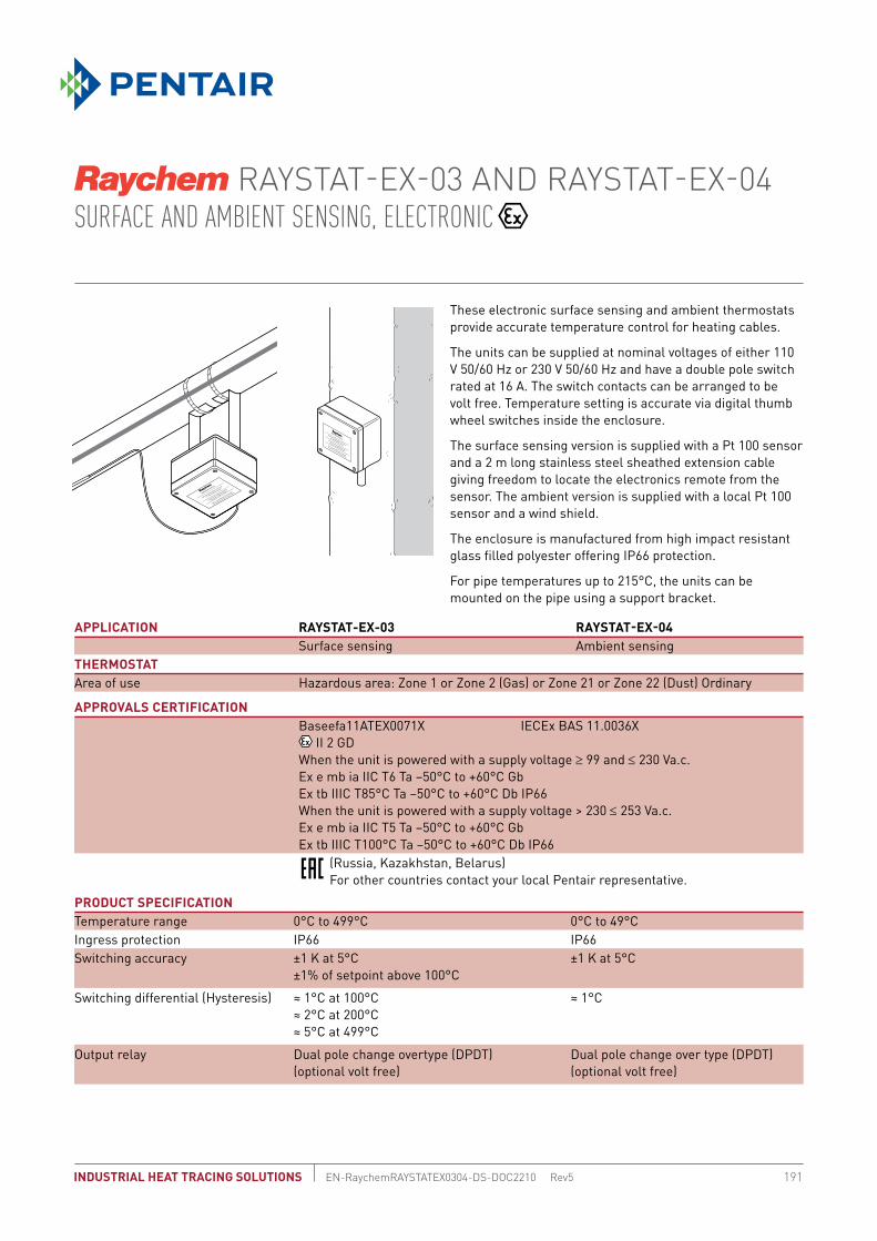
191EN-RaychemRAYSTATEX0304-DS-DOC2210 Rev5
RAYSTAT-EX-03 AND RAYSTAT-EX-04 SURFACE AND AMBIENT SENSING, ELECTRONIC
INDUSTRIAL HEAT TRACING SOLUTIONS
These electronic surface sensing and ambient thermostats provide accurate temperature control for heating cables.
The units can be supplied at nominal voltages of either 110 V 50/60 Hz or 230 V 50/60 Hz and have a double pole switch rated at 16 A. The switch contacts can be arranged to be volt free. Temperature setting is accurate via digital thumb wheel switches inside the enclosure.
The surface sensing version is supplied with a Pt 100 sensor and a 2 m long stainless steel sheathed extension cable giving freedom to locate the electronics remote from the sensor. The ambient version is supplied with a local Pt 100 sensor and a wind shield.
The enclosure is manufactured from high impact resistant glass filled polyester offering IP66 protection.
For pipe temperatures up to 215°C, the units can be mounted on the pipe using a support bracket.
APPLICATION RAYSTAT-EX-03 RAYSTAT-EX-04Surface sensing Ambient sensing
THERMOSTATArea of use Hazardous area: Zone 1 or Zone 2 (Gas) or Zone 21 or Zone 22 (Dust) Ordinary
APPROVALS CERTIFICATIONBaseefa11ATEX0071X IECEx BAS 11.0036X
II 2 GDWhen the unit is powered with a supply voltage ≥ 99 and ≤ 230 Va.c. Ex e mb ia IIC T6 Ta –50°C to +60°C GbEx tb IIIC T85°C Ta –50°C to +60°C Db IP66When the unit is powered with a supply voltage > 230 ≤ 253 Va.c. Ex e mb ia IIC T5 Ta –50°C to +60°C GbEx tb IIIC T100°C Ta –50°C to +60°C Db IP66
PRODUCT SPECIFICATIONTemperature range 0°C to 499°C 0°C to 49°CIngress protection IP66 IP66Switching accuracy ±1 K at 5°C
±1% of setpoint above 100°C±1 K at 5°C
Switching differential (Hysteresis) ≈ 1°C at 100°C≈ 2°C at 200°C≈ 5°C at 499°C
≈ 1°C
Output relay Dual pole change overtype (DPDT)(optional volt free)
Dual pole change over type (DPDT)(optional volt free)
(Russia, Kazakhstan, Belarus) For other countries contact your local Pentair representative.

RAYSTAT-EX-03 AND RAYSTAT-EX-04
EN-RaychemRAYSTATEX0304-DS-DOC2210 Rev5192 INDUSTRIAL HEAT TRACING SOLUTIONS
PRODUCT SPECIFICATION (continued)Switching capacity 16 A 110 Vac ±10% 50/60 Hz
16 A 230/253 Vac ±10% 50/60 Hzresistive load
16 A 110 Vac ±10% 50/60 Hz16 A 230/253 Vac ±10% 50/60 Hzresistive load
Ambient temperature range –50°C to +60°C –50°C to +60°CSupply voltage 110 Vac ±10% 50/60 Hz
230/253 Vac ±10% 50/60 Hz110 Vac ±10% 50/60 Hz230/253 Vac ±10% 50/60 Hz
Internal power consumption 110 Vac ~ 4 VA, 230/253 Vac ~ 3 VATerminal size max. 4 mm2 max. 4 mm2
DIMENSIONS (IN MM) RAYSTAT-EX-03 RAYSTAT-EX-04
TYPICAL WIRING DIAGRAM FOR DIRECT SWITCHING
Cable entries 2 x M20 glands (cable ∅ 7.5 – 13 mm)1 x M25 with M25(M)/M20(F) adaptor and (M20) plug
2 x M20 glands (cable ∅ 7.5 – 13 mm) 1 x M25 with M25(M)/M20(F) adaptor and (M20) plug
Sensor 2 wire Pt 100, stainless steel sensor, 2 m long 2 wire Pt 100, stainless steel sensor, complete with wind shield
MOUNTING METHODRaychem support bracket SB-100 or SB-101, SB125 or surface mounting with 4 fixing holes on 110x140 mm centres
Raychem support bracket SB-100 or SB-101, SB125 or surface mounting with 4 fixing holes on 110x140 mm centres
ORDERING DETAILSPart Description RAYSTAT-EX-03 RAYSTAT-EX-04PN (Weight) 333472-000 (3.0 kg) 462834-000 (3.1 kg)
160
90
160
3
110
140
160
140
110
523
90
160 110
0
160
90
160
3
110
140
160
140
110
523
90
160 110
0
Heating system
Sensor
* Circuit breaker configurations may vary according to local standards/requirements
** Link 1-8 and/or 3-5 can be removed to provide potential-free contacts
*** Terminal 2: 110 Vac input terminal
*
230 V / 50 HzNPE
L1
max.16 A/C
1 2 3 126 98754
RAYST AT-EX-03/04
Pt 100
NO C NC CNO
1 2 3 126 98754
RAYST AT-EX-03/04
Pt 100
NO C NC CNO
N
PE
L1
max.16 A/C
400 V / 50 HzL2L3
*
**
***
***
NC
*
Sensor
Sensor
**

ETS-05
193INDUSTRIAL HEAT TRACING SOLUTIONS EN-RaychemETS05-DS-DOC2210 Rev2
SURFACE SENSING ELECTRONIC THERMOSTAT
PRODUCT OVERVIEW
The Raychem ETS-05 electronic surface sensing thermostat provides accurate temperature control for heating cables.The ETS-05 is available in two versions. The ETS-05-L2-E is for temperatures up to 199°C, while the ETS-05-H2-E can be used for temperatures up to 499°C. The maximum nominal load is 32 A for both thermostats. Temperature setting is accurate via digital rotary switches inside the enclosure.
The ETS-05 has a LED indicator which indicates the status of the thermostat (powered on/off), the status of the heat-tracing cable (powered on/off) and the status of the sensor. In case of sensor failure the thermostat can switch to an on or off state, depending upon the users requirement.
PRODUCT CHARACTERISTICS
ETS-05-L2-E ETS-05-H2-EApplication Surface sensing Surface sensingArea of use Hazardous area: Zone 1 or Zone 2 (Gas) or Zone 21 or Zone 22 (Dust) Ordinary
APPROVALS CERTIFICATION
Raychem – ETS-05 Electronic Thermostat II 2(1)G II 2D Ex e ia mb (Ga) IIC T5 Gb Ex tb IIIC T100°C Db Ta–40 to +60°C Supply = 99-121V (ETS-05-x1-x) or 195-230V (ETS-05-x2-x) Maximum switched current 32A Resistive IECEx BAS 13.0071 Baseefa13ATEX0137 Um=253V Max. Current = 0.5A Prospective short circuit current 1500A
PRODUCT SPECIFICATION
Temperature setpoint range 0°C to 199°C 0°C to 499°C
Temperature measurement range –55°C to 260°C –55°C to 585°C
Maximum sensor lead resistance 20 Ohm 20 Ohm
Ingress protection IP66 IP66
Switching accuracy ±1 K at 5°C ±1 K at 5°C, 2°C at 499°C
Switching differential (Hysteresis) ≈ 3°C ≈ 3°C
Output relay Single Pole change over type (SPST) Single Pole change over type (SPST)
Switching capacity 32 A resistive load 32 A resistive load
Ambient temperature range –40°C to + 60°C –40°C to + 60°C
Supply voltage 230 V +10% / -15% 50/60 Hz 230 V +10% / –15% 50/60 Hz
Internal power consumption 3 VA 3 VA
Terminal size max. 6 mm2 max. 6 mm2
Cable entries 2 x M25: 1 x M25 gland for power cable in 1 x M25 rain plug for heating cable out
2 x M25: 1 x M25 gland for power cable in 1 x M25 rain plug for heating cable out
Sensor M16 gland with 3 wire PT100 flexible sensor, 2 m long
M16 gland with 3 wire PT100, stainless steel sensor, 2 m long,
(Russia, Kazakhstan, Belarus) For other countries contact your local Pentair representative.

ETS-05
INDUSTRIAL HEAT TRACING SOLUTIONSEN-RaychemETS05-DS-DOC2210 Rev2194
LED STATUS INDICATIONS
Green: ETS-05 powered on, heat-tracing cable off
Green: ETS-05 powered on, heat-tracing cable off
Yellow: ETS-05 powered on, heat-tracing cable on
Yellow: ETS-05 powered on, heat-tracing cable on
Red flashing: Sensor failure - controller in fail safe mode
Red flashing: Sensor failure - controller in fail safe mode
DIMENSIONS (IN MM)
12345678
90 12340123
400 1 0 1
Power Terminals
1
Line Out
2
NeutralOut
3
NeutralSupply
4
230V Supply
5
Earth
6
Earth
7
Earth
Terminals 2 and 3 are joined electricallyTerminals 5, 6 and 7 are joined electrically
Sensor/Failure Mode Select Terminals
4321
Link 3-4 removed = Output OFFLink 3-4 fitted = Output ON
Terminals 1 to 3 allow for the connection of a three wire PT100 sensor.
Terminals 3 to 4 allow the user to select the default heating status on sensor error.Without a link fitted the heating will turn OFF if a sensor error is detected (default)With a link fitted the heating will turn ON if a sensor error is detected

ETS-05
195INDUSTRIAL HEAT TRACING SOLUTIONS EN-RaychemETS05-DS-DOC2210 Rev2
TYPICAL WIRING DIAGRAM FOR DIRECT SWITCHING
MOUNTING METHOD
Support bracket SB-100, SB-101, SB-110, SB-111, SB-130 or surface mounting with 4 fixing holes on 106 x 82 mm centres
Support bracket SB-100, or SB-101, SB-110, SB-111, SB-130 or surface mounting with 4 fixing holes on 106 x 82 mm centres
ORDERING DETAILS
Product Name ETS-05-L2-E ETS-05-H2-E
Part number 1244-014367 1244-014368
* Circuit breaker configurations may vary according to local standards/requirements
PE 1 2 3PE PE
PE
L1out
Fail-Safeoption
32 AMP
30 mA
MAX *
ETS-05
in 4
Link 3-4 removed = Output OFFLink 3-4 fitted = Output ON

AT-TS-13 AND AT-TS-14SURFACE SENSING THERMOSTAT, ELECTRONIC
EN-RaychemATTS13ATTS14-DS-DOC2210 Rev4196 INDUSTRIAL HEAT TRACING SOLUTIONS
AT-TS thermostats provide temperature control in safe area. The temperature set point can be checked through a window in the lid. LED´s are providing an indication when cables are energized (Heating ON) or when the temperature sensor is defect (sensor break or sensor short-circuit).The temperature sensor has a length of 3 meter and can be shortened for ambient sensing operating. Direct connection of the heating cable is possible. Connection kits need to be ordered separately. The thermostat is available in 2 temperature ranges.
6030
090
120
C°
GENERAL AT-TS-13 AT-TS-14Area of use Ordinary area, outdoors Ordinary area, outdoorsSupply voltage 230 Vac +10% –15% 50/60 Hz 230 Vac +10% –15% 50/60 HzMax. switching current 16 A, 250 Vac 16 A, 250 VacMax. conductor size 2.5 mm2 2.5 mm2
Switching differential 0.6 K to 1 K 0.6 K to 1 KSwitching accuracy ± 1 K at 5°C (calibration point) 2 K at 60°C (calibration point)Switch type SPST (normally open) SPST (normally open)Adjustable temperature range –5°C to +15°C 0°C to +120°C
HOUSINGTemperature setting inside insideExposure temperature –20°C to +50°C –20°C to +50°CIngress protection IP65 according to EN 60529 IP65 according to EN 60529Entries 1 x M20 for supply cable (∅ 8-13 mm)
1 x M25 for heating element (∅ 11-17 mm) 1 x M16 for the sensor
1 x M20 for supply cable (∅ 8-13 mm) 1 x M25 for heating element (∅ 11-17 mm) 1 x M16 for the sensor
Material ABS ABSLid fixing nickel-plated quick release screws nickel-plated quick release screwsMounting SB-110 and SB-111 or surface mount SB-110 and SB-111 or surface mount
APPROVALS(Russia, Kazakhstan, Belarus) For other countries contact your local Pentair representative.

AT-TS-13 AND AT-TS-14
197EN-RaychemATTS13ATTS14-DS-DOC2210 Rev4INDUSTRIAL HEAT TRACING SOLUTIONS
DIMENSIONS (IN MM)
A Green LED Heating cable onB Red LED Sensor breakC Red LED Sensor short-circuit
TEMPERATURE SENSOR AT-TS-13 AT-TS-14 Type PTC KTY 83-110 PTC KTY 83-110Length sensor cable 3 m 3 mDiameter sensor cable 5.5 mm 5.5 mmDiameter sensor head 6.5 mm 6.5 mmSensor material PVC SiliconeMax. exposure temperature sensor cable 80°C 160°C
The sensor cable may be extended to a maximum of 100 m using a 2-conductor wire with a cross-section of 1.5 mm2. The sensor cable should be shielded if it is laid in cable ducts or in the vicinity of high-voltage carrying cables. The shield of the extension cable should be grounded at the controller end only.
OUTPUT PARAMETERSAlarm on LED Green LED: Heating Cable ON
Red LED: Sensor break Red Led: Sensor short-circuit
Green LED: Heating Cable ON Red LED: Sensor break Red Led: Sensor short-circuit
ORDERING DETAILSPart description AT-TS-13 AT-TS-14PN (Weight) 728129-000 (0.44 kg) 648945-000 (0.44 kg)
ACCESSORIESPA Reducer Reducer M25 (M)/M20 (F) Reducer M25 (M)/M20 (F)PN 184856-000 184856-000Spare temperature sensor HARD-69 HARD-69(AT-TS-13 and AT-TS-14) (Max. exposure temperature 160°C)PN (Weight) 133571-000 (180 g) 133571-000 (180 g)

AT-TS-13 AND AT-TS-14
EN-RaychemATTS13ATTS14-DS-DOC2210 Rev4198 INDUSTRIAL HEAT TRACING SOLUTIONS
WIRING DIAGRAM FOR THERMOSTAT
AT-TS-13 or AT-TS-14
1 2
4986
53
max.C 16A
Heating systemTemperature
sensor
Heating systemTemperature
sensor
AT-TS-13/14 with contactor
* Two- or four-pole electrical protection by circuit-breaker may be needed for local circumstances, standards and regulations
** Depending on the application, one- or three-pole circuit-breakers or contactors may be used*** Optional: Potential-free circuit-breaker for connection to the BMS

RAYSTAT-EC0-10 AMBIENT SENSING ENERGY SAVING FROST PROTECTION CONTROLLER
199EN-RaychemRAYSTATECO10-DS-DOC2210 Rev4INDUSTRIAL HEAT TRACING SOLUTIONS
The RAYSTAT-ECO-10 temperature controller is designed to control heating cables used for frost protection applications. It continuously adjusts the heat-tracing output based on the ambient temperature. Using a proprietary algorithm, the RAYSTAT-ECO-10 controller measures ambient temperature and determines the appropriate cycle time during which the heating cables will be energised.
Since ambient temperatures in winter are often below freezing point, but well above the minimum designed ambient temperature, significant energy savings are realised. Parameters are displayed and can be set easily. The controller includes a 25 A relay which allows direct switching of the heating circuit. The enclosure can easily be installed outdoors. The unit includes a Pt 100 sensor for determining ambient temperature in ordinary area.
The RAYSTAT-ECO-10 controller is designed to provide trouble-free, long term operation. In addition to the display, the controller includes an alarm relay that switches either upon low supply voltage, upon output fault or upon RTD failure thus allowing remote indication of system status.
GENERALArea of use Ordinary area, outdoorsAmbient operating temperature range –20°C to +40°CSupply voltage (nominal) 230 V +10% –10%, 50/60 HzInternal power consumption ≤ 14 VA
ENCLOSUREProtection IP65Base and lid Grey polycarbonate base
Transparent lidLid fixing 4 captive screws Entries 2 x M25, 1 x M20, 1 x M16
Direct entry of heating cable into unit with M25 connection kitGland plug 1 x M20
APPROVALS(Russia, Kazakhstan, Belarus) For other countries contact your local Pentair representative.

RAYSTAT-EC0-10
EN-RaychemRAYSTATECO10-DS-DOC2210 Rev4200 INDUSTRIAL HEAT TRACING SOLUTIONS
DIMENSIONS (IN MM)
10888
160
148
120
Ø 4
.4
4.530
3.5
90
% ON
–15 –10 -5 0 5 10
100806040200
% ONAmbient temperature
TEMPERATURE SENSORType 3-wire Pt 100 according to IEC Class BArea of use Ordinary areaSensor can be extended with a 3-wire shielded cable of max. 20 Ω per conductor (max. 150 m with a 3 x 1.5 mm2 cable).The sensor cable should be shielded if it is laid in cable ducts or in the vicinity of high-voltage carrying cables. The shield of the extension cable should be grounded at the controller end only.
OUTPUT RELAYSControl relay Single pole single throw relay, rating: 25 A at 250 Vac Alarm relay Single pole double throw relay, rating: 2 A at 250 Vac, voltfree
PARAMETER SETTINGSMaintain temperature set point 0°C to + 30°C (heating 0% powered)Minimum ambient temperature –30°C to 0°C (heating 100% powered)Heater Operation if Sensor Error ON (100%) or OFF, user defined ON or OFFVoltage Free Operation YES or NOParameters can be programmed without power supply (internal battery) and parameters are stored in non-volatile memory.
ENERGY SAVING WITH PROPORTIONAL AMBIENT SENSING CONTROL (PASC)Duty cycle (power to heater ON) depends on the ambient temperature. For example: If minimum temperature= –15°C and if maintain temperature (set point)= +5°C
AMBIENT T° % ON–15 100 Min. Ambient–10 75
–5 500 255 0 Set point
Result: At ambient temperature of –5°C, 50% energy is saved
DIAGNOSED ALARMSSensor errors Sensor short/Sensor open circuitLow temperature Min. expected ambient temperature reachedVoltage errors Low supply voltage/Output voltage fault

RAYSTAT-EC0-10
201EN-RaychemRAYSTATECO10-DS-DOC2210 Rev4INDUSTRIAL HEAT TRACING SOLUTIONS
Heating cable
Normal operation
Temp. Pt 100 sensor
30 mARAYSTAT-CONTROL/ECO-10
alarm2 A max.
Max. C 25 A
VOLTAGE FREE OPERATION: REMOVE LINKS W1 AND W2
30 mA
RAYSTAT-CONTROL/ECO-10
alarm2 A max.
2 A
Heating cableTemp. Pt 100 sensor
* Electrical protection by circuit-breaker may be needed for local circumstances, standards and regulations.
** Depending on the application, one- or three-pole circuit-breakers or contactors may be used.
*** Optional
A
B
1.
2.3.
4.
DISPLAY LAYOUT
A. LED Display (parameter and error indications)B. Push buttons 1. Battery activation 2. Parameter selection 3. Increase value 4. Decrease value
CONNECTION DETAILS

RAYSTAT-EC0-10
EN-RaychemRAYSTATECO10-DS-DOC2210 Rev4202 INDUSTRIAL HEAT TRACING SOLUTIONS
CONNECTION TERMINALSSupply 3 terminals for 0.75 mm2 to 4 mm2
Pt 100 connection 4 terminals for 0.75 mm2 to 2.5 mm2
Control relay connection 3 terminals for 0.75 mm2 to 4 mm2
Alarm relay connection 3 terminals for 0.75 mm2 to 2.5 mm2
MOUNTING METHOD Surface mounting with 4 fixing holes on 148 x 108 mm centres, M4 clearance
Support bracket SB-100, SB-101 (SB-110 or SB-111)
ORDERING DETAILSPart description RAYSTAT-ECO-10PN (Weight) 145232-000 (0.8 kg)
ACCESSORIES PA Reducer Reducer M25 (M)/M20 (F)PN 184856-000

RAYSTAT-CONTROL-10 SURFACE SENSING PROGRAMMABLE THERMOSTAT WITH ALARM RELAY
EN-RaychemRAYSTATCONTROL10-DS-DOC2210 Rev4INDUSTRIAL HEAT TRACING SOLUTIONS 203
The RAYSTAT-CONTROL-10 surface sensing thermostat is designed to provide user friendly measurement and control for heating cables. The thermostat has a 25 A control relay (that can be arranged to be volt free) and a 2 A volt free SPDT alarm relay.
Parameter and eventual alarm conditions are shown on the digital display and settings can be programmed easily, even without power supply.
The RAYSTAT-CONTROL-10 thermostat is supplied with a Pt100 sensor. This sensor has a 3 m long silicone extension cable giving freedom to locate the electronics remote from the sensor.
Two M25 entries allow for the power cable and heating cable to be connected directly into the unit. The units can be mounted on the pipe using the SB-100 or SB-101 support bracket.
RAYSTAT-CONTROL-10
GENERALApplication Surface sensingArea of use Ordinary area (indoors, outdoors)
Sensing in zone 1 or zone 2 possible with MONI-PT100-EXE (seperately available)Ambient operating temperature range –20°C to +40°CSupply voltage (nominal) 230 V +10% –10%, 50/60 HzInternal power consumption ≤ 14 VA
ENCLOSUREIP65
Base and lid Grey polycarbonate base Transparent lid
Lid fixing 4 captive screws Entries 2 x M25, 1 x M20, 1 x M16
Direct entry of heating cable into unit with M25 connection kitGland plug 1 x M20
APPROVALS(Russia, Kazakhstan, Belarus) For other countries contact your local Pentair representative.

RAYSTAT-CONTROL-10
EN-RaychemRAYSTATCONTROL10-DS-DOC2210 Rev4204 INDUSTRIAL HEAT TRACING SOLUTIONS
DIMENSIONS (IN MM)
10888
160
148
120
Ø 4
.4
4.530
3.5
90
A
B
1.
2.3.
4.
TEMPERATURE SENSORType 3-wire Pt 100 according to IEC Class BMaximum exposure temperature 200°CArea of use Ordinary area Sensor can be extended with a 3-wire shielded cable of max. 20 Ω per conductor (max. 150 m with a 3 x 1.5 mm2 cable).Sensing in hazardous area zone 1 or zone 2 can be done with MONI-PT100-EXE.The sensor cable should be shielded if it is laid in cable ducts or in the vicinity of high-voltage carrying cables. The shield of the extension cable should be grounded at the controller end only.
OUTPUT RELAYSControl relay Single pole single throw relay, rating: 25 A at 250 Vac Alarm relay Single pole double throw relay, rating: 2 A at 250 Vac, voltfree
PROGRAMMABLE PARAMETER SETTINGSTemperature setting 0°C to +150°CHysteresis 1 K to 5 KLow Temperature Alarm –40°C to +148°CHigh Temperature Alarm +2°C to +150°C or switched OFFHeater Operation if Sensor Error ON or OFFVolt Free Operation YES or NOParameters can be programmed without power supply (internal battery) and parameters are stored in non-volatile memory.
DIAGNOSED ALARMSSensor errors Sensor short/Sensor open circuitLow temperature High temperature/Low temperatureVoltage errors Low supply voltage/Output voltage fault
DISPLAY LAYOUT
A. LED Display (parameter and error indications)B. Push buttons 1. Battery activation 2. Parameter selection 3. Increase value 4. Decrease value

RAYSTAT-CONTROL-10
205EN-RaychemRAYSTATCONTROL10-DS-DOC2210 Rev4INDUSTRIAL HEAT TRACING SOLUTIONS
Heating cable
Normal operation
Temp. Pt 100 sensor
30 mARAYSTAT-CONTROL/ECO-10
alarm2 A max.
Max. C 25 A
VOLTAGE FREE OPERATION: REMOVE LINKS W1 AND W2
CONNECTION DETAILS
30 mA
RAYSTAT-CONTROL/ECO-10
alarm2 A max.
2 A
Heating cableTemp. Pt 100 sensor
* Electrical protection by circuit-breaker may be needed for local circumstances, standards and regulations.
** Depending on the application, one- or three-pole circuit-breakers or contactors may be used.
*** Optional
CONNECTION TERMINALSSupply 3 terminals for 0.75 mm2 to 4 mm2
Pt 100 connection 4 terminals for 0.75 mm2 to 2.5 mm2
Control relay connection 3 terminals for 0.75 mm2 to 4 mm2
Alarm relay connection 3 terminals for 0.75 mm2 to 2.5 mm2
MOUNTING METHOD Surface mounting with 4 fixing holes on 148 x 108 mm centres, M4 clearance
Support bracket SB-100, SB-101
ORDERING DETAILSPart description RAYSTAT-CONTROL-10
PN (Weight) 828810-000 0.8 kg)
ACCESSORIES PA Reducer Reducer M25 (M)/M20 (F)PN 184856-000

T-M-10-S/+X+YSURFACE SENSING THERMOSTAT
EN-RaychemTM10SXY-DS-DOC2210 Rev3206 INDUSTRIAL HEAT TRACING SOLUTIONS
A surface sensing thermostat providing temperature control in safe areas.
Temperature set point adjustment can be completed, without opening the enclosure, via a removable plug in the lid. The 2 meter long stainless steel capillary is protected at the enclosure by a flexible conduit.
Direct connection of the heating cable is possible.
The thermostat is available in 3 temperature ranges: 0–50°C; 0–200°C; 50–300°C.
GENERAL T-M-10-S/+0+50C T-M-10-S/0+200C T-M-10-S/+50+300CArea of use Ordinary area Ordinary area Ordinary area
PRODUCT SPECIFICATIONMax rated voltage (nom) 230 Vac 230 Vac 230 Vac Temperature setting 0°C to +50°C 0°C to +200°C +50°C to +300°C Switching type Single pole change over
(SPDT) 100,000 cycles at 16 A Single pole change over (SPDT) 100,000 cycles at 16 A
Single pole change over (SPDT) 100,000 cycles at 16 A
Switching capacity Max 16 A Max 16 A Max 16 A Hysteresis/Differential 2.5% of temperature range 2.5% of temperature range 2.5%of temperature range Accuracy ±1.5% of setpoint for temperature setting in upper third of range (measured at 22°C) Setting Internal dial, through lid Internal dial, through lid Internal dial, through lid Terminal size 4 mm2 4 mm2 4 mm2
Ambient operating temp. range –20°C to +80°C –20°C to +80°C –20°C to +80°C
OUTPUT PARAMETERSControl relay Change-over switch Change-over switch Change-over switch

T-M-10-S/+X+Y
207EN-RaychemTM10SXY-DS-DOC2210 Rev3INDUSTRIAL HEAT TRACING SOLUTIONS
DIMENSIONS (IN MM)
122
106 90
82 120
ENCLOSURE T-M-10-S/0+50C T-M-10-S/0+200C T-M-10-S/+50+300C Protection IP65 IP65 IP65Dimension 122 x 120 x 90 mm 122 x 120 x 90 mm 122 x 120 x 90 mm Materials body and lid Grey, polyester enclosure Lid fixing 4 captive screws, stainless steel Entries 2 entries:
1 x M25 Reducer M25 (M)/M20 (F) incl. M20 gland (∅ 8-13 mm) 1 x M20 gland (∅ 8-13 mm)
TEMPERATURE SENSORType Fluid filled capillary, 2 m longDimensions ∅ 8 mm 8 mm 8 mm
Length sensing element
166 mm 78 mm 56 mm
Material V4A Stainless SteelExposure temperature –40°C to +60°C –20°C to +230°C –20°C to +345°C Minimum bending radius 10 mm for capillary, the sensor cannot be bent
MOUNTING METHODSupport bracket SB-110 or SB-111 or
surface mountSB-110 or SB-111 or surface mount
SB-110 or SB-111 or surface mount

T-M-10-S/+X+Y
EN-RaychemTM10SXY-DS-DOC2210 Rev3208 INDUSTRIAL HEAT TRACING SOLUTIONS
Heating system
MaxC16A
30 mA
LN
PE
21 3 4 5
ORDERING DETAILS
Ordering references PN Number WeightT-M-10-S/0+50C 105336-000 1 kgT-M-10-S/0+200C 337388-000 1 kgT-M-10-S/+50+300C 607672-000 1 kg
MEANING OF REFERENCE: T-M-10-S/+X+YT = thermostat M = mechanical thermostat10 = control thermostatS = surface sensing x = min temperature of control range y = max temperature of control range
CONNECTION DETAILS

T-M-20-S/+X+Y/EX SURFACE SENSING THERMOSTAT WITH SAFETY LIMITER FOR HAZARDOUS AREA
EN-RaychemTM20SXYEX-DS-DOC2210 Rev5INDUSTRIAL HEAT TRACING SOLUTIONS 209
GENERAL T-M-20-s/+0+120C/EX T-M-20-S/+0+200C/EX T-M-20-S/+50+300C/EX
Area of use Hazardous area: Zone 1 or Zone 2 (Gas) or Zone 21 or Zone 22 (Dust)Ordinary
APPROVAL CERTIFICATION
EPS 13 ATEX 1 510 II 2G Ex d e IIC T4/T5/T6 Gb II 2D Ex tb IIIC T85°C /T100°C/T130°C Db
EPS 13 ATEX 1 510 II 2G Ex d e IIC T4/T5/T6 Gb II 2D Ex tb IIIC T85°C /T100°C/T130°C Db
EPS 13 ATEX 1 510 II 2G Ex d e IIC T4/T5/T6 Gb II 2D Ex tb IIIC T85°C
/T100°C/T130°C Db
(Russia, Kazakhstan, Belarus) For other countries contact your local Pentair representative.
PRODUCT SPECIFICATIONTemperature setting
Controller +0°C to +120°C +0°C to +200°C +50°C to +300°CLimiter +0°C to +120°C +50°C to +300°C +50°C to +300°C
Switching type
Single pole change over (SPDT) >100.000 cycles at I nom
Single pole change over (SPDT) >100.000 cycles at I nom
Single pole change over (SPDT) >100.000 cycles at I nom
Switching capacity
Maximum 16A at 400 Vac, resistive load
Maximum 16A at 400 Vac, resistive load
Maximum 16A at 400 Vac, resistive load
Hysteresis/Differential
Controller max. 2.5% range, calibrated downwards
max. 2.5% range, calibrated downwards
max. 2.5% range, calibrated downwards
Limiter max 7% calibrated upwards max. 7.5%, calibrated upwards max. 7.5%, calibrated upwardsSetting Inside enclosure Inside enclosure Inside enclosureReset limiter Inside enclosure by means of a screwdriverTerminal size 4 mm2 4 mm2 4 mm2
Terminal type spring-type terminals spring-type terminals spring-type terminals Ambient operating temp. range
–40°C to +70°C –40°C to +70°C –40°C to +70°C
A surface sensing thermostat providing temperature control and temperature limit in hazardous areas.
The safety limiter prevents the heating system exceeding a preset maximum temperature should the control function fail to operate or an unsafe process temperature occur. The maximum rated voltage is 400 VAC. The switching current capacity is 16 A maximum via independent Ex d single pole change over micro switches with volt-free contacts.
The switches are mounted within an Ex e enclosure together with a spring-type terminal block for fast easy connection. The sensors are 3 meter long stainless steel fluid filled bulb and capillary.
The thermostat is delivered with Ex approved power cable glands and plugs and the entries offer the possibility for a variety of connections such as connecting M25 and M20 glands for direct heating cable entry or alarm output.
The thermostat with limiter is available in 3 temperature ranges: +0°C +120°C, +0°C +200°C and +50°C +300°C

T-M-20-S/+X+Y/EX
EN-RaychemTM20SXYEX-DS-DOC2210 Rev5210 INDUSTRIAL HEAT TRACING SOLUTIONS
OUTPUT PARAMETERS T-M-20-s/+0+120C/EX T-M-20-S/+0+200C/EX T-M-20-S/+50+300C/EXControl relay Change-over switch Change-over switch Change-over switch Limiter relay Change-over switch with possibility for external alarm
Capillary leakage detection system
ENCLOSUREProtection IP65 IP65 IP65 Dimension 220 x 120 x 90 mm 220 x 120 x 90 mm 220 x 120 x 90 mm Materials body and lid Black, glass filled polyester
enclosureBlack, glass filled polyester enclosure
Black, glass filled polyester enclosure
Lid fixing 4 captive screws, stainless steel
4 captive screws, stainless steel
4 captive screws, stainless steel
Entries 6 entries: 1 x M25 gland (∅ 8-17 mm): power supply
1 x M25 stopping plug: output to heating cables
2 x M20 stopping plug: output to heating cables (possibility to connect single conductor heating element)
2 x M20: capillary sensors
TEMPERATURE SENSORType Fluid filled capillary,
3 m longFluid filled capillary, 2 m long
Fluid filled capillary, 2 m long
Dimensions Controller ∅ 6 mm; length sensing element = 90 mm
∅ 6 mm; length sensing element = 72 mm
∅ 4 mm; length sensing element = 135 mm
Limiter ∅ 6 mm; length sensing element = 58 mm
∅ 4 mm; length sensing element = 78 mm
∅ 4 mm; length sensing element = 78 mm
Material stainless steel stainless steelTemperature exposure
Controller –40°C +138°C –40°C +230°C –40°C +345°CLimiter –40°C +138°C –40°C +345°C –40°C +345°C
Minimum bending radius 5 mm for capillary (not for sensor) 5 mm for capillary (not for sensor) 5 mm for capillary (not for sensor)
MOUNTING METHODSupport bracket SB-120, SB-125 or surface mounting via 4 fixing holes at 204 x 82 centresPN SB-120 165886-000
SB-125 1244-00603
DIMENSIONS (IN MM)

T-M-20-S/+X+Y/EX
211EN-RaychemTM20SXYEX-DS-DOC2210 Rev5INDUSTRIAL HEAT TRACING SOLUTIONS
2A
= upward adjustment
= download adjustment
Controller
NPE
HeatingSystem
Limiter fault signalMains voltageCaution: not floating contact
N L1 2
22 4 4
11
4 11 12 14
TWSTB
Limiter
ORDERING DETAILS
Ordering references: PN Number WeightT-M-20-S/+0+200C/EX 1244-013410 2 kgT-M-20-S/+50+300C/EX 1244-013411 2 kgT-M-20-S/+0+120C/EX 1244-016536 2 kg
MEANING OF REFERENCE: T-M-20-S/+X+Y/EX T = thermostatM = mechanical thermostat 20 = control thermostat + limiterS = surface sensing x = min temperature of control range y = max temperature of control range Ex = hazardous area
CONNECTION DETAILS

T-M-20-S/+X+YSURFACE SENSING THERMOSTAT WITH LIMITER
EN-RaychemTM20SXY-DS-DOC2210 Rev3212 INDUSTRIAL HEAT TRACING SOLUTIONS
A surface sensing thermostat providing temperature control and temperature limiter in safe areas. The high limit cut-out prevents the heating system exceeding a preset maximum temperature should the control function fail to operate or an unsafe process temperature occur.
Temperature set point adjustment and limiter reset can be completed, without opening the enclosure, via removable plugs in the lid.
Both 2 meter long stainless steel fluid filled bulb and capillary are protected at the enclosure by a flexible conduit.
Direct connection of the heating cable is possible. The thermostat is available in 3 temperature ranges. 0–50°C; 0–200°C; 50–300°C.
T
GENERAL T-M-20-S/0+50C T-M-20-S/0+200C T-M-20-S/+50+300CArea of use Ordinary area Ordinary area Ordinary area
PRODUCT SPECIFICATIONMax rated voltage (nom) 230 Vac 230 Vac 230 VacTemperature setting Controller 0°C to +50°C 0°C to +200°C +50°C to +300°C
Limiter +20°C to +150°C +130°C to +200°C +20°C to +400°CSwitching type Single pole change over (SPDT)
100,000 cycles at 16 A (controller) 500 cycles at 10 A (limiter)
Switching capacity Controller Max 16 A at 230 Vac Max 16 A at 230 Vac Max 16 A at 230 VacLimiter Max 10 A at 230 Vac Max 10 A at 230 Vac Max 10 A at 230 Vac
Breaking capacity Controller 3700 VA 3700 VA 3700 VALimiter 2300 VA 2300 VA 2300 VA
Hysteresis/Differential 2.5% of temperature range 2.5% of temperature range 2.5% of temperature rangeAccuracy ±0.5% of setpoint in upper third of temperature range (at 22°C ambient)Setting Internal dial, through lid Internal dial, through lid Internal dial, through lidTerminal size 4 mm2 4 mm2 4 mm2
Ambient operating temp. range –20°C to +80°C –20°C to +80°C –20°C to +80°C

T-M-20-S/+X+Y
213EN-RaychemTM20SXY-DS-DOC2210 Rev3INDUSTRIAL HEAT TRACING SOLUTIONS
DIMENSIONS (IN MM)
220
90204
82 120
OUTPUT PARAMETERS T-M-20-S/0+50C T-M-20-S/0+200C T-M-20-S/+50+300CControl relay Change-over switch (SPDT) Limiter relay Change-over switch with possibility for external alarm (SPDT)
ENCLOSUREProtection IP65 IP65 IP65Dimension 222 x 120 x 90 mm 222 x 120 x 90 mm 222 x 120 x 90 mmMaterials body and lid Grey,
polyester enclosureGrey, polyester enclosure
Grey, polyester enclosure
Lid fixing 4 captive screws, stainless steel
Entries 3 entries: 1 x M25 Reducer M25 (M)/M20 (F) incl. M20 gland (Ø 8–13 mm) 1 x M20 gland (∅ 8–13 mm) 1 x M20 gland (∅ 8–13 mm)
TEMPERATURE SENSORType Fluid filled capillary, 2 meter longDimensionsController ∅ 8 mm 8 mm 8 mm
Length sensing element 166 mm 78 mm 56 mmLimiter ∅ 6 mm 6 mm 6 mm
Length sensing element 80 mm 78 mm 176 mmMaterial V4A Stainless Steel V4A Stainless Steel V4A Stainless SteelExposure temperature
Controller –40°C to +60°C –20°C to +230°C –20°C to +345°CLimiter –40°C to +170°C –20°C to +230°C –40°C to +500°C
Minimum bending radius 10 mm for capillary, the sensor cannot be bent
MOUNTING METHODSupport bracket SB-120 or surface mount

T-M-20-S/+X+Y
EN-RaychemTM20SXY-DS-DOC2210 Rev3214 INDUSTRIAL HEAT TRACING SOLUTIONS
Heating system
ORDERING DETAILS
Ordering references PN Number WeightT-M-20-S/0+50C 260448-000 1.9 kgT-M-20-S/0+200C 750502-000 1.9 kgT-M-20-S/+50+300C 608706-000 1.9 kg
MEANING OF REFERENCE: T-M-20-S/+X+YT= thermostatM= mechanical thermostat20= control thermostat + limiter S= surface sensingx= min temperature of control rangey= max temperature of control range
CONNECTION DETAILS
T
MaxC16A
30 mA
LN
PE
21 3 4 5 76 8
2
1
4 2
1
4
Controller Limiter

TCONTROL-CONT-03 SINGLE-CIRCUIT ELECTRONIC CONTROLLER WITH DUAL DISPLAY
EN-RaychemTCONTROLCONT03-DS-DOC2210 Rev4INDUSTRIAL HEAT TRACING SOLUTIONS 215
The Raychem TCONTROL-CONT-03 family of electronic controllers provide accurate temperature control and centralized monitoring for individual heat-tracing circuits.
The compact panel mount TCONTROL-CONT-03 has two displays for indicating the process value and the set point. During programming these displays provide user guidance and visual aid to simplify commissioning.
Alternatively, the optional and easy to use Raychem TCONTROL-CONT-03/CONFIG software can be used for computer aided configuration.
Raychem TCONTROL-CONT-03 units are factory configured for ON/OFF control and are suitable for most heat-tracing applications. Other types of control algorithms can be configured by the user.
Different hardware configurations are available: Units with a relay output for controlling electro-mechanical relays or solid state relays and TCONTROL-CONT-03/MA units with an analog output for driving other types of actuators like thyristors. The health of the temperature input sensor is permanently monitored for failures. An alarm will appear in the event of sensor break or short circuit. In the event of a sensor failure the control output switches to a user defined state (ON or OFF)
SPECIFIC FEATURES:
• Time delayed controller activation after initial power up (this can be used to avoid peak demands during start-up)• Service counter included in order to count and eventually alarm on the number of relay operations.
GENERALApplication Raychem TCONTROL-CONT-03 units are panel mount controllers and are typically
used for providing tight temperature control of individual heat-tracing circuits.
Area of use Non hazardous area indoors (panel mount – through the panel)Approvals/Certification Electrical Safety to DIN EN 61010-1 over voltage category III, pollution degree 2
EMC DIN EN 61326, Class B to industrial requirements.
(Russia, Kazakhstan, Belarus) For other countries contact your local Pentair representative.
Memory data backup EEPROM based non-volatile memory. No loss of configuration data after power outage or long term shut down.
Display 2 piece of 7-segment LED display with status indication LED´s (yellow/green)Supported control modes ON/OFF, P, PI, PD or PID with auto-tuning are user selectableMeasuring accuracy Pt100 3-wire error ≤ 0.1%,
Pt100 2-wire error ≤ 0.4%Thermocouples (incl. cold junction) error ≤ 0.25%Voltage and current inputs error ≤ 0.1%

TCONTROL-CONT-03
EN-RaychemTCONTROLCONT03-DS-DOC2210 Rev4216 INDUSTRIAL HEAT TRACING SOLUTIONS
ELECTRICAL PROPERTIESSupply Voltage & own power consumption
110 Vac to 240 Vac –15/+10%, 48 to 63 Hz & ~15 VA
Electrical connections Via screw terminals on the back of the unit. Terminals are suitable for wires ranging from 1 to maximum 1.3 mm2 solid core or 1 mm2 stranded with cable shoe. Terminal strips are pluggable.
Supported output types (depending on model)
TCONTROL-TCONT-03: 3 relay outputs (SPST) + 1 logic output TCONTROL-CONT-03/MA: 2 relay outputs (SPST) + analog output TCONTROL-CONT-03/COM: 3 relay outputs (SPST) + 1 logic output + RS485 TCONTROL-CONT-03/COMA: 2 relay outputs (SPST) + analog output + RS485
INPUT OPTIONS (ALL TYPES)Temperature sensor inputs Pt 100, Pt 1000 RTD´s in 2- and 3 wire connection, KTY11-6 sensors
Thermocouple types: L, J, U, T, K, E, N, S
Electrical input signals 0/4 .. 20 mA or 0/2 .. 10 V (Ri = 100 Kohm)Temperature control range From –200 to + 2400°C depending on the type of temperature sensor used
OUTPUT OPTIONS AND OUTPUT RATINGS (DEPENDING ON TYPE)TCONTROL-CONT-03 TCONTROL-CONT-03/COM
Control and alarm relay contacts (SPST) are rated 3 A at 230 VAC. Expected lifetime: 350k operations at rated current or ~900K operations at 1 A Logic output 0 .. 12 V. Maximum current 20 mA
TCONTROL-CONT-03/MA TCONTROL-CONT-03/COMA
Control output, analog: 0/4 .. 20 mA Rload ≥ 500 Ohm Logic output 0 .. 12 V, maximum current 20 mA Alarm relay contacts (SPST) are rated 3 A at 230 VAC. Expected lifetime: 350k operations at rated current. 900k operations at 1 A
Communication options (*) RS-485, Modbus at 9600, 19200 or 38400 BPS. Maximum up to 32 devices per network. (*)Alarm options 2 independently configurable alarm relay outputs are provided. TCONTROL-CONT-03
units automatically alarm in case of sensor break or sensor short. On top of the input sensor driven alarms up to 8 different temperature triggered alarm functions can be defined. (see installation instructions for details)
(1) Connector for optional programming interface (2) Panel cut-out
Minimum spacing in between panel cut-outs
Horizontal spacing
Vertical spacing
TCONTROL-CONT-03 (all types)
Without Space for configuration
connector> 8 mm > 8 mm
With Space for configuration
connector> 8 mm > 65 mm
DIMENSIONS (IN MM)
(2)
48
48 44,5
44,5
90,5 548
48 44,5
44,5
90,5 5

TCONTROL-CONT-03
217EN-RaychemTCONTROLCONT03-DS-DOC2210 Rev4INDUSTRIAL HEAT TRACING SOLUTIONS
ENCLOSUREHousing type Plastic enclosure approved to IEC 61554 (ABS) Suitable for installation in electrical
distribution panels Environmental protection Front IP65, rear IP20 to DIN EN60529Max. operating temperature –5 to +55°CMax. storage temperature –40 to +70°CRelative humidity 90% maximum, no condensationInstallation position All positions allowed. (*) supported on TCONTROL-CONT-03/COMx units onl
CONNECTION DIAGRAM
12
(4)
(3)(2)
(1)
56
N(L–)L1(L+)
–13+14
–17+18
192021222324
(3)
(7)
99
0/4...20mA0/2...10V
0/12V
0/2...10 V
0/4...20 mA
RxD/T/Tx D–
+
–
+–
+
+
Output K1Relay 3 A/250 V
Output K4 (depending on model)TCONTROL-CONT-03, K4 = Relay output (SPST) rated 3 A/250 VTCONTROL-CONT-MA, K4 = Analog output 0/4 .. 20 mA or 0/2 ..10 V
Output K3Logic output 0/12 V or can be configured as digital input
RS-485 Communication interfaceSupported in TCONTROL-CONT-03/COM and TCONTROL-CONT-03/COMA only
Output K2Relay 3 A/250 V
Power supply 110 to 240 V AC
(~15 VA)
WIRING EXAMPLE
Ordering details Part description Product Number WeightControl units TCONTROL-TCONT-03 1244-006829 ~ 0.125 kg
TCONTROL-CONT-03/MA 1244-006830TCONTROL-CONT-03/COM 1244-006982TCONTROL-CONT-03/COMA 1244-006981
ACCESSORY SELECTION TABLEConfiguration and setup interface + software
TCONTROL-CONT-03/CONFIG 1244-006983 ~ 0.120 kg
ACCESSORY SELECTION TABLESensors for hazardous area MONI-PT100-EXE (1), (2) 967094-000
MONI-PT100-4/20MA 704058-000Sensor for non-hazardous area MONI-PT100-NH 140910-000Support bracket for temperature sensors
JB-SB-26 338265-000
Note 1: Sensor can be extended with a 3-wire shielded cable of max 30 Ohms per conductor (max. 150 m with a 1.5 mm2 cable). The sensor cable should be shielded if it is laid in cable ducts or in the vicinity of high-voltage carrying cables. The shield of the extension cable should be grounded at the controller end only.
Note 2: MONI-PT100-EXE temperature sensors can be directly connected to the TCONTROL-CONT-03 input terminals. There is no need to use current limiting devices such as zener barriers or isolators.
Note 3: Installed in ordinary area.

TCON-CSD/20 DIN RAIL MOUNTABLE ELECTRONIC THERMOSTAT WITH DISPLAY
EN-RaychemTCONCSD20-DS-DOC2210 Rev4218 INDUSTRIAL HEAT TRACING SOLUTIONS
The TCON-CSD/20 is a compact digital thermostat for simple ON/OFF temperature control. The temperature is measured through a temperature sensor and shown on a LCD display. The actual status of the output relay is signaled via a LED.
The instrument is commissioned and operated via three soft key push buttons on the unit’s front panel. Through its compact design and robust construction the TCON-CSD/20 allows for simple and space-saving installation.
Specific features:• Time-delayed controller activation after initial power up
(can be used to avoid peak demands on power during start-up)
• Parameter level can be protected by means of a secret code
• Adjustable switching differential.• Input sensors are permanently monitored for cable short
or breakage.
GENERALApplication Usable for all applications requiring tight temperature control for either line sensing or
ambient sensing control Area of use DIN rail mounting in panels or enclosures installed in non-hazardous area. Sensing
temperature in hazardous area Zone 1 is possible when used in conjunction with MONI-PT100-EXE or MONI-PT100-EXE-SENSOR (separately available)
Temperature control range –200°C to +500°C (accuracy 0.1%)Ambient operating temperature 0°C to +55°CStorage temperature –40°C to +70°CClimatic conditions ≤75% relative humidity, no condensationLED indicator The LED at the front of the unit lights up when the output relay is energized.
ENCLOSUREProtection IP 20 to EN 60529Material PolycarbonateInstallation On 35 x 7.5 mm DIN railInstallation position Any position allowedFlammability class UL 94 VO

TCON-CSD/20
219EN-RaychemTCONCSD20-DS-DOC2210 Rev4INDUSTRIAL HEAT TRACING SOLUTIONS
DIMENSIONS (IN MM)
Supply230 Vac +10/–15%
Measurement inputPt 100
Relay outputchangeover (floating)10 A/250 Vac
34,5
93,5 90 45
22,5
22,5
51,5 61,6
4
1 (common)
L1 (L+)N (L-)
2 NO3 NC
5
WIRING DIAGRAM
ELECTRICAL DATAPower supply & own power consumption
230 Vac +10/–15%, 48 – 63 Hz< 1 VA
Connection terminals Screw terminals for wires with a maximum cross-section of 2.5 mm2
Relay output 10 A rated changeover contact (SPDT)Contact lifetime A minimum lifetime of 150 K operations at 10 A/250 Vac 50 Hz resistive load.
TEMPERATURE SENSORPt100, Pt1000 or KTY2X-6 all connected in 2-wire circuit Sensor “open” and sensor “short” will be automatically detected and will cause the output to switch to the customer programmed default either permanently ON or OFF When using 2-wire temperature sensors there will be an error on the temperature readout of approximately 1°C per 0.39 Ohm lead resistance added.TCON-CSD/20 units are equipped with an option to compensate for the cable resistance added in order to improve the accuracy. Refer to the installation instructions for more details. When the sensor cable is laid in cable ducts or in the vicinity of high voltage carrying cables the sensor extension cable should be shielded. The shield of the extension cable should be grounded at the controller end only.
Switching point accuracy ±2% of range span Switching differential Adjustable from 0.25% to 5% (factory set at minimum value) Zero point correction Enables matching of the switching point and probe accuracy (offset)
ELECTROMAGNETIC COMPATIBILITYTo EN 61 326. Emission approved to Class B, immunity to industrial requirements
ELECTRICAL SAFETYTo EN 61 010, Part 1, over voltage category III, pollution degree 2
DATA BACKUPEEPROM (unit does not loose configuration settings after power outage)
ORDERING DETAILSOrder reference & weight 1244-001133 (0.11 kg)

HTC-915-CONT HEAT-TRACE CONTROL SYSTEM
EN-RaychemHTC915CONT-DS-DOC2210 Rev4220 INDUSTRIAL HEAT TRACING SOLUTIONS
PRODUCT OVERVIEW
The Raychem HTC-915 system is a compact, full-featured microprocessor-based single-point heat-trace controller. The HTC-915-CONT provides control and monitoring of electrical heat-tracing circuits for both freeze protection and temperature maintenance and can be set to monitor and alarm for high and low temperature, high and low current, ground fault level, and voltage. The Raychem HTC-915-CONT is provided with two outputs: one to drive an external contactor coil, and the other to drive an external solid-state relay (SSR). Communications capability is included for remote control and configuration, complete with Supervisor software capability.
Rx
CONTROL
The Raychem HTC-915-CONT measures temperature via 3-wire platinum PT100 connected directly to the unit. When used with an Ex approved PT100 sensor (as is the MONI-PT100-EXE) the controller can measure temperatures in a hazardous area. Open, shorted, or out of range PT100 resistance is automatically detected. If an PT100 failure occurs, the control output trips open and an alarm is generated. The controller can be used in line sensing, ambient sensing, proportional ambient sensing, and power limiting mode.
MONITORING
A broad variety of parameters are measured including: temperature, voltage, power, contactor cycles, hours in use, load resistance, load current, and ground-fault current. To ensure system integrity, the system can be programmed to periodically check the heating cable for faults, alerting maintenance personnel of a heat-tracing problem. A potential free relay is provided for alarm annunciation back to a Distributed Control System (DCS) or alarm indicator.
GROUND-FAULT ALARMING
Optionally, the HTC-915-CONT can be programmed to measure ground-fault current. This option allows for the generation of early warnings before the ELCB trips. The trip level of the early alarm is user definable and can be set at any value between 10 and 250 mA. The ground fault alarms allow for preventive maintenance to be scheduled before the safety device trips and causes down time of important pipelines. Note that this alarm may only be used to generate a warning, it is not intended to replace the RCD (ELCB), which is mandatory for most applications.
OVERTEMPERATURE PREVENTION
In order to assure that T class temperatures inside hazardous areas are not being exceeded the HTC-915-CONT can be equipped with the temperature limiter HTC-915-LIM. The HTC-915-LIM is a compact microprocessor based temperature limiter that provides protection against overtemperature of heating cables. (Refer to the installation instructions of the HTC-915-LIM for the full list of details.)

HTC-915-CONT
221EN-RaychemHTC915CONT-DS-DOC2210 Rev4INDUSTRIAL HEAT TRACING SOLUTIONS
INSTALLATION
The Raychem HTC-915-CONT comes ready to install, and the DIN rail mount plastic enclosure is approved for use in indoor locations. The HTC-915-CONT operator interface includes LED displays and function keys that make it easy to set-up and maintain - no additional devices are needed. Alarm conditions and program settings are easy to interpret on the full-text front panel. Settings are stored in nonvolatile memory in the event of power failure.
COMMUNICATIONS
Multiple Raychem HTC-915-CONT units may be networked to a host PC running Windows-based Supervisor software for central programming, status review, and alarm annunciation. The HTC-915-CONT supports the Modbus protocol and includes an RS-485 communications interface.
APPLICATIONType Surface sensing/ambient sensingArea of use Non-hazardous area indoors, typically panel mountedApproval certification CE marked
(Russia, Kazakhstan, Belarus) For other countries contact your local Pentair representative.
PRODUCT SPECIFICATIONTemperature range controller –60°C to 570°C in steps of 1 K Control algorithms EMR: Line sensing on/off, proportional ambient
SSR: Line sensing on/off, proportional, proportional ambient, power limiting, soft startSwitching accuracy 1 K
ELECTRICAL PROPERTIESConnection terminals Screw type terminals. All terminals suitable for stranded and solid core connection
cables having a cross section between 0.5 and 2.5 mm2 (24 to 12 AWG) Supply voltage 100 Vac to 250 Vac, +10% -10%, 50/60 Hz, 0.15 A to 0.06 A Power consumption Max 20 VA with limiter connectedControl output Contactor control
output(EMR) Electromechanical relay rated 3 A/250 Vac, 50/60 Hz
Solid-state relay control output
(SSR) 12 VDC, 75 mA. max. to drive normally open Solid state relays. Depending on the application, one, two or three phase switching elements have to be used. (Solid state relays are not included)
Switching capacity Depends on the type of switch element used (The switch element is external)
Alarm output relay Relay contact rated 3 A/250 Vac, 50/60 Hz Output is user programmable to open or to close on alarm.
Power output 12 Vdc, 200 mA max.
TEMPERATURE SENSORType 100 Ω platinum Pt 100, 3-wire, α = 0.00385 Ω/°C. Can be extended with a three core
shielded cable of maximum 20 Ω lead resistance per conductor.
Quantity 2 RTD inputs available
COMMUNICATIONSProtocol Modbus RTU or ASCII Topology Multidrop/daisychain Cable Single shielded twisted pair, 0.5 mm2 (24 AWG) or larger Length Typical 2.7 km max @ 9600 Baud Quantity Up to 32 devices Address Programmable

HTC-915-CONT
EN-RaychemHTC915CONT-DS-DOC2210 Rev4222 INDUSTRIAL HEAT TRACING SOLUTIONS
PROGRAMMING AND SETTINGMethod Via programmable keypad or via RS485 interface Units of measure °C or °F Digital display Actual temperature, control temperature, heater current, load power, voltage,
resistance, ground fault level, alarm status, programming parameter values. LED indicators LEDs available for: display mode, heater ON, alarm condition, receive/transmit data.Memory Nonvolatile, restore after power loss. Stored parameters (measured) Minimum and maximum process temperature.
Maximum ground fault current, maximum heater current. Power accumulator. Contactor cycle counter. Time in use clock.
Alarm conditions Low/high temperature, Low/high current, Low/high voltage. Low/high resistance. Groundfault alarm/trip. RTD failure, loss of programmed values, switch failure.
Other Multi language support, password protection.
MONITORINGTemperature Low/High alarm range –60°C to 570°C or OFF Ground fault (via external CT, optional)
Alarm/Trip range 10 mA to 250 mA or OFF
Load current (via external CT, optional)
Low/High alarm range 0.3 A to 100 A or OFF (can be ajusted to match heater current)
Voltage Low/High alarm range 10 Vac to 330 Vac or OFF Resistance Low resistance range 1 to 100% deviation (can be ajusted to match heater current)
High resistance range 1 to 250% deviation Power Power limit 3 W to 33 KW Auto cycle Diagnostic test interval adjustable from 1 to 240 minutes or 1 to 240 hours
ENCLOSUREAmbient operating temperature range
–40°C to +50°C
Ambient storage temperature range –40°C to +85°C Relative humidity 0% to 90% Non condensing Ingress protection Housing: IP40, Terminals: IP20 Material ASA-PC, color: green Flammability class V0 (UL94) Mounting method Panel mounting on 35 mm DIN rail
ENCLOSURE DIMENSIONS
75
90 105
SHIF T TEST BACK ENTER
MONI TO R ALARM CONFI G ALAR M
OUTPU T
915 SERIES HEA T -TRACING CONTROLLER
Tx
Rx

HTC-915-CONT
223EN-RaychemHTC915CONT-DS-DOC2210 Rev4INDUSTRIAL HEAT TRACING SOLUTIONS
WIRING DIAGRAM
ORDERING DETAILSController Part description HTC-915-CONT
PN (Weight) 10275-001 (0.4 kg)Limiter Part description HTC-915-LIM
PN (Weight) 10275-003 (0.2 kg)Current sensor (load current transformer)
HTC-915/CT 1244-000276 (0.15 kg)
Current sensor (earth leakage current transformer)
HTC-915/ELCT 1244-000277 (0.15 kg)
RTD for Hazardous area zone 1 MONI-PT100-EXE 967094-000 (0.44 kg)RTD for non hazardous area MONI-PT100-NH 140910-000 (0.22 kg)RS485 Communication cable See datasheet RS485-WIRESolid state relays 20 A 230 Vac single phase DT-SSR-1-23-20 1244-001468 (0.16 kg)
50 A 480 Vac single phase DT-SSR-1-48-50 1244-001467 (0.75 kg)
1 2 3 4 5 6 7 8
915 SERIESLIMITER
POWER
ALARM
HEATERCURRENT
Tx/Rx
RESET TRIP
14 13 12 11 10 9
SHIF T TEST BACK ENTER
MONI TO R ALARM CONFI G ALAR M
OUTPU T
915 SERIES HEA T -TRACING CONTROLLER
Tx
Rx
PE N L
1 2 3 4 5 6 7 8 9 10 11 12 13 14 15 16
30 29 28 27 26 25 24 23 22 21 20 19 18 17
1 2 3 4 5 6 7 8
PE N L
Limiter is optional and not included
To controller
To limiter+ –
Optional RS-485 comunnications TS2
(optional)TS1Heating system
To external alarm
annunciater/DCS or PLC
input Max 3 A 250 Vac
To external alarm annunciater/DCS
or PLC input Max 3 A 250 Vac
External input
To Limiter 13/14
CT input
Terminal assignments for the controller1. RTD 1 source2. RTD 1 sense3. RTD 1 common4. Shield5. RTD 2 source6. RTD 2 sense7. RTD 2 common8. External Input +
(Inhibit/override)9. External Input –
(Inhibit/override)10. Communications
(RS-485+)11. Communications
(RS-485 – )12. Shield13. Digital common
(to Limiter 1)14. +12 Vdc out (to Limiter 2)15. TX data (to Limiter 3)16. RX data
(from Limiter 4)17. Mains Input (L1) 18. Mains Input (L2/neutral)19. Control relay output20. Control relay output21. Alarm relay output22. Alarm relay output 23. PE 24. SSR control output +25. SSR control output –26. Load Current CT input27. Load Current CT input28. Shield29. GF CT input30. GF CT input

HTC-915-LIM TEMPERATURE LIMITER
EN-RaychemHTC915LIM-DS-DOC2210 Rev4224 INDUSTRIAL HEAT TRACING SOLUTIONS
PRODUCT OVERVIEW
The Raychem HTC-915-LIM is a compact, microprocessor-based temperature limiter that provides protection against over-temperature. The HTC-915-LIM has two output relays, one normally closed limiter relay (opening in occurrence of over temperature) and one alarm relay. The HTC-915-LIM is available in two versions: the first one is the base unit for use in conjunction with the HTC-915-CONT (Heat-Trace control system). The lock out temperature of this device can be programmed and altered via the front panel of the HTC-915 control unit. The limiter can be set at any value between 20 and 450°C in steps of 1K.
A second version of the HTC-915-LIM has a preprogrammed lock out temperature. HTC-915-LIM limiters are available for T1, T2, T3, T4 and T5 classified areas as indicated in table at the bottom of next page (*).
OPERATION
The Raychem HTC-915-LIM measures temperature via a 3-wire PT100 connected directly to the input terminals of the unit. In order to assure the hottest temperature is being measured the measuring tip of the PT100 needs to be installed at a representative location. When used with an Ex approved sensor (as is the MONI-PT100-EXE), the HTC-915-LIM can measure temperatures in hazardous area. Open, shorted or out-of-range PT100 resistance is automatically detected. As a result of that the control output will trip open and an alarm will be generated. When in normal operation the set point temperature of the limiter is exceeded the control output will trip open. Once tripped, the control output will remain open even if the measured temperature drops below the set point. The unit will not restart until manually reset. The HTC-915-LIM can be reset via the front panel of the unit by pressing and holding the reset button for 2 seconds or via the alarm menu of the HTC-915-CONT when the limiter is used in conjunction with a HTC-915-CONT Heat-Trace control system. Another possibility to reset the limiter is via the remote input of the HTC-915-CONT controller or via the optional Raychem Supervisor software.
MONITORING
When the limiter is used in conjunction with the Raychem HTC-915-CONT, the combination can be used as a fully featured control and monitoring system that measures a broad variety of parameters such as: temperature, voltage, power, contactor cycles, hours in use, load resistance, load current, and ground-fault current. To ensure system integrity, the controller can be programmed to periodically check the heating cable for faults, alerting maintenance personnel of a heat-tracing problem. Additional alarm outputs are available on the controller (refer to the controller datasheet for the full list of features).
OVERTEMPERATURE ALLOWANCE
The Raychem HTC-915-LIM can be configured such that it will allow its setpoint temperature to be exceeded without tripping. In this instance, the unit is programmed to measure load current, and will allow a temporary over-temperature condition only when no current flows to the load. This feature shall only be used under certain, well-defined circumstances, such as when the process is heated by external heat sources, or when the installation is being steam cleaned.
INSTALLATION
The Raychem HTC-915-LIM can be used as a stand alone unit with a fixed preprogrammed lock-out temperature as well as in combination with a Raychem HTC-915-CONT control unit. The DIN rail mount plastic enclosure is for use in safe area only. The HTC-915-CONT operator interface includes all functions required to simplify set-up and integration of the limiter.
915 SER IES
LIM ITER
P O W E R A L A R M
H E A T E R C U R R E N T
T x /R x R E S E T
T R IP

HTC-915-LIM
225EN-RaychemHTC915LIM-DS-DOC2210 Rev4INDUSTRIAL HEAT TRACING SOLUTIONS
APPLICATIONType Surface sensing
electronicArea of use Ordinary area locations, indoorsApproval certification CE marked
(Russia, Kazakhstan, Belarus) For other countries contact your local Pentair representative.
PRODUCT SPECIFICATIONTemperature range limiter 20°C to 450°C in steps of 1 KSwitching accuracy 1 K
ELECTRICAL PROPERTIESConnection terminals Screw type terminals. All terminals suitable for stranded and solid core connection
cables having a cross section between 0.5 and 2.5 mm2 (24 to 12 AWG) Power supply 12 Vdc to 24 Vdc, 100 to 50 mA. Max.
(can be directly obtained from a Raychem HTC-915-CONT)Control output NC relay contact rated 3 A 250 Vac, 50/60 Hz Alarm output relay Relay contact rated 3 A 250 Vac, 56/60 Hz (N.C. in operation opening on alarm or power
outage)
TEMPERATURE SENSORType 100 Ω platinum RTD, 3-wire, α = 0.00385 Ω/°C. Quantity 1 RTD input availableCable extension Can be extended with a three core shielded cable of maximum 20 Ω lead resistance per
conductor. Open, shorted or out-of-range RTD resistance is detected. If an RTD failure is detected, the control output trips open.
COMMUNICATIONS (TO RAYCHEM 915 CONTROLLER)Topology Point-point (limiter >< controller)Cable Four conductor cable, 0.5 mm2 (24 AWG) or largerLength 3 m max.
PROGRAMMING AND SETTINGMethod Via the keypad of the Raychem HTC-915-CONT or Supervisory softwareUnits of measure °C or °F, depending on the units setting of the programming deviceAlarm conditions Over-temperature, RTD failure, CT failure, loss of programmed values, limiter reset.
MONITORINGLED indicators LEDs available for: power, presence of heater current, limiter trip, Tx/Rx, alarm Current (via external CT, optional) Presence of Heater current, 0.2 A min.
ENCLOSUREAmbient operating temperature range
–40°C to +50°C
Ambient storage temperature range –40°C to +85°CRelative humidity 0% to 90% Non condensingProtection Housing: IP40, Terminals: IP20Materials ASA-PC, color: greenMounting Panel mounting on 35 mm DIN rail
(*) T1 T2 T3 T4 T5
Model HTC-915-LIM-T1 HTC-915-LIM-T2 HTC-915-LIM-T3 HTC-915-LIM-T4 HTC-915-LIM-T5 Lock out temperature 450°C 300°C 200°C 135°C 100°C
When used in conjunction with the HTC-915-CONT (Heat-Trace control system) the pre programmed set point can be altered

HTC-915-LIM
EN-RaychemHTC915LIM-DS-DOC2210 Rev4226 INDUSTRIAL HEAT TRACING SOLUTIONS
WIRING DIAGRAM
DIMENSIONS (IN MM)
75
45 105
915 SERIES LIMITER
POWE R
ALAR M
HEA TER CURRENT
Tx /R x
RESET TRIP
PE N L
1 2 3 4 5 6 7 8
915 SERIES LIMITER
POWER
ALARM
HEA TE R CURRENT
Tx /R x
RESE T TRIP
14 13 12 11 10 9
12 Vdc power supply can be obtained from
HTC-915-CONT
To external alarm annunciater/DCS or PLC input Max 3 A 250 Vac
Heating system
Terminal assignments of the limiter1. Digital common
(from HTC 13)2. +12 Vdc in (from HTC 14)3. RX data (from HTC 15)4. TX data (to HTC 16)5. RTD 1 source6. RTD 1 sense7. RTD 1 common8. Shield9. Control relay output10. Control relay output11. Alarm relay output12. Alarm relay output13. Load Current CT input14. Load Current CT input
* Wiring for Communications with HTC-915-CONT Controller omitted for clarity
Refer to installation instructions for details.** Current sensor optional and not included
ORDERING DETAILSController Part description HTC-915-CONT
PN (Weight) 10275-001 (0.4 kg)Limiter Part description HTC-915-LIM
PN (Weight) 10275-003 (0.2 kg)Limiter HTC-915-LIM base unit for use with HTC-915-CONT 10275-003
HTC-915-LIM/T1 Preprogrammed to trip at 450°C (+0/–10°K) 10275-004 HTC-915-LIM/T2 Preprogrammed to trip at 300°C (+0/–10°K) 10275-005 HTC-915-LIM/T3 Preprogrammed to trip at 200°C (+0/–5°K) 10275-006 HTC-915-LIM/T4 Preprogrammed to trip at 135°C (+0/–5°K) 10275-007 HTC-915-LIM/T5 Preprogrammed to trip at 100°C (+0/–5°K) 10275-008
Current sensor (load current transformer)
HTC-915/CT 1244-000276 (0.15 kg)
RTD for Hazardous area zone 1 MONI-PT100-EXE 967094-000 (0.44 kg)

227
NGC-20-C-E AND NGC-20-CL-EFIELD-MOUNTED ELECTRONIC HEAT-TRACING CONTROL UNIT
INDUSTRIAL HEAT TRACING SOLUTIONS EN-RaychemNGC20CECLE-DS-DOC2210 Rev4
PRODUCT OVERVIEW
The Raychem NGC-20 is an electronic heat-tracing control unit featuring the benefits of local control and the capability for central monitoring. Raychem NGC-20 control unit can be used for single phase circuits up to 25 A and is approved for use in hazardous areas. The Raychem NGC-20 can provide tight temperature control and is available with an IEC 61508-SIL 2 classified safety temperature limiter on board (NGC-20-CL-E). It measures the temperature with up to two RTD(s) connected to the unit. The Safety temperature limiter has a dedicated temperature input.
CONTROL, MONITORING AND ALARM CAPABILITIES
The Raychem NGC-20 offers several different control algorithms including PASC for an optimised electrical heat-tracing control. The Raychem NGC-20 offers alarms for high and low temperature, high and low current, ground-fault current and voltage. The trip and warning level of the ground-fault current is user configurable and can be used as a warning and to isolate circuits. The Raychem NGC-20 control unit provides a dry contact relay for alarm annunciation.
AUTOMATED HEAT-TRACING SYSTEM CHECK
To ensure system integrity the Raychem NGC-20 control unit can be configured to periodically check dormant heating cables for faults. As a consequence maintenance is systematically informed about the status of the heat-tracing system and unexpected and usually expensive downtime of important pipelines can be reduced.
COMMUNICATIONS AND NETWORKING
The Raychem NGC-20 control unit is equipped with a RS-485 interface. Through this interface up to 247 Raychem NGC-20 units can be networked to a single Raychem NGC-UIT or to one serial port of standard PC running Pentair´ Raychem Supervisor software.
The Raychem NGC-20 control unit can as well be monitored and/or configured via the Raychem NGC-CMA wireless handheld device. This device is available for hazardous and non-hazardous areas.
INSTALLATION
The Raychem NGC-20 control unit can be installed in the field near the heating application. The Raychem NGC-20 enclosures are manufactured from high impact-resistant, UV stabilized glass-filled polyester suitable for installation indoors or outdoors. One heating cable can be directly connected to the unit. The units can be mounted on the heated surface via an appropriate support bracket.

NGC-20-C-E AND NGC-20-CL-E
228 INDUSTRIAL HEAT TRACING SOLUTIONS EN-RaychemNGC20CECLE-DS-DOC2210 Rev4
CONFIGURATION AND COMMISSIONING
The Raychem NGC-20 control unit can be commissioned locally by means of a handheld programming device (Raychem NGC-CMA) or from a central location using the Raychem NGC-UIT or Raychem Supervisor Software. After programming, all settings are permanently stored in the non-volatile memory of the Raychem NGC-20 control unit, avoiding loss of data in the event of power failure or after a long term power shutdown. The Raychem NGC-20 control unit allows the heating and power cable to be connected directly to the unit.
DIMENSIONS (IN MM)
220 120
120
Baseefa08SR0134 SIL2IEC 61508-1:1998 & IEC 61508-2:2000
100 - 254 VAC
Baseefa08ATEX0184X IECEx BAS 08.0047X II 2 GDGB Ex e mb ib IIC T* See ScheduleDb Ex tD A21 IP66 T95°C
Lot/Los/Lot N°:
Serial number insideSeriennummer innenN° de série à l’interieur
Operating voltage:Betriebsspannung:Tension nominale:
PN-1244-007036 1180ModBus:
Connections / Anschlüsse / Raccordements
Texte Français dans le manuel techniqueDeutsche Texte siehe Betriebsanleitung
Leuven, Belgium
Ex i Connections / Anschlüsse / Raccordements
Ex e
Safety Temperature Limiter according to:Sicherheitstemperaturbegrenzer nach:Limiteur de Sécurité selon:
Switch current de-rating table / Tabelle temparaturabhängiger Schaltstrom / Tableau de dégrèvement courant de coupure
Temperature Class T5
Ambient temp. range Maximum switch current
–40°C – +50°C 25 A
Temperature Class T4Ambient temp. range Maximum switch current
–40°C – +54°C 20 A–40°C – +56°C 16 A
–40°C – +56°C 25 A
Heat-Tracing Temperature Control Unit with safety limiter
Temperaturregler mit Sicherheitstemperaturbegrenzer
Contrôleur/Limiteur de Température pour Traçage Electrique
Sample shown is Raychem NGC-20-CL-E Gland included in scoop of delivery - 1 x M25 x 1,5
GENERALApplication type Raychem NGC-20-C(L)-E units are approved for use in Hazardous area Zone 1
or Zone 2 (Gas) or Zone 21 or Zone 22 (Dust) and non hazardous areas
APPROVALSBaseefa08ATEX0184X
II 2 GD Gb Ex e mb ib IIC T* Db Ex tD A21 IP66 T95°CIECEx BAS 08.0047X Gb Ex e mb ib IIC T* Db Ex tD A21 IP66 T95°CT*: The switching capacity depends on the hazardous area temperature classification
(T-Class) and the maximum expected use temperature. Ratings as shown in table below
Temperature Class T5 Temperature Class T4
Maximum Ambient Temperature
Maximum Switching Current
Maximum Ambient Temperature
Maximum Switching Current
+50°C 25 AUp to 56°C 25 A+54°C 20 A
+56°C 16 AAll values as per hazardous area certification.Current ratings are given for a supply voltage of 254 V +/-10%, 50/60 Hz and resistive loads only.
FUNCTIONAL SAFETY APPROVAL
Baseefa08SR0134 SIL2 IEC 61508-1:1998 & IEC 61508-2:2000
Conditions of Safe Use Refer to Hazardous Area Certificate or installation instructions
(Russia, Kazakhstan, Belarus) For other countries contact your local Pentair representative.

NGC-20-C-E AND NGC-20-CL-E
229INDUSTRIAL HEAT TRACING SOLUTIONS EN-RaychemNGC20CECLE-DS-DOC2210 Rev4
ENVIRONMENTALTemperature range control unit From –80°C to +700°C in steps of 1KTemperature range limiter From –60°C to +599°C in steps of 1K (NGC-20-CL-E only)Ambient operating temperature From –40°C to +56°CStorage temperature From –55°C to +80°C
ENCLOSURE Raychem NGC-20-C(L)-E units can be installed directly on the pipe via an appropriate support bracket as long as the maximum permitted ambient temperature is not exceeded. Alternatively, units can be mounted on any stable structure via the moulded holes in the enclosure.
Protection IP 66 per IEC-60529Material Glass fibre reinforced enclosure with internal earth plate on the bottomEntries
3 x M251 x M25 gland ∅ 8 – 17 mm: power IN/heating cable out1 x M25 stopping plug: daisy chaining of power1 x M25 rain plug: daisy chaining of power
3 x M20 Digital communication IN/OUT and alarm (all with stopping plugs)2 X M16 Temperature sensor(s) 1 with stopping plug one with rain plug
Mounting & installation Installation on an appropriate support bracket directly on the heated surface up to temperatures of 230°C. When the temperature of the heated surface is above 230°C, install the control unit to a stable structure nearby the application.
Installation position Any position allowed, typical use with glands facing down
1 EC-61508 Safety related information is published in the NGC-20 installation instructions INSTALL-130. A copy of the INSTALL-130 can be downloaded from the literature section on [email protected] or can be obtained via your local Pentair representative.
ELECTRICAL DATAPower supply & own power consumption
100 Vac to 254 Vac +/-10 % 50/60 Hz 20 VA max.
Connection terminals Spring-typeL, N and PE terminals 9 pc (cables with diameter ranging from 0.2 to 6 mm2)Alarm output terminals 3 pc (cables with diameter ranging from 0.2 to 2.5 mm2)Pt 100 (RTD) terminals 12 pc (cables with diameter ranging from 0.2 to 1.5 mm2)RS-485 communication 7 pc (0.2 to 1.5 mm2)Internal Earth stud for RTD shield 1 pc (Cable diameter max 6 mm2)Contact lifetime main switch 500k operations at 25 A/250 Vac (resistive load)Alarm output relay Contact rated 250 Vac/3 A
Relay output is software programmable to open, close or to toggle in case of alarm
Electromagnetic compatibility EN 61000-6-2:2005 (Gen. Immunity standard for industrial environments) EN 61000-6-3:2007 (Gen. Emission standard for residential, commercial and light industrial) EN 61000-3-2-2006 (Limits for harmonic current emissions) EN 61000-3-3:1995+A1:2001+A2:2005 (limitation of voltage fluctuations and flicker)
Electrical safety EN 61010-1, Category III, Pollution degree 2Vibration & Shock Shock to EN 60068-2-27: 1/2 sine wave of 11 ms duration, 15 g
Vibration to EN 60068-2-6/sine wave 10 to 150 Hz (p-p), 2 g
TEMPERATURE SENSORSCompatible types 100 Ω platinum, 3-wire, α = 0.00385 Ω/°C. Can be extended with a three core shielded
or braided cable of maximum 20 Ω lead resistance per conductor.Quantity Two RTD inputs for the control unit plus one independent temperature input for the
safety limiter. All temperature sensors are permanently monitored for “sensor short”, “sensor break”.

NGC-20-C-E AND NGC-20-CL-E
230 INDUSTRIAL HEAT TRACING SOLUTIONS EN-RaychemNGC20CECLE-DS-DOC2210 Rev4
COMMUNICATIONSPhysical network RS-485 and Bluetooth Class 1Protocol/topology Modbus RTU or ASCII. Multi drop/Daisy chainCable and maximum length Shielded twisted pair cable, 0.5 mm2 (AWG 24) or larger
maximum cable length between should be no more than 1200 mMaximum quantity of control units in one network
Max. of 247 units per Raychem NGC-UIT or per serial communication port
(Modbus) Network address Software programmable via Raychem NGC-CMA-NH, Raychem NGC-CMA-EX or Raychem Supervisor
PROGRAMMING AND SETTINGMethod Through handheld programming device Raychem NGC-CMA-NH, NGC-CMA-EX
(hazardous area) and a wireless Bluetooth connection or via RS485 interface and Raychem Supervisor software or Raychem User Interface Terminal (NGC-UIT2-ORD) and Raychem software.
Units of measure °C or °F, software selectable Memory Non-volatile, no loss of parameters after the event of power outage or long term shut
down, data holding time ~10 years.LED indicators Status LEDS are available for:NGC-20-C-E Heater, Alarm, RS-485 communication, Bluetooth communicationNGC-20-CL-E Heater, Alarm, Limiter Tripped, RS-485 communication and Bluetooth
MEASURING RANGESTemperature range control unit From –80°C to +700°C in steps of 1KTemperature range limiter From –60°C to +599°C in steps of 1K (NGC-20-CL-E only)Voltage From 50 Vac to 305 VacLoad Current From 0.3 A to 30 AGround-fault current From 10 mA to 250 mA (RCD/ELCB required due to IEC and/or local regulations)Heater time alarm From 1 to 1 x 10⁶ hoursRelay cycle alarm From 0 to 2 x 10⁶ cycl
Ordering information
RAYCHEM NGC-20 CONTROL UNITSProduct name NGC-20-C-E (Hazardous area approved control unit without safety temperature limiter)Part number & (weight) 1244-007035 (2.2 kg)Product name NGC-20-CL-E (Hazardous area approved control unit with integrated safety
temperature limiter)Part number & (weight) 1244-007036 (2.3 kg)
Raychem NGC-20 accessories
TEMPERATURE SENSORSProduct name MONI-PT100-260/2 or MONI-PT100-EXE-SENSOR
SUPPORT BRACKET FOR INSTALLATION ON PIPEProduct name SB-125Part number & (weight) 1244-06603 (0.5 kg)
BLUETOOTH ENABLED HANDHELD PROGRAMMING DEVICE WITH CUSTOMIZED RAYCHEM SOFTWAREProduct name NGC-CMA-EX (Hazardous area approved device for use in Zone 1, 2, 21, 22) Part number & (weight) 1244-006605 (1.2 kg)Product name NGC-CMA-NH (Industrial grade, not approved for use in hazardous area)Part number & (weight) 1244-006606 (0.8 kg)

NGC-20-C-E AND NGC-20-CL-E
231INDUSTRIAL HEAT TRACING SOLUTIONS EN-RaychemNGC20CECLE-DS-DOC2210 Rev4
CONNECTION DIAGRAM (TYPICAL)
W/B
W/B
R
R
R R PE
L
N
PE
RS485
RS485 S
S
+Li Lo Ni No PE PE PE Lo No
+
–
– T
PER PE
R PEW/B
to next NGC-20
RS485 cable to next device
Heater
RTD 2
RTD 1
RTD LIMITER
RS485 cable from previous device
2nd RTD not added
for drawing clarity
PT100 temperature sensor(s)
Heating system
Internal RS485 end of line termination
resistor
Alarm250 Vac/3 A
Max
When the device is the last on the communication line install a wire bridge between the - and T terminal as shown
by the dotted line
PT100 temperature sensor Only to be used for the LIMITER

NGC-30PANEL MOUNTED ELECTRONIC MULTI-CIRCUIT HEAT-TRACING CONTROL, MONITORING AND POWER DISTRIBUTION SYSTEM
EN-RaychemNGC30-DS-DOC2210 Rev4232 INDUSTRIAL HEAT TRACING SOLUTIONS
PRODUCT OVERVIEW
The Raychem NGC-30 is a multi circuit electronic control, monitoring and power distribution system for heat-tracing used in process temperature maintenance and freeze protection applications. The system consists of multiple components covering a broad range of requirements from simple temperature monitoring to ground fault, voltage and current measurement, bringing valuable information about the status and health of the heat-tracing circuits from the field into a central location. The Raychem NGC-30 system can minimise routine checks by transforming field data into valuable information for maintenance and operations.
RAYCHEM NGC-30 PANEL
The NGC-30 is available as a complete distribution panel system. Typical characteristics for these panels are easy access, pre-wired and all wiring landed on easy accessible terminals. The enclosure is based on industrial standards while the wiring is optimised for maintenance purposes. The panels are equipped with earth leakage circuit breakers and a main circuit breaker. In addition to these standard features the customer can select additional options based upon the heat-tracing monitoring and control requirements. For example the options include types of contactors (solid state or mechanical), number of circuits plus spare required, voltage monitoring, alarm light indications, panel size, cable entry location and other parameters. A Raychem NGC-30 panel system can consist of multiple cabinets which are interlinked via a dedicated communication link. In general the master panel contains the User Interface Terminal (UIT), typically built into the door.
800 mm
100 mm
2000 mm
CABLE DUCT
TERMINAL STRIP
PLINTH
Card Rack Modules
USER INTERFACE TERMINAL
MAIN SWITCH
RAYCHEM NGC-30 COMPONENTS
Customers who wish to integrate the Raychem NGC-30 system into their own control panels can obtain the individual components separately. The Raychem NGC-30 system is configurable in different ways depending upon the requirements of the customer. The user interface for the Raychem NGC-30 is the User Interface Terminal (UIT). As soon as ground-fault measurement, line current measurements or distributed control requirements become important, the components Card Rack (CR), Card Rack Modules for mechanical relays (CRM) and/or solid state relays (CRMS), Current Transformer Modules (CTM) and Voltage Module (CVM) should be chosen. Users who want to build on the known and proven technology used in the MoniTrace 200N-E can continue using the fully compatible components; Remote Monitoring Modules (RMM) and Remote Modules for Control (RMC). The powerful Raychem Supervisor (DTS) heat-tracing controller configuration and monitoring PC-software package completes the system. The Client - Server application enables the user to access all information from anywhere in the world, making Raychem Supervisor a strong management tool for the entire Heat Management System.

NGC-30
233EN-RaychemNGC30-DS-DOC2210 Rev4INDUSTRIAL HEAT TRACING SOLUTIONS
UIT UIT UIT
CRM / CRMS RMM CRM / CRMS RMM RMC
RTD RTD RTD
Raychem Supervisor
Heat-Trace cable
Heat-Trace cable
Heat-Trace cable
Raychem Supervisor
Raychem Supervisor
And More ...
Examples of various Raychem NGC-30 configurationsThe following section gives an overview of the different components used in the Raychem NGC-30 system.
RAYCHEM USER INTERFACE TERMINAL (UIT)
The Raychem User Interface Terminal (UIT) is the central part of the Raychem NGC-30 communication. The UIT can be used as well with the Raychem NGC-20 (for more information see the Raychem NGC-20 datasheet). It covers heat-tracing monitoring, configuration and maintenance purposes. The Raychem User Interface Terminal (UIT) consists of a 8.4" LCD colour display using touch screen technology. This provides an easy user interface for programming without the need for keyboards or cryptic labels. The Raychem UIT communicates via RS-485 to the field and via RS-232/RS-485/Ethernet (selectable) to the Raychem Supervisory Software package as well as the plant process control system. The user interface terminal is available in two different models; the Raychem NGC-UIT2-ORD, ideal for indoor applications, is for direct mounting on the Raychem NGC-30 panel door. The Remote User Interface Terminal (NGC-UIT2-ORD-R) is a panel mounted display (NGC-UIT2-EX) for use with the Raychem NGC-30 panel that allows for the user interface to be mounted remotely.For detailed description see installation instruction NGC-UIT2-EX: INSTALL-168.
CARD RACK MODULE (CRM/CRMS)
The Raychem Card Rack Module controls up to 5 heat-tracing circuits. The Card Rack Modules are available in two versions, the Raychem NGC-30 CRM (for mechanical relays) and the Raychem NGC-30 CRMS (for solid state relays). Up to four of these Card Rack Modules can be installed in a panel mounted Card Rack. RTD’s are either directly connected to the Raychem CRM(S) or alternatively collected via RMM’s locally or centralized in the field (distributed architecture). The CRM/CRMS solution can control up to 260 individual heat-tracing circuits and monitor up to 388 temperature inputs (including 128 temperature inputs via RMMs).
CR
CRM(S)

NGC-30
EN-RaychemNGC30-DS-DOC2210 Rev4234 INDUSTRIAL HEAT TRACING SOLUTIONS
CURRENT TRANSFORMER (CTM)
Raychem Current Transformers are an important part of the Raychem NGC-30 system. Raychem CRM in combination with current transformers offer the capability of monitoring and alarming on ground-fault and operating currents. Circuits can be tripped by the controller on high ground-fault currents.
VOLTAGE MODULE (CVM)
Raychem Voltage modules (CVM), used in combination with a Raychem CRM(S) offer the option to monitor the voltage in the panel. The Raychem CVM module uses one channel on one Raychem CRM board in a panel.
REMOTE MODULES FOR CONTROL (RMC)
The Raychem NGC-30 system also includes integrated control functionality. Multiple relay outputs to operate contactors of each heat-tracing circuit will be provided by Remote Modules for Control (RMC). Temperature inputs will be provided by Remote Monitoring Modules (RMM) while the control is executed by the UIT. Raychem RMC units are modular and may be configured with 2 to 40 relay outputs. Each RMC unit also includes two digital inputs (DI) to monitor the status of circuit breakers or power contactors. A single UIT control unit can communicate with up to 10 RMC modules via a single, twisted pair RS-485 cable to provide distributed control of up to 250 heating cable circuits with a maximum of 128 temperature inputs (see Raychem RMM below). For more information refer to the datasheet of Raychem MONI-RMC. Circuits controlled via RMCs, can’t be combined with the current transformers (CTM). The Raychem NGC-30 system also supports building mixed systems of relay outputs via CRM(S) and RMCs, individual circuits can therefore be configured in the most appropriate way.
REMOTE MONITORING MODULES (RMM)
Remote Monitoring Modules (RMM) provide temperature monitoring capability for the Raychem NGC-30 system. The RMM accepts inputs up to eight Pt 100 temperature sensors that measure pipe or ambient temperatures in a heat-tracing system. Up to 16 RMMs for a total monitoring capacity of 128 temperatures can be connected to the NGC-30 system. There are two versions available. The RMM2-E is without an enclosure. The RMM2-EX-E is build into a Hazardous approved enclosure. For more details see the RMM2-E/RMM2-EX-E datasheet in Technical Databook.
ON
TxD
I/O RUN
I/O ERR
RxD
CRC
750-312
Address x 1
x 10 +
–
2

NGC-30
235EN-RaychemNGC30-DS-DOC2210 Rev4INDUSTRIAL HEAT TRACING SOLUTIONS
RAYCHEM SUPERVISORY SOFTWARE
The Raychem NGC-30 system integrates seamless with the Raychem Supervisor (DTS) heat-tracing controller configuration and monitoring software. It provides a graphical user interface for Raychem communication and heat-tracing controller products. The software supports the latest Raychem control systems via ModBus® protocol. Raychem Supervisor is a powerful client-server software package that gives the possibility to configure and monitor controllers from almost anywhere in the world, using the latest connectivity technologies. In addition to this functionality Raychem Supervisor includes the following functions:– Logging & trending, – Configuration of alarms– Batch & recipe processing, – Scheduled events,– Group displays for monitoring multiple controllers at the same time– Virtual Private Network (VPN) functionality for monitoring possibility on global
basis– Plant Reference Model for structuring controller on a logical way– Support of plant documentation reports like plant group, location, line/
equipment number, breaker panel, controller panel, user and roles are included.
For more detailed information see Raychem Supervisor datasheet.
COMPATIBILITY WITH MONITRACE 200N-E
The Raychem NGC-30 is an upgrade of Pentair very successful MoniTrace-200N-E system. It provides a state-of-the-art user interface and an opportunity for existing 200N-E installations to benefit from the new features of the Raychem Supervisor software. Using the new Raychem NGC-30 UIT2, circuits in existing MoniTrace 200 installations can now be upgraded to include monitoring functionality of ground fault and operating current and many other features as described in this document.
Technical Details
APPLICATIONType Surface Sensing/Ambient Sensing/PASC (Proportional Ambient Sensing Control)Area of use Non-hazardous area indoors or outdoors typically panel mounted
APPROVAL CERTIFICATIONNGC-UIT2-EX All components for ordinary areas.
(Russia, Kazakhstan, Belarus) For other countries contact your local Pentair representative.
ELECTROMAGNETIC COMPATIBILITYImmunity All components tested for heavy industrial environmentsEmissions All components tested for residential/commercial/light industrial environmentsVibration Raychem NGC-30 UIT: meets requirements of IEC-60068-2-6 Shock Raychem NGC-30 UIT: meets requirements of IEC-60068-2-27
ENCLOSUREProtection UIT: IP 65 (NEMA 4) when mounted in a panel door.Ambient operating temperature range UIT: –30°C to 60°C
CRM(S): –40°C to 60°C, storage temp –40°C to 75°C

NGC-30
EN-RaychemNGC30-DS-DOC2210 Rev4236 INDUSTRIAL HEAT TRACING SOLUTIONS
ELECTRICAL PROPERTIESConnection terminals UIT and CRM both are equipped with 2.5 mm2 Phoenix style connectors with retaining
screws.Power supply The NGC-UIT2-EX requires supply voltage of 9-30 V DC, 3.6-1.2 A.
The CRM’s powered by 12 V DC @ 400 mA per board. For more information about RMC and RMM see datasheets of individual components
Power consumption UIT: 36 W max, CRM/CRMS: 5 W max.Power output CRM and CTM are calibrated for a maximum load of 60 AControl output Wired directly to contactor or SSR
CRM: SPST 3 A @ 277 V AC max 50/60 Hz CRMS: 12 V DC @ 30 mA max per output
Communications
HARDWARE (UIT)Local port/ remote port; Communication port 1 UIT
Isolated RS232/RS-485, selectable. Ports may be used to communicate with (Raychem Supervisor Software) or DCS.The local RS-232 is a non-isolated, 9 pin D sub male;Remote RS-485 #2 is 2-wire isolated, 9 pin D sub male;Data rate is 9600 to 57600 baud;Maximum cable length for RS-485 not to exceed 1200 m (4000 ft). Cable to be shielded twisted pair.Max number of devices 247, Fail safe design with optional termination resistors Max length 1200 m, Data rate to 9600 baud.
Field port; communication port 2 UIT RS485, used to communicate with external devices like RMM, RMC and NGC-30. typical max. cable length 1200 m, cable to be shielded twisted pair.Fail safe design with optional termination resistors
LAN UIT 10/100 Base-T Ethernet port with link and activity status LEDs. Protocol Modbus via TCP/IP; can be used to communicate to Raychem Supervisor
USB Port UIT USB 2.0 Host port type A receptable
COMMUNICATIONSTemperature (UIT)
Low alarm range –73°C to 482°C or offHigh Alarm range –73°C to 482°C or off
Ground fault monitoring (UIT, CRM, CT)Alarm range 10 mA to 200 mATrip range 10 mA to 200 mA or off
Operating current (UIT, CRM, CT)Low alarm range 1 A to 60 A or offHigh alarm range 1 A to 60 A or off
Voltage (CRM, CVM; optional) Displays supply voltage to heat-tracing (Note: requires one operating current input)
Autocycle Each loop can be programmed from 1 to 1000 or offTemperature sensor inputs One input standard per control point on CRM, optional temperature inputs via max. 16
RMMs (8 RTDs per RMM)
COMMUNICATIONSControl modes EMR: line sensing on/off, ambient on/off,
PASC (proportional ambient sensing control)SSR: line sensing on/off, ambient on/off,
PASC (proportional ambient sensing control), Proportional (includes soft start for all SSR control modes)
Units °C or °FDeadband 1°C to 10°C

NGC-30
237EN-RaychemNGC30-DS-DOC2210 Rev4INDUSTRIAL HEAT TRACING SOLUTIONS
ALARM OUTPUTS UIT: 3 (3 open collector outputs, to be combined with external relays)
CONTROL OUTPUTSNumber of output relays CRM: 3-pole mechanical
CRMS: 1, 2 or 3 pole solid state, normally open (NO)Current maximum, used in combination with CRM(S) and CTM
SSR: 60 A at 40°CEMR: 60 A at 40°C
NETWORK CONNECTIONNumber of RMM's Up to 16, individually addressable, each with up to 8, 3 wire Pt 100 inputsNumber of CRM/CTM's Up to 52 NGC-30-CRM may be connected to one NGC-30-UIT in combination with
repeaters. 1 CRM has 5 circuits. In total 260 circuits per NGC-30 system.
DISPLAYType LCD is a XGA, colour TFT transflective device with integral LED backlightScreen size 175 mm x 132 mmTouchscreen 5-wire resistive touch screen interface for user entry, usable with gloved fingers
PROGRAMMING AND SETTINGSMethod Via touch screen or Raychem Supervisor 2.1 or higherLanguage(s) English, Russian, French, German, Spanish, Czech, ChineseMemory Non-volatile, restores after power loss
ORDERING NGC-30 CONTROL SYSTEM
The NGC-30 is offered as a complete solution, where the control system is already integrated into fully engineered control and power distribution panels. Using standard industrial enclosures, specific care has been taken to design the systems to highest safety standards by enabling optimum access for easy maintenance, as well a clear layout of the functional blocks and terminals. Customers desiring to build their own systems, can use the individual components of the Raychem NGC-30 and integrate them into their own power distribution panels. Below both options are described how to order the NGC-30 system.
ORDERING DETAILS INDIVIDUAL COMPONENTS
Product name Description Part Number (Weight)NGC-UIT2-EX User Interface Terminal 10332-032 (1.78 kg)NGC-UIT2-ORD-R User Interface Terminal with enclosure 10332-016 (8.86 kg)NGC-30-CRM-E Card Rack Module (EMR) 10720-008 (0.68 kg)NGC-30-CRMS-E Card Rack Module (SSR) 10720-009 (0.50 kg)NGC-30-CTM-E Current Transformer Module 10720-010 ( 0.36 kg)NGC-30-CVM-E Voltage Monitoring Module (CVM) 10720-011 (0.20 kg)NGC-30-CR-E Card Rack 10720-012 (3.66 kg) PS12 Transformer 12 V DC 1244-001505 (0.18 kg)

NGC-40PANEL MOUNTED ADVANCED MODULAR HEAT-TRACING CONTROL SYSTEM
EN-RaychemNGC40-DS-DOC2210 Rev4238 INDUSTRIAL HEAT TRACING SOLUTIONS
PRODUCT OVERVIEW
The Raychem NGC-40 is a multipoint electronic control, monitoring and power distribution system with a unique single-point controller architecture providing the most reliable central control and monitoring solution for your Heat Management System.
By taking advantage of innovative modular packaging techniques, the Raychem NGC-40 system provides configuration and component flexibility so that it may be optimised for a customer’s project specific needs.
Local configuration and monitoring with Raychem Touch 1500 touch screen display
Heat-tracing system
NGC-40 system
CONTROL MODULES: NGC-40-HTC & NGC-40-HTC3
The Raychem NGC-40 uses a single controller module per heat-tracing circuit for maximum reliability. The Raychem NGC-40 control system can be powered between 100 to 240 Vac, while mechanical contactors (EMRs) or solid-state relays (SSRs) allow circuit switching up to 60 A at 600 Vac. There are dedicated control modules available for single phase (NGC-40-HTC) and three-phase (NGC-40-HTC3) heat-tracing circuits. The Raychem NGC-40 control modules include ground-fault detection and protection. The control modules guarantee precise single phase and three-phase line current measurements. Up to eight (8) temperature sensors (RTDs) can be used for each heat-tracing circuit allowing a variety of temperature control, monitoring, and alarming configurations. The Raychem NGC-40 provides alarm outputs and digital inputs. The alarm output can be used to control an external annunciator. The digital input is programmable and may be used for various functions such as forcing outputs on and off or generating alarms, making the system more flexible to match each customer’s specific needs.
SIL2 SAFETY TEMPERATURE LIMITER: NGC-40-SLIM
The Raychem NGC-40 has a SIL2 certified safety temperature limiter module. The module can be used with up to 3 temperature inputs for three phase heat-tracing circuits. The limiter can be associated with a Raychem NGC-40 controller and use current information for latching the trip functionality. The front panel of the limiter module has LED indicators for various status conditions. The front panel also provides a button to confirm new set trip point, a reset trip button and a reset alarm button. The module has one output for the contactor and one output for external alarm annunciation. The safety temperature limiter can be reset via the digital input, the user interface Touch 1500 and Raychem Supervisor.
HTC
HTC3

NGC-40
239EN-RaychemNGC40-DS-DOC2210 Rev4INDUSTRIAL HEAT TRACING SOLUTIONS
IO MODULE: NGC-40-IO
In addition to hardwiring an RTD directly into a Heat Trace Control module, RTDs can be wired to Input/output modules (NGC-40-IO) within the panel and assigned to heat-tracing circuits through software. This means that a Raychem NGC-40 system can be optimised for the specific application needs. Each IO module accepts up to four additional RTD inputs.
RMM2
The Raychem NGC-40 works with the MONI-RMM2 module. Each RMM2 module installed in the field can accept up to 8 RTDs. 16 RMM2 Modules can be daisy chained together via RS-485 for a total of 128 temperature inputs. Since multiple RMM2s can be networked over a single cable to the Raychem NGC-40, the cost of RTD field wiring will be significantly reduced.
COMMUNICATION MODULE: NGC-40-BRIDGE
The Raychem NGC-40 system supports multiple communications ports, allowing serial interfaces (RS-485 and RS-232) and network connections (Ethernet) to be used with external devices. All communications with the NGC-40 panel are accomplished through the NGC-40-BRIDGE module which acts as the central router for the system, connecting the panel’s control modules, IO modules, safety limiter modules, RMM2 Modules, as well as upstream devices such as Raychem Touch 1500 touch screen, Raychem Supervisor (DTS) and Distributed Control System (DCS). Communications to devices external to the NGC-40 panel are done via Modbus® protocol over Ethernet, RS-485 or RS-232.
RAYCHEM TOUCH 1500
The Raychem NGC-40 system supports multiple communications ports, allowing serial interfaces (RS-485 and RS-232) and network connections (Ethernet) to be used with external devices. All communications with the NGC-40 panel are accomplished through the NGC-40-BRIDGE module which acts as the central router for the system, connecting the panel’s control modules, IO modules, safety limiter modules, RMM2 Modules, as well as upstream devices such as Raychem Touch 1500 touch screen, Raychem Supervisor (DTS) and Distributed Control System (DCS). Communications to devices external to the NGC-40 panel are done via Modbus® protocol over Ethernet, RS-485 or RS-232.
RAYCHEM SUPERVISOR SOFTWARE
The Raychem Supervisor (DTS) software package provides a remote, graphic interface for the Raychem NGC-40. The software allows the user to configure and monitor various NGC systems from a central location. It also provides an audible alarm tone, acknowledges and clears alarms; and contains advanced features such as data logging, trending, implement changes in batches, and other useful functions. Users can access all information from anywhere in the world, making Raychem Supervisor a powerful management tool for the entire Heat Management System.

NGC-40
EN-RaychemNGC40-DS-DOC2210 Rev4240 INDUSTRIAL HEAT TRACING SOLUTIONS
GENERAL RAYCHEM NGC-40 CONTROLLER MODULESApplication type The Raychem NGC-40 units shall be installed in non-hazardous areas.
Hazardous area approved sensors shall be used when the system is applied to heat-tracing circuits in hazardous areas.
Approval certification
ELECTROMAGNETIC COMPATIBILITYEmissions EN 61000-6-3Immunity EN 61000-6-2Supply voltage 24 Vdc +- 10%Internal power consumption < 2.4 W per moduleAmbient operating temperature –40ºC to 65ºC (–40ºF to 149ºF)Ambient storage temperature –40ºC to 75ºC (–40ºF to 167ºF)Environment PD2, CAT IIIMaximum altitude 2,000 m (6,562 ft)Humidity 5 – 90% non-condensingMounting Din Rail – 35 mm
CAN NETWORKING PORTType 2-wire isolated CAN-based peer to peer network. Isolated to 24 Vdc – verified by
500 Vrms dielectric withstand testConnection Two 8-pin RJ-45 connectors (both may be used for Input or Output connections)
Protocol Proprietary NGC-40Topology Daisy chainCable length 10 m (33 ft) maximumQuantity Up to 80 HTC/HTC3 and IO modules per network segmentAddress Unique, factory assigned
CONNECTION TERMINALS AND HOUSINGWiring terminals Spring-type, 0.5 to 2.5 mm2 (24 to 12 AWG)Housing Size 45.1 mm (1.78 in) wide x 87 mm (3.43 in) high x 106.4 mm (4.2 in) deep
Module specific information
NGC-40-HTC/NGC-40-HTC3Temperature Sensors Type 100 Ω platinum RTD, 3-wire,α = 0.00385 ohms/ohm/ºC Can be extended with a
3-conductor shielded cable of 20 Ω maximum per conductor 100 Ω, Ni-Fe, 2-wire. Can be extended with a 2-wire shielded cable of 20 Ω maximum per conductor
Quantity Temperature sensors One per NGC-40-HTC/HTC3 moduleMeasuring range Temperature range from -80˚C to +700˚C (−112°F to 1292°F)Current measurement Internal to the moduleCurrent measurement NGC-40-HTC 1 for single-phase line current measurements, 60A, +/- 2% of rangeCurrent measurement NGC-40-HTC3 3 for three-phase line current measurements, 60A, +/- 2% of rangeGround-fault 1 for ground-fault measurements, 10-250 mA, +/- 2% of rangeAlarm Relay Dry contact relay (voltage free). Relay contact rated 250 V/3 A 50/60 Hz (EC) and
277 V/3 A 50/60 Hz (cCSAus). Alarm relay is programmable. N0 and NC contacts available.
Contactor Output Relay Relay contact rated 250 V/3 A 50/60 Hz (EC) and 277 V/3 A 50/60 Hz (cCSAus).SSR Output 12 Vdc @ 45 mA max per outputDigital Input Multi-purpose input Multi-purpose input for connection to external dry (voltage-free)
contact or DC voltage. May be user programmable for: not used/force off/force on functions. It can be configured to be active open or active closed.
ETL not for NGC-40-SLIM module
(Russia, Kazakhstan, Belarus) For other countries contact your local Pentair representative.

NGC-40
241EN-RaychemNGC40-DS-DOC2210 Rev4INDUSTRIAL HEAT TRACING SOLUTIONS
NGC-40-SLIMFunctional Safety Approval Functional safety according to Baseefa10SR0109 SIL 2 IEC 61508-1-1998 &
IEC 61508-2-2000
Conditions of use See installation instructionsMeasuring range Temperature range limiter from +50˚C to +500˚C (-22˚F to 932˚F)Temperature Sensor Type: 100 Ω platinum RTD, 3-wire, α = 0.00385 ohms/ohm/˚C. Can be extended with a
3-conductor shielded cable of 20 Ω maximum per conductor. Quantity: 3 per NGC-40-SLIM module.
Digital Input Used for resetting the safety temperature limiter remotely. The Digital Input will be for connection to external dry (voltage free) contactor or DC voltage. The input shall be 5 – 24 VDC/1mA max with 100 ohms of loop resistance and configured as active low.
NGC-40-IOTemperature Sensors Type 100 Ω platinum RTD, 3-wire,α = 0.00385 ohms/ohm/ºC Can be extended with a
3-conductor shielded cable of 20 Ω maximum per conductor 100 Ω, Ni-Fe, 2-wire. Can be extended with a 2-wire shielded cable of 20 Ω maximum per conductor.
Quantity Temperature sensors Up to four wired directly to each NGC-40-IO moduleAlarm Relay Dry contact relay (voltage free). Relay contact rated 250 V/3 A 50/60 Hz (EC) and
277 V/3 A 50/60 Hz (cCSAus). Alarm relay is programmable. N0 and NC contacts available.
Digital Input Multi-purpose input Multi-purpose input for connection to external dry (voltage-free) contact or DC voltage. May be user programmable for: not used/force off/force on functions. It can be configured to be active open or active closed.
NGC-40-BRIDGE
Communications COM1, COM2Type 2-wire RS-485Cable One shielded twisted pairLength 1,200 m (4,000 ft) maximumQuantity Up to 255 devices per portData rate 9600, 19.2K, 38.4K, 57.6K, 115.2K baudData bits 7 or 8Parity None, even, oddStop bits 0, 1, 2Tx delay 0 – 5 sec.Protocol Modbus RTU or ASCIIConnection terminals Spring-type terminals
COMMUNICATIONS COM3Type RS-232Cable Custom TTC# 10332-005Length 15 m (50 ft) maximumData rate 9600, 19.2K, 38.4K, 57.6K, 115.2K baudData bits 7 or 8Parity None, even, oddStop bits 0, 1, 2Tx delay 0 – 5 sec.Protocol Modbus RTU or ASCIIConnection terminals RJ-11
ETHERNETType 10/100 BaseT Ethernet networkLength 100 m (328 ft)Data rates 10 or 100 MB/sProtocol Connection terminalsConnection terminals Shielded 8-pin RJ-45 connector on front of module

NGC-40
EN-RaychemNGC40-DS-DOC2210 Rev4242 INDUSTRIAL HEAT TRACING SOLUTIONS
NGC-40-PTMConnection terminals Spring-type, 0.5 to 2.5 mm2 (24 to 18 AWG). As the current to the modules require up to
2.05 A @ 24Vdc (20 modules - see CAN Bus connection diagrams) the minimum wire size to the module shall be 1.0 mm2 (AWG18)
CAN networking and module Power Two RJ-45 connectors, one each IN and OUT. Provides CAN bus signals and 24 Vdc power.
TOUCH 1500
General
Area of use Nonhazardous, Indoors (IP65, NEMA 4)Supply voltage 10 – 30 VdcAmperage rating Steady state 1.8 ASurge current 16 A
Operating temperature 0°C to 50°C (32°F to 122°F) w/o space heater, –30°C to 50°C (–22°F to 122°F) using space heater and screen cover
Storage temperature –20°C to 60°C (–4°F to 140°F)Dimensions 449.9 mm ( W) X 315.6 mm (H) X 141.7 mm (D)
Relay outputs One Form C relay rated at 12 A @ 250 Vac. Relay is used as a common alarm. To be ordered separately
Display LCD is a 15-in XGA, color TFT transflective device with integral CCFL backlight Touch Screen 4-wire resistive touch screen interface for user entry
NETWORK CONNECTIONLocal/Remote Port RS-232/RS-485 ports may be used to communicate with host
(Raychem Supervisor Software) or DCS 9 pin D sub male
Remote RS-485 2-wire isolated, 9 pin D sub male Data rate 9600 to 57600 baud Maximum cable length not to exceed 1200 m (4000 ft). Cable length to be shielded, twisted pair.
Field Port RS-485, 2-wire isolated, used for communication with external devices, such as Raychem NGC-40-BRIDGE and Raychem NGC-20. Maximum cable length not to exceed 1200 m (4000 ft). Cable to be shielded twisted pair. Signals 2-wire isolated, 9 pin D sub male Data rate to 9600 baud
LAN 10/100 Base-T Ethernet port with Link and Activity Status LEDs (X2)USB Ports USB 2.0 Host port Type A receptacle (X4)
PART NUMBERS
Product name Description Part Number
NGC-40-HTC NGC-40 single phase heat trace control module 10730-003
NGC-40-HTC3 NGC-40 three phase heat trace control module 10730-004
NGC-40-SLIM NGC-40 Safety Temperature Limiter 1244-010700
NGC-40-IO NGC-40 Input - Output Module 10730-001
NGC-40-BRIDGE NGC-40 Communication Bridge Module 10730-002
NGC-40-PTM NGC-40 Power Termination Module 10730-005
TOUCH1500 TOUCH1500 display kit– 15" Touchscreen and Relay Output Module
10332-009
TOUCH1500R Touch 1500 in enclosure for remote mounting on wall 10332-020
RELAY OUTPUT - TOUCH Relay Output Module /w Modbus for Touch 1500 10332-017
NGC-40-CAN05 NGC-40 CAN Cable Length 5" 20578011-005
NGC-40-CAN48 NGC-40 CAN Cable Length 48" 20578011-048
NGC-40-TB CANbus termination plug 10392-043
PS-24 24 Vdc Power supply 972049-000

MONI-RMM2-E HEAT-TRACING REMOTE MONITORING MODULE
EN-RaychemMONIRMM2-DS-DOC2210 Rev4INDUSTRIAL HEAT TRACING SOLUTIONS 243
The Remote Monitoring Modules (RMM2) provide temperature monitoring capability for Raychem NGC controller family. The RMM2 accepts inputs from up to eight Pt 100 temperature sensors that measure pipe or ambient temperatures in a heat-tracing system. Multiple RMM2 units communicate with a single Raychem NGC User Interface Terminal (Raychem NGC-UIT) providing centralised monitoring of temperatures.
A single, twisted pair RS-485 cable connects up to 16 RMMs for a total monitoring capacity of 128 temperatures per Raychem NGC controller network.
CONTROL AND MONITORING
A Raychem NGC network controls up to 260 circuits of heat-tracing per system based on ambient or pipe temperatures. The RMM2 may be used to collect both ambient and pipe temperatures for control or for extensive monitoring of the heat-tracing system. The RMM2 units are placed near desired monitoring locations, even in hazardous areas (Zone 2). Multiple temperature sensor inputs are networked over a single cable, significantly reducing installation cost for temperature monitoring.
ALARMS
Low and high temperature alarms may be set for sensors connected to the Raychem NGC controllers via the RMM2. Alarm limits are set and alarm conditions are reported to the user. Additional alarms are triggered for failed temperature sensors and communication errors. Alarms may be reported remotely through an alarm relay in the Raychem NGC-UIT or via Raychem Supervisor.
CONFIGURATIONS
The RMM2 is an electronic device that clips to a DIN 35 rail. The complete kit for ordinary and hazardous areas (Zone 2) include an RMM2 mounted in a rugged polyester enclosure with appropriate terminals and cable glands. For other installation options, contact Pentair Thermal Management.

MONI-RMM2-E
EN-RaychemMONIRMM2-DS-DOC2210 Rev4244 INDUSTRIAL HEAT TRACING SOLUTIONS
60 mm
42 mm
15mm
75 mm
125 mm
0
DIMENSIONS (IN MM)
GENERALArea of use Hazardous area (Zone 2) or non-hazardous area
RMM2-EX-E hazardous area zone 2 or non-hazardous area RMM2-E panel mount, safe area
APPROVALSBaseefa03ATEX0739X
II 3GD T70°C EEx nR II T6 (–20°C ≤ Ta ≤ 60°C)(Russia, Kazakhstan, Belarus) For other countries contact your local Pentair representative.
Ambient operating temperature range –40°C to +60°CAmbient storage temperature range –51°C to +60°C Relative humidity max. 95%, noncondensingSupply voltage (nominal) 115/230 Vac +10% -10% 50/60 Hz (jumper selectable)Internal power consumption 3 VA
RMM2 HAZARDOUS AREA ENCLOSURE MONI-RMM2-EX-EProtection IP66Base and lid Material: glassfibre-reinforced polyester, lid seal: siliconeColour BlackAmbient temperature range –20°C to +60°CLid fixing 4 x M6, cheese-head, captive, stainless steelEntries 12 x M20 for cable diameters ranging from 6 to 12 mmGlands provided (EEx e) 12 x M20 with integral stopping plugsMounting Surface mounting with 4 fixing holes on 240 x 110 mm centres
hole diameter: 5 mm
TEMPERATURE SENSORSType 3 wire Pt 100, temperature coefficient per IEC 751-1983Quantity to be connected Up to 8 Pt 100 per RMM2
The sensor cable may be extended with a 3 (+PE)-wire signal cable adding 20 Ohms lead resistance maximum. When using 1.5 mm2 cable this equals to ±150 m of cable. When the sensor cable is laid in cable ducts or in the vicinity of highvoltage carrying cables the sensor extension cable should be shielded. The shield of the extension cable should be grounded at the controller end only.
Area of use Use sensors with the appropriate approvals required for the area of use

MONI-RMM2-E
245EN-RaychemMONIRMM2-DS-DOC2210 Rev4INDUSTRIAL HEAT TRACING SOLUTIONS
0
160
91
240
260
110
6.5
ENCLOSURE DETAILS - HAZARDOUS AREA ENCLOSURE RMM2-EX-E
DIMENSIONS (IN MM)
COMMUNICATION TO NGC-30-UIT RAYCHEM NGC CONTROLLERSType RS-485Cable 1 shielded twisted pairLength 1200 m max.Quantity Up to 16 RMM2 UIT per Raychem NGC networkAddress Switch-selectable on RMM2
CONNECTION TERMINALSSupply (in-out) 4 terminals for cables 0.2 mm2 to 4 mm2
Earth 10 terminals for cables up to 4 mm2 aside the RMM2 unitPt 100 connections 8 x 3 terminals for cables 0.2 mm2 to 2.5 mm2
RS-485 connection 2 x 3 terminals for cables 0.2 mm2 to 2.5 mm2
ELECTROMAGNETIC COMPATIBILITYImmunity Complies with EN 50 082-2 (heavy industrial)Emissions Complies with EN 50 081-1 (light industrial)
ORDERING DETAILS Part descriptions Product Number WeightRMM2No enclosure, internal electronics module only
RMM2-E 307988-000 1.2 kg
With hazardous area enclosure RMM2-EX-E 676040-000 3.2 kg
Pipe temperature sensors (Pt 100)Pt 100 temperature sensor for Zone 1 MONI-PT100-EXE 967094-000 0.6 kgPt 100 temperature sensor for ordinary areas
MONI-PT100-NH 140910-000 0.2 kg

MONI-RMC HEAT-TRACING REMOTE MODULE FOR CONTROL
EN-RaychemMONIRMC-DS-DOC2210 Rev4246 INDUSTRIAL HEAT TRACING SOLUTIONS
Raychem remote modules for control (RMC) provide multiple relay outputs for switching heating cable circuits controlled by the Raychem NGC User Interface Terminal (NGC-UIT). RMC units are modular and may be configured with 2 to 40 relay outputs. A single Raychem NGC-30-UIT can communicate with up to 10 RMC via a single, twisted pair RS-485 cable to provide distributed control of up to 260 heating cable circuits.
CONTROL AND MONITORING
The Raychem NGC-30 controls and monitors multiple heat-tracing circuits based on pipe or ambient temperatures. These temperatures can collected locally by Raychem remote monitoring modules (RMM2) connected on the same RS-485 network. Based on temperature inputs from the RMM2, the Raychem NGC-UIT determines which heating cable circuits are to be energised and sends this information to RMC, which then turn on or off the heating cable power contactors. Because temperature inputs and control outputs are located near equipment to be sensed or controlled, wiring costs are reduced significantly.
ALARM INPUTS
Each RMC unit includes two inputs to monitor the status of circuit breakers or power contactors. For example, one input may be used for a common circuit breaker trip alarm, providing an alarm indication at the Raychem NGC-UIT if any circuits fail due to earth fault or overcurrent events. Alarms may be reported remotely through an alarm relay in the Raychem NGC-UIT or through an RS-485 connection to Raychem Supervisor. Up to 20 MONI-RMC-2DI 2 channel digital input moduls can be added if required.
CONFIGURATIONS
The RMC are modular, electronic devices that mount on a DIN 35 rail. RMC units must be installed in panels or enclosures suitable for the area classification and environment. For each RMC installation, purchase one MONI-RMC-BASE kit, which includes the network processor, digital inputs, and end terminator; one MONI-RMC-PS24 24-Vdc power supply; and up to 16 MONI-RMC-2RO 2-channel relay output modules, as required.
ON
TxD
I/O RUN
I/O ERR
RxD
CRC
750-312
Address x 1
x 10 +
–
2

MONI-RMC
247EN-RaychemMONIRMC-DS-DOC2210 Rev4INDUSTRIAL HEAT TRACING SOLUTIONS
CONNECTION DETAILS
ON
TxD
IO/RN
IO/ER
RxD
CRC
750-
312
Networkprocessor
Supplymodule
Relaymodule
Endtermination
100
38
35
12 12
Digitalinputs
75
D1 D2
D1 D2
24V 0V
24V
0V
L L
N N
L L
N N
L
N
V IN
MONI-RMC-PS24power supply (optionel)
90
750-400 750-612 750-512 750-600
RS-485 networkconnection module
RS-485+ (5)– (6) (9)
0 1 2 3 4 5 6 7 8
9
0 1 2 3 4 5 6 7 8
9
Address x 1
x 10
GENERALArea of use Ordinary areas
(Russia, Kazakhstan, Belarus) For other countries contact your local Pentair representative.
Ambient operating temperature range 0°C to 55°CAmbient storage temperature range –40°C to 70°CRelative humidity Max. 95%, noncondensingProtection IP2X per IEC 529Supply voltage 24 VdcSupply current < 2 A
RELAY OUTPUTSQuantity per RMC 1 to 20 two-channel modules (2 to 40 relay outputs)Total relay outputs via RMCs 260Type Mechanical, normally open, non-floatingVoltage, maximum 250 Vac, 30 VdcCurrent, maximum AC/DC 2 A Maximum power 60 W/500 VA (resistive)Isolation 4 kVLife (operations) 1 x 10⁶ at 0.35 A to 0.2 x 10⁶ at 2 AConnection terminals 0.08 mm2–2.5 mm2, Spring-type
SUPPLY MODULEVoltage 230 Vac/dcCurrent 10 AConnection terminals Spring-type for cables from 0.08 mm2 to 2.5 mm2
DIGITAL INPUTSQuantity per RMC Up to 20 two-channel modules (2 to 40 digital inputs)Type Solid-state, 24 Vdc sourceCurrent consumption 5 mAIsolation 500 VConnection terminals 0.08 mm2–2.5 mm2 (Spring-type)

MONI-RMC
EN-RaychemMONIRMC-DS-DOC2210 Rev4248 INDUSTRIAL HEAT TRACING SOLUTIONS
DIMENSIONS (IN MM)
AC INPUT
OUTPUT, 24Vdc 2 A
0 1 2 3 4 5 6 7 8
9
0 1 2 3 4 5 6 7 8
9
ON
TxD
RxD
CRC
Address x 1
x 10 WAG
O75
0-31
2I/0
SYST
EM
750-400 750-612
V IN
750-512
15 16
750-512 750-600
N
L
L N
IO/RN
IO/ER
24V
24V
0V
0V
L
N N
D1 D2
D1 D2
L L
N N
L L
Contactor 2Contactor 1
Contactor coilDigital
input 1
RS-485+ (5)– (6) (9)
24V
0V
Contactor coil supply
24 Vdc
Power supply(typical)
N
COMMUNICATION TO RAYCHEM NGC-UITType RS-485Connection terminals 0.08 mm2 to 2.5 mm2 (Spring-type)Cable 1 shielded twisted pairLength 1200 m max.Quantity Up to 10 RMC may be connected to one Raychem NGC-UITAddress Switch-selectable on RMC, 10 addresses, 1-99
MOUNTING METHODClips to DIN 35 rail
ELECTROMAGNETIC COMPATIBILITYImmunity Complies with EN 50 082-2 (heavy industrial)Emissions Complies with EN 50 081-2 (heavy industrial)
ORDERING DETAILS & WEIGHT Part description Product Number WeightRemote module for control (RMC)Base unit* MONI-RMC-BASE 309735-000 0.5 kgTwo-channel relay output module** MONI-RMC-2RO 920455-000 0.05 kgTwo-channel digital input module*** MONI-RMC-2DI 062367-000 0.05 kg24 Vdc power supply MONI-RMC-PS24 972049-000 0.7 kg
* Purchase one base for each RMC installation. Includes network processor, two digital inputs, end termination, and RS-485 connection module with ribbon cable.
** Purchase one module for each set of two relay outputs required. Minimum of one module (2 relay outputs), maximum of 20 (40 relay outputs) per RMC base.
*** Purchase one module for each set of two digital inputs required. Minimum of one module (2 digital inputs), maximum of 20 (40 digital inputs) per RMC base. Additional module for each pair of digital inputs required. One MONI-RMC-2DI module is included in each MONI-RMC-BASE unit

NGC-CMA-EX AND NGC-CMA-NHCONFIGURATION AND MONITORING ASSISTANT (CMA)
EN-RaychemNGCCMAEXNH-DS-DOC2210 Rev4INDUSTRIAL HEAT TRACING SOLUTIONS 249
PRODUCT OVERVIEW
The Raychem NGC-CMA is an easy-to-use wireless handheld device for configuration and monitoring of Raychem NGC-20 control units. The handheld device has an intuitive user interface eliminating the need for extensive training. The hand held device is available in two versions. For non-hazardous areas, use type handheld device: NGC-CMA-NH. For hazardous area Zone 1 (Zone 21) and Zone 2 (Zone 22), use type: NGC-CMA-EX.
HARDWARE DESIGN
The Raychem NGC-CMA devices are designed for high productivity in an industrial environment. They are protected against humidity, dust, corrosion and extreme ambient temperatures. The high impact resistant TFT display with touch-screen functionality guarantees ease of use.
SOFTWARE
The Raychem NGC-CMA software has been designed to provide full configuration and monitoring capabilities of the Raychem NGC-20 control units. The Raychem NGC-CMA allows wireless connectivity via Bluetooth® to any Raychem NGC-20 unit within range. The devices are based on HP iPAQ technology and are running a Windows Mobile® operating system.
Raychem NGC-CMA-NH Raychem NGC-CMA-EX
GENERAL RAYCHEM NGC-CMA-NH RAYCHEM NGC-CMA-EX
Typical use Raychem NGC-CMA-EX and Raychem NGC-CMA-NH units are used for the configuration and monitoring of Raychem NGC-20 of heat-tracing control units.
Approvals/Certification General industrial use as well indoors as outdoors. Non hazardous areas only.
II 2G EEx ia IIC T4 II 2D T99°C IP65ZELM 04 ATEX 0200
(Russia, Kazakhstan, Belarus) For other countries contact your local Pentair representative.
Conditions of safe use Refer to user instructions Refer to Hazardous Area CertificationEnvironmental protection IP65, anti-static, non corrosive and shock proof housing (shock proof up to 1 m)Compatible control units Raychem NGC-20-C-E, Raychem NGC-20-CL-E

NGC-CMA-EX AND NGC-CMA-NH
EN-RaychemNGCCMAEXNH-DS-DOC2210 Rev4250 INDUSTRIAL HEAT TRACING SOLUTIONS
PRODUCT SPECIFICATION RAYCHEM NGC-CMA-NH RAYCHEM NGC-CMA-EXOperating temperature –20°C to +60°C –20°C to +50°C Charging temperature 0°C to +60°C Devices may not be charged in
hazardous areasStorage temperature –10°C to +60°CRelative humidity Storage and operation up to 90% relative humidity Dimensions 178 x 85 x 39 mm 178 x 85 x 39 mmConnectivity Integrated WLAN 802.11b, Bluetooth™ Class II, IrDA. USB via charger cord and USB
docking stationOperating system Windows® Mobile™ 5 Software for Pocket PC - Premium EditionProcessor 520 MHz processor based on Intel® XScale™ technologyBluetooth interface Integrated Bluetooth Class II chip (1 mW TX power). The range of the wireless
connection may vary depending on the site conditions. Always try to be in direct line of sight when setting up a connection. Try to avoid obstacles. Range only guaranteed up to 2 meter distance
Memory Random Access Memory (RAM): 64 MB SDRAMRead Only Memory (ROM): 128 MB flash ROM of which is minimum 80 MB user accessible depending on the operating system language
Display 3.5" Transreflective TFT color display with 64,000 colors protected by means of a Makrolon™ protection foil (foil is not user replaceable). Unit can be set up to work in either landscape of portrait mode
Audio Integrated microphone and speakerPower supply Rechargeable Lithium-Ion battery. Capacity variable depending on device type
(NGC-PCMA-ORD = 2880 mAh and NGC-PCMA-ORD = 4000 mAh) Note: Battery life depends upon user’s operational habits, configuration, use of wireless functions and backlighting. Batteries are not replaceable by user
Charger Input voltage: 100 ~ 240 Vac, 50/60 Hz. 0.3 A Output voltage: 5 Vdc, Max. 2 A (typical values)
Software (included) System tools: Pocket Word, Pocket Excel, Pocket Outlook, Internet Explorer, Jet Keys (virtual keyboard), Bluetooth Manager, File Store, (non-volatile data storage in Flash-ROM), iTask Manager Image Zone, Self test, Audio, Power Status and Raychem CMA software
Keyboard & buttons ON/OFF Power switch, reset keys and 5 user programmable function keys, 5-way navigation field
Kit Content Raychem NGC-CMA-xx unit with full featured Raychem configuration and monitoring software pre-installed. Charger, Operating Instructions, Safety Instructions, Software CD (Microsoft license and windows mobile. This CD does not contain Raychem software)
ORDERING INFORMATION & WEIGHT NGC-CMA-NH (0.55 KG) NGC-CMA-EX (0.7 KG)PN 1244-006606 1244-006605
LIST OF ACCESSORIES AND SPARE PARTSNGC-CMA-LCC (Leather carrying holster case)
1244-006580 (0.13 kg)
NGC-CMA-USB (USB data transmission set. This is not required in case the units are used with the NGC-CMA-BAY or the units are set up for wireless communication either via Bluetooth or Wireless LAN)
1244-006581 (0.19 kg)
NGC-CMA-BAY (Docking station)
1244-006607 (0.35 kg)

SUPERVISORHEAT-TRACING CONTROLLER CONFIGURATION AND MONITORING SOFTWARE
EN-RaychemSupervisor-DS-DOC2210 Rev3INDUSTRIAL HEAT TRACING SOLUTIONS 251
RAYCHEM SUPERVISOR ENTERPRISE EDITION
Client #1
Client #2
Client #N
LAN/WAN
HTC
HTC
HTCHTC
HTC
HTC
HTC
HTC
HTC
Slave server #1 with optional client software
Slave server #2 with optional
client software
Master server with optional client software
Slave server #M with optional client software
Raychem Supervisor enterprise edition supports full multi-user,
multi-server network capabilities.
Client #1
Client #2
Client #4
Typical single master, multiple client system
Master server with optional client software
LAN/WAN
HTC
HTC
HTC
Raychem Supervisor standard edition supports single server and multi-user capabilities for up to four simultaneous users.
RAYCHEM SUPERVISOR STANDARD EDITION

RAYCHEM SUPERVISOR
EN-RaychemSupervisor-DS-DOC2210 Rev3252 INDUSTRIAL HEAT TRACING SOLUTIONS
OVERVIEW
The Raychem Supervisor (DTS) heat-tracing controller configuration and monitoring software provides a graphical user interface for Raychem heat-tracing communication and controller products. Heat-trace system information can be accessed and managed from almost anywhere in the world, making Raychem Supervisor a powerful management tool for the entire Heat Management System (HMS).
NETWORK AND CONNECTIVITY
By using the latest network technologies costs can be reduced. Devices are no longer limited to simple hard-wired serial communications, but take advantage of existing network infrastructures including Ethernet LANs (Local Area Networks) and Internet-based WANs (Wide Area Networks).
SCALABILITY
Raychem Supervisor is available in two versions. The standard edition is a single server multi-user version and provides connectivity to several hundreds of control units in the field and can support up to four simultaneous users. The standard edition is available for download at www.pentairthermal.com The Enterprise edition offers unlimited multi-user, multi-server network capabilities.
RAYCHEM SUPERVISOR FUNCTIONALITYDevice configuration Individual devices can be configured in either offline or online mode. After confirmation
data will be uploaded into heat-tracing control devices.
Online monitoring Raychem Supervisor is capable of monitoring online signals like temperature, ground-fault current, current, voltage of individual controllers or sets of controllers into user-defined groups.
Trending & historical data storage A trending tool offers user defined trending of heat-tracing data which can be stored into the database on a user-defined time interval and storage mechanism.
Alarm and events Alarms and events are displayed in a pop-up window on the screen. These can be individually acknowledged by the user. All alarms and events are stored in the database for post-event analyses.
Plant reference model Heat-tracing circuits can be organised via a model which represents the layout of the plant. It enables easy heat-tracing circuit finding in the entire heat-tracing system.
Enhanced documentation link to device configuration & monitoring utilities
Raychem Supervisor offers the possibility to link heat-tracing circuits to design and construction documentation and makes it easily accessible to the user (examples: P&IDs, heat-tracing isometrics).
Data import & export The Export function allows the user to export system devices and plant documentation, and save the data in an XML-format file which can also be imported.
Reports Numerous pre-defined reports are available like device configurations, alarms and events (historical and current), user roles etc.
Batch, recipes and event scheduler Multiple pre-defined heat-trace setting changes can be executed at the same time by using the batch and recipe tool. Batches can be launched manually or automatic at a scheduled date and time or at regular intervals.
System wide data synchronisation Raychem Supervisor synchronises continuously with the controllers in the field. Local changes in the controller will reflect in Raychem Supervisor and vice versa.
E-mail on alarm notification An E-mail service is available for sending notifications to selected users when alarms occur.
Internal user messaging A build-in messaging tool offers the possibility to have instantaneous communication between Raychem Supervisor clients connected to the same Raychem Supervisor network.
Multi level security and individual user defined preferences
Raychem Supervisor security is based on plant groups, users and roles which offers differentiation between each end-user responsibility, rights and preferences.
Languages English

RAYCHEM SUPERVISOR
253EN-RaychemSupervisor-DS-DOC2210 Rev3INDUSTRIAL HEAT TRACING SOLUTIONS
CONTROLLER COMPATIBILITYThis software is compatible with any of the following controllers that have the appropriate communications interface installed:• Raychem NGC-20 Direct• Raychem NGC-20 via NGC-UIT2• Raychem NGC-30 • Raychem NGC-40• Raychem HTC-915 family
SYSTEM REQUIREMENTS
General • CD-ROM drive• 1 or more available serial ports (for master or slave computers that connect
to field devices)• A mouse or other compatible pointing device• SVGA display with 800x600 resolution• Microsoft Windows® XP Pro, XP Home or 2000 (slave & client computers)• Microsoft Windows® Server 2000 thru 2008 (SQL Masters) • Microsoft SQL Server 2000 thru 2008 (SQL Masters)• Microsoft Windows® XP Pro SP3 or newer• Microsoft .NET Framework version 4.0• Microsoft Windows 7/Vista compatible (32 or 64 bit)• Network connectivity
Master server computer • Pentium® 4 – 2.4 GHz or faster (recommended), Pentium® III – 500 MHz (minimum) PC• A hard disk with at least 500 MB of free space (recommended), 150 MB (minimum)• 1 gigabyte of RAM (recommended), 256 MB of RAM (minimum)
Slave server computer(s) (optional) • Pentium® 4 – 1 GHz or faster (recommended), Pentium® III – 300 MHz (minimum) PC• A hard disk with at least 150 MB of free space (recommended), 50 MB (minimum)• 256 MB of RAM (recommended), 128 MB of RAM (minimum)
Client computer(s) • Pentium® III – 500 MHz or faster (recommended), Pentium® II – 300 MHz (minimum) PC • A hard disk with at least 50 MB of free space • 256 MB of RAM (recommended), 128 MB of RAM (minimum)
DTS Database (included in license) Raychem Supervisor Standard edition runs on MSDE. Raychem Supervisor Enterprise edition runs on SQL Server 2000
REGISTRATIONRaychem Supervisor will run in TRIAL mode for up to 14 days. For more information about how to register within this period, see the Raychem Supervisor Heat-Tracing Controller Configuration and Monitoring Software Installation and Operating Instructions (INSTALL-118) or visit http://www.pentairthermal.com/Raychemsupervisor.
COMMUNICATIONModBus protocol via:• TCP/IP• RS-232• RS-485
ORDERING DETAILS
Product Name Description Part Number RemarksDT2-Std DTS V2.x – Standard Edition 1244-004645 registration required
after 14 daysDT2-Enterprise DTS V2.x – Enterprise - base package
(master + 2 slaves + 5 users)10391-010 license required
DT2-Upgrade/Slv DTS V2.x – Slave server upgrade (two additional slave servers)
10391-011 license required
DT2-Upgrade/Usr DTS V2.x – User upgrade (five additional users)
10391-012 license required

MONI-PT100-NHTEMPERATURE SENSOR FOR ORDINARY AREA
EN-RaychemMONIPT100NH-DS-DOC2210 Rev4254 INDUSTRIAL HEAT TRACING SOLUTIONS
2 wire Pt 100 sensor with glass fiber reinforced polycarbonate junction box for installation in ordinary area.
AREA OF USE Ordinary area
APPROVALS (Russia, Kazakhstan, Belarus) For other countries contact your local Pentair representative.
SENSORType Pt 100 (2 wire)
DIN IEC 751, Class BMaterial Tip: stainless steel
Extension cable: siliconeTemperature measuring range –50°C to +180°CTemperature range extension cable –50°C to +180°C (+215°C maximum 1000 hrs), max. exposure temp. tip: +400°CLength 2 mDiameter Extension cable ca 4.6 mm, tip ca 6.0 mmMinimum bending radius Extension cable: 5 mm, the measuring tip should not be bent
ENCLOSUREIngress protection IP66Material Glass fiber reinforced polycarbonate (gray)Dimensions With = 65 mm Height = 65 mm Depth = 57 mmCable gland M20 (polyamide) suitable for cable diameters ranging from 10 mm to 14 mmOperating temperature –30°C to +80°CLid sealing gasket material CFC-free PolyurethaneCover screws PlasticMounting For pipe mount use JB-SB-26 wall mount surface mount via moulded holes at
50 x 50 mm

MONI-PT100-NH
255EN-RaychemMONIPT100NH-DS-DOC2210 Rev4INDUSTRIAL HEAT TRACING SOLUTIONS
INSTALLATION AND CONNECTIONTerminals 3 front entry spring-type terminals (terminals 2 and 3 are bridged)Terminal sizing Terminals suitable for cables from 0.15 mm to 2.5 mm2
ORDERING DETAILSPart Description MONI-PT100-NHPN (Weight) 140910-000 (0.22 kg)

MONI-PT100-EXE TEMPERATURE SENSOR FOR HAZARDOUS AREAS
EN-RaychemMONIPT100EXE-DS-DOC2210 Rev4256 INDUSTRIAL HEAT TRACING SOLUTIONS
3 wire Pt 100 sensor connected to a black glass fiber reinforced polyester junction box with 4 front entry spring-type terminals.
M20 EEx e cable gland preinstalled.
AREA OF USE Hazardous environment Zone I
APPROVALSBaseefa11ATEX0068X
II 2 GDEx e IIC T6 Ta –50°C to + 60°C GbEx tb IIIC T85°C Ta –50°C to +60°C Db IP66IECEx BAS 11.0033XEx e IIC T6 Ta –50°C to +60°C GbEx tb IIIC T85°C Ta –50°C to +60°C Db IP66
SENSORType Pt 100 (3 wire)
DIN IEC 751, Class B.Material extension cable and tip both stainless steel (MI)Temperature measuring range –100°C to +500°CMaximum exposure temp. tip +585°C Length 2 mDiameter ca 3 mmMinimum bending radius extension cable: 20 mm, the measuring tip should not be bent
ENCLOSUREMaterial Glass fiber reinforced polyester (black)Ingress protection IP66Dimensions With = 80 mm Height = 75 mm Depth = 55 mmCable entry M20 (EEx e) suitable for cable diameters ranging from 10 mm to 14 mmOperating temperature –50°C to +60°CSealing gasket material tongue and groove system with silicone sealCover screws Stainless steel M4 threadedMounting For pipe mount use JB-SB-26 wall mount surface mount via moulded holes at 68 x 45 mm
For Russia, Kazakhstan, Belarus. For other countries contact your local Pentair representative.

MONI-PT100-EXE
257EN-RaychemMONIPT100EXE-DS-DOC2210 Rev4INDUSTRIAL HEAT TRACING SOLUTIONS
INSTALLATION AND CONNECTIONTerminals 4 front entry spring-type terminals Terminal sizing suitable for cables from 0.5 mm2 to 2.5 mm2
ORDERING DETAILSPart Description MONI-PT100-EXEPN (Weight) 967094-00 (0.44 kg)

MONI-PT100-EXE-AMBAMBIENT SENSING TEMPERATURE SENSOR FOR HAZARDOUS AREA (PT100)
EN-RaychemMONIPT100EXEAMB-DS-DOC2210 Rev3258 INDUSTRIAL HEAT TRACING SOLUTIONS
PRODUCT OVERVIEW
The MONI-PT100-EXE-AMB 3-wire Pt 100 temperature sensor connected to glass fiber reinforced polyester junction box. The sensor is approved for hazardous area and can be used in safe area. The protection tube not only mechanically protects the actual temperature sensor it also prevents the sensor from sudden temperature changes caused by direct sunlight and or wind. The MONI-PT100-EXE-AMB sensors need to be installed such that they measure a temperature
GENERAL FEATURES
Area of use Hazardous area Zone 1 or Zone 2 Gas (Zone 21, Zone 22 Dust)
APPROVALS
II2GDEx e IIC T6 Ta-50°C TO +60°C GbEx tb IIIC T185°C Ta–50°C TO +60°C Db IP66Baseefa 11ATEX0068XIECEx BAS 11.0033X
SENSOR
Type Pt 100 (3-Wire) acc. DIN IEC 751, Class B
Material Sensor: stainless steel (MI) Protection tube: brass
Temperature measuring range Assembly –50°C to +60°C (Sensor measuring range from –100°C to +500°C)
ENCLOSURE
Material Glass fiber reinforced box (Black) M4 captive stainless steel cover screws.
Ingress protection IP66
Dimensions Box: With = 80 mm Height = 75 mm Depth = 55 mm Installed: with = ~110 Height = ~200 mm
Cable entry M20 (Ex e) suitable for cable diameters ranging form 10 mm to 14 mm
Operating temperature –50°C to +60°C
Mounting Surface mount via molded holes centered at 68 x 45 mm. Any installation position is allowed.
INSTALLATION AND CONNECTIONTerminals 4 front entry cage clamp terminals suitable for cables from 0.5- to 2.5 mm2
ORDERING DETAILSPart number 1244-004451

MONI-PT100-4/20MA 3 WIRE PT 100 SENSOR WITH 4 TO 20 MA TRANSMITTER FOR HAZARDOUS AREA
EN-RaychemMONIPT100420MA-DS-DOC2210 Rev4INDUSTRIAL HEAT TRACING SOLUTIONS 259
Pt 100 sensor connected to a 4-20 mA transmitter built in a black glass fiber reinforced polyester junction box with M20 cable gland (Blue).
AREA OF USE Hazardous environment Zone I
APPROVALS CESI 02 ATEX 115, II 1G EEX eia IIC T6 0722Baseefa03ATEX0201U, II 2G EEx eII 1180PTB 01 ATEX 1061U, II 2G EEx ell T6 0123
(Russia, Kazakhstan, Belarus) For other countries contact your local Pentair representative.
SENSORType Pt 100 (3 wire)
DIN IEC 751, Class B.Material extension cable and tip both stainless steel (MI).Temperature measuring range: –50°C to +250°C (transmitter)Maximum exposure temp. tip +585°C Length 2 mDiameter ca 3 mmMinimum bending radius extension cable: 20 mm, the measuring tip should not be bent
ENCLOSUREIngress protection IP66Material Glass fiber reinforced polyester (black)Dimensions Width = 80 mm Heigth = 75 mm Depth = 55 mmCable gland M20, blue (EEx e) suitable for cable diameters ranging from 10 mm to 14 mmOperating temperature –20°C to +55°CSealing gasket material tongue and groove system with silicone sealCover screws Stainless steel M4 threadedFor pipe mounting use JB-SB-26

MONI-PT100-4/20MA
EN-RaychemMONIPT100420MA-DS-DOC2210 Rev4260 INDUSTRIAL HEAT TRACING SOLUTIONS
INSTALLATION AND CONNECTIONTerminals 2 screw terminals Terminal sizing suitable for cables from 0.5 mm2 to 1.5 mm2
ORDERING DETAILSPart Description MONI-PT100-4/20MAPN (Weight) 704058-000 (0.46 kg)

MONI-PT100-260/2 TEMPERATURE SENSOR WITH M16 GLAND
EN-RaychemMONIPT1002602-DS-DOC2210 Rev4INDUSTRIAL HEAT TRACING SOLUTIONS 261
PRODUCT OVERVIEW
MONI-PT100-260/2 temperature sensor is designed for providing accurate temperature measurements.
The MONI-PT100-260/2 sensor exhibits excellent mechanical, electrical and thermal properties what makes the sensor extremely useful for a broad range of applications. The sensor can be connected to the control device using 3-wire technology for providing highest accuracy and measuring stability.
AREA OF USENon hazardous area or hazardous area Zone 1, Zone 21 or Zone 2, Zone 22 when connected to intrinsic safe circuits
(Russia, Kazakhstan, Belarus) For other countries contact your local Pentair representative.
SENSORType Pt 100 (3 wire)
DIN IEC 751, Class BJacket/Sheath Material Extension cable PTFE (Fluoropolymer)
Measuring tip stainless steel (316 Ti)Cable construction BraidedMeasuring range –50°C to 260°CMaximum exposure temp. tip 400°CLength Total sensor length 2 m (other lengths are available on request)
Length of the measuring tip ca 50 mmNominal Diameter (OD) Diameter of the sensor cable 4.8 mm
Diameter of the tip 6 mm.Conductors 4 x 0.5 mm2 (Red, Red, White and braid)
PTFE insulatedMinimum bending radius Sensor cable minimum 20 mm, The measuring tip should not be bent
CABLE GLANDApprovals II 2GD EEx e II
PTB 05 ATEX 1068 XThread size (color) M16 (Black)Material Polyamide (PA) Halogen-freeTemperature range –40°C to +75°CCable acceptance size Suitable for cables from 4 to 9 mm diameterPN (Weight) 704058-000 (0.12 kg)

MONI-PT100-EXE-SENSOR TEMPERATURE SENSOR FOR HAZARDOUS AREA (WITHOUT JUNCTION BOX)
EN-RaychemMONIPT100EXESENSOR-DS-DOC2210 Rev4262 INDUSTRIAL HEAT TRACING SOLUTIONS
Certified EEx e II cable gland preinstalled on the sensor lead (M16, Brass, inclusive sealing washer, locknut and earth tag
AREA OF USEHazardous environment Zone I
APPROVALSBaseefa11ATEX0070X
II 2 GDEx e IIC T6 Ta –50°C to +60°C GbEx tb IIIC T85°C Ta –50°C to +60°C Db IP66IECEx BAS 11.0035XEx e IIC T6 Ta –50°C to +60°C GbEx tb IIIC T85°C Ta –50°C to + 60°C Db IP66
SENSORType Pt 100 (3 wire)
DIN IEC 751, Class B.Material Stainless steel (MI).Temperature measuring range –100°C to +500°CMaximum exposure temperature +585°CLength 2 mDiameter ca 3 mmMinimum bending radius extension cable: 20 mm, the measuring tip should not be bent
INSTALLATION AND CONNECTIONM16 (Brass) compression gland pre-installed on the sensor. Sealing washer, earth tag and locknut included.Maximum operating temperature (for the gland)
–50°C to +60°C
ORDERING DETAILSPart Description MONI-PT100-EXE-SENSORPN (Weight) 529022-000 (0.11 kg)
For Russia, Kazakhstan, Belarus. For other countries contact your local Pentair representative.

RS485-WIRE RS485 COMMUNICATION CABLES
EN-RaychemRS485WIRE-DS-DOC2210 Rev4INDUSTRIAL HEAT TRACING SOLUTIONS 263
PRODUCT OVERVIEW
RS485-WIRE are braided and shielded type cables suitable for RS485 data transmission. Screen continuity and polarity must be maintained throughout the entire communication network. Connections must be made at each panel in accordance with the details provided in the appropriate product manual. Do not share communication cables with other signals or power. Keep data cables away from fluorescent lights, power cables and heavy duty machinery.
Zero Halogen (Low Smoke) cables of the same construction are available on request. (Flame retardant to IEC 60332-3C).
Type RS485-WIRE-B1 (Single pair construction)
RS485-WIRE-B2 (Single pair construction)
GENERAL Cables suitable for IEA RS-485 communications. Typical use RS485 communications, In- and outdoorsApprovals/Certification UL 2919, VW-1 UL 2919, VW-1
(Russia, Kazakhstan, Belarus) For other countries contact your local Pentair representative.
Construction RS485-WIRE-B1 (Single pair construction)
RS485-WIRE-B2 (Dual Pair construction)
Conductors Two tinned Copper conductors Four tinned Copper conductors24AWG (7 x 0.20 mm) 24AWG (7 x 0.20 mm)
Insulation Polyethylene (PE) Polyethylene (PE) Pairing One single twisted Pair Two twisted pairs Identification Blue/white + White/blue Pair 1: Blue/white + White/blue
Pair 2: White/Orange + Orange/White Screening Aluminium polyester tape Aluminium polyester tape
Tinned Copper Braid (90% coverage) Tinned Copper Braid (90% coverage)Jacket Type RS485-WIRE-B1- and RS485-WIRE-B2 made of PVC (Polyvinylchloride)
RS485-WIRE-ZHB1- and RS485-WIRE-ZHB2 made of LSOHColour All type Grey
RS485-WIRE-B1
RS485-WIRE-B2

RS485-WIRE
EN-RaychemRS485WIRE-DS-DOC2210 Rev4264 INDUSTRIAL HEAT TRACING SOLUTIONS
ELECTRICAL PROPERTIESMax operating voltage 300 V RMS 300 V RMSCapacitance 45 Pf/m (measured between conductors) 45 Pf/m (measured between conductors)Conductor resistance 80 Ohm/km ∅ 20°C 80 Ohm/km ∅ 20°CNominal Impedance 120 Ohm 120 OhmVelocity of Propagation 66% 66%Max allowed Current 2.10 A @ 25°C 2.10 A @ 25°C
PHYSICAL PROPERTIESNominal Diameter (OD) 5.90 mm (±0.2 mm) 8.64 mm (±0.2 mm)Temperature range –30°C to +80°C –30°C to +80°CMinimum Bend radius 63 mm 89 mmMax continuous length 1000 m 1000 mPolyvinylchloride types RS485-WIRE-B1 RS485-WIRE-B2Part number (Weight) 1244-006598 (55 kg/km) 1244-006599 (90 kg/km)Zero Halogen types RS485-WIRE-ZHB1 RS485-WIRE-ZHB2Part number (Weight) 1244-006600 (55 kg/km) 1244-006601 (90 kg/km)

RAYCHEM CONTROL, MONITORING AND POWER DISTRIBUTION PANELS
EN-RaychemPowerDistributionPanels-DS-DOC2210 Rev3INDUSTRIAL HEAT TRACING SOLUTIONS 265
PRODUCT OVERVIEW
Raychem distribution panels are specially designed to power, control and monitoring electrical heat tracing circuits. The system offers a complete standard set of configurations, serving most heat-tracing applications. The panels vary from simple power distribution panels up to systems with full control and monitoring capability. The panels are available with a combined incomer or with a separate incomer section.
The power distribution panels with control and monitoring functionality are equipped with the advanced Raychem control and monitoring systems like the NGC-40. Multiple panels can be combined and optionally supervised by means of the TOUCH1500 interface.
Heat-tracing system
NGC-40 system
Standard Panel AdvantagesStandard control, monitoring and power distribution panels have the following advantages:• No surprises or unpredictable cost increases • All dimensions and features known during quotation stage so full clarity at the moment of ordering • Proven design• High Quality: • Design optimized for electrical heat-tracing and based on years of experience in the industry • Repeatedly build and pre-tested at the panel shop so no need for FAT• Optimized scheduling: • No need to spend time on detailed panel design • Reduced time spend for the client leading to cost reduction • Short lead times
Panels are available as:• Incomer sections: Power Supply System (PSS)• Outgoing sections: Power Distribution System (PDS)• Combination of incomer and outgoing in one panel enclosure

RAYCHEM CONTROL, MONITORING AND POWER DISTRIBUTION PANELS
EN-RaychemPowerDistributionPanels-DS-DOC2210 Rev3266 INDUSTRIAL HEAT TRACING SOLUTIONS
IO MODULE: NGC-40-IO
In addition to hardwiring an RTD directly into a Heat Trace Control module, RTDs can be wired to Input/Output modules (NGC-40-IO) within the panel and assigned to heat-tracing circuits through software. This means that a Raychem NGC-40 system can be optimised for the specific application needs. Each IO module accepts up to four additional RTD inputs. The alarm output can be used to control an external annunciator. The digital input is programmable and may be used for various functions such as forcing heat-tracing outputs on or off or generating CB trip alarms.
RMM2
The Raychem NGC-40 system works with the MONI-RMM2 module and each RMM2 can accept up to 8 RTDs. 16 RMM2 Modules can be daisy chained together via RS-485 for a total of 128 temperature inputs per NGC-40-BRIDGE. This will significantly reduce the cost of RTD field wiring.
CONTROL MODULES: NGC-40-HTC & NGC-40-HTC3
The Raychem NGC-40 system uses a single controller module per heat-tracing circuit for maximum reliability. There are dedicated control modules available for single phase (NGC-40-HTC) and three-phase (NGC-40-HTC3) heat-tracing circuits. The Raychem NGC-40 control modules include ground-fault detection and protection while guaranteeing precise single phase and three-phase line current measurements. Up to eight (8) temperature sensors (RTDs) can be used for each heat-tracing circuit allowing a variety of temperature control, monitoring, and alarming configurations. The temperature sensors can be connected via the NGC-40-HTC and -HTC3, NGC-40-IO and the field mounted RMM2 module. The Raychem NGC-40 control modules provides digital inputs as well as alarm outputs that can be used to control an external annunciator. The digital input is programmable and may be used for various functions such as forcing heat-tracing outputs on or off or generating CB trip alarms, making the system more flexible to match each customer’s specific needs.
SIL2 SAFETY TEMPERATURE LIMITER: NGC-40-SLIM
The Raychem NGC-40 includes an optional SIL2 certified safety temperature limiter module. The module can be used with up to 3 temperature inputs for three phase heat-tracing circuits. The limiter can be associated with a Raychem NGC-40 control module and use the heater current information to manage the trip functionality. The front panel of the limiter module has LED indicators, like the other modules, for various status conditions and provides buttons to confirm a new trip setpoint, and reset trip or alarm conditions. The module has one output for the contactor and one output for external alarm annunciation. The safety temperature limiter can also be reset via the digital input, the user interface Touch 1500 and Raychem Supervisor.
HTC
HTC3
CONTROL SYSTEM POWER DISTRIBUTION PANELS: RAYCHEM NGC-40
The Raychem NGC-40 is a multipoint electronic control and monitoring system with unique single-point controller architecture for heat-tracing used in process temperature maintenance and freeze protection applications. By taking advantage of innovative modular packaging techniques, the Raychem NGC-40 system provides configuration and component flexibility so that it may be optimized for specific applications needs. The Raychem NGC-40 system consists out of the following components:

RAYCHEM CONTROL, MONITORING AND POWER DISTRIBUTION PANELS
267EN-RaychemPowerDistributionPanels-DS-DOC2210 Rev3INDUSTRIAL HEAT TRACING SOLUTIONS
COMMUNICATION MODULE: NGC-40-BRIDGE
The Raychem NGC-40 system supports multiple communications ports, allowing serial interfaces (RS-485 and RS-232) and network connections (Ethernet) to be used with external devices. All communications with the NGC-40 panel are accomplished through the NGC-40-BRIDGE module which acts as the central router for the system, connecting the panel’s control modules, IO modules, safety limiter modules, RMM2 modules, as well as upstream devices such as Raychem Touch 1500 touch screen, Raychem Supervisor (DTS) and Distributed Control System (DCS). Communications to devices external to the NGC-40 panel use the Modbus protocol over Ethernet, RS-485 or RS-232.
POWER TERMINATION MODULE: NGC-40-PTM
The NGC-40-PTM distributes power to the NGC-40 modules. Each NGC-40-PTM can provide power to a maximum of 10 NGC-40 modules and supports redundant power supply connections.
RAYCHEM TOUCH 1500
The Raychem Touch 1500 user interface has easy-to-navigate displays, with intuitive screens for use with the Raychem NGC-40 and Raychem NGC-20 control panels. The Raychem Touch 1500 is to be installed where the physical heat-tracing hardware is located to assist with system commissioning, setup, troubleshooting and on-site monitoring and control. The Raychem Touch 1500 has a 15-inch LCD color display with touch-screen technology, and provides an easy user interface for programming without using keyboards. It has RS-485, RS-232, and 10/100Base-T Ethernet communications ports that allow communication with the Bridge Module (NGC-40-BRIDGE). An USB interface is included for configuration and software upgrades.
RAYCHEM SUPERVISOR SOFTWARE
The Raychem Supervisor (DTS) software package provides a remote, graphic interface for the Raychem NGC-family. The software allows the user to configure and monitor various NGC systems from a central location. It also provides an audible alarm tone, acknowledges and clears alarms; and contains advanced features such as data logging, trending, batched change management, and other useful functions. Users can access all information from anywhere in the world, making Raychem Supervisor a powerful management tool for the entire Heat Management System.
For more detailed specifications of the modules see the Raychem NGC-40 datasheet.

RAYCHEM CONTROL, MONITORING AND POWER DISTRIBUTION PANELS
EN-RaychemPowerDistributionPanels-DS-DOC2210 Rev3268 INDUSTRIAL HEAT TRACING SOLUTIONS
STANDARD PANEL COMBINATIONS
The following table shows typical combinations of panels usable in different applications, followed by a list showing individual panels including their part number.
PSS-160A/10KA-PDS-40-24HTC/16A
• Raychem NGC-40 control & monitoring system• Incomer: rated 160 A, 3P+N, 10 kA short circuit• Outgoing circuits: 24 * 1-Phase controller, 2P EMR, ELCB 16 A (2P), 30 mA• Size: 1200 (w) * 2200 (h) * 400 (d) including plinth
PSS-160A/10KA-PDS-40-24HTC/16A–T
• Including User Interface TOUCH1500
PSS-160A/10KA-PDS-40-30HTC/16A
• Raychem NGC-40 control & monitoring system• Incomer: rated 160 A, 3P+N, 10 kA short circuit• Outgoing circuits: 30 * 1-Phase controller, 2P EMR, ELCB 16 A (2P), 30mA• Size: 1200 (w) * 2200 (h) * 400 (d) including plinth
PSS-160A/10KA-PDS-40-30HTC/16A-T
• Including User Interface TOUCH1500
PSS-160A/10KA-PDS-40-12HTC/25A-2HTC3/40A
• Raychem NGC-40 control & monitoring system• Incomer: rated 160 A, 3P+N, 10kA short circuit• Outgoing circuits: -12* 1-Phase controller, 2P EMR, ELCB 25 A (2P), 30 mA - 2 * 3-Phase controller, 4P EMR, ELCB 40 A (4P), 30 mA• Size: 800 (w) * 2200 (h) * 400 (d) including plinth
PSS-160A/10KA-PDS-40-12HTC/25A-2HTC3/40A-T
• Including User Interface TOUCH1500
CB
CB
CB
CB
24V
24V
CBCBCBCBCBCBCBCB CB CB CB CB
CBCBCBCBCBCBCBCB CB CB CB CB
CB CB CB CB CB
Brid
ge HTC
HTC
HTC
HTC
HTC
HTC
HTC
HTC
HTC
HTC
HTC
HTC
HTC
HTC
HTC
HTC
HTC
HTC
HTC
HTC
HTC
P T M
HTC
CB
LBS
CB
CB
HTC
HTC
F u s e
P T M
P T M
F u s e
HTC
HTC
HTC
HTC
HTC
C C C CC
C C C CC
HTC
C C C CCC C C CC
C C C CCC C C CC
IO
CB
CB
CB
CB
24V
24V
CBCBCBCBCBCBCBCB CB CB CB CB
CBCBCBCBCBCBCBCB CB CB CB CB
Brid
ge HTC
HTC
HTC
HTC
HTC
HTC
HTC
HTC
HTC
HTC
HTC
HTC
HTC
HTC
HTC
HTC
HTC
HTC
HTC
HTC
P T M
HTC
LBS
CB
CB
F u s e
P T M
P T M
F u s e
HTC
HTC
C C C CC
C C C CC
HTC
C C C CCC C C CC
C C CC
IO
CB
CB
24V
24V
CBCB CB CB CB CB
CB CB CB CB
Brid
ge HTC
HTC
HTC
HTC
HTC
HTC
HTC
HTC
HTC
HTC
HTC
CB
CB
F u s e
P T M
P T M
F u s e
HTC
C C C CC
C C CC
C C C CC
CB
CB CB CB
HTC3
HTC3
IO
LBS
TECHNICAL INFORMATION PANELS
• Area classification: non EX, indoors• Colour: RAL 7035• Protection degree: IP55• Cable entry: bottom panel, split bottom plate• Power: 3 Phase + Neutral • phase-to-phase: 400V• Incomer: 3P+N+PE• Earthing: TN-S• Short circuit protection: 10 kA / 25 kA depending upon panel selection• Load break switch: 160 A, 250 A, 400 A depending upon panel selection• Outgoing circuits: - ELCB 1-phase circuits: 16 A, 2P, 30 mA or 25 A, 2P, 30 mA depending upon panel selection - ELCB 3-phase circuits: 40 A, 4P, 30 mA• Terminal size outgoing circuits: 10 mm2 • Panel dimensions: depending upon configuration. See section panel combinations

RAYCHEM CONTROL, MONITORING AND POWER DISTRIBUTION PANELS
269EN-RaychemPowerDistributionPanels-DS-DOC2210 Rev3INDUSTRIAL HEAT TRACING SOLUTIONS
INCOMER SECTION: PSS-250A/25KA (-T)
• 250 A, 3P+N, 25 kA short circuit• Size: 600 (w) * 2200 (h) * 400 (d) including plinth• Optional: User Interface TOUCH1500
OUTGOING SECTION: PDS-40R-18HTC/25A
• 18 * 1-Phase controller, 2P EMR, ELCB 25 A (2P), 30 mA• Size: 800 (w) * 2200 (h) * 400 (d) including plinth
INCOMER SECTION: PSS-250A/25KA (-T)
• 250 A, 3P+N, 25 kA short circuit• Size: 600 (w) * 2200 (h) * 400 (d) including plinth• Optional: User Interface TOUCH1500
OUTGOING SECTION: PDS-40R-24HTC/25A
• 24 * 1-Phase controller, 2P EMR, ELCB 25 A (2P), 30 mA• Size: 1200 (w) * 2200 (h) * 400 (d) including plinth
INCOMER SECTION: PSS-250A/25KA (-T)
• 250 A, 3P+N 25 kA short circuit• Size: 600 (w) * 2200 (h) * 400 (d) including plinth• Optional: User Interface TOUCH1500
OUTGOING SECTION: PDS-40R-30HTC/25A
• 30 * 1-Phase controller, 2P EMR, ELCB 25 A (2P), 30 mA• Size: 1200 (w) * 2200 (h) * 400 (d) including plinth
INCOMER SECTION: PSS-400A/25KA (-T)
• 400 A, 3P+N, 25 kA short circuit• Size: 600 (w) * 2200 (h) * 400 (d) including plinth• Optional: User Interface TOUCH1500
OUTGOING SECTION: PDS-40R-12HTC3/40A
• 12 * 3-Phase controller, 4P EMR, ELCB 40 A (4P), 30 mA• Size: 800 (w) * 2200 (h) * 400 (d) including plinth
OUTGOING SECTION: PDS-40-12SLIM
• 12 * Safety Temperature Limiter, 40 A 4P EMR• Up to 3 sensors per NGC-40-SLIM device• To be combined with all other Raychem NGC-40 power distribution panels (PDS)• Size: 600 (w) * 2200 (h) * 400 (d) including plinth
CB
CB
CB
CBCBCB CB CB CB CB
CBCBCBCBCBCBCBCB CB CB CB CB
CB CB CB CB CB
Brid
ge HTC
HTC
HTC
HTC
HTC
HTC
HTC
HTC
HTC
HTC
HTC
HTC
HTC
HTC
HTC
HTC
HTC
HTC
HTC
HTC
HTC
HTC
HTC
HTC
C
CB
C C CC
C C C CC
HTC
HTC
HTC
HTC
HTC
CB CB CB CB CB
C C C CC
C C
F u s e
F u s e
PTM
CB
P T M
HTC
P T M
C C C CC C CC
C C C CC
LBS
CB CB24
V
F u s e
CB CB24
V
CB
CB
CBCBCBCBCBCBCB
CBCBCBCBCBCBCB
CBCBCBCB
Brid
ge HTC
HTC
HTC
HTC
HTC
HTC
HTC
HTC
HTC
P T M
HTC
HTC
HTC
HTC
HTC
HTC
HTC
HTC
C C C CCC C C CC
CB
C C C CC C
C
C
F u s e
HTC
P T M
LBS
CB CB24
V
F u s e
CB CB24
V
CB
CB
CB
CB
CBCBCBCBCBCBCBCB CB CB CB CB
CB CB CB CB CB
Brid
ge HTC
HTC
HTC
HTC
HTC
HTC
HTC
HTC
HTC
HTC
HTC
HTC
HTC
HTC
HTC
HTC
HTC
HTC
HTC
HTC
C
CB
C CC
C C C CC
HTC
HTC
HTC
CB CB CB CB CB
C C C CC
C C
F u s e
F u s e
PTM
CB
P T M
HTC
P T M
C C C CC C CC
LBS
CB CB24
V
F u s e
CB CB24
V
Brid
ge
C C C CCC C C CC
C C
CB CB CB CB
CB CB CB CB
CB CB CB CB
P T M
CB
CB
CB
CB
F u s e
F u s e
F u s e
P T M
HTC3
HTC3
HTC3
HTC3
HTC3
HTC3
HTC3
HTC3
HTC3
LBS
CB CB24
V
F u s e
CB CB24
V
HTC3
HTC3
HTC3
Cabinet 80 * 200Cabinet 80 * 200
Sen
sors
Pow
er o
utpu
t
C C C CC C CC
SLI
M
SLI
M
SLI
M P T M S
LIM
SLI
MP T M S
LIM
SLI
M
SLI
M
SLI
M
SLI
M
SLI
M
C C CC
SLI
M
LBS
CB CB24
V
F u s e
CB CB24
V
Cab
les
from
con
trolle
r pan
el
CB
CB
CB

RAYCHEM CONTROL, MONITORING AND POWER DISTRIBUTION PANELS
EN-RaychemPowerDistributionPanels-DS-DOC2210 Rev3270 INDUSTRIAL HEAT TRACING SOLUTIONS
INCOMER SECTION: PSS-250A/25KA (-T)
• 250 A, 3P+N, 25 kA short circuit• Size: 600 (w) * 2200 (h) * 400 (d) including plinth• Optional: User Interface TOUCH1500
OUTGOING SECTION: PDS-40R-3PASC-24CB/25A
• 3 PASC controlled groups, 3 * EMR, 4P, 80 A• CB: 24 * 25 A (1-Phase, 2P), 30 mA • Size: 800 (w) * 2200 (h) * 400 (d) including plinth
INCOMER SECTION: PSS-250A/25KA
• 250 A, 3P+N, 25 kA short circuit• Size: 600 (w) * 2200 (h) * 400 (d) including plinth
OUTGOING SECTION: PDS-R-30CB/25A
• ELCB 30 * 25 A (2P), 30 mA• No controllers• Auxiliary contacts CBs to terminals• Size: 800 (w) * 2200 (h) * 400 (d) including plinth
For a more detailed description of the panels please ask your local representative.
CB
CB
CBContactor
CBCBCBCB CB CB CB
CBCBCBCB CB CB CB
CBCBCBCB CB CB CB
PTM
BrHTC
Contactor
Contactor
HTC
HTC
LBS
CB CB24
V
F u s e
CB CB24
V
CBCBCB
CBCB
F u s e
F u s e
F u s e
CBCB
CBCBCBCBCBCBCB
CBCBCBCB
F u s e
LBS
CB CB
CB
24V
CB CB CB
CBCBCBCB CB CB CB
CBCB
CBCB
CB CB CB
F u s e
F u s e
CB
CB
STANDARD PANEL DESCRIPTION AND PART NUMBERS
Product name Description Part Number
PSS-160A/10kA-PDS-40-24HTC/16A–T Incoming section 160 A, 10kA, Outgoing section 24 * NGC-40-HTC 16A circuits with TOUCH1500
1244-014348
PSS-160A/10kA-PDS-40-24HTC/16A Incoming section 160 A, 10kA, Outgoing section 24 * NGC-40-HTC 16A circuits. No TOUCH1500
1244-014349
PSS-160A/10kA-PDS-40-30HTC/16A-T Incoming section 160 A, 10kA, Outgoing section 30 * NGC-40-HTC 16A circuits with TOUCH1500
1244-014350
PSS-160A/10kA-PDS-40-30HTC/16A Incoming section 160 A, 10kA, Outgoing section 30 * NGC-40-HTC 16A circuits. No TOUCH1500
1244-014351
PSS-160A/10kA-PDS-40-12HTC/25A- HTC3/40A-T
Incoming section 160 A, 10kA, Outgoing section 12 * NGC-40-HTC 25A and 2 * NGC-40-HTC3 40A circuits with TOUCH1500
1244-014352
PSS-160A/10kA-PDS-40-12HTC/25A- 2HTC3/40A
Incoming section 160 A, 10kA, Outgoing section 12 * NGC-40-HTC 25A and 2 * NGC-40-HTC3 40A circuits. No TOUCH1500
1244-014353
PSS-250A/25kA-T Incomer panel 250A, 25kA with TOUCH1500 User Interface 1244-014354
PSS-250A/25kA Incomer panel 250A, 25kA, No TOUCH1500 User Interface 1244-014355
PSS-400A/25kA-T Incomer panel 400A, 25kA with TOUCH1500 User Interface 1244-014356
PSS-400A/25kA Incomer panel 400A, 25kA, No TOUCH1500 User Interface 1244-014357

RAYCHEM CONTROL, MONITORING AND POWER DISTRIBUTION PANELS
271EN-RaychemPowerDistributionPanels-DS-DOC2210 Rev3INDUSTRIAL HEAT TRACING SOLUTIONS
PRODUCT NAME DEFINITIONPSS-***A/**kA-T
PSS Power Supply System
***A 250: 250A incomer switch 400: 400A incomer switch
**kA 10: 10 kA short circuit protection 25: 25 kA short circuit protection
T Touch1500 (optional)
PDS-40*-**HTC/*A-**HTC3/*A-*PASC-**CB/*A
Power Distribution System
40* 40: Panel equipped with Raychem NGC-40 controllers. L: The panel is positioned on left side of PSS panel.R: The panel is positioned on right side of PSS panel.
**HTC/*A **: Number of Raychem NGC-40-HTC controllers*: CB rating of electrical heat tracing circuits
**HTC3/*A **: Number of Raychem NGC-40-HTC3 controllers*: CB rating of electrical heat tracing circuits (per phase)
*PASC *: number of PASC controllers
**CB/*A **: Number on uncontrolled/PASC outgoing circuits*: CB rating of uncontrolled/PASC circuits.
PSS-***A/**kA-PDS-40-**HTC/**A
Panel including incoming and outgoing sections in one enclosure. For individual description of components see explanation text above.
STANDARD PANEL DESCRIPTION AND PART NUMBERS
Product name Description Part Number
PDS-40L-18HTC/25A Raychem NGC-40 Outgoing panel, 18 HTC circuits, 25A CB, positioned on left side of PSS panel.
1244-014358
PDS-40R-18HTC/25A Raychem NGC-40 Outgoing panel, 18 HTC circuits, 25A CB, positioned on right side of PSS panel.
1244-014359
PDS-40L-24HTC/25A Raychem NGC-40 Outgoing panel, 24 HTC circuits, 25A CB, positioned on left side of PSS panel.
1244-014360
PDS-40R-24HTC/25A Raychem NGC-40 Outgoing panel, 24 HTC circuits, 25A CB, positioned on right side of PSS panel.
1244-014361
PDS-40L-30HTC/25A Raychem NGC-40 Outgoing panel, 30 HTC circuits, 25A CB, positioned on left side of PSS panel.
1244-014362
PDS-40R-30HTC/25A Raychem NGC-40 Outgoing panel, 30 HTC circuits, 25A CB, positioned on right side of PSS panel.
1244-014363
PDS-40L-12HTC3/40A Raychem NGC-40 Outgoing panel, 12 HTC3 circuits, 40A CB, positioned on left side of PSS panel.
1244-014364
PDS-40R-12HTC3/40A Raychem NGC-40 Outgoing panel, 12 HTC3 circuits, 40A CB, positioned on right side of PSS panel.
1244-014365
PDS-40-12SLIM Raychem NGC-40 outgoing panel, 12 * Safety Temperature Limiter panel.
1244-014476
PDS-40L-3PASC-24CB/25A Raychem NGC-40 outgoing panel, 3 PASC circuits feeding 24 outgoing Circuits, 25A each, positioned on right side of PSS panel.
1244-014477
PDS-40R-3PASC-24CB/25A Raychem NGC-40 outgoing panel, 3 PASC circuits feeding 24 outgoing Circuits, 25A each, positioned on right side of PSS panel.
1244-014478
PDS-L-30CB/25A Outgoing panel, 30 uncontrolled circuits, 25A each, positioned on right side of PSS panel.
1244-014479
PDS-R-30CB/25A Outgoing panel, 30 uncontrolled circuits, 25A each, positioned on right side of PSS panel.
1244-014480

ACCESSORIES
EN-RaychemAccessories-DS-DOC2210 Rev4272 INDUSTRIAL HEAT TRACING SOLUTIONS
Support brackets are used to fix equipment such as thermostats or junction boxes on pipes or cable trays. Support brackets require additional pipe straps which have to be ordered separately.They include a set of M6 and/or M4 fixing screws, nuts, washers and spring lock washers for the fixation of one junction box or thermostat. They are fabricated in stainless steel (SS304, and passivation)The table below outlines the typical compatibility of each bracket with relevant equipment, for other equipment please contact Pentair representative.
SUPPORTS
x y
x
y
x
y
SB-100 192932-000
SB-101 990944-000
SB-110 707366-000
SB-130** 1244-006602
AT-TS-13 x x x xAT-TS-14 x x x xJB-82 x x x xJB-EX-20(-EP) x x x xJB-EX-21 x x xJB-EX-21/35MM2JB-EX-25/35MM2JB-EX-32/35MM2JBU-100(-L)-E(P) x x xMONI-PT100-EXE x xMONI-PT100-NH x xMONI-PT100-4/20mA x xRAYSTAT-CONTROL-10 x x xRAYSTAT-ECO-10 x x xRAYSTAT-EX-02 x x x xRAYSTAT-EX-03 x x xRAYSTAT-EX-04 x x xNGC-20-C(L)-ET-M-10-S/+x+y x x xT-M-20-S/+x+y(/EX) x
**Support bracket for fixation to cable trays

ACCESSORIES
273EN-RaychemAccessories-DS-DOC2210 Rev4INDUSTRIAL HEAT TRACING SOLUTIONS
TECHNICAL DATA
SB-100 192932-000
SB-101 990944-000
SB-110 707366-000
SB-130** 1244-006602
Plate size (mm) X x Y 160 x 230 160 x 160 130 x 130 180 x 315Distance pipe-plate (mm) 100 160 100 N.A.Number of pipe straps required 2 2 1 2Max. pipe temperature (°C) 230 230 230 N.A.Weight (kg) 0.70 0.59 0.40 0.62
x y
xy
x
y
SB-111 579796-000
SB-120 165886-000
JB-SB-26 338265-000
SB-125 1244-00603
AT-TS-13 xAT-TS-14 xJB-82 x xJB-EX-20(-EP) xJB-EX-21JB-EX-21/35MM2 x*JB-EX-25/35MM2 x*JB-EX-32/35MM2 x*JBU-100(-L)-E(P) xMONI-PT100-EXE x xMONI-PT100-NH x xMONI-PT100-4/20mA x xRAYSTAT-CONTROL-10 xRAYSTAT-ECO-10 xRAYSTAT-EX-02 x xRAYSTAT-EX-03 xRAYSTAT-EX-04 xNGC-20-C(L)-E x xT-M-10-S/+x+y xT-M-20-S/+x+y(/EX) x x
* Use 2 brackets per junction box
TECHNICAL DATAPlate size (mm) X x Y 130 x 130 220 x 120 80 x 80 220 x 232Distance pipe-plate (mm) 100 120 100 100Number of pipe straps required 2 2 1 2Max. pipe temperature (°C) 230 230 230 230Weight (kg) 0.48 0.66 0.20 0.90

ACCESSORIES
EN-RaychemAccessories-DS-DOC2210 Rev4274 INDUSTRIAL HEAT TRACING SOLUTIONS
LABELS AND TAGS
Warning labels indicate the presence of electrical heat-tracing under the insulation of the pipe or other equipment. (min. of 1 label per 5 m of heat-tracing line). Also suitable for stainless steel pipes (<5ppm leachable halide).
Language EHT label reference Product number
Arabian LAB-ETL-ARA 036236-000Bulgarian LAB-I-01/bulgarian 1244-002183Croatian ETL-HR 938764-000Czech ETL-CZ 731605-000Danish ETL-DK C97690-000Dutch LAB-I-23 749153-000English LAB-I-01 938947-000Estonian/English LAB-ETL-EST 1244-001415Finnish LAB-ETL-SF 756479-000French LAB-I-05 883061-000German/French/Italian (230V) LAB-ETL-CH 148648-000German ETL-G 597779-000German/French/Italian/ English (400V)
LAB-ETL-400 1244-007644
Hungarian LAB-ETL-H 623725-000Italian ETL-I C97688-000Latvian LAB-I-32 841822-000Lithuanian LAB-ETL-LIT 105300-000Norwegian ETL-N C97689-000Norwegian/English LAB-ETL-NE 165899-000Polish ETL-PL 258203-000Portugese LAB-ETL-POR 945960-000Romanian ETL-RO 902104-000Russian LAB-ETL-R 574738-000Russian/English LAB-I-01/E/R 1244-001060Russian/English/Azeri LAB-I-01/AZ/R/E 1244-012283Slovenian ETL-SLO 538156-000Spanish ETL-Spanish C97686-000Swedish LAB-ETL-S 691703-000
Language Component label reference Product number
English LAB-I-02 774499-000Russian/English LAB-I-02/E/R
LAB-ENDSEAL1244-001059146909-000
English ETL-END-SEALLAB-SPLICE
103405-000007063-000
STABILIZED DESIGN LABELS If compliance to the T-class or A.I.T. cannot be achieved by the unconditional T-rating of the heating cable, the hazardous area regulations require that cable sheath temperature is determined by the rules of stabilized design as per EN 60079-30 and the heating circuit is marked accordingly. The following labels are available for this purpose (min.1 label per heating circuit)
LAB-I-35 Stabilized design sticker. To be installed when power-limiting VPL heating cables are used in hazardous areas. PN: 574124-000 Weight: 0,0015 kg

ACCESSORIES
275EN-RaychemAccessories-DS-DOC2210 Rev4INDUSTRIAL HEAT TRACING SOLUTIONS
PI-LABEL-EX Aluminum tag plate. To be installed when series polymer insulated XPI & XPI-S heating cables are used in hazardous areas. PN: 1244-006940 Weight: 0.04 kg
PI-LABEL-NH Aluminum tag plate. To be installed when series polymer insulated XPI & XPI-S heating cables are used non hazardous areas. This label is not mandatory but highly recommended for future reference.PN: 1244-006941 Weight: 0.04 kg
PIPE STRAPSMetal straps for pipe mounting of integrated power connections, above the insulation tees and end seals as well as support brackets and the tubular insulation entry. Banding: stainless steel
Pipe outer diameter in mm (inches) Pipe strap PN
(Weight)20 - 47 (1/2" - 11/4") PSE-047 700333-000 (0.017 kg)40 - 90 (11/4" - 3") PSE-090 976935-000 (0.024 kg)
60 - 288 (2" - 10") PSE-280 664775-000 (0.052 kg)60 - 540 (2" - 20") PSE-540 364489-000 (0.052 kg)
PROTECTIVE GROMMET
G-02Silicone grommet that protects the heating cable at sharp edges such as endplates of insulation cladding, flanges etc. It can be cut-to-length and resists temperatures up to 215°C.Sold in pieces of 1 m.
PN: 412549-000 Weight: 0.37 kg/m)
FIXING MATERIALS
Self-adhesive tape for fixing the heating cables on pipes or other equipment.
GT-66
Glass cloth tape for attaching heating cable to pipe. Not for stainless steel pipes or for installation temperatures below 5°C.20 m per roll, 12 mm width.PN: C77220-000 Weight: 0.053 kg
GS-54
Glass cloth tape with silicone adhesive system (<5ppm leachable halide) for attaching heating cable to pipe. For stainless steel pipes or for any installation below 5°C.16 m per roll, 12 mm width.PN: C77221-000 Weight: 0.048 kg
LAB-EX-XTV-KTV Aluminum tag plate for XTV and KTV self-regulating heating cables. To be installed if T-class compliance was proven by stabilized design and not by unconditional T-rating.PN: 1244-011961 Weight: 0.04 kg
LAB-EX-FXT Aluminum tag plate. To be installed when parallel constant wattage FMT or FHT heating cables are used in hazardous areas. PN: 1244-006953 Weight: 0.04 kg

ACCESSORIES
EN-RaychemAccessories-DS-DOC2210 Rev4276 INDUSTRIAL HEAT TRACING SOLUTIONS
ATE-180
Aluminium tape* for attaching heating cables and thermostat sensors to pipes and tanks. Minimum installation temperature: 0°C. Also suitable for stainless steel pipes (<5ppm leachable halide)55 m per roll, 63.5 mm width.PN: 846243-000 Weight: 0.84 kg*Power output of selfregulating heating cables might increase when installed with aluminium tape or other heat transfer aids. Please use TraceCalc or contact Pentair representative for further details.
HWA-METAL-MESH-SS-50MM-10M
Stainless steel mesh for fixation of heating cables on valves, pumps or other odd-shaped surfaces. This mesh provides optimum contact and heat transfer between heating cables and heated equipment and can be used for exposure temperatures up to 400°C.10 m per roll, 50 mm width.PN: 1244-005772 Weight: 0.36 kg
HWA-PI-FIX- SS-XMM-10M
Stainless steel clip band to attach Polymer Insulated series heating cables to pipes. Clips at regular distances to allow for even heater spacing. Band available in two sizes for different diameter ranges. 10 m per roll.For diameters up to 5 mm, HWA-PI-FIX-SS-5MM-10MPN: 1244-007768 Weight: 0.32 kgFor diameters up to 8 mm, HWA-PI-FIX-SS-8MM-10MPN: 1244-007769 Weight: 0.52 kg
HARD-SPACER-SS-25MM-25M
Stainless steel spacer for fixing the heating cable on walls, tanks and vessels, etc. Width spacer: 12.5 mm. Fixing distance for cables: each 25 mm.25 m per roll.PN: 107826-000 Weight: 1.10 kg

ACCESSORIES
277EN-RaychemAccessories-DS-DOC2210 Rev4INDUSTRIAL HEAT TRACING SOLUTIONS
TERMINALS
HWA-WAGO-TSTAT-KIT
Thermostat kit with supplementary terminals to connect thermostats of type RAYSTAT-EX-02 to the junction boxes JBS, JBM and JBU.The kit includes 2 terminals Spring-type terminals (1 x L, 1 x PE), 1 power cable gland GL-36-M25, 1 end plate and 1 installation instruction.PN: 966659-000 Weight: 0.073 kg
PTB 98 ATEX 3133 U (Terminal)
II 2G Ex e II II 2D
and
PTB 99 ATEX 3128 X (Gland)
II 2G Ex e II II 2D Ex tD A21 IP66
HWA-WAGO-PHASE
Phase/neutral terminal (Ex e), spare part for various junction boxes, max. 10 mm2 solid/stranded.PN: 633476-000 Weight: 0.019 kg
PTB 98 ATEX 3133 U II 2G Ex e II II 2D
HWA-WAGO-EARTH
Earth terminal (Ex e), spare part for various junction boxes, max. 10 mm2 solid/stranded.PN: 911505-000 Weight: 0.027 kg
PTB 98 ATEX 3133 U II 2G Ex e II II 2D
HWA-WAGO-ENDPLATE
End plate for HWA-WAGO-..., 10 mm2 terminals, spare part.PN: 983674-000 Weight: 0.003 kg
PTB 98 ATEX 3133 U II 2G Ex e II II 2D
HWA-WAGO-JUMPER
Jumper to bridge HWA-WAGO-..., 10 mm2 terminals, spare part.PN: 550942-000 Weight: 0.0004 kg
PTB 98 ATEX 3133 U II 2G Ex e II II 2D
HWA-WDM-PHASE-35
Phase/neutral screw terminal (Ex e), spare part for JB-EX-xx/35MM2 junction boxes, max. 35 mm² solid/stranded.PN: 1244-006990 Weight: 0.052 kg
KEMA 98 ATEX 1683 U II 2G Ex e II II 2D
HWA-WDM-EARTH-35
Earth screw terminal (Ex e), spare part for JB-EX-xx/35MM2 junction boxes, max. 35 mm² solid/stranded.PN: 1244-006992 Weight: 0.077 kg
KEMA 98 ATEX 1683 U II 2G Ex e II II 2D
(Russia, Kazakhstan, Belarus) For other countries contact your local Pentair representative. Valid for following terminals, glands, plugs, adaptors and reducers.

ACCESSORIES
EN-RaychemAccessories-DS-DOC2210 Rev4278 INDUSTRIAL HEAT TRACING SOLUTIONS
HWA-WDM-EARTH-10
Earth screw terminal (Ex e), spare part for JB-EX-xx/35MM2 junction boxes, max. 10 mm² solid/stranded.PN: 1244-006992 Weight: 0.030 kg
KEMA 98 ATEX 1683 U II 2G Ex e II II 2D
HWA-WDM-JUMPER-35-2
Jumper to bridge two HWA-WDM-… 35 mm² terminals, spare partPN: 1244-006995 Weight: 0.013 kg
KEMA 98 ATEX 1683 U II 2G Ex e II II 2D
HWA-WDM-JUMPER-35-3
Jumper to bridge three HWA-WDM-… 35 mm² terminals, spare partPN: 1244-006996 Weight: 0.020 kg
KEMA 98 ATEX 1683 U II 2G Ex e II II 2D
HWA-WDM-PLATE
End plate for HWA-WDM-… 35 mm² terminals, spare partPN: 1244-007004 Weight: 0.005 kg
GLANDS
GL-33
3/4" NPT power cable gland for RAYSTAT-EX-02 (Ex d IIC)Nickel plated brass.For use with armoured power cables with outer sheath diameter of 13.5 - 21 mm and inner sheath diameter of 10 - 16 mm.PN: 493217-000 Weight: 0.15 kg
GL-34
3/4" NPT power cable gland for RAYSTAT-EX-02 (Ex d IIC)Nickel plated brass.For use with non-armoured power cables with outer sheath diameter of 10 - 16 mm.PN: 931945-000 Weight: 0.07 kg
GL-36-M25
M25 power cable gland (Ex e)Polyamide.For use with non-armoured power cables with outer diameter range 8 - 17 mm.Spare part for JBS-100, JBM-100 and JBU-100.PN: 774424-000 Weight: 0.016 kg
GL-38-M25-METAL
M25 power cable gland (Ex e II and Ex d IIC) for use with junction boxes with internal earth plate (-EP) or metal boxes.For use with armoured power cables with sheath diameter of 12 - 21 mm and inner sheath diameter 8.5 - 16 mm. PN: 056622-000 Weight: 0.15 kg

ACCESSORIES
279EN-RaychemAccessories-DS-DOC2210 Rev4INDUSTRIAL HEAT TRACING SOLUTIONS
GL-44-M20-KIT
M20 cable gland (Ex e), polyamide for use with PI cables with a diameter range of 5 -13 mm. With green/yellow sleeve.PN: 1244-000 848 Weight: 0.17 kg
GL-45-M32
M32 cable gland (Ex e), polyamide for use with power cables with a diameter range of 12 - 21 mm.PN: 1244-000 847 Weight: 0.028 kg
GL-50-M20
M20 cable gland (Ex e), polyamide for use with power cables with a diameter range of 5.5 - 13 mm.PN: 1244-007000 Weight: 0.009 kg
GL-51-M40
M40 cable gland (Ex e), polyamide for use with power cables with a diameter range of 17 - 28 mm.PN: 1244-007003 Weight: 0.045 kg
PLUGS
HWA-PLUG-M20-EXE-PLASTIC
M20 stopping plug Ex e.Polyamide.Spare parts for various junction boxes. PN: 1244-000 845 Weight: 0.003 kg
PTB 98 ATEX 3130 II 2G Ex e II II 2D Ex tD A21 IP66
IECEx PTB 03.0000
HWA-PLUG-M25-EXE-PLASTIC
M25 stopping plug Ex e.Polyamide.Spare parts for JBS-100, JBM-100 and JBU-100.PN: 434994-000 Weight: 0.007 kg
PTB 98 ATEX 3130 II 2G Ex e II II 2D Ex tD A21 IP66IECEx PTB 03.0000

ACCESSORIES
EN-RaychemAccessories-DS-DOC2210 Rev4280 INDUSTRIAL HEAT TRACING SOLUTIONS
ADAPTORS/REDUCERS
Prod Description Male FemaleHazardous
area approved
Material Extra accessories
Product Number (Weight)
REDUCER-M25/M20-EEXE M25 M20 Ex e Polyamide None 1244-002089 (0.021 kg)REDUCER-M32/M25-EEXE M32 M25 Ex e Polyamide None 1244-000859 (0.009 kg)REDUCER-M40/M32 M40 M32 Ex e Polyamide O-ring 1244-007007 (0.016 kg)
ADPT-PG16-M25-EEXE M25 PG16 Ex e Polyamide O-ring 541892-000 (0.020 kg)REDUCER-M25/20-EEXD M25 M20 Ex d Brass O-ring 404287-000 (0.07 kg)REDUCER-M25/20 M25 M20 Ex d Brass Locknut,
Fibre washer, O-ring
630617-000 (0.07 kg)
REDUCER-M25/M20-EEXD-SS
M25 M20 Ex d Stainless steel
O-ring 1244-002090 (0.028 kg)
REDUCER-1NPT/PG16-EEXD
1" NPT PG16 Ex d Stainless steel
None 414478-000 (0.10 kg)
REDUCER-1NPT/M25 1" NPT M25 Ex d Stainless steel
None 1244-000953 (0.55 kg)
REDUCER-M25/PG16-EEXE
PG16 M25 Ex e Polyamide O-ring 953780-000 (0.03 kg)
ADAPTOR-M20/25 M20 M25 Ex d Brass Locknut and O-ring
492799-000 (0.092 kg)
ADPT-M20/25-EEXD M20 M25 Ex d Brass O-ring 684953-000 (0.09 kg)
APPROVALS
REDUCER-M25/20-EEXDSIRA 00ATEX1094 I M2 II 2GD
Ex d I/IIC Mb Gb Ex e I/IIC Mb GbEx tb IIIC Db IP6X
IECEx SIR 05.0042U
REDUCER-M25/PG16-EEXESIRA00ATEX3091 II 2GD
Ex e IIC GbEx tb IIIC Db IP 6X
IECEx SIR 05.0042U

ACCESSORIES
281EN-RaychemAccessories-DS-DOC2210 Rev4INDUSTRIAL HEAT TRACING SOLUTIONS
SMALL PIPE ADAPTORS
JBS-SPA
Small pipe adaptor required for pipes ≤ 1" (DN25), applicable for JBS-100, E-100, E-100-LE90515-000 (bag of 5 adaptors) Weight: 0.14 kg
JBM-SPA
Small pipe adaptor required for pipes ≤ 1" (DN25), applicable for JBM-100, T-100D55673-000 (bag of 5 adaptors) Weight: 0.40 kg
POWER SUPPLY
MONI-RMC-PS24
24 Vdc stabilized power supplyWide range input (100 - 240 Vac) power supply to provide 24 Vdc input for MONI- RMC-BASE. Surface or DIN 35 rail mounted.PN: 972049-000 Weight: 0.28 kg
MONI-PS1212 Vdc stabilized power supplyWide range input (100 - 240 Vac) power supply to provide 12 Vdc input for the Raychem NGC-30-CRM-E and Raychem NGC-30-CRMS-E cards. DIN 35 rail mountable.PN: 1244-001505 Weight: 0.18 kg

Inner Outer .02"
.045"
Yellow markOuter jacket scoring blade (under cap)0.020 inch blade height
Red markInner jacket
scoring blade (under cap)0.045 inch
blade height
Protective blade cap
Ergonomichandle
Core scoring blade
Jacket slitting blades
Jacket slitting tips
Ruler mark
Drawer withreplacement blades
PRODUCT OVERVIEW
The STRIPPING-TOOL-SR-CABLE is designed for use with Raychem BTV-CR, BTV-CT, QTVR-CT, XTV-CT, KTV-CT, HWAT, XL-Trace, IceStop and RaySol self-regulating heat-tracing cables. The tool is designed for faster, safer and more reliable cable terminations.
The tool has two sets of blades designed for precise scoring of the outer and inner jackets of the cables mentioned above. The scoring blades are protected by a spring-loaded cap that rotates automatically. For safety, the cap rotates back to its original position automatically after the cutting operation is performed.
The tool also includes a unique core scoring feature that prevents damage to the conductors. The tool has a robust metallic body, ergonomic contour and replaceable blades.
PRODUCT SPECIFICATIONS
Body Symmetric and Ergonomic Aluminum A380 Metallic Body with TPE soft sleeve.
Jacket scoring blades A pair of jacket scoring stainless steel blades with depth ranges of 0.04–0.06 inch and 0.01–0.03 inch.
Blade cover Spring loaded Zinc alloy cap that covers both the blades when the tool is not in use.
Core scoring feature Core scoring blade which will prevent damage to the conductors. The blade height should be 0.01–0.04 inch.
Replaceable blades All blades can be replaced with a screwdriver. Replaceable blades are provided with the tool.
Coating Metallic body coated with electrostatic epoxy powder 0.002–0.005 inch thick.
ORDERING DETAILS - CATALOG NUMBER PART NUMBER
Stripping tool STRIPPING-TOOL-SR-CABLE P000001126
Replacement jacket scoring blade Techni Edge® #10 Hobby blade TE01-103
Should be ordered directly from Techni Edge.
Replacement jacket slitting blade Techni Edge 3/8 inch 13 point blade TE01-333
Should be ordered directly from Techni Edge.
STRIPPING-TOOL-SR-CABLESTRIPPING TOOL FOR RAYCHEM SELF-REGULATING CABLES
282 INDUSTRIAL HEAT TRACING SOLUTIONS EN-RaychemStrippingToolSRcable-DS-H58743 01/14

284
TOOLBOX FOR ELECTRICAL CONNECTION SYSTEM FOR PI HEATING CABLESPI-TOOL-SET-XX
INDUSTRIAL HEAT TRACING SOLUTIONS EN-RaychemPITOOLSET-DS-DOC2210 Rev5
The PI-TOOL-SET-xx is a handy metal box containing all materials required to connect Polymer Insulated (PI) heating cables to a suitable cold lead and also to splice two PI heating cables. Electrical continuation is maintained via specially engineered crimps, which provide a highly reliable electrical (gas tight) connection.
In order to assure consistently reliable connections, the crimp is to be performed with the specified crimp tool (PI-TOOL-xx) equipped with the appropriate crimping dies (CD-PI-xx). Different tools are available: a mechanical tool for connecting small size cables (up to 2.5 mm2) and an hydraulic tool for large size cables (from 4 to 25 mm2).
Apart from the crimp tool and dies, the kit contains a variety of crimps (CRP-PI-xx). The tables on this datasheet are providing an overview of the possible combinations of tools, dies and crimps for various PI heating cables. Packs containing 10 pc of crimps are available as spare parts. Connection kits providing the insulation of the connection, have to be ordered separately.
PI-TOOL-SET-01
PI-TOOL-SET-02
APPLICATION Electrical connection system for Polymer Insulated (PI) heating cables.
KIT CONTENTS PI-TOOL-SET-01 PI-TOOL-SET-02Crimp tool PI-TOOL-01 PI-TOOL-02Crimping dies CD-PI-02 CD-PI-03, CD-PI-04, CD-PI-05, CD-PI-06Crimps PI-CRP-01N, PI-CRP-02N, PI-CRP-03N,
PI-CRP-04 to PI-CRP-06 (50 pcs each)PI-CRP-07 to PI-CRP-017 (50 pcs each)PI-CRP-18 to PI-CRP-24 (25 pcs each)
ORDERING DETAILSPart number (Weight) 1244-000583 (2.5 kg) 1244-000584 (12.5 kg)
APPROVALS(Russia, Kazakhstan, Belarus) For other countries contact your local Pentair representative.

PI-TOOL-SET-XX
284 INDUSTRIAL HEAT TRACING SOLUTIONS EN-RaychemPITOOLSET-DS-DOC2210 Rev5
GENERAL ACCESSORIES
Crimp tool set with various inserts and crimps Part number
PI-TOOL-SET-01 1244-000583 Complete set for cold leads/heating cables up to 2.5 mm2
PI-TOOL-SET-02 1244-000584 Complete set for cold leads/heating cables from 4 to 25 mm2
Crimp tools (spare part) Part number Crimping dies (spare part) Part numberPI-TOOL-01 1244-000549 CD-PI-02 1244-000554PI-TOOL-02 1244-000551 CD-PI-03 1244-000552
CD-PI-04 1244-000553CD-PI-05 1244-000555CD-PI-06 1244-000556
COMPATIBILITY- AND SELECTION CHART AND SELECTION FOR CRIMPS, DIES AND TOOLS
Table 1: PI-TOOL-SET-01 for conductor size ≤ 2,5 mm2
Kit
Possible combinations for all XPI (XPI-NH, XPI, XPI-S)
heating cables (Ω/km)Crimp type Part number Spare tool
& crimping dies
FROM TO (10 pieces per pack) Die Tool
CS-1
50-2
.5-P
I
65 / 180 / 200 / 380 / 480 / 600 / 700 / 810 / 1000 / 1440 / 1750 / 2000 / 3000 / 4000 4400 / 5600 /
7000 / 8000
65 / 180 / 200 / 380 / 480 / 600 / 700 / 810 / 1000 / 1440 / 1750 / 2000 / 3000 / 4000 / 4400 / 5600 / 7000 /
8000
PI-CRP-01N 1244-016256
CD-PI-02(black)
PI-T
OO
L-01
11.7 65 / 180 / 200 / 380 / 480 / 600 / 700 / 810 / 1000 / 1440 / 1750 / 2000 / 3000 / 4000 / 4400 / 5600 / 7000 /
8000
PI-CRP-02N 1244-016257
11.7 / 15 / 17.8 / 25 / 50 / 80 / 100 / 150 / 320
11.7 / 15 / 17.8 / 25 / 50 / 80 / 100 / 150 / 320
PI-CRP-03N 1244-016258
7 / 10 65 / 180 /200 / 380 / 480 / 600 / 700 / 810 / 1000 / 1440 / 1750 / 2000 / 3000 / 4000 / 4400 / 5600 / 7000 /
8000
PI-CRP-04 1244-016259
7 / 10 / 11.7 / 31.5 / 100 15 / 17.8 / 25 / 50 / 80 / 150 / 320
PI-CRP-05 1244-016260
7 / 10 / 11.7 / 31.5 7 / 10 / 11.7 / 31.5 / 100 PI-CRP-06 1244-016261
Important: The electrical insulation for the crimp connection has to be ordered separately (CS-150-xx-PI). If the inscriptions on crimps PI-CRP-01N, PI-CRP-02N and PI-CRP-03N do not contain ‘N’, please do no longer use. Contact Pentair for more information.

PI-TOOL-SET-XX
285INDUSTRIAL HEAT TRACING SOLUTIONS EN-RaychemPITOOLSET-DS-DOC2210 Rev5
CRIMP SELECTION AND INSTALLATION TABLE
Table 2: PI-TOOL-SET-02 for conductor size 4 to 25 mm2
Kit
Possible combinations for all XPI (XPI-NH, XPI, XPI-S)
heating cables (Ω/km)Crimp type Part number Spare tool
& crimping dies
FROM TO (10 pieces per pack) Die Tool
CS-1
50-6
-PI
4.4 11.7 / 15 PI-CRP-07 1244-016262CD-PI-03
(Grey)
PI-T
OO
L-02
4.4 7 / 10 PI-CRP-08 1244-0162634.4 4.4 PI-CRP-09 1244-0162642.9 11.7 / 31.5 / 100 PI-CRP-10 1244-016265
CD-PI-04(Blue)
2.9 7 / 10 PI-CRP-11 1244-0162662.9 4.4 PI-CRP-12 1244-0162672.9 2.9 PI-CRP-13 1244-016268
CS-1
50-2
5-PI
1.8 7 PI-CRP-14 1244-0162691.8 7 / 4.4 PI-CRP-15 1244-0162701.8 2.9 PI-CRP-16 1244-0162711.8 1.8 PI-CRP-17 1244-0162721.1 4.4 PI-CRP-18 1244-016273
(Red)V + N
1.1 2.9 PI-CRP-19 1244-0162741.1 1.8 PI-CRP-20 1244-0162751.1 1.1 PI-CRP-21 1244-0162760.8 2.9 PI-CRP-22 1244-016277 CD-PI-06
(Yellow)V + N
0.8 1.8 PI-CRP-23 1244-0162780.8 1.1 PI-CRP-24 1244-016279
Important: The electrical insulation for the crimp connection has to be ordered separately. (CS-150-xx-PI)
THE CRIMP FOR THE ELECTRICAL CONNECTION OF THE BRAID IS INCLUDED IN THE CS-150-XX-PI KIT
Table 3: CS-150-xx-PI braid crimps
Kit Braid crimp Partnumber Die ToolCS-150-2.5-PI BR-CRP-2.5 1244-016304 CD-PI-02 PI-TOOL-01CS-150-6-PI BR-CRP-6 1244-016305 CD-PI-03 PI-TOOL-02CS-150-25-PI BR-CRP-25 1244-016306 CD-PI-04 PI-TOOL-02

WIRING ACCESSORIESACCESSORIES FOR THE TERMINATION OF MI HEATING UNITS
EN-RaychemWiringAccessories-DS-DOC2210 Rev4286 INDUSTRIAL HEAT TRACING SOLUTIONS
TYPICAL TERMINATION OF MI HEATING CABLE
For the termination of bulk MI heating cables, a range of accessories is available. The termination of MI heating units requires adequate training and sufficient experience. In particular for hazardous area applications, factory termination of the MI heating units is strongly recommended.
For possible combinations and detailed order information of glands, seals, joints and other accessories also refer to datasheet for MI Termination Accessories (reference DOC-606), available on our website at www.pentairthermal.com or contact Pentair.
Heating cable
Brazed hot/cold joint (factory terminated; can also be laser welded)
MI cold lead cable
Gland
Potted seal
Conductor wire sleeveEarth wire sleeve
Earth wire
Conductor wire
PCE/”cold lead type”/”cold lead length”/”flex. Tail length”/”gland type”Example: PCE/SC1H2.5/4M/300MM/M20
PRE-TERMINATED MI DOUBLE COLD ENDS
Cold lead length
Flex. tail length Flex. tail length
To facilitate occasional on-site termination and eventual repairs, Pentair offers Pre-terminated MI double Cold Ends (PCE).The standard PCEs consist of 4m of cold lead cable of the appropriate type which ends are pre-terminated with a factory seal, gland assembly and insulated flexible tails. The use of Pre-terminated Cold Ends (PCE) significantly increases the reliability of field-termination and repairs of cold leads since they are fully factory tested and assembled in a controlled manufacturing environment.
A PCE with a single conductor cable includes two terminations, sufficient for the termination of an MI heating unit type B. A PCE with dual conductor cable includes two terminations, sufficient for the termination of two MI heating unit type D or for one MI heating unit type E.
Any ingress of moisture is minimized, if the PCE is cut (typically in the middle) just before the connection to a heating cable. Unused ends can be sealed for storage using wax or other appropriate sealing methods. More details on the available types can be found in MI Termination Accessoiries (reference DOC-606).

WIRING ACCESSORIES
287EN-RaychemWiringAccessories-DS-DOC2210 Rev4INDUSTRIAL HEAT TRACING SOLUTIONS
GLANDS, SEALS, JOINTS, FERRULES
RGM
Metric brass glands are standard – more details on accessories for mineral insulated heating cables, refer to datasheet for MI Termination Accessories (reference DOC-606).
RLM20M20 brass lock nuts for securing glands
RLM25
M25 brass lock nuts for securing glands
SATP20
Fibre washers for glands, M20
SATP25
Fibre washers for glands, M25
RHG20
M20 gland shrouds for enhanced gland protection
RHG25
M25 gland shrouds for enhanced gland protection
RPAL/RPSL
Hazardous and ordinary area seals are supplied with 300 mm tails including earth tail.
More details on mineral insulated accessories, refer to datasheet for MI Termination Accessories (reference DOC-606).
SJK
Joint types SJK are made of brass, types SJKAS are made of stainless steel. For more details such as compatibility with various heating cables and order references, refer to datasheet for MI Termination Accessories (reference DOC-606).
SJK-PILOT-...
Universal hot/cold or hot/hot joint for brazed connection of MI heating cables and/or cold leads. Universal joints have two pilot holes (one for the joint body and one for the joint bush) that must be drilled to match the exact diameter of the heating cable and/or cold lead during the termination operation or field repair. Joint types SJK are made of brass, types SJKAS are made of stainless steel. For more details such as compatibility with various heating cables and order references, refer to datasheet for MI Termination Accessories (reference DOC-606).
The preferred solution to join two heating cables includes a short section of cold lead joined between the two MI heating cables with two hot/cold joints. Contact Pentair for more information.

WIRING ACCESSORIES
EN-RaychemWiringAccessories-DS-DOC2210 Rev4288 INDUSTRIAL HEAT TRACING SOLUTIONS
SPOT...-PILOT
End cap for the termination of dual conductor MI heating cables. The end caps have a pilot hole that must be drilled to match the exact diameter of the heating cable during the termination operation. End cap types SPOT are made of brass, types SPOTAS are made of stainless steel. For more details such as compatibility with various heating cables and order references, refer to data-sheet for MI Termination Accessories (reference DOC-606).
SJKF
Ferrules (copper) for reliable connection of MI conductors in hot/cold joints. More details, refer to datasheet for MI Termination Accessories (reference DOC-606).
FABRICATION CONSUMABLESSABAG13 Silver solder for brazed joints, use for conductor
SABAG14 Silver solder for brazed joints, use for joint body
SABF Brazing flux (250g)
SMP-300 Magnesium oxide powder (250g)
RMX Grey potting compound
SMH Wax for temporary sealing of bulk MI heating cable ends or cold leads. Minimum order quantity: 500 g, higher quantities per multiples of 100g.
TOOLS
ZSU
Large stripping tool – all cable sizes, spare blades ZSUB. For Copper and Cupro-Nickel cables.
ZSUS
Small stripping tool – cable Ø < 9 mm, spare blades ZSUSB. For Copper and Cupro-Nickel cables.
ZR
Ringing tool for cable ∅ < 9 mm.
ZPM20, ZPM25
Potting tool, ensures quick and accurate screwing on of the brass pot and is used in conjunction with the appropriate RGM cable gland (M20 or M25).
ZDC20, ZDC25
Crimping tool for 20 and 25 mm seals.

DET-4000HAND HELD CABLE FAULT LOCATOR
EN-RaychemDET4000-DS-DOC2210 Rev0INDUSTRIAL HEAT TRACING SOLUTIONS 289
The DET-4000 is a cable fault locater working on the principles of Time Domain Reflectrometry or TDR. The DET-4000 is a hand held cable fault locater from the latest generation. The DET-4000 gives genuine universal performance for short and long range applications on all types of metallic cable including many types of heating cable. Innovative features result in a versatile, cable-test instrument that is remarkably easy to use.
PRINCIPLES OF OPERATION
If a cable is metal and it has at least two conductors, it can be tested by a TDR. TDRs will troubleshoot and measure all types of cables. The TDR works on the same principle as radar. A pulse of energy is transmitted down the cable under test. When that pulse reaches the end of the cable, or a fault along the cable, part or all of the pulse energy is reflected back to the instrument. The TDR measures the time it takes for the signal to travel down the cable, see the problem, and reflect back. The TDR then converts this time to distance and displays the information as a waveform and/or distance reading.
The DET-4000 can be used to locate and identify faults in all types of metallic paired cables including heating cables. TDRs can locate both major or minor cabling problems including; sheath faults, broken conductors, water damage, loose connectors, crimps, cuts, smashed cables, shorted conductors, system components, and a variety of other fault conditions. In addition, TDRs can be used to test reels of cable for shipping damage, cable shortages, cable usage, and inventory management. The speed and accuracy of the DET-4000 makes it today’s preferred method of cable fault location.
• Easy single-handed operation
• Light Hand-held instrument for long and short range applications
• Usable for high variety of metallic cables
• Cable attenuation compensation and narrow pulse for clear and simple trace display
• Large, high resolution display
• Tactile push buttons
• Proven durability

DET-4000
EN-RaychemDET4000-DS-DOC2210 Rev0290 INDUSTRIAL HEAT TRACING SOLUTIONS
CHARACTERISTICSTest Signal Output 1/2 Sine, balanced.Amplitude ≤6 V into 105ΩOutput Impedance 105Ω nominal.Pulse Widths 5 ns to 2,500 ns (automatic).Input Protection ±200 V, DC+ peak AC, to a maximum of 440 Hz.Maximum Range 15,000 m (45,000 ft.) depending on cable type and condition.Cursor Resolution 0.4% of selected range.Display 5.25 inch, high-contrast, high-resolution, backlit LCD, 520 x 200 pixels.Display Ranges Eleven automatic display ranges plus single-button expand windowAmplifier 5 mV reflection produces a full-screen vertical deflection.Gain 0 to 63 dB.Horizontal Design Accuracy 0.01% ± 300 ps ± Vp uncertainty ± cursor resolution .
ORDERING DETAILSPart description DET-4000PN (Weight) 1244-015976 (1 kg)
ENVIRONMENTALTemperature Operating: 0° C to +45° C.
Non-operating: –20° C to +60° CHumidity: 95% RH,non-condensing.
EMI Emissions EN55011,Class A. EN60555-2.
Power Battery pack with battery charger
PHYSICALDimensions mm inchHeight 141 5.6Width 211 8.3Depth 43 1.8Weight kg lb.Net 1 2.2

EUROPE, MIDDLE EAST, AFRICA Tel: +32.16.213.511Fax: [email protected]
BELGIË / BELGIQUETel. +32 16 21 35 02Fax +32 16 21 36 [email protected]
BULGARIATel./fax +359 56 86 68 86fax +359 56 86 68 [email protected]
ČESKÁ REPUBLIKATel. +420 241 009 215Fax +420 241 009 [email protected]
DANMARKTel. +45 70 11 04 00Fax +45 70 11 04 [email protected]
DEUTSCHLANDTel. 0800 1818205Fax 0800 [email protected]
ESPAÑATel. +34 902 125 307Fax +34 91 640 29 [email protected]
FRANCETél. 0800 906045Fax 0800 [email protected]
HRVATSKATel. +385 1 605 01 88Fax +385 1 605 01 88 [email protected]
ITALIATel. +39 02 577 61 51Fax +39 02 577 61 55 [email protected]
LIETUVA/LATVIJA/EESTITel. +370 5 2136633Fax +370 5 [email protected]
MAGYARORSZÁGTel. +36 1 253 7617Fax +36 1 253 [email protected]
NEDERLANDTel. 0800 0224978Fax 0800 [email protected]
NORGETel. +47 66 81 79 90Fax +47 66 80 83 [email protected]
ÖSTERREICHTel. 0800 297410Fax 0800 [email protected]
POLSKATel. +48 22 331 29 50Fax +48 22 331 29 51 [email protected]
REPUBLIC OF KAZAKHSTANTel. +7 495 926 18 85Fax +7 495 926 18 86 [email protected]
РОССИЯТел. +7 495 926 18 85Факс +7 495 926 18 [email protected]
SERBIA AND MONTENEGROTel. +381 230 401 770Fax +381 230 401 [email protected]
SCHWEIZ / SUISSETel. 0800 551308Fax 0800 [email protected]
SUOMIPuh. 0800 11 67 99Telekopio 0800 11 86 [email protected]
SVERIGETel. +46 31 335 58 00Fax +46 31 335 58 [email protected]
TÜRKIYETel. +90 530 977 64 67Fax +32 16 21 36 [email protected]
UNITED KINGDOMTel. 0800 969013Fax 0800 [email protected]
INDUSTRIAL HEAT TRACING PRODUCTS & SERVICESINDUSTRIAL HEAT TRACING SOLUTIONS WWW.PENTAIRTHERMAL.COMEN-IndustrialHeatTracingEMEA-SB-DOC2210 Rev4INDUSTRIAL HEAT TRACING SOLUTIONS
INDUSTRIAL HEAT TRACING PRODUCTS & SERVICESIEC / ATEX
Pentair, AMC, BTV, DigiTrace, DigiTrace logo, DigiTrace Supervisor, HBTV, HQTV, HTPG, HTPI, HXTV, JBM, JBS, KTV, LBTV, NGC, PetroTrace, PLI, Pyrotenax, Pyrotenax logo, QTVR, RayClic, RaySol, RayStat, RHS, RMM2, SC, SHC, ShowerGuard, SLBTV, STS, Trac-Loc, Trac Calc, TraceCalc Net, TraceCalc Net logo, TraceCalc Pro logo, Tracer, Tracer logo, TraceTek, TraceTek logo, VLBTV, VLKTV, VPL, We manage the heat you need and XTV are owned by Pentair or its global affiliates. All other trademarks are the property of their respective owners.
© 2001-2015 Pentair.
WWW.PENTAIRTHERMAL.COM
IEC / ATEX