Industrial Design and Analysis of Structural Membranes
15
MULTI-SCIENCE PUBLISHING CO. LTD. 5 Wates Way, Brentwood, Essex CM15 9TB, United Kingdom Reprinted from INTERNATIONAL JOURNAL OF SPACE STRUCTURES Volume 24 · Number 4 · 2009 Industrial Design and Analysis of Structural Membranes by E. Haug, P. De Kermel, B. Gawenat, A. Michalski
-
Upload
independent -
Category
Documents
-
view
0 -
download
0
Transcript of Industrial Design and Analysis of Structural Membranes
M U LT I - S C I E N C E P U B L I S H I N G C O . LT D .
5 Wates Way, Brentwood, Essex CM15 9TB, United Kingdom
Reprinted from
INTERNATIONAL JOURNAL OF
SPACE STRUCTURESVolume 24 · Number 4 · 2009
Industrial Design and Analysis of Structural Membranes
by
E. Haug, P. De Kermel, B. Gawenat, A. Michalski

INTRODUCTIONThe paper employs several types of computationalsoftware for the static and dynamic simulation oftechnical and biological membranes. The differentsoftware is edited by ESI Group (cf. www.esi-group.com) and ESI France and important features arebriefly outlined as follows.
LISA (LIghtweight Structures Analysis; based onthe Ph.D. work by E. Haug, 1969-1971 at UCBerkeley) is a finite element code for shape findingand static/dynamic load analyses of flexiblemembrane, beam and cable structures. The solutionmethods for non-linear geometric and materialequilibrium comprise the Total Lagrange (TL)formulation (materials), the Updated Lagrange (UL)formulation (soap films), the implicit Newton-Raphson (NR) iteration and Dynamic Relaxation(DR) for static solution, and implicitNewmark/Wilson (NW) and explicit centereddifference (CD) direct integration for dynamicsolution.
PAM-Solid is a Computational Solid Dynamics
Industrial Design and Analysisof Structural Membranes
E. Haug*, P. De Kermel**, B. Gawenat†, A. Michalski†
*Retired; e-mail: [email protected] , web page: http://www.esi-group.com/**ESI France, Parc d’Affaires SILIC , 99 rue des Solets , BP 80112
94513 Rungis Cedex FRANCEe-mail: [email protected] , web page: http://www.esi-group.com/
†Architekturbureau Rasch + Bradatsch, Kesslerweg 22D-70771 LEINFELDEN-Oberaichen
e-mail: [email protected], web page: http://www.sl-rasch.de/
(Received 17/01/08 - Revised version 16/05/08 Acceptation 15/07/08)
ABSTRACT: This overview paper summarizes the status of design andanalysis of small and large, complex, flexible and adaptable industrialmembrane structures in architecture, automotive and space industries, with thenumerical tools developed and implemented by the authors and theiraffiliations. Examples from aero-space membranes, airbag simulations used bycar makers, and from impact biomechanics, enlarge the field of applicationbeyond structural engineering.
Key Words: Numerical Design and Analysis, Flexible Membrane Structures,Textile Fabrics.
International Journal of Space Structures Vol. 24 No. 4 2009 191
(CSD) code library, used here for dynamic airbagsimulation, with explicit (and implicit) timediscretization and Finite Element (FE) and “Particle”space discretization (Smooth Particle Hydrodynamics– SPH; Finite Pointset Method - FPM). The LISAfabric membrane finite element is implemented in thispackage.
PAM-Flow is a Computational Fluid Dynamics(CFD) code with non-structured mesh, used here forwind load evaluation and fluid-structure interaction(FSI) simulation when coupled to one of the structurecodes.
The following discussions and examples involveapplications of these codes. Since LISA is devoted tolightweight structures, some of its features arehighlighted below.
FINITE ELEMENTS1-7
Figure 1 shows the cable & bar finite elements, the 3Dflexible beam finite element and the 3D iso-parametricTL formulated quadrilateral (warped) membrane finiteelement, all non-linear with large deformation,implemented in LISA.
*Corresponding author: [email protected] and [email protected]

192 International Journal of Space Structures Vol. 24 No. 4 2009
Industrial Design and Analysis of Structural Membranes
Figure 1. LISA finite element types
SHAPE FINDING8-17
With LISA, membrane surfaces often simulateminimum surface isotropic film shapes of constant(stretch-independent) “pre-stress” magnitudes “CP”,suspended between rigid or flexible boundaries (likesoap films), sometimes superimposed with, orreplaced by, anisotropic “pre-stress” films (directed“force-fluxes”), whereby constant (stretch-independent) forces “PE” and “QU” propagate (likesuperimposed pre-stress cables with constant force)through (user-defined) continuous stripes ofmembrane elements, Figure 2. As the membrane findsits simulated shape under specified combinations ofpre-stresses, the prescribed stresses and/or force fluxesdo not change with the deformation of the membrane,as, for example, this is the case with isotropic physicalsoap films. The shape of a prototype tent structure,generated by LISA as an isotropic soap film,suspended by elastic and/or constant force (“pre-stress”) boundary cables, supported by masts, is alsoshown in Figure 2.
Figure 2. LISA Shape finding membrane finite elements andexample
When the boundaries, pre-stresses and loads (self-weight, inflation pressure) are well defined, the shapefinding methods lead to acceptable forms. Cables, barsand beams simulate elastic support cables, stays,
arches and frames. Force Density Methods (FDM) areimplemented for completeness.
ApplicationsFigure 38 shows totally stress-controlled shapes of anaxially symmetric membrane, suspended between twodistant parallel concentric stiff rings (“cooling tower”).By superimposing vertical force flux (PE) andisotropic soap film (CP) pre-stresses in the elements,this shape is characterized by the pre-stress ratio of theisotropic soap film / vertical force flux, or CP/PE(QU=0). Each resulting equilibrium shape stores thesmallest amount of surface energy, which, in the caseof a pure soap film (PE=0), corresponds to a surfacewith minimal area content (“minimal surface”). Theseries starts with CP=0 (upper left inset), which leadsto a section of a perfect cone under the vertical forceflux, PE≠0. If soap film pre-stresses, CP, are added andthe superimposed vertical force flux, PE, is graduallyreduced (top center to bottom center), the membranewill increasingly constrict, until it reaches an unstablestate (bottom center).
Figure 3. LISA shape finding of a “cooling tower”
Here the initially 3D-curved surface, embedded in 3Dspace, has converged into two (more “minimal”)separate flat 2D equilibrium surfaces, however stillnumerically connected by a very thin circular cylinder(of zero surface energy), made of a single ring ofelements (“worm hole”). The location of this cylinderis determined by the manner the FE mesh grid has“bunched” (any parallel location is equivalent) and itsdiameter is conditioned by the numerical precisionfrom the computer round-off. For vanishing verticalforce flux, PE = 0, a stable 3D-curved membrane canonly be obtained when the two separating rings arepositioned closer to each other (bottom right). Theterm “worm hole” is borrowed loosely from the fieldof cosmology: “Worm holes are probably the mostloved physical phenomena by sci-fi writers, becausethey simply are so extremely funky, they could offer time

E. Haug, P. De Kermel, B. Gawenat, A. Michalski
International Journal of Space Structures Vol. 24 No. 4 2009 193
CUTTING PATTERNS11,13,14
In Figure 5, the stress-controlled films are replacedautomatically by identically stressed elastic technicalfabrics, by using a built-in “metric retrieval method”.This method in principle superior to other methodsand/or overall “pre-stress compensation factors”. Amethodology is outlined for “optimal” cutting patterndefinition on the example of a pneumatic membranesuspended in a rigid rectangular frame.
Figure 5. LISA general membrane cutting pattern evaluationmethodology
In step 1, Figure 5, an isotropic soap film with desiredpre-stress is inflated by constant pressure, usingconstant stress soap film finite elements.
In step 2, geodesic gores of desired widths areidentified on the soap film surface. This may be doneby superimposing a 1D pattern of “pre-stress” cablesover the 2D grid of soap film membranes, which willautomatically pull the membrane grid into shortestpath connections on the pressurized surface, herebyconnecting their boundary fixation points by geodesiclines. If the cable forces are kept small compared to themembrane pre-stress, the perturbation of the overall3D shape will be negligible.
In step 3, the “metric retrieval method” (“inverseengineering”) automatically calculates the stress-compensated dimensions of each and every membranefinite element, made of the elastic technical fabrictypes. Inelastic deformations (permanent stretch)should be eliminated beforehand by pre-stretching thematerial. These elements are substituted “under stress”- identical to the applied “pre-stress” - into thegeodesic gores of membrane material, identified instep 2.
In step 4 each gore made of pre-stressed fabric finiteelements is treated individually as a substructure,isolated one by one and “3D-relaxed” from its pre-stresses by application of statically determinate 3Dsupport conditions and zero internal and external loads.
travel, travel into parallel universes, as well as just ashort cut to places light years away in our own universe.[http://www.physlib.com/worm_holes.html]”.
Worm holes are thought to occur naturally at thescale of the Planck length (about 10-33cm) - the “round-off” precision of our local “3-brane”[http://fr.wikipedia.org/wiki/N-brane]?
Figure 413, 14 shows an example where a pure soapfilm with constant pre-stress, CP=const (PE=QU=0),is suspended into a flat ring opening and graduallyinflated by the pressure resulting from increasingmasses of air stored inside the inflated volume, whichis achieved by application of the LISA option“pressure x volume = constant” (pV=const) at eachincremental stage of inflation. While the rise of therotationally symmetric doughnut-section surfaceincreases at the initial stages of inflation, associatedwith a rise in pressure due to the increasing 3Dcurvature of the surface, an arrested instability in theform of a lopsided “hernia” will develop at some fixedstage of added mass of air, as demonstrated by thephotograph of a physical soap film (left, third fromtop). This change in equilibrium shape happens,because, beyond this point, the lopsided soap filmmembrane stores the same mass of air at less surfaceenergy than the original rotationally symmetricmembrane. At the point of bifurcation the pressure willdrop suddenly since the 3D curvature of the herniedmembrane decreases (center, third from top). Theapplication of “constant pressure” conditions(p=const) would lead to a run-away instability at thispoint. Upon pumping in more air, the lopsided herniawill keep growing until it swallows the outer and innersuspension ring boundaries (watch center insets) toform two separate spherical sections, still connectedby an inclined “worm hole”, made of a very thin ringof elements. Further inflation might lead to fullyspherical soap bubbles (not shown).
Figure 4. LISA shape finding of a torus ring segment

194 International Journal of Space Structures Vol. 24 No. 4 2009
Industrial Design and Analysis of Structural Membranes
In step 5 the so obtained fully stress-free 3D goresare forced into a convenient plane by cancelling allnormal distances to that plane, while permitting allnodes to slide freely inside the plane, while respectingstatically determinate in-plane support conditions. Theinevitable (but smallest possible!) elastic stretching ofthe “2D-relaxed” initially warped gore material willproduce a state of non-zero self-equilibrating (smallestpossible!) stresses (“noise”), different from the ideallyzero 2D stress state. Zero 2D stress noise will resultonly if the gores are developable surfaces (such ascylinders), or if, for example, a warp/weft fabric has noin-plane shear resistance (naked weaves). In the lattercase the cutting pattern has no unique geometry, butneeds specification of the 2D alignment of the fibers.
In step 6 the exact 2D shape of each (“noisy”)flattened gore is used as the (best possible!) “stress-free” cutting pattern of the chosen new (virgin)technical fabric material.
In step 7, the individual new gores are assembledinto the original full membrane surface by matchingtheir boundaries “under stress” (edges of adjacentflattened gores may not have the same lengths).Inflation of the assembled membrane will nowreproduce the best possible approximation to the 3Dshape and the state of “pre-stress” of the original 3Dsoap film (step 1), up to the inevitable (minimal)“noise” (under reversed sign), due to the deformationof the assembled flat gores into spatially curvedsurfaces. The noise depends on the in-plane stiffnessof the material and on the 3D-curvature of the chosengores. Gore-to-gore seam lines (and/or partitioningcables) can be considered by including correspondingmaterials, starting with step 3.
The qualifiers “best”, “smallest noise”, “optimal”are based on the fact that the 3D elastic technicalfabric gores will flatten under a minimum of storedelastic energy while forced into their 2D planar shapesas described in step 5.
MATERIAL MODELS3-5, 23-27
For cable, bar and beam elements, linear elasticmaterial models and several types of non-linearmaterials are available for the convenient modeling ofcable nets and supporting structures (boundary cables,masts, arches, etc.).
For fabric membrane elements, Figure 6 gives anoverview on the coated fabric with layered stack-up(top left), the plain weave warp-weft coated fabric (topright) and the knitted fabric models (bottom).
Figure 6. LISA membrane material models
Coated fabrics3-5, 26
The simplest membrane material is an isotropic linearelastic film (“coating”). The simplest coated fiberreinforced fabrics can be modeled under uni-axial orbi-axial states of stress, respectively, with layeredstack-ups of linear elastic straight unidirectional fibersrunning at specified angles within an isotropic film(“coating”). Fabrics without coating can be simulatedby omitting the coating material.
Non-linear fabric fiber materials are represented byspecified functions or fiber response curves, includinglinear unloading and irreversible permanent set (cf.Figure 8(c)). This set will vanish after pre-stretching ofa membrane before it is built into the assembledstructure (recommended).
Figure 7 shows the primary and secondary creepeffects, built into the fiber materials, for simulating theloss of pre-stress over time, represented bycorresponding standard spring/dashpot materialmodels. In dynamic load cases, damping effectssimulate dispersion of kinetic energy.
The LISA creep model26 (a) consists of a primary(reversible) and a secondary (irreversible) creepmechanism, plus a linear or non-linear spring to modelthe instantaneous strain response, all in series. Themodel can be calibrated on standard technical fabriccyclic creep tests (b), where an imposed force-timehistory (c) produces a total strain-time history (d),which exhibits the effects of short term (reversible)and long term (irreversible) creep. The fiber force-strain diagram from the test (e) is used to calibrate themodel. The simulated diagram for the warp fibers (f)compares well with the corresponding branch from thetest (e). The initial (plastic) “permanent set”, mainlydue to the response of the non-linear spring, and the“hysteresis” behavior during subsequent high and lowstrain cycles is seen to be reproduced well by themodel.

E. Haug, P. De Kermel, B. Gawenat, A. Michalski
Figure 7. LISA fiber creep material model
Plain weave fabrics23-26
Plain weave fabrics are shown in Figures 8 to 11.
International Journal of Space Structures Vol. 24 No. 4 2009 195
Figure 8. LISA plain weave coated material model andschematic response
They are characterized by the weave materialproperties (fibers, threads, coating) and by the weavegeometry (initial thread spacing, degree of undulationand opening angle). Figure 8(a) shows the structure ofthe un-deformed plain weave, with the 2D layout ofthe undulated warp and weft threads, a cross sectionthrough the fabric thickness (cutting through thecoating and the undulated warp and weft threads) anda cross section of a warp thread showing the fibers it ismade of. The coated fabric resists changes in threadpath undulation mainly by the local bending resistanceof its coating material. Naked weaves de-undulatewithout notable in-plane resistance. Oncekinematically “locked” under bi-axial in-planemembrane states of stress, or after de-undulation underuni-axial membrane states of stress, the coated plainweave fabric resists in-plane stretching mainly by theaxial resistance of its threads, i.e., of their constituentfibers (the in-plane stretch resistance of coatingmaterials is usually small compared to the one of thefibers). The out-of-plane fabric bending resistance,mainly from the coating material, is covered by shellfinite elements. Such elements may become necessaryfor the simulation of the stowing of folded fabrics intovery narrow containments.

196 International Journal of Space Structures Vol. 24 No. 4 2009
Industrial Design and Analysis of Structural Membranes
Figure 8(b) schematically shows the plain weavecoated fabric response with linear elastic fibers underbi-axial stress material resistance tests (stress ratiowarp/weft = 1:1), warp tests (1:0) and fill (weft) tests(0:1). While the average in-plane fabric force-strainF(ε) response is quasi-linear under bi-axial stress(1:1), it is non-linear under the uni-axial stress testsbecause of the associated change in thread pathundulation. If the coating material were totally absent,the F(ε)-curves would be bi-linear with zero slope(stretch resistance) up to the “intercept strains” A1 andA2 for fully stretched out fibers, and with linear slopethereafter, corresponding to the 1D linear elasticresistance from the assumed constant stiffness of thethreads (fibers). The negative “complementaryintercept strains” A1’ and A2’ in the non-loadeddirections of the uni-axial tests are due to the increasein undulation (shrinking) of the non-loaded threads,caused by the de-undulation (stretching) of the loadedthreads. The presence of coating material can changethis bi-linear response into non-linear curves withinitial slopes (tangents), mainly due to the weavegeometry and the bending resistance of the coating tode-undulation. These curves eventually catch upasymptotically with the linear thread resistance slopesat larger strains. The different “intercept strains” A1and A2 (and A1’ and A2’) and the slightly non-linear(1:1) response are due to non-symmetric plain weavegeometries. If the weaves were perfectly symmetric(same initial thread undulation, thread spacing andthread stiffness), then A1 will be equal to A2 and F(ε)for the bi-axial (1:1) test will be linear (for linear fibermaterials).
Figure 8(c) shows the linear and non-linear fiber(thread) material models implemented in LISA. In thenon-linear case, the shown f(ε) curve mimics thebehavior of the molecules of Polyester fibers with aninitial linear branch (“crystalline” phase), followed bya softening branch (molecular stretching “entropyelasticity” phase), due to the breaking of the secondarymolecular cross connections, with subsequent re-stiffening (“rupture phase”) when the secondaryconnections are increasingly broken and the moleculesare stretched out (schematic). The non-linearunloading slope QDOWN can be specifiedindependently.
Figure 8(d), finally, is equivalent in all respects toFigure 8(b), with non-linear fiber material.
Figure 9, schematically, shows the way the coatedwarp and fill (weft) threads are modeled with the helpof local equivalent beams (right insets), with axial
stiffness resisting in-plane membrane stretching fromthe straight threads (fibers) and with bending stiffnessfrom the added coating resisting changes in threadundulation.
Figure 9. LISA plain weave beam model (schematic)
Figure 10 shows at each integration point of themembrane finite element (a), how the weave model isimplemented (b) by its non-linear minimum repetitivewarp/weft thread module (c), the symmetric half ofwhich (d) is programmed (hard-wired) as a local non-linear discrete 4 degree-of-freedom (DOF) beam finiteelement assembly, the response of which is solved bysub-iteration at each membrane integration point. Thelocal model has representative local warp, weft and(1/2) transverse beams and it is “smeared” into aglobal 2D continuum model characterizing the in-plane fabric material response of the membrane finiteelements. The hard-wired local discrete 3D beammodel (d) will deform as shown schematically inFigure 9 (right hand side insets) under bi-axial, warpand weft material tests. It is “loaded” by the localdisplacements (DOF 1 and 2), calculated from thedeformed global strain field at each membrane finiteelement integration point.
Figure 10. LISA plain weave beam model (implementation)
The local discrete beam module response is evaluatediteratively at each integration point of the membraneelement subroutine in the directions of its 2 in-plane

E. Haug, P. De Kermel, B. Gawenat, A. Michalski
(1,2) and 2 out-of-plane degrees of freedom (3,4).After local convergence, the in-plane response (DOFs1,2) is transformed into stresses in the localcoordinates of the membrane finite element.
Figure 11 shows typical plain weave materialresponses under uniaxial and bi-axial material tests ofa coated fabric material used in the EU-fundedCRAFT Project DELITE. In the case of the (0:1) wefttest, the rightmost force response curve belongs to theweft fibers, while the warp fibers stretch in thenegative abscissa direction (zero warp force). Notethat these “complementary strains” in the warpdirection from the (0:1) weft test can also be plotted asa function of the applied weft force (the warp force isequal to zero in the weft test), which helps visualizingthe kinematic coupling between the families ofundulated warp and weft threads (leftmost curve).
Figure 11. LISA Plain weave material test responses (DELITEProject)
Knitted fabrics27
Planar so-called “warp-knitted” fabric materials,Figures 12 to 15, can exhibit very large-strain stress-free in-plane stretch modes under uni-axial in-planeloading conditions. While in (non-coated) plain weavefabrics such modes are much more limited and arerelated to the out-of-plane undulation/de-undulationkinematics of the warp and weft threads, such modesare related to mutual in-plane sliding motions(assumed frictionless) of the inter-knitted families ofthreads across their connecting loops. The associatedstress-free stretches can be quite large (500%!), andcan be exploited for applications where stress-freedeformation modes are beneficial.
Figure 12 shows the yarn structure of theimplemented warp-knitted fabric (here with twooverlaid “inter-knitted” layers), each consisting ofthread number 1, inter-looped with thread number 2,etc. It is assumed that the threads can slide without
International Journal of Space Structures Vol. 24 No. 4 2009 197
friction at their connecting loops. The directions inwhich the thread paths zig-zag lengthwise through theknitted fabric are called “wales” (corresponding to thewarp direction in plain weaves), while the heretoperpendicular directions are called “courses”(corresponding to the plain weave weft direction).
Figure 12. Warp knit structure
Figure 13 shows one layer of the fabric (and itsrepetitive module) under a given state of bi-axial in-plane stress, where the knit geometry has slid freelyinto the shown pattern. Assuming frictionless inter-loop sliding, equal forces, F, must act in each thread.The in-plane knit geometry follows from the in-planeequilibrium conditions between the doubled-threadedsections (force 2F) and the single thread sections(force F). It is characterized by the thread angles andspacing.
Figure 13. Repetitive warp knit module

198 International Journal of Space Structures Vol. 24 No. 4 2009
Industrial Design and Analysis of Structural Membranes
Figure 14 shows at each integration point of themembrane finite element (a), how the warp knit modelis implemented (b) by its non-linear minimumrepetitive knit module (c), the equilibrium conditionsof which (d) are programmed (hard-wired) as a localnon-linear discrete cable finite element assembly. Thelocal 2D discrete knit model has representative localelastic cable elements and it is “smeared” into a global2D continuum model characterizing the in-plane fabricmaterial response of the membrane finite elements.The hard-wired local 2D cable model (d) will deformas shown in the right hand side insets under bi-axialmaterial tests under different in-plane stress ratios. It is“loaded” by the local displacements calculated fromthe deformed global membrane element strain field ateach membrane element integration point. Itscalculated force “response” is converted into local in-plane membrane finite element stresses, substituted ateach integration point. The local discrete cable moduleresponse is evaluated iteratively at each integrationpoint of the membrane element subroutine in thedirections of its 2 degrees of freedom, one in thedirection of the courses and the other in the directionof the wales. After convergence, this response istransformed into the local coordinates of themembrane finite element.
Figure 14. LISA knit model (implementation)
Figure 15 shows an application of the knit model to theinflation of a cylindrical side-impact airbag, which isinitially stowed in the cladding of the roof beambetween the A- and B-pillar of a passenger car. Duringinflation, the membrane cylinder must increase itsdiameter for maximum protection of the car occupant.This is possible through the capacity of the knittedfabric to undergo large stress-free in-plane stretches,whereby the cylinder shortens while it widens uponinflation. The resulting shape will contain additionalsmall elastic deformations caused by the elasticstretches of the fabric thread material.
Figure 15. LISA knit model (application)
LOAD ANALYSISLISA permits static and dynamic analysis of structuresunder dead load (gravity), life loads (wind, snow),retractile elements (sliders), member and supportfailures, etc.
Simulation of creep behavior26
One rarely performed check in the design of pre-stressed membranes is accurate creep simulation.Creep strains cause the loss of the introduced pre-stress and can lead to undesired deformation undersustained loads. On the other hand, unwanted stressconcentrations due to pre-stressing of membranes withbadly tailored cutting patterns might simply “creepaway” over time! A load scenario as it may apply to atent structure during its life time is discussed next.
Figure 16 shows a pre-stressed membrane prototypetent structure (“5-point sail”) (SL GmbH/Canobbio;EC-funded Craft DELITE Project) that has beeninvestigated under various cycles of pre-stress, creepand loads. The membrane surface has an area of 42.7square meters and it covers an area of 39.4 squaremeters. The membrane material is PVC-PES type II.Edge PES-Belts 40x3mm are sewed or welded to themembrane with steel-rings or shackles at the corners.Its supporting masts were made of steel St37 withsuspension cables of diameter 12 mm. The membrane

E. Haug, P. De Kermel, B. Gawenat, A. Michalski
near the pulled edge belts, both in the warp and weftdirections. These over-stresses reduce by creeprelaxation in steps (2) and (3) after 1⁄2 and 1 hour creeprelaxation, respectively. Note that the stress level at thecenter region of the membrane does not change bymuch, i.e., the target stress (1000N/m) is aboutpreserved. In step (4) the pre-stress is applied a secondtime, followed by a 1 hour relaxation period in step(5). Steps (6) and (7) repeat this process once more.Comparing the stress distributions (left insets)between step (5) and (1), one may note that thesubsequent creep deformations tend to delimit thedifferences of stresses from the coarse “large scaleflattening method” used for generating the cuttingpattern. The subsequent phases of 100 hour, step (8),and 1 month creep relaxation, step (9), show a markedincrease in secondary (irrecoverable) creepdeformation (right insets) and a large drop in the over-stresses and general stress levels. The stresses in thecenter part of the tent structure are not so muchaffected, however, meaning that creep relaxation mayproduce beneficial reductions of over-stresses, i.e.,stress homogenization. Step (10) shows the resultingstress and strain under the application of a uniformsnow load after one day of creep. Step (11) depicts thesituation under removal of the snow load and after 1hour creep. In step (12) the target pre-stress isintroduced again and step 13 shows the state after 1hour creep relaxation. Thereafter one applies a centralpoint load in step (14), the effect of which is modifiedafter one hour creep in step (15). In step (16) this loadis removed and the final state is shown in step (17)after one hour of creep relaxation.
One may observe that the primary (recoverable)creep strain can recover (decrease), in particular underloads which decrease certain stress levels, and that thesecondary creep strains can only increase. Successivere-tensioning and loading/unloading of the membranetends to level out initial large stress concentrations,introduced here by the approximate “large scaleflattening method” used to define the one single patchof membrane cutting pattern. The extra effort inperforming a creep analysis may be justified in casesof the design of cycles of post-tensioning undercomplex loadings.
International Journal of Space Structures Vol. 24 No. 4 2009 199
pre-stress was 1000 N/m. The cutting pattern is rotatedby 22.5° from the main axis of the roof to avoid stressconcentrations, introduced when either the warp or theweft directions become perfectly aligned with themajor load carrying directions of the roof (top insets).Its initial shape has been found as an isotropic soapfilm membrane (bottom left inset) and this shape hasbeen replaced by the technical fabric using the “largescale flattening method” practiced by SL GmbH(bottom right inset). In this method an equal mesh gridis mapped onto the shape of an isotropic soap filmmembrane, found previously, and the mapped griddirections are identified with the fabric warp/weftdirections. This equal mesh grid is laid out in a planewith orthogonal grid lines, whereby in reality the shearresistance of the coating material would disturb thefree rotation of the warp/weft directions. An overalcompensation factor compensates for the elasticdeformations from the pre-stress. The so obtainedlarge scale (approximate) cutting pattern is thensubstituted into the 3D boundaries.
Figure 16. Canobbio/DELITE prototype tent
Figure 17 summarizes the applied pre-stress, externalload and creep time schedule, and it shows the residualstress distributions in the warp and weft directions andthe respective resulting primary (recoverable) andsecondary (irrecoverable) creep deformation contourplots on the membrane surface in the warp and theweft direction. In step (1), the membrane is pre-stressed via the edge belts to achieve the target pre-stress of 1000 N/m near its center. Due to the applied“large scale flattening method” the stress distributionis not uniform, but one has considerable over-stresses

200 International Journal of Space Structures Vol. 24 No. 4 2009
Industrial Design and Analysis of Structural Membranes

E. Haug, P. De Kermel, B. Gawenat, A. Michalski
International Journal of Space Structures Vol. 24 No. 4 2009 201
Figure 17: Practical load and creep cycles
Simulation of wind loads22
Wind load analysis uses pressure calculated by CFDcodes, such as PAM-Flow (or from wind tunnel tests andwind norms) with and without aero-elastic couplingbetween the air flow and the deformation of thestructure18, 19. For true fluid-structure interaction couplingsimulation (FSI) PAM-Solid is coupled with PAM-Flow.Such events are discussed in a parallel paper22.
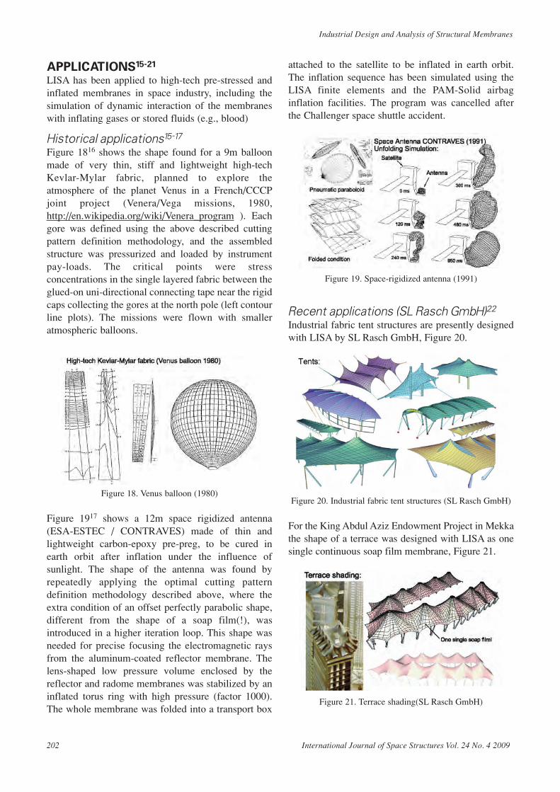
APPLICATIONS15-21
LISA has been applied to high-tech pre-stressed andinflated membranes in space industry, including thesimulation of dynamic interaction of the membraneswith inflating gases or stored fluids (e.g., blood)
Historical applications15-17
Figure 1816 shows the shape found for a 9m balloonmade of very thin, stiff and lightweight high-techKevlar-Mylar fabric, planned to explore theatmosphere of the planet Venus in a French/CCCPjoint project (Venera/Vega missions, 1980,http://en.wikipedia.org/wiki/Venera_program ). Eachgore was defined using the above described cuttingpattern definition methodology, and the assembledstructure was pressurized and loaded by instrumentpay-loads. The critical points were stressconcentrations in the single layered fabric between theglued-on uni-directional connecting tape near the rigidcaps collecting the gores at the north pole (left contourline plots). The missions were flown with smalleratmospheric balloons.
Figure 18. Venus balloon (1980)
Figure 1917 shows a 12m space rigidized antenna(ESA-ESTEC / CONTRAVES) made of thin andlightweight carbon-epoxy pre-preg, to be cured inearth orbit after inflation under the influence ofsunlight. The shape of the antenna was found byrepeatedly applying the optimal cutting patterndefinition methodology described above, where theextra condition of an offset perfectly parabolic shape,different from the shape of a soap film(!), wasintroduced in a higher iteration loop. This shape wasneeded for precise focusing the electromagnetic raysfrom the aluminum-coated reflector membrane. Thelens-shaped low pressure volume enclosed by thereflector and radome membranes was stabilized by aninflated torus ring with high pressure (factor 1000).The whole membrane was folded into a transport box
attached to the satellite to be inflated in earth orbit.The inflation sequence has been simulated using theLISA finite elements and the PAM-Solid airbaginflation facilities. The program was cancelled afterthe Challenger space shuttle accident.
Figure 19. Space-rigidized antenna (1991)
Recent applications (SL Rasch GmbH)22
Industrial fabric tent structures are presently designedwith LISA by SL Rasch GmbH, Figure 20.
Figure 20. Industrial fabric tent structures (SL Rasch GmbH)
For the King Abdul Aziz Endowment Project in Mekkathe shape of a terrace was designed with LISA as onesingle continuous soap film membrane, Figure 21.
Figure 21. Terrace shading(SL Rasch GmbH)
202 International Journal of Space Structures Vol. 24 No. 4 2009
Industrial Design and Analysis of Structural Membranes

E. Haug, P. De Kermel, B. Gawenat, A. Michalski
Various retractable umbrella structures are designedand developed using LISA for the shape definition andPAM-Flow for wind load analysis, Figure 22. Thecoupled LISA/PAM-Flow and PAM-Solid/PAM Flowcodes are being used by ESI France for the iterativestatic and coupled dynamic fluid-structure interaction(FSI) analysis under the effect of wind loads22.
Figure 22. Industrial umbrella structures (SL Rasch GmbH)
Further applications18-21
Finally, the LISA membrane element is used inindustrial studies and in the design for airbags (Figure23) and hollow organs (Figure 24).
Figure 23. Airbag inflation simulation (ESI Group)
Figure 23 summarizes the coupled fluid-structureinteraction inflation process of an industrial airbag,starting with a fully folded airbag membrane (initiallyplaced in its box), subjected to the action of injectedgas from the airbag gas generator, after the crashsensors have signaled a crash event. The injected gasis modeled by the mesh-free “Finite Point-set Method”(FPM), which allows to simulate high energy gasflows in complex, time-variable, flow domains. Theexplicit dynamic solution scheme uses the PAM-SolidCSD code with the LISA membrane finite element tosimulate the airbag membrane and the FPM optionbuilt into the same code to simulate the evolution in
the gas domain. The evolution of the gas domain(particle velocity vector snapshots, bottom row), theinflating airbag (separated plots, center row) and itsinteraction with a biomechanical model of the 5-thpercentile female driver in the out-of-position posture(top row) of a mandatory regulation crash test isshown in the figure.
Figure 2420,21 summarizes a few applications fromthe field of impact biomechanics (ESI Group/ESIFrance/Prof. H.Y. Choi, Hongik University), where themembrane finite elements are used in the PAM-Solidcode to model the biological membranes of theimpacted human bodies, coupled to mesh-free optionsand/or constant volume incompressible fluid-filled“bio-bag” options (airbags with an almostincompressible stored medium). The simulations wereperformed in ongoing research projects (for exampleEU-funded HUMOS Projectshttp://www.passivesafety.com/08_documents/docs_projects/final_reports/final_report_humos.pdf) with thegoal to make virtual crash tests with models of humansrather than with models of regulation crash dummies.The car making industries (and the consumers) puthigh expectation in the potential of virtual crash testswith human vehicle occupants, since this importantaspect of car safety design cannot be covered with realhuman passengers in real crash tests.
Figure 24. Simulation of biomechanical membranes
The discussed applications translate the versatility ofmembrane finite element simulation beyond tentstructures in architecture and structural engineering.Indeed, the same numerical technology applies to avery wide range of topics involving technical andbiological membranes.
CONCLUSIONSThe reported numerical simulation technology enablesthe shape design and load resistance analysis ofindustrial technical membranes in architecture, spaceand car making industries.
International Journal of Space Structures Vol. 24 No. 4 2009 203

REFERENCES[1] Haug, E., Formermittlung von Netzen, Die Bautechnik,
Heft 9, 1971.[2] Haug, E., Powell, G.H., Analytical shape finding of cable
nets, IASS Pacific Symposium – Part II on TensionStructures and Space Frames, Tokyo and Kyoto, October1971.
[3] Haug, E., Powell, G.H., Finite element analysis of non-linear membrane structures, IASS Pacific Symposium –Part II on Tension Structures and Space Frames, Tokyoand Kyoto, October 1971.
[4] Haug, E., Powell, G.H., Finite element analysis of non-linear membrane structures, Report n° SESM72-7,Structural Engineering Laboratory, University ofCalifornia, Berkeley, California, February 1972.
[5] Haug, E., Finite element analysis of pneumatic structures,IASS Symposium on Pneumatic Structures, Delft, 1972.
[6] Haug, E., Remarks on un-symmetric coefficient matricesin implicit non-linear finite element membrane and cableanalysis, Internationales Symposium WeitgespannteFlächentragwerke des SFB 64, Stuttgart, April 1976.
[7] Haug, E., de Rouvray, A., Carignan, M., Analysedynamique des ancrages immergés par la méthode deséléments finis, Report n° ESI/EE/75-335, EngineeringSystems International, 20 rue Saarinen, 94578 Rungis,France.
[8] Haug, E., Oelbermann, J., Numerische Ermittlung vonMinimalflächen, Proc. Symposium Minimalkonstruktionen,Essen, R. Müller, Köln-Braunsfeld, March 1977
[9] Haug, E., Oelbermann, J., Numerical design and analysisof pneumatic structures, CIB, International Symposiumon Air Supported Structures, Venice, June 1977.
[10] Oelbermann, J., Haug, E., Berechnung des Zuschnittseiner Membrane mit Hilfe der Finiten Element Methode,SFB-Colloquium on Large Span Structures, Stuttgart,May 1979.
[11] Haug, E., “Engineering Contributions to the Design ofLightweight Structures via Numerical Experiments”,Invited paper, SFB-Colloquim on Large Span Structures,Stuttgart, May 1980.
[12] Haug, E., Numerical design and analysis of lightweightstructures, Invited paper in the Symposium on AirSupported Structures, London, June 1981.
[13] Haug, E., Numerical Simulation of Soap Films, IL15 AirHall Handbook, Institute for Lightweight Structures,University of Stuttgart, Director Frei Otto, 1982.
[14] Haug, E., Numerical Simulation of Soap Films, IL18Information of the Institute for Lightweight Structures(IL), University of Stuttgart, Editor Frei Otto, 1987
[15] Haug, E., Numerical analysis on pneumatic structures bythe finite element method, Invited paper in the collectionof articles Pneumatic Building Structures by theSTROYIZDAT Publishing House, Moscow, 1983.
[16] Haug, E., de Rouvray, A., “Finite Element Design of aHigh Pressure Balloon with PAM-LISA™”, AIAA 8thAerodynamic Decelerator and Balloon TechnologyConference HYANNIS, Mass., Apr. 2-4, 1984.
[17] Haug, E., Protard, J.B., Milcent, G., ESI SA, Herren, A.,OERLIKON-CONTRAVES, Brunner, O., ESA/ESTEC,The numerical simulation of the inflation process ofspace rigidized antenna structures. ESI SA, ESA/ESTEC,Contraves, Intl. Conference on Spacecraft Structures &Mechanical Testing, ESTEC, 24-26/4/1991.
[18] Löhner, R., Haug, E., de Kermel, P., Matilla, J.L.,Mestreau, E., New advances in fluid-structure interactionusing adaptive unstructured grids and automatic meshgeneration, Proc. Second World Conf. Appl.Computational Fluid Dynamics, Basel World User DaysCFD 1994, Basel, May 1994.
[19] Haug, E., Lasry, D., de Kermel, P., Dynamic simulationof industrial membranes including their interaction withsurrounding media, 3rd International Symposium of theSFB 230 “Evolution of Natural Structures”, Universityof Stuttgart, October 4-7, 1994.
[20] Haug, E., Biomechanical models in vehicle accidentsimulation, PAM User Meetings, ESI Group, 1995.
[21] Haug, E., Choi, H.Y., Robin, S., Beaugonin, M., HumanModels for Crash and Impact Simulation, 4-th Chapter inHANDBOOK OF NUMERICAL ANALYSIS, ed. P.G.Ciarlet, Vol XII: Special Volume “Computational Modelsfor the Human Body”, invited editor N. Ayache, Elsevier,June 2004.
[22] Michalski, A., Haug, E. and Bletzinger, K.-U., On theapplication of the fluid structure interaction simulationfor the design of umbrella structures, Intl. Conf. onTextile Composites and Inflatable Structures,STRUCTURAL MEMBRANES 2007, E. Oñate, and B.Kröplin, (Eds), CIMNE, Barcelona, 2007.
[23] Losch, M.H., Bestimmung der mechanischen Konstantenfür einen zwei-dimensionalen, nichtlinearen,anisotropen, elastischen Stoff am Bbeispiel beschichteterGewebe, Diss. Universität Stuttgart, Prof. U. Wegner,University of Stuttgart, 1971.
[24] Reinhardt, H.W., Ein- und zweiachsige Verformungs-und Festigkeitsuntersuchungen an einem beschichtetenGittergewebe, Report SFB64 Nb 31/1975, UniversityStuttgart, 1975.
[25] Meffert, B., Mechanische Eigenschaften PVC-beschichteter Polyestergewebe, Institut fürKunststoffverarbeitung (IKV), RWTH Aachen, Mai 1978.
[26] DELITE - Design and Manufacture of Minimum EnergyForms of Lightweight Tension Membranes, EC CRAFTContract BRST.CT98-5166, July 2000.
[27] Goertz, C., ITS-Theorie Teil 2: Bewegliche Innenblase,Knitting, Vergleich mit Tests, Report BM-99005, AutolivASG/TC2, Feb. 1999.
204 International Journal of Space Structures Vol. 24 No. 4 2009
Industrial Design and Analysis of Structural Membranes