INDUSTRIAL CHEMICAL PROCESS (For the Academic year
153
1 With the blessings of Their Holinesses Sri Chandrasekharendra Saraswathi Viswa Maha Vidyalaya (University Established under section 3 of UGC Act 1956) Enathur, Kanchipuram Accredited with Grade ‘A’ by NAAC INDUSTRIAL CHEMICAL PROCESS COURSE MATERIAL (SIXTH SEMESTER - EIE) (For the Academic year - 2020-2021) PREPARED BY Dr.T.SUNDAR ASSISTANT PROFESSOR DEPARTMENT OF ELECTRONICS & INSTRUMENTATION ENGINEERING
-
Upload
khangminh22 -
Category
Documents
-
view
0 -
download
0
Transcript of INDUSTRIAL CHEMICAL PROCESS (For the Academic year

1
With the blessings of Their Holinesses
Sri Chandrasekharendra Saraswathi Viswa Maha Vidyalaya
(University Established under section 3 of UGC Act 1956) Enathur, Kanchipuram
Accredited with Grade ‘A’ by NAAC
INDUSTRIAL CHEMICAL PROCESS
COURSE MATERIAL
(SIXTH SEMESTER - EIE)
(For the Academic year - 2020-2021)
PREPARED BY
Dr.T.SUNDAR
ASSISTANT PROFESSOR
DEPARTMENT OF ELECTRONICS & INSTRUMENTATION
ENGINEERING

2
TABLE OF CONTENTS
Sl.No TITLE Page .No
1. AIM 3
2. OBJECTIVE 3
3. UNIT – I 5
4. UNIT – II 30
5. UNIT – III 49
6. UNIT – IV 68
7. UNIT - V 80
8. MULTIPLE CHOICE QUESTIONS WITH ANSWER 120
9. ASSIGNMENT / QUESTION BANK 142
10. USEFUL VIDEO LINK 148
11. CONCLUSION 152
12. REFERENCE 152

3
Pre – requisite: Nil. AIM To provide basic knowledge about Industrial chemical process. Course Objectives The objective of the course is to impart knowledge on: 1. To study the basic manufacturing various chemicals. 2. To get adequate knowledge about the Mass transfer/ Distillation/ extraction/ leaching process. 3. To study the characteristics of chemical reactors. 4. To study the process variables and control in unit operation. 5. To study about various Automation techniques. UNIT- I Overview of a chemical process Industries-Manufacture of H2 SO4,NaoH,NH3, Edible oil, pulp
and paper, pertolecem, refining plastics (P.E; PVC), polyester fibre - These process industries
cover: Inorganic (H2 SO4,NaoH,NH3) organic (Edible, pulp & paper), petroleum, polymer (PE,
PVC) & fibre
UNIT -II Mass transfer - mechanism - Distillation Absorption, extraction, leaching, adsorption, drying, and crystallization.
UNIT- III
Chemical reactors, mixing, size reduction, filtration, other separations membrane separation, solvent extraction, centrifugation-P&I diagram, Chemical engineering symbols,SAMA. UNIT -IV Concept of material, energy momentum balance, case study of process variables and control in
typical unit operation as distillation, absorption, reactors, heat exchangers
UNIT -V Automation of Assembly lines- Concept of automation in industry,mechanization and automation.
Automation using Hydraulic systems – Design aspects of various elements of hydraulic systems such as pumps, valves, filters, reservoirs, accumulators, actuators and intensifiers. Automation using pneumatic systems – Pneumatic fundamentals – Introduction to Automation
SEM: INDUSTRIAL CHEMICAL PROCESS T P C Branch: 3 - 3 CODE:

4
using pneumatic systems. Course Outcomes On completion of this course, the students will be able to, CO1. Understand the basic manufacturing various chemicals. CO2. Get adequate knowledge about the Mass transfer/ Distillation/ extraction/ leaching process. CO3. Understand characteristics of chemical reactors. CO4. Understand about case study of process variables and control in unit operation. CO5. Understand about various Automation techniques.
TEXT BOOKS 1. Dryden‘s outlines of chemical technology by Gopal Rao,East West Publishers 1997, New Delhi. 2. Shreve‘s chemical process industries Mc Grew Hill,Auckland,1984. 3. Unit operations of chemical engg - Mccabe , J.smith & P.Harriott, Mc Graw Hill, 7th Edition, 2004. 4. Shukla and G.N. Pandey “Text book on Chemical Technology”, Vikas publishing company 1997 5. Moulin, J.A., M. Makkee, and Diepen, A.V., Chemical Process Technology, Wiley, 2001.
REFERENCES
1. Perry‘s chemical engg‘s hand book - Mc Graw Hill,8th Edition ,2008. 2. Kirk and othmer ,”Encyclopedia of Chemical Technology”, III Edition. 3. Srikumar Koyikkal,”Chemical Process Technology and Simulation”,PHI Learning Ltd (2013).
Mapping of COs with Pos PO1 PO2 PO3 PO4 PO5 PO6 PO7 PO8 PO9 PO10 PO11 PO12 CO1
✓ ✓ ✓ ✓ ✓ ✓
CO2 ✓ ✓ ✓ ✓ ✓ ✓
CO3 ✓ ✓ ✓ ✓ ✓
CO4 ✓ ✓ ✓ ✓ ✓ ✓
CO5 ✓ ✓ ✓ ✓ ✓
5
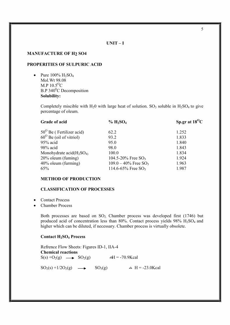
UNIT – I MANUFACTURE OF H2 SO4 PROPERITIES OF SULPURIC ACID
Pure 100% H2SO4 Mol.Wt 98.08 M.P 10.5OC B.P 3400C Decomposition Solubility: Completely miscible with H20 with large heat of solution. SO3 soluble in H2SO4 to give percentage of oleum. Grade of acid % H2SO4 Sp.gr at 18OC 50O Be ( Fertilizer acid) 62.2 1.252 60O Be (oil of vitriol) 93.2 1.833 95% acid 95.0 1.840 98% acid 98.0 1.843 Monohydrate acid(H2SO4) 100.0 1.834 20% oleum (fuming) 104.5-20% Free SO3 1.924 40% oleum (furming) 109.0 – 40% Free SO3 1.963 65% 114.6-65% Free SO3 1.987 METHOD OF PRODUCTION CLASSIFICATION OF PROCESSES
Contact Process Chamber Process
Both processes are based on SO2. Chamber process was developed first (1746) but produced acid of concentration less than 80%. Contact process yields 98% H2SO4 and higher which can be diluted, if necessary. Chamber process is virtually obsolete. Contact H2SO4 Process Refrence Flow Sheets: Figures ID-1, IIA-4 Chemical reactions S(s) +O2(g) SO2(g) H = -70.9Kcal SO2(s) +1/2O2(g) SO3(g) H = -23.0Kcal
6
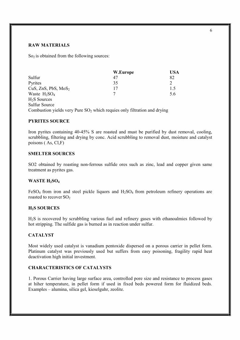
RAW MATERIALS So2 is obtained from the following sources: W.Europe USA Sulfur 47 82 Pyrites 35 2 CuS, ZnS, PbS, MoS2 17 1.5 Waste H2SO4 7 5.6 H2S Sources Sulfur Source Combustion yields very Pure SO2 which requies only filtration and drying PYRITES SOURCE Iron pyrites containing 40-45% S are roasted and must be purified by dust removal, cooling, scrubbling, filtering and drying by conc. Acid scrubbling to removal dust, moisture and catalyst poisons ( As, Cl,F) SMELTER SOURCES SO2 obtained by roasting non-ferrous sulfide ores such as zinc, lead and copper given same treatment as pyrites gas.
WASTE H2SO4
FeSO4 from iron and steel pickle liquors and H2SO4 from petroleum refinery operations are roasted to recover SO2
H2S SOURCES H2S is recovered by scrubbling various fuel and refinery gases with ethanoalmies followed by hot stripping. The sulfide gas is burned as in reaction under sulfur. CATALYST Most widely used catalyst is vanadium pentoxide dispersed on a porous carrier in pellet form. Platinum catalyst was previously used but suffers from easy poisoning, fragility rapid heat deactivation high initial investment. CHARACTERISTICS OF CATALYSTS 1. Porous Carrier having large surface area, controlled pore size and resistance to process gases at hiher temperature, in pellet form if used in fixed beds powered form for fluidized beds. Examples – alumina, silica gel, kieselguhr, zeolite.

7
2. Active catalytic agent – V2O5 in this case. Preparations are secret for competitive reasons usually consist of adding H2O soluble compounds to gels or porous substrates and firing at temperature below sintering point. 3. Promotor – alkali and or metallic compounds added in trace amounts to enhance activity of catalytic agent. ADVANTAGES OF V2 O5 CATALYST
Relatively immune to poisons Low initial investment and only 5% replacement per year. Requires only 10Kg of catalyst mass containing 7-8 % V2 O5 per daily ton of 100% acid.
DISADVANTAGES OF V2 O5 CATALYST
Must use dilute SO2 input (7 -10%) as catalyst is less active and requires high O2 / SO2 to give economic conversion. Large converters and high initial investment are necessary.
PROCESS DESCRIPTION
Air- SO2 gas containing 7 -10% SO2 and 11 – 14% O2 is preheated by converter gas, if necessary and sent to first stage reactors of steel construction. This is the high temperature (500-600OC ) stage, contains 30% of total catalyst and converts about 80% of SO2. The converter product is cooled by heat exchange at 300OC and fed to a second stage where total yield is increased to 97% by operating at 400-450OC for favorable equilibrium.
High yield product gases are cooled to 150OC by water and air heat exchanges and absorbed in oleum fed at a rate to allow not over a 1% rise in acid strength. Final scrubbling is done with a lower strength (97%) acid. Oleum concentrations upto 40% can be made by tower absorption. Higher strength oleum upto 65% is prepared by distilling 20% oleum.

8

9
MANUFACTURING CHLORINE – CAUSTIC SODA These two chemicals are being discussed in combination as they are produced as they are produced as co-products in the electrolysis of brine. This process accounts for 80% of caustic soda and > 95% of chlorine production of India 1. PERTINENT PROPERTIES OF CHLORINE (Cl2) Mol.wt 70.9 MP -101.6oC Critical Temp. 146OC BP -34.6 OC Critical Pressure 93.5 atms Liquefaction point 5.7 atms and 15 OC Toxic gas 0.35-2.0 ppm is max.conc. Grades Technical (99.0%) 2. PERTINENT PROPERTIES OF SODIUM HYDROXIDE (NaOH) Mol.wt 40.00 BP 1390 OC MP 318 OC Very soluble in water with high exothernmic heat of solution Grades : Available in solid form of flakes, granules, sticks, lumps, pellets and aqueous solutions (50 and 73% NaOH) . Purity of solid forms ranges from 60% Na2O(77.4% NaOH) to 76%Na2O (98% NaOH) 3. CONSUMPTION PATTERN The start of the chlorine industry in the 1920’s was the result of successful development of the electrolytic brine decomposition process. Caustic soda, formed in the ratio of 1.1 tons per ton of chlorine in the electrolytic process, had previously been solely manufactured by a lime soda ash process which is gradually being replaced. Virtually all the basic discoveries and inventions necessary for the development of both the diaphragm and mercury cell processes for the brine electrolysis were made during the period from 1883 to 1893. The first diaphragm plant in the USA was built in 1893 in Rumford Falls, NY. The first mercury cell of industrial significance was invented in 1892 to make pure caustic soda. With the development of the LeBlanc and Solvay processes for making sodium carbonate, sodium hydroxide became a relatively common chemical. Soda ash was converted to caustic soda by the well known lime soda reaction. Even though electrolytic caustic soda was produced in the 1890’s the lime soda process remained dominant until the late 1940’s. Caustic soda is no
10
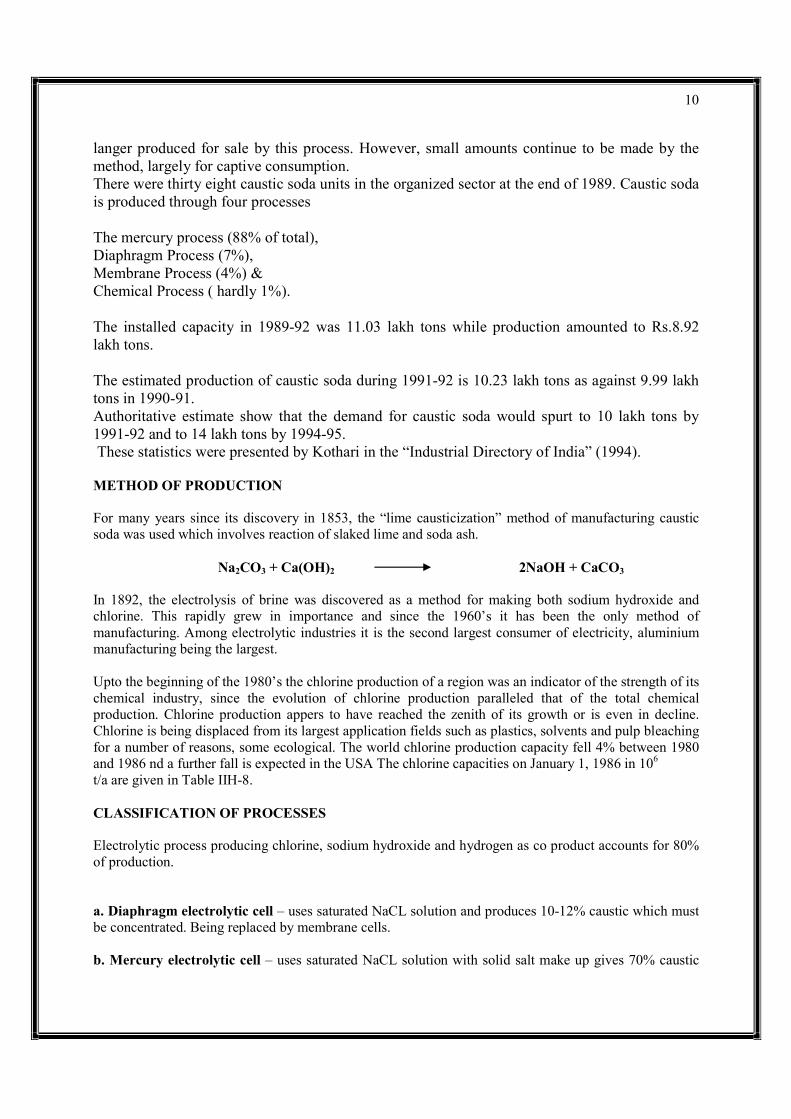
langer produced for sale by this process. However, small amounts continue to be made by the method, largely for captive consumption. There were thirty eight caustic soda units in the organized sector at the end of 1989. Caustic soda is produced through four processes The mercury process (88% of total), Diaphragm Process (7%), Membrane Process (4%) & Chemical Process ( hardly 1%). The installed capacity in 1989-92 was 11.03 lakh tons while production amounted to Rs.8.92 lakh tons. The estimated production of caustic soda during 1991-92 is 10.23 lakh tons as against 9.99 lakh tons in 1990-91. Authoritative estimate show that the demand for caustic soda would spurt to 10 lakh tons by 1991-92 and to 14 lakh tons by 1994-95. These statistics were presented by Kothari in the “Industrial Directory of India” (1994). METHOD OF PRODUCTION For many years since its discovery in 1853, the “lime causticization” method of manufacturing caustic soda was used which involves reaction of slaked lime and soda ash. Na2CO3 + Ca(OH)2 2NaOH + CaCO3
In 1892, the electrolysis of brine was discovered as a method for making both sodium hydroxide and chlorine. This rapidly grew in importance and since the 1960’s it has been the only method of manufacturing. Among electrolytic industries it is the second largest consumer of electricity, aluminium manufacturing being the largest. Upto the beginning of the 1980’s the chlorine production of a region was an indicator of the strength of its chemical industry, since the evolution of chlorine production paralleled that of the total chemical production. Chlorine production appers to have reached the zenith of its growth or is even in decline. Chlorine is being displaced from its largest application fields such as plastics, solvents and pulp bleaching for a number of reasons, some ecological. The world chlorine production capacity fell 4% between 1980 and 1986 nd a further fall is expected in the USA The chlorine capacities on January 1, 1986 in 106
t/a are given in Table IIH-8. CLASSIFICATION OF PROCESSES Electrolytic process producing chlorine, sodium hydroxide and hydrogen as co product accounts for 80% of production. a. Diaphragm electrolytic cell – uses saturated NaCL solution and produces 10-12% caustic which must be concentrated. Being replaced by membrane cells. b. Mercury electrolytic cell – uses saturated NaCL solution with solid salt make up gives 70% caustic

11
solutions directly. Chlorine Processes without co –products a. HCL air oxidation with Fe2O3 catalyst b. HCL –air-CL2 oxychlorination processes, e.g production of ethylene dichlorine form ethylene c. HNO3- NaCl air process NaOH process with no CL2 co – product Na2CO3-Ca(OH)2 no further investments allocated as process not competitive.
12
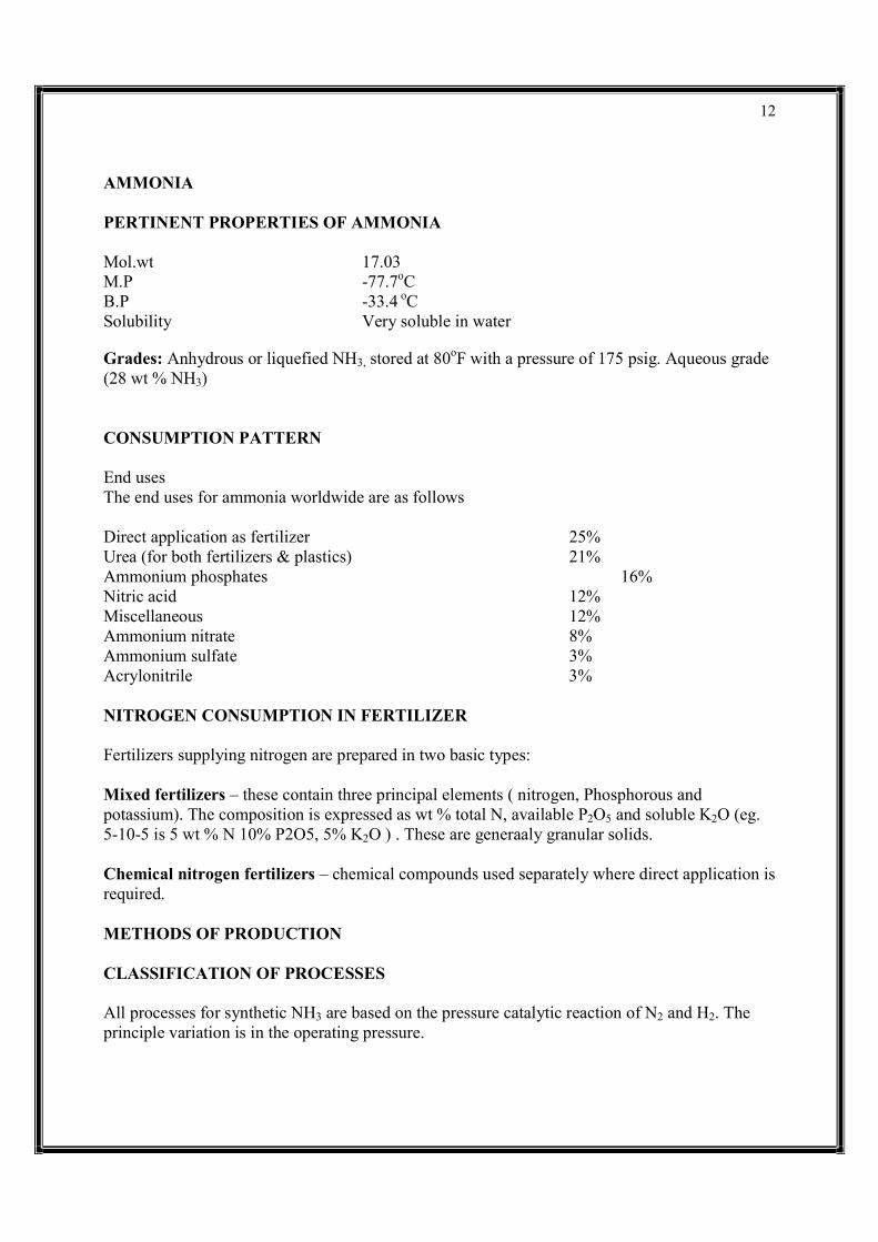
AMMONIA PERTINENT PROPERTIES OF AMMONIA Mol.wt 17.03 M.P -77.7oC B.P -33.4 oC Solubility Very soluble in water
Grades: Anhydrous or liquefied NH3, stored at 80oF with a pressure of 175 psig. Aqueous grade (28 wt % NH3) CONSUMPTION PATTERN End uses The end uses for ammonia worldwide are as follows Direct application as fertilizer 25% Urea (for both fertilizers & plastics) 21% Ammonium phosphates 16% Nitric acid 12% Miscellaneous 12% Ammonium nitrate 8% Ammonium sulfate 3% Acrylonitrile 3% NITROGEN CONSUMPTION IN FERTILIZER Fertilizers supplying nitrogen are prepared in two basic types: Mixed fertilizers – these contain three principal elements ( nitrogen, Phosphorous and potassium). The composition is expressed as wt % total N, available P2O5 and soluble K2O (eg. 5-10-5 is 5 wt % N 10% P2O5, 5% K2O ) . These are generaaly granular solids. Chemical nitrogen fertilizers – chemical compounds used separately where direct application is required. METHODS OF PRODUCTION CLASSIFICATION OF PROCESSES All processes for synthetic NH3 are based on the pressure catalytic reaction of N2 and H2. The principle variation is in the operating pressure.

13
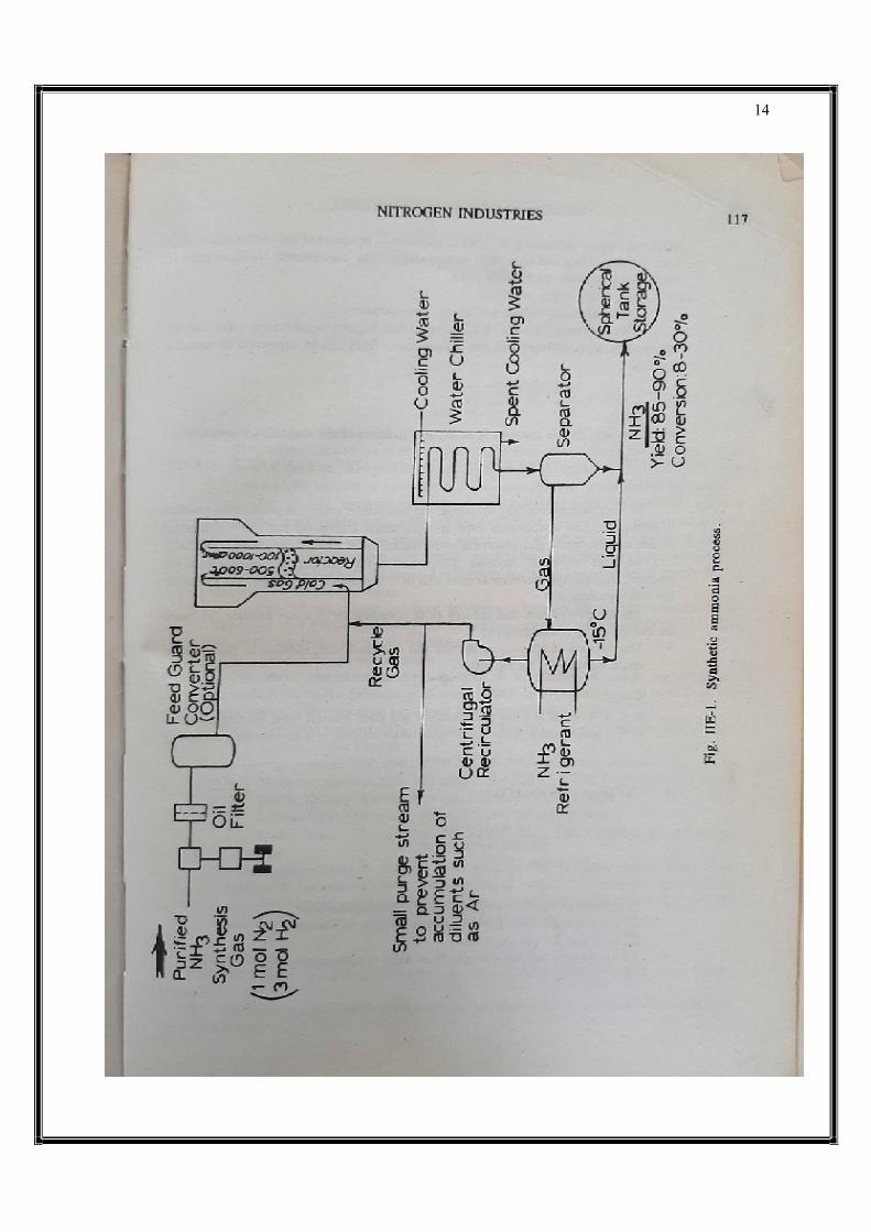
PROCESS DESCRIPTION Ammonia synthesis gas (3 moles pure H2: 1 mole pure N2) is compressed to the operating pressure (1---1000 atms. Depending on conversion required). It is sent through a filter to remove compression oil and additionally through a high temperature guard converter ( converts CO and CO2 to CH4 and removes traces of H20, H2S, P and As). This is done by catalyst and suitable getter materials. The relatively cool gas is added along the outside of converter tube walls to provide cooling so that carbon steel can be used for the thick wall pressure vessel and internal tubes. The preheated gas flows next through the inside of the tube which contains promoted poronus iron catalyst at 500-550OC. The NH3 product with an 8 30% conversion depending on process conditions is removed by condensation first with water cooling and then NH3 refrigeration. The unconverted N2-H2 mixture is recirculated to allow an 85-90% yield.
14

15
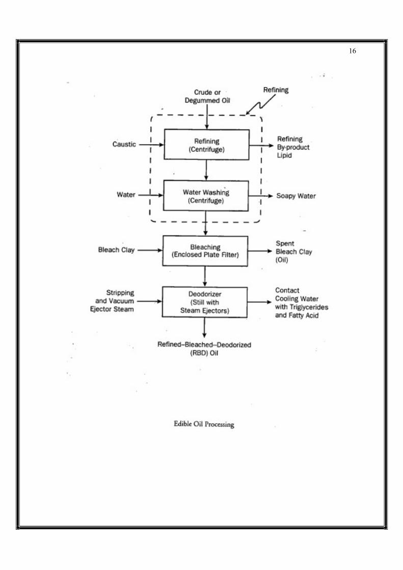
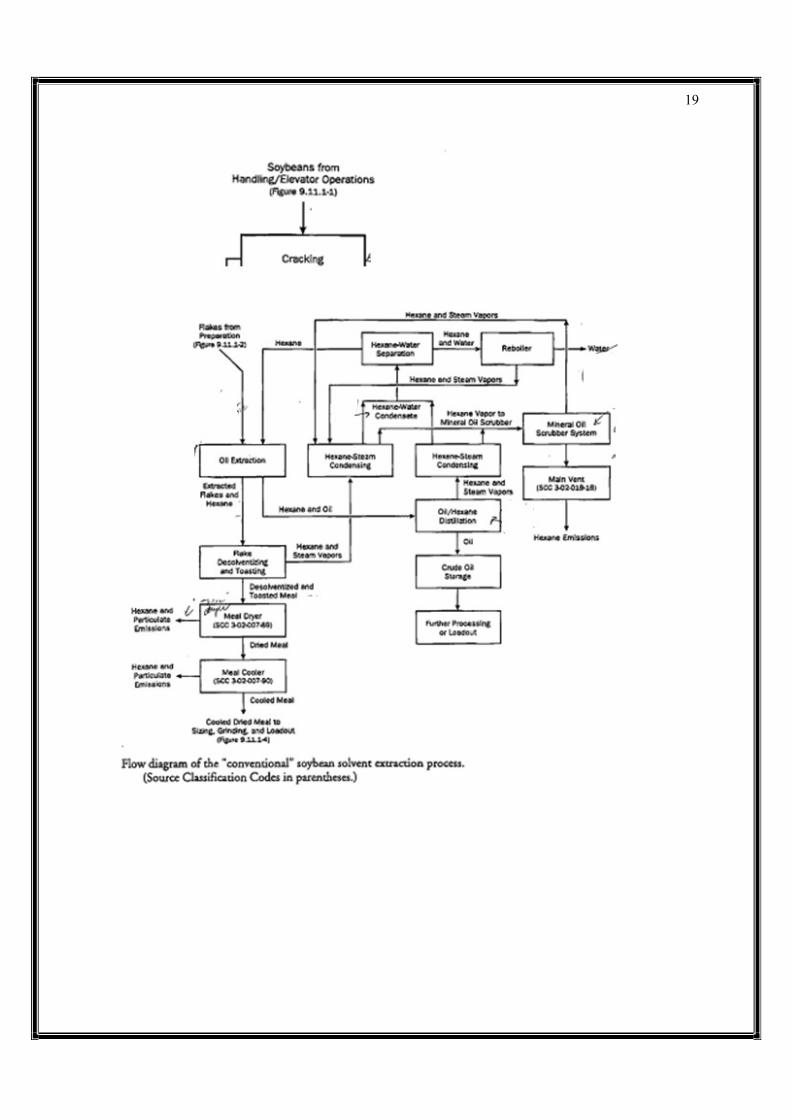
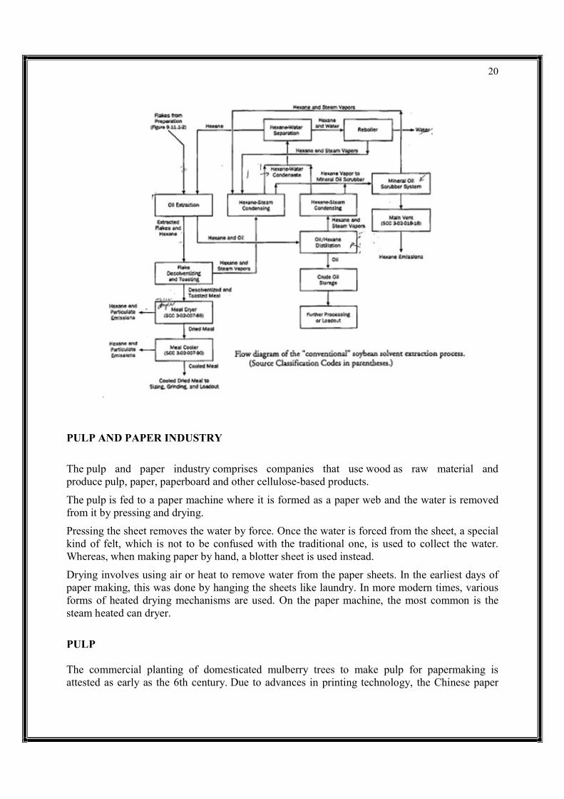
EDIBLE OIL This discussion presents information on the soybean processing industry and a description of the refining of edible soybean oil. The review of NOPA diagrams consisted of a discussion of process flow diagrams previously submitted to EPA by NOPA. Copies of the annotated diagrams are attached to this memorandum. A. General Information Generally, the soybean industry annually processes 1.1. to 1.3 billion bushels of soybeans. For 1995, most plants are operating at about 70 percent of capacity. The Cargill plant at Fayetteville is one of the larger plants in the U.S. and is in the top 20 percent in terms of production capacity. For most plants, there have not been a lot changes over the past 15 years and those changes that have occurred were the result of EPA regulations or the increase in energy costs. During this 15 year period, there has been a move from the use of deep bed extractors towards shallow bed extractors. Also, changes have occurred in the desolventizing/toaster (DT) systems. Generally, plants do not change control devices without an increase in capacity. In conventional soybean processing plants, there is no production of soybean meal for human consumption (white flake production). Only about 8 plants in the U.S. have flasher systems for white flake production. These flasher systems use superheated hexane in the flake desolventizing step and do not use meal dryers. B. Soybean Oil Refining Crude soybean oil contains free fatty acids, phosphorus compounds, protein fines, and triglycerides. The crude oil can be either treated directly with caustic or undergo an optional step to degum the oil, which removes the lecithin. After treatment with caustic, the oil is centrifuged to separate the aqueous refining by-product lipid from the oil. This lipid solution contains protein fines, phosphorus compounds, some saponified triglycerides, and sodium salts of the fatty acids. Following separation of the lipid, the oil is washed with water and centrifuged to remove some of the remaining saponified triglycerides. The refined oil is then bleached and deodorized. In the bleaching step, the refined oil is treated with bleach clay and then transferred to a vacuum bleaching tank. Following the bleaching step, the spent clay is filtered from the oil and the refined, bleached oil is ready for the deodorizing step. Prior to the deodorizing step, the bleached oil may be hydrogenated using a nickel catalyst and the resultant liquid supercooled to filter out the saturated oil. The refined, bleached oil is deodorized by stripping in a still with steam ejectors. In the stripping process, any triglycerides and fatty acids remaining in the refined, bleached oil are removed and the refined-bleached deodorized (RBD) oil is ready for processing into commercial products. A process flow diagram for the edible oil processing operation is attached to this memorandum.
16

17

18
19
20
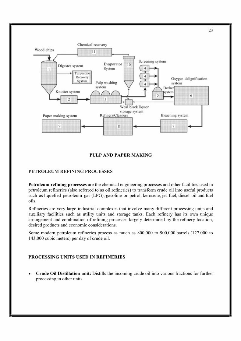
PULP AND PAPER INDUSTRY
The pulp and paper industry comprises companies that use wood as raw material and produce pulp, paper, paperboard and other cellulose-based products.
The pulp is fed to a paper machine where it is formed as a paper web and the water is removed from it by pressing and drying.
Pressing the sheet removes the water by force. Once the water is forced from the sheet, a special kind of felt, which is not to be confused with the traditional one, is used to collect the water. Whereas, when making paper by hand, a blotter sheet is used instead.
Drying involves using air or heat to remove water from the paper sheets. In the earliest days of paper making, this was done by hanging the sheets like laundry. In more modern times, various forms of heated drying mechanisms are used. On the paper machine, the most common is the steam heated can dryer.
PULP The commercial planting of domesticated mulberry trees to make pulp for papermaking is attested as early as the 6th century. Due to advances in printing technology, the Chinese paper

21
industry continued to grow under the Song dynasty to meet the rising demand for printed books. Demand for paper was also stimulated by the Song government, which needed a large supply of paper for printing paper money and exchange certificates. The first mechanised paper machine was installed at Frogmore Paper Mill, Apsley, Hertfordshire in 1803, followed by another in 1804. The site operates currently as a museum.
The pulp and paper industry has been criticized by environmental groups like the Natural Resources Defense Council for unsustainable deforestation and clearcutting of old-growth forest. The industry trend is to expand globally to countries like Russia, China and Indonesia with low wages and low environmental oversight. According to Greenpeace, farmers in Central America illegally rip up vast tracts of native forest for cattle and soybean production without any consequences, and companies who buy timber from private land owners contribute to massive deforestation of the Amazon Rainforest. On the other hand, the situation is quite different where forest growth has been on the increase for a number of years. It is estimated for instance that since 1990 forests have grown in Europe by a size equivalent to that of Switzerland (44,160 KM) which has been supported through the practice of sustainable forest management by the industry. In Sweden, for every tree that is felled, two are planted.
The pulp and paper industry consumes a significant amount of water and energy and produces wastewater with a high concentration of chemical oxygen demand (COD), among other contaminants. Recent studies underline coagulation as an appropriate pre-treatment of pulp and paper industrial wastewater and as a cost-effective solution for the removal of COD and the reduction of pressures on the aquatic environment.
LIST OF MAIN COUNTRIES BY PRODUCTION QUANTITY
According to statistic data by RISI, main producing countries of paper and paperboard, not including pulp, in the world are as follows
Rank 2011
Country Production in 2011
(1,000 ton) Share 2011
Rank 2010
Production in 2010 (1,000 ton)
1 China 99,300 24.9% 1 92,599
2 United States 75,083 18.8% 2 75,849
3 Japan 26,627 6.7% 3 27,288
4 Germany 22,698 5.7% 4 23,122

Rank 2011
Country Production in 2011
5 Canada
6 South Korea
7 Finland
8 Sweden
9 Brazil
10 Indonesia
World Total
Pulp and paper mills are highly wood preparation, pulping, chemical recovery, bleaching, and papermaking to convert wood to the final product. Processing options and the type of wood processed are often determined by the final product. The pulp for papermaking may be produced from virgin fibre by chemical or mechanical means or may be produced by the repulping of paper for recycling. Wood is the main original raw material. Paper for recycling accounts for about 50 % of the fibrstraw, hemp, grass, cotton and other cellulosebasically a two-step process in which a fibrous raw material is first converted into pulp, and then the pulp is converted into papseparated from the unusable fraction of the wood, the lignin. Pulp making can be done mechanically or chemically. The pulp is then bleached and further processed, depending on the type and grade of paper that is to be produced. In the paper factory, the pulp is dried and pressed to produce paper sheets. Post-Non recycled paper is either land
Production in 2011 (1,000 ton)
Share 2011
Rank 2010
Production in 2010
12,112 3.0% 5
11,492 2.9% 8
11,329 2.8% 6
11,298 2.8% 7
10,159 2.5% 10
10,035 2.5% 9
398,975 100.0%
Pulp and paper mills are highly complex and integrate many different process areas including wood preparation, pulping, chemical recovery, bleaching, and papermaking to convert wood to the final product. Processing options and the type of wood processed are often determined by the
The pulp for papermaking may be produced from virgin fibre by chemical or mechanical means or may be produced by the repulping of paper for recycling. Wood is the main original raw material. Paper for recycling accounts for about 50 % of the fibres used straw, hemp, grass, cotton and other cellulose-bearing material can be used. Paper production is
step process in which a fibrous raw material is first converted into pulp, and then the pulp is converted into paper. The harvested wood is first processed so that the separated from the unusable fraction of the wood, the lignin. Pulp making can be done mechanically or chemically. The pulp is then bleached and further processed, depending on the
ade of paper that is to be produced. In the paper factory, the pulp is dried and pressed -use, an increasing fraction of paper and paper products is recycled.
Non recycled paper is either land filled or incinerated.
22
Production in 2010 (1,000 ton)
12,787
11,120
11,789
11,410
9,796
9,951
394,244
complex and integrate many different process areas including wood preparation, pulping, chemical recovery, bleaching, and papermaking to convert wood to the final product. Processing options and the type of wood processed are often determined by the
The pulp for papermaking may be produced from virgin fibre by chemical or mechanical means or may be produced by the repulping of paper for recycling. Wood is the main original raw
es used – but in a few cases bearing material can be used. Paper production is
step process in which a fibrous raw material is first converted into pulp, and then er. The harvested wood is first processed so that the fibers are
separated from the unusable fraction of the wood, the lignin. Pulp making can be done mechanically or chemically. The pulp is then bleached and further processed, depending on the
ade of paper that is to be produced. In the paper factory, the pulp is dried and pressed use, an increasing fraction of paper and paper products is recycled.
23
PULP AND PAPER MAKING
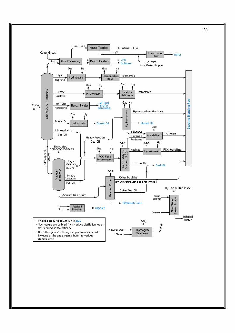
PETROLEUM REFINING PROCESSES
Petroleum refining processes are the chemical engineering processes and other facilities used in petroleum refineries (also referred to as oil refineries) to transform crude oil into useful products such as liquefied petroleum gas (LPG), gasoline or petrol, kerosene, jet fuel, diesel oil and fuel oils.
Refineries are very large industrial complexes that involve many different processing units and auxiliary facilities such as utility units and storage tanks. Each refinery has its own unique arrangement and combination of refining processes largely determined by the refinery location, desired products and economic considerations.
Some modern petroleum refineries process as much as 800,000 to 900,000 barrels (127,000 to 143,000 cubic meters) per day of crude oil.
PROCESSING UNITS USED IN REFINERIES
Crude Oil Distillation unit: Distills the incoming crude oil into various fractions for further processing in other units.

24
Vacuum distillation unit: Further distills the residue oil from the bottom of the crude oil distillation unit. The vacuum distillation is performed at a pressure well below atmospheric pressure.
Naphtha hydrotreater unit: Uses hydrogen to desulfurize the naphtha fraction from the crude oil distillation or other units within the refinery.
Catalytic reforming unit: Converts the desulfurized naphtha molecules into higher-octane molecules to produce reformate, which is a component of the end-product gasoline or petrol.
Alkylation unit: Converts isobutane and butylenes into alkylate, which is a very high-octane component of the end-product gasoline or petrol.
Isomerization unit: Converts linear molecules such as normal pentane into higher-octane branched molecules for blending into the end-product gasoline. Also used to convert linear normal butane into isobutane for use in the alkylation unit.
Distillate hydrotreater unit: Uses hydrogen to desulfurize some of the other distilled fractions from the crude oil distillation unit (such as diesel oil).
Merox (mercaptan oxidizer) or similar units: Desulfurize LPG, kerosene or jet fuel by oxidizing undesired mercaptans to organic disulfides.
Amine gas treater, Claus unit, and tail gas treatment for converting hydrogen sulfide gas from the hydrotreaters into end-product elemental sulfur. The large majority of the 64,000,000 metric tons of sulfur produced worldwide in 2005 was byproduct sulfur from petroleum refining and natural gas processing plants.
Fluid catalytic cracking (FCC) unit: Upgrades the heavier, higher-boiling fractions from the crude oil distillation by converting them into lighter and lower boiling, more valuable products.
Hydrocracker unit: Uses hydrogen to upgrade heavier fractions from the crude oil distillation and the vacuum distillation units into lighter, more valuable products.
Visbreaker unit upgrades heavy residual oils from the vacuum distillation unit by thermally cracking them into lighter, more valuable reduced viscosity products.
Delayed coking and fluid coker units: Convert very heavy residual oils into end-product petroleum coke as well as naphtha and petrol oil by-products.

25
TYPICAL PETROLEUM REFINERY
The image below is a schematic flow diagram of a typical petroleum refinery that depicts the various refining processes and the flow of intermediate product streams that occurs between the inlet crude oil feedstock and the final end-products.
The diagram depicts only one of the literally hundreds of different oil refinery configurations. The diagram also does not include any of the usual refinery facilities providing utilities such as steam, cooling water, and electric power as well as storage tanks for crude oil feedstock and for intermediate products and end products.
26
27
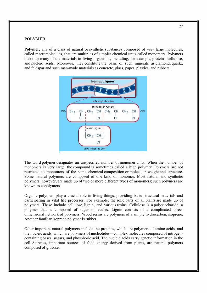
POLYMER Polymer, any of a class of natural or synthetic substances composed of very large molecules, called macromolecules, that are multiples of simpler chemical units called monomers. Polymers make up many of the materials in living organisms, including, for example, proteins, cellulose, and nucleic acids. Moreover, they constitute the basis of such minerals as diamond, quartz, and feldspar and such man-made materials as concrete, glass, paper, plastics, and rubbers.
The word polymer designates an unspecified number of monomer units. When the number of monomers is very large, the compound is sometimes called a high polymer. Polymers are not restricted to monomers of the same chemical composition or molecular weight and structure. Some natural polymers are composed of one kind of monomer. Most natural and synthetic polymers, however, are made up of two or more different types of monomers; such polymers are known as copolymers.
Organic polymers play a crucial role in living things, providing basic structural materials and participating in vital life processes. For example, the solid parts of all plants are made up of polymers. These include cellulose, lignin, and various resins. Cellulose is a polysaccharide, a polymer that is composed of sugar molecules. Lignin consists of a complicated three-dimensional network of polymers. Wood resins are polymers of a simple hydrocarbon, isoprene. Another familiar isoprene polymer is rubber.
Other important natural polymers include the proteins, which are polymers of amino acids, and the nucleic acids, which are polymers of nucleotides—complex molecules composed of nitrogen-containing bases, sugars, and phosphoric acid. The nucleic acids carry genetic information in the cell. Starches, important sources of food energy derived from plants, are natural polymers composed of glucose.

28
Many inorganic polymers also are found in nature, including diamond and graphite. Both are composed of carbon. In diamond, carbon atoms are linked in a three-dimensional network that gives the material its hardness. In graphite, used as a lubricant and in pencil “leads,” the carbon atoms link in planes that can slide across one another.
Synthetic polymers are produced in different types of reactions. Many simple hydrocarbons, such as ethylene and propylene, can be transformed into polymers by adding one monomer after another to the growing chain. Polyethylene, composed of repeating ethylene monomers, is an addition polymer. It may have as many as 10,000 monomers joined in long coiled chains. Polyethylene is crystalline, translucent, and thermoplastic—i.e., it softens when heated. It is used for coatings, packaging, molded parts, and the manufacture of bottles and containers. Polypropylene is also crystalline and thermoplastic but is harder than polyethylene. Its molecules may consist of from 50,000 to 200,000 monomers. This compound is used in the textile industry and to make molded objects.
Other addition polymers include polybutadiene, polyisoprene, and polychloroprene, which are all important in the manufacture of synthetic rubbers. Some polymers, such as polystyrene, are glassy and transparent at room temperature, as well as being thermoplastic. Polystyrene can be coloured any shade and is used in the manufacture of toys and other plastic objects.
29
If one hydrogen atom in ethylene is replaced by a chlorine atom, vinyl chloride is produced. This polymerizes to polyvinyl chloride (PVC), a colourless, hard, tough, thermoplastic material that can be manufactured in a number of forms, including foams, films, and fibres. Vinyl acetate, produced by the reaction of ethylene and acetic acid, polymerizes to amorphous, soft resins used as coatings and adhesives. It copolymerizes with vinyl chloride to produce a large family of thermoplastic materials.
Many important polymers have oxygen or nitrogen atoms, along with those of carbon, in the backbone chain. Among such macromolecular materials with oxygen atoms are polyacetals. The simplest polyacetal is polyformaldehyde. It has a high melting point and is crystalline and resistant to abrasion and the action of solvents. Acetal resins are more like metal than are any other plastics and are used in the manufacture of machine parts such as gears and bearings.
A linear polymer characterized by a repetition of ester groups along the backbone chain is called a polyester. Open-chain polyesters are colourless, crystalline, thermoplastic materials. Those with high molecular weights (10,000 to 15,000 molecules) are employed in the manufacture of films, molded objects, and fibres such as Dacron.
The polyamides include the naturally occurring proteins casein, found in milk, and zein, found in corn (maize), from which plastics, fibres, adhesives, and coatings are made. Among the synthetic polyamides are the urea-formaldehyde resins, which are thermosetting. They are used to produce molded objects and as adhesives and coatings for textiles and paper. Also important are the polyamide resins known as nylons. They are strong, resistant to heat and abrasion, noncombustible, and nontoxic, and they can be coloured. Their best-known use is as textile fibres, but they have many other applications.
30
UNIT – II Mass transfer describes the transport of mass from one point to another and is one of the main pillars in the subject of Transport Phenomena. Mass transfer may take place in a single phase or over phase boundaries in multiphase systems. In the vast majority of engineering problems, mass transfer involves at least one fluid phase (gas or liquid), although it may also be described in solid-phase materials. In many cases, the mass transfer of species takes place together with chemical reactions. This implies that flux of a chemical species does not have to be conserved in a volume element, since chemical species may be produced or consumed in such an element. The chemical reactions are sources or sinks in such flux balances.
The theory of mass transfer allows for the computation of mass flux in a system and the distribution of the mass of different species over time and space in such a system, also when chemical reactions are present. The purpose of such computations is to understand, and possibly design or control, such a system.
MASS TRASFER MECHANISM
The faradaic current that flows at any time is a direct measure of the rate of the electrochemical reaction taking place at the electrode. Further, the current itself is dependent upon two things:
1. The rate at which material gets from the bulk of solution to the electrode, known as mass transport, and
2. The rate at which electrons can transfer across the interface, or charge transfer kinetics.
These two processes are inexorably intertwined in the flow of current.
There are three basic mechanisms of mass transport:
Diffusion – defined as the spontaneous movement of any material from where it is to where it is not
Migration – the movement of charged particles in an electric field
Convection – movement of material contained within a volume element of stirred (hydrodynamic) solution
DIFFUSION
The random movement of molecules from a region of high concentration to regions of lower concentration for one dimension, is called diffusion. The rate at which a molecule diffuses is dependent upon the difference in concentration between two points in solution, called the concentration gradient, and on the diffusion coefficient, DD, which has a characteristic value for

a specific solution species at fixed temperature.
This movement of a chemical species under the influence of a concentration gradient is described by Fick’s first law. A particle i will diffuse through a crossconcentration gradient across the selected area. Flux, as particles per unit time across the given segment, is expressed as Ji according to
where ∂Ci/∂x∂Ci/∂x expresses the concentration gradient andparticle i.
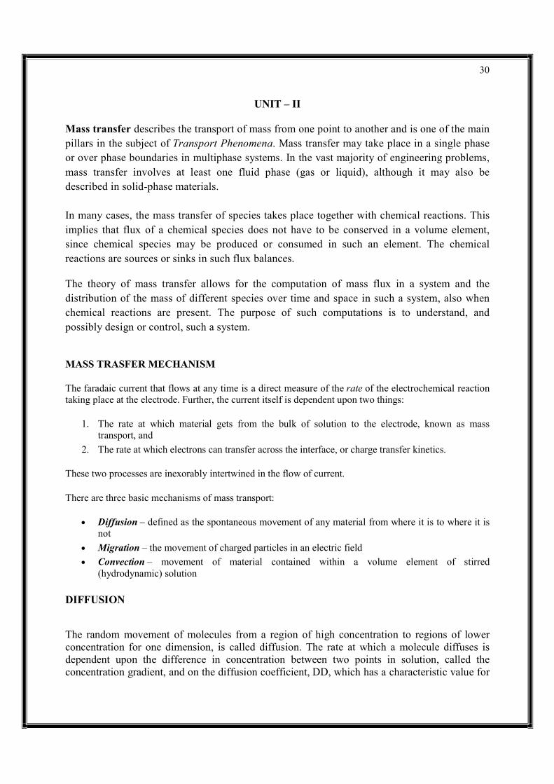
MIGRATION
The movement of charged particles in response to a local electric field is called migration. The contribution of migration to the total flux is proportional to the charge of the ion, the ion concentration, the diffusion coefficient, aexperienced by the ion. A change in the applied potential to a solid electrode in a solution containing ions affects charge migration as illustrated inthe electrode surface.
a specific solution species at fixed temperature.
DIFFUSION
This movement of a chemical species under the influence of a concentration gradient is described . A particle i will diffuse through a cross-sectional area as a function of the
concentration gradient across the selected area. Flux, as particles per unit time across the given segment, is expressed as Ji according to
Ji=−Di∂Ci∂x
expresses the concentration gradient and Di the diffusion coefficient for
The movement of charged particles in response to a local electric field is called migration. The contribution of migration to the total flux is proportional to the charge of the ion, the ion concentration, the diffusion coefficient, and the magnitude of the electric field gradient experienced by the ion. A change in the applied potential to a solid electrode in a solution containing ions affects charge migration as illustrated in Figure for increasing negative charge at
31
This movement of a chemical species under the influence of a concentration gradient is described sectional area as a function of the
concentration gradient across the selected area. Flux, as particles per unit time across the given
the diffusion coefficient for
The movement of charged particles in response to a local electric field is called migration. The contribution of migration to the total flux is proportional to the charge of the ion, the ion
nd the magnitude of the electric field gradient experienced by the ion. A change in the applied potential to a solid electrode in a solution
for increasing negative charge at
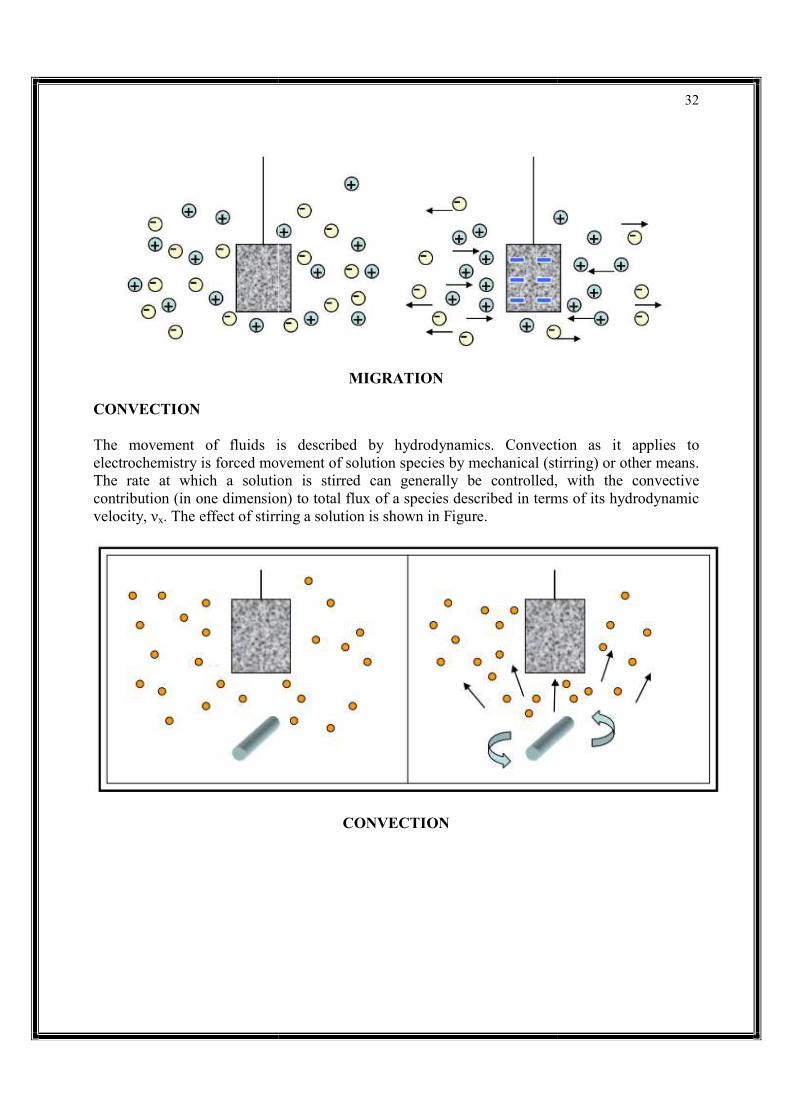
CONVECTION
The movement of fluids is described by hydrodynamics. Convection as it applies to electrochemistry is forced movement of solution species by mechanical (stirring) or other means. The rate at which a solution is stirred can contribution (in one dimension) to total flux of a species described in terms of its hydrodynamic velocity, νx. The effect of stirring a solution is shown in
MIGRATION
The movement of fluids is described by hydrodynamics. Convection as it applies to electrochemistry is forced movement of solution species by mechanical (stirring) or other means. The rate at which a solution is stirred can generally be controlled, with the convective contribution (in one dimension) to total flux of a species described in terms of its hydrodynamic
. The effect of stirring a solution is shown in Figure.
CONVECTION
32
The movement of fluids is described by hydrodynamics. Convection as it applies to electrochemistry is forced movement of solution species by mechanical (stirring) or other means.
generally be controlled, with the convective contribution (in one dimension) to total flux of a species described in terms of its hydrodynamic
33
TOTAL MASS TRANSPORT
The total mass transport of material, or flux, to an electrode is described for one dimension by the Nernst-Planck equation
J(x,t)=−[D(∂C(x,t)/∂x)]−[(zF/RT)DC(x,t)](∂φ(x,t)/∂x)+C(x,t)νx(x,t)(3.2)(3.2)J(x,t)=−[D(∂C(x,t)/∂x)]−[(zF/RT)DC(x,t)](∂φ(x,t)/∂x)+C(x,t)νx(x,t)
where J is the flux (mol cm-2 s-1), D is the diffusion coefficient of the solution species (cm2/s), C is the concentration of the species (mol/cm3), φ is the electrostatic potential, and νx is the hydrodynamic velocity. The Nernst-Planck equation combines the individual contributions from diffusion (concentration gradient), migration (electric field), and convection (hydrodynamic velocity). This equation shows that the flux of material towards the electrode surface is proportional to either of three slopes of concentration, electrostatic potential, or hydrodynamic velocity, all as a function of distance from the electrode surface.
Electrochemical experiments can be designed to eliminate the contributions of electrostatic potential and hydrodynamic velocity to the overall flux of electroactive species, limiting mass transport to the contribution from diffusion. The currents resulting from these experiments can then be classified as diffusion controlled.
Contributions from migration can be effectively eliminated by adding an inert electrolyte to the solution at a 10 – 100 fold excess with respect to the redox couple of interest. The electric field between the two electrodes involved in the measurement is dissipated over all of the ions in solution and not just the electroactive material. Under these conditions, the contribution of migration to the observed current is < 1%. Contributions from convection can be reduced or eliminated by working in quiet (unstirred) solutions. With careful control of external vibration and temperature, diffusion controlled measurements for up to 20 seconds or so can be made without significant convective effects.
The flux can then be related to the observed current at the working electrode by
it=nFAD(∂Ci/∂x)│x=0(3.3)(3.3)it=nFAD(∂Ci/∂x)│x=0
where A is the electrode area (cm2), and other symbols have their previous meaning. We will investigate this relationship further in the next section.

34
DISTILLATION
Distillation is the process of separating the components or substances from a liquid mixture by using selective boiling and condensation. Distillation may result in essentially complete separation (nearly pure components), or it may be a partial separation that increases the concentration of selected components in the mixture. In either case, the process exploits differences in the relative volatility of the mixture's components. In industrial applications, distillation is a unit operation of practically universal importance, but it is a physical separation process, not a chemical reaction.
Distillation has many applications. For example:
The distillation of fermented products produces distilled beverages with a high alcohol content, or separates other fermentation products of commercial value.
Distillation is an effective and traditional method of desalination.
In the petroleum industry, oil stabilization is a form of partial distillation that reduces the vapor pressure of crude oil, thereby making it safe for storage and transport as well as reducing the atmospheric emissions of volatile hydrocarbons. In midstream operations at oil refineries, fractional distillation is a major class of operation for transforming crude oil into fuels and chemical feed stocks.[2][3][4]
Cryogenic distillation leads to the separation of air into its components – notably oxygen, nitrogen, and argon – for industrial use.
In the chemical industry, large amounts of crude liquid products of chemical synthesis are distilled to separate them, either from other products, from impurities, or from unreacted starting materials.
DISTILLATION

35
An installation used for distillation, especially of distilled beverages, is a distillery. The distillation equipment itself is a still.
APPLICATION OF DISTILLATION
The application of distillation can roughly be divided into four groups: laboratory scale, industrial distillation, distillation of herbs for perfumery and medicinals (herbal distillate), and food processing. The latter two are distinctively different from the former two in that distillation is not used as a true purification method but more to transfer all volatiles from the source materials to the distillate in the processing of beverages and herbs.
The main difference between laboratory scale distillation and industrial distillation are that laboratory scale distillation is often performed on a batch basis, whereas industrial distillation often occurs continuously. In batch distillation, the composition of the source material, the vapors of the distilling compounds, and the distillate change during the distillation. In batch distillation, a still is charged (supplied) with a batch of feed mixture, which is then separated into its component fractions, which are collected sequentially from most volatile to less volatile, with the bottoms – remaining least or non-volatile fraction – removed at the end. The still can then be recharged and the process repeated.
In continuous distillation, the source materials, vapors, and distillate are kept at a constant composition by carefully replenishing the source material and removing fractions from both vapor and liquid in the system. This results in a more detailed control of the separation process.
ABSORPTION
DEFINITION ABSORPTION The process of one material (absorbate) being retained by another (absorbent); this may be the physical solution of a gas, liquid, or solid in a liquid, attachment of molecules of a gas, vapour, liquid, or dissolved substance to a solid surface by physical forces, etc. In spectrophotometry, absorption of light at characteristic wavelengths or bands of wavelengths is used to identify the chemical nature of molecules, atoms or ions and to measure the concentrations of these species.
In chemistry, absorption is a physical or chemical phenomenon or a process in which atoms, molecules or ions enter some bulk phase – liquid or solid material. This is a different process from adsorption, since molecules undergoing absorption are taken up by the volume, not by the surface (as in the case for adsorption). A more general term is sorption, which covers absorption, adsorption, and ion exchange. Absorption is a condition in which something takes in another substance.
In many processes important in technology, the chemical absorption is used in place of the physical process, e.g., absorption of carbon dioxide by sodium hydroxide – such acid-base processes do not follow the Nernst partition law.

36
For some examples of this effect, see liquid-liquid extraction. It is possible to extract a solute from one liquid phase to another without a chemical reaction. Examples of such solutes are noble gases and osmium tetroxide.
The process of absorption means that a substance captures and transforms energy. The absorbent distributes the material it captures throughout whole and adsorbent only distributes it through the surface.
The process of gas or liquid which penetrate into the body of adsorbent is commonly known as absorption.
TOWERS OF ABSORPTION OF GASES
EXTRACTION Extraction in chemistry is a separation process consisting in the separation of a substance from a matrix. Common examples include liquid-liquid extraction, and solid phase extraction. The distribution of a solute between two phases is an equilibrium condition described by partition theory. This is based on exactly how the analyte moves from the initial solvent into the extracting solvent. The term washing may also be used to refer to an extraction in which impurities are extracted from the solvent containing the desired compound.
37
TYPES OF EXTRACTION
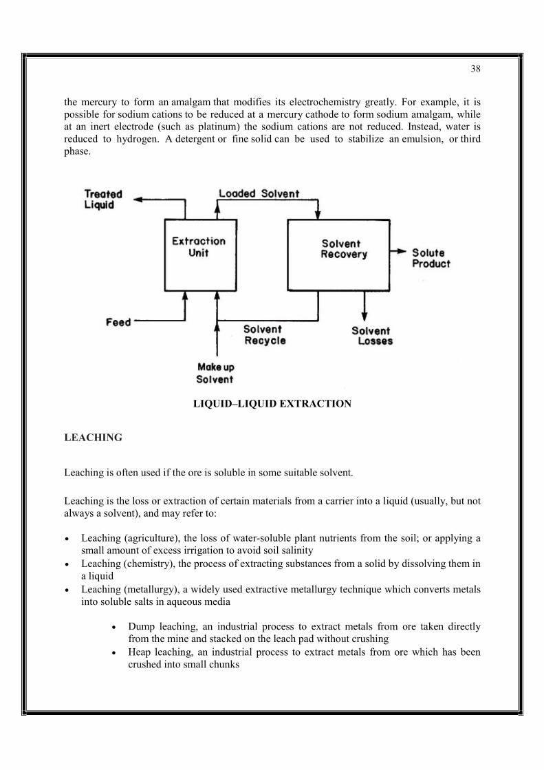
Liquid–liquid extraction Solid-phase extraction Acid-base extraction Supercritical fluid extraction Ultrasound-assisted extraction Heat reflux extraction Mechanochemical-assisted extraction Microwave-assisted extraction LIQUID–LIQUID EXTRACTION
Liquid–liquid extraction (LLE), also known as solvent extraction and partitioning, is a method to separate compounds or metal complexes, based on their relative solubilities in two different immiscible liquids, usually water (polar) and an organic solvent (non-polar). There is a net transfer of one or more species from one liquid into another liquid phase, generally from aqueous to organic. The transfer is driven by chemical potential, i.e. once the transfer is complete, the overall system of chemical components that make up the solutes and the solvents are in a more stable configuration (lower free energy). The solvent that is enriched in solute(s) is called extract. The feed solution that is depleted in solute(s) is called the raffinate. LLE is a basic technique in chemical laboratories, where it is performed using a variety of apparatus, from separatory funnels to countercurrent distribution equipment called as mixer settlers. This type of process is commonly performed after a chemical reaction as part of the work-up, often including an acidic work-up.
The term partitioning is commonly used to refer to the underlying chemical and physical processes involved in liquid–liquid extraction, but on another reading may be fully synonymous with it. The term solvent extraction can also refer to the separation of a substance from a mixture by preferentially dissolving that substance in a suitable solvent. In that case, a soluble compound is separated from an insoluble compound or a complex matrix.
From a hydrometallurgical perspective, solvent extraction is exclusively used in separation and purification of uranium and plutonium, zirconium and hafnium, separation of cobalt and nickel, separation and purification of rare earth elements etc., its greatest advantage being its ability to selectively separate out even very similar metals. One obtains high-purity single metal streams on 'stripping' out the metal value from the 'loaded' organic wherein one can precipitate or deposit the metal value. Stripping is the opposite of extraction: Transfer of mass from organic to aqueous phase.
LLE is also widely used in the production of fine organic compounds, the processing of perfumes, the production of vegetable oils and biodiesel, and other industries, It is among the most common initial separation techniques, though some difficulties result in extracting out closely related functional groups.
Liquid–liquid extraction is possible in non-aqueous systems: In a system consisting of a molten metal in contact with molten salts, metals can be extracted from one phase to the other. This is related to a mercury electrode where a metal can be reduced, the metal will often then dissolve in
38
the mercury to form an amalgam that modifies its electrochemistry greatly. For example, it is possible for sodium cations to be reduced at a mercury cathode to form sodium amalgam, while at an inert electrode (such as platinum) the sodium cations are not reduced. Instead, water is reduced to hydrogen. A detergent or fine solid can be used to stabilize an emulsion, or third phase.
LIQUID–LIQUID EXTRACTION
LEACHING
Leaching is often used if the ore is soluble in some suitable solvent.
Leaching is the loss or extraction of certain materials from a carrier into a liquid (usually, but not always a solvent), and may refer to:
Leaching (agriculture), the loss of water-soluble plant nutrients from the soil; or applying a small amount of excess irrigation to avoid soil salinity
Leaching (chemistry), the process of extracting substances from a solid by dissolving them in a liquid
Leaching (metallurgy), a widely used extractive metallurgy technique which converts metals into soluble salts in aqueous media
Dump leaching, an industrial process to extract metals from ore taken directly from the mine and stacked on the leach pad without crushing
Heap leaching, an industrial process to extract metals from ore which has been crushed into small chunks
39
Tank leaching, a hydro metallurgical method of extracting valuable material from ore
In-situ leaching, a process of recovering minerals such as copper and uranium through boreholes drilled into the deposit
Leaching (pedology), the loss of mineral and organic solutes due to percolation from soil Bioleaching, the extraction of specific metals from their ores through the use of bacteria and
fungi
Leaching is the process of a solute becoming detached or extracted from its carrier substance by way of a solvent.
Leaching is a naturally occurring process which scientists have adapted for a variety of applications with a variety of methods. Specific extraction methods depend on the soluble characteristics relative to the sorbent material such as concentration, distribution, nature, and size. Leaching can occur naturally seen from plant substances (inorganic and organic), solute leaching in soil, and in the decomposition of organic materials. Leaching can also be applied affectedly to enhance water quality and contaminant removal, as well as for disposal of hazardous waste products such as fly ash, or rare earth elements (REEs). Understanding leaching characteristics is important in preventing or encouraging the leaching process and preparing for it in the case where it is inevitable.
In an ideal leaching equilibrium stage, all the solute is dissolved by the solvent, leaving the carrier of the solute unchanged. The process of leaching however is not always ideal, and can be quite complex to understand and replicate, and often different methodologies will produce different results.
LEACHING PROCESS
There are many types of leaching scenarios, therefore the extent of this topic is vast. In general however, the three substances can be described as:
a carrier, substance A, a solute, substance B, and a solvent, substance C.
Substance A and B are somewhat homogenous in a system prior to the introduction of substance C. At the beginning of the leaching process, substance C will work at dissolving the surficial substance B at a fairly high rate. The rate of dissolution however will decrease substantially once it needs to penetrate through the pores of substance A in order to continue targeting substance B. This penetration can often lead to dissolution of substance A,or the product of more than one solute, both unsatisfactory if specific leaching is desirable. Things to be considered when observing the leaching process are the physiochemical and biological properties of the carrier and solute, and certain properties may be more important depending on the material, the solvent, and their availability.
40
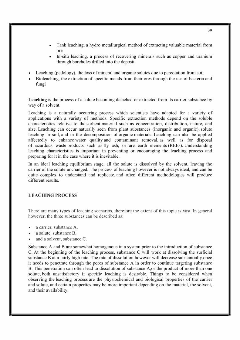
PROCESS OF CHEMICAL LEACHING METHOD ADSORPTION DEFINITION Increase in the concentration of a substance at the interface of a condensed and a liquid or gaseous layer owing to the operation of surface forces.

41
Note 1: Adsorption of proteins is of great importance when a material is in contact with blood or body fluids. In the case of blood, albumin, which is largely predominant, is generally adsorbed first, and then rearrangements occur in favor of other minor proteins according to surface affinity against mass law selection (Vroman effect).
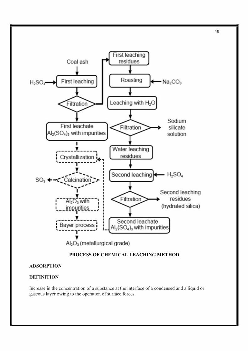
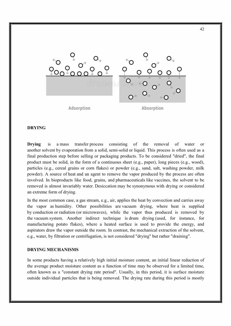
Note 2: Adsorbed molecules are those that are resistant to washing with the same solvent medium in the case of adsorption from solutions. The washing conditions can thus modify the measurement results, particularly when the interaction energy is low. Adsorption is the adhesion of atoms, ions or molecules from a gas, liquid or dissolved solid to a surface. This process creates a film of the adsorbate on the surface of the adsorbent. This process differs from absorption, in which a fluid (the absorbate) is dissolved by or permeates a liquid or solid (the absorbent), respectively. Adsorption is a surface phenomenon, while absorption involves the whole volume of the material, although adsorption does often precede absorption. The term sorption encompasses both processes, while desorption is the reverse of it.
Similar to surface tension, adsorption is a consequence of surface energy. In a bulk material, all the bonding requirements (be they ionic, covalent or metallic) of the constituent atoms of the material are filled by other atoms in the material. However, atoms on the surface of the adsorbent are not wholly surrounded by other adsorbent atoms and therefore can attract adsorbates. The exact nature of the bonding depends on the details of the species involved, but the adsorption process is generally classified as physisorption (characteristic of weak van der Waals forces) or chemisorption (characteristic of covalent bonding). It may also occur due to electrostatic attraction.
Adsorption is present in many natural, physical, biological and chemical systems and is widely used in industrial applications such as heterogeneous catalysts, activated charcoal, capturing and using waste heat to provide cold water for air conditioning and other process requirements (adsorption chillers), synthetic resins, increasing storage capacity of carbide-derived carbons and water purification. Adsorption, ion exchange and chromatography are sorption processes in which certain adsorbates are selectively transferred from the fluid phase to the surface of insoluble, rigid particles suspended in a vessel or packed in a column. Pharmaceutical industry applications, which use adsorption as a means to prolong neurological exposure to specific drugs or parts thereof, are lesser known.
The word "adsorption" was coined in 1881 by German physicist Heinrich Kayser (1853–1940).
42
DRYING
Drying is a mass transfer process consisting of the removal of water or another solvent by evaporation from a solid, semi-solid or liquid. This process is often used as a final production step before selling or packaging products. To be considered "dried", the final product must be solid, in the form of a continuous sheet (e.g., paper), long pieces (e.g., wood), particles (e.g., cereal grains or corn flakes) or powder (e.g., sand, salt, washing powder, milk powder). A source of heat and an agent to remove the vapor produced by the process are often involved. In bioproducts like food, grains, and pharmaceuticals like vaccines, the solvent to be removed is almost invariably water. Desiccation may be synonymous with drying or considered an extreme form of drying.
In the most common case, a gas stream, e.g., air, applies the heat by convection and carries away the vapor as humidity. Other possibilities are vacuum drying, where heat is supplied by conduction or radiation (or microwaves), while the vapor thus produced is removed by the vacuum system. Another indirect technique is drum drying (used, for instance, for manufacturing potato flakes), where a heated surface is used to provide the energy, and aspirators draw the vapor outside the room. In contrast, the mechanical extraction of the solvent, e.g., water, by filtration or centrifugation, is not considered "drying" but rather "draining".
DRYING MECHANISMS In some products having a relatively high initial moisture content, an initial linear reduction of the average product moisture content as a function of time may be observed for a limited time, often known as a "constant drying rate period". Usually, in this period, it is surface moisture outside individual particles that is being removed. The drying rate during this period is mostly

43
dependent on the rate of heat transfer to the material being dried. Therefore, the maximum achievable drying rate is considered to be heat-transfer limited. If drying is continued, the slope of the curve, the drying rate, becomes less steep (falling rate period) and eventually tends to become nearly horizontal at very long times. The product moisture content is then constant at the "equilibrium moisture content", where it is, in practice, in equilibrium with the dehydrating medium. In the falling-rate period, water migration from the product interior to the surface is mostly by molecular diffusion, i,e. the water flux is proportional to the moisture content gradient. This means that water moves from zones with higher moisture content to zones with lower values, a phenomenon explained by the second law of thermodynamics. If water removal is considerable, the products usually undergo shrinkage and deformation, except in a well-designed freeze-drying process. The drying rate in the falling-rate period is controlled by the rate of removal of moisture or solvent from the interior of the solid being dried and is referred to as being "mass-transfer limited". This is widely noticed in hygroscopic products such as fruits and vegetables, where drying occurs in the falling rate period with the constant drying rate period said to be negligible.
METHOD OF DRYING
The following are some general methods of drying:
Application of hot air (convective or direct drying). Air heating increases the drying force for heat transfer and accelerates drying. It also reduces air relative humidity, further increasing the driving force for drying. In the falling rate period, as moisture content falls, the solids heat up and the higher temperatures speed up diffusion of water from the interior of the solid to the surface. However, product quality considerations limit the applicable rise to air temperature. Excessively hot air can almost completely dehydrate the solid surface, so that its pores shrink and almost close, leading to crust formation or "case hardening", which is usually undesirable. For instance in wood (timber) drying, air is heated (which speeds up drying) though some steam is also added to it (which hinders drying rate to a certain extent) in order to avoid excessive surface dehydration and product deformation owing to high moisture gradients across timber thickness. Spray drying belongs in this category.
Indirect or contact drying (heating through a hot wall), as drum drying, vacuum drying. Again, higher wall temperatures will speed up drying but this is limited by product degradation or case-hardening. Drum drying belongs in this category.
Dielectric drying (radiofrequency or microwaves being absorbed inside the material) is the focus of intense research nowadays. It may be used to assist air drying or vacuum drying. Researchers have found that microwave finish drying speeds up the otherwise very low drying rate at the end of the classical drying methods.
Freeze drying or lyophilization is a drying method where the solvent is frozen prior to drying and is then sublimed, i.e., passed to the gas phase directly from the solid phase, below the

44
melting point of the solvent. It is increasingly applied to dry foods, beyond its already classical pharmaceutical or medical applications. It keeps biological properties of proteins, and retains vitamins and bioactive compounds. Pressure can be reduced by a high vacuum pump (though freeze drying at atmospheric pressure is possible in dry air). If using a vacuum pump, the vapor produced by sublimation is removed from the system by converting it into ice in a condenser, operating at very low temperatures, outside the freeze drying chamber.
Supercritical drying (superheated steam drying) involves steam drying of products containing water. This process is feasible because water in the product is boiled off, and joined with the drying medium, increasing its flow. It is usually employed in closed circuit and allows a proportion of latent heat to be recovered by recompression, a feature which is not possible with conventional air drying, for instance. The process has potential for use in foods if carried out at reduced pressure, to lower the boiling point.
Natural air drying takes place when materials are dried with unheated forced air, taking advantage of its natural drying potential. The process is slow and weather-dependent, so a wise strategy "fan off-fan on" must be devised considering the following conditions: Air temperature, relative humidity and moisture content and temperature of the material being dried. Grains are increasingly dried with this technique, and the total time (including fan off and on periods) may last from one week to various months, if a winter rest can be tolerated in cold areas.
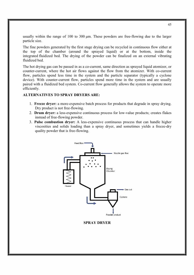
SPRAY DRYING
Spray drying is a method of producing a dry powder from a liquid or slurry by rapidly drying with a hot gas. This is the preferred method of drying of many thermally-sensitive materials such as foods and pharmaceuticals. A consistent particle size distribution is a reason for spray drying some industrial products such as catalysts. Air is the heated drying medium; however, if the liquid is a flammable solvent such as ethanol or the product is oxygen-sensitive then nitrogen is used.
All spray dryers use some type of atomizer or spray nozzle to disperse the liquid or slurry into a controlled drop size spray. The most common of these are rotary disk and single-fluid high pressure swirl nozzles. Atomizer wheels are known to provide broader particle size distribution, but both methods allow for consistent distribution of particle size. Alternatively, for some applications two-fluid or ultrasonic nozzles are used. Depending on the process requirements, drop sizes from 10 to 500 μm can be achieved with the appropriate choices. The most common applications are in the 100 to 200 μm diameter range. The dry powder is often free-flowing.
The most common type of spray dryers are called single effect. There is a single source of drying air at the top of the chamber (see n°4 on the diagram). In most cases the air is blown in the same direction as the sprayed liquid (co-current). A fine powder is produced, but it can have poor flow and produce much dust. To overcome the dust and poor flow of the powder, a new generation of spray dryers called multiple effect spray dryers has been produced. Instead of drying the liquid in one stage, drying is done through two steps: the first at the top (as per single effect) and the second with an integrated static bed at the bottom of the chamber. The bed provides a humid environment which causes smaller particles to clump, producing more uniform particle sizes,
45
usually within the range of 100 to 300 μm. These powders are free-flowing due to the larger particle size.
The fine powders generated by the first stage drying can be recycled in continuous flow either at the top of the chamber (around the sprayed liquid) or at the bottom, inside the integrated fluidized bed. The drying of the powder can be finalized on an external vibrating fluidized bed.
The hot drying gas can be passed in as a co-current, same direction as sprayed liquid atomizer, or counter-current, where the hot air flows against the flow from the atomizer. With co-current flow, particles spend less time in the system and the particle separator (typically a cyclone device). With counter-current flow, particles spend more time in the system and are usually paired with a fluidized bed system. Co-current flow generally allows the system to operate more efficiently.
ALTERNATIVES TO SPRAY DRYERS ARE:
1. Freeze dryer: a more-expensive batch process for products that degrade in spray drying. Dry product is not free-flowing.
2. Drum dryer: a less-expensive continuous process for low-value products; creates flakes instead of free-flowing powder.
3. Pulse combustion dryer: A less-expensive continuous process that can handle higher viscosities and solids loading than a spray dryer, and sometimes yields a freeze-dry quality powder that is free-flowing.
SPRAY DRYER

46
CRYSTALLIZATION
Crystallization or crystallisation is the process by which a solid forms, where the atoms or molecules are highly organized into a structure known as a crystal. Some of the ways by which crystals form are precipitating from a solution, freezing, or more rarely deposition directly from a gas. Attributes of the resulting crystal depend largely on factors such as temperature, air pressure, and in the case of liquid crystals, time of fluid evaporation.
Crystallization occurs in two major steps. The first is nucleation, the appearance of a crystalline phase from either a supercooled liquid or a supersaturated solvent. The second step is known as crystal growth, which is the increase in the size of particles and leads to a crystal state. An important feature of this step is that loose particles form layers at the crystal's surface and lodge themselves into open inconsistencies such as pores, cracks, etc.
The majority of minerals and organic molecules crystallize easily, and the resulting crystals are generally of good quality, i.e. without visible defects. However, larger biochemical particles, like proteins, are often difficult to crystallize. The ease with which molecules will crystallize strongly depends on the intensity of either atomic forces (in the case of mineral substances), intermolecular forces (organic and biochemical substances) or intramolecular forces (biochemical substances).
Crystallization is also a chemical solid–liquid separation technique, in which mass transfer of a solute from the liquid solution to a pure solid crystalline phase occurs. In chemical engineering, crystallization occurs in a crystallizer. Crystallization is therefore related to precipitation, although the result is not amorphous or disordered, but a crystal.
COOLING CRYSTALLIZATION
APPLICATION
Most chemical compounds, dissolved in most solvents, show the so-called direct solubility that is, the solubility threshold increases with temperature.
So, whenever the conditions are favorable, crystal formation results from simply cooling the solution. Here cooling is a relative term: austenite crystals in a steel form well above 1000 °C. An example of this crystallization process is the production of Glauber's salt, a crystalline form of sodium sulfate. In the diagram, where equilibrium temperature is on the x-axis and equilibrium concentration (as mass percent of solute in saturated solution) in y-axis, it is clear that sulfate solubility quickly decreases below 32.5 °C. Assuming a saturated solution at 30 °C, by cooling it to 0 °C (note that this is possible thanks to the freezing-point depression), the precipitation of a mass of sulfate occurs corresponding to the change in solubility from 29% (equilibrium value at 30 °C) to approximately 4.5% (at 0 °C) – actually a larger crystal mass is precipitated, since sulfate entrains hydration water, and this has the side effect of increasing the final concentration.

47
There are limitations in the use of cooling crystallization:
Many solutes precipitate in hydrate form at low temperatures: in the previous example this is acceptable, and even useful, but it may be detrimental when, for example, the mass of water of hydration to reach a stable hydrate crystallization form is more than the available water: a single block of hydrate solute will be formed – this occurs in the case of calcium chloride);
Maximum supersaturation will take place in the coldest points. These may be the heat exchanger tubes which are sensitive to scaling, and heat exchange may be greatly reduced or discontinued;
A decrease in temperature usually implies an increase of the viscosity of a solution. Too high a viscosity may give hydraulic problems, and the laminar flow thus created may affect the crystallization dynamics.
It is not applicable to compounds having reverse solubility, a term to indicate that solubility increases with temperature decrease (an example occurs with sodium sulfate where solubility is reversed above 32.5 °C).
COOLING CRYSTALLIZATION
The simplest cooling crystallizers are tanks provided with a mixer for internal circulation, where temperature decrease is obtained by heat exchange with an intermediate fluid circulating in a jacket. These simple machines are used in batch processes, as in processing of pharmaceuticals and are prone to scaling. Batch processes normally provide a relatively variable quality of the product along with the batch.
The Swenson-Walker crystallizer is a model, specifically conceived by Swenson Co. around 1920, having a semicylindric horizontal hollow trough in which a hollow screw conveyor or some hollow discs, in which a refrigerating fluid is circulated, plunge during rotation on a longitudinal axis. The refrigerating fluid is sometimes also circulated in a jacket around the trough. Crystals precipitate on the cold surfaces of the screw/discs, from which they are removed by scrapers and settle on the bottom of the trough. The screw, if provided, pushes the slurry towards a discharge port.
A common practice is to cool the solutions by flash evaporation: when a liquid at a given T0 temperature is transferred in a chamber at a pressure P1 such that the liquid saturation temperature T1 at P1 is lower than T0, the liquid will release heat according to the temperature difference and a quantity of solvent, whose total latent heat of vaporization equals the difference in enthalpy. In simple words, the liquid is cooled by evaporating a part of it.
In the sugar industry, vertical cooling crystallizers are used to exhaust the molasses in the last crystallization stage downstream of vacuum pans, prior to centrifugation. The massecuite enters the crystallizers at the top, and cooling water is pumped through pipes in counterflow.
48
EVAPORATIVE CRYSTALLIZERS
Most industrial crystallizers are of the evaporative type, such as the very large sodium chloride and sucrose units, whose production accounts for more than 50% of the total world production of crystals. The most common type is the forced circulation (FC) model (see evaporator). A pumping device (a pump or an axial flow mixer) keeps the crystal slurry in homogeneous suspension throughout the tank, including the exchange surfaces; by controlling pump flow, control of the contact time of the crystal mass with the supersaturated solution is achieved, together with reasonable velocities at the exchange surfaces. The Oslo, mentioned above, is a refining of the evaporative forced circulation crystallizer, now equipped with a large crystals settling zone to increase the retention time (usually low in the FC) and to roughly separate heavy slurry zones from clear liquid. Evaporative crystallizers tend to yield larger average crystal size and narrows the crystal size distribution curve.

49
UNIT – III CHEMICAL REACTION
A chemical reaction is a process that leads to the chemical transformation of one set of chemical substances to another. Classically, chemical reactions encompass changes that only involve the positions of electrons in the forming and breaking of chemical bonds between atoms, with no change to the nuclei (no change to the elements present), and can often be described by a chemical equation. Nuclear chemistry is a sub-discipline of chemistry that involves the chemical reactions of unstable and radioactive elements where both electronic and nuclear changes can occur.
The substance (or substances) initially involved in a chemical reaction are called reactants or reagents. Chemical reactions are usually characterized by a chemical change, and they yield one or more products, which usually have properties different from the reactants. Reactions often consist of a sequence of individual sub-steps, the so-called elementary reactions, and the information on the precise course of action is part of the reaction mechanism. Chemical reactions are described with chemical equations, which symbolically present the starting materials, end products, and sometimes intermediate products and reaction conditions.
Chemical reactions happen at a characteristic reaction rate at a given temperature and chemical concentration. Typically, reaction rates increase with increasing temperature because there is more thermal energy available to reach the activation energy necessary for breaking bonds between atoms.
Reactions may proceed in the forward or reverse direction until they go to completion or reach equilibrium. Reactions that proceed in the forward direction to approach equilibrium are often described as spontaneous, requiring no input of free energy to go forward. Non-spontaneous reactions require input of free energy to go forward (examples include charging a battery by applying an external electrical power source, or photosynthesis driven by absorption of electromagnetic radiation in the form of sunlight).
Different chemical reactions are used in combinations during chemical synthesis in order to obtain a desired product. In biochemistry, a consecutive series of chemical reactions (where the product of one reaction is the reactant of the next reaction) form metabolic pathways. These reactions are often catalyzed by protein enzymes. Enzymes increase the rates of biochemical reactions, so that metabolic syntheses and decompositions impossible under ordinary conditions can occur at the temperatures and concentrations present within a cell.
The general concept of a chemical reaction has been extended to reactions between entities smaller than atoms, including nuclear reactions, radioactive decays, and reactions between elementary particles, as described by quantum field theory.

50
CHEMICAL REACTOR CHEMICAL EQUATION CH4 + 2 O2 → CO2 + 2 H2O, a coefficient of 2 must be placed before the oxygen gas on the reactants side and before the water on the products side in order for, as per the law of conservation of mass, the quantity of each element does not change during the reaction. APPLICATION
Chemical reactions are central to chemical engineering where they are used for the synthesis of new compounds from natural raw materials such as petroleum and mineral ores. It is essential to make the reaction as efficient as possible, maximizing the yield and minimizing the amount of reagents, energy inputs and waste. Catalysts are especially helpful for reducing the energy required for the reaction and increasing its reaction rate.
Some specific reactions have their niche applications. For example, the thermite reaction is used to generate light and heat in pyrotechnics and welding. Although it is less controllable than the more conventional oxy-fuel welding, arc welding and flash welding, it requires much less equipment and is still used to mend rails, especially in remote areas.
SIZE REDUCTION Size reduction is a process of reducing large solid unit masses - vegetables or chemical substances into small unit masses, coarse particles or fine particles. Size reduction is commonly employed in pharmaceutical industries. Size reduction process is also referred to as Comminution and Grinding. When the particle size of solids is reduced by mechanical means it

51
is known as Milling. The size reduction operation can be divided into two major categories depending on whether the material is a solid or a liquid. If the material is solid, the process is called grinding and cutting, if it is liquid, emulsification or atomization. OBJECTIVES OF SIZE REDUCTION
Size reduction leads to increase of surface area.
Pharmaceutical capsules, insufflations (i.e. powders inhaled directly into the lungs).suppositories and ointments require particles size to be below 60 mm size.
To increase the therapeutic effectiveness of certain drugs by reducing the particle size.
Size reduction produces particles in narrow size range. Mixing of powders with narrow
Range is easier and uniform. Pharmaceutical suspensions require finer particle size. It
reduces rate of sedimentation.
MECHANISM OF SIZE REDUCTION Impact – this involve hammer or bar at high speed (hammer mill).
Compression- particle crushed b/w rollers by the application of force (roller mill).
Cutting – the material cut by a sharp blade (cutter mill)
Attrition - arising from particles scraping against one another or rubbing action (fluid energy
mill).Laws governing size reduction
Griffith theory -The amount of force to be applied depends on the crack length.
Kick's law- Work required to reduce the size of a given quantity of material is constant for the
same reduction ratio regardless of the original size.
Rittinger's law -Worked use for particulate size reduction is directly proportional to the new
surface produced.
Bond's law -Worked used to reduce particle size is proportional to the square root of the
diameter of the particle produced.
FACTORS AFFECTING SIZE REDUCTION Selection of mill - It is related to feed, milled product, safety and economics Factors related to nature of raw materials affecting size reduction
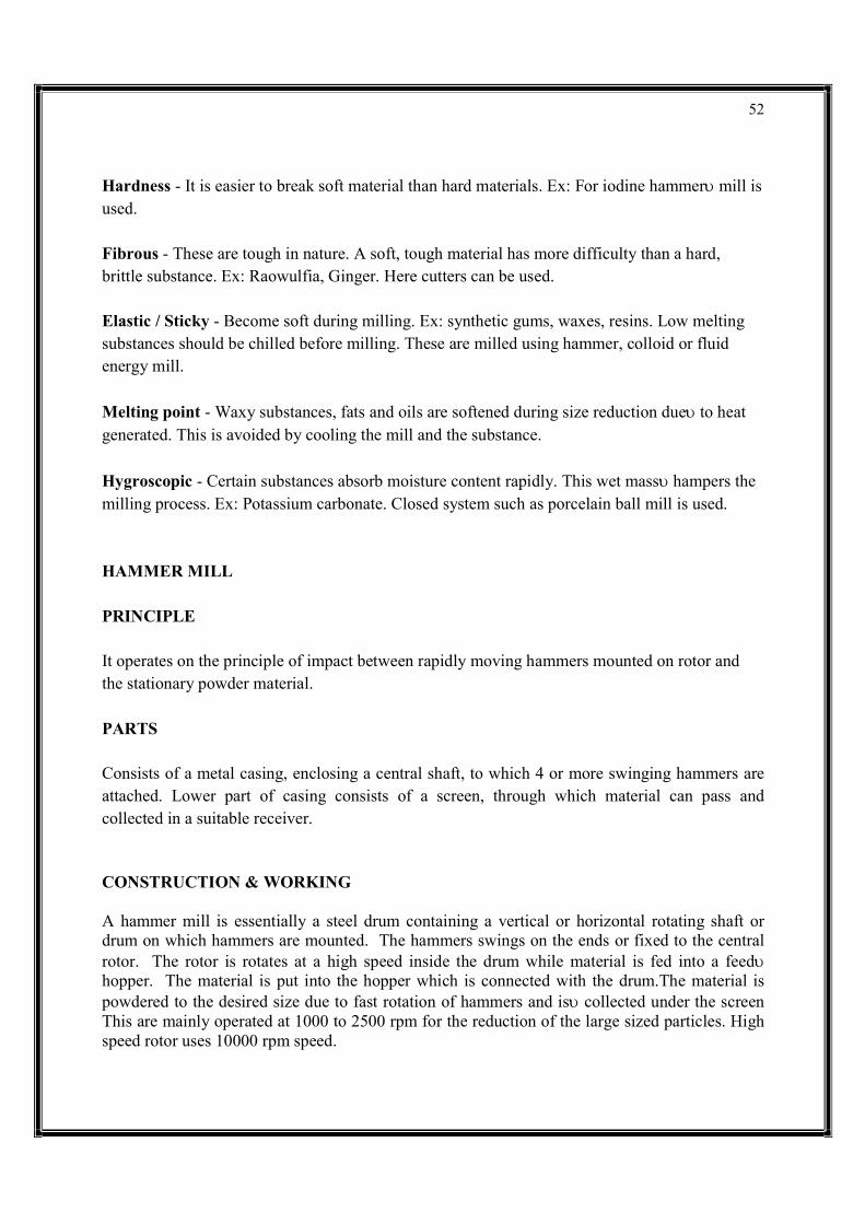
52
Hardness - It is easier to break soft material than hard materials. Ex: For iodine hammer mill is used. Fibrous - These are tough in nature. A soft, tough material has more difficulty than a hard, brittle substance. Ex: Raowulfia, Ginger. Here cutters can be used. Elastic / Sticky - Become soft during milling. Ex: synthetic gums, waxes, resins. Low melting substances should be chilled before milling. These are milled using hammer, colloid or fluid energy mill.
Melting point - Waxy substances, fats and oils are softened during size reduction due to heat generated. This is avoided by cooling the mill and the substance.
Hygroscopic - Certain substances absorb moisture content rapidly. This wet mass hampers the milling process. Ex: Potassium carbonate. Closed system such as porcelain ball mill is used. HAMMER MILL PRINCIPLE It operates on the principle of impact between rapidly moving hammers mounted on rotor and the stationary powder material. PARTS Consists of a metal casing, enclosing a central shaft, to which 4 or more swinging hammers are attached. Lower part of casing consists of a screen, through which material can pass and collected in a suitable receiver. CONSTRUCTION & WORKING A hammer mill is essentially a steel drum containing a vertical or horizontal rotating shaft or drum on which hammers are mounted. The hammers swings on the ends or fixed to the central rotor. The rotor is rotates at a high speed inside the drum while material is fed into a feed hopper. The material is put into the hopper which is connected with the drum.The material is powdered to the desired size due to fast rotation of hammers and is collected under the screen This are mainly operated at 1000 to 2500 rpm for the reduction of the large sized particles. High speed rotor uses 10000 rpm speed.
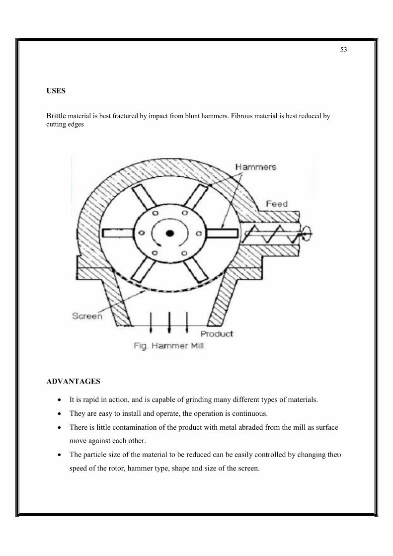
53
USES Brittle material is best fractured by impact from blunt hammers. Fibrous material is best reduced by cutting edges
ADVANTAGES
It is rapid in action, and is capable of grinding many different types of materials.
They are easy to install and operate, the operation is continuous.
There is little contamination of the product with metal abraded from the mill as surface
move against each other.
The particle size of the material to be reduced can be easily controlled by changing the
speed of the rotor, hammer type, shape and size of the screen.
54
DISADVANTAGES
Heat buildup during milling is more, therefore, product degradation is possible.
Hammer mills cannot be employed to mill sticky, fibrous and hard materials.
The screens may get clogged.
BALL MILL PRINCIPLE It operates on the principle of impact and attrition between the rapidly moving balls and the powder material, both enclosed in a hollow cylinder. PARTS Consists of a hollow cylinder mounted on a metallic frame such that it can be rotated along its longitudinal axis. Cylinder contains balls occupying 30–50 % of mill volume. Weight of ball is constant; Size depends on the feed quantity and diameter of mill. WORKING At low speeds, the ball roll over each other and attrition (rubbing action) will be the
predominate mode of action. Thus, in the ball mill, impact or attrition or both are responsible for the size reduction. ADVANTAGES
It can produce very fine powder.
Ball mill is used for both wet and dry grinding processes.
Toxic substances can be ground, as the cylinder is closed system. Installation, operation and labour costs are low
DISADVANTAGES
The ball mill is a very noisy machine.
Ball mill is a slow process.
Soft, fibrous material cannot be milled by ball mill.

55
USES
Stainless steel are preferred in the production of ophthalmic& parentral products.
Ball mill at low speed is used for milling dyes, pigments & insecticides.
EDGE RUNNER MILL PRINCIPLE The size reduction is done by crushing due to heavy weight of stone.
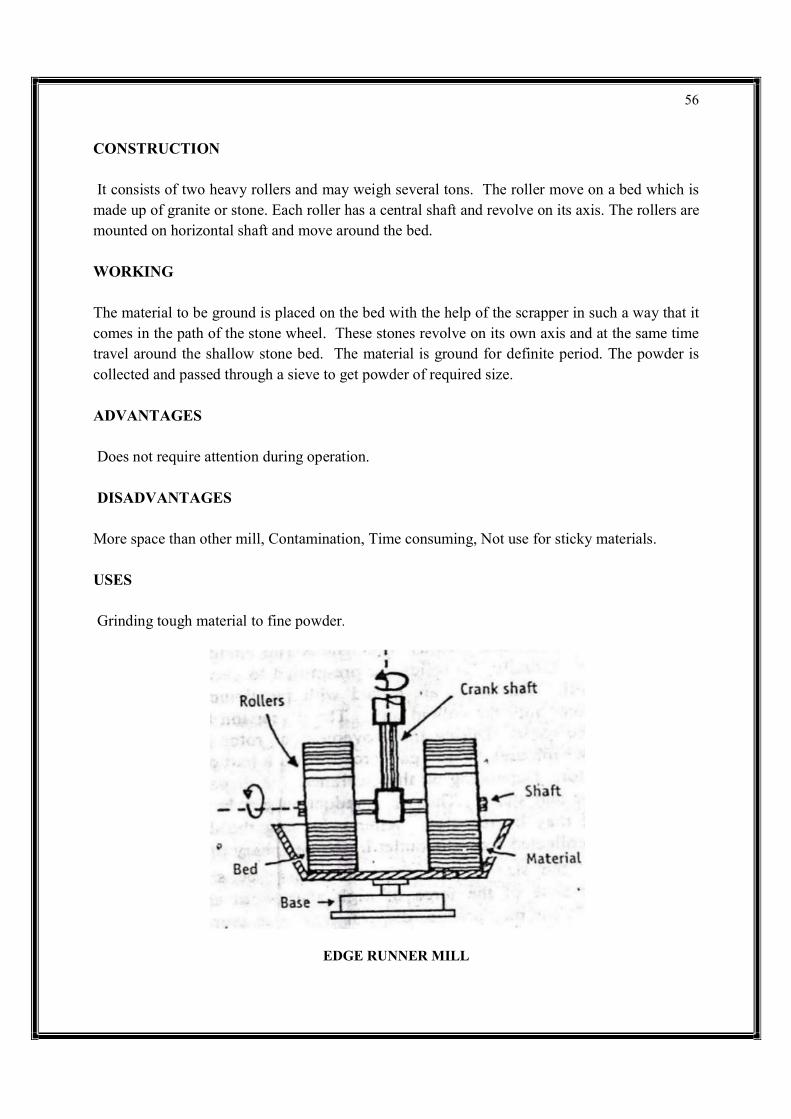
56
CONSTRUCTION It consists of two heavy rollers and may weigh several tons. The roller move on a bed which is made up of granite or stone. Each roller has a central shaft and revolve on its axis. The rollers are mounted on horizontal shaft and move around the bed. WORKING The material to be ground is placed on the bed with the help of the scrapper in such a way that it comes in the path of the stone wheel. These stones revolve on its own axis and at the same time travel around the shallow stone bed. The material is ground for definite period. The powder is collected and passed through a sieve to get powder of required size. ADVANTAGES Does not require attention during operation. DISADVANTAGES More space than other mill, Contamination, Time consuming, Not use for sticky materials. USES Grinding tough material to fine powder.
EDGE RUNNER MILL

57
END RUNNER MILL PRINCIPLE
Size reduction is done by crushing due to heavy weight of steel pestle. Shearing stress is also involved during movement of mortar and pestle. CONSTRUCTION It is considered as mechanical mortar pestle. It consists of a steel mortar which is fixed to a plate. The construction of mortar is connected to horizontal shaft bearing a pulley so the plate with mortar can be rotated at high speed. The pestle is dumb-bell shaped and bottom of pestle is flat. Construction of pestle is done in such a way that it can be raised from mortar for cleaning and emptying WORKING The material to be ground is placed in the mortar. The mortar revolves at a high speed. The revolving mortar causes the pestle to revolve during this process, size reduction is achieved. ADVANTAGES End runner mill provides moderately fine powder and operates successfully with fibrous materials, bark, woods fruits, leaves, etc. Wet grinding with very viscous material such as ointments and paste is also possible DISADVANTAGES Not suitable for unbroken or slightly broken condition of drug. USES Use for fine grinding.
END RUNNER MILL
58
FLUID ENERGY MILL PRINCIPLE It operates on the principle of impact and attrition. PARTS Consists of a loop of pipe with diameter 20-200 mm. The overall height of the pipe is 2 m. Inlet for feed and a series of nozzles for air, inert gas. Outlet with classifier which prevents the particles to pass until they become sufficiently fine. CONSTRUCTION It consists of a loop of pipe, which has a diameter of 20 to 200 mm , depending on the overall height of the loop ,which may be upto about 2 m . There is an inlet for the feed and a series of nozzles for the inlet of air or an inert gas. It also has an outlet with a classifier which allow the air to escape but prevents the particles to pass until they become sufficiently fine. WORKING The air or inert gas is introduced with a very high pressure through the nozzles .Solids are introduced into air steam through inlet .due to high degree of turbulence, impact and attritional forces occurs between the particles. The fine particles are collected through a classifier .Fluid energy mill reduces the particles to 1 to 20 micron. To get a very fine powder , even upto five micron, the material is pretreated to reduce the particle size to the order of 100 mesh and then passed through fluid energy mill. Uses The mill is used to grind heat sensitive material to fine powder. The mill is used to grind those drugs in which high degree of purity is required. ADVANTAGES
The mill is used to grind the material to fine powder.
The particle size of powder can be controlled due to the use of a classifier.
There is no wear of the mill and hence there is no contamination of the product.
It is useful for grinding heat sensitive substances such as sulphonamides, vitamins and antibiotics.

59
DISADVANTAGES
Tendency of forming aggregates or agglomerates after milling.
Generation of amorphous content due to high energy impact.
Formation of ultra-fine particles.
High energy consumption.
FLUID ENERGY MILL
FILTRATION Filtration is a physical, biological or chemical operation that separates solid matter and fluid from a mixture with a filter medium that has a complex structure through which only the fluid can pass. Solid particles that cannot pass through the filter medium are described as oversize and the fluid that passes through is called the filtrate. Oversize particles may form a filter cake on top of the filter and may also block the filter lattice, preventing the fluid phase from crossing the filter, known as blinding. The size of the largest particles that can successfully pass through a filter is called the effective pore size of that filter. The separation of solid and fluid is imperfect; solids will be contaminated with some fluid and filtrate will contain fine particles (depending on the pore size, filter thickness and biological activity). Filtration occurs both in nature and in engineered systems; there are biological, geological, and industrial forms.
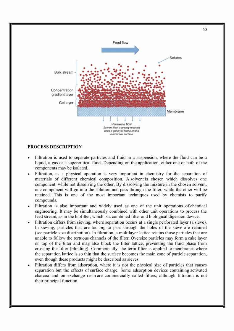
60
PROCESS DESCRIPTION
Filtration is used to separate particles and fluid in a suspension, where the fluid can be a liquid, a gas or a supercritical fluid. Depending on the application, either one or both of the components may be isolated.
Filtration, as a physical operation is very important in chemistry for the separation of materials of different chemical composition. A solvent is chosen which dissolves one component, while not dissolving the other. By dissolving the mixture in the chosen solvent, one component will go into the solution and pass through the filter, while the other will be retained. This is one of the most important techniques used by chemists to purify compounds.
Filtration is also important and widely used as one of the unit operations of chemical engineering. It may be simultaneously combined with other unit operations to process the feed stream, as in the biofilter, which is a combined filter and biological digestion device.
Filtration differs from sieving, where separation occurs at a single perforated layer (a sieve). In sieving, particles that are too big to pass through the holes of the sieve are retained (see particle size distribution). In filtration, a multilayer lattice retains those particles that are unable to follow the tortuous channels of the filter. Oversize particles may form a cake layer on top of the filter and may also block the filter lattice, preventing the fluid phase from crossing the filter (blinding). Commercially, the term filter is applied to membranes where the separation lattice is so thin that the surface becomes the main zone of particle separation, even though these products might be described as sieves.
Filtration differs from adsorption, where it is not the physical size of particles that causes separation but the effects of surface charge. Some adsorption devices containing activated charcoal and ion exchange resin are commercially called filters, although filtration is not their principal function.
61
Filtration differs from removal of magnetic contaminants from fluids with magnets (typically lubrication oil, coolants and fuel oils), because there is no filter medium. Commercial devices called ‘magnetic filters’ are sold, but the name reflects their use, not their mode of operation.
In biological filters, oversize particulates are trapped and ingested and the resulting metabolites may be released. For example, in animals (including humans), renal filtration removes waste from the blood, and in water treatment and sewage treatment, undesirable constituents are removed by absorption into a biological film grown on or in the filter medium, as in slow sand filtration.
METHOD There are many different methods of filtration; all aim to attain the separation of substances. Separation is achieved by some form of interaction between the substance or objects to be removed and the filter. The substance that is to pass through the filter must be a fluid, i.e. a liquid or gas. Methods of filtration vary depending on the location of the targeted material, i.e. whether it is dissolved in the fluid phase or suspended as a solid. There are several filtration techniques depending on the desired outcome namely, hot, cold and vacuum filtration. Some of the major purposes of getting the desired outcome are, for the removal of impurities from a mixture or, for the isolation of solids from a mixture. HOT FILTRATION
Hot filtration method is mainly used to separate solids from a hot solution. This is done in order to prevent crystal formation in the filter funnel and other apparatuses that comes in contact with the solution. As a result, the apparatus and the solution used are heated in order to prevent the rapid decrease in temperature which in turn, would lead to the crystallization of the solids in the funnel and hinder the filtration process. One of the most important measures to prevent the formation of crystals in the funnel and to undergo effective hot filtration is the use stemless filter funnel. Due to the absence of stem in the filter funnel, there is a decrease in the surface area of contact between the solution and the stem of the filter funnel, hence preventing re-crystallization of solid in the funnel, adversely affecting filtration process.
COLD FILTRATION
Cold filtration method is the use of ice bath in order to rapidly cool down the solution to be crystallized rather than leaving it out to cool it down slowly in the room temperature. This technique results to the formation of very small crystals as opposed to getting large crystals by cooling the solution down at room temperature.
62
VACUUM FILTRATION
Vacuum Filtration technique is most preferred for small batch of solution in order to quickly dry out small crystals. This method requires a Büchner funnel, filter paper of smaller diameter than the funnel, Büchner flask, and rubber tubing to connect to vacuum source.
Two main types of filter media are employed in laboratories: a surface filter, a solid sieve which traps the solid particles, with or without the aid of filter paper (e.g. Büchner funnel, Belt filter, Rotary vacuum-drum filter, Cross-flow filters, Screen filter); and a depth filter, a bed of granular material which retains the solid particles as it passes (e.g. sand filter). The first type allows the solid particles, i.e. the residue, to be collected intact; the second type does not permit this. However, the second type is less prone to clogging due to the greater surface area where the particles can be trapped. Also, when the solid particles are very fine, it is often cheaper and easier to discard the contaminated granules than to clean the solid sieve.
Filter media can be cleaned by rinsing with solvents or detergents. Alternatively, in engineering applications, such as swimming pool water treatment plants, they may be cleaned by backwashing. Self-cleaning screen filters utilize point-of-suction backwashing to clean the screen without interrupting system flow.
SOLVENT EXTRACTION Solvent extraction, also called liquid-liquid extraction (LLE) and partitioning, is a method to separate compounds based on their relative solubilities in two different immiscible liquids. Immiscible liquids are ones that cannot get mixed up together and separate into layers when shaken together. These liquids are usually water and an organic solvent. LLE is an extraction of a substance from one liquid into another liquid phase. The most common use of the distribution principle is in the extraction of substances by solvents, which are often employed in a laboratory or in large scale manufacturing. Organic compounds are generally much more soluble in organic solvents, like benzene, chloroform, and ether, than in water and these solvents are immiscible with water. Organic compounds are then quite easily separated from the mixture with inorganic compounds in aqueous medium by adding benzene, chloroform, etc. Upon shaking, these separate into two layers. Since organic compounds have their distribution ratio largely in favor of the benzene phase, more of them would pass into a non-aqueous layer. Finally this non-aqueous layer is removed and distilled to obtain the purified compound.
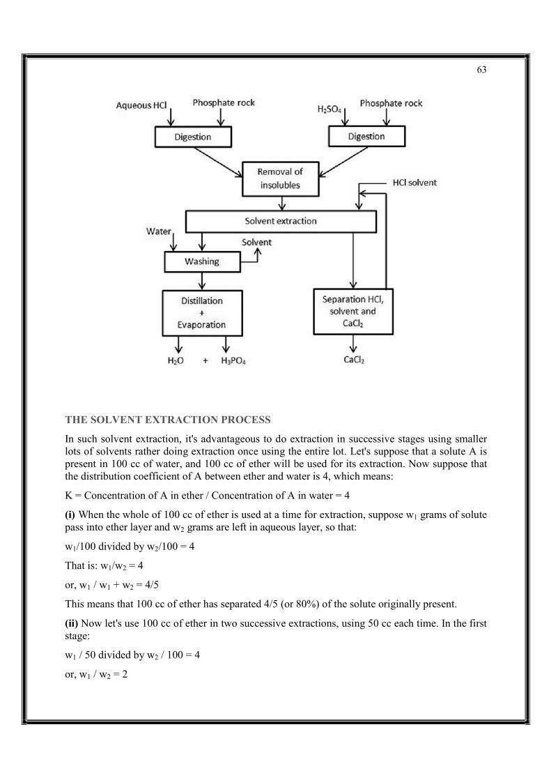
63
THE SOLVENT EXTRACTION PROCESS
In such solvent extraction, it's advantageous to do extraction in successive stages using smaller lots of solvents rather doing extraction once using the entire lot. Let's suppose that a solute A is present in 100 cc of water, and 100 cc of ether will be used for its extraction. Now suppose that the distribution coefficient of A between ether and water is 4, which means:
K = Concentration of A in ether / Concentration of A in water = 4
(i) When the whole of 100 cc of ether is used at a time for extraction, suppose w1 grams of solute pass into ether layer and w2 grams are left in aqueous layer, so that:
w1/100 divided by w2/100 = 4
That is: w1/w2 = 4
or, w1 / w1 + w2 = 4/5
This means that 100 cc of ether has separated 4/5 (or 80%) of the solute originally present.
(ii) Now let's use 100 cc of ether in two successive extractions, using 50 cc each time. In the first stage:
w1 / 50 divided by w2 / 100 = 4
or, w1 / w2 = 2

64
or, w1 / w1 + w2 = 2/3
In the first extraction 2/3 (that is, 66.7%) is extracted. So 1/3 of the original amount is still retained in aqueous medium. In the second extraction, again using 50 cc of ether, we will further extract 2/3 of 1/3 (that is, 2/9) of the original amount. In other words, in two extractions using the same 100 cc ether we can separate (2/3 + 2/9), or 88.9%, of the original amount of the compound. Thus, a two-stage extraction is more efficient. If the same 100 cc of solution is used in four or five lots, a still greater proportion could be extracted.
PIPING AND INSTRUMENTATION DIAGRAM (P&ID)
A piping and instrumentation diagram (P&ID) is a detailed diagram in the process industry which shows the piping and process equipment together with the instrumentation and control devices.
Superordinate to the P&ID is the process flow diagram (PFD) which indicates the more general flow of plant processes and the relationship between major equipment of a plant facility.
piping and instrumentation diagram (P&ID) is defined as follows:
1. A diagram which shows the interconnection of process equipment and the instrumentation used to control the process. In the process industry, a standard set of symbols is used to prepare drawings of processes. The instrument symbols used in these drawings are generally based on International Society of Automation (ISA) Standard S5.1
2. The primary schematic drawing used for laying out a process control installation.
They usually contain the following information:
Mechanical equipment, including:
Pressure vessels, columns, tanks, pumps, compressors, heat exchangers, furnaces, wellheads, fans, cooling towers, turbo-expanders, pig traps (see 'symbols' below)
Bursting discs, restriction orifices, strainers and filters, steam traps, moisture traps, sight-glasses, silencers, flares and vents, flame arrestors, vortex breakers, eductors
Process piping, sizes and identification, including:
Pipe classes and piping line numbers
Flow directions
Interconnections references
Permanent start-up, flush and bypass lines
Pipelines and flowlines
Blinds and spectacle blinds

65
Insulation and heat tracing
Process control instrumentation and designation (names, numbers, unique tag identifiers), including:
Valves and their types and identifications (e.g. isolation, shutoff, relief and safety valves, valve interlocks)
Control inputs and outputs (sensors and final elements, interlocks)
Miscellaneous - vents, drains, flanges, special fittings, sampling lines, reducers and swages
Interfaces for class changes
Computer control system
Identification of components and subsystems delivered by others
P&IDs are originally drawn up at the design stage from a combination of process flow sheet data, the mechanical process equipment design, and the instrumentation engineering design. During the design stage, the diagram also provides the basis for the development of system control schemes, allowing for further safety and operational investigations, such as a Hazard and operability study (HAZOP). To do this, it is critical to demonstrate the physical sequence of equipment and systems, as well as how these systems connect.
P&IDs also play a significant role in the maintenance and modification of the process after initial build. Modifications are red-penned onto the diagrams and are vital records of the current plant design.
They are also vital in enabling development of;
Control and shutdown schemes
Safety and regulatory requirements
Start-up sequences
Operational understanding.
P&IDs form the basis for the live mimic diagrams displayed on graphical user interfaces of large industrial control systems such as SCADA and distributed control systems.
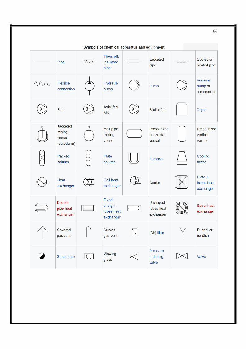
66
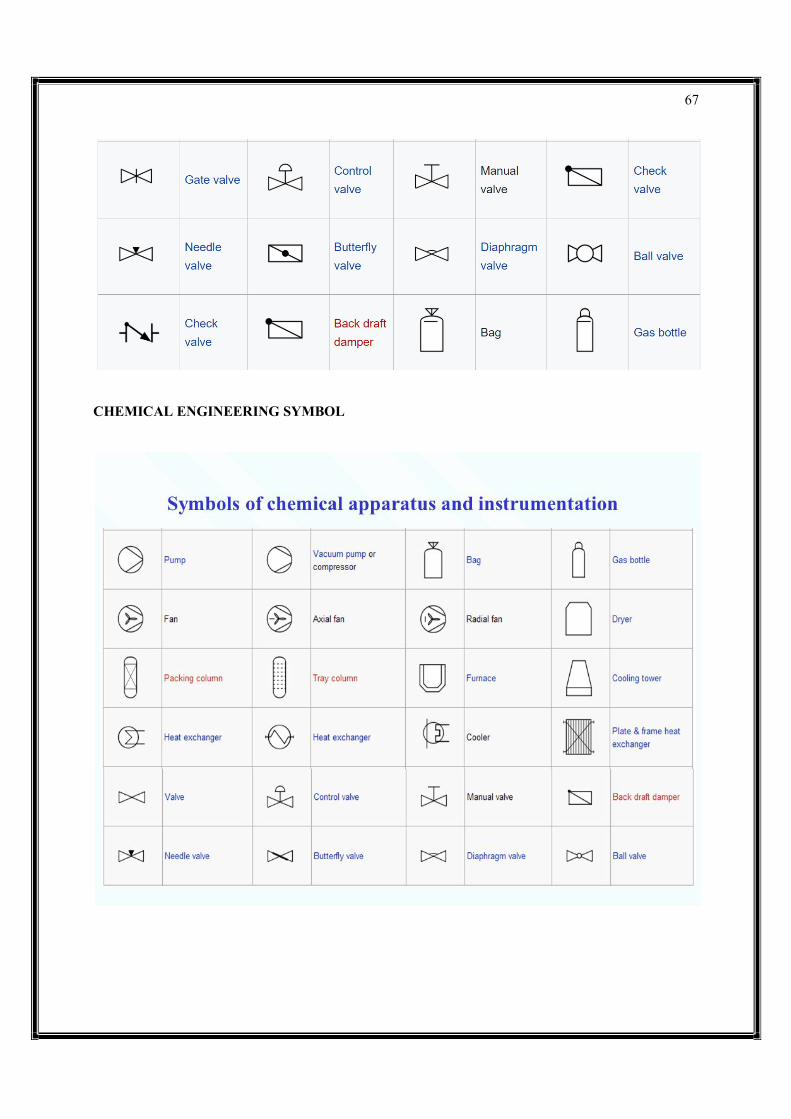
67
CHEMICAL ENGINEERING SYMBOL

68
UNIT –IV
MASS BALANCE dmdt=d(ρV)dt=∑˙min−∑˙mout SPECIES BALANCE A species balance tracks the number of moles n of species A in a control volume. The accumulation of A, d(nA)/dt, in a control volume is calculated by inlet, outlet, reaction generation, and reaction consumption rates. dnAdt=∑˙nAin−∑˙nAout+∑˙nAgen−∑˙nAconsdnAdt=∑n˙Ain−∑n˙Aout+∑n˙Agen−∑n˙Acons
The molar amount, nA is often measured as a concentration, cA and reaction rates are often expressed in terms of a specific reaction rate, rA, as a molar rate of generation per volume. dcAVdt=∑cAin˙Vin−∑cAout˙Vout+rAVdcAVdt=∑cAinV˙in−∑cAoutV˙out+rAV
MOMENTUM BALANCE A momentum balance is the accumulation of momentum for a control volume equal to the sum of forces F acting on that control volume. d(mv)dt=∑Fd(mv)dt=∑F
with m as the mass in the control volume and v as the velocity of the control volume.
ENERGY BALANCE dEdt=d(U+K+P)dt=∑˙min(^hin+v2in2gc+zingingc)−∑˙mout(^hout+v2out2gc+zoutgoutgc)+Q+WsdEdt=d(U+K+P)dt=∑m˙in(h^in+vin22gc+zingingc)−∑m˙out(h^out+vout22gc+zoutgoutgc)+Q+Ws
Kinetic (K) and potential (P) energy terms are omitted because the internal energy (due to temperature) is typically a much larger contribution than any elevation (z) or velocity (v) changes of a fluid for most chemical processes. dhdt=∑˙min^hin−∑˙min^hout+Q+Wsdhdt=∑m˙inh^in−∑m˙inh^out+Q+Ws
The enthalpy, h, is related to temperature as m cp (T-Tref) where cp is the heat capacity. With a constant reference temperature (Tref), this reduces to the following. mcpdTdt=∑˙mincp(Tin−Tref)−∑˙moutcp(Tout−Tref)+Q+WsmcpdTdt=∑m˙incp(Tin−Tref)−∑m˙outcp(Tout−Tref)+Q+Ws
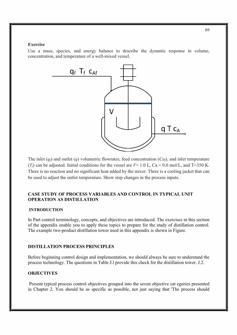
69
Exercise Use a mass, species, and energy balance to describe the dynamic response in volume, concentration, and temperature of a well-mixed vessel.
The inlet (qf) and outlet (q) volumetric flowrates, feed concentration (Caf), and inlet temperature (Tf) can be adjusted. Initial conditions for the vessel are V= 1.0 L, Ca = 0.0 mol/L, and T=350 K. There is no reaction and no significant heat added by the mixer. There is a cooling jacket that can be used to adjust the outlet temperature. Show step changes in the process inputs. CASE STUDY OF PROCESS VARIABLES AND CONTROL IN TYPICAL UNIT OPERATION AS DISTILLATION INTRODUCTION In Part control terminology, concepts, and objectives are introduced. The exercises in this section of the appendix enable you to apply these topics to prepare for the study of distillation control. The example two-product distillation tower used in this appendix is shown in Figure. DISTILLATION PROCESS PRINCIPLES Before beginning control design and implementation, we should always be sure to understand the process technology. The questions in Table J.l provide this check for the distillation tower. J.2. OBJECTIVES Present typical process control objectives grouped into the seven objective cat egories presented in Chapter 2. You should be as specific as possible, not just saying that 'The process should

70
remain safe" or "Profit should be maximized." Remember that these objectives must be clear enough to direct the control design and implementation.
POTENTIAL BENEFITS FROM CONTROL INTRODUCTION Answer the following questions for a simple, two-product distillation tower like the one in Figure J.l that is separating a binary mixture. 1. Explain input variables and equipment performance factors that are likely to affect the profit of an operating distillation tower; do not include design decisions like the number of trays that cannot be changed during normal operation. 2. What information is required to determine the costs for the energy used in condensing and reboiling? 3. Some data is provided for the distillation tower in Figure J.2. For this question, assume that the light key in the bottoms should never exceed 0.016 mole
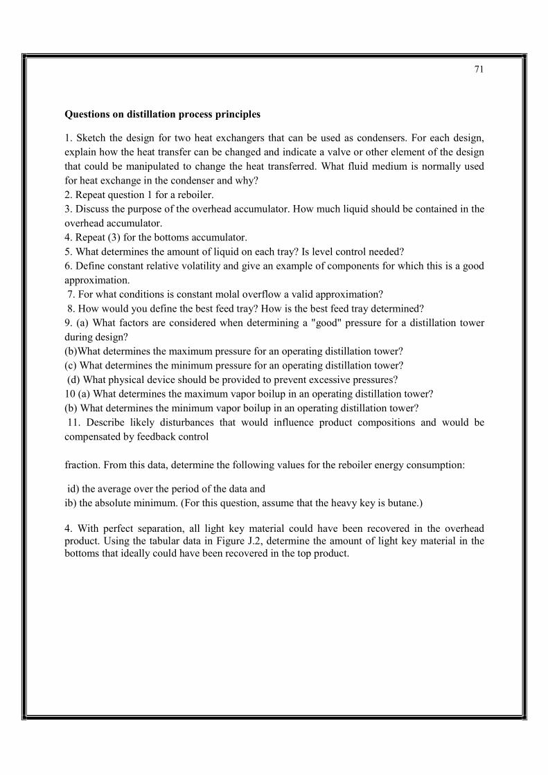
71
Questions on distillation process principles 1. Sketch the design for two heat exchangers that can be used as condensers. For each design, explain how the heat transfer can be changed and indicate a valve or other element of the design that could be manipulated to change the heat transferred. What fluid medium is normally used for heat exchange in the condenser and why? 2. Repeat question 1 for a reboiler. 3. Discuss the purpose of the overhead accumulator. How much liquid should be contained in the overhead accumulator. 4. Repeat (3) for the bottoms accumulator. 5. What determines the amount of liquid on each tray? Is level control needed? 6. Define constant relative volatility and give an example of components for which this is a good approximation. 7. For what conditions is constant molal overflow a valid approximation? 8. How would you define the best feed tray? How is the best feed tray determined? 9. (a) What factors are considered when determining a "good" pressure for a distillation tower during design? (b)What determines the maximum pressure for an operating distillation tower? (c) What determines the minimum pressure for an operating distillation tower? (d) What physical device should be provided to prevent excessive pressures? 10 (a) What determines the maximum vapor boilup in an operating distillation tower? (b) What determines the minimum vapor boilup in an operating distillation tower? 11. Describe likely disturbances that would influence product compositions and would be compensated by feedback control fraction. From this data, determine the following values for the reboiler energy consumption: id) the average over the period of the data and ib) the absolute minimum. (For this question, assume that the heavy key is butane.) 4. With perfect separation, all light key material could have been recovered in the overhead product. Using the tabular data in Figure J.2, determine the amount of light key material in the bottoms that ideally could have been recovered in the top product.
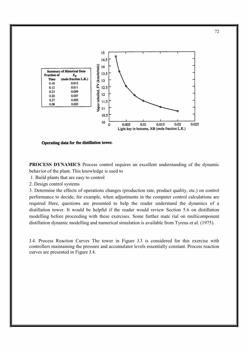
72
PROCESS DYNAMICS Process control requires an excellent understanding of the dynamic behavior of the plant. This knowledge is used to 1. Build plants that are easy to control 2. Design control systems 3. Determine the effects of operations changes (production rate, product quality, etc.) on control performance to decide, for example, when adjustments in the computer control calculations are required Here, questions are presented to help the reader understand the dynamics of a distillation tower. It would be helpful if the reader would review Section 5.6 on distillation modelling before proceeding with these exercises. Some further mate rial on multicomponent distillation dynamic modelling and numerical simulation is available from Tyreus et al. (1975). J.4. Process Reaction Curves The tower in Figure J.3 is considered for this exercise with controllers maintaining the pressure and accumulator levels essentially constant. Process reaction curves are presented in Figure J.4.

73
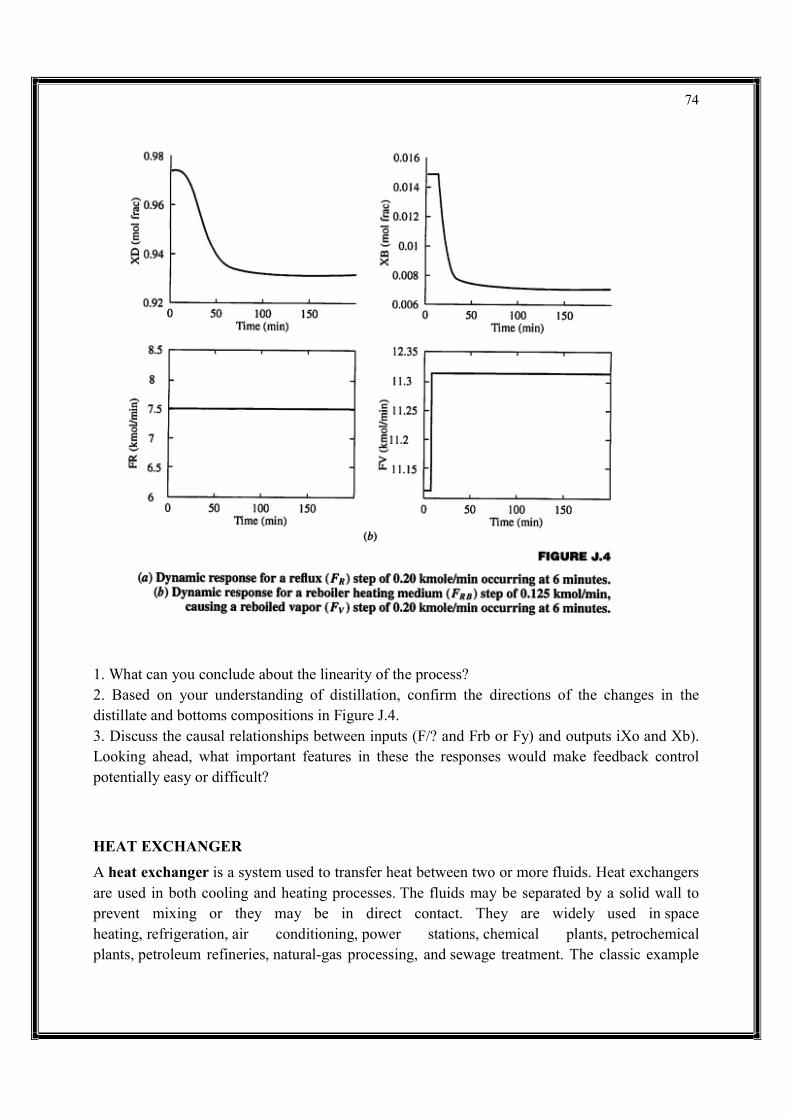
74
1. What can you conclude about the linearity of the process? 2. Based on your understanding of distillation, confirm the directions of the changes in the distillate and bottoms compositions in Figure J.4. 3. Discuss the causal relationships between inputs (F/? and Frb or Fy) and outputs iXo and Xb). Looking ahead, what important features in these the responses would make feedback control potentially easy or difficult? HEAT EXCHANGER
A heat exchanger is a system used to transfer heat between two or more fluids. Heat exchangers are used in both cooling and heating processes. The fluids may be separated by a solid wall to prevent mixing or they may be in direct contact. They are widely used in space heating, refrigeration, air conditioning, power stations, chemical plants, petrochemical plants, petroleum refineries, natural-gas processing, and sewage treatment. The classic example

75
of a heat exchanger is found in an internal combustion engine in which a circulating fluid known as engine coolant flows through radiator coils and air flows past the coils, which cools the coolant and heats the incoming air. Another example is the heat sink, which is a passive heat exchanger that transfers the heat generated by an electronic or a mechanical device to a fluid medium, often air or a liquid coolant.
TYPES • Shell and tube heat exchanger • Plate heat exchangers • Plate and shell heat exchanger • Adiabatic wheel heat exchanger • Plate fin heat exchanger • Pillow plate heat exchanger • Fluid heat exchangers • Waste heat recovery units • Dynamic scraped surface heat exchanger • Phase-change heat exchangers • Direct contact heat exchangers • Microchannel heat exchangers
Double pipe heat exchangers are the simplest exchangers used in industries. On one hand, these heat exchangers are cheap for both design and maintenance, making them a good choice for small industries. On the other hand, their low efficiency coupled with the high space occupied in large scales, has led modern industries to use more efficient heat exchangers like shell and tube or plate. However, since double pipe heat exchangers are simple, they are used to teach heat exchanger design basics to students as the fundamental rules for all heat exchangers are the same.
1. Double-pipe heat exchanger
(a) When the other fluid flows into the annular gap between two tubes, one fluid flows through the smaller pipe. The flow may be a current flow or parallel flow in a double pipe heat exchanger.
(b) Parallel flow, where at the same point, the hot and cold liquids join, flow in the same direction and exit at the same end.
(c) Counter flow, where at opposite ends, hot and cold fluids join, flow in the opposite direction and exit at opposite ends.
The figure above illustrates the parallel and counter-flow flow directions of the fluid exchanger. If this is done under comparable conditions, more heat is transferred to the counter-flow device
76
than to the parallel flow heat exchanger. Owing to the large temperature differential arising from the high thermal voltage, the temperature profiles of the two heat exchangers display two significant disadvantages in the parallel-flow design. Which indicates that the partnership is a distinct disadvantage if it is intended a design is to increase the cold fluid temperature. Where two fluids are expected to be taken to exactly the same temperature, the parallel flow configuration is beneficial. While the counter flow heat exchanger has more significant advantages compare to parallel flow design. Where it can reduce thermal stress and produce more uniform rate of heat transfer.
2. Shell-and-tube heat exchanger
The main constituents of this type of heat exchanger seem to be the tube box, shell, the front rear end headers, and baffles. The baffles are used to support the tubes, direct the fluid flow to the tubes in an approximately natural manner, and maximize the turbulence of the shell fluid. There is many various kinds of baffles, and the choice of baffle form, spacing, and geometry depending on the allowable flow rate of the drop in shell-side force, the need for tube support, and the flow-induced vibrations. There are several variations of shell-and - tube exchangers available; the differences lie in the arrangement of flow configurations and details of construction. 3. Plate Heat Exchanger A plate heat exchanger contains an amount of thin shaped heat transfer plates bundled together. The gasket arrangement of each pair of plates provides two separate channel system. Each pair of plates form a channel where the fluid can flow through. The pairs are attached by welding and bolting methods. The following shows the components in the heat exchanger.
In single channels the configuration of the gaskets enables flow through. Thus, this allows the main and secondary media in counter-current flow. A gasket plate heat exchanger has a heat region from corrugated plates. The gasket function as seal between plates and they are located between frame and pressure plates. Fluid flows in a counter current direction throughout the heat exchanger. An efficient thermal performance is produced. Plates are produced in different depths, sizes and corrugated shapes. There is different type of plates available which includes plate and frame, plate and shell and spiral plate heat exchangers. The distribution area guarantees the flow of fluid to the whole heat transfer surface. This helps to prevent stagnant area that can cause accumulation of unwanted material on solid surfaces. High flow turbulence between plates results in a greater transfer of heat and a decrease in pressure.
4. Condensers and Boilers Heat exchangers
Using a two-phase heat transfer system are condensers, boilers and evaporators. Condensers are instruments that take and cool hot gas or vapor to the point of condensation and transform the gas into a liquid form. The point at which liquid transforms to gas is called vaporization and vice versa is called condensation. Surface condenser is the most common type of condenser where it includes a water supply device. Figure 5 below displays a two-pass surface condenser.
77
The pressure of steam at the turbine outlet is low where the steam density is very low where the flow rate is very high. To prevent a decrease in pressure in the movement of steam from the turbine to condenser, the condenser unit is placed underneath and connected to the turbine. Inside the tubes the cooling water runs in a parallel way, while steam moves in a vertical downward position from the wide opening at the top and travel through the tube. Furthermore, boilers are categorized as initial application of heat exchangers. The word steam generator was regularly used to describe a boiler unit where a hot liquid stream is the source of heat rather than the combustion products. Depending on the dimensions and configurations the boilers are manufactured. Several boilers are only able to produce hot fluid while on the other hand the others are manufactured for steam production
SHELL AND TUBE HEAT EXCHANGERS
Shell and tube heat exchangers consist of a series of tubes which contain fluid that must be either heated or cooled. A second fluid runs over the tubes that are being heated or cooled so that it can either provide the heat or absorb the heat required. A set of tubes is called the tube bundle and can be made up of several types of tubes: plain, longitudinally finned, etc. Shell and tube heat exchangers are typically used for high-pressure applications (with pressures greater than 30 bar and temperatures greater than 260 °C).[4] This is because the shell and tube heat exchangers are robust due to their shape. Several thermal design features must be considered when designing the tubes in the shell and tube heat exchangers: There can be many variations on the shell and tube design. Typically, the ends of each tube are connected to plenums (sometimes called water boxes) through holes in tubesheets. The tubes may be straight or bent in the shape of a U, called U-tubes.
Tube diameter: Using a small tube diameter makes the heat exchanger both economical and compact. However, it is more likely for the heat exchanger to foul up faster and the small size makes mechanical cleaning of the fouling difficult. To prevail over the fouling and cleaning problems, larger tube diameters can be used. Thus to determine the tube diameter, the available space, cost and fouling nature of the fluids must be considered.
Tube thickness: The thickness of the wall of the tubes is usually determined to ensure:
There is enough room for corrosion
That flow-induced vibration has resistance
Axial strength
Availability of spare parts
Hoop strength (to withstand internal tube pressure)
Buckling strength (to withstand overpressure in the shell)
Tube length: heat exchangers are usually cheaper when they have a smaller shell diameter and a long tube length. Thus, typically there is an aim to make the heat exchanger as long as physically possible whilst not exceeding production capabilities. However, there are many
78
limitations for this, including space available at the installation site and the need to ensure tubes are available in lengths that are twice the required length (so they can be withdrawn and replaced). Also, long, thin tubes are difficult to take out and replace.
Tube pitch: when designing the tubes, it is practical to ensure that the tube pitch (i.e., the centre-centre distance of adjoining tubes) is not less than 1.25 times the tubes' outside diameter. A larger tube pitch leads to a larger overall shell diameter, which leads to a more expensive heat exchanger.
Tube corrugation: this type of tubes, mainly used for the inner tubes, increases the turbulence of the fluids and the effect is very important in the heat transfer giving a better performance.
Tube Layout: refers to how tubes are positioned within the shell. There are four main types of tube layout, which are, triangular (30°), rotated triangular (60°), square (90°) and rotated square (45°). The triangular patterns are employed to give greater heat transfer as they force the fluid to flow in a more turbulent fashion around the piping. Square patterns are employed where high fouling is experienced and cleaning is more regular.
Baffle Design: baffles are used in shell and tube heat exchangers to direct fluid across the tube bundle. They run perpendicularly to the shell and hold the bundle, preventing the tubes from sagging over a long length. They can also prevent the tubes from vibrating. The most common type of baffle is the segmental baffle. The semicircular segmental baffles are oriented at 180 degrees to the adjacent baffles forcing the fluid to flow upward and downwards between the tube bundle. Baffle spacing is of large thermodynamic concern when designing shell and tube heat exchangers. Baffles must be spaced with consideration for the conversion of pressure drop and heat transfer. For thermo economic optimization it is suggested that the baffles be spaced no closer than 20% of the shell's inner diameter. Having baffles spaced too closely causes a greater pressure drop because of flow redirection. Consequently, having the baffles spaced too far apart means that there may be cooler spots in the corners between baffles. It is also important to ensure the baffles are spaced close enough that the tubes do not sag. The other main type of baffle is the disc and doughnut baffle, which consists of two concentric baffles. An outer, wider baffle looks like a doughnut, whilst the inner baffle is shaped like a disk. This type of baffle forces the fluid to pass around each side of the disk then through the doughnut baffle generating a different type of fluid flow.
Fixed tube liquid-cooled heat exchangers especially suitable for marine and harsh applications can be assembled with brass shells, copper tubes, brass baffles, and forged brass integral end hubs.
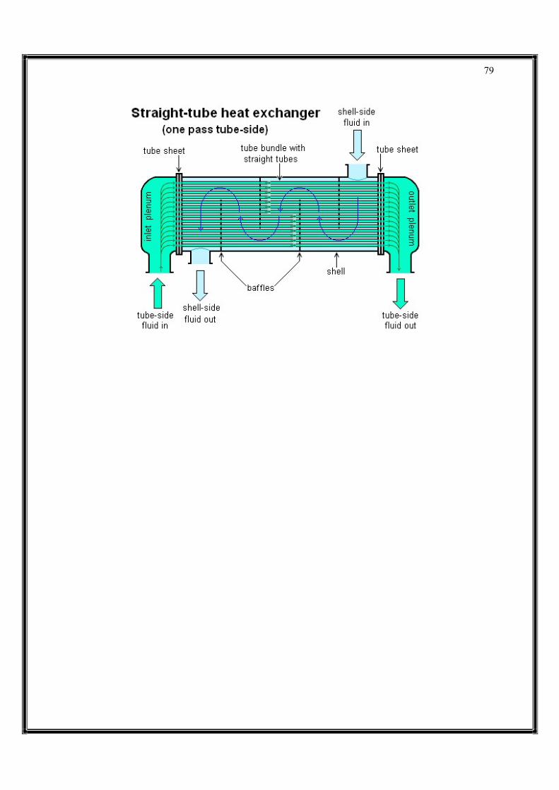
79

80
UNIT –V A HYDRAULIC SYSTEM A solution along hydraulic lines is shown in Figure. A hydraulic linear actuator suitable for this application is the ram, shown schematically in Figure. This consists of a movable piston connected directly to the output shaft. If fluid is pumped into pipe A, the piston will move up and the shaft will extend; if fluid is pumped into pipe B, the shaft will retract. Obviously some method of retrieving fluid from the non-pressurized side of the piston must be incorporated. The maximum force available from the cylinder depends on fluid pressure and cross-sectional area of the piston. This is discussed further in a later section but, as an example, a typical hydraulic pressure of 150 bar will lift 150kg cm−2 of piston area. A load of 2000kg could thus be lifted by a 4.2cm diameter piston. A suitable hydraulic system is shown in Figure . The system requires a liquid fluid to operate; this is expensive and messy and, consequently, the piping must act as a closed loop, with fluid transferred from a storage tank to one side of the piston, and returned from the other side of the piston to the tank. Fluid is drawn from the tank by a pump which produces fluid flow at the required 150 bar Such high-pressure pumps, however, cannot operate into a dead-end load as they deliver constant volumes of fluid from input to output ports for each revolution of the pump shaft. With a dead-end load, fluid pressure rises indefinitely, until a pipe or the pump itself fails. Some form of pressure regulation, as shown, is therefore required to spill excess fluid back to the tank. Cylinder movement is controlled by a three-position changeover valve. To extend the cylinder, port A is connected to the pressure line and port B to the tank. To reverse the motion, port B is connected to the pressure line and port A to the tank. In its center position the valve locks the fluid into the cylinder (thereby holding it in position) and dead-ends the fluid lines (causing all the pump output fluid to return to the tank via the pressure regulator). There are a few auxiliary points worthy of comment. First, speed control is easily achieved by regulating the volume flow rate to the cylinder (discussed in a later section). Precise control at low speeds is one of the main advantages of hydraulic systems. Second, travel limits are determined by the cylinder stroke and cylinders, generally, can be allowed to stall at the ends of travel so no overtravel protection is required. Third, the pump needs to be turned by an external power source, almost certainly an AC induction motor which, in turn, requires a motor starter and overload protection. Fourth, hydraulic fluid needs to be very clean, hence a filter is needed (shown in Figure) to remove dirt particles before the fluid passes from the tank to the pump One final point worth mentioning is that leaks of fluid from the system are unsightly, slippery (hence hazardous) and environmentally very undesirable. A major failure can be catastrophic. At first sight Figure appears inordinately complicated compared with the electrical system of Figure, but it should be remembered that all parts enclosed in the broken-lined box in Figure are common to an area of plant and not usually devoted to just one motion as we have drawn.

81
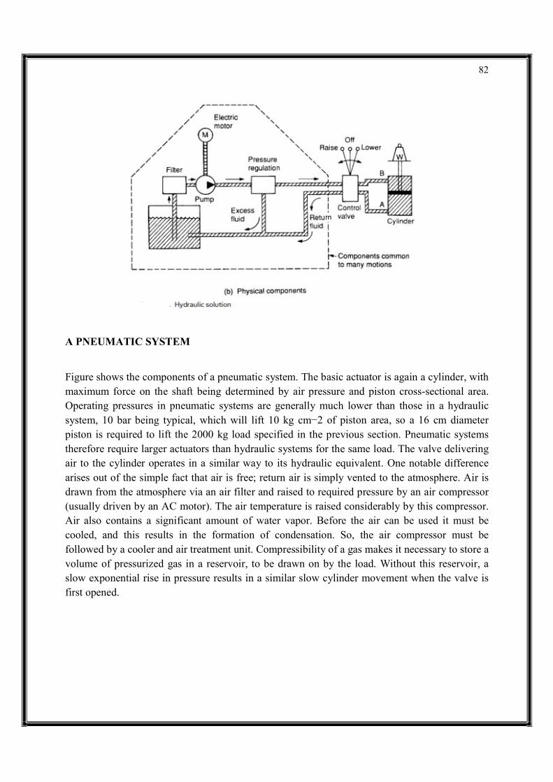
82
A PNEUMATIC SYSTEM Figure shows the components of a pneumatic system. The basic actuator is again a cylinder, with maximum force on the shaft being determined by air pressure and piston cross-sectional area. Operating pressures in pneumatic systems are generally much lower than those in a hydraulic system, 10 bar being typical, which will lift 10 kg cm−2 of piston area, so a 16 cm diameter piston is required to lift the 2000 kg load specified in the previous section. Pneumatic systems therefore require larger actuators than hydraulic systems for the same load. The valve delivering air to the cylinder operates in a similar way to its hydraulic equivalent. One notable difference arises out of the simple fact that air is free; return air is simply vented to the atmosphere. Air is drawn from the atmosphere via an air filter and raised to required pressure by an air compressor (usually driven by an AC motor). The air temperature is raised considerably by this compressor. Air also contains a significant amount of water vapor. Before the air can be used it must be cooled, and this results in the formation of condensation. So, the air compressor must be followed by a cooler and air treatment unit. Compressibility of a gas makes it necessary to store a volume of pressurized gas in a reservoir, to be drawn on by the load. Without this reservoir, a slow exponential rise in pressure results in a similar slow cylinder movement when the valve is first opened.

83
The air treatment unit is thus followed by an air reservoir. Hydraulic systems require a pressure regulator to spill excess fluid back to the tank, but pressure control in a hydraulic system is much simpler. A pressure switch, fitted to the air reservoir, starts the compressor motor when pressure falls and stops it again when pressure reaches the required level. The general impression is again one of complexity, but units in the broken-lined box are again common to one plant or even a whole site. Many factories produce compressed air at one central station and distribute an air ring main to all places on the site in a similar way to other services such as electricity, water or gas. DEFINITION OF TERMS There is an almost universal lack of standardization of units used for measurement in industry, and every engineer will tell tales of gauges indicating, say, velocity in furlongs per fortnight. Hydraulics and pneumatic systems suffer particularly from this characteristic, and it is by no means unusual to find pressure indicated at different locations in the same system in bar, kpascal and psi. There is, however, a welcome (and overdue) movement to standardization on the International System (SI) of units, but it will be some time before this is complete. The engineer will therefore encounter many odd-ball systems in the years to come. Any measurement system requires definition of the six units used to measure: • length: • mass; • time; • temperature; • electrical current; • light intensity. Of these, hydraulic/pneumatic engineers are primarily concerned with the first three. Other units (such as velocity, force, pressure) can be defined in terms of these basic units. Velocity, for example, is defined in terms of length/time. The old British Imperial system used units of foot, pound and second (and was consequently known as the fps system). Early metric systems used centimeter, gram and second (known as the cgs system), and meter, kilogram and second (the mks system). The mks system evolved into the SI system which introduces a more logical method of defining force and pressure (discussed in later
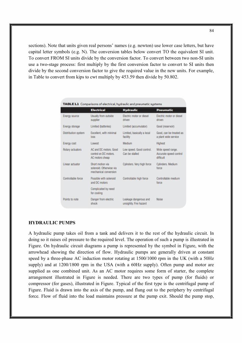
84
sections). Note that units given real persons’ names (e.g. newton) use lower case letters, but have capital letter symbols (e.g. N). The conversion tables below convert TO the equivalent SI unit. To convert FROM SI units divide by the conversion factor. To convert between two non-SI units use a two-stage process: first multiply by the first conversion factor to convert to SI units then divide by the second conversion factor to give the required value in the new units. For example, in Table to convert from kips to cwt multiply by 453.59 then divide by 50.802.
HYDRAULIC PUMPS A hydraulic pump takes oil from a tank and delivers it to the rest of the hydraulic circuit. In doing so it raises oil pressure to the required level. The operation of such a pump is illustrated in Figure. On hydraulic circuit diagrams a pump is represented by the symbol in Figure, with the arrowhead showing the direction of flow. Hydraulic pumps are generally driven at constant speed by a three-phase AC induction motor rotating at 1500/1000 rpm in the UK (with a 50Hz supply) and at 1200/1800 rpm in the USA (with a 60Hz supply). Often pump and motor are supplied as one combined unit. As an AC motor requires some form of starter, the complete arrangement illustrated in Figure is needed. There are two types of pump (for fluids) or compressor (for gases), illustrated in Figure. Typical of the first type is the centrifugal pump of Figure. Fluid is drawn into the axis of the pump, and flung out to the periphery by centrifugal force. Flow of fluid into the load maintains pressure at the pump exit. Should the pump stop,
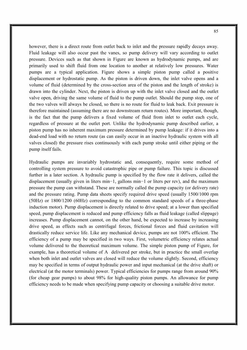
85
however, there is a direct route from outlet back to inlet and the pressure rapidly decays away. Fluid leakage will also occur past the vanes, so pump delivery will vary according to outlet pressure. Devices such as that shown in Figure are known as hydrodynamic pumps, and are primarily used to shift fluid from one location to another at relatively low pressures. Water pumps are a typical application. Figure shows a simple piston pump called a positive displacement or hydrostatic pump. As the piston is driven down, the inlet valve opens and a volume of fluid (determined by the cross-section area of the piston and the length of stroke) is drawn into the cylinder. Next, the piston is driven up with the inlet valve closed and the outlet valve open, driving the same volume of fluid to the pump outlet. Should the pump stop, one of the two valves will always be closed, so there is no route for fluid to leak back. Exit pressure is therefore maintained (assuming there are no downstream return routes). More important, though, is the fact that the pump delivers a fixed volume of fluid from inlet to outlet each cycle, regardless of pressure at the outlet port. Unlike the hydrodynamic pump described earlier, a piston pump has no inherent maximum pressure determined by pump leakage: if it drives into a dead-end load with no return route (as can easily occur in an inactive hydraulic system with all valves closed) the pressure rises continuously with each pump stroke until either piping or the pump itself fails. Hydraulic pumps are invariably hydrostatic and, consequently, require some method of controlling system pressure to avoid catastrophic pipe or pump failure. This topic is discussed further in a later section. A hydraulic pump is specified by the flow rate it delivers, called the displacement (usually given in liters min−1, gallons min−1 or liters per rev), and the maximum pressure the pump can withstand. These are normally called the pump capacity (or delivery rate) and the pressure rating. Pump data sheets specify required drive speed (usually 1500/1000 rpm (50Hz) or 1800/1200 (60Hz) corresponding to the common standard speeds of a three-phase induction motor). Pump displacement is directly related to drive speed; at a lower than specified speed, pump displacement is reduced and pump efficiency falls as fluid leakage (called slippage) increases. Pump displacement cannot, on the other hand, be expected to increase by increasing drive speed, as effects such as centrifugal forces, frictional forces and fluid cavitation will drastically reduce service life. Like any mechanical device, pumps are not 100% efficient. The efficiency of a pump may be specified in two ways. First, volumetric efficiency relates actual volume delivered to the theoretical maximum volume. The simple piston pump of Figure, for example, has a theoretical volume of A delivered per stroke, but in practice the small overlap when both inlet and outlet valves are closed will reduce the volume slightly. Second, efficiency may be specified in terms of output hydraulic power and input mechanical (at the drive shaft) or electrical (at the motor terminals) power. Typical efficiencies for pumps range from around 90% (for cheap gear pumps) to about 98% for high-quality piston pumps. An allowance for pump efficiency needs to be made when specifying pump capacity or choosing a suitable drive motor.
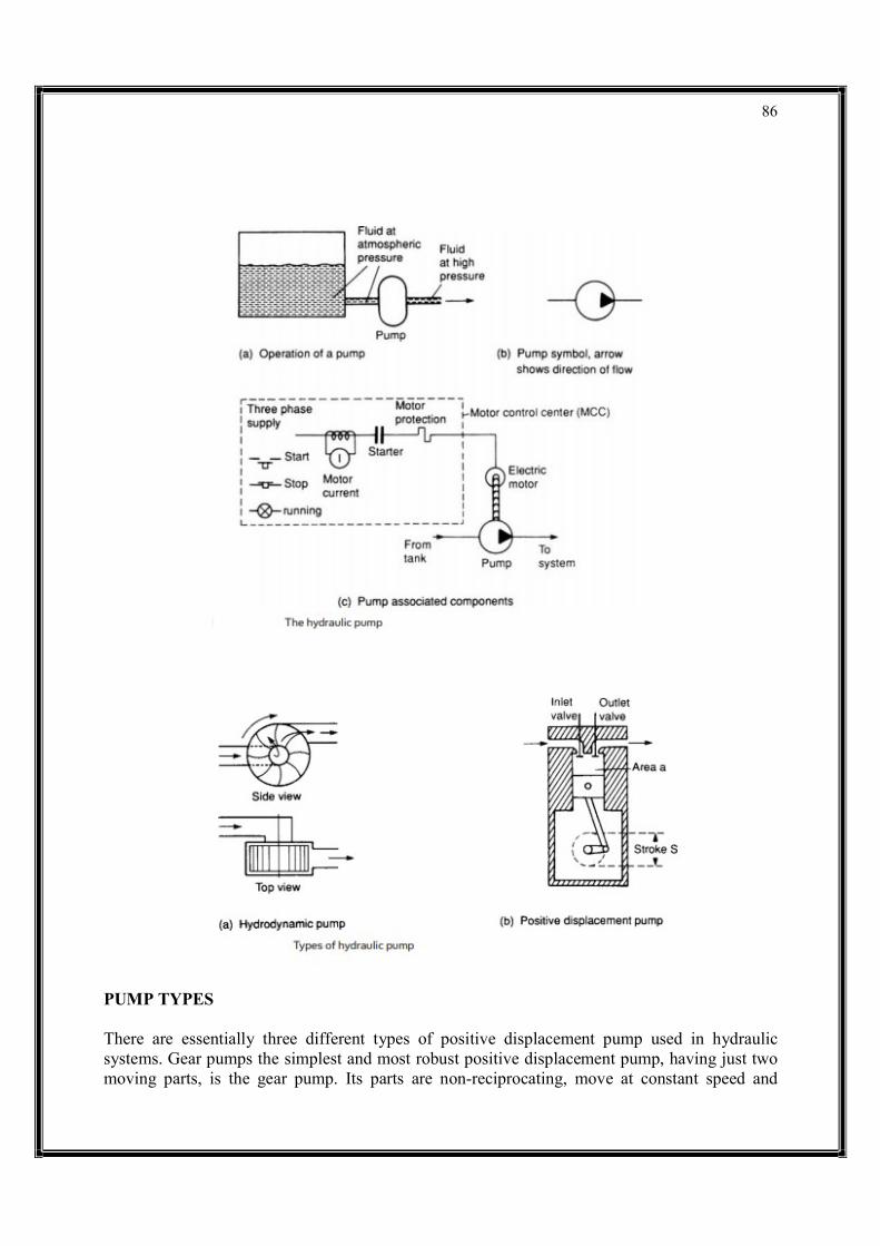
86
PUMP TYPES There are essentially three different types of positive displacement pump used in hydraulic systems. Gear pumps the simplest and most robust positive displacement pump, having just two moving parts, is the gear pump. Its parts are non-reciprocating, move at constant speed and

87
experience a uniform force. Internal construction, shown in Figure, consists of just two close meshing gear wheels which rotate as shown. The direction of rotation of the gears should be carefully noted; it is the opposite of that intuitively expected by most people. As the teeth come out of mesh at the center, a partial vacuum is formed which draws fluid into the inlet chamber. Fluid is trapped between the outer teeth and the pump housing, causing a continual transfer of fluid from inlet chamber to outlet chamber where it is discharged to the system.
Pump displacement is determined by: volume of fluid between each pair of teeth; number of teeth; and speed of rotation. Note the pump merely delivers a fixed volume of fluid from inlet port to outlet port for each rotation; outlet port pressure is determined solely by design of the rest of the system. Gear pumps are compact and cheap but are noisy. Performance of any pump is limited by leakage and the ability of the pump to withstand the pressure differential between inlet and outlet ports. The gear pump obviously requires closely meshing gears, minimum clearance between teeth and housing, and also between the gear face and side plates. Often the side plates of a pump are designed as deliberately replaceable wear plates. The operational method of a gear pump means that high displacements can be achieved by multiple parallel gear assemblies driven from a single shaft and motor. Wear in a gear pump is primarily caused by dirt particles in the hydraulic fluid, so cleanliness and filtration are particularly important. The pressure differential causes large side loads to be applied to the gear shafts at 45° to the center line as shown. Volumetric efficiency of gear pumps at 90% is lowest of the three basic pump types. There are some variations of the basic gear pump. In Figure, gears have been replaced by lobes giving a pump called, not surprisingly, a lobe pump. Figure is another variation called the internal gear pump, where an external-driven gear wheel is connected to a smaller internal gear, with fluid separation as gears disengage being performed by a crescent-shaped molding. Yet another variation on the theme is the gerotor pump of Figure , where the crescent molding is dispensed

88
with by using an internal gear with one less tooth than the outer gear wheel.
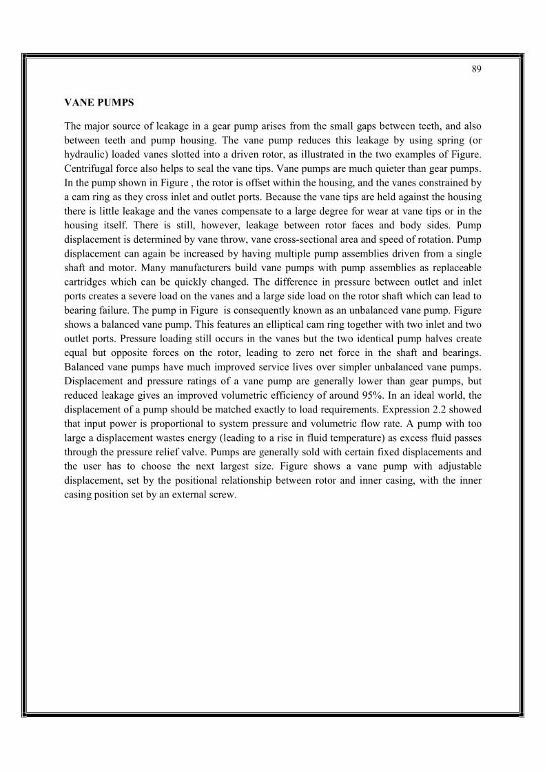
89
VANE PUMPS The major source of leakage in a gear pump arises from the small gaps between teeth, and also between teeth and pump housing. The vane pump reduces this leakage by using spring (or hydraulic) loaded vanes slotted into a driven rotor, as illustrated in the two examples of Figure. Centrifugal force also helps to seal the vane tips. Vane pumps are much quieter than gear pumps. In the pump shown in Figure , the rotor is offset within the housing, and the vanes constrained by a cam ring as they cross inlet and outlet ports. Because the vane tips are held against the housing there is little leakage and the vanes compensate to a large degree for wear at vane tips or in the housing itself. There is still, however, leakage between rotor faces and body sides. Pump displacement is determined by vane throw, vane cross-sectional area and speed of rotation. Pump displacement can again be increased by having multiple pump assemblies driven from a single shaft and motor. Many manufacturers build vane pumps with pump assemblies as replaceable cartridges which can be quickly changed. The difference in pressure between outlet and inlet ports creates a severe load on the vanes and a large side load on the rotor shaft which can lead to bearing failure. The pump in Figure is consequently known as an unbalanced vane pump. Figure shows a balanced vane pump. This features an elliptical cam ring together with two inlet and two outlet ports. Pressure loading still occurs in the vanes but the two identical pump halves create equal but opposite forces on the rotor, leading to zero net force in the shaft and bearings. Balanced vane pumps have much improved service lives over simpler unbalanced vane pumps. Displacement and pressure ratings of a vane pump are generally lower than gear pumps, but reduced leakage gives an improved volumetric efficiency of around 95%. In an ideal world, the displacement of a pump should be matched exactly to load requirements. Expression 2.2 showed that input power is proportional to system pressure and volumetric flow rate. A pump with too large a displacement wastes energy (leading to a rise in fluid temperature) as excess fluid passes through the pressure relief valve. Pumps are generally sold with certain fixed displacements and the user has to choose the next largest size. Figure shows a vane pump with adjustable displacement, set by the positional relationship between rotor and inner casing, with the inner casing position set by an external screw.
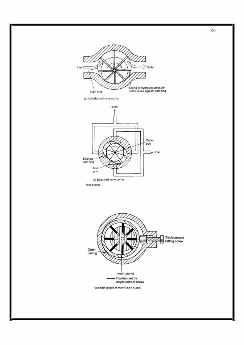
90

91
PISTON PUMPS A piston pump is superficially similar to a motor car engine, and a simple single cylinder arrangement was shown earlier in Figure. Such a simple pump, however, delivering a single pulse of fluid per revolution, generates unacceptably large pressure pulses into the system. Practical piston pumps therefore employ multiple cylinders and pistons to smooth out fluid delivery, and much ingenuity goes into designing multicylinder pumps which are surprisingly compact. The displacement of a piston pump can be easily calculated:
Q = (number of pistons) × (piston area) × (piston stroke) × (drive speed) Figure shows one form of radial piston pump. The pump consists of several hollow pistons inside a stationary cylinder block. Each piston has spring loaded inlet and outlet valves. As the inner cam rotates, fluid is transferred relatively smoothly from inlet port to the outlet port. The pump of Figure uses the same principle, but employs a stationary cam and a rotating cylinder block. This arrangement does not require multiple inlet and outlet valves and is consequently simpler, more reliable, and cheaper. Not surprisingly most radial piston pumps have this construction. Like gear and vane pumps, radial piston pumps can provide increased displacement by the use of multiple assemblies driven from a common shaft. An alternative form of piston pump is the axial design of Figure, where multiple pistons are arranged in a rotating cylinder. The pistons are stroked by a fixed angled plate called the swash plate. Each piston can be kept in contact with the swash plate by springs or by a rotating shoe plate linked to the swash plate

92

93
Pump displacement is controlled by altering the angle of the swash plate; the larger the angle, the greater the displacement. With the swash plate vertical displacement is zero, and flow can even be reversed. Swash plate angle (and hence pump displacement) can easily be controlled remotely with the addition of a separate hydraulic cylinder. An alternative form of axial piston pump is the bent axis pump of Figure. Stroking of the pistons is achieved because of the angle between the drive shaft and the rotating cylinder block. Pump displacement can be adjusted by altering the drive shaft angle. Piston pumps have very high volumetric efficiency (over 98%) and can be used at the highest hydraulic pressures. They are, though, bulky and noisy. Being more complex than vane and gear pumps, they are correspondingly more expensive and maintenance requires more skill. Table gives a comparison of the various types of pump. The figures in Table are typical values and manufacturers’ catalogs should be checked for a specific application. The displacement of gear, vane and radial piston pumps can be increased with multiple assemblies. Specialist pumps are available for pressures up to about 7000 bar at low flows. The delivery from centrifugal and gear pumps can be made variable by changing the speed of the pump motor with a variable frequency (VF) drive.
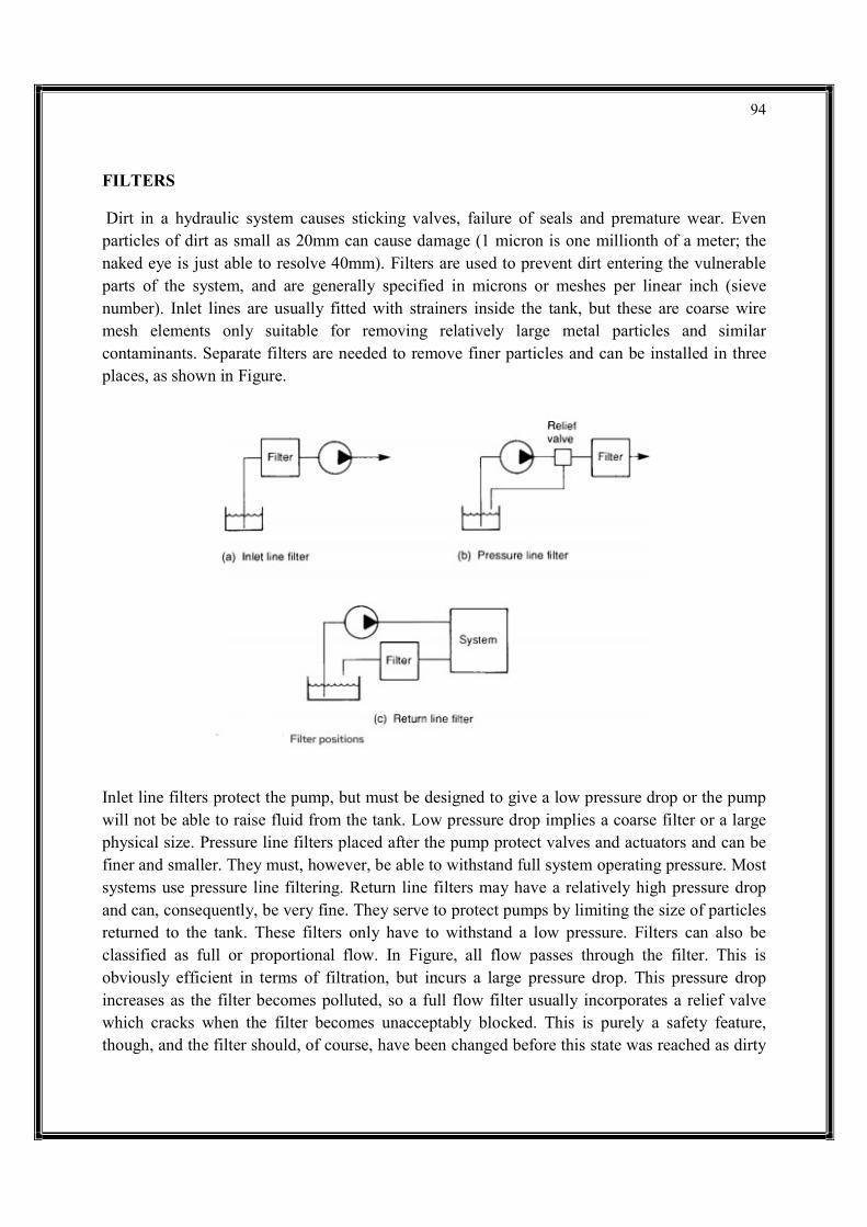
94
FILTERS Dirt in a hydraulic system causes sticking valves, failure of seals and premature wear. Even particles of dirt as small as 20mm can cause damage (1 micron is one millionth of a meter; the naked eye is just able to resolve 40mm). Filters are used to prevent dirt entering the vulnerable parts of the system, and are generally specified in microns or meshes per linear inch (sieve number). Inlet lines are usually fitted with strainers inside the tank, but these are coarse wire mesh elements only suitable for removing relatively large metal particles and similar contaminants. Separate filters are needed to remove finer particles and can be installed in three places, as shown in Figure.
Inlet line filters protect the pump, but must be designed to give a low pressure drop or the pump will not be able to raise fluid from the tank. Low pressure drop implies a coarse filter or a large physical size. Pressure line filters placed after the pump protect valves and actuators and can be finer and smaller. They must, however, be able to withstand full system operating pressure. Most systems use pressure line filtering. Return line filters may have a relatively high pressure drop and can, consequently, be very fine. They serve to protect pumps by limiting the size of particles returned to the tank. These filters only have to withstand a low pressure. Filters can also be classified as full or proportional flow. In Figure, all flow passes through the filter. This is obviously efficient in terms of filtration, but incurs a large pressure drop. This pressure drop increases as the filter becomes polluted, so a full flow filter usually incorporates a relief valve which cracks when the filter becomes unacceptably blocked. This is purely a safety feature, though, and the filter should, of course, have been changed before this state was reached as dirty
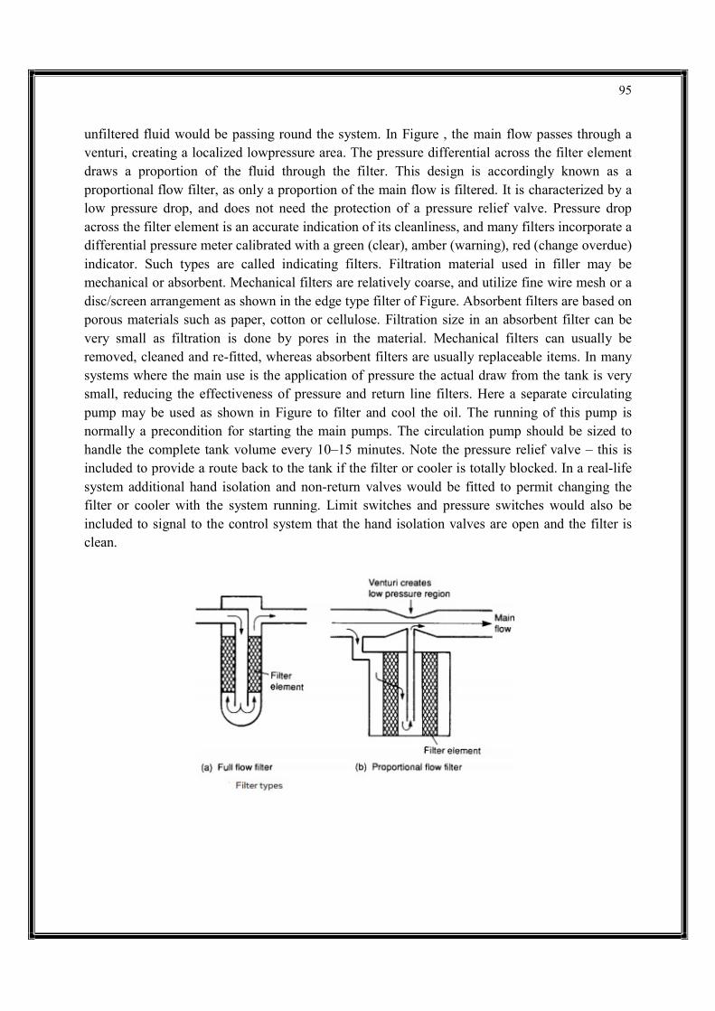
95
unfiltered fluid would be passing round the system. In Figure , the main flow passes through a venturi, creating a localized lowpressure area. The pressure differential across the filter element draws a proportion of the fluid through the filter. This design is accordingly known as a proportional flow filter, as only a proportion of the main flow is filtered. It is characterized by a low pressure drop, and does not need the protection of a pressure relief valve. Pressure drop across the filter element is an accurate indication of its cleanliness, and many filters incorporate a differential pressure meter calibrated with a green (clear), amber (warning), red (change overdue) indicator. Such types are called indicating filters. Filtration material used in filler may be mechanical or absorbent. Mechanical filters are relatively coarse, and utilize fine wire mesh or a disc/screen arrangement as shown in the edge type filter of Figure. Absorbent filters are based on porous materials such as paper, cotton or cellulose. Filtration size in an absorbent filter can be very small as filtration is done by pores in the material. Mechanical filters can usually be removed, cleaned and re-fitted, whereas absorbent filters are usually replaceable items. In many systems where the main use is the application of pressure the actual draw from the tank is very small, reducing the effectiveness of pressure and return line filters. Here a separate circulating pump may be used as shown in Figure to filter and cool the oil. The running of this pump is normally a precondition for starting the main pumps. The circulation pump should be sized to handle the complete tank volume every 10–15 minutes. Note the pressure relief valve – this is included to provide a route back to the tank if the filter or cooler is totally blocked. In a real-life system additional hand isolation and non-return valves would be fitted to permit changing the filter or cooler with the system running. Limit switches and pressure switches would also be included to signal to the control system that the hand isolation valves are open and the filter is clean.

96
Control Valves Pneumatic and hydraulic systems require control valves to direct and regulate the flow of fluid from compressor or pump to the various load devices. Although there are significant practical differences between pneumatic and hydraulic devices (mainly arising from differences in operating pressures and types of seals needed for gas or liquid) the operating principles and descriptions are very similar. Although valves are used for many purposes, there are essentially only two types of valve. An infinite position valve can take up any position between open and closed and, consequently, can be used to modulate flow or pressure. Relief valves described in earlier chapters are simple infinite position valves. Most control valves, however, are only used to allow or block flow of fluid. Such valves are called finite position valves. An analogy between the two types of valve is the comparison between an electric light dimmer and a simple on/ off switch. Connections to a valve are termed ‘ports’. A simple on/off valve therefore has two ports. Most control valves, however, have four ports, shown in hydraulic and pneumatic forms in Figure. In both the load is connected to ports labeled A, B and the pressure supply (from pump or compressor) to port P. In the hydraulic valve, fluid is returned to the tank from port T. In the pneumatic valve return air is vented from port R. Figure shows internal operation of valves. To extend the ram, ports P and B are connected to deliver fluid and ports A and T connected to return fluid. To retract the ram, ports P and A are connected to
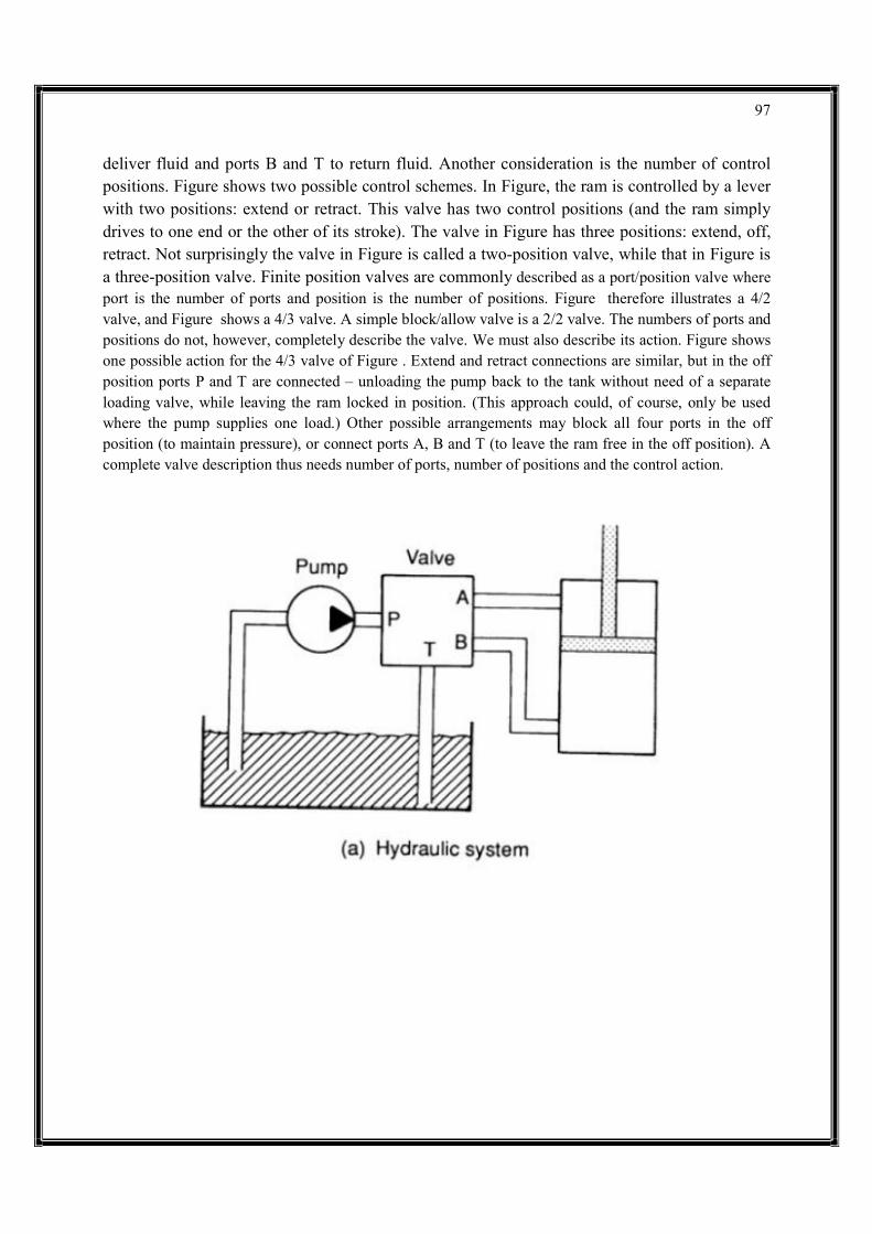
97
deliver fluid and ports B and T to return fluid. Another consideration is the number of control positions. Figure shows two possible control schemes. In Figure, the ram is controlled by a lever with two positions: extend or retract. This valve has two control positions (and the ram simply drives to one end or the other of its stroke). The valve in Figure has three positions: extend, off, retract. Not surprisingly the valve in Figure is called a two-position valve, while that in Figure is a three-position valve. Finite position valves are commonly described as a port/position valve where port is the number of ports and position is the number of positions. Figure therefore illustrates a 4/2 valve, and Figure shows a 4/3 valve. A simple block/allow valve is a 2/2 valve. The numbers of ports and positions do not, however, completely describe the valve. We must also describe its action. Figure shows one possible action for the 4/3 valve of Figure . Extend and retract connections are similar, but in the off position ports P and T are connected – unloading the pump back to the tank without need of a separate loading valve, while leaving the ram locked in position. (This approach could, of course, only be used where the pump supplies one load.) Other possible arrangements may block all four ports in the off position (to maintain pressure), or connect ports A, B and T (to leave the ram free in the off position). A complete valve description thus needs number of ports, number of positions and the control action.
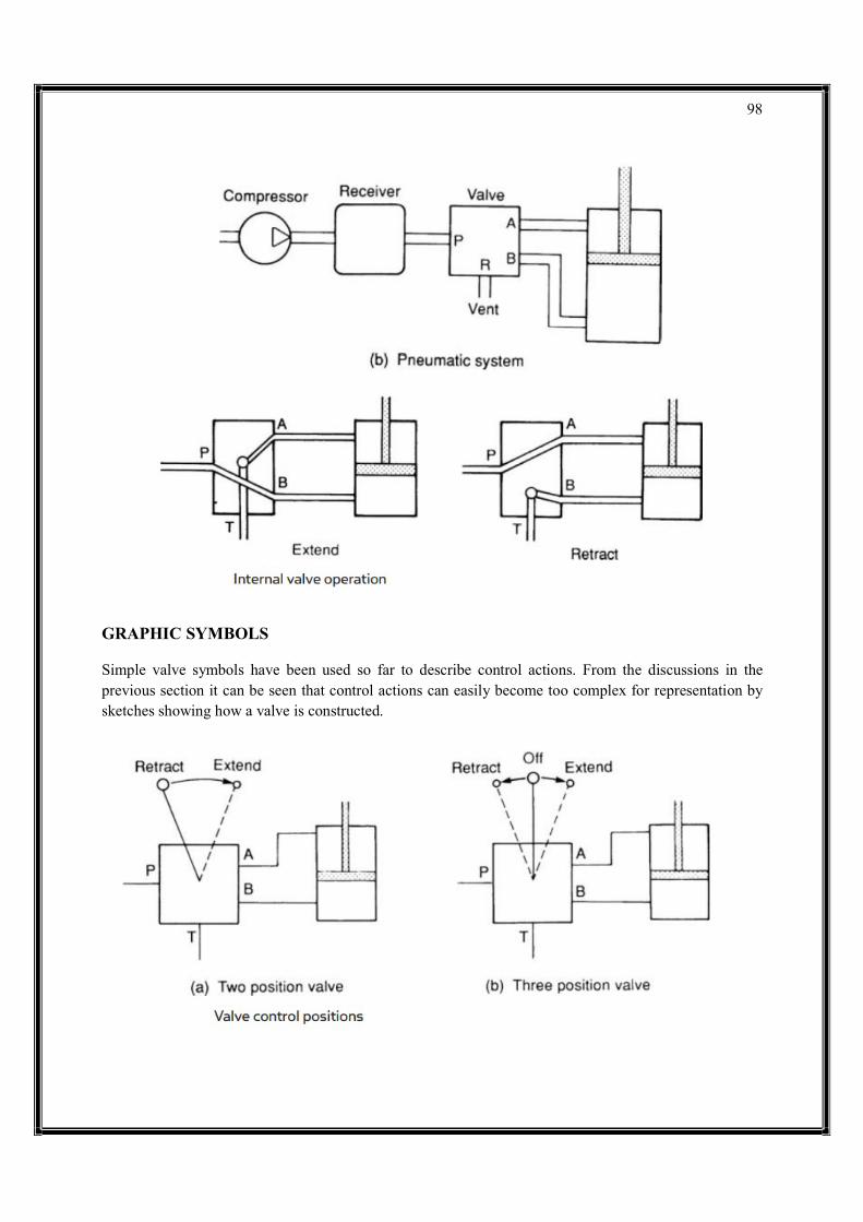
98
GRAPHIC SYMBOLS Simple valve symbols have been used so far to describe control actions. From the discussions in the previous section it can be seen that control actions can easily become too complex for representation by sketches showing how a valve is constructed.

99
A set of graphic symbols has therefore evolved (similar, in principle, to symbols used on electrical circuit diagrams). These show component function without showing the physical construction of each device. A 3/2 spool valve and a 3/2 rotary valve with the same function have the same symbol, despite their totally different constructions. Symbols are described in various national documents: DIN24300, BS2917, ISO1219 and the new ISO5599, CETOP RP3 plus the original American JIC and ANSI symbols. Differences between these are minor. A valve is represented by a square for each of its switching positions. Figure thus shows the symbol of a two-position valve, and Figure a three-position valve. Valve positions can be represented by letters a, b, c and so on, with 0 being used for a central neutral position. Ports of a valve are shown on the outside of boxes in normal unoperated or initial position. Four ports have been added to the two-position valve symbol shown in Figure . Designations given to ports are normally:

100
Arrow-headed lines represent direction of flow. In Figure , for example, fluid is delivered from port P to port A and returned from port B to port T when the valve is in its normal state a. In state b, flow is reversed. This valve symbol corresponds to the valve represented in Figures . Shut-off positions are represented by T, as shown by the central position of the valve in Figure and internal flow paths can be represented as shown in Figure. This latter valve, incidentally, vents the load in the off position. In pneumatic systems, lines commonly vent to atmosphere directly at the valve, as shown by port R in Figure. Figure shows symbols for the various ways in which valves can be operated. Figure thus represents a 4/2 valve operated by a pushbutton. With the pushbutton depressed the ram extends. With the pushbutton released, the spring pushes the valve to position a and the ram retracts. Actuation symbols can be combined. Figure represents a solenoidoperated 4/3 valve, with spring return to center. Infinite-position valve symbols are shown in Figure. A basic valve is represented by a single square as shown in Figure, with the valve being shown in a normal, or non-operated, position. Control is shown by normal actuation symbols: in Figure, for example, the spring pushes the valve right, decreasing flow, and pilot pressure pushes the valve left, increasing flow. This represents a pressure-relief valve which would be connected into a hydraulic system as shown in Figure .

101

102
TYPES OF CONTROL VALVE There are essentially three types of control valve: poppet valves, spool valves and rotary valves. Poppet valves in a poppet valve, simple discs, cones or balls are used in conjunction with simple valve seats to control flow. Figure shows the construction and symbol of a simple 2/2 normally closed valve, where depression of the pushbutton lifts the ball off its seat and allows fluid to flow from port P to port A. When the button is released, spring and fluid pressure force the ball up again, closing the valve. Figure shows the construction and symbol of a disc seal 3/2 poppet. With the pushbutton released, ports A and R is linked via the hollow pushbutton stem. If the pushbutton is pressed, port R is first sealed, then the valve disc pushed down to open the valve and connect ports P and A. As before, spring and fluid pressure from port P closes the valve. The valve construction and symbol shown in Figure is a poppet changeover 4/2 valve using two stems and disc valves. With the pushbutton released, ports A and R are linked via the hollow left-hand stem and ports P and B linked via the normally open right-hand disc valve. When the pushbutton is pressed, the link between ports A and R is first closed, then the link between P and B closed. The link between A and P is next opened, and finally the link between B and R opened. When the pushbutton is released, air and spring pressure puts the valve back to its original state. Poppet valves are simple, cheap and robust, but it is generally simpler to manufacture valves more complicated than those shown in Figure by using spool valves. Further, a major disadvantage of poppet valves is the force needed to operate them. In the poppet valve of Figure, for example, the force required on the pushbutton to operate the valve is P×a newtons. Large-capacity valves need large valve areas, leading to large operating force. The high pressure in hydraulic systems thus tends to prevent use of simple poppet valves and they are, therefore, mainly found in low-pressure pneumatic systems.

103

104
SPOOL VALVES Spool (or slide) valves are constructed with a spool moving horizontally within the valve body, as shown for the 4/2 valve in Figure . Raised areas called ‘lands’ block or open ports to give the required operation. The operation of a spool valve is generally balanced. In the valve construction in Figure , for example, pressure is applied to opposing faces D and E and low tank pressure to faces F and G. There is no net force on the spool from system pressure, allowing the spool to be easily moved. Figure is a changeover 4/2 spool valve. Comparison of the valves shown in Figures shows they have the same body construction, the only difference being the size and position of lands on the spool. This is a major costsaving advantage of spool valves; different operations can be achieved with a common body and different spools. This obviously reduces manufacturing costs. As a valve goes from one state to another the port connections will go through a transitional state. This temporary state may be important in some cases, for example the designers would not want a cylinder supporting a load to be connected to the tank even for a brief moment. If the transitional state is important the valve can be ordered accordingly and the transitional state shown on the diagram. Figure shows that the transitional state, denoted by the dashed central lines, blocks all four ports. Note that although this is a two-position valve, with the inclusion of the transitional state it is shown by three blocks. Figure shows various forms of three-position changeover valves; note, again, these use one body with different functions achieved by different land patterns. Spool valves are operated by shifting the spool. This can be achieved by button, lever or striker, or remotely with a solenoid. Self-centering can easily be provided if springs are mounted at the end of the spool shaft. Solenoid-operated valves commonly work at 24 V DC or 110 V AC. Each has its own advantages and disadvantages. A DC power supply has to be provided for 24 V DC solenoids, which, in large systems, is substantial and costly. Operating current of a 24 V solenoid is higher than that of a 110 V solenoid. Care must be taken with plant cabling to avoid voltage drops on return legs if a common single line return is used. Current through a DC solenoid is set by the winding resistance. Current in an AC solenoid, on the other hand, is set by the inductance of the windings, and this is usually designed to give a high inrush current followed by low holding current. This is achieved by using the core of the solenoid (linked to the spool) to raise the coil inductance when the spool has moved. One side effect of this is that a jammed spool results in a permanent high current which can damage the coil or the device driving it. Each and every AC solenoid should be protected by an individual fuse. DC solenoids do not suffer from this characteristic. A burned out DC solenoid coil is almost unknown. Whatever form of solenoid is used it is very useful when fault finding to have local electrical indication built into the solenoid plug top. This allows a fault to be quickly identified as either an electrical or hydraulic problem. Fault finding is discussed further in Chapter 9. A solenoid can exert a pull or push of about 5–10kg. This is adequate for most pneumatic spool valves, but is too low for direct operation of large-capacity hydraulic valves. Here pilot operation must be used, a topic discussed later.
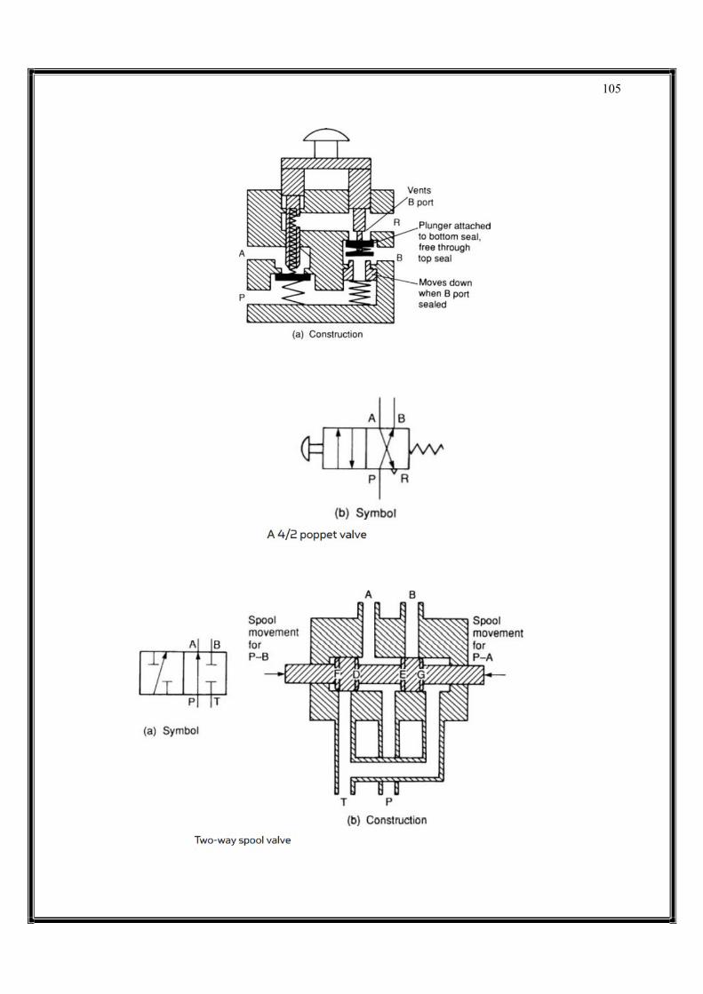
105
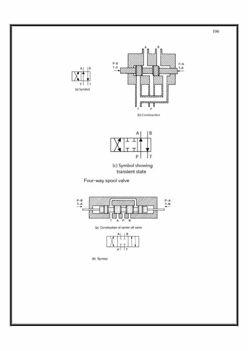
106
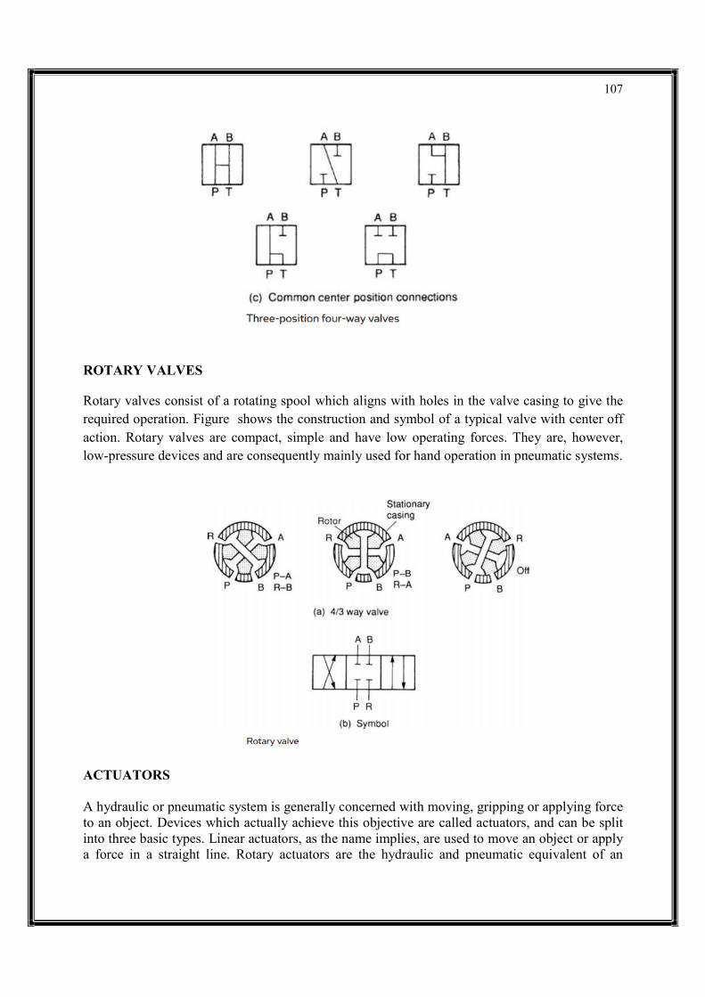
107
ROTARY VALVES Rotary valves consist of a rotating spool which aligns with holes in the valve casing to give the required operation. Figure shows the construction and symbol of a typical valve with center off action. Rotary valves are compact, simple and have low operating forces. They are, however, low-pressure devices and are consequently mainly used for hand operation in pneumatic systems.
ACTUATORS
A hydraulic or pneumatic system is generally concerned with moving, gripping or applying force to an object. Devices which actually achieve this objective are called actuators, and can be split into three basic types. Linear actuators, as the name implies, are used to move an object or apply a force in a straight line. Rotary actuators are the hydraulic and pneumatic equivalent of an

108
electric motor. This chapter discusses linear and rotary actuators. The third type of actuator is used to operate flow control valves for process control of gases, liquids or steam. These actuators are generally pneumatically operated and are discussed with process control pneumatics. LINEAR ACTUATORS The basic linear actuator is the cylinder, or ram, shown in schematic form in Figure. Practical constructional details are discussed later. The cylinder in Figure consists of a piston, radius R, moving in a bore. The piston is connected to a rod of radius r which drives the load. Obviously if pressure is applied to port X (with port Y venting) the piston extends. Similarly, if pressure is applied to port Y (with port X venting), the piston retracts. The force applied by a piston depends on both the area and the applied pressure. For the extend stroke, area A is given by πR2. For a pressure P applied to port X, the extend force available is: Fc = P π R2 The units of expression 5.1 depend on the system being used. If SI units are used, the force is in newtons. Expression 5.1 gives the maximum achievable force obtained with the cylinder in a stalled condition. One example of this occurs where an object is to be gripped or shaped.
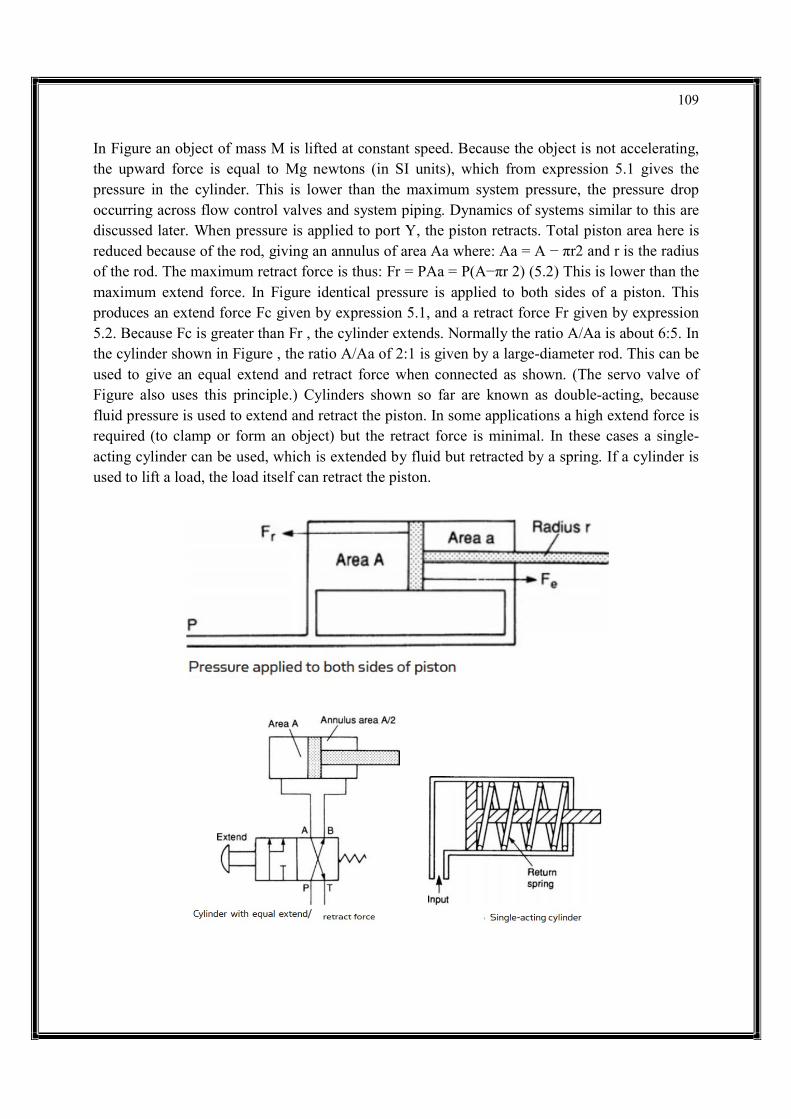
109
In Figure an object of mass M is lifted at constant speed. Because the object is not accelerating, the upward force is equal to Mg newtons (in SI units), which from expression 5.1 gives the pressure in the cylinder. This is lower than the maximum system pressure, the pressure drop occurring across flow control valves and system piping. Dynamics of systems similar to this are discussed later. When pressure is applied to port Y, the piston retracts. Total piston area here is reduced because of the rod, giving an annulus of area Aa where: Aa = A − πr2 and r is the radius of the rod. The maximum retract force is thus: Fr = PAa = P(A−πr 2) (5.2) This is lower than the maximum extend force. In Figure identical pressure is applied to both sides of a piston. This produces an extend force Fc given by expression 5.1, and a retract force Fr given by expression 5.2. Because Fc is greater than Fr , the cylinder extends. Normally the ratio A/Aa is about 6:5. In the cylinder shown in Figure , the ratio A/Aa of 2:1 is given by a large-diameter rod. This can be used to give an equal extend and retract force when connected as shown. (The servo valve of Figure also uses this principle.) Cylinders shown so far are known as double-acting, because fluid pressure is used to extend and retract the piston. In some applications a high extend force is required (to clamp or form an object) but the retract force is minimal. In these cases a single-acting cylinder can be used, which is extended by fluid but retracted by a spring. If a cylinder is used to lift a load, the load itself can retract the piston.
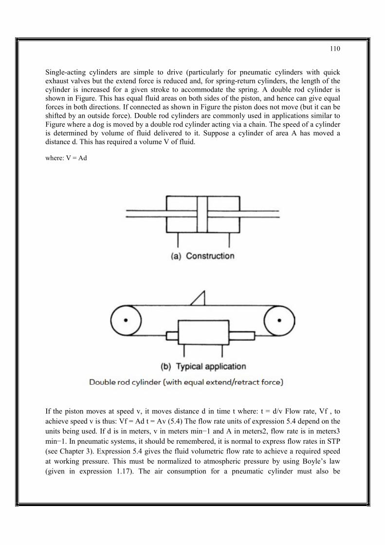
110
Single-acting cylinders are simple to drive (particularly for pneumatic cylinders with quick exhaust valves but the extend force is reduced and, for spring-return cylinders, the length of the cylinder is increased for a given stroke to accommodate the spring. A double rod cylinder is shown in Figure. This has equal fluid areas on both sides of the piston, and hence can give equal forces in both directions. If connected as shown in Figure the piston does not move (but it can be shifted by an outside force). Double rod cylinders are commonly used in applications similar to Figure where a dog is moved by a double rod cylinder acting via a chain. The speed of a cylinder is determined by volume of fluid delivered to it. Suppose a cylinder of area A has moved a distance d. This has required a volume V of fluid. where: V = Ad
If the piston moves at speed v, it moves distance d in time t where: t = d/v Flow rate, Vf , to achieve speed v is thus: Vf = Ad t = Av (5.4) The flow rate units of expression 5.4 depend on the units being used. If d is in meters, v in meters min−1 and A in meters2, flow rate is in meters3 min−1. In pneumatic systems, it should be remembered, it is normal to express flow rates in STP (see Chapter 3). Expression 5.4 gives the fluid volumetric flow rate to achieve a required speed at working pressure. This must be normalized to atmospheric pressure by using Boyle’s law (given in expression 1.17). The air consumption for a pneumatic cylinder must also be
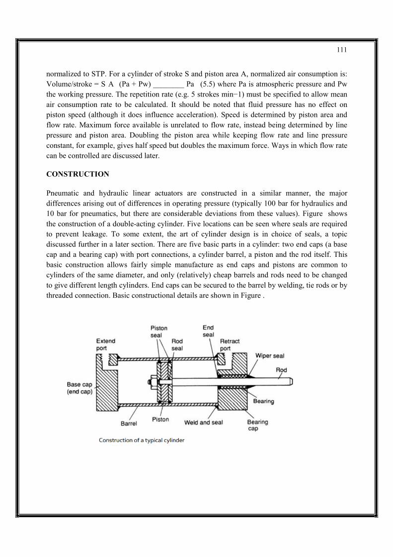
111
normalized to STP. For a cylinder of stroke S and piston area A, normalized air consumption is: Volume/stroke = S A (Pa + Pw) ________ Pa (5.5) where Pa is atmospheric pressure and Pw the working pressure. The repetition rate (e.g. 5 strokes min−1) must be specified to allow mean air consumption rate to be calculated. It should be noted that fluid pressure has no effect on piston speed (although it does influence acceleration). Speed is determined by piston area and flow rate. Maximum force available is unrelated to flow rate, instead being determined by line pressure and piston area. Doubling the piston area while keeping flow rate and line pressure constant, for example, gives half speed but doubles the maximum force. Ways in which flow rate can be controlled are discussed later. CONSTRUCTION Pneumatic and hydraulic linear actuators are constructed in a similar manner, the major differences arising out of differences in operating pressure (typically 100 bar for hydraulics and 10 bar for pneumatics, but there are considerable deviations from these values). Figure shows the construction of a double-acting cylinder. Five locations can be seen where seals are required to prevent leakage. To some extent, the art of cylinder design is in choice of seals, a topic discussed further in a later section. There are five basic parts in a cylinder: two end caps (a base cap and a bearing cap) with port connections, a cylinder barrel, a piston and the rod itself. This basic construction allows fairly simple manufacture as end caps and pistons are common to cylinders of the same diameter, and only (relatively) cheap barrels and rods need to be changed to give different length cylinders. End caps can be secured to the barrel by welding, tie rods or by threaded connection. Basic constructional details are shown in Figure .
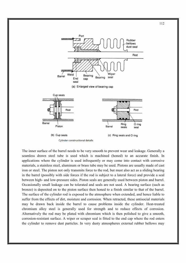
112
The inner surface of the barrel needs to be very smooth to prevent wear and leakage. Generally a seamless drawn steel tube is used which is machined (honed) to an accurate finish. In applications where the cylinder is used infrequently or may come into contact with corrosive materials, a stainless steel, aluminum or brass tube may be used. Pistons are usually made of cast iron or steel. The piston not only transmits force to the rod, but must also act as a sliding bearing in the barrel (possibly with side forces if the rod is subject to a lateral force) and provide a seal between high- and low-pressure sides. Piston seals are generally used between piston and barrel. Occasionally small leakage can be tolerated and seals are not used. A bearing surface (such as bronze) is deposited on to the piston surface then honed to a finish similar to that of the barrel. The surface of the cylinder rod is exposed to the atmosphere when extended, and hence liable to suffer from the effects of dirt, moisture and corrosion. When retracted, these antisocial materials may be drawn back inside the barrel to cause problems inside the cylinder. Heat-treated chromium alloy steel is generally used for strength and to reduce effects of corrosion. Alternatively the rod may be plated with chromium which is then polished to give a smooth, corrosion-resistant surface. A wiper or scraper seal is fitted to the end cap where the rod enters the cylinder to remove dust particles. In very dusty atmospheres external rubber bellows may
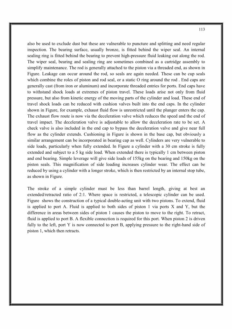
113
also be used to exclude dust but these are vulnerable to puncture and splitting and need regular inspection. The bearing surface, usually bronze, is fitted behind the wiper seal. An internal sealing ring is fitted behind the bearing to prevent high-pressure fluid leaking out along the rod. The wiper seal, bearing and sealing ring are sometimes combined as a cartridge assembly to simplify maintenance. The rod is generally attached to the piston via a threaded end, as shown in Figure. Leakage can occur around the rod, so seals are again needed. These can be cup seals which combine the roles of piston and rod seal, or a static O ring around the rod . End caps are generally cast (from iron or aluminum) and incorporate threaded entries for ports. End caps have to withstand shock loads at extremes of piston travel. These loads arise not only from fluid pressure, but also from kinetic energy of the moving parts of the cylinder and load. These end of travel shock loads can be reduced with cushion valves built into the end caps. In the cylinder shown in Figure, for example, exhaust fluid flow is unrestricted until the plunger enters the cap. The exhaust flow route is now via the deceleration valve which reduces the speed and the end of travel impact. The deceleration valve is adjustable to allow the deceleration rate to be set. A check valve is also included in the end cap to bypass the deceleration valve and give near full flow as the cylinder extends. Cushioning in Figure is shown in the base cap, but obviously a similar arrangement can be incorporated in bearing cap as well. Cylinders are very vulnerable to side loads, particularly when fully extended. In Figure a cylinder with a 30 cm stroke is fully extended and subject to a 5 kg side load. When extended there is typically 1 cm between piston and end bearing. Simple leverage will give side loads of 155kg on the bearing and 150kg on the piston seals. This magnification of side loading increases cylinder wear. The effect can be reduced by using a cylinder with a longer stroke, which is then restricted by an internal stop tube, as shown in Figure. The stroke of a simple cylinder must be less than barrel length, giving at best an extended/retracted ratio of 2:1. Where space is restricted, a telescopic cylinder can be used. Figure shows the construction of a typical double-acting unit with two pistons. To extend, fluid is applied to port A. Fluid is applied to both sides of piston 1 via ports X and Y, but the difference in areas between sides of piston 1 causes the piston to move to the right. To retract, fluid is applied to port B. A flexible connection is required for this port. When piston 2 is driven fully to the left, port Y is now connected to port B, applying pressure to the right-hand side of piston 1, which then retracts.

114
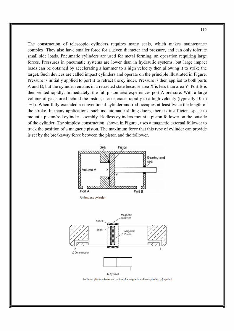
115
The construction of telescopic cylinders requires many seals, which makes maintenance complex. They also have smaller force for a given diameter and pressure, and can only tolerate small side loads. Pneumatic cylinders are used for metal forming, an operation requiring large forces. Pressures in pneumatic systems are lower than in hydraulic systems, but large impact loads can be obtained by accelerating a hammer to a high velocity then allowing it to strike the target. Such devices are called impact cylinders and operate on the principle illustrated in Figure. Pressure is initially applied to port B to retract the cylinder. Pressure is then applied to both ports A and B, but the cylinder remains in a retracted state because area X is less than area Y. Port B is then vented rapidly. Immediately, the full piston area experiences port A pressure. With a large volume of gas stored behind the piston, it accelerates rapidly to a high velocity (typically 10 m s−1). When fully extended a conventional cylinder and rod occupies at least twice the length of the stroke. In many applications, such as automatic sliding doors, there is insufficient space to mount a piston/rod cylinder assembly. Rodless cylinders mount a piston follower on the outside of the cylinder. The simplest construction, shown in Figure , uses a magnetic external follower to track the position of a magnetic piston. The maximum force that this type of cylinder can provide is set by the breakaway force between the piston and the follower.

116
piston and the follower. This connection link passes through a slot in the cylinder wall which is sealed by magnetic strip seals either side of the link. Although capable of providing the full force of which the cylinder is capable, the seal is vulnerable to dust intrusion which may cause leaks from the seal. Sequencing applications, particularly those controlled by PLCs, often need to know the position of cylinders. Although conventional limit switches can be mounted to moving parts of the controlled plant it is often cheaper and simpler to use cylinders with integral end of travel limit switches. The piston in the cylinder is made of magnetic material or has embedded magnets and operates simple reed switches mounted on the outside of the cylinder barrel. The reed switches are usually strapped to the barrel with jubilee clips to allow accurate setting of the actuation position. HYDRAULIC ACCUMULATORS In a simple hydraulic system, the pump size (delivery rate and hence motor power) is determined by the maximum requirements of the actuators. In Figure a system operates intermittently at a pressure of between 150 and 200 bar, needing a flow rate of 100 L min−1 for 10s at a repetition rate of 1 minute. With a simple system (pump, pressure regulator and loading valve) this requires a 200 bar, 100 L min−1 pump (driven by about a 50 hp motor) which spends around 85% of its time unloading to the tank. In Figure a storage device called an accumulator has been added to the system. This can store, and release, a quantity of fluid at the required system pressure. In many respects it resembles the operation of a capacitor in an electronic power supply. The operation is shown in Figure . At time A the system is turned on, and the pump loads, causing pressure to rise as the fluid is delivered to the accumulator via the non-return valve V3. At time B, working pressure is reached and a pressure switch on the accumulator causes the pump to unload. This state is maintained as non-return valve V3 holds the system pressure. The actuator operates between times C and D. This draws fluid from the accumulator, causing a fall of system pressure. The pressure switch on the accumulator puts the pump on load again but it takes until time E before the accumulator is charged ready for the next actuator movement at time F. An accumulator reduces pump requirements. The original system required a 100 L min−1 pump. With an accumulator, however, a pump only needs to provide 17 L min−1 (that is, 100 L min−1 for 10 s every minute). Pump size, and hence motor size, have been reduced by a factor of six with obvious cost and space savings, plus gains in ancillary equipment such as motor starters and cabling. There is no gain in the energy used; with the simple system a 50 hp motor

117

118
loads for 17% of the time, with an accumulator a 10 hp motor loads for about 90% of the time. Most accumulators operate by compressing a gas (although older and smaller accumulators may work by compressing a spring or lifting a weight with a cylinder). The most common form is the gas-filled bladder accumulator shown in Figure. Gas is precharged to some pressure with the accumulator empty of fluid when the whole of the accumulator is filled with gas. A poppet valve at the accumulator base prevents the bladder extruding out into the piping. Accumulators are sized by Boyle’s law and a knowledge of the demands of the actuators. For the example system of Figure , assuming a precharge of 120 bar, a charged accumulator pressure of 180 bar and a fall to a pressure to 160 bar during the removal of 17 liters of fluid: let V be the volume of the accumulator. This gives us the three states illustrated in Figure, to which Boyle’s law can be applied to find the required accumulator volume.
119
From Figures using Boyle’s law: 160v = 180 (v−17) which reduces to: n = 153 liters From Figure: 120V = 160 × 153 or: V = 204 liters Hence an accumulator of around 250 liters is required, with a precharge of 120 bar and a pressure switch set at 180 bar. Accumulators can also be used to act as ‘buffers’ on a system to absorb shocks and snub pressure spikes. Again the accumulator acts in similar manner to a capacitor in an electronic circuit. An accumulator, however, brings an additional danger into the system, as it is possible for high pressures to exist in the circuit even though the pump has been stopped. If a coupling is opened under these circumstances the accumulator discharges all its fluid at working pressure. The author speaks from personal experience of having committed this cardinal sin and being covered in oil for his mistake! Extreme care should therefore be taken when working on circuits with accumulators. Normally a manual or automatic blowdown valve is included to allow the accumulator pressure to be released. The pressure gauge should be observed during blowdown and no work undertaken until it is certain all pressure has been released. Figure shows typical blowdown circuits. Once a system has warmed up, a quick check can be made on the state of an accumulator with the flat of the hand. There should always be a significant temperature difference between the gas and the hydraulic oil and the oil/gas split can be detected by the temperature change on the body of the accumulator. If the whole body is the same temperature something has gone severely wrong with the gas bladder. An accumulator is a pressurized vessel and as such requires certification if it contains more than 250 bar.liters. It will require a recorded expert visual inspection every 5 years and a full volumetric pressure test every 10 years.
120
MULTIPLE CHOICE QUESTIONS WITH ANSWER
UNIT – I
1. Which manner is a chemical or biochemical plant not operated in? a) Continuous b) Batch-wise c) Semi-continuous d) Discontinuous
2. When is a separation process not required in a manufacturing process? a) When there is a decomposition reaction b) When there is a complete conversion c) When the byproducts are in form of gases d) When the reaction is reversible 3. If only 5% of Ethylene is converted to Ethylene glycol, why is there a need of separation process? a) To feed more reactant to the reacting mixture b) To remove the ethylene glycol formed c) To recover the unreacted Ethylene Glycol d) To start an intermediate reaction 4. Chemical reactions require feed mixtures from non-renewable resources like coal, petroleum. What is used in place of non-renewable sources? a) Sunlight b) Biomass c) Biodiesel d) Microorganisms 5. Which of the following is a condition of operation for biochemical plant? a) Metallic catalyst b) Chemical catalyst c) Elevated temperature d) Non-pathologic state of the organism
6. Aqueous sodium hydroxide reacts with white phosphorous to form phosphine.
a) NaH2PO2
b) P2O5
c) Na2PO3
d) P2O3

121
7. Which of the following pairs liberate gas a when they react with each other?
a) SiO2, Na
b) Fused NaOH, C
c) Mg, B2O3
d) Mg, CO2
8. In extreme weather, oxygen reacts with nitrogen to form
a. nitrogen (II) oxide only
b. nitrogen (IV) oxide only
c. nitrogen (III) oxide
d. nitrogen (II) and nitrogen (IV) oxide
9. The Castner-Kellner cell used for the manufacture of NaOH, the cathode in the central compartment is made of
a) Iron
b) Carbon
c) Mercury
d) Nickel
10. Consider the reaction: 6NaOH +3Cl2 -------> 5NaCl + A + 3H2O. The oxidation number of chlorine in “A” is
a) Iron
b) Carbon
c) Mercury
d) Nickel
11. The natural gas and steam react together in Haber’s process to form
a) oxygen
b) nitrogen
c) carbon dioxide
122
d) hydrogen
12. During the production of ammonia low temperature is required. The advantages of low temperatures could be
a) slow only
b) better yields only
c) better quality
d) slow and better yields
13. The factories which produce fertilizers usually have plants of
a) ammonia production
b) nitric acid production
c) ammonium nitrate production
d) All of above
14. The only condition for nitrogen based fertilizers is that they must be soluble in
a) acid
b) base
c) water
d) alkalis
MULTIPLE CHOICE QUESTIONS WITH ANSWER
UNIT –II 1. The column used for differential distillation is_______________ a) Still b) Differential column c) Batch column d) Continuous Column

123
2. Simple distillation is a___________ process. a) Batch b) Continuous c) Adiabatic d) Differential Column 3. After the separation by differential distillation, the high volatile and low volatile components are stored in _____________ a) Batch b) Cuts c) Distill d) Adiabatic 4. For a ternary mixture, the number of cuts required is_________ a) 1 b) 2 c) 3 d) 4 5. The equation applicable for batch distillation is _________ a) Frenske’s equation b) Rayleigh equation c) Wilke-chan equation d) None of the mentioned 6. Estimate the feed rate, if the composition of the more volatile component in the feed is 50% and the residue is 10% and the equilibrium relation is given by y*= 1.975x. Also, the rate of residue is 60 mol/hr. a) 213 mol/hr b) 313 mol/hr c) 413 mol/hr d) 513 mol/hr
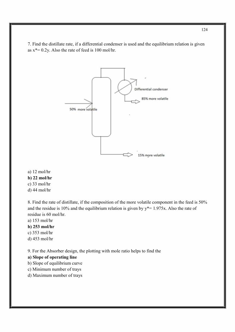
124
7. Find the distillate rate, if a differential condenser is used and the equilibrium relation is given as x*= 0.2y. Also the rate of feed is 100 mol/hr.
a) 12 mol/hr b) 22 mol/hr c) 33 mol/hr d) 44 mol/hr 8. Find the rate of distillate, if the composition of the more volatile component in the feed is 50% and the residue is 10% and the equilibrium relation is given by y*= 1.975x. Also the rate of residue is 60 mol/hr. a) 153 mol/hr b) 253 mol/hr c) 353 mol/hr d) 453 mol/hr 9. For the Absorber design, the plotting with mole ratio helps to find the a) Slope of operating line b) Slope of equilibrium curve c) Minimum number of trays d) Maximum number of trays
125
10. The equation helps us to find the number of trays in an absorber theoretically is _________ a) Frenske’s Equation b) Rayleigh’s Equation c) Kremser’s Equation d) None of the mentioned 11. Packed towers are _____________ a) Absorption tower b) Stripper c) Absorber or Stripper d) All of the mentioned 12. Packing height in the packed tower = NTU x __________ a) HTU b) HETP c) NTU d) HETP + HTU 13. Find the absorption tower height if Number of gas phase transfer units 4.09 Height of gas phase transfer units 1.5 meters a) 2.72 meters b) 0.36 meters c) 6.135 meters d) None of the mentioned 14. Solvent extraction is basically known as a) Gas-liquid extraction b) Liquid- liquid extraction c) Liquid –solid extraction d) None of the mentioned 15. Liquid-liquid mixture is separated with solvent extraction by adding _______ solvent. a) Soluble b) Insoluble c) Partially soluble d) All of the mentioned

126
16. Find the representation X.
a) Extract b) Raffinate c) Residue d) None of the mentioned 17. Solvent lean phase are known as a) Extract b) Raffinate c) Residue d) None of the mentioned 18. Fractional extraction is also known as ________ a) Solvent b) Double solvent c) Triple solvent d) None of the mentioned 19. The composition of substances in the extraction are represented by __________ a) Rectangle b) Isosceles triangle c) Equilateral triangle d) None of the mentioned 20. On spraying the liquid over gas leads to ____________ a) Humidification b) Evaporation c) Heating of gas d) None of the mentioned

127
21. The additional operation requires for drying gas and liquid is _________ a) Absorption b) Adsorption c) Humidification d) De-humidification 22. The given solid will gain or remove moisture till.
a) pA > P b) pA< P c) pA= p d) pA= 0 23. The moisture in the solid after attaining equilibrium is known as a) Bound moisture b) Unbound moisture c) Equilibrium moisture d) Free moisture 24. The moisture inside the substance is known as __________ a) Bound moisture b) Unbound moisture c) Equilibrium moisture d) Free moisture
128
25. Find the weight of the wet solid if dry solid is 2 kg and the moisture is 0.5 kg. a) 2 kg b) 2.5kg c) 3 kg d) 3.5 kg 26. Find the moisture content in dry basis if the weight of dry solid is 5 kg and the moisture is 2 kg. a) 0.2 b) 0.3 c) 0.4 d) 0.5 27. Find the moisture content in wet basis is the weight of the dry solid is 3 kg and the weight of the moisture is 2 kg. a) 0.2 b) 0.3 c) 0.35 d) 0.4
MULTPLE CHOICE QUESTION WITH ANSWER
UNIT – III
1. Back mixing can occur only in _________ in a chemical process. a) Stagnant reaction b) Flow reaction c) Both the reactions d) Does not depend on it 2. How many types of reactors are there? a) 2 b) 3 c) 4 d) Many number 3. In which reactor one reactant is feed and other reactant is added continuously? a) Simple batch reactor b) Semi batch reactor c) Continuous homogeneous reactor d) Continuous heterogeneous reactor

129
4. When a large volume is there, what type of reactor is used? a) Tubular reactor b) Simple batch reactor c) Semi batch reactor d) Tower reactor 5. Which tower has a horizontal tank, with low ratio of length to diameter? a) Baffled tank reactor b) Tower reactor c) Longitudinal reactor d) All of the mentioned 6. Which reactor has zero back mixing? a) Tubular reactor b) Longitudinal reactor c) Semi batch reactor d) All of the mentioned 7. What %cent age back mixing takes place in a Stirred tank reactor? a) 100% b) 75% c) 50% d) 0% 8. What is the other name of series reaction? a) Complex reaction b) Parallel reaction c) Consecutive reaction d) None of the mentioned 9. For a large scale production, which reactor is preferable? a) Batch reactor b) Semi batch reactor c) Continuous reactor d) None of the mentioned 10. For a high degree of agitation, which reactor is used? a) Stirred tank b) Tubular reactor c) Longitudinal reactor d) All of the mentioned
130
11. Which is the simple and the oldest technique for solvent extraction? a) Spray column b) Packed column c) Plate column d) Decanter 12. Why are spray columns rarely used? a) High cost b) High efficiency c) More size of equipment required d) Due to axial dispersion 13. How does packing the column help? a) Lessens the mass transfer b) Increases the mass transfer by not breaking the large drops c) Decreases the interfacial area d) Increases the mass transfer by breaking the large droplets thus increasing interfacial area 14. Why is HETP larger than for staged devices? a) To avoid overflow b) To avoid back-mixing c) To avoid the cost increment d) To get full efficiency 15. What is the use of plate columns? a) Increases axial mixing b) Reduces axial mixing by packing columns c) Reduces axial mixing and promotes a stage-wise type of contact d) Reduces the cost 16. How is agitation not induced in columns? a) Oscillating pulse to liquid b) Rotating agitators c) By moving plates back and forth d) By using mixers 17. How agitation is achieved in the scheibel column? a) Liquid phases are contacted in fixed intervals by unbafled, flat bladed, turbine type agitators b) By moving plates c) By hands d) Gravity separation
131
18. What type of agitator is rotating disk agitator? a) Rotating agitator b) By moving plates c) By hands d) Gravity separation
MULTIPLE CHOICE QUESTIONS WITH ANSWER
UNIT –IV 1. Some examples of heat exchanger are (i) Condensers and evaporators in refrigeration units (ii) Evaporator of an ice plant and milk chiller of a pasteurizing plant (iii) Automobile radiators and oil coolers of heat engines Identify the correct answer a) i only b) ii and iii c) i, ii and iii d) i and ii 2. Heat exchangers are classified into how many categories? a) 1 b) 2 c) 3 d) 4 3. Based upon the nature of heat exchange process, the heat exchangers are classified into how many categories a) 1 b) 2 c) 3 d) 4 4. The energy transfer between the hot fluid and cold fluids is brought about by their complete physical mixing in a) Direct contact heat exchanger b) Regenerators c) Recuperators d) Boilers

132
5. Which type of flow arrangement is this?
a) Counter flow b) Parallel flow c) Regenerator d) Shell and tube 6. Which of the following is not an example of recuperators type heat exchanger? a) Automobile radiators b) Condensers c) Chemical factories d) Oil heaters for an aero plane 7. In how many categories heat exchangers are classified on the basis of direction of flow of fluids? a) 4 categories b) 3 categories c) 2 categories d) 1 categories 8. In how many categories heat exchangers are classified on the basis of mechanical design of heat exchanger surface? a) 2 b) 4

133
c) 1 d) 3 9. In how many categories heat exchangers are classified on the basis of physical state of heat exchanging fluids? a) 1 b) 2 c) 3 d) 4 10. Many types of heat exchangers have been developed to meet the widely varying applications. Based upon their (i) Operating principle (ii) Arrangement of flow path (iii) Design Identify the correct statements a) i, ii and iii b) i and ii c) ii and iii d) i and iii 11. Capacity ratio is defined as the product of a) Mass and temperature b) Mass and specific heat c) Specific heat and temperature d) Time and temperature 12. Which of the following is not associated with a heat exchanger? a) Fouling b) NTU c) Capacity ratio d) Mc Adam’s correction factor 13. Consider the above problem, if the fluid flow rates and the inlet conditions remain unchanged, workout the lowest temperature to which the oil may be cooled by increasing length of the exchanger a) 46.62 degree Celsius b) 56.62 degree Celsius c) 66.62 degree Celsius d) 76.62 degree Celsius

134
14. Consider the above problem, find the tube length. Let the diameter of tube is 25 mm a) 14.5 m b) 15.5 m c) 16.5 m d) 17.5 m 15. For evaporators and condensers, for the given conditions, the logarithmic mean temperature difference for parallel flow is a) Does not depend on counter flow b) Smaller than counter flow c) Greater than counter flow d) Equal to counter flow 16. Consider the above problem, find the capacity ratio of the heat exchanger a) 0.555 b) 0.444 c) 0.333 d) 0.222 17. Which of the following phases of designing of heat exchangers does designer consider corrosive nature of the fluid in? a. The thermal analysis b. The mechanical design c. The design for manufacture d. none of the above 18. Which of the following is NOT a type of heat exchanger? a. Recuperator b. Regenerator c. Mixer d. none of the above 19. The two fluids are not mixed and kept separated as they both flow through heat exchanger in a. Transfer type heat exchanger or recuperator b. Storage type heat exchanger or regenerator c. Direct contact type heat exchanger or mixer d. none of the above
135
20. Which of the following is/are example/s of direct contact type heat exchanger? a. jet condenser b. desuperheater c. cooling tower d. all of the above 21. What are the compact heat exchangers? a. the heat exchangers having small surface area per unit volume b. the heat exchangers having large surface area per unit volume c. the heat exchangers having small surface area per unit weight d. the heat exchangers having large surface area per unit weight 22. Which of the following can be considered as more compact efficient heat exchanger? a. Car radiators b. Stirling engine regenerator c. Ceramic regenerator in gas turbine d. none of the above 23. The compact heat exchangers are commonly used in a. gas to gas heat transfer b. gas to liquid heat transfer c. both a. and b. d. none of the above 24. Usually, the flow arrangement of two fluids in compact heat exchangers is a. parallel flow b. counter flow c. cross flow d. none of the above
136
25. What is the purpose of using baffles in shell-and-tube heat exchangers? a. to maintain uniform spacing between tubes b. to enhance heat transfer c. both a. and b. d. none of the above
MULTIPLE CHOICE QUESTIONS WITH ANSWER
UNIT - V 1. Cam lobe hydraulic motor is a type of a. axial hydraulic motor b. orbit hydraulic motor c. gear hydraulic motor d. radial hydraulic motor 2. Which of the following is a type of low-torque high-speed motor? a. radial piston motors b. axial piston motors c. bent axis motor d. gear motor 3. What is the function of hydraulic motor? 1. hydraulic motor converts hydraulic oil under pressure into torque and angular displacement 2. hydraulic motor converts hydraulic oil under pressure into force and linear displacement 3. hydraulic motor converts hydraulic energy into mechanical energy 4. hydraulic motor converts mechanical energy into hydraulic energy a. 1 and 4 b. 1 and 3 c. 2 and 3 d. 2 and 4

137
4. When does holding piston keep the angle between yoke and cylinder block maximum? a. when set pressure is greater than load pressure b. when set pressure is less than load pressure c. when set pressure and load pressure are same d. all of the above 5. What happens when the distance between flange and cylinder block is varied? a. piston displacement cannot be varied b. variable flow rate of fluid can be achieved c. fixed flow rate can be achieved d. all of the above 6. In which of these pumps, swash plate is replaced by cylinder block? a. bent axis piston pump b. radial piston pump c. axial piston pump d. none of the above 7. A bent axis piston pump has a. pump axis bent b. cylinder block which is inclined at an angle to the drive shaft c. both a. and b. d. none of the above 8. Which of the following statements are true? 1. piston pumps are self priming 2. piston pumps require high maintenance 3. piston pumps have low cost of production 4. piston pumps have low volumetric efficiency
138
a. 1 and 2 b. 3 and 4 c. 1 and 3 d. all of the above 9. What is the difference between vane pump and radial piston pump? a. in radial piston pump, radial slots in vane pumps are replaced by radial bores which accommodate pistons b. in radial piston pump, radial slots in vane pumps are replaced by radial bores which accommodate swash plate c. in radial piston pump, radial slots in vane pumps are replaced by radial bores which accommodate both swash plate and pistons d. none of the above 10. What are the reasons causing pressure drop in hydraulic systems? 1. long length of pipe 2. friction 3. type of fluid 4. losses in valves and bends a. 1 and 4 b. only 1 c. 2 and 3 d. all of the above 11. What causes internal leakage in internal gear pump? a. less tolerance level between the meshing surfaces b. more tolerance level between the meshing surfaces c. no tolerance between the meshing surfaces d. none of the above

139
12. What causes suction of fluid into the gear pump? a. when pressure drops during disengagement of teeth at the suction side b. when pressure increases during disengagement of teeth at the suction side c. when pressure drops during engagement of teeth at the suction side d. when pressure increases during engagement of teeth at the suction side 13. In pressure compensated vane pump, 1. having variations in eccentricity between rotor and cam ring gives variable displacement 2. as eccentricity between rotor and cam decreases, flow of fluid decreases 3. as eccentricity between rotor and cam decreases, flow of fluid increases 4. having variations in eccentricity between rotor and cam ring gives fixed displacement a. 1 and 3 b. 3 and 4 c. 2 and 4 d. 1 and 2 14. Which of the following statements is false for vane pumps? a. wear in contact surfaces occurs due to continuous contact between vane tips and the cam ring b. different sizes of cartridge kits can be replaced in same vane pump c. elliptical cam ring is replaced by round cam ring to reduce unbalanced forces d. none of the above 15. The Reynolds number for laminar flow is a. more than 2800 b. more than 2000 c. less than 2000 d. between 2000 and 2800.

140
16. The ratio of inertia force to viscosity is known as a. Biot number b. Reynold number c. Cauchy number d. Euler number 17. If a pump gives higher flow rate to the valve then, pressure drop in the valve a. increases b. decreases c. remains the same d. none of the above 18. Which flow pattern gets affected when cross section of the pipe is changed? a. laminar flow b. turbulent flow c. laminar and turbulent d. none of the above 19. What is the characteristic of turbulent flow? a. high velocity b. the direction of flow and movement of particles is same c. change in cross section does not affect the flow d. all of the above 20. A fluid used in hydraulic systems should have a. low oxidation resistance b. high oxidation resistance c. high oxidation enhancing ability d. none of the above
141
21. High viscosity fluids have a. low pressure drop b. less power consumption c. slow operation d. all of the above 22. What is the DC range of of solenoids in pneumatic systems? a. 12 V and 24 V b. 110 V and 220 V c. both a. and b. d. none of the above 23. How is strong magnetic field in a solenoid achieved? a. strong magnetic field in a solenoid is achieved, if coil acts as conductor b. coil is surrounded by a iron frame c. iron core is placed at the centre of the coil d. all of the above 24. What is the function of sequence valve used in hydraulic circuits? a. sequence valves are used to perform number of operations one after the other after the set pressure is reached b. sequence valves are used to perform number of operations continuously before the set pressure is reached c. sequence valves after reaching set pressure oil is flown to the tank d. all of the above 25. When does expansion of spring and retraction of cylinder take place in spring type single acting cylinder? a. oil pressure exerted is less than spring compression pressure b. oil pressure exerted is more than spring compression pressure c. oil pressure exerted and spring compression pressure are same d. none of the above
142
ASSIGNMENT / QUESTION BANK
INDUSTRIAL CHEMICAL PROCESS
Part – A
Unit – I
1. How does crude desalter work? 2. What is oil refinery process? 3. What are the changes occurring during the vulcanization? 4. Why beating is required in the manufacture of pulp? 5. What are PVC and PE? 6. Name any three synthetic fibers. 7. What are the general constituents of crude petroleum? 8. Give the importance of flow charts in chemical process industries. 9. What is the process of making plastic? 10. Write the classification of petrochemical industry. 11. What is PVC plastic used for? 12. What are the types of edible oils? 13. What is edible oil made of? 14. What is pulp fiction mean? 15. Why is it called kraft paper? 16. What are the types of paper? 17. How paper is manufactured step by step? 18. What is sulfuric acid used for? 19. What is the main use of ammonia?
Part – A
Unit – II 1. Define selectivity for a solvent. 2. What is In-situ leaching? 3. State Raoult’s law. 4. What are the factors which affect a leaching operation? 5. Difference Between absorption and adsorption. 6. Define extraction. 7. Define Fick’s law of diffusion. 8. Name and give units of flux in momentum, heat and mass transfer. 9. What is diffusive mass transfer? 10. What is the difference between mass transfer and heat transfer? 11. Define absorption. Give an example? 12. What is the mechanism of adsorption? 13. Why the process of adsorption is always exothermic? 14. What is the process of leaching?

143
15. What is leaching in extraction? 16. What do you mean by leaching? 17. What is mean by drying? 18. What is the purpose of drying? 19. What are the types of dryers? 20. What is crystallization? Give an example?
Part – A
Unit – III
1. What are the mixers used for cohesive solids? 2. What are the forces involved in size reduction in a ball mill? 3. Difference between ideal plug flow and mixed flow. 4. Define Mixing. 5. What is filtration? 6. What is chemical reactor? Give the few examples. 7. What are the different ways adopted for size reduction in process industries? 8. What is mixing index? Explain its significance. 9. What is P&I diagram? 10. What is GLR reactor? 11. Difference between CSTR and PFR. 12. Define Size reduction. 13. What is the process of filtration? 14. What are the two types of filtration? 15. What occurs in chemical filtration? 16. What are some commonly used solvent for extraction? 17. How does solvent extraction work? 18. How does membrane separation work? 19. What are the types of centrifugation? 20. What is centrifugation and where it is used?
Part – A
Unit – IV
1. What is purging and recycle operation with an example? 2. What is recycling ratio? 3. What is reflux ration? 4. What are excess and limiting reactants? 5. Define offset. 6. What are the types of controller eliminates offset? 7. Difference between sensible heat and latent heat. 8. Classify the material balance problem. 9. What are the different between endothermic and exothermic reactants?
144
10. What is heat exchanger? 11. How does a reactor work? 12. Difference between condenser and heat exchanger. 13. How does absorption occur? 14. What is the process of distillation? 15. What are the three steps of distillation? 16. What happens during a distillation? 17. What are the different types of heat exchangers? 18. What does a heat exchanger do on a combi boiler? 19. What are heat exchangers used for?
Part – A
Unit – V
1. Why is diaphragm pumps widely used as metering pumps? 2. Indicate any two advantages of pressure filter. 3. Define actuator in a pneumatic system. 4. Give the elements of a computer control system. 5. What is accumulator? Give an example. 6. What is a control valve? 7. Write down the fundamental concepts in pneumatic systems. 8. What are the objectives of automatic process control? 9. What is intensifier? 10. Write the importance of process automation in industries. 11. Difference between accumulators and actuators. 12. Difference between hydraulic systems and pneumatic system. 13. What are the different types of filters? 14. What do you mean by automation? 15. What is the need of automation? 16. What are the types of pumps used in automation industry? 17. What are the different types of valves? 18. Where are ball valves used? 19. What is the main function of the accumulator? 20. Why accumulator is used in hydraulic system?
Part – B
Unit – I Question No: 11 11.1. Describe the various stages involved in the manufacturing of paper with neat diagram. 11.2. List the different sweetening treatments used in petroleum processing. Discuss any one method in detail with neat sketch. 11.3. Discuss about the manufacturing of sulphuric acid by contact method with neat flow chart diagram.

145
11.4. Classify as per the order of their cuts, the various petroleum products obtained from crude petroleum with their uses. 11.5. Explain manufacturing of NaoH with neat diagram.
Or Question No: 12 12.1. Discuss the different products obtained from the refining of petroleum at various stages and also give commercial applications. 12.2. Describe the manufacture of polyester fibre does takes place with neat sketch. 12.3. Explain the production of chlorine and caustic soda by electrolytic process with a neat flow sheet. 12.4. Explain the manufacturing of Edible oil process with a neat layout diagram. 12.5. Explain the various stages involved in the manufacturing of pulp with neat diagram.
Part – B
Unit – II
Question No: 13 13.1. Discuss the method of calculation for multistage crosscurrent leaching. 13.2. Explain loading and flooding in packed towers in detail with neat sketch. 13.3. Explain the working principle of azeotropic and extractive distillation with neat diagram and also give an application. 13.4. Explain the different types of absorption towers with neat sketch. 13.5. Describe with neat sketch of crystallization process.
Or Question No: 14 14.1. Explain with neat diagram of flash plant distillation process. 14.2. Explain the factors to be considered in the choice of solvent extraction. 14.3. Explain centrifugal extraction with a neat sketch. 14.4. Explain the principle and mechanism of adsorption. 14.5. Explain any two types of the commercial dryers with neat sketch.

146
Part – B
Unit – III Question No: 15 15.1. Explain briefly about the working principle of vacuum rotary filter and also mention the advantage and disadvantage of vacuum rotary filter. 15.2. Discuss the factors to be considered in the choice of solvent for extraction. 15.3. Describe the construction and working principle of an extractor for the extraction of oil from oil seeds with a neat diagram. 15.4. Describe the design equation for batch reactor with neat necessary diagram. 15.5. Illustration the operation of solvent extraction with P & I diagram. 15.6. Explain about the plug flow reactor with neat sketch.
Or Question No: 16 16.1. Explain the P & I diagram for temperature process with neat diagram. 16.2. Describe the SAMA diagram for temperature process in industry. 16.3. Explain the different types of techniques used for size reduction analysis. 16.4. Describe the specific surface area, average particle size and number of particles found for a mixture. 16.5. Discuss in detail about the membrane separation process.
Part – B
Unit – IV
Question No: 17 17.1. Describe the material balance to any two unit operations with neat sketch. 17.2. Explain the various control schemes used for the control of shell and tube heat exchanger. 17.3. Explain briefly about the case study of process variables and control in typical unit operation as distillation. 17.4. Write short notes on
i) Vapour pressure plots (4) ii) Key component (4) iii) Unsteady state energy balances (4) iv) Dalton’s law and Amagat’s law (4)
Or

147
Question No: 18 18.1. Write short notes on
i) Recycle and bypass (4) ii) Dew point (4) iii) Theoretical flame temperature (4) iv) Latent heat of fusion and latent heat of vaporization (4)
18.2. Explain briefly about the material and energy balance in a process industry with a case study. 18.3. Describe about the control system used in fluidized bed reactors. 18.4. Explain the control mechanism followed in absorption process.
Part – B
Unit – V Question No: 19 19.1. Explain the concept of automation in chemical process industries with an example. 19.2. Explain the design aspect of the various elements of the hydraulic systems in pumps. 19.3. Discuss about the accumulators and intensifiers with draw a necessary diagram. 19.4. Explain briefly about the introduction of pneumatic system and their application used in automation. 19.5. Describe the design principle of a centrifugal pump and also explain the priming of a centrifugal pump with a neat diagram.
Or Question No: 20 20.1. Describe about the automation in plant industries using pneumatic system 20.2. Explain about the automation using hydraulic system with a block diagram. 20.3. Describe briefly about the actuators and valves used in hydraulic system with draw a neat sketch. 20.4. Explain briefly about the fundamental of pneumatic system used in automation.

148
USEFUL VIDEO LINK INDUSTRIAL CHEMICAL PROCESS
UNIT- I Manufacture of H2 SO4 https://www.youtube.com/watch?v=Bu3ns9Ii80M Manufacture of NaoH https://www.youtube.com/watch?v=EQxI392wsT4 Manufacture of NH3 https://www.youtube.com/watch?v=Bv8Wybi4I94 Edible oil https://www.youtube.com/watch?v=sXPfmW0i6nA pulp and paper https://www.youtube.com/watch?v=e80aec5O6ls Refining plastics (P.E; PVC) https://www.youtube.com/watch?v=m6DfNUSqeAA polyester fibre https://www.youtube.com/watch?v=H-yBefbeEDs Petroleum https://www.youtube.com/watch?v=J2-tDV8KYEA Polymer https://www.youtube.com/watch?v=t9UtS70GR44 UNIT -II Mass transfer https://www.youtube.com/watch?v=Yc2eSffzhBI&list=PLwdnzlV3ogoVX_S_8DyKa7RudEazDL0o_&index=1 https://www.youtube.com/watch?v=6wi2ReP2ezI&list=PLwdnzlV3ogoVX_S_8DyKa7RudEazDL0o_&index=2

149
Mechanism https://www.youtube.com/watch?v=6wi2ReP2ezI&t=212s Distillation https://www.youtube.com/watch?v=xxNfJLMNS4E Absorption https://www.youtube.com/watch?v=n-qAi3SHqLc Extraction https://www.youtube.com/watch?v=hj4uq29_qLw Leaching https://www.youtube.com/watch?v=vNFSnxOX0WQ Adsorption https://www.youtube.com/watch?v=fQllYy7M4M0 Drying https://www.youtube.com/watch?v=p24t77zkNvw Crystallization https://www.youtube.com/watch?v=5ArAs0srDcw
UNIT- III Chemical reactors https://www.youtube.com/watch?v=EILSfuqqUJc Mixing https://www.youtube.com/watch?v=xNk88ergrVA Size reduction https://www.youtube.com/watch?v=oeugjWvlReg
150
Filtration https://www.youtube.com/watch?v=OqBXNRmvZWs Other separations membrane separation https://www.youtube.com/watch?v=napOhqnDR9I Solvent extraction https://www.youtube.com/watch?v=hj4uq29_qLw&t=4s Centrifugation-P&I diagram https://www.youtube.com/watch?v=mmSennUmkvQ
UNIT -IV Energy momentum balance https://www.youtube.com/watch?v=yZgo8M0zchU Case study of process variables and control in typical unit operation as distillation https://www.youtube.com/watch?v=wHHH4IiEqyk Heat exchangers https://www.youtube.com/watch?v=oN92OYyTyeA&list=PLbRMhDVUMngd2xQIxWLv9utozJnGnxfMS UNIT -V Automation of Assembly lines https://www.youtube.com/watch?v=8RdHXbMPcqE Concept of automation in industry, mechanization and automation https://www.youtube.com/watch?v=se9XxkpXP74 Automation using Hydraulic systems https://www.youtube.com/watch?v=3xN6QVAuL8w
Design aspects of various elements of hydraulic systems such as pumps, valves, filters, reservoirs, accumulators, actuators and intensifiers.
151
https://www.youtube.com/watch?v=mNEMF_o2AS4 https://www.youtube.com/watch?v=jY1E8vLCAeg https://www.youtube.com/watch?v=Ho1WmmgbN9c https://www.youtube.com/watch?v=BwHkw3KA4Q8 https://www.youtube.com/watch?v=s1bogpSvaSU https://www.youtube.com/watch?v=EBeriyu96Ew https://www.youtube.com/watch?v=4KMYD-Jg5fQ Automation using pneumatic systems https://www.youtube.com/watch?v=0cRSYB1PfQg Pneumatic fundamentals https://www.youtube.com/watch?v=BQ11ROrp6eM Introduction to Automation using pneumatic systems https://www.youtube.com/watch?v=S_WJ-0Lujvk
152
CONCLUSION The aim of the course is introduced the basic knowledge of characteristics of chemical reaction and manufacturing methods of various chemical. In this course we have briefly discussed about the manufacturing system and there characteristics of reaction in the chemical. Also we have in deep explained about the variable and control process in the chemical reaction with various automation techniques. REFERENCE 1. Dryden‘s outlines of chemical technology by Gopal Rao,East West Publishers 1997,
New Delhi.
2. Shreve‘s chemical process industries Mc Grew Hill,Auckland,1984.
3. Unit operations of chemical engg - Mccabe , J.smith & P.Harriott, Mc Graw Hill,
7th Edition, 2004.
4. Shukla and G.N. Pandey “Text book on Chemical Technology”, Vikas publishing company
1997
5. Moulin, J.A., M. Makkee, and Diepen, A.V., Chemical Process Technology, Wiley, 2001.
6. Perry‘s chemical engg‘s hand book - Mc Graw Hill,8th Edition ,2008.
7.Kirk and othmer ,”Encyclopedia of Chemical Technology”, III Edition.
8.Srikumar Koyikkal,”Chemical Process Technology and Simulation”,PHI Learning Ltd (2013).

153