Indoor navigation: state of the art and future trends
23
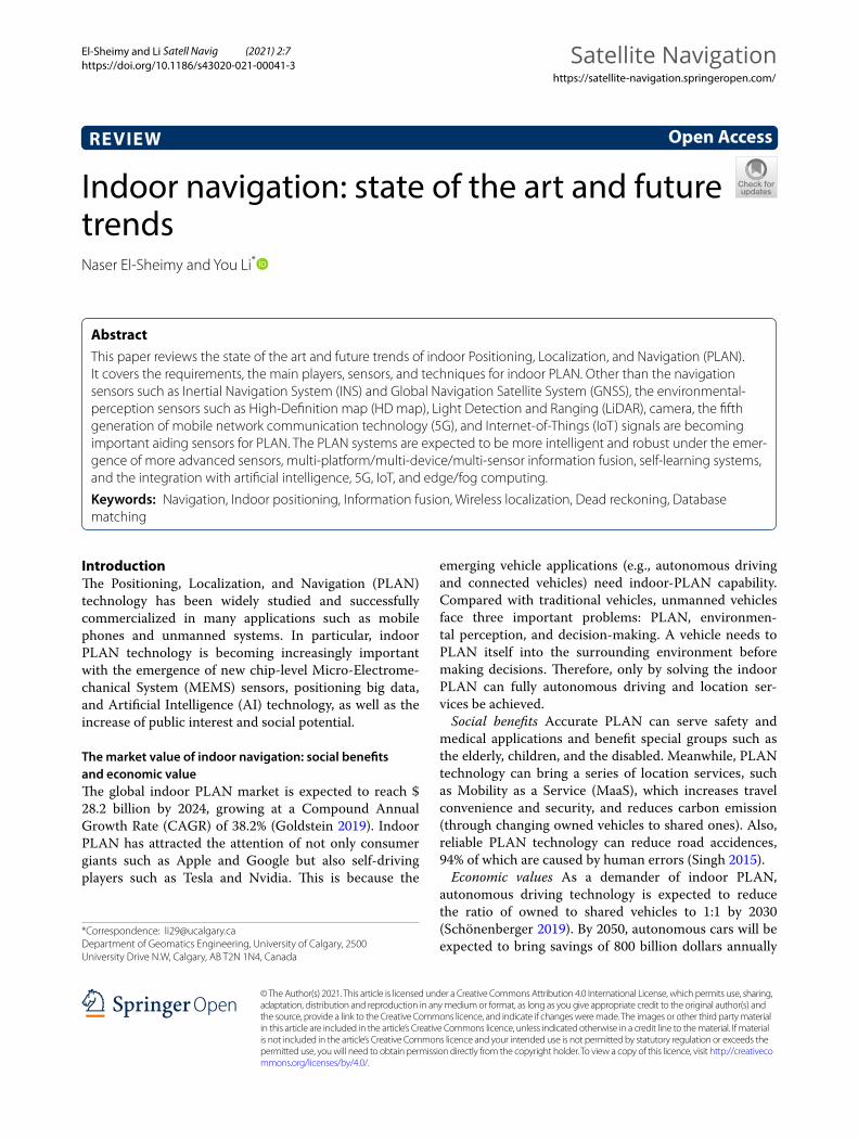
El‑Sheimy and Li Satell Navig (2021) 2:7 https://doi.org/10.1186/s43020‑021‑00041‑3 REVIEW Indoor navigation: state of the art and future trends Naser El‑Sheimy and You Li * Abstract This paper reviews the state of the art and future trends of indoor Positioning, Localization, and Navigation (PLAN). It covers the requirements, the main players, sensors, and techniques for indoor PLAN. Other than the navigation sensors such as Inertial Navigation System (INS) and Global Navigation Satellite System (GNSS), the environmental‑ perception sensors such as High‑Definition map (HD map), Light Detection and Ranging (LiDAR), camera, the fifth generation of mobile network communication technology (5G), and Internet‑of‑Things (IoT) signals are becoming important aiding sensors for PLAN. The PLAN systems are expected to be more intelligent and robust under the emer‑ gence of more advanced sensors, multi‑platform/multi‑device/multi‑sensor information fusion, self‑learning systems, and the integration with artificial intelligence, 5G, IoT, and edge/fog computing. Keywords: Navigation, Indoor positioning, Information fusion, Wireless localization, Dead reckoning, Database matching © The Author(s) 2021. This article is licensed under a Creative Commons Attribution 4.0 International License, which permits use, sharing, adaptation, distribution and reproduction in any medium or format, as long as you give appropriate credit to the original author(s) and the source, provide a link to the Creative Commons licence, and indicate if changes were made. The images or other third party material in this article are included in the article’s Creative Commons licence, unless indicated otherwise in a credit line to the material. If material is not included in the article’s Creative Commons licence and your intended use is not permitted by statutory regulation or exceeds the permitted use, you will need to obtain permission directly from the copyright holder. To view a copy of this licence, visit http://creativeco mmons.org/licenses/by/4.0/. Introduction e Positioning, Localization, and Navigation (PLAN) technology has been widely studied and successfully commercialized in many applications such as mobile phones and unmanned systems. In particular, indoor PLAN technology is becoming increasingly important with the emergence of new chip-level Micro-Electrome- chanical System (MEMS) sensors, positioning big data, and Artificial Intelligence (AI) technology, as well as the increase of public interest and social potential. The market value of indoor navigation: social benefits and economic value e global indoor PLAN market is expected to reach $ 28.2 billion by 2024, growing at a Compound Annual Growth Rate (CAGR) of 38.2% (Goldstein 2019). Indoor PLAN has attracted the attention of not only consumer giants such as Apple and Google but also self-driving players such as Tesla and Nvidia. is is because the emerging vehicle applications (e.g., autonomous driving and connected vehicles) need indoor-PLAN capability. Compared with traditional vehicles, unmanned vehicles face three important problems: PLAN, environmen- tal perception, and decision-making. A vehicle needs to PLAN itself into the surrounding environment before making decisions. erefore, only by solving the indoor PLAN can fully autonomous driving and location ser- vices be achieved. Social benefits Accurate PLAN can serve safety and medical applications and benefit special groups such as the elderly, children, and the disabled. Meanwhile, PLAN technology can bring a series of location services, such as Mobility as a Service (MaaS), which increases travel convenience and security, and reduces carbon emission (through changing owned vehicles to shared ones). Also, reliable PLAN technology can reduce road accidences, 94% of which are caused by human errors (Singh 2015). Economic values As a demander of indoor PLAN, autonomous driving technology is expected to reduce the ratio of owned to shared vehicles to 1:1 by 2030 (Schönenberger 2019). By 2050, autonomous cars will be expected to bring savings of 800 billion dollars annually Open Access Satellite Navigation https://satellite‑navigation.springeropen.com/ *Correspondence: [email protected] Department of Geomatics Engineering, University of Calgary, 2500 University Drive N.W, Calgary, AB T2N 1N4, Canada
-
Upload
khangminh22 -
Category
Documents
-
view
2 -
download
0
Transcript of Indoor navigation: state of the art and future trends
El‑Sheimy and Li Satell Navig (2021) 2:7 https://doi.org/10.1186/s43020‑021‑00041‑3
REVIEW
Indoor navigation: state of the art and future trendsNaser El‑Sheimy and You Li*
Abstract
This paper reviews the state of the art and future trends of indoor Positioning, Localization, and Navigation (PLAN). It covers the requirements, the main players, sensors, and techniques for indoor PLAN. Other than the navigation sensors such as Inertial Navigation System (INS) and Global Navigation Satellite System (GNSS), the environmental‑perception sensors such as High‑Definition map (HD map), Light Detection and Ranging (LiDAR), camera, the fifth generation of mobile network communication technology (5G), and Internet‑of‑Things (IoT) signals are becoming important aiding sensors for PLAN. The PLAN systems are expected to be more intelligent and robust under the emer‑gence of more advanced sensors, multi‑platform/multi‑device/multi‑sensor information fusion, self‑learning systems, and the integration with artificial intelligence, 5G, IoT, and edge/fog computing.
Keywords: Navigation, Indoor positioning, Information fusion, Wireless localization, Dead reckoning, Database matching
© The Author(s) 2021. This article is licensed under a Creative Commons Attribution 4.0 International License, which permits use, sharing, adaptation, distribution and reproduction in any medium or format, as long as you give appropriate credit to the original author(s) and the source, provide a link to the Creative Commons licence, and indicate if changes were made. The images or other third party material in this article are included in the article’s Creative Commons licence, unless indicated otherwise in a credit line to the material. If material is not included in the article’s Creative Commons licence and your intended use is not permitted by statutory regulation or exceeds the permitted use, you will need to obtain permission directly from the copyright holder. To view a copy of this licence, visit http://creat iveco mmons .org/licen ses/by/4.0/.
IntroductionThe Positioning, Localization, and Navigation (PLAN) technology has been widely studied and successfully commercialized in many applications such as mobile phones and unmanned systems. In particular, indoor PLAN technology is becoming increasingly important with the emergence of new chip-level Micro-Electrome-chanical System (MEMS) sensors, positioning big data, and Artificial Intelligence (AI) technology, as well as the increase of public interest and social potential.
The market value of indoor navigation: social benefits and economic valueThe global indoor PLAN market is expected to reach $ 28.2 billion by 2024, growing at a Compound Annual Growth Rate (CAGR) of 38.2% (Goldstein 2019). Indoor PLAN has attracted the attention of not only consumer giants such as Apple and Google but also self-driving players such as Tesla and Nvidia. This is because the
emerging vehicle applications (e.g., autonomous driving and connected vehicles) need indoor-PLAN capability. Compared with traditional vehicles, unmanned vehicles face three important problems: PLAN, environmen-tal perception, and decision-making. A vehicle needs to PLAN itself into the surrounding environment before making decisions. Therefore, only by solving the indoor PLAN can fully autonomous driving and location ser-vices be achieved.
Social benefits Accurate PLAN can serve safety and medical applications and benefit special groups such as the elderly, children, and the disabled. Meanwhile, PLAN technology can bring a series of location services, such as Mobility as a Service (MaaS), which increases travel convenience and security, and reduces carbon emission (through changing owned vehicles to shared ones). Also, reliable PLAN technology can reduce road accidences, 94% of which are caused by human errors (Singh 2015).
Economic values As a demander of indoor PLAN, autonomous driving technology is expected to reduce the ratio of owned to shared vehicles to 1:1 by 2030 (Schönenberger 2019). By 2050, autonomous cars will be expected to bring savings of 800 billion dollars annually
Open Access
Satellite Navigationhttps://satellite‑navigation.springeropen.com/
*Correspondence: [email protected] of Geomatics Engineering, University of Calgary, 2500 University Drive N.W, Calgary, AB T2N 1N4, Canada
Page 2 of 23El‑Sheimy and Li Satell Navig (2021) 2:7
by reducing congestion, accidents, energy consumption, and time consumption (Schönenberger 2019). The huge social and economic benefits promote the demand for PLAN technology facing the autonomous driving and mass consumer markets.
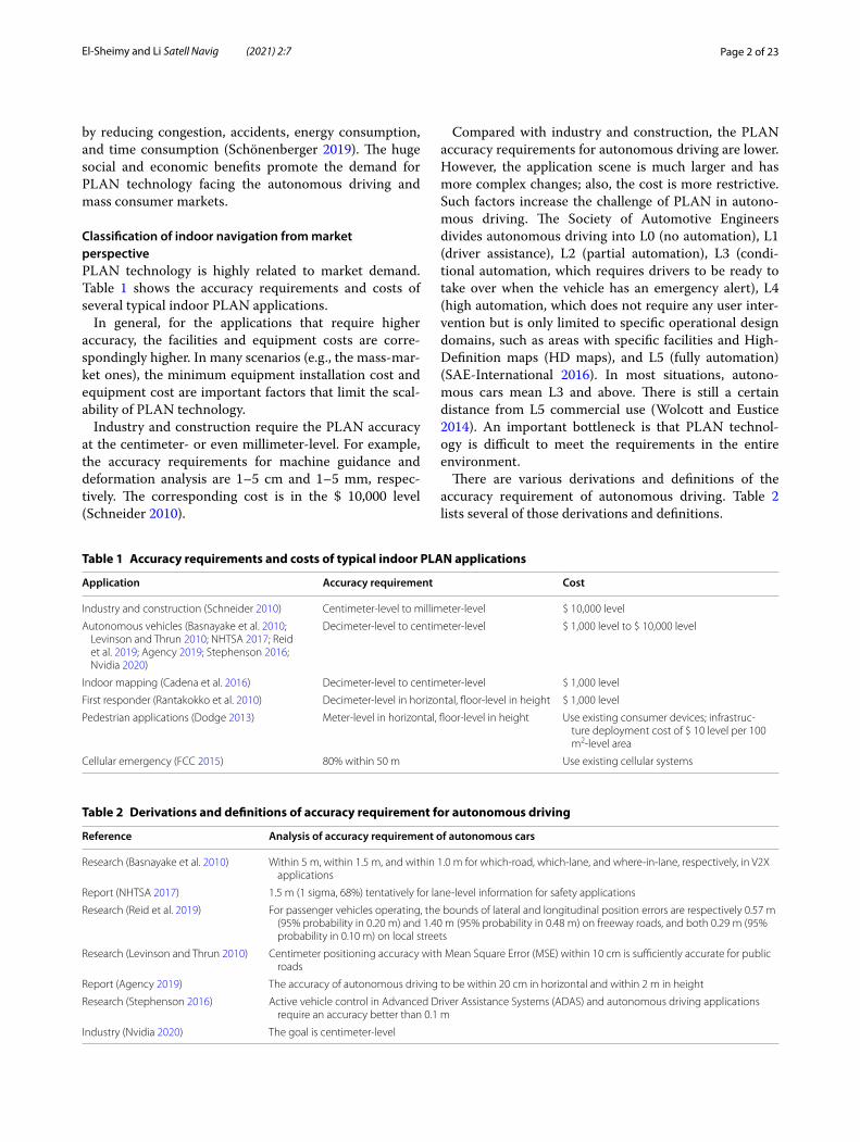
Classification of indoor navigation from market perspectivePLAN technology is highly related to market demand. Table 1 shows the accuracy requirements and costs of several typical indoor PLAN applications.
In general, for the applications that require higher accuracy, the facilities and equipment costs are corre-spondingly higher. In many scenarios (e.g., the mass-mar-ket ones), the minimum equipment installation cost and equipment cost are important factors that limit the scal-ability of PLAN technology.
Industry and construction require the PLAN accuracy at the centimeter- or even millimeter-level. For example, the accuracy requirements for machine guidance and deformation analysis are 1–5 cm and 1–5 mm, respec-tively. The corresponding cost is in the $ 10,000 level (Schneider 2010).
Compared with industry and construction, the PLAN accuracy requirements for autonomous driving are lower. However, the application scene is much larger and has more complex changes; also, the cost is more restrictive. Such factors increase the challenge of PLAN in autono-mous driving. The Society of Automotive Engineers divides autonomous driving into L0 (no automation), L1 (driver assistance), L2 (partial automation), L3 (condi-tional automation, which requires drivers to be ready to take over when the vehicle has an emergency alert), L4 (high automation, which does not require any user inter-vention but is only limited to specific operational design domains, such as areas with specific facilities and High-Definition maps (HD maps), and L5 (fully automation) (SAE-International 2016). In most situations, autono-mous cars mean L3 and above. There is still a certain distance from L5 commercial use (Wolcott and Eustice 2014). An important bottleneck is that PLAN technol-ogy is difficult to meet the requirements in the entire environment.
There are various derivations and definitions of the accuracy requirement of autonomous driving. Table 2 lists several of those derivations and definitions.
Table 1 Accuracy requirements and costs of typical indoor PLAN applications
Application Accuracy requirement Cost
Industry and construction (Schneider 2010) Centimeter‑level to millimeter‑level $ 10,000 level
Autonomous vehicles (Basnayake et al. 2010; Levinson and Thrun 2010; NHTSA 2017; Reid et al. 2019; Agency 2019; Stephenson 2016; Nvidia 2020)
Decimeter‑level to centimeter‑level $ 1,000 level to $ 10,000 level
Indoor mapping (Cadena et al. 2016) Decimeter‑level to centimeter‑level $ 1,000 level
First responder (Rantakokko et al. 2010) Decimeter‑level in horizontal, floor‑level in height $ 1,000 level
Pedestrian applications (Dodge 2013) Meter‑level in horizontal, floor‑level in height Use existing consumer devices; infrastruc‑ture deployment cost of $ 10 level per 100 m2‑level area
Cellular emergency (FCC 2015) 80% within 50 m Use existing cellular systems
Table 2 Derivations and definitions of accuracy requirement for autonomous driving
Reference Analysis of accuracy requirement of autonomous cars
Research (Basnayake et al. 2010) Within 5 m, within 1.5 m, and within 1.0 m for which‑road, which‑lane, and where‑in‑lane, respectively, in V2X applications
Report (NHTSA 2017) 1.5 m (1 sigma, 68%) tentatively for lane‑level information for safety applications
Research (Reid et al. 2019) For passenger vehicles operating, the bounds of lateral and longitudinal position errors are respectively 0.57 m (95% probability in 0.20 m) and 1.40 m (95% probability in 0.48 m) on freeway roads, and both 0.29 m (95% probability in 0.10 m) on local streets
Research (Levinson and Thrun 2010) Centimeter positioning accuracy with Mean Square Error (MSE) within 10 cm is sufficiently accurate for public roads
Report (Agency 2019) The accuracy of autonomous driving to be within 20 cm in horizontal and within 2 m in height
Research (Stephenson 2016) Active vehicle control in Advanced Driver Assistance Systems (ADAS) and autonomous driving applications require an accuracy better than 0.1 m
Industry (Nvidia 2020) The goal is centimeter‑level
Page 3 of 23El‑Sheimy and Li Satell Navig (2021) 2:7
The research work (Basnayake et al. 2010) shows the accuracy requirements in Vehicle-to-Everything (V2X) applications for which-road (within 5 m), which-lane (within 1.5 m), and where-in-lane (within 1.0 m). The National Highway Safety Administration (NHTSA 2017) reports a requirement of 1.5 m (1 sigma, 68% probabil-ity) tentatively for lane-level information for safety appli-cations. The research work (Reid et al. 2019) derives an accuracy requirement based on road geometry standards and vehicle dimensions. For passenger vehicle operat-ing, the bounds of lateral and longitudinal position errors are respectively 0.57 m (95% probability in 0.20 m) and 1.40 m (95% probability in 0.48 m) on freeway roads, and both 0.29 m (95% probability in 0.10 m) on local streets. In contrast, the research work (Levinson and Thrun 2010) believes that centimeter positioning accuracy (with a Root Mean Square (RMS) error of within 10 cm) is suf-ficient for public roads, while the report (Agency 2019) defines the accuracy for autonomous driving to be within 20 cm in horizontal and within 2 m in height. Meanwhile, the research work (Stephenson 2016) reports that active vehicle control in ADAS and autonomous driving appli-cations require an accuracy better than 0.1 m. Beyond research, the goal for autonomous driving is set at the centimeter-level by many autonomous-driving compa-nies (e.g., (Nvidia 2020)). To summarize, autonomous driving requires the PLAN accuracy at decimeter-level to centimeter-level. The current cost is in the order of $ 1000 to $ 10,000 (when using three-Dimensional (3D) Light Detection and Ranging (LiDAR)).
For indoor mapping, the review paper (Cadena et al. 2016) shows that the accuracy within 10 cm is sufficient for two-Dimensional (2D) Simultaneous Localization and Mapping (SLAM). Indoor mapping is commonly con-ducted with a vehicle that moves slower in a smaller area when compared with autonomous driving. The cost of a short-range 2D LiDAR for indoor mapping is in the order of $ 1000.
The research work (Rantakokko et al. 2010) illustrates that first responders require indoor PLAN accuracy of 1 m in horizontal and within 2 m in height. The cost for first responders is at the $ 1,000-level.
For mass-market applications, it is difficult to find a standard of PLAN accuracy requirement. An accepted accuracy classification is that 1–5 m is high, 6–10 m is moderate, and over 11 m is low (Dodge 2013). The verti-cal accuracy requirement is commonly on the floor-level. For such applications, it is important to use existing con-sumer equipment and reduce base station deployment costs. On average, the deployment in a 100 m2-level area costs approximately $ 10-level. The E-911 cellular emer-gency system uses cellular signals and has an accuracy requirement of 80% for an error of 50 m (FCC 2015).
The cost of indoor PLAN applications depends on the sensors used. The main sensors and solutions will be introduced in the following section.
Main players of indoor navigationVarious researchers and manufacturers investigate indoor PLAN problems from different perspectives.
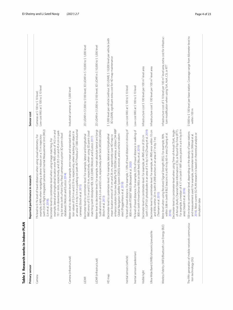
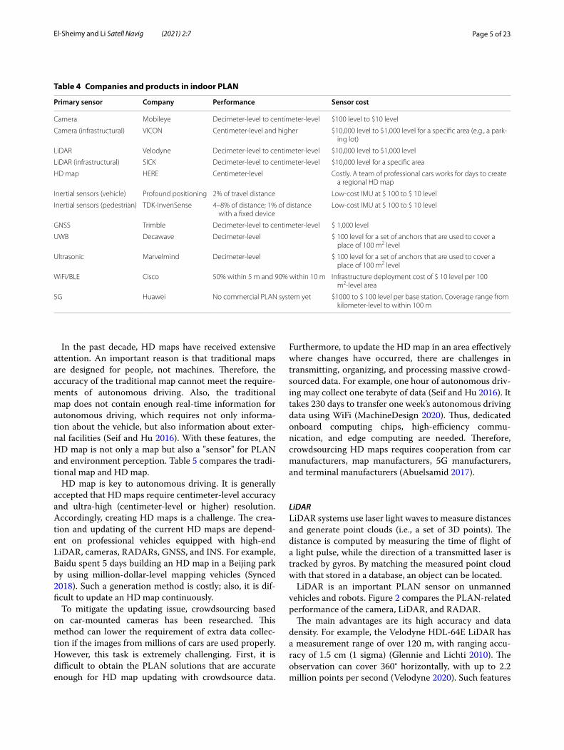
Table 3 lists the selected research works that can reflect the typical navigation accuracy for different sensors, while Table 4 shows the selected players from the indus-trial. The primary sensor, reported accuracy, and sensor costs are covered.
The actual PLAN performance is related to the factors such as infrastructure deployment (e.g., sensor type and deployment density), sensor grade, environment factors (e.g., the significance of features and area size), and vehi-cle dynamics.
In general, different types of sensors have various prin-ciples, measurement types, PLAN algorithms, perfor-mances, and costs. It is important to select the proper sensor and PLAN solution according to requirements.
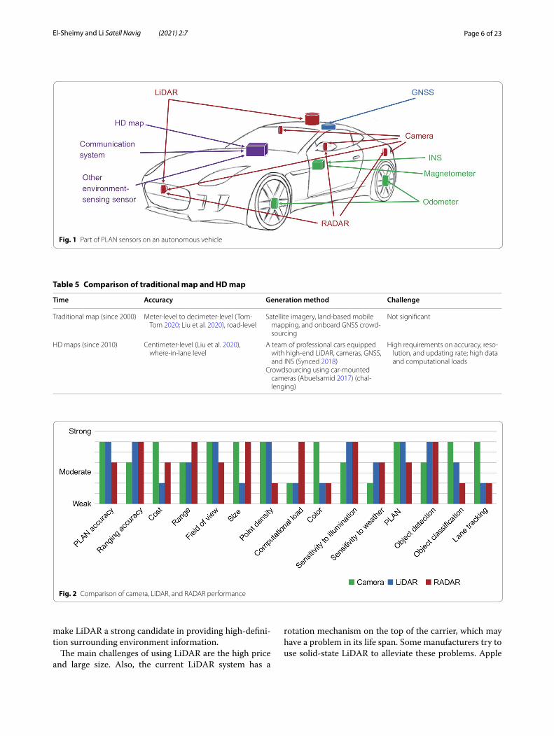
State of the artTo achieve an accurate and robust PLAN for autonomous vehicles, multiple types of sensors and techniques are required. Figure 1 shows part of the PLAN sensors that have been in autonomous cars. This section summarizes the state-of-the-art sensors and PLAN techniques.
Sensors for indoor navigationThe sensors include environmental monitoring and awareness sensors (e.g., HD map, LiDAR, RAdio Detec-tion and Ranging (RADAR), camera, WiFi/BLE, 5G, and Low-Power Wide-Area Network (LPWAN)), and the navigation sensors (e.g., Inertial Navigation Systems (INS) and GNSS). The advantages and challenges for each sensor are also introduced and compared.
Environmental monitoring and awareness sensors (aiding sensors for navigation system)HD mapsCar-mounted road maps have been successfully com-mercialized since the beginning of this century. Also, companies such as Google and HERE have launched indoor maps for public places. These maps contain roads, buildings, and Point-of-Interest (POI) information and commonly have meter-level to decimeter-level accuracy. The main purpose of these maps is to assist people to navigate and perform location service applications. The main approaches for generating these maps are satel-lite imagery, land-based mobile mapping, and onboard GNSS crowdsourcing.
Page 4 of 23El‑Sheimy and Li Satell Navig (2021) 2:7
Tabl
e 3
Rese
arch
wor
ks in
indo
or P
LAN
Prim
ary
sens
orRe
port
ed p
erfo
rman
ce in
rese
arch
Sens
or c
ost
Cam
era
1% le
vel t
o 0.
1% le
vel o
f tra
vel d
ista
nce
whe
n us
ing
visu
al o
dom
etry
. For
ex
ampl
e, 0
.46%
whe
n na
viga
ting
a dr
one
indo
ors
on a
75
m tr
ajec
tory
(w
ith D
JI A
3 fli
ght i
nteg
rate
d ca
mer
a an
d In
ertia
l Mea
sure
men
t Uni
t (IM
U))
(Lin
et a
l. 20
18);
Dec
imet
er‑le
vel t
o ce
ntim
eter
‑leve
l whe
n us
ing
imag
e m
atch
ing.
For
ex
ampl
e, la
tera
l and
long
itudi
nal l
ocat
ion
erro
r RM
S va
lues
of 1
4.3
cm a
nd
19.1
cm
in d
ownt
own
test
s, re
spec
tivel
y, a
nd 2
0.5
cm a
nd 4
5.4
cm in
par
k‑in
g lo
t tes
ts (w
ith a
Poi
nt G
rey
Flea
3 ca
mer
a an
d a
prio
ri 3D
poi
nt‑c
loud
da
taba
se) (
Wol
cott
and
Eus
tice
2014
)
Cam
eras
at $
100
to $
10
leve
l;Lo
w‑c
ost I
MU
at $
100
to $
10
leve
l
Cam
era
(infra
stru
ctur
al)
Met
er‑le
vel t
o de
cim
eter
‑leve
l. Fo
r exa
mpl
e, e
rror
mea
n an
d st
anda
rd d
evia
‑tio
n va
lues
of 0
.24
m a
nd 0
.19
m, r
espe
ctiv
ely,
whe
n tr
acki
ng a
n ob
ject
in
an a
rea
of 3
m b
y 3
m in
a p
arki
ng lo
t (w
ith A
VT P
rosi
lica
GT
1380
indu
stria
l ca
mer
as) (
Ibis
ch e
t al.
2015
)
Indu
stria
l cam
eras
at $
1,0
00 le
vel
LiD
AR
Dec
imet
er‑le
vel t
o ce
ntim
eter
‑leve
l. Fo
r exa
mpl
e, la
tera
l and
long
itudi
nal
RMS
erro
rs o
f 0.1
3 m
and
0.1
6 m
, res
pect
ivel
y, w
hen
usin
g 3D
poi
nt c
loud
m
atch
ing
(with
Vel
odyn
e H
DL‑
32E
LiD
AR)
(Wol
cott
and
Eus
tice
2017
)
2D L
iDA
R in
$1,
000
to $
100
leve
l; 3D
LiD
AR
in $
10,
000
to $
1,0
00 le
vel
LiD
AR
(infra
stru
ctur
al)
Met
er‑le
vel t
o de
cim
eter
‑leve
l. Fo
r exa
mpl
e, m
ean
abso
lute
late
ral a
nd lo
ngi‑
tudi
nal e
rror
s of
6.3
cm
and
8.5
cm
, res
pect
ivel
y (w
ith S
ick
LMS5
00 L
iDA
Rs)
(Ibis
ch e
t al.
2013
)
2D L
iDA
R in
$1,
000
to $
100
leve
l; 3D
LiD
AR
in $
10,
000
to $
1,0
00 le
vel
HD
map
Dec
imet
er‑le
vel t
o ce
ntim
eter
‑leve
l. Fo
r exa
mpl
e, la
tera
l and
long
itudi
nal
mea
n lo
catio
n er
rors
of 1
4 cm
and
26
cm, r
espe
ctiv
ely
(use
HD
map
to
enha
nce
solu
tion
from
two
Blac
kFly
PG
E‑50
S5M
cam
eras
, a U
blox
C94
‑M8P
G
loba
l Nav
igat
ion
Sate
llite
Sys
tem
(GN
SS) r
ecei
ver,
and
a ve
hicl
e od
om‑
eter
) (Po
ggen
hans
et a
l. 20
18)
$ 1,
000
leve
l per
veh
icle
(with
out 3
D L
iDA
R); $
10,
000
leve
l per
veh
icle
(with
3D
LiD
AR)
; sig
nific
ant e
xtra
cos
t for
HD
‑map
mai
nten
ance
Iner
tial s
enso
rs (v
ehic
le)
1% le
vel o
f tra
vel d
ista
nce.
For
exa
mpl
e, 1
.10%
of t
rave
l dis
tanc
e in
driv
ing
of
800
m (w
ith R
T300
32 IMU
) (Br
ossa
rd e
t al.
2020
)Lo
w‑c
ost I
MU
at $
100
to $
10
leve
l
Iner
tial s
enso
rs (p
edes
tria
n)1%
leve
l of t
rave
l dis
tanc
e. F
or e
xam
ple,
0.5
% o
f tra
vel d
ista
nce
in w
alki
ng o
f 80
0 m
(with
4 In
venS
ense
IMU
s on
bot
h fe
et) (
Niu
et a
l. 20
19)
Low
‑cos
t IM
U a
t $ 1
00 to
$ 1
0 le
vel
Visi
ble
light
Dec
imet
er‑le
vel t
o ce
ntim
eter
‑leve
l. Fo
r exa
mpl
e, a
n RM
S er
ror o
f 20
cm
(with
5 O
PT10
1 ph
otod
iode
s in
an
area
of 5
m b
y 5
m) (
Zhua
ng e
t al.
2019
)In
frast
ruct
ure
cost
$ 1
00 le
vel p
er 1
00 m
2 ‑leve
l are
a
Ultr
a‑W
ide
Band
(UW
B)/u
ltras
onic
/pse
udol
iteD
ecim
eter
‑leve
l to
cent
imet
er‑le
vel.
For e
xam
ple,
an
RMS
erro
r with
in 1
0 cm
an
d 95
% w
ithin
20
m (w
ith 8
UW
B an
chor
s in
an
area
of 7
m b
y 7
m)
(Tie
man
n et
al.
2015
)
Infra
stru
ctur
e co
st $
100
leve
l per
100
m2 ‑le
vel a
rea
Wire
less
Fid
elity
(WiF
i)/Bl
ueto
oth
Low
Ene
rgy
(BLE
)M
ete‑
leve
l whe
n us
ing
Rece
ived
Sig
nal S
tren
gth
(RSS
). Fo
r exa
mpl
e, 9
0%
with
in 3
.88
m (w
ith 8
BLE
bea
cons
in a
40
m b
y 60
m a
rea
(Zhu
ang
et a
l. 20
16);
Dec
imet
er‑le
vel t
o ce
ntim
eter
‑leve
l whe
n us
ing
Tim
e‑of
‑Arr
ival
(ToA
), A
ngle
‑of
‑Arr
ival
(AoA
), C
hann
el‑S
tate
‑Info
rmat
ion
(CSI
), or
Rou
nd‑T
rip‑T
ime
(RTT
). Fo
r exa
mpl
e, a
med
ian
of 4
.17
cm (w
ith 1
WiF
i acc
ess
poin
t in
a 6
m b
y 8
m
area
) (Va
sish
t et a
l. 20
16)
Infra
stru
ctur
e co
st o
f $ 1
0 le
vel p
er 1
00 m
2 ‑leve
l are
a; e
xtra
cos
t for
infra
stru
c‑tu
re m
odifi
catio
n w
hen
usin
g To
A, A
oA, C
SI, o
r RTT
The
fifth
gen
erat
ion
of m
obile
net
wor
k co
mm
unic
a‑tio
n te
chno
logy
(5G
)10
0‑m
‑leve
l to
cent
imet
er‑le
vel,
depe
ndin
g on
the
dens
ity o
f bas
e st
atio
ns
and
mea
sure
men
t use
d. F
or e
xam
ple,
cen
timet
er‑le
vel i
n (W
itris
al e
t al.
2016
). M
ost c
urre
nt 5
G P
LAN
rese
arch
is b
ased
on
theo
retic
al a
naly
sis
or
sim
ulat
ion
data
$100
0 to
$ 1
00 le
vel p
er b
ase
stat
ion.
Cov
erag
e ra
nge
from
kilo
met
er‑le
vel t
o w
ithin
100
m
Page 5 of 23El‑Sheimy and Li Satell Navig (2021) 2:7
In the past decade, HD maps have received extensive attention. An important reason is that traditional maps are designed for people, not machines. Therefore, the accuracy of the traditional map cannot meet the require-ments of autonomous driving. Also, the traditional map does not contain enough real-time information for autonomous driving, which requires not only informa-tion about the vehicle, but also information about exter-nal facilities (Seif and Hu 2016). With these features, the HD map is not only a map but also a "sensor" for PLAN and environment perception. Table 5 compares the tradi-tional map and HD map.
HD map is key to autonomous driving. It is generally accepted that HD maps require centimeter-level accuracy and ultra-high (centimeter-level or higher) resolution. Accordingly, creating HD maps is a challenge. The crea-tion and updating of the current HD maps are depend-ent on professional vehicles equipped with high-end LiDAR, cameras, RADARs, GNSS, and INS. For example, Baidu spent 5 days building an HD map in a Beijing park by using million-dollar-level mapping vehicles (Synced 2018). Such a generation method is costly; also, it is dif-ficult to update an HD map continuously.
To mitigate the updating issue, crowdsourcing based on car-mounted cameras has been researched. This method can lower the requirement of extra data collec-tion if the images from millions of cars are used properly. However, this task is extremely challenging. First, it is difficult to obtain the PLAN solutions that are accurate enough for HD map updating with crowdsource data.
Furthermore, to update the HD map in an area effectively where changes have occurred, there are challenges in transmitting, organizing, and processing massive crowd-sourced data. For example, one hour of autonomous driv-ing may collect one terabyte of data (Seif and Hu 2016). It takes 230 days to transfer one week’s autonomous driving data using WiFi (MachineDesign 2020). Thus, dedicated onboard computing chips, high-efficiency commu-nication, and edge computing are needed. Therefore, crowdsourcing HD maps requires cooperation from car manufacturers, map manufacturers, 5G manufacturers, and terminal manufacturers (Abuelsamid 2017).
LiDARLiDAR systems use laser light waves to measure distances and generate point clouds (i.e., a set of 3D points). The distance is computed by measuring the time of flight of a light pulse, while the direction of a transmitted laser is tracked by gyros. By matching the measured point cloud with that stored in a database, an object can be located.
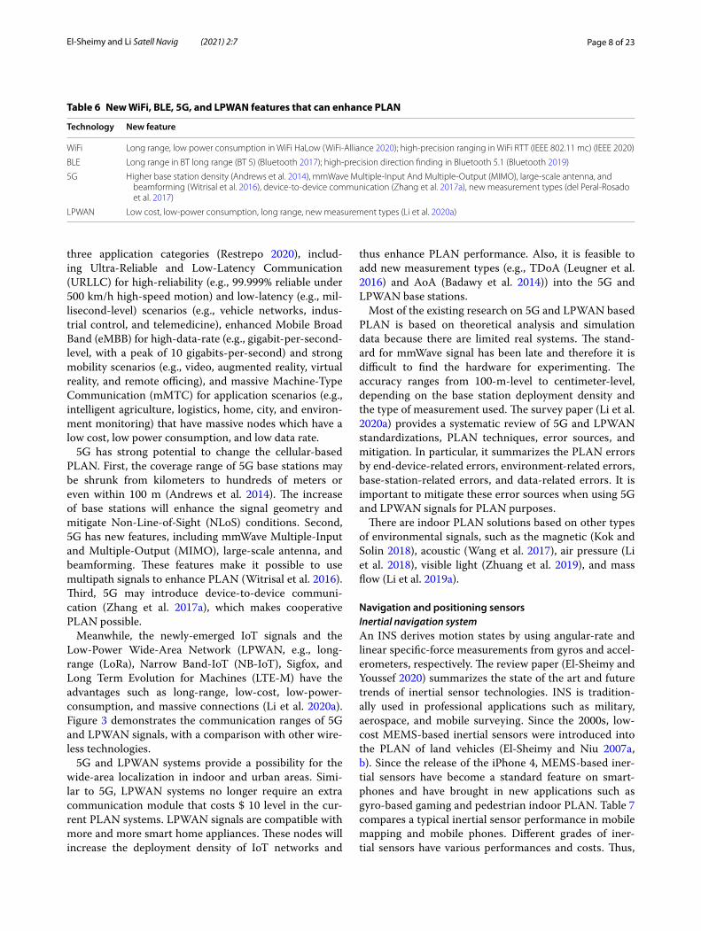
LiDAR is an important PLAN sensor on unmanned vehicles and robots. Figure 2 compares the PLAN-related performance of the camera, LiDAR, and RADAR.
The main advantages are its high accuracy and data density. For example, the Velodyne HDL-64E LiDAR has a measurement range of over 120 m, with ranging accu-racy of 1.5 cm (1 sigma) (Glennie and Lichti 2010). The observation can cover 360° horizontally, with up to 2.2 million points per second (Velodyne 2020). Such features
Table 4 Companies and products in indoor PLAN
Primary sensor Company Performance Sensor cost
Camera Mobileye Decimeter‑level to centimeter‑level $100 level to $10 level
Camera (infrastructural) VICON Centimeter‑level and higher $10,000 level to $1,000 level for a specific area (e.g., a park‑ing lot)
LiDAR Velodyne Decimeter‑level to centimeter‑level $10,000 level to $1,000 level
LiDAR (infrastructural) SICK Decimeter‑level to centimeter‑level $10,000 level for a specific area
HD map HERE Centimeter‑level Costly. A team of professional cars works for days to create a regional HD map
Inertial sensors (vehicle) Profound positioning 2% of travel distance Low‑cost IMU at $ 100 to $ 10 level
Inertial sensors (pedestrian) TDK‑InvenSense 4–8% of distance; 1% of distance with a fixed device
Low‑cost IMU at $ 100 to $ 10 level
GNSS Trimble Decimeter‑level to centimeter‑level $ 1,000 level
UWB Decawave Decimeter‑level $ 100 level for a set of anchors that are used to cover a place of 100 m2 level
Ultrasonic Marvelmind Decimeter‑level $ 100 level for a set of anchors that are used to cover a place of 100 m2 level
WiFi/BLE Cisco 50% within 5 m and 90% within 10 m Infrastructure deployment cost of $ 10 level per 100 m2‑level area
5G Huawei No commercial PLAN system yet $1000 to $ 100 level per base station. Coverage range from kilometer‑level to within 100 m
Page 6 of 23El‑Sheimy and Li Satell Navig (2021) 2:7
make LiDAR a strong candidate in providing high-defini-tion surrounding environment information.
The main challenges of using LiDAR are the high price and large size. Also, the current LiDAR system has a
rotation mechanism on the top of the carrier, which may have a problem in its life span. Some manufacturers try to use solid-state LiDAR to alleviate these problems. Apple
Fig. 1 Part of PLAN sensors on an autonomous vehicle
Table 5 Comparison of traditional map and HD map
Time Accuracy Generation method Challenge
Traditional map (since 2000) Meter‑level to decimeter‑level (Tom‑Tom 2020; Liu et al. 2020), road‑level
Satellite imagery, land‑based mobile mapping, and onboard GNSS crowd‑sourcing
Not significant
HD maps (since 2010) Centimeter‑level (Liu et al. 2020), where‑in‑lane level
A team of professional cars equipped with high‑end LiDAR, cameras, GNSS, and INS (Synced 2018)
Crowdsourcing using car‑mounted cameras (Abuelsamid 2017) (chal‑lenging)
High requirements on accuracy, reso‑lution, and updating rate; high data and computational loads
Fig. 2 Comparison of camera, LiDAR, and RADAR performance

Page 7 of 23El‑Sheimy and Li Satell Navig (2021) 2:7
unveils a new iPad Pro with a LiDAR scanner, which may bring new directions to indoor PLAN.
LiDAR measurements are used for PLAN through 2D or 3D matching. For example, the research works (de Paula Veronese et al. 2016) and (Wolcott and Eustice 2017) match LiDAR measurements with a 2D grid map and a 3D point cloud map, respectively. The PLAN per-formance is generally better when the surrounding envi-ronment features are significant and distinct from other places; otherwise, performance is limited. The LiDAR measurement performance will not be affected by light but may be affected by weather conditions.
CameraCameras are used for PLAN and perception by collect-ing and analyzing images. Compared with LiDAR and RADAR, the camera has a much lower cost. Also, the camera has the advantages such as rich feature informa-tion and color information. Also, the camera is a passive sensing technology, which does not transmit signals and thus does not have errors on the signal-propagation side. Moreover, the current 2D computer vision algorithm is more advanced, which has also promoted the application of cameras.
Similar to LiDAR, the camera depends on the sig-nificance of environmental features. Also, the camera is more susceptible to weather and illumination conditions. Its performance degrades under harsher conditions, such as in darkness, rain, fog, and snow. Thus, it is important to develop camera sensors with self-cleaning, longer dynamic range, better low light sensitivity, and higher near-infrared sensitivity. Furthermore, the amount of raw camera data is large. Multiple cameras on an autonomous vehicle can generate gigabyte-level raw data every minute or even every second.
Some PLAN solutions use cameras, instead of a high-end LiDAR, to reduce hardware cost. An example is Tesla’s autopilot system (Tesla 2020). This system con-tains many cameras, including three forward cameras (wide, main, and narrow), four side cameras (forward and rearward), and a rear camera. To assure the PLAN performance in the environments that are challenging for cameras, RADARs and ultrasonic sensors are used.
The two main camera-based PLAN approaches are visual odometry/SLAM and image matching. For the former, the research work (Mur-Artal and Tardós 2017) can support visual SLAM using monocular, stereo, and Red–Green–Blue-Depth (RGB-D) cameras. For image matching, road markers, signs, poles, and artificial fea-tures (e.g., Quick Response (QR) codes) can be used. The research work (Gruyer et al. 2016) uses two cameras to take the ground road marker and match it with a preci-sion road marker map. In contrast, the research works
(Wolcott and Eustice 2014) and (McManus et al. 2013) respectively use images from monocular and stereo cam-eras to match the 3D point cloud map generated by a sur-vey vehicle equipped with 3D LiDAR scanners.
RADARRADAR has also received intensive attention in the autonomous driving industry. Similar to LiDAR, the RADAR determines the distance by measuring the round-trip time difference of the signal. The difference is that the RADAR emits radio waves, instead of laser waves. Compared with LiDAR, the RADAR generally has a further measurement range. For example, the Bosch LRR RADA can reach up to 250 m. Also, the price of a RADAR system has dropped to the order of $ 1,000 to $ 100. Moreover, RADAR systems are lightweight, which makes it possible to embed them in cars.
On the other hand, the density of RADAR measure-ments is much lower than that of LiDARs and cameras. Therefore, RADAR is often used for obstacle avoid-ance, rather than as the main sensor of PLAN. Similar to LiDAR, the measurement performance of RADAR is not affected by light but may be affected by weather conditions.
WiFi/BLEWiFi and BLE are the most widely used indoor wireless PLAN technologies for consumer electronics. The com-monly used observation is RSS (Zhuang et al. 2016), and the typical positioning accuracy is at meter-level. Also, researchers have extracted high-accuracy measurements, such as CSI (Halperin et al. 2011), RTT (Ciurana et al. 2007), and AoA (Quuppa 2020). Such measurements can be used for decimeter-level or even centimeter-level PLAN.
A major advantage of WiFi systems is that they can use existing communication facilities. In contrast, BLE is flexible and convenient to deploy. To meet the future Internet-of-Things (IoT) and precise localization require-ments, new features have been added to both the latest WiFi and BLE technologies. Table 6 lists the new WiFi, BLE, 5G, and LPWAN features that can enhance PLAN. WiFi HaLow (WiFi-Alliance 2020) and Bluetooth long range (Bluetooth 5) (Bluetooth 2017) are released to improve the signal range, while WiFi RTT (IEEE 802.11 mc) (IEEE 2020) and Bluetooth direction finding (Blue-tooth 5.1) (Bluetooth 2019) have been released for preci-sion positioning.
5G/LPWAN5G has attracted intensive attention due to its high speed, high reliability, and low latency in communication. Com-pared with previous cellular technologies, 5G has defined
Page 8 of 23El‑Sheimy and Li Satell Navig (2021) 2:7
three application categories (Restrepo 2020), includ-ing Ultra-Reliable and Low-Latency Communication (URLLC) for high-reliability (e.g., 99.999% reliable under 500 km/h high-speed motion) and low-latency (e.g., mil-lisecond-level) scenarios (e.g., vehicle networks, indus-trial control, and telemedicine), enhanced Mobile Broad Band (eMBB) for high-data-rate (e.g., gigabit-per-second-level, with a peak of 10 gigabits-per-second) and strong mobility scenarios (e.g., video, augmented reality, virtual reality, and remote officing), and massive Machine-Type Communication (mMTC) for application scenarios (e.g., intelligent agriculture, logistics, home, city, and environ-ment monitoring) that have massive nodes which have a low cost, low power consumption, and low data rate.
5G has strong potential to change the cellular-based PLAN. First, the coverage range of 5G base stations may be shrunk from kilometers to hundreds of meters or even within 100 m (Andrews et al. 2014). The increase of base stations will enhance the signal geometry and mitigate Non-Line-of-Sight (NLoS) conditions. Second, 5G has new features, including mmWave Multiple-Input and Multiple-Output (MIMO), large-scale antenna, and beamforming. These features make it possible to use multipath signals to enhance PLAN (Witrisal et al. 2016). Third, 5G may introduce device-to-device communi-cation (Zhang et al. 2017a), which makes cooperative PLAN possible.
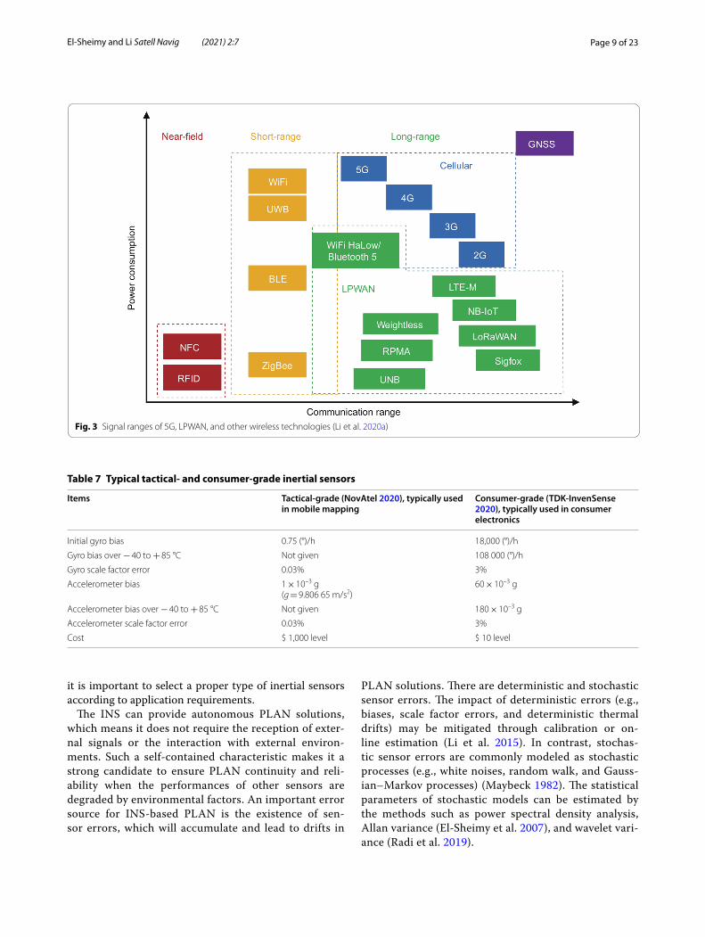
Meanwhile, the newly-emerged IoT signals and the Low-Power Wide-Area Network (LPWAN, e.g., long-range (LoRa), Narrow Band-IoT (NB-IoT), Sigfox, and Long Term Evolution for Machines (LTE-M) have the advantages such as long-range, low-cost, low-power-consumption, and massive connections (Li et al. 2020a). Figure 3 demonstrates the communication ranges of 5G and LPWAN signals, with a comparison with other wire-less technologies.
5G and LPWAN systems provide a possibility for the wide-area localization in indoor and urban areas. Simi-lar to 5G, LPWAN systems no longer require an extra communication module that costs $ 10 level in the cur-rent PLAN systems. LPWAN signals are compatible with more and more smart home appliances. These nodes will increase the deployment density of IoT networks and
thus enhance PLAN performance. Also, it is feasible to add new measurement types (e.g., TDoA (Leugner et al. 2016) and AoA (Badawy et al. 2014)) into the 5G and LPWAN base stations.
Most of the existing research on 5G and LPWAN based PLAN is based on theoretical analysis and simulation data because there are limited real systems. The stand-ard for mmWave signal has been late and therefore it is difficult to find the hardware for experimenting. The accuracy ranges from 100-m-level to centimeter-level, depending on the base station deployment density and the type of measurement used. The survey paper (Li et al. 2020a) provides a systematic review of 5G and LPWAN standardizations, PLAN techniques, error sources, and mitigation. In particular, it summarizes the PLAN errors by end-device-related errors, environment-related errors, base-station-related errors, and data-related errors. It is important to mitigate these error sources when using 5G and LPWAN signals for PLAN purposes.
There are indoor PLAN solutions based on other types of environmental signals, such as the magnetic (Kok and Solin 2018), acoustic (Wang et al. 2017), air pressure (Li et al. 2018), visible light (Zhuang et al. 2019), and mass flow (Li et al. 2019a).
Navigation and positioning sensorsInertial navigation systemAn INS derives motion states by using angular-rate and linear specific-force measurements from gyros and accel-erometers, respectively. The review paper (El-Sheimy and Youssef 2020) summarizes the state of the art and future trends of inertial sensor technologies. INS is tradition-ally used in professional applications such as military, aerospace, and mobile surveying. Since the 2000s, low-cost MEMS-based inertial sensors were introduced into the PLAN of land vehicles (El-Sheimy and Niu 2007a, b). Since the release of the iPhone 4, MEMS-based iner-tial sensors have become a standard feature on smart-phones and have brought in new applications such as gyro-based gaming and pedestrian indoor PLAN. Table 7 compares a typical inertial sensor performance in mobile mapping and mobile phones. Different grades of iner-tial sensors have various performances and costs. Thus,
Table 6 New WiFi, BLE, 5G, and LPWAN features that can enhance PLAN
Technology New feature
WiFi Long range, low power consumption in WiFi HaLow (WiFi‑Alliance 2020); high‑precision ranging in WiFi RTT (IEEE 802.11 mc) (IEEE 2020)
BLE Long range in BT long range (BT 5) (Bluetooth 2017); high‑precision direction finding in Bluetooth 5.1 (Bluetooth 2019)
5G Higher base station density (Andrews et al. 2014), mmWave Multiple‑Input And Multiple‑Output (MIMO), large‑scale antenna, and beamforming (Witrisal et al. 2016), device‑to‑device communication (Zhang et al. 2017a), new measurement types (del Peral‑Rosado et al. 2017)
LPWAN Low cost, low‑power consumption, long range, new measurement types (Li et al. 2020a)
Page 9 of 23El‑Sheimy and Li Satell Navig (2021) 2:7
it is important to select a proper type of inertial sensors according to application requirements.
The INS can provide autonomous PLAN solutions, which means it does not require the reception of exter-nal signals or the interaction with external environ-ments. Such a self-contained characteristic makes it a strong candidate to ensure PLAN continuity and reli-ability when the performances of other sensors are degraded by environmental factors. An important error source for INS-based PLAN is the existence of sen-sor errors, which will accumulate and lead to drifts in
PLAN solutions. There are deterministic and stochastic sensor errors. The impact of deterministic errors (e.g., biases, scale factor errors, and deterministic thermal drifts) may be mitigated through calibration or on-line estimation (Li et al. 2015). In contrast, stochas-tic sensor errors are commonly modeled as stochastic processes (e.g., white noises, random walk, and Gauss-ian–Markov processes) (Maybeck 1982). The statistical parameters of stochastic models can be estimated by the methods such as power spectral density analysis, Allan variance (El-Sheimy et al. 2007), and wavelet vari-ance (Radi et al. 2019).
Fig. 3 Signal ranges of 5G, LPWAN, and other wireless technologies (Li et al. 2020a)
Table 7 Typical tactical- and consumer-grade inertial sensors
Items Tactical-grade (NovAtel 2020), typically used in mobile mapping
Consumer-grade (TDK-InvenSense 2020), typically used in consumer electronics
Initial gyro bias 0.75 (°)/h 18,000 (°)/h
Gyro bias over − 40 to + 85 °C Not given 108 000 (°)/h
Gyro scale factor error 0.03% 3%
Accelerometer bias 1 × 10⁻³ g(g = 9.806 65 m/s2)
60 × 10–3 g
Accelerometer bias over − 40 to + 85 °C Not given 180 × 10–3 g
Accelerometer scale factor error 0.03% 3%
Cost $ 1,000 level $ 10 level
Page 10 of 23El‑Sheimy and Li Satell Navig (2021) 2:7
Global navigation satellite system (as an initializer)GNSS localizes a receiver using satellite multilateration. It is one of the most widely used and most well-com-mercialized PLAN technology. Standalone GNSS and GNSS/INS integration are the mainstream PLAN solu-tions for outdoor applications. In autonomous driving, the GNSS transfers from the primary PLAN sensor to the second core. The main reason is that GNSS signals may be degraded in urban and indoor areas. Even so, high-precision GNSS is still important to provide an initial localization to reduce the searching space and computational load of other sensors (e.g., HD map and LiDAR) (Levinson et al. 2007).
The previous boundaries between high-precision pro-fessional and mass-market GNSS uses are blurring. A piece of evidence is the integration between high-pre-cision GNSS techniques and mass-market chips. Also, the latest smartphones are being able to provide high-precision GNSS measurements and PLAN solutions.
Table 8 lists the main GNSS positioning techniques. Single Point Positioning (SPP) and Differential-GNSS (DGNSS) are based on pseudo-range measurements, while Real-Time Kinematic (RTK), Precise Point Posi-tioning (PPP), and PPP with Ambiguity Resolution (PPP-AR) are based on carrier-phase measurements. DGNSS and RTK are relative positioning methods that mitigate some errors by differencing measure-ments across the rover and base receivers. In contrast, PPP and PPP-AR provide precise positioning at a sin-gle receiver by using precise satellite orbit correction, clock correction, and parameter-estimation models. They commonly need minutes for convergence (Trim-ble 2020).
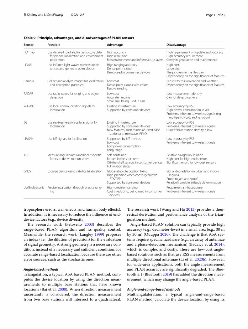
There are other types of PLAN sensors, such as mag-netometer, odometer, UWB, ultrasonic, and pseudolite. In recent years, there appears relatively low-cost UWB and ultrasonic sensors (e.g., (Decawave 2020; Marvel-mind 2020). Such sensors typically can provide a deci-meter-level ranging accuracy within a distance of 30 m. Also, Apple has built a UWB module into the iPhone 11, which may bring new opportunities for indoor PLAN. To summarize, Table 9 illustrates the principle, advantages, and disadvantages of the existing PLAN sensors.
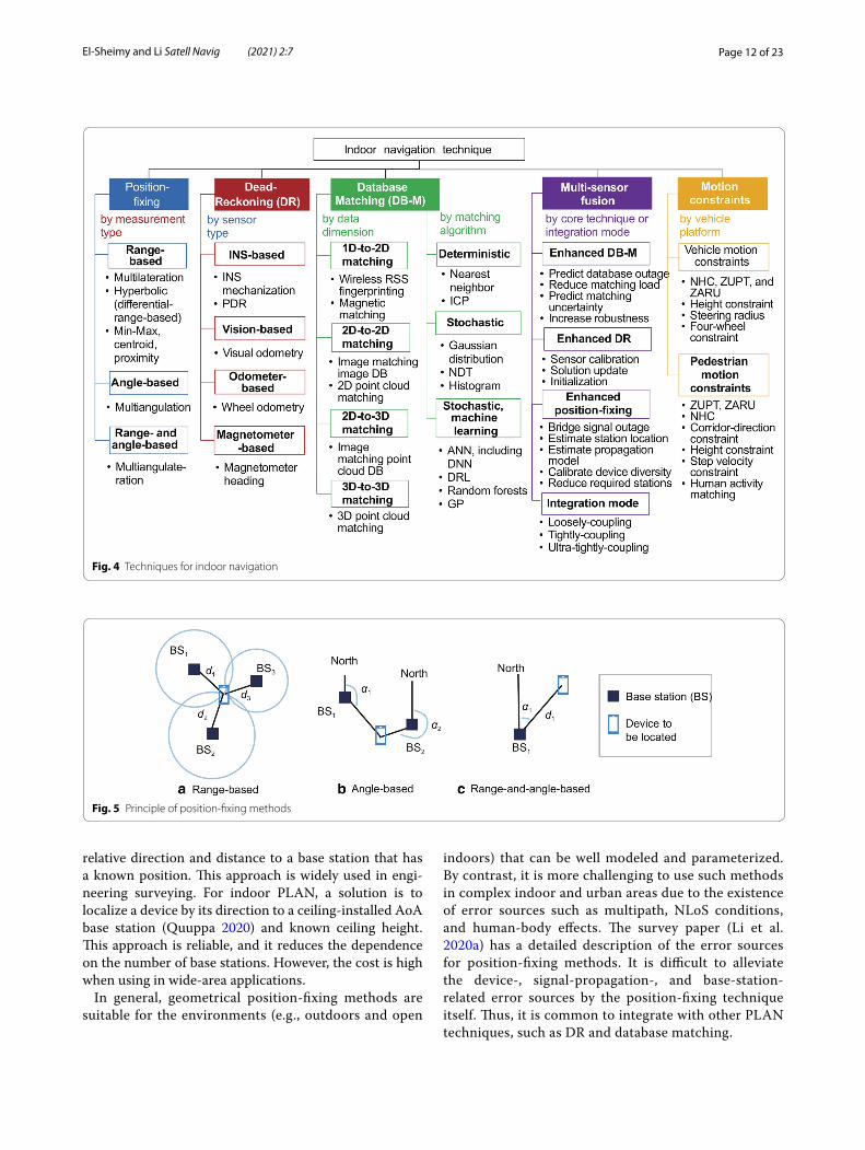
Techniques and algorithms for indoor navigationThe PLAN techniques include position-fixing, Dead-Reckoning (DR), database matching, multi-sensor fusion, and motion constraints. Figure 4 demonstrates the indoor PLAN techniques. The details are provided in the following subsections.
Position-fixing techniquesGeometrical position-fixing methods have been widely applied over the past few decades, especially in the field of satellite positioning and wireless sensor networks. The basic principle is the geometric calculation of distance and angle measurements. By the type of measurement, position-fixing methods include range-based (e.g., multi-lateration, min–max, centroid, proximity, and hyperbolic positioning), angle-based (e.g., multiangulation), and angle-and-range-based (e.g., multiangulateration). Fig-ure 5 shows the basic principle of these methods.
Range‑based methodsThe location of a device can be estimated by measuring its distance to at least three base stations (or satellites) whose locations are known. The most typical method is multilateration (Guvenc and Chong 2009), which is geo-metrically the intersection of multiple spheres (for 3D positioning) or circles (for 2D positioning). Also, the method has several simplified versions. For example, the min–max method (Will et al. 2012) computes the inter-section of multiple cubes or squares, while the centroid method (Pivato et al. 2011) calculates the weighted aver-age of multiple base station locations. Moreover, the proximity method (Bshara et al. 2011) is a further simpli-fication by using the location of the closest base station. Meanwhile, the differences of device-base-station ranges can be used to mitigate the influence of device diversity and some signal-propagation errors (Kaune et al. 2011).
For position-fixing, the base station location is usually set manually or estimated using base-station localization approaches (Cheng et al. 2005). The distances between the device and the base stations are modeled as Path-Loss Models (PLMs) and parameters are estimated (Li 2006). To achieve accurate ranging, it is important to mitigate the influence of error sources (e.g., ionospheric errors,
Table 8 GNSS positioning techniques
Technique Accuracy Measurement Methods for accuracy improvement
SPP Meter‑level Pseudo‑range None
DGNSS Decimeter‑level to meter‑level Pseudo‑range Differential measurements
RTK Centimeter‑level Carrier‑phase Differential measurements, ambiguity resolution
PPP Decimeter‑level to centimeter‑level Carrier‑phase Precise satellite orbit and clock corrections, float ambiguity
PPP‑AR Similar to RTK Carrier‑phase Precise satellite orbit and clock corrections, ambiguity resolution
Page 11 of 23El‑Sheimy and Li Satell Navig (2021) 2:7
troposphere errors, wall effects, and human body effects). In addition, it is necessary to reduce the influence of end-device factors (e.g., device diversity).
The research work (Petovello 2003) describes the range-based PLAN algorithm and its quality control. Meanwhile, the research work (Langley 1999) proposes an index (i.e., the dilution of precision) for the evaluation of signal geometry. A strong geometry is a necessary con-dition, instead of a necessary and sufficient condition, for accurate range-based localization because there are other error sources, such as the stochastic ones.
Angle‑based methodsTriangulation, a typical AoA based PLAN method, com-putes the device location by using the direction meas-urements to multiple base stations that have known locations (Bai et al. 2008). When direction measurement uncertainty is considered, the direction measurement from two base stations will intersect to a quadrilateral.
The research work (Wang and Ho 2015) provides a theo-retical derivation and performance analysis of the trian-gulation method.
Angle-based PLAN solution can typically provide high accuracy (e.g., decimeter-level) in a small area (e.g., 30 m by 30 m) (Quuppa 2020). The challenge is that AoA sys-tems require specific hardware (e.g., an array of antennae and a phase-detection mechanism) (Badawy et al. 2014), which is complex and costly. There are low-cost angle-based solutions such as that use RSS measurements from multiple directional antennae (Li et al. 2020b). However, for wide-area applications, both the angle measurement and PLAN accuracy are significantly degraded. The Blue-tooth 5.1 (Bluetooth 2019) has added the direction meas-urement, which may change the angle-based PLAN.
Angle‑and‑range‑based methodsMultiangulateration, a typical angle-and-range-based PLAN method, calculate the device location by using its
Table 9 Principle, advantages, and disadvantages of PLAN sensors
Sensor Principle Advantage Disadvantage
HD map Use detailed road and infrastructure data for precise localization and environment perception
High accuracyHigh resolutionRich environment and infrastructure layers
High requirement on update and accuracyHigh accuracy requirementCostly in generation and maintenance
LiDAR Use infrared light waves to measure dis‑tances and generate point clouds
High ranging accuracyDense point cloudBeing used in consumer devices
High costLarge sizeThe problem in the life spanDependency on the significance of features
Camera Collect and analyze images for localization and perception purposes
Low costDense point clouds with colorsPassive sensing
Sensitivity to illumination and weatherDependency on the significance of features
RADAR Use radio waves for ranging and object detection
Low costAccurate rangingSmall size, being used in cars
Low measurement densityCannot detect markers
WiFi/BLE Use local communication signals for localization
Existing infrastructureSupported by consumer devices
Low accuracy by RSSHigh power consumption in WiFiProblems inherent to wireless signals (e.g.,
multipath, NLoS, and variation)
5G Use next‑generation cellular signal for localization
Existing infrastructureSupported by consumer devicesNew features, such as miniaturized base
station and mmWave MIMO
Low accuracy by RSSProblems inherent to wireless signalsCurrent base station density is low
LPWAN Use IoT signals for localization Supported by IoT devicesLow costLow power consumptionLong range
Low accuracy by RSSProblems inherent to wireless signals
INS Measure angular rates and linear specific forces to derive motion states
Self‑containedRobust in the short termOff‑the‑shelf sensors in consumer devicesFull motion states
Relative navigation solutionHigh cost for high‑end sensorsSignificant errors for low‑cost sensors
GNSS Localize device using satellite trilateration Global absolute position fixingHigh precision when converged (with
RTK/PPP)Supported by consumer devices
Signal degradation in urban and indoor regions
Prone to jam and spoofRelatively weak in attitude determination
UWB/ultrasonic Precise localization through precise rang‑ing
High‑precision rangingCost is reducing, being used in consumer
devices
Require extra infrastructureProblems inherent to wireless signals
Page 12 of 23El‑Sheimy and Li Satell Navig (2021) 2:7
relative direction and distance to a base station that has a known position. This approach is widely used in engi-neering surveying. For indoor PLAN, a solution is to localize a device by its direction to a ceiling-installed AoA base station (Quuppa 2020) and known ceiling height. This approach is reliable, and it reduces the dependence on the number of base stations. However, the cost is high when using in wide-area applications.
In general, geometrical position-fixing methods are suitable for the environments (e.g., outdoors and open
indoors) that can be well modeled and parameterized. By contrast, it is more challenging to use such methods in complex indoor and urban areas due to the existence of error sources such as multipath, NLoS conditions, and human-body effects. The survey paper (Li et al. 2020a) has a detailed description of the error sources for position-fixing methods. It is difficult to alleviate the device-, signal-propagation-, and base-station-related error sources by the position-fixing technique itself. Thus, it is common to integrate with other PLAN techniques, such as DR and database matching.
Fig. 4 Techniques for indoor navigation
Fig. 5 Principle of position‑fixing methods
Page 13 of 23El‑Sheimy and Li Satell Navig (2021) 2:7
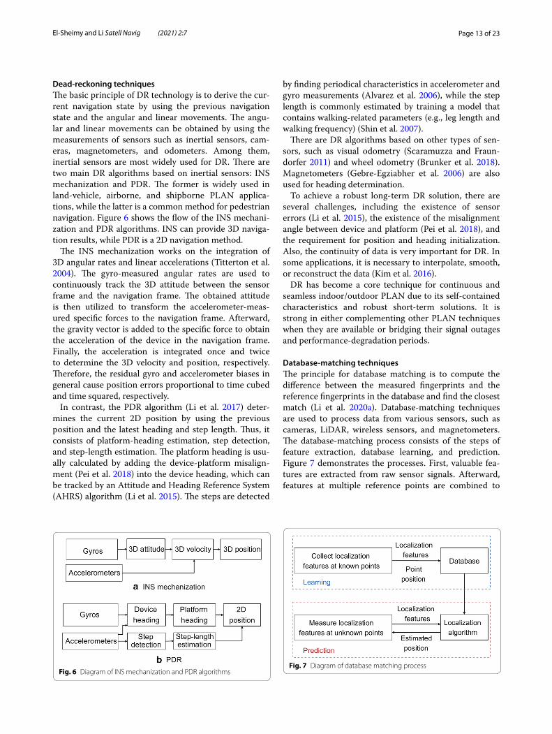
Dead-reckoning techniquesThe basic principle of DR technology is to derive the cur-rent navigation state by using the previous navigation state and the angular and linear movements. The angu-lar and linear movements can be obtained by using the measurements of sensors such as inertial sensors, cam-eras, magnetometers, and odometers. Among them, inertial sensors are most widely used for DR. There are two main DR algorithms based on inertial sensors: INS mechanization and PDR. The former is widely used in land-vehicle, airborne, and shipborne PLAN applica-tions, while the latter is a common method for pedestrian navigation. Figure 6 shows the flow of the INS mechani-zation and PDR algorithms. INS can provide 3D naviga-tion results, while PDR is a 2D navigation method.
The INS mechanization works on the integration of 3D angular rates and linear accelerations (Titterton et al. 2004). The gyro-measured angular rates are used to continuously track the 3D attitude between the sensor frame and the navigation frame. The obtained attitude is then utilized to transform the accelerometer-meas-ured specific forces to the navigation frame. Afterward, the gravity vector is added to the specific force to obtain the acceleration of the device in the navigation frame. Finally, the acceleration is integrated once and twice to determine the 3D velocity and position, respectively. Therefore, the residual gyro and accelerometer biases in general cause position errors proportional to time cubed and time squared, respectively.
In contrast, the PDR algorithm (Li et al. 2017) deter-mines the current 2D position by using the previous position and the latest heading and step length. Thus, it consists of platform-heading estimation, step detection, and step-length estimation. The platform heading is usu-ally calculated by adding the device-platform misalign-ment (Pei et al. 2018) into the device heading, which can be tracked by an Attitude and Heading Reference System (AHRS) algorithm (Li et al. 2015). The steps are detected
by finding periodical characteristics in accelerometer and gyro measurements (Alvarez et al. 2006), while the step length is commonly estimated by training a model that contains walking-related parameters (e.g., leg length and walking frequency) (Shin et al. 2007).
There are DR algorithms based on other types of sen-sors, such as visual odometry (Scaramuzza and Fraun-dorfer 2011) and wheel odometry (Brunker et al. 2018). Magnetometers (Gebre-Egziabher et al. 2006) are also used for heading determination.
To achieve a robust long-term DR solution, there are several challenges, including the existence of sensor errors (Li et al. 2015), the existence of the misalignment angle between device and platform (Pei et al. 2018), and the requirement for position and heading initialization. Also, the continuity of data is very important for DR. In some applications, it is necessary to interpolate, smooth, or reconstruct the data (Kim et al. 2016).
DR has become a core technique for continuous and seamless indoor/outdoor PLAN due to its self-contained characteristics and robust short-term solutions. It is strong in either complementing other PLAN techniques when they are available or bridging their signal outages and performance-degradation periods.
Database-matching techniquesThe principle for database matching is to compute the difference between the measured fingerprints and the reference fingerprints in the database and find the closest match (Li et al. 2020a). Database-matching techniques are used to process data from various sensors, such as cameras, LiDAR, wireless sensors, and magnetometers. The database-matching process consists of the steps of feature extraction, database learning, and prediction. Figure 7 demonstrates the processes. First, valuable fea-tures are extracted from raw sensor signals. Afterward, features at multiple reference points are combined to
Fig. 6 Diagram of INS mechanization and PDR algorithmsFig. 7 Diagram of database matching process
Page 14 of 23El‑Sheimy and Li Satell Navig (2021) 2:7
generate a database. Finally, the real-time measured fea-tures are compared with those in the database to localize the device.
According to the dimensions of measurements and the database, database-matching algorithms can be divided into the 1D (measurement)-to-2D (database) matching, the 2D-to-2D matching, the 2D-to-3D matching, and the 3D-to-3D matching. In the 1D-to-2D matching, the real-time feature measurement can be expressed as a vector, while the database is a matrix. Such a matching approach has been used to match features such as wireless RSS (Li et al. 2017) and magnetic intensity (Li et al. 2018). Examples of the 2D-to-2D matching are the matching of real-time image features (e.g., road markers) and an image feature database (e.g., a road marker map) (Gruyer et al. 2016), and the matching of 2D LiDAR points and a grid map (de Paula Veronese et al. 2016). By contrast, the 2D-to-3D matching is a current hot spot. For exam-ple, it matches images to a 3D point cloud map (Wolcott and Eustice 2014). Finally, an example of the 3D-to-3D matching is the matching of 3D LiDAR measurements and a 3D point cloud map (Wolcott and Eustice 2017).
According to the prediction algorithm, database-matching algorithms can be divided into the determinis-tic (e.g., nearest neighbors (Lim et al. 2006) and Iterative Closest Point (ICP) (Chetverikov et al. 2002)) and sto-chastic (e.g., Gaussian distribution (Haeberlen et al. 2004), Normal Distribution Transform (NDT) (Biber and Straßer 2003), histogram (Rusu et al. 2008), and machine-learning-based) ones. Machine learning methods, such as Artificial Neural Network (ANN) (Li et al. 2019b), random forests (Guo et al. 2018), Deep Reinforcement
Learning (DRL) (Li et al. 2019c), and Gaussian Process (GP) (Hähnel and Fox 2006), have also been applied.
With the rapid development of machine-learning tech-niques and the diversity in modern PLAN applications, database matching has been attracted even more atten-tion than geometrical methods. The database matching methods are suitable for scenarios that are difficult to model or parameterize. On the other hand, the inconsist-ency between real-time measurement and the database is the main error source in database matching. Such incon-sistency may be caused by the existence of new environ-ments and varying environments and other factors. The survey paper (Li et al. 2020a) has a detailed description of the error sources for database matching.
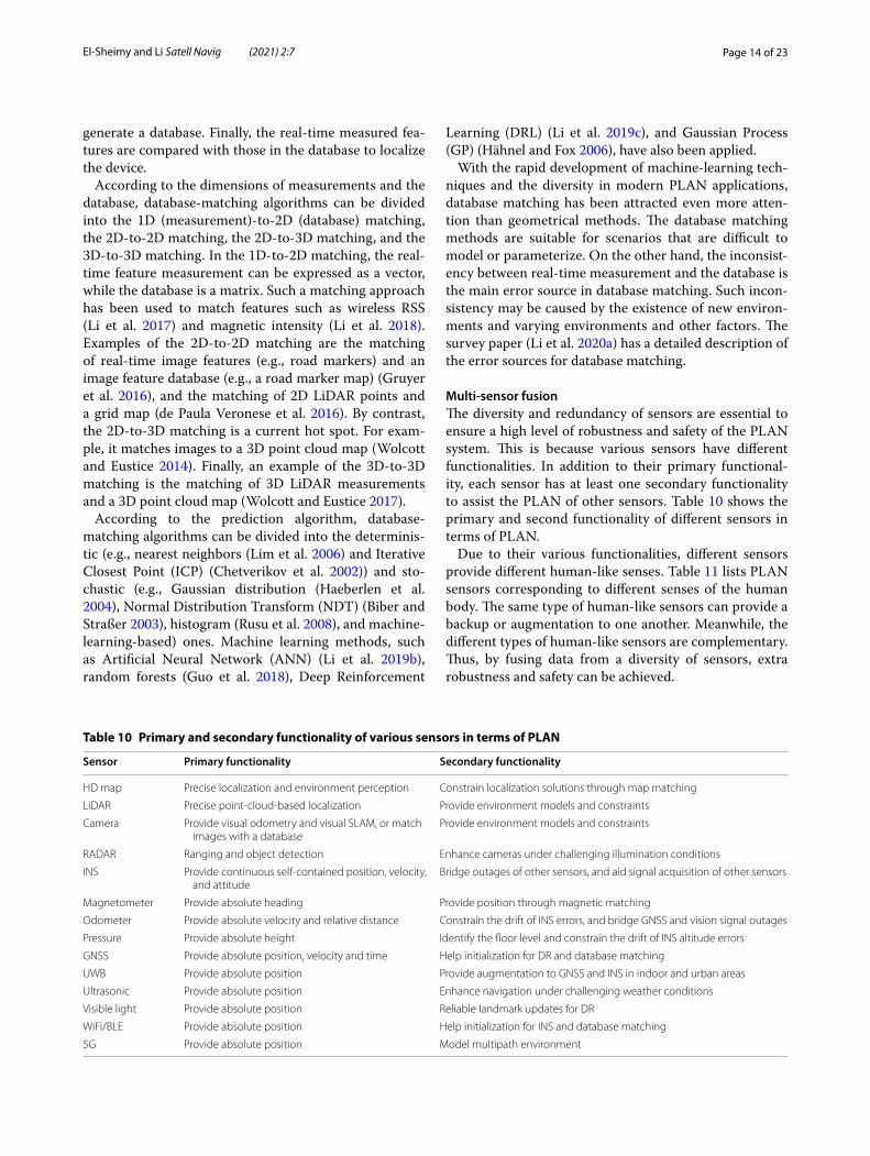
Multi-sensor fusionThe diversity and redundancy of sensors are essential to ensure a high level of robustness and safety of the PLAN system. This is because various sensors have different functionalities. In addition to their primary functional-ity, each sensor has at least one secondary functionality to assist the PLAN of other sensors. Table 10 shows the primary and second functionality of different sensors in terms of PLAN.
Due to their various functionalities, different sensors provide different human-like senses. Table 11 lists PLAN sensors corresponding to different senses of the human body. The same type of human-like sensors can provide a backup or augmentation to one another. Meanwhile, the different types of human-like sensors are complementary. Thus, by fusing data from a diversity of sensors, extra robustness and safety can be achieved.
Table 10 Primary and secondary functionality of various sensors in terms of PLAN
Sensor Primary functionality Secondary functionality
HD map Precise localization and environment perception Constrain localization solutions through map matching
LiDAR Precise point‑cloud‑based localization Provide environment models and constraints
Camera Provide visual odometry and visual SLAM, or match images with a database
Provide environment models and constraints
RADAR Ranging and object detection Enhance cameras under challenging illumination conditions
INS Provide continuous self‑contained position, velocity, and attitude
Bridge outages of other sensors, and aid signal acquisition of other sensors
Magnetometer Provide absolute heading Provide position through magnetic matching
Odometer Provide absolute velocity and relative distance Constrain the drift of INS errors, and bridge GNSS and vision signal outages
Pressure Provide absolute height Identify the floor level and constrain the drift of INS altitude errors
GNSS Provide absolute position, velocity and time Help initialization for DR and database matching
UWB Provide absolute position Provide augmentation to GNSS and INS in indoor and urban areas
Ultrasonic Provide absolute position Enhance navigation under challenging weather conditions
Visible light Provide absolute position Reliable landmark updates for DR
WiFi/BLE Provide absolute position Help initialization for INS and database matching
5G Provide absolute position Model multipath environment
Page 15 of 23El‑Sheimy and Li Satell Navig (2021) 2:7
To be specific, for position-fixing and database-match-ing methods, the loss of signals or features lead to out-ages in the PLAN solution. Also, changes in the model and database parameters may degrade the PLAN per-formance. To mitigate these issues, DR techniques can be used (El-Sheimy and Niu 2007a, b). Moreover, the use of other techniques can enhance position-fixing through more advanced base station position estimation (Cheng et al. 2005), propagation-model estimation (Seco and Jiménez 2017), and device diversity calibration (He et al. 2018). Also, the number of base stations required can be reduced (Li et al. 2020b). On the other hand, position-fixing and database-matching techniques can provide initialization and periodical updates for DR (Shin 2005), which in turn calibrate sensors and suppress the drift of DR results.
Database matching can also be enhanced by other tech-niques. For example, the position-fixing method can be used to reduce the searching space of database-match-ing (Zhang et al. 2017b), predict the database in unvis-ited areas (Li et al. 2019d), and predict the uncertainty of database-matching results (Li et al. 2019e). Also, a more robust PLAN solution may be achieved by integrat-ing position-fixing and database-matching techniques (Kodippili and Dias 2010).
From the perspective of integration mode, there are three levels of integration. The first level is loosely cou-pling (Shin 2005), which fuses PLAN solutions from dif-ferent sensors. The second level is tightly-coupling (Gao et al. 2020), which fuses various sensor measurements to obtain a PLAN solution. The third level is ultra-tightly-coupling, which using the data or results from some sen-sors to enhance the performance of other sensors.
Motion constraintsMotion constraints are used to enhance PLAN solu-tions from the perspective of algorithms, instead of add-ing extra sensors. Such constraints are especially useful for low-cost PLAN systems that are not affordable for
extra hardware costs. For land-based vehicles, the Non-Holonomic Constraints (NHC) can improve the head-ing and position accuracy significantly when the vehicle moves with enough speed (Niu et al. 2010), while the Zero velocity UPdaTe (ZUPT) and Zero Angular Rate Update (ZARU, also known as Zero Integrate Head-ing Rate (ZIHR)) respectively provide zero-velocity and zero-angular-rate constraints when the vehicle is quasi-static (Shin 2005). When the vehicle moves at low speed, a steering constraint can be applied (Niu et al. 2010). Moreover, there are other constraints such as the height constraint (Godha and Cannon 2007) and the four-wheel constraint (Brunker et al. 2018).
For pedestrian navigation, ZUPT (Foxlin 2005) and ZARU (Li et al. 2015) are most commonly used. Also, the NHC and step velocity constraint (Zhuang et al. 2015) have been applied. Furthermore, in indoor environments, constraints such as the corridor-direction constraint (Abdulrahim et al. 2010), the height constraint (Abdulra-him et al. 2012), and the human-activity constraint (Zhou et al. 2015) are useful to enhance the PLAN solution.
Use casesMulti-sensor-based indoor navigation has been utilized in various applications, such as pedestrians, vehicles, robots, animals, and sports. This chapter introduces some examples. Three of our previous cases on indoor navigation are demonstrated. The used vehicle platforms include smartphones, drones, and robots.
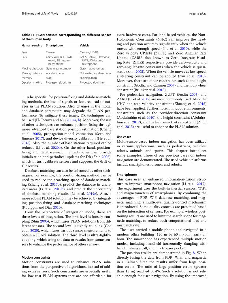
SmartphonesThis case uses an enhanced information-fusion struc-ture to improve smartphone navigation (Li et al. 2017). The experiment uses the built-in inertial sensors, WiFi, and magnetometers of smartphones. By combining the advantages of PDR, WiFi database matching, and mag-netic matching, a multi-level quality-control mechanism is introduced. Some quality controls are presented based on the interaction of sensors. For example, wireless posi-tioning results are used to limit the search scope for mag-netic matching, to reduce both computational load and mismatch rate.
The user carried a mobile phone and navigated in a modern office building (120 m by 60 m) for nearly an hour. The smartphone has experienced multiple motion modes, including handheld horizontally, dangling with hand, making a call, and in a trouser pocket.
The position results are demonstrated in Fig. 8. When directly fusing the data from PDR, WiFi, and magnetic in a Kalman filter, the results suffer from large posi-tion errors. The ratio of large position errors (greater than 15 m) reached 33.4%. Such a solution is not reli-able enough for user navigation. By using the improved
Table 11 PLAN sensors corresponding to different senses of the human body
Human sensing Smartphone Vehicle
Eyes Camera Camera, LiDAR
Ears GNSS, WiFi, BLE, UWB (new), 5G (future), microphone
GNSS, RADAR, ultrasonic, UWB, 5G (future), microphone
Moving direction Gyro, magnetometer Gyro, magnetometer
Moving distance Accelerometer Odometer, accelerometer
Memory Map HD map, map
Decision making Processor, algorithm Processor, algorithm
Page 16 of 23El‑Sheimy and Li Satell Navig (2021) 2:7
multi-source fusion, the ratio of large errors was reduced to 0.8%. This use case indicates the importance of sensor interaction and robust multi-sensor fusion.
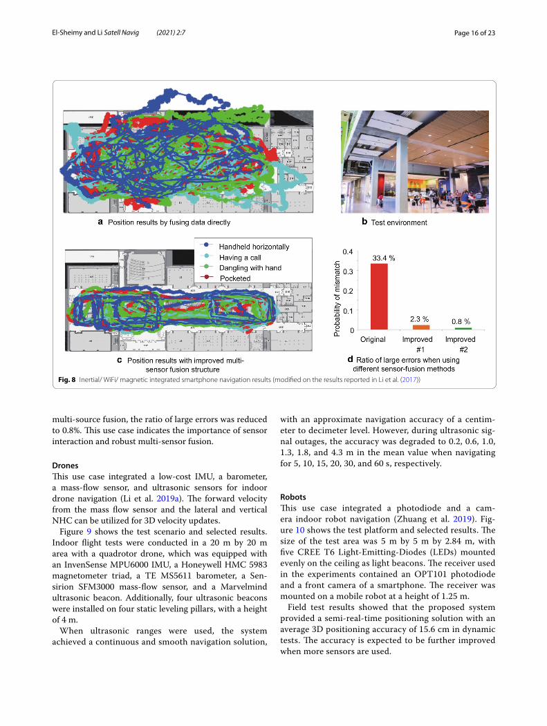
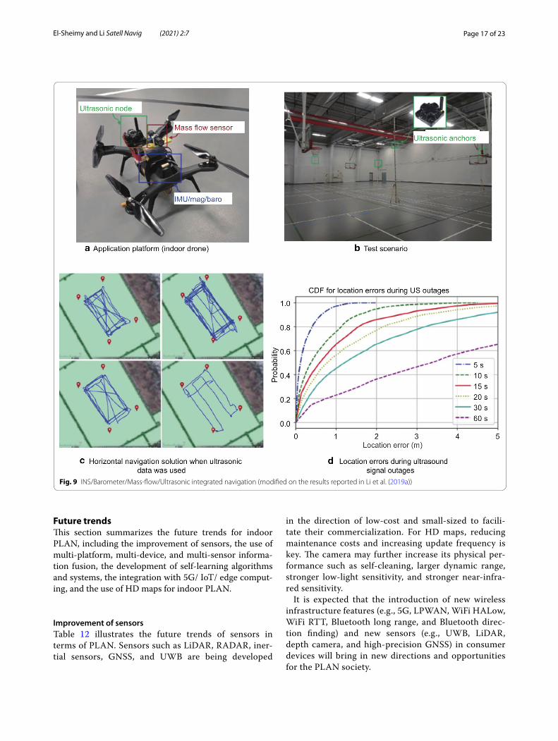
DronesThis use case integrated a low-cost IMU, a barometer, a mass-flow sensor, and ultrasonic sensors for indoor drone navigation (Li et al. 2019a). The forward velocity from the mass flow sensor and the lateral and vertical NHC can be utilized for 3D velocity updates.
Figure 9 shows the test scenario and selected results. Indoor flight tests were conducted in a 20 m by 20 m area with a quadrotor drone, which was equipped with an InvenSense MPU6000 IMU, a Honeywell HMC 5983 magnetometer triad, a TE MS5611 barometer, a Sen-sirion SFM3000 mass-flow sensor, and a Marvelmind ultrasonic beacon. Additionally, four ultrasonic beacons were installed on four static leveling pillars, with a height of 4 m.
When ultrasonic ranges were used, the system achieved a continuous and smooth navigation solution,
with an approximate navigation accuracy of a centim-eter to decimeter level. However, during ultrasonic sig-nal outages, the accuracy was degraded to 0.2, 0.6, 1.0, 1.3, 1.8, and 4.3 m in the mean value when navigating for 5, 10, 15, 20, 30, and 60 s, respectively.
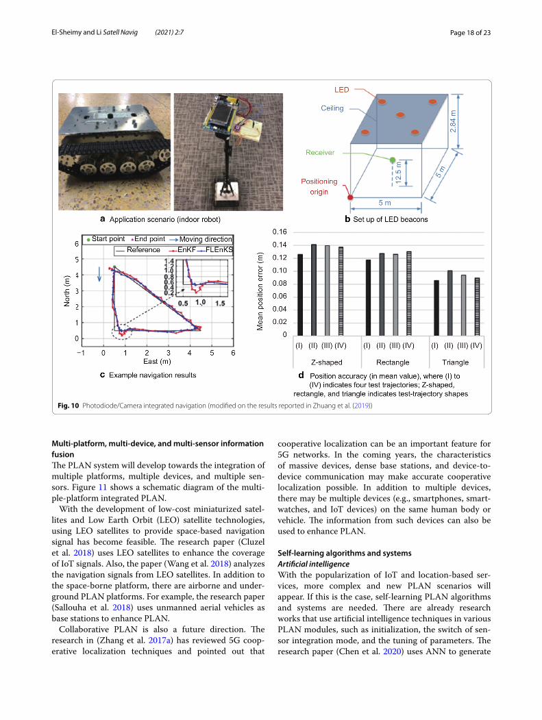
RobotsThis use case integrated a photodiode and a cam-era indoor robot navigation (Zhuang et al. 2019). Fig-ure 10 shows the test platform and selected results. The size of the test area was 5 m by 5 m by 2.84 m, with five CREE T6 Light-Emitting-Diodes (LEDs) mounted evenly on the ceiling as light beacons. The receiver used in the experiments contained an OPT101 photodiode and a front camera of a smartphone. The receiver was mounted on a mobile robot at a height of 1.25 m.
Field test results showed that the proposed system provided a semi-real-time positioning solution with an average 3D positioning accuracy of 15.6 cm in dynamic tests. The accuracy is expected to be further improved when more sensors are used.
Fig. 8 Inertial/ WiFi/ magnetic integrated smartphone navigation results (modified on the results reported in Li et al. (2017))
Page 17 of 23El‑Sheimy and Li Satell Navig (2021) 2:7
Future trendsThis section summarizes the future trends for indoor PLAN, including the improvement of sensors, the use of multi-platform, multi-device, and multi-sensor informa-tion fusion, the development of self-learning algorithms and systems, the integration with 5G/ IoT/ edge comput-ing, and the use of HD maps for indoor PLAN.
Improvement of sensorsTable 12 illustrates the future trends of sensors in terms of PLAN. Sensors such as LiDAR, RADAR, iner-tial sensors, GNSS, and UWB are being developed
in the direction of low-cost and small-sized to facili-tate their commercialization. For HD maps, reducing maintenance costs and increasing update frequency is key. The camera may further increase its physical per-formance such as self-cleaning, larger dynamic range, stronger low-light sensitivity, and stronger near-infra-red sensitivity.
It is expected that the introduction of new wireless infrastructure features (e.g., 5G, LPWAN, WiFi HALow, WiFi RTT, Bluetooth long range, and Bluetooth direc-tion finding) and new sensors (e.g., UWB, LiDAR, depth camera, and high-precision GNSS) in consumer devices will bring in new directions and opportunities for the PLAN society.
Fig. 9 INS/Barometer/Mass‑flow/Ultrasonic integrated navigation (modified on the results reported in Li et al. (2019a))
Page 18 of 23El‑Sheimy and Li Satell Navig (2021) 2:7
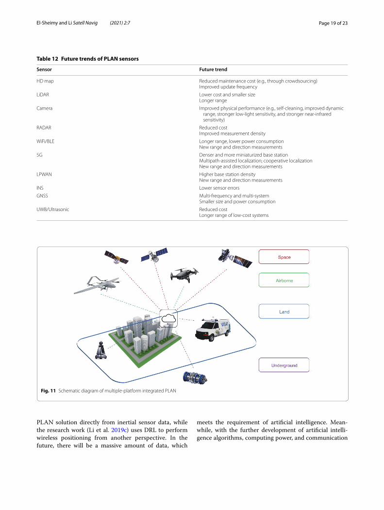
Multi-platform, multi-device, and multi-sensor information fusionThe PLAN system will develop towards the integration of multiple platforms, multiple devices, and multiple sen-sors. Figure 11 shows a schematic diagram of the multi-ple-platform integrated PLAN.
With the development of low-cost miniaturized satel-lites and Low Earth Orbit (LEO) satellite technologies, using LEO satellites to provide space-based navigation signal has become feasible. The research paper (Cluzel et al. 2018) uses LEO satellites to enhance the coverage of IoT signals. Also, the paper (Wang et al. 2018) analyzes the navigation signals from LEO satellites. In addition to the space-borne platform, there are airborne and under-ground PLAN platforms. For example, the research paper (Sallouha et al. 2018) uses unmanned aerial vehicles as base stations to enhance PLAN.
Collaborative PLAN is also a future direction. The research in (Zhang et al. 2017a) has reviewed 5G coop-erative localization techniques and pointed out that
cooperative localization can be an important feature for 5G networks. In the coming years, the characteristics of massive devices, dense base stations, and device-to-device communication may make accurate cooperative localization possible. In addition to multiple devices, there may be multiple devices (e.g., smartphones, smart-watches, and IoT devices) on the same human body or vehicle. The information from such devices can also be used to enhance PLAN.
Self-learning algorithms and systemsArtificial intelligenceWith the popularization of IoT and location-based ser-vices, more complex and new PLAN scenarios will appear. If this is the case, self-learning PLAN algorithms and systems are needed. There are already research works that use artificial intelligence techniques in various PLAN modules, such as initialization, the switch of sen-sor integration mode, and the tuning of parameters. The research paper (Chen et al. 2020) uses ANN to generate
Fig. 10 Photodiode/Camera integrated navigation (modified on the results reported in Zhuang et al. (2019))
Page 19 of 23El‑Sheimy and Li Satell Navig (2021) 2:7
PLAN solution directly from inertial sensor data, while the research work (Li et al. 2019c) uses DRL to perform wireless positioning from another perspective. In the future, there will be a massive amount of data, which
meets the requirement of artificial intelligence. Mean-while, with the further development of artificial intelli-gence algorithms, computing power, and communication
Table 12 Future trends of PLAN sensors
Sensor Future trend
HD map Reduced maintenance cost (e.g., through crowdsourcing)Improved update frequency
LiDAR Lower cost and smaller sizeLonger range
Camera Improved physical performance (e.g., self‑cleaning, improved dynamic range, stronger low‑light sensitivity, and stronger near‑infrared sensitivity)
RADAR Reduced costImproved measurement density
WiFi/BLE Longer range, lower power consumptionNew range and direction measurements
5G Denser and more miniaturized base stationMultipath‑assisted localization; cooperative localizationNew range and direction measurements
LPWAN Higher base station densityNew range and direction measurements
INS Lower sensor errors
GNSS Multi‑frequency and multi‑systemSmaller size and power consumption
UWB/Ultrasonic Reduced costLonger range of low‑cost systems
Fig. 11 Schematic diagram of multiple‑platform integrated PLAN
Page 20 of 23El‑Sheimy and Li Satell Navig (2021) 2:7
capabilities, the integration between PLAN and artificial intelligence will become tighter.
Data crowdsourcing (e.g., co-location)The data from numerous consumer electronics and sen-sor networks will make crowdsourcing (e.g., co-location) a reality. As mentioned in the HD map subsection, the crowdsourcing technique may fundamentally change the mode of map and HD map generation. Furthermore, using crowdsourced data can enhance PLAN perfor-mance. For example, the crowdsourced data contains more comprehensive information than an ego-only car in teams of map availability and sensing range. On the other hand, as pointed out in (Li et al. 2019e), how to select the most valuable data from the crowdsourced big data to update the database is still a challenge. It is difficult to evaluate the reliability of data automatically by the soft-ware in the absence of manual intervention and lack of evaluation reference.
Integration with 5G, IoT, and edge/fog computingAs described in the 5G subsection, the development of 5G and IoT technologies are changing PLAN. The new features (e.g., dense miniaturized base stations, mm-wave MIMO, and device-to-device communication) can directly enhance PLAN. Also, the combination of 5G/IoT and edge/fog computing will bring new PLAN opportunities. Edge/fog computing allows data process-ing as close to the source as possible, enables PLAN data processing with faster speed, reduces latency, and gives overall better outcomes. The review papers (Oteafy and Hassanein 2018) and (Shi et al. 2016) provide detailed overviews of edge computing and fog computing, respec-tively. Such techniques may be able to change the exist-ing operation mode on HD maps and for PLAN. It may become possible to online repair or optimize HD maps by using SLAM and artificial intelligence technologies.
HD maps for indoor navigationHD maps will be extended from outdoors to indoors. The cooperation among the manufacturers of cars, maps, 5G, and consumer devices have already shown its importance (Abuelsamid 2017). The high accuracy and rich informa-tion of the HD map make it a valuable indoor PLAN sen-sor and even a platform that links people, vehicles, and the environment. Indoor and outdoor PLAN may need different HD map elements. Therefore, different HD maps may be developed according to different scenarios. Similar to outdoors, the standardization of indoor HD maps will be important but challenging.
ConclusionThis article first reviews the market value, including the social benefits and economic values, of indoor navi-gation, followed by the classification from the marker perspective and the main players. Then, it compares the state-of-the-art sensors, including navigation sen-sors and environmental-perception (as aiding sensors for navigation), and techniques, including position-fix-ing, dead-reckoning, database matching, multi-sensor fusion, and motion constraints. Finally, it points out several future trends, including the improvement of sensors, the use of multi-platform, multi-device, and multi-sensor information fusion, the development of self-learning algorithms and systems, the integration with 5G/IoT/edge computing, and the use of HD maps for indoor PLAN.
Authors’ contributionsNE devised the article structure and general contents and structure and writing parts of the manuscript. YL assisted in summarizing and writing the manuscript. Both authors have read and approved the final manuscript.
Authors’ informationNaser El‑Sheimy is a Professor at the Department of Geomatics Engineering, the University of Calgary. He is a Fellow of the Canadian Academy of Engineer‑ing and the US Institute of Navigation and a Tier‑I Canada Research Chair in Geomatics Multi‑sensor Systems. His research expertise includes Geomatics multi‑sensor systems, GPS/INS integration, and mobile mapping systems. He is also the founder and CEO of Profound Positioning Inc. He published two books, 6 book chapters, and over 450 papers in academic journals, conference and workshop proceedings, in which he has received over 30 paper awards. He supervised and graduated over 60 Masters and Ph.D. students. He is the recipient of many national and international awards including the ASTech “Leadership in Alberta Technology” Award, and the Association of Professional Engineers, Geologists, and Geophysicists of Alberta (APEGGA) Educational Excellence Award.
You Li is a Senior Researcher at the University of Calgary. He received Ph.D. degrees from both Wuhan University and the University of Calgary in 2016 and was selected for the national young talented project in 2020. His research focuses on ubiquitous internet‑of‑things localization. He has hosted/partici‑pated in four national research projects, and co‑published over 70 academic papers, and has over 20 patents pending. He serves as an Associate Editor for the IEEE Sensors Journal, a committee member at the IAG unmanned naviga‑tion system and ISPRS mobile mapping working groups. He has won four best paper awards and a winner in the EvAAL international indoor localization competition.
FundingThis work was supported by Canada Research Chairs programs (Grant No. RT691875).
Availability of data and materialsData sharing is not applicable to this article as no datasets were generated or analyzed in this review article.
Competing interestsThe authors declare that they have no competing interests.
Received: 3 November 2020 Accepted: 9 February 2021
Page 21 of 23El‑Sheimy and Li Satell Navig (2021) 2:7
ReferencesAbdulrahim, K., Hide, C., Moore, T., & Hill, C. (2010). Aiding MEMS IMU with
building heading for indoor pedestrian navigation. In 2010 ubiquitous positioning indoor navigation and location based service. Helsinki: IEEE.
Abdulrahim, K., Hide, C., Moore, T., & Hill, C. (2012). Using constraints for shoe mounted indoor pedestrian navigation. Journal of Navigation, 65(1), 15–28.
Abuelsamid, S. (2017). BMW, HERE and mobileye team up to crowd‑source HD maps for self‑driving. https ://www.forbe s.com/sites /samab uelsa mid/2017/02/21/bmw‑here‑and‑mobil eye‑team‑up‑to‑crowd ‑sourc e‑hd‑maps‑for‑self‑drivi ng/#6f04e 0577c b3. Accessed April 28, 2020.
Agency, E. G. (2019). Report on road user needs and requirements. https ://www.gsc‑europ a.eu/sites /defau lt/files /sites /all/files /Repor t_on_User_Needs _and_Requi remen ts_Road.pdf. Accessed April 28, 2020.
Alvarez, D., González, R. C., López, A., & Alvarez, J. C. (2006). Comparison of step length estimators from weareable accelerometer devices. Annual international conference of the IEEE engineering in medicine and biology (pp. 5964–5967). IEEE: New York.
Andrews, J. G., Buzzi, S., Choi, W., Hanly, S. V., Lozano, A., Soong, A. C. K., & Zhang, J. C. (2014). What will 5G be? IEEE Journal on Selected Areas in Communications, 32(6), 1065–1082.
Badawy, A., Khattab, T., Trinchero, D., Fouly, T. E., & Mohamed, A. (2014). A simple AoA estimation scheme. arXiv:1409.5744.
Bai, L., Peng, C. Y., & Biswas, S. (2008). Association of DOA estimation from two ULAs. IEEE Transactions on Instrumentation and Measurement, 57(6), 1094–1101. https ://doi.org/10.1109/TIM.2007.91512 2.
Basnayake, C., Williams, T., Alves, P., & Lachapelle, G. J. G. W. (2010). Can GNSS Drive V2X? GPS World, 21(10), 35–43.
Biber, P., & Straßer, W. (2003). The normal distributions transform: A new approach to laser scan matching. Proceedings 2003 IEEE/RSJ international conference on intelligent robots and systems (IROS) (pp. 2743–2748). IEEE: Las Vegas, NV.
Bluetooth. (2017). Exploring Bluetooth 5—going the distance. https ://www.bluet ooth.com/blog/explo ring‑bluet ooth‑5‑going ‑the‑dista nce/. Accessed April 28, 2020.
Bluetooth. (2019). Bluetooth 5.1 Direction finding. https ://www.bluet ooth.com/wp‑conte nt/uploa ds/2019/05/BTAsi a/1145‑NORDI C‑Bluet ooth‑Asia‑2019B lueto oth‑5.1‑Direc tion‑Findi ng‑Theor y‑and‑Pract ice‑v0.pdf. Accessed April 28, 2020.
Brossard, M., Barrau, A., & Bonnabel, S. (2020). AI‑IMU dead‑reckoning. IEEE Transactions on Intelligent Vehicles, 5(4), 585–595. https ://doi.org/10.1109/TIV.2020.29807 58.
Brunker, A., Wohlgemuth, T., Frey, M., & Gauterin, F. (2018). Odometry 2.0: A slip‑adaptive EIF‑based four‑wheel‑odometry model for parking. IEEE Transactions on Intelligent Vehicles, 4(1), 114–126.
Bshara, M., Orguner, U., Gustafsson, F., & Van Biesen, L. (2011). Robust tracking in cellular networks using HMM filters and cell‑ID measurements. IEEE Transactions on Vehicular Technology, 60(3), 1016–1024.
Cadena, C., Carlone, L., Carrillo, H., Latif, Y., Scaramuzza, D., Neira, J., et al. (2016). Past, present, and future of simultaneous localization and mapping: Toward the robust‑perception age. IEEE Transactions on Robotics, 32(6), 1309–1332.
Chen, C., Zhao, P., Lu, C. X., Wang, W., Markham, A., & Trigoni, A. (2020). Deep‑learning‑based pedestrian inertial navigation: Methods, data set, and on‑device inference. IEEE Internet of Things Journal, 7(5), 4431–4441.
Cheng, Y. C., Chawathe, Y., Lamarca, A., & Krumm, J. (2005). Accuracy charac‑terization for metropolitan‑scale Wi‑Fi localization. In Proceedings of the 3rd international conference on mobile systems, applications, and services, MobiSys 2005 (pp. 233–245). Seattle, WA: IEEE.
Chetverikov, D., Svirko, D., Stepanov, D., & Krsek, P. (2002). The trimmed iterative closest point algorithm. Object recognition supported by user interaction for service robots (pp. 545–548). IEEE: Quebec City, QC.
Ciurana, M., Barcelo‑Arroyo, F., & Izquierdo, F. (2007). A ranging system with IEEE 802.11 data frames. In 2007 IEEE radio and wireless symposium (pp. 133–136). Long Beach, CA: IEEE.
Cluzel, S., Franck, L., Radzik, J., Cazalens, S., Dervin, M., Baudoin, C., & Drago‑mirescu, D. (2018). 3GPP NB‑IOT coverage extension using LEO satel‑lites. IEEE Vehicular Technology Conference (pp. 1–5). IEEE: Porto.
de Paula Veronese, L., Guivant, J., Cheein, F. A. A., Oliveira‑Santos, T., Mutz, F., de Aguiar, E., et al. (2016). A light‑weight yet accurate localization system for autonomous cars in large‑scale and complex environments. 2016
IEEE 19th international conference on intelligent transportation systems (ITSC) (pp. 520–525). IEEE: Rio de Janeiro.
Decawave. (2020). DWM1000 Module. https ://www.decaw ave.com/produ ct/dwm10 00‑modul e/. Accessed April 28, 2020.
del Peral‑Rosado, J. A., Raulefs, R., López‑Salcedo, J. A., & Seco‑Granados, G. (2017). Survey of cellular mobile radio localization methods: From 1G to 5G. IEEE Communications Surveys and Tutorials, 20(2), 1124–1148.
Dodge, D. (2013). Indoor Location startups innovating Indoor Positioning. https ://dondo dge.typep ad.com/the_next_big_thing /2013/06/indoo r‑locat ion‑start ups‑innov ating ‑indoo r‑posit ionin g.html. Accessed April 28, 2020.
El‑Sheimy, N., & Niu, X. (2007a). The promise of MEMS to the navigation com‑munity. Inside GNSS, 2(2), 46–56.
El‑Sheimy, N., & Niu, X. (2007b). The promise of MEMS to the navigation com‑munity. Inside GNSS, 2(2), 26–56.
El‑Sheimy, N., Hou, H., & Niu, X. (2007). Analysis and modeling of inertial sensors using Allan variance. IEEE Transactions on Instrumentation and Measurement, 57(1), 140–149.
El‑Sheimy, N., & Youssef, A. (2020). Inertial sensors technologies for navigation applications: State of the art and future trends. Satellite Navigation, 1(1), 2.
FCC. (2015). FCC 15–9. https ://ecfsa pi.fcc.gov/file/60001 02592 5.pdf. Accessed 28 April 2020.
Foxlin, E. (2005). Pedestrian tracking with shoe‑mounted inertial sensors. IEEE Computer Graphics and Applications, 25(6), 38–46.
Gao, Z., Ge, M., Li, Y., Pan, Y., Chen, Q., & Zhang, H. (2020). Modeling of multi‑sensor tightly aided BDS triple‑frequency precise point positioning and initial assessments. Information Fusion, 55, 184–198.
Gebre‑Egziabher, D., Elkaim, G. H., David Powell, J., & Parkinson, B. W. (2006). Calibration of strapdown magnetometers in magnetic field domain. Journal of Aerospace Engineering, 19(2), 87–102.
Glennie, C., & Lichti, D. D. J. R. S. (2010). Static calibration and analysis of the Velodyne HDL‑64E S2 for high accuracy mobile scanning. Remote Sens-ing, 2(6), 1610–1624.
Godha, S., & Cannon, M. E. (2007). GPS/MEMS INS integrated system for naviga‑tion in urban areas. GPS Solutions, 11(3), 193–203.
Goldstein. (2019). Global Indoor Positioning and Indoor Navigation (IPIN) Market Outlook, 2024. https ://www.golds teinr esear ch.com/repor t/globa l‑indoo r‑posit ionin g‑and‑indoo r‑navig ation ‑ipin‑marke t‑outlo ok‑2024‑globa l‑oppor tunit y‑and‑deman d‑analy sis‑marke t‑forec ast‑2016‑2024. Accessed April 28, 2020.
Gruyer, D., Belaroussi, R., & Revilloud, M. (2016). Accurate lateral position‑ing from map data and road marking detection. Expert Systems with Applications, 43, 1–8.
Guo, X., Ansari, N., Li, L., & Li, H. (2018). Indoor localization by fusing a group of fingerprints based on random forests. IEEE Internet of Things Journal, 5(6), 4686–4698.
Guvenc, I., & Chong, C. C. (2009). A survey on TOA based wireless localization and NLOS mitigation techniques. IEEE Communications Surveys and Tutorials, 11(3), 107–124.
Haeberlen, A., Flannery, E., Ladd, A. M., Rudys, A., Wallach, D. S., & Kavraki, L.E. (2004). Practical robust localization over large‑scale 802.11 wireless networks. In Proceedings of the 10th annual international conference on Mobile computing and networking (pp. 70–84). Philadelphia, PA: IEEE.
Hähnel, B. F. D., & Fox, D. (2006). Gaussian processes for signal strength‑based location estimation. In Proceeding of robotics: Science and systems. Philadelphia, PA: IEEE.
Halperin, D., Hu, W., Sheth, A., & Wetherall, D. (2011). Tool release: Gathering 802.11 n traces with channel state information. ACM SIGCOMM Com-puter Communication Review, 41(1), 53–53.
He, S., Chan, S. H. G., Yu, L., & Liu, N. (2018). SLAC: Calibration‑free pedometer‑fingerprint fusion for indoor localization. IEEE Transactions on Mobile Computing, 17(5), 1176–1189.
Ibisch, A., Stümper, S., Altinger, H., Neuhausen, M., Tschentscher, M., Schlipsing, M., Salinen, J., & Knoll, A. (2013). Towards autonomous driving in a parking garage: Vehicle localization and tracking using environment‑embedded lidar sensors. In 2013 IEEE intelligent vehicles symposium (IV) (pp. 829–834). Gold Coast: IEEE.
Ibisch, A., Houben, S., Michael, M., Kesten, R., & Schuller, F. (2015). Arbitrary object localization and tracking via multiple‑camera surveillance system embedded in a parking garage. In Video surveillance and
Page 22 of 23El‑Sheimy and Li Satell Navig (2021) 2:7
transportation imaging applications 2015 (pp. 94070G). San Francisco, CA: International Society for Optics and Photonics.
IEEE. (2020). IEEE 802.11TM Wireless Local Area Network. http://www.ieee8 02.org/11/. Accessed 28 April 2020.
Kaune, R., Hörst, J., & Koch, W. (2011). Accuracy analysis for TDOA localization in sensor networks. 14th international conference on information fusion (pp. 1–8). IEEE: Chicago, Illinois, USA.
Kim, K. J., Agrawal, V., Gaunaurd, I., Gailey, R. S., & Bennett, C. L. (2016). Missing sample recovery for wireless inertial sensor‑based human movement acquisition. IEEE Transactions on Neural Systems and Rehabilitation Engi-neering, 24(11), 1191–1198. https ://doi.org/10.1109/TNSRE .2016.25321 21.
Kodippili, N. S., & Dias, D. (2010). Integration of fingerprinting and trilateration techniques for improved indoor localization. In 2010 7th international conference on wireless and optical communications networks. Colombo: IEEE.
Kok, M., & Solin, A. (2018). Scalable magnetic field SLAM in 3D using Gaussian process maps. 2018 21st international conference on information fusion (FUSION) (pp. 1353–1360). IEEE: Cambridge.
Langley, R. B. (1999). Dilution of precision. GPS World, 1(1), 1–5.Leugner, S., Pelka, M., & Hellbrück, H. (2016). Comparison of wired and wireless
synchronization with clock drift compensation suited for U‑TDoA locali‑zation. 2016 13th workshop on positioning, navigation and communica-tions (WPNC) (pp. 1–4). IEEE: Bremen.
Levinson, J., Montemerlo, M., & Thrun, S. (2007). Map‑based precision vehicle localization in urban environments. In Robotics: Science and systems (pp. 1). Atlanta, GA: IEEE.
Levinson, J., & Thrun, S. (2010). Robust vehicle localization in urban environ‑ments using probabilistic maps. 2010 IEEE international conference on robotics and automation (pp. 4372–4378). IEEE: Anchorage, AK.
Li, X. (2006). RSS‑based location estimation with unknown pathloss model. IEEE Transactions on Wireless Communications, 5(12), 3626–3633. https ://doi.org/10.1109/TWC.2006.25698 5.
Li, Y., Georgy, J., Niu, X., Li, Q., & El‑Sheimy, N. (2015). Autonomous calibration of MEMS gyros in consumer portable devices. IEEE Sensors Journal, 15(7), 4062–4072.
Li, Y., Zhuang, Y., Zhang, P., Lan, H., Niu, X., & El‑Sheimy, N. (2017). An improved inertial/wifi/magnetic fusion structure for indoor navigation. Informa-tion Fusion, 34, 101–119.
Li, Y., Gao, Z., He, Z., Zhang, P., Chen, R., & El‑Sheimy, N. (2018). Multi‑sensor multi‑floor 3D localization with robust floor detection. IEEE Access, 6, 76689–76699.
Li, Y., Zahran, S., Zhuang, Y., Gao, Z. Z., Luo, Y. R., He, Z., et al. (2019a). IMU/mag‑netometer/barometer/mass‑flow sensor integrated indoor quadrotor UAV localization with robust velocity updates. Remote Sensing, 11(7), 838. https ://doi.org/10.3390/rs110 70838 .
Li, Y., Gao, Z. Z., He, Z., Zhuang, Y., Radi, A., Chen, R. Z., & El‑Sheimy, N. (2019b). Wireless fingerprinting uncertainty prediction based on machine learn‑ing. Sensors, 19(2), 324.
Li, Y., Hu, X., Zhuang, Y., Gao, Z., Zhang, P., & El‑Sheimy, N. (2019c). Deep Reinforcement Learning (DRL): another perspective for unsupervised wireless localization. IEEE Internet of Things Journal.
Li, Y., He, Z., Zhuang, Y., Gao, Z. Z., Tsai, G. J., & Pei, L. (2019d). Robust localiza‑tion through integration of crowdsourcing and machine learning. In Presented at the International conference on mobile mapping technology. Shenzhen, China.
Li, Y., He, Z., Gao, Z., Zhuang, Y., Shi, C., & El‑Sheimy, N. (2019). Toward robust crowdsourcing‑based localization: A fingerprinting accuracy indicator enhanced wireless/magnetic/inertial integration approach. IEEE Internet of Things Journal, 6(2), 3585–3600.
Li, Y., Zhuang, Y., Hu, X., Gao, Z. Z., Hu, J., Chen, L., He, Z., Pei, L., Chen, K. J., Wang, M. S., Niu, X. J., Chen, R. Z., Thompson, J., Ghannouchi, F., & El‑Sheimy, N. (2020a). Location‑Enabled IoT (LE‑IoT): A survey of positioning tech‑niques, error sources, and mitigation. IEEE Internet of Things Journal.
Li, Y., Yan, K. L., He, Z., Li, Y. Q., Gao, Z. Z., Pei, L., et al. (2020). Cost‑effective locali‑zation using RSS from single wireless access point. IEEE Transactions on Instrumentation and Measurement, 69(5), 1860–1870. https ://doi.org/10.1109/TIM.2019.29227 52.
Lim, H., Kung, L. C., Hou, J. C., & Luo, H. (2006). Zero‑configuration, robust indoor localization: Theory and experimentation. In Proceedings IEEE
INFOCOM 2006. 25TH IEEE international conference on computer com-munications. Barcelona: IEEE.
Lin, Y., Gao, F., Qin, T., Gao, W. L., Liu, T. B., Wu, W., et al. (2018). Autonomous aerial navigation using monocular visual‑inertial fusion. Journal of Field Robotics, 35(1), 23–51.
Liu, R., Wang, J., & Zhang, B. (2020). High definition map for automated driving: Overview and analysis. The Journal of Navigation, 73(2), 324–341.
MachineDesign. (2020). 5G’s Important Role in Autonomous Car Technol‑ogy. https ://www.machi nedes ign.com/mecha nical ‑motio n‑syste ms/artic le/21837 614/5gs‑impor tant‑role‑in‑auton omous ‑car‑techn ology . Accessed April 28, 2020.
Marvelmind. (2020). Indoor Navigation System Operating manual. https ://marve lmind .com/pics/marve lmind _navig ation _syste m_manua l.pdf. Accessed April 28, 2020.
Maybeck, P. S. (1982). Stochastic models, estimation, and control. London: Academic Press.
McManus, C., Churchill, W., Napier, A., Davis, B., & Newman, P. (2013). Distraction suppression for vision‑based pose estimation at city scales. 2013 IEEE international conference on robotics and automation (pp. 3762–3769). IEEE: Karlsruhe.
Mur‑Artal, R., & Tardós, J. D. (2017). Orb‑slam2: An open‑source slam system for monocular, stereo, and RGB‑d cameras. IEEE Transactions on Robotics, 33(5), 1255–1262.
NHTSA. (2017). Federal motor vehicle safety standards; V2V communications. Federal Register, 82(8), 3854–4019.
Niu, X., Zhang, H., Chiang, K. W., & El‑Sheimy, N. (2010). Using land‑vehicle steering constraint to improve the heading estimation of mems GPS/ins georeferencing systems. ISPRS - International Archives of the Photo-grammetry, Remote Sensing Spatial Information Sciences, 38(1), 1–5.
Niu, X., Li, Y., Kuang, J., & Zhang, P. (2019). Data fusion of dual foot‑mounted IMU for pedestrian navigation. IEEE Sensors Journal, 19(12), 4577–4584.
NovAtel, H. (2020). IMU‑FSAS. https ://docs.novat el.com/OEM7/Conte nt/Techn ical_Specs _IMU/FSAS_Overv iew.htm. Accessed 28 April 2020.
Nvidia. (2020). DRIVE Labs: How Localization Helps Vehicles Find Their Way. https ://news.devel oper.nvidi a.com/drive ‑labs‑how‑local izati on‑helps ‑vehic les‑find‑their ‑way/. Accessed April 28, 2020.
Oteafy, S. M. A., & Hassanein, H. S. (2018). IoT in the fog: A roadmap for data‑centric IoT development. IEEE Communications Magazine, 56(3), 157–163.
Pei, L., Liu, D., Zou, D., Leefookchoy, R., Chen, Y., & He, Z. (2018). Optimal heading estimation based multidimensional particle filter for pedes‑trian indoor positioning. IEEE Access, 6, 49705–49720. https ://doi.org/10.1109/ACCES S.2018.28687 92.
Petovello, M. (2003). Real-time integration of a tactical-grade IMU and GPS for high-accuracy positioning and navigation. Calgary: University of Calgary.
Pivato, P., Palopoli, L., & Petri, D. (2011). Accuracy of RSS‑based centroid localization algorithms in an indoor environment. IEEE Transactions on Instrumentation and Measurement, 60(10), 3451–3460.
Poggenhans, F., Salscheider, N. O., & Stiller, C. (2018). Precise localization in high‑definition road maps for urban regions. 2018 IEEE/RSJ international conference on intelligent robots and systems (IROS) (pp. 2167–2174). IEEE: Madrid.
Quuppa. (2020). Product and Technology. http://quupp a.com/techn ology /. Accessed 28 April 2020.
Radi, A., Bakalli, G., Guerrier, S., El‑Sheimy, N., Sesay, A. B., & Molinari, R. (2019). A multisignal wavelet variance‑based framework for inertial sensor stochastic error modeling. IEEE Transactions on Instrumentation and Measurement, 68(12), 4924–4936.
Rantakokko, J., Händel, P., Fredholm, M., & Marsten‑Eklöf, F. (2010). User require‑ments for localization and tracking technology: A survey of mission‑specific needs and constraints. 2010 international conference on indoor positioning and indoor navigation (pp. 1–9). IEEE: Zurich.
Reid, T. G. R., Houts, S. E., Cammarata, R., Mills, G., Agarwal, S., Vora, A., & Pandey, G. (2019). Localization requirements for autonomous vehicles. arXiv:1906.01061.
Restrepo, J. (2020). World radio 5G roadmap: challenges and opportunities ahead. https ://www.itu.int/en/ITU‑R/semin ars/rrs/RRS‑17‑Ameri cas/Docum ents/Forum /1_ITU%20Joa quin%20Res trepo .pdf. Accessed April 28, 2020.
Page 23 of 23El‑Sheimy and Li Satell Navig (2021) 2:7
Rusu, R. B., Blodow, N., Marton, Z. C., & Beetz, M. (2008). Aligning point cloud views using persistent feature histograms. 2008 IEEE/RSJ international conference on intelligent robots and systems (pp. 3384–3391). IEEE: Nice.
SAE‑International. (2016). Taxonomy and definitions for terms related to driv‑ing automation systems for on‑road motor vehicles. https ://www.sae.org/stand ards/conte nt/j3016 _20160 9/. Accessed April 28, 2020.
Sallouha, H., Azari, M. M., Chiumento, A., & Pollin, S. (2018). Aerial anchors posi‑tioning for reliable RSS‑based outdoor localization in urban environ‑ments. IEEE Wireless Communications Letters, 7(3), 376–379.
Scaramuzza, D., & Fraundorfer, F. (2011). Visual odometry [tutorial]. IEEE Robotics and Automation Magazine, 18(4), 80–92.
Schneider, O. (2010). Requirements for positioning and navigation in under‑ground constructions. International conference on indoor positioning and indoor navigation (pp. 1–4). IEEE: Zurich.
Schönenberger. (2019). The automotive digital transformation and the eco‑nomic impacts of existing data access model. https ://www.fiare gion1 .com/wp‑conte nt/uploa ds/2019/03/The‑Autom otive ‑Digit al‑Trans forma tion_Full‑study .pdf. Accessed April 28, 2020.
Seco, F., & Jiménez, A. R. (2017). Autocalibration of a wireless positioning net‑work with a FastSLAM algorithm. 2017 international conference on indoor positioning and indoor navigation (pp. 1–8). IEEE: Sapporo.
Seif, H. G., & Hu, X. (2016). Autonomous driving in the iCity—HD maps as a key challenge of the automotive industry. Engineering, 2(2), 159–162.
Shi, W., Cao, J., Zhang, Q., Li, Y., & Xu, L. (2016). Edge computing: Vision and challenges. IEEE Internet of Things Journal, 3(5), 637–646.
Shin, E. H. (2005). Estimation techniques for low-cost inertial navigation. Calgary: University of Calgary.
Shin, S.H., Park, C.G., Kim, J.W., Hong, H.S., & Lee, J.M. (2007). Adaptive step length estimation algorithm using low‑cost MEMS inertial sensors. In Proceedings of the 2007 IEEE sensors applications symposium. San Diego, CA: IEEE.
Singh, S. (2015). Critical reasons for crashes investigated in the national motor vehicle crash causation survey. https ://crash stats .nhtsa .dot.gov/Api/Publi c/ViewP ublic ation /81211 5. Accessed April 28, 2020.
Stephenson, S. (2016). Automotive applications of high precision GNSS. Notting‑ham: University of Nottingham.
Synced. (2018). The Golden Age of HD Mapping for Autonomous Driving. https ://mediu m.com/synce drevi ew/the‑golde n‑age‑of‑hd‑mappi ng‑for‑auton omous ‑drivi ng‑b2a2e c4c11 d. Accessed April 28, 2020.
TDK‑InvenSense. (2020). MPU‑9250 Nine‑Axis (Gyro + Accelerometer + Compass) MEMS MotionTracking™ Device. https ://inven sense .tdk.com/produ cts/motio n‑track ing/9‑axis/mpu‑9250/. Accessed April 28, 2020.
Tesla. (2020). Autopilot. https ://www.tesla .com/autop ilot. Accessed April 28, 2020.
Tiemann, J., Schweikowski, F., & Wietfeld, C. (2015). Design of an UWB indoor‑positioning system for UAV navigation in GNSS‑denied environments. 2015 international conference on indoor positioning and indoor navigation (IPIN) (pp. 1–7). IEEE: Calgary.
Titterton, D., Weston, J.L., & Weston, J. (2004). Strapdown inertial navigation technology. IET.
TomTom. (2020). Extending the vision of automated vehicles with HD Maps and ADASIS. http://downl oad.tomto m.com/open/banne rs/Elekt robit _TomTo m_white paper .pdf. Accessed April 28, 2020.
Trimble. (2020). Trimble RTX. https ://posit ionin gserv ices.trimb le.com/servi ces/rtx/?gclid =CjwKC AjwnI r1BRA WEiwA 6GpwN Y78s‑u6pUz ELeIu _elfou mO63L mR2QH f72Q9 pM‑L‑NXyJj omWCX 6BoCE 5YQAv D_BwE. Accessed April 28, 2020.
Vasisht, D., Kumar, S., & Katabi, D. (2016). Decimeter‑level localization with a single WiFi access point. 13th USENIX symposium on networked systems design and implementation (pp. 165–178). USENIX Association: Santa Clara.
Velodyne. (2020). HDL‑64E High Definition Real‑Time 3D Lidar. https ://velod yneli dar.com/produ cts/hdl‑64e/. Accessed April 28, 2020.
Wang, L., Chen, R. Z., Li, D. R., Zhang, G., Shen, X., Yu, B. G., et al. (2018). Initial assessment of the LEO based navigation signal augmentation system from Luojia‑1A satellite. Sensors (Switzerland), 18(11), 3919.
Wang, Y., & Ho, K. J. I. T. O. W. C. (2015). An asymptotically efficient estimator in closed‑form for 3‑D AOA localization using a sensor network. IEEE Transactions on Wireless Communications, 14(12), 6524–6535.
Wang, Y. T., Li, J., Zheng, R., & Zhao, D. (2017). ARABIS: An Asynchronous acous‑tic indoor positioning system for mobile devices. 2017 international conference on indoor positioning and indoor navigation (pp. 1–8). IEEE: Sapporo.
WiFi‑Alliance. (2020). Wi‑Fi HaLow low power, long range Wi‑Fi. https ://www.wi‑fi.org/disco ver‑wi‑fi/wi‑fi‑halow . Accessed April 28, 2020.
Will, H., Hillebrandt, T., Yuan, Y., Yubin, Z., & Kyas, M. (2012). The membership degree min‑max localization algorithm. 2012 ubiquitous positioning, indoor navigation, and location based service (UPINLBS) (pp. 1–10). IEEE: Helsinki.
Witrisal, K., Meissner, P., Leitinger, E., Shen, Y., Gustafson, C., Tufvesson, F., et al. (2016). High‑accuracy localization for assisted living: 5G systems will turn multipath channels from foe to friend. IEEE Signal Processing Magazine, 33(2), 59–70.
Wolcott, R. W., & Eustice, R. M. (2014). Visual localization within lidar maps for automated urban driving. 2014 IEEE/RSJ international conference on intel-ligent robots and systems (pp. 176–183). IEEE: Chicago, IL.
Wolcott, R. W., & Eustice, R. M. (2017). Robust LIDAR localization using multiresolution Gaussian mixture maps for autonomous driving. The International Journal of Robotics Research, 36(3), 292–319.
Zhang, J., Han, G., Sun, N., & Shu, L. (2017). Path‑loss‑based fingerprint localiza‑tion approach for location‑based services in indoor environments. IEEE Access, 5, 13756–13769.
Zhang, P., Lu, J., Wang, Y., & Wang, Q. (2017). Cooperative localization in 5G networks: A survey. ICT Express, 3(1), 27–32.
Zhou, B., Li, Q., Mao, Q., Tu, W., & Zhang, X. (2015). Activity sequence‑based indoor pedestrian localization using smartphones. IEEE Transactions on Human-Machine Systems, 45(5), 562–574.
Zhuang, Y., Lan, H., Li, Y., & El‑Sheimy, N. (2015). PDR/INS/WiFi integration based on handheld devices for indoor pedestrian navigation. Micromachines, 6(6), 793–812.
Zhuang, Y., Yang, J., Li, Y., Qi, L., & El‑Sheimy, N. (2016). Smartphone‑based indoor localization with bluetooth low energy beacons. Sensors, 16(5), 596.
Zhuang, Y., Wang, Q., Li, Y., Gao, Z. Z., Zhou, B. P., Qi, L. N., et al. (2019). The inte‑gration of photodiode and camera for visible light positioning by using fixed‑lag ensemble Kalman smoother. Remote Sensing, 11(11), 1387.
Publisher’s noteSpringer Nature remains neutral with regard to jurisdictional claims in pub‑lished maps and institutional affiliations.