Towards a 3D network model for indoor navigation
16
1 INTRODUCTION Indoor navigation approaches are actively developed in the last years for rescue and evacuation from buildings. Fire alert systems and light- & sound-based evacuation systems are commonly available in all large buildings. Many of the public buildings are even equipped with modern systems allowing for tracking people. Yet such ways are insufficient for evacuation or rescue processes. A successful indoor navigation relies on: an up-to-date navigation model of buildings, an accurate indoor positioning and adjustable navigation routes concerning real-time changes of buildings and pedestrians. One of the most significant factors in this process is the accurate and up-to-date navigation model. At present there are various approaches to model buildings for the purpose of navigation (Stoffel et al. 2007, Lamarche & Donikian 2004, Li & He 2008, Li et al. 2010). Most of these methods are based on pre-defined 2D floor plan or pre-defined simple 3D models of buildings. Those models merely represent the static state of buildings and can not take changes within indoor environment into account. For instance, when a part of a building is unavailable during a disaster (e.g. fire), the pre-defined navigation plans would be ineffective and the rescue process may be disturbed. 3D building represented as a collection of 2D floor plans has also insufficiencies. Multi-story buildings may have intermediate levels within certain floors. It is impossible to use 2D plans to exactly represent this complexity. How to exactly represent these indoor structures becomes a tough problem. Use of 2D plans may fail to represent correctly vertical indoor environments (such as configuration of stairs, elevators and escalators). The currently proposed 3D navigation models are demonstrated on simple (regular- structured) buildings and fail to provide automatic approaches for routing in complex interior structures. Generally, automatic derivation of the navigation model from complex 3D building models is one of the most critical obstacles presently. The changes (unavailable corridors, exits, 77 Towards a 3D network model for indoor navigation L. Liu & S. Zlatanova Delft University of Technology, GIS Technology Section, Delft, The Netherlands ABSTRACT: Indoor navigation is a fast developing area, but researchers are facing various challenges. One of them is the 3D model that could support the navigation. After reviewing current development of models for indoor navigation, in this paper we generalize essential emergency phases of buildings and clarify requirements for indoor navigation models. Then typical indoor navigation models are compared and their pros and cons are given. Based on these work, we propose a 3D network called “Indoor Visibility Structure”, which makes use of 3D geometry & semantics of buildings and allow for automatic generation of navigation network. The proposed approach is designed to resolve navigation in complex buildings. Ultimately, by relying on the IVS, its updating mechanism, and corresponding routing strategy considering indoor real-time changes, the ‘door-to-door’ navigation within buildings could be achieved.
Transcript of Towards a 3D network model for indoor navigation
1 INTRODUCTION
Indoor navigation approaches are actively developed in the last years for rescue and evacuation from buildings. Fire alert systems and light- & sound-based evacuation systems are commonly available in all large buildings. Many of the public buildings are even equipped with modern systems allowing for tracking people. Yet such ways are insufficient for evacuation or rescue processes. A successful indoor navigation relies on: an up-to-date navigation model of buildings, an accurate indoor positioning and adjustable navigation routes concerning real-time changes of buildings and pedestrians. One of the most significant factors in this process is the accurate and up-to-date navigation model.
At present there are various approaches to model buildings for the purpose of navigation (Stoffel et al. 2007, Lamarche & Donikian 2004, Li & He 2008, Li et al. 2010). Most of these methods are based on pre-defined 2D floor plan or pre-defined simple 3D models of buildings. Those models merely represent the static state of buildings and can not take changes within indoor environment into account. For instance, when a part of a building is unavailable during a disaster (e.g. fire), the pre-defined navigation plans would be ineffective and the rescue process may be disturbed.
3D building represented as a collection of 2D floor plans has also insufficiencies. Multi-story buildings may have intermediate levels within certain floors. It is impossible to use 2D plans to exactly represent this complexity. How to exactly represent these indoor structures becomes a tough problem. Use of 2D plans may fail to represent correctly vertical indoor environments (such as configuration of stairs, elevators and escalators).
The currently proposed 3D navigation models are demonstrated on simple (regular-structured) buildings and fail to provide automatic approaches for routing in complex interior structures. Generally, automatic derivation of the navigation model from complex 3D building models is one of the most critical obstacles presently. The changes (unavailable corridors, exits,
77
Towards a 3D network model for indoor navigation
L. Liu & S. ZlatanovaDelft University of Technology, GIS Technology Section, Delft, The Netherlands
ABSTRACT: Indoor navigation is a fast developing area, but researchers are facing various challenges. One of them is the 3D model that could support the navigation. After reviewing current development of models for indoor navigation, in this paper we generalize essential emergency phases of buildings and clarify requirements for indoor navigation models. Then typical indoor navigation models are compared and their pros and cons are given. Based on these work, we propose a 3D network called “Indoor Visibility Structure”, which makes use of 3D geometry & semantics of buildings and allow for automatic generation of navigation network. The proposed approach is designed to resolve navigation in complex buildings. Ultimately, by relying on the IVS, its updating mechanism, and corresponding routing strategy considering indoor real-time changes, the ‘door-to-door’ navigation within buildings could be achieved.
etc.) in the environment due to smoke, water, or other types of damages are represented only on the network for navigation. Thus, the link with the geometry of the building is disturbed and may lead to a loss of important information. For example, windows on the first and second floors, which are not normally included in the network for navigation, might be omitted as options for escape.
This paper presents a new concept to navigation modeling, which makes use of 3D geometry & semantics of a building and allows for automatic generation of navigation network. Depending on the damages on the building different networks can be derived, i.e. taking into account different construction elements. The proposed approach aims at resolving navigation in complex buildings, by relaying on an Indoor Visibility Structure and a ‘door-to-door’ navigation within buildings.
Following this introduction, section 2 summarizes the essential emergency phases of buildings, navigation requirements and evaluation criteria of indoor navigation models. Section 3 introduces several typical indoor navigation models and assesses these models. Section 4 provides a possible better solution for indoor navigation models, including navigation model design and routing strategy. Section 5 presents the conclusion of this paper.
2 REQUIREMENTS FOR INDOOR NAVIGATION MODELS
While good for an emergency situation (e.g. fire, air pollution) a model and the corresponding system for navigation might be inappropriate for others (e.g. earthquake & flood). In case of flood usually the first floors are mostly damaged (i.e. escape to the upper floors is recommended), while in case of fire the upper floors might be more dangerous. It is never known which parts of the building are more secure, but estimates can be made on which construction elements (i.e. the semantics that is needed) might play a role in the navigation within buildings.
2.1 Buildings status in emergency situations
Accurate information about the status of the building is one of the most critical aspects in successful navigation and evacuation. The conditions in the building change during an incident: stairs might be not accessible due to rubble or fire, exits might be unavailable due to high water level, rooms and corridors might be not recommendable due to smoke or gas leakage. Therefore, to make sure navigation models could be applied in all kinds of cases, it is necessary to classify the status of buildings in an emergency. We propose following classification: − Status 0. Normal state, no change within indoor environments (this is the everyday status). In
this stage, elevators could be used, yet emergency exits of buildings cannot be open. Pedestrians can walk freely within the buildings.
− Status 1. Some accidents occurs in buildings (e.g. on fire or gas leak), yet it causes no damage of main structure in this status. In this phase, normal and emergency exits may be opened, but elevators may not be used, etc. Evacuees could escape from the incident building according to evacuation instructions, following sound and light instructions.
− Status 2. A certain detriment of indoor environments is obvious. Because the structure of buildings would be deformed or not accessible (e.g. smoke, water, etc.), some parts of the buildings will be shut-down.
− Status 3. If it is the case, the disaster building is seriously damaged (might be collapsed floors). That means it is difficult to find an escape way for people in some isolated indoor areas. It is also barely possible for rescuers to enter the building.
A scenario could be used to describe these Statuses: fire hazard happens in the 12th floor of a building with 30 stories. At first, the fire spread endangers several rooms in the 12th floor yet the staircases still can be used. Smoke from the fire has not disseminated too far. This scene could be considered as Status 1. In this case, elevators would be stopped while emergency exits would open. People can utilize passageways and safe exits for evacuation according to predefined evacuation plan.
78
After a while, if the fire extends to the adjacent floors, the stairs connecting the 12th floor with other floors would be destroyed and some parts of the floors may collapse. Then there would be isolated areas within the building. Since the structure of the building is changed and the vertical connections around the 12th floor are cut off, the original evacuation plan becomes invalid. There may be some other hazards as well, such as pervasive smoke which would greatly impede people’s movements. Now the building emergency is in the Status 2. It is possible for people above the 12th floor to get to the roof platform and wait for rescue. While pedestrians below the 12th floor could escape by staircases, outside fire escapes and some temporary exits (e.g. windows could be broken and treated as exits below the 3rd floor).
If the whole building is almost enveloped by the fire and smoke and its structure is seriously impaired, then the situation is in Status 3. In this case, each story of the building suffers various degrees of damage. Besides, indoor space is split up severely. Not only vertical connections but also most connectors within every floor of the building are unavailable. Rescuers might break the ceiling and jump into the next less-damaged story for searching new outlets. Remaining available windows could be considered as exits if there is help from outside rescue equipments (such as fire fighting trucks). Nevertheless, it is hardly possible to find escape ways for people within indoor isolated regions by themselves under this condition.
2.2 Requirements to indoor model for navigation
To be able to provide navigation in all the different response phases (building statuses), we propose the model has to have the following properties:
− Semantically-rich; − Automatic generation of network from original geometry; − Dynamic routing capacity (re-computing alternatives and prediction); − Considering door-to-door movement.
“Semantic-rich” is related to keeping useful navigation information. Since in an emergency situation, the most interesting question to evacuees is “where are the exits?” By means of affluent semantics, required knowledge could be readily abstracted (such as “what are doors?”), which facilitates automation of navigation model generation.
“Automatic generation of network” means that the network for navigation should be automatically derived from any 3D geometry representation of a building. Under the emergency condition, the indoor environment is more and more difficult for evacuation with constant changes within building. Therefore, it should be possible to derive a new network, which will incorporate new appropriate building elements (such as windows, doors, or other parts that can be used as exits) for specific users. Apparently this has to be fast and real-time computation.
“Dynamic routing capacity” means that the evacuation system should consider changing environment (smoke, blockages, crowds blocking areas and exits). Two kinds of routing are to be considered: 1) simple re-routing when user cannot continue due to blockages; and 2) re-routing by considering the movement of the treat (plume, flood).
“Door-to-door navigation” implies that the path-finding should represent the most natural movement in emergencies. For instance, people would like to head directly to the door they need to pass through, instead of walking along the wall (e.g. in case of a power outage and poor visibility of exits). We name this direct movement towards exits as door-to-door.
There are differences between indoor navigation models for individual persons and crowds. In the context of this research we consider individuals or a small group of people that move together. The navigation model will then treat crowds as “moving obstacles” and seek a feasible route around them. To be able to navigate crowds, they could be partitioned into separated crowd flows. Then evacuation for different groups of crowd becomes a dispatching problem at the macro-level, which will make use of all possible exits of the building and attempt to avert indoor congestion.
79
3 EXISTING INDOOR NAVIGATION MODELS
In this section, we will discuss several typical indoor navigation models, which are dual graph, navigable space, regular-grid and sub-division. According to aforementioned criteria in section 2.2, their pros and cons will be given in the following subsections.
3.1 Dual graph
There are several types of derived graph model of buildings. The first group of methods is the conventional Dual Graph approach proposed by Lee (2001), which uses a Node-Relation structure (NRS) to represent the connectivity of buildings based on Poincaré Duality theory. Poincaré Duality converts “Room - Door” relations in primal space to “Node - Edge” relations in dual space (Munkres 1984, Corbett 1985). In order to represent indoor environments more accurate, Lee (2004) extends the NRS to Geometric Network Model (GNM), which introduces geometrical metric. Lee (2004) also mentions a skeleton-abstraction algorithm to help construct 3D GNM. That is the Straight-Medial Axis Transformation (S-MAT) modelling method (Eppstein & Erickson 1999, Choi & Lee 2009), which can abstract linear features from simple polygons (such as corridors).
Another method named Multilayered Space-event model provides a multilayer representation for different spatial models, such as topographic space for 3D buildings and sensor space for sensor range partition (Becker et al. 2009). In the model, each space layer is divided into primal and dual spaces on one hand, and also divided into topology and geometry spaces on the other hand. Various layers of the topological space models are connected by so called “joint-state” edges, which represent there is space overlap of two nodes from different space models. At a time only one “joint state” edge and related nodes are active. Ultimately, “space-event” (people’s movement) is expressed by topological space representation. In the dual space of topographic space layer, a dual graph could be derived by the same way as Lee (2004) mentioned.
Conventional Dual Graph model is accepted by many researchers (Lee 2004, Meijers et al. 2005, Li & He 2008, Becker et al. 2009, Boguslawski and Gold 2010). It indeed has benefits: 1) it contains geometry and explicit topology of buildings; 2) it can be generated automatically; 3) indoor route calculation (e.g. shortest path) can be conducted readily and fast (Kwan & Lee 2005). Musliman (2008) proves that conventional Dual Graph could support dynamic changes (insert or delete edges quickly) as well.
Except for the apparent merits of conventional Dual Graph (DG) model, according to the criteria in section 2.2, we summarize some deficiencies of this kind of navigation model. DG model may ignore some semantics (e.g. pedestrian-dependent factors) of indoor environments. Then it may not represent accessibility within buildings accurately. For instance, it could not reflect a door only opened for pedestrians who have the key.
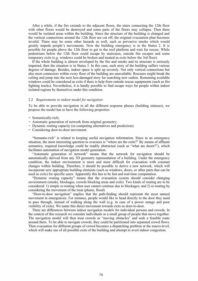
Figure 1. An example of “door to door” routes
Furthermore, S-MAT, which is mostly used for approximation of complex spaces in conventional DG model, fails to provide “door to door” routes for people. As shown in Figure 1, the straight medial axis of a corridor is D1-M1-M2-M3-M4-D4. Even if the person could not see the door D3 from D1, the “door to door” route could be D1-S1-D3 (the dash line), which means
80
the person will see D3 until he reaches S1. Yet the DG route would be D1-M1-M2-M3-D3 in this case.
Another inconvenience of the conventional DG model is the localization of an individual person on a DG model. If the indoor location of a person could be acquired, the location should be represented by its projection on the medial-axis of connections (e.g. corridors and stairs) or nodes (closed space) of the DG model, which might be quite different from the real position of the person (especially in complex shaped buildings).
Yuan & Schneider (2010) propose the Direct Path Graph (DPG). It considers three types of elements: cells, path segments and accessibility. Cells are the different units (spaces) in indoor environment. Path segment is referred to as a part of the shortest path between certain two access points, where access points (e.g. doors) are attached to cells. Concave vertices of cells are incorporated into paths between doors (in a single cell) as well. Accessibility of cells is determined by attributes of corresponding access points and path segments. Nodes of DPG consist of access points and concave points of cells, and each edge denotes the shortest route between any two nodes. Besides, DPG records distance information for every edge. Apparently, DPG is dedicated to improving the S-MAT approach. Theoretically, after employing the shortest path algorithm on DPG, the shortest route between two given nodes could be acquired. Here the “direct path” and “door-to-door” have the same meaning, that is, to look for the shortest way between any two doors (or exits).
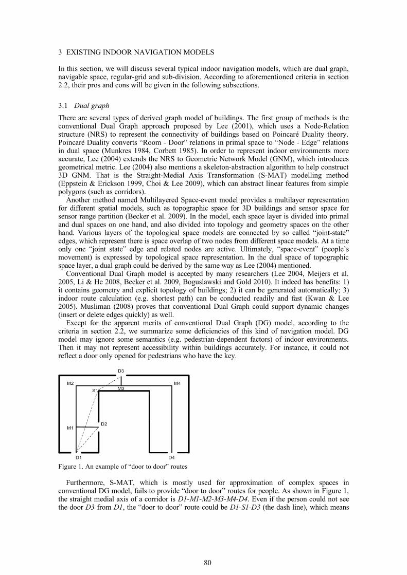
Nevertheless, in the work of Yuan & Schneider (2010), the way to obtain the shortest path segments between two nodes could not always derive the real shortest path. Figure 2 illustrates a “direct path” between two doors in a strange shaped room. The bold line in left image is the “direct path”, which is derived by dividing one straight line into two lines when the line intersects concave boundary. While the bold line in the right image is the genuine shortest path between the two doors. It is apparent that the path-generation approach used in DPG may not acquire the shortest path in some cases (e.g. some irregular-shaped room).
Figure 2. A comparison of the generated route in DPG with the genuine shortest path
Moreover, the DPG may not be suitable for navigation in complex indoor environments. It is possible that there are many doors and lots of concave points. Then the amount of nodes (including doors and concave points) and edges of DPG will soar. The computational complexity of the routing algorithm may be very high and the performance will decrease (Goetz & Zipf 2011).
3.2 Navigable space
Navigable space model (Slingsby & Raper 2008, Schaap 2010) intends to construct topologically-connected and navigable spaces (surfaces) to point out where pedestrians are able to move. The approach for navigable space model could reconstruct a 2.5D model from 2D plan with limited height and surface constraints. The group of models can provide some specific semantics (e.g. time and pedestrian-dependent properties within indoor environments) for navigation. Besides, it is relatively easy to locate pedestrians in this model, because the position could be pointed out in one piece of surface of the model.
Navigable space model could deal with all statuses of buildings. It is semantically-rich but the derivation of the network might be challenging for complex surfaces (Shaap 2010). It could provide the accessible space for diverse users, but there is no “door to door” style route in it.
81
The possibilities to automatically generate navigable spaces of various levels might be another problem.
3.3 Regular-grid model
The group of regular-grid graph models has two sub-types: 2D and 3D grid graphs. By overlapping discrete 2D grids with a 2D plan, the membership value of each grid is assigned according to the underlying cellular unit (such as rooms). Then a grid-based graph could be generated: the nodes represent the grids and edges of a certain node represent link relationships between the node and its neighbours (Li et al. 2009). On this type of graph, static shortest path analysis could be easily conducted. Besides, it is convenient to conduct 2D diffusion analysis (smoke, flood etc.) on 2D grid graph models.
Basically 3D grid graph is the extension of the 2D grid graph. The purpose of 3D grid-based (voxel) graph is to represent the 3D structure of indoor space. Then in a floor, intermediate levels (e.g. ramps and obstacles in air) could be measured. Yuan & Schneider (2010) propose a model called LEGO graph based on 3D voxels. LEGO-graph only provides all feasible or possible paths with different accessible widths and heights. Yet they have not proposed an algorithm to compute optimal navigation routes. Bandi & Thalmann (1998) give a more specific solution. They discretize building elements into 3D voxel and compute an obstacle-free feasible route with consideration of surmountable and insurmountable obstacles and “hole” areas in space.
Generally, regular-gird graph can readily point out the membership (e.g. corridors, rooms and stairways) of a grid. Besides, 3D grid graph can concern height constraints for indoor navigation. Current 2D and 3D grid models could be derived from 2D plans or 3D geometry automatically. The path-finding computational efficiency of grid model depends on required granularities and different algorithms. Fine-grained grid graph might provide the ‘door to door" navigation routes for pedestrians.
3.4 Sub-division
This type of method concerns subdividing 2D plans into cells according to certain criteria (e.g. distances between walls, visibility etc.). There are different criteria to sub-divide indoor space in literature. With consideration of passing bottlenecks in a 2D plan, Lamarche & Donikian (2004) apply constrained Delaunay triangulation algorithm and Convex Cell optimisation to subdivide a 2D plan. The subdivision locally conserves bottleneck information.
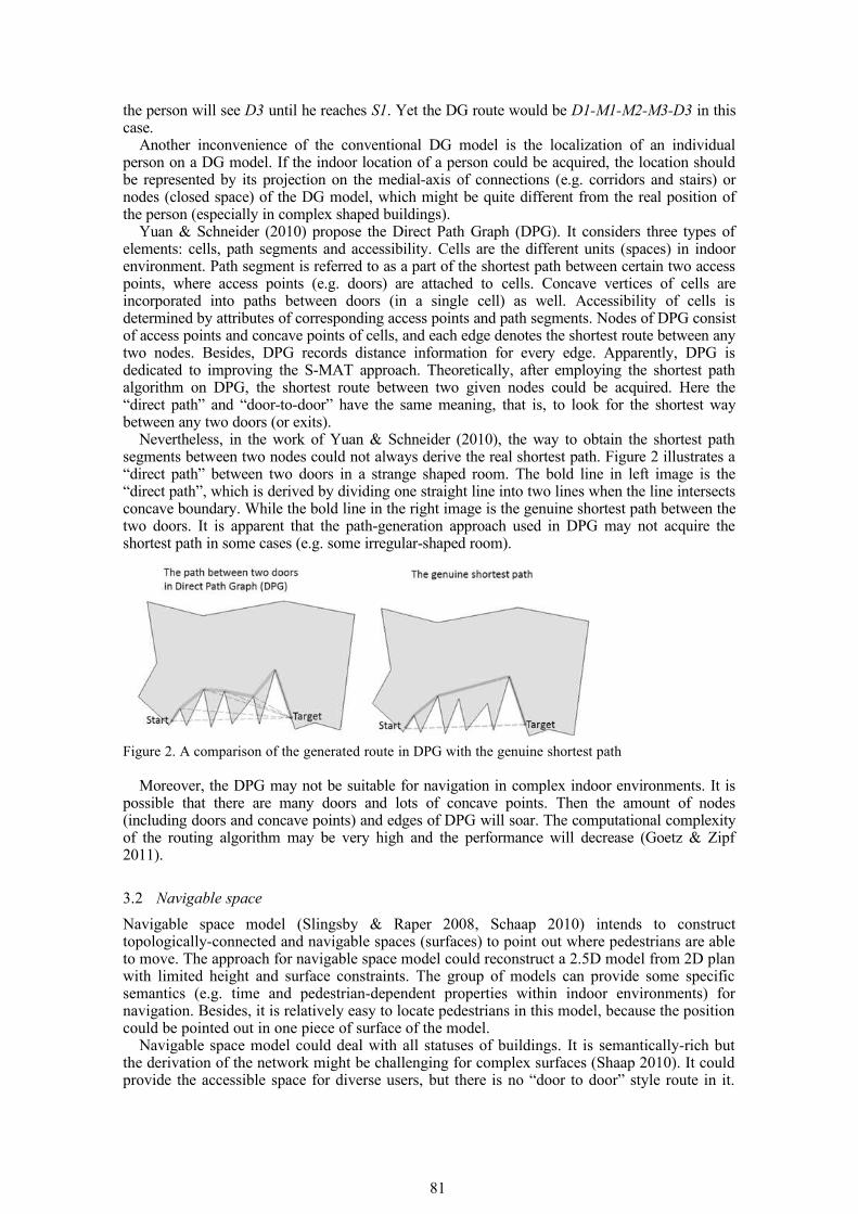
A different approach is given by Lorenz et al. (2006). For buildings with simple rooms and corridors, indoor space (2D plan) is decomposed into cells to build a graph structure. As shown in Figure 3, cell centres are connected with doors. However, the graph may result in some unnecessary tortuous paths. For instance, if there could be a direct connection between two doors, it is unnecessary to pass through a cell centre (e.g. a node of the corridor). Besides, there is no completely automation of the cell decomposition.
Figure 3. Cell centres and paths overlaid with a floor Plan (Lorenz et al. 2006)
82
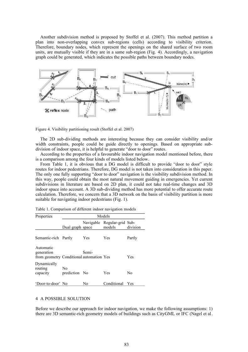
Another subdivision method is proposed by Stoffel et al. (2007). This method partition a plan into non-overlapping convex sub-regions (cells) according to visibility criterion. Therefore, boundary nodes, which represent the openings on the shared surface of two room units, are mutually visible if they are in a same sub-region (Fig. 4). Accordingly, a navigation graph could be generated, which indicates the possible paths between boundary nodes.
Figure 4. Visibility partitioning result (Stoffel et al. 2007)
The 2D sub-dividing methods are interesting because they can consider visibility and/or width constraints, people could be guide directly to openings. Based on appropriate sub-division of indoor space, it is helpful to generate “door to door” routes.
According to the properties of a favourable indoor navigation model mentioned before, there is a comparison among the four kinds of models listed below.
From Table 1, it is obvious that a DG model is difficult to provide “door to door” style routes for indoor pedestrians. Therefore, DG model is not taken into consideration in this paper. The only one fully supporting “door to door” navigation is the visibility subdivision method. In this way, people could obtain the most natural movement guiding in emergencies. Yet current subdivisions in literature are based on 2D plan, it could not take real-time changes and 3D indoor space into account. A 3D sub-dividing method has more potential to offer accurate route calculation. Therefore, we concern that a 3D network on the basis of visibility partition is more suitable for navigating indoor pedestrians (Fig. 1).
Table 1. Comparison of different indoor navigation models
Properties Models
Dual graphNavigable space
Regular-grid models
Sub-division
Semantic-rich Partly Yes Yes Partly
Automatic generation from geometry Conditional
Semi-automation Yes Yes
Dynamically routing capacity
No prediction No Yes No
‘Door-to-door’ No No Conditional Yes
4 A POSSIBLE SOLUTION
Before we describe our approach for indoor navigation, we make the following assumptions: 1) there are 3D semantic-rich geometry models of buildings such as CityGML or IFC (Nagel et al .
83
2009, Isikdag & Zlatanova 2009); 2) sensor data (smoke detector & monitor etc.) could be used for real-time update; 3) as mentioned previously the navigation model aims to serve small groups of users (first responders and/or people who need help).
In this section, we will introduce a new indoor navigation structure making use of 3D geometry and semantics of buildings and provide corresponding routing strategy.
4.1 Indoor navigation model
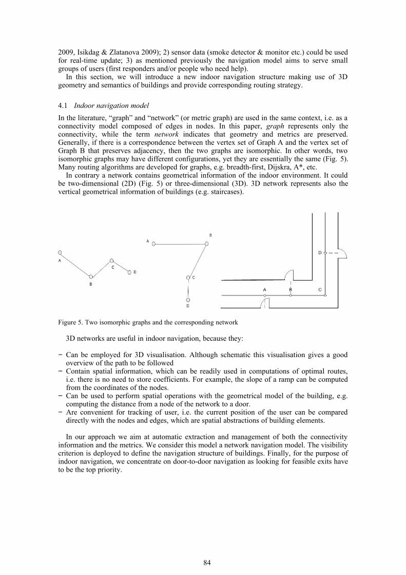
In the literature, “graph” and “network” (or metric graph) are used in the same context, i.e. as a connectivity model composed of edges in nodes. In this paper, graph represents only the connectivity, while the term network indicates that geometry and metrics are preserved. Generally, if there is a correspondence between the vertex set of Graph A and the vertex set of Graph B that preserves adjacency, then the two graphs are isomorphic. In other words, two isomorphic graphs may have different configurations, yet they are essentially the same (Fig. 5). Many routing algorithms are developed for graphs, e.g. breadth-first, Dijskra, A*, etc.
In contrary a network contains geometrical information of the indoor environment. It could be two-dimensional (2D) (Fig. 5) or three-dimensional (3D). 3D network represents also the vertical geometrical information of buildings (e.g. staircases).
Figure 5. Two isomorphic graphs and the corresponding network
3D networks are useful in indoor navigation, because they:
− Can be employed for 3D visualisation. Although schematic this visualisation gives a good overview of the path to be followed
− Contain spatial information, which can be readily used in computations of optimal routes, i.e. there is no need to store coefficients. For example, the slope of a ramp can be computed from the coordinates of the nodes.
− Can be used to perform spatial operations with the geometrical model of the building, e.g. computing the distance from a node of the network to a door.
− Are convenient for tracking of user, i.e. the current position of the user can be compared directly with the nodes and edges, which are spatial abstractions of building elements.
In our approach we aim at automatic extraction and management of both the connectivity information and the metrics. We consider this model a network navigation model. The visibility criterion is deployed to define the navigation structure of buildings. Finally, for the purpose of indoor navigation, we concentrate on door-to-door navigation as looking for feasible exits have to be the top priority.
84
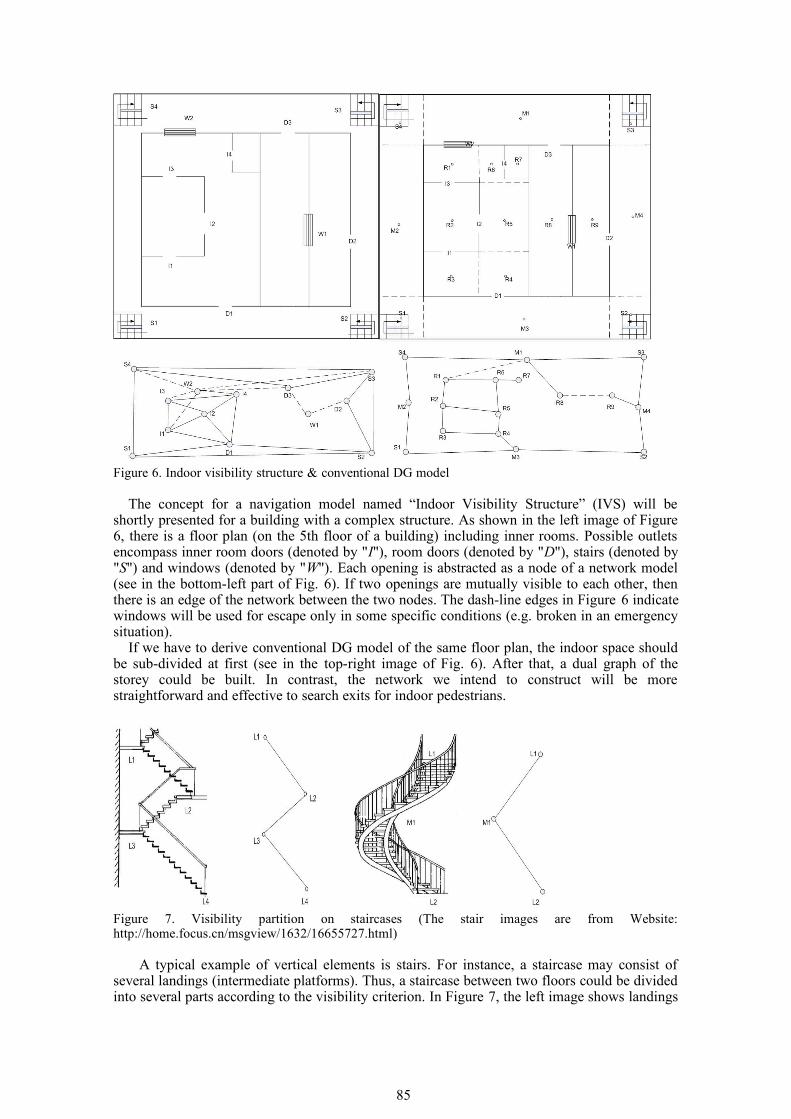
Figure 6. Indoor visibility structure & conventional DG model
The concept for a navigation model named “Indoor Visibility Structure” (IVS) will be shortly presented for a building with a complex structure. As shown in the left image of Figure 6, there is a floor plan (on the 5th floor of a building) including inner rooms. Possible outlets encompass inner room doors (denoted by "I"), room doors (denoted by "D"), stairs (denoted by "S") and windows (denoted by "W"). Each opening is abstracted as a node of a network model (see in the bottom-left part of Fig. 6). If two openings are mutually visible to each other, then there is an edge of the network between the two nodes. The dash-line edges in Figure 6 indicate windows will be used for escape only in some specific conditions (e.g. broken in an emergency situation).
If we have to derive conventional DG model of the same floor plan, the indoor space should be sub-divided at first (see in the top-right image of Fig. 6). After that, a dual graph of the storey could be built. In contrast, the network we intend to construct will be more straightforward and effective to search exits for indoor pedestrians.
Figure 7. Visibility partition on staircases (The stair images are from Website: http://home.focus.cn/msgview/1632/16655727.html)
A typical example of vertical elements is stairs. For instance, a staircase may consist of several landings (intermediate platforms). Thus, a staircase between two floors could be divided into several parts according to the visibility criterion. In Figure 7, the left image shows landings
85
are treated as nodes in a regular staircase. They could be connected by “visible” edges. While the right image demonstrates a spiral staircase is partitioned into three nodes. Although M1 is not a landing, it is the visible far-end point viewed from L1. So M1 is inserted as an intermediate node between L1 and L2.
Although there is certain work related to IVS, such as DPG, IVS has advantages over the counterpart. For a single room, they both follow the same principle (to find out the shortest route between two specific doors). As mentioned before (section 3.1), the path-derivation approach used in DPG may not always derive the shortest path in real sense between any two doors. Thus, we have developed a new algorithm to derive the shortest route between two openings in a single room, which is shown as follows:
Algorithm Door-to-Door_Route (startDoor, targetDoor, Pt)Input: startDoor, targetDoor, and a set Pt including start and target doors and all concave
vertices in a single room. Output: The sequence of vertices forming the door-to-door path, which is stored in a vector
Route.
// VisibleCP denotes a vector storing visible concave vertices from current location.// AdjMatrix represents the adjacency matrix of Pt.
if (IsNotVisible (startDoor, targetDoor) )then{
Determine Pt in the room;AdjMatrix ← Ф;for each node Pt[i]{
VisibleCP ← Ф;FindVisibleCP(Pt[i], VisibleCP);for each visible concave point VisibleCP[j]
Corresponding weight in AdjMatrix =Distance (Pt[i], VisibleCP[j]);
}ShortestPath (AdjMatrix, Route);
return Route;}else{ Connect the startDoor and targetDoor with a straight line; Add startDoor and targetDoor to the vector Route; return Route;}
With this door-to-door algorithm, we can acquire the genuine shortest path between two doors (i.e. as shown in Fig. 2, right). More information regarding the algorithm could be found in Liu & Zlatanova, 2011.
As discussed in section 3.1, door-to-door approach applied for the entire building may result in a very complex network. In this case, all mutually visible doors have to be connected with each other. For example, a building with 2 floors, 22 offices and two stairs will result in 50 nodes and 462 edges (Fig. 8).
86
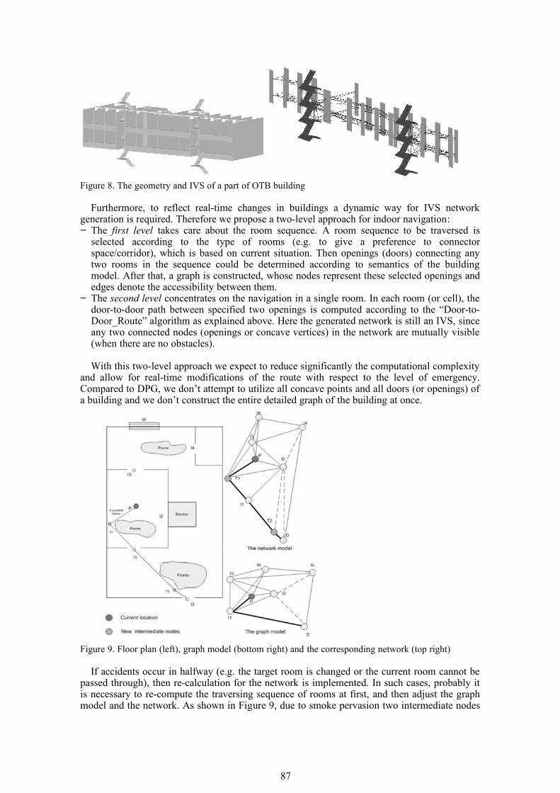
Figure 8. The geometry and IVS of a part of OTB building
Furthermore, to reflect real-time changes in buildings a dynamic way for IVS network generation is required. Therefore we propose a two-level approach for indoor navigation: − The first level takes care about the room sequence. A room sequence to be traversed is
selected according to the type of rooms (e.g. to give a preference to connector space/corridor), which is based on current situation. Then openings (doors) connecting any two rooms in the sequence could be determined according to semantics of the building model. After that, a graph is constructed, whose nodes represent these selected openings and edges denote the accessibility between them.
− The second level concentrates on the navigation in a single room. In each room (or cell), the door-to-door path between specified two openings is computed according to the “Door-to-Door_Route” algorithm as explained above. Here the generated network is still an IVS, since any two connected nodes (openings or concave vertices) in the network are mutually visible (when there are no obstacles).
With this two-level approach we expect to reduce significantly the computational complexity and allow for real-time modifications of the route with respect to the level of emergency. Compared to DPG, we don’t attempt to utilize all concave points and all doors (or openings) of a building and we don’t construct the entire detailed graph of the building at once.
Figure 9. Floor plan (left), graph model (bottom right) and the corresponding network (top right)
If accidents occur in halfway (e.g. the target room is changed or the current room cannot be passed through), then re-calculation for the network is implemented. In such cases, probably it is necessary to re-compute the traversing sequence of rooms at first, and then adjust the graph model and the network. As shown in Figure 9, due to smoke pervasion two intermediate nodes
87
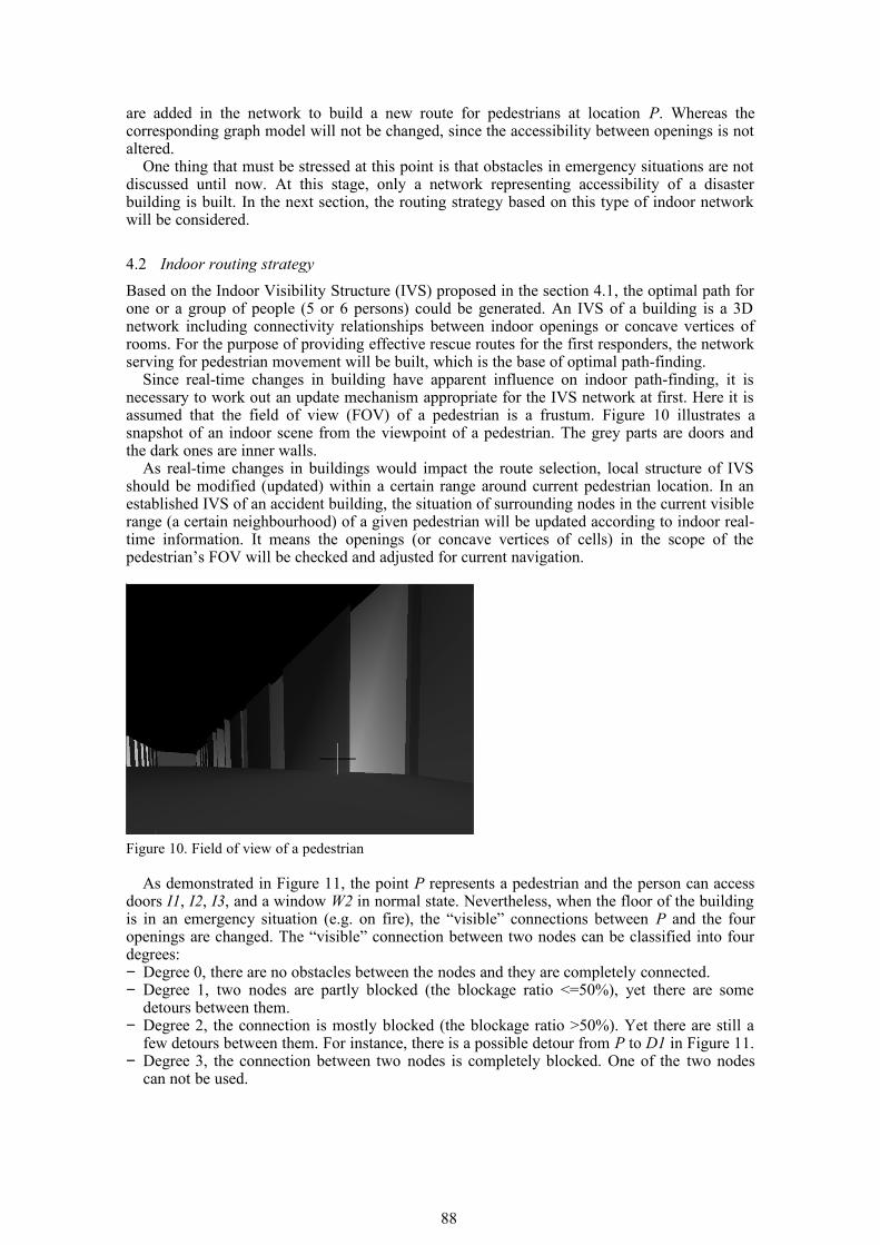
are added in the network to build a new route for pedestrians at location P. Whereas the corresponding graph model will not be changed, since the accessibility between openings is not altered.
One thing that must be stressed at this point is that obstacles in emergency situations are not discussed until now. At this stage, only a network representing accessibility of a disaster building is built. In the next section, the routing strategy based on this type of indoor network will be considered.
4.2 Indoor routing strategy
Based on the Indoor Visibility Structure (IVS) proposed in the section 4.1, the optimal path for one or a group of people (5 or 6 persons) could be generated. An IVS of a building is a 3D network including connectivity relationships between indoor openings or concave vertices of rooms. For the purpose of providing effective rescue routes for the first responders, the network serving for pedestrian movement will be built, which is the base of optimal path-finding.
Since real-time changes in building have apparent influence on indoor path-finding, it is necessary to work out an update mechanism appropriate for the IVS network at first. Here it is assumed that the field of view (FOV) of a pedestrian is a frustum. Figure 10 illustrates a snapshot of an indoor scene from the viewpoint of a pedestrian. The grey parts are doors and the dark ones are inner walls.
As real-time changes in buildings would impact the route selection, local structure of IVS should be modified (updated) within a certain range around current pedestrian location. In an established IVS of an accident building, the situation of surrounding nodes in the current visible range (a certain neighbourhood) of a given pedestrian will be updated according to indoor real-time information. It means the openings (or concave vertices of cells) in the scope of the pedestrian’s FOV will be checked and adjusted for current navigation.
Figure 10. Field of view of a pedestrian
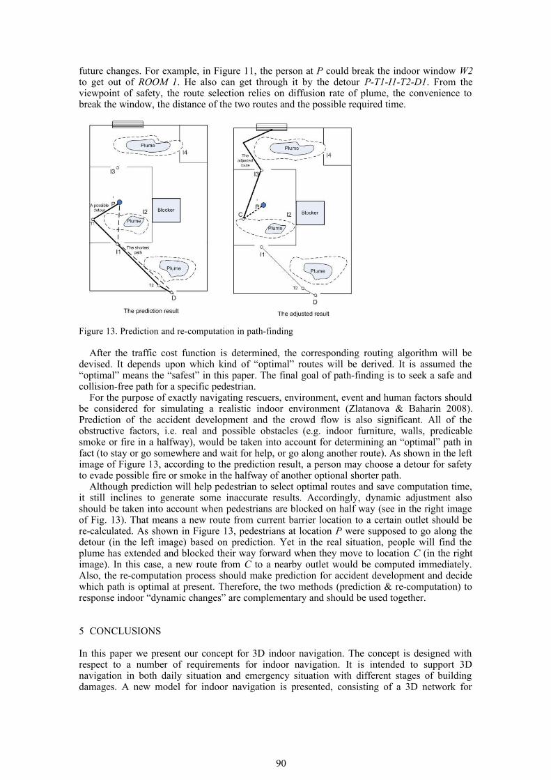
As demonstrated in Figure 11, the point P represents a pedestrian and the person can access doors I1, I2, I3, and a window W2 in normal state. Nevertheless, when the floor of the building is in an emergency situation (e.g. on fire), the “visible” connections between P and the four openings are changed. The “visible” connection between two nodes can be classified into four degrees: − Degree 0, there are no obstacles between the nodes and they are completely connected. − Degree 1, two nodes are partly blocked (the blockage ratio <=50%), yet there are some
detours between them. − Degree 2, the connection is mostly blocked (the blockage ratio >50%). Yet there are still a
few detours between them. For instance, there is a possible detour from P to D1 in Figure 11.− Degree 3, the connection between two nodes is completely blocked. One of the two nodes
can not be used.
88
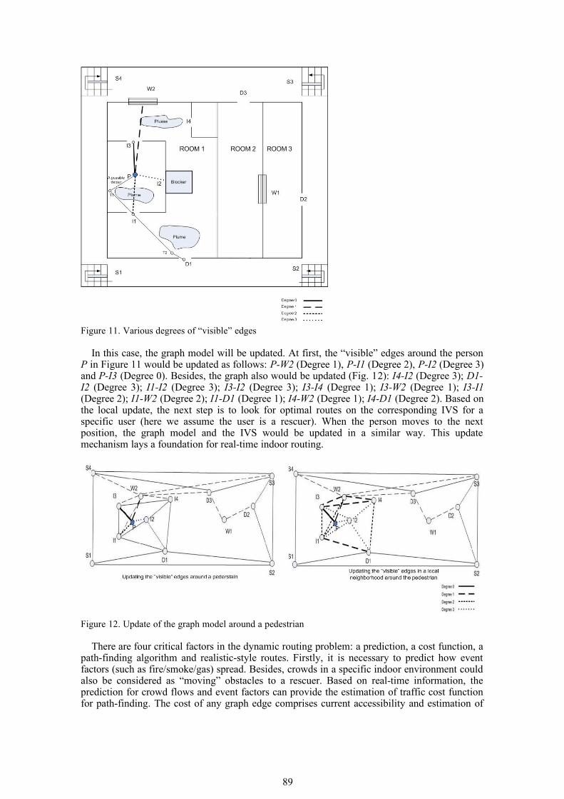
Figure 11. Various degrees of “visible” edges
In this case, the graph model will be updated. At first, the “visible” edges around the person P in Figure 11 would be updated as follows: P-W2 (Degree 1), P-I1 (Degree 2), P-I2 (Degree 3) and P-I3 (Degree 0). Besides, the graph also would be updated (Fig. 12): I4-I2 (Degree 3); D1-I2 (Degree 3); I1-I2 (Degree 3); I3-I2 (Degree 3); I3-I4 (Degree 1); I3-W2 (Degree 1); I3-I1 (Degree 2); I1-W2 (Degree 2); I1-D1 (Degree 1); I4-W2 (Degree 1); I4-D1 (Degree 2). Based on the local update, the next step is to look for optimal routes on the corresponding IVS for a specific user (here we assume the user is a rescuer). When the person moves to the next position, the graph model and the IVS would be updated in a similar way. This update mechanism lays a foundation for real-time indoor routing.
Figure 12. Update of the graph model around a pedestrian
There are four critical factors in the dynamic routing problem: a prediction, a cost function, a path-finding algorithm and realistic-style routes. Firstly, it is necessary to predict how event factors (such as fire/smoke/gas) spread. Besides, crowds in a specific indoor environment could also be considered as “moving” obstacles to a rescuer. Based on real-time information, the prediction for crowd flows and event factors can provide the estimation of traffic cost function for path-finding. The cost of any graph edge comprises current accessibility and estimation of
89
future changes. For example, in Figure 11, the person at P could break the indoor window W2 to get out of ROOM 1. He also can get through it by the detour P-T1-I1-T2-D1. From the viewpoint of safety, the route selection relies on diffusion rate of plume, the convenience to break the window, the distance of the two routes and the possible required time.
Figure 13. Prediction and re-computation in path-finding
After the traffic cost function is determined, the corresponding routing algorithm will be devised. It depends upon which kind of “optimal” routes will be derived. It is assumed the “optimal” means the “safest” in this paper. The final goal of path-finding is to seek a safe and collision-free path for a specific pedestrian.
For the purpose of exactly navigating rescuers, environment, event and human factors should be considered for simulating a realistic indoor environment (Zlatanova & Baharin 2008). Prediction of the accident development and the crowd flow is also significant. All of the obstructive factors, i.e. real and possible obstacles (e.g. indoor furniture, walls, predicable smoke or fire in a halfway), would be taken into account for determining an “optimal” path in fact (to stay or go somewhere and wait for help, or go along another route). As shown in the left image of Figure 13, according to the prediction result, a person may choose a detour for safety to evade possible fire or smoke in the halfway of another optional shorter path.
Although prediction will help pedestrian to select optimal routes and save computation time, it still inclines to generate some inaccurate results. Accordingly, dynamic adjustment also should be taken into account when pedestrians are blocked on half way (see in the right image of Fig. 13). That means a new route from current barrier location to a certain outlet should be re-calculated. As shown in Figure 13, pedestrians at location P were supposed to go along the detour (in the left image) based on prediction. Yet in the real situation, people will find the plume has extended and blocked their way forward when they move to location C (in the right image). In this case, a new route from C to a nearby outlet would be computed immediately. Also, the re-computation process should make prediction for accident development and decide which path is optimal at present. Therefore, the two methods (prediction & re-computation) to response indoor “dynamic changes” are complementary and should be used together.
5 CONCLUSIONS
In this paper we present our concept for 3D indoor navigation. The concept is designed with respect to a number of requirements for indoor navigation. It is intended to support 3D navigation in both daily situation and emergency situation with different stages of building damages. A new model for indoor navigation is presented, consisting of a 3D network for
90
navigation and corresponding routing strategy. The 3D network model named “Indoor Visibility Structure” (IVS) makes use of semantics of buildings. It could be automatically generated from 3D geometry of buildings. The proposed approach is designed to resolve navigation in complex buildings. Ultimately, by resting on the IVS, the routing strategy considering indoor real-time changes and updating the IVS, the ‘door-to-door’ navigation within buildings could be achieved.
The future work will concentrate on further development and formalization of the model, implementation and performing tests.
REFERENCES
Bandi, S. & Thalmann, D. 1998. Space discretization for efficient human navigation. Computer Graphics Forum 17(3): 195-206.
Becker, T. Nagel, C. & Kolbe, T. H. 2009. A Multilayered Space-Event Model for Navigation in Indoor Spaces. In Lee, J. & Zlatanova, S. (eds), 3D Geoinformation Sciences: 61-77. Berlin: Springer.
Boguslawski, P. and Gold, C., 2010, Construction Operators for Modelling 3D Objects and Dual Navigation Structures, in Jiyeong Lee and Sisi Zlatanova (eds.), 3D Geo-Information Sciences (Lecture Notes in Geoinformation and Cartography; Springer Berlin Heidelberg), pp. 47-59.
Choi, J. & Lee, J. 2009. 3D Geo-Network for Agent-based Building Evacuation Simulation. In Lee, J. & Zlatanova, S. (eds), 3D Geo-Information Sciences: 283-299. Berlin: Springer.
Corbett, J.P. 1979. Topological Principles in Cartography. In Technical Paper 48: 61-65. Washington DC: US Bureau of the Census.
Corbett, J.P. 1985. A general topological model for spatial reference. In J.P. van Est (ed.), Report of Spatially Oriented Referencing Systems Association (SORSA) Workshop: 9-24.
Eppstein, D.& Erickson, J. 1999. Raising Roofs, Crashing Cycles & Playing Pool: Applications of a Data Structure for Finding Pairwise Interactions. In 14th Annual ACM Symposium on Computational Geometry: 58-67. Minneapolis.
Franz, G. Mallot, H. & Wiener, J. 2005. Graph-based Models of Space in Architecture and Cognitive Science - a Comparative Analysis. In Leong, Y-T. & Lasker, G.E. (eds), Proceedings of the 17th International Conference on Systems Research, Informatics and Cybernetics: 30-38.
Goetz, M. & Zipf, A. 2011. Formal Definition of an User-adaptive and Length-optimal Routing Graph for Complex Indoor Environments. In Joint ISPRS Workshop on 3D City Modelling & Applications and the 6th 3D GeoInfo Conference, Wuhan, China. Heidelberg: Springer.
Isikdag, U and S. Zlatanova, 2009, A SWOT analysis on the implementation of BIM within geospatial environment, in Krek, Rumor, Zlatanova & Fendel (eds.), In:Urban and Regional data Management, UDMS Annuals 2009, 15-30 Boca Raton: CRC press, Taylor & Francis
Kwak, S. Nam, H. & Jun, C. 2010. An enhanced indoor pedestrian model supporting spatial DBMSs. In Proceedings of the 2nd ACM SIGSPATIAL International Workshop on Indoor Spatial Awareness (ISA’10): 25-32. New York: ACM.
Kwan, M. P. & Lee, J. 2005. Emergency response after 9/11: the potential of real-time 3D GIS for quick emergency response in micro-spatial environments. Computers, Environment and Urban Systems 29: 93-113.
Lamarche, F. & Donikian S. 2004. Crowd of virtual humans: a new approach for real time navigation in complex and structured environments. Computer Graphics Forum 23 (3): 509-518.
Lee, J. 2001a. 3D Data Model for Representing Topological Relations of Urban Features. In Proceedings of the 21st Annual ESRI International User Conference . San Diego, USA.
Lee, J. 2001b. A spatial access oriented implementation of a topological data model for 3D urban entities. In University Consortium for Geographic Information Science (UCGIS) Summer Assembly . Buffalo, New York.
Lee, J. 2004. A Spatial Access-Oriented Implementation of a 3-D GIS Topological Data Model for Urban Entities. Geoinformatica 8(3): 237-264.
Li, X. Claramuntb, C.& Rayb, C. 2010. A grid graph-based model for the analysis of 2D indoor spaces. Computers, Environment and Urban Systems 34(6): 532-540.
Li, Y. He, Z. 2008. 3D Indoor Navigation: a Framework of Combining BIM with 3D GIS. In proceedings of 44th ISOCARP Congress.
Liu, L. & Zlatanova, S. 2011. A "door-to-door" Path-finding Approach for Indoor Navigation. In Proceedings of GeoInformation For Disaster Management Conference 2011, Antalya, 3-8 May 2011.
Lorenz, B. Ohlbach, H.J. & Stoffel, E.P. 2006. A Hybrid Spatial Model for Representing Indoor Environments. In Proceedings of W2GIS (LNCS 4295): 102-112. Hong Kong, China.
Meijers, M. Zlatanova, S. & Preifer, N. 2005. 3D geoinformation indoors: structuring for evacuation. In Proceedings of Next generation 3D city models. Bonn, Germany.
Munkres, J.R. 1984. Elements of Algebraic Topology. Menlo Park, CA: Addison-Wesley.Musliman, I.A. Rahman, A.A. Coors, V. 2008. Implementing 3D network analysis in 3D-GIS. In The
International Archives of the Photogrammetry, Remote Sensing and Spatial Information Sciences 37 (Part B2): 913-918. Beijing.
Nagel, C., A. Stadler and T. H. Kolbe, 2009, Conceptual requirements for the automatic reconstruction of building information models from uninterpreted 3d models, in: Kolbe, Zhang&Zlatanova (eds), International Archives of Photogrammetry, Remote Sensing and Spatial Information Sciences , Vol.
91

XXXVIII-3-4/c3, 46-53, Berlin, GermanySchaap, J. 2010. Towards a 3D geo-data model to support pedestrian routing in multimodal public
transport travel advices. MSc Thesis. GIMA MSc. programme, Utrecht University, Netherlands. Slingsby, A. & Raper, J. 2008. Navigable Space in 3D City Models for Pedestrians. In Van Oosterom P.
Zlatanova, S. Penninga, F. & Fendel, E. (eds), Advances in 3D Geoinformation Systems: 49-64. Berlin: Springer.
Stoffel, E. Lorenz, B. & Ohlbach, H. 2007. Towards a Semantic Spatial Model for Pedestrian Indoor Navigation. In Hainaut, J. & Rundensteiner, E. (eds), ER’ 07 Workshops / Advances in Conceptual Modeling: 328-337. Berlin: Springer.
Yuan, W. & Schneide, M. 2010. Supporting 3D Route Planning in Indoor Space Based on the LEGO Representation. In proceedings of ISA’10. New York: ACM.
Yuan, W. & Schneider, M. 2010. iNav: An indoor navigation model supporting length-dependent optimal routing. In The 13th AGILE International Conference on Geographic Information Science . Heidelberg: Springer.
Zlatanova, S. and S. Baharin, 2008. Optimal Navigation for First Responders. In Van der Walle, Song, Zlatanova & Li (eds.), Information systems for crisis response and management, 529-542. Harbin, China.
92