School Improvement Plan 2020-2021 - Indiana Department of ...
Upload
khangminh22Category
view
0download
0
INDIANA DEPARTMENT OF ENVIRONMENTAL MANAGEMENT We Protect Hoosiers and Our Environment.
Mitchell E. Daniels Jr. 100 North Senate Avenue Governor Indianapolis, Indiana 46204 (317) 232-8603Thomas W. Easterly Toll Free (800) 451-6027 Commissioner www.idem.IN.gov
Recycled Paper An Equal Opportunity Employer Please Recycle
NOTICE OF 30-DAY PERIOD FOR PUBLIC COMMENT
Preliminary Findings Regarding the Renewal of a
Part 70 Operating Permit
For Essroc Cement Corporation in Cass County The Indiana Department of Environmental Management (IDEM) has received an application from Essroc Cement Company located at State Road 25 South, 3084 West County Road 225 South, Logansport, IN 46947 for a renewal of its Part 70 Operating Permit issued on December 27, 2003. If approved by IDEM’s Office of Air Quality (OAQ), this proposed renewal would allow Essroc Cement Company to continue to operate its existing source. This draft Part 70 Operating Permit Renewal (T017-26351-00005) does not contain any new equipment that would emit air pollutants; however, some conditions from previously issued permits/approvals have been corrected, changed or removed. This notice fulfills the public notice procedures to which those conditions are subject. IDEM has reviewed this application, and has developed preliminary findings, consisting of a draft permit and several supporting documents, that would allow for these changes. A copy of the permit application and IDEM’s preliminary findings are available at: Logansport / Cass County Public Library 616 East Broadway Logansport, IN 46947
A copy of the preliminary findings is available on the Internet at: http://www.in.gov/ai/appfiles/idem-caats/. How can you participate in this process? The date that this notice is published in a newspaper marks the beginning of a 30-day public comment period. If the 30th day of the comment period falls on a day when IDEM offices are closed for business, all comments must be postmarked or delivered in person on the next business day that IDEM is open. You may request that IDEM hold a public hearing about this draft permit. If adverse comments concerning the air pollution impact of this draft permit are received, with a request for a public hearing, IDEM will decide whether or not to hold a public hearing. IDEM could also decide to hold a public meeting instead of, or in addition to, a public hearing. If a public hearing or meeting is held, IDEM will make a separate announcement of the date, time, and location of that hearing or meeting. At a hearing, you would have an opportunity to submit written comments and make verbal comments. At a meeting, you would have an opportunity to submit written comments, ask questions, and discuss any air pollution concerns with IDEM staff. Comments and supporting documentation, or a request for a public hearing should be sent in writing to IDEM at the address below. If you comment via e-mail, please include your full U.S. mailing address so that you can be added IDEM’s mailing list to receive notice of future action related to this permit. If you do not want to comment at this time, but would like to receive notice of future action related to this permit application, please contact IDEM at the address below. Please refer to permit number T017-26351-00005 in all correspondence.


INDIANA DEPARTMENT OF ENVIRONMENTAL MANAGEMENTWe Protect Hoosiers and Our Environment.
Mitchell E. Daniels Jr. 100 North Senate Avenue Governor Indianapolis, Indiana 46204 (317) 232-8603 Thomas W. Easterly Toll Free (800) 451-6027 Commissioner www.idem.IN.gov
Recycled Paper An Equal Opportunity Employer Please Recycle
DRAFT PART 70 OPERATING PERMIT RENEWAL
OFFICE OF AIR QUALITY
Essroc Cement Corporation State Road 25 South, 3084 West County Road 225 South
Logansport, Indiana 46947
(herein known as the Permittee) is hereby authorized to operate subject to the conditions contained herein, the source described in Section A (Source Summary) of this permit.
The Permittee must comply with all conditions of this permit. Noncompliance with any provisions of this permit is grounds for enforcement action; permit termination, revocation and reissuance, or modification; or denial of a permit renewal application. Noncompliance with any provision of this permit, except any provision specifically designated as not federally enforceable, constitutes a violation of the Clean Air Act. It shall not be a defense for the Permittee in an enforcement action that it would have been necessary to halt or reduce the permitted activity in order to maintain compliance with the conditions of this permit. An emergency does constitute an affirmative defense in an enforcement action provided the Permittee complies with the applicable requirements set forth in Section B, Emergency Provisions. This permit is issued in accordance with 326 IAC 2 and 40 CFR Part 70 Appendix A and contains the conditions and provisions specified in 326 IAC 2-7 as required by 42 U.S.C. 7401, et. seq. (Clean Air Act as amended by the 1990 Clean Air Act Amendments), 40 CFR Part 70.6, IC 13-15 and IC 13-17. Operation Permit No. T017-26351-00005
Issued by: Chrystal A. Wagner, Section Chief Permits Branch Office of Air Quality
Issuance Date: Expiration Date:

Essroc Cement Corporation Page 2 of 82 Logansport, Indiana OP No. T017-26351-00005 Permit Reviewer: Jenny Acker
Draft TABLE OF CONTENTS
A SOURCE SUMMARY ...................................................................................................................... 7 A.1 General Information [326 IAC 2-7-4(c)][326 IAC 2-7-5(15)][326 IAC 2-7-1(22)] A.2 Emission Units and Pollution Control Equipment Summary [326 IAC 2-7-4(c)(3)]
[326 IAC 2-7-5(15)] A.3 Specifically Regulated Insignificant Activities [326 IAC 2-7-1(21)][326 IAC 2-7-4(c)]
[326 IAC 2-7-5(15)] A.4 Part 70 Permit Applicability [326 IAC 2-7-2]
B GENERAL CONDITIONS .............................................................................................................. 18
B.1 Definitions [326 IAC 2-7-1] B.2 Revocation of Permits [326 IAC 2-2-8] B.3 Permit Term [326 IAC 2-7-5(2)][326 IAC 2-1.1-9.5][326 IAC 2-7-4(a)(1)(D)]
[IC 13-15-3-6(a)] B.4 Term of Conditions [326 IAC 2-1.1-9.5] B.5 Enforceability [326 IAC 2-7-7] [IC 13-17-12] B.6 Severability [326 IAC 2-7-5(5)] B.7 Property Rights or Exclusive Privilege [326 IAC 2-7-5(6)(D)] B.8 Duty to Provide Information [326 IAC 2-7-5(6)(E)] B.9 Certification [326 IAC 2-7-4(f)][326 IAC 2-7-6(1)][326 IAC 2-7-5(3)(C)] B.10 Annual Compliance Certification [326 IAC 2-7-6(5)] B.11 Preventive Maintenance Plan [326 IAC 2-7-5(1),(3) and (13)][326 IAC 2-7-6(1) and (6)]
[326 IAC 1-6-3] B.12 Emergency Provisions [326 IAC 2-7-16] B.13 Permit Shield [326 IAC 2-7-15][326 IAC 2-7-20][326 IAC 2-7-12] B.14 Prior Permits Superseded [326 IAC 2-1.1-9.5][326 IAC 2-7-10.5] B.15 Termination of Right to Operate [326 IAC 2-7-10][326 IAC 2-7-4(a)] B.16 Deviations from Permit Requirements and Conditions [326 IAC 2-7-5(3)(C)(ii)] B.17 Permit Modification, Reopening, Revocation and Reissuance, or Termination
[326 IAC 2-7-5(6)(C)][326 IAC 2-7-8(a)][326 IAC 2-7-9] B.18 Permit Renewal [326 IAC 2-7-3][326 IAC 2-7-4][326 IAC 2-7-8(e)] B.19 Permit Amendment or Modification [326 IAC 2-7-11][326 IAC 2-7-12] B.20 Permit Revision Under Economic Incentives and Other Programs [326 IAC 2-7-5(8)]
[326 IAC 2-7-12(b)(2)] B.21 Operational Flexibility [326 IAC 2-7-20][326 IAC 2-7-10.5] B.22 Source Modification Requirement [326 IAC 2-7-10.5] B.23 Inspection and Entry [326 IAC 2-7-6][IC 13-14-2-2][IC 13-30-3-1][IC 13-17-3-2] B.24 Transfer of Ownership or Operational Control [326 IAC 2-7-11] B.25 Annual Fee Payment [326 IAC 2-7-19] [326 IAC 2-7-5(7)][326 IAC 2-1.1-7] B.26 Credible Evidence [326 IAC 2-7-5(3)][326 IAC 2-7-6][62 FR 8314] [326 IAC 1-1-6]
C SOURCE OPERATION CONDITIONS.......................................................................................... 30
Emission Limitations and Standards [326 IAC 2-7-5(1)] C.1 Particulate Emission Limitations For Processes with Process Weight Rates
Less Than One Hundred (100) Pounds per Hour [326 IAC 6-3-2] C.2 Opacity [326 IAC 5-1] C.3 Open Burning [326 IAC 4-1] [IC 13-17-9] C.4 Incineration [326 IAC 4-2] [326 IAC 9-1-2] C.5 Fugitive Dust Emissions [326 IAC 6-4] C.6 Stack Height [326 IAC 1-7] C.7 Asbestos Abatement Projects [326 IAC 14-10] [326 IAC 18] [40 CFR 61, Subpart M] Testing Requirements [326 IAC 2-7-6(1)] C.8 Performance Testing [326 IAC 3-6]

Essroc Cement Corporation Page 3 of 82 Logansport, Indiana OP No. T017-26351-00005 Permit Reviewer: Jenny Acker
Draft Compliance Requirements [326 IAC 2-1.1-11] C.9 Compliance Requirements [326 IAC 2-1.1-11] Compliance Monitoring Requirements [326 IAC 2-7-5(1)][326 IAC 2-7-6(1)] C.10 Compliance Monitoring [326 IAC 2-7-5(3)][326 IAC 2-7-6(1)] C.11 Maintenance of Continuous Opacity Monitoring Equipment
[326 IAC 2-7-5(3)(A)(iii)] C.12 Maintenance of Continuous Emission Monitoring Equipment
[326 IAC 2-7-5(3)(A)(iii)] C.13 Monitoring Methods [326 IAC 3] [40 CFR 60] [40 CFR 63] C.14 Instrument Specifications [326 IAC 2-1.1-11] [326 IAC 2-7-5(3)]
[326 IAC 2-7-6(1)] Corrective Actions and Response Steps [326 IAC 2-7-5][326 IAC 2-7-6] C.15 Emergency Reduction Plans [326 IAC 1-5-2] [326 IAC 1-5-3] C.16 Risk Management Plan [326 IAC 2-7-5(12)] [40 CFR 68] C.17 Response to Excursions or Exceedances [326 IAC 2-7-5] [326 IAC 2-7-6] C.18 Actions Related to Noncompliance Demonstrated by a Stack Test [326 IAC 2-7-5]
[326 IAC 2-7-6] Record Keeping and Reporting Requirements [326 IAC 2-7-5(3)] [326 IAC 2-7-19] C.19 Emission Statement [326 IAC 2-7-5(3)(C)(iii)][326 IAC 2-7-5(7)][326 IAC 2-7-19(c)]
[326 IAC 2-6] C.20 General Record Keeping Requirements [326 IAC 2-7-5(3)] [326 IAC 2-7-6] [326 IAC 2-2]
[326 IAC 2-3] C.21 General Reporting Requirements [326 IAC 2-7-5(3)(C)] [326 IAC 2-1.1-11]
[326 IAC 2-2]
Stratospheric Ozone Protection C.22 Compliance with 40 CFR 82 and 326 IAC 22-1
D.1 FACILITY OPERATION CONDITIONS - Quarry Activities, Stockpile Operations, and .......... 40
Raw Material Sizing
Emission Limitations and Standards [326 IAC 2-7-5(1)] D.1.1 Particulate Emissions [326 IAC 6-3-2] D.1.2 Preventive Maintenance Plan [326 IAC 2-7-5(13)] Compliance Determination Requirements D.1.3 Particulate Control [326 IAC 2-7-6(6)] Compliance Monitoring Requirements [326 IAC 2-7-6(1)] [326 IAC 2-7-5(1)] D.1.4 Visible Emissions Notations and Compliance Assurance Monitoring (CAM) [40 CFR Part
64] D.1.5 Parametric Monitoring and Compliance Assurance Monitoring (CAM) [40 CFR Part 64] D.1.6 Broken or Failed Bag Detection Record Keeping and Reporting Requirements [326 IAC 2-7-5(3)] [326 IAC 2-7-19] D.1.7 Record Keeping Requirements
D.2 FACILITY OPERATION CONDITIONS - CKD Operations, Clay processing operations, ....... 44
Crane storage facilities, Raw Mill facilities, Unloading station facilities, Fossil fuel facilities, Clinker handling facilities, Finish mill facilities, Silo storage facilities and transfer operations, Finish product

Essroc Cement Corporation Page 4 of 82 Logansport, Indiana OP No. T017-26351-00005 Permit Reviewer: Jenny Acker
Draft loadout, Finish product masonry packing and portland packing
Emission Limitations and Standards [326 IAC 2-7-5(1)] D.2.1 PSD Minor Limits - PM and PM10 [326 IAC 2-2] D.2.2 Particulate Emissions [326 IAC 6-3-2] D.2.3 Preventive Maintenance Plan [326 IAC 2-7-5(13)] Compliance Determination Requirements D.2.4 Testing Requirements [326 IAC 2-7-6(1),(6)] D.2.5 Particulate Control [326 IAC 2-7-6(6)] Compliance Monitoring Requirements [326 IAC 2-7-6(1)] [326 IAC 2-7-5(1)] D.2.6 Visible Emissions Notations and Compliance Assurance Monitoring (CAM) [40 CFR Part
64] D.2.7 Parametric Monitoring and Compliance Assurance Monitoring (CAM) [40 CFR Part 64] D.2.8 Broken or Failed Bag Detection Record Keeping and Reporting Requirements [326 IAC 2-7-5(3)] [326 IAC 2-7-19] D.2.9 Record Keeping Requirements
D.3 FACILITY OPERATION CONDITIONS - Kilns ............................................................................. 52
Emission Limitations and Standards [326 IAC 2-7-5(1)] D.3.1 Sulfur Dioxide (SO2) [326 IAC 7-1.1-1] D.3.2 PSD Applicability for kilns [326 IAC 2-2-3] [326 IAC 2-7-6(3)] [326 IAC 2-7-15] D.3.3 Preventive Maintenance Plan [326 IAC 2-7-5(13)] Compliance Determination Requirements D.3.4 Continuous Emissions Monitoring [326 IAC 3-5] [326 IAC 2-7-6(1),(6)] D.3.5 Sulfur Dioxide Emissions and Sulfur Content [326 IAC 2-7-5(A)] [326 IAC 2-7-6] Compliance Monitoring Requirements [326 IAC 2-7-6(1)] [326 IAC 2-7-5(1)] D.3.6 Visible Emissions Notations Record Keeping and Reporting Requirements [326 IAC 2-7-5(3)] [326 IAC 2-7-19] D.3.7 Record Keeping Requirements D.3.8 Reporting Requirements
D.4 FACILITY OPERATION CONDITIONS - Clinker Coolers ........................................................... 56
Emission Limitations and IAC 2-7-5(1)] D.4.1 Preventive Maintenance Plan [326 IAC 2-7-5(13)] Compliance Determination Requirements D.4.2 Continuous Emissions Monitoring [326 IAC 3-5] Compliance Monitoring Requirements [326 IAC 2-7-6(1)] [326 IAC 2-7-5(1)] D.4.3 Visible Emission Notations Record Keeping and Reporting Requirements [326 IAC 2-7-5(3)] [326 IAC 2-7-19] D.4.4 Record Keeping Requirements D.4.5 Reporting Requirements

Essroc Cement Corporation Page 5 of 82 Logansport, Indiana OP No. T017-26351-00005 Permit Reviewer: Jenny Acker
Draft D.5 FACILITY OPERATION CONDITIONS - Degreasing Operations .............................................. 58
Emission Limitations and Standards [326 IAC 2-7-5(1)] D.5.1 Volatile Organic Compounds (VOC) [326 IAC 8-3-2] D.5.2 Volatile Organic Compounds (VOC) [326 IAC 8-3-5]
E.1 FACILITY OPERATION CONDITIONS - Standards of Performance for Coal ......................... 60 Preparation Plants
New Source Performance Standards (NSPS) Requirements [326 IAC 2-7-5(1)] E.1.1 General Provisions Relating to New Source Performance Standards [40 CFR Part 60,
Subpart A] [326 IAC 12-1] E.1.2 Standards of Performance for Coal Preparation Plants [40 CFR Part 60, Subpart Y] [326
IAC 12]
E.2 FACILITY OPERATION CONDITIONS - National Emission Standard for Equipment ............ 61 Leaks (Fugitive Emission Sources)
National Emission Standards for Hazardous Air Pollutants (NESHAP) Requirements [326 IAC 2-7-5(1)] E.2.1 General Provisions Relating to National Emission Standards for Hazardous Air Pollutants
under 40 CFR Part 61 [40 CFR Part 61, Subpart A] [326 IAC 14-1] E.2.2 National Emission Standard for Equipment Leaks (Fugitive Emission Sources) [40 CFR
Part 61, Subpart V]
E.3 FACILITY OPERATION CONDITIONS - National Emission Standard for Benzene ............... 63 Waste Operations
National Emission Standards for Hazardous Air Pollutants (NESHAP) Requirements [326 IAC 2-7-5(1)] E.3.1 General Provisions Relating to National Emission Standards for Hazardous Air Pollutants
under 40 CFR Part 61 [40 CFR Part 61, Subpart A] [326 IAC 14-1] E.3.2 National Emission Standard for Benzene Waste Operations [40 CFR Part 61, Subpart FF]
E.4 FACILITY OPERATION CONDITIONS - National Emission Standards for Hazardous .......... 65 Air Pollutants from Off-Site Waste and Recovery Operations
National Emission Standards for Hazardous Air Pollutants (NESHAP) Requirements [326 IAC 2-7-5(1)] E.4.1 General Provisions Relating to National Emission Standards for Hazardous Air Pollutants
under 40 CFR Part 63 [40 CFR Part 63, Subpart A] [326 IAC 20-1] E.4.2 National Emission Standards for Hazardous Air Pollutants from Off-Site Waste and
Recovery Operations [40 CFR Part 63, Subpart DD] [326 IAC 20-23]
E.5 FACILITY OPERATION CONDITIONS - National Emission Standards for Hazardous .......... 67 Air Pollutants from Hazardous Waste Combustors
National Emission Standards for Hazardous Air Pollutants (NESHAP) Requirements [326 IAC 2-7-5(1)] E.5.1 General Provisions Relating to National Emission Standards for Hazardous Air Pollutants
under 40 CFR Part 63 [40 CFR Part 63, Subpart A] [326 IAC 20-1] E.5.2 National Emission Standards for Hazardous Air Pollutants from Hazardous Waste
Combustors [40 CFR Part 63, Subpart EEE] [326 IAC 20-28]
Essroc Cement Corporation Page 6 of 82 Logansport, Indiana OP No. T017-26351-00005 Permit Reviewer: Jenny Acker
Draft E.6 FACILITY OPERATION CONDITIONS - National Emission Standards for Hazardous .......... 69
Air Pollutants from the Portland Cement Manufacturing Industry
National Emission Standards for Hazardous Air Pollutants (NESHAP) Requirements [326 IAC 2-7-5(1)] E.6.1 General Provisions Relating to National Emission Standards for Hazardous Air Pollutants
under 40 CFR Part 63 [40 CFR Part 63, Subpart A] [326 IAC 20-1] E.6.2 National Emission Standards for Hazardous Air Pollutants from the Portland Cement
Manufacturing Industry [40 CFR Part 63, Subpart LLL] [326 IAC 20-27]
Certification Emergency Occurrence Report Quarterly Reports Quarterly Deviation and Compliance Monitoring Report Attachments
Attachment A - 40 CFR 60, Subpart Y - Standards of Performance for Coal Preparation Plants Attachment B - 40 CFR 61, Subpart V - National Emission Standard for Equipment Leaks
(Fugitive Emission Sources) Attachment C - 40 CFR 61, Subpart FF - National Emission Standard for Benzene Waste
Operations Attachment D - 40 CFR 63, Subpart DD - National Emission Standards for Hazardous Air
Pollutants from Off-Site Waste and Recovery Operations Attachment E - 40 CFR 63, Subpart EEE - National Emission Standards for Hazardous Air
Pollutants from Hazardous Waste Combustors Attachment F - 40 CFR 63, Subpart LLL - National Emission Standards for Hazardous Air
Pollutants from the Portland Cement Manufacturing Industry
Essroc Cement Corporation Page 7 of 82 Logansport, Indiana OP No. T017-26351-00005 Permit Reviewer: Jenny Acker
Draft SECTION A SOURCE SUMMARY This permit is based on information requested by the Indiana Department of Environmental Management (IDEM), Office of Air Quality (OAQ). The information describing the source contained in conditions A.1 through A.3 and the description boxes in Sections D is descriptive information and does not constitute enforceable conditions. However, the Permittee should be aware that a physical change or a change in the method of operation that may render this descriptive information obsolete or inaccurate may trigger requirements for the Permittee to obtain additional permits or seek modification of this permit pursuant to 326 IAC 2, or change other applicable requirements presented in the permit application. A.1 General Information [326 IAC 2-7-4(c)] [326 IAC 2-7-5(15)] [326 IAC 2-7-1(22)]
The Permittee owns and operates a portland cement manufacturing plant.
Source Address: State Road 25 South, 3084 West County Road 225 South, Logansport, Indiana 46947
Mailing Address: State Road 25 South, 3084 West County Road 225 South, Logansport, Indiana 46947
General Source Phone Number: (574) 753-5121 SIC Code: 3241 County Location: Cass Source Location Status: Attainment for all criteria pollutants Source Status: Part 70 Permit Program Major Source, under PSD Rules Major Source, Section 112 of the Clean Air Act 1 of 28 listed source categories
A.2 Emission Units and Pollution Control Equipment Summary [326 IAC 2-7-4(c)(3)]
[326 IAC 2-7-5(15)] This stationary source consists of the following emission units and pollution control devices:
Quarry Activities
(1) Drilling and blasting, identified as EU101 and EU102 respectively, commenced operation in 1961, with associated fugitive particulate matter (PM) emissions.
Raw Material / Clinker Stockpile Operations
(2) One (1) limestone stockpile, identified as EU103, created in 1961. (3) Two (2) reclaimed clay stockpiles, identified as EU104 and EU105, created in 1961. (4) Two (2) wet flyash stockpiles, identified as EU106 and EU107, created in 1967. (5) Carhoe Missouri clay unloading, identified as EU108, created in 1962. (6) Truck to quarry loading, identified as EU109, commenced operation in 1961. (7) One (1) Mo. clay stockpile, identified as EU110, created in 1962. (8) One (1) alternate materials stockpile, identified as EU111, created in 1967. (9) One (1) overburden clay stockpile, identified as EU128, created in 1962. (10) One (1) iron stockpile, identified as EU301, created in 1967. (11) Iron unloading, identified as EU302, commenced operation in 1967.

Essroc Cement Corporation Page 8 of 82 Logansport, Indiana OP No. T017-26351-00005 Permit Reviewer: Jenny Acker
Draft (12) One (1) gypsum stockpile, identified as EU303, created in 1962. (13) Gypsum unloading, identified as EU304, created in 1962. (14) One (1) coal/coke stockpile, identified as EU305, created in 1962. (15) Coal/coke unloading, identified as EU306, commenced operation in 1962. (16) One (1) coal/coke crane storage stockpile, located outside, identified as EU312, created
in 1962. (17) Coal/coke unloading, identified as EU313, commenced operation in 1962. (18) West clinker stockpiles, identified as EU512, created in 1962. (19) Special clinker stockpile, identified as EU513, created in 1962. (20) Clinker loading, identified as EU514, commenced operation in 1962. (21) Special clinker stockpile (crushed), identified as EU515, created in 1962. Raw Material Sizing Operations
(22) Raw material loading, identified as EU112, commenced operation in 1962. (23) Raw material unloading, identified as EU114, commenced operation in 1962. (24) One (1) apron feeder transfer to primary crusher, identified as EU115, constructed in
1961, with a nominal throughput of 550 tons per hour. (25) One (1) primary crusher, identified as EU116, constructed in 1961, with a nominal
capacity of 550 tons per hour, with PM emissions controlled by one (1) baghouse, identified as baghouse CE101, and exhausting to one (1) stack, identified as EP101.
(26) One (1) clean-up screw, identified as EU117, constructed in 1961, with a nominal capacity
of 15 tons per hour. (27) One (1) impact apron feeder, identified as EU118, constructed in 1961, with a nominal
capacity of 550 tons per hour, with emissions controlled by one (1) baghouse, identified as baghouse CE101, and exhausting to one (1) stack, identified as EP101.
(28) Belt 1 covered conveyor, identified as EU119, constructed in 1962, with a nominal
capacity of 550 tons per hour, with emissions controlled by two baghouses, identified as baghouse CE101 and baghouse CE102 (replaced in 2008), and exhausting to two (2) stacks, identified as EP101 and EP102, respectively.
(29) Screen transfers, identified as EU120, constructed in 1962, with a nominal capacity of 550
tons per hour. (30) Belt 2 covered conveyor, identified as EU121, constructed in 1962, with a nominal
capacity of 300 tons per hour. (31) One (1) secondary crusher, identified as EU122, constructed in 1969, with a nominal
capacity of 300 tons per hour, with PM emissions controlled by one (1) baghouse,

Essroc Cement Corporation Page 9 of 82 Logansport, Indiana OP No. T017-26351-00005 Permit Reviewer: Jenny Acker
Draft identified as baghouse CE102 (replaced in 2008), and exhausting to one (1) stack, identified as EP102
(32) Belt 3 covered conveyor, identified as EU201, constructed in 1962, with a nominal
capacity of 550 tons per hour. Kiln #1 Recycled CKD Operations
(33) #1 recycled dust elevator, identified as EU408, constructed in 1965, with emissions controlled by a baghouse, identified as baghouse 106 (CE402), and exhausting to one (1) stack, identified as EP402.
(34) One (1) recycled dust holding tank, identified as EU409, and constructed in 1965. (35) One (1) feeder screw and F-K pump, identified as EU410, constructed in 1965, with
emissions controlled by a baghouse, identified as baghouse 106 (CE402), and exhausting to one (1) stack, identified as EP402.
Kiln #1 Waste CKD Operations
(36) Five (5) discharge hopper screws, identified as EU402, constructed in 1965. (37) One (1) covered 16" cross screw, identified as EU403, constructed in 1965. (38) One (1) #1 waste dust elevator, identified as EU404, constructed in 1965. (39) One (1) 9" cross screw, identified as EU405, constructed in 1965. Kiln #2 Recycled CKD Operations
(40) #2 recycled dust elevator, identified as EU417, constructed in 1965, with emissions controlled by a baghouse, identified as baghouse 106 (CE402), and exhausting to one (1) stack, identified as EP402.
(41) One (1) recycled dust holding tank, identified as EU418, constructed in 1965. (42) One (1) feeder screw and F-K pump, identified as EU419, constructed in 1965, with
emissions controlled by a baghouse, identified as baghouse 106 (CE402), and exhausting to one (1) stack, identified as EP402.
Kiln #2 Waste CKD Operations
(43) Five (5) discharge hopper screws, identified as EU414, constructed in 1965. (44) 16" covered cross screws, identified as EU415, constructed in 1965. (45) #2 waste dust elevator, identified as EU416, constructed in 1965. Waste CKD Disposal Operations
(46) Truck loading, identified as EU407, commenced operation in 1962. (47) One (1) cement kiln dust pile, identified as EU423, commenced operation in 1962.

Essroc Cement Corporation Page 10 of 82 Logansport, Indiana OP No. T017-26351-00005 Permit Reviewer: Jenny Acker
Draft Clay Processing Operations
(48) Clay unloading to hopper, identified as EU123, commenced operation in 1962, with a nominal capacity of 30 tons per hour.
(49) One (1) wobbler feeder for transferring clay to the log washer system, identified as
EU124, constructed in 1962, with a nominal capacity of 30 tons per hour. (50) One (1) log washer system, identified as EU125, constructed in 1962, with a nominal
capacity of 30 tons per hour. (51) One (1) waste gravel pile, identified as EU126, created in 1962. (52) Loading waste gravel into trucks, identified as EU127, commenced operation in 1962. Crane Storage Facilities
(53) Three (3) limestone storage bins, identified as EU202, constructed in 1962. (54) One (1) Missouri clay storage bin, identified as EU203, constructed in 1962. (55) One (1) iron storage bin, identified as EU204, constructed in 1962. (56) West flyash truck unloading utilizing pneumatic conveying, identified as EU210, including
tank 9, commenced operation in 1962, with a nominal storage capacity of 100 tons, tank 10 with a nominal storage capacity of 100 tons, tank 11 with a nominal storage capacity of 125 tons, and tank 12 with a nominal capacity of 125 tons, with emissions controlled by a baghouse, identified as baghouse 138 (CE202) (replaced in 2008), and exhausting to one (1) stack, identified as EP202.
(57) One (1) inside west flyash holding tank, identified as EU211, with a nominal storage
capacity of 130 tons, constructed in 1962, with emissions controlled by a baghouse, identified as baghouse 104 (CE203), and exhausting to one (1) stack, identified as EP203.
(58) East flyash truck unloading utilizing pneumatic conveying, identified as EU213,
commenced operation in 1962, with emissions controlled by a baghouse, identified as baghouse 103 (CE204), and exhausting to one (1) stack, identified as EP204.
(59) One (1) east flyash storage bin, identified as EU214, constructed in 1962. (60) One (1) spare storage bin, identified as EU314, constructed in 1962. (61) One (1) coal/coke storage bin, identified as EU315, constructed in 1962. (62) Two (2) gypsum storage bins, identified as EU316, constructed in 1962. (63) Clinker bin 1 finish mill #1, identified as EU505, constructed in 1962. (64) Stone/clinker bin 2 finish mill #1, identified as EU506, constructed in 1962. (65) Clinker bin 3 finish mill #1, identified as EU507, constructed in 1962. (66) Crane unloading, identified as EU510, commenced operation in 1962. (67) Clinker bin 1 #2 finish mill, identified as EU520, constructed in 1962.

Essroc Cement Corporation Page 11 of 82 Logansport, Indiana OP No. T017-26351-00005 Permit Reviewer: Jenny Acker
Draft (68) Clinker bin 2 #2 finish mill, identified as EU521, constructed in 1962. (69) Bin 1 clinker spill pile, identified as EU522, constructed in 1962. Raw Mill Facilities
(70) Three belt feeders, identified as EU205, constructed in 1962, with a nominal capacity of 45 tons per hour.
(71) One (1) Missouri clay belt feeder, identified as EU206, constructed in 1962, with a
nominal capacity of 45 tons per hour. (72) One (1) iron feeder, identified as EU207, constructed in 1962, with a nominal capacity of
45 tons per hour. (73) One (1) covered cross belt, identified as EU208, constructed in 1962, with a nominal
capacity of 45 tons per hour. (74) One (1) covered raw mill feed belt, identified as EU209, constructed in 1962, with a
nominal capacity of 175 tons per hour, with emissions controlled by a baghouse, identified as baghouse 105 (CE201), and exhausting to one (1) stack, identified as EP201.
(75) Transfer screw to raw mill, identified as EU212, constructed in 1962, with a nominal
capacity of 15 tons per hour. (76) One (1) east short covered screw, identified as EU215, constructed in 1962, with a
nominal capacity of 15 tons per hour. (77) One (1) E-W long covered screw, identified as EU216, constructed in 1962, with a
nominal capacity of 15 tons per hour, with particulate matter emissions controlled by one (1) baghouse, identified as baghouse 105 (CE201), and exhausting to one (1) stack, identified as EP201.
Unloading Station Facilities
(78) Railroad unloading, identified as EU307, commenced operation in 1962. (79) Two (2) unloading station hoppers, identified as EU308a and EU308b, constructed in
1962. (80) One (1) belt feeder, identified as EU309, constructed in 1962. (81) Belt 7 covered conveyor, identified as EU310, constructed in 1962. (82) Conveyor transfer to outside storage, identified as EU311, constructed in 1962. (83) Crane unloading, identified as EU325, constructed in 1962. Fossil Fuel Facilities
(84) One (1) spare belt feeder to belt 8, identified as EU317, constructed in 1962. (85) One (1) coal/coke belt feeder to belt 8, identified as EU318, constructed in 1962. (86) Belt 8 to coal/coke tanks, identified as EU319, constructed in 1962.

Essroc Cement Corporation Page 12 of 82 Logansport, Indiana OP No. T017-26351-00005 Permit Reviewer: Jenny Acker
Draft (87) One (1) coal/coke tank #1, identified as EU320, constructed in 1962. (88) Belt feed to coal mill #1, identified as EU321, constructed in 1962. (89) Coal/Coke cross belt, identified as EU322, constructed in 1962. (90) One (1) coal/coke tank #2, identified as EU323, constructed in 1962. (91) Belt feed to coal mill #2, identified as EU324, constructed in 1962. Kiln #1 Clinker Handling Facilities
(92) One (1) #1 clinker drag conveyor, identified as EU501, constructed in 1962, with emissions controlled by a baghouse, identified as baghouse 109 (CE501), and exhausting to one (1) stack, identified as EP501.
(93) #1 CCDC screws, identified as EU502, constructed in 1962. (94) #1 clinker elevator, identified as EU503, constructed in 1962, with emissions controlled by
a baghouse, identified as baghouse 109 (CE501), and exhausting to one (1) stack, identified as EP501.
(95) Clinker conveyor transfer system, identified as EU504, constructed in 1962 and modified
in 1975, with emissions controlled by two (2) baghouses, identified as baghouses 110 (CE502) and 140 (CE804), and exhausting to two (2) stacks, identified as EP502 and EP804, respectively.
Kiln #2 Clinker Handling Facilities
(96) #2 clinker drag conveyor, identified as EU516, constructed in 1964, with emissions controlled by two (2) baghouses, identified as baghouse 112 (CE503) and baghouse 113 (CE504), and exhausting to two (2) stacks, identified as EP503 and EP504, respectively.
(97) #2 CCDC screw conveyor, identified as EU517 constructed in 1964. (98) #2 clinker elevator, identified as EU518, constructed in 1964, with emissions controlled by
two baghouses, identified as baghouse 112 (CE503) and as baghouse 113 (CE504), and exhausting to two (2) stacks, identified as EP503 and EP504, respectively.
(99) Clinker conveyor transfer system circuit, identified as EU519, constructed in 1964, with
emissions controlled by two (2) baghouses, identified as baghouses 113 (CE504) and 141 (CE805), and exhausting to two (2) stacks, identified as EP504 and EP805, respectively.
Finish Mill #1 Facilities
(100) Clinker bin #1 feeder, identified as EU508, constructed in 1962. (101) Stone/clinker bin 2 feeder, identified as EU509, constructed in 1962. (102) One (1) gypsum feed belt, identified as EU511, constructed in 1962. (103) One (1) finish mill #1 feed belt, identified as EU601, constructed in 1962, with a nominal
capacity of 45.0 tons per hour, with PM emissions controlled by one (1) baghouse, identified as baghouse 114 (CE601), and exhausting to one (1) stack, identified as EP601.

Essroc Cement Corporation Page 13 of 82 Logansport, Indiana OP No. T017-26351-00005 Permit Reviewer: Jenny Acker
Draft (104) one (1) finish mill #1 circuit, identified as EU602, constructed in 1962, with emissions
controlled by a baghouse, identified as baghouse 116 (CE602), and exhausting to one (1) stack, identified as EP602.
(105) One (1) separator, cooler #1 and transfer, identified as EU603, constructed in 1962, with
emissions controlled by a baghouse, identified as baghouse 115 (CE603), and exhausting to one (1) stack, identified as EP603.
Finish Mill #2 Facilities
(106) Clinker bin 1 feeder, identified as EU523, constructed in 1964. (107) Clinker bin 2 feeder, identified as EU524, constructed in 1964. (108) FM #2 gypsum feeder, identified as EU525, constructed in 1964. (109) One (1) finish mill #2 feed belt, identified as EU604, constructed in 1964, with a nominal
capacity of 45.0 tons per hour, with PM emissions controlled by two (2) baghouses, identified as baghouses 117a (CE604a) and 117b (CE604b), respectively, and exhausting to one (1) stack, identified as EP604.
(110) One (1) finish mill #2 circuit, identified as EU605, constructed in 1964, with emissions
controlled by a baghouse, identified as baghouse 119 (CE605), and exhausting to one (1) stack, identified as EP605.
(111) One (1) separator, cooler #2 and transfer, identified as EU606, constructed in 1964, with
emissions controlled by a baghouse, identified as baghouse 118 (CE606), and exhausting to one (1) stack, identified as EP606.
Finish Product Silo Storage Facilities
(112) Silos 11/12/13/14/15/16/17/18, identified as EU704, constructed in 1965, with emissions controlled by a baghouse, identified as baghouse 126 (CE704), and exhausting to one (1) stack, identified as EP704.
(113) Silos 1/2/3/4/5/6/7, identified as EU709, constructed in 1961, with emissions controlled by
a baghouse, identified as baghouse 122 (CE709), and exhausting to one (1) stack, identified as EP709.
(114) Silos 8/9/10, identified as EU711, constructed in 1961, with emissions controlled by a
baghouse, identified as baghouse 124 (CE711), and exhausting to one (1) stack, identified as EP711.
Finish Product Silo Transfer Operations
(115) Truck/Railroad car unloading and internal transfers to silos, identified as EU701 and EU702, commenced operation in 1962, with emissions from EU701 controlled by one (1) baghouse, identified as baghouse 132 (CE701), and emissions from EU702 controlled by one (1) baghouse, identified as 133 (CE702), and exhausting to two (2) stacks, identified as EP701 and EP702, respectively.

Essroc Cement Corporation Page 14 of 82 Logansport, Indiana OP No. T017-26351-00005 Permit Reviewer: Jenny Acker
Draft Finish Product Loadout Old Silos (West) Operation
(116) West bulk truck loadout, identified as EU712, constructed in 1962, with emissions controlled by a baghouse, identified as baghouse 129 (CE712), and exhausting to one (1) stack, identified as EP712.
(117) Bulk railroad loadout, identified as EU713, constructed in 1962, with emissions controlled
by a baghouse, identified as baghouse 130 (CE713), and exhausting to one (1) stack, identified as EP713.
Finish Product Loadout New Silos (East) Operation
(118) East bulk truck loadout, identified as EU706, constructed in 1965, with emissions controlled by a baghouse, identified as baghouse 131 (CE706), and exhausting to one (1) stack, identified as EP706.
Finish Product Masonry Packing
(119) Transfer to masonry packer, identified as EU801, constructed in 1965, with emissions controlled by two (2) baghouses, identified as baghouses 128 (CE801) and 139 (CE802), and exhausting to two (2) stacks, identified as EP801 and EP802, respectively.
(120) One (1) masonry packer, identified as EU802, constructed in 1965, with emissions
controlled by a baghouse, identified as baghouse 128 (CE801), and exhausting to one (1) stack, identified as EP801.
(121) Transfer to pallets/storage (masonry), identified as EU803, constructed in 1965. Finish Product Portland Packing
(122) Transfer to portland packer, identified as EU804, constructed in 1962, with emissions controlled by a baghouse, identified as baghouse 127 (CE803), and exhausting to one (1) stack, identified as EP803.
(123) One (1) portland packer, identified as EU805, constructed in 1962, with emissions
controlled by a baghouse, identified as baghouse 127 (CE803), and exhausting to one (1) stack, identified as EP803.
(124) Transfer to pallets/storage (portland), identified as EU806, constructed in 1962. Kiln #1 and Kiln #2 Facilities
(125) One (1) wet process rotary cement kiln #1, identified as EU401, constructed in 1962, with a nominal heat input of 245 million Btu per hour, with a nominal production rate of 42.0 tons per hour (as clinker), with PM emissions controlled by one (1) baghouse, identified as Baghouse CE401, approved for construction in 2007, and exhausting to one (1) stack, identified as EP401. Raw material sources include clay, sand, limestone, and other sources of silica, alumina, iron, calcium, magnesium, and trace elements. As part of the semi-direct firing system, a pulverizing mill is used to grind the solid fuels that are used in the kiln. The pulverizing mill exhausts to the kiln.
(126) One (1) wet process rotary cement kiln #2, identified as EU413, constructed in 1964, with
a nominal heat input of 245 million Btu per hour, with a nominal production rate of 42.0 tons per hour (as clinker), with PM emissions controlled by one (1) electrostatic precipitator (ESP #2), identified as CE402, approved to be replaced by a baghouse, identified as Baghouse CE405, approved for construction in 2007, and exhausting to one

Essroc Cement Corporation Page 15 of 82 Logansport, Indiana OP No. T017-26351-00005 Permit Reviewer: Jenny Acker
Draft (1) stack, identified as EP401. Raw material sources include clay, sand, limestone, and other sources of silica, alumina, iron, calcium, magnesium, and trace elements. As part of the semi-direct firing system, a pulverizing mill is used to grind the solid fuels that are used in the kiln. The pulverizing mill exhausts to the kiln.
Kiln #1 and Kiln #2 are subject to the requirements of 40 CFR 61, Subpart FF (National Emission Standard for Benzene Waste Operations), because they are considered part of a hazardous waste treatment, storage, and disposal facility which operates under a hazardous waste management permit under subtitle C of the Solid Waste Disposal Act.
Clinker Cooler #1 Facilities
(127) One (1) clinker cooler #1, identified as EU412, constructed in 1962, with a nominal production rate of 42.0 tons per hour, with PM emissions controlled by one (1) baghouse, identified as baghouse 107 (CE404), and exhausting to one (1) stack, identified as EP404.
Clinker Cooler #2 Facilities
(128) One (1) clinker cooler #2, identified as EU421, constructed in 1962, with a nominal production rate of 42.0 tons per hour, with PM emissions controlled by one (1) baghouse, identified as baghouse 111 (CE407), and exhausting to one (1) stack, identified as EP404.
CKD –To-Finish Mill (CKD2FM) Recycling Operations
(129) One (1) waste dust tank, constructed in 1962, modified in 2005 with the addition of one (1) CKD2FM surge system, collectively identified as EU406, with emissions controlled by a baghouse, constructed in 2006, identified as baghouse 142 (CE901), and exhausting to one (1) stack, identified as EP901.
(130) One (1) CKD2FM recycling storage tank system, identified as EU902, constructed in
2006, with particulate emissions controlled by one (1) baghouse, identified as baghouse 143 (CE902), and exhausting to one (1) stack, identified as EP902.
(131) One (1) CKD2FM #1 FM recycling system, identified as EU903, constructed in 2006. (132) One (1) CKD2FM #2 FM recycling system, identified as EU904, constructed in 2006.
Haul Roads
(133) Numerous hauls roads, collectively identified as EU900, including the following:
(a) Quarry haul road, created in 1961. (b) One (1) cement kiln dust haul road system, constructed in 1962.
A.3 Specifically Regulated Insignificant Activities [326 IAC 2-7-1(21)] [326 IAC 2-7-4(c)]
[326 IAC 2-7-5(15)] This stationary source also includes the following insignificant activities which are specifically regulated, as defined in 326 IAC 2-7-1(21):
(1) Degreasing operations that do not exceed 145 gallons per 12 months, except if subject to
326 IAC 20-6 including one parts washer constructed in 1991. [326 IAC 8-3-2] [326 IAC 8-3-5]

Essroc Cement Corporation Page 16 of 82 Logansport, Indiana OP No. T017-26351-00005 Permit Reviewer: Jenny Acker
Draft (2) Hazardous Waste fuel facility
(A) Waste Management Units (i) Ten (10) hazardous waste-derived fuel storage tanks, installed in 1987
and 1994, with capacities ranging from 22,000-39,000 gallons. All tanks are connected to an integrated emission control system.
(ii) Carbon Steel Piping System (iii) Tank Rail Cars and Trucks
(B) Equipment components (i) Valves (ii) Pumps (iii) AWFCO Valves
(C) Caps (hose end covers) (D) Flanges (E) Manways (F) Flame Arrestors (G) Filter Pots (H) Micro-motion Flow Meters (I) Level Transmitters (J) Pressure Indicators (K) Pressure Transmitters (L) Emergency Conservation Vent (M) Carbon Canister VOC Monitor (N) Tank Emergency Relief Ports (O) High Level Probes (P) Activated Carbon Canister System
The waste fuel operations are subject to the requirements of 40 CFR 61, Subpart V (National Emission Standard for Equipment Leaks (Fugitive Sources)), because they are intended to operate in volatile hazardous air pollutant (VHAP) service. Each pump, compressor, pressure relief device, sampling connection system, open-ended valve or line, valve, connector, surge control vessel, and control device associated with the waste fuel operations are subject to the requirements of 40 CFR 61, Subpart V.
The waste fuel operations are subject to the requirements of 40 CFR 61, Subpart FF (National Emission Standard for Benzene Waste Operations), because they are considered part of a hazardous waste treatment, storage, and disposal facility which operates under a hazardous waste management permit under subtitle C of the Solid Waste Disposal Act.
(3) Other emission units or activities with potential uncontrolled emissions below the
insignificant threshold levels. (A) Raw mill #1 and Raw mill #2
Raw mill #1 and Raw mill #2 are subject to the requirements of 40 CFR 63, Subpart LLL (National Emissions Standards for Hazardous Air Pollutants (NESHAP) from the Portland Cement Manufacturing Industry).
(B) Coal mill #1 and Coal mill #2
Coal mill #1 and coal mill #2 are subject to the requirements of 40 CFR 60, Subpart Y (Standards of Performance for Coal Preparation Plants) because they pulverize coal. These coal mills are not considered "thermal dryers" under 40 CFR 60, Subpart Y.

Essroc Cement Corporation Page 17 of 82 Logansport, Indiana OP No. T017-26351-00005 Permit Reviewer: Jenny Acker
Draft A.4 Part 70 Permit Applicability [326 IAC 2-7-2]
This stationary source is required to have a Part 70 permit by 326 IAC 2-7-2 (Applicability) because:
(a) It is a major source, as defined in 326 IAC 2-7-1(22); and
(b) It is a source in a source category designated by the United States Environmental
Protection Agency (U.S. EPA) under 40 CFR 70.3 (Part 70 - Applicability).

Essroc Cement Corporation Page 18 of 82 Logansport, Indiana OP No. T017-26351-00005 Permit Reviewer: Jenny Acker
Draft SECTION B GENERAL CONDITIONS B.1 Definitions [326 IAC 2-7-1]
Terms in this permit shall have the definition assigned to such terms in the referenced regulation. In the absence of definitions in the referenced regulation, the applicable definitions found in the statutes or regulations (IC 13-11, 326 IAC 1-2 and 326 IAC 2-7) shall prevail.
B.2 Revocation of Permits [326 IAC 2-2-8]
Pursuant to 326 IAC 2-2-8(a)(1), this permit to construct shall expire if construction is not commenced within eighteen (18) months after receipt of this approval or if construction is discontinued for a period of eighteen (18) months or more.
B.3 Permit Term [326 IAC 2-7-5(2)][326 IAC 2-1.1-9.5][326 IAC 2-7-4(a)(1)(D)][IC 13-15-3-6(a)]
(a) This permit, 017-26351-00005, is issued for a fixed term of five (5) years from the issuance date of this permit, as determined in accordance with IC 4-21.5-3-5(f) and IC 13-15-5-3. Subsequent revisions, modifications, or amendments of this permit do not affect the expiration date of this permit.
(b) If IDEM, OAQ, upon receiving a timely and complete renewal permit application, fails to
issue or deny the permit renewal prior to the expiration date of this permit, this existing permit shall not expire and all terms and conditions shall continue in effect, including any permit shield provided in 326 IAC 2-7-15, until the renewal permit has been issued or denied.
B.4 Term of Conditions [326 IAC 2-1.1-9.5]
Notwithstanding the permit term of a permit to construct, a permit to operate, or a permit modification, any condition established in a permit issued pursuant to a permitting program approved in the state implementation plan shall remain in effect until:
(a) the condition is modified in a subsequent permit action pursuant to Title I of the Clean Air
Act; or (b) the emission unit to which the condition pertains permanently ceases operation.
B.5 Enforceability [326 IAC 2-7-7] [IC 13-17-12] Unless otherwise stated, all terms and conditions in this permit, including any provisions designed to limit the source's potential to emit, are enforceable by IDEM, the United States Environmental Protection Agency (U.S. EPA) and by citizens in accordance with the Clean Air Act.
B.6 Severability [326 IAC 2-7-5(5)] The provisions of this permit are severable; a determination that any portion of this permit is invalid shall not affect the validity of the remainder of the permit.
B.7 Property Rights or Exclusive Privilege [326 IAC 2-7-5(6)(D)]
This permit does not convey any property rights of any sort or any exclusive privilege. B.8 Duty to Provide Information [326 IAC 2-7-5(6)(E)]
(a) The Permittee shall furnish to IDEM, OAQ, within a reasonable time, any information that IDEM, OAQ may request in writing to determine whether cause exists for modifying, revoking and reissuing, or terminating this permit, or to determine compliance with this permit. The submittal by the Permittee does require the certification by the "responsible official" as defined by 326 IAC 2-7-1(34). Upon request, the Permittee shall also furnish to IDEM, OAQ copies of records required to be kept by this permit.

Essroc Cement Corporation Page 19 of 82 Logansport, Indiana OP No. T017-26351-00005 Permit Reviewer: Jenny Acker
Draft (b) For information furnished by the Permittee to IDEM, OAQ, the Permittee may include a
claim of confidentiality in accordance with 326 IAC 17.1. When furnishing copies of requested records directly to U. S. EPA, the Permittee may assert a claim of confidentiality in accordance with 40 CFR 2, Subpart B.
B.9 Certification [326 IAC 2-7-4(f)][326 IAC 2-7-6(1)][326 IAC 2-7-5(3)(C)]
(a) Where specifically designated by this permit or required by an applicable requirement, any application form, report, or compliance certification submitted shall contain certification by the "responsible official" of truth, accuracy, and completeness. This certification shall state that, based on information and belief formed after reasonable inquiry, the statements and information in the document are true, accurate, and complete.
(b) One (1) certification shall be included, using the attached Certification Form, with each
submittal requiring certification. One (1) certification may cover multiple forms in one (1) submittal.
(c) A "responsible official" is defined at 326 IAC 2-7-1(34).
B.10 Annual Compliance Certification [326 IAC 2-7-6(5)] (a) The Permittee shall annually submit a compliance certification report which addresses the
status of the source’s compliance with the terms and conditions contained in this permit, including emission limitations, standards, or work practices. The initial certification shall cover the time period from the date of final permit issuance through December 31 of the same year. All subsequent certifications shall cover the time period from January 1 to December 31 of the previous year, and shall be submitted no later than July 1 of each year to: Indiana Department of Environmental Management Compliance and Enforcement Branch, Office of Air Quality 100 North Senate Avenue MC 61-53 IGCN 1003 Indianapolis, Indiana 46204-2251 and United States Environmental Protection Agency, Region V Air and Radiation Division, Air Enforcement Branch - Indiana (AE-17J) 77 West Jackson Boulevard Chicago, Illinois 60604-3590
(b) The annual compliance certification report required by this permit shall be considered timely if the date postmarked on the envelope or certified mail receipt, or affixed by the shipper on the private shipping receipt, is on or before the date it is due. If the document is submitted by any other means, it shall be considered timely if received by IDEM, OAQ, on or before the date it is due.
(c) The annual compliance certification report shall include the following:
(1) The appropriate identification of each term or condition of this permit that is the basis of the certification;
(2) The compliance status; (3) Whether compliance was continuous or intermittent;
Essroc Cement Corporation Page 20 of 82 Logansport, Indiana OP No. T017-26351-00005 Permit Reviewer: Jenny Acker
Draft (4) The methods used for determining the compliance status of the source, currently
and over the reporting period consistent with 326 IAC 2-7-5(3); and (5) Such other facts, as specified in Sections D of this permit, as IDEM, OAQ may
require to determine the compliance status of the source. The submittal by the Permittee does require the certification by the "responsible official" as defined by 326 IAC 2-7-1(34).
B.11 Preventive Maintenance Plan [326 IAC 2-7-5(1),(3) and (13)][326 IAC 2-7-6(1) and (6)]
[326 IAC 1-6-3] (a) If required by specific condition(s) in Section D of this permit, the Permittee shall prepare
and maintain Preventive Maintenance Plans (PMPs) within ninety (90) days after issuance of this permit or ninety (90) days after initial start-up, whichever is later, including the following information on each facility:
(1) Identification of the individual(s) responsible for inspecting, maintaining, and
repairing emission control devices; (2) A description of the items or conditions that will be inspected and the inspection
schedule for said items or conditions; and (3) Identification and quantification of the replacement parts that will be maintained in
inventory for quick replacement. If, due to circumstances beyond the Permittee’s control, the PMPs cannot be prepared and maintained within the above time frame, the Permittee may extend the date an additional ninety (90) days provided the Permittee notifies: Indiana Department of Environmental Management Compliance and Enforcement Branch, Office of Air Quality 100 North Senate Avenue MC 61-53 IGCN 1003 Indianapolis, Indiana 46204-2251 The PMP extension notification does not require the certification by the "responsible official" as defined by 326 IAC 2-7-1(34).
(b) A copy of the PMPs shall be submitted to IDEM, OAQ upon request and within a reasonable time, and shall be subject to review and approval by IDEM, OAQ. IDEM, OAQ may require the Permittee to revise its PMPs whenever lack of proper maintenance causes or is the primary contributor to an exceedance of any limitation on emissions or potential to emit. The PMPs do not require the certification by the "responsible official" as defined by 326 IAC 2-7-1(34).
(c) To the extent the Permittee is required by 40 CFR Part 60/63 to have an Operation Maintenance, and Monitoring (OMM) Plan for a unit, such Plan is deemed to satisfy the PMP requirements of 326 IAC 1-6-3 for that unit.
B.12 Emergency Provisions [326 IAC 2-7-16]
(a) An emergency, as defined in 326 IAC 2-7-1(12), is not an affirmative defense for an action brought for noncompliance with a federal or state health-based emission limitation.
(b) An emergency, as defined in 326 IAC 2-7-1(12), constitutes an affirmative defense to an action brought for noncompliance with a technology-based emission limitation if the

Essroc Cement Corporation Page 21 of 82 Logansport, Indiana OP No. T017-26351-00005 Permit Reviewer: Jenny Acker
Draft affirmative defense of an emergency is demonstrated through properly signed, contemporaneous operating logs or other relevant evidence that describe the following: (1) An emergency occurred and the Permittee can, to the extent possible, identify the
causes of the emergency; (2) The permitted facility was at the time being properly operated; (3) During the period of an emergency, the Permittee took all reasonable steps to
minimize levels of emissions that exceeded the emission standards or other requirements in this permit;
(4) For each emergency lasting one (1) hour or more, the Permittee notified IDEM,
OAQ, within four (4) daytime business hours after the beginning of the emergency, or after the emergency was discovered or reasonably should have been discovered; Telephone Number: 1-800-451-6027 (ask for Office of Air Quality, Compliance Section), or Telephone Number: 317-233-0178 (ask for Compliance Section) Facsimile Number: 317-233-6865
(5) For each emergency lasting one (1) hour or more, the Permittee submitted the attached Emergency Occurrence Report Form or its equivalent, either by mail or facsimile to: Indiana Department of Environmental Management Compliance and Enforcement Branch, Office of Air Quality 100 North Senate Avenue MC 61-53 IGCN 1003 Indianapolis, Indiana 46204-2251 within two (2) working days of the time when emission limitations were exceeded due to the emergency.
The notice fulfills the requirement of 326 IAC 2-7-5(3)(C)(ii) and must contain the following: (A) A description of the emergency;
(B) Any steps taken to mitigate the emissions; and
(C) Corrective actions taken.
The notification which shall be submitted by the Permittee does not require the certification by the "responsible official" as defined by 326 IAC 2-7-1(34).
(6) The Permittee immediately took all reasonable steps to correct the emergency.
(c) In any enforcement proceeding, the Permittee seeking to establish the occurrence of an emergency has the burden of proof.
(d) This emergency provision supersedes 326 IAC 1-6 (Malfunctions). This permit condition is in addition to any emergency or upset provision contained in any applicable requirement.

Essroc Cement Corporation Page 22 of 82 Logansport, Indiana OP No. T017-26351-00005 Permit Reviewer: Jenny Acker
Draft (e) The Permittee seeking to establish the occurrence of an emergency shall make records
available upon request to ensure that failure to implement a PMP did not cause or contribute to an exceedance of any limitations on emissions. However, IDEM, OAQ may require that the Preventive Maintenance Plans required under 326 IAC 2-7-4(c)(9) be revised in response to an emergency.
(f) Failure to notify IDEM, OAQ by telephone or facsimile of an emergency lasting more than one (1) hour in accordance with (b)(4) and (5) of this condition shall constitute a violation of 326 IAC 2-7 and any other applicable rules.
(g) If the emergency situation causes a deviation from a technology-based limit, the Permittee
may continue to operate the affected emitting facilities during the emergency provided the Permittee immediately takes all reasonable steps to correct the emergency and minimize emissions.
(h) The Permittee shall include all emergencies in the Quarterly Deviation and Compliance
Monitoring Report. B.13 Permit Shield [326 IAC 2-7-15][326 IAC 2-7-20][326 IAC 2-7-12]
(a) Pursuant to 326 IAC 2-7-15, the Permittee has been granted a permit shield. The permit shield provides that compliance with the conditions of this permit shall be deemed compliance with any applicable requirements as of the date of permit issuance, provided that either the applicable requirements are included and specifically identified in this permit or the permit contains an explicit determination or concise summary of a determination that other specifically identified requirements are not applicable. The Indiana statutes from IC 13 and rules from 326 IAC, referenced in conditions in this permit, are those applicable at the time the permit was issued. The issuance or possession of this permit shall not alone constitute a defense against an alleged violation of any law, regulation or standard, except for the requirement to obtain a Part 70 permit under 326 IAC 2-7 or for applicable requirements for which a permit shield has been granted. This permit shield does not extend to applicable requirements which are promulgated after the date of issuance of this permit unless this permit has been modified to reflect such new requirements.
(b) In addition to the nonapplicability determinations set forth in Section D of this permit, the IDEM, OAQ has made the following determinations regarding this source: (1) None of the petroleum storage tanks listed in Section A.3 of this permit are
subject to the requirements of the New Source Performance Standard (NSPS) 40 CFR 60.110 (Subpart K), or 40 CFR 60.110a (Subpart Ka) because all the petroleum storage tanks have capacities less than 40,000 gallons.
(2) None of the storage tanks listed in Section A.3 of this permit are subject to the
NSPS 326 IAC 12, 40 CFR 60.110b (Subpart Kb) because the tanks have capacities less than 10,500 gallons, or do not contain a substance categorized as volatile organic liquid (VOL).
(3) The quarry activities and the raw material sizing facilities listed in Section D.1 of
this permit are not subject to the requirements of the NSPS 326 IAC 12, 40 CFR 60.670 (Subpart OOO) because they were constructed prior to the applicability date of August 31, 1983.
(4) None of the facilities listed in Sections D.2, D.3, and D.4 of this permit are subject
to the requirements of the NSPS 326 IAC 12, 40 CFR 60.670 (Subpart OOO)

Essroc Cement Corporation Page 23 of 82 Logansport, Indiana OP No. T017-26351-00005 Permit Reviewer: Jenny Acker
Draft because this rule specifically exempts facilities that are subject to the requirements of the NSPS, 40 CFR 60.60 (Subpart F), and facilities which follow in the plant process any facility which is subject to the requirements of the NSPS, 40 CFR 60.60 (Subpart F).
(5) None of the facilities listed in this permit are subject to the requirements of the
NSPS 326 IAC 12, 40 CFR 60.730 (Subpart UUU) because the source does not fit the definition of a mineral processing plant.
(6) None of the facilities listed in Section D.2, except for the east and west flyash
truck unloading facilities (EU210 and EU213), are subject to the requirements of the New Source Performance Standards (NSPS), 40 CFR 60, Subparts A and F (Standards of Performance for Portland Cement Plants).
(7) The open/unenclosed material stockpiles listed in Section D.2, and any
associated haul roads, are not subject to the requirements of the National Emission Standards for Hazardous Air Pollutants (NESHAP) from the Portland Cement Manufacturing Industry, 40 CFR 63, Subparts A and LLL.
(8) The kilns #1 and #2 listed in Section D.3 are not subject to the requirements of
the New Source Performance Standards (NSPS), 40 CFR 60, Subparts A and F (Standards of Performance for Portland Cement Plants) because they were constructed prior to the applicability date of August 17, 1971.
(9) The clinker cooler #1 listed in Section D.4 is not subject to the requirements of the
New Source Performance Standards (NSPS), 40 CFR 60, Subparts A and F (Standards of Performance for Portland Cement Plants) because it was constructed prior to the applicability date of August 17, 1971 and has not been modified since the applicability date.
(10) None of the parts washers specifically listed in Section D.5 are subject to the
requirements of the National Emissions Standards for Hazardous Air Pollutants (NESHAP) 326 IAC 20-1, 40 CFR 63.460 (Subpart T) because they do not utilize a solvent containing methylene chloride, perchloroethylene, trichloroethylene, 1,1,1-trichloroethane, carbon tetrachloride, or chloroform, or any combination of these halogens, in a total concentration greater than five percent by weight.
(c) If, after issuance of this permit, it is determined that the permit is in nonconformance with
an applicable requirement that applied to the source on the date of permit issuance, IDEM, OAQ, shall immediately take steps to reopen and revise this permit and issue a compliance order to the Permittee to ensure expeditious compliance with the applicable requirement until the permit is reissued. The permit shield shall continue in effect so long as the Permittee is in compliance with the compliance order.
(d) No permit shield shall apply to any permit term or condition that is determined after issuance of this permit to have been based on erroneous information supplied in the permit application. Erroneous information means information that the Permittee knew to be false, or in the exercise of reasonable care should have been known to be false, at the time the information was submitted.
(e) Nothing in 326 IAC 2-7-15 or in this permit shall alter or affect the following: (1) The provisions of Section 303 of the Clean Air Act (emergency orders), including
the authority of the U.S. EPA under Section 303 of the Clean Air Act;
Essroc Cement Corporation Page 24 of 82 Logansport, Indiana OP No. T017-26351-00005 Permit Reviewer: Jenny Acker
Draft (2) The liability of the Permittee for any violation of applicable requirements prior to or
at the time of this permit's issuance; (3) The applicable requirements of the acid rain program, consistent with Section
408(a) of the Clean Air Act; and (4) The ability of U.S. EPA to obtain information from the Permittee under Section
114 of the Clean Air Act.
(f) This permit shield is not applicable to any change made under 326 IAC 2-7-20(b)(2) (Sections 502(b)(10) of the Clean Air Act changes) and 326 IAC 2-7-20(c)(2) (trading based on State Implementation Plan (SIP) provisions).
(g) This permit shield is not applicable to modifications eligible for group processing until after IDEM, OAQ, has issued the modifications. [326 IAC 2-7-12(c)(7)]
(h) This permit shield is not applicable to minor Part 70 permit modifications until after IDEM, OAQ, has issued the modification. [326 IAC 2-7-12(b)(8)]
B.14 Prior Permits Superseded [326 IAC 2-1.1-9.5][326 IAC 2-7-10.5]
(a) All terms and conditions of permits established prior to 017-26351-00005 and issued pursuant to permitting programs approved into the state implementation plan have been either: (1) incorporated as originally stated, (2) revised under 326 IAC 2-7-10.5, or (3) deleted under 326 IAC 2-7-10.5.
(b) Provided that all terms and conditions are accurately reflected in this combined permit, all previous registrations and permits are superseded by this combined new source review and part 70 operating permit.
B.15 Termination of Right to Operate [326 IAC 2-7-10][326 IAC 2-7-4(a)]
The Permittee's right to operate this source terminates with the expiration of this permit unless a timely and complete renewal application is submitted at least nine (9) months prior to the date of expiration of the source’s existing permit, consistent with 326 IAC 2-7-3 and 326 IAC 2-7-4(a).
B.16 Deviations from Permit Requirements and Conditions [326 IAC 2-7-5(3)(C)(ii)] (a) Deviations from any permit requirements (for emergencies see Section B - Emergency
Provisions), the probable cause of such deviations, and any response steps or preventive measures taken shall be reported to: Indiana Department of Environmental Management Compliance and Enforcement Branch, Office of Air Quality 100 North Senate Avenue MC 61-53 IGCN 1003 Indianapolis, Indiana 46204-2251 using the attached Quarterly Deviation and Compliance Monitoring Report, or its equivalent. A deviation required to be reported pursuant to an applicable requirement that exists independent of this permit, shall be reported according to the schedule stated in the applicable requirement and does not need to be included in this report.
Essroc Cement Corporation Page 25 of 82 Logansport, Indiana OP No. T017-26351-00005 Permit Reviewer: Jenny Acker
Draft The Quarterly Deviation and Compliance Monitoring Report does require the certification by the "responsible official" as defined by 326 IAC 2-7-1(34).
(b) A deviation is an exceedance of a permit limitation or a failure to comply with a requirement of the permit.
B.17 Permit Modification, Reopening, Revocation and Reissuance, or Termination
[326 IAC 2-7-5(6)(C)][326 IAC 2-7-8(a)][326 IAC 2-7-9] (a) This permit may be modified, reopened, revoked and reissued, or terminated for cause.
The filing of a request by the Permittee for a Part 70 Operating Permit modification, revocation and reissuance, or termination, or of a notification of planned changes or anticipated noncompliance does not stay any condition of this permit. [326 IAC 2-7-5(6)(C)] The notification by the Permittee does require the certification by the "responsible official" as defined by 326 IAC 2-7-1(34).
(b) This permit shall be reopened and revised under any of the circumstances listed in IC 13-15-7-2 or if IDEM, OAQ determines any of the following: (1) That this permit contains a material mistake. (2) That inaccurate statements were made in establishing the emissions standards or
other terms or conditions. (3) That this permit must be revised or revoked to assure compliance with an
applicable requirement. [326 IAC 2-7-9(a)(3)]
(c) Proceedings by IDEM, OAQ to reopen and revise this permit shall follow the same procedures as apply to initial permit issuance and shall affect only those parts of this permit for which cause to reopen exists. Such reopening and revision shall be made as expeditiously as practicable. [326 IAC 2-7-9(b)]
(d) The reopening and revision of this permit, under 326 IAC 2-7-9(a), shall not be initiated before notice of such intent is provided to the Permittee by IDEM, OAQ at least thirty (30) days in advance of the date this permit is to be reopened, except that IDEM, OAQ may provide a shorter time period in the case of an emergency. [326 IAC 2-7-9(c)]
B.18 Permit Renewal [326 IAC 2-7-3][326 IAC 2-7-4][326 IAC 2-7-8(e)]
(a) The application for renewal shall be submitted using the application form or forms prescribed by IDEM, OAQ and shall include the information specified in 326 IAC 2-7-4. Such information shall be included in the application for each emission unit at this source, except those emission units included on the trivial or insignificant activities list contained in 326 IAC 2-7-1(21) and 326 IAC 2-7-1(40). The renewal application does require the certification by the "responsible official" as defined by 326 IAC 2-7-1(34). Request for renewal shall be submitted to: Indiana Department of Environmental Management Permit Administration and Support Section, Office of Air Quality 100 North Senate Avenue MC 61-53 IGCN 1003 Indianapolis, Indiana 46204-2251
(b) A timely renewal application is one that is:
(1) Submitted at least nine (9) months prior to the date of the expiration of this permit; and

Essroc Cement Corporation Page 26 of 82 Logansport, Indiana OP No. T017-26351-00005 Permit Reviewer: Jenny Acker
Draft (2) If the date postmarked on the envelope or certified mail receipt, or affixed by the
shipper on the private shipping receipt, is on or before the date it is due. If the document is submitted by any other means, it shall be considered timely if received by IDEM, OAQ on or before the date it is due.
(c) If the Permittee submits a timely and complete application for renewal of this permit, the
source’s failure to have a permit is not a violation of 326 IAC 2-7 until IDEM, OAQ takes final action on the renewal application, except that this protection shall cease to apply if, subsequent to the completeness determination, the Permittee fails to submit by the deadline specified in writing by IDEM, OAQ any additional information identified as being needed to process the application.
B.19 Permit Amendment or Modification [326 IAC 2-7-11][326 IAC 2-7-12] (a) Permit amendments and modifications are governed by the requirements of 326 IAC 2-7-
11 or 326 IAC 2-7-12 whenever the Permittee seeks to amend or modify this permit.
(b) Any application requesting an amendment or modification of this permit shall be submitted to: Indiana Department of Environmental Management Permit Administration and Support Section, Office of Air Quality 100 North Senate Avenue MC 61-53 IGCN 1003 Indianapolis, Indiana 46204-2251 Any such application shall be certified by the "responsible official" as defined by 326 IAC 2-7-1(34).
(c) The Permittee may implement administrative amendment changes addressed in the request for an administrative amendment immediately upon submittal of the request. [326 IAC 2-7-11(c)(3)]
B.20 Permit Revision Under Economic Incentives and Other Programs [326 IAC 2-7-5(8)][326 IAC 2-7-12(b)(2)] (a) No Part 70 permit revision shall be required under any approved economic incentives,
marketable Part 70 permits, emissions trading, and other similar programs or processes for changes that are provided for in a Part 70 permit.
(b) Notwithstanding 326 IAC 2-7-12(b)(1) and 326 IAC 2-7-12(c)(1), minor Part 70 permit modification procedures may be used for Part 70 modifications involving the use of economic incentives, marketable Part 70 permits, emissions trading, and other similar approaches to the extent that such minor Part 70 permit modification procedures are explicitly provided for in the applicable State Implementation Plan (SIP) or in applicable requirements promulgated or approved by the U.S. EPA.
B.21 Operational Flexibility [326 IAC 2-7-20][326 IAC 2-7-10.5]
(a) The Permittee may make any change or changes at the source that are described in 326 IAC 2-7-20(b),(c), or (e) without a prior permit revision, if each of the following conditions is met: (1) The changes are not modifications under any provision of Title I of the Clean Air
Act; (2) Any preconstruction approval required by 326 IAC 2-7-10.5 has been obtained;
Essroc Cement Corporation Page 27 of 82 Logansport, Indiana OP No. T017-26351-00005 Permit Reviewer: Jenny Acker
Draft (3) The changes do not result in emissions which exceed the limitations provided in
this permit (whether expressed herein as a rate of emissions or in terms of total emissions);
(4) The Permittee notifies the:
Indiana Department of Environmental Management Permit Administration and Support Section, Office of Air Quality 100 North Senate Avenue MC 61-53 IGCN 1003 Indianapolis, Indiana 46204-2251 and United States Environmental Protection Agency, Region V Air and Radiation Division, Regulation Development Branch - Indiana (AR-18J) 77 West Jackson Boulevard Chicago, Illinois 60604-3590
in advance of the change by written notification at least ten (10) days in advance of the proposed change. The Permittee shall attach every such notice to the Permittee's copy of this permit; and
(5) The Permittee maintains records on-site, on a rolling five (5) year basis, which
document all such changes and emission trades that are subject to 326 IAC 2-7-20(b),(c), or (e). The Permittee shall make such records available, upon reasonable request, for public review.
Such records shall consist of all information required to be submitted to IDEM, OAQ in the notices specified in 326 IAC 2-7-20(b)(1), (c)(1), and (e)(2).
(b) The Permittee may make Section 502(b)(10) of the Clean Air Act changes (this term is
defined at 326 IAC 2-7-1(36)) without a permit revision, subject to the constraint of 326 IAC 2-7-20(a). For each such Section 502(b)(10) of the Clean Air Act change, the required written notification shall include the following: (1) A brief description of the change within the source; (2) The date on which the change will occur; (3) Any change in emissions; and (4) Any permit term or condition that is no longer applicable as a result of the change. The notification which shall be submitted is not considered an application form, report or compliance certification. Therefore, the notification by the Permittee does not require the certification by the “responsible official” as defined by 326 IAC 2-7-1(34).
(c) Emission Trades [326 IAC 2-7-20(c)] The Permittee may trade emissions increases and decreases at the source, where the applicable SIP provides for such emission trades without requiring a permit revision, subject to the constraints of Section (a) of this condition and those in 326 IAC 2-7-20(c).

Essroc Cement Corporation Page 28 of 82 Logansport, Indiana OP No. T017-26351-00005 Permit Reviewer: Jenny Acker
Draft (d) Alternative Operating Scenarios [326 IAC 2-7-20(d)]
The Permittee may make changes at the source within the range of alternative operating scenarios that are described in the terms and conditions of this permit in accordance with 326 IAC 2-7-5(9). No prior notification of IDEM, OAQ, or U.S. EPA is required.
(e) Backup fuel switches specifically addressed in, and limited under, Section D of this permit shall not be considered alternative operating scenarios. Therefore, the notification requirements of part (a) of this condition do not apply.
B.22 Source Modification Requirement [326 IAC 2-7-10.5]
A modification, construction, or reconstruction is governed by the requirements of 326 IAC 2 and 326 IAC 2-7-10.5.
B.23 Inspection and Entry [326 IAC 2-7-6][IC 13-14-2-2][IC 13-30-3-1][IC 13-17-3-2] Upon presentation of proper identification cards, credentials, and other documents as may be required by law, and subject to the Permittee’s right under all applicable laws and regulations to assert that the information collected by the agency is confidential and entitled to be treated as such, the Permittee shall allow IDEM, OAQ, U.S. EPA, or an authorized representative to perform the following:
(a) Enter upon the Permittee's premises where a Part 70 source is located, or emissions
related activity is conducted, or where records must be kept under the conditions of this permit;
(b) As authorized by the Clean Air Act, IC 13-14-2-2, IC 13-17-3-2, and IC 13-30-3-1, have access to and copy any records that must be kept under the conditions of this permit;
(c) As authorized by the Clean Air Act, IC 13-14-2-2, IC 13-17-3-2, and IC 13-30-3-1, inspect any facilities, equipment (including monitoring and air pollution control equipment), practices, or operations regulated or required under this permit;
(d) As authorized by the Clean Air Act, IC 13-14-2-2, IC 13-17-3-2, and IC 13-30-3-1, sample or monitor substances or parameters for the purpose of assuring compliance with this permit or applicable requirements; and
(e) As authorized by the Clean Air Act, IC 13-14-2-2, IC 13-17-3-2, and IC 13-30-3-1, utilize any photographic, recording, testing, monitoring, or other equipment for the purpose of assuring compliance with this permit or applicable requirements.
B.24 Transfer of Ownership or Operational Control [326 IAC 2-7-11]
(a) The Permittee must comply with the requirements of 326 IAC 2-7-11 whenever the Permittee seeks to change the ownership or operational control of the source and no other change in the permit is necessary.
(b) Any application requesting a change in the ownership or operational control of the source shall contain a written agreement containing a specific date for transfer of permit responsibility, coverage and liability between the current and new Permittee. The application shall be submitted to: Indiana Department of Environmental Management Permit Administration and Support Section, Office of Air Quality 100 North Senate Avenue MC 61-53 IGCN 1003 Indianapolis, Indiana 46204-2251

Essroc Cement Corporation Page 29 of 82 Logansport, Indiana OP No. T017-26351-00005 Permit Reviewer: Jenny Acker
Draft The application which shall be submitted by the Permittee does require the certification by the "responsible official" as defined by 326 IAC 2-7-1(34).
(c) The Permittee may implement administrative amendment changes addressed in the request for an administrative amendment immediately upon submittal of the request. [326 IAC 2-7-11(c)(3)]
B.25 Annual Fee Payment [326 IAC 2-7-19] [326 IAC 2-7-5(7)][326 IAC 2-1.1-7]
(a) The Permittee shall pay annual fees to IDEM, OAQ within thirty (30) calendar days of receipt of a billing. Pursuant to 326 IAC 2-7-19(b), if the Permittee does not receive a bill from IDEM, OAQ the applicable fee is due April 1 of each year.
(b) Except as provided in 326 IAC 2-7-19(e), failure to pay may result in administrative
enforcement action or revocation of this permit. (c) The Permittee may call the following telephone numbers: 1-800-451-6027 or 317-233-
4230 (ask for OAQ, Billing, Licensing, and Training Section), to determine the appropriate permit fee.
B.26 Credible Evidence [326 IAC 2-7-5(3)][326 IAC 2-7-6][62 FR 8314] [326 IAC 1-1-6]
For the purpose of submitting compliance certifications or establishing whether or not the Permittee has violated or is in violation of any condition of this permit, nothing in this permit shall preclude the use, including the exclusive use, of any credible evidence or information relevant to whether the Permittee would have been in compliance with the condition of this permit if the appropriate performance or compliance test or procedure had been performed.

Essroc Cement Corporation Page 30 of 82 Logansport, Indiana OP No. T017-26351-00005 Permit Reviewer: Jenny Acker
Draft SECTION C SOURCE OPERATION CONDITIONS
Entire Source
Emission Limitations and Standards [326 IAC 2-7-5(1)]
C.1 Particulate Emission Limitations For Processes with Process Weight Rates Less Than One Hundred (100) Pounds per Hour [326 IAC 6-3-2] Pursuant to 326 IAC 6-3-2(e)(2), particulate emissions from any process not exempt under 326 IAC 6-3-1(b) or (c) which has a maximum process weight rate less than 100 pounds per hour and the methods in 326 IAC 6-3-2(b) through (d) do not apply shall not exceed 0.551 pounds per hour.
C.2 Opacity [326 IAC 5-1] Pursuant to 326 IAC 5-1-2 (Opacity Limitations), except as provided in 326 IAC 5-1-3 (Temporary Alternative Opacity Limitations), opacity shall meet the following, unless otherwise stated in this permit:
(a) Opacity shall not exceed an average of forty percent (40%) in any one (1) six (6) minute
averaging period as determined in 326 IAC 5-1-4.
(b) Opacity shall not exceed sixty percent (60%) for more than a cumulative total of fifteen (15) minutes (sixty (60) readings as measured according to 40 CFR 60, Appendix A, Method 9 or fifteen (15) one (1) minute nonoverlapping integrated averages for a continuous opacity monitor) in a six (6) hour period.
C.3 Open Burning [326 IAC 4-1] [IC 13-17-9] The Permittee shall not open burn any material except as provided in 326 IAC 4-1-3, 326 IAC 4-1-4 or 326 IAC 4-1-6. The previous sentence notwithstanding, the Permittee may open burn in accordance with an open burning approval issued by the Commissioner under 326 IAC 4-1-4.1.
C.4 Incineration [326 IAC 4-2] [326 IAC 9-1-2]
The Permittee shall not operate an incinerator or incinerate any waste or refuse except as provided in 326 IAC 4-2 and 326 IAC 9-1-2.
C.5 Fugitive Dust Emissions [326 IAC 6-4]
The Permittee shall not allow fugitive dust to escape beyond the property line or boundaries of the property, right-of-way, or easement on which the source is located, in a manner that would violate 326 IAC 6-4 (Fugitive Dust Emissions). 326 IAC 6-4-2(4) is not federally enforceable.
C.6 Stack Height [326 IAC 1-7] The Permittee shall comply with the applicable provisions of 326 IAC 1-7 (Stack Height Provisions), for all exhaust stacks through which a potential (before controls) of twenty-five (25) tons per year or more of particulate matter or sulfur dioxide is emitted. The provisions of 326 IAC 1-7-1(3), 326 IAC 1-7-2, 326 IAC 1-7-3(c) and (d), 326 IAC 1-7-4, and 326 IAC 1-7-5(a), (b), and (d) are not federally enforceable.
C.7 Asbestos Abatement Projects [326 IAC 14-10] [326 IAC 18] [40 CFR 61, Subpart M] (a) Notification requirements apply to each owner or operator. If the combined amount of
regulated asbestos containing material (RACM) to be stripped, removed or disturbed is at least 260 linear feet on pipes or 160 square feet on other facility components, or at least thirty-five (35) cubic feet on all facility components, then the notification requirements of 326 IAC 14-10-3 are mandatory. All demolition projects require notification whether or not asbestos is present.

Essroc Cement Corporation Page 31 of 82 Logansport, Indiana OP No. T017-26351-00005 Permit Reviewer: Jenny Acker
Draft
(b) The Permittee shall ensure that a written notification is sent on a form provided by the Commissioner at least ten (10) working days before asbestos stripping or removal work or before demolition begins, per 326 IAC 14-10-3, and shall update such notice as necessary, including, but not limited to the following: (1) When the amount of affected asbestos containing material increases or
decreases by at least twenty percent (20%); or (2) If there is a change in the following:
(A) Asbestos removal or demolition start date;
(B) Removal or demolition contractor; or
(C) Waste disposal site.
(c) The Permittee shall ensure that the notice is postmarked or delivered according to the guidelines set forth in 326 IAC 14-10-3(2).
(d) The notice to be submitted shall include the information enumerated in 326 IAC 14-10-3(3). All required notifications shall be submitted to: Indiana Department of Environmental Management Compliance and Enforcement Branch, Office of Air Quality 100 North Senate Avenue MC 61-53 IGCN 1003 Indianapolis, Indiana 46204-2251 The notice shall include a signed certification from the owner or operator that the information provided in this notification is correct and that only Indiana licensed workers and project supervisors will be used to implement the asbestos removal project. The notifications do not require a certification by the "responsible official" as defined by 326 IAC 2-7-1(34).
(e) Procedures for Asbestos Emission Control The Permittee shall comply with the applicable emission control procedures in 326 IAC 14-10-4 and 40 CFR 61.145(c). Per 326 IAC 14-10-1, emission control requirements are applicable for any removal or disturbance of RACM greater than three (3) linear feet on pipes or three (3) square feet on any other facility components or a total of at least 0.75 cubic feet on all facility components.
(f) Demolition and Renovation The Permittee shall thoroughly inspect the affected facility or part of the facility where the demolition or renovation will occur for the presence of asbestos pursuant to 40 CFR 61.145(a).
(g) Indiana Licensed Asbestos Inspector The Permittee shall comply with 326 IAC 14-10-1(a) that requires the owner or operator, prior to a renovation/demolition, to use an Indiana Licensed Asbestos Inspector to thoroughly inspect the affected portion of the facility for the presence of asbestos. The requirement to use an Indiana Licensed Asbestos inspector is not federally enforceable.

Essroc Cement Corporation Page 32 of 82 Logansport, Indiana OP No. T017-26351-00005 Permit Reviewer: Jenny Acker
Draft Testing Requirements [326 IAC 2-7-6(1)]
C.8 Performance Testing [326 IAC 3-6] (a) Compliance testing on new emissions units shall be conducted within 60 days after
achieving maximum production rate, but no later than 180 days after initial start-up, if specified in Section D of this approval. All testing shall be performed according to the provisions of 326 IAC 3-6 (Source Sampling Procedures), except as provided elsewhere in this permit, utilizing any applicable procedures and analysis methods specified in 40 CFR 51, 40 CFR 60, 40 CFR 61, 40 CFR 63, 40 CFR 75, or other procedures approved by IDEM, OAQ. A test protocol, except as provided elsewhere in this permit, shall be submitted to: Indiana Department of Environmental Management Compliance and Enforcement Branch, Office of Air Quality 100 North Senate Avenue MC 61-53 IGCN 1003 Indianapolis, Indiana 46204-2251 no later than thirty-five (35) days prior to the intended test date. The protocol submitted by the Permittee does not require certification by the "responsible official" as defined by 326 IAC 2-7-1(34).
(b) The Permittee shall notify IDEM, OAQ of the actual test date at least fourteen (14) days prior to the actual test date. The notification submitted by the Permittee does not require certification by the "responsible official" as defined by 326 IAC 2-7-1(34).
(c) Pursuant to 326 IAC 3-6-4(b), all test reports must be received by IDEM, OAQ not later than forty-five (45) days after the completion of the testing. An extension may be granted by IDEM, OAQ if the Permittee submits to IDEM, OAQ a reasonable written explanation not later than five (5) days prior to the end of the initial forty-five (45) day period.
Compliance Requirements [326 IAC 2-1.1-11]
C.9 Compliance Requirements [326 IAC 2-1.1-11] The commissioner may require stack testing, monitoring, or reporting at any time to assure compliance with all applicable requirements by issuing an order under 326 IAC 2-1.1-11. Any monitoring or testing shall be performed in accordance with 326 IAC 3 or other methods approved by the commissioner or the U. S. EPA.
Compliance Monitoring Requirements [326 IAC 2-7-5(1)][326 IAC 2-7-6(1)]
C.10 Compliance Monitoring [326 IAC 2-7-5(3)][326 IAC 2-7-6(1)] Unless otherwise specified in this permit, all monitoring and record keeping requirements not already legally required shall be implemented within ninety (90) days of permit issuance or ninety (90) days of initial start-up, whichever is later. If required by Section D, the Permittee shall be responsible for installing any necessary equipment and initiating any required monitoring related to that equipment. If due to circumstances beyond its control, that equipment cannot be installed and operated within ninety (90) days, the Permittee may extend the compliance schedule related to the equipment for an additional ninety (90) days provided the Permittee notifies:

Essroc Cement Corporation Page 33 of 82 Logansport, Indiana OP No. T017-26351-00005 Permit Reviewer: Jenny Acker
Draft Indiana Department of Environmental Management Compliance and Enforcement Branch, Office of Air Quality 100 North Senate Avenue MC 61-53 IGCN 1003 Indianapolis, Indiana 46204-2251 in writing, prior to the end of the initial ninety (90) day compliance schedule, with full justification of the reasons for the inability to meet this date.
The notification which shall be submitted by the Permittee does require the certification by the "responsible official" as defined by 326 IAC 2-7-1(34).
Unless otherwise specified in the approval for the new emission unit(s), compliance monitoring for new emission units or emission units added through a source modification shall be implemented when operation begins.
C.11 Maintenance of Continuous Opacity Monitoring Equipment [326 IAC 2-7-5(3)(A)(iii)] (a) The Permittee shall install, calibrate, maintain, and operate all necessary continuous
opacity monitoring systems (COMS) and related equipment. (b) All COMS shall meet the performance specifications of 40 CFR 60, Appendix B,
Performance Specification No. 1, and are subject to monitor system certification requirements pursuant to 326 IAC 3-5.
(c) In the event that a breakdown of a COMS occurs, a record shall be made of the times and reasons of the breakdown and efforts made to correct the problem.
(d) Whenever a COMS is malfunctioning or is down for maintenance or repairs for a period of twenty-four (24) hours or more and a backup COMS is not online within twenty-four (24) hours of shutdown or malfunction of the primary COMS, the Permittee shall provide a certified opacity reader, who may be an employee of the Permittee or an independent contractor, to self-monitor the emissions from the emission unit stack.
(1) Visible emission readings shall be performed in accordance with 40 CFR 60,
Appendix A, Method 9, for a minimum of five (5) consecutive six (6) minute averaging periods beginning not more than twenty-four (24) hours after the start of the malfunction or down time.
(2) Method 9 opacity readings shall be repeated for a minimum of five (5)
consecutive six (6) minute averaging periods at least twice per day during daylight operations, with at least four (4) hours between each set of readings, until a COMS is online.
(3) Method 9 readings may be discontinued once a COMS is online.
(4) Any opacity exceedances determined by Method 9 readings shall be reported
with the Quarterly Opacity Exceedances Reports. (e) Nothing in this permit shall excuse the Permittee from complying with the requirements to
operate a continuous opacity monitoring system pursuant to 326 IAC 3-5, (and 40 CFR 60 and/or 40 CFR 63).
C.12 Maintenance of Continuous Emission Monitoring Equipment [326 IAC 2-7-5(3)(A)(iii)]
(a) The Permittee shall install, calibrate, maintain, and operate all necessary continuous emission monitoring systems (CEMS) and related equipment.

Essroc Cement Corporation Page 34 of 82 Logansport, Indiana OP No. T017-26351-00005 Permit Reviewer: Jenny Acker
Draft (b) In the event that a breakdown of a continuous emission monitoring system occurs, a
record shall be made of the times and reasons of the breakdown and efforts made to correct the problem.
(c) Whenever a continuous emission monitor other than an opacity monitor is malfunctioning or will be down for calibration, maintenance, or repairs for a period of four (4) hours or more, a calibrated backup CEMS shall be brought online within four (4) hours of shutdown of the primary CEMS, and shall be operated until such time as the primary CEMS is back in operation.
(d) Nothing in this permit shall excuse the Permittee from complying with the requirements to operate a continuous emission monitoring system pursuant to 40 CFR 63, Subpart EEE and 40 CFR 63, Subpart LLL.
C.13 Monitoring Methods [326 IAC 3] [40 CFR 60] [40 CFR 63]
Any monitoring or testing required by Section D of this permit shall be performed according to the provisions of 326 IAC 3, 40 CFR 60, Appendix A, 40 CFR 60, Appendix B, 40 CFR 63, or other approved methods as specified in this permit.
C.14 Instrument Specifications [326 IAC 2-1.1-11] [326 IAC 2-7-5(3)] [326 IAC 2-7-6(1)] (a) When required by any condition of this permit, an analog instrument used to measure a
parameter related to the operation of an air pollution control device shall have a scale such that the expected maximum reading for the normal range shall be no less than twenty percent (20%) of full scale.
The Permittee may request that the IDEM, OAQ approve the use of an instrument that does not
meet the above specifications provided the Permittee can demonstrate that an alternative instrument specification will adequately ensure compliance with permit conditions requiring the measurement of the parameters.
Corrective Actions and Response Steps [326 IAC 2-7-5][326 IAC 2-7-6]
C.15 Emergency Reduction Plans [326 IAC 1-5-2] [326 IAC 1-5-3] Pursuant to 326 IAC 1-5-2 (Emergency Reduction Plans; Submission):
(a) The Permittee shall prepare written emergency reduction plans (ERPs) consistent with
safe operating procedures.
(b) These ERPs shall be submitted for approval to: Indiana Department of Environmental Management Compliance and Enforcement Branch, Office of Air Quality 100 North Senate Avenue MC 61-53 IGCN 1003 Indianapolis, Indiana 46204-2251 within ninety (90) days after the date of issuance of this permit. The ERP does require the certification by the "responsible official" as defined by 326 IAC 2-7-1(34).
(c) If the ERP is disapproved by IDEM, OAQ, the Permittee shall have an additional thirty (30) days to resolve the differences and submit an approvable ERP.
(d) These ERPs shall state those actions that will be taken, when each episode level is declared, to reduce or eliminate emissions of the appropriate air pollutants.

Essroc Cement Corporation Page 35 of 82 Logansport, Indiana OP No. T017-26351-00005 Permit Reviewer: Jenny Acker
Draft
(e) Said ERPs shall also identify the sources of air pollutants, the approximate amount of reduction of the pollutants, and a brief description of the manner in which the reduction will be achieved.
(f) Upon direct notification by IDEM, OAQ that a specific air pollution episode level is in effect, the Permittee shall immediately put into effect the actions stipulated in the approved ERP for the appropriate episode level. [326 IAC 1-5-3]
C.16 Risk Management Plan [326 IAC 2-7-5(12)] [40 CFR 68]
If a regulated substance, as defined in 40 CFR 68, is present at a source in more than a threshold quantity, the Permittee must comply with the applicable requirements of 40 CFR 68.
C.17 Response to Excursions or Exceedances [326 IAC 2-7-5] [326 IAC 2-7-6] (a) Upon detecting an excursion or exceedance, the Permittee shall restore operation of the
emissions unit (including any control device and associated capture system) to its normal or usual manner of operation as expeditiously as practicable in accordance with good air pollution control practices for minimizing emissions.
(b) The response shall include minimizing the period of any startup, shutdown or malfunction
and taking any necessary corrective actions to restore normal operation and prevent the likely recurrence of the cause of an excursion or exceedance (other than those caused by excused startup or shutdown conditions). Corrective actions may include, but are not limited to, the following:
(1) initial inspection and evaluation; (2) recording that operations returned to normal without operator action (such as
through response by a computerized distribution control system); or (3) any necessary follow-up actions to return operation to within the indicator range,
designated condition, or below the applicable emission limitation or standard, as applicable.
(c) A determination of whether the Permittee has used acceptable procedures in response to
an excursion or exceedance will be based on information available, which may include, but is not limited to, the following: (1) monitoring results; (2) review of operation and maintenance procedures and records; and/or (3) inspection of the control device, associated capture system, and the process.
(d) Failure to take reasonable response steps shall be considered a deviation from the
permit. (e) The Permittee shall maintain the following records:
(1) monitoring data; (2) monitor performance data, if applicable; and (3) corrective actions taken.

Essroc Cement Corporation Page 36 of 82 Logansport, Indiana OP No. T017-26351-00005 Permit Reviewer: Jenny Acker
Draft C.18 Actions Related to Noncompliance Demonstrated by a Stack Test [326 IAC 2-7-5][326 IAC 2-7-6]
(a) When the results of a stack test performed in conformance with Section C - Performance Testing, of this permit exceed the level specified in any condition of this permit, the Permittee shall take appropriate response actions. The Permittee shall submit a description of these response actions to IDEM, OAQ, within thirty (30) days of receipt of the test results. The Permittee shall take appropriate action to minimize excess emissions from the affected facility while the response actions are being implemented.
(b) A retest to demonstrate compliance shall be performed within one hundred twenty (120) days of receipt of the original test results. Should the Permittee demonstrate to IDEM, OAQ that retesting in one hundred twenty (120) days is not practicable, IDEM, OAQ may extend the retesting deadline.
(c) IDEM, OAQ reserves the authority to take any actions allowed under law in response to noncompliant stack tests.
The response action documents submitted pursuant to this condition do require the certification by the "responsible official" as defined by 326 IAC 2-7-1(34).
Record Keeping and Reporting Requirements [326 IAC 2-7-5(3)] [326 IAC 2-7-19]
C.19 Emission Statement [326 IAC 2-7-5(3)(C)(iii)][326 IAC 2-7-5(7)][326 IAC 2-7-19(c)][326 IAC 2-6] (a) Pursuant to 326 IAC 2-6-3(a)(1), the Permittee shall submit by July 1 of each year an
emission statement covering the previous calendar year. The emission statement shall contain, at a minimum, the information specified in 326 IAC 2-6-4(c) and shall meet the following requirements:
(1) Indicate estimated actual emissions of all pollutants listed in 326 IAC 2-6-4(a); (2) Indicate estimated actual emissions of regulated pollutants as defined by
326 IAC 2-7-1(32) (“Regulated pollutant, which is used only for purposes of Section 19 of this rule”) from the source, for purpose of fee assessment.
The statement must be submitted to:
Indiana Department of Environmental Management Technical Support and Modeling Section, Office of Air Quality 100 North Senate Avenue MC 61-50 IGCN 1003 Indianapolis, Indiana 46204-2251 The emission statement does require the certification by the “responsible official” as defined by 326 IAC 2-7-1(34).
(b) The emission statement required by this permit shall be considered timely if the date
postmarked on the envelope or certified mail receipt, or affixed by the shipper on the private shipping receipt, is on or before the date it is due. If the document is submitted by any other means, it shall be considered timely if received by IDEM, OAQ on or before the date it is due.
C.20 General Record Keeping Requirements [326 IAC 2-7-5(3)] [326 IAC 2-7-6]
[326 IAC 2-2][326 IAC 2-3] (a) Records of all required monitoring data, reports and support information required by this
permit shall be retained for a period of at least five (5) years from the date of monitoring sample, measurement, report, or application. These records shall be physically present or electronically accessible at the source location for a minimum of three (3) years. The

Essroc Cement Corporation Page 37 of 82 Logansport, Indiana OP No. T017-26351-00005 Permit Reviewer: Jenny Acker
Draft records may be stored elsewhere for the remaining two (2) years as long as they are available upon request. If the Commissioner makes a request for records to the Permittee, the Permittee shall furnish the records to the Commissioner within a reasonable time.
(b) Unless otherwise specified in this permit, all record keeping requirements not already legally required shall be implemented within ninety (90) days of permit issuance or ninety (90) days of initial start-up, whichever is later.
(c) If there is a reasonable possibility (as defined in 40 CFR 51.165(a)(6)(vi)(A),
40 CFR 51.165(a)(6)(vi)(B), 40 CFR 51.166(r)(6)(vi)(a), and/or 40 CFR 51.166(r)(6)(vi)(b)) that a “project” (as defined in 326 IAC 2-2-1(qq) and/or 326 IAC 2-3-1(ll)) at an existing emissions unit, other than projects at a source with a Plantwide Applicability Limitation (PAL), which is not part of a “major modification” (as defined in 326 IAC 2-2-1(ee) and/or 326 IAC 2-3-1(z)) may result in significant emissions increase and the Permittee elects to utilize the “projected actual emissions” (as defined in 326 IAC 2-2-1(rr) and/or 326 IAC 2-3-1(mm)), the Permittee shall comply with following:
(1) Before beginning actual construction of the “project” (as defined in
326 IAC 2-2-1(qq) and/or 326 IAC 2-3-1(ll)) at an existing emissions unit, document and maintain the following records:
(A) A description of the project. (B) Identification of any emissions unit whose emissions of a regulated new
source review pollutant could be affected by the project. (C) A description of the applicability test used to determine that the project is
not a major modification for any regulated NSR pollutant, including:
(i) Baseline actual emissions; (ii) Projected actual emissions; (iii) Amount of emissions excluded under section 326 IAC 2-2-
1(rr)(2)(A)(iii) and/or 326 IAC 2-3-1 (mm)(2)(A)(iii); and (iv) An explanation for why the amount was excluded, and any
netting calculations, if applicable.
(d) If there is a reasonable possibility (as defined in 40 CFR 51.165(a)(6)(vi)(A) and/or 40 CFR 51.166(r)(6)(vi)(a)) that a “project” (as defined in 326 IAC 2-2-1(qq) and/or 326 IAC 2-3-1(ll)) at an existing emissions unit, other than projects at a source with a Plantwide Applicability Limitation (PAL), which is not part of a “major modification” (as defined in 326 IAC 2-2-1(ee) and/or 326 IAC 2-3-1(z)) may result in significant emissions increase and the Permittee elects to utilize the “projected actual emissions” (as defined in 326 IAC 2-2-1(rr) and/or 326 IAC 2-3-1(mm)), the Permittee shall comply with following:
(1) Monitor the emissions of any regulated NSR pollutant that could increase as a
result of the project and that is emitted by any existing emissions unit identified in (1)(B) above; and
(2) Calculate and maintain a record of the annual emissions, in tons per year on a
calendar year basis, for a period of five (5) years following resumption of regular operations after the change, or for a period of ten (10) years following resumption

Essroc Cement Corporation Page 38 of 82 Logansport, Indiana OP No. T017-26351-00005 Permit Reviewer: Jenny Acker
Draft of regular operations after the change if the project increases the design capacity of or the potential to emit that regulated NSR pollutant at the emissions unit.
C.21 General Reporting Requirements [326 IAC 2-7-5(3)(C)] [326 IAC 2-1.1-11] [326 IAC 2-2]
(a) The Permittee shall submit the attached Quarterly Deviation and Compliance Monitoring Report or its equivalent. Any deviation from permit requirements, the date(s) of each deviation, the cause of the deviation, and the response steps taken must be reported. This report shall be submitted within thirty (30) days of the end of the reporting period. The Quarterly Deviation and Compliance Monitoring Report shall include the certification by the "responsible official" as defined by 326 IAC 2-7-1(34).
(b) The report required in (a) of this condition and reports required by conditions in Section D of this permit shall be submitted to: Indiana Department of Environmental Management Compliance and Enforcement Branch, Office of Air Quality 100 North Senate Avenue MC 61-53 IGCN 1003 Indianapolis, Indiana 46204-2251
(c) Unless otherwise specified in this permit, any notice, report, or other submission required by this permit shall be considered timely if the date postmarked on the envelope or certified mail receipt, or affixed by the shipper on the private shipping receipt, is on or before the date it is due. If the document is submitted by any other means, it shall be considered timely if received by IDEM, OAQ on or before the date it is due.
(d) Unless otherwise specified in this permit, all reports required in Section D of this permit shall be submitted within thirty (30) days of the end of the reporting period. All reports do require the certification by the "responsible official" as defined by 326 IAC 2-7-1(34).
(e) The first report shall cover the period commencing on the date of issuance of this permit
or the date of initial start-up, whichever is later, and ending on the last day of the reporting period. Reporting periods are based on calendar years, unless otherwise specified in this permit. For the purpose of this permit, “calendar year” means the twelve (12) month period from January 1 to December 31 inclusive.
(f) If the Permittee is required to comply with the recordkeeping provisions of (d) in Section C - General Record Keeping Requirements for any “project” (as defined in 326 IAC 2-2-1 (qq) and/or 326 IAC 2-3-1 (ll)) at an existing emissions unit, and the project meets the following criteria, then the Permittee shall submit a report to IDEM, OAQ: (1) The annual emissions, in tons per year, from the project identified in (c)(1) in
Section C- General Record Keeping Requirements exceed the baseline actual emissions, as documented and maintained under Section C- General Record Keeping Requirements (c)(1)(C)(i), by a significant amount, as defined in 326 IAC 2-2-1 (xx) and/or 326 IAC 2-3-1 (qq), for that regulated NSR pollutant, and
(2) The emissions differ from the preconstruction projection as documented and
maintained under Section C - General Record Keeping Requirements (c)(1)(C)(ii). (g) The report for project at an existing emissions unit shall be submitted within sixty (60)
days after the end of the year and contain the following:
(1) The name, address, and telephone number of the major stationary source.

Essroc Cement Corporation Page 39 of 82 Logansport, Indiana OP No. T017-26351-00005 Permit Reviewer: Jenny Acker
Draft (2) The annual emissions calculated in accordance with (d)(1) and (2) in Section C -
General Record Keeping Requirements. (3) The emissions calculated under the actual-to-projected actual test stated in
326 IAC 2-2-2(d)(3) and/or 326 IAC 2-3-2(c)(3). (4) Any other information that the Permittee deems fit to include in this report. Reports required in this part shall be submitted to: Indiana Department of Environmental Management Air Compliance Section, Office of Air Quality 100 North Senate Avenue MC 61-53 IGCN 1003 Indianapolis, Indiana 46204-2251
(h) The Permittee shall make the information required to be documented and maintained in accordance with (c) in Section C- General Record Keeping Requirements available for review upon a request for inspection by IDEM, OAQ. The general public may request this information from the IDEM, OAQ under 326 IAC 17.1.
Stratospheric Ozone Protection
C.22 Compliance with 40 CFR 82 and 326 IAC 22-1 Pursuant to 40 CFR 82 (Protection of Stratospheric Ozone), Subpart F, except as provided for motor vehicle air conditioners in Subpart B, the Permittee shall comply with the standards for recycling and emissions reduction:
(a) Persons opening appliances for maintenance, service, repair, or disposal must comply
with the required practices pursuant to 40 CFR 82.156.
(b) Equipment used during the maintenance, service, repair, or disposal of appliances must comply with the standards for recycling and recovery equipment pursuant to 40 CFR 82.158.
(c) Persons performing maintenance, service, repair, or disposal of appliances must be certified by an approved technician certification program pursuant to 40 CFR 82.161.

Essroc Cement Corporation Page 40 of 82 Logansport, Indiana OP No. T017-26351-00005 Permit Reviewer: Jenny Acker
Draft SECTION D.1 FACILITY OPERATION CONDITIONS Facility Description [326 IAC 2-7-5(15)] Note: Complete Descriptions are shown in Section A.2. Quarrying and Raw Material/Clinker Stockpile Operations (1) Drilling and blasting, identified as EU101 and EU102 respectively. (2) One (1) limestone stockpile, identified as EU103. (3) Two (2) reclaimed clay stockpiles, identified as EU104 and EU105. (4) Two (2) wet flyash stockpiles, identified as EU106 and EU107. (5) Carhoe Missouri clay unloading, identified as EU108. (6) Truck to quarry loading, identified as EU109. (7) One (1) Mo. clay stockpile, identified as EU110. (8) One (1) alternate materials stockpile, identified as EU111. (9) One (1) overburden clay stockpile, identified as EU128. (10) One (1) iron stockpile, identified as EU301. (11) Iron unloading, identified as EU302. (12) One (1) gypsum stockpile, identified as EU303. (13) Gypsum unloading, identified as EU304. (14) One (1) coal/coke stockpile, identified as EU305. (15) Coal/coke unloading, identified as EU306. (16) One (1) coal/coke crane storage stockpile, located outside, identified as EU312. (17) Coal/coke unloading, identified as EU313. (18) West clinker storage stockpile, identified as EU512. (19) Special clinker stockpile, identified as EU513. (20) Clinker loading, identified as EU514. (21) Special clinker stockpile (crushed), identified as EU515. Raw Material Sizing Operations (22) Raw material loading, identified as EU112. (23) Raw material unloading, identified as EU114. (24) One (1) apron feeder transfer to primary crusher, identified as EU115. (25) One (1) primary crusher, identified as EU116. (26) One (1) clean-up screw, identified as EU117. (27) One (1) impact apron feeder, identified as EU118. (28) Belt 1 covered conveyor, identified as EU119. (29) Screen transfers, identified as EU120. (30) Belt 2 covered conveyor, identified as EU121. (31) One (1) secondary crusher, identified as EU122. (32) Belt 3 covered conveyor, identified as EU201. (The information describing the processes contained in this facility description box is descriptive information and does not constitute enforceable conditions.)
Emission Limitations and Standards [326 IAC 2-7-5(1)]
D.1.1 Particulate Emissions [326 IAC 6-3-2] Pursuant to 326 IAC 6-3-2 (Particulate Emission Limitations for Manufacturing Processes), particulate emissions from the following operations shall not exceed the pound per hour limit listed in the table below:

Essroc Cement Corporation Page 41 of 82 Logansport, Indiana OP No. T017-26351-00005 Permit Reviewer: Jenny Acker
Draft
Unit ID Process Description Process Weight
Rate (tons/hr)
Particulate Emission Limit
(lbs/hr) EU112, EU114 through
EU122, and EU201 raw material sizing facilities 550 70.1
The pounds per hour limitations were calculated with the following equation: Interpolation and extrapolation of the data for the process weight rate in excess of 60,000 pounds per hour shall be accomplished by use of the equation:
E = 55.0 P0.11 - 40 where E = rate of emission in pounds per hour; and P = process weight rate in tons per hour When the process weight rate exceeds 200 tons per hour, the maximum allowable emissions may exceed the pound per hour limit calculated using the above-referenced equation, provided the concentration of particulate matter in the discharge gases to the atmosphere is less than 0.10 pounds per on thousand (1,000) pounds of gases.
D.1.2 Preventive Maintenance Plan [326 IAC 2-7-5(13)]
A Preventive Maintenance Plan, in accordance with Section B - Preventive Maintenance Plan, of this permit, is required for the emission control devices listed in this section.
Compliance Determination Requirements
D.1.3 Particulate Control [326 IAC 2-7-6(6)] (a) In order to comply with D.1.1, the baghouse for particulate control shall be in operation
and control emissions at all times an associated facility, as listed in the table below, is in operation.
Unit ID (Unit Description) Baghouse ID
EU116 (primary crusher) CE101 EU118 (impact apron feeder) CE101 EU119 (belt 1 covered conveyor)) CE101 & CE102 EU122 (secondary crusher) CE102
(b) In the event that bag failure is observed in a multi-compartment baghouse, if operations will continue for ten (10) days or more after the failure is observed before the failed units will be repaired or replaced, the Permittee shall promptly notify the IDEM, OAQ of the expected date the failed units will be repaired or replaced. The notification shall also include the status of the applicable compliance monitoring parameters with respect to normal, and the results of any response actions taken up to the time of notification.
Compliance Monitoring Requirements [326 IAC 2-7-6(1)] [326 IAC 2-7-5(1)]
D.1.4 Visible Emissions Notations and Compliance Assurance Monitoring (CAM) [40 CFR Part 64] (a) Visible emission notations of each of the baghouse stack exhausts shall be performed
once per day during normal daylight operations. A trained employee shall record whether visible emissions are present.

Essroc Cement Corporation Page 42 of 82 Logansport, Indiana OP No. T017-26351-00005 Permit Reviewer: Jenny Acker
Draft (b) For processes operated continuously, "normal" means those conditions prevailing, or
expected to prevail, eighty percent (80%) of the time the process is in operation, not counting startup or shut down time.
(c) In the case of batch or discontinuous operations, readings shall be taken during that part
of the operation that would normally be expected to cause the greatest emissions.
(d) A trained employee is an employee who has worked at the plant at least one (1) month and has been trained in the appearance and characteristics of visible emissions for that specific process.
(e) If abnormal missions are observed, the Permittee shall take reasonable response steps in
accordance with Section C- Response to Excursions or Exceedances. Failure to take response steps in accordance with Section C - Response to Excursions or Exceedances, shall be considered a deviation from this permit.
Compliance with these monitoring requirements satisfies, in part, CAM for the following units: primary crusher (EU116), impact apron feeder (EU118), belt 1 covered conveyor (EU119), and secondary crusher (EU122).
D.1.5 Parametric Monitoring and Compliance Assurance Monitoring (CAM) [40 CFR Part 64]
The Permittee shall record the pressure drop across each baghouse, at least once per day when the associated facility is in operation. When for any one reading, the pressure drop across a baghouse is outside the normal range of 1.0 and 8.0 inches of water or a range established during the latest stack test, the Permittee shall take reasonable response steps in accordance with Section C - Response to Excursions or Exceedances. A pressure reading that is outside of the above mentioned range is not a deviation from this permit. Failure to take response steps in accordance with Section C - Response to Excursions or Exceedances, shall be considered a deviation from this permit. The instrument used for determining the pressure shall comply with Section C - Instrument Specifications, of this permit, shall be subject to approval by IDEM, OAQ, and shall be calibrated at least once every six (6) months. Compliance with these monitoring requirements satisfies, in part, CAM for the following units: primary crusher (EU116), impact apron feeder (EU118), belt 1 covered conveyor (EU119), and secondary crusher (EU122).
D.1.6 Broken or Failed Bag Detection
(a) For a single compartment baghouse controlling emissions from a process operated continuously, a failed unit and the associated process shall be shut down immediately until the failed unit has been repaired or replaced. Operations may continue only if the event qualifies as an emergency and the Permittee satisfies the requirements of the emergency provisions of this permit (Section B - Emergency Provisions).
(b) For a single compartment baghouse controlling emissions from a batch process, the feed
to the process shall be shut down immediately until the failed unit has been repaired or replaced. The emissions unit shall be shut down no later than the completion of the processing of the material in the emissions unit. Operations may continue only if the event qualifies as an emergency and the Permittee satisfies the requirements of the emergency provisions of this permit (Section B - Emergency Provisions).
Bag failure can be indicated by a significant drop in the baghouse’s pressure reading with abnormal visible emissions, by an opacity violation, or by other means such as gas temperature, flow rate, air infiltration, leaks, dust traces or triboflows.

Essroc Cement Corporation Page 43 of 82 Logansport, Indiana OP No. T017-26351-00005 Permit Reviewer: Jenny Acker
Draft Record Keeping and Reporting Requirements [326 IAC 2-7-5(3)] [326 IAC 2-7-19]
D.1.7 Record Keeping Requirements (a) To document compliance with Condition D.1.4, the Permittee shall maintain daily records
of the visible emission notations of each baghouse stack exhaust. The Permittee shall include in its daily record when a visible emission notation is not taken and the reason for the lack of a visible emission notation (e.g. the process did not operate that day).
(b) To document compliance with Condition D.1.5, the Permittee shall maintain daily records
of the pressure drop across each baghouse. The Permittee shall include in its daily record when a pressure drop reading is not taken and the reason for the lack of a pressure drop reading (e.g. the process did not operate that day).
(c) All records shall be maintained in accordance with Section C - General Record Keeping
Requirements, of this permit.

Essroc Cement Corporation Page 44 of 82 Logansport, Indiana OP No. T017-26351-00005 Permit Reviewer: Jenny Acker
Draft SECTION D.2 FACILITY OPERATION CONDITIONS Facility Description [326 IAC 2-7-5(15)] Note: Complete Descriptions are shown in Section A.2. Kiln #1 Recycled CKD Operations (33) #1 recycled dust elevator, identified as EU408. (34) One (1) recycled dust holding tank, identified as EU409. (35) One (1) feeder screw and F-K pump, identified as EU410. Kiln #1 Waste CKD Operations (36) Five (5) discharge hopper screws, identified as EU402. (37) One (1) covered 16" cross screw, identified as EU403. (38) One (1) #1 waste dust elevator, identified as EU404. (39) One (1) 9" cross screw, identified as EU405. Kiln #2 Recycled CKD Operations (40) #2 recycled dust elevator, identified as EU417. (41) One (1) recycled dust holding tank, identified as EU418. (42) One (1) feeder screw and F-K pump, identified as EU419. Kiln #2 Waste CKD Operations (43) Five (5) discharge hopper screws, identified as EU414. (44) 16" covered cross screws, identified as EU415. (45) #2 waste dust elevator, identified as EU416. Waste CKD Disposal Operations (46) Truck loading, identified as EU407. (47) One (1) cement kiln dust pile, identified as EU423. Clay Processing Operations (48) Clay unloading to hopper, identified as EU123. (49) One (1) wobbler feeder for transferring clay to the log washer system, identified as EU124. (50) One (1) log washer system, identified as EU125. (51) One (1) waste gravel pile, identified as EU126. (52) Loading waste gravel into trucks, identified as EU127. Crane Storage Facilities (53) Three (3) limestone storage bins, identified as EU202. (54) One (1) Missouri clay storage bin, identified as EU203. (55) One (1) iron storage bin, identified as EU204. (56) West flyash truck unloading utilizing pneumatic conveying, identified as EU210. (57) One (1) inside west flyash holding tank, identified as EU211. (58) East flyash truck unloading utilizing pneumatic conveying, identified as EU213. (59) One (1) east flyash storage bin, identified as EU214. (60) One (1) spare storage bin, identified as EU314. (61) One (1) coal/coke storage bin, identified as EU315. (62) Two (2) gypsum storage bins, identified as EU316. (63) Clinker bin 1 finish mill #1, identified as EU505. (64) Stone/clinker bin 2 finish mill #1, identified as EU506. (65) Clinker bin 3 finish mill #1, identified as EU507. (66) Crane unloading, identified as EU510. (67) Clinker bin 1 #2 finish mill, identified as EU520. (68) Clinker bin 2 #2 finish mill, identified as EU521. (69) Bin 1 clinker spill pile, identified as EU522.

Essroc Cement Corporation Page 45 of 82 Logansport, Indiana OP No. T017-26351-00005 Permit Reviewer: Jenny Acker
Draft Raw Mill Facilities (70) Three belt feeders, identified as EU205. (71) One (1) Missouri clay belt feeder, identified as EU206. (72) One (1) iron feeder, identified as EU207. (73) One (1) covered cross belt, identified as EU208. (74) One (1) covered raw mill feed belt, identified as EU209. (75) Transfer screw to raw mill, identified as EU212. (76) One (1) east short covered screw, identified as EU215. (77) One (1) E-W long covered screw, identified as EU216. Unloading Station Facilities (78) Railroad unloading, identified as EU307. (79) Two (2) unloading station hoppers, identified as EU308a and EU308b. (80) One (1) belt feeder, identified as EU309. (81) Belt 7 covered conveyor, identified as EU310. (82) Conveyor transfer to outside storage, identified as EU311. (83) Crane unloading, identified as EU325. Fossil Fuel Facilities (84) One (1) spare belt feeder to belt 8, identified as EU317. (85) One (1) coal/coke belt feeder to belt 8, identified as EU318. (86) Belt 8 to coal/coke tanks, identified as EU319. (87) One (1) coal/coke tank #1, identified as EU320. (88) Belt feed to coal mill #1, identified as EU321. (89) Coal/Coke cross belt, identified as EU322. (90) One (1) coal/coke tank #2, identified as EU323. (91) Belt feed to coal mill #2, identified as EU324. Kiln #1 Clinker Handling Facilities (92) One (1) #1 clinker drag conveyor, identified as EU501. (93) #1 CCDC screws, identified as EU502. (94) #1 clinker elevator, identified as EU503. (95) Clinker conveyor transfer system, identified as EU504. Kiln #2 Clinker Handling Facilities (96) #2 clinker drag conveyor, identified as EU516. (97) #2 CCDC screw conveyor, identified as EU517. (98) #2 clinker elevator, identified as EU518. (99) Clinker conveyor transfer system circuit, identified as EU519. Finish Mill #1 Facilities (100) Clinker bin #1 feeder, identified as EU508. (101) Stone/clinker bin 2 feeder, identified as EU509. (102) One (1) gypsum feed belt, identified as EU511. (103) One (1) finish mill #1 feed belt, identified as EU601. (104) One (1) finish mill #1 circuit, identified as EU602. (105) One (1) separator, cooler #1 and transfer, identified as EU603. Finish Mill #2 Facilities (106) Clinker bin 1 feeder, identified as EU523. (107) Clinker bin 2 feeder, identified as EU524. (108) FM #2 gypsum feeder, identified as EU525. (109) One (1) finish mill #2 feed belt, identified as EU604. (110) One (1) finish mill #2 circuit, identified as EU605. (111) One (1) separator, cooler #2 and transfer, identified as EU606.

Essroc Cement Corporation Page 46 of 82 Logansport, Indiana OP No. T017-26351-00005 Permit Reviewer: Jenny Acker
Draft Finish Product Silo Storage Facilities (112) Silos 11/12/13/14/15/16/17/18, identified as EU704. (113) Silos 1/2/3/4/5/6/7 identified as EU709. (114) Silos 8/9/10, identified as EU711. Finish Product Silo Transfer Operations (115) Truck/Railroad car unloading and internal transfers to silos, identified as EU701 and EU702. Finish Product Loadout Old Silos (West) Operation (116) West bulk truck loadout, identified as EU712. (117) Bulk railroad loadout, identified as EU713. Finish Product Loadout New Silos (East) Operation (118) East bulk truck loadout, identified as EU706. Finish Product Masonry Packing (119) Transfer to masonry packer, identified as EU801. (120) One (1) masonry packer, identified as EU802. (121) Transfer to pallets/storage (masonry), identified as EU803. Finish Product Portland Packing (122) Transfer to portland packer, identified as EU804. (123) One (1) portland packer, identified as EU805. (124) Transfer to pallets/storage (portland), identified as EU806. CKD –To-Finish Mill (CKD2FM) Recycling Operations (129) One (1) waste dust tank, and one (1) CKD2FM surge system, collectively identified as EU406. (130) One (1) CKD2FM recycling storage tank system, identified as EU902. (131) One (1) CKD2FM #1 FM recycling system, identified as EU903. (132) One (1) CKD2FM #2 FM recycling system, identified as EU904. (The information describing the processes contained in this facility description box is descriptive information and does not constitute enforceable conditions.)
Emission Limitations and Standards [326 IAC 2-7-5(1)]
D.2.1 PSD Minor Limits - PM and PM10 [326 IAC 2-2] In order to render the requirements of 326 IAC 2-2 (PSD) not applicable, the following conditions shall apply: (a) PM and PM10 emissions shall be limited as follows:
Emission Unit PM PM10 CKD2FM recycling storage
tank system (EU902)
0.72 (lb/ton of CKD)
0.46 (lb/ton of CKD)
CKD2FM #1 FM recycling system
(EU903)
0.003 (lb/ton of CKD)
0.0011 (lb/ton of CKD)
CKD2FM #2 FM recycling system
(EU904)
0.003 (lb/ton of CKD)
0.0011 (lb/ton of CKD)

Essroc Cement Corporation Page 47 of 82 Logansport, Indiana OP No. T017-26351-00005 Permit Reviewer: Jenny Acker
Draft (b) The Permittee shall limit the throughput of CKD per twelve consecutive month period, with
compliance determined at the end of each month, according to the following:
Emission Unit CKD Throughput (tons) CKD2FM recycling storage tank system
(EU902) 65,000
CKD2FM #1 FM recycling system (EU903)
CKD2FM #2 FM recycling system (EU904)
65,000 (combined)
Compliance with the above limits will ensure than total PM and PM10 emissions from Minor Source Modification 017-22319-00005 shall be less than 25 and 15 tons per year, respectively. Therefore, the requirements of 326 IAC 2-2 (Prevention of Significant Deterioration) are rendered not applicable.
D.2.2 Particulate Emissions [326 IAC 6-3-2] Pursuant to 326 IAC 6-3-2 (Particulate Emission Limitations for Manufacturing Processes), particulate emissions from the following operations shall not exceed the pound per hour limit (E) listed in the table below:
Unit ID Process Description Process
Weight Rate (tons/hr)
Particulate Emission Limit
(E) (lbs/hr)
EU408 - EU410 kiln #1 recycled CKD operations 15 25.16
EU402 - EU405 kiln #1 waste CKD operations 15 25.16
EU417 - EU419 kiln #2 recycled CKD operations 15 25.16
EU414 - EU416 kiln #2 waste CKD operations 15 25.16
EU407 CKD loading operation 30 39.96 EU123 - EU125, & EU127 clay processing facilities 30 39.96 EU202, EU204, EU210, EU211, EU213 & EU214
raw material storage process 200 58.51
EU505 - EU509, EU511, EU520, EU521,
& EU523 - EU525
transferring clinker from storage bins to finish mills 45 43.6
EU205-209, EU212, EU215 & EU216 raw mill facilities 175 57.07
EU307 - EU311, & EU325 unloading station facilities 200 58.51 EU314 - EU324 fossil fuel facilities 200 58.51
EU501 - EU504 kiln #1 clinker handling facilities 42 42.97
EU516 - EU519 kiln #2 clinker handling facilities 42 42.97
EU601 - EU603 finish mill #1 45 43.6 EU604 - EU606 finish mill #2 45 43.6

Essroc Cement Corporation Page 48 of 82 Logansport, Indiana OP No. T017-26351-00005 Permit Reviewer: Jenny Acker
Draft
Unit ID Process Description Process
Weight Rate (tons/hr)
Particulate Emission Limit
(E) (lbs/hr) EU704, EU709, EU711 silos 420 66.89
EU712 west bulk truck loadout 450 67.7 EU706 east bulk truck loadout 450 67.7
EU701 & EU702 truck/RR car unloading
process and internal transfer to silos
100 51.28
EU713 bulk RR loadout process 100 51.28
EU801 - EU803 finish product masonry packing 44 43.4
EU804 - EU806 finish product portland packing 44 43.4
EU406 the waste dust tank, and CKD2FM surge system 30 39.96
EU902 - EU904 CKD2FM recycling storage tank system, and CKD2FM
#1FM and CKD #2FM 14 24.03
The pounds per hour limitations were calculated with the following equations: Interpolation of the data for the process weight rates up to (and including) 60,000 pounds per hour shall be accomplished by use of the equation:
E = 4.1 P0.67 where E = rate of emission in pounds per hour; and P = process weight rate in tons per hour Interpolation and extrapolation of the data for the process weight rates in excess of 60,000 pounds per hour shall be accomplished by use of the equation:
E = 55.0 P0.11 - 40 where E = rate of emission in pounds per hour; and P = process weight rate in tons per hour When the process weight rate exceeds 200 tons per hour, the maximum allowable emission may exceed the pound per hour limit calculated using the above-referenced equation, provided the concentration of particulate matter in the discharge gases to the atmosphere is less than 0.10 pounds per on thousand (1,000) pounds of gases.
D.2.3 Preventive Maintenance Plan [326 IAC 2-7-5(13)] A Preventive Maintenance Plan, in accordance with Section B - Preventive Maintenance Plan, of this permit, is required for the emission control devices listed in this section.
Compliance Determination Requirements
D.2.4 Testing Requirements [326 IAC 2-7-6(1),(6)] [326 IAC 2-1.1-11] In order to demonstrate compliance with Condition D.2.2, the Permittee shall perform PM testing on the Finish mill #1 (EU601 through EU603), Finish mill #2 (EU604 through EU606), and Raw Mills (EU205 through EU209, EU212, EU215, and EU216) utilizing methods as approved by the Commissioner. These tests shall be conducted within five (5) years of the prior valid stack test and shall be repeated at least once every five (5) years. Testing shall be conducted in accordance with Section C- Performance Testing. All associated facilities exhausting to a single stack must all be operating when determining compliance with the limit.

Essroc Cement Corporation Page 49 of 82 Logansport, Indiana OP No. T017-26351-00005 Permit Reviewer: Jenny Acker
Draft D.2.5 Particulate Control [326 IAC 2-7-6(6)]
(a) In order to comply with D.2.1, the baghouse for particulate control shall be in operation and control emissions at all times an associated facility, as listed in the table below, is in operation.
Unit ID (Unit Description) Baghouse ID
EU408 (#1 recycled dust elevator) CE402 EU410 (feeder screw & F-K pump) CE402 EU417 (#2 recycled dust elevator) CE402 EU419 (feeder screw & F-K pump) CE402 EU210 (west flyash truck unloading) CE202 EU211 (inside west flyash holding tank) CE203 EU213 (east flyash truck unloading) CE204 EU209 (covered raw mill feed belt) CE201 EU216 (E-W long covered screw) CE201 EU501 (#1 clinker drag conyevor) CE501 EU503 (#1 clinker elevator) CE501 EU504 (clinker conveyor transfer system) CE502 & CE804 EU516 (#2 clinker drag conyevor) CE503 & CE504 EU518 (#2 clinker elevator) CE503 & CE504 EU519 (clinker conveyor transfer system circuit) CE504 & CE805 EU601 (finish mill #1 feed belt) CE601 EU602 (finish mill #1 circuit) CE602 EU603 (separator, cooler #1 and transfer) CE603 EU604 (finish mill #2 feed belt) CE604a & CE604b EU605 (finish mill #2 circuit) CE605 EU606 (separator, cooler #2 and transfer) CE606 EU704 (silos 11/12/13/14/15/16/17/18 CE704 EU709 (silos 1/2/3/4/5/6/7) CE709 EU711 (silos 8/9/10) CE711 EU701 (truck/railroad car unloading and transfer to internal silos) CE701
EU702 (truck/railroad car unloading and transfer to internal silos) CE702
EU712 (west bulk truck loadout) CE712 EU713 (bulk railroad loadout) CE713 EU706 (east bulk truck loadout) CE706 EU801 (transfer to masonry packer) CE801 & CE802 EU802 (masonry packer) CE801 EU804 (transfer to portland packer) CE803 EU805 (portland packer) CE803 EU406 (waste dust tank and CKD2FM surge system) CE901
EU902 (CKD2FM recycling storage tank system) CE902
(b) In the event that bag failure is observed in a multi-compartment baghouse, if operations will continue for ten (10) days or more after the failure is observed before the failed units will be repaired or replaced, the Permittee shall promptly notify the IDEM, OAQ of the

Essroc Cement Corporation Page 50 of 82 Logansport, Indiana OP No. T017-26351-00005 Permit Reviewer: Jenny Acker
Draft expected date the failed units will be repaired or replaced. The notification shall also include the status of the applicable compliance monitoring parameters with respect to normal, and the results of any response actions taken up to the time of notification.
Compliance Monitoring Requirements [326 IAC 2-7-6(1)] [326 IAC 2-7-5(1)]
D.2.6 Visible Emissions Notations and Compliance Assurance Monitoring (CAM) [40 CFR Part 64] (a) Visible emission notations of each of the baghouse stack exhausts shall be performed
once per day during normal daylight operations when venting to the atmosphere. A trained employee shall record whether visible emissions are present.
(b) For processes operated continuously, "normal" means those conditions prevailing, or
expected to prevail, eighty percent (80%) of the time the process is in operation, not counting startup or shut down time.
(c) In the case of batch or discontinuous operations, readings shall be taken during that part
of the operation that would normally be expected to cause the greatest emissions.
(d) A trained employee is an employee who has worked at the plant at least one (1) month and has been trained in the appearance and characteristics of visible emissions for that specific process.
(e) If abnormal missions are observed, the Permittee shall take reasonable response steps in
accordance with Section C- Response to Excursions or Exceedances. Failure to take response steps in accordance with Section C - Response to Excursions or Exceedances, shall be considered a deviation from this permit.
Compliance with these monitoring requirements satisfies, in part, CAM for the following units: #1 recycled dust elevator (EU408), feeder screw and F-K pump (EU410), #2 recycled dust elevator (EU417), feeder screw and F-K pump (EU419), west flyash truck unloading (EU210), west flyash holding tank (EU211), east flyash truck unloading (EU213), covered raw mill feed belt (EU209), E-W long covered screw (EU216), #1 clinker drag conveyor (EU501), #1 clinker elevator (EU503), clinker conveyor transfer system (EU504), #2 clinker drag conveyor (EU516), #2 clinker elevator (EU518), clinker conveyor transfer system circuit (EU519), finish mill #1 feed belt (EU601), finish mill #1 circuit (EU602), separator, cooler #1 and transfer (EU603), finish mill #2 feed belt (EU604), finish mill #2 circuit (EU605), separator, cooler #2 and transfer (EU606), silos 11/12/13/14/15/16/17/18 (EU704), silos 1/2/3/4/5/6/7 (EU709), silos 8/9/10 (EU711), truck/Railroad car unloading and internal transfers to silos (EU701) and (EU702), west bulk truck loadout (EU712), bulk railroad loadout (EU713),east bulk truck loadout (EU706), transfer to masonry packer (EU801), masonry packer (EU802), transfer to portland packer (EU804), and portland packer (EU805).
D.2.7 Parametric Monitoring and Compliance Assurance Monitoring (CAM) [40 CFR Part 64]
The Permittee shall record the pressure drop across each baghouse, at least once per day when the associated facility is in operation. When for any one reading, the pressure drop across a baghouse is outside the normal range of 1.0 and 8.0 inches of water or a range established during the latest stack test, the Permittee shall take reasonable response steps in accordance with Section C - Response to Excursions or Exceedances. A pressure reading that is outside of the above mentioned range is not a deviation from this permit. Failure to take response steps in accordance with Section C - Response to Excursions or Exceedances, shall be considered a deviation from this permit. The instrument used for determining the pressure shall comply with Section C - Instrument Specifications, of this permit, shall be subject to approval by IDEM, OAQ, and shall be calibrated at least once every six (6) months.

Essroc Cement Corporation Page 51 of 82 Logansport, Indiana OP No. T017-26351-00005 Permit Reviewer: Jenny Acker
Draft Compliance with these monitoring requirements satisfies, in part, CAM for the following units: #1 recycled dust elevator (EU408), feeder screw and F-K pump (EU410), #2 recycled dust elevator (EU417), feeder screw and F-K pump (EU419), west flyash truck unloading (EU210), west flyash holding tank (EU211), east flyash truck unloading (EU213), covered raw mill feed belt (EU209), E-W long covered screw (EU216), #1 clinker drag conveyor (EU501), #1 clinker elevator (EU503), clinker conveyor transfer system (EU504), #2 clinker drag conveyor (EU516), #2 clinker elevator (EU518), clinker conveyor transfer system circuit (EU519), finish mill #1 feed belt (EU601), finish mill #1 circuit (EU602), separator, cooler #1 and transfer (EU603), finish mill #2 feed belt (EU604), finish mill #2 circuit (EU605), separator, cooler #2 and transfer (EU606), silos 11/12/13/14/15/16/17/18 (EU704), silos 1/2/3/4/5/6/7 (EU709), silos 8/9/10 (EU711), truck/Railroad car unloading and internal transfers to silos (EU701) and (EU702), west bulk truck loadout (EU712), bulk railroad loadout (EU713),east bulk truck loadout (EU706), transfer to masonry packer (EU801), masonry packer (EU802), transfer to portland packer (EU804), and portland packer (EU805).
D.2.8 Broken or Failed Bag Detection
(a) For a single compartment baghouse controlling emissions from a process operated continuously, a failed unit and the associated process shall be shut down immediately until the failed unit has been repaired or replaced. Operations may continue only if the event qualifies as an emergency and the Permittee satisfies the requirements of the emergency provisions of this permit (Section B - Emergency Provisions).
(b) For a single compartment baghouse controlling emissions from a batch process, the feed
to the process shall be shut down immediately until the failed unit has been repaired or replaced. The emissions unit shall be shut down no later than the completion of the processing of the material in the emissions unit. Operations may continue only if the event qualifies as an emergency and the Permittee satisfies the requirements of the emergency provisions of this permit (Section B - Emergency Provisions).
Bag failure can be indicated by a significant drop in the baghouse’s pressure reading with abnormal visible emissions, by an opacity violation, or by other means such as gas temperature, flow rate, air infiltration, leaks, dust traces or triboflows.
Record Keeping and Reporting Requirements [326 IAC 2-7-5(3)] [326 IAC 2-7-19]
D.2.9 Record Keeping Requirements (a) To document compliance with Condition D.2.6, the Permittee shall maintain daily records
of the visible emission notations of each baghouse stack exhaust. The Permittee shall include in its daily record when a visible emission notation is not taken and the reason for the lack of a visible emission notation (e.g. the process did not operate that day).
(b) To document compliance with Condition D.2.7, the Permittee shall maintain daily records
of the pressure drop across each baghouse. The Permittee shall include in its daily record when a pressure drop reading is not taken and the reason for the lack of a pressure drop reading (e.g. the process did not operate that day).
(c) All records shall be maintained in accordance with Section C - General Record Keeping
Requirements, of this permit.

Essroc Cement Corporation Page 52 of 82 Logansport, Indiana OP No. T017-26351-00005 Permit Reviewer: Jenny Acker
Draft SECTION D.3 FACILITY OPERATION CONDITIONS Facility Description [326 IAC 2-7-5(15)] Note: Complete Descriptions are shown in Section A.2. Kiln #1 and Kiln #2 Facilities (125) One (1) wet process rotary cement kiln #1, identified as EU401. (126) One (1) wet process rotary cement kiln #2, identified as EU413. (The information describing the processes contained in this facility description box is descriptive information and does not constitute enforceable conditions.)
Emission Limitations and Standards [326 IAC 2-7-5(1)]
D.3.1 Sulfur Dioxide (SO2) [326 IAC 7-1.1-1] [326 IAC 7-2-1] (a) Pursuant to 326 IAC 7-1.1 (SO2 Emissions Limitations) the SO2 emissions from the
combustion of coal or the simultaneous combustion of coal and oil, in kiln #1 and kiln #2 shall not exceed six (6.0) pounds per MMBtu heat input. Pursuant to 326 IAC 7-2-1, compliance shall be demonstrated on a calendar month average.
(b) Pursuant to 326 IAC 7-1.1 (SO2 Emissions Limitations) the SO2 emissions from the
combustion of fuel oil only from each of the kilns shall not exceed five tenths (0.5) pounds per MMBtu heat input. Pursuant to 326 IAC 7-2-1, compliance shall be demonstrated on a calendar month average.
D.3.2 PSD Applicability for Kilns [326 IAC 2-2-3] [326 IAC 2-7-6(3)] [326 IAC 2-7-15]
The EPA has alleged an enforcement action that the kilns are subject to the requirements of 326 IAC 2-2 (Prevention of Significant Deterioration). Therefore, the Permit Shield provided by Condition B.13 of this permit does not apply to the kilns with regards to 326 IAC 2-2 (PSD). If the enforcement action results in a settlement or determination that the kilns are subject to 326 IAC 2-2, the OAQ will promptly reopen this permit using the provisions of 326 IAC 2-7-9 (Permit Reopening) to include detailed requirements necessary to comply with 326 IAC 2-2 (PSD) and a schedule for achieving compliance with such requirements.
D.3.3 Preventive Maintenance Plan [326 IAC 2-7-5(13)] A Preventive Maintenance Plan, in accordance with Section B - Preventive Maintenance Plan, of this permit, is required for these facilities and their emission control devices.
Compliance Determination Requirements
D.3.4 Continuous Emissions Monitoring [326 IAC 3-5] [326 IAC 2-7-6(1),(6)] (a) Pursuant to 326 IAC 3-5 (Continuous Monitoring of Emissions) continuous opacity
monitoring systems (COMS) for kiln #1 (EU401) and kiln #2 (EU413) shall be calibrated, maintained, and operated for measuring opacity, which meet all applicable performance specifications of 326 IAC 3-5-2.
(b) All continuous emission monitoring systems are subject to monitor system certification
requirements pursuant to 326 IAC 3-5-3. (c) Nothing in this permit shall excuse the Permittee from complying with the requirements to
operate a continuous emission monitoring system pursuant to 326 IAC 3-5, 40 CFR 63, Subpart EEE, and 40 CFR 63, Subpart LLL.

Essroc Cement Corporation Page 53 of 82 Logansport, Indiana OP No. T017-26351-00005 Permit Reviewer: Jenny Acker
Draft D.3.5 Sulfur Dioxide Emissions and Sulfur Content [326 IAC 2-7-5(A)] [326 IAC 2-7-6]
(a) Pursuant to 326 IAC 7-2, the Permittee shall demonstrate that the sulfur dioxide emissions from coal combustion or simultaneous combustion of coal and oil, do not exceed six (6.0) pounds per MMBtu. Pursuant to 326 IAC 7-2, compliance with the SO2 limit in D.3.1(a) shall be determined utilizing one of the following methods:
(1) Coal sampling and analysis shall be performed using one of the following
procedures:
(A) Minimum Coal Sampling Requirements and Analysis Methods [326 IAC 3-7-2(b)(3)]:
(i) The coal sample acquisition point shall be at a location where
representative samples of the total coal flow to be combusted by the facility or facilities may be obtained. A single as-bunkered or as-burned sampling station may be used to represent the coal to be combusted by multiple facilities using the same stockpile feed system;
(ii) Coal shall be sampled at least three (3) times per day and at
least one (1) time per eight (8) hour period unless no coal is bunkered during the preceding eight (8) hour period;
(iii) Minimum sample size shall be five hundred (500) grams; (iv) Samples shall be composited and analyzed at the end of each
calendar month; (v) Preparation of the coal sample, heat content analysis, and sulfur
content analysis shall be determined pursuant to 326 IAC 3-7-2(c), (d), (e); or
(B) Sample and analyze the coal pursuant to 326 IAC 3-7-2(a); or (C) Sample and analyze the coal pursuant to 326 IAC 3-7-3; or
(2) Upon written notification to IDEM by a facility owner or operator, continuous
emission monitoring data collected and reported pursuant to 326 IAC 3-5-1 may be used as the means for determining compliance with the emission limitations in 326 IAC 7-2. Upon such notification, the other requirements of 326 IAC 7-2 shall not apply. [326 IAC 7-2-1(e)]
(3) Compliance may also be determined by conducting a stack test for sulfur dioxide
emissions from the kilns, using 40 CFR 60, Appendix A, Method 6 in accordance with the procedures in 326 IAC 3-6, which is conducted with such frequency as to generate the amount of information required by (1) or (2) above. [326 IAC 7-2-1(b)]
A determination of noncompliance pursuant to any of the methods specified in (1), (2), or (3) above shall not be refuted by evidence of compliance pursuant to the other method.
(b) Compliance with the limit in Condition D.3.1(b) shall be determined utilizing one of the
following options.
(1) Pursuant to 326 IAC 3-7-4, the Permittee shall demonstrate that the sulfur dioxide emissions do not exceed five-tenths (0.5) pounds per million Btu heat input by:

Essroc Cement Corporation Page 54 of 82 Logansport, Indiana OP No. T017-26351-00005 Permit Reviewer: Jenny Acker
Draft
(A) Providing vendor analysis of fuel delivered, if accompanied by a vendor certification, or;
(B) Analyzing the oil sample to determine the sulfur content of the oil via the
procedures in 40 CFR 60, Appendix A, Method 19.
(i) Oil samples may be collected from the fuel tank immediately after the fuel tank is filled and before any oil is combusted; and
(ii) If a partially empty fuel tank is refilled, a new sample and analysis
would be required upon filling.
(2) Compliance may also be determined by conducting a stack test for sulfur dioxide emissions from each of the kilns and heaters, using 40 CFR 60, Appendix A, Method 6 in accordance with the procedures in 326 IAC 3-6.
A determination of noncompliance pursuant to any of the methods specified in (1) or (2) above shall not be refuted by evidence of compliance pursuant to the other method.
Compliance Monitoring Requirements [326 IAC 2-7-6(1)] [326 IAC 2-7-5(1)]
D.3.6 Visible Emissions Notations Whenever a COMS is malfunctioning or down for maintenance, or repairs for a period of twenty-four (24) hours or more and a backup COMS is not online within twenty-four (24) hours of shutdown or malfunction of the primary COMS, and the process is operating, (a) The Permittee shall provide a certified opacity reader, who may be an employee of the
Permittee or an independent contractor, to self-monitor the emissions from the emission unit stack.
(1) Visible emission readings shall be performed in accordance with 40 CFR 60,
Appendix A, Method 9, for a minimum of five (5) consecutive six (6) minute averaging periods beginning not more than twenty-four (24) hours after the start of the malfunction or down time.
(2) Method 9 opacity readings shall be repeated for a minimum of five (5)
consecutive six (6) minute averaging periods at least twice per day during daylight operations, with at least four (4) hours between each set of readings, until a COMS is online.
(3) Method 9 readings may be discontinued once a COM is online. (4) Any opacity exceedances determined by Method 9 readings shall be reported
with the Quarterly Opacity Exceedances Reports.
Record Keeping and Reporting Requirements [326 IAC 2-7-5(3)] [326 IAC 2-7-19]
D.3.7 Record Keeping Requirements (a) To document compliance with Condition D.3.1 and D.3.5, the Permittee shall maintain
records in accordance with (1) through (4) below. Records maintained for (1) through (4) shall be taken on a calendar month average and shall be complete and sufficient to establish compliance with the SO2 emission limits established in D.3.1.
(1) Calendar dates covered in the compliance determination period;

Essroc Cement Corporation Page 55 of 82 Logansport, Indiana OP No. T017-26351-00005 Permit Reviewer: Jenny Acker
Draft (2) Actual coal and fuel oil usage since last compliance determination period; (3) Sulfur content and heat content of both the coal and the fuel oil; (4) Sulfur dioxide emission rates.
(b) Pursuant to 326 IAC 3-7-5(a), the Permittee shall develop a standard operating procedure
(SOP) to be followed for sampling, handling, analysis, quality control, quality assurance, and data reporting of the information collected pursuant to 326 IAC 3-7-2 through 326 IAC 3-7-4. In addition, any revision to the SOP shall be submitted to IDEM, OAQ.
(c) To document compliance with Section C - Opacity, the Permittee shall maintain records in
accordance with (1) through (3) below. Records shall be complete and sufficient to establish compliance with the limits established in Section C - Opacity.
(1) Data and results from the most recent performance specifications tests, pursuant
to 326 IAC 3-5-3. (2) All continuous emissions monitoring data, pursuant to 326 IAC 3-5. (3) The results of all method 9 visible emission readings taken during any periods of
COMS downtime.
(d) All records shall be maintained in accordance with Section C - General Record Keeping Requirements, of this permit.
D.3.8 Reporting Requirements
(a) A quarterly summary of the information to document compliance with the SO2 limit specified in Condition D.3.1 shall be submitted to the address listed in Section C - General Reporting Requirements, of this permit, using the reporting form located at the end of this permit, or its equivalent, within thirty (30) days after the end of the quarter being reported.
(b) A quarterly report of opacity exceedances and a quarterly summary of the information to
document compliance Condition D.3.4 shall be submitted to the address listed in Section C - General Reporting Requirements, of this permit, within thirty (30) days after the end of the quarter being reported.
The reports submitted by the Permittee do require the certification by the “responsible official” as defined by 326 IAC 2-7-1(34).

Essroc Cement Corporation Page 56 of 82 Logansport, Indiana OP No. T017-26351-00005 Permit Reviewer: Jenny Acker
Draft SECTION D.4 FACILITY OPERATION CONDITIONS Facility Description [326 IAC 2-7-5(15)] Note: Complete Descriptions are shown in Section A.2. The clinker cooler #1 facilities (127) One (1) clinker cooler #1, identified as EU412. The clinker cooler #2 facilities (128) One (1) clinker cooler #2, identified as EU421. (The information describing the process contained in this facility description box is descriptive information and does not constitute enforceable conditions.)
Emission Limitations and Standards [326 IAC 2-7-5(1)]
D.4.1 Preventive Maintenance Plan [326 IAC 2-7-5(13)] A Preventive Maintenance Plan, in accordance with Section B - Preventive Maintenance Plan, of this permit, is required for these facilities and its emission control devices.
Compliance Determination Requirements
D.4.2 Continuous Emissions Monitoring [326 IAC 3-5] (a) Pursuant to 326 IAC 3-5 (Continuous Monitoring of Emissions) continuous opacity
monitoring systems (COMS) for clinker cooler #1 (EU412) and clinker cooker #2 (EU421) shall be calibrated, maintained, and operated for measuring opacity, which meet all applicable performance specifications of 326 IAC 3-5-2.
(b) All continuous emission monitoring systems are subject to monitor system certification
requirements pursuant to 326 IAC 3-5-3. (c) Nothing in this permit shall excuse the Permittee from complying with the requirements to
operate a continuous emission monitoring system pursuant to 326 IAC 3-5 and 40 CFR 63, Subpart LLL.
Compliance Monitoring Requirements [326 IAC 2-7-6(1)] [326 IAC 2-7-5(1)]
D.4.3 Visible Emissions Notations Whenever a COMS is malfunctioning or down for maintenance, or repairs for a period of twenty-four (24) hours or more and a backup COMS is not online within twenty-four (24) hours of shutdown or malfunction of the primary COMS, and the process is operating, (a) The Permittee shall provide a certified opacity reader, who may be an employee of the
Permittee or an independent contractor, to self-monitor the emissions from the emission unit stack.
(1) Visible emission readings shall be performed in accordance with 40 CFR 60,
Appendix A, Method 9, for a minimum of five (5) consecutive six (6) minute averaging periods beginning not more than twenty-four (24) hours after the start of the malfunction or down time.
(2) Method 9 opacity readings shall be repeated for a minimum of five (5)
consecutive six (6) minute averaging periods at least twice per day during daylight operations, with at least four (4) hours between each set of readings, until a COMS is online.
Essroc Cement Corporation Page 57 of 82 Logansport, Indiana OP No. T017-26351-00005 Permit Reviewer: Jenny Acker
Draft (3) Method 9 readings may be discontinued once a COM is online. (4) Any opacity exceedances determined by Method 9 readings shall be reported
with the Quarterly Opacity Exceedances Reports.
Record Keeping and Reporting Requirements [326 IAC 2-7-5(3)] [326 IAC 2-7-19]
D.4.4 Record Keeping Requirements (a) To document compliance with Section C - Opacity and Condition D.4.2, the Permittee
shall maintain records in accordance with (1) through (5) below. Records shall be complete and sufficient to establish compliance with the limits established in Section C - Opacity an Condition D.3.4.
(1) Data and results from the most recent performance specifications tests, pursuant
to 326 IAC 3-5-3. (2) All continuous emissions monitoring data, pursuant to 326 IAC 3-5. (3) The results of all method 9 visible emission readings taken during any periods of
COMS downtime.
(b) All records shall be maintained in accordance with Section C - General Record Keeping Requirements, of this permit.
D.4.5 Reporting Requirements
A quarterly summary of excess opacity emissions, as defined in 326 IAC 3-5-7, from the continuous monitoring system shall be submitted to the address listed in Section C - General Reporting Requirements, of this permit, within thirty (30) days after the end of the quarter being reported. The reports submitted by the Permittee do require the certification by the “responsible official” as defined by 326 IAC 2-7-1(34).

Essroc Cement Corporation Page 58 of 82 Logansport, Indiana OP No. T017-26351-00005 Permit Reviewer: Jenny Acker
Draft SECTION D.5 FACILITY OPERATION CONDITIONS
Facility Description [326 IAC 2-7-5(15)] Insignificant Activity Degreasing operations Insignificant Activities (1) Degreasing operations that do not exceed 145 gallons per 12 months, except if subject to 326
IAC 20-6 including one parts washer constructed in 1991. [326 IAC 8-3-2] [326 IAC 8-3-5] (The information describing the process contained in this facility description box is descriptive information and does not constitute enforceable conditions.)
Emission Limitations and Standards [326 IAC 2-7-5(1)]
D.5.1 Volatile Organic Compounds (VOC) [326 IAC 8-3-2] Pursuant to 326 IAC 8-3-2 (Cold Cleaner Operations) for cold cleaning operations constructed after January 1, 1980, the Permittee shall: (a) Equip the cleaner with a cover; (b) Equip the cleaner with a facility for draining cleaned parts; (c) Close the degreaser cover whenever parts are not being handled in the cleaner; (d) Drain cleaned parts for at least fifteen (15) seconds or until dripping ceases; (e) Provide a permanent, conspicuous label summarizing the operation requirements; (f) Store waste solvent only in covered containers and not dispose of waste solvent or
transfer it to another party, in such a manner that greater than twenty percent (20%) of the waste solvent (by weight) can evaporate into the atmosphere.
D.5.2 Volatile Organic Compounds (VOC) [326 IAC 8-3-5]
(a) Pursuant to 326 IAC 8-3-5(a) (Cold Cleaner Degreaser Operation and Control), for a cold cleaner degreaser facility construction of which commenced after July 1, 1990, the Permittee shall ensure that the following control equipment requirements are met:
(1) Equip the degreaser with a cover. The cover must be designed so that it can be
easily operated with one (1) hand if:
(A) The solvent volatility is greater than two (2) kiloPascals (fifteen (15) millimeters of mercury or three-tenths (0.3) pounds per square inch) measured at thirty-eight degrees Celsius (38OC) (one hundred degrees Fahrenheit (100OF));
(B) The solvent is agitated; or (C) The solvent is heated.
(2) Equip the degreaser with a facility for draining cleaned articles. If the solvent
volatility is greater than four and three-tenths (4.3) kiloPascals (thirty-two (32) millimeters of mercury or six-tenths (0.6) pounds per square inch) measured at

Essroc Cement Corporation Page 59 of 82 Logansport, Indiana OP No. T017-26351-00005 Permit Reviewer: Jenny Acker
Draft thirty-eight degrees Celsius (38OC) (one hundred degrees Fahrenheit (100OF)), then the drainage facility must be internal such that articles are enclosed under the cover while draining. The drainage facility may be external for applications where an internal type cannot fit into the cleaning system.
(3) Provide a permanent, conspicuous label which lists the operating requirements
outlined in subsection (b). (4) The solvent spray, if used, must be a solid, fluid stream and shall be applied at a
pressure which does not cause excessive splashing. (5) Equip the degreaser with one (1) of the following control devices if the solvent
volatility is greater than four and three-tenths (4.3) kiloPascals (thirty-two (32) millimeters of mercury or six-tenths (0.6) pounds per square inch) measured at thirty-eight degrees Celsius (38OC) (one hundred degrees Fahrenheit (100OF)), or if the solvent is heated to a temperature greater than forty-eight and nine-tenths degrees Celsius (48.9OC) (one hundred twenty degrees Fahrenheit (120OF)): (A) A freeboard that attains a freeboard ratio of seventy-five hundredths
(0.75) or greater. (B) A water cover when solvent is used is insoluble in, and heavier than,
water. (C) Other systems of demonstrated equivalent control such as a refrigerated
chiller of carbon adsorption. Such systems shall be submitted to the U.S. EPA as a SIP revision.
(b) Pursuant to 326 IAC 8-3-5(b) (Cold Cleaner Degreaser Operation and Control), for a cold
cleaning facility construction of which commenced after July 1, 1990, the Permittee shall ensure that the following operating requirements are met:
(1) Close the cover whenever articles are not being handled in the degreaser. (2) Drain cleaned articles for at least fifteen (15) seconds or until dripping ceases. (3) Store waste solvent only in covered containers and prohibit the disposal or
transfer of waste solvent in any manner in which greater than twenty percent (20%) of the waste solvent by weight could evaporate.

Essroc Cement Corporation Page 60 of 82 Logansport, Indiana OP No. T017-26351-00005 Permit Reviewer: Jenny Acker
Draft SECTION E.1 FACILITY OPERATION CONDITIONS
Facility Description [326 IAC 2-7-5(15)] Insignificant Activities (3) Other emission units or activities with potential uncontrolled emissions below the insignificant
threshold levels. (B) Coal mill #1 and Coal mill #2.
(The information describing the process contained in this facility description box is descriptive information and does not constitute enforceable conditions.)
New Source Performance Standards (NSPS) Requirements [326 IAC 2-7-5(1)]
E.1.1 General Provisions Relating to New Source Performance Standards [40 CFR Part 60, Subpart A] [326 IAC 12-1] (a) Pursuant to 40 CFR 60.1, the Permittee shall comply with the provisions of 40 CFR Part
60 Subpart A - General Provisions, which are incorporated by reference as 326 IAC 12-1, except as otherwise specified in 40 CFR Part 60, Subpart Y.
(b) Pursuant to 40 CFR 60.19, the Permittee shall submit all required notifications and reports
to:
Indiana Department of Environmental Management Compliance and Enforcement Branch, Office of Air Quality 100 North Senate Avenue MC 61-53 IGCN 1003 Indianapolis, Indiana 46204-2251
E.1.2 Standards of Performance for Coal Preparation Plants [40 CFR Part 60, Subpart Y] [326 IAC 12]
Pursuant to 40 CFR Part 60, Subpart Y, the Permittee shall comply with the provisions of Standard of Performance for Coal Preparation Plants (included as Attachment A of this permit), which are incorporated by reference as 326 IAC 12, as specified as follows:
(1) 40 CFR 60.250 (2) 40 CFR 60.251 (3) 40 CFR 60.252 (c) (4) 40 CFR 60.254 (a), (b)(2)

Essroc Cement Corporation Page 61 of 82 Logansport, Indiana OP No. T017-26351-00005 Permit Reviewer: Jenny Acker
Draft SECTION E.2 FACILITY OPERATION CONDITIONS
Facility Description [326 IAC 2-7-5(15)] Insignificant Activities (2) Hazardous Waste fuel facility
(A) Waste Management Units
(i) Ten (10) hazardous waste-derived fuel storage tanks, installed in 1987 and 1994, with capacities ranging from 22,000-39,000 gallons. All tanks are connected to an integrated emission control system.
(ii) Carbon Steel Piping System (iii) Tank Rail Cars and Trucks
(B) Equipment components (i) Valves (ii) Pumps (iii) AWFCO Valves
(C) Caps (hose end covers) (D) Flanges (E) Manways (F) Flame Arrestors (G) Filter Pots (H) Micro-motion Flow Meters (I) Level Transmitters (J) Pressure Indicators (K) Pressure Transmitters (L) Emergency Conservation Vent (M) Carbon Canister VOC Monitor (N) Tank Emergency Relief Ports (O) High Level Probes (P) Activated Carbon Canister System
(The information describing the process contained in this facility description box is descriptive information and does not constitute enforceable conditions.) National Emission Standards for Hazardous Air Pollutants (NESHAP) Requirements [326 IAC 2-7-5(1)]
E.2.1 General Provisions Relating to National Emission Standards for Hazardous Air Pollutants under 40 CFR Part 61 [40 CFR Part 61, Subpart A] [326 IAC 14-1] (a) Pursuant to 40 CFR 61, Subpart V, the Permittee shall comply with the provisions of 40
CFR Part 61 Subpart A - General Provisions, which are incorporated by reference as 326 IAC 14-1, except as otherwise specified in 40 CFR Part 61, Subpart V.
(b) Pursuant to 40 CFR 61.04, the Permittee shall submit all required notifications and reports
to:
Indiana Department of Environmental Management Compliance and Enforcement Branch, Office of Air Quality 100 North Senate Avenue MC 61-53 IGCN 1003 Indianapolis, Indiana 46204-2251

Essroc Cement Corporation Page 62 of 82 Logansport, Indiana OP No. T017-26351-00005 Permit Reviewer: Jenny Acker
Draft E.2.2 National Emission Standard for Equipment Leaks (Fugitive Emission Sources) [40 CFR Part 61,
Subpart V] Pursuant to 40 CFR Part 61, Subpart V, the Permittee shall comply with the provisions of National Emission Standard for Equipment Leaks (Fugitive Emission Sources) (included as Attachment B of this permit), as specified as follows: (1) 40 CFR 61.240 (a), (b), and (c) (2) 40 CFR 61.241 (3) 40 CFR 61.242-1 (4) 40 CFR 61.242-2 (5) 40 CFR 61.242-3 (6) 40 CFR 61.242-4 (7) 40 CFR 61.242-5 (8) 40 CFR 61.242-6 (9) 40 CFR 61.242-7 (10) 40 CFR 61.242-8 (11) 40 CFR 61.242-9 (12) 40 CFR 61.242-10 (13) 40 CFR 61.242-11 (a), (b), (c), (e), (f), (g), (h), (i), (j), (k), (l), and (m) (14) 40 CFR 61.245 (a), (b), (c), and (d) (15) 40 CFR 61.246 (a), (b), (c), (d), (e), (f), (h), (i), and (j) (16) 40 CFR 61.247 (a)(1), (2), (3), and (5) (17) 40 CFR 61.247(b) (18) 40 CFR 61.247(c) (19) 40 CFR 61.247(e) (20) Table 1 to Subpart V Part 61 (21) Table 2 to Subpart V Part 61
Essroc Cement Corporation Page 63 of 82 Logansport, Indiana OP No. T017-26351-00005 Permit Reviewer: Jenny Acker
Draft SECTION E.3 FACILITY OPERATION CONDITIONS
Facility Description [326 IAC 2-7-5(15)] Kiln #1 and Kiln #2 Facilities (125) One (1) wet process rotary cement kiln #1, identified as EU401. (126) One (1) wet process rotary cement kiln #2, identified as EU413. Insignificant Activities (2) Hazardous Waste fuel facility
(A) Waste Management Units
(i) Ten (10) hazardous waste-derived fuel storage tanks, installed in 1987 and 1994, with capacities ranging from 22,000-39,000 gallons. All tanks are connected to an integrated emission control system.
(ii) Carbon Steel Piping System (iii) Tank Rail Cars and Trucks
(B) Equipment components (i) Valves (ii) Pumps (iii) AWFCO Valves
(C) Caps (hose end covers) (D) Flanges (E) Manways (F) Flame Arrestors (G) Filter Pots (H) Micro-motion Flow Meters (I) Level Transmitters (J) Pressure Indicators (K) Pressure Transmitters (L) Emergency Conservation Vent (M) Carbon Canister VOC Monitor (N) Tank Emergency Relief Ports (O) High Level Probes (P) Activated Carbon Canister System
(The information describing the process contained in this facility description box is descriptive information and does not constitute enforceable conditions.) National Emission Standards for Hazardous Air Pollutants (NESHAP) Requirements [326 IAC 2-7-5(1)]
E.3.1 General Provisions Relating to National Emission Standards for Hazardous Air Pollutants under 40 CFR Part 61 [40 CFR Part 61, Subpart A] [326 IAC 14-1] (a) Pursuant to 40 CFR 61, Subpart FF, the Permittee shall comply with the provisions of 40
CFR Part 61 Subpart A - General Provisions, which are incorporated by reference as 326 IAC 14-1, except as otherwise specified in 40 CFR Part 61, Subpart FF.
(b) Pursuant to 40 CFR 61.04, the Permittee shall submit all required notifications and reports
to:

Essroc Cement Corporation Page 64 of 82 Logansport, Indiana OP No. T017-26351-00005 Permit Reviewer: Jenny Acker
Draft Indiana Department of Environmental Management Compliance and Enforcement Branch, Office of Air Quality 100 North Senate Avenue MC 61-53 IGCN 1003 Indianapolis, Indiana 46204-2251
E.3.2 National Emission Standard for Benzene Waste Operations [40 CFR Part 61, Subpart FF]
Pursuant to 40 CFR Part 61, Subpart FF, the Permittee shall comply with the provisions of National Emission Standard for Benzene Waste Operations (included as Attachment C of this permit), as specified as follows: (1) 40 CFR 61.340 (2) 40 CFR 61.341 (3) 40 CFR 61.342 (4) 40 CFR 61.343 (a), (b), (e) (5) 40 CFR 61.345 (6) 40 CFR 61.349 (a)(1), (a)(2)(ii), (a)(2)(iv) (7) 40 CFR 61.349 (b), (c), (e), (f), (g), (h) (8) 40 CFR 61.350 (9) 40 CFR 61.354 (a), (b), (c)(5), (d), (e), (f), (g) (10) 40 CFR 61.355 (a), (b)(3), (b)(4), (b)(5), (b)(6), (b)(7) (11) 40 CFR 63.355 (c)(1)(i)(C), (c)(1)(i)(D) (12) 40 CFR 61.355 (c)(1)(ii), (c)(1)(iii), (c)(1)(iv), and (c)(1)(v) (13) 40 CFR 61.355 (c)(2), (c)(3) (14) 40 CFR 61.355 (d), (e), (f), (h), (i), (j), (k) (15) 40 CFR 61.356 (a), (b)(1), (b)(2), (b)(3), (b)(4), (b)(5), (16) 40 CFR 61.356 (c), (d), (g), (f)(1), (f)(2)(i)(C), (f)(2)(i)(G), (f)(3), (g), (h) (17) 40 CFR 61.356 (j)(1), (j)(2), (j)(3), (j)(6), (j)(9), (j)(10), (m), (n) (18) 40 CFR 61.357(a), (b), (c), (19) 40 CFR 61.357 (d)(1), (d)(2), (d)(3), (d)(5), (d)(6) (20) 40 CFR 61.357 (d)(7)(i), (d)(7)(ii), (d)(7)(iii), (d)(7)(v), (d)(8) (21) 40 CFR 61.358

Essroc Cement Corporation Page 65 of 82 Logansport, Indiana OP No. T017-26351-00005 Permit Reviewer: Jenny Acker
Draft SECTION E.4 FACILITY OPERATION CONDITIONS
Facility Description [326 IAC 2-7-5(15)] Insignificant Activities (2) Hazardous Waste fuel facility
(A) Waste Management Units
(i) Ten (10) hazardous waste-derived fuel storage tanks, installed in 1987 and 1994, with capacities ranging from 22,000-39,000 gallons. All tanks are connected to an integrated emission control system.
(ii) Carbon Steel Piping System (iii) Tank Rail Cars and Trucks
(B) Equipment components (i) Valves (ii) Pumps (iii) AWFCO Valves
(C) Caps (hose end covers) (D) Flanges (E) Manways (F) Flame Arrestors (G) Filter Pots (H) Micro-motion Flow Meters (I) Level Transmitters (J) Pressure Indicators (K) Pressure Transmitters (L) Emergency Conservation Vent (M) Carbon Canister VOC Monitor (N) Tank Emergency Relief Ports (O) High Level Probes (P) Activated Carbon Canister System
(The information describing the process contained in this facility description box is descriptive information and does not constitute enforceable conditions.) National Emission Standards for Hazardous Air Pollutants (NESHAP) Requirements [326 IAC 2-7-5(1)]
E.4.1 General Provisions Relating to National Emission Standards for Hazardous Air Pollutants under 40 CFR Part 63 [40 CFR Part 63, Subpart A] [326 IAC 20-1] (a) Pursuant to 40 CFR 63, Subpart DD, the Permittee shall comply with the provisions of 40
CFR Part 63 Subpart A - General Provisions, which are incorporated by reference as 326 IAC 20-1-1, except as otherwise specified in 40 CFR Part 63, Subpart DD.
(b) Pursuant to 40 CFR 63.10, the Permittee shall submit all required notifications and reports
to:
Indiana Department of Environmental Management Compliance and Enforcement Branch, Office of Air Quality 100 North Senate Avenue MC 61-53 IGCN 1003 Indianapolis, Indiana 46204-2251

Essroc Cement Corporation Page 66 of 82 Logansport, Indiana OP No. T017-26351-00005 Permit Reviewer: Jenny Acker
Draft E.4.2 National Emission Standards for Hazardous Air Pollutants from Off-Site Waste and Recovery
Operations [40 CFR Part 63, Subpart DD] [326 IAC 20-23] Pursuant to 40 CFR Part 63, Subpart DD, the Permittee shall comply with the provisions of National Emission Standards for Hazardous Air Pollutants from Off-Site Waste and Recovery Operations (included as Attachment D of this permit), which are incorporated by reference as 326 IAC 20-23, as specified as follows: (1) 40 CFR 63.680 (a), (b), (c), (e), (f) (2) 40 CFR 63.681 (3) 40 CFR 63.683 (a), (b)(1)(i), (b)(2)(i), (c)(1)(i), (c)(2), (d) (4) 40 CFR 63.685 (5) 40 CFR 63.687 (6) 40 CFR 63.688 (7) 40 CFR 63.689 (8) 40 CFR 63.690 (9) 40 CFR 63.691(a), (b)(1) (10) 40 CFR 63.695 (a)(2), (a)(3) (11) 40 CFR 63.695 (f) (12) 40 CFR 63.696 (a), (b), (c), (d), (e), (f) (13) 40 CFR 63.697 (a), (b), (c) (14) 40 CFR 63.698 (15) Table 1 to 40 CFR 63 Subpart DD (16) Table 2 to 40 CFR 63 Subpart DD (17) Table 3 to 40 CFR 63 Subpart DD (18) Table 4 to 40 CFR 63 Subpart DD

Essroc Cement Corporation Page 67 of 82 Logansport, Indiana OP No. T017-26351-00005 Permit Reviewer: Jenny Acker
Draft SECTION E.5 FACILITY OPERATION CONDITIONS
Facility Description [326 IAC 2-7-5(15)] Kiln #1 and Kiln #2 Facilities
(125) One (1) wet process rotary cement kiln #1, identified as EU401. (126) One (1) wet process rotary cement kiln #2, identified as EU413. (The information describing the process contained in this facility description box is descriptive information and does not constitute enforceable conditions.) National Emission Standards for Hazardous Air Pollutants (NESHAP) Requirements [326 IAC 2-7-5(1)]
E.5.1 General Provisions Relating to National Emission Standards for Hazardous Air Pollutants under 40 CFR Part 63 [40 CFR Part 63, Subpart A] [326 IAC 20-1] (a) Pursuant to 40 CFR 63, Subpart EEE, the Permittee shall comply with the provisions of
40 CFR Part 63 Subpart A - General Provisions, which are incorporated by reference as 326 IAC 20-1-1, except as otherwise specified in 40 CFR Part 63, Subpart EEE.
(b) Pursuant to 40 CFR 63.10, the Permittee shall submit all required notifications and reports
to:
Indiana Department of Environmental Management Compliance and Enforcement Branch, Office of Air Quality 100 North Senate Avenue MC 61-53 IGCN 1003 Indianapolis, Indiana 46204-2251
E.5.2 National Emission Standards for Hazardous Air Pollutants from Hazardous Waste Combustors [40
CFR Part 63, Subpart EEE] [326 IAC 20-28] Pursuant to 40 CFR Part 63, Subpart EEE, the Permittee shall comply with the provisions of National Emission Standards for Hazardous Air Pollutants from Hazardous Waste Combustors (included as Attachment E of this permit), which are incorporated by reference as 326 IAC 20-28, as specified as follows: (1) 40 CFR 63.1200 (2) 40 CFR 63.1201 (3) 40 CFR 63.1204 (a)(1), (a)(2), (a)(3), (a)(5), (a)(5)(ii)(A), (a)(6), (a)(7)(i), (a)(7)(ii) (4) 40 CFR 63.1204 (c)(1), (c)(2), (c)(3), (f), (h), (i) (5) 40 CFR 63.1206 (a)(1)(i)(A), (a)(1)(ii)(A), (a)(3) (6) 40 CFR 63.1206 (b)(1), (b)(2), (b)(3), (b)(4), (b)(5), (b)(6), (b)(7), (b)(8), (b)(11) (7) 40 CFR 63.1206 (b)(12), (b)(13)(i)(A)(1) (8) 40 CFR 63.1206 (c)(1), (c)(2), (c)(3), (c)(4), (c)(5) (9) 40 CFR 63.1206 (c)(6)(i), (c)(6)(ii), (c)(6)(iv), (c)(6)(v), (c)(6)(vi), (c)(6)(vii) (10) 40 CFR 63.1206 (c)(7), (c)(8), (c)(9) (11) 40 CFR 63.1207 (a), (b)(1), (b)(2), (c), (d), (e) (12) 40 CFR 63.1207 (f)(1)(i), (f)(1)(ii), (f)(1)(ii), (f)(1)(iv), (f)(1)(v), (f)(1)(vi), (f)(1)(vii), (13) 40 CFR 63.1207(f)(1)(viii), (f)(1)(ix), (f)(1)(x), (f)(1)(xi), (f)(1)(xii), (f)(1)(xv), (14) 40 CFR 63.1207 (f)(1)(xvi) (f)(1)(xvii), (f)(1)(xix), (f)(1)(xxii), (f)(1)(xxvi), (15) 40 CFR 63.1207 (f)(1)(xxvii) (f)(2)(i), (f)(2)(ii), (f)(2)(iii), (f)(2)(v), (f)(2)(vi), (f)(2)(vii) (16) 40 CFR 63.1207 (f)(2)(viii), (f)(2)(ix), (f)(2)(x) (17) 40 CFR 63.1207 (g)(1)(i)(A), (g)(1)(i)(C), (g)(1)(ii), (g)(1)(iii), (g)(2)(i)

Essroc Cement Corporation Page 68 of 82 Logansport, Indiana OP No. T017-26351-00005 Permit Reviewer: Jenny Acker
Draft (18) 40 CFR 63.1207 (g)(2)(ii), (g)(2)(iii), (g)(2)(v) (19) 40 CFR 63.1207 (h), (i), (j), (k), (l), (m) (20) 40 CFR 63.1208 (a), (b)(1)(i)(A), (b)(1)(i)(B)(1), (b)(1)(i)(B)(2), (b)(1)(ii) (21) 40 CFR 63.1208 (b)(1)(iii), (b)(2), (b)(3), (b)(4), (b)(5)(i), (b)(5)(ii), (b)(6), (b)(7) (22) 40 CFR 63.1208 (b)(8), (b)(9) (23) 40 CFR 63.1209 (a)(1)(i), (a)(1)(ii), (a)(1)(iii), (a)(1)(v) (24) 40 CFR 63.1209 (a)(2), (a)(3), (a)(4), (a)(5), (a)(6), (a)(7) (25) 40 CFR 63.1209 (b), (c), (d), (e), (f), (h), (i), (j), (k)(1)(i), (k)(2)(ii), (k)(3), (k)(4), (26) 40 CFR 63.1209 (k)(9) (l)(1)(iii), (l)(1)(iv), (l)(1)(v) (27) 40 CFR 63.1209 (m)(2), (n)91), (n)(2)(i), (n)(2)(ii), (n)(2)(iii), (n)(2)(vii), (n)(3) (28) 40 CFR 63.1209 (n)(4), (n)(5), (O)(1)(i), (O)(2)\ (29) 40 CFR 63.1209 (p), (q), (r) (30) 40 CFR 63.1210 (31) 40 CFR 63.1211 (32) 40 CFR 63.1212 (33) 40 CFR 63.1213 (34) 40 CFR 63.1214 (35) 40 CFR 63.1215 (a), (b)(1), (b)(2), (b)(3), (b)(4), (b)(5), (b)(6), (b)(7)(iii) (36) 40 CFR 63.1215 (c), (d), (e)(1), (e)(2)(i), (f)(1), (f)(2), (f)(3), (f)(4), (f)(5)(i) (37) 40 CFR 63.1215 (g), (h) (38) Table 1 of 63.1215 (39) Table 2 of 63.1215 (40) Table 3 of 63.1215 (41) Table 4 of 63.1215 (42) 40 CFR 63.1220 (a)(1), (a)(2), (a)(3), (a)(4), (a)(5)(ii), (a)(6), (a)(7) (43) 40 CFR 63.1220 (c), (d), (f), (g), (h) (44) Table 1 to Subpart EEE of Part 63 (45) Table 1 to Subpart EEE of Part 63 (46) Appendix to Subpart EEE of Part 63
Essroc Cement Corporation Page 69 of 82 Logansport, Indiana OP No. T017-26351-00005 Permit Reviewer: Jenny Acker
Draft SECTION E.6 FACILITY OPERATION CONDITIONS Facility Description [326 IAC 2-7-5(15)] Note: Complete Descriptions are shown in Section A.2. Kiln #1 Recycled CKD Operations (33) #1 recycled dust elevator, identified as EU408. (34) One (1) recycled dust holding tank, identified as EU409. (35) One (1) feeder screw and F-K pump, identified as EU410. Kiln #1 Waste CKD Operations (36) Five (5) discharge hopper screws, identified as EU402. (37) One (1) covered 16" cross screw, identified as EU403. (38) One (1) #1 waste dust elevator, identified as EU404. (39) One (1) 9" cross screw, identified as EU405. Kiln #2 Recycled CKD Operations (40) #2 recycled dust elevator, identified as EU417. (41) One (1) recycled dust holding tank, identified as EU418. (42) One (1) feeder screw and F-K pump, identified as EU419. Kiln #2 Waste CKD Operations (43) Five (5) discharge hopper screws, identified as EU414. (44) 16" covered cross screws, identified as EU415. (45) #2 waste dust elevator, identified as EU416. Clay Processing Operations (48) Clay unloading to hopper, identified as EU123. (49) One (1) wobbler feeder for transferring clay to the log washer system, identified as EU124. (50) One (1) log washer system, identified as EU125. (51) One (1) waste gravel pile, identified as EU126. (52) Loading waste gravel into trucks, identified as EU127. Crane Storage Facilities (53) Three (3) limestone storage bins, identified as EU202. (54) One (1) Missouri clay storage bin, identified as EU203. (55) One (1) iron storage bin, identified as EU204. (56) West flyash truck unloading utilizing pneumatic conveying, identified as EU210. (57) One (1) inside west flyash holding tank, identified as EU211. (58) East flyash truck unloading utilizing pneumatic conveying, identified as EU213. (59) One (1) east flyash storage bin, identified as EU214. (60) One (1) spare storage bin, identified as EU314. (62) Two (2) gypsum storage bins, identified as EU316. (63) Clinker bin 1 finish mill #1, identified as EU505. (64) Stone/clinker bin 2 finish mill #1, identified as EU506. (65) Clinker bin 3 finish mill #1, identified as EU507. (66) Crane unloading, identified as EU510. (67) Clinker bin 1 #2 finish mill, identified as EU520. (68) Clinker bin 2 #2 finish mill, identified as EU521. (69) Bin 1 clinker spill pile, identified as EU522.

Essroc Cement Corporation Page 70 of 82 Logansport, Indiana OP No. T017-26351-00005 Permit Reviewer: Jenny Acker
Draft Raw Mill Facilities (70) Three belt feeders, identified as EU205. (71) One (1) Missouri clay belt feeder, identified as EU206. (72) One (1) iron feeder, identified as EU207. (73) One (1) covered cross belt, identified as EU208. (74) One (1) covered raw mill feed belt, identified as EU209. (75) Transfer screw to raw mill, identified as EU212. (76) One (1) east short covered screw, identified as EU215. (77) One (1) E-W long covered screw, identified as EU216. Unloading Station Facilities (78) Railroad unloading, identified as EU307. (79) Two (2) unloading station hoppers, identified as EU308a and EU308b. (80) One (1) belt feeder, identified as EU309. (81) Belt 7 covered conveyor, identified as EU310. (82) Conveyor transfer to outside storage, identified as EU311. (83) Crane unloading, identified as EU325. Kiln #1 Clinker Handling Facilities (92) One (1) #1 clinker drag conveyor, identified as EU501. (93) #1 CCDC screws, identified as EU502. (94) #1 clinker elevator, identified as EU503. (95) Clinker conveyor transfer system, identified as EU504. Kiln #2 Clinker Handling Facilities (96) #2 clinker drag conveyor, identified as EU516. (97) #2 CCDC screw conveyor, identified as EU517. (98) #2 clinker elevator, identified as EU518. (99) Clinker conveyor transfer system circuit, identified as EU519. Finish Mill #1 Facilities (100) Clinker bin #1 feeder, identified as EU508. (101) Stone/clinker bin 2 feeder, identified as EU509. (102) One (1) gypsum feed belt, identified as EU511. (103) One (1) finish mill #1 feed belt, identified as EU601. (104) One (1) finish mill #1 circuit, identified as EU602. (105) One (1) separator, cooler #1 and transfer, identified as EU603. Finish Mill #2 Facilities (106) Clinker bin 1 feeder, identified as EU523. (107) Clinker bin 2 feeder, identified as EU524. (108) FM #2 gypsum feeder, identified as EU525. (109) One (1) finish mill #2 feed belt, identified as EU604. (110) One (1) finish mill #2 circuit, identified as EU605. (111) One (1) separator, cooler #2 and transfer, identified as EU606. Finish Product Silo Storage Facilities (112) Silos 11/12/13/14/15/16/17/18, identified as EU704. (113) Silos 1/2/3/4/5/6/7 identified as EU709. (114) Silos 8/9/10, identified as EU711. Finish Product Silo Transfer Operations (115) Truck/Railroad car unloading and internal transfers to silos, identified as EU701 and EU702.

Essroc Cement Corporation Page 71 of 82 Logansport, Indiana OP No. T017-26351-00005 Permit Reviewer: Jenny Acker
Draft Finish Product Loadout Old Silos (West) Operation (116) West bulk truck loadout, identified as EU712. (117) Bulk railroad loadout, identified as EU713. Finish Product Loadout New Silos (East) Operation (118) East bulk truck loadout, identified as EU706. Finish Product Masonry Packing (119) Transfer to masonry packer, identified as EU801. (120) One (1) masonry packer, identified as EU802. (121) Transfer to pallets/storage (masonry), identified as EU803. Finish Product Portland Packing (122) Transfer to portland packer, identified as EU804. (123) One (1) portland packer, identified as EU805. (124) Transfer to pallets/storage (portland), identified as EU806. CKD –To-Finish Mill (CKD2FM) Recycling Operations (129) One (1) waste dust tank, and one (1) CKD2FM surge system, collectively identified as EU406. (130) One (1) CKD2FM recycling storage tank system, identified as EU902. (131) One (1) CKD2FM #1 FM recycling system, identified as EU903. (132) One (1) CKD2FM #2 FM recycling system, identified as EU904. Note: 40 CFR 63, Subpart LLL does not apply to open/unenclosed material stockpiles and haul roads
associated with the above emissions processes. Kiln #1 and Kiln #2 Facilities (125) One (1) wet process rotary cement kiln #1, identified as EU401. (126) One (1) wet process rotary cement kiln #2, identified as EU413. The clinker cooler #1 facilities (127) One (1) clinker cooler #1, identified as EU412. The clinker cooler #2 facilities (128) One (1) clinker cooler #2, identified as EU421. Insignificant Activities Raw mill #1 Raw mill #2 (The information describing the processes contained in this facility description box is descriptive information and does not constitute enforceable conditions.)
National Emission Standards for Hazardous Air Pollutants (NESHAP) Requirements [326 IAC 2-7-5(1)]
E.6.1 General Provisions Relating to National Emission Standards for Hazardous Air Pollutants under 40 CFR Part 63 [40 CFR Part 63, Subpart A] [326 IAC 20-1] (a) Pursuant to 40 CFR 63, Subpart LLL, the Permittee shall comply with the provisions of 40
CFR Part 63 Subpart A - General Provisions, which are incorporated by reference as 326 IAC 20-1-1, except as otherwise specified in 40 CFR Part 63, Subpart LLL.
(b) Pursuant to 40 CFR 63.10, the Permittee shall submit all required notifications and reports
to:

Essroc Cement Corporation Page 72 of 82 Logansport, Indiana OP No. T017-26351-00005 Permit Reviewer: Jenny Acker
Draft
Indiana Department of Environmental Management Compliance and Enforcement Branch, Office of Air Quality 100 North Senate Avenue MC 61-53 IGCN 1003 Indianapolis, Indiana 46204-2251
E.6.2 National Emission Standards for Hazardous Air Pollutants from the Portland Cement
Manufacturing Industry [40 CFR Part 63, Subpart LLL] [326 IAC 20-27] Pursuant to 40 CFR Part 63, Subpart LLL the Permittee shall comply with the provisions of National Emission Standards for Hazardous Air Pollutants from the Portland Cement Manufacturing Industry (included as Attachment F of this permit), which are incorporated by reference as 326 IAC 20-27, as specified as follows:
Group 1 Emissions Units • Kiln #1 Recycled CKD Operations • Kiln #1 Waste CKD Operations • Kiln #2 Recycled CKD Operations • Kiln #2 Waste CKD Operations • Clay Processing Operations • Crane Storage Facilities (except EU315) • Raw Mill Facilities • Unloading Station Facilities • Kiln #1 Clinker Handling Facilities • Kiln #2 Clinker Handling Facilities • Finish Mill #1 Facilities (as follows)
Clinker bin #1 feeder, identified as EU508. Stone/clinker bin 2 feeder, identified as EU509. One (1) gypsum feed belt, identified as EU511
• Finish Mill #2 Facilities (as follows) Clinker bin 1 feeder, identified as EU523. Clinker bin 2 feeder, identified as EU524. FM #2 gypsum feeder, identified as EU525.
• Finish Product Silo Storage Facilities • Finish Product Silo Transfer Operations • Finish Product Loadout Old Silos (West) Operation • Finish Product Loadout New Silos (East) Operation • Finish Product Masonry Packing • Finish Product Portland Packing • CKD –To-Finish Mill (CKD2FM) Recycling Operations Note: Open/unenclosed material stockpiles and haul roads associated with the Group 1
Emissions Units are not subject the requirements of 40 CFR 63, Subpart LLL. Group 2 Emissions Units • Finish Mill #1 Facilities (as follows)
One (1) finish mill #1 feed belt, identified as EU601. One (1) finish mill #1 circuit, identified as EU602. One (1) separator, cooler #1 and transfer, identified as EU603.
• Finish Mill #2 Facilities (as follows) One (1) finish mill #2 feed belt, identified as EU604. One (1) finish mill #2 circuit, identified as EU605. One (1) separator, cooler #2 and transfer, identified as EU606.

Essroc Cement Corporation Page 73 of 82 Logansport, Indiana OP No. T017-26351-00005 Permit Reviewer: Jenny Acker
Draft • Raw mill #1 (Insignificant Activity) • Raw mill #2 (Insignificant Activity) Group 3 Emissions Units • One (1) clinker cooler #1, identified as EU412. • One (1) clinker cooler #2, identified as EU421. Group 1
Emissions Units Group 2
Emissions Units Group 3
Emissions Units 40 CFR 63.1340 applicable applicable applicable 40 CFR 63.1341 applicable applicable applicable 40 CFR 63.1342 applicable applicable applicable 40 CFR 63.1345 -- -- applicable 40 CFR 63.1347 -- applicable -- 40 CFR 63.1348 applicable -- -- 40 CFR 63.1349(a) applicable applicable applicable 40 CFR 63.1349 (b)(1)(i),(v), and (vi), and (c)
-- -- applicable
40 CFR 63.1349 (b)(2) applicable applicable -- 40 CFR 63.1350 (a)(1), (2) and (4), and (b)
applicable applicable applicable
40 CFR 63.1350(d) -- -- applicable 40 CFR 63.1350 (e) and (m) -- applicable -- 40 CFR 63.1351 (a) and (b) applicable applicable applicable 40 CFR 63.1353 applicable applicable applicable 40 CFR 63.1354 (a), (b)(1), (2), (3), (4), (5), (6), (7) and (8)
applicable applicable applicable
40 CFR 63.1355 applicable applicable applicable 40 CFR 63.1356 applicable applicable applicable 40 CFR 63.1357 applicable applicable applicable 40 CFR 63.1358 applicable applicable applicable Table 1 to Subpart LLL of Part 63
applicable applicable applicable

Essroc Cement Corporation Page 74 of 82 Logansport, Indiana OP No. T017-26351-00005 Permit Reviewer: Jenny Acker
Draft INDIANA DEPARTMENT OF ENVIRONMENTAL MANAGEMENT
OFFICE OF AIR QUALITY COMPLIANCE AND ENFORCEMENT BRANCH
PART 70 OPERATING PERMIT
CERTIFICATION Source Name: Essroc Cement Corporation Source Address: State Road 25 South, 3084 W. C.R. 225 South, Logansport, Indiana Mailing Address: State Road 25 South, 3084 W. C.R. 225 South, Logansport, Indiana Part 70 Permit Renewal No.: T017-26351-00005
This certification shall be included when submitting monitoring, testing reports/results
or other documents as required by this permit.
Please check what document is being certified: Annual Compliance Certification Letter Test Result (specify) Report (specify) Notification (specify) Affidavit (specify) Other (specify)
I certify that, based on information and belief formed after reasonable inquiry, the statements and information in the document are true, accurate, and complete. Signature: Printed Name: Title/Position: Date:
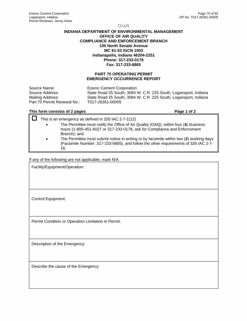
Essroc Cement Corporation Page 75 of 82 Logansport, Indiana OP No. T017-26351-00005 Permit Reviewer: Jenny Acker
Draft INDIANA DEPARTMENT OF ENVIRONMENTAL MANAGEMENT
OFFICE OF AIR QUALITY COMPLIANCE AND ENFORCEMENT BRANCH
100 North Senate Avenue MC 61-53 IGCN 1003
Indianapolis, Indiana 46204-2251 Phone: 317-233-0178
Fax: 317-233-6865
PART 70 OPERATING PERMIT EMERGENCY OCCURRENCE REPORT
Source Name: Essroc Cement Corporation Source Address: State Road 25 South, 3084 W. C.R. 225 South, Logansport, Indiana Mailing Address: State Road 25 South, 3084 W. C.R. 225 South, Logansport, Indiana Part 70 Permit Renewal No.: T017-26351-00005 This form consists of 2 pages Page 1 of 2
This is an emergency as defined in 326 IAC 2-7-1(12) • The Permittee must notify the Office of Air Quality (OAQ), within four (4) business
hours (1-800-451-6027 or 317-233-0178, ask for Compliance and Enforcement Branch); and
• The Permittee must submit notice in writing or by facsimile within two (2) working days (Facsimile Number: 317-233-6865), and follow the other requirements of 326 IAC 2-7-16.
If any of the following are not applicable, mark N/A
Facility/Equipment/Operation: Control Equipment: Permit Condition or Operation Limitation in Permit: Description of the Emergency: Describe the cause of the Emergency:

Essroc Cement Corporation Page 76 of 82 Logansport, Indiana OP No. T017-26351-00005 Permit Reviewer: Jenny Acker
Draft If any of the following are not applicable, mark N/A Page 2 of 2
Date/Time Emergency started: Date/Time Emergency was corrected: Was the facility being properly operated at the time of the emergency? Y N Describe: Type of Pollutants Emitted: TSP, PM-10, SO2, VOC, NOX, CO, Pb, other: Estimated amount of pollutant(s) emitted during emergency: Describe the steps taken to mitigate the problem: Describe the corrective actions/response steps taken: Describe the measures taken to minimize emissions: If applicable, describe the reasons why continued operation of the facilities are necessary to prevent imminent injury to persons, severe damage to equipment, substantial loss of capital investment, or loss of product or raw materials of substantial economic value:
Form Completed by:
Title / Position:
Date:
Phone:
A certification is not required for this report.

Essroc Cement Corporation Page 77 of 82 Logansport, Indiana OP No. T017-26351-00005 Permit Reviewer: Jenny Acker
Draft INDIANA DEPARTMENT OF ENVIRONMENTAL MANAGEMENT
OFFICE OF AIR QUALITY COMPLIANCE AND ENFORCEMENT BRANCH
Part 70 Quarterly Report for Use When Combusting Only Coal
Source Name: Essroc Cement Corporation Source Address: State Road 25 South, 3084 W. C.R. 225 South, Logansport, Indiana Mailing Address: State Road 25 South, 3084 W. C.R. 225 South, Logansport, Indiana Part 70 Permit Renewal No.: T017-26351-00005 Facility: Kilns #1 and 2 Parameter: Sulfur Dioxide (SO2) emissions from the combustion of coal Limit: 6.0 pounds per million Btu heat input
FACILITY: YEAR:
Month
Monthly Average
Coal Sulfur Content (%)
Monthly Average
Coal Heat Content (MMBtu/lb)
Coal
Consumption (tons)
Equivalent Sulfur
Dioxide Emissions (lbs/MMBtu)
No deviation occurred in this quarter.
Deviation/s occurred in this quarter. Deviation has been reported on:
Submitted by: Title / Position: Signature: Date: Phone:
Attach a signed certification to complete this report.

Essroc Cement Corporation Page 78 of 82 Logansport, Indiana OP No. T017-26351-00005 Permit Reviewer: Jenny Acker
Draft
INDIANA DEPARTMENT OF ENVIRONMENTAL MANAGEMENT OFFICE OF AIR QUALITY
COMPLIANCE AND ENFORCEMENT BRANCH
Part 70 Quarterly Report for Use When Combusting Only Fuel Oil
Source Name: Essroc Cement Corporation Source Address: State Road 25 South, 3084 W. C.R. 225 South, Logansport, Indiana Mailing Address: State Road 25 South, 3084 W. C.R. 225 South, Logansport, Indiana Part 70 Permit Renewal No.: T017-26351-00005 Facility: Kilns #1 and 2 Parameter: Sulfur Dioxide (SO2) emissions from fuel oil combustion Limit: 0.5 pounds per million Btu heat input
FACILITY: YEAR:
Month
Monthly Average
Fuel Oil Sulfur Content
(%)
Monthly Average
Fuel Oil Heat Content (MMBtu/lb)
Fuel Oil
Consumption (Gallons)
Equivalent Sulfur
Dioxide Emissions (lbs/MMBtu)
No deviation occurred in this quarter.
Deviation/s occurred in this quarter. Deviation has been reported on:
Submitted by: Title / Position: Signature: Date: Phone:
Attach a signed certification to complete this report.

Essroc Cement Corporation Page 79 of 82 Logansport, Indiana OP No. T017-26351-00005 Permit Reviewer: Jenny Acker
Draft INDIANA DEPARTMENT OF ENVIRONMENTAL MANAGEMENT
OFFICE OF AIR QUALITY COMPLIANCE AND ENFORCEMENT BRANCH
Part 70 Quarterly Report for Use When Combusting Coal and Fuel Oil
Simultaneously
Source Name: Essroc Cement Corporation Source Address: State Road 25 South, 3084 W. C.R. 225 South, Logansport, Indiana Mailing Address: State Road 25 South, 3084 W. C.R. 225 South, Logansport, Indiana Part 70 Permit Renewal No.: T017-26351-00005 Facility: Kilns #1 and 2 Parameter: Sulfur Dioxide (SO2) emissions from the simultaneous combustion of coal
and oil Limit: 6.0 pounds per million Btu heat input Compliance with the SO2 limit shall be determined using the following equation: SO2 emissions (lbs/MMBtu) = (Fuel oil usage x EF coefficient x fuel oil sulfur content + coal usage x EF coefficient x coal sulfur content) / (fuel oil usage x HHV oil + coal usage x HHV coal).
FACILITY: YEAR:
Monthly Average Sulfur Content
(%)
Monthly Average
Heat Content (MMBtu/lb)
Fuel
Consumption
Equivalent Sulfur Dioxide
Emissions (lbs/MMBtu)
Month
Coal
Fuel Oil
Coal
Fuel Oil
Coal (tons)
Fuel Oil (gallons)
Coal
Fuel Oil
Total
No deviation occurred in this quarter.
Deviation/s occurred in this quarter.
Deviation has been reported on:
Submitted by: Title / Position: Signature: Date: Phone: Attach a signed certification to complete this report.

Essroc Cement Corporation Page 80 of 82 Logansport, Indiana OP No. T017-26351-00005 Permit Reviewer: Jenny Acker
Draft
INDIANA DEPARTMENT OF ENVIRONMENTAL MANAGEMENT OFFICE OF AIR QUALITY
COMPLIANCE AND ENFORCEMENT BRANCH
Part 70 Quarterly Report for CKD Throughput EU902 to EU904
Source Name: Essroc Cement Corporation Source Address: State Road 25 South, 3084 W. C.R. 225 South, Logansport, Indiana Mailing Address: State Road 25 South, 3084 W. C.R. 225 South, Logansport, Indiana Part 70 Permit Renewal No.: T017-26351-00005 Facility: CKD2FM recycling storage tank system (EU902) CKD2FM #1 FM (EU903) and CKD2FM #2 FM (EU904) Parameter: Cement Kiln Dust (CKD) throughput Limit: 65,000 tons per twelve (12) consecutive month period for EU902. 65,000 tons per twelve (12) consecutive month period for EU903 and
EU904 combined. FACILITY: YEAR:
Monthly CKD throughput (tons)
CKD2FM recycling storage tank system (EU902)
CKD2FM #1 FM (EU903) and
CKD2FM #2 FM (EU904) (Combined)
This Month Previous 11 Months 12 Month Total This Month Previous 11
Months 12 Month Total
No deviation occurred in this quarter.
Deviation/s occurred in this quarter. Deviation has been reported on:
Submitted by: Title / Position: Signature: Date: Phone:
Attach a signed certification to complete this report.

Essroc Cement Corporation Page 81 of 82 Logansport, Indiana OP No. T017-26351-00005 Permit Reviewer: Jenny Acker
Draft INDIANA DEPARTMENT OF ENVIRONMENTAL MANAGEMENT
OFFICE OF AIR QUALITY COMPLIANCE AND ENFORCEMENT BRANCH
PART 70 OPERATING PERMIT
QUARTERLY DEVIATION AND COMPLIANCE MONITORING REPORT Source Name: Essroc Cement Corporation Source Address: State Road 25 South, 3084 W. C.R. 225 South, Logansport, Indiana Mailing Address: State Road 25 South, 3084 W. C.R. 225 South, Logansport, Indiana Part 70 Permit Renewal No.: T017-26351-00005
Months: ___________ to ____________ Year: ______________
Page 1 of 2 This report shall be submitted quarterly based on a calendar year. Any deviation from the requirements, the date(s) of each deviation, the probable cause of the deviation, and the response steps taken must be reported. Deviations that are required to be reported by an applicable requirement shall be reported according to the schedule stated in the applicable requirement and do not need to be included in this report. Additional pages may be attached if necessary. If no deviations occurred, please specify in the box marked “No deviations occurred this reporting period”.
NO DEVIATIONS OCCURRED THIS REPORTING PERIOD.
THE FOLLOWING DEVIATIONS OCCURRED THIS REPORTING PERIOD Permit Requirement (specify permit condition #) Date of Deviation:
Duration of Deviation:
Number of Deviations: Probable Cause of Deviation: Response Steps Taken: Permit Requirement (specify permit condition #) Date of Deviation:
Duration of Deviation:
Number of Deviations: Probable Cause of Deviation: Response Steps Taken:

Essroc Cement Corporation Page 82 of 82 Logansport, Indiana OP No. T017-26351-00005 Permit Reviewer: Jenny Acker
Draft Page 2 of 2
Permit Requirement (specify permit condition #) Date of Deviation:
Duration of Deviation:
Number of Deviations: Probable Cause of Deviation: Response Steps Taken: Permit Requirement (specify permit condition #) Date of Deviation:
Duration of Deviation:
Number of Deviations: Probable Cause of Deviation: Response Steps Taken: Permit Requirement (specify permit condition #) Date of Deviation:
Duration of Deviation:
Number of Deviations: Probable Cause of Deviation: Response Steps Taken:
Form Completed By:
Title/Position:
Date:
Phone:
Attach a signed certification to complete this report.

Page 1 of 3 DRAFT
Indiana Department of Environmental Management Office of Air Quality
Attachment A
Title 40: Protection of Environment PART 60—STANDARDS OF PERFORMANCE FOR NEW STATIONARY SOURCES
Subpart Y—Standards of Performance for Coal Preparation Plants
§ 60.250 Applicability and designation of affected facility.
(a) The provisions of this subpart are applicable to any of the following affected facilities in coal preparation plants which process more than 181 Mg (200 tons) per day: Thermal dryers, pneumatic coal-cleaning equipment (air tables), coal processing and conveying equipment (including breakers and crushers), coal storage systems, and coal transfer and loading systems.
(b) Any facility under paragraph (a) of this section that commences construction or modification after October 24, 1974, is subject to the requirements of this subpart.
[42 FR 37938, July 25, 1977; 42 FR 44812, Sept. 7, 1977, as amended at 65 FR 61757, Oct. 17, 2000]
§ 60.251 Definitions.
As used in this subpart, all terms not defined herein have the meaning given them in the Act and in subpart A of this part.
(a) Coal preparation plant means any facility (excluding underground mining operations) which prepares coal by one or more of the following processes: breaking, crushing, screening, wet or dry cleaning, and thermal drying.
(b) Bituminous coal means solid fossil fuel classified as bituminous coal by ASTM Designation D388–77, 90, 91, 95, or 98a (incorporated by reference—see §60.17).
(c) Coal means all solid fossil fuels classified as anthracite, bituminous, subbituminous, or lignite by ASTM Designation D388–77, 90, 91, 95, or 98a (incorporated by reference—see §60.17).
(d) Cyclonic flow means a spiraling movement of exhaust gases within a duct or stack.
(e) Thermal dryer means any facility in which the moisture content of bituminous coal is reduced by contact with a heated gas stream which is exhausted to the atmosphere.
(f) Pneumatic coal-cleaning equipment means any facility which classifies bituminous coal by size or separates bituminous coal from refuse by application of air stream(s).
(g) Coal processing and conveying equipment means any machinery used to reduce the size of coal or to separate coal from refuse, and the equipment used to convey coal to or remove coal and refuse from the machinery. This includes, but is not limited to, breakers, crushers, screens, and conveyor belts.
(h) Coal storage system means any facility used to store coal except for open storage piles.
(i) Transfer and loading system means any facility used to transfer and load coal for shipment.
[41 FR 2234, Jan. 15, 1976, as amended at 48 FR 3738, Jan. 27, 1983; 65 FR 61757, Oct. 17, 2000]
Essroc Cement Corporation Attachment A Page 2 of 3 Logansport, Indiana 40 CFR 60, Subpart Y First OP Renewal No. 017-26351-00005 Permit Reviewer: Jenny Acker DRAFT § 60.252 Standards for particulate matter.
(a) On and after the date on which the performance test required to be conducted by §60.8 is completed, an owner or operator subject to the provisions of this subpart shall not cause to be discharged into the atmosphere from any thermal dryer gases which:
(1) Contain particulate matter in excess of 0.070 g/dscm (0.031 gr/dscf).
(2) Exhibit 20 percent opacity or greater.
(b) On and after the date on which the performance test required to be conducted by §60.8 is completed, an owner or operator subject to the provisions of this subpart shall not cause to be discharged into the atmosphere from any pneumatic coal cleaning equipment, gases which:
(1) Contain particulate matter in excess of 0.040 g/dscm (0.017 gr/dscf).
(2) Exhibit 10 percent opacity or greater.
(c) On and after the date on which the performance test required to be conducted by §60.8 is completed, an owner or operator subject to the provisions of this subpart shall not cause to be discharged into the atmosphere from any coal processing and conveying equipment, coal storage system, or coal transfer and loading system processing coal, gases which exhibit 20 percent opacity or greater.
[41 FR 2234, Jan. 15, 1976, as amended at 65 FR 61757, Oct. 17, 2000]
§ 60.253 Monitoring of operations.
(a) The owner or operator of any thermal dryer shall install, calibrate, maintain, and continuously operate monitoring devices as follows:
(1) A monitoring device for the measurement of the temperature of the gas stream at the exit of the thermal dryer on a continuous basis. The monitoring device is to be certified by the manufacturer to be accurate within ±1.7 °C (±3 °F).
(2) For affected facilities that use venturi scrubber emission control equipment:
(i) A monitoring device for the continuous measurement of the pressure loss through the venturi constriction of the control equipment. The monitoring device is to be certified by the manufacturer to be accurate within ±1 inch water gauge.
(ii) A monitoring device for the continuous measurement of the water supply pressure to the control equipment. The monitoring device is to be certified by the manufacturer to be accurate within ±5 percent of design water supply pressure. The pressure sensor or tap must be located close to the water discharge point. The Administrator may be consulted for approval of alternative locations.
(b) All monitoring devices under paragraph (a) of this section are to be recalibrated annually in accordance with procedures under §60.13(b).
[41 FR 2234, Jan. 15, 1976, as amended at 54 FR 6671, Feb. 14, 1989; 65 FR 61757, Oct. 17, 2000]
§ 60.254 Test methods and procedures.
(a) In conducting the performance tests required in §60.8, the owner or operator shall use as reference methods and procedures the test methods in appendix A of this part or other methods and procedures as specified in this section, except as provided in §60.8(b).

Essroc Cement Corporation Attachment A Page 3 of 3 Logansport, Indiana 40 CFR 60, Subpart Y First OP Renewal No. 017-26351-00005 Permit Reviewer: Jenny Acker DRAFT (b) The owner or operator shall determine compliance with the particular matter standards in §60.252 as follows:
(1) Method 5 shall be used to determine the particulate matter concentration. The sampling time and sample volume for each run shall be at least 60 minutes and 0.85 dscm (30 dscf). Sampling shall begin no less than 30 minutes after startup and shall terminate before shutdown procedures begin.
(2) Method 9 and the procedures in §60.11 shall be used to determine opacity.
[54 FR 6671, Feb. 14, 1989]
This document was downloaded from the following source on May 5, 2008: Subpart Y--STANDARDS OF PERFORMANCE FOR COAL PREPARATION PLANTS

Page 1 of 20 DRAFT
Indiana Department of Environmental Management Office of Air Quality
Attachment B
Title 40: Protection of Environment PART 61—NATIONAL EMISSION STANDARDS FOR HAZARDOUS AIR POLLUTANTS
Subpart V—National Emission Standard for Equipment Leaks (Fugitive Emission Sources)
Source: 49 FR 23513, June 6, 1984, unless otherwise noted.
§ 61.240 Applicability and designation of sources.
(a) The provisions of this subpart apply to each of the following sources that are intended to operate in volatile hazardous air pollutant (VHAP) service: pumps, compressors, pressure relief devices, sampling connection systems, open-ended valves or lines, valves, connectors, surge control vessels, bottoms receivers, and control devices or systems required by this subpart.
(b) The provisions of this subpart apply to the sources listed in paragraph (a) after the date of promulgation of a specific subpart in part 61.
(c) While the provisions of this subpart are effective, a source to which this subpart applies that is also subject to the provisions of 40 CFR part 60 only will be required to comply with the provisions of this subpart.
(d) Alternative means of compliance —(1) Option to comply with part 65. Owners or operators may choose to comply with 40 CFR part 65 to satisfy the requirements of §§61.242–1 through 61.247 for equipment that is subject to this subpart and that is part of the same process unit. When choosing to comply with 40 CFR part 65, the requirements of §§61.245(d) and 61.246(i) and (j) still apply. Other provisions applying to owners or operators who choose to comply with 40 CFR part 65 are provided in 40 CFR 65.1.
(2) Part 65, subpart C or F. For owners or operators choosing to comply with 40 CFR part 65, each surge control vessel and bottoms receiver subject to this subpart that meets the conditions specified in table 1 or table 2 of this subpart shall meet the requirements for storage vessels in 40 CFR part 65, subpart C; all other equipment subject to this subpart shall meet the requirements in 40 CFR part 65, subpart F.
(3) Part 61, subpart A. Owners or operators who choose to comply with 40 CFR part 65, subpart C or F, must also comply with §§61.01, 61.02, 61.05 through 61.08, 61.10(b) through (d), 61.11, and 61.15 for that equipment. All sections and paragraphs of subpart A of this part that are not mentioned in this paragraph (d)(3) do not apply to owners or operators of equipment subject to this subpart complying with 40 CFR part 65, subpart C or F, except that provisions required to be met prior to implementing 40 CFR part 65 still apply. Owners and operators who choose to comply with 40 CFR part 65, subpart C or F, must comply with 40 CFR part 65, subpart A.
(4) Rules referencing this subpart. Owners or operators referenced to this subpart from subpart F or J of this part may choose to comply with 40 CFR part 65 for all equipment listed in paragraph (a) of this section.
[49 FR 23513, June 6, 1984, as amended at 65 FR 78280, Dec. 14, 2000]
§ 61.241 Definitions.
As used in this subpart, all terms not defined herein shall have the meaning given them in the Act, in subpart A of part 61, or in specific subparts of part 61; and the following terms shall have specific meaning given them:
Bottoms receiver means a tank that collects distillation bottoms before the stream is sent for storage or for further downstream processing.

Essroc Cement Corporation Attachment B Page 2 of 20 Logansport, Indiana 40 CFR 61, Subpart V First OP Renewal No. 017-26351-00005 Permit Reviewer: Jenny Acker DRAFT Closed-vent system means a system that is not open to atmosphere and that is composed of hard-piping, ductwork, connections, and, if necessary, flow-inducing devices that transport gas or vapor from a piece or pieces of equipment to a control device or back to a process.
Connector means flanged, screwed, welded, or other joined fittings used to connect two pipe lines or a pipe line and a piece of equipment. For the purpose of reporting and recordkeeping, connector means flanged fittings that are not covered by insulation or other materials that prevent location of the fittings.
Control device means an enclosed combustion device, vapor recovery system, or flare.
Double block and bleed system means two block valves connected in series with a bleed valve or line that can vent the line between the two block valves.
Duct work means a conveyance system such as those commonly used for heating and ventilation systems. It is often made of sheet metal and often has sections connected by screws or crimping. Hard-piping is not ductwork.
Equipment means each pump, compressor, pressure relief device, sampling connection system, open-ended valve or line, valve, connector, surge control vessel, bottoms receiver in VHAP service, and any control devices or systems required by this subpart.
First attempt at repair means to take rapid action for the purpose of stopping or reducing leakage of organic material to atmosphere using best practices.
In gas/vapor service means that a piece of equipment contains process fluid that is in the gaseous state at operating conditions.
Fuel gas means gases that are combusted to derive useful work or heat.
Fuel gas system means the offsite and onsite piping and flow and pressure control system that gathers gaseous stream(s) generated by onsite operations, may blend them with other sources of gas, and transports the gaseous stream for use as fuel gas in combustion devices or in-process combustion equipment, such as furnaces and gas turbines, either singly or in combination.
Hard-piping means pipe or tubing that is manufactured and properly installed using good engineering judgement and standards such as ASME B31.3, Process Piping (available from the American Society of Mechanical Engineers, PO Box 2900, Fairfield, NJ 07007–2900).
In liquid service means that a piece of equipment is not in gas/vapor service.
In-situ sampling systems means nonextractive samplers or in-line samplers.
In vacuum service means that equipment is operating at an internal pressure which is at least 5 kilopascals (kPa) (0.7 psia) below ambient pressure.
In VHAP service means that a piece of equipment either contains or contacts a fluid (liquid or gas) that is at least 10 percent by weight a volatile hazardous air pollutant (VHAP) as determined according to the provisions of §61.245(d). The provisions of §61.245(d) also specify how to determine that a piece of equipment is not in VHAP service.
In VOC service means, for the purposes of this subpart, that (a) the piece of equipment contains or contacts a process fluid that is at least 10 percent VOC by weight (see 40 CFR 60.2 for the definition of volatile organic compound or VOC and 40 CFR 60.485(d) to determine whether a piece of equipment is not in VOC service) and (b) the piece of equipment is not in heavy liquid service as defined in 40 CFR 60.481.
Maximum true vapor pressure means the equilibrium partial pressure exerted by the total VHAP in the stored or transferred liquid at the temperature equal to the highest calendar-month average of the liquid storage or transfer temperature for liquids stored or transferred above or below the ambient temperature or at the local maximum

Essroc Cement Corporation Attachment B Page 3 of 20 Logansport, Indiana 40 CFR 61, Subpart V First OP Renewal No. 017-26351-00005 Permit Reviewer: Jenny Acker DRAFT monthly average temperature as reported by the National Weather Service for liquids stored or transferred at the ambient temperature, as determined:
(1) In accordance with methods described in American Petroleum Institute Publication 2517, Evaporative Loss From External Floating-Roof Tanks (incorporated by reference as specified in §61.18); or
(2) As obtained from standard reference texts; or
(3) As determined by the American Society for Testing and Materials Method D2879–83, Standard Test Method for Vapor Pressure-Temperature Relationship and Initial Decomposition Temperature of Liquids by Isoteniscope (incorporated by reference as specified in §61.18); or
(4) Any other method approved by the Administrator.
Open-ended valve or line means any valve, except pressure relief valves, having one side of the valve seat in contact with process fluid and one side open to atmosphere, either directly or through open piping.
Pressure release means the emission of materials resulting from the system pressure being greater than the set pressure of the pressure relief device.
Process unit means equipment assembled to produce a VHAP or its derivatives as intermediates or final products, or equipment assembled to use a VHAP in the production of a product. A process unit can operate independently if supplied with sufficient feed or raw materials and sufficient product storage facilities.
Process unit shutdown means a work practice or operational procedure that stops production from a process unit or part of a process unit. An unscheduled work practice or operational procedure that stops production from a process unit or part of a process unit for less than 24 hours is not a process unit shutdown. The use of spare equipment and technically feasible bypassing of equipment without stopping production are not process unit shutdowns.
Repaired means that equipment is adjusted, or otherwise altered, to eliminate a leak.
Sampling connection system means an assembly of equipment within a process unit used during periods of representative operation to take samples of the process fluid. Equipment used to take non-routine grab samples is not considered a sampling connection system.
Semiannual means a 6-month period; the first semiannual period concludes on the last day of the last month during the 180 days following initial startup for new sources; and the first semiannual period concludes on the last day of the last full month during the 180 days after the effective date of a specific subpart that references this subpart for existing sources.
Sensor means a device that measures a physical quantity or the change in a physical quantity, such as temperature, pressure, flow rate, pH, or liquid level.
Stuffing box pressure means the fluid (liquid or gas) pressure inside the casing or housing of a piece of equipment, on the process side of the inboard seal.
Surge control vessel means feed drums, recycle drums, and intermediate vessels. Surge control vessels are used within a process unit when in-process storage, mixing, or management of flow rates of volumes is needed on a recurring or ongoing basis to assist in production of a product.
Volatile hazardous air pollutant or VHAP means a substance regulated under this part for which a standard for equipment leaks of the substance has been proposed and promulgated. Benzene is a VHAP. Vinyl chloride is a VHAP.
[49 FR 23513, June 6, 1984; 49 FR 38946, Oct. 2, 1984, as amended at 51 FR 34915, Sept. 30, 1986; 54 FR 38076, Sept. 14, 1989; 65 FR 62158, Oct. 17, 2000; 65 FR 78280, Dec. 14, 2000]

Essroc Cement Corporation Attachment B Page 4 of 20 Logansport, Indiana 40 CFR 61, Subpart V First OP Renewal No. 017-26351-00005 Permit Reviewer: Jenny Acker DRAFT § 61.242-1 Standards: General.
(a) Each owner or operator subject to the provisions of this subpart shall demonstrate compliance with the requirements of §§61.242–1 to 61.242–11 for each new and existing source as required in 40 CFR 61.05, except as provided in §§61.243 and 61.244.
(b) Compliance with this subpart will be detemined by review of records, review of performance test results, and inspection using the methods and procedures specified in §61.245.
(c)(1) An owner or operator may request a determination of alternative means of emission limitation to the requirements of §§61.242–2, 61.242–3, 61.242–5, 61.242–6, 61.242–7, 61.242–8, 61.242–9 and 61.242–11 as provided in §61.244.
(2) If the Administrator makes a determination that a means of emission limitation is at least a permissible alternative to the requirements of §61.242–2, 61.242–3, 61.242–5, 61.242–6, 61.242–7, 61.242–8, 61.242–9 or 61.242–11, an owner or operator shall comply with the requirements of that determination.
(d) Each piece of equipment to which this subpart applies shall be marked in such a manner that it can be distinquished readily from other pieces of equipment.
(e) Equipment that is in vacuum service is excluded from the requirements of §61.242–2, to §61.242–11 if it is identified as required in §61.246(e)(5).
[49 FR 23513, June 6, 1984; 49 FR 38946, Oct. 2, 1984]
§ 61.242-2 Standards: Pumps.
(a)(1) Each pump shall be monitored monthly to detect leaks by the methods specified in §61.245(b), except as provided in §61.242–1(c) and paragraphs (d), (e), (f) and (g) of this section.
(2) Each pump shall be checked by visual inspection each calendar week for indications of liquids dripping from the pump seal.
(b)(1) If an instrument reading of 10,000 ppm or greater is measured, a leak is detected.
(2) If there are indications of liquids dripping from the pump seal, a leak is detected.
(c)(1) When a leak is detected, it shall be repaired as soon as practicable, but not later than 15 calendar days after it is detected, except as provided in §61.242–10.
(2) A first attempt at repair shall be made no later than 5 calendar days after each leak is detected.
(d) Each pump equipped with a dual mechanical seal system that includes a barrier fluid system is exempt from the requirements of paragraphs (a) and (b) of this section, provided the following requirements are met:
(1) Each dual mechanical seal system is:
(i) Operated with the barrier fluid at a pressure that is at all times greater than the pump stuffing box pressure; or
(ii) Equipped with a barrier fluid degassing reservoir that is routed to a process or fuel gas system or connected by a closed-vent system to a control device that complies with the requirements of §61.242–11; or
(iii) Equipped with a system that purges the barrier fluid into a process stream with zero VHAP emissions to atmosphere.
Essroc Cement Corporation Attachment B Page 5 of 20 Logansport, Indiana 40 CFR 61, Subpart V First OP Renewal No. 017-26351-00005 Permit Reviewer: Jenny Acker DRAFT (2) The barrier fluid is not in VHAP service and, if the pump is covered by standards under 40 CFR part 60, is not in VOC service.
(3) Each barrier fluid system is equipped with a sensor that will detect failure of the seal system, the barrier fluid system, or both.
(4) Each pump is checked by visual inspection each calendar week for indications of liquids dripping from the pump seal.
(i) If there are indications of liquid dripping from the pump seal at the time of the weekly inspection, the pump shall be monitored as specified in §61.245 to determine the presence of VOC and VHAP in the barrier fluid.
(ii) If the monitor reading (taking into account any background readings) indicates the presence of VHAP, a leak is detected. For the purpose of this paragraph, the monitor may be calibrated with VHAP, or may employ a gas chromatography column to limit the response of the monitor to VHAP, at the option of the owner or operator.
(iii) If an instrument reading of 10,000 ppm or greater (total VOC) is measured, a leak is detected.
(5) Each sensor as described in paragraph (d)(3) of this section is checked daily or is equipped with an audible alarm.
(6)(i) The owner or operator determines, based on design considerations and operating experience, criteria applicable to the presence and frequency of drips and to the sensor that indicates failure of the seal system, the barrier fluid system, or both.
(ii) If indications of liquids dripping from the pump seal exceed the criteria established in paragraph (d)(6)(i) of this section, or if, based on the criteria established in paragraph (d)(6)(i) of this section, the sensor indicates failure of the seal system, the barrier fluid system, or both, a leak is detected.
(iii) When a leak is detected, it shall be repaired as soon as practicable, but no later than 15 calendar days after it is detected, except as provided in §61.242–10.
(iv) A first attempt at repair shall be made no later than five calendar days after each leak is detected.
(e) Any pump that is designated, as described in §61.246(e)(2), for no detectable emissions, as indicated by an instrument reading of less than 500 ppm above background, is exempt from the requirements of paragraphs (a), (c), and (d) if the pump:
(1) Has no externally actuated shaft penetrating the pump housing,
(2) Is demonstrated to be operating with no detectable emissions, as indicated by an instrument reading of less than 500 ppm above background, as measured by the method specified in §61.245(c), and
(3) Is tested for compliance with paragraph (e)(2) initially upon designation, annually, and at other times requested by the Administrator.
(f) If any pump is equipped with a closed-vent system capable of capturing and transporting any leakage from the seal or seals to a process or fuel gas system or to a control device that complies with the requirements of §61.242–11, it is exempt from the requirements of paragraphs (a) through (e) of this section.
(g) Any pump that is designated, as described in §61.246(f)(1), as an unsafe-to-monitor pump is exempt from the monitoring and inspection requirements of paragraphs (a) and (d)(4) through (6) of this section if:
(1) The owner or operator of the pump demonstrates that the pump is unsafe-to-monitor because monitoring personnel would be exposed to an immediate danger as a consequence of complying with paragraph (a) of this section; and

Essroc Cement Corporation Attachment B Page 6 of 20 Logansport, Indiana 40 CFR 61, Subpart V First OP Renewal No. 017-26351-00005 Permit Reviewer: Jenny Acker DRAFT (2) The owner or operator of the pump has a written plan that requires monitoring of the pump as frequently as practicable during safe-to-monitor times but not more frequently than the periodic monitoring schedule otherwise applicable, and repair of the equipment according to the procedures in paragraph (c) of this section if a leak is detected.
(h) Any pump that is located within the boundary of an unmanned plant site is exempt from the weekly visual inspection requirement of paragraphs (a)(2) and (d)(4) of this section, and the daily requirements of paragraph (d)(5) of this section, provided that each pump is visually inspected as often as practicable and at least monthly.
[49 FR 23513, June 6, 1984, as amended at 49 FR 38946, Oct. 2, 1984; 55 FR 28349, July 10, 1990; 65 FR 78281, Dec. 14, 2000]
§ 61.242-3 Standards: Compressors.
(a) Each compressor shall be equipped with a seal system that includes a barrier fluid system and that prevents leakage of process fluid to atmosphere, except as provided in §61.242–1(c) and paragraphs (h) and (i) of this section.
(b) Each compressor seal system as required in paragraph (a) shall be:
(1) Operated with the barrier fluid at a pressure that is greater than the compressor stuffing box pressure; or
(2) Equipped with a barrier fluid system degassing reservoir that is routed to a process or fuel gas system or connected by a closed-vent system to a control device that complies with the requirements of §61.242–11; or
(3) Equipped with a system that purges the barrier fluid into a process stream with zero VHAP emissions to atmosphere.
(c) The barrier fluid shall not be in VHAP service and, if the compressor is covered by standards under 40 CFR part 60, shall not be in VOC service.
(d) Each barrier fluid system as described in paragraphs (a)–(c) of this section shall be equipped with a sensor that will detect failure of the seal system, barrier fluid system, or both.
(e)(1) Each sensor as required in paragraph (d) of this section shall be checked daily or shall be equipped with an audible alarm unless the compressor is located within the boundary of an unmanned plant site.
(2) The owner or operator shall determine, based on design considerations and operating experience, a criterion that indicates failure of the seal system, the barrier fluid system, or both.
(f) If the sensor indicates failure of the seal system, the barrier fluid system, or both based on the criterion determined under paragraph (e)(2) of this section, a leak is detected.
(g)(1) When a leak is detected, it shall be repaired as soon as practicable, but not later than 15 calendar days after it is detected, except as provided in §61.242–10.
(2) A first attempt at repair shall be made no later than 5 calendar days after eack leak is detected.
(h) A compressor is exempt from the requirements of paragraphs (a) and (b) of this section if it is equipped with a closed-vent system to capture and transport leakage from the compressor drive shaft back to a process or fuel gas system or to a control device that complies with the requirements of §61.242–11, except as provided in paragraph (i) of this section.
(i) Any Compressor that is designated, as described in §61.246(e)(2), for no detectable emission as indicated by an instrument reading of less than 500 ppm above background is exempt from the requirements of paragraphs (a)–(h) if the compressor:

Essroc Cement Corporation Attachment B Page 7 of 20 Logansport, Indiana 40 CFR 61, Subpart V First OP Renewal No. 017-26351-00005 Permit Reviewer: Jenny Acker DRAFT (1) Is demonstrated to be operating with no detectable emissions, as indicated by an instrument reading of less than 500 ppm above background, as measured by the method specified in §61.245(c); and
(2) Is tested for compliance with paragraph (i)(1) initially upon designation, annually, and at other times requested by the Administrator.
[49 FR 23513, June 6, 1984; 49 FR 38946, Oct. 2, 1984, as amended at 65 FR 78281, Dec. 14, 2000]
§ 61.242-4 Standards: Pressure relief devices in gas/vapor service.
(a) Except during pressure releases, each pressure relief device in gas/vapor service shall be operated with no detectable emissions, as indicated by an instrument reading of less than 500 ppm above background, as measured by the method specified in §61.245(c).
(b)(1) After each pressure release, the pressure relief device shall be returned to a condition of no detectable emissions, as indicated by an instrument reading of less than 500 ppm above background, as soon as practicable, but no later than 5 calendar days after each pressure release, except as provided in §61.242–10.
(2) No later than 5 calendar days after the pressure release, the pressure relief device shall be monitored to confirm the condition of no detectable emissions, as indicated by an instrument reading of less than 500 ppm above background, as measured by the method specified in §61.245(c).
(c) Any pressure relief device that is routed to a process or fuel gas system or equipped with a closed-vent system capable of capturing and transporting leakage from the pressure relief device to a control device as described in §61.242–11 is exempt from the requirements of paragraphs (a) and (b) of this section.
(d)(1) Any pressure relief device that is equipped with a rupture disk upstream of the pressure relief device is exempt from the requirements of paragraphs (a) and (b) of this section, provided the owner or operator complies with the requirements in paragraph (d)(2) of this section.
(2) After each pressure release, a new rupture disk shall be installed upstream of the pressure relief device as soon as practicable, but no later than 5 calendar days after each pressure release, except as provided in §61.242–10.
[49 FR 23513, June 6, 1984; 49 FR 38946, Oct. 2, 1984, as amended at 65 FR 78281, Dec. 14, 2000]
§ 61.242-5 Standards: Sampling connecting systems.
(a) Each sampling connection system shall be equipped with a closed-purge, closed-loop, or closed vent system, except as provided in §61.242–1(c). Gases displaced during filling of the sample container are not required to be collected or captured.
(b) Each closed-purge, closed-loop, or closed vent system as required in paragraph (a) of this section shall comply with the requirements specified in paragraphs (b)(1) through (4) of this section:
(1) Return the purged process fluid directly to the process line; or
(2) Collect and recycle the purged process fluid; or
(3) Be designed and operated to capture and transport all the purged process fluid to a control device that complies with the requirements of §61.242–11; or
(4) Collect, store, and transport the purged process fluid to any of the following systems or facilities:
(i) A waste management unit as defined in 40 CFR 63.111 if the waste management unit is subject to and operated in compliance with the provisions of 40 CFR part 63, subpart G, applicable to Group 1 wastewater streams; or

Essroc Cement Corporation Attachment B Page 8 of 20 Logansport, Indiana 40 CFR 61, Subpart V First OP Renewal No. 017-26351-00005 Permit Reviewer: Jenny Acker DRAFT (ii) A treatment, storage, or disposal facility subject to regulation under 40 CFR part 262, 264, 265, or 266; or
(iii) A facility permitted, licensed, or registered by a State to manage municipal or industrial solid waste, if the process fluids are not hazardous waste as defined in 40 CFR part 261.
(c) In-situ sampling systems and sampling systems without purges are exempt from the requirements of paragraphs (a) and (b) of this section.
[65 FR 78281, Dec. 14, 2000]
§ 61.242-6 Standards: Open-ended valves or lines.
(a)(1) Each open-ended valve or line shall be equipped with a cap, blind flange, plug, or a second valve, except as provided in §61.242–1(c).
(2) The cap, blind flange, plug, or second valve shall seal the open end at all times except during operations requiring process fluid flow through the open-ended valve or line.
(b) Each open-ended valve or line equipped with a second valve shall be operated in a manner such that the valve on the process fluid end is closed before the second valve is closed.
(c) When a double block and bleed system is being used, the bleed valve or line may remain open during operations that require venting the line between the block valves but shall comply with paragraph (a) at all other times.
(d) Open-ended valves or lines in an emergency shutdown system which are designed to open automatically in the event of a process upset are exempt from the requirements of paragraphs (a), (b) and (c) of this section.
(e) Open-ended valves or lines containing materials which would autocatalytically polymerize or would present an explosion, serious overpressure, or other safety hazard if capped or equipped with a double block and bleed system as specified in paragraphs (a) through (c) of this section are exempt from the requirements of paragraphs (a) through (c) of this section.
[49 FR 23513, June 6, 1984, as amended at 65 FR 78282, Dec. 14, 2000]
§ 61.242-7 Standards: Valves.
(a) Each valve shall be monitored monthly to detect leaks by the method specified in §61.245(b) and shall comply with paragraphs (b)–(e), except as provided in paragraphs (f), (g), and (h) of this section, §61.243–1 or §61.243–2, and §61.242–1(c).
(b) If an instrument reading of 10,000 ppm or greater is measured, a leak is detected.
(c)(1) Any valve for which a leak is not detected for 2 successive months may be monitored the first month of every quarter, beginning with the next quarter, until a leak is detected.
(2) If a leak is detected, the valve shall be monitored monthly until a leak is not detected for 2 successive months.
(d)(1) When a leak is detected, it shall be repaired as soon as practicable, but no later than 15 calendar days after the leak is detected, except as provided in §61.242–10.
(2) A first attempt at repair shall be made no later than 5 calendar days after each leak is detected.
(e) First attempts at repair include, but are not limited to, the following best practices where practicable:
(1) Tightening of bonnet bolts;

Essroc Cement Corporation Attachment B Page 9 of 20 Logansport, Indiana 40 CFR 61, Subpart V First OP Renewal No. 017-26351-00005 Permit Reviewer: Jenny Acker DRAFT (2) Replacement of bonnet bolts;
(3) Tightening of packing gland nuts; and
(4) Injection of lubricant into lubricated packing.
(f) Any valve that is designated, as described in §61.246(e)(2), for no detectable emissions, as indicated by an instrument reading of less than 500 ppm above background, is exempt from the requirements of paragraph (a) if the valve:
(1) Has no external actuating mechanism in contact with the process fluid;
(2) Is operated with emissions less than 500 ppm above background, as measured by the method specified in §61.245(c); and
(3) Is tested for compliance with paragraph (f)(2) initially upon designation, annually, and at other times requested by the Administrator.
(g) Any valve that is designated, as described in §61.246(f)(1), as an unsafe-to-monitor valve is exempt from the requirements of paragraph (a) if:
(1) The owner or operator of the valve demonstrates that the valve is unsafe to monitor because monitoring personnel would be exposed to an immediate danger as a consequence of complying with paragraph (a); and
(2) The owner or operator of the valve has a written plan that requires monitoring of the valve as frequent as practicable during safe-to-monitor times.
(h) Any valve that is designated, as described in §61.246(f)(2), as a difficult-to-monitor valve is exempt from the requirements of paragraph (a) if:
(1) The owner or operator of the valve demonstrates that the valve cannot be monitored without elevating the monitoring personnel more than 2 meters above a support surface;
(2) The process unit within which the valve is located is an existing process unit; and
(3) The owner or operator of the valve follows a written plan that requires monitoring of the valve at least once per calendar year.
§ 61.242-8 Standards: Pressure relief services in liquid service and connectors.
(a) If evidence of a potential leak is found by visual, audible, olfactory, or any other detection method at pressure relief devices in liquid service and connectors, the owner or operator shall follow either one of the following procedures, except as provided in §61.242–1(c):
(1) The owner or operator shall monitor the equipment within 5 days by the method specified in §61.245(b) and shall comply with the requirements of paragraphs (b) through (d) of this section.
(2) The owner or operator shall eliminate the visual, audible, olfactory, or other indication of a potential leak.
(b) If an instrument reading of 10,000 ppm or greater is measured, a leak is detected.
(c)(1) When a leak is detected, it shall be repaired as soon as practicable, but not later than 15 calendar days after it is detected, except as provided in §61.242–10.
(2) The first attempt at repair shall be made no later than 5 calendar days after each leak is detected.

Essroc Cement Corporation Attachment B Page 10 of 20 Logansport, Indiana 40 CFR 61, Subpart V First OP Renewal No. 017-26351-00005 Permit Reviewer: Jenny Acker DRAFT (d) First attempts at repair include, but are not limited to, the best practices described under §61.242–7(e).
[49 FR 23513, June 6, 1984; 49 FR 38946, Oct. 2, 1984, as amended at 65 FR 78282, Dec. 14, 2000]
§ 61.242-9 Standards: Surge control vessels and bottoms receivers.
Each surge control vessel or bottoms receiver that is not routed back to the process and that meets the conditions specified in table 1 or table 2 of this subpart shall be equipped with a closed-vent system capable of capturing and transporting any leakage from the vessel back to the process or to a control device as described in §61.242–11, except as provided in §61.242–1(c); or comply with the requirements of 40 CFR 63.119(b) or (c).
[65 FR 78282, Dec. 14, 2000]
§ 61.242-10 Standards: Delay of repair.
(a) Delay of repair of equipment for which leaks have been detected will be allowed if repair within 15 days is technically infeasible without a process unit shutdown. Repair of this equipment shall occur before the end of the next process unit shutdown.
(b) Delay of repair of equipment for which leaks have been detected will be allowed for equipment that is isolated from the process and that does not remain in VHAP service.
(c) Delay of repair for valves will be allowed if:
(1) The owner or operator demonstrates that emissions of purged material resulting from immediate repair are greater than the fugitive emissions likely to result from delay of repair, and
(2) When repair procedures are effected, the purged material is collected and destroyed or recovered in a control device complying with §61.242–11.
(d) Delay of repair for pumps will be allowed if:
(1) Repair requires the use of a dual mechanical seal system that includes a barrier fluid system, and
(2) Repair is completed as soon as practicable, but not later than 6 months after the leak was detected.
(e) Delay of repair beyond a process unit shutdown will be allowed for a valve if valve assembly replacement is necessary during the process unit shutdown, valve assembly supplies have been depleted, and valve assembly supplies had been sufficiently stocked before the supplies were depleted. Delay of repair beyond the next process unit shutdown will not be allowed unless the next process unit shutdown occurs sooner than 6 months after the first process unit shutdown.
[49 FR 23513, June 6, 1984, as amended at 65 FR 78282, Dec. 14, 2000]
§ 61.242-11 Standards: Closed-vent systems and control devices.
(a) Owners or operators of closed-vent systems and control devices used to comply with provisions of this subpart shall comply with the provisions of this section, except as provided in §61.242–1(c).
(b) Vapor recovery systems (for example, condensers and absorbers) shall be designed and operated to recover the organic vapors vented to them with an efficiency of 95 percent or greater, or to an exit concentration of 20 parts per million by volume, whichever is less stringent.
(c) Enclosed combustion devices shall be designed and operated to reduce the VHAP emissions vented to them with an efficiency of 95 percent or greater, or to an exit concentration of 20 parts per million by volume, on a dry basis,

Essroc Cement Corporation Attachment B Page 11 of 20 Logansport, Indiana 40 CFR 61, Subpart V First OP Renewal No. 017-26351-00005 Permit Reviewer: Jenny Acker DRAFT corrected to 3 percent oxygen, whichever is less stringent, or to provide a minimum residence time of 0.50 seconds at a minimum temperature of 760 °C.
(d) Flares shall used to comply with this subpart shall comply with the requirements of §60.18.
(e) Owners or operators of control devices that are used to comply with the provisions of this supbart shall monitor these control devices to ensure that they are operated and maintained in conformance with their design.
(f) Except as provided in paragraphs (i) through (k) of this section, each closed vent system shall be inspected according to the procedures and schedule specified in paragraph (f)(1) or (2) of this section, as applicable.
(1) If the vapor collection system or closed vent system is constructed of hard-piping, the owner or operator shall comply with the following requirements:
(i) Conduct an initial inspection according to the procedures in §61.245(b); and
(ii) Conduct annual visual inspections for visible, audible, or olfactory indications of leaks.
(2) If the vapor collection system or closed vent system is constructed of ductwork, the owner or operator shall:
(i) Conduct an initial inspection according to the procedures in §61.245(b); and
(ii) Conduct annual inspections according to the procedures in §61.245(b).
(g) Leaks, as indicated by an instrument reading greater than 500 parts per million by volume above background or by visual inspections, shall be repaired as soon as practicable except as provided in paragraph (h) of this section.
(1) A first attempt at repair shall be made no later than 5 calendar days after the leak is detected.
(2) Repair shall be completed no later than 15 calendar days after the leak is detected.
(h) Delay of repair of a closed vent system for which leaks have been detected is allowed if the repair is technically infeasible without a process unit shutdown, or if the owner or operator determines that emissions resulting from immediate repair would be greater than the fugitive emissions likely to result from delay of repair. Repair of such equipment shall be complete by the end of the next process unit shutdown.
(i) If a vapor collection system or closed vent system is operated under a vacuum, it is exempt from the inspection requirements of paragraphs (f)(1)(i) and (2) of this section.
(j) Any parts of the closed vent system that are designated, as described in paragraph (l)(1) of this section, as unsafe-to-inspect are exempt from the inspection requirements of paragraphs (f)(1)(i) and (2) of this section if they comply with the following requirements:
(1) The owner or operator determines that the equipment is unsafe-to-inspect because inspecting personnel would be exposed to an imminent or potential danger as a consequence of complying with paragraph (f)(1)(i) or (2) of this section; and
(2) The owner or operator has a written plan that requires inspection of the equipment as frequently as practicable during safe-to-inspect times.
(k) Any parts of the closed vent system that are designated, as described in paragraph (l)(2) of this section, as difficult-to-inspect are exempt from the inspection requirements of paragraphs (f)(1)(i) and (2) of this section if they comply with the following requirements:

Essroc Cement Corporation Attachment B Page 12 of 20 Logansport, Indiana 40 CFR 61, Subpart V First OP Renewal No. 017-26351-00005 Permit Reviewer: Jenny Acker DRAFT (1) The owner or operator determines that the equipment cannot be inspected without elevating the inspecting personnel more than 2 meters above a support surface; and
(2) The owner or operator has a written plan that requires inspection of the equipment at least once every 5 years. A closed vent system is exempt from inspection if it is operated under a vacuum.
(l) The owner or operator shall record the following information:
(1) Identification of all parts of the closed vent system that are designated as unsafe-to-inspect, an explanation of why the equipment is unsafe-to-inspect, and the plan for inspecting the equipment.
(2) Identification of all parts of the closed vent system that are designated as difficult-to-inspect, an explanation of why the equipment is difficult-to-inspect, and the plan for inspecting the equipment.
(3) For each inspection during which a leak is detected, a record of the information specified in §61.246(c).
(4) For each inspection conducted in accordance with §61.245(b) during which no leaks are detected, a record that the inspection was performed, the date of the inspection, and a statement that no leaks were detected.
(5) For each visual inspection conducted in accordance with paragraph (f)(1)(ii) of this section during which no leaks are detected, a record that the inspection was performed, the date of the inspection, and a statement that no leaks were detected.
(m) Closed vent systems and control devices used to comply with provisions of this subpart shall be operated at all times when emissions may be vented to them.
[49 FR 23513, June 6, 1984; 49 FR 38946, Oct. 2, 1984, as amended at 51 FR 2702, Jan. 21, 1986; 65 FR 62158, Oct. 17, 2000; 65 FR 78282, Dec. 14, 2000]
§ 61.243-1 Alternative standards for valves in VHAP service—allowable percentage of valves leaking.
(a) An owner or operator may elect to have all valves within a process unit to comply with an allowable percentage of valves leaking of equal to or less than 2.0 percent.
(b) The following requirements shall be met if an owner or operator decides to comply with an allowable percentage of valves leaking:
(1) An owner or operator must notify the Administrator that the owner or operator has elected to have all valves within a process unit to comply with the allowable percentage of valves leaking before implementing this alternative standard, as specified in §61.247(d).
(2) A performance test as specified in paragraph (c) of this section shall be conducted initially upon designation, annually, and at other times requested by the Administrator.
(3) If a valve leak is detected, it shall be repaired in accordance with §61.242–7(d) and (e).
(c) Performance tests shall be conducted in the following manner:
(1) All valves in VHAP service within the process unit shall be monitored within 1 week by the methods specified in §61.245(b).
(2) If an instrument reading of 10,000 ppm or greater is measured, a leak is detected.
(3) The leak percentage shall be determined by dividing the number of valves in VHAP service for which leaks are detected by the number of valves in VHAP service within the process unit.

Essroc Cement Corporation Attachment B Page 13 of 20 Logansport, Indiana 40 CFR 61, Subpart V First OP Renewal No. 017-26351-00005 Permit Reviewer: Jenny Acker DRAFT (d) Owner or operators who elect to have all valves comply with this alternative standard shall not have a process unit with a leak percentage greater than 2.0 percent.
(e) If an owner or operator decides no longer to comply with §61.243–1, the owner or operator must notify the Administrator in writing that the work practice standard described in §61.242–7(a)-(e) will be followed.
§ 61.243-2 Alternative standards for valves in VHAP service—skip period leak detection and repair.
(a)(1) An owner or operator may elect for all valves within a process unit to comply with one of the alternative work practices specified in paragraphs (b)(2) and (3) of this section.
(2) An owner or operator must notify the Administrator before implementing one of the alternative work practices, as specified in §61.247(d).
(b)(1) An owner or operator shall comply initially with the requirements for valves, as described in §61.242–7.
(2) After 2 consecutive quarterly leak detection periods with the percentage of valves leaking equal to or less than 2.0, an owner or operator may begin to skip one of the quarterly leak detection periods for the valves in VHAP service.
(3) After five consecutive quarterly leak detection periods with the percentage of valves leaking equal to or less than 2.0, an owner or operator may begin to skip three of the quarterly leak detection periods for the valves in VHAP service.
(4) If the percentage of valves leaking is greater than 2.0, the owner or operator shall comply with the requirements as described in §61.242–7 but may again elect to use this section.
[49 FR 23513, June 6, 1984, as amended at 65 FR 62158, Oct. 17, 2000]
§ 61.244 Alternative means of emission limitation.
(a) Permission to use an alternative means of emission limitation under section 112(e)(3) of the Clean Air Act shall be governed by the following procedures:
(b) Where the standard is an equipment, design, or operational requirement:
(1) Each owner or operator applying for permission shall be responsible for collecting and verifying test data for an alternative means of emission limitation to test data for the equipment, design, and operational requirements.
(2) The Administrator may condition the permission on requirements that may be necessary to assure operation and maintenance to achieve the same emission reduction as the equipment, design, and operational requirements.
(c) Where the standard is a work practice:
(1) Each owner or operator applying for permission shall be responsible for collecting and verifying test data for an alternative means of emission limitation.
(2) For each source for which permission is requested, the emission reduction achieved by the required work practices shall be demonstrated for a minimum period of 12 months.
(3) For each source for which permission is requested, the emission reduction achieved by the alternative means of emission limitation shall be demonstrated.
(4) Each owner or operator applying for permission shall commit in writing each source to work practices that provide for emission reductions equal to or greater than the emission reductions achieved by the required work practices.

Essroc Cement Corporation Attachment B Page 14 of 20 Logansport, Indiana 40 CFR 61, Subpart V First OP Renewal No. 017-26351-00005 Permit Reviewer: Jenny Acker DRAFT (5) The Administrator will compare the demonstrated emission reduction for the alternative means of emission limitation to the demonstrated emission reduction for the required work practices and will consider the commitment in paragraph (c)(4).
(6) The Administrator may condition the permission on requirements that may be necessary to assure operation and maintenance to achieve the same emission reduction as the required work practices of this subpart.
(d) An owner or operator may offer a unique approach to demonstrate the alternative means of emission limitation.
(e)(1) Manufacturers of equipment used to control equipment leaks of a VHAP may apply to the Administrator for permission for an alternative means of emission limitation that achieves a reduction in emissions of the VHAP achieved by the equipment, design, and operational requirements of this subpart.
(2) The Administrator will grant permission according to the provisions of paragraphs (b), (c), and (d).
[49 FR 23513, June 6, 1984, as amended at 65 FR 62158, Oct. 17, 2000]
§ 61.245 Test methods and procedures.
(a) Each owner or operator subject to the provisions of this subpart shall comply with the test methods and procedures requirements provided in this section.
(b) Monitoring, as required in §§61.242, 61.243, 61.244, and 61.135, shall comply with the following requirements:
(1) Monitoring shall comply with Method 21 of appendix A of 40 CFR part 60.
(2) The detection instrument shall meet the performance criteria of Method 21.
(3) The instrument shall be calibrated before use on each day of its use by the procedures specified in Method 21.
(4) Calibration gases shall be:
(i) Zero air (less than 10 ppm of hydrocarbon in air); and
(ii) A mixture of methane or n-hexane and air at a concentration of approximately, but less than, 10,000 ppm methane or n-hexane.
(5) The instrument probe shall be traversed around all potential leak interfaces as close to the interface as possible as described in Method 21.
(c) When equipment is tested for compliance with or monitored for no detectable emissions, the owner or operator shall comply with the following requirements:
(1) The requirements of paragraphs (b) (1) through (4) shall apply.
(2) The background level shall be determined, as set forth in Method 21.
(3) The instrument probe shall be traversed around all potential leak interfaces as close to the interface as possible as described in Method 21.
(4) The arithmetic difference between the maximum concentration indicated by the instrument and the background level is compared with 500 ppm for determining compliance.
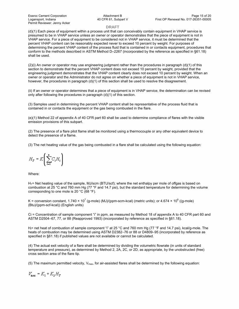
Essroc Cement Corporation Attachment B Page 15 of 20 Logansport, Indiana 40 CFR 61, Subpart V First OP Renewal No. 017-26351-00005 Permit Reviewer: Jenny Acker DRAFT (d)(1) Each piece of equipment within a process unit that can conceivably contain equipment in VHAP service is presumed to be in VHAP service unless an owner or operator demonstrates that the piece of equipment is not in VHAP service. For a piece of equipment to be considered not in VHAP service, it must be determined that the percent VHAP content can be reasonably expected never to exceed 10 percent by weight. For purposes of determining the percent VHAP content of the process fluid that is contained in or contacts equipment, procedures that conform to the methods described in ASTM Method D–2267 (incorporated by the reference as specified in §61.18) shall be used.
(2)(i) An owner or operator may use engineering judgment rather than the procedures in paragraph (d)(1) of this section to demonstrate that the percent VHAP content does not exceed 10 percent by weight, provided that the engineering judgment demonstrates that the VHAP content clearly does not exceed 10 percent by weight. When an owner or operator and the Administrator do not agree on whether a piece of equipment is not in VHAP service, however, the procedures in paragraph (d)(1) of this section shall be used to resolve the disagreement.
(ii) If an owner or operator determines that a piece of equipment is in VHAP service, the determination can be revised only after following the procedures in paragraph (d)(1) of this section.
(3) Samples used in determining the percent VHAP content shall be representative of the process fluid that is contained in or contacts the equipment or the gas being combusted in the flare.
(e)(1) Method 22 of appendix A of 40 CFR part 60 shall be used to determine compliance of flares with the visible emission provisions of this subpart.
(2) The presence of a flare pilot flame shall be monitored using a thermocouple or any other equivalent device to detect the presence of a flame.
(3) The net heating value of the gas being combusted in a flare shall be calculated using the following equation:
Where:
HT= Net heating value of the sample, MJ/scm (BTU/scf); where the net enthalpy per mole of offgas is based on combustion at 25 °C and 760 mm Hg (77 °F and 14.7 psi), but the standard temperature for determining the volume corresponding to one mole is 20 °C (68 °F).
K = conversion constant, 1.740 × 10⁷ (g-mole) (MJ)/(ppm-scm-kcal) (metric units); or 4.674 × 10⁸ ((g-mole) (Btu)/(ppm-scf-kcal)) (English units)
Ci = Concentration of sample component “i” in ppm, as measured by Method 18 of appendix A to 40 CFR part 60 and ASTM D2504–67, 77, or 88 (Reapproved 1993) (incorporated by reference as specified in §61.18).
Hi= net heat of combustion of sample component “i” at 25 °C and 760 mm Hg (77 °F and 14.7 psi), kcal/g-mole. The heats of combustion may be determined using ASTM D2382–76 or 88 or D4809–95 (incorporated by reference as specified in §61.18) if published values are not available or cannot be calculated.
(4) The actual exit velocity of a flare shall be determined by dividing the volumetric flowrate (in units of standard temperature and pressure), as determined by Method 2, 2A, 2C, or 2D, as appropriate, by the unobstructed (free) cross section area of the flare tip.
(5) The maximum permitted velocity, Vmax, for air-assisted flares shall be determined by the following equation:

Essroc Cement Corporation Attachment B Page 16 of 20 Logansport, Indiana 40 CFR 61, Subpart V First OP Renewal No. 017-26351-00005 Permit Reviewer: Jenny Acker DRAFT Where:
Vmax= Maximum permitted velocity, m/sec (ft/sec).
HT= Net heating value of the gas being combusted, as determined in paragraph (e)(3) of this section, MJ/scm (Btu/scf).
K1= 8.706 m/sec (metric units)
= 28.56 ft/sec (English units)
K2= 0.7084 m4 /(MJ-sec) (metric units)
= 0.087 ft4 /(Btu-sec) (English units)
[49 FR 23513, June 6, 1984, as amended at 49 FR 38946, Oct. 2, 1984; 49 FR 43647, Oct. 31, 1984; 53 FR 36972, Sept. 23, 1988; 54 FR 38077, Sept. 14, 1989; 65 FR 62158, Oct. 17, 2000]
§ 61.246 Recordkeeping requirements.
(a)(1) Each owner or operator subject to the provisions of this subpart shall comply with the recordkeeping requirements of this section.
(2) An owner or operator of more than one process unit subject to the provisions of this subpart may comply with the recordkeeping requirements for these process units in one recordkeeping system if the system identifies each record by each process unit.
(b) When each leak is detected as specified in §§61.242–2, 61.242–3, 61.242–7, 61.242–8, and 61.135, the following requirements apply:
(1) A weatherproof and readily visible identification, marked with the equipment identification number, shall be attached to the leaking equipment.
(2) The identification on a valve may be removed after it has been monitored for 2 successive months as specified in §61.242–7(c) and no leak has been detected during those 2 months.
(3) The identification on equipment, except on a valve, may be removed after it has been repaired.
(c) When each leak is detected as specified in §§61.242–2, 61.242–3. 61.242–7, 61.242–8, and 61.135, the following information shall be recorded in a log and shall be kept for 2 years in a readily accessible location:
(1) The instrument and operator identification numbers and the equipment identification number.
(2) The date the leak was detected and the dates of each attempt to repair the leak.
(3) Repair methods applied in each attempt to repair the leak.
(4) “Above 10,000” if the maximum instrument reading measured by the methods specified in §61.245(a) after each repair attempt is equal to or greater than 10,000 ppm.
(5) “Repair delayed” and the reason for the delay if a leak is not repaired within 15 calendar days after discovery of the leak.

Essroc Cement Corporation Attachment B Page 17 of 20 Logansport, Indiana 40 CFR 61, Subpart V First OP Renewal No. 017-26351-00005 Permit Reviewer: Jenny Acker DRAFT (6) The signature of the owner or operator (or designate) whose decision it was that repair could not be effected without a process shutdown.
(7) The expected date of successful repair of the leak if a leak is not repaired within 15 calendar days.
(8) Dates of process unit shutdowns that occur while the equipment is unrepaired.
(9) The date of successful repair of the leak.
(d) The following information pertaining to the design requirements for closed-vent systems and control devices described in §61.242–11 shall be recorded and kept in a readily accessible location:
(1) Detailed schematics, design specifications, and piping and instrumentation diagrams.
(2) The dates and descriptions of any changes in the design specifications.
(3) A description of the parameter or parameters monitored, as required in §61.242–11(e), to ensure that control devices are operated and maintained in conformance with their design and an explanation of why that parameter (or parameters) was selected for the monitoring.
(4) Periods when the closed-vent systems and control devices required in §§61.242–2, 61.242–3, 61.242–4, 61.242–5 and 61.242–9 are not operated as designed, including periods when a flare pilot light does not have a flame.
(5) Dates of startups and shutdowns of the closed-vent systems and control devices required in §§61.242–2, 61.242–3, 61.242–4, 61.242–5 and 61.242–9.
(e) The following information pertaining to all equipment to which a standard applies shall be recorded in a log that is kept in a readily accessible location:
(1) A list of identification numbers for equipment (except welded fittings) subject to the requirements of this subpart.
(2)(i) A list of identification numbers for equipment that the owner or operator elects to designate for no detectable emissions as indicated by an instrument reading of less than 500 ppm above background.
(ii) The designation of this equipment for no detectable emissions shall be signed by the owner or operator.
(3) A list of equipment identification numbers for pressure relief devices required to comply with §61.242–4(a).
(4)(i) The dates of each compliance test required in §§61.242–2(e), 61.242–3(i), 61.242–4, 61.242–7(f), and 61.135(g).
(ii) The background level measured during each compliance test.
(iii) The maximum instrument reading measured at the equipment during each compliance test.
(5) A list of identification numbers for equipment in vacuum service.
(f) The following information pertaining to all valves subject to the requirements of §61.242–7(g) and (h) and to all pumps subject to the requirements of §61.242–2(g) shall be recorded in a log that is kept in a readily accessible location:
(1) A list of identification numbers for valves and pumps that are designated as unsafe to monitor, an explanation for each valve or pump stating why the valve or pump is unsafe to monitor, and the plan for monitoring each valve or pump.
Essroc Cement Corporation Attachment B Page 18 of 20 Logansport, Indiana 40 CFR 61, Subpart V First OP Renewal No. 017-26351-00005 Permit Reviewer: Jenny Acker DRAFT (2) A list of identification numbers for valves that are designated as difficult to monitor, an explanation for each valve stating why the valve is difficult to monitor, and the planned schedule for monitoring each valve.
(g) The following information shall be recorded for valves complying with §61.243–2:
(1) A schedule of monitoring.
(2) The percent of valves found leaking during each monitoring period.
(h) The following information shall be recorded in a log that is kept in a readily accessible location:
(1) Design criterion required in §§61.242–2(d)(5), 61.242–3(e)(2), and 61.135(e)(4) and an explanation of the design criterion; and
(2) Any changes to this criterion and the reasons for the changes.
(i) The following information shall be recorded in a log that is kept in a readily accessible location for use in determining exemptions as provided in the applicability section of this subpart and other specific subparts:
(1) An analysis demonstrating the design capacity of the process unit, and
(2) An analysis demonstrating that equipment is not in VHAP service.
(j) Information and data used to demonstrate that a piece of equipment is not in VHAP service shall be recorded in a log that is kept in a readily accessible location.
[49 FR 23513, June 6, 1984, as amended at 49 FR 38946, Oct. 2, 1984; 54 FR 38077, Sept. 14, 1989; 65 FR 78283, Dec. 14, 2000]
§ 61.247 Reporting requirements.
(a)(1) An owner or operator of any piece of equipment to which this subpart applies shall submit a statement in writing notifying the Administrator that the requirements of §§61.242, 61.245, 61.246, and 61.247 are being implemented.
(2) In the case of an existing source or a new source which has an initial startup date preceding the effective date, the statement is to be submitted within 90 days of the effective date, unless a waiver of compliance is granted under §61.11, along with the information required under §61.10. If a waiver of compliance is granted, the statement is to be submitted on a date scheduled by the Administrator.
(3) In the case of new sources which did not have an initial startup date preceding December 14, 2000, the statement required under paragraph (a)(1) of this section shall be submitted with the application for approval of construction, as described in §61.07.
(4) For owners and operators complying with 40 CFR part 65, subpart C or F, the statement required under paragraph (a)(1) of this section shall notify the Administrator that the requirements of 40 CFR part 65, subpart C or F, are being implemented.
(5) The statement is to contain the following information for each source:
(i) Equipment identification number and process unit identification.
(ii) Type of equipment (for example, a pump or pipeline valve).
(iii) Percent by weight VHAP in the fluid at the equipment.

Essroc Cement Corporation Attachment B Page 19 of 20 Logansport, Indiana 40 CFR 61, Subpart V First OP Renewal No. 017-26351-00005 Permit Reviewer: Jenny Acker DRAFT (iv) Process fluid state at the equipment (gas/vapor or liquid).
(v) Method of compliance with the standard (for example, “monthly leak detection and repair” or “equipped with dual mechanical seals”).
(b) A report shall be submitted to the Administrator semiannually starting 6 months after the initial report required in paragraph (a) of this section, that includes the following information:
(1) Process unit identification.
(2) For each month during the semiannual reporting period,
(i) Number of valves for which leaks were detected as described in §61.242–7(b) of §61.243–2.
(ii) Number of valves for which leaks were not repaired as required in §61.242–7(d).
(iii) Number of pumps for which leaks were detected as described in §61.242–2 (b) and (d)(6).
(iv) Number of pumps for which leaks were not repaired as required in §61.242–2 (c) and (d)(6).
(v) Number of compressors for which leaks were detected as described in §61.242–3(f).
(vi) Number of compressors for which leaks were not repaired as required in §61.242–3(g).
(vii) The facts that explain any delay of repairs and, where appropriate, why a process unit shutdown was technically infeasible.
(3) Dates of process unit shutdowns which occurred within the semiannual reporting period.
(4) Revisions to items reported according to paragraph (a) if changes have occurred since the initial report or subsequent revisions to the initial report.
Note: Compliance with the requirements of §61.10(c) is not required for revisions documented under this paragraph.
(5) The results of all performance tests and monitoring to determine compliance with no detectable emissions and with §§61.243–1 and 61.243–2 conducted within the semiannual reporting period.
(c) In the first report submitted as required in paragraph (a) of this section, the report shall include a reporting schedule stating the months that semiannual reports shall be submitted. Subsequent reports shall be submitted according to that schedule, unless a revised schedule has been submitted in a previous semiannual report.
(d) An owner or operator electing to comply with the provisions of §§61.243–1 and 61.243–2 shall notify the Administrator of the alternative standard selected 90 days before implementing either of the provisions.
(e) An application for approval of construction or modification, §§61.05(a) and 61.07, will not be required if—
(1) The new source complies with the standard, §61.242;
(2) The new source is not part of the construction of a process unit; and
(3) In the next semiannual report required by paragraph (b) of this section, the information in paragraph (a)(5) of this section is reported.

Essroc Cement Corporation Attachment B Page 20 of 20 Logansport, Indiana 40 CFR 61, Subpart V First OP Renewal No. 017-26351-00005 Permit Reviewer: Jenny Acker DRAFT (f) For owners or operators choosing to comply with 40 CFR part 65, subpart C or F, an application for approval of construction or modification, as required under §§61.05 and 61.07 will not be required if:
(1) The new source complies with 40 CFR 65.106 through 65.115 and with 40 CFR part 65, subpart C, for surge control vessels and bottoms receivers;
(2) The new source is not part of the construction of a process unit; and
(3) In the next semiannual report required by 40 CFR 65.120(b) and 65.48(b), the information in paragraph (a)(5) of this section is reported.
[49 FR 23513, June 6, 1984, as amended at 49 FR 38947, Oct. 2, 1984; 54 FR 38077, Sept. 14, 1989; 65 FR 78283, Dec. 14, 2000]
Table 1 to Subpart V of Part 61—Surge Control Vessels and Bottoms Receivers at Existing Sources
Vessel capacity (cubic meters)
Vapor pressure1
(kilopascals)
75 ≤ capacity < 151 ≥ 13.1
151 ≤ capacity ≥ 5.2
1Maximum true vapor pressure as defined in §61.241.
[65 FR 78283, Dec. 14, 2000]
Table 2 to Subpart V of Part 61—Surge Control Vessels and Bottoms Receivers at New Sources
Vessel capacity (cubic meters)
Vapor pressure1
(kilopascals)
38 ≤ capacity < 151 ≥ 13.1
151 ≤ capacity ≥ 0.7
1Maximum true vapor pressure as defined in §61.241.
[65 FR 78283, Dec. 14, 2000]
This document was downloaded from the following source on January 16, 2009: Subpart V--NATIONAL EMISSION STANDARD FOR EQUIPMENT LEAKS (FUGITIVE EMISSION SOURCES)

Page 1 of 191 DRAFT
Indiana Department of Environmental Management Office of Air Quality
Attachment C
Title 40: Protection of Environment PART 61—NATIONAL EMISSION STANDARDS FOR HAZARDOUS AIR POLLUTANTS
Browse Previous
Subpart FF—National Emission Standard for Benzene Waste Operations
Source: 55 FR 8346, Mar. 7, 1990, unless otherwise noted.
§ 61.340 Applicability.
(a) The provisions of this subpart apply to owners and operators of chemical manufacturing plants, coke by-product recovery plants, and petroleum refineries.
(b) The provisions of this subpart apply to owners and operators of hazardous waste treatment, storage, and disposal facilities that treat, store, or dispose of hazardous waste generated by any facility listed in paragraph (a) of this section. The waste streams at hazardous waste treatment, storage, and disposal facilities subject to the provisions of this subpart are the benzene-containing hazardous waste from any facility listed in paragraph (a) of this section. A hazardous waste treatment, storage, and disposal facility is a facility that must obtain a hazardous waste management permit under subtitle C of the Solid Waste Disposal Act.
(c) At each facility identified in paragraph (a) or (b) of this section, the following waste is exempt from the requirements of this subpart:
(1) Waste in the form of gases or vapors that is emitted from process fluids:
(2) Waste that is contained in a segregated stormwater sewer system.
(d) At each facility identified in paragraph (a) or (b) of this section, any gaseous stream from a waste management unit, treatment process, or wastewater treatment system routed to a fuel gas system, as defined in §61.341, is exempt from this subpart. No testing, monitoring, recordkeeping, or reporting is required under this subpart for any gaseous stream from a waste management unit, treatment process, or wastewater treatment unit routed to a fuel gas system.
[55 FR 8346, Mar. 7, 1990, as amended at 55 FR 37231, Sept. 10, 1990; 58 FR 3095, Jan. 7, 1993; 67 FR 68531, Nov. 12, 2002]
§ 61.341 Definitions.
Benzene concentration means the fraction by weight of benzene in a waste as determined in accordance with the procedures specified in §61.355 of this subpart.
Car-seal means a seal that is placed on a device that is used to change the position of a valve (e.g., from opened to closed) in such a way that the position of the valve cannot be changed without breaking the seal.
Chemical manufacturing plant means any facility engaged in the production of chemicals by chemical, thermal, physical, or biological processes for use as a product, co-product, by-product, or intermediate including but not limited to industrial organic chemicals, organic pesticide products, pharmaceutical preparations, paint and allied products, fertilizers, and agricultural chemicals. Examples of chemical manufacturing plants include facilities at which process units are operated to produce one or more of the following chemicals: benzenesulfonic acid, benzene,

Essroc Cement Corporation Attachment C Page 2 of 191 Logansport, Indiana 40 CFR 61, Subpart FF First OP Renewal No. 017-26351-00005 Permit Reviewer: Jenny Acker DRAFT chlorobenzene, cumene, cyclohexane, ethylene, ethylbenzene, hydroquinone, linear alklylbenzene, nitrobenzene, resorcinol, sulfolane, or styrene.
Closed-vent system means a system that is not open to the atmosphere and is composed of piping, ductwork, connections, and, if necessary, flow inducing devices that transport gas or vapor from an emission source to a control device.
Coke by-product recovery plant means any facility designed and operated for the separation and recovery of coal tar derivatives (by-products) evolved from coal during the coking process of a coke oven battery.
Container means any portable waste management unit in which a material is stored, transported, treated, or otherwise handled. Examples of containers are drums, barrels, tank trucks, barges, dumpsters, tank cars, dump trucks, and ships.
Control device means an enclosed combustion device, vapor recovery system, or flare.
Cover means a device or system which is placed on or over a waste placed in a waste management unit so that the entire waste surface area is enclosed and sealed to minimize air emissions. A cover may have openings necessary for operation, inspection, and maintenance of the waste management unit such as access hatches, sampling ports, and gauge wells provided that each opening is closed and sealed when not in use. Example of covers include a fixed roof installed on a tank, a lid installed on a container, and an air-supported enclosure installed over a waste management unit.
External floating roof means a pontoon-type or double-deck type cover with certain rim sealing mechanisms that rests on the liquid surface in a waste management unit with no fixed roof.
Facility means all process units and product tanks that generate waste within a stationary source, and all waste management units that are used for waste treatment, storage, or disposal within a stationary source.
Fixed roof means a cover that is mounted on a waste management unit in a stationary manner and that does not move with fluctuations in liquid level.
Floating roof means a cover with certain rim sealing mechanisms consisting of a double deck, pontoon single deck, internal floating cover or covered floating roof, which rests upon and is supported by the liquid being contained, and is equipped with a closure seal or seals to close the space between the roof edge and unit wall.
Flow indicator means a device which indicates whether gas flow is present in a line or vent system.
Fuel gas system means the offsite and onsite piping and control system that gathers gaseous streams generated by facility operations, may blend them with sources of gas, if available, and transports the blended gaseous fuel at suitable pressures for use as fuel in heaters, furnaces, boilers, incinerators, gas turbines, and other combustion devices located within or outside the facility. The fuel is piped directly to each individual combustion device, and the system typically operates at pressures over atmospheric.
Individual drain system means the system used to convey waste from a process unit, product storage tank, or waste management unit to a waste management unit. The term includes all process drains and common junction boxes, together with their associated sewer lines and other junction boxes, down to the receiving waste management unit.
Internal floating roof means a cover that rests or floats on the liquid surface inside a waste management unit that has a fixed roof.
Liquid-mounted seal means a foam or liquid-filled primary seal mounted in contact with the liquid between the waste management unit wall and the floating roof continuously around the circumference.
Loading means the introduction of waste into a waste management unit but not necessarily to complete capacity (also referred to as filling).

Essroc Cement Corporation Attachment C Page 3 of 191 Logansport, Indiana 40 CFR 61, Subpart FF First OP Renewal No. 017-26351-00005 Permit Reviewer: Jenny Acker DRAFT Maximum organic vapor pressure means the equilibrium partial pressure exerted by the waste at the temperature equal to the highest calendar-month average of the waste storage temperature for waste stored above or below the ambient temperature or at the local maximum monthly average temperature as reported by the National Weather Service for waste stored at the ambient temperature, as determined:
(1) In accordance with §60.17(c); or
(2) As obtained from standard reference texts; or
(3) In accordance with §60.17(a)(37); or
(4) Any other method approved by the Administrator.
No detectable emissions means less than 500 parts per million by volume (ppmv) above background levels, as measured by a detection instrument reading in accordance with the procedures specified in §61.355(h) of this subpart.
Oil-water separator means a waste management unit, generally a tank or surface impoundment, used to separate oil from water. An oil-water separator consists of not only the separation unit but also the forebay and other separator basins, skimmers, weirs, grit chambers, sludge hoppers, and bar screens that are located directly after the individual drain system and prior to additional treatment units such as an air flotation unit, clarifier, or biological treatment unit. Examples of an oil-water separator incude an API separator, parallel-plate interceptor, and corrugated-plate interceptor with the associated ancillary equipment.
Petroleum refinery means any facility engaged in producing gasoline, kerosene, distillate fuel oils, residual fuel oils, lubricants, or other products through the distillation of petroleum, or through the redistillation, cracking, or reforming of unfinished petroleum derivatives.
Petroleum means the crude oil removed from the earth and the oils derived from tar sands, shale, and coal.
Point of waste generation means the location where the waste stream exits the process unit component or storage tank prior to handling or treatment in an operation that is not an integral part of the production process, or in the case of waste management units that generate new wastes after treatment, the location where the waste stream exits the waste management unit component.
Process unit means equipment assembled and connected by pipes or ducts to produce intermediate or final products. A process unit can be operated independently if supplied with sufficient fuel or raw materials and sufficient product storage facilities.
Process unit turnaround means the shutting down of the operations of a process unit, the purging of the contents of the process unit, the maintenance or repair work, followed by restarting of the process.
Process unit turnaround waste means a waste that is generated as a result of a process unit turnaround.
Process wastewater means water which comes in contact with benzene during manufacturing or processing operations conducted within a process unit. Process wastewater is not organic wastes, process fluids, product tank drawdown, cooling tower blowdown, steam trap condensate, or landfill leachate.
Process wastewater stream means a waste stream that contains only process wastewater.
Product tank means a stationary unit that is designed to contain an accumulation of materials that are fed to or produced by a process unit, and is constructed primarily of non-earthen materials (e.g., wood, concrete, steel, plastic) which provide structural support.
Product tank drawdown means any material or mixture of materials discharged from a product tank for the purpose of removing water or other contaminants from the product tank.

Essroc Cement Corporation Attachment C Page 4 of 191 Logansport, Indiana 40 CFR 61, Subpart FF First OP Renewal No. 017-26351-00005 Permit Reviewer: Jenny Acker DRAFT Safety device means a closure device such as a pressure relief valve, frangible disc, fusible plug, or any other type of device which functions exclusively to prevent physical damage or permanent deformation to a unit or its air emission control equipment by venting gases or vapors directly to the atmosphere during unsafe conditions resulting from an unplanned, accidental, or emergency event. For the purpose of this subpart, a safety device is not used for routine venting of gases or vapors from the vapor headspace underneath a cover such as during filling of the unit or to adjust the pressure in this vapor headspace in response to normal daily diurnal ambient temperature fluctuations. A safety device is designed to remain in a closed position during normal operations and open only when the internal pressure, or another relevant parameter, exceeds the device threshold setting applicable to the air emission control equipment as determined by the owner or operator based on manufacturer recommendations, applicable regulations, fire protection and prevention codes, standard engineering codes and practices, or other requirements for the safe handling of flammable, ignitable, explosive, reactive, or hazardous materials.
Segregated stormwater sewer system means a drain and collection system designed and operated for the sole purpose of collecting rainfall runoff at a facility, and which is segregated from all other individual drain systems.
Sewer line means a lateral, trunk line, branch line, or other enclosed conduit used to convey waste to a downstream waste management unit.
Slop oil means the floating oil and solids that accumulate on the surface of an oil-water separator.
Sour water stream means a stream that:
(1) Contains ammonia or sulfur compounds (usually hydrogen sulfide) at concentrations of 10 ppm by weight or more;
(2) Is generated from separation of water from a feed stock, intermediate, or product that contained ammonia or sulfur compounds; and
(3) Requires treatment to remove the ammonia or sulfur compounds.
Sour water stripper means a unit that:
(1) Is designed and operated to remove ammonia or sulfur compounds (usually hydrogen sulfide) from sour water streams;
(2) Has the sour water streams transferred to the stripper through hard piping or other enclosed system; and
(3) Is operated in such a manner that the offgases are sent to a sulfur recovery unit, processing unit, incinerator, flare, or other combustion device.
Surface impoundment means a waste management unit which is a natural topographic depression, man-made excavation, or diked area formed primarily of earthen materials (although it may be lined with man-made materials), which is designed to hold an accumulation of liquid wastes or waste containing free liquids, and which is not an injection well. Examples of surface impoundments are holding, storage, settling, and aeration pits, ponds, and lagoons.
Tank means a stationary waste management unit that is designed to contain an accumulation of waste and is constructed primarily of nonearthen materials (e.g., wood, concrete, steel, plastic) which provide structural support.
Treatment process means a stream stripping unit, thin-film evaporation unit, waste incinerator, or any other process used to comply with §61.348 of this subpart.
Vapor-mounted seal means a foam-filled primary seal mounted continuously around the perimeter of a waste management unit so there is an annular vapor space underneath the seal. The annular vapor space is bounded by the bottom of the primary seal, the unit wall, the liquid surface, and the floating roof.

Essroc Cement Corporation Attachment C Page 5 of 191 Logansport, Indiana 40 CFR 61, Subpart FF First OP Renewal No. 017-26351-00005 Permit Reviewer: Jenny Acker DRAFT Waste means any material resulting from industrial, commercial, mining or agricultural operations, or from community activities that is discarded or is being accumulated, stored, or physically, chemically, thermally, or biologically treated prior to being discarded, recycled, or discharged.
Waste management unit means a piece of equipment, structure, or transport mechanism used in handling, storage, treatment, or disposal of waste. Examples of a waste management unit include a tank, surface impoundment, container, oil-water separator, individual drain system, steam stripping unit, thin-film evaporation unit, waste incinerator, and landfill.
Waste stream means the waste generated by a particular process unit, product tank, or waste management unit. The characteristics of the waste stream (e.g., flow rate, benzene concentration, water content) are determined at the point of waste generation. Examples of a waste stream include process wastewater, product tank drawdown, sludge and slop oil removed from waste management units, and landfill leachate.
Wastewater treatment system means any component, piece of equipment, or installation that receives, manages, or treats process wastewater, product tank drawdown, or landfill leachate prior to direct or indirect discharge in accordance with the National Pollutant Discharge Elimination System permit regulations under 40 CFR part 122. These systems typically include individual drain systems, oil-water separators, air flotation units, equalization tanks, and biological treatment units.
Water seal controls means a seal pot, p-leg trap, or other type of trap filled with water (e.g., flooded sewers that maintain water levels adequate to prevent air flow through the system) that creates a water barrier between the sewer line and the atmosphere. The water level of the seal must be maintained in the vertical leg of a drain in order to be considered a water seal.
[55 FR 8346, Mar. 7, 1990; 55 FR 12444, Apr. 3, 1990, as amended at 58 FR 3095, Jan. 7, 1993; 67 FR 68531, Nov. 12, 2002]
§ 61.342 Standards: General.
(a) An owner or operator of a facility at which the total annual benzene quantity from facility waste is less than 10 megagrams per year (Mg/yr) (11 ton/yr) shall be exempt from the requirements of paragraphs (b) and (c) of this section. The total annual benzene quantity from facility waste is the sum of the annual benzene quantity for each waste stream at the facility that has a flow-weighted annual average water content greater than 10 percent or that is mixed with water, or other wastes, at any time and the mixture has an annual average water content greater than 10 percent. The benzene quantity in a waste stream is to be counted only once without multiple counting if other waste streams are mixed with or generated from the original waste stream. Other specific requirements for calculating the total annual benzene waste quantity are as follows:
(1) Wastes that are exempted from control under §§61.342(c)(2) and 61.342(c)(3) are included in the calculation of the total annual benzene quantity if they have an annual average water content greater than 10 percent, or if they are mixed with water or other wastes at any time and the mixture has an annual average water content greater than 10 percent.
(2) The benzene in a material subject to this subpart that is sold is included in the calculation of the total annual benzene quantity if the material has an annual average water content greater than 10 percent.
(3) Benzene in wastes generated by remediation activities conducted at the facility, such as the excavation of contaminated soil, pumping and treatment of groundwater, and the recovery of product from soil or groundwater, are not included in the calculation of total annual benzene quantity for that facility. If the facility's total annual benzene quantity is 10 Mg/yr (11 ton/yr) or more, wastes generated by remediation activities are subject to the requirements of paragraphs (c) through (h) of this section. If the facility is managing remediation waste generated offsite, the benzene in this waste shall be included in the calculation of total annual benzene quantity in facility waste, if the waste streams have an annual average water content greater than 10 percent, or if they are mixed with water or other wastes at any time and the mixture has an annual average water content greater than 10 percent.
(4) The total annual benzene quantity is determined based upon the quantity of benzene in the waste before any waste treatment occurs to remove the benzene except as specified in §61.355(c)(1)(i) (A) through (C).

Essroc Cement Corporation Attachment C Page 6 of 191 Logansport, Indiana 40 CFR 61, Subpart FF First OP Renewal No. 017-26351-00005 Permit Reviewer: Jenny Acker DRAFT (b) Each owner or operator of a facility at which the total annual benzene quantity from facility waste is equal to or greater than 10 Mg/yr (11 ton/yr) as determined in paragraph (a) of this section shall be in compliance with the requirements of paragraphs (c) through (h) of this section no later than 90 days following the effective date, unless a waiver of compliance has been obtained under §61.11, or by the initial startup for a new source with an initial startup after the effective date.
(1) The owner or operator of an existing source unable to comply with the rule within the required time may request a waiver of compliance under §61.10.
(2) As part of the waiver application, the owner or operator shall submit to the Administrator a plan under §61.10(b)(3) that is an enforceable commitment to obtain environmental benefits to mitigate the benzene emissions that result from extending the compliance date. The plan shall include the following information:
(i) A description of the method of compliance, including the control approach, schedule for installing controls, and quantity of the benzene emissions that result from extending the compliance date;
(ii) If the control approach involves a compliance strategy designed to obtain integrated compliance with multiple regulatory requirements, a description of the other regulations involved and their effective dates; and
(iii) A description of the actions to be taken at the facility to obtain mitigating environmental benefits, including how the benefits will be obtained, the schedule for these actions, and an estimate of the quantifiable benefits that directly result from these actions.
(c) Each owner or operator of a facility at which the total annual benzene quantity from facility waste is equal to or greater than 10 Mg/yr (11 ton/yr) as determined in paragraph (a) of this section shall manage and treat the facility waste as follows:
(1) For each waste stream that contains benzene, including (but not limited to) organic waste streams that contain less than 10 percent water and aqueous waste streams, even if the wastes are not discharged to an individual drain system, the owner or operator shall:
(i) Remove or destroy the benzene contained in the waste using a treatment process or wastewater treatment system that complies with the standards specified in §61.348 of this subpart.
(ii) Comply with the standards specified in §§61.343 through 61.347 of this subpart for each waste management unit that receives or manages the waste stream prior to and during treatment of the waste stream in accordance with paragraph (c)(1)(i) of this section.
(iii) Each waste management unit used to manage or treat waste streams that will be recycled to a process shall comply with the standards specified in §§61.343 through 61.347. Once the waste stream is recycled to a process, including to a tank used for the storage of production process feed, product, or product intermediates, unless this tank is used primarily for the storage of wastes, the material is no longer subject to paragraph (c) of this section.
(2) A waste stream is exempt from paragraph (c)(1) of this section provided that the owner or operator demonstrates initially and, thereafter, at least once per year that the flow-weighted annual average benzene concentration for the waste stream is less than 10 ppmw as determined by the procedures specified in §61.355(c)(2) or §61.355(c)(3).
(3) A waste stream is exempt from paragraph (c)(1) of this section provided that the owner or operator demonstrates initially and, thereafter, at least once per year that the conditions specified in either paragraph (c)(3)(i) or (c)(3)(ii) of this section are met.
(i) The waste stream is process wastewater that has a flow rate less than 0.02 liters per minute (0.005 gallons per minute) or an annual wastewater quantity of less than 10 Mg/yr (11 ton/yr); or
(ii) All of the following conditions are met:
(A) The owner or operator does not choose to exempt process wastewater under paragraph (c)(3)(i) of this section,

Essroc Cement Corporation Attachment C Page 7 of 191 Logansport, Indiana 40 CFR 61, Subpart FF First OP Renewal No. 017-26351-00005 Permit Reviewer: Jenny Acker DRAFT (B) The total annual benzene quantity in all waste streams chosen for exemption in paragraph (c)(3)(ii) of this section does not exceed 2.0 Mg/yr (2.2 ton/yr) as determined in the procedures in §61.355(j), and
(C) The total annual benzene quantity in a waste stream chosen for exemption, including process unit turnaround waste, is determined for the year in which the waste is generated.
(d) As an alternative to the requirements specified in paragraphs (c) and (e) of this section, an owner or operator of a facility at which the total annual benzene quantity from facility waste is equal to or greater than 10 Mg/yr (11 ton/yr) as determined in paragraph (a) of this section may elect to manage and treat the facility waste as follows:
(1) The owner or operator shall manage and treat facility waste other than process wastewater in accordance with the requirements of paragraph (c)(1) of this section.
(2) The owner or operator shall manage and treat process wastewater in accordance with the following requirements:
(i) Process wastewater shall be treated to achieve a total annual benzene quantity from facility process wastewater less than 1 Mg/yr (1.1 ton/yr). Total annual benzene from facility process wastewater shall be determined by adding together the annual benzene quantity at the point of waste generation for each untreated process wastewater stream plus the annual benzene quantity exiting the treatment process for each process wastewater stream treated in accordance with the requirements of paragraph (c)(1)(i) of this section.
(ii) Each treated process wastewater stream identified in paragraph (d)(2)(i) of this section shall be managed and treated in accordance with paragraph (c)(1) of this section.
(iii) Each untreated process wastewater stream identified in paragraph (d)(2)(i) of this section is exempt from the requirements of paragraph (c)(1) of this section.
(e) As an alternative to the requirements specified in paragraphs (c) and (d) of this section, an owner or operator of a facility at which the total annual benzene quantity from facility waste is equal to or greater than 10 Mg/yr (11 ton/yr) as determined in paragraph (a) of this section may elect to manage and treat the facility waste as follows:
(1) The owner or operator shall manage and treat facility waste with a flow-weighted annual average water content of less than 10 percent in accordance with the requirements of paragraph (c)(1) of this section; and
(2) The owner or operator shall manage and treat facility waste (including remediation and process unit turnaround waste) with a flow-weighted annual average water content of 10 percent or greater, on a volume basis as total water, and each waste stream that is mixed with water or wastes at any time such that the resulting mixture has an annual water content greater than 10 percent, in accordance with the following:
(i) The benzene quantity for the wastes described in paragraph (e)(2) of this section must be equal to or less than 6.0 Mg/yr (6.6 ton/yr), as determined in §61.355(k). Wastes as described in paragraph (e)(2) of this section that are transferred offsite shall be included in the determination of benzene quantity as provided in §61.355(k). The provisions of paragraph (f) of this section shall not apply to any owner or operator who elects to comply with the provisions of paragraph (e) of this section.
(ii) The determination of benzene quantity for each waste stream defined in paragraph (e)(2) of this section shall be made in accordance with §61.355(k).
(f) Rather than treating the waste onsite, an owner or operator may elect to comply with paragraph (c)(1)(i) of this section by transferring the waste offsite to another facility where the waste is treated in accordance with the requirements of paragraph (c)(1)(i) of this section. The owner or operator transferring the waste shall:
(1) Comply with the standards specified in §§61.343 through 61.347 of this subpart for each waste management unit that receives or manages the waste prior to shipment of the waste offsite.
(2) Include with each offsite waste shipment a notice stating that the waste contains benzene which is required to be managed and treated in accordance with the provisions of this subpart.

Essroc Cement Corporation Attachment C Page 8 of 191 Logansport, Indiana 40 CFR 61, Subpart FF First OP Renewal No. 017-26351-00005 Permit Reviewer: Jenny Acker DRAFT (g) Compliance with this subpart will be determined by review of facility records and results from tests and inspections using methods and procedures specified in §61.355 of this subpart.
(h) Permission to use an alternative means of compliance to meet the requirements of §§61.342 through 61.352 of this subpart may be granted by the Administrator as provided in §61.353 of this subpart.
[55 FR 8346, Mar. 7, 1990, as amended at 58 FR 3095, Jan. 7, 1993; 65 FR 62159, 62160, Oct. 17, 2000]
§ 61.343 Standards: Tanks.
(a) Except as provided in paragraph (b) of this section and in §61.351, the owner or operator must meet the standards in paragraph (a)(1) or (2) of this section for each tank in which the waste stream is placed in accordance with §61.342 (c)(1)(ii). The standards in this section apply to the treatment and storage of the waste stream in a tank, including dewatering.
(1) The owner or operator shall install, operate, and maintain a fixed-roof and closed-vent system that routes all organic vapors vented from the tank to a control device.
(i) The fixed-roof shall meet the following requirements:
(A) The cover and all openings (e.g., access hatches, sampling ports, and gauge wells) shall be designed to operate with no detectable emissions as indicated by an instrument reading of less than 500 ppmv above background, as determined initially and thereafter at least once per year by the methods specified in §61.355(h) of this subpart.
(B) Each opening shall be maintained in a closed, sealed position (e.g., covered by a lid that is gasketed and latched) at all times that waste is in the tank except when it is necessary to use the opening for waste sampling or removal, or for equipment inspection, maintenance, or repair.
(C) If the cover and closed-vent system operate such that the tank is maintained at a pressure less than atmospheric pressure, then paragraph (a)(1)(i)(B) of this section does not apply to any opening that meets all of thefollowing conditions:
( 1 ) The purpose of the opening is to provide dilution air to reduce the explosion hazard;
( 2 ) The opening is designed to operate with no detectable emissions as indicated by an instrument reading of less than 500 ppmv above background, as determined initially and thereafter at least once per year by the methods specified in §61.355(h); and
( 3 ) The pressure is monitored continuously to ensure that the pressure in the tank remains below atmospheric pressure.
(ii) The closed-vent system and control device shall be designed and operated in accordance with the requirements of §61.349 of this subpart.
(2) The owner or operator must install, operate, and maintain an enclosure and closed-vent system that routes all organic vapors vented from the tank, located inside the enclosure, to a control device in accordance with the requirements specified in paragraph (e) of this section.
(b) For a tank that meets all the conditions specified in paragraph (b)(1) of this section, the owner or operator may elect to comply with paragraph (b)(2) of this section as an alternative to the requirements specified in paragraph (a)(1) of this section.
(1) The waste managed in the tank complying with paragraph (b)(2) of this section shall meet all of the following conditions:

Essroc Cement Corporation Attachment C Page 9 of 191 Logansport, Indiana 40 CFR 61, Subpart FF First OP Renewal No. 017-26351-00005 Permit Reviewer: Jenny Acker DRAFT (i) Each waste stream managed in the tank must have a flow-weighted annual average water content less than or equal to 10 percent water, on a volume basis as total water.
(ii) The waste managed in the tank either:
(A) Has a maximum organic vapor pressure less than 5.2 kilopascals (kPa) (0.75 pounds per square inch (psi));
(B) Has a maximum organic vapor pressure less than 27.6 kPa (4.0 psi) and is managed in a tank having design capacity less than 151 m3 (40,000 gal); or
(C) Has a maximum organic vapor pressure less than 76.6 kPa (11.1 psi) and is managed in a tank having a design capacity less than 75 m3 (20,000 gal).
(2) The owner or operator shall install, operate, and maintain a fixed roof as specified in paragraph (a)(1)(i).
(3) For each tank complying with paragraph (b) of this section, one or more devices which vent directly to the atmosphere may be used on the tank provided each device remains in a closed, sealed position during normal operations except when the device needs to open to prevent physical damage or permanent deformation of the tank or cover resulting from filling or emptying the tank, diurnal temperature changes, atmospheric pressure changes or malfunction of the unit in accordance with good engineering and safety practices for handling flammable, explosive, or other hazardous materials.
(c) Each fixed-roof, seal, access door, and all other openings shall be checked by visual inspection initially and quarterly thereafter to ensure that no cracks or gaps occur and that access doors and other openings are closed and gasketed properly.
(d) Except as provided in §61.350 of this subpart, when a broken seal or gasket or other problem is identified, or when detectable emissions are measured, first efforts at repair shall be made as soon as practicable, but not later than 45 calendar days after identification.
(e) Each owner or operator who controls air pollutant emissions by using an enclosure vented through a closed-vent system to a control device must meet the requirements specified in paragraphs (e)(1) through (4) of this section.
(1) The tank must be located inside a total enclosure. The enclosure must be designed and operated in accordance with the criteria for a permanent total enclosure as specified in “Procedure T—Criteria for and Verification of a Permanent or Temporary Total Enclosure” in 40 CFR 52.741, appendix B. The enclosure may have permanent or temporary openings to allow worker access; passage of material into or out of the enclosure by conveyor, vehicles, or other mechanical means; entry of permanent mechanical or electrical equipment; or direct airflow into the enclosure. The owner or operator must perform the verification procedure for the enclosure as specified in section 5.0 of Procedure T initially when the enclosure is first installed and, thereafter, annually. A facility that has conducted an initial compliance demonstration and that performs annual compliance demonstrations in accordance with the requirements for Tank Level 2 control requirements 40 CFR 264.1084(i) or 40 CFR 265(i) is not required to make repeat demonstrations of initial and continuous compliance for the purposes of this subpart.
(2) The enclosure must be vented through a closed-vent system to a control device that is designed and operated in accordance with the standards for control devices specified in §61.349.
(3) Safety devices, as defined in this subpart, may be installed and operated as necessary on any enclosure, closed-vent system, or control device used to comply with the requirements of paragraphs (e)(1) and (2) of this section.
(4) The closed-vent system must be designed and operated in accordance with the requirements of §61.349.
[55 FR 8346, Mar. 7, 1990, as amended at 55 FR 18331, May 2, 1990; 58 FR 3096, Jan. 7, 1993; 67 FR 68532, Nov. 12, 2002; 68 FR 6082, Feb. 6, 2003; 68 FR 67935, Dec. 4, 2003]

Essroc Cement Corporation Attachment C Page 10 of 191 Logansport, Indiana 40 CFR 61, Subpart FF First OP Renewal No. 017-26351-00005 Permit Reviewer: Jenny Acker DRAFT § 61.344 Standards: Surface impoundments.
(a) The owner or operator shall meet the following standards for each surface impoundment in which waste is placed in accordance with §61.342(c)(1)(ii) of this subpart:
(1) The owner or operator shall install, operate, and maintain on each surface impoundment a cover (e.g., air-supported structure or rigid cover) and closed-vent system that routes all organic vapors vented from the surface impoundment to a control device.
(i) The cover shall meet the following requirements:
(A) The cover and all openings (e.g., access hatches, sampling ports, and gauge wells) shall be designed to operate with no detectable emissions as indicated by an instrument reading of less than 500 ppmv above background, initially and thereafter at least once per year by the methods specified in §61.355(h) of this subpart.
(B) Each opening shall be maintained in a closed, sealed position (e.g., covered by a lid that is gasketed and latched) at all times that waste is in the surface impoundment except when it is necessary to use the opening for waste sampling or removal, or for equipment inspection, maintenance, or repair.
(C) If the cover and closed-vent system operate such that the enclosure of the surface impoundment is maintained at a pressure less than atmospheric pressure, then paragraph (a)(1)(i)(B) of this section does not apply to any opening that meets all of the following conditions:
( 1 ) The purpose of the opening is to provide dilution air to reduce the explosion hazard;
( 2 ) The opening is designed to operate with no detectable emissions as indicated by an instrument reading of less than 500 ppmv above background, as determined initially and thereafter at least once per year by the methods specified in §61.355(h) of this subpart; and
( 3 ) The pressure is monitored continuously to ensure that the pressure in the enclosure of the surface impoundment remains below atmospheric pressure.
(D) The cover shall be used at all times that waste is placed in the surface impoundment except during removal of treatment residuals in accordance with 40 CFR 268.4 or closure of the surface impoundment in accordance with 40 CFR 264.228. (Note: the treatment residuals generated by these activities may be subject to the requirements of this part.)
(ii) The closed-vent system and control device shall be designed and operated in accordance with §61.349 of this subpart.
(b) Each cover seal, access hatch, and all other openings shall be checked by visual inspection initially and quarterly thereafter to ensure that no cracks or gaps occur and that access hatches and other openings are closed and gasketed properly.
(c) Except as provided in §61.350 of this subpart, when a broken seal or gasket or other problem is identified, or when detectable emissions are measured, first efforts at repair shall be made as soon as practicable, but not later than 15 calendar days after identification.
[55 FR 8346, Mar. 7, 1990, as amended at 58 FR 3097, Jan. 7, 1993]
§ 61.345 Standards: Containers.
(a) The owner or operator shall meet the following standards for each container in which waste is placed in accordance with §61.342(c)(1)(ii) of this subpart:
Essroc Cement Corporation Attachment C Page 11 of 191 Logansport, Indiana 40 CFR 61, Subpart FF First OP Renewal No. 017-26351-00005 Permit Reviewer: Jenny Acker DRAFT (1) The owner or operator shall install, operate, and maintain a cover on each container used to handle, transfer, or store waste in accordance with the following requirements:
(i) The cover and all openings (e.g., bungs, hatches, and sampling ports) shall be designed to operate with no detectable emissions as indicated by an instrument reading of less than 500 ppmv above background, initially and thereafter at least once per year by the methods specified in §61.355(h) of this subpart.
(ii) Except as provided in paragraph (a)(4) of this section, each opening shall be maintained in a closed, sealed position (e.g., covered by a lid that is gasketed and latched) at all times that waste is in the container except when it is necessary to use the opening for waste loading, removal, inspection, or sampling.
(2) When a waste is transferred into a container by pumping, the owner or operator shall perform the transfer using a submerged fill pipe. The submerged fill pipe outlet shall extend to within two fill pipe diameters of the bottom of the container while the container is being loaded. During loading of the waste, the cover shall remain in place and all openings shall be maintained in a closed, sealed position except for those openings required for the submerged fill pipe, those openings required for venting of the container to prevent physical damage or permanent deformation of the container or cover, and any openings complying with paragraph (a)(4) of this section.
(3) Treatment of a waste in a container, including aeration, thermal or other treatment, must be performed by the owner or operator in a manner such that while the waste is being treated the container meets the standards specified in paragraphs (a)(3)(i) through (iii) of this section, except for covers and closed-vent systems that meet the requirements in paragraph (a)(4) of this section.
(i) The owner or operator must either:
(A) Vent the container inside a total enclosure which is exhausted through a closed-vent system to a control device in accordance with the requirements of paragraphs (a)(3)(ii)(A) and (B) of this section; or
(B) Vent the covered or closed container directly through a closed-vent system to a control device in accordance with the requirements of paragraphs (a)(3)(ii)(B) and (C) of this section.
(ii) The owner or operator must meet the following requirements, as applicable to the type of air emission control equipment selected by the owner or operator:
(A) The total enclosure must be designed and operated in accordance with the criteria for a permanent total enclosure as specified in section 5 of the “Procedure T—Criteria for and Verification of a Permanent or Temporary Total Enclosure” in 40 CFR 52.741, appendix B. The enclosure may have permanent or temporary openings to allow worker access; passage of containers through the enclosure by conveyor or other mechanical means; entry of permanent mechanical or electrical equipment; or direct airflow into the enclosure. The owner or operator must perform the verification procedure for the enclosure as specified in section 5.0 of “Procedure T—Criteria for and Verification of a Permanent or Temporary Total Enclosure” initially when the enclosure is first installed and, thereafter, annually. A facility that has conducted an initial compliance demonstration and that performs annual compliance demonstrations in accordance with the Container Level 3 control requirements in 40 CFR 264.1086(e)(2)(i) or 40 CFR 265.1086(e)(2)(i) is not required to make repeat demonstrations of initial and continuous compliance for the purposes of this subpart.
(B) The closed-vent system and control device must be designed and operated in accordance with the requirements of §61.349.
(C) For a container cover, the cover and all openings ( e.g., doors, hatches) must be designed to operate with no detectable emissions as indicated by an instrument reading of less than 500 ppmv above background, initially and thereafter at least once per year by the methods specified in §61.355(h).
(iii) Safety devices, as defined in this subpart, may be installed and operated as necessary on any container, enclosure, closed-vent system, or control device used to comply with the requirements of paragraph (a)(3)(i) of this section.
Essroc Cement Corporation Attachment C Page 12 of 191 Logansport, Indiana 40 CFR 61, Subpart FF First OP Renewal No. 017-26351-00005 Permit Reviewer: Jenny Acker DRAFT (4) If the cover and closed-vent system operate such that the container is maintained at a pressure less than atmospheric pressure, the owner or operator may operate the system with an opening that is not sealed and kept closed at all times if the following conditions are met:
(i) The purpose of the opening is to provide dilution air to reduce the explosion hazard;
(ii) The opening is designed to operate with no detectable emissions as indicated by an instrument reading of less than 500 ppmv above background, as determined initially and thereafter at least once per year by methods specified in §61.355(h); and
(iii) The pressure is monitored continuously to ensure that the pressure in the container remains below atmospheric pressure.
(b) Each cover and all openings shall be visually inspected initially and quarterly thereafter to ensure that they are closed and gasketed properly.
(c) Except as provided in §61.350 of this subpart, when a broken seal or gasket or other problem is identified, first efforts at repair shall be made as soon as practicable, but not later than 15 calendar days after identification.
[55 FR 8346, Mar. 7, 1990, as amended at 58 FR 3097, Jan. 7, 1993; 67 FR 68532, Nov. 12, 2002; 68 FR 67936, Dec. 4, 2003]
§ 61.346 Standards: Individual drain systems.
(a) Except as provided in paragraph (b) of this section, the owner or operator shall meet the following standards for each individual drain system in which waste is placed in accordance with §61.342(c)(1)(ii) of this subpart:
(1) The owner or operator shall install, operate, and maintain on each drain system opening a cover and closed-vent system that routes all organic vapors vented from the drain system to a control device.
(i) The cover shall meet the following requirements:
(A) The cover and all openings (e.g., access hatches, sampling ports) shall be designed to operate with no detactable emissions as indicated by an instrument reading of less than 500 ppmv above background, initially and thereafter at least once per year by the methods specified in §61.355(h) of this subpart.
(B) Each opening shall be maintained in a closed, sealed position (e.g., covered by a lid that is gasketed and latched) at all times that waste is in the drain system except when it is necessary to use the opening for waste sampling or removal, or for equipment inspection, maintenance, or repair.
(C) If the cover and closed-vent system operate such that the individual drain system is maintained at a pressure less than atmospheric pressure, then paragraph (a)(1)(i)(B) of this section does not apply to any opening that meets all of the following conditions:
( 1 ) The purpose of the opening is to provide dilution air to reduce the explosion hazard;
( 2 ) The opening is designed to operate with no detectable emissions as indicated by an instrument reading of less than 500 ppmv above background, as determined initially and thereafter at least once per year by the methods specified in §61.355(h); and
( 3 ) The pressure is monitored continuously to ensure that the pressure in the individual drain system remains below atmospheric pressure.
(ii) The closed-vent system and control device shall be designed and operated in accordance with §61.349 of this subpart.
Essroc Cement Corporation Attachment C Page 13 of 191 Logansport, Indiana 40 CFR 61, Subpart FF First OP Renewal No. 017-26351-00005 Permit Reviewer: Jenny Acker DRAFT (2) Each cover seal, access hatch, and all other openings shall be checked by visual inspection initially and quarterly thereafter to ensure that no cracks or gaps occur and that access hatches and other openings are closed and gasketed properly.
(3) Except as provided in §61.350 of this subpart, when a broken seal or gasket or other problem is identified, or when detectable emissions are measured, first efforts at repair shall be made as soon as practicable, but not later than 15 calendar days after identification.
(b) As an alternative to complying with paragraph (a) of this section, an owner or operator may elect to comply with the following requirements:
(1) Each drain shall be equipped with water seal controls or a tightly sealed cap or plug.
(2) Each junction box shall be equipped with a cover and may have a vent pipe. The vent pipe shall be at least 90 cm (3 ft) in length and shall not exceed 10.2 cm (4 in) in diameter.
(i) Junction box covers shall have a tight seal around the edge and shall be kept in place at all times, except during inspection and maintenance.
(ii) One of the following methods shall be used to control emissions from the junction box vent pipe to the atmosphere:
(A) Equip the junction box with a system to prevent the flow of organic vapors from the junction box vent pipe to the atmosphere during normal operation. An example of such a system includes use of water seal controls on the junction box. A flow indicator shall be installed, operated, and maintained on each junction box vent pipe to ensure that organic vapors are not vented from the junction box to the atmosphere during normal operation.
(B) Connect the junction box vent pipe to a closed-vent system and control device in accordance with §61.349 of this subpart.
(3) Each sewer line shall not be open to the atmosphere and shall be covered or enclosed in a manner so as to have no visual gaps or cracks in joints, seals, or other emission interfaces.
(4) Equipment installed in accordance with paragraphs (b)(1), (b)(2), or (b)(3) of this section shall be inspected as follows:
(i) Each drain using water seal controls shall be checked by visual or physical inspection initially and thereafter quarterly for indications of low water levels or other conditions that would reduce the effectiveness of water seal controls.
(ii) Each drain using a tightly sealed cap or plug shall be visually inspected initially and thereafter quarterly to ensure caps or plugs are in place and properly installed.
(iii) Each junction box shall be visually inspected initially and thereafter quarterly to ensure that the cover is in place and to ensure that the cover has a tight seal around the edge.
(iv) The unburied portion of each sewer line shall be visually inspected initially and thereafter quarterly for indication of cracks, gaps, or other problems that could result in benzene emissions.
(5) Except as provided in §61.350 of this subpart, when a broken seal, gap, crack or other problem is identified, first efforts at repair shall be made as soon as practicable, but not later than 15 calendar days after identification.
[55 FR 8346, Mar. 7, 1990, as amended at 55 FR 37231, Sept. 10, 1990; 58 FR 3097, Jan. 7, 1993]

Essroc Cement Corporation Attachment C Page 14 of 191 Logansport, Indiana 40 CFR 61, Subpart FF First OP Renewal No. 017-26351-00005 Permit Reviewer: Jenny Acker DRAFT § 61.347 Standards: Oil-water separators.
(a) Except as provided in §61.352 of this subpart, the owner or operator shall meet the following standards for each oil-water separator in which waste is placed in accordance with §61.342(c)(1)(ii) of this subpart:
(1) The owner or operator shall install, operate, and maintain a fixed-roof and closed-vent system that routes all organic vapors vented from the oil-water separator to a control device.
(i) The fixed-roof shall meet the following requirements:
(A) The cover and all openings (e.g., access hatches, sampling ports, and gauge wells) shall be designed to operate with no detectable emissions as indicated by an instrument reading of less than 500 ppmv above background, as determined initially and thereafter at least once per year by the methods specified in §61.355(h) of this subpart.
(B) Each opening shall be maintained in a closed, sealed position (e.g., covered by a lid that is gasketed and latched) at all times that waste is in the oil-water separator except when it is necessary to use the opening for waste sampling or removal, or for equipment inspection, maintenance, or repair.
(C) If the cover and closed-vent system operate such that the oil-water separator is maintained at a pressure less than atmospheric pressure, then paragraph (a)(1)(i)(B) of this section does not apply to any opening that meets all of the following conditions:
( 1 ) The purpose of the opening is to provide dilution air to reduce the explosion hazard;
( 2 ) The opening is designed to operate with no detectable emissions as indicated by an instrument reading of less than 500 ppmv above background, as determined initially and thereafter at least once per year by the methods specified in §61.355(h); and
( 3 ) The pressure is monitored continuously to ensure that the pressure in the oil-water separator remains below atmospheric pressure.
(ii) The closed-vent system and control device shall be designed and operated in accordance with the requirements of §61.349 of this subpart.
(b) Each cover seal, access hatch, and all other openings shall be checked by visual inspection initially and quarterly thereafter to ensure that no cracks or gaps occur between the cover and oil-water separator wall and that access hatches and other openings are closed and gasketed properly.
(c) Except as provided in §61.350 of this subpart, when a broken seal or gasket or other problem is identified, or when detectable emissions are measured, first efforts at repair shall be made as soon as practicable, but not later than 15 calendar days after identification.
[55 FR 8346, Mar. 7, 1990, as amended at 58 FR 3098, Jan. 7, 1993]
§ 61.348 Standards: Treatment processes.
(a) Except as provided in paragraph (a)(5) of this section, the owner or operator shall treat the waste stream in accordance with the following requirements:
(1) The owner or operator shall design, install, operate, and maintain a treatment process that either:
(i) Removes benzene from the waste stream to a level less than 10 parts per million by weight (ppmw) on a flow-weighted annual average basis,
(ii) Removes benzene from the waste stream by 99 percent or more on a mass basis, or

Essroc Cement Corporation Attachment C Page 15 of 191 Logansport, Indiana 40 CFR 61, Subpart FF First OP Renewal No. 017-26351-00005 Permit Reviewer: Jenny Acker DRAFT (iii) Destroys benzene in the waste stream by incinerating the waste in a combustion unit that achieves a destruction efficiency of 99 percent or greater for benzene.
(2) Each treatment process complying with paragraphs (a)(1)(i) or (a)(1)(ii) of this section shall be designed and operated in accordance with the appropriate waste management unit standards specified in §§61.343 through 61.347 of this subpart. For example, if a treatment process is a tank, then the owner or operator shall comply with §61.343 of this subpart.
(3) For the purpose of complying with the requirements specified in paragraph (a)(1)(i) of this section, the intentional or unintentional reduction in the benzene concentration of a waste stream by dilution of the waste stream with other wastes or materials is not allowed.
(4) An owner or operator may aggregate or mix together individual waste streams to create a combined waste stream for the purpose of facilitating treatment of waste to comply with the requirements of paragraph (a)(1) of this section except as provided in paragraph (a)(5) of this section.
(5) If an owner or operator aggregates or mixes any combination of process wastewater, product tank drawdown, or landfill leachate subject to §61.342(c)(1) of this subpart together with other waste streams to create a combined waste stream for the purpose of facilitating management or treatment of waste in a wastewater treatment system, then the wastewater treatment system shall be operated in accordance with paragraph (b) of this section. These provisions apply to above-ground wastewater treatment systems as well as those that are at or below ground level.
(b) Except for facilities complying with §61.342(e), the owner or operator that aggregates or mixes individual waste streams as defined in paragraph (a)(5) of this section for management and treatment in a wastewater treatment system shall comply with the following requirements:
(1) The owner or operator shall design and operate each waste management unit that comprises the wastewater treatment system in accordance with the appropriate standards specified in §§61.343 through 61.347 of this subpart.
(2) The provisions of paragraph (b)(1) of this section do not apply to any waste management unit that the owner or operator demonstrates to meet the following conditions initially and, thereafter, at least once per year:
(i) The benzene content of each waste stream entering the waste management unit is less than 10 ppmw on a flow-weighted annual average basis as determined by the procedures specified in §61.355(c) of this subpart; and
(ii) The total annual benzene quantity contained in all waste streams managed or treated in exempt waste management units comprising the facility wastewater treatment systems is less than 1 Mg/yr (1.1 ton/yr). For this determination, total annual benzene quantity shall be calculated as follows:
(A) The total annual benzene quantity shall be calculated as the sum of the individual benzene quantities determined at each location where a waste stream first enters an exempt waste management unit. The benzene quantity discharged from an exempt waste management unit shall not be included in this calculation.
(B) The annual benzene quantity in a waste stream managed or treated in an enhanced biodegradation unit shall not be included in the calculation of the total annual benzene quantity, if the enhanced biodegradation unit is the first exempt unit in which the waste is managed or treated. A unit shall be considered enhanced biodegradation if it is a suspended-growth process that generates biomass, uses recycled biomass, and periodically removes biomass from the process. An enhanced biodegradation unit typically operates at a food-to-microorganism ratio in the range of 0.05 to 1.0 kg of biological oxygen demand per kg of biomass per day, a mixed liquor suspended solids ratio in the range of 1 to 8 grams per liter (0.008 to 0.7 pounds per liter), and a residence time in the range of 3 to 36 hours.
(c) The owner and operator shall demonstrate that each treatment process or wastewater treatment system unit, except as provided in paragraph (d) of this section, achieves the appropriate conditions specified in paragraphs (a) or (b) of this section in accordance with the following requirements:
(1) Engineering calculations in accordance with requirements specified in §61.356(e) of this subpart; or

Essroc Cement Corporation Attachment C Page 16 of 191 Logansport, Indiana 40 CFR 61, Subpart FF First OP Renewal No. 017-26351-00005 Permit Reviewer: Jenny Acker DRAFT (2) Performance tests conducted using the test methods and procedures that meet the requirements specified in §61.355 of this subpart.
(d) A treatment process or waste stream is in compliance with the requirements of this subpart and exempt from the requirements of paragraph (c) of this section provided that the owner or operator documents that the treatment process or waste stream is in compliance with other regulatory requirements as follows:
(1) The treatment process is a hazardous waste incinerator for which the owner or operator has been issued a final permit under 40 CFR part 270 and complies with the requirements of 40 CFR part 264, subpart O;
(2) The treatment process is an industrial furnace or boiler burning hazardous waste for energy recovery for which the owner or operator has been issued a final permit under 40 CFR part 270 and complies with the requirements of 40 CFR part 266, subpart D;
(3) The waste stream is treated by a means or to a level that meets benzene-specific treatment standards in accordance with the Land Disposal Restrictions under 40 CFR part 268, and the treatment process is designed and operated with a closed-vent system and control device meeting the requirements of §61.349 of this subpart;
(4) The waste stream is treated by a means or to a level that meets benzene-specific effluent limitations or performance standards in accordance with the Effluent Guidelines and Standards under 40 CFR parts 401–464, and the treatment process is designed and operated with a closed-vent system and control device meeting the requirements of §61.349 of this subpart; or
(5) The waste stream is discharged to an underground injection well for which the owner or operator has been issued a final permit under 40 CFR part 270 and complies with the requirements of 40 CFR part 122.
(e) Except as specified in paragraph (e)(3) of this section, if the treatment process or wastewater treatment system unit has any openings (e.g., access doors, hatches, etc.), all such openings shall be sealed (e.g., gasketed, latched, etc.) and kept closed at all times when waste is being treated, except during inspection and maintenance.
(1) Each seal, access door, and all other openings shall be checked by visual inspections initially and quarterly thereafter to ensure that no cracks or gaps occur and that openings are closed and gasketed properly.
(2) Except as provided in §61.350 of this subpart, when a broken seal or gasket or other problem is identified, first efforts at repair shall be made as soon as practicable, but not later than 15 calendar days after identification.
(3) If the cover and closed-vent system operate such that the treatment process and wastewater treatment system unit are maintained at a pressure less than atmospheric pressure, the owner or operator may operate the system with an opening that is not sealed and kept closed at all times if the following conditions are met:
(i) The purpose of the opening is to provide dilution air to reduce the explosion hazard;
(ii) The opening is designed to operate with no detectable emissions as indicated by an instrument reading of less than 500 ppmv above background, as determined initially and thereafter at least once per year by the methods specified in §61.355(h); and
(iii) The pressure is monitored continuously to ensure that the pressure in the treatment process and wastewater treatment system unit remain below atmospheric pressure.
(f) Except for treatment processes complying with paragraph (d) of this section, the Administrator may request at any time an owner or operator demonstrate that a treatment process or wastewater treatment system unit meets the applicable requirements specified in paragraphs (a) or (b) of this section by conducting a performance test using the test methods and procedures as required in §61.355 of this subpart.
(g) The owner or operator of a treatment process or wastewater treatment system unit that is used to comply with the provisions of this section shall monitor the unit in accordance with the applicable requirements in §61.354 of this subpart.

Essroc Cement Corporation Attachment C Page 17 of 191 Logansport, Indiana 40 CFR 61, Subpart FF First OP Renewal No. 017-26351-00005 Permit Reviewer: Jenny Acker DRAFT [55 FR 8346, Mar. 7, 1990, as amended at 55 FR 37231, Sept. 10, 1990; 58 FR 3098, Jan. 7, 1993; 65 FR 62160, Oct. 17, 2000]
§ 61.349 Standards: Closed-ventsystems and control devices.
(a) For each closed-vent system and control device used to comply with standards in accordance with §§61.343 through 61.348 of this subpart, the owner or operator shall properly design, install, operate, and maintain the closed-vent system and control device in accordance with the following requirements:
(1) The closed-vent system shall:
(i) Be designed to operate with no detectable emissions as indicated by an instrument reading of less than 500 ppmv above background, as determined initially and thereafter at least once per year by the methods specified in §61.355(h) of this subpart.
(ii) Vent systems that contain any bypass line that could divert the vent stream away from a control device used to comply with the provisions of this subpart shall install, maintain, and operate according to the manufacturer's specifications a flow indicator that provides a record of vent stream flow away from the control device at least once every 15 minutes, except as provided in paragraph (a)(1)(ii)(B) of this section.
(A) The flow indicator shall be installed at the entrance to any bypass line that could divert the vent stream away from the control device to the atmosphere.
(B) Where the bypass line valve is secured in the closed position with a car-seal or a lock-and-key type configuration, a flow indicator is not required.
(iii) All gauging and sampling devices shall be gas-tight except when gauging or sampling is taking place.
(iv) For each closed-vent system complying with paragraph (a) of this section, one or more devices which vent directly to the atmosphere may be used on the closed-vent system provided each device remains in a closed, sealed position during normal operations except when the device needs to open to prevent physical damage or permanent deformation of the closed-vent system resulting from malfunction of the unit in accordance with good engineering and safety practices for handling flammable, explosive, or other hazardous materials.
(2) The control device shall be designed and operated in accordance with the following conditions:
(i) An enclosed combustion device (e.g., a vapor incinerator, boiler, or process heater) shall meet one of the following conditions:
(A) Reduce the organic emissions vented to it by 95 weight percent or greater;
(B) Achieve a total organic compound concentration of 20 ppmv (as the sum of the concentrations for individual compounds using Method 18) on a dry basis corrected to 3 percent oxygen; or
(C) Provide a minimum residence time of 0.5 seconds at a minimum temperature of 760 °C (1,400 °F). If a boiler or process heater issued as the control device, then the vent stream shall be introduced into the flame zone of the boiler or process heater.
(ii) A vapor recovery system (e.g., a carbon adsorption system or a condenser) shall recover or control the organic emissions vented to it with an efficiency of 95 weight percent or greater, or shall recover or control the benzene emissions vented to it with an efficiency of 98 weight percent or greater.
(iii) A flare shall comply with the requirements of 40 CFR 60.18.
(iv) A control device other than those described in paragraphs (a)(2) (i) through (iii) of this section may be used provided that the following conditions are met:

Essroc Cement Corporation Attachment C Page 18 of 191 Logansport, Indiana 40 CFR 61, Subpart FF First OP Renewal No. 017-26351-00005 Permit Reviewer: Jenny Acker DRAFT (A) The device shall recover or control the organic emissions vented to it with an efficiency of 95 weight percent or greater, or shall recover or control the benzene emissions vented to it with an efficiency of 98 weight percent or greater.
(B) The owner or operator shall develop test data and design information that documents the control device will achieve an emission control efficiency of either 95 percent or greater for organic compounds or 98 percent or greater for benzene.
(C) The owner or operator shall identify:
( 1 ) The critical operating parameters that affect the emission control performance of the device;
( 2 ) The range of values of these operating parameters that ensure the emission control efficiency specified in paragraph (a)(2)(iv)(A) of this section is maintained during operation of the device; and
( 3 ) How these operating parameters will be monitored to ensure the proper operation and maintenance of the device.
(D) The owner or operator shall submit the information and data specified in paragraphs (a)(2)(iv) (B) and (C) of this section to the Administrator prior to operation of the alternative control device.
(E) The Administrator will determine, based on the information submitted under paragraph (a)(2)(iv)(D) of this section, if the control device subiect to paragraph (a)(2)(iv) of this section meets the requirements of §61.349. The control device subject to paragraph (a)(2)(iv) of this section may be operated prior to receiving approval from the Administrator. However, if the Administrator determines that the control device does not meet the requirements of §61.349, the facility may be subject to enforcement action beginning from the time the control device began operation.
(b) Each closed-vent system and control device used to comply with this subpart shall be operated at all times when waste is placed in the waste management unit vented to the control device except when maintenance or repair of the waste management unit cannot be completed without a shutdown of the control device.
(c) An owner and operator shall demonstrate that each control device, except for a flare, achieves the appropriate conditions specified in paragraph (a)(2) of this section by using one of the following methods:
(1) Engineering calculations in accordance with requirements specified in §61.356(f) of this subpart; or
(2) Performance tests conducted using the test methods and procedures that meet the requirements specified in §61.355 of this subpart.
(d) An owner or operator shall demonstrate compliance of each flare in accordance with paragraph (a)(2)(iii) of this section.
(e) The Administrator may request at any time an owner or operator demonstrate that a control device meets the applicable conditions specified in paragraph (a)(2) of this section by conducting a performance test using the test methods and procedures as required in §61.355, and for control devices subject to paragraph (a)(2)(iv) of this section, the Administrator may specify alternative test methods and procedures, as appropriate.
(f) Each closed-vent system and control device shall be visually inspected initially and quarterly thereafter. The visual inspection shall include inspection of ductwork and piping and connections to covers and control devices for evidence of visable defects such as holes in ductwork or piping and loose connections.
(g) Except as provided in §61.350 of this subpart, if visible defects are observed during an inspection, or if other problems are identified, or if detectable emissions are measured, a first effort to repair the closed-vent system and control device shall be made as soon as practicable but no later than 5 calendar days after detection. Repair shall be completed no later than 15 calendar days after the emissions are detected or the visible defect is observed.

Essroc Cement Corporation Attachment C Page 19 of 191 Logansport, Indiana 40 CFR 61, Subpart FF First OP Renewal No. 017-26351-00005 Permit Reviewer: Jenny Acker DRAFT (h) The owner or operator of a control device that is used to comply with the provisions of this section shall monitor the control device in accordance with §61.354(c) of this subpart.
[55 FR 8346, Mar. 7, 1990; 55 FR 12444, Apr. 3, 1990, as amended at 55 FR 37231, Sept. 10, 1990; 58 FR 3098, Jan. 7, 1993; 65 FR 62160, Oct. 17, 2000]
§ 61.350 Standards: Delay of repair.
(a) Delay of repair of facilities or units that are subject to the provisions of this subpart will be allowed if the repair is technically impossible without a complete or partial facility or unit shutdown.
(b) Repair of such equipment shall occur before the end of the next facility or unit shutdown.
§ 61.351 Alternative standards for tanks.
(a) As an alternative to the standards for tanks specified in §61.343 of this subpart, an owner or operator may elect to comply with one of the following:
(1) A fixed roof and internal floating roof meeting the requirements in 40 CFR 60.112b(a)(1);
(2) An external floating roof meeting the requirements of 40 CFR 60.112b (a)(2); or
(3) An alternative means of emission limitation as described in 40 CFR 60.114b.
(b) If an owner or operator elects to comply with the provisions of this section, then the owner or operator is exempt from the provisions of §61.343 of this subpart applicable to the same facilities.
[55 FR 8346, Mar. 7, 1990, as amended at 55 FR 37231, Sept. 10, 1990]
§ 61.352 Alternative standards for oil-water separators.
(a) As an alternative to the standards for oil-water separators specified in §61.347 of this subpart, an owner or operator may elect to comply with one of the following:
(1) A floating roof meeting the requirements in 40 CFR 60.693–2(a); or
(2) An alternative means of emission limitation as described in 40 CFR 60.694.
(b) For portions of the oil-water separator where it is infeasible to construct and operate a floating roof, such as over the weir mechanism, a fixed roof vented to a vapor control device that meets the requirements in §§61.347 and 61.349 of this subpart shall be installed and operated.
(c) Except as provided in paragraph (b) of this section, if an owner or operator elects to comply with the provisions of this section, then the owner or operator is exempt from the provisions in §61.347 of this subpart applicable to the same facilities.
§ 61.353 Alternative means of emission limitation.
(a) If, in the Administrator's judgment, an alternative means of emission limitation will achieve a reduction in benzene emissions at least equivalent to the reduction in benzene emissions from the source achieved by the applicable design, equipment, work practice, or operational requirements in §§61.342 through 61.349, the Administrator will publish in theFederal Registera notice permitting the use of the alternative means for purposes of compliance with that requirement. The notice may condition the permission on requirements related to the operation and maintenance of the alternative means.

Essroc Cement Corporation Attachment C Page 20 of 191 Logansport, Indiana 40 CFR 61, Subpart FF First OP Renewal No. 017-26351-00005 Permit Reviewer: Jenny Acker DRAFT (b) Any notice under paragraph (a) of this section shall be published only after public notice and an opportunity for a hearing.
(c) Any person seeking permission under this section shall collect, verify, and submit to the Administrator information showing that the alternative means achieves equivalent emission reductions.
[55 FR 8346, Mar. 7, 1990, as amended at 58 FR 3099, Jan. 7, 1993]
§ 61.354 Monitoring of operations.
(a) Except for a treatment process or waste stream complying with §61.348(d), the owner or operator shall monitor each treatment process or wastewater treatment system unit to ensure the unit is properly operated and maintained by one of the following monitoring procedures:
(1) Measure the benzene concentration of the waste stream exiting the treatment process complying with §61.348(a)(1)(i) at least once per month by collecting and analyzing one or more samples using the procedures specified in §61.355(c)(3).
(2) Install, calibrate, operate, and maintain according to manufacturer's specifications equipment to continuously monitor and record a process parameter (or parameters) for the treatment process or wastewater treatment system unit that indicates proper system operation. The owner or operator shall inspect at least once each operating day the data recorded by the monitoring equipment (e.g., temperature monitor or flow indicator) to ensure that the unit is operating properly.
(b) If an owner or operator complies with the requirements of §61.348(b), then the owner or operator shall monitor each wastewater treatment system to ensure the unit is properly operated and maintained by the appropriate monitoring procedure as follows:
(1) For the first exempt waste management unit in each waste treatment train, other than an enhanced biodegradation unit, measure the flow rate, using the procedures of §61.355(b), and the benzene concentration of each waste stream entering the unit at least once per month by collecting and analyzing one or more samples using the procedures specified in §61.355(c)(3).
(2) For each enhanced biodegradation unit that is the first exempt waste management unit in a treatment train, measure the benzene concentration of each waste stream entering the unit at least once per month by collecting and analyzing one or more samples using the procedures specified in §61.355(c)(3).
(c) An owner or operator subject to the requirements in §61.349 of this subpart shall install, calibrate, maintain, and operate according to the manufacturer's specifications a device to continuously monitor the control device operation as specified in the following paragraphs, unless alternative monitoring procedures or requirements are approved for that facility by the Administrator. The owner or operator shall inspect at least once each operating day the data recorded by the monitoring equipment (e.g., temperature monitor or flow indicator) to ensure that the control device is operating properly.
(1) For a thermal vapor incinerator, a temperature monitoring device equipped with a continuous recorder. The device shall have an accuracy of ±1 percent of the temperature being monitored in °C or ±0.5 °C, whichever is greater. The temperature sensor shall be installed at a representative location in the combustion chamber.
(2) For a catalytic vapor incinerator, a temperature monitoring device equipped with a continuous recorder. The device shall be capable of monitoring temperature at two locations, and have an accuracy of ±1 percent of the temperature being monitored in °C or ±0.5 °C, whichever is greater. One temperature sensor shall be installed in the vent stream at the nearest feasible point to the catalyst bed inlet and a second temperature sensor shall be installed in the vent stream at the nearest feasible point to the catalyst bed outlet.
(3) For a flare, a monitoring device in accordance with 40 CFR 60.18(f)(2) equipped with a continuous recorder.

Essroc Cement Corporation Attachment C Page 21 of 191 Logansport, Indiana 40 CFR 61, Subpart FF First OP Renewal No. 017-26351-00005 Permit Reviewer: Jenny Acker DRAFT (4) For a boiler or process heater having a design heat input capacity less than 44 MW (150 × 106 BTU/hr), a temperature monitoring device equipped with a continuous recorder. The device shall have an accuracy of ±1 percent of the temperature being monitored in °C or ±0.5 °C, whichever is greater. The temperature sensor shall be installed at a representative location in the combustion chamber.
(5) For a boiler or process heater having a design heat input capacity greater than or equal to 44 MW (150 × 106 BTU/hr), a monitoring device equipped with a continuous recorder to measure a parameter(s) that indicates good combustion operating practices are being used.
(6) For a condenser, either:
(i) A monitoring device equipped with a continuous recorder to measure either the concentration level of the organic compounds or the concentration level of benzene in the exhaust vent stream from the condenser; or
(ii) A temperature monitoring device equipped with a continuous recorder. The device shall be capable of monitoring temperature at two locations, and have an accuracy of ±1 percent of the temperature being monitored in °C or ±0.5 °C, whichever is greater. One temperature sensor shall be installed at a location in the exhaust stream from the condenser, and a second temperature sensor shall be installed at a location in the coolant fluid exiting the condenser.
(7) For a carbon adsorption system that regenerates the carbon bed directly in the control device such as a fixed-bed carbon adsorber, either:
(i) A monitoring device equipped with a continuous recorder to measure either the concentration level of the organic compounds or the benzene concentration level in the exhaust vent stream from the carbon bed; or
(ii) A monitoring device equipped with a continuous recorder to measure a parameter that indicates the carbon bed is regenerated on a regular, predetermined time cycle.
(8) For a vapor recovery system other than a condenser or carbon adsorption system, a monitoring device equipped with a continuous recorder to measure either the concentration level of the organic compounds or the benzene concentration level in the exhaust vent stream from the control device.
(9) For a control device subject to the requirements of §61.349(a)(2)(iv), devices to monitor the parameters as specified in §61.349(a)(2)(iv)(C).
(d) For a carbon adsorption system that does not regenerate the carbon bed directly on site in the control device (e.g., a carbon canister), either the concentration level of the organic compounds or the concentration level of benzene in the exhaust vent stream from the carbon adsorption system shall be monitored on a regular schedule, and the existing carbon shall be replaced with fresh carbon immediately when carbon breakthrough is indicated. The device shall be monitored on a daily basis or at intervals no greater than 20 percent of the design carbon replacement interval, whichever is greater. As an alternative to conducting this monitoring, an owner or operator may replace the carbon in the carbon adsorption system with fresh carbon at a regular predetermined time interval that is less than the carbon replacement interval that is determined by the maximum design flow rate and either the organic concentration or the benzene concentration in the gas stream vented to the carbon adsorption system.
(e) An alternative operation or process parameter may be monitored if it can be demonstrated that another parameter will ensure that the control device is operated in conformance with these standards and the control device's design specifications.
(f) Owners or operators using a closed-vent system that contains any bypass line that could divert a vent stream from a control device used to comply with the provisions of this subpart shall do the following:
(1) Visually inspect the bypass line valve at least once every month, checking the position of the valve and the condition of the car-seal or closure mechanism required under §61.349(a)(1)(ii) to ensure that the valve is maintained in the closed position and the vent stream is not diverted through the bypass line.

Essroc Cement Corporation Attachment C Page 22 of 191 Logansport, Indiana 40 CFR 61, Subpart FF First OP Renewal No. 017-26351-00005 Permit Reviewer: Jenny Acker DRAFT (2) Visually inspect the readings from each flow monitoring device required by §61.349(a)(1)(ii) at least once each operating day to check that vapors are being routed to the control device as required.
(g) Each owner or operator who uses a system for emission control that is maintained at a pressure less than atmospheric pressure with openings to provide dilution air shall install, calibrate, maintain, and operate according to the manufacturer's specifications a device equipped with a continuous recorder to monitor the pressure in the unit to ensure that it is less than atmospheric pressure.
[55 FR 8346, Mar. 7, 1990, as amended at 58 FR 3099, Jan. 7, 1993; 65 FR 62160, Oct. 17, 2000]
§ 61.355 Test methods, procedures, and compliance provisions.
(a) An owner or operator shall determine the total annual benzene quantity from facility waste by the following procedure:
(1) For each waste stream subject to this subpart having a flow-weighted annual average water content greater than 10 percent water, on a volume basis as total water, or is mixed with water or other wastes at any time and the resulting mixture has an annual average water content greater than 10 percent as specified in §61.342(a), the owner or operator shall:
(i) Determine the annual waste quantity for each waste stream using the procedures specified in paragraph (b) of this section.
(ii) Determine the flow-weighted annual average benzene concentration for each waste stream using the procedures specified in paragraph (c) of this section.
(iii) Calculate the annual benzene quantity for each waste stream by multiplying the annual waste quantity of the waste stream times the flow-weighted annual average benzene concentration.
(2) Total annual benzene quantity from facility waste is calculated by adding together the annual benzene quantity for each waste stream generated during the year and the annual benzene quantity for each process unit turnaround waste annualized according to paragraph (b)(4) of this section.
(3) If the total annual benzene quantity from facility waste is equal to or greater than 10 Mg/yr (11 ton/yr), then the owner or operator shall comply with the requirements of §61.342 (c), (d), or (e).
(4) If the total annual benzene quantity from facility waste is less than 10 Mg/yr (11 ton/yr) but is equal to or greater than 1 Mg/yr (1.1 ton/yr), then the owner or operator shall:
(i) Comply with the recordkeeping requirements of §61.356 and reporting requirements of §61.357 of this subpart; and
(ii) Repeat the determination of total annual benzene quantity from facility waste at least once per year and whenever there is a change in the process generating the waste that could cause the total annual benzene quantity from facility waste to increase to 10 Mg/yr (11 ton/yr) or more.
(5) If the total annual benzene quantity from facility waste is less than 1 Mg/yr (1.1 ton/yr), then the owner or operator shall:
(i) Comply with the recordkeeping requirements of §61.356 and reporting requirements of §61.357 of this subpart; and
(ii) Repeat the determination of total annual benzene quantity from facility waste whenever there is a change in the process generating the waste that could cause the total annual benzene quantity from facility waste to increase to 1 Mg/yr (1.1 ton/yr) or more.

Essroc Cement Corporation Attachment C Page 23 of 191 Logansport, Indiana 40 CFR 61, Subpart FF First OP Renewal No. 017-26351-00005 Permit Reviewer: Jenny Acker DRAFT (6) The benzene quantity in a waste stream that is generated less than one time per year, except as provided for process unit turnaround waste in paragraph (b)(4) of this section, shall be included in the determination of total annual benzene quantity from facility waste for the year in which the waste is generated unless the waste stream is otherwise excluded from the determination of total annual benzene quantity from facility waste in accordance with paragraphs (a) through (c) of this section. The benzene quantity in this waste stream shall not be annualized or averaged over the time interval between the activities that resulted in generation of the waste, for purposes of determining the total annual benzene quantity from facility waste.
(b) For purposes of the calculation required by paragraph (a) of this section, an owner or operator shall determine the annual waste quantity at the point of waste generation, unless otherwise provided in paragraphs (b) (1), (2), (3), and (4) of this section, by one of the methods given in paragraphs (b) (5) through (7) of this section.
(1) The determination of annual waste quantity for sour water streams that are processed in sour water strippers shall be made at the point that the water exits the sour water stripper.
(2) The determination of annual waste quantity for wastes at coke by-product plants subject to and complying with the control requirements of §61.132, 61.133, 61.134, or 61.139 of subpart L of this part shall be made at the location that the waste stream exits the process unit component or waste management unit controlled by that subpart or at the exit of the ammonia still, provided that the following conditions are met:
(i) The transfer of wastes between units complying with the control requirements of subpart L of this part, process units, and the ammonia still is made through hard piping or other enclosed system.
(ii) The ammonia still meets the definition of a sour water stripper in §61.341.
(3) The determination of annual waste quantity for wastes that are received at hazardous waste treatment, storage, or disposal facilities from offsite shall be made at the point where the waste enters the hazardous waste treatment, storage, or disposal facility.
(4) The determination of annual waste quantity for each process unit turnaround waste generated only at 2 year or greater intervals, may be made by dividing the total quantity of waste generated during the most recent process unit turnaround by the time period (in the nearest tenth of a year) between the turnaround resulting in generation of the waste and the most recent preceding process turnaround for the unit. The resulting annual waste quantity shall be included in the calculation of the annual benzene quantity as provided in paragraph (a)(1)(iii) of this section for the year in which the turnaround occurs and for each subsequent year until the unit undergoes the next process turnaround. For estimates of total annual benzene quantity as specified in the 90-day report, required under §61.357(a)(1), the owner or operator shall estimate the waste quantity generated during the most recent turnaround, and the time period between turnarounds in accordance with good engineering practices. If the owner or operator chooses not to annualize process unit turnaround waste, as specified in this paragraph, then the process unit turnaround waste quantity shall be included in the calculation of the annual benzene quantity for the year in which the turnaround occurs.
(5) Select the highest annual quantity of waste managed from historical records representing the most recent 5 years of operation or, if the facility has been in service for less than 5 years but at least 1 year, from historical records representing the total operating life of the facility;
(6) Use the maximum design capacity of the waste management unit; or
(7) Use measurements that are representative of maximum waste generation rates.
(c) For the purposes of the calculation required by §§61.355(a) of this subpart, an owner or operator shall determine the flow-weighted annual average ben- zene concentration in a manner that meets the requirements given in paragraph (c)(1) of this section using either of the methods given in paragraphs (c)(2) and (c)(3) of this section.
(1) The determination of flow-weighted annual average benzene concentration shall meet all of the following criteria:

Essroc Cement Corporation Attachment C Page 24 of 191 Logansport, Indiana 40 CFR 61, Subpart FF First OP Renewal No. 017-26351-00005 Permit Reviewer: Jenny Acker DRAFT (i) The determination shall be made at the point of waste generation except for the specific cases given in paragraphs (c)(1)(i)(A) through (D) of this section.
(A) The determination for sour water streams that are processed in sour water strippers shall be made at the point that the water exits the sour water stripper.
(B) The determination for wastes at coke by-product plants subject to and complying with the control requirements of §61.132, 61.133, 61.134, or 61.139 of subpart L of this part shall be made at the location that the waste stream exits the process unit component or waste management unit controlled by that subpart or at the exit of the ammonia still, provided that the following conditions are met:
( 1 ) The transfer of wastes between units complying with the control requirements of subpart L of this part, process units, and the ammonia still is made through hard piping or other enclosed system.
( 2 ) The ammonia still meets the definition of a sour water stripper in §61.341.
(C) The determination for wastes that are received from offsite shall be made at the point where the waste enters the hazardous waste treatment, storage, or disposal facility.
(D) The determination of flow-weighted annual average benzene concentration for process unit turnaround waste shall be made using either of the methods given in paragraph (c)(2) or (c)(3) of this section. The resulting flow-weighted annual average benzene concentration shall be included in the calculation of annual benzene quantity as provided in paragraph (a)(1)(iii) of this section for the year in which the turnaround occurs and for each subsequent year until the unit undergoes the next process unit turnaround.
(ii) Volatilization of the benzene by exposure to air shall not be used in the determination to reduce the benzene concentration.
(iii) Mixing or diluting the waste stream with other wastes or other materials shall not be used in the determination—to reduce the benzene concentration.
(iv) The determination shall be made prior to any treatment of the waste that removes benzene, except as specified in paragraphs (c)(1)(i)(A) through (D) of this section.
(v) For wastes with multiple phases, the determination shall provide the weighted-average benzene concentration based on the benzene concentration in each phase of the waste and the relative proportion of the phases.
(2) Knowledge of the waste. The owner or operator shall provide sufficient information to document the flow-weighted annual average benzene concentration of each waste stream. Examples of information that could constitute knowledge include material balances, records of chemicals purchases, or previous test results provided the results are still relevant to the current waste stream conditions. If test data are used, then the owner or operator shall provide documentation describing the testing protocol and the means by which sampling variability and analytical variability were accounted for in the determination of the flow-weighted annual average benzene concentration for the waste stream. When an owner or operator and the Administrator do not agree on determinations of the flow-weighted annual average benzene concentration based on knowledge of the waste, the procedures under paragraph (c)(3) of this section shall be used to resolve the disagreement.
(3) Measurements of the benzene concentration in the waste stream in accordance with the following procedures:
(i) Collect a minimum of three representative samples from each waste stream. Where feasible, samples shall be taken from an enclosed pipe prior to the waste being exposed to the atmosphere.
(ii) For waste in enclosed pipes, the following procedures shall be used:
(A) Samples shall be collected prior to the waste being exposed to the atmosphere in order to minimize the loss of benzene prior to sampling.

Essroc Cement Corporation Attachment C Page 25 of 191 Logansport, Indiana 40 CFR 61, Subpart FF First OP Renewal No. 017-26351-00005 Permit Reviewer: Jenny Acker DRAFT (B) A static mixer shall be installed in the process line or in a by-pass line unless the owner or operator demonstrates that installation of a static mixer in the line is not necessary to accurately determine the benzene concentration of the waste stream.
(C) The sampling tap shall be located within two pipe diameters of the static mixer outlet.
(D) Prior to the initiation of sampling, sample lines and cooling coil shall be purged with at least four volumes of waste.
(E) After purging, the sample flow shall be directed to a sample container and the tip of the sampling tube shall be kept below the surface of the waste during sampling to minimize contact with the atmosphere.
(F) Samples shall be collected at a flow rate such that the cooling coil is able to maintain a waste temperature less than 10 °C (50 °F).
(G) After filling, the sample container shall be capped immediately (within 5 seconds) to leave a minimum headspace in the container.
(H) The sample containers shall immediately be cooled and maintained at a temperature below 10 °C (50 °F) for transfer to the laboratory.
(iii) When sampling from an enclosed pipe is not feasible, a minimum of three representative samples shall be collected in a manner to minimize exposure of the sample to the atmosphere and loss of benzene prior to sampling.
(iv) Each waste sample shall be analyzed using one of the following test methods for determining the benzene concentration in a waste stream:
(A) Method 8020, Aromatic Volatile Organics, in “Test Methods for Evaluating Solid Waste, Physical/Chemical Methods,” EPA Publication No. SW–846 (incorporation by reference as specified in §61.18 of this part);
(B) Method 8021, Volatile Organic Compounds in Water by Purge and Trap Capillary Column Gas Chromatography with Photoionization and Electrolytic Conductivity Detectors in Series in “Test Methods for Evaluating Solid Waste, Physical/Chemical Methods,” EPA Publication No. SW–846 (incorporation by reference as specified in §61.18 of this part);
(C) Method 8240, Gas Chromatography/Mass Spectrometry for Volatile Organics in “Test Methods for Evaluating Solid Waste, Physical/Chemical Methods,” EPA Publication No. SW–846 (incorporation by reference as specified in §61.18 of this part);
(D) Method 8260, Gas Chromatography/Mass Spectrometry for Volatile Organics: Capillary Column Technique in “Test Methods for Evaluating Solid Waste, Physical/Chemical Methods,” EPA Publication No. SW–846 (incorporation by reference as specified in §61.18 of this part);
(E) Method 602, Purgeable Aromatics, as described in 40 CFR part 136, appendix A, Test Procedures for Analysis of Organic Pollutants, for wastewaters for which this is an approved EPA methods; or
(F) Method 624, Purgeables, as described in 40 CFR part 136, appendix A, Test Procedures for Analysis of Organic Pollutants, for wastewaters for which this is an approved EPA method.
(v) The flow-weighted annual average benzene concentration shall be calculated by averaging the results of the sample analyses as follows:

Essroc Cement Corporation Attachment C Page 26 of 191 Logansport, Indiana 40 CFR 61, Subpart FF First OP Renewal No. 017-26351-00005 Permit Reviewer: Jenny Acker DRAFT Where:
C=Flow-weighted annual average benzene concentration for waste stream, ppmw.
Qt=Total annual waste quantity for waste stream, kg/yr (lb/yr).
n=Number of waste samples (at least 3).
Qi=Annual waste quantity for waste stream represented by Ci, kg/yr (lb/yr).
Ci=Measured concentration of benzene in waste sample i, ppmw.
(d) An owner or operator using performance tests to demonstrate compliance of a treatment process with §61.348 (a)(1)(i) shall measure the flow-weighted annual average benzene concentration of the waste stream exiting the treatment process by collecting and analyzing a minimum of three representative samples of the waste stream using the procedures in paragraph (c)(3) of this section. The test shall be conducted under conditions that exist when the treatment process is operating at the highest inlet waste stream flow rate and benzene content expected to occur. Operations during periods of startup, shutdown, and malfunction shall not constitute representative conditions for the purpose of a test. The owner or operator shall record all process information as is necessary to document the operating conditions during the test.
(e) An owner or operator using performance tests to demonstrate compliance of a treatment process with §61.348(a)(1)(ii) of this subpart shall determine the percent reduction of benzene in the waste stream on a mass basis by the following procedure:
(1) The test shall be conducted under conditions that exist when the treatment process is operating at the highest inlet waste stream flow rate and benzene content expected to occur. Operations during periods of startup, shutdown, and malfunction shall not constitute representative conditions for the purpose of a test. The owner or operator shall record all process information as is necessary to document the operating conditions during the test.
(2) All testing equipment shall be prepared and installed as specified in the appropriate test methods.
(3) The mass flow rate of benzene entering the treatment process (Eb) shall be determined by computing the product of the flow rate of the waste stream entering the treatment process, as determined by the inlet flow meter, and the benzene concentration of the waste stream, as determined using the sampling and analytical procedures specified in paragraph (c)(2) or (c)(3) of this section. Three grab samples of the waste shall be taken at equally spaced time intervals over a 1-hour period. Each 1-hour period constitutes a run, and the performance test shall consist of a minimum of 3 runs conducted over a 3-hour period. The mass flow rate of benzene entering the treatment process is calculated as follows:
Where:
Eb= Mass flow rate of benzene entering the treatment process, kg/hr (lb/hr).
K = Density of the waste stream, kg/m3 (lb/ft3 ).
Vi= Average volume flow rate of waste entering the treatment process during each run i, m3 /hr (ft3 /hr).
Ci= Average concentration of benzene in the waste stream entering the treatment process during each run i, ppmw.
n = Number of runs.

Essroc Cement Corporation Attachment C Page 27 of 191 Logansport, Indiana 40 CFR 61, Subpart FF First OP Renewal No. 017-26351-00005 Permit Reviewer: Jenny Acker DRAFT 106 = Conversion factor for ppmw.
(4) The mass flow rate of benzene exiting the treatment process (Ea) shall be determined by computing the product of the flow rate of the waste stream exiting the treatment process, as determined by the outlet flow meter or the inlet flow meter, and the benzene concentration of the waste stream, as determined using the sampling and analytical procedures specified in paragraph (c)(2) or (c)(3) of this section. Three grab samples of the waste shall be taken at equally spaced time intervals over a 1-hour period. Each 1-hour period constitutes a run, and the performance test shall consist of a minimum of 3 runs conducted over the same 3-hour period at which the mass flow rate of benzene entering the treatment process is determined. The mass flow rate of benzene exiting the treatment process is calculated as follows:
Where:
Ea= Mass flow rate of benzene exiting the treatment process, kg/hr (lb/hr).
K = Density of the waste stream, kg/m3 (lb/ft3 ).
Vi= Average volume flow rate of waste exiting the treatment process during each run i, m3 /hr (ft3 /hr).
Ci= Average concentration of benzene in the waste stream exiting the treatment process during each run i, ppmw.
n = Number of runs.
106 = Conversion factor for ppmw.
(f) An owner or operator using performance tests to demonstrate compliance of a treatment process with §61.348(a)(1)(iii) of this subpart shall determine the benzene destruction efficiency for the combustion unit by the following procedure:
(1) The test shall be conducted under conditions that exist when the combustion unit is operating at the highest inlet waste stream flow rate and benzene content expected to occur. Operations during periods of startup, shutdown, and malfunction shall not constitute representative conditions for the purpose of a test. The owner or operator shall record all process information necessary to document the operating conditions during the test.
(2) All testing equipment shall be prepared and installed as specified in the appropriate test methods.
(3) The mass flow rate of benzene entering the combustion unit shall be determined by computing the product of the flow rate of the waste stream entering the combustion unit, as determined by the inlet flow meter, and the benzene concentration of the waste stream, as determined using the sampling procedures in paragraph (c)(2) or (c)(3) of this section. Three grab samples of the waste shall be taken at equally spaced time intervals over a 1-hour period. Each 1-hour period constitutes a run, and the performance test shall consist of a minimum of 3 runs conducted over a 3-hour period. The mass flow rate of benzene into the combustion unit is calculated as follows:
Where:
Eb= Mass flow rate of benzene entering the combustion unit, kg/hr (lb/hr).
Essroc Cement Corporation Attachment C Page 28 of 191 Logansport, Indiana 40 CFR 61, Subpart FF First OP Renewal No. 017-26351-00005 Permit Reviewer: Jenny Acker DRAFT K = Density of the waste stream, kg/m3 (lb/ft3 ).
Vi= Average volume flow rate of waste entering the combustion unit during each run i, m3 /hr (ft3 /hr).
Ci= Average concentration of benzene in the waste stream entering the combustion unit during each run i, ppmw.
n = Number of runs.
106 = Conversion factor for ppmw.
(4) The mass flow rate of benzene exiting the combustion unit exhaust stack shall be determined as follows:
(i) The time period for the test shall not be less than 3 hours during which at least 3 stack gas samples are collected and be the same time period at which the mass flow rate of benzene entering the treatment process is determined. Each sample shall be collected over a 1-hour period (e.g., in a tedlar bag) to represent a time-integrated composite sample and each 1-hour period shall correspond to the periods when the waste feed is sampled.
(ii) A run shall consist of a 1-hour period during the test. For each run:
(A) The reading from each measurement shall be recorded;
(B) The volume exhausted shall be determined using Method 2, 2A, 2C, or 2D from appendix A of 40 CFR part 60, as appropriate.
(C) The average benzene concentration in the exhaust downstream of the combustion unit shall be determined using Method 18 from appendix A of 40 CFR part 60.
(iii) The mass of benzene emitted during each run shall be calculated as follows:
Where:
Mi= Mass of benzene emitted during run i, kg (lb).
V = Volume of air-vapor mixture exhausted at standard conditions, m3 (ft3 ).
C = Concentration of benzene measured in the exhaust, ppmv.
Db= Density of benzene, 3.24 kg/m3 (0.202 lb/ft3 ).
106 = Conversion factor for ppmv.
(iv) The benzene mass emission rate in the exhaust shall be calculated as follows:
Where:
Ea= Mass flow rate of benzene emitted from the combustion unit, kg/hr (lb/hr).

Essroc Cement Corporation Attachment C Page 29 of 191 Logansport, Indiana 40 CFR 61, Subpart FF First OP Renewal No. 017-26351-00005 Permit Reviewer: Jenny Acker DRAFT Mi= Mass of benzene emitted from the combustion unit during run i, kg (lb).
T = Total time of all runs, hr.
n = Number of runs.
(5) The benzene destruction efficiency for the combustion unit shall be calculated as follows:
Where:
R = Benzene destruction efficiency for the combustion unit, percent.
Eb= Mass flow rate of benzene entering the combustion unit, kg/hr (lb/hr).
Ea= Mass flow rate of benzene emitted from the combustion unit, kg/hr (lb/hr).
(g) An owner or operator using performance tests to demonstrate compliance of a wastewater treatment system unit with §61.348(b) shall measure the flow-weighted annual average benzene concentration of the wastewater stream where the waste stream enters an exempt waste management unit by collecting and analyzing a minimum of three representative samples of the waste stream using the procedures in paragraph (c)(3) of this section. The test shall be conducted under conditions that exist when the wastewater treatment system is operating at the highest inlet wastewater stream flow rate and benzene content expected to occur. Operations during periods of startup, shutdown, and malfunction shall not constitute representative conditions for the purpose of a test. The owner or operator shall record all process information as is necessary to document the operating conditions during the test.
(h) An owner or operator shall test equipment for compliance with no detectable emissions as required in §§61.343 through 61.347, and §61.349 of this subpart in accordance with the following requirements:
(1) Monitoring shall comply with Method 21 from appendix A of 40 CFR part 60.
(2) The detection instrument shall meet the performance criteria of Method 21.
(3) The instrument shall be calibrated before use on each day of its use by the procedures specified in Method 21.
(4) Calibration gases shall be:
(i) Zero air (less than 10 ppm of hydrocarbon in air); and
(ii) A mixture of methane or n-hexane and air at a concentration of approximately, but less than, 10,000 ppm methane or n-hexane.
(5) The background level shall be determined as set forth in Method 21.
(6) The instrument probe shall be traversed around all potential leak interfaces as close as possible to the interface as described in Method 21.
(7) The arithmetic difference between the maximum concentration indicated by the instrument and the background level is compared to 500 ppm for determining compliance.

Essroc Cement Corporation Attachment C Page 30 of 191 Logansport, Indiana 40 CFR 61, Subpart FF First OP Renewal No. 017-26351-00005 Permit Reviewer: Jenny Acker DRAFT (i) An owner or operator using a performance test to demonstrate compliance of a control device with either the organic reduction efficiency requirement or the benzene reduction efficiency requirement specified under §61.349(a)(2) shall use the following procedures:
(1) The test shall be conducted under conditions that exist when the waste management unit vented to the control device is operating at the highest load or capacity level expected to occur. Operations during periods of startup, shutdown, and malfunction shall not constitute representative conditions for the purpose of a test. The owner or operator shall record all process information necessary to document the operating conditions during the test.
(2) Sampling sites shall be selected using Method 1 or 1A from appendix A of 40 CFR part 60, as appropriate.
(3) The mass flow rate of either the organics or benzene entering and exiting the control device shall be determined as follows:
(i) The time period for the test shall not be less than 3 hours during which at least 3 stack gas samples are collected. Samples of the vent stream entering and exiting the control device shall be collected during the same time period. Each sample shall be collected over a 1-hour period (e.g., in a tedlar bag) to represent a time-integrated composite sample.
(ii) A run shall consist of a 1-hour period during the test. For each run:
(A) The reading from each measurement shall be recorded;
(B) The volume exhausted shall be determined using Method 2, 2A, 2C, or 2D from appendix A of 40 CFR part 60, as appropriate;
(C) The organic concentration or the benzene concentration, as appropriate, in the vent stream entering and exiting the control shall be determined using Method 18 from appendix A of 40 CFR part 60.
(iii) The mass of organics or benzene entering and exiting the control device during each run shall be calculated as follows:
Maj= Mass of organics or benzene in the vent stream entering the control device during run j, kg (lb).
Mbj= Mass of organics or benzene in the vent stream exiting the control device during run j, kg (lb).
Vaj= Volume of vent stream entering the control device during run j, at standard conditions, m3 (ft3 ).
Vbj= Volume of vent stream exiting the control device during run j, at standard conditions, m3 (ft3 ).
Cai= Organic concentration of compound i or the benzene concentration measured in the vent stream entering the control device as determined by Method 18, ppm by volume on a dry basis.
Cbi= Organic concentration of compound i or the benzene concentration measured in the vent stream exiting the control device as determined by Method 18, ppm by volume on a dry basis.

Essroc Cement Corporation Attachment C Page 31 of 191 Logansport, Indiana 40 CFR 61, Subpart FF First OP Renewal No. 017-26351-00005 Permit Reviewer: Jenny Acker DRAFT MWi= Molecular weight of organic compound i in the vent stream, or the molecular weight of benzene, kg/kg-mol (lb/lb-mole).
n = Number of organic compounds in the vent stream; if benzene reduction efficiency is being demonstrated, then n=1.
K1= Conversion factor for molar volume at standard conditions (293 K and 760 mm Hg (527 R and 14.7 psia))
= 0.0416 kg-mol/m3 (0.00118 lb-mol/ft3 )
10−6=Conversion factor for ppmv.
(iv) The mass flow rate of organics or benzene entering and exiting the control device shall be calculated as follows:
Where:
Ea= Mass flow rate of organics or benzene entering the control device, kg/hr (lb/hr).
Eb= Mass flow rate of organics or benzene exiting the control device, kg/hr (lb/hr).
Maj= Mass of organics or benzene in the vent stream entering the control device during run j, kg (lb).
Mbj= Mass of organics or benzene in the vent stream exiting the control device during run j, kg (lb).
T = Total time of all runs, hr.
n = Number of runs.
(4) The organic reduction efficiency or the benzene reduction efficiency for the control device shall be calculated as follows:
Where:
R = Total organic reduction of efficiency or benzene reduction efficiency for the control device, percent.
Eb= Mass flow rate of organics or benzene entering the control device, kg/hr (lb/hr).
Ea= Mass flow rate of organic or benzene emitted from the control device, kg/hr (lb/hr).

Essroc Cement Corporation Attachment C Page 32 of 191 Logansport, Indiana 40 CFR 61, Subpart FF First OP Renewal No. 017-26351-00005 Permit Reviewer: Jenny Acker DRAFT (j) An owner or operator shall determine the benzene quantity for the purposes of the calculation required by §61.342 (c)(3)(ii)(B) according to the provisions of paragraph (a) of this section, except that the procedures in paragraph (a) of this section shall also apply to wastes with a water content of 10 percent or less.
(k) An owner or operator shall determine the benzene quantity for the purposes of the calculation required by §61.342(e)(2) by the following procedure:
(1) For each waste stream that is not controlled for air emissions in accordance with §61.343. 61.344, 61.345, 61.346, 61.347, or 61.348(a), as applicable to the waste management unit that manages the waste, the benzene quantity shall be determined as specified in paragraph (a) of this section, except that paragraph (b)(4) of this section shall not apply, i.e., the waste quantity for process unit turnaround waste is not annualized but shall be included in the determination of benzene quantity for the year in which the waste is generated for the purposes of the calculation required by §61.342(e)(2).
(2) For each waste stream that is controlled for air emissions in accordance with §61.343. 61.344, 61.345, 61.346, 61.347, or 61.348(a), as applicable to the waste management unit that manages the waste, the determination of annual waste quantity and flow-weighted annual average benzene concentration shall be made at the first applicable location as described in paragraphs (k)(2)(i), (k)(2)(ii), and (k)(2)(iii) of this section and prior to any reduction of benzene concentration through volatilization of the benzene, using the methods given in (k)(2)(iv) and (k)(2)(v) of this section.
(i) Where the waste stream enters the first waste management unit not complying with §§61.343, 61.344, 61.345, 61.346, 61.347, and 61.348(a) that are applicable to the waste management unit,
(ii) For each waste stream that is managed or treated only in compliance with §§61.343 through 61.348(a) up to the point of final direct discharge from the facility, the determination of benzene quantity shall be prior to any reduction of benzene concentration through volatilization of the benzene, or
(iii) For wastes managed in units controlled for air emissions in accordance with §§61.343, 61.344, 61.345, 61.346, 61.347, and 61.348(a), and then transferred offsite, facilities shall use the first applicable offsite location as described in paragraphs (k)(2)(i) and (k)(2)(ii) of this section if they have documentation from the offsite facility of the benzene quantity at this location. Facilities without this documentation for offsite wastes shall use the benzene quantity determined at the point where the transferred waste leaves the facility.
(iv) Annual waste quantity shall be determined using the procedures in paragraphs (b)(5), (6), or (7) of this section, and
(v) The flow-weighted annual average benzene concentration shall be determined using the procedures in paragraphs (c)(2) or (3) of this section.
(3) The benzene quantity in a waste stream that is generated less than one time per year, including process unit turnaround waste, shall be included in the determination of benzene quantity as determined in paragraph (k)(6) of this section for the year in which the waste is generated. The benzene quantity in this waste stream shall not be annualized or averaged over the time interval between the activities that resulted in generation of the waste for purposes of determining benzene quantity as determined in paragraph (k)(6) of this section.
(4) The benzene in waste entering an enhanced biodegradation unit, as defined in §61.348(b)(2)(ii)(B), shall not be included in the determination of benzene quantity, determined in paragraph (k)(6) of this section, if the following conditions are met:
(i) The benzene concentration for each waste stream entering the enhanced biodegradation unit is less than 10 ppmw on a flow-weighted annual average basis, and
(ii) All prior waste management units managing the waste comply with §§61.343, 61.344, 61.345, 61.346, 61.347 and 61.348(a).

Essroc Cement Corporation Attachment C Page 33 of 191 Logansport, Indiana 40 CFR 61, Subpart FF First OP Renewal No. 017-26351-00005 Permit Reviewer: Jenny Acker DRAFT (5) The benzene quantity for each waste stream in paragraph (k)(2) of this section shall be determined by multiplying the annual waste quantity of each waste stream times its flow-weighted annual average benzene concentration.
(6) The total benzene quantity for the purposes of the calculation required by §61.342(e)(2) shall be determined by adding together the benzene quantities determined in paragraphs (k)(1) and (k)(5) of this section for each applicable waste stream.
(7) If the benzene quantity determined in paragraph (6) of this section exceeds 6.0 Mg/yr (6.6 ton/yr) only because of multiple counting of the benzene quantity for a waste stream, the owner or operator may use the following procedures for the purposes of the calculation required by §61.342(e)(2):
(i) Determine which waste management units are involved in the multiple counting of benzene;
(ii) Determine the quantity of benzene that is emitted, recovered, or removed from the affected units identified in paragraph (k)(7)(i) of this section, or destroyed in the units if applicable, using either direct measurements or the best available estimation techniques developed or approved by the Administrator.
(iii) Adjust the benzene quantity to eliminate the multiple counting of benzene based on the results from paragraph (k)(7)(ii) of this section and determine the total benzene quantity for the purposes of the calculation required by §61.342(e)(2).
(iv) Submit in the annual report required under §61.357(a) a description of the methods used and the resulting calculations for the alternative procedure under paragraph (k)(7) of this section, the benzene quantity determination from paragraph (k)(6) of this section, and the adjusted benzene quantity determination from paragraph (k)(7)(iii) of this section.
[55 FR 8346, Mar. 7, 1990; 55 FR 12444, Apr. 3, 1990, as amended at 55 FR 37231, Sept. 10, 1990; 58 FR 3099, Jan. 7, 1993; 65 FR 62160, Oct. 17, 2000]
§ 61.356 Recordkeeping requirements.
(a) Each owner or operator of a facility subject to the provisions of this subpart shall comply with the recordkeeping requirements of this section. Each record shall be maintained in a readily accessible location at the facility site for a period not less than two years from the date the information is recorded unless otherwise specified.
(b) Each owner or operator shall maintain records that identify each waste stream at the facility subject to this subpart, and indicate whether or not the waste stream is controlled for benzene emissions in accordance with this subpart. In addition the owner or operator shall maintain the following records:
(1) For each waste stream not controlled for benzene emissions in accordance with this subpart, the records shall include all test results, measurements, calculations, and other documentation used to determine the following information for the waste stream: waste stream identification, water content, whether or not the waste stream is a process wastewater stream, annual waste quantity, range of benzene concentrations, annual average flow-weighted benzene concentration, and annual benzene quantity.
(2) For each waste stream exempt from §61.342(c)(1) in accordance with §61.342(c)(3), the records shall include:
(i) All measurements, calculations, and other documentation used to determine that the continuous flow of process wastewater is less than 0.02 liters (0.005 gallons) per minute or the annual waste quantity of process wastewater is less than 10 Mg/yr (11 ton/yr) in accordance with §61.342(c)(3)(i), or
(ii) All measurements, calculations, and other documentation used to determine that the sum of the total annual benzene quantity in all exempt waste streams does not exceed 2.0 Mg/yr (2.2 ton/yr) in accordance with §61.342(c)(3)(ii).
(3) For each facility where process wastewater streams are controlled for benzene emissions in accordance with §61.342(d) of this subpart, the records shall include for each treated process wastewater stream all measurements,

Essroc Cement Corporation Attachment C Page 34 of 191 Logansport, Indiana 40 CFR 61, Subpart FF First OP Renewal No. 017-26351-00005 Permit Reviewer: Jenny Acker DRAFT calculations, and other documentation used to determine the annual benzene quantity in the process wastewater stream exiting the treatment process.
(4) For each facility where waste streams are controlled for benzene emissions in accordance with §61.342(e), the records shall include for each waste stream all measurements, including the locations of the measurements, calculations, and other documentation used to determine that the total benzene quantity does not exceed 6.0 Mg/yr (6.6 ton/yr).
(5) For each facility where the annual waste quantity for process unit turnaround waste is determined in accordance with §61.355(b)(5), the records shall include all test results, measurements, calculations, and other documentation used to determine the following information: identification of each process unit at the facility that undergoes turnarounds, the date of the most recent turnaround for each process unit, identification of each process unit turnaround waste, the water content of each process unit turnaround waste, the annual waste quantity determined in accordance with §61.355(b)(5), the range of benzene concentrations in the waste, the annual average flow-weighted benzene concentration of the waste, and the annual benzene quantity calculated in accordance with §61.355(a)(1)(iii) of this section.
(6) For each facility where wastewater streams are controlled for benzene emissions in accordance with §61.348(b)(2), the records shall include all measurements, calculations, and other documentation used to determine the annual benzene content of the waste streams and the total annual benzene quantity contained in all waste streams managed or treated in exempt waste management units.
(c) An owner or operator transferring waste off-site to another facility for treatment in accordance with §61.342(f) shall maintain documentation for each offsite waste shipment that includes the following information: Date waste is shipped offsite, quantity of waste shipped offsite, name and address of the facility receiving the waste, and a copy of the notice sent with the waste shipment.
(d) An owner or operator using control equipment in accordance with §§61.343 through 61.347 shall maintain engineering design documentation for all control equipment that is installed on the waste management unit. The documentation shall be retained for the life of the control equipment. If a control device is used, then the owner or operator shall maintain the control device records required by paragraph (f) of this section.
(e) An owner or operator using a treatment process or wastewater treatment system unit in accordance with §61.348 of this subpart shall maintain the following records. The documentation shall be retained for the life of the unit.
(1) A statement signed and dated by the owner or operator certifying that the unit is designed to operate at the documented performance level when the waste stream entering the unit is at the highest waste stream flow rate and benzene content expected to occur.
(2) If engineering calculations are used to determine treatment process or wastewater treatment system unit performance, then the owner or operator shall maintain the complete design analysis for the unit. The design analysis shall include for example the following information: Design specifications, drawings, schematics, piping and instrumentation diagrams, and other documentation necessary to demonstrate the unit performance.
(3) If performance tests are used to determine treatment process or wastewater treatment system unit performance, then the owner or operator shall maintain all test information necessary to demonstrate the unit performance.
(i) A description of the unit including the following information: type of treatment process; manufacturer name and model number; and for each waste stream entering and exiting the unit, the waste stream type (e.g., process wastewater, sludge, slurry, etc.), and the design flow rate and benzene content.
(ii) Documentation describing the test protocol and the means by which sampling variability and analytical variability were accounted for in the determination of the unit performance. The description of the test protocol shall include the following information: sampling locations, sampling method, sampling frequency, and analytical procedures used for sample analysis.
(iii) Records of unit operating conditions during each test run including all key process parameters.

Essroc Cement Corporation Attachment C Page 35 of 191 Logansport, Indiana 40 CFR 61, Subpart FF First OP Renewal No. 017-26351-00005 Permit Reviewer: Jenny Acker DRAFT (iv) All test results.
(4) If a control device is used, then the owner or operator shall maintain the control device records required by paragraph (f) of this section.
(f) An owner or operator using a closed-vent system and control device in accordance with §61.349 of this subpart shall maintain the following records. The documentation shall be retained for the life of the control device.
(1) A statement signed and dated by the owner or operator certifying that the closed-vent system and control device is designed to operate at the documented performance level when the waste management unit vented to the control device is or would be operating at the highest load or capacity expected to occur.
(2) If engineering calculations are used to determine control device performance in accordance with §61.349(c), then a design analysis for the control device that includes for example:
(i) Specifications, drawings, schematics, and piping and instrumentation diagrams prepared by the owner or operator, or the control device manufacturer or vendor that describe the control device design based on acceptable engineering texts. The design analysis shall address the following vent stream characteristics and control device operating parameters:
(A) For a thermal vapor incinerator, the design analysis shall consider the vent stream composition, constituent concentrations, and flow rate. The design analysis shall also establish the design minimum and average temperature in the combustion zone and the combustion zone residence time.
(B) For a catalytic vapor incinerator, the design analysis shall consider the vent stream composition, constituent concentrations, and flow rate. The design analysis shall also establish the design minimum and average temperatures across the catalyst bed inlet and outlet.
(C) For a boiler or process heater, the design analysis shall consider the vent stream composition, constituent concentrations, and flow rate. The design analysis shall also establish the design minimum and average flame zone temperatures, combustion zone residence time, and description of method and location where the vent stream is introduced into the flame zone.
(D) For a flare, the design analysis shall consider the vent stream composition, constituent concentrations, and flow rate. The design analysis shall also consider the requirements specified in 40 CFR 60.18.
(E) For a condenser, the design analysis shall consider the vent stream composition, constituent concentration, flow rate, relative humidity, and temperature. The design analysis shall also establish the design outlet organic compound concentration level or the design outlet benzene concentration level, design average temperature of the condenser exhaust vent stream, and the design average temperatures of the coolant fluid at the condenser inlet and outlet.
(F) For a carbon adsorption system that regenerates the carbon bed directly on-site in the control device such as a fixed-bed adsorber, the design analysis shall consider the vent stream composition, constituent concentration, flow rate, relative humidity, and temperature. The design analysis shall also establish the design exhaust vent stream organic compound concentration level or the design exhaust vent stream benzene concentration level, number and capacity of carbon beds, type and working capacity of activated carbon used for carbon beds, design total steam flow over the period of each complete carbon bed regeneration cycle, duration of the carbon bed steaming and cooling/drying cycles, design carbon bed temperature after regeneration, design carbon bed regeneration time, and design service life of carbon.
(G) For a carbon adsorption system that does not regenerate the carbon bed directly on-site in the control device, such as a carbon canister, the design analysis shall consider the vent stream composition, constituent concentration, flow rate, relative humidity, and temperature. The design analysis shall also establish the design exhaust vent stream organic compound concentration level or the design exhaust vent stream benzene concentration level, capacity of carbon bed, type and working capacity of activated carbon used for carbon bed, and design carbon replacement interval based on the total carbon working capacity of the control device and source operating schedule.

Essroc Cement Corporation Attachment C Page 36 of 191 Logansport, Indiana 40 CFR 61, Subpart FF First OP Renewal No. 017-26351-00005 Permit Reviewer: Jenny Acker DRAFT (H) For a control device subject to the requirements of §61.349(a)(2)(iv), the design analysis shall consider the vent stream composition, constituent concentration, and flow rate. The design analysis shall also include all of the information submitted under §61.349 (a)(2)(iv).
(ii) [Reserved]
(3) If performance tests are used to determine control device performance in accordance with §61.349(c) of this subpart:
(i) A description of how it is determined that the test is conducted when the waste management unit or treatment process is operating at the highest load or capacity level. This description shall include the estimated or design flow rate and organic content of each vent stream and definition of the acceptable operating ranges of key process and control parameters during the test program.
(ii) A description of the control device including the type of control device, control device manufacturer's name and model number, control device dimensions, capacity, and construction materials.
(iii) A detailed description of sampling and monitoring procedures, including sampling and monitoring locations in the system, the equipment to be used, sampling and monitoring frequency, and planned analytical procedures for sample analysis.
(iv) All test results.
(g) An owner or operator shall maintain a record for each visual inspection required by §§61.343 through 61.347 of this subpart that identifies a problem (such as a broken seal, gap or other problem) which could result in benzene emissions. The record shall include the date of the inspection, waste management unit and control equipment location where the problem is identified, a description of the problem, a description of the corrective action taken, and the date the corrective action was completed.
(h) An owner or operator shall maintain a record for each test of no detectable emissions required by §§61.343 through 61.347 and §61.349 of this subpart. The record shall include the following information: date the test is performed, background level measured during test, and maximum concentration indicated by the instrument reading measured for each potential leak interface. If detectable emissions are measured at a leak interface, then the record shall also include the waste management unit, control equipment, and leak interface location where detectable emissions were measured, a description of the problem, a description of the corrective action taken, and the date the corrective action was completed.
(i) For each treatment process and wastewater treatment system unit operated to comply with §61.348, the owner or operator shall maintain documentation that includes the following information regarding the unit operation:
(1) Dates of startup and shutdown of the unit.
(2) If measurements of waste stream benzene concentration are performed in accordance with §61.354(a)(1) of this subpart, the owner or operator shall maintain records that include date each test is performed and all test results.
(3) If a process parameter is continuously monitored in accordance with §61.354(a)(2) of this subpart, the owner or operator shall maintain records that include a description of the operating parameter (or parameters ) to be monitored to ensure that the unit will be operated in conformance with these standards and the unit's design specifications, and an explanation of the criteria used for selection of that parameter (or parameters). This documentation shall be kept for the life of the unit.
(4) If measurements of waste stream benzene concentration are performed in accordance with §61.354(b), the owner or operator shall maintain records that include the date each test is performed and all test results.
(5) Periods when the unit is not operated as designed.

Essroc Cement Corporation Attachment C Page 37 of 191 Logansport, Indiana 40 CFR 61, Subpart FF First OP Renewal No. 017-26351-00005 Permit Reviewer: Jenny Acker DRAFT (j) For each control device, the owner or operator shall maintain documentation that includes the following information regarding the control device operation:
(1) Dates of startup and shutdown of the closed-vent system and control device.
(2) A description of the operating parameter (or parameters ) to be monitored to ensure that the control device will be operated in conformance with these standards and the control device's design specifications and an explanation of the criteria used for selection of that parameter (or parameters). This documentation shall be kept for the life of the control device.
(3) Periods when the closed-vent system and control device are not operated as designed including all periods and the duration when:
(i) Any valve car-seal or closure mechanism required under §61.349(a)(1)(ii) is broken or the by-pass line valve position has changed.
(ii) The flow monitoring devices required under §61.349(a)(1)(ii) indicate that vapors are not routed to the control device as required.
(4) If a thermal vapor incinerator is used, then the owner or operator shall maintain continuous records of the temperature of the gas stream in the combustion zone of the incinerator and records of all 3-hour periods of operation during which the average temperature of the gas stream in the combustion zone is more than 28 °C (50 °F) below the design combustion zone temperature.
(5) If a catalytic vapor incinerator is used, then the owner or operator shall maintain continuous records of the temperature of the gas stream both upstream and downstream of the catalyst bed of the incinerator, records of all 3-hour periods of operation during which the average temperature measured before the catalyst bed is more than 28 °C (50 °F) below the design gas stream temperature, and records of all 3-hour periods of operation during which the average temperature difference across the catalyst bed is less than 80 percent of the design temperature difference.
(6) If a boiler or process heater is used, then the owner or operator shall maintain records of each occurrence when there is a change in the location at which the vent stream is introduced into the flame zone as required by §61.349(a)(2)(i)(C). For a boiler or process heater having a design heat input capacity less than 44 MW (150 × 106 BTU/hr), the owner or operator shall maintain continuous records of the temperature of the gas stream in the combustion zone of the boiler or process heater and records of all 3-hour periods of operation during which the average temperature of the gas stream in the combustion zone is more than 28 °C (50 °F) below the design combustion zone temperature. For a boiler or process heater having a design heat input capacity greater than or equal to 44 MW (150 × 106 BTU/hr), the owner or operator shall maintain continuous records of the parameter(s) monitored in accordance with the requirements of §61.354(c)(5).
(7) If a flare is used, then the owner or operator shall maintain continuous records of the flare pilot flame monitoring and records of all periods during which the pilot flame is absent.
(8) If a condenser is used, then the owner or operator shall maintain records from the monitoring device of the parameters selected to be monitored in accordance with §61.354(c)(6). If concentration of organics or concentration of benzene in the control device outlet gas stream is monitored, then the owner or operator shall record all 3-hour periods of operation during which the concentration of organics or the concentration of benzene in the exhaust stream is more than 20 percent greater than the design value. If the temperature of the condenser exhaust stream and coolant fluid is monitored, then the owner or operator shall record all 3-hour periods of operation during which the temperature of the condenser exhaust vent stream is more than 6 °C (11 °F) above the design average exhaust vent stream temperature, or the temperature of the coolant fluid exiting the condenser is more than 6 °C (11 °F) above the design average coolant fluid temperature at the condenser outlet.
(9) If a carbon adsorber is used, then the owner or operator shall maintain records from the monitoring device of the concentration of organics or the concentration of benzene in the control device outlet gas stream. If the concentration of organics or the concentration of benzene in the control device outlet gas stream is monitored, then the owner or operator shall record all 3-hour periods of operation during which the concentration of organics or the concentration of benzene in the exhaust stream is more than 20 percent greater than the design value. If the carbon bed regeneration

Essroc Cement Corporation Attachment C Page 38 of 191 Logansport, Indiana 40 CFR 61, Subpart FF First OP Renewal No. 017-26351-00005 Permit Reviewer: Jenny Acker DRAFT interval is monitored, then the owner or operator shall record each occurrence when the vent stream continues to flow through the control device beyond the predetermined carbon bed regeneration time.
(10) If a carbon adsorber that is not regenerated directly on site in the control device is used, then the owner or operator shall maintain records of dates and times when the control device is monitored, when breakthrough is measured, and shall record the date and time then the existing carbon in the control device is replaced with fresh carbon.
(11) If an alternative operational or process parameter is monitored for a control device, as allowed in §61.354(e) of this subpart, then the owner or operator shall maintain records of the continuously monitored parameter, including periods when the device is not operated as designed.
(12) If a control device subject to the requirements of §61.349(a)(2)(iv) is used, then the owner or operator shall maintain records of the parameters that are monitored and each occurrence when the parameters monitored are outside the range of values specified in §61.349(a)(2)(iv)(C), or other records as specified by the Administrator.
(k) An owner or operator who elects to install and operate the control equipment in §61.351 of this subpart shall comply with the recordkeeping requirements in 40 CFR 60.115b.
(l) An owner or operator who elects to install and operate the control equipment in §61.352 of this subpart shall maintain records of the following:
(1) The date, location, and corrective action for each visual inspection required by 40 CFR 60.693–2(a)(5), during which a broken seal, gap, or other problem is identified that could result in benzene emissions.
(2) Results of the seal gap measurements required by 40 CFR 60.693–2(a).
(m) If a system is used for emission control that is maintained at a pressure less than atmospheric pressure with openings to provide dilution air, then the owner or operator shall maintain records of the monitoring device and records of all periods during which the pressure in the unit is operated at a pressure that is equal to or greater than atmospheric pressure.
(n) Each owner or operator using a total enclosure to comply with control requirements for tanks in §61.343 or the control requirements for containers in §61.345 must keep the records required in paragraphs (n)(1) and (2) of this section. Owners or operators may use records as required in 40 CFR 264.1089(b)(2)(iv) or 40 CFR 265.1090(b)(2)(iv) for a tank or as required in 40 CFR 264.1089(d)(1) or 40 CFR 265.1090(d)(1) for a container to meet the recordkeeping requirement in paragraph (n)(1) of this section. The owner or operator must make the records of each verification of a total enclosure available for inspection upon request.
(1) Records of the most recent set of calculations and measurements performed to verify that the enclosure meets the criteria of a permanent total enclosure as specified in “Procedure T—Criteria for and Verification of a Permanent or Temporary Total Enclosure” in 40 CFR 52.741, appendix B;
(2) Records required for a closed-vent system and control device according to the requirements in paragraphs (d) (f), and (j) of this section.
[55 FR 8346, Mar. 7, 1990; 55 FR 12444, Apr. 3, 1990; 55 FR 18331, May 2, 1990, as amended at 58 FR 3103, Jan. 7, 1993; 65 FR 62161, Oct. 17, 2000; 67 FR 68533, Nov. 12, 2002]
§ 61.357 Reporting requirements.
(a) Each owner or operator of a chemical plant, petroleum refinery, coke by-product recovery plant, and any facility managing wastes from these industries shall submit to the Administrator within 90 days after January 7, 1993, or by the initial startup for a new source with an initial startup after the effective date, a report that summarizes the regulatory status of each waste stream subject to §61.342 and is determined by the procedures specified in §61.355(c) to contain benzene. Each owner or operator subject to this subpart who has no benzene onsite in wastes,

Essroc Cement Corporation Attachment C Page 39 of 191 Logansport, Indiana 40 CFR 61, Subpart FF First OP Renewal No. 017-26351-00005 Permit Reviewer: Jenny Acker DRAFT products, by-products, or intermediates shall submit an initial report that is a statement to this effect. For all other owners or operators subject to this subpart, the report shall include the following information:
(1) Total annual benzene quantity from facility waste determined in accordance with §61.355(a) of this subpart.
(2) A table identifying each waste stream and whether or not the waste stream will be controlled for benzene emissions in accordance with the requirements of this subpart.
(3) For each waste stream identified as not being controlled for benzene emissions in accordance with the requirements of this subpart the following information shall be added to the table:
(i) Whether or not the water content of the waste stream is greater than 10 percent;
(ii) Whether or not the waste stream is a process wastewater stream, product tank drawdown, or landfill leachate;
(iii) Annual waste quantity for the waste stream;
(iv) Range of benzene concentrations for the waste stream;
(v) Annual average flow-weighted benzene concentration for the waste stream; and
(vi) Annual benzene quantity for the waste stream.
(4) The information required in paragraphs (a) (1), (2), and (3) of this section should represent the waste stream characteristics based on current configuration and operating conditions. An owner or operator only needs to list in the report those waste streams that contact materials containing benzene. The report does not need to include a description of the controls to be installed to comply with the standard or other information required in §61.10(a).
(b) If the total annual benzene quantity from facility waste is less than 1 Mg/yr (1.1 ton/yr), then the owner or operator shall submit to the Administrator a report that updates the information listed in paragraphs (a)(1) through (a)(3) of this section whenever there is a change in the process generating the waste stream that could cause the total annual benzene quantity from facility waste to increase to 1 Mg/yr (1.1 ton/yr) or more.
(c) If the total annual benzene quantity from facility waste is less than 10 Mg/yr (11 ton/yr) but is equal to or greater than 1 Mg/yr (1.1 ton/yr), then the owner or operator shall submit to the Administrator a report that updates the information listed in paragraphs (a)(1) through (a)(3) of this section. The report shall be submitted annually and whenever there is a change in the process generating the waste stream that could cause the total annual benzene quantity from facility waste to increase to 10 Mg/yr (11 ton/yr) or more. If the information in the annual report required by paragraphs (a)(1) through (a)(3) of this section is not changed in the following year, the owner or operator may submit a statement to that effect.
(d) If the total annual benzene quantity from facility waste is equal to or greater than 10 Mg/yr (11 ton/yr), then the owner or operator shall submit to the Administrator the following reports:
(1) Within 90 days after January 7, 1993, unless a waiver of compliance under §61.11 of this part is granted, or by the date of initial startup for a new source with an initial startup after the effective date, a certification that the equipment necessary to comply with these standards has been installed and that the required initial inspections or tests have been carried out in accordance with this subpart. If a waiver of compliance is granted under §61.11, the certification of equipment necessary to comply with these standards shall be submitted by the date the waiver of compliance expires.
(2) Beginning on the date that the equipment necessary to comply with these standards has been certified in accordance with paragraph (d)(1) of this section, the owner or operator shall submit annually to the Administrator a report that updates the information listed in paragraphs (a)(1) through (a)(3) of this section. If the information in the annual report required by paragraphs (a)(1) through (a)(3) of this section is not changed in the following year, the owner or operator may submit a statement to that effect.

Essroc Cement Corporation Attachment C Page 40 of 191 Logansport, Indiana 40 CFR 61, Subpart FF First OP Renewal No. 017-26351-00005 Permit Reviewer: Jenny Acker DRAFT (3) If an owner or operator elects to comply with the requirements of §61.342(c)(3)(ii), then the report required by paragraph (d)(2) of this section shall include a table identifying each waste stream chosen for exemption and the total annual benzene quantity in these exempted streams.
(4) If an owner or operator elects to comply with the alternative requirements of §61.342(d) of this subpart, then he shall include in the report required by paragraph (d)(2) of this section a table presenting the following information for each process wastewater stream:
(i) Whether or not the process wastewater stream is being controlled for benzene emissions in accordance with the requirements of this subpart;
(ii) For each process wastewater stream identified as not being controlled for benzene emissions in accordance with the requirements of this subpart, the table shall report the following information for the process wastewater stream as determined at the point of waste generation: annual waste quantity, range of benzene concentrations, annual average flow-weighted benzene concentration, and annual benzene quantity;
(iii) For each process wastewater stream identified as being controlled for benzene emissions in accordance with the requirements of this subpart, the table shall report the following information for the process wastewater stream as determined at the exit to the treatment process: Annual waste quantity, range of benzene concentrations, annual average flow-weighted benzene concentration, and annual benzene quantity.
(5) If an owner or operator elects to comply with the alternative requirements of §61.342(e), then the report required by paragraph (d)(2) of this section shall include a table presenting the following information for each waste stream:
(i) For each waste stream identified as not being controlled for benzene emissions in accordance with the requirements of this subpart; the table shall report the following information for the waste stream as determined at the point of waste generation: annual waste quantity, range of benzene concentrations, annual average flow-weighted benzene concentration, and annual benzene quantity;
(ii) For each waste stream identified as being controlled for benzene emissions in accordance with the requirements of this subpart; the table shall report the following information for the waste stream as determined at the applicable location described in §61.355(k)(2): Annual waste quantity, range of benzene concentrations, annual average flow-weighted benzene concentration, and annual benzene quantity.
(6) Beginning 3 months after the date that the equipment necessary to comply with these standards has been certified in accordance with paragraph (d)(1) of this section, the owner or operator shall submit quarterly to the Administrator a certification that all of the required inspections have been carried out in accordance with the requirements of this subpart.
(7) Beginning 3 months after the date that the equipment necessary to comply with these standards has been certified in accordance with paragraph (d)(1) of this section, the owner or operator shall submit a report quarterly to the Administrator that includes:
(i) If a treatment process or wastewater treatment system unit is monitored in accordance with §61.354(a)(1) of this subpart, then each period of operation during which the concentration of benzene in the monitored waste stream exiting the unit is equal to or greater than 10 ppmw.
(ii) If a treatment process or wastewater treatment system unit is monitored in accordance with §61.354(a)(2) of this subpart, then each 3-hour period of operation during which the average value of the monitored parameter is outside the range of acceptable values or during which the unit is not operating as designed.
(iii) If a treatment process or wastewater treatment system unit is monitored in accordance with §61.354(b), then each period of operation during which the flow-weighted annual average concentration of benzene in the monitored waste stream entering the unit is equal to or greater than 10 ppmw and/or the total annual benzene quantity is equal to or greater than 1.0 mg/yr.

Essroc Cement Corporation Attachment C Page 41 of 191 Logansport, Indiana 40 CFR 61, Subpart FF First OP Renewal No. 017-26351-00005 Permit Reviewer: Jenny Acker DRAFT (iv) For a control device monitored in accordance with §61.354(c) of this subpart, each period of operation monitored during which any of the following conditions occur, as applicable to the control device:
(A) Each 3-hour period of operation during which the average temperature of the gas stream in the combustion zone of a thermal vapor incinerator, as measured by the temperature monitoring device, is more than 28 °C (50 °F) below the design combustion zone temperature.
(B) Each 3-hour period of operation during which the average temperature of the gas stream immediately before the catalyst bed of a catalytic vapor incinerator, as measured by the temperature monitoring device, is more than 28 °C (50 °F) below the design gas stream temperature, and any 3-hour period during which the average temperature difference across the catalyst bed (i.e., the difference between the temperatures of the gas stream immediately before and after the catalyst bed), as measured by the temperature monitoring device, is less than 80 percent of the design temperature difference.
(C) Each 3-hour period of operation during which the average temperature of the gas stream in the combustion zone of a boiler or process heater having a design heat input capacity less than 44 MW (150 × 106 BTU/hr), as mesured by the temperature monitoring device, is more than 28 °C (50 °F) below the design combustion zone temperature.
(D) Each 3-hour period of operation during which the average concentration of organics or the average concentration of benzene in the exhaust gases from a carbon adsorber, condenser, or other vapor recovery system is more than 20 percent greater than the design concentration level of organics or benzene in the exhaust gas.
(E) Each 3-hour period of operation during which the temperature of the condenser exhaust vent stream is more than 6 °C (11 °F) above the design average exhaust vent stream temperature, or the temperature of the coolant fluid exiting the condenser is more than 6 °C (11 °F) above the design average coolant fluid temperature at the condenser outlet.
(F) Each period in which the pilot flame of a flare is absent.
(G) Each occurrence when there is a change in the location at which the vent stream is introduced into the flame zone of a boiler or process heater as required by §61.349(a)(2)(i)(C) of this subpart.
(H) Each occurrence when the carbon in a carbon adsorber system that is regenerated directly on site in the control device is not regenerated at the predetermined carbon bed regeneration time.
(I) Each occurrence when the carbon in a carbon adsorber system that is not regenerated directly on site in the control device is not replaced at the predetermined interval specified in §61.354(c) of this subpart.
(J) Each 3-hour period of operation during which the parameters monitored are outside the range of values specified in §61.349(a)(2)(iv)(C), or any other periods specified by the Administrator for a control device subject to the requirements of §61.349(a)(2)(iv).
(v) For a cover and closed-vent system monitored in accordance with §61.354(g), the owner or operator shall submit a report quarterly to the Administrator that identifies any period in which the pressure in the waste management unit is equal to or greater than atmospheric pressure.
(8) Beginning one year after the date that the equipment necessary to comply with these standards has been certified in accordance with paragraph (d)(1) of this section, the owner or operator shall submit annually to the Administrator a report that summarizes all inspections required by §§61.342 through 61.354 during which detectable emissions are measured or a problem (such as a broken seal, gap or other problem) that could result in benzone emissions is identified, including information about the repairs or corrective action taken.
(e) An owner or operator electing to comply with the provisions of §§61.351 or 61.352 of this subpart shall notify the Administrator of the alternative standard selected in the report required under §61.07 or §61.10 of this part.
(f) An owner or operator who elects to install and operate the control equipment in §61.351 of this subpart shall comply with the reporting requirements in 40 CFR 60.115b.

Essroc Cement Corporation Attachment C Page 42 of 191 Logansport, Indiana 40 CFR 61, Subpart FF First OP Renewal No. 017-26351-00005 Permit Reviewer: Jenny Acker DRAFT (g) An owner or operator who elects to install and operate the control equipment in §61.352 of this subpart shall submit initial and quarterly reports that identify all seal gap measurements, as required in 40 CFR 60.693–2(a), that are outside the prescribed limits.
[55 FR 8346, Mar. 7 1990; 55 FR 12444, Apr. 3, 1990, as amended at 55 FR 37231, Sept. 10, 1990; 58 FR 3105, Jan. 7, 1993; 65 FR 62161, Oct. 17, 2000]
§ 61.358 Delegation of authority.
(a) In delegating implementation and enforcement authority to a State under section 112(d) of the Clean Air Act, the authorities contained in paragraph (b) of this section shall be retained by the Administrator and not transferred to a State.
(b) Alternative means of emission limitation under §61.353 of this subpart will not be delegated to States.
§ 61.359 [Reserved]
Appendix A to Part 61
View or download PDF

Essroc Cement Corporation Attachment C Page 43 of 191 Logansport, Indiana 40 CFR 61, Subpart FF First OP Renewal No. 017-26351-00005 Permit Reviewer: Jenny Acker DRAFT
View or download PDF
View or download PDF
Essroc Cement Corporation Attachment C Page 44 of 191 Logansport, Indiana 40 CFR 61, Subpart FF First OP Renewal No. 017-26351-00005 Permit Reviewer: Jenny Acker DRAFT
View or download PDF
View or download PDF

Essroc Cement Corporation Attachment C Page 45 of 191 Logansport, Indiana 40 CFR 61, Subpart FF First OP Renewal No. 017-26351-00005 Permit Reviewer: Jenny Acker DRAFT
View or download PDF
View or download PDF
II. Waiver Requests
A. Waiver of Compliance. Owners or operators of sources unable to operate in compliance with the National Emission Standards for Hazardous Air Pollutants prior to 90 days after the effective date of any standards or amendments which require the submission of such information may request a waiver of compliance from the Administrator of the U.S. Environmental Protection Agency for the time period necessary to install appropriate control devices or make modifications to achieve compliance. The Administrator may grant a waiver of compliance with the standard for a period not exceeding two years from the effective date of the hazardous pollutant standards, if he finds that such period is necessary for the installation of controls and that steps will be taken during the period of the waiver to assure that the health of persons will be protected from imminent endangerment.
The report information provided in Section I must accompany this application. Applications should be sent to the appropriate EPA regional office.
1. Processes Involved —Indicate the process or processes emitting hazardous pollutants to which emission controls are to be applied.
2. Controls
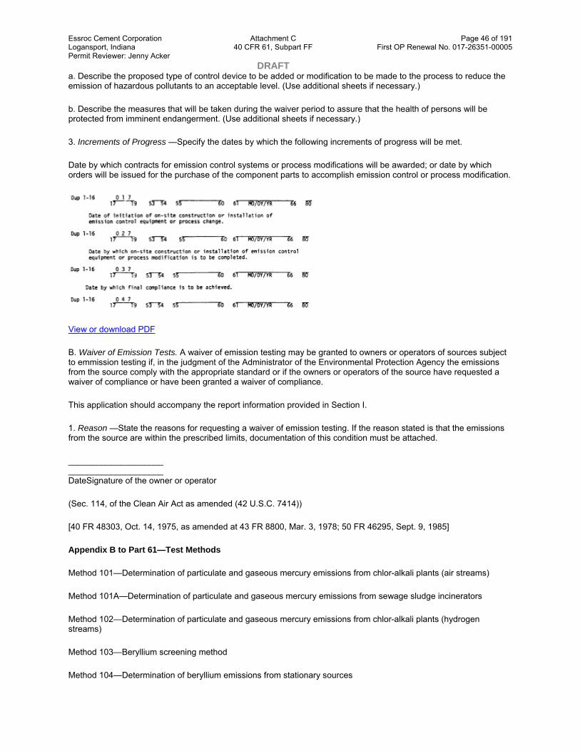
Essroc Cement Corporation Attachment C Page 46 of 191 Logansport, Indiana 40 CFR 61, Subpart FF First OP Renewal No. 017-26351-00005 Permit Reviewer: Jenny Acker DRAFT a. Describe the proposed type of control device to be added or modification to be made to the process to reduce the emission of hazardous pollutants to an acceptable level. (Use additional sheets if necessary.)
b. Describe the measures that will be taken during the waiver period to assure that the health of persons will be protected from imminent endangerment. (Use additional sheets if necessary.)
3. Increments of Progress —Specify the dates by which the following increments of progress will be met.
Date by which contracts for emission control systems or process modifications will be awarded; or date by which orders will be issued for the purchase of the component parts to accomplish emission control or process modification.
View or download PDF
B. Waiver of Emission Tests. A waiver of emission testing may be granted to owners or operators of sources subject to emmission testing if, in the judgment of the Administrator of the Environmental Protection Agency the emissions from the source comply with the appropriate standard or if the owners or operators of the source have requested a waiver of compliance or have been granted a waiver of compliance.
This application should accompany the report information provided in Section I.
1. Reason —State the reasons for requesting a waiver of emission testing. If the reason stated is that the emissions from the source are within the prescribed limits, documentation of this condition must be attached.
____________________ ____________________ DateSignature of the owner or operator
(Sec. 114, of the Clean Air Act as amended (42 U.S.C. 7414))
[40 FR 48303, Oct. 14, 1975, as amended at 43 FR 8800, Mar. 3, 1978; 50 FR 46295, Sept. 9, 1985]
Appendix B to Part 61—Test Methods
Method 101—Determination of particulate and gaseous mercury emissions from chlor-alkali plants (air streams)
Method 101A—Determination of particulate and gaseous mercury emissions from sewage sludge incinerators
Method 102—Determination of particulate and gaseous mercury emissions from chlor-alkali plants (hydrogen streams)
Method 103—Beryllium screening method
Method 104—Determination of beryllium emissions from stationary sources

Essroc Cement Corporation Attachment C Page 47 of 191 Logansport, Indiana 40 CFR 61, Subpart FF First OP Renewal No. 017-26351-00005 Permit Reviewer: Jenny Acker DRAFT Method 105—Determination of mercury in wastewater treatment plant sewage sludges
Method 106—Determination of vinyl chloride emissions from stationary sources
Method 107—Determination of vinyl chloride content of in-process wastewater samples, and vinyl chloride content of polyvinyl chloride resin slurry, wet cake, and latex samples
Method 107A—Determination of vinyl chloride content of solvents, resin-solvent solution, polyvinyl chloride resin, resin slurry, wet resin, and latex samples
Method 108—Determination of particulate and gaseous arsenic emissions
Method 108A—Determination of arsenic content in ore samples from nonferrous smelters
Method 108B—Determination of arsenic content in ore samples from nonferrous smelters
Method 108C—Determination of arsenic content in ore samples from nonferrous smelters (molybdenum blue photometric procedure)
Method 111—Determination of Polonium—210 emissions from stationary sources
Method 101—Determination of Particulate and Gaseous Mercury Emissions From Chlor-Alkali Plants (Air Streams)
Note: This method does not include all of the specifications ( e.g., equipment and supplies) and procedures ( e.g., sampling and analytical) essential to its performance. Some material is incorporated by reference from methods in appendix A to 40 CFR part 60. Therefore, to obtain reliable results, persons using this method should have a thorough knowledge of at least the following additional test methods: Method 1, Method 2, Method 3, and Method 5.
1.0 Scope and Application
1.1 Analytes.
Analyte CAS No. Sensitivity
Mercury (Hg) 7439–97–6 Dependent upon recorder and spectrophotometer.
1.2 Applicability. This method is applicable for the determination of Hg emissions, including both particulate and gaseous Hg, from chlor-alkali plants and other sources (as specified in the regulations) where the carrier-gas stream in the duct or stack is principally air.
1.3 Data Quality Objectives. Adherence to the requirements of this method will enhance the quality of the data obtained from air pollutant sampling methods.
2.0 Summary of Method
Particulate and gaseous Hg emissions are withdrawn isokinetically from the source and collected in acidic iodine monochloride (ICl) solution. The Hg collected (in the mercuric form) is reduced to elemental Hg, which is then aerated from the solution into an optical cell and measured by atomic absorption spectrophotometry.
3.0 Definitions[Reserved]
4.0 Interferences
4.1 Sample Collection. Sulfur dioxide (SO2) reduces ICl and causes premature depletion of the ICl solution.

Essroc Cement Corporation Attachment C Page 48 of 191 Logansport, Indiana 40 CFR 61, Subpart FF First OP Renewal No. 017-26351-00005 Permit Reviewer: Jenny Acker DRAFT 4.2 Sample Analysis.
4.2.1 ICl concentrations greater than 10−4molar inhibit the reduction of the Hg (II) ion in the aeration cell.
4.2.2 Condensation of water vapor on the optical cell windows causes a positive interference.
5.0 Safety
5.1 Disclaimer. This method may involve hazardous materials, operations, and equipment. This test method does not purport to address all of the safety problems associated with its use. It is the responsibility of the user of this test method to establish appropriate safety and health practices and determine the applicability of regulatory limitations prior to performing this test method.
5.2 Corrosive Reagents. The following reagents are hazardous. Personal protective equipment and safe procedures are useful in preventing chemical splashes. If contact occurs, immediately flush with copious amounts of water for at least 15 minutes. Remove clothing under shower and decontaminate. Treat residual chemical burn as thermal burn.
5.2.1 Hydrochloric Acid (HCl). Highly toxic and corrosive. Causes severe damage to tissues. Vapors are highly irritating to eyes, skin, nose, and lungs, causing severe damage. May cause bronchitis, pneumonia, or edema of lungs. Exposure to concentrations of 0.13 to 0.2 percent can be lethal to humans in a few minutes. Provide ventilation to limit exposure. Reacts with metals, producing hydrogen gas.
5.2.2 Nitric Acid (HNO3). Highly corrosive to eyes, skin, nose, and lungs. Vapors cause bronchitis, pneumonia, or edema of lungs. Reaction to inhalation may be delayed as long as 30 hours and still be fatal. Provide ventilation to limit exposure. Strong oxidizer. Hazardous reaction may occur with organic materials such as solvents.
5.2.3 Sulfuric Acid (H2SO4). Rapidly destructive to body tissue. Will cause third degree burns. Eye damage may result in blindness. Inhalation may be fatal from spasm of the larynx, usually within 30 minutes. 3 mg/m3 will cause lung damage. 1 mg/m3 for 8 hours will cause lung damage or, in higher concentrations, death. Provide ventilation to limit inhalation. Reacts violently with metals and organics.
6.0 Equipment and Supplies.
6.1 Sample Collection. A schematic of the sampling train used in performing this method is shown in Figure 101–1; it is similar to the Method 5 sampling train. The following items are required for sample collection:
6.1.1 Probe Nozzle, Pitot Tube, Differential Pressure Gauge, Metering System, Barometer, and Gas Density Determination Equipment. Same as Method 5, Sections 6.1.1.1, 6.1.1.3, 6.1.1.4, 6.1.1.9, 6.1.2, and 6.1.3, respectively.
6.1.2 Probe Liner. Borosilicate or quartz glass tubing. A heating system capable of maintaining a gas temperature of 120 ±14 °C (248 ±25 °F) at the probe exit during sampling may be used to prevent water condensation.
Note: Do not use metal probe liners.
6.1.3 Impingers. Four Greenburg-Smith impingers connected in series with leak-free ground glass fittings or any similar leak-free noncontaminating fittings. For the first, third, and fourth impingers, impingers that are modified by replacing the tip with a 13-mm ID (0.5-in.) glass tube extending to 13 mm (0.5 in.) from the bottom of the flask may be used.
6.1.4 Acid Trap. Mine Safety Appliances air line filter, Catalog number 81857, with acid absorbing cartridge and suitable connections, or equivalent.
6.2 Sample Recovery. The following items are needed for sample recovery:
6.2.1 Glass Sample Bottles. Leakless, with Teflon-lined caps, 1000- and 100-ml.

Essroc Cement Corporation Attachment C Page 49 of 191 Logansport, Indiana 40 CFR 61, Subpart FF First OP Renewal No. 017-26351-00005 Permit Reviewer: Jenny Acker DRAFT 6.2.2 Graduated Cylinder. 250-ml.
6.2.3 Funnel and Rubber Policeman. To aid in transfer of silica gel to container; not necessary if silica gel is weighed in the field.
6.2.4 Funnel. Glass, to aid in sample recovery.
6.3 Sample Preparation and Analysis. The following items are needed for sample preparation and analysis:
6.3.1 Atomic Absorption Spectrophotometer. Perkin-Elmer 303, or equivalent, containing a hollow-cathode mercury lamp and the optical cell described in Section 6.3.2.
6.3.2 Optical Cell. Cylindrical shape with quartz end windows and having the dimensions shown in Figure 101–2. Wind the cell with approximately 2 meters (6 ft) of 24-gauge Nichrome wire, or equivalent, and wrap with fiberglass insulation tape, or equivalent; do not let the wires touch each other.
6.3.3 Aeration Cell. Constructed according to the specifications in Figure 101–3. Do not use a glass frit as a substitute for the blown glass bubbler tip shown in Figure 101–3.
6.3.4 Recorder. Matched to output of the spectrophotometer described in Section 6.3.1.
6.3.5 Variable Transformer. To vary the voltage on the optical cell from 0 to 40 volts.
6.3.6 Hood. For venting optical cell exhaust.
6.3.7 Flow Metering Valve.
6.3.8 Rate Meter. Rotameter, or equivalent, capable of measuring to within 2 percent a gas flow of 1.5 liters/min (0.053 cfm).
6.3.9 Aeration Gas Cylinder. Nitrogen or dry, Hg-free air, equipped with a single-stage regulator.
6.3.10 Tubing. For making connections. Use glass tubing (ungreased ball and socket connections are recommended) for all tubing connections between the solution cell and the optical cell; do not use Tygon tubing, other types of flexible tubing, or metal tubing as substitutes. Teflon, steel, or copper tubing may be used between the nitrogen tank and flow metering valve (Section 6.3.7), and Tygon, gum, or rubber tubing between the flow metering valve and the aeration cell.
6.3.11 Flow Rate Calibration Equipment. Bubble flow meter or wet-test meter for measuring a gas flow rate of 1.5 ±0.1 liters/min (0.053 ±0.0035 cfm).
6.3.12 Volumetric Flasks. Class A with penny head standard taper stoppers; 100-, 250-, 500-, and 1000-ml.
6.3.13 Volumetric Pipets. Class A; 1-, 2-, 3-, 4-, and 5-ml.
6.3.14 Graduated Cylinder. 50-ml.
6.3.15 Magnetic Stirrer. General-purpose laboratory type.
6.3.16 Magnetic Stirring Bar. Teflon-coated.
6.3.17 Balance. Capable of weighing to ±0.5 g.
6.3.18 Alternative Analytical Apparatus. Alternative systems are allowable as long as they meet the following criteria:

Essroc Cement Corporation Attachment C Page 50 of 191 Logansport, Indiana 40 CFR 61, Subpart FF First OP Renewal No. 017-26351-00005 Permit Reviewer: Jenny Acker DRAFT 6.3.18.1 A linear calibration curve is generated and two consecutive samples of the same aliquot size and concentration agree within 3 percent of their average.
6.3.18.2 A minimum of 95 percent of the spike is recovered when an aliquot of a source sample is spiked with a known concentration of Hg (II) compound.
6.3.18.3 The reducing agent should be added after the aeration cell is closed.
6.3.18.4 The aeration bottle bubbler should not contain a frit.
6.3.18.5 Any Tygon tubing used should be as short as possible and conditioned prior to use until blanks and standards yield linear and reproducible results.
6.3.18.6 If manual stirring is done before aeration, it should be done with the aeration cell closed.
6.3.18.7 A drying tube should not be used unless it is conditioned as the Tygon tubing above.
7.0 Reagents and Standards
Unless otherwise indicated, all reagents must conform to the specifications established by the Committee on Analytical Reagents of the American Chemical Society; where such specifications are not available, use the best available grade.
7.1 Sample Collection. The following reagents are required for sample collection:
7.1.1 Water. Deionized distilled, to conform to ASTM D 1193–77 or 91 (incorporated by reference—see §61.18), Type 1. If high concentrations of organic matter are not expected to be present, the analyst may eliminate the KMnO4test for oxidizable organic matter. Use this water in all dilutions and solution preparations.
7.1.2 Nitric Acid, 50 Percent (v/v). Mix equal volumes of concentrated HNO3and water, being careful to add the acid to the water slowly.
7.1.3 Silica Gel. Indicating type, 6- to 16-mesh. If previously used, dry at 175 °C (350 °F) for 2 hours. The tester may use new silica gel as received.
7.1.4 Potassium Iodide (KI) Solution, 25 Percent. Dissolve 250 g of KI in water, and dilute to 1 liter.
7.1.5 Iodine Monochloride Stock Solution, 1.0 M. To 800 ml of 25 percent KI solution, add 800 ml of concentrated HCl. Cool to room temperature. With vigorous stirring, slowly add 135 g of potassium iodate (KIO3), and stir until all free iodine has dissolved. A clear orange-red solution occurs when all the KIO3has been added. Cool to room temperature, and dilute to 1800 ml with water. Keep the solution in amber glass bottles to prevent degradation.
7.1.6 Absorbing Solution, 0.1 M ICl. Dilute 100 ml of the 1.0 M ICl stock solution to 1 liter with water. Keep the solution in amber glass bottles and in darkness to prevent degradation. This reagent is stable for at least two months.
7.2 Sample Preparation and Analysis. The following reagents and standards are required for sample preparation and analysis:
7.2.1 Reagents.
7.2.1.1 Tin (II) Solution. Prepare fresh daily, and keep sealed when not being used. Completely dissolve 20 g of tin (II) chloride (or 25 g of tin (II) sulfate) crystals (Baker Analyzed reagent grade or any other brand that will give a clear solution) in 25 ml of concentrated HCl. Dilute to 250 ml with water. Do not substitute HNO3, H2SO4, or other strong acids for the HCl.
Essroc Cement Corporation Attachment C Page 51 of 191 Logansport, Indiana 40 CFR 61, Subpart FF First OP Renewal No. 017-26351-00005 Permit Reviewer: Jenny Acker DRAFT 7.2.1.2 Sulfuric Acid, 5 Percent (v/v). Dilute 25 ml of concentrated H2SO4to 500 ml with water.
7.2.2 Standards
7.2.2.1 Hg Stock Solution, 1 mg Hg/ml. Prepare and store all Hg standard solutions in borosilicate glass containers. Completely dissolve 0.1354 g of Hg (II) chloride in 75 ml of water in a 100-ml glass volumetric flask. Add 10 ml of concentrated HNO3, and adjust the volume to exactly 100 ml with water. Mix thoroughly. This solution is stable for at least one month.
7.2.2.2 Intermediate Hg Standard Solution, 10 µg Hg/ml. Prepare fresh weekly. Pipet 5.0 ml of the Hg stock solution (Section 7.2.2.1) into a 500-ml glass volumetric flask, and add 20 ml of the 5 percent H2SO4solution. Dilute to exactly 500 ml with water. Thoroughly mix the solution.
7.2.2.3 Working Hg Standard Solution, 200 ng Hg/ml. Prepare fresh daily. Pipet 5.0 ml of the intermediate Hg standard solution (Section 7.2.2.2) into a 250-ml volumetric glass flask. Add 10 ml of the 5 percent H2SO4and 2 ml of the 0.1 M ICl absorbing solution taken as a blank (Section 8.7.4.3), and dilute to 250 ml with water. Mix thoroughly.
8.0 Sample Collection, Preservation, Transport, and Storage
Because of the complexity of this method, testers should be trained and experienced with the test procedures to ensure reliable results. Since the amount of Hg that is collected generally is small, the method must be carefully applied to prevent contamination or loss of sample.
8.1 Pretest Preparation. Follow the general procedure outlined in Method 5, Section 8.1, except omit Sections 8.1.2 and 8.1.3.
8.2 Preliminary Determinations. Follow the general procedure outlined in Method 5, Section 8.2, with the exception of the following:
8.2.1 Select a nozzle size based on the range of velocity heads to assure that it is not necessary to change the nozzle size in order to maintain isokinetic sampling rates below 28 liters/min (1.0 cfm).
8.2.2 Perform test runs such that samples are obtained over a period or periods that accurately determine the maximum emissions that occur in a 24-hour period. In the case of cyclic operations, run sufficient tests for the accurate determination of the emissions that occur over the duration of the cycle. A minimum sample time of 2 hours is recommended. In some instances, high Hg or high SO2concentrations make it impossible to sample for the desired minimum time. This is indicated by reddening (liberation of free iodine) in the first impinger. In these cases, the sample run may be divided into two or more subruns to ensure that the absorbing solution is not depleted.
8.3 Preparation of Sampling Train.
8.3.1 Clean all glassware (probe, impingers, and connectors) by rinsing with 50 percent HNO3, tap water, 0.1 M ICl, tap water, and finally deionized distilled water. Place 100 ml of 0.1 M ICl in each of the first three impingers. Take care to prevent the absorbing solution from contacting any greased surfaces. Place approximately 200 g of preweighed silica gel in the fourth impinger. More silica gel may be used, but care should be taken to ensure that it is not entrained and carried out from the impinger during sampling. Place the silica gel container in a clean place for later use in the sample recovery. Alternatively, determine and record the weight of the silica gel plus impinger to the nearest 0.5 g.
8.3.2 Install the selected nozzle using a Viton A O-ring when stack temperatures are less than 260 °C (500 °F). Use a fiberglass string gasket if temperatures are higher. See APTD–0576 (Reference 3 in Method 5) for details. Other connecting systems using either 316 stainless steel or Teflon ferrules may be used. Mark the probe with heat-resistant tape or by some other method to denote the proper distance into the stack or duct for each sampling point.
8.3.3 Assemble the train as shown in Figure 101–1, using (if necessary) a very light coat of silicone grease on all ground glass joints. Grease only the outer portion (see APTD–0576) to avoid the possibility of contamination by the silicone grease.

Essroc Cement Corporation Attachment C Page 52 of 191 Logansport, Indiana 40 CFR 61, Subpart FF First OP Renewal No. 017-26351-00005 Permit Reviewer: Jenny Acker DRAFT Note: An empty impinger may be inserted between the third impinger and the silica gel to remove excess moisture from the sample stream.
8.3.4 After the sampling train has been assembled, turn on and set the probe heating system, if applicable, at the desired operating temperature. Allow time for the temperatures to stabilize. Place crushed ice around the impingers.
8.4 Leak-Check Procedures. Follow the leak-check procedures outlined in Method 5, Section 8.4.
8.5 Sampling Train Operation. Follow the general procedure outlined in Method 5, Section 8.5. For each run, record the data required on a data sheet such as the one shown in Figure 101–4.
8.6 Calculation of Percent Isokinetic. Same as Method 5, Section 8.6.
8.7 Sample Recovery. Begin proper cleanup procedure as soon as the probe is removed from the stack at the end of the sampling period.
8.7.1 Allow the probe to cool. When it can be safely handled, wipe off any external particulate matter near the tip of the probe nozzle, and place a cap over it. Do not cap off the probe tip tightly while the sampling train is cooling. Capping would create a vacuum and draw liquid out from the impingers.
8.7.2 Before moving the sampling train to the cleanup site, remove the probe from the train, wipe off the silicone grease, and cap the open outlet of the probe. Be careful not to lose any condensate that might be present. Wipe off the silicone grease from the impinger. Use either ground-glass stoppers, plastic caps, or serum caps to close these openings.
8.7.3 Transfer the probe and impinger assembly to a cleanup area that is clean, protected from the wind, and free of Hg contamination. The ambient air in laboratories located in the immediate vicinity of Hg-using facilities is not normally free of Hg contamination.
8.7.4 Inspect the train before and during disassembly, and note any abnormal conditions. Treat the samples as follows.
8.7.4.1 Container No. 1 (Impingers and Probe).
8.7.4.1.1 Using a graduated cylinder, measure the liquid in the first three impingers to within 1 ml. Record the volume of liquid present ( e.g., see Figure 5–6 of Method 5). This information is needed to calculate the moisture content of the effluent gas. (Use only glass storage bottles and graduated cylinders that have been precleaned as in Section 8.3.1) Place the contents of the first three impingers into a 1000-ml glass sample bottle.
8.7.4.1.2 Taking care that dust on the outside of the probe or other exterior surfaces does not get into the sample, quantitatively recover the Hg (and any condensate) from the probe nozzle, probe fitting, and probe liner as follows: Rinse these components with two 50-ml portions of 0.1 M ICl. Next, rinse the probe nozzle, fitting and liner, and each piece of connecting glassware between the probe liner and the back half of the third impinger with a maximum of 400 ml of water. Add all washings to the 1000-ml glass sample bottle containing the liquid from the first three impingers.
8.7.4.1.3 After all washings have been collected in the sample container, tighten the lid on the container to prevent leakage during shipment to the laboratory. Mark the height of the liquid to determine later whether leakage occurred during transport. Label the container to identify clearly its contents.
8.7.4.2 Container No. 2 (Silica Gel). Same as Method 5, Section 8.7.6.3.
8.7.4.3 Container No. 3 (Absorbing Solution Blank). Place 50 ml of the 0.1 M ICl absorbing solution in a 100-ml sample bottle. Seal the container. Use this blank to prepare the working Hg standard solution (Section 7.2.2.3).
9.0 Quality Control

Essroc Cement Corporation Attachment C Page 53 of 191 Logansport, Indiana 40 CFR 61, Subpart FF First OP Renewal No. 017-26351-00005 Permit Reviewer: Jenny Acker DRAFT 9.1 Miscellaneous Quality Control Measures.
Section Quality control measure Effect
8.4 10.2 Sampling equipment leak-checks and calibration
Ensure accuracy and precision of sampling measurements.
10.5, 10.6
Spectrophotometer calibration Ensure linearity of spectrophotometer response to standards.
11.3.3 Check for matrix effects Eliminate matrix effects.
9.2 Volume Metering System Checks. Same as Method 5, Section 9.2.
10.0 Calibration and Standardizations
Note: Maintain a laboratory log of all calibrations.
10.1 Before use, clean all glassware, both new and used, as follows: brush with soap and tap water, liberally rinse with tap water, soak for 1 hour in 50 percent HNO3, and then rinse with deionized distilled water.
10.2 Sampling Equipment. Calibrate the sampling equipment according to the procedures outlined in the following sections of Method 5: Section 10.1 (Probe Nozzle), Section 10.2 (Pitot Tube Assembly), Section 10.3 (Metering System), Section 10.5 (Temperature Sensors), Section 10.6 (Barometer).
10.3 Aeration System Flow Rate Meter. Assemble the aeration system as shown in Figure 101–5. Set the outlet pressure on the aeration gas cylinder regulator to a minimum pressure of 500 mm Hg (10 psi), and use the flow metering valve and a bubble flowmeter or wet-test meter to obtain a flow rate of 1.5 ±0.1 liters/min (0.053 ±0.0035 cfm) through the aeration cell. After the calibration of the aeration system flow rate meter is complete, remove the bubble flowmeter from the system.
10.4 Optical Cell Heating System. Using a 50-ml graduated cylinder, add 50 ml of water to the bottle section of the aeration cell, and attach the bottle section to the bubbler section of the cell. Attach the aeration cell to the optical cell and while aerating at 1.5 ±0.1 liters/min (0.053 ±0.0035 cfm), determine the minimum variable transformer setting necessary to prevent condensation of moisture in the optical cell and in the connecting tubing. (This setting should not exceed 20 volts.)
10.5 Spectrophotometer and Recorder.
10.5.1 The Hg response may be measured by either peak height or peak area.
Note: The temperature of the solution affects the rate at which elemental Hg is released from a solution and, consequently, it affects the shape of the absorption curve (area) and the point of maximum absorbance (peak height). Therefore, to obtain reproducible results, bring all solutions to room temperature before use.
10.5.2 Set the spectrophotometer wavelength at 253.7 nm, and make certain the optical cell is at the minimum temperature that will prevent water condensation. Then set the recorder scale as follows: Using a 50-ml graduated cylinder, add 50 ml of water to the aeration cell bottle. Add three drops of Antifoam B to the bottle, and then pipet 5.0 ml of the working Hg standard solution into the aeration cell.
Note: Always add the Hg-containing solution to the aeration cell after the 50 ml of water.
10.5.3 Place a Teflon-coated stirring bar in the bottle. Before attaching the bottle section to the bubbler section of the aeration cell, make certain that (1) the aeration cell exit arm stopcock (Figure 101–3) is closed (so that Hg will not prematurely enter the optical cell when the reducing agent is being added) and (2) there is no flow through the bubbler. If conditions (1) and (2) are met, attach the bottle section to the bubbler section of the aeration cell. Pipet 5

Essroc Cement Corporation Attachment C Page 54 of 191 Logansport, Indiana 40 CFR 61, Subpart FF First OP Renewal No. 017-26351-00005 Permit Reviewer: Jenny Acker DRAFT ml of tin (II) reducing solution into the aeration cell through the side arm, and immediately stopper the side arm. Stir the solution for 15 seconds, turn on the recorder, open the aeration cell exit arm stopcock, and immediately initiate aeration with continued stirring. Determine the maximum absorbance of the standard, and set this value to read 90 percent of the recorder full scale.
10.6 Calibration Curve.
10.6.1 After setting the recorder scale, repeat the procedure in Section 10.5 using 0.0-, 1.0-, 2.0-, 3.0-, 4.0-, and 5.0-ml aliquots of the working standard solution (final amount of Hg in the aeration cell is 0, 200, 400, 600, 800, and 1000 ng, respectively). Repeat this procedure on each aliquot size until two consecutive peaks agree within 3 percent of their average value.
Note: To prevent Hg carryover from one sample to another, do not close the aeration cell from the optical cell until the recorder pen has returned to the baseline.)
10.6.2 It should not be necessary to disconnect the aeration gas inlet line from the aeration cell when changing samples. After separating the bottle and bubbler sections of the aeration cell, place the bubbler section into a 600-ml beaker containing approximately 400 ml of water. Rinse the bottle section of the aeration cell with a stream of water to remove all traces of the tin (II) reducing agent. Also, to prevent the loss of Hg before aeration, remove all traces of the reducing agent between samples by washing with water. It will be necessary, however, to wash the aeration cell parts with concentrated HCl if any of the following conditions occur: (1) A white film appears on any inside surface of the aeration cell, (2) the calibration curve changes suddenly, or (3) the replicate samples do not yield reproducible results.
10.6.3 Subtract the average peak height (or peak area) of the blank (0.0-ml aliquot)—which must be less than 2 percent of recorder full scale—from the averaged peak heights of the 1.0-, 2.0-, 3.0-, 4.0-, and 5.0-ml aliquot standards. If the blank absorbance is greater than 2 percent of full-scale, the probable cause is Hg contamination of a reagent or carry-over of Hg from a previous sample. Prepare the calibration curve by plotting the corrected peak height of each standard solution versus the corresponding final total Hg weight in the aeration cell (in ng), and draw the best fit straight line. This line should either pass through the origin or pass through a point no further from the origin than ±2 percent of the recorder full scale. If the line does not pass through or very near to the origin, check for nonlinearity of the curve and for incorrectly prepared standards.
11.0 Analytical Procedure
11.1 Sample Loss Check. Check the liquid level in each container to see whether liquid was lost during transport. If a noticeable amount of leakage occurred, either void the sample or use methods subject to the approval of the Administrator to account for the losses.
11.2 Sample Preparation. Treat each sample as follows:
11.2.1 Container No. 1 (Impingers and Probe). Carefully transfer the contents of Container No. 1 into a 1000-ml volumetric flask, and adjust the volume to exactly 1000 ml with water.
11.2.2 Dilutions. Pipet a 2-ml aliquot from the diluted sample from Section 11.2.1 into a 250-ml volumetric flask. Add 10 ml of 5 percent H2SO4, and adjust the volume to exactly 250 ml with water. This solution is stable for at least 72 hours.
Note: The dilution factor will be 250/2 for this solution.
11.3 Analysis. Calibrate the analytical equipment and develop a calibration curve as outlined in Sections 10.3 through 10.6.
11.3.1 Mercury Samples. Repeat the procedure used to establish the calibration curve with an appropriately sized aliquot (1 to 5 ml) of the diluted sample (from Section 11.2.2) until two consecutive peak heights agree within 3 percent of their average value. The peak maximum of an aliquot (except the 5-ml aliquot) must be greater than 10

Essroc Cement Corporation Attachment C Page 55 of 191 Logansport, Indiana 40 CFR 61, Subpart FF First OP Renewal No. 017-26351-00005 Permit Reviewer: Jenny Acker DRAFT percent of the recorder full scale. If the peak maximum of a 1.0-ml aliquot is off scale on the recorder, further dilute the original source sample to bring the Hg concentration into the calibration range of the spectrophotometer.
11.3.2 Run a blank and standard at least after every five samples to check the spectrophotometer calibration. The peak height of the blank must pass through a point no further from the origin than ±2 percent of the recorder full scale. The difference between the measured concentration of the standard (the product of the corrected peak height and the reciprocal of the least squares slope) and the actual concentration of the standard must be less than 7 percent, or recalibration of the analyzer is required.
11.3.3 Check for Matrix Effects (optional). Use the Method of Standard Additions as follows to check at least one sample from each source for matrix effects on the Hg results. The Method of Standard Additions procedures described on pages 9–4 and 9–5 of the section entitled “General Information” of the Perkin Elmer Corporation Atomic Absorption Spectrophotometry Manual, Number 303–0152 (Reference 16 in Section 16.0) are recommended. If the results of the Method of Standard Additions procedure used on the single source sample do not agree to within ±5 percent of the value obtained by the routine atomic absorption analysis, then reanalyze all samples from the source using the Method of Standard Additions procedure.
11.4 Container No. 2 (Silica Gel). Weigh the spent silica gel (or silica gel plus impinger) to the nearest 0.5 g using a balance. (This step may be conducted in the field.)
12.0 Data Analysis and Calculations
Carry out calculations, retaining at least one extra decimal significant figure beyond that of the acquired data. Round off figures only after the final calculation. Other forms of the equations may be used as long as they give equivalent results.
12.1 Average Dry Gas Meter Temperature and Average Orifice Pressure Drop, Dry Gas Volume, Volume of Water Vapor Condensed, Moisture Content, and Isokinetic Variation. Same as Method 5, Sections 12.2 through 12.5 and 12.11, respectively.
12.2 Stack Gas Velocity. Using the data from this test and Equation 2–9 of Method 2, calculate the average stack gas velocity vs.
12.3 Total Mercury.
12.3.1 For each source sample, correct the average maximum absorbance of the two consecutive samples whose peak heights agree within 3 percent of their average for the contribution of the solution blank (see Section 10.6.3). Use the calibration curve and these corrected averages to determine the final total weight of Hg in ng in the aeration cell for each source sample.
12.3.2 Correct for any dilutions made to bring the sample into the working range of the spectrophotometer. Then calculate the Hg in the original solution, mHg, as follows:
Where:
CHg(AC)= Total ng of Hg in aliquot analyzed (reagent blank subtracted).
DF = Dilution factor for the Hg-containing solution (before adding to the aeration cell; e.g., DF = 250/2 if the source samples were diluted as described in Section 11.2.2).
Vf= Solution volume of original sample, 1000 ml for samples diluted as described in Section 11.2.1.
10−3= Conversion factor, µg/ng.

Essroc Cement Corporation Attachment C Page 56 of 191 Logansport, Indiana 40 CFR 61, Subpart FF First OP Renewal No. 017-26351-00005 Permit Reviewer: Jenny Acker DRAFT S = Aliquot volume added to aeration cell, ml.
12.4 Mercury Emission Rate. Calculate the daily Hg emission rate, R, using Equation 101–2. For continuous operations, the operating time is equal to 86,400 seconds per day. For cyclic operations, use only the time per day each stack is in operation. The total Hg emission rate from a source will be the summation of results from all stacks.
Where:
K1= 0.3858 °K/mm Hg for metric units.
K1= 17.64 °R/in. Hg for English units.
K3= 10−6g/µg for metric units.
= 2.2046 “ × 10−9lb/µg for English units.
Ps= Absolute stack gas pressure, mm Hg (in. Hg).
t = Daily operating time, sec/day.
Ts= Absolute average stack gas temperature, °K (°R).
Vm(std)= Dry gas sample volume at standard conditions, scm (scf).
Vw(std)= Volume of water vapor at standard conditions, scm (scf).
12.5 Determination of Compliance. Each performance test consists of three repetitions of the applicable test method. For the purpose of determining compliance with an applicable national emission standard, use the average of the results of all repetitions.
13.0 Method Performance
The following estimates are based on collaborative tests, wherein 13 laboratories performed duplicate analyses on two Hg-containing samples from a chlor-alkali plant and on one laboratory-prepared sample of known Hg concentration. The sample concentrations ranged from 2 to 65 µg Hg/ml.
13.1 Precision. The estimated intra-laboratory and inter-laboratory standard deviations are 1.6 and 1.8 µg Hg/ml, respectively.
13.2 Accuracy. The participating laboratories that analyzed a 64.3 µg Hg/ml (in 0.1 M ICl) standard obtained a mean of 63.7 µg Hg/ml.
13.3 Analytical Range. After initial dilution, the range of this method is 0.5 to 120 µg Hg/ml. The upper limit can be extended by further dilution of the sample.
14.0 Pollution Prevention.[Reserved]
15.0 Waste Management.[Reserved]
Essroc Cement Corporation Attachment C Page 57 of 191 Logansport, Indiana 40 CFR 61, Subpart FF First OP Renewal No. 017-26351-00005 Permit Reviewer: Jenny Acker DRAFT 16.0 References
Same as Method 5, Section 17.0, References 1–3, 5, and 6, with the addition of the following:
1. Determining Dust Concentration in a Gas Stream. ASME Performance Test Code No. 27. New York, NY. 1957.
2. DeVorkin, Howard, et al. Air Pollution Source Testing Manual. Air Pollution Control District. Los Angeles, CA. November 1963.
3. Hatch, W.R., and W.I. Ott. Determination of Sub-Microgram Quantities of Mercury by Atomic Absorption Spectrophotometry. Anal. Chem. 40:2085–87. 1968.
4. Mark, L.S. Mechanical Engineers' Handbook. McGraw-Hill Book Co., Inc. New York, NY. 1951.
5. Western Precipitation Division of Joy Manufacturing Co. Methods for Determination of Velocity, Volume, Dust and Mist Content of Gases. Bulletin WP–50. Los Angeles, CA. 1968.
6. Perry, J.H. Chemical Engineers' Handbook. McGraw-Hill Book Co., Inc. New York, NY. 1960.
7. Shigehara, R.T., W.F. Todd, and W.S. Smith. Significance of Errors in Stack Sampling Measurements. Stack Sampling News. 1 (3):6–18. September 1973.
8. Smith, W.S., R.T. Shigehara, and W.F. Todd. A Method of Interpreting Stack Sampling Data. Stack Sampling News. 1 (2):8–17. August 1973.
9. Standard Method for Sampling Stacks for Particulate Matter. In: 1971 Annual Book of ASTM Standards, Part 23. ASTM Designation D 2928–71. Philadelphia, PA 1971.
10. Vennard, J.K. Elementary Fluid Mechanics. John Wiley and Sons, Inc. New York. 1947.
11. Mitchell, W.J. and M.R. Midgett. Improved Procedure for Determining Mercury Emissions from Mercury Cell Chlor-Alkali Plants. J. APCA. 26 :674–677. July 1976.
12. Shigehara, R.T. Adjustments in the EPA Nomograph for Different Pitot Tube Coefficients and Dry Molecular Weights. Stack Sampling News. 2 :4–11. October 1974.
13. Vollaro, R.F. Recommended Procedure for Sample Traverses in Ducts Smaller than 12 Inches in Diameter. U.S. Environmental Protection Agency, Emission Measurement Branch. Research Triangle Park, NC. November 1976.
14. Klein, R. and C. Hach. Standard Additions: Uses and Limitation in Spectrophotometric Measurements. Amer. Lab. 9 :21. 1977.
15. Perkin Elmer Corporation. Analytical Methods for Atomic Absorption Spectrophotometry. Norwalk, Connecticut. September 1976.
17.0 Tables, Diagrams, Flowcharts, and Validation Data

Essroc Cement Corporation Attachment C Page 58 of 191 Logansport, Indiana 40 CFR 61, Subpart FF First OP Renewal No. 017-26351-00005 Permit Reviewer: Jenny Acker DRAFT
View or download PDF

Essroc Cement Corporation Attachment C Page 59 of 191 Logansport, Indiana 40 CFR 61, Subpart FF First OP Renewal No. 017-26351-00005 Permit Reviewer: Jenny Acker DRAFT
View or download PDF

Essroc Cement Corporation Attachment C Page 60 of 191 Logansport, Indiana 40 CFR 61, Subpart FF First OP Renewal No. 017-26351-00005 Permit Reviewer: Jenny Acker DRAFT
View or download PDF

Essroc Cement Corporation Attachment C Page 61 of 191 Logansport, Indiana 40 CFR 61, Subpart FF First OP Renewal No. 017-26351-00005 Permit Reviewer: Jenny Acker DRAFT
View or download PDF

Essroc Cement Corporation Attachment C Page 62 of 191 Logansport, Indiana 40 CFR 61, Subpart FF First OP Renewal No. 017-26351-00005 Permit Reviewer: Jenny Acker DRAFT
View or download PDF
Method 101A—Determination of Particulate and Gaseous Mercury Emissions From Sewage Sludge Incinerators
Note: This method does not include all of the specifications ( e.g., equipment and supplies) and procedures ( e.g., sampling and analytical) essential to its performance. Some material is incorporated by reference from methods in appendix A to 40 CFR part 60 and in this part. Therefore, to obtain reliable results, persons using this method should also have a thorough knowledge of at least the following additional test methods: Methods 1, Method 2, Method 3, and Method 5 of part 60 (appendix A), and Method 101 part 61 (appendix B).
1.0 Scope and Application
1.1 Analytes.

Essroc Cement Corporation Attachment C Page 63 of 191 Logansport, Indiana 40 CFR 61, Subpart FF First OP Renewal No. 017-26351-00005 Permit Reviewer: Jenny Acker DRAFT
Analyte CAS No. Sensitivity
Mercury (Hg) 7439–97–6 Dependent upon spectrophotometer and recorder.
1.2 Applicability. This method is applicable for the determination of Hg emissions from sewage sludge incinerators and other sources as specified in an applicable subpart of the regulations.
1.3 Data Quality Objectives. Adherence to the requirements of this method will enhance the quality of the data obtained from air pollutant sampling methods.
2.0 Summary of Method
2.1 Particulate and gaseous Hg emissions are withdrawn isokinetically from the source and are collected in acidic potassium permanganate (KMnO4) solution. The Hg collected (in the mercuric form) is reduced to elemental Hg, which is then aerated from the solution into an optical cell and measured by atomic absorption spectrophotometry.
3.0 Definitions.[Reserved]
4.0 Interferences
4.1 Sample Collection. Excessive oxidizable organic matter in the stack gas prematurely depletes the KMnO4solution and thereby prevents further collection of Hg.
4.2 Analysis. Condensation of water vapor on the optical cell windows causes a positive interference.
5.0 Safety
5.1 Disclaimer. This method may involve hazardous materials, operations, and equipment. This test method may not address all of the safety problems associated with its use. It is the responsibility of the user of this test method to establish appropriate safety and health practices and determine the applicability of regulatory limitations prior to performing this test method.
5.2 Corrosive Reagents. The following reagents are hazardous. Personal protective equipment and safe procedures are useful in preventing chemical splashes. If contact occurs, immediately flush with copious amounts of water for at least 15 minutes. Remove clothing under shower and decontaminate. Treat residual chemical burns as thermal burns.
5.2.1 Hydrochloric Acid (HCl). Highly toxic. Vapors are highly irritating to eyes, skin, nose, and lungs, causing severe damage. May cause bronchitis, pneumonia, or edema of lungs. Exposure to concentrations of 0.13 to 0.2 percent can be lethal to humans in a few minutes. Provide ventilation to limit exposure. Reacts with metals, producing hydrogen gas.
5.2.2 Nitric Acid (HNO3). Highly corrosive to eyes, skin, nose, and lungs. Vapors cause bronchitis, pneumonia, or edema of lungs. Reaction to inhalation may be delayed as long as 30 hours and still be fatal. Provide ventilation to limit exposure. Strong oxidizer. Hazardous reaction may occur with organic materials such as solvents.
5.2.3 Sulfuric acid (H2SO4). Rapidly destructive to body tissue. Will cause third degree burns. Eye damage may result in blindness. Inhalation may be fatal from spasm of the larynx, usually within 30 minutes. May cause lung tissue damage with edema. 3 mg/m3 will cause lung damage in uninitiated. 1 mg/m3 for 8 hours will cause lung damage or, in higher concentrations, death. Provide ventilation to limit inhalation. Reacts violently with metals and organics.
5.3 Chlorine Evolution. Hydrochloric acid reacts with KMnO4to liberate chlorine gas. Although this is a minimal concern when small quantities of HCl (5–10 ml) are used in the impinger rinse, a potential safety hazard may still exist. At sources that emit higher concentrations of oxidizable materials ( e.g., power plants), more HCl may be required to remove the larger amounts of brown deposit formed in the impingers. In such cases, the potential safety hazards due to sample container pressurization are greater, because of the larger volume of HCl rinse added to the

Essroc Cement Corporation Attachment C Page 64 of 191 Logansport, Indiana 40 CFR 61, Subpart FF First OP Renewal No. 017-26351-00005 Permit Reviewer: Jenny Acker DRAFT recovered sample. These hazards are eliminated by storing and analyzing the HCl impinger wash separately from the permanganate impinger sample.
6.0 Equipment and Supplies
6.1 Sample Collection and Sample Recovery. Same as Method 101, Sections 6.1 and 6.2, respectively, with the following exceptions:
6.1.1 Probe Liner. Same as in Method 101, Section 6.1.2, except that if a filter is used ahead of the impingers, the probe heating system must be used to minimize the condensation of gaseous Hg.
6.1.2 Filter Holder (Optional). Borosilicate glass with a rigid stainless-steel wire-screen filter support (do not use glass frit supports) and a silicone rubber or Teflon gasket, designed to provide a positive seal against leakage from outside or around the filter. The filter holder must be equipped with a filter heating system capable of maintaining a temperature around the filter holder of 120 ±14 °C (248 ±25 °F) during sampling to minimize both water and gaseous Hg condensation. A filter may also be used in cases where the stream contains large quantities of particulate matter.
6.2 Sample Analysis. Same as Method 101, Section 6.3, with the following additions and exceptions:
6.2.1 Volumetric Pipets. Class A; 1-, 2-, 3-, 4-, 5-, 10-, and 20-ml.
6.2.2 Graduated Cylinder. 25-ml.
6.2.3 Steam Bath.
6.2.4 Atomic Absorption Spectrophotometer or Equivalent. Any atomic absorption unit with an open sample presentation area in which to mount the optical cell is suitable. Instrument settings recommended by the particular manufacturer should be followed. Instruments designed specifically for the measurement of mercury using the cold-vapor technique are commercially available and may be substituted for the atomic absorption spectrophotometer.
6.2.5 Optical Cell. Alternatively, a heat lamp mounted above the cell or a moisture trap installed upstream of the cell may be used.
6.2.6 Aeration Cell. Alternatively, aeration cells available with commercial cold vapor instrumentation may be used.
6.2.7 Aeration Gas Cylinder. Nitrogen, argon, or dry, Hg-free air, equipped with a single-stage regulator. Alternatively, aeration may be provided by a peristaltic metering pump. If a commercial cold vapor instrument is used, follow the manufacturer's recommendations.
7.0 Reagents and Standards
Unless otherwise indicated, it is intended that all reagents conform to the specifications established by the Committee on Analytical Reagents of the American Chemical Society, where such specifications are available; otherwise, use the best available grade.
7.1 Sample Collection and Recovery. The following reagents are required for sample collection and recovery:
7.1.1 Water. Deionized distilled, to conform to ASTM D 1193–77 or 91 Type 1. If high concentrations of organic matter are not expected to be present, the analyst may eliminate the KMnO4test for oxidizable organic matter. Use this water in all dilutions and solution preparations.
7.1.2 Nitric Acid, 50 Percent (V/V). Mix equal volumes of concentrated HNO3and water, being careful to add the acid to the water slowly.

Essroc Cement Corporation Attachment C Page 65 of 191 Logansport, Indiana 40 CFR 61, Subpart FF First OP Renewal No. 017-26351-00005 Permit Reviewer: Jenny Acker DRAFT 7.1.3 Silica Gel. Indicating type, 6 to 16 mesh. If previously used, dry at 175 °C (350 °F) for 2 hours. New silica gel may be used as received.
7.1.4 Filter (Optional). Glass fiber filter, without organic binder, exhibiting at least 99.95 percent efficiency on 0.3-µm dioctyl phthalate smoke particles. The filter in cases where the gas stream contains large quantities of particulate matter, but blank filters should be analyzed for Hg content.
7.1.5 Sulfuric Acid, 10 Percent (V/V). Carefully add and mix 100 ml of concentrated H2SO4to 900 ml of water.
7.1.6 Absorbing Solution, 4 Percent KMnO4(W/V). Prepare fresh daily. Dissolve 40 g of KMnO4in sufficient 10 percent H2SO4to make 1 liter. Prepare and store in glass bottles to prevent degradation.
7.1.7 Hydrochloric Acid, 8 N. Carefully add and mix 67 ml of concentrated HCl to 33 ml of water.
7.2 Sample Analysis. The following reagents and standards are required for sample analysis:
7.2.1 Water. Same as in Section 7.1.1.
7.2.2 Tin (II) Solution. Prepare fresh daily, and keep sealed when not being used. Completely dissolve 20 g of tin (II) chloride (or 25 g of tin (II) sulfate) crystals (Baker Analyzed reagent grade or any other brand that will give a clear solution) in 25 ml of concentrated HCl. Dilute to 250 ml with water. Do not substitute HNO3H2SO4, or other strong acids for the HCl.
7.2.3 Sodium Chloride-Hydroxylamine Solution. Dissolve 12 g of sodium chloride and 12 g of hydroxylamine sulfate (or 12 g of hydroxylamine hydrochloride) in water and dilute to 100 ml.
7.2.4 Hydrochloric Acid, 8 N. Same as Section 7.1.7.
7.2.5 Nitric Acid, 15 Percent (V/V). Carefully add 15 ml HNO3to 85 ml of water.
7.2.6 Antifoam B Silicon Emulsion. J.T. Baker Company (or equivalent).
7.2.7 Mercury Stock Solution, 1 mg Hg/ml. Prepare and store all Hg standard solutions in borosilicate glass containers. Completely dissolve 0.1354 g of Hg (II) chloride in 75 ml of water. Add 10 ml of concentrated HNO3, and adjust the volume to exactly 100 ml with water. Mix thoroughly. This solution is stable for at least one month.
7.2.8 Intermediate Hg Standard Solution, 10 µg/ml. Prepare fresh weekly. Pipet 5.0 ml of the Hg stock solution (Section 7.2.7) into a 500 ml volumetric flask, and add 20 ml of 15 percent HNO3solution. Adjust the volume to exactly 500 ml with water. Thoroughly mix the solution.
7.2.9 Working Hg Standard Solution, 200 ng Hg/ml. Prepare fresh daily. Pipet 5.0 ml from the “Intermediate Hg Standard Solution” (Section 7.2.8) into a 250-ml volumetric flask. Add 5 ml of 4 percent KMnO4absorbing solution and 5 ml of 15 percent HNO3. Adjust the volume to exactly 250 ml with water. Mix thoroughly.
7.2.10 Potassium Permanganate, 5 Percent (W/V). Dissolve 5 g of KMnO4in water and dilute to 100 ml.
7.2.11 Filter. Whatman No. 40, or equivalent.
8.0 Sample Collection, Preservation, Transport, and Storage
Same as Method 101, Section 8.0, with the exception of the following:
8.1 Preliminary Determinations. Same as Method 101, Section 8.2, except that the liberation of free iodine in the first impinger due to high Hg or sulfur dioxide concentrations is not applicable. In this method, high oxidizable organic content may make it impossible to sample for the desired minimum time. This problem is indicated by the complete

Essroc Cement Corporation Attachment C Page 66 of 191 Logansport, Indiana 40 CFR 61, Subpart FF First OP Renewal No. 017-26351-00005 Permit Reviewer: Jenny Acker DRAFT bleaching of the purple color of the KMnO4solution. In cases where an excess of water condensation is encountered, collect two runs to make one sample, or add an extra impinger in front of the first impinger (also containing acidified KMnO4solution).
8.2 Preparation of Sampling Train. Same as Method 101, Section 8.3, with the exception of the following:
8.2.1 In this method, clean all the glass components by rinsing with 50 percent HNO3, tap water, 8 N HCl, tap water, and finally with deionized distilled water. Then place 50 ml of absorbing solution in the first impinger and 100 ml in each of the second and third impingers.
8.2.2 If a filter is used, use a pair of tweezers to place the filter in the filter holder. Be sure to center the filter, and place the gasket in the proper position to prevent the sample gas stream from bypassing the filter. Check the filter for tears after assembly is completed. Be sure also to set the filter heating system at the desired operating temperature after the sampling train has been assembled.
8.3 Sampling Train Operation. In addition to the procedure outlined in Method 101, Section 8.5, maintain a temperature around the filter (if applicable) of 120 ±14 °C (248 ±25 °F).
8.4 Sample Recovery. Same as Method 101, Section 8.7, with the exception of the following:
8.4.1 Transfer the probe, impinger assembly, and (if applicable) filter assembly to the cleanup area.
8.4.2 Treat the sample as follows:
8.4.2.1 Container No. 1 (Impinger, Probe, and Filter Holder) and, if applicable, Container No. 1A (HCl rinse).
8.4.2.1.1 Using a graduated cylinder, measure the liquid in the first three impingers to within 1 ml. Record the volume of liquid present ( e.g., see Figure 5–6 of Method 5). This information is needed to calculate the moisture content of the effluent gas. (Use only graduated cylinder and glass storage bottles that have been precleaned as in Section 8.2.1.) Place the contents of the first three impingers (four if an extra impinger was added as described in Section 8.1) into a 1000-ml glass sample bottle labeled Container No. 1.
Note: If a filter is used, remove the filter from its holder as outlined under Section 8.4.3.
8.4.2.1.2 Taking care that dust on the outside of the probe or other exterior surfaces does not get into the sample, quantitatively recover the Hg (and any condensate) from the probe nozzle, probe fitting, probe liner, front half of the filter holder (if applicable), and impingers as follows: Rinse these components with a total of 400 ml (350 ml if an extra impinger was added as described in Section 8.1) of fresh absorbing solution, carefully assuring removal of all loose particulate matter from the impingers; add all washings to the 1000 ml glass sample bottle. To remove any residual brown deposits on the glassware following the permanganate rinse, rinse with approximately 100 ml of water, carefully assuring removal of all loose particulate matter from the impingers. Add this rinse to Container No. 1.
8.4.2.1.3 If no visible deposits remain after this water rinse, do not rinse with 8 N HCl. If deposits do remain on the glassware after the water rinse, wash impinger walls and stems with 25 ml of 8 N HCl, and place the wash in a separate container labeled Container No. 1A as follows: Place 200 ml of water in a sample container labeled Container No. 1A. Wash the impinger walls and stem with the HCl by turning the impinger on its side and rotating it so that the HCl contacts all inside surfaces. Pour the HCl wash carefully with stirring into Container No. 1A.
8.4.2.1.4 After all washings have been collected in the appropriate sample container(s), tighten the lid(s) on the container(s) to prevent leakage during shipment to the laboratory. Mark the height of the fluid level to allow subsequent determination of whether leakage has occurred during transport. Label each container to identify its contents clearly.
8.4.3 Container No. 2 (Silica Gel). Same as Method 5, Section 8.7.6.3.
8.4.4 Container No. 3 (Filter). If a filter was used, carefully remove it from the filter holder, place it in a 100-ml glass sample bottle, and add 20 to 40 ml of absorbing solution. If it is necessary to fold the filter, be sure that the particulate

Essroc Cement Corporation Attachment C Page 67 of 191 Logansport, Indiana 40 CFR 61, Subpart FF First OP Renewal No. 017-26351-00005 Permit Reviewer: Jenny Acker DRAFT cake is inside the fold. Carefully transfer to the 100-ml sample bottle any particulate matter and filter fibers that adhere to the filter holder gasket by using a dry Nylon bristle brush and a sharp-edged blade. Seal the container. Label the container to identify its contents clearly. Mark the height of the fluid level to allow subsequent determination of whether leakage has occurred during transport.
8.4.5 Container No. 4 (Filter Blank). If a filter was used, treat an unused filter from the same filter lot as that used for sampling according to the procedures outlined in Section 8.4.4.
8.4.6 Container No. 5 (Absorbing Solution Blank). Place 650 ml of 4 percent KMnO4absorbing solution in a 1000-ml sample bottle. Seal the container.
8.4.7 Container No. 6 (HCl Rinse Blank). Place 200 ml of water in a 1000-ml sample bottle, and add 25 ml of 8 N HCl carefully with stirring. Seal the container. Only one blank sample per 3 runs is required.
9.0 Quality Control
9.1 Miscellaneous Quality Control Measures.
Section Quality control measure Effect
8.0, 10.0
Sampling equipment leak-checks and calibration
Ensure accuracy and precision of sampling measurements.
10.2 Spectrophotometer calibration Ensure linearity of spectrophotometer response to standards.
11.3.3 Check for matrix effects Eliminate matrix effects.
9.2 Volume Metering System Checks. Same as Method 5, Section 9.2.
10.0 Calibration and Standardization
Same as Method 101, Section 10.0, with the following exceptions:
10.1 Optical Cell Heating System Calibration. Same as in Method 101, Section 10.4, except use a-25 ml graduated cylinder to add 25 ml of water to the bottle section of the aeration cell.
10.2 Spectrophotometer and Recorder Calibration.
10.2.1 The Hg response may be measured by either peak height or peak area.
Note: The temperature of the solution affects the rate at which elemental Hg is released from a solution and, consequently, it affects the shape of the absorption curve (area) and the point of maximum absorbance (peak height). To obtain reproducible results, all solutions must be brought to room temperature before use.
10.2.2 Set the spectrophotometer wave length at 253.7 nm, and make certain the optical cell is at the minimum temperature that will prevent water condensation. Then set the recorder scale as follows: Using a 25-ml graduated cylinder, add 25 ml of water to the aeration cell bottle. Add three drops of Antifoam B to the bottle, and then pipet 5.0 ml of the working Hg standard solution into the aeration cell.
Note: Always add the Hg-containing solution to the aeration cell after the 25 ml of water.
10.2.3 Place a Teflon-coated stirring bar in the bottle. Add 5 ml of absorbing solution to the aeration bottle, and mix well. Before attaching the bottle section to the bubbler section of the aeration cell, make certain that (1) the aeration cell exit arm stopcock (Figure 101–3 of Method 101) is closed (so that Hg will not prematurely enter the optical cell
Essroc Cement Corporation Attachment C Page 68 of 191 Logansport, Indiana 40 CFR 61, Subpart FF First OP Renewal No. 017-26351-00005 Permit Reviewer: Jenny Acker DRAFT when the reducing agent is being added) and (2) there is no flow through the bubbler. If conditions (1) and (2) are met, attach the bottle section to the bubbler section of the aeration cell. Add sodium chloride-hydroxylamine in 1 ml increments until the solution is colorless. Now add 5 ml of tin (II) solution to the aeration bottle through the side arm, and immediately stopper the side arm. Stir the solution for 15 seconds, turn on the recorder, open the aeration cell exit arm stopcock, and immediately initiate aeration with continued stirring. Determine the maximum absorbance of the standard, and set this value to read 90 percent of the recorder full scale.
11.0 Analytical Procedure
11.1 Sample Loss Check. Check the liquid level in each container to see if liquid was lost during transport. If a noticeable amount of leakage occurred, either void the sample or use methods subject to the approval of the Administrator to account for the losses.
11.2 Sample Preparation. Treat sample containers as follows:
11.2.1 Containers No. 3 and No. 4 (Filter and Filter Blank).
11.2.1.1 If a filter is used, place the contents, including the filter, of Containers No. 3 and No. 4 in separate 250-ml beakers, and heat the beakers on a steam bath until most of the liquid has evaporated. Do not heat to dryness. Add 20 ml of concentrated HNO3to the beakers, cover them with a watch glass, and heat on a hot plate at 70 °C (160 °F) for 2 hours. Remove from the hot plate.
11.2.1.2 Filter the solution from digestion of the Container No. 3 contents through Whatman No. 40 filter paper, and save the filtrate for addition to the Container No. 1 filtrate as described in Section 11.2.2. Discard the filter paper.
11.2.1.3 Filter the solution from digestion of the Container No. 4 contents through Whatman No. 40 filter paper, and save the filtrate for addition to Container No. 5 filtrate as described in Section 11.2.3 below. Discard the filter paper.
11.2.2 Container No. 1 (Impingers, Probe, and Filter Holder) and, if applicable, No. 1A (HCl rinse).
11.2.2.1 Filter the contents of Container No. 1 through Whatman No. 40 filter paper into a 1 liter volumetric flask to remove the brown manganese dioxide (MnO2) precipitate. Save the filter for digestion of the brown MnO2precipitate. Add the sample filtrate from Container No. 3 to the 1-liter volumetric flask, and dilute to volume with water. If the combined filtrates are greater than 1000 ml, determine the volume to the nearest ml and make the appropriate corrections for blank subtractions. Mix thoroughly. Mark the filtrate as analysis Sample No. A.1 and analyze for Hg within 48 hr of the filtration step. Place the saved filter, which was used to remove the brown MnO2precipitate, into an appropriate sized container. In a laboratory hood, add 25 ml of 8 N HCl to the filter and allow to digest for a minimum of 24 hours at room temperature.
11.2.2.2 Filter the contents of Container 1A through Whatman No. 40 filter paper into a 500-ml volumetric flask. Then filter the digestate of the brown MnO2precipitate from Container No. 1 through Whatman No. 40 filter paper into the same 500-ml volumetric flask, and dilute to volume with water. Mark this combined 500 ml dilute solution as analysis Sample No. A.2. Discard the filters.
11.2.3 Container No. 5 (Absorbing Solution Blank) and No. 6 (HCl Rinse Blank).
11.2.3.1 Treat Container No. 5 as Container No. 1 (as described in Section 11.2.2), except substitute the filter blank filtrate from Container No. 4 for the sample filtrate from Container No. 3, and mark as Sample A.1 Blank.
11.2.3.2 Treat Container No. 6 as Container No. 1A, (as described in Section 11.2.2, except substitute the filtrate from the digested blank MnO2precipitate for the filtrate from the digested sample MnO2precipitate, and mark as Sample No. A.2 Blank.
Note: When analyzing samples A.1 Blank and HCl A.2 Blank, always begin with 10 ml aliquots. This applies specifically to blank samples.
11.3 Analysis. Calibrate the analytical equipment and develop a calibration curve as outlined in Section 10.0.

Essroc Cement Corporation Attachment C Page 69 of 191 Logansport, Indiana 40 CFR 61, Subpart FF First OP Renewal No. 017-26351-00005 Permit Reviewer: Jenny Acker DRAFT 11.3.1 Mercury Samples. Then repeat the procedure used to establish the calibration curve with appropriately sized aliquots (1 to 10 ml) of the samples (from Sections 11.2.2 and 11.2.3) until two consecutive peak heights agree within 3 percent of their average value. If the 10 ml sample is below the detectable limit, use a larger aliquot (up to 20 ml), but decrease the volume of water added to the aeration cell accordingly to prevent the solution volume from exceeding the capacity of the aeration bottle. If the peak maximum of a 1.0 ml aliquot is off scale, further dilute the original sample to bring the Hg concentration into the calibration range of the spectrophotometer. If the Hg content of the absorbing solution and filter blank is below the working range of the analytical method, use zero for the blank.
11.3.2 Run a blank and standard at least after every five samples to check the spectrophotometer calibration; recalibrate as necessary.
11.3.3 Check for Matrix Effects (optional). Same as Method 101, Section 11.3.3.
12.0 Data Analysis and Calculations
Note: Carry out calculations, retaining at least one extra decimal significant figure beyond that of the acquired data. Round off figures only after the final calculation. Other forms of the equations may be used as long as they give equivalent results.
12.1 Nomenclature.
C(fltr)Hg= Total ng of Hg in aliquot of KMnO4filtrate and HNO3digestion of filter analyzed (aliquot of analysis Sample No. A.1).
C(fltr blk)Hg= Total ng of Hg in aliquot of KMnO4blank and HNO3digestion of blank filter analyzed (aliquot of analysis Sample No. A.1 blank).
C(HC1 blk)Hg= Total ng of Hg analyzed in aliquot of the 500-ml analysis Sample No. HCl A.2 blank.
C(HCl)Hg= Total ng of Hg analyzed in the aliquot from the 500-ml analysis Sample No. HCl A.2.
DF = Dilution factor for the HCl-digested Hg-containing solution, Analysis Sample No. “HCl A.2.”
DFblk= Dilution factor for the HCl-digested Hg containing solution, Analysis Sample No. “HCl A.2 blank.” (Refer to sample No. “HCl A.2” dilution factor above.)
m(fltr)Hg= Total blank corrected µg of Hg in KMnO4filtrate and HNO3digestion of filter sample.
m(HCl)Hg= Total blank corrected µg of Hg in HCl rinse and HCl digestate of filter sample.
mHg= Total blank corrected Hg content in each sample, µg.
S = Aliquot volume of sample added to aeration cell, ml.
Sblk= Aliquot volume of blank added to aeration cell, ml.
Vf(blk)= Solution volume of blank sample, 1000 ml for samples diluted as described in Section 11.2.2.
Vf(fltr)= Solution volume of original sample, normally 1000 ml for samples diluted as described in Section 11.2.2.
Vf(HCl)= Solution volume of original sample, 500 ml for samples diluted as described in Section 11.2.1.
10−3= Conversion factor, µg/ng.

Essroc Cement Corporation Attachment C Page 70 of 191 Logansport, Indiana 40 CFR 61, Subpart FF First OP Renewal No. 017-26351-00005 Permit Reviewer: Jenny Acker DRAFT 12.2 Average Dry Gas Meter Temperature and Average Orifice Pressure Drop, Dry Gas Volume, Volume of Water Vapor Condensed, Moisture Content, Isokinetic Variation, and Stack Gas Velocity and Volumetric Flow Rate. Same as Method 5, Sections 12.2 through 12.5, 12.11, and 12.12, respectively.
12.3 Total Mercury.
12.3.1 For each source sample, correct the average maximum absorbance of the two consecutive samples whose peak heights agree within 3 percent of their average for the contribution of the blank. Use the calibration curve and these corrected averages to determine the final total weight of Hg in ng in the aeration cell for each source sample.
12.3.2 Correct for any dilutions made to bring the sample into the working range of the spectrophotometer.
Note: This dilution factor applies only to the intermediate dilution steps, since the original sample volume [(Vf)HCL] of “HCl A.2” has been factored out in the equation along with the sample aliquot (S). In Eq. 101A–1, the sample aliquot, S, is introduced directly into the aeration cell for analysis according to the procedure outlined in Section 11.3.1. A dilution factor is required only if it is necessary to bring the sample into the analytical instrument's calibration range.
Note: The maximum allowable blank subtraction for the HCl is the lesser of the two following values: (1) the actual blank measured value (analysis Sample No. HCl A.2 blank), or (2) 5% of the Hg content in the combined HCl rinse and digested sample (analysis Sample No. HCl A.2).
Note: The maximum allowable blank subtraction for the HCl is the lesser of the two following values: (1) the actual blank measured value (analysis Sample No. “A.1 blank”), or (2) 5% of the Hg content in the filtrate (analysis Sample No. “A.1”).
12.3 Mercury Emission Rate. Same as Method 101, Section 12.3.
12.4 Determination of Compliance. Same as Method 101, Section 12.4.
13.0 Method Performance
13.1 Precision. Based on eight paired-train tests, the intra-laboratory standard deviation was estimated to be 4.8 µg/ml in the concentration range of 50 to 130 µg/m3.
13.2 Bias. [Reserved]
13.3 Range. After initial dilution, the range of this method is 20 to 800 ng Hg/ml. The upper limit can be extended by further dilution of the sample.
14.0 Pollution Prevention[Reserved]
15.0 Waste Management[Reserved]

Essroc Cement Corporation Attachment C Page 71 of 191 Logansport, Indiana 40 CFR 61, Subpart FF First OP Renewal No. 017-26351-00005 Permit Reviewer: Jenny Acker DRAFT 16.0 References
Same as Section 16.0 of Method 101, with the addition of the following:
1. Mitchell, W.J., et al. Test Methods to Determine the Mercury Emissions from Sludge Incineration Plants. U.S. Environmental Protection Agency. Research Triangle Park, NC. Publication No. EPA–600/4–79–058. September 1979.
2. Wilshire, Frank W., et al. Reliability Study of the U.S. EPA's Method 101A—Determination of Particulate and Gaseous Mercury Emissions. U.S. Environmental Protection Agency. Research Triangle Park, NC. Report No. 600/D–31/219 AREAL 367, NTIS Acc No. PB91–233361.
3. Memorandum from William J. Mitchell to Roger T. Shigehara discussing the potential safety hazard in Section 7.2 of Method 101A. February 28, 1990.
17.0 Tables, Diagrams, Flowcharts, And Validation Data[Reserved]
Method 102—Determination of Particulate and Gaseous Mercury Emissions From Chlor-Alkali Plants (Hydrogen Streams)
Note: This method does not include all of the specifications ( e.g., equipment and supplies) and procedures ( e.g., sampling and analytical) essential to its performance. Some material is incorporated by reference from other methods in this part and in appendix A to 40 CFR part 60. Therefore, to obtain reliable results, persons using this method should have a thorough knowledge of at least the following additional test methods: Method 1, Method 2, Method 3, Method 5, and Method 101.
1.0 Scope and Application
1.1 Analytes.
Analyte CAS No. Sensitivity
Mercury (Hg) 7439–97–6 Dependent upon recorder and spectrophotometer.
1.2 Applicability. This method is applicable for the determination of Hg emissions, including both particulate and gaseous Hg, from chlor-alkali plants and other sources (as specified in the regulations) where the carrier-gas stream in the duct or stack is principally hydrogen.
1.3 Data Quality Objectives. Adherence to the requirements of this method will enhance the quality of the data obtained from air pollutant sampling methods.
2.0 Summary of Method
2.1 Particulate and gaseous Hg emissions are withdrawn isokinetically from the source and collected in acidic iodine monochloride (ICl) solution. The Hg collected (in the mercuric form) is reduced to elemental Hg, which is then aerated from the solution into an optical cell and measured by atomic absorption spectrophotometry.
3.0 Definitions[Reserved]
4.0 Interferences
Same as Method 101, Section 4.2.
5.0 Safety

Essroc Cement Corporation Attachment C Page 72 of 191 Logansport, Indiana 40 CFR 61, Subpart FF First OP Renewal No. 017-26351-00005 Permit Reviewer: Jenny Acker DRAFT 5.1 Disclaimer. This method may involve hazardous materials, operations, and equipment. This test method may not address all of the safety problems associated with its use. It is the responsibility of the user of this test method to establish appropriate safety and health practices and determine the applicability of regulatory limitations prior to performing this test method.
5.2 Corrosive Reagents. Same as Method 101, Section 5.2.
5.3 Explosive Mixtures. The sampler must conduct the source test under conditions of utmost safety because hydrogen and air mixtures are explosive. Since the sampling train essentially is leakless, attention to safe operation can be concentrated at the inlet and outlet. If a leak does occur, however, remove the meter box cover to avoid a possible explosive mixture. The following specific precautions are recommended:
5.3.1 Operate only the vacuum pump during the test. The other electrical equipment, e.g., heaters, fans, and timers, normally are not essential to the success of a hydrogen stream test.
5.3.2 Seal the sample port to minimize leakage of hydrogen from the stack.
5.3.3 Vent sampled hydrogen at least 3 m (10 ft) away from the train. This can be accomplished by attaching a 13-mm (0.50-in.) ID Tygon tube to the exhaust from the orifice meter.
Note: A smaller ID tubing may cause the orifice meter calibration to be erroneous. Take care to ensure that the exhaust line is not bent or pinched.
6.0 Equipment and Supplies
Same as Method 101, Section 6.0, with the exception of the following:
6.1 Probe Heating System. Do not use, unless otherwise specified.
6.2 Glass Fiber Filter. Do not use, unless otherwise specified.
7.0 Reagents and Standards
Same as Method 101, Section 7.0.
8.0 Sample Collection, Preservation, Transport, and Storage
Same as Method 101, Section 8.0, with the exception of the following:
8.1 Setting of Isokinetic Rates.
8.1.1 If a nomograph is used, take special care in the calculation of the molecular weight of the stack gas and in the setting of the nomograph to maintain isokinetic conditions during sampling (Sections 8.1.1.1 through 8.1.1.3 below).
8.1.1.1 Calibrate the meter box orifice. Use the techniques described in APTD–0576 (see Reference 9 in Section 17.0 of Method 5). Calibration of the orifice meter at flow conditions that simulate the conditions at the source is suggested. Calibration should either be done with hydrogen or with some other gas having similar Reynolds Number so that there is similarity between the Reynolds Numbers during calibration and during sampling.
8.1.1.2 The nomograph described in APTD–0576 cannot be used to calculate the C factor because the nomograph is designed for use when the stack gas dry molecular weight is 29 ±4. Instead, the following calculation should be made to determine the proper C factor:

Essroc Cement Corporation Attachment C Page 73 of 191 Logansport, Indiana 40 CFR 61, Subpart FF First OP Renewal No. 017-26351-00005 Permit Reviewer: Jenny Acker DRAFT
Where:
Bws= Fraction by volume of water vapor in the stack gas.
Cp= Pitot tube calibration coefficient, dimensionless.
Md= Dry molecular weight of stack gas, lb/lb-mole.
Ps= Absolute pressure of stack gas, in. Hg.
Pm= Absolute pressure of gas at the meter, in. Hg.
Tm= Absolute temperature of gas at the orifice, °R.
∆H@= Meter box calibration factor obtained in Section 8.1.1.1, in. H2O.
0.00154 = (in. H2O/°R).
Note: This calculation is left in English units, and is not converted to metric units because nomographs are based on English units.
8.1.1.3 Set the calculated C factor on the operating nomograph, and select the proper nozzle diameter and K factor as specified in APTD–0576. If the C factor obtained in Section 8.1.1.2 exceeds the values specified on the existing operating nomograph, expand the C scale logarithmically so that the values can be properly located.
8.1.2 If a calculator is used to set isokinetic rates, it is suggested that the isokinetic equation presented in Reference 13 in Section 17.0 of Method 101 be consulted.
8.2 Sampling in Small (<12-in. Diameter) Stacks. When the stack diameter (or equivalent diameter) is less than 12 inches, conventional pitot tube-probe assemblies should not be used. For sampling guidelines, see Reference 14 in Section 17.0 of Method 101.
9.0 Quality Control
Same as Method 101, Section 9.0.
10.0 Calibration and Standardizations
Same as Method 101, Section 10.0.
11.0 Analytical Procedure
Same as Method 101, Section 11.0.
12.0 Data Analysis and Calculations
Same as Method 101, Section 12.0.
13.0 Method Performance

Essroc Cement Corporation Attachment C Page 74 of 191 Logansport, Indiana 40 CFR 61, Subpart FF First OP Renewal No. 017-26351-00005 Permit Reviewer: Jenny Acker DRAFT Same as Method 101, Section 13.0.
13.1 Analytical Range. After initial dilution, the range of this method is 0.5 to 120 µg Hg/ml. The upper limit can be extended by further dilution of the sample.
14.0 Pollution Prevention.[Reserved]
15.0 Waste Management.[Reserved]
16.0 References
Same as Method 101, Section 16.0.
17.0 Tables, Diagrams, Flowcharts, and Validation Data.[Reserved]
Method 103—Beryllium Screening Method
1.0 Scope and Application
1.1 Analytes.
Analyte CAS No. Sensitivity
Beryllium (Be) 7440–41–7 Dependent upon analytical procedure used.
1.2 Applicability. This procedure details guidelines and requirements for methods acceptable for use in determining Be emissions in ducts or stacks at stationary sources.
1.3 Data Quality Objectives. Adherence to the requirements of this method will enhance the quality of the data obtained from air pollutant sampling methods.
2.0 Summary of Method
2.1 Particulate Be emissions are withdrawn isokinetically from three points in a duct or stack and are collected on a filter. The collected sample is analyzed for Be using an appropriate technique.
3.0 Definitions.[Reserved]
4.0 Interferences.[Reserved]
5.0 Safety
5.1 Disclaimer. This method may involve hazardous materials, operations, and equipment. This test method may not address all of the safety problems associated with its use. It is the responsibility of the user of this test method to establish appropriate safety and health practices and determine the applicability of regulatory limitations prior to performing this test method.
5.2 Hydrochloric Acid (HCl). Highly corrosive and toxic. Vapors are highly irritating to eyes, skin, nose, and lungs, causing severe damage. May cause bronchitis, pneumonia, or edema of lungs. Exposure to concentrations of 0.13 to 0.2 percent can be lethal to humans in a few minutes. Provide ventilation to limit exposure. Reacts with metals, producing hydrogen gas. Personal protective equipment and safe procedures are useful in preventing chemical splashes. If contact occurs, immediately flush with copious amounts of water at least 15 minutes. Remove clothing under shower and decontaminate. Treat residual chemical burn as thermal burn.
Essroc Cement Corporation Attachment C Page 75 of 191 Logansport, Indiana 40 CFR 61, Subpart FF First OP Renewal No. 017-26351-00005 Permit Reviewer: Jenny Acker DRAFT 6.0 Equipment and Supplies
6.1 Sample Collection. A schematic of the required sampling train configuration is shown in Figure 103–1 in Section 17.0. The essential components of the train are as follows:
6.1.1 Nozzle. Stainless steel, or equivalent, with sharp, tapered leading edge.
6.1.2 Probe. Sheathed borosilicate or quartz glass tubing.
6.1.3 Filter. Millipore AA, or equivalent, with appropriate filter holder that provides a positive seal against leakage from outside or around the filter. It is suggested that a Whatman 41, or equivalent, be placed immediately against the back side of the Millipore filter as a guard against breakage of the Millipore. Include the backup filter in the analysis. To be equivalent, other filters shall exhibit at least 99.95 percent efficiency (0.05 percent penetration) on 0.3 micron dioctyl phthalate smoke particles, and be amenable to the Be analysis procedure. The filter efficiency tests shall be conducted in accordance with ASTM D 2986–71, 78, 95a (incorporated by reference—see §61.18). Test data from the supplier's quality control program are sufficient for this purpose.
6.1.4 Meter-Pump System. Any system that will maintain isokinetic sampling rate, determine sample volume, and is capable of a sampling rate of greater than 14 lpm (0.5 cfm).
6.2 Measurement of Stack Conditions. The following equipment is used to measure stack conditions:
6.2.1 Pitot Tube. Type S, or equivalent, with a constant coefficient (±5 percent) over the working range.
6.2.2 Inclined Manometer, or Equivalent. To measure velocity head to ±10 percent of the minimum value.
6.2.3 Temperature Measuring Device. To measure stack temperature to ±1.5 percent of the minimum absolute stack temperature.
6.2.4 Pressure Measuring Device. To measure stack pressure to ±2.5 mm Hg (0.1 in. Hg).
6.2.5 Barometer. To measure atmospheric pressure to ±2.5 mm Hg (0.1 in. Hg).
6.2.6 Wet and Dry Bulb Thermometers, Drying Tubes, Condensers, or Equivalent. To determine stack gas moisture content to ±1 percent.
6.3 Sample Recovery.
6.3.1 Probe Cleaning Equipment. Probe brush or cleaning rod at least as long as probe, or equivalent. Clean cotton balls, or equivalent, should be used with the rod.
6.3.2 Leakless Glass Sample Bottles. To contain sample.
6.4 Analysis. All equipment necessary to perform an atomic absorption, spectrographic, fluorometric, chromatographic, or equivalent analysis.
7.0 Reagents and Standards
7.1 Sample Recovery.
7.1.1 Water. Deionized distilled, to conform to ASTM D 1193–77, 91 (incorporated by reference—see §61.18), Type 3.
7.1.2 Acetone. Reagent grade.

Essroc Cement Corporation Attachment C Page 76 of 191 Logansport, Indiana 40 CFR 61, Subpart FF First OP Renewal No. 017-26351-00005 Permit Reviewer: Jenny Acker DRAFT 7.1.3 Wash Acid, 50 Percent (V/V) Hydrochloric Acid (HCl). Mix equal volumes of concentrated HCl and water, being careful to add the acid slowly to the water.
7.2 Analysis. Reagents and standards as necessary for the selected analytical procedure.
8.0 Sample Collection, Preservation, Transport, and Storage
Guidelines for source testing are detailed in the following sections. These guidelines are generally applicable; however, most sample sites differ to some degree and temporary alterations such as stack extensions or expansions often are required to insure the best possible sample site. Further, since Be is hazardous, care should be taken to minimize exposure. Finally, since the total quantity of Be to be collected is quite small, the test must be carefully conducted to prevent contamination or loss of sample.
8.1 Selection of a Sampling Site and Number of Sample Runs. Select a suitable sample site that is as close as practicable to the point of atmospheric emission. If possible, stacks smaller than one foot in diameter should not be sampled.
8.1.1 Ideal Sampling Site. The ideal sampling site is at least eight stack or duct diameters downstream and two diameters upstream from any flow disturbance such as a bend, expansion or contraction. For rectangular cross sections, use Equation 103–1 in Section 12.2 to determine an equivalent diameter, De.
8.1.2 Alternate Sampling Site. Some sampling situations may render the above sampling site criteria impractical. In such cases, select an alternate site no less than two diameters downstream and one-half diameter upstream from any point of flow disturbance. Additional sample runs are recommended at any sample site not meeting the criteria of Section 8.1.1.
8.1.3 Number of Sample Runs Per Test. Three sample runs constitute a test. Conduct each run at one of three different points. Select three points that proportionately divide the diameter, or are located at 25, 50, and 75 percent of the diameter from the inside wall. For horizontal ducts, sample on a vertical line through the centroid. For rectangular ducts, sample on a line through the centroid and parallel to a side. If additional sample runs are performed per Section 8.1.2, proportionately divide the duct to accommodate the total number of runs.
8.2 Measurement of Stack Conditions. Using the equipment described in Section 6.2, measure the stack gas pressure, moisture, and temperature to determine the molecular weight of the stack gas. Sound engineering estimates may be made in lieu of direct measurements. Describe the basis for such estimates in the test report.
8.3 Preparation of Sampling Train.
8.3.1 Assemble the sampling train as shown in Figure 103–1. It is recommended that all glassware be precleaned by soaking in wash acid for two hours.
8.3.2 Leak check the sampling train at the sampling site. The leakage rate should not be in excess of 1 percent of the desired sample rate.
8.4 Sampling Train Operation.
8.4.1 For each run, measure the velocity at the selected sampling point. Determine the isokinetic sampling rate. Record the velocity head and the required sampling rate. Place the nozzle at the sampling point with the tip pointing directly into the gas stream. Immediately start the pump and adjust the flow to isokinetic conditions. At the conclusion of the test, record the sampling rate. Again measure the velocity head at the sampling point. The required isokinetic rate at the end of the period should not have deviated more than 20 percent from that originally calculated. Describe the reason for any deviation beyond 20 percent in the test report.
8.4.2 Sample at a minimum rate of 14 liters/min (0.5 cfm). Obtain samples over such a period or periods of time as are necessary to determine the maximum emissions which would occur in a 24-hour period. In the case of cyclic operations, perform sufficient sample runs so as to allow determination or calculation of the emissions that occur over the duration of the cycle. A minimum sampling time of two hours per run is recommended.

Essroc Cement Corporation Attachment C Page 77 of 191 Logansport, Indiana 40 CFR 61, Subpart FF First OP Renewal No. 017-26351-00005 Permit Reviewer: Jenny Acker DRAFT 8.5 Sample Recovery.
8.5.1 It is recommended that all glassware be precleaned as in Section 8.3. Sample recovery should also be performed in an area free of possible Be contamination. When the sampling train is moved, exercise care to prevent breakage and contamination. Set aside a portion of the acetone used in the sample recovery as a blank for analysis. The total amount of acetone used should be measured for accurate blank correction. Blanks can be eliminated if prior analysis shows negligible amounts.
8.5.2 Remove the filter (and backup filter, if used) and any loose particulate matter from filter holder, and place in a container.
8.5.3 Clean the probe with acetone and a brush or long rod and cotton balls. Wash into the container with the filter. Wash out the filter holder with acetone, and add to the same container.
9.0 Quality Control.[Reserved]
10.0 Calibration and Standardization
10.1 Sampling Train. As a procedural check, compare the sampling rate regulation with a dry gas meter, spirometer, rotameter (calibrated for prevailing atmospheric conditions), or equivalent, attached to the nozzle inlet of the complete sampling train.
10.2 Analysis. Perform the analysis standardization as suggested by the manufacturer of the instrument, or the procedures for the analytical method in use.
11.0 Analytical Procedure
Make the necessary preparation of samples and analyze for Be. Any currently acceptable method (e.g., atomic absorption, spectrographic, fluorometric, chromatographic) may be used.
12.0 Data Analysis and Calculations
12.1 Nomenclature.
As(avg) = Stack area, m2 (ft2 ).
L = Length.
R = Be emission rate, g/day.
Vs(avg) = Average stack gas velocity, m/sec (ft/sec).
Vtotal= Total volume of gas sampled, m3 (ft3 ).
W = Width.
Wt= Total weight of Be collected, mg.
10−6= Conversion factor, g/µg.
86,400 = Conversion factor, sec/day.
12.2 Calculate the equivalent diameter, De, for a rectangular cross section as follows:

Essroc Cement Corporation Attachment C Page 78 of 191 Logansport, Indiana 40 CFR 61, Subpart FF First OP Renewal No. 017-26351-00005 Permit Reviewer: Jenny Acker DRAFT
12.3 Calculate the Be emission rate, R, in g/day for each stack using Equation 103–2. For cyclic operations, use only the time per day each stack is in operation. The total Be emission rate from a source is the summation of results from all stacks.
12.4 Test Report. Prepare a test report that includes as a minimum: A detailed description of the sampling train used, results of the procedural check described in Section 10.1 with all data and calculations made, all pertinent data taken during the test, the basis for any estimates made, isokinetic sampling calculations, and emission results. Include a description of the test site, with a block diagram and brief description of the process, location of the sample points in the stack cross section, and stack dimensions and distances from any point of disturbance.
13.0 Method Performance.[Reserved]
14.0 Pollution Prevention.[Reserved]
15.0 Waste Management.[Reserved]
16.0 References.[Reserved]
17.0 Tables, Diagrams, Flow Charts, and Validation Data

Essroc Cement Corporation Attachment C Page 79 of 191 Logansport, Indiana 40 CFR 61, Subpart FF First OP Renewal No. 017-26351-00005 Permit Reviewer: Jenny Acker DRAFT
View or download PDF
Method 104—Determination of Beryllium Emissions From Stationary Sources
Note: This method does not include all of the specifications ( e.g., equipment and supplies) and procedures ( e.g., sampling and analytical) essential to its performance. Some material is incorporated by reference from methods in appendix A to 40 CFR part 60. Therefore, to obtain reliable results, persons using this method should have a thorough knowledge of at least the following additional test methods: Method 1, Method 2, Method 3, and Method 5 in appendix A, part 60.
1.0 Scope and Application
1.1 Analytes.

Essroc Cement Corporation Attachment C Page 80 of 191 Logansport, Indiana 40 CFR 61, Subpart FF First OP Renewal No. 017-26351-00005 Permit Reviewer: Jenny Acker DRAFT
Analyte CAS No. Sensitivity
Beryllium (Be) 7440–41–7 Dependent upon recorder and spectrophotometer.
1.2 Applicability. This method is applicable for the determination of Be emissions in ducts or stacks at stationary sources. Unless otherwise specified, this method is not intended to apply to gas streams other than those emitted directly to the atmosphere without further processing.
1.3 Data Quality Objectives. Adherences to the requirements of this method will enhance the quality of the data obtained from air pollutant sampling methods.
2.0 Summary of Method
2.1 Particulate and gaseous Be emissions are withdrawn isokinetically from the source and are collected on a glass fiber filter and in water. The collected sample is digested in an acid solution and is analyzed by atomic absorption spectrophotometry.
3.0 Definitions[Reserved]
4.0 Interferences
4.1 Matrix Effects. Analysis for Be by flame atomic absorption spectrophotometry is sensitive to the chemical composition and to the physical properties ( e.g., viscosity, pH) of the sample. Aluminum and silicon in particular are known to interfere when present in appreciable quantities. The analytical procedure includes (optionally) the use of the Method of Standard Additions to check for these matrix effects, and sample analysis using the Method of Standard Additions if significant matrix effects are found to be present (see Reference 2 in Section 16.0).
5.0 Safety
5.1 Disclaimer. This method may involve hazardous materials, operations, and equipment. This test method may not address all of the safety problems associated with its use. It is the responsibility of the user of this test method to establish appropriate safety and health practices and determine the applicability of regulatory limitations prior to performing this test method.
5.2 Corrosive reagents. The following reagents are hazardous. Personal protective equipment and safe procedures are useful in preventing chemical splashes. If contact occurs, immediately flush with copious amounts of water at least 15 minutes. Remove clothing under shower and decontaminate. Treat residual chemical burn as thermal burn.
5.2.1 Hydrochloric Acid (HCl). Highly toxic. Vapors are highly irritating to eyes, skin, nose, and lungs, causing severe damage. May cause bronchitis, pneumonia, or edema of lungs. Exposure to concentrations of 0.13 to 0.2 percent can be lethal to humans in a few minutes. Provide ventilation to limit exposure. Reacts with metals, producing hydrogen gas.
5.2.2 Hydrogen Peroxide (H2O2). Irritating to eyes, skin, nose, and lungs.
5.2.3 Nitric Acid (HNO3). Highly corrosive to eyes, skin, nose, and lungs. Vapors cause bronchitis, pneumonia, or edema of lungs. Reaction to inhalation may be delayed as long as 30 hours and still be fatal. Provide ventilation to limit exposure. Strong oxidizer. Hazardous reaction may occur with organic materials such as solvents.
5.2.4 Sodium Hydroxide (NaOH). Causes severe damage to eyes and skin. Inhalation causes irritation to nose, throat, and lungs. Reacts exothermically with limited amounts of water.
5.3 Beryllium is hazardous, and precautions should be taken to minimize exposure.
6.0 Equipment and Supplies

Essroc Cement Corporation Attachment C Page 81 of 191 Logansport, Indiana 40 CFR 61, Subpart FF First OP Renewal No. 017-26351-00005 Permit Reviewer: Jenny Acker DRAFT 6.1 Sample Collection. Same as Method 5, Section 6.1, with the exception of the following:
6.1.1 Sampling Train. Same as Method 5, Section 6.1.1, with the exception of the following:
6.1.2 Probe Liner. Borosilicate or quartz glass tubing. A heating system capable of maintaining a gas temperature of 120 ±14 °C (248 ±25 °F) at the probe exit during sampling to prevent water condensation may be used.
Note: Do not use metal probe liners.
6.1.3 Filter Holder. Borosilicate glass, with a glass frit filter support and a silicone rubber gasket. Other materials of construction ( e.g., stainless steel, Teflon, Viton) may be used, subject to the approval of the Administrator. The holder design shall provide a positive seal against leakage from the outside or around the filter. The holder shall be attached immediately at the outlet of the probe. A heating system capable of maintaining the filter at a minimum temperature in the range of the stack temperature may be used to prevent condensation from occurring.
6.1.4 Impingers. Four Greenburg-Smith impingers connected in series with leak-free ground glass fittings or any similar leak-free noncontaminating fittings. For the first, third, and fourth impingers, use impingers that are modified by replacing the tip with a 13 mm-ID (0.5 in.) glass tube extending to 13 mm (0.5 in.) from the bottom of the flask may be used.
6.2 Sample Recovery. The following items are needed for sample recovery:
6.2.1 Probe Cleaning Rod. At least as long as probe.
6.2.2 Glass Sample Bottles. Leakless, with Teflon-lined caps, 1000 ml.
6.2.3 Petri Dishes. For filter samples, glass or polyethylene, unless otherwise specified by the Administrator.
6.2.4 Graduated Cylinder. 250 ml.
6.2.5 Funnel and Rubber Policeman. To aid in transfer of silica gel to container; not necessary if silica gel is weighed in the field.
6.2.6 Funnel. Glass, to aid in sample recovery.
6.2.7 Plastic Jar. Approximately 300 ml.
6.3 Analysis. The following items are needed for sample analysis:
6.3.1 Atomic Absorption Spectrophotometer. Perkin-Elmer 303, or equivalent, with nitrous oxide/acetylene burner.
6.3.2 Hot Plate.
6.3.3 Perchloric Acid Fume Hood.
7.0 Reagents and Standards
Note: Unless otherwise indicated, it is intended that all reagents conform to the specifications established by the Committee on Analytical Reagents of the American Chemical Society, where such specifications are available; otherwise, use the best available grade.
7.1 Sample Collection. Same as Method 5, Section 7.1, including deionized distilled water conforming to ASTM D 1193–77 or 91 (incorporated by reference—see §61.18), Type 3. The Millipore AA filter is recommended.

Essroc Cement Corporation Attachment C Page 82 of 191 Logansport, Indiana 40 CFR 61, Subpart FF First OP Renewal No. 017-26351-00005 Permit Reviewer: Jenny Acker DRAFT 7.2 Sample Recovery. Same as Method 5 in appendix A, part 60, Section 7.2, with the addition of the following:
7.2.1 Wash Acid, 50 Percent (V/V) Hydrochloric Acid (HCl). Mix equal volumes of concentrated HCl and water, being careful to add the acid slowly to the water.
7.3 Sample Preparation and Analysis. The following reagents and standards and standards are needed for sample preparation and analysis:
7.3.1 Water. Same as in Section 7.1.
7.3.2. Perchloric Acid (HClO4). Concentrated (70 percent V/V).
7.3.3 Nitric Acid (HNO3). Concentrated.
7.3.4 Beryllium Powder. Minimum purity 98 percent.
7.3.5 Sulfuric Acid (H2SO4) Solution, 12 N. Dilute 33 ml of concentrated H2SO4to 1 liter with water.
7.3.6 Hydrochloric Acid Solution, 25 Percent HCl (V/V).
7.3.7 Stock Beryllium Standard Solution, 10 µg Be/ml. Dissolve 10.0 mg of Be in 80 ml of 12 N H2SO4in a 1000-ml volumetric flask. Dilute to volume with water. This solution is stable for at least one month. Equivalent strength Be stock solutions may be prepared from Be salts such as BeCl2and Be(NO3)2(98 percent minimum purity).
7.3.8 Working Beryllium Standard Solution, 1 µg Be/ml. Dilute a 10 ml aliquot of the stock beryllium standard solution to 100 ml with 25 percent HCl solution to give a concentration of 1 mg/ml. Prepare this dilute stock solution fresh daily.
8.0 Sample Collection, Preservation, Transport, and Storage
The amount of Be that is collected is generally small, therefore, it is necessary to exercise particular care to prevent contamination or loss of sample.
8.1 Pretest Preparation. Same as Method 5, Section 8.1, except omit Section 8.1.3.
8.2 Preliminary Determinations. Same as Method 5, Section 8.2, with the exception of the following:
8.2.1 Select a nozzle size based on the range of velocity heads to assure that it is not necessary to change the nozzle size in order to maintain isokinetic sampling rates below 28 liters/min (1.0 cfm).
8.2.2 Obtain samples over a period or periods of time that accurately determine the maximum emissions that occur in a 24-hour period. In the case of cyclic operations, perform sufficient sample runs for the accurate determination of the emissions that occur over the duration of the cycle. A minimum sample time of 2 hours per run is recommended.
8.3 Preparation of Sampling Train. Same as Method 5, Section 8.3, with the exception of the following:
8.3.1 Prior to assembly, clean all glassware (probe, impingers, and connectors) by first soaking in wash acid for 2 hours, followed by rinsing with water.
8.3.2 Save a portion of the water for a blank analysis.
8.3.3 Procedures relating to the use of metal probe liners are not applicable.

Essroc Cement Corporation Attachment C Page 83 of 191 Logansport, Indiana 40 CFR 61, Subpart FF First OP Renewal No. 017-26351-00005 Permit Reviewer: Jenny Acker DRAFT 8.3.4 Probe and filter heating systems are needed only if water condensation is a problem. If this is the case, adjust the heaters to provide a temperature at or above the stack temperature. However, membrane filters such as the Millipore AA are limited to about 107 °C (225 °F). If the stack gas is in excess of about 93 °C (200 °F), consideration should be given to an alternate procedure such as moving the filter holder downstream of the first impinger to insure that the filter does not exceed its temperature limit. After the sampling train has been assembled, turn on and set the probe heating system, if applicable, at the desired operating temperature. Allow time for the temperatures to stabilize. Place crushed ice around the impingers.
Note: An empty impinger may be inserted between the third impinger and the silica gel to remove excess moisture from the sample stream.
8.4 Leak Check Procedures, Sampling Train Operation, and Calculation of Percent Isokinetic. Same as Method 5, Sections 8.4, 8.5, and 8.6, respectively.
8.5 Sample Recovery. Same as Method 5, Section 8.7, except treat the sample as follows: Transfer the probe and impinger assembly to a cleanup area that is clean, protected from the wind, and free of Be contamination. Inspect the train before and during this assembly, and note any abnormal conditions. Treat the sample as follows: Disconnect the probe from the impinger train.
8.5.1 Container No. 1. Same as Method 5, Section 8.7.6.1.
8.5.2 Container No. 2. Place the contents (measured to 1 ml) of the first three impingers into a glass sample bottle. Use the procedures outlined in Section 8.7.6.2 of Method 5, where applicable, to rinse the probe nozzle, probe fitting, probe liner, filter holder, and all glassware between the filter holder and the back half of the third impinger with water. Repeat this procedure with acetone. Place both water and acetone rinse solutions in the sample bottle with the contents of the impingers.
8.5.3 Container No. 3. Same as Method 5, Section 8.7.6.3.
8.6 Blanks.
8.6.1 Water Blank. Save a portion of the water as a blank. Take 200 ml directly from the wash bottle being used and place it in a plastic sample container labeled “H2O blank.”
8.6.2 Filter. Save two filters from each lot of filters used in sampling. Place these filters in a container labeled “filter blank.”
8.7 Post-test Glassware Rinsing. If an additional test is desired, the glassware can be carefully double rinsed with water and reassembled. However, if the glassware is out of use more than 2 days, repeat the initial acid wash procedure.
9.0 Quality Control
9.1 Miscellaneous Quality Control Measures.
Section Quality control measure Effect
8.4, 10.1
Sampling equipment leak checks and calibration
Ensure accuracy and precision of sampling measurements.
10.2 Spectrophotometer calibration Ensure linearity of spectrophotometer response to standards.
11.5 Check for matrix effects Eliminate matrix effects.
11.6 Audit sample analysis Evaluate analyst's technique and standards preparation.

Essroc Cement Corporation Attachment C Page 84 of 191 Logansport, Indiana 40 CFR 61, Subpart FF First OP Renewal No. 017-26351-00005 Permit Reviewer: Jenny Acker DRAFT 9.2 Volume Metering System Checks. Same as Method 5, Section 9.2.
10.0 Calibration and Standardization
Note: Maintain a laboratory log of all calibrations.
10.1 Sampling Equipment. Same as Method 5, Section 10.0.
10.2 Preparation of Standard Solutions. Pipet 1, 3, 5, 8, and 10 ml of the 1.0 µg Be/ml working standard solution into separate 100 ml volumetric flasks, and dilute to the mark with water. The total amounts of Be in these standards are 1, 3, 5, 8, and 10 µg, respectively.
10.3 Spectrophotometer and Recorder. The Be response may be measured by either peak height or peak area. Analyze an aliquot of the 10-µg standard at 234.8 nm using a nitrous oxide/acetylene flame. Determine the maximum absorbance of the standard, and set this value to read 90 percent of the recorder full scale.
10.4 Calibration Curve.
10.4.1 After setting the recorder scale, analyze an appropriately sized aliquot of each standard and the BLANK (see Section 11) until two consecutive peaks agree within 3 percent of their average value.
10.4.3 Subtract the average peak height (or peak area) of the blank—which must be less than 2 percent of recorder full scale—from the averaged peak heights of the standards. If the blank absorbance is greater than 2 percent of full-scale, the probable cause is Be contamination of a reagent or carry-over of Be from a previous sample. Prepare the calibration curve by plotting the corrected peak height of each standard solution versus the corresponding total Be weight in the standard (in µg).
10.5 Spectrophotometer Calibration Quality Control. Calculate the least squares slope of the calibration curve. The line must pass through the origin or through a point no further from the origin than ±2 percent of the recorder full scale. Multiply the corrected peak height by the reciprocal of the least squares slope to determine the distance each calibration point lies from the theoretical calibration line. The difference between the calculated concentration values and the actual concentrations (i.e., 1, 3, 5, 8, and 10 µg Be) must be less than 7 percent for all standards.
11.0 Analytical Procedure
11.1 Sample Loss Check. Prior to analysis, check the liquid level in Container No. 2. Note on the analytical data sheet whether leakage occurred during transport. If a noticeable amount of leakage occurred, either void the sample or take steps, subject to the approval of the Administrator, to adjust the final results.
11.2 Glassware Cleaning. Before use, clean all glassware according to the procedure of Section 8.3.1.
11.3 Sample Preparation. The digestion of Be samples is accomplished in part in concentrated HClO4.
Note: The sample must be heated to light brown fumes after the initial HNO3 addition; otherwise, dangerous perchlorates may result from the subsequent HClO4digestion. HClO4should be used only under a hood.
11.3.1 Container No. 1. Transfer the filter and any loose particulate matter from Container No. 1 to a 150-ml beaker. Add 35 ml concentrated HNO3. To oxidize all organic matter, heat on a hotplate until light brown fumes are evident. Cool to room temperature, and add 5 ml 12 N H2SO4and 5 ml concentrated HClO4.
11.3.2 Container No. 2. Place a portion of the water and acetone sample into a 150 ml beaker, and put on a hotplate. Add portions of the remainder as evaporation proceeds and evaporate to dryness. Cool the residue, and add 35 ml concentrated HNO3. To oxidize all organic matter, heat on a hotplate until light brown fumes are evident. Cool to room temperature, and add 5 ml 12 N H2SO4and 5 ml concentrated HClO4. Then proceed with step 11.3.4.

Essroc Cement Corporation Attachment C Page 85 of 191 Logansport, Indiana 40 CFR 61, Subpart FF First OP Renewal No. 017-26351-00005 Permit Reviewer: Jenny Acker DRAFT 11.3.3 Final Sample Preparation. Add the sample from Section 11.3.2 to the 150-ml beaker from Section 11.3.1. Replace on a hotplate, and evaporate to dryness in a HClO4hood. Cool the residue to room temperature, add 10.0 ml of 25 percent V/V HCl, and mix to dissolve the residue.
11.3.4 Filter and Water Blanks. Cut each filter into strips, and treat each filter individually as directed in Section 11.3.1. Treat the 200-ml water blank as directed in Section 11.3.2. Combine and treat these blanks as directed in Section 11.3.3.
11.4 Spectrophotometer Preparation. Turn on the power; set the wavelength, slit width, and lamp current; and adjust the background corrector as instructed by the manufacturer's manual for the particular atomic absorption spectrophotometer. Adjust the burner and flame characteristics as necessary.
11.5 Analysis. Calibrate the analytical equipment and develop a calibration curve as outlined in Sections 10.4 and 10.5.
11.5.1 Beryllium Samples. Repeat the procedure used to establish the calibration curve with an appropriately sized aliquot of each sample (from Section 11.3.3) until two consecutive peak heights agree within 3 percent of their average value. The peak height of each sample must be greater than 10 percent of the recorder full scale. If the peak height of the sample is off scale on the recorder, further dilute the original source sample to bring the Be concentration into the calibration range of the spectrophotometer.
11.5.2 Run a blank and standard at least after every five samples to check the spectrophotometer calibration. The peak height of the blank must pass through a point no further from the origin than ±2 percent of the recorder full scale. The difference between the measured concentration of the standard (the product of the corrected peak height and the reciprocal of the least squares slope) and the actual concentration of the standard must be less than 7 percent, or recalibration of the analyzer is required.
11.5.3 Check for Matrix Effects (optional). Use the Method of Standard Additions (see Reference 2 in Section 16.0) to check at least one sample from each source for matrix effects on the Be results. If the results of the Method of Standard Additions procedure used on the single source sample do not agree to within 5 percent of the value obtained by the routine atomic absorption analysis, then reanalyze all samples from the source using the Method of Standard Additions procedure.
11.6 Container No. 2 (Silica Gel). Weigh the spent silica gel (or silica gel plus impinger) to the nearest 0.5 g using a balance. (This step may be conducted in the field.)
12.0 Data Analysis and Calculations
Carry out calculations, retaining at least one extra decimal significant figure beyond that of the acquired data. Round off figures only after the final calculation. Other forms of the equations may be used as long as they give equivalent results.
12.1 Nomenclature.
K1= 0.3858 °K/mm Hg for metric units.
= 17.64 °R/in. Hg for English units.
K3= 10−6g/µg for metric units.
= 2.2046 × 10⁻⁹lb/µg for English units.
mBe= Total weight of beryllium in the source sample.
Ps= Absolute stack gas pressure, mm Hg (in. Hg).

Essroc Cement Corporation Attachment C Page 86 of 191 Logansport, Indiana 40 CFR 61, Subpart FF First OP Renewal No. 017-26351-00005 Permit Reviewer: Jenny Acker DRAFT t = Daily operating time, sec/day.
Ts= Absolute average stack gas temperature, °K (°R).
Vm(std)= Dry gas sample volume at standard conditions, scm (scf).
Vw(std)= Volume of water vapor at standard conditions, scm (scf).
12.2 Average Dry Gas Meter Temperature and Average Orifice Pressure Drop, Dry Gas Volume, Volume of Water Vapor Condensed, Moisture Content, Isokinetic Variation, and Stack Gas Velocity and Volumetric Flow Rate. Same as Method 5, Sections 12.2 through 12.5, 12.11, and 12.12, respectively.
12.3 Total Beryllium. For each source sample, correct the average maximum absorbance of the two consecutive samples whose peak heights agree within 3 percent of their average for the contribution of the solution blank (see Sections 11.3.4 and 11.5.2). Correcting for any dilutions if necessary, use the calibration curve and these corrected averages to determine the total weight of Be in each source sample.
12.4 Beryllium Emission Rate. Calculate the daily Hg emission rate, R, using Equation 104–1. For continuous operations, the operating time is equal to 86,400 seconds per day. For cyclic operations, use only the time per day each stack is in operation. The total Hg emission rate from a source will be the summation of results from all stacks.
12.5 Determination of Compliance. Each performance test consists of three sample runs. For the purpose of determining compliance with an applicable national emission standard, use the average of the results of all sample runs.
13.0 Method Performance.[Reserved]
14.0 Pollution Prevention.[Reserved]
15.0 Waste Management.[Reserved]
16.0 References
Same as References 1, 2, and 4–11 of Section 16.0 of Method 101 with the addition of the following:
1. Amos, M.D., and J.B. Willis. Use of High-Temperature Pre-Mixed Flames in Atomic Absorption Spectroscopy. Spectrochim. Acta. 22:1325. 1966.
2. Fleet, B., K.V. Liberty, and T. S. West. A Study of Some Matrix Effects in the Determination of Beryllium by Atomic Absorption Spectroscopy in the Nitrous Oxide-Acetylene Flame. Talanta 17:203. 1970.
17.0 Tables, Diagrams, Flowcharts, And Validation Data[Reserved]
Method 105—Determination of Mercury in Wastewater Treatment Plant Sewage Sludges
Note: This method does not include all of the specifications ( e.g., equipment and supplies) and procedures ( e.g., sampling and analytical) essential to its performance. Some material is incorporated by reference from other methods in this part. Therefore, to obtain reliable results, persons using this method should also have a thorough knowledge of at least the following additional test methods: Method 101 and Method 101A.

Essroc Cement Corporation Attachment C Page 87 of 191 Logansport, Indiana 40 CFR 61, Subpart FF First OP Renewal No. 017-26351-00005 Permit Reviewer: Jenny Acker DRAFT 1.0 Scope and Application
1.1 Analytes.
Analyte CAS No. Sensitivity
Mercury (Hg) 7439–97–6 Dependent upon spectrophotometer and recorder.
1.2 Applicability. This method is applicable for the determination of total organic and inorganic Hg content in sewage sludges.
1.3 Data Quality Objectives. Adherence to the requirements of this method will enhance the quality of the data obtained from air pollutant sampling methods.
2.0 Summary of Method
2.1 Time-composite sludge samples are withdrawn from the conveyor belt subsequent to dewatering and before incineration or drying. A weighed portion of the sludge is digested in aqua regia and is oxidized by potassium permanganate (KMnO4). Mercury in the digested sample is then measured by the conventional spectrophotometric cold-vapor technique.
3.0 Definitions[Reserved]
4.0 Interferences[Reserved]
5.0 Safety
5.1 Disclaimer. This method may involve hazardous materials, operations, and equipment. This test method may not address all of the safety problems associated with its use. It is the responsibility of the user of this test method to establish appropriate safety and health practices and determine the applicability of regulatory limitations prior to performing this test method.
5.2 Corrosive Reagents. The following reagents are hazardous. Personal protective equipment and safe procedures are useful in preventing chemical splashes. If contact occurs, immediately flush with copious amounts of water at least 15 minutes. Remove clothing under shower and decontaminate. Treat residual chemical burn as thermal burn.
5.2.1 Hydrochloric Acid (HCl). Highly toxic. Vapors are highly irritating to eyes, skin, nose, and lungs, causing severe damage. May cause bronchitis, pneumonia, or edema of lungs. Exposure to concentrations of 0.13 to 0.2 percent can be lethal to humans in a few minutes. Provide ventilation to limit exposure. Reacts with metals, producing hydrogen gas.
5.2.2 Nitric Acid (HNO3). Highly corrosive to eyes, skin, nose, and lungs. Vapors cause bronchitis, pneumonia, or edema of lungs. Reaction to inhalation may be delayed as long as 30 hours and still be fatal. Provide ventilation to limit exposure. Strong oxidizer. Hazardous reaction may occur with organic materials such as solvents.
6.0 Equipment and Supplies
6.1 Sample Collection and Mixing. The following items are required for collection and mixing of the sludge samples:
6.1.1 Container. Plastic, 50-liter.
6.1.2 Scoop. To remove 950-ml (1 quart.) sludge sample.
6.1.3 Mixer. Mortar mixer, wheelbarrow-type, 57-liter (or equivalent) with electricity-driven motor.

Essroc Cement Corporation Attachment C Page 88 of 191 Logansport, Indiana 40 CFR 61, Subpart FF First OP Renewal No. 017-26351-00005 Permit Reviewer: Jenny Acker DRAFT 6.1.4 Blender. Waring-type, 2-liter.
6.1.5 Scoop. To remove 100-ml and 20-ml samples of blended sludge.
6.1.6 Erlenmeyer Flasks. Four, 125-ml.
6.1.7 Beakers. Glass beakers in the following sizes: 50 ml (1), 200 ml (1), 400 ml (2).
6.2 Sample Preparation and Analysis. Same as Method 101, Section 6.3, with the addition of the following:
6.2.1 Hot Plate.
6.2.2 Desiccator.
6.2.3 Filter Paper. S and S No. 588 (or equivalent).
6.2.4 Beakers. Glass beakers, 200 ml and 400 ml (2 each).
7.0 Reagents and Standards
Note: Unless otherwise indicated, it is intended that all reagents conform to the specifications established by the Committee on Analytical Reagents of the American Chemical Society, where such specifications are available; otherwise, use the best available grade.
7.1 Sample Analysis. Same as Method 101A, Section 7.2, with the following additions and exceptions:
7.1.1 Hydrochloric Acid. The concentrated HCl specified in Method 101A, Section 7.2.4, is not required.
7.1.2 Aqua Regia. Prepare immediately before use. Carefully add one volume of concentrated HNO3to three volumes of concentrated HCl.
8.0 Sample Collection, Preservation, Storage, and Transport
8.1 Sludge Sampling. Withdraw equal volume increments of sludge [for a total of at least 15 liters (16 quarts)] at intervals of 30 min over an 8-hr period, and combine in a rigid plastic container.
8.2 Sludge Mixing. Transfer the entire 15-liter sample to a mortar mixer. Mix the sample for a minimum of 30 min at 30 rpm. Take six 100-ml portions of sludge, and combine in a 2-liter blender. Blend sludge for 5 min; add water as necessary to give a fluid consistency. Immediately after stopping the blender, withdraw four 20-ml portions of blended sludge, and place them in separate, tared 125-ml Erlenmeyer flasks. Reweigh each flask to determine the exact amount of sludge added.
8.3 Sample Holding Time. Samples shall be analyzed within the time specified in the applicable subpart of the regulations.
9.0 Quality Control
Section Quality control measure Effect
10.0 Spectrophotometer calibration Ensure linearity of spectrophotometer response to standards.
11.0 Check for matrix effects Eliminate matrix effects.
10.0 Calibration and Standardization
Essroc Cement Corporation Attachment C Page 89 of 191 Logansport, Indiana 40 CFR 61, Subpart FF First OP Renewal No. 017-26351-00005 Permit Reviewer: Jenny Acker DRAFT Same as Method 101A, Section 10.2.
11.0 Analytical Procedures
11.1 Solids Content of Blended Sludge. Dry one of the 20-ml blended samples from Section 8.2 in an oven at 105 °C (221 °F) to constant weight. Cool in a desiccator, weigh and record the dry weight of the sample.
11.2 Aqua Regia Digestion of Blended Samples.
11.2.1 To each of the three remaining 20-ml samples from Section 8.2 add 25 ml of aqua regia, and digest the on a hot plate at low heat (do not boil) for 30 min, or until samples are a pale yellow-brown color and are void of the dark brown color characteristic of organic matter. Remove from hotplate and allow to cool.
11.2.2 Filter each digested sample separately through an S and S No. 588 filter or equivalent, and rinse the filter contents with 50 ml of water. Transfer the filtrate and filter washing to a 100-ml volumetric flask, and carefully dilute to volume with water.
11.3 Solids Content of the Sludge Before Blending. Remove two 100-ml portions of mixed sludge from the mortar mixer and place in separate, tared 400-ml beakers. Reweigh each beaker to determine the exact amount of sludge added. Dry in oven at 105 °C (221 °F) and cool in a desiccator to constant weight.
11.4 Analysis for Mercury. Analyze the three aqua regia-digested samples using the procedures outlined in Method 101A, Section 11.0.
12.0 Data Analysis and Calculations
12.1 Nomenclature.
Cm= Concentration of Hg in the digested sample, µg/g.
Fsb= Weight fraction of solids in the blended sludge.
Fsm= Weight fraction of solids in the collected sludge after mixing.
M = Hg content of the sewage sludge (on a dry basis), µg/g.
m = Mass of Hg in the aliquot of digested sample analyzed, µg.
n = number of digested samples (specified in Section 11.2 as three).
Va= Volume of digested sample analyzed, ml.
Vs= Volume of digested sample, ml.
Wb= Weight of empty sample beaker, g.
Wbs= Weight of sample beaker and sample, g.
Wbd= Weight of sample beaker and sample after drying, g.
Wf= Weight of empty sample flask, g.
Wfd= Weight of sample flask and sample after drying, g.

Essroc Cement Corporation Attachment C Page 90 of 191 Logansport, Indiana 40 CFR 61, Subpart FF First OP Renewal No. 017-26351-00005 Permit Reviewer: Jenny Acker DRAFT Wfs= Weight of sample flask and sample, g.
12.2 Mercury Content of Digested Sample (Wet Basis).
12.2.1 For each sample analyzed for Hg content, calculate the arithmetic mean maximum absorbance of the two consecutive samples whose peak heights agree ±3 percent of their average. Correct this average value for the contribution of the blank. Use the calibration curve and these corrected averages to determine the final Hg concentration in the solution cell for each sludge sample.
12.2.2 Calculate the average Hg concentration of the digested samples by correcting for any dilutions made to bring the sample into the working range of the spectrophotometer and for the weight of the sludge portion digested, using Equation 105–1.
12.3 Solids Content of Blended Sludge. Determine the solids content of the blended sludge using Equation 105–2.
12.4 Solids Content of Bulk Sample (before blending but, after mixing in mortar mixer). Determine the solids content of each 100 ml aliquot (Section 11.3), and average the results.
12.5 Mercury Content of Bulk Sample (Dry Basis). Average the results from the three samples from each 8-hr composite sample, and calculate the Hg concentration of the composite sample on a dry basis.
13.0 Method Performance
13.1 Range. The range of this method is 0.2 to 5 micrograms per gram; it may be extended by increasing or decreasing sample size.
14.0 Pollution Prevention.[Reserved]
15.0 Waste Management.[Reserved]
16.0 References
1. Bishop, J.N. Mercury in Sediments. Ontario Water Resources Commission. Toronto, Ontario, Canada. 1971.
2. Salma, M. Private Communication. EPA California/Nevada Basin Office. Alameda, California.

Essroc Cement Corporation Attachment C Page 91 of 191 Logansport, Indiana 40 CFR 61, Subpart FF First OP Renewal No. 017-26351-00005 Permit Reviewer: Jenny Acker DRAFT 3. Hatch, W.R. and W.L. Ott. Determination of Sub-Microgram Quantities of Mercury by Atomic Absorption Spectrophotometry. Analytical Chemistry. 40:2085. 1968.
4. Bradenberger, H., and H. Bader. The Determination of Nanogram Levels of Mercury in Solution by a Flameless Atomic Absorption Technique. Atomic Absorption Newsletter. 6:101. 1967.
5. Analytical Quality Control Laboratory (AQCL). Mercury in Sediment (Cold Vapor Technique) (Provisional Method). U.S. Environmental Protection Agency. Cincinnati, Ohio. April 1972.
6. Kopp, J.F., M.C. Longbottom, and L.B. Lobring. “Cold Vapor” Method for Determining Mercury. Journal AWWA. 64(1):20–25. 1972.
7. Manual of Methods for Chemical Analysis of Water and Wastes. U.S. Environmental Protection Agency. Cincinnati, Ohio. Publication No. EPA–624/2–74–003. December 1974. pp. 118–138.
8. Mitchell, W.J., M.R. Midgett, J. Suggs, R.J. Velton, and D. Albrink. Sampling and Homogenizing Sewage for Analysis. Environmental Monitoring and Support Laboratory, Office of Research and Development, U.S. Environmental Protection Agency. Research Triangle Park, N.C. March 1979. p. 7.
17.0 Tables, Diagrams, Flowcharts, and Validation Data.[Reserved]
Method 106—Determination of Vinyl Chloride Emissions From Stationary Sources
1.0 Scope and Application
1.1 Analytes.
Analyte CAS No. Sensitivity
Vinyl Chloride (CH2:CHCl) 75–01–4 Dependent upon analytical equipment.
1.2 Applicability. This method is applicable for the determination of vinyl chloride emissions from ethylene dichloride, vinyl chloride, and polyvinyl chloride manufacturing processes. This method does not measure vinyl chloride contained in particulate matter.
1.3 Data Quality Objectives. Adherence to the requirements of this method will enhance the quality of the data obtained from air pollutant sampling methods.
2.0 Summary of Method
2.1 An integrated bag sample of stack gas containing vinyl chloride is subjected to GC analysis using a flame ionization detector (FID).
3.0 Definitions.[Reserved]
4.0 Interferences
4.1 Resolution interferences of vinyl chloride may be encountered on some sources. Therefore, the chromatograph operator should select the column and operating parameters best suited to the particular analysis requirements. The selection made is subject to approval of the Administrator. Approval is automatic, provided that confirming data are produced through an adequate supplemental analytical technique, and that the data are available for review by the Administrator. An example of this would be analysis with a different column or GC/mass spectroscopy.
5.0 Safety
Essroc Cement Corporation Attachment C Page 92 of 191 Logansport, Indiana 40 CFR 61, Subpart FF First OP Renewal No. 017-26351-00005 Permit Reviewer: Jenny Acker DRAFT 5.1 Disclaimer. This method may involve hazardous materials, operations, and equipment. This test method may not address all of the safety problems associated with its use. It is the responsibility of the user of this test method to establish appropriate safety and health practices and determine the applicability of regulatory limitations prior to performing this test method.
5.2 Toxic Analyte. Care must be exercised to prevent exposure of sampling personnel to vinyl chloride, which is a carcinogen.
6.0 Equipment and Supplies
6.1 Sample Collection (see Figure 106–1). The sampling train consists of the following components:
6.1.1 Probe. Stainless steel, borosilicate glass, Teflon tubing (as stack temperature permits), or equivalent, equipped with a glass wool plug to remove particulate matter.
6.1.2 Sample Lines. Teflon, 6.4-mm outside diameter, of sufficient length to connect probe to bag. Use a new unused piece for each series of bag samples that constitutes an emission test, and discard upon completion of the test.
6.1.3 Quick Connects. Stainless steel, male (2) and female (2), with ball checks (one pair without), located as shown in Figure 106–1.
6.1.4 Tedlar Bags. 50- to 100-liter capacity, to contain sample. Aluminized Mylar bags may be used if the samples are analyzed within 24 hours of collection.
6.1.5 Bag Containers. Rigid leak-proof containers for sample bags, with covering to protect contents from sunlight.
6.1.6 Needle Valve. To adjust sample flow rates.
6.1.7 Pump. Leak-free, with minimum of 2-liter/min capacity.
6.1.8 Charcoal Tube. To prevent admission of vinyl chloride and other organics to the atmosphere in the vicinity of samplers.
6.1.9 Flowmeter. For observing sampling flow rate; capable of measuring a flow range from 0.10 to 1.00 liter/min.
6.1.10 Connecting Tubing. Teflon, 6.4-mm outside diameter, to assemble sampling train (Figure 106–1).
6.1.11 Tubing Fittings and Connectors. Teflon or stainless steel, to assemble sampling training.
6.2 Sample Recovery. Teflon tubing, 6.4-mm outside diameter, to connect bag to GC sample loop. Use a new unused piece for each series of bag samples that constitutes an emission test, and discard upon conclusion of analysis of those bags.
6.3 Analysis. The following equipment is required:
6.3.1 Gas Chromatograph. With FID potentiometric strip chart recorder and 1.0 to 5.0-ml heated sampling loop in automatic sample valve. The chromatographic system shall be capable of producing a response to 0.1-ppmv vinyl chloride that is at least as great as the average noise level. (Response is measured from the average value of the base line to the maximum of the wave form, while standard operating conditions are in use.)
6.3.2 Chromatographic Columns. Columns as listed below. Other columns may be used provided that the precision and accuracy of the analysis of vinyl chloride standards are not impaired and that information is available for review confirming that there is adequate resolution of vinyl chloride peak. (Adequate resolution is defined as an area overlap

Essroc Cement Corporation Attachment C Page 93 of 191 Logansport, Indiana 40 CFR 61, Subpart FF First OP Renewal No. 017-26351-00005 Permit Reviewer: Jenny Acker DRAFT of not more than 10 percent of the vinyl chloride peak by an interferent peak. Calculation of area overlap is explained in Procedure 1 of appendix C to this part: “Determination of Adequate Chromatographic Peak Resolution.”)
6.3.2.1 Column A. Stainless steel, 2.0 m by 3.2 mm, containing 80/100-mesh Chromasorb 102.
6.3.2.2 Column B. Stainless steel, 2.0 m by 3.2 mm, containing 20 percent GE SF–96 on 60/ip-mesh Chromasorb P AW; or stainless steel, 1.0 m by 3.2 mm containing 80/100-mesh Porapak T. Column B is required as a secondary column if acetaldehyde is present. If used, column B is placed after column A. The combined columns should be operated at 120 °C (250 °F).
6.3.3 Rate Meters (2). Rotameter , or equivalent, 100-ml/min capacity, with flow control valves.
6.3.4 Gas Regulators. For required gas cylinders.
6.3.5 Temperature Sensor. Accurate to ±1 °C (±2 °F), to measure temperature of heated sample loop at time of sample injection.
6.3.6 Barometer. Accurate to ±5 mm Hg, to measure atmospheric pressure around GC during sample analysis.
6.3.7 Pump. Leak-free, with minimum of 100-ml/min capacity.
6.3.8 Recorder. Strip chart type, optionally equipped with either disc or electronic integrator.
6.3.9 Planimeter. Optional, in place of disc or electronic integrator on recorder, to measure chromatograph peak areas.
6.4 Calibration and Standardization.
6.4.1 Tubing. Teflon, 6.4-mm outside diameter, separate pieces marked for each calibration concentration.
Note: The following items are required only if the optional standard gas preparation procedures (Section 10.1) are followed.
6.4.2 Tedlar Bags. Sixteen-inch-square size, with valve; separate bag marked for each calibration concentration.
6.4.3 Syringes. 0.5-ml and 50-µl, gas tight, individually calibrated to dispense gaseous vinyl chloride.
6.4.4 Dry Gas Meter with Temperature and Pressure Gauges. Singer Model DTM–115 with 802 index, or equivalent, to meter nitrogen in preparation of standard gas mixtures, calibrated at the flow rate used to prepare standards.
7.0 Reagents and Standards
7.1 Analysis. The following reagents are required for analysis.
7.1.1 Helium or Nitrogen. Purity 99.9995 percent or greater, for chromatographic carrier gas.
7.1.2 Hydrogen. Purity 99.9995 percent or greater.
7.1.3 Oxygen or Air. Either oxygen (purity 99.99 percent or greater) or air (less than 0.1 ppmv total hydrocarbon content), as required by detector.
7.2 Calibration. Use one of the following options: either Sections 7.2.1 and 7.2.2, or Section 7.2.3.

Essroc Cement Corporation Attachment C Page 94 of 191 Logansport, Indiana 40 CFR 61, Subpart FF First OP Renewal No. 017-26351-00005 Permit Reviewer: Jenny Acker DRAFT 7.2.1 Vinyl Chloride. Pure vinyl chloride gas certified by the manufacturer to contain a minimum of 99.9 percent vinyl chloride. If the gas manufacturer maintains a bulk cylinder supply of 99.9+ percent vinyl chloride, the certification analysis may have been performed on this supply, rather than on each gas cylinder prepared from this bulk supply. The date of gas cylinder preparation and the certified analysis must have been affixed to the cylinder before shipment from the gas manufacturer to the buyer.
7.2.2 Nitrogen. Same as described in Section 7.1.1.
7.2.3 Cylinder Standards. Gas mixture standards (50-,10-, and 5 ppmv vinyl chloride) in nitrogen cylinders may be used to directly prepare a chromatograph calibration curve as described in Section 10.3 if the following conditions are met: (a) The manufacturer certifies the gas composition with an accuracy of ±3 percent or better. (b) The manufacturer recommends a maximum shelf life over which the gas concentration does not change by greater than ±5 percent from the certified value. (c) The manufacturer affixes the date of gas cylinder preparation, certified vinyl chloride concentration, and recommended maximum shelf to the cylinder before shipment to the buyer.
7.2.3.1 Cylinder Standards Certification. The manufacturer shall certify the concentration of vinyl chloride in nitrogen in each cylinder by (a) directly analyzing each cylinder and (b) calibrating his analytical procedure on the day of cylinder analysis. To calibrate his analytical procedure, the manufacturer shall use as a minimum, a three point calibration curve. It is recommended that the manufacturer maintain (1) a high concentration calibration standard (between 50 and 100 ppmv) to prepare his calibration curve by an appropriate dilution technique and (2) a low-concentration calibration standard (between 5 and 10 ppmv) to verify the dilution technique used. If the difference between the apparent concentration read from the calibration curve and the true concentration assigned to the low-concentration calibration standard exceeds 5 percent of the true concentration, the manufacturer shall determine the source of error and correct it, then repeat the three-point calibration.
7.2.3.2 Verification of Manufacturer's Calibration Standards. Before using a standard, the manufacturer shall verify each calibration standard (a) by comparing it to gas mixtures prepared (with 99 mole percent vinyl chloride) in accordance with the procedure described in Section 7.2.1 or (b) calibrating it against vinyl chloride cylinder Standard Reference Materials (SRM's) prepared by the National Institute of Standards and Technology, if such SRM's are available. The agreement between the initially determined concentration value and the verification concentration value must be ±5 percent. The manufacturer must reverify all calibration standards on a time interval consistent with the shelf life of the cylinder standards sold.
7.2.4 Audit Cylinder Standards.
7.2.4.1 Gas mixture standards with concentrations known only to the person supervising the analysis of samples. The concentrations of the audit cylinders should be: one low-concentration cylinder in the range of 5 to 20 ppmv vinyl chloride and one high-concentration cylinder in the range of 20 to 50 ppmv. When available, obtain audit samples from the appropriate EPA Regional Office or from the responsible enforcement authority.
Note: The responsible enforcement agency should be notified at least 30 days prior to the test date to allow sufficient time for sample delivery.
7.2.4.2 Alternatively, audit cylinders obtained from a commercial gas manufacturer may be used provided: (a) the gas meets the conditions described in Section 7.2.3, (b) the gas manufacturer certifies the audit cylinder as described in Section 7.2.3.1, and (c) the gas manufacturer obtains an independent analysis of the audit cylinders to verify this analysis. Independent analysis is defined here to mean analysis performed by an individual different than the individual who performs the gas manufacturer's analysis, while using calibration standards and analysis equipment different from those used for the gas manufacturer's analysis. Verification is complete and acceptable when the independent analysis concentration is within 5 percent of the gas manufacturer's concentration.
8.0 Sample Collection, Preservation, Storage, and Transport
Note: Performance of this method should not be attempted by persons unfamiliar with the operation of a gas chromatograph (GC) nor by those who are unfamiliar with source sampling, because knowledge beyond the scope of this presentation is required.

Essroc Cement Corporation Attachment C Page 95 of 191 Logansport, Indiana 40 CFR 61, Subpart FF First OP Renewal No. 017-26351-00005 Permit Reviewer: Jenny Acker DRAFT 8.1 Bag Leak-Check. The following leak-check procedure is recommended, but not required, prior to sample collection. The post-test leak-check procedure is mandatory. Connect a water manometer and pressurize the bag to 5 to 10 cm H2O (2 to 4 in. H2O). Allow to stand for 10 min. Any displacement in the water manometer indicates a leak. Also, check the rigid container for leaks in this manner.
Note: An alternative leak-check method is to pressurize the bag to 5 to 10 cm H2O and allow it to stand overnight. A deflated bag indicates a leak. For each sample bag in its rigid container, place a rotameter in line between the bag and the pump inlet. Evacuate the bag. Failure of the rotameter to register zero flow when the bag appears to be empty indicates a leak.
8.2 Sample Collection. Assemble the sample train as shown in Figure 106–1. Join the quick connects as illustrated, and determine that all connection between the bag and the probe are tight. Place the end of the probe at the centroid of the stack and start the pump with the needle valve adjusted to yield a flow that will fill over 50 percent of bag volume in the specific sample period. After allowing sufficient time to purge the line several times, change the vacuum line from the container to the bag and evacuate the bag until the rotameter indicates no flow. Then reposition the sample and vacuum lines and begin the actual sampling, keeping the rate proportional to the stack velocity. At all times, direct the gas exiting the rotameter away from sampling personnel. At the end of the sample period, shut off the pump, disconnect the sample line from the bag, and disconnect the vacuum line from the bag container. Protect the bag container from sunlight.
8.3 Sample Storage. Keep the sample bags out of direct sunlight. When at all possible, analysis is to be performed within 24 hours, but in no case in excess of 72 hours of sample collection. Aluminized Mylar bag samples must be analyzed within 24 hours.
8.4 Post-test Bag Leak-Check. Subsequent to recovery and analysis of the sample, leak-check the sample bag according to the procedure outlined in Section 8.1.
9.0 Quality Control
9.1 Miscellaneous Quality Control
Section Quality control measure Effect
10.3 Chromatograph calibration Ensure precision and accuracy of chromatograph.
11.1 Audit sample analysis Evaluate analytical technique and standards preparation.
9.2 Immediately after the preparation of the calibration curve and prior to the sample analyses, perform the analysis audit described in appendix C, Procedure 2: “Procedure for Field Auditing GC Analysis.”
10.0 Calibration and Standardization
Note: Maintain a laboratory log of all calibrations.
10.1 Preparation of Vinyl Chloride Standard Gas Mixtures. (Optional Procedure-delete if cylinder standards are used.) Evacuate a 16-inch square Tedlar bag that has passed a leak-check (described in Section 8.1) and meter in 5.0 liters of nitrogen. While the bag is filling, use the 0.5-ml syringe to inject 250 µl of 99.9+ percent vinyl chloride gas through the wall of the bag. Upon withdrawing the syringe, immediately cover the resulting hole with a piece of adhesive tape. The bag now contains a vinyl chloride concentration of 50 ppmv. In a like manner use the 50 µl syringe to prepare gas mixtures having 10-and 5-ppmv vinyl chloride concentrations. Place each bag on a smooth surface and alternately depress opposite sides of the bag 50 times to further mix the gases. These gas mixture standards may be used for 10 days from the date of preparation, after which time new gas mixtures must be prepared. (Caution: Contamination may be a problem when a bag is reused if the new gas mixture standard is a lower concentration than the previous gas mixture standard.)
10.2 Determination of Vinyl Chloride Retention Time. (This section can be performed simultaneously with Section 10.3.) Establish chromatograph conditions identical with those in Section 11.3. Determine proper attenuator position.

Essroc Cement Corporation Attachment C Page 96 of 191 Logansport, Indiana 40 CFR 61, Subpart FF First OP Renewal No. 017-26351-00005 Permit Reviewer: Jenny Acker DRAFT Flush the sampling loop with helium or nitrogen and activate the sample valve. Record the injection time, sample loop temperature, column temperature, carrier gas flow rate, chart speed, and attenuator setting. Record peaks and detector responses that occur in the absence of vinyl chloride. Maintain conditions with the equipment plumbing arranged identically to Section 11.2, and flush the sample loop for 30 seconds at the rate of 100 ml/min with one of the vinyl chloride calibration mixtures. Then activate the sample valve. Record the injection time. Select the peak that corresponds to vinyl chloride. Measure the distance on the chart from the injection time to the time at which the peak maximum occurs. This quantity divided by the chart speed is defined as the retention time. Since other organics may be present in the sample, positive identification of the vinyl chloride peak must be made.
10.3 Preparation of Chromatograph Calibration Curve. Make a GC measurement of each gas mixture standard (described in Section 7.2.3 or 10.1) using conditions identical to those listed in Sections 11.2 and 11.3. Flush the sampling loop for 30 seconds at the rate of 100 ml/min with one of the standard mixtures, and activate the sample valve. Record the concentration of vinyl chloride injected (Cc), attenuator setting, chart speed, peak area, sample loop temperature, column temperature, carrier gas flow rate, and retention time. Record the barometric pressure. Calculate Ac, the peak area multiplied by the attenuator setting. Repeat until two consecutive injection areas are within 5 percent, then plot the average of those two values versus Cc. When the other standard gas mixtures have been similarly analyzed and plotted, draw a straight line through the points derived by the least squares method. Perform calibration daily, or before and after the analysis of each emission test set of bag samples, whichever is more frequent. For each group of sample analyses, use the average of the two calibration curves which bracket that group to determine the respective sample concentrations. If the two calibration curves differ by more than 5 percent from their mean value, then report the final results by both calibration curves.
11.0 Analytical Procedure
11.1 Audit Sample Analysis. Immediately after the preparation of the calibration curve and prior to the sample analyses, perform the analysis audit described in Procedure 2 of appendix C to this part: “Procedure for Field Auditing GC Analysis.”
11.2 Sample Recovery. With a new piece of Teflon tubing identified for that bag, connect a bag inlet valve to the gas chromatograph sample valve. Switch the valve to receive gas from the bag through the sample loop. Arrange the equipment so the sample gas passes from the sample valve to 100-ml/min rotameter with flow control valve followed by a charcoal tube and a 1-in. H2O pressure gauge. Maintain the sample flow either by a vacuum pump or container pressurization if the collection bag remains in the rigid container. After sample loop purging is ceased, allow the pressure gauge to return to zero before activating the gas sampling valve.
11.3 Analysis.
11.3.1 Set the column temperature to 100 °C (210 °F) and the detector temperature to 150 °C (300 °F). When optimum hydrogen and oxygen (or air) flow rates have been determined, verify and maintain these flow rates during all chromatography operations. Using helium or nitrogen as the carrier gas, establish a flow rate in the range consistent with the manufacturer's requirements for satisfactory detector operation. A flow rate of approximately 40 ml/min should produce adequate separations. Observe the base line periodically and determine that the noise level has stabilized and that base line drift has ceased. Purge the sample loop for 30 seconds at the rate of 100 ml/min, shut off flow, allow the sample loop pressure to reach atmospheric pressure as indicated by the H2O manometer, then activate the sample valve. Record the injection time (the position of the pen on the chart at the time of sample injection), sample number, sample loop temperature, column temperature, carrier gas flow rate, chart speed, and attenuator setting. Record the barometric pressure. From the chart, note the peak having the retention time corresponding to vinyl chloride as determined in Section 10.2. Measure the vinyl chloride peak area, Am, by use of a disc integrator, electronic integrator, or a planimeter. Measure and record the peak heights, Hm. Record Amand retention time. Repeat the injection at least two times or until two consecutive values for the total area of the vinyl chloride peak agree within 5 percent of their average. Use the average value for these two total areas to compute the bag concentration.
11.3.2 Compare the ratio of Hmto Amfor the vinyl chloride sample with the same ratio for the standard peak that is closest in height. If these ratios differ by more than 10 percent, the vinyl chloride peak may not be pure (possibly acetaldehyde is present) and the secondary column should be employed (see Section 6.3.2.2).

Essroc Cement Corporation Attachment C Page 97 of 191 Logansport, Indiana 40 CFR 61, Subpart FF First OP Renewal No. 017-26351-00005 Permit Reviewer: Jenny Acker DRAFT 11.4 Determination of Bag Water Vapor Content. Measure the ambient temperature and barometric pressure near the bag. From a water saturation vapor pressure table, determine and record the water vapor content of the bag, Bwb, as a decimal figure. (Assume the relative humidity to be 100 percent unless a lesser value is known.)
12.0 Calculations and Data Analysis
12.1 Nomenclature.
Am= Measured peak area.
Af= Attenuation factor.
Bwb= Water vapor content of the bag sample, as analyzed, volume fraction.
Cb= Concentration of vinyl chloride in the bag, ppmv.
Cc= Concentration of vinyl chloride in the standard sample, ppmv.
Pi= Laboratory pressure at time of analysis, mm Hg.
Pr= Reference pressure, the laboratory pressure recorded during calibration, mm Hg.
Ti= Absolute sample loop temperature at the time of analysis, °K (°R).
Tr= Reference temperature, the sample loop temperature recorded during calibration, °K (°R).
12.2 Sample Peak Area. Determine the sample peak area, Ac, as follows:
12.3 Vinyl Chloride Concentration. From the calibration curves prepared in Section 10.3, determine the average concentration value of vinyl chloride, Cc, that corresponds to Ac, the sample peak area. Calculate the concentration of vinyl chloride in the bag, Cb, as follows:
13.0 Method Performance
13.1 Analytical Range. This method is designed for the 0.1 to 50 parts per million by volume (ppmv) range. However, common gas chromatograph (GC) instruments are capable of detecting 0.02 ppmv vinyl chloride. With proper calibration, the upper limit may be extended as needed.
14.0 Pollution Prevention,[Reserved]
15.0 Waste Management,[Reserved]
16.0 References
1. Brown D.W., E.W. Loy, and M.H. Stephenson. Vinyl Chloride Monitoring Near the B. F. Goodrich Chemical Company in Louisville, KY. Region IV, U.S. Environmental Protection Agency, Surveillance and Analysis Division, Athens, GA. June 24, 1974.

Essroc Cement Corporation Attachment C Page 98 of 191 Logansport, Indiana 40 CFR 61, Subpart FF First OP Renewal No. 017-26351-00005 Permit Reviewer: Jenny Acker DRAFT 2. G.D. Clayton and Associates. Evaluation of a Collection and Analytical Procedure for Vinyl Chloride in Air. U.S. Environmental Protection Agency, Research Triangle Park, N.C. EPA Contract No. 68–02–1408, Task Order No. 2, EPA Report No. 75–VCL–1. December 13, 1974.
3. Midwest Research Institute. Standardization of Stationary Source Emission Method for Vinyl Chloride. U.S. Environmental Protection Agency, Research Triangle Park, N.C. Publication No. EPA–600/4–77–026. May 1977.
4. Scheil, G. and M.C. Sharp. Collaborative Testing of EPA Method 106 (Vinyl Chloride) that Will Provide for a Standardized Stationary Source Emission Measurement Method. U.S. Environmental Protection Agency, Research Triangle Park, N.C. Publication No. EPA 600/4–78–058. October 1978.
17.0 Tables, Diagrams Flowcharts, and Validation Data.

Essroc Cement Corporation Attachment C Page 99 of 191 Logansport, Indiana 40 CFR 61, Subpart FF First OP Renewal No. 017-26351-00005 Permit Reviewer: Jenny Acker DRAFT View or download PDF
Method 107—Determination of Vinyl Chloride Content of In-Process Wastewater Samples, and Vinyl Chloride Content of Polyvinyl Chloride Resin Slurry, Wet Cake, and Latex Samples
Note: Performance of this method should not be attempted by persons unfamiliar with the operation of a gas chromatograph (GC) nor by those who are unfamiliar with source sampling, because knowledge beyond the scope of this presentation is required. This method does not include all of the specifications ( e.g., equipment and supplies) and procedures ( e.g., sampling and analytical) essential to its performance. Some material is incorporated by reference from other methods in this part. Therefore, to obtain reliable results, persons using this method should have a thorough knowledge of at least the following additional test methods: Method 106.
1.0 Scope and Application
1.1 Analytes.
Analyte CAS No. Sensitivity
Vinyl Chloride (CH2:CHCl) 75–01–4 Dependent upon analytical equipment.
1.2 Applicability. This method is applicable for the determination of the vinyl chloride monomer (VCM) content of in-process wastewater samples, and the residual vinyl chloride monomer (RCVM) content of polyvinyl chloride (PVC) resins, wet, cake, slurry, and latex samples. It cannot be used for polymer in fused forms, such as sheet or cubes. This method is not acceptable where methods from section 304(h) of the Clean Water Act, 33 U.S.C. 1251 et seq. (the Federal Water Pollution Control Amendments of 1972 as amended by the Clean Water Act of 1977) are required.
1.3 Data Quality Objectives. Adherence to the requirements of this method will enhance the quality of the data obtained from air pollutant sampling methods.
2.0 Summary of Method
2.1 The basis for this method relates to the vapor equilibrium that is established at a constant known temperature in a closed system between RVCM, PVC resin, water, and air. The RVCM in a PVC resin will equilibrate rapidly in a closed vessel, provided that the temperature of the PVC resin is maintained above the glass transition temperature of that specific resin.
2.2 A sample of PVC or in-process wastewater is collected in a vial or bottle and is conditioned. The headspace in the vial or bottle is then analyzed for vinyl chloride using gas chromatography with a flame ionization detector.
3.0 Definitions[Reserved]
4.0 Interferences
4.1 The chromatograph columns and the corresponding operating parameters herein described normally provide an adequate resolution of vinyl chloride; however, resolution interferences may be encountered on some sources. Therefore, the chromatograph operator shall select the column and operating parameters best suited to his particular analysis requirements, subject to the approval of the Administrator. Approval is automatic provided that confirming data are produced through an adequate supplemental analytical technique, such as analysis with a different column or GC/mass spectroscopy, and that these data are made available for review by the Administrator.
5.0 Safety
5.1 Disclaimer. This method may involve hazardous materials, operations, and equipment. This test method may not address all of the safety problems associated with its use. It is the responsibility of the user of this test method to establish appropriate safety and health practices and determine the applicability of regulatory limitations prior to performing this test method.

Essroc Cement Corporation Attachment C Page 100 of 191 Logansport, Indiana 40 CFR 61, Subpart FF First OP Renewal No. 017-26351-00005 Permit Reviewer: Jenny Acker DRAFT 5.2 Toxic Analyte. Care must be exercised to prevent exposure of sampling personnel to vinyl chloride, which is a carcinogen. Do not release vinyl chloride to the laboratory atmosphere during preparation of standards. Venting or purging with VCM/air mixtures must be held to a minimum. When they are required, the vapor must be routed to outside air. Vinyl chloride, even at low ppm levels, must never be vented inside the laboratory. After vials have been analyzed, the gas must be vented prior to removal of the vial from the instrument turntable. Vials must be vented through a hypodermic needle connected to an activated charcoal tube to prevent release of vinyl chloride into the laboratory atmosphere. The charcoal must be replaced prior to vinyl chloride breakthrough.
6.0 Equipment and Supplies
6.1 Sample Collection. The following equipment is required:
6.1.1 Glass bottles. 60-ml (2-oz) capacity, with wax-lined screw-on tops, for PVC samples.
6.1.2 Glass Vials. Headspace vials, with Teflon-faced butyl rubber sealing discs, for water samples.
6.1.3 Adhesive Tape. To prevent loosening of bottle tops.
6.2 Sample Recovery. The following equipment is required:
6.2.1 Glass Vials. Headspace vials, with butyl rubber septa and aluminum caps. Silicone rubber is not acceptable.
6.2.2 Analytical Balance. Capable of determining sample weight within an accuracy of ±1 percent.
6.2.3 Vial Sealer. To seal headspace vials.
6.2.4 Syringe. 100-ml capacity.
6.3 Analysis. The following equipment is required:
6.3.1 Headspace Sampler and Chromatograph. Capable of sampling and analyzing a constant amount of headspace gas from a sealed vial, while maintaining that vial at a temperature of 90 °C ±0.5 °C (194 °F ±0.9 °F). The chromatograph shall be equipped with a flame ionization detector (FID). Perkin-Elmer Corporation Models F–40, F–42, F–45, HS–6, and HS–100, and Hewlett-Packard Corporation Model 19395A have been found satisfactory. Chromatograph backflush capability may be required.
6.3.2 Chromatographic Columns. Stainless steel 1 m by 3.2 mm and 2 m by 3.2 mm, both containing 50/80-mesh Porapak Q. Other columns may be used provided that the precision and accuracy of the analysis of vinyl chloride standards are not impaired and information confirming that there is adequate resolution of the vinyl chloride peak are available for review. (Adequate resolution is defined as an area overlap of not more than 10 percent of the vinyl chloride peak by an interferant peak. Calculation of area overlap is explained in Procedure 1 of appendix C to this part: “Determination of Adequate Chromatographic Peak Resolution.”) Two 1.83 m columns, each containing 1 percent Carbowax 1500 on Carbopak B, have been found satisfactory for samples containing acetaldehyde.
6.3.3 Temperature Sensor. Range 0 to 100 °C (32 to 212 °F) accurate to 0.1 °C.
6.3.4 Integrator-Recorder. To record chromatograms.
6.3.5 Barometer. Accurate to 1 mm Hg.
6.3.6 Regulators. For required gas cylinders.
6.3.7 Headspace Vial Pre-Pressurizer. Nitrogen pressurized hypodermic needle inside protective shield.
7.0 Reagents and Standards

Essroc Cement Corporation Attachment C Page 101 of 191 Logansport, Indiana 40 CFR 61, Subpart FF First OP Renewal No. 017-26351-00005 Permit Reviewer: Jenny Acker DRAFT 7.1 Analysis. Same as Method 106, Section 7.1, with the addition of the following:
7.1.1 Water. Interference-free.
7.2 Calibration. The following items are required for calibration:
7.2.1 Cylinder Standards (4). Gas mixture standards (50-, 500-, 2000- and 4000-ppm vinyl chloride in nitrogen cylinders). Cylinder standards may be used directly to prepare a chromatograph calibration curve as described in Section 10.3, if the following conditions are met: (a) The manufacturer certifies the gas composition with an accuracy of ±3 percent or better (see Section 7.2.1.1). (b) The manufacturer recommends a maximum shelf life over which the gas concentration does not change by greater than ±5 percent from the certified value. (c) The manufacturer affixes the date of gas cylinder preparation, certified vinyl chloride concentration, and recommended maximum shelf life to the cylinder before shipment to the buyer.
7.2.1.1 Cylinder Standards Certification. The manufacturer shall certify the concentration of vinyl chloride in nitrogen in each cylinder by (a) directly analyzing each cylinder and (b) calibrating the analytical procedure on the day of cylinder analysis. To calibrate the analytical procedure, the manufacturer shall use, as a minimum, a 3-point calibration curve. It is recommended that the manufacturer maintain (1) a high-concentration calibration standard (between 4000 and 8000 ppm) to prepare the calibration curve by an appropriate dilution technique and (2) a low-concentration calibration standard (between 50 and 500 ppm) to verify the dilution technique used. If the difference between the apparent concentration read from the calibration curve and the true concentration assigned to the low-concentration calibration standard exceeds 5 percent of the true concentration, the manufacturer shall determine the source of error and correct it, then repeat the 3-point calibration.
7.2.1.2 Verification of Manufacturer's Calibration Standards. Before using, the manufacturer shall verify each calibration standard by (a) comparing it to gas mixtures prepared (with 99 mole percent vinyl chloride) in accordance with the procedure described in Section 10.1 of Method 106 or by (b) calibrating it against vinyl chloride cylinder Standard Reference Materials (SRMs) prepared by the National Institute of Standards and Technology, if such SRMs are available. The agreement between the initially determined concentration value and the verification concentration value must be within 5 percent. The manufacturer must reverify all calibration standards on a time interval consistent with the shelf life of the cylinder standards sold.
8.0 Sample Collection, Preservation, Storage, and Transport
8.1 Sample Collection.
8.1.1 PVC Sampling. Allow the resin or slurry to flow from a tap on the tank or silo until the tap line has been well purged. Extend and fill a 60-ml sample bottle under the tap, and immediately tighten a cap on the bottle. Wrap adhesive tape around the cap and bottle to prevent the cap from loosening. Place an identifying label on each bottle, and record the date, time, and sample location both on the bottles and in a log book.
8.1.2 Water Sampling. At the sampling location fill the vials bubble-free to overflowing so that a convex meniscus forms at the top. The excess water is displaced as the sealing disc is carefully placed, with the Teflon side down, on the opening of the vial. Place the aluminum seal over the disc and the neck of the vial, and crimp into place. Affix an identifying label on the bottle, and record the date, time, and sample location both on the vials and in a log book.
8.2 Sample Storage. All samples must be analyzed within 24 hours of collection, and must be refrigerated during this period.
9.0 Quality Control
Section Quality control measure Effect
10.3 Chromatograph calibration Ensure precision and accuracy of chromatograph.
10.0 Calibration and Standardization

Essroc Cement Corporation Attachment C Page 102 of 191 Logansport, Indiana 40 CFR 61, Subpart FF First OP Renewal No. 017-26351-00005 Permit Reviewer: Jenny Acker DRAFT Note: Maintain a laboratory log of all calibrations.
10.1 Preparation of Standards. Calibration standards are prepared as follows: Place 100 µl or about two equal drops of distilled water in the sample vial, then fill the vial with the VCM/nitrogen standard, rapidly seat the septum, and seal with the aluminum cap. Use a1/8-in. stainless steel line from the cylinder to the vial. Do not use rubber or Tygon tubing. The sample line from the cylinder must be purged (into a properly vented hood) for several minutes prior to filling the vials. After purging, reduce the flow rate to between 500 and 1000 cc/min. Place end of tubing into vial (near bottom). Position a septum on top of the vial, pressing it against the1/8-in. filling tube to minimize the size of the vent opening. This is necessary to minimize mixing air with the standard in the vial. Each vial is to be purged with standard for 90 seconds, during which time the filling tube is gradually slid to the top of the vial. After the 90 seconds, the tube is removed with the septum, simultaneously sealing the vial. Practice will be necessary to develop good technique. Rubber gloves should be worn during the above operations. The sealed vial must then be pressurized for 60 seconds using the vial prepressurizer. Test the vial for leakage by placing a drop of water on the septum at the needle hole. Prepressurization of standards is not required unless samples have been prepressurized.
10.2 Analyzer Calibration. Calibration is to be performed each 8-hour period the chromatograph is used. Alternatively, calibration with duplicate 50-, 500-, 2,000-, and 4,000-ppm standards (hereafter described as a four-point calibration) may be performed on a monthly basis, provided that a calibration confirmation test consisting of duplicate analyses of an appropriate standard is performed once per plant shift, or once per chromatograph carrousel operation (if the chromatograph operation is less frequent than once per shift). The criterion for acceptance of each calibration confirmation test is that both analyses of 500-ppm standards [2,000-ppm standards if dispersion resin (excluding latex resin) samples are being analyzed] must be within 5 percent of the most recent four-point calibration curve. If this criterion is not met, then a complete four-point calibration must be performed before sample analyses can proceed.
10.3 Preparation of Chromatograph Calibration Curve. Prepare two vials each of 50-, 500-, 2,000-, and 4,000-ppm standards. Run the calibration samples in exactly the same manner as regular samples. Plot As, the integrator area counts for each standard sample, versus Cc, the concentration of vinyl chloride in each standard sample. Draw a straight line through the points derived by the least squares method.
11.0 Analytical Procedure
11.1 Preparation of Equipment. Install the chromatographic column and condition overnight at 160 °C (320 °F). In the first operation, Porapak columns must be purged for 1 hour at 230 °C (450 °F).
Do not connect the exit end of the column to the detector while conditioning. Hydrogen and air to the detector must be turned off while the column is disconnected.
11.2 Flow Rate Adjustments. Adjust flow rates as follows:
11.2.1. Nitrogen Carrier Gas. Set regulator on cylinder to read 50 psig. Set regulator on chromatograph to produce a flow rate of 30.0 cc/min. Accurately measure the flow rate at the exit end of the column using the soap film flowmeter and a stopwatch, with the oven and column at the analysis temperature. After the instrument program advances to the “B” (backflush) mode, adjust the nitrogen pressure regulator to exactly balance the nitrogen flow rate at the detector as was obtained in the “A” mode.
11.2.2. Vial Prepressurizer Nitrogen.
11.2.2.1 After the nitrogen carrier is set, solve the following equation and adjust the pressure on the vial prepressurizer accordingly.
Where:

Essroc Cement Corporation Attachment C Page 103 of 191 Logansport, Indiana 40 CFR 61, Subpart FF First OP Renewal No. 017-26351-00005 Permit Reviewer: Jenny Acker DRAFT T1= Ambient temperature, °K (°R).
T2= Conditioning bath temperature, °K (°R).
P1= Gas chromatograph absolute dosing pressure (analysis mode), k Pa.
Pw1= Water vapor pressure 525.8 mm Hg @ 90 °C.
Pw2= Water vapor pressure 19.8 mm Hg @ 22 °C.
7.50 = mm Hg per k Pa.
10 kPa = Factor to adjust the prepressurized pressure to slightly less than the dosing pressure.
11.2.2.2 Because of gauge errors, the apparatus may over-pressurize the vial. If the vial pressure is at or higher than the dosing pressure, an audible double injection will occur. If the vial pressure is too low, errors will occur on resin samples because of inadequate time for head-space gas equilibrium. This condition can be avoided by running several standard gas samples at various pressures around the calculated pressure, and then selecting the highest pressure that does not produce a double injection. All samples and standards must be pressurized for 60 seconds using the vial prepressurizer. The vial is then placed into the 90 °C conditioning bath and tested for leakage by placing a drop of water on the septum at the needle hole. A clean, burr-free needle is mandatory.
11.2.3. Burner Air Supply. Set regulator on cylinder to read 50 psig. Set regulator on chromatograph to supply air to burner at a rate between 250 and 300 cc/min. Check with bubble flowmeter.
11.2.4. Hydrogen Supply. Set regulator on cylinder to read 30 psig. Set regulator on chromatograph to supply approximately 35 ±5 cc/min. Optimize hydrogen flow to yield the most sensitive detector response without extinguishing the flame. Check flow with bubble meter and record this flow.
11.3 Temperature Adjustments. Set temperatures as follows:
11.3.1. Oven (chromatograph column), 140 °C (280 °F).
11.3.2. Dosing Line, 150 °C (300 °F).
11.3.3. Injection Block, 170 °C (340 °F).
11.3.4. Sample Chamber, Water Temperature, 90 °C ±1.0 °C (194 °F ±1.8 °F).
11.4 Ignition of Flame Ionization Detector. Ignite the detector according to the manufacturer's instructions.
11.5 Amplifier Balance. Balance the amplifier according to the manufacturer's instructions.
11.6 Programming the Chromatograph. Program the chromatograph as follows:
11.6.1. I—Dosing or Injection Time. The normal setting is 2 seconds.
11.6.2. A—Analysis Time. The normal setting is approximately 70 percent of the VCM retention time. When this timer terminates, the programmer initiates backflushing of the first column.
11.6.3. B—Backflushing Time. The normal setting is double the analysis time.
11.6.4. W—Stabilization Time. The normal setting is 0.5 min to 1.0 min.

Essroc Cement Corporation Attachment C Page 104 of 191 Logansport, Indiana 40 CFR 61, Subpart FF First OP Renewal No. 017-26351-00005 Permit Reviewer: Jenny Acker DRAFT 11.6.5. X—Number of Analyses Per Sample. The normal setting is one.
11.7. Sample Treatment. All samples must be recovered and analyzed within 24 hours after collection.
11.7.1 Resin Samples. The weight of the resin used must be between 0.1 and 4.5 grams. An exact weight must be obtained (within ±1 percent) for each sample. In the case of suspension resins, a volumetric cup can be prepared for holding the required amount of sample. When the cup is used, open the sample bottle, and add the cup volume of resin to the tared sample vial (tared, including septum and aluminum cap). Obtain the exact sample weight, add 100 ml or about two equal drops of water, and immediately seal the vial. Report this value on the data sheet; it is required for calculation of RVCM. In the case of dispersion resins, the cup cannot be used. Weigh the sample in an aluminum dish, transfer the sample to the tared vial, and accurately weigh it in the vial. After prepressurization of the samples, condition them for a minimum of 1 hour in the 90 °C (190 °F) bath. Do not exceed 5 hours. Prepressurization is not required if the sample weight, as analyzed, does not exceed 0.2 gram. It is also not required if solution of the prepressurization equation yields an absolute prepressurization value that is within 30 percent of the atmospheric pressure.
Note: Some aluminum vial caps have a center section that must be removed prior to placing into sample tray. If the cap is not removed, the injection needle will be damaged.
11.7.2 Suspension Resin Slurry and Wet Cake Samples. Decant the water from a wet cake sample, and turn the sample bottle upside down onto a paper towel. Wait for the water to drain, place approximately 0.2 to 4.0 grams of the wet cake sample in a tared vial (tared, including septum and aluminum cap) and seal immediately. Then determine the sample weight (1 percent). All samples weighing over 0.2 gram, must be prepressurized prior to conditioning for 1 hour at 90 °C (190 °F), except as noted in Section 11.7.1. A sample of wet cake is used to determine total solids (TS). This is required for calculating the RVCM.
11.7.3 Dispersion Resin Slurry and Geon Latex Samples. The materials should not be filtered. Sample must be thoroughly mixed. Using a tared vial (tared, including septum and aluminum cap) add approximately eight drops (0.25 to 0.35 g) of slurry or latex using a medicine dropper. This should be done immediately after mixing. Seal the vial as soon as possible. Determine sample weight (1 percent). Condition the vial for 1 hour at 90 °C (190 °F) in the analyzer bath. Determine the TS on the slurry sample (Section 11.10).
11.7.4 In-process Wastewater Samples. Using a tared vial (tared, including septum and aluminum cap) quickly add approximately 1 cc of water using a medicine dropper. Seal the vial as soon as possible. Determine sample weight (1 percent). Condition the vial for 1 hour at 90 °C (190 °F) in the analyzer bath.
11.8 Preparation of Sample Turntable.
11.8.1 Before placing any sample into turntable, be certain that the center section of the aluminum cap has been removed. The numbered sample vials should be placed in the corresponding numbered positions in the turntable. Insert samples in the following order:
11.8.1.1 Positions 1 and 2. Old 2000-ppm standards for conditioning. These are necessary only after the analyzer has not been used for 24 hours or longer.
11.8.1.2 Position 3. 50-ppm standard, freshly prepared.
11.8.1.3 Position 4. 500-ppm standard, freshly prepared.
11.8.1.4 Position 5. 2000-ppm standard, freshly prepared.
11.8.1.5 Position 6. 4000-ppm standard, freshly prepared.
11.8.1.6 Position 7. Sample No. 7 (This is the first sample of the day, but is given as 7 to be consistent with the turntable and the integrator printout.)

Essroc Cement Corporation Attachment C Page 105 of 191 Logansport, Indiana 40 CFR 61, Subpart FF First OP Renewal No. 017-26351-00005 Permit Reviewer: Jenny Acker DRAFT 11.8.2 After all samples have been positioned, insert the second set of 50-, 500-, 2000-, and 4000-ppm standards. Samples, including standards, must be conditioned in the bath of 90 °C (190 °F) for a minimum of one hour and a maximum of five hours.
11.9 Start Chromatograph Program. When all samples, including standards, have been conditioned at 90 °C (190 °F) for at least one hour, start the analysis program according to the manufacturer's instructions. These instructions must be carefully followed when starting and stopping a program to prevent damage to the dosing assembly.
11.10 Determination of Total Solids. For wet cake, slurry, resin solution, and PVC latex samples, determine TS for each sample by accurately weighing approximately 3 to 4 grams of sample in an aluminum pan before and after placing in a draft oven (105 to 110 °C (221 to 230 °F)). Samples must be dried to constant weight. After first weighing, return the pan to the oven for a short period of time, and then reweigh to verify complete dryness. The TS are then calculated as the final sample weight divided by initial sample weight.
12.0 Calculations and Data Analysis
12.1 Nomenclature.
As= Chromatogram area counts of vinyl chloride for the sample, area counts.
As= Chromatogram area counts of vinyl chloride for the sample.
Cc= Concentration of vinyl chloride in the standard sample, ppm.
Kp= Henry's Law Constant for VCM in PVC 90 °C, 6.52 × 10⁻⁶g/g/mm Hg.
Kw= Henry's Law Constant for VCM in water 90 °C, 7 × 10⁻⁷g/g/mm Hg.
Mv= Molecular weight of VCM, 62.5 g/mole.
m = Sample weight, g.
Pa= Ambient atmospheric pressure, mm Hg.
R = Gas constant, (623603 ml) (mm Hg)/(mole)(°K).
Rf= Response factor in area counts per ppm VCM.
Rs= Response factor, area counts/ppm.
Tl= Ambient laboratory temperature, °K.
TS = Total solids expressed as a decimal fraction.
T2= Equilibrium temperature, °K.
Vg= Volume of vapor phase, ml.
Vv= Vial volume,3 ml.

Essroc Cement Corporation Attachment C Page 106 of 191 Logansport, Indiana 40 CFR 61, Subpart FF First OP Renewal No. 017-26351-00005 Permit Reviewer: Jenny Acker DRAFT 1.36 = Density of PVC at 90 °C, g/3 ml.
0.9653 = Density of water at 90 °C, g/3 ml.
12.2 Response Factor. If the calibration curve described in Section 10.3 passes through zero, an average response factor, Rf, may be used to facilitate computation of vinyl chloride sample concentrations.
12.2.1 To compute Rf, first compute a response factor, Rs, for each sample as follows:
12.2.2 Sum the individual response factors, and calculate Rf. If the calibration curve does not pass through zero, use the calibration curve to determine each sample concentration.
12.3 Residual Vinyl Chloride Monomer Concentration, (Crvc) or Vinyl Chloride Monomer Concentration. Calculate Crvcin ppm or mg/kg as follows:
Note: Results calculated using these equations represent concentration based on the total sample. To obtain results based on dry PVC content, divide by TS.
13.0 Method Performance
13.1 Range and Sensitivity. The lower limit of detection of vinyl chloride will vary according to the sampling and chromatographic system. The system should be capable of producing a measurement for a 50-ppm vinyl chloride standard that is at least 10 times the standard deviation of the system background noise level.
13.2 An interlaboratory comparison between seven laboratories of three resin samples, each split into three parts, yielded a standard deviation of 2.63 percent for a sample with a mean of 2.09 ppm, 4.16 percent for a sample with a mean of 1.66 ppm, and 5.29 percent for a sample with a mean of 62.66 ppm.
14.0 Pollution Prevention[Reserved]
15.0 Waste Management[Reserved]
16.0 References
1. B.F. Goodrich, Residual Vinyl Chloride Monomer Content of Polyvinyl Chloride Resins, Latex, Wet Cake, Slurry and Water Samples. B.F. Goodrich Chemical Group Standard Test Procedure No. 1005-E. B.F. Goodrich Technical Center, Avon Lake, Ohio. October 8, 1979.
2. Berens, A.R. The Diffusion of Vinyl Chloride in Polyvinyl Chloride. ACS-Division of Polymer Chemistry, Polymer Preprints 15 (2):197. 1974.
3. Berens, A.R. The Diffusion of Vinyl Chloride in Polyvinyl Chloride. ACS-Division of Polymer Chemistry, Polymer Preprints 15 (2):203. 1974.
4. Berens, A.R., et. al. Analysis for Vinyl Chloride in PVC Powders by Head-Space Gas Chromatography. Journal of Applied Polymer Science. 19:3169–3172. 1975.

Essroc Cement Corporation Attachment C Page 107 of 191 Logansport, Indiana 40 CFR 61, Subpart FF First OP Renewal No. 017-26351-00005 Permit Reviewer: Jenny Acker DRAFT 5. Mansfield, R.A. The Evaluation of Henry's Law Constant (Kp) and Water Enhancement in the Perkin-Elmer Multifract F–40 Gas Chromatograph. B.F. Goodrich. Avon Lake, Ohio. February 10, 1978.
17.0 Tables, Diagrams, Flowcharts, and Validation Data[Reserved]
Method 107A—Determination of Vinyl Chloride Content of Solvents, Resin-Solvent Solution, Polyvinyl Chloride Resin, Resin Slurry, Wet Resin, and Latex Samples
Introduction
Performance of this method should not be attempted by persons unfamiliar with the operation of a gas chromatograph (GC) or by those who are unfamiliar with source sampling because knowledge beyond the scope of this presentation is required. Care must be exercised to prevent exposure of sampling personnel to vinyl chloride, a carcinogen.
1. Applicability and Principle
1.1 Applicability. This is an alternative method and applies to the measurement of the vinyl chloride content of solvents, resin solvent solutions, polyvinyl chloride (PVC) resin, wet cake slurries, latex, and fabricated resin samples. This method is not acceptable where methods from Section 304(h) of the Clean Water Act, 33 U.S.C. 1251 et seq., (the Federal Water Pollution Control Act Amendments of 1972 as amended by the Clean Water Act of 1977) are required.
1.2 Principle. The basis for this method lies in the direct injection of a liquid sample into a chromatograph and the subsequent evaporation of all volatile material into the carrier gas stream of the chromatograph, thus permitting analysis of all volatile material including vinyl chloride.
2. Range and Sensitivity
The lower limit of detection of vinyl chloride in dry PVC resin is 0.2 ppm. For resin solutions, latexes, and wet resin, this limit rises inversely as the nonvolatile (resin) content decreases.
With proper calibration, the upper limit may be extended as needed.
3. Interferences
The chromatograph columns and the corresponding operating parameters herein described normally provide an adequate resolution of vinyl chloride. In cases where resolution interferences are encountered, the chromatograph operator shall select the column and operating parameters best suited to his particular analysis problem, subject to the approval of the Administrator. Approval is automatic, provided that the tester produces confirming data through an adequate supplemental analytical technique, such as analysis with a different column or GC/mass spectroscopy, and has the data available for review by the Administrator.
4. Precision and Reproducibility
A standard sample of latex containing 181.8 ppm vinyl chloride analyzed 10 times by the alternative method showed a standard deviation of 7.5 percent and a mean error of 0.21 percent.
A sample of vinyl chloride copolymer resin solution was analyzed 10 times by the alternative method and showed a standard deviation of 6.6 percent at a level of 35 ppm.
5. Safety
Do not release vinyl chloride to the laboratory atmosphere during preparation of standards. Venting or purging with vinyl chloride monomer (VCM) air mixtures must be held to minimum. When purging is required, the vapor must be routed to outside air. Vinyl chloride, even at low-ppm levels, must never be vented inside the laboratory.

Essroc Cement Corporation Attachment C Page 108 of 191 Logansport, Indiana 40 CFR 61, Subpart FF First OP Renewal No. 017-26351-00005 Permit Reviewer: Jenny Acker DRAFT 6. Apparatus
6.1 Sampling. The following equipment is required:
6.1.1 Glass Bottles. 16-oz wide mouth wide polyethylene-lined, screw-on tops.
6.1.2 Adhesive Tape. To prevent loosening of bottle tops.
6.2 Sample Recovery. The following equipment is required:
6.2.1 Glass Vials. 20-ml capacity with polycone screw caps.
6.2.2 Analytical Balance. Capable of weighing to ±0.01 gram.
6.2.3 Syringe. 50-microliter size, with removable needle.
6.2.4 Fritted Glass Sparger. Fine porosity.
6.2.5 Aluminum Weighing Dishes.
6.2.6 Sample Roller or Shaker. To help dissolve sample.
6.3 Analysis. The following equipment is required:
6.3.1 Gas Chromatograph. Hewlett Packard Model 5720A or equivalent.
6.3.2 Chromatograph Column. Stainless steel, 6.1 m by 3.2 mm, packed with 20 percent Tergitol E–35 on Chromosorb W AW 60/80 mesh. The analyst may use other columns provided that the precision and accuracy of the analysis of vinyl chloride standards are not impaired and that he has available for review information confirming that there is adequate resolution of the vinyl chloride peak. (Adequate resolution is defined as an area overlap of not more than 10 percent of the vinyl chloride peak by an interfering peak. Calculation of area overlap is explained in Apendix C, Procedure 1: “Determination of Adequate Chromatographic Peak Resolution.”)
6.3.3 Valco Instrument Six-Port Rotary Valve. For column back flush.
6.3.4 Septa. For chromatograph injection port.
6.3.5 Injection Port Liners. For chromatograph used.
6.3.6 Regulators. For required gas cylinders.
6.3.7 Soap Film Flowmeter. Hewlett Packard No. 0101-0113 or equivalent.
6.4 Calibration. The following equipment is required:
6.4.1 Analytical Balance. Capable of weighing to ±0.0001 g.
6.4.2 Erlenmeyer Flask With Glass Stopper. 125 ml.
6.4.3 Pipets. 0.1, 0.5, 1, 5, 10, and 50 ml.
6.4.4 Volumetric Flasks. 10 and 100 ml.

Essroc Cement Corporation Attachment C Page 109 of 191 Logansport, Indiana 40 CFR 61, Subpart FF First OP Renewal No. 017-26351-00005 Permit Reviewer: Jenny Acker DRAFT 7. Reagents
Use only reagents that are of chromatograph grade.
7.1 Analysis. The following items are required:
7.1.1 Hydrogen Gas. Zero grade.
7.1.2 Nitrogen Gas. Zero grade.
7.1.3 Air. Zero grade.
7.1.4 Tetrahydrofuran (THF). Reagent grade.
Analyze the THF by injecting 10 microliters into the prepared gas chromatograph. Compare the THF chromatogram with that shown in Figure 107A–1. If the chromatogram is comparable to A, the THF should be sparged with pure nitrogen for approximately 2 hours using the fritted glass sparger to attempt to remove the interfering peak. Reanalyze the sparged THF to determine whether the THF is acceptable for use. If the scan is comparable to B, the THF should be acceptable for use in the analysis.
7.1.5 N, N-Dimethylacetamide (DMAC). Spectrographic grade. For use in place of THF.
7.2 Calibration. The following item is required:
7.2.1 Vinyl Chloride 99.9 Percent. Ideal Gas Products lecture bottle, or equivalent. For preparation of standard solutions.
8. Procedure
8.1 Sampling. Allow the liquid or dried resin to flow from a tap on the tank, silo, or pipeline until the tap has been purged. Fill a wide-mouth pint bottle, and immediately tightly cap the bottle. Place an identifying label on each bottle and record the date, time, sample location, and material.
8.2 Sample Treatment. Sample must be run within 24 hours.
8.2.1 Resin Samples. Weigh 9.00 ±0.01 g of THF or DMAC in a tared 20-ml vial. Add 1.00 ±0.01 g of resin to the tared vial containing the THF or DMAC. Close the vial tightly with the screw cap, and shake or otherwise agitate the vial until complete solution of the resin is obtained. Shaking may require several minutes to several hours, depending on the nature of the resin.
8.2.2 Suspension Resin Slurry and Wet Resin Sample. Slurry must be filtered using a small Buchner funnel with vacuum to yield a wet resin sample. The filtering process must be continued only as long as a steady stream of water

Essroc Cement Corporation Attachment C Page 110 of 191 Logansport, Indiana 40 CFR 61, Subpart FF First OP Renewal No. 017-26351-00005 Permit Reviewer: Jenny Acker DRAFT is exiting from the funnel. Excessive filtration time could result in some loss of VCM. The wet resin sample is weighed into a tared 20-ml vial with THF or DMAC as described earlier for resin samples (8.2.1) and treated the same as the resin sample. A sample of the wet resin is used to determine total solids as required for calculating the residual VCM (Section 8.3.4).
8.2.3 Latex and Resin Solvent Solutions. Samples must be thoroughly mixed. Weigh 1.00 ±0.01 g of the latex or resin-solvent solution into a 20-ml vial containing 9.00 ±0.01 g of THF or DMAC as for the resin samples (8.2.1). Cap and shake until complete solution is obtained. Determine the total solids of the latex or resin solution sample (Section 8.3.4).
8.2.4 Solvents and Non-viscous Liquid Samples. No preparation of these samples is required. The neat samples are injected directly into the GC.
8.3 Analysis.
8.3.1 Preparation of GC. Install the chromatographic column, and condition overnight at 70 °C. Do not connect the exit end of the column to the detector while conditioning.
8.3.1.1 Flow Rate Adjustments. Adjust the flow rate as follows:
a. Nitrogen Carrier Gas. Set regulator on cylinder to read 60 psig. Set column flow controller on the chromatograph using the soap film flowmeter to yield a flow rate of 40 cc/min.
b. Burner Air Supply. Set regulator on the cylinder at 40 psig. Set regulator on the chromatograph to supply air to the burner to yield a flow rate of 250 to 300 cc/min using the flowmeter.
c. Hydrogen. Set regulator on cylinder to read 60 psig. Set regulator on the chromatograph to supply 30 to 40 cc/min using the flowmeter. Optimize hydrogen flow to yield the most sensitive detector response without extinguishing the flame. Check flow with flowmeter and record this flow.
d. Nitrogen Back Flush Gas. Set regulator on the chromatograph using the soap film flowmeter to yield a flow rate of 40 cc/min.
8.3.1.2 Temperature Adjustments. Set temperature as follows:
a. Oven (chromatographic column) at 70 °C.
b. Injection Port at 100 °C.
c. Detector at 300 °C.
8.3.1.3 Ignition of Flame Ionization Detector. Ignite the detector according to the manufacturer's instructions. Allow system to stabilize approximately 1 hour.
8.3.1.4 Recorder. Set pen at zero and start chart drive.
8.3.1.5 Attenuation. Set attenuation to yield desired peak height depending on sample VCM content.
8.3.2 Chromatographic Analyses.
a. Sample Injection. Remove needle from 50-microliter syringe. Open sample vial and draw 50-microliters of THF or DMAC sample recovery solution into the syringe. Recap sample vial. Attach needle to the syringe and while holding the syringe vertically (needle uppermost), eject 40 microliters into an absorbent tissue. Wipe needle with tissue. Now inject 10 microliters into chromatograph system. Repeat the injection until two consecutive values for the height of the

Essroc Cement Corporation Attachment C Page 111 of 191 Logansport, Indiana 40 CFR 61, Subpart FF First OP Renewal No. 017-26351-00005 Permit Reviewer: Jenny Acker DRAFT vinyl chloride peak do not vary more than 5 percent. Use the average value for these two peak heights to compute the sample concentration.
b. Back Flush. After 4 minutes has elapsed after sample injection, actuate the back flush valve to purge the first 4 feet of the chromatographic column of solvent and other high boilers.
c. Sample Data. Record on the chromatograph strip chart the data from the sample label.
d. Elution Time. Vinyl chloride elutes at 2.8 minutes. Acetaldehyde elutes at 3.7 minutes. Analysis is considered complete when chart pen becomes stable. After 5 minutes, reset back flush valve and inject next sample.
8.3.3 Chromatograph Servicing.
a. Septum. Replace after five sample injections.
b. Sample Port Liner. Replace the sample port liner with a clean spare after five sample injections.
c. Chromatograph Shutdown. If the chromatograph has been shut down overnight, rerun one or more samples from the preceding day to test stability and precision prior to starting on the current day's work.
8.3.4 Determination of Total Solids (TS). For wet resin, resin solution, and PVC latex samples, determine the TS for each sample by accurately weighing approximately 3 to 5 grams of sample into a tared aluminum pan. The initial procedure is as follows:
a. Where water is the major volatile component: Tare the weighing dish, and add 3 to 5 grams of sample to the dish. Weigh to the nearest milligram.
b. Where volatile solvent is the major volatile component: Transfer a portion of the sample to a 20-ml screw cap vial and cap immediately. Weigh the vial to the nearest milligram. Uncap the vial and transfer a 3- to 5-gram portion of the sample to a tared aluminum weighing dish. Recap the vial and reweigh to the nearest milligram. The vial weight loss is the sample weight.
To continue, place the weighing pan in a 130 °C oven for 1 hour. Remove the dish and allow to cool to room temperature in a desiccator. Weigh the pan to the nearest 0.1 mg. Total solids is the weight of material in the aluminum pan after heating divided by the net weight of sample added to the pan originally times 100.
9. Calibration of the Chromatograph
9.1 Preparation of Standards. Prepare a 1 percent by weight (approximate) solution of vinyl chloride in THF or DMAC by bubbling vinyl chloride gas from a cylinder into a tared 125-ml glass-stoppered flask containing THF or DMAC. The weight of vinyl chloride to be added should be calculated prior to this operation, i.e., 1 percent of the weight of THF or DMAC contained in the tared flask. This must be carried out in a laboratory hood. Adjust the vinyl chloride flow from the cylinder so that the vinyl chloride dissolves essentially completely in the THF or DMAC and is not blown to the atmosphere. Take particular care not to volatize any of the solution. Stopper the flask and swirl the solution to effect complete mixing. Weigh the stoppered flask to nearest 0.1 mg to determine the exact amount of vinyl chloride added.
Pipet 10 ml of the approximately 1 percent solution into a 100-ml glass-stoppered volumetric flask, and add THF or DMAC to fill to the mark. Cap the flask and invert 10 to 20 times. This solution contains approximately 1,000 ppm by weight of vinyl chloride (note the exact concentration).
Pipet 50-, 10-, 5-, 1-, 0.5-, and 0.1-ml aliquots of the approximately 1,000 ppm solution into 10 ml glass stoppered volumetric flasks. Dilute to the mark with THF or DMAC, cap the flasks and invert each 10 to 20 times. These solutions contain approximately 500, 100, 50, 10, 5, and 1 ppm vinyl chloride. Note the exact concentration of each one. These standards are to be kept under refrigeration in stoppered bottles, and must be renewed every 3 months.
9.2 Preparation of Chromatograph Calibration Curve.

Essroc Cement Corporation Attachment C Page 112 of 191 Logansport, Indiana 40 CFR 61, Subpart FF First OP Renewal No. 017-26351-00005 Permit Reviewer: Jenny Acker DRAFT Obtain the GC for each of the six final solutions prepared in Section 9.1 by using the procedure in Section 8.3.2. Prepare a chart plotting peak height obtained from the chromatogram of each solution versus the known concentration. Draw a straight line through the points derived by the least squares method.
10. Calculations
10.1 Response Factor. From the calibration curve described in Section 9.2, select the value of Ccthat corresponds to Hcfor each sample. Compute the response factor, Rf, for each sample as follows:
where:
Rf=Chromatograph response factor, ppm/mm.
Cc=Concentration of vinyl chloride in the standard sample, ppm.
Hc=Peak height of the standard sample, mm.
10.2 Residual vinyl chloride monomer concentration (Crvc) or vinyl chloride monomer concentration in resin:
Where:
Crvc=Concentration of residual vinyl chloride monomer, ppm.
Hs=Peak height of sample, mm.
Rf=Chromatograph response factor.
10.3 Samples containing volatile material, i.e., resin solutions, wet resin, and latexes:
where:
TS=Total solids in the sample, weight fraction.
10.4 Samples of solvents and in process wastewater:
Where:
0.888=Specific gravity of THF.

Essroc Cement Corporation Attachment C Page 113 of 191 Logansport, Indiana 40 CFR 61, Subpart FF First OP Renewal No. 017-26351-00005 Permit Reviewer: Jenny Acker DRAFT 11. Bibliography
1. Communication from R. N. Wheeler, Jr.; Union Carbide Corporation. Part 61 National Emissions Standards for Hazardous Air Pollutants appendix B, Method 107—Alternate Method, September 19, 1977.
Method 108—Determination of Particulate and Gaseous Arsenic Emissions
Note: This method does not include all of the specifications ( e.g., equipment and supplies) and procedures ( e.g., sampling and analytical) essential to its performance. Some material is incorporated by reference from other methods in appendix A to 40 CFR part 60. Therefore, to obtain reliable results, persons using this method should have a thorough knowledge of at least the following additional test methods: Method 1, Method 2, Method 3, Method 5, and Method 12.
1.0 Scope and Application.
1.1 Analytes.
Analyte CAS No. Sensitivity
Arsenic compounds as arsenic (As) 7440–38–2 Lower limit 10 µg/ml or less.
1.2 Applicability. This method is applicable for the determination of inorganic As emissions from stationary sources as specified in an applicable subpart of the regulations.
1.3 Data Quality Objectives. Adherence to the requirements of this method will enhance the quality of the data obtained from air pollutant sampling methods.
2.0 Summary of Method
Particulate and gaseous As emissions are withdrawn isokinetically from the source and are collected on a glass mat filter and in water. The collected arsenic is then analyzed by means of atomic absorption spectrophotometry (AAS).
3.0 Definitions.[Reserved]
4.0 Interferences
Analysis for As by flame AAS is sensitive to the chemical composition and to the physical properties ( e.g., viscosity, pH) of the sample. The analytical procedure includes a check for matrix effects (Section 11.5).
5.0 Safety
5.1 This method may involve hazardous materials, operations, and equipment. This test method may not address all of the safety problems associated with its use. It is the responsibility of the user to establish appropriate safety and health practices and determine the applicability of regulatory limitations prior to performing this test method.
5.2 Corrosive reagents. The following reagents are hazardous. Personal protective equipment and safe procedures that prevent chemical splashes are recommended. If contact occurs, immediately flush with copious amounts of water for at least 15 minutes. Remove clothing under shower and decontaminate. Treat residual chemical burns as thermal burns.
5.2.1 Hydrochloric Acid (HCl). Highly corrosive liquid with toxic vapors. Vapors are highly irritating to eyes, skin, nose, and lungs, causing severe damage. May cause bronchitis, pneumonia, or edema of lungs. Exposure to concentrations of 0.13 to 0.2 percent can be lethal to humans in a few minutes. Provide ventilation to limit exposure. Reacts with metals, producing hydrogen gas.

Essroc Cement Corporation Attachment C Page 114 of 191 Logansport, Indiana 40 CFR 61, Subpart FF First OP Renewal No. 017-26351-00005 Permit Reviewer: Jenny Acker DRAFT 5.2.2 Hydrogen Peroxide (H2O2). Very harmful to eyes. 30% H2O2can burn skin, nose, and lungs.
5.2.3 Nitric Acid (HNO3). Highly corrosive to eyes, skin, nose, and lungs. Vapors are highly toxic and can cause bronchitis, pneumonia, or edema of lungs. Reaction to inhalation may be delayed as long as 30 hours and still be fatal. Provide ventilation to limit exposure. Strong oxidizer. Hazardous reaction may occur with organic materials such as solvents.
5.2.4 Sodium Hydroxide (NaOH). Causes severe damage to eyes and skin. Inhalation causes irritation to nose, throat, and lungs. Reacts exothermically with small amounts of water.
6.0 Equipment and Supplies
6.1 Sample Collection. A schematic of the sampling train used in performing this method is shown in Figure 108–1; it is similar to the Method 5 sampling train of 40 CFR part 60, appendix A. The following items are required for sample collection:
6.1.1 Probe Nozzle, Probe Liner, Pitot Tube, Differential Pressure Gauge, Filter Holder, Filter Heating System, Temperature Sensor, Metering System, Barometer, and Gas Density Determination Equipment. Same as Method 5, Sections 6.1.1.1 to 6.1.1.7, 6.1.1.9, 6.1.2, and 6.1.3, respectively.
6.1.2 Impingers. Four impingers connected in series with leak-free ground-glass fittings or any similar leak-free noncontaminating fittings. For the first, third, and fourth impingers, use the Greenburg-Smith design, modified by replacing the tip with a 1.3-cm ID (0.5-in.) glass tube extending to about 1.3 cm (0.5 in.) from the bottom of the flask. For the second impinger, use the Greenburg-Smith design with the standard tip. Modifications ( e.g., flexible connections between the impingers, materials other than glass, or flexible vacuum lines to connect the filter holder to the condenser) are subject to the approval of the Administrator.
6.1.3 Temperature Sensor. Place a temperature sensor, capable of measuring temperature to within 1 °C (2 °F), at the outlet of the fourth impinger for monitoring purposes.
6.2 Sample Recovery. The following items are required for sample recovery:
6.2.1 Probe-Liner and Probe-Nozzle Brushes, Petri Dishes, Graduated Cylinder and/or Balance, Plastic Storage Containers, and Funnel and Rubber Policeman. Same as Method 5, Sections 6.2.1 and 6.2.4 to 6.2.8, respectively.
6.2.2 Wash Bottles. Polyethylene (2).
6.2.3 Sample Storage Containers. Chemically resistant, polyethylene or polypropylene for glassware washes, 500- or 1000-ml.
6.3 Analysis. The following items are required for analysis:
6.3.1 Spectrophotometer. Equipped with an electrodeless discharge lamp and a background corrector to measure absorbance at 193.7 nanometers (nm). For measuring samples having less than 10 µg As/ml, use a vapor generator accessory or a graphite furnace.
6.3.2 Recorder. To match the output of the spectrophotometer.
6.3.3 Beakers. 150 ml.
6.3.4 Volumetric Flasks. Glass 50-, 100-, 200-, 500-, and 1000-ml; and polypropylene, 50-ml.
6.3.5 Balance. To measure within 0.5 g.
6.3.6 Volumetric Pipets. 1-, 2-, 3-, 5-, 8-, and 10-ml.

Essroc Cement Corporation Attachment C Page 115 of 191 Logansport, Indiana 40 CFR 61, Subpart FF First OP Renewal No. 017-26351-00005 Permit Reviewer: Jenny Acker DRAFT 6.3.7 Oven.
6.3.8 Hot Plate.
7.0 Reagents and Standards
Unless otherwise indicated, it is intended that all reagents conform to the specifications established by the Committee on Analytical Reagents of the American Chemical Society, where such specifications are available; otherwise, use the best available grade.
7.1 The following reagents are required for sample collection:
7.1.1 Filters. Same as Method 5, Section 7.1.1, except that the filters need not be unreactive to SO2.
7.1.2 Silica Gel, Crushed Ice, and Stopcock Grease. Same as Method 5, Sections 7.1.2, 7.1.4, and 7.1.5, respectively.
7.1.3 Water. Deionized distilled to meet ASTM D 1193–77 or 91 (incorporated by reference-see §61.18), Type 3. When high concentrations of organic matter are not expected to be present, the KMnO4test for oxidizable organic matter may be omitted.
7.2 Sample Recovery.
7.2.1 0.1 N NaOH. Dissolve 4.00 g of NaOH in about 500 ml of water in a 1-liter volumetric flask. Then, dilute to exactly 1.0 liter with water.
7.3 Analysis. The following reagents and standards are required for analysis:
7.3.1 Water. Same as Section 7.1.3.
7.3.2 Sodium Hydroxide, 0.1 N. Same as in Section 7.2.1.
7.3.3 Sodium Borohydride (NaBH4), 5 Percent Weight by Volume (W/V). Dissolve 50.0 g of NaBH4in about 500 ml of 0.1 N NaOH in a 1-liter volumetric flask. Then, dilute to exactly 1.0 liter with 0.1 N NaOH.
7.3.4 Hydrochloric Acid, Concentrated.
7.3.5 Potassium Iodide (KI), 30 Percent (W/V). Dissolve 300 g of KI in 500 ml of water in a 1 liter volumetric flask. Then, dilute to exactly 1.0 liter with water.
7.3.6 Nitric Acid, Concentrated.
7.3.7 Nitric Acid, 0.8 N. Dilute 52 ml of concentrated HNO3to exactly 1.0 liter with water.
7.3.8 Nitric Acid, 50 Percent by Volume (V/V). Add 50 ml concentrated HNO3to 50 ml water.
7.3.9 Stock Arsenic Standard, 1 mg As/ml. Dissolve 1.3203 g of primary standard grade As2O3in 20 ml of 0.1 N NaOH in a 150 ml beaker. Slowly add 30 ml of concentrated HNO3. Heat the resulting solution and evaporate just to dryness. Transfer the residue quantitatively to a 1-liter volumetric flask, and dilute to 1.0 liter with water.
7.3.10 Arsenic Working Solution, 1.0 µg As/ml. Pipet exactly 1.0 ml of stock arsenic standard into an acid-cleaned, appropriately labeled 1-liter volumetric flask containing about 500 ml of water and 5 ml of concentrated HNO3. Dilute to exactly 1.0 liter with water.

Essroc Cement Corporation Attachment C Page 116 of 191 Logansport, Indiana 40 CFR 61, Subpart FF First OP Renewal No. 017-26351-00005 Permit Reviewer: Jenny Acker DRAFT 7.3.11 Air. Suitable quality for AAS analysis.
7.3.12 Acetylene. Suitable quality for AAS analysis.
7.3.13 Nickel Nitrate, 5 Percent Ni (W/V). Dissolve 24.780 g of nickel nitrate hexahydrate [Ni(NO3)26H2O] in water in a 100-ml volumetric flask, and dilute to 100 ml with water.
7.3.14 Nickel Nitrate, 1 Percent Ni (W/V). Pipet 20 ml of 5 percent nickel nitrate solution into a 100-ml volumetric flask, and dilute to exactly 100 ml with water.
7.3.15 Hydrogen Peroxide, 3 Percent by Volume. Pipet 50 ml of 30 percent H2O2into a 500-ml volumetric flask, and dilute to exactly 500 ml with water.
7.3.16 Quality Assurance Audit Samples. When making compliance determinations, and upon availability, audit samples may be obtained from the appropriate EPA regional Office or from the responsible enforcement authority.
Note: The responsible enforcement authority should be notified at least 30 days prior to the test date to allow sufficient time for sample delivery.
8.0 Sample Collection, Preservation, Transport, and Storage
8.1 Pretest Preparation. Follow the general procedure given in Method 5, Section 8.1, except the filter need not be weighed, and the 200 ml of 0.1N NaOH and Container 4 should be tared to within 0.5 g.
8.2 Preliminary Determinations. Follow the general procedure given in Method 5, Section 8.2, except select the nozzle size to maintain isokinetic sampling rates below 28 liters/min (1.0 cfm).
8.3 Preparation of Sampling Train. Follow the general procedure given in Method 5, Section 8.3.
8.4 Leak-Check Procedures. Same as Method 5, Section 8.4.
8.5 Sampling Train Operation. Follow the general procedure given in Method 5, Section 8.5, except maintain isokinetic sampling flow rates below 28 liters/min (1.0 cfm). For each run, record the data required on a data sheet similar to the one shown in Figure 108–2.
8.6 Calculation of Percent Isokinetic. Same as Method 5, Section 8.6.
8.7 Sample Recovery. Same as Method 5, Section 8.7, except that 0.1 N NaOH is used as the cleanup solvent instead of acetone and that the impinger water is treated as follows:
8.7.1 Container Number 4 (Impinger Water). Clean each of the first three impingers and connecting glassware in the following manner:
8.7.1.1 Wipe the impinger ball joints free of silicone grease, and cap the joints.
8.7.1.2 Rotate and agitate each of the first two impingers, using the impinger contents as a rinse solution.
8.7.1.3 Transfer the liquid from the first three impingers to Container Number 4. Remove the outlet ball-joint cap, and drain the contents through this opening. Do not separate the impinger parts (inner and outer tubes) while transferring their contents to the container.
8.7.1.4 Weigh the contents of Container No. 4 to within 0.5 g. Record in the log the weight of liquid along with a notation of any color or film observed in the impinger catch. The weight of liquid is needed along with the silica gel data to calculate the stack gas moisture content.

Essroc Cement Corporation Attachment C Page 117 of 191 Logansport, Indiana 40 CFR 61, Subpart FF First OP Renewal No. 017-26351-00005 Permit Reviewer: Jenny Acker DRAFT Note: Measure and record the total amount of 0.1 N NaOH used for rinsing under Sections 8.7.1.5 and 8.7.1.6.
8.7.1.5 Pour approximately 30 ml of 0.1 NaOH into each of the first two impingers, and agitate the impingers. Drain the 0.1 N NaOH through the outlet arm of each impinger into Container Number 4. Repeat this operation a second time; inspect the impingers for any abnormal conditions.
8.7.1.6 Wipe the ball joints of the glassware connecting the impingers and the back half of the filter holder free of silicone grease, and rinse each piece of glassware twice with 0.1 N NaOH; transfer this rinse into Container Number 4. (DO NOT RINSE or brush the glass-fritted filter support.) Mark the height of the fluid level to determine whether leakage occurs during transport. Label the container to identify clearly its contents.
8.8 Blanks.
8.8.1 Sodium Hydroxide. Save a portion of the 0.1 N NaOH used for cleanup as a blank. Take 200 ml of this solution directly from the wash bottle being used and place it in a plastic sample container labeled “NaOH blank.”
8.8.2 Water. Save a sample of the water, and place it in a container labeled “H2O blank.”
8.8.3 Filter. Save two filters from each lot of filters used in sampling. Place these filters in a container labeled “filter blank.”
9.0 Quality Control
9.1 Miscellaneous Quality Control Measures.
Section Quality control measure Effect
8.4, 10.1
Sampling equipment leak-checks and calibration
Ensures accuracy and precision of sampling measurements.
10.4 Spectrophotometer calibration Ensures linearity of spectrophotometer response to standards.
11.5 Check for matrix effects Eliminates matrix effects.
11.6 Audit sample analysis Evaluates analyst's technique and standards preparation.
9.2 Volume Metering System Checks. Same as Method 5, Section 9.2.
10.0 Calibration and Standardization
Note: Maintain a laboratory log of all calibrations.
10.1 Sampling Equipment. Same as Method 5, Section 10.0.
10.2 Preparation of Standard Solutions.
10.2.1 For the high level procedure, pipet 1, 3, 5, 8, and 10 ml of the 1.0 mg As/ml stock solution into separate 100 ml volumetric flasks, each containing 5 ml of concentrated HNO3. Dilute to the mark with water.
10.2.2 For the low level vapor generator procedure, pipet 1, 2, 3, and 5 ml of 1.0 µg As/ml standard solution into separate reaction tubes. Dilute to the mark with water.
Essroc Cement Corporation Attachment C Page 118 of 191 Logansport, Indiana 40 CFR 61, Subpart FF First OP Renewal No. 017-26351-00005 Permit Reviewer: Jenny Acker DRAFT 10.2.3 For the low level graphite furnace procedure, pipet 1, 5, 10 and 15 ml of 1.0 µg As/ml standard solution into separate flasks along with 2 ml of the 5 percent nickel nitrate solution and 10 ml of the 3 percent H2O2solution. Dilute to the mark with water.
10.3 Calibration Curve. Analyze a 0.8 N HNO3blank and each standard solution according to the procedures outlined in section 11.4.1. Repeat this procedure on each standard solution until two consecutive peaks agree within 3 percent of their average value. Subtract the average peak height (or peak area) of the blank—which must be less than 2 percent of recorder full scale—from the averaged peak height of each standard solution. If the blank absorbance is greater than 2 percent of full-scale, the probable cause is As contamination of a reagent or carry-over of As from a previous sample. Prepare the calibration curve by plotting the corrected peak height of each standard solution versus the corresponding final total As weight in the solution.
10.4 Spectrophotometer Calibration Quality Control. Calculate the least squares slope of the calibration curve. The line must pass through the origin or through a point no further from the origin than ±2 percent of the recorder full scale. Multiply the corrected peak height by the reciprocal of the least squares slope to determine the distance each calibration point lies from the theoretical calibration line. The difference between the calculated concentration values and the actual concentrations ( e.g., 1, 3, 5, 8, and 10 mg As for the high-level procedure) must be less than 7 percent for all standards.
Note: For instruments equipped with direct concentration readout devices, preparation of a standard curve will not be necessary. In all cases, follow calibration and operational procedures in the manufacturers' instruction manual.
11.0 Analytical Procedure
11.1 Sample Loss Check. Prior to analysis, check the liquid level in Containers Number 2 and Number 4. Note on the analytical data sheet whether leakage occurred during transport. If a noticeable amount of leakage occurred, either void the sample or take steps, subject to the approval of the Administrator, to adjust the final results.
11.2 Sample Preparation.
11.2.1 Container Number 1 (Filter). Place the filter and loose particulate matter in a 150 ml beaker. Also, add the filtered solid material from Container Number 2 (see Section 11.2.2). Add 50 ml of 0.1 N NaOH. Then stir and warm on a hot plate at low heat (do not boil) for about 15 minutes. Add 10 ml of concentrated HNO3, bring to a boil, then simmer for about 15 minutes. Filter the solution through a glass fiber filter. Wash with hot water, and catch the filtrate in a clean 150 ml beaker. Boil the filtrate, and evaporate to dryness. Cool, add 5 ml of 50 percent HNO3, and then warm and stir. Allow to cool. Transfer to a 50-ml volumetric flask, dilute to volume with water, and mix well.
11.2.2 Container Number 2 (Probe Wash).
11.2.2.1 Filter (using a glass fiber filter) the contents of Container Number 2 into a 200 ml volumetric flask. Combine the filtered (solid) material with the contents of Container Number 1 (Filter).
11.2.2.2 Dilute the filtrate to exactly 200 ml with water. Then pipet 50 ml into a 150 ml beaker. Add 10 ml of concentrated HNO3, bring to a boil, and evaporate to dryness. Allow to cool, add 5 ml of 50 percent HNO3, and then warm and stir. Allow the solution to cool, transfer to a 50-ml volumetric flask, dilute to volume with water, and mix well.
11.2.3 Container Number 4 (Impinger Solution). Transfer the contents of Container Number 4 to a 500 ml volumetric flask, and dilute to exactly 500-ml with water. Pipet 50 ml of the solution into a 150-ml beaker. Add 10 ml of concentrated HNO3, bring to a boil, and evaporate to dryness. Allow to cool, add 5 ml of 50 percent HNO3, and then warm and stir. Allow the solution to cool, transfer to a 50-ml volumetric flask, dilute to volume with water, and mix well.
11.2.4 Filter Blank. Cut each filter into strips, and treat each filter individually as directed in Section 11.2.1, beginning with the sentence, “Add 50 ml of 0.1 N NaOH.”
Essroc Cement Corporation Attachment C Page 119 of 191 Logansport, Indiana 40 CFR 61, Subpart FF First OP Renewal No. 017-26351-00005 Permit Reviewer: Jenny Acker DRAFT 11.2.5 Sodium Hydroxide and Water Blanks. Treat separately 50 ml of 0.1 N NaOH and 50 ml water, as directed under Section 11.2.3, beginning with the sentence, “Pipet 50 ml of the solution into a 150-ml beaker.”
11.3 Spectrophotometer Preparation. Turn on the power; set the wavelength, slit width, and lamp current. Adjust the background corrector as instructed by the manufacturer's manual for the particular atomic absorption spectrophotometer. Adjust the burner and flame characteristics as necessary.
11.4 Analysis. Calibrate the analytical equipment and develop a calibration curve as outlined in Sections 10.2 through 10.4.
11.4.1 Arsenic Samples. Analyze an appropriately sized aliquot of each diluted sample (from Sections 11.2.1 through 11.2.3) until two consecutive peak heights agree within 3 percent of their average value. If applicable, follow the procedures outlined in Section 11.4.1.1. If the sample concentration falls outside the range of the calibration curve, make an appropriate dilution with 0.8 N HNO3so that the final concentration falls within the range of the curve. Using the calibration curve, determine the arsenic concentration in each sample fraction.
Note: Because instruments vary between manufacturers, no detailed operating instructions will be given here. Instead, the instrument manufacturer's detailed operating instructions should be followed.
11.4.1.1 Arsenic Determination at Low Concentration. The lower limit of flame AAS is 10 µg As/ml. If the arsenic concentration of any sample is at a lower level, use the graphite furnace or vapor generator which is available as an accessory component. Flame, graphite furnace, or vapor generators may be used for samples whose concentrations are between 10 and 30 µg/ml. Follow the manufacturer's instructions in the use of such equipment.
11.4.1.1.1 Vapor Generator Procedure. Place a sample containing between 0 and 5 µg of arsenic in the reaction tube, and dilute to 15 ml with water. Since there is some trial and error involved in this procedure, it may be necessary to screen the samples by conventional atomic absorption until an approximate concentration is determined. After determining the approximate concentration, adjust the volume of the sample accordingly. Pipet 15 ml of concentrated HCl into each tube. Add 1 ml of 30 percent KI solution. Place the reaction tube into a 50 °C (120 °F) water bath for 5 minutes. Cool to room temperature. Connect the reaction tube to the vapor generator assembly. When the instrument response has returned to baseline, inject 5.0 ml of 5 percent NaBH4, and integrate the resulting spectrophotometer signal over a 30-second time period.
11.4.1.1.2 Graphite Furnace Procedure. Dilute the digested sample so that a 5 ml aliquot contains less than 1.5 µg of arsenic. Pipet 5 ml of this digested solution into a 10-ml volumetric flask. Add 1 ml of the 1 percent nickel nitrate solution, 0.5 ml of 50 percent HNO3, and 1 ml of the 3 percent hydrogen peroxide and dilute to 10 ml with water. The sample is now ready for analysis.
11.4.1.2 Run a blank (0.8 N HNO3) and standard at least after every five samples to check the spectrophotometer calibration. The peak height of the blank must pass through a point no further from the origin than ±2 percent of the recorder full scale. The difference between the measured concentration of the standard (the product of the corrected average peak height and the reciprocal of the least squares slope) and the actual concentration of the standard must be less than 7 percent, or recalibration of the analyzer is required.
11.4.1.3 Determine the arsenic concentration in the filter blank (i.e., the average of the two blank values from each lot).
11.4.2 Container Number 3 (Silica Gel). This step may be conducted in the field. Weigh the spent silica gel (or silica gel plus impinger) to the nearest 0.5 g; record this weight.
11.5 Check for matrix effects on the arsenic results. Same as Method 12, Section 11.5.
11.6 Audit Sample Analysis.
11.6.1 When the method is used to analyze samples to demonstrate compliance with a source emission regulation, a set of EPA audit samples must be analyzed, subject to availability.

Essroc Cement Corporation Attachment C Page 120 of 191 Logansport, Indiana 40 CFR 61, Subpart FF First OP Renewal No. 017-26351-00005 Permit Reviewer: Jenny Acker DRAFT 11.6.2 Concurrently analyze the audit samples and the compliance samples in the same manner to evaluate the technique of the analyst and the standards preparation.
Note: It is recommended that known quality control samples be analyzed prior to the compliance and audit sample analyses to optimize the system accuracy and precision. These quality control samples may be obtained by contacting the appropriate EPA regional Office or the responsible enforcement authority.
11.6.3 The same analyst, analytical reagents, and analytical system shall be used for the compliance samples and the EPA audit samples. If this condition is met, duplicate auditing of subsequent compliance analyses for the same enforcement agency within a 30-day period is waived. An audit sample set may not be used to validate different sets of compliance samples under the jurisdiction of separate enforcement agencies, unless prior arrangements have been made with both enforcement agencies.
11.7 Audit Sample Results.
11.7.1 Calculate the audit sample concentrations in g/m3and submit results using the instructions provided with the audit samples.
11.7.2 Report the results of the audit samples and the compliance determination samples along with their identification numbers, and the analyst's name to the responsible enforcement authority. Include this information with reports of any subsequent compliance analyses for the same enforcement authority during the 30-day period.
11.7.3 The concentrations of the audit samples obtained by the analyst shall agree within 10 percent of the actual concentrations. If the 10 percent specification is not met, reanalyze the compliance and audit samples, and include initial and reanalysis values in the test report.
11.7.4 Failure to meet the 10 percent specification may require retests until the audit problems are resolved. However, if the audit results do not affect the compliance or noncompliance status of the affected facility, the Administrator may waive the reanalysis requirement, further audits, or retests and accept the results of the compliance test. While steps are being taken to resolve audit analysis problems, the Administrator may also choose to use the data to determine the compliance or noncompliance status of the affected facility.
12.0 Data Analysis and Calculations
12.1 Nomenclature.
Bws= Water in the gas stream, proportion by volume.
Ca= Concentration of arsenic as read from the standard curve, µg/ml.
Cc= Actual audit concentration, g/m3 .
Cd= Determined audit concentration, g/m3 .
Cs= Arsenic concentration in stack gas, dry basis, converted to standard conditions, g/dsm3 (gr/dscf).
Ea= Arsenic mass emission rate, g/hr (lb/hr).
Fd= Dilution factor (equals 1 if the sample has not been diluted).
I = Percent of isokinetic sampling.
mbi= Total mass of all four impingers and contents before sampling, g.
mfi= Total mass of all four impingers and contents after sampling, g.

Essroc Cement Corporation Attachment C Page 121 of 191 Logansport, Indiana 40 CFR 61, Subpart FF First OP Renewal No. 017-26351-00005 Permit Reviewer: Jenny Acker DRAFT mn= Total mass of arsenic collected in a specific part of the sampling train, µg.
mt= Total mass of arsenic collected in the sampling train, µg.
Tm= Absolute average dry gas meter temperature (see Figure 108–2), °K (°R).
Vm= Volume of gas sample as measured by the dry gas meter, dry basis, m3 (ft3 ).
Vm(std)= Volume of gas sample as measured by the dry gas meter, corrected to standard conditions, m3 (ft3 ).
Vn= Volume of solution in which the arsenic is contained, ml.
Vw(std)= Volume of water vapor collected in the sampling train, corrected to standard conditions, m3 (ft3 ).
∆H = Average pressure differential across the orifice meter (see Figure 108–2), mm H2O (in. H2O).
12.2 Average Dry Gas Meter Temperatures (Tm) and Average Orifice Pressure Drop (∆H). See data sheet (Figure 108–2).
12.3 Dry Gas Volume. Using data from this test, calculate Vm(std)according to the procedures outlined in Method 5, Section 12.3.
12.4 Volume of Water Vapor.
Where:
K2= 0.001334 m3 /g for metric units.
= 0.047012 ft3 /g for English units.
12.5 Moisture Content.
12.6 Amount of Arsenic Collected.
12.6.1 Calculate the amount of arsenic collected in each part of the sampling train, as follows:
12.6.2 Calculate the total amount of arsenic collected in the sampling train as follows:

Essroc Cement Corporation Attachment C Page 122 of 191 Logansport, Indiana 40 CFR 61, Subpart FF First OP Renewal No. 017-26351-00005 Permit Reviewer: Jenny Acker DRAFT 12.7 Calculate the arsenic concentration in the stack gas (dry basis, adjusted to standard conditions) as follows:
Where:
K3= 10−6g/µg for metric units
= 1.54 × 10⁻⁵gr/µg for English units
12.8 Stack Gas Velocity and Volumetric Flow Rate. Calculate the average stack gas velocity and volumetric flow rate using data obtained in this method and the equations in Sections 12.2 and 12.3 of Method 2.
12.9 Pollutant Mass Rate. Calculate the arsenic mass emission rate as follows:
12.10 Isokinetic Variation. Same as Method 5, Section 12.11.
13.0 Method Performance
13.1 Sensitivity. The lower limit of flame AAS 10 µg As/ml. The analytical procedure includes provisions for the use of a graphite furnace or vapor generator for samples with a lower arsenic concentration.
14.0 Pollution Prevention.[Reserved]
15.0 Waste Management.[Reserved]
16.0 References.
Same as References 1 through 9 of Method 5, Section 17.0, with the addition of the following:
1. Perkin Elmer Corporation. Analytical Methods for Atomic Absorption Spectrophotometry. 303–0152. Norwalk, Connecticut. September 1976. pp. 5–6.
2. Standard Specification for Reagent Water. In: Annual Book of American Society for Testing and Materials Standards. Part 31: Water, Atmospheric Analysis. American Society for Testing and Materials. Philadelphia, PA. 1974. pp. 40–42.
3. Stack Sampling Safety Manual (Draft). U.S. Environmental Protection Agency, Office of Air Quality Planning and Standard, Research Triangle Park, NC. September 1978.
17.0 Tables, Diagrams, Flowcharts, and Validation Data
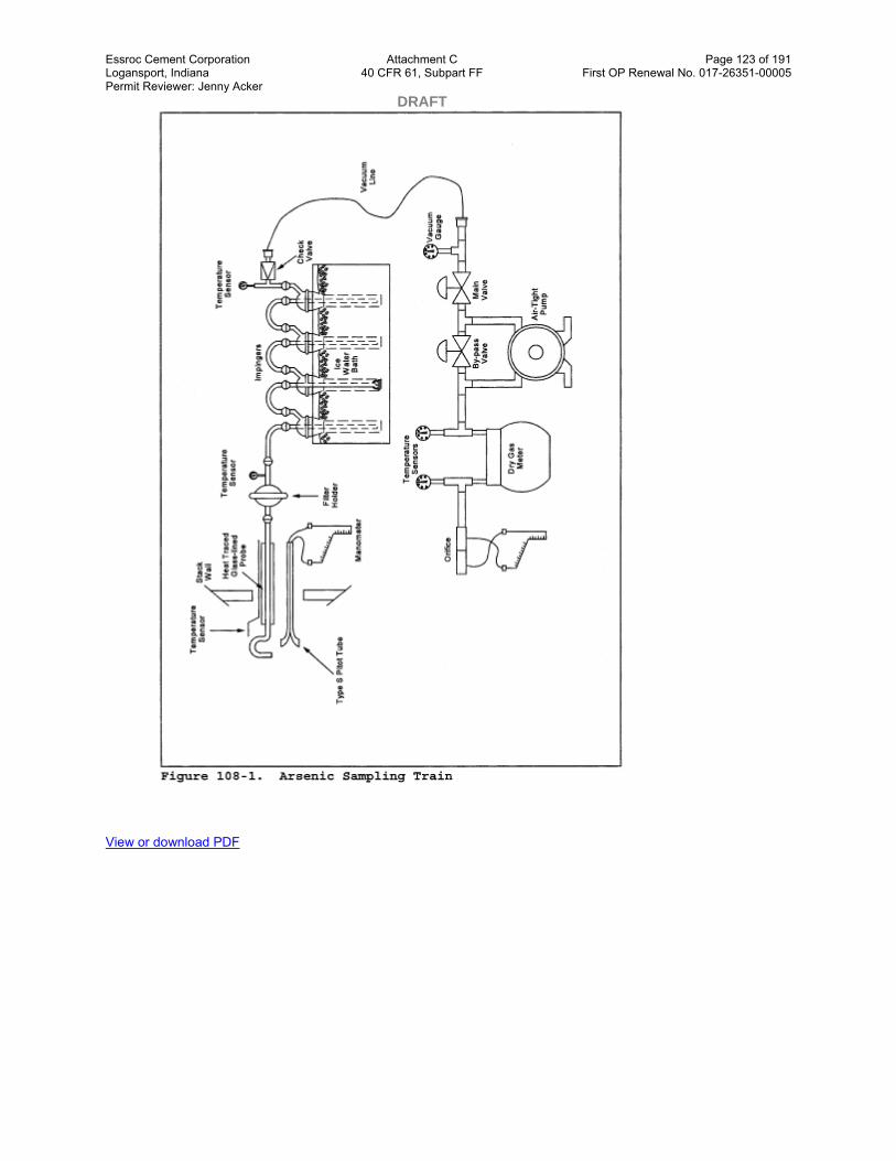
Essroc Cement Corporation Attachment C Page 123 of 191 Logansport, Indiana 40 CFR 61, Subpart FF First OP Renewal No. 017-26351-00005 Permit Reviewer: Jenny Acker DRAFT
View or download PDF

Essroc Cement Corporation Attachment C Page 124 of 191 Logansport, Indiana 40 CFR 61, Subpart FF First OP Renewal No. 017-26351-00005 Permit Reviewer: Jenny Acker DRAFT
View or download PDF
Method 108A—Determination of Arsenic Content in Ore Samples From Nonferrous Smelters
Note: This method does not include all of the specifications ( e.g., equipment and supplies) and procedures ( e.g., sampling and analytical) essential to its performance. Some material is incorporated by reference from other methods in appendix A to 40 CFR part 60. Therefore, to obtain reliable results, persons using this method should have a thorough knowledge of Method 12.
1.0 Scope and Application
1.1 Analytes.
Essroc Cement Corporation Attachment C Page 125 of 191 Logansport, Indiana 40 CFR 61, Subpart FF First OP Renewal No. 017-26351-00005 Permit Reviewer: Jenny Acker DRAFT
Analyte CAS No. Sensitivity
Arsenic compounds as arsenic (As) 7440–38–2 Lower limit 10 µg/ml or less.
1.2 Applicability. This method applies to the determination of inorganic As content of process ore and reverberatory matte samples from nonferrous smelters and other sources as specified in an applicable subpart of the regulations.
1.3 Data Quality Objectives. Adherence to the requirements of this method will enhance the quality of the data obtained from air pollutant sampling methods.
2.0 Summary of Method
Arsenic bound in ore samples is liberated by acid digestion and analyzed by flame atomic absorption spectrophotometry (AAS).
3.0 Definitions[Reserved]
4.0 Interferences
Analysis for As by flame AAS is sensitive to the chemical composition and to the physical properties ( e.g., viscosity, pH) of the sample. The analytical procedure includes a check for matrix effects (section 11.5).
5.0 Safety
5.1 Disclaimer. This method may involve hazardous materials, operations, and equipment. This test method may not address all of the safety problems associated with its use. It is the responsibility of the user to establish appropriate safety and health practices and determine the applicability of regulatory limitations prior to performing this test method.
5.2 Corrosive Reagents. The following reagents are hazardous. Personal protective equipment and safe procedures that prevent chemical splashes are recommended. If contact occurs, immediately flush with copious amounts of water for at least 15 minutes. Remove clothing under shower and decontaminate. Treat residual chemical burns as thermal burns.
5.2.1 Hydrochloric Acid (HCl). Highly corrosive liquid with toxic vapors. Vapors are highly irritating to eyes, skin, nose, and lungs, causing severe damage. May cause bronchitis, pneumonia, or edema of lungs. Exposure to concentrations of 0.13 to 0.2 percent can be lethal to humans in a few minutes. Provide ventilation to limit exposure. Reacts with metals, producing hydrogen gas.
5.2.2 Hydrofluoric Acid (HF). Highly corrosive to eyes, skin, nose, throat, and lungs. Reaction to exposure may be delayed by 24 hours or more. Provide ventilation to limit exposure.
5.2.3 Hydrogen Peroxide (H2O2). Very harmful to eyes. 30% H2O2can burn skin, nose, and lungs.
5.2.4 Nitric Acid (HNO3). Highly corrosive to eyes, skin, nose, and lungs. Vapors are highly toxic and can cause bronchitis, pneumonia, or edema of lungs. Reaction to inhalation may be delayed as long as 30 hours and still be fatal. Provide ventilation to limit exposure. Strong oxidizer. Hazardous reaction may occur with organic materials such as solvents.
5.2.5 Sodium Hydroxide (NaOH). Causes severe damage to eyes and skin. Inhalation causes irritation to nose, throat, and lungs. Reacts exothermically with limited amounts of water.
6.0 Equipment and Supplies
6.1 Sample Collection and Preparation. The following items are required for sample collection and preparation:
Essroc Cement Corporation Attachment C Page 126 of 191 Logansport, Indiana 40 CFR 61, Subpart FF First OP Renewal No. 017-26351-00005 Permit Reviewer: Jenny Acker DRAFT 6.1.1 Parr Acid Digestion Bomb. Stainless steel with vapor-tight Teflon cup and cover.
6.1.2 Volumetric Pipets. 2- and 5-ml sizes.
6.1.3 Volumetric Flask. 50-ml polypropylene with screw caps, (one needed per standard).
6.1.4 Funnel. Polyethylene or polypropylene.
6.1.5 Oven. Capable of maintaining a temperature of approximately 105 °C (221 °F).
6.1.6 Analytical Balance. To measure to within 0.1 mg.
6.2 Analysis. The following items are required for analysis:
6.2.1 Spectrophotometer and Recorder. Equipped with an electrodeless discharge lamp and a background corrector to measure absorbance at 193.7 nm. For measuring samples having less than 10 µg As/ml, use a graphite furnace or vapor generator accessory. The recorder shall match the output of the spectrophotometer.
6.2.2 Volumetric Flasks. Class A, 50-ml (one needed per sample and blank), 500-ml, and 1-liter.
6.2.3 Volumetric Pipets. Class A, 1-, 5-, 10-, and 25-ml sizes.
7.0 Reagents and Standards.
Unless otherwise indicated, it is intended that all reagents conform to the specifications established by the Committee on Analytical Reagents of the American Chemical Society, where such specifications are available; otherwise, use the best available grade.
7.1 Sample Collection and Preparation. The following reagents are required for sample collection and preparation:
7.1.1 Water. Deionized distilled to meet ASTM D 1193–77 or 91 Type 3 (incorporated by reference—See §61.18). When high concentrations of organic matter are not expected to be present, the KMnO4test for oxidizable organic matter may be omitted. Use in all dilutions requiring water.
7.1.2 Nitric Acid Concentrated.
7.1.3 Nitric Acid, 0.5 N. In a 1-liter volumetric flask containing water, add 32 ml of concentrated HNO3and dilute to volume with water.
7.1.4 Hydrofluoric Acid, Concentrated.
7.1.5 Potassium Chloride (KCl) Solution, 10 percent weight by volume (W/V). Dissolve 10 g KCl in water, add 3 ml concentrated HNO3, and dilute to 100 ml.
7.1.6 Filter. Teflon filters, 3-micron porosity, 47-mm size. (Available from Millipore Co., type FS, Catalog Number FSLW04700.)
7.1.7 Sodium Borohydride (NaBH4), 5 Percent (W/V). Dissolve 50.0 g of NaBH4in about 500 ml of 0.1 N NaOH in a 1-liter volumetric flask. Then, dilute to exactly 1.0 liter with 0.1 N NaOH.
7.1.8 Nickel Nitrate, 5 Percent Ni (W/V). Dissolve 24.780 g of nickel nitrate hexahydrate [Ni(NO3)26H2O] in water in a 100-ml volumetric flask, and dilute to 100 ml with water.
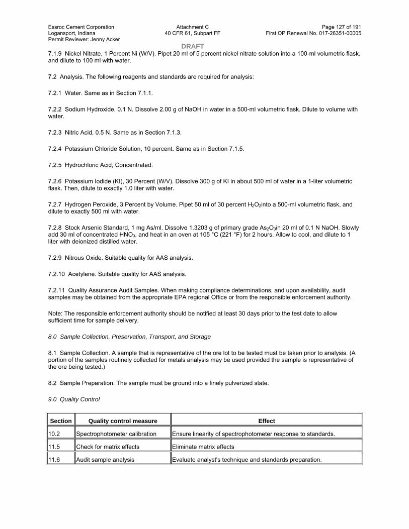
Essroc Cement Corporation Attachment C Page 127 of 191 Logansport, Indiana 40 CFR 61, Subpart FF First OP Renewal No. 017-26351-00005 Permit Reviewer: Jenny Acker DRAFT 7.1.9 Nickel Nitrate, 1 Percent Ni (W/V). Pipet 20 ml of 5 percent nickel nitrate solution into a 100-ml volumetric flask, and dilute to 100 ml with water.
7.2 Analysis. The following reagents and standards are required for analysis:
7.2.1 Water. Same as in Section 7.1.1.
7.2.2 Sodium Hydroxide, 0.1 N. Dissolve 2.00 g of NaOH in water in a 500-ml volumetric flask. Dilute to volume with water.
7.2.3 Nitric Acid, 0.5 N. Same as in Section 7.1.3.
7.2.4 Potassium Chloride Solution, 10 percent. Same as in Section 7.1.5.
7.2.5 Hydrochloric Acid, Concentrated.
7.2.6 Potassium Iodide (KI), 30 Percent (W/V). Dissolve 300 g of KI in about 500 ml of water in a 1-liter volumetric flask. Then, dilute to exactly 1.0 liter with water.
7.2.7 Hydrogen Peroxide, 3 Percent by Volume. Pipet 50 ml of 30 percent H2O2into a 500-ml volumetric flask, and dilute to exactly 500 ml with water.
7.2.8 Stock Arsenic Standard, 1 mg As/ml. Dissolve 1.3203 g of primary grade As2O3in 20 ml of 0.1 N NaOH. Slowly add 30 ml of concentrated HNO3, and heat in an oven at 105 °C (221 °F) for 2 hours. Allow to cool, and dilute to 1 liter with deionized distilled water.
7.2.9 Nitrous Oxide. Suitable quality for AAS analysis.
7.2.10 Acetylene. Suitable quality for AAS analysis.
7.2.11 Quality Assurance Audit Samples. When making compliance determinations, and upon availability, audit samples may be obtained from the appropriate EPA regional Office or from the responsible enforcement authority.
Note: The responsible enforcement authority should be notified at least 30 days prior to the test date to allow sufficient time for sample delivery.
8.0 Sample Collection, Preservation, Transport, and Storage
8.1 Sample Collection. A sample that is representative of the ore lot to be tested must be taken prior to analysis. (A portion of the samples routinely collected for metals analysis may be used provided the sample is representative of the ore being tested.)
8.2 Sample Preparation. The sample must be ground into a finely pulverized state.
9.0 Quality Control
Section Quality control measure Effect
10.2 Spectrophotometer calibration Ensure linearity of spectrophotometer response to standards.
11.5 Check for matrix effects Eliminate matrix effects
11.6 Audit sample analysis Evaluate analyst's technique and standards preparation.

Essroc Cement Corporation Attachment C Page 128 of 191 Logansport, Indiana 40 CFR 61, Subpart FF First OP Renewal No. 017-26351-00005 Permit Reviewer: Jenny Acker DRAFT 10.0 Calibration and Standardizations
Note: Maintain a laboratory log of all calibrations.
10.1 Preparation of Standard Solutions. Pipet 1, 5, 10, and 25 ml of the stock As solution into separate 100-ml volumetric flasks. Add 10 ml KCl solution and dilute to the mark with 0.5 N HNO3. This will give standard concentrations of 10, 50, 100, and 250 µg As/ml. For low-level arsenic samples that require the use of a graphite furnace or vapor generator, follow the procedures in Section 11.3:1. Dilute 10 ml of KCl solution to 100 ml with 0.5 N HNO3and use as a reagent blank.
10.2 Calibration Curve. Analyze the reagent blank and each standard solution according to the procedures outlined in Section 11.3. Repeat this procedure on each standard solution until two consecutive peaks agree within 3 percent of their average value. Subtract the average peak height (or peak area) of the blank—which must be less than 2 percent of recorder full scale—from the averaged peak heights of each standard solution. If the blank absorbance is greater than 2 percent of full-scale, the probable cause is Hg contamination of a reagent or carry-over of As from a previous sample. Prepare the calibration curve by plotting the corrected peak height of each standard solution versus the corresponding final total As weight in the solution.
10.3 Spectrophotometer Calibration Quality Control. Calculate the least squares slope of the calibration curve. The line must pass through the origin or through a point no further from the origin than ±2 percent of the recorder full scale. Multiply the corrected peak height by the reciprocal of the least squares slope to determine the distance each calibration point lies from the theoretical calibration line. The difference between the calculated concentration values and the actual concentrations must be less than 7 percent for all standards.
Note: For instruments equipped with direct concentration readout devices, preparation of a standard curve will not be necessary. In all cases, follow calibration and operational procedures in the manufacturer's instruction manual.
11.0 Analytical Procedure
11.1 Sample Preparation. Weigh 50 to 500 mg of finely pulverized sample to the nearest 0.1 mg. Transfer the sample into the Teflon cup of the digestion bomb, and add 2 ml each of concentrated HNO3and HF. Seal the bomb immediately to prevent the loss of any volatile arsenic compounds that may form. Heat in an oven at 105 °C (221 °F) for 2 hours. Remove the bomb from the oven and allow to cool. Using a Teflon filter, quantitatively filter the digested sample into a 50-ml polypropylene volumetric flask. Rinse the bomb three times with small portions of 0.5 N HNO3, and filter the rinses into the flask. Add 5 ml of KCl solution to the flask, and dilute to 50 ml with 0.5 N HNO3.
11.2 Spectrophotometer Preparation.
11.2.1 Turn on the power; set the wavelength, slit width, and lamp current. Adjust the background corrector as instructed by the manufacturer's manual for the particular atomic absorption spectrophotometer. Adjust the burner and flame characteristics as necessary.
11.2.2 Develop a spectrophotometer calibration curve as outlined in Sections 10.2 and 10.3.
11.3 Arsenic Determination. Analyze an appropriately sized aliquot of each diluted sample (from Section 11.1) until two consecutive peak heights agree within 3 percent of their average value. If applicable, follow the procedures outlined in Section 11.3.1. If the sample concentration falls outside the range of the calibration curve, make an appropriate dilution with 0.5 N HNO3so that the final concentration falls within the range of the curve. Using the calibration curve, determine the As concentration in each sample.
Note: Because instruments vary between manufacturers, no detailed operating instructions will be given here. Instead, the instrument manufacturer's detailed operating instructions should be followed.
11.3.1 Arsenic Determination at Low Concentration. The lower limit of flame AAS is 10 µg As/ml. If the arsenic concentration of any sample is at a lower level, use the vapor generator or graphite furnace which is available as an accessory component. Flame, graphite furnace, or vapor generators may be used for samples whose concentrations are between 10 and 30 µg/ml. Follow the manufacturer's instructions in the use of such equipment.

Essroc Cement Corporation Attachment C Page 129 of 191 Logansport, Indiana 40 CFR 61, Subpart FF First OP Renewal No. 017-26351-00005 Permit Reviewer: Jenny Acker DRAFT 11.3.1.1 Vapor Generator Procedure. Place a sample containing between 0 and 5 µg of arsenic in the reaction tube, and dilute to 15 ml with water. Since there is some trial and error involved in this procedure, it may be necessary to screen the samples by conventional AAS until an approximate concentration is determined. After determining the approximate concentration, adjust the volume of the sample accordingly. Pipet 15 ml of concentrated HCl into each tube. Add 1 ml of 30 percent KI solution. Place the reaction tube into a 50 °C (120 °F) water bath for 5 minutes. Cool to room temperature. Connect the reaction tube to the vapor generator assembly. When the instrument response has returned to baseline, inject 5.0 ml of 5 percent NaBH4and integrate the resulting spectrophotometer signal over a 30-second time period.
11.3.1.2 Graphite Furnace Procedure. Pipet 5 ml of the digested solution into a 10-ml volumetric flask. Add 1 ml of the 1 percent nickel nitrate solution, 0.5 ml of 50 percent HNO3, and 1 ml of the 3 percent H2O2, and dilute to 10 ml with water. The sample is now ready to inject in the furnace for analysis.
11.4 Run a blank and standard at least after every five samples to check the spectrophotometer calibration. The peak height of the blank must pass through a point no further from the origin than ±2 percent of the recorder full scale. The difference between the measured concentration of the standard (the product of the corrected average peak height and the reciprocal of the least squares slope) and the actual concentration of the standard must be less than 7 percent, or recalibration of the analyzer is required.
11.5 Mandatory Check for Matrix Effects on the Arsenic Results. Same as Method 12, Section 11.5.
11.6 Audit Sample Analysis.
11.6.1 When the method is used to analyze samples to demonstrate compliance with a source emission regulation, a set of EPA audit samples must be analyzed, subject to availability.
11.6.2 Concurrently analyze the audit samples and the compliance samples in the same manner to evaluate the technique of the analyst and the standards preparation.
Note: It is recommended that known quality control samples be analyzed prior to the compliance and audit sample analyses to optimize the system accuracy and precision. These quality control samples may be obtained by contacting the appropriate EPA regional Office or the responsible enforcement authority.
11.6.3 The same analyst, analytical reagents, and analytical system shall be used for the compliance samples and the EPA audit samples. If this condition is met, duplicate auditing of subsequent compliance analyses for the same enforcement agency within a 30-day period is waived. An audit sample set may not be used to validate different sets of compliance samples under the jurisdiction of separate enforcement agencies, unless prior arrangements have been made with both enforcement agencies.
11.7 Audit Sample Results.
11.7.1 Calculate the audit sample concentrations in g/m3 and submit results using the instructions provided with the audit samples.
11.7.2 Report the results of the audit samples and the compliance determination samples along with their identification numbers, and the analyst's name to the responsible enforcement authority. Include this information with reports of any subsequent compliance analyses for the same enforcement authority during the 30-day period.
11.7.3 The concentrations of the audit samples obtained by the analyst shall agree within 10 percent of the actual concentrations. If the 10 percent specification is not met, reanalyze the compliance and audit samples, and include initial and reanalysis values in the test report.
11.7.4 Failure to meet the 10 percent specification may require retests until the audit problems are resolved. However, if the audit results do not affect the compliance or noncompliance status of the affected facility, the Administrator may waive the reanalysis requirement, further audits, or retests and accept the results of the compliance test. While steps are being taken to resolve audit analysis problems, the Administrator may also choose to use the data to determine the compliance or noncompliance status of the affected facility.

Essroc Cement Corporation Attachment C Page 130 of 191 Logansport, Indiana 40 CFR 61, Subpart FF First OP Renewal No. 017-26351-00005 Permit Reviewer: Jenny Acker DRAFT 12.0 Data Analysis and Calculations
12.1 Calculate the percent arsenic in the ore sample as follows:
Where:
Ca= Concentration of As as read from the standard curve, µg/ml.
Fd= Dilution factor (equals to 1 if the sample has not been diluted).
W = Weight of ore sample analyzed, mg.
5 = (50 ml sample “ 100)/(103 µg/mg).
13.0 Method Performance
13.1 Sensitivity. The lower limit of flame AAS is 10 µg As/ml. The analytical procedure includes provisions for the use of a graphite furnace or vapor generator for samples with a lower arsenic concentration.
14.0 Pollution Prevention.[Reserved]
15.0 Waste Management.[Reserved]
16.0 References
Same as References 1 through 9 of Section 17.0 of Method 5, with the addition of the following:
1. Perkin Elmer Corporation. Analytical Methods of Atomic Absorption Spectrophotometry. 303–0152. Norwalk, Connecticut. September 1976. pp 5–6.
2. Ringwald, D. Arsenic Determination on Process Materials from ASARCO's Copper Smelter in Tacoma, Washington. Unpublished Report. Prepared for Emission Measurement Branch, Emission Standards and Engineering Division, U.S. Environmental Protection Agency, Research Triangle Park, North Carolina. August 1980. 35 pp.
3. Stack Sampling Safety Manual (Draft). U.S. Environmental Protection Agency, Office of Air Quality Planning and Standard, Research Triangle Park, NC. September 1978.
17.0 Tables, Diagrams, Flowcharts, and Validation Data.[Reserved]
Method 108B—Determination of Arsenic Content in Ore Samples From Nonferrous Smelters
Note: This method does not include all of the specifications ( e.g., equipment and supplies) and procedures ( e.g., sampling and analytical) essential to its performance. Some material is incorporated by reference from other methods in this appendix and in appendix A to 40 CFR part 60. Therefore, to obtain reliable results, persons using this method should have a thorough knowledge of at least the following additional test methods: Method 12 and Method 108A.
1.0 Scope and Application
1.1 Analytes.

Essroc Cement Corporation Attachment C Page 131 of 191 Logansport, Indiana 40 CFR 61, Subpart FF First OP Renewal No. 017-26351-00005 Permit Reviewer: Jenny Acker DRAFT
Analyte CAS No. Sensitivity
Arsenic compounds as arsenic (As) 7440–38–2 Lower limit 10 µg/ml.
1.2 Applicability. This method applies to the determination of inorganic As content of process ore and reverberatory matte samples from nonferrous smelters and other sources as specified in an applicable subpart of the regulations. Samples resulting in an analytical concentration greater than 10 µg As/ml may be analyzed by this method. For lower level arsenic samples, Method 108C should be used.
1.3 Data Quality Objectives. Adherence to the requirements of this method will enhance the quality of the data obtained from air pollutant sampling methods.
2.0 Summary of Method
Arsenic bound in ore samples is liberated by acid digestion and analyzed by flame atomic absorption spectrophotometry (AAS).
3.0 Definitions[Reserved]
4.0 Interferences
Analysis for As by flame AAS is sensitive to the chemical composition and to the physical properties ( e.g., viscosity, pH) of the sample. The analytical procedure includes a check for matrix effects (Section 11.4).
5.0 Safety
5.1 Disclaimer. This method may involve hazardous materials, operations, and equipment. This test method may not address all of the safety problems associated with its use. It is the responsibility of the user to establish appropriate safety and health practices and determine the applicability of regulatory limitations prior to performing this test method.
5.2 Corrosive Reagents. The following reagents are hazardous. Personal protective equipment and safe procedures that prevent chemical splashes are recommended. If contact occurs, immediately flush with copious amounts of water for at least 15 minutes. Remove clothing under shower and decontaminate. Treat residual chemical burns as thermal burns.
5.2.1 Hydrochloric acid (HCl). Highly corrosive liquid with toxic vapors. Vapors are highly irritating to eyes, skin, nose, and lungs, causing severe damage. May cause bronchitis, pneumonia, or edema of lungs. Exposure to concentrations of 0.13 to 0.2 percent can be lethal to humans in a few minutes. Provide ventilation to limit exposure. Reacts with metals, producing hydrogen gas.
5.2.2 Hydrofluoric Acid (HF). Highly corrosive to eyes, skin, nose, throat, and lungs. Reaction to exposure may be delayed by 24 hours or more. Provide ventilation to limit exposure.
5.2.3 Nitric Acid (HNO3). Highly corrosive to eyes, skin, nose, and lungs. Vapors are highly toxic and can cause bronchitis, pneumonia, or edema of lungs. Reaction to inhalation may be delayed as long as 30 hours and still be fatal. Provide ventilation to limit exposure. Strong oxidizer. Hazardous reaction may occur with organic materials such as solvents.
5.2.4 Perchloric Acid (HClO4). Corrosive to eyes, skin, nose, and throat. Provide ventilation to limit exposure. Very strong oxidizer. Keep separate from water and oxidizable materials to prevent vigorous evolution of heat, spontaneous combustion, or explosion. Heat solutions containing HClO4only in hoods specifically designed for HClO4.
6.0 Equipment and Supplies
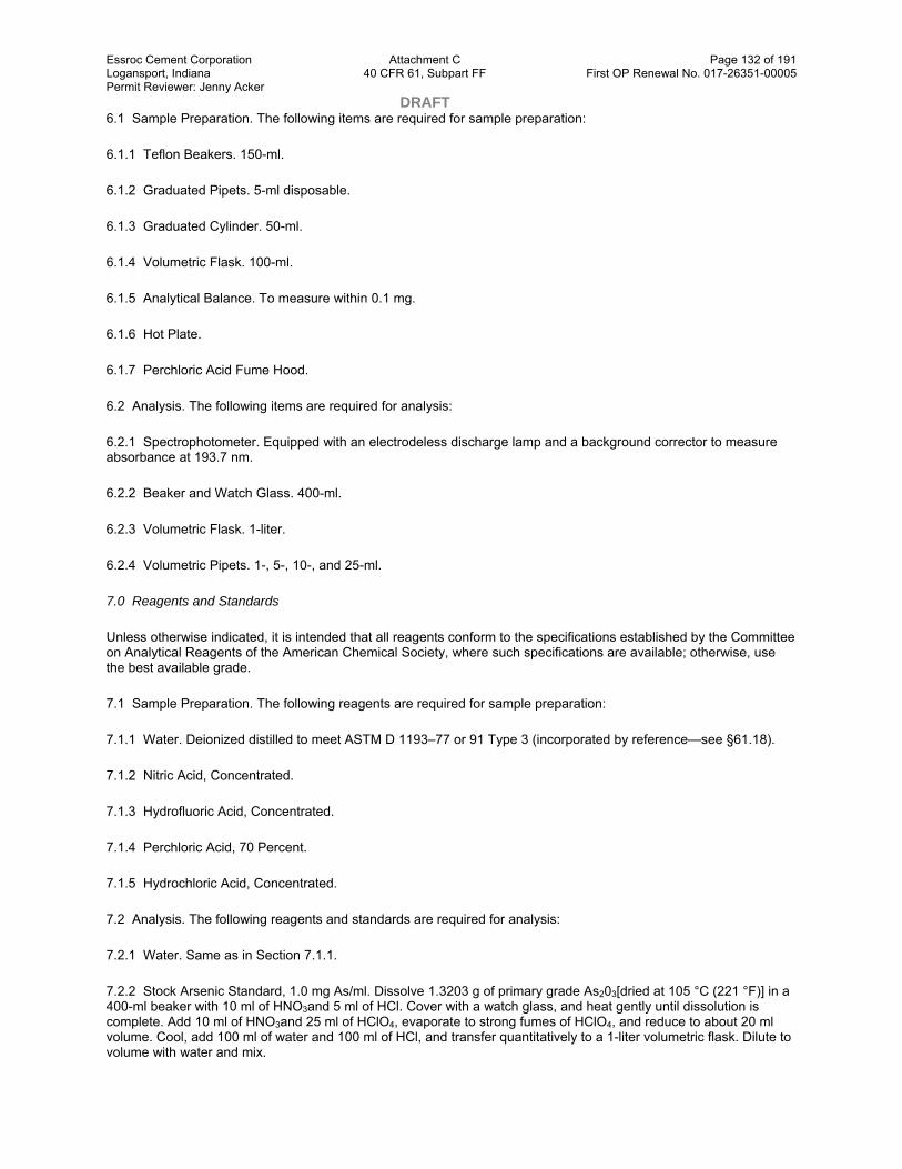
Essroc Cement Corporation Attachment C Page 132 of 191 Logansport, Indiana 40 CFR 61, Subpart FF First OP Renewal No. 017-26351-00005 Permit Reviewer: Jenny Acker DRAFT 6.1 Sample Preparation. The following items are required for sample preparation:
6.1.1 Teflon Beakers. 150-ml.
6.1.2 Graduated Pipets. 5-ml disposable.
6.1.3 Graduated Cylinder. 50-ml.
6.1.4 Volumetric Flask. 100-ml.
6.1.5 Analytical Balance. To measure within 0.1 mg.
6.1.6 Hot Plate.
6.1.7 Perchloric Acid Fume Hood.
6.2 Analysis. The following items are required for analysis:
6.2.1 Spectrophotometer. Equipped with an electrodeless discharge lamp and a background corrector to measure absorbance at 193.7 nm.
6.2.2 Beaker and Watch Glass. 400-ml.
6.2.3 Volumetric Flask. 1-liter.
6.2.4 Volumetric Pipets. 1-, 5-, 10-, and 25-ml.
7.0 Reagents and Standards
Unless otherwise indicated, it is intended that all reagents conform to the specifications established by the Committee on Analytical Reagents of the American Chemical Society, where such specifications are available; otherwise, use the best available grade.
7.1 Sample Preparation. The following reagents are required for sample preparation:
7.1.1 Water. Deionized distilled to meet ASTM D 1193–77 or 91 Type 3 (incorporated by reference—see §61.18).
7.1.2 Nitric Acid, Concentrated.
7.1.3 Hydrofluoric Acid, Concentrated.
7.1.4 Perchloric Acid, 70 Percent.
7.1.5 Hydrochloric Acid, Concentrated.
7.2 Analysis. The following reagents and standards are required for analysis:
7.2.1 Water. Same as in Section 7.1.1.
7.2.2 Stock Arsenic Standard, 1.0 mg As/ml. Dissolve 1.3203 g of primary grade As203[dried at 105 °C (221 °F)] in a 400-ml beaker with 10 ml of HNO3and 5 ml of HCl. Cover with a watch glass, and heat gently until dissolution is complete. Add 10 ml of HNO3and 25 ml of HClO4, evaporate to strong fumes of HClO4, and reduce to about 20 ml volume. Cool, add 100 ml of water and 100 ml of HCl, and transfer quantitatively to a 1-liter volumetric flask. Dilute to volume with water and mix.
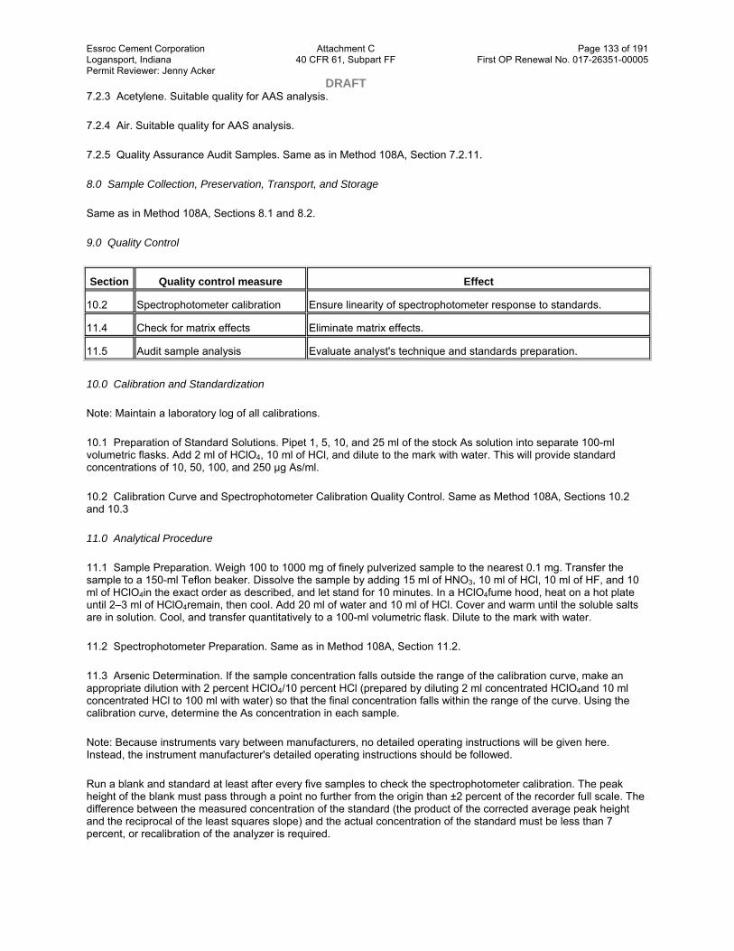
Essroc Cement Corporation Attachment C Page 133 of 191 Logansport, Indiana 40 CFR 61, Subpart FF First OP Renewal No. 017-26351-00005 Permit Reviewer: Jenny Acker DRAFT 7.2.3 Acetylene. Suitable quality for AAS analysis.
7.2.4 Air. Suitable quality for AAS analysis.
7.2.5 Quality Assurance Audit Samples. Same as in Method 108A, Section 7.2.11.
8.0 Sample Collection, Preservation, Transport, and Storage
Same as in Method 108A, Sections 8.1 and 8.2.
9.0 Quality Control
Section Quality control measure Effect
10.2 Spectrophotometer calibration Ensure linearity of spectrophotometer response to standards.
11.4 Check for matrix effects Eliminate matrix effects.
11.5 Audit sample analysis Evaluate analyst's technique and standards preparation.
10.0 Calibration and Standardization
Note: Maintain a laboratory log of all calibrations.
10.1 Preparation of Standard Solutions. Pipet 1, 5, 10, and 25 ml of the stock As solution into separate 100-ml volumetric flasks. Add 2 ml of HClO4, 10 ml of HCl, and dilute to the mark with water. This will provide standard concentrations of 10, 50, 100, and 250 µg As/ml.
10.2 Calibration Curve and Spectrophotometer Calibration Quality Control. Same as Method 108A, Sections 10.2 and 10.3
11.0 Analytical Procedure
11.1 Sample Preparation. Weigh 100 to 1000 mg of finely pulverized sample to the nearest 0.1 mg. Transfer the sample to a 150-ml Teflon beaker. Dissolve the sample by adding 15 ml of HNO3, 10 ml of HCl, 10 ml of HF, and 10 ml of HClO4in the exact order as described, and let stand for 10 minutes. In a HClO4fume hood, heat on a hot plate until 2–3 ml of HClO4remain, then cool. Add 20 ml of water and 10 ml of HCl. Cover and warm until the soluble salts are in solution. Cool, and transfer quantitatively to a 100-ml volumetric flask. Dilute to the mark with water.
11.2 Spectrophotometer Preparation. Same as in Method 108A, Section 11.2.
11.3 Arsenic Determination. If the sample concentration falls outside the range of the calibration curve, make an appropriate dilution with 2 percent HClO4/10 percent HCl (prepared by diluting 2 ml concentrated HClO4and 10 ml concentrated HCl to 100 ml with water) so that the final concentration falls within the range of the curve. Using the calibration curve, determine the As concentration in each sample.
Note: Because instruments vary between manufacturers, no detailed operating instructions will be given here. Instead, the instrument manufacturer's detailed operating instructions should be followed.
Run a blank and standard at least after every five samples to check the spectrophotometer calibration. The peak height of the blank must pass through a point no further from the origin than ±2 percent of the recorder full scale. The difference between the measured concentration of the standard (the product of the corrected average peak height and the reciprocal of the least squares slope) and the actual concentration of the standard must be less than 7 percent, or recalibration of the analyzer is required.

Essroc Cement Corporation Attachment C Page 134 of 191 Logansport, Indiana 40 CFR 61, Subpart FF First OP Renewal No. 017-26351-00005 Permit Reviewer: Jenny Acker DRAFT 11.4 Mandatory Check for Matrix Effects on the Arsenic Results. Same as Method 12, Section 11.5.
11.5 Audit Sample Analysis. Same as in Method 108A, Section 11.6.
12.0 Data Analysis and Calculations
Same as in Method 108A, Section 12.0.
13.0 Method Performance
13.1 Sensitivity. The lower limit of flame AAS is 10 µg As/ml.
14.0 Pollution Prevention[Reserved]
15.0 Waste Management[Reserved]
16.0 References
Same as in Method 108A, Section 16.0.
17.0 Tables, Diagrams, Flowcharts, and Validation Data[Reserved]
Method 108C—Determination of Arsenic Content in Ore Samples From Nonferrous Smelters (Molybdenum Blue Photometric Procedure)
Note: This method does not include all of the specifications ( e.g., equipment and supplies) and procedures ( e.g., sampling and analytical) essential to its performance. Some material is incorporated by reference from other methods in this part. Therefore, to obtain reliable results, persons using this method should have a thorough knowledge of at least Method 108A.
1.0 Scope and Application
1.1 Analytes.
Analyte CAS No. Sensitivity
Arsenic compounds as arsenic (As) 7440–38–2 Lower limit 0.0002 percent As by weight.
1.2 Applicability. This method applies to the determination of inorganic As content of process ore and reverberatory matte samples from nonferrous smelters and other sources as specified in an applicable subpart of the regulations.
1.3 Data Quality Objectives. Adherence to the requirements of this method will enhance the quality of the data obtained from air pollutant sampling methods.
2.0 Summary of Method
Arsenic bound in ore samples is liberated by acid digestion and analyzed by the molybdenum blue photometric procedure.
3.0 Definitions.[Reserved]
4.0 Interferences.[Reserved]
5.0 Safety

Essroc Cement Corporation Attachment C Page 135 of 191 Logansport, Indiana 40 CFR 61, Subpart FF First OP Renewal No. 017-26351-00005 Permit Reviewer: Jenny Acker DRAFT 5.1 Disclaimer. This method may involve hazardous materials, operations, and equipment. This test method may not address all of the safety problems associated with its use. It is the responsibility of the user to establish appropriate safety and health practices and determine the applicability of regulatory limitations prior to performing this test method.
5.2 Corrosive Reagents. The following reagents are hazardous. Personal protective equipment and safe procedures that prevent chemical splashes are recommended. If contact occurs, immediately flush with copious amounts of water for at least 15 minutes. Remove clothing under shower and decontaminate. Treat residual chemical burns as thermal burns.
5.2.1 Hydrochloric Acid (HCl). Highly corrosive liquid with toxic vapors. Vapors are highly irritating to eyes, skin, nose, and lungs, causing severe damage. May cause bronchitis, pneumonia, or edema of lungs. Exposure to concentrations of 0.13 to 0.2 percent can be lethal to humans in a few minutes. Provide ventilation to limit exposure. Reacts with metals, producing hydrogen gas.
5.2.2 Hydrofluoric Acid (HF). Highly corrosive to eyes, skin, nose, throat, and lungs. Reaction to exposure may be delayed by 24 hours or more. Provide ventilation to limit exposure.
5.2.3 Nitric Acid (HNO4). Highly corrosive to eyes, skin, nose, and lungs. Vapors are highly toxic and can cause bronchitis, pneumonia, or edema of lungs. Reaction to inhalation may be delayed as long as 30 hours and still be fatal. Provide ventilation to limit exposure. Strong oxidizer. Hazardous reaction may occur with organic materials such as solvents.
5.2.4 Perchloric Acid (HClO4). Corrosive to eyes, skin, nose, and throat. Provide ventilation to limit exposure. Very strong oxidizer. Keep separate from water and oxidizable materials to prevent vigorous evolution of heat, spontaneous combustion, or explosion. Heat solutions containing HClO4only in hoods specifically designed for HClO4.
5.2.5 Sulfuric acid (H2SO4). Rapidly destructive to body tissue. Will cause third degree burns. Eye damage may result in blindness. Inhalation may be fatal from spasm of the larynx, usually within 30 minutes. May cause lung tissue damage with edema. 3 mg/m3 will cause lung damage in uninitiated. 1 mg/m3 for 8 hours will cause lung damage or, in higher concentrations, death. Provide ventilation to limit inhalation. Reacts violently with metals and organics.
6.0 Equipment and Supplies
6.1 Sample Preparation. The following items are required for sample preparation:
6.1.1 Analytical Balance. To measure to within 0.1 mg.
6.1.2 Erlenmeyer Flask. 300-ml.
6.1.3 Hot Plate.
6.1.4 Distillation Apparatus. No. 6, in ASTM E 50–82, 86, or 90 (Reapproved 1995)(incorporated by reference—see §61.18); detailed in Figure 108C–1.
6.1.5 Graduated Cylinder. 50-ml.
6.1.6 Perchloric Acid Fume Hood.
6.2 Analysis. The following items are required for analysis:
6.2.1 Spectrophotometer. Capable of measuring at 660 nm.
6.2.2 Volumetric Flasks. 50- and 100-ml.

Essroc Cement Corporation Attachment C Page 136 of 191 Logansport, Indiana 40 CFR 61, Subpart FF First OP Renewal No. 017-26351-00005 Permit Reviewer: Jenny Acker DRAFT 7.0 Reagents and Standards
Unless otherwise indicated, it is intended that all reagents conform to the specifications established by the Committee on Analytical Reagents of the American Chemical Society, where such specifications are available; otherwise, use the best available grade.
7.1 Sample Preparation. The following reagents are required for sample preparation:
7.1.1 Water. Deionized distilled to meet ASTM D 1193–77 or 91 Type 3 (incorporated by reference—see §61.18). When high concentrations of organic matter are not expected to be present, the KMnO4test for oxidizable organic matter may be omitted. Use in all dilutions requiring water.
7.1.2 Nitric Acid, Concentrated.
7.1.3 Hydrofluoric Acid, Concentrated.
7.1.4 Sulfuric Acid, Concentrated.
7.1.5 Perchloric Acid, 70 Percent.
7.1.6 Hydrochloric Acid, Concentrated.
7.1.7 Dilute Hydrochloric Acid. Add one part concentrated HCl to nine parts water.
7.1.8 Hydrazine Sulfate ((NH2)2·H2SO4).
7.1.9 Potassium Bromide (KBr).
7.1.10 Bromine Water, Saturated.
7.2 Analysis. The following reagents and standards are required for analysis:
7.2.1 Water. Same as in Section 7.1.1.
7.2.2 Methyl Orange Solution, 1 g/liter.
7.2.3 Ammonium Molybdate Solution, 5 g/liter. Dissolve 0.5 g (NH4)Mo7O24·4H2O in water in a 100-ml volumetric flask, and dilute to the mark. This solution must be freshly prepared.
7.2.4 Standard Arsenic Solution, 10 µg As/ml. Dissolve 0.13203 g of As2O3in 100 ml HCl in a 1-liter volumetric flask. Add 200 ml of water, cool, dilute to the mark with water, and mix. Transfer 100 ml of this solution to a 1-liter volumetric flask, add 40 ml HCl, cool, dilute to the mark, and mix.
7.2.5 Hydrazine Sulfate Solution, 1 g/liter. Dissolve 0.1 g of [(NH2)2·H2SO4] in water, and dilute to 100 ml in a volumetric flask. This solution must be freshly prepared.
7.2.6 Potassium Bromate (KBrO3) Solution, 0.03 Percent Weight by Volume (W/V). Dissolve 0.3 g KBrO3in water, and dilute to 1 liter with water.
7.2.7 Ammonium Hydroxide (NH4OH), Concentrated.
7.2.8 Boiling Granules.
7.2.9 Hydrochloric Acid, 50 percent by volume. Dilute equal parts concentrated HCl with water.

Essroc Cement Corporation Attachment C Page 137 of 191 Logansport, Indiana 40 CFR 61, Subpart FF First OP Renewal No. 017-26351-00005 Permit Reviewer: Jenny Acker DRAFT 7.2.10 Quality Assurance Audit Samples. Same as in Method 108A, Section 7.2.11.
8.0 Sample Collection, Preservation, Transport, and Storage
Same as in Method 108A, Sections 8.1 and 8.2.
9.0 Quality Control
Section Quality control measure Effect
10.2 Calibration curve preparation Ensure linearity of spectrophotometric analysis of standards.
11.3 Audit sample analysis Evaluate analyst's technique and standards preparation.
10.0 Calibration and Standardizations
Note: Maintain a laboratory log of all calibrations.
10.1 Preparation of Standard Solutions. Transfer 1.0, 2.0, 4.0, 8.0, 12.0, 16.0, and 20.0 ml of standard arsenic solution (10 µg/ml) to each of seven 50-ml volumetric flasks. Dilute to 20 ml with dilute HCl. Add one drop of methyl orange solution and neutralize to the yellow color with dropwise addition of NH4OH. Just bring back to the red color by dropwise addition of dilute HCl, and add 10 ml in excess. Proceed with the color development as described in Section 11.2.
10.2 Calibration Curve. Plot the spectrophotometric readings of the calibration solutions against µg As per 50 ml of solution. Use this curve to determine the As concentration of each sample.
10.3 Spectrophotometer Calibration Quality Control. Calculate the least squares slope of the calibration curve. The line must pass through the origin or through a point no further from the origin than ±2 percent of the recorder full scale. Multiply the corrected peak height by the reciprocal of the least squares slope to determine the distance each calibration point lies from the theoretical calibration line. The difference between the calculated concentration values and the actual concentrations must be less than 7 percent for all standards.
11.0 Analytical Procedure
11.1 Sample Preparation.
11.1.1 Weigh 1.0 g of finely pulverized sample to the nearest 0.1 mg. Transfer the sample to a 300 ml Erlenmeyer flask and add 15 ml of HNO3, 4 ml HCl, 2 ml HF, 3 ml HClO4, and 15 ml H2SO4, in the order listed. In a HClO4fume hood, heat on a hot plate to decompose the sample. Then heat while swirling over an open flame until dense white fumes evolve. Cool, add 15 ml of water, swirl to hydrate the H2SO4completely, and add several boiling granules. Cool to room temperature.
11.1.2 Add 1 g of KBr, 1 g hydrazine sulfate, and 50 ml HCl. Immediately attach the distillation head with thermometer and dip the side arm into a 50-ml graduated cylinder containing 25 ml of water and 2 ml of bromine water. Keep the graduated cylinder immersed in a beaker of cold water during distillation. Distill until the temperature of the vapor in the flask reaches 107 °C (225 °F). When distillation is complete, remove the flask from the hot plate, and simultaneously wash down the side arm with water as it is removed from the cylinder.
11.1.3 If the expected arsenic content is in the range of 0.0020 to 0.10 percent, dilute the distillate to the 50-ml mark of the cylinder with water, stopper, and mix. Transfer a 5.0-ml aliquot to a 50-ml volumetric flask. Add 10 ml of water and a boiling granule. Place the flask on a hot plate, and heat gently until the bromine is expelled and the color of methyl orange indicator persists upon the addition of 1 to 2 drops. Cool the flask to room temperature. Neutralize just to the yellow color of the indicator with dropwise additions of NH4OH. Bring back to the red color by dropwise addition of dilute HCl, and add 10 ml excess. Proceed with the molybdenum blue color development as described in Section 11.2.

Essroc Cement Corporation Attachment C Page 138 of 191 Logansport, Indiana 40 CFR 61, Subpart FF First OP Renewal No. 017-26351-00005 Permit Reviewer: Jenny Acker DRAFT 11.1.4 If the expected arsenic content is in the range of 0.0002 to 0.0010 percent As, transfer either the entire initial distillate or the measured remaining distillate from Section 11.1.2 to a 250-ml beaker. Wash the cylinder with two successive portions of concentrated HNO3, adding each portion to the distillate in the beaker. Add 4 ml of concentrated HClO4, a boiling granule, and cover with a flat watch glass placed slightly to one side. Boil gently on a hot plate until the volume is reduced to approximately 10 ml. Add 3 ml of HNO3, and continue the evaporation until HClO4is refluxing on the beaker cover. Cool briefly, rinse the underside of the watch glass and the inside of the beaker with about 3–5 ml of water, cover, and continue the evaporation to expel all but 2 ml of the HClO4.
Note: If the solution appears cloudy due to a small amount of antimony distilling over, add 4 ml of 50 percent HCl and 5 ml of water, cover, and warm gently until clear. If cloudiness persists, add 5 ml of HNO3and 2 ml H2SO4. Continue the evaporation of volatile acids to solubilize the antimony until dense white fumes of H2SO4appear. Retain at least 1 ml of the H2SO4.
11.1.5 To the 2 ml of HClO4solution or 1 ml of H2SO4solution, add 15 ml of water, boil gently for 2 minutes, and then cool. Proceed with the molybdenum blue color development by neutralizing the solution directly in the beaker just to the yellow indicator color by dropwise addition of NH4OH. Obtain the red color by dropwise addition of dilute HCl. Transfer the solution to a 50-ml volumetric flask. Rinse the beaker successively with 10 ml of dilute HCl, followed by several small portions of water. At this point the volume of solution in the flask should be no more than 40 ml. Continue with the color development as described in Section 11.2.
11.2 Analysis.
11.2.1 Add 1 ml of KBrO3solution to the flask and heat on a low-temperature hot plate to about 50 °C (122 °F) to oxidize the arsenic and methyl orange. Add 5.0 ml of ammonium molybdate solution to the warm solution and mix. Add 2.0 ml of hydrazine sulfate solution, dilute until the solution comes within the neck of the flask, and mix. Place the flask in a 400 ml beaker, 80 percent full of boiling water, for 10 minutes. Enough heat must be supplied to prevent the water bath from cooling much below the boiling point upon inserting the volumetric flask. Remove the flask, cool to room temperature, dilute to the mark, and mix.
11.2.2 Transfer a suitable portion of the reference solution to an absorption cell, and adjust the spectrophotometer to the initial setting using a light band centered at 660 nm. While maintaining this spectrophotometer adjustment, take the readings of the calibration solutions followed by the samples.
11.3 Audit Sample Analysis. Same as in Method 108A, Section 11.6.
12.0 Data Analysis and Calculations
Same as in Method 108A, Section 12.0.
13.0 Method Performance.[Reserved]
14.0 Pollution Prevention.[Reserved]
15.0 Waste Management.[Reserved]
16.0 References
1. Ringwald, D. Arsenic Determination on Process Materials from ASARCO's Copper Smelter in Tacoma, Washington. Unpublished Report. Prepared for the Emission Measurement Branch, Technical Support Division, U.S. Environmental Protection Agency, Research Triangle Park, North Carolina. August 1980. 35 pp.

Essroc Cement Corporation Attachment C Page 139 of 191 Logansport, Indiana 40 CFR 61, Subpart FF First OP Renewal No. 017-26351-00005 Permit Reviewer: Jenny Acker DRAFT 17.0 Tables, Diagrams, Flowcharts, and Validation
Data
View or download PDF
Method 111—Determination of Polonium–210 Emissions From Stationary Sources
Note: This method does not include all of the specifications ( e.g., equipment and supplies) and procedures ( e.g., sampling and analytical) essential to its performance. Some material is incorporated by reference from methods in appendix A to 40 CFR part 60. Therefore, to obtain reliable results, persons using this method should have a thorough knowledge of at least the following additional test methods: Method 1, Method 2, Method 3, and Method 5.
1.0 Scope and Application
1.1 Analytes.
Analyte CAS No. Sensitivity
Polonium 7440–08–6 Not specified.
1.2 Applicability. This method is applicable for the determination of the polonium-210 content of particulate matter samples collected from stationary source exhaust stacks, and for the use of these data to calculate polonium-210 emissions from individual sources and from all affected sources at a facility.
1.3 Data Quality Objectives. Adherence to the requirements of this method will enhance the quality of the data obtained from air pollutant sampling methods.
2.0 Summary of Method
A particulate matter sample, collected according to Method 5, is analyzed for polonium-210 content: the polonium-210 in the sample is put in solution, deposited on a metal disc, and the radioactive disintegration rate measured. Polonium in acid solution spontaneously deposits on surfaces of metals that are more electropositive than polonium.

Essroc Cement Corporation Attachment C Page 140 of 191 Logansport, Indiana 40 CFR 61, Subpart FF First OP Renewal No. 017-26351-00005 Permit Reviewer: Jenny Acker DRAFT This principle is routinely used in the radiochemical analysis of polonium-210. Data reduction procedures are provided, allowing the calculation of polonium-210 emissions from individual sources and from all affected sources at a facility, using data obtained from Methods 2 and 5 and from the analytical procedures herein.
3.0 Definitions[Reserved]
4.0 Interferences[Reserved]
5.0 Safety
5.1 Disclaimer. This method may involve hazardous materials, operations, and equipment. This test method may not address all of the safety problems associated with its use. It is the responsibility of the user of this test method to establish appropriate safety and health practices and determine the applicability of regulatory limitations prior to performing this test method.
5.2 Corrosive Reagents. The following reagents are hazardous. Personal protective equipment and safe procedures are useful in preventing chemical splashes. If contact occurs, immediately flush with copious amounts of water at least 15 minutes. Remove clothing under shower and decontaminate. Treat residual chemical burns as thermal burns.
5.2.1 Hydrochloric Acid (HCl). Highly corrosive liquid with toxic vapors. Vapors are highly irritating to eyes, skin, nose, and lungs, causing severe damage. May cause bronchitis, pneumonia, or edema of lungs. Exposure to concentrations of 0.13 to 0.2 percent can be lethal to humans in a few minutes. Provide ventilation to limit exposure. Reacts with metals, producing hydrogen gas.
5.2.2 Hydrofluoric Acid (HF). Highly corrosive to eyes, skin, nose, throat, and lungs. Reaction to exposure may be delayed by 24 hours or more. Provide ventilation to limit exposure.
5.2.3 Nitric Acid (HNO3). Highly corrosive to eyes, skin, nose, and lungs. Vapors cause bronchitis, pneumonia, or edema of lungs. Reaction to inhalation may be delayed as long as 30 hours and still be fatal. Provide ventilation to limit exposure. Strong oxidizer. Hazardous reaction may occur with organic materials such as solvents.
5.2.4 Perchloric Acid (HClO4). Corrosive to eyes, skin, nose, and throat. Provide ventilation to limit exposure. Keep separate from water and oxidizable materials to prevent vigorous evolution of heat, spontaneous combustion, or explosion. Heat solutions containing HClO4only in hoods specifically designed for HClO4.
6.0 Equipment and Supplies
6.1 Alpha Spectrometry System. Consisting of a multichannel analyzer, biasing electronics, silicon surface barrier detector, vacuum pump and chamber.
6.2 Constant Temperature Bath at 85 °C (185 °F).
6.3 Polished Silver Discs. 3.8 cm diameter, 0.4 mm thick with a small hole near the edge.
6.4 Glass Beakers. 400 ml, 150 ml.
6.5 Hot Plate, Electric.
6.6 Fume Hood.
6.7 Teflon Beakers, 150 ml.
6.8 Magnetic Stirrer.

Essroc Cement Corporation Attachment C Page 141 of 191 Logansport, Indiana 40 CFR 61, Subpart FF First OP Renewal No. 017-26351-00005 Permit Reviewer: Jenny Acker DRAFT 6.9 Stirring Bar.
6.10 Hooks. Plastic or glass, to suspend plating discs.
6.11 Internal Proportional Counter. For measuring alpha particles.
6.12 Nucleopore Filter Membranes. 25 mm diameter, 0.2 micrometer pore size or equivalent.
6.13 Planchets. Stainless steel, 32 mm diameter with 1.5 mm lip.
6.14 Transparent Plastic Tape. 2.5 cm wide with adhesive on both sides.
6.15 Epoxy Spray Enamel.
6.16 Suction Filter Apparatus. For 25 mm diameter filter.
6.17 Wash Bottles, 250 ml capacity.
6.18 Graduated Cylinder, plastic, 25 ml capacity.
6.19 Volumetric Flasks, 100 ml, 250 ml.
7.0 Reagents and Standards
Unless otherwise indicated, it is intended that all reagents conform to the specifications established by the Committee on Analytical Reagents of the American Chemical Society, where such specifications are available; otherwise, use the best available grade.
7.1 Ascorbic Acid.
7.2 Ammonium Hydroxide (NH4OH), 15 M.
7.3 Water. Deionized distilled, to conform to ASTM D 1193–77 or 91 (incorporated by reference—see §61.18), Type 3. Use in all dilutions requiring water.
7.4 Ethanol (C2H5OH), 95 percent.
7.5 Hydrochloric Acid, 12 M.
7.6 Hydrochloric Acid, 1 M. Dilute 83 ml of the 12 M HCl to 1 liter with distilled water.
7.7 Hydrofluoric Acid, 29 M.
7.8 Hydrofluoric Acid, 3 M. Dilute 52 ml of the 29 M HF to 500 ml with distilled water. Use a plastic graduated cylinder and storage bottle.
7.9 Lanthanum Carrier, 0.1 mg La+3/ml. Dissolve 0.078 gram lanthanum nitrate, La(NO3)3·6H2O in 250 ml of 1 M HCl.
7.10 Nitric Acid, 16 M.
7.11 Perchloric Acid, 12 M.
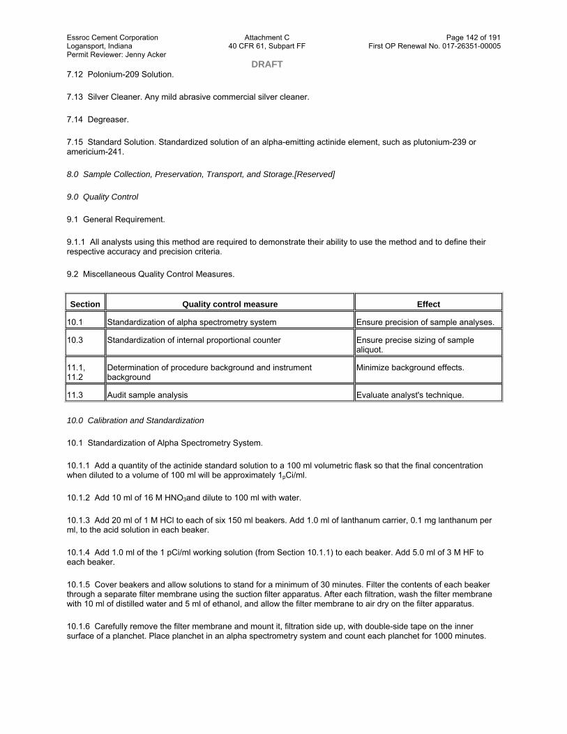
Essroc Cement Corporation Attachment C Page 142 of 191 Logansport, Indiana 40 CFR 61, Subpart FF First OP Renewal No. 017-26351-00005 Permit Reviewer: Jenny Acker DRAFT 7.12 Polonium-209 Solution.
7.13 Silver Cleaner. Any mild abrasive commercial silver cleaner.
7.14 Degreaser.
7.15 Standard Solution. Standardized solution of an alpha-emitting actinide element, such as plutonium-239 or americium-241.
8.0 Sample Collection, Preservation, Transport, and Storage.[Reserved]
9.0 Quality Control
9.1 General Requirement.
9.1.1 All analysts using this method are required to demonstrate their ability to use the method and to define their respective accuracy and precision criteria.
9.2 Miscellaneous Quality Control Measures.
Section Quality control measure Effect
10.1 Standardization of alpha spectrometry system Ensure precision of sample analyses.
10.3 Standardization of internal proportional counter Ensure precise sizing of sample aliquot.
11.1, 11.2
Determination of procedure background and instrument background
Minimize background effects.
11.3 Audit sample analysis Evaluate analyst's technique.
10.0 Calibration and Standardization
10.1 Standardization of Alpha Spectrometry System.
10.1.1 Add a quantity of the actinide standard solution to a 100 ml volumetric flask so that the final concentration when diluted to a volume of 100 ml will be approximately 1pCi/ml.
10.1.2 Add 10 ml of 16 M HNO3and dilute to 100 ml with water.
10.1.3 Add 20 ml of 1 M HCl to each of six 150 ml beakers. Add 1.0 ml of lanthanum carrier, 0.1 mg lanthanum per ml, to the acid solution in each beaker.
10.1.4 Add 1.0 ml of the 1 pCi/ml working solution (from Section 10.1.1) to each beaker. Add 5.0 ml of 3 M HF to each beaker.
10.1.5 Cover beakers and allow solutions to stand for a minimum of 30 minutes. Filter the contents of each beaker through a separate filter membrane using the suction filter apparatus. After each filtration, wash the filter membrane with 10 ml of distilled water and 5 ml of ethanol, and allow the filter membrane to air dry on the filter apparatus.
10.1.6 Carefully remove the filter membrane and mount it, filtration side up, with double-side tape on the inner surface of a planchet. Place planchet in an alpha spectrometry system and count each planchet for 1000 minutes.

Essroc Cement Corporation Attachment C Page 143 of 191 Logansport, Indiana 40 CFR 61, Subpart FF First OP Renewal No. 017-26351-00005 Permit Reviewer: Jenny Acker DRAFT 10.1.7 Calculate the counting efficiency of the detector for each aliquot of the 1 pCi/ml actinide working solution using Eq. 111–1 in Section 12.2.
10.1.8 Determine the average counting efficiency of the detector, Ec, by calculating the average of the six determinations.
10.2 Preparation of Standardized Solution of Polonium-209.
10.2.1 Add a quantity of the Po-209 solution to a 100 ml volumetric flask so that the final concentration when diluted to a 100 ml volume will be approximately 1 pCi/ml.
10.2.2 Follow the procedures outlined in Sections 10.1.2 through 10.1.6, except substitute 1.0 ml of polonium-209 tracer solution (Section 10.2.1) and 3.0 ml of 15 M ammonium hydroxide for the 1 pCi/ml actinide working solution and the 3 M HF, respectively.
10.2.3 Calculate the activity of each aliquot of the polonium-209 tracer solution using Eq. 111–2 in Section 12.3.
10.2.4 Determine the average activity of the polonium-209 tracer solution, F, by averaging the results of the six determinations.
10.3 Standardization of Internal Proportional Counter
10.3.1 Add a quantity of the actinide standard solution to a 100 ml volumetric flask so that the final concentration when diluted to a 100 ml volume will be approximately 100 pCi/ml.
10.3.2 Follow the procedures outlined in Sections 10.1.2 through 10.1.6, except substitute the 100 pCi/ml actinide working solution for the 1 pCi/ml solution, place the planchet in an internal proportional counter (instead of an alpha spectrometry system), and count for 100 minutes (instead of 1000 minutes).
10.3.3 Calculate the counting efficiency of the internal proportional counter for each aliquot of the 100 pCi/ml actinide working solution using Eq. 111–3 in 12.4.
10.3.4 Determine the average counting efficiency of the internal proportional counter, EI, by averaging the results of the six determinations.
11.0 Analytical Procedure
Note: Perform duplicate analyses of all samples, including background counts, quality assurance audit samples, and Method 5 samples. Duplicate measurements are considered acceptable when the difference between them is less than two standard deviations as described in EPA 600/4–77–001 or subsequent revisions.
11.1 Determination of Procedure Background. Background counts used in all equations are determined by performing the specific analysis required using the analytical reagents only. All procedure background counts and sample counts for the internal proportional counter should utilize a counting time of 100 minutes; for the alpha spectrometry system, 1000 minutes. These background counts should be performed no less frequently than once per 10 sample analyses.
11.2 Determination of Instrument Background. Instrument backgrounds of the internal proportional counter and the alpha spectrometry system should be determined on a weekly basis. Instrument background should not exceed procedure background. If this occurs, it may be due to a malfunction or contamination, and should be corrected before use.
11.3 Quality Assurance Audit Samples. An externally prepared performance evaluation sample shall be analyzed no less frequently than once per 10 sample analyses, and the results reported with the test results.
Essroc Cement Corporation Attachment C Page 144 of 191 Logansport, Indiana 40 CFR 61, Subpart FF First OP Renewal No. 017-26351-00005 Permit Reviewer: Jenny Acker DRAFT 11.4 Sample Preparation. Treat the Method 5 samples [ i.e., the glass fiber filter (Container No. 1) and the acetone rinse (Container No. 2)] as follows:
11.4.1 Container No. 1. Transfer the filter and any loose particulate matter from the sample container to a 150-ml Teflon beaker.
11.4.2 Container No. 2. Note the level of liquid in the container, and confirm on the analysis sheet whether leakage occurred during transport. If a noticeable amount of leakage has occurred, either void the sample or use methods, subject to the approval of the Administrator, to correct the final results. Transfer the contents to a 400-ml glass beaker. Add polonium-209 tracer solution to the glass beaker in an amount approximately equal to the amount of polonium-210 expected in the total particulate sample. Record the activity of the tracer solution added. Add 16 M nitric acid to the beaker to digest and loosen the residue.
11.4.3 Transfer the contents of the glass beaker to the Teflon beaker containing the glass fiber filter. Rinse the glass beaker with 16 M HNO3. If necessary, reduce the volume in the beaker by evaporation until all of the nitric acid HNO3from the glass beaker has been transferred to the Teflon beaker.
11.4.4 Add 30 ml of 29 M HF to the Teflon beaker and evaporate to near dryness on a hot plate in a properly operating hood.
Note: Do not allow the residue to go to dryness and overheat; this will result in loss of polonium.
11.4.5 Repeat step 11.4.4 until the filter is dissolved.
11.4.6 Add 100 ml of 16 M HNO3to the residue in the Teflon beaker and evaporate to near dryness.
Note: Do not allow the residue to go to dryness.
11.4.7 Add 50 ml of 16 M HNO3and 10 ml of 12 M perchloric acid to the Teflon beaker and heat until dense fumes of perchloric acid are evolved.
11.4.8 Repeat steps 11.4.4 to 11.4.7 as necessary until sample is completely dissolved.
11.4.9 Add 10 ml of 12 M HCl to the Teflon beaker and evaporate to dryness. Repeat additions and evaporations several times.
11.4.10 Transfer the sample to a 250-ml volumetric flask and dilute to volume with 3 M HCl.
11.5 Sample Screening. To avoid contamination of the alpha spectrometry system, check each sample as follows:
11.5.1 Add 20 ml of 1 M HCl, 1 ml of the lanthanum carrier solution (0.1 mg La/ml), a 1 ml aliquot of the sample solution from Section 11.4.10, and 3 ml of 15 M ammonium hydroxide to a 250-ml beaker in the order listed. Allow this solution to stand for a minimum of 30 minutes.
11.5.2 Filter the solution through a filter membrane using the suction filter apparatus. Wash the filter membrane with 10 ml of water and 5 ml of ethanol, and allow the filter membrane to air dry on the filter apparatus.
11.5.3 Carefully remove the filter membrane and mount it, filtration side up, with double-side tape on the inner surface of a planchet. Place the planchet in an internal proportional counter, and count for 100 minutes.
11.5.4 Calculate the activity of the sample using Eq. 111–4 in Section 12.5.
11.5.5 Determine the aliquot volume of the sample solution from Section 11.4.10 to be analyzed for polonium-210, such that the aliquot contains an activity between 1 and 4 picocuries. Use Eq. 111–5 in Section 12.6.

Essroc Cement Corporation Attachment C Page 145 of 191 Logansport, Indiana 40 CFR 61, Subpart FF First OP Renewal No. 017-26351-00005 Permit Reviewer: Jenny Acker DRAFT 11.6 Preparation of Silver Disc for Spontaneous Electrodeposition.
11.6.1 Clean both sides of the polished silver disc with silver cleaner and with degreaser.
11.6.2 Place disc on absorbent paper and spray one side with epoxy spray enamel. This should be carried out in a well-ventilated area, with the disc lying flat to keep paint on one side only. Allow paint to dry for 24 hours before using disc for deposition.
11.7 Sample Analysis.
11.7.1 Add the aliquot of sample solution from Section 11.4.10 to be analyzed for polonium-210, the volume of which was determined in Section 11.5.5, to a suitable 200-ml container to be placed in a constant temperature bath.
Note: Aliquot volume may require a larger container.
11.7.2 If necessary, bring the volume to 100 ml with 1 M HCl. If the aliquot volume exceeds 100 ml, use total aliquot.
11.7.3 Add 200 mg of ascorbic acid and heat solution to 85 °C (185 °F) in a constant temperature bath.
11.7.4 Suspend a silver disc in the heated solution using a glass or plastic rod with a hook inserted through the hole in the disc. The disc should be totally immersed in the solution, and the solution must be stirred constantly, at all times during the plating operation. Maintain the disc in solution for 3 hours.
11.7.5 Remove the silver disc, rinse with deionized distilled water, and allow to air dry at room temperature.
11.7.6 Place the disc, with deposition side (unpainted side) up, on a planchet and secure with double-side plastic tape. Place the planchet with disc in alpha spectrometry system and count for 1000 minutes.
12.0 Data Analysis and Calculations.
12.1 Nomenclature.
A = Picocuries of polonium-210 in the Method 5 sample (from Section 12.8).
AA= Picocuries of actinide added.
AL= Volume of sample aliquot used, in ml (specified in Section 11.5.1 as 1 ml).
AS= Aliquot to be analyzed, in ml.
BB= Procedure background counts measured in polonium-209 spectral region.
BT= Polonium-209 tracer counts in sample.
CT= Total counts in polonium-210 spectral region.
D = Decay correction for time “t” (in days) from sample collection to sample counting, given by: D=e−0.005t
EC= Average counting efficiency of detector (from Section 10.1.8), as counts per disintegration.
ECi= Counting efficiency of the detector for aliquot i of the actinide working solution, counts per disintegration.
EI= Average counting efficiency of the internal proportional counter, as determined in Section 10.3.4, counts per disintegration.

Essroc Cement Corporation Attachment C Page 146 of 191 Logansport, Indiana 40 CFR 61, Subpart FF First OP Renewal No. 017-26351-00005 Permit Reviewer: Jenny Acker DRAFT EIi= Counting efficiency of the internal proportional counter for aliquot i of the 100 pCi/ml actinide working solution, counts per disintegration.
EY= The fraction of polonium-209 recovered on the planchet (from Section 12.7).
F= Average activity of polonium-209 in sample (from Section 10.2.4), in pCi.
Fi= activity of aliquot i of the polonium-209 tracer solution, in pCi.
L = Dilution factor (unitless). This is the volume of sample solution prepared (specified as 250 ml in Section 11.1.10) divided by the volume of the aliquot of sample solution analyzed for polonium-210 (from Section 11.7.1).
Mi= Phosphorous rock processing rate of the source being tested, during run i, Mg/hr.
Mk= Phosphate rock processed annually by source k, in Mg/yr.
n = Number of calciners at the elemental phosphorus plant.
P = Total activity of sample solution from Section 11.4.10, in pCi (see Eq. 111–4).
Qsd= Volumetric flow rate of effluent stream, as determined by Method 2, in dscm/hr.
S = Annual polonium-210 emissions from the entire facility, in curies/yr.
Vm(std)= Volume of air sample, as determined by Method 5, in dscm.
Xk= Emission rate from source k, from Section 12.10, in curies/Mg.
10−12= Curies per picocurie.
2.22 = Disintegrations per minute per picocurie.
250 = Volume of solution from Section 11.4.10, in ml.
12.2 Counting Efficiency. Calculate the counting efficiency of the detector for each aliquot of the 1 pCi/ml actinide working solution using Eq. 111–1.
Where:
CB= Background counts in same peak area as CS.
CS= Gross counts in actinide peak.
T = Counting time in minutes, specified in Section 10.1.6 as 1000 minutes.
12.3 Polonium-209 Tracer Solution Activity. Calculate the activity of each aliquot of the polonium-209 tracer solution using Eq. 111–2.

Essroc Cement Corporation Attachment C Page 147 of 191 Logansport, Indiana 40 CFR 61, Subpart FF First OP Renewal No. 017-26351-00005 Permit Reviewer: Jenny Acker DRAFT
Where:
CB= Background counts in the 4.88 MeV region of spectrum the in the counting time T.
CS= Gross counts of polonium-209 in the 4.88 MeV region of the spectrum in the counting time T.
T = Counting time, specified in Section 10.1.6 as 1000 minutes.
12.4 Control Efficiency of Internal Proportional Counter. Calculate the counting efficiency of the internal proportional counter for each aliquot of the 100 pCi/ml actinide working solution using Eq. 111–3.
Where:
CB= Gross counts of procedure background.
CS= Gross counts of standard.
T = Counting time in minutes, specified in Section 10.3.2 as 100 minutes.
12.5 Calculate the activity of the sample using Eq. 111–4.
Where:
CB= Total counts of procedure background. (See Section 11.1).
CS= Total counts of screening sample.
T = Counting time for sample and background (which must be equal), in minutes (specified in Section 11.5.3 as 100 minutes).
12.6 Aliquot Volume. Determine the aliquot volume of the sample solution from Section 11.4.10 to be analyzed for polonium-210 , such that the aliquot contains an activity between 1 and 4 picocuries using Eq. 111–5.
12.7 Polonium-209 Recovery. Calculate the fraction of polonium-209 recovered on the planchet, EY, using Eq. 111–6.

Essroc Cement Corporation Attachment C Page 148 of 191 Logansport, Indiana 40 CFR 61, Subpart FF First OP Renewal No. 017-26351-00005 Permit Reviewer: Jenny Acker DRAFT
Where:
T = Counting time, specified in Section 11.1 as 1000 minutes.
12.8 Polonium-210 Activity. Calculate the activity of polonium-210 in the Method 5 sample (including glass fiber filter and acetone rinse) using Eq. 111–7.
Where:
CB= Procedure background counts in polonium-210 spectral region.
T = Counting time, specified in Section 11.1 as 1000 minutes for all alpha spectrometry sample and background counts.
12.9 Emission Rate from Each Stack.
12.9.1 For each test run, i, on a stack, calculate the measured polonium-210 emission rate, RSi, using Eq. 111–8.
12.9.2 Determine the average polonium-210 emission rate from the stack, RS, by taking the sum of the measured emission rates for all runs, and dividing by the number of runs performed.
12.9.3 Repeat steps 12.9.1 and 12.9.2 for each stack of each calciner.
12.10 Emission Rate from Each Source. Determine the total polonium-210 emission rate, Xk, from each source, k, by taking the sum of the average emission rates from all stacks to which the source exhausts.
12.11 Annual Polonium-210 Emission Rate from Entire Facility. Determine the annual elemental phosphorus plant emissions of polonium-210, S, using Eq. 111–9.
13.0 Method Performance.[Reserved]
14.0 Pollution Prevention.[Reserved]
15.0 Waste Management.[Reserved]
16.0 References

Essroc Cement Corporation Attachment C Page 149 of 191 Logansport, Indiana 40 CFR 61, Subpart FF First OP Renewal No. 017-26351-00005 Permit Reviewer: Jenny Acker DRAFT 1. Blanchard, R.L. “Rapid Determination of Lead-210 and Polonium-210 in Environmental Samples by Deposition on Nickel.” Anal. Chem., 38 :189, pp. 189–192. February 1966.
17.0 Tables, Diagrams, Flowcharts, and Validation Data[Reserved]
Method 114—Test Methods for Measuring Radionuclide Emissions from Stationary Sources
1. Purpose and Background
This method provides the requirements for: (1) Stack monitoring and sample collection methods appropriate for radionuclides; (2) radiochemical methods which are used in determining the amounts of radionuclides collected by the stack sampling and; (3) quality assurance methods which are conducted in conjunction with these measurements. These methods are appropriate for emissions for stationary sources. A list of references is provided.
Many different types of facilities release radionuclides into air. These radionuclides differ in the chemical and physical forms, half-lives and type of radiation emitted. The appropriate combination of sample extraction, collection and analysis for an individual radionuclide is dependent upon many interrelated factors including the mixture of other radionuclides present. Because of this wide range of conditions, no single method for monitoring or sample collection and analysis of a radionuclide is applicable to all types of facilities. Therefore, a series of methods based on “principles of measurement” are described for monitoring and sample collection and analysis which are applicable to the measurement of radionuclides found in effluent streams at stationary sources. This approach provides the user with the flexibility to choose the most appropriate combination of monitoring and sample collection and analysis methods which are applicable to the effluent stream to be measured.
2. Stack Monitoring and Sample Collection Methods
Monitoring and sample collection methods are described based on “principles of monitoring and sample collection” which are applicable to the measurement of radionuclides from effluent streams at stationary sources. Radionuclides of most elements will be in the particulate form in these effluent streams and can be readily collected using a suitable filter media. Radionuclides of hydrogen, oxygen, carbon, nitrogen, the noble gases and in some circumstances iodine will be in the gaseous form. Radionuclides of these elements will require either the use of an in-line or off-line monitor to directly measure the radionuclides, or suitable sorbers, condensers or bubblers to collect the radionuclides.
2.1 Radionuclides as Particulates. The extracted effluent stream is passed through a filter media to remove the particulates. The filter must have a high efficiency for removal of sub-micron particles. The guidance in ANSI/HPS N13.1–1999 (section 6.6.2 Filter media) shall be followed in using filter media to collect particulates (incorporated by reference—see §61.18 of this part).
2.2 Radionuclides as Gases.
2.2.1 The Radionuclide Tritium (H–3). Tritium in the form of water vapor is collected from the extracted effluent sample by sorption, condensation or dissolution techniques. Appropriate collectors may include silica gel, molecular sieves, and ethylene glycol or water bubblers.
Tritium in the gaseous form may be measured directly in the sample stream using Method B–1, collected as a gas sample or may be oxidized using a metal catalyst to tritiated water and collected as described above.
2.2.2 Radionuclides of Iodine. Iodine is collected from an extracted sample by sorption or dissolution techniques. Appropriate collectors may include charcoal, impregnated charcoal, metal zeolite and caustic solutions.
2.2.3 Radionuclides of Argon, Krypton and Xenon. Radionuclides of these elements are either measured directly by an in-line or off-line monitor, or are collected from the extracted sample by low temperature sorption techniques, Appropriate sorbers may include charcoal or metal zeolite.
2.2.4 Radionuclides of Oxygen, Carbon, Nitrogen and Radon. Radionuclides of these elements are measured directly using an in-line or off-line monitor. Radionuclides of carbon in the form of carbon dioxide may be collected by dissolution in caustic solutions.

Essroc Cement Corporation Attachment C Page 150 of 191 Logansport, Indiana 40 CFR 61, Subpart FF First OP Renewal No. 017-26351-00005 Permit Reviewer: Jenny Acker DRAFT 2.3 Definition of Terms
In-line monitor means a continuous measurement system in which the detector is placed directly in or adjacent to the effluent stream. This may involve either gross radioactivity measurements or specific radionuclide measurements. Gross measurements shall be made in conformance with the conditions specified in Methods A–4, B–2 and G–4.
Off-line monitor means a measurement system in which the detector is used to continuously measure an extracted sample of the effluent stream. This may involve either gross radioactivity measurements or specific radionuclide measurements. Gross measurements shall be made in conformance with the conditions specified in Methods A–4, B–2 and G–4.
Sample collection means a procedure in which the radionuclides are removed from an extracted sample of the effluent using a collection media. These collection media include filters, absorbers, bubblers and condensers. The collected sample is analyzed using the methods described in Section 3.
3. Radionuclide Analysis Methods
A series of methods based on “principles of measurement” are described which are applicable to the analysis of radionuclides collected from airborne effluent streams at stationary sources. These methods are applicable only under the conditions stated and within the limitations described. Some methods specify that only a single radionuclide be present in the sample or the chemically separated sample. This condition should be interpreted to mean that no other radionuclides are present in quantities which would interfere with the measurement.
Also identified (Table 1) are methods for a selected list of radionuclides. The listed radionuclides are those which are most commonly used and which have the greatest potential for causing dose to members of the public. Use of methods based on principles of measurement other than those described in this section must be approved in advance of use by the Administrator. For radionuclides not listed in Table 1, any of the described methods may be used provided the user can demonstrate that the applicability conditions of the method have been met.
The type of method applicable to the analysis of a radionuclide is dependent upon the type of radiation emitted, i.e., alpha, beta or gamma. Therefore, the methods described below are grouped according to principles of measurements for the analysis of alpha, beta and gamma emitting radionuclides.
3.1 Methods for Alpha Emitting Radionuclides
3.1.1 Method A–1, Radiochemistry-Alpha Spectrometry.
Principle: The element of interest is separated from other elements, and from the sample matrix using radiochemical techniques. The procedure may involve precipitation, ion exchange, or solvent extraction. Carriers (elements chemically similar to the element of interest) may be used. The element is deposited on a planchet in a very thin film by electrodeposition or by coprecipitation on a very small amount of carrier, such as lanthanum fluoride. The deposited element is then counted with an alpha spectrometer. The activity of the nuclide of interest is measured by the number of alpha counts in the appropriate energy region. A correction for chemical yield and counting efficiency is made using a standardized radioactive nuclide (tracer) of the same element. If a radioactive tracer is not available for the element of interest, a predetermined chemical yield factor may be used.
Applicability: This method is applicable for determining the activity of any alpha-emitting radionuclide, regardless of what other radionuclides are present in the sample provided the chemical separation step produces a very thin sample and removes all other radionuclides which could interfere in the spectral region of interest. APHA–605(2), ASTM–D–3972(13).
3.1.2 Method A–2, Radiochemistry-Alpha Counting.
Principle: The element of interest is separated from other elements, and from the sample matrix using radiochemistry. The procedure may involve precipitation, ion exchange, or solvent extraction. Carriers (elements chemically similar to the element of interest) may be used. The element is deposited on a planchet in a thin film and counted with an alpha

Essroc Cement Corporation Attachment C Page 151 of 191 Logansport, Indiana 40 CFR 61, Subpart FF First OP Renewal No. 017-26351-00005 Permit Reviewer: Jenny Acker DRAFT counter. A correction for chemical yield (if necessary) is made. The alpha count rate measures the total activity of all emitting radionuclides of the separated element.
Applicability: This method is applicable for the measurement of any alpha-emitting radionuclide, provided no other alpha emitting radionuclide is present in the separated sample. It may also be applicable for determining compliance, when other radionuclides of the separated element are present, provided that the calculated emission rate is assigned to the radionuclide which could be present in the sample that has the highest dose conversion factor. IDO–12096(18).
3.1.3 Method A–3, Direct Alpha Spectrometry.
Principle: The sample, collected on a suitable filter, is counted directly on an alpha spectrometer. The sample must be thin enough and collected on the surface of the filter so that any absorption of alpha particle energy in the sample or the filter, which would degrade the spectrum, is minimal.
Applicability: This method is applicable to simple mixtures of alpha emitting radionuclides and only when the amount of particulates collected on the filter paper are relatively small and the alpha spectra is adequately resolved. Resolutions should be 50 keV (FWHM) or better, ASTM–D–3084(16).
3.1.4 Method A–4, Direct Alpha Counting (Gross alpha determination).
Principle: The sample, collected on a suitable filter, is counted with an alpha counter. The sample must be thin enough so that self-absorption is not significant and the filter must be of such a nature that the particles are retained on the surface.
Applicability: Gross alpha determinations may be used to measure emissions of specific radionuclides only (1) when it is known that the sample contains only a single radionuclide, or the identity and isotopic ratio of the radionuclides in the sample are well-known, and (2) measurements using either Method A–1, A–2 or A–5 have shown that this method provides a reasonably accurate measurement of the emission rate. Gross alpha measurements are applicable to unidentified mixtures of radionuclides only for the purposes and under the conditions described in section 3.7. APHA–601(3), ASTM–D–1943(10).
3.1.5 Method A–5, Chemical Determination of Uranium.
Principle: Uranium may be measured chemically by either colorimetry or fluorometry. In both procedures, the sample is dissolved, the uranium is oxidized to the hexavalent form and extracted into a suitable solvent. Impurities are removed from the solvent layer. For colorimetry, dibenzoylmethane is added, and the uranium is measured by the absorbance in a colorimeter. For fluorometry, a portion of the solution is fused with a sodium fluoride-lithium fluoride flux and the uranium is determined by the ultraviolet activated fluorescence of the fused disk in a fluorometer.
Applicability: This method is applicable to the measurements of emission rates of uranium when the isotopic ratio of the uranium radionuclides is well known. ASTM–E–318(15), ASTM–D–2907(14).
3.1.6 Method A–6, Radon-222—Continuous Gas Monitor.
Principle: Radon-222 is measured directly in a continuously extracted sample stream by passing the air stream through a calibrated scintillation cell. Prior to the scintillation cell, the air stream is treated to remove particulates and excess moisture. The alpha particles from radon-222 and its decay products strike a zinc sulfide coating on the inside of the scintillation cell producing light pulses. The light pulses are detected by a photomultiplier tube which generates electrical pulses. These pulses are processed by the system electronics and the read out is in pCi/l of radon-222.
Applicability: This method is applicable to the measurement of radon-222 in effluent streams which do not contain significant quantities of radon-220. Users of this method should calibrate the monitor in a radon calibration chamber at least twice per year. The background of the monitor should also be checked periodically by operating the instrument in a low radon environment. EPA 520/1–89–009(24).
3.1.7 Method A–7, Radon-222-Alpha Track Detectors

Essroc Cement Corporation Attachment C Page 152 of 191 Logansport, Indiana 40 CFR 61, Subpart FF First OP Renewal No. 017-26351-00005 Permit Reviewer: Jenny Acker DRAFT Principle: Radon-222 is measured directly in the effluent stream using alpha track detectors (ATD). The alpha particles emitted by radon-222 and its decay products strike a small plastic strip and produce submicron damage tracks. The plastic strip is placed in a caustic solution that accentuates the damage tracks which are counted using a microscope or automatic counting system. The number of tracks per unit area is correlated to the radon concentration in air using a conversion factor derived from data generated in a radon calibration facility.
Applicability: Prior approval from EPA is required for use of this method. This method is only applicable to effluent streams which do not contain significant quantities of radon-220, unless special detectors are used to discriminate against radon-220. This method may be used only when ATDs have been demonstrated to produce data comparable to data obtained with Method A–6. Such data should be submitted to EPA when requesting approval for the use of this method. EPA 520/1–89–009(24).
3.2 Methods for Gaseous Beta Emitting Radionuclides.
3.2.1 Method B–1, Direct Counting in Flow-Through Ionization Chambers.
Principle: An ionization chamber containing a specific volume of gas which flows at a given flow rate through the chamber is used. The sample (effluent stream sample) acts as the counting gas for the chamber. The activity of the radionuclide is determined from the current measured in the ionization chamber.
Applicability: This method is applicable for measuring the activity of a gaseous beta-emitting radionuclide in an effluent stream that is suitable as a counting gas, when no other beta-emitting nuclides are present. DOE/EP–0096(17), NCRP–58(23).
3.2.2 Method B–2, Direct Counting With In-line or Off-line Beta Detectors.
Principle: The beta detector is placed directly in the effluent stream (in-line) or an extracted sample of the effluent stream is passed through a chamber containing a beta detector (off-line). The activities of the radionuclides present in the effluent stream are determined from the beta count rate, and a knowledge of the radionuclides present and the relationship of the gross beta count rate and the specific radionuclide concentration.
Applicability: This method is applicable only to radionuclides with maximum beta particle energies greater then 0.2 MeV. This method may be used to measure emissions of specific radionuclides only when it is known that the sample contains only a single radionuclide or the identity and isotopic ratio of the radionuclides in the effluent stream are well known. Specific radionuclide analysis of periodic grab samples may be used to identify the types and quantities of radionuclides present and to establish the relationship between specific radionuclide analyses and gross beta count rates.
This method is applicable to unidentified mixtures of gaseous radionuclides only for the purposes and under the conditions described in section 3.7.
3.3 Methods for Non-Gaseous Beta Emitting Radionuclides.
3.3.1 Method B–3, Radiochemistry-Beta Counting.
Principle: The element of interest is separated from other elements, and from the sample matrix by radiochemistry. This may involve precipitation, distillation, ion exchange, or solvent extraction. Carriers (elements chemically similar to the element of interest) may be used. The element is deposited on a planchet, and counted with a beta counter. Corrections for chemical yield, and decay (if necessary) are made. The beta count rate determines the total activity of all radionuclides of the separated element. This method may also involve the radiochemical separation and counting of a daughter element, after a suitable period of ingrowth, in which case it is specific for the parent nuclide.
Applicability: This method is applicable for measuring the activity of any beta-emitting radionuclide, with a maximum energy greater than 0.2 MeV, provided no other radionuclide is present in the separated sample. APHA–608(5).
3.3.2 Method B–4, Direct Beta Counting (Gross beta determination).

Essroc Cement Corporation Attachment C Page 153 of 191 Logansport, Indiana 40 CFR 61, Subpart FF First OP Renewal No. 017-26351-00005 Permit Reviewer: Jenny Acker DRAFT Principle: The sample, collected on a suitable filter, is counted with a beta counter. The sample must be thin enough so that self-absorption corrections can be made.
Applicability: Gross beta measurements are applicable only to radionuclides with maximum beta particle energies greater than 0.2 MeV. Gross beta measurements may be used to measure emissions of specific radionuclides only (1) when it is known that the sample contains only a single radionuclide, and (2) measurements made using Method B–3 show reasonable agreement with the gross beta measurement. Gross beta measurements are applicable to mixtures of radionuclides only for the purposes and under the conditions described in section 3.7. APHA–602(4), ASTM–D–1890(11).
3.3.3 Method B–5, Liquid Scintillation Spectrometry.
Principle: An aliquot of a collected sample or the result of some other chemical separation or processing technique is added to a liquid scintillation “cocktail” which is viewed by photomultiplier tubes in a liquid scintillation spectrometer. The spectrometer is adjusted to establish a channel or “window” for the pulse energy appropriate to the nuclide of interest. The activity of the nuclide of interest is measured by the counting rate in the appropriate energy channel. Corrections are made for chemical yield where separations are made.
Applicability: This method is applicable to any beta-emitting nuclide when no other radionuclide is present in the sample or the separated sample provided that it can be incorporated in the scintillation cocktail. This method is also applicable for samples which contain more than one radionuclide but only when the energies of the beta particles are sufficiently separated so that they can be resolved by the spectrometer. This method is most applicable to the measurement of low-energy beta emitters such as tritium and carbon-14. APHA–609(6), EML–LV–539–17(19).
3.4 Gamma Emitting Radionuclides
3.4.1 Method G–1, High Resolution Gamma Spectrometry.
Principle: The sample is counted with a high resolution gamma detector, usually either a Ge(Li) or a high purity Ge detector, connected to a multichannel analyzer or computer. The gamma emitting radionuclides in the sample are measured from the gamma count rates in the energy regions characteristic of the individual radionuclide. Corrections are made for counts contributed by other radionuclides to the spectral regions of the radionuclides of interest. Radiochemical separations may be made prior to counting but are usually not necessary.
Applicability: This method is applicable to the measurement of any gamma emitting radionuclide with gamma energies greater than 20 keV. It can be applied to complex mixtures of radionuclides. The samples counted may be in the form of particulate filters, absorbers, liquids or gases. The method may also be applied to the analysis of gaseous gamma emitting radionuclides directly in an effluent stream by passing the stream through a chamber or cell containing the detector. ASTM–3649(9), IDO–12096(18).
3.4.2 Method G–2, Low Resolution Gamma Spectrometry.
Principle: The sample is counted with a low resolution gamma detector, a thallium activated sodium iodide crystal. The detector is coupled to a photomultiplier tube and connected to a multichannel analyzer. The gamma emitting radionuclides in the sample are measured from the gamma count rates in the energy regions characteristic of the individual radionuclides. Corrections are made for counts contributed by other radionuclides to the spectral regions of the radionuclides of interest. Radiochemical separation may be used prior to counting to obtain less complex gamma spectra if needed.
Applicability: This method is applicable to the measurement of gamma emitting radionuclides with energies greater than 100 keV. It can be applied only to relatively simple mixtures of gamma emitting radionuclides. The samples counted may be in the form of particulate filters, absorbers, liquids or gas. The method can be applied to the analysis of gaseous radionuclides directly in an effluent stream by passing the gas stream through a chamber or cell containing the detector. ASTM–D–2459(12), EMSL–LV–0539–17(19).
3.4.3 Method G–3, Single Channel Gamma Spectrometry.
Essroc Cement Corporation Attachment C Page 154 of 191 Logansport, Indiana 40 CFR 61, Subpart FF First OP Renewal No. 017-26351-00005 Permit Reviewer: Jenny Acker DRAFT Principle: The sample is counted with a thallium activated sodium iodide crystal. The detector is coupled to a photomultiplier tube connected to a single channel analyzer. The activity of a gamma emitting radionuclide is determined from the gamma counts in the energy range for which the counter is set.
Applicability: This method is applicable to the measurement of a single gamma emitting radionuclide. It is not applicable to mixtures of radionuclides. The samples counted may be in the form of particulate filters, absorbers, liquids or gas. The method can be applied to the analysis of gaseous radionuclides directly in an effluent stream by passing the gas stream through a chamber or cell containing the detector.
3.4.4 Method G–4, Gross Gamma Counting.
Principle: The sample is counted with a gamma detector usually a thallium activated sodium iodine crystal. The detector is coupled to a photomultiplier tube and gamma rays above a specific threshold energy level are counted.
Applicability: Gross gamma measurements may be used to measure emissions of specific radionuclides only when it is known that the sample contains a single radionuclide or the identity and isotopic ratio of the radionuclides in the effluent stream are well known. When gross gamma measurements are used to determine emissions of specific radionuclides periodic measurements using Methods G–1 or G–2 should be made to demonstrate that the gross gamma measurements provide reliable emission data. This method may be applied to analysis of gaseous radionuclides directly in an effluent stream by placing the detector directly in or adjacent to the effluent stream or passing an extracted sample of the effluent stream through a chamber or cell containing the detector.
3.5 Counting Methods. All of the above methods with the exception of Method A–5 involve counting the radiation emitted by the radionuclide. Counting methods applicable to the measurement of alpha, beta and gamma radiations are listed below. The equipment needed and the counting principles involved are described in detail in ASTM–3648(8).
3.5.1 Alpha Counting:
• Gas Flow Proportional Counters. The alpha particles cause ionization in the counting gas and the resulting electrical pulses are counted. These counters may be windowless or have very thin windows.
• Scintillation Counters. The alpha particles transfer energy to a scintillator resulting in a production of light photons which strike a photomultiplier tube converting the light photons to electrical pulses which are counted. The counters may involve the use of solid scintillation materials such as zinc sulfide or liquid scintillation solutions.
• Solid-State Counters. Semiconductor materials, such as silicon surface-barrier p-n junctions, act as solid ionization chambers. The alpha particles interact which the detector producing electron hole pairs. The charged pair is collected by an applied electrical field and the resulting electrical pulses are counted.
• Alpha Spectrometers. Semiconductor detectors used in conjunction with multichannel analyzers for energy discrimination.
3.5.2 Beta Counting:
• Ionization Chambers. These chambers contain the beta-emitting nuclide in gaseous form. The ionization current produced is measured.
• Geiger-Muller (GM) Counters-or Gas Flow Proportional Counters. The beta particles cause ionization in the counting gas and the resulting electrical pulses are counted. Proportional gas flow counters which are heavily shielded by lead or other metal, and provided with an anti-coincidence shield to reject cosmic rays, are called low background beta counters.
• Scintillation Counters. The beta particles transfer energy to a scintillator resulting in a production of light photons, which strike a photomultiplier tube converting the light photon to electrical pulses which are counted. This may involve the use of anthracene crystals, plastic scintillator, or liquid scintillation solutions with organic phosphors.

Essroc Cement Corporation Attachment C Page 155 of 191 Logansport, Indiana 40 CFR 61, Subpart FF First OP Renewal No. 017-26351-00005 Permit Reviewer: Jenny Acker DRAFT • Liquid Scintillation Spectrometers. Liquid scintillation counters which use two photomultiplier tubes in coincidence to reduce background counts. This counter may also electronically discriminate among pulses of a given range of energy.
3.5.3 Gamma Counting:
• Low-Resolution Gamma Spectrometers. The gamma rays interact with thallium activated sodium iodide or cesium iodide crystal resulting in the release of light photons which strike a photomultiplier tube converting the light pulses to electrical pulses proportional to the energy of the gamma ray. Multi-channel analyzers are used to separate and store the pulses according to the energy absorbed in the crystal.
• High-Resolution gamma Spectrometers. Gamma rays interact with a lithium-drifted (Ge(Li)) or high-purity germanium (HPGe) semiconductor detectors resulting in a production of electron-hole pairs. The charged pair is collected by an applied electrical field. A very stable low noise preamplifier amplifies the pulses of electrical charge resulting from the gamma photon interactions. Multichannel analyzers or computers are used to separate and store the pulses according to the energy absorbed in the crystal.
• Single Channel Analyzers. Thallium activated sodium iodide crystals used with a single window analyzer. Pulses from the photomultiplier tubes are separated in a single predetermined energy range.
3.5.4 Calibration of Counters. Counters are calibrated for specific radionuclide measurements using a standard of the radionuclide under either identical or very similar conditions as the sample to be counted. For gamma spectrometers a series of standards covering the energy range of interest may be used to construct a calibration curve relating gamma energy to counting efficiency.
In those cases where a standard is not available for a radionuclide, counters may be calibrated using a standard with energy characteristics as similar as possible to the radionuclide to be measured. For gross alpha and beta measurements of the unidentified mixtures of radionuclides, alpha counters are calibrated with a natural uranium standard and beta counters with a cesium-137 standard. The standard must contain the same weight and distribution of solids as the samples, and be mounted in an identical manner. If the samples contain variable amounts of solids, calibration curves relating weight of solids present to counting efficiency are prepared. Standards other than those prescribed may be used provided it can be shown that such standards are more applicable to the radionuclide mixture measured.
3.6 Radiochemical Methods for Selected Radionuclides. Methods for a selected list of radionuclides are listed in Table 1. The radionuclides listed are those which are most commonly used and which have the greatest potential for causing doses to members of the public. For radionuclides not listed in Table 1, methods based on any of the applicable “principles of measurement” described in section 3.1 through 3.4 may be used.
3.7 Applicability of Gross Alpha and Beta Measurements to Unidentified Mixtures of Radionuclides. Gross alpha and beta measurements may be used as a screening measurement as a part of an emission measurement program to identify the need to do specific radionuclide analyses or to confirm or verify that unexpected radionuclides are not being released in significant quantities.
Gross alpha (Method A–4) or gross beta (Methods B–2 or B–4) measurements may also be used for the purpose of comparing the measured concentrations in the effluent stream with the limiting “Concentration Levels for Environmental Compliance” in table 2 of appendix E. For unidentified mixtures, the measured concentration value shall be compared with the lowest environmental concentration limit for any radionuclide which is not known to be absent from the effluent stream.
Table 1—List of Approved Methods for Specific Radionuclides
Radionuclide Approved methods of analysis
Am-241 A–1, A–2, A–3, A–4
Ar-41 B–1,B–2,G–1,G–2, G–3, G–4

Essroc Cement Corporation Attachment C Page 156 of 191 Logansport, Indiana 40 CFR 61, Subpart FF First OP Renewal No. 017-26351-00005 Permit Reviewer: Jenny Acker DRAFT
Radionuclide Approved methods of analysis
Ba-140 G–1, G–2, G–3, G–4
Br-82 G–1, G–2, G–3, G–4
C-11 B–1,B–2,G–1,G–2,G–3, G–4
C-14 B–5
Ca-45 B–3, B–4, B–5
Ce-144 G–1, G–2, G–3, G–4
Cm-244 A–1, A–2, A–3, A–4
Co-60 G–1, G–2, G–3, G–4
Cr-51 G–1, G–2, G–3, G–4
Cs-134 G–1, G–2, G–3, G–4
Cs-137 G–1, G–2, G–3, G–4
Fe-55 B–5, G–1
Fe-59 G–1, G–2, G–3, G–4
Ga-67 G–1, G–2, G–3, G–4
H-3 (H2O) B–5
H-3 (gas) B–1
I-123 G–1, G–2, G–3, G–4
I-125 G–1
I-131 G–1, G–2, G–3, G–4
In-113m G–1, G–2, G–3, G–4
Ir-192 G–1, G–2, G–3, G–4
Kr-85 B–1, B–2, B–5, G–1, G–2, G–3, G–4
Kr-87 B–1, B–2, G–1, G–2, G–3, G–4
Kr-88 B–1, B–2, G–1, G–2, G–3, G–4
Mn-54 G–1, G–2, G–3, G–4
Mo-99 G–1, G–2, G–3, G–4
N-13 B–1, B–2, G–1, G–2, G–3, G–4
O-15 B–1, B–2, G–1, G–2, G–3, G–4
P-32 B–3, B–4, B–5
Pm-147 B–3, B–4, B–5
Po-210 A–1, A–2, A–3, A–4
Pu-238 A–1, A–2, A–3, A–4
Pu-239 A–1, A–2, A–3, A–4
Pu-240 A–1, A–2, A–3, A–4
Ra–226 A–1, A–2, G–1, G–2

Essroc Cement Corporation Attachment C Page 157 of 191 Logansport, Indiana 40 CFR 61, Subpart FF First OP Renewal No. 017-26351-00005 Permit Reviewer: Jenny Acker DRAFT
Radionuclide Approved methods of analysis
S-35 B–5
Se-75 G–1, G–2, G–3, G–4
Sr-90 B–3, B–4, B–5
Tc-99 B–3, B–4, B–5
Te-201 G–1, G–2, G–3, G–4
Uranium (total alpha) A–1, A–2, A–3, A–4
Uranium (Isotopic) A–1, A–3
Uranium (Natural) A–5
Xe-133 G–1
Yb-169 G–1, G–2, G–3, G–4
Zn-65 G–1, G–2, G–3, G–4
4. Quality Assurance Methods
Each facility required to measure their radionuclide emissions shall conduct a quality assurance program in conjunction with the radionuclide emission measurements. This program shall assure that the emission measurements are representative, and are of known precision and accuracy and shall include administrative controls to assure prompt response when emission measurements indicate unexpectedly large emissions. The program shall consist of a system of policies, organizational responsibilities, written procedures, data quality specifications, audits, corrective actions and reports. This quality assurance program shall include the following program elements:
4.1 The organizational structure, functional responsibilities, levels of authority and lines of communications for all activities related to the emissions measurement program shall be identified and documented.
4.2 Administrative controls shall be prescribed to ensure prompt response in the event that emission levels increase due to unplanned operations.
4.3 The sample collection and analysis procedures used in measuring the emissions shall be described including where applicable:
4.3.1 Identification of sampling sites and number of sampling points, including the rationale for site selections.
4.3.2 A description of sampling probes and representativeness of the samples.
4.3.3 A description of any continuous monitoring system used to measure emissions, including the sensitivity of the system, calibration procedures and frequency of calibration.
4.3.4 A description of the sample collection systems for each radionuclide measured, including frequency of collection, calibration procedures and frequency of calibration.
4.3.5 A description of the laboratory analysis procedures used for each radionuclide measured, including frequency of analysis, calibration procedures and frequency of calibration.
4.3.6 A description of the sample flow rate measurement systems or procedures, including calibration procedures and frequency of calibration.
4.3.7 A description of the effluent flow rate measurement procedures, including frequency of measurements, calibration procedures and frequency of calibration.

Essroc Cement Corporation Attachment C Page 158 of 191 Logansport, Indiana 40 CFR 61, Subpart FF First OP Renewal No. 017-26351-00005 Permit Reviewer: Jenny Acker DRAFT 4.4 The objectives of the quality assurance program shall be documented and shall state the required precision, accuracy and completeness of the emission measurement data including a description of the procedures used to assess these parameters. Accuracy is the degree of agreement of a measurement with a true or known value. Precision is a measure of the agreement among individual measurements of the same parameters under similar conditions. Completeness is a measure of the amount of valid data obtained compared to the amount expected under normal conditions.
4.5 A quality control program shall be established to evaluate and track the quality of the emissions measurement data against preset criteria. The program should include where applicable a system of replicates, spiked samples, split samples, blanks and control charts. The number and frequency of such quality control checks shall be identified.
4.6 A sample tracking system shall be established to provide for positive identification of samples and data through all phases of the sample collection, analysis and reporting system. Sample handling and preservation procedures shall be established to maintain the integrity of samples during collection, storage and analysis.
4.7 Regular maintenance, calibration and field checks shall be performed for each sampling system in use by satisfying the requirements found in Table 2: Maintenance, Calibration and Field Check Requirements.
Table 2—Maintenance, Calibration and Field Check Requirements
Sampling system components Frequency of activity
Cleaning of thermal anemometer elements As required by application.
Inspect pitot tubes for contaminant deposits At least annually.
Inspect pitot tube systems for leaks At least annually.
Inspect sharp-edged nozzles for damage At least annually or after maintenance that could cause damage.
Check nozzles for alignment, presence of deposits, or other potentially degrading factors
Annually.
Check transport lines of HEPA-filtered applications to determine if cleaning is required
Annually.
Clean transport lines Visible deposits for HEPA-filtered applications. Mean mass of deposited material exceeds 1g/m2for other applications.
Inspect or test the sample transport system for leaks
At least annually.
Check mass flow meters of sampling systems with a secondary or transfer standard
At least quarterly.
Inspect rotameters of sampling systems for presence of foreign matter
At the start of each sampling period.
Check response of stack flow rate systems At least quarterly.
Calibration of flow meters of sampling systems At least annually.
Calibration of effluent flow measurement devices At least annually.
Calibration of timing devices At least annually.
4.8 Periodic internal and external audits shall be performed to monitor compliance with the quality assurance program. These audits shall be performed in accordance with written procedures and conducted by personnel who do not have responsibility for performing any of the operations being audited.

Essroc Cement Corporation Attachment C Page 159 of 191 Logansport, Indiana 40 CFR 61, Subpart FF First OP Renewal No. 017-26351-00005 Permit Reviewer: Jenny Acker DRAFT 4.9 A corrective action program shall be established including criteria for when corrective action is needed, what corrective actions will be taken and who is responsible for taking the corrective action.
4.10 Periodic reports to responsible management shall be prepared on the performance of the emissions measurements program. These reports should include assessment of the quality of the data, results of audits and description of corrective actions.
4.11 The quality assurance program should be documented in a quality assurance project plan that should address each of the above requirements.
5. References
(1) American National Standards Institute “Guide to Sampling Airborne Radioactive Materials in Nuclear Facilities”, ANSI–N13.1–1969, American National Standards Institute, New York, New York (1969).
(2) American Public Health Association, “Methods of Air Sampling”, 2nd Edition, Method 605, “Tentative Method of Analysis for Plutonium Content of Atmospheric Particulate Matter”. American Public Health Association, New York, NY (1977).
(3) Ibid, Method 601, “Tentative Method of Analysis for Gross Alpha Radioactivity Content of the Atmosphere”.
(4) Ibid, Method 602, “Tentative Method of the Analysis for Gross Beta Radioactivity Content of the Atmosphere”.
(5) Ibid, Method 608, “Tentative Method of Analysis for Strontium-90 Content of Atmospheric Particulate Matter”.
(6) Ibid, Method 609, “Tentative Method of Analysis for Tritium Content of the Atmosphere”.
(7) Ibid, Method 603, “Tentative Method of Analysis for Iodine-131 Content of the Atmosphere”.
(8) American Society for Testing and Materials, 1986 Annual Book ASTM Standards, Designation D–3648–78, “Standard Practices for the Measurement of Radioactivity”. American Society for Testing and Materials, Philadelphia, PA (1986).
(9) Ibid, Designation D–3649–85, “Standard Practice for High Resolution Gamma Spectrometry”.
(10) Ibid, Designation D–1943–81, “Standard Test Method for Alpha Particle Radioactivity of Water”.
(11) Ibid, Designation D–1890–81, “Standard Test Method for Beta Particle Radioactivity of Water”.
(12) Ibid, Designation D–2459–72, “Standard Test Method for Gamma Spectrometry of Water”.
(13) Ibid, Designation D–3972–82, “Standard Test Method for Isotopic Uranium in Water by Radiochemistry”.
(14) Ibid, Designation D–2907–83, “Standard Test Methods for Microquantities of Uranium in Water by Fluorometry”.
(15) Ibid, Designation E–318, “Standard Test Method for Uranium in Aqueous Solutions by Colorimetry”.
(16) Ibid, Designation D–3084–75, “Standard Practice for Alpha Spectrometry of Water”.
(17) Corley, J.P. and C.D. Corbit, “A Guide for Effluent Radiological Measurements at DOE Installations”, DOE/EP–0096, Pacific Northwest Laboratories, Richland, Washington (1983).
(18) Department of Energy, “RESL Analytical Chemistry Branch Procedures Manual”, IDO–12096, U.S. Department of Energy, Idaho Falls, Idaho (1982).

Essroc Cement Corporation Attachment C Page 160 of 191 Logansport, Indiana 40 CFR 61, Subpart FF First OP Renewal No. 017-26351-00005 Permit Reviewer: Jenny Acker DRAFT (19) Environmental Protection Agency, “Radiochemical Analytical Procedures for Analysis of Environmental Samples”, EMSL–LV–0539–17, U.S. Environmental Protection Agency, Environmental Monitoring and Support Laboratory, Las Vegas, Nevada (1979).
(20) Environmental Protection Agency, “Radiochemistry Procedures Manual”, EPA 520/5–84–006, Eastern Environmental Radiation Facility, Montgomery, Alabama (1984).
(21) National Council on Radiation Protection and Measurements, NCRP Report No. 50, “Environmental Radiation Measurements”, National Council on Radiation Protection and Measurement, Bethesda, Maryland (1976).
(22) Ibid, Report No. 47, “Tritium Measurement Techniques”. (1976).
(23) Ibid, Report No. 58 “A Handbook of Radioactivity Measurement Procedures” (1985).
(24) Environmental Protection Agency, “Indoor Radon and Radon Decay Product Measurement Protocols”, EPA 520/1–89–009, U.S. Environmental Protection Agency, Washington, DC (1989).
Method 115—Monitoring for Radon-222 Emissions
This appendix describes the monitoring methods which must be used in determining the radon-222 emissions from underground uranium mines, uranium mill tailings piles, phosphogypsum stacks, and other piles of waste material emitting radon.
1. Radon-222 Emissions from Underground Uranium Mine Vents
1.1 Sampling Frequency and Calculation of Emissions. Radon-222 emissions from underground uranium mine vents shall be determined using one of the following methods:
1.1.1 Continuous Measurement. These measurements shall be made and the emissions calculated as follows:
(a) The radon-222 concentration shall be continuously measured at each mine vent whenever the mine ventilation system is operational.
(b) Each mine vent exhaust flow rate shall be measured at least 4 times per year.
(c) A weekly radon-222 emission rate for the mine shall be calculated and recorded weekly as follows:
Aw= C1Q1T1+ C2Q2T2+ . . . CiQiTi
Where:
Aw=Total radon-222 emitted from the mine during week (Ci)
Ci=Average radon-222 concentration in mine vent i(Ci/m3 )
Qi=Volumetric flow rate from mine vent i(m3 /hr)
Ti=Hours of mine ventilation system operation during week for mine vent i(hr)
(d) The annual radon-222 emission rate is the sum of the weekly emission rates during a calendar year.
1.1.2 Periodic Measurement. This method is applicable only to mines that continuously operate their ventilation system except for extended shutdowns. Mines which start up and shut down their ventilation system frequently must

Essroc Cement Corporation Attachment C Page 161 of 191 Logansport, Indiana 40 CFR 61, Subpart FF First OP Renewal No. 017-26351-00005 Permit Reviewer: Jenny Acker DRAFT use the continuous measurement method describe in Section 1.1.1 above. Emission rates determined using periodic measurements shall be measured and calculated as follows:
(a) The radon-222 shall be continuously measured at each mine vent for at least one week every three months.
(b) Each mine vent exhaust flow rate shall be measured at least once during each of the radon-222 measurement periods.
(c) A weekly radon-222 emission rate shall be calculated for each weekly period according to the method described in Section 1.1.1. In this calculation T=168 hr.
(d) The annual radon-222 emission rate from the mine should be calculated as follows:
Where:
Ay=Annual radon-222 emission rate from the mine(Ci)
Awi=Weekly radon-222 emission rate during the measurement period i (Ci)
n=Number of weekly measurement periods per year
Ws=Number of weeks during the year that the mine ventilation system is shut down in excess of 7 consecutive days, i.e. the sum of the number of weeks each shut down exceeds 7 days
1.2 Test Methods and Procedures
Each underground mine required to test its emissions, unless an equivalent or alternative method has been approved by the Administrator, shall use the following test methods:
1.2.1 Test Method 1 of appendix A to part 60 shall be used to determine velocity traverses. The sampling point in the duct shall be either the centroid of the cross section or the point of average velocity.
1.2.2 Test Method 2 of appendix A to part 60 shall be used to determine velocity and volumetric flow rates.
1.2.3 Test Methods A–6 or A–7 of appendix B, Method 114 to part 61 shall be used for the analysis of radon–222. Use of Method A–7 requires prior approval of EPA based on conditions described in appendix B.
1.2.4 A quality assurance program shall be conducted in conformance with the programs described for Continuous Radon Monitors and Alpha Track Detectors in EPA 520/1–89–009. (2)
2. Radon–222 Emissions from Uranium Mill Tailings Piles
2.1 Measurement and Calculation of Radon Flux from Uranium Mill Tailings Piles.
2.1.1 Frequency of Flux Measurement. A single set of radon flux measurements may be made, or if the owner or operator chooses, more frequent measurements may be made over a one year period. These measurements may involve quarterly, monthly or weekly intervals. All radon measurements shall be made as described in paragraphs 2.1.2 through 2.1.6 except that for measurements made over a one year period, the requirement of paragraph 2.1.4(c) shall not apply. The mean radon flux from the pile shall be the arithmetic mean of the mean radon flux for each measurement period. The weather conditions, moisture content of the tailings and area of the pile covered by

Essroc Cement Corporation Attachment C Page 162 of 191 Logansport, Indiana 40 CFR 61, Subpart FF First OP Renewal No. 017-26351-00005 Permit Reviewer: Jenny Acker DRAFT water existing at the time of the measurement shall be chosen so as to provide measurements representative of the long term radon flux from the pile and shall be subject to EPA review and approval.
2.1.2 Distribution of Flux Measurements. The distribution and number of radon flux measurements required on a pile will depend on clearly defined areas of the pile (called regions) that can have significantly different radon fluxes due to surface conditions. The mean radon flux shall be determined for each individual region of the pile. Regions that shall be considered for operating mill tailings piles are:
(a) Water covered areas,
(b) Water saturated areas (beaches),
(c) Dry top surface areas, and
(d) Sides, except where earthen material is used in dam construction.
For mill tailings after disposal the pile shall be considered to consist of only one region.
2.1.3 Number of Flux Measurements. Radon flux measurements shall be made within each region on the pile, except for those areas covered with water. Measurements shall be made at regularly spaced locations across the surface of the region, realizing that surface roughness will prohibit measurements in some areas of a region. The minimum number of flux measurements considered necessary to determine a representative mean radon flux value for each type of region on an operating pile is:
(a) Water covered area—no measurements required as radon flux is assumed to be zero,
(b) Water saturated beaches—100 radon flux measurements,
(c) Loose and dry top surface—100 radon flux measurements,
(d) Sides—100 radon flux measurements, except where earthern material is used in dam construction.
For a mill tailings pile after disposal which consists of only one region a minimum of 100 measurements are required.
2.1.4 Restrictions to Radon Flux Measurements. The following restrictions are placed on making radon flux measurements:
(a) Measurements shall not be initiated within 24 hours of a rainfall.
(b) If a rainfall occurs during the 24 hour measurements period, the measurement is invalid if the seal around the lip of the collector has washed away or if the collector is surrounded by water.
(c) Measurements shall not be performed if the ambient temperature is below 35 °F or if the ground is frozen.
2.1.5 Areas of Pile Regions. The approximate area of each region of the pile shall be determined in units of square meters.
2.1.6 Radon Flux Measurement. Measuring radon flux involves the adsorption of radon on activated charcoal in a large-area collector. The radon collector is placed on the surface of the pile area to be measured and allowed to collect radon for a time period of 24 hours. The radon collected on the charcoal is measured by gamma-ray spectroscopy. The detailed measurement procedure provided in appendix A of EPA 520/5–85–0029(1) shall be used to measure the radon flux on uranium mill tailings, except the surface of the tailings shall not be penetrated by the lip of the radon collector as directed in the procedure, rather the collector shall be carefully positioned on a flat surface with soil or tailings used to seal the edge.
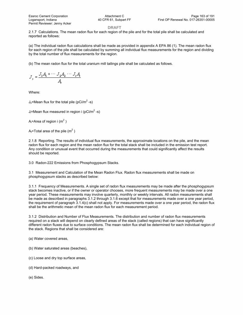
Essroc Cement Corporation Attachment C Page 163 of 191 Logansport, Indiana 40 CFR 61, Subpart FF First OP Renewal No. 017-26351-00005 Permit Reviewer: Jenny Acker DRAFT 2.1.7 Calculations. The mean radon flux for each region of the pile and for the total pile shall be calculated and reported as follows:
(a) The individual radon flux calculations shall be made as provided in appendix A EPA 86 (1). The mean radon flux for each region of the pile shall be calculated by summing all individual flux measurements for the region and dividing by the total number of flux measurements for the region.
(b) The mean radon flux for the total uranium mill tailings pile shall be calculated as follows.
Where:
Js=Mean flux for the total pile (pCi/m2 -s)
Ji=Mean flux measured in region i (pCi/m2 -s)
Ai=Area of region i (m2 )
At=Total area of the pile (m2 )
2.1.8 Reporting. The results of individual flux measurements, the approximate locations on the pile, and the mean radon flux for each region and the mean radon flux for the total stack shall be included in the emission test report. Any condition or unusual event that occurred during the measurements that could significantly affect the results should be reported.
3.0 Radon-222 Emissions from Phosphogypsum Stacks.
3.1 Measurement and Calculation of the Mean Radon Flux. Radon flux measurements shall be made on phosphogypsum stacks as described below:
3.1.1 Frequency of Measurements. A single set of radon flux measurements may be made after the phosphogypsum stack becomes inactive, or if the owner or operator chooses, more frequent measurements may be made over a one year period. These measurements may involve quarterly, monthly or weekly intervals. All radon measurements shall be made as described in paragraphs 3.1.2 through 3.1.6 except that for measurements made over a one year period, the requirement of paragraph 3.1.4(c) shall not apply. For measurements made over a one year period, the radon flux shall be the arithmetic mean of the mean radon flux for each measurement period.
3.1.2 Distribution and Number of Flux Measurements. The distribution and number of radon flux measurements required on a stack will depend on clearly defined areas of the stack (called regions) that can have significantly different radon fluxes due to surface conditions. The mean radon flux shall be determined for each individual region of the stack. Regions that shall be considered are:
(a) Water covered areas,
(b) Water saturated areas (beaches),
(c) Loose and dry top surface areas,
(d) Hard-packed roadways, and
(e) Sides.

Essroc Cement Corporation Attachment C Page 164 of 191 Logansport, Indiana 40 CFR 61, Subpart FF First OP Renewal No. 017-26351-00005 Permit Reviewer: Jenny Acker DRAFT 3.1.3 Number of Flux Measurements. Radon flux measurements shall be made within each region on the phosphogypsum stack, except for those areas covered with water. Measurements shall be made at regularly spaced locations across the surface of the region, realizing that surface roughness will prohibit measurements in some areas of a region. The minimum number of flux measurements considered necessary to determine a representative mean radon flux value for each type of region is:
(a) Water covered area—no measurements required as radon flux is assumed to be zero,
(b) Water saturated beaches—50 radon flux measurements,
(c) Loose and dry top surface—100 radon flux measurements,
(d) Hard-packed roadways—50 radon flux measurements, and
(e) Sides—100 radon flux measurements.
A minimum of 300 measurements are required. A stack that has no water cover can be considered to consist of two regions, top and sides, and will require a minimum of only 200 measurements.
3.1.4 Restrictions to Radon Flux Measurements. The following restrictions are placed on making radon flux measurements:
(a) Measurements shall not be initiated within 24 hours of a rainfall.
(b) If a rainfall occurs during the 24 hour measurement period, the measurement is invalid if the seal around the lip of the collector has washed away or if the collector is surrounded by water.
(c) Measurements shall not be performed if the ambient temperature is below 35 °F or if the ground is frozen.
3.1.5 Areas of Stack Regions. The approximate area of each region of the stack shall be determined in units of square meters.
3.1.6 Radon Flux Measurements. Measuring radon flux involves the adsorption of radon on activated charcoal in a large-area collector. The radon collector is placed on the surface of the stack area to be measured and allowed to collect radon for a time period of 24 hours. The radon collected on the charcoal is measured by gamma-ray spectroscopy. The detailed measurement procedure provided in appendix A of EPA 520/5–85–0029(1) shall be used to measure the radon flux on phosphogypsum stacks, except the surface of the phosphogypsum shall not be penetrated by the lip of the radon collector as directed in the procedure, rather the collector shall be carefully positioned on a flat surface with soil or phosphogypsum used to seal the edge.
3.1.7 Calculations. The mean radon flux for each region of the phosphogypsum stack and for the total stack shall be calculated and reported as follows:
(a) The individual radon flux calculations shall be made as provided in appendix A EPA 86 (1). The mean radon flux for each region of the stack shall be calculated by summing all individual flux measurements for the region and dividing by the total number of flux measurements for the region.
(b) The mean radon flux for the total phosphogypsum stack shall be calculated as follows.
Where:

Essroc Cement Corporation Attachment C Page 165 of 191 Logansport, Indiana 40 CFR 61, Subpart FF First OP Renewal No. 017-26351-00005 Permit Reviewer: Jenny Acker DRAFT Js=Mean flux for the total stack (pCi/m2 -s)
Ji=Mean flux measured in region i (pCi/m2 -s)
Ai=Area of region i (m2 )
At=Total area of the stack
3.1.8 Reporting. The results of individual flux measurements, the approximate locations on the stack, and the mean radon flux for each region and the mean radon flux for the total stack shall be included in the emission test report. Any condition or unusual event that occurred during the measurements that could significantly affect the results should be reported.
4.0 Quality Assurance Procedures for Measuring Rn–222 Flux
A. Sampling Procedures
Records of field activities and laboratory measurements shall be maintained. The following information shall be recorded for each charcoal canister measurement:
(a) Site
(b) Name of pile
(c) Sample location
(d) Sample ID number
(e) Date and time on
(f) Date and time off
(g) Observations of meteorological conditions and comments
Records shall include all applicable information associated with determining the sample measurement, calculations, observations, and comments.
B. Sample Custody
Custodial control of all charcoal samples exposed in the field shall be maintained in accordance with EPA chain-of-custody field procedures. A control record shall document all custody changes that occur between the field and laboratory personnel.
C. Calibration Procedures and Frequency
The radioactivity of two standard charcoal sources, each containing a carefully determined quantity of radium-226 uniformly distributed through 180g of activated charcoal, shall be measured. An efficiency factor is computed by dividing the average measured radioactivity of the two standard charcoal sources, minus the background, in cpm by the known radioactivity of the charcoal sources in dpm. The same two standard charcoal sources shall be counted at the beginning and at the end of each day's counting as a check of the radioactivity counting equipment. A background count using unexposed charcoal should also be made at the beginning and at the end of each counting day to check for inadvertent contamination of the detector or other changes affecting the background. The unexposed charcoal comprising the blank is changed with each new batch of charcoal used.
D. Internal Quality Control Checks and Frequency

Essroc Cement Corporation Attachment C Page 166 of 191 Logansport, Indiana 40 CFR 61, Subpart FF First OP Renewal No. 017-26351-00005 Permit Reviewer: Jenny Acker DRAFT The charcoal from every tenth exposed canister shall be recounted. Five percent of the samples analyzed shall be either blanks (charcoal having no radioactivity added) or samples spiked with known quantities of radium-226.
E. Data Precision, Accuracy, and Completeness
The precision, accuracy, and completeness of measurements and analyses shall be within the following limits for samples measuring greater than 1.0 pCi/m2 −s.
(a) Precision: 10%
(b) Accuracy: ±10%
(c) Completeness: at least 85% of the measurements must yield useable results.
5.0 References
(1) Hartley, J.N. and Freeman, H.D., “Radon Flux Measurements on Gardinier and Royster phosphogypsum Piles Near Tampa and Mulberry, Florida,” U.S. Environmental Protection Agency Report, EPA 520/5–85–029, January 1986.
(2) Environmental Protection Agency, “Indoor Radon and Radon Decay Product Measurement Protocols”, EPA 520/1–89–009, U.S. Environmental Protection Agency, Washington, DC. (1989).
[38 FR 8826, Apr. 6, 1973]
Editorial Notes: 1. ForFederal Registercitations to appendix B see the List of CFR Sections Affected, which appears in the Finding Aids section of the printed volume and on GPO Access.
2. At 65 FR 62161, Oct. 17, 2000, appendix B to part 61 was amended by revising Methods 101, 101A, 102, 103, 104, 105, 106, 107, 107A, 108, 108A, 108B, 108C, and 111. However, because the amendment contains no revised text for Method 107A, this part of the revision could not be incorporated.
Appendix C to Part 61—Quality Assurance Procedures
Procedure 1—Determination of Adequate Chromatographic Peak Resolution
In this method of dealing with resolution, the extent to which one chromatographic peak overlaps another is determined.
For convenience, consider the range of the elution curve of each compound as running from −2σ to +2σ. This range is used in other resolution criteria, and it contains 95.45 percent of the area of a normal curve. If two peaks are separated by a known distance, b, one can determine the fraction of the area of one curve that lies within the range of the other. The extent to which the elution curve of a contaminant compound overlaps the curve of a compound that is under analysis is found by integrating the contaminant curve over the limits b−2σsto b+2σs,where σsis the standard deviation of the sample curve.
This calculation can be simplified in several ways. Overlap can be determined for curves of unit area; then actual areas can be introduced. Desired integration can be resolved into two integrals of the normal distribution function for which there are convenient calculation programs and tables. An example would be Program 15 in Texas Instruments Program Manual ST1, 1975, Texas Instruments, Inc., Dallas, Texas 75222.

Essroc Cement Corporation Attachment C Page 167 of 191 Logansport, Indiana 40 CFR 61, Subpart FF First OP Renewal No. 017-26351-00005 Permit Reviewer: Jenny Acker DRAFT
View or download PDF
In judging the suitability of alternate GC columns or the effects of altering chromatographic conditions, one can employ the area overlap as the resolution parameter with a specific maximum permissible value.
The use of Gaussian functions to describe chromatographic elution curves is widespread. However, some elution curves are highly asymmetric. In cases where the sample peak is followed by a contaminant that has a leading edge that rises sharply but the curve then tails off, it may be possible to define an effective width for tcas “twice the distance from the leading edge to a perpendicular line through the maxim of the contaminant curve, measured along a perpendicular bisection of that line.”
Procedure 2—Procedure for Field Auditing GC Analysis
Responsibilities of audit supervisor and analyst at the source sampling site include the following:
A. The audit supervisor verifies that audit cylinders are stored in a safe location both before and after the audit to prevent vandalism.
B. At the beginning and conclusion of the audit, the analyst records each cylinder number and pressure. An audit cylinder is never analyzed when the pressure drops below 200 psi.

Essroc Cement Corporation Attachment C Page 168 of 191 Logansport, Indiana 40 CFR 61, Subpart FF First OP Renewal No. 017-26351-00005 Permit Reviewer: Jenny Acker DRAFT C. During the audit, the analyst performs a minimum of two consecutive analyses of each audit cylinder gas. The audit must be conducted to coincide with the analysis of source test samples, normally immediately after GC calibration and prior to sample analyses.
D. At the end of audit analyses, the audit supervisor requests the calculated concentrations from the analyst and compares the results with the actual audit concentrations. If each measured concentration agrees with the respective actual concentration within ±10 percent, he directs the analyst to begin analyzing source samples. Audit supervisor judgment and/or supervisory policy determine action when agreement is not within ±10 percent. When a consistent bias in excess of 10 percent is found, it may be possible to proceed with the sample analysis, with a corrective factor to be applied to the results at a later time. However, every attempt should be made to locate the cause of the discrepancy, as it may be misleading. The audit supervisor records each cylinder number, cylinder pressure (at the end of the audit), and all calculated concentrations. The individual being audited must not under any circumstance be told actual audit concentrations until calculated concentrations have been submitted to the audit supervisor.
Field Audit Report
Part A— To be filled out by organization supplying audit cylinders.
1. Organization supplying audit sample(s) and shipping address
____________________
2. Audit supervisor, organization, and phone number
____________________ ____________________
3. Shipping instructions: Name, Address, Attention
____________________ ____________________ ____________________ 4. Guaranteed arrival date for cylinders____________________ 5. Planned shipping date for cylinders____________________
6. Details on audit cylinders from last analysis
Low conc. High conc.
a. Date of last analysis
b. Cylinder number
c. Cylinder pressure, psi
d. Audit gas(es)/balance gas
e. Audit gas(es), ppm
f. Cylinder construction
Part B —To be filled out by audit supervisor.
1. Process sampled____________________ ____________________ 2. Audit location____________________ ____________________

Essroc Cement Corporation Attachment C Page 169 of 191 Logansport, Indiana 40 CFR 61, Subpart FF First OP Renewal No. 017-26351-00005 Permit Reviewer: Jenny Acker DRAFT 3. Name of individual audit____________________ 4. Audit date____________________
5. Audit results:
Low conc. cylinder High conc. cylinder
a. Cylinder number
b. Cylinder pressure before audit, psi
c. Cylinder pressure after audit, psi
d. Measured concentration, ppm Injection #1* Injection #2* Average
e. Actual audit concentration, ppm (Part A, 6e)
f. Audit accuracy:1
Low Conc. Cylinder
High Conc. Cylinder
Percent1accuracy=
Measured Conc.−Actual Conc.
________________ ×100
Actual Conc.
g. Problems detected (if any)
1Results of two consecutive injections that meet the sample analysis criteria of the test method.
[47 FR 39178, Sept. 7, 1982]
Appendix D to Part 61—Methods for Estimating Radionuclide Emissions
1. Purpose and Background
Facility owners or operators may estimate radionuclide emissions to the atmosphere for dose calculations instead of measuring emissions. Particulate emissions from mill tailings piles should be estimated using the procedures listed in reference re #2. All other emissions may be estimated by using the “Procedures” listed below, or using the method described in reference #1.
2. Procedure
To estimate emissions to the atmosphere:
(a) Determine the amount (in curies) used at facilities for the period under consideration. Radioactive materials in sealed packages that remain unopened, and have not leaked during the assessment period should not be included in the calculation.
(b) Multiply the amount used by the following factors which depend on the physical state of the radionuclide. They are:
(i) 1 for gases;

Essroc Cement Corporation Attachment C Page 170 of 191 Logansport, Indiana 40 CFR 61, Subpart FF First OP Renewal No. 017-26351-00005 Permit Reviewer: Jenny Acker DRAFT (ii) 10−3for liquids or particulate solids; and
(iii) 10−6for solids.
If any nuclide is heated to a temperature of 100 degrees Celsius or more, boils at a temperature of 100 degrees Celsius or less, or is intentionally dispersed into the environment, it must be considered to be a gas.
(c) If a control device is installed between the place of use and the point of release, multiply emissions from (b) by an adjustment factor. These are presented in Table 1.
Table 1—Adjustment to Emission Factors for Effluent Controls
Controls
Types of radionuclides
controlled
Adjustment factor to
emissions Comments and conditions
HEPA filters Particulates 0.01 Not applicable to gaseous radionuclides; periodic testing is prudent to ensure high removal efficiency.
Fabric filter Particulates 0.1 Monitoring would be prudent to guard against tears in filter.
Sintered metal Particulates 1 Insufficient data to make recommendation.
Activated carbon filters Iodine gas 0.1 Efficiency is time dependent; monitoring is necessary to ensure effectiveness.
Douglas bags: Held one week or longer for decay
Xenon 0.5/wk Based on xenon half-life of 5.3 days;
Douglas bags: Released within one week
Xenon 1 Provides no reduction of exposure to general public.
Venturi scrubbers Particulates Gases
0.05 1
Although venturis may remove gases, variability in gaseous removal efficiency dictates adjustment factor for particulates only.
Packed bed scrubbers Gases 0.1 Not applicable to particulates.
Electrostatic precipitators
Particulates 0.05 Not applicable for gaseous radionuclides
Xenon traps Xenon 0.1 Efficiency is time dependent; monitoring is necessary to ensure effectiveness.
Fume hoods All 1 Provides no reduction to general public exposures.
Vent stacks All 1 Generally provides no reduction of exposure to general public.
References
(1) Environmental Protection Agency, “A Guide for Determining Compliance with the Clean Air Act Standards for Radionuclides Emissions from NRC-Licensed and Non-DOE Federal Facilities”, EPA 520/1–89–002, January 1989.
(2) Nuclear Regulatory Commission, “Methods for Estimating Radioactive and Toxic Airborne Source Terms for Uranium Milling Operations”, U.S. Nuclear Regulatory Commission Regulatory Guide 3.59, March 1987.
[54 FR 51711, Dec. 15, 1989]
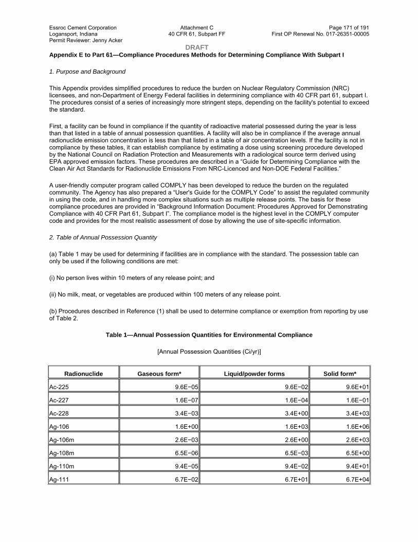
Essroc Cement Corporation Attachment C Page 171 of 191 Logansport, Indiana 40 CFR 61, Subpart FF First OP Renewal No. 017-26351-00005 Permit Reviewer: Jenny Acker DRAFT Appendix E to Part 61—Compliance Procedures Methods for Determining Compliance With Subpart I
1. Purpose and Background
This Appendix provides simplified procedures to reduce the burden on Nuclear Regulatory Commission (NRC) licensees, and non-Department of Energy Federal facilities in determining compliance with 40 CFR part 61, subpart I. The procedures consist of a series of increasingly more stringent steps, depending on the facility's potential to exceed the standard.
First, a facility can be found in compliance if the quantity of radioactive material possessed during the year is less than that listed in a table of annual possession quantities. A facility will also be in compliance if the average annual radionuclide emission concentration is less than that listed in a table of air concentration levels. If the facility is not in compliance by these tables, it can establish compliance by estimating a dose using screening procedure developed by the National Council on Radiation Protection and Measurements with a radiological source term derived using EPA approved emission factors. These procedures are described in a “Guide for Determining Compliance with the Clean Air Act Standards for Radionuclide Emissions From NRC-Licenced and Non-DOE Federal Facilities.”
A user-friendly computer program called COMPLY has been developed to reduce the burden on the regulated community. The Agency has also prepared a “User's Guide for the COMPLY Code” to assist the regulated community in using the code, and in handling more complex situations such as multiple release points. The basis for these compliance procedures are provided in “Background Information Document: Procedures Approved for Demonstrating Compliance with 40 CFR Part 61, Subpart I”. The compliance model is the highest level in the COMPLY computer code and provides for the most realistic assessment of dose by allowing the use of site-specific information.
2. Table of Annual Possession Quantity
(a) Table 1 may be used for determining if facilities are in compliance with the standard. The possession table can only be used if the following conditions are met:
(i) No person lives within 10 meters of any release point; and
(ii) No milk, meat, or vegetables are produced within 100 meters of any release point.
(b) Procedures described in Reference (1) shall be used to determine compliance or exemption from reporting by use of Table 2.
Table 1—Annual Possession Quantities for Environmental Compliance
[Annual Possession Quantities (Ci/yr)]
Radionuclide Gaseous form* Liquid/powder forms Solid form*
Ac-225 9.6E−05 9.6E−02 9.6E+01
Ac-227 1.6E−07 1.6E−04 1.6E−01
Ac-228 3.4E−03 3.4E+00 3.4E+03
Ag-106 1.6E+00 1.6E+03 1.6E+06
Ag-106m 2.6E−03 2.6E+00 2.6E+03
Ag-108m 6.5E−06 6.5E−03 6.5E+00
Ag-110m 9.4E−05 9.4E−02 9.4E+01
Ag-111 6.7E−02 6.7E+01 6.7E+04
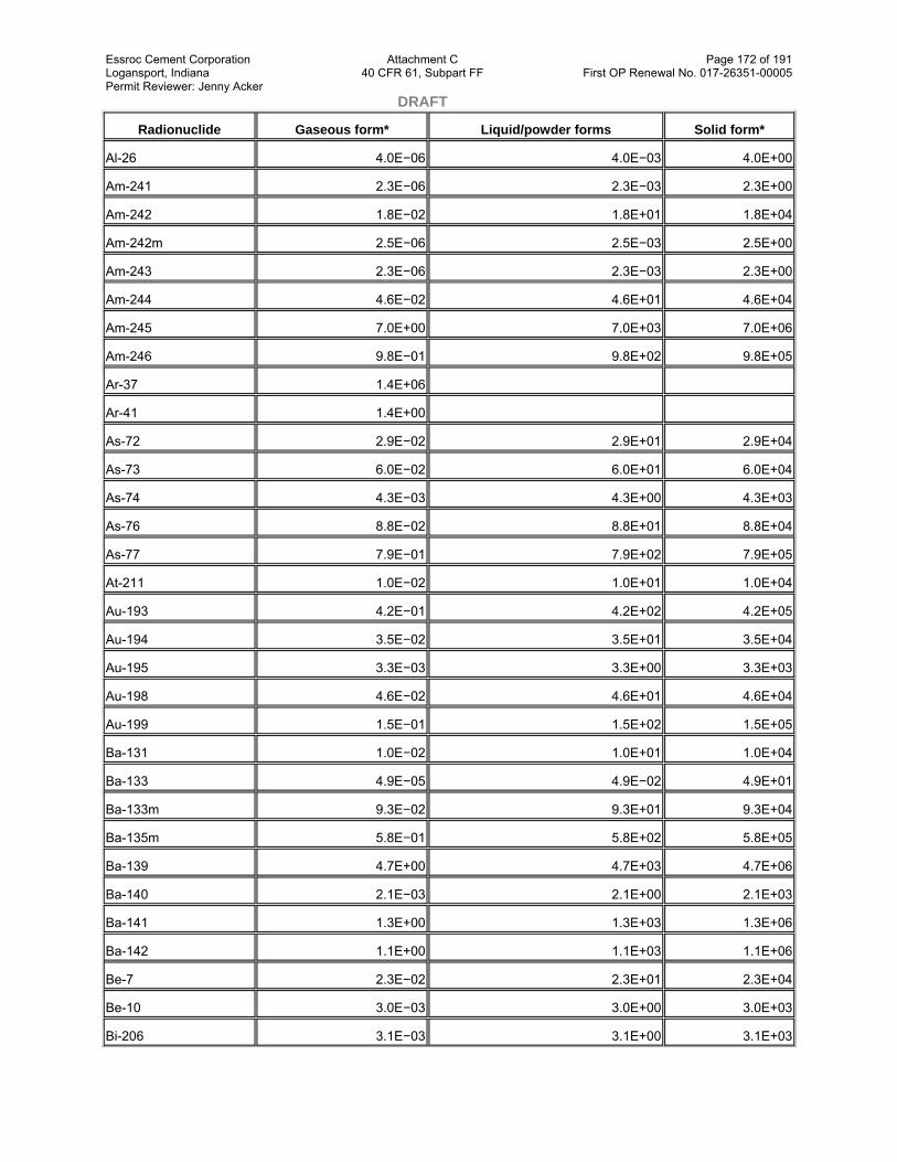
Essroc Cement Corporation Attachment C Page 172 of 191 Logansport, Indiana 40 CFR 61, Subpart FF First OP Renewal No. 017-26351-00005 Permit Reviewer: Jenny Acker DRAFT
Radionuclide Gaseous form* Liquid/powder forms Solid form*
Al-26 4.0E−06 4.0E−03 4.0E+00
Am-241 2.3E−06 2.3E−03 2.3E+00
Am-242 1.8E−02 1.8E+01 1.8E+04
Am-242m 2.5E−06 2.5E−03 2.5E+00
Am-243 2.3E−06 2.3E−03 2.3E+00
Am-244 4.6E−02 4.6E+01 4.6E+04
Am-245 7.0E+00 7.0E+03 7.0E+06
Am-246 9.8E−01 9.8E+02 9.8E+05
Ar-37 1.4E+06
Ar-41 1.4E+00
As-72 2.9E−02 2.9E+01 2.9E+04
As-73 6.0E−02 6.0E+01 6.0E+04
As-74 4.3E−03 4.3E+00 4.3E+03
As-76 8.8E−02 8.8E+01 8.8E+04
As-77 7.9E−01 7.9E+02 7.9E+05
At-211 1.0E−02 1.0E+01 1.0E+04
Au-193 4.2E−01 4.2E+02 4.2E+05
Au-194 3.5E−02 3.5E+01 3.5E+04
Au-195 3.3E−03 3.3E+00 3.3E+03
Au-198 4.6E−02 4.6E+01 4.6E+04
Au-199 1.5E−01 1.5E+02 1.5E+05
Ba-131 1.0E−02 1.0E+01 1.0E+04
Ba-133 4.9E−05 4.9E−02 4.9E+01
Ba-133m 9.3E−02 9.3E+01 9.3E+04
Ba-135m 5.8E−01 5.8E+02 5.8E+05
Ba-139 4.7E+00 4.7E+03 4.7E+06
Ba-140 2.1E−03 2.1E+00 2.1E+03
Ba-141 1.3E+00 1.3E+03 1.3E+06
Ba-142 1.1E+00 1.1E+03 1.1E+06
Be-7 2.3E−02 2.3E+01 2.3E+04
Be-10 3.0E−03 3.0E+00 3.0E+03
Bi-206 3.1E−03 3.1E+00 3.1E+03

Essroc Cement Corporation Attachment C Page 173 of 191 Logansport, Indiana 40 CFR 61, Subpart FF First OP Renewal No. 017-26351-00005 Permit Reviewer: Jenny Acker DRAFT
Radionuclide Gaseous form* Liquid/powder forms Solid form*
Bi-207 8.4E−06 8.4E−03 8.4E+00
Bi-210 4.2E−03 4.2E+00 4.2E+03
Bi-212 4.7E−02 4.7E+01 4.7E+04
Bi-213 6.0E−02 6.0E+01 6.0E+04
Bi-214 1.4E−01 1.4E+02 1.4E+05
Bk-249 7.0E−04 7.0E−01 7.0E+02
Bk-250 1.0E−01 1.0E+02 1.0E+05
Br-77 7.5E−02 7.5E+01 7.5E+04
Br-80 1.2E+01 1.2E+04 1.2E+07
Br-80m 1.5E+00 1.5E+03 1.5E+06
Br-82 1.6E−02 1.6E+01 1.6E+04
Br-83 9.9E+00 9.9E+03 9.9E+06
Br-84 5.6E−01 5.6E+02 5.6E+05
C-11 1.3E+00 1.3E+03 1.3E+06
C-14 2.9E−01 2.9E+02 2.9E+05
Ca-41 2.7E−02 2.7E+01 2.7E+04
Ca-45 5.8E−02 5.8E+01 5.8E+04
Ca-47 1.1E−02 1.1E+01 1.1E+04
Cd-109 5.0E−03 5.0E+00 5.0E+03
Cd-113 3.3E−04 3.3E−01 3.3E+02
Cd-113m 4.4E−04 4.4E−01 4.4E+02
Cd-115 5.4E−02 5.4E+01 5.4E+04
Cd-115m 1.0E−02 1.0E+01 1.0E+04
Cd-117 5.6E−02 5.6E+01 5.6E+04
Cd-117m 1.3E−01 1.3E+02 1.3E+05
Ce-139 2.6E−03 2.6E+00 2.6E+03
Ce-141 1.8E−02 1.8E+01 1.8E+04
Ce-143 1.0E−01 1.0E+02 1.0E+05
Ce-144 1.7E−03 1.7E+00 1.7E+03
Cf-248 2.0E−05 2.0E−02 2.0E+01
Cf-249 1.7E−06 1.7E−03 1.7E+00
Cf-250 4.0E−06 4.0E−03 4.0E+00

Essroc Cement Corporation Attachment C Page 174 of 191 Logansport, Indiana 40 CFR 61, Subpart FF First OP Renewal No. 017-26351-00005 Permit Reviewer: Jenny Acker DRAFT
Radionuclide Gaseous form* Liquid/powder forms Solid form*
Cf-251 1.7E−06 1.7E−03 1.7E+00
Cf-252 6.4E−06 6.4E−03 6.4E+00
Cf-253 3.3E−04 3.3E−01 3.3E+02
Cf-254 3.6E−06 3.6E−03 3.6E+00
Cl-36 1.9E−04 1.9E−01 1.9E+02
Cl-38 6.5E−01 6.5E+02 6.5E+05
Cm-242 6.0E−05 6.0E−02 6.0E+01
Cm-243 3.3E−06 3.3E−03 3.3E+00
Cm-244 4.2E−06 4.2E−03 4.2E+00
Cm-245 2.3E−06 2.3E−03 2.3E+00
Cm-246 2.3E−06 2.3E−03 2.3E+00
Cm-247 2.3E−06 2.3E−03 2.3E+00
Cm-248 6.4E−07 6.4E−04 6.4E−01
Cm-249 4.6E+00 4.6E+03 4.6E+06
Cm-250 1.1E−07 1.1E−04 1.1E−01
Co-56 2.4E−04 2.4E−01 2.4E+02
Co-57 1.6E−03 1.6E+00 1.6E+03
Co-58 9.0E−04 9.0E−01 9.0E+02
Co-58m 1.7E−01 1.7E+02 1.7E+05
Co-60 1.6E−05 1.6E−02 1.6E+01
Co-60m 4.0E+00 4.0E+03 4.0E+06
Co-61 3.8E+00 3.8E+03 3.8E+06
Cr-49 9.0E−01 9.0E+02 9.0E+05
Cr-51 6.3E−02 6.3E+01 6.3E+04
Cs-129 1.5E−01 1.5E+02 1.5E+05
Cs-131 2.8E−01 2.8E+02 2.8E+05
Cs-132 1.3E−02 1.3E+01 1.3E+04
Cs-134 5.2E−05 5.2E−02 5.2E+01
Cs-134m 3.2E−01 3.2E+02 3.2E+05
Cs-135 2.4E−02 2.4E+01 2.4E+04
Cs-136 2.1E−03 2.1E+00 2.1E+03
Cs-137 2.3E−05 2.3E−02 2.3E+01

Essroc Cement Corporation Attachment C Page 175 of 191 Logansport, Indiana 40 CFR 61, Subpart FF First OP Renewal No. 017-26351-00005 Permit Reviewer: Jenny Acker DRAFT
Radionuclide Gaseous form* Liquid/powder forms Solid form*
Cs-138 4.4E−01 4.4E+02 4.4E+05
Cu-61 4.0E−01 4.0E+02 4.0E+05
Cu-64 5.2E−01 5.2E+02 5.2E+05
Cu-67 1.5E−01 1.5E+02 1.5E+05
Dy-157 4.4E−01 4.4E+02 4.4E+05
Dy-165 5.6E+00 5.6E+03 5.6E+06
Dy-166 8.1E−02 8.1E+01 8.1E+04
Er-169 4.0E−01 4.0E+02 4.0E+05
Er-171 3.6E−01 3.6E+02 3.6E+05
Es-253 2.6E−04 2.6E−01 2.6E+02
Es-254 2.3E−05 2.3E−02 2.3E+01
Es-254m 1.8E−03 1.8E+00 1.8E+03
Eu-152 1.6E−05 1.6E−02 1.6E+01
Eu-152m 3.5E−01 3.5E+02 3.5E+05
Eu-154 2.0E−05 2.0E−02 2.0E+01
Eu-155 5.2E−04 5.2E−01 5.2E+02
Eu-156 3.2E−03 3.2E+00 3.2E+03
F-18 5.6E−01 5.6E+02 5.6E+05
Fe-52 4.9E−02 4.9E+01 4.9E+04
Fe-55 1.4E−01 1.4E+02 1.4E+05
Fe-59 1.3E−03 1.3E+00 1.3E+03
Fm-254 1.8E−02 1.8E+01 1.8E+04
Fm-255 4.0E−03 4.0E+00 4.0E+03
Fr-223 1.4E−01 1.4E+02 1.4E+05
Ga-66 5.6E−02 5.6E+01 5.6E+04
Ga-67 1.1E−01 1.1E+02 1.1E+05
Ga-68 7.6E−01 7.6E+02 7.6E+05
Ga-72 3.6E−02 3.6E+01 3.6E+04
Gd-152 4.4E−06 4.4E−03 4.4E+00
Gd-153 2.0E−03 2.0E+00 2.0E+03
Gd-159 6.8E−01 6.8E+02 6.8E+05
Ge-68 2.3E−04 2.3E−01 2.3E+02
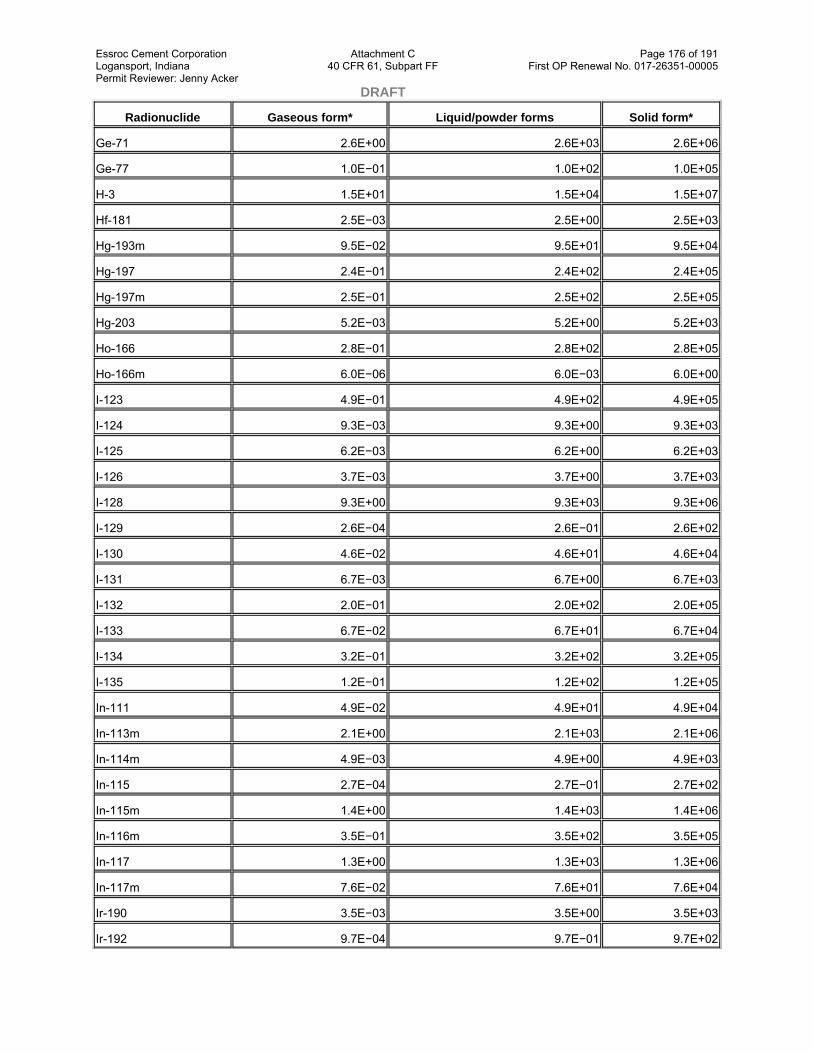
Essroc Cement Corporation Attachment C Page 176 of 191 Logansport, Indiana 40 CFR 61, Subpart FF First OP Renewal No. 017-26351-00005 Permit Reviewer: Jenny Acker DRAFT
Radionuclide Gaseous form* Liquid/powder forms Solid form*
Ge-71 2.6E+00 2.6E+03 2.6E+06
Ge-77 1.0E−01 1.0E+02 1.0E+05
H-3 1.5E+01 1.5E+04 1.5E+07
Hf-181 2.5E−03 2.5E+00 2.5E+03
Hg-193m 9.5E−02 9.5E+01 9.5E+04
Hg-197 2.4E−01 2.4E+02 2.4E+05
Hg-197m 2.5E−01 2.5E+02 2.5E+05
Hg-203 5.2E−03 5.2E+00 5.2E+03
Ho-166 2.8E−01 2.8E+02 2.8E+05
Ho-166m 6.0E−06 6.0E−03 6.0E+00
I-123 4.9E−01 4.9E+02 4.9E+05
I-124 9.3E−03 9.3E+00 9.3E+03
I-125 6.2E−03 6.2E+00 6.2E+03
I-126 3.7E−03 3.7E+00 3.7E+03
I-128 9.3E+00 9.3E+03 9.3E+06
I-129 2.6E−04 2.6E−01 2.6E+02
I-130 4.6E−02 4.6E+01 4.6E+04
I-131 6.7E−03 6.7E+00 6.7E+03
I-132 2.0E−01 2.0E+02 2.0E+05
I-133 6.7E−02 6.7E+01 6.7E+04
I-134 3.2E−01 3.2E+02 3.2E+05
I-135 1.2E−01 1.2E+02 1.2E+05
In-111 4.9E−02 4.9E+01 4.9E+04
In-113m 2.1E+00 2.1E+03 2.1E+06
In-114m 4.9E−03 4.9E+00 4.9E+03
In-115 2.7E−04 2.7E−01 2.7E+02
In-115m 1.4E+00 1.4E+03 1.4E+06
In-116m 3.5E−01 3.5E+02 3.5E+05
In-117 1.3E+00 1.3E+03 1.3E+06
In-117m 7.6E−02 7.6E+01 7.6E+04
Ir-190 3.5E−03 3.5E+00 3.5E+03
Ir-192 9.7E−04 9.7E−01 9.7E+02

Essroc Cement Corporation Attachment C Page 177 of 191 Logansport, Indiana 40 CFR 61, Subpart FF First OP Renewal No. 017-26351-00005 Permit Reviewer: Jenny Acker DRAFT
Radionuclide Gaseous form* Liquid/powder forms Solid form*
Ir-194 2.5E−01 2.5E+02 2.5E+05
Ir-194m 1.5E−04 1.5E−01 1.5E+02
K-40 6.8E−05 6.8E−02 6.8E+01
K-42 2.9E−01 2.9E+02 2.9E+05
K-43 6.0E−02 6.0E+01 6.0E+04
K-44 4.9E−01 4.9E+02 4.9E+05
Kr-79 7.0E+00
Kr-81 1.8E+02
Kr-83m 2.0E+04
Kr-85 8.4E+02
Kr-85m 1.1E+01
Kr-87 2.0E+00
Kr-88 4.2E−01
La-140 1.6E−02 1.6E+01 1.6E+04
La-141 1.1E+00 1.1E+03 1.1E+06
La-142 2.3E−01 2.3E+02 2.3E+05
Lu-177 1.4E−01 1.4E+02 1.4E+05
Lu-177m 3.5E−04 3.5E−01 3.5E+02
Mg-28 2.1E−02 2.1E+01 2.1E+04
Mn-52 3.5E−03 3.5E+00 3.5E+03
Mn-52m 5.2E−01 5.2E+02 5.2E+05
Mn-53 5.7E−02 5.7E+01 5.7E+04
Mn-54 2.5E−04 2.5E−01 2.5E+02
Mn-56 2.5E−01 2.5E+02 2.5E+05
Mo-93 1.5E−03 1.5E+00 1.5E+03
Mo-99** 5.7E−02 5.7E+01 5.7E+04
Mo-101 8.4E−01 8.4E+02 8.4E+05
Na-22 3.2E−05 3.2E−02 3.2E+01
Na-24 2.6E−02 2.6E+01 2.6E+04
Nb-90 2.5E−02 2.5E+01 2.5E+04
Nb-93m 1.2E−02 1.2E+01 1.2E+04
Nb-94 6.0E−06 6.0E−03 6.0E+00

Essroc Cement Corporation Attachment C Page 178 of 191 Logansport, Indiana 40 CFR 61, Subpart FF First OP Renewal No. 017-26351-00005 Permit Reviewer: Jenny Acker DRAFT
Radionuclide Gaseous form* Liquid/powder forms Solid form*
Nb-95 2.3E−03 2.3E+00 2.3E+03
Nb-95m 2.0E−02 2.0E+01 2.0E+04
Nb-96 2.5E−02 2.5E+01 2.5E+04
Nb-97 1.0E+00 1.0E+03 1.0E+06
Nd-147 3.0E−02 3.0E+01 3.0E+04
Nd-149 1.1E+00 1.1E+03 1.1E+06
Ni-56 2.0E−03 2.0E+00 2.0E+03
Ni-57 2.1E−02 2.1E+01 2.1E+04
Ni-59 2.2E−02 2.2E+01 2.2E+04
Ni-63 1.4E−01 1.4E+02 1.4E+05
Ni-65 7.0E−01 7.0E+02 7.0E+05
Np-235 3.0E−02 3.0E+01 3.0E+04
Np-237 1.8E−06 1.8E−03 1.8E+00
Np-238 1.9E−02 1.9E+01 1.9E+04
Np-239 1.0E−01 1.0E+02 1.0E+05
Np-240 6.5E−01 6.5E+02 6.5E+05
Np-240m 4.7E+00 4.7E+03 4.7E+06
Os-185 9.2E−04 9.2E−01 9.2E+02
Os-191m 9.0E−01 9.0E+02 9.0E+05
Os-191 3.8E−02 3.8E+01 3.8E+04
Os-193 2.9E−01 2.9E+02 2.9E+05
P-32 1.7E−02 1.7E+01 1.7E+04
P-33 1.2E−01 1.2E+02 1.2E+05
Pa-230 6.3E−04 6.3E−01 6.3E+02
Pa-231 8.3E−07 8.3E−04 8.3E−01
Pa-233 9.3E−03 9.3E+00 9.3E+03
Pa-234 9.3E−02 9.3E+01 9.3E+04
Pb-203 8.3E−02 8.3E+01 8.3E+04
Pb-205 1.2E−02 1.2E+01 1.2E+04
Pb-209 1.1E+01 1.1E+04 1.1E+07
Pb-210 5.5E−05 5.5E−02 5.5E+01
Pb-211 1.2E−01 1.2E+02 1.2E+05

Essroc Cement Corporation Attachment C Page 179 of 191 Logansport, Indiana 40 CFR 61, Subpart FF First OP Renewal No. 017-26351-00005 Permit Reviewer: Jenny Acker DRAFT
Radionuclide Gaseous form* Liquid/powder forms Solid form*
Pb-212 6.0E−03 6.0E+00 6.0E+03
Pb-214 1.2E−01 1.2E+02 1.2E+05
Pd-103 2.1E−01 2.1E+02 2.1E+05
Pd-107 8.2E−02 8.2E+01 8.2E+04
Pd-109 9.4E−01 9.4E+02 9.4E+05
Pm-143 7.6E−04 7.6E−01 7.6E+02
Pm-144 1.1E−04 1.1E−01 1.1E+02
Pm-145 5.2E−04 5.2E−01 5.2E+02
Pm-146 4.4E−05 4.4E−02 4.4E+01
Pm-147 2.6E−02 2.6E+01 2.6E+04
Pm-148 1.7E−02 1.7E+01 1.7E+04
Pm-148m 7.6E−04 7.6E−01 7.6E+02
Pm-149 2.8E−01 2.8E+02 2.8E+05
Pm-151 1.2E−01 1.2E+02 1.2E+05
Po-210 9.3E−05 9.3E−02 9.3E+01
Pr-142 2.8E−01 2.8E+02 2.8E+05
Pr-143 1.0E−01 1.0E+02 1.0E+05
Pr-144 1.5E+01 1.5E+04 1.5E+07
Pt-191 6.4E−02 6.4E+01 6.4E+04
Pt-193 2.1E−02 2.1E+01 2.1E+04
Pt-193m 4.8E−01 4.8E+02 4.8E+05
Pt-195m 1.4E−01 1.4E+02 1.4E+05
Pt-197 1.1E+00 1.1E+03 1.1E+06
Pt-197m 3.6E+00 3.6E+03 3.6E+06
Pu-236 7.0E−06 7.0E−03 7.0E+00
Pu-237 2.3E−02 2.3E+01 2.3E+04
Pu-238 2.7E−06 2.7E−03 2.7E+00
Pu-239 2.5E−06 2.5E−03 2.5E+00
Pu-240 2.5E−06 2.5E−03 2.5E+00
Pu-241 1.3E−04 1.3E−01 1.3E+02
Pu-242 2.5E−06 2.5E−03 2.5E+00
Pu-243 3.8E+00 3.8E+03 3.8E+06

Essroc Cement Corporation Attachment C Page 180 of 191 Logansport, Indiana 40 CFR 61, Subpart FF First OP Renewal No. 017-26351-00005 Permit Reviewer: Jenny Acker DRAFT
Radionuclide Gaseous form* Liquid/powder forms Solid form*
Pu-244 2.4E−06 2.4E−03 2.4E+00
Pu-245 2.1E−01 2.1E+02 2.1E+05
Pu-246 4.8E−03 4.8E+00 4.8E+03
Ra-223 1.3E−04 1.3E−01 1.3E+02
Ra-224 3.2E−04 3.2E−01 3.2E+02
Ra-225 1.3E−04 1.3E−01 1.3E+02
Ra-226 5.5E−06 5.5E−03 5.5E+00
Ra-228 1.3E−05 1.3E−02 1.3E+01
Rb-81 4.2E−01 4.2E+02 4.2E+05
Rb-83 1.4E−03 1.4E+00 1.4E+03
Rb-84 2.0E−03 2.0E+00 2.0E+03
Rb-86 1.7E−02 1.7E+01 1.7E+04
Rb-87 1.0E−02 1.0E+01 1.0E+04
Rb-88 1.7E+00 1.7E+03 1.7E+06
Rb-89 6.4E−01 6.4E+02 6.4E+05
Re−184 1.8E−03 1.8E+00 1.8E+03
Re-184m 3.6E−04 3.6E−01 3.6E+02
Re-186 1.9E−01 1.9E+02 1.9E+05
Re-187 9.3E+00 9.3E+03 9.3E+06
Re-188 3.7E−01 3.7E+02 3.7E+05
Rh-103m 1.7E+02 1.7E+05 1.7E+08
Rh-105 3.4E−01 3.4E+02 3.4E+05
Ru-97 8.3E−02 8.3E+01 8.3E+04
Ru-103 3.1E−03 3.1E+00 3.1E+03
Ru-105 2.9E−01 2.9E+02 2.9E+05
Ru-106 5.9E−04 5.9E−01 5.9E+02
S-35 7.5E−02 7.5E+01 7.5E+04
Sb-117 2.0E+00 2.0E+03 2.0E+06
Sb-122 3.9E−02 3.9E+01 3.9E+04
Sb-124 6.0E−04 6.0E−01 6.0E+02
Sb-125 1.4E−04 1.4E−01 1.4E+02
Sb-126 1.8E−03 1.8E+00 1.8E+03

Essroc Cement Corporation Attachment C Page 181 of 191 Logansport, Indiana 40 CFR 61, Subpart FF First OP Renewal No. 017-26351-00005 Permit Reviewer: Jenny Acker DRAFT
Radionuclide Gaseous form* Liquid/powder forms Solid form*
Sb-126m 7.6E−01 7.6E+02 7.6E+05
Sb-127 2.0E−02 2.0E+01 2.0E+04
Sb-129 1.8E−01 1.8E+02 1.8E+05
Sc-44 1.4E−01 1.4E+02 1.4E+05
Sc-46 4.0E−04 4.0E−01 4.0E+02
Sc-47 1.1E−01 1.1E+02 1.1E+05
Sc-48 1.1E−02 1.1E+01 1.1E+04
Sc-49 1.0E+01 1.0E+04 1.0E+07
Se-73 1.6E−01 1.6E+02 1.6E+05
Se-75 1.1E−03 1.1E+00 1.1E+03
Se-79 6.9E−03 6.9E+00 6.9E+03
Si-31 4.7E+00 4.7E+03 4.7E+06
Si-32 7.2E−04 7.2E−01 7.2E+02
Sm-147 1.4E−05 1.4E−02 1.4E+01
Sm-151 3.5E−02 3.5E+01 3.5E+04
Sm-153 2.4E−01 2.4E+02 2.4E+05
Sn-113 1.9E−03 1.9E+00 1.9E+03
Sn-117m 2.3E−02 2.3E+01 2.3E+04
Sn-119m 2.8E−02 2.8E+01 2.8E+04
Sn-123 1.8E−02 1.8E+01 1.8E+04
Sn-125 7.2E−03 7.2E+00 7.2E+03
Sn-126 4.7E−06 4.7E−03 4.7E+00
Sr-82 1.9E−03 1.9E+00 1.9E+03
Sr-85 1.9E−03 1.9E+00 1.9E+03
Sr-85m 1.5E+00 1.5E+03 1.5E+06
Sr-87m 1.2E+00 1.2E+03 1.2E+06
Sr-89 2.1E−02 2.1E+01 2.1E+04
Sr-90 5.2E−04 5.2E−01 5.2E+02
Sr-91 1.2E−01 1.2E+02 1.2E+05
Sr-92 2.5E−01 2.5E+02 2.5E+05
Ta-182 4.4E−04 4.4E−01 4.4E+02
Tb-157 2.2E−03 2.2E+00 2.2E+03

Essroc Cement Corporation Attachment C Page 182 of 191 Logansport, Indiana 40 CFR 61, Subpart FF First OP Renewal No. 017-26351-00005 Permit Reviewer: Jenny Acker DRAFT
Radionuclide Gaseous form* Liquid/powder forms Solid form*
Tb-160 8.4E−04 8.4E−01 8.4E+02
Tc-95 9.0E−02 9.0E+01 9.0E+04
Tc-95m 1.4E−03 1.4E+00 1.4E+03
Tc-96 5.6E−03 5.6E+00 5.6E+03
Tc-96m 7.0E−01 7.0E+02 7.0E+05
Tc-97 1.5E−03 1.5E+00 1.5E+03
Tc-97m 7.2E−02 7.2E+01 7.2E+04
Tc-98 6.4E−06 6.4E−03 6.4E+00
Tc-99 9.0E−03 9.0E+00 9.0E+03
Tc-99m 1.4E+00 1.4E+03 1.4E+06
Tc-101 3.8E+00 3.8E+03 3.8E+06
Te-121 6.0E−03 6.0E+00 6.0E+03
Te-121m 5.3E−04 5.3E−01 5.3E+02
Te-123 1.2E−03 1.2E+00 1.2E+03
Te-123m 2.7E−03 2.7E+00 2.7E+03
Te-125m 1.5E−02 1.5E+01 1.5E+04
Te-127 2.9E+00 2.9E+03 2.9E+06
Te-127m 7.3E−03 7.3E+00 7.3E+03
Te-129 6.5E+00 6.5E+03 6.5E+06
Te-129m 6.1E−03 6.1E+00 6.1E+03
Te-131 9.4E−01 9.4E+02 9.4E+05
Te-131m 1.8E−02 1.8E+01 1.8E+04
Te-132 6.2E−03 6.2E+00 6.2E+03
Te-133 1.2E+00 1.2E+03 1.2E+06
Te-133m 2.9E−01 2.9E+02 2.9E+05
Te-134 4.4E−01 4.4E+02 4.4E+05
Th-226 3.0E−02 3.0E+01 3.0E+04
Th-227 6.4E−05 6.4E−02 6.4E+01
Th-228 2.9E−06 2.9E−03 2.9E+00
Th-229 4.9E−07 4.9E−04 4.9E−01
Th-230 3.2E−06 3.2E−03 3.2E+00
Th-231 8.4E−01 8.4E+02 8.4E+05

Essroc Cement Corporation Attachment C Page 183 of 191 Logansport, Indiana 40 CFR 61, Subpart FF First OP Renewal No. 017-26351-00005 Permit Reviewer: Jenny Acker DRAFT
Radionuclide Gaseous form* Liquid/powder forms Solid form*
Th-232 6.0E−07 6.0E−04 6.0E−01
Th-234 2.0E−02 2.0E+01 2.0E+04
Ti-44 5.2E−06 5.2E−03 5.2E+00
Ti-45 4.0E−01 4.0E+02 4.0E+05
Tl-200 4.4E−02 4.4E+01 4.4E+04
Tl-201 1.8E−01 1.8E+02 1.8E+05
Tl-202 1.0E−02 1.0E+01 1.0E+04
Tl-204 2.5E−02 2.5E+01 2.5E+04
Tm-170 2.4E−02 2.4E+01 2.4E+04
Tm-171 5.9E−02 5.9E+01 5.9E+04
U-230 5.0E−05 5.0E−02 5.0E+01
U-231 1.4E−01 1.4E+02 1.4E+05
U-232 1.3E−06 1.3E−03 1.3E+00
U-233 7.6E−06 7.6E−03 7.6E+00
U-234 7.6E−06 7.6E−03 7.6E+00
U-235 7.0E−06 7.0E−03 7.0E+00
U-236 8.4E−06 8.4E−03 8.4E+00
U-237 4.7E−02 4.7E+01 4.7E+04
U-238 8.6E−06 8.6E−03 8.6E+00
U-239 8.3E+00 8.3E+03 8.3E+06
U-240 1.8E−01 1.8E+02 1.8E+05
V-48 1.4E−03 1.4E+00 1.4E+03
V-49 1.3E+00 1.3E+03 1.3E+06
W-181 1.1E−02 1.1E+01 1.1E+04
W-185 1.6E−01 1.6E+02 1.6E+05
W-187 1.1E−01 1.1E+02 1.1E+05
W-188 1.0E−02 1.0E+01 1.0E+04
Xe-122 7.6E−02 7.6E+01 7.6E+04
Xe-123 1.6E+00 1.6E+03 1.6E+06
Xe-125 6.0E−01
Xe-127 7.0E+00
Xe-129m 7.6E+01

Essroc Cement Corporation Attachment C Page 184 of 191 Logansport, Indiana 40 CFR 61, Subpart FF First OP Renewal No. 017-26351-00005 Permit Reviewer: Jenny Acker DRAFT
Radionuclide Gaseous form* Liquid/powder forms Solid form*
Xe-131m 2.2E+02
Xe-133 5.2E+01
Xe-133m 6.0E+01
Xe-135 7.6E+00
Xe-135m 4.2E+00
Xe-138 9.9E−01
Y-86 2.8E−02 2.8E+01 2.8E+04
Y-87 2.3E−02 2.3E+01 2.3E+04
Y-88 2.5E−04 2.5E−01 2.5E+02
Y-90 1.1E−01 1.1E+02 1.1E+05
Y-90m 4.3E−01 4.3E+02 4.3E+05
Y-91 1.8E−02 1.8E+01 1.8E+04
Y-91m 1.6E+00 1.6E+03 1.6E+06
Y-92 7.0E−01 7.0E+02 7.0E+05
Y-93 3.8E−01 3.8E+02 3.8E+05
Yb-169 5.5E−03 5.5E+00 5.5E+03
Yb-175 2.1E−01 2.1E+02 2.1E+05
Zn-62 8.6E−02 8.6E+01 8.6E+04
Zn-65 4.4E−04 4.4E−01 4.4E+02
Zn-69 2.7E+01 2.7E+04 2.7E+07
Zn-69m 2.0E−01 2.0E+02 2.0E+05
Zr-86 2.4E−02 2.4E+01 2.4E+04
Zr-88 2.7E−04 2.7E−01 2.7E+02
Zr-89 1.6E−02 1.6E+01 1.6E+04
Zr-93 2.8E−03 2.8E+00 2.8E+03
Zr-95 6.4E−04 6.4E−01 6.4E+02
Zr-97 4.6E−02 4.6E+01 4.6E+04
*Radionuclides boiling at 100°C or less, or exposed to a temperature of 100°C, must be considered a gas. Capsules containing radionuclides in liquid or powder form can be considered to be solids.
**Mo-99 contained in a generator to produce Technetium-99 can be assumed to be a solid.
3. Table of Concentration Levels

Essroc Cement Corporation Attachment C Page 185 of 191 Logansport, Indiana 40 CFR 61, Subpart FF First OP Renewal No. 017-26351-00005 Permit Reviewer: Jenny Acker DRAFT (a) Table 2 may be used for determining if facilities are in compliance with the standard.
1. The concentration table as applied to emission estimates can only be used if all releases are from point sources and concentrations have been measured at the stack or vent using EPA-approved methods, and the distance between each stack or vent and the nearest resident is greater than 3 times the diameter of the stack or vent. Procedures provided in Ref. (1) shall be used to determine compliance or exemption from reporting by use of Table 2.
2. The concentration table may be used to determine compliance with the standard based on environmental measurements provided these measurements are made in conformance with the requirements of §61.107(b)(5).
4. NCRP Screening Model
The procedures described in Reference (4) may be used to determine doses to members of the general public from emissions of radionuclides to the atmosphere. Both the total dose from all radionuclides emitted, and the dose caused by radioactive iodine must be considered in accordance with the procedures in Ref. (1).
5. The COMPLY Computer Code
The COMPLY computer code may be used to determine compliance with subpart I. The compliance model in the COMPLY computer code may be used to determine the dose to members of the general public from emissions of radionuclides to the atmosphere. The EPA may add radionuclides to all or any part of COMPLY to cover radionuclides that may be used by the regulated community.
Table 2—Concentration Levels for Environmental Compliance
Radionuclide Concentration (Ci/m3) Radionuclide Concentration (Ci/m3)
Ac-225 9.1E−14 Bi-207 1.0E−14
Ac-227 1.6E−16 Bi-210 2.9E−13
Ac-228 3.7E−12 Bi-212 5.6E−11
Ag-106 1.9E−09 Bi-213 7.1E−11
Ag-106m 1.2E−12 Bi-214 1.4E−10
Ag-108m 7.1E−15 Bk-249 5.6E−13
Ag-110m 9.1E−14 Bk-250 9.1E−11
Ag-111 2.5E−12 Br-77 4.2E−11
Al-26 4.8E−15 Br-80 1.4E−08
Am-241 1.9E−15 Br-80m 1.8E−09
Am-242 1.5E−11 Br-82 1.2E−11
Am-242m 2.0E−15 Br-83 1.2E−08
Am-243 1.8E−15 Br-84 6.7E−10
Am-244 4.0E−11 C-11 1.5E−09
Am-245 8.3E−09 C-14 1.0E−11
Am-246 1.2E−09 Ca-41 4.2E−13
Ar-37 1.6E−03 Ca-45 1.3E−12
Ar-41 1.7E−09 Ca-47 2.4E−12
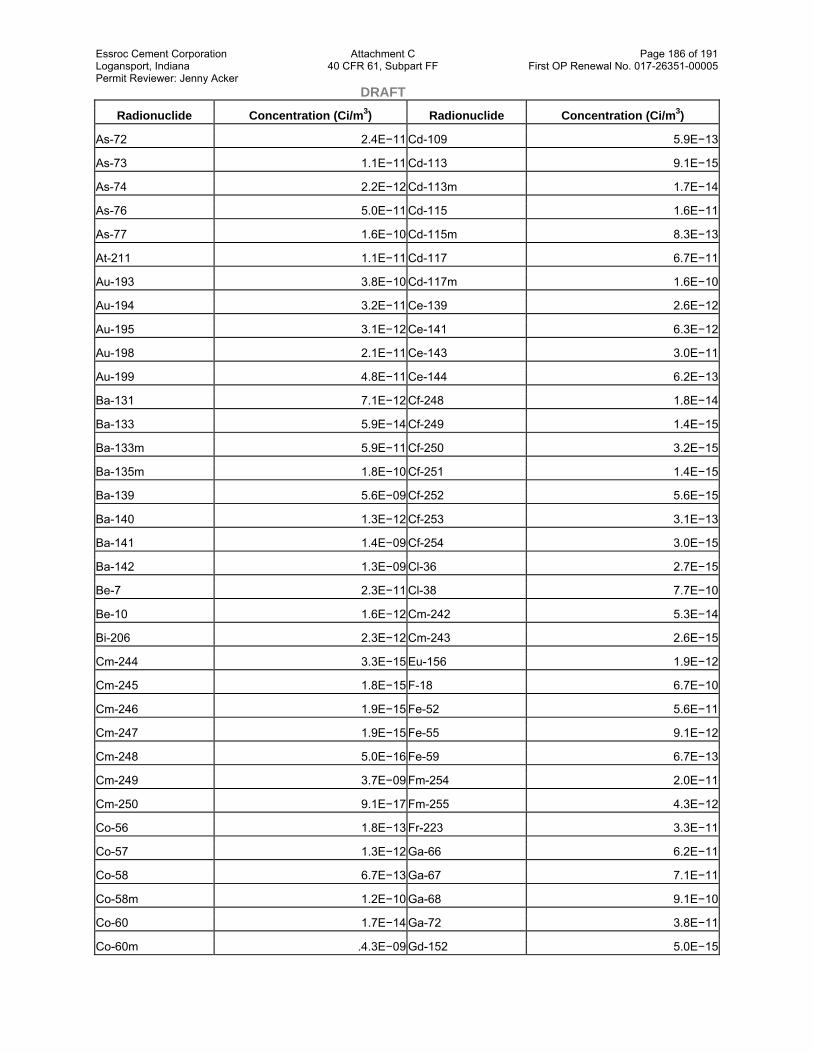
Essroc Cement Corporation Attachment C Page 186 of 191 Logansport, Indiana 40 CFR 61, Subpart FF First OP Renewal No. 017-26351-00005 Permit Reviewer: Jenny Acker DRAFT
Radionuclide Concentration (Ci/m3) Radionuclide Concentration (Ci/m3)
As-72 2.4E−11 Cd-109 5.9E−13
As-73 1.1E−11 Cd-113 9.1E−15
As-74 2.2E−12 Cd-113m 1.7E−14
As-76 5.0E−11 Cd-115 1.6E−11
As-77 1.6E−10 Cd-115m 8.3E−13
At-211 1.1E−11 Cd-117 6.7E−11
Au-193 3.8E−10 Cd-117m 1.6E−10
Au-194 3.2E−11 Ce-139 2.6E−12
Au-195 3.1E−12 Ce-141 6.3E−12
Au-198 2.1E−11 Ce-143 3.0E−11
Au-199 4.8E−11 Ce-144 6.2E−13
Ba-131 7.1E−12 Cf-248 1.8E−14
Ba-133 5.9E−14 Cf-249 1.4E−15
Ba-133m 5.9E−11 Cf-250 3.2E−15
Ba-135m 1.8E−10 Cf-251 1.4E−15
Ba-139 5.6E−09 Cf-252 5.6E−15
Ba-140 1.3E−12 Cf-253 3.1E−13
Ba-141 1.4E−09 Cf-254 3.0E−15
Ba-142 1.3E−09 Cl-36 2.7E−15
Be-7 2.3E−11 Cl-38 7.7E−10
Be-10 1.6E−12 Cm-242 5.3E−14
Bi-206 2.3E−12 Cm-243 2.6E−15
Cm-244 3.3E−15 Eu-156 1.9E−12
Cm-245 1.8E−15 F-18 6.7E−10
Cm-246 1.9E−15 Fe-52 5.6E−11
Cm-247 1.9E−15 Fe-55 9.1E−12
Cm-248 5.0E−16 Fe-59 6.7E−13
Cm-249 3.7E−09 Fm-254 2.0E−11
Cm-250 9.1E−17 Fm-255 4.3E−12
Co-56 1.8E−13 Fr-223 3.3E−11
Co-57 1.3E−12 Ga-66 6.2E−11
Co-58 6.7E−13 Ga-67 7.1E−11
Co-58m 1.2E−10 Ga-68 9.1E−10
Co-60 1.7E−14 Ga-72 3.8E−11
Co-60m .4.3E−09 Gd-152 5.0E−15

Essroc Cement Corporation Attachment C Page 187 of 191 Logansport, Indiana 40 CFR 61, Subpart FF First OP Renewal No. 017-26351-00005 Permit Reviewer: Jenny Acker DRAFT
Radionuclide Concentration (Ci/m3) Radionuclide Concentration (Ci/m3)
Co-61 4.5E−09 Gd-153 2.1E−12
Cr-49 1.1E−09 Gd-159 2.9E−10
Cr-51 3.1E−11 Ge-68 2.0E−13
Cs-129 1.4E−10 Ge-71 2.4E−10
Cs-131 3.3E−11 Ge-77 1.0E−10
Cs-132 4.8E−12 H-3 1.5E−09
Cs-134 2.7E−14 Hf-181 1.9E−12
Cs-134m 1.7E−10 Hg-193m 1.0E−10
Cs-135 4.0E−13 Hg-197 8.3E−11
Cs-136 5.3E−13 Hg-197m 1.1E−10
Cs-137 1.9E−14 Hg-203 1.0E−12
Cs-138 5.3E−10 Ho-166 7.1E−11
Cu-61 4.8E−10 Ho-166m 7.1E−15
Cu-64 5.3E−10 I-123 4.3E−10
Cu-67 5.0E−11 I-124 6.2E−13
Dy-157 5.0E−10 I-125 1.2E−13
Dy-165 6.7E−09 I-126 1.1E−13
Dy-166 1.1E−11 I-128 1.1E−08
Er-169 2.9E−11 I-129 9.1E−15
Er-171 4.0E−10 I-130 4.5E−11
Es-253 2.4E−13 I-131 2.1E−13
Es-254 2.0E−14 I-132 2.3E−10
Es-254m 1.8E−12 I-133 2.0E−11
Eu-152 2.0E−14 I-134 3.8E−10
Eu-152m 3.6E−10 I-135 1.2E−10
Eu-154 2.3E−14 In-111 3.6E−11
Eu-155 5.9E−13 In-113m 2.5E−09
In-114m 9.1E−13 Nb-95 2.2E−12
In-115 7.1E−14 Nb-95m 1.4E−11
In-115m 1.6E−09 Nb-96 2.4E−11
In-116m 4.2E−10 Nb-97 1.2E−09
In-117 1.6E−09 Nd-147 7.7E−12
In-117m 9.1E−11 Nd-149 7.1E−10
Ir-190 2.6E−12 Ni-56 1.7E−12
Ir-192 9.1E−13 Ni-57 1.8E−11

Essroc Cement Corporation Attachment C Page 188 of 191 Logansport, Indiana 40 CFR 61, Subpart FF First OP Renewal No. 017-26351-00005 Permit Reviewer: Jenny Acker DRAFT
Radionuclide Concentration (Ci/m3) Radionuclide Concentration (Ci/m3)
Ir-194 1.1E−10 Ni-59 1.5E−11
Ir-194m 1.7E−13 Ni-63 1.4E−11
K-40 2.7E−14 Ni-65 8.3E−10
K-42 2.6E−10 Np-235 2.5E−11
K-43 6.2E−11 Np-237 1.2E−15
K-44 5.9E−10 Np-238 1.4E−11
Kr-79 8.3E−09 Np-239 3.8E−11
Kr-81 2.1E−07 Np-240 7.7E−10
Kr-83m 2.3E−05 Np-240m 5.6E−09
Kr-85 1.0E−06 Os-185 1.0E−12
Kr-85m 1.3E−08 Os-191m 2.9E−10
Kr-87 2.4E−09 Os-191 1.1E−11
Kr-88 5.0E−10 Os-193 9.1E−11
La-140 1.2E−11 P-32 3.3E−13
La-141 7.7E−10 P-33 2.4E−12
La-142 2.7E−10 Pa-230 3.2E−13
Lu-177 2.4E−11 Pa-231 5.9E−16
Lu-177m 3.6E−13 Pa-233 4.8E−12
Mg-28 1.5E−11 Pa-234 1.1E−10
Mn-52 2.8E−12 Pb-203 6.2E−11
Mn-52m 6.2E−10 Pb-205 5.6E−12
Mn-53 1.5E−11 Pb-209 1.3E−08
Mn-54 2.8E−13 Pb-2I0 2.8E−15
Mn-56 2.9E−10 Pb-211 1.4E−10
Mo-93 1.1E−12 Pb-212 6.3E−12
Mo-99 1.4E−11 Pb-214 1.2E−10
Mo-101 1.0E−09 Pd-103 3.8E−11
Na-22 2.6E−14 Pd-107 3.1E−11
Na-24 2.6E−11 Pd-109 4.8E−10
Nb-90 2.6E−11 Pm-143 9.1E−13
Nb-93m 1.0E−11 Pm-144 1.3E−13
Nb-94 7.1E−15 Pm-145 6.2E−13
Pm-146 5.3E−14 Re-184m 3.7E−13
Pm-147 1.1E−11 Re-186 1.8E−11
Pm-148 5.0E−12 Re-187 2.6E−10

Essroc Cement Corporation Attachment C Page 189 of 191 Logansport, Indiana 40 CFR 61, Subpart FF First OP Renewal No. 017-26351-00005 Permit Reviewer: Jenny Acker DRAFT
Radionuclide Concentration (Ci/m3) Radionuclide Concentration (Ci/m3)
Pm-148m 6.7E−13 Re-188 1.7E−10
Pm-149 4.2E−11 Rh-103m 2.1E−07
Pm-151 7.1E−11 Rh-105 1.3E−10
Po-210 7.1E−15 Ru-97 6.7E−11
Pr-142 1.1E−10 Ru-103 2.6E−12
Pr-143 7.1E−12 Ru-105 2.8E−10
Pr-144 1.8E−08 Ru-106 3.4E−13
Pt-191 4.3E−11 S-35 1.3E−12
Pt-193 1.8E−11 Sb-117 2.4E−09
Pt-193m 4.8E−11 Sb-122 1.4E−11
Pt-195m 3.2E−11 Sb-124 5.3E−13
Pt-197 4.0E−10 Sb-125 1.6E−13
Pt-197m 2.6E−09 Sb-126 1.4E−12
Pu-236 5.9E−15 Sb-126m 9.1E−10
Pu-237 1.9E−11 Sb-127 7.1E−12
Pu-238 2.1E−15 Sb-129 7.7E−11
Pu-239 2.0E−15 Sc-44 1.7E−10
Pu-240 2.0E−15 Sc-46 4.2E−13
Pu-241 1.0E−13 Sc-47 3.8E−11
Pu-242 2.0E−15 Sc-48 9.1E−12
Pu-243 4.2E−09 Sc-49 1.2E−08
Pu-244 2.0E−15 Se-73 1.7E−10
Pu-245 2.1E−10 Se-75 1.7E−13
Pu-246 2.2E−12 Se-79 1.1E−13
Ra-223 4.2E−14 Si-31 5.6E−09
Ra-224 1.5E−13 Si-32 3.4E−14
Ra-225 5.0E−14 Sm-147 1.4E−14
Ra-226 3.3E−15 Sm-151 2.1E−11
Ra-228 5.9E−15 Sm-153 5.9E−11
Rb-81 5.0E−10 Sn-113 1.4E−12
Rb-83 3.4E−13 Sn-117m 5.6E−12
Rb-84 3.6E−13 Sn-119m 5.3E−12
Rb-86 5.6E−13 Sn-123 1.1E−12
Rb-87 1.6E−13 Sn-125 1.7E−12
Rb-88 2.1E−09 Sn-126 5.3E−15

Essroc Cement Corporation Attachment C Page 190 of 191 Logansport, Indiana 40 CFR 61, Subpart FF First OP Renewal No. 017-26351-00005 Permit Reviewer: Jenny Acker DRAFT
Radionuclide Concentration (Ci/m3) Radionuclide Concentration (Ci/m3)
Rb-89 7.1E−10 Sr-82 6.2E−13
Re-184 1.5E−12 Sr-85 1.8E−12
Sr-85m 1.6E−09 Th-232 6.2E−16
Sr-87m 1.4E−09 Th-234 2.2E−12
Sr-89 1.8E−12 Ti-44 6.2E−15
Sr-90 1.9E−14 Ti-45 4.8E−10
Sr-91 9.1E−11 Tl-200 4.5E−11
Sr-92 2.9E−10 Tl-201 1.0E−10
Ta-182 4.5E−13 Tl-202 5.0E−12
Tb-157 2.5E−12 Tl-204 1.2E−12
Tb-160 7.7E−13 Tm-170 3.3E−12
Tc-95 1.0E−10 Tm-171 2.6E−11
Tc-95m 1.4E−12 U-230 1.5E−14
Tc-96 5.6E−12 U-231 4.2E−11
Tc-96m 6.7E−10 U-232 1.3E−15
Tc-97 .7.1E−13 U-233 7.1E−15
Tc-97m 7.1E−12 U-234 7.7E−15
Tc-98 6.7E−15 U-235 7.1E−15
Tc-99 1.4E−13 U-236 7.7E−15
Tc-99m 1.7E−09 U-237 1.0E−11
Tc-101 4.5E−09 U-238 8.3E−15
Te-121 1.0E−12 U-239 4.3E−09
Te-121m 1.2E−13 U-240 1.3E−10
Te-123 1.4E−13 V-48 1.0E−12
Te-123m 2.0E−13 V-49 1.6E−10
Te-125m 3.6E−13 W-181 6.7E−12
Te-127 1.0E−09 W-185 2.6E−12
Te-127m 1.5E−13 W-187 7.7E−11
Te-129 7.7E−09 W-188 5.3E−13
Te-129m 1.4E−13 Xe-122 9.1E−11
Te-131 9.1E−11 Xe-123 1.6E−09
Te-131m 1.0E−12 Xe-125 1.1E−11
Te-132 7.1E−13 Xe-127 8.3E−09
Te-133 9.1E−10 Xe-129m 9.1E−08
Te-133m 2.2E−10 Xe-131m 2.6E−07
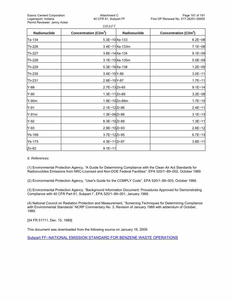
Essroc Cement Corporation Attachment C Page 191 of 191 Logansport, Indiana 40 CFR 61, Subpart FF First OP Renewal No. 017-26351-00005 Permit Reviewer: Jenny Acker DRAFT
Radionuclide Concentration (Ci/m3) Radionuclide Concentration (Ci/m3)
Te-134 5.3E−10 Xe-133 6.2E−08
Th-226 3.4E−11 Xe-133m 7.1E−08
Th-227 3.8E−14 Xe-135 9.1E−09
Th-228 3.1E−15 Xe-135m 5.0E−09
Th-229 5.3E−16 Xe-138 1.2E−09
Th-230 3.4E−15 Y-86 3.0E−11
Th-231 2.9E−10 Y-87 1.7E−11
Y-88 2.7E−13 Zn-65 9.1E−14
Y-90 1.3E−11 Zn-69 3.2E−08
Y-90m 1.9E−10 Zn-69m 1.7E−10
Y-91 2.1E−12 Zr-86 2.4E−11
Y-91m 1.3E−09 Zr-88 3.1E−13
Y-92 8.3E−10 Zr-89 1.3E−11
Y-93 2.9E−10 Zr-93 2.6E−12
Yb-169 3.7E−12 Zr-95 6.7E−13
Yb-175 4.3E−11 Zr-97 3.8E−11
Zn-62 9.1E−11
6. References
(1) Environmental Protection Agency, “A Guide for Determining Compliance with the Clean Air Act Standards for Radionuclides Emissions from NRC-Licensed and Non-DOE Federal Facilities”, EPA 520/1–89–002, October 1989.
(2) Environmental Protection Agency, “User's Guide for the COMPLY Code”, EPA 520/1–89–003, October 1989.
(3) Environmental Protection Agency, “Background Information Document: Procedures Approved for Demonstrating Compliance with 40 CFR Part 61, Subpart I”, EPA 520/1–89–001, January 1989.
(4) National Council on Radiation Protection and Measurement, “Screening Techniques for Determining Compliance with Environmental Standards” NCRP Commentary No. 3, Revision of January 1989 with addendum of October, 1989.
[54 FR 51711, Dec. 15, 1989]
This document was downloaded from the following source on January 16, 2009: Subpart FF--NATIONAL EMISSION STANDARD FOR BENZENE WASTE OPERATIONS

Page 1 of 62 DRAFT
Indiana Department of Environmental Management Office of Air Quality
Attachment D
Title 40: Protection of Environment PART 63—NATIONAL EMISSION STANDARDS FOR HAZARDOUS AIR POLLUTANTS FOR SOURCE CATEGORIES
Browse Previous | Browse Next
Subpart DD—National Emission Standards for Hazardous Air Pollutants from Off-Site Waste and Recovery Operations
Source: 61 FR 34158, July 1, 1996, unless otherwise noted.
§ 63.680 Applicability and designation of affected sources.
(a) The provisions of this subpart apply to the owner and operator of a plant site for which both of the conditions specified in paragraphs (a)(1) and (a)(2) of this section are applicable. If either one of these conditions does not apply to the plant site, then the owner and operator of the plant site are not subject to the provisions of this subpart.
(1) The plant site is a major source of hazardous air pollutant (HAP) emissions as defined in 40 CFR 63.2.
(2) At the plant site is located one or more of operations that receives off-site materials as specified in paragraph (b) of this section and the operations is one of the following waste management operations or recovery operations as specified in paragraphs (a)(2)(i) through (a)(2)(vi) of this section.
(i) A waste management operation that receives off-site material and the operation is regulated as a hazardous waste treatment, storage, and disposal facility (TSDF) under either 40 CFR part 264 or part 265.
(ii) A waste management operation that treats wastewater which is an off-site material and the operation is exempted from regulation as a hazardous waste treatment, storage, and disposal facility under 40 CFR 264.1(g)(6) or 40 CFR 265.1(c)(10).
(iii) A waste management operation that treats wastewater which is an off-site material and the operation meets both of the following conditions:
(A) The operation is subject to regulation under either section 402 or 307(b) of the Clean Water Act but is not owned by a “state” or “municipality” as defined by section 502(3) and 502(4), respectively, of the Clean Water Act; and
(B) The treatment of wastewater received from off-site is the predominant activity performed at the plant site.
(iv) A recovery operation that recycles or reprocesses hazardous waste which is an off-site material and the operation is exempted from regulation as a hazardous waste treatment, disposal, and storage facility under 40 CFR 264.1(g)(2) or 40 CFR 265.1(c)(6).
(v) A recovery operation that recycles or reprocesses used solvent which is an off-site material and the operation is not part of a chemical, petroleum, or other manufacturing process that is required to use air emission controls by another subpart of 40 CFR part 63 or 40 CFR part 61.
(vi) A recovery operation that re-refines or reprocesses used oil which is an off-site material and the operation is regulated under 40 CFR 279 subpart F—Standards for Used Oil Processors and Refiners.

Essroc Cement Corporation Attachment D Page 2 of 62 Logansport, Indiana 40 CFR 63, Subpart DD First OP Renewal No. 017-26351-00005 Permit Reviewer: Jenny Acker DRAFT (b) For the purpose of implementing this subpart, an off-site material is a material that meets all of the criteria specified in paragraph (b)(1) of this section but is not one of the materials specified in paragraph (b)(2) of this section.
(1) An off-site material is a material that meets all of the criteria specified in paragraphs (b)(1)(i) through (b)(1)(iii) of this section. If any one of these criteria do not apply to the material, then the material is not an off-site material subject to this subpart.
(i) The material is a waste, used oil, or used solvent as defined in §63.681 of this subpart;
(ii) The waste, used oil, or used solvent is not produced or generated within the plant site, but the material is delivered, transferred, or otherwise moved to the plant site from a location outside the boundaries of the plant site; and
(iii) The waste, used oil, or used solvent contains one or more of the hazardous air pollutants (HAP) listed in Table 1 of this subpart based on the composition of the material at the point-of-delivery, as defined in §63.681 of this subpart.
(2) For the purpose of implementing this subpart, the following materials are not off-site materials:
(i) Household waste as defined in 40 CFR 258.2.
(ii) Radioactive mixed waste managed in accordance with all applicable regulations under Atomic Energy Act and Nuclear Waste Policy Act authorities.
(iii) Waste that is generated as a result of implementing remedial activities required under the Resource Conservation and Recovery Act (RCRA) corrective action authorities (RCRA sections 3004(u), 3004(v), or 3008(h)), Comprehensive Environmental Response, Compensation, and Liability Act (CERCLA) authorities, or similar Federal or State authorities.
(iv) Waste containing HAP that is generated by residential households (e.g., old paint, home garden pesticides) and subsequently is collected as a community service by government agencies, businesses, or other organizations for the purpose of promoting the proper disposal of this waste.
(v) Waste that is transferred from a chemical manufacturing plant or other facility for which both of the following conditions apply to the waste:
(A) The management of the waste at the facility is required either under part 63 subpart F—National Emission Standards for Organic Hazardous Air Pollutants from the Synthetic Organic Chemical Manufacturing Industry or under another subpart in 40 CFR part 63 to meet the air emission control standards for process wastewater specified in 40 CFR 63.132 through 63.147; and
(B) The owner or operator of the facility from which the waste is transferred has complied with the provisions of 40 CFR 63.132(g)(1)(ii) and (g)(2).
(vi) Waste that is transferred from a chemical manufacturing plant, petroleum refinery, or coke by-product recovery plant which is subject to 40 CFR part 61, subpart FF—National Emission Standards for Benzene Waste Operations, and for which both of the following conditions apply to the waste:
(A) The waste is generated at a facility that is not exempted under the provisions of 40 CFR 61.342(a) from meeting the air emission control standards of 40 CFR part 61, subpart FF; and
(B) The owner or operator of the facility from which the waste is transferred has complied with the provisions of 40 CFR 61.342(f)(2).
(vii) Ship ballast water pumped from a ship to an onshore wastewater treatment facility.
Essroc Cement Corporation Attachment D Page 3 of 62 Logansport, Indiana 40 CFR 63, Subpart DD First OP Renewal No. 017-26351-00005 Permit Reviewer: Jenny Acker DRAFT (viii) Hazardous waste that is stored for 10 days or less at a transfer facility in compliance with the provisions of 40 CFR 263.12.
(c) Affected sources —(1) Off-site material management units. For each operation specified in paragraphs (a)(2)(i) through (a)(2)(vi) of this section that is located at the plant site, the affected source is the entire group of off-site material management units associated with the operation. An off-site material management unit is a tank, container, surface impoundment, oil-water separator, organic-water separator, or transfer system used to manage off-site material. For the purpose of implementing the standards under this subpart, a unit that meets the definition of a tank or container but also is equipped with a vent that serves as a process vent for any of the processes listed in paragraphs (c)(2)(i) through (c)(2)(vi) of this section is not an off-site material management unit but instead is a process vent and is to be included in the appropriate affected source group under paragraph (c)(2) of this section. Examples of such a unit may include, but are not limited to, a distillate receiver vessel, a primary condenser, a bottoms receiver vessel, a surge control tank, a separator tank, and a hot well.
(2) Process vents. For each operation specified in paragraphs (a)(2)(i) through (a)(2)(vi) of this section that is located at the plant site, the affected source is the entire group of process equipment associated with the process vents for the processes listed in paragraphs (c)(2)(i) through (c)(2)(vi) of this section.
(i) Distillation process used for the treatment, recycling, or recovery of off-site material. Distillation means a process, either batch or continuous, separating one or more off-site material feed streams into two or more exit streams having different component concentrations from those in the feed stream or streams. The separation is achieved by the redistribution of the components between the liquid and vapor phases as they approach equilibrium within the distillation unit.
(ii) Fractionation process used for the treatment, recycling, or recovery of off-site material. Fractionation means a liquid mixture separation process or method used to separate a mixture of several volatile components of different boiling points in successive stages, each stage removing from the mixture some proportion of one of the components.
(iii) Thin-film evaporation process used for the treatment, recycling, or recovery of off-site material. Thin-film evaporation means a liquid mixture separation process or method that uses a heating surface consisting of a large diameter tube that may be either straight or tapered, horizontal or vertical. Liquid is spread on the tube wall by a rotating assembly of blades that maintain a close clearance from the wall or actually ride on the film of liquid on the wall.
(iv) Solvent extraction process used for the treatment, recycling, or recovery of off-site material. Solvent extraction means a separation process or method in which a solid or a solution is contacted with a liquid solvent (the material and the solvent being relatively insoluble in each other) to preferentially dissolve and transfer one or more components into the solvent.
(v) Steam stripping process used for the treatment, recycling, or recovery of off-site material. Steam stripping means a liquid mixture separation process or method in which vaporization of the volatile components of a liquid mixture occurs by the introduction of steam directly into the process.
(vi) Gas stripping process used for the treatment, recycling, or recovery of off-site material. Gas stripping means a desorption process or method used to transfer one or more volatile components from a liquid mixture into a gas stream either with or without the application of heat to the liquid. Packed towers, spray towers, and bubble-cap, sieve, or valve-type plate towers are examples of the process configurations used for contacting the gas and a liquid.
(3) Equipment leaks. For each operation specified in paragraphs (a)(2)(i) through (a)(2)(vi) of this section that is located at the plant site, the affected source is the entire group of equipment components for which each component meets all of the conditions specified in paragraphs (c)(3)(i) through (c)(3)(iii) of this section. If any one of these conditions do not apply to an equipment component, then that component is not part of the affected source for equipment leaks.
(i) The equipment component is a pump, compressor, agitator, pressure relief device, sampling connection system, open-ended valve or line, valve, connector, or instrumentation system;

Essroc Cement Corporation Attachment D Page 4 of 62 Logansport, Indiana 40 CFR 63, Subpart DD First OP Renewal No. 017-26351-00005 Permit Reviewer: Jenny Acker DRAFT (ii) The equipment component contains or contacts off-site material having a total HAP concentration equal to or greater than 10 percent by weight; and
(iii) The equipment component is intended to operate for 300 hours or more during a calendar year in off-site material service, as defined in §63.681 of this subpart.
(d) Facility-wide exemption. The owner or operator of affected sources subject to this subpart is exempted from the requirements of §§63.682 through 63.699 of this subpart in situations when the total annual quantity of the HAP that is contained in the off-site material received at the plant site is less than 1 megagram per year. For a plant site to be exempted under the provisions of this paragraph (d), the owner or operator must meet the requirements in paragraphs (d)(1) through (d)(3) of this section.
(1) The owner or operator must prepare an initial determination of the total annual HAP quantity in the off-site material received at the plant site. This determination is based on the total quantity of the HAP listed in Table 1 of this subpart as determined at the point-of-delivery for each off-site material stream.
(2) The owner or operator must prepare a new determination whenever the extent of changes to the quantity or composition of the off-site material received at the plant site could cause the total annual HAP quantity in the off-site material received at the plant site to exceed the limit of 1 megagram per year.
(3) The owner or operator must maintain documentation to support the owner's or operator's determination of the total annual HAP quantity in the off-site material received at the plant site. This documentation must include the basis and data used for determining the HAP content of the off-site material.
(e) Compliance dates —(1) Existing sources. The owner or operator of an affected source that commenced construction or reconstruction before October 13, 1994, must achieve compliance with the provisions of this subpart on or before the date specified in paragraph (e)(1)(i) or (e)(1)(ii) of this section as applicable to the affected source.
(i) For an affected source that commenced construction or reconstruction before October 13, 1994 and receives off-site material for the first time before February 1, 2000, the owner or operator of this affected source must achieve compliance with the provisions of the subpart on or before February 1, 2000 unless an extension has been granted by the Administrator as provided in 40 CFR 63.6(i).
(ii) For an affected source that commenced construction or reconstruction before October 13, 1994, but receives off-site material for the first time on or after February 1, 2000, the owner or operator of the affected source must achieve compliance with the provisions of this subpart upon the first date that the affected source begins to manage off-site material.
(2) New sources. The owner or operator of an affected source for which construction or reconstruction commences on or after October 13, 1994, must achieve compliance with the provisions of this subpart on or before July 1, 1996, or upon initial startup of operations, whichever date is later as provided in 40 CFR 63.6(b).
(f) The provisions of 40 CFR part 63, subpart A—General Provisions that apply and those that do not apply to this subpart are specified in Table 2 of this subpart.
[61 FR 34158, July 1, 1996, as amended at 65 FR 38963, July 20, 1999]
§ 63.681 Definitions.
All terms used in this subpart shall have the meaning given to them in this section, 40 CFR 63.2 of this part, and the Act.
Boiler means an enclosed combustion device that extracts useful energy in the form of steam and is not an incinerator or a process heater.

Essroc Cement Corporation Attachment D Page 5 of 62 Logansport, Indiana 40 CFR 63, Subpart DD First OP Renewal No. 017-26351-00005 Permit Reviewer: Jenny Acker DRAFT Closed-vent system means a system that is not open to the atmosphere and is composed of hard-piping, ductwork, connections, and, if necessary, fans, blowers, or other flow-inducing devices that conveys gas or vapor from an emission point to a control device.
Closure device means a cap, hatch, lid, plug, seal, valve, or other type of fitting that prevents or reduces air pollutant emissions to the atmosphere by blocking an opening in a cover when the device is secured in the closed position. Closure devices include devices that are detachable from the cover (e.g., a sampling port cap), manually operated (e.g., a hinged access lid or hatch), or automatically operated (e.g., a spring-loaded pressure relief valve).
Container means a portable unit used to hold material. Examples of containers include but are not limited to drums, dumpsters, roll-off boxes, bulk cargo containers commonly known as “portable tanks” or “totes”, cargo tank trucks, and tank rail cars.
Continuous record means documentation of data values measured at least once every 15 minutes and recorded at the frequency specified in this subpart.
Continuous recorder means a data recording device that either records an instantaneous data value at least once every 15 minutes or records 15-minutes or more frequent block averages.
Continuous seal means a seal that forms a continuous closure that completely covers the space between the edge of the floating roof and the wall of a tank. A continuous seal may be a vapor-mounted seal, liquid-mounted seal, or metallic shoe seal. A continuous seal may be constructed of fastened segments so as to form a continuous seal.
Control device means equipment used for recovering, removing, oxidizing, or destroying organic vapors. Examples of such equipment include but are not limited to carbon adsorbers, condensers, vapor incinerators, flares, boilers, and process heaters.
Cover means a device or system that provides a continuous barrier over the material managed in an off-site material management unit to prevent or reduce air pollutant emissions to the atmosphere. A cover may have openings needed for operation, inspection, sampling, maintenance, and repair of the unit provided that each opening is closed when not in use (e.g., access hatches, sampling ports). A cover may be a separate piece of equipment which can be detached and removed from the unit or a cover may be formed by structural features permanently integrated into the design of the unit.
Emission point means an individual tank, surface impoundment, container, oil-water or organic-water separator, transfer system, process vent, or enclosure.
Enclosure means a structure that surrounds a tank or container, captures organic vapors emitted from the tank or container, and vents the captured vapor through a closed vent system to a control device.
External floating roof means a pontoon-type or double-deck type cover that rests on the liquid surface in a tank with no fixed roof.
Fixed roof means a cover that is mounted on a unit in a stationary position and does not move with fluctuations in the level of the liquid managed in the unit.
Flame zone means the portion of the combustion chamber in a boiler or process heater occupied by the flame envelope.
Floating roof means a cover consisting of a double deck, pontoon single deck, or internal floating cover which rests upon and is supported by the liquid being contained, and is equipped with a continuous seal.
Flow indicator means a device that indicates whether gas is flowing, or whether the valve position would allow gas to flow in a bypass line.
Hard-piping means pipe or tubing that is manufactured and properly installed in accordance with relevant standards and good engineering practices.

Essroc Cement Corporation Attachment D Page 6 of 62 Logansport, Indiana 40 CFR 63, Subpart DD First OP Renewal No. 017-26351-00005 Permit Reviewer: Jenny Acker DRAFT Hazardous air pollutants or HAP means the specific organic chemical compounds, isomers, and mixtures listed in Table 1 of this subpart.
Hazardous waste means a waste that is determined to be hazardous under the Resource Conservation and Recovery Act (PL 94–580) (RCRA), as implemented by 40 CFR parts 260 and 261.
Individual drain system means a stationary system used to convey wastewater streams or residuals to a waste management unit or to discharge or disposal. The term includes hard-piping, all drains and junction boxes, together with their associated sewer lines and other junction boxes (e.g., manholes, sumps, and lift stations) conveying wastewater streams or residuals. For the purpose of this subpart, an individual drain system is not a drain and collection system that is designed and operated for the sole purpose of collecting rainfall runoff (e.g., stormwater sewer system) and is segregated from all other individual drain systems.
Internal floating roof means a cover that rests or floats on the liquid surface (but not necessarily in complete contact with it inside a tank that has a fixed roof).
Light-material service means the container is used to manage an off-site material for which both of the following conditions apply: the vapor pressure of one or more of the organic constituents in the off-site material is greater than 0.3 kilopascals (kPa) at 20 °C; and the total concentration of the pure organic constituents having a vapor pressure greater than 0.3 kPa at 20 °C is equal to or greater than 20 percent by weight.
Liquid-mounted seal means a foam- or liquid-filled continuous seal mounted in contact with the liquid in a unit.
Maximum HAP vapor pressure means the sum of the individual HAP equilibrium partial pressure exerted by an off-site material at the temperature equal to either: the local maximum monthly average temperature as reported by the National Weather Service when the off-site material is stored or treated at ambient temperature; or the highest calendar-month average temperature of the off-site material when the off-site material is stored at temperatures above the ambient temperature or when the off-site material is stored or treated at temperatures below the ambient temperature. For the purpose of this subpart, maximum HAP vapor pressure is determined using the procedures specified in §63.694(j) of this subpart.
Metallic shoe seal means a continuous seal that is constructed of metal sheets which are held vertically against the wall of the tank by springs, weighted levers, or other mechanisms and is connected to the floating roof by braces or other means. A flexible coated fabric (envelope) spans the annular space between the metal sheet and the floating roof.
No detectable organic emissions means no escape of organics to the atmosphere as determined using the procedure specified in §63.694(k) of this subpart.
Off-site material means a material that meets all of the criteria specified in paragraph §63.680(b)(1) of this subpart but is not one of the materials specified in §63.680(b)(2) of this subpart.
Off-site material management unit means a tank, container, surface impoundment, oil-water separator, organic-water separator, or transfer system used to manage off-site material.
Off-site material service means any time when a pump, compressor, agitator, pressure relief device, sampling connection system, open-ended valve or line, valve, connector, or instrumentation system contains or contacts off-site material.
Off-site material stream means an off-site material produced or generated by a particular process or source such that the composition and form of the material comprising the stream remain consistent. An off-site material stream may be delivered, transferred, or otherwise moved to the plant site in a continuous flow of material (e.g., wastewater flowing through a pipeline) or in a series of discrete batches of material (e.g., a truckload of drums all containing the same off-site material or multiple bulk truck loads of an off-site material produced by the same process).
Oil-water separator means a separator as defined for this subpart that is used to separate oil from water.

Essroc Cement Corporation Attachment D Page 7 of 62 Logansport, Indiana 40 CFR 63, Subpart DD First OP Renewal No. 017-26351-00005 Permit Reviewer: Jenny Acker DRAFT Operating parameter value means a minimum or maximum value established for a control device or treatment process parameter which, if achieved by itself or in combination with one or more other operating parameter values, determines that an owner or operator has complied with an applicable emission limitation or standard.
Organic-water separator means a separator as defined for this subpart that is used to separate organics from water.
Plant site means all contiguous or adjoining property that is under common control including properties that are separated only by a road or other public right-of-way. Common control includes properties that are owned, leased, or operated by the same entity, parent entity, subsidiary, or any combination thereof. A unit or group of units within a contiguous property that are not under common control (e.g., a wastewater treatment unit or solvent recovery unit located at the site but is sold to a different company) is a different plant site.
Point-of-delivery means the point at the boundary or within the plant site where the owner or operator first accepts custody, takes possession, or assumes responsibility for the management of an off-site material stream managed in a waste management operation or recovery operation specified in §63.680 (a)(2)(i) through (a)(2)(vi) of this subpart. The characteristics of an off-site material stream are determined prior to combining the off-site material stream with other off-site material streams or with any other materials.
Point-of-treatment means a point after the treated material exits the treatment process but before the first point downstream of the treatment process exit where the organic constituents in the treated material have the potential to volatilize and be released to the atmosphere. For the purpose of applying this definition to this subpart, the first point downstream of the treatment process exit is not a fugitive emission point due to an equipment leak from any of the following equipment components: pumps, compressors, valves, connectors, instrumentation systems, or safety devices.
Process heater means an enclosed combustion device that transfers heat released by burning fuel directly to process streams or to heat transfer liquids other than water.
Process vent means an open-ended pipe, stack, or duct through which a gas stream containing HAP is continuously or intermittently discharged to the atmosphere from any of the processes listed in §63.680(c)(2)(i) through (c)(2)(vi) of this section. For the purpose of this subpart, a process vent is none of the following: a pressure-relief vent or other vent that is used as a safety device (as defined in this section); an open-ended line or other vent that is subject to the equipment leak control requirements under §63.691 of this subpart; or a stack or other vent that is used to exhaust combustion products from a boiler, furnace, process heater, incinerator, or other combustion device.
Recovery operation means the collection of off-site material management units, process vents, and equipment components used at a plant site to manage an off-site material stream from the point-of-delivery through the point where the material has been recycled, reprocessed, or re-refined to obtain the intended product or to remove the physical and chemical impurities of concern.
Safety device means a closure device such as a pressure relief valve, frangible disc, fusible plug, or any other type of device which functions to prevent physical damage or permanent deformation to equipment by venting gases or vapors during unsafe conditions resulting from an unplanned, accidental, or emergency event. For the purpose of this subpart, a safety device is not used for routine venting of gases or vapors from the vapor headspace underneath a cover such as during filling of the unit or to adjust the pressure in this vapor headspace in response to normal daily diurnal ambient temperature fluctuations. A safety device is designed to remain in a closed position during normal operations and open only when the internal pressure, or another relevant parameter, exceeds the device threshold setting applicable to the equipment as determined by the owner or operator based on manufacturer recommendations, applicable regulations, fire protection and prevention codes, standard engineering codes and practices, or other requirements for the safe handling of flammable, combustible, explosive, reactive, or hazardous materials.
Separator means a waste management unit, generally a tank, used to separate oil or organics from water. A separator consists of not only the separation unit but also the forebay and other separator basins, skimmers, weirs, grit chambers, sludge hoppers, and bar screens that are located directly after the individual drain system and prior to any additional treatment units such as an air flotation unit clarifier or biological treatment unit. Examples of a separator include, but are not limited to, an API separator, parallel-plate interceptor, and corrugated-plate interceptor with the associated ancillary equipment.

Essroc Cement Corporation Attachment D Page 8 of 62 Logansport, Indiana 40 CFR 63, Subpart DD First OP Renewal No. 017-26351-00005 Permit Reviewer: Jenny Acker DRAFT Single-seal system means a floating roof having one continuous seal. This seal may be vapor-mounted, liquid-mounted, or a metallic shoe seal.
Surface impoundment means a unit that is a natural topographical depression, man-made excavation, or diked area formed primarily of earthen materials (although it may be lined with man-made materials), which is designed to hold an accumulation of liquids. Examples of surface impoundments include holding, storage, settling, and aeration pits, ponds, and lagoons.
Tank means a stationary unit that is constructed primarily of nonearthen materials (such as wood, concrete, steel, fiberglass, or plastic) which provide structural support and is designed to hold an accumulation of liquids or other materials.
Transfer system means a stationary system for which the predominant function is to convey liquids or solid materials from one point to another point within a waste management operation or recovery operation. For the purpose of this subpart, the conveyance of material using a container (as defined for this subpart) or a self-propelled vehicle (e.g., a front-end loader) is not a transfer system. Examples of a transfer system include but are not limited to a pipeline, an individual drain system, a gravity-operated conveyor (such as a chute), and a mechanically-powered conveyor (such as a belt or screw conveyor).
Temperature monitoring device means a piece of equipment used to monitor temperature and having an accuracy of ±1 percent of the temperature being monitored expressed in degrees Celsius (°C) or ±1.2 degrees °C, whichever value is greater.
Treatment process means a process in which an off-site material stream is physically, chemically, thermally, or biologically treated to destroy, degrade, or remove hazardous air pollutants contained in the off-site material. A treatment process can be composed of a single unit (e.g., a steam stripper) or a series of units (e.g., a wastewater treatment system). A treatment process can be used to treat one or more off-site material streams at the same time.
Used oil means any oil refined from crude oil or any synthetic oil that has been used and as a result of such use is contaminated by physical or chemical impurities. This definition is the same definition of “used oil” in 40 CFR 279.1.
Used solvent means a mixture of aliphatic hydrocarbons or a mixture of one and two ring aromatic hydrocarbons that has been used as a solvent and as a result of such use is contaminated by physical or chemical impurities.
Vapor-mounted seal means a continuous seal that is mounted such that there is a vapor space between the liquid in the unit and the bottom of the seal.
Volatile organic hazardous air pollutant concentration or VOHAP concentration means the fraction by weight of those compounds listed in Table 1 of this subpart that are in an off-site material as measured using Method 305 in appendix A of this part and expressed in terms of parts per million (ppm). As an alternative to using Method 305, an owner or operator may determine the HAP concentration of an off-site material using any one of the other test methods specified in §63.694(b)(2)(ii) of this subpart. When a test method specified in §63.694(b)(2)(ii) of this subpart other than Method 305 is used to determine the speciated HAP concentration of an off-site material, the individual compound concentration may be adjusted by the corresponding fm305value listed in Table 1 of this subpart to determine a VOHAP concentration.
Waste means a material generated from industrial, commercial, mining, or agricultural operations or from community activities that is discarded, discharged, or is being accumulated, stored, or physically, chemically, thermally, or biologically treated prior to being discarded or discharged.
Waste management operation means the collection of off-site material management units, process vents, and equipment components used at a plant site to manage an off-site material stream from the point-of-delivery to the point where the waste exits or is discharged from the plant site or the waste is placed for on-site disposal in a unit not subject to this subpart (e.g., a waste incinerator, a land disposal unit).
Waste stabilization process means any physical or chemical process used to either reduce the mobility of hazardous constituents in a waste or eliminate free liquids as determined by Test Method 9095—Paint Filter Liquids Test in “Test Methods for Evaluating Solid Waste, Physical/Chemical Methods,” EPA Publication No. SW–846, Third Edition,

Essroc Cement Corporation Attachment D Page 9 of 62 Logansport, Indiana 40 CFR 63, Subpart DD First OP Renewal No. 017-26351-00005 Permit Reviewer: Jenny Acker DRAFT September 1986, as amended by Update I, November 15, 1992. (As an alternative, an owner or operator may use any more recent, updated version of Method 9095 approved by the EPA.) A waste stabilization process includes mixing the waste with binders or other materials and curing the resulting waste and binder mixture. Other synonymous terms used to refer to this process are “waste fixation” or “waste solidification.” A waste stabilization process does not include the adding of absorbent materials to the surface of a waste, without mixing, agitation, or subsequent curing, to absorb free liquid.
[61 FR 34158, July 1, 1996, as amended at 64 FR 38964, July 20, 1999]
§ 63.682 [Reserved]
§ 63.683 Standards: General.
(a) The general standards under this section apply to owners and operators of affected sources as designated in §63.680(c) of this subpart.
(b) Off-site material management units. (1) For each off-site material management unit that is part of an affected source, the owner or operator must meet the requirements in either paragraph (b)(1)(i), (b)(1)(ii), or (b)(1)(iii) of this section except for those off-site material management units exempted under paragraph (b)(2) of this section.
(i) The owner or operator controls air emissions from the off-site material management unit in accordance with the applicable standards specified in §§63.685 through 63.689 of this subpart.
(ii) The owner or operator removes or destroys HAP in the off-site material before placing the material in the off-site material management unit by treating the material in accordance with the standards specified in §63.684 of this subpart.
(iii) The owner or operator determines before placing off-site material in the off-site material management unit that the average VOHAP concentration of the off-site material is less than 500 parts per million by weight (ppmw) at the point-of-delivery. The owner or operator must perform an initial determination of the average VOHAP concentration of the off-site material using the procedures specified in §63.694(b) of this subpart. This initial determination must be performed either before the first time any portion of the off-site material stream is placed in the unit or by the compliance date, whichever date is later. Thereafter, the owner or operator must review and update, as necessary, this determination at least once every calendar year following the date of the initial determination for the off-site material stream.
(2) An off-site material management unit is exempted from the requirements in paragraph (b)(1) of this section when the owner or operator meets one of the exemptions provided in paragraphs (b)(2)(i) through (b)(2)(iv) of this section as applicable to the unit.
(i) An off-site material management unit is exempted from the requirements in paragraph (b)(1) of this section if the off-site material management unit is also subject to another subpart under 40 CFR part 63 or 40 CFR part 61, and the owner or operator is controlling the HAP listed in Table 1 of this subpart that are emitted from the unit in compliance with the provisions specified in the other applicable subpart under part 61 or part 63.
(ii) At the discretion of the owner or operator, one or a combination of off-site material management units may be exempted from the requirements in paragraph (b)(1) of this section when these units meet the condition that the total annual quantity of HAP contained in the off-site material placed in the units exempted under this paragraph (b)(2)(ii) is less than 1 megagram per year. For the off-site material management units selected by the owner or operator to be exempted from the requirements in paragraph (b)(1) of this section, the owner or operator must meet the requirements in paragraphs (b)(2)(ii)(A) and (b)(2)(ii)(B) of this section. An owner or operator may change the off-site material management units selected to be exempted under this paragraph (b)(2)(ii) by preparing a new designation for the exempt-units as required by paragraph (b)(2)(ii)(A) of this section and performing a new determination as required by paragraph (b)(2)(ii)(B) of this section.
(A) The owner or operator must designate each of the off-site material management units selected by the owner or operator to be exempt under paragraph (b)(2)(ii) of this section by either submitting to the Administrator a written notification identifying the exempt-units or permanently marking the exempt-units at the plant site. If an owner or

Essroc Cement Corporation Attachment D Page 10 of 62 Logansport, Indiana 40 CFR 63, Subpart DD First OP Renewal No. 017-26351-00005 Permit Reviewer: Jenny Acker DRAFT operator chooses to prepare and submit a written notification, this notification must include a site plan, process diagram, or other appropriate documentation identifying each of the exempt-units. If an owner or operator chooses to permanently mark the exempt-units, each exempt-unit must be marked in such a manner that it can be readily identified as an exempt-unit from the other off-site material management units located at the plant site.
(B) The owner or operator must prepare an initial determination of the total annual HAP quantity in the off-site material placed in the units exempted under this paragraph (b)(2)(ii). This determination is based on the total quantity of the HAP listed in Table 1 of this subpart as determined at the point where the off-site material is placed in each exempted unit. The owner or operator must perform a new determination whenever the extent of changes to the quantity or composition of the off-site material placed in the exempted units could cause the total annual HAP content in the off-site material to exceed 1 megagram per year. The owner or operator must maintain documentation to support the most recent determination of the total annual HAP quantity. This documentation must include the basis and data used for determining the HAP content of the off-site material.
(iii) A tank or surface impoundment is exempted from the requirements in paragraph (b)(1) of this section if the unit is used for a biological treatment process that meets the requirements in either paragraph (b)(2)(iii)(A) or (b)(2)(iii)(B) of this section and the owner or operator complies with the monitoring requirements in §63.684(e)(4) of this subpart.
(A) The HAP biodegradation efficiency (Rbio) for the biological treatment process is equal to or greater than 95 percent. The HAP biodegradation efficiency (Rbio) shall be determined in accordance with the requirements of §63.694(h) of this subpart.
(B) The total actual HAP mass removal rate (MRbio) for the off-site material treated by the biological treatment process is equal to or greater than the required HAP mass removal rate (RMR) for the off-site material. The total actual HAP mass removal rate (MRbio) must be determined in accordance with the requirements of §63.694(i) of this subpart. The required HAP mass removal rate (RMR) must be determined in accordance with the requirements of §63.694(e) of this subpart.
(iv) An off-site material management unit is exempted from the requirements in paragraph (b)(1) of this section if the off-site material placed in the unit is a hazardous waste that meets the conditions specified in either paragraph (b)(2)(iv)(A) or (b)(2)(iv)(B) of this section.
(A) The hazardous waste meets the numerical organic concentration limits, applicable to the hazardous waste, as specified in 40 CFR part 268—Land Disposal Restrictions, listed in the table, “Treatment Standards for Hazardous Waste” in 40 CFR 268.40.
(B) The organic hazardous constituents in the hazardous waste have been treated by the treatment technology established by the EPA for the hazardous waste in 40 CFR 268.42(a), or have been removed or destroyed by an equivalent method of treatment approved by the EPA under 40 CFR 268.42(b).
(v) A tank used for bulk feed of off-site material to a waste incinerator is exempted from the requirements specified in paragraph (b)(1) of this section if the tank meets all of the conditions specified in paragraphs (b)(2)(v)(A) through (b)(2)(v)(C) of this section.
(A) The tank is located inside an enclosure vented to a control device that is designed and operated in accordance with all applicable requirements specified under 40 CFR part 61, subpart FF—National Emission Standards for Benzene Waste Operations for a facility at which the total annual benzene quantity from the facility waste is equal to or greater than 10 megagrams per year;
(B) The enclosure and control device serving the tank were installed and began operation prior to July 1, 1996; and
(C) The enclosure is designed and operated in accordance with the criteria for a permanent total enclosure as specified in “Procedure T—Criteria for and Verification of a Permanent or Temporary Total Enclosure” under 40 CFR 52.741, appendix B. The enclosure may have permanent or temporary openings to allow worker access; passage of material into or out of the enclosure by conveyor, vehicles, or other mechanical or electrical equipment; or to direct air flow into the enclosure. The owner or operator must annually perform the verification procedure for the enclosure as specified in Section 5.0 to “Procedure T—Criteria for and Verification of a Permanent or Temporary Total Enclosure.”

Essroc Cement Corporation Attachment D Page 11 of 62 Logansport, Indiana 40 CFR 63, Subpart DD First OP Renewal No. 017-26351-00005 Permit Reviewer: Jenny Acker DRAFT (c) Process vents. (1) For each process vent that is part of an affected source, the owner or operator must meet the requirements in either paragraph (c)(1)(i) or (c)(1)(ii) of this section except for those process vents exempted under paragraph (c)(2) of this section.
(i) The owner or operator controls air emissions from the process vent in accordance with the standards specified in §63.690 of this subpart.
(ii) The owner or operator determines before placing off-site material in the process equipment associated with the process vent that the average VOHAP concentration of the off-site material is less than ppmw at the point-of-delivery. The owner or operator must perform an initial determination of the average VOHAP concentration of the off-site material using the procedures specified in §63.694(b) of this subpart before any portion of the off-site material stream is placed in the unit. Thereafter, the owner or operator must review and update, as necessary, this determination at least once every calendar year following the date of the initial determination for the off-site material stream.
(2) A process vent is exempted from the requirements of paragraph (c)(1) of this section when the owner or operator meets one of the exemptions provided in paragraphs (c)(2)(i) through (c)(2)(iii) of this section.
(i) A process vent is exempted from the requirements in paragraph (c)(1) of this section if the process vent is also subject to another subpart under part 63 or 40 CFR part 61, and the owner or operator is controlling the HAP listed in Table 1 of this subpart that are emitted from the process vent in compliance with the provisions specified in the other applicable subpart under part 61 or part 63.
(ii) A process vent is exempted from the requirements specified in paragraph (c)(1) of this section if the owner or operator determines that the process vent stream flow rate is less than 0.005 cubic meters per minute (m3 /min) at standard conditions (as defined in 40 CFR 63.2). The process vent stream flow rate shall be determined in accordance with the procedures specified in §63.694(m) of this subpart. Documentation must be prepared by the owner or operator and maintained at the plant site to support the determination of the process vent stream flow rate. This documentation must include identification of each process vent exempted under this paragraph and the test results used to determine the process vent stream flow rate.
(iii) A process vent is exempted from the requirements specified in paragraph (c)(1) of this section if the owner or operator determines that the process vent stream flow rate is less than 6.0 m3 /min at standard conditions (as defined in 40 CFR 63.2) and the total HAP concentration is less than 20 ppmv. The process vent stream flow rate and total HAP concentration shall be determined in accordance with the procedures specified in §63.694(m) of this subpart. Documentation must be prepared by the owner or operator and maintained at the plant site to support the determination of the process vent stream flow rate and total HAP concentration. This documentation must include identification of each process vent exempted under this paragraph (c)(2)(iii) and the test results used to determine the process vent stream flow rate and total HAP concentration. The owner or operator must perform a new determination of the process vent stream flow rate and total HAP concentration when the extent of changes to operation of the unit on which the process vent is used could cause either the process vent stream flow rate to exceed the limit of 6.0 m3 /min or the total HAP concentration to exceed the limit of 20 ppmv.
(d) Equipment leaks. The owner or operator must control equipment leaks from each equipment component that is part of the affected source specified in §63.680(c)(3) of this subpart by implementing leak detection and control measures in accordance with the standards specified in §63.691 of this subpart.
[64 FR 38965, July 20, 1999]
§ 63.684 Standards: Off-site material treatment.
(a) The provisions of this section apply to the treatment of off-site material to remove or destroy HAP for which §63.683(b)(1)(ii) of this subpart references the requirements of this section for such treatment.
(b) The owner or operator shall remove or destroy the HAP contained in off-site material streams to be managed in the off-site material management unit in accordance with §63.683(b)(1)(ii) of this subpart using a treatment process that continuously achieves, under normal operations, one or more of the performance levels specified in paragraphs (b)(1) through (b)(5) of this section (as applicable to the type of treatment process) for the range of off-site material stream compositions and quantities expected to be treated.
Essroc Cement Corporation Attachment D Page 12 of 62 Logansport, Indiana 40 CFR 63, Subpart DD First OP Renewal No. 017-26351-00005 Permit Reviewer: Jenny Acker DRAFT (1) VOHAP concentration. The treatment process shall reduce the VOHAP concentration of the off-site material using a means, other than by dilution, to achieve one of the following performance levels, as applicable:
(i) In the case when every off-site material stream entering the treatment process has an average VOHAP concentration equal to or greater than 500 ppmw at the point-of-delivery, then the VOHAP concentration of the off-site material shall be reduced to a level that is less than 500 ppmw at the point-of-treatment.
(ii) In the case when off-site material streams entering the treatment process are a mixture of off-site material streams having an average VOHAP concentration equal to or greater than 500 ppmw at the point-of-delivery with off-site material streams having average VOHAP concentrations less than 500 ppmw at the point-of-delivery, then the VOHAP concentration of the off-site material must be reduced to a level at the point-of-treatment that meets the performance level specified in either paragraph (b)(1)(ii)(A) or (B) of this section.
(A) Less than the VOHAP concentration limit (CR) established for the treatment process using the procedure specified in §63.694(d); or
(B) Less than the lowest VOHAP concentration determined for each of the off-site material streams entering the treatment process as determined by the VOHAP concentration of the off-site material at the point-of-delivery.
(2) HAP mass removal. The treatment process shall achieve a performance level such that the total quantity of HAP actually removed from the off-site material stream (MR) is equal to or greater than the required mass removal (RMR) established for the off-site material stream using the procedure specified in §63.694(e) of this subpart. The MR for the off-site material streams shall be determined using the procedures specified in §63.694(f) of this subpart.
(3) HAP reduction efficiency. For any treatment process except a treatment process that uses biological degradation and is performed in an open tank or surface impoundment, the treatment process must achieve the applicable performance level specified in either paragraph (b)(3)(i) or (b)(3)(ii) of this section.
(i) In the case when the owner or operator determines that off-site material stream entering the treatment process has an average VOHAP concentration less than 10,000 ppmw at the point-of-delivery, then the treatment process shall achieve a performance level such that the total quantity of HAP in the off-site material stream is reduced by 95 percent or more. The HAP reduction efficiency (R) for the treatment process shall be determined using the procedure specified in §63.694(g) of this subpart. The average VOHAP concentration of the off-site material stream at the point-of-delivery shall be determined using the procedure specified in §63.694(b) of this subpart.
(ii) In the case when the off-site material stream entering the treatment process has an average VOHAP concentration equal to or greater than 10,000 ppmw at the point-of-delivery, then the treatment process shall achieve a performance level such that the total quantity of HAP in the off-site material stream is reduced by 95 percent or more, and the average VOHAP concentration of the off-site material at the point-of-treatment is less than 100 parts per million by weight (ppmw). The HAP reduction efficiency (R) for the treatment process shall be determined using the procedure specified in §63.694(g) of this subpart. The average VOHAP concentration of the off-site material stream at the point-of-treatment shall be determined using the procedure specified in §63.694(c) of this subpart.
(4) Biological degradation performed in an open tank or surface impoundment. A treatment process using biological degradation and performed in an open tank or surface impoundment must achieve the performance level specified in either paragraph (b)(4)(i) or (b)(4)(ii) of this section.
(i) The HAP reduction efficiency (R) for the treatment process is equal to or greater than 95 percent, and the HAP biodegradation efficiency (Rbio) for the treatment process is equal to or greater than 95 percent. The HAP reduction efficiency (R) shall be determined using the procedure specified in §63.694(g) of this subpart. The HAP biodegradation efficiency (Rbio) shall be determined in accordance with the requirements of §63.694(h) of this subpart.
(ii) The total quantity of HAP actually removed from the off-site material stream by biological degradation (MRbio) shall be equal to or greater than the required mass removal (RMR) established for the off-site material stream using the procedure specified in §63.694(e) of this subpart. The MRbioof the off-site material stream shall be determined using the procedures specified in §63.694(i) of this subpart.

Essroc Cement Corporation Attachment D Page 13 of 62 Logansport, Indiana 40 CFR 63, Subpart DD First OP Renewal No. 017-26351-00005 Permit Reviewer: Jenny Acker DRAFT (5) Incineration. The treatment process must destroy the HAP contained in the off-site material stream using one of the combustion devices specified in paragraphs (b)(5)(i) through (b)(5)(iv) of this section.
(i) An incinerator for which the owner or operator has been issued a final permit under 40 CFR part 270, and the incinerator is designed and operated in accordance with the requirements of 40 CFR part 264, subpart O—Incinerators, or
(ii) An incinerator for which the owner or operator has certified compliance with the interim status requirements of 40 CFR part 265, subpart O—Incinerators.
(iii) A boiler or industrial furnace for which the owner or operator has been issued a final permit under 40 CFR part 270, and the combustion unit is designed and operated in accordance with the requirements of 40 CFR part 266, subpart H—Hazardous Waste Burned in Boilers and Industrial Furnaces.
(iv) A boiler or industrial furnace for which the owner or operator has certified compliance with the interim status requirements of 40 CFR part 266, subpart H Hazardous Waste Burned in Boilers and Industrial Furnaces.
(c) For a treatment process that removes the HAP from the off-site material by a means other than thermal destruction or biological degradation to achieve one of the performances levels specified in paragraph (b)(1), (b)(2), or (b)(3) of this section, the owner or operator shall manage the HAP removed from the off-site material in such a manner to minimize release of these HAP to the atmosphere, to the extent practical. Examples of HAP emission control measures that meet the requirements of this paragraph include managing the HAP removed from the off-site material in units that use air emission controls in accordance with the standards specified in §§63.685 through 63.689 of this subpart, as applicable to the unit.
(d) When the owner or operator treats the off-site material to meet one of the performance levels specified in paragraphs (b)(1) through (b)(4) of this section, the owner or operator shall demonstrate that the treatment process achieves the selected performance level for the range of expected off-site material stream compositions expected to be treated. An initial demonstration shall be performed as soon as possible but no later than 30 days after first time an owner or operator begins using the treatment process to manage off-site material streams in accordance with the requirements of either §63.683(b)(1)(ii) or §63.683(b)(2)(ii) of this subpart as applicable to the affected off-site material management unit or process equipment. Thereafter, the owner or operator shall review and update, as necessary, this demonstration at least once every calendar year following the date of the initial demonstration.
(e) When the owner or operator treats the off-site material to meet one of the performance levels specified in paragraphs (b)(1) through (b)(4) of this section, the owner or operator shall ensure that the treatment process is achieving the applicable performance requirements by continuously monitoring the operation of the process when it is used to treat off-site material by complying with paragraphs (e)(1) through (e)(3) or, for biological treatment units, paragraph (e)(4) of this section:
(1) A continuous monitoring system shall be installed and operated for each treatment that measures operating parameters appropriate for the treatment process technology. This system shall include a continuous recorder that records the measured values of the selected operating parameters. The monitoring equipment shall be installed, calibrated, and maintained in accordance with the equipment manufacturer's specifications. The continuous recorder shall be a data recording device that is capable of recording either an instantaneous data value at least once every 15 minutes or an average value for intervals of 15 minutes or less.
(2) For each monitored operating parameter, the owner or operator shall establish a minimum operating parameter value or a maximum operating parameter value, as appropriate, to define the range of conditions at which the treatment process must be operated to continuously achieve the applicable performance requirements of this section.
(3) When the treatment process is operating to treat off-site material, the owner or operator shall inspect the data recorded by the continuous monitoring system on a routine basis and operate the treatment process such that the actual value of each monitored operating parameter is greater than the minimum operating parameter value or less than the maximum operating parameter value, as appropriate, established for the treatment process.
(4) When the treatment process is a biological treatment process that is complying with paragraph (b)(4) of this section, the owner or operator must establish and implement a written procedure to monitor the appropriate
Essroc Cement Corporation Attachment D Page 14 of 62 Logansport, Indiana 40 CFR 63, Subpart DD First OP Renewal No. 017-26351-00005 Permit Reviewer: Jenny Acker DRAFT parameters that demonstrate proper operation of the biological treatment unit in accordance with the evaluation required in §63.694(h) of this subpart. The written procedure must list the operating parameters that will be monitored and state the frequency of monitoring to ensure that the biological treatment unit is operating between the minimum operating parameter values and maximum operating parameter values to establish that the biological treatment unit is continuously achieving the performance requirement.
(f) The owner or operator must maintain records for each treatment process in accordance with the requirements of §63.696(a) of this subpart.
(g) The owner or operator must prepare and submit reports for each treatment process in accordance with the requirements of §63.697(a) of this subpart.
(h) The Administrator may at any time conduct or request that the owner or operator conduct testing necessary to demonstrate that a treatment process is achieving the applicable performance requirements of this section. The testing shall be conducted in accordance with the applicable requirements of this section. The Administrator may elect to have an authorized representative observe testing conducted by the owner or operator.
[61 FR 34158, July 1, 1996, as amended at 64 FR 38967, July 20, 1999; 66 FR 1266, Jan. 8, 2001; 68 FR 37351, June 23, 2003]
§ 63.685 Standards: Tanks.
(a) The provisions of this section apply to the control of air emissions from tanks for which §63.683(b)(1)(i) of this subpart references the use of this section for such air emission control.
(b) The owner or operator shall control air emissions from each tank subject to this section in accordance with the following applicable requirements:
(1) For a tank that is part of an existing affected source but the tank is not used to manage off-site material having a maximum HAP vapor pressure kilopascal (kPa) that is equal to or greater than 76.6 kPa nor is the tank used for a waste stabilization process as defined in §63.681 of this subpart, the owner or operator shall determine whether the tank is required to use either Tank Level 1 controls or Tank Level 2 controls as specified for the tank by Table 3 of this subpart based on the off-site material maximum HAP vapor pressure and the tank's design capacity. The owner or operator shall control air emissions from a tank required by Table 3 to use Tank Level 1 controls in accordance with the requirements of paragraph (c) of this section. The owner or operator shall control air emissions from a tank required by Table 3 to use Tank Level 2 controls in accordance with the requirements of paragraph (d) of this section.
(2) For a tank that is part of a new affected source but the tank is not used to manage off-site material having a maximum HAP vapor pressure that is equal to or greater than 76.6 kPa nor is the tank used for a waste stabilization process as defined in §63.681 of this subpart, the owner or operator shall determine whether the tank is required to use either Tank Level 1 controls or Tank Level 2 controls as specified for the tank by Table 4 of this subpart based on the off-site material maximum HAP vapor pressure and the tank's design capacity. The owner or operator shall control air emissions from a tank required by Table 4 to use Tank Level 1 controls in accordance with the requirements of paragraph (c) of this section. The owner or operator shall control air emissions from a tank required by Table 4 to use Tank Level 2 controls in accordance with the requirements of paragraph (d) of this section.
(3) For a tank that is used for a waste stabilization process, the owner or operator shall control air emissions from the tank by using Tank Level 2 controls in accordance with the requirements of paragraph (d) of this section.
(4) For a tank that manages off-site material having a maximum HAP vapor pressure that is equal to or greater than 76.6 kPa, the owner or operator must control air emissions by using one of the tanks specified in paragraphs (b)(4)(i) through (b)(4)(iii) of this section.
(i) A tank vented through a closed-vent system to a control device in accordance with the requirements specified in paragraph (g) of this section;

Essroc Cement Corporation Attachment D Page 15 of 62 Logansport, Indiana 40 CFR 63, Subpart DD First OP Renewal No. 017-26351-00005 Permit Reviewer: Jenny Acker DRAFT (ii) A pressure tank designed and operated in accordance with the requirements specified in paragraph (h) of this section; or
(iii) A tank located inside an enclosure that is vented through a closed-vent system to an enclosed combustion control device in accordance with the requirements specified in paragraph (i) of this section.
(c) Owners and operators controlling air emissions from a tank using Tank Level 1 controls shall meet the following requirements:
(1) The owner or operator shall determine the maximum HAP vapor pressure for an off-site material to be managed in the tank using Tank Level 1 controls before the first time the off-site material is placed in the tank. The maximum HAP vapor pressure shall be determined using the procedures specified in §63.694(j) of this subpart. Thereafter, the owner or operator shall perform a new determination whenever changes to the off-site material managed in the tank could potentially cause the maximum HAP vapor pressure to increase to a level that is equal to or greater than the maximum HAP vapor pressure limit for the tank design capacity category specified in Table 3 or Table 4 of this subpart, as applicable to the tank.
(2) The owner or operator must control air emissions from the tank in accordance with the requirements in either paragraph (c)(2)(i), (c)(2)(ii), or (c)(2)(iii) of this section, as applicable to the tank.
(i) The owner or operator controls air emissions from the tank in accordance with the provisions specified in subpart 00 of 40 CFR part 63—National Emission Standards for Tanks—Level 1.
(ii) As an alternative to meeting the requirements in paragraph (c)(2)(i) of this section, an owner or operator may control air emissions from the tank in accordance with the provisions for Tank Level 2 controls as specified in paragraph (d) of this section.
(iii) As an alternative to meeting the requirements in paragraph (c)(2)(i) of this section when a tank is used as an interim transfer point to transfer off-site material from containers to another off-site material management unit, an owner or operator may control air emissions from the tank in accordance with the requirements in paragraphs (c)(2)(iii)(A) and (c)(2)(iii)(B) of this section. An example of such a tank is an in-ground tank into which organic-contaminated debris is dumped from roll-off boxes or dump trucks, and then this debris is promptly transferred from the tank to a macroencapsulation unit by a backhoe.
(A) During those periods of time when the material transfer activity is occurring, the tank may be operated without a cover.
(B) At all other times, air emissions from the tank must be controlled in accordance with the provisions specified in 40 CFR part 67, subpart 00—National Emission Standards for Tanks—Level 1.
(d) Owners and operators controlling air emissions from a tank using Tank Level 2 controls shall use one of the following tanks:
(1) A fixed-roof tank equipped with an internal floating roof in accordance with the requirements specified in paragraph (e) of this section;
(2) A tank equipped with an external floating roof in accordance with the requirements specified in paragraph (f) of this section;
(3) A tank vented through a closed-vent system to a control device in accordance with the requirements specified in paragraph (g) of this section;
(4) A pressure tank designed and operated in accordance with the requirements specified in paragraph (h) of this section; or
(5) A tank located inside an enclosure that is vented through a closed-vent system to an enclosed combustion control device in accordance with the requirements specified in paragraph (i) of this section.

Essroc Cement Corporation Attachment D Page 16 of 62 Logansport, Indiana 40 CFR 63, Subpart DD First OP Renewal No. 017-26351-00005 Permit Reviewer: Jenny Acker DRAFT (e) The owner or operator who elects to control air emissions from a tank using a fixed-roof with an internal floating roof shall meet the requirements specified in paragraphs (e)(1) through (e)(3) of this section.
(1) The tank shall be equipped with a fixed roof and an internal floating roof in accordance with the following requirements:
(i) The internal floating roof shall be designed to float on the liquid surface except when the floating roof must be supported by the leg supports.
(ii) The internal floating roof shall be equipped with a continuous seal between the wall of the tank and the floating roof edge that meets either of the following requirements:
(A) A single continuous seal that is either a liquid-mounted seal or a metallic shoe seal, as defined in §63.681 of this subpart; or
(B) Two continuous seals mounted one above the other. The lower seal may be a vapor-mounted seal.
(iii) The internal floating roof shall meet the following specifications:
(A) Each opening in a noncontact internal floating roof except for automatic bleeder vents (vacuum breaker vents) and the rim space vents is to provide a projection below the liquid surface.
(B) Each opening in the internal floating roof shall be equipped with a gasketed cover or a gasketed lid except for leg sleeves, automatic bleeder vents, rim space vents, column wells, ladder wells, sample wells, and stub drains.
(C) Each penetration of the internal floating roof for the purpose of sampling shall have a slit fabric cover that covers at least 90 percent of the opening.
(D) Each automatic bleeder vent and rim space vent shall be gasketed.
(E) Each penetration of the internal floating roof that allows for passage of a ladder shall have a gasketed sliding cover.
(F) Each penetration of the internal floating roof that allows for passage of a column supporting the fixed roof shall have a flexible fabric sleeve seal or a gasketed sliding cover.
(2) The owner or operator shall operate the tank in accordance with the following requirements:
(i) When the floating roof is resting on the leg supports, the process of filling, emptying, or refilling shall be continuous and shall be accomplished as soon as practical.
(ii) Automatic bleeder vents are to be set closed at all times when the roof is floating, except when the roof is being floated off or is being landed on the leg supports.
(iii) Prior to filling the tank, each cover, access hatch, gauge float well or lid on any opening in the internal floating roof shall be bolted or fastened closed (i.e., no visible gaps). Rim spaces vents are to be set to open only when the internal floating roof is not floating or when the pressure beneath the rim exceeds the manufacturer's recommended setting.
(3) The owner or operator shall inspect the internal floating roof in accordance with the procedures specified in §63.695(b) of this subpart.
(f) The owner or operator who elects to control tank emissions by using an external floating roof shall meet the requirements specified in paragraphs (f)(1) through (f)(3) of this section.

Essroc Cement Corporation Attachment D Page 17 of 62 Logansport, Indiana 40 CFR 63, Subpart DD First OP Renewal No. 017-26351-00005 Permit Reviewer: Jenny Acker DRAFT (1) The owner or operator shall design the external floating roof in accordance with the following requirements:
(i) The external floating roof shall be designed to float on the liquid surface except when the floating roof must be supported by the leg supports.
(ii) The floating roof shall be equipped with two continuous seals, one above the other, between the wall of the tank and the roof edge. The lower seal is referred to as the primary seal, and the upper seal is referred to as the secondary seal.
(A) The primary seal shall be a liquid-mounted seal or a metallic shoe seal, as defined in §63.681 of this subpart. The total area of the gaps between the tank wall and the primary seal shall not exceed 212 square centimeters (cm2) per meter of tank diameter, and the width of any portion of these gaps shall not exceed 3.8 centimeters (cm). If a metallic shoe seal is used for the primary seal, the metallic shoe seal shall be designed so that one end extends into the liquid in the tank and the other end extends a vertical distance of at least 61 centimeters (24 inches) above the liquid surface.
(B) The secondary seal shall be mounted above the primary seal and cover the annular space between the floating roof and the wall of the tank. The total area of the gaps between the tank wall and the secondary seal shall not exceed 21.2 square centimeters (cm2 ) per meter of tank diameter, and the width of any portion of these gaps shall not exceed 1.3 centimeters (cm).
(iii) The external floating roof shall be meet the following specifications:
(A) Except for automatic bleeder vents (vacuum breaker vents) and rim space vents, each opening in a noncontact external floating roof shall provide a projection below the liquid surface.
(B) Except for automatic bleeder vents, rim space vents, roof drains, and leg sleeves, each opening in the roof shall be equipped with a gasketed cover, seal, or lid.
(C) Each access hatch and each gauge float wells shall be equipped with covers designed to be bolted or fastened when the cover is secured in the closed position.
(D) Each automatic bleeder vent and each rim space vents shall be equipped with a gasket.
(E) Each roof drain that empties into the liquid managed in the tank shall be equipped with a slotted membrane fabric cover that covers at least 90 percent of the area of the opening.
(F) Each unslotted and slotted guide pole well shall be equipped with a gasketed sliding cover or a flexible fabric sleeve seal.
(G) Each unslotted guide pole shall be equipped with a gasketed cap on the end of the pole.
(H) Each slotted guide pole shall be equipped with a gasketed float or other device which closes off the surface from the atmosphere.
(I) Each gauge hatch and each sample well shall be equipped with a gasketed cover.
(2) The owner or operator shall operate the tank in accordance with the following requirements:
(i) When the floating roof is resting on the leg supports, the process of filling, emptying, or refilling shall be continuous and shall be accomplished as soon as practical.
(ii) Except for automatic bleeder vents, rim space vents, roof drains, and leg sleeves, each opening in the roof shall be secured and maintained in a closed position at all times except when the closure device must be open for access.

Essroc Cement Corporation Attachment D Page 18 of 62 Logansport, Indiana 40 CFR 63, Subpart DD First OP Renewal No. 017-26351-00005 Permit Reviewer: Jenny Acker DRAFT (iii) Covers on each access hatch and each gauge float well shall be bolted or fastened when secured in the closed position.
(iv) Automatic bleeder vents shall be set closed at all times when the roof is floating, except when the roof is being floated off or is being landed on the leg supports.
(v) Rim space vents shall be set to open only at those times that the roof is being floated off the roof leg supports or when the pressure beneath the rim seal exceeds the manufacturer's recommended setting.
(vi) The cap on the end of each unslotted guide pole shall be secured in the closed position at all times except when measuring the level or collecting samples of the liquid in the tank.
(vii) The cover on each gauge hatch or sample well shall be secured in the closed position at all times except when the hatch or well must be opened for access.
(viii) Both the primary seal and the secondary seal shall completely cover the annular space between the external floating roof and the wall of the tank in a continuous fashion except during inspections.
(3) The owner or operator shall inspect the external floating roof in accordance with the procedures specified in §63.695(b) of this subpart.
(g) The owner or operator who controls tank air emissions by venting to a control device shall meet the requirements specified in paragraphs (g)(1) through (g)(3) of this section.
(1) The tank shall be covered by a fixed roof and vented directly through a closed-vent system to a control device in accordance with the following requirements:
(i) The fixed roof and its closure devices shall be designed to form a continuous barrier over the entire surface area of the liquid in the tank.
(ii) Each opening in the fixed roof not vented to the control device shall be equipped with a closure device. If the pressure in the vapor headspace underneath the fixed roof is less than atmospheric pressure when the control device is operating, the closure devices shall be designed to operate such that when the closure device is secured in the closed position there are no visible cracks, holes, gaps, or other open spaces in the closure device or between the perimeter of the cover opening and the closure device. If the pressure in the vapor headspace underneath the fixed roof is equal to or greater than atmospheric pressure when the control device is operating, the closure device shall be designed to operate with no detectable organic emissions.
(iii) The fixed roof and its closure devices shall be made of suitable materials that will minimize exposure of the off-site material to the atmosphere, to the extent practical, and will maintain the integrity of the equipment throughout its intended service life. Factors to be considered when selecting the materials for and designing the fixed roof and closure devices shall include: organic vapor permeability, the effects of any contact with the liquid and its vapor managed in the tank; the effects of outdoor exposure to wind, moisture, and sunlight; and the operating practices used for the tank on which the fixed roof is installed.
(iv) The closed-vent system and control device shall be designed and operated in accordance with the requirements of §63.693 of this subpart.
(2) Whenever an off-site material is in the tank, the fixed roof shall be installed with each closure device secured in the closed position and the vapor headspace underneath the fixed roof vented to the control device except as follows:
(i) Venting to the control device is not required, and opening of closure devices or removal of the fixed roof is allowed at the following times:
(A) To provide access to the tank for performing routine inspection, maintenance, or other activities needed for normal operations. Examples of such activities include those times when a worker needs to open a port to sample liquid in the tank, or when a worker needs to open a hatch to maintain or repair equipment. Following completion of
Essroc Cement Corporation Attachment D Page 19 of 62 Logansport, Indiana 40 CFR 63, Subpart DD First OP Renewal No. 017-26351-00005 Permit Reviewer: Jenny Acker DRAFT the activity, the owner or operator shall promptly secure the closure device in the closed position or reinstall the cover, as applicable, to the tank.
(B) To remove accumulated sludge or other residues from the bottom of the tank.
(ii) Opening of a safety device, as defined in §63.681 of this subpart, is allowed at any time conditions require it to do so to avoid an unsafe condition.
(3) The owner or operator shall inspect and monitor the air emission control equipment in accordance with the procedures specified in §63.695 of this subpart.
(h) The owner or operator who elects to control tank air emissions by using a pressure tank shall meet the following requirements.
(1) The tank shall be designed not to vent to the atmosphere as a result of compression of the vapor headspace in the tank during filling of the tank to its design capacity.
(2) All tank openings shall be equipped with closure devices designed to operate with no detectable organic emissions as determined using the procedure specified in §63.694(k) of this subpart.
(3) Whenever an off-site material is in the tank, the tank shall be operated as a closed system that does not vent to the atmosphere except under either of the following conditions as specified in paragraph (h)(3)(i) or (h)(3)(ii) of this section.
(i) At those times when opening of a safety device, as defined in §63.681 of this subpart, is required to avoid an unsafe condition.
(ii) At those times when purging of inerts from the tank is required and the purge stream is routed to a closed-vent system and control device designed and operated in accordance with the requirements of §63.693 of this subpart.
(i) The owner or operator who elects to control air emissions by using an enclosure vented through a closed-vent system to an enclosed combustion control device shall meet the requirements specified in paragraphs (i)(1) through (4) of this section.
(1) The tank shall be located inside an enclosure. The enclosure shall be designed and operated in accordance with the criteria for a permanent total enclosure as specified in “Procedure T—Criteria for and Verification of a Permanent or Temporary Total Enclosure” under 40 CFR 52.741, Appendix B. The enclosure may have permanent or temporary openings to allow worker access; passage of material into or out of the enclosure by conveyor, vehicles, or other mechanical means; entry of permanent mechanical or electrical equipment; or to direct airflow into the enclosure. The owner or operator shall perform the verification procedure for the enclosure as specified in Section 5.0 to “Procedure T—Criteria for and Verification of a Permanent or Temporary Total Enclosure” initially when the enclosure is first installed and, thereafter, annually.
(2) The enclosure shall be vented through a closed-vent system to an enclosed combustion control device that is designed and operated in accordance with the standards for either a vapor incinerator, boiler, or process heater specified in §63.693 of this subpart.
(3) Opening of a safety device, as defined in §63.681 of this subpart, is allowed at any time conditions require it to do so to avoid an unsafe condition.
(4) The owner or operator shall inspect and monitor the closed-vent system and control device as specified in §63.693.
[61 FR 34158, July 1, 1996, as amended at 64 FR 38968, July 20, 1999; 66 FR 1266, Jan. 8, 2001]

Essroc Cement Corporation Attachment D Page 20 of 62 Logansport, Indiana 40 CFR 63, Subpart DD First OP Renewal No. 017-26351-00005 Permit Reviewer: Jenny Acker DRAFT § 63.686 Standards: Oil-water and organic-water separators.
(a) The provisions of this section apply to the control of air emissions from oil-water separators and organic-water separators for which §63.683(b)(1)(i) of this subpart references the use of this section for such air emission control.
(b) The owner or operator shall control air emissions from each separator subject to this section by using one of the following:
(1) A floating roof in accordance with all applicable provisions specified in 40 CFR 63 subpart VV—National Emission Standards for Oil-Water Separators and Organic-Water Separators. For portions of the separator where it is infeasible to install and operate a floating roof, such as over a weir mechanism, the owner or operator shall comply with the requirements specified in paragraph (b)(2) of this section.
(2) A fixed-roof that is vented through a closed-vent system to a control device in accordance with all applicable provisions specified in 40 CFR 63 subpart VV—National Emission Standards for Oil-Water Separators and Organic-Water Separators.
(3) A pressurized separator that operates as a closed system in accordance with all applicable provisions specified in 40 CFR part 63, subpart VV—National Emission Standards for Oil-Water Separators and Organic-Water Separators.
[61 FR 34158, July 1, 1996, as amended at 64 FR 38969, July 20, 1999]
§ 63.687 Standards: Surface impoundments.
(a) The provisions of this section apply to the control of air emissions from surface impoundments for which §63.683(b)(1)(i) of this subpart references the use of this section for such air emission control.
(b) The owner or operator shall control air emissions from each surface impoundment subject to this section by using one of the following:
(1) A floating membrane cover in accordance with the applicable provisions specified in 40 CFR 63 subpart QQ—National Emission Standards for Surface Impoundments; or
(2) A cover that is vented through a closed-vent system to a control device in accordance with all applicable provisions specified in 40 CFR 63 subpart QQ—National Emission Standards for Surface Impoundments.
[61 FR 34158, July 1, 1996, as amended at 64 FR 38969, July 20, 1999]
§ 63.688 Standards: Containers.
(a) The provisions of this section apply to the control of air emissions from containers for which §63.683(b)(1)(i) of this subpart references the use of this section for such air emission control.
(b) The owner or operator shall control air emissions from each container subject to this section in accordance with the following requirements, as applicable to the container, except when the special provisions for waste stabilization processes specified in paragraph (c) of this section apply to the container.
(1) For a container having a design capacity greater than 0.1 m3 and less than or equal to 0.46 m3 , the owner or operator must control air emissions from the container in accordance with the requirements in either paragraph (b)(1)(i) or (b)(1)(ii) of this section.
(i) The owner or operator controls air emissions from the container in accordance with the standards for Container Level 1 controls as specified in 40 CFR part 63, subpart PP—National Emission Standards for Containers.

Essroc Cement Corporation Attachment D Page 21 of 62 Logansport, Indiana 40 CFR 63, Subpart DD First OP Renewal No. 017-26351-00005 Permit Reviewer: Jenny Acker DRAFT (ii) As an alternative to meeting the requirements in paragraph (b)(1)(i) of this section, an owner or operator may choose to control air emissions from the container in accordance with the standards for either Container Level 2 controls or Container Level 3 controls as specified in subpart PP of this part 63—National Emission Standards for Containers.
(2) For a container having a design capacity greater than 0.46 m3 and the container is not in light-material service as defined in §63.681 of this subpart, the owner or operator must control air emissions from the container in accordance with the requirements in either paragraph (b)(1)(i) or (b)(1)(ii) of this section.
(3) For a container having a design capacity greater than 0.46 m3 and the container is in light-material service as defined in §63.681 of this subpart, the owner or operator must control air emissions from the container in accordance with the requirements in either paragraph (b)(3)(i) or (b)(3)(ii) of this section.
(i) The owner or operator controls air emissions from the container in accordance with the standards for Container Level 2 controls as specified in 40 CFR part 63, subpart PP—National Emission Standards for Containers.
(ii) As an alternative to meeting the requirements in paragraph (b)(3)(i) of this section, an owner or operator may choose to control air emissions from the container in accordance with the standards for Container Level 3 controls as specified in 40 CFR part 63, subpart PP—National Emission Standards for Containers.
(c) When a container subject to this subpart and having a design capacity greater than 0.1 m3 is used for treatment of an off-site material by a waste stabilization process as defined in §63.681 of this subpart, the owner or operator shall control air emissions from the container at those times during the process when the off-site material in the container is exposed to the atmosphere in accordance with the standards for Container Level 3 controls as specified in 40 CFR part 63, subpart PP—National Emission Standards for Containers.
[61 FR 34158, July 1, 1996, as amended at 64 FR 38969, July 20, 1999]
§ 63.689 Standards: Transfer systems.
(a) The provisions of this section apply to the control of air emissions from transfer systems for which §63.683(b)(1)(i) of this subpart references the use of this section for such air emission control.
(b) For each transfer system that is subject to this section and is an individual drain system, the owner or operator shall control air emissions in accordance with the standards specified in 40 CFR part 63, subpart RR—National Emission Standards for Individual Drain Systems.
(c) For each transfer system that is subject to this section but is not an individual drain system, the owner or operator shall control air emissions by using one of the transfer systems specified in paragraphs (c)(1) through (c)(3) of this section.
(1) A transfer system that uses covers in accordance with the requirements specified in paragraph (d) of this section.
(2) A transfer system that consists of continuous hard-piping. All joints or seams between the pipe sections shall be permanently or semi-permanently sealed (e.g., a welded joint between two sections of metal pipe or a bolted and gasketed flange).
(3) A transfer system that is enclosed and vented through a closed-vent system to a control device in accordance with the requirements specified in paragraphs (c)(3)(i) and (c)(3)(ii) of this section.
(i) The transfer system is designed and operated such that an internal pressure in the vapor headspace in the enclosure is maintained at a level less than atmospheric pressure when the control device is operating, and
(ii) The closed-vent system and control device are designed and operated in accordance with the requirements of §63.693 of this subpart.

Essroc Cement Corporation Attachment D Page 22 of 62 Logansport, Indiana 40 CFR 63, Subpart DD First OP Renewal No. 017-26351-00005 Permit Reviewer: Jenny Acker DRAFT (d) Owners and operators controlling air emissions from a transfer system using covers in accordance with the provisions of paragraph (c)(1) of this section shall meet the requirements specified in paragraphs (d)(1) through (d)(6) of this section.
(1) The cover and its closure devices shall be designed to form a continuous barrier over the entire surface area of the off-site material as it is conveyed by the transfer system except for the openings at the inlet and outlet to the transfer system through which the off-site material passes. The inlet and outlet openings used for passage of the off-site material through the transfer system shall be the minimum size required for practical operation of the transfer system.
(2) The cover shall be installed in a manner such that there are no visible cracks, holes, gaps, or other open spaces between cover section joints or between the interface of the cover edge and its mounting.
(3) Except for the inlet and outlet openings to the transfer system through which the off-site material passes, each opening in the cover shall be equipped with a closure device designed to operate such that when the closure device is secured in the closed position there are no visible cracks, holes, gaps, or other open spaces in the closure device or between the perimeter of the opening and the closure device.
(4) The cover and its closure devices shall be made of suitable materials that will minimize exposure of the off-site material to the atmosphere, to the extent practical, and will maintain the integrity of the equipment throughout its intended service life. Factors to be considered when selecting the materials for and designing the cover and closure devices shall include: organic vapor permeability; the effects of any contact with the material or its vapors conveyed in the transfer system; the effects of outdoor exposure to wind, moisture, and sunlight; and the operating practices used for the transfer system on which the cover is installed.
(5) Whenever an off-site material is in the transfer system, the cover shall be installed with each closure device secured in the closed position except as specified in paragraph (d)(5)(i) or (d)(5)(ii) of this section.
(i) Opening of closure devices or removal of the cover is allowed to provide access to the transfer system for performing routine inspection, maintenance, repair, or other activities needed for normal operations. Examples of such activities include those times when a worker needs to open a hatch or remove the cover to repair conveyance equipment mounted under the cover or to clear a blockage of material inside the system. Following completion of the activity, the owner or operator shall promptly secure the closure device in the closed position or reinstall the cover, as applicable.
(ii) Opening of a safety device, as defined in §63.681 of this subpart, is allowed at any time conditions require it to do so to avoid an unsafe condition.
(6) The owner or operator shall inspect the air emission control equipment in accordance with the requirements specified in §63.695 of this subpart.
[61 FR 34158, July 1, 1996, as amended at 64 FR 38970, July 20, 1999]
§ 63.690 Standards: Process vents.
(a) The provisions of this section apply to the control of air emissions from process vents for which §63.683(c)(1)(i) of this subpart references the use of this section for such air emission control.
(b) The owner or operator must route the vent stream from each affected process vent through a closed-vent system to a control device that meets the standards specified in §63.693 of this subpart. For the purpose of complying with this paragraph (b), a primary condenser is not a control device; however, a second condenser or other organic recovery device that is operated downstream of the primary condenser is considered a control device.
[64 FR 38970, July 20, 1999]

Essroc Cement Corporation Attachment D Page 23 of 62 Logansport, Indiana 40 CFR 63, Subpart DD First OP Renewal No. 017-26351-00005 Permit Reviewer: Jenny Acker DRAFT § 63.691 Standards: Equipment leaks.
(a) The provisions of this section apply to the control of air emissions from equipment leaks for which §63.683(d) references the use of this section for such air emissions control.
(b) The owner or operator shall control the HAP emitted from equipment leaks in accordance with the applicable provisions specified in either paragraph (b)(1) or (b)(2) of this section.
(1) The owner or operator controls the HAP emitted from equipment leaks in accordance with §61.242 through §61.247 in 40 CFR part 61, subpart V—National Emission Standards for Equipment Leaks; or
(2) The owner or operator controls the HAP emitted from equipment leaks in accordance with §63.162 through §63.182 in subpart H—National Emission Standards for Organic Hazardous Air Pollutants from Equipment Leaks.
[64 FR 38970, July 20, 1999, as amended at 66 FR 1266, Jan. 8, 2001]
§ 63.692 [Reserved]
§ 63.693 Standards: Closed-vent systems and control devices.
(a) The provisions of this section apply to closed-vent systems and control devices used to control air emissions for which another standard references the use of this section for such air emission control.
(b) For each closed-vent system and control device used to comply with this section, the owner or operator shall meet the following requirements:
(1) The owner or operator must use a closed-vent system that meets the requirements specified in paragraph (c) of this section.
(2) The owner or operator must use a control device that meets the requirements specified in paragraphs (d) through (h) of this section as applicable to the type and design of the control device selected by the owner or operator to comply with the provisions of this section.
(3) Whenever gases or vapors containing HAP are vented through a closed-vent system connected to a control device used to comply with this section, the control device must be operating except at those times listed in either paragraph (b)(3)(i) or (b)(3)(ii) of this section.
(i) The control device may be bypassed for the purpose of performing planned routine maintenance of the closed-vent system or control device in situations when the routine maintenance cannot be performed during periods that the emission point vented to the control device is shutdown. On an annual basis, the total time that the closed-vent system or control device is bypassed to perform routine maintenance shall not exceed 240 hours per each calendar year.
(ii) The control device may be bypassed for the purpose of correcting a malfunction of the closed-vent system or control device. The owner or operator shall perform the adjustments or repairs necessary to correct the malfunction as soon as practicable after the malfunction is detected.
(4) The owner or operator must inspect and monitor each closed-vent system in accordance with the requirements specified in either paragraph (b)(4)(i) or (b)(4)(ii) of this section.
(i) The owner or operator inspects and monitors the closed-vent system in accordance with the requirements specified in §63.695(c) of this subpart, and complies with the applicable recordkeeping requirements in §63.696 of this subpart and the applicable reporting requirements in §63.697 of this subpart.
(ii) As an alternative to meeting the requirements specified in paragraph (b)(4)(i) of this section, the owner or operator may choose to inspect and monitor the closed-vent system in accordance with the requirements under 40 CFR part

Essroc Cement Corporation Attachment D Page 24 of 62 Logansport, Indiana 40 CFR 63, Subpart DD First OP Renewal No. 017-26351-00005 Permit Reviewer: Jenny Acker DRAFT 63, subpart H—National Emission Standards for Organic Hazardous Air Pollutants for Equipment Leaks as specified in 40 CFR 63.172(f) through (h), and complies with the applicable recordkeeping requirements in 40 CFR 63.181 and the applicable reporting requirements in 40 CFR 63.182.
(5) The owner or operator must monitor the operation of each control device in accordance with the requirements specified in paragraphs (d) through (h) of this section as applicable to the type and design of the control device selected by the owner or operator to comply with the provisions of this section.
(6) The owner or operator shall maintain records for each control device in accordance with the requirements of §63.696 of this subpart.
(7) The owner or operator shall prepare and submit reports for each control device in accordance with the requirements of §63.697 of this subpart.
(8) In the case when an owner or operator chooses to use a design analysis to demonstrate compliance of a control device with the applicable performance requirements specified in this section as provided for in paragraphs (d) through (g) of this section, the Administrator may request that the design analysis be revised or amended by the owner or operator to correct any deficiencies identified by the Administrator. If the owner or operator and the Administrator do not agree on the acceptability of using the design analysis (including any changes requested by the Administrator) to demonstrate that the control device achieves the applicable performance requirements, then the disagreement must be resolved using the results of a performance test conducted by the owner or operator in accordance with the requirements of §63.694(l) of this subpart. The Administrator may choose to have an authorized representative observe the performance test conducted by the owner or operator. Should the results of this performance test not agree with the determination of control device performance based on the design analysis, then the results of the performance test will be used to establish compliance with this subpart.
(c) Closed-vent system requirements.
(1) The vent stream required to be controlled shall be conveyed to the control device by either of the following closed-vent systems:
(i) A closed-vent system that is designed to operate with no detectable organic emissions using the procedure specified in §63.694(k) of this subpart; or
(ii) A closed-vent system that is designed to operate at a pressure below atmospheric pressure. The system shall be equipped with at least one pressure gage or other pressure measurement device that can be read from a readily accessible location to verify that negative pressure is being maintained in the closed-vent system when the control device is operating.
(2) In situations when the closed-vent system includes bypass devices that could be used to divert a vent stream from the closed-vent system to the atmosphere at a point upstream of the control device inlet, each bypass device must be equipped with either a flow indicator as specified in paragraph (c)(2)(i) of this section or a seal or locking device as specified in paragraph (c)(2)(ii) of this section. For the purpose of complying with this paragraph (c)(2), low leg drains, high point bleeds, analyzer vents, open-ended valves or lines, or pressure relief valves needed for safety reasons are not subject to the requirements of this paragraph (c)(2).
(i) If a flow indicator is used, the indicator must be installed at the entrance to the bypass line used to divert the vent stream from the closed-vent system to the atmosphere. The flow indicator must indicate a reading at least once every 15 minutes. The owner or operator must maintain records of the following information: hourly records of whether the flow indicator was operating and whether flow was detected at any time during the hour; and records of all periods when flow is detected or the flow indicator is not operating.
(ii) If a seal or locking device is used to comply with paragraph (c)(2) of this section, the device shall be placed on the mechanism by which the bypass device position is controlled ( e.g., valve handle, damper lever) when the bypass device is in the closed position such that the bypass device cannot be opened without breaking the seal or removing the lock. Examples of such devices include, but are not limited to, a car-seal or a lock-and-key configuration valve.
(d) Carbon adsorption control device requirements.

Essroc Cement Corporation Attachment D Page 25 of 62 Logansport, Indiana 40 CFR 63, Subpart DD First OP Renewal No. 017-26351-00005 Permit Reviewer: Jenny Acker DRAFT (1) The carbon adsorption system must achieve the performance specifications in either paragraph (d)(1)(i) or (d)(1)(ii) of this section.
(i) Recover 95 percent or more, on a weight-basis, of the total organic compounds (TOC), less methane and ethane, contained in the vent stream entering the carbon adsorption system; or
(ii) Recover 95 percent or more, on a weight-basis, of the total HAP listed in Table 1 of this subpart contained in the vent stream entering the carbon adsorption system.
(2) The owner or operator must demonstrate that the carbon adsorption system achieves the performance requirements in paragraph (d)(1) of this section by either performing a performance test as specified in paragraph (d)(2)(i) of this section or a design analysis as specified in paragraph (d)(2)(ii) of this section.
(i) An owner or operator choosing to use a performance test to demonstrate compliance must conduct the test in accordance with the requirements of §63.694(l) of this subpart.
(ii) An owner or operator choosing to use a design analysis to demonstrate compliance must include as part of this design analysis the information specified in either paragraph (d)(2)(ii)(A) or (d)(2)(ii)(B) of this section as applicable to the carbon adsorption system design.
(A) For a regenerable carbon adsorption system, the design analysis shall address the vent stream composition, constituent concentrations, flow rate, relative humidity, and temperature and shall establish the design exhaust vent stream organic compound concentration, adsorption cycle time, number and capacity of carbon beds, type and working capacity of activated carbon used for carbon beds, design total regeneration steam flow over the period of each complete carbon bed regeneration cycle, design carbon bed temperature after regeneration, design carbon bed regeneration time, and design service life of the carbon.
(B) For a nonregenerable carbon adsorption system (e.g., a carbon canister), the design analysis shall address the vent stream composition, constituent concentrations, flow rate, relative humidity, and temperature and shall establish the design exhaust vent stream organic compound concentration, carbon bed capacity, activated carbon type and working capacity, and design carbon replacement interval based on the total carbon working capacity of the control device and emission point operating schedule.
(3) The owner or operator must monitor the operation of the carbon adsorption system in accordance with the requirements of §63.695(e) using one of the continuous monitoring systems specified in paragraphs (d)(3)(i) through (iii) of this section. Monitoring the operation of a nonregenerable carbon adsorption system ( e.g., a carbon canister) using a continuous monitoring system is not required when the carbon canister or the carbon in the control device is replaced on a regular basis according to the requirements in paragraph (d)(4)(iii) of this section.
(i) For a regenerative-type carbon adsorption system:
(A) A continuous parameter monitoring system to measure and record the average total regeneration stream mass flow or volumetric flow during each carbon bed regeneration cycle. The integrating regenerating stream flow monitoring device must have an accuracy of ±10 percent; and
(B) A continuous parameter monitoring system to measure and record the average carbon bed temperature for the duration of the carbon bed steaming cycle and to measure the actual carbon bed temperature after regeneration and within 15 minutes of completing the cooling cycle. The accuracy of the temperature monitoring device must be ±1 percent of the temperature being measured, expressed in degrees Celsius or ±5 °C, whichever is greater.
(ii) A continuous monitoring system to measure and record the daily average concentration level of organic compounds in the exhaust gas stream from the control device. The organic monitoring system must comply either with Performance Specification 8 or 9 in 40 CFR part 60, appendix B. The relative accuracy provision of Performance Specification 8, Sections 2.4 and 3 need not be conducted.
(iii) A continuous monitoring system that measures other alternative operating parameters upon approval of the Administrator as specified in 40 CFR 63.8(f)(1) through (f)(5) of this part.

Essroc Cement Corporation Attachment D Page 26 of 62 Logansport, Indiana 40 CFR 63, Subpart DD First OP Renewal No. 017-26351-00005 Permit Reviewer: Jenny Acker DRAFT (4) The owner or operator shall manage the carbon used for the carbon adsorption system, as follows:
(i) Following the initial startup of the control device, all carbon in the control device shall be replaced with fresh carbon on a regular, predetermined time interval that is no longer than the carbon service life established for the carbon adsorption system. The provisions of this paragraph (d)(4)(i) do not apply to a nonregenerable carbon adsorption system ( e.g., a carbon canister) for which the carbon canister or the carbon in the control device is replaced on a regular basis according to the requirements in paragraph (d)(4)(iii) of this section.
(ii) The spent carbon removed from the carbon adsorption system must be either regenerated, reactivated, or burned in one of the units specified in paragraphs (d)(4)(ii)(A) through (d)(4)(ii)(G) of this section.
(A) Regenerated or reactivated in a thermal treatment unit for which the owner or operator has been issued a final permit under 40 CFR part 270 that implements the requirements of 40 CFR part 264, subpart X.
(B) Regenerated or reactivated in a thermal treatment unit equipped with and operating air emission controls in accordance with this section.
(C) Regenerated or reactivated in a thermal treatment unit equipped with and operating organic air emission controls in accordance with a national emission standard for hazardous air pollutants under another subpart in 40 CFR part 63 or 40 CFR part 61.
(D) Burned in a hazardous waste incinerator for which the owner or operator has been issued a final permit under 40 CFR part 270 that implements the requirements of 40 CFR part 264, subpart O.
(E) Burned in a hazardous waste incinerator for which the owner or operator has designed and operates the incinerator in accordance with the interim status requirements of 40 CFR part 265, subpart O.
(F) Burned in a boiler or industrial furnace for which the owner or operator has been issued a final permit under 40 CFR part 270 that implements the requirements of 40 CFR part 266, subpart H.
(G) Burned in a boiler or industrial furnace for which the owner or operator has designed and operates the unit in accordance with the interim status requirements of 40 CFR part 266, subpart H.
(iii) As an alternative to meeting the requirements in paragraphs (d)(3) and (d)(4)(i) of this section, an owner or operator of a nonregenerable carbon adsorption system may choose to replace on a regular basis the carbon canister or the carbon in the control device using the procedures in either paragraph (d)(4)(iii)(A) or (d)(4)(iii)(B) of this section. For the purpose of complying with this paragraph (d)(4)(iii), a nonregenerable carbon adsorption system means a carbon adsorption system that does not regenerate the carbon bed directly onsite in the control device, such as a carbon canister. The spent carbon removed from the nonregenerable carbon adsorption system must be managed according to the requirements in paragraph (d)(4)(ii) of this section.
(A) Monitor the concentration level of the organic compounds in the exhaust vent from the carbon adsorption system on a regular schedule, and when carbon breakthrough is indicated, immediately replace either the existing carbon canister with a new carbon canister or replace the existing carbon in the control device with fresh carbon. Measurement of the concentration level of the organic compounds in the exhaust vent stream must be made with a detection instrument that is appropriate for the composition of organic constituents in the vent stream and is routinely calibrated to measure the organic concentration level expected to occur at breakthrough. The monitoring frequency must be daily or at an interval no greater than 20 percent of the time required to consume the total carbon working capacity established as a requirement of paragraph (d)(2)(ii)(B) of this section, whichever is longer.
(B) Replace either the existing carbon canister with a new carbon canister or replace the existing carbon in the control device with fresh carbon at a regular, predetermined time interval that is less than the design carbon replacement interval established as a requirement of paragraph (d)(2)(ii)(B) of this section.
(e) Condenser control device requirements.

Essroc Cement Corporation Attachment D Page 27 of 62 Logansport, Indiana 40 CFR 63, Subpart DD First OP Renewal No. 017-26351-00005 Permit Reviewer: Jenny Acker DRAFT (1) The condenser must achieve the performance specifications in either paragraph (e)(1)(i) or (e)(1)(ii) of this section.
(i) Recover 95 percent or more, on a weight-basis, of the total organic compounds (TOC), less methane and ethane, contained in the vent stream entering the condenser; or
(ii) Recover 95 percent or more, on a weight-basis, of the total HAP, listed in Table 1 of this subpart, contained in the vent stream entering the condenser.
(2) The owner or operator must demonstrate that the condenser achieves the performance requirements in paragraph (e)(1) of this section by either performing a performance test as specified in paragraph (e)(2)(i) of this section or a design analysis as specified in paragraph (e)(2)(ii) of this section.
(i) An owner or operator choosing to use a performance tests to demonstrate compliance must conduct the test in accordance with the requirements of §63.694(l) of this subpart.
(ii) An owner or operator choosing to use a design analysis to demonstrate compliance must include as part of this design analysis the following information: description of the vent stream composition, constituent concentrations, flow rate, relative humidity, and temperature; and specification of the design outlet organic compound concentration level, design average temperature of the condenser exhaust vent stream, and the design average temperatures of the coolant fluid at the condenser inlet and outlet.
(3) The owner or operator must monitor the operation of the condenser in accordance with the requirements of §63.695(e) of this subpart using one of the continuous monitoring systems specified in paragraphs (e)(3)(i) through (e)(3)(iii) of this section.
(i) A continuous parameter monitoring system to measure and record the daily average temperature of the exhaust gases from the control device. The accuracy of the temperature monitoring device shall be ±1 percent of the temperature being measured, expressed in degrees Celsius or ±5 °C, whichever is greater.
(ii) A continuous monitoring system to measure and record the daily average concentration level of organic compounds in the exhaust gas stream from the control device. The organic monitoring system must comply either with Performance Specification 8 or 9 in 40 CFR part 60, appendix B. The relative accuracy provision of Performance Specification 8, Sections 2.4 and 3 need not be conducted.
(iii) A continuous monitoring system that measures other alternative operating parameters upon approval of the Administrator as specified in 40 CFR 63.8(f)(1) through (f)(5) of this part.
(f) Vapor incinerator control device requirements.
(1) The vapor incinerator must achieve the performance specifications in either paragraph (f)(1)(i), (f)(1)(ii), or (f)(1)(iii) of this section.
(i) Destroy the total organic compounds (TOC), less methane and ethane, contained in the vent stream entering the vapor incinerator either:
(A) By 95 percent or more, on a weight-basis, or
(B) To achieve a total incinerator outlet concentration for the TOC, less methane and ethane, of less than or equal to ppmv on a dry basis corrected to 3 percent oxygen.
(ii) Destroy the HAP listed in Table 1 of this subpart contained in the vent stream entering the vapor incinerator either:
(A) By 95 percent or more, on a total HAP weight-basis, or

Essroc Cement Corporation Attachment D Page 28 of 62 Logansport, Indiana 40 CFR 63, Subpart DD First OP Renewal No. 017-26351-00005 Permit Reviewer: Jenny Acker DRAFT (B) To achieve a total incinerator outlet concentration for the HAP, listed in Table 1 of this subpart, of less than or equal to ppmv on a dry basis corrected to 3 percent oxygen.
(iii) Maintain the conditions in the vapor incinerator combustion chamber at a residence time of 0.5 seconds or longer and at a temperature of 760°C or higher.
(2) The owner or operator must demonstrate that the vapor incinerator achieves the performance requirements in paragraph (f)(1) of this section by either performing a performance test as specified in paragraph (f)(2)(i) of this section or a design analysis as specified in paragraph (f)(2)(ii) of this section.
(i) An owner or operator choosing to use a performance test to demonstrate compliance must conduct the test in accordance with the requirements of §63.694(l) of this subpart.
(ii) An owner or operator choosing to use a design analysis to demonstrate compliance must include as part of this design analysis the information specified in either paragraph (f)(2)(ii)(A) or (f)(2)(ii)(B) of this section as applicable to the vapor incinerator design.
(A) For a thermal vapor incinerator, the design analysis shall address the vent stream composition, constituent concentrations, and flow rate and shall establish the design minimum and average temperatures in the combustion chamber and the combustion chamber residence time.
(B) For a catalytic vapor incinerator, the design analysis shall address the vent stream composition, constituent concentrations, and flow rate and shall establish the design minimum and average temperatures across the catalyst bed inlet and outlet, and the design service life of the catalyst.
(3) The owner or operator must monitor the operation of the vapor incinerator in accordance with the requirements of §63.695(e) of this subpart using one of the continuous monitoring systems specified in paragraphs (f)(3)(i) through (f)(3)(iv) of this section as applicable to the type of vapor incinerator used.
(i) For a thermal vapor incinerator, a continuous parameter monitoring system to measure and record the daily average temperature of the exhaust gases from the control device. The accuracy of the temperature monitoring device must be ±1 percent of the temperature being measured, expressed in degrees Celsius of ±0.5 °C, whichever is greater.
(ii) For a catalytic vapor incinerator, a temperature monitoring device capable of monitoring temperature at two locations equipped with a continuous recorder. One temperature sensor shall be installed in the vent stream at the nearest feasible point to the catalyst bed inlet and a second temperature sensor shall be installed in the vent stream at the nearest feasible point to the catalyst bed outlet.
(iii) For either type of vapor incinerator, a continuous monitoring system to measure and record the daily average concentration of organic compounds in the exhaust vent stream from the control device. The organic monitoring system must comply either with Performance Specification 8 or 9 in 40 CFR part 60, appendix B. The relative accuracy provision of Performance Specification 8, Sections 2.4 and 3 need not be conducted.
(iv) For either type of vapor incinerator, a continuous monitoring system that measures alternative operating parameters other than those specified in paragraph (f)(3)(i) or (f)(3)(ii) of this section upon approval of the Administrator as specified in 40 CFR 63.8(f)(1) through (f)(5) of this part.
(g) Boilers and process heaters control device requirements.
(1) The boiler or process heater must achieve the performance specifications in either paragraph (g)(1)(i), (g)(1)(ii), (g)(1)(iii), (g)(1)(iv), or (g)(1)(v) of this section.
(i) Destroy the total organic compounds (TOC), less methane and ethane, contained in the vent stream introduced into the flame zone of the boiler or process heater either:
(A) By 95 percent or more, on a weight-basis, or

Essroc Cement Corporation Attachment D Page 29 of 62 Logansport, Indiana 40 CFR 63, Subpart DD First OP Renewal No. 017-26351-00005 Permit Reviewer: Jenny Acker DRAFT (B) To achieve in the exhausted combustion gases a total concentration for the TOC, less methane and ethane, of less than or equal to 20 parts ppmv on a dry basis corrected to 3 percent oxygen.
(ii) Destroy the HAP listed in Table 1 of this subpart contained in the vent stream entering the vapor incinerator either:
(A) By 95 percent or more, on a total HAP weight-basis, or
(B) To achieve in the exhausted combustion gases a total concentration for the HAP, listed in Table 1 of the subpart, of less than or equal to 20 ppmv on a dry basis corrected to 3 percent oxygen.
(iii) Introduce the vent stream into the flame zone of the boiler or process heater and maintain the conditions in the combustion chamber at a residence time of 0.5 seconds or longer and at a temperature of 760°C or higher.
(iv) Introduce the vent stream with the fuel that provides the predominate heat input to the boiler or process heater (i.e., the primary fuel); or
(v) Introduce the vent stream to a boiler or process heater for which the owner or operator either has been issued a final permit under 40 CFR part 270 and complies with the requirements of 40 CFR part 266, subpart H of this chapter; or has certified compliance with the interim status requirements of 40 CFR part 266, subpart H of this chapter.
(2) The owner or operator must demonstrate that the boiler or process heater achieves the performance specifications in paragraph (g)(1) of this section chosen by the owner or operator using the applicable method specified in paragraph (g)(2)(i) or (g)(2)(ii) of this section.
(i) If an owner or operator chooses to comply with the performance specifications in either paragraph (g)(1)(i), (g)(1)(ii), or (g)(1)(iii) of this section, the owner or operator must demonstrate compliance with the applicable performance specifications by either performing a performance test as specified in paragraph (g)(2)(i)(A) of this section or a design analysis as specified in paragraph (g)(2)(i)(B) of this section.
(A) An owner or operator choosing to use a performance test to demonstrate compliance must conduct the test in accordance with the requirements of §63.694(l) of this subpart.
(B) An owner or operator choosing to use a design analysis to demonstrate compliance must include as part of this design analysis the following information: description of the vent stream composition, constituent concentrations, and flow rate; specification of the design minimum and average flame zone temperatures and combustion zone residence time; and description of the method and location by which the vent stream is introduced into the flame zone.
(ii) If an owner or operator chooses to comply with the performance specifications in either paragraph (g)(1)(iv) or (g)(1)(v) of this section, the owner or operator must demonstrate compliance by maintaining the records that document that the boiler or process heater is designed and operated in accordance with the applicable requirements of this section.
(3) For a boiler or process heater complying with the performance specifications in either paragraph (g)(1)(i), (g)(1)(ii), or (g)(1)(iii) of this section, the owner or operator must monitor the operation of a boiler or process heater in accordance with the requirements of §63.695(e) of this subpart using one of the continuous monitoring systems specified in paragraphs (g)(3)(i) through (g)(3)(iii) of this section.
(i) A continuous parameter monitoring system to measure and record the daily average combustion zone temperature. The accuracy of the temperature sensor must be ±1 percent of the temperature being measured, expressed in degrees Celsius or ±0.5 °C, whichever is greater;
(ii) A continuous monitoring system to measure and record the daily average concentration of organic compounds in the exhaust vent stream from the control device. The organic monitoring system must comply either with Performance Specification 8 or 9 in 40 CFR part 60, appendix B. The relative accuracy provision of Performance Specification 8, Sections 2.4 and 3 need not be conducted.

Essroc Cement Corporation Attachment D Page 30 of 62 Logansport, Indiana 40 CFR 63, Subpart DD First OP Renewal No. 017-26351-00005 Permit Reviewer: Jenny Acker DRAFT (iii) A continuous monitoring system that measures alternative operating parameters other than those specified in paragraph (g)(3)(i) or (g)(3)(ii) of this section upon approval of the Administrator as specified in 40 CFR 63.8(f)(1) through (f)(5) of this part.
(h) Flare control device requirements.
(1) The flare must be designed and operated in accordance with the requirements in 40 CFR 63.11(b).
(2) The owner or operator must demonstrate that the flare achieves the requirements in paragraph (h)(1) of this section by performing the procedures specified in paragraph (h)(2)(i) of this section. A previous compliance demonstration for the flare that meets all of the conditions specified in paragraph (h)(2)(ii) of this section may be used by an owner or operator to demonstrate compliance with this paragraph (h)(2).
(i) To demonstrate that a flare achieves the requirements in paragraph (h)(1) of this section, the owner or operator performs all of the procedures specified in paragraphs (h)(2)(i)(A) through (h)(2)(i)(C) of this section.
(A) The owner or operator conducts a visible emission test for the flare in accordance with the requirements specified in 40 CFR 63.11(b)(4).
(B) The owner or operator determines the net heating value of the gas being combusted in the flare in accordance with the requirements specified in 40 CFR 63.11(b)(6); and
(C) The owner or operator determines the flare exit velocity in accordance with the requirements applicable to the flare design as specified in 40 CFR 63.11(b)(7) or 40 CFR 63.11(b)(8).
(ii) A previous compliance demonstration for the flare may be used by an owner or operator to demonstrate compliance with paragraph (h)(2) of this section provided that all conditions for the compliance determination and subsequent flare operation are met as specified in paragraphs (h)(2)(ii)(A) and (h)(2)(ii)(B) of this section.
(A) The owner or operator conducted the compliance determination using the procedures specified in paragraph (h)(2)(i) of this section.
(B) No flare operating parameter or process changes have occurred since completion of the compliance determination which could affect the compliance determination results.
(3) The owner or operator must monitor the operation of the flare using a heat sensing monitoring device (including but not limited to a thermocouple, ultraviolet beam sensor, or infrared sensor) that continuously detects the presence of a pilot flame. The owner or operator must record, for each 1-hour period, whether the monitor was continuously operating and whether a pilot flame was continuously present during each hour as required in §63.696(b)(3) of this subpart.
[64 FR 38970, July 20, 1999, as amended at 66 FR 1266, Jan. 8, 2001; 68 FR 37351, June 23, 2003]
§ 63.694 Testing methods and procedures.
(a) This section specifies the testing methods and procedures required for this subpart to perform the following:
(1) To determine the average VOHAP concentration for off-site material streams at the point-of-delivery for compliance with standards specified §63.683 of this subpart, the testing methods and procedures are specified in paragraph (b) of this section.
(2) To determine the average VOHAP concentration for treated off-site material streams at the point-of-treatment for compliance with standards specified §63.684 of this subpart, the testing methods and procedures are specified in paragraph (c) of this section.

Essroc Cement Corporation Attachment D Page 31 of 62 Logansport, Indiana 40 CFR 63, Subpart DD First OP Renewal No. 017-26351-00005 Permit Reviewer: Jenny Acker DRAFT (3) To determine the treatment process VOHAP concentration limit (CR) for compliance with standards specified §63.684 of this subpart, the testing methods and procedures are specified in paragraph (d) of this section.
(4) To determine treatment process required HAP removal rate (RMR) for compliance with standards specified §63.684 of this subpart, the testing methods and procedures are specified in paragraph (e) of this section.
(5) To determine treatment process actual HAP removal rate (MR) for compliance with standards specified §63.684 of this subpart, the testing methods and procedures are specified in paragraph (f) of this section.
(6) To determine treatment process required HAP reduction efficiency (R) for compliance with standards specified in §63.684 of this subpart, the testing methods and procedures are specified in paragraph (g) of this section.
(7) To determine treatment process required HAP biodegradation efficiency (Rbio) for compliance with standards specified in §63.684 of this subpart, the testing methods and procedures are specified in paragraph (h) of this section.
(8) To determine treatment process required actual HAP mass removal rate (MRbio) for compliance with standards specified in§63.684 of this subpart, the testing methods and procedures are specified in paragraph (i) of this section.
(9) To determine maximum organic HAP vapor pressure of off-site materials in tanks for compliance with the standards specified in §63.685 of this subpart, the testing methods and procedures are specified in paragraph (j) of this section.
(10) To determine no detectable organic emissions, the testing methods and procedures are specified in paragraph (k) of this section.
(11) To determine closed-vent system and control device performance for compliance with the standards specified in §63.693 of this subpart, the testing methods and procedures are specified in paragraph (l) of this section.
(12) To determine process vent stream flow rate and total organic HAP concentration for compliance with the standards specified in §63.693 of this subpart, the testing methods and procedures are specified in paragraph (m) of this section.
(b) Testing methods and procedures to determine average VOHAP concentration of an off-site material stream at the point-of-delivery.
(1) The average VOHAP concentration of an off-site material at the point-of-delivery shall be determined using either direct measurement as specified in paragraph (b)(2) of this section or by knowledge as specified in paragraph (b)(3) of this section.
(2) Direct measurement to determine VOHAP concentration— (i) Sampling. Samples of the off-site material stream shall be collected from the container, pipeline, or other device used to deliver the off-site material stream to the plant site in a manner such that volatilization of organics contained in the sample is minimized and an adequately representative sample is collected and maintained for analysis by the selected method.
(A) The averaging period to be used for determining the average VOHAP concentration for the off-site material stream on a mass-weighted average basis shall be designated and recorded. The averaging period can represent any time interval that the owner or operator determines is appropriate for the off-site material stream but shall not exceed 1 year.
(B) A sufficient number of samples, but no less than four samples, shall be collected to represent the complete range of HAP compositions and HAP quantities that occur in the off-site material stream during the entire averaging period due to normal variations in the operating conditions for the source or process generating the off-site material stream. Examples of such normal variations are seasonal variations in off-site material quantity or fluctuations in ambient temperature.
(C) All samples shall be collected and handled in accordance with written procedures prepared by the owner or operator and documented in a site sampling plan. This plan shall describe the procedure by which representative

Essroc Cement Corporation Attachment D Page 32 of 62 Logansport, Indiana 40 CFR 63, Subpart DD First OP Renewal No. 017-26351-00005 Permit Reviewer: Jenny Acker DRAFT samples of the off-site material stream are collected such that a minimum loss of organics occurs throughout the sample collection and handling process and by which sample integrity is maintained. A copy of the written sampling plan shall be maintained on-site in the plant site operating records. An example of an acceptable sampling plan includes a plan incorporating sample collection and handling procedures in accordance with the requirements specified in “Test Methods for Evaluating Solid Waste, Physical/Chemical Methods,” EPA Publication No. SW–846 or Method 25D in 40 CFR part 60, appendix A.
(ii) Analysis. Each collected sample must be prepared and analyzed in accordance with one of the following methods as applicable to the sampled off-site material for the purpose of measuring the HAP listed in Table 1 of this subpart:
(A) Method 305 in 40 CFR part 63, appendix A.
(B) Method 25D in 40 CFR part 60, appendix A.
(C) Method 624 in 40 CFR part 136, appendix A. If this method is used to analyze one or more compounds that are not on the method's published list of approved compounds, the Alternative Test Procedure specified in 40 CFR 136.4 and 40 CFR 136.5 must be followed.
(D) Method 625 in 40 CFR part 136, appendix A. For the purpose of using this method to comply with this subpart, the owner or operator must perform corrections to these compounds based on the “accuracy as recovery” using the factors in Table 7 of the method. If this method is used to analyze one or more compounds that are not on the method's published list of approved compounds, the Alternative Test Procedure specified in 40 CFR 136.4 and 40 CFR 136.5 must be followed.
(E) Method 1624 in 40 CFR part 136, appendix A.
(F) Method 1625 in 40 CFR part 136, appendix A.
(G) Method 8260 in “Test Methods for Evaluating Solid Waste, Physical/Chemical Methods,” EPA Publication No. SW–846, Third Edition, September 1986, as amended by Update I, November 15, 1992. As an alternative, an owner or operator may use any more recent, updated version of Method 8260 approved by the EPA. For the purpose of using Method 8260 to comply with this subpart, the owner or operator must maintain a formal quality assurance program consistent with section 8 of Method 8260, and this program must include the following elements related to measuring the concentrations of volatile compounds:
( 1 ) Documentation of site-specific procedures to minimize the loss of compounds due to volatilization, biodegradation, reaction, or sorption during the sample collection, storage, and preparation steps.
( 2 ) Documentation of specific quality assurance procedures followed during sampling, sample preparation, sample introduction, and analysis.
( 3 ) Measurement of the average accuracy and precision of the specific procedures, including field duplicates and field spiking of the off-site material source before or during sampling with compounds having similar chemical characteristics to the target analytes.
(H) Method 8270 in “Test Methods for Evaluating Solid Waste, Physical/Chemical Methods,” EPA Publication No. SW–846, Third Edition, September 1986, as amended by Update I, November 15, 1992. As an alternative, an owner or operator may use any more recent, updated version of Method 8270 approved by the EPA. For the purpose of using Method 8270 to comply with this subpart, the owner or operator must maintain a formal quality assurance program consistent with Method 8270, and this program must include the following elements related to measuring the concentrations of volatile compounds:
( 1 ) Documentation of site-specific procedures to minimize the loss of compounds due to volatilization, biodegradation, reaction, or sorption during the sample collection, storage, and preparation steps.
( 2 ) Documentation of specific quality assurance procedures followed during sampling, sample preparation, sample introduction, and analysis.

Essroc Cement Corporation Attachment D Page 33 of 62 Logansport, Indiana 40 CFR 63, Subpart DD First OP Renewal No. 017-26351-00005 Permit Reviewer: Jenny Acker DRAFT ( 3 ) Measurement of the average accuracy and precision of the specific procedures, including field duplicates and field spiking of the off-site material source before or during sampling with compounds having similar chemical characteristics to the target analytes.
(I) Any other analysis method that has been validated in accordance with the procedures specified in section 5.1 and section 5.3 and the corresponding calculations in section 6.1 or section 6.3 of Method 301 in appendix A in 40 CFR part 63. The data are acceptable if they meet the criteria specified in section 6.1.5 or section 6.3.3 of Method 301. If correction is required under section 6.3.3 of Method 301, the data are acceptable if the correction factor is within the range of 0.7 to 1.30. Other sections of Method 301 are not required.
(iii) Calculations. The average VOHAP concentration (C) on a mass-weighted basis shall be calculated by using the results for all samples analyzed in accordance with paragraph (b)(2)(ii) of this section and the following equation. An owner or operator using a test method that provides species-specific chemical concentrations may adjust the measured concentrations to the corresponding concentration values which would be obtained had the off-site material samples been analyzed using Method 305. To adjust these data, the measured concentration for each individual HAP chemical species contained in the off-site material is multiplied by the appropriate species-specific adjustment factor (fm305) listed in Table 1 of this subpart.
Where:
C = Average VOHAP concentration of the off-site material at the point-of-delivery on a mass-weighted basis, ppmw.
i = Individual sample “i” of the off-site material.
n = Total number of samples of the off-site material collected (at least 4) for the averaging period (not to exceed 1 year).
Qi= Mass quantity of off-site material stream represented by Ci, kg/hr.
QT= Total mass quantity of off-site material during the averaging period, kg/hr.
Ci= Measured VOHAP concentration of sample “i” as determined in accordance with the requirements of §63.694(a), ppmw.
(3) Knowledge of the off-site material to determine VOHAP concentration.
(i) Documentation shall be prepared that presents the information used as the basis for the owner's or operator's knowledge of the off-site material stream's average VOHAP concentration. Examples of information that may be used as the basis for knowledge include: material balances for the source or process generating the off-site material stream; species-specific chemical test data for the off-site material stream from previous testing that are still applicable to the current off-site material stream; previous test data for other locations managing the same type of off-site material stream; or other knowledge based on information in documents such as manifests, shipping papers, or waste certification notices.
(ii) If test data are used as the basis for knowledge, then the owner or operator shall document the test method, sampling protocol, and the means by which sampling variability and analytical variability are accounted for in the determination of the average VOHAP concentration. For example, an owner or operator may use HAP concentration test data for the off-site material stream that are validated in accordance with Method 301 in 40 CFR part 63, appendix A of this part as the basis for knowledge of the off-site material.
(iii) An owner or operator using species-specific chemical concentration test data as the basis for knowledge of the off-site material may adjust the test data to the corresponding average VOHAP concentration value which would be obtained had the off-site material samples been analyzed using Method 305. To adjust these data, the measured

Essroc Cement Corporation Attachment D Page 34 of 62 Logansport, Indiana 40 CFR 63, Subpart DD First OP Renewal No. 017-26351-00005 Permit Reviewer: Jenny Acker DRAFT concentration for each individual HAP chemical species contained in the off-site material is multiplied by the appropriate species-specific adjustment factor (fm305) listed in Table 1 of this subpart.
(iv) In the event that the Administrator and the owner or operator disagree on a determination of the average VOHAP concentration for an off-site material stream using knowledge, then the results from a determination of VOHAP concentration using direct measurement as specified in paragraph (b)(2) of this section shall be used to establish compliance with the applicable requirements of this subpart. The Administrator may perform or request that the owner or operator perform this determination using direct measurement.
(c) Determination of average VOHAP concentration of an off-site material stream at the point-of-treatment.
(1) Sampling. Samples of the off-site material stream shall be collected at the point-of-treatment in a manner such that volatilization of organics contained in the sample is minimized and an adequately representative sample is collected and maintained for analysis by the selected method.
(i) The averaging period to be used for determining the average VOHAP concentration for the off-site material stream on a mass-weighted average basis shall be designated and recorded. The averaging period can represent any time interval that the owner or operator determines is appropriate for the off-site material stream but shall not exceed 1 year.
(ii) A sufficient number of samples, but no less than four samples, shall be collected to represent the complete range of HAP compositions and HAP quantities that occur in the off-site material stream during the entire averaging period due to normal variations in the operating conditions for the treatment process. Examples of such normal variations are seasonal variations in off-site material quantity or fluctuations in ambient temperature.
(iii) All samples shall be collected and handled in accordance with written procedures prepared by the owner or operator and documented in a site sampling plan. This plan shall describe the procedure by which representative samples of the off-site material stream are collected such that a minimum loss of organics occurs throughout the sample collection and handling process and by which sample integrity is maintained. A copy of the written sampling plan shall be maintained on-site in the plant site operating records. An example of an acceptable sampling plan includes a plan incorporating sample collection and handling procedures in accordance with the requirements specified in “Test Methods for Evaluating Solid Waste, Physical/Chemical Methods,” EPA Publication No. SW–846 or Method 25D in 40 CFR part 60, appendix A.
(2) Analysis. Each collected sample must be prepared and analyzed in accordance with one of the methods specified in paragraphs (b)(2)(ii)(A) through (b)(2)(ii)(I) of this section, as applicable to the sampled off-site material, for the purpose of measuring the HAP listed in Table 1 of this subpart.
(3) Calculations. The average VOHAP concentration (C) a mass-weighted basis shall be calculated by using the results for all samples analyzed in accordance with paragraph (c)(2) of this section and the following equation. An owner or operator using a test method that provides species-specific chemical concentrations may adjust the measured concentrations to the corresponding concentration values which would be obtained had the off-site material samples been analyzed using Method 305. To adjust these data, the measured concentration for each individual HAP chemical species contained in the off-site material is multiplied by the appropriate species-specific adjustment factor (fm305) listed in Table 1 of this subpart.
Where:
C= Average VOHAP concentration of the off-site material on a mass-weighted basis, ppmw.
i = Individual sample “i” of the off-site material.

Essroc Cement Corporation Attachment D Page 35 of 62 Logansport, Indiana 40 CFR 63, Subpart DD First OP Renewal No. 017-26351-00005 Permit Reviewer: Jenny Acker DRAFT n = Total number of samples of the off-site material collected (at least 4) for the averaging period (not to exceed 1 year).
Qi= Mass quantity of off-site material stream represented by Ci, kg/hr.
QT= Total mass quantity of off-site material during the averaging period, kg/hr.
Ci= Measured VOHAP concentration of sample “i” as determined in accordance with the requirements of §63.694(a), ppmw.
(d) Determination of treatment process VOHAP concentration limit (CR). (1) All of the off-site material streams entering the treatment process shall be identified.
(2) The average VOHAP concentration of each off-site material stream at the point-of-delivery shall be determined using the procedures specified in paragraph (b) of this section.
(3) The VOHAP concentration limit (CR) shall be calculated by using the results determined for each individual off-site material stream and the following equation:
where:
CR=VOHAP concentration limit, ppmw.
x=Individual off-site material stream “x” that has a VOHAP concentration less than 500 ppmw at the point-of-delivery.
y=Individual off-site material stream “y” that has a VOHAP concentration equal to or greater than 500 ppmw at the point-of-delivery.
m=Total number of “x” off-site material streams treated by process.
n=Total number of “y” off-site material streams treated by process.
Qx=Total mass quantity of off-site material stream “x”, kg/yr.
Qy=Total mass quantity of off-site material stream “y”, kg/yr.
Cx=VOHAP concentration of off-site material stream “x” at the point-of-delivery, ppmw.
(e) Determination of required HAP mass removal rate (RMR).
(1) Each individual stream containing HAP that enters the treatment process shall be identified.
(2) The average VOHAP concentration at the point-of-delivery for each stream identified in paragraph (e)(1) of this section shall be determined using the test methods and procedures specified in paragraph (b) of this section.

Essroc Cement Corporation Attachment D Page 36 of 62 Logansport, Indiana 40 CFR 63, Subpart DD First OP Renewal No. 017-26351-00005 Permit Reviewer: Jenny Acker DRAFT (3) For each stream identified in paragraph (e)(1) of this section that has an average VOHAP concentration equal to or greater than 500 ppmw at the point-of-delivery, the average volumetric flow rate and the density of the off-site material stream at the point-of-delivery shall be determined.
(4) The required HAP mass removal rate (RMR) shall be calculated by using the average VOHAP concentration, average volumetric flow rate, and density determined in paragraph (e)(3) of this section for each stream and the following equation:
Where:
RMR = Required HAP mass removal rate, kg/hr.
y = Individual stream “y” that has a VOHAP concentration equal to or greater than 500 ppmw at the point-of-delivery as determined in §63.694(b).
n = Total number of “y” streams treated by process.
Vy= Average volumetric flow rate of stream “y” at the point-of-delivery, m3 /hr.
ky= Density of stream “y”, kg/m3 .
Cy= Average VOHAP concentration of stream “y” at the point-of-delivery as determined in §63.694(b)(2), ppmw.
(f) Determination of actual HAP mass removal rate (MR).
(1) The actual HAP mass removal rate (MR) shall be determined based on results for a minimum of three consecutive runs. The sampling time for each run shall be 1 hour.
(2) The HAP mass flow entering the process (Eb) and the HAP mass flow exiting the process (Ea) shall be determined using the test methods and procedures specified in paragraphs (g)(2) through (g)(4) of this section.
(3) The actual mass removal rate shall be calculated using the HAP mass flow rates determined in paragraph (f)(2) of this section and the following equation:
MR = Eb−Ea
where:
MR = Actual HAP mass removal rate, kg/hr.
Eb= HAP mass flow entering process as determined in paragraph (f)(2) of this section, kg/hr.
Ea= HAP mass flow exiting process as determined in paragraph (f)(2) of this section, kg/hr.
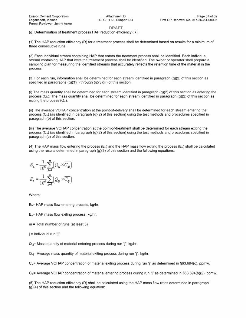
Essroc Cement Corporation Attachment D Page 37 of 62 Logansport, Indiana 40 CFR 63, Subpart DD First OP Renewal No. 017-26351-00005 Permit Reviewer: Jenny Acker DRAFT (g) Determination of treatment process HAP reduction efficiency (R).
(1) The HAP reduction efficiency (R) for a treatment process shall be determined based on results for a minimum of three consecutive runs.
(2) Each individual stream containing HAP that enters the treatment process shall be identified. Each individual stream containing HAP that exits the treatment process shall be identified. The owner or operator shall prepare a sampling plan for measuring the identified streams that accurately reflects the retention time of the material in the process.
(3) For each run, information shall be determined for each stream identified in paragraph (g)(2) of this section as specified in paragraphs (g)(3)(i) through (g)(3)(iii) of this section.
(i) The mass quantity shall be determined for each stream identified in paragraph (g)(2) of this section as entering the process (Qb). The mass quantity shall be determined for each stream identified in paragraph (g)(2) of this section as exiting the process (Qa).
(ii) The average VOHAP concentration at the point-of-delivery shall be determined for each stream entering the process (Cb) (as identified in paragraph (g)(2) of this section) using the test methods and procedures specified in paragraph (b) of this section.
(iii) The average VOHAP concentration at the point-of-treatment shall be determined for each stream exiting the process (Ca) (as identified in paragraph (g)(2) of this section) using the test methods and procedures specified in paragraph (c) of this section.
(4) The HAP mass flow entering the process (Eb) and the HAP mass flow exiting the process (Ea) shall be calculated using the results determined in paragraph (g)(3) of this section and the following equations:
Where:
Eb= HAP mass flow entering process, kg/hr.
Ea= HAP mass flow exiting process, kg/hr.
m = Total number of runs (at least 3)
j = Individual run “j”
Qbj= Mass quantity of material entering process during run “j”, kg/hr.
Qaj= Average mass quantity of material exiting process during run “j”, kg/hr.
Caj= Average VOHAP concentration of material exiting process during run “j” as determined in §63.694(c), ppmw.
Cbj= Average VOHAP concentration of material entering process during run “j” as determined in §63.694(b)(2), ppmw.
(5) The HAP reduction efficiency (R) shall be calculated using the HAP mass flow rates determined in paragraph (g)(4) of this section and the following equation:

Essroc Cement Corporation Attachment D Page 38 of 62 Logansport, Indiana 40 CFR 63, Subpart DD First OP Renewal No. 017-26351-00005 Permit Reviewer: Jenny Acker DRAFT
Where:
R = HAP reduction efficiency, percent.
Eb= HAP mass flow entering process as determined in paragraph (g)(4) of this section, kg/hr.
Ea= HAP mass flow exiting process as determined in accordance with the requirements of paragraph (g)(4) of this section, kg/hr.
(h) Determination of HAP biodegradation efficiency (Rbio).
(1) The fraction of HAP biodegraded (Fbio) shall be determined using one of the procedures specified in appendix C of this part 63.
(2) The HAP biodegradation efficiency (Rbio) shall be calculated by using the following equation:
Rbio−Fbio×100
where:
Rbio= HAP biodegradation efficiency, percent.
Fbio= Fraction of HAP biodegraded as determined in paragraph (h)(1) of this section.
(i) Determination of actual HAP mass removal rate (MRbio).
(1) The actual HAP mass removal rate (MRbio) shall be determined based on results for a minimum of three consecutive runs. The sampling time for each run shall be 1 hour.
(2) The HAP mass flow entering the process (Eb) shall be determined using the test methods and procedures specified in paragraphs (g)(2) through (g)(4) of this section.
(3) The fraction of HAP biodegraded (Fbio) shall be determined using the procedure specified in 40 CFR part 63, appendix C of this part.
(4) The actual mass removal rate shall be calculated by using the HAP mass flow rates and fraction of HAP biodegraded determined in paragraphs (i)(2) and (i)(3), respectively, of this section and the following equation:
MRbio=Eb ×Fbio
Where:
MRbio= Actual HAP mass removal rate, kg/hr.
Eb= HAP mass flow entering process, kg/hr.
Fbio= Fraction of HAP biodegraded.
(j) Determination of maximum HAP vapor pressure for off-site material in a tank. (1) The maximum HAP vapor pressure of the off-site material composition managed in a tank shall be determined using either direct measurement

Essroc Cement Corporation Attachment D Page 39 of 62 Logansport, Indiana 40 CFR 63, Subpart DD First OP Renewal No. 017-26351-00005 Permit Reviewer: Jenny Acker DRAFT as specified in paragraph (j)(2) of this section or by knowledge of the off-site material as specified by paragraph (j)(3) of this section.
(2) Direct measurement to determine the maximum HAP vapor pressure of an off-site material.
(i) Sampling. A sufficient number of samples shall be collected to be representative of the off-site material contained in the tank. All samples shall be collected and handled in accordance with written procedures prepared by the owner or operator and documented in a site sampling plan. This plan shall describe the procedure by which representative samples of the off-site material is collected such that a minimum loss of organics occurs throughout the sample collection and handling process and by which sample integrity is maintained. A copy of the written sampling plan shall be maintained on-site in the plant site operating records. An example of an acceptable sampling plan includes a plan incorporating sample collection and handling procedures in accordance with the requirements specified in “Test Methods for Evaluating Solid Waste, Physical/Chemical Methods,” EPA Publication No. SW–846 or Method 25D in 40 CFR part 60, appendix A.
(ii) Analysis. Any one of the following methods may be used to analyze the samples and compute the maximum HAP vapor pressure of the off-site material:
(A) Method 25E in 40 CFR part 60 appendix A;
(B) Methods described in American Petroleum Institute Bulletin 2517, “Evaporation Loss from External Floating Roof Tanks,”;
(C) Methods obtained from standard reference texts;
(D) ASTM Method 2879–83; or
(E) Any other method approved by the Administrator.
(3) Use of knowledge to determine the maximum HAP vapor pressure of the off-site material. Documentation shall be prepared and recorded that presents the information used as the basis for the owner's or operator's knowledge that the maximum HAP vapor pressure of the off-site material is less than the maximum vapor pressure limit listed in Table 3 or Table 4 of this subpart for the applicable tank design capacity category. Examples of information that may be used include: the off-site material is generated by a process for which at other locations it previously has been determined by direct measurement that the off-site material maximum HAP vapor pressure is less than the maximum vapor pressure limit for the appropriate tank design capacity category.
(k) Procedure for determining no detectable organic emissions for the purpose of complying with this subpart.
(1) The test shall be conducted in accordance with the procedures specified in Method 21 of 40 CFR part 60, appendix A. Each potential leak interface (i.e., a location where organic vapor leakage could occur) on the cover and associated closure devices shall be checked. Potential leak interfaces that are associated with covers and closure devices include, but are not limited to: the interface of the cover and its foundation mounting; the periphery of any opening on the cover and its associated closure device; and the sealing seat interface on a spring-loaded pressure-relief valve.
(2) The test shall be performed when the unit contains a material having a total organic concentration representative of the range of concentrations for the materials expected to be managed in the unit. During the test, the cover and closure devices shall be secured in the closed position.
(3) The detection instrument shall meet the performance criteria of Method 21 of 40 CFR part 60, appendix A, except the instrument response factor criteria in section 3.1.2(a) of Method 21 shall be for the average composition of the organic constituents in the material placed in the unit, not for each individual organic constituent.
(4) The detection instrument shall be calibrated before use on each day of its use by the procedures specified in Method 21 of 40 CFR part 60, appendix A.

Essroc Cement Corporation Attachment D Page 40 of 62 Logansport, Indiana 40 CFR 63, Subpart DD First OP Renewal No. 017-26351-00005 Permit Reviewer: Jenny Acker DRAFT (5) Calibration gases shall be as follows:
(i) Zero air (less than 10 ppmv hydrocarbon in air); and
(ii) A mixture of methane or n-hexane in air at a concentration of approximately, but less than, 10,000 ppmv.
(6) An owner or operator may choose to adjust or not adjust the detection instrument readings to account for the background organic concentration level. If an owner or operator chooses to adjust the instrument readings for the background level, the background level value must be determined according to the procedures in Method 21 of 40 CFR part 60, appendix A.
(7) Each potential leak interface shall be checked by traversing the instrument probe around the potential leak interface as close to the interface as possible, as described in Method 21. In the case when the configuration of the cover or closure device prevents a complete traverse of the interface, all accessible portions of the interface shall be sampled. In the case when the configuration of the closure device prevents any sampling at the interface and the device is equipped with an enclosed extension or horn (e.g., some pressure relief devices), the instrument probe inlet shall be placed at approximately the center of the exhaust area to the atmosphere.
(8) An owner or operator must determine if a potential leak interface operates with no detectable emissions using the applicable procedure specified in paragraph (k)(8)(i) or (k)(8)(ii) of this section.
(i) If an owner or operator chooses not to adjust the detection instrument readings for the background organic concentration level, then the maximum organic concentration value measured by the detection instrument is compared directly to the applicable value for the potential leak interface as specified in paragraph (k)(9) of this section.
(ii) If an owner or operator chooses to adjust the detection instrument readings for the background organic concentration level, the value of the arithmetic difference between the maximum organic concentration value measured by the instrument and the background organic concentration value as determined in paragraph (k)(6) of this section is compared with the applicable value for the potential leak interface as specified in paragraph (k)(9) of this section.
(9) A potential leak interface is determined to operate with no detectable emissions using the applicable criteria specified in paragraphs (k)(9)(i) and (k)(9)(ii) of this section.
(i) For a potential leak interface other than a seal around a shaft that passes through a cover opening, the potential leak interface is determined to operate with no detectable organic emissions if the organic concentration value determined in paragraph (k)(8) is less than 500 ppmv.
(ii) For a seal around a shaft that passes through a cover opening, the potential leak interface is determined to operate with no detectable organic emissions if the organic concentration value determined in paragraph (k)(8) is less than 10,000 ppmv.
(l) Control device performance test procedures.
(1) Method 1 or 1A of 40 CFR part 60, appendix A, as appropriate, shall be used for selection of the sampling sites at the inlet and outlet of the control device.
(i) To determine compliance with a control device percent reduction requirement, sampling sites shall be located at the inlet of the control device as specified in paragraphs (l)(1)(i)(A) and (l)(1)(i)(B) of this section, and at the outlet of the control device.
(A) The control device inlet sampling site shall be located after the final product recovery device.
(B) If a vent stream is introduced with the combustion air or as an auxiliary fuel into a boiler or process heater, the location of the inlet sampling sites shall be selected to ensure that the measurement of total HAP concentration or

Essroc Cement Corporation Attachment D Page 41 of 62 Logansport, Indiana 40 CFR 63, Subpart DD First OP Renewal No. 017-26351-00005 Permit Reviewer: Jenny Acker DRAFT TOC concentration, as applicable, includes all vent streams and primary and secondary fuels introduced into the boiler or process heater.
(ii) To determine compliance with an enclosed combustion device concentration limit, the sampling site shall be located at the outlet of the device.
(2) The gas volumetric flow rate shall be determined using Method 2, 2A, 2C, or 2D of 40 CFR part 60, appendix A, as appropriate.
(3) To determine compliance with the control device percent reduction requirement, the owner or operator shall use Method 18 of 40 CFR part 60, appendix A of this chapter; alternatively, any other method or data that has been validated according to the applicable procedures in Method 301 in 40 CFR part 63, appendix A of this part may be used. The following procedures shall be used to calculate percent reduction efficiency:
(i) The minimum sampling time for each run shall be 1 hour in which either an integrated sample or a minimum of four grab samples shall be taken. If grab sampling is used, then the samples shall be taken at approximately equal intervals in time such as 15 minute intervals during the run.
(ii) The mass rate of either TOC (minus methane and ethane) or total HAP (Eiand Eo,respectively) shall be computed.
(A) The following equations shall be used:
Where:
Cij, Coj= Concentration of sample component j of the gas stream at the inlet and outlet of the control device, respectively, dry basis, parts per million by volume.
Ei, Eo= Mass rate of TOC (minus methane and ethane) or total HAP at the inlet and outlet of the control device, respectively, dry basis, kilogram per hour.
Mij, Moj= Molecular weight of sample component j of the gas stream at the inlet and outlet of the control device, respectively, gram/gram-mole.
Qi, Qo= Flow rate of gas stream at the inlet and outlet of the control device, respectively, dry standard cubic meter per minute.
K2= Constant, 2.494×10⁻⁶ (parts per million)−1 (gram-mole per standard cubic meter) (kilogram/gram) (minute/hour), where standard temperature (gram-mole per standard cubic meter) is 20 °C.
(B) When the TOC mass rate is calculated, all organic compounds (minus methane and ethane) measured by Method 18 of 40 CFR part 60, appendix A shall be summed using the equation in paragraph (l)(3)(ii)(A) of this section.
(C) When the total HAP mass rate is calculated, only the HAP constituents shall be summed using the equation in paragraph (l)(3)(ii)(A) of this section.
(iii) The percent reduction in TOC (minus methane and ethane) or total HAP shall be calculated as follows:
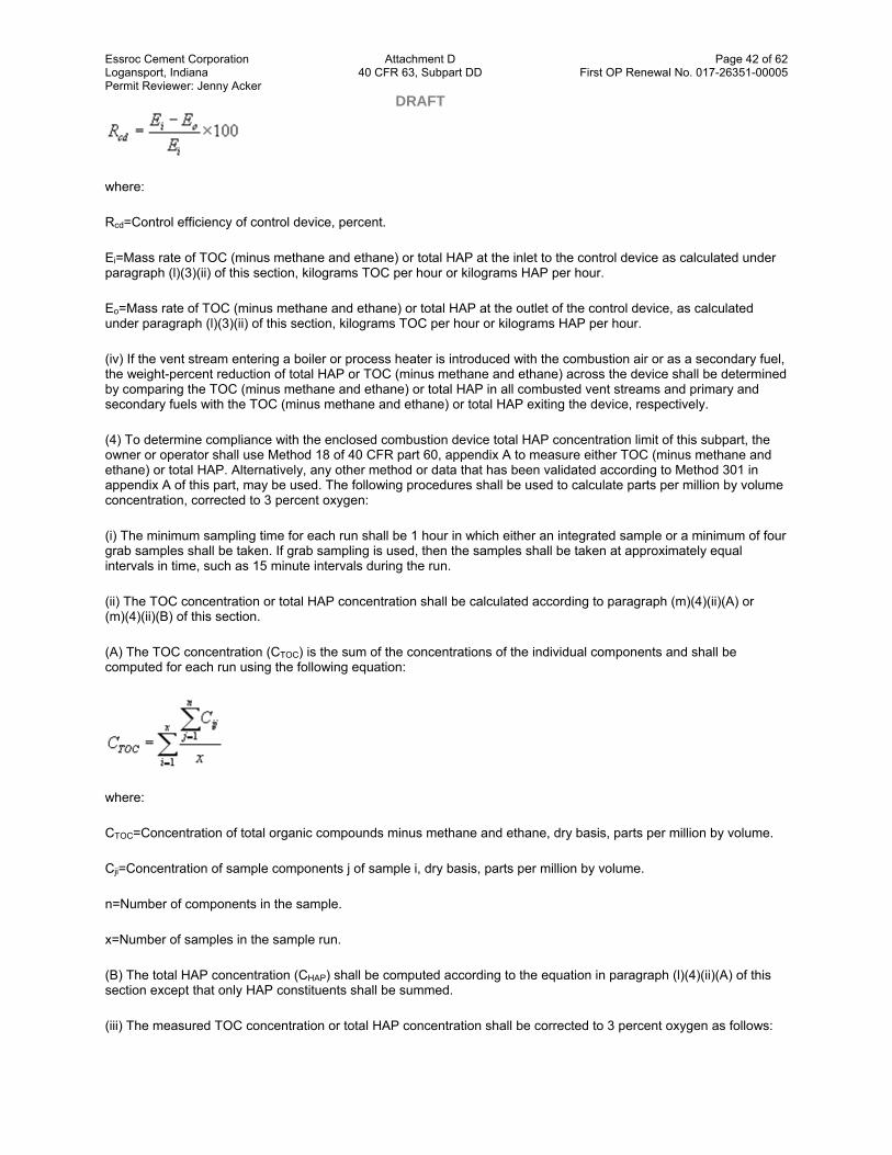
Essroc Cement Corporation Attachment D Page 42 of 62 Logansport, Indiana 40 CFR 63, Subpart DD First OP Renewal No. 017-26351-00005 Permit Reviewer: Jenny Acker DRAFT
where:
Rcd=Control efficiency of control device, percent.
Ei=Mass rate of TOC (minus methane and ethane) or total HAP at the inlet to the control device as calculated under paragraph (l)(3)(ii) of this section, kilograms TOC per hour or kilograms HAP per hour.
Eo=Mass rate of TOC (minus methane and ethane) or total HAP at the outlet of the control device, as calculated under paragraph (l)(3)(ii) of this section, kilograms TOC per hour or kilograms HAP per hour.
(iv) If the vent stream entering a boiler or process heater is introduced with the combustion air or as a secondary fuel, the weight-percent reduction of total HAP or TOC (minus methane and ethane) across the device shall be determined by comparing the TOC (minus methane and ethane) or total HAP in all combusted vent streams and primary and secondary fuels with the TOC (minus methane and ethane) or total HAP exiting the device, respectively.
(4) To determine compliance with the enclosed combustion device total HAP concentration limit of this subpart, the owner or operator shall use Method 18 of 40 CFR part 60, appendix A to measure either TOC (minus methane and ethane) or total HAP. Alternatively, any other method or data that has been validated according to Method 301 in appendix A of this part, may be used. The following procedures shall be used to calculate parts per million by volume concentration, corrected to 3 percent oxygen:
(i) The minimum sampling time for each run shall be 1 hour in which either an integrated sample or a minimum of four grab samples shall be taken. If grab sampling is used, then the samples shall be taken at approximately equal intervals in time, such as 15 minute intervals during the run.
(ii) The TOC concentration or total HAP concentration shall be calculated according to paragraph (m)(4)(ii)(A) or (m)(4)(ii)(B) of this section.
(A) The TOC concentration (CTOC) is the sum of the concentrations of the individual components and shall be computed for each run using the following equation:
where:
CTOC=Concentration of total organic compounds minus methane and ethane, dry basis, parts per million by volume.
Cji=Concentration of sample components j of sample i, dry basis, parts per million by volume.
n=Number of components in the sample.
x=Number of samples in the sample run.
(B) The total HAP concentration (CHAP) shall be computed according to the equation in paragraph (l)(4)(ii)(A) of this section except that only HAP constituents shall be summed.
(iii) The measured TOC concentration or total HAP concentration shall be corrected to 3 percent oxygen as follows:

Essroc Cement Corporation Attachment D Page 43 of 62 Logansport, Indiana 40 CFR 63, Subpart DD First OP Renewal No. 017-26351-00005 Permit Reviewer: Jenny Acker DRAFT (A) The emission rate correction factor or excess air, integrated sampling and analysis procedures of Method 3B of 40 CFR part 60, appendix A shall be used to determine the oxygen concentration (%O2dry). The samples shall be collected during the same time that the samples are collected for determining TOC concentration or total HAP concentration.
(B) The concentration corrected to 3 percent oxygen (Cc) shall be computed using the following equation:
where:
Cc=TOC concentration or total HAP concentration corrected to 3 percent oxygen, dry basis, parts per million by volume.
Cm=Measured TOC concentration or total HAP concentration, dry basis, parts per million by volume.
%O2dry=Concentration of oxygen, dry basis, percent by volume.
(m) Determination of process vent stream flow rate and total HAP concentration.
(1) Method 1 or 1A of 40 CFR part 60, appendix A, as appropriate, must be used for selection of the sampling site.
(2) No traverse site selection method is needed for vents smaller than 0.10 meter in diameter.
(3) Process vent stream gas volumetric flow rate must be determined using Method 2, 2A, 2C, or 2D of 40 CFR part 60, appendix A, as appropriate.
(4) Process vent stream total HAP concentration must be measured using the following procedures:
(i) Method 18 of 40 CFR part 60, appendix A, must be used to measure the total HAP concentration. Alternatively, any other method or data that has been validated according to the protocol in Method 301 of appendix A of this part may be used.
(ii) Where Method 18 of 40 CFR part 60, appendix A, is used, the following procedures must be used to calculate parts per million by volume concentration:
(A) The minimum sampling time for each run must be 1 hour in which either an integrated sample or four grab samples must be taken. If grab sampling is used, then the samples must be taken at approximately equal intervals in time, such as 15 minute intervals during the run.
(B) The total HAP concentration (CHAP) must be computed according to the following equation:
Where:
CHAP = Total concentration of HAP compounds listed in Table 1 of this subpart, dry basis, parts per million by volume.
Essroc Cement Corporation Attachment D Page 44 of 62 Logansport, Indiana 40 CFR 63, Subpart DD First OP Renewal No. 017-26351-00005 Permit Reviewer: Jenny Acker DRAFT Cji = Concentration of sample component j of the sample i, dry basis, parts per million by volume.
n = Number of components in the sample.
x = Number of samples in the sample run.
[61 FR 34158, July 1, 1996, as amended at 64 FR 38974, July 20, 1999; 66 FR 1267, Jan. 8, 2001]
§ 63.695 Inspection and monitoring requirements.
(a) This section specifies the inspection and monitoring procedures required to perform the following:
(1) To inspect tank fixed roofs and floating roofs for compliance with the Tank Level 2 controls standards specified in §63.685 of this subpart, the inspection procedures are specified in paragraph (b) of this section.
(2) To inspect and monitor closed-vent systems for compliance with the standards specified in §63.693 of this subpart, the inspection and monitoring procedures are specified in paragraph (c) of this section.
(3) To inspect and monitor transfer system covers for compliance with the standards specified in §63.689(c)(1) of this subpart, the inspection and monitoring procedures are specified in paragraph (d) of this section.
(4) To monitor and record off-site material treatment processes for compliance with the standards specified in 63.684(e), the monitoring procedures are specified in paragraph (e) of this section.
(b) Tank Level 2 fixed roof and floating roof inspection requirements.
(1) Owners and operators that use a tank equipped with an internal floating roof in accordance with the provisions of §63.685(e) of this subpart shall meet the following inspection requirements:
(i) The floating roof and its closure devices shall be visually inspected by the owner or operator to check for defects that could result in air emissions. Defects include, but are not limited to, the internal floating roof is not floating on the surface of the liquid inside the tank; liquid has accumulated on top of the internal floating roof; any portion of the roof seals have detached from the roof rim; holes, tears, or other openings are visible in the seal fabric; the gaskets no longer close off the waste surfaces from the atmosphere; or the slotted membrane has more than 10 percent open area.
(ii) The owner or operator shall inspect the internal floating roof components as follows except as provided for in paragraph (b)(1)(iii) of this section:
(A) Visually inspect the internal floating roof components through openings on the fixed-roof (e.g., manholes and roof hatches) at least once every calendar year after initial fill, and
(B) Visually inspect the internal floating roof, primary seal, secondary seal (if one is in service), gaskets, slotted membranes, and sleeve seals (if any) each time the tank is emptied and degassed and at least every 10 years. Prior to each inspection, the owner or operator shall notify the Administrator in accordance with the reporting requirements specified in §63.697 of this subpart.
(iii) As an alternative to performing the inspections specified in paragraph (b)(1)(ii) of this section for an internal floating roof equipped with two continuous seals mounted one above the other, the owner or operator may visually inspect the internal floating roof, primary and secondary seals, gaskets, slotted membranes, and sleeve seals (if any) each time the tank is emptied and degassed and at least every 5 years. Prior to each inspection, the owner or operator shall notify the Administrator in accordance with the reporting requirements specified in §63.697 of this subpart.
(iv) In the event that a defect is detected, the owner or operator shall repair the defect in accordance with the requirements of paragraph (b)(4) of this section.

Essroc Cement Corporation Attachment D Page 45 of 62 Logansport, Indiana 40 CFR 63, Subpart DD First OP Renewal No. 017-26351-00005 Permit Reviewer: Jenny Acker DRAFT (v) The owner or operator shall maintain a record of the inspection in accordance with the requirements specified in §63.696 of this subpart.
(2) Owners and operators that use a tank equipped with an external floating roof in accordance with the provisions of §63.685(f) of this subpart shall meet the following requirements:
(i) The owner or operator shall measure the external floating roof seal gaps in accordance with the following requirements:
(A) The owner or operator shall perform measurements of gaps between the tank wall and the primary seal within 60 days after initial operation of the tank following installation of the floating roof and, thereafter, at least once every 5 years. Prior to each inspection, the owner or operator shall notify the Administrator in accordance with the reporting requirements specified in §63.697 of this subpart.
(B) The owner or operator shall perform measurements of gaps between the tank wall and the secondary seal within 60 days after initial operation of the separator following installation of the floating roof and, thereafter, at least once every year. Prior to each inspection, the owner or operator shall notify the Administrator in accordance with the reporting requirements specified in §63.697 of this subpart.
(C) If a tank ceases to hold off-site material for a period of 1 year or more, subsequent introduction of off-site material into the tank shall be considered an initial operation for the purposes of paragraphs (b)(2)(i)(A) and (b)(2)(i)(B) of this section.
(D) The owner shall determine the total surface area of gaps in the primary seal and in the secondary seal individually using the following procedure.
( 1 ) The seal gap measurements shall be performed at one or more floating roof levels when the roof is floating off the roof supports.
( 2 ) Seal gaps, if any, shall be measured around the entire perimeter of the floating roof in each place where a 0.32-centimeter (cm) (1/8-inch) diameter uniform probe passes freely (without forcing or binding against the seal) between the seal and the wall of the tank and measure the circumferential distance of each such location.
( 3 ) For a seal gap measured under paragraph (b)(2) of this section, the gap surface area shall be determined by using probes of various widths to measure accurately the actual distance from the tank wall to the seal and multiplying each such width by its respective circumferential distance.
( 4 ) The total gap area shall be calculated by adding the gap surface areas determined for each identified gap location for the primary seal and the secondary seal individually, and then dividing the sum for each seal type by the nominal diameter of the tank. These total gap areas for the primary seal and secondary seal are then compared to the respective standards for the seal type as specified in §63.685(f)(1) of this subpart.
(E) In the event that the seal gap measurements do not conform to the specifications in §63.685(f)(1) of this subpart, the owner or operator shall repair the defect in accordance with the requirements of paragraph (b)(4) of this section.
(F) The owner or operator shall maintain a record of the inspection in accordance with the requirements specified in §63.696 of this subpart.
(ii) The owner or operator shall visually inspect the external floating roof in accordance with the following requirements:
(A) The floating roof and its closure devices shall be visually inspected by the owner or operator to check for defects that could result in air emissions. Defects include, but are not limited to: holes, tears, or other openings in the rim seal or seal fabric of the floating roof; a rim seal detached from the floating roof; all or a portion of the floating roof deck being submerged below the surface of the liquid in the tank; broken, cracked, or otherwise damaged seals or gaskets on closure devices; and broken or missing hatches, access covers, caps, or other closure devices.

Essroc Cement Corporation Attachment D Page 46 of 62 Logansport, Indiana 40 CFR 63, Subpart DD First OP Renewal No. 017-26351-00005 Permit Reviewer: Jenny Acker DRAFT (B) The owner or operator shall perform the inspections following installation of the external floating roof and, thereafter, at least once every year.
(C) In the event that a defect is detected, the owner or operator shall repair the defect in accordance with the requirements of paragraph (b)(4) of this section.
(D) The owner or operator shall maintain a record of the inspection in accordance with the requirements specified in §63.696(d) of this subpart.
(3) Owners and operators that use a tank equipped with a fixed roof in accordance with the provisions of §63.685(g) of this subpart shall meet the following requirements:
(i) The fixed roof and its closure devices shall be visually inspected by the owner or operator to check for defects that could result in air emissions. Defects include, but are not limited to, visible cracks, holes, or gaps in the roof sections or between the roof and the separator wall; broken, cracked, or otherwise damaged seals or gaskets on closure devices; and broken or missing hatches, access covers, caps, or other closure devices. In the case when a tank is buried partially or entirely underground, inspection is required only for those portions of the cover that extend to or above the ground surface, and those connections that are on such portions of the cover (e.g., fill ports, access hatches, gauge wells, etc.) and can be opened to the atmosphere.
(ii) The owner or operator must perform an initial inspection following installation of the fixed roof. Thereafter, the owner or operator must perform the inspections at least once every calendar year except as provided for in paragraph (f) of this section.
(iii) In the event that a defect is detected, the owner or operator shall repair the defect in accordance with the requirements of paragraph (b)(4) of this section.
(iv) The owner or operator shall maintain a record of the inspection in accordance with the requirements specified in §63.696(e) of this subpart.
(4) The owner or operator shall repair each defect detected during an inspection performed in accordance with the requirements of paragraph (b)(1), (b)(2), or (b)(3) of this section in the following manner:
(i) The owner or operator shall within 45 calendar days of detecting the defect either repair the defect or empty the tank and remove it from service. If within this 45-day period the defect cannot be repaired or the tank cannot be removed from service without disrupting operations at the plant site, the owner or operator is allowed two 30-day extensions. In cases when an owner or operator elects to use a 30-day extension, the owner or operator shall prepare and maintain documentation describing the defect, explaining why alternative storage capacity is not available, and specify a schedule of actions that will ensure that the control equipment will be repaired or the tank emptied as soon as possible.
(ii) When a defect is detected during an inspection of a tank that has been emptied and degassed, the owner or operator shall repair the defect before refilling the tank.
(c) Owners and operators that use a closed-vent system in accordance with the provisions of §63.693 of this subpart shall meet the following inspection and monitoring requirements:
(1) Each closed-vent system that is used to comply with §63.693(c)(1)(i) of this subpart shall be inspected and monitored in accordance with the following requirements:
(i) At initial startup, the owner or operator shall monitor the closed-vent system components and connections using the procedures specified in §63.694(k) of this subpart to demonstrate that the closed-vent system operates with no detectable organic emissions.
(ii) After initial startup, the owner or operator shall inspect and monitor the closed-vent system as follows:

Essroc Cement Corporation Attachment D Page 47 of 62 Logansport, Indiana 40 CFR 63, Subpart DD First OP Renewal No. 017-26351-00005 Permit Reviewer: Jenny Acker DRAFT (A) Closed-vent system joints, seams, or other connections that are permanently or semi-permanently sealed (e.g., a welded joint between two sections of hard piping or a bolted and gasketed ducting flange) shall be visually inspected at least once per year to check for defects that could result in air emissions. The owner or operator shall monitor a component or connection using the procedures specified in §63.694(k) of this subpart to demonstrate that it operates with no detectable organic emissions following any time the component is repaired or replaced (e.g., a section of damaged hard piping is replaced with new hard piping) or the connection is unsealed (e.g., a flange is unbolted).
(B) Closed-vent system components or connections other than those specified in paragraph (c)(1)(ii)(A) of this section, shall be monitored at least once per year using the procedures specified in §63.694(k) of this subpart to demonstrate that components or connections operate with no detectable organic emissions.
(C) The continuous monitoring system required by §63.693(b)(4)(i) shall monitor and record either an instantaneous data value at least once every 15 minutes or an average value for intervals of 15 minutes or less.
(D) The owner or operator shall visually inspect the seal or closure mechanism required by §63.693(c)(2)(ii) at least once every month to verify that the bypass mechanism is maintained in the closed position.
(iii) In the event that a defect or leak is detected, the owner or operator shall repair the defect or leak in accordance with the requirements of paragraph (c)(3) of this section.
(iv) The owner or operator shall maintain a record of the inspection and monitoring in accordance with the requirements specified in §63.696 of this subpart.
(2) Each closed-vent system that is used to comply with §63.693(c)(1)(ii) of this subpart shall be inspected and monitored in accordance with the following requirements:
(i) The closed-vent system shall be visually inspected by the owner or operator to check for defects that could result in air emissions. Defects include, but are not limited to, visible cracks, holes, or gaps in ductwork or piping; loose connections; or broken or missing caps or other closure devices.
(ii) The owner or operator must perform an initial inspection following installation of the closed-vent system. Thereafter, the owner or operator must perform the inspections at least once every calendar year except as provided for in paragraph (f) of this section.
(iii) In the event that a defect is detected, the owner or operator shall repair the defect in accordance with the requirements of paragraph (c)(3) of this section.
(iv) The owner or operator shall maintain a record of the inspection in accordance with the requirements specified in §63.696 of this subpart.
(3) The owner or operator shall repair all detected defects as follows:
(i) The owner or operator shall make first efforts at repair of the defect no later than 5 calendar days after detection and repair shall be completed as soon as possible but no later than 45 calendar days after detection.
(ii) Repair of a defect may be delayed beyond 45 calendar days if either of the conditions specified in paragraph (c)(3)(ii)(A) or (c)(3)(ii)(B) occurs. In this case, the owner or operator must repair the defect the next time the process or unit that vents to the closed-vent system is shutdown. Repair of the defect must be completed before the process or unit resumes operation.
(A) Completion of the repair is technically infeasible without the shutdown of the process or unit that vents to the closed-vent system.
(B) The owner or operator determines that the air emissions resulting from the repair of the defect within the specified period would be greater than the fugitive emissions likely to result by delaying the repair until the next time the process or unit that vents to the closed-vent system is shutdown.
Essroc Cement Corporation Attachment D Page 48 of 62 Logansport, Indiana 40 CFR 63, Subpart DD First OP Renewal No. 017-26351-00005 Permit Reviewer: Jenny Acker DRAFT (iii) The owner or operator shall maintain a record of the defect repair in accordance with the requirements specified in §63.696 of this subpart.
(d) Owners and operators that use a transfer system equipped with a cover in accordance with the provisions of §63.689(c)(1) of this subpart shall meet the following inspection requirements:
(1) The cover and its closure devices shall be visually inspected by the owner or operator to check for defects that could result in air emissions. Defects include, but are not limited to, visible cracks, holes, or gaps in the cover sections or between the cover and its mounting; broken, cracked, or otherwise damaged seals or gaskets on closure devices; and broken or missing hatches, access covers, caps, or other closure devices. In the case when a transfer system is buried partially or entirely underground, inspection is required only for those portions of the cover that extend to or above the ground surface, and those connections that are on such portions of the cover (e.g., access hatches, etc.) and can be opened to the atmosphere.
(2) The owner or operator must perform an initial inspection following installation of the cover. Thereafter, the owner or operator must perform the inspections at least once every calendar year except as provided for in paragraph (f) of this section.
(3) In the event that a defect is detected, the owner or operator shall repair the defect in accordance with the requirements of paragraph (d)(5) of this section.
(4) The owner or operator shall maintain a record of the inspection in accordance with the requirements specified in §63.696 of this subpart.
(5) The owner or operator shall repair all detected defects as follows:
(i) The owner or operator shall make first efforts at repair of the defect no later than 5 calendar days after detection and repair shall be completed as soon as possible but no later than 45 calendar days after detection except as provided in paragraph (d)(5)(ii) of this section.
(ii) Repair of a defect may be delayed beyond 45 calendar days if the owner or operator determines that repair of the defect requires emptying or temporary removal from service of the transfer system and no alternative transfer system is available at the site to accept the material normally handled by the system. In this case, the owner or operator shall repair the defect the next time the process or unit that is generating the material handled by the transfer system stops operation. Repair of the defect must be completed before the process or unit resumes operation.
(iii) The owner or operator shall maintain a record of the defect repair in accordance with the requirements specified in §63.696 of this subpart.
(e) Control device monitoring requirements. For each control device required under §63.693 of this subpart to be monitored in accordance with the provisions of this paragraph (e), the owner or operator must ensure that each control device operates properly by monitoring the control device in accordance with the requirements specified in paragraphs (e)(1) through (e)(7) of this section.
(1) A continuous parameter monitoring system must be used to measure the operating parameter or parameters specified for the control device in §63.693(d) through §63.693(g) of this subpart as applicable to the type and design of the control device. The continuous parameter monitoring system must meet the following specifications and requirements:
(i) The continuous parameter monitoring system must measure either an instantaneous value at least once every 15 minutes or an average value for intervals of 15 minutes or less and continuously record either:
(A) Each measured data value; or
(B) Each block average value for each 1-hour period or shorter periods calculated from all measured data values during each period. If values are measured more frequently than once per minute, a single value for each minute may be used to calculate the hourly (or shorter period) block average instead of all measured values.

Essroc Cement Corporation Attachment D Page 49 of 62 Logansport, Indiana 40 CFR 63, Subpart DD First OP Renewal No. 017-26351-00005 Permit Reviewer: Jenny Acker DRAFT (ii) The monitoring system must be installed, calibrated, operated, and maintained in accordance with the manufacturer's specifications or other written procedures that provide reasonable assurance that the monitoring equipment is operating properly.
(2) Using the data recorded by the monitoring system, the owner or operator must calculate the daily average value for each monitored operating parameter for each operating day. If operation of the control device is continuous, the operating day is a 24-hour period. If control device operation is not continuous, the operating day is the total number of hours of control device operation per 24-hour period. Valid data points must be available for 75 percent of the operating hours in an operating day to compute the daily average.
(3) For each monitored operating parameter, the owner or operator must establish a minimum operating parameter value or a maximum operating parameter value, as appropriate, to define the range of conditions at which the control device must be operated to continuously achieve the applicable performance requirements specified in §63.693(b)(2) of this subpart. Each minimum or maximum operating parameter value must be established in accordance with the requirements in paragraphs (e)(3)(i) and (e)(3)(ii) of this section.
(i) If the owner or operator conducts a performance test to demonstrate control device performance, then the minimum or maximum operating parameter value must be established based on values measured during the performance test and supplemented, as necessary, by the control device design specifications, manufacturer recommendations, or other applicable information.
(ii) If the owner or operator uses a control device design analysis to demonstrate control device performance, then the minimum or maximum operating parameter value must be established based on the control device design analysis and supplemented, as necessary, by the control device manufacturer recommendations or other applicable information.
(4) An excursion for a given control device is determined to have occurred when the monitoring data or lack of monitoring data result in any one of the criteria specified in paragraphs (e)(4)(i) through (e)(4)(iii) of this section being met. When multiple operating parameters are monitored for the same control device and during the same operating day more than one of these operating parameters meets an excursion criterion specified in paragraphs (e)(4)(i) through (e)(4)(iii) of this section, then a single excursion is determined to have occurred for the control device for that operating day.
(i) An excursion occurs when the daily average value of a monitored operating parameter is less than the minimum operating parameter limit (or, if applicable, greater than the maximum operating parameter limit) established for the operating parameter in accordance with the requirements of paragraph (e)(3) of this section.
(ii) An excursion occurs when the period of control device operation is 4 hours or greater in an operating day and the monitoring data are insufficient to constitute a valid hour of data for at least 75 percent of the operating hours. Monitoring data are insufficient to constitute a valid hour of data if measured values are unavailable for any of the 15-minute periods within the hour.
(iii) An excursion occurs when the period of control device operation is less than 4 hours in an operating day and more than 1 of the hours during the period does not constitute a valid hour of data due to insufficient monitoring data. Monitoring data are insufficient to constitute a valid hour of data if measured values are unavailable for any of the 15-minute periods within the hour.
(5) For each excursion, except as provided for in paragraph(e)(6) of this section, the owner or operator shall be deemed to have failed to have applied control in a manner that achieves the required operating parameter limits. Failure to achieve the required operating parameter limits is a violation of this standard.
(6) An excursion is not a violation of this standard under any one of the conditions specified in paragraphs (e)(6)(i) and (e)(6)(ii) of this section.
(i) An excursion is not a violation nor does it count toward the number of excused excursions allowed under paragraph (e)(6)(ii) of this section when the excursion occurs during any one of the following periods:

Essroc Cement Corporation Attachment D Page 50 of 62 Logansport, Indiana 40 CFR 63, Subpart DD First OP Renewal No. 017-26351-00005 Permit Reviewer: Jenny Acker DRAFT (A) During a period of startup, shutdown, or malfunction when the affected facility is operated during such period in accordance with §63.6(e)(1); or
(B) During periods of non-operation of the unit or the process that is vented to the control device (resulting in cessation of HAP emissions to which the monitoring applies).
(ii) For each control device, one excused excursion is allowed per semiannual period for any reason. The initial semiannual period is the 6-month reporting period addressed by the first semiannual report submitted by the owner or operator in accordance with §63.697(b)(4) of this subpart.
(7) Nothing in paragraphs (e)(1) through (e)(6) of this section shall be construed to allow or excuse a monitoring parameter excursion caused by any activity that violates other applicable provisions of this subpart.
(f) Alternative inspection and monitoring interval. Following the initial inspection and monitoring of a piece of air pollution control equipment in accordance with the applicable provisions of this section, subsequent inspection and monitoring of the equipment may be performed at intervals longer than 1 year when an owner or operator determines that performing the required inspection or monitoring procedures would expose a worker to dangerous, hazardous, or otherwise unsafe conditions and the owner or operator complies with the requirements specified in paragraphs (f)(1) and (f)(2) of this section.
(1) The owner or operator must prepare and maintain at the plant site written documentation identifying the specific air pollution control equipment designated as “unsafe to inspect and monitor.” The documentation must include for each piece of air pollution control equipment designated as such a written explanation of the reasons why the equipment is unsafe to inspect or monitor using the applicable procedures under this section.
(2) The owner or operator must develop and implement a written plan and schedule to inspect and monitor the air pollution control equipment using the applicable procedures specified in this section during times when a worker can safely access the air pollution control equipment. The required inspections and monitoring must be performed as frequently as practicable but do not need to be performed more frequently than the periodic schedule that would be otherwise applicable to the air pollution control equipment under the provisions of this section. A copy of the written plan and schedule must be maintained at the plant site.
[64 FR 38977, July 20, 1999, as amended at 68 FR 37352, June 23, 2003; 71 FR 20457, Apr. 20, 2006]
§ 63.696 Recordkeeping requirements.
(a) The owner or operator subject to this subpart shall comply with the recordkeeping requirements in §63.10 under 40 CFR 63 subpart A—General Provisions that are applicable to this subpart as specified in Table 2 of this subpart.
(b) The owner or operator of a control device subject to this subpart shall maintain the records in accordance with the requirements of 40 CFR 63.10 of this part.
(c) [Reserved]
(d) Each owner or operator using an internal floating roof to comply with the tank control requirements specified in §63.685(e) of this subpart or using an external floating roof to comply with the tank control requirements specified in §63.685(f) of this subpart shall prepare and maintain the following records:
(1) Documentation describing the floating roof design and the dimensions of the tank.
(2) A record for each inspection required by §63.695(b) of this subpart, as applicable to the tank, that includes the following information: a tank identification number (or other unique identification description as selected by the owner or operator) and the date of inspection.
(3) The owner or operator shall record for each defect detected during inspections required by §63.695(b) of this subpart the following information: the location of the defect, a description of the defect, the date of detection, and corrective action taken to repair the defect. In the event that repair of the defect is delayed in accordance with the

Essroc Cement Corporation Attachment D Page 51 of 62 Logansport, Indiana 40 CFR 63, Subpart DD First OP Renewal No. 017-26351-00005 Permit Reviewer: Jenny Acker DRAFT provisions of §63.695(b)(4) of this section, the owner or operator shall also record the reason for the delay and the date that completion of repair of the defect is expected.
(4) Owners and operators that use a tank equipped with an external floating roof in accordance with the provisions of §63.685(f) of this subpart shall prepare and maintain records for each seal gap inspection required by §63.695(b) describing the results of the seal gap measurements. The records shall include the date of that the measurements are performed, the raw data obtained for the measurements, and the calculations of the total gap surface area. In the event that the seal gap measurements do not conform to the specifications in §63.695(b) of this subpart, the records shall include a description of the repairs that were made, the date the repairs were made, and the date the separator was emptied, if necessary.
(e) Each owner or operator using a fixed roof to comply with the tank control requirements specified in §63.685(g) of this subpart shall prepare and maintain the following records:
(1) A record for each inspection required by §63.695(b) of this subpart, as applicable to the tank, that includes the following information: a tank identification number (or other unique identification description as selected by the owner or operator) and the date of inspection.
(2) The owner or operator shall record for each defect detected during inspections required by §63.695(b) of this subpart the following information: the location of the defect, a description of the defect, the date of detection, and corrective action taken to repair the defect. In the event that repair of the defect is delayed in accordance with the provisions of §63.695(b)(4) of this section, the owner or operator shall also record the reason for the delay and the date that completion of repair of the defect is expected.
(f) Each owner or operator using an enclosure to comply with the tank control requirements specified in §63.685(i) of this subpart shall prepare and maintain records for the most recent set of calculations and measurements performed by the owner or operator to verify that the enclosure meets the criteria of a permanent total enclosure as specified in “Procedure T—Criteria for and Verification of a Permanent or Temporary Total Enclosure” under 40 CFR 52.741, Appendix B.
(g) An owner or operator shall record, on a semiannual basis, the information specified in paragraphs (g)(1) and (g)(2) of this section for those planned routine maintenance operations that would require the control device not to meet the requirements of §63.693(d) through (h) of this subpart, as applicable.
(1) A description of the planned routine maintenance that is anticipated to be performed for the control device during the next 6 months. This description shall include the type of maintenance necessary, planned frequency of maintenance, and lengths of maintenance periods.
(2) A description of the planned routine maintenance that was performed for the control device during the previous 6 months. This description shall include the type of maintenance performed and the total number of hours during these 6 months that the control device did not meet the requirement of §63.693 (d) through (h) of this subpart, as applicable, due to planned routine maintenance.
(h) An owner or operator shall record the information specified in paragraphs (h)(1) through (h)(3) of this section for those unexpected control device system malfunctions that would require the control device not to meet the requirements of §63.693 (d) through (h) of this subpart, as applicable.
(1) The occurrence and duration of each malfunction of the control device system.
(2) The duration of each period during a malfunction when gases, vapors, or fumes are vented from the waste management unit through the closed-vent system to the control device while the control device is not properly functioning.
(3) Actions taken during periods of malfunction to restore a malfunctioning control device to its normal or usual manner of operation.

Essroc Cement Corporation Attachment D Page 52 of 62 Logansport, Indiana 40 CFR 63, Subpart DD First OP Renewal No. 017-26351-00005 Permit Reviewer: Jenny Acker DRAFT § 63.697 Reporting requirements.
(a) Each owner or operator of an affected source subject to this subpart must comply with the notification requirements specified in paragraph (a)(1) of this section and the reporting requirements specified in paragraph (a)(2) of this section.
(1) The owner or operator of an affected source must submit notices to the Administrator in accordance with the applicable notification requirements in 40 CFR 63.9 as specified in Table 2 of this subpart. For the purpose of this subpart, an owner or operator subject to the initial notification requirements under 40 CFR 63.9(b)(2) must submit the required notification on or before October 19, 1999.
(2) The owner or operator of an affected source must submit reports to the Administrator in accordance with the applicable reporting requirements in 40 CFR 63.10 as specified in Table 2 of this subpart.
(b) The owner or operator of a control device used to meet the requirements of §63.693 of this subpart shall submit the following notifications and reports to the Administrator:
(1) A Notification of Performance Tests specified in §63.7 and §63.9(g) of this part,
(2) Performance test reports specified in §63.10(d)(2) of this part, and
(3) Startup, shutdown, and malfunction reports specified in §63.10(d)(5) of this part.
(i) If actions taken by an owner or operator during a startup, shutdown, or malfunction of an affected source (including actions taken to correct a malfunction) are not completely consistent with the procedures specified in the source's startup, shutdown, and malfunction plan specified in §63.6(e)(3) of this part, the owner or operator shall state such information in the report. The startup, shutdown, or malfunction report shall consist of a letter, containing the name, title, and signature of the responsible official who is certifying its accuracy, that shall be submitted to the Administrator, and
(ii) Separate startup, shutdown, or malfunction reports are not required if the information is included in the summary report specified in paragraph (b)(4) of this section.
(4) A summary report specified in §63.10(e)(3) of this part shall be submitted on a semiannual basis (i.e., once every 6-month period). The summary report must include a description of all excursions as defined in §63.695(e) of this subpart that have occurred during the 6-month reporting period. For each excursion caused when the daily average value of a monitored operating parameter is less than the minimum operating parameter limit (or, if applicable, greater than the maximum operating parameter limit), the report must include the daily average values of the monitored parameter, the applicable operating parameter limit, and the date and duration of the period that the exceedance occurred. For each excursion caused by lack of monitoring data, the report must include the date and duration of period when the monitoring data were not collected and the reason why the data were not collected.
(c) Each owner or operator using an internal floating roof or external floating roof to comply with the Tank Level 2 control requirements specified in §63.685(d) of this subpart shall notify the Administrator in advance of each inspection required under §63.695(b) of this subpart to provide the Administrator with the opportunity to have an observer present during the inspection. The owner or operator shall notify the Administrator of the date and location of the inspection as follows:
(1) Prior to each inspection to measure external floating roof seal gaps as required under §63.695(b) of this subpart, written notification shall be prepared and sent by the owner or operator so that it is received by the Administrator at least 30 calendar days before the date the measurements are scheduled to be performed.
(2) Prior to each visual inspection of an internal floating roof or external floating roof in a tank that has been emptied and degassed, written notification shall be prepared and sent by the owner or operator so that it is received by the Administrator at least 30 calendar days before refilling the tank except when an inspection is not planned as provided for in paragraph (c)(3) of this section.

Essroc Cement Corporation Attachment D Page 53 of 62 Logansport, Indiana 40 CFR 63, Subpart DD First OP Renewal No. 017-26351-00005 Permit Reviewer: Jenny Acker DRAFT (3) When a visual inspection is not planned and the owner or operator could not have known about the inspection 30 calendar days before refilling the tank, the owner or operator shall notify the Administrator as soon as possible, but no later than 7 calendar days before refilling of the tank. This notification may be made by telephone and immediately followed by a written explanation for why the inspection is unplanned. Alternatively, written notification, including the explanation for the unplanned inspection, may be sent so that it is received by the Administrator at least 7 calendar days before refilling the tank.
[61 FR 34158, July 1, 1996, as amended at 64 FR 38981, July 20, 1999]
§ 63.698 Implementation and enforcement.
(a) This subpart can be implemented and enforced by the U.S. EPA, or a delegated authority such as the applicable State, local, or Tribal agency. If the U.S. EPA Administrator has delegated authority to a State, local, or Tribal agency, then that agency, in addition to the U.S. EPA, has the authority to implement and enforce this subpart. Contact the applicable U.S. EPA Regional Office to find out if this subpart is delegated to a State, local, or Tribal agency.
(b) In delegating implementation and enforcement authority of this subpart to a State, local, or Tribal agency under subpart E of this part, the authorities contained in paragraph (c) of this section are retained by the Administrator of U.S. EPA and cannot be transferred to the State, local, or Tribal agency.
(c) The authorities that cannot be delegated to State, local, or Tribal agencies are as specified in paragraphs (c)(1) through (4) of this section.
(1) Approval of alternatives to the requirements in §§63.680, 63.683 through 63.691, and 63.693. Where these standards reference another subpart, the cited provisions will be delegated according to the delegation provisions of the referenced subpart.
(2) Approval of major alternatives to test methods under §63.7(e)(2)(ii) and (f), as defined in §63.90, and as required in this subpart.
(3) Approval of major alternatives to monitoring under §63.8(f), as defined in §63.90, and as required in this subpart.
(4) Approval of major alternatives to recordkeeping and reporting under §63.10(f), as defined in §63.90, and as required in this subpart.
[68 FR 37352, June 23, 2003]
Table 1 to Subpart DD of Part 63—List of Hazardous Air Pollutants (HAP) for Subpart DD
CAS No.a Chemical name fm305
75–07–0 Acetaldehyde 1.000
75–05–8 Acetonitrile 0.989
98–86–2 Acetophenone 0.314
107–02–8 Acrolein 1.000
107–13–1 Acrylonitrile 0.999
107–05–1 Allyl chloride 1.000
71–43–2 Benzene (includes benzene in gasoline) 1.000
98–07–7 Benzotrichloride (isomers and mixture) 0.958
100–44–7 Benzyl chloride 1.000
92–52–4 Biphenyl 0.864

Essroc Cement Corporation Attachment D Page 54 of 62 Logansport, Indiana 40 CFR 63, Subpart DD First OP Renewal No. 017-26351-00005 Permit Reviewer: Jenny Acker DRAFT CAS No.a Chemical name fm305
542–88–1 Bis(chloromethyl)etherb 0.999
75–25–2 Bromoform 0.998
106–99–0 1,3-Butadiene 1.000
75–15–0 Carbon disulfide 1.000
56–23–5 Carbon tetrachloride 1.000
43–58–1 Carbonyl sulfide 1.000
133–90–4 Chloramben 0.633
108–90–7 Chlorobenzene 1.000
67–66–3 Chloroform 1.000
107–30–2 Chloromethyl methyl etherb 1.000
126–99–8 Chloroprene 1.000
98–82–8 Cumene 1.000
94–75–7 2,4-D, salts and esters 0.167
334–88–3 Diazomethanec 0.999
132–64–9 Dibenzofurans 0.967
96–12–8 1,2-Dibromo-3-chloropropane 1.000
106–46–7 1,4-Dichlorobenzene(p) 1.000
107–06–2 Dichloroethane (Ethylene dichloride) 1.000
111–44–4 Dichloroethyl ether (Bis(2-chloroethyl ether) 0.757
542–75–6 1,3-Dichloropropene 1.000
79–44–7 Dimethyl carbamoyl chloridec 0.150
64–67–5 Diethyl sulfate 0.0025
77–78–1 Dimethyl sulfate 0.086
121–69–7 N,N-Dimethylaniline 0.0008
51–28–5 2,4-Dinitrophenol 0.0077
121–14–2 2,4-Dinitrotoluene 0.0848
123–91–1 1,4-Dioxane (1,4-Diethyleneoxide) 0.869
106–89–8 Epichlorohydrin (1-Chloro-2,3-epoxypropane) 0.939
106–88–7 1,2-Epoxybutane 1.000
140–88–5 Ethyl acrylate 1.000
100–41–4 Ethyl benzene 1.000
75–00–3 Ethyl chloride (Chloroethane) 1.000
106–93–4 Ethylene dibromide (Dibromoethane) 0.999
107–06–2 Ethylene dichloride (1,2-Dichloroethane) 1.000
151–56–4 Ethylene imine (Aziridine) 0.867

Essroc Cement Corporation Attachment D Page 55 of 62 Logansport, Indiana 40 CFR 63, Subpart DD First OP Renewal No. 017-26351-00005 Permit Reviewer: Jenny Acker DRAFT CAS No.a Chemical name fm305
75–21–8 Ethylene oxide 1.000
75–34–3 Ethylidene dichloride (1,1-Dichloroethane) 1.000
Glycol ethersdthat have a Henry's Law constant value equal to or greater than 0.1 Y/X (1.8×10⁻⁶atm/gm-mole/m3) at 25°C
(e)
118–74–1 Hexachlorobenzene 0.97
87–68–3 Hexachlorobutadiene 0.88
67–72–1 Hexachloroethane 0.499
110–54–3 Hexane 1.000
78–59–1 Isophorone 0.506
58–89–9 Lindane (all isomers) 1.000
67–56–1 Methanol 0.855
74–83–9 Methyl bromide (Bromomethane) 1.000
74–87–3 Methyl chloride (Choromethane) 1.000
71–55–6 Methyl chloroform (1,1,1-Trichloroethane) 1.000
78–93–3 Methyl ethyl ketone (2-Butanone) 0.990
74–88–4 Methyl iodide (Iodomethane) 1.0001
108–10–1 Methyl isobutyl ketone (Hexone) 0.9796
624–83–9 Methyl isocyanate 1.000
80–62–6 Methyl methacrylate 0.916
1634–04–4
Methyl tert butyl ether 1.000
75–09–2 Methylene chloride (Dichloromethane) 1.000
91–20–3 Naphthalene 0.994
98–95–3 Nitrobenzene 0.394
79–46–9 2-Nitropropane 0.989
82–68–8 Pentachloronitrobenzene (Quintobenzene) 0.839
87–86–5 Pentachlorophenol 0.0898
75–44–5 Phosgenec 1.000
123–38–6 Propionaldehyde 0.999
78–87–5 Propylene dichloride (1,2–Dichloropropane) 1.000
75–56–9 Propylene oxide 1.000
75–55–8 1,2–Propylenimine (2–Methyl aziridine) 0.945
100–42–5 Styrene 1.000
96–09–3 Styrene oxide 0.830
79–34–5 1,1,2,2–Tetrachloroethane 0.999

Essroc Cement Corporation Attachment D Page 56 of 62 Logansport, Indiana 40 CFR 63, Subpart DD First OP Renewal No. 017-26351-00005 Permit Reviewer: Jenny Acker DRAFT CAS No.a Chemical name fm305
127–18–4 Tetrachloroethylene (Perchloroethylene) 1.000
108–88–3 Toluene 1.000
95–53–4 o-Toluidine 0.152
120–82–1 1,2,4–Trichlorobenzene 1.000
71–55–6 1,1,1–Trichloroethane (Methyl chlorform) 1.000
79–00–5 1,1,2–Trichloroethane (Vinyl trichloride) 1.000
79–01–6 Trichloroethylene 1.000
95–95–4 2,4,5–Trichlorophenol 0.108
88–06–2 2,4,6–Trichlorophenol 0.132
121–44–8 Triethylamine 1.000
540–84–1 2,2,4–Trimethylpentane 1.000
108–05–4 Vinyl acetate 1.000
593–60–2 Vinyl bromide 1.000
75–01–4 Vinyl chloride 1.000
75–35–4 Vinylidene chloride (1,1–Dichloroethylene) 1.000
1330–20–7
Xylenes (isomers and mixture) 1.000
95–47–6 o-Xylenes 1.000
108–38–3 m-Xylenes 1.000
106–42–3 p-Xylenes 1.000
Notes:
fm 305= Method 305 fraction measure factor.
a. CAS numbers refer to the Chemical Abstracts Services registry number assigned to specific compounds, isomers, or mixtures of compounds.
b. Denotes a HAP that hydrolyzes quickly in water, but the hydrolysis products are also HAP chemicals.
c. Denotes a HAP that may react violently with water, exercise caustic is an expected analyte.
d. Denotes a HAP that hydrolyzes slowly in water.
e. The fm 305factors for some of the more common glycol ethers can be obtained by contacting the Waste and Chemical Processes Group, Office of Air Quality Planning and Standards, Research Triangle Park, NC 27711.
[64 FR 38981, July 20, 1999]

Essroc Cement Corporation Attachment D Page 57 of 62 Logansport, Indiana 40 CFR 63, Subpart DD First OP Renewal No. 017-26351-00005 Permit Reviewer: Jenny Acker DRAFT Table 2 to Subpart DD of Part 63—Applicability of Paragraphs in Subpart A of This Part 63—General Provisions to Subpart DD
Subpart A reference Applies to
Subpart DD Explanation
63.1(a)(1) Yes
63.1(a)(2) Yes
63.1(a)(3) Yes
63.1(a)(4) No Subpart DD (this table) specifies applicability of each paragraph in subpart A to subpart DD.
63.1(a)(5)–63.1(a)(9) No
63.1(a)(10) Yes
63.1(a)(11) Yes
63.1(a)(12) Yes
63.1(a)(13) Yes
63.1(a)(14) Yes
63.1(b)(1) No Subpart DD specifies its own applicability.
63.1(b)(2) Yes
63.1(b)(3) No
63.1(c)(1) No Subpart DD explicitly specifies requirements that apply.
63.1(c)(2) No Area sources are not subject to subpart DD.
63.1(c)(3) No
63.1(c)(4) Yes
63.1(c)(5) Yes Except that sources are not required to submit notifications overridden by this table.
63.1(d) No
63.1(e) No
63.2 Yes §63.681 of subpart DD specifies that if the same term is defined in subparts A and DD, it shall have the meaning given in subpart DD.
63.3 Yes
63.4(a)(1)–63.4(a)(3) Yes
63.4(a)(4) No Reserved.
63.4(a)(5) Yes
63.4(b) Yes
63.4(c) Yes
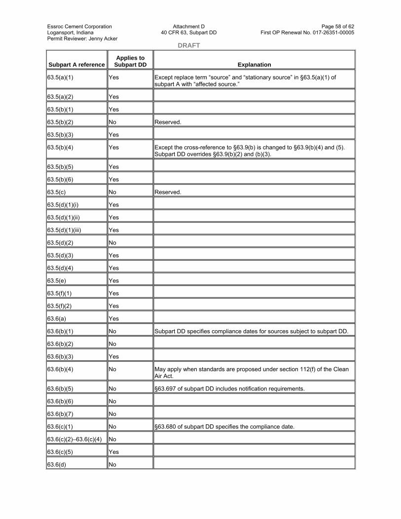
Essroc Cement Corporation Attachment D Page 58 of 62 Logansport, Indiana 40 CFR 63, Subpart DD First OP Renewal No. 017-26351-00005 Permit Reviewer: Jenny Acker DRAFT
Subpart A reference Applies to
Subpart DD Explanation
63.5(a)(1) Yes Except replace term “source” and “stationary source” in §63.5(a)(1) of subpart A with “affected source.”
63.5(a)(2) Yes
63.5(b)(1) Yes
63.5(b)(2) No Reserved.
63.5(b)(3) Yes
63.5(b)(4) Yes Except the cross-reference to §63.9(b) is changed to §63.9(b)(4) and (5). Subpart DD overrides §63.9(b)(2) and (b)(3).
63.5(b)(5) Yes
63.5(b)(6) Yes
63.5(c) No Reserved.
63.5(d)(1)(i) Yes
63.5(d)(1)(ii) Yes
63.5(d)(1)(iii) Yes
63.5(d)(2) No
63.5(d)(3) Yes
63.5(d)(4) Yes
63.5(e) Yes
63.5(f)(1) Yes
63.5(f)(2) Yes
63.6(a) Yes
63.6(b)(1) No Subpart DD specifies compliance dates for sources subject to subpart DD.
63.6(b)(2) No
63.6(b)(3) Yes
63.6(b)(4) No May apply when standards are proposed under section 112(f) of the Clean Air Act.
63.6(b)(5) No §63.697 of subpart DD includes notification requirements.
63.6(b)(6) No
63.6(b)(7) No
63.6(c)(1) No §63.680 of subpart DD specifies the compliance date.
63.6(c)(2)–63.6(c)(4) No
63.6(c)(5) Yes
63.6(d) No
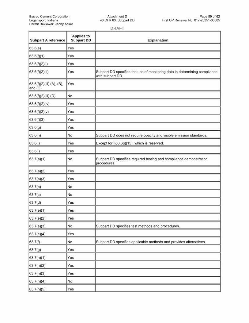
Essroc Cement Corporation Attachment D Page 59 of 62 Logansport, Indiana 40 CFR 63, Subpart DD First OP Renewal No. 017-26351-00005 Permit Reviewer: Jenny Acker DRAFT
Subpart A reference Applies to
Subpart DD Explanation
63.6(e) Yes
63.6(f)(1) Yes
63.6(f)(2)(i) Yes
63.6(f)(2)(ii) Yes Subpart DD specifies the use of monitoring data in determining compliance with subpart DD.
63.6(f)(2)(iii) (A), (B), and (C)
Yes
63.6(f)(2)(iii) (D) No
63.6(f)(2)(iv) Yes
63.6(f)(2)(v) Yes
63.6(f)(3) Yes
63.6(g) Yes
63.6(h) No Subpart DD does not require opacity and visible emission standards.
63.6(i) Yes Except for §63.6(i)(15), which is reserved.
63.6(j) Yes
63.7(a)(1) No Subpart DD specifies required testing and compliance demonstration procedures.
63.7(a)(2) Yes
63.7(a)(3) Yes
63.7(b) No
63.7(c) No
63.7(d) Yes
63.7(e)(1) Yes
63.7(e)(2) Yes
63.7(e)(3) No Subpart DD specifies test methods and procedures.
63.7(e)(4) Yes
63.7(f) No Subpart DD specifies applicable methods and provides alternatives.
63.7(g) Yes
63.7(h)(1) Yes
63.7(h)(2) Yes
63.7(h)(3) Yes
63.7(h)(4) No
63.7(h)(5) Yes

Essroc Cement Corporation Attachment D Page 60 of 62 Logansport, Indiana 40 CFR 63, Subpart DD First OP Renewal No. 017-26351-00005 Permit Reviewer: Jenny Acker DRAFT
Subpart A reference Applies to
Subpart DD Explanation
63.8(a) No
63.8(b)(1) Yes
63.8(b)(2) No Subpart DD specifies locations to conduct monitoring.
63.8(b)(3) Yes
63.8(c)(1)(i) Yes
63.8(c)(1)(ii) Yes
63.8(c)(1)(iii) Yes
63.8(c)(2) Yes
63.8(c)(3) Yes
63.8(c)(4) No Subpart DD specifies monitoring frequency
63.8(c)(5)–63.8(c)(8) No
63.8(d) No
63.8(e) No
63.8(f)(1) Yes
63.8(f)(2) Yes
63.8(f)(3) Yes
63.8(f)(4)(i) Yes
63.8(f)(4)(ii) Yes
63.8(f)(4)(iii) No
63.8(f)(5)(i) Yes
63.8(f)(5)(ii) No
63.8(f)(5)(iii) Yes
63.8(f)(6) Yes
63.8(g) Yes
63.9(a) Yes
63.9(b)(1)(i) Yes
63.9(b)(1)(ii) No
63.9(b)(2) Yes
63.9(b)(3) No
63.9(b)(4) Yes
63.9(b)(5) Yes

Essroc Cement Corporation Attachment D Page 61 of 62 Logansport, Indiana 40 CFR 63, Subpart DD First OP Renewal No. 017-26351-00005 Permit Reviewer: Jenny Acker DRAFT
Subpart A reference Applies to
Subpart DD Explanation
63.9(c) Yes
63.9(d) Yes
63.9(e) No
63.9(f) No
63.9(g) No
63.9(h) Yes
63.9(i) Yes
63.9(j) No
63.10(a) Yes
63.10(b)(1) Yes
63.10(b)(2)(i) Yes
63.10(b)(2)(ii) Yes
63.10(b)(2)(iii) No
63.10(b)(2)(iv) Yes
63.10(b)(2)(v) Yes
63.10(b)(2)(vi)–(ix) Yes
63.10(b)(2)(x)–(xi) Yes
63.10(b)(2) (xii)–(xiv) No
63.10(b)(3) Yes
63.10(c) No
63.10(d)(1) No
63.10(d)(2) Yes
63.10(d)(3) No
63.10(d)(4) Yes
63.10(d)(5)(i) Yes
63.10(d)(5)(ii) Yes
63.10(e) No
63.10(f) Yes
63.11–63.15 Yes
aWherever subpart A specifies “postmark” dates, submittals may be sent by methods other than the U.S. Mail (e.g., by fax or courier). Submittals shall be sent by the specified dates, but a postmark is not required.

Essroc Cement Corporation Attachment D Page 62 of 62 Logansport, Indiana 40 CFR 63, Subpart DD First OP Renewal No. 017-26351-00005 Permit Reviewer: Jenny Acker DRAFT [64 FR 38983, July 20, 1999, as amended at 66 FR 1267, Jan. 8, 2001]
Table 3 to Subpart DD of Part 63—Tank Control Levels for Tanks at Existing Affected Sources as Required by 40 CFR 63.685(b)(1)
Tank design capacity (cubic meters) Maximum HAP vapor pressure of off-site material
managed in tank (kilopascals) Tank control
level
Design capacity less than 75 m3 Maximum HAP vapor pressure less than 76.6 kPa Level 1.
Design capacity equal to or greater than 75 m3and less than 151 m3
Maximum HAP vapor pressure less than 27.6 kPa Level 1.
Maximum HAP vapor pressure equal to or greater than 27.6 kPa
Level 2.
Design capacity equal to or greater than 151 m3
Maximum HAP vapor pressures less than 5.2 kPa Level 1.
Maximum HAP vapor pressure equal to or greater than 5.2 kPa
Level 2.
Table 4 to Subpart DD of Part 63—Tank Control Levels for Tanks at New Affected Sources as Required by 40 CFR 63.685(b)(2)
Tank design capacity (cubic meters) Maximum HAP vapor pressure of off-site material
managed in tank (kilopascals) Tank control
level
Design capacity less than 38 m3 Maximum HAP vapor pressure less than 76.6 kPa Level 1.
Design capacity equal to or greater than 38 m3and less than 151 m3
Maximum HAP vapor pressure less than 13.1 kPa Level 1.
Maximum HAP vapor pressure equal to or greater than 13.1 kPa
Level 2.
Design capacity equal to or greater than 151 m3
Maximum HAP vapor pressure less than 0.7 kPa Level 1.
Maximum HAP vapor pressure equal to or greater than 0.7 kPa
Level 2.
This document was downloaded from the following source on January 16, 2009: Subpart DD--NATIONAL EMISSION STANDARDS FOR HAZARDOUS AIR POLLUTANTS FROM OFF-SITE WASTE AND RECOVERY OPERATIONS

Page 1 of 117 DRAFT
Indiana Department of Environmental Management Office of Air Quality
Attachment E
Title 40: Protection of Environment PART 63—NATIONAL EMISSION STANDARDS FOR HAZARDOUS AIR POLLUTANTS FOR SOURCE CATEGORIES
Subpart EEE—National Emission Standards for Hazardous Air Pollutants from Hazardous Waste Combustors
Source: 64 FR 53038, Sept. 30, 1999, unless otherwise noted.
General
§ 63.1200 Who is subject to these regulations?
The provisions of this subpart apply to all hazardous waste combustors: hazardous waste incinerators, hazardous waste cement kilns, hazardous waste lightweight aggregate kilns, hazardous waste solid fuel boilers, hazardous waste liquid fuel boilers, and hazardous waste hydrochloric acid production furnaces. Hazardous waste combustors are also subject to applicable requirements under parts 260 through 270 of this chapter.
(a) What if I am an area source? (1) Both area sources and major sources are subject to this subpart.
(2) Both area sources and major sources subject to this subpart, but not previously subject to title V, are immediately subject to the requirement to apply for and obtain a title V permit in all States, and in areas covered by part 71 of this chapter.
(b) These regulations in this subpart do not apply to sources that meet the criteria in Table 1 of this Section, as follows:
Table 1 to §63.1200—Hazardous Waste Combustors Exempt From Subpart EEE
If And if Then
(1) You are a previously affected source
(i) You ceased feeding hazardous waste for a period of time greater than the hazardous waste residence time (i.e., hazardous waste no longer resides in the combustion chamber); (ii) You have initiated the closure requirements of subpart G, parts 264 or 265 of this chapter; (iii) You begin complying with the requirements of all other applicable standards of this part (Part 63); and(iv) You notify the Administrator in writing that you are no longer an affected source under this subpart (Subpart EEE)
You are no longer subject to this subpart (Subpart EEE).
(2) You are a research, development, and demonstration source
You operate for no longer than one year after first burning hazardous waste (Note that the Administrator can extend this one-year restriction on a case-by-case basis upon your written request documenting when you first burned hazardous waste and the justification for needing additional time to perform research, development, or demonstration operations).
You are not subject to this subpart (Subpart EEE). This exemption applies even if there is a hazardous waste combustor at the plant site that is regulated under this subpart. You still, however, remain subject to §270.65 of this chapter.

Essroc Cement Corporation Attachment E Page 2 of 117 Logansport, Indiana 40 CFR 63, Subpart EEE First OP Renewal No. 017-26351-00005 Permit Reviewer: Jenny Acker DRAFT
If And if Then
(3) The only hazardous wastes you burn are exempt from regulation under §266.100(c) of this chapter
You are not subject to the requirements of this subpart (Subpart EEE).
(4) You meet the definition of a small quantity burner under §266.108 of this chapter
You are not subject to the requirements of this subpart (Subpart EEE).
(c) Table 1 of this section specifies the provisions of subpart A (General Provisions, §§63.1–63.15) that apply and those that do not apply to sources affected by this subpart.
[64 FR 53038, Sept. 30, 1999, as amended at 65 FR 42297, July 10, 2000; 67 FR 6986, Feb. 14, 2002; 70 FR 59540, Oct. 12, 2005]
§ 63.1201 Definitions and acronyms used in this subpart.
(a) The terms used in this subpart are defined in the Act, in subpart A of this part, or in this section as follows:
Air pollution control system means the equipment used to reduce the release of particulate matter and other pollutants to the atmosphere.
Automatic waste feed cutoff (AWFCO) system means a system comprised of cutoff valves, actuator, sensor, data manager, and other necessary components and electrical circuitry designed, operated and maintained to stop the flow of hazardous waste to the combustion unit automatically and immediately (except as provided by §63.1206(c)(3)(viii)) when any operating requirement is exceeded.
Btu means British Thermal Units.
By-pass duct means a device which diverts a minimum of 10 percent of a cement kiln's off gas, or a device which the Administrator determines on a case-by-case basis diverts a sample of kiln gas that contains levels of carbon monoxide or hydrocarbons representative of the levels in the kiln.
Combustion chamber means the area in which controlled flame combustion of hazardous waste occurs.
Continuous monitor means a device which continuously samples the regulated parameter specified in §63.1209 without interruption, evaluates the detector response at least once every 15 seconds, and computes and records the average value at least every 60 seconds, except during allowable periods of calibration and except as defined otherwise by the CEMS Performance Specifications in appendix B, part 60 of this chapter.
Dioxin/furan and dioxins and furans mean tetra-, penta-, hexa-, hepta-, and octa-chlorinated dibenzo dioxins and furans.
Existing source means any affected source that is not a new source.
Feedrate operating limits means limits on the feedrate of materials ( e.g., metals, chlorine) to the combustor that are established based on comprehensive performance testing. The limits are established and monitored by knowing the concentration of the limited material ( e.g., chlorine) in each feedstream and the flowrate of each feedstream.
Feedstream means any material fed into a hazardous waste combustor, including, but not limited to, any pumpable or nonpumpable solid, liquid, or gas.

Essroc Cement Corporation Attachment E Page 3 of 117 Logansport, Indiana 40 CFR 63, Subpart EEE First OP Renewal No. 017-26351-00005 Permit Reviewer: Jenny Acker DRAFT Flowrate means the rate at which a feedstream is fed into a hazardous waste combustor.
Hazardous waste is defined in §261.3 of this chapter.
Hazardous waste burning cement kiln means a rotary kiln and any associated preheater or precalciner devices that produce clinker by heating limestone and other materials for subsequent production of cement for use in commerce, and that burns hazardous waste at any time.
Hazardous waste combustor means a hazardous waste incinerator, hazardous waste burning cement kiln, hazardous waste burning lightweight aggregate kiln, hazardous waste liquid fuel boiler, hazardous waste solid fuel boiler, or hazardous waste hydrochloric acid production furnace.
Hazardous waste hydrochloric acid production furnace and Hazardous Waste HCl production furnace mean a halogen acid furnace defined under §260.10 of this chapter that produces aqueous hydrochloric acid (HCl) product and that burns hazardous waste at any time.
Hazardous waste incinerator means a device defined as an incinerator in §260.10 of this chapter and that burns hazardous waste at any time. For purposes of this subpart, the hazardous waste incinerator includes all associated firing systems and air pollution control devices, as well as the combustion chamber equipment.
Hazardous waste lightweight aggregate kiln means a rotary kiln that produces clinker by heating materials such as slate, shale and clay for subsequent production of lightweight aggregate used in commerce, and that burns hazardous waste at any time.
Hazardous waste liquid fuel boiler means a boiler defined under §260.10 of this chapter that does not burn solid fuels and that burns hazardous waste at any time. Liquid fuel boiler includes boilers that only burn gaseous fuel.
Hazardous waste residence time means the time elapsed from cutoff of the flow of hazardous waste into the combustor (including, for example, the time required for liquids to flow from the cutoff valve into the combustor) until solid, liquid, and gaseous materials from the hazardous waste (excluding residues that may adhere to combustion chamber surfaces and excluding waste-derived recycled materials such as cement kiln dust and internally recycled metals) exit the combustion chamber. For combustors with multiple firing systems whereby the residence time may vary for the firing systems, the hazardous waste residence time for purposes of complying with this subpart means the longest residence time for any firing system in use at the time of the waste cutoff.
Hazardous waste solid fuel boiler means a boiler defined under §260.10 of this chapter that burns a solid fuel and that burns hazardous waste at any time.
Initial comprehensive performance test means the comprehensive performance test that is used as the basis for initially demonstrating compliance with the standards.
In-line kiln raw mill means a hazardous waste burning cement kiln design whereby kiln gas is ducted through the raw material mill for portions of time to facilitate drying and heating of the raw material.
Instantaneous monitoring for combustion system leak control means detecting and recording pressure, without use of an averaging period, at a frequency adequate to detect combustion system leak events from hazardous waste combustion.
Monovent means an exhaust configuration of a building or emission control device ( e.g. positive pressure fabric filter) that extends the length of the structure and has a width very small in relation to its length ( i.e., length to width ratio is typically greater than 5:1). The exhaust may be an open vent with or without a roof, louvered vents, or a combination of such features.
MTEC means maximum theoretical emissions concentration of metals or HCl/Cl, expressed as µg/dscm, and is calculated by dividing the feedrate by the gas flowrate.

Essroc Cement Corporation Attachment E Page 4 of 117 Logansport, Indiana 40 CFR 63, Subpart EEE First OP Renewal No. 017-26351-00005 Permit Reviewer: Jenny Acker DRAFT New source means any affected source the construction or reconstruction of which is commenced after the dates specified under §§63.1206(a)(1)(i)(B), (a)(1)(ii)(B), and (a)(2)(ii).
One-minute average means the average of detector responses calculated at least every 60 seconds from responses obtained at least every 15 seconds.
Operating record means a documentation retained at the facility for ready inspection by authorized officials of all information required by the standards to document and maintain compliance with the applicable regulations, including data and information, reports, notifications, and communications with regulatory officials.
Operating requirements means operating terms or conditions, limits, or operating parameter limits developed under this subpart that ensure compliance with the emission standards.
Preheater tower combustion gas monitoring location means a location within the preheater tower of a dry process cement kiln downstream (in terms of gas flow) of all hazardous waste firing locations and where a representative sample of combustion gas to measure combustion efficiency can be monitored.
Raw material feed means the prepared and mixed materials, which include but are not limited to materials such as limestone, clay, shale, sand, iron ore, mill scale, cement kiln dust and flyash, that are fed to a cement or lightweight aggregate kiln. Raw material feed does not include the fuels used in the kiln to produce heat to form the clinker product.
Research, development, and demonstration source means a source engaged in laboratory, pilot plant, or prototype demonstration operations:
(1) Whose primary purpose is to conduct research, development, or short-term demonstration of an innovative and experimental hazardous waste treatment technology or process; and
(2) Where the operations are under the close supervision of technically-trained personnel.
Rolling average means the average of all one-minute averages over the averaging period.
Run means the net period of time during which an air emission sample is collected under a given set of operating conditions. Three or more runs constitutes a test. Unless otherwise specified, a run may be either intermittent or continuous.
Run average means the average of the one-minute average parameter values for a run.
System removal efficiency means [1 − Emission Rate (mass/time) / Feedrate (mass/time)] X 100.
TEQ means the international method of expressing toxicity equivalents for dioxins and furans as defined in U.S. EPA, Interim Procedures for Estimating Risks Associated with Exposures to Mixtures of Chlorinated Dibenzo-p-dioxins and -dibenzofurans (CDDs and CDFs) and 1989 Update, March 1989.
You means the owner or operator of a hazardous waste combustor.
(b) The acronyms used in this subpart refer to the following:
AWFCO means automatic waste feed cutoff.
CAS means chemical abstract services registry.
CEMS means continuous emissions monitoring system.
CMS means continuous monitoring system.
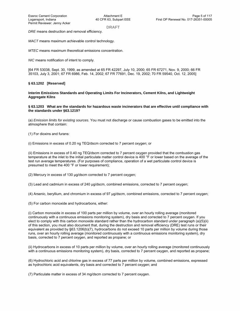
Essroc Cement Corporation Attachment E Page 5 of 117 Logansport, Indiana 40 CFR 63, Subpart EEE First OP Renewal No. 017-26351-00005 Permit Reviewer: Jenny Acker DRAFT DRE means destruction and removal efficiency.
MACT means maximum achievable control technology.
MTEC means maximum theoretical emissions concentration.
NIC means notification of intent to comply.
[64 FR 53038, Sept. 30, 1999, as amended at 65 FR 42297, July 10, 2000; 65 FR 67271, Nov. 9, 2000; 66 FR 35103, July 3, 2001; 67 FR 6986, Feb. 14, 2002; 67 FR 77691, Dec. 19, 2002; 70 FR 59540, Oct. 12, 2005]
§ 63.1202 [Reserved]
Interim Emissions Standards and Operating Limits For Incinerators, Cement Kilns, and Lightweight Aggregate Kilns
§ 63.1203 What are the standards for hazardous waste incinerators that are effective until compliance with the standards under §63.1219?
(a) Emission limits for existing sources. You must not discharge or cause combustion gases to be emitted into the atmosphere that contain:
(1) For dioxins and furans:
(i) Emissions in excess of 0.20 ng TEQ/dscm corrected to 7 percent oxygen; or
(ii) Emissions in excess of 0.40 ng TEQ/dscm corrected to 7 percent oxygen provided that the combustion gas temperature at the inlet to the initial particulate matter control device is 400 °F or lower based on the average of the test run average temperatures. (For purposes of compliance, operation of a wet particulate control device is presumed to meet the 400 °F or lower requirement);
(2) Mercury in excess of 130 µg/dscm corrected to 7 percent oxygen;
(3) Lead and cadmium in excess of 240 µg/dscm, combined emissions, corrected to 7 percent oxygen;
(4) Arsenic, beryllium, and chromium in excess of 97 µg/dscm, combined emissions, corrected to 7 percent oxygen;
(5) For carbon monoxide and hydrocarbons, either:
(i) Carbon monoxide in excess of 100 parts per million by volume, over an hourly rolling average (monitored continuously with a continuous emissions monitoring system), dry basis and corrected to 7 percent oxygen. If you elect to comply with this carbon monoxide standard rather than the hydrocarbon standard under paragraph (a)(5)(ii) of this section, you must also document that, during the destruction and removal efficiency (DRE) test runs or their equivalent as provided by §63.1206(b)(7), hydrocarbons do not exceed 10 parts per million by volume during those runs, over an hourly rolling average (monitored continuously with a continuous emissions monitoring system), dry basis, corrected to 7 percent oxygen, and reported as propane; or
(ii) Hydrocarbons in excess of 10 parts per million by volume, over an hourly rolling average (monitored continuously with a continuous emissions monitoring system), dry basis, corrected to 7 percent oxygen, and reported as propane;
(6) Hydrochloric acid and chlorine gas in excess of 77 parts per million by volume, combined emissions, expressed as hydrochloric acid equivalents, dry basis and corrected to 7 percent oxygen; and
(7) Particulate matter in excess of 34 mg/dscm corrected to 7 percent oxygen.
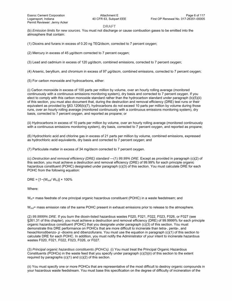
Essroc Cement Corporation Attachment E Page 6 of 117 Logansport, Indiana 40 CFR 63, Subpart EEE First OP Renewal No. 017-26351-00005 Permit Reviewer: Jenny Acker DRAFT (b) Emission limits for new sources. You must not discharge or cause combustion gases to be emitted into the atmosphere that contain:
(1) Dioxins and furans in excess of 0.20 ng TEQ/dscm, corrected to 7 percent oxygen;
(2) Mercury in excess of 45 µg/dscm corrected to 7 percent oxygen;
(3) Lead and cadmium in excess of 120 µg/dscm, combined emissions, corrected to 7 percent oxygen;
(4) Arsenic, beryllium, and chromium in excess of 97 µg/dscm, combined emissions, corrected to 7 percent oxygen;
(5) For carbon monoxide and hydrocarbons, either:
(i) Carbon monoxide in excess of 100 parts per million by volume, over an hourly rolling average (monitored continuously with a continuous emissions monitoring system), dry basis and corrected to 7 percent oxygen. If you elect to comply with this carbon monoxide standard rather than the hydrocarbon standard under paragraph (b)(5)(ii) of this section, you must also document that, during the destruction and removal efficiency (DRE) test runs or their equivalent as provided by §63.1206(b)(7), hydrocarbons do not exceed 10 parts per million by volume during those runs, over an hourly rolling average (monitored continuously with a continuous emissions monitoring system), dry basis, corrected to 7 percent oxygen, and reported as propane; or
(ii) Hydrocarbons in excess of 10 parts per million by volume, over an hourly rolling average (monitored continuously with a continuous emissions monitoring system), dry basis, corrected to 7 percent oxygen, and reported as propane;
(6) Hydrochloric acid and chlorine gas in excess of 21 parts per million by volume, combined emissions, expressed as hydrochloric acid equivalents, dry basis and corrected to 7 percent oxygen; and
(7) Particulate matter in excess of 34 mg/dscm corrected to 7 percent oxygen.
(c) Destruction and removal efficiency (DRE) standard —(1) 99.99% DRE. Except as provided in paragraph (c)(2) of this section, you must achieve a destruction and removal efficiency (DRE) of 99.99% for each principle organic hazardous constituent (POHC) designated under paragraph (c)(3) of this section. You must calculate DRE for each POHC from the following equation:
DRE = [1−(Wout/ Win)] × 100%
Where:
Win= mass feedrate of one principal organic hazardous constituent (POHC) in a waste feedstream; and
Wout= mass emission rate of the same POHC present in exhaust emissions prior to release to the atmosphere.
(2) 99.9999% DRE. If you burn the dioxin-listed hazardous wastes F020, F021, F022, F023, F026, or F027 (see §261.31 of this chapter), you must achieve a destruction and removal efficiency (DRE) of 99.9999% for each principle organic hazardous constituent (POHC) that you designate under paragraph (c)(3) of this section. You must demonstrate this DRE performance on POHCs that are more difficult to incinerate than tetra-, penta-, and hexachlorodibenzo- p -dioxins and dibenzofurans. You must use the equation in paragraph (c)(1) of this section to calculate DRE for each POHC. In addition, you must notify the Administrator of your intent to incinerate hazardous wastes F020, F021, F022, F023, F026, or F027.
(3) Principal organic hazardous constituents (POHCs). (i) You must treat the Principal Organic Hazardous Constituents (POHCs) in the waste feed that you specify under paragraph (c)(3)(ii) of this section to the extent required by paragraphs (c)(1) and (c)(2) of this section.
(ii) You must specify one or more POHCs that are representative of the most difficult to destroy organic compounds in your hazardous waste feedstream. You must base this specification on the degree of difficulty of incineration of the

Essroc Cement Corporation Attachment E Page 7 of 117 Logansport, Indiana 40 CFR 63, Subpart EEE First OP Renewal No. 017-26351-00005 Permit Reviewer: Jenny Acker DRAFT organic constituents in the hazardous waste and on their concentration or mass in the hazardous waste feed, considering the results of hazardous waste analyses or other data and information.
(d) Significant figures. The emission limits provided by paragraphs (a) and (b) of this section are presented with two significant figures. Although you must perform intermediate calculations using at least three significant figures, you may round the resultant emission levels to two significant figures to document compliance.
(e) The provisions of this section no longer apply after any of the following dates, whichever occurs first:
(1) The date that your source begins to comply with §63.1219 by placing a Documentation of Compliance in the operating record pursuant to §63.1211(c);
(2) The date that your source begins to comply with §63.1219 by submitting a Notification of Compliance pursuant to §63.1210(b); or
(3) The date for your source to comply with §63.1219 pursuant to §63.1206 and any extensions granted there under.
[67 FR 6809, Feb. 13, 2002, as amended at 70 FR 59541, Oct. 12, 2005; 73 FR 18979, Apr. 8, 2008]
§ 63.1204 What are the standards for hazardous waste burning cement kilns that are effective until compliance with the standards under §63.1220?
(a) Emission limits for existing sources. You must not discharge or cause combustion gases to be emitted into the atmosphere that contain:
(1) For dioxins and furans:
(i) Emissions in excess of 0.20 ng TEQ/dscm corrected to 7 percent oxygen; or
(ii) Emissions in excess of 0.40 ng TEQ/dscm corrected to 7 percent oxygen provided that the combustion gas temperature at the inlet to the initial dry particulate matter control device is 400 °F or lower based on the average of the test run average temperatures;
(2) Mercury in excess of 120 µg/dscm corrected to 7 percent oxygen;
(3) Lead and cadmium in excess of 330 µg/dscm, combined emissions, corrected to 7 percent oxygen;
(4) Arsenic, beryllium, and chromium in excess of 56 µg/dscm, combined emissions, corrected to 7 percent oxygen;
(5) Carbon monoxide and hydrocarbons. (i) For kilns equipped with a by-pass duct or midkiln gas sampling system, either:
(A) Carbon monoxide in the by-pass duct or mid-kiln gas sampling system in excess of 100 parts per million by volume, over an hourly rolling average (monitored continuously with a continuous emissions monitoring system), dry basis and corrected to 7 percent oxygen. If you elect to comply with this carbon monoxide standard rather than the hydrocarbon standard under paragraph (a)(5)(i)(B) of this section, you must also document that, during the destruction and removal efficiency (DRE) test runs or their equivalent as provided by §63.1206(b)(7), hydrocarbons in the by-pass duct or mid-kiln gas sampling system do not exceed 10 parts per million by volume during those runs, over an hourly rolling average (monitored continuously with a continuous emissions monitoring system), dry basis, corrected to 7 percent oxygen, and reported as propane; or
(B) Hydrocarbons in the by-pass duct or midkiln gas sampling system in excess of 10 parts per million by volume, over an hourly rolling average (monitored continuously with a continuous emissions monitoring system), dry basis, corrected to 7 percent oxygen, and reported as propane;

Essroc Cement Corporation Attachment E Page 8 of 117 Logansport, Indiana 40 CFR 63, Subpart EEE First OP Renewal No. 017-26351-00005 Permit Reviewer: Jenny Acker DRAFT (ii) For kilns not equipped with a by-pass duct or midkiln gas sampling system, either:
(A) Hydrocarbons in the main stack in excess of 20 parts per million by volume, over an hourly rolling average (monitored continuously with a continuous emissions monitoring system), dry basis, corrected to 7 percent oxygen, and reported as propane; or
(B) Carbon monoxide in the main stack in excess of 100 parts per million by volume, over an hourly rolling average (monitored continuously with a continuous emissions monitoring system), dry basis and corrected to 7 percent oxygen. If you elect to comply with this carbon monoxide standard rather than the hydrocarbon standard under paragraph (a)(5)(ii)(A) of this section, you also must document that, during the destruction and removal efficiency (DRE) test runs or their equivalent as provided by §63.1206(b)(7), hydrocarbons in the main stack do not exceed 20 parts per million by volume during those runs, over an hourly rolling average (monitored continuously with a continuous emissions monitoring system), dry basis, corrected to 7 percent oxygen, and reported as propane.
(6) Hydrochloric acid and chlorine gas in excess of 130 parts per million by volume, combined emissions, expressed as hydrochloric acid equivalents, dry basis, corrected to 7 percent oxygen; and
(7) Particulate matter in excess of 0.15 kg/Mg dry feed and opacity greater than 20 percent.
(i) You must use suitable methods to determine the kiln raw material feedrate.
(ii) Except as provided in paragraph (a)(7)(iii) of this section, you must compute the particulate matter emission rate, E, from the following equation:
E=(Cs×Qsd)/P
Where:
E=emission rate of particulate matter, kg/Mg of kiln raw material feed;
Cs=concentration of particulate matter, kg/dscm;
Qsd=volumetric flowrate of effluent gas, dscm/hr; and
P=total kiln raw material feed (dry basis), Mg/hr.
(iii) If you operate a preheater or preheater/precalciner kiln with dual stacks, you must test simultaneously and compute the combined particulate matter emission rate, Ec, from the following equation:
Ec=(Csk×Qsdk+Csb×Qsdb)/P
Where:
Ec=the combined emission rate of particulate matter from the kiln and bypass stack, kg/Mg of kiln raw material feed;
Csk=concentration of particulate matter in the kiln effluent, kg/dscm;
Qsdk=volumetric flowrate of kiln effluent gas, dscm/hr;
Csb=concentration of particulate matter in the bypass stack effluent, kg/dscm;
Qsdb=volumetric flowrate of bypass stack effluent gas, dscm/hr; and
P = total kiln raw material feed (dry basis), Mg/hr.

Essroc Cement Corporation Attachment E Page 9 of 117 Logansport, Indiana 40 CFR 63, Subpart EEE First OP Renewal No. 017-26351-00005 Permit Reviewer: Jenny Acker DRAFT (b) Emission limits for new sources. You must not discharge or cause combustion gases to be emitted into the atmosphere that contain:
(1) For dioxins and furans:
(i) Emissions in excess of 0.20 ng TEQ/dscm corrected to 7 percent oxygen; or
(ii) Emissions in excess of 0.40 ng TEQ/dscm corrected to 7 percent oxygen provided that the combustion gas temperature at the inlet to the initial dry particulate matter control device is 400 °F or lower based on the average of the test run average temperatures;
(2) Mercury in excess of 120 µg/dscm corrected to 7 percent oxygen;
(3) Lead and cadmium in excess of 180 µg/dscm, combined emissions, corrected to 7 percent oxygen;
(4) Arsenic, beryllium, and chromium in excess of 54 µg/dscm, combined emissions, corrected to 7 percent oxygen;
(5) Carbon monoxide and hydrocarbons. (i) For kilns equipped with a by-pass duct or midkiln gas sampling system, carbon monoxide and hydrocarbons emissions are limited in both the bypass duct or midkiln gas sampling system and the main stack as follows:
(A) Emissions in the by-pass or midkiln gas sampling system are limited to either:
( 1 ) Carbon monoxide in excess of 100 parts per million by volume, over an hourly rolling average (monitored continuously with a continuous emissions monitoring system), dry basis and corrected to 7 percent oxygen. If you elect to comply with this carbon monoxide standard rather than the hydrocarbon standard under paragraph (b)(5)(i)(A)( 2 ) of this section, you also must document that, during the destruction and removal efficiency (DRE) test runs or their equivalent as provided by §63.1206(b)(7), hydrocarbons do not exceed 10 parts per million by volume during those runs, over an hourly rolling average (monitored continuously with a continuous emissions monitoring system), dry basis, corrected to 7 percent oxygen, and reported as propane; or
( 2 ) Hydrocarbons in the by-pass duct or midkiln gas sampling system in excess of 10 parts per million by volume, over an hourly rolling average (monitored continuously with a continuous emissions monitoring system), dry basis, corrected to 7 percent oxygen, and reported as propane; and
(B) Hydrocarbons in the main stack are limited, if construction of the kiln commenced after April 19, 1996 at a plant site where a cement kiln (whether burning hazardous waste or not) did not previously exist, to 50 parts per million by volume, over a 30-day block average (monitored continuously with a continuous monitoring system), dry basis, corrected to 7 percent oxygen, and reported as propane.
(ii) For kilns not equipped with a by-pass duct or midkiln gas sampling system, hydrocarbons and carbon monoxide are limited in the main stack to either:
(A) Hydrocarbons not exceeding 20 parts per million by volume, over an hourly rolling average (monitored continuously with a continuous emissions monitoring system), dry basis, corrected to 7 percent oxygen, and reported as propane; or
(B)( 1 ) Carbon monoxide not exceeding 100 parts per million by volume, over an hourly rolling average (monitored continuously with a continuous emissions monitoring system), dry basis, corrected to 7 percent oxygen; and
( 2 ) Hydrocarbons not exceeding 20 parts per million by volume, over an hourly rolling average (monitored continuously with a continuous monitoring system), dry basis, corrected to 7 percent oxygen, and reported as propane at any time during the destruction and removal efficiency (DRE) test runs or their equivalent as provided by §63.1206(b)(7); and
Essroc Cement Corporation Attachment E Page 10 of 117 Logansport, Indiana 40 CFR 63, Subpart EEE First OP Renewal No. 017-26351-00005 Permit Reviewer: Jenny Acker DRAFT ( 3 ) If construction of the kiln commenced after April 19, 1996 at a plant site where a cement kiln (whether burning hazardous waste or not) did not previously exist, hydrocarbons are limited to 50 parts per million by volume, over a 30-day block average (monitored continuously with a continuous monitoring system), dry basis, corrected to 7 percent oxygen, and reported as propane.
(6) Hydrochloric acid and chlorine gas in excess of 86 parts per million, combined emissions, expressed as hydrochloric acid equivalents, dry basis and corrected to 7 percent oxygen; and
(7) Particulate matter in excess of 0.15 kg/Mg dry feed and opacity greater than 20 percent.
(i) You must use suitable methods to determine the kiln raw material feedrate.
(ii) Except as provided in paragraph (a)(7)(iii) of this section, you must compute the particulate matter emission rate, E, from the equation specified in paragraph (a)(7)(ii) of this section.
(iii) If you operate a preheater or preheater/precalciner kiln with dual stacks, you must test simultaneously and compute the combined particulate matter emission rate, Ec, from the equation specified in paragraph (a)(7)(iii) of this section.
(c) Destruction and removal efficiency (DRE) standard —(1) 99.99% DRE. Except as provided in paragraph (c)(2) of this section, you must achieve a destruction and removal efficiency (DRE) of 99.99% for each principle organic hazardous constituent (POHC) designated under paragraph (c)(3) of this section. You must calculate DRE for each POHC from the following equation:
DRE=[1−(Wout/Win)]×100%
Where:
Win=mass feedrate of one principal organic hazardous constituent (POHC) in a waste feedstream; and
Wout=mass emission rate of the same POHC present in exhaust emissions prior to release to the atmosphere.
(2) 99.9999% DRE. If you burn the dioxin-listed hazardous wastes F020, F021, F022, F023, F026, or F027 (see §261.31 of this chapter), you must achieve a destruction and removal efficiency (DRE) of 99.9999% for each principle organic hazardous constituent (POHC) that you designate under paragraph (c)(3) of this section. You must demonstrate this DRE performance on POHCs that are more difficult to incinerate than tetra-, penta-, and hexachlorodibenzo- p -dioxins and dibenzofurans. You must use the equation in paragraph (c)(1) of this section to calculate DRE for each POHC. In addition, you must notify the Administrator of your intent to incinerate hazardous wastes F020, F021, F022, F023, F026, or F027.
(3) Principal organic hazardous constituents (POHCs). (i) You must treat the Principal Organic Hazardous Constituents (POHCs) in the waste feed that you specify under paragraph (c)(3)(ii) of this section to the extent required by paragraphs (c)(1) and (c)(2) of this section.
(ii) You must specify one or more POHCs that are representative of the most difficult to destroy organic compounds in your hazardous waste feedstream. You must base this specification on the degree of difficulty of incineration of the organic constituents in the hazardous waste and on their concentration or mass in the hazardous waste feed, considering the results of hazardous waste analyses or other data and information.
(d) Cement kilns with in-line kiln raw mills —(1) General. (i) You must conduct performance testing when the raw mill is on-line and when the mill is off-line to demonstrate compliance with the emission standards, and you must establish separate operating parameter limits under §63.1209 for each mode of operation, except as provided by paragraph (d)(1)(iv) of this section.
(ii) You must document in the operating record each time you change from one mode of operation to the alternate mode and begin complying with the operating parameter limits for that alternate mode of operation.

Essroc Cement Corporation Attachment E Page 11 of 117 Logansport, Indiana 40 CFR 63, Subpart EEE First OP Renewal No. 017-26351-00005 Permit Reviewer: Jenny Acker DRAFT (iii) You must calculate rolling averages for operating parameter limits as provided by §63.1209(q)(2).
(iv) If your in-line kiln raw mill has dual stacks, you may assume that the dioxin/furan emission levels in the by-pass stack and the operating parameter limits determined during performance testing of the by-pass stack when the raw mill is off-line are the same as when the mill is on-line.
(2) Emissions averaging. You may comply with the mercury, semivolatile metal, low volatile metal, and hydrochloric acid/chlorine gas emission standards on a time-weighted average basis under the following procedures:
(i) Averaging methodology. You must calculate the time-weighted average emission concentration with the following equation:
Ctotal={Cmill-off×(Tmill-off/(Tmill-off+Tmill-on))}+{Cmill-on×(Tmill-on/(Tmill-off+Tmill-on))}
Where:
Ctotal=time-weighted average concentration of a regulated constituent considering both raw mill on time and off time;
Cmill-off=average performance test concentration of regulated constituent with the raw mill off-line;
Cmill-on=average performance test concentration of regulated constituent with the raw mill on-line;
Tmill-off=time when kiln gases are not routed through the raw mill; and
Tmill-on=time when kiln gases are routed through the raw mill.
(ii) Compliance. (A) If you use this emission averaging provision, you must document in the operating record compliance with the emission standards on an annual basis by using the equation provided by paragraph (d)(2) of this section.
(B) Compliance is based on one-year block averages beginning on the day you submit the initial notification of compliance.
(iii) Notification. (A) If you elect to document compliance with one or more emission standards using this emission averaging provision, you must notify the Administrator in the initial comprehensive performance test plan submitted under §63.1207(e).
(B) You must include historical raw mill operation data in the performance test plan to estimate future raw mill down-time and document in the performance test plan that estimated emissions and estimated raw mill down-time will not result in an exceedance of an emission standard on an annual basis.
(C) You must document in the notification of compliance submitted under §63.1207(j) that an emission standard will not be exceeded based on the documented emissions from the performance test and predicted raw mill down-time.
(e) Preheater or preheater/precalciner kilns with dual stacks —(1) General. You must conduct performance testing on each stack to demonstrate compliance with the emission standards, and you must establish operating parameter limits under §63.1209 for each stack, except as provided by paragraph (d)(1)(iv) of this section for dioxin/furan emissions testing and operating parameter limits for the by-pass stack of in-line raw mills.
(2) Emissions averaging. You may comply with the mercury, semivolatile metal, low volatile metal, and hydrochloric acid/chlorine gas emission standards specified in this section on a gas flowrate-weighted average basis under the following procedures:
(i) Averaging methodology. You must calculate the gas flowrate-weighted average emission concentration using the following equation:

Essroc Cement Corporation Attachment E Page 12 of 117 Logansport, Indiana 40 CFR 63, Subpart EEE First OP Renewal No. 017-26351-00005 Permit Reviewer: Jenny Acker DRAFT Ctot= {Cmain× (Qmain/(Qmain+ Qbypass))} + {Cbypass×(Qbypass/ (Qmain+ Qbypass))}
Where:
Ctot= gas flowrate-weighted average concentration of the regulated constituent;
Cmain= average performance test concentration demonstrated in the main stack;
Cbypass= average performance test concentration demonstrated in the bypass stack;
Qmain= volumetric flowrate of main stack effluent gas; and
Qbypass= volumetric flowrate of bypass effluent gas.
(ii) Compliance. (A) You must demonstrate compliance with the emission standard(s) using the emission concentrations determined from the performance tests and the equation provided by paragraph (e)(1) of this section; and
(B) You must develop operating parameter limits for bypass stack and main stack flowrates that ensure the emission concentrations calculated with the equation in paragraph (e)(1) of this section do not exceed the emission standards on a 12-hour rolling average basis. You must include these flowrate limits in the Notification of Compliance.
(iii) Notification. If you elect to document compliance under this emissions averaging provision, you must:
(A) Notify the Administrator in the initial comprehensive performance test plan submitted under §63.1207(e). The performance test plan must include, at a minimum, information describing the flowrate limits established under paragraph (e)(2)(ii)(B) of this section; and
(B) Document in the Notification of Compliance submitted under §63.1207(j) the demonstrated gas flowrate-weighted average emissions that you calculate with the equation provided by paragraph (e)(2) of this section.
(f) Significant figures. The emission limits provided by paragraphs (a) and (b) of this section are presented with two significant figures. Although you must perform intermediate calculations using at least three significant figures, you may round the resultant emission levels to two significant figures to document compliance.
(g) [Reserved]
(h) When you comply with the particulate matter requirements of paragraphs (a)(7) or (b)(7) of this section, you are exempt from the New Source Performance Standard for particulate matter and opacity under §60.60 of this chapter.
(i) The provisions of this section no longer apply after any of the following dates, whichever occurs first:
(1) The date that your source begins to comply with §63.1220 by placing a Documentation of Compliance in the operating record pursuant to §63.1211(c);
(2) The date that your source begins to comply with §63.1220 by submitting a Notification of Compliance pursuant to §63.1210(b); or
(3) The date for your source to comply with §63.1220 pursuant to §63.1206 and any extensions granted there under.
[67 FR 6809, Feb. 13, 2002, as amended at 67 FR 6987, Feb. 14, 2002; 70 FR 59541, Oct. 12, 2005; 73 FR 18979, Apr. 8, 2008]

Essroc Cement Corporation Attachment E Page 13 of 117 Logansport, Indiana 40 CFR 63, Subpart EEE First OP Renewal No. 017-26351-00005 Permit Reviewer: Jenny Acker DRAFT § 63.1205 What are the standards for hazardous waste burning lightweight aggregate kilns that are effective until compliance with the standards under §63.1221?
(a) Emission limits for existing sources. You must not discharge or cause combustion gases to be emitted into the atmosphere that contain:
(1) For dioxins and furans:
(i) Emissions in excess of 0.20 ng TEQ/dscm corrected to 7 percent oxygen; or
(ii) Rapid quench of the combustion gas temperature at the exit of the (last) combustion chamber (or exit of any waste heat recovery system) to 400 °F or lower based on the average of the test run average temperatures. You must also notify in writing the RCRA authority that you are complying with this option;
(2) Mercury in excess of 120 µg/dscm corrected to 7 percent oxygen;
(3) Lead and cadmium in excess of 250 µg/dscm, combined emissions, corrected to 7 percent oxygen;
(4) Arsenic, beryllium, and chromium in excess of 110 µg/dscm, combined emissions, corrected to 7 percent oxygen;
(5) Carbon monoxide and hydrocarbons. (i) Carbon monoxide in excess of 100 parts per million by volume, over an hourly rolling average (monitored continuously with a continuous emissions monitoring system), dry basis and corrected to 7 percent oxygen. If you elect to comply with this carbon monoxide standard rather than the hydrocarbon standard under paragraph (a)(5)(ii) of this section, you also must document that, during the destruction and removal efficiency (DRE) test runs or their equivalent as provided by §63.1206(b)(7), hydrocarbons do not exceed 20 parts per million by volume during those runs, over an hourly rolling average (monitored continuously with a continuous emissions monitoring system), dry basis, corrected to 7 percent oxygen, and reported as propane; or
(ii) Hydrocarbons in excess of 20 parts per million by volume, over an hourly rolling average, dry basis, corrected to 7 percent oxygen, and reported as propane;
(6) Hydrochloric acid and chlorine gas in excess of 600 parts per million by volume, combined emissions, expressed as hydrochloric acid equivalents, dry basis and corrected to 7 percent oxygen; and
(7) Particulate matter in excess of 57 mg/dscm corrected to 7 percent oxygen.
(b) Emission limits for new sources. You must not discharge or cause combustion gases to be emitted into the atmosphere that contain:
(1) For dioxins and furans:
(i) Emissions in excess of 0.20 ng TEQ/dscm corrected to 7 percent oxygen; or
(ii) Rapid quench of the combustion gas temperature at the exit of the (last) combustion chamber (or exit of any waste heat recovery system) to 400 °F or lower based on the average of the test run average temperatures. You must also notify in writing the RCRA authority that you are complying with this option;
(2) Mercury in excess of 120 µg/dscm corrected to 7 percent oxygen;
(3) Lead and cadmium in excess of 43 µg/dscm, combined emissions, corrected to 7 percent oxygen;
(4) Arsenic, beryllium, and chromium in excess of 110 µg/dscm, combined emissions, corrected to 7 percent oxygen;
(5) Carbon monoxide and hydrocarbons. (i) Carbon monoxide in excess of 100 parts per million by volume, over an hourly rolling average (monitored continuously with a continuous emissions monitoring system), dry basis and
Essroc Cement Corporation Attachment E Page 14 of 117 Logansport, Indiana 40 CFR 63, Subpart EEE First OP Renewal No. 017-26351-00005 Permit Reviewer: Jenny Acker DRAFT corrected to 7 percent oxygen. If you elect to comply with this carbon monoxide standard rather than the hydrocarbon standard under paragraph (b)(5)(ii) of this section, you also must document that, during the destruction and removal efficiency (DRE) test runs or their equivalent as provided by §63.1206(b)(7), hydrocarbons do not exceed 20 parts per million by volume during those runs, over an hourly rolling average (monitored continuously with a continuous emissions monitoring system), dry basis, corrected to 7 percent oxygen, and reported as propane; or
(ii) Hydrocarbons in excess of 20 parts per million by volume, over an hourly rolling average, dry basis, corrected to 7 percent oxygen, and reported as propane;
(6) Hydrochloric acid and chlorine gas in excess of 600 parts per million by volume, combined emissions, expressed as hydrochloric acid equivalents, dry basis and corrected to 7 percent oxygen; and
(7) Particulate matter in excess of 57 mg/dscm corrected to 7 percent oxygen.
(c) Destruction and removal efficiency (DRE) standard —(1) 99.99% DRE. Except as provided in paragraph (c)(2) of this section, you must achieve a destruction and removal efficiency (DRE) of 99.99% for each principal organic hazardous constituent (POHC) designated under paragraph (c)(3) of this section. You must calculate DRE for each POHC from the following equation:
DRE = [1—(Wout/ Win)] × 100%
Where:
Win= mass feedrate of one principal organic hazardous constituent (POHC) in a waste feedstream; and
Wout= mass emission rate of the same POHC present in exhaust emissions prior to release to the atmosphere.
(2) 99.9999% DRE. If you burn the dioxin-listed hazardous wastes F020, F021, F022, F023, F026, or F027 (see §261.31 of this chapter), you must achieve a destruction and removal efficiency (DRE) of 99.9999% for each principal organic hazardous constituent (POHC) that you designate under paragraph (c)(3) of this section. You must demonstrate this DRE performance on POHCs that are more difficult to incinerate than tetra-, penta-, and hexachlorodibenzo-dioxins and dibenzofurans. You must use the equation in paragraph (c)(1) of this section to calculate DRE for each POHC. In addition, you must notify the Administrator of your intent to burn hazardous wastes F020, F021, F022, F023, F026, or F027.
(3) Principal organic hazardous constituents (POHCs). (i) You must treat the Principal Organic Hazardous Constituents (POHCs) in the waste feed that you specify under paragraph (c)(3)(ii) of this section to the extent required by paragraphs (c)(1) and (c)(2) of this section.
(ii) You must specify one or more POHCs that are representative of the most difficult to destroy organic compounds in your hazardous waste feedstream. You must base this specification on the degree of difficulty of incineration of the organic constituents in the hazardous waste and on their concentration or mass in the hazardous waste feed, considering the results of hazardous waste analyses or other data and information.
(d) Significant figures. The emission limits provided by paragraphs (a) and (b) of this section are presented with two significant figures. Although you must perform intermediate calculations using at least three significant figures, you may round the resultant emission levels to two significant figures to document compliance.
(e) The provisions of this section no longer apply after any of the following dates, whichever occurs first:
(1) The date that your source begins to comply with §63.1221 by placing a Documentation of Compliance in the operating record pursuant to §63.1211(c);
(2) The date that your source begins to comply with §63.1221 by submitting a Notification of Compliance pursuant to §63.1210(b); or
Essroc Cement Corporation Attachment E Page 15 of 117 Logansport, Indiana 40 CFR 63, Subpart EEE First OP Renewal No. 017-26351-00005 Permit Reviewer: Jenny Acker DRAFT (3) The date for your source to comply with §63.1221 pursuant to §63.1206 and any extensions granted there under.
[67 FR 6812, Feb. 13, 2002, as amended at 67 FR 77691, Dec. 19, 2002; 70 FR 59541, Oct. 12, 2005; 73 FR 18979, Apr. 8, 2008]
Monitoring and Compliance Provisions
§ 63.1206 When and how must you comply with the standards and operating requirements?
(a) Compliance dates —(1) Compliance dates for incinerators, cement kilns, and lightweight aggregate kilns that burn hazardous waste —(i) Compliance date for standards under §§63.1203, 63.1204, and 63.1205 —(A) Compliance dates for existing sources. You must comply with the emission standards under §§63.1203, 63.1204, and 63.1205 and the other requirements of this subpart no later than the compliance date, September 30, 2003, unless the Administrator grants you an extension of time under §63.6(i) or §63.1213, except:
( 1 ) Cement kilns are exempt from the bag leak detection system requirements under paragraph (c)(8) of this section;
( 2 ) The bag leak detection system required under §63.1206(c)(8) must be capable of continuously detecting and recording particulate matter emissions at concentrations of 1.0 milligram per actual cubic meter unless you demonstrate under §63.1209(g)(1) that a higher detection limit would adequately detect bag leaks, in lieu of the requirement for the higher detection limit under paragraph (c)(8)(ii)(A) of this section; and
( 3 ) The excessive exceedances notification requirements for bag leak detection systems under paragraph (c)(8)(iv) of this section are waived.
(B) New or reconstructed sources. ( 1 ) If you commenced construction or reconstruction of your hazardous waste combustor after April 19, 1996, you must comply with the emission standards under §§63.1203, 63.1204, and 63.1205 and the other requirements of this subpart by the later of September 30, 1999 or the date the source starts operations, except as provided by paragraphs (a)(1)(i)(A)( 1 ) through ( 3 ) and (a)(1)(i)(B)( 2 ) of this section. The costs of retrofitting and replacement of equipment that is installed specifically to comply with this subpart, between April 19, 1996 and a source's compliance date, are not considered to be reconstruction costs.
( 2 ) For a standard under §§63.1203, 63.1204, and 63.1205 that is more stringent than the standard proposed on April 19, 1996, you may achieve compliance no later than September 30, 2003 if you comply with the standard proposed on April 19, 1996 after September 30, 1999. This exception does not apply, however, to new or reconstructed area source hazardous waste combustors that become major sources after September 30, 1999. As provided by §63.6(b)(7), such sources must comply with the standards under §§63.1203, 63.1204, and 63.1205 at startup.
(ii) Compliance date for standards under §§63.1219, 63.1220, and 63.1221. (A) Compliance dates for existing sources. You must comply with the emission standards under §§63.1219, 63.1220, and 63.1221 and the other requirements of this subpart no later than the compliance date, October 14, 2008, unless the Administrator grants you an extension of time under §63.6(i) or §63.1213.
(B) New or reconstructed sources. ( 1 ) If you commenced construction or reconstruction of your hazardous waste combustor after April 20, 2004, you must comply with the new source emission standards under §§63.1219, 63.1220, and 63.1221 and the other requirements of this subpart by the later of October 12, 2005 or the date the source starts operations, except as provided by paragraphs (a)(1)(ii)(B)( 2 ) and (a)(1)(ii)(B)( 3 ) of this section. The costs of retrofitting and replacement of equipment that is installed specifically to comply with this subpart, between April 20, 2004, and a source's compliance date, are not considered to be reconstruction costs.
( 2 ) For a standard under §§63.1219, 63.1220, and 63.1221 that is more stringent than the standard proposed on April 20, 2004, you may achieve compliance no later than October 14, 2008, if you comply with the standard proposed on April 20, 2004, after October 12, 2005. This exception does not apply, however, to new or reconstructed area source hazardous waste combustors that become major sources after October 14, 2008. As provided by §63.6(b)(7), such sources must comply with the standards under §§63.1219, 63.1220, and 63.1221 at startup.

Essroc Cement Corporation Attachment E Page 16 of 117 Logansport, Indiana 40 CFR 63, Subpart EEE First OP Renewal No. 017-26351-00005 Permit Reviewer: Jenny Acker DRAFT ( 3 ) Temporary particulate matter standard under §63.1220 for new cement kilns. You are not required to comply with the particulate matter standard specified under §63.1220(b)(7)(i) until EPA takes final action with regard to the particulate matter standard pursuant to reconsideration proceedings. If you start up a new or reconstructed hazardous waste burning cement kiln as defined by this subpart, you must not emit particulate matter in excess of 0.15 kg/Mg dry feed, as determined according to the requirements under §63.1204(b)(7)(i) through (iii).
(2) Compliance date for solid fuel boilers, liquid fuel boilers, and hydrochloric acid production furnaces that burn hazardous waste for standards under §§63.1216, 63.1217, and 63.1218 . (i) Compliance date for existing sources. You must comply with the standards of this subpart no later than the compliance date, October 14, 2008, unless the Administrator grants you an extension of time under §63.6(i) or §63.1213.
(ii) New or reconstructed sources . (A) If you commenced construction or reconstruction of your hazardous waste combustor after April 20, 2004, you must comply with the new source emission standards of this subpart by the later of October 12, 2005, or the date the source starts operations, except as provided by paragraph (a)(2)(ii)(B) of this section. The costs of retrofitting and replacement of equipment that is installed specifically to comply with this subpart, between April 20, 2004, and a source's compliance date, are not considered to be reconstruction costs.
(B) For a standard in the subpart that is more stringent than the standard proposed on April 20, 2004, you may achieve compliance no later than October 14, 2008, if you comply with the standard proposed on April 20, 2004, after October 12, 2005. This exception does not apply, however, to new or reconstructed area source hazardous waste combustors that become major sources after October 14, 2008. As provided by §63.6(b)(7), such sources must comply with this subpart at startup.
(3) Early compliance. If you choose to comply with the emission standards of this subpart prior to the dates specified in paragraphs (a)(1) and (a)(2) of this section, your compliance date is the earlier of the date you postmark the Notification of Compliance under §63.1207(j)(1) or the dates specified in paragraphs (a)(1) and (a)(2) of this section.
(b) Compliance with standards —(1) Applicability. The emission standards and operating requirements set forth in this subpart apply at all times except:
(i) During periods of startup, shutdown, and malfunction; and
(ii) When hazardous waste is not in the combustion chamber (i.e., the hazardous waste feed to the combustor has been cut off for a period of time not less than the hazardous waste residence time) and you have documented in the operating record that you are complying with all otherwise applicable requirements and standards promulgated under authority of sections 112 (e.g., 40 CFR part 63, subparts LLL, DDDDD, and NNNNN) or 129 of the Clean Air Act in lieu of the emission standards under §§63.1203, 63.1204, 63.1205, 63.1215, 63.1216, 63.1217, 63.1218, 63.1219, 63.1220, and 63.1221; the monitoring and compliance standards of this section and §§63.1207 through 63.1209, except the modes of operation requirements of §63.1209(q); and the notification, reporting, and recordkeeping requirements of §§63.1210 through 63.1212.
(2) Methods for determining compliance. The Administrator will determine compliance with the emission standards of this subpart as provided by §63.6(f)(2). Conducting performance testing under operating conditions representative of the extreme range of normal conditions is consistent with the requirements of §§63.6(f)(2)(iii)(B) and 63.7(e)(1) to conduct performance testing under representative operating conditions.
(3) Finding of compliance. The Administrator will make a finding concerning compliance with the emission standards and other requirements of this subpart as provided by §63.6(f)(3).
(4) Extension of compliance with emission standards. The Administrator may grant an extension of compliance with the emission standards of this subpart as provided by §§63.6(i) and 63.1213.
(5) Changes in design, operation, or maintenance —(i) Changes that may adversely affect compliance. If you plan to change (as defined in paragraph (b)(5)(iii) of this section) the design, operation, or maintenance practices of the source in a manner that may adversely affect compliance with any emission standard that is not monitored with a CEMS:

Essroc Cement Corporation Attachment E Page 17 of 117 Logansport, Indiana 40 CFR 63, Subpart EEE First OP Renewal No. 017-26351-00005 Permit Reviewer: Jenny Acker DRAFT (A) Notification. You must notify the Administrator at least 60 days prior to the change, unless you document circumstances that dictate that such prior notice is not reasonably feasible. The notification must include:
( 1 ) A description of the changes and which emission standards may be affected; and
( 2 ) A comprehensive performance test schedule and test plan under the requirements of §63.1207(f) that will document compliance with the affected emission standard(s);
(B) Performance test. You must conduct a comprehensive performance test under the requirements of §§63.1207(f)(1) and (g)(1) to document compliance with the affected emission standard(s) and establish operating parameter limits as required under §63.1209, and submit to the Administrator a Notification of Compliance under §§63.1207(j) and 63.1210(d); and
(C) Restriction on waste burning. ( 1 ) Except as provided by paragraph (b)(5)(i)(C)( 2 ) of this section, after the change and prior to submitting the notification of compliance, you must not burn hazardous waste for more than a total of 720 hours (renewable at the discretion of the Administrator) and only for the purposes of pretesting or comprehensive performance testing. Pretesting is defined at §63.1207(h)(2)(i) and (ii).
( 2 ) You may petition the Administrator to obtain written approval to burn hazardous waste in the interim prior to submitting a Notification of Compliance for purposes other than testing or pretesting. You must specify operating requirements, including limits on operating parameters, that you determine will ensure compliance with the emission standards of this subpart based on available information. The Administrator will review, modify as necessary, and approve if warranted the interim operating requirements.
(ii) Changes that will not affect compliance. If you determine that a change will not adversely affect compliance with the emission standards or operating requirements, you must document the change in the operating record upon making such change. You must revise as necessary the performance test plan, Documentation of Compliance, Notification of Compliance, and start-up, shutdown, and malfunction plan to reflect these changes.
(iii) Definition of “change.” For purposes of paragraph (b)(5) of this section, “change” means any change in design, operation, or maintenance practices that were documented in the comprehensive performance test plan, Notification of Compliance, or startup, shutdown, and malfunction plan.
(6) Compliance with the carbon monoxide and hydrocarbon emission standards. This paragraph applies to sources that elect to comply with the carbon monoxide and hydrocarbon emissions standards of this subpart by documenting continuous compliance with the carbon monoxide standard using a continuous emissions monitoring system and documenting compliance with the hydrocarbon standard during the destruction and removal efficiency (DRE) performance test or its equivalent.
(i) If a DRE test performed pursuant to §63.1207(c)(2) is acceptable as documentation of compliance with the DRE standard, you may use the highest hourly rolling average hydrocarbon level achieved during the DRE test runs to document compliance with the hydrocarbon standard. An acceptable DRE test is any test for which the data and results are determined to meet quality assurance objectives (on a site-specific basis) such that the results adequately demonstrate compliance with the DRE standard.
(ii) If during this acceptable DRE test you did not obtain hydrocarbon emissions data sufficient to document compliance with the hydrocarbon standard, you must either:
(A) Perform, as part of the performance test, an “equivalent DRE test” to document compliance with the hydrocarbon standard. An equivalent DRE test is comprised of a minimum of three runs each with a minimum duration of one hour during which you operate the combustor as close as reasonably possible to the operating parameter limits that you established based on the initial DRE test. You must use the highest hourly rolling average hydrocarbon emission level achieved during the equivalent DRE test to document compliance with the hydrocarbon standard; or
(B) Perform a DRE test as part of the performance test.
(7) Compliance with the DRE standard. (i) Except as provided in paragraphs (b)(7)(ii) and (b)(7)(iii) of this section:

Essroc Cement Corporation Attachment E Page 18 of 117 Logansport, Indiana 40 CFR 63, Subpart EEE First OP Renewal No. 017-26351-00005 Permit Reviewer: Jenny Acker DRAFT (A) You must document compliance with the Destruction and Removal Efficiency (DRE) standard under this subpart only once provided that you do not modify the source after the DRE test in a manner that could affect the ability of the source to achieve the DRE standard.
(B) You may use any DRE test data that documents that your source achieves the required level of DRE provided:
( 1 ) You have not modified the design or operation of your source in a manner that could effect the ability of your source to achieve the DRE standard since the DRE test was performed; and,
( 2 ) The DRE test data meet quality assurance objectives determined on a site-specific basis.
(ii) Sources that feed hazardous waste at locations other than the normal flame zone. (A) Except as provided by paragraph (b)(7)(ii)(B) of this section, if you feed hazardous waste at a location in the combustion system other than the normal flame zone, then you must demonstrate compliance with the DRE standard during each comprehensive performance test;
(B)( 1 ) A cement kiln that feeds hazardous waste at a location other than the normal flame zone need only demonstrate compliance with the DRE standard during three consecutive comprehensive performance tests provided that:
( i ) All three tests achieve the DRE standard in this subpart; and
( ii ) The design, operation, and maintenance features of each of the three tests are similar;
( iii ) The data in lieu restriction of §63.1207(c)(2)(iv) does not apply when complying with the provisions of paragraph (b)(7)(ii)(B) of this section;
( 2 ) If at any time you change your design, operation, and maintenance features in a manner that could reasonably be expected to affect your ability to meet the DRE standard, then you must comply with the requirements of paragraph (b)(7)(ii)(A) of this section.
(iii) For sources that do not use DRE previous testing to document conformance with the DRE standard pursuant to §63.1207(c)(2), you must perform DRE testing during the initial comprehensive performance test.
(8) Applicability of particulate matter and opacity standards during particulate matter CEMS correlation tests. (i) Any particulate matter and opacity standards of parts 60, 61, 63, 264, 265, and 266 of this chapter ( i.e., any title 40 particulate or opacity standards) applicable to a hazardous waste combustor do not apply while you conduct particulate matter continuous emissions monitoring system (CEMS) correlation tests ( i.e., correlation with manual stack methods) under the conditions of paragraphs (b)(8)(iii) through (vii) of this section.
(ii) Any permit or other emissions or operating parameter limits or conditions, including any limitation on workplace practices, that are applicable to hazardous waste combustors to ensure compliance with any particulate matter and opacity standards of parts 60, 61, 63, 264, 265, and 266 of this chapter ( i.e., any title 40 particulate or opacity standards) do not apply while you conduct particulate matter CEMS correlation tests under the conditions of paragraphs (b)(8)(iii) through (vii) of this section.
(iii) For the provisions of this section to apply, you must:
(A) Develop a particulate matter CEMS correlation test plan that includes the following information. This test plan may be included as part of the comprehensive performance test plan required under §§63.1207(e) and (f):
( 1 ) Number of test conditions and number of runs for each test condition;
( 2 ) Target particulate matter emission level for each test condition;
( 3 ) How you plan to modify operations to attain the desired particulate matter emission levels; and

Essroc Cement Corporation Attachment E Page 19 of 117 Logansport, Indiana 40 CFR 63, Subpart EEE First OP Renewal No. 017-26351-00005 Permit Reviewer: Jenny Acker DRAFT ( 4 ) Anticipated normal particulate matter emission levels; and
(B) Submit the test plan to the Administrator for approval at least 90 calendar days before the correlation test is scheduled to be conducted.
(iv) The Administrator will review and approve/disapprove the correlation test plan under the procedures for review and approval of the site-specific test plan provided by §63.7(c)(3)(i) and (iii). If the Administrator fails to approve or disapprove the correlation test plan within the time period specified by §63.7(c)(3)(i), the plan is considered approved, unless the Administrator has requested additional information.
(v) The particulate matter and opacity standards and associated operating limits and conditions will not be waived for more than 96 hours, in the aggregate, for a correlation test, including all runs of all test conditions, unless more time is approved by the Administrator.
(vi) The stack sampling team must be on-site and prepared to perform correlation testing no later than 24 hours after you modify operations to attain the desired particulate matter emissions concentrations, unless you document in the correlation test plan that a longer period of conditioning is appropriate.
(vii) You must return to operating conditions indicative of compliance with the applicable particulate matter and opacity standards as soon as possible after correlation testing is completed.
(9) Alternative standards for existing or new hazardous waste burning lightweight aggregate kilns using MACT. (i) You may petition the Administrator to request alternative standards to the mercury or hydrogen chloride/chlorine gas emission standards of this subpart, to the semivolatile metals emission standards under §§63.1205, 63.1221(a)(3)(ii), or 63.1221(b)(3)(ii), or to the low volatile metals emissions standards under §§63.1205, 63.1221(a)(4)(ii), or 63.1221(b)(4)(ii) if:
(A) You cannot achieve one or more of these standards while using maximum achievable control technology (MACT) because of raw material contributions to emissions of mercury, semivolatile metals, low volatile metals, or hydrogen chloride/chlorine gas; or
(B) You determine that mercury is not present at detectable levels in your raw material.
(ii) The alternative standard that you recommend under paragraph (b)(9)(i)(A) of this section may be an operating requirement, such as a hazardous waste feedrate limitation for metals and/or chlorine, and/or an emission limitation.
(iii) The alternative standard must include a requirement to use MACT, or better, applicable to the standard for which the source is seeking relief, as defined in paragraphs (b)(9)(viii) and (ix) of this section.
(iv) Documentation required. (A) The alternative standard petition you submit under paragraph (b)(9)(i)(A) of this section must include data or information documenting that raw material contributions to emissions prevent you from complying with the emission standard even though the source is using MACT, as defined under paragraphs (b)(9)(viii) and (ix) of this section, for the standard for which you are seeking relief.
(B) Alternative standard petitions that you submit under paragraph (b)(9)(i)(B) of this section must include data or information documenting that mercury is not present at detectable levels in raw materials.
(v) You must include data or information with semivolatile metal and low volatility metal alternative standard petitions that you submit under paragraph (b)(9)(i)(A) of this section documenting that increased chlorine feedrates associated with the burning of hazardous waste, when compared to non-hazardous waste operations, do not significantly increase metal emissions attributable to raw materials.
(vi) You must include data or information with semivolatile metals, low volatile metals, and hydrogen chloride/chlorine gas alternative standard petitions that you submit under paragraph (b)(9)(i)(A) of this section documenting that semivolatile metals, low volatile metals, and hydrogen chloride/chlorine gas emissions attributable to the hazardous waste only will not exceed the emission standards of this subpart.
Essroc Cement Corporation Attachment E Page 20 of 117 Logansport, Indiana 40 CFR 63, Subpart EEE First OP Renewal No. 017-26351-00005 Permit Reviewer: Jenny Acker DRAFT (vii) You must not operate pursuant to your recommended alternative standards in lieu of emission standards specified in this subpart:
(A) Unless the Administrator approves the provisions of the alternative standard petition request or establishes other alternative standards; and
(B) Until you submit a revised Notification of Compliance that incorporates the revised standards.
(viii) For purposes of this alternative standard provision, MACT for existing hazardous waste burning lightweight aggregate kilns is defined as:
(A) For mercury, a hazardous waste feedrate corresponding to an MTEC of 24 µg/dscm or less;
(B) For semivolatile metals, a hazardous waste feedrate corresponding to an MTEC of 280,000 µg/dscm or less, and use of a particulate matter control device that achieves particulate matter emissions of 57 mg/dscm or less;
(C) For low volatile metals, a hazardous waste feedrate corresponding to an MTEC of 120,000 µg/dscm or less, and use of a particulate matter control device that achieves particulate matter emissions of 57 mg/dscm or less; and
(D) For hydrogen chloride/chlorine gas, a hazardous waste chlorine feedrate corresponding to an MTEC of 2,000,000 µgm/dscm or less, and use of an air pollution control device with a hydrogen chloride/chlorine gas removal efficiency of 85 percent or greater.
(ix) For purposes of this alternative standard provision, MACT for new hazardous waste burning lightweight aggregate kilns is defined as:
(A) For mercury, a hazardous waste feedrate corresponding to an MTEC of 4 µg/dscm or less;
(B) For semivolatile metals, a hazardous waste feedrate corresponding to an MTEC of 280,000 µg/dscm or less, and use of a particulate matter control device that achieves particulate matter emissions of 57 mg/dscm or less;
(C) For low volatile metals, a hazardous waste feedrate corresponding to an MTEC of 46,000 µg/dscm or less, and use of a particulate matter control device that achieves particulate matter emissions of 57 mg/dscm or less;
(D) For hydrogen chloride/chlorine gas, a hazardous waste chlorine feedrate corresponding to an MTEC of 14,000,000 µgm/dscm or less, and use of an air pollution control device with a hydrogen chloride/chlorine gas removal efficiency of 99.6 percent or greater.
(10) Alternative standards for existing or new hazardous waste burning cement kilns using MACT. (i) You may petition the Administrator to request alternative standards to the mercury or hydrogen chloride/chlorine gas emission standards of this subpart, to the semivolatile metals emission standards under §§63.1204, 63.1220(a)(3)(ii), or 63.1220(b)(3)(ii), or to the low volatile metals emissions standards under §§63.1204, 63.1220(a)(4)(ii), or 63.1220(b)(4)(ii) if:
(A) You cannot achieve one or more of these standards while using maximum achievable control technology (MACT) because of raw material contributions to emissions of mercury, semivolatile metals, low volatile metals, or hydrogen chloride/chlorine gas; or
(B) You determine that mercury is not present at detectable levels in your raw material.
(ii) The alternative standard that you recommend under paragraph (b)(10)(i)(A) of this section may be an operating requirement, such as a hazardous waste feedrate limitation for metals and/or chlorine, and/or an emission limitation.
(iii) The alternative standard must include a requirement to use MACT, or better, applicable to the standard for which the source is seeking relief, as defined in paragraphs (b)(10)(viii) and (ix) of this section.

Essroc Cement Corporation Attachment E Page 21 of 117 Logansport, Indiana 40 CFR 63, Subpart EEE First OP Renewal No. 017-26351-00005 Permit Reviewer: Jenny Acker DRAFT (iv) Documentation required. (A) The alternative standard petition you submit under paragraph (b)(10)(i)(A) of this section must include data or information documenting that raw material contributions to emissions prevent you from complying with the emission standard even though the source is using MACT, as defined in paragraphs (b)(10)(viii) and (ix) of this section, for the standard for which you are seeking relief.
(B) Alternative standard petitions that you submit under paragraph (b)(10)(i)(B) of this section must include data or information documenting that mercury is not present at detectable levels in raw materials.
(v) You must include data or information with semivolatile metal and low volatile metal alternative standard petitions that you submit under paragraph (b)(10)(i)(A) of this section documenting that increased chlorine feedrates associated with the burning of hazardous waste, when compared to non-hazardous waste operations, do not significantly increase metal emissions attributable to raw materials.
(vi) You must include data or information with semivolatile metals, low volatile metals, and hydrogen chloride/chlorine gas alternative standard petitions that you submit under paragraph (b)(10)(i)(A) of this section documenting that emissions of the regulated metals and hydrogen chloride/chlorine gas attributable to the hazardous waste only will not exceed the emission standards in this subpart.
(vii) You must not operate pursuant to your recommended alternative standards in lieu of emission standards specified in this subpart:
(A) Unless the Administrator approves the provisions of the alternative standard petition request or establishes other alternative standards; and
(B) Until you submit a revised Notification of Compliance that incorporates the revised standards.
(viii) For purposes of this alternative standard provision, MACT for existing hazardous waste burning cement kilns is defined as:
(A) For mercury, a hazardous waste feedrate corresponding to an MTEC of 88 µg/dscm or less;
(B) For semivolatile metals, a hazardous waste feedrate corresponding to an MTEC of 31,000 µg/dscm or less, and use of a particulate matter control device that achieves particulate matter emissions of 0.15 kg/Mg dry feed or less;
(C) For low volatile metals, a hazardous waste feedrate corresponding to an MTEC of 54,000 µg/dscm or less, and use of a particulate matter control device that achieves particulate matter emissions of 0.15 kg/Mg dry feed or less; and
(D) For hydrogen chloride/chlorine gas, a hazardous waste chlorine feedrate corresponding to an MTEC of 720,000 µgm/dscm or less.
(ix) For purposes of this alternative standard provision, MACT for new hazardous waste burning cement kilns is defined as:
(A) For mercury, a hazardous waste feedrate corresponding to an MTEC of 7 µg/dscm or less;
(B) For semivolatile metals, a hazardous waste feedrate corresponding to an MTEC of 31,000 µg/dscm or less, and use of a particulate matter control device that achieves particulate matter emissions of 0.15 kg/Mg dry feed or less;
(C) For low volatile metals, a hazardous waste feedrate corresponding to an MTEC of 15,000 µg/dscm or less, and use of a particulate matter control device that achieves particulate matter emissions of 0.15 kg/Mg dry feed or less;
(D) For hydrogen chloride/chlorine gas, a hazardous waste chlorine feedrate corresponding to an MTEC of 420,000 µgm/dscm or less.

Essroc Cement Corporation Attachment E Page 22 of 117 Logansport, Indiana 40 CFR 63, Subpart EEE First OP Renewal No. 017-26351-00005 Permit Reviewer: Jenny Acker DRAFT (11) Calculation of hazardous waste residence time. You must calculate the hazardous waste residence time and include the calculation in the performance test plan under §63.1207(f) and the operating record. You must also provide the hazardous waste residence time in the Documentation of Compliance under §63.1211(c) and the Notification of Compliance under §§63.1207(j) and 63.1210(d).
(12) Documenting compliance with the standards based on performance testing. (i) You must conduct a minimum of three runs of a performance test required under §63.1207 to document compliance with the emission standards of this subpart.
(ii) You must document compliance with the emission standards based on the arithmetic average of the emission results of each run, except that you must document compliance with the destruction and removal efficiency standard for each run of the comprehensive performance test individually.
(13) Cement kilns and lightweight aggregate kilns that feed hazardous waste at a location other than the end where products are normally discharged and where fuels are normally fired.
(i) Cement kilns that feed hazardous waste at a location other than the end where products are normally discharged and where fuels are normally fired must comply with the carbon monoxide and hydrocarbon standards of this subpart as follows:
(A) For existing sources, you must not discharge or cause combustion gases to be emitted into the atmosphere that contain either:
( 1 ) Hydrocarbons in the main stack in excess of 20 parts per million by volume, over an hourly rolling average (monitored continuously with a continuous emissions monitoring system), dry basis, corrected to 7 percent oxygen, and reported as propane; or
( 2 ) Hydrocarbons both in the by-pass duct and at a preheater tower combustion gas monitoring location in excess of 10 parts per million by volume, at each location, over an hourly rolling average (monitored continuously with a continuous emissions monitoring system), dry basis, corrected to 7 percent oxygen, and reported as propane; or
( 3 ) If the only firing location of hazardous waste upstream (in terms of gas flow) of the point where combustion gases are diverted into the bypass duct is at the kiln end where products are normally discharged, then both hydrocarbons at the preheater tower combustion gas monitoring location in excess of 10 parts per million by volume, over an hourly rolling average (monitored continuously with a continuous emissions monitoring system), dry basis, corrected to 7 percent oxygen, and reported as propane, and either hydrocarbons in the by-pass duct in excess of 10 parts per million by volume, over an hourly rolling average (monitored continuously with a continuous emissions monitoring system), dry basis, corrected to 7 percent oxygen, and reported as propane, or carbon monoxide in excess of 100 parts per million by volume, over an hourly rolling average (monitored continuously with a continuous emissions monitoring system), dry basis, and corrected to 7 percent oxygen. If you comply with the carbon monoxide standard of 100 parts per million by volume in the by-pass duct, then you must also not discharge or cause combustion gases to be emitted into the atmosphere that contain hydrocarbons in the by-pass duct in excess of 10 parts per million by volume, over an hourly rolling average (monitored continuously with a continuous emissions monitoring system), dry basis, corrected to 7 percent oxygen, and reported as propane, at any time during the destruction and removal efficiency (DRE) test runs or their equivalent as provided by §63.1206(b)(7).
(B) For new sources, you must not discharge or cause combustion gases to be emitted into the atmosphere that contain either:
( 1 ) Hydrocarbons in the main stack in excess of 20 parts per million by volume, over an hourly rolling average (monitored continuously with a continuous emissions monitoring system), dry basis, corrected to 7 percent oxygen, and reported as propane; or
( 2 )( i ) Hydrocarbons both in the by-pass duct and at a preheater tower combustion gas monitoring location in excess of 10 parts per million by volume, at each location, over an hourly rolling average (monitored continuously with a continuous emissions monitoring system), dry basis, corrected to 7 percent oxygen, and reported as propane, and
Essroc Cement Corporation Attachment E Page 23 of 117 Logansport, Indiana 40 CFR 63, Subpart EEE First OP Renewal No. 017-26351-00005 Permit Reviewer: Jenny Acker DRAFT ( ii ) Hydrocarbons in the main stack, if construction of the kiln commenced after April 19, 1996 at a plant site where a cement kiln (whether burning hazardous waste or not) did not previously exist, to 50 parts per million by volume, over a 30-day block average (monitored continuously with a continuous emissions monitoring system), dry basis, corrected to 7 percent oxygen, and reported as propane; or
( 3 )( i ) If the only firing location of hazardous waste upstream (in terms of gas flow) of the point where combustion gases are diverted into the bypass duct is at the kiln end where products are normally discharged, then both hydrocarbons at the preheater tower combustion gas monitoring location in excess of 10 parts per million by volume, over an hourly rolling average (monitored continuously with a continuous emissions monitoring system), dry basis, corrected to 7 percent oxygen, and reported as propane, and either hydrocarbons in the by-pass duct in excess of 10 parts per million by volume, over an hourly rolling average (monitored continuously with a continuous emissions monitoring system), dry basis, corrected to 7 percent oxygen, and reported as propane, or carbon monoxide in excess of 100 parts per million by volume, over an hourly rolling average (monitored continuously with a continuous emissions monitoring system), dry basis, and corrected to 7 percent oxygen. If you comply with the carbon monoxide standard of 100 parts per million by volume in the by-pass duct, then you must also not discharge or cause combustion gases to be emitted into the atmosphere that contain hydrocarbons in the by-pass duct in excess of 10 parts per million by volume, over an hourly rolling average (monitored continuously with a continuous emissions monitoring system), dry basis, corrected to 7 percent oxygen, and reported as propane, at any time during the destruction and removal efficiency (DRE) test runs or their equivalent as provided by §63.1206(b)(7).
( ii ) If construction of the kiln commenced after April 19, 1996 at a plant site where a cement kiln (whether burning hazardous waste or not) did not previously exist, hydrocarbons are limited to 50 parts per million by volume, over a 30-day block average (monitored continuously with a continuous emissions monitoring system), dry basis, corrected to 7 percent oxygen, and reported as propane.
(ii) Lightweight aggregate kilns that feed hazardous waste at a location other than the end where products are normally discharged and where fuels are normally fired must comply with the hydrocarbon standards of this subpart as follows:
(A) Existing sources must comply with the 20 parts per million by volume hydrocarbon standard of this subpart;
(B) New sources must comply with the 20 parts per million by volume hydrocarbon standard of this subpart.
(14) Alternative to the particulate matter standard for incinerators. (i). General. In lieu of complying with the particulate matter standards under §63.1203, you may elect to comply with the following alternative metal emission control requirements:
(ii) Alternative metal emission control requirements for existing incinerators. (A) You must not discharge or cause combustion gases to be emitted into the atmosphere that contain cadmium, lead, and selenium in excess of 240 µgm/dscm, combined emissions, corrected to 7 percent oxygen; and,
(B) You must not discharge or cause combustion gases to be emitted into the atmosphere that contain antimony, arsenic, beryllium, chromium, cobalt, manganese, and nickel in excess of 97 µgm/dscm, combined emissions, corrected to 7 percent oxygen.
(iii) Alternative metal emission control requirements for new incinerators. (A) You must not discharge or cause combustion gases to be emitted into the atmosphere that contain cadmium, lead, and selenium in excess of 24 µgm/dscm, combined emissions, corrected to 7 percent oxygen; and,
(B) You must not discharge or cause combustion gases to be emitted into the atmosphere that contain antimony, arsenic, beryllium, chromium, cobalt, manganese, and nickel in excess of 97 µgm/dscm, combined emissions, corrected to 7 percent oxygen.
(iv) Operating limits . Semivolatile and low volatile metal operating parameter limits must be established to ensure compliance with the alternative emission limitations described in paragraphs (b)(14)(ii) and (iii) of this section pursuant to §63.1209(n), except that semivolatile metal feedrate limits apply to lead, cadmium, and selenium, combined, and low volatile metal feedrate limits apply to arsenic, beryllium, chromium, antimony, cobalt, manganese, and nickel, combined.

Essroc Cement Corporation Attachment E Page 24 of 117 Logansport, Indiana 40 CFR 63, Subpart EEE First OP Renewal No. 017-26351-00005 Permit Reviewer: Jenny Acker DRAFT (15) Alternative to the interim standards for mercury for cement and lightweight aggregate kilns. (i) General. In lieu of complying with the applicable mercury standards of §§63.1204(a)(2) and (b)(2) for existing and new cement kilns and §§63.1205(a)(2) and (b)(2) for existing and new lightweight aggregate kilns, you may instead elect to comply with the alternative mercury standard described in paragraphs (b)(15)(ii) through (b)(15)(v) of this section.
(ii) Operating requirement. You must not exceed a hazardous waste feedrate corresponding to a maximum theoretical emission concentration (MTEC) of 120 µg/dscm on a twelve-hour rolling average.
(iii) To document compliance with the operating requirement of paragraph (b)(15)(ii) of this section, you must:
(A) Monitor and record the feedrate of mercury for each hazardous waste feedstream according to §63.1209(c);
(B) Monitor with a CMS and record in the operating record the gas flowrate (either directly or by monitoring a surrogate parameter that you have correlated to gas flowrate);
(C) Continuously calculate and record in the operating record a MTEC assuming mercury from all hazardous waste feedstreams is emitted;
(D) Interlock the MTEC calculated in paragraph (b)(15)(iii)(C) of this section to the AWFCO system to stop hazardous waste burning when the MTEC exceeds the operating requirement of paragraph (b)(15)(ii) of this section.
(iv) In lieu of the requirement in paragraph (b)(15)(iii) of this section, you may:
(A) Identify in the Notification of Compliance a minimum gas flowrate limit and a maximum feedrate limit of mercury from all hazardous waste feedstreams that ensures the MTEC calculated in paragraph (b)(15)(iii)(C) of this section is below the operating requirement of paragraph (b)(15)(ii) of this section; and
(B) Interlock the minimum gas flowrate limit and maximum feedrate limits in paragraph (b)(15)(iv)(A) of this section to the AWFCO system to stop hazardous waste burning when the gas flowrate or mercury feedrate exceeds the limits in paragraph (b)(15)(iv)(A) of this section.
(v) Notification requirement. You must notify in writing the RCRA authority that you intend to comply with the alternative standard.
(16) Compliance with subcategory standards for liquid fuel boilers. You must comply with the mercury, semivolatile metals, low volatile metals, and hydrogen chloride and chlorine standards for liquid fuel boilers under §63.1217 as follows:
(i) You must determine the as-fired heating value of each batch of hazardous waste fired by each firing system of the boiler so that you know the mass-weighted heating value of the hazardous waste fired at all times.
(ii) If the as-fired heating value of the hazardous waste is 10,000 Btu per pound or greater, you are subject to the thermal emission concentration standards (lb/million Btu) under §63.1217.
(iii) If the as-fired heating value of the hazardous waste is less than 10,000 Btu/lb, you are subject to the mass or volume emission concentration standards (µgm/dscm or ppmv) under §63.1217.
(iv) If the as-fired heating value of hazardous wastes varies above and below 10,000 Btu/lb over time, you are subject to the thermal concentration standards when the heating value is 10,000 Btu/lb or greater and the mass concentration standards when the heating value is less than 10,000 Btu/lb. You may elect to comply at all times with the more stringent operating requirements that ensure compliance with both the thermal emission concentration standards and the mass or volume emission concentration standards.
(c) Operating requirements —(1) General. (i) You must operate only under the operating requirements specified in the Documentation of Compliance under §63.1211(c) or the Notification of Compliance under §§63.1207(j) and 63.1210(d), except:

Essroc Cement Corporation Attachment E Page 25 of 117 Logansport, Indiana 40 CFR 63, Subpart EEE First OP Renewal No. 017-26351-00005 Permit Reviewer: Jenny Acker DRAFT (A) During performance tests under approved test plans according to §63.1207(e), (f), and (g), and
(B) Under the conditions of paragraph (b)(1)(i) or (ii) of this section;
(ii) The Documentation of Compliance and the Notification of Compliance must contain operating requirements including, but not limited to, the operating requirements in this section and §63.1209
(iii) Failure to comply with the operating requirements is failure to ensure compliance with the emission standards of this subpart;
(iv) Operating requirements in the Notification of Compliance are applicable requirements for purposes of parts 70 and 71 of this chapter;
(v) The operating requirements specified in the Notification of Compliance will be incorporated in the title V permit.
(2) Startup, shutdown, and malfunction plan. (i) You are subject to the startup, shutdown, and malfunction plan requirements of §63.6(e)(3).
(ii) If you elect to comply with §§270.235(a)(1)(iii), 270.235(a)(2)(iii), or 270.235(b)(1)(ii) of this chapter to address RCRA concerns that you minimize emissions of toxic compounds from startup, shutdown, and malfunction events (including releases from emergency safety vents):
(A) The startup, shutdown, and malfunction plan must include a description of potential causes of malfunctions, including releases from emergency safety vents, that may result in significant releases of hazardous air pollutants, and actions the source is taking to minimize the frequency and severity of those malfunctions.
(B) You must submit the startup, shutdown, and malfunction plan to the Administrator for review and approval.
( 1 ) Approval procedure. The Administrator will notify you of approval or intention to deny approval of the startup, shutdown, and malfunction plan within 90 calendar days after receipt of the original request and within 60 calendar days after receipt of any supplemental information that you submit. Before disapproving the plan, the Administrator will notify you of the Administrator's intention to disapprove the plan together with:
( i ) Notice of the information and findings on which intended disapproval is based; and
( ii ) Notice of opportunity for you to present additional information to the Administrator before final action on disapproval of the plan. At the time the Administrator notifies you of intention to disapprove the plan, the Administrator will specify how much time you will have after being notified on the intended disapproval to submit additional information.
( 2 ) Responsibility of owners and operators. You are responsible for ensuring that you submit any supplementary and additional information supporting your plan in a timely manner to enable the Administrator to consider whether to approve the plan. Neither your submittal of the plan, nor the Administrator's failure to approve or disapprove the plan, relieves you of the responsibility to comply with the provisions of this subpart.
(C) Changes to the plan that may significantly increase emissions. ( 1 ) You must request approval in writing from the Administrator within 5 days after making a change to the startup, shutdown, and malfunction plan that may significantly increase emissions of hazardous air pollutants.
( 2 ) To request approval of such changes to the startup, shutdown, and malfunction plan, you must follow the procedures provided by paragraph (c)(2)(ii)(B) of this section for initial approval of the plan.
(iii) You must identify in the plan a projected oxygen correction factor based on normal operations to use during periods of startup and shutdown.
(iv) You must record the plan in the operating record.

Essroc Cement Corporation Attachment E Page 26 of 117 Logansport, Indiana 40 CFR 63, Subpart EEE First OP Renewal No. 017-26351-00005 Permit Reviewer: Jenny Acker DRAFT (v) Operating under the startup, shutdown, and malfunction plan. (A) Compliance with AWFCO requirements during malfunctions. ( 1 ) During malfunctions, the automatic waste feed cutoff requirements of §63.1206(c)(3) continue to apply, except for paragraphs (c)(3)(v) and (c)(3)(vi) of this section. If you exceed a part 63, Subpart EEE, of this chapter emission standard monitored by a CEMS or COMs or operating limit specified under §63.1209, the automatic waste feed cutoff system must immediately and automatically cutoff the hazardous waste feed, except as provided by paragraph (c)(3)(viii) of this section. If the malfunction itself prevents immediate and automatic cutoff of the hazardous waste feed, however, you must cease feeding hazardous waste as quickly as possible.
( 2 ) Although the automatic waste feed cutoff requirements continue to apply during a malfunction, an exceedance of an emission standard monitored by a CEMS or COMS or operating limit specified under §63.1209 is not a violation of this subpart if you take the corrective measures prescribed in the startup, shutdown, and malfunction plan.
( 3 ) Excessive exceedances during malfunctions. For each set of 10 exceedances of an emission standard or operating requirement while hazardous waste remains in the combustion chamber ( i.e., when the hazardous waste residence time has not transpired since the hazardous waste feed was cutoff) during a 60-day block period, you must:
( i ) Within 45 days of the 10th exceedance, complete an investigation of the cause of each exceedance and evaluation of approaches to minimize the frequency, duration, and severity of each exceedance, and revise the startup, shutdown, and malfunction plan as warranted by the evaluation to minimize the frequency, duration, and severity of each exceedance; and
( ii ) Record the results of the investigation and evaluation in the operating record, and include a summary of the investigation and evaluation, and any changes to the startup, shutdown, and malfunction plan, in the excess emissions report required under §63.10(e)(3).
(B) Compliance with AWFCO requirements when burning hazardous waste during startup and shutdown. ( 1 ) If you feed hazardous waste during startup or shutdown, you must include waste feed restrictions ( e.g., type and quantity), and other appropriate operating conditions and limits in the startup, shutdown, and malfunction plan.
( 2 ) You must interlock the operating limits you establish under paragraph (c)(2)(v)(B)( 1 ) of this section with the automatic waste feed cutoff system required under §63.1206(c)(3), except for paragraphs (c)(3)(v) and (c)(3)(vi) of this section.
( 3 ) When feeding hazardous waste during startup or shutdown, the automatic waste feed cutoff system must immediately and automatically cutoff the hazardous waste feed if you exceed the operating limits you establish under paragraph (c)(2)(v)(B)( 1 ) of this section, except as provided by paragraph (c)(3)(viii) of this section.
( 4 ) Although the automatic waste feed cutoff requirements of this paragraph apply during startup and shutdown, an exceedance of an emission standard or operating limit is not a violation of this subpart if you comply with the operating procedures prescribed in the startup, shutdown, and malfunction plan.
(3) Automatic waste feed cutoff (AWFCO) —(i) General. Upon the compliance date, you must operate the hazardous waste combustor with a functioning system that immediately and automatically cuts off the hazardous waste feed, except as provided by paragraph (c)(3)(viii) of this section:
(A) When any of the following are exceeded: Operating parameter limits specified under §63.1209; an emission standard monitored by a CEMS; and the allowable combustion chamber pressure;
(B) When the span value of any CMS detector, except a CEMS, is met or exceeded;
(C) Upon malfunction of a CMS monitoring an operating parameter limit specified under §63.1209 or an emission level; or
(D) When any component of the automatic waste feed cutoff system fails.

Essroc Cement Corporation Attachment E Page 27 of 117 Logansport, Indiana 40 CFR 63, Subpart EEE First OP Renewal No. 017-26351-00005 Permit Reviewer: Jenny Acker DRAFT (ii) Ducting of combustion gases. During an AWFCO, you must continue to duct combustion gasses to the air pollution control system while hazardous waste remains in the combustion chamber ( i.e ., if the hazardous waste residence time has not transpired since the hazardous waste feed cutoff system was activated).
(iii) Restarting waste feed. You must continue to monitor during the cutoff the operating parameters for which limits are established under §63.1209 and the emissions required under that section to be monitored by a CEMS, and you must not restart the hazardous waste feed until the operating parameters and emission levels are within the specified limits.
(iv) Failure of the AWFCO system. If the AWFCO system fails to automatically and immediately cutoff the flow of hazardous waste upon exceedance of a parameter required to be interlocked with the AWFCO system under paragraph (c)(3)(i) of this section, you have failed to comply with the AWFCO requirements of paragraph (c)(3) of this section. If an equipment or other failure prevents immediate and automatic cutoff of the hazardous waste feed, however, you must cease feeding hazardous waste as quickly as possible.
(v) Corrective measures. If, after any AWFCO, there is an exceedance of an emission standard or operating requirement, irrespective of whether the exceedance occurred while hazardous waste remained in the combustion chamber ( i.e., whether the hazardous waste residence time has transpired since the hazardous waste feed cutoff system was activated), you must investigate the cause of the AWFCO, take appropriate corrective measures to minimize future AWFCOs, and record the findings and corrective measures in the operating record.
(vi) Excessive exceedance reporting. (A) For each set of 10 exceedances of an emission standard or operating requirement while hazardous waste remains in the combustion chamber ( i.e., when the hazardous waste residence time has not transpired since the hazardous waste feed was cutoff) during a 60-day block period, you must submit to the Administrator a written report within 5 calendar days of the 10th exceedance documenting the exceedances and results of the investigation and corrective measures taken.
(B) On a case-by-case basis, the Administrator may require excessive exceedance reporting when fewer than 10 exceedances occur during a 60-day block period.
(vii) Testing. The AWFCO system and associated alarms must be tested at least weekly to verify operability, unless you document in the operating record that weekly inspections will unduly restrict or upset operations and that less frequent inspection will be adequate. At a minimum, you must conduct operability testing at least monthly. You must document and record in the operating record AWFCO operability test procedures and results.
(viii) Ramping down waste feed. (A) You may ramp down the waste feedrate of pumpable hazardous waste over a period not to exceed one minute, except as provided by paragraph (c)(3)(viii)(B) of this section. If you elect to ramp down the waste feed, you must document ramp down procedures in the operating and maintenance plan. The procedures must specify that the ramp down begins immediately upon initiation of automatic waste feed cutoff and the procedures must prescribe a bona fide ramping down. If an emission standard or operating limit is exceeded during the ramp down, you have failed to comply with the emission standards or operating requirements of this subpart.
(B) If the automatic waste feed cutoff is triggered by an exceedance of any of the following operating limits, you may not ramp down the waste feed cutoff: Minimum combustion chamber temperature, maximum hazardous waste feedrate, or any hazardous waste firing system operating limits that may be established for your combustor.
(4) ESV openings —(i) Failure to meet standards. If an emergency safety vent (ESV) opens when hazardous waste remains in the combustion chamber ( i.e., when the hazardous waste residence time has not expired) during an event other than a malfunction as defined in the startup, shutdown, and malfunction plan such that combustion gases are not treated as during the most recent comprehensive performance test ( e.g., if the combustion gas by-passes any emission control device that was operating during the performance test), you must document in the operating record whether you remain in compliance with the emission standards of this subpart considering emissions during the ESV opening event.
(ii) ESV operating plan. (A) You must develop an ESV operating plan, comply with the operating plan, and keep the plan in the operating record.

Essroc Cement Corporation Attachment E Page 28 of 117 Logansport, Indiana 40 CFR 63, Subpart EEE First OP Renewal No. 017-26351-00005 Permit Reviewer: Jenny Acker DRAFT (B) The ESV operating plan must provide detailed procedures for rapidly stopping the waste feed, shutting down the combustor, and maintaining temperature and negative pressure in the combustion chamber during the hazardous waste residence time, if feasible. The plan must include calculations and information and data documenting the effectiveness of the plan's procedures for ensuring that combustion chamber temperature and negative pressure are maintained as is reasonably feasible.
(iii) Corrective measures. After any ESV opening that results in a failure to meet the emission standards as defined in paragraph (c)(4)(i) of this section, you must investigate the cause of the ESV opening, take appropriate corrective measures to minimize such future ESV openings, and record the findings and corrective measures in the operating record.
(iv) Reporting requirements. You must submit to the Administrator a written report within 5 days of an ESV opening that results in failure to meet the emission standards of this subpart (as determined in paragraph (c)(4)(i) of this section) documenting the result of the investigation and corrective measures taken.
(5) Combustion system leaks. (i) Combustion system leaks of hazardous air pollutants must be controlled by:
(A) Keeping the combustion zone sealed to prevent combustion system leaks; or
(B) Maintaining the maximum combustion zone pressure lower than ambient pressure using an instantaneous monitor; or
(C) Upon prior written approval of the Administrator, an alternative means of control to provide control of combustion system leaks equivalent to maintenance of combustion zone pressure lower than ambient pressure; or
(D) Upon prior written approval of the Administrator, other technique(s) which can be demonstrated to prevent fugitive emissions without use of instantaneous pressure limits; and
(ii) You must specify in the performance test workplan and Notification of Compliance the method that will be used to control combustion system leaks. If you control combustion system leaks by maintaining the combustion zone pressure lower than ambient pressure using an instantaneous monitor, you must also specify in the performance test workplan and Notification of Compliance the monitoring and recording frequency of the pressure monitor, and specify how the monitoring approach will be integrated into the automatic waste feed cutoff system.
(6) Operator training and certification. (i) You must establish training programs for all categories of personnel whose activities may reasonably be expected to directly affect emissions of hazardous air pollutants from the source. Such persons include, but are not limited to, chief facility operators, control room operators, continuous monitoring system operators, persons that sample and analyze feedstreams, persons that manage and charge feedstreams to the combustor, persons that operate emission control devices, and ash and waste handlers. Each training program shall be of a technical level commensurate with the person's job duties specified in the training manual. Each commensurate training program shall require an examination to be administered by the instructor at the end of the training course. Passing of this test shall be deemed the “certification” for personnel, except that, for control room operators, the training and certification program shall be as specified in paragraphs (c)(6)(iii) through (c)(6)(vi) of this section.
(ii) You must ensure that the source is operated and maintained at all times by persons who are trained and certified to perform these and any other duties that may affect emissions of hazardous air pollutants. A certified control room operator must be on duty at the site at all times the source is in operation.
(iii) Hazardous waste incinerator control room operators must:
(A) Be trained and certified under a site-specific, source-developed and implemented program that meets the requirements of paragraph (c)(6)(v) of this section; or
(B) Be trained under the requirements of, and certified under, one of the following American Society of Mechanical Engineers (ASME) standards: QHO–1–1994, QHO–1a–1996, or QHO–1–2004 (Standard for the Qualification and Certification of Hazardous Waste Incinerator Operators). If you elect to use the ASME program:

Essroc Cement Corporation Attachment E Page 29 of 117 Logansport, Indiana 40 CFR 63, Subpart EEE First OP Renewal No. 017-26351-00005 Permit Reviewer: Jenny Acker DRAFT ( 1 ) Control room operators must, prior to the compliance date, achieve provisional certification, and must submit an application to ASME and be scheduled for the full certification exam. Within one year of the compliance date, control room operators must achieve full certification;
( 2 ) New operators and operators of new sources must, before assuming their duties, achieve provisional certification, and must submit an application to ASME, and be scheduled for the full certification exam. Within one year of assuming their duties, these operators must achieve full certification; or
(C) Be trained and certified under a State program.
(iv) Control room operators of cement kilns, lightweight aggregate kilns, solid fuel boilers, liquid fuel boilers, and hydrochloric acid production furnaces must be trained and certified under:
(A) A site-specific, source-developed and implemented program that meets the requirements of paragraph (c)(6)(v) of this section; or
(B) A State program.
(v) Site-specific, source developed and implemented training programs for control room operators must include the following elements:
(A) Training on the following subjects:
( 1 ) Environmental concerns, including types of emissions;
( 2 ) Basic combustion principles, including products of combustion;
( 3 ) Operation of the specific type of combustor used by the operator, including proper startup, waste firing, and shutdown procedures;
( 4 ) Combustion controls and continuous monitoring systems;
( 5 ) Operation of air pollution control equipment and factors affecting performance;
( 6 ) Inspection and maintenance of the combustor, continuous monitoring systems, and air pollution control devices;
( 7 ) Actions to correct malfunctions or conditions that may lead to malfunction;
( 8 ) Residue characteristics and handling procedures; and
( 9 ) Applicable Federal, state, and local regulations, including Occupational Safety and Health Administration workplace standards; and
(B) An examination designed and administered by the instructor; and
(C) Written material covering the training course topics that may serve as reference material following completion of the course.
(vi) To maintain control room operator qualification under a site-specific, source developed and implemented training program as provided by paragraph (c)(6)(v) of this section, control room operators must complete an annual review or refresher course covering, at a minimum, the following topics:
(A) Update of regulations;

Essroc Cement Corporation Attachment E Page 30 of 117 Logansport, Indiana 40 CFR 63, Subpart EEE First OP Renewal No. 017-26351-00005 Permit Reviewer: Jenny Acker DRAFT (B) Combustor operation, including startup and shutdown procedures, waste firing, and residue handling;
(C) Inspection and maintenance;
(D) Responses to malfunctions or conditions that may lead to malfunction; and
(E) Operating problems encountered by the operator.
(vii) You must record the operator training and certification program in the operating record.
(7) Operation and maintenance plan —(i) You must prepare and at all times operate according to an operation and maintenance plan that describes in detail procedures for operation, inspection, maintenance, and corrective measures for all components of the combustor, including associated pollution control equipment, that could affect emissions of regulated hazardous air pollutants.
(ii) The plan must prescribe how you will operate and maintain the combustor in a manner consistent with good air pollution control practices for minimizing emissions at least to the levels achieved during the comprehensive performance test.
(iii) This plan ensures compliance with the operation and maintenance requirements of §63.6(e) and minimizes emissions of pollutants, automatic waste feed cutoffs, and malfunctions.
(iv) You must record the plan in the operating record.
(8) Bag leak detection system requirements. (i) If your combustor is equipped with a baghouse (fabric filter), you must continuously operate either:
(A) A bag leak detection system that meets the specifications and requirements of paragraph (c)(8)(ii) of this section and you must comply with the corrective measures and notification requirements of paragraphs (c)(8)(iii) and (iv) of this section; or
(B) A particulate matter detection system under paragraph (c)(9) of this section.
(ii) Bag leak detection system specification and requirements. (A) The bag leak detection system must be certified by the manufacturer to be capable of continuously detecting and recording particulate matter emissions at concentrations of 1.0 milligrams per actual cubic meter unless you demonstrate, under §63.1209(g)(1), that a higher detection limit would routinely detect particulate matter loadings during normal operations;
(B) The bag leak detection system shall provide output of relative or absolute particulate matter loadings;
(C) The bag leak detection system shall be equipped with an alarm system that will sound an audible alarm when an increase in relative particulate loadings is detected over a preset level;
(D) The bag leak detection system shall be installed and operated in a manner consistent with available written guidance from the U.S. Environmental Protection Agency or, in the absence of such written guidance, the manufacturer's written specifications and recommendations for installation, operation, and adjustment of the system;
(E) The initial adjustment of the system shall, at a minimum, consist of establishing the baseline output by adjusting the sensitivity (range) and the averaging period of the device, and establishing the alarm set points and the alarm delay time;
(F) Following initial adjustment, you must not adjust the sensitivity or range, averaging period, alarm set points, or alarm delay time, except as detailed in the operation and maintenance plan required under paragraph (c)(7) of this section. You must not increase the sensitivity by more than 100 percent or decrease the sensitivity by more than 50 percent over a 365 day period unless such adjustment follows a complete baghouse inspection which demonstrates the baghouse is in good operating condition;

Essroc Cement Corporation Attachment E Page 31 of 117 Logansport, Indiana 40 CFR 63, Subpart EEE First OP Renewal No. 017-26351-00005 Permit Reviewer: Jenny Acker DRAFT (G) For negative pressure or induced air baghouses, and positive pressure baghouses that are discharged to the atmosphere through a stack, the bag leak detector shall be installed downstream of the baghouse and upstream of any wet acid gas scrubber; and
(H) Where multiple detectors are required, the system's instrumentation and alarm system may be shared among the detectors.
(iii) Bag leak detection system corrective measures requirements. The operating and maintenance plan required by paragraph (c)(7) of this section must include a corrective measures plan that specifies the procedures you will follow in the case of a bag leak detection system alarm. The corrective measures plan must include, at a minimum, the procedures used to determine and record the time and cause of the alarm as well as the corrective measures taken to correct the control device malfunction or minimize emissions as specified below. Failure to initiate the corrective measures required by this paragraph is failure to ensure compliance with the emission standards in this subpart.
(A) You must initiate the procedures used to determine the cause of the alarm within 30 minutes of the time the alarm first sounds; and
(B) You must alleviate the cause of the alarm by taking the necessary corrective measure(s) which may include, but are not to be limited to, the following:
( 1 ) Inspecting the baghouse for air leaks, torn or broken filter elements, or any other malfunction that may cause an increase in emissions;
( 2 ) Sealing off defective bags or filter media;
( 3 ) Replacing defective bags or filter media, or otherwise repairing the control device;
( 4 ) Sealing off a defective baghouse compartment;
( 5 ) Cleaning the bag leak detection system probe, or otherwise repairing the bag leak detection system; or
( 6 ) Shutting down the combustor.
(iv) Excessive exceedances notification. If you operate the combustor when the detector response exceeds the alarm set-point more than 5 percent of the time during any 6-month block time period, you must submit a notification to the Administrator within 30 days of the end of the 6-month block time period that describes the causes of the exceedances and the revisions to the design, operation, or maintenance of the combustor or baghouse you are taking to minimize exceedances. To document compliance with this requirement:
(A) You must keep records of the date, time, and duration of each alarm, the time corrective action was initiated and completed, and a brief description of the cause of the alarm and the corrective action taken;
(B) You must record the percent of the operating time during each 6-month period that the alarm sounds;
(C) In calculating the operating time percentage, if inspection of the fabric filter demonstrates that no corrective action is required, no alarm time is counted; and
(D) If corrective action is required, each alarm shall be counted as a minimum of 1 hour.
(9) Particulate matter detection system requirements . If you combustor is equipped with an electrostatic precipitator or ionizing wet scrubber and you elect not to establish under §63.1209(m)(1)(iv) site-specific control device operating parameter limits that are linked to the automatic waste feed cutoff system under paragraph (c)(3) of this section, or your combustor is equipped with a fabric filter and you elect to use a particulate matter detection system pursuant to paragraph (c)(8)(i)(B) of this section, you must continuously operate a particulate matter detection system that meets the specifications and requirements of paragraphs (c)(9)(i) through (iii) of this section and you must comply with the corrective measures and notification requirements of paragraphs (c)(9)(iv) through (v) of this section.

Essroc Cement Corporation Attachment E Page 32 of 117 Logansport, Indiana 40 CFR 63, Subpart EEE First OP Renewal No. 017-26351-00005 Permit Reviewer: Jenny Acker DRAFT (i) Particulate matter detection system requirements. —(A) The particulate matter detection system must be certified by the manufacturer to be capable of continuously detecting and recording particulate matter emissions at concentrations of 1.0 milligrams per actual cubic meter unless you demonstrate, under §63.1209(g)(1), that a higher detection limit would routinely detect particulate matter loadings during normal operations;
(B) The particulate matter detector shall provide output of relative or absolute particulate matter loadings;
(C) The particulate matter detection system shall be equipped with an alarm system that will sound an audible alarm when an increase in relative or absolute particulate loadings is detected over the set-point
(D) You must install, operate, and maintain the particulate matter detection system in a manner consistent with the provisions of paragraph (c)(9) of this section and available written guidance from the U.S. Environmental Protection Agency or, in the absence of such written guidance, the manufacturer's written specifications and recommendations for installation, operation, maintenance and quality assurance of the system;
(E) You must include procedures for installation, operation, maintenance, and quality assurance of the particulate matter detection system in the site-specific continuous monitoring system test plan required under §63.8(e)(3) of this chapter.
(F) Where multiple detectors are required to monitor multiple control devices, the system's instrumentation and alarm system may be shared among the detectors.
(G) You must establish the alarm set-point as provided by either paragraph (c)(9)(ii) or paragraph (c)(9)(iii) of this section.
(ii) Establishing the alarm set-point without extrapolation. (A) The alarm set-point is the average of the test run averages of the detector response achieved during the comprehensive performance test demonstrating compliance with the particulate matter emission standard.
(B) During the comprehensive performance test, you may simulate emission concentrations at the upper end of the range of normal operations by means including feeding high levels of ash and detuning the emission control equipment.
(C) You must comply with the alarm set-point on a 6-hour rolling average, updated each hour with a one-hour block average that is the average of the detector responses over each 15-minute block;
(iii) Establishing the alarm set-point with extrapolation. You may extrapolate the average of the test run averages of the detector response achieved during the comprehensive performance test as provided by paragraph (c)(9)(iii)(A) of this section to establish an alarm level after you approximate the correlation of the detector response to particulate matter concentration as prescribed by paragraph (c)(9)(iii)(B) of this section. You must comply with the extrapolated alarm set-point on a 6-hour rolling average, updated each hour with a one-hour block average that is the average of the detector responses over each 15-minute block.
(A) You may extrapolate the detector response up to a particulate matter concentration that is 50% of the particulate matter emission standard or 125% of the highest particulate matter concentration used to develop the correlation under paragraph (c)(9)(iii)(B) of this section, whichever is greater. The extrapolated emission concentration must not exceed the particulate matter emission standard.
(B) To establish an approximate correlation of the detector response to particulate matter emission concentrations, you should use as guidance Performance Specification-11 for PM CEMS (40 CFR Part 60, Appendix B), except that you need only conduct 5 runs to establish the initial correlation under Section 8.6 of Performance Specification 11.
(C) For quality assurance, you should use as guidance Procedure 2 of Appendix F to Part 60 of this chapter and the detector manufacturer's recommended procedures for periodic quality assurance checks and tests, except that:
( 1 ) You must conduct annual Relative Response Audits as prescribed by Procedure 2 of Appendix F to Part 60 of this chapter (Section 10.3(6));

Essroc Cement Corporation Attachment E Page 33 of 117 Logansport, Indiana 40 CFR 63, Subpart EEE First OP Renewal No. 017-26351-00005 Permit Reviewer: Jenny Acker DRAFT ( 2 ) You need only conduct Relative Response Audits on a 3-year interval after passing two sequential annual Relative Response Audits.
(D) An exceedance of the particulate matter emission standard by a particulate matter detection system for which particulate emission concentrations have been approximately correlated with the detector response under paragraph (c)(9)(iii) of this section is not evidence that the standard has been exceeded. The approximate correlation is used for compliance assurance to determine when corrective measures must be taken rather than for compliance monitoring.
(iv) Particulate matter detection system corrective measures requirements. The operating and maintenance plan required by paragraph (c)(7) of this section must include a corrective measures plan that specifies the procedures you will follow in the case of a particulate matter detection system alarm. The corrective measures plan must include, at a minimum, the procedures used to determine and record the time and cause of the alarm as well as the corrective measures taken to correct the control device malfunction or minimize emissions as specified below. Failure to initiate the corrective measures required by this paragraph is failure to ensure compliance with the emission standards in this subpart.
(A) You must initiate the procedures used to determine the cause of the alarm within 30 minutes of the time the alarm first sounds; and
(B) You must alleviate the cause of the alarm by taking the necessary corrective measure(s) which may include shutting down the combustor.
(v) Excessive exceedances notification. If you operate the combustor when the detector response exceeds the alarm set-point more than 5 percent of the time during any 6-month block time period, you must submit a notification to the Administrator within 30 days of the end of the 6-month block time period that describes the causes of the exceedances and the revisions to the design, operation, or maintenance of the combustor or emission control device you are taking to minimize exceedances. To document compliance with this requirement:
(A) You must keep records of the date, time, and duration of each alarm, the time corrective action was initiated and completed, and a brief description of the cause of the alarm and the corrective action taken;
(B) You must record the percent of the operating time during each 6-month period that the alarm sounds;
(C) In calculating the operating time percentage, if inspection of the emission control device demonstrates that no corrective action is required, no alarm time is counted; and
(D) If corrective action is required, each alarm shall be counted as a minimum of 1 hour.
[64 FR 53038, Sept. 30, 1999, as amended at 65 FR 42298, July 10, 2000; 65 FR 67271, Nov. 9, 2000; 66 FR 24272, May 14, 2001; 66 FR 35103, July 3, 2001; 66 FR 63317, Dec. 7, 2001; 67 FR 6813, Feb. 13, 2002; 67 FR 6989, Feb. 14, 2002; 67 FR 77691, Dec. 19, 2002; 70 FR 59541, Oct. 12, 2005; 70 FR 75047, Dec. 19, 2005; 71 FR 20459, Apr. 20, 2006; 71 FR 62393, Oct. 25, 2006; 73 FR 18979, Apr. 8, 2008]
§ 63.1207 What are the performance testing requirements?
(a) General. The provisions of §63.7 apply, except as noted below.
(b) Types of performance tests —(1) Comprehensive performance test. You must conduct comprehensive performance tests to demonstrate compliance with the emission standards provided by this subpart, establish limits for the operating parameters provided by §63.1209, and demonstrate compliance with the performance specifications for continuous monitoring systems.
(2) Confirmatory performance test. You must conduct confirmatory performance tests to:
(i) Demonstrate compliance with the dioxin/furan emission standard when the source operates under normal operating conditions; and

Essroc Cement Corporation Attachment E Page 34 of 117 Logansport, Indiana 40 CFR 63, Subpart EEE First OP Renewal No. 017-26351-00005 Permit Reviewer: Jenny Acker DRAFT (ii) Conduct a performance evaluation of continuous monitoring systems required for compliance assurance with the dioxin/furan emission standard under §63.1209(k).
(3) One-Time Dioxin/Furan Test for Sources Not Subject to a Numerical Dioxin/Furan Standard. For solid fuel boilers and hydrochloric acid production furnaces, for lightweight aggregate kilns that are not subject to a numerical dioxin/furan emission standard under §63.1221, and liquid fuel boilers that are not subject to a numerical dioxin/furan emission standard under §63.1217, you must conduct a one-time emission test for dioxin/furan under feed and operating conditions that are most likely to reflect daily maximum operating variability, similar to a dioxin/furan comprehensive performance test.
(i) You must conduct the dioxin/furan emissions test no later than the deadline for conducting the initial comprehensive performance test.
(ii) You may use dioxin/furan emissions data from previous testing to meet this requirement, provided that:
(A) The testing was conducted under feed and operating conditions that are most likely to reflect daily maximum operating variability, similar to a dioxin/furan compliance test;
(B) You have not changed the design or operation of the source in a manner that could significantly affect stack gas dioxin/furan emission concentrations; and
(C) The data meet quality assurance objectives that may be determined on a site-specific basis.
(iii) You may use dioxin/furan emissions data from a source to represent emissions from another on-site source in lieu of testing (i.e., data in lieu of testing) if the design and operation, including hazardous waste feed and other feedstreams, of the sources are identical.
(iv) You must include the results of the one-time dioxin/furan emissions test with the results of the initial comprehensive performance test in the Notification of Compliance.
(v) You must repeat the dioxin/furan emissions test if you change the design or operation of the source in a manner that may increase dioxin/furan emissions.
(vi) Sources that are required to perform the one-time dioxin/furan test pursuant to paragraph (b)(3) of this section are not required to perform confirmatory performance tests.
(c) Initial comprehensive performance test —(1) Test date. Except as provided by paragraphs (c)(2) and (c)(3) of this section, you must commence the initial comprehensive performance test not later than six months after the compliance date.
(2) Data in lieu of the initial comprehensive performance test. (i) You may request that previous emissions test data serve as documentation of conformance with the emission standards of this subpart provided that the previous testing:
(A) Was initiated after 54 months prior to the compliance date, except as provided by paragraphs (c)(2)(iii) or (c)(2)(iv) of this section;
(B) Results in data that meet quality assurance objectives (determined on a site-specific basis) such that the results demonstrate compliance with the applicable standards;
(C) Was in conformance with the requirements of paragraph (g)(1) of this section; and
(D) Was sufficient to establish the applicable operating parameter limits under §63.1209.
(ii) You must submit data in lieu of the initial comprehensive performance test in lieu of (i.e., if the data are in lieu of all performance testing) or with the notification of performance test required under paragraph (e) of this section.

Essroc Cement Corporation Attachment E Page 35 of 117 Logansport, Indiana 40 CFR 63, Subpart EEE First OP Renewal No. 017-26351-00005 Permit Reviewer: Jenny Acker DRAFT (iii) The data in lieu test age restriction provided in paragraph (c)(2)(i)(A) of this section does not apply for the duration of the interim standards (i.e., the standards published in theFederal Registeron February 13, 2002, 67 FR 6792). See 40 CFR parts 63, 264, 265, 266, 270, and 271 revised as of July 1, 2002. Paragraph (c)(2)(i)(A) of this section does not apply until EPA promulgates permanent replacement standards pursuant to the Settlement Agreement noticed in theFederal Registeron November 16, 2001 (66 FR 57715).
(iv) The data in lieu test age restriction provided in paragraph (c)(2)(i)(A) of this section does not apply to DRE data provided you do not feed hazardous waste at a location in the combustion system other than the normal flame zone.
(3) For incinerators, cement kilns, and lightweight aggregate kilns, you must commence the initial comprehensive performance test to demonstrate compliance with the standards under §§63.1219, 63.1220, and 63.1221 not later than 12 months after the compliance date.
(d) Frequency of testing. Except as otherwise specified in paragraph (d)(4) of this section, you must conduct testing periodically as prescribed in paragraphs (d)(1) through (d)(3) of this section. The date of commencement of the initial comprehensive performance test is the basis for establishing the deadline to commence the initial confirmatory performance test and the next comprehensive performance test. You may conduct performance testing at any time prior to the required date. The deadline for commencing subsequent confirmatory and comprehensive performance testing is based on the date of commencement of the previous comprehensive performance test. Unless the Administrator grants a time extension under paragraph (i) of this section, you must conduct testing as follows:
(1) Comprehensive performance testing . Except as otherwise specified in paragraph (d)(4) of this section, you must commence testing no later than 61 months after the date of commencing the previous comprehensive performance test used to show compliance with §§63.1216, 63.1217, 63.1218, 63.1219, 63.1220, or 63.1221. If you submit data in lieu of the initial performance test, you must commence the subsequent comprehensive performance test within 61 months of commencing the test used to provide the data in lieu of the initial performance test.
(2) Confirmatory performance testing . Except as otherwise specified in paragraph (d)(4) of this section, you must commence confirmatory performance testing no later than 31 months after the date of commencing the previous comprehensive performance test used to show compliance with §§63.1217, 63.1219, 63.1220, or 63.1221. If you submit data in lieu of the initial performance test, you must commence the initial confirmatory performance test within 31 months of the date six months after the compliance date. To ensure that the confirmatory test is conducted approximately midway between comprehensive performance tests, the Administrator will not approve a test plan that schedules testing within 18 months of commencing the previous comprehensive performance test.
(3) Duration of testing. You must complete performance testing within 60 days after the date of commencement, unless the Administrator determines that a time extension is warranted based on your documentation in writing of factors beyond your control that prevent you from meeting the 60-day deadline.
(4) Applicable testing requirements under the interim standards . (i) Waiver of periodic comprehensive performance tests . Except as provided by paragraph (c)(2) of this section, you must conduct only an initial comprehensive performance test under the interim standards ( §§63.1203 through 63.1205 ); all subsequent comprehensive performance testing requirements are waived under the interim standards. The provisions in the introductory text to paragraph (d) and in paragraph (d)(1) of this section apply only to tests used to demonstrate compliance with the replacement standards promulgated on or after October 12, 2005.
(ii) Waiver of confirmatory performance tests . You are not required to conduct a confirmatory test under the interim standards ( §§63.1203 through 63.1205 ). The confirmatory testing requirements in the introductory text to paragraph (d) and in paragraph (d)(2) of this section apply only after you have demonstrated compliance with the replacement standards promulgated on or after October 12, 2005.
(ii) Waiver of confirmatory performance tests. You are not required to conduct a confirmatory test under the interim standards ( i.e., the standards published in theFederal Registeron February 13, 2002. The confirmatory testing requirements in the introductory text to paragraph (d) and in paragraph (d)(2) of this section are waived until EPA promulgates permanent replacement standards pursuant to the Settlement Agreement noticed in theFederal Registeron November 16, 2001.

Essroc Cement Corporation Attachment E Page 36 of 117 Logansport, Indiana 40 CFR 63, Subpart EEE First OP Renewal No. 017-26351-00005 Permit Reviewer: Jenny Acker DRAFT (e) Notification of performance test and CMS performance evaluation, and approval of test plan and CMS performance evaluation plan. (1) The provisions of §63.7(b) and (c) and §63.8(e) apply, except:
(i) Comprehensive performance test. You must submit to the Administrator a notification of your intention to conduct a comprehensive performance test and CMS performance evaluation and a site-specific test plan and CMS performance evaluation test plan at least one year before the performance test and performance evaluation are scheduled to begin.
(A) The Administrator will notify you of approval or intent to deny approval of the site-specific test plan and CMS performance evaluation test plan within 9 months after receipt of the original plan.
(B) You must submit to the Administrator a notification of your intention to conduct the comprehensive performance test at least 60 calendar days before the test is scheduled to begin.
(ii) Confirmatory performance test. You must submit to the Administrator a notification of your intention to conduct a confirmatory performance test and CMS performance evaluation and a site-specific test plan and CMS performance evaluation test plan at least 60 calendar days before the performance test is scheduled to begin. The Administrator will notify you of approval or intent to deny approval of the site-specific test plan and CMS performance evaluation test plan within 30 calendar days after receipt of the original test plans.
(2) You must make your site-specific test plan and CMS performance evaluation test plan available to the public for review no later than 60 calendar days before initiation of the test. You must issue a public notice to all persons on your facility/public mailing list (developed pursuant to 40 CFR 70.7(h), 71.11(d)(3)(i)(E) and 124.10(c)(1)(ix)) announcing the availability of the test plans and the location where the test plans are available for review. The test plans must be accessible to the public for 60 calendar days, beginning on the date that you issue your public notice. The location must be unrestricted and provide access to the public during reasonable hours and provide a means for the public to obtain copies. The notification must include the following information at a minimum:
(i) The name and telephone number of the source's contact person;
(ii) The name and telephone number of the regulatory agency's contact person;
(iii) The location where the test plans and any necessary supporting documentation can be reviewed and copied;
(iv) The time period for which the test plans will be available for public review; and
(v) An expected time period for commencement and completion of the performance test and CMS performance evaluation test.
(3) Petitions for time extension if Administrator fails to approve or deny test plans. You may petition the Administrator under §63.7(h) to obtain a “waiver” of any performance test—initial or periodic performance test; comprehensive or confirmatory test. The “waiver” would be implemented as an extension of time to conduct the performance test at a later date.
(i) Qualifications for the waiver. (A) You may not petition the Administrator for a waiver under this section if the Administrator has issued a notification of intent to deny your test plan(s) under §63.7(c)(3)(i)(B);
(B) You must submit a site-specific emissions testing plan and a continuous monitoring system performance evaluation test plan at least one year before a comprehensive performance test is scheduled to begin as required by paragraph (c)(1) of this section, or at least 60 days before a confirmatory performance test is scheduled to begin as required by paragraph (d) of this section. The test plans must include all required documentation, including the substantive content requirements of paragraph (f) of this section and §63.8(e); and
(C) You must make a good faith effort to accommodate the Administrator's comments on the test plans.

Essroc Cement Corporation Attachment E Page 37 of 117 Logansport, Indiana 40 CFR 63, Subpart EEE First OP Renewal No. 017-26351-00005 Permit Reviewer: Jenny Acker DRAFT (ii) Procedures for obtaining a waiver and duration of the waiver: (A) You must submit to the Administrator a waiver petition or request to renew the petition under §63.7(h) separately for each source at least 60 days prior to the scheduled date of the performance test;
(B) The Administrator will approve or deny the petition within 30 days of receipt and notify you promptly of the decision;
(C) The Administrator will not approve an individual waiver petition for a duration exceeding 6 months;
(D) The Administrator will include a sunset provision in the waiver ending the waiver within 6 months;
(E) You may submit a revised petition to renew the waiver under §63.7(h)(3)(iii) at least 60 days prior to the end date of the most recently approved waiver petition;
(F) The Administrator may approve a revised petition for a total waiver period up to 12 months.
(iii) Content of the waiver. (A) You must provide documentation to enable the Administrator to determine that the source is meeting the relevant standard(s) on a continuous basis as required by §63.7(h)(2). For extension requests for the initial comprehensive performance test, you must submit your Documentation of Compliance to assist the Administrator in making this determination.
(B) You must include in the petition information justifying your request for a waiver, such as the technical or economic infeasibility, or the impracticality, of the affected source performing the required test, as required by §63.7(h)(3)(iii).
(iv) Public notice. At the same time that you submit your petition to the Administrator, you must notify the public (e.g., distribute a notice to the facility/public mailing list developed pursuant to 40 CFR 70.7(h), 71.11(d)(3)(i)(E) and 124.10(c)(1)(ix)) of your petition to waive a performance test. The notification must include all of the following information at a minimum:
(A) The name and telephone number of the source's contact person;
(B) The name and telephone number of the regulatory agency's contact person;
(C) The date the source submitted its site-specific performance test plan and CMS performance evaluation test plans; and
(D) The length of time requested for the waiver.
(f) Content of performance test plan. The provisions of §§63.7(c)(2)(i)–(iii) and (v) regarding the content of the test plan apply. In addition, you must include the following information in the test plan:
(1) Content of comprehensive performance test plan. (i) An analysis of each feedstream, including hazardous waste, other fuels, and industrial furnace feedstocks, as fired, that includes:
(A) Heating value, levels of ash (for hazardous waste incinerators only), levels of semivolatile metals, low volatile metals, mercury, and total chlorine (organic and inorganic); and
(B) Viscosity or description of the physical form of the feedstream;
(ii) For organic hazardous air pollutants established by 42 U.S.C. 7412(b)(1), excluding caprolactam (CAS number 105602) as provided by §63.60:
(A) Except as provided by paragraph (f)(1)(ii)(D) of this section, an identification of such organic hazardous air pollutants that are present in each hazardous waste feedstream. You need not analyze for organic hazardous air pollutants that would reasonably not be expected to be found in the feedstream. You must identify any constituents

Essroc Cement Corporation Attachment E Page 38 of 117 Logansport, Indiana 40 CFR 63, Subpart EEE First OP Renewal No. 017-26351-00005 Permit Reviewer: Jenny Acker DRAFT you exclude from analysis and explain the basis for excluding them. You must conduct the feedstream analysis according to §63.1208(b)(8);
(B) An approximate quantification of such identified organic hazardous air pollutants in the hazardous waste feedstreams, within the precision produced by analytical procedures of §63.1208(b)(8); and
(C) A description of blending procedures, if applicable, prior to firing the hazardous waste feedstream, including a detailed analysis of the materials prior to blending, and blending ratios.
(D) The Administrator may approve on a case-by-case basis a hazardous waste feedstream analysis for organic hazardous air pollutants in lieu of the analysis required under paragraph (f)(1)(ii)(A) of this section if the reduced analysis is sufficient to ensure that the POHCs used to demonstrate compliance with the applicable DRE standards of this subpart continue to be representative of the most difficult to destroy organic compounds in your hazardous waste feedstreams;
(iii) A detailed engineering description of the hazardous waste combustor, including:
(A) Manufacturer's name and model number of the hazardous waste combustor;
(B) Type of hazardous waste combustor;
(C) Maximum design capacity in appropriate units;
(D) Description of the feed system for each feedstream;
(E) Capacity of each feed system;
(F) Description of automatic hazardous waste feed cutoff system(s);
(G) Description of the design, operation, and maintenance practices for any air pollution control system; and
(H) Description of the design, operation, and maintenance practices of any stack gas monitoring and pollution control monitoring systems;
(iv) A detailed description of sampling and monitoring procedures including sampling and monitoring locations in the system, the equipment to be used, sampling and monitoring frequency, and planned analytical procedures for sample analysis;
(v) A detailed test schedule for each hazardous waste for which the performance test is planned, including date(s), duration, quantity of hazardous waste to be burned, and other relevant factors;
(vi) A detailed test protocol, including, for each hazardous waste identified, the ranges of hazardous waste feedrate for each feed system, and, as appropriate, the feedrates of other fuels and feedstocks, and any other relevant parameters that may affect the ability of the hazardous waste combustor to meet the emission standards;
(vii) A description of, and planned operating conditions for, any emission control equipment that will be used;
(viii) Procedures for rapidly stopping the hazardous waste feed and controlling emissions in the event of an equipment malfunction;
(ix) A determination of the hazardous waste residence time as required by §63.1206(b)(11);
(x) If you are requesting to extrapolate metal feedrate limits from comprehensive performance test levels under §§63.1209(l)(1)(v) or 63.1209(n)(2)(vii):

Essroc Cement Corporation Attachment E Page 39 of 117 Logansport, Indiana 40 CFR 63, Subpart EEE First OP Renewal No. 017-26351-00005 Permit Reviewer: Jenny Acker DRAFT (A) A description of the extrapolation methodology and rationale for how the approach ensures compliance with the emission standards;
(B) Documentation of the historical range of normal ( i.e ., other than during compliance testing) metals feedrates for each feedstream;
(C) Documentation that the level of spiking recommended during the performance test will mask sampling and analysis imprecision and inaccuracy to the extent that the extrapolated feedrate limits adequately assure compliance with the emission standards;
(xi) If you do not continuously monitor regulated constituents in natural gas, process air feedstreams, and feedstreams from vapor recovery systems under §63.1209(c)(5), you must include documentation of the expected levels of regulated constituents in those feedstreams;
(xii) Documentation justifying the duration of system conditioning required to ensure the combustor has achieved steady-state operations under performance test operating conditions, as provided by paragraph (g)(1)(iii) of this section;
(xiii) For cement kilns with in-line raw mills, if you elect to use the emissions averaging provision of this subpart, you must notify the Administrator of your intent in the initial (and subsequent) comprehensive performance test plan, and provide the information required by the emission averaging provision;
(xiv) For preheater or preheater/precalciner cement kilns with dual stacks, if you elect to use the emissions averaging provision of this subpart, you must notify the Administrator of your intent in the initial (and subsequent) comprehensive performance test plan, and provide the information required by the emission averaging provision;
(xv) If you request to use Method 23 for dioxin/furan you must provide the information required under §63.1208(b)(1)(i)(B);
(xvi) If you are not required to conduct performance testing to document compliance with the mercury, semivolatile metals, low volatile metals, or hydrogen chloride/chlorine gas emission standards under paragraph (m) of this section, you must include with the comprehensive performance test plan documentation of compliance with the provisions of that section.
(xvii) If you propose to use a surrogate for measuring or monitoring gas flowrate, you must document in the comprehensive performance test plan that the surrogate adequately correlates with gas flowrate, as required by paragraph (m)(7) of this section, and §63.1209(j)(2), (k)(3), (m)(2)(i), (n)(5)(i), and (o)(2)(i).
(xviii) You must submit an application to request alternative monitoring under §63.1209(g)(1) not later than with the comprehensive performance test plan, as required by §63.1209(g)(1)(iii)(A).
(xix) You must document the temperature location measurement in the comprehensive performance test plan, as required by §§63.1209(j)(1)(i) and 63.1209(k)(2)(i).
(xx) If your source is equipped with activated carbon injection, you must document in the comprehensive performance test plan:
(A) The manufacturer specifications for minimum carrier fluid flowrate or pressure drop, as required by §63.1209(k)(6)(ii); and
(B) Key parameters that affect carbon adsorption, and the operating limits you establish for those parameters based on the carbon used during the performance test, if you elect not to specify and use the brand and type of carbon used during the comprehensive performance test, as required by §63.1209(k)(6)(iii).
(xxi) If your source is equipped with a carbon bed system, and you elect not to specify and use the brand and type of carbon used during the comprehensive performance test, you must include in the comprehensive performance test

Essroc Cement Corporation Attachment E Page 40 of 117 Logansport, Indiana 40 CFR 63, Subpart EEE First OP Renewal No. 017-26351-00005 Permit Reviewer: Jenny Acker DRAFT plan key parameters that affect carbon adsorption, and the operating limits you establish for those parameters based on the carbon used during the performance test, as required by §63.1209(k)(7)(ii).
(xxii) If you feed a dioxin/furan inhibitor into the combustion system, you must document in the comprehensive performance test plan key parameters that affect the effectiveness of the inhibitor, and the operating limits you establish for those parameters based on the inhibitor fed during the performance test, if you elect not to specify and use the brand and type of inhibitor used during the comprehensive performance test, as required by §63.1209(k)(9)(ii).
(xxiii) If your source is equipped with a wet scrubber and you elect to monitor solids content of the scrubber liquid manually but believe that hourly monitoring of solids content is not warranted, you must support an alternative monitoring frequency in the comprehensive performance test plan, as required by §63.1209(m)(1)(i)(B)( 1 )( i ).
(xxiv) If your source is equipped with a particulate matter control device other than a wet scrubber, baghouse, or electrostatic precipitator, you must include in the comprehensive performance test plan:
(A) Documentation to support the operating parameter limits you establish for the control device, as required by §63.1209(m)(1)(iv)(A)( 4 ); and
(B) Support for the use of manufacturer specifications if you recommend such specifications in lieu of basing operating limits on performance test operating levels, as required by §63.1209(m)(1)(iv)(D).
(xxv) If your source is equipped with a dry scrubber to control hydrogen chloride and chlorine gas, you must document in the comprehensive performance test plan key parameters that affect adsorption, and the limits you establish for those parameters based on the sorbent used during the performance test, if you elect not to specify and use the brand and type of sorbent used during the comprehensive performance test, as required by §63.1209(o)(4)(iii)(A); and
(xxvi) For purposes of calculating semivolatile metal, low volatile metal, mercury, and total chlorine (organic and inorganic), and ash feedrate limits, a description of how you will handle performance test feedstream analytical results that determines these constituents are not present at detectable levels.
(xxvii) Such other information as the Administrator reasonably finds necessary to determine whether to approve the performance test plan.
(2) Content of confirmatory test plan. (i) A description of your normal hydrocarbon or carbon monoxide operating levels, as specified in paragraph (g)(2)(i) of this section, and an explanation of how these normal levels were determined;
(ii) A description of your normal applicable operating parameter levels, as specified in paragraph (g)(2)(ii) of this section, and an explanation of how these normal levels were determined;
(iii) A description of your normal chlorine operating levels, as specified in paragraph (g)(2)(iii) of this section, and an explanation of how these normal levels were determined;
(iv) If you use carbon injection or a carbon bed, a description of your normal cleaning cycle of the particulate matter control device, as specified in paragraph (g)(2)(iv) of this section, and an explanation of how these normal levels were determined;
(v) A detailed description of sampling and monitoring procedures including sampling and monitoring locations in the system, the equipment to be used, sampling and monitoring frequency, and planned analytical procedures for sample analysis;
(vi) A detailed test schedule for each hazardous waste for which the performance test is planned, including date(s), duration, quantity of hazardous waste to be burned, and other relevant factors;

Essroc Cement Corporation Attachment E Page 41 of 117 Logansport, Indiana 40 CFR 63, Subpart EEE First OP Renewal No. 017-26351-00005 Permit Reviewer: Jenny Acker DRAFT (vii) A detailed test protocol, including, for each hazardous waste identified, the ranges of hazardous waste feedrate for each feed system, and, as appropriate, the feedrates of other fuels and feedstocks, and any other relevant parameters that may affect the ability of the hazardous waste combustor to meet the dioxin/furan emission standard;
(viii) A description of, and planned operating conditions for, any emission control equipment that will be used;
(ix) Procedures for rapidly stopping the hazardous waste feed and controlling emissions in the event of an equipment malfunction; and
(x) Such other information as the Administrator reasonably finds necessary to determine whether to approve the confirmatory test plan.
(g) Operating conditions during testing. You must comply with the provisions of §63.7(e). Conducting performance testing under operating conditions representative of the extreme range of normal conditions is consistent with the requirement of §63.7(e)(1) to conduct performance testing under representative operating conditions.
(1) Comprehensive performance testing —(i) Operations during testing. For the following parameters, you must operate the combustor during the performance test under normal conditions (or conditions that will result in higher than normal emissions):
(A) Chlorine feedrate. You must feed normal (or higher) levels of chlorine during the dioxin/furan performance test;
(B) Ash feedrate. For hazardous waste incinerators, you must conduct the following tests when feeding normal (or higher) levels of ash: The semivolatile metal and low volatile metal performance tests; and the dioxin/furan and mercury performance tests if activated carbon injection or a carbon bed is used; and
(C) Cleaning cycle of the particulate matter control device. You must conduct the following tests when the particulate matter control device undergoes its normal (or more frequent) cleaning cycle: The particulate matter, semivolatile metal, and low volatile metal performance tests; and the dioxin/furan and mercury performance tests if activated carbon injection or a carbon bed is used.
(ii) Modes of operation. Given that you must establish limits for the applicable operating parameters specified in §63.1209 based on operations during the comprehensive performance test, you may conduct testing under two or more operating modes to provide operating flexibility.
(iii) Steady-state conditions. (A) Prior to obtaining performance test data, you must operate under performance test conditions until you reach steady-state operations with respect to emissions of pollutants you must measure during the performance test and operating parameters under §63.1209 for which you must establish limits. During system conditioning, you must ensure that each operating parameter for which you must establish a limit is held at the level planned for the performance test. You must include documentation in the performance test plan under paragraph (f) of this section justifying the duration of system conditioning.
(B) If you own or operate a hazardous waste cement kiln that recycles collected particulate matter ( i.e., cement kiln dust) into the kiln, you must sample and analyze the recycled particulate matter prior to obtaining performance test data for levels of selected metals that must be measured during performance testing to document that the system has reached steady-state conditions ( i.e., that metals levels have stabilized). You must document the rationale for selecting metals that are indicative of system equilibrium and include the information in the performance test plan under paragraph (f) of this section. To determine system equilibrium, you must sample and analyze the recycled particulate matter hourly for each selected metal, unless you submit in the performance test plan a justification for reduced sampling and analysis and the Administrator approves in writing a reduced sampling and analysis frequency.
(2) Confirmatory performance testing. You must conduct confirmatory performance testing for dioxin/furan under normal operating conditions for the following parameters:
(i) Carbon monoxide (or hydrocarbon) CEMS emissions levels must be within the range of the average value to the maximum value allowed, except as provided by paragraph (g)(2)(v) of this section. The average value is defined as the sum of the hourly rolling average values recorded (each minute) over the previous 12 months, divided by the

Essroc Cement Corporation Attachment E Page 42 of 117 Logansport, Indiana 40 CFR 63, Subpart EEE First OP Renewal No. 017-26351-00005 Permit Reviewer: Jenny Acker DRAFT number of rolling averages recorded during that time. The average value must not include calibration data, startup data, shutdown data, malfunction data, and data obtained when not burning hazardous waste;
(ii) Each operating limit (specified in §63.1209) established to maintain compliance with the dioxin/furan emission standard must be held within the range of the average value over the previous 12 months and the maximum or minimum, as appropriate, that is allowed, except as provided by paragraph (g)(2)(v) of this section. The average value is defined as the sum of the rolling average values recorded over the previous 12 months, divided by the number of rolling averages recorded during that time. The average value must not include calibration data, startup data, shutdown data, malfunction data, and data obtained when not burning hazardous waste;
(iii) You must feed chlorine at normal feedrates or greater; and
(iv) If the combustor is equipped with carbon injection or carbon bed, normal cleaning cycle of the particulate matter control device.
(v) The Administrator may approve an alternative range to that required by paragraphs (g)(2)(i) and (ii) of this section if you document in the confirmatory performance test plan that it may be problematic to maintain the required range during the test. In addition, when making the finding of compliance, the Administrator may consider test conditions outside of the range specified in the test plan based on a finding that you could not reasonably maintain the range specified in the test plan and considering factors including whether the time duration and level of the parameter when operations were out of the specified range were such that operations during the confirmatory test are determined to be reasonably representative of normal operations. In addition, the Administrator will consider the proximity of the emission test results to the standard.
(h) Operating conditions during subsequent testing. (1) Current operating parameter limits established under §63.1209 are waived during subsequent comprehensive performance testing.
(2) Current operating parameter limits are also waived during pretesting prior to comprehensive performance testing for an aggregate time not to exceed 720 hours of operation (renewable at the discretion of the Administrator) under an approved test plan or if the source records the results of the pretesting. Pretesting means:
(i) Operations when stack emissions testing for dioxin/furan, mercury, semivolatile metals, low volatile metals, particulate matter, or hydrogen chloride/chlorine gas is being performed; and
(ii) Operations to reach steady-state operating conditions prior to stack emissions testing under paragraph (g)(1)(iii) of this section.
(i) Time extension for subsequent performance tests. After the initial comprehensive performance test, you may request up to a one-year time extension for conducting a comprehensive or confirmatory performance test to consolidate performance testing with other state or federally required emission testing, or for other reasons deemed acceptable by the Administrator. If the Administrator grants a time extension for a comprehensive performance test, the deadlines for commencing the next comprehensive and confirmatory tests are based on the date that the subject comprehensive performance test commences.
(1) You must submit in writing to the Administrator any request under this paragraph for a time extension for conducting a performance test.
(2) You must include in the request for an extension for conducting a performance test the following:
(i) A description of the reasons for requesting the time extension;
(ii) The date by which you will commence performance testing.
(3) The Administrator will notify you in writing of approval or intention to deny approval of your request for an extension for conducting a performance test within 30 calendar days after receipt of sufficient information to evaluate your request. The 30-day approval or denial period will begin after you have been notified in writing that your application is complete. The Administrator will notify you in writing whether the application contains sufficient

Essroc Cement Corporation Attachment E Page 43 of 117 Logansport, Indiana 40 CFR 63, Subpart EEE First OP Renewal No. 017-26351-00005 Permit Reviewer: Jenny Acker DRAFT information to make a determination within 30 calendar days after receipt of the original application and within 30 calendar days after receipt of any supplementary information that you submit.
(4) When notifying you that your application is not complete, the Administrator will specify the information needed to complete the application. The Administrator will also provide notice of opportunity for you to present, in writing, within 30 calendar days after notification of the incomplete application, additional information or arguments to the Administrator to enable further action on the application.
(5) Before denying any request for an extension for performance testing, the Administrator will notify you in writing of the Administrator's intention to issue the denial, together with:
(i) Notice of the information and findings on which the intended denial is based; and
(ii) Notice of opportunity for you to present in writing, within 15 calendar days after notification of the intended denial, additional information or arguments to the Administrator before further action on the request.
(6) The Administrator's final determination to deny any request for an extension will be in writing and will set forth specific grounds upon which the denial is based. The final determination will be made within 30 calendar days after the presentation of additional information or argument (if the application is complete), or within 30 calendar days after the final date specified for the presentation if no presentation is made.
(j) Notification of compliance —(1) Comprehensive performance test. (i) Except as provided by paragraphs (j)(4) and (j)(5) of this section, within 90 days of completion of a comprehensive performance test, you must postmark a Notification of Compliance documenting compliance with the emission standards and continuous monitoring system requirements, and identifying operating parameter limits under §63.1209.
(ii) Upon postmark of the Notification of Compliance, you must comply with all operating requirements specified in the Notification of Compliance in lieu of the limits specified in the Documentation of Compliance required under §63.1211(c).
(2) Confirmatory performance test. Except as provided by paragraph (j)(4) of this section, within 90 days of completion of a confirmatory performance test, you must postmark a Notification of Compliance documenting compliance or noncompliance with the applicable dioxin/furan emission standard.
(3) See §§63.7(g), 63.9(h), and 63.1210(d) for additional requirements pertaining to the Notification of Compliance ( e.g. , you must include results of performance tests in the Notification of Compliance).
(4) Time extension. You may submit a written request to the Administrator for a time extension documenting that, for reasons beyond your control, you may not be able to meet the 90-day deadline for submitting the Notification of Compliance after completion of testing. The Administrator will determine whether a time extension is warranted.
(5) Early compliance. If you conduct the initial comprehensive performance test prior to the compliance date, you must postmark the Notification of Compliance within 90 days of completion of the performance test or by the compliance date, whichever is later.
(k) Failure to submit a timely notification of compliance. (1) If you fail to postmark a Notification of Compliance by the specified date, you must cease hazardous waste burning immediately.
(2) Prior to submitting a revised Notification of Compliance as provided by paragraph (k)(3) of this section, you may burn hazardous waste only for the purpose of pretesting or comprehensive performance testing and only for a maximum of 720 hours (renewable at the discretion of the Administrator).
(3) You must submit to the Administrator a Notification of Compliance subsequent to a new comprehensive performance test before resuming hazardous waste burning.
(l) Failure of performance test —(1) Comprehensive performance test. The provisions of this paragraph do not apply to the initial comprehensive performance test if you conduct the test prior to your compliance date.

Essroc Cement Corporation Attachment E Page 44 of 117 Logansport, Indiana 40 CFR 63, Subpart EEE First OP Renewal No. 017-26351-00005 Permit Reviewer: Jenny Acker DRAFT (i) If you determine (based on CEM recordings, results of analyses of stack samples, or results of CMS performance evaluations) that you have exceeded any emission standard during a comprehensive performance test for a mode of operation, you must cease hazardous waste burning immediately under that mode of operation. You must make this determination within 90 days following completion of the performance test.
(ii) If you have failed to demonstrate compliance with the emission standards for any mode of operation:
(A) Prior to submitting a revised Notification of Compliance as provided by paragraph (l)(1)(ii)(C) of this section, you may burn hazardous waste only for the purpose of pretesting or comprehensive performance testing under revised operating conditions, and only for a maximum of 720 hours (renewable at the discretion of the Administrator), except as provided by paragraph (l)(3) of this section;
(B) You must conduct a comprehensive performance test under revised operating conditions following the requirements for performance testing of this section; and
(C) You must submit to the Administrator a Notification of Compliance subsequent to the new comprehensive performance test.
(2) Confirmatory performance test. If you determine (based on CEM recordings, results of analyses of stack samples, or results of CMS performance evaluations) that you have failed the dioxin/furan emission standard during a confirmatory performance test, you must cease burning hazardous waste immediately. You must make this determination within 90 days following completion of the performance test. To burn hazardous waste in the future:
(i) You must submit to the Administrator for review and approval a test plan to conduct a comprehensive performance test to identify revised limits on the applicable dioxin/furan operating parameters specified in §63.1209(k);
(ii) You must submit to the Administrator a Notification of Compliance with the dioxin/furan emission standard under the provisions of paragraphs (j) and (k) of this section and this paragraph (l). You must include in the Notification of Compliance the revised limits on the applicable dioxin/furan operating parameters specified in §63.1209(k); and
(iii) Until the Notification of Compliance is submitted, you must not burn hazardous waste except for purposes of pretesting or confirmatory performance testing, and for a maximum of 720 hours (renewable at the discretion of the Administrator), except as provided by paragraph (l)(3) of this section.
(3) You may petition the Administrator to obtain written approval to burn hazardous waste in the interim prior to submitting a Notification of Compliance for purposes other than testing or pretesting. You must specify operating requirements, including limits on operating parameters, that you determine will ensure compliance with the emission standards of this subpart based on available information including data from the failed performance test. The Administrator will review, modify as necessary, and approve if warranted the interim operating requirements. An approval of interim operating requirements will include a schedule for submitting a Notification of Compliance.
(m) Waiver of performance test . You are not required to conduct performance tests to document compliance with the mercury, semivolatile metals, low volatile metals, or hydrogen chloride/chlorine gas emission standards under the conditions specified in paragraphs (m)(1) or (m)(2) of this section. The waiver provisions of this paragraph apply in addition to the provisions of §63.7(h).
(1) Emission standards based on exhaust gas flow rate . (i) You are deemed to be in compliance with an emission standard based on the volumetric flow rate of exhaust gas (i.e. µg/dscm or ppmv) if the twelve-hour rolling average maximum theoretical emission concentration (MTEC) determined as specified below does not exceed the emission standard:
(A) Determine the feedrate of mercury, semivolatile metals, low volatile metals, or total chlorine and chloride from all feedstreams;
(B) Determine the stack gas flowrate; and

Essroc Cement Corporation Attachment E Page 45 of 117 Logansport, Indiana 40 CFR 63, Subpart EEE First OP Renewal No. 017-26351-00005 Permit Reviewer: Jenny Acker DRAFT (C) Calculate a MTEC for each standard assuming all mercury, semivolatile metals, low volatile metals, or total chlorine (organic and inorganic) from all feedstreams is emitted;
(ii) To document compliance with this provision, you must:
(A) Monitor and record the feedrate of mercury, semivolatile metals, low volatile metals, and total chlorine and chloride from all feedstreams according to §63.1209(c);
(B) Monitor with a CMS and record in the operating record the gas flowrate (either directly or by monitoring a surrogate parameter that you have correlated to gas flowrate);
(C) Continuously calculate and record in the operating record the MTEC under the procedures of paragraph (m)(1)(i) of this section; and
(D) Interlock the MTEC calculated in paragraph (m)(1)(i)(C) of this section to the AWFCO system to stop hazardous waste burning when the MTEC exceeds the emission standard.
(iii) in lieu of the requirement in paragraphs (m)(1)(ii)(C) and (D) of this section, you may:
(A) Identify in the Notification of Compliance a minimum gas flowrate limit and a maximum feedrate limit of mercury, semivolatile metals, low volatile metals, and/or total chlorine and chloride from all feedstreams that ensures the MTEC as calculated in paragraph (m)(1)(i)(C) of this section is below the applicable emission standard; and
(B) Interlock the minimum gas flowrate limit and maximum feedrate limit of paragraph (m)(1)(iii)(A) of this section to the AWFCO system to stop hazardous waste burning when the gas flowrate or mercury, semivolatile metals, low volatile metals, and/or total chlorine and chloride feedrate exceeds the limits of paragraph (m)(1)(iii)(A) of this section.
(2) Emission standards based on hazardous waste thermal concentration . (i) You are deemed to be in compliance with an emission standard specified on a hazardous waste thermal concentration basis (i.e., pounds emitted per million Btu of heat input) if the HAP thermal concentration in the waste feed does not exceed the allowable HAP thermal concentration emission rate.
(ii) To document compliance with this provision, you must:
(A) Monitor and record the feedrate of mercury, semivolatile metals, low volatile metals, and total chlorine and chloride from all hazardous waste feedstreams in accordance with §63.1209(c);
(B) Determine and record the higher heating value of each hazardous waste feed;
(C) Continuously calculate and record the thermal feed rate of all hazardous waste feedstreams by summing the products of each hazardous waste feed rate multiplied by the higher heating value of that hazardous waste;
(D) Continuously calculate and record the total HAP thermal feed concentration for each constituent by dividing the HAP feedrate determined in paragraph (m)(2)(ii)(A) of this section by the thermal feed rate determined in paragraph (m)(2)(ii)(C) of this section for all hazardous waste feedstreams;
(E) Interlock the HAP thermal feed concentration for each constituent with the AWFCO to stop hazardous waste feed when the thermal feed concentration exceeds the applicable thermal emission standard.
(3) When you determine the feedrate of mercury, semivolatile metals, low volatile metals, or total chlorine and chloride for purposes of this provision, except as provided by paragraph (m)(4) of this section, you must assume that the analyte is present at the full detection limit when the feedstream analysis determines that the analyte in not detected in the feedstream.

Essroc Cement Corporation Attachment E Page 46 of 117 Logansport, Indiana 40 CFR 63, Subpart EEE First OP Renewal No. 017-26351-00005 Permit Reviewer: Jenny Acker DRAFT (4) Owners and operators of hazardous waste burning cement kilns and lightweight aggregate kilns may assume that mercury is present in raw material at half the detection limit when the raw material feedstream analysis determines that mercury is not detected.
(5) You must state in the site-specific test plan that you submit for review and approval under paragraph (e) of this section that you intend to comply with the provisions of this paragraph. You must include in the test plan documentation that any surrogate that is proposed for gas flowrate adequately correlates with the gas flowrate.
[64 FR 53038, Sept. 30, 1999, as amended at 65 FR 42299, July 10, 2000; 65 FR 67271, Nov. 9, 2000; 66 FR 35106, July 3, 2001; 66 FR 63318, Dec. 6, 2001; 67 FR 6814, Feb. 13, 2002; 67 FR 6990, Feb. 14, 2002; 67 FR 77691, Dec. 19, 2002; 70 FR 59546, Oct. 12, 2005; 73 FR 18980, Apr. 8, 2008]
§ 63.1208 What are the test methods?
(a) [Reserved]
(b) Test methods. You must use the following test methods to determine compliance with the emissions standards of this subpart:
(1) Dioxins and furans. (i) To determine compliance with the emission standard for dioxins and furans, you must use:
(A) Method 0023A, Sampling Method for Polychlorinated Dibenzo- p -Dioxins and Polychlorinated Dibenzofurans emissions from Stationary Sources, EPA Publication SW–846 (incorporated by reference—see §63.14); or
(B) Method 23, provided in appendix A, part 60 of this chapter, after approval by the Administrator.
( 1 ) You may request approval to use Method 23 in the performance test plan required under §63.1207(e)(i) and (ii).
( 2 ) In determining whether to grant approval to use Method 23, the Administrator may consider factors including whether dioxin/furan were detected at levels substantially below the emission standard in previous testing, and whether previous Method 0023 analyses detected low levels of dioxin/furan in the front half of the sampling train.
( 3 ) Sources that emit carbonaceous particulate matter, such as coal-fired boilers, and sources equipped with activated carbon injection, will be deemed not suitable for use of Method 23 unless you document that there would not be a significant improvement in quality assurance with Method 0023A.
(ii) You must sample for a minimum of three hours, and you must collect a minimum sample volume of 2.5 dscm;
(iii) You may assume that nondetects are present at zero concentration.
(2) Mercury. You must use Method 29, provided in appendix A, part 60 of this chapter, to demonstrate compliance with emission standard for mercury.
(3) Cadmium and lead. You must use Method 29, provided in appendix A, part 60 of this chapter, to determine compliance with the emission standard for cadmium and lead (combined).
(4) Arsenic, beryllium, and chromium. You must use Method 29, provided in appendix A, part 60 of this chapter, to determine compliance with the emission standard for arsenic, beryllium, and chromium (combined).
(5) Hydrogen chloride and chlorine gas —(i) Compliance with MACT standards . To determine compliance with the emission standard for hydrogen chloride and chlorine gas (combined), you must use:
(A) Method 26/26A as provided in appendix A, part 60 of this chapter; or
(B) Methods 320 or 321 as provided in appendix A, part 63 of this chapter, or

Essroc Cement Corporation Attachment E Page 47 of 117 Logansport, Indiana 40 CFR 63, Subpart EEE First OP Renewal No. 017-26351-00005 Permit Reviewer: Jenny Acker DRAFT (C) ASTM D 6735–01, Standard Test Method for Measurement of Gaseous Chlorides and Fluorides from Mineral Calcining Exhaust Sources—Impinger Method to measure emissions of hydrogen chloride, and Method 26/26A to measure emissions of chlorine gas, provided that you follow the provisions in paragraphs (b)(5)(C)( 1 ) through ( 6 ) of this section. ASTM D 6735–01 is available for purchase from at least one of the following addresses: American Society for Testing and Materials (ASTM), 100 Barr Harbor Drive, Post Office Box C700, West Conshohocken, PA 19428–2959; or ProQuest, 300 North Zeeb Road, Ann Arbor, MI 48106.
( 1 ) A test must include three or more runs in which a pair of samples is obtained simultaneously for each run according to section 11.2.6 of ASTM Method D6735–01.
( 2 ) You must calculate the test run standard deviation of each set of paired samples to quantify data precision, according to Equation 1 of this section:
Where:
RSDa= The test run relative standard deviation of sample pair a, percent.
C1aand C2a= The HCl concentrations, milligram/dry standard cubic meter (mg/dscm), from the paired samples.
( 3 ) You must calculate the test average relative standard deviation according to Equation 2 of this section:
Where:
RSDTA= The test average relative standard deviation, percent.
RSDa= The test run relative standard deviation for sample pair a.
p = The number of test runs, ≥3.
( 4 ) If RSDTA is greater than 20 percent, the data are invalid and the test must be repeated.
( 5 ) The post-test analyte spike procedure of section 11.2.7 of ASTM Method D6735–01 is conducted, and the percent recovery is calculated according to section 12.6 of ASTM Method D6735–01.
( 6 ) If the percent recovery is between 70 percent and 130 percent, inclusive, the test is valid. If the percent recovery is outside of this range, the data are considered invalid, and the test must be repeated.
(ii) Compliance with risk-based limits under §63.1215. To demonstrate compliance with emission limits established under §63.1215, you must use Method 26/26A as provided in appendix A, part 60 of this chapter, Method 320 as provided in appendix A, part 63 of this chapter, Method 321 as provided in appendix A, part 63 of this chapter, or ASTM D 6735–01, Standard Test Method for Measurement of Gaseous Chlorides and Fluorides from Mineral Calcining Exhaust Sources—Impinger Method (following the provisions of paragraphs (b)(5)(C)( 1 ) through ( 6 ) of this section), except:
(A) For cement kilns and sources equipped with a dry acid gas scrubber, you must use Methods 320 or 321 as provided in appendix A, part 63 of this chapter, or ASTM D 6735–01 to measure hydrogen chloride, and the back-

Essroc Cement Corporation Attachment E Page 48 of 117 Logansport, Indiana 40 CFR 63, Subpart EEE First OP Renewal No. 017-26351-00005 Permit Reviewer: Jenny Acker DRAFT half, caustic impingers of Method 26/26A as provided in appendix A, part 60 of this chapter to measure chlorine gas; and
(B) For incinerators, boilers, and lightweight aggregate kilns, you must use Methods 320 or 321 as provided in appendix A, part 63 of this chapter, or ASTM D 6735–01 to measure hydrogen chloride, and Method 26/26A as provided in appendix A, part 60 of this chapter to measure total chlorine, and calculate chlorine gas by difference if:
( 1 ) The bromine/chlorine ratio in feedstreams is greater than 5 percent; or
( 2 ) The sulfur/chlorine ratio in feedstreams is greater than 50 percent.
(6) Particulate matter. You must use Methods 5 or 5I, provided in appendix A, part 60 of this chapter, to demonstrate compliance with the emission standard for particulate matter.
(7) Other Test Methods. You may use applicable test methods in EPA Publication SW-846, as incorporated by reference in paragraph (a) of this section, as necessary to demonstrate compliance with requirements of this subpart, except as otherwise specified in paragraphs (b)(2)–(b)(6) of this section.
(8) Feedstream analytical methods. You may use any reliable analytical method to determine feedstream concentrations of metals, chlorine, and other constituents. It is your responsibility to ensure that the sampling and analysis procedures are unbiased, precise, and that the results are representative of the feedstream.
(9) Opacity. If you determine compliance with the opacity standard under the monitoring requirements of §§63.1209(a)(1)(iv) and (a)(1)(v), you must use Method 9, provided in appendix A, part 60 of this chapter.
[64 FR 53038, Sept. 30, 1999, as amended at 69 FR 18803, Apr. 9, 2004; 70 FR 59547, Oct. 12, 2005]
§ 63.1209 What are the monitoring requirements?
(a) Continuous emissions monitoring systems (CEMS) and continuous opacity monitoring systems (COMS). (1)(i) You must use either a carbon monoxide or hydrocarbon CEMS to demonstrate and monitor compliance with the carbon monoxide and hydrocarbon standard under this subpart. You must also use an oxygen CEMS to continuously correct the carbon monoxide or hydrocarbon level to 7 percent oxygen.
(ii) (A) Cement kilns under §63.1204 —Except as provided by paragraphs (a)(1)(iv) and (a)(1)(v) of the section, you must use a COMS to demonstrate and monitor compliance with the opacity standard under §§63.1204(a)(7) and (b)(7) at each point where emissions are vented from these affected sources including the bypass stack of a preheater or preheater/precalciner kiln with dual stacks.
(B) Cement kilns under §63.1220 —Except as provided by paragraphs (a)(1)(iv) and (a)(1)(v) of the section and unless your source is equipped with a bag leak detection system under §63.1206(c)(8) or a particulate matter detection system under §63.1206(c)(9), you must use a COMS to demonstrate and monitor compliance with the opacity standard under §§63.1220(a)(7) and (b)(7) at each point where emissions are vented from these affected sources including the bypass stack of a preheater or preheater/precalciner kiln with dual stacks.
(C) You must maintain and operate each COMS in accordance with the requirements of §63.8(c) except for the requirements under §63.8(c)(3). The requirements of §63.1211(c) shall be complied with instead of §63.8(c)(3); and
(D) Compliance is based on a six-minute block average.
(iii) You must install, calibrate, maintain, and operate a particulate matter CEMS to demonstrate and monitor compliance with the particulate matter standards under this subpart. However, compliance with the requirements in this section to install, calibrate, maintain and operate the PM CEMS is not required until such time that the Agency promulgates all performance specifications and operational requirements applicable to PM CEMS.

Essroc Cement Corporation Attachment E Page 49 of 117 Logansport, Indiana 40 CFR 63, Subpart EEE First OP Renewal No. 017-26351-00005 Permit Reviewer: Jenny Acker DRAFT (iv) If you operate a cement kiln subject to the provisions of this subpart and use a fabric filter with multiple stacks or an electrostatic precipitator with multiple stacks, you may, in lieu of installing the COMS required by paragraph (a)(1)(ii) of this section, comply with the opacity standard in accordance with the procedures of Method 9 to part 60 of this chapter:
(A) You must conduct the Method 9 test while the affected source is operating at the highest load or capacity level reasonably expected to occur within the day;
(B) The duration of the Method 9 test shall be at least 30 minutes each day;
(C) You must use the Method 9 procedures to monitor and record the average opacity for each six-minute block period during the test; and
(D) To remain in compliance, all six-minute block averages must not exceed the opacity standard.
(v) If you operate a cement kiln subject to the provisions of this subpart and use a particulate matter control device that exhausts through a monovent, or if the use of a COMS in accordance with the installation specification of Performance Specification 1 (PS–1) of appendix B to part 60 of this chapter is not feasible, you may, in lieu of installing the COMS required by paragraph (a)(1)(ii) of this section, comply with the opacity standard in accordance with the procedures of Method 9 to part 60 of this chapter:
(A) You must conduct the Method 9 test while the affected source is operating at the highest load or capacity level reasonably expected to occur within the day;
(B) The duration of the Method 9 test shall be at least 30 minutes each day;
(C) You must use the Method 9 procedures to monitor and record the average opacity for each six-minute block period during the test; and
(D) To remain in compliance, all six-minute block averages must not exceed the opacity standard.
(2) Performance specifications. You must install, calibrate, maintain, and continuously operate the CEMS and COMS in compliance with the quality assurance procedures provided in the appendix to this subpart and Performance Specifications 1 (opacity), 4B (carbon monoxide and oxygen), and 8A (hydrocarbons) in appendix B, part 60 of this chapter.
(3) Carbon monoxide readings exceeding the span. (i) Except as provided by paragraph (a)(3)(ii) of this section, if a carbon monoxide CEMS detects a response that results in a one-minute average at or above the 3,000 ppmv span level required by Performance Specification 4B in appendix B, part 60 of this chapter, the one-minute average must be recorded as 10,000 ppmv. The one-minute 10,000 ppmv value must be used for calculating the hourly rolling average carbon monoxide level.
(ii) Carbon monoxide CEMS that use a span value of 10,000 ppmv when one-minute carbon monoxide levels are equal to or exceed 3,000 ppmv are not subject to paragraph (a)(3)(i) of this section. Carbon monoxide CEMS that use a span value of 10,000 are subject to the same CEMS performance and equipment specifications when operating in the range of 3,000 ppmv to 10,000 ppmv that are provided by Performance Specification 4B for other carbon monoxide CEMS, except:
(A) Calibration drift must be less than 300 ppmv; and
(B) Calibration error must be less than 500 ppmv.
(4) Hydrocarbon readings exceeding the span. (i) Except as provided by paragraph (a)(4)(ii) of this section, if a hydrocarbon CEMS detects a response that results in a one-minute average at or above the 100 ppmv span level required by Performance Specification 8A in appendix B, part 60 of this chapter, the one-minute average must be recorded as 500 ppmv. The one-minute 500 ppmv value must be used for calculating the hourly rolling average HC level.

Essroc Cement Corporation Attachment E Page 50 of 117 Logansport, Indiana 40 CFR 63, Subpart EEE First OP Renewal No. 017-26351-00005 Permit Reviewer: Jenny Acker DRAFT (ii) Hydrocarbon CEMS that use a span value of 500 ppmv when one-minute hydrocarbon levels are equal to or exceed 100 ppmv are not subject to paragraph (a)(4)(i) of this section. Hydrocarbon CEMS that use a span value of 500 ppmv are subject to the same CEMS performance and equipment specifications when operating in the range of 100 ppmv to 500 ppmv that are provided by Performance Specification 8A for other hydrocarbon CEMS, except:
(A) The zero and high-level calibration gas must have a hydrocarbon level of between 0 and 100 ppmv, and between 250 and 450 ppmv, respectively;
(B) The strip chart recorder, computer, or digital recorder must be capable of recording all readings within the CEM measurement range and must have a resolution of 2.5 ppmv;
(C) The CEMS calibration must not differ by more than ±15 ppmv after each 24-hour period of the seven day test at both zero and high levels;
(D) The calibration error must be no greater than 25 ppmv; and
(E) The zero level, mid-level, and high level calibration gas used to determine calibration error must have a hydrocarbon level of 0–200 ppmv, 150–200 ppmv, and 350–400 ppmv, respectively.
(5) Petitions to use CEMS for other standards. You may petition the Administrator to use CEMS for compliance monitoring for particulate matter, mercury, semivolatile metals, low volatile metals, and hydrogen chloride and chlorine gas under §63.8(f) in lieu of compliance with the corresponding operating parameter limits under this section.
(6) Calculation of rolling averages —(i) Calculation of rolling averages initially. The carbon monoxide or hydrocarbon CEMS must begin recording one-minute average values by 12:01 a.m. and hourly rolling average values by 1:01 a.m., when 60 one-minute values will be available for calculating the initial hourly rolling average for those sources that come into compliance on the regulatory compliance date. Sources that elect to come into compliance before the regulatory compliance date must begin recording one-minute and hourly rolling average values within 60 seconds and 60 minutes (when 60 one-minute values will be available for calculating the initial hourly rolling average), respectively, from the time at which compliance begins.
(ii) Calculation of rolling averages upon intermittent operations. You must ignore periods of time when one-minute values are not available for calculating the hourly rolling average. When one-minute values become available again, the first one-minute value is added to the previous 59 values to calculate the hourly rolling average.
(iii) Calculation of rolling averages when the hazardous waste feed is cutoff. (A) Except as provided by paragraph (a)(6)(iii)(B) of this section, you must continue monitoring carbon monoxide and hydrocarbons when the hazardous waste feed is cutoff if the source is operating. You must not resume feeding hazardous waste if the emission levels exceed the standard.
(B) You are not subject to the CEMS requirements of this subpart during periods of time you meet the requirements of §63.1206(b)(1)(ii) (compliance with emissions standards for nonhazardous waste burning sources when you are not burning hazardous waste).
(7) Operating parameter limits for hydrocarbons. If you elect to comply with the carbon monoxide and hydrocarbon emission standard by continuously monitoring carbon monoxide with a CEMS, you must demonstrate that hydrocarbon emissions during the comprehensive performance test do not exceed the hydrocarbon emissions standard. In addition, the limits you establish on the destruction and removal efficiency (DRE) operating parameters required under paragraph (j) of this section also ensure that you maintain compliance with the hydrocarbon emission standard. If you do not conduct the hydrocarbon demonstration and DRE tests concurrently, you must establish separate operating parameter limits under paragraph (j) of this section based on each test and the more restrictive of the operating parameter limits applies.
(b) Other continuous monitoring systems (CMS). (1) You must use CMS (e.g., thermocouples, pressure transducers, flow meters) to document compliance with the applicable operating parameter limits under this section.

Essroc Cement Corporation Attachment E Page 51 of 117 Logansport, Indiana 40 CFR 63, Subpart EEE First OP Renewal No. 017-26351-00005 Permit Reviewer: Jenny Acker DRAFT (2) Except as specified in paragraphs (b)(2)(i) and (ii) of this section, you must install and operate continuous monitoring systems other than CEMS in conformance with §63.8(c)(3) that requires you, at a minimum, to comply with the manufacturer's written specifications or recommendations for installation, operation, and calibration of the system:
(i) Calibration of thermocouples and pyrometers. The calibration of thermocouples must be verified at a frequency and in a manner consistent with manufacturer specifications, but no less frequent than once per year. You must operate and maintain optical pyrometers in accordance with manufacturer specifications unless otherwise approved by the Administrator. You must calibrate optical pyrometers in accordance with the frequency and procedures recommended by the manufacturer, but no less frequent than once per year, unless otherwise approved by the Administrator. And,
(ii) Accuracy and calibration of weight measurement devices for activated carbon injection systems. If you operate a carbon injection system, the accuracy of the weight measurement device must be ± 1 percent of the weight being measured. The calibration of the device must be verified at least once each calendar quarter at a frequency of approximately 120 days.
(3) CMS must sample the regulated parameter without interruption, and evaluate the detector response at least once each 15 seconds, and compute and record the average values at least every 60 seconds.
(4) The span of the non-CEMS CMS detector must not be exceeded. You must interlock the span limits into the automatic waste feed cutoff system required by §63.1206(c)(3).
(5) Calculation of rolling averages —(i) Calculation of rolling averages initially. Continuous monitoring systems must begin recording one-minute average values by 12:01 a.m., hourly rolling average values by 1:01 a.m.(e.g., when 60 one-minute values will be available for calculating the initial hourly rolling average), and twelve-hour rolling averages by 12:01 p.m.(e.g., when 720 one-minute averages are available to calculate a 12-hour rolling average), for those sources that come into compliance on the regulatory compliance date. Sources that elect to come into compliance before the regulatory compliance date must begin recording one-minute, hourly rolling average, and 12-hour rolling average values within 60 seconds, 60 minutes (when 60 one-minute values will be available for calculating the initial hourly rolling average), and 720 minutes (when 720 one-minute values will be available for calculating the initial 12-hour hourly rolling average) respectively, from the time at which compliance begins.
(ii) Calculation of rolling averages upon intermittent operations. You must ignore periods of time when one-minute values are not available for calculating rolling averages. When one-minute values become available again, the first one-minute value is added to the previous one-minute values to calculate rolling averages.
(iii) Calculation of rolling averages when the hazardous waste feed is cutoff. (A) Except as provided by paragraph (b)(5)(iii)(B) of this section, you must continue monitoring operating parameter limits with a CMS when the hazardous waste feed is cutoff if the source is operating. You must not resume feeding hazardous waste if an operating parameter exceeds its limit.
(B) You are not subject to the CMS requirements of this subpart during periods of time you meet the requirements of §63.1206(b)(1)(ii) (compliance with emissions standards for nonhazardous waste burning sources when you are not burning hazardous waste).
(c) Analysis of feedstreams —(1) General. Prior to feeding the material, you must obtain an analysis of each feedstream that is sufficient to document compliance with the applicable feedrate limits provided by this section.
(2) Feedstream analysis plan. You must develop and implement a feedstream analysis plan and record it in the operating record. The plan must specify at a minimum:
(i) The parameters for which you will analyze each feedstream to ensure compliance with the operating parameter limits of this section;
(ii) Whether you will obtain the analysis by performing sampling and analysis or by other methods, such as using analytical information obtained from others or using other published or documented data or information;

Essroc Cement Corporation Attachment E Page 52 of 117 Logansport, Indiana 40 CFR 63, Subpart EEE First OP Renewal No. 017-26351-00005 Permit Reviewer: Jenny Acker DRAFT (iii) How you will use the analysis to document compliance with applicable feedrate limits ( e.g., if you blend hazardous wastes and obtain analyses of the wastes prior to blending but not of the blended, as-fired, waste, the plan must describe how you will determine the pertinent parameters of the blended waste);
(iv) The test methods which you will use to obtain the analyses;
(v) The sampling method which you will use to obtain a representative sample of each feedstream to be analyzed using sampling methods described in appendix IX, part 266 of this chapter, or an equivalent method; and
(vi) The frequency with which you will review or repeat the initial analysis of the feedstream to ensure that the analysis is accurate and up to date.
(3) Review and approval of analysis plan. You must submit the feedstream analysis plan to the Administrator for review and approval, if requested.
(4) Compliance with feedrate limits. To comply with the applicable feedrate limits of this section, you must monitor and record feedrates as follows:
(i) Determine and record the value of the parameter for each feedstream by sampling and analysis or other method;
(ii) Determine and record the mass or volume flowrate of each feedstream by a CMS. If you determine flowrate of a feedstream by volume, you must determine and record the density of the feedstream by sampling and analysis (unless you report the constituent concentration in units of weight per unit volume (e.g., mg/l)); and
(iii) Calculate and record the mass feedrate of the parameter per unit time.
(5) Waiver of monitoring of constituents in certain feedstreams. You are not required to monitor levels of metals or chlorine in the following feedstreams to document compliance with the feedrate limits under this section provided that you document in the comprehensive performance test plan the expected levels of the constituent in the feedstream and account for those assumed feedrate levels in documenting compliance with feedrate limits: natural gas, process air, and feedstreams from vapor recovery systems.
(d) Performance evaluations. (1) The requirements of §§63.8(d) (Quality control program) and (e) (Performance evaluation of continuous monitoring systems) apply, except that you must conduct performance evaluations of components of the CMS under the frequency and procedures (for example, submittal of performance evaluation test plan for review and approval) applicable to performance tests as provided by §63.1207.
(2) You must comply with the quality assurance procedures for CEMS prescribed in the appendix to this subpart.
(e) Conduct of monitoring. The provisions of §63.8(b) apply.
(f) Operation and maintenance of continuous monitoring systems. The provisions of §63.8(c) apply except:
(1) Section 63.8(c)(3). The requirements of §63.1211(c), that requires CMSs to be installed, calibrated, and operational on the compliance date, shall be complied with instead of section 63.8(c)(3);
(2) Section 63.8(c)(4)(ii). The performance specifications for carbon monoxide, hydrocarbon, and oxygen CEMSs in subpart B, part 60 of this chapter that requires detectors to measure the sample concentration at least once every 15 seconds for calculating an average emission rate once every 60 seconds shall be complied with instead of section 63.8(c)(4)(ii); and
(3) Sections 63.8(c)(4)(i), (c)(5), and (c)(7)(i)(C) pertaining to COMS apply only to owners and operators of hazardous waste burning cement kilns.
(g) Alternative monitoring requirements other than continuous emissions monitoring systems (CEMS) —(1) Requests to use alternatives to operating parameter monitoring requirements. (i) You may submit an application to the
Essroc Cement Corporation Attachment E Page 53 of 117 Logansport, Indiana 40 CFR 63, Subpart EEE First OP Renewal No. 017-26351-00005 Permit Reviewer: Jenny Acker DRAFT Administrator under this paragraph for approval of alternative operating parameter monitoring requirements to document compliance with the emission standards of this subpart. For requests to use additional CEMS, however, you must use paragraph (a)(5) of this section and §63.8(f). Alternative requests to operating parameter monitoring requirements that include unproven monitoring methods may not be made under this paragraph and must be made under §63.8(f).
(ii) You may submit an application to waive an operating parameter limit specified in this section based on documentation that neither that operating parameter limit nor an alternative operating parameter limit is needed to ensure compliance with the emission standards of this subpart.
(iii) You must comply with the following procedures for applications submitted under paragraphs (g)(1)(i) and (ii) of this section:
(A) Timing of the application. You must submit the application to the Administrator not later than with the comprehensive performance test plan.
(B) Content of the application. You must include in the application:
( 1 ) Data or information justifying your request for an alternative monitoring requirement (or for a waiver of an operating parameter limit), such as the technical or economic infeasibility or the impracticality of using the required approach;
( 2 ) A description of the proposed alternative monitoring requirement, including the operating parameter to be monitored, the monitoring approach/technique ( e.g., type of detector, monitoring location), the averaging period for the limit, and how the limit is to be calculated; and
( 3 ) Data or information documenting that the alternative monitoring requirement would provide equivalent or better assurance of compliance with the relevant emission standard, or that it is the monitoring requirement that best assures compliance with the standard and that is technically and economically practicable.
(C) Approval of request to use an alternative monitoring requirement or waive an operating parameter limit. The Administrator will notify you of approval or intention to deny approval of the request within 90 calendar days after receipt of the original request and within 60 calendar days after receipt of any supplementary information that you submit. The Administrator will not approve an alternative monitoring request unless the alternative monitoring requirement provides equivalent or better assurance of compliance with the relevant emission standard, or is the monitoring requirement that best assures compliance with the standard and that is technically and economically practicable. Before disapproving any request, the Administrator will notify you of the Administrator's intention to disapprove the request together with:
( 1 ) Notice of the information and findings on which the intended disapproval is based; and
( 2 ) Notice of opportunity for you to present additional information to the Administrator before final action on the request. At the time the Administrator notifies you of intention to disapprove the request, the Administrator will specify how much time you will have after being notified of the intended disapproval to submit the additional information.
(D) Responsibility of owners and operators. You are responsible for ensuring that you submit any supplementary and additional information supporting your application in a timely manner to enable the Administrator to consider your application during review of the comprehensive performance test plan. Neither your submittal of an application, nor the Administrator's failure to approve or disapprove the application, relieves you of the responsibility to comply with the provisions of this subpart.
(iv) Dual Standards that incorporate the Interim Standards for HAP metals. (A) Semivolatile and Low Volatile Metals. You may petition the Administrator to waive a feedrate operating parameter limit under paragraph (n)(2) of this section for either the emission standards expressed in a thermal emissions format or the interim standards based on documentation that the feedrate operating parameter limit is not needed to ensure compliance with the relevant standard on a continuous basis.

Essroc Cement Corporation Attachment E Page 54 of 117 Logansport, Indiana 40 CFR 63, Subpart EEE First OP Renewal No. 017-26351-00005 Permit Reviewer: Jenny Acker DRAFT (B) Mercury. You may petition the Administrator to waive a feedrate operating parameter limit under paragraph (l)(1) of this section for either the feed concentration standard under §§63.1220(a)(2)(i) and (b)(2)(i) or the interim standards based on documentation that the feedrate operating parameter limit is not needed to ensure compliance with the relevant standard on a continuous basis.
(2) Administrator's discretion to specify additional or alternative requirements. The Administrator may determine on a case-by-case basis at any time (e.g., during review of the comprehensive performance test plan, during compliance certification review) that you may need to limit additional or alternative operating parameters (e.g., opacity in addition to or in lieu of operating parameter limits on the particulate matter control device) or that alternative approaches to establish limits on operating parameters may be necessary to document compliance with the emission standards of this subpart.
(h) Reduction of monitoring data. The provisions of §63.8(g) apply.
(i) When an operating parameter is applicable to multiple standards. Paragraphs (j) through (p) of this section require you to establish limits on operating parameters based on comprehensive performance testing to ensure you maintain compliance with the emission standards of this subpart. For several parameters, you must establish a limit for the parameter to ensure compliance with more than one emission standard. An example is a limit on minimum combustion chamber temperature to ensure compliance with both the DRE standard of paragraph (j) of this section and the dioxin/furan standard of paragraph (k) of this section. If the performance tests for such standards are not performed simultaneously, the most stringent limit for a parameter derived from independent performance tests applies.
(j) DRE. To remain in compliance with the destruction and removal efficiency (DRE) standard, you must establish operating limits during the comprehensive performance test (or during a previous DRE test under provisions of §63.1206(b)(7)) for the following parameters, unless the limits are based on manufacturer specifications, and comply with those limits at all times that hazardous waste remains in the combustion chamber ( i.e., the hazardous waste residence time has not transpired since the hazardous waste feed cutoff system was activated):
(1) Minimum combustion chamber temperature. (i) You must measure the temperature of each combustion chamber at a location that best represents, as practicable, the bulk gas temperature in the combustion zone. You must document the temperature measurement location in the test plan you submit under §63.1207(e);
(ii) You must establish a minimum hourly rolling average limit as the average of the test run averages;
(2) Maximum flue gas flowrate or production rate. (i) As an indicator of gas residence time in the control device, you must establish and comply with a limit on the maximum flue gas flowrate, the maximum production rate, or another parameter that you document in the site-specific test plan as an appropriate surrogate for gas residence time, as the average of the maximum hourly rolling averages for each run.
(ii) You must comply with this limit on a hourly rolling average basis;
(3) Maximum hazardous waste feedrate. (i) You must establish limits on the maximum pumpable and total (i.e., pumpable and nonpumpable) hazardous waste feedrate for each location where hazardous waste is fed.
(ii) You must establish the limits as the average of the maximum hourly rolling averages for each run.
(iii) You must comply with the feedrate limit(s) on a hourly rolling average basis;
(4) Operation of waste firing system. You must specify operating parameters and limits to ensure that good operation of each hazardous waste firing system is maintained.
(k) Dioxins and furans. You must comply with the dioxin and furans emission standard by establishing and complying with the following operating parameter limits. You must base the limits on operations during the comprehensive performance test, unless the limits are based on manufacturer specifications.

Essroc Cement Corporation Attachment E Page 55 of 117 Logansport, Indiana 40 CFR 63, Subpart EEE First OP Renewal No. 017-26351-00005 Permit Reviewer: Jenny Acker DRAFT (1) Gas temperature at the inlet to a dry particulate matter control device. (i) For sources other than a lightweight aggregate kiln, if the combustor is equipped with an electrostatic precipitator, baghouse (fabric filter), or other dry emissions control device where particulate matter is suspended in contact with combustion gas, you must establish a limit on the maximum temperature of the gas at the inlet to the device on an hourly rolling average. You must establish the hourly rolling average limit as the average of the test run averages.
(ii) For hazardous waste burning lightweight aggregate kilns, you must establish a limit on the maximum temperature of the gas at the exit of the (last) combustion chamber (or exit of any waste heat recovery system) on an hourly rolling average. The limit must be established as the average of the test run averages;
(2) Minimum combustion chamber temperature. (i) For sources other than cement kilns, you must measure the temperature of each combustion chamber at a location that best represents, as practicable, the bulk gas temperature in the combustion zone. You must document the temperature measurement location in the test plan you submit under §§63.1207(e) and (f);
(ii) You must establish a minimum hourly rolling average limit as the average of the test run averages.
(3) Maximum flue gas flowrate or production rate. (i) As an indicator of gas residence time in the control device, you must establish and comply with a limit on the maximum flue gas flowrate, the maximum production rate, or another parameter that you document in the site-specific test plan as an appropriate surrogate for gas residence time, as the average of the maximum hourly rolling averages for each run.
(ii) You must comply with this limit on a hourly rolling average basis;
(4) Maximum hazardous waste feedrate. (i) You must establish limits on the maximum pumpable and total (pumpable and nonpumpable) hazardous waste feedrate for each location where waste is fed.
(ii) You must establish the limits as the average of the maximum hourly rolling averages for each run.
(iii) You must comply with the feedrate limit(s) on a hourly rolling average basis;
(5) Particulate matter operating limit. If your combustor is equipped with an activated carbon injection system, you must establish operating parameter limits on the particulate matter control device as specified by paragraph (m)(1) of this section;
(6) Activated carbon injection parameter limits. If your combustor is equipped with an activated carbon injection system:
(i) Carbon feedrate. You must establish a limit on minimum carbon injection rate on an hourly rolling average calculated as the average of the test run averages. If your carbon injection system injects carbon at more than one location, you must establish a carbon feedrate limit for each location.
(ii) Carrier fluid. You must establish a limit on minimum carrier fluid (gas or liquid) flowrate or pressure drop as an hourly rolling average based on the manufacturer's specifications. You must document the specifications in the test plan you submit under §§63.1207(e) and (f);
(iii) Carbon specification. (A) You must specify and use the brand ( i.e., manufacturer) and type of carbon used during the comprehensive performance test until a subsequent comprehensive performance test is conducted, unless you document in the site-specific performance test plan required under §§63.1207(e) and (f) key parameters that affect adsorption and establish limits on those parameters based on the carbon used in the performance test.
(B) You may substitute at any time a different brand or type of carbon provided that the replacement has equivalent or improved properties compared to the carbon used in the performance test and conforms to the key sorbent parameters you identify under paragraph (k)(6)(iii)(A) of this section. You must include in the operating record documentation that the substitute carbon will provide the same level of control as the original carbon.
(7) Carbon bed parameter limits. If your combustor is equipped with a carbon bed system:

Essroc Cement Corporation Attachment E Page 56 of 117 Logansport, Indiana 40 CFR 63, Subpart EEE First OP Renewal No. 017-26351-00005 Permit Reviewer: Jenny Acker DRAFT (i) Monitoring bed life. You must:
(A) Monitor performance of the carbon bed consistent with manufacturer's specifications and recommendations to ensure the carbon bed (or bed segment for sources with multiple segments) has not reached the end of its useful life to minimize dioxin/furan and mercury emissions at least to the levels required by the emission standards;
(B) Document the monitoring procedures in the operation and maintenance plan;
(C) Record results of the performance monitoring in the operating record; and
(D) Replace the bed or bed segment before it has reached the end of its useful life to minimize dioxin/furan and mercury emissions at least to the levels required by the emission standards.
(ii) Carbon specification. (A) You must specify and use the brand ( i.e., manufacturer) and type of carbon used during the comprehensive performance test until a subsequent comprehensive performance test is conducted, unless you document in the site-specific performance test plan required under §§63.1207(e) and (f) key parameters that affect adsorption and establish limits on those parameters based on the carbon used in the performance test.
(B) You may substitute at any time a different brand or type of carbon provided that the replacement has equivalent or improved properties compared to the carbon used in the performance test. You must include in the operating record documentation that the substitute carbon will provide an equivalent or improved level of control as the original carbon.
(iii) Maximum temperature. You must measure the temperature of the carbon bed at either the bed inlet or exit and you must establish a maximum temperature limit on an hourly rolling average as the average of the test run averages.
(8) Catalytic oxidizer parameter limits. If your combustor is equipped with a catalytic oxidizer, you must establish limits on the following parameters:
(i) Minimum flue gas temperature at the entrance of the catalyst. You must establish a limit on minimum flue gas temperature at the entrance of the catalyst on an hourly rolling average as the average of the test run averages.
(ii) Maximum time in-use. You must replace a catalytic oxidizer with a new catalytic oxidizer when it has reached the maximum service time specified by the manufacturer.
(iii) Catalyst replacement specifications. When you replace a catalyst with a new one, the new catalyst must be equivalent to or better than the one used during the previous comprehensive test, as measured by:
(A) Catalytic metal loading for each metal;
(B) Space time, expressed in the units s−1, the maximum rated volumetric flow of combustion gas through the catalyst divided by the volume of the catalyst; and
(C) Substrate construction, including materials of construction, washcoat type, and pore density.
(iv) Maximum flue gas temperature. You must establish a maximum flue gas temperature limit at the entrance of the catalyst as an hourly rolling average, based on manufacturer's specifications.
(9) Inhibitor feedrate parameter limits. If you feed a dioxin/furan inhibitor into the combustion system, you must establish limits for the following parameters:
(i) Minimum inhibitor feedrate. You must establish a limit on minimum inhibitor feedrate on an hourly rolling average as the average of the test run averages.

Essroc Cement Corporation Attachment E Page 57 of 117 Logansport, Indiana 40 CFR 63, Subpart EEE First OP Renewal No. 017-26351-00005 Permit Reviewer: Jenny Acker DRAFT (ii) Inhibitor specifications. (A) You must specify and use the brand ( i.e., manufacturer) and type of inhibitor used during the comprehensive performance test until a subsequent comprehensive performance test is conducted, unless you document in the site-specific performance test plan required under §§63.1207(e) and (f) key parameters that affect the effectiveness of the inhibitor and establish limits on those parameters based on the inhibitor used in the performance test.
(B) You may substitute at any time a different brand or type of inhibitor provided that the replacement has equivalent or improved properties compared to the inhibitor used in the performance test and conforms to the key parameters you identify under paragraph (k)(9)(ii)(A) of this section. You must include in the operating record documentation that the substitute inhibitor will provide the same level of control as the original inhibitor.
(l) Mercury. You must comply with the mercury emission standard by establishing and complying with the following operating parameter limits. You must base the limits on operations during the comprehensive performance test, unless the limits are based on manufacturer specifications.
(1) Feedrate of mercury. (i) For incinerators and solid fuel boilers, when complying with the mercury emission standards under §§63.1203, 63.1216 and 63.1219, you must establish a 12-hour rolling average limit for the total feedrate of mercury in all feedstreams as the average of the test run averages.
(ii) For liquid fuel boilers, when complying with the mercury emission standards of §63.1217, you must establish a rolling average limit for the mercury feedrate as follows on an averaging period not to exceed an annual rolling average:
(A) You must calculate a mercury system removal efficiency for each test run and calculate the average system removal efficiency of the test run averages. If emissions exceed the mercury emission standard during the comprehensive performance test, it is not a violation because the averaging period for the mercury emission standard is (not-to-exceed) one year and compliance is based on compliance with the mercury feedrate limit with an averaging period not-to-exceed one year.
(B) If you burn hazardous waste with a heating value of 10,000 Btu/lb or greater, you must calculate the mercury feedrate limit as follows:
( 1 ) The mercury feedrate limit is the emission standard divided by [1 − system removal efficiency].
( 2 ) The mercury feedrate limit is a hazardous waste thermal concentration limit expressed as pounds of mercury in hazardous waste feedstreams per million Btu of hazardous waste fired.
( 3 ) You must comply with the hazardous waste mercury thermal concentration limit by determining the feedrate of mercury in all hazardous waste feedstreams (lb/hr) at least once a minute and the hazardous waste thermal feedrate (MM Btu/hr) at least once a minute to calculate a 60-minute average thermal emission concentration as [hazardous waste mercury feedrate (lb/hr) / hazardous waste thermal feedrate (MM Btu/hr)].
( 4 ) You must calculate a rolling average hazardous waste mercury thermal concentration that is updated each hour.
( 5 ) If you select an averaging period for the feedrate limit that is greater than a 12-hour rolling average, you must calculate the initial rolling average as though you had selected a 12-hour rolling average, as provided by paragraph (b)(5)(i) of this section. Thereafter, you must calculate rolling averages using either one-minute or one-hour updates. Hourly updates shall be calculated using the average of the one-minute average data for the preceding hour. For the period beginning with initial operation under this standard until the source has operated for the full averaging period that you select, the average feedrate shall be based only on actual operation under this standard.
(C) If you burn hazardous waste with a heating value of less than 10,000 Btu/lb, you must calculate the mercury feedrate limit as follows:
( 1 ) You must calculate the mercury feedrate limit as the mercury emission standard divided by [1 − System Removal Efficiency].

Essroc Cement Corporation Attachment E Page 58 of 117 Logansport, Indiana 40 CFR 63, Subpart EEE First OP Renewal No. 017-26351-00005 Permit Reviewer: Jenny Acker DRAFT ( 2 ) The feedrate limit is expressed as a mass concentration per unit volume of stack gas (µgm/dscm) and is converted to a mass feedrate (lb/hr) by multiplying it by the average stack gas flowrate of the test run averages.
( 3 ) You must comply with the feedrate limit by determining the mercury feedrate (lb/hr) at least once a minute to calculate a 60-minute average feedrate.
( 4 ) You must update the rolling average feedrate each hour with this 60-minute feedrate measurement.
( 5 ) If you select an averaging period for the feedrate limit that is greater than a 12-hour rolling average, you must calculate the initial rolling average as though you had selected a 12-hour rolling average, as provided by paragraph (b)(5)(i) of this section. Thereafter, you must calculate rolling averages using either one-minute or one-hour updates. Hourly updates shall be calculated using the average of the one-minute average data for the preceding hour. For the period beginning with initial operation under this standard until the source has operated for the full averaging period that you select, the average feedrate shall be based only on actual operation under this standard.
(D) If your boiler is equipped with a wet scrubber, you must comply with the following unless you document in the performance test plan that you do not feed chlorine at rates that may substantially affect the system removal efficiency of mercury for purposes of establishing a mercury feedrate limit based on the system removal efficiency during the test:
( 1 ) Scrubber blowdown must be minimized during a pretest conditioning period and during the performance test:
( 2 ) Scrubber water must be preconditioned so that mercury in the water is at equilibrium with stack gas at the mercury feedrate level of the performance test; and
( 3 ) You must establish an operating limit on minimum pH of scrubber water as the average of the test run averages and comply with the limit on an hourly rolling average.
(iii) For cement kilns:
(A) When complying with the emission standards under §§63.1220(a)(2)(i) and (b)(2)(i), you must:
( 1 ) Comply with the mercury hazardous waste feed concentration operating requirement on a twelve-hour rolling average;
( 2 ) Monitor and record in the operating record the as-fired mercury concentration in the hazardous waste (or the weighted-average mercury concentration for multiple hazardous waste feedstreams);
( 3 ) Initiate an automatic waste feed cutoff that immediately and automatically cuts off the hazardous waste feed when the as-fired mercury concentration operating requirement is exceeded;
(B) When complying with the emission standards under §§63.1204 and 63.1220(a)(2)(ii)(A) and (b)(2)(ii)(A), you must establish a 12-hour rolling average limit for the feedrate of mercury in all feedstreams as the average of the test run averages;
(C) Except as provided by paragraph (l)(1)(iii)(D) of this section, when complying with the hazardous waste maximum theoretical emission concentration (MTEC) under §63.1220(a)(2)(ii)(B) and (b)(2)(ii)(B), you must:
( 1 ) Comply with the MTEC operating requirement on a twelve-hour rolling average;
( 2 ) Monitor and record the feedrate of mercury for each hazardous waste feedstream according to §63.1209(c);
( 3 ) Monitor with a CMS and record in the operating record the gas flowrate (either directly or by monitoring a surrogate parameter that you have correlated to gas flowrate);

Essroc Cement Corporation Attachment E Page 59 of 117 Logansport, Indiana 40 CFR 63, Subpart EEE First OP Renewal No. 017-26351-00005 Permit Reviewer: Jenny Acker DRAFT ( 4 ) Continuously calculate and record in the operating record a MTEC assuming mercury from all hazardous waste feedstreams is emitted;
( 5 ) Initiate an automatic waste feed cutoff that immediately and automatically cuts off the hazardous waste feed when the MTEC operating requirement is exceeded;
(D) In lieu of complying with paragraph (l)(1)(iii)(C) of this section, you may:
( 1 ) Identify in the Notification of Compliance a minimum gas flowrate limit and a maximum feedrate limit of mercury from all hazardous waste feedstreams that ensures the MTEC calculated in paragraph (l)(1)(iii)(C)( 4 ) of this section is below the operating requirement under paragraphs §§63.1220(a)(2)(ii)(B) and (b)(2)(ii)(B); and
( 2 ) Initiate an automatic waste feed cutoff that immediately and automatically cuts off the hazardous waste feed when either the gas flowrate or mercury feedrate exceeds the limits identified in paragraph (l)(1)(iii)(D)( 1 ) of this section.
(iv) For lightweight aggregate kilns:
(A) When complying with the emission standards under §§63.1205, 63.1221(a)(2)(i) and (b)(2)(i), you must establish a 12-hour rolling average limit for the total feedrate of mercury in all feedstreams as the average of the test run averages;
(B) Except as provided by paragraph (l)(1)(iv)(C) of this section, when complying with the hazardous waste feedrate corresponding to a maximum theoretical emission concentration (MTEC) under §§63.1221(a)(2)(ii) and (b)(2)(ii), you must:
( 1 ) Comply with the MTEC operating requirement on a twelve-hour rolling average;
( 2 ) Monitor and record the feedrate of mercury for each hazardous waste feedstream according to §63.1209(c);
( 3 ) Monitor with a CMS and record in the operating record the gas flowrate (either directly or by monitoring a surrogate parameter that you have correlated to gas flowrate);
( 4 ) Continuously calculate and record in the operating record a MTEC assuming mercury from all hazardous waste feedstreams is emitted;
( 5 ) Initiate an automatic waste feed cutoff that immediately and automatically cuts off the hazardous waste feed when the MTEC operating requirement is exceeded;
(C) In lieu of complying with paragraph (l)(1)(iv)(B) of this section, you may:
( 1 ) Identify in the Notification of Compliance a minimum gas flowrate limit and a maximum feedrate limit of mercury from all hazardous waste feedstreams that ensures the MTEC calculated in paragraph (l)(1)(iv)(B)( 4 ) of this section is below the operating requirement under paragraphs §§63.1221(a)(2)(ii) and (b)(2)(ii); and
( 2 ) Initiate an automatic waste feed cutoff that immediately and automatically cuts off the hazardous waste feed when either the gas flowrate or mercury feedrate exceeds the limits identified in paragraph (l)(1)(iv)(C)( 1 ) of this section.
(v) Extrapolation of feedrate levels. In lieu of establishing mercury feedrate limits as specified in paragraphs (l)(1)(i) through (iv) of this section, you may request as part of the performance test plan under §§63.7(b) and (c) and §§63.1207 (e) and (f) to use the mercury feedrates and associated emission rates during the comprehensive performance test to extrapolate to higher allowable feedrate limits and emission rates. The extrapolation methodology will be reviewed and approved, as warranted, by the Administrator. The review will consider in particular whether:

Essroc Cement Corporation Attachment E Page 60 of 117 Logansport, Indiana 40 CFR 63, Subpart EEE First OP Renewal No. 017-26351-00005 Permit Reviewer: Jenny Acker DRAFT (A) Performance test metal feedrates are appropriate ( i.e. , whether feedrates are at least at normal levels; depending on the heterogeneity of the waste, whether some level of spiking would be appropriate; and whether the physical form and species of spiked material is appropriate); and
(B) Whether the extrapolated feedrates you request are warranted considering historical metal feedrate data.
(2) Wet scrubber. If your combustor is equipped with a wet scrubber, you must establish operating parameter limits prescribed by paragraph (o)(3) of this section, except for paragraph (o)(3)(iv).
(3) Activated carbon injection. If your combustor is equipped with an activated carbon injection system, you must establish operating parameter limits prescribed by paragraphs (k)(5) and (k)(6) of this section.
(4) Activated carbon bed. If your combustor is equipped with an activated carbon bed system, you must comply with the requirements of (k)(7) of this section to assure compliance with the mercury emission standard.
(m) Particulate matter. You must comply with the particulate matter emission standard by establishing and complying with the following operating parameter limits. You must base the limits on operations during the comprehensive performance test, unless the limits are based on manufacturer specifications.
(1) Control device operating parameter limits (OPLs). (i) Wet scrubbers. For sources equipped with wet scrubbers, including ionizing wet scrubbers, high energy wet scrubbers such as venturi, hydrosonic, collision, or free jet wet scrubbers, and low energy wet scrubbers such as spray towers, packed beds, or tray towers, you must establish limits on the following parameters:
(A) For high energy scrubbers only, minimum pressure drop across the wet scrubber on an hourly rolling average, established as the average of the test run averages;
(B) For all wet scrubbers:
( 1 ) To ensure that the solids content of the scrubber liquid does not exceed levels during the performance test, you must either:
( i ) Establish a limit on solids content of the scrubber liquid using a CMS or by manual sampling and analysis. If you elect to monitor solids content manually, you must sample and analyze the scrubber liquid hourly unless you support an alternative monitoring frequency in the performance test plan that you submit for review and approval; or
( ii ) Establish a minimum blowdown rate using a CMS and either a minimum scrubber tank volume or liquid level using a CMS.
( 2 ) For maximum solids content monitored with a CMS, you must establish a limit on a twelve-hour rolling average as the average of the test run averages.
( 3 ) For maximum solids content measured manually, you must establish an hourly limit, as measured at least once per hour, unless you support an alternative monitoring frequency in the performance test plan that you submit for review and approval. You must establish the maximum hourly limit as the average of the manual measurement averages for each run.
( 4 ) For minimum blowdown rate and either a minimum scrubber tank volume or liquid level using a CMS, you must establish a limit on an hourly rolling average as the average of the test run averages.
(C) For high energy wet scrubbers only, you must establish limits on either the minimum liquid to gas ratio or the minimum scrubber water flowrate and maximum flue gas flowrate on an hourly rolling average. If you establish limits on maximum flue gas flowrate under this paragraph, you need not establish a limit on maximum flue gas flowrate under paragraph (m)(2) of this section. You must establish these hourly rolling average limits as the average of the test run averages; and

Essroc Cement Corporation Attachment E Page 61 of 117 Logansport, Indiana 40 CFR 63, Subpart EEE First OP Renewal No. 017-26351-00005 Permit Reviewer: Jenny Acker DRAFT (ii)–(iii) [Reserved]
(iv) Other particulate matter control devices. For each particulate matter control device that is not a fabric filter or high energy wet scrubber, or is not an electrostatic precipitator or ionizing wet scrubber for which you elect to monitor particulate matter loadings under §63.1206(c)(9) of this chapter for process control, you must ensure that the control device is properly operated and maintained as required by §63.1206(c)(7) and by monitoring the operation of the control device as follows:
(A) During each comprehensive performance test conducted to demonstrate compliance with the particulate matter emissions standard, you must establish a range of operating values for the control device that is a representative and reliable indicator that the control device is operating within the same range of conditions as during the performance test. You must establish this range of operating values as follows:
( 1 ) You must select a set of operating parameters appropriate for the control device design that you determine to be a representative and reliable indicator of the control device performance.
( 2 ) You must measure and record values for each of the selected operating parameters during each test run of the performance test. A value for each selected parameter must be recorded using a continuous monitor.
( 3 ) For each selected operating parameter measured in accordance with the requirements of paragraph (m)(1)(iv)(A)( 1 ) of this section, you must establish a minimum operating parameter limit or a maximum operating parameter limit, as appropriate for the parameter, to define the operating limits within which the control device can operate and still continuously achieve the same operating conditions as during the performance test.
( 4 ) You must prepare written documentation to support the operating parameter limits established for the control device and you must include this documentation in the performance test plan that you submit for review and approval. This documentation must include a description for each selected parameter and the operating range and monitoring frequency required to ensure the control device is being properly operated and maintained.
(B) You must install, calibrate, operate, and maintain a monitoring device equipped with a recorder to measure the values for each operating parameter selected in accordance with the requirements of paragraph (m)(1)(iv)(A)( 1 ) of this section. You must install, calibrate, and maintain the monitoring equipment in accordance with the equipment manufacturer's specifications. The recorder must record the detector responses at least every 60 seconds, as required in the definition of continuous monitor.
(C) You must regularly inspect the data recorded by the operating parameter monitoring system at a sufficient frequency to ensure the control device is operating properly. An excursion is determined to have occurred any time that the actual value of a selected operating parameter is less than the minimum operating limit (or, if applicable, greater than the maximum operating limit) established for the parameter in accordance with the requirements of paragraph (m)(1)(iv)(A)(3) of this section.
(D) Operating parameters selected in accordance with paragraph (m)(1)(iv) of this section may be based on manufacturer specifications provided you support the use of manufacturer specifications in the performance test plan that you submit for review and approval.
(2) Maximum flue gas flowrate or production rate. (i) As an indicator of gas residence time in the control device, you must establish a limit on the maximum flue gas flowrate, the maximum production rate, or another parameter that you document in the site-specific test plan as an appropriate surrogate for gas residence time, as the average of the maximum hourly rolling averages for each run.
(ii) You must comply with this limit on a hourly rolling average basis;
(3) Maximum ash feedrate. Owners and operators of hazardous waste incinerators, solid fuel boilers, and liquid fuel boilers must establish a maximum ash feedrate limit as a 12-hour rolling average based on the average of the test run averages. This requirement is waived, however, if you comply with the particulate matter detection system requirements under §63.1206(c)(9).

Essroc Cement Corporation Attachment E Page 62 of 117 Logansport, Indiana 40 CFR 63, Subpart EEE First OP Renewal No. 017-26351-00005 Permit Reviewer: Jenny Acker DRAFT (n) Semivolatile metals and low volatility metals. You must comply with the semivolatile metal (cadmium and lead) and low volatile metal (arsenic, beryllium, and chromium) emission standards by establishing and complying with the following operating parameter limits. You must base the limits on operations during the comprehensive performance test, unless the limits are based on manufacturer specifications.
(1) Maximum inlet temperature to dry particulate matter air pollution control device. You must establish a limit on the maximum inlet temperature to the primary dry metals emissions control device ( e.g., electrostatic precipitator, baghouse) on an hourly rolling average basis as the average of the test run averages.
(2) Maximum feedrate of semivolatile and low volatile metals. (i) General. You must establish feedrate limits for semivolatile metals (cadmium and lead) and low volatile metals (arsenic, beryllium, and chromium) as follows, except as provided by paragraph (n)(2)(vii) of this section.
(ii) For incinerators, cement kilns, and lightweight aggregate kilns, when complying with the emission standards under §§63.1203, 63.1204, 63.1205, and 63.1219, and for solid fuel boilers when complying with the emission standards under §63.1216, you must establish 12-hour rolling average limits for the total feedrate of semivolatile and low volatile metals in all feedstreams as the average of the test run averages.
(iii) Cement kilns under §63.1220 —(A) When complying with the emission standards under §63.1220(a)(3)(i), (a)(4)(i), (b)(3)(i), and (b)(4)(i), you must establish 12-hour rolling average feedrate limits for semivolatile and low volatile metals as the thermal concentration of semivolatile metals or low volatile metals in all hazardous waste feedstreams. You must calculate hazardous waste thermal concentrations for semivolatile metals and low volatile metals for each run as the total mass feedrate of semivolatile metals or low volatile metals for all hazardous waste feedstreams divided by the total heat input rate for all hazardous waste feedstreams. The 12-hour rolling average feedrate limits for semivolatile metals and low volatile metals are the average of the test run averages, calculated on a thermal concentration basis, for all hazardous waste feeds.
(B) When complying with the emission standards under §§63.1220(a)(3)(ii), (a)(4)(ii), (b)(3)(ii), and (b)(4)(ii), you must establish 12-hour rolling average limits for the total feedrate of semivolatile and low volatile metals in all feedstreams as the average of the test run averages.
(iv) Lightweight aggregate kilns under §63.1221 —(A) When complying with the emission standards under §§63.1221(a)(3)(i), (a)(4)(i), (b)(3)(i), and (b)(4)(i), you must establish 12-hour rolling average feedrate limits for semivolatile and low volatile metals as the thermal concentration of semivolatile metals or low volatile metals in all hazardous waste feedstreams as specified in paragraphs (n)(2)(iii)(A) of this section.
(B) When complying with the emission standards under §§63.1221(a)(3)(ii), (a)(4)(ii), (b)(3)(ii), and (b)(4)(ii), you must establish 12-hour rolling average limits for the total feedrate of semivolatile and low volatile metals in all feedstreams as the average of the test run averages.
(v) Liquid fuel boilers under §63.1217. (A) Semivolatile metals. You must establish a rolling average limit for the semivolatile metal feedrate as follows on an averaging period not to exceed an annual rolling average.
( 1 ) System removal efficiency. You must calculate a semivolatile metal system removal efficiency for each test run and calculate the average system removal efficiency of the test run averages. If emissions exceed the semivolatile metal emission standard during the comprehensive performance test, it is not a violation because the averaging period for the semivolatile metal emission standard is one year and compliance is based on compliance with the semivolatile metal feedrate limit that has an averaging period not to exceed an annual rolling average.
( 2 ) Boilers that feed hazardous waste with a heating value of 10,000 Btu/lb or greater. You must calculate the semivolatile metal feedrate limit as the semivolatile metal emission standard divided by [1 − System Removal Efficiency].
( i ) The feedrate limit is a hazardous waste thermal concentration limit expressed as pounds of semivolatile metals in all hazardous waste feedstreams per million Btu of hazardous waste fed to the boiler.
( ii ) You must comply with the hazardous waste semivolatile metal thermal concentration limit by determining the feedrate of semivolatile metal in all hazardous waste feedstreams (lb/hr) and the hazardous waste thermal feedrate

Essroc Cement Corporation Attachment E Page 63 of 117 Logansport, Indiana 40 CFR 63, Subpart EEE First OP Renewal No. 017-26351-00005 Permit Reviewer: Jenny Acker DRAFT (MM Btu/hr) at least once a minute to calculate a 60-minute average thermal emission concentration as [hazardous waste semivolatile metal feedrate (lb/hr) / hazardous waste thermal feedrate (MM Btu/hr)].
( iii ) You must calculate a rolling average hazardous waste semivolatile metal thermal concentration that is updated each hour.
( iv ) If you select an averaging period for the feedrate limit that is greater than a 12-hour rolling average, you must calculate the initial rolling average as though you had selected a 12-hour rolling average, as provided by paragraph (b)(5)(i) of this section. Thereafter, you must calculate rolling averages using either one-minute or one-hour updates. Hourly updates shall be calculated using the average of the one-minute average data for the preceding hour. For the period beginning with initial operation under this standard until the source has operated for the full averaging period that you select, the average feedrate shall be based only on actual operation under this standard.
( 3 ) Boilers that feed hazardous waste with a heating value less than 10,000 Btu/lb. ( i ) You must calculate the semivolatile metal feedrate limit as the semivolatile metal emission standard divided by [1 − System Removal Efficiency].
( ii ) The feedrate limit is expressed as a mass concentration per unit volume of stack gas (µgm/dscm) and is converted to a mass feedrate (lb/hr) by multiplying it by the average stack gas flowrate (dscm/hr) of the test run averages.
( iii ) You must comply with the feedrate limit by determining the semivolatile metal feedrate (lb/hr) at least once a minute to calculate a 60-minute average feedrate.
( iv ) You must update the rolling average feedrate each hour with this 60-minute feedrate measurement.
( v ) If you select an averaging period for the feedrate limit that is greater than a 12-hour rolling average, you must calculate the initial rolling average as though you had selected a 12-hour rolling average, as provided by paragraph (b)(5)(i) of this section. Thereafter, you must calculate rolling averages using either one-minute or one-hour updates. Hourly updates shall be calculated using the average of the one-minute average data for the preceding hour. For the period beginning with initial operation under this standard until the source has operated for the full averaging period that you select, the average feedrate shall be based only on actual operation under this standard.
(B) Chromium —( 1 ) Boilers that feed hazardous waste with a heating value of 10,000 Btu/lb or greater. ( i ) The 12-hour rolling average feedrate limit is a hazardous waste thermal concentration limit expressed as pounds of chromium in all hazardous waste feedstreams per million Btu of hazardous waste fed to the boiler. You must establish the 12-hour rolling average feedrate limit as the average of the test run averages.
( ii ) You must comply with the hazardous waste chromium thermal concentration limit by determining the feedrate of chromium in all hazardous waste feedstreams (lb/hr) and the hazardous waste thermal feedrate (MMBtu/hr) at least once each minute as [hazardous waste chromium feedrate (lb/hr)/hazardous waste thermal feedrate (MMBtu/hr)].
( 2 ) Boilers that feed hazardous waste with a heating value less than 10,000 Btu/lb. You must establish a 12-hour rolling average limit for the total feedrate (lb/hr) of chromium in all feedstreams as the average of the test run averages.
(vi) LVM limits for pumpable wastes. You must establish separate feedrate limits for low volatile metals in pumpable feedstreams using the procedures prescribed above for total low volatile metals. Dual feedrate limits for both pumpable and total feedstreams are not required, however, if you base the total feedrate limit solely on the feedrate of pumpable feedstreams.
(vii) Extrapolation of feedrate levels. In lieu of establishing feedrate limits as specified in paragraphs (n)(2)(ii) through (vi) of this section, you may request as part of the performance test plan under §§63.7(b) and (c) and §§63.1207(e) and (f) to use the semivolatile metal and low volatile metal feedrates and associated emission rates during the comprehensive performance test to extrapolate to higher allowable feedrate limits and emission rates. The extrapolation methodology will be reviewed and approved, as warranted, by the Administrator. The review will consider in particular whether:

Essroc Cement Corporation Attachment E Page 64 of 117 Logansport, Indiana 40 CFR 63, Subpart EEE First OP Renewal No. 017-26351-00005 Permit Reviewer: Jenny Acker DRAFT (A) Performance test metal feedrates are appropriate ( i.e. , whether feedrates are at least at normal levels; depending on the heterogeneity of the waste, whether some level of spiking would be appropriate; and whether the physical form and species of spiked material is appropriate); and
(B) Whether the extrapolated feedrates you request are warranted considering historical metal feedrate data.
(3) Control device operating parameter limits (OPLs). You must establish operating parameter limits on the particulate matter control device as specified by paragraph (m)(1) of this section;
(4) Maximum total chlorine and chloride feedrate. You must establish a 12-hour rolling average limit for the feedrate of total chlorine and chloride in all feedstreams as the average of the test run averages.
(5) Maximum flue gas flowrate or production rate. (i) As an indicator of gas residence time in the control device, you must establish a limit on the maximum flue gas flowrate, the maximum production rate, or another parameter that you document in the site-specific test plan as an appropriate surrogate for gas residence time, as the average of the maximum hourly rolling averages for each run.
(ii) You must comply with this limit on a hourly rolling average basis.
(o) Hydrogen chloride and chlorine gas. You must comply with the hydrogen chloride and chlorine gas emission standard by establishing and complying with the following operating parameter limits. You must base the limits on operations during the comprehensive performance test, unless the limits are based on manufacturer specifications.
(1) Feedrate of total chlorine and chloride. (i) Incinerators, cement kilns, lightweight aggregate kilns, solid fuel boilers, and hydrochloric acid production furnaces. You must establish a 12-hour rolling average limit for the total feedrate of chlorine (organic and inorganic) in all feedstreams as the average of the test run averages.
(ii) Liquid fuel boilers. (A) Boilers that feed hazardous waste with a heating value not less than 10,000 Btu/lb. ( 1 ) The feedrate limit is a hazardous waste thermal concentration limit expressed as pounds of chlorine (organic and inorganic) in all hazardous waste feedstreams per million Btu of hazardous waste fed to the boiler.
( 2 ) You must establish a 12-hour rolling average feedrate limit as the average of the test run averages.
( 3 ) You must comply with the feedrate limit by determining the mass feedrate of hazardous waste feedstreams (lb/hr) at least once a minute and by knowing the chlorine content (organic and inorganic, lb of chlorine/lb of hazardous waste) and heating value (Btu/lb) of hazardous waste feedstreams at all times to calculate a 1-minute average feedrate measurement as [hazardous waste chlorine content (lb of chlorine/lb of hazardous waste feed)/hazardous waste heating value (Btu/lb of hazardous waste)]. You must update the rolling average feedrate each hour with this 60-minute average feedrate measurement.
(B) Boilers that feed hazardous waste with a heating value less than 10,000 Btu/lb. You must establish a 12-hour rolling average limit for the total feedrate of chlorine (organic and inorganic) in all feedstreams as the average of the test run averages. You must update the rolling average feedrate each hour with a 60-minute average feedrate measurement.
(2) Maximum flue gas flowrate or production rate. (i) As an indicator of gas residence time in the control device, you must establish a limit on the maximum flue gas flowrate, the maximum production rate, or another parameter that you document in the site-specific test plan as an appropriate surrogate for gas residence time, as the average of the maximum hourly rolling averages for each run.
(ii) You must comply with this limit on a hourly rolling average basis;
(3) Wet scrubber. If your combustor is equipped with a wet scrubber:
(i) If your source is equipped with a high energy wet scrubber such as a venturi, hydrosonic, collision, or free jet wet scrubber, you must establish a limit on minimum pressure drop across the wet scrubber on an hourly rolling average as the average of the test run averages;

Essroc Cement Corporation Attachment E Page 65 of 117 Logansport, Indiana 40 CFR 63, Subpart EEE First OP Renewal No. 017-26351-00005 Permit Reviewer: Jenny Acker DRAFT (ii) If your source is equipped with a low energy wet scrubber such as a spray tower, packed bed, or tray tower, you must establish a minimum pressure drop across the wet scrubber based on manufacturer's specifications. You must comply with the limit on an hourly rolling average;
(iii) If your source is equipped with a low energy wet scrubber, you must establish a limit on minimum liquid feed pressure to the wet scrubber based on manufacturer's specifications. You must comply with the limit on an hourly rolling average;
(iv) You must establish a limit on minimum pH on an hourly rolling average as the average of the test run averages;
(v) You must establish limits on either the minimum liquid to gas ratio or the minimum scrubber water flowrate and maximum flue gas flowrate on an hourly rolling average as the average of the test run averages. If you establish limits on maximum flue gas flowrate under this paragraph, you need not establish a limit on maximum flue gas flowrate under paragraph (o)(2) of this section; and
(4) Dry scrubber. If your combustor is equipped with a dry scrubber, you must establish the following operating parameter limits:
(i) Minimum sorbent feedrate. You must establish a limit on minimum sorbent feedrate on an hourly rolling average as the average of the test run averages.
(ii) Minimum carrier fluid flowrate or nozzle pressure drop. You must establish a limit on minimum carrier fluid (gas or liquid) flowrate or nozzle pressure drop based on manufacturer's specifications.
(iii) Sorbent specifications. (A) You must specify and use the brand ( i.e., manufacturer) and type of sorbent used during the comprehensive performance test until a subsequent comprehensive performance test is conducted, unless you document in the site-specific performance test plan required under §§63.1207(e) and (f) key parameters that affect adsorption and establish limits on those parameters based on the sorbent used in the performance test.
(B) You may substitute at any time a different brand or type of sorbent provided that the replacement has equivalent or improved properties compared to the sorbent used in the performance test and conforms to the key sorbent parameters you identify under paragraph (o)(4)(iii)(A) of this section. You must record in the operating record documentation that the substitute sorbent will provide the same level of control as the original sorbent.
(p) Maximum combustion chamber pressure. If you comply with the requirements for combustion system leaks under §63.1206(c)(5) by maintaining the maximum combustion chamber zone pressure lower than ambient pressure to prevent combustion systems leaks from hazardous waste combustion, you must perform instantaneous monitoring of pressure and the automatic waste feed cutoff system must be engaged when negative pressure is not adequately maintained.
(q) Operating under different modes of operation. If you operate under different modes of operation, you must establish operating parameter limits for each mode. You must document in the operating record when you change a mode of operation and begin complying with the operating limits for an alternative mode of operation.
(1) Operating under otherwise applicable standards after the hazardous waste residence time has transpired. As provided by §63.1206(b)(1)(ii), you may operate under otherwise applicable requirements promulgated under sections 112 and 129 of the Clean Air Act in lieu of the substantive requirements of this subpart.
(i) The otherwise applicable requirements promulgated under sections 112 and 129 of the Clean Air Act are applicable requirements under this subpart.
(ii) You must specify (e.g., by reference) the otherwise applicable requirements as a mode of operation in your Documentation of Compliance under §63.1211(c), your Notification of Compliance under §63.1207(j), and your title V permit application. These requirements include the otherwise applicable requirements governing emission standards, monitoring and compliance, and notification, reporting, and recordkeeping.

Essroc Cement Corporation Attachment E Page 66 of 117 Logansport, Indiana 40 CFR 63, Subpart EEE First OP Renewal No. 017-26351-00005 Permit Reviewer: Jenny Acker DRAFT (2) Calculating rolling averages under different modes of operation. When you transition to a different mode of operation, you must calculate rolling averages as follows:
(i) Retrieval approach. Calculate rolling averages anew using the continuous monitoring system values previously recorded for that mode of operation (i.e., you ignore continuous monitoring system values subsequently recorded under other modes of operation when you transition back to a mode of operation); or
(ii) Start anew. Calculate rolling averages anew without considering previous recordings.
(A) Rolling averages must be calculated as the average of the available one-minute values for the parameter until enough one-minute values are available to calculate hourly or 12-hour rolling averages, whichever is applicable to the parameter.
(B) You may not transition to a new mode of operation using this approach if the most recent operation in that mode resulted in an exceedance of an applicable emission standard measured with a CEMS or operating parameter limit prior to the hazardous waste residence time expiring; or
(iii) Seamless transition. Continue calculating rolling averages using data from the previous operating mode provided that both the operating limit and the averaging period for the parameter are the same for both modes of operation.
(r) Averaging periods. The averaging periods specified in this section for operating parameters are not-to-exceed averaging periods. You may elect to use shorter averaging periods. For example, you may elect to use a 1-hour rolling average rather than the 12-hour rolling average specified in paragraph (l)(1)(i) of this section for mercury.
[64 FR 53038, Sept. 30, 1999, as amended at 65 FR 42300, July 10, 2000; 65 FR 67271, Nov. 9, 2000; 66 FR 24272, May 14, 2001; 66 FR 35106, July 3, 2001; 67 FR 6815, Feb. 13, 2002; 67 FR 6991, Feb. 14, 2002; 67 FR 77691, Dec. 19, 2002; 70 FR 59548, Oct. 12, 2005; 73 FR 18981, Apr. 8, 2008]
Notification, Reporting and Recordkeeping
§ 63.1210 What are the notification requirements?
(a) Summary of requirements. (1) You must submit the following notifications to the Administrator:
Reference Notification
63.9(b) Initial notifications that you are subject to Subpart EEE of this Part.
63.9(d) Notification that you are subject to special compliance requirements.
63.9(j) Notification and documentation of any change in information already provided under §63.9.
63.1206(b)(5)(i) Notification of changes in design, operation, or maintenance.
63.1206(c)(7)(ii)(C) Notification of excessive bag leak detection system exceedances.
63.1207(e), 63.9(e) 63.9(g)(1) and (3) Notification of performance test and continuous monitoring system evaluation, including the performance test plan and CMS performance evaluation plan.1
63.1210(b) Notification of intent to comply.
63.1210(d), 63.1207(j), 63.1207(k), 63.1207(l), 63.9(h), 63.10(d)(2), 63.10(e)(2)
Notification of compliance, including results of performance tests and continuous monitoring system performance evaluations.
1You may also be required on a case-by-case basis to submit a feedstream analysis plan under §63.1209(c)(3).

Essroc Cement Corporation Attachment E Page 67 of 117 Logansport, Indiana 40 CFR 63, Subpart EEE First OP Renewal No. 017-26351-00005 Permit Reviewer: Jenny Acker DRAFT (2) You must submit the following notifications to the Administrator if you request or elect to comply with alternative requirements:
Reference Notification, request, petition, or application
63.9(i) You may request an adjustment to time periods or postmark deadlines for submittal and review of required information.
63.10(e)(3)(ii) You may request to reduce the frequency of excess emissions and CMS performance reports.
63.10(f) You may request to waive recordkeeping or reporting requirements.
63.1204(d)(2)(iii), 63.1220(d)(2)(iii)
Notification that you elect to comply with the emission averaging requirements for cement kilns with in-line raw mills.
63.1204(e)(2)(iii), 63.1220(e)(2)(iii)
Notification that you elect to comply with the emission averaging requirements for preheater or preheater/precalciner kilns with dual stacks.
63.1206(b)(4), 63.1213, 63.6(i), 63.9(c)
You may request an extension of the compliance date for up to one year.
63.1206(b)(5)(i)(C) You may request to burn hazardous waste for more than 720 hours and for purposes other than testing or pretesting after making a change in the design or operation that could affect compliance with emission standards and prior to submitting a revised Notification of Compliance.
63.1206(b)(8)(iii)(B) If you elect to conduct particulate matter CEMS correlation testing and wish to have federal particulate matter and opacity standards and associated operating limits waived during the testing, you must notify the Administrator by submitting the correlation test plan for review and approval.
63.1206(b)(8)(v) You may request approval to have the particulate matter and opacity standards and associated operating limits and conditions waived for more than 96 hours for a correlation test.
63.1206(b)(9) Owners and operators of lightweight aggregate kilns may request approval of alternative emission standards for mercury, semivolatile metal, low volatile metal, and hydrogen chloride/chlorine gas under certain conditions.
63.1206(b)(10) Owners and operators of cement kilns may request approval of alternative emission standards for mercury, semivolatile metal, low volatile metal, and hydrogen chloride/chlorine gas under certain conditions.
63.1206(b)(14) Owners and operators of incinerators may elect to comply with an alternative to the particulate matter standard.
63.1206(b)(15) Owners and operators of cement and lightweight aggregate kilns may request to comply with the alternative to the interim standards for mercury.
63.1206(c)(2)(ii)(C) You may request to make changes to the startup, shutdown, and malfunction plan.
63.1206(c)(5)(i)(C) You may request an alternative means of control to provide control of combustion system leaks.
63.1206(c)(5)(i)(D) You may request other techniques to prevent fugitive emissions without use of instantaneous pressure limits.
63.1207(c)(2) You may request to base initial compliance on data in lieu of a comprehensive performance test.
63.1207(d)(3) You may request more than 60 days to complete a performance test if additional time is needed for reasons beyond your control.
63.1207(e)(3), 63.7(h) You may request a time extension if the Administrator fails to approve or deny your test plan.
Essroc Cement Corporation Attachment E Page 68 of 117 Logansport, Indiana 40 CFR 63, Subpart EEE First OP Renewal No. 017-26351-00005 Permit Reviewer: Jenny Acker DRAFT
Reference Notification, request, petition, or application
63.1207(h)(2) You may request to waive current operating parameter limits during pretesting for more than 720 hours.
63.1207(f)(1)(ii)(D) You may request a reduced hazardous waste feedstream analysis for organic hazardous air pollutants if the reduced analysis continues to be representative of organic hazardous air pollutants in your hazardous waste feedstreams.
63.1207(g)(2)(v) You may request to operate under a wider operating range for a parameter during confirmatory performance testing.
63.1207(i) You may request up to a one-year time extension for conducting a performance test (other than the initial comprehensive performance test) to consolidate testing with other state or federally-required testing.
63.1207(j)(4) You may request more than 90 days to submit a Notification of Compliance after completing a performance test if additional time is needed for reasons beyond your control.
63.1207(l)(3) After failure of a performance test, you may request to burn hazardous waste for more than 720 hours and for purposes other than testing or pretesting.
63.1209(a)(5), 63.8(f) You may request: (1) Approval of alternative monitoring methods for compliance with standards that are monitored with a CEMS; and (2) approval to use a CEMS in lieu of operating parameter limits.
63.1209(g)(1) You may request approval of: (1) Alternatives to operating parameter monitoring requirements, except for standards that you must monitor with a continuous emission monitoring system (CEMS) and except for requests to use a CEMS in lieu of operating parameter limits; or (2) a waiver of an operating parameter limit.
63.1209(l)(1) You may request to extrapolate mercury feedrate limits.
63.1209(n)(2) You may request to extrapolate semivolatile and low volatile metal feedrate limits.
63.1211(d) You may request to use data compression techniques to record data on a less frequent basis than required by §63.1209.
(b) Notification of intent to comply (NIC). These procedures apply to sources that have not previously complied with the requirements of paragraphs (b) and (c) of this section, and to sources that previously complied with the NIC requirements of §§63.1210 and 63.1212(a), which were in effect prior to October 11, 2000, that must make a technology change requiring a Class 1 permit modification to meet the standards of §§63.1219, 63.1220, and 63.1221.
(1) You must prepare a Notification of Intent to Comply that includes all of the following information:
(i) General information:
(A) The name and address of the owner/operator and the source;
(B) Whether the source is a major or an area source;
(C) Waste minimization and emission control technique(s) being considered;
(D) Emission monitoring technique(s) you are considering;
(E) Waste minimization and emission control technique(s) effectiveness;
(F) A description of the evaluation criteria used or to be used to select waste minimization and/or emission control technique(s); and

Essroc Cement Corporation Attachment E Page 69 of 117 Logansport, Indiana 40 CFR 63, Subpart EEE First OP Renewal No. 017-26351-00005 Permit Reviewer: Jenny Acker DRAFT (G) A general description of how you intend to comply with the emission standards of this subpart.
(ii) As applicable to each source, information on key activities and estimated dates for these activities that will bring the source into compliance with emission control requirements of this subpart. You must include all of the following key activities and dates in your NIC:
(A) The dates by which you anticipate you will develop engineering designs for emission control systems or process changes for emissions;
(B) The date by which you anticipate you will commit internal or external resources for installing emission control systems or making process changes for emission control, or the date by which you will issue orders for the purchase of component parts to accomplish emission control or process changes.
(C) The date by which you anticipate you will submit construction applications;
(D) The date by which you anticipate you will initiate on-site construction, installation of emission control equipment, or process change;
(E) The date by which you anticipate you will complete on-site construction, installation of emission control equipment, or process change; and
(F) The date by which you anticipate you will achieve final compliance. The individual dates and milestones listed in paragraphs (b)(1)(ii)(A) through (F) of this section as part of the NIC are not requirements and therefore are not enforceable deadlines; the requirements of paragraphs (b)(1)(ii)(A) through (F) of this section must be included as part of the NIC only to inform the public of how you intend to comply with the emission standards of this subpart.
(iii) A summary of the public meeting required under paragraph (c) of this section;
(iv) If you intend to cease burning hazardous waste prior to or on the compliance date, the requirements of paragraphs (b)(1)(ii) and (b)(1)(iii) of this section do not apply. You must include in your NIC a schedule of key dates for the steps to be taken to stop hazardous waste activity at your combustion unit. Key dates include the date for submittal of RCRA closure documents required under subpart G, part 264 or subpart G, part 265 of this chapter.
(2) You must make a draft of the NIC available for public review no later than 30 days prior to the public meeting required under paragraph (c)(1) of this section or no later than 9 months after the effective date of the rule if you intend to cease burning hazardous waste prior to or on the compliance date.
(3) You must submit the final NIC to the Administrator:
(i) Existing units. No later than one year following the effective date of the emission standards of this subpart; or
(ii) New units. No later than 60 days following the informal public meeting.
(c) NIC public meeting and notice. (1) Prior to the submission of the NIC to the permitting agency and:
(i) Existing units. No later than 10 months after the effective date of the emission standards of this subpart, you must hold at least one informal meeting with the public to discuss the anticipated activities described in the draft NIC for achieving compliance with the emission standards of this subpart. You must post a sign-in sheet or otherwise provide a voluntary opportunity for attendees to provide their names and addresses.
(ii) New units. No earlier than thirty (30) days following notice of the informal public meeting, you must hold at least one informal meeting with the public to discuss the anticipated activities described in the draft NIC for achieving compliance with the emission standards of this subpart. You must post a sign-in sheet or otherwise provide a voluntary opportunity for attendees to provide their names and addresses.

Essroc Cement Corporation Attachment E Page 70 of 117 Logansport, Indiana 40 CFR 63, Subpart EEE First OP Renewal No. 017-26351-00005 Permit Reviewer: Jenny Acker DRAFT (2) You must submit a summary of the meeting, along with the list of attendees and their addresses developed under paragraph (b)(1) of this section, and copies of any written comments or materials submitted at the meeting, to the Administrator as part of the final NIC, in accordance with paragraph (b)(1)(iii) of this section;
(3) You must provide public notice of the NIC meeting at least 30 days prior to the meeting and you must maintain, and provide to the Administrator upon request, documentation of the notice. You must provide public notice in all of the following forms:
(i) Newspaper advertisement. You must publish a notice in a newspaper of general circulation in the county or equivalent jurisdiction of your facility. In addition, you must publish the notice in newspapers of general circulation in adjacent counties or equivalent jurisdiction where such publication would be necessary to inform the affected public. You must publish the notice as a display advertisement.
(ii) Visible and accessible sign. You must post a notice on a clearly marked sign at or near the source. If you place the sign on the site of the hazardous waste combustor, the sign must be large enough to be readable from the nearest spot where the public would pass by the site.
(iii) Broadcast media announcement. You must broadcast a notice at least once on at least one local radio station or television station.
(iv) Notice to the facility mailing list. You must provide a copy of the notice to the facility mailing list in accordance with §124.10(c)(1)(ix) of this chapter.
(4) You must include all of the following in the notices required under paragraph (c)(3) of this section:
(i) The date, time, and location of the meeting;
(ii) A brief description of the purpose of the meeting;
(iii) A brief description of the source and proposed operations, including the address or a map (e.g., a sketched or copied street map) of the source location;
(iv) A statement encouraging people to contact the source at least 72 hours before the meeting if they need special access to participate in the meeting;
(v) A statement describing how the draft NIC (and final NIC, if requested) can be obtained; and
(vi) The name, address, and telephone number of a contact person for the NIC.
(5) The requirements of this paragraph do not apply to sources that intend to cease burning hazardous waste prior to or on the compliance date.
(d) Notification of compliance. (1) The Notification of Compliance status requirements of §63.9(h) apply, except that:
(i) The notification is a Notification of Compliance, rather than compliance status;
(ii) The notification is required for the initial comprehensive performance test and each subsequent comprehensive and confirmatory performance test; and
(iii) You must postmark the notification before the close of business on the 90th day following completion of relevant compliance demonstration activity specified in this subpart rather than the 60th day as required by §63.9(h)(2)(ii).
(2) Upon postmark of the Notification of Compliance, the operating parameter limits identified in the Notification of Compliance, as applicable, shall be complied with, the limits identified in the Documentation of Compliance or a previous Notification of Compliance are no longer applicable.
Essroc Cement Corporation Attachment E Page 71 of 117 Logansport, Indiana 40 CFR 63, Subpart EEE First OP Renewal No. 017-26351-00005 Permit Reviewer: Jenny Acker DRAFT (3) The Notification of Compliance requirements of §63.1207(j) also apply.
[64 FR 53038, Sept. 30, 1999, as amended at 64 FR 63211, Nov. 19, 1999; 65 FR 42301, July 10, 2000; 66 FR 24272, May 14, 2001; 67 FR 6992, Feb. 14, 2002; 70 FR 59552, Oct. 12, 2005; 73 FR 18982, Apr. 8, 2008]
§ 63.1211 What are the recordkeeping and reporting requirements?
(a) Summary of reporting requirements. You must submit the following reports to the Administrator:
Reference Report
63.10(d)(4) Compliance progress reports, if required as a condition of an extension of the compliance date granted under §63.6(i).
63.10(d)(5)(i) Periodic startup, shutdown, and malfunction reports.
63.10(d)(5)(ii) Immediate startup, shutdown, and malfunction reports.
63.10(e)(3) Excessive emissions and continuous monitoring system performance report and summary report.
63.1206(c)(2)(ii)(B) Startup, shutdown, and malfunction plan.
63.1206(c)(3)(vi) Excessive exceedances reports.
63.1206(c)(4)(iv) Emergency safety vent opening reports.
(b) Summary of recordkeeping requirements. You must retain the following in the operating record:
Reference Document, Data, or Information
63.1200, 63.10(b) and (c) General. Information required to document and maintain compliance with the regulations of Subpart EEE, including data recorded by continuous monitoring systems (CMS), and copies of all notifications, reports, plans, and other documents submitted to the Administrator.
63.1204(d)(1)(ii), 63.1220(d)(1)(ii)
Documentation of mode of operation changes for cement kilns with in-line raw mills.
63.1204(d)(2)(ii), 63.1220(d)(2)(ii)
Documentation of compliance with the emission averaging requirements for cement kilns with in-line raw mills.
63.1204(e)(2)(ii), 63.1220(e)(2)(ii)
Documentation of compliance with the emission averaging requirements for preheater or preheater/precalciner kilns with dual stacks.
63.1206(b)(1)(ii) If you elect to comply with all applicable requirements and standards promulgated under authority of the Clean Air Act, including Sections 112 and 129, in lieu of the requirements of Subpart EEE when not burning hazardous waste, you must document in the operating record that you are in compliance with those requirements.
63.1206(b)(5)(ii) Documentation that a change will not adversely affect compliance with the emission standards or operating requirements.
63.1206(b)(11) Calculation of hazardous waste residence time.
63.1206(c)(2) Startup, shutdown, and malfunction plan.
63.1206(c)(2)(v)(A) Documentation of your investigation and evaluation of excessive exceedances during malfunctions.
63.1206(c)(3)(v) Corrective measures for any automatic waste feed cutoff that results in an exceedance of an emission standard or operating parameter limit.

Essroc Cement Corporation Attachment E Page 72 of 117 Logansport, Indiana 40 CFR 63, Subpart EEE First OP Renewal No. 017-26351-00005 Permit Reviewer: Jenny Acker DRAFT
Reference Document, Data, or Information
63.1206(c)(3)(vii) Documentation and results of the automatic waste feed cutoff operability testing.
63.1206(c)(4)(ii) Emergency safety vent operating plan.
63.1206(c)(4)(iii) Corrective measures for any emergency safety vent opening.
63.1206(c)(5)(ii) Method used for control of combustion system leaks.
63.1206(c)(6) Operator training and certification program.
63.1206(c)(7)(i)(D) Operation and maintenance plan.
63.1209(c)(2) Feedstream analysis plan.
63.1209(k)(6)(iii), 63.1209(k)(7)(ii), 63.1209(k)(9)(ii), 63.1209(o)(4)(iii)
Documentation that a substitute activated carbon, dioxin/furan formation reaction inhibitor, or dry scrubber sorbent will provide the same level of control as the original material.
63.1209(k)(7)(i)(C) Results of carbon bed performance monitoring.
63.1209(q) Documentation of changes in modes of operation.
63.1211(c) Documentation of compliance.
(c) Documentation of compliance. (1) By the compliance date, you must develop and include in the operating record a Documentation of Compliance. You are not subject to this requirement, however, if you submit a Notification of Compliance under §63.1207(j) prior to the compliance date. Upon inclusion of the Documentation of Compliance in the operating record, hazardous waste burning incinerators, cement kilns, and lightweight aggregate kilns regulated under the interim standards of §§63.1203, 63.1204, and 63.1205 are no longer subject to compliance with the previously applicable Notification of Compliance.
(2) The Documentation of Compliance must identify the applicable emission standards under this subpart and the limits on the operating parameters under §63.1209 that will ensure compliance with those emission standards.
(3) You must include a signed and dated certification in the Documentation of Compliance that:
(i) Required CEMs and CMS are installed, calibrated, and continuously operating in compliance with the requirements of this subpart; and
(ii) Based on an engineering evaluation prepared under your direction or supervision in accordance with a system designed to ensure that qualified personnel properly gathered and evaluated the information and supporting documentation, and considering at a minimum the design, operation, and maintenance characteristics of the combustor and emissions control equipment, the types, quantities, and characteristics of feedstreams, and available emissions data:
(A) You are in compliance with the emission standards of this subpart; and
(B) The limits on the operating parameters under §63.1209 ensure compliance with the emission standards of this subpart.
(4) You must comply with the emission standards and operating parameter limits specified in the Documentation of Compliance.
(d) Data compression. You may submit a written request to the Administrator for approval to use data compression techniques to record data from CMS, including CEMS, on a frequency less than that required by §63.1209. You must submit the request for review and approval as part of the comprehensive performance test plan.
(1) You must record a data value at least once each ten minutes.
Essroc Cement Corporation Attachment E Page 73 of 117 Logansport, Indiana 40 CFR 63, Subpart EEE First OP Renewal No. 017-26351-00005 Permit Reviewer: Jenny Acker DRAFT (2) For each CEMS or operating parameter for which you request to use data compression techniques, you must recommend:
(i) A fluctuation limit that defines the maximum permissible deviation of a new data value from a previously generated value without requiring you to revert to recording each one-minute value.
(A) If you exceed a fluctuation limit, you must record each one-minute value for a period of time not less than ten minutes.
(B) If neither the fluctuation limit nor the data compression limit are exceeded during that period of time, you may reinitiate recording data values on a frequency of at least once each ten minutes; and
(ii) A data compression limit defined as the closest level to an operating parameter limit or emission standard at which reduced data recording is allowed.
(A) Within this level and the operating parameter limit or emission standard, you must record each one-minute average.
(B) The data compression limit should reflect a level at which you are unlikely to exceed the specific operating parameter limit or emission standard, considering its averaging period, with the addition of a new one-minute average.
[64 FR 53038, Sept. 30, 1999, as amended at 64 FR 63212, Nov. 19, 1999; 65 FR 42301, July 10, 2000; 66 FR 24272, May 14, 2001; 66 FR 35106, July 3, 2001; 67 FR 6993, Feb. 14, 2002; 70 FR 59554, Oct. 12, 2005]
Other
§ 63.1212 What are the other requirements pertaining to the NIC?
(a) Certification of intent to comply. The Notice of Intent to Comply (NIC) must contain the following certification signed and dated by a responsible official as defined under §63.2 of this chapter: I certify under penalty of law that I have personally examined and am familiar with the information submitted in this document and all attachments and that, based on my inquiry of those individuals immediately responsible for obtaining the information, I believe that the information is true, accurate, and complete. I am aware that there are significant penalties for submitting false information, including the possibility of fine and imprisonment.
(b) New units. Any source that files a RCRA permit application or permit modification request for construction of a hazardous waste combustion unit after October 12, 2005 must:
(1) Prepare a draft NIC pursuant to §63.1210(b) and make it available to the public upon issuance of the notice of public meeting pursuant to §63.1210(c)(3);
(2) Prepare a draft comprehensive performance test plan pursuant to the requirements of §63.1207 and make it available for public review upon issuance of the notice of NIC public meeting;
(3) Provide notice to the public of a pre-application meeting pursuant to §124.31 of this chapter or notice to the public of a permit modification request pursuant to §270.42 of this chapter;
(4) Hold an informal public meeting [pursuant to §63.1210(c)(1) and (c)(2)] no earlier than 30 days following notice of the NIC public meeting and notice of the pre-application meeting or notice of the permit modification request to discuss anticipated activities described in the draft NIC and pre-application or permit modification request for achieving compliance with the emission standards of this subpart; and
(5) Submit a final NIC pursuant to §63.1210(b)(3).

Essroc Cement Corporation Attachment E Page 74 of 117 Logansport, Indiana 40 CFR 63, Subpart EEE First OP Renewal No. 017-26351-00005 Permit Reviewer: Jenny Acker DRAFT (c) Information Repository specific to new combustion units. (1) Any source that files a RCRA permit application or modification request for construction of a new hazardous waste combustion unit after October 12, 2005 may be required to establish an information repository if deemed appropriate.
(2) The Administrator may assess the need, on a case-by-case basis for an information repository. When assessing the need for a repository, the Administrator shall consider the level of public interest, the presence of an existing repository, and any information available via the New Source Review and Title V permit processes. If the Administrator determines a need for a repository, then the Administrator shall notify the facility that it must establish and maintain an information repository.
(3) The information repository shall contain all documents, reports, data, and information deemed necessary by the Administrator. The Administrator shall have the discretion to limit the contents of the repository.
(4) The information repository shall be located and maintained at a site chosen by the source. If the Administrator finds the site unsuitable for the purposes and persons for which it was established, due to problems with location, hours of availability, access, or other relevant considerations, then the Administrator shall specify a more appropriate site.
(5) The Administrator shall require the source to provide a written notice about the information repository to all individuals on the source mailing list.
(6) The source shall be responsible for maintaining and updating the repository with appropriate information throughout a period specified by the Administrator. The Administrator may close the repository at his or her discretion based on the considerations in paragraph (c)(2) of this section.
[70 FR 59555, Oct. 12, 2005, as amended at 73 FR 18982, Apr. 8, 2008]
§ 63.1213 How can the compliance date be extended to install pollution prevention or waste minimization controls?
(a) Applicability. You may request from the Administrator or State with an approved Title V program an extension of the compliance date of up to one year. An extension may be granted if you can reasonably document that the installation of pollution prevention or waste minimization measures will significantly reduce the amount and/or toxicity of hazardous wastes entering the feedstream(s) of the hazardous waste combustor(s), and that you could not install the necessary control measures and comply with the emission standards and operating requirements of this subpart by the compliance date.
(b) Requirements for requesting an extension. (1) You must make your requests for an (up to) one-year extension in writing in accordance with §63.6(i)(4)(B) and (C). The request must contain the following information:
(i) A description of pollution prevention or waste minimization controls that, when installed, will significantly reduce the amount and/or toxicity of hazardous wastes entering the feedstream(s) of the hazardous waste combustor(s). Pollution prevention or waste minimization measures may include: equipment or technology modifications, reformulation or redesign of products, substitution of raw materials, improvements in work practices, maintenance, training, inventory control, or recycling practices conducted as defined in §261.1(c) of this chapter;
(ii) A description of other pollution controls to be installed that are necessary to comply with the emission standards and operating requirements;
(iii) A reduction goal or estimate of the annual reductions in quantity and/or toxicity of hazardous waste(s) entering combustion feedstream(s) that you will achieve by installing the proposed pollution prevention or waste minimization measures;
(iv) A comparison of reductions in the amounts and/or toxicity of hazardous wastes combusted after installation of pollution prevention or waste minimization measures to the amounts and/or toxicity of hazardous wastes combusted prior to the installation of these measures. If the difference is less than a fifteen percent reduction, include a comparison to pollution prevention and waste minimization reductions recorded during the previous five years;

Essroc Cement Corporation Attachment E Page 75 of 117 Logansport, Indiana 40 CFR 63, Subpart EEE First OP Renewal No. 017-26351-00005 Permit Reviewer: Jenny Acker DRAFT (v) Reasonable documentation that installation of the pollution prevention or waste minimization changes will not result in a net increase (except for documented increases in production) of hazardous constituents released to the environment through other emissions, wastes or effluents;
(vi) Reasonable documentation that the design and installation of waste minimization and other measures that are necessary for compliance with the emission standards and operating requirements of this subpart cannot otherwise be installed within the three year compliance period, and
(vii) The information required in §63.6(i)(6)(i)(B) through (D).
(2) You may enclose documentation prepared under an existing State-required pollution prevention program that contains the information prescribed in paragraph (b) of this section with a request for extension in lieu of complying with the time extension requirements of that paragraph.
(c) Approval of request for extension of compliance date. Based on the information provided in any request made under paragraph (a) of this section, the Administrator or State with an approved title V program may grant an extension of the compliance date of this subpart. The extension will be in writing in accordance with §§63.6(i)(10)(i) through 63.6(i)(10)(v)(A).
[57 FR 61992, Dec. 29, 1992, as amended at 67 FR 6994, Feb. 14, 2002; 67 FR 77691, Dec. 19, 2002]
§ 63.1214 Implementation and enforcement.
(a) This subpart can be implemented and enforced by the U.S. EPA, or a delegated authority such as the applicable State, local, or Tribal agency. If the U.S. EPA Administrator has delegated authority to a State, local, or Tribal agency, then that agency, in addition to the U.S. EPA, has the authority to implement and enforce this subpart. Contact the applicable U.S. EPA Regional Office to find out if this subpart is delegated to a State, local, or Tribal agency.
(b) In delegating implementation and enforcement authority of this subpart to a State, local, or Tribal agency under subpart E of this part, the authorities contained in paragraph (c) of this section are retained by the Administrator of U.S. EPA and cannot be transferred to the State, local, or Tribal agency.
(c) The authorities that cannot be delegated to State, local, or Tribal agencies are as specified in paragraphs (c)(1) through (4) of this section.
(1) Approval of alternatives to requirements in §§63.1200, 63.1203, 63.1204, 63.1205, 63.1206(a), 63.1215, 63.1216, 63.1217, 63.1218, 63.1219, 63.1220, and 63.1221.
(2) Approval of major alternatives to test methods under §§63.7(e)(2)(ii) and (f), 63.1208(b), and 63.1209(a)(1), as defined under §63.90, and as required in this subpart.
(3) Approval of major alternatives to monitoring under §§63.8(f) and 63.1209(a)(5), as defined under §63.90, and as required in this subpart.
(4) Approval of major alternatives to recordkeeping and reporting under §§63.10(f) and 63.1211(a) through (c), as defined under §63.90, and as required in this subpart.
[68 FR 37356, June 23, 2003, as amended at 70 FR 59555, Oct. 12, 2005]
§ 63.1215 What are the health-based compliance alternatives for total chlorine?
(a) General —(1) Overview. You may establish and comply with health-based compliance alternatives for total chlorine under the procedures prescribed in this section for your hazardous waste combustors other than hydrochloric acid production furnaces. You may comply with these health-based compliance alternatives in lieu of the emission standards for total chlorine provided under §§63.1216, 63.1217, 63.1219, 63.1220, and 63.1221. To identify and comply with the limits, you must:
Essroc Cement Corporation Attachment E Page 76 of 117 Logansport, Indiana 40 CFR 63, Subpart EEE First OP Renewal No. 017-26351-00005 Permit Reviewer: Jenny Acker DRAFT (i) Identify a total chlorine emission concentration (ppmv) expressed as chloride (Cl(−)) equivalent for each on site hazardous waste combustor. You may select total chlorine emission concentrations as you choose to demonstrate eligibility for the risk-based limits under this section, except as provided by paragraph (b)(7) of this section;
(ii) Apportion the total chlorine emission concentration between HCl and Cl2according to paragraph (b)(6)(i) of this section, and calculate HCl and Cl2emission rates (lb/hr) using the gas flowrate and other parameters from the most recent regulatory compliance test.
(iii) Calculate the annual average HCl-equivalent emission rate as prescribed in paragraph (b)(2) of this section.
(iv) Perform an eligibility demonstration to determine if your HCl-equivalent emission rate meets the national exposure standard and thus is below the annual average HCl-equivalent emission rate limit, as prescribed by paragraph (c) of this section;
(v) Submit your eligibility demonstration for review and approval, as prescribed by paragraph (e) of this section, which must include information to ensure that the 1-hour average HCl-equivalent emission rate limit is not exceeded, as prescribed by paragraph (d) of this section;
(vi) Demonstrate compliance with the annual average HCl-equivalent emission rate limit during the comprehensive performance test, as prescribed by the testing and monitoring requirements under paragraph (e) of this section;
(vii) Comply with compliance monitoring requirements, including establishing feedrate limits on total chlorine and chloride, and operating parameter limits on emission control equipment, as prescribed by paragraph (f) of this section; and
(viii) Comply with the requirements for changes, as prescribed by paragraph (h) of this section.
(2) Definitions. In addition to the definitions under §63.1201, the following definitions apply to this section:
1–Hour Average HCl-Equivalent Emission Rate means the HCl-equivalent emission rate (lb/hr) determined by equating the toxicity of chlorine to HCl using aRELs as the health risk metric for acute exposure.
1–Hour Average HCl-Equivalent Emission Rate Limit means the HCl-equivalent emission rate (lb/hr) determined by equating the toxicity of chlorine to HCl using aRELs as the health risk metric for acute exposure and which ensures that maximum 1-hour average ambient concentrations of HCl-equivalents do not exceed a Hazard Index of 1.0, rounded to the nearest tenths decimal place (0.1), at an off-site receptor location.
Acute Reference Exposure Level (aREL) means health thresholds below which there would be no adverse health effects for greater than once in a lifetime exposures of one hour. ARELs are developed by the California Office of Health Hazard Assessment and are available at http://www.oehha.ca.gov/air/acute_rels/acuterel.html.
Annual Average HCl-Equivalent Emission Rate means the HCl-equivalent emission rate (lb/hr) determined by equating the toxicity of chlorine to HCl using RfCs as the health risk metric for long-term exposure.
Annual Average HCl-Equivalent Emission Rate Limit means the HCl-equivalent emission rate (lb/hr) determined by equating the toxicity of chlorine to HCl using RfCs as the health risk metric for long-term exposure and which ensures that maximum annual average ambient concentrations of HCl equivalents do not exceed a Hazard Index of 1.0, rounded to the nearest tenths decimal place (0.1), at an off-site receptor location.
Hazard Index (HI) means the sum of more than one Hazard Quotient for multiple substances and/or multiple exposure pathways. In this section, the Hazard Index is the sum of the Hazard Quotients for HCl and chlorine.
Hazard Quotient (HQ) means the ratio of the predicted media concentration of a pollutant to the media concentration at which no adverse effects are expected. For chronic inhalation exposures, the HQ is calculated under this section as the air concentration divided by the RfC. For acute inhalation exposures, the HQ is calculated under this section as the air concentration divided by the aREL.
Essroc Cement Corporation Attachment E Page 77 of 117 Logansport, Indiana 40 CFR 63, Subpart EEE First OP Renewal No. 017-26351-00005 Permit Reviewer: Jenny Acker DRAFT Look-up table analysis means a risk screening analysis based on comparing the HCl-equivalent emission rate from the affected source to the appropriate HCl-equivalent emission rate limit specified in Tables 1 through 4 of this section.
Reference Concentration (RfC) means an estimate (with uncertainty spanning perhaps an order of magnitude) of a continuous inhalation exposure to the human population (including sensitive subgroups) that is likely to be without an appreciable risk of deleterious effects during a lifetime. It can be derived from various types of human or animal data, with uncertainty factors generally applied to reflect limitations of the data used.
(b) HCl-equivalent emission rates . (1) You must express total chlorine emission rates for each hazardous waste combustor as HCl-equivalent emission rates.
(2) Annual average rates . You must calculate annual average toxicity-weighted HCl-equivalent emission rates for each combustor as follows:
ERLTtw= ERHCl+ ERCl2× (RfCHCl/RfCCl2)
Where:
ERLTtwis the annual average HCl toxicity-weighted emission rate (HCl-equivalent emission rate) considering long-term exposures, lb/hr
ERHClis the emission rate of HCl in lbs/hr
ERCl2is the emission rate of chlorine in lbs/hr
RfCHClis the reference concentration of HCl
RfCCl2is the reference concentration of chlorine
(3) 1-hour average rates . You must calculate 1-hour average toxicity-weighted HCl-equivalent emission rates for each combustor as follows:
ERSTtw= ERHCl+ ERCl2× (aRELHCl/aRELCl2)
Where:
ERSTtwis the 1-hour average HCl-toxicity-weighted emission rate (HCl-equivalent emission rate) considering 1-hour (short-term) exposures, lb/hr
ERHClis the emission rate of HCl in lbs/hr
ERCl2is the emission rate of chlorine in lbs/hr
aRELHClis the aREL for HCl
aRELCl2is the aREL for chlorine
(4) You must use the RfC values for hydrogen chloride and chlorine found at http://epa.gov/ttn/atw/toxsource/ summary.html .
(5) You must use the aREL values for hydrogen chloride and chlorine found at http://www.oehha.ca.gov/air/ acute_rels/acuterel.html .

Essroc Cement Corporation Attachment E Page 78 of 117 Logansport, Indiana 40 CFR 63, Subpart EEE First OP Renewal No. 017-26351-00005 Permit Reviewer: Jenny Acker DRAFT (6) Cl 2 HCl ratios —(i) Ratio for calculating annual average HCl-equivalent emission rates . (A) To calculate the annual average HCl-equivalent emission rate (lb/hr) for each combustor, you must apportion the total chlorine emission concentration (ppmv chloride (Cl(-)) equivalent) between HCl and chlorine according to the historical average Cl2/HCl volumetric ratio for all regulatory compliance tests.
(B) You must calculate HCl and Cl2emission rates (lb/hr) using the apportioned emission concentrations and the gas flowrate and other parameters from the most recent regulatory compliance test.
(C) You must calculate the annual average HCl-equivalent emission rate using these HCl and Cl2emission rates and the equation in paragraph (b)(2) of this section.
(ii) Ratio for calculating 1-hour average HCl-equivalent emission rates . (A) To calculate the 1-hour average HCl-equivalent emission rate for each combustor as a criterion for you to determine under paragraph (d) of this section if an hourly rolling average feedrate limit on total chlorine and chloride may be waived, you must apportion the total chlorine emission concentration (ppmv chloride (Cl(-)) equivalent) between HCl and chlorine according to the historical highest Cl2/HCl volumetric ratio for all regulatory compliance tests.
(B) You must calculate HCl and Cl2emission rates (lb/hr) using the apportioned emission concentrations and the gas flowrate and other parameters from the most recent regulatory compliance test.
(C) You must calculate the 1-hour average HCl-equivalent emission rate using these HCl and Cl2emission rates and the equation in paragraph (b)(3) of this section.
(iii) Ratios for new sources . (A) You must use engineering information to estimate the Cl2/HCl volumetric ratio for a new source for the initial eligibility demonstration.
(B) You must use the Cl2/HCl volumetric ratio demonstrated during the initial comprehensive performance test to demonstrate in the Notification of Compliance that your HCl-equivalent emission rate does not exceed your HCl-equivalent emission rate limit.
(C) When approving the test plan for the initial comprehensive performance test, the permitting authority will establish a periodic testing requirement, such as every 3 months for 1 year, to establish a record of representative Cl2/HCl volumetric ratios.
( 1 ) You must revise your HCl-equivalent emission rates and HCl-equivalent emission rate limits after each such test using the procedures prescribed in paragraphs (b)(6)(i) and (ii) of this section.
( 2 ) If you no longer are eligible for the health-based compliance alternative, you must notify the permitting authority immediately and either:
( i ) Submit a revised eligibility demonstration requesting lower HCl-equivalent emission rate limits, establishing lower HCl-equivalent emission rates, and establishing by downward extrapolation lower feedrate limits for total chlorine and chloride; or
( ii ) Request a compliance schedule of up to three years to demonstrate compliance with the emission standards under §§63.1216, 63.1217, 63.1219, 63.1220, and 63.1221.
(iv) Unrepresentative or inadequate historical Cl 2 /HCl volumetric ratios . (A) If you believe that the Cl2/HCl volumetric ratio for one or more historical regulatory compliance tests is not representative of the current ratio, you may request that the permitting authority allow you to screen those ratios from the analysis of historical ratios.
(B) If the permitting authority believes that too few historical ratios are available to calculate a representative average ratio or establish a maximum ratio, the permitting authority may require you to conduct periodic testing to establish representative ratios.

Essroc Cement Corporation Attachment E Page 79 of 117 Logansport, Indiana 40 CFR 63, Subpart EEE First OP Renewal No. 017-26351-00005 Permit Reviewer: Jenny Acker DRAFT (v) Updating Cl 2 /HCl ratios . You must include the Cl2/HCl volumetric ratio demonstrated during each performance test in your data base of historical Cl2/HCl ratios to update the ratios you establish under paragraphs (b)(6)(i) and (ii) of this section for subsequent calculations of the annual average and 1-hour average HCl-equivalent emission rates.
(7) Emission rates are capped . The hydrogen chloride and chlorine emission rates you use to calculate the HCl-equivalent emission rate limit for incinerators, cement kilns, and lightweight aggregate kilns must not result in total chlorine emission concentrations exceeding:
(i) For incinerators that were existing sources on April 19, 1996: 77 parts per million by volume, combined emissions, expressed as chloride (Cl(-)) equivalent, dry basis and corrected to 7 percent oxygen;
(ii) For incinerators that are new or reconstructed sources after April 19, 1996: 21 parts per million by volume, combined emissions, expressed as chloride (Cl(-)) equivalent, dry basis and corrected to 7 percent oxygen;
(iii) For cement kilns that were existing sources on April 19, 1996: 130 parts per million by volume, combined emissions, expressed as chloride (Cl(-)) equivalent, dry basis and corrected to 7 percent oxygen;
(iv) For cement kilns that are new or reconstructed sources after April 19, 1996: 86 parts per million by volume, combined emissions, expressed as chloride (Cl(-)) equivalent, dry basis and corrected to 7 percent oxygen;
(v) For lightweight aggregate kilns that were existing sources on April 19, 1996: 600 parts per million by volume, combined emissions, expressed as chloride (Cl(-)) equivalent, dry basis and corrected to 7 percent oxygen;
(vi) For lightweight aggregate kilns that are new or reconstructed sources after April 19, 1996: 600 parts per million by volume, combined emissions, expressed as chloride (Cl(-)) equivalent, dry basis and corrected to 7 percent oxygen.
(c) Eligibility demonstration —(1) General. (i) You must perform an eligibility demonstration to determine whether the total chlorine emission rates you select for each on-site hazardous waste combustor meet the national exposure standards using either a look-up table analysis prescribed by paragraph (c)(3) of this section, or a site-specific compliance demonstration prescribed by paragraph (c)(4) of this section.
(ii) You must also determine in your eligibility demonstration whether each combustor may exceed the 1-hour HCl-equivalent emission rate limit absent an hourly rolling average limit on the feedrate of total chlorine and chloride, as provided by paragraph (d) of this section.
(2) Definition of eligibility. (i) Eligibility for the risk-based total chlorine standard is determined by comparing the annual average HCl-equivalent emission rate for the total chlorine emission rate you select for each combustor to the annual average HCl-equivalent emission rate limit.
(ii) The annual average HCl-equivalent emission rate limit ensures that the Hazard Index for chronic exposure from HCl and chlorine emissions from all on-site hazardous waste combustors is less than or equal to 1.0, rounded to the nearest tenths decimal place (0.1), for the actual individual most exposed to the facility's emissions, considering off-site locations where people reside and where people congregate for work, school, or recreation.
(iii) Your facility is eligible for the health-based compliance alternative for total chlorine if either:
(A) The annual average HCl-equivalent emission rate for each on-site hazardous waste combustor is below the appropriate value in the look-up table determined under paragraph (c)(3) of this section; or
(B) The annual average HCl-equivalent emission rate for each on-site hazardous waste combustor is below the annual average HCl-equivalent emission rate limit you calculate based on a site-specific compliance demonstration under paragraph (c)(4) of this section.
(3) Look-up table analysis. Look-up tables for the eligibility demonstration are provided as Tables 1 and 2 to this section.

Essroc Cement Corporation Attachment E Page 80 of 117 Logansport, Indiana 40 CFR 63, Subpart EEE First OP Renewal No. 017-26351-00005 Permit Reviewer: Jenny Acker DRAFT (i) Table 1 presents annual average HCl-equivalent emission rate limits for sources located in flat terrain. For purposes of this analysis, flat terrain is terrain that rises to a level not exceeding one half the stack height within a distance of 50 stack heights.
(ii) Table 2 presents annual average HCl-equivalent emission rate limits for sources located in simple elevated terrain. For purposes of this analysis, simple elevated terrain is terrain that rises to a level exceeding one half the stack height, but that does not exceed the stack height, within a distance of 50 stack heights.
(iii) To determine the annual average HCl-equivalent emission rate limit for a source from the look-up table, you must use the stack height and stack diameter for your hazardous waste combustors and the distance between the stack and the property boundary.
(iv) If any of these values for stack height, stack diameter, and distance to nearest property boundary do not match the exact values in the look-up table, you must use the next lowest table value.
(v) Adjusted HCl-equivalent emission rate limit for multiple on-site combustors. (A) If you have more than one hazardous waste combustor on site, the sum across all hazardous waste combustors of the ratio of the adjusted HCl-equivalent emission rate limit to the HCl-equivalent emission rate limit provided by Tables 1 or 2 cannot exceed 1.0, according to the following equation:
Where:
i = number of on-site hazardous waste combustors;
HCl-Equivalent Emission Rate Limit Adjustedimeans the apportioned, allowable HCl-equivalent emission rate limit for combustor i, and
HCl-Equivalent Emission Rate Limit Tableimeans the HCl-equivalent emission rate limit from Table 1 or 2 to §63.1215 for combustor i.
(B) The adjusted HCl-equivalent emission rate limit becomes the HCl-equivalent emission rate limit.
(4) Site-specific compliance demonstration. (i) You may use any scientifically-accepted peer-reviewed risk assessment methodology for your site-specific compliance demonstration to calculate an annual average HCl-equivalent emission rate limit for each on-site hazardous waste combustor. An example of one approach for performing the demonstration for air toxics can be found in the EPA's “Air Toxics Risk Assessment Reference Library, Volume 2, Site-Specific Risk Assessment Technical Resource Document,” which may be obtained through the EPA's Air Toxics Web site at http://www.epa.gov/ttn/fera/risk_atra_main.html.
(ii) The annual average HCl-equivalent emission rate limit is the HCl-equivalent emission rate that ensures that the Hazard Index associated with maximum annual average exposures is not greater than 1.0 rounded to the nearest tenths decimal place (0.1).
(iii) To determine the annual average HCl-equivalent emission rate limit, your site-specific compliance demonstration must, at a minimum:
(A) Estimate long-term inhalation exposures through the estimation of annual or multi-year average ambient concentrations;
(B) Estimate the inhalation exposure for the actual individual most exposed to the facility's emissions from hazardous waste combustors, considering off-site locations where people reside and where people congregate for work, school, or recreation;

Essroc Cement Corporation Attachment E Page 81 of 117 Logansport, Indiana 40 CFR 63, Subpart EEE First OP Renewal No. 017-26351-00005 Permit Reviewer: Jenny Acker DRAFT (C) Use site-specific, quality-assured data wherever possible;
(D) Use health-protective default assumptions wherever site-specific data are not available, and:
(E) Contain adequate documentation of the data and methods used for the assessment so that it is transparent and can be reproduced by an experienced risk assessor and emissions measurement expert.
(iv) Your site-specific compliance demonstration need not:
(A) Assume any attenuation of exposure concentrations due to the penetration of outdoor pollutants into indoor exposure areas;
(B) Assume any reaction or deposition of the emitted pollutants during transport from the emission point to the point of exposure.
(d) Assurance that the 1-hour HCl-equivalent emission rate limit will not be exceeded. To ensure that the 1-hour HCl-equivalent emission rate limit will not be exceeded when complying with the annual average HCl-equivalent emission rate limit, you must establish a 1-hour average HCl-equivalent emission rate for each combustor, establish a 1-hour average HCl-equivalent emission rate limit for each combustor, and consider site-specific factors including prescribed criteria to determine if the 1-hour average HCl-equivalent emission rate limit may be exceeded absent an hourly rolling average limit on the feedrate of total chlorine and chloride. If the 1-hour average HCl-equivalent emission rate limit may be exceeded, you must establish an hourly rolling average feedrate limit on total chlorine as provided by paragraph (f)(3) of this section.
(1) 1-hour average HCl-equivalent emission rate. You must calculate the 1-hour average HCl-equivalent emission rate from the total chlorine emission concentration you select for each source as prescribed in paragraph (b)(6)(ii)(C) of this section.
(2) 1-hour average HCl-equivalent emission rate limit. You must establish the 1-hour average HCl-equivalent emission rate limit for each affected source using either a look-up table analysis or site-specific analysis:
(i) Look-up table analysis. Look-up tables are provided for 1-hour average HCl-equivalent emission rate limits as Table 3 and Table 4 to this section. Table 3 provides limits for facilities located in flat terrain. Table 4 provides limits for facilities located in simple elevated terrain. You must use the Tables to establish 1-hour average HCl-equivalent emission rate limits as prescribed in paragraphs (c)(3)(iii) through (c)(3)(v) of this section for annual average HCl-equivalent emission rate limits.
(ii) Site-specific analysis. The 1-hour average HCl-equivalent emission rate limit is the HCl-equivalent emission rate that ensures that the Hazard Index associated with maximum 1-hour average exposures is not greater than 1.0 rounded to the nearest tenths decimal place (0.1). You must follow the risk assessment procedures under paragraph (c)(4) of this section to estimate short-term inhalation exposures through the estimation of maximum 1-hour average ambient concentrations.
(3) Criteria for determining whether the 1-hour HCl-equivalent emission rate may be exceeded absent an hourly rolling average limit on the feedrate of total chlorine and chloride. An hourly rolling average feedrate limit on total chlorine and chloride is waived if you determine considering the criteria listed below that the long-term feedrate limit (and averaging period) established under paragraph (c)(4)(i) of this section will also ensure that the 1-hour average HCl-equivalent emission rate will not exceed the 1-hour average HCl-equivalent emission rate limit you calculate for each combustor.
(i) The ratio of the 1-hour average HCl-equivalent emission rate based on the total chlorine emission rate you select for each hazardous waste combustor to the 1-hour average HCl-equivalent emission rate limit for the combustor; and
(ii) The potential for the source to vary total chlorine and chloride feedrates substantially over the averaging period for the feedrate limit established under paragraph (c)(4)(i) of this section.

Essroc Cement Corporation Attachment E Page 82 of 117 Logansport, Indiana 40 CFR 63, Subpart EEE First OP Renewal No. 017-26351-00005 Permit Reviewer: Jenny Acker DRAFT (e) Review and approval of eligibility demonstrations —(1) Content of the eligibility demonstration —(i) General. The eligibility demonstration must include the following information, at a minimum:
(A) Identification of each hazardous waste combustor combustion gas emission point (e.g., generally, the flue gas stack);
(B) The maximum and average capacity at which each combustor will operate, and the maximum rated capacity for each combustor, using the metric of stack gas volume (under both actual and standard conditions) emitted per unit of time, as well as any other metric that is appropriate for the combustor (e.g., million Btu/hr heat input for boilers; tons of dry raw material feed/hour for cement kilns);
(C) Stack parameters for each combustor, including, but not limited to stack height, stack diameter, stack gas temperature, and stack gas exit velocity;
(D) Plot plan showing all stack emission points, nearby residences and property boundary line;
(E) Identification of any stack gas control devices used to reduce emissions from each combustor;
(F) Identification of the RfC values used to calculate annual average HCl-equivalent emission rates and the aREL values used to calculate 1-hour average HCl-equivalent emission rates;
(G) Calculations used to determine the annual average and 1-hour average HCl-equivalent emission rates and rate limits, including calculation of the Cl2/HCl ratios as prescribed by paragraph (b)(6) of this section;
(ii) Additional content to implement the annual average HCl-equivalent emission rate limit. You must include the following in your eligibility demonstration to implement the annual average HCl-equivalent emission rate limit:
(A) For incinerators, cement kilns, and lightweight aggregate kilns, calculations to confirm that the annual average HCl-equivalent emission rate that you calculate from the total chlorine emission rate you select for each combustor does not exceed the limits provided by paragraph (b)(7) of this section;
(B) Comparison of the annual average HCl-equivalent emission rate limit for each combustor to the annual average HCl-equivalent emission rate for the total chlorine emission rate you select for each combustor;
(C) The annual average HCl-equivalent emission rate limit for each hazardous waste combustor, and the limits on operating parameters required under paragraph (g)(1) of this section;
(D) Determination of the long-term chlorine feedrate limit, including the total chlorine system removal efficiency for sources that establish an (up to) annual rolling average feedrate limit under paragraph (g)(2)(ii) of this section;
(iii) Additional content to implement the 1-hour average HCl-equivalent emission rate limit. You must include the following in your eligibility demonstration to implement the 1-hour average HCl-equivalent emission rate limit:
(A) Determination of whether the combustor may exceed the 1-hour HCl-equivalent emission rate limit absent an hourly rolling average chlorine feedrate limit, including:
( 1 ) Determination of the 1-hour average HCl-equivalent emission rate from the total chlorine emission rate you select for the combustor;
( 2 ) Determination of the 1-hour average HCl-equivalent emission rate limit using either look-up Tables 3 and 4 to this section or site-specific risk analysis;
( 3 ) Determination of the ratio of the 1-hour average HCl-equivalent emission rate to the 1-hour average HCl-equivalent emission rate limit for the combustor; and

Essroc Cement Corporation Attachment E Page 83 of 117 Logansport, Indiana 40 CFR 63, Subpart EEE First OP Renewal No. 017-26351-00005 Permit Reviewer: Jenny Acker DRAFT ( 4 ) The potential for the source to vary total chlorine and chloride feedrates substantially over the averaging period for the long-term feedrate limit established under paragraphs (g)(2)(i) and (g)(2)(ii) of this section; and
(B) Determination of the hourly rolling average chlorine feedrate limit, including the total chlorine system removal efficiency.
(iv) Additional content of a look-up table demonstration. If you use the look-up table analysis to establish HCl-equivalent emission rate limits, your eligibility demonstration must also contain, at a minimum, the following:
(A) Documentation that the facility is located in either flat or simple elevated terrain; and
(B) For facilities with more than one on-site hazardous waste combustor, documentation that the sum of the ratios for all such combustors of the HCl-equivalent emission rate to the HCl-equivalent emission rate limit does not exceed 1.0.
(v) Additional content of a site-specific compliance demonstration. If you use a site-specific compliance demonstration, your eligibility demonstration must also contain, at a minimum, the following information to support your determination of the annual average HCl-equivalent emission rate limit for each combustor:
(A) Identification of the risk assessment methodology used;
(B) Documentation of the fate and transport model used;
(C) Documentation of the fate and transport model inputs, including the stack parameters listed in paragraph (d)(1)(i)(C) of this section converted to the dimensions required for the model;
(D) As applicable:
( 1 ) Meteorological data;
( 2 ) Building, land use, and terrain data;
( 3 ) Receptor locations and population data, including areas where people congregate for work, school, or recreation; and
( 4 ) Other facility-specific parameters input into the model;
(E) Documentation of the fate and transport model outputs; and
(F) Documentation of any exposure assessment and risk characterization calculations.
(2) Review and approval —(i) Existing sources. (A) If you operate an existing source, you must submit the eligibility demonstration to your permitting authority for review and approval not later than 12 months prior to the compliance date. You must also submit a separate copy of the eligibility demonstration to: U.S. EPA, Risk and Exposure Assessment Group, Emission Standards Division (C404–01), Attn: Group Leader, Research Triangle Park, North Carolina 27711, electronic mail address [email protected].
(B) Your permitting authority should notify you of approval or intent to disapprove your eligibility demonstration within 6 months after receipt of the original demonstration, and within 3 months after receipt of any supplemental information that you submit. A notice of intent to disapprove your eligibility demonstration, whether before or after the compliance date, will identify incomplete or inaccurate information or noncompliance with prescribed procedures and specify how much time you will have to submit additional information or to achieve the MACT standards for total chlorine under §§63.1216, 63.1217, 63.1219, 63.1220, and 63.1221. If your eligibility demonstration is disapproved, the permitting authority may extend the compliance date of the total chlorine standards to allow you to make changes to the design or operation of the combustor or related systems as quickly as practicable to enable you to achieve compliance with the MACT total chlorine standards.

Essroc Cement Corporation Attachment E Page 84 of 117 Logansport, Indiana 40 CFR 63, Subpart EEE First OP Renewal No. 017-26351-00005 Permit Reviewer: Jenny Acker DRAFT (C) If your permitting authority has not approved your eligibility demonstration by the compliance date, and has not issued a notice of intent to disapprove your demonstration, you may nonetheless begin complying, on the compliance date, with the HCl-equivalent emission rate limits you present in your eligibility demonstration.
(D) If your permitting authority issues a notice of intent to disapprove your eligibility demonstration after the compliance date, the authority will identify the basis for that notice and specify how much time you will have to submit additional information or to comply with the MACT standards for total chlorine under §§63.1216, 63.1217, 63.1219, 63.1220, and 63.1221. The permitting authority may extend the compliance date of the total chlorine standards to allow you to make changes to the design or operation of the combustor or related systems as quickly as practicable to enable you to achieve compliance with the MACT standards for total chlorine.
(ii) New or reconstructed sources. (A) General. The procedures for review and approval of eligibility demonstrations applicable to existing sources under paragraph (e)(2)(i) of this section also apply to new or reconstructed sources, except that the date you must submit the eligibility demonstration is as prescribed in this paragraph (e)(2)(ii).
(B) If you operate a new or reconstructed source that starts up before April 12, 2007, or a solid fuel boiler or liquid fuel boiler that is an area source that increases its emissions or its potential to emit such that it becomes a major source of HAP before April 12, 2007, you must either:
( 1 ) Comply with the final total chlorine emission standards under §§63.1216, 63.1217, 63.1219, 63.1220, and 63.1221, by October 12, 2005, or upon startup, whichever is later, except for a standard that is more stringent than the standard proposed on April 20, 2004 for your source. If a final standard is more stringent than the proposed standard, you may comply with the proposed standard until October 14, 2008, after which you must comply with the final standard; or
( 2 ) Submit an eligibility demonstration for review and approval under this section by April 12, 2006, and comply with the HCl-equivalent emission rate limits and operating requirements you establish in the eligibility demonstration.
(C) If you operate a new or reconstructed source that starts up on or after April 12, 2007, or a solid fuel boiler or liquid fuel boiler that is an area source that increases its emissions or its potential to emit such that it becomes a major source of HAP on or after April 12, 2007, you must either:
( 1 ) Comply with the final total chlorine emission standards under §§63.1216, 63.1217, 63.1219, 63.1220, and 63.1221 upon startup. If the final standard is more stringent than the standard proposed for your source on April 20, 2004, however, and if you start operations before October 14, 2008, you may comply with the proposed standard until October 14, 2008, after which you must comply with the final standard; or
( 2 ) Submit an eligibility demonstration for review and approval under this section 12 months prior to startup.
(f) Testing requirements —(1) General. You must comply with the requirements for comprehensive performance testing under §63.1207.
(2) System removal efficiency. (i) You must calculate the total chlorine removal efficiency of the combustor during each run of the comprehensive performance test.
(ii) You must calculate the average system removal efficiency as the average of the test run averages.
(iii) If your source does not control emissions of total chlorine, you must assume zero system removal efficiency.
(3) Annual average HCl-equivalent emission rate limit. If emissions during the comprehensive performance test exceed the annual average HCl-equivalent emission rate limit, eligibility for emission limits under this section is not affected. This emission rate limit is an annual average limit even though compliance is based on a 12-hour or (up to) an annual rolling average feedrate limit on total chlorine and chloride because the feedrate limit is also used for compliance assurance for the semivolatile metal emission standard
(4) 1-hour average HCl-equivalent emission rate limit. Total chlorine emissions during each run of the comprehensive performance test cannot exceed the 1-hour average HCl-equivalent emission rate limit.

Essroc Cement Corporation Attachment E Page 85 of 117 Logansport, Indiana 40 CFR 63, Subpart EEE First OP Renewal No. 017-26351-00005 Permit Reviewer: Jenny Acker DRAFT (5) Test methods. (i) If you operate a cement kiln or a combustor equipped with a dry acid gas scrubber, you must use EPA Method 320/321 or ASTM D 6735–01, or an equivalent method, to measure hydrogen chloride, and the back-half (caustic impingers) of Method 26/26A, or an equivalent method, to measure chlorine gas.
(ii) Bromine and sulfur considerations. If you operate an incinerator, boiler, or lightweight aggregate kiln and your feedstreams contain bromine or sulfur during the comprehensive performance test at levels specified under paragraph (e)(2)(ii)(B) of this section, you must use EPA Method 320/321 or ASTM D 6735–01, or an equivalent method, to measure hydrogen chloride, and Method 26/26A, or an equivalent method, to measure chlorine and hydrogen chloride, and determine your chlorine emissions as follows:
(A) You must determine your chlorine emissions to be the higher of the value measured by Method 26/26A as provided in appendix A–8, part 60 of this chapter, or an equivalent method, or the value calculated by the difference between the combined hydrogen chloride and chlorine levels measured by Method 26/26A as provided in appendix A–8, part 60 of this chapter, or an equivalent method, and the hydrogen chloride measurement from EPA Method 320/321 as provided in appendix A, part 63 of this chapter, or ASTM D 6735–01 as described under §63.1208(b)(5)(i)(C), or an equivalent method.
(B) The procedures under paragraph (f)(2)(ii) of this section for determining hydrogen chloride and chlorine emissions apply if you feed bromine or sulfur during the performance test at the levels specified in this paragraph (f)(5)(ii)(B):
( 1 ) If the bromine/chlorine ratio in feedstreams is greater than 5 percent by mass; or
( 2 ) If the sulfur/chlorine ratio in feedstreams is greater than 50 percent by mass.
(g) Monitoring requirements —(1) General. You must establish and comply with limits on the same operating parameters that apply to sources complying with the MACT standard for total chlorine under §63.1209(o), except that feedrate limits on total chlorine and chloride must be established according to paragraphs (g)(2) and (g)(3) of this section:
(2) Feedrate limit to ensure compliance with the annual average HCl-equivalent emission rate limit. (i) For sources subject to the feedrate limit for total chlorine and chloride under §63.1209(n)(4) to ensure compliance with the semivolatile metals standard:
(A) The feedrate limit (and averaging period) for total chlorine and chloride to ensure compliance with the annual average HCl-equivalent emission rate limit is the same as required by §63.1209(n)(4), except as provided by paragraph (g)(2)(i)(B) of this section.
(B) The numerical value of the total chlorine and chloride feedrate limit ( i.e. , not considering the averaging period) you establish under §63.1209(n)(4) must not exceed the value you calculate as the annual average HCl-equivalent emission rate limit (lb/hr) divided by [1 − system removal efficiency], where the system removal efficiency is calculated as prescribed by paragraph (f)(2) of this section.
(ii) For sources exempt from the feedrate limit for total chlorine and chloride under §63.1209(n)(4) because they comply with §63.1207(m)(2), the feedrate limit for total chlorine and chloride to ensure compliance with the annual average HCl-equivalent emission rate must be established as follows:
(A) You must establish an average period for the feedrate limit that does not exceed an annual rolling average;
(B) The numerical value of the total chlorine and chloride feedrate limit ( i.e. , not considering the averaging period) must not exceed the value you calculate as the annual average HCl-equivalent emission rate limit (lb/hr) divided by [1 − system removal efficiency], where the system removal efficiency is calculated as prescribed by paragraph (f)(2) of this section.
(C) You must calculate the initial rolling average as though you had selected a 12-hour rolling average, as provided by paragraph (b)(5)(i) of this section. You must calculate rolling averages thereafter as the average of the available one-minute values until enough one-minute values are available to calculate the rolling average period you select. At that time and thereafter, you update the rolling average feedrate each hour with a 60-minute average feedrate.

Essroc Cement Corporation Attachment E Page 86 of 117 Logansport, Indiana 40 CFR 63, Subpart EEE First OP Renewal No. 017-26351-00005 Permit Reviewer: Jenny Acker DRAFT (3) Feedrate limit to ensure compliance with the 1-hour average HCl-equivalent emission rate limit. (i) You must establish an hourly rolling average feedrate limit on total chlorine and chloride to ensure compliance with the 1-hour average HCl-equivalent emission rate limit unless you determine that the hourly rolling average feedrate limit is waived under paragraph (d) of this section.
(ii) You must calculate the hourly rolling average feedrate limit for total chlorine and chloride as the 1-hour average HCl-equivalent emission rate limit (lb/hr) divided by [1 − system removal efficiency], where the system removal efficiency is calculated as prescribed by paragraph (f)(2)(ii) of this section.
(h) Changes —(1) Changes over which you have control. (i) Changes that would affect the HCl-equivalent emission rate limit. (A) If you plan to change the design, operation, or maintenance of the facility in a manner than would decrease the annual average or 1-hour average HCl-equivalent emission rate limit, you must submit to the permitting authority prior to the change a revised eligibility demonstration documenting the lower emission rate limits and calculations of reduced total chlorine and chloride feedrate limits.
(B) If you plan to change the design, operation, or maintenance of the facility in a manner than would increase the annual average or 1-hour average HCl-equivalent emission rate limit, and you elect to increase your total chlorine and chloride feedrate limits. You must also submit to the permitting authority prior to the change a revised eligibility demonstration documenting the increased emission rate limits and calculations of the increased feedrate limits prior to the change.
(ii) Changes that could affect system removal efficiency. (A) If you plan to change the design, operation, or maintenance of the combustor in a manner than could decrease the system removal efficiency, you are subject to the requirements of §63.1206(b)(5) for conducting a performance test to reestablish the combustor's system removal efficiency and you must submit a revised eligibility demonstration documenting the lower system removal efficiency and the reduced feedrate limits on total chlorine and chloride.
(B) If you plan to change the design, operation, or maintenance of the combustor in a manner than could increase the system removal efficiency, and you elect to document the increased system removal efficiency to establish higher feedrate limits on total chlorine and chloride, you are subject to the requirements of §63.1206(b)(5) for conducting a performance test to reestablish the combustor's system removal efficiency. You must also submit to the permitting authority a revised eligibility demonstration documenting the higher system removal efficiency and the increased feedrate limits on total chlorine and chloride.
(2) Changes over which you do not have control that may decrease the HCl-equivalent emission rate limits. These requirements apply if you use a site-specific risk assessment under paragraph (c)(4) of this section to demonstrate eligibility for the health-based limits.
(i) Proactive review . You must submit for review and approval with each comprehensive performance test plan either a certification that the information used in your eligibility demonstration has not changed in a manner that would decrease the annual average or 1-hour average HCl-equivalent emission rate limit, or a revised eligibility demonstration.
(ii) Reactive review. If in the interim between your comprehensive performance tests you have reason to know of changes that would decrease the annual average or 1-hour average HCl-equivalent emission rate limit, you must submit a revised eligibility demonstration as soon as practicable but not more frequently than annually.
(iii) Compliance schedule. If you determine that you cannot demonstrate compliance with a lower annual average HCl-equivalent emission rate limit during the comprehensive performance test because you need additional time to complete changes to the design or operation of the source, you may request that the permitting authority grant you additional time to make those changes as quickly as practicable.

Essroc Cement Corporation Attachment E Page 87 of 117 Logansport, Indiana 40 CFR 63, Subpart EEE First OP Renewal No. 017-26351-00005 Permit Reviewer: Jenny Acker DRAFT
View or download PDF

Essroc Cement Corporation Attachment E Page 88 of 117 Logansport, Indiana 40 CFR 63, Subpart EEE First OP Renewal No. 017-26351-00005 Permit Reviewer: Jenny Acker DRAFT
View or download PDF

Essroc Cement Corporation Attachment E Page 89 of 117 Logansport, Indiana 40 CFR 63, Subpart EEE First OP Renewal No. 017-26351-00005 Permit Reviewer: Jenny Acker DRAFT
View or download PDF

Essroc Cement Corporation Attachment E Page 90 of 117 Logansport, Indiana 40 CFR 63, Subpart EEE First OP Renewal No. 017-26351-00005 Permit Reviewer: Jenny Acker DRAFT
View or download PDF
[70 FR 59565, Oct. 12, 2005, as amended at 73 FR 18983, Apr. 8, 2008]
Emissions Standards and Operating Limits for Solid Fuel Boilers, Liquid Fuel Boilers, and Hydrochloric Acid Production Furnaces
§ 63.1216 What are the standards for solid fuel boilers that burn hazardous waste?
(a) Emission limits for existing sources. You must not discharge or cause combustion gases to be emitted into the atmosphere that contain:
(1) For dioxins and furans, either carbon monoxide or hydrocarbon emissions in excess of the limits provided by paragraph (a)(5) of this section;
(2) Mercury in excess of 11 µgm/dscm corrected to 7 percent oxygen;
(3) For cadmium and lead combined, except for an area source as defined under §63.2, emissions in excess of 180 µgm/dscm, corrected to 7 percent oxygen;

Essroc Cement Corporation Attachment E Page 91 of 117 Logansport, Indiana 40 CFR 63, Subpart EEE First OP Renewal No. 017-26351-00005 Permit Reviewer: Jenny Acker DRAFT (4) For arsenic, beryllium, and chromium combined, except for an area source as defined under §63.2, emissions in excess of 380 µgm/dscm, corrected to 7 percent oxygen;
(5) For carbon monoxide and hydrocarbons, either:
(i) Carbon monoxide in excess of 100 parts per million by volume, over an hourly rolling average (monitored continuously with a continuous emissions monitoring system), dry basis and corrected to 7 percent oxygen. If you elect to comply with this carbon monoxide standard rather than the hydrocarbon standard under paragraph (a)(5)(ii) of this section, you must also document that, during the destruction and removal efficiency (DRE) test runs or their equivalent as provided by §63.1206(b)(7), hydrocarbons do not exceed 10 parts per million by volume during those runs, over an hourly rolling average (monitored continuously with a continuous emissions monitoring system), dry basis, corrected to 7 percent oxygen, and reported as propane; or
(ii) Hydrocarbons in excess of 10 parts per million by volume, over an hourly rolling average (monitored continuously with a continuous emissions monitoring system), dry basis, corrected to 7 percent oxygen, and reported as propane;
(6) For hydrogen chloride and chlorine combined, except for an area source as defined under §63.2, emissions in excess of 440 parts per million by volume, expressed as a chloride (Cl(-)) equivalent, dry basis and corrected to 7 percent oxygen; and
(7) For particulate matter, except for an area source as defined under §63.2 or as provided by paragraph (e) of this section, emissions in excess of 68 mg/dscm corrected to 7 percent oxygen.
(b) Emission limits for new sources. You must not discharge or cause combustion gases to be emitted into the atmosphere that contain:
(1) For dioxins and furans, either carbon monoxide or hydrocarbon emissions in excess of the limits provided by paragraph (b)(5) of this section;
(2) Mercury in excess of 11 µgm/dscm corrected to 7 percent oxygen;
(3) For cadmium and lead combined, except for an area source as defined under §63.2, emissions in excess of 180 µgm/dscm, corrected to 7 percent oxygen;
(4) For arsenic, beryllium, and chromium combined, except for an area source as defined under §63.2, emissions in excess of 190 µgm/dscm, corrected to 7 percent oxygen;
(5) For carbon monoxide and hydrocarbons, either:
(i) Carbon monoxide in excess of 100 parts per million by volume, over an hourly rolling average (monitored continuously with a continuous emissions monitoring system), dry basis and corrected to 7 percent oxygen. If you elect to comply with this carbon monoxide standard rather than the hydrocarbon standard under paragraph (b)(5)(ii) of this section, you must also document that, during the destruction and removal efficiency (DRE) test runs or their equivalent as provided by §63.1206(b)(7), hydrocarbons do not exceed 10 parts per million by volume during those runs, over an hourly rolling average (monitored continuously with a continuous emissions monitoring system), dry basis, corrected to 7 percent oxygen, and reported as propane; or
(ii) Hydrocarbons in excess of 10 parts per million by volume, over an hourly rolling average (monitored continuously with a continuous emissions monitoring system), dry basis, corrected to 7 percent oxygen, and reported as propane;
(6) For hydrogen chloride and chlorine combined, except for an area source as defined under §63.2, emissions in excess of 73 parts per million by volume, expressed as a chloride (Cl(-)) equivalent, dry basis and corrected to 7 percent oxygen; and
(7) For particulate matter, except for an area source as defined under §63.2 or as provided by paragraph (e) of this section, emissions in excess of 34 mg/dscm corrected to 7 percent oxygen.
Essroc Cement Corporation Attachment E Page 92 of 117 Logansport, Indiana 40 CFR 63, Subpart EEE First OP Renewal No. 017-26351-00005 Permit Reviewer: Jenny Acker DRAFT (c) Destruction and removal efficiency (DRE) standard —(1) 99.99% DRE. Except as provided in paragraph (c)(2) of this section, you must achieve a DRE of 99.99% for each principle organic hazardous constituent (POHC) designated under paragraph (c)(3) of this section. You must calculate DRE for each POHC from the following equation:
DRE = [1 − (Wout÷ Win)] × 100%
Where:
Win= mass feedrate of one POHC in a waste feedstream; and
Wout= mass emission rate of the same POHC present in exhaust emissions prior to release to the atmosphere.
(2) 99.9999% DRE. If you burn the dioxin-listed hazardous wastes F020, F021, F022, F023, F026, or F027 (see §261.31 of this chapter), you must achieve a DRE of 99.9999% for each POHC that you designate under paragraph (c)(3) of this section. You must demonstrate this DRE performance on POHCs that are more difficult to incinerate than tetra-, penta-, and hexachlorodibenzo- p -dioxins and dibenzofurans. You must use the equation in paragraph (c)(1) of this section to calculate DRE for each POHC. In addition, you must notify the Administrator of your intent to incinerate hazardous wastes F020, F021, F022, F023, F026, or F027.
(3) Principal organic hazardous constituents (POHCs). (i) You must treat the POHCs in the waste feed that you specify under paragraph (c)(3)(ii) of this section to the extent required by paragraphs (c)(1) and (c)(2) of this section.
(ii) You must specify one or more POHCs that are representative of the most difficult to destroy organic compounds in your hazardous waste feedstream. You must base this specification on the degree of difficulty of incineration of the organic constituents in the hazardous waste and on their concentration or mass in the hazardous waste feed, considering the results of hazardous waste analyses or other data and information.
(d) Significant figures. The emission limits provided by paragraphs (a) and (b) of this section are presented with two significant figures. Although you must perform intermediate calculations using at least three significant figures, you may round the resultant emission levels to two significant figures to document compliance.
(e) Alternative to the particulate matter standard —(1) General. In lieu of complying with the particulate matter standards of this section, you may elect to comply with the following alternative metal emission control requirement:
(2) Alternative metal emission control requirements for existing solid fuel boilers. (i) You must not discharge or cause combustion gases to be emitted into the atmosphere that contain cadmium, lead, and selenium in excess of 180 µgm/dscm, combined emissions, corrected to 7 percent oxygen; and,
(ii) You must not discharge or cause combustion gases to be emitted into the atmosphere that contain antimony, arsenic, beryllium, chromium, cobalt, manganese, and nickel in excess of 380 µgm/dscm, combined emissions, corrected to 7 percent oxygen.
(3) Alternative metal emission control requirements for new solid fuel boilers. (i) You must not discharge or cause combustion gases to be emitted into the atmosphere that contain cadmium, lead, and selenium in excess of 180 µgm/dscm, combined emissions, corrected to 7 percent oxygen; and,
(ii) You must not discharge or cause combustion gases to be emitted into the atmosphere that contain antimony, arsenic, beryllium, chromium, cobalt, manganese, and nickel in excess of 190 µgm/dscm, combined emissions, corrected to 7 percent oxygen.
(4) Operating limits. Semivolatile and low volatile metal operating parameter limits must be established to ensure compliance with the alternative emission limitations described in paragraphs (e)(2) and (e)(3) of this section pursuant to §63.1209(n), except that semivolatile metal feedrate limits apply to lead, cadmium, and selenium, combined, and low volatile metal feedrate limits apply to arsenic, beryllium, chromium, antimony, cobalt, manganese, and nickel, combined.

Essroc Cement Corporation Attachment E Page 93 of 117 Logansport, Indiana 40 CFR 63, Subpart EEE First OP Renewal No. 017-26351-00005 Permit Reviewer: Jenny Acker DRAFT (f) Elective standards for area sources. Area sources as defined under §63.2 are subject to the standards for cadmium and lead, the standards for arsenic, beryllium, and chromium, the standards for hydrogen chloride and chlorine, and the standards for particulate matter under this section if they elect under §266.100(b)(3) of this chapter to comply with those standards in lieu of the standards under 40 CFR 266.105, 266.106, and 266.107 to control those pollutants.
[70 FR 59565, Oct. 12, 2005]
§ 63.1217 What are the standards for liquid fuel boilers that burn hazardous waste?
(a) Emission limits for existing sources. You must not discharge or cause combustion gases to be emitted into the atmosphere that contain:
(1)(i) Dioxins and furans in excess of 0.40 ng TEQ/dscm, corrected to 7 percent oxygen, for liquid fuel boilers equipped with a dry air pollution control system; or
(ii) Either carbon monoxide or hydrocarbon emissions in excess of the limits provided by paragraph (a)(5) of this section for sources not equipped with a dry air pollution control system;
(iii) A source equipped with a wet air pollution control system followed by a dry air pollution control system is not considered to be a dry air pollution control system, and a source equipped with a dry air pollution control system followed by a wet air pollution control system is considered to be a dry air pollution control system for purposes of this emission limit;
(2) For mercury, except as provided for in paragraph (a)(2)(iii) of this section:
(i) When you burn hazardous waste with an as-fired heating value less than 10,000 Btu/lb, emissions in excess of 19 µgm/dscm, corrected to 7 percent oxygen, on an (not-to-exceed) annual averaging period;
(ii) When you burn hazardous waste with an as-fired heating value 10,000 Btu/lb or greater, emissions in excess of 4.2 × 10⁻⁵lbs mercury attributable to the hazardous waste per million Btu heat input from the hazardous waste on an (not-to-exceed) annual averaging period;
(iii) The boiler operated by Diversified Scientific Services, Inc. with EPA identification number TND982109142, and which burns radioactive waste mixed with hazardous waste, must comply with the mercury emission standard under §63.1219(a)(2);
(3) For cadmium and lead combined, except for an area source as defined under §63.2,
(i) When you burn hazardous waste with an as-fired heating value less than 10,000 Btu/lb, emissions in excess of 150 µgm/dscm, corrected to 7 percent oxygen, on an (not-to-exceed) annual averaging period;
(ii) When you burn hazardous waste with an as-fired heating value of 10,000 Btu/lb or greater, emissions in excess of 8.2 × 10⁻⁵lbs combined cadmium and lead emissions attributable to the hazardous waste per million Btu heat input from the hazardous waste on an (not-to-exceed) annual averaging period;
(4) For chromium, except for an area source as defined under §63.2:
(i) When you burn hazardous waste with an as-fired heating value less than 10,000 Btu/lb, emissions in excess of 370 µgm/dscm, corrected to 7 percent oxygen;
(ii) When you burn hazardous waste with an as-fired heating value of 10,000 Btu/lb or greater, emissions in excess of 1.3 × 10⁻⁴lbs chromium emissions attributable to the hazardous waste per million Btu heat input from the hazardous waste;
(5) For carbon monoxide and hydrocarbons, either:
Essroc Cement Corporation Attachment E Page 94 of 117 Logansport, Indiana 40 CFR 63, Subpart EEE First OP Renewal No. 017-26351-00005 Permit Reviewer: Jenny Acker DRAFT (i) Carbon monoxide in excess of 100 parts per million by volume, over an hourly rolling average (monitored continuously with a continuous emissions monitoring system), dry basis and corrected to 7 percent oxygen. If you elect to comply with this carbon monoxide standard rather than the hydrocarbon standard under paragraph (a)(5)(ii) of this section, you must also document that, during the destruction and removal efficiency (DRE) test runs or their equivalent as provided by §63.1206(b)(7), hydrocarbons do not exceed 10 parts per million by volume during those runs, over an hourly rolling average (monitored continuously with a continuous emissions monitoring system), dry basis, corrected to 7 percent oxygen, and reported as propane; or
(ii) Hydrocarbons in excess of 10 parts per million by volume, over an hourly rolling average (monitored continuously with a continuous emissions monitoring system), dry basis, corrected to 7 percent oxygen, and reported as propane;
(6) For hydrogen chloride and chlorine, except for an area source as defined under §63.2:
(i) When you burn hazardous waste with an as-fired heating value less than 10,000 Btu/lb, emissions in excess of 31 parts per million by volume, combined emissions, expressed as a chloride (Cl(-)) equivalent, dry basis and corrected to 7 percent oxygen;
(ii) When you burn hazardous waste with an as-fired heating value of 10,000 Btu/lb or greater, emissions in excess of 5.1 × 10⁻²lbs combined emissions of hydrogen chloride and chlorine gas attributable to the hazardous waste per million Btu heat input from the hazardous waste;
(7) For particulate matter, except for an area source as defined under §63.2 or as provided by paragraph (e) of this section, emissions in excess of 80 mg/dscm corrected to 7 percent oxygen.
(b) Emission limits for new sources. You must not discharge or cause combustion gases to be emitted into the atmosphere that contain:
(1)(i) Dioxins and furans in excess of 0.40 ng TEQ/dscm, corrected to 7 percent oxygen, for liquid fuel boilers equipped with a dry air pollution control system; or
(ii) Either carbon monoxide or hydrocarbon emissions in excess of the limits provided by paragraph (b)(5) of this section for sources not equipped with a dry air pollution control system;
(iii) A source equipped with a wet air pollution control system followed by a dry air pollution control system is not considered to be a dry air pollution control system, and a source equipped with a dry air pollution control system followed by a wet air pollution control system is considered to be a dry air pollution control system for purposes of this emission limit;
(2) For mercury:
(i) When you burn hazardous waste with an as-fired heating value less than 10,000 Btu/lb, emissions in excess of 6.8 µgm/dscm, corrected to 7 percent oxygen, on an (not-to-exceed) annual averaging period;
(ii) When you burn hazardous waste with an as-fired heating value of 10,000 Btu/lb or greater, emissions in excess of 1.2 × 10⁻⁶lbs mercury emissions attributable to the hazardous waste per million Btu heat input from the hazardous waste on an (not-to-exceed) annual averaging period;
(3) For cadmium and lead combined, except for an area source as defined under §63.2:
(i) When you burn hazardous waste with an as-fired heating value less than 10,000 Btu/lb, emissions in excess of 78 µgm/dscm, corrected to 7 percent oxygen, on an (not-to-exceed) annual averaging period;
(ii) When you burn hazardous waste with an as-fired heating value greater than or equal to 10,000 Btu/lb, emissions in excess of 6.2 × 10⁻⁶lbs combined cadmium and lead emissions attributable to the hazardous waste per million Btu heat input from the hazardous waste on an (not-to-exceed) annual averaging period;

Essroc Cement Corporation Attachment E Page 95 of 117 Logansport, Indiana 40 CFR 63, Subpart EEE First OP Renewal No. 017-26351-00005 Permit Reviewer: Jenny Acker DRAFT (4) For chromium, except for an area source as defined under §63.2:
(i) When you burn hazardous waste with an as-fired heating value less than 10,000 Btu/lb, emissions in excess of 12 µgm/dscm, corrected to 7 percent oxygen;
(ii) When you burn hazardous waste with an as-fired heating value of 10,000 Btu/lb or greater, emissions in excess of 1.4 × 10⁻⁵lbs chromium emissions attributable to the hazardous waste per million Btu heat input from the hazardous waste;
(5) For carbon monoxide and hydrocarbons, either:
(i) Carbon monoxide in excess of 100 parts per million by volume, over an hourly rolling average (monitored continuously with a continuous emissions monitoring system), dry basis and corrected to 7 percent oxygen. If you elect to comply with this carbon monoxide standard rather than the hydrocarbon standard under paragraph (b)(5)(ii) of this section, you must also document that, during the destruction and removal efficiency (DRE) test runs or their equivalent as provided by §63.1206(b)(7), hydrocarbons do not exceed 10 parts per million by volume during those runs, over an hourly rolling average (monitored continuously with a continuous emissions monitoring system), dry basis, corrected to 7 percent oxygen, and reported as propane; or
(ii) Hydrocarbons in excess of 10 parts per million by volume, over an hourly rolling average (monitored continuously with a continuous emissions monitoring system), dry basis, corrected to 7 percent oxygen, and reported as propane;
(6) For hydrogen chloride and chlorine, except for an area source as defined under §63.2:
(i) When you burn hazardous waste with an as-fired heating value less than 10,000 Btu/lb, emissions in excess of 31 parts per million by volume, combined emissions, expressed as a chloride (Cl(-)) equivalent, dry basis and corrected to 7 percent oxygen;
(ii) When you burn hazardous waste with an as-fired heating value of 10,000 Btu/lb or greater, emissions in excess of 5.1 ×−2lbs combined emissions of hydrogen chloride and chlorine gas attributable to the hazardous waste per million Btu heat input from the hazardous waste;
(7) For particulate matter, except for an area source as defined under §63.2 or as provided by paragraph (e) of this section, emissions in excess of 20 mg/dscm corrected to 7 percent oxygen.
(c) Destruction and removal efficiency (DRE) standard —(1) 99.99% DRE. Except as provided in paragraph (c)(2) of this section, you must achieve a DRE of 99.99% for each principle organic hazardous constituent (POHC) designated under paragraph (c)(3) of this section. You must calculate DRE for each POHC from the following equation:
DRE = [1 − (Wout÷ Win)] × 100%
Where:
Win= mass feedrate of one POHC in a waste feedstream; and
Wout= mass emission rate of the same POHC present in exhaust emissions prior to release to the atmosphere.
(2) 99.9999% DRE. If you burn the dioxin-listed hazardous wastes F020, F021, F022, F023, F026, or F027 (see §261.31 of this chapter), you must achieve a DRE of 99.9999% for each POHC that you designate under paragraph (c)(3) of this section. You must demonstrate this DRE performance on POHCs that are more difficult to incinerate than tetra-, penta-, and hexachlorodibenzo- p -dioxins and dibenzofurans. You must use the equation in paragraph (c)(1) of this section to calculate DRE for each POHC. In addition, you must notify the Administrator of your intent to incinerate hazardous wastes F020, F021, F022, F023, F026, or F027.
(3) Principal organic hazardous constituents (POHCs). (i) You must treat the POHCs in the waste feed that you specify under paragraph (c)(3)(ii) of this section to the extent required by paragraphs (c)(1) and (c)(2) of this section.

Essroc Cement Corporation Attachment E Page 96 of 117 Logansport, Indiana 40 CFR 63, Subpart EEE First OP Renewal No. 017-26351-00005 Permit Reviewer: Jenny Acker DRAFT (ii) You must specify one or more POHCs that are representative of the most difficult to destroy organic compounds in your hazardous waste feedstream. You must base this specification on the degree of difficulty of incineration of the organic constituents in the hazardous waste and on their concentration or mass in the hazardous waste feed, considering the results of hazardous waste analyses or other data and information.
(d) Significant figures. The emission limits provided by paragraphs (a) and (b) of this section are presented with two significant figures. Although you must perform intermediate calculations using at least three significant figures, you may round the resultant emission levels to two significant figures to document compliance.
(e) Alternative to the particulate matter standard —(1) General. In lieu of complying with the particulate matter standards of this section, you may elect to comply with the following alternative metal emission control requirement:
(2) Alternative metal emission control requirements for existing liquid fuel boilers. (i) When you burn hazardous waste with a heating value less than 10,000 Btu/lb:
(A) You must not discharge or cause combustion gases to be emitted into the atmosphere that contain cadmium, lead, and selenium, combined, in excess of 150 µgm/dscm, corrected to 7 percent oxygen; and
(B) You must not discharge or cause combustion gases to be emitted into the atmosphere that contain antimony, arsenic, beryllium, chromium, cobalt, manganese, and nickel, combined, in excess of 370 µgm/dscm, corrected to 7 percent oxygen;
(ii) When you burn hazardous waste with a heating value of 10,000 Btu/lb or greater:
(A) You must not discharge or cause combustion gases to be emitted into the atmosphere that contain in excess of 8.2 × 10⁻⁵lbs combined emissions of cadmium, lead, and selenium attributable to the hazardous waste per million Btu heat input from the hazardous waste; and
(B) You must not discharge or cause combustion gases to be emitted into the atmosphere that contain either in excess of 1.3 × 10⁻⁴lbs combined emissions of antimony, arsenic, beryllium, chromium, cobalt, manganese, and nickel attributable to the hazardous waste per million Btu heat input from the hazardous waste;
(3) Alternative metal emission control requirements for new liquid fuel boilers. (i) When you burn hazardous waste with a heating value less than 10,000 Btu/lb:
(A) You must not discharge or cause combustion gases to be emitted into the atmosphere that contain cadmium, lead, and selenium, combined, in excess of 78 µgm/dscm, corrected to 7 percent oxygen; and
(B) You must not discharge or cause combustion gases to be emitted into the atmosphere that contain antimony, arsenic, beryllium, chromium, cobalt, manganese, and nickel, combined, in excess of 12 µgm/dscm, corrected to 7 percent oxygen;
(ii) When you burn hazardous waste with a heating value greater than or equal to 10,000 Btu/lb:
(A) You must not discharge or cause combustion gases to be emitted into the atmosphere that contain in excess of 6.2 × 10⁻⁶lbs combined emissions of cadmium, lead, and selenium attributable to the hazardous waste per million Btu heat input from the hazardous waste; and
(B) You must not discharge or cause combustion gases to be emitted into the atmosphere that contain either in excess of 1.4 × 10⁻⁵lbs combined emissions of antimony, arsenic, beryllium, chromium, cobalt, manganese, and nickel attributable to the hazardous waste per million Btu heat input from the hazardous waste;
(4) Operating limits. Semivolatile and low volatile metal operating parameter limits must be established to ensure compliance with the alternative emission limitations described in paragraphs (e)(2) and (e)(3) of this section pursuant to §63.1209(n), except that semivolatile metal feedrate limits apply to lead, cadmium, and selenium, combined, and low volatile metal feedrate limits apply to arsenic, beryllium, chromium, antimony, cobalt, manganese, and nickel, combined.

Essroc Cement Corporation Attachment E Page 97 of 117 Logansport, Indiana 40 CFR 63, Subpart EEE First OP Renewal No. 017-26351-00005 Permit Reviewer: Jenny Acker DRAFT (f) Elective standards for area sources. Area sources as defined under §63.2 are subject to the standards for cadmium and lead, the standards for chromium, the standards for hydrogen chloride and chlorine, and the standards for particulate matter under this section if they elect under §266.100(b)(3) of this chapter to comply with those standards in lieu of the standards under 40 CFR 266.105, 266.106, and 266.107 to control those pollutants.
[70 FR 59567, Oct. 12, 2005, as amended at 73 FR 18983, Apr. 8, 2008]
§ 63.1218 What are the standards for hydrochloric acid production furnaces that burn hazardous waste?
(a) Emission limits for existing sources. You must not discharge or cause combustion gases to be emitted into the atmosphere that contain:
(1) For dioxins and furans, either carbon monoxide or hydrocarbon emissions in excess of the limits provided by paragraph (a)(5) of this section;
(2) For mercury, hydrogen chloride and chlorine gas emissions in excess of the levels provided by paragraph (a)(6) of this section;
(3) For lead and cadmium, except for an area source as defined under §63.2, hydrogen chloride and chlorine gas emissions in excess of the levels provided by paragraph (a)(6) of this section;
(4) For arsenic, beryllium, and chromium, except for an area source as defined under §63.2, hydrogen chloride and chlorine gas emissions in excess of the levels provided by paragraph (a)(6) of this section;
(5) For carbon monoxide and hydrocarbons, either:
(i) Carbon monoxide in excess of 100 parts per million by volume, over an hourly rolling average (monitored continuously with a continuous emissions monitoring system), dry basis and corrected to 7 percent oxygen. If you elect to comply with this carbon monoxide standard rather than the hydrocarbon standard under paragraph (a)(5)(ii) of this section, you must also document that, during the destruction and removal efficiency (DRE) test runs or their equivalent as provided by §63.1206(b)(7), hydrocarbons do not exceed 10 parts per million by volume during those runs, over an hourly rolling average (monitored continuously with a continuous emissions monitoring system), dry basis, corrected to 7 percent oxygen, and reported as propane; or
(ii) Hydrocarbons in excess of 10 parts per million by volume, over an hourly rolling average (monitored continuously with a continuous emissions monitoring system), dry basis, corrected to 7 percent oxygen, and reported as propane;
(6) For hydrogen chloride and chlorine gas, either:
(i) Emission in excess of 150 parts per million by volume, combined emissions, expressed as a chloride (Cl(−)equivalent, dry basis and corrected to 7 percent oxygen; or
(ii) Emissions greater than the levels that would be emitted if the source is achieving a system removal efficiency (SRE) of less than 99.923 percent for total chlorine and chloride fed to the combustor. You must calculate SRE from the following equation:
SRE = [1 − (Clout/ Clin)] × 100%
Where:
Cl in = mass feedrate of total chlorine or chloride in all feedstreams, reported as chloride; and
Cl out = mass emission rate of hydrogen chloride and chlorine gas, reported as chloride, in exhaust emissions prior to release to the atmosphere.

Essroc Cement Corporation Attachment E Page 98 of 117 Logansport, Indiana 40 CFR 63, Subpart EEE First OP Renewal No. 017-26351-00005 Permit Reviewer: Jenny Acker DRAFT (7) For particulate matter, except for an area source as defined under §63.2, hydrogen chloride and chlorine gas emissions in excess of the levels provided by paragraph (a)(6) of this section.
(b) Emission limits for new sources. You must not discharge or cause combustion gases to be emitted into the atmosphere that contain:
(1) For dioxins and furans, either carbon monoxide or hydrocarbon emissions in excess of the limits provided by paragraph (b)(5) of this section;
(2) For mercury, hydrogen chloride and chlorine gas emissions in excess of the levels provided by paragraph (b)(6) of this section;
(3) For lead and cadmium, except for an area source as defined under §63.2, hydrogen chloride and chlorine gas emissions in excess of the levels provided by paragraph (b)(6) of this section;
(4) For arsenic, beryllium, and chromium, except for an area source as defined under §63.2, hydrogen chloride and chlorine gas emissions in excess of the levels provided by paragraph (b)(6) of this section;
(5) For carbon monoxide and hydrocarbons, either:
(i) Carbon monoxide in excess of 100 parts per million by volume, over an hourly rolling average (monitored continuously with a continuous emissions monitoring system), dry basis and corrected to 7 percent oxygen. If you elect to comply with this carbon monoxide standard rather than the hydrocarbon standard under paragraph (b)(5)(ii) of this section, you must also document that, during the destruction and removal efficiency (DRE) test runs or their equivalent as provided by §63.1206(b)(7), hydrocarbons do not exceed 10 parts per million by volume during those runs, over an hourly rolling average (monitored continuously with a continuous emissions monitoring system), dry basis, corrected to 7 percent oxygen, and reported as propane; or
(ii) Hydrocarbons in excess of 10 parts per million by volume, over an hourly rolling average (monitored continuously with a continuous emissions monitoring system), dry basis, corrected to 7 percent oxygen, and reported as propane;
(6) For hydrogen chloride and chlorine gas, either:
(i) Emission in excess of 25 parts per million by volume, combined emissions, expressed as a chloride (Cl(−)equivalent, dry basis and corrected to 7 percent oxygen; or
(ii) Emissions greater than the levels that would be emitted if the source is achieving a system removal efficiency (SRE) of less than 99.987 percent for total chlorine and chloride fed to the combustor. You must calculate SRE from the following equation:
SRE = [1 − (Clout/ Clin)] × 100%
Where:
Cl in = mass feedrate of total chlorine or chloride in all feedstreams, reported as chloride; and
Cl out = mass emission rate of hydrogen chloride and chlorine gas, reported as chloride, in exhaust emissions prior to release to the atmosphere.
(7) For particulate matter, except for an area source as defined under §63.2, hydrogen chloride and chlorine gas emissions in excess of the levels provided by paragraph (b)(6) of this section.
(c) Destruction and removal efficiency (DRE) standard —(1) 99.99% DRE. Except as provided in paragraph (c)(2) of this section, you must achieve a DRE of 99.99% for each principle organic hazardous constituent (POHC) designated under paragraph (c)(3) of this section. You must calculate DRE for each POHC from the following equation:

Essroc Cement Corporation Attachment E Page 99 of 117 Logansport, Indiana 40 CFR 63, Subpart EEE First OP Renewal No. 017-26351-00005 Permit Reviewer: Jenny Acker DRAFT DRE = [1 − (Wout/ Win)] × 100%
Where:
Win = mass feedrate of one POHC in a waste feedstream; and
Wout = mass emission rate of the same POHC present in exhaust emissions prior to release to the atmosphere.
(2) 99.9999% DRE. If you burn the dioxin-listed hazardous wastes F020, F021, F022, F023, F026, or F027 (see §261.31 of this chapter), you must achieve a DRE of 99.9999% for each POHC that you designate under paragraph (c)(3) of this section. You must demonstrate this DRE performance on POHCs that are more difficult to incinerate than tetra-, penta-, and hexachlorodibenzo- p -dioxins and dibenzofurans. You must use the equation in paragraph (c)(1) of this section to calculate DRE for each POHC. In addition, you must notify the Administrator of your intent to incinerate hazardous wastes F020, F021, F022, F023, F026, or F027.
(3) Principal organic hazardous constituents (POHCs). (i) You must treat the POHCs in the waste feed that you specify under paragraph (c)(3)(ii) of this section to the extent required by paragraphs (c)(1) and (c)(2) of this section.
(ii) You must specify one or more POHCs that are representative of the most difficult to destroy organic compounds in your hazardous waste feedstream. You must base this specification on the degree of difficulty of incineration of the organic constituents in the hazardous waste and on their concentration or mass in the hazardous waste feed, considering the results of hazardous waste analyses or other data and information.
(d) Significant figures. The emission limits provided by paragraphs (a) and (b) of this section are presented with two significant figures. Although you must perform intermediate calculations using at least three significant figures, you may round the resultant emission levels to two significant figures to document compliance.
(e) Elective standards for area sources. Area sources as defined under §63.2 are subject to the standards for cadmium and lead, the standards for arsenic, beryllium, and chromium, the standards for hydrogen chloride and chlorine, and the standards for particulate matter under this section if they elect under §266.100(b)(3) of this chapter to comply with those standards in lieu of the standards under 40 CFR 266.105, 266.106, and 266.107 to control those pollutants.
[70 FR 59569, Oct. 12, 2005]
Replacement Emissions Standards and Operating Limits for Incinerators, Cement Kilns, and Lightweight Aggregate Kilns
§ 63.1219 What are the replacement standards for hazardous waste incinerators?
(a) Emission limits for existing sources. You must not discharge or cause combustion gases to be emitted into the atmosphere that contain:
(1) For dioxins and furans:
(i) For incinerators equipped with either a waste heat boiler or dry air pollution control system, either:
(A) Emissions in excess of 0.20 ng TEQ/dscm, corrected to 7 percent oxygen; or
(B) Emissions in excess of 0.40 ng TEQ/dscm, corrected to 7 percent oxygen, provided that the combustion gas temperature at the inlet to the initial particulate matter control device is 400 °F or lower based on the average of the test run average temperatures. (For purposes of compliance, operation of a wet particulate matter control device is presumed to meet the 400 °F or lower requirement);
(ii) Emissions in excess of 0.40 ng TEQ/dscm, corrected to 7 percent oxygen, for incinerators not equipped with either a waste heat boiler or dry air pollution control system;

Essroc Cement Corporation Attachment E Page 100 of 117 Logansport, Indiana 40 CFR 63, Subpart EEE First OP Renewal No. 017-26351-00005 Permit Reviewer: Jenny Acker DRAFT (iii) A source equipped with a wet air pollution control system followed by a dry air pollution control system is not considered to be a dry air pollution control system, and a source equipped with a dry air pollution control system followed by a wet air pollution control system is considered to be a dry air pollution control system for purposes of this standard;
(2) Mercury in excess of 130 µgm/dscm, corrected to 7 percent oxygen;
(3) Cadmium and lead in excess of 230 µgm/dscm, combined emissions, corrected to 7 percent oxygen;
(4) Arsenic, beryllium, and chromium in excess of 92 µgm/dscm, combined emissions, corrected to 7 percent oxygen;
(5) For carbon monoxide and hydrocarbons, either:
(i) Carbon monoxide in excess of 100 parts per million by volume, over an hourly rolling average (monitored continuously with a continuous emissions monitoring system), dry basis and corrected to 7 percent oxygen. If you elect to comply with this carbon monoxide standard rather than the hydrocarbon standard under paragraph (a)(5)(ii) of this section, you must also document that, during the destruction and removal efficiency (DRE) test runs or their equivalent as provided by §63.1206(b)(7), hydrocarbons do not exceed 10 parts per million by volume during those runs, over an hourly rolling average (monitored continuously with a continuous emissions monitoring system), dry basis, corrected to 7 percent oxygen, and reported as propane; or
(ii) Hydrocarbons in excess of 10 parts per million by volume, over an hourly rolling average (monitored continuously with a continuous emissions monitoring system), dry basis, corrected to 7 percent oxygen, and reported as propane;
(6) Hydrogen chloride and chlorine gas (total chlorine) in excess of 32 parts per million by volume, combined emissions, expressed as a chloride (Cl(−)) equivalent, dry basis and corrected to 7 percent oxygen; and
(7) Except as provided by paragraph (e) of this section, particulate matter in excess of 0.013 gr/dscf corrected to 7 percent oxygen.
(b) Emission limits for new sources. You must not discharge or cause combustion gases to be emitted into the atmosphere that contain:
(1)(i) Dioxins and furans in excess of 0.11 ng TEQ/dscm corrected to 7 percent oxygen for incinerators equipped with either a waste heat boiler or dry air pollution control system; or
(ii) Dioxins and furans in excess of 0.20 ng TEQ/dscm corrected to 7 percent oxygen for sources not equipped with either a waste heat boiler or dry air pollution control system;
(iii) A source equipped with a wet air pollution control system followed by a dry air pollution control system is not considered to be a dry air pollution control system, and a source equipped with a dry air pollution control system followed by a wet air pollution control system is considered to be a dry air pollution control system for purposes of this standard;
(2) Mercury in excess of 8.1 µgm/dscm, corrected to 7 percent oxygen;
(3) Cadmium and lead in excess of 10 µgm/dscm, combined emissions, corrected to 7 percent oxygen;
(4) Arsenic, beryllium, and chromium in excess of 23 µgm/dscm, combined emissions, corrected to 7 percent oxygen;
(5) For carbon monoxide and hydrocarbons, either:
(i) Carbon monoxide in excess of 100 parts per million by volume, over an hourly rolling average (monitored continuously with a continuous emissions monitoring system), dry basis and corrected to 7 percent oxygen. If you elect to comply with this carbon monoxide standard rather than the hydrocarbon standard under paragraph (b)(5)(ii) of this section, you must also document that, during the destruction and removal efficiency (DRE) test runs or their

Essroc Cement Corporation Attachment E Page 101 of 117 Logansport, Indiana 40 CFR 63, Subpart EEE First OP Renewal No. 017-26351-00005 Permit Reviewer: Jenny Acker DRAFT equivalent as provided by §63.1206(b)(7), hydrocarbons do not exceed 10 parts per million by volume during those runs, over an hourly rolling average (monitored continuously with a continuous emissions monitoring system), dry basis, corrected to 7 percent oxygen, and reported as propane; or
(ii) Hydrocarbons in excess of 10 parts per million by volume, over an hourly rolling average (monitored continuously with a continuous emissions monitoring system), dry basis, corrected to 7 percent oxygen, and reported as propane;
(6) Hydrogen chloride and chlorine gas in excess of 21 parts per million by volume, combined emissions, expressed as a chloride (Cl(−)) equivalent, dry basis and corrected to 7 percent oxygen; and
(7) Except as provided by paragraph (e) of this section, particulate matter in excess of 0.0015 gr/dscf, corrected to 7 percent oxygen.
(c) Destruction and removal efficiency (DRE) standard . (1) 99.99% DRE . Except as provided in paragraph (c)(2) of this section, you must achieve a destruction and removal efficiency (DRE) of 99.99% for each principle organic hazardous constituent (POHC) designated under paragraph (c)(3) of this section. You must calculate DRE for each POHC from the following equation:
DRE = [1 − (Wout/ Win)] × 100%
Where:
Win= mass feedrate of one POHC in a waste feedstream; and
Wout= mass emission rate of the same POHC present in exhaust emissions prior to release to the atmosphere.
(2) 99.9999% DRE . If you burn the dioxin-listed hazardous wastes F020, F021, F022, F023, F026, or F027 (see §261.31 of this chapter), you must achieve a DRE of 99.9999% for each POHC that you designate under paragraph (c)(3) of this section. You must demonstrate this DRE performance on POHCs that are more difficult to incinerate than tetra-, penta-, and hexachlorodibenzo- p -dioxins and dibenzofurans. You must use the equation in paragraph (c)(1) of this section to calculate DRE for each POHC. In addition, you must notify the Administrator of your intent to incinerate hazardous wastes F020, F021, F022, F023, F026, or F027.
(3) Principal organic hazardous constituent (POHC) . (i) You must treat each POHC in the waste feed that you specify under paragraph (c)(3)(ii) of this section to the extent required by paragraphs (c)(1) and (c)(2) of this section.
(ii) You must specify one or more POHCs that are representative of the most difficult to destroy organic compounds in your hazardous waste feedstream. You must base this specification on the degree of difficulty of incineration of the organic constituents in the hazardous waste and on their concentration or mass in the hazardous waste feed, considering the results of hazardous waste analyses or other data and information.
(d) Significant figures . The emission limits provided by paragraphs (a) and (b) of this section are presented with two significant figures. Although you must perform intermediate calculations using at least three significant figures, you may round the resultant emission levels to two significant figures to document compliance.
(e) Alternative to the particulate matter standard . (1). General . In lieu of complying with the particulate matter standards of this section, you may elect to comply with the following alternative metal emission control requirement:
(2) Alternative metal emission control requirements for existing incinerators . (i) You must not discharge or cause combustion gases to be emitted into the atmosphere that contain cadmium, lead, and selenium in excess of 230 µgm/dscm, combined emissions, corrected to 7 percent oxygen; and,
(ii) You must not discharge or cause combustion gases to be emitted into the atmosphere that contain antimony, arsenic, beryllium, chromium, cobalt, manganese, and nickel in excess of 92 µgm/dscm, combined emissions, corrected to 7 percent oxygen.

Essroc Cement Corporation Attachment E Page 102 of 117 Logansport, Indiana 40 CFR 63, Subpart EEE First OP Renewal No. 017-26351-00005 Permit Reviewer: Jenny Acker DRAFT (3) Alternative metal emission control requirements for new incinerators . (i) You must not discharge or cause combustion gases to be emitted into the atmosphere that contain cadmium, lead, and selenium in excess of 10 µgm/dscm, combined emissions, corrected to 7 percent oxygen; and,
(ii) You must not discharge or cause combustion gases to be emitted into the atmosphere that contain antimony, arsenic, beryllium, chromium, cobalt, manganese, and nickel in excess of 23 µgm/dscm, combined emissions, corrected to 7 percent oxygen.
(4) Operating limits . Semivolatile and low volatile metal operating parameter limits must be established to ensure compliance with the alternative emission limitations described in paragraphs (e)(2) and (e)(3) of this section pursuant to §63.1209(n), except that semivolatile metal feedrate limits apply to lead, cadmium, and selenium, combined, and low volatile metal feedrate limits apply to arsenic, beryllium, chromium, antimony, cobalt, manganese, and nickel, combined.
[70 FR 59570, Oct. 12, 2005]
§ 63.1220 What are the replacement standards for hazardous waste burning cement kilns?
(a) Emission and hazardous waste feed limits for existing sources . You must not discharge or cause combustion gases to be emitted into the atmosphere or feed hazardous waste that contain:
(1) For dioxins and furans, either:
(i) Emissions in excess of 0.20 ng TEQ/dscm corrected to 7 percent oxygen; or
(ii) Emissions in excess of 0.40 ng TEQ/dscm corrected to 7 percent oxygen provided that the combustion gas temperature at the inlet to the initial dry particulate matter control device is 400 °F or lower based on the average of the test run average temperatures;
(2) For mercury, both:
(i) An average as-fired concentration of mercury in all hazardous waste feedstreams in excess of 3.0 parts per million by weight; and
(ii) Either:
(A) Emissions in excess of 120 µg/dscm, corrected to 7 percent oxygen, or
(B) A hazardous waste feed maximum theoretical emission concentration (MTEC) in excess of 120 µg/dscm;
(iii) A hazardous waste feedrate corresponding to a maximum theoretical emission concentration (MTEC) in excess of 120 µgm/dscm;
(3) For cadmium and lead, both:
(i) Emissions in excess of 7.6 × 10⁻⁴lbs combined emissions of cadmium and lead attributable to the hazardous waste per million Btu heat input from the hazardous waste; and
(ii) Emissions in excess of 330 µgm/dscm, combined emissions, corrected to 7 percent oxygen;
(4) For arsenic, beryllium, and chromium, both:
(i) Emissions in excess of 2.1 × 10⁻⁵lbs combined emissions of arsenic, beryllium, and chromium attributable to the hazardous waste per million Btu heat input from the hazardous waste; and

Essroc Cement Corporation Attachment E Page 103 of 117 Logansport, Indiana 40 CFR 63, Subpart EEE First OP Renewal No. 017-26351-00005 Permit Reviewer: Jenny Acker DRAFT (ii) Emissions in excess of 56 µgm/dscm, combined emissions, corrected to 7 percent oxygen;
(5) Carbon monoxide and hydrocarbons . (i) For kilns equipped with a by-pass duct or midkiln gas sampling system, either:
(A) Carbon monoxide in the by-pass duct or mid-kiln gas sampling system in excess of 100 parts per million by volume, over an hourly rolling average (monitored continuously with a continuous emissions monitoring system), dry basis and corrected to 7 percent oxygen. If you elect to comply with this carbon monoxide standard rather than the hydrocarbon standard under paragraph (a)(5)(i)(B) of this section, you must also document that, during the destruction and removal efficiency (DRE) test runs or their equivalent as provided by §63.1206(b)(7), hydrocarbons in the by-pass duct or mid-kiln gas sampling system do not exceed 10 parts per million by volume during those runs, over an hourly rolling average (monitored continuously with a continuous emissions monitoring system), dry basis, corrected to 7 percent oxygen, and reported as propane; or
(B) Hydrocarbons in the by-pass duct or midkiln gas sampling system in excess of 10 parts per million by volume, over an hourly rolling average (monitored continuously with a continuous emissions monitoring system), dry basis, corrected to 7 percent oxygen, and reported as propane;
(ii) For kilns not equipped with a by-pass duct or midkiln gas sampling system, either:
(A) Hydrocarbons in the main stack in excess of 20 parts per million by volume, over an hourly rolling average (monitored continuously with a continuous emissions monitoring system), dry basis, corrected to 7 percent oxygen, and reported as propane; or
(B) Carbon monoxide in the main stack in excess of 100 parts per million by volume, over an hourly rolling average (monitored continuously with a continuous emissions monitoring system), dry basis and corrected to 7 percent oxygen. If you elect to comply with this carbon monoxide standard rather than the hydrocarbon standard under paragraph (a)(5)(ii)(A) of this section, you also must document that, during the destruction and removal efficiency (DRE) test runs or their equivalent as provided by §63.1206(b)(7), hydrocarbons in the main stack do not exceed 20 parts per million by volume during those runs, over an hourly rolling average (monitored continuously with a continuous emissions monitoring system), dry basis, corrected to 7 percent oxygen, and reported as propane.
(6) Hydrogen chloride and chlorine gas in excess of 120 parts per million by volume, combined emissions, expressed as a chloride (Cl(-)) equivalent, dry basis, corrected to 7 percent oxygen; and
(7) For particulate matter, both:
(i) Emissions in excess of 0.028 gr/dscf corrected to 7 percent oxygen; and
(ii) Opacity greater than 20 percent, unless your source is equipped with a bag leak detection system under §63.1206(c)(8) or a particulate matter detection system under §63.1206(c)(9).
(b) Emission and hazardous waste feed limits for new sources . You must not discharge or cause combustion gases to be emitted into the atmosphere or feed hazardous waste that contain:
(1) For dioxins and furans, either:
(i) Emissions in excess of 0.20 ng TEQ/dscm corrected to 7 percent oxygen; or
(ii) Either:
(A) Emissions in excess of 120 µg/dscm, corrected to 7 percent oxygen, or
(B) A hazardous waste feed maximum theoretical emission concentration (MTEC) in excess of 120 µg/dscm;
(2) For mercury, both:

Essroc Cement Corporation Attachment E Page 104 of 117 Logansport, Indiana 40 CFR 63, Subpart EEE First OP Renewal No. 017-26351-00005 Permit Reviewer: Jenny Acker DRAFT (i) An average as-fired concentration of mercury in all hazardous waste feedstreams in excess of 1.9 parts per million by weight; and
(ii) Emissions in excess of 120 µgm/dscm, corrected to 7 percent oxygen; or
(iii) A hazardous waste feedrate corresponding to a maximum theoretical emission concentration (MTEC) in excess of 120 µgm/dscm;
(3) For cadmium and lead, both:
(i) Emissions in excess of 6.2 × 10⁻⁵lbs combined emissions of cadmium and lead attributable to the hazardous waste per million Btu heat input from the hazardous waste; and
(ii) Emissions in excess of 180 µgm/dscm, combined emissions, corrected to 7 percent oxygen;
(4) For arsenic, beryllium, and chromium, both:
(i) Emissions in excess of 1.5 × 10⁻⁵lbs combined emissions of arsenic, beryllium, and chromium attributable to the hazardous waste per million Btu heat input from the hazardous waste; and
(ii) Emissions in excess of 54 µgm/dscm, combined emissions, corrected to 7 percent oxygen;
(5) Carbon monoxide and hydrocarbons . (i) For kilns equipped with a by-pass duct or midkiln gas sampling system, carbon monoxide and hydrocarbons emissions are limited in both the bypass duct or midkiln gas sampling system and the main stack as follows:
(A) Emissions in the by-pass or midkiln gas sampling system are limited to either:
( 1 ) Carbon monoxide in excess of 100 parts per million by volume, over an hourly rolling average (monitored continuously with a continuous emissions monitoring system), dry basis and corrected to 7 percent oxygen. If you elect to comply with this carbon monoxide standard rather than the hydrocarbon standard under paragraph (b)(5)(i)(A)( 2 ) of this section, you also must document that, during the destruction and removal efficiency (DRE) test runs or their equivalent as provided by §63.1206(b)(7), hydrocarbons do not exceed 10 parts per million by volume during those runs, over an hourly rolling average (monitored continuously with a continuous emissions monitoring system), dry basis, corrected to 7 percent oxygen, and reported as propane; or
( 2 ) Hydrocarbons in the by-pass duct or midkiln gas sampling system in excess of 10 parts per million by volume, over an hourly rolling average (monitored continuously with a continuous emissions monitoring system), dry basis, corrected to 7 percent oxygen, and reported as propane; and
(B) Hydrocarbons in the main stack are limited, if construction of the kiln commenced after April 19, 1996 at a plant site where a cement kiln (whether burning hazardous waste or not) did not previously exist, to 50 parts per million by volume, over a 30-day block average (monitored continuously with a continuous monitoring system), dry basis, corrected to 7 percent oxygen, and reported as propane.
(ii) For kilns not equipped with a by-pass duct or midkiln gas sampling system, hydrocarbons and carbon monoxide are limited in the main stack to either:
(A) Hydrocarbons not exceeding 20 parts per million by volume, over an hourly rolling average (monitored continuously with a continuous emissions monitoring system), dry basis, corrected to 7 percent oxygen, and reported as propane; or
(B)( 1 ) Carbon monoxide not exceeding 100 parts per million by volume, over an hourly rolling average (monitored continuously with a continuous emissions monitoring system), dry basis, corrected to 7 percent oxygen; and

Essroc Cement Corporation Attachment E Page 105 of 117 Logansport, Indiana 40 CFR 63, Subpart EEE First OP Renewal No. 017-26351-00005 Permit Reviewer: Jenny Acker DRAFT ( 2 ) Hydrocarbons not exceeding 20 parts per million by volume, over an hourly rolling average (monitored continuously with a continuous monitoring system), dry basis, corrected to 7 percent oxygen, and reported as propane at any time during the destruction and removal efficiency (DRE) test runs or their equivalent as provided by §63.1206(b)(7); and
( 3 ) If construction of the kiln commenced after April 19, 1996 at a plant site where a cement kiln (whether burning hazardous waste or not) did not previously exist, hydrocarbons are limited to 50 parts per million by volume, over a 30-day block average (monitored continuously with a continuous monitoring system), dry basis, corrected to 7 percent oxygen, and reported as propane.
(6) Hydrogen chloride and chlorine gas in excess of 86 parts per million by volume, combined emissions, expressed as a chloride (Cl(-)) equivalent, dry basis and corrected to 7 percent oxygen; and
(7) For particulate matter:
(i) Except as provided by §63.1206(a)(1)(ii)(B)( 3 ) and paragraph (b)(7)(iii) of this section, particulate matter emissions in excess of 0.0023 gr/dscf corrected to 7 percent oxygen.
(ii) Opacity greater than 20 percent, unless your source is equipped with a bag leak detection system under §63.1206(c)(8) or a particulate matter detection system under §63.1206(c)(9).
(iii) The particulate matter standard specified in paragraph (b)(7)(i) of this section is stayed from March 23, 2006 to June 23, 2006. During the period that this stay is in effect, you must not emit particulate matter in excess of 0.15 kg/Mg dry feed, as determined according to the requirements under §63.1204(b)(7)(i) through (iii).
(c) Destruction and removal efficiency (DRE) standard . (1) 99.99% DRE . Except as provided in paragraph (c)(2) of this section, you must achieve a destruction and removal efficiency (DRE) of 99.99% for each principle organic hazardous constituent (POHC) designated under paragraph (c)(3) of this section. You must calculate DRE for each POHC from the following equation:
DRE = [1 − (Wout/Win)] × 100%
Where:
Win= mass feedrate of one POHC in a waste feedstream; and
Wout= mass emission rate of the same POHC present in exhaust emissions prior to release to the atmosphere.
(2) 99.9999% DRE. If you burn the dioxin-listed hazardous wastes F020, F021, F022, F023, F026, or F027 (see §261.31 of this chapter), you must achieve a DRE of 99.9999% for each POHC that you designate under paragraph (c)(3) of this section. You must demonstrate this DRE performance on POHCs that are more difficult to incinerate than tetra-, penta-, and hexachlorodibenzo- p -dioxins and dibenzofurans. You must use the equation in paragraph (c)(1) of this section to calculate DRE for each POHC. In addition, you must notify the Administrator of your intent to incinerate hazardous wastes F020, F021, F022, F023, F026, or F027.
(3) Principal organic hazardous constituent (POHC). (i) You must treat each POHC in the waste feed that you specify under paragraph (c)(3)(ii) of this section to the extent required by paragraphs (c)(1) and (c)(2) of this section.
(ii) You must specify one or more POHCs that are representative of the most difficult to destroy organic compounds in your hazardous waste feedstream. You must base this specification on the degree of difficulty of incineration of the organic constituents in the hazardous waste and on their concentration or mass in the hazardous waste feed, considering the results of hazardous waste analyses or other data and information.
(d) Cement kilns with in-line kiln raw mills —(1) General. (i) You must conduct performance testing when the raw mill is on-line and when the mill is off-line to demonstrate compliance with the emission standards, and you must establish separate operating parameter limits under §63.1209 for each mode of operation, except as provided by paragraphs (d)(1)(iv) and (d)(1)(v) of this section.

Essroc Cement Corporation Attachment E Page 106 of 117 Logansport, Indiana 40 CFR 63, Subpart EEE First OP Renewal No. 017-26351-00005 Permit Reviewer: Jenny Acker DRAFT (ii) You must document in the operating record each time you change from one mode of operation to the alternate mode and begin complying with the operating parameter limits for that alternate mode of operation.
(iii) You must calculate rolling averages for operating parameter limits as provided by §63.1209(q)(2).
(iv) If your in-line kiln raw mill has dual stacks, you may assume that the dioxin/furan emission levels in the by-pass stack and the operating parameter limits determined during performance testing of the by-pass stack when the raw mill is off-line are the same as when the mill is on-line.
(v) In lieu of conducting a performance test to demonstrate compliance with the dioxin/furan emission standards for the mode of operation when the raw mill is on-line, you may specify in the performance test workplan and Notification of Compliance the same operating parameter limits required under §63.1209(k) for the mode of operation when the raw mill is on-line as you establish during performance testing for the mode of operation when the raw mill is off-line.
(2) Emissions averaging. You may comply with the mercury, semivolatile metal, low volatile metal, and hydrogen chloride/chlorine gas emission standards on a time-weighted average basis under the following procedures:
(i) Averaging methodology. You must calculate the time-weighted average emission concentration with the following equation:
Ctotal= {Cmill-off× (Tmill-off/(Tmill-off+ Tmill-on))} + {Cmill-on× (Tmill-on/(Tmill-off+ Tmill-on))}
Where:
Ctotal= time-weighted average concentration of a regulated constituent considering both raw mill on time and off time;
Cmill-off= average performance test concentration of regulated constituent with the raw mill off-line;
Cmill-on= average performance test concentration of regulated constituent with the raw mill on-line;
Tmill-off= time when kiln gases are not routed through the raw mill; and
Tmill-on= time when kiln gases are routed through the raw mill.
(ii) Compliance. (A) If you use this emission averaging provision, you must document in the operating record compliance with the emission standards on an annual basis by using the equation provided by paragraph (d)(2) of this section.
(B) Compliance is based on one-year block averages beginning on the day you submit the initial notification of compliance.
(iii) Notification. (A) If you elect to document compliance with one or more emission standards using this emission averaging provision, you must notify the Administrator in the initial comprehensive performance test plan submitted under §63.1207(e).
(B) You must include historical raw mill operation data in the performance test plan to estimate future raw mill down-time and document in the performance test plan that estimated emissions and estimated raw mill down-time will not result in an exceedance of an emission standard on an annual basis.
(C) You must document in the notification of compliance submitted under §63.1207(j) that an emission standard will not be exceeded based on the documented emissions from the performance test and predicted raw mill down-time.
(e) Preheater or preheater/precalciner kilns with dual stacks —(1) General. You must conduct performance testing on each stack to demonstrate compliance with the emission standards, and you must establish operating parameter

Essroc Cement Corporation Attachment E Page 107 of 117 Logansport, Indiana 40 CFR 63, Subpart EEE First OP Renewal No. 017-26351-00005 Permit Reviewer: Jenny Acker DRAFT limits under §63.1209 for each stack, except as provided by paragraph (d)(1)(iv) of this section for dioxin/furan emissions testing and operating parameter limits for the by-pass stack of in-line raw mills.
(2) Emissions averaging. You may comply with the mercury, semivolatile metal, low volatile metal, and hydrogen chloride/chlorine gas emission standards specified in this section on a gas flowrate-weighted average basis under the following procedures:
(i) Averaging methodology. You must calculate the gas flowrate-weighted average emission concentration using the following equation:
Ctot= {Cmain× (Qmain/(Qmain+ Qbypass))} + {Cbypass× (Qbypass/(Qmain+ Qbypass))}
Where:
Ctot= gas flowrate-weighted average concentration of the regulated constituent;
Cmain= average performance test concentration demonstrated in the main stack;
Cbypass= average performance test concentration demonstrated in the bypass stack;
Qmain= volumetric flowrate of main stack effluent gas; and
Qbypass= volumetric flowrate of bypass effluent gas.
(ii) Compliance. (A) You must demonstrate compliance with the emission standard(s) using the emission concentrations determined from the performance tests and the equation provided by paragraph (e)(1) of this section; and
(B) You must develop operating parameter limits for bypass stack and main stack flowrates that ensure the emission concentrations calculated with the equation in paragraph (e)(1) of this section do not exceed the emission standards on a 12-hour rolling average basis. You must include these flowrate limits in the Notification of Compliance.
(iii) Notification . If you elect to document compliance under this emissions averaging provision, you must:
(A) Notify the Administrator in the initial comprehensive performance test plan submitted under §63.1207(e). The performance test plan must include, at a minimum, information describing the flowrate limits established under paragraph (e)(2)(ii)(B) of this section; and
(B) Document in the Notification of Compliance submitted under §63.1207(j) the demonstrated gas flowrate-weighted average emissions that you calculate with the equation provided by paragraph (e)(2) of this section.
(f) Significant figures . The emission limits provided by paragraphs (a) and (b) of this section are presented with two significant figures. Although you must perform intermediate calculations using at least three significant figures, you may round the resultant emission levels to two significant figures to document compliance.
(g) [Reserved]
(h) When you comply with the particulate matter requirements of paragraphs (a)(7) or (b)(7) of this section, you are exempt from the New Source Performance Standard for particulate matter and opacity under §60.60 of this chapter.
[70 FR 59571, Oct. 12, 2005, as amended at 71 FR 62394, Oct. 25, 2006; 73 FR 18983, Apr. 8, 2008]

Essroc Cement Corporation Attachment E Page 108 of 117 Logansport, Indiana 40 CFR 63, Subpart EEE First OP Renewal No. 017-26351-00005 Permit Reviewer: Jenny Acker DRAFT § 63.1221 What are the replacement standards for hazardous waste burning lightweight aggregate kilns?
(a) Emission and hazardous waste feed limits for existing sources . You must not discharge or cause combustion gases to be emitted into the atmosphere or feed hazardous waste that contain:
(1) For dioxins and furans, either:
(i) Emissions in excess of 0.20 ng TEQ/dscm corrected to 7 percent oxygen; or
(ii) Rapid quench of the combustion gas temperature at the exit of the (last) combustion chamber (or exit of any waste heat recovery system that immediately follows the last combustion chamber) to 400 °F or lower based on the average of the test run average temperatures. You must also notify in writing the RCRA authority that you are complying with this option;
(2) For mercury, either:
(i) Emissions in excess of 120 µgm/dscm, corrected to 7 percent oxygen; or
(ii) A hazardous waste feedrate corresponding to a maximum theoretical emission concentration (MTEC) in excess of 120 µgm/dscm;
(3) For cadmium and lead, both:
(i) Emissions in excess of 3.0 × 10⁻⁴lbs combined emissions of cadmium and lead attributable to the hazardous waste per million Btu heat input from the hazardous waste; and
(ii) Emissions in excess of 250 µgm/dscm, combined emissions, corrected to 7 percent oxygen;
(4) For arsenic, beryllium, and chromium, both:
(i) In excess of 9.5 × 10⁻⁵lbs combined emissions of arsenic, beryllium, and chromium attributable to the hazardous waste per million Btu heat input from the hazardous waste;
(ii) Emissions in excess of 110 µgm/dscm, combined emissions, corrected to 7 percent oxygen;
(5) Carbon monoxide and hydrocarbons . (i) Carbon monoxide in excess of 100 parts per million by volume, over an hourly rolling average (monitored continuously with a continuous emissions monitoring system), dry basis and corrected to 7 percent oxygen. If you elect to comply with this carbon monoxide standard rather than the hydrocarbon standard under paragraph (a)(5)(ii) of this section, you also must document that, during the destruction and removal efficiency (DRE) test runs or their equivalent as provided by §63.1206(b)(7), hydrocarbons do not exceed 20 parts per million by volume during those runs, over an hourly rolling average (monitored continuously with a continuous emissions monitoring system), dry basis, corrected to 7 percent oxygen, and reported as propane; or
(ii) Hydrocarbons in excess of 20 parts per million by volume, over an hourly rolling average, dry basis, corrected to 7 percent oxygen, and reported as propane;
(6) Hydrogen chloride and chlorine gas in excess of 600 parts per million by volume, combined emissions, expressed as a chloride (Cl(-)) equivalent, dry basis and corrected to 7 percent oxygen; and
(7) Particulate matter emissions in excess of 0.025 gr/dscf, corrected to 7 percent oxygen.
(b) Emission and hazardous waste feed limits for new sources . You must not discharge or cause combustion gases to be emitted into the atmosphere or feed hazardous waste that contain:
(1) For dioxins and furans, either:

Essroc Cement Corporation Attachment E Page 109 of 117 Logansport, Indiana 40 CFR 63, Subpart EEE First OP Renewal No. 017-26351-00005 Permit Reviewer: Jenny Acker DRAFT (i) Emissions in excess of 0.20 ng TEQ/dscm corrected to 7 percent oxygen; or
(ii) Rapid quench of the combustion gas temperature at the exit of the (last) combustion chamber (or exit of any waste heat recovery system that immediately follows the last combustion chamber) to 400 °F or lower based on the average of the test run average temperatures. You must also notify in writing the RCRA authority that you are complying with this option;
(2) For mercury, either:
(i) Emissions in excess of 120 µgm/dscm, corrected to 7 percent oxygen; or
(ii) A hazardous waste feedrate corresponding to a maximum theoretical emission concentration (MTEC) in excess of 120 µgm/dscm;
(3) For cadmium and lead, both:
(i) Emissions in excess of 3.7 × 10⁻⁵lbs combined emissions of cadmium and lead attributable to the hazardous waste per million Btu heat input from the hazardous waste; and
(ii) Emissions in excess of 43 µgm/dscm, combined emissions, corrected to 7 percent oxygen;
(4) For arsenic, beryllium, and chromium, both:
(i) In excess of 3.3 × 10⁻⁵ lbs combined emissions of arsenic, beryllium, and chromium attributable to the hazardous waste per million Btu heat input from the hazardous waste;
(ii) Emissions in excess of 110 µgm/dscm, combined emissions, corrected to 7 percent oxygen;
(5) Carbon monoxide and hydrocarbons . (i) Carbon monoxide in excess of 100 parts per million by volume, over an hourly rolling average (monitored continuously with a continuous emissions monitoring system), dry basis and corrected to 7 percent oxygen. If you elect to comply with this carbon monoxide standard rather than the hydrocarbon standard under paragraph (b)(5)(ii) of this section, you also must document that, during the destruction and removal efficiency (DRE) test runs or their equivalent as provided by §63.1206(b)(7), hydrocarbons do not exceed 20 parts per million by volume during those runs, over an hourly rolling average (monitored continuously with a continuous emissions monitoring system), dry basis, corrected to 7 percent oxygen, and reported as propane; or
(ii) Hydrocarbons in excess of 20 parts per million by volume, over an hourly rolling average, dry basis, corrected to 7 percent oxygen, and reported as propane;
(6) Hydrogen chloride and chlorine gas in excess of 600 parts per million by volume, combined emissions, expressed as a chloride (Cl(-)) equivalent, dry basis and corrected to 7 percent oxygen; and
(7) Particulate matter emissions in excess of 0.0098 gr/dscf corrected to 7 percent oxygen.
(c) Destruction and removal efficiency (DRE) standard . (1) 99.99% DRE . Except as provided in paragraph (c)(2) of this section, you must achieve a destruction and removal efficiency (DRE) of 99.99% for each principal organic hazardous constituent (POHC) designated under paragraph (c)(3) of this section. You must calculate DRE for each POHC from the following equation:
DRE = [1 − (Wout/ Win)] × 100%
Where:
Win= mass feedrate of one POHC in a waste feedstream; and

Essroc Cement Corporation Attachment E Page 110 of 117 Logansport, Indiana 40 CFR 63, Subpart EEE First OP Renewal No. 017-26351-00005 Permit Reviewer: Jenny Acker DRAFT Wout= mass emission rate of the same POHC present in exhaust emissions prior to release to the atmosphere.
(2) 99.9999% DRE . If you burn the dioxin-listed hazardous wastes F020, F021, F022, F023, F026, or F027 (see §261.31 of this chapter), you must achieve a destruction and removal efficiency (DRE) of 99.9999% for each POHC that you designate under paragraph (c)(3) of this section. You must demonstrate this DRE performance on POHCs that are more difficult to incinerate than tetra-, penta-, and hexachlorodibenzo-dioxins and dibenzofurans. You must use the equation in paragraph (c)(1) of this section to calculate DRE for each POHC. In addition, you must notify the Administrator of your intent to burn hazardous wastes F020, F021, F022, F023, F026, or F027.
(3) Principal organic hazardous constituents (POHCs) . (i) You must treat each POHC in the waste feed that you specify under paragraph (c)(3)(ii) of this section to the extent required by paragraphs (c)(1) and (c)(2) of this section.
(ii) You must specify one or more POHCs that are representative of the most difficult to destroy organic compounds in your hazardous waste feedstream. You must base this specification on the degree of difficulty of incineration of the organic constituents in the hazardous waste and on their concentration or mass in the hazardous waste feed, considering the results of hazardous waste analyses or other data and information.
(d) Significant figures . The emission limits provided by paragraphs (a) and (b) of this section are presented with two significant figures. Although you must perform intermediate calculations using at least three significant figures, you may round the resultant emission levels to two significant figures to document compliance.
[70 FR 59574, Oct. 12, 2005]
Table 1 to Subpart EEE of Part 63—General Provisions Applicable to Subpart EEE
Reference
Applies to subpart
EEE Explanation
63.1 Yes.
63.2 Yes.
63.3 Yes.
63.4 Yes.
63.5 Yes.
63.6(a), (b), (c), (d), and (e)
Yes.
63.6(f) Yes Except that the performance test requirements of Sec. 63.1207 apply instead of §63.6(f)(2)(iii)(B).
63.6(g) and (h)
Yes.
63.6(i) Yes Section 63.1213 specifies that the compliance date may also be extended for inability to install necessary emission control equipment by the compliance date because of implementation of pollution prevention or waste minimization controls.
63.6(j) Yes.
63.7(a) Yes Except §63.1207(e)(3) allows you to petition the Administrator under §63.7(h) to provide an extension of time to conduct a performance test.
63.7(b) Yes Except §63.1207(e) requires you to submit the site-specific test plan for approval at least one year before the comprehensive performance test is scheduled to begin.

Essroc Cement Corporation Attachment E Page 111 of 117 Logansport, Indiana 40 CFR 63, Subpart EEE First OP Renewal No. 017-26351-00005 Permit Reviewer: Jenny Acker DRAFT
Reference
Applies to subpart
EEE Explanation
63.7(c) Yes Except §63.1207(e) requires you to submit the site-specific test plan (including the quality assurance provisions under §63.7(c)) for approval at least one year before the comprehensive performance test is scheduled to begin.
63.7(d) Yes.
63.7(e) Yes Except §63.1207 prescribes operations during performance testing and §63.1209 specifies operating limits that will be established during performance testing (such that testing is likely to be representative of the extreme range of normal performance).
63.7(f) Yes.
63.7(g) Yes Except §63.1207(j) requiring that you submit the results of the performance test (and the notification of compliance) within 90 days of completing the test, unless the Administrator grants a time extension, applies instead of §63.7(g)(1).
63.7(h) Yes Except §63.1207(c)(2) allows data in lieu of the initial comprehensive performance test, and §63.1207(m) provides a waiver of certain performance tests. You must submit requests for these waivers with the site-specific test plan.
63.8(a) and (b)
Yes.
63.8(c) Yes Except: (1) §63.1211(c) that requires you to install, calibrate, and operate CMS by the compliance date applies instead of §63.8(c)(3); and (2) the performance specifications for CO, HC, and O2 CEMS in subpart B, of this chapter requiring that the detectors measure the sample concentration at least once every 15 seconds for calculating an average emission level once every 60 seconds apply instead of §63.8(c)(4)(ii).
63.8(d) Yes.
63.8(e) Yes Except §63.1207(e) requiring you to submit the site-specific comprehensive performance test plan and the CMS performance evaluation test plan for approval at least one year prior to the planned test date applies instead of §§63.8(e)(2) and (3)(iii).
63.8(f) and (g)
Yes.
63.9(a) Yes.
63.9(b) Yes Note: Section 63.9(b)(1)(ii) pertains to notification requirements for area sources that become a major source, and §63.9(b)(2)(v) requires a major source determination. Although area sources are subject to all provisions of this subpart (Subpart EEE), these sections nonetheless apply because the major source determination may affect the applicability of part 63 standards or title V permit requirements to other sources (i.e., other than a hazardous waste combustor) of hazardous air pollutants at the facility.
63.9(c) and (d)
Yes.
63.9(e) Yes Except §63.1207(e) which requires you to submit the comprehensive performance test plan for approval one year prior to the planned performance test date applies instead of §63.9(e).
63.9(f) Yes Section 63.9(f) applies if you are allowed under §63.1209(a)(1)(v) to use visible determination of opacity for compliance in lieu of a COMS.
63.9(g) Yes Except §63.9(g)(2) pertaining to COMS does not apply.
Essroc Cement Corporation Attachment E Page 112 of 117 Logansport, Indiana 40 CFR 63, Subpart EEE First OP Renewal No. 017-26351-00005 Permit Reviewer: Jenny Acker DRAFT
Reference
Applies to subpart
EEE Explanation
63.9(h) Yes Except §63.1207(j) requiring you to submit the notification of compliance within 90 days of completing a performance test unless the Administrator grants a time extension applies instead of §63.9(h)(2)(iii). Note: Even though area sources are subject to this subpart, the major source determination required by §63.9(h)(2)(i)(E) is applicable to hazardous waste combustors for the reasons discussed above.
63.9(i) and (j) Yes.
63.10 Yes Except reports of performance test results required under §63.10(d)(2) may be submitted up to 90 days after completion of the test.
63.11 No.
63.12–63.15 Yes.
[67 FR 6994, Feb. 14, 2002]
Appendix to Subpart EEE of Part 63—Quality Assurance Procedures for Continuous Emissions Monitors Used for Hazardous Waste Combustors
1. Applicability and Principle
1.1 Applicability. These quality assurance requirements are used to evaluate the effectiveness of quality control (QC) and quality assurance (QA) procedures and the quality of data produced by continuous emission monitoring systems (CEMS) that are used for determining compliance with the emission standards on a continuous basis as specified in the applicable regulation. The QA procedures specified by these requirements represent the minimum requirements necessary for the control and assessment of the quality of CEMS data used to demonstrate compliance with the emission standards provided under this subpart EEE of part 63. Owners and operators must meet these minimum requirements and are encouraged to develop and implement a more extensive QA program. These requirements supersede those found in part 60, Appendix F, of this chapter. Appendix F does not apply to hazardous waste-burning devices.
1.2 Principle. The QA procedures consist of two distinct and equally important functions. One function is the assessment of the quality of the CEMS data by estimating accuracy. The other function is the control and improvement of the quality of the CEMS data by implementing QC policies and corrective actions. These two functions form a control loop. When the assessment function indicates that the data quality is inadequate, the source must immediately stop burning hazardous waste. The CEM data control effort must be increased until the data quality is acceptable before hazardous waste burning can resume.
a. In order to provide uniformity in the assessment and reporting of data quality, this procedure explicitly specifies the assessment methods for response drift and accuracy. The methods are based on procedures included in the applicable performance specifications provided in appendix B to part 60 of this chapter. These procedures also require the analysis of the EPA audit samples concurrent with certain reference method (RM) analyses as specified in the applicable RM's.
b. Because the control and corrective action function encompasses a variety of policies, specifications, standards, and corrective measures, this procedure treats QC requirements in general terms to allow each source owner or operator to develop a QC system that is most effective and efficient for the circumstances.
2. Definitions
2.1 Continuous Emission Monitoring System (CEMS). The total equipment required for the determination of a pollutant concentration. The system consists of the following major subsystems:

Essroc Cement Corporation Attachment E Page 113 of 117 Logansport, Indiana 40 CFR 63, Subpart EEE First OP Renewal No. 017-26351-00005 Permit Reviewer: Jenny Acker DRAFT 2.1.1 Sample Interface. That portion of the CEMS used for one or more of the following: sample acquisition, sample transport, and sample conditioning, or protection of the monitor from the effects of the stack effluent.
2.1.2 Pollutant Analyzer. That portion of the CEMS that senses the pollutant concentration and generates a proportional output.
2.1.3 Diluent Analyzer. That portion of the CEMS that senses the diluent gas (O2) and generates an output proportional to the gas concentration.
2.1.4 Data Recorder. That portion of the CEMS that provides a permanent record of the analyzer output. The data recorder may provide automatic data reduction and CEMS control capabilities.
2.2 Relative Accuracy (RA). The absolute mean difference between the pollutant concentration determined by the CEMS and the value determined by the reference method (RM) plus the 2.5 percent error confidence coefficient of a series of test divided by the mean of the RM tests or the applicable emission limit.
2.3 Calibration Drift (CD). The difference in the CEMS output readings from the established reference value after a stated period of operation during which no unscheduled maintenance, repair, or adjustment took place.
2.4 Zero Drift (ZD). The difference in CEMS output readings at the zero pollutant level after a stated period of operation during which no unscheduled maintenance, repair, or adjustment took place.
2.5 Calibration Standard. Calibration standards produce a known and unchanging response when presented to the pollutant analyzer portion of the CEMS, and are used to calibrate the drift or response of the analyzer.
2.6 Relative Accuracy Test Audit (RATA). Comparison of CEMS measurements to reference method measurements in order to evaluate relative accuracy following procedures and specification given in the appropriate performance specification.
2.7 Absolute Calibration Audit (ACA). Equivalent to calibration error (CE) test defined in the appropriate performance specification using NIST traceable calibration standards to challenge the CEMS and assess accuracy.
2.8 Rolling Average. The average emissions, based on some (specified) time period, calculated every minute from a one-minute average of four measurements taken at 15-second intervals.
3. QA/QC Requirements
3.1 QC Requirements. a. Each owner or operator must develop and implement a QC program. At a minimum, each QC program must include written procedures describing in detail complete, step-by-step procedures and operations for the following activities.
1. Checks for component failures, leaks, and other abnormal conditions.
2. Calibration of CEMS.
3. CD determination and adjustment of CEMS.
4. Integration of CEMS with the automatic waste feed cutoff (AWFCO) system.
5. Preventive Maintenance of CEMS (including spare parts inventory).
6. Data recording, calculations, and reporting.
7. Checks of record keeping.

Essroc Cement Corporation Attachment E Page 114 of 117 Logansport, Indiana 40 CFR 63, Subpart EEE First OP Renewal No. 017-26351-00005 Permit Reviewer: Jenny Acker DRAFT 8. Accuracy audit procedures, including sampling and analysis methods.
9. Program of corrective action for malfunctioning CEMS.
10. Operator training and certification.
11. Maintaining and ensuring current certification or naming of cylinder gasses, metal solutions, and particulate samples used for audit and accuracy tests, daily checks, and calibrations.
b. Whenever excessive inaccuracies occur for two consecutive quarters, the current written procedures must be revised or the CEMS modified or replaced to correct the deficiency causing the excessive inaccuracies. These written procedures must be kept on record and available for inspection by the enforcement agency.
3.2 QA Requirements. Each source owner or operator must develop and implement a QA plan that includes, at a minimum, the following.
1. QA responsibilities (including maintaining records, preparing reports, reviewing reports).
2. Schedules for the daily checks, periodic audits, and preventive maintenance.
3. Check lists and data sheets.
4. Preventive maintenance procedures.
5. Description of the media, format, and location of all records and reports.
6. Provisions for a review of the CEMS data at least once a year. Based on the results of the review, the owner or operator must revise or update the QA plan, if necessary.
4. CD and ZD Assessment and Daily System Audit
4.1 CD and ZD Requirement. Owners and operators must check, record, and quantify the ZD and the CD at least once daily (approximately 24 hours) in accordance with the method prescribed by the manufacturer. The CEMS calibration must, at a minimum, be adjusted whenever the daily ZD or CD exceeds the limits in the Performance Specifications. If, on any given ZD and/or CD check the ZD and/or CD exceed(s) two times the limits in the Performance Specifications, or if the cumulative adjustment to the ZD and/or CD (see Section 4.2) exceed(s) three times the limits in the Performance Specifications, hazardous waste burning must immediately cease and the CEMS must be serviced and recalibrated. Hazardous waste burning cannot resume until the owner or operator documents that the CEMS is in compliance with the Performance Specifications by carrying out an ACA.
4.2 Recording Requirements for Automatic ZD and CD Adjusting Monitors. Monitors that automatically adjust the data to the corrected calibration values must record the unadjusted concentration measurement prior to resetting the calibration, if performed, or record the amount of the adjustment.
4.3 Daily System Audit. The audit must include a review of the calibration check data, an inspection of the recording system, an inspection of the control panel warning lights, and an inspection of the sample transport and interface system (e.g., flowmeters, filters, etc.) as appropriate.
4.4 Data Recording and Reporting. All measurements from the CEMS must be retained in the operating record for at least 5 years.
5. Performance Evaluation for CO, O2, and HC CEMS
Carbon Monoxide (CO), Oxygen (O2), and Hydrocarbon (HC) CEMS. An Absolute Calibration Audit (ACA) must be conducted quarterly, and a Relative Accuracy Test Audit (RATA) (if applicable, see sections 5.1 and 5.2) must be

Essroc Cement Corporation Attachment E Page 115 of 117 Logansport, Indiana 40 CFR 63, Subpart EEE First OP Renewal No. 017-26351-00005 Permit Reviewer: Jenny Acker DRAFT conducted yearly. An Interference Response Tests must be performed whenever an ACA or a RATA is conducted. When a performance test is also required under §63.1207 to document compliance with emission standards, the RATA must coincide with the performance test. The audits must be conducted as follows.
5.1 Relative Accuracy Test Audit (RATA). This requirement applies to O2and CO CEMS. The RATA must be conducted at least yearly. Conduct the RATA as described in the RA test procedure (or alternate procedures section) described in the applicable Performance Specifications. In addition, analyze the appropriate performance audit samples received from the EPA as described in the applicable sampling methods.
5.2 Absolute Calibration Audit (ACA). The ACA must be conducted at least quarterly except in a quarter when a RATA (if applicable, see section 5.1) is conducted instead. Conduct an ACA as described in the calibration error (CE) test procedure described in the applicable Performance Specifications.
5.3 Interference Response Test. The interference response test must be conducted whenever an ACA or RATA is conducted. Conduct an interference response test as described in the applicable Performance Specifications.
5.4 Excessive Audit Inaccuracy. If the RA from the RATA or the CE from the ACA exceeds the criteria in the applicable Performance Specifications, hazardous waste burning must cease immediately. Hazardous waste burning cannot resume until the owner or operator takes corrective measures and audit the CEMS with a RATA to document that the CEMS is operating within the specifications.
6. Other Requirements
6.1 Performance Specifications. CEMS used by owners and operators of HWCs must comply with the following performance specifications in appendix B to part 60 of this chapter:
Table I: Performance Specifications for CEMS
CEMS Performance specification
Carbon monoxide 4B
Oxygen 4B
Total hydrocarbons 8A
6.2 Downtime due to Calibration. Facilities may continue to burn hazardous waste for a maximum of 20 minutes while calibrating the CEMS. If all CEMS are calibrated at once, the facility must have twenty minutes to calibrate all the CEMS. If CEMS are calibrated individually, the facility must have twenty minutes to calibrate each CEMS. If the CEMS are calibrated individually, other CEMS must be operational while the individual CEMS is being calibrated.
6.3 Span of the CEMS.
6.3.1 CO CEMS. The CO CEM must have two ranges, a low range with a span of 200 ppmv and a high range with a span of 3000 ppmv at an oxygen correction factor of 1. A one-range CEM may be used, but it must meet the performance specifications for the low range in the specified span of the low range.
6.3.2 O 2 CEMS. The O2CEM must have a span of 25 percent. The span may be higher than 25 percent if the O2concentration at the sampling point is greater than 25 percent.
6.3.3 HC CEMS. The HC CEM must have a span of 100 ppmv, expressed as propane, at an oxygen correction factor of 1.
6.3.4 CEMS Span Values. When the Oxygen Correction Factor is Greater than 2. When an owner or operator installs a CEMS at a location of high ambient air dilution, i.e., where the maximum oxygen correction factor as determined by the permitting agency is greater than 2, the owner or operator must install a CEM with a lower span(s), proportionate to the larger oxygen correction factor, than those specified above.

Essroc Cement Corporation Attachment E Page 116 of 117 Logansport, Indiana 40 CFR 63, Subpart EEE First OP Renewal No. 017-26351-00005 Permit Reviewer: Jenny Acker DRAFT 6.3.5 Use of Alternative Spans. Owner or operators may request approval to use alternative spans and ranges to those specified. Alternate spans must be approved in writing in advance by the Administrator. In considering approval of alternative spans and ranges, the Administrator will consider that measurements beyond the span will be recorded as values at the maximum span for purposes of calculating rolling averages.
6.3.6 Documentation of Span Values. The span value must be documented by the CEMS manufacturer with laboratory data.
6.4.1 Moisture Correction. Method 4 of appendix A, part 60 of this chapter, must be used to determine moisture content of the stack gasses.
6.4.2 Oxygen Correction Factor. Measured pollutant levels must be corrected for the amount of oxygen in the stack according to the following formula:
Where:
Pc= concentration of the pollutant or standard corrected to 7 percent oxygen, dry basis;
Pm= measured concentration of the pollutant, dry basis;
E = volume fraction of oxygen in the combustion air fed into the device, on a dry basis (normally 21 percent or 0.21 if only air is fed);
Y = measured fraction of oxygen on a dry basis at the sampling point.
The oxygen correction factor is:
6.4.3 Temperature Correction. Correction values for temperature are obtainable from standard reference materials.
6.5 Rolling Average. A rolling average is the arithmetic average of all one-minute averages over the averaging period.
6.5.1 One-Minute Average for CO and HHC CEMS. One-minute averages are the arithmetic average of the four most recent 15-second observations and must be calculated using the following equation:
Where:
c= the one minute average
ci= a fifteen-second observation from the CEM
Fifteen second observations must not be rounded or smoothed. Fifteen-second observations may be disregarded only as a result of a failure in the CEMS and allowed in the source's quality assurance plan at the time of the CEMS failure. One-minute averages must not be rounded, smoothed, or disregarded.

Essroc Cement Corporation Attachment E Page 117 of 117 Logansport, Indiana 40 CFR 63, Subpart EEE First OP Renewal No. 017-26351-00005 Permit Reviewer: Jenny Acker DRAFT 6.5.2 Ten Minute Rolling Average Equation. The ten minute rolling average must be calculated using the following equation:
Where:
C RA= The concentration of the standard, expressed as a rolling average
ci= a one minute average
6.5.3 Hourly Rolling Average Equation for CO and THC CEMS and Operating Parameter Limits. The rolling average, based on a specific number integer of hours, must be calculated using the following equation:
Where:
c RA= The concentration of the standard, expressed as a rolling average
ci= a one minute average
6.5.4 Averaging Periods for CEMS other than CO and THC. The averaging period for CEMS other than CO and THC CEMS must be calculated as a rolling average of all one-hour values over the averaging period. An hourly average is comprised of 4 measurements taken at equally spaced time intervals, or at most every 15 minutes. Fewer than 4 measurements might be available within an hour for reasons such as facility downtime or CEMS calibration. If at least two measurements (30 minutes of data) are available, an hourly average must be calculated. The n -hour rolling average is calculated by averaging the n most recent hourly averages.
6.6 Units of the Standards for the Purposes of Recording and Reporting Emissions. Emissions must be recorded and reported expressed after correcting for oxygen, temperature, and moisture. Emissions must be reported in metric, but may also be reported in the English system of units, at 7 percent oxygen, 20 °C, and on a dry basis.
6.7 Rounding and Significant Figures. Emissions must be rounded to two significant figures using ASTM procedure E–29–90 or its successor. Rounding must be avoided prior to rounding for the reported value.
7. Bibliography
1. 40 CFR part 60, appendix F, “Quality Assurance Procedures: Procedure 1. Quality Assurance Requirements for Gas continuous Emission Monitoring Systems Used For Compliance Determination”.
[64 FR 53038, Sept. 30, 1999, as amended at 65 FR 42301, July 10, 2000]
This document was downloaded from the following source on April 24, 2008: Subpart EEE--NATIONAL EMISSION STANDARDS FOR HAZARDOUS AIR POLLUTANTS FROM HAZARDOUS WASTE COMBUSTORS

Page 1 of 25 DRAFT
Indiana Department of Environmental Management Office of Air Quality
Attachment F
Title 40: Protection of Environment PART 63—NATIONAL EMISSION STANDARDS FOR HAZARDOUS AIR POLLUTANTS FOR SOURCE CATEGORIES
Subpart LLL—National Emission Standards for Hazardous Air Pollutants From the Portland Cement Manufacturing Industry
Source: 64 FR 31925, June 14, 1999, unless otherwise noted.
General
§ 63.1340 Applicability and designation of affected sources.
(a) Except as specified in paragraphs (b) and (c) of this section, the provisions of this subpart apply to each new and existing portland cement plant which is a major source or an area source as defined in §63.2.
(b) The affected sources subject to this subpart are:
(1) Each kiln and each in-line kiln/raw mill at any major or area source, including alkali bypasses, except for kilns and in-line kiln/raw mills that burn hazardous waste and are subject to and regulated under subpart EEE of this part;
(2) Each clinker cooler at any portland cement plant which is a major source;
(3) Each raw mill at any portland cement plant which is a major source;
(4) Each finish mill at any portland cement plant which is a major source;
(5) Each raw material dryer at any portland cement plant which is a major source and each greenfield raw material dryer at any portland cement plant which is a major or area source;
(6) Each raw material, clinker, or finished product storage bin at any portland cement plant which is a major source;
(7) Each conveying system transfer point including those associated with coal preparation used to convey coal from the mill to the kiln at any portland cement plant which is a major source; and
(8) Each bagging and bulk loading and unloading system at any portland cement plant which is a major source.
(c) For portland cement plants with on-site nonmetallic mineral processing facilities, the first affected source in the sequence of materials handling operations subject to this subpart is the raw material storage, which is just prior to the raw mill. Any equipment of the on-site nonmetallic mineral processing plant which precedes the raw material storage is not subject to this subpart. In addition, the primary and secondary crushers of the on-site nonmetallic mineral processing plant, regardless of whether they precede the raw material storage, are not subject to this subpart. Furthermore, the first conveyor transfer point subject to this subpart is the transfer point associated with the conveyor transferring material from the raw material storage to the raw mill.
(d) The owner or operator of any affected source subject to the provisions of this subpart is subject to title V permitting requirements.
[64 FR 31925, June 14, 1999, as amended at 67 FR 16619, Apr. 5, 2002; 67 FR 72584, Dec. 6, 2002]

Essroc Cement Corporation Attachment F Page 2 of 25 Logansport, Indiana 40 CFR 63, Subpart LLL First OP Renewal No. 017-26351-00005 Permit Reviewer: Jenny Acker DRAFT § 63.1341 Definitions.
All terms used in this subpart that are not defined in this section have the meaning given to them in the CAA and in subpart A of this part.
Alkali bypass means a duct between the feed end of the kiln and the preheater tower through which a portion of the kiln exit gas stream is withdrawn and quickly cooled by air or water to avoid excessive buildup of alkali, chloride and/or sulfur on the raw feed. This may also be referred to as the “kiln exhaust gas bypass”.
Bagging system means the equipment which fills bags with portland cement.
Bin means a manmade enclosure for storage of raw materials, clinker, or finished product prior to further processing at a portland cement plant.
Clinker cooler means equipment into which clinker product leaving the kiln is placed to be cooled by air supplied by a forced draft or natural draft supply system.
Continuous monitor means a device which continuously samples the regulated parameter specified in §63.1350 of this subpart without interruption, evaluates the detector response at least once every 15 seconds, and computes and records the average value at least every 60 seconds, except during allowable periods of calibration and except as defined otherwise by the continuous emission monitoring system performance specifications in appendix B to part 60 of this chapter.
Conveying system means a device for transporting materials from one piece of equipment or location to another location within a facility. Conveying systems include but are not limited to the following: feeders, belt conveyors, bucket elevators and pneumatic systems.
Conveying system transfer point means a point where any material including but not limited to feed material, fuel, clinker or product, is transferred to or from a conveying system, or between separate parts of a conveying system.
Dioxins and furans (D/F) means tetra-, penta-, hexa-, hepta-, and octa-chlorinated dibenzo dioxins and furans.
Facility means all contiguous or adjoining property that is under common ownership or control, including properties that are separated only by a road or other public right-of-way.
Feed means the prepared and mixed materials, which include but are not limited to materials such as limestone, clay, shale, sand, iron ore, mill scale, cement kiln dust and flyash, that are fed to the kiln. Feed does not include the fuels used in the kiln to produce heat to form the clinker product.
Finish mill means a roll crusher, ball and tube mill or other size reduction equipment used to grind clinker to a fine powder. Gypsum and other materials may be added to and blended with clinker in a finish mill. The finish mill also includes the air separator associated with the finish mill.
Greenfield kiln, in-line kiln/raw mill, or raw material dryer means a kiln, in-line kiln/raw mill, or raw material dryer for which construction is commenced at a plant site (where no kilns and no in-line kiln/raw mills were in operation at any time prior to March 24, 1998) after March 24, 1998.
Hazardous waste is defined in §261.3 of this chapter.
In-line kiln/raw mill means a system in a portland cement production process where a dry kiln system is integrated with the raw mill so that all or a portion of the kiln exhaust gases are used to perform the drying operation of the raw mill, with no auxiliary heat source used. In this system the kiln is capable of operating without the raw mill operating, but the raw mill cannot operate without the kiln gases, and consequently, the raw mill does not generate a separate exhaust gas stream.

Essroc Cement Corporation Attachment F Page 3 of 25 Logansport, Indiana 40 CFR 63, Subpart LLL First OP Renewal No. 017-26351-00005 Permit Reviewer: Jenny Acker DRAFT Kiln means a device, including any associated preheater or precalciner devices, that produces clinker by heating limestone and other materials for subsequent production of portland cement.
Kiln exhaust gas bypass means alkali bypass.
Monovent means an exhaust configuration of a building or emission control device (e. g. positive pressure fabric filter) that extends the length of the structure and has a width very small in relation to its length (i. e., length to width ratio is typically greater than 5:1). The exhaust may be an open vent with or without a roof, louvered vents, or a combination of such features.
New brownfield kiln, in-line kiln raw mill, or raw material dryer means a kiln, in-line kiln/raw mill or raw material dryer for which construction is commenced at a plant site (where kilns and/or in-line kiln/raw mills were in operation prior to March 24, 1998) after March 24, 1998.
One-minute average means the average of thermocouple or other sensor responses calculated at least every 60 seconds from responses obtained at least once during each consecutive 15 second period.
Portland cement plant means any facility manufacturing portland cement.
Raw material dryer means an impact dryer, drum dryer, paddle-equipped rapid dryer, air separator, or other equipment used to reduce the moisture content of feed materials.
Raw mill means a ball and tube mill, vertical roller mill or other size reduction equipment, that is not part of an in-line kiln/raw mill, used to grind feed to the appropriate size. Moisture may be added or removed from the feed during the grinding operation. If the raw mill is used to remove moisture from feed materials, it is also, by definition, a raw material dryer. The raw mill also includes the air separator associated with the raw mill.
Rolling average means the average of all one-minute averages over the averaging period.
Run average means the average of the one-minute parameter values for a run.
TEQ means the international method of expressing toxicity equivalents for dioxins and furans as defined in U.S. EPA, Interim Procedures for Estimating Risks Associated with Exposures to Mixtures of Chlorinated Dibenzo-p-dioxins and -dibenzofurans (CDDs and CDFs) and 1989 Update, March 1989.
[64 FR 31925, June 14, 1999, as amended at 67 FR 16619, Apr. 5, 2002]
Emission Standards and Operating Limits
§ 63.1342 Standards: General.
Table 1 to this subpart provides cross references to the 40 CFR part 63, subpart A, general provisions, indicating the applicability of the general provisions requirements to subpart LLL.
[71 FR 76549, Dec. 20, 2006]
§ 63.1343 Standards for kilns and in-line kiln/raw mills.
(a) General. The provisions in this section apply to each kiln, each in-line kiln/raw mill, and any alkali bypass associated with that kiln or in-line kiln/raw mill. All gaseous, mercury and D/F emission limits are on a dry basis, corrected to 7 percent oxygen. All total hydrocarbon (THC) emission limits are measured as propane. The block averaging periods to demonstrate compliance are hourly for 20 ppmv total hydrocarbon (THC) limits and monthly for the 50 ppmv THC limit.

Essroc Cement Corporation Attachment F Page 4 of 25 Logansport, Indiana 40 CFR 63, Subpart LLL First OP Renewal No. 017-26351-00005 Permit Reviewer: Jenny Acker DRAFT (b) Existing kilns located at major sources. No owner or operator of an existing kiln or an existing kiln/raw mill located at a facility that is a major source subject to the provisions of this subpart shall cause to be discharged into the atmosphere from these affected sources, any gases which:
(1) Contain particulate matter (PM) in excess of 0.15 kg per Mg (0.30 lb per ton) of feed (dry basis) to the kiln. When there is an alkali bypass associated with a kiln or in-line kiln/raw mill, the combined particulate matter emissions from the kiln or in-line kiln/raw mill and the alkali bypass are subject to this emission limit.
(2) Exhibit opacity greater than 20 percent.
(3) Contain D/F in excess of:
(i) 0.20 ng per dscm (8.7 × 10⁻¹¹gr per dscf) (TEQ); or
(ii) 0.40 ng per dscm (1.7 × 10⁻¹⁰gr per dscf) (TEQ) when the average of the performance test run average temperatures at the inlet to the particulate matter control device is 204 °C (400 °F) or less.
(c) Reconstructed or new kilns located at major sources. No owner or operator of a reconstructed or new kiln or reconstructed or new inline kiln/raw mill located at a facility which is a major source subject to the provisions of this subpart shall cause to be discharged into the atmosphere from these affected sources any gases which:
(1) Contain particulate matter in excess of 0.15 kg per Mg (0.30 lb per ton) of feed (dry basis) to the kiln. When there is an alkali bypass associated with a kiln or in-line kiln/raw mill, the combined particulate matter emissions from the kiln or in-line kiln/raw mill and the bypass stack are subject to this emission limit.
(2) Exhibit opacity greater than 20 percent.
(3) Contain D/F in excess of:
(i) 0.20 ng per dscm (8.7 × 10⁻¹¹gr per dscf) (TEQ); or
(ii) 0.40 ng per dscm (1.7 × 10⁻¹⁰gr per dscf) (TEQ) when the average of the performance test run average temperatures at the inlet to the particulate matter control device is 204 °C (400 °F) or less.
(4) Contain total hydrocarbons (THC), from the main exhaust of the kiln, or main exhaust of the in-line kiln/raw mill, in excess of 20 ppmv if the source is a new or reconstructed source that commenced construction after December 2, 2005. As an alternative to meeting the 20 ppmv standard you may demonstrate a 98 percent reduction of THC emissions from the exit of the kiln to discharge to the atmosphere. If the source is a greenfield kiln that commenced construction on or prior to December 2, 2005, then the THC limit is 50 ppmv.
(5) Contain mercury from the main exhaust of the kiln, or main exhaust of the in-line kiln/raw mill, or the alkali bypass in excess of 41µg/dscm if the source is a new or reconstructed source that commenced construction after December 2, 2005. As an alternative to meeting the 41 µg/dscm standard you may route the emissions through a packed bed or spray tower wet scrubber with a liquid-to-gas (l/g) ratio of 30 gallons per 1000 actual cubic feet per minute (acfm) or more and meet a site-specific emissions limit based on the measured performance of the wet scrubber.
(d) Existing kilns located at area sources. No owner or operator of an existing kiln or an existing in-line kiln/raw mill located at a facility that is an area source subject to the provisions of this subpart shall cause to be discharged into the atmosphere from these affected sources any gases which:
(1) Contain D/F in excess of 0.20 ng per dscm (8.7 × 10⁻¹¹gr per dscf) (TEQ); or
(2) Contain D/F in excess of 0.40 ng per dscm (1.7 × 10⁻¹⁰gr per dscf) (TEQ) when the average of the performance test run average temperatures at the inlet to the particulate matter control device is 204 °C (400 °F) or less.

Essroc Cement Corporation Attachment F Page 5 of 25 Logansport, Indiana 40 CFR 63, Subpart LLL First OP Renewal No. 017-26351-00005 Permit Reviewer: Jenny Acker DRAFT (e) New or reconstructed kilns located at area sources. No owner or operator of a new or reconstructed kiln or new or reconstructed in-line kiln/raw mill located at a facility that is an area source subject to the provisions of this subpart shall cause to be discharged into the atmosphere from these affected sources any gases which:
(1) Contain D/F in excess of:
(i) 0.20 ng per dscm (8.7 × 10⁻¹¹gr per dscf) (TEQ; or
(ii) 0.40 ng per dscm (1.7 × 10⁻¹⁰gr per dscf) (TEQ) when the average of the performance test run average temperatures at the inlet to the particulate matter control device is 204 °C (400 °F) or less.
(2) Contain total hydrocarbons (THC), from the main exhaust of the kiln, or main exhaust of the in-line kiln/raw mill, in excess of 20 ppmv if the source is a new or reconstructed source that commenced construction after December 2, 2005. As an alternative to meeting the 20 ppmv standard you may demonstrate a 98 percent reduction of THC emissions from the exit of the kiln to discharge to the atmosphere. If the source is a greenfield kiln that commenced construction on or prior to December 2, 2005, then the THC limit is 50 ppmv.
(3) Contain mercury from the main exhaust of the kiln, or main exhaust of the in-line kiln/raw mill, or the alkali bypass in excess of 41 µg/dscm if the source is a new or reconstructed source that commenced construction after December 2, 2005. As an alternative to meeting the 41 µg/dscm standard you may route the emissions through a packed bed or spray tower wet scrubber with a liquid-to-gas (l/g) ratio of 30 gallons per 1000 actual cubic feet per minute (acfm) or more and meet a site-specific emissions limit based on the measured performance of the wet scrubber.
[71 FR 76549, Dec. 20, 2006]
§ 63.1344 Operating limits for kilns and in-line kiln/raw mills.
(a) The owner or operator of a kiln subject to a D/F emission limitation under §63.1343 must operate the kiln such that the temperature of the gas at the inlet to the kiln particulate matter control device (PMCD) and alkali bypass PMCD, if applicable, does not exceed the applicable temperature limit specified in paragraph (b) of this section. The owner or operator of an in-line kiln/raw mill subject to a D/F emission limitation under §63.1343 must operate the in-line kiln/raw mill, such that:
(1) When the raw mill of the in-line kiln/raw mill is operating, the applicable temperature limit for the main in-line kiln/raw mill exhaust, specified in paragraph (b) of this section and established during the performance test when the raw mill was operating is not exceeded.
(2) When the raw mill of the in-line kiln/raw mill is not operating, the applicable temperature limit for the main in-line kiln/raw mill exhaust, specified in paragraph (b) of this section and established during the performance test when the raw mill was not operating, is not exceeded.
(3) If the in-line kiln/raw mill is equipped with an alkali bypass, the applicable temperature limit for the alkali bypass specified in paragraph (b) of this section and established during the performance test, with or without the raw mill operating, is not exceeded.
(b) The temperature limit for affected sources meeting the limits of paragraph (a) of this section or paragraphs (a)(1) through (a)(3) of this section is determined in accordance with §63.1349(b)(3)(iv).
(c) The owner or operator of an affected source subject to a mercury, THC or D/F emission limitation under §63.1343 that employs carbon injection as an emission control technique must operate the carbon injection system in accordance with paragraphs (c)(1) and (c)(2) of this section.
(1) The three-hour rolling average activated carbon injection rate shall be equal to or greater than the activated carbon injection rate determined in accordance with §63.1349(b)(3)(vi).
(2) The owner or operator shall either:

Essroc Cement Corporation Attachment F Page 6 of 25 Logansport, Indiana 40 CFR 63, Subpart LLL First OP Renewal No. 017-26351-00005 Permit Reviewer: Jenny Acker DRAFT (i) Maintain the minimum activated carbon injection carrier gas flow rate, as a three-hour rolling average, based on the manufacturer's specifications. These specifications must be documented in the test plan developed in accordance with §63.7(c), or
(ii) Maintain the minimum activated carbon injection carrier gas pressure drop, as a three-hour rolling average, based on the manufacturer's specifications. These specifications must be documented in the test plan developed in accordance with §63.7(c).
(d) Except as provided in paragraph (e) of this section, the owner or operator of an affected source subject to a mercury, THC or D/F emission limitation under §63.1343 that employs carbon injection as an emission control technique must specify and use the brand and type of activated carbon used during the performance test until a subsequent performance test is conducted, unless the site-specific performance test plan contains documentation of key parameters that affect adsorption and the owner or operator establishes limits based on those parameters, and the limits on these parameters are maintained.
(e) The owner or operator of an affected source subject to a D/F, THC, or mercury emission limitation under §63.1343 that employs carbon injection as an emission control technique may substitute, at any time, a different brand or type of activated carbon provided that the replacement has equivalent or improved properties compared to the activated carbon specified in the site-specific performance test plan and used in the performance test. The owner or operator must maintain documentation that the substitute activated carbon will provide the same or better level of control as the original activated carbon.
(f) Existing kilns and in-line kilns/raw mills must implement good combustion practices (GCP) designed to minimize THC from fuel combustion. GCP include training all operators and supervisors to operate and maintain the kiln and calciner, and the pollution control systems in accordance with good engineering practices. The training shall include methods for minimizing excess emissions.
(g) No kiln and in-line kiln/raw mill may use as a raw material or fuel any fly ash where the mercury content of the fly ash has been increased through the use of activated carbon, or any other sorbent unless the facility can demonstrate that the use of that fly ash will not result in an increase in mercury emissions over baseline emissions (i.e. emissions not using the fly ash). The facility has the burden of proving there has been no emissions increase over baseline.
(h) All kilns and in-line kilns/raw mills must remove (i.e. not recycle to the kiln) from the kiln system sufficient cement kiln dust to maintain the desired product quality.
(i) New and reconstructed kilns and in-line kilns/raw mills must not exceed the average hourly CKD recycle rate measured during mercury performance testing. Any exceedance of this average hourly rate is considered a violation of the standard.
[64 FR 31925, June 14, 1999, as amended at 67 FR 72585, Dec. 6, 2002; 71 FR 76550, Dec. 20, 2006]
§ 63.1345 Standards for clinker coolers.
(a) No owner or operator of a new or existing clinker cooler at a facility which is a major source subject to the provisions of this subpart shall cause to be discharged into the atmosphere from the clinker cooler any gases which:
(1) Contain particulate matter in excess of 0.050 kg per Mg (0.10 lb per ton) of feed (dry basis) to the kiln.
(2) Exhibit opacity greater than ten percent.
(b) [Reserved]
§ 63.1346 Standards for new or reconstructed raw material dryers.
(a) New or reconstructed raw material dryers located at facilities that are major sources can not discharge to the atmosphere any gases which:

Essroc Cement Corporation Attachment F Page 7 of 25 Logansport, Indiana 40 CFR 63, Subpart LLL First OP Renewal No. 017-26351-00005 Permit Reviewer: Jenny Acker DRAFT (1) Exhibit opacity greater than ten percent, or
(2) Contain THC in excess of 20 ppmv, on a dry basis as propane corrected to 7 percent oxygen if the source commenced construction after December 2, 2005. As an alternative to the 20 ppmv standard, you may demonstrate a 98 percent reduction in THC emissions from the exit of the raw materials dryer to discharge to the atmosphere. If the source is a greenfield dryer constructed on or prior to December 2, 2005, then the THC limit is 50 ppmv, on a dry basis corrected to 7 percent oxygen.
(b) New or reconstructed raw materials dryers located at a facility that is an area source cannot discharge to the atmosphere any gases which contain THC in excess of 20 ppmv, on a dry basis as propane corrected to 7 percent oxygen if the source commenced construction after December 2, 2005. As an alternative to the 20 ppmv standard, you may demonstrate a 98 percent reduction in THC emissions from the exit of the raw materials dryer to discharge to the atmosphere. If the source is a greenfield dryer constructed on or prior to December 2, 2005, then the THC limit is 50 ppmv, on a dry basis corrected to 7 percent oxygen.
[71 FR 76551, Dec. 20, 2006]
§ 63.1347 Standards for raw and finish mills.
The owner or operator of each new or existing raw mill or finish mill at a facility which is a major source subject to the provisions of this subpart shall not cause to be discharged from the mill sweep or air separator air pollution control devices of these affected sources any gases which exhibit opacity in excess of ten percent.
§ 63.1348 Standards for affected sources other than kilns; in-line kiln/raw mills; clinker coolers; new and reconstructed raw material dryers; and raw and finish mills.
The owner or operator of each new or existing raw material, clinker, or finished product storage bin; conveying system transfer point; bagging system; and bulk loading or unloading system; and each existing raw material dryer, at a facility which is a major source subject to the provisions of this subpart shall not cause to be discharged any gases from these affected sources which exhibit opacity in excess of ten percent.
Monitoring and Compliance Provisions
§ 63.1349 Performance testing requirements.
(a) The owner or operator of an affected source subject to this subpart shall demonstrate initial compliance with the emission limits of §63.1343 and §§63.1345 through 63.1348 using the test methods and procedures in paragraph (b) of this section and §63.7. Performance test results shall be documented in complete test reports that contain the information required by paragraphs (a)(1) through (a)(10) of this section, as well as all other relevant information. The plan to be followed during testing shall be made available to the Administrator prior to testing, if requested.
(1) A brief description of the process and the air pollution control system;
(2) Sampling location description(s);
(3) A description of sampling and analytical procedures and any modifications to standard procedures;
(4) Test results;
(5) Quality assurance procedures and results;
(6) Records of operating conditions during the test, preparation of standards, and calibration procedures;
(7) Raw data sheets for field sampling and field and laboratory analyses;

Essroc Cement Corporation Attachment F Page 8 of 25 Logansport, Indiana 40 CFR 63, Subpart LLL First OP Renewal No. 017-26351-00005 Permit Reviewer: Jenny Acker DRAFT (8) Documentation of calculations;
(9) All data recorded and used to establish parameters for compliance monitoring; and
(10) Any other information required by the test method.
(b) Performance tests to demonstrate initial compliance with this subpart shall be conducted as specified in paragraphs (b)(1) through (b)(4) of this section.
(1) The owner or operator of a kiln subject to limitations on particulate matter emissions shall demonstrate initial compliance by conducting a performance test as specified in paragraphs (b)(1)(i) through (b)(1)(iv) of this section. The owner or operator of an in-line kiln/raw mill subject to limitations on particulate matter emissions shall demonstrate initial compliance by conducting separate performance tests as specified in paragraphs (b)(1)(i) through (b)(1)(iv) of this section while the raw mill of the in-line kiln/raw mill is under normal operating conditions and while the raw mill of the in-line kiln/raw mill is not operating. The owner or operator of a clinker cooler subject to limitations on particulate matter emissions shall demonstrate initial compliance by conducting a performance test as specified in paragraphs (b)(1)(i) through (b)(1)(iii) of this section. The opacity exhibited during the period of the Method 5 of Appendix A to part 60 of this chapter performance tests required by paragraph (b)(1)(i) of this section shall be determined as required in paragraphs (b)(1)(v) through (vi) of this section.
(i) Method 5 of appendix A to part 60 of this chapter shall be used to determine PM emissions. Each performance test shall consist of three separate runs under the conditions that exist when the affected source is operating at the representative performance conditions in accordance with §63.7(e). Each run shall be conducted for at least 1 hour, and the minimum sample volume shall be 0.85 dscm (30 dscf). The average of the three runs shall be used to determine compliance. A determination of the PM collected in the impingers (“back half”) of the Method 5 particulate sampling train is not required to demonstrate initial compliance with the PM standards of this subpart. However, this shall not preclude the permitting authority from requiring a determination of the “back half” for other purposes.
(ii) Suitable methods shall be used to determine the kiln or inline kiln/raw mill feed rate, except for fuels, for each run.
(iii) The emission rate, E, of PM shall be computed for each run using equation 1:
View or download PDF
Where:
E = emission rate of particulate matter, kg/Mg of kiln feed.
cs= concentration of PM, kg/dscm.
Qsd= volumetric flow rate of effluent gas, dscm/hr.
P = total kiln feed (dry basis), Mg/hr.
(iv) When there is an alkali bypass associated with a kiln or in-line kiln/raw mill, the main exhaust and alkali bypass of the kiln or in-line kiln/raw mill shall be tested simultaneously and the combined emission rate of particulate matter from the kiln or in-line kiln/raw mill and alkali bypass shall be computed for each run using equation 2,
View or download PDF
Where:

Essroc Cement Corporation Attachment F Page 9 of 25 Logansport, Indiana 40 CFR 63, Subpart LLL First OP Renewal No. 017-26351-00005 Permit Reviewer: Jenny Acker DRAFT Ec= the combined emission rate of particulate matter from the kiln or in-line kiln/raw mill and bypass stack, kg/Mg of kiln feed.
csk= concentration of particulate matter in the kiln or in-line kiln/raw mill effluent, kg/dscm.
Qsdk= volumetric flow rate of kiln or in-line kiln/raw mill effluent, dscm/hr.
csb= concentration of particulate matter in the alkali bypass gas, kg/dscm.
Qsdb= volumetric flow rate of alkali bypass gas, dscm/hr.
P=total kiln feed (dry basis), Mg/hr.
(v) Except as provided in paragraph (b)(1)(vi) of this section the opacity exhibited during the period of the Method 5 performance tests required by paragraph (b)(1)(i) of this section shall be determined through the use of a continuous opacity monitor (COM). The maximum six-minute average opacity during the three Method 5 test runs shall be determined during each Method 5 test run, and used to demonstrate initial compliance with the applicable opacity limits of §63.1343(b)(2), §63.1343(c)(2), or §63.1345(a)(2).
(vi) Each owner or operator of a kiln, in-line kiln/raw mill, or clinker cooler subject to the provisions of this subpart using a fabric filter with multiple stacks or an electrostatic precipitator with multiple stacks may, in lieu of installing the continuous opacity monitoring system required by paragraph (b)(1)(v) of this section, conduct an opacity test in accordance with Method 9 of appendix A to part 60 of this chapter during each Method 5 performance test required by paragraph (b)(1)(i) of this section. If the control device exhausts through a monovent, or if the use of a COM in accordance with the installation specifications of Performance Specification 1 (PS–1) of appendix B to part 60 of this chapter is not feasible, a test shall be conducted in accordance with Method 9 of appendix A to part 60 of this chapter during each Method 5 performance test required by paragraph (b)(1)(i) of this section. The maximum six-minute average opacity shall be determined during the three Method 5 test runs, and used to demonstrate initial compliance with the applicable opacity limits of §63.1343(b)(2), §63.1343(c)(2), or §63.1345(a)(2).
(2) The owner or operator of any affected source subject to limitations on opacity under this subpart that is not subject to paragraph (b)(1) of this section shall demonstrate initial compliance with the affected source opacity limit by conducting a test in accordance with Method 9 of appendix A to part 60 of this chapter. The performance test shall be conducted under the conditions that exist when the affected source is operating at the representative performance conditions in accordance with §63.7(e). The maximum 6-minute average opacity exhibited during the test period shall be used to determine whether the affected source is in initial compliance with the standard. The duration of the Method 9 performance test shall be 3 hours (30 6-minute averages), except that the duration of the Method 9 performance test may be reduced to 1 hour if the conditions of paragraphs (b)(2)(i) through (ii) of this section apply:
(i) There are no individual readings greater than 10 percent opacity;
(ii) There are no more than three readings of 10 percent for the first 1-hour period.
(3) The owner or operator of an affected source subject to limitations on D/F emissions under this subpart shall demonstrate initial compliance with the D/F emission limit by conducting a performance test using Method 23 of appendix A to part 60 of this chapter. The owner or operator of an in-line kiln/raw mill shall demonstrate initial compliance by conducting separate performance tests while the raw mill of the in-line kiln/raw mill is under normal operating conditions and while the raw mill of the in-line kiln/raw mill is not operating. The owner or operator of a kiln or in-line kiln/raw mill equipped with an alkali bypass shall conduct simultaneous performance tests of the kiln or in-line kiln/raw mill exhaust and the alkali bypass. However, the owner or operator of an in-line kiln/raw mill may conduct a performance test of the alkali bypass exhaust when the raw mill of the in-line kiln/raw mill is operating or not operating.
(i) Each performance test shall consist of three separate runs; each run shall be conducted under the conditions that exist when the affected source is operating at the representative performance conditions in accordance with §63.7(e). The duration of each run shall be at least 3 hours, and the sample volume for each run shall be at least 2.5 dscm (90 dscf). The concentration shall be determined for each run, and the arithmetic average of the concentrations measured for the three runs shall be calculated and used to determine compliance.

Essroc Cement Corporation Attachment F Page 10 of 25 Logansport, Indiana 40 CFR 63, Subpart LLL First OP Renewal No. 017-26351-00005 Permit Reviewer: Jenny Acker DRAFT (ii) The temperature at the inlet to the kiln or in-line kiln/raw mill PMCD, and where applicable, the temperature at the inlet to the alkali bypass PMCD, must be continuously recorded during the period of the Method 23 test, and the continuous temperature record(s) must be included in the performance test report.
(iii) One-minute average temperatures must be calculated for each minute of each run of the test.
(iv) The run average temperature must be calculated for each run, and the average of the run average temperatures must be determined and included in the performance test report and will determine the applicable temperature limit in accordance with §63.1344(b).
(v) If activated carbon injection is used for D/F control, the rate of activated carbon injection to the kiln or in-line kiln/raw mill exhaust, and where applicable, the rate of activated carbon injection to the alkali bypass exhaust, must be continuously recorded during the period of the Method 23 test, and the continuous injection rate record(s) must be included in the performance test report. In addition, the performance test report must include the brand and type of activated carbon used during the performance test and a continuous record of either the carrier gas flow rate or the carrier gas pressure drop for the duration of the test. Activated carbon injection rate parameters must be determined in accordance with paragraphs (b)(3)(vi) of this section.
(vi) The run average injection rate must be calculated for each run, and the average of the run average injection rates must be determined and included in the performance test report and will determine the applicable injection rate limit in accordance with §63.1344(c)(1).
(4)(i) The owner or operator of an affected source subject to limitations on emissions of THC shall demonstrate initial compliance with the THC limit by operating a continuous emission monitor in accordance with Performance Specification 8A of appendix B to part 60 of this chapter. The duration of the performance test shall be three hours, and the average THC concentration (as calculated from the one-minute averages) during the three-hour performance test shall be calculated. The owner or operator of an in-line kiln/raw mill shall demonstrate initial compliance by conducting separate performance tests while the raw mill of the in-line kiln/raw mill is under normal operating conditions and while the raw mill of the in-line kiln/raw mill is not operating.
(ii) The owner or operator of an affected source subject to limitations on emissions of THC who elects to demonstrate compliance with the alternative THC emission limit of 98 percent weight reduction must demonstrate compliance by also operating a continuous emission monitor in accordance with Performance Specification 8A of appendix B to part 60 at the inlet to the THC control device of the kiln, inline kiln raw mill, or raw materials dryer in the same manner as prescribed in paragraph (i) above. Alternately, you may elect to demonstrate a 98 weight percent reduction in THC across the control device using the performance test requirements in 40 CFR part 63, subpart SS.
(5) The owner or operator of a kiln or in-line kiln/raw mill subject to the 41 µg/dscm mercury standard shall demonstrate compliance using EPA Method 29 of 40 CFR part 60. ASTM D6784–02, Standard Test Method for Elemental, Oxidized, Particle-Bound and Total Mercury Gas Generated from Coal-Fired Stationary Sources (Ontario Hydro Method), is an acceptable alternative to EPA Method 29 (portion for mercury only). If the kiln has an in-line raw mill, you must demonstrate compliance with both raw mill off and raw mill on. You must record the hourly recycle rate of CKD during both test conditions and calculate an average hourly rate for the three test runs for each test condition.
(c) Except as provided in paragraph (e) of this section, performance tests required under paragraphs (b)(1) and (b)(2) of this section shall be repeated every five years, except that the owner or operator of a kiln, in-line kiln/raw mill or clinker cooler is not required to repeat the initial performance test of opacity for the kiln, in-line kiln/raw mill or clinker cooler.
(d) Performance tests required under paragraph (b)(3) of this section shall be repeated every 30 months.
(e)(1) If a source plans to undertake a change in operations that may adversely affect compliance with an applicable D/F standard under this subpart, the source must conduct a performance test and establish new temperature limit(s) as specified in paragraph (b)(3) of this section.
(2) If a source plans to undertake a change in operations that may adversely affect compliance with an applicable PM standard under §63.1343, the source must conduct a performance test as specified in paragraph (b)(1) of this section.

Essroc Cement Corporation Attachment F Page 11 of 25 Logansport, Indiana 40 CFR 63, Subpart LLL First OP Renewal No. 017-26351-00005 Permit Reviewer: Jenny Acker DRAFT (3) In preparation for and while conducting a performance test required in paragraph (e)(1) of this section, a source may operate under the planned operational change conditions for a period not to exceed 360 hours, provided that the conditions in paragraphs (e)(3)(i) through (iv) of this section are met. The source shall submit temperature and other monitoring data that are recorded during the pretest operations.
(i) The source must provide the Administrator written notice at least 60 days prior to undertaking an operational change that may adversely affect compliance with an applicable standard under this subpart, or as soon as practicable where 60 days advance notice is not feasible. Notice provided under this paragraph shall include a description of the planned change, the emissions standards that may be affected by the change, and a schedule for completion of the performance test required under paragraph (e)(1) of this section, including when the planned operational change period would begin.
(ii) The performance test results must be documented in a test report according to paragraph (a) of this section.
(iii) A test plan must be made available to the Administrator prior to testing, if requested.
(iv) The performance test must be conducted, and it must be completed within 360 hours after the planned operational change period begins.
[64 FR 31925, June 14, 1999, as amended at 67 FR 16619, Apr. 5, 2002; 67 FR 72585, Dec. 6, 2002; 71 FR 76551, Dec. 20, 2006]
§ 63.1350 Monitoring requirements.
(a) The owner or operator of each portland cement plant shall prepare for each affected source subject to the provisions of this subpart, a written operations and maintenance plan. The plan shall be submitted to the Administrator for review and approval as part of the application for a part 70 permit and shall include the following information:
(1) Procedures for proper operation and maintenance of the affected source and air pollution control devices in order to meet the emission limits and operating limits of §§63.1343 through 63.1348;
(2) Corrective actions to be taken when required by paragraph (e) of this section;
(3) Procedures to be used during an inspection of the components of the combustion system of each kiln and each in-line kiln raw mill located at the facility at least once per year; and
(4) Procedures to be used to periodically monitor affected sources subject to opacity standards under §§63.1346 and 63.1348. Such procedures must include the provisions of paragraphs (a)(4)(i) through (a)(4)(iv) of this section.
(i) The owner or operator must conduct a monthly 1-minute visible emissions test of each affected source in accordance with Method 22 of Appendix A to part 60 of this chapter. The test must be conducted while the affected source is in operation.
(ii) If no visible emissions are observed in six consecutive monthly tests for any affected source, the owner or operator may decrease the frequency of testing from monthly to semi-annually for that affected source. If visible emissions are observed during any semi-annual test, the owner or operator must resume testing of that affected source on a monthly basis and maintain that schedule until no visible emissions are observed in six consecutive monthly tests.
(iii) If no visible emissions are observed during the semi-annual test for any affected source, the owner or operator may decrease the frequency of testing from semi-annually to annually for that affected source. If visible emissions are observed during any annual test, the owner or operator must resume testing of that affected source on a monthly basis and maintain that schedule until no visible emissions are observed in six consecutive monthly tests.

Essroc Cement Corporation Attachment F Page 12 of 25 Logansport, Indiana 40 CFR 63, Subpart LLL First OP Renewal No. 017-26351-00005 Permit Reviewer: Jenny Acker DRAFT (iv) If visible emissions are observed during any Method 22 test, the owner or operator must conduct a 6-minute test of opacity in accordance with Method 9 of appendix A to part 60 of this chapter. The Method 9 test must begin within one hour of any observation of visible emissions.
(v) The requirement to conduct Method 22 visible emissions monitoring under this paragraph shall not apply to any totally enclosed conveying system transfer point, regardless of the location of the transfer point. “Totally enclosed conveying system transfer point” shall mean a conveying system transfer point that is enclosed on all sides, top, and bottom. The enclosures for these transfer points shall be operated and maintained as total enclosures on a continuing basis in accordance with the facility operations and maintenance plan.
(vi) If any partially enclosed or unenclosed conveying system transfer point is located in a building, the owner or operator of the portland cement plant shall have the option to conduct a Method 22 visible emissions monitoring test according to the requirements of paragraphs (a)(4)(i) through (iv) of this section for each such conveying system transfer point located within the building, or for the building itself, according to paragraph (a)(4)(vii) of this section.
(vii) If visible emissions from a building are monitored, the requirements of paragraphs (a)(4)(i) through (iv) of this section apply to the monitoring of the building, and you must also test visible emissions from each side, roof and vent of the building for at least 1 minute. The test must be conducted under normal operating conditions.
(b) Failure to comply with any provision of the operations and maintenance plan developed in accordance with paragraph (a) of this section shall be a violation of the standard.
(c) The owner or operator of a kiln or in-line kiln/raw mill shall monitor opacity at each point where emissions are vented from these affected sources including alkali bypasses in accordance with paragraphs (c)(1) through (c)(3) of this section.
(1) Except as provided in paragraph (c)(2) of this section, the owner or operator shall install, calibrate, maintain, and continuously operate a continuous opacity monitor (COM) located at the outlet of the PM control device to continuously monitor the opacity. The COM shall be installed, maintained, calibrated, and operated as required by subpart A, general provisions of this part, and according to PS–1 of appendix B to part 60 of this chapter.
(2) The owner or operator of a kiln or in-line kiln/raw mill subject to the provisions of this subpart using a fabric filter with multiple stacks or an electrostatic precipitator with multiple stacks may, in lieu of installing the continuous opacity monitoring system required by paragraph (c)(1) of this section, monitor opacity in accordance with paragraphs (c)(2)(i) through (ii) of this section. If the control device exhausts through a monovent, or if the use of a COM in accordance with the installation specifications of PS–1 of appendix B to part 60 of this chapter is not feasible, the owner or operator must monitor opacity in accordance with paragraphs (c)(2)(i) through (ii) of this section.
(i) Perform daily visual opacity observations of each stack in accordance with the procedures of Method 9 of appendix A to part 60 of this chapter. The Method 9 test shall be conducted while the affected source is operating at the representative performance conditions. The duration of the Method 9 test shall be at least 30 minutes each day.
(ii) Use the Method 9 procedures to monitor and record the average opacity for each six-minute period during the test.
(3) To remain in compliance, the opacity must be maintained such that the 6-minute average opacity for any 6-minute block period does not exceed 20 percent. If the average opacity for any 6-minute block period exceeds 20 percent, this shall constitute a violation of the standard.
(d) The owner or operator of a clinker cooler shall monitor opacity at each point where emissions are vented from the clinker cooler in accordance with paragraphs (d)(1) through (d)(3) of this section.
(1) Except as provided in paragraph (d)(2) of this section, the owner or operator shall install, calibrate, maintain, and continuously operate a COM located at the outlet of the clinker cooler PM control device to continuously monitor the opacity. The COM shall be installed, maintained, calibrated, and operated as required by subpart A, general provisions of this part, and according to PS–1 of appendix B to part 60 of this chapter.

Essroc Cement Corporation Attachment F Page 13 of 25 Logansport, Indiana 40 CFR 63, Subpart LLL First OP Renewal No. 017-26351-00005 Permit Reviewer: Jenny Acker DRAFT (2) The owner or operator of a clinker cooler subject to the provisions of this subpart using a fabric filter with multiple stacks or an electrostatic precipitator with multiple stacks may, in lieu of installing the continuous opacity monitoring system required by paragraph (d)(1) of this section, monitor opacity in accordance with paragraphs (d)(2)(i) through (ii) of this section. If the control device exhausts through a monovent, or if the use of a COM in accordance with the installation specifications of PS–1 of appendix B to part 60 of this chapter is not feasible, the owner or operator must monitor opacity in accordance with paragraphs (d)(2)(i) through (ii) of this section.
(i) Perform daily visual opacity observations of each stack in accordance with the procedures of Method 9 of appendix A to part 60 of this chapter. The Method 9 test shall be conducted while the affected source is operating at the representative performance conditions. The duration of the Method 9 test shall be at least 30 minutes each day.
(ii) Use the Method 9 procedures to monitor and record the average opacity for each six-minute period during the test.
(3) To remain in compliance, the opacity must be maintained such that the 6-minute average opacity for any 6-minute block period does not exceed 10 percent. If the average opacity for any 6-minute block period exceeds 10 percent, this shall constitute a violation of the standard.
(e) The owner or operator of a raw mill or finish mill shall monitor opacity by conducting daily visual emissions observations of the mill sweep and air separator PMCD of these affected sources in accordance with the procedures of Method 22 of appendix A to part 60 of this chapter. The Method 22 test shall be conducted while the affected source is operating at the representative performance conditions. The duration of the Method 22 test shall be 6 minutes. If visible emissions are observed during any Method 22 visible emissions test, the owner or operator must:
(1) Initiate, within one-hour, the corrective actions specified in the site specific operating and maintenance plan developed in accordance with paragraphs (a)(1) and (a)(2) of this section; and
(2) Within 24 hours of the end of the Method 22 test in which visible emissions were observed, conduct a followup Method 22 test of each stack from which visible emissions were observed during the previous Method 22 test. If visible emissions are observed during the followup Method 22 test from any stack from which visible emissions were observed during the previous Method 22 test, conduct a visual opacity test of each stack from which emissions were observed during the follow up Method 22 test in accordance with Method 9 of appendix A to part 60 of this chapter. The duration of the Method 9 test shall be 30 minutes.
(f) The owner or operator of an affected source subject to a limitation on D/F emissions shall monitor D/F emissions in accordance with paragraphs (f)(1) through (f)(6) of this section.
(1) The owner or operator shall install, calibrate, maintain, and continuously operate a continuous monitor to record the temperature of the exhaust gases from the kiln, in-line kiln/raw mill and alkali bypass, if applicable, at the inlet to, or upstream of, the kiln, in-line kiln/raw mill and/or alkali bypass PM control devices.
(i) The recorder response range must include zero and 1.5 times either of the average temperatures established according to the requirements in §63.1349(b)(3)(iv).
(ii) The reference method must be a National Institute of Standards and Technology calibrated reference thermocouple-potentiometer system or alternate reference, subject to approval by the Administrator.
(2) The owner or operator shall monitor and continuously record the temperature of the exhaust gases from the kiln, in-line kiln/raw mill and alkali bypass, if applicable, at the inlet to the kiln, in-line kiln/raw mill and/or alkali bypass PMCD.
(3) The three-hour rolling average temperature shall be calculated as the average of 180 successive one-minute average temperatures.
(4) Periods of time when one-minute averages are not available shall be ignored when calculating three-hour rolling averages. When one-minute averages become available, the first one-minute average is added to the previous 179 values to calculate the three-hour rolling average.

Essroc Cement Corporation Attachment F Page 14 of 25 Logansport, Indiana 40 CFR 63, Subpart LLL First OP Renewal No. 017-26351-00005 Permit Reviewer: Jenny Acker DRAFT (5) When the operating status of the raw mill of the in-line kiln/raw mill is changed from off to on, or from on to off the calculation of the three-hour rolling average temperature must begin anew, without considering previous recordings.
(6) The calibration of all thermocouples and other temperature sensors shall be verified at least once every three months.
(g) The owner or operator of an affected source subject to an emissions limitation on D/F, THC or mercury emissions that employs carbon injection as an emission control technique shall comply with the monitoring requirements of paragraphs (f)(1) through (f)(6) and (g)(1) through (g)(6) of this section to demonstrate continuous compliance with the D/F, THC or mercury emissions standard.
(1) Install, operate, calibrate and maintain a continuous monitor to record the rate of activated carbon injection. The accuracy of the rate measurement device must be ±1 percent of the rate being measured.
(2) Verify the calibration of the device at least once every three months.
(3) The three-hour rolling average activated carbon injection rate shall be calculated as the average of 180 successive one-minute average activated carbon injection rates.
(4) Periods of time when one-minute averages are not available shall be ignored when calculating three-hour rolling averages. When one-minute averages become available, the first one-minute average is added to the previous 179 values to calculate the three-hour rolling average.
(5) When the operating status of the raw mill of the in-line kiln/raw mill is changed from off to on, or from on to off, the calculation of the three-hour rolling average activated carbon injection rate must begin anew, without considering previous recordings.
(6) The owner or operator must install, operate, calibrate and maintain a continuous monitor to record the activated carbon injection system carrier gas parameter (either the carrier gas flow rate or the carrier gas pressure drop) established during the mercury, THC or D/F performance test in accordance with paragraphs (g)(6)(i) through (g)(6)(iii) of this section.
(i) The owner or operator shall install, calibrate, operate and maintain a device to continuously monitor and record the parameter value.
(ii) The owner or operator must calculate and record three-hour rolling averages of the parameter value.
(iii) Periods of time when one-minute averages are not available shall be ignored when calculating three-hour rolling averages. When one-minute averages become available, the first one-minute average shall be added to the previous 179 values to calculate the three-hour rolling average.
(h) The owner or operator of an affected source subject to a limitation on THC emissions under this subpart shall comply with the monitoring requirements of paragraphs (h)(1) through (h)(3) of this section to demonstrate continuous compliance with the THC emission standard:
(1) The owner or operator shall install, operate and maintain a THC continuous emission monitoring system in accordance with Performance Specification 8A, of appendix B to part 60 of this chapter and comply with all of the requirements for continuous monitoring systems found in the general provisions, subpart A of this part.
(2) The owner or operator is not required to calculate hourly rolling averages in accordance with section 4.9 of Performance Specification 8A if they are only complying with the 50 ppmv THC emissions limit.
(3) For facilities complying with the 50 ppmv THC emissions limit, any thirty-day block average THC concentration in any gas discharged from a greenfield raw material dryer, the main exhaust of a greenfield kiln, or the main exhaust of a greenfield in-line kiln/raw mill, exceeding 50 ppmvd, reported as propane, corrected to seven percent oxygen, is a violation of the standard.

Essroc Cement Corporation Attachment F Page 15 of 25 Logansport, Indiana 40 CFR 63, Subpart LLL First OP Renewal No. 017-26351-00005 Permit Reviewer: Jenny Acker DRAFT (4) For new facilities complying with the 20 ppmv THC emissions limit, any hourly average THC concentration in any gas discharged from a raw material dryer, the main exhaust of a greenfield kiln, or the main exhaust of a kiln or in-line kiln/raw mill, exceeding 20 ppmvd, reported as propane, corrected to seven percent oxygen, is a violation of the standard.
(i) The owner or operator of any kiln or in-line kiln/raw mill subject to a D/F emission limit under this subpart shall conduct an inspection of the components of the combustion system of each kiln or in-line kiln raw mill at least once per year.
(j) The owner or operator of an affected source subject to a limitation on opacity under §63.1346 or §63.1348 shall monitor opacity in accordance with the operation and maintenance plan developed in accordance with paragraph (a) of this section.
(k) The owner or operator of an affected source subject to a particulate matter standard under §63.1343 shall install, calibrate, maintain, and operate a particulate matter continuous emission monitoring system (PM CEMS) to measure the particulate matter discharged to the atmosphere. All requirements relating to installation, calibration, maintenance, operation or performance of the PM CEMS and implementation of the PM CEMS requirement are deferred pending further rulemaking.
(l) An owner or operator may submit an application to the Administrator for approval of alternate monitoring requirements to demonstrate compliance with the emission standards of this subpart, except for emission standards for THC, subject to the provisions of paragraphs (l)(1) through (l)(6) of this section.
(1) The Administrator will not approve averaging periods other than those specified in this section, unless the owner or operator documents, using data or information, that the longer averaging period will ensure that emissions do not exceed levels achieved during the performance test over any increment of time equivalent to the time required to conduct three runs of the performance test.
(2) If the application to use an alternate monitoring requirement is approved, the owner or operator must continue to use the original monitoring requirement until approval is received to use another monitoring requirement.
(3) The owner or operator shall submit the application for approval of alternate monitoring requirements no later than the notification of performance test. The application must contain the information specified in paragraphs (l)(3)(i) through (l)(3)(iii) of this section:
(i) Data or information justifying the request, such as the technical or economic infeasibility, or the impracticality of using the required approach;
(ii) A description of the proposed alternative monitoring requirement, including the operating parameter to be monitored, the monitoring approach and technique, the averaging period for the limit, and how the limit is to be calculated; and
(iii) Data or information documenting that the alternative monitoring requirement would provide equivalent or better assurance of compliance with the relevant emission standard.
(4) The Administrator will notify the owner or operator of the approval or denial of the application within 90 calendar days after receipt of the original request, or within 60 calendar days of the receipt of any supplementary information, whichever is later. The Administrator will not approve an alternate monitoring application unless it would provide equivalent or better assurance of compliance with the relevant emission standard. Before disapproving any alternate monitoring application, the Administrator will provide:
(i) Notice of the information and findings upon which the intended disapproval is based; and
(ii) Notice of opportunity for the owner or operator to present additional supporting information before final action is taken on the application. This notice will specify how much additional time is allowed for the owner or operator to provide additional supporting information.

Essroc Cement Corporation Attachment F Page 16 of 25 Logansport, Indiana 40 CFR 63, Subpart LLL First OP Renewal No. 017-26351-00005 Permit Reviewer: Jenny Acker DRAFT (5) The owner or operator is responsible for submitting any supporting information in a timely manner to enable the Administrator to consider the application prior to the performance test. Neither submittal of an application, nor the Administrator's failure to approve or disapprove the application relieves the owner or operator of the responsibility to comply with any provision of this subpart.
(6) The Administrator may decide at any time, on a case-by-case basis that additional or alternative operating limits, or alternative approaches to establishing operating limits, are necessary to demonstrate compliance with the emission standards of this subpart.
(m) The requirements under paragraph (e) of this section to conduct daily Method 22 testing shall not apply to any specific raw mill or finish mill equipped with a continuous opacity monitor COM or bag leak detection system (BLDS). If the owner or operator chooses to install a COM in lieu of conducting the daily visual emissions testing required under paragraph (e) of this section, then the COM must be installed at the outlet of the PM control device of the raw mill or finish mill, and the COM must be installed, maintained, calibrated, and operated as required by the general provisions in subpart A of this part and according to PS–1 of appendix B to part 60 of this chapter. To remain in compliance, the opacity must be maintained such that the 6-minute average opacity for any 6-minute block period does not exceed 10 percent. If the average opacity for any 6-minute block period exceeds 10 percent, this shall constitute a violation of the standard. If the owner or operator chooses to install a BLDS in lieu of conducting the daily visual emissions testing required under paragraph (e) of this section, the requirements in paragraphs (m)(1) through (9) of this section apply to each BLDS:
(1) The BLDS must be certified by the manufacturer to be capable of detecting PM emissions at concentrations of 10 milligrams per actual cubic meter (0.0044 grains per actual cubic foot) or less. “Certify” shall mean that the instrument manufacturer has tested the instrument on gas streams having a range of particle size distributions and confirmed by means of valid filterable PM tests that the minimum detectable concentration limit is at or below 10 milligrams per actual cubic meter (0.0044 grains per actual cubic foot) or less.
(2) The sensor on the BLDS must provide output of relative PM emissions.
(3) The BLDS must have an alarm that will activate automatically when it detects a significant increase in relative PM emissions greater than a preset level.
(4) The presence of an alarm condition should be clearly apparent to facility operating personnel.
(5) For a positive-pressure fabric filter, each compartment or cell must have a bag leak detector. For a negative-pressure or induced-air fabric filter, the bag leak detector must be installed downstream of the fabric filter. If multiple bag leak detectors are required (for either type of fabric filter), detectors may share the system instrumentation and alarm.
(6) All BLDS must be installed, operated, adjusted, and maintained so that they are based on the manufacturer's written specifications and recommendations. The EPA recommends that where appropriate, the standard operating procedures manual for each bag leak detection system include concepts from EPA's “Fabric Filter Bag Leak Detection Guidance” (EPA–454/R–98–015, September 1997).
(7) The baseline output of the system must be established as follows:
(i) Adjust the range and the averaging period of the device; and
(ii) Establish the alarm set points and the alarm delay time.
(8) After initial adjustment, the range, averaging period, alarm set points, or alarm delay time may not be adjusted except as specified in the operations and maintenance plan required by paragraph (a) of this section. In no event may the range be increased by more than 100 percent or decreased by more than 50 percent over a 1 calendar year period unless a responsible official as defined in §63.2 certifies in writing to the Administrator that the fabric filter has been inspected and found to be in good operating condition.

Essroc Cement Corporation Attachment F Page 17 of 25 Logansport, Indiana 40 CFR 63, Subpart LLL First OP Renewal No. 017-26351-00005 Permit Reviewer: Jenny Acker DRAFT (9) The owner or operator must maintain and operate the fabric filter such that the bag leak detector alarm is not activated and alarm condition does not exist for more than 5 percent of the total operating time in a 6-month block period. Each time the alarm activates, alarm time will be counted as the actual amount of time taken by the owner or operator to initiate corrective actions. If inspection of the fabric filter demonstrates that no corrective actions are necessary, no alarm time will be counted. The owner or operator must continuously record the output from the BLDS during periods of normal operation. Normal operation does not include periods when the BLDS is being maintained or during startup, shutdown or malfunction.
(n) Any kiln or kiln/in-line raw mill using a control device (other then ACI) to comply with a mercury emissions limit or equipment standard will monitor the control device parameters as specified in 40 CFR part 63 subpart SS.
(o) For kilns and in-line kilns/raw mills complying with the requirements in Section 63.1344(g), each owner or operator must obtain a certification from the supplier for each shipment of fly ash received to demonstrate that the fly ash was not derived from a source in which the use of activated carbon, or any other sorbent, is used as a method of mercury emissions control. The certification shall include the name of the supplier and a signed statement from the supplier confirming that the fly ash was not derived from a source in which the use of activated carbon, or any other sorbent, is used as a method of emission control.
(p) If the facility opts to use a fly ash derived from a source in which the use of activated carbon, or any other sorbent, is used as a method of mercury emissions control and demonstrate that the use of this fly ash does not increase mercury emissions, they must obtain daily fly ash samples, composites monthly, and analyze the samples for mercury.
[64 FR 31925, June 14, 1999, as amended at 64 FR 53070, Sept. 30, 1999; 67 FR 16620, Apr. 5, 2002; 67 FR 44769, July 5, 2002; 67 FR 72585, Dec. 6, 2002; 71 FR 76551, Dec. 20, 2006]
§ 63.1351 Compliance dates.
(a) Except as noted in paragraph (c) below, the compliance date for an owner or operator of an existing affected source subject to the provisions of this subpart is June 14, 2002.
(b) Except as noted in paragraph (d) below, the compliance date for an owner or operator of an affected source subject to the provisions of this subpart that commences new construction or reconstruction after March 24, 1998, is June 14, 1999, or upon startup of operations, whichever is later.
(c) The compliance date for an existing source to meet the requirements of GCP for THC is December 20, 2007.
(d) The compliance date for a new source which commenced construction after December 2, 2005, and before December 20, 2006 to meet the THC emission limit of 20 ppmv/98 percent reduction or the mercury standard of 41 µg/dscm or a site-specific standard based on application of a wet scrubber will be December 21, 2009.
[71 FR 76552, Dec. 20, 2006]
§ 63.1352 Additional test methods.
(a) Owners or operators conducting tests to determine the rates of emission of hydrogen chloride (HCl) from kilns, in-line kiln/raw mills and associated bypass stacks at portland cement manufacturing facilities, for use in applicability determinations under §63.1340 are permitted to use Method 320 or Method 321 of appendix A of this part.
(b) Owners or operators conducting tests to determine the rates of emission of hydrogen chloride (HCl) from kilns, in-line kiln/raw mills and associated bypass stacks at portland cement manufacturing facilities, for use in applicability determinations under §63.1340 are permitted to use Methods 26 or 26A of appendix A to part 60 of this chapter, except that the results of these tests shall not be used to establish status as an area source.
(c) Owners or operators conducting tests to determine the rates of emission of specific organic HAP from raw material dryers, kilns and in-line kiln/raw mills at portland cement manufacturing facilities, for use in applicability

Essroc Cement Corporation Attachment F Page 18 of 25 Logansport, Indiana 40 CFR 63, Subpart LLL First OP Renewal No. 017-26351-00005 Permit Reviewer: Jenny Acker DRAFT determinations under §63.1340 of this subpart are permitted to use Method 320 of appendix A to this part, or Method 18 of appendix A to part 60 of this chapter.
Notification, Reporting and Recordkeeping
§ 63.1353 Notification requirements.
(a) The notification provisions of 40 CFR part 63, subpart A that apply and those that do not apply to owners and operators of affected sources subject to this subpart are listed in Table 1 of this subpart. If any State requires a notice that contains all of the information required in a notification listed in this section, the owner or operator may send the Administrator a copy of the notice sent to the State to satisfy the requirements of this section for that notification.
(b) Each owner or operator subject to the requirements of this subpart shall comply with the notification requirements in §63.9 as follows:
(1) Initial notifications as required by §63.9(b) through (d). For the purposes of this subpart, a Title V or 40 CFR part 70 permit application may be used in lieu of the initial notification required under §63.9(b), provided the same information is contained in the permit application as required by §63.9(b), and the State to which the permit application has been submitted has an approved operating permit program under part 70 of this chapter and has received delegation of authority from the EPA. Permit applications shall be submitted by the same due dates as those specified for the initial notification.
(2) Notification of performance tests, as required by §§63.7 and 63.9(e).
(3) Notification of opacity and visible emission observations required by §63.1349 in accordance with §§63.6(h)(5) and 63.9(f).
(4) Notification, as required by §63.9(g), of the date that the continuous emission monitor performance evaluation required by §63.8(e) is scheduled to begin.
(5) Notification of compliance status, as required by §63.9(h).
§ 63.1354 Reporting requirements.
(a) The reporting provisions of subpart A of this part that apply and those that do not apply to owners or operators of affected sources subject to this subpart are listed in Table 1 of this subpart. If any State requires a report that contains all of the information required in a report listed in this section, the owner or operator may send the Administrator a copy of the report sent to the State to satisfy the requirements of this section for that report.
(b) The owner or operator of an affected source shall comply with the reporting requirements specified in §63.10 of the general provisions of this part 63, subpart A as follows:
(1) As required by §63.10(d)(2), the owner or operator shall report the results of performance tests as part of the notification of compliance status.
(2) As required by §63.10(d)(3), the owner or operator of an affected source shall report the opacity results from tests required by §63.1349.
(3) As required by §63.10(d)(4), the owner or operator of an affected source who is required to submit progress reports as a condition of receiving an extension of compliance under §63.6(i) shall submit such reports by the dates specified in the written extension of compliance.
(4) As required by §63.10(d)(5), if actions taken by an owner or operator during a startup, shutdown, or malfunction of an affected source (including actions taken to correct a malfunction) are consistent with the procedures specified in the source's startup, shutdown, and malfunction plan specified in §63.6(e)(3), the owner or operator shall state such information in a semiannual report. Reports shall only be required if a startup, shutdown, or malfunction occurred

Essroc Cement Corporation Attachment F Page 19 of 25 Logansport, Indiana 40 CFR 63, Subpart LLL First OP Renewal No. 017-26351-00005 Permit Reviewer: Jenny Acker DRAFT during the reporting period. The startup, shutdown, and malfunction report may be submitted simultaneously with the excess emissions and continuous monitoring system performance reports; and
(5) Any time an action taken by an owner or operator during a startup, shutdown, or malfunction (including actions taken to correct a malfunction) is not consistent with the procedures in the startup, shutdown, and malfunction plan, the owner or operator shall make an immediate report of the actions taken for that event within 2 working days, by telephone call or facsimile (FAX) transmission. The immediate report shall be followed by a letter, certified by the owner or operator or other responsible official, explaining the circumstances of the event, the reasons for not following the startup, shutdown, and malfunction plan, and whether any excess emissions and/or parameter monitoring exceedances are believed to have occurred.
(6) As required by §63.10(e)(2), the owner or operator shall submit a written report of the results of the performance evaluation for the continuous monitoring system required by §63.8(e). The owner or operator shall submit the report simultaneously with the results of the performance test.
(7) As required by §63.10(e)(2), the owner or operator of an affected source using a continuous opacity monitoring system to determine opacity compliance during any performance test required under §63.7 and described in §63.6(d)(6) shall report the results of the continuous opacity monitoring system performance evaluation conducted under §63.8(e).
(8) As required by §63.10(e)(3), the owner or operator of an affected source equipped with a continuous emission monitor shall submit an excess emissions and continuous monitoring system performance report for any event when the continuous monitoring system data indicate the source is not in compliance with the applicable emission limitation or operating parameter limit.
(9) The owner or operator shall submit a summary report semiannually which contains the information specified in §63.10(e)(3)(vi). In addition, the summary report shall include:
(i) All exceedences of maximum control device inlet gas temperature limits specified in §63.1344(a) and (b);
(ii) All failures to calibrate thermocouples and other temperature sensors as required under §63.1350(f)(7) of this subpart; and
(iii) All failures to maintain the activated carbon injection rate, and the activated carbon injection carrier gas flow rate or pressure drop, as applicable, as required under §63.1344(c).
(iv) The results of any combustion system component inspections conducted within the reporting period as required under §63.1350(i).
(v) All failures to comply with any provision of the operation and maintenance plan developed in accordance with §63.1350(a).
(10) If the total continuous monitoring system downtime for any CEM or any continuous monitoring system (CMS) for the reporting period is ten percent or greater of the total operating time for the reporting period, the owner or operator shall submit an excess emissions and continuous monitoring system performance report along with the summary report.
§ 63.1355 Recordkeeping requirements.
(a) The owner or operator shall maintain files of all information (including all reports and notifications) required by this section recorded in a form suitable and readily available for inspection and review as required by §63.10(b)(1). The files shall be retained for at least five years following the date of each occurrence, measurement, maintenance, corrective action, report, or record. At a minimum, the most recent two years of data shall be retained on site. The remaining three years of data may be retained off site. The files may be maintained on microfilm, on a computer, on floppy disks, on magnetic tape, or on microfiche.
Essroc Cement Corporation Attachment F Page 20 of 25 Logansport, Indiana 40 CFR 63, Subpart LLL First OP Renewal No. 017-26351-00005 Permit Reviewer: Jenny Acker DRAFT (b) The owner or operator shall maintain records for each affected source as required by §63.10(b)(2) and (b)(3) of this part; and
(1) All documentation supporting initial notifications and notifications of compliance status under §63.9;
(2) All records of applicability determination, including supporting analyses; and
(3) If the owner or operator has been granted a waiver under §63.8(f)(6), any information demonstrating whether a source is meeting the requirements for a waiver of recordkeeping or reporting requirements.
(c) In addition to the recordkeeping requirements in paragraph (b) of this section, the owner or operator of an affected source equipped with a continuous monitoring system shall maintain all records required by §63.10(c).
(d) You must keep annual records of the amount of CKD which is removed from the kiln system and either disposed of as solid waste or otherwise recycled for a beneficial use outside of the kiln system.
(e) You must keep records of the amount of CKD recycled on an hourly basis.
(f) You must keep records of all fly ash supplier certifications as required by §63.1350(o).
[64 FR 31925, June 14, 1999, as amended at 71 FR 76552, Dec. 20, 2006]
Other
§ 63.1356 Exemption from new source performance standards.
(a) Except as provided in paragraphs (a)(1) and (2) of this section, any affected source subject to the provisions of this subpart is exempt from any otherwise applicable new source performance standard contained in subpart F or subpart OOO of part 60 of this chapter.
(1) Kilns and in-line kiln/raw mills, as applicable, under 40 CFR 60.60(b), located at area sources are subject to PM and opacity limits and associated reporting and recordkeeping, under 40 CFR part 60, subpart F.
(2) Greenfield raw material dryers, as applicable under 40 CFR 60.60(b), located at area sources, are subject to opacity limits and associated reporting and recordkeeping under 40 CFR part 60, subpart F.
(b) The requirements of subpart Y of part 60 of this chapter, “Standards of Performance for Coal Preparation Plants,” do not apply to conveying system transfer points used to convey coal from the mill to the kiln that are associated with coal preparation at a portland cement plant that is a major source under this subpart.
[64 FR 31925, June 14, 1999, as amended at 67 FR 16622, Apr. 5, 2002; 71 FR 76552, Dec. 20, 2006]
§ 63.1357 Temporary, conditioned exemption from particulate matter and opacity standards.
(a) Subject to the limitations of paragraphs (b) through (f) of this section, an owner or operator conducting PM CEMS correlation tests (that is, correlation with manual stack methods) is exempt from:
(1) Any particulate matter and opacity standards of part 60 or part 63 of this chapter that are applicable to cement kilns and in-line kiln/raw mills.
(2) Any permit or other emissions or operating parameter or other limitation on workplace practices that are applicable to cement kilns and in-line kiln raw mills to ensure compliance with any particulate matter and opacity standards of this part or part 60 of this chapter.

Essroc Cement Corporation Attachment F Page 21 of 25 Logansport, Indiana 40 CFR 63, Subpart LLL First OP Renewal No. 017-26351-00005 Permit Reviewer: Jenny Acker DRAFT (b) The owner or operator must develop a PM CEMS correlation test plan. The plan must be submitted to the Administrator for approval at least 90 days before the correlation test is scheduled to be conducted. The plan must include:
(1) The number of test conditions and the number of runs for each test condition;
(2) The target particulate matter emission level for each test condition;
(3) How the operation of the affected source will be modified to attain the desired particulate matter emission rate; and
(4) The anticipated normal particulate matter emission level.
(c) The Administrator will review and approve or disapprove the correlation test plan in accordance with §63.7(c)(3)(i) and (iii). If the Administrator fails to approve or disapprove the correlation test plan within the time period specified in §63.7(c)(3)(iii), the plan shall be considered approved, unless the Administrator has requested additional information.
(d) The stack sampling team must be on-site and prepared to perform correlation testing no later than 24 hours after operations are modified to attain the desired particulate matter emissions concentrations, unless the correlation test plan documents that a longer period is appropriate.
(e) The PM and opacity standards and associated operating limits and conditions will not be waived for more than 96 hours, in the aggregate, for the purposes of conducting tests to correlate PM CEMS with manual method test results, including all runs and conditions, except as described in this paragraph. Where additional time is required to correlate a PM CEMS device, a source may petition the Administrator for an extension of the 96-hour aggregate waiver of compliance with the PM and opacity standards. An extension of the 96-hour aggregate waiver is renewable at the discretion of the Administrator.
(f) The owner or operator must return the affected source to operating conditions indicative of compliance with the applicable particulate matter and opacity standards as soon as possible after correlation testing is completed.
[64 FR 31925, June 14, 1999, as amended at 67 FR 16622, Apr. 5, 2002]
§ 63.1358 Implementation and enforcement.
(a) This subpart can be implemented and enforced by the U.S. EPA, or a delegated authority such as the applicable State, local, or Tribal agency. If the U.S. EPA Administrator has delegated authority to a State, local, or Tribal agency, then that agency, in addition to the U.S. EPA, has the authority to implement and enforce this subpart. Contact the applicable U.S. EPA Regional Office to find out if this subpart is delegated to a State, local, or Tribal agency.
(b) In delegating implementation and enforcement authority of this subpart to a State, local, or Tribal agency under subpart E of this part, the authorities contained in paragraph (c) of this section are retained by the Administrator of U.S. EPA and cannot be transferred to the State, local, or Tribal agency.
(c) The authorities that cannot be delegated to State, local, or Tribal agencies are as specified in paragraphs (c)(1) through (4) of this section.
(1) Approval of alternatives to the requirements in §§63.1340, 63.1342 through 63.1348, and 63.1351.
(2) Approval of major alternatives to test methods under §63.7(e)(2)(ii) and (f), as defined in §63.90, and as required in this subpart.
(3) Approval of major alternatives to monitoring under §63.8(f), as defined in §63.90, and as required in this subpart.
(4) Approval of major alternatives to recordkeeping and reporting under §63.10(f), as defined in §63.90, and as required in this subpart.

Essroc Cement Corporation Attachment F Page 22 of 25 Logansport, Indiana 40 CFR 63, Subpart LLL First OP Renewal No. 017-26351-00005 Permit Reviewer: Jenny Acker DRAFT [68 FR 37359, June 23, 2003]
§ 63.1359 [Reserved]
Table 1 to Subpart LLL of Part 63—Applicability of General Provisions
Citation Requirement
Applies to Subpart
LLL Explaination
63.1(a)(1)–(4) Applicability Yes
63.1(a)(5) No [Reserved]
63.1(a)(6)–(8) Applicability Yes
63.1(a)(9) No [Reserved]
63.1(a)(10)–(14)
Applicability Yes
63.1(b)(1) Initial Applicability Determination No §63.1340 specifies applicability.
63.1(b)(2)–(3) Initial Applicability Determination Yes
63.1(c)(1) Applicability After Standard Established
Yes
63.1(c)(2) Permit Requirements Yes Area sources must obtain Title V permits.
63.1(c)(3) No [Reserved]
63.1(c)(4)–(5) Extensions, Notifications Yes
63.1(d) No [Reserved]
63.1(e) Applicability of Permit Program Yes
63.2 Definitions Yes Additional definitions in §63.1341.
63.3(a)–(c) Units and Abbreviations Yes
63.4(a)(1)–(3) Prohibited Activities Yes
63.4(a)(4) No [Reserved]
63.4(a)(5) Compliance date Yes
63.4(b)–(c) Circumvention, Severability Yes
63.5(a)(1)–(2) Construction/Reconstruction Yes
63.5(b)(1) Compliance Dates Yes
63.5(b)(2) No [Reserved]
63.5(b)(3)–(6) Construction Approval, Applicability Yes
63.5(c) No [Reserved]
63.5(d)(1)–(4) Approval of Construction/Reconstruction
Yes
63.5(e) Approval of Construction/Reconstruction
Yes

Essroc Cement Corporation Attachment F Page 23 of 25 Logansport, Indiana 40 CFR 63, Subpart LLL First OP Renewal No. 017-26351-00005 Permit Reviewer: Jenny Acker DRAFT
Citation Requirement
Applies to Subpart
LLL Explaination
63.5(f)(1)–(2) Approval of Construction/Reconstruction
Yes
63.6(a) Compliance for Standards and Maintenance
Yes
63.6(b)(1)–(5) Compliance Dates Yes
63.6(b)(6) No [Reserved]
63.6(b)(7) Compliance Dates Yes
63.6(c)(1)–(2) Compliance Dates Yes
63.6(c)(3)–(4) No [Reserved]
63.6(c)(5) Compliance Dates Yes
63.6(d) No [Reserved]
63.6(e)(1)–(2) Operation & Maintenance Yes
63.6(e)(3) Startup, Shutdown Malfunction Plan Yes
63.6(f)(1)–(3) Compliance with Emission Standards
Yes
63.6(g)(1)–(3) Alternative Standard Yes
63.6(h)(1)–(2) Opacity/VE Standards Yes
63.6(h)(3) No [Reserved]
63.6(h)(4)–(h)(5)(i)
Opacity/VE Standards Yes
63.6(h)(5)(ii)–(iv)
Opacity/VE Standards No Test duration specified in subpart LLL.
63.6(h)(6) Opacity/VE Standards Yes
63.6(h)(7) Opacity/VE Standards Yes
63.6(i)(1)–(14) Extension of Compliance Yes
63.6(i)(15) No [Reserved]
63.6(i)(16) Extension of Compliance Yes
63.6(j) Exemption from Compliance Yes
63.7(a)(1)–(3) Performance Testing Requirements Yes §63.1349 has specific requirements.
63.7(b) Notification Yes
63.7(c) Quality Assurance/Test Plan Yes
63.7(d) Testing Facilities Yes
63.7(e)(1)–(4) Conduct of Tests Yes
63.7(f) Alternative Test Method Yes
63.7(g) Data Analysis Yes
63.7(h) Waiver of Tests Yes

Essroc Cement Corporation Attachment F Page 24 of 25 Logansport, Indiana 40 CFR 63, Subpart LLL First OP Renewal No. 017-26351-00005 Permit Reviewer: Jenny Acker DRAFT
Citation Requirement
Applies to Subpart
LLL Explaination
63.8(a)(1) Monitoring Requirements Yes
63.8(a)(2) Monitoring No §63.1350 includes CEMS requirements.
63.8(a)(3) No [Reserved]
63.8(a)(4) Monitoring No Flares not applicable.
63.8(b)(1)–(3) Conduct of Monitoring Yes
63.8(c)(1)–(8) CMS Operation/Maintenance Yes Performance specification supersedes requirements for THC CEMS Temperature and activated carbon injection monitoring data reduction requirements given in subpart LLL.
63.8(d) Quality Control Yes
63.8(e) Performance Evaluation for CMS Yes Performance specification supersedes requirements for THC CEMS.
63.8(f)(1)–(5) Alternative Monitoring Method Yes Additional requirements in §63.1350(l).
63.8(f)(6) Alternative to RATA Test Yes
63.8(g) Data Reduction Yes
63.9(a) Notification Requirements Yes
63.9(b)(1)–(5) Initial Notifications Yes
63.9(c) Request for Compliance Extension Yes
63.9(d) New Source Notification for Special Compliance Requirements
Yes
63.9(e) Notification of Performance Test Yes
63.9(f) Notification of VE/Opacity Test Yes Notification not required for VE/opacity test under §63.1350(e) and (j).
63.9(g) Additional CMS Notifications Yes
63.9(h)(1)–(3) Notification of Compliance Status Yes
63.9(h)(4) No [Reserved]
63.9(h)(5)–(6) Notification of Compliance Status Yes
63.9(i) Adjustment of Deadlines Yes
63.9(j) Change in Previous Information Yes
63.10(a) Recordkeeping/Reporting Yes
63.10(b) General Requirements Yes
63.10(c)(1) Additional CMS Recordkeeping Yes PS–8A supersedes requirements for THC CEMS.
63.10(c)(2)–(4)
No [Reserved]
63.10(c)(5)–(8)
Additional CMS Recordkeeping Yes PS–8A supersedes requirements for THC CEMS.
63.10(c)(9) No [Reserved]

Essroc Cement Corporation Attachment F Page 25 of 25 Logansport, Indiana 40 CFR 63, Subpart LLL First OP Renewal No. 017-26351-00005 Permit Reviewer: Jenny Acker DRAFT
Citation Requirement
Applies to Subpart
LLL Explaination
63.10(c)(10)–(15)
Additional CMS Recordkeeping Yes PS–8A supersedes requirements for THC CEMS.
63.10(d)(1) General Reporting Requirements Yes
63.10(d)(2) Performance Test Results Yes
63.10(d)(3) Opacity or VE Observations Yes
63.10(d)(4) Progress Reports Yes
63.10(d)(5) Startup, Shutdown, Malfunction Reports
Yes
63.10(e)(1)–(2)
Additional CMS Reports Yes
63.10(e)(3) Excess Emissions and CMS Performance Reports
Yes Exceedances are defined in subpart LLL.
63.10(f) Waiver for Recordkeeping/Reporting Yes
63.11(a)–(b) Control Device Requirements No Flares not applicable.
63.12(a)–(c) State Authority and Delegations Yes
63.13(a)–(c) State/Regional Addresses Yes
63.14(a)–(b) Incorporation by Reference Yes
63.15(a)–(b) Availability of Information Yes
[67 FR 16622, Apr. 5, 2002]
This document was downloaded from the following source on April 24, 2008: Subpart LLL--NATIONAL EMISSION STANDARDS FOR HAZARDOUS AIR POLLUTANTS FROM THE PORTLAND CEMENT MANUFACTURING INDUSTRY

Indiana Department of Environmental Management
Office of Air Quality
Technical Support Document (TSD) for a Part 70 Operating Permit Renewal
Source Background and Description
Source Name: Essroc Cement Corporation Source Location: State Road 25 South, 3084 West County Road 225
South, Logansport, IN 46947 County: Cass SIC Code: 3241 NAICSS Code: 327310 TV Operating Permit Renewal No.: 017-26351-00005 Permit Reviewer: Jenny Acker
The Office of Air Quality (OAQ) has reviewed the operating permit renewal application from Essroc Cement Corporation relating to the operation of a stationary portland cement manufacturing plant.
History
On March 31, 2008, Essroc Cement Corporation submitted an application to the OAQ requesting to renew its operating permit. Essroc Cement Corporation was issued a Part 70 Operating Permit (T 017-6033-00005) on December 27, 2003.
Permitted Emission Units and Pollution Control Equipment
Quarry Activities
(1) Drilling and blasting, identified as EU101 and EU102 respectively, commenced operation in 1961, with associated fugitive particulate matter (PM) emissions.
Raw Material / Clinker Stockpile Operations
(2) One (1) limestone stockpile, identified as EU103, created in 1961. (3) Two (2) reclaimed clay stockpiles, identified as EU104 and EU105, created in 1961. (4) Two (2) wet flyash stockpiles, identified as EU106 and EU107, created in 1967. (5) Carhoe Missouri clay unloading, identified as EU108, created in 1962. (6) Truck to quarry loading, identified as EU109, commenced operation in 1961. (7) One (1) Mo. clay stockpile, identified as EU110, created in 1962. (8) One (1) alternate materials stockpile, identified as EU111, created in 1967. (9) One (1) overburden clay stockpile, identified as EU128, created in 1962. (10) One (1) iron stockpile, identified as EU301, created in 1967. (11) Iron unloading, identified as EU302, commenced operation in 1967.

Essroc Cement Corporation Page 2 of 55 Logansport, IN Part 70 Operating Permit Renewal No. 017-26351-00005 Permit Reviewer: Jenny Acker
(12) One (1) gypsum stockpile, identified as EU303, created in 1962. (13) Gypsum unloading, identified as EU304, created in 1962. (14) One (1) coal/coke stockpile, identified as EU305, created in 1962. (15) Coal/coke unloading, identified as EU306, commenced operation in 1962. (16) One (1) coal/coke crane storage stockpile, located outside, identified as EU312, created
in 1962. (17) Coal/coke unloading, identified as EU313, commenced operation in 1962. (18) West clinker stockpiles, identified as EU512, created in 1962. (19) Special clinker stockpile, identified as EU513, created in 1962. (20) Clinker loading, identified as EU514, commenced operation in 1962. (21) Special clinker stockpile (crushed), identified as EU515, created in 1962. Raw Material Sizing Operations
(22) Raw material loading, identified as EU112, commenced operation in 1962. (23) Raw material unloading, identified as EU114, commenced operation in 1962. (24) One (1) apron feeder transfer to primary crusher, identified as EU115, constructed in
1961, with a nominal throughput of 550 tons per hour. (25) One (1) primary crusher, identified as EU116, constructed in 1961, with a nominal
capacity of 550 tons per hour, with PM emissions controlled by one (1) baghouse, identified as baghouse CE101, and exhausting to one (1) stack, identified as EP101.
(26) One (1) clean-up screw, identified as EU117, constructed in 1961, with a nominal
capacity of 15 tons per hour. (27) One (1) impact apron feeder, identified as EU118, constructed in 1961, with a nominal
capacity of 550 tons per hour, with emissions controlled by one (1) baghouse, identified as baghouse CE101, and exhausting to one (1) stack, identified as EP101.
(28) Belt 1 covered conveyor, identified as EU119, constructed in 1962, with a nominal
capacity of 550 tons per hour, with emissions controlled by two baghouses, identified as baghouse CE101 and baghouse CE102 (replaced in 2008), and exhausting to two (2) stacks, identified as EP101 and EP102, respectively.
(29) Screen transfers, identified as EU120, constructed in 1962, with a nominal capacity of
550 tons per hour. (30) Belt 2 covered conveyor, identified as EU121, constructed in 1962, with a nominal
capacity of 300 tons per hour. (31) One (1) secondary crusher, identified as EU122, constructed in 1969, with a nominal
capacity of 300 tons per hour, with PM emissions controlled by one (1) baghouse,

Essroc Cement Corporation Page 3 of 55 Logansport, IN Part 70 Operating Permit Renewal No. 017-26351-00005 Permit Reviewer: Jenny Acker
identified as baghouse CE102 (replaced in 2008), and exhausting to one (1) stack, identified as EP102
(32) Belt 3 covered conveyor, identified as EU201, constructed in 1962, with a nominal
capacity of 550 tons per hour. Kiln #1 Recycled CKD Operations
(33) #1 recycled dust elevator, identified as EU408, constructed in 1965, with emissions controlled by a baghouse, identified as baghouse 106 (CE402), and exhausting to one (1) stack, identified as EP402.
(34) One (1) recycled dust holding tank, identified as EU409, and constructed in 1965. (35) One (1) feeder screw and F-K pump, identified as EU410, constructed in 1965, with
emissions controlled by a baghouse, identified as baghouse 106 (CE402), and exhausting to one (1) stack, identified as EP402.
Kiln #1 Waste CKD Operations
(36) Five (5) discharge hopper screws, identified as EU402, constructed in 1965. (37) One (1) covered 16" cross screw, identified as EU403, constructed in 1965. (38) One (1) #1 waste dust elevator, identified as EU404, constructed in 1965. (39) One (1) 9" cross screw, identified as EU405, constructed in 1965. Kiln #2 Recycled CKD Operations
(40) #2 recycled dust elevator, identified as EU417, constructed in 1965, with emissions controlled by a baghouse, identified as baghouse 106 (CE402), and exhausting to one (1) stack, identified as EP402.
(41) One (1) recycled dust holding tank, identified as EU418, constructed in 1965. (42) One (1) feeder screw and F-K pump, identified as EU419, constructed in 1965, with
emissions controlled by a baghouse, identified as baghouse 106 (CE402), and exhausting to one (1) stack, identified as EP402.
Kiln #2 Waste CKD Operations
(43) Five (5) discharge hopper screws, identified as EU414, constructed in 1965. (44) 16" covered cross screws, identified as EU415, constructed in 1965. (45) #2 waste dust elevator, identified as EU416, constructed in 1965. Waste CKD Disposal Operations
(46) Truck loading, identified as EU407, commenced operation in 1962. (47) One (1) cement kiln dust pile, identified as EU423, commenced operation in 1962.

Essroc Cement Corporation Page 4 of 55 Logansport, IN Part 70 Operating Permit Renewal No. 017-26351-00005 Permit Reviewer: Jenny Acker
Clay Processing Operations
(48) Clay unloading to hopper, identified as EU123, commenced operation in 1962, with a nominal capacity of 30 tons per hour.
(49) One (1) wobbler feeder for transferring clay to the log washer system, identified as
EU124, constructed in 1962, with a nominal capacity of 30 tons per hour. (50) One (1) log washer system, identified as EU125, constructed in 1962, with a nominal
capacity of 30 tons per hour. (51) One (1) waste gravel pile, identified as EU126, created in 1962. (52) Loading waste gravel into trucks, identified as EU127, commenced operation in 1962. Crane Storage Facilities
(53) Three (3) limestone storage bins, identified as EU202, constructed in 1962. (54) One (1) Missouri clay storage bin, identified as EU203, constructed in 1962. (55) One (1) iron storage bin, identified as EU204, constructed in 1962. (56) West flyash truck unloading utilizing pneumatic conveying, identified as EU210, including
tank 9, commenced operation in 1962, with a nominal storage capacity of 100 tons, tank 10 with a nominal storage capacity of 100 tons, tank 11 with a nominal storage capacity of 125 tons, and tank 12 with a nominal capacity of 125 tons, with emissions controlled by a baghouse, identified as baghouse 138 (CE202) (replaced in 2008), and exhausting to one (1) stack, identified as EP202.
(57) One (1) inside west flyash holding tank, identified as EU211, with a nominal storage
capacity of 130 tons, constructed in 1962, with emissions controlled by a baghouse, identified as baghouse 104 (CE203), and exhausting to one (1) stack, identified as EP203.
(58) East flyash truck unloading utilizing pneumatic conveying, identified as EU213,
commenced operation in 1962, with emissions controlled by a baghouse, identified as baghouse 103 (CE204), and exhausting to one (1) stack, identified as EP204.
(59) One (1) east flyash storage bin, identified as EU214, constructed in 1962. (60) One (1) spare storage bin, identified as EU314, constructed in 1962. (61) One (1) coal/coke storage bin, identified as EU315, constructed in 1962. (62) Two (2) gypsum storage bins, identified as EU316, constructed in 1962. (63) Clinker bin 1 finish mill #1, identified as EU505, constructed in 1962. (64) Stone/clinker bin 2 finish mill #1, identified as EU506, constructed in 1962. (65) Clinker bin 3 finish mill #1, identified as EU507, constructed in 1962. (66) Crane unloading, identified as EU510, commenced operation in 1962. (67) Clinker bin 1 #2 finish mill, identified as EU520, constructed in 1962.

Essroc Cement Corporation Page 5 of 55 Logansport, IN Part 70 Operating Permit Renewal No. 017-26351-00005 Permit Reviewer: Jenny Acker
(68) Clinker bin 2 #2 finish mill, identified as EU521, constructed in 1962. (69) Bin 1 clinker spill pile, identified as EU522, constructed in 1962. Raw Mill Facilities
(70) Three belt feeders, identified as EU205, constructed in 1962, with a nominal capacity of 45 tons per hour.
(71) One (1) Missouri clay belt feeder, identified as EU206, constructed in 1962, with a
nominal capacity of 45 tons per hour. (72) One (1) iron feeder, identified as EU207, constructed in 1962, with a nominal capacity of
45 tons per hour. (73) One (1) covered cross belt, identified as EU208, constructed in 1962, with a nominal
capacity of 45 tons per hour. (74) One (1) covered raw mill feed belt, identified as EU209, constructed in 1962, with a
nominal capacity of 175 tons per hour, with emissions controlled by a baghouse, identified as baghouse 105 (CE201), and exhausting to one (1) stack, identified as EP201.
(75) Transfer screw to raw mill, identified as EU212, constructed in 1962, with a nominal
capacity of 15 tons per hour. (76) One (1) east short covered screw, identified as EU215, constructed in 1962, with a
nominal capacity of 15 tons per hour. (77) One (1) E-W long covered screw, identified as EU216, constructed in 1962, with a
nominal capacity of 15 tons per hour, with particulate matter emissions controlled by one (1) baghouse, identified as baghouse 105 (CE201), and exhausting to one (1) stack, identified as EP405.
Unloading Station Facilities
(78) Railroad unloading, identified as EU307, commenced operation in 1962. (79) Two (2) unloading station hoppers, identified as EU308a and EU308b, constructed in
1962. (80) One (1) belt feeder, identified as EU309, constructed in 1962. (81) Belt 7 covered conveyor, identified as EU310, constructed in 1962. (82) Conveyor transfer to outside storage, identified as EU311, constructed in 1962. (83) Crane unloading, identified as EU325, constructed in 1962. Fossil Fuel Facilities
(84) One (1) spare belt feeder to belt 8, identified as EU317, constructed in 1962. (85) One (1) coal/coke belt feeder to belt 8, identified as EU318, constructed in 1962.

Essroc Cement Corporation Page 6 of 55 Logansport, IN Part 70 Operating Permit Renewal No. 017-26351-00005 Permit Reviewer: Jenny Acker
(86) Belt 8 to coal/coke tanks, identified as EU319, constructed in 1962. (87) One (1) coal/coke tank #1, identified as EU320, constructed in 1962. (88) Belt feed to coal mill #1, identified as EU321, constructed in 1962. (89) Coal/Coke cross belt, identified as EU322, constructed in 1962. (90) One (1) coal/coke tank #2, identified as EU323, constructed in 1962. (91) Belt feed to coal mill #2, identified as EU324, constructed in 1962. Kiln #1 Clinker Handling Facilities
(92) One (1) #1 clinker drag conveyor, identified as EU501, constructed in 1962, with emissions controlled by a baghouse, identified as baghouse 109 (CE501), and exhausting to one (1) stack, identified as EP501.
(93) #1 CCDC screws, identified as EU502, constructed in 1962. (94) #1 clinker elevator, identified as EU503, constructed in 1962, with emissions controlled
by a baghouse, identified as baghouse 109 (CE501), and exhausting to one (1) stack, identified as EP501.
(95) Clinker conveyor transfer system, identified as EU504, constructed in 1962 and modified
in 1975, with emissions controlled by two (2) baghouses, identified as baghouses 110 (CE502) and 140 (CE804), and exhausting to two (2) stacks, identified as EP502 and EP804, respectively.
Kiln #2 Clinker Handling Facilities
(96) #2 clinker drag conveyor, identified as EU516, constructed in 1964, with emissions controlled by two (2) baghouses, identified as baghouse 112 (CE503) and baghouse 113 (CE504), and exhausting to two (2) stacks, identified as EP503 and EP504, respectively.
(97) #2 CCDC screw conveyor, identified as EU517 constructed in 1964. (98) #2 clinker elevator, identified as EU518, constructed in 1964, with emissions controlled
by two baghouses, identified as baghouse 112 (CE503) and as baghouse 113 (CE504), and exhausting to two (2) stacks, identified as EP503 and EP504, respectively.
(99) Clinker conveyor transfer system circuit, identified as EU519, constructed in 1964, with
emissions controlled by two (2) baghouses, identified as baghouses 113 (CE504) and 141 (CE805), and exhausting to two (2) stacks, identified as EP504 and EP805, respectively.
Finish Mill #1 Facilities
(100) Clinker bin #1 feeder, identified as EU508, constructed in 1962. (101) Stone/clinker bin 2 feeder, identified as EU509, constructed in 1962. (102) One (1) gypsum feed belt, identified as EU511, constructed in 1962. (103) One (1) finish mill #1 feed belt, identified as EU601, constructed in 1962, with a nominal
capacity of 45.0 tons per hour, with PM emissions controlled by one (1) baghouse,

Essroc Cement Corporation Page 7 of 55 Logansport, IN Part 70 Operating Permit Renewal No. 017-26351-00005 Permit Reviewer: Jenny Acker
identified as baghouse 114 (CE601), and exhausting to one (1) stack, identified as EP601.
(104) one (1) finish mill #1 circuit, identified as EU602, constructed in 1962, with emissions
controlled by a baghouse, identified as baghouse 116 (CE602), and exhausting to one (1) stack, identified as EP602.
(105) One (1) separator, cooler #1 and transfer, identified as EU603, constructed in 1962, with
emissions controlled by a baghouse, identified as baghouse 115 (CE603), and exhausting to one (1) stack, identified as EP603.
Finish Mill #2 Facilities
(106) Clinker bin 1 feeder, identified as EU523, constructed in 1964. (107) Clinker bin 2 feeder, identified as EU524, constructed in 1964. (108) FM #2 gypsum feeder, identified as EU525, constructed in 1964. (109) One (1) finish mill #2 feed belt, identified as EU604, constructed in 1964, with a nominal
capacity of 45.0 tons per hour, with PM emissions controlled by two (2) baghouses, identified as baghouses 117a (CE604a) and 117b (CE604b), respectively, and exhausting to one (1) stack, identified as EP604.
(110) One (1) finish mill #2 circuit, identified as EU605, constructed in 1964, with emissions
controlled by a baghouse, identified as baghouse 119 (CE605), and exhausting to one (1) stack, identified as EP605.
(111) One (1) separator, cooler #2 and transfer, identified as EU606, constructed in 1964, with
emissions controlled by a baghouse, identified as baghouse 118 (CE606), and exhausting to one (1) stack, identified as EP606.
Finish Product Silo Storage Facilities
(112) Silos 11/12/13/14/15/16/17/18, identified as EU704, constructed in 1965, with emissions controlled by a baghouse, identified as baghouse 126 (CE704), and exhausting to one (1) stack, identified as EP704.
(113) Silos 1/2/3/4/5/6/7, identified as EU709, constructed in 1961, with emissions controlled by
a baghouse, identified as baghouse 122 (CE709), and exhausting to one (1) stack, identified as EP709.
(114) Silos 8/9/10, identified as EU711, constructed in 1961, with emissions controlled by a
baghouse, identified as baghouse 124 (CE711), and exhausting to one (1) stack, identified as EP711.
Finish Product Silo Transfer Operations
(115) Truck/Railroad car unloading and internal transfers to silos, identified as EU701 and EU702, commenced operation in 1962, with emissions from EU701 controlled by one (1) baghouse, identified as baghouse 132 (CE701), and emissions from EU702 controlled by one (1) baghouse, identified as 133 (CE702), and exhausting to two (2) stacks, identified as EP701 and EP702, respectively.
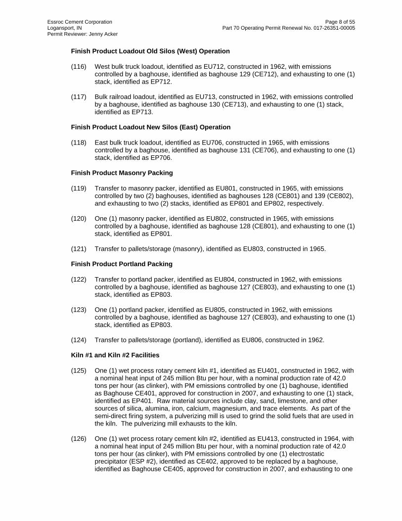
Essroc Cement Corporation Page 8 of 55 Logansport, IN Part 70 Operating Permit Renewal No. 017-26351-00005 Permit Reviewer: Jenny Acker
Finish Product Loadout Old Silos (West) Operation
(116) West bulk truck loadout, identified as EU712, constructed in 1962, with emissions controlled by a baghouse, identified as baghouse 129 (CE712), and exhausting to one (1) stack, identified as EP712.
(117) Bulk railroad loadout, identified as EU713, constructed in 1962, with emissions controlled
by a baghouse, identified as baghouse 130 (CE713), and exhausting to one (1) stack, identified as EP713.
Finish Product Loadout New Silos (East) Operation
(118) East bulk truck loadout, identified as EU706, constructed in 1965, with emissions controlled by a baghouse, identified as baghouse 131 (CE706), and exhausting to one (1) stack, identified as EP706.
Finish Product Masonry Packing
(119) Transfer to masonry packer, identified as EU801, constructed in 1965, with emissions controlled by two (2) baghouses, identified as baghouses 128 (CE801) and 139 (CE802), and exhausting to two (2) stacks, identified as EP801 and EP802, respectively.
(120) One (1) masonry packer, identified as EU802, constructed in 1965, with emissions
controlled by a baghouse, identified as baghouse 128 (CE801), and exhausting to one (1) stack, identified as EP801.
(121) Transfer to pallets/storage (masonry), identified as EU803, constructed in 1965. Finish Product Portland Packing
(122) Transfer to portland packer, identified as EU804, constructed in 1962, with emissions controlled by a baghouse, identified as baghouse 127 (CE803), and exhausting to one (1) stack, identified as EP803.
(123) One (1) portland packer, identified as EU805, constructed in 1962, with emissions
controlled by a baghouse, identified as baghouse 127 (CE803), and exhausting to one (1) stack, identified as EP803.
(124) Transfer to pallets/storage (portland), identified as EU806, constructed in 1962. Kiln #1 and Kiln #2 Facilities
(125) One (1) wet process rotary cement kiln #1, identified as EU401, constructed in 1962, with a nominal heat input of 245 million Btu per hour, with a nominal production rate of 42.0 tons per hour (as clinker), with PM emissions controlled by one (1) baghouse, identified as Baghouse CE401, approved for construction in 2007, and exhausting to one (1) stack, identified as EP401. Raw material sources include clay, sand, limestone, and other sources of silica, alumina, iron, calcium, magnesium, and trace elements. As part of the semi-direct firing system, a pulverizing mill is used to grind the solid fuels that are used in the kiln. The pulverizing mill exhausts to the kiln.
(126) One (1) wet process rotary cement kiln #2, identified as EU413, constructed in 1964, with
a nominal heat input of 245 million Btu per hour, with a nominal production rate of 42.0 tons per hour (as clinker), with PM emissions controlled by one (1) electrostatic precipitator (ESP #2), identified as CE402, approved to be replaced by a baghouse, identified as Baghouse CE405, approved for construction in 2007, and exhausting to one

Essroc Cement Corporation Page 9 of 55 Logansport, IN Part 70 Operating Permit Renewal No. 017-26351-00005 Permit Reviewer: Jenny Acker
(1) stack, identified as EP401. Raw material sources include clay, sand, limestone, and other sources of silica, alumina, iron, calcium, magnesium, and trace elements. As part of the semi-direct firing system, a pulverizing mill is used to grind the solid fuels that are used in the kiln. The pulverizing mill exhausts to the kiln.
Kiln #1 and Kiln #2 are subject to the requirements of 40 CFR 61, Subpart FF (National Emission Standard for Benzene Waste Operations), because they are considered part of a hazardous waste treatment, storage, and disposal facility which operates under a hazardous waste management permit under subtitle C of the Solid Waste Disposal Act.
Clinker Cooler #1 Facilities
(127) One (1) clinker cooler #1, identified as EU412, constructed in 1962, with a nominal production rate of 42.0 tons per hour, with PM emissions controlled by one (1) baghouse, identified as baghouse 107 (CE404), and exhausting to one (1) stack, identified as EP404.
Clinker Cooler #2 Facilities
(128) One (1) clinker cooler #2, identified as EU421, constructed in 1962, with a nominal production rate of 42.0 tons per hour, with PM emissions controlled by one (1) baghouse, identified as baghouse 111 (CE407), and exhausting to one (1) stack, identified as EP404.
CKD –To-Finish Mill (CKD2FM) Recycling Operations
(129) One (1) waste dust tank, constructed in 1962, modified in 2005 with the addition of one (1) CKD2FM surge system, collectively identified as EU406, with emissions controlled by a baghouse, constructed in 2006, identified as baghouse 142 (CE901), and exhausting to one (1) stack, identified as EP901.
(130) One (1) CKD2FM recycling storage tank system, identified as EU902, constructed in
2006, with particulate emissions controlled by one (1) baghouse, identified as baghouse 143 (CE902), and exhausting to one (1) stack, identified as EP902.
(131) One (1) CKD2FM #1 FM recycling system, identified as EU903, constructed in 2006. (132) One (1) CKD2FM #2 FM recycling system, identified as EU904, constructed in 2006.
Haul Roads
(133) Numerous hauls roads, collectively identified as EU900, including the following:
(a) Quarry haul road, created in 1961. (b) One (1) cement kiln dust haul road system, constructed in 1962.
Emission Units and Pollution Control Equipment Removed From the Source
(1) #1 recycled dust scoop system/insufflation system, identified as EU411, with emissions exhausting directly to the kilns. The #1 recycled dust scoop was constructed in 1995. The insufflation system was constructed in 1965.

Essroc Cement Corporation Page 10 of 55 Logansport, IN Part 70 Operating Permit Renewal No. 017-26351-00005 Permit Reviewer: Jenny Acker
(2) #2 recycled dust scoop system/insufflation system, identified as EU420, with emissions exhausting directly to the kilns. The #2 recycled dust scoop system was constructed in 1995. The insufflation system was constructed in 1965.
(3) One (1) silo, Silo 15, identified as EU905, constructed in 1965, with particulate emissions
controlled by one (1) baghouse, identified as baghouse 144 and CE905, and exhausting to one (1) stack, identified as EP905.
Insignificant Activities
(a) Space heaters, process heaters, or boilers using the following fuels:
(1) Natural gas-fired combustion sources with heat input equal to or less than ten million (10,000,000) Btu per hour.
(2) Propane or liquefied petroleum gas, or butane-fired combustion sources with
heat input equal to or less than six million (6,000,000) Btu per hour. (b) A gasoline fuel transfer and dispensing operation handling less than or equal to 1,300
gallons per day, such as filling of tanks, locomotives, automobiles, having a storage capacity less than or equal to 10,500 gallons.
(c) A petroleum fuel, other than gasoline, dispensing facility having a storage capacity less
than or equal to 10,500 gallons, and dispensing less than or equal to 230,000 gallons per month.
(d) The following VOC and HAP storage containers:
(1) Storage tanks with capacity less than or equal to 1,000 gallons and annual throughput less than 12,000 gallons.
(2) Vessels storing lubricating oils, hydraulic oils, machining oils, and machining
fluids. (e) Refractory storage not requiring air pollution control equipment. (f) Application of oils, greases, lubricants, or other nonvolatile materials applied as
temporary protective coatings. (g) Degreasing operations that do not exceed 145 gallons per 12 months, except if subject to
326 IAC 20-6. [326 IAC 8-3-2] [326 IAC 8-3-5] (h) The following equipment related to manufacturing activities not resulting in the emission
of HAPs: brazing equipment, cutting torches, soldering equipment, welding equipment. (i) Closed loop heating and cooling systems. (j) Activities associated with the treatment of wastewater streams with an oil and grease
content less than or equal to 1% by volume. (k) Water runoff ponds for petroleum coke-cutting and coke storage piles. (l) Any operation using aqueous solutions containing less than 1% by weight of VOCs,
excluding HAPs.

Essroc Cement Corporation Page 11 of 55 Logansport, IN Part 70 Operating Permit Renewal No. 017-26351-00005 Permit Reviewer: Jenny Acker
(m) Noncontact cooling tower systems with either of the following:
(1) Forced and induced draft cooling tower system not regulated under a NESHAP. (n) Replacement or repair of electrostatic precipitators, bags in baghouses and filters in other
air filtration equipment. (o) Process vessel degreasing and cleaning to prepare for internal repairs. (p) Paved and unpaved roads and parking lots with public access. (q) Conveyors as follows:
(1) Covered conveyor for coal or coke conveying of less than or equal to 360 tons per day;
(2) Covered conveyors for limestone conveying of less than or equal to 7,200 tons
per day for sources other than mineral processing plants constructed after August 31, 1983;
(3) Uncovered coal conveying of less than or equal to 120 tons per day. (4) Underground conveyors.
(r) Purging of gas lines and vessels that is related to routing maintenance and repair of
buildings, structures, or vehicles at the source where air emissions from those activities would not be associated with any production process.
(s) Equipment used to collect any material that might be released during a malfunction,
process upset, or spill cleanup, including catch tanks, temporary liquid separators, tanks, and fluid handling equipment.
(t) Blowdown for any of the following: sight glass; boiler; compressors; pumps; and cooling
tower. (u) Emergency generators as follows:
(1) Gasoline generators not exceeding 110 horsepower. (2) Diesel generators not exceeding 1600 horsepower.
(v) Purge double block and bleed valves. (w) Filter or coalescer media changeout. (x) A laboratory as defined in 326 IAC 2-7-1(21)(D). Other categories with emissions below insignificant thresholds: (a) Degreasing operations (b) Grinding aid storage tanks (c) Baghouse 134 mill building (d) Clay screening station (e) Doorclone separation (f) Raw mill #1 (g) Raw mill #2

Essroc Cement Corporation Page 12 of 55 Logansport, IN Part 70 Operating Permit Renewal No. 017-26351-00005 Permit Reviewer: Jenny Acker
(h) DSM classifier (i) Eight (8) slurry tanks (j) Coal mill #1 (k) Coal mill #2 (l) Alternative Fuel and Oil Tanks, permitted in 2008, located at the fuel oil containment
area, and utilized for alternative fuels for the kilns.
(1) Two (2) heated 15,600 gallon tanks, brought on-site in 2008. (2) One (1) existing diesel fuel tank, converted to an alternative fuel and oil tank.
Alternative fuels may include biodiesel, used oil, or other comparable fuels that do not meet the criteria of hazardous.
(m) Hazardous Waste fuel facility
(1) Waste Management Units (A) Ten (10) hazardous waste-derived fuel storage tanks, installed in 1987
and 1994, with capacities ranging from 22,000-39,000 gallons. All tanks are connected to an integrated emission control system.
(B) Carbon Steel Piping System (C) Tank Rail Cars and Trucks
(2) Equipment components (A) Valves (B) Pumps (C) AWFCO Valves
(3) Caps (hose end covers) (4) Flanges (5) Manways (6) Flame Arrestors (7) Filter Pots (8) Micro-motion Flow Meters (9) Level Transmitters (10) Pressure Indicators (11) Pressure Transmitters (12) Emergency Conservation Vent (13) Carbon Canister VOC Monitor (14) Tank Emergency Relief Ports (15) High Level Probes (16) Activated Carbon Canister System
Trivial Activities
(1) Water related activities including: (A) Production of hot water for on-site personal use not related to any industrial or
production process. (B) Water treatment activities used to provide potable and process water for the
plant, excluding any activities associated with wastewater treatment. (C) Pressure washing of equipment.

Essroc Cement Corporation Page 13 of 55 Logansport, IN Part 70 Operating Permit Renewal No. 017-26351-00005 Permit Reviewer: Jenny Acker
(2) Combustion Activities including the following: (A) Portable electrical generators that can be moved by hand from one location to
another. (C) Combustion emissions from propulsion of mobile sources. (D) Tobacco smoking rooms and areas. (E) Indoor and outdoor kerosene heaters.
(3) Ventilation and venting related equipment including the following: (A) Ventilation exhaust, central chiller water systems, refrigeration and air
conditioning equipment, not related to any industrial or production process, including natural draft hoods or ventilating systems that do not remove air pollutants.
(B) Stacks and vents from plumbing traps used to prevent the discharge of sewer
gases, handling domestic sewage only, excluding those at wastewater treatment plants or those handling any industrial waste.
(C) Vents from continuous emissions monitors and other analyzers. (D) Natural gas pressure regulator vents, excluding venting at oil and gas production
facilities. (E) Air vents from air compressors. (F) Vents for air cooling of electric motors provided the air does not commingle with
regulated air pollutants
(4) Activities related to routine fabrication, maintenance and repair of buildings, structures, equipment or vehicles at the source where air emissions from those activities would not be associated with any commercial production process including the following: (A) Activities associated with the repair and maintenance of paved and unpaved
rods, including paving or sealing, or both, of parking lots and roadways. (B) Painting including interior and exterior painting of buildings, and solvents use,
excluding degreasing operations utilizing halogenated organic solvents. (C) Brazing, soldering, or welding operations and associated equipment. (D) Portable blast-cleaning equipment with enclosures. (E) Blast cleaning equipment using water as the suspension agent and associated
equipment.
(F) Batteries and battery charging stations, except at battery manufacturing plants.
(G) Lubrication, including hand-held spray can lubrication, dipping metal parts into lubricating oil, and manual or automated addition of cutting oil in machining operations.
(H) Non-asbestos insulation installation or removal.

Essroc Cement Corporation Page 14 of 55 Logansport, IN Part 70 Operating Permit Renewal No. 017-26351-00005 Permit Reviewer: Jenny Acker
(I) Tarring, retarring and repair of building roofs. (J) Bead blasting of heater tubes. (K) Instrument air dryer and filter maintenance. (L) Manual tank gauging.
(5) Activities performed using hand-held equipment including the following:
- Buffing - Carving - Cutting, excluding cutting torches - Drilling - Sawing - Turning wood, metal or plastic - Grinding - Sanding - Machining wood, metal or plastic - Polishing - Surface grinding
(6) Housekeeping and janitorial activities and supplies including the following: (A) vacuum cleaning systems used exclusively for housekeeping or custodial
activities or both. (B) Steam cleaning activities. (C) Restrooms and associated cleanup operations and supplies. (D) Alkaline or phosphate cleaners and associated equipment. (E) Mobile floor sweepers and floor scrubbers. (F) Pest control fumigation.
(7) Office related activities including the following: (A) Office supplies and equipment. (B) Photocopying equipment and associated supplies. (C) Paper shredding. (D) Blueprint machines, photographic equipment, and associated supplies.
(8) Lawn care and landscape maintenance activities and equipment, including the storage,
spraying or application of insecticides, pesticides and herbicides. (9) Storage equipment and activities including:
(A) Pressurized storage tanks and associated piping for the following: acetylene, liquid petroleum gas (LPG), nitrogen dioxide, carbon monoxide, sulfur dioxide.
(B) Storage tanks, vessels, and containers holding or storing liquid substances that
do not contain any VOC or HAP. (C) Storage tanks, reservoirs, and pumping and handling equipment of any size
containing soap, wax, vegetable oil, grease, animal fat, and nonvolatile aqueous salt solutions, provided appropriate lids and covers are utilized.

Essroc Cement Corporation Page 15 of 55 Logansport, IN Part 70 Operating Permit Renewal No. 017-26351-00005 Permit Reviewer: Jenny Acker
(D) Storage of drums containing maintenance raw materials. (E) Storage of the following: any non-HAP containing material in solid form stored in
a sealed or covered container. (F) Portable containers used for the collection, storage, or disposal of materials
provided the container capacity is equal to or less than forty-six hundredths (0.46) cubic meters and the container is closed except when the material is added or removed.
(10) Emergency and standby equipment including:
(A) Safety and emergency equipment, except engine driven fire pumps, including fire
suppression systems and emergency road flares. (B) Process safety relief devices installed solely for the purpose of minimizing injury
to persons or damage to equipment which could result from abnormal process operating conditions, including the following: (i) Explosion relief vents, diaphragms or panels. (ii) Rupture discs. (iii) Safety relief valves.
(C) Activities and equipment associated with on-site medical care not otherwise
specifically regulated.
(11) Sampling and testing equipment and activities including the following:
(A) Equipment used for quality control/assurance or inspection purposes, including sampling equipment used to withdraw materials for analysis.
(B) Hydraulic and hydrostatic testing equipment. (C) Ground water monitoring wells and associated sample collection equipment. (D) Humidity chambers. (E) Sampling of waste. (F) Instrument air dryers and distribution.
(12) Use of consumer products and equipment where the product or equipment is used at a source in the same manner as normal consumer use and is not associated with any production process.
(13) Activities generating limited amounts of fugitive dust including:
(A) Fugitive emissions related to movement of passenger vehicles, provided the emissions are not counted for applicability purposes under 326 IAC 2-7-1(22)(B), and any required fugitive dust control plan or its equivalent is submitted.
(B) Soil Boring. (C) Road salting and sanding.

Essroc Cement Corporation Page 16 of 55 Logansport, IN Part 70 Operating Permit Renewal No. 017-26351-00005 Permit Reviewer: Jenny Acker
(14) Activities associated with production including the following: (A) Electrical resistance welding. (B) Drop hammers or hydraulic presses for forging or metalworking. (C) Air compressors and pneumatically operated equipment, including hand tools. (D) Compressor or pump lubrication and seal oil systems. (E) Handling of solid steel, including coils and slabs, excluding scrap burning,
scarfing, and charging into steel making furnaces and vessels.
(15) Miscellaneous equipment, but not emissions associated with the process for which the equipment is used, and activities including the following:
(A) Equipment used for surface coating, painting, dipping or spraying operations,
except those that will emit VOCs or HAPs. (B) Electric or steam heated drying oven and autoclaves, including only the heating
emissions and not any associated process emissions. (C) Manual loading and unloading operations. (D) Construction and demolition operations. (E) Mechanical equipment gear boxes and vents which are isolated from process
materials.
Existing Approvals
Since the issuance of the Part 70 Operating Permit T017-6033-00005 on December 27, 2003, the source has constructed or has been operating under the following approvals as well: (a) Minor Source Modification No. 017-22319-00005 issued on February 3, 2006; (b) Significant Source Modification No. 017-22539-00005 issued on April 4, 2006; and, (c) Significant Source Modification No. 017-25047-00005 issued on December 13, 2007.
All terms and conditions of previous permits issued pursuant to permitting programs approved into the state implementation plan have been either incorporated as originally stated, revised, or deleted by this permit. All previous registrations and permits are superseded by this permit.
The following terms and conditions from previous approvals have been revised in this Part 70 Operating Permit Renewal: (a) IDEM, OAQ no longer specifies the applicable requirements of the New Source
Performance Standards (NSPS) (40 CFR 60) and/or the National Emission Standards for Hazardous Organic Compounds (NESHAP) (40 CFR 61 and 63) in the Section D conditions. Instead, the applicable requirements are incorporated by reference in the new E Sections of the permit.
Therefore, the following conditions, which contained requirements pursuant to 40 CFR 60, 61, and/or 63, have been deleted from the permit.

Essroc Cement Corporation Page 17 of 55 Logansport, IN Part 70 Operating Permit Renewal No. 017-26351-00005 Permit Reviewer: Jenny Acker
• Original Condition D.2.3 - General Provisions Relating to NESHAP [326 IAC 20-1][40
CFR Part 63, Subpart A] • Original Condition D.2.4 - NESHAP Emissions Limitation [40 CFR 63, Subpart LLL] • Original Condition D.2.7(a) and (b) - Testing Requirements [326 IAC 2-7-6(1),(6)]
[326 IAC 2-1.1-11] [40 CFR 63, Subpart LLL] • Original Condition D.2.9 - NESHAP Monitoring Requirements [40 CFR 63, Subpart
LLL] • Original Condition D.2.10(e) - Visible Emissions Notations • Original Condition D.2.13(c) - Record Keeping Requirements • Original Condition D.2.14 - Reporting Requirements • Original Condition D.3.2 - General Provisions Relating to NESHAP [326 IAC 20-1][40
CFR Part 63, Subpart A] • Original Condition D.3.3 - NESHAP Emissions Limitation [40 CFR Part 63, Subpart
EEE] • Original Condition D.3.4 - Alternate Emission Limitations [40 CFR Part 63.1206,
Subpart EEE] • Original Condition D.3.6 - National Emission Standard for Benzene Waste Operations
[40 CFR Part 61, Subpart FF] • Original Condition D.3.9 - Testing Requirements [40 CFR 63, Subpart EEE] [326 IAC
2-7-6(1),(6)] [326 IAC 2-1-3(i)(8)] [326 IAC 2-1.1-11] • Original Condition D.3.13 - NESHAP Monitoring Requirements [40 CFR 63, Subpart
EEE] • Original Condition D.3.18(d) and (e) - Record Keeping Requirements • Original Condition D.3.19(c), (d), (e), (f), and (g) - Reporting Requirements • Original Condition D.4.1 - General Provisions Relating to NESHAP [326 IAC 20-1][40
CFR Part 63, Subpart A] • Original Condition D.4.2 - NESHAP Emissions Limitation [40 CFR 63, Subpart LLL] • Original Condition D.4.5 - NESHAP Testing Requirements [40 CFR 63, Subpart LLL]
[326 IAC 2-1.1-11] [326 IAC 2-7-6(1),(6)] [326 IAC 2-1-3(i)(8)]
• Original Condition D.4.8 - NESHAP Monitoring Requirements [40 CFR 63, Subpart LLL]
• Original Condition D.4.11(d) - Record Keeping Requirements • Original Condition D.4.14(b), (c), (d), and (e) - Reporting Requirements • Original Condition D.6.1 - General Provisions Relating to NESHAP [326 IAC 20-1][40
CFR Part 63, Subpart A] • Original Condition D.6.2 - General Provisions Relating to NESHAP [326 IAC 14-1][40
CFR Part 61, Subpart A] • Original Condition D.6.3 - Off-site Waste and Recovery Operations NESHAP [326
IAC 20-23-1] [40 CFR Part 63, Subpart DD] [40 CFR 61, Subpart FF]
• Original Condition D.6.4 - National Emission Standard for Equipment Leaks (Fugitive Emission Sources)[326 IAC 14-8-1] [40 CFR 61, Subpart V] [40 CFR 63, Subpart DD]
• Original Condition D.6.5 - Monitoring Procedures for Equipment Leaks [326 IAC 2-7-6(1)] [40 CFR 61, Subpart V] [40 CFR 63, Subpart DD]
• Original Condition D.6.6 - National Emission Standard for Benzene Waste Operations [40 CFR Part 61, Subpart FF]
• Original Condition D.6.7 - Standards: Closed-Vent Systems and Activated Carbon Canister System [40 CFR Part 61, Subpart FF] [40 CFR 61.349]

Essroc Cement Corporation Page 18 of 55 Logansport, IN Part 70 Operating Permit Renewal No. 017-26351-00005 Permit Reviewer: Jenny Acker
• Original Condition D.6.8 - Monitoring Procedures for Tanks [326 IAC 2-7-6(1)] [40 CFR 61, Subpart FF]
• Original Condition D.6.9 - Monitoring Procedures for Containers [326 IAC 2-7-6(1)] [40 CFR 61, Subpart FF]
• Original Condition D.6.10 - Monitoring Procedures for Activated Carbon Canister System and Closed-Vent System [326 IAC 2-7-6(1)] [40 CFR 61, Subpart FF]
• Original Condition D.6.11 - Startup, Shutdown, and Malfunction Plan [40 CFR 63.6(e)(3) General Provisions]
• Original Condition D.6.12 - Leak Detection Testing Requirements [326 IAC 2-7-6(1)] [40 CFR 61, Subpart FF]
• Original Condition D.6.13 - Activated Carbon Canister System Compliance Determination Requirements [326 IAC 2-7-6(1)] [40 CFR 61, Subpart FF]
• Original Condition D.6.14 - General Record Keeping Requirements [40 CFR 63, Subpart A] [40 CFR 63, Subpart DD] [40 CFR 61, Subpart FF]
• Original Condition D.6.15 - Record Keeping Requirements for Equipment Leaks [40 CFR 63, Subpart DD] [40 CFR 61, Subpart V]
• Original Condition D.6.16 - Record Keeping Requirements for Tanks and Containers [40 CFR 61, Subpart FF]
• Original Condition D.6.17 - Record Keeping Requirements for Activated Carbon Canister System and Closed-Vent System [40 CFR 61, Subpart FF]
• Original Condition D.6.18 - Reporting Requirements [40 CFR 63, Subpart A] [40 CFR 63, Subpart DD] [40 CFR 61, Subpart V]
• Original Condition D.6.19 - Reporting Requirements [40 CFR 61, Subpart FF]
(b) IDEM, OAQ no longer specifies determinations of non-applicability in the Section D conditions. Instead, at the request of the Permittee, the non-applicability determinations are contained within Section B - Permit Shield. The following conditions have been incorporated into the Section B - Permit Shield condition. • Original Condition D.1.3 - Determinations of Nonapplicability [40 CFR 60, Subparts A,
F, and OOO] [40 CFR 63, Subparts A and LLL] • Original Condition D.2.5 - Determinations of Nonapplicability [40 CFR 60, Subparts A
and F] • Original Condition D.3.5 - Determinations of Nonapplicability [40 CFR 60, Subparts A
and F] • Original Condition D.4.3 - Determination of Nonapplicability [40 CFR 60, Subparts A
and F] • Original Condition D.5.3 - Determinations of Nonapplicability [40 CFR 63.460
(Subpart T)] [40 CFR 60, Subparts A and F] [40 CFR 63, Subparts A and LLL]
(c) Minor Source Modification 017-22319-00005, issued on February 3, 2006, authorized the re-purposing of Silo 15 from the collection of finish product silo storage facilities, collectively identified as EU704, to a CKD silo, identified as EU905. Essroc will not be repurposing Silo 15.
Therefore, original Condition D.2.1, which contained PM/PM10 limitations necessary to render PSD not applicable to MSM 017-22319-00005, have been revised to remove reference to Silo 15. No changes to existing limits were necessary. See State Rule Applicability - Entire Source Section of this TSD for further details.

Essroc Cement Corporation Page 19 of 55 Logansport, IN Part 70 Operating Permit Renewal No. 017-26351-00005 Permit Reviewer: Jenny Acker
(d) With regards to record keeping requirements for a daily filter inspection log, the intent is
that the Permittee makes a record of some sort every day. If an inspection is completed, a "normal" or "abnormal" notation is made. If no inspection is made, a notation is required as to why it wasn't, such as the unit was not operating. In order to attempt to clarify the requirements, the recordkeeping requirements, contained throughout the D Sections of the permit, relating to the daily parametric monitoring have been revised.
The following terms and conditions from previous approvals have been determined no longer applicable; therefore, were not incorporated into this Part 70 Operating Permit Renewal: (a) Minor Source Modification 017-22319-00005, issued on February 3, 2006, authorized the
re-purposing of Silo 15 from the collection of finish product silo storage facilities, collectively identified as EU704, to a CKD silo, identified as EU905. Essroc will not be repurposing Silo 15.
Therefore, original Condition D.1.1, which contained PM/PM10 limitations necessary to render to PSD not applicable to MSM 017-22319-00005, has been deleted. Additionally, any Compliance Determination or Monitoring requirements associated with Silo 15 have been deleted.
(b) Original Conditions D.3.10 (Particulate Control), D.3.14 (ESP Parametric Monitoring and
ESP Inspections), D.3.15 (Baghouse Parametric Monitoring), and D.3.16 (Broken or Failed Bag Detection) contained compliance determination and monitoring requirements to ensure compliance with particulate emission limitations established under 40 CFR 63, Subpart EEE. Since the requirements of 40 CFR 63, Subpart EEE, are no longer contained in Section D.3, original Conditions D.3.10, D.3.14, D.3.15, and D.3.16 have been removed from the permit.
(c) Original Conditions D.4.7 (Particulate Control) and D.4.9 (Parametric Monitoring)
contained compliance determination and monitoring requirements to ensure compliance with particulate emission limitations established under 40 CFR 63, Subpart EEE. Since the requirements of 40 CFR 63, Subpart EEE, are no longer contained in Section D.4, original Conditions D.4.7 and D.4.9 have been removed from the permit.
Enforcement Issue
The EPA has issued a notice of violation alleging that the kilns are not in compliance with the requirements of PSD. The EPA alleges that Essroc made modifications to the kilns, and began using pet coke as a fuel in the kilns, both of which triggered the requirements of PSD. This case is on-going and has not yet been resolved; therefore, no detailed compliance plan has been established. IDEM has included language in the Part 70 permit stating that the permit shield will not apply to the kilns with regards to the requirements of 326 IAC 2-2 (PSD). Once the enforcement case has been resolved, IDEM will reopen the permit to establish the permit shield for the kilns and, if necessary, include the provisions of the compliance plan in the Part 70 permit.
Emission Calculations
See Appendix A of this document for detailed emission calculations.

Essroc Cement Corporation Page 20 of 55 Logansport, IN Part 70 Operating Permit Renewal No. 017-26351-00005 Permit Reviewer: Jenny Acker
County Attainment Status
The source is located in Cass County.
Pollutant Designation SO2 Better than national standards. CO Unclassifiable or attainment effective November 15, 1990. O3 Unclassifiable or attainment effective June 15, 2004, for the 8-hour ozone standard. 1
PM10 Unclassifiable effective November 15, 1990. NO2 Cannot be classified or better than national standards. Pb Not designated.
1Unclassifiable or attainment effective October 18, 2000, for the 1-hour ozone standard which was revoked effective June 15, 2005. Unclassifiable or attainment effective April 5, 2005, for PM2.5.
(a) Ozone Standards
(1) On October 25, 2006, the Indiana Air Pollution Control Board finalized a rule
revision to 326 IAC 1-4-1 revoking the one-hour ozone standard in Indiana.
(2) On September 6, 2007, the Indiana Air Pollution Control Board finalized a temporary emergency rule to re-designate Allen, Clark, Elkhart, Floyd, LaPorte, St. Joseph counties as attainment for the 8-hour ozone standard.
(3) On November 9, 2007, the Indiana Air Pollution Control Board finalized a temporary emergency rule to re-designate Boone, Hamilton, Hancock, Hendricks, Johnson, Madison, Marion, Morgan, and Shelby counties as attainment for the 8-hour ozone standard.
(4) Volatile organic compounds (VOC) and Nitrogen Oxides (NOx) are regulated
under the Clean Air Act (CAA) for the purposes of attaining and maintaining the National Ambient Air Quality Standards (NAAQS) for ozone. Therefore, VOC and NOx emissions are considered when evaluating the rule applicability relating to ozone. Cass County has been designated as attainment or unclassifiable for ozone. Therefore, VOC and NOx emissions were reviewed pursuant to the requirements for Prevention of Significant Deterioration (PSD), 326 IAC 2-2.
(b) PM2.5
Cass County has been classified as attainment for PM2.5. On May 8, 2008 U.S. EPA promulgated the requirements for Prevention of Significant Deterioration (PSD) for PM2.5 emissions, and these rules became effective on July 15, 2008. Indiana has three years from the publication of these rules to revise its PSD rules, 326 IAC 2-2, to include those requirements. The May 8, 2008 rule revisions require IDEM to regulate PM10 emissions as a surrogate for PM2.5 emissions until 326 IAC 2-2 is revised.
(c) Other Criteria Pollutants Cass County has been classified as attainment or unclassifiable in Indiana for SO2, CO, PM10, NO2, and Pb. Therefore, these emissions were reviewed pursuant to the requirements for Prevention of Significant Deterioration (PSD), 326 IAC 2-2.
(d) Since this source is classified as a portland cement plant, it is considered one of the
twenty-eight (28) listed source categories, as specified in 326 IAC 2-2-1(gg)(1).
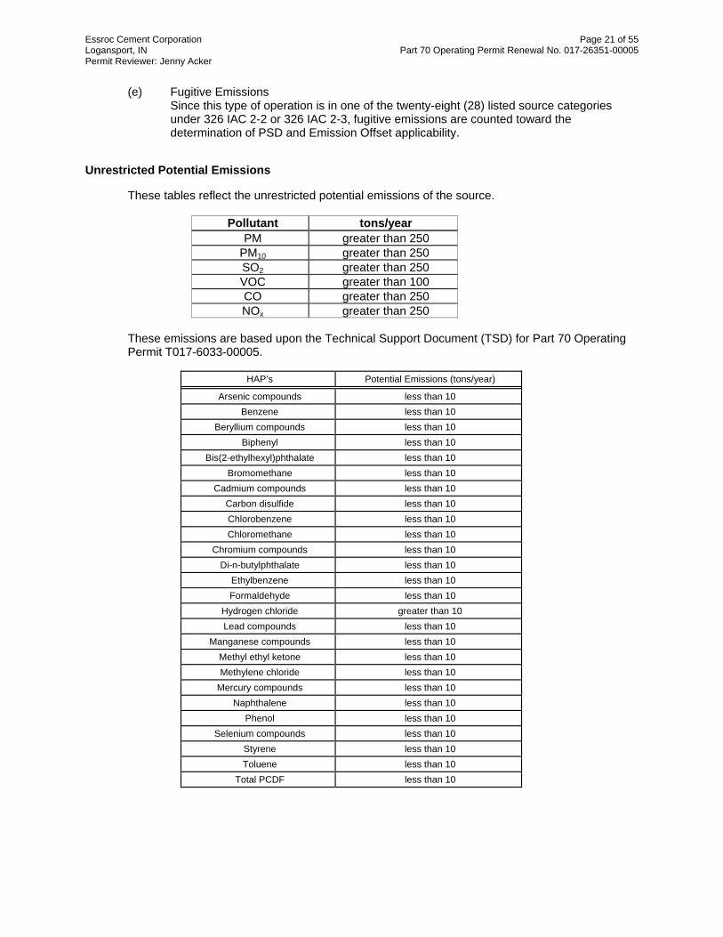
Essroc Cement Corporation Page 21 of 55 Logansport, IN Part 70 Operating Permit Renewal No. 017-26351-00005 Permit Reviewer: Jenny Acker
(e) Fugitive Emissions Since this type of operation is in one of the twenty-eight (28) listed source categories under 326 IAC 2-2 or 326 IAC 2-3, fugitive emissions are counted toward the determination of PSD and Emission Offset applicability.
Unrestricted Potential Emissions
These tables reflect the unrestricted potential emissions of the source.
Pollutant tons/year PM greater than 250
PM10 greater than 250 SO2 greater than 250 VOC greater than 100 CO greater than 250 NOx greater than 250
These emissions are based upon the Technical Support Document (TSD) for Part 70 Operating Permit T017-6033-00005.
HAP’s Potential Emissions (tons/year)
Arsenic compounds less than 10 Benzene less than 10
Beryllium compounds less than 10 Biphenyl less than 10
Bis(2-ethylhexyl)phthalate less than 10 Bromomethane less than 10
Cadmium compounds less than 10 Carbon disulfide less than 10 Chlorobenzene less than 10 Chloromethane less than 10
Chromium compounds less than 10 Di-n-butylphthalate less than 10
Ethylbenzene less than 10 Formaldehyde less than 10
Hydrogen chloride greater than 10 Lead compounds less than 10
Manganese compounds less than 10 Methyl ethyl ketone less than 10 Methylene chloride less than 10
Mercury compounds less than 10 Naphthalene less than 10
Phenol less than 10 Selenium compounds less than 10
Styrene less than 10 Toluene less than 10
Total PCDF less than 10

Essroc Cement Corporation Page 22 of 55 Logansport, IN Part 70 Operating Permit Renewal No. 017-26351-00005 Permit Reviewer: Jenny Acker
HAP’s Potential Emissions (tons/year) Total TCDF less than 10
Xylenes less than 10
TOTAL greater than 25 Note The emissions for HAPs were determined through use of AP-42 emission
factors. The emission factors are based on controlled emissions. Potential emissions may be greater than those stated above.
These emissions are based upon the Technical Support Document (TSD) for Part 70 Operating Permit T017-6033-00005. The Permittee has agreed that this source is a major for Part 70 Permits 326 IAC 2-7, and Prevention of Significant Deterioration (PSD) 326 IAC 2-2. No calculations of unrestricted Potential to Emit have been done for the criteria pollutants. (a) The potential to emit (as defined in 326 IAC 2-7-1(29)) of PM, PM10, SO2, VOC, CO, and
NOX is equal to or greater than 100 tons per year. Therefore, the source is subject to the provisions of 326 IAC 2-7.
(b) The potential to emit (as defined in 326 IAC 2-7-1(29)) of any single HAP is equal to or
greater than ten (10) tons per year and the potential to emit (as defined in 326 IAC 2-7-1(29)) of a combination of HAPs is equal to or greater than twenty-five (25) tons per year. Therefore, the source is subject to the provisions of 326 IAC 2-7.
(c) Since this type of operation is one of the twenty-eight (28) listed source categories under
326 IAC 2-7, fugitive emissions are counted toward the determination of Part 70 applicability.
Actual Emissions
The following table shows the actual emissions from the source. This information reflects the 2006 OAQ emission data.
Pollutant Actual Emissions (tons/year)
PM not reported
PM10 260.92
SO2 978.66 VOC 30.19 CO 165.05 NOx 1,896.51
Part 70 Permit Conditions
This source is subject to the requirements of 326 IAC 2-7, pursuant to which the source has to meet the following:
(a) Emission limitations and standards, including those operational requirements and
limitations that assure compliance with all applicable requirements at the time of issuance of Part 70 permits.

Essroc Cement Corporation Page 23 of 55 Logansport, IN Part 70 Operating Permit Renewal No. 017-26351-00005 Permit Reviewer: Jenny Acker
(b) Monitoring and related record keeping requirements which assume that all reasonable information is provided to evaluate continuous compliance with the applicable requirements.
Potential to Emit After Issuance
The table below summarizes the potential to emit, reflecting all limits, of the emission units. Any control equipment is considered federally enforceable only after issuance of this Part 70 permit renewal, and only to the extent that the effect of the control equipment is made practically enforceable in the permit.
Pollutant Actual Emissions (tons/year)
PM Greater than 100
PM10 Greater than 100
SO2 Greater than 100 VOC Greater than 100 CO Greater than 100 NOx Greater than 100
(a) This existing stationary source is major for PSD because the emissions of at least one
criteria pollutant are greater than one hundred (>100) tons per year, and it is one of the twenty-eight (28) listed source categories.
(b) Fugitive Emissions
Since this type of operation is in one of the twenty-eight (28) listed source categories under 326 IAC 2-2 or 326 IAC 2-3, fugitive emissions are counted toward the determination of Prevention of Significant Deterioration (PSD).
Federal Rule Applicability
CAM Pursuant to 40 CFR 64.2, Compliance Assurance Monitoring (CAM) is applicable to each new or modified emission unit that involves a pollutant-specific emission unit and meets the following criteria: (a) has a potential to emit before controls equal to or greater than the major source threshold
for the pollutant involved; (b) is subject to an emission limitation or standard for that pollutant; and (c) uses a control device, as defined in 40 CFR 64.1, to comply with that emission limitation or
standard.

Essroc Cement Corporation Page 24 of 55 Logansport, IN Part 70 Operating Permit Renewal No. 017-26351-00005 Permit Reviewer: Jenny Acker
The following tables are used to identify the applicability of each of the criteria, under 40 CFR 64.1, to each existing emission unit and specified pollutant subject to CAM: SO2, NOx, and CO - CAM Applicability
CAM - SO2, NOX and CO
Emission Unit ID
Control Device ID
(BH unless specified
otherwise)
Emission Limitation
(Y/N)
Uncontrolled PTE (tpy)
Controlled PTE (tpy)
Major Source
Threshold (tons/year)
CAM Applicable
(Y/N)
Large Unit (Y/N)
SO2 Kiln #1 N Y > 100 > 100 100 N n/a Kiln #2 N Y > 100 > 100 100 N n/a
NOx Kiln #1 N N > 100 > 100 100 N n/a Kiln #2 N N > 100 > 100 100 N n/a
CO Kiln #1 N N < 100 < 100 100 N n/a Kiln #2 N N < 100 < 100 100 N n/a
Based on this evaluation, the requirements of 40 CFR Part 64 (CAM) are not applicable to any of the existing units, for SO2, NOx, and/or CO, as part of this Part 70 permit renewal. PM/PM10 - CAM Applicability
CAM - PM/PM10 (Table 1)
Emission Unit ID
Control Device ID
(BH unless specified
otherwise)
Emission Limitation
(Y/N)
Uncontrolled PTE (tpy)
Controlled PTE (tpy)
Major Source
Threshold (tons/year)
CAM Applicable
(Y/N)
Large Unit (Y/N)
*EU112 N (326 IAC 6-3-2(e)) -- -- 100 N n/a *EU114 N (326 IAC 6-3-2 (e)) -- -- 100 N n/a *EU115 N (326 IAC 6-3-2(e)) -- -- 100 N n/a *EU117 N (326 IAC 6-3-2(e)) -- -- 100 N n/a *EU120 N (326 IAC 6-3-2(e)) -- -- 100 N n/a *EU121 N (326 IAC 6-3-2(e)) -- -- 100 N n/a *EU123 N (326 IAC 6-3-2(e)) -- -- 100 N n/a *EU124 N (326 IAC 6-3-2(e)) -- -- 100 N n/a *EU125 N (326 IAC 6-3-2(e)) -- -- 100 N n/a *EU127 N (326 IAC 6-3-2(e)) -- -- 100 N n/a *EU201 N (326 IAC 6-3-2(e)) -- -- 100 N n/a *EU202 N (326 IAC 6-3-2(e)) -- -- 100 N n/a *EU204 N (326 IAC 6-3-2(e)) -- -- 100 N n/a *EU205 N (326 IAC 6-3-2(e)) -- -- 100 N n/a *EU206 N (326 IAC 6-3-2(e)) -- -- 100 N n/a *EU207 N (326 IAC 6-3-2(e)) -- -- 100 N n/a *EU208 N (326 IAC 6-3-2(e)) -- -- 100 N n/a *EU212 N (326 IAC 6-3-2(e)) -- -- 100 N n/a *EU214 N (326 IAC 6-3-2(e)) -- -- 100 N n/a *EU215 N (326 IAC 6-3-2(e)) -- -- 100 N n/a *EU307 N (326 IAC 6-3-2(e)) -- -- 100 N n/a

Essroc Cement Corporation Page 25 of 55 Logansport, IN Part 70 Operating Permit Renewal No. 017-26351-00005 Permit Reviewer: Jenny Acker
CAM - PM/PM10 (Table 1)
Emission Unit ID
Control Device ID
(BH unless specified
otherwise)
Emission Limitation
(Y/N)
Uncontrolled PTE (tpy)
Controlled PTE (tpy)
Major Source
Threshold (tons/year)
CAM Applicable
(Y/N)
Large Unit (Y/N)
*EU308 N (326 IAC 6-3-2(e)) -- -- 100 N n/a *EU309 N (326 IAC 6-3-2(e)) -- -- 100 N n/a *EU310 N (326 IAC 6-3-2(e)) -- -- 100 N n/a *EU311 N (326 IAC 6-3-2(e)) -- -- 100 N n/a *EU314 N (326 IAC 6-3-2(e)) -- -- 100 N n/a *EU315 N (326 IAC 6-3-2(e)) -- -- 100 N n/a *EU316 N (326 IAC 6-3-2(e)) -- -- 100 N n/a *EU317 N (326 IAC 6-3-2(e)) -- -- 100 N n/a *EU318 N (326 IAC 6-3-2(e)) -- -- 100 N n/a *EU319 N (326 IAC 6-3-2(e)) -- -- 100 N n/a *EU320 N (326 IAC 6-3-2(e)) -- -- 100 N n/a *EU321 N (326 IAC 6-3-2(e)) -- -- 100 N n/a *EU322 N (326 IAC 6-3-2(e)) -- -- 100 N n/a *EU323 N (326 IAC 6-3-2(e)) -- -- 100 N n/a *EU324 N (326 IAC 6-3-2(e)) -- -- 100 N n/a *EU325 N (326 IAC 6-3-2(e)) -- -- 100 N n/a *EU401 Y 40 CFR 63,
Subpart LLL -- -- 100 N n/a
*EU402 N (326 IAC 6-3-2(e)) -- -- 100 N n/a *EU403 N (326 IAC 6-3-2(e)) -- -- 100 N n/a *EU404 N (326 IAC 6-3-2(e)) -- -- 100 N n/a *EU405 N (326 IAC 6-3-2(e)) -- -- 100 N n/a *EU407 N (326 IAC 6-3-2(e)) -- -- 100 N n/a
1) EU409 N (326 IAC 6-3-2(e)) 0 0 100 N n/a
EU412 Y 40 CFR 63, Subpart LLL 37,167 74.33 100 N n/a
2) EU413 Y 40 CFR 63, Subpart LLL 810,926 810.93 100 N n/a
*EU414 N (326 IAC 6-3-2(e)) -- -- 100 N n/a *EU415 N (326 IAC 6-3-2(e)) -- -- 100 N n/a *EU416 N (326 IAC 6-3-2(e)) -- -- 100 N n/a *EU418 N (326 IAC 6-3-2(e)) -- -- 100 N n/a
*EU421 Y 40 CFR 63, Subpart LLL -- -- 100 N n/a
*EU502 N (326 IAC 6-3-2(e)) -- -- 100 N n/a *EU505 N (326 IAC 6-3-2(e)) -- -- 100 N n/a *EU506 N (326 IAC 6-3-2(e)) -- -- 100 N n/a *EU507 N (326 IAC 6-3-2(e)) -- -- 100 N n/a *EU508 N (326 IAC 6-3-2(e)) -- -- 100 N n/a *EU509 N (326 IAC 6-3-2(e)) -- -- 100 N n/a *EU511 N (326 IAC 6-3-2(e)) -- -- 100 N n/a *EU517 N (326 IAC 6-3-2(e)) -- -- 100 N n/a *EU520 N (326 IAC 6-3-2(e)) -- -- 100 N n/a *EU521 N (326 IAC 6-3-2(e)) -- -- 100 N n/a *EU523 N (326 IAC 6-3-2(e)) -- -- 100 N n/a *EU524 N (326 IAC 6-3-2(e)) -- -- 100 N n/a *EU525 N (326 IAC 6-3-2(e)) -- -- 100 N n/a *EU803 N (326 IAC 6-3-2(e)) -- -- 100 N n/a *EU806 N (326 IAC 6-3-2(e)) -- -- 100 N n/a

Essroc Cement Corporation Page 26 of 55 Logansport, IN Part 70 Operating Permit Renewal No. 017-26351-00005 Permit Reviewer: Jenny Acker
CAM - PM/PM10 (Table 1)
Emission Unit ID
Control Device ID
(BH unless specified
otherwise)
Emission Limitation
(Y/N)
Uncontrolled PTE (tpy)
Controlled PTE (tpy)
Major Source
Threshold (tons/year)
CAM Applicable
(Y/N)
Large Unit (Y/N)
EU902 Y (326 IAC 2-2) (326 IAC 6-3-2(e))
44.15 (PM) 28.21 (PM10)
5.11 100 N n/a
EU903 N (326 IAC 2-2) (326 IAC 6-3-2(e))
0.22 (PM) 0.08 (PM10)
0.22 (PM) 0.08 (PM10)
100 N n/a
EU904 N (326 IAC 2-2) (326 IAC 6-3-2(e))
0.05 (PM) 0.02 (PM10)
0.05 (PM) 0.02 (PM10)
100 N n/a
* PTE calculations have not been conducted for these emission units. 1) EU409 has no direct exhaust 2) Kiln #2 (EU413) is currently equipped with an electrostatic precipitator (ESP); however, the source has been issued a permit modification authorizing the replacement of the ESP with a baghouse.
PM/PM10 Table 1 (1) Based on this evaluation, the requirements of 40 CFR Part 64 (CAM) are not
applicable to emissions units EU401, EU412, EU413, and EU421 for PM and PM10. There are no applicable emission limitations established for PM. Pursuant to 40 CFR 64.2(b)(1)(i), the requirements of CAM shall not apply to emission limitations or standards required by a NESHAP proposed after November 15, 1990. Therefore, the requirements of CAM do not apply to these units for the PM10 emission limitations established under 40 CFR 63, Subpart LLL with a proposed date of June 14, 1999.
(2) Based on this evaluation, the requirements of 40 CFR Part 64 (CAM) are not
applicable to emissions unit EU902 for PM and PM10. Although the emissions unit is equipped with a control device, it is not required to comply with emission limitations for PM established under 326 IAC 6-3-2(e) and 326 IAC 2-2, or the emission limitations for PM10 established under 326 IAC 2-2.
(3) Based on this evaluation, the requirements of 40 CFR Part 64 (CAM) are not
applicable to the remaining emissions units for PM or PM10. The emissions units are not equipped with control devices .
CAM - PM/PM10 (Table 2)
Emission Unit ID
Control Device ID
(BH unless specified
otherwise)
Emission Limitation
(Y/N)
Uncontrolled PTE (tpy)
Controlled PTE (tpy)
Major Source
Threshold (tons/year)
CAM Applicable
(Y/N)
Large Unit (Y/N)
EU210 Y (326 IAC 6-3-2(e)) 429 3.0 100 Y N EU211 Y (326 IAC 6-3-2(e)) 429 3.0 100 Y N EU213 Y (326 IAC 6-3-2(e)) 536 3.75 100 Y N EU406 Y (326 IAC 6-3-2(e)) 484 0.97 100 Y N EU601 Y (326 IAC 6-3-2(e)) 901 1.8 100 Y N EU602 Y (326 IAC 6-3-2(e)) 6,457 12.91 100 Y N EU603 Y (326 IAC 6-3-2(e)) 17,495 34.99 100 Y N
EU604a/b Y (326 IAC 6-3-2(e)) 1,915 3.83 100 Y N EU605 Y (326 IAC 6-3-2(e)) 6,457 12.91 100 Y N EU606 Y (326 IAC 6-3-2(e)) 17,495 34.99 100 Y N EU701 Y (326 IAC 6-3-2(e)) 1,877 3.75 100 Y N EU702 Y (326 IAC 6-3-2(e)) 1,877 3.75 100 Y N

Essroc Cement Corporation Page 27 of 55 Logansport, IN Part 70 Operating Permit Renewal No. 017-26351-00005 Permit Reviewer: Jenny Acker
CAM - PM/PM10 (Table 2)
Emission Unit ID
Control Device ID
(BH unless specified
otherwise)
Emission Limitation
(Y/N)
Uncontrolled PTE (tpy)
Controlled PTE (tpy)
Major Source
Threshold (tons/year)
CAM Applicable
(Y/N)
Large Unit (Y/N)
EU704 Y (326 IAC 6-3-2(e)) 3,454 6.91 100 Y N EU706 Y (326 IAC 6-3-2(e)) 3,454 6.91 100 Y N EU709 Y (326 IAC 6-3-2(e)) 1,727 3.45 100 Y N EU711 Y (326 IAC 6-3-2(e)) 1,727 3.45 100 Y N EU712 Y (326 IAC 6-3-2(e)) 2,703 5.41 100 Y N EU713 Y (326 IAC 6-3-2(e)) 3,154 6.31 100 Y N
PM/PM10 Table 2 (1) Based on this evaluation, the requirements of 40 CFR Part 64, CAM are
applicable to these emissions units for PM upon issuance of this Part 70 Operating Permit Renewal No. 017-26351-00005. The requirements of CAM are applicable because each unit has uncontrolled potential to emit above the major source thresholds for PM, is subject to an emissions limit for PM [326 IAC 6-3-2(e)], and uses a control device to comply with the emissions limit. These units are not considered large units since the controlled PM emissions do not exceed the major source threshold. The existing Part 70 Compliance Monitoring Requirements shall satisfy the CAM requirements. See the Compliance Monitoring Section of this TSD for the detailed CAM requirements.
(2) Based on this evaluation, the requirements of 40 CFR Part 64, CAM are not applicable to these emissions units for PM10 upon issuance of this Part 70 Operating Permit Renewal No. 017-26351-00005, since there are no emission limitations established for PM10.
CAM - PM/PM10 (Table 3)
Emission Unit ID
Control Device ID
(BH unless specified
otherwise)
Emission Limitation
(Y/N)
Uncontrolled PTE (tpy)
Controlled PTE (tpy)
Major Source
Threshold (tons/year)
CAM Applicable
(Y/N)
Large Unit (Y/N)
CE101 EU116, EU118, EU119
(326 IAC 6-3-2(e)) 7,584 15.17 100 Y N
CE102 EU119, EU122 (326 IAC 6-3-2(e)) 2,928 5.86 100 Y N
CE201 EU209, EU216 (326 IAC 6-3-2(e)) 6,007 12.01 100 Y N
CE402
EU408, EU410, EU417, EU419
(326 IAC 6-3-2(e)) 1,588 11.11 100 Y N
CE501 EU501, EU503 (326 IAC 6-3-2(e)) 8,034 16.07 100 Y N
CE502 EU504 (326 IAC 6-3-2(e)) 300 2.10 100 Y N
CE503 EU516, EU518 (326 IAC 6-3-2(e)) 4,055 8.11 100 Y N
CE504 EU516, EU518, EU519
(326 IAC 6-3-2(e)) 4,055 926 100 Y N

Essroc Cement Corporation Page 28 of 55 Logansport, IN Part 70 Operating Permit Renewal No. 017-26351-00005 Permit Reviewer: Jenny Acker
CAM - PM/PM10 (Table 3)
Emission Unit ID
Control Device ID
(BH unless specified
otherwise)
Emission Limitation
(Y/N)
Uncontrolled PTE (tpy)
Controlled PTE (tpy)
Major Source
Threshold (tons/year)
CAM Applicable
(Y/N)
Large Unit (Y/N)
CE801 EU801, EU802 (326 IAC 6-3-2(e)) 6,833 13.67 100 Y N
CE802 EU801 (326 IAC 6-3-2(e)) 901 4.51 100 Y N
CE803 EU804, EU805 (326 IAC 6-3-2(e)) 6,758 13.52 100 Y N
CE804 EU504 (326 IAC 6-3-2(e)) 300 2.10 100 Y N CE805 EU519 (326 IAC 6-3-2(e)) 100
PM/PM10 Table 3 For a control device common to more than one pollutant-specific emissions unit, 40 CFR 64.4(f) allows the owner or operator to submit monitoring for the control device and identify the pollutant-specific emissions units affected rather than submit separate monitoring for each pollutant-specific emissions unit. Since the potential emissions of each pollutant-specific emissions units has not been calculated, for the purposes of evaluating CAM applicability, each emissions unit venting to a common control device is considered to have potential emissions equivalent to the uncontrolled PTE. Therefore, for the purpose of determining CAM applicability, the control devices were evaluated rather than each pollutant-specific emissions unit. (1) Based on this evaluation, the requirements of 40 CFR Part 64, CAM are
applicable to these emission units for PM upon issuance of this Part 70 Operating Permit Renewal No. 017-26351-00005. The requirements of CAM are applicable because each unit has uncontrolled potential to emit above the major source thresholds for PM, is subject to an emissions limit for PM [326 IAC 6-3-2(e)], and uses a control device to comply with the emissions limit. These units are not considered large units since the controlled PM emissions do not exceed the major source threshold. The existing Part 70 Compliance Monitoring Requirements shall satisfy the CAM requirements. See the Compliance Monitoring Section of this TSD for the detailed CAM requirements.
(2) Based on this evaluation, the requirements of 40 CFR Part 64, CAM are not applicable to these emission units for PM10 upon issuance of this Part 70 Operating Permit Renewal No. 017-26351-00005, since there are no emission limitations established for PM10.
VOC and HAPs Emission Units: (a) The emission units associated with the hazardous waste fuel facility are subject to the
following requirements:
Under 40 CFR 61, Subpart V (National Emission Standards for Hazardous Air Pollutants (NESHAP) for Equipment Leaks), issued June 6, 1994, the emission units associated with the hazardous waste fuel facility are subject to subject to emission limitations or standards since the emission units are intended to operate VHAP service. These emission limitations or standards are expressed as work practices, process or control device parameter, or other form of specific design, equipment, operational, or operational and maintenance requirements.

Essroc Cement Corporation Page 29 of 55 Logansport, IN Part 70 Operating Permit Renewal No. 017-26351-00005 Permit Reviewer: Jenny Acker
Under 40 CFR 61, Subpart FF (National Emission Standards for Hazardous Air
Pollutants (NESHAP) for Benzene Waste Operations), issued March 7, 1990, the emission units associated with the hazardous waste fuel facility are subject to emission limitations or standards since the hazardous waste fuel facility treats waste containing benzene. These emission limitations and standards are expressed as concentrations and % reductions, as well as, work practices, process or control device parameter, or other form of specific design, equipment, operational, or operational and maintenance requirements.
Under 40 CFR 63, Subpart DD (National Emission Standards for Hazardous Air
Pollutants (NESHAP) from Off-Site Waste and Recovery Operations), issued July 1, 1996, the emission units associated with the hazardous waste fuel facility are subject to emission limitations or standards for the HAPs specified in Table 1 to Subpart DD of Part 63. These emission limitations and standards are expressed as concentrations and % reductions, as well as, work practices, process or control device parameter, or other form of specific design, equipment, operational, or operational and maintenance requirements.
Pursuant to 40 CFR 64.2(b)(1)(i), the requirements of CAM shall not apply to an emission limitation or standard pursuant to Section 111 or Section 112 of the Clean Air Act, which was proposed after November 15, 1990. Since 40 CFR 63, Subpart DD, was proposed after November 15, 1990, emission units subject to emission limitations or standards under Subpart DD, are not subject to the requirements of CAM. 40 CFR 63, Subpart DD, exempts tanks, surface impounds, containers, and transfer systems, from the emission standards under Subpart DD, when the specified emission is also subject to another subpart under 40 CFR 61 or 63. Therefore, emission units complying with emissions limitations or standards under 40 CFR 61, Subparts V and/or FF in lieu of 40 CFR 63, Subpart DD, are not subject to the requirements of CAM for emission limitations or standards under Subparts V, FF, or DD. There are no other emission limitations or standards applicable to the emission units associated with the hazardous waste fuel facility. The emission units associated with the hazardous waste fuel facility are specified as follows: Hazardous waste fuel facility (a) Waste Management Units
(1) Ten (10) hazardous waste-derived fuel storage tanks, installed in 1987 and 1994, with capacities ranging from 22,000-39,000 gallons. All tanks are connected to an integrated emission control system.
(2) Carbon Steel Piping System (3) Tank Rail Cars and Trucks
(b) Equipment components (1) Valves (2) Pumps (3) AWFCO Valves
(c) Caps (hose end covers) (d) Flanges (e) Manways (f) Flame Arrestors (g) Filter Pots (h Micro-motion Flow Meters (i) Level Transmitters

Essroc Cement Corporation Page 30 of 55 Logansport, IN Part 70 Operating Permit Renewal No. 017-26351-00005 Permit Reviewer: Jenny Acker
(j) Pressure Indicators (k) Pressure Transmitters (l) Emergency Conservation Vent (m) Carbon Canister VOC Monitor (n) Tank Emergency Relief Ports (o) High Level Probes (p) Activated Carbon Canister System
(b) Kiln #1 and Kiln #2 are subject to emission limitations and standards under 40 CFR 63, Subpart EEE for the following: dioxon/furan (TEQ); mercury; lead and cadmium; arsenic, beryllium, and chromium; hydrocarbons; and hydrochloric acid and chlorine gas.
Pursuant to 40 CFR 64.2(b)(1)(i), the requirements of CAM shall not apply to an emission limitation or standard pursuant to Section 111 or Section 112 of the Clean Air Act, which were proposed after November 15, 1990. Since 40 CFR 63, Subpart EEE, was proposed after November 15, 1990, kiln #1 and kiln #2 are not subject to the requirements of CAM for emission limitations or standards under Subpart EEE.
There are no other emission limitations or standards for VOC or HAPs applicable to kiln #1 or kiln #2.
NSPS 40 CFR 60, Subpart F The following analysis only serves to document which emission units were subject to the New Source Performance Standard (NSPS) for Portland Cement Plants (40 CFR 60, Subpart F) prior to the effective date of the National Emission Standards for Hazardous Air Pollutants (NESHAP) from the Portland Cement Manufacturing Industry (40 CFR 63, Subpart LLL). (a) The following affected facilities at Essroc were subject to the requirements of the NSPS for
Portland Cement Plants (40 CFR 60, Subpart F), which is incoporated by reference as 326 IAC 12, because they were either constructed or modified after the applicability date of August 17, 1971:
EU213 east flyash truck unloading EU210 west flyash truck unloading EU 421 clinker cooler #2
However, pursuant to 40 CFR 63.1356, any affected source subject to the provisions of the NESHAP from the Portland Cement Manufacturing Industry (40 CFR 63, Subpart LLL) is exempt from the any otherwise applicable new source performance standard contained in Subpart F or Subpart OOO of 40 CFR Part 60. These facilities became subject to the requirements of 40 CFR 63, Subpart LLL on June 14, 2002. Therefore, on and after June 14, 2002, the above facilties are no longer subject to the requirements of 40 CFR 60, Subpart F.
(b) The following facilities that were altered after August 17, 1971, were not considered modifications for the purpose of 40 CFR 60, Subpart F : (1) Clinker conveyor transfer system (EU504) - Although the clinker conveyor transfer
system was constructed (1975) after the applicability date of August 17, 1971, conveyors are not considered affected facilities for the purposes of Subpart F. Subpart F considers the conveyor transfer points the affected facilities. Since the clinker conveyor transfer system replaced an existing conveyor, the transfer points already existed. Therefore, no modification occurred due to this addition.

Essroc Cement Corporation Page 31 of 55 Logansport, IN Part 70 Operating Permit Renewal No. 017-26351-00005 Permit Reviewer: Jenny Acker
(2) The bulk truck loadout systems, constructed in 1965 - Although the bulk truck loadout systems were changed in 1992 and 1995, the changes consisted only of reshaping the loadout chutes, which had no effect on emissions. Also, the cost of the changes was minimal and much less than the cost of reconstruction. Therefore, no modification occurred due to these changes.
(c) The remainder of the facilities at Essroc were not subject to the NSPS for Portland
Cement Plants (40 CFR 60, Subpart F) because they were constructed prior to the applicability date of August 17, 1971.
40 CFR 60, Subpart K The requirements of the New Source Performance Standard (NSPS) for Storage Vessels for Petroleum Liquids for Which Construction, Reconstruction, or Modification Commenced After June 11, 1973, and Prior to May 19, 1978 (40 CFR 60, Subpart K) are not included in this permit. None of the petroleum storage tanks at Essroc have storage capacities equal to or greater than 40,000 gallons.
40 CFR 60, Subpart Ka The requirements of the New Source Performance Standard (NSPS) for Storage Vessels for Petroleum Liquids for Which Construction, Reconstruction, or Modification Commenced After May 19, 1978, and Prior to July 23, 1984 (40 CFR 60, Subpart K) are not included in this permit. None of the petroleum storage tanks at Essroc have storage capacities equal to or greater than 40,000 gallons.
40 CFR 60, Subpart Kb The requirements of the New Source Performance Standard (NSPS) for Volatile Organic Liquid Storage Vessels (Including Petroleum Liquid Storage Vessels) for Which Construction, Reconstruction, or Modification Commenced After July 23, 1984 (40 CFR 60, Subpart Kb) are not included in this permit. None of the tanks at Essroc for which construction, reconstruction, or modification commenced after July 23, 1984 which store volatile organic liquids (VOL) have storage capacities equal to or greater than 19,812.90 gallons.
40 CFR 60, Subpart Y (a) The coal processing facilities at this source meet the definition of a coal preparation plant
because they pulverize coal. This rule establishes particulate emission limitations for the coal mills that have commenced construction or modification after October 24, 1974. The coal mills are not considered “thermal dryers” for the purposes of this rule because they do not exhaust to the atmosphere. The coal mills exhaust to the kilns. The following affected facilities at Essroc are subject to the requirements of the New Source Performance Standard (NSPS) for Coal Preparation Plants (40 CFR 60, Subpart Y), which are incorporated by reference as 326 IAC 12, because they were either constructed or modified after the applicability date of October 24, 1974:
Coal mill #1 Coal mill #2
Nonapplicable portions of the NSPS will not be included in the permit. These facilities are subject to the following portions of 40 CFR 60, Subpart Y. (1) 40 CFR 60.250 (2) 40 CFR 60.251 (3) 40 CFR 60.252 (c) (4) 40 CFR 60.254 (a), (b)(2)

Essroc Cement Corporation Page 32 of 55 Logansport, IN Part 70 Operating Permit Renewal No. 017-26351-00005 Permit Reviewer: Jenny Acker
The provisions of 40 CFR 60 Subpart A – General Provisions, which are incorporated by reference as 326 IAC 12-1, apply to the facilities described in this section except when otherwise specified in 40 CFR 60, Subpart Y.
(b) Coal conveyors used to transport coal to the kilns, which were constructed or modified after the applicability date of October 24, 1974, are subject to the requirements of the National Emission Standards for Hazardous Air Pollutants (NESHAP) from the Portland Cement Manufacturing Industry (40 CFR 63, Subpart LLL). Pursuant to 40 CFR 63.1356(b), the requirements of subpart Y of Part 60 of 40 CFR do not apply to conveying system transfer points used to convey coal from the mill to the kiln that are associated with coal preparation at a portland cement plant that is a major source under under Section 112 of the Clean Air Act (CAA). Therefore, these facilities are exempt from the requirements of the 40 CFR 60, Subpart Y.
(c) The remainder of the coal processing facilities at Essroc are not subject to the requirements of the NSPS for Coal Preparation Plants (40 CFR 60, Subpart Y) because they were constructed prior to the applicability date of October 24, 1974.
40 CFR 60, Subpart OOO Pursuant to 40 CFR 63.1356(a), any affected source subject to the provisions of the National Emission Standards for Hazardous Air Pollutants (NESHAP) from the Portland Cement Manufacturing Industry (40 CFR 63, Subpart LLL) is exempt from any otherwise applicable new source performance standard contained in Subpart F or Subpart OOO of 40 CFR Part 60. The mineral processing facilities at Essroc were constructed prior the applicability date of August 31, 1983 or they are subject to 40 CFR 63, Subaprt LLL. Therefore, the requirements of the New Source Performance Standard (NSPS) for Nonmetallic Mineral Processing Plants (40 CFR 60, Subpart OOO) are not included in the permit.
40 CFR 60, Subpart UUU The requirements of the New Source Performance Standard (NSPS) for Calciners and Dryers in Mineral Industries (40 CFR 60, Subpart UUU) are not included in the permit. The source does not fit the definition of a mineral processing plant.
NESHAP 40 CFR 61, Subpart V
The following facilities are subject to the requirements of the National Emission Standard for Equipment Leaks (Fugitive Emission Sources) (40 CFR 61, Subpart V), because the facilities are intended to operate in volatile hazardous air pollutant (VHAP) service.
Hazardous waste fuel facility (a) Waste Management Units
(1) Ten (10) hazardous waste-derived fuel storage tanks, installed in 1987 and 1994, with capacities ranging from 22,000-39,000 gallons. All tanks are connected to an integrated emission control system.
(2) Carbon Steel Piping System (3) Tank Rail Cars and Trucks
(b) Equipment components (1) Valves (2) Pumps (3) AWFCO Valves
(c) Caps (hose end covers) (d) Flanges (e) Manways

Essroc Cement Corporation Page 33 of 55 Logansport, IN Part 70 Operating Permit Renewal No. 017-26351-00005 Permit Reviewer: Jenny Acker
(f) Flame Arrestors (g) Filter Pots (h Micro-motion Flow Meters (i) Level Transmitters (j) Pressure Indicators (k) Pressure Transmitters (l) Emergency Conservation Vent (m) Carbon Canister VOC Monitor (n) Tank Emergency Relief Ports (o) High Level Probes (p) Activated Carbon Canister System
Nonapplicable portions of 40 CFR 61, Subpart V will not be included in the permit. These facilities are subject to the following portions of 40 CFR 61, Subpart V. (1) 40 CFR 61.240 (a), (b), and (c) (2) 40 CFR 61.241 (3) 40 CFR 61.242-1 (4) 40 CFR 61.242-2 (5) 40 CFR 61.242-3 (6) 40 CFR 61.242-4 (7) 40 CFR 61.242-5 (8) 40 CFR 61.242-6 (9) 40 CFR 61.242-7 (10) 40 CFR 61.242-8 (11) 40 CFR 61.242-9 (12) 40 CFR 61.242-10 (13) 40 CFR 61.242-11 (a), (b), (c), (e), (f), (g), (h), (i), (j), (k), (l), and (m) (14) 40 CFR 61.245 (a), (b), (c), and (d) (15) 40 CFR 61.246 (a), (b), (c), (d), (e), (f), (h), (i), and (j) (16) 40 CFR 61.247 (a)(1), (2), (3), and (5) (17) 40 CFR 61.247(b) (18) 40 CFR 61.247(c) (19) 40 CFR 61.247(e) (20) Table 1 to Subpart V Part 61 (21) Table 2 to Subpart V Part 61 The provisions of 40 CFR 61 Subpart A – General Provisions, which are incorporated as 326 IAC 14-1, apply to the facility described in this section except when otherwise specified in 40 CFR 61, Subpart V.
40 CFR 61, Subpart FF
This source is subject to the requirements of the National Emission Standard for Benzene Waste Operations (40 CFR 61, Subpart FF) because the source is a hazardous waste treatment, storage, and disposal facility which receives benzene containing waste from facilities listed in 40 CFR 61.340(a). The requirements of this subpart pertain to all of the hazardous waste tanks, the activated carbon canister system, the kiln, hazardous waste tank trucks and rail cars, and all connecting vent piping. All hazardous waste tanks, the activated carbon canister system, the kilns, hazardous waste tank trucks and rail cars, and all connecting vent piping are subject to the requirements of 40 CFR 61, Subpart FF in accordance with the following table.
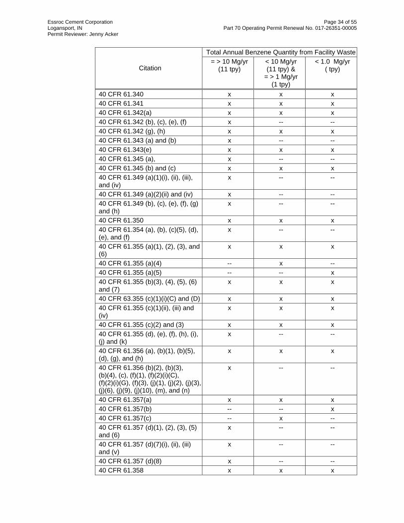
Essroc Cement Corporation Page 34 of 55 Logansport, IN Part 70 Operating Permit Renewal No. 017-26351-00005 Permit Reviewer: Jenny Acker
Total Annual Benzene Quantity from Facility Waste
Citation = > 10 Mg/yr
(11 tpy) < 10 Mg/yr (11 tpy) &
= > 1 Mg/yr (1 tpy)
< 1.0 Mg/yr ( tpy)
40 CFR 61.340 x x x 40 CFR 61.341 x x x 40 CFR 61.342(a) x x x 40 CFR 61.342 (b), (c), (e), (f) x -- -- 40 CFR 61.342 (g), (h) x x x 40 CFR 61.343 (a) and (b) x -- -- 40 CFR 61.343(e) x x x 40 CFR 61.345 (a), x -- -- 40 CFR 61.345 (b) and (c) x x x 40 CFR 61.349 (a)(1)(i), (ii), (iii), and (iv)
x -- --
40 CFR 61.349 (a)(2)(ii) and (iv) x -- -- 40 CFR 61.349 (b), (c), (e), (f), (g) and (h)
x -- --
40 CFR 61.350 x x x 40 CFR 61.354 (a), (b), (c)(5), (d), (e), and (f)
x -- --
40 CFR 61.355 (a)(1), (2), (3), and (6)
x x x
40 CFR 61.355 (a)(4) -- x -- 40 CFR 61.355 (a)(5) -- -- x 40 CFR 61.355 (b)(3), (4), (5), (6) and (7)
x x x
40 CFR 63.355 (c)(1)(i)(C) and (D) x x x 40 CFR 61.355 (c)(1)(ii), (iii) and (iv)
x x x
40 CFR 61.355 (c)(2) and (3) x x x 40 CFR 61.355 (d), (e), (f), (h), (i), (j) and (k)
x -- --
40 CFR 61.356 (a), (b)(1), (b)(5), (d), (g), and (h)
x x x
40 CFR 61.356 (b)(2), (b)(3), (b)(4), (c), (f)(1), (f)(2)(i)(C), (f)(2)(i)(G), (f)(3), (j)(1), (j)(2), (j)(3), (j)(6), (j)(9), (j)(10), (m), and (n)
x -- --
40 CFR 61.357(a) x x x 40 CFR 61.357(b) -- -- x 40 CFR 61.357(c) -- x -- 40 CFR 61.357 (d)(1), (2), (3), (5) and (6)
x -- --
40 CFR 61.357 (d)(7)(i), (ii), (iii) and (v)
x -- --
40 CFR 61.357 (d)(8) x -- -- 40 CFR 61.358 x x x

Essroc Cement Corporation Page 35 of 55 Logansport, IN Part 70 Operating Permit Renewal No. 017-26351-00005 Permit Reviewer: Jenny Acker
The provisions of 40 CFR 61 Subpart A – General Provisions, which are incorporated as 326 IAC 14-1, apply to the facility described in this section except when otherwise specified in 40 CFR 61, Subpart FF.
40 CFR 63, Subpart T
The parts washer at this source is not subject to the requirements of the National Emission Standards for Hazardous Air Pollutants (NESHAP) for Halogenated Solvent Degreasers (40 CFR 63, Subpart T) because they do not utilize a solvent containing methylene chloride, perchloroethylene, trichloroethylene, 1,1,1-trichloroethane, carbon tetrachloride, or chloroform, or any combination of these halogens, in a total concentration greater than five percent by weight. The requirements of the NESHAP for Halogenated Solvent Degreasers (40 CFR 63, Subpart T) are not included in the permit.
40 CFR 63, Subpart DD
This source is subject to the requirements of the National Emission Standard for Hazardous Air Pollutants (NESHAP) from Off-Site Waste and Recovery Operations (40 CFR 63, Subpart DD), which is incorporated by reference as 326 IAC 20-23, because the plant is a major source of hazardous air pollutant (HAP) emissions and the facility is regulated as a hazardous waste treatment, storage, and disposal facility which receives off-site material as specified in paragraph 40 CFR 63.680(b). The following units are subject to the requirements of 40 CFR 63, Subpart DD.
Hazardous Waste fuel facility (a) Waste Management Units
(1) Ten (10) hazardous waste-derived fuel storage tanks, installed in 1987 and 1994, with capacities ranging from 22,000-39,000 gallons. All tanks are connected to an integrated emission control system.
(2) Carbon Steel Piping System (3) Tank Rail Cars and Trucks
(b) Equipment components (1) Valves (2) Pumps (3) AWFCO Valves
(c) Caps (hose end covers) (d) Flanges (e) Manways (f) Flame Arrestors (g) Filter Pots (h Micro-motion Flow Meters (i) Level Transmitters (j) Pressure Indicators (k) Pressure Transmitters (l) Emergency Conservation Vent (m) Carbon Canister VOC Monitor (n) Tank Emergency Relief Ports (o) High Level Probes (p) Activated Carbon Canister System
Nonapplicable portions of the NESHAP will not be included in the permit. These facilities are subject to the requirements of 40 CFR 63, Subpart DD in accordance with the following table.
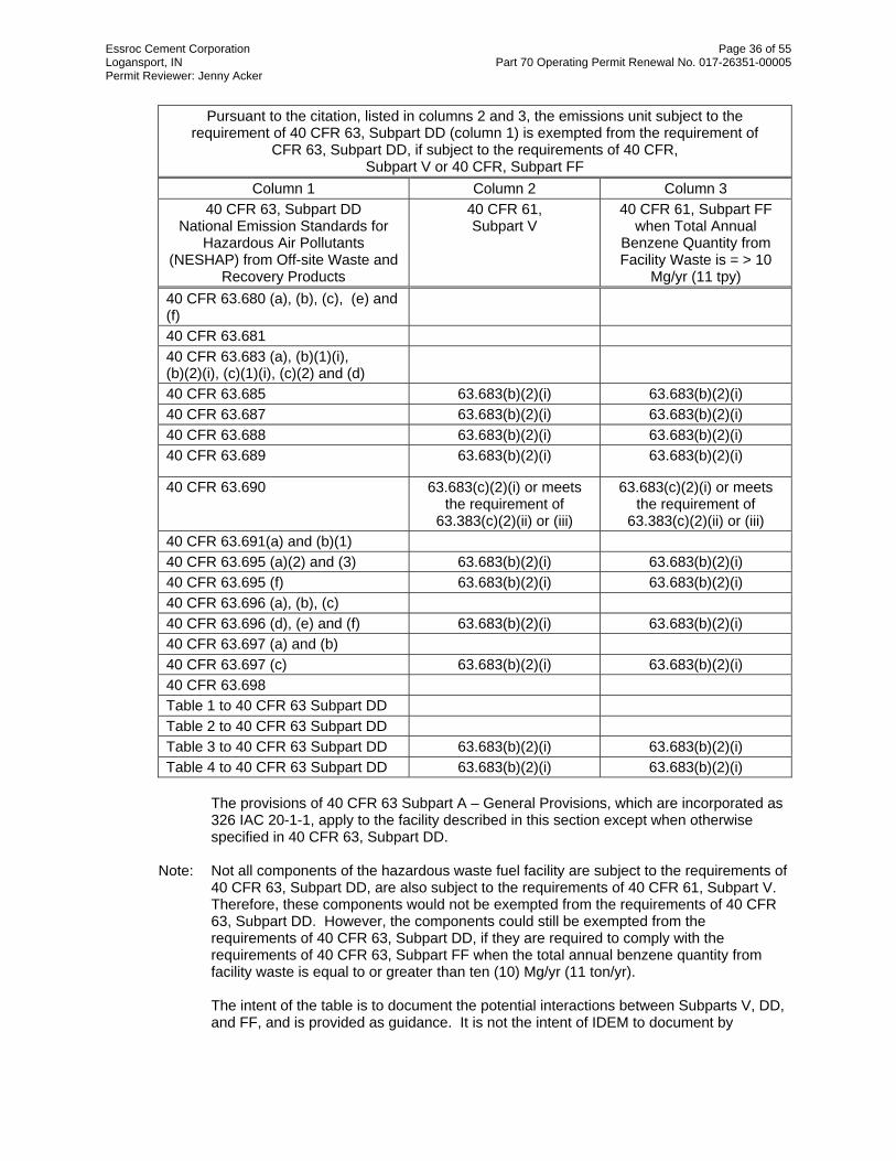
Essroc Cement Corporation Page 36 of 55 Logansport, IN Part 70 Operating Permit Renewal No. 017-26351-00005 Permit Reviewer: Jenny Acker
Pursuant to the citation, listed in columns 2 and 3, the emissions unit subject to the requirement of 40 CFR 63, Subpart DD (column 1) is exempted from the requirement of
CFR 63, Subpart DD, if subject to the requirements of 40 CFR, Subpart V or 40 CFR, Subpart FF
Column 1 Column 2 Column 3 40 CFR 63, Subpart DD
National Emission Standards for Hazardous Air Pollutants
(NESHAP) from Off-site Waste and Recovery Products
40 CFR 61, Subpart V
40 CFR 61, Subpart FF when Total Annual
Benzene Quantity from Facility Waste is = > 10
Mg/yr (11 tpy) 40 CFR 63.680 (a), (b), (c), (e) and (f)
40 CFR 63.681 40 CFR 63.683 (a), (b)(1)(i), (b)(2)(i), (c)(1)(i), (c)(2) and (d)
40 CFR 63.685 63.683(b)(2)(i) 63.683(b)(2)(i) 40 CFR 63.687 63.683(b)(2)(i) 63.683(b)(2)(i) 40 CFR 63.688 63.683(b)(2)(i) 63.683(b)(2)(i) 40 CFR 63.689 63.683(b)(2)(i) 63.683(b)(2)(i)
40 CFR 63.690 63.683(c)(2)(i) or meets the requirement of
63.383(c)(2)(ii) or (iii)
63.683(c)(2)(i) or meets the requirement of
63.383(c)(2)(ii) or (iii) 40 CFR 63.691(a) and (b)(1) 40 CFR 63.695 (a)(2) and (3) 63.683(b)(2)(i) 63.683(b)(2)(i) 40 CFR 63.695 (f) 63.683(b)(2)(i) 63.683(b)(2)(i) 40 CFR 63.696 (a), (b), (c) 40 CFR 63.696 (d), (e) and (f) 63.683(b)(2)(i) 63.683(b)(2)(i) 40 CFR 63.697 (a) and (b) 40 CFR 63.697 (c) 63.683(b)(2)(i) 63.683(b)(2)(i) 40 CFR 63.698 Table 1 to 40 CFR 63 Subpart DD Table 2 to 40 CFR 63 Subpart DD Table 3 to 40 CFR 63 Subpart DD 63.683(b)(2)(i) 63.683(b)(2)(i) Table 4 to 40 CFR 63 Subpart DD 63.683(b)(2)(i) 63.683(b)(2)(i)
The provisions of 40 CFR 63 Subpart A – General Provisions, which are incorporated as 326 IAC 20-1-1, apply to the facility described in this section except when otherwise specified in 40 CFR 63, Subpart DD.
Note: Not all components of the hazardous waste fuel facility are subject to the requirements of
40 CFR 63, Subpart DD, are also subject to the requirements of 40 CFR 61, Subpart V. Therefore, these components would not be exempted from the requirements of 40 CFR 63, Subpart DD. However, the components could still be exempted from the requirements of 40 CFR 63, Subpart DD, if they are required to comply with the requirements of 40 CFR 63, Subpart FF when the total annual benzene quantity from facility waste is equal to or greater than ten (10) Mg/yr (11 ton/yr). The intent of the table is to document the potential interactions between Subparts V, DD, and FF, and is provided as guidance. It is not the intent of IDEM to document by
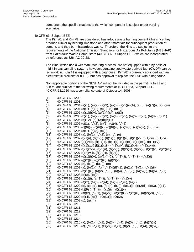
Essroc Cement Corporation Page 37 of 55 Logansport, IN Part 70 Operating Permit Renewal No. 017-26351-00005 Permit Reviewer: Jenny Acker
component the specific citations to the which component is subject under varying scenarios.
40 CFR 63, Subpart EEE
The Kiln #1 and Kiln #2 are considered hazardous waste burning cement kilns since they produce clinker by heating limestone and other materials for subsequent production of cement, and they burn hazardous waste. Therefore, the kilns are subject to the requirements of the National Emission Standards for Hazardous Air Pollutants (NESHAP) from Hazardous Waste Combustors (40 CFR 63, Subpart EEE) which are incorporated by reference as 326 IAC 20-28. The kilns, which use a wet manufacturing process, are not equipped with a by-pass or mid-kiln gas sampling system; however, containerized waste-derived fuel (CWDF) can be fed mid-kiln. Kiln #1 is equipped with a baghouse. Kiln #2 is currently equipped with an electrostatic precipitator (ESP), but has approval to replace the ESP with a baghouse. Non-applicable portions of the NESHAP will not be included in the permit. Kiln #1 and Kiln #2 are subject to the following requirements of 40 CFR 63, Subpart EEE. 40 CFR 63.1220 has a compliance date of October 14, 2008. (1) 40 CFR 63.1200 (2) 40 CFR 63.1201 (3) 40 CFR 63.1204 (a)(1), (a)(2), (a)(3), (a)(5), (a)(5)(ii)(A), (a)(6), (a)(7)(i), (a)(7)(ii) (4) 40 CFR 63.1204 (c)(1), (c)(2), (c)(3), (f), (h), (i) (5) 40 CFR 63.1206 (a)(1)(i)(A), (a)(1)(ii)(A), (a)(3) (6) 40 CFR 63.1206 (b)(1), (b)(2), (b)(3), (b)(4), (b)(5), (b)(6), (b)(7), (b)(8), (b)(11) (7) 40 CFR 63.1206 (b)(12), (b)(13)(i)(A)(1) (8) 40 CFR 63.1206 (c)(1), (c)(2), (c)(3), (c)(4), (c)(5) (9) 40 CFR 63.1206 (c)(6)(i), (c)(6)(ii), (c)(6)(iv), (c)(6)(v), (c)(6)(vi), (c)(6)(vii) (10) 40 CFR 63.1206 (c)(7), (c)(8), (c)(9) (11) 40 CFR 63.1207 (a), (b)(1), (b)(2), (c), (d), (e) (12) 40 CFR 63.1207 (f)(1)(i), (f)(1)(ii), (f)(1)(ii), (f)(1)(iv), (f)(1)(v), (f)(1)(vi), (f)(1)(vii), (13) 40 CFR 63.1207(f)(1)(viii), (f)(1)(ix), (f)(1)(x), (f)(1)(xi), (f)(1)(xii), (f)(1)(xv), (14) 40 CFR 63.1207 (f)(1)(xvi) (f)(1)(xvii), (f)(1)(xix), (f)(1)(xxii), (f)(1)(xxvi), (15) 40 CFR 63.1207 (f)(1)(xxvii) (f)(2)(i), (f)(2)(ii), (f)(2)(iii), (f)(2)(v), (f)(2)(vi), (f)(2)(vii) (16) 40 CFR 63.1207 (f)(2)(viii), (f)(2)(ix), (f)(2)(x) (17) 40 CFR 63.1207 (g)(1)(i)(A), (g)(1)(i)(C), (g)(1)(ii), (g)(1)(iii), (g)(2)(i) (18) 40 CFR 63.1207 (g)(2)(ii), (g)(2)(iii), (g)(2)(v) (19) 40 CFR 63.1207 (h), (i), (j), (k), (l), (m) (20) 40 CFR 63.1208 (a), (b)(1)(i)(A), (b)(1)(i)(B)(1), (b)(1)(i)(B)(2), (b)(1)(ii) (21) 40 CFR 63.1208 (b)(1)(iii), (b)(2), (b)(3), (b)(4), (b)(5)(i), (b)(5)(ii), (b)(6), (b)(7) (22) 40 CFR 63.1208 (b)(8), (b)(9) (23) 40 CFR 63.1209 (a)(1)(i), (a)(1)(ii), (a)(1)(iii), (a)(1)(v) (24) 40 CFR 63.1209 (a)(2), (a)(3), (a)(4), (a)(5), (a)(6), (a)(7) (25) 40 CFR 63.1209 (b), (c), (d), (e), (f), (h), (i), (j), (k)(1)(i), (k)(2)(ii), (k)(3), (k)(4), (26) 40 CFR 63.1209 (k)(9) (l)(1)(iii), (l)(1)(iv), (l)(1)(v) (27) 40 CFR 63.1209 (m)(2), (n)91), (n)(2)(i), (n)(2)(ii), (n)(2)(iii), (n)(2)(vii), (n)(3) (28) 40 CFR 63.1209 (n)(4), (n)(5), (O)(1)(i), (O)(2)\ (29) 40 CFR 63.1209 (p), (q), (r) (30) 40 CFR 63.1210 (31) 40 CFR 63.1211 (32) 40 CFR 63.1212 (33) 40 CFR 63.1213 (34) 40 CFR 63.1214 (35) 40 CFR 63.1215 (a), (b)(1), (b)(2), (b)(3), (b)(4), (b)(5), (b)(6), (b)(7)(iii) (36) 40 CFR 63.1215 (c), (d), (e)(1), (e)(2)(i), (f)(1), (f)(2), (f)(3), (f)(4), (f)(5)(i)

Essroc Cement Corporation Page 38 of 55 Logansport, IN Part 70 Operating Permit Renewal No. 017-26351-00005 Permit Reviewer: Jenny Acker
(37) 40 CFR 63.1215 (g), (h) (38) Table 1 of 63.1215 (39) Table 2 of 63.1215 (40) Table 3 of 63.1215 (41) Table 4 of 63.1215 (42) 40 CFR 63.1220 (a)(1), (a)(2), (a)(3), (a)(4), (a)(5)(ii), (a)(6), (a)(7) (43) 40 CFR 63.1220 (c), (d), (f), (g), (h) (44) Table 1 to Subpart EEE of Part 63 (45) Table 1 to Subpart EEE of Part 63 (46) Appendix to Subpart EEE of Part 63 The provisions of 40 CFR 63 Subpart A – General Provisions, which are incorporated as 326 IAC 20-1-1, apply to the facility described in this section except when otherwise specified in 40 CFR 63, Subpart EEE.
40 CFR 63, Subpart LLL (a) None of the quarry facilities/emission units or raw material sizing facilities/emission units
listed in this section are subject to the requirements of the National Emissions Standards for Hazardous Air Pollutants (NESHAP) from the Portland Cement Manufacturing Industry (40 CFR 63, Subpart LLL) because they are not affected facilities under this rule. These facilities/emission units precede the raw material storage, which is just prior to the raw mill, in the sequence of materials handling operations. The rule specifically states that for portland cement plants with on-site nonmetallic mineral processing facilities, the first affected source in the sequence of materials handling operations subject to the rule is the raw material storage, which is just prior to the raw mill. The rule states that the primary and secondary crushers and any other equipment of the on-site nonmetallic mineral processing plant which precedes the raw material storage are not subject to this rule. Furthermore, the rule states that the first conveyor transfer point subject to this rule is the transfer point associated with the conveyor transferring material from the raw material storage to the raw mill.
(b) Under 40 CFR 63, Subpart LLL, a raw mill is used to grind feed to the approriate size.
Feed, by definition under 40 CFR 63, Subpart LLL, does not include the fuels used in the kiln to produce heat. Therefore, Coal mill #1 and Coal mill #2 are not raw mills and not subject to the requirements of 40 CFR 63, Subpart LLL.
(c) The following facilites are associate with coal preparation prior to the coal mills and are not considered part of a non-metallic mineral processing process. Therefore, they are not subject to the requirements of 40 CFR 63, Subpart LLL.
• Crane Storage Facilities (as follows)
One (1) coal/coke storage bin, identified as EU315. • Fossil Fuel Facilities (as follows)
One (1) spare belt feeder to belt 8, identified as EU317. One (1) coal/coke belt feeder to belt 8, identified as EU318. Belt 8 to coal/coke tanks, identified as EU319. One (1) coal/coke tank #1, identified as EU320. Belt feed to coal mill #1, identified as EU321. Coal/Coke cross belt, identified as EU322. One (1) coal/coke tank #2, identified as EU323. Belt feed to coal mill #2, identified as EU324
(d) Kiln #1 (EU401), and kiln #2 (EU413), are not subject to the requirements of the NESHAP
from the Portland Cement Manufacturing Industry (40 CFR 63, Subpart LLL) because they normally burn hazardous waste; and therefore, are subject to the requirements of the
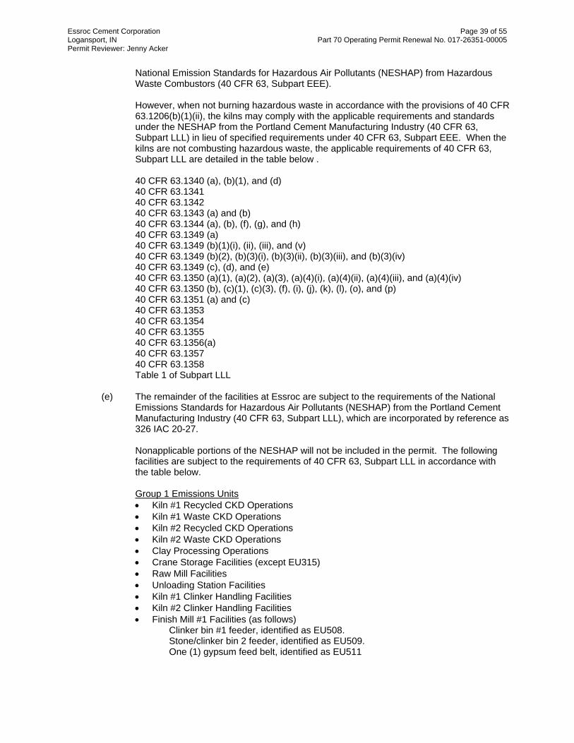
Essroc Cement Corporation Page 39 of 55 Logansport, IN Part 70 Operating Permit Renewal No. 017-26351-00005 Permit Reviewer: Jenny Acker
National Emission Standards for Hazardous Air Pollutants (NESHAP) from Hazardous Waste Combustors (40 CFR 63, Subpart EEE).
However, when not burning hazardous waste in accordance with the provisions of 40 CFR 63.1206(b)(1)(ii), the kilns may comply with the applicable requirements and standards under the NESHAP from the Portland Cement Manufacturing Industry (40 CFR 63, Subpart LLL) in lieu of specified requirements under 40 CFR 63, Subpart EEE. When the kilns are not combusting hazardous waste, the applicable requirements of 40 CFR 63, Subpart LLL are detailed in the table below . 40 CFR 63.1340 (a), (b)(1), and (d) 40 CFR 63.1341 40 CFR 63.1342 40 CFR 63.1343 (a) and (b) 40 CFR 63.1344 (a), (b), (f), (g), and (h) 40 CFR 63.1349 (a) 40 CFR 63.1349 (b)(1)(i), (ii), (iii), and (v) 40 CFR 63.1349 (b)(2), (b)(3)(i), (b)(3)(ii), (b)(3)(iii), and (b)(3)(iv) 40 CFR 63.1349 (c), (d), and (e) 40 CFR 63.1350 (a)(1), (a)(2), (a)(3), (a)(4)(i), (a)(4)(ii), (a)(4)(iii), and (a)(4)(iv) 40 CFR 63.1350 (b), (c)(1), (c)(3), (f), (i), (j), (k), (l), (o), and (p) 40 CFR 63.1351 (a) and (c) 40 CFR 63.1353 40 CFR 63.1354 40 CFR 63.1355 40 CFR 63.1356(a) 40 CFR 63.1357 40 CFR 63.1358 Table 1 of Subpart LLL
(e) The remainder of the facilities at Essroc are subject to the requirements of the National
Emissions Standards for Hazardous Air Pollutants (NESHAP) from the Portland Cement Manufacturing Industry (40 CFR 63, Subpart LLL), which are incorporated by reference as 326 IAC 20-27. Nonapplicable portions of the NESHAP will not be included in the permit. The following facilities are subject to the requirements of 40 CFR 63, Subpart LLL in accordance with the table below. Group 1 Emissions Units • Kiln #1 Recycled CKD Operations • Kiln #1 Waste CKD Operations • Kiln #2 Recycled CKD Operations • Kiln #2 Waste CKD Operations • Clay Processing Operations • Crane Storage Facilities (except EU315) • Raw Mill Facilities • Unloading Station Facilities • Kiln #1 Clinker Handling Facilities • Kiln #2 Clinker Handling Facilities • Finish Mill #1 Facilities (as follows)
Clinker bin #1 feeder, identified as EU508. Stone/clinker bin 2 feeder, identified as EU509. One (1) gypsum feed belt, identified as EU511

Essroc Cement Corporation Page 40 of 55 Logansport, IN Part 70 Operating Permit Renewal No. 017-26351-00005 Permit Reviewer: Jenny Acker
• Finish Mill #2 Facilities (as follows) Clinker bin 1 feeder, identified as EU523. Clinker bin 2 feeder, identified as EU524. FM #2 gypsum feeder, identified as EU525.
• Finish Product Silo Storage Facilities • Finish Product Silo Transfer Operations • Finish Product Loadout Old Silos (West) Operation • Finish Product Loadout New Silos (East) Operation • Finish Product Masonry Packing • Finish Product Portland Packing • CKD –To-Finish Mill (CKD2FM) Recycling Operations Note: Open/unenclosed material stockpiles and haul roads associated with the Group 1
Emissions Units are not subject the requirements of 40 CFR 63, Subpart LLL. Group 2 Emissions Units • Finish Mill #1 Facilities (as follows)
One (1) finish mill #1 feed belt, identified as EU601. One (1) finish mill #1 circuit, identified as EU602. One (1) separator, cooler #1 and transfer, identified as EU603.
• Finish Mill #2 Facilities (as follows) One (1) finish mill #2 feed belt, identified as EU604. One (1) finish mill #2 circuit, identified as EU605. One (1) separator, cooler #2 and transfer, identified as EU606.
• Raw mill #1 (Insignificant Activity) • Raw mill #2 (Insignificant Activity) Group 3 Emissions Units • One (1) clinker cooler #1, identified as EU412. • One (1) clinker cooler #2, identified as EU421. Group 1
Emissions Units Group 2
Emissions Units Group 3
Emissions Units 40 CFR 63.1340 x x x 40 CFR 63.1341 x x x 40 CFR 63.1342 x x x 40 CFR 63.1345 -- -- x 40 CFR 63.1347 -- x -- 40 CFR 63.1348 x -- -- 40 CFR 63.1349(a) x x x 40 CFR 63.1349 (b)(1)(i),(v), and (vi), and (c)
-- -- x
40 CFR 63.1349 (b)(2) x x -- 40 CFR 63.1350 (a)(1), (2) and (4), and (b)
x x x
40 CFR 63.1350(d) -- -- x 40 CFR 63.1350 (e) and (m) -- x -- 40 CFR 63.1351 (a) and (b) x x x 40 CFR 63.1353 x x x 40 CFR 63.1354 (a), (b)(1), (2), (3), (4), (5), (6), (7) and
x x x

Essroc Cement Corporation Page 41 of 55 Logansport, IN Part 70 Operating Permit Renewal No. 017-26351-00005 Permit Reviewer: Jenny Acker
(8) 40 CFR 63.1355 x x x 40 CFR 63.1356 x x x 40 CFR 63.1357 x x x 40 CFR 63.1358 x x x Table 1 to Subpart LLL of Part 63
x x x
The provisions of 40 CFR 63 Subpart A – General Provisions, which are incorporated as 326 IAC 20-1-1, apply to the facility described in this section except when otherwise specified in 40 CFR 63, Subpart LLL.
State Rule Applicability - Entire Source
326 IAC 2-2 (Prevention of Significant Deterioration (PSD)) The EPA has issued a notice of violation alleging that the kilns are not in compliance with the requirements of PSD. The EPA alleges that Essroc made modifications to the kilns, and began using pet coke as a fuel in the kilns, both of which triggered the requirements of PSD. This case is on-going and has not yet been resolved; therefore, no detailed compliance plan has been established. IDEM has included language in the Part 70 permit stating that the permit shield will not apply to the kilns with regards to the requirements of 326 IAC 2-2 (PSD). Once the enforcement case has been resolved, IDEM will reopen the permit to establish the permit shield for the kilns and, if necessary, include the provisions of the compliance plan in the Part 70 permit. MSM 017-22319-00005 & SPM 017-22539-00005 The source was issued Minor Source Modification 017-22319-00005 (February 3, 2006) & Significant Permit Modification 017-22539-00005 (April 4, 2006) relating to the CKD-To-Finish Mill (CKD2FM) Project. The project allowed the source to divert cement kiln dust (CKD), which was being disposed, to finish mill #1 circuit and finish mill #2 circuit, where the CKD is recycled back into the cement manufacturing process. The source accepted limitations which rendered the requirements of 326 IAC 2-2 (PSD) not applicable to the project. As part of the Part 70 Operating Permit Renewal (017-26351-00005), the limitations are being modified as follows:
PM and PM10 emissions shall be limited as follows:
Emission Unit PM PM10 CKD2FM recycling
storage tank system (EU902)
0.72 (lb/ton of CKD)
0.46 (lb/ton of CKD)
CKD2FM #1 FM recycling system (EU903)
0.003 (lb/ton of CKD)
0.0011 (lb/ton of CKD)
CKD2FM #2 FM recycling system (EU904)
0.003 (lb/ton of CKD)
0.0011 (lb/ton of CKD)
Silo 15 (EU905) Described in Section D.1
0.72 (lb/ton of CKD)
0.46 (lb/ton of CKD)
The Permittee shall limit the throughput of CKD per twelve consecutive month period, with compliance determined at the end of each month, according to the following:
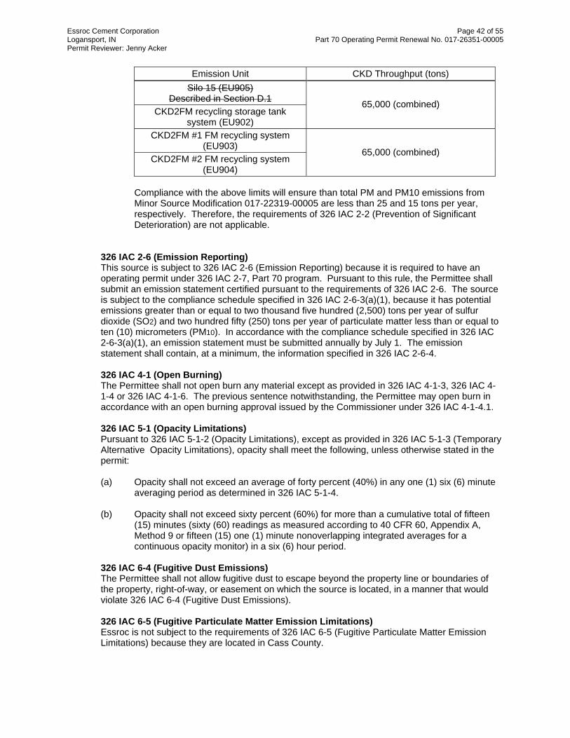
Essroc Cement Corporation Page 42 of 55 Logansport, IN Part 70 Operating Permit Renewal No. 017-26351-00005 Permit Reviewer: Jenny Acker
Emission Unit CKD Throughput (tons) Silo 15 (EU905)
Described in Section D.1 CKD2FM recycling storage tank
system (EU902)
65,000 (combined)
CKD2FM #1 FM recycling system (EU903)
CKD2FM #2 FM recycling system (EU904)
65,000 (combined)
Compliance with the above limits will ensure than total PM and PM10 emissions from Minor Source Modification 017-22319-00005 are less than 25 and 15 tons per year, respectively. Therefore, the requirements of 326 IAC 2-2 (Prevention of Significant Deterioration) are not applicable.
326 IAC 2-6 (Emission Reporting) This source is subject to 326 IAC 2-6 (Emission Reporting) because it is required to have an operating permit under 326 IAC 2-7, Part 70 program. Pursuant to this rule, the Permittee shall submit an emission statement certified pursuant to the requirements of 326 IAC 2-6. The source is subject to the compliance schedule specified in 326 IAC 2-6-3(a)(1), because it has potential emissions greater than or equal to two thousand five hundred (2,500) tons per year of sulfur dioxide (SO2) and two hundred fifty (250) tons per year of particulate matter less than or equal to ten (10) micrometers (PM10). In accordance with the compliance schedule specified in 326 IAC 2-6-3(a)(1), an emission statement must be submitted annually by July 1. The emission statement shall contain, at a minimum, the information specified in 326 IAC 2-6-4.
326 IAC 4-1 (Open Burning) The Permittee shall not open burn any material except as provided in 326 IAC 4-1-3, 326 IAC 4-1-4 or 326 IAC 4-1-6. The previous sentence notwithstanding, the Permittee may open burn in accordance with an open burning approval issued by the Commissioner under 326 IAC 4-1-4.1. 326 IAC 5-1 (Opacity Limitations) Pursuant to 326 IAC 5-1-2 (Opacity Limitations), except as provided in 326 IAC 5-1-3 (Temporary Alternative Opacity Limitations), opacity shall meet the following, unless otherwise stated in the permit: (a) Opacity shall not exceed an average of forty percent (40%) in any one (1) six (6) minute
averaging period as determined in 326 IAC 5-1-4. (b) Opacity shall not exceed sixty percent (60%) for more than a cumulative total of fifteen
(15) minutes (sixty (60) readings as measured according to 40 CFR 60, Appendix A, Method 9 or fifteen (15) one (1) minute nonoverlapping integrated averages for a continuous opacity monitor) in a six (6) hour period.
326 IAC 6-4 (Fugitive Dust Emissions) The Permittee shall not allow fugitive dust to escape beyond the property line or boundaries of the property, right-of-way, or easement on which the source is located, in a manner that would violate 326 IAC 6-4 (Fugitive Dust Emissions).
326 IAC 6-5 (Fugitive Particulate Matter Emission Limitations) Essroc is not subject to the requirements of 326 IAC 6-5 (Fugitive Particulate Matter Emission Limitations) because they are located in Cass County.

Essroc Cement Corporation Page 43 of 55 Logansport, IN Part 70 Operating Permit Renewal No. 017-26351-00005 Permit Reviewer: Jenny Acker
Pursuant to Agreed Order A-4202 entered into on June 9, 1999, fugitive particulate matter emissions shall be controlled according to the plan approved by IDEM on February 8, 2000, as may be amended from time to time with IDEM approval. The plan consists of: (a) Water sprays shall be used to control fugitive emissions from the primary apron feeder at
the crusher department on an as-needed basis. Due to safety concerns, these water spray are not operated when the temperature is below 35 degrees F or when freezing can occur.
(b) Vehicular traffic is to follow established roadways (paved and unpaved) and observe the
posted speed limits. (c) Equipment is to be operated in such a manner as to minimize spills. (d) Spilled materials shall be cleaned up in a timely manner. (e) Leaks in potential sources of fugitive emissions shall be repaired in a timely manner. (f) The road sweeper is to be operated as needed, weather conditions permitting. (g) The water spray truck is to be operated as needed; however, due to safety concerns, the
water spray truck is not operated when the temperature is below 35 degrees F or frozen conditions exist/occur while the roadways are wet.
(h) Conveyors will be maintained to minimize fugitive dust emissions. (i) During unloading, material handling, and material transfer operations, free fall heights
from the feed belts shall be minimized. (j) Parking lots/areas
(1) The paved lots are used solely for visitor parking and do not handle any traffic volume. These areas are on the route of the road sweeper.
(2) The unpaved lots are used primarily for employee parking and do not handle a
high volume of traffic. These lots are on the route of the water spray truck. These lots are wetted on an as-needed basis.
(k) The area around the storage piles are to be maintained in such a manner as to minimize
the potential for fugitive particulate matter emissions.
The agreed order expired on June 30, 2002; therefore, no fugitive dust plan is in force at this time.
State Rule Applicability – Individual Facilities 326 IAC 2-4.1 (Major Sources of Hazardous Air Pollutants (HAP)) The operation of kiln #1 (EU401) and Kiln #2 (EU413) will result in greater than ten (10) tons per year for a single HAP and greater than twenty-five (25) tons per year for a combination of HAPs. Therefore, 326 IAC 2-4.1 would apply to the kilns, however, pursuant to 326 IAC 2-4.1-1(b)(2), because these facilities are specifically regulated or exempted from regulation by the National Emission Standards for Hazardous Air Pollutants (NESHAP) from the Portland Cement Manufacturing Industry (40 CFR 63, Subpart LLL), which was issued pursuant to Section 112(d) of the CAA, these facilities are exempt from the requirements of 326 IAC 2-4.1.

Essroc Cement Corporation Page 44 of 55 Logansport, IN Part 70 Operating Permit Renewal No. 017-26351-00005 Permit Reviewer: Jenny Acker
326 IAC 3-5-1 (Continuous Monitoring of Emissions) Pursuant to 326 IAC 3-5-1(c)(5) portland cement plants shall monitor opacity at the following facilities: kilns and clinker coolers. Therefore, the kilns and clinker coolers are affected sources and are subject to the requirements of 326 IAC 3 (Monitoring Requirements). The source shall install, calibrate, and maintain a continuous monitoring system (COMS) for opacity. 326 IAC 6-3-2 (Particulate Emission Limitations for Manufacturing Processes) Miscellaneous Units The definition of manufacturing process in 326 IAC 6-3-1.5(a)(2) is “any single or series of actions, operations, or treatments in which a mechanical, physical, or chemical transformation of material occurs that emits, or has the potential to emit, particulate in the production of the product. The term includes transference, conveyance, or repair of a product.” As stated, this definition could lead to an interpretation that the manufacturing of Portland cement from start to finish could be considered a process. However, the IDEM, OAQ has historically viewed processes as groups of equipment that are physically connected and perform a similar function (i.e. the storage or handling of material). In making the determination, the definition for process weight rate in 326 IAC 1-2-59 was relied upon when more than one interpretation could be made. The last paragraph of the definition states: “When the nature of any process or operation or the design of any is such as to permit more than one interpretation for this definition, the interpretation that results in the minimum value for allowable emission shall apply.” The following determinations were made during the Initial Part 70 permitting process.
(1) The raw material sizing equipment, including the raw material loading and unloading
(EU112 and EU114), apron feeder (EU115), primary crusher (EU116), clean-up screw (EU117), impact apron feeder (EU118), belt #1 covered conveyor (EU119), screen transfers (EU120), belt #2 covered conveyor (EU121), secondary crusher (EU122), and belt #3 covered conveyor (EU201) were grouped together as one process because they operate in sequence, are dependent on each other and are used to accomplish one goal, being the sizing and preparation of the quarried material.
(2) The clay unloading process (EU123), wobbler feeder (EU124), log washer system
(EU125), and the waste gravel loading process (EU127), were grouped together as one process, because they operate in sequence, are dependent on each other and are used to accomplish one goal, being the storage and transfer of clay.
(3) The crane storage facilities including limestone storage bins (EU202), Missouri clay
storage bins (EU203), west flyash truck unloading (EU210), west flyash holding tank (EU211), east flyash truck unloading (EU213), and east flyash storage tank (EU214), were grouped together as one process, because they operate in sequence, are dependent on each other and are used to accomplish one goal, being the storage of any raw materials.
(4) The raw mill facilities including three belt feeders (EU205), Missouri clay belt feeder
(EU206), iron feeder (EU207), covered cross belt (EU208), covered raw mill feed belt (EU209), transfer screw to raw mill (EU212), east short covered screw (EU215), and E-W long covered screw (EU216), were grouped together as one process, because they operate in sequence, are dependent on each other and are used to accomplish one goal, being the transfer of any raw materials.
(5) The Unloading station facilities including the railroad unloading (EU307), unloading
station hopper (EU308), belt feeder (EU309), belt 7 covered conveyor (EU310), conveyor transfer to outside storage (EU311), and crane unloading (EU325), were grouped

Essroc Cement Corporation Page 45 of 55 Logansport, IN Part 70 Operating Permit Renewal No. 017-26351-00005 Permit Reviewer: Jenny Acker
together as one process because they operate in sequence, and are used to accomplish one goal, being the unloading and handling of fossil fuels.
(6) The fossil fuel facilities including the spare storage bin (EU314), coal/coke storage bin
(EU315), two (2) gypsum storage bins (EU316), spare belt feeder to belt 8 (EU317), coal/coke belt feeder to belt 8 (EU318), belt 8 to coal/coke tanks (EU319), coal/coke tank #1 (EU320), belt feed to coal mill #1 (EU321), coal/coke cross belt (EU322) coal/coke tank #2 (EU323) and belt feed to coal mill #2 (EU324) were grouped together as one process because they operate in sequence and are used to accomplish one goal, being the fossil fuel storage and transfer to the kilns.
(7) The recycled CKD operations including the #1 recycled dust elevator (EU408), recycled
dust holding tank (EU409), and feeder screw & F-K pump (EU410), were grouped together because they operate in sequence dependent on each other, and are used to accomplish one goal, being the recycling of cement kiln dust from kiln #1.
(8) The #2 recycled CKD operations including the #2 recycled dust elevator (EU417),
recycled dust holding tank (EU418), and feeder screw & F-K pump (EU419), were grouped together because they operate in sequence dependent on each other, and are used to accomplish one goal, being the recycling of cement kiln dust from kiln #1.
(9) The covered 16" cross screw (EU403), the #1 waste dust elevator (EU404), the
discharge hopper screws (EU402), and the 9" cross screw (EU405) were grouped together because they operate in sequence and are used to accomplish one goal, being the disposal of waste dust from kiln #1.
(10) The covered 16" cross screw (EU415), the #2 waste dust elevator (EU416), and the
discharge hopper screws (EU414), were grouped together because they operate in sequence and are used to accomplish one goal, being the disposal of waste dust from kiln #2.
(11) The clinker exiting the coolers is transferred to the storage bins. The #1 clinker drag
conveyor (EU501), #1 CCDC screws (EU502), #1 clinker elevator (EU503) and clinker conveyor transfer system (EU504) were grouped together because they are interconnected facilities that have one specific function which is to transfer clinker from the coolers to the storage bins.
(12) The clinker exiting the coolers is transferred to the storage bins. The #2 clinker drag
conveyor (EU516), #2 CCDC screws (EU517), #2 clinker elevator (EU518) and clinker conveyor transfer system circuit (EU519) were grouped together because they are interconnected facilities that have one specific function which is to transfer clinker from the coolers to the storage bins.
(13) The clinker is then transferred from the storage bins to the finish mills. The clinker bin 1
finish mill #1 (EU505), the stone/clinker bin 2 finish mill #1 (EU506), clinker bin 3 finish mill #1 (EU507), clinker bin 1 feeder (EU508), stone/clinker bin 2 feeder (EU509), the gypsum feed belt (EU511), clinker bin 1 #2 finish mill (EU520), clinker bin 2 #2 finish mill (EU521), clinker bin 1 feeder (EU523), clinker bin 2 feeder (EU524), and FM #2 gypsum feeder (EU525) were grouped together because they have one specific function which is to transfer all clinker from the storage bins to the finish mills.
(14) Although the finish mills #1 and #2 (EU601 through EU603) and (EU604 through EU606),
respectively, perform similar functions, they are operated independently such as to allow each finish mill to produce a slightly different grade of cement and are not physically connected to each other. Therefore, they were considered separate processes.

Essroc Cement Corporation Page 46 of 55 Logansport, IN Part 70 Operating Permit Renewal No. 017-26351-00005 Permit Reviewer: Jenny Acker
(16) The silo operations and the silo transfers (EU704, EU709, & EU711) were grouped together because they are physically connected, are operated dependently in sequence, and are used to accomplish the same goal, which is storage and transfer of finish material to the loading facilities.
(17) The east truck loadout (EU706), the west truck loadout (EU712), and the railroad loadout
(EU713) were not grouped together because they can operate independently. (18) The masonry packing operations (EU801 through EU803) and the portland packing
operations (EU804 through EU806) were not grouped together because they can operate independently.
(19) The CKD2FM recycling storage tank system (EU902) and the CKD2FM #1FM (EU903)
and CKD2FM #2 (EU904)were grouped together because they operate in sequence to move cement kiln dust to finish mills #1 and #2. The waste dust tank and CKD2FM surge system (EU406) were considered a separate system, because they can deliver CKD to other loadout operations.
The limitations for these facilities were calculated using the following equations
Interpolation of the data for the process weight rate up to sixty thousand (60,000) pounds per hour shall be accomplished by use of the equation:
E = 4.10 P 0.67 where E = rate of emission in pounds per hour and P = process weight rate in tons per hour
Interpolation and extrapolation of the data for the process weight rate in excess of sixty thousand (60,000) pounds per hour shall be accomplished by use of the equation:
E = 55.0 P 0.11 - 40 where E = rate of emission in pounds per hour and P = process weight rate in tons per hour
When the process weight rate exceeds 200 tons per hour, the maximum allowable emission may exceed the pound per hour limit calculated using the above-referenced equation, provided the concentration of particulate matter in the discharge gases to the atmosphere is less than 0.10 pounds per on thousand (1,000) pounds of gases.
Therefore the limits for the various facilities are as follows:
Unit ID Process Description Process
Weight Rate (tons/hr)
Particulate Emission Limit
(E) (lbs/hr) EU112, EU114 through
EU122, and EU201 Raw Material Sizing 550 70.1
EU408 - EU410 kiln #1 recycled CKD operations 15 25.16
EU402 - EU405 kiln #1 waste CKD operations 15 25.16
EU417 - EU419 kiln #2 recycled CKD operations 15 25.16
EU414 - EU416 kiln #2 waste CKD operations 15 25.16
EU407 CKD loading operation 30 39.96 EU123 - EU125, & EU127 clay processing facilities 30 39.96

Essroc Cement Corporation Page 47 of 55 Logansport, IN Part 70 Operating Permit Renewal No. 017-26351-00005 Permit Reviewer: Jenny Acker
Unit ID Process Description Process
Weight Rate (tons/hr)
Particulate Emission Limit
(E) (lbs/hr) EU202, EU204, EU210, EU211, EU213 & EU214
raw material storage process 200 58.51
EU505 - EU509, EU511, EU520, EU521,
& EU523 - EU525
transferring clinker from storage bins to finish mills 45 43.6
EU205-209, EU212, EU215 & EU216 raw mill facilities 175 57.07
EU307 - EU311, & EU325 unloading station facilities 200 58.51 EU314 - EU324 fossil fuel facilities 200 58.51
EU501 - EU504 kiln #1 clinker handling facilities 42 42.97
EU516 - EU519 kiln #2 clinker handling facilities 42 42.97
EU601 - EU603 finish mill #1 45 43.6 EU604 - EU606 finish mill #2 45 43.6
EU704, EU709, EU711 silos 420 66.89 EU712 west bulk truck loadout 450 67.7 EU706 east bulk truck loadout 450 67.7
EU701 & EU702 truck/RR car unloading
process and internal transfer to silos
100 51.28
EU713 bulk RR loadout process 100 51.28
EU801 - EU803 finish product masonry packing 44 43.4
EU804 - EU806 finish product portland packing 44 43.4
EU406 the waste dust tank, and CKD2FM surge system 30 39.96
EU902 - EU904 CKD2FM recycling storage tank system, and CKD2FM
#1FM and CKD #2FM 14 24.03
The control equipment shall be in operation at all times the associated facility is in operation, in order to comply with this limit. Cement Kilns and Clinker Coolers Pursuant to 326 IAC 6-3-1(c)(6), this rule (326 IAC 6-3) shall not apply if a particulate limitation established in 326 IAC 20 is more stringent than the particulate limitation established in this rule (326 IAC 6-3). (a) The kilns are subject to 326 IAC 6-3-2(b) for cement kilns which commenced operation
prior to December 6, 1968. The particulate limitation (E (lb/hr)) for a process weight above thirty (30) tons per hour shall be established in accordance with the following equation: E = 15.0 P 0.50 Where E = rate of emission in pounds per hour and P = process weight rate in tons/hr. At a process weight rate of 42 tons/hr, the resulting E = 97 lbs/hr. However, when combusting hazardous waste, the kilns are subject to requirements of 40 CFR 63.1204(a)(7), which limits particulate emissions from the kilns to <= 0.15 kg/Mg (0.304 lb/ton). When not combusting hazardous waste the kilns are subject to an alternative

Essroc Cement Corporation Page 48 of 55 Logansport, IN Part 70 Operating Permit Renewal No. 017-26351-00005 Permit Reviewer: Jenny Acker
particulate emission limitation established at 40 CFR 63.1343(b)(1) of <=0.15 kg/Mg. At 42 tons per hour and PM<= 0.304 lb/ton, the resulting allowable emissions are 12.6 lb/hr, which is more stringent than 97 lbs/hr. Therefore, the requirements of 326 IAC 6-3 do not apply to the kilns.
(b) The clinker coolers are 326 IAC 6-3-2(e) for which the particulate emission limitation (E) for a process weight rate above thirty (30) tons per hour shall be established in accordance with the following equation:
E = 55.0 P 0.11 - 40 where E = rate of emission in pounds per hour and P = process weight rate in tons per hour At a process weight rate of 42 tons/hr, the resulting E = 42.97 lbs/hr. However, the clinker coolers are subject to a particulate emission limitation established at 40 CFR 63.1345 (a)(1) of 0.05 kg/Mg (0.10 lb/ton). At 42 tons per hour the resulting allowable emissions are 4.2 lbs/hr, which is more stringent than 42.97 lbs/hr. Therefore, requirements of 326 IAC 6-3 do not apply to the clinker coolers.
326 IAC 7-1.1 ( Sulfur Dioxide Emission Limitations) The kilns are subject to this rule because each kiln has the potential to emit greater than 25 tons per year or 10 pounds per hour of SO2. The SO2 emissions from each of the kilns shall not exceed 6.0 pounds per million Btu of heat input when combusting coal or a combination of coal and oil. The sulfur content of the coal combusted shall not exceed 4.1 weight percent. Compliance shall be determined on a calendar month average.
326 IAC 7-2-1 (Sulfur Dioxide Compliance Reporting) Pursuant to this rule, a quarterly report shall be submitted including the average sulfur content, heat content, the sulfur dioxide emission rate in pounds per million Btu, and the coal consumptions. Coal sampling and analysis data shall be collected pursuant to the procedures specified in 326 IAC 3-7-2 for coal combustion.
326 IAC 8-1-6 None of the facilities at this plant are subject to the requirements of this rule because they all have the potential to emit less than 25 tons per year of VOC and/or they were constructed prior to January 1, 1980. No other 326 IAC 8 rules apply to any of the significant emission units at this source.
326 IAC 10-3 (NOx Reduction Requirements) Pursuant to 326 IAC 10-3-2(6), the requirements of 326 IAC 10-3 do not apply to the kilns because they are less than 14 feet in diameter.
State Rule Applicability - Insignificant Activities
326 IAC 8-4-3 (Petroleum Liquid Storage Facilities) All of the petroleum storage tanks at ESSROC have capacities less than 39,000 gallons. Therefore, the requirements of 326 IAC 8-4-3 do not apply. 326 IAC 8-4-6 (Gasoline Dispensing Facilities) The gasoline dispensing facility at ESSROC was constructed prior to July 1, 1989, and has monthly gasoline throughputs of less than 10,000 gallons. Therefore, the requirements of 326 IAC 8-4-6 do not apply.

Essroc Cement Corporation Page 49 of 55 Logansport, IN Part 70 Operating Permit Renewal No. 017-26351-00005 Permit Reviewer: Jenny Acker
326 IAC 8-3-2 (Cold Cleaner Operations) and 326 IAC 8-3-5 (Cold Cleaner Degreaser Operation and Control) The parts washers are subject to the requirements of these rules. Pursuant to 326 IAC 8-3-2 (Cold Cleaner Operations), the Permittee shall: (a) Equip the cleaner with a cover; (b) Equip the cleaner with a facility for draining cleaned parts; (c) Close the degreaser cover whenever parts are not being handled in the cleaner; (d) Drain cleaned parts for at least fifteen (15) seconds or until dripping ceases; (e) Provide a permanent, conspicuous label summarizing the operation requirements; (f) Store waste solvent only in covered containers and not dispose of waste solvent or
transfer it to another party, in such a manner that greater than twenty percent (20%) of the waste solvent (by weight) can evaporate into the atmosphere.
Pursuant to 326 IAC 8-3-5(a) (Cold Cleaner Degreaser Operation and Control), for a cold cleaner degreaser facility, the Permittee shall ensure that the following control equipment requirements are met:
(1) Equip the degreaser with a cover. The cover must be designed so that it can be easily
operated with one (1) hand if:
(A) The solvent volatility is greater than two (2) kiloPascals (fifteen (15) millimeters of mercury or three-tenths (0.3) pounds per square inch) measured at thirty-eight degrees Celsius (38OC) (one hundred degrees Fahrenheit (100OF));
(B) The solvent is agitated; or (C) The solvent is heated.
(2) Equip the degreaser with a facility for draining cleaned articles. If the solvent volatility is greater than four and three-tenths (4.3) kiloPascals (thirty-two (32) millimeters of mercury or six-tenths (0.6) pounds per square inch) measured at thirty-eight degrees Celsius (38OC) (one hundred degrees Fahrenheit (100OF)), then the drainage facility must be internal such that articles are enclosed under the cover while draining. The drainage facility may be external for applications where an internal type cannot fit into the cleaning system.
(3) Provide a permanent, conspicuous label which lists the operating requirements outlined
in subsection (b). (4) The solvent spray, if used, must be a solid, fluid stream and shall be applied at a
pressure which does not cause excessive splashing. (5) Equip the degreaser with one (1) of the following control devices if the solvent volatility is
greater than four and three-tenths (4.3) kiloPascals (thirty-two (32) millimeters of mercury or six-tenths (0.6) pounds per square inch) measured at thirty-eight degrees Celsius (38OC) (one hundred degrees Fahrenheit (100OF)), or if the solvent is heated to a temperature greater than forty-eight and nine-tenths degrees Celsius (48.9OC) (one hundred twenty degrees Fahrenheit (120OF)):

Essroc Cement Corporation Page 50 of 55 Logansport, IN Part 70 Operating Permit Renewal No. 017-26351-00005 Permit Reviewer: Jenny Acker
(A) A freeboard that attains a freeboard ratio of seventy-five hundredths (0.75) or greater.
(B) A water cover when solvent is used is insoluble in, and heavier than, water. (C) Other systems of demonstrated equivalent control such as a refrigerated chiller
of carbon adsorption. Such systems shall be submitted to the U.S. EPA as a SIP revision.
Pursuant to 326 IAC 8-3-5(b) (Cold Cleaner Degreaser Operation and Control), for a cold cleaning facility, the Permittee shall ensure that the following operating requirements are met:
(1) Close the cover whenever articles are not being handled in the degreaser. (2) Drain cleaned articles for at least fifteen (15) seconds or until dripping ceases. (3) Store waste solvent only in covered containers and prohibit the disposal or transfer of
waste solvent in any manner in which greater than twenty percent (20%) of the waste solvent by weight could evaporate.
Testing Requirements
To demonstrate compliance with 326 IAC 6-3-2(e), the Permittee shall perform PM testing on the Finish mill #1 (EU601 through EU603), Finish mill #2 (EU604 through EU606), and Raw Mills (EU205 through EU209, EU212, EU215, and EU216) utilizing methods as approved by the Commissioner. These tests shall be conducted within five (5) years of the prior valid stack test and shall be repeated at least once every five (5) years. Testing shall be conducted in accordance with Section C- Performance Testing. All associated facilities exhausting to a single stack must all be operating when determining compliance with the limit.
Compliance Determination and Monitoring Requirements
Permits issued under 326 IAC 2-7 are required to ensure that sources can demonstrate compliance with all applicable state and federal rules on a continuous basis. All state and federal rules contain compliance provisions, however, these provisions do not always fulfill the requirement for a continuous demonstration. When this occurs, IDEM, OAQ, in conjunction with the source, must develop specific conditions to satisfy 326 IAC 2-7-5. As a result, Compliance Determination Requirements are included in the permit. The Compliance Determination Requirements in Section D of the permit are those conditions that are found directly within state and federal rules and the violation of which serves as grounds for enforcement action. If the Compliance Determination Requirements are not sufficient to demonstrate continuous compliance, they will be supplemented with Compliance Monitoring Requirements, also in Section D of the permit. Unlike Compliance Determination Requirements, failure to meet Compliance Monitoring conditions would serve as a trigger for corrective actions and not grounds for enforcement action. However, a violation in relation to a compliance monitoring condition will arise through a source's failure to take the appropriate corrective actions within a specific time period.

Essroc Cement Corporation Page 51 of 55 Logansport, IN Part 70 Operating Permit Renewal No. 017-26351-00005 Permit Reviewer: Jenny Acker
The Compliance Determination Requirements applicable are as follows:
(a) Kiln #1 (EU401) and kiln #2 (EU402) have applicable Compliance Determination Requirements as follows:
Continuous Monitoring
Pursuant to 326 IAC 3-5 (Continuous Monitoring of Emissions) continuous opacity monitoring systems (COMS) for kiln #1 (EU401) and kiln #2 (EU413) shall be calibrated, maintained, and operated for measuring opacity, which meet all applicable performance specifications of 326 IAC 3-5-2. All continuous emission monitoring systems are subject to monitor system certification requirements pursuant to 326 IAC 3-5-3. Nothing in this permit shall excuse the Permittee from complying with the requirements to operate a continuous emission monitoring system pursuant to 326 IAC 3-5, 40 CFR 63, Subpart EEE, and 40 CFR 63, Subpart LLL. SO2 Emissions
(1) Pursuant to 326 IAC 7-2, the Permittee shall demonstrate that the sulfur dioxide
emissions from coal combustion or simultaneous combustion of coal and oil, do not exceed six (6.0) pounds per MMBtu. Pursuant to 326 IAC 7-2, compliance with the SO2 limit shall be determined utilizing one of the following methods:
(A) Coal sampling and analysis shall be performed using one of the following
procedures:
(i) Minimum Coal Sampling Requirements and Analysis Methods [326 IAC 3-7-2(b)(3)]: The coal sample acquisition point shall be at a location where representative samples of the total coal flow to be combusted by the facility or facilities may be obtained. A single as-bunkered or as-burned sampling station may be used to represent the coal to be combusted by multiple facilities using the same stockpile feed system; Coal shall be sampled at least three (3) times per day and at least one (1) time per eight (8) hour period unless no coal is bunkered during the preceding eight (8) hour period; Minimum sample size shall be five hundred (500) grams; Samples shall be composited and analyzed at the end of each calendar month; Preparation of the coal sample, heat content analysis, and sulfur content analysis shall be determined pursuant to 326 IAC 3-7-2(c), (d), (e); or
(ii) Sample and analyze the coal pursuant to 326 IAC 3-7-2(a); or (iii) Sample and analyze the coal pursuant to 326 IAC 3-7-3; or
(B) Upon written notification to IDEM by a facility owner or operator,
continuous emission monitoring data collected and reported pursuant to 326 IAC 3-5-1 may be used as the means for determining compliance with the emission limitations in 326 IAC 7-2. Upon such notification, the other requirements of 326 IAC 7-2 shall not apply. [326 IAC 7-2-1(e)]
(C) Compliance may also be determined by conducting a stack test for sulfur
dioxide emissions from the kilns, using 40 CFR 60, Appendix A, Method 6 in accordance with the procedures in 326 IAC 3-6, which is conducted with such frequency as to generate the amount of information required by (1) or (2) above. [326 IAC 7-2-1(b)]

Essroc Cement Corporation Page 52 of 55 Logansport, IN Part 70 Operating Permit Renewal No. 017-26351-00005 Permit Reviewer: Jenny Acker
A determination of noncompliance pursuant to any of the methods specified in (A), (B), or (C) above shall not be refuted by evidence of compliance pursuant to the other method.
(2) Compliance with the SO2 limit shall be determined utilizing one of the following
options.
(A) Pursuant to 326 IAC 3-7-4, the Permittee shall demonstrate that the sulfur dioxide emissions do not exceed five-tenths (0.5) pounds per million Btu heat input by:
(i) Providing vendor analysis of fuel delivered, if accompanied by a
vendor certification, or; (ii) Analyzing the oil sample to determine the sulfur content of the oil
via the procedures in 40 CFR 60, Appendix A, Method 19. Oil samples may be collected from the fuel tank immediately after the fuel tank is filled and before any oil is combusted; and If a partially empty fuel tank is refilled, a new sample and analysis would be required upon filling.
(B) Compliance may also be determined by conducting a stack test for sulfur
dioxide emissions from each of the kilns and heaters, using 40 CFR 60, Appendix A, Method 6 in accordance with the procedures in 326 IAC 3-6.
A determination of noncompliance pursuant to any of the methods specified in (A) or (B) above shall not be refuted by evidence of compliance pursuant to the other method.
(b) Clinker cooler #1 (EU412) and clinker cooler #2 (EU421) have applicable Compliance
Determination Requirements as follows:
Continuous Monitoring
Pursuant to 326 IAC 3-5 (Continuous Monitoring of Emissions) continuous opacity monitoring systems (COMS) for clinker cooler #1 (EU412) and clinker cooker #2 (EU421) shall be calibrated, maintained, and operated for measuring opacity, which meet all applicable performance specifications of 326 IAC 3-5-2. All continuous emission monitoring systems are subject to monitor system certification requirements pursuant to 326 IAC 3-5-3. Nothing in this permit shall excuse the Permittee from complying with the requirements to operate a continuous emission monitoring system pursuant to 326 IAC 3-5, 40 CFR 63 and 40 CFR 63, Subpart LLL.
The Compliance Monitoring Requirements applicable are as follows: (a) Visible Emissions Notations
(1) Visible emission notations of all baghouses/dust collector stack exhausts shall be performed once per day during normal operations:
A trained employee shall record whether emissions are normal or abnormal. For processes operated continuously, "normal" means those conditions prevailing, or expected to prevail, eighty percent (80%) of the time the process is in operation, not counting startup or shut down time. In the case of batch or discontinuous operations, readings shall be taken during that part of the operation that would
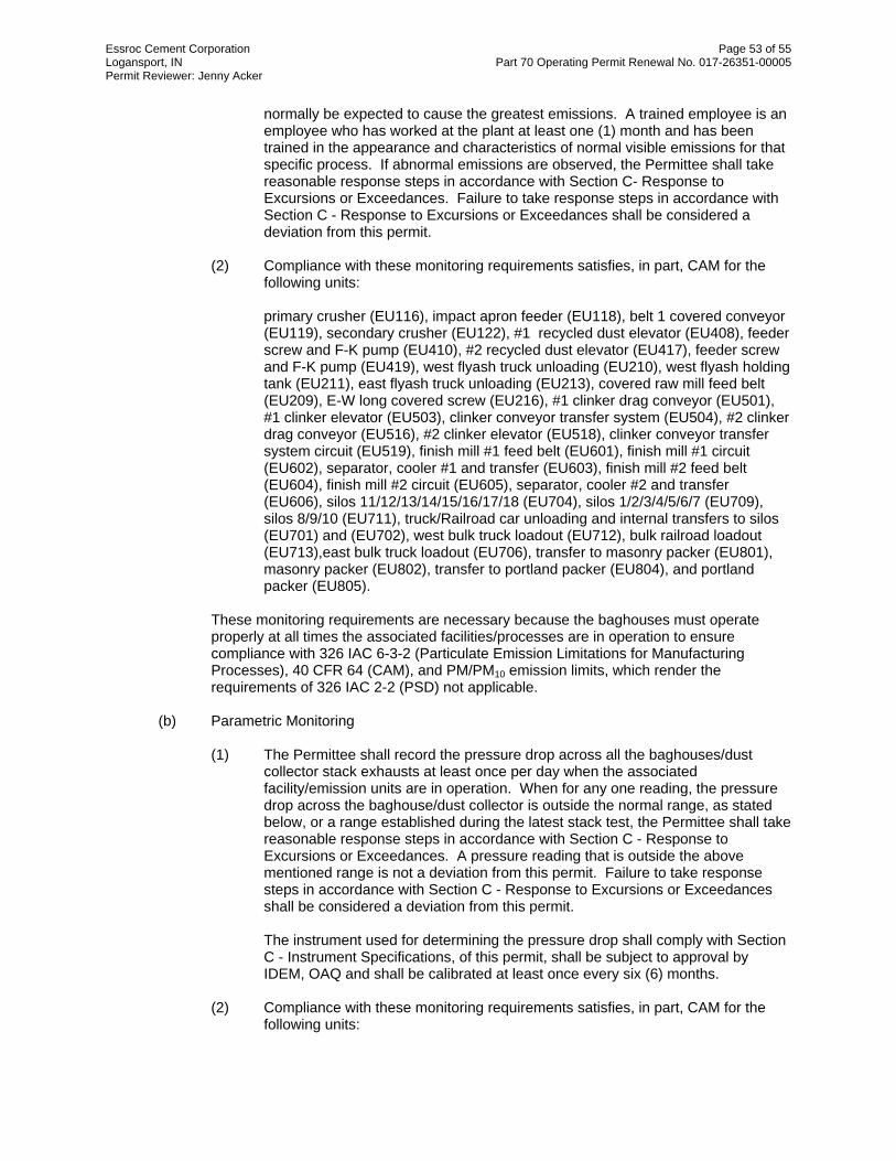
Essroc Cement Corporation Page 53 of 55 Logansport, IN Part 70 Operating Permit Renewal No. 017-26351-00005 Permit Reviewer: Jenny Acker
normally be expected to cause the greatest emissions. A trained employee is an employee who has worked at the plant at least one (1) month and has been trained in the appearance and characteristics of normal visible emissions for that specific process. If abnormal emissions are observed, the Permittee shall take reasonable response steps in accordance with Section C- Response to Excursions or Exceedances. Failure to take response steps in accordance with Section C - Response to Excursions or Exceedances shall be considered a deviation from this permit.
(2) Compliance with these monitoring requirements satisfies, in part, CAM for the following units:
primary crusher (EU116), impact apron feeder (EU118), belt 1 covered conveyor (EU119), secondary crusher (EU122), #1 recycled dust elevator (EU408), feeder screw and F-K pump (EU410), #2 recycled dust elevator (EU417), feeder screw and F-K pump (EU419), west flyash truck unloading (EU210), west flyash holding tank (EU211), east flyash truck unloading (EU213), covered raw mill feed belt (EU209), E-W long covered screw (EU216), #1 clinker drag conveyor (EU501), #1 clinker elevator (EU503), clinker conveyor transfer system (EU504), #2 clinker drag conveyor (EU516), #2 clinker elevator (EU518), clinker conveyor transfer system circuit (EU519), finish mill #1 feed belt (EU601), finish mill #1 circuit (EU602), separator, cooler #1 and transfer (EU603), finish mill #2 feed belt (EU604), finish mill #2 circuit (EU605), separator, cooler #2 and transfer (EU606), silos 11/12/13/14/15/16/17/18 (EU704), silos 1/2/3/4/5/6/7 (EU709), silos 8/9/10 (EU711), truck/Railroad car unloading and internal transfers to silos (EU701) and (EU702), west bulk truck loadout (EU712), bulk railroad loadout (EU713),east bulk truck loadout (EU706), transfer to masonry packer (EU801), masonry packer (EU802), transfer to portland packer (EU804), and portland packer (EU805).
These monitoring requirements are necessary because the baghouses must operate properly at all times the associated facilities/processes are in operation to ensure compliance with 326 IAC 6-3-2 (Particulate Emission Limitations for Manufacturing Processes), 40 CFR 64 (CAM), and PM/PM10 emission limits, which render the requirements of 326 IAC 2-2 (PSD) not applicable.
(b) Parametric Monitoring
(1) The Permittee shall record the pressure drop across all the baghouses/dust collector stack exhausts at least once per day when the associated facility/emission units are in operation. When for any one reading, the pressure drop across the baghouse/dust collector is outside the normal range, as stated below, or a range established during the latest stack test, the Permittee shall take reasonable response steps in accordance with Section C - Response to Excursions or Exceedances. A pressure reading that is outside the above mentioned range is not a deviation from this permit. Failure to take response steps in accordance with Section C - Response to Excursions or Exceedances shall be considered a deviation from this permit. The instrument used for determining the pressure drop shall comply with Section C - Instrument Specifications, of this permit, shall be subject to approval by IDEM, OAQ and shall be calibrated at least once every six (6) months.
(2) Compliance with these monitoring requirements satisfies, in part, CAM for the following units:

Essroc Cement Corporation Page 54 of 55 Logansport, IN Part 70 Operating Permit Renewal No. 017-26351-00005 Permit Reviewer: Jenny Acker
primary crusher (EU116), impact apron feeder (EU118), belt 1 covered conveyor (EU119), secondary crusher (EU122), #1 recycled dust elevator (EU408), feeder screw and F-K pump (EU410), #2 recycled dust elevator (EU417), feeder screw and F-K pump (EU419), west flyash truck unloading (EU210), west flyash holding tank (EU211), east flyash truck unloading (EU213), covered raw mill feed belt (EU209), E-W long covered screw (EU216), #1 clinker drag conveyor (EU501), #1 clinker elevator (EU503), clinker conveyor transfer system (EU504), #2 clinker drag conveyor (EU516), #2 clinker elevator (EU518), clinker conveyor transfer system circuit (EU519), finish mill #1 feed belt (EU601), finish mill #1 circuit (EU602), separator, cooler #1 and transfer (EU603), finish mill #2 feed belt (EU604), finish mill #2 circuit (EU605), separator, cooler #2 and transfer (EU606), silos 11/12/13/14/15/16/17/18 (EU704), silos 1/2/3/4/5/6/7 (EU709), silos 8/9/10 (EU711), truck/Railroad car unloading and internal transfers to silos (EU701) and (EU702), west bulk truck loadout (EU712), bulk railroad loadout (EU713),east bulk truck loadout (EU706), transfer to masonry packer (EU801), masonry packer (EU802), transfer to portland packer (EU804), and portland packer (EU805).
These monitoring requirements are necessary because the baghouses must operate properly at all times the associated facilities/processes are in operation to ensure compliance with 326 IAC 6-3-2 (Particulate Emission Limitations for Manufacturing Processes), 40 CFR 64 (CAM), and PM/PM10 emission limits, which render the requirements of 326 IAC 2-2 (PSD) not applicable.
(c) Kiln #1 (EU401), kiln #2 (EU402), clinker cooler #1 (EU412), and clinker cooler #2 (EU421) have applicable Compliance Monitoring Requirements as follows: Continuous Monitoring Downtime Whenever a COMS is malfunctioning or down for maintenance or repairs for a period of twenty-four (24) hours or more and a backup COMS is not online within twenty-four (24) hours of shutdown or malfunction of the primary COMS, and the process is operating, the Permittee shall provide a certified opacity reader, who may be an employee of the Permittee or an independent contractor, to self-monitor
(1) Visible emission readings shall be performed in accordance with 40 CFR 60,
Appendix A, Method 9, for a minimum of five (5) consecutive six (6) minute averaging periods beginning not more than twenty-four (24) hours after the start of the malfunction or down time.
(2) Method 9 opacity readings shall be repeated for a minimum of five (5)
consecutive six (6) minute averaging periods at least twice per day during daylight operations, with at least four (4) hours between each set of readings, until a COMS is online.
(3) Method 9 readings may be discontinued once a COM is online. (4) Any opacity exceedances determined by Method 9 readings shall be reported
with the Quarterly Opacity Exceedances Reports.
These monitoring requirements are necessary because the baghouses and/or electrostatic precipitator must operate properly at all times the associated facilities/processes are in operation to ensure compliance with 326 IAC 5-1(Opacity Limitations) and 326 IAC 2-7.

Essroc Cement Corporation Page 55 of 55 Logansport, IN Part 70 Operating Permit Renewal No. 017-26351-00005 Permit Reviewer: Jenny Acker
Recommendation
The staff recommends to the Commissioner that the Part 70 Operating Permit Renewal be approved. This recommendation is based on the following facts and conditions: Unless otherwise stated, information used in this review was derived from the application and additional information submitted by the applicant. An application for the purposes of this review was received on March 31, 2008.
Conclusion
The operation of this stationary portland cement manufacturing plant shall be subject to the conditions of the attached Part 70 Operating Permit Renewal No. 017-26351-00005.

Appendix A: Emissions Calculations Page 1 of 2 TSD App APM/PM-10 Emissions from Baghouses
Company Name: Essroc Cement CompanyCompany Address: State Road 25 South, 3084 West County Road 225 South
Logansport, IN 46947Part 70 Operating Permit Renewal No.: T017-26351-00005
Reviewer: Jenny AckerDate: 5-Jan-09
Baghouse Emission Units Grain Loading Flow Rate Controlled PM/PM10 Control Eff. Uncontrolled PM/PM10ID Controlled (gr/dscf) (acfm) (lbs/hr) (ton/yr) (%) (lbs/hr) (ton/yr)
CE101 EU116, EU118, EU119 0.04 10,100 3.46 15.17 99.8% 1,731 7,584CE102 EU119, EU122 0.04 3,900 1.34 5.86 99.8% 669 2,928CE201 EU209, EU216 0.04 8,000 2.74 12.01 99.8% 1,371 6,007CE202 EU210 0.04 2,000 0.69 3.00 99.3% 98 429CE203 EU211 0.04 2,000 0.69 3.00 99.3% 98 429CE204 EU213 0.04 2,500 0.86 3.75 99.3% 122 536
BH CE402 EU408, EU410, EU417, EU419 0.04 7,400 2.54 11.11 99.3% 362 1,588CE404 EU412 0.04 49,500 16.97 74.33 99.8% 8,486 37,167CE405 EU413 0.08 270,000 185.14 810.93 99.9% 185,143 810,926
ESP CE402 EU413 0.08 270,000 185.14 810.93 99.9% 185,143 810,926CE407 EU421 0.04 49,500 16.97 74.33 99.8% 8,486 37,167CE501 EU501, EU503 0.04 10,700 3.67 16.07 99.8% 1,834 8,034CE502 EU504 0.04 1,400 0.48 2.10 99.3% 69 300CE503 EU516, EU518 0.04 5,400 1.85 8.11 99.8% 926 4,055CE504 EU516, EU518, EU519 0.04 5,400 1.85 8.11 99.8% 926 4,055CE601 EU601 0.04 1,200 0.41 1.80 99.8% 206 901CE602 EU602 0.04 8,600 2.95 12.91 99.8% 1,474 6,457CE603 EU603 0.04 23,300 7.99 34.99 99.8% 3,994 17,495CE604a EU604 0.04 800 0.27 1.20 99.8% 137 601CE604b EU604 0.04 1,750 0.60 2.63 99.8% 300 1,314CE605 EU605 0.04 8,600 2.95 12.91 99.8% 1,474 6,457CE606 EU606 0.04 23,300 7.99 34.99 99.8% 3,994 17,495CE701 EU701 0.04 2,500 0.86 3.75 99.8% 429 1,877CE702 EU702 0.04 2,500 0.86 3.75 99.8% 429 1,877CE704 EU704 0.04 4,600 1.58 6.91 99.8% 789 3,454CE706 EU706 0.04 4,600 1.58 6.91 99.8% 789 3,454CE709 EU709 0.04 2,300 0.79 3.45 99.8% 394 1,727CE711 EU711 0.04 2,300 0.79 3.45 99.8% 394 1,727CE712 EU712 0.04 3,600 1.23 5.41 99.8% 617 2,703CE713 EU713 0.04 4,200 1.44 6.31 99.8% 720 3,154CE801 EU801, EU802 0.04 9,100 3.12 13.67 99.8% 1,560 6,833CE802 EU801 0.04 3,000 1.03 4.51 99.5% 206 901CE803 EU804, EU805 0.04 9,000 3.09 13.52 99.8% 1,543 6,758CE804 EU504 0.04 1,400 0.48 2.10 99.3% 69 300CE805 EU519 0.04 5,400 1.85 8.11 99.8% 926 4,055CE901 EU406 0.04 644 0.22 0.97 99.8% 110 484CE902 EU902 0.04 3,400 1.17 5.11 99.8% 44 44
Methodology:Controlled PTE PM/PM10 (lb/hr) = air flow (acfm) * loading (grain/dscf) * 60 (min/hr) * 1/7000 (gr/lb)Controlled PTE PM/PM10 (tpy) = Controlled PTE (lb/hr) * 8760 hrs/yr * 1/2000 lb/tonUncontrolled PTE PM/PM10 (lb/hr) = controlled PTE PM/PM10 (lb/hr) / (1- Control Eff.)Uncontrolled PTE PM/PM10 (tpy) = Uncontrolled PTE (tpy) / (1- Control Eff)

Appendix A: Emissions Calculations Page 2 of 2 TSD App A
Company Name: Essroc Cement CompanyCompany Address: State Road 25 South, 3084 West County Road 225 South
Logansport, IN 46947Part 70 Operating Permit Renewal No.: T017-26351-00005
Reviewer: Jenny AckerDate: 5-Jan-09
Throughput Notes
[PM (lb/ton)] [PM10 (lb/ton)] [tons/yr]
EU406 Waste CKD Tank & CKD2FM Surge SystemAP-42 Emission Factor 5th ed., Sec. 11.12-2.
EU902 CKD2FM Recycling Storage Tank SystemAP-42 Emission Factor 5th ed., Sec. 11.12-2
0.7200 0.4600 lbs/ton 12264014 tph (max
capacity)8,760 44.15 28.21
EU903 CKD2FM #1 FM Recycling SystemAP-42 Emission Factor 5th ed., Sec. 11.12-2
0.0030 0.0011 lbs/ton 14454016.5 tph (max
capacity)8,760 0.22 0.08
EU904 CKD2FM #2 FM Recycling SystemAP-42 Emission Factor 5th ed., Sec. 11.12-2
0.0030 0.0011 lbs/ton 306603.5 tph (max
capacity)8,760 0.05 0.02
44.41 28.30
Throughput Notes
[PM (lb/ton)] [PM10 (lb/ton)] [tons/yr]
EU902 CKD2FM Recycling Storage Tank SystemAP-42 Emission Factor 5th ed., Sec. 11.12-2
0.7200 0.4600 lbs/ton 65,000 8,760 23.40 14.95
EU903 CKD2FM #1 FM Recycling SystemAP-42 Emission Factor 5th ed., Sec. 11.12-2
0.0030 0.0011 lbs/ton 8,760
EU904 CKD2FM #2 FM Recycling SystemAP-42 Emission Factor 5th ed., Sec. 11.12-2
0.0030 0.0011 lbs/ton 8,760
23.50 14.99
PTE from CKD2FM
EU No. EU Description
Factor ProcessPM PM10
TypeValue
Units
ValueUnits
Hours[tpy]
Loading into the CKD tank emissions are already accounted for. The screw conveyors located at the bottom of the CDK tank are completely enclosed. Any emissions are contained
Totals
Hours[tpy]
PTE from CKD2FM - Limited Material Throughput
EU No.
Totals
PM10
Type
65,000 0.10 0.04
EU Description
Factor ProcessPM
Copyright © 2022 FDOKUMEN