Final Report vol.1 - Environmental Protection Department
273
-
Upload
khangminh22 -
Category
Documents
-
view
2 -
download
0
Transcript of Final Report vol.1 - Environmental Protection Department


Cover Photograph by Airphoto Intemaffonal Ltd
Highways Department - Western Harbour Unk Office
Central Kowloon Route Study
Final Report
Volume 1
Engineering Feasibility and Preliminary Design
May 1993
Parsons Brinckerhoff Maunsell Consultants
in association with
MVA Asia . Shankland Cox . CES (Asia) . Chesterton Petty

Contents

o o o o o o o o o o o o o o o o o o o o o o o
Parsons Brinckerhoff Maunsell Consultants Central Kowloon Route Study
FINAL REPORT
VOLUME 1
ENGINEERING FEASIBILITY AND PRELIMINARY DESIGN
Contents
Summary And Recommendations
1.
2.
3.
Introduction
1.1 1.2 1.3 1.4 1.5
The Central Kowloon Route.............................................................. 1-1 Study Background.......................................................................... 1-1 Study Objectives............................................................................ 1-2 Study Output................................................................................ 1-3 Form of Report .............................................. ; .............................. 1-4
Constraints
2.1 2.2 2.3 2.4 2.5 2.6 2.7 2.8 2.9
Introduction.................................................................................. 2-1 Traffic Constraints........................................... .............................. 2-1 Planning Constraints....................................................................... 2-1 Transport Infrastructure Constraints ..................................................... 2-2 Geotechnical Constraints .......................................................... ;....... 2-2 Environmental Constraints................................................................ 2-2 Utility Constraints.......................................................................... 2-3 Urban Landscape........................................................................... 2-3 Financing ............................................................................... :.... 2-4
Transport and Traffic Studies
3.1 3.2 3.3 3.4 3.5
Introduction.... ............................................................................. 3-1 Traffic Forecasting Methodology ........................................................ 3-3 Traffic Forecasts........................................................................... 3-4 Traffic Engineering Analyses ......................................................... ;.. 3-16 Traffic Management During Construction............................................. 3-17
Appendix
3.1 Traffic Signals Calculations
1
/

Parsons Brinckerhoff Maunsell Consultants Central Kowlnon Route Study
4.
5.
6.
Geological and Geotechnical Information
4.1 4.2 4.3 4.4 4.5 4.6
Existing Subsoil Information..................... ........................................ 4-1 Site Investigation........................................................................... 4-1 Geological Profiles and Map............................................................. 4-2 Information on Building Foundations and Other Structures ......................... 4-5 Effects of CKR Construction............................................................. 4-11 Slope Reinstatement........................................................................ 4-13
Alignment
5.1 5.2 5.3 5.4 5.5 5.6 5.7 5.8 5.9 5.10
5.11 5.12
Introduction .................................................................................. 5-1 Design Standards........................................................................... 5-1 The Western Section ....................................................................... 5-2 The Western Tunnel Section:............................................................ 5-3 The Central Tunnel Section.............................................................. 5-4 The Eastern Tunnel Section.............................................................. 5-4 The Eastern Approach and To Kwa Wan Interchange............................... 5-5 Phase 1 Arrangements..................................................................... 5-6 Recommended Topographic Survey Requirements................................... 5-7 Desireability of Lowering Vertical Alignment at Ko Shan Park and Abandonment of EKL MTR Route................................................ 5-7 Toll Variations .............................................................................. 5-8 Toll Collection Method Variations...................................................... 5-9
Roadworks
6.1 6.2 6.3 6.4
Pavement..... ............................ ................................................... 6-1 Slip Roads................................................................................... 6-2 Temporary Connections................................................................... 6-2 Drainage..................................................................................... 6-2
7. Tunnel Construction
8.
7.1 7.2 7.3 7.4
Introduction ................................................................................. 7-1 Box Tunnel Sections ....................................................................... 7-1 Driven Section.............................................................................. 7-2 Underground Tunnel Facilities ........................................................... 7-3
Structures
8.1 8.2 8.3 8.4 8.5
Bridges....................................................................................... 8-1 Depressed Roads........................................................................... 8-1 Buildings..................................................................................... 8-1 Pump Station ....................................................... :........................ 8-2 Joint Development Structures............. ............................................... 8-7
2
o o o o o o o o o o o o o o o o o o o o o o

o o o o o o o o o o o o o o o o o o o o o o o
Parsons Brinckerhoff Maunsell Consultants Central Kowloon Route Study
9.
10.
11.
12.
13.
Toll Plaza
9.1 9.2 9.3 9.4 9.5 9.6
Ultimate Configuration.................................................................... 9-1 Interim Configuration (phase 1)......................................................... 9-2 Control Area ..................................................................... ;.......... 9-2 Bus Laybys.................................................................................. 9-3 Pedestrian Access.......................................................................... 9-3 Toll Collection System.................................................................... 9-3
Traffic Surveillance and Control System
10.1 10.2 10.3 10.4 10.5 10.6 10.7 1O.S 10.9
Traffic Operations, Maintenance and Safety.......................................... 10-1 Tidal Flow................................................................................... 10-3 Maintenance ................................................................................. 10-3 Incident Handling.......................................................................... 10-3 Computer System........................................................................... 10-4 Field Equipment............................................................................ 10-4 Surveillance and Monitoring ............................. ~............................... 10-7 ControL ........ : ............................................................................. 10-S Emergency................................................................................... 10-9
Tunnel Systems
11.1 11.2 11.3 11.4 11.5 11.6 11.7
Utilities
12.1 12.2 12.3 12.4 12.5 12.6 12.7 12.S .. 12.9
Introduction................................................................................. 11-1 Ventilation................................................................................... 11-1 Lighting System............................................................................ 11-5 Electrical Power Supply System......................................................... 11-S Central Monitoring and Control System (CMCS).................................... 11-10 Drainage System............................................................................ 11-12 Fire Protection System.................................................................... 11-13
Airport Railway............................................................................ 12-1 MTR .......................................................................................... 12-1 Gas ............................................................................................. 12-1 Water ......................................................................................... 12-2 Sewer ............................................................................ ; ............. 12-3 Electricity .............................................................................. 0 ..... 12-3 Telephone.................................................................................... 12-4 Surface Water Drainage .................................................................... 12-5 Routing of Future Utilities Through Tunnel........................................... 12-5
Land Requirements
13.1 13.2 13.3 13.4
Acquisition of Private Land.............................................................. 13-1 Reprovisioning ....................................................... ; .............. ,....... 13-2 Route Protection ................................................ ~........................... 13-2 Implications of Current Government Policy........................................... 13-3
3

Parsons Brinckerhoff Maunsell Consultants Central Kowloon Route Study
14. Programme
14.1 14.2 14.3 14.4 14.5 14.6 14.7
Construction Phasing...................................................................... 14-1 Requirements................................................................................ 14-2 Programme Assumptions .................................................................. 14-2 Site Availability ............................................................................. 14-3 Time for Laud Clearance................................................................. 14-4 Separate Public/Private Programmes ...................... ;............................ 14-4 Phase 1 Programme........................................................................ 14-5
15. Construction
16.
17.
18.
15.1 15.2 15.3 15.4 15.5
WKC Entrusted Works .................................................................... 15-1 Contract Splits.............................................................................. 15-2 Storage and Work Areas.................................................................. 15-2 Access........................................................................................ 15-2 Rock Excavation............................................................................ 15-3
Operations and Maintenance
16.1 Single Tube Operation..................................................................... 16-1 16.2 Operation and Maintenance (O&M) Resources....................................... 16-1 16.3 Maintenance of Joint Development Structures .......... ,.............................. 16-1
Cost
17.1 Resumption .................................................................................. 17-1 17.2 Reprovisioning .............................................................................. 17-1 17.3 Construction. ............................ .................................................... 17-1 17.4 Advance. Works at WKC.......................................................... ........ 17-6 17.5 Operation and Maintenance (O&M) ..................................................... 17-6 17.6 Joint Development Costs at USD 'G' Site............................................. 17-6
Financial Assessment
18.1 18.2 18.3 18.4 18.5 18.6
Toll Sensitivity Tests...................................................................... 18-1 Toll Selection................................................................................ 18-6 Toll Revenues............................................................................... 18-6 Commercial Advertising Space.......................................................... 18-9 Other Revenues.......... ................................................................... 18-9 Cash Flow..... ... ... ................................... ....................... .............. 18-9
4
o o o o o o o o o o o o o o o o o o o o o o o

o o o o o o o o o o o o o o o o o o o o o o C)
Parsons Brinckerhojf Maul/sell Consultants Central Kowlool/ Route Study
19. Design Standards Memorandum
19.1 19.2 19.3 19.4 19.5 19.6 19.7 19.8 19.9 19.10 19.11 19.12 19.13 19.14 19.15 19.16 19.17 19.18 19.19 19.20 19.21
Appendices
Introduction ................................... ,............................................. 19-1 Highway Alignment and Civil Engineering............................................ 19-1 Protection Against Inundation............................................................ 19-3 Tunnel Structure Design.................................................................. 19-4 Cracking in Concrete...................................................................... 19-5 Tunnel Finishes............................................................................. 19-6 Toll Plaza Layout.......................................................................... 19-6 Building Requirements.................................................................... 19-7 Utilities and Drainage..................................................................... 19-7 Electrical and Mechanical Services..................................................... 19-8 Traffic Control.............................................................................. 19-9 Surveillance................................................................................. 19-9 Emergency Communications............................................................. 19-9 Fire Protection.............................................................................. 19-10 Lighting...................................................................................... 19-11 Drainage..................................................................................... 19-11 Power Supplies............................................................................. 19-12 Ventilation ................................................................................... 19-12 Security...................................................................................... 19-14 Toll Collection System.................................................................... 19-14 Central Monitoring and Control......................................................... 19-14
A The Brief
B Responses to Comments
Volume 2 Preliminary Design Drawings
Volume 3 Planning, Environmental and Urban Landscape Assessment
Volume 4 Geological and Geotechnical Supplementary Information
5

Summary and Recommendations

o o o o o o o o o o o o o o o o o o o o o o C)
Parsons Brinckerhojf Maunsell Consultallts Central Kowloon Route Study
1.
2.
3.
SUMMARY AND RECOMMENDATIONS
INTRODUCTION
a. The Central Kowloon Route (KCR) is a proposed dual two lane urban trunk road connecting the Kowloon Bay Reclamation with the West Kowloon Reclamation. The recommended route is generally underground and will pass through densely developed areas of To Kwa Wan and Yau Ma Tei.
b. The need for additional road capacity across the Kowloon Peninsula has been identified in several previous studies and provision for connections to the CKR are being made in the West Kowloon Expressway (WKE) project. In view of the need to finalise interchange arrangements with the WKE and to enable an alignment ·to be estabished, Highways Department appointed Parsons Brinckerhoff Maunsell Consuitants to carry out Engineering Feasibility Studies and Preliminary Design for the Route.
STUDY PHASES
The study of the Central Kowloon Route ("CKR") proceeded through four basic study phases as briefly described .below:
Study Phase 1 Study Phase 2
Study Phase 3 Study Phase 4
STUDY PHASE 1
Assembly of base data and agreement on issues to be addressed. Preparation, assessment and' discussion of options for various aspects of the project. Preparation of recommended scheme and preliminary design for the scheme. Circulation of Draft Final Report and preparation of Final Report.
a. During this initial study phase, a number of constraints were identified in the western half of the originally conceived alignment which presented significant challenges:
1) CKR, as an elevated highway passing through the LDC site (south of Waterloo Road, between Ferry Street and Nathan Road), would limit LDC's flexibility for development. Further, the elevated highway would most likely need to be fully enclosed to avoid undue noise impacts. An enclosed, elevated highway, some 500 metres long, would be both relatively expensive and visually intrusive;
2) The originally conceived alignment passed through the telephone exchange building at 524A Nathan Road. Early indications were reprovisioning of the facilities would be inordinately expensive (in excess of $250 million) and time consuming (about three years); and
3) The originally conceived alignment almost certainly would require resumption of a significant portion of the Lutheran School on Waterloo Road.
b. Thus, it was desireable to consider options to the western half of the route and in order to avoid delay to the West Kowloon Expressway project, earlier than initially contemplated. Therefore, late in Study Phase 1, an assessment of options (a Study Phase 2 task) commenced, and the effort continued into Study Phase 2.
/ i.

Parsons Bril)ckerhoff Maunsell ConsuitanlS Cenlrai Kowioon Route Study
4. STUDY PHASE 2
a. In this study phase, a significantly better option to the original alignment was identified.
1) Taking advantage of a narrow corridor, the alignment would pass:
a) in tunoel under (rather than over) the West Kowloon Corridor;
b) immediately north of the Housing Society's Six Streets Redevelopment;
c) inunediately south of the MTR Yau Ma Tei Station;
d) through the slot under Nathan Road pavement and over the top of MTR tunoel; and
e) immediately north of the Salvation Army building on Wing Sing Lane.
2) 1bis alignment would avoid the LDC site, the telephone exchange and the Lutheran School. Furtber, tbe land above tbe tunoel could be redeveloped after the highway was constructed far easier, and with much less visual and landscape impact, than if the CKR was an elevated highway.
3) Field mapping indicated the geology of this part of Kowloon was more conducive to a tunoel the further south tbe alignment was located. Accordingly, the northward swing of the alignment in Ho Man Tin (as depicted in Appendix A of the Brief) was eliminated, and a straighter alignment from Yau Ma Tei to To Kwa Wan was adopted. 1bis new alignment would not ouly be more economical to construct, as an added benefit it would provide a much smoother ride for the driver.
b. Three construction phases were identified.
1) The first phase (referred to as "Phase 1" in this report) would provide for the CKR conoecting the Yau Ma Tei Interchange with the local street network in To Kwa Wan. It would be constructed prior to construction of the Kowloon Bay Reclamation, the North-South Highway ("NSH") and the eastbound extension of the CKR across the Kowloon Bay Reclamation (referred to as the "Kowloon Bay Conoector" ~or "KBC").
2) The second phase ("Phase 2", herein) would provide for the interchange between CKR and NSH and would require construction of a portion of the Kowloon Bay Reclamation.
3) The final phase ("Phase 3") would provide for the interchange of the KBC with the CKR-NSH interchange after construction of the Kowloon Bay Reclamation.
c. During the last half of Study Phase 2, an initial environment assessment was prepared, the various options were narrowed down and one scheme recommended for preliminary design. Concepts for redevelopment above the highway tunoel were developed which indicated joint development would be feasible in certain locations.
d. During Study Phase 2, the issue of route protection was addressed.
1) The programme being developed for the CKR indicated a gap of possibly five or more years from completion of preliminary design to start of construction. As the potential CKR corridor is rather narrow and is constrained by numerous existing structures [see Para. 4.a.l) abovel, there is limited flexibility to shift the CKR to avoid future development. The concern was expressed that private development might occur in the
ii.
o C) o o o o o o o o o o o o o o o o o o o o o

o o o o o o o o o o o o o o o o o o o o o o o
Parsons Brinckerhoff Maunsell Consultants Central Kowloon Route Study
s.
CKR corridor of such a nature that it might preclude construction of the CKR. Thus, protection from such a possible development was deemed essential.
2) During this study phase, several government departments evaluated land protection options with no defInitive conclusion.
STUDY PHASE 3
a. Several refinements/revisions to the selected scheme occurred during the preliminary design:
1) The CKR box tunnel in Yau Ma Tei was narrowed to minimum dimensions to avoid the need to resume three existing schools on the north side of Tung Kun Street between Ferry Street and Reclamation Street.
2) The decision to toll the CKR from its opening was confirmed. The following phasing and toll rates were used for preliminary engineering design purposes:
Completion of Years of Toll Rate (see Note below) Construction Phase Operation (1986 $) (1990 $)
1 2001 - 2005 3.00 4.10 2 2006 - 2010 5.00 6.85 3 2011 - open 15.00 20.54
Note: The CKR Study does not recommend any toll levels and it was agreed that these should be the subject of further study nearer the time of tunnel opening.
3) The Permanent International Association of Road Congresses ("PIARC") issued a report revising upwards the estimated amount of future air emissions from vehicles. A new method for exhausting the estimated increase in tunnel emissions, using ventilation stacks at the portals, was therefore developed.
4) Based on the results of the site investigation ("S.I.") programme, vertical alignment refinements were made. Also, revisions to possible construction approaches at the two rock portals were developed. (Note the term "rock portal" refers to the end of mixed-face tunneling and the start of the two (one eastbound and one westbound) driven or mined tunnels in rock. There would be two rock portals: the west rock portal would be to the east of Nathan Road, and the east rock portal would be under Ko Shan Park to the east of Ko Shan Theatre.)
6. STUDY PHASE 4
a. During this study phase, the entrusted works in the West Kowloon Corridor ("WKC") were prepared. The entrusted works consist of the top slab and outer diaphragm walls of the CKR box tunnel under the various streets and highways constructed in the WKC project.
b. The results of the comments and responses to the Draft Final Ropmt wefe incorporated in the Final Report. For a listing of the comments and responses, refer to Appendix B.
iii.

o o
Parsons Brinckerhoff Maunsell Consultants Central Kowloon Route Study o 7. RECOMMENDATIONS
Key recommendations in the Final Report include: o
a. Programme for Route Protection of CKR o 1) Develop the necessary justifications to establish the legal basis for CKR route protection
aod to provide for the finaocial resources required to support the route protection. 0 2) Prepare coordinated setting out for the corridor to define the area requiring protection aod
identify buildingslsites under possible influence of the CKR tunnel construction. Estimated 0 Cost: $310,000 (1992 $).
h. Construction Phasing of CKR
1) Entrusted Works - Construction to occur between 1993 aod 1998.
a) West Kowloon Corridor (WKC) Entrusted Works
(1) Diaphragm walls and top slab of the CKR sufficient to enable Phase 1 of the CKR to proceed at a later date with little disruption to traffic on roadways constructed under the WKC programme.
(2) Construction of entrusted works is anticipated by RHE/K, HyD to commence on 1st July 1994 and be completed by 31st January 1995.
(3) Estimated Cost: $35.7 million (1992 $).
b) Possible Entrusted Works
(1) West Kowloon Reclamation Carpark - Construction date unknown.
(a) Assuming the Carpark on the West Kowloon Reclamation is constructed prior to the CKR, the following would be the entrusted works:
- a ventilation shaft from the basement level to a height of about 50 metres above ground level.
- a 25 ± m X 20 ± m fan room, either in the basement or on the roof.
(b) Estimated Cost: $10.8 million (1992 $).
(2) Chatham Road North - USD 'G' Site Construction start between 1993 aod 1996.
(a) Assuming the sports complex at 'G' Site between Chathan Road North and Ko Shan Road would be constructed prior to the CKR, sufficient space for the CKR to pass beneath the building or through the basement would be required. Walls, slabs and possibly increased sizes of foundations would constitute the entrusted works.
(b) Estimated Cost: $30.6 million (1992 $).
(3) Such other entrusted works as identified over the years.
iv.
o o o o o o o o o o o o o o o o

o o o o o o o o o o o o o o o o o o o o o o o
~arsons Brinckerhoff Maunsell Consultallls Central Kowloon Route Study
2) Central Kowloon Route Phase 1 - Construction from 1 Jan, 1997 to 1 Jan, 2001
3)
a) Construction of the CKR from the interchange with WKE to the "interim" toll plaza and temporary interchange at Y uk Yat Street! Bailey Street.
b) Estimated Cost: $1,853.7 million (1992 $) assuming all above entrusted works materialized.
Central Kowloon Route Phase 2 - Construction from 1 Jan, 2004 to 1 Jan, 2006
a) Construction of the interchange between the CKR and the North-South Highway, including a revised toll plaza.
b) Estimated Cost: $278.9 million (1992 $).
4) Central Kowloon Route Phase 3 - Construction from 1 Jan, 2009 to 1 Jan, 2011.
a) Construction of the remaining portion of the interchange between the CKR, North-South Highway and the Kowloon Bay Connector, including a revised toll plaza.
b) Estimated Cost: $109.1 million (1992 $).
v.

Introduction 1

o o o o o o o o o o o o o o o o o o o o o o o
Parsons Brinckerhoff Maunsell Consultants Central Kowloon Route Study
1.
1.1.
1.2
1.2.1
1.2.2
1.2.3
1.2.4
1.2.5
1.2.6
INTRODUCTION
THE CENTRAL KOWLOON ROUTE
The Central Kowloon Route (CKR) is a proposed dual two lane urban trunk road connecting the planned Kowloon Bay reclamation in the east with the future West Kowloon Expressway and West Kowloon Reclamation ( under construction). The route will primarily be underground and will pass through densely developed areas of To Kwa Wan and Yau Ma Tei. It is possible that construction of the Central Kowloon Route will act as a catalyst for urban renewal in these areas.
STUDY BACKGROUND
The Second Comprehensive Transport Study (CTS-2), completed in 1989, proposed, amongst other proposals, improvements to Route 4 by 1996, to increase traffic capacity on East-West routes across Kowloon by the year 2001. However, the Central Kowloon Traffic Study (CKTS) and the West Kowloon Reclamation Transport Study (WKRTS) concluded later that additional East-West capacity would be required by 2001 even with the CTS-2 proposals in operation particularly since major developments were envisaged in Metroplan on both the West and East Kowloon.
The WKRTS proposed a new dual two lane urban trunk route - the Central Kowloon Route (CKR) as an alternative to upgrading existing routes with capacity limitations. This route has also been referred to as the Cross Kowloon Route in various studies. The route was proposed as a connection between the West Kowloon Expressway (WKE) via an elevated route and tunnel through the centre of Kowloon to the planned North South Highway (NSH) in To Kwa Wan. The primary function of the CKR would be to provide a trunk road across the centre of Kowloon and leave ground level roads to deal with the traffic within broad metro districts.
The CKR as shown on Figures Nos. 001 and 002 will connect in the west with the WKE, the West Kowloon Reclamation Primary Distributor (Road PI) and the Western Harbour Crossing (WHC). The eastern end will have connections with the NSH, To Kwa Wan/Hung Horn and new routes serving Kowloon Bay Reclamation with a possible connection through to long term route from Tseung Kwan O.
The CKTS forecasted the CKR to attract 2,500 - 3,000 pcus per direction in the peak hour in 2001, whereas the WKRTS forecasted a traffic increase to over 4,000 pcus with 2,100 pcus flowing between the WKE and the CKR in the peak direction in 2011. These figures reflected assumed major developments on Kowloon Bay Reclamation as well as in West Kowloon and the CKR as a toll free route.
Various alignment options for the Route had been considered by the WKRTS and the preferred alignment ran elevated from a major interchange with the WKE and WHC (Yau Ma Tei Interchange), along a route parallel to and offset some 50m south of Waterloo Road, requiring demolition of some buildings along that aligmnent, then crossing Nathan Road to enter a cut-and-cover tunnel under the site of the Lutheran Middle School before entering a bored tunnel under the eastern end of the True Light Girls School. This option west of N~than Road offered a more cost effective route through old properties and an opportunity to develop the Route as part of an urban renewal scheme.
To the east of Nathan Road, the preferred alignment descended into a tunnel swinging northwards to pass under Princess Margaret Road, then advanced east towards the Ko Shan Road Park where the route continued in a tunnel immediately below ground to cross under Chatham Road North and
Vollll-l

Parsons Brinckerhoif Maunsell Consultants Central Kowloon Route Study
1.2.7
1.2.8
1.2.9
1.2.10
1.2.11
1.2.12
1.3
1.3.1
Ma Tau Wai Road, before ascending onto the East Kowloon reclamation to form an interchange with the NSH. Some buildings east of Ma Tau Wai Road would have had to be demolished, and there was also an opportunity to develop the Route as part of an urban renewal scheme.
In planning the railway to serve the new airport and North Lantau, the Airport Railway Feasibility Study (ARFS) recommended a preferred alignment running north-south between the Yau Ma Tei Interchange and Ferry Street. It was proposed to construct this section of the Airport Railway by cut-and-cover, and it would have affected the CKR and the slip roads of the Yau Ma Tei Interchange.
The interfacing WHC and WKE projects are planned to be completed by 1996 ready for the replacement airport opening in 1997. The programme for the airport Railway had yet to be finalised. For the NSH, there is no detailed planning or time frame yet although the road reserve has been in existence for some time and the initial section between Whampoa Garden and Bailey Street already opened to traffic. The NSH will be connected to the south, at Whampoa Garden, with the Hung Hom Bypass and Princess Margaret Road Link which is programmed to be completed between 1996 and 2001. The NSH will be extended to the north with an interim connection to Sung Wong Toi Road (as proposed in the CKTS) and then across the site ofKai Tak to an interchange on Kai Fuk Road near the Airport Tunnel portal. It will ultimately be extended northwards to connect with the Kwun Tong Bypass south of the Prince Edward Road interchange. The actual location and timing of this northern extension will depend upon the rate of developments at Kai Tak (after airport relocation), in East Kowloon and in Tseung Kwan 0 and is the subject of study in the South-East Kowloon Development Statement Study (SKDSS).
The Route also crossed the existing MTR Yau Ma Tei Station at Nathan Road and the future East Kowloon Line at To Kwa Wan. The East Kowloon Line has been route-protected.
The long lead time required in implementing the full eastern connections of the CKR suggested temporary connections to enable the Route to be used to relieve traffic in the medium term across the Kowloon peninsula before its full potential is require<!. At the eastern end, the Route could be connected into the local network at To Kwa Wan; 'while at the western end a short term temporary link onto the Route from Nathan Road was suggested.
Where the Route crossed Ferry Street, a set of supporting columns was required between the northbound and southbound carriageways of the West Kowloon Corridor - YMT Section (Phase Il) [WKC-YMT(II)] flyover. As construction of the supporting pile caps would notbe possible after the WKC-YMT(Il) has been constructed, these pile caps and possibly the columns up to the corridor level needed to be constructed with the WKC-YMT(Il) project. The detailed design of WKC-YMT(Il) was scheduled to commence in August 1991, and the works completed by mid-1996.
Implementation of the CKR was dependent on land acquisition, but then current traffic studies suggested, that to meet forecasted traffic demands, the CKR should be completed within the years 2001 to 2005, depending upon the rate of development in West Kowloon and at Kai Tak, on East Kowloon Reclamation, in East Kowloon and in Tseung Kwan o.
STUDY OBJECTIVES
The Brief for the Study is in Appendix A. (Note the Environmental Assessment Scope of Work is in Appendix 2.1 in Volume 3.) As stated in the Brief, the primary objectives of the Study were:
a) to further develop the alignment as determined by the WKE Consultancy and establish the cross-section of the elevated structure running parallel to Waterloo Road between the Yau Ma Tei Interchange and the tunnel portal off Nathan Road;
Vol 111-2
o o o o o o o o o o o o o o o o o o o o o o o

o o o o o o o o o o o o o o o o o o o o o o
Parsol/s Bril/ckerhojJ Maul/sell Consultants Celltral Kowloon Route Study
1.3.2
1.3.3
1.4
1.4.1
b) to establish the best alignment and cross-section of the tunnel, in both bored and cut-and-cover sections, linking the eastern elevated structure with the interchange on the East· Kowloon Reclamation;
c) to establish the most suitable interchange arrangements between the CKR and the existing and planned road systems in East Kowloon;
d) to prepare an acceptable layout and preliminary design for the selected structure and tunnel configuration and approach roads based on traffic forecasts for year 2011 including requirements relating to port and airport developments;
e) to prepare schematic arrangements of tunnel mechanical and electrical systems based upon current international, Environmental Protection, Fire Services and Transport Departments' standards for the most cost effective, efficient, safe and enviromnentally acceptable operation of the tunnel;
f) to provide design information to transport projects in the vicinity such as WKC-YMT(I\) and the proposed Airport Railway which will cross the CKR within the elevated section.
During the course of the study, above objectives a), b) and f) evolved as follows:
a) to further develop the alignment as determined by the WKE Consultancy;
b) to establish the best alignment and cross-section of the tunnel, in both bored and cut-and-cover sections, linking the tunnel with the Yau Ma Tei Interchange and with the interchange on the East Kowloon Reclamation;
f) to provide design information to transport projects in the vicinity such as WKC-YMT(U) and the proposed Airport Railway which will cross the CKR within the tunnel section.
Further, during the second month of the study, the Land Development Corporation (LDC) suggested the following additional objective:
g) to derive a design which would both minimise the adverse effect on the LDC scheme area, and allow the LDC scheme to proceed in advance of the construction! commissioning of the new road.
STUDY OUTPUT
The Brief required preparation of a self-contained report and an executive summary. In addition, during the course of the Study, a series of working papers and discussion papers on specific issues were prepared, circulated and discussed. The content of the papers and resultant discussions are incorporated into the Final Report.
For reference, Table 1.1 summarises the titles and dates of submissions of the papers 4Illd reports and the dates of submissions of responses.
Vo11l1-3

Parsons Brinckerhoff Maunsell Consultants Central Kowloon Route Study
1.5 FORM OF REPORT
1.5.1
1.5.2
The Final Report consists of four volumes.
Volume 1 - Preliminary Design Volume 2 - Drawings Volume 3 - Planning, Environmental and Urban Landscape Assessment. Volume 4 - Geological and Geotechnical Supplementary Information
Volume 4 has limited distribution and is available for inspection at the HyD(WHL) office and GEO. - ··V
Vol 111-4
o o o o o o o o o o o o o o o o o o o o o o o

0
0
0 Parsons Brinckerhoff Maunsell Consultallts Central Kowloon Route Study
0 TABLE 1.1 WORK1NG PAPERS, REPORTS AND DISCUSSION PAPERS
0 Date of Date of Response Paper No. Title Submission Submission
0 Rpt (1) Inception Report 27 Sep 1991 27 Nov 1991
WPNo.l Design & Standards 9 Oct 1991 27 Nov 1991
0 WPNo.2 Route Selection Constraints and Issues 31 Oct 1991 28 Feb 1992
0 WPNo.3 Traffic Modelling 16 Dec 1991 26 Mar 1992
0 WP No.4 Geotechnical and Geological Data Review 5 Dec 1991 11 Feb 1992
0 WP No.5 West Kowloon Corridor Design 28 Oct 1991 13 Jan 1992
0 WPNo.6 Cancelled and Replaced by DP(I)
0 DP (1) Qualitative Comparison of Western Alternatives 29 Nov 1991 10 Mar 1992
0 WPNo.7 East Approaches 13 Feb 1992 15 Apr 1992
WPNo.8 Redevelopment Concepts 17 Feb 1992 Apr 1992
0 WPNo.9 Impact of Tolling and Provision of Toll
0 Facilities 11 Feb 1992 23 Jun 1992
WP No.lO Tunnel Options 20 Feb 1992 8 May 1992
0 WP No. 11 Initial Environmental Assessment 27 Feb 1992 27 Apr 1992
0 WP No.12 Scheme Selection 6 Apr 1992 11 Jun 1992
0 DP (2) Recommended Scheme Towards Preserving the Tung Kun Schools May 1992 24 Jun 1992
0 DP (3) Implications of a Toll During the Interim Phase 23 Jun 1992 2'1 Jul 1992
Cl Rpt (2) Advance Copy, Vol. 3 of Draft Final Report 11 Aug 1992 ByDFR
0 Rpt (3) Draft Final Report 17 Sep 1992 Included with Final Report.
0
C' Vo11l1-5

Constraints 2
;

o o o o o o o o o o o o o o o o o o o o o o
Parsons Brinckerhoff Maunsell Consullams Cenlral Kowloon Route Study
2.
2.1
2.1.1
2.2
2.2.1
2.2.2
2.3.1
2.3.2
2.3.3
CONSTRAINTS
INTRODUCTION
This chapter outlines the major constraints on the CKR project which have heen identified and discussed in the Study (generally in the previously mentioned working papers) and those constraints to he resolved in the future.
TRAFFIC CONSTRAINTS
The traffic forecasts are sensitive to changes in the overall Kowloon road network, year of opening, level of toll charged, percentage of goods vehicles, and rate of development on the Kowloon Bay reclamation among other factors.
There should be a new forecast of traffic prior to commencement of detailed design for each of the three CKR construction phases. Updated traffic forecasts would be used to confirm such elements as ramp widths, merging and weaving lengths, and size of toll plaza including number of toll boths.
PLANNING CONSTRAINTS
\The planning constraints are discussed in detail in this Report in Volume 3, Chapter 1. A ,'summary of the findings therein follows:
The long·term negative effects of the CKR western approaches on land use will be minimal given that: the plan of the West Kowloon Reclamation has been amended to satisfactorily accommodate the route; the schools at Tung Kun Street will be retained; and submerging the route will allow redevelopment along the lines recommended in the West Kowloon Development Statement. Submerging the route also will avoid impacting the schools on Wylie Road, the Oi Man Estates and the Ko Shan Theatre.
The recommended route for the CKR through the eastern approaches will have limited land·use impact in the long term. Approaches to minimise construction impacts to Ko Shan Park will be incorporated into the detail design. Further, implementation of the CKR will provide positive stimulus to redevelopment in areas where the normal operation of the market has been frustrated to date.
Physical Constraints
Figure No. 095 shows physical constraints to the KCR alignment.
Construction of the Housing Society'S Six Streets Redevelopment on Tung Kun Street, Yau Ma Tei and of the building at 52 Wing Kwong Street in To Kwa Wan are in progress at the time of issuance of this Report. Topographic surveys of the construction should be undertaken to establish these physical constraints more exactly.
Vo11l2·1
/

o Parsons Brinckerhoff Maunsell Consultallls Celllral Kowloon Route Study
o 2.3.4
2.4
2.4.1
2.4.2
2.4.3
2.4.4
2.5
2.5.1
2.5.2
2.6
2.6.1
2.6.1.1
Outstanding Planning Issues
Whilst the recommended route for the CKR has clearly satisfied planning objectives in both minimising land-use impacts and facilitating renewal there remains a number of outstanding issues to be resolved prior to implementation. These issues include:
a) the means by which the CKR route can be protected;
b) agency involvement in the redevelopment schemes.
TRANSPORT INFRASTRUCTURE CONSTRAINTS
Existing constraints identified were the MTRC Nathan Road Corridor, the Kowloon-Canton Railway (KCR) at Princess Margaret Road, and East Kowloon Way elevated road in Chatham Road. The CKR will avoid impacting the three noted constraints.
Identified as "proposed constraints under design" were the West Kowloon Expressway (WKE) and West Kowloon Corridor (WKC). The CKR will connect to the WKE, and CKR entrusted works in the WKC construction will allow for future CKR construction to proceed without impacting on the operational WKC.
The CKR was developed so as not to conflict with the MTR East Kowloon Line reserve if1 Ma Tau Wai Road. It should be noted it is possible this reserve will not be required as the lirie)n~y be constructed a few kilometres to the east on the proposed Kowloon Bay reclamation. -"
The CKR was developed so as not to preclude construction of some form of North-South Highwa;: or some form of Kowloon Bay Connector. Both those highways will be the subject of futur';: studies, and, likewise, the schemes ultimately selected for each should not preclude con~!ructio~ of the CKR.
GEOTECHNICAL CONSTRAINTS
The CKR was designed to take advantage of the results of the geological and geotechnical investigation. For example, as a result of the identification of a deep weathering/fault zone alongside the KCR route, the CKR was shifted both southward and deeper to be in less weathered granite.
Prior to commencement of CKR detailed design, additional site (geotechnical) investigation should be undertaken to permit further refinement of the alignment and the design. Additional data may provide rationale for less expensive construction techniques at such locations as the two rock portals.
ENVIRONMENTAL CONSTRAINTS
o o o o o o o o o o o o o o o o
The environmental constraints are discussed in detail in this Report in Volume 3, Chapter 2. A 0 summary of the findings therein follows :
Noise
The decision to route the CKR in tunnel for most of its length provides, by far, the most effective noise mitIgation solution for reduction of impacts to existing receivers.
Vo11l2-2
o o o (\ ,-'

o o o o o o o o o o o o o o o o o o o o o o
Parsons Brinckerhoff Maunsell Consultants Central Kowloon Route Study
2.6.1.2
2.6.2
2.6.2.1
2.6.2.2
2.6.2.3
2.6.2.4
2.6.3
2.6.3.1
The noise contribution from the CKR to residential zoned area of the West Kowloon reclamation (WKR) is potentially in exceedance of planniog criteria, although not over the whole area and only at~higher floors. Before commencing detail desigo, a review of planned, or then existing, sensitive uses on the WKR should be undertaken to ascertain if further noise mitigation measures will be required.
Air Quality
None of the identified ASRs on the existing land at west and east portals and mid-vent building are estimated to exceed the limit of Air Quality Objectives (AQOs).
The operational air quality impact at west portal reclamation area is estimated to be within the acceptable levels of AQOs.
Some areas, within 20m from the roads at the east portal reclamation are estimated to exceed the limit of I-hour N02 exposure limit. . The future development planning at the east portal should take into account the air quality requirement.
Prior to commencing detail design, a review of then extant and planned sensitive receptors should be undertaken. If necessary, the three vent stacks (west portal, Fat Kwong Street, and east portal) could be shifted or raised to improve the estimated air quality at the sensitive receptors.
Water Quality
A possible tunnel spoil disposal option would be to use the material to form a small reclamation in Kowloon Bay as an advance reclamation for the proposed Kowloon Bay reclamation. The reclamation would be approximately 3Ha. This disposal option will have considerable cost advantages. This option is still only conceptual, and it is not proposed to undertake a full water quality assessment at this stage. However, if it is decided to form the reclamation with tunnel spoil, the water quality impacts should be reviewed.
2.7 UTILITY CONSTRAINTS
2.7.1
2.7.2
2.7.3
2.8
A number of utilities will require diversion during CKR construction. None of the diversions appear to be inordinately complex, as the CKR horizontal and vertical aIigoment developed in the preliminary desigo was established to avoid the most troublesome ones. For example, the telephone exchange building near Nathan Road will be avoided.
The CKR will pass well under several existing and planned reservoirs. The Fat Kwong Street Ventilation Building and shaft down to the CKR will slightly impinge on a proposed reservoir.
The CKR was developed in conjunction with a proposed extension to the To Kwa Wan sewerage treatment plant such that neither should preclude construction of the other.
URBAN LANDSCAPE
The urban landscape constraints are discussed in detail in this report in Volume 3, Chapter 3. A summary of the findings therein follows :
Vo11l2-3

Parsons Brinckerhoff Maunsell Consultants Central Kowwon Route Study
2.8.1
2.8.2
2.8.3
2.9
2.9.1
2.9.2
2.9.3
There would be significant visual impact on the residents and users of the neighbouring buildings and streets from the loss of building, the excavation and engineering works and the reconstruction of the buildings. This impact would be limited to the construction period and no significant long term impact is anticipated once reconstruction is completed.
The Ko Shan Park space would be reconstructed in its present layout of footpaths, seating areas and planting beds, with the use of some semi·mature trees to increase the immediate impact of the replacement planting, to compensate for those that would be lost. There should be no longer term visual impact in the park area.
There would be views from the existing buildings to the north and west of the area of the tunnel portal and toU plaza, although the portal and plaza would be set weU down below ground levels and seen against a backdrop of the reclamation development. Dense tree and shrub planting is proposed in the areas immediately around the new roads and on the embankments of the roads leading to and from the tunnel, in order to screen future ground level views from the reclamation side, to break up the extent of the hard paved road space and to provide a suitable landscape setting for the road.
FINANCING
Government's ability or desire to finance the project when required may be limited. Government, therefore, may wish to consider the option of privatisation of the CKR, whereby fmancing would be provided by non·governmental sources.
A financial study should be undertaken to assess the feasibility of privatisation. A possible sub· option, would include joint development rights in the CKR privatisation package. Early completion of a fmancial study would provide additional flexibility to Government in its deliberations.
Additional Government Staff are likely to be required for implementaion of the project, in particular for land acquisition, and financing will need to be obtained for these staff and associated office accommodation.
Vo11l2·4
o o o o o o o o o o o o o o o o o o o o o o o

Transport and Traffic Studies 3

( )
o o o o o o o o
(
(
(
Parsons Brinckerhoff Maunsell Consultants Ce~tral Kowloon Route Study
3.
3.1
3.1.1
3.1.2
3.1.3
3.1.4
TRANSPORT AND TRAFFIC STUDIES
INTRODUCfION
The Central Kowloon Route (CKR) will form a vital strategic link across Kowloon connecting the Route 3 corridor and West Kowloon Reclamation with the North·South Highway, Kowloon Bay/Kai Tak and ultimately strategic routes in East Kowloon iinking to Tseung Kwan O. Several studies, the Central Kowloon Traffic Study (CKTS), the West Kowloon Reclamation Transportation Study (WKRTS) and West Kowloon Expressway Study (WKES), have confinned the strategic demand for the route and also revealed the difficulties in developing alternative corridors.
The emphasis in the Central Kowloon Route Study was therefore on developing the engineering design for the route. In this respect the transport and traffic studies were focused on the engineering design aspects; the basic transportation planning and forecasting having been largely completed.
The principal requirements of the transport and traffic studies were as follows:
Prepare traffic design figures for a 2011 design year based on the most recently adopted Government forecasts.
Prepare traffic design figures for 2001·2006 for assessments of traffic arrangements during construction and phasing of adjacent road network.
Assess the impact of the completed route on opening and in 2011 and, develop associated traffic schemes to accommodate the route.
Develop traffic diversion schemes to facilitate construction of the route.
Assess the viability of the CKR as a toll route; in particular assess the potential revenues, and also the impact on traffic usage.
Investigate and develop operating strategies for the CKR.
East· West Routes '<
As shown in Figure No. 002 east·west traffic movements across Kowloon are currently provided by:
Route 4 - Dual 2/3 lane Lung Cheung Road with lower than usual horiwntal and vertical design standards. Plans are being prepared for upgrading to a consistent dual three-lane standard with completion by 1996.
Boundary Street/Prince Edward Road/ Argyle Street - major distributor roads with some grade-separation and numerous at- grade signalised junctions. Multi-purpose use with strategic, district and local traffic.
Route 2/Gascoigne Road/East Kowloon Way - On completion of West Kowloon Corridor, a free-flow route with single lane capacity constriction at its western end.
Vol 113-1

Parsons Brinckerhojf Maullsell Consultallls Celltral Kowlooll Route Study
3.1.5
Hung Horn Bypass/Salisbury Road/(Kowloon Point) - On completion of the Hung Hom Bypass, this will provide a route from the east into Tsim Sha Tsui. If Road PI from the West Kowloon Reclamation is completed through future reclamation at Kowloon Point, a new southerly east-west route will be formed.
Route 4 is scheduled for upgrading by 1996. The upgrading of the Boundary Street/Prince Edward Road/ Argyle Street corridors using elevated roads or underpasses has been rejected for a mix of traffic, cost and environmental reasons. Elevated links between the West Kowloon Expressway and Boundary Street/Prince Edward Road, identified by the West Kowloon Reclamation Study, are now considered as long term (2011 or later) schemes. The upgrading of the Gascoigne Road corridor is also seen as a long term possibility and was recommended by the West Kowloon Corridor Study. The possible southerly route of Hung Horn Bypass, Salisbury Road and Road P I extensions is not regarded as a major through route. Instead it will provide improVed corridors into South Kowloon and for travel across the southern tip of the peninsula.
3.1.6 The CKR will form a strategic route across Kowloon and should have limited access. In this respect , it is anticipated to provide the following connections:
in the West:
Route 3 - to/from north - to/from south (Western Harbour Crossing)
Road PI - to/from north - to/from south (via Road D I I-Jordan Road Extension, for northbound travel)
and in the East:
North-South Highway (NSH) - to/from North to/from South
Kowloon Bay Connector - to/from Kowloon Bay - to/from trunk roads leading to East Kowloon and
Tseung Kwan O.
3. 1.7 The CKR is envisaged to carry major strategic movements across Kowloon and into the primary distributors serving the West Kowloon Reclamation (Road PI) and the future Kai Tak/Kowloon Bay reclamation (NSH).
3.1.8
3.1.9
3.1.10
The study assessed the appropriateness of connections to District distributor roads, such as Nathan Road in the west, or Bailey Street in the east.
A number of local traffic management and pedestrian improvement schemes developed in the Central Kowloon and Northwest Kowloon Traffic Studies are planned for implementation in the vicinity of the CKR. For the purposes of the study, it was assumed that these will be in operation before CKR opening. The most important schemes are Yuk Yat Street Extension and associated circulation in Bailey Street/Chi Kiang Street.
In Hong Kong, tunnel routes are normally operated as toll facilities if they cross a major geographical feature and alternative routes are limited and take much longer. The Airport Tunnel is the only non-tolled Hong Kong tunnel as it does not cross a major geographical feature and there is a ground-level alternative, Prince Edward Road. The CKR, likewise, will be a tunnel which does not cross a major geographical feature and which has parallel, existing ground-level alternative routes. Nevertheless, an assessment of operating the CKR as a toll facility was made as part of the project. The assessment of tolling on traffic using the CKR, and also the impact on adjacent roads, is described in Chapter 18.
Vol 113-2
o
n
(
(
)
\
"-..)
(
(j
(

f I
o o o o o o
( I
f
l )
Parsons Brillckerhoff Maunsell Consultams Central Kowlooll Route Study
3.1.11
3.1.12
The following schemes were assumed to be in operation before CKR opening:
Route 4 Widening West Kowloon Corridor Stage IV A and Stage IVB. Traffic management schemes put forward by CKTS and NWKTS. Hung Horn Bypass and Princess Margaret Road Links. Road P! connection between West Kowloon Reclamation and Salisbury Road .
The following roads would be completed after CKR opening:
Western section of Boundary Street and Prince Edward Road Elevated Links connecting to Route 3. Gascoigne Road Widening. Kowloon Bay Connector. North-South Highway.
3.2 TRAmc FORECASTING METHODOLOGY
3.2.1 Traffic forecasts prepared by previous studies - CTS2, CKTS, and WKRTS have all indicated capacity shortfalls across Kowloon in the post-200! period. This result largely arises from traffic generated by the planned developments at West Kowloon reclamation and at Kai Talc and Kowloon Bay. In fact, existing cross Kowloon routes are already under pressure.
3.2.2 The previous CTS-2 based traffic forecasts gave traffic volumes requiring a dual two-lane facility, and this configuration was adopted for the present study, whicb has a design year of 2011. Further development in South-east Kowloon after tbat date may generate traffic demand exceeding tbe dual two-lane capacity. It was not witbin the study Brief to look beyond 2011, and hence only a dual two-lane facility could be justified at this stage.
3.2.3 The traffic forecasts have been developed from CTS-2 figures using a two-stage modelling approach. The first stage involved the assignments of CTS-2 matrices to the corresponding networks for different design years. The assignments provided territory boundary conditions whicb defined the routes of traffic using major road links througbout the territory. Based on these CTS-2 assignments, the strategic road links cbosen by internal (study area related) and external (through) traffic to enter andlor exit tbe study area were determined.
The second stage of the analysis was based on the West Kowloon Reclamation Area Model (RAM) whicb was originally developed during the West Kowloon Reclamation Traffic Study (WKRTS); this model was expanded to include Hung Horn and Kowloon City for Central Kowloon Route (CKR) application. The trip matrices for the RAM were developed from CTS-2 assignments using the sub-area cordoning technique; tbe matrices were tben expanded to fmer zones based on land use data available from West Kowloon Reclamation Study (WKRS) and Central Kowloon Traffic Study (CKTS).
The CTS-2 model was used to produce traffic forecasts for strategic links outside the study area, while the RAM model witb a finer zone system was used to improve assignments within the study area to provide detailed traffic figures for design purposes.
The traffic forecasts were based on the currently adopted input assumptions used by Government in the most recent transportation studies. These were based on the following assumptions and input data.
Vol 1/3-3

Parsons Brinckerhoff Maunsell Consultants Central Kowloon Route Study
3.3
3.3.1
3.3.2
3.3.3
a) Planning Data
The latest set of land use demographic data produced by the Government Planning Department was used to produce the CTS-2oo1, 2006 trip matrices which were provided to the consultant in July 1990. The population and employment data for 1986, 1996, 2001, 2006 and 2011 were summarised to 28 sectors for comparisons and are shown in Tables 3.1 and 3.2. As indicated, even with the two new reclamations in West Kowloon and Kai Tak/Kowloon Bay, the total Kowloon popUlation and employment are expected to decrease by almost ten and six per cent respectively between 1986 and 2011.
b) Transport Network
The corresponding highway and major rail networks for 2011 are shown in Tables 3.3 and 3.4. These lists were based on CTS-2 model inputs and reviewed with Highway Department for the likely implementation programme. As shown the Central Kowloon Route is expected before 2006.
c) Car Ownership Restraint
Based on the recent CTS-2 Update, private car ownership was assumed to increase at a rate of 5 % per year up to 2011 and a 7.5 % and 15 % reduction was applied to the total private car trips in 2006 and 2011 respectively.
d) Goods Vehicle Restraint
Goods vehicle growth was assumed to be in line with GDP growth up to 2011 with 6.25 % reduction for all good vehicle trips and 12.5% reduction for port related goods vehicle trips. This is also broadly in line with CTS-2 Update work.
TRAFFIC FORECASTS
Table 3.5 give.fraffic forecasts for the CKR and major parallal east-west routes for years 2001, 2006 and 2011 based on the assumption that the CKR is a toll free facility. Table 3.6 gives, for comparison, traffic forecasts for the same years but without CKR being implemented.
To give an indication of the impact of the CKR on cross Kowloon traffic a loosely defmed NorthSouth Screenline cutting the major east-west routes was analysed. The screenline is not a fine screenline but rather a line through the point of capacity restraint on each of the major east-west routes.
Total Traffic
In general, the total traffic volumes across Kowloon is slightly higher in the PM peak than in the AM peak. This is generally the case within an urban environment when relatively more non-work related traffic occurs in the PM Peak. The marginal growth in total traffic across Kowloon between 2001 and 2006 is due to the impact of restraint measures in vehicle trips as discussed in section 3.2.6. The growth between 2006 and 2011 is forecaste to be around two percent per annum which is considered reasonable compared with an average growth of almost three percent per annum over the past 20 years. Much of the growth between 2006 and 2011 will be due to the further developments in Kowloon Bay Reclamation.
Vo11l3-4
o o o o o o o o o o o o o o o o o o o o o o o

o o o o o o o o o o
C)
o o o o
Parsons Brinckerhojf Maunsell Consultants Central Kowloon Route Study
TABLE 3.1 POPULATION PLANNING DATA
No
SECTOR
AREA
HONG KONG ISLAND
Western
2 Central & Sheung Wan
3 Wanchai & Causeway Bay
4 Eastern
5 Southern
6 Green Island Reclamation
7 C~ntra1 & Wanchai Reclamation
TOTAL HONG KONG ISLAND
KOWLOON
8 Tsim Sha Tsui
9 Yau Ma Tei
10 MongKok
11 North West Kow1oon (Sham Shui Po)
12 Hung Hom & Ho Man Tin
13 Kowloon Tong
14 North East Kowloon (Wong Tai Sin)
15 East Kow1oon (Kwun Tong)
16 West Kowloon Reclamation
17 Kai Tak & Kowloon Bay Reclamation
TOTAL KOWLOON
NEW TERRITORIES
18 TSllen Wan & Kwai Chung
19 Tsing Yi & Container Port
20 Tuen MUD
21 Yuen Long & Tin Shui Wai (& Kam Tin)
22 Sheung Shui & Fanling
23 Tai Po
24 Sha Tin
25 Ma On Shan
26 Junk Bay and South East N.T.
TOTAL NEW TERRITORIES
1986
176542 82498
224572 475274 248624
o o
1991
174063 88337
212867 546433
273699 o o
1996
183241 101100
223144 553650 297736
o o
Year
2001
167200
90780 204520 547520 305830
o o
2006
171320 93730
204890 547650 295650
48810 o
2011
162250 87730
193030'.
506350
284610 113960 14550
1207510 1295399 1358871 1315850 1362050 1362480
46206 122457
200985 328604 352454 143651 515670 666180
o 215
45060 103115 186101 300816 358770 124536 406660 618702
o o
57540 95283
175186
277342 317192 85686
409098 537965
o o
53470 80960
143710
261720 318670 70790
472870 526940
67863 126480
51020 68100
137040 262210 318680 78010
427840 541500
84077 234240
47160 62690
128100 242440
311020 87290
411190 516650
91562 262520
2376422 2143760 1955292 2123473 2202717 2160622
576540 74810
286460
243287 105177 156551
366354
169 45825
1855173
530336 155362 400722
273366
142879 200324 424868
69001 122298
2319156
460823 171097 447650 360638
205595 281072
448299 155946 206014
2737134
476280 171230 435420 359270
197790 289190
439230 165000 279780
2813190
471400 163730 434840 364790
197020
287670 438660
179000 279350
2816460
449330 155830 436480
3611 10 196350
286130 438270
179000 367780
2870280
o ISLANDS
27 Lantau 45617 50517 24560 82670 141710 220740
o 2998 2270 25483 24310 23280 22200 28 Other Islands
48615 52787 50043 106980164990 242940 TOTAL ISLANDS
o TOTAL TERRITORY WIDE 5487720 5811102 6101340 6359493 6546217 6636322
Note: West Kowloon Reclamation based on WKRTS.
Vo11l3-5
o

Parsons Brinckerhoff Maunsell ConsultanlS
TABLE 3.2 EMPLOYMENT PLANNING DATA
SECTOR
No AREA
HONG KONG ISLAND
Western
2 Central & Sheung Wan
3 Wanchai & Causeway Bay
4 Eastern
5 Southern
6 Green Island Reclamation
7 Central & Wanchai Reclamation
TOTAL HONG KONG ISLAND
KOWLOON
8 Tsim Sha Tsui
9 Ysu Ma Tei
10 MongKok 11 North West Kowloon (Sham Shui Po)
12 Hung Horn & Ho Man Tin
13 Kowloon Tong
14 North East Kowloon (Wong Tai Sin)
15 East Kowloon (Kwun Tong)
16 West Kowloon Reclamation
17 Kai Tak & Kowloon Bay Reclamation
1986
67649 194113
157457 146333
77278 o o
642830
104655 80816
123505
213778 151851 27377
154060 309040
o 18603
1991
72245 253993 175880
186547
92357 o o
781022
112644 70873
105135 165320
135416 23865
110021 287755
o 18858
1996
75725 292467 232234
219459 93552
o 8066
921503
129613 73829
124341 142745
118943 18147
119333 272973
22470
Central Kowloon Route Study
Year 2001
69166 261365 229046
199456 100621
4738 51263
915655
134516 65083 98498
137092
128407 18815
125107 297332
48377
2006
68807 249215 224891
199017 99053 20825 68931
930739
129715 61306 90102
139775
105275 25766
113711 314936
69746
2011
70856 223399 212672
195159
99228 28512 62820
892646
124396 66287 86030
133397 93503 28280
108404 316901
109857
TOTAL KOWLOON 1183685 1029887 1022394 1053227 1050332 1067055
NEW TERRITORIES
18 Tsuen Wan & Kwai Chung
19 Tsing Yi & Container Port
20 Tuen MUD
21 Yuen Long & Tin Shui Wai (& Kam Tin)
22 Sheung Shui & Fanling 23 Tai Po
24 Sha Tin
25 Ma On Shan 26 Junk Bay and South East N. T.
TOTAL NEW TERRITORIES
ISLANDS
27 Lantau
28 Other Islands
TOTAL ISLANDS
304879 40763
124583 86090
38992 58023
166519
13 19346
839208
5406
3186
8592
237857 72808
166092 109318
55507 85638
205709
340172 118413
139360 83364 51059
83584 116812
334274 129339 139328
88632 49158
84741 114237
333011 127643 146959
87835 50622
78947 117292
306091 122538
155952 109235 61933
75021 111562
15131 29416 30687 33417 32502 50040 54038 72764 90863 110263
998100 1016218 1043160 1066589 1085097
8160 2441
10601
23281
5887
29168
74857
5593
80450
110622 5669
116291
141188
5222
146410
TOTAL TERRITORY WIDE 2674315 2819610 2989283 3092492 3163951 3191208
Note: West Kowloon Reclamation based on WKRTS.
VolllHi
o o o o o o
o o o o o
o o o
o c' c

o o o o o o o o o o
o o o o
o c'
Parsons Brinckerhoff Maunsell Consultallts Celltral Kowloon Route Study
TABLE 3.3 HIGHWAY NETWORK ASSUMPTIONS
Links Status
2001 HIGHWAY NETWORK
The 2001 highway network will consist of 1991 network plus:-
1) New Territories Circular Road improvements (Mai Po to Au Tau, & widening to dual 3-lane under Phase VI)
2) Yuen Long - Tuen Mun eastern corridor and Yuen Long west link
3) Kwai Chung Road improvements
4) Route 3 (Western Harbour Crossing)
5) Route 7 (Sai Ying Pun to Kennedy Town)
6) Route 3 (West Kowloon Expressway)
7) Route 3 (CRA1)
8) Lung Cheung Road and Ching Cheung Road improvements - Lai Chi Kok Park to Lion Rock Tunnel (Route 4 Widening)
9) Lantau Fixed Crossing
10) North Lantau Expressway
11) West Kowloon Corridor - Yau Ma Tei Section
12) Yuen Long Southern Bypass
13) Tin Shui Wai West Access
14) Texaco Road improvements - Phase 1 Texaco Road improvements - Phase 2 and 3
15) Tin Shui Wai east access and Long Ping estate link
1992 Under Construction
1993 Under Construction
1992 Under Construction
1996 } }
1996 } Airport } Core
1996/97 } Schemes }
1996/97 }
1996 Likely to be phased over the next few years
1996/97 } Airport } Core
1996/97 } Schemes
1996 Expected
1994 Partly under construction
1994 Under construction
1993 Under construction 1996 Expected
1996 Under construction
Vo11l3-7

Parsons Brinckerhoff Maunsell ConsultanlS Central Kowloon Route Study
TABLE 3.3 IDGHWAY NETWORK ASSUMPTIONS (Cont'd)
Links Status
16) Route 3 (Country Park) 1999 Expected
17) Hung Horn Bypass and Princess Margaret Road 1998 Expected Link
18) North Tsing Yi Coastal Road 2001 Expected
19) Route 5 extension from Shek Wai Kok to 2001 Expected Chai Wan Kok
20) Completion of Lung Cheung Road Improvement 2001 Expected to Lion Rock Tunnel (Route 4 Widening)
------------------------------------------------------------------------------------------------2006 IDGHW AY NETWORK
The 2006 highway network will be the 2001 network plus:-
21) Island Eastern Corridor Link (Causeway Bay 2001 Expected to Wan Chai)
. 22) Central & Wan Chai Bypass 2006 Expected
23) Route 16 between West Kowloon and Sha Tin 2006 Expected
24) Cross Kowloon Route 2006 Expected
25) Route 7 (Kennedy Town to Aberdeen) 2006 Expected
26) Green Island Link 2006 Expected
---------------------------------------------------------------------------------------------------2011 IDGHW AY NETWORK
The 2011 highway network will be the 2006 network plus:
27) Route 3 (CRA4) 2009 Expected
28) Ma Wan - Sham Tseng Link 2009 Expected
29) Kowloon Bay Connector between Kai Tak and Kwun Tong 2011 Expected
30) Boundary Street Flyover (West) 2011 Expected
(1) This link will be included in the 2006 network in the CTS-2 Update which will be available in April, 1992.
Voll/3-8
o o
o o o o o o
o o C:
o G
o
-Cl

o o o o o o o o o o o o o o Cj
C)
o o o o o o c
Parsons Brinckerhojf Maunsell Consullanls Cenlral Kowloon ROUle Slutiy
TABLE 3.4 RAIL NETWORK ASSUMPTIONS
2001 RAIL NETWORK
The 2001 rail network will consist existing rail network plus:-
1) Airport Railway 2) North West LRT Regional Link
------------------------------------------------------------------------------------------------------
2006 RAIL NETWORK
The 2006 rail network will consist of 2001 network plus:-
3) MTR extension to Tseung Kwan 0 4) MTR extension to Northwest New Territories 5) MTR urban rail line through Central Kowloon Extension to Tai Wai through Diamond Hill.
Note: The future rail networks only provide an indicative rail strategy based on latest information. Revised MTR network development plans are anticipated.
Vo11l3-9

o o
Parsons Brinckerhoff Maunsell Consultants Central Kowloon Route Study o Table 3.5 Peak Hour Traffic Across Kowloon - with Central Kowloon Route o
Forecast Year o Link 2001 2006 2011
Route Capacity AM PM AM PM AM PM o Eastbound o Route 4 5,400 ~~'lll!l 5,300 5,300 5,300 ~!lOO .;.~:KL.;.: 5,100 Boundary St. 4,900 4,000 4,400 4,500 4,400 4,600 4,900 Argyle SI. 1,600 1,600 1,600 Gascoigne Road Flyover 1,800 gl!~
o Salisbury Road 3,400 1,900 Central Kowloon Route 3,600 1,800 2,800 2,300 o Total 20,700 17,100 19,300 18,700 20,000 f!ltll!l ~1ifRPP o Westbound o Route 4 5,400 5,200 5,200 5,000 5,300 4,900 5,100 Prince Edward Road 4,500 ~!Riig ir~OO ;.)L.:::~.:::::. o Argyle St. 1,800 1,700 1,800 Gascoigne Road Flyover 1,800 ~j~p :.:': ~1~g9 :",:.:
Salisbury Road 3,400 1,400 1,700 1,900 2,000 2,300 2,500 o Central Kowloon Route 3,600 2,100 1,600 2,300 1,900 3,300 3,600
Total 20,500 18,300 17,000 18,000 18,100 19,700 20,100 o o
Notes:
1. Traffic flows in PCU with NO TOLL on CKR. o 2. ~p Predicted flow greater than link capacity. o
o o o o o
Vo11l3-10

o o o o o o o o o o
C) C;
Parsons Brinckerhoff Maunsell Consultants Central Kowloon Route Study
Table 3.6 Peak Hour Traffic Across Kowloon - without Central Kowloon Route
Route
Eastbound
Route 4 Boundary St. Argyle St. Gascoigne Road Flyover Salisbury Road
Total
Westbound
Route 4 Prince Edward Road Argyle St. Gascoigne Road Flyover Salisbury Road
Total
Link Capacity
5,400 4,900 1,600 1,800 3,400
17,100
5,400 4,500 1,800 1,800 3,400
16,900
Forecast Year
2001 2006 2011 AM PM AM PM AM PM
~iRl1!! !I'SilO .:.;;r.::;:~::<·: 5,300 5,300 ~l{i~ 5,200 4,300 4,800 4,600 4,700 1,600
6t1~ 2,500 9!1@m!
16,700 ~~19~ :t1R~l1!! il§*\¥!~ ~~;\~1I ~Rigq9
5,400 5,400 5,100 5,300 5,100
16,400 16,700
C) Notes:
1. Traffic flows in PCU.
2. !m!g Predicted flow greater than link capacity.
o o o u c' c VoI1l3-11
!

Parsons Brinckerhoff Maunsell Consultants Central Kowloon Route Study
3.3.4
3.3.5
3.3.6
3.3.7
3.3.8
3.3.9
Directional Split
Apart from the AM peak in 2001, the total eastbound traffic is expected to be slightly higher than westbound in both peak hours, especially in the PM peak. This is largely due to consistently higher eastbound flows on Salisbury Road and on Gascoigne Road Flyover which include significant levels of cross harbour traffic, while on Argyle Street, the westbound traffic is higher in fue AM peak and lower in the PM peak.
No Central Kowloon Route
Without the CKR, the total Cross Kowloon traffic demand would exceed the capacity provided by all existing major corridors by as much as 15 percent in the PM peak in 2011. The under supply of capacity will be more serious for individual corridors in the southern part of Kowloon. This is indicated by a volume/capacity ratio as high as 1.5 or 50 percent over capacity projected for Gascoigne Road Flyover in the 2011 PM peak. In the year 2001, although the total cross Kowloon traffic demand is expected to be approximately 5 percent greater than the capacity provided on the east-west corridor, the demand on Gascoigne Road Flyover is still 33 percent in excess of the capacity which would cause significant delay.
With Central Kowloon Route
The most significant relief in traffic as a result of the CKR will be on the Hung Hom Bypass/Salisbury RoadlPl corridor. This is because the CKR will provide a more direct free-flow route across Kowloon in the south, especially by 2011 when it is connected to Kwun Tong by the Kowloon Bay Connector. To the north, the impact on Gascoigne Road may not appear to be as significant as it will still be operating above capacity throughout the forecast period (2001-2011). It is unlikely that the CKR will attract a large amount of traffic from Gascoigne Road, as any resultant capacity on Gascoigne Road will then be filled by traffic switching back from Salisbury Road; hence, the relief on the Salisbury Road corridor. Further to the north, the impact of CKR will be much less. However, with the CKR, the overall traffic across Kowloon will increase, due to a change in travel patterns of Cross Harbour traffic.and traffic between east and west New Territories.
The CKR traffic forecast for 200 I, with 2,800 pcu' s in the PM Peak eastbound direction, would require two lanes. This represents a volume/capacity ratio of 0.78 which is equivalent to a level of service B and the operating speed will be close to a free flow speed of 70 RmIh. The reduction in traffic volume along Salisbury Road would range from 300 to 700 pcu's.
The traffic forecasts on the CKR for both peak hours in 2006 are similar to those of 200 1. However by 2011, the maximum forecast traffic on the CKR will be 3,900 pcu's in the eastbound PM peak. This will exceed the capacity by 8 percent and the other direction and peak hour will operate at capacity as well. This implies full utilization of the CKR by 2011 if the route is operated as a toIl free facility. Again the main diversion of traffic will be from Salisbury Road.
Traffic Source
The origins and destinctions of traffic on the CKR using the To Kwa Wan interchange are summarized in Table 3.7. More than half of the eastbound CKR traffic in 2006 will make a right turn southbound onto the North-South Highway in both AM and PM peaks (60 and 68 % respectively). Westbound CKR traffic in 2006 will mainly come from the north with 60 % in the AM peak and 56 % in the PM peak. This implies that eastbound CKR traffic will divert mainly from the Hung Hom Bypass, and westbound CKR traffic will divert mainly from the other corridors (Route 4, Prince Edward Rd/Argyle SI. and Route 2) as shown earlier in Tables 3.5 and 3.6.
Vo11l3-12
o o o o
o o o o o o o o o o o o o o o o o

o o o
o o o o o o C,
/
c\ C)
c CJ
o
c'
Parsons Brinckerhoff Maunsell Consultants Central Kowloon Route Study
TABLE 3.7 TO KWA WAN INTERCHANGE - TRAFFIC DIRECTIONAL DISTRIBUTION
3.3.10
3.3.11
Distribution of CKR Traffic (%) CKR DIRECTION 2006 2011
AM PM AM PM
Eastbound North 40 32 28 23 East 71 66 South 60 68 1 11
Westbound North 60 56 40 36 East 45 55 South 40 44 15 9
By 2011, because of further development in Kowloon Bay Reclamation and the extension of CKR to Kwun Tong, most eastbound CKR traffic (71 % in AM POllk and 66% in PM peak) will go straight across the interchange. The rest of the eastbound CKR traffic will mainly turn left northbound onto the North-South Highway (28% in AM peak and 23% in PM peak). Westbound on the CKR, 45 % of traffic will come from the east (CKR Extension and Kowloon Bay Reclamation), and the majority of the other traffic will come from the north (40% in the AM peak and 36 % in the PM peak). Without the CKR, most of the traffic to and from the east (Kowloon Bay Connector and Kowloon Bay Reclamation) would be using Hung Horn Bypass and Route 2 corridors as shown in Tables 3.5 and 3.6.
North-South Highway
The provision of the elevated North-South Highway is expected to have marginal impact on the CKR and other parallel routes, as shown in Table 3.8. This is because most traffic is still using the ground level of the North-South Highway to access theCKR to and from the North.
VoI1l3-13
/

Parsons Brinckerhoff Maunsell Consultants Central Kowloon Route Study
TABLE3.8 2006 CKR TRAFFIC FORECASTS WITH AND WITHOUT NORTH-SOUTH ffiGHWAY
Route 2006 Traffic Flows (PCU's) AM Peak
W NSH W/O NSH W NSH PM Peak
W/ONSH
Eastbound
Route 4 Boundary SI. Argyle St.
5,300 4,500 1,700 2,200 2,700 2,300
5,300 4,500 1,800
5,300 5,300 4,400 4,400 1,800 1,800
Gascoigoe Road Flyover Salisbury Road
2,200 2,600
2,100 2,100 3,500 3,500
Central Kowloon Route (No toll) 2,200 2,800 2,800
Total 18,700 18,600 20,000 19,900
Westbound
Route 4 5,000 5,000 5,000 Prince Edward Road Argyle St.
5,000 4,600 2,300 1,900 1,900 2,300
4,800 2,200
4,600 4,600 2,100 2,100
Gascoigoe Road Flyover Salisbury Road
1,900 1,800
2,200 2,200 2,000 1,900
Central Kowloon Route (No toll) 2,000 1,900 1,800
Total
3.3.12
3.3.13
3.3.14
18,000 17,700 18,100 . 17,900
Traffic Forecasling Overview
The traffic forecasts described are based on CTS-2 projections. CTS-2 applies a standard and accepted forecasting procedure with standard and agreed input assumptions. The purpose of this section is to review certain items of the procedure and development assumptions in the light of current developments in the CKR catchment area.
The traffic model makes no allowance for "generated travel", i.e. travel which arises as a result of constructing the road. This is often examined "outside" of a model, as there is no completely accepted theory for estimating its magnitude. Figures of 5% - 10% are frequently considered for this item, and this is well within the errors of forecasting. However the estimate could be higher if the current traffic volumes, and the forecasts derived from them, are based on heavily congested conditions, figures of 15 % - 20 % could then arise.
The 1986 CTS-2 showed that traffic conditions in Urban Kowloon were worse than in Hong Kong Island, and a screenline runuing north-south through Kowloon had one of the worst operating conditions in the Territory. Therefore any improvements such as observed by the CKR in conditions would have larger impact than roads in other areas in terms of generated travel. However, this would depend to a large degree if traffic from the CKR could be handled by the local network, once traffic had left the CKR and entered the local distributor and secondary road system prior to reaching its destination.
Vol 1/3-14
o o o o o o o
o o o o o
o o o o o o
o

o o o o o o o o o o o Cl
j
o o o o o o o o o o c
Parsons Brinckerhoff Maunsell Consultants Central Kowloon Route Study
3.3.15
3.3.16
3.3.17
3.3.18
3.3.19
3.3.20
The traffic forecasts are dependent on the assumptions of development which have been agreed as a suitable basis for the traffic projections. There are two key items:
the territory distribution of land use;
- the extent of airport relocation.
The land use pattern generally assumed by transport studies, including this study, is compatible with Metroplan. However, this represents to some degree a planning objective, and the actual development pattern in a particular year may in practice fall short of the objective. The latest employment data shows more emphasis in the urban area than contained in Metroplan; this may in part be due to the reluctance of employers to move to the New Towns. Population shows a similar pattern. This would tend to increase travel volumes in Kowloon above the forecast level. Conversely, the traffic volumes depend very strongly on redevelopment of Kai Tak and the provision of the Kowloon Bay Connector; delay in these projects would reduce the traffic volumes.
The airport is located at Kai Tak up to 1997, then relocated to Chek Lap Kok; the planning assumptions picture a clean transition. In practice, the relocation process is likely to be spread over several years, as the individual employers involved in airport associated activities make their decision to relocate for their own commercial reasons involving leases, investment in existing accommodation or other decisions. In the example of freight handlers, it is possible that offices around Kai Tak may be retained as in-town sites for consolidation of small items, before transfer to Chek Lap Kok.
The impact of the relocation in traffic terms is likely to be complex. If some airport associated activities do remain near the existing Kai Tak site, the travel demand for the CKR will clearly be higher than currently forecast.
There is inevitably some degree of uncertainty in forecasts; therefore, to permit the traffic forecasts for CKR to proceed, the Consultants have based their figures on the agreed and accepted CTS-2 assumptions and procedures. The objective of describing these problem areas is to indicate whether the general CTS-2 procedures are on the high or low side as regards potential usage of the CKR. Whilst there is a range in forecasts, and the CTS-2 figure should represent the middle of that range, the items described above suggest that the forecasts for the CKR are more likely to he low rather than high.
There is no agreed and accepted methodology for adjusting the figures or assessing the magnitude of the figures being "low". However, one practical approach is to regard the traffic flows as occurring several years hefore the dates given earlier in this Chapter. This indicates that the CKR would he required earlier than 2004 implied by the recent CTS-2 update. However, balanced against this is the need for the provision of an efficient interchange between the CKR and the North-South Highway in order for CKR traffic to access the Kai Tak area. Also the traffic volumes on the CKR are strongly dependent on the extent of development of the Kai Tak site, and delays in the redevelopment would clearly delay the traffic growth for the CKR.
In summary, the CKR is currently viewed by the CTS-2 update as required by about 2004, whereas this CKR study envisages a need hy 2001. The general patterns of demand in Kowloon and the uncertainty of development would indicate that the CKR could he required even earlier. However, this would need to he tied in with the provision of an interchange with the North-South Highway and the development on the Kai Tak site.
Vol 113-15

Parsons Brinckerhoff Maunsell Consultants Central Kow/oon Route StudY
3.4 TRAFFIC ENGINEERING ANALYSES
3.4.1
3.4.2
3.4.3
3.4.4
TABLE 3.9
Desigu Speed
(kmIh)
Yau Ma Tei Interchange
Figures 010 and 011 give estimated traffice flows on the Yau Ma Tei interchange for years 2006 and 2011 in the AM and PM peaks under toll free and assumed toll scenarios. It is emphasied that the assumed toll levels are not recommended tolls and have only been used to give an indication of sensitivity of interchange links to toll levels. It can be seen from the forecasts that imposition of a toll reduces link flows between the interchange and South Kowloon indicating that traffic is diverting from CKR to alternative routes such as Salisbury RoadlHung Horn-ByPasS. ---
The main concern on arrangements at the Yau Ma Tei interchange was for westbound traffic being faced with a choice between three slip roads on leaving the tunnel portal. The slip roads lead to Kwai Chung. Tsim Sha Tsui and West KowloonlHong Kong Island. Table 3.9 gives details of weaving calculations that have been carried out to check the adequacy of the proposed arrangements. It is recommended that during detailed desigu alternative traffic lane arrangements are considered with a view to reducing the amount of weaving movements.
To Kwa Wan Interchange
Figures 012 and 013 contain estimated AM and PM traffic flows for the To Kwa Wan interchange in desigu years 2006 and 2011 for both toll free and tolled scenarios. The traffic flows again show that link flows to the south are the most sensitive to toll levels. The layout of the interchange and provision of link roads should be re-examined after likely toll levels have been determined and development patterns in East Kowloon are more precisely defined.
Weaving calculations (included in Table 3.9) have been carried out to confirm the adequacy of the area between the tunnel portal and toll plaza.
TRAFFIC WEAVING CALCULATIONS
Qnw Qwl Qw2 Lmin Lact D Nos. of (vph) (vph) (vph) (m) (m) (vph) Lanes
required
Westbound tunnel exit
70 1913 723 723 170 250 1400 3.1
Eastbound tunnel exit (toll plaza approach)
50 1835 1419 416 140 150 1600 2.8
Notes :
1. Traffic flows are 2011 PM peak with NO TOLL.
2. Refer TPDM Volume 2 4.6.10 for calculation method.
Vo11l3-16
o c o o o o o o o o o o o o o o o o o o o
o

o o o o o o o o o o c c
C)
c c C)
o
o
c
Parsons Brinckerhoff Maunsell Consultants Central Kowloon Route Study
3.4.5
Phase 1 - To Kwa Wan Interchange
The Phase 1 To Kwa Wan Interchange shown on Figure 063 results in traffic using the existing street network to get to and from the tunnel. The capacity of siguaIised junctions adjacent to the tunnel slip roads has been checked and the results are summarised in Table 3.10. Details of the calculations are given in Appendix 3.1.
TABLE 3.10 PHASE I - TO KWA WAN INTERCHANGE SIGNALISED JUNCTION RESERVE CAPACITIES
Ref
A B C D E
Junction Location
Yuk YatlBailey/Sung 00 Streets Yuk Yat/Chi Kiang Streets/CKR Ramp Bailey StreetlHung Hom Road/CKR Ramp To Kwa Wan Road/Chi Kiang Street Ma Tau Wai Road/Bailey Street
Year 2006 AM Peak
No Toll $5.00 Toll
62% 23% 25% 35% 78%
72% 45% 50% 25% 61%
PM Peak No Toll $5.00 Toll
24% 7% 41% 35% 25%
26% 31% 22% 26% 59%
3.5 TRAFFIC MANAGEMENT DURING CONSTRUCTION
3.5.1
3.5.2
The cut-and-cover sections of the CKR tunnels wll be constructed under existing streets in many locations. In order to allow construction to proceed traffic management and diversions will need to be implemented during tunnel construction. The following sections discuss preliminary traffic management measures that have been considered in the following areas.
- Yau Ma Tei - Nathan Road - Chatham Road and Ma Tau Wai Road - To Kwa Wan
Yau Ma Tei
Roads that will need to be temporarily closed or will be affected during construction are summarised below together with proposed diversions.
Ferry Street Southbound
Ferry Street southbound will need to be closed during diaphragm wall and tunnel top slab construction. Traffic can be diverted to Ching Ping Street during constru,tion at Ferry Street. Transport Department have accepted in principle temporary closure of Ferry Street (memo KR 1711200-33 dated 24th February 1993 refers).
Vo11l3-17

Parsons Brinckerhojf Maunsell Consu/tanls Central Kowloon Route Study
3.5.3
3.5.4
Ching Ping Street
Ching Ping Street will need to be closed for tunnel construction and to allow slewing of 400kv electricity cables. It should be noted that closure of Ching Ping Street cannot coincide with the temporary closure of Ferry Street southbound.
Tung Kun Street
The CKR tnnnels run in the same direction as and under Tung Kun Street and it will be necessary to close the street whilst diaphragm walls and tunnel roof slabs are being constructed.
Reclamation Street
Two traffic lanes will be maintained during tunnel construction by phasing wall construction and using temporary road decks across the tunnel excavation.
Shanghai Street
Two traffic lanes will be maintained at all time in a similar manner to that outlined for Reclamation Street.
Temple Street
Temple Street will need to be closed during diaphragm wall construciton as the street is not wide enough to allow wall construction to be phased. Temporary decking could then be installed allowing the street to be reopened before excavation for the tunnel roof slab.
Arthur Street
Construction of the CKR across Arthur Street will be similar to construction across Temple Street and will again require temporary closure of the street.
Nathan Road
Figure No. 090 gives a sequence of traffic diversions on Nathan Road which enable the CKR to be constructed whilst maintaining a minimum of two traffic lanes in each direction and 3.5m wide footpaths on either side of the road.
Existing bus stops over and adjacant to the CKR excavation will need to be temporarily relocated so that the two traffic lanes are available to traffic.
Chatham Road and Ma Tau Wai Road
Figure No. 091 gives details of temporary traffic and pedestrian diversions envisaged during construction of the CKR tnnnels. Two traffic lanes in each direction and 3.5m wide footpaths are maintained on both Chatham and Ma Tau Wai Roads during the construction period.
Vo11l3-18
o o o o
o o
o o o o o o o o o o o o o o o

o o
o o o o o o o
c'
C) o o o
o c
c
Parsons Brinckerhoff Maunsell Consultallts Central Kowloon Route Study
3.5.5 To Kwa Wan
Streets that will be directly affected during CKR construction include:
Kai Ming Street
Tbe street will need to be closed between Yule Shing Street and Wing K wong Street during CKR construction. Traffic can be diverted via Yule Shing Street, Hung Fook Street and Wing K wong Street. .
Wing K wong Street
Tbe portion of Wing Kwong Street between Hung Fook Street and Kai Ming Street will be closed during CKR wall and tunnel roof construction under the street. Tbe construction should be phased so that Wing Kwong Street is not closed at the same time as Kai Ming Street.
Yuk Yat Street
Construction will be phased so that with temporary direction of Yuk Yat Street eastwards the street can be kept open to traffic throughout the construction period.
Vo11l3-19

Appendix 3.1
Traffic Signals Calculations

o o C' TRAFFIC SIGNALS CALCULATION Job No' .. MVA ASIA L' 'td Iml e
o o o o o o C)
C,
( ') /
C)
o c; o o o (;
o u c
Junction: f,Q.A.'#!a S'tu..t.z ~Jffl)u St~! ~~ taa:c Stud Design Year: ,:u,.o ~ Description: No !VW $--"[19:£/) DeoIgnecfBy: Checked By: .
I I !j Prop. _Flow A.M. Peak P.M. Peak Approach WIdth Radius Turning (pcuJhr) Flow Y CriIIcoI ~ Y CriIIcoI
(m) , (m) l (%) .... M. P.M. (PCuftl~ Value y (pcuftl~ Value y
i"" nh.ir.iiJ. J lA I 3.43 It; tJ,o'1K .2D18 5lj.!J. 0.15' 634- 0·1-02,
'I"~ _lU~.er ~ ~ A I 3.4:3 1!7 i!3-Yi ( i-351 1+% o.).s( O<)S~ '5'5~ O,'W7. O.~) ........ - f I
IR,.:P,,.9t IJrR- B .2 ~·65 .2/.20 :2.120 i ~,p- P,t i10 ~ p:~ lBadtM"it W11, ~ g 2 :3.b5 15 {qtt-( (<13-6 I-w" • 0.1 o l>·(Xc ?~O D.~ 'r'f 02~
-U- , , 1>.--:;. A, fA 7. ~. ,. e tl.",.; . 1',_. ,u P
IO.-'A ...... /'/,,, .. fJ. is t-
1N0"': ITraffic ow pculh~ CI>od< ChooI<
+/:?~ Pod .
Pod
~o ldlfc) ....... Ph ...
(J6·q) y 1o.4-~ y 0·571 710 L (sec) .2!; L (aec) ~
(E3t:;) 660 (?'is) C (sec) Po C (aec) 1.).:0
7·~T I v p,act. ()·7t3 I v pract f).r"/~
(f~) R.C. (%) +6-<. R.C. (%) +~ Stage I Phase Diagrams -.,
~\ . I 1 2 ~-->\ 3 ~-~I 4 5
" -> c ",,~ c "',)
t fa "..
1>,(, 1>" ~--~ 'E.
I/G=bTG= 55 TVG b T G- .30 TVG- 6 G_ 9 IVG= G= II/G- IG= I/G= IG= IVG- IG~ IVG- G- IVG= G- IVG- IG-
Dale: Junction: 0

o ~O
TRAFFIC SIGNALS CALCULATION Job No' .. ' MVA ASIA L' '\ d 0 ,m, e
Junction: CItA-~ Jt...w.£/ ~ ~ UuLO Description: N-=::" {~5 TfX-(.
J B Prop. Salullllion Flow
Approach j WIdth Radius H Tumlng rDCulM
(m) (m) (%) A.M. P.M.
f\i;M». S'Cce~ ri, I 7:Pr )5 ~Ug ~i,g8 "l'};IV: A .. , ~ "2 .2 a .Ji.'3 16 I'" Rn 17~
7'i:' t;:,.~ .n-f,~j~;~ t... 5 I 6.R'7t J1; -i~/b MI6 0
.,;:"",11. IM. 9f'. s~ c- o2 b·K'lf JiIii7 4fCl7 u ~ ~ .'/0,7, ~o:'" D :3 ·z
[NOliiS: ---h . -3-17D ~-c-(5JV)
-{[36~ ,2>0 Ifro
~o [&.:> $"0 (J 0) iflJ'
(5: ) Stage I Phase Diagrams
1 I 2 tr 3,.,1' 4 • \ -~ 0 ' .... _>
, 0>/
'" /to )I' I~
~ ~ V- i' ~---> ,- :I> . .- / ,
Of I" vo-bloa 4-() Ivo- b 10- 55 Ivo= 6 0= 9 Ivo= vo- To= Tvo- To= Tvo~ 0= '1 lvo-
Date: .
Design Year: ~ Deoigned By: Checked By:
A.M. Peak P.M. Peak
Flow y Critical Flow Y Critical
(pculhr) Valuo y (pculhr) Valuo y
610 047} J'1 r.;> 0.;)4-1 3<,[;- 1'16~ -3bc- O·}-o
flio> ' . ..2./2.. 0 . .2-/2 1'3-3-0 '7.:3('.'1 o.+tt-, /.22t' 0)5f1 'h:2A I (IbD 0.20'> b·).O
T
Checl< Chock
Pod Pod -- Ph ...
y OSo3 y p.5?"l,
L(oec) .23 L (aec) 2.3 c (sec) i:kJ c (sec) jU
I v pract. 6.'73 ' y pract 0,73 R.C. (%) 1'/6 R.C. r%) -f~(
5
0= ",0= 10= G= Ivo= 10= Junction: 0
o o o o o o o o o o o o o o o o o o o C'

o o C TRAFFIC SIGNALS CALCULATION Job No' ..
C
o o o C·
o o c' C
C
C~
C
C)
Junction: cA.l, ~ 8.t..u.a/ ~ ~ uM.£6 Description: N::== {~O t~
! JJ Prop. SoIunolion Flow
Approach I WIdth Radius Turning (pcUJhr)
(m) (m) l (%) AM. P.M.
(\1 'V;"", S'CCB ~ 'AI , II..R'?t /5 ~UR -u,gg /I), ;.U",:" .. 1«1-P, ..1 ~2 .2 B·4-3 16 I "T Ro /7J1o
-
1'1.; ,,",'Ao .~ ~f' I'I~ 't.. B I 6·~ tI; -iilb -Mtb 71
~.~ .. ~~ C- o2 b~!'1 JI.ICj7 Jl,r:?'1 <T
Pc'" .~ ,'/tut, ~,,' t:> :3 C
..
[Notes: "---k /Jf.f)o
-{'''' (",~ [.:t3-c.) 9 ~o i (7"Z77) ( r so)
MVA ASIA L' 't d Irnl e
Design Year: ..2cUG DeeJgned By: Checked By:
A.M. Peak P,M. Peak
Flow Y CrJIIcoI Flow Y . CriIIcoI
(pculh~ Value y (pcu/h~ Value y
IOc',) ~:27r ,hro b,)/
;(:W (). i»f ;HC b./.:I. ----
IbCfV 0.1(..,-'1 O.i(.lq /J(S'D f). It ,!,J o·I(..'i% , .'1)-.:> 01'72- 0.(")) ::too o,rJ1 D(%1 ,
Chocl< Chocl<
Pod Pod ...... ...... y 0.5'1/ y k?67~
l (sec) 023 l (sec) ~3
C (sec) /20 c (sec) OD o o o G
C
C
(
':"0) r (.ft;o) /7,SD
CjrfD) . I v pract. 0,73 I y pract. 0.'73
R.C.I") -f~~ R.C.I") +'7 Stage I Phase Diagrams
1 I 2
C f' 3",1> 4 5 I , -~ 0
, '-'> ->I
'" '" J>I IJ>
~ ~ -} t <!---:> .. - :I> . .- , ,
~ ~ VG~6TG~ bR TvG~ 6- G= ;2.7 TVG~ b G= ---r.r TVG= G= IVG= IG-
VG= IG- IVG= G= IVG= G- ( IVG= G= IVG~ IG=
Date: Junction: 0
!

TRAFFIC SIGNALS CALCULATI0N-- Job No.: MVA ASIA Limited
o o o
Junction: !3GA.'.!..t.A.1 Jtua / er ~ f)u SlA.U.Z / hule 0a:c SUt.Cl Design Year: ~ 6 Description: IVI! Ncfi '(4. t.- 0/ I!J-I'/) v v Oeoigned By: Checked By: 0
)
v
ID."" ,r,' .1' C
; Notes:
Stage I Phase Diagrams
1 Ar -"t ',->
t 1>"
I/G= b 10- S2.
I/G= 10= Iva= b 10= Iva= 10=
ij Prop. Saluration Flow
w_ Radius Turning (pcUJhrI
(m) (m) ~ (%) A.M. P.M.
A.M. Peak P.t.!. Peak
Flow Y Critical Flow Y Critical
(pcuftl~ Value y (PCUftl~ Value y
3.43 I, !2D<fK .w:fB 4i." O.2~D 1566 0:;';/0 3.4:3 I!? il:J.3 ;i.?i
I '
('i¥T , '
I Hame OW pcu,"r) , C!>o<k Chock
.fto +/;;?q.0:J .... .... ...... Ph ...
OSr;) (ItC0 y ;:>.!t£c;' y o.r/k-
5'1"" L (sec) X- L (sec) ~ ('(IV 67'){!Ol;o)
C (sec) /;;J.c C (sec) /2.0
~') y pracl C)3 I y pract 0.'7'.'" R.C. (") +'1). R.C. (") +2.6
3 5
fe ". I
~--,. 1>" lO.
'1-1 Iva= 6 0= .9 Jva= G- h/G= IG-Iva= 0= IVG= G= II/G= IG=
Date: Junction: o
o o o o o o o o o o o o o o o o o o o

o o o o o o o o o o o o o o Cl
0
C)
0
0
0
0
0 (\
TRAFFIC SIGNALS CALCULATION Job No.:
Junction: BcU~ SlA.uX I t/7A-~ fkm,v ~ Description: IY~ WfIf Cff! r;iLY Deoigned By:
~ MVA ASIA Limited
Design Year: c:J~ 6 Checked By:
A.M. Peak P.M. Peak Approach
I & 'B Prop. SoIu"""'." Flow
f. M -cm) Aadcm
;)", H ~"::,)ng'I--_~'DCumn::l---I Flow y Critical Flow Y CriticoI ... ,~ A.M. P.M. (PCUJhr) Value y (pcu/hr) Value y
u
~,.~.p::: ~,~ 8/ 11213,~ is
v
1flOf .. :
Stage I Phase Diagrams /
1~ 2 :I
~ I/G= 61G= 4-~ TvG= 6 G- ,z/.J- TVG= 6
I/G= IG= IVG= IG= IVG=
,
G= S WG= G=
G= IVG= G= Date: Junction:
h/G= IG-
IVG= IG=
.
"""'" .... ......
0
!

TRAFFIC SIGNALS CALCULATION Job No.:
Junction: 13tU~ ttA.uZ ~ -fh,t,'!J ~ ~ Description: !r~ WYh q: TIii
MVA ASIA Limited
Design Year: O>t:I"O G 0eeIgnecf By: Checked By:
Approach J j 'U P'op. Saturation Flow A.M. Peak P.M. Peak Width Radius::J'" ~:::-... Ing
(m) (m) l.3 (%)
- (pc ulM Flow y Critical Flow Y CriticoI
A.M. P.M. (peull,,) Value y (PCU/h~ Value y
v I
I I
v ,
I Notes: ,."'e OW pouCh') Chock Chock
~~) Pod Pod (,- Ph ... Ph ...
So Y ~. q.fi/1 y O.[~o6 le!:, !;7) OleO v.
{i'~,"~~ l (sec) ;J..i' l (sec) If:
C (sec) "70 C (sec) '/c C,{:O t'-_ 'lit '715/;~ ")I:c io y pract y pracl
(iO'1"~) Uh') (cc) R.C. (") +1/-1 R.C. (") +22· Stage I Phase Diagrams
2 3
I/G= 6!G= ,'5D !VG= (, G= i'7 !VG= 6 G= I) !VG~ G= h/G= !G= I/G= b IG= 5'7 IVG= - G= / 'b !VG= t G= .. 5
Dale: Junction: o
o o o o o o o o o o o o 0-
o o o o o o o o o o

o o o TRAFFIC SIGNALS CALCULATION Job No.:
~ MVA ASIA limited
I Junction: To ~ WO-n fQ,~~//t.;" ~ s-c l/ Description: ryo Nffi ($ 0 JU) DeIlgnedBy:
Design Year: ~ Checkod By:
o o o o o o C)
C", ./
C,
0
C)
0
0
o C,
C
C
Approach J i Width
(m)
Tn 1-. A I.. .IM A.I>.", It:). I 7.()
6 2
I t.;. I ,
[NOliO:
Stage I Phase Diagrama
1 ~l(~) ~-.~ ~
. lrJ.- ~ 2 ;J
IVG "7 IG- 14
12 /'?rJ 9- J :?rJ, 'lJ' ".lOSS ~iI
10 ;7i4 /Ji? 10 16h5 16/£
3 + 4
Date:
A.M. Peak P.M. Peak
/ I
-$/[:0 0. lif5 H-[}o t.>2J!1 61h fIJ,oC' 570 O.27~ 1j-65 03i'1) 51! 0.).11
4Q'l (J.-1t'C o··reD /f.6z- 0,2.11 o.i-"r7 I
Chock Chock .... .... ..... ...... O.5.U;, y D.9l :l.5 LC...,) 02§;
1;).0 C(sec) /20 0·713 I voract 11'78 1~ R.C. 1%1 -tK
5
G=
G= Junction: o
,J

o
TRAFFIC SIGNALS CALCULATION
~o MVA ASIA Limited C) Job No.:
Junction: To ~ Wan IW~( u;., /r"AAAt:l S-C Design Year: ~ Description: fY() Nm J 1> S' (Ba) '-' Deoigned By: Checked By:
Solurallon Flow U Prop.
Radius :.! Turning (m) ~ (%)
Approach 1 i w_ (m)
A.M. Peak
(pcu/hfj Flow Y CriticoI Flow Y Cri1icaJ
A.M. P.M. (pcu/hr) Value y (pcu/hrl VaI.. y
P.M. Peak
3.2. 10 ::d!r; 201 '} 44.'" 0.)./ It-3,2 10 1 bft3 t;I.v 0.0'7;
16bS Q I
6 :2
/;-1 ( .
1"°1": I,rattic ow pc~ "'-" Chock
. 'i'7o Pod Pod
(}t"o (J'to) ....... Ph_
y o.!;~ y D·~U
) 6"70 J' 'f<-> {7'ji. l (sec) X l (aec) ~ ifllo. {it e) ---z: ('J.v p-v [11:2-0) c (sec) C (aec)
V pract. o·1rz, y pract. o·7lj (41I-o)
R.C. (%) +.2~ R.C. (%) Db Stage I Phase Diagrams
t ~'(~) <t.-~ ~ 2 ;J 3 + 4 'lo
/r:l- ~
<: of-A3 'E
(i4 ~" t, , '<IF ,;,J <.- -~
5
l;
VG=b IG- 39 IVG- 7 IG- 14- IVG- 0 G= 54- IVG= G=
VG= IG- IVG- lG- IVG- G- IVG= G= Date: Junction: 0
o o o o o o o o o o o 0
0
0
0
0
0
0
Cl
Cl

o o C TRAFFIC SIGNALS CALCULATION Job No' ..
o o o o o o Ci
C) C!
C,
C) o C; o o o o o C
Junction: (VleA. Tcw., WM, ~MLLBtt-i~ gl:.,u£l Description: No Nu{ Uf. t2. To(l ,)
! i !J Prop. SoIlJnIIIon Flow
Approach WIdth Radius Turning (oculllll
(m) (m) g (%) A.M. P.M.
IM AT..:-r;::,J)J ~-::& Ft I ~.O /0 174-0 {{/n ~.;I., ~N"--'> fl I '.0 4/10 I{./lO
. ~ I. .. '~"j <i" t.. fi. /, , :3.0 2'; /'1:39/ I(J~
Ih"4~ h'~' I?"/ SiII.-.5 ,? 6·0 -?q7'o ~'7'0
~- -:-;. ~Z: \A:6-:t e1 3 6·0 ~if70 .YI7o ~--;::o. <;.( \.V:g ~ ~ ~-i b·o Iq. ~5&, -iscfi,
r i> .. -;- • or. ~ A I" o.<A. C 2.:0 IPAd" •• ;' '- to, ~ l6 :3 10..... ~',·NA .. ;,,,,,,, H :I,
ID.· '" ............ , r:".,. C 1
I
(NOl88: IT rallic ow pcu/fi~
110 UJ7..) ~LiD t4-.n:) b--3o
.0( "(41q) 1rt-o
L 'f 7''') ~ "h'" ~[> ((;.~) L4rc)
Stage I Phase Diagrams
1 A 1 2 4-r 3 4
').. ~
~ _\ 11-
~: ..... ~ '0/
}z~ <E-- -). J:.-y 'Cl ia. .J It.
C C
VG~"71G 4-5 TVG= 7fTo= ie Tvo= h 0- l8 Ivo-VG= IG= Tvo- 10= Ivo= 0= Ivo-
Date:
~ MVA ASIA L' 'Id Iml e
Design Year: ~.nJ6 DeeIgnecI By: Checked By:
"-M. Peek P.M. Peek Flow y CrIticoI Flow Y CrIticoI
(pcu/hr) Value y (pcu/hr) -Value y
161.(.. o.O'}lf fSv 0'/07 3CJ.f., fJ·o9/~ Hfi.o 0,/0]
Ho {).).73 0.?-73 ~o[o D./W 0.1./.0"
~o 1J.t/'JJ( Jt.IO 0./03
t;mb D.(af; 0.(9-f, Cf'1D O."Xt- (X)q,.~ J.{..'1o O-i?>7 6C57) 0.16"
I
Check Chock
Pod Pod ..... ..... Y 0.1.1-14 y o.b9.
L( ... ) I ( L (&ee) 11 c (sec) (do c (sec) 1:><> y pract. oJI;r I y"",et o.itX R.C. (") +7i R.C. (") T)..~
5
0= IVG- IG-0= Ivo= 10= Junction: 0

TRAFFIC SIGNALS CALCULATION Job No' ..
Junction: (VI(A TtU<, /,vtU, tec~ / !5~~ S/:.-ua Description: /yp N'" (<;/, S Tha)
I i I1 Prop. Saturation Flow
Approach WIdth Radius Turning (pcto!w)
(m) (m) l (%) AM. P.M.
M .:a.. T. , lA t .. i Rt1. t-S-4 Il I ~.(> 10 17.22- lb 17 '"/ . ! .
M.. tnu. I., 'o,J NR-7 fl I C·o 4110 4/10
M .. TA. /,,,..' D..( ~ ~ P, 1,2 ~.o 25 Iq~ 1'1:3>? /'vi .. lA • Wtli Rd SS- B 1112. 6·0 -sq7'o 'SY!70
Sh·l. ~'C l!.$1' et ~ 6.0 1/170 .YI7o f> .0. <;;.( '11$ /? t2 13 {,·o 11+ -3S<f'6 -is&'
1>."" AIr, :", JI.JIrlA.. C 2,3 P"du7, ~. i'J.~ .Er :3 0, J. d.l.J.AIA.. t~ H ~
P"",l.c {:y("", C"'>( ..... F "2-q
Not .. : I' rame ow peU/';) (hJ UJe:
~/l.t'v 6c'-o !/(.Sb) -< 'V,Sj0 7,<.:,
[~)n 4tu 1<0 '5 if-c (6<.-"t) (4°0
Stage I Phase Diagrams
1 A t 2 4-F 3 4
'>- ~
~ _\ I\-,
Gr' .... r:. -.j
~~ ~--> ~-..;; Cl ~ -lit.
e c VG-7IG- 4(' IVG= q IG= (0 II/G= 6 G- iU_ IVG=
VG= IG= IVG= 10= Ivo= G= IVG=
Date:
MVA ASIA Limited
Design Year: c2.nJb DeoIgned By: Checked By:
A.M. Peak P.M. Peak
Flow Y CriIicaI Flow Y CriIicaI
(pculh~ Value y (pculh~ Value y
/'71/.. O./Cl /0"0 o/v7 /..i.tb O'IO/,: /{'li-D 0.107
eO'O b·7&" D.?{P 5:3-0 0.2-73 1>.1-13 f.i..IO P·IO» Jt.oc o.{o(
7'1p ~.{q 0.''/'1 '16'0 O.J./J.? D,').J,t 'J
5lJ.o 0.1e;,' bO'b O.lbl
Che<k Chock
Pod Pod Ph ... Ph ...
y o~ y 0.5/5 l (sec) i 1 l C&eC) / I cc...,) 14:> C(...,) lA::. y pract. o./b), ypracl oirrf RC. (%) +6( R.C. (%) +5e
. / , 5
G= IVG- IG=
G= !I/G= 10=
Junction: 0
o o
o o o o o o o o o o o o o o o o o o o

Geological and Geotechnical Information 4
o o
o o o o o o o o o o o
o o o o o o o C'
Parsons Brinckerhoff Maunsell Consultants Central Kowloon Route Study
4.
4.1
4.1.1
4.1.2
4.2
4.2.1
4.2.2
4.2.3
GEOTECHNICAL AND GEOLOGICAL INFORMATION
(See Vol.4, "Geological and Geotechnical Supplementary Information" for copies of drillhole logs, laboratory testing results and interpreted subsoil profile.)
EXISTING SUBSOIL INFORMATION
The study area lies in the middle portion of the Kowloon peninsula running west-east from Yau Ma Tei to To Kwa Wan over which most of the area are developed. Quite extensive borehole records prepared for various developments and studies in the past are held and indexed in the data bank of GEO, CESD with facilities for inspection and obtaining copies. Copies of borehole records in the vicinity of this project area have been obtained from these records, geological boundaries, depth to unweathered rock, zones of reclamation, groundwater level and permeability of different types of soil or weathered rock, if available, have been determined. In addition, borehole records were also retrieved from different sources such as MTRC, East Kowloon Way, KCRC and the in·house library. About 100 numbers of borehole records have been searched, a register of data has been compiled and is included in Appendix A in Volume 4.
In addition to the existing borehole records, geological information has been obtained from the Hong Kong Geological Survey sheet 11 and the Geotechnical Area Studies Programme, Report I, Hong Kong and Kowloon. Aerial photographs taken in 1963, 1969, 1980 and 1990, have also been studied.
SITE INVESTIGATION
Site Mapping
Site investigation commenced with an assessment of the copies of existing information, namely existing borehole data, maps, and aerial photographs, in conjunction with a detailed site mapping exercise along the corridor of routes under study. Site mapping was facilitated by exposures on the hillslopes of King's Park, along the cultings slopes for the K.C.R.C., on areas of open ground in Ho Man Tin and in the old quarry located at Ko Shan Park. Although much of the ground is now covered or altered, as the result of building development, old aerial photographs were of benefit in indicating previous landforms and in tracing geological lineaments and boundaries.
Fieldwork
In order to supplement the basic geological information obtained from existing records, and in order to determine ground conditions at specific locations, critical to this project, site investigation work was carried out as part of this study. A total of 15 number of verticaldrillholes and 9 number of inclined drillholes were sunk. Field tests which included vane shear tests, standard penetration tests, pressuremeter tests, permeability tests and impression packer tests were carried out.
Undisturbed samples were obtained at specific depths by using U76 and Mazier samplers for soil identification and laboratory tests.
Laboratory Testing
In order to make use of the samples obtained to provide data for design, laboratory tests were ordered. Laboratory testing ordered included physical property tests such as unit weight, natural
Vo11l4-1

o o
Parsons Brinckerhoff Maunsell Consultants Central Kowloon Route Study
4.3
o moisture content, Atterberg Limits (for plastic soils), grain size distribution and specific gravity tests on selected samples. 0 Strength testing ordered included single and multi-stage triaxial compression tests to determine shear strength of the soils. One dimensional consolidation tests were ordered to determine the 0 compressibility of the fine-grained soils.
It should be pointed out that due to programme constraints, soil testing ordered for the samples 0 taken at the eastern approaches and all the rock testing could not be completed within the design contract period, subsequently these tests were deleted. It is recommended the above laboratory tests be carried out during the detail design stage. 0
GEOLOGICAL PROFILES AND MAP o 4.3.1 Subsurface Conditions - Superficial Deposits
4.3.1.1
4.3.1.2
Based on the available information of the ground conditions in the study area, the interpreted subsoil profiles are shown in Drawings Nos. 5A5911106 to 108 (in Volume 4), and can be described as follows:
Western Approaches
The western extremity of the project is located in an area of sea where reclamation with sand fill is in progress. In Yau Ma Tei District, from the existing sea wall at Ferry Street to Nathan Road, is an area of lowlying ground which was reclaimed in phases, mostly prior to 1945. The ground typically comprises man-made fill, marine sand and marine mud overlying weathered granite and granite bedrock. The thicknesses of these superficial deposits is about 30 metres at Ferry Street and decreases towards N athan Road.
Central Section
a) The central section extends from Nathan Road to Chatham Road and comprises hilly ground at King's Road and at Ho Man Tin Hill and a major valley in between. Bedrock comprises granite which is exposed at Ko Shan Park and is generally weathered. Weathered granite with boulders can be seen in King's Park, and in the cuttings alongside the KCRC and Princess Margaret Road. Bands of debris flow deposits are found in the old valleys between King's Park Garden, King's Park Flats and Ho Man Tin Hill. The thickness varies from lOm to 15m, and the base of debris flow deposits is in general above +5 mPD. It comprises mainly unsorted sand, gravel and cobbles. Its characteristics are highly variable.
b) Throughout the central section, it is expected that the tunnel alignments will be deep enough to ensure that they will be located in rock. During construction, portal sites will be developed at the toe of the hillslopes west of King's Park in the west and to the east of Ko Shan Theatre in.the east. At King's Park the rock joints tend to be widely spaced. Weathering on joints results in a ground profile with a gradual change from bedrock with widely spaced weathered joints to completely weathered granite with relict boulders without a clearly defined unweathered rock stratum. Therefore at the site of the western rock portals, defmition of . unweathered rock level is particularly difficult. Commencing from the toe of the hillslopes both drives will encounter mixed ground, soil and rock initially. After about 60 metres, both drives will be located in rock with joints. For the first 60 metres of the drives the proportions of soil and rock to be encountered are uncertain at this stage. ·The available information indicates that the Eastbound Tunnel may be located in softer ground, with less rock, than the Westbound Tunnel. Both drives will be not far below the water table. Further site
Vo11l4-2
o o o o o o o o o o o o o

o o
o o o o o o o C)
o
c o o o o
c
Parsons Brinckerhoff Maunsell Consultants Central Kowloon Route Study
4.3.1.3
4.3.2
4.3.3
4.3.3.1
4.3.3.2
investigation is needed in this area during the detailed design stage in order to better define the proportion of soft ground excavation.
Eastern Approaches
To the east of Chatham Road at To Kwa Wan, the site is 10wlying and was formed.by reclamation in parts before 1924 and in part before 1967. The area is covered mainly by man-made fill overlying marine mud, marine sand, and alluvium with an average thickness of more than 30 m~tres of deposited soils overlying insitu weathered granite. Alluvium is highly variable depending on constituents such as sand, gravel and clay/silt and is often gravelly at its base and more clayey in the upper reaches. The more granular zones may be highly permeable.
Groundwater Conditions
As revealed from the existing borehole records in the lowlying areas, to the west of Nathan Road and to the east of Chatham Road, the groundwater level is about 1m to 4m below the existing ground surface. For cut and.cover construction in these locations below the water table, ground water control and dewatering is an important design consideration. In the hilly terrain between Nathan Road and Chatham Road, groundwater levels have been reported within the completely weathered rock and close to rockhead. In the disused tunnel network at Nathan Road, the invert level varies from +6 mPD to +8 mPD and minor seepage is observed in places. Based on the limited number of field permeability test records, the average permeability of completely weathered granite is 5 x 1Q-'m/s and moderately to slightly weathered granite is lO"m/s respectively.
Rock Conditions
Field Mapping
a) The study area is in the developed urban area of Kowloon and most of the area is covered by hard paving and top soil or fill materials. Field mapping of rock outcrops was carried out at exposures at the Lutheran Middle School, 5()()-502 Nathan Road adjacent to the existing disused tunnel portsl, to the east of Fat Kwong Street overlooking Sheung Lok Street and at the quarry face behind Ko Shan Park. The rock exposures along the KCR cutting alongside Wylie Road are a good geological indicator and very useful for the determination of the construction method across the KCR tracks. It is observed that KCR has completed some remedial works on the cuttings.
b) A disused tunnel network is located to the east of 474-512 Nathan Road underneath the existing slope with the invert of the tunnel at the level of Nathan Road. The whole tunnel is lined with granite masonry walls and contiguous precast reinforced concrete arch lintels, and surface mapping in the tunnels is not possible (refer Drawing no. GCMd90/48 of GEO, CESD).
c) Besides the Nathan Road network, there is another disused tunnel network in the study area and two just outside; namely Gascoigne Road network, the Valley Road network and the Chatham Road network.
Zone of Deep Weathering/Fault Zone
Four major photogeologicallineaments have been identified, located as follows:-a) valley between King's Park Garden and King's Park Flats; b) alongside KCR route; c) underneath Oi Man Estate and d) alongside Fat K wong Street.
Vo11l4-3

Parsons Brinckerhoff Maunsell Consultants Central Kowloon Route Study
4.3.3.3
4.3.3.4
Regional structural lineaments are orientated SW to NE and NNW tu SSE. These four lineaments are trending NNW to SSE and are almost perpendicular tu the axis of the alignment. Such photolineaments are generally found to coincide with minor faults. Hence zones of deep weathering and close jointing are expected to be encountered at tunnel level. Complementary lineaments orientated SW to NE, which would be sub-parallel to the alignment have not been identified during this study.
The inclined borehole CKR9 has revealed two minor faults at 27m-33m and at S2m-SSm located at the valley between King's Park Garden and King's Park Flats. Change of grain size of rock is found at 26m and 28m in borehole CKRll and some minor weathered seams in borehole CKRI2, which indicate no major alteration and fault related activities has taken place in the area alongside the KCR route. Structural control features has not been identified by the two borholes CKR12 & 13 drilled next to the photogeologicallineaments identified underneath of Di Man Estate. Altered granite is found between 32m-36m at borehole CKRI4. The altered granite is graded into highly to moderately weathered rock and part of the feldspar has been altered to koalinite. A fault is found alongside Fat Kwong Street. It is confirmed by partly brecciated and koalinized moderately weak - moderately strong granite found in CKR1S, 16 & 17 at depth between 22.5m-43m, 29mSlm and 19m-4S respectively. The dip directions of these faults or photolineaments are not defined.
Fracture Zone
Fractured zones are generally related to faults, alteration of rock and weathered seams. The strength of rocks found in these fractured zones has been adversely affected due to chloritization and koalinization, and pegmatitic rock is not uncommon in the fractured zone. Brecciated rock is found to be fractured to highly fractured at places where fault has been identified.
In the existing borehole records, only the recent borehole logs provide more information on the quality of the moderately to slightly weathered granite. Most of the boreholes penetrate about +Sm into rock. In general, the degree of fracturing of rock decreases with depth; that is, it changes from highly fractured to moderately fractured and then slightly fractured. From the records, the moderately weathered granite is highly to moderately fractured, and the slightly weathered granite is massive and intact.
Preliminary engineering geological maps of scale I: 1000 have been prepared with sections cutting along and perpendicular to the direction of the axis of the route showing the interpreted engineering geology. (See Drawing nos. SAS911301 to 303).
Tunnel Supports
Based on the tunnel vertical and horizontal alignments and the site investigation results, the rock conditions encountered along the tunnels alignments together with the preliminary design of the tunnel supports are summarized in Table 4.1.
The different types of tunnel support are described as follows:-
Type A Drill and blast in hard rock, full face, twin drives, llm wide x llm high overall, occasional stemming grouting in fissures to reduce water inflow using sodium silicate grout, occasional rock bolting, say 6m long rock bolts, 4 bolts per metre of tunnel per tube.
Type B Drill and blast in predominantly hard rock, full face, regular drilling from the face to probe ahead, grouting with sodium silicate grout to control water inflow, twin drives llm wide x Urn high overall, regular rock bolting estimated using 10 bolts per metre for each tube.
Vo11l4-4
o o o o o o o o o o o o o o o o o o o o o o o

C) o c' C'
o o o o o o
c
C) Ci
o o
Ci
c
Parsons Brinckerhoff Maunsell Consultants Central Kowloon Route Study
4.4
4.4.1
4.4.1.1
Type C Drill and blast in mixed ground, mostly rock, twindrives llm wide x llm high overall, regular drilling and grouting from the face using cementlbentonite and sodium silicate grouts for each tube, regular rock bolting 10 bolts per m, shotcrete IS0mm thick for 60 % of roof and walls, steel frames at Srn clc on average.
Type D Mining in soil with boulders, twin drives each of six headings of 4.5m x S.5m approx., regular drilling and grouting from the face or from above where possible, using cementlbentonite .and sodium silicate grouts, split steel sets at 1.2m clc, shotcrete 150mm thick With mesh on each heading.
INFORMATION ON BUILDING FOUNDATIONS AND OTHER STRUCTURES
Foundation records of existing buildings have been inspected at, or copies have been obtained from Building Ordinance Office, Housing Department, Education Department and Architectural Services Department and designers of the buildings.
The foundation types of the buildings in the study area are discussed as follows:-
The study area is mostly intensively developed. Building development was initially sporadic. At the turn of the centuary lowlying areas were subject to shoreline and individual development. During this centuary phases of reclamation and development have gone apace with substantial areas of Yau Ma Tei built up prior to 1945. Intensive development of Ma Tau Kok followed and in the last few decades the higher ground of Ho Man Tin Hill has been built up. Development has been followed by redevelopment and, in the lowlying areas old and new buildings are found alongside each other. With time buildings have increased in height, foundation loads have become greater, and foundation levels have become deeper.
a) Western Approaches
1) From Road Dl to Ferry Street the site is currently being filled and will comprise new reclamation. The existing seawall will become redundant once the reclamation has been completed. The presence of the old sea wall should be recognised in the detailed design stage since it will create an obstacle to construction. At Ferry Street a section of CKR tuunel is to be built in conjunction with the construction of the West Kowloon Corridor viaduct structure. There are no existing structures in this section above ground.
2) From Ferry Street to Portland Street buildings are generally 6 to 15 storeys high. The foundation types are generally precast concrete piles or Franki piles driven into insitu weathered granite, or bored piles with cast insitu concrete founded at about rockhead. From Portland Street to Nathan Road the buildings are mostly more than 20 storeys high. Bedrock is about 20m below ground. The foundations of these buildings are often resting on rock or on piles driven to refusal in dense completely weathered granite. Beneath Nathan Road, the MTR Yau Ma Tei underground station is founded on granite bedrock.
b) Central Section (Between Nathan Road and Ko Shan Park)
The Meteorological Station, King's Park Flats and the two schools at the road junction of Ho Man Tin Hill road and Wylie Road are expected to be founded on shallow foundations such as pad footings or spread footings. The Oi Man Estate foundation records show that hand dug caissons carried down to bedrock are generally adopted for high rise buildings, and Franki piles and footings are used for medium and small rise buildings respectively. For Chun Man Court, Franki piles were generally adopted. Shallow foundations resting on rock were used to support the Ko Shan Theatre.
Vo11l4-5

e: ..... .. b.
-- ------
EASTBOUND TUNNEL
Chainage 1090-1320 1320-1570 1570-1620 1620-1700 1700-2010
Tunnel Support Type A B D B A
Rock Grade II&Ill Ill/IV VIII & IllIV II,IllIIV I, II, IllIIV
Chainage 2100-2120 2120-2490 2490-2550 2550-2580
Tunnel Support Type C A B C
Rock Grade U,IllIV I,U,IIIIIV UIIV I,UIV
WESTBOUND TUNNEL
Chainage 1110-1300 1300-1550 1550-1620 1620-1710 1710-2010
Tunnel Support Type A B D B A
Rock Grade II&III IllIIV V III&IIIIIV II,IllIIV I,II,IIIIIV
Chainage 2100-2120 2120-2490 2490-2580
TuunelSupportType C A B
Rock Grade II,IIIIIV I,II,IIIIIV IIIIV
Notes:
(I) Description of rock grade shall refer to geoguide 3, Rock and Soil Description, GEO, CESD.
(2) All sections are assumed to be below the water table.
2010-2030
B
IIIIV & IllIV
2010-2030
B
IIIIV &IIIIV
o 0 0 0 0 o 0 0000000000
..., ~ .,
~ ~
'" !'" il .....
~ 2030-2100
A
I, U, IllIIV
~ ~ :l-0 ~ " :0;-
~ n 0 " " il El< ~ c: 0 Q ~ ., il " " c- if ..., :: c " " " lE.
'" 2030-2100 c '" '" 0
A ., !;i"
I,U,IIIIIV e:-o ~ -:r '" ..., c
" " lE. > g. ~ § ::
~
'" ~ " !;i" ~ ~ '" " SO ;:: 1i: ~
~
o 0 0 0 o 0

o o
o
o o o o o o
C)
C)
C') /
c) c. : /
o o
o
Parsons Brinckerhoff Maunsell Consultants Central Kowloon Route Study
4.4.2
4.4.2.1
c) Eastern Approaches
To the east of To Kwa Wan Road, the existing older style buildings are 6 to 10 storeys high; the typical foundation types are precast concrete piles and Franki piles driven to refusal and are considered to have been founded in completely weathered granite. Some of the old buildings were founded in dense alluvium. The foundations for piers of the East Kowloon Way viaduct are bored piles founded on bedrock.
Sensitivity of Buildings and Structures to Disturbance
WeStern Approaches
a) In the western approaches, cut-and-cover construction is proposed. Due to the intensity of development in the area, cut-and-cover construction is planoed to be carried out very close to existing occupied buildings. Many of the buildings are old and typically foundations do not extend to bedrock .. Foundations are generally located within the zone of influence of the cut-and-cover construction. Therefore it will be necessary to adopt construction methods and controls on site to limit the movements of the ground and adjacent buildings. Open cuts are not feasible due to lack of space and it is envisaged that diaphragm walls or contiguous pile walls will be adopted for temporary ground support in this area. Top down construction is assumed in order to facilitate ground level works. The early construction of a roof slab and backfilling tends to reduce total ground movements. In the past underground construction utilising diaphragm walls or contiguous pile walls have been adopted in close proximity to buildings of these types. Experience has shown that in many cases damage has been reported although the cases of severe damage or of potential danger requiring evacuation have been very few. As a consequence, particularly sensitive structures should be identified and building protection measures, including controls or methods of working, reducing the diaphragm wall panel width, prestressing of struts, controls on dewatering, necessity of ground treatment and underpinning of existing structures, should be developed in the detailed desigu stage.
b) For purposes of detailed desigu it will be necessary to carry out detailed surveys of the existing buildings to confirm whether or not resumption and demolition will be required to construct the tunnels. Within an influence zone of about 15 metre from the structural outer envelope, a detailed condition survey will be required and an assessment made of the capacity of the structure to withstand the forecast effects of construction. Where the capacity is insufficient, it will be necessary to specify stricter control on the construction methods for building protection measures.
c) The general condition of the buildings along the site may be summarised as follows. The Housing Society "Six Street Redevelopment" will be of recent construction with deep foundations which should be able to withstand the effect of cut-and-cover tunnel construction. The three school buildings north of Tung Kun Street are probably founded on driven piles. Close proximity of cut-and-cover construction will require restrictions on ground movements such that the work can proceed cautiously but without additional support measures.
For the older buildings fronting Reclamation Street, Shanghai Street, Temple Street and Arthur Street, no records can be found. From previous experience, buildings of this type have been founded on relatively short driven piles, and sometimes on footings. Amongst these buildings, demolition will be required for purposes of construction. Where adjoining buildings remain, exposed party walls will require shoring. Cut-and-cover construction will have to be phased and controlled in order to sustain support to these buildings. Newer buildings in the vicinity are generally taller with deeper foundations and are not as sensitive construction as the older buildings. Standard practice of groundwater control and ground support should maintain adequate support to these buildings. (See Figure. No. 033.)
Vo11l4-7

Parsons Brinckerhoff Maunsell Consultants Central Kowloon Route Study
4.4.2.2
4.4.2.3
Nathan Road and the MTR
a) The MTR running tunnels are located in rock in this vicinity and will therefore be relatively unaffected by the CKR cut-and-cover construction. However, the MTR tunnels are fairly shallow and are only just deep enough to permit the CKR tunnels to pass over them at very shallow depth with minimal cover at Nathan Road. (See Figure No. 033).
b) In the immediate vicinity of the MTR running tunnels, working space will be very limited and it is likely that hand excavation methods will be used. It is anticipated to use contiguous hand dug caissons down to rock in place of contiguous bored piling or diaphragm walls. In order to minimise construction conflicts in this busy corridor, it is proposed that the CKR tunnel in a box structure be constructed by top-down methods.
c) On both sides of Nathan Road, the buildings are generally more than 20 storeys high and are expected to rest on rock some 10 to 20m below ground. If the CKR tunnel rests on fill above the MTR tunnels, support may be required locally to prevent settlement of the CKR cut-and-cover tunnels onto the MTR tunnels during construction. Any works proposed within the Railway Protection Area will need to be discussed and agreed with the MTRC during the detailed design period. Loading on the MTR tunnels from the CKR tunnels must not exceed MTR's requirements.
West Rock Tunnel Portals
a) The west rock tunnel portals are located to the east side of Nathan road. The site is currently occupied by three high rise buildings, a back lane, and the· toe of a large steep slope. Tbe area is to be used for the initial tunnel drives by mining methods commencing within a section of cut-and- cover construction (See Figure No. 032) and extending into the hillside until the two tunnel drives are completely in rock.
b) Ground conditions are expected to comprise a limited depth of fill and transported materials at the site of the buildings, and insitu granite ranging from completely weathered granite at shallow depth to slightly to moderately weathered granite at depth. Ground water levels have been reported to be just below ground level at Nathan Road and are expected to be higher under the higher ground. The tunnels are expected to be located below the water table.
c) Nearby structures to be considered include highrise buildings at 482-494 Nathan Road and the Salvation Army Headquarters building at Wing Sing Lane immediately adjacent to the site, and a network of wartime tunnels beneath the hillslopes crossing the proposed tunnels at approximately 2 metres clearance above the crown.
d) Construction of the tunnels in this area will be particularly difficult. The conditions include softground progressing to mixed ground until full face rock conditions are encountered, over a chainage of about 60 metres.
e) In order to plan the construction in this area more information about the ground conditions is required. Additional site investigation boring will be needed in the hillslopes to better define the extent of mixed ground and to provide Tenderers with better information on which to base their prices.
f) The work will be below the water table. It will be close to three occupied highrise buildings and closely beneath a wartime tunnel network. Difficult ground conditions will require cautious methods for mining. Control of groundwater and ground movements needed to be able to tunnel safely should provide adequate controls to protect the adjacent buildings.
g) Both tunnels will pass within a few metres below the existing wartime tunnels. It is envisaged
Vol 114-8
o o o o o o o o o o o o o o o o o o o o o o o

o o c
o
o o o o
c C)
c··· .. j
c C
C:
c' l)
l
Parsons Brinckerhoff Maunsell Consultants Central Kowloon Route Study
4.4.2.4
that the tunnels will require protection such as provision of drainage and backfilling at the sections closest to the CKR tunnel drives.
King's Park
Buildings located in King's Park are on higher ground. It is expected that the mined tunnels will be sufficiently deep that there will be no disturbance to the meteorological station, nor to the King's Park Flats for which foundations are expected to be shallow pad or spread footings. Tunnelling work in this area will affect the Royal Observatory seismic instruments and close liaison
---~will be requireO:-The tunnels will pass unaer llieY!iil Ma Tei freshwaterseivice-ieseiVoir~-wHn-- ._-- .. --.. _ .. -its invert at +60.46 mPD. If there is any leakage from the reservoir, it could result in high water
4.4.2.5
4.4.2.6
4.4.2.7
pressures in this area of tunnel and tunnelling should proceed cognizant of this fact. The use of explosives for mining should be controlled to meet specified limits of vibration as described in below.
Wylie Road/KCR/Princess Margaret Road
The vertical profiles for the tunnels lie deep enough below the KCR for mined tunnelling methods to be used through this area. A photogeological lineament alongside the KCR in this area is expected to be associated with a zone of closely spaced joints and deep weathering at tunnel level and could give rise to the need for special temporary support in the tunnels. Close monitoring of the KCR track levels will be required during and for a while after construction in this area, even though no major adverse effects are anticipated. Foundations of the two schools on Wylie Road are expected to be shallow pad or spread footings but should not be adversely affected by the tunnelling. In the light of the probable fault/fracture zone and the close proximity of the KCR tunnel, extensive site investigation is necessary at the detail design stage to confirm the ground conditions and to determine the temporary works and construction method.
Oi Man Estate
a) Oi Man Estate comprises 20 storey residential buildings supported by hand dug caissons taken down to bedrock, and carpark and commercial complexes of 5 to 6 storeys. The tunnels are relatively deep in this area, located in bedrock below the foundation levels. Tunnelling is not expected to induce movement in the buildings, but the use of explosives may have to be limited to limit vibrations in the area.
b) A photogeologicallineament has been identified in this areas. This probable fault is expected to appear as a zone of closely spaced joints and weathering in the tunnel.
Fat Kwong Street
a) The alignments pass below a dozen or more of the buildings. The alignments are quite deep and no constraints are expected in this area, nor in the area to the east of Fat. K wong Street.
b) The temporary housing estate comprises open steel frame structures on shal,1ow footings located at the top of Ho Man Tin Hill. The tunnels are located at a depth of more than 50 metres and are expected to have no adverse effects on the housing area. The Ho. Man Tin Hill Reservoir is also at a high elevation and will provide little restraint on the tunnelling. Any leakage from the reservoir could lead to high ground water pressures in the tunnels at dep.th. Blasting in the tunnels shall be limited to meet the limits on vibrations reqnired by W.S.D.
Vo11l4-9

.Parsons Brinckerhoff Maunsell Consultallls Central Kowloon Route Study
4.4.2.8
4.4.2.9
4.4.2.10
Ko Shan Road
a) In the vicinity of Ko Shan Road, the tunnels pass helow the steep rock slopes of the former Ko Shan Quarry, and below the park and theatre, with rock portals located east of the theatre. The steep rock slopes have been subjected to an engineering study and stabilising works including the construction of a rock trap at the bottom. Mining the tunnels is unlikely to affect the overall stability of the rock slopes. If exposives are used, moderate limits on charge size should result in no adverse effect on rock masses beyond the detachment of smaller fragments envisaged by the provision of the rock trap.
b) Within the park the only structure of concern is Ko Shan Theatre. The theatre presents a restraint to tunnel construction. The theatre will have to be maintained during construction. The alignments have been selected to pass sufficiently below the theatre to enable mined tunnels to portal out just east of the theatre even though tunnel gradients are constrained by the need to pass above the reserved alignment for the proposed East Kowloon Line of the MTR. During construction· portions of the ornamental terraces below the theatre may be temporarily taken over. Local traffic circulation schemes will be necessary for Ko Shan Road during construction.
c) Mining the tunnels is assumed to commence from two shafts located between Ko Shan Theatre and Ko Shan road. It is expected that the tunnels will be driven westwards from the portals in granite bedrock. For the initial lengths of drive passing below the theatre building there will be only a few metres of rock cover. Due to the thin cover, mining will have to be carefully controlled using small explosive charges or by non-explosive means. Working methods and hours should take account of the use of the theatre and the residential neighbourhood.
Chatham Road North and To Kwa Wan Road
Severe constraints are present in this area because of the East Kowloon Way elevated road and the reserve for the East Kowloon Line MTR. Considering the horizontal alignment, there is insufficient space between the East Kowloon Way column footings for the cut-and-cover tunnel to pass through in a dual 2-lane box. Consequently, a more flexible solution has been adopted; namely that two independent 2-lane boxes are used, each passing under a different span of the elevated roadway. During construction sufficient support must be provided to the elevated road foundations so that no significant movement takes place.
To Kwa Wan
a) From To Kwa Wan Road to the proposed East Kowloon Reclamation the tunnels are proposed to be built by the cut-and-cover method as a single unit. Under that method, a number of buildings will have to be resumed and demolished. In order to limit the extent of the work, open excavation is not envisaged. Temporary retaining walls to provide ground support and cut-offs for ground water are envisaged.
b) Most of the buildings in this area are quite old and are of 6 to 10 storeys. No records of buildings of this type are available. Experience has shown that relatively short driven piles were used in some cases, in other cases piles were not found. Since it is not practical to demolish only a part of such buildings, and since, in many cases, the tunnel envelope only intersects part of the building, the demolition of the whole of each building means that in most cases the remaining buildings are several metres from the proposed construction. Other buildings in the area appear to be newer buildings on redeveloped sites and are of more robust condition.
c) It is expected that the adoption of substantial temporary works for ground support and control
Vo11l4-10
o o o o o o o
o o o o o o o o o o o o o o o

o o o o o o o o o o o C) C)
o C) C)
C)
o o o o C)
c'
Parsons Brinckerhoff Maunsell Consultants Central Kowloon Route Study
4.5
4.5.1
4.5.1.1
4.5.1.2
4.5: 1.3
of dewaterings will permit cut-and-cover construction without additional measures for building protection in most cases.
d) For purposes of detailed design, a survey of location of buildings should be carried out to verify the alignment and the need for demolition. A condition survey of all buildings within the zone of influence of the works should be undertaken and an assessment should be made of their ability to withstand the effects of construction. Where the building is assessed to be not capable to withstand these effects, protective measures shall be specified.
e) Where demolition results in exposure of a party wall, it is assumed that shoring will be . required to sustain the stability of the wall.
EFFECTS OF CKR CONSTRUCTION
Disused Tunnels
Disused wartime tunnels are located in the lower hillslope immediately to the east of Nos. 474-512 Nathan Road. Information about the tunnels is held by GEO, CESD and is shown on their Drawing no. GCMd 90/48. Entrance tunnels are orientated from west to east and are connected by an inner tunnel runuing from north to south which is perpendicular to the proposed CKR alignment. The invert of the inner tunnel varies from about +6 to +8 mPD. The headroom is about 2m. At the closest, the inner tunnel is only about 2m above the CKR tunnels.
The disused tunnels have been fully lined with masonry walls and concrete lintels. At present it is not possible to see the ground from inside the tunnels. Site investigation data indicates that the .tunnel network is in mixed ground of soil, corestones, and rock.
It is expected that driving the CKR tunnels in close proximity to the inner tunnel will cause distress. It is assumed that support to the existing tunnel will be provided such as by means of drainage and backfilling.
4.5.2 Reservoirs
4.5.2.1
4.5.2.2
4.5.2.3
4.5.2.4
The alignment passes beneath two fresh water reservoirs:
a) the Yau Ma Tei fresh water service reservoir adjacent to the Royal Observatory;
b) lhe Ho Man Tin Hill reservoir at the crest of the slope west of Ko Shan Park.
The CKR will also be quite deep below proposed reservoirs west of Fat Kwong Street in a waterworks reserve.
The reservoirs are at relatively high elevation and the tunnels are located in bedrock tens of metres below them. Leakage could result in high water pressures in the vicinity of the CKR tunnels. Special attention should be paid with regard to water seepage when tunnelling through these areas.
The use of explosives when mining shall be controlled to limit blast vibrations at the reservoirs to the specified limits. For tunnels at this depth the restrictions are not particularly onerous. Excavation by blasting should be possible by introducing a sufficient number of delays per round.
VoI1l4-11

Parsons Brinckerhoff Maunsell Consultants Central Kowloon Route Study
4.5.3
4.5.3.1
4.5.3.2
4.5.4
4.5.4.1
4.5.4.2
Groundwater Drawdown and Settlement
It will be important to maiotaio the existiog groundwater levels over most of the project area, especially io the reclamation areas of Yau Ma Tei and To Kwa Wan where soft and compressible soil deposits are present. Substantialloweriog of the groundwater level would lead to unacceptably large ground settlements. Buildiogs with shallow foundation systems such as spread footiogs and raft foundation are most susceptible to ground movements. Buildiogs with pile foundation are influenced to a lesser extent, however, soil movements may impose negative skin friction which will cause additional loadiogs onto the piles. Therefore the capacity of piles and ground movements must be checked to determine the acceptable limits.
The groundwater control will have an iofluence on the acceptable methods of excavation support because some methods will lower groundwater levels. In particular, soldier piles and laggiog require dewatering and may not be acceptable. In areas where loweriog is unacceptable, groundwater control such as recharging the water table or groutiog the ground to reduce its permeability may be used to minimize groundwater drawdown.
Blasting Impact
It is anticipated that sections of the tunnels passiog underneath Kiog's Park Garden, Kiog's Park Flats, Oi Man Estate up to Sheung Lok Street and Ko Shan Park will be io general witbio moderately to slightly weathered granitic rock except when passiog through some shear zones or zones of deep weathering. Taking ioto account the anticipated ground vibrations, due to blastiog, on the existing structures such as buildiog foundations, serVice reservoirs and the existing formed slopes, drill and blast techniques of rock tunnel excavation are considered to be feasible. A preliminary assessment of the effects of blasting is discussed io the followiog sections.
Effect on Existing Structures
a) Along the proposed alignments, there are a variety of different types of structures iocIudiog low-rise and medium size (20 storeys) residential buildings, disused tunnels and service reservoirs. The effect of blastiog vibration on these structures can be considered minimal when the peak particle velocity (Ppv) and vibration amplitude experienced by the structures are below limit values. In the preliminary assessment, the peak particle velocity has been estimated using the factors for granite rock terrain as recently determined from monitored trial blasts io granite rock for Chek Lap Kok New Airport. The blast vibration effect can be controlled by varying the charge weight per delay. The further the distance between the blast and the structure on a constant charge weight per delay, the less the effect will be. The following limit values are generally adopted io Hong Kong:.
Type of Structure of Peak Particular Vibrational Installation Velocity (mm/s) Amplitude (mm)
Water Retaining Structure 13 0.1 Water Tunnels
Water Mains 25 0.2 Other Structures and Pipes
M.T.R. Structures 25
The preliminary assessment indicates that, at the expected distances from tunnels to structures, these limits can be met by limiting the blasting charge weight per delay to weights which are practical for purposes of tunnelling.
Vo11l4-12
o o o o o o o o o o o o o o o o o o o o o
o

o o
o o o o o o o C)
C)
o C)
o
(J
(
Parsons Brinckerhoff Maunsell Consultants Central Kowloon Route Study
4.S.4.3
4.S.4.4
4.6
4.6.1
4.6.2
Effect on Existing Slopes
a) Typical blasting vibrations, whilst observing a ppv limit of 2Smmlsec., result in a peak acceleration of the order of O.04g. Since the current standard for slope stability design is a factor of safety of 1.4, an acceleration of O.04g for a short duration is unlikely to have a significant reduction in the factor of safety for engineered slopes. Controlled blasting should be feasible when tunnelling in rock beneath the slopes at the western rock portal.
b) At the eastern approaches and to the west of Ko Shan Park, where an old quarry face about SOrn high is exposed, a preliminary assessment indicates that an overall instability of this rock slope is remote, but individual toppling or sliding of blocks may happen. Actually, some rock bolts and buttresses have already been constructed along the quarry face, and a rock trap has been formed by an embankment about Srn high to separate the rock slope and Ko Shan Park. It is anticipated that overall instability of the rock slope is very unlikely to be induced from the blasting or tunnel excavation, as the vibration levels on the rock slope Can be controlled within the limit values by reducing the charge weight per delay. However, close monitoring, precautionary measures and maintenance works are required during construction of tunnels.
c) All other existing slopes (which are at a greater distance from the preliminary tunnel alignment as compared with the above-mentioned slope at the eastern approaches) should experience minimal blasting effects from tunnel excavation by controlling the charge weight per delay. A detailed assessment shall be performed in the detailed design stage.
Blasting will affect the seismic instruments of the Royal Observatory; close liaison will be required during construction.
SLOPE REINSTATEMENT
The planning for the western rock portals on the western slopes to King's Park has been based on minimum excavation of the existing hillslopes. Therefore very little reinstatement is envisaged. If the slope were cut back to provide more space at the toe for more extensive development over the cut-and-cover section, reinstatement work would be necessary and the slope would have to be stabilised to a high standard appropriate to the use of the site for development.
For the east rock portals, granite bedrock is found at relatively shallow depth (Sm below existing ground). Cut-and-cover construction would be feasible in this area with tunnel drives continuing once rock has been met. Slope reinstatement work in this area is assumed to amount to reinstatement of the existing hard and soft landscaping.
Vo11l4-13

Alignment 5
I

o o
o o o o o o o o o o o o o o o o o
o c)
Parsons Brinckerhoff Maunsell Consultants Celllral Kowloon Route
5.
5.1
5.1.1
5.1.2
5.1.2.1
5.1.2.2
5.2
5.2.1
5.2.2
5.2.2.1
ALIGNMENT
INTRODUCTION
This chapter discusses the selected alignment for the highway tunnel and the Yau Ma Tei Interchange in five geographical sections. The first section is on the West Kowloon Reclamation (WKR). The next three sections are based on probable construction methods of the highway tunnel. The fifth section covers the To Kwa Wan Interchange. In sequence, from west to east, they are:
a) Western section - Bridge and highway from the WKE interchange to the west portal, all on the WKR;
b) Western Tunnel Section - from West Kowloon Reclamation to east of Nathan Road;
c) Central Tunnel Section - from east of N athan Road to Ko Shan Park;
d) Eastern Tunnel Section - from Ko Shan Park to portal east of Yuk Yat Street;
e) To Kwa Wan Interchange - east of the tunnel portal east of Yuk Yat Street.
Definitions
Phases: see Paragraph 14.1.
Portals : see Paragraph 7.1.
DESIGN STANDARDS
General Alignment Standards
The Hong Kong Transport Planning and Design Manual (TPDM) is the basic standard for the alignment design.
In general, the minimum design speed is 70kmlh. Inside the highway tunnel, the minimum horizontal curve radius will be 600m. This radius enables minimum sight line requirement to be met without any widening of the tunnel. The superelevation criteria has been reduced to a maximum of 3.0 % with this 600m radius. This low rate of superelevation will be particularly useful when the overall height of the cut-and-cover box section is severely constrained by existing underground structures, utilities and ground-level streets.
Tunnel Section Geometric Standards
Figure No. 030 shows general spatial requirements for the tunnel as described below.
Carriageway Width
The Central Kowloon Route will be a dual two-lane trunk road with each carriageway 7.3m wide outside the tunnel. Inside the tunnel, 6.75m has been commonly used in Hong Kong. According to the TPDM, this is the minimum acceptable dimension, and it will be used in the CKR design.
Vo11/5-1

Parsons Brinckerhoff Maunsell Consultants Central Kowloon Route
5.2.2.2
5.2.2.4
5.2.2.4
5.2 .. 2.5
5.2.2.6
Walkway Width
In general, generous footway width is not economically feasible in the situation of a tunnel. Generally a one metre width will be provided for the tunnel, except for the part west of Nathan Road where existing structures impose a severe constraint on the overall width of the tunnel. In this area, 800mm width will be provided as a minimum.
Walkway Height
a) The TPDM "standard" allows a minimum walkway height of 0.5m above the carriageway. No upper limit is stated, except that 0.65m should not be exceeded unless steps are provided from the carriageway to the walkway.
b) The cross-sections given in TPDM Diagram 5.9.5.2 show a concrete profile barrier of 0.8m high. It was suggested that steps can be cut into the barrier at intervals to overcome the problem of excess height for pedestrians. However, this has previously been discouraged because it allows access only at intervals rather than continuously.
c) Considering the lack of relatively sharp curves in the tunnel alignment, the inconvenience of steps, and the increased cost of high walkways throughout the tunnels, a 0.5m high walkway has been used.
Vehicular Venical Clearance
In Hong Kong a vertical clearance of 5.1m is required for tunnels as shown in diagram 3.10.2.1 ofTPDM.
CrossJall
The road crossfall will affect the overall structure height if a horizontal ceiling is used. The introduction of a crown to the road surface would reduce the effect of the cross fall of the tunnel, but would necessitate drainage to both sides of the road. It is not necessary, however, to have the usual 2.5 % crossfall within tunnel as drain!,ge is primarily for wash water and emergency fire fighting water. For CKR tunnel design, a minimum crossfall of 1 % will be applied.
Supere/evation
For the same reasoning as stated above, and in consideration of the gentle curvature of the alignments, the superelevation will be limited to 3.0% (for horizontal curve radii greater than 600m) to avoid excessive effect on overall structural height.
5.3 THE WESTERN SECTION
5.3.1 Project Interfaces
The non-tunnel segment, west of the west portal, connects to the Yau Ma Tei Iilterchange of the West Kowloon Expressway (WKE) project which is currently under detailed:design.
Vo11l5-2
o o o o o o o o o o
o o o o o o o o o o o

o o
o o o o o o o o C) C) o C)
o
()
()
c ('
Parsons Brinckerhoff Maunsell Consultants Central Kowloon Route
5.3.2 Connections with WKE Structures
The structural layout and configurations have been based on works of the WKE desigu team. Locations of the foundations for the elevated roads leading to and from the CKR tunnel will be positioned to clear the future underground structures such as the 4500 x 3700 four cell box culvert and the airport railway tunnels. Supports that are common to both WKE and CKR elevated structures will be built under the WKE contract to minimize disturbance to future traffic during CKR construction. Figure Nos. 020 and 063 show the connections between CKR and the Yau Ma Tei Interchange.
5.4 THE WESTERN TUNNEL SECTION
5.4.1
5.4.1.1
5.4.1.2
5.4.1.3
5.4.2
Horizontal Alignment
The horizontal aligument of this portion of the CKR is shown on Figure No. 021 and the proposed road siguing and markings are shown on Figure No. 026.
At the western end of the cut-and-cover tunnel, near Ferry Street, the two westbound traffic lanes will rapidly diverge into five traffic lanes. The extra width will be for the connecting roads at the Yau Ma Tei Interchange leading to the four separate destinations. In addition to meeting WKE and WKC desigu interfaces, the aligument will avoid:
the Housing Society's Six Street Redevelopment south of Tung Kun Street; the three school buildings on the north side of Tung Kun Street; the southern end of the MTRC Yau Ma Tei Station; and the Salvation Army Headquarters building on Wing Sing Lane.
The available horizontal space is a minimum between the three schools and the Six Streets Redevelopment area. In order to preserve the three schools, the tunnel section will be reduced by:
changing the ventilation scheme; reducing the diaphragm wall thickness; reducing the walkway width; reducing the centre wall thickness.
Figure No. 032 shows the reduced section configuration.
At the eastern end of this western tunnel section, near Nathan Road, the horizontal separation of the carriageways will take place immediately east of the existing caisson walls of the MTRC Yau Ma Tei Station to minimize land resumption and impact on the Salvation Army Headquarters building.
Vertical Alignment
Figure No. 021 shows the vertical alignment for the tunnel.
At the western end, the aligument will rise to the west at 6 %, from a low vertical-intersection-point of - 7.1mpd, to meet the Yau Ma Tei Interchange. Because of the needs to keep the gradient as flat as practical and match the interface requirements of the adjacent projects, the CKR tunnel will be very shallow. Part of the West Kowloon Corridor road ramps will be resting on top of the CKR tunnel top slab, and the junction of Tung Kun Street and Ching Ping Street may need to be slightly to raised to give enough cover for the CKR tunnel structure. It is expected that utility relocation will be needed at this location. Elsewhere, the highway will be below the utility and
Vo11l5-3

o
Parsons Brinckerhoff Maunsell Consultants Central Kowloon Route o drainage installations in Reclamation Street and between two 600mm MTR cooling water mains Cl and the existing MTR tunnels in Nathan Road. This arrangement will keep the eastern portion of· the tunnel at a maximum gradient of 1. 85 %.
5.5 THE CENTRAL TUNNEL SECTION
5.5.1
5.5.2
Background
The central section of the tunnel will be where rock tunnel construction techniques are used; the length of this section will be approximately 1500m.
Factors that have been taken into consideration in examining alignment options include:
geological conditions; the two schools on Wylie Road near its junction with Princess Margaret Road; the Kowloon Canton Railway (KCR); the foundations of the Princess Margaret Road bridge over the KCR; the foundations to Oi Man Estate east of Princess Margaret Road; and Ko Shan Theatre.
Horizontal and Vertical Alignment
The horizontal and vertical alignments are shown on Fignres Nos. 022, 023 and 024. The alignment will pass south of the schools on Wylie Road and under the foundations of Oi Man Estate and Ko Shan Theatre at sufficient depth to avoid distrubance to them. This alignment will result iu the following :
o o o o o o o
reverse horizontal curvature at the western end; 0 at least one tunnel diameter clearance for the eastbound tunnel below the bottom of the
.' building foundation at Oi Man Estate; approximately 10m vertical clearance between the tunnel crown and KCR tunnel; and a relatively mild gradient for both eastbound and westbound traffi" with the steepest ascending gradient at 2.05 %.
5.6 THE EASTERN TUNNEL SECTION
5.6.1
5.6.1.1
Horizontal Alignment
The eastern section of the tunnel will pass through an area of generally thirty year old buildings with a few new and tall bUildings. It is envisaged that the tunnel will be constructed using cut·and-cover techniques requiring building demolition along the route. The major factors that have been taken into consideration in selecting the alignment in this section are :
East Kowloon Way foundations; MTR East Kowloon Line Reserve; utilities and drainage along Chatham Road North and Ma Tau Wai Road; buildings that are relatively' new and tall which are classified as strong constraints; and the 1650mm dia sewer along Yuk Yat Street.
Figure No. 024 shows the horizontal alignment for the eastern section of tunnel.
Vol1l54
o o o o o o o o o Cl
o o c) c o
o o C,
/
o c c
c c' C
Ci
c
c'
Parsons Brinckerhoff Maunsell Consultants Central Kowloon Route
5.6.1.2 . This alignment will avoid all the buildings identified as offering strong constraint. A feature for the alignment will be the use of a series of 600m radius curves to thread the eastbound tunnel through the East Kowloon Way foundations, south of Wong Teck Building and north of the new building at 52 Wing Kwong Street. This alignment will satisfy the design criteria as stated in Section 19.
5.6.2 Vertical Alignment
5.6.2.1 The vertical alignment for this section of the tunnel is shown on Figure No. 024.
5.6.2.2
5.7
5.7.1
5.7.1.1
5.7.1.2
5.7.2
5.7.2.1
This alignment will provide vertical clearance for all utilities and drains, with the exception of the 1650mm dia sewer under Yuk Yat Street. It will be necessary either to pump the sewer flow over the tunnel or to divert the sewer to cross the CKR further east. The tunnel may also restrain the vertical alignment of the future MTR East Kowloon Line which, according to MTRC, has not yet been determined.
The alignment will provide a favourable gradient of generally less than 1 % except at the eastern pnrtal where a maximum gradient of 3 % has been used to meet the toll plaza area.
THE EASTERN APPROACH AND TO KW A WAN INTERCHANGE
The Eastern Approach
Figure No. 025 shows the toll plaza layout, Figure No. 037 the toll plaza section and elevation and Figure No. 027 the proposed road signin3 and markings.
The toll plaza for both eastbound and westbound traffic will be located at less than 200m from the eastern portal. Because of the proximity of lite toll plaza, the need to stay below Yuk Yat Street, and the need to maintain a maximum gradient of 3 % for traffic approaching the toll booths, the toll plaza will be below existing ground.
To protect the tunnel from sea water intrusion, a physical boundary of retaining walls and embankments of up to +5.5mPD !Will be provided around the pnrtal area. Because of the importance of flood protection to the tunnel'and its facilities, further study is recommended during the detailed design stage to confirm the elevation of this protection barrier.
The To Kwa Wan Interchange
The design of this interchange is based on the following assumptions:
a) The interchange will be as close to the existing seawall as practical to minimize the reclamation needed before the Kowloon Bay Connector is built;
b) The interchange will acconur.odate the alignment of the North-South Highway given in the Central Kowloon Traffic Study repnrt;
c) The connecting road layouts will avoid the present and future sewage treatment plant sites;
d) Connection to the junction of Hung Hom Road and Bailey Street will be provided.
Vo11l5-5

Parsons Brinckerhoff Maunsell Consultants Central Kowloon Route
5.7.2.2 This interchange is one of many possible alternatives for the given assumptions and traffic prediction. 'As land use, population projection and other factors change, other alternatives should be studied. At the writing of this Report, a study on the East Kowloon Bay reclamation and its relat~ traffic issues is being carried out. The result of this study, the South East Kowloon Development Statement, will not be available until after this Report is completed. When the future findings of the South East Kowloon Development Statement are available, further evaluation and design of this interchange should be carried out. With more up-to-date land-use planning and traffic forecast information, it is likely that the interchange linking CKR with the North-South Highway (NSH) and Kowloon Bay Connector (KBC) will be located further eastward. As a result, the interchange will likely take on a-different shape.
S.S PHASE 1 ARRANGEMENTS
5.8.1
5.8.1.1
5.8:1.2
West Interchange
At the Yau Ma Tei Interchange, the CKR traffic will diverge from two lanes inside the tunnel to five lanes outside the westbound traffic portal. Here, four slip roads lead to four different destinations:
Kwai Chung, Western part of Hong Kong, Western part of Kowloon, Tsim Sha Tsui.
For the eastbound traffic, vehicles from different directions merge on an elevated structure above Road D 1 before decending rapidly at 6 % gradient into the tunnel.
The layout shown on Figure Nos. 020 and 021 is based on the peak hour traffic flow for no toll scenario in the year 2011. Under Phase 1 operation (2001 to 2006) without the NSH and the KBC, the traffic will be less, and hence the tunnel and associated slip roads will provide more capacity than required.
5.8.2 East Interchange
5.8.2.1
5.8.2.2
5.8.2.3
Figures Nos. 060, 066 & 067 show three options for the Phase 1 layout. The options are all similar in concept with two separate slip roads being provided for westbound traffic to give direct access to the tunnel from the north and south.
The option shown on Figure No. 060 was developed on the assumption the roadworks would be restricted to the existing reclamation. The implications of this restriction are:
(i) tight radius curves are required for the temporary slip roads, these curves are undesirable especially on the tunnel exits where vehicles speeds may be high.
(ii) temporary toll plazas are required as there is insufficient space between the tunnel portal and seawall for the permanent toll plaza.
Following comments on this option in the Draft Final Report two further options have been considered.
The option shown on Figure No. 066 is based on forming a limited reclamation using tunnel spoil. The benefits of this scheme over the previous scheme are:
Vo11l5-6
G
G
o o o o o o o o o o o o o o o o o o o o o

o o
C"
C; /
o o o o
(
c
c/ c'
( :
-"
c
Parsons Brinckerhoff Maunsell Consultallts Central Kowloon Route
5.8.2.4
5.8.2.5
5.9
5.9.1
5.9.2
5.10
5.10.1
(i) The permanent toll plaza can be used in the temporary situation.
(ii) Construction costs may be reduced as the need to take spoil off site is reduced (Refer 15.5.2).
(iii) Vehicles entering the tight curves from the tunnel will be slowed by the toll plaza especially if manual collection methods are used.
The traffic impact in To Kwa Wan of this scheme will be essentially the same as the first option the impacts of which are discussed in Chapter 3 of this report.
Figure No. 067 shows the third option considered with the northern slip roads connecting into Shun Fung Street. The implications of this option are:
(i) Imported fill will be needed to form the reclamation and hence construction costs will be increased.
(ii) Road curve radii are improved for traffic exiting the tunnel.
(iii) The existing cargo handling area along the King Wan Street water frontage will be reduced in size.
The traffic impacts in To Kwa Wan will again be similar to the first option considered as the main traffic routes will be similar as described below.
Traffic from the north will access the tunnel slip road via Kwei Chow and King Wan Streets (for options 1 & 2 the same route extended along Shun Fung and Yuk Vat Streets would be used).
Traffic exiting the tunnel would still be discharged onto Yuk Vat Street with the option of going either to the north or south.
Traffic to and from the south or Chi Kiang and Bailey Streets would be unaffected.
The Phase 1 layouts should be re-examined during detailed design when proposals for the Kowloon Bay Reclamation and possible redevelopment in To Kwa Wan are better defined in terms of both layout and programme.
RECOMMENDED TOPOGRAPIDC SURVEY REQUIREMENTS
For the cut-and-cover tunnels and their connections with the driven tunnel, an approximately 65m corridor is recommended as a minimum for topographic survey. At locations where the tunnel will diverge or widen, this corridor should be measured with at least a 20m boundary from the outer faces of the tunnel boxes in order to cover enough area.
Features offering constraint to the alignment design should be surveyed in detail to allow accurate determination of both their structure and foundation positions. These features include the buildings highlighted on Figure No. 106.
DESIREABILITY OF LOWERING VERTICAL ALIGNMENT AT KO SHAN PARK AND ABANDONMENT OF EKL MTR ROUTE
The Railway Development Study has been considering relocation of the East Kowloon Line reserve to the proposed Kowloon Bay Reclamation. Should the proposal be confirmed, the possible EKL
Voll/5-7

o o
Parsons Brinckerhoff Maunsell Consultants Central Kowloon Route
o conflict with CKR will disappear. In anticipation of that scenario (the EKL MTR reserve is no longer an issue), consideration was given to lowering the CKR so that it would bio in rock (bored 0 tunnel), rather than a cut-and-cover tunnel, under the eastern half of Ko Shan Park.
a) Further deepening of the CKR would he possible if the EKL reserve is abandoned. There 0 would be a possible reduction in impact to Ko Shan Park, but there would be an off-setting possible increase in disruption to Chatham Road and Ma Tau Wai Road. The deepening also would make it more difficult to develop a satisfactory Phase 1 toll plaza. c·
b) As the benefits of deepening appear to be outweighed by the disbenefits, deepening will no ) longer be considered, even if the scenario of abandoning the EKL reserve comes to pass.
o 5.11 TOLL VARIATIONS
5.11.1
5.11.2
During the feasibility study and preliminary design of this project, various scenarios for tolling were considered including different toll levels and operating the tunnel as a toll free facility. The Study Steering Group directed that a toll collection facility be included in the preliminary design.
To Kwa Wan Interchange
The To Kwa Wan interchange layout shown on Figure No. 025 is based on the "no toll" scenario which gives the largest volume of traffic through CKR at peak hour in the design year 2011. Under any toll scenario the volume of traffic using CKR would be reduced from the "no toll" scenario. Based on traffic volumes from Figure Nos. 012 and 013, three slip roads with low traffic volume have been identified and shown on Figure No. 025. The origin and destination of each slip road is as follows:
Slip Road
1
2
3
Origin
eastbound from CKR
eastbound from CKR
northbound traffic from North-South Highway and local area
Destination
"---,!orthbound to North-South Highway
junction of Hung Hom Road and Bailey Street
northbound to CKR
Since the predicted traffic volume on each of these slip roads will be low, and is sensitive to toll levels the need for the each should be examined during the detailed design stage.
Simultaneously, the traffic volume be may increased locally on other adjacent road ~etworks. Two "reserve corridors" have been identified in the To Kwa Wan interchange which will provide extra room for variations resulting from different toll scenarios.
Vau Ma Tei Interchange
The situation at the Yau Ma Tei interchange will ~ similar to that at To Kwa Wan. Some I1II1!PS may be oversized, while others may need to have their capacity increased. The interchange should be reviewed to be comensurate with the toll scenario at detailed design.
Vo11l5-8
o o o o o o o o o o o o o o o o

o o o o o o o o o o C,
J
c) c c C) c
c
c c
Parsons Brillckerhoff Maullsell COllsultallts Celltral Kowlooll Route
S.U TOLL COLLECTION METHOD VARIATIONS
Throughout the CKR study, different mixes of autotoll and manual toll combinations have been considered. The current design assumes 60 % autotoll and 40 % manual toll for each phase of the CKR development. This mix of toll collection method will give flexibility to the drivers and help to minimize the practical number of toll booth. Any other combination of autotoll and manual toll will affect the number of toll booths and impact the layout of toll plaza. Specifically, when only manual toll collection is used, the layout for the toll plaza, the adjacent slip roads and the support for the elevated structures above, will require major revision. Current Transport Department policy on this matter should be reviewed during detailed design.
Vo11l5-9

Roadworks 6

o o c c' c
o
c\ ()
c c
c; c
o
Parsons Brinckerhoff Maunsell Consultants Central Kowloon Route Study
6.
6.1
6.1.1
6.1.2
6.1.3
6.1.4
6.1.5
6.2
6.2.1
6.2.2
ROADWORKS
PAVEMENT
The CKR has a design speed of 70kmlh, and will be carried for much of its route on a reinforced concrete slab in both cut·and-cover and driven tunnel.
As recommended by HKCEM, an asphaltic friction course will be provided outside the tunnel, which will have the advantage of reducing the level of road noise and providing a permeable open-textured surfaced layer. A asphaltic friction course may not be suitable in the tull plaza area due tu the risks of oil spillage, and its use there should be reviewed at the detail design stage.
Within the tunnel an asphaltic surfacing will be used in order to improve riding quality and reduce noise levels from those that would be generated from a concrete running surface.
At both ends of the tunnel, where CKR connects to interchanges, the distributor roads will have a design speed of 70kmlh and as such are not regarded as 'high speed roads'. At the western portion, the roadway will transition rapidly from the tunnel to the elevated structures. At the eastern end, part of the roads will be at grade.
The pavement design takes into account the possibility of settlement where the roadway will be on reclamation. At this stage, no details are available of the nature of the reclamation fill nor the reclamation method proposed in the east Kowloon reclamation area. For preliminary design purposes, it is assumed that marine sand will be used for reclamation fill and ground improvement works will be carried out to limit post-construction settlements to 50mm. Compaction of the fill above water level is also assumed. Flexible design will minimise settlement problems.
The design of flexible pavements should generally be based on Highways Department's Road Note 1. For preliminary design, a subgrade CBR of 5 to 6 % has been assumed. When more information is available on the nature of the material to be used in the upper layers of the reclamation, the design subgrade CBR will be re-assessed. Appropriate measures, such as differential preloading or run-on slab construction, will be used to minimise differential settlements at transitions from at-grade to piled structures.
The pavement design will take account of the anticipated structural and reclamation sub-grade conditions to provide an easily maintained, durable highway surface with a safe and comfortable dding quality. Details are shown in Figure No. 036.
SLIP ROADS
The slip roads are designed to the geometric standards set in TPDM Volume 2.
At a main line design speed of 70kmlh, the associated design speed for slip road is 40kmlh with a normal minimum horizontal minimum radius of 60m and an absolute radius of 35m. In Phases 2 and 3, this criteria can be achieved. The smallest horiZontal radius for at-grade slip road is lOOm.
For Phase I, however, this requirement cannot be satisfied. The slip road alignment leading to and from the eastern tunnel portal is restricted asdescribed in 5.8.2.2.
Vo11l6-1

Parsons Brinckerhoff Maunsell Consultants Central Kowloon Route Study
6.3 TEMPORARY CONNECTIONS
6.3.1
6.3.2
6.3.3
6.4
6.4.1
Cut-and cover construction will interrupt traffic on every street crossed for at least two months. The general requirements for traffic diversions are mentioned in the construction programme discusion in Paragraph 14.2. In addition, Paragraph 3.5 describes, in detail, temporary traffic management during construction.
For the interim phase (phase 1), a connection will he provided at the junction of Yuk Vat Str"", with Chi Kiang Street. This connection will allow southbound traffic from Yuk Yat Street to make left turns onto the slip road leading towards the westbound tunnel. This will he necessary to ease the traffic entering the westbound tunnel from Bailey street. A traffic island will divert the flow for this temporary connection. At Phase 2, this connection will he ahandoned, and the area will he landscaped and returned to the USD as a part of Hoi Sham Park.
In order to maintain continual access to and from Ko Shan Park, a temporary vehicular access and two temporary pedestrian accesses will he provided during the CKR construction period of about eight months. These temporary accesses are shown on Figure No. 065. They will he maintained until reinstatement of the current park access road and footpaths.
DRAINAGE
Drainage
The majority of the CKR roadway will he within tunnel. Storm water drainage will as a result not
o o o o o o o o o o o
he a major problem. The two types of roadway drainage discussed in this section area: 0 a) Elevated Structures;
b) At-grade Roads
Drainage within the tunnels is described _ in Chapter 11 of this Report.
6.4.2 Elevated Structures
Highway drainage is norrnslly desigued in accordance with Road Note 6.
The elevated structures will have a conventional, positive surface drainage system using carriageway gullies connected to a carrier drain system routed inside the structural box section voids. Down pipes will be concealed if possible, but full rodding access will he provided and unnecessary bends avoided.
6.4.3 At-grade Roads
6.4.3.1
6.4.3.2
The at-grade section of the CKR and the connecting at-grade roadways will all be drained by a conventional gravity system with collection via carriageway gullies to outfalls in the reclamation areas.
The drainage in the eastern portal and toll plaza area will require special attention. At this location, the roadway elevation will be generally below +5.0mPD and falling towards the tunnel portal. Under such situation, a large sump_ or series of sumps will need to be provided. Water collected will have to be pumped to an elevation of +5.5mPD at nearby drainage structures.
Vo11l6-2
o o o o o o o o o o o

o o o o o o o o o o o C)
C) o C) c o o o o o o
Parsons Brinckerhoff Maunsell Consultants Central Kowloon Route Study
6.4.3.3 Retaining walls and earth berms up to +5.5mPD have been reconnnended to protect the portals from flood inundation. In view of the importance of this subject, it is reconnnended that during. the detailed design stage, an evaluation of the design flood protection level be conducted.
Vo11l6-3

Tunnel Construction 7
J

o o
o
o o c'
C)
C··, _/
c' c) c) c/ c·· c
Parsons Brinckerhojf Maunsell Consultants Central Kowloon Route
7.
7.1
7.1.1
7.1.1.1
7.1.1.2
7.1.1.3
7.1.1.4
7.1.1.5
7.2
7.2.1
7.2.2
TUNNEL CONSTRUCTION
INTRODUCTION
The planning of the Central Kowloon Route was predicated upon placing the roadway underground to provide a new cross-Kowloon connector and increase the traffic capacity of the existing road network while minimizing environmental impacts through grade separation. Through the central part of the line with substantial rock cover, the underground roadway will be built predominantly as rock tunnel. It is anticipated that such a rock tunnel would be constructed by drill-and-blast (referred to as either driven or mined) methods. Cut-and-cover sections will be constructed where the depth is shallow; the roadway depth being set to clear subsurface utilities and structures. On account of insufficient cover over profiles in soil, it is not expected that any soil tunnelling will be required except for forming the rock portal structures. Special treatment may be required in those areas, details of which will be considered during detail design after further geotechnical investigation.
Overview of Tunnel Types :
From west portal (west of WKC) to west rock portal (east of Nathan Road):
twin-cell cut-and-cover box tunnel with longitudinal ventilation (see Fig. No. 032).
From west rock portal to mid-vent building (at Fat Kwong Street):
driven tunnel with semi-transverse ventilation (vent duct of l7m') (see Fig. No. 034).
From mid-vent building to east rock portal (in Ko Shan Park east of Ko Shan Theatre):
driven tunnel with semi-transverse ventilation (vent duct of 12m') (see Fig. No. 034)
From east rock portal to east of Ma Tau Wai Road:
two single-cell cut-and-cover box tunnels with semi-transverse ventilation (see Fig. No. 035).
From east of Ma Tau Wai Road to east portal (east of Yuk Yat Street):
twin-cell cut-and-cover box tunnel with semi-transverse ventilation (see. Fig. No. 035).
BOX TUNNEL SECTIONS
At the west portal, the westbound cut-and-cover tunnel will extend further west than the eastbound in order to allow for extraction of noxious gases above the roadway. The extended section of the westbound tunnel will need to be designed to incorporate the space required above the roadway for ventilation ducts.
Beneath the West Kowloon Corridor (WKC), entrusted works will be carried out at the time that WKC is constructed in order to minimise disruption during Phase 1. Entrusted works will include diaphragm walls, barrettes along the line of the central wall, and the roof slab. (See Fignre No. 2(0). In this section, the diaphragm walls will be cast to underside of roof slab level, and the roof slab cast over the top in order to meet WKC requirements for minimum movement of the WKC. Barrettes will support the roof initially, later being demolished to underside of floor slab level as a permanent central wail is built during the Phase 1 CKR contract.
Volll7-1

Parsons Brinckerhoff Maunsell Consultants Central Ko.wloon Route
7.2.3
7.2.4
7.2.5
7.2.6
7.2.7
In the section of tunnel adjacent to the schools on Tung Kun Street, absolute minimum "width of tunnel construction will be required in order that the schools may be preserved. It is possible that temporary decking will be used by the contractor in this area in order to provide access to the schools during construction. "
Requirements not to increase loading to the MTRC tunnels under Nathan Road, result in the CKR having to span across the MTRC tunnels. Excavation support will be provided at lower level by horizontal pipe piles above the MTR and by sheet piles at higher level. The tunnel will be supported by barrettes, bored piles or hand dug caissons at each side of the MTR tunnels.
East of Nathan Road, excavation support is expected to be by contiguous pile walls or hand-dug caissons. From the west side of Nathan Road to the rock tunnel, an independent box section will be constructed within the excavation support and, where possible, enveloped in a wateIproofing membrane. As the sides of the box probably will be cast against the excavation support, it may not be possible to provide a wateIproofing membrane to the sides, although a spray-on type might be suitable on the uneven surfaces.
Eastward from the east rock portal, separate cut-and-cover tunnels for each traffic direction will be provided until the viaduct foundations for the East Kowloon Line in Chatham Road North have been passed since insufficient width exists to permit passage of a dual two lane width tunnel. Over most of the length of this tunnel, it will be necessary to limit ground movements resulting from excavation because of the proximity of buildings which might otherwise suffer damage. This will require the use of rigid excavation support systems. In the interests of economy and because space is not available in many areas, tunnel sections have been adopted which utilise the diaphragm walls as the structural side walls of the tunnel. It is assumed entrusted works will be required at USD "G" Site if construction at that location goes ahead prior to construction of the CKR.
For these separate cut-and-cover tunnels, the provision of a cross-adit by mining in soft ground will generally be expensive and prone to leakage and is generally to be avoided, especially in areas of reclamation. Construction will need to be by cut-and-cover methods and will require excavation support systems allowing the area to be dewatered. Thus, it is assumed, it will be more economical to provide emergency egress stairs to the surface than a cross adit. Diaphragm walls can be set back locally to provide space within the excavation for construction of the egress stairs, or they can be incoIporated in joint development such as at USD "G" Site.
7.3 DRIVEN SECTION
7.3.1
7.3.2
(Sometimes referred to as "mined" section.)
The method of excavation is expected to be mainly drill-and-blast. The most appropriate section, therefore, will be a horseshoe section as shown in Figure No. 034. The curvature of the sides fits well with the traffic envelope to minimise excavation quantities. This shape also permits the use of ribs acting as an arch to support the sides and roof of the tunnel in case of heavily jointed rock, or for swelling or squeezing ground. Whilst the typical sections shown indicate a flat bottom at the level of the underside of the granular base drainage, a curved bottom (twice the radius of the roof) could also be used to channel drainage during construction and to assist in resisting squeezing ground if this is encountered.
The ceiling above the roadway is expected to be precast in panels. Use could be made of the arching effect to form a ceiling as was used for Tate's Cairn Tunnel, or the ceiling could be suspended by hangers from the top of the tunnel. The shape proposed allows for CCTV cameras and lane use signals to be provided beneath the ceiling and above the traffic envelope. Clearance will be provided above the traffic envelope at the sides for electrical and control cables to pass down the walls.
Vo1117-2
o o o o o o o o o o o o o o o o o o o o o o o

o o c
(1
C)
o C:
/
c c
c
c
Parsons Brinckerhoff Maunsell Consultants Central Kowloon Route
7.3.3
7.3.4
7.3.5
7.4
7.4.1
7.4.2
7.4.3
7.4.4
Adjacent to each walkway, space will be provided for the niches, control cables on brackets and power supply cables. These will be hidden behind cladding panels extending up as far as required, but not necessarily as far as the ceiling. In common with tunnels elsewhere, it is probable that vitreous enamelled steel panels will be used. Where reqnired, a shallow U-channel will be located at the base of the wall at walkway level to collect leakage water, wash water and condensation, discharging this to the roadway drainage at intervals. Tunnel drainage will be collected at the lower edge of the road and will run by gravity to low point sumps from where it will be pumped to the portal sumps.
In determining appropriate values for the height of the centre of curvature and the radius, the minimum radius was calculated that provided sufficient clearances at each critical point around the tunnel for various centres of curvature and provided the required ventilation duct area. The assumption was made that the road crossfall would reverse so that a symmetrical section was used.
In general, the provision of pedestrian cross-adits in rock tunnels is very expensive compared with cut-and-cover tunnels or immersed tubes and has not been provided in some of the Hong Kong tunnels. In line with safety recommendations elsewhere, it is recommended that cross-adits be provided. While it has been assumed that these will be provided at about lOOm intervals, it is suggested that consideration be given to providing these at extended intervals. The cost saving if adits are 200m apart in the rock tunnel (in lieu of lOOm apart) is estimated to be about $2,900,000.
UNDERGROUND TUNNEL FACILITIES
Auxiliary Facilities
Consideration was given to the possibility of placing auxiliary tunnel facilities underground. The decision to implement a scheme with facilities located underground must be based on assessment of the advantages and disadvantages of so doing. In particular:
Do cost savings or cost penalties accrue? Is it environmentally desirable to relocate underground? Are other sites above ground available? Is access to the facility compromised? Is a below-ground location a logical decision?
Based on the assessment, only a limited number of CKR facilities could be located underground, primarily pump rooms.
The Fat Kwong Street Vent Building (FKSVB) is typical of a facility which will not be located underground. Following is a summary of the FKSVB assessment as an example of why most facilities will be above ground: The distance from existing ground to top of tunnel will be more than adequate to locate the majority of the FKSVB underground. Nevertheless, the added construction cost and operational difficulties of an underground site are deemed to outweigh the benefit of a structure which uses less ground space and has a smaller visual appearance. Hence, above-ground siting will be implemented for the FKSVB.
Pedestrian Subway at Nathan Road
Several properties along both sid~s of N athan Road will be resumed to provide a corridor for the CKR. As redevelopment over CKR is being considered, the feasibility of a pedestrian subway across Nathan Road connecting the redevelopment on either side of Nathan Road was also considered.
Vo11l7-3

Parsons Brinckerhoff Maunsell Consultants Central Kowloon Route
7.4.5
7.4.5.1
7.4.S.2
a) According to the preliminary design of CKR (as shown on Fignres Nos. 033 and 106) the current location of Hung Hsing Building was considered as a site to provide access for a pedestrian subway. However, on the western side of Nathan Road, there will be approximately 3m between the future CKR external wall and'the existing Camy House. This space would not be enough for a pedestrian subway.
b) At the northern side of CKR along Nathan Road, the situation is similar. Here, it is also assumed the present site occupied by Hop Fat Commercial Centre and Shing Hing Building will be redeveloped:-Because of the proximity of the existing MTR station caisson walls, there woula nolbeenough space for a pedestrian subway between them and the CKR tunnel. At a lower level, below the CKR bottom slab, space also would be limited by the presence of MTR tunnels. A proposed gap of less than l.Sm between CKR ,and these MTR tunnels would not be adequate for pedestrian underpass.
c) A third alternative considered was at the MTR Station connection to the north of CKR. If connections could be made between the eastern side of Nathan Road and the MTR Station, the existing pedestrian stairway on Man Ming Lane could provide a connection across Nathan Road. However, this portion of the station is currently occupied by station equipment and does not appear readily available for pedestrian usage; access to the station through this location would require relocation of the existing MTRC equipment and appears impractical. This option could be considered anew during detail design if the cost is deemed reasonable considering the benefit of development.
Vault under Ko Shan Park
After construction of the tunnel box and reinstatement of park facilities and Ko Shan Road, two vaults will remain between the surface and the top of the tunnel box. Each vault will be about 60m long by 12m wide with variable heights ranging from about Sm to llm.
These vaults could be developed to serve a number of possible uses, such as :
parking for Ko Shan Theatre and Ko Shan Park;
indoor recreational facilities related to Ko Shan Park or the proposed sports complex at the USD "G" site;
Underground storage.
Volll7-4
o o o o o o o o o o o o o o o o o o o o o o

Structures 8
J

o o c
o
o o o
c'
C)
c;
C·, ./
C:
c)
C
c.
Parsons Brinckerhoff Maunsell Consultants Central Kowwon Route Study
8.
8.1
8.1.1
8.1.2
8.1.3
8.1.4
8.2
8.2.1
8.2.2
8.2.3
8.3
8.3.1
8.3.1.1
STRUCTURES
BRIDGES
Preliminary design of the bridges (structural layout and cross section) at the Yau Ma Tei Interchange have previously been designed by the WKE design team and will be included in the CKR construction (see Fignre No. 031).
The other bridges under consideration in the Central Kowloon Route Study are those associated with the proposed To Kwa Wan Interchange and will in general be multi-span viaducts with spans of up to 40m. Bridges will accommodate variable width roads and variable road horizontal and vertical curvature. Fignre No. 038 shows proposed cross sections for the To Kwa Wan bridges.
It is considered that for the bridges to be visually acceptable, curved members will be needed, and, therefore, the bridges will be designed as prestressed, cast-in-situ, concrete construction. Bridge foundations will comprise large diameter bored piles with reinforced concrete pile caps and columns. Piles will be either end bearing on rock or acting as friction piles in decomposed rock.
Road drainage on the bridges would be designed to the latest Highways Department standards with discharge into nearby storm drains/culverts extended under the Kowloon Bay reclamation project. Bridge deck drainage sumps would be hidden behind precast concrete fascia panels.
DEPRESSED ROADS
At the tunnel approaches, the roads will be below ground level and the normal water table and as a consequence structures will need to be designed to retain the adjacent ground and to resist flotation.
Fignre No. 036 shows proposed cross sections for depressed roads. Conventional reinforced concrete retaining walls, in conjunction with a heavy reinforced concrete base slab extended outside the walls, will be provided to resist uplift forces. Some of the retaining walls will be fairly high, and it is recommended that architectural studies on wall finishes be carried out during detailed design of the structures. Raised mounds will be incorporated alongside the roads; these mounds will assist in resisting flotation forces and will also be planted so as to visually screen the roads.
Retaining walls may also serve as noise barriers. Depending on the results of any reassessment of noise quality undertaken during detail design, walls may be raised to reduce CKR noise impacts to nearby sensitive receptors .
BUILDINGS
From west to east, the proposed buildings provided as part of the CKR are:
West Ventilation Building
This building (also referred to as the West Portal Building) will consist primarily of a fan room (25m x 20m) and a ventilation shaft and will be located near West Kowloon Reclamation Road D1.
Vo11l8-1

Parsons Brinckerhoff Maunsell Consultants Central Kowloon Route Study
8.3.1.2
8.3.2
8.3.3
8.3.4
8.3.S
8.3.S.1
8.3.6
8.3.6.1
8.3.6.2
8.3.6.3
8.3.7.3
8.4
8.4.1
It has been assumed that the· fan room will be located either in the basement or on the roof of a proposed carpark. (See Figure No. 020) The west ventilation building could be located elsewhere in the general ~icinity if the carpark is eliminated from future planning.
Kiosk
At the western portal, a secondary control point will be provided in a kiosk. This kiosk will house tunnel security and control staff who will respond, in coordination with staff of the administration building, to emergencies and incidents, as well as to normal operational requiremen~.
Substation
The substation also referred to as the West Portal Substation) will be located immediately north and west of the west portal. See Table 8.1 for a preliminary accommodation schedule for the substation.
Fat Kwong Street Ventilation Building
This building (also referred to as the Mid-vent Building) will be located some SOm above the CKR at Fat Kwong Street. See Figure Nos. 023 and 046.
Workshop
The workshop will be located east of the east portal and will includes stores and garage facilities.
Administration Building
The administration building will be near the toll plaza. It will contain office accommodation for tunnel staff, messing, locker facilities, security and also the Central Control Room for monitoring and controlling tunnel operations. The building wil be airconditioned, noise insulated and will, for convenience, be integral with stores, workshop and garage facilities.
The site will be south of the east portal, at about lOOm from the toll plaza. A perimeter road will provide access to the building and the workshops from the Central Kowloon Route. . Restricted access to the local road system for use by tunnel staff also will be provided.
The building will be about three storeys high. A preliminary accommodation schedule is provided to show the size, function and category of each room (see Table 8.2).
East Ventilation Building
This building (also referred to as the East Portal Building) will consist primarily of a fan room and ventilation shaft and the east substation. The two-storey building will have two levels of substation and two levels of ventilation equipment. See Table 8.3 for a preliminary accommodation schedule.
PUMP STATION
Two fire service pump stations (including fire pumps and fire services water tank), one located at the West Portal Building and the other at the. Administration Building, will be required.
Vo11l8-2
o o o o o o o o o o o o o o o o o o o o o o o

o o
C:
o o o
c c c c c
c\ l)
c
c c
Parsons Brinckerhoff Maunsell Consullants Central Kowloon Route Study
TABLE S.l WEST PORTAL SUBSTATION - PRELIMINARY ACCOMMODATION SCHEDULE
Room Usage
CLPRoom Emergency Generator Room Fuel Tank Room H.V. Switch and Transformer Room MDF Duct Room CO, Room L. V. Switch Room and Lighting
Control Centre UPS Room & Battery Room Telecom Equipment Room Portable Telephone Company Room FS. Tank/Pump Room
SUB-TOTAL
Area m'
50 35 6
150 10 10
120 70 10 18
100
579
Comments
3 Rooms
Air-conditioned
x x x
Note : Allow 70 m' for circulation and assume two levels. Therefore, each level will be approximately 320 m'.
TABLES.2 ADMlNISTRATION BUILDING - ACCOMMODATION SCHEDULE
Room Usage Area M' Comments Air-conditioned Ceiling required
GROUND FLOOR
Foyer/Lobby 50 x x Reception 10 x x Security 8 x x First Aid Room 18 Handbasin required for x x
first aid station.
Traffic & Toll Area
Traffic Day Room 25 Lounge with small x x canteen for traffic patrol and emergency response crew.
Recreational Area! 45 x x Rest Room
Training/Parade 80 Muster area for x x Room/Lecture Room uniformed staff,
training area and used for report writing/interview.
Table 8.2 (Cont'd)
Vo11l8-3

0
0 Parsons Brinckerhoif Maunsell Consultants Central Kowloon Route Study
0 Table 8.2 (Cont'd) 0 Room Usage Area M' Comments Air-CO!lditioned Ceiling required
Cash Office 30 Secure area protected x x 0 by electronic door locks, CCTV and alarms. 0 Vault 20 Inclusive of safe x x deposit chute and Chubb vault door. 0 Toll Cash Counting Room 12 Toll collector cash x x reconciliation area and wall safe cash 0 boxes. (Toll collectors cash boxes accessible from 0 corridor.)
Operations Store Room 12 Adjacent to traffic day room and external 0 stair.
Utilities 0 Female Toilets 10 Employees and visitors x x Male Toilets 20 Employees and visitors x x
0 Standby Generator 58 Standby diesel power plant Fuel Tank Room 10 CLPRoom 60
0 Low Voltage Switch Room and Lighting COl!trol Centre 70
Dual UPS Room 30 0 Battery Room 40
HKTC MDF Room 6 CO,Room 9
0 MDFRoom 9 Refuse 20
Circulation and Stairs 80 0 Services Ducts 12
0 FIRST FLOOR
Lockers 0 Senior Staff Lockers 70 Inc. toilets and showers. x x
0 Male Locker Room 140 Inc. toilets and showers. x x
0
0 Table 8.2 (Con/'d)
0 Vo11l8-4
0

0
0 C)
Parsons Brinckerhoff Maunsell Consultants Central Kowloon Route Study
0 Table 8.2 (Cont'd)
Area M2 Room Usage Comments Air-conditioned Ceiling required
0 Kitchen & Canteen
0 Senior Mess Room 35 x x Staff Canteen 125 x x Kitchen 45 x Pantry 12 x
0 Kitchen office 6 x x Uniform Store 20 Collection and dispatch x
0 of laundry and storage of uniforms.
Electronic Maintenance
0 ~M OfficefVVorkshop 80 x ~M Supervisor 20 x
0 ~MManager 20 x General Store 20
0 Circulation and Stairs 80
Services Ducts 12
0 SECOND FLOOR
0 Management
Tunnel Manager 40 x x
0 Secretary Filing 25 x x Strong Room 12 Chubb vault door. x Document Store 8 x
0 Administration Manager 20 x x General Administration· 225 x " Reception/Secretaries 25 Open floor arrangement. x x
0 Conference Room 40 x x TeaRoom 8 x x
Cl Computer/Communication
Programming and 40 x x
0 Library Area Computer Room 55 Raised computer floor. x x Toll Computer Room 12 Raised computer floor. x x
0 Offices 80 Senior Controllers. x x Control Room 225 Sized on traditional x x
HK standard panels for
0 mimic map and TV monitors. Raised computer floor.
0 Table 8.2 (Cont'd)
0 Vo11l8-5
C

Parsons Brinckerhoff Maunsell Consultants Central Kowloon Route Study
Table 8.2 (Cont'd)
Room Usage Area M' Comments Air-conditioned Ceiling required
TSCS Equipment Room 80 CCTV, Radio, P ABX, x x Emergency Telephone, P 1.\ Equipment Room.
Circulation and StajrL ~O
Services ducts 12
ROOF LEVEL
Plant Room 200 F.S. Tank 30 Approx. 36,000
litres on roof. Lift Machine Room 20
TABLE 8.3 EAST VENTILATION BUILDING PRELIMINARY ACCOMODATION SCHEDULE
Room Usage Area m2 Comments Air-conditioned
CLP Room Emergency Generator Room Fuel Tank Room H.V. Switch and
Transformer Room MDF Duct Room CO,Room L. V. Switch Room and
Lighting Control Centre UPS Room & Battery Room Telecom Equipment Room Portable Telephone Company Room FS. TanklPump Room MCCRoom
SUB-TOTAL
50 35 6
150
10 10
80 70 10 18
100 60
599
3 Nos.
x X
X
Note: Allow 71m' for circulation and assume two levels for substation. Therefore, each level will be : In addition there will be two levels of tunuel vent fan rooms
Therefore total floor area at each level will be :
335 m'
335 m'
670 m'
Vo11l8-6
o c o o o o o o o o o o o o o o o o o o o c o

o o
o o o o o o 0 ' /
o
C) o C)
C: /
c; (j
o C,
o c
Parsons Brinckerhoff Maunsell Consultants Central Kowloon Route Study
8.S
8.5.1
8.5.2
8.5.2.1
8.5.3
8.5.4
JOINT DEVELOPMENT STRUCTURES
Although one of the selection criteria used in arriving at the optimum alignment was. to minimise impact on existing buildings, it will still be necessary to remove a number of buildings in order to be able to construct the cut-and-cover sections of the roadway. In as much as the cut-and-cover roadway is below ground level, and as the surface areas are not required for the CKR after construction, there will be no need to sterilize this land. Surface roadways may be reinstated and, as has been customary in the past, parkland may be constructed above tunnels. In addition to traditional treatment, particularly since it will not be evident that the CKR is below ground, it is logical to consider redevelopment over the tunnels. (See Figure No. 109).
Development may take a number of forms, most of which involve joint development:
a) After completion of the CKR, development may proceed on adjacent land with completely independent structures spanning, if necessary, across and independent of the CKR.
b) As Paragraph a) above, but with structures founded in part or wholly on top of the CKR. There are two scenarios. One where the future development is known and the second where it is possible, but not yet planned. This will usually require the locations of such foundations to be known in advance and for the loading transmitted down through the foundations to be known. Additional costs for CKR will be incurred which should be reimbursed by the potential developers.
c) Joint development, where both the CKR (or that portion of the CKR) and the building above are constructed simultaneously. It would also be possible for the building to extend below the CKR. Costs for construction would be shared.
d) Development taking place prior to construction of the CKR. It may be necessary for some entrusted works, for example diaphragm walls and a roof slab, to be made at the time of
. development. Width limitations may not make it possible to provide space for previously constructed piles to be located within a future central wall of the tunnel.
An example of d) above will be the entrusted works to be constructed below the WKC, namely tWo diaphragm walls, a line of barrettes and a roof slab.
Entrusted work may be necessary at the USD site "G" on Ko Shan Road. Depending upon the schedule proposed for construction of the USD building, any of the above methods of development could be used. It is expected, however, that the CKR will be constructed later, necessitating methods 8.5.2.c) or 8.5.2.d) to be used. It is noted that for environmental reasons, it would be desireable to provide construction access between the surface and the cut-and-cover tunnels within the building by means of a vertical shaft and suitable hoisting equipment. Such equipment would be in use for about two years during construction of the mined tunnel and the cut-and-cover sections in the vicinity. Noise and dust nuisance would be much reduced to the surounding buildings.
Many of the properties which will be resumed are on very small parcels of land. It will not be practical to return these small parcels to the original owners and expect them to be able to redevelop, except as Paragraphs b) and c) above. Potential for redevelopment will be considerably imprOVed if consolidation of parcels is made, and if some existing roads are realigned or closed.
! Vo11l8-7

Toll Plaza 9
J

o o
o o o
c
c c c
l
c' c
c c
Parsons Brinckerhoff Maunsell Consultants Central Kowloon Route Study
9.
9.1
9.1.1
9.1.2
9.1.3
J'- .
9.2
9.2.1
9.2.2
9.2.3
TOLL PLAZA
ULTIMATE CONFIGURATION
The feasibility and impact of tolling have been extensively examined during the course of this study. The conclusions are :
(i) the CKR will be tolled from the day it is opened to traffic, with the toll level to be decided.
(ii) a mix of manual and automatic toll facilities will be provided. Levels of 50% and 90% autotoll have been assessed.
Possible toll revenues and financial issues are covered further in Chapter 18, Financial Assessment of this report.
The ultimate configuration of the toll plaza will be designed for the tunnel capacity of 4200pcu/dirlhr on the assumption of 60 % autotoll/40% manual. The requirements for toll booths are given in Table 9.1.
Table 9.1 ULTIMATE TOLL BOOTH REQUIREMENTS
Traffic Design Autoll Manual Total Direction flow No. capacity No. capacity No. capacity
Eastbound ToNSH 1200 1 1500 2 900 3 2400 ToKBC 3200 2 3000 2 900 4 3900
Westbound 4200 2 3000 4 1800 6 4800
Note: 1 overwidth manual lane to be provided for each traffic direction.
The toll plaza layout is shown on Figure No. 025.
INTERIM CONFIGURATION (PHASE 1)
For the initial period of operation of the tunnel (i.e. the period 2001-2005) the North-South Highway and the Kowloon Bay Connector will not have been constructed, and therefore an interim interchange will be necessary, requiring an interim toll plaza arrangement.
With a $2.74 (1990$) toll from the opening year of 2001, traffic levels will be 1500 pcu'slhr eastbound and 500 pcu'slhr westbound in the PM Peak. These will rise to 2500 pcu's and 1500 pcu's respectively by 2006 and prior to opening of the North-South Highway. However, the westbound traffic will be much higher in the 2006 AM Peak (2406/pcuslhr.) which will therefore be the design flow.
Accordingly, the toll booth layout has been designed to cope with the 2006 flows. The requirements for toll booths are given in Table 9.2.
Vo11l9-1
!

Parsons Brinckerhcff Maunsell Consultants Central Kowloon Route Study
9.3
9.3.1
9.3.2
9.3.3
9.4
9.4.1
9.5
9.5.1
9.5.2
Table 9.2 Phase 1 TOLL BOOTH REQUIREMENTS
. Traffic Design Autoll Manual Total Direction flow No. capacity No. capacity No. capacity
Eastbound 2500 1 1500 3 1350 4 2850
Westbound 2410 1 1500 3 1350 4 2850
Note : 1) 1 overwidth manual land to be provided for each traffic direction. 2) Toll booth capacity assumes free flow beyond booth. 3) Number of booths may requie to be increased if booths are positioned on separate
slip roads.
CONTROL AREA
All toll booths and associated matrix displays in the ultimate configuration will be viewed from the Administration Building which is located approximately 90 metres to the west.
For the interim configuration, if the toll booths are out of sight of the administration building, it will be necessary to incorporate CCTV surveillance of the split toll plazas.
Space will be allocated in the Administration Building site for recovery, rescue and maintenance vehicles, and parking for staff and visitors. Access to and from both carriageways of the tunnel will be possible by means of an overbridge on the tunnel portal and U-turn loops on both sides of the CKR in the ultimate configuration. In the interim situation, ouly part of the overbridge routing will be provided. Access to the Administration Building will be possible via Yuk Yat Street and other local roads and the two interim slip ramps.
BUSLAYBYS
At the eastern end, bus laybys are proposed on the adjacent road network, for interchange between tunnel buses and other routes. There will be some differences for interim and final configurations, and the arrangements will be as follows:
Yuk Yat Street SIB carriageway between Chi Kiang Street and Bailey Street
Yuk Yat Street NIB carriageway just north of Chi Kiang Street
PEDESTRIAN ACCESS
Bailey Street W IB carriageway just east of Hung Horn Road
Bailey Street BIB carriageway just west of Hung Horn Road
Pedestrian access to the Administration Building will be from Yuk Yat Street via the U-turn loop road in the final configuration.
Access for toll operators to the toll booths will be at grade across the front of the toll islands. A footpath will be provided between the booths and. the Admiuistration Building.
Vo11l9-2
o o o
o o o o o o o o o o o o o o o o o

o o
c' o o ·CI
j
o c c c
c C,
j
( .
~j
c (
Parsons Brinckerhoff Maunsell Consultallls Celllral Kowl()on Route Study
9.6 TOLL COLLECTION SYSTEM
9.6.1 Manual System
9.6.1.1
9.6.1.2
9.6.1.3
9.6.1.4
9.6.1.5
9.6.1.6
9.6.2
9.6.2.1
9.6.2.2
9.6.2.3
Equipment required will be similar to that used currently in Hong Kong tunnels. Each island will incorporate a toll booth of approximate dimensions 1.2m wide, 2.5m long and 2.6m - 2.9m high.
The booths will be generally stainless steel frames with fibre glass mouldings and will allow space for toll collectors terminals and associated equipment, ventilation and air conditioning equipment (generally on top).
As differential tolls will be applied dependent on vehicle class, automatic classification will also be required, and therefore axle detectors will be required in each lane.
Payment will be made by cash or prepaid (paper) vouchers, possibly magnetic cards or prepaid magnetic vouchers.
Ancillary equipment will include overhead lane control signals (red cross/green arrow matrix type), red and green lane traffic lights, a patron external display to indicate toll paid, and a classification repeater sign above the toll lane visible to the control centre in the Administration Building.
The control centre will incorporate the plaza computer, management terminals, tolls surveillance desk, mimic diagram if required, and traffic control and surveillance terminals and monitors.
Automatic System
Automatic no-stop toll collection using modem electronic techniques.is now in operation at more than fifty toll plazas around the world, in countries such as America, Norway, France, Spain, Portugal and England.
For the operator the advantages are:
smaller toll· plaza meaning less land required and lower construction cost;
less staff required for toll collection and supervision;
reduced cash handling;
greater security.
For the driver the benefits will be:
Toll payment without stopping;
No delay or congestion at toll plaza;
No need to look for change for toll payment;
One simple account can be used to pay tolls at all toll facilities and also payment for any car parks included in system;
Detailed information on tolls available for vehicle fleet operator and business user.
Vol119-3

Parsons Brinckerhoff Maunsell Consultants Central Kowloon Route Study
9.6.2.4 Current systems are very easy to use and simple to install. While ideally suited for installation at new toll plazas, they can easily be added to existing toll facilities.
The system for eKR should be selected during detail design and a system compatible with others then in·use in Hong Kong would appear to be the most appropriate.
Vo11l9-4
o o o o o o o o o o o o o o o o o o o o o o o

Traffic Surveillance and Control System 10

o o
o o
o o o
C) o o o o c
o
G
c c
Parsons Brinckerhoff Maunsell Consultants Central Kowloon Route Study
10. TRAFFIC SURVEILLANCE AND CONTROL SYSTEM
10.1
10.1.1
10.1.2
10.1.3
10.1.4
10.1.5
10.1.6
10.1.7
10.1.8
10.1.9
TRAFFIC OPERATIONS, MAINTENANCE AND SAFETY
Incidents and accidents on major routes can cause severe congestion as well as safety problems, especially in the case of a tunnel such as the CKR tunnel, which will have no hard shoulder. Because of the proximity of CKR to the Yau Ma Tei Interchange on the new West Kowloon Reclamation, the concern will be doubly important, and a high level of control and surveillance will be essential.
Analysis carried out during the Western Harbour Crossing and Lantau Fixed Crossing studies, supported by RSSD statistics, does however indicate that accident rates in tunnels generally compare favourably with other roads. Table 10.1 gives a comparison.
Incidents are more prevalent than accidents and have a greater impact on tunnel operations. Some figures collected from tunnel managers in Hong Kong in 1990 are given in Table 10.2.
Control equipment will include lane control signals, variable message signs, overheight detectors, and a radio broadcast system.
To cover all reasonable events, the system will consider the following: Normal operation Caution, restricted speed Emergency lane closure Emergency tube closure Bi-directional flow Pre-planned lane closure Pre-planned tube closure Full tunnel closure.
Overheight vehicles have to be intercepted on the approaches to the tunnel. These are normally detected by a combination of infra-red and loop detectors. These can provide an alarm to the control centre or toll plaza and can be used to drive variable message signs to inform the vehicle driver to divert. Consideration can also be given during detail design to the installation of a physical barrier at an appropriate height.
Overweight vehicles have a significant effect on road surfacing although, where concrete carriageway is normally provided in tunnels this is less of a consideration. There does not seem to be any particular operational justification for incorporating a weighbridge, and this would be likely to raise enforcement and maintenance issues. Transport Department have however requested they be provided for general enforcement of weight limits.
Maintenance, bi-directional flow and emergencies will all require diversions via cross-over facilities outside each tunnel portal. At the eastern end, the cross-over will be positioned 20 metres from the portal and will be sufficient to permit two lanes of traffic to be switched onto the opposite carriageway. At the western end, the cross-over will be positioned immediately after the portal, and will be similarly sufficient for switching traffic.
Equipment around the cross-over points will include standard lane-use signals and variable message signs. Near the western portal, there will also be space for a small control kiosk in communication with the control centre, and room at both portals for patrol vehicles and assembly of traffic cones and other equipment for on-site traffic management.
Vo11l10-1
J

G
G Parsons Brinc/(£rhojf Maunsell Consultants Central Kow/oon Route Study
o TABLE 10.1 ACCIDENT STATISTICS ON HONG KONG ROADS AND TUNNELS
o Facility, Length million PI accidents External (Date) ID AADT veh.km. No. Rate(2) Toll Other o Aberdeen Tunnel
_(1989.) 1990 A8,200 . 24.45 6 0.24 4 4 o
(1988) 45,064 30.87 2 0.06 5 8 (1987) 40,942 27.69 2 0.07 4 5 o Airport Tunnel (1989) 1260(1) 45,064 15.54 18 1.15 (1988) 47,376 21.78 21 0.96 o (1987) 44,304 20.38 18 0.88
Cross· Harbour Tunnel o (1989) 1835 117,374 59.92 17 0.28 1 13 (1988) 116,712 79.45 21 0.26 9 (1987) 111,085 75.62 26 0.34 1 17 o Lion Rock Tunnel (Oct' 89) 1418 101,648 51.94 17 0.33 o (1989) 1418 102,069 39.62 16 0.40 8 (1988) 1418 99,891 51.70 24 0.46 13 (1987) 1418 92,122 47.70 23 0.48 15 o
Tsing Yi Bridge 600 47,576 10.42 1 0.10 o
Island Eastern Corridor (1988) 8600 63,760 200.14 127 0.63 o
Tolo Highway (1988) 5960 50,350 109.53 48 0.44 o
Tuen Mun Road (1988) 18200 60,410 401.30 226 0.56 o
Tai Po Road (Ma Liu Shui) (1988) 4920 4,580 8.22 5 0.61 o
Castle Peak Road (Ting Kau) (1988) 11250 7,140 29.31 39 1.33 o
Notes: o (1) Excluding Slip Road H traffic (2) rate per million veh. km
Reference: Based on analysis of accident statistics supplied by Road Safety and Standards Division, Transport Department. o
o o
Vo11l10-2
o

o o C,
c o O·
/
o o o
c' c C
o
c
c
G
c'
c
Parsons Brinckerhoff Maunsell Consultants Central Kowloon Route Study
10.2
10.2.1
10.2.2
10.3
10.3.1
10.3.2
10.3.3
10.4
10.4.1
10.4.2
TABLE 10.2 INCIDENTS IN HONG KONG TUNNEL AREAS (1989)
Tunnel
Aberdeen Airport Cross Harbour Lion Rock
TIDAL FLOW
No. of Incidents/year
712 466
2272 2257
Peak hour forecasts up to 2011 indicate that it is unlikely that tidal flow measures will be necessary. Operating tidal flow is normally only beneficial when the heavier flow is twice the lighter flow and the bore for the heavier flow is over capacity.
There may be occasions, beyond the design period of this Study, when traffic pressures or special occasions justify tidal flow, and it could be considered for the CKR at that time.
MAlNTENANCE
Considerable tunnel maintenance work will be required. This will necessitate the closure of one or more tunnel lanes. In existing Hong Kong tunnels, maintenance closures are for very short-term activities about once a week, medium term cleaning for five nights per month per tube, and for longer term activities such as road surfacing.
For the first two categories the normal practice is to close the tunnel at night when residual traffic . can use the alternative tube (two-way). The closure time of a fully used tunnel is set by when the traffic drops to a half of its peak value (to close one of two 2- lane tunnels). In the most difficult case in Hong Kong, the Cross Harbour Tunnel, traffic drops sharply below this threshold for just 4 hours per n{ght between 3a.m. and 7a.m.
Tunnels carrying the heavy all-day load of the Cross Harbour Tunnel are rare. In more normal circumstances, appreciably longer periods are available each night, during which traffic flow falls to low enough levels to close one tube for maintenance. This ability will be further increased for the CKR by the existence of several parallel routes across Kowloon, provided the maintenance arrangements are coordinated and well advertised.
INCIDENT HANDLING
Incident handling should pose little problem for patrol and recovery vehicles which could be based at the Administration Building and at the U-turn loop near the western portal: It may be appropriate to consider provision of a holding area for broken-down vehicles near the western portal, perhaps underneath the slip ramps converging on the CKR.
When contra-flow is in operation in the tunnel, as required to clear. an incident, it would be necessary to reduce the speed limit. Hence, it would be advisable to incorporate speed limit signs in the design of the variable message signs at each end, possibly with repeater signs inside the tunnel. (See Paragraph 10.8.)
Vo11l10-3

Parsons Brinckerhojf Maunsell Consultants Central Kowloon Route Study
10.5
10.5.1
10.5.2
10.5.3
10.5.4
10.5.5
10.6
10.6.1
COMPUTER SYSTEM
A central computer system consisting of dual processor units is recommended. Figure No. 048 shows the proposed traffic surveillance and Control System Block Diagram.
The computer system will include data storage devices, central processing units (CPUs), operation and system printers, communication data link between CPU s, and peripheral interface equipment.
Visual display units will be used to provide man-machine interface so that tunnel controller can monitor and control the traffic conditions inside tunnel and in the approach area. A central display board (CDB) will provide a complete overview of the tunnel control area. The status of field equipment and alarms will be shown on the CDB to keep tunnel controller informed of any incident. This approach will enable tunnel controllers to take prompt actions such as implementing a pre-set traffic plan in order to control the traffic incident efficiently and effectively. Computer software should be based on proven systems and be user friendly. Extensive use of pull down menus is recommended.
To safeguard the system availability, switching will be employed to provide automatic system changeover from the duty system to the standby system in the event of duty system failure. Furthermore, the data network will be arranged in a local area network environment such that continuous data transfer will be possible in both the duty and standby processing units.
The computer system will be an interactive and real time system. Status in the field equipment will be continuously monitored and sent back to the central computer for analysis. Any abnormal event will be logged in the operation printer for subsequent analysis.
FIELD EQUIPMENT
Figure No. 049 shows the layout of the traffic surveillance and control equipment inside the tunnels.
Automatic Incident Detector
10.6.1.1 Automatic incident detectors "(AIDs) will be used to collect real time traffic data and sent to the traffic computer for data dissemination and traffic analysis; Any change of normal traffic pattern will generate alarms to indicate possible occurrence of traffic incidents.
10.6.1.2 It is recommended that AIDs utilise the proven technology of inductive loops. Inductive loops will be embedded in each lane of the roadway at intervals of 200 metres inside the tunnel area for detection and in the approach areas.
10.6.1.3 The AID system will consist of traffic processor, input and output communication ports, AID controllers, feeder cables and inductive loops. The operation principle will be based on the change of inductance in the loops whose electro-magnetic field will change as a result of vehicle movement. Different output signals, in form of traffic direction, occupancy and density, will be sent to the processor for calculation and analysis. The traffic statistics will be displayed to the tunnel controller for information and action.
10.6.1.4 It is noted that the inductive loop is a very sensitive material and is easily affected by adjacent metallic objects such as reinforcement bar embedded in the roadway. Therefore, the distance between the inductive loop and other adjacent metallic parts should be considered during the implementation stage to minimise the undesirable interference. Different frequencies will be
Vollll0-4
o o o o o o o o o o o o o o o o o o o o o o o

o o
c
o o
c c
c
c
C·· .
j
c (
Parsons Brinckerhoff Maunsell Consultants Central Kow/oon Route Study
assigned for adjacent loops with adequate frequency separations so the system will have minimum "channel cross-talk "effect.
10.6.2 Closed Circuit Television
10.6.2.1 To provide surveillance inside the tunnel control area, cameras will he installed along the tunnel section as well as the approach areas situated on both ends of the tunnel. Cameras installed will include tunnel cameras, gantry cameras and high mast cameras. Pictures from cameras will he transmitted to the control centre via fibre optic cables. The video signal will he displayed on monitors located inside the ·control centre.
10.6.2.2 The CCTV system will consist of cameras, monitors, switching device and control panel. The switching device will enable the tunnel controller to select a particular camera of interest for close monitoring. Each camera will be assigned an identification code. Both character generator and date/time generator will be installed to generate the necessary information on the monitor. A video recording system will be used for recording information for further investigation as and when necessary.
10.6.2.3 Cameras equipped with panning feature will be installed on the ceiling of the tunnel. The normal interval between two cameras will be approximately 200 metres, and they will he placed closer on those tunnel sections where the horizontal radius does not permit sufficient viewing distance.
10.6.2.4 Outdoor cameras will be installed inside weather-resistant housings to avoid particles and water from entering into the cameras. The cameras will he equipped with pan and tilt features which can enable the outdoor cameras to he moved horizontally and vertically. These movements will provide system flexibility as well as system coverage. Apart from these features, zooming facility will also be provided to magnify any object in question in order to provide an assessment of road condition. For the sake of easy maintenance, remote washer and wiper provision will be provided.
10.6.3 Emergency Telephone
Emergency telephones will be provided in the tunnel at lOOm intervals on both sides of the carriageway in niches and at strategic locations on the side of the approach roads at both ends of the tunnel. In case of emergency, tunnel users could use this telephone to communicate with the tunnel controller who can then dispatch a tunnel patrol vehicle to the site as necessary. Lifting of the emergency telephone handset will raise both the visual and the audio alarm inside the control room. The tunnel controller can also call any particular emergency telephone via push buttons on the control console to establish a two-way communication. The emergency telephone system will have the queueing capability for simultaneous telephone calls from different call points in the field.
10.6.4 Lane-use Signals
10.6.4.1 Lane-use signals are vital for giving traffic instructions to tunnel users. They will he located at intervals of 200 metres for straight road. The criteria will he that two lane-use signals can he seen by the tunnel users. Lane-use signals will be installed and Centred above each traffic lane. They could be mounted on gantries and will show three different aspects : down green arrow for lane open, oblique green arrow for lane change (in the special case when lane ·changing in the tunnel will be permitted) and red cross for lane closure.
10.6.4.2 To alert tunnel users on the approach roads, wig-wag signal consisting of double amber lamps will he used in conjunction with the lane-use signal. This wig-wag signal will flash when a red cross or an oblique green arrow is displayed. The lane-use signals will be remotely monitored and controlled by the tunnel controller via the traffic computer. In order to provide high operational flexibility, local control panel to switch the lane-use signals on or off will also be provided.
Volll1O-5
J

o o
Parsons Brinckerhoff Maunsell Consultants Central Kowloon Route Study o 10.6.4.3 On the tunnel ceiling, conventional horizontally-mounted traffic signals will be used. They will be 0
mounted above the traffic gauge. Large matrix signals are not proposed inside the tunnel because of the )ligh cost penalty in terms of civil construction cost. The cost implication is in the order of HK$30 million. 0
10.6.S Overheight Detector
The overheight vehicle detectors (OVD) will be mounted on two poles on both sides of the road. Bach set of OVD will consist of two light-beam barriers and associated inductive loops. A light beam transmitter installed on the first pole will generate a continuous signal to the receiver mounted on a second pole opposite to the first pole. An alarm signal will be generated when an overheight vehicle has triggered the detection system. The sensitivity of the detection system will be able to be adjusted to provide maximum system flexibility. Three types of alarms will be provided to the tunnel controller. Namely:
- detection of offending vehicle, equipment failure, power supply failure.
10.6.6 Public Address System
10.6.6.1 Public address system will be used to broadcast traffic messages to tunnel users during abnormal traffic condition. Pre-recorded traffic instructions will be broadcast to drivers during critical traffic situations such as traffic accident, oil spillage and fire. The public address system coverage will include the tunnel portal areas, toll plaza and Administration Building. Speaker zones will be divided according to the different area category such that the tunnel controller can select individual zone or groups of zones for broadcast. There will be break-in capability for tunnel announcements.
10.6.6.2 The system will consist of central control panel with zoning panel and amplifiers. A microphone installed on the panel will be used to allow the tunnel controller to speak directly to the selected zones. Voice recording device will be used and integrated into the central control panel.
10.6.7 Radio System
10.6.7.1· The radio communication system will consist of the following three radio systems:
Public services radio rebroadcasting system; Emergency services radio system for both RHKP and FSD; Twmel operation and maintenance radio system.
10.6.7.2 Public services radio rebroadcast system will provide continuous radio reception for the existing AM and FM broadcast throughout the tunnel section. Normal radio programmes of AM and FM channels will be rebroadcast to the tunnel users via the leaky coaxial cables installed along the tunnel section.
10.6.7.3 Emergency services radio system will allow both RHKP and FSD staff to use their existing vehicle radio and portable radio equipment to maintain essential radio communications with their respective control centres in case of emergency. In order to provide good system reliability, dedicated antenna will be required for transmitting and receiving radio signals to and from the respective RHKP and FSD control centres. Transmission via hilltop repeater may be required depending on the locations of the RHKP and FSD control centres at the time of CKR implementation.
Vo11l10-6
o o o o o o o o o o o o o o o o o o

o o
o o o o o o C) o o o o ()
o o
o ()
c'
Parsons Brinckerhoff Maunsell Consultants Central Kowloon Route Study
10.6.7.4 A operation and maintenance staff radio system will be required to establish the radio communication between tunnel controller and operational staff in the field. The operational staff will use both the vehicle radio and portable radio equipment for daily communications.
10.6.8 Traffic Signal
10.6.8.1 Traffic signals will be installed in the tunnel portal areas as well as in the cross-over regions. They will be switcbed on to control the tunnel traffic under abnormal traffic situation. The traffic signals will be scanned and controlled by the software algorithm embedded in the traffic computer. In case of abnormal traffic condition, the traffic signal will be changed to suit according to pre-set traffic plans.
10.6.8.2 The traffic signal unit will consist of signal l«ns, reflectors, lampholders, halogen lamps, transformer and signal tail cables. Each set of signal will have three aspects which will be red, amber and green. They will be mounted on the poles situated on the sides of the road. The normal signal sequence will be used i.e. red, starting amber, green, amber, red.
10.6.9 Variable Message Sign
10.6.9.1 Variable message signs (VMSs) will be installed in strategic locations within the tunnel control area. They will serve to provide route information as well as emergency traffic messages to tunnel users. There will be two major categories of VMSs: light matrix type (LMT) and electro-mechanical sign.
10.6.9.2 A LMT variable message sign will consist of sign lamps, light conductors and matrix plate. The lamps illuminate bundles of optical fibres which will be arranged in form of light matrix. Both pre-deterrnined Chinese characters and English letters will be illuminated to convey the traffic messages· to the tunnel users. Because the diversion point of destinations (Tsim Sha Tsui, Hong Kong West, Kowloon West and K wai Chung) near the west tunnel portal will be relatively short, an advance directional sign as well as VMS will be installed above the traffic gauge in chainage 800 for the westbound traffic.
10.6.9.3 Electro-mechanical VMSs, in form of "tunnel closed" signs, will be installed at the entrances of tunnel control area. Other VMSs are required at the tunnel portal areas as and when required. The variable message sign will be based on the prism mechanism. To display a traffic message, the prisms will be turned simultaneously. The signs will comprise of both fixed and moving parts which will be integrated into the front sign face so that a clear and legible message can be displayed to tunnel users when required.
10.7 SURVEILLANCE & MONITORING
10.7.1 An incident can be defined as an abnormality in either traffic flow or equipment which affects traffic and requires prompt actions. Traffic incidents will normally be detected via the following methods:
The tunnel controller has identified a traffic incident within the tunnel control area through the CCTV cameras. The tunnel controller has received a fire alarm signal through the fire detection system. Abnormal traffic flow has been detected via the detection algorithm embedded in the incident detection computer system. This will generate an alarm inside the control room. An alarm has been raised by an offending vehicle triggering the overheight vehicle detection system. Equipment failure or power supply failure alarm has been raised inside the control room.
Vol1l10-7

o c
Parsons Brinckerhoff Maunsell ConsultanlS Central Kowloon Route Study o
10.7.2
10.8
10.S.1
10.S.2
10.S.3
10.8.4
10.8.5
Reports from the tunnel operational staff patrolling in the tunnel control area. Reports from tunnel users via the emergency telephone system. Weighbridge operator has identified an overweight vehicle.
The verification process will generally precede the response process. Depending on the type and nature of incident, the verification action will be conducted in conjunction with the response action.
o o
When an alarm is raised in the control centre, the tunnel controller will use the CCTV cameras to 0 look at the incident site to ascertain whether the incident is a-genuine incident. The-controller-will-then assess and evaluate the seriousness of the traffic incident and decide on the response strategies required to deal with the traffic incident with a view to revert the abnormal traffic to normal traffic 0 condition again.
CONTROL
To control the traffic by adopting an appropriate traffic response plan, confirmation and awareness of the following conditions will be made:
The occurrence of an incident; Traffic flow conditions upstream of the incident; Traffic flow conditions downstream of the incident; Traffic flow conditions in adjacent lanes.
As a result of traffic incident, traffic control measure can be implemented in according to the different categories of prevailing condition. Categories include:
Minimal, requiring precautionary measures except lane closure; Minor, requiring the closure of a lane; Major, requiring the closure of a tube; Grave emergency, requiring the closure of both tubes.
Traffic control will be made by means of switching on appropriate variable message signs. Traffic signals at the portals can be switched to red to suspend the abnormal traffic temporarily. Minimum traffic delay is preferrable to expedite the arrival of rescue and medical aid. Dispatching of towing vehicles will be coordinated ·via the control centre in case of vehicle breakdown in the tunnel.
Other effective traffic control measures will include the closing of lane to maintain standard of safety. The operational staff will be able to direct the traffic in the area where traffic merge is required. Under this circumstance, the speed liruit can be changed to a lower speed for safety reason. The implementation of different traffic plan depends on the following conditions:
The nature of normal and abnormal conditions; Specific location of a particular roadway condition; The current traffic diversion; The prevailing traffic direction; The current traffic volume inside tunnel; The current traffic volume in the approach areas.
Overheight detectors will be provided on both the approach areas of the tunnel. They will be placed on strategic locations on the approach road so that :
o o o o o o o o o o o o o
Offending vehicle can be intercepted regardless of which access road it is on heading towards 0 the tunnel portal;
o Vo11l10-S

0
0
C
c\' C,
0
0
0
0
0
C)
C' /
C, /
C)
C) C) Ci
0
C ~,
C
C
C'
C
•
Parsons Brinckerhoff Maunsell Consultants Central Kowloon Route Study
Alarms can be raised in good time to allow the appropriate change of signs and signals as and when required. The barrier will not cause physical damage to the overheight vehicle.
10.8.5.1 The toll plaza on the eastern approach will be Used as a barrier to stop the offending vehicle coming from the eastern direction. A set of overheight detection system will be placed in advance of the toll plaza and will act as a front-line detection system. Upon detection of the overheight vehicle, an alarm will be raised, and the central computer system will switch on a pre-set traffic plan to stop the offending vehicle which can then be diverted away from the tunnel area via a slip road adjacent to the tunnel portal area.
10.8.5.2 On the western approach, overheight detection systems will be required for different approach roads. They will serve as front-line detection. Appropriate stop signs mounted on the gantry will be switched on to stop the offending vehicle. A siren will be actuated, and the controller inside the control kiosk will be alerted. The controller will accept the alarm and will direct the offending vehicle away from the tunnel. The tunnel traffic can be returned to normal after the controller has diverted the offending vehicle to the slip road and informed the control centre by mobile radio that the offending vehicle has diverted.
10.8.5.3 A second set of overheight detection systems will also be required on the western approach as a secondary measure in case the offending vehicle cannot be intercepted initially. Under this circumstance, the red cross stop signs will be displayed on the portal signs. Because of the relatively short time to intercept the offending vehicle and the down-grade leading to the tunnel, a physical barrier simulating the traffic gauge envelope will be installed just before the tunnel portal. In addition, traffic signals at the tunnel portal will show a red signal to stop all traffic. The distance between the detector and the traffic signals will be calculated to allow the traffic signals to start at green and change to red via the starting amber signal in adequate time to reduce the likelihood the offending vehicle will damage the expensive equipment installed inside the tunnel.
10.9 EMERGENCY
In case of fire or smoke emergencies inside tunnel, special arrangement will be required to control the fire. Tunnel controller will switch the system to "fire" or "smoke extraction" mode. The appropriate pre-planned strategy will be adopted to extract the smoke out of the tunnel in an effective manner. FSD and RHKP will be alerted in the event of fire or spillage of oil. Recovery vehicles will be despatched to the site to remove affected vehicles when the situation is safe.
Vo11l10-9

Tunnel Systems 11
J
o o
C
C
o
o c c (
c' Cl
C
c
Cl
C
c c
Parsons Brinckerhoff Maunsell Consultants Central Kowloon Route Study
11.
11.1
11.2
11.2.1
11.2.2
TUNNEL SYSTEMS
INTRODUCTION
This chapter describes the following tunnel systems: ventilation; electrical power supply; central monitoring & control; drainage; and fire protection.
Figures Nos. 052 & 053 show typical layouts of equipment wilhin the tunnel cross section. The traffic surveillance and control system is described in Chapter 10.
VENTll..ATION
Design Objectives
The mechanical ventilation system for the tunnels will :
monitor the air quality inside the tunnel and limit concentrations of vehicle emitted pollutants to acceptable levels by use of mechanical ventilation; monitor and maintain visibility inside the tunnel; control the spread of smoke and heat and extract smoke to provide a smoke-free evacuation path for passengers; and minimize the extents of noise and air impacts on the environment at tunnel portals and around lhe areas of ventilati9n buildings.
Operational Air Impact
The ventilation system operational air quality impacts are addressed in Chapter 2 of Volume 3.
11.2.3 Design Parameters and Criteria
11.2.3.1 The following standards of air quality inside tunnel have been adopted:
CO 125ppm NO 15ppm NOz 1.5ppm
) Advised by EPD, conversion of NOx to NOzinside tunnel is 10%. ) inside tunnel is 10 %
11.2.3.2 A maximum traffic throughput of 2000 pculh/lane for bolh uni-directional and bi-directional traffic is used'.
11.2.3.3 The following predicted traffic composition mix during AM peak hour of CKR is adopted:
Vehicle Type
Private Motorcycle Private car Taxi
Percentage in terms of Total No. of Vehicles
3.2 24.0 7.2
VoI1l11-1

Parsons Brinckerhoff Maunsell Consultants Central Kowloon Route Study
Passenger van Private bus Total Private
Goods Light goods Heavy goods Total Goods
PLB F ranchised Bus Total Public Transportation
Traffic flow by vehicle mode:
Private Goods Public Transportation
Peak Hour 40% 56% 4%
2.4 ~
40
20.2 35.8
56
0.8 ~
4
8prn - midnight 56% 41% 3%
11.2.3.4 A preliminary analysis of the above traffic mix data indicates that the percentage of diesel engine vehicles will be 57.4 %, their average weight will be 8434 kg and the overall pcu/veh value will be 1.58 for CKR.
11.2.3.5 The emission factors of vehicles are based on the recommendations of PIARe 1991 and the anticipated emission standard as advised by EPD. The following classifications of PIARC 1991 in emission standards are selected for design year 2011:
a) Passenger cars (99% petrol engine): FTP75.
b) Taxi and 2.5 ton vans (100% diesel for taxis): FTP75.
c) Goods vehicles (100% diesel engine): US Transient 88.
11.2.3.6 Noise levels from the ventilation system shall not exceed 85 dB(A) at 1.5m above the road surface inside the tunnel when the ventilation system is in operation. Noise impact to the outside environment shall observe the requirements stipulated in the Noise Control Ordinance Technical Memorandum.
11.2.3.7 The air velocity along the running tunnel shall not exceed llmls under any operating conditions.
11.2.3.8 Although Category 1, Category 2 and Category 5 dangerous goods vehicles are expected to be prohibited from entering the tunnel, a hypothetical heat release rate of 50MW because of fire has been assumed for design. This heat release rate is equivalent to the rate of heat generation from a single petrol tanker which has overturned and caught fire. This rate will increase due to ventilation provided at the site of the fire which will fan the flames, and the fanned heat release rate is assumed to be 100MW. Despite the extremely low probability, the ventilation system will be designed to cater for a fire heat release rate of 100MW. The tunnel ventilation will also be designed to overcome bacldayering of smoke so that a path clear of smoke can be maintained for
. people to escape from the fire in case of uni-directional traffic. .
VoI1l11-2
o o
o o o o o o o o o o o o o o o o o o o o

o o o o o o o o o o o o o o o o o o o o o o C)
Parsons Brinckerhoff Maunsell Consultants Central Kowloon Route Study
11.2.4 Fresh Air Requirements
11.2.4.1 Fresh air will be required to dilute the pollutants generated by vehicle exhausts in the tunnel. The longer the tunnel and steeper the gradient, the higher will be the fresh air requirement.
11.2.4.2 The methodology for estimating fresh air requirements within the tunnels is based upon recommendations given in the PlARC Report 1987 and the PlARC Report 1991 in respect to the emission factors of the vehicle categories mentioned above.
11.2.4.3 A high proportion of goods vehicles is expected using CKR. The nitrogen oxides, NOx, emission is identified as the major component of air pollutants. The fresh air requirement for dilution of NOx is much higher than those required for CO and haze.
11.2.4.4 For the whole tunnel system of twin tube (four-lanes) roadway, a maximum 930m3!s fresh air will be required to dilute the N Ox pollutant inside tunnel at a speed of 70kmlh under the maximum tunnel throughput capacity. The fresh air will be partly contributed from the piston action of moving vehicles and partly supplied from the mechanical ventilation system.
11.2.5 Ventilation System
11.2.5.1 Two types of tunnel will be constructed for CKR. For the middle section under the hill, driven tunnel of horse-shoe shape will be used. At the two portal sides under the developed urban area, cut-and-cover tunnel of rectangular shape will be provided.
11.2.5.2 Six ventilation schemes were studied. With regard to fire safety, tunnel air velocities and air quality impact of portal emissions, a semi-transverse supply with mid-vent exhaust, was seleCted as the base for further study. The subsequent air impact investigations indicated that the extent of impact to the portal neighbourhoods from portal emissions were too high to be acceptable. As a means of mitigation, portal vent stacks were added at both portals to extract the tunnel vitiated air and eliminate the portal emissions.
11.2.5.3 The construction of the western cut-and-cover tunnel will be restrained by the three schools on Tung Kun Street to the north, Six Streets Redevelopment to the south and the Yau Ma Tei MTR Station at Nathan Road underneath. Under such constraint, there will not be room to construct a continuous air duct at crown or alongside this 500m tunnel. Thus, in lieu of the semi-transverse system to be provided elsewhere for the CKR, longitudinal ventilation will be provided in the western cut-and-cover tunnel. To cater for the ventilation requirements, rev~rsible jet fans, installed in ceiling recesses about 300m from the portal, will be provided.
11.2.5.4 For the driven tunnel, the overhead supply air duct will be mounted at the tunnel crown.
11.2.5.5 East of the east rock portal, the air duct will transition from the ceiling location in mined tunnel to side location in eastern cut-and-cover tunnel.
11.2.5.6 As shown in Figure No. 044, ventilation fans will be installed in three locations, namely, the West and East Portal Vent Buildings (which house the portal ven! stack exhaust fans) and the Fat Kwong Street (FKS) Vent Building where all the tunnel supply air fans and mid-vent stack exhaust fans will be mounted.
11.2.5.7 Fresh air will be supplied by fans in FKS Vent Building through vertical vent shaft to the overhead ventilation ducts, running longitudinally at crown along mined tunnel and installed on side along eastern cut-and-cover tunnel. Air outlets will be provided at regular intervals along the air ducts. Each outlet slot will have a sliding plate, which will be adjusted at the time of commissioning to provide an appropriate amount of fresh air to the tunnel.
VoI1l11-3

Parsons Brinckerhojf Maunsell Consultants Central Kow/oon Route Study
11.2.6 NonnaJ System Operation
11.2.6.1 The fans will be automatically controlled by central monitoring and control system. The tuonel environment will be continuously monitored by environmental sensors installed inside the tuonels. These sensors measure the concentrations of CO and NO and visibility level inside the tuonel. Provision is allowed for the installation of NO, sensor when snitable products are available in the market and considered technically and practically feasible for tuonel application. Tunnel air velocities will be also monitored by air velocity sensors. Apart from automatic control, each fan and damper can be manually operated through a hard-wired control logic for use in case of computer failure.
11.2.6.2 The CKR tuonels normally will be operated for uni-directional traffic throughout the whole day except for the period of maintenance generally after midnight. During normal uni-directional traffic, fresh air will be supplied from the longitudinal air duct according to the density of traffic, and the tuonel vitiated air exhausted by the three vent stacks. For the western cut-and-cover tuonel, the piston action of the moving vehicles will ventilate the tuonel by drawing in outside fresh air through entrance portal. As the ventilation system will employ a full air exhaust concept, the tuonel air recirculation problem at the portals thus will be eliminated.
11.2.6.3 In the event of special condition, such as car accident inside one tuonel tube, the other tuonel tube will be operated for bi-directional traffic. During the particular period of bi-directional traffic operating in one tuonel tube, fresh air will be supplied from the longitudinal air duct and from the west portal by the action of jet fans installed inside western cut-and-cover tuonel while the vitiated air will be exhausted by the FKS vent stack.
11.2.7 Emergency System Operation
11.2.7.1 Upon the receipt of fire alarm and affirmation of occurrence of fire inside tuonel, the entrance to both tubes of the tunnels will be closed and operating fans will be stopped. When a fire occurs within a traffic tunnel carrying uni-directional traffic, vehicles downstream of the fire site can escape by proceeding towards the exit portal. Vehicles upstream of the fire site will be trapped. Fans will be started according to the locations of fire inside tuonel. A smoke-free environment in the section of tunnel upstream of the fire site will be provided for tunnel patrons to escape. Fignre No. 045 depicts a possible mode of operation for the ventilation system under various locations of fire inside the tunnel.
11.2.7.2 In view of the fan installation and location of FKS Vent Building, the tuonel will be divided into three sections, namely, western cut-and-cover tunnel, the western mined tunnel, and the eastern tunnel (including the eastern mined tunnel and eastern cut-and-cover tunnel), for fire zone control.
11.2.7.3 During fire emergencies involving bi-directional traffic, the supply air fans can be reversed to extract smoke through the longitudinal ventilation ducts. For a fire occurring in the 500m long western cut-and-cover tunnel, longitudinal air flow will be provided by the fans installed in FKS Vent Building. The air flow direction can be selected by the operator in connection with the conditions inside tunnel. Passenger evacuation can be through the cross-passages to the other tube or through the west portal.
11.2.7.4 All the fans used for hot air exhaust will be suitable for operating continuously for one hour at an average temperature of 250°C. The emergency mode tables of the fire scenarios are illustrated in Figure No. 045.
Volll11-4
o o o o o o o o o o o o o o o o o o o o o
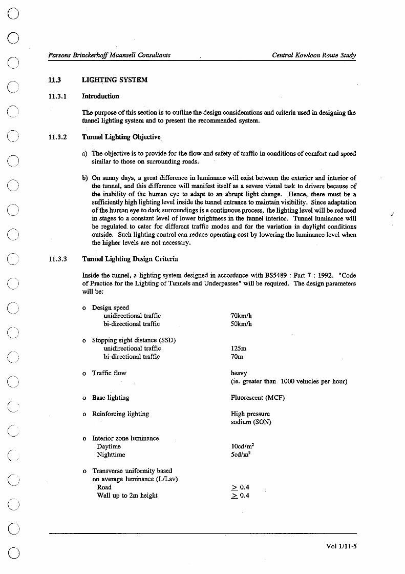
o o o c
o o o o
c' C)
C) c)
c
o o
Parsons Brinckerhoff Maunsell ConsultanlS Cenlral Kowloon Route Study
11.3
11.3.1
11.3.2
11.3.3
LIGHTING SYSTEM
Introduction
The purpose of this section is to outline the design considerations and criteria used in designing the tunnel lighting system and to present the recommended system.
Tunnel Lighting Objective
a) The objective is to provide for the flow and safety of traffic in conditions of comfort and speed similar to those on surrounding roads.
b) On sunny days, a great difference in luminance will exist between the exterior and interior of the tunnel, and this difference will manifest itself as a severe visual task to drivers because of the inability of the human eye to adapt to an abrupt light change. Hence, there must be a sufficiently high lighting level inside the tunnel entrance to maintain visibility. Since adaptation ofthe human eye to dark surroundings is a continuous process, the lighting level will be reduced in stages to a constant level of lower brightness in the tunnel interior. Tunnel luminance will be regulated. to cater for different traffic modes and for the variation in daylight conditions outside. Such lighting control can reduce operating cost by lowering the luminance level when the higher levels are not necessary.
Tunnel Lighting Design Criteria
Inside the tunnel, a lighting system designed in accordance with BS5489 : Part 7 : 1992. "Code of Practice for the Lighting of Tunnels and Underpasses" will be required. The design parameters will be:
o Design speed unidirectional traffic bi-directional traffic
o Stopping sight distance (SSD) unidirectional traffic bi-directional traffic
o Traffic flow
o Base lighting
o Reinforcing lighting
o Interior zone luminance Daytime Nighttime
o Transverse uniformity based on average luminance (L/Lav)
Road Wall up to 2m height
70kmlh 50kmlh
125m 70m
heavy (ie. greater than 1000 vehicles per hour)
Fluorescent (M CF)
High pressure sodium (SON)
IOcd/m' 5cd/m'
2.0.4 2. 0.4
VoI1l11-5

Parsons Brinckerhoff Maunsell Consultants Central Kowloon Route Study
11.3.4
o Longitudinal uniformity along centre of lane (LlLmax)
oZone lun.:;inancc variation
o ' Access zone luminance [Lw] (Actual value to be ascertained on site)
o Maximum reduction ratio of access zone luminance to threshold zone luminance
o Maximum reduction ratio of stepped change in luminance levels in transition zone
o Critical flicker frequency
o Glare restriction - maximum threshold increment
o Maximum ratio of luminance changes between successive stages of switching
o Coefficient of diffused reflectance Wall Road surface Ceiling
o Maintenance factor
Lwninaires
2. 0.6
As shown in Figure No. 047
6000cd/m'
13:1
3:1
205Hz to 15Hz
15%
5:1
0.6 0.15 0.0
0.7
Durable, long-life and energy saving luminaires will be used throughout the tunnel areas. Full consideration should be paid to the life cycle costing during the detail design and equipment selection process. In principle, the following applications will be adopted:-
Application
Tunnel base lighting
Tunnel reinforcing lighting
High mast lighting and street lighting
Indoor lighting in ancillary buildings
Luminaire Type
Fluorescent (MCF)
High pressure sodium (SON)
High pressure sodium (SON)
Fluorescent (MCF)
Furthermore, tunnelluminaires will be water resistaot, dust resistaot, and corrosion resistaot. In addition, the luminaires will be designed to allow easy lamp and gear replacement.
Volllll-6
o G
o o o o o o o o o o o o o o o o o o o o

o o c') ()
o o o o 0 '
/
c' c c::
c) c) o
o
c
Parsons Brinckerhoff Maunsell Consultants Central Kowloon Route Study
11.3.5
11.3.6
11.3.7
11.3.8
11.3.9
Base Lighting
The base lighting installation will consist of continuous or near continuous row of luminaires (2 x 58W M.CF fluorescent tube) ceiling-mounted directly above the lane dividing line. During nighttime, one fluorescent tube will be switched off. This arrangement of base lighting can avoid problems of flicker and provide good uniformity in interior zone lighting in both daytime and nighttime. Guiding the drivers to stay in their own drive lane will be a bonus of this lighting scheme.
Reinforcing Lighting
a) Luminaires with high pressure sodium (SON) lamps or fluorescent (MCF) tubes will be ceiling mounted in rows over the road surface in the threshold and transition zones as shown in Figure No. 047. The zone lengths and luminance levels of the reinforcing lighting will be according to the CIE luminance reduction curve and also the desigu criteria. Reinforcing lighting will be provided at both ends of the tunoel to facilitate bi-directional traffic within the same tube during daytime.
b) Because of the east-west orientation of the tunoel alignment, tunoel users may, when emerging from the tunoel, be directly facing the rising or setting sun. In order to compensate for this situation, the exit zone lighting will be boosted to reduce the contrast in lighting levels. As reinforcing lighting will be provided at each end of each tube, this enhanced lighting requirement will be readily available.
Switching Control
Tunnel luminance will be automatically regulated in accordance with the extemalluminance level. Luminance sensors will be installed at each tunnel entrance and directed towards the tunoel entranceS to obtain a measuring field of view as close as practical to that used for the estimation of L,.,. Signals from the luminance sensors will then be used to control switching. Regulation of tunoelluminance at the entrance zones will be done in a stepped switching manner with reduction ratio ofluminance levels between successive stages of.switching not greater than 5: 1. The lighting control system will be located in the Central ConJF1l1 Room of the Administration Building and will be capable of manually overriding the automatic switching in a fallback situation.
Emergency Lighting
The tunoel lighting system will be fed from dual supply sources so the possibility of an instantaneous total loss of tunnel illumination will be remote. To safeguard against accidents which may occur at the moment of sudden loss of all tunoel illumination from a general territory-wide black-out, 14% of the tunnel base lighting will be supported by UPS systems until the emergency generator starts up. The sudden decrease in luminance of the interior zone, frolll the normal full level to a low level (1. 7cd/m') maintained only by UPS-fed luminaires, will still be visually acceptable.
Approach Road Lighting
High mast lighting posts with high pressure sodium (SON) lamps will be employed at the toll plaza. and the portal areas. Conventional street lighting will be provided to cover the approach roads. The luminance level and equipment standards will meet the standards of the Highways Department Lighting Division. The luminaires will be designed and positioned to minimize the effect of glare to the nearby residential areas.
Voll/11-7

Parsons Brinckerhoff Maunsell Consultants Central Kowloon Route Study
11.4 ELECTRICAL POWER SUPPLY SYSTEM
11.4.1 Introduction
This section presents the principle features of ·the recommended electrical power supply system.
11.4.2 Design Objectives
11.4.2.1 The electrical power supply· system will be designed to a high degree of reliability, flexibility and continuity to cater for the operational and safety requirements of a heavy traffic vehicular tunnel with the following provisions:
Secure power supplies obtained from two independent sources from the power supply company. Automatic changeover at low voltage level for feeding all loads. Uninterruptible power supply for critical loads and computer equipment.
These criteria will be implemented throughout the design of both high voltage and low voltage distribution systems.
11.4.2.2 The proposed system voltages feeding various electrical equipment of the tunnel will be:
11.4.3
11.4.4
11.4.5
RV Distribution System : Tunnel Ventilation Fans: Tunnel Lighting : Miscellaneous Equipment :
Electrical Loading
11 kV, 3-phase 380 V, 3-phase 220 V, 1-phase 380 V, 3-phase, 220 V, I-phase
The estimated maximum electricity demand of the tunnel for the dual two-lane configuration is 7 MV A, which will be subject to review during the detailed design stage.
High Voltage (HV) Distribution System
The HV distribution scheme for the tunnel is shown in Figure No. 050. The schematic diagram for the fan motor control centre is shown on Figure No. 054. For security reasons, it is recommended to have two independent sources of supply at 11 kV from China Light and Power Company Limited (CLP), one at each tunnel portal. Each source will be adequate to meet the maximum electricity demand of the tunnel. The HV switch rooms, which are located at Fat Kwong Street Vent Building and both portal buildings, will be interconnected as an open ring to provide a dual-source supply system. This arrangement can be manually switched to resume full tunnel operation in the event of failure of supply at one end of the tunnel. In connection with the low voltage power supply scheme described below, this scheme will prevent complete black-out within any section of the tunnel. Since the interconnection of power sources from CLP will be involved, selected circuit breakers will be interlocked to prevent inadvertent paralleling of power sources.
Low Voltage (LV) Distribution System
11.4.5.1 The LV (380 V 3-phase and 220 V I-phase) distribution system will be integrated with the HV distribution system to provide increased reliability as shown in Figures Nos. 050 & 051. Each LV system will be connected to dual transformers at each HV switch room such that each transformer supplies approximately half of the normal loading. When one transformer or interconnector becomes faulty, or a main fails at the power source, automatic changeover failities with electrical and mechanical interlock will transfer load between each pair of transformers. All transformers will be sized to meet their maximum demand.
VoI1l11-8
o o o o o o o o o o o o o o o o o o o o o o o

o o
o C)
o o o o o C) ( \
/
o o ()
G
G
o o
c)
Parsons Brinckerhojf Maunsell Consultants Central Kowloon Route Study
11.4.5.2 The latest information indicates that the space available in the west portal Vent Building (located in the carparl< building) will not be sufficient to accommodate the CLP switch room and the RV swit.ch room. The power supplies for the exhaust fans in the portal Vent 'Building will therefore need to be fed from transformers in the substation via low voltage cables. However, it should be emphasized that the equipment installation costs and the operating costs would be reduced if the substation and the Vent Building could be integrated together at the portal area. Such integration may be possible and should be examined during detailed design of the building.
11.4.5.3 In addition, a CLP substation will be located at the Administration Building to cater for the electrical loads there. Dual sources at LV wiII be made available from CLP. The capacity of each source will be adequate to meet the maximum load demand at the Administration Building and Toll Plaza.
11.4.6 Emergency Generators
11.4.6.1 Emergency generators will be installed at Fat Kwong Street Vent Building, both portal buildings, and Administration Building. Generators will be adequately sized and will be capable of taking up their emergency loads within 15 seconds of a main power failure. Emergency generators will be provided to maintain operation of the following essential loads for a minimum of six hours during a main power failure :
air-conditioning for computer room, control rooms and uninterruptible power supply room. all loads backed up by uninterruptible power supply. essential lighting and power for ancillary buildings. essential lighting and power within tunnel tubes. fire services systems. mechanical ventilation for battery rooms. tunnel drainage system.
11.4.6.2 For the Administration Building and Toll Plaza the emergency generator and its fuel tank will be rated to feed the essential loads for 24 hours.
11.4.7 Uninterruptible Power Supply (UPS) System
11.4.7.1 UPS systems will be provided to maintain the operation of the critical equipment for tbe period between complete main's failure and before the emergency generator is ready to take over the loads. Static converter type UPS systems will have adequate capacity to supply the following services for a minimum of 30 minutes:
computer systems control room facilities CCTV cameras and recording equipment emergency lighting essential conununication equipment fire alarms plant monitoring equipment toll collection system traffic control equipment.
11.4.7.2 To increase the reliability of the uninterruptible supply for the computer systems, the UPS system serving these systems will be of the dual parallel, redundant module type with a common battery bank. Other UPS systems will be of the single module type.
VoI1l11-9

Parsons Brinckerhoff Maunsell Consultants Central Kowloon Route Study
11.4.8 Cabling
11.4.8.1 RV cabling will be armoured copper cables with flame retardant properties. RV cabling inside the tunnel will be generally running behind the tunnel cladding and enclosed in two hours fire resisting period (FRP) enclosure.
11.4.8.2 LV cabling for the tunnel ventilation system and those systems backed up by UPS will be fire resistant, low-smoke, halogen-free, armoured copper cables to maintain circuit integrity under fire conditions.
Other LV cabling running inside the tunnel will be low-smoke halogen-free armoured copper cables.
LV cabling at the other areas will generally be armoured copper cables with flame retardant properties.
11.5 CENTRAL MONITORING & CONTROL SYSTEM (CMCS)
11.5.1
11.5.2
CMCS Objectives
CMCS will be provided to enable the tunnel operators to monitor the status of the complete electrical and mechanical systems and to monitor and control the tunnel ventilation, tunnel lighting and tunnel drainage system in the Central Control Room (CCR) at the Administration Building as described below. In addition to the automatic control functions of CMCS, hardwired control console will also be provided as the backup control of the tunnel ventilation system in case of failure of the computer equipment. The recommended arrangement of CMCS is shown in Figure No. 055.
Features of CMCS
CMCS will be used to monitor and/or control the following systems:
a) Tunnel Ventilation System
The tunnel ventilation fans will be controlled under the following operational modes:
Mode of Oneration
Fully automatic operating mode
Semi-automatic operating mode
Description
CMCS will continously monitor the CO, NO, NOx visibility and air velocity levels in the traffic boxes and control the tunnel ventilation fans operation automatically to maintain the tunnel conditonswithin the specified limits. Note, NOx only monitored if suitable equipment is available.
Individual ventilation fans will be operated by keying in the corresponding command through 'the man-machine interface of CMCS. The computer software will regulate the starting and operating sequence to avoid excessive power surge.
Vo11!1l-10
o G
o o o o o o o o o o o o o o o o o o o o o

o o c
o o o o o c C'
c c Ci
c/ c C)
o o
Parsons Brinckerhoff Maunsell Consultants
Remote operating mode
Local operating mode
b) Tunnel Lighting System
Central Kowloon Route Study
The tonnel ventilation fans will be operated via the hardwired back-up control console. The computer functions will be overriden.
The tonnel ventilation fans will be operated at the motor control centre in the corresponding ventilation building. Under this operating mode, all remote control functions at the CCR will be overriden.
CMCS will monitor the operation of the tonnellighting system. The tonnellighting system will be controlled automatically via a control loop with photometers, lighting control centre (LCC), lighting control console and relay panels. CMCS will monitor the statos of the photometer system and the lighting switching contactors. The statos and incident data will be displayed and recorded at the CCR. An alarm will be raised when the statos of the lighting contactors do not match with the required lighting level. A back-up lighting control console will be provided at the CCR to allow manual override operation.
c) Electrical Power Supply System
CMCS will monitor the operation of the power supply equipment and will display the statos and raise alarms on failure of the following systems in tonnel and buildings:
HV system LV system emergency generators battery and charger system UPS system.
CMCS will log all alarms in sequence.
d) Fire Services Systems
CMCS will monitor the statos of the following fire services installations:
tonnel fire hydrant system, tonnel hose reel system, automatic foam system for the petrol interceptors adjacent to the mid-tonnel sumps, master fire alarms of buildings.
e) Plumbing and Drainage Systems
CMCS will monitor the following plumbing and drainage systems:
flooding alarms and pump statos of the tonnel sumps, flooding alarms and pump statos of the portal sumps, flooding alarms and pump statos of the lift pit sump in the Administration Building, master failure alarms of plumbing and drainage system of buildings.
In addition, CMCS will provide remote on/off control of the tonnel sump pumps at the CCR.
Volll11-11

Parsons Brinckerhoff Maunsell Consultants . Central Kowloon Route Study
f) MV AC Systems
CMCS will monitor the following MV AC systems :-
status of the air-conditioning equipment of the computer room, the Central Control Room and the UPS rooms, master failure alarm of central air conditioning system of the Administration Building, failure alarms of ventilation fans in major plant rooms.
11.6 DRAINAGE SYSTEM
11.6.1 Design Criteria
11.6.1.1 The drainage system for the tunnel will consist essentially of two parts, each with their own different design criteria. Surface water collected within the catchment area of the portal sump will be dealt with by one part of the system designed to handle large quantities of storm water expected, whereas water collected within the tunnel will be dealt with by another part. This paragraph describes the design of the drainage system within these areas.
11.6.2 Surface Water Drainage
11.6.2.1 In order to protect against inundation of the tunnel and approach ramps by floods caused by heavy rainfall, all areas surrounding the portal will reach an elevation of at least +S.SmPD. Within the flooding zone boundary, all rain water will run towards the tunnels. The water will be collected in portal sumps, passing through a petrol interceptor before being pumped up to a drainage manhole at grade level where it will be discharged to the public sewer.
11.6.2.2 The drainage system schematic is shown in Fignres Nos. 040 and 041. Surface water will be collected by two rows of transverse gratings immediately inside each tunnel portal.
11.6.2.3 Water will be led to a petrol interceptor and sump located under the road surface within the tunnel portal. Six sets of pumps, each of looLls capacity, will be required at the west portal sump while eleven sets of pumps, each of IS0Lls capacity, will be required at the east portal sump. The west portal sump will have an effective holding capacity of 200m3, and the east portal sump will have an effective holding capacity of 350m3. The pump and sump combination will be able to cater for extreme rainfall of all possible durations as shown under the 1 in SO year curve of the Mean Rainfall Intensity Chart attached to Volume VI Section 2 of the CE Manual. When the total run-off exceeds the total capacity that the pumps can handle, the balance of the rainwater will be held in the sump and be discharged after the peak of the rain storm has passed. More severe storms of relatively long duration could possibly cause the holding capacity of the sumps to be exceeded and cause some water to enter the tunnel.
11.6.2.4 A stand-by pump will be provided for each portal sump. In case of pump failure, the stand-by pump will be switched on automatically to takeover the duty. Apart from the main discharge pumps, there will be a small pump of 4 Lis capacity for maintenance dewatering purposes.
11.6.2.5 Each sump will include a petrol interceptor which will be designed to meet a rainfall intensity of 25mm per hour.
Voll/IH2
o o o o o o o o o o o o o o o o o o o o o o o

o o
o o o o
c' c C
c Cl
c c c c'
c
Parsons Brinckerhoff Maunsell Consultants Central Kowloon Route Study
11.6.3 Tunnel Drainage
11.6.3.1 The tunnel drainage system will be designed to deal with minor leakage from the tunnel structure, surface water spilled over and not collected by the porta! drainage system, and surface water carried along by vehicles entering the tunnel. The drainage system will also handle the expected run-off from tunnel washing, testing and operation of fire hydrants, and spillage from vehicles.
11.6.3.2 Foul water will be drained through discrete gratings located to one side of the carriageway into a continuous, enclosed channel. All water wilLbe collected in two mid·tunnel sump of 50m3 effective capacity each, incorporating a petrol interceptor of 8m3 respectively. Foul water will be discharged to. the separate sumps at the west porta! and east porta! respectively and then discharged into' the foul drainage system.
11.6.3.3 Two main pumps, one duty and one stand·by, each of 75 Lis capacity will be provided in each mid·tunnel sump to cope with the maximum run-off, the main contributor would be the fire hydrants. Two dewatering pumps, each of capacity 4 Lis, would also be provided in each mid·tunnel sump to handle small run·off. .
11.6.4 Petrol Interceptor
11.6.4.1 Each of the petrol interceptors will contain three compartments such that the escape of petrol and oil can be reduced. The interceptors will be designed to have a. retention time of twenty minutes based on average inflow. To reduce the risk of fire occurring in the petrol interceptor, a foam blanketing system should be provided in accordance with NFP A 11 standard and with the lower explosive limit set at 0.8 %.
11.7 FIRE PROTECTION SYSTEM
11. 7.1 Design Criteria
11.7.1.1 The fire protection system will consist of a fire alarm system and a fire fighting system. The fire alarm system will provide a fast and accurate report to the Fire Services Communication Centre (FSCC) and to the tunnel operators once a fire has been reported. Early reporting of a fire is essential so that prompt action can be taken to put out the fire while it is at an early stage of development. The fire fighting system must allow the tunnel operators, tunnel patrons and the Fire Services personnel to tackle the fire once it has started. Portable fire extinguishers and hose reels can be used by untrained people to fight the fire before the firemen arrive. In addition to this ready·use equipment, facilities must also be provided to allow the tunnel operators and FSD to fight and control the fire efficiently so as to minimize damage to life and property. Such facilities must include fire hydrants, a telecommunication system and a closed circuit television system.
11. 7 .1.2 Hydrant mains and hose reel mains will be fed by pumps and tanks at both the West Portal Building and Administration Building. Should the supply from either building fail, the supply from the other building must be able to meet the maximum system requirements.
11. 7 .1.3 A fire services water tank of 36m3 capacity will be adequate in case of an unrestricted water supply being available with a minimum flow rate of 4000Llmin. Otherwise, a fire services water tank with an effective capacity of 240m3, sufficient for the simultaneous operation for one hour of two hydrant outlets, each at 2000Llmin, may then be required. Fire pumps and fire services water tank for hydrants may not be required if an unrestricted water supply is available which has a minimum flow rate of 4000 Llmin and can maintain a minimum pressure of 170kPa at each hydrant outlet. However, a break tank would still be required for running the hose reel system.
Volll11·13
/

Parsons Brinckerhoff Mau1Isell Consultants Central Kowloon Route Study
11.7.2 Fire Alann System
11.7.2.1 Break-glass fire alarm units will be provided at 50m intervals on offside and lOOm intervals on nearside. These units will be installed on both sides of the carriageways such that they can be easiiy reached by tunnel patrons. For easy identification of fire site, each tube will be divided into fire zones. The break-glass units will be segregated sequentially into groups in accordance with the fire zone to which they belong. Once a break-glass fire alarm unit is activated, an alarm will be transmitted to the main fire alarm panel at the fire control centre inside the Central Control Room (CCR). Through the direct telephone line link to the fire control centre, the FSCC will copy the fire alarm message from the tunnel.
11. 7 .2.2 A fire warning signal will also be raised and sent to the CCR and Fire Services Communication Centre once any of the fire extinguishers provided along the tunnel has been taken from its position, signifying the intended use of the extinguisher. A warning signal will also be transmitted to the CCR automatically when any door of a hose reel cabinet is opened or when any emergency telephone handset is taken out from its position. Having received the fire alarm messages and/or warning signals, the operators at the CCR can confirm the exact location of fire through the tunnel CCTV and then operate the tunnel ventilation system in the appropriate mode.
11.7.3 Hose Reel System
11.7.3.1 Hose reels containing hoses 30m long will be provided along the carriageway (Figure No. 043) at a separation of SOm. Every part of the carriageway should be reached by the water jet of the hose reel.
11.7.3.2 Figure No. 042 shows the proposed piping schematic for both the fire hydrant and hose reel systems. Each hose reel will be able to project a jet not less than 6 metres in length.
11.7.3.3 Sectional valves will be provided along the hose reel main in the tunnel to facilitate detection of water leakage and for isolating defective pipe sections while maintaining an operable system in the unaffected part. These valves will be equipped with micro-switches such that the open/close positions can be monitored through the central monitoring and control system.
11.7.3.4 It should be noted that the proposed system configuration represents one of the solutions. Other possible solutions include a third fire services tank and pump room location at Fat Kwong Street Vent Building. Integration of this third tank/pump location with the same at west portal area to form a main network is another alternative. The system configuration should be reviewed in the detail design stage.
11.7.4 Fire Extinguishers
Three sets of portable 4.5kg C02 fire extinguishers will be housed in niches on both sides of the carriageways at lOOm intervals.
11. 7.5 Fire Hydrant System
11.7.5.1 Fire hydrants will be provid~ for the ~se of the Fire Services personnel only. The outlets will be housed in niches in the walls adjacent to the the crosspassages at lOOm interval",
11.7.5.2 As shown in Figure No. 042, the hydrant main will be fed directly by two separate connections from the WSD mains. The two connections will be located at the West Portal BUilding and Administration Building near the east portal.
VoI1l11-14
o o o o o o o o o o o o o o o o o o o o o o o

o o Ci
o o o o o o o Ci
/
c) o o C) o o o o o u o Cl
/
Parsops Brinckerhoff Maunsell Consultants Central Kowloon Route Study
11.7.5.3 Sectional valves will be provided along the hydrant main in the tunnel to facilitate detection of water leakage and for isolating defective pipe sections while maintaining an operable system in the unaffected part. These valves will be equipped with micro-switches such that the open/close positions can be monitored through the central monitoring and control system.
11.7.5.4 Fire hydrant shall have twin outlets fitted with instantaneous couplings and be capable of discharging water at a rate of not less than 4000 Llmin at a minimum running pressure of 170 kPa at the outlets with two 65mm outlets operating simultaneously. To restrict the maximum water pressure at the hydrant outlet to the allowable 700kPa, pressure reducing valves will be provided.
11.7.5.5 Alternatives of system configuration including the use of fire services tank and pump room (pumps probably not required) located at Fat Kwong Street Vent Building should be evaluated in the detail design stage.
11.7.6 Fire Control Centre
11.7.6.1 The fire control centre will be located in the CCR inside the Administration Building. The CCR will house control centres for the traffic control and surveillance system and the central monitoring and control system in addition to the main fire alarm panel. The integrated central control should facilitate efficient operation and quick response to fire events.
11.7.7 Other Auxiliary Systems
11.7.7.1 Emergency power points of Fire Services Department approved type will be provided at lOOm intervals on both sides of the tunnel. Each point shall be provided with one ironclad water-proof 15 amp. 3-pin socket "Niphan" model no. N549A, complete with one "on/off" switch and shall be used for fire fighting/rescue equipment. The concentration of carbon monoxide (CO) and nitric oxide (NO) inside the tunnel will be monitored. An alarm will be registered before the concentration reaches a level hazardous to health.
11.7.8 Emergency Facilities
11.7.8.1 Emergency Services Radio Coverage
Arrangements will be made to extend the Police and Fire Services radio systems through the tunnel to give continuity of coverage. Radiating, slotted leaky coaxial cables will be mounted on the roof of the tunnel.
11. 7 .8.2 Fire Services Telephone Facilities
Sockets will be provided at the tunnel portals to enable standard portable telephone instruments to be connected to a PSTN direct exchange line and to the Fire Services Department Control Centre over private wire direct telephone circuits.
11.7.8.3 Emergency Announcements
Facilities will be provided for announcements to be made to tunnel users by public address system in toll plaza and tunnel portal areas, and also by injection into the retransmission of public radio programmes within the tunnel. A radiating coaxial cable will be mounted on the roof of the tunnel for this purpose.
VoI1l11-15

Parsons Brinckerhoff Maunsell Consultants Central Kowloon Route Study
11.7.8.4 Direct Line Telephones
Separate telephone instruments with direct line connections to the Royal Hong Kong Police (RHKP) and FSD will be provided in the control room at the Administration Building.
11.7.8.5 Emergency Telephone
o o o o o
Emergency telephone facilities will be provided at an interval of 100 metres on both sides inside 0 the tunnel and in strategic locations along the approach roads.
11.7.8.6 Emergency Equipment Niche o Emergency equipment described above, such as telephones, hosereels, fire extinguishers etc, will be housed in niches (or recesses) in the tunnel walls and enclosed behind flush doors. The niches 0 will have illuminated sigus defining the equipment contained in them. The locations of these niches is illustrated in Figure No. 043. Niche doors shall have contact switches so that when a door is opened an alarm will be registered in the control room identifying the niche involved. 0
11.7.8.7 Illuminated Signs
Illuminated signs for emergency telephones and fire extinguishers shall be provided and shall be easily discernible along the tunnel. Self-illuminated signage shall be provided to pedestrian cross passages indicating their location and purpose.
VoI1l11-l6
o o o o o o o o o o o o o

Utilities 1 2
J

o o c c c c) o
c! c c c c c c c c
C,
Parsons BrinckerhoJ! Maunsell Consultants Central Kowloon Route Study
12.
12.1
12.2
12.2.1
12.2.2
UTILITIES
Based on the information supplied by the relevant Government authorities and utility undertakers, the approximate locations of the major services and utilities have been identified and are shown on Figures No. 080 to 085 together with preliminary diversion routes.
'This section highlights some of the major installations along the CKR alignment.
AIRPORT RAILWAY
An underground railway alignment and proposed outer structure limits have been identified for the future airport railway in the Yau Ma Tei interchange area. The railway tunnels will be formed from concrete base and roof slabs spanning between diaphragm walls. This form of structure is very stiff and it should be possible to place elevated road foundations close to the tunnel external walls without causing disturbance to the structure. .
The West Kowloon Expressway design provided the foundation layout of the elevated highway structures to fit the railway tunnel reserved corridor.
Figure No. 041 shows the proposed reserved corridor for the airport railway.
MASS TRANSIT RAILWAY
MTR Cooling Water Mains
There are two 600mm cooling water mains running at a shallow depth above the MTR tunnels. At the CKR crossing south of the MTR Yau Ma Tei station, the CKR tunnel will pass between the cooling water mains and tlie MTR tunnels.
The MTRC require 600mm minimum cover to the cooling water main and 300mm clearance between the main and tunnel roof slab. The CKR tunnel roof will be reduced in thickness at the water mains to enable to above requirements to be satisfied.
Figure No. 033 shows the proposed tunnel crossing Nathan Road.
Vent Shaft Reserve
To the east of Nathan Road on the CKR alignment there is a piece ofland reserved for construction of a vent shaft for the future extension of tlie Kwun Tong Line from Yau Ma Tei to Fortress Hill. MTRC have advised that the reserve can be relocated north of the CKR provided a level platform similar to the existing platform is provided. The proposed new location for the future MTRC vent shaft is shown on Figure No. 033.
12.3 GAS
12.3.1 Western Approaches
12.3.1.1 The main gas distribution system generally runs in a north-south direction along Nathan Road, Portland Street and Reclamation Street. The mains are low pressure up to 300mm dia., and there are numerous small diameter (150mm or less) connections to buildings within the area. These mains will be maintained and temporarily protected during construction or diverted as necessary.
Vo11l12-1
/

Parsons BrinckerhojJ Maunsell Consultants Central Kowloon Route Study
12.3.1.2 The gas company is planning to install 400mm dia. medium pressure main and 300mm dia. Iow pressure main in a north-south direction along Ferry Street in conjunction with the West Kowloon Corridor - Yau Ma Tei Section Phase Il works. A utility trough will be provided at the top of CKR western portal to accommodate the 400mm dia. medium pressure main crossing CKR. The 300mm dia. low pressur;, main is proposed along Ching Ping Street. As there will only be proximately 700mm soil cover above the CKR top slab at the proposed location of the 300mm dia. Iow pressure main it is recommenced the main be diverted into the Ferry Street Central reserve before CKR Construction commences.
12.3.2 Central Section
There are no major gas mains in the tunnel vicinity.
12.3.3 Eastern Approaches
12.3.3.1 The CKR corridor will cross several 300 dia. and 400 dia. Iow and medium pressure gas mains running along Chatham Road and Ma Tau Wai Road. The gas company is also planning to lay two Nos. 400 dia. medium pressure gas mains along Wing Kwong Street and the proposed Yuk Yat Street extension.
12.3.3.2 Temporary diversions of these mains will be required during construction to enable diaphragm walls to be built.
U.4 WATER
12.4.1 Western Approaches
12.4.1.1 There are several major water supply installations within the area through which the CKR will pass. These include a 1400 dia. fresh water main.along Reclamation Street, the Yau Ma Tei freshwater service reservoir east of Nathan road, and various connecting mains.
12.4.1.2 In addition to the above, there are large diameter water mains along Ferry Street (450 dia. fresh and 450 dia. salt) and Nathan Road (2 x 600 dia. fresh). There are also numerous smaller diameter fresh and salt water mains serving the immediate area.
12.4.1.3 The existing 1400 dia. main and fresh water reservoir will be maintained and care will need to be taken during construction. The water mains along Ferry Street should be diverted into the Ferry Street Central reserve before CKR construction commences. The water mains in Nathan Road may require temporary diversion during construction.
12.4.2 Central Section
The major water supply installations close to CKR include 600 dia. freshwater main in Wylie Road and Ho Man Tin freshwater service reservoirs above Ko Shan Park. These installations are well above the CKR tunnel, and no diversions are envisaged.
12.4.3 Eastern Approaches
12.4.3.1 The significant water supply installations in the area of the proposed CKR include a 900 dia. salt water main along Ma Tau Wai Road, 600 dia. freshwater main along Ko Shan Road and 450 dia. freshwater main being laid along the Yuk Yat Street extension.
Vo11l12-2
o o o o o o o
o o o o o o o o o o o o o o o

o o
o o o o o o o o C) C) C) C) C)
o o o o
Parsons Brinckerhoff Maunsell Consultants Central Kowloon Route Study
12.4.3.2 The remainder of the water mains form a local distribution network and comprise smaller diameter mains.
12.4.3.3 The water mains will be need to be temporarily diverted to allow diaphragm wall construction to proceed.
n.s SEWER
12.5.1 Western Approaches
12.5.1.1 A 900 dia. sewer running along Reclamation Street will conflict with the CKR tunnel structore. The North West Kowloon Sewerate Master Plan (NWKSMP) Study recommends that much of the flow in this sewer is intercepted at Public Square Street and diverted into a new intercepting sewer on the line of the existing seawall. It is proposed that the section of sewer in Reclamation Street north of Public Square Street be reconstructed to fall to Public Square Street and hence to the intercepter sewer when the CKR is implemented.
12.5:1.2 As discussed in 12.5.1.1 the NWKSMP recommended new intercepting sewer along the line of the existing seawall west of Ferry Street. The West Kowloon Corridor (WKC) project has revised the location to a point further east and if the intercepter sewer is laid as planned by WKC th~n there will be a conflict between the sewer & CKR tunnel base slab. To avoid this problem it is recommended that the intercepting sewer be laid on the alignment originally proposed by the North West Kowloon Sewerage Master Plan Study.
12.5.2 Central Section
The drainage record plans show no sewers near the CKR alignment.
12.5.3 Eastern Approaches
12.5.3.1 The main sewerage drains run along Ma Tau Wai Road and along the· proposed Yuk Yat Street extension at a low level. It is apparent that th~ system has evolved over time with the initial sewer in Ma Tau Wai Road being duplicated and the sewer along Yuk Yat Street being relatively recent and built in conjunction with the To Kwa Wan sewerage screening plant. The North and South Kowloon Sewerage Master Plan Study shows the 900mm dia. sewer along Bailey Street is intended to intercept all the flow from the upstream sewers in Ma Tau Wai Road and convey it to the To Kwa Wan sewage screening plant and that the main sewer along Ma Tau Wai Road between Bailey Street and Wing Kwong Street will be abandoned.
12.5.3.3 The 1650 dia. sewer along Yuk Yat Street will clash with the CKR. It would be possible to divert the sewer to the east so it passed under the CKR toll plaza area near the edge of the existing To Kwa Wan reclamation. If a diversion of the sewer away from CKR is found to be impractical, a pumping station can be installed to lift the sewer over the tunnel structure. ·Alternatively, an inverted siphon can be provided to place the sewer under the tunnel structure. Further investigation is required in detailed design stage.
12.6 ELECTRlCITY
12.6.1 Western Approaches
o 12.6.1.1 There are no existing main transmission (132kV and above) cables located within the western approach area.
o o Vo11l12-3

Parsons Brinckerhoff Maunsell Consultants , Central Kowloon Route Study
12.6.1.2 The other existing installations are medium voltage (33kV) and below which can be diverted without major difficulty.
12.6.1.3 In conjunction with the West Kowloon Corridor project 400kV cables will be laid along the west side of Ferry Street and along Ching Ping Street. The cables on Ferry Street will be laid in the services trough at the CKR tunnel portal and will not interfere with future construction of the tunnel. The cables along Ching Ping Street will interfere with diaphragm wall construction and CL&P have been requested to allow sufficient slack in the cables to enable them to be slewed 4m in the future. The slewing operation will require temporary closure of Ching Ping Street. Due to inadequate cover to the tunnel it will be necessary for the cables to pass through ducts cast into the tunnel roof.
12.6.2 Central Section
There are 3 x 400kV underground transmission cables between Wylie Road and the KCRC cutting.
o c o o o o o o
These cables will not be affected by the CKR structure, but should be noted during tunnelling 0 operations as they may interfere with electrical blasting primers; ,
12.6.3 Eastern Approach
12.6.3.1 The major electricity supply installations include:
Existing
3 x 400kV and 9 x 132kV transmission cables under Ko Shan Road; - 132kV substation on Ko Shan Road;
2 x 132kV transmission cables along Ma Tau Wai Road; and 1 x 132kV transmission cables along Wing Kwong Street.
Planned
- 132kV cables along Yuk Yat Street extension
o o o o o
12.6.3.2 The concentration of high voltage cableS in Ko Shan Road is a potential problem and it is 0 recommended that bored tunnel methods be used in order to avoid the need to relocate or disturb the cables. The substation in Ko Shan Road will be unaffected by the CKR.
12.6.3.3 During construction of the CKR across Ma Tau Wai Road, Wing Kwong Street and Yuk Yat Street 0 the 132kV cables will need to be uncovered and slewed to permit diaphragm walling to be constructed.
12.7 TELEPHONE
12.7.1 Western Approaches
12.7.1.1 There are existing telephone cables along Ferry Street. The telephone company will divert these during the West Kowloon Corridor - Yau Ma Tei Section Phase II project.
12.7.1.2 The HKTC will lay 20 way telephone ducts on the western side of Ferry Street after completion of the West Kowloon Corridor (WKC) project. These ducts will be installed in the service trough at the CKR tunnel portal and hence will not interfere with tunnel construction.
Vo11l12-4
o o o o o o o

o o o o o o o o o o
c' C) c;
o o C)
c u u C'
Parsons Brinckerhoff Maunsell Consultants Central Kowloon Route Study
12.7.1.3 As advanced works 10 the WKC telephone cables will be laid along Ching Ping Street. The HKTC has agreed 10 leave slack in the cables so that the cables can be readily slewed in future to allow for diaphragm wall works.
12.7.1.4 Diversion or slewing of other telephone cables may also be required. Updated layouts will need to be obtained during detailed design of the CKR.
12.7.2 (lentral Section
12.7.2.1 . There are localized telephone cables serving premises around Ho Man Tin Hill and Wylie Road.
12.7.2.2 No diversion works are envisaged as there is sufficient clearance between the tunnel structure and ground level roads.
12.7.3 Eastern Approaches
12.7.3.1 The existing telephone cables running along Chatham Road North and Ma Tau Wai Road will need 10 be slewed during construction of diaphragm walls. The cables will then need to be suspended during excavation for the tunnel roof slab and until the roof slab is completed and backfilled.
12.7.3.2 In addition 10 the main cable routes there are feeder routes in Ko Shan Park and along Kai Ming Street and again it should be possible to construct the CKR tunnels without disrupting service provided care is taken and cables protected from heavy construction plant.
12.8 SURFACE WATER DRAINAGE
12.8.1 Western Approaches
12.8.2
12.8.3
12.9
The main surface water drainage drains run along Waterloo Road and Public Square Street with the area between drained by a network of generally small (300rnm dia. or less) drains running along the existing streets. It is unlikely ~at the existing drainage network meets current design standards and as a consequence will probably be reconstructed and rationalised by others when the area is redeveloped. No major drain diversions are envisaged, but local diversion may be required 10 aid the construction of CKR and will need to be further investigated in detailed design of the CKR.
Central Section
There is a 1500 dia. surface water drain east of Wylie Road. Even though the drain is fairly deep, there would still be 10m clearance between the drain and the tunnel. No major problem is anticipated· during tunnelling operation.
Eastern Approaches
The main surface water outfalls are located to north and south and run parallel to the CKR corridor. The CKR will not have a major impact on existing surface water drainage systems.
ROUTING OF FUTURE UTILITIES THROUGH TUNNEL
The CKR will traverse over 2,300m of densely populated land with many utilities crossing above and running along side of it.
Vo11l12-5

Parsons Brinckerhoff Maunsell Consultants Central Kowloon Route Study
With the construction of CKR, a direct corridor for linking utilities between the eastern and western part of Kowloon will be possible, although it is premature at this stage to be specific. This opportunity for providing connection through the highway tunnel, without disruption to surface traffic and local businesses should be evaluated by all utility companies and, if feasible, incorporated in the detailed design stage.
Vol 1I12-<i
o o o o o o o o o o o o o o o o o o o o o o o

Land Requirements 13
J

o o
c c C)
Ci
c
c c C
c
c
Parsons Brinckerhoff Maunsell Consultants Central Kowloon Route Study
13. LAND REQUIREMENTS
13.1 ACQUISITION OF PRIVATE LAND
13.1.1 Introduction
13.1.1.1 The alignment of the Central Kowloon Route will bisect Kowloon and, unlike other major highways, will not follow existing road alignments. Consequently, its traverse across established built-up areas will necessitate the acquisition of private property, much of which is already fully developed.
13.1.1.2 By adopting an underground form, CKR's impact on existing developments will be minimised, and there will be opportunities for property development upon completion or even in conjunction with the construction of the tunnel structure.
13.1.1.3 In general, the land required for resumption will be the out-to-out horizontal dimensions of the tunnel. In addition, the tunnel when it is not in rock, will have a zone of influence which may require resumption and demolition of buildings within about 15 metres from the outer structural envelope of the tunnel. It will be necessary during detailed design of the CKR to estimate the capacity of buildings adjacent to the tunnel to withstand the forecasted effects of construction to determine if they need to be resumed.
13.1.1.4 Fignre No. 095 shows buildings which will need to be resumed for CKR construction.
13.1.2 Western Approaches (Yau Ma Tei)
13.1.3
13.1.3.1
13.1.4
13.1.4.1
13.1.4.2
13.1.4.3
The CKR alignment will affect a total of 24 individual private lots which will need to be cleared to facilitate the construction of the road. The majority of these are old buildings below 6 storeys in height, but in the vicinity of Nathan Road, a number of substantial modem buildings will be affected.
Eastern Approaches (Hung Hom)
The adopted alignment will affect approximately 74 buildings. The majority of these are old 6-8 storey tenements contained within an area already considered suitable for comprehensive redevelopment.
Method of Acquisition
Whilst properties could be acquired prior to commencement of the scheme by way of voluntary surrender, it must be assumed that the majority, including any private streets, will be acquired by resumption under the Roads (Works, Use and Compensation) Ordinance.
The estimated total cost of acquisition! resumption is:
Western Approaches Eastern Approaches
$2800 million $1620 million $4420 million
These costs are based on the terms normally paid by Government in the event of resumption of property for a public purpose, but exclude the cost of rehousing the affected occupants.
VoI1l13-1

Parsons Brinckerhoff Maunsell Consultants Central Kowloon Route Study
13.1.5
13.2
13.3
Timing
Acquisition can take place at any time, but resumption can only be effected once the Road Scheme has been authorised under the Ordinance.
REPROVISIONING
The main areas of concern are the three schools in Tung Kun Street and Ko Shan Park. However the scheme as recommended will avoid entirely the need for reprovisioning of these facilities, although construction will cause some inconvenience in terms of access and short term environmental impact. In particular, it will be necessary to maintain access to the schools via Shek Luen Road through the existing market area. If the market is not redeveloped before construction of the road, relocation of some market facilities will be necessary for access to the schools during the period of tunnel construction.
ROUTE PROTECTION
The need to protect the alignment of the route was examined during the study and has been the subject of extensive consideration within Government.
It has emerged that there is at present no established mechanism by which the route can be protected and at the same time avoid blighting properties along the alignment of the road.
13.3.1 Need for Route Protection
The proposed alignment will traverse built-up areas and will require the demolition and clearance of several private lots to facilite construction. At present, many of the buildigns along the route are old medium to low rise structures which, if acquired now, could be redeveloped in conjunction with the construction of the tunnel. However, the road is not scheduled for construction until 1997 and, in the interim, there is no way of preventing the redevelopment of private lots. If such redevelopment is carried out, the redeveloped properties would encroach upon the corridor imposing constraints upon subsequent acquisition, clearance and tunnel construction.
13.3.2 Existing Position
13.3.2.1 The study team is not aware of any similar road having been proposed anywhere in Hong Kong, the more usual option being an elevated structure along an existing road alignment where only
. minimal land acquisition is required. There are no statutory measures available for route protection prior to the authorisation of a scheme under the Roads (Works, Use and Compensation) Ordinance.
13.3.2.2 However, the alignment could be shown on the Outline Zoning Plan and owners could be granted by the Building Authority bonus plot ratio and site coverage under Building Planning Regulations Section 22(2) in return for an undertaking by owners to surrender land for road widening following redevelopment. However, there is no statutory means to enforce such a set-back, and in any event the fmal alignment of the tunnel suggests that the set-back required would, in most instances, be too great to allow the opportunity of independent redevelopments to take place.
13.3.2.3 The most closely-related form of development is the Mass Transit Railway'. In this case, route protection is achieved under Section 15 of the Mass Transit Railway (Land Resumption and Related Provisions) Ordinance whereby the Building Authority has the power to reject building plans where the proposals are incompatible with the construction of the railway. There are no provisions for compensation unless a previously granted consent is withd.rawn.
Vo11l13-2
o o o o o o o o o o o o o o o o o o o o o o

o o o o o o o o o o o o o o o o C)
o C)
o o o Cl
Parsons Brinckerhoff Maunsell Consultants Central Kow/oon Route Study
13.3.2.4 There are no comparable provisions for protecting any other form of infrastructure development apart fJ:Om designation on the Outline Zoning Plans. This is appropriate fO,r specifying appropriate uses for land, but since it does not give rise to compensation provisions nor for the specialised engineering conditions necessary to provide compatibility with the development of the proposed road structure, it is doubtful if it could be utilised to protect the route other than as an interim measure.
13.3.3 the l'roblem
13.3.3.1
There is a need for legislation to provide appropriate powers to enable the protection of major inf11!Structure developments and specifically for this proposed route.
Redevelopment
a) The study has identified the properties which would be affected along the proposed alignment, and land searches reveal that there is a high probability of redevelopment taking place prior to 1997 particularly at the Western Approaches.
b) To the east, most of the existing private lots are developed with 6-8 storey tenement structures, three of which are in mUltiple ownership.
c) To. the Western Approach, the majority of the properties west of Nathan Road are in single ownership.
d) Multiple ownership is generally considered to be one of the main obstacles to redevelopment taking place, whereas buildings in single ownership are quite likely to be redeveloped when economic conditions are appropriate.
13.3.3.2 Effect of Redevelopment
13.3.4
13.4
13.4.1
13.4.2
13.4.3
At present, many of the single ownership buildings are medium to low rise structures. Upon amalgamation of sites, redevelopment can be expected to be more intensive and, if the route is not protected at an early stage, Government would be faced with the resumption of a recently constructed building.
Solution
It is proposed that the question of route protection needs to be considered as a territory-wide problem. However, as an interim solution to the problem of protecting the alignment of this route, it is proposed the Outline Zoning Plan be amended to incorporate the road alignment. If action is not taken at an early stage, there may be a need for the acquisition of a greater number of substaotial buildings than is indicated at present in the costings in this report.
IMPLICATIONS OF CURRENT GOVERNMENT POLICY
The construction of an underground roadway will give rise to opportunities for redevelopment of land above without the tunnel structure affecting the redevelopment.
This opportunity CQuld be by way of fully integrated structure or, more likely, the development of buildings which straddle the tunnel and hence are structurally independent.
Analysis of lots affected and the area of land therein not affected by the road suggests that there will, in practice, be few opportunities for private developments to take place before or even in conjunction with the development of the road.
Vol 1113-3

Parsons Brinckerhoff M aunsell Consultants Central Kowloon Route Study
13.4.4 It is therefore envisaged that the road will be constructed after all properties have been acquired by Government. Accordingly. redevelopment will take place on sites made available by Government after the tunnel is completed and incorporating detailed engineering conditions relating to development around the fllad structure. The area for the road will be excised from the land grant in the same manner as land strata required for tbe Mass Transit Railway is excised from land grants.
Volll13-4
o o o o o o o o o o o o o o o o o o o o o o Cl

Programme 14
J

o o
o o o c c c c c c c c ( .. "-- ..
c
c c c
Parsons Brinckerhoff Maunsell Consultants Central Kowloon Route Study
14
14.1
14.1.1
14.1.1.1
14.1.1.2
14.1.2
14.1.3
PROGRAMME
CONSTRUCfION PHASING
Implementation of the CKR, as developed in this Report, has been based on the following construction phasing.
Entrusted Works Phase· Construction to occur between 1993 and 1997.
West Kowloon Corridor (WKC) Entrusted Works
a) Diaphragm walls and top slab of the CKR sufficient to enable Phase 1 of the CKR to proceed with little disruption to traffic ou roadways constructed noder the WKC programme.
b) Construction of entrusted works to commence in 1994 and be completed in 1995.
Other possible Entrusted Works
a) Carpark (On West Kowloon Reclamation) • Construction date nnknown. Assuming the carpark on the WKR is constructed prior to the CKR, the entrusted works would be:
a ventilation shaft from the basement level to a height of about 50 metres above gronod level; a 25 ±m x 20±m fan room (but no fans at this stage), either in the basement or on the carpark roof.
b) USD "G" Site· Construction start between 1993 and 1996.
1) Assuming the "G" Site on Ko Shan Road would be constructed prior to the CKR, sufficient space for the CKR to pass beneath the building or through the basement would be required. Walls, slabs and possibly increased sizes of fonodations would constitute the entrusted works.
2) Under one scenario (see Para. 15.5.3), space for two lifts would be provided in the building, including two truck accesses to local streets.
c) Such other entrusted works as identified over the years.
CKR Phase 1· Construction from 1 Jan, 1997 to 1 Jan, 2001 (See Table 14.1 and Fig 14.1).
Construction of the CKR from the interchange with WKE to the "interim" toll plaza and temporary interchange at Yuk Yat Street/Bailey Street as illustrated on Figures Nos. 060·065.
CKR Phase 2 . Construction from 1 Jan, 2004 to 1 Jan, 2006.
Construction of the interchange between the CKR and the North·South Highway, including a revised toll plaza to the extents shown on Figure No. 070.
Vo11l14·l

o o
Parsons Brinckerhoff Maunsell Consultants Central Kowloon Route Study o 14.1.4
14.2
14.2.1
14.2.2
14.3
14.3.1
14.3.2
14.3.3
14.3.4
14.3.5
CKR Phase 3 - Construction from 1 Jan, 2009 to 1 Jan, 2011. o Construction of the remaining portion of the interchange between the CKR, North-South Highway and the Kowloon Bay Connector, including a revised toll plaza. Figure No. 071 shows the extent 0 of Phase 3 works.
REQUIREMENTS o The implementation programme was designed to enable the Central Kowloon Route to become operational in early 2001 whilst leaving adequate time for construction, design and land acquisition 0 procedures.
Statutory o a) . The main statutory procedure to follow will be Gazetting of the Scheme under the Roads o.
(Works, Use and Compensation) Ordinance (Chapter 370). Objections to the scheme will almost certainly be received from affected property owners. The programme allows time for attempting to resolve the objections and also time for the scheme to be submitted for the 0 approval of the Governor in Council.
b) Resumption of properties affected by the project will only be able to commence after the scheme has been authorised under the Roads Ordinance. It is recommended that the period of notice in the order for resumption be fairly lengthy to allow time for dealing with multiple and sub-tenancies (see Para. 14.5).
Contractual
o o
The programme must allow adequate tendering and tender assessment periods to enable contractors 0 to obtain competitive quotations for the various components, especially electrical and mechanical installations. The tender assessment could also be complex with contractors probably offering alternatives. 0
PROGRAMME ASSUMPTIONS
The construction programme for Phases 1, 2 and 3 is based on the following:
The Yau Ma Tei interchange bridge structures over the WKE have been constructed under the WKE project.
A carpark in the south-east corner of Road D1 and CKR has been constructed by others, and provision for a fan room and ventilation shaft has been provided for in the construction of the carpark [Para. 14.1.1.2. all.
The diaghragm walls and top slab of the CKR from the west side of Ramp C to the west side of relocated Ferry Street have been constructed by others [Para. 14.1.1.1].
The contractor may not close more than half the north-bound lanes nor more than half the southbound lanes between WKC and Nathan Road at anyone time.
Ferry Street Southbound can be closed to traffic for a period.
Vo11l14-2
o o o o o o o o o

o o
o c) o o o o o o o o o o o o o o o C)
o Cl
Parsons BrinckerhoffMaunsell Consultants Central Kowloon Route Study
14.3.6
14.3.7
14.3.8
14.3.9
14.3.10
14.3.11
14.3.12
14.3.13
14.3.14
14.3.15
14.3.16
Tung Kun Street (between Ching Ping Street and Reclamation Street) :
a) Construction of the CKR tunnel in this area will be by the top-down method. Tbe CKR Contractor shall build the two outer diaphragm walls and the tunnel roof in a four-month period commencing the first day of the school summer holiday .
. b) Access (pedestrian and vehicular, and especially emergency vehicles such as fire fighting vehicles) must always be maintained to the three schools which are located on the north side of Tung Kun Street. Access can be via Ching Ping Street, Canton Road, Reclamation Street or Shek Luen Road connecting Ching Ping Street and Reclamation Street on the south side of the existing fruit market. Tbe fruit market is assumed to be relocated elsewhere by the end of 1997.
c) When Phase 1 construction commences, there will be an existing run-in and a run-out to the Six Streets Redevelopment on Tung Kun Street approximately opposite Canton Road. Six metre wide, unobstructed access for emergency vehicles, from either Tung Kun Street or Canton Road to either the run-in or the run-out, must be maintained by the CKR Contractor at all times.
Tbe relocated Reclamation Street sewer must be operational before the existing sewer is abandoned.
A minimum of two lanes in each direction shall be maintained on Nathan Road, Chatham Road and Ma Tau Wei Road at all times. Where practicable existing numbers of traffic lanes should be maintained.
Tbe cut-and-cover tunnel from the west portal to east of Nathan Road shall be completed before excavation commences on the driven tunnel east of the west rock portal.
Excavation from the rock tunnel shall be removed from the site westward through the west portal to Road Dl (less than 10% of the total volume) or eastward through the east portal to Bailey Street (more than 90% of the total volume).
Construction of the MTR ventilation shaft east of Nathan Road and north of the CKR will commence after the CKR Phase 1 is completed.
Space for the Fat KwongStreet Ventilation Building and the ventilation shaft from the building down to the CKR mined tunnel has been provided for in the proposed Ho Man Tin West Salt Water and Fresh Water Service Reservoirs.
Pedestrian and vehicle access to Ko Shan Park and Ko Shan Tbeatre shall be maintained at all times.
Provision has been made for the two CKR box tunnel sections in the proposed USD "G" Site between Ko Shan Road and Chatham Road.
Construction of the MTR EKL will not commence before the CKR Phase 1 is open to traffic.
Tbe proposed To .Kwan Wan Sewage Treatment Works (STW) Extension and the CKR will each provide for the others construction. Tbere are two current programme options for the STW Extension. In one, STW Extension is completed before CKR Phase 1 Construction commences. In the other, STW Extension Construction commences at about the time CKR Phase 1 construction is completed.
Vol 1114-3

Parsons Brinckerhojf Maunsell Consultants Central Kowloon Route Study
14.3.17
14.3.18
14.4
The North-South Highway (NSH) will be constructed and open to traffic on 1 January 2006 and will include CKR Phase 2. Construction by others will have included sufficient reclamation to provide for the interchange of CKR and NSH.
The Kowloon Bay Connector (KBC) will be constructed and open to traffic on 1 January 2011 and will include CKR Phase 3. Construction by others will have included sufficient reclamation to provide for the interchange of CKR, NSH and KBC.
SITE AVAILABILITY
To the east and west of the central driven tunnel, the land will only be made available once it is acquired by Government. This availability can either be by agreement with the landowners or by resumption under the Roads (Works, Use and Compensation) Ordinance. Hence, the timing of site availability will be entirely dependent on the gazetting and authorization of the road scheme. Given the number of private interests affected, it can be expected that there will be a significant number of objections to the scheme and that as a consequence there will be a long period between gazetting and seheme authorisation.
14.5 TIME FOR LAND CLEARANCE
14.6
For the purpose of assessing land clearance time, it is assumed that all private interests and road closures will be effected under the Roads (Works, Use and Compensation) Ordinance. Clearance cannot be affected until the properties have reverted to Government. Normal procedures call for not less than three months' notice of reversion and allow six to nine months thereafter for clearance. However, given the scale of the resumption programme required, it is likely that clearance would require a much longer period to complete and realistically this would be 15 to 18 months giving the following time scale:
Gazetting of Road Scheme Preparation of Gazette Plans : Gazette Period for Public Objections: Resolution of Objections:
(Exec. Council Paper): Authorization: Contingency (Say):
Notice of Resumption:
Reversion:
Clearance:
Contingency
2 2
12 1 1
1
3
12
3
SEPARATE PUBLIC/PRIVATE PROGRAMMES
Cum. Months
2 4
16 17 18
19
22
34-37
Property Development in the area of the tunnel could be undertaken by an agency such as the Land Development Corporation as part of a Comprehensive DevelopmentProposal. There is, however, no timetable for development, but given the scale of ownership, we would envisage development taking place in conjunction with, rather than ahead of the tunnel. However, if the area is designated
Vo11l14-4
o o o o o o o o o o o o o o o o o o o o o
o

o o C
Ci
o o o (')
o C
c C
c'
C,
c!
c
Parsons Brinckerhoff Maunsell Consultants Central Kowloon Route Study
14.7
14.7.1
a "Comprehensive Development Area", the redevelopment could be phased to align with the development of the road.
PHASE 1 PROGRAMME
The Phase 1 implementation programme given at Table 14.1 and on Figure No. 100 was developed based on the following:
a) Some refinement of the preliminary design would be necessary to incorporate revisions arising from the passage of time, such as changes necessitated by the pending South-East Kowloon Development Statement.
b) Reversion (resumption) and clearance would require 4 and 12 months respectively (see Para. 14.5) for a total of 16 months. (If clearance required longer, it would result in an overlap with the tendering period and the beginning of construction which should be acceptable.)
c) lliere is sufficient time available to remove the rock excavation through the east portal. (If there was insufficient time, truck lifts near Ko Shan Road would be required which could reduce the construction period by one year, but with additional construction activity ,on Ko Shan Road and other local roads. (See Paragraph 15.5.3.)
d) In theory a four year construction programme would be adequate, however past experience on tunnel projects suggests an extra six to twelve months may be required. An additional time "contingency" should be considered prior to commencement of detailed design.
Table 14.1 PHASE 1 IMPLEMENTATION PROGRAMME
Target , Target Duration Commencement Completion
Task (Months) Date Date
Select Consultants 3 114/93 117193
Refme Preliminary Design 3 117193 1110/93
District Board Consultations 3 1110193 111194
Refine Final Report 111194
Roads Ordinance Gazette and Authorization 17 111194 116/95
Detailed Design 18 111195 117/96
Resumption 4 116/95 1110195
Clearance 12 1110195 1110196
Tendering & Award 6 117196 111197
Construction (see Figure 100) 48 111197 111101
Vo11l14-5

Construction 15
J

o o
o o o o o o o ()
()
o o o
o o o (j
(j
(j
c
Parsons Brinckerhoff Maunsell Consultants Central Kowloon Route Study
15.
15.1
15.1.1
15.1.2
15.1.3
15.1.4
15.1.5
15.1.6
15.1.7
15.1.8
15.1.9
CONSTRUCTION
WKC ENTRUSTED WORKS
The proposed WKC entrusted works will extend from the eastbound CKR portal to the western side of proposed Ferry Street (southbound), a total length of approximately 70.5m. The works include a similar length of the adjacent westbound tunnel. See Figure No. 200.
Permanent works are required under the West Kowloon Corridor (WKC) and the proposed relocated Ferry Street (northbound), in order to reduce the impact on traffic using the WKC when Central Kowloon Route (CKR) is constructed at a later date. These entrusted works are in lieu of permanent works previously envisaged to be WKC Column Detailed Design in the Stody Brief.
The proposed CKR eastbound portal is located some 9m west of WKC Ramp C. The space between the portal and Ramp C will be used for a utility trench passing above the tunnel. The portion of the westbound tunnel from the utility trench to the westbound west portal (about 30m) is not part of the WKC entrusted works; it will be provided in the Phase 1 CKR Construction.
The method of construction proposed for the fmal works in this area is top-down construction. The extent of this work at this stage will be provision of the permanent diaphragm walls (which form the outside walls of the tunnel), the permanent roof slab with moment connections to the outside walls, barettes providing temporary supports to the tunnel roof along the line of the central dividing wall, and waterproofing to the roof and slab.
The lowest level of the underside of the roof will be at +2.79 m.p.d., so there should be no undue difficulty in dewatering the area.
Whilst it would appear that the final tunnel could be built as a box in the vicinity of the portal, diaphragm walls and barrettes will be used because it is necessary to found the tunnel on CDG in order to keep settlement to a minimum for WKC within this area, which is a reclamation area. Furthermore, there will be extensive construction below road level just to the west of this area in CKR Phase I, in order to provide a portal sump, petrol interceptor, a pump room, and croSS tunnel interceptor drains near the portal.
It is envisaged that there may be some fine tuning of the horizontal and vertical position of CKR during CKR final design subsequent to the WKC entrusted works construction. For that reason, the final position and formed faces of the central wall can be made later, and the base slab and roadway constructed to final levels at a later date. A key will be left in the outside walls at about road slab level to provide upward shear resistance. This joint will not be a moment joint.
Some walls or slabs forming part of the WKC permanent works may require starter bars to be left in the top of the roof slab. These will be provided in locations to be advised by WKC.
There is an existing pedestrian underpass in the area of the CKR North Wall. Demolition of the underpass will allow CKR early construction works to proceed. The existing vertical seawall is located under CKR Ramp C, and possible earlier seawalls are believed to exist inland of this location. Construction in this area will therefore be dependent upon completion of the West Kowloon Reclamation in the vicinity.
Diaphragm wall construction in the vicinity of the existing seawall will be difficult. It is expected that removal of parts of the wall and its rubble foundation will first be required, followed by
Vo11l15-1

Parsons Brinckerhoff Maunsell Consultants Central Kowloon Route Study
IS. 1.10
IS.1.11
15.2
IS.2.1
IS.2.2
backfilling (lean mix, possibly with bentonite) and possibly some grouting of the area before diaphragm wall construction can begin. Further stages of grouting may be required.
The envisaged stages of construction for the entrusted works are:
• Construct temporary guide walls and permanent reinforced concrete diaphragm walls and barettes, with the level of concrete to exceed underside of roof level. At Ferry Street, the level is +2.79 m.p.d., rising to +6.81 m.p.d. at the west portal (eastbound). To avoid the use~ of ~all forms and soffit falsework, the general area should be filled to at least underside of slab level before construction of the diaphragm walls. Toe level of the diaphragm walls is expected to be about -20 m.p.d.
Using open excavation, excavate down to underside of roof level. Cut back wall concrete to underside of roof level. Place blinding with separation layer, cast roof, apply roof waterproofing, and backfill.
The future wode stages in CKR Phase 1 are anticipated to be :
Excavate to underside of floor slab level.
Form shear keys in the diaphragm walls for the floor slab. Place blinding, waterproofmg and waterproofing protection. Cast floor slab.
Construct permanent central dividing wall while, if required, removing the temporary roof supports (barrettes). Construct cladding to inside face of diaphragm walls.
After floor slab is in place, form a strut between the walls, excavate down to deeper levels as required to complete sumps, drains etc.
CONTRACT SPLITS
As the individual parts of the project are not much use to traffic if opened separately, Phase 1 construction should be considered as one contract.
If a contract split is required then the road ood bridge works at the eastern ood western approaches could be let as separate contracts.
15.3 STORAGE AND WORK AREAS
Areas under the WKE viaducts, the area north of the CKR between Road D 1 ood WKC, ood the toll plaza area could form the primary storage ood work areas.
15.4 ACCESS
IS.4.1
IS.4.2
It would be desirable to minimise as much as possible construction traffic on Nathoo Road during construction at th~ west rock portal, it is however impractical to eliminate all of it.
Ideally, the western approach cut-ood-cover tunnels would provide the best access to the driven tunnel. (Cut-and-cover tunnels could only be justified if they could bring 00 early additional benefit to the project.) Perhaps selling the development rights, either above or adjacent to these cut-ood-cover tunnels would justify their early construction in addition, of course, to the traffic and community benefits of minimising the construction traffic in Yau Ma Tei and To Kwa Woo.
Vo11l1S-2
o o o o o o o o o o o o o o o o o o o o o o o

o o
o o o o
C)
c
c C ...
/
c c
c c c' c
Parsons Brinckerhoff Maunsell Consultants Central Kowloon Route Study
15.4.3
15.4.4
15.4.5
15.4.6
15.4.7
15.4.7.1
15.4.8
15.4.9
15.5
15.5.1
It will take at least 25 months to get access to the rock tunnel through the western cut-and-cover section, and the contractor should be able to get access through the rock tunnel from the east in that time.
The 200 metres of CKR walis and roof slab in front of the three Tung Kun Street schools could be constructed in four to six months provided all services are relocated prior to the holiday period. Once the diaphragm walls have been trimmed back, ready to take the roof slab, most of the noisy work will have occured while schools are in recess. Excavation for the base slab would then continue under the roof slab with access from under the WKC.
The roof slab would require to be constructed in these early years sufficient to :
prop diaphragm walls during partial excavation for access road. protect adjacent existing buildings against distress. allow building development to proceed above CKR.
Typical diaphragm wall production per rig would be 5m of wall length per two days. With 2200m of wall, the contractor would need 440 panels at 3.4 + rig-years. Say four rigs for ten to twelve months with two rigs at each cut-and-cover tunnel.
The contractor might seriously consider a construction adit from Chun Yi Lane (above 120m in length) if early tunnel access is required. It is recommended that this option be discouraged as it would put heavy construction traffic on the lane and in Waterloo Road.
Ko Shan· Road appears to offer few access advantages, particularly its steep grade, its location relatively near the ventilation building and that it would make joining up the driven and cut-andcover tunnels more difficult.
If commercial rights cannot be obtained, then the driven tunnel would probably require a shorter construction period to attract a BOT operator. This will mean creating another four faces, possibly via Chun Yi Lane. Access and traffic problems off Waterloo Road may preclude this option, in which case, there would appear to be time to build the tunnel over four years if the right "commercial deal" can be negotiated with the contractor (e.g., building rights to improve cash flow and overall return).
Construction access to the rock tunnel via the Fat Kwong Street ventilation shaft is unlikely to be timely or cost effective to be of much value to the contractor.
ROCK EXCAVATION
A key factor in the Study was to consider various approaches to remove the 300,000 cubic metres of rock excavation. Elements in the consideration included:
a) Obviously, different methods will be more costly to construct than others. Should the decision be left solely to the contractor to select the most economical method?
b) Impact to the community caused by the trucks hauling the excavation. Should the contractor be restricted from using certain routes? Should a location be provided for the excavated material?
c) Some approaches will take longer to construct than others. Will there be sufficient time provided in the tender for the contractor to be able to chose an approach which is economical and yet has minimal impact upon the community?
Vo11l15-3

o o
Parsons Brinckerhoff Maunsell Consultants Central Kowloon Route Study o 15.5.2 A synposis of rmdings from the Study which bear upon the decision: o
a) Construction of the west rock portal will take a significantly longer duration than will the east rock portal. o
b) Construction of the west cut-and-cover tunnel will take about the same duration as will the east cut-and-cover tunnel. o
c) Extensive hauling on Nathan Road is to be avoided. Chatham Road and Ma Tau Wai Road may be used for hauling, if required. However, haulage from the rock portals onto the local 0 street system should be avoided, as a general practice.
d) Haulage of the rock excavation eastward (through the east rock portal) rather than westward 0 (through the west rock portal) appears preferable because:
e)
f)
g)
h)
it will avoid N athan Road; and the east rock portal should be formed several months before the west rock portal. 0
Hauling the rock excavation eastward (through the east rock portal) can be accomplished in, 0 at least, three ways:
1) Trucking rock from the heading inside the tunnel to truck lifts in Ko Shan Park and 0 driving onto the local road network;
2) Trucking rock from the heading to truck lifts in the building to be constructed at USD "G" Site and driving onto the local road network; and
3) Trucking rock from heading through eastern cut-and-cover tunnel and out the east portal. 0 The rock excavation would be suitable for reclamation fill in Kowloon Bay. At a depth of 10 metres, its surface area would be approximately 3Ha.
The quantity of rock excavation is about 300,OOOm' and excavation should take about one year. 60,000 round-trips are required at about Sm'/truck. To avoid affecting the one year for tunneling operations, the haulage would need to be a 24-hoUf activity. Eight truck movements would be required every hour if 315 work days are assumed for the year of construction. Avoiding night-time hauling on local road, will result in an additional year reqnired for construction unless the rock excavation is. used for reclamation fill.
End dumping the rock excavation east of the existing seawall east of Phase 1 interchange in To Kwa Wan should be environmentally acceptable and economical. The rock fill would provide an early start to the Kowloon Bay reclamation and save the CKR contractor about $S/m' in haulage costs to some more remote site. ($S/m' x 300,OOOm' = $1.5 million in savings plus the saving to the future reclamation project.)
An easy access to the seawall for end dumping the rock excavation would ·be the eastern cut-and-cover tunnel. Completing the eastern cut-and-cover tunnel before starting the rock excavation will add one year to the construction programme, but would eliminate the haulage of rock on the local street network. The contractor could work a 24-hpUf day and cost savings would include $1.5 million for haulage and $15 to 20 million for the elimination of two truck lifts near Ko Shan Road.
Vol)lIS-4
o o o o o o o
o o o

o o C,
o o o
c' c c
c' ( : '-j
c c
c
Parsons Brinckerhojf Maunsell Consultants Central Kowloon Route Study
15.5.3
15.5.3.1
Recommendations
Based on the above findings, while a three year Phase 1 construction programme is possible, the foIlowing recommendation is made :
Allow a "fourth" year to the construction programme (commence a year earlier) and restrict all rock excavation to movement eastward through the eastern cut,and-cover tunnel to be enddumped into the "future" Kowloon Bay reclamation.
15.5.3.2 Even though the fourth year may be added today to the construction programme, events in the future may result in late commencement of construction, effectively eliminating the fourth year. In the event Government stiII wishes to retain the construction completion date, the contractor could construct two truck lifts in Ko Shan Park. AB such truck lifts would disturb park patrons for about one year, a second reconunendation is proposed as a contingency:
As entrusted works in the USD "G" Site building, provide space for two truck lifts in the building. Truck lifts would only be added into the building and utilised if time was not available to haul all rock excavation eastward through the eastern cut-and-cover tunnel.
Vol 1115-5

Operations and Maintenance 16
J

c
(
(
(
(
(
(
(
Parsons Brinckerhoff Maunsell Consultants Central Kowloon Route Study
16. OPERATIONS AND MAINTENANCE
16.1 SINGLE TUBE OPERATION
16.1.1
16.1.2
16.2
The possibility of operating Ibe tunnel wilb two-way traffic in one tube for Ibe initial years was considered in conjunction wilb deferring construction of Ibe second tube. The Steering Group concluded Ibat this option should not be adopted.
Single tube operations will be required only when Ibe second tube is unavailable because of planned maintenance or in a emergency.
OPERATION AND MAINTENANCE (O&M) RESOURCES
An estimate of resource costs is shown in Para. 17.5. The es.timate was developed primarily from data in Para.9 (Toll Plaza), Para. ID (Traffic Surveillance and Control System) and Para. II (Tunnel Systems).
16.3 MAINTENANCE OF JOINT DEVELOPMENT STRUCTURES
It is envisaged that most structures would be independent rather than integrated. It is, however, possible to have joint foundations at, for example, Ibe central alignment of Ibe tunnel. This would involve the reinforcement of the tunnel structure and the provision of support to the development (See Figure No. 109).
Maintenance of ajoint structure should be controlled hy the HyD, with cost sharing by the building developer, to protect the HyD interests and provide for Ibe safety of the driving public.
Vol 1116-1
I

Cost 17
J
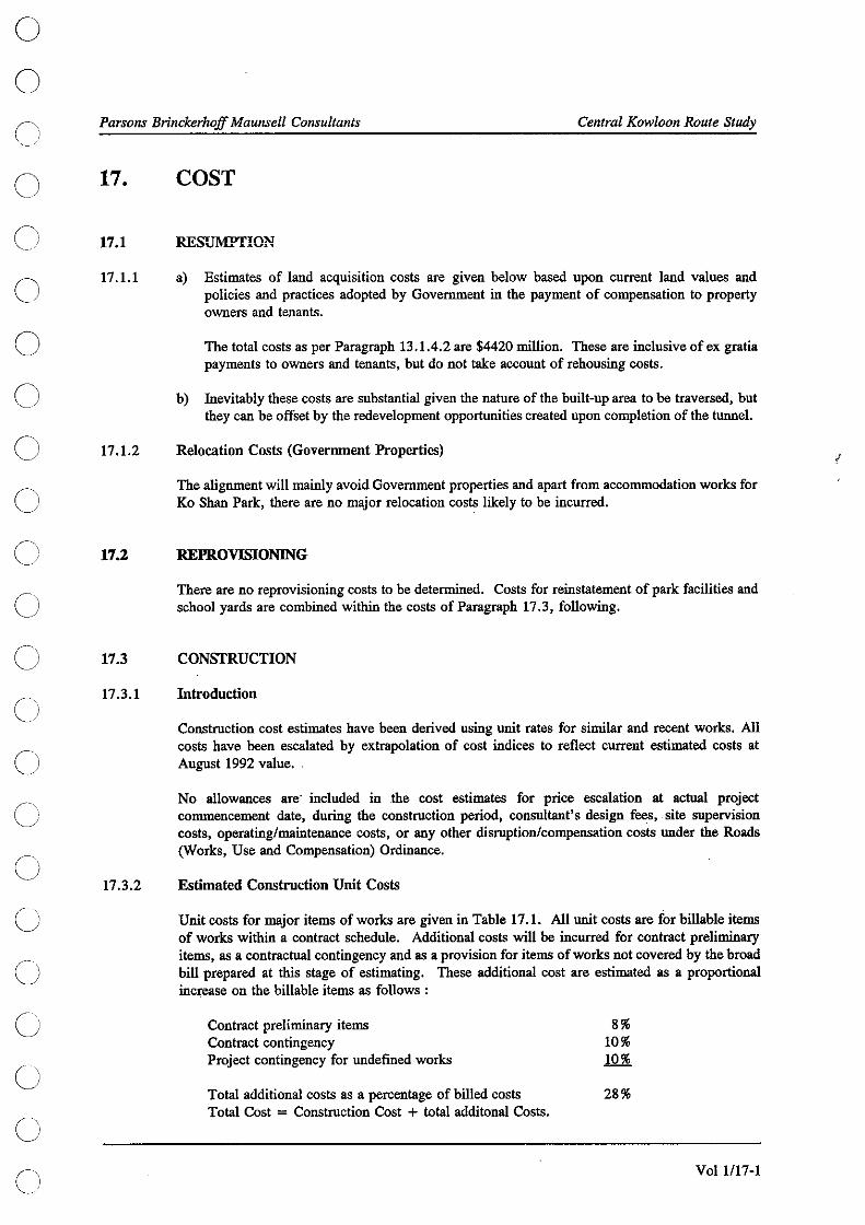
o o
o o o o o o
C) C)
Cl /
o o o o o o o o
Parsons Brinckerhoff Maunsell Consultants Central Kowloon Route Study
17.
17.1
17.1.1
17.1.2
17.2
17.3
17.3.1
17.3.2
COST
RESllMPfION
a) Estimates of land acquisition costs are given below based upon current land values and policies and practices adopted by Government in the payment of compensation to property owners and tenants.
The total costs as per Paragraph 13.1.4.2 are $4420 million. These are inclusive of ex gratia payments to owners and tenants, but do not take account of rehousing costs.
b) lnevitably these costs are substantial given the nature of the built-up area to be traversed, but they can be offset by the redevelopment opportunities created upon completion of the tunnel.
Relocation Costs (Government Properties)
The alignment will mainly avoid Government properties and apart from accommodation works for Ko Shan Park, there are no major relocation costs likely to be incurred.
REPROVISIONING
There are no reprovisioning costs to be determined. Costs for reinstatement of park facilities and school yards are combined within the costs of Paragraph 17.3, following.
CONSTRUCTION
Introduction
Construction cost estimates have been derived using nnit rates for similar and recent works. All costs have been escalated by extrapolation of cost indices to reflect current estimated costs at August 1992 value.
No allowances are' included in the cost estimates for price escalation at actual project commencement date, during the construction period, consultant's design fees, -site supervision costs, operating/maintenance costs, or any other disruption/compensation costs under the Roads (Works, Use and Compensation) Ordinance.
Estimated Construction Unit Costs
Unit costs for major items of works are given in Table 17.1. All nnit costs are for billable items of works within a contract schedule. Additional costs will be incurred for contract preliminary items, as a contractual contingency and as a provision for items of works not covered by the broad bill prepared at this stage of estimating. These additional cost are estimated as a proportional increase on the billable items as follows:
Contract preliminary items Contract contingency Project contingency for undefined works
Total additional costs as a percentage of billed costs Total Cost = Construction Cost + total additonal Costs.
8% 10% 10%
28%
VoI1l17-1
J

Parsons Brinckerhoff Maunsell Consultants Central Kowloon Route Study
Table 17.1 UNIT COSTS FOR MAJOR CONSTRUCTION ITEMS
Items
1. Roadworks
Roadworks at grade Roadworks at grade on embankment
2. Depressed road structures
Depth 0-2m, width below lOm Depth 2-4m, width below lOm Depth 4-6m, width below lOm Depth 0-2m, width above 25m Depth 2-4m, width above 25m Depth 4-6m, width above 25m
3. Retaining walls
Retaining height 0-2m Retaining height 2-4m Retaining height 4-6m
4. Bridge structures
At western approaches At eastern approaches
5. Mined Tunnels
West of Fat Kwong Ventilation Building East of Fat Kwong Ventilation Building Tunnel initial supports
6. Buildings
Substation Administration Building
Unit Costs ($)
1,200/sq.m. 1,350/sq.m.
7,700/sq.m. 10,700/sq.m. 14,500/sq.m. 5,500/sq.m. 6,300/sq.m. 7,500/sq.m.
4,800/sq.m. 4,300/sq.m. 5,300/sq.m.
7,700/sq.m. 8,400/sq.~.
$12S,OOO/m $120,OOO/m
$3S,OOO/m
$S,250/sq.m $6,SOO/sq.m
Vo11l17-2
o o o o o o o o o o o o o o o o o o o o o o

o o c' C)
o o o
c c' c C-\
/
c) c c c' c c
c' c
Parsons Brinckerhoff Maunsell Consultants Central Kowloon Route Study
17.3.3 Total Estimat~d Cost
Table 17.2 gives the estimated construction costs for the proposed project works :-
Table 17.2 ESTIMATED CONSTRUCTION COSTS
Description Estimated Cost ($M)
1. Western Approach
Roadworks at grade Roadworks at grade on embankment Depressed road structures Retaining walls Bridge Structures
2. Tunnels and Ventilation Buildings
2.1 Western End Cut-and-Cover Tunnel Cut-and-cover tunnel excluding entrusted works Entrusted works
2.2 Driven Tunnel
2.3 Eastern End Cut-and-Cover Tunnel Cut-and-cover tunnel excluding entrusted works Entrusted works
2.4 Ventilation Buildings and Shafts
Western ventilation building and ventilation duct Fat Kwong Street ventilation building and ventilation shaft Eastern ventilation bUilding and ventilation duct
3. Eastern Approach Phase 1
4.
Roadworks at grade Depressed road structures Retaining walls
Toll Plaza and Administration Buildings
Toll connection islands, booths and roofs Western control room Western Substation Eastern workshop Eastern administration building
2.4 1.7
19.3 1.0
86.2
195.0 36.3
478.6
260.1 23.9
8.4 18.6 6.7
15.1 38.8
3.5
1.2 2.1 2.6 3.2 7.2
110.6
1027.6
57.4
16.3
Table 17.2 Cont'd
Vo11l17-3

o o
Parsons Brinckerhoff Maunsell Consultants Central Kowloon Route Study o Table 17.2 ESTIMATED CONSTRUCTION COSTS (Cont'd) o
Description Estimated Cost ($M) o S. E&M System o
5.1 Ventilation Systems
Mechanical Equipment 39.6 o Electrical Works 7.2
5.2 Tunnel Power System o HV Distribution System 17.4 LV Distribution System 9.9 o UPS System 6.4 Emergency Generators 3.9 Earthing System 1.3 o
5.3 Lighting System o Tunnel Lighting 48.1 High Mast Lighting 3.0 o
5.4 CMCS 20.0
55 Tunnel Fire Services 10.7 o 5.6 Tunnel Plumbing & Drainage 3.5 o 5.7 TSCS 127.3
5.8 General Building Services 21.0 o 5.9 Toll Equipment 27.7
347.0 o 6. Miscellaneous
Site clearance and demolition 10.6 o
Diversion of sewer at Yut Yak Street (inverted siphon) 1.5 Landscaping 1.0 Provisional environmental mitigation cost (noise barrier) 5.6
o Temporary road deck and carriageway 6.3 Storage building for explosives 1.0
26.0 o o
Table 17.2 Cont'd o o
Vo11l17-4
Cl

o o c
Parsons Brinckerhoff Maunsell Consultants Central Kowloon Route Study
c Table 17.2 ESTIMATED CONSTRUCTION COSTS (Cont'd)
Description Estimated Cost ($M)
7. Eastern Approach Phase 2
C' 7.1 Stage 1
o C
c c
c
17.3.4
(
c
c; c
Roadworks at grade Roadworks at grade with embankment Depressed road structures Bridge structures
7.2 Stage 2
Roadworks at grade Roadworks at grade with embankment Depressed road structures Retaining walls Bridge structures
8. East Approach Phase 3
Roadworks at grade Roadworks at grade with embankment Retaining walls Bridge structures
9. Allow 28 % additional on-cost
10. Total Construction Cost
Construction Costs by Phase
Costs by Phase from Table 7.2 are:
WKC Entrusted Works (see 17.4) Carpark Entrusted Works USD "G" Site Entrusted Works (see 17.5) Tunnel Phase 1 Tunnel Phase 2 Tunnel Phase 3
Note :
12.0 2.4
60.5 38.4
8.8 5.7 2.2 1.4
85.9
14.8 1.7 0.2
68.5
217.3
85.2
528.5
HK$2415.9m
Estimated Costs ($M) 35.7 10.8 30.6
1853.7 278.9 109:1
$2416.0
1) These costs differ slightly from those in Table 17.2 above because of roundings and adjustments.
2) Each item includes construction cost, contract and preliminary costs and contingencies.
VoI1l17-5

Parsol)S Brinckerhoff Maunsell Consultants Central Kowloon Route Study
17.4
17.4.1
17.4.2
17.5
ADVANCE WORKS AT WKC
. The estimated construction cost, current at August 1992, for the works entrusted to the WKC project, described in Paragraph 7.2.2 and shown on Figure No. 200 will be $28 million excluding contract preliminaries, contract and project contingencies. This estimate is subject to refinement during detailed desigu.
No allowances are included in the cost estimates for price escalation at future project - commencement date, during the construction period, consultant's design fees, site supervision costs, any other disruption/compensation costs under the Roads (Works, Use and Compensation) Ordinance, or any additional cost, other than construction cost, incurred by WKC contract due to incorporation of the entrusted works.
OPERATION AND MAINTENANCE (0 & M)
o o o
o o o o
Operation and maintenance costs have been estimated as $39 million per annum at August 1992 C)
17.6
prices. Items breakdown for such costs are :
1. Staff Payroll, Replacement and Other Expenditure
TCSC E&M Toll
2. Electricity Cost ($O.6IkWh)
Tunnel ventilation Tunnel lighting Buildings
JOINT DEVELOPMENT COSTS AT USD "G" SITE
Estimated Cost ($M per annum)
Total:
12.2 4.4 6.8
8.5 3.1 3.7
23.4
15.3
HK$38.7m
There is insufficient information at this stage to establish the modes of joint development, but three possible alternatives are envisaged for the purpose of cost estimates. Such estimates are very preliminary and will have tu be revised when details of joint development are available.
1. Option A - USD "G" site developed before CKR
Diaphragm walls and top slabs of cut-and-cover tuunel will be entrusted to USD "G" .Site development.
Vo11l17-6
o o o o o o o o o o o o o

o o
o o o o o Cl
C,
C) c;
C;
Ci
G
G
C)
c!
Parsons Brinckerhojf Maunsell Consultants
The estimated costs are at follows:
Cost omitted from CKR Cost of works entrusted to USD
Central Kow/oon Route Study
Estimated Cost ISM)
(23.9) 23.1
2. Option B - USD "G" site developed before CKR and with basement underneath CKR
Diaphragm walls, top and bottom slabs of cut-and-cover tunnels will be entrusted to USD "G" site development.
The estimated costs are as follows:
Cost omitted from CKR Cost of works entrusted to USD
3. Option C - USD "G" Site developed after CKR
Estimated Cost ISM)
(29.1) 28.4
Diaphragm walls are enlarged to form part of foundation of the future USD development. The estimated costs are as follows:
Estimated Cost ISM)
Cost of USD works entrusted to CKR 2.8
VoI1l17-7
J

Financial Assessment 18
I

o o
o o o o o o o o o o (
'! j
c C) c) C)
o o (
Parsons Brinckerhoff Maunsell Consultants Central Kowloon Route Study
18.
18.1
18.1.1
18.1.2
18.1.3
18.1.4
18.1.5
FINANCIAL ASSESSMENT
TOLL SENSITIVITY TESTS
The Brief required assessment of the feasibility of tolling the CKR, and the resultant effect on parallel routes. Clearly, tolling would result in less traffic on the CKR, and a range of toll levels have been assessed to quantify the impact. A policy decision has, however, been given that the CKR will be tolled, and preliminary design was based on this premise.
Four different toll options were tested. To be consistent with CTS-2, the tolls for goods vehicles and other public transport modes were assumed to be in fixed ratios to private cars. These tolls are shown in Table 18.1, and for modelling purposes, they were converted to 1986 dollar price.
TABLE 18.1
Toll
Option
Ratio A B C D
TOLL OPTIONS - 1990$ TOLLS
Car
1.00 2.74 (2.00) 6.85 ( 5.00)
13.69 (10.00) 20.54 (15.00)
Goods Vehicle
2.00 5.48 ( 4.00) 13.69 (10.00) 27.39 (20.00) 41.08 (30.00)
Toll
PLB
1.50 4.11 ( 3.00)
10.27 ( 7.50) 20.54 (15.00) 30.81 (22.50)
Bus
3.00 8.22 (6.00)
20.54 (15.00) 41.08 (30.00) 61.62 (45.00)
( ) tolls expressed in 1986$ for input into transport model.
Each option was modelled for 200 I, 2006 and 2011. The corresponding sub-regional model (RAM) highway networks were modified to incorporate toll links for private and goods vehicle assignments.
In order to reflect the impacts of tolls in the decision of route choice, the assignment algorithm was based on a Generalized Cost Unit. This is made up of travel time, operating cost (which is distance based), and any toll cost involved. The factors to convert distance and tolls were derived from CTS-2 operating cost and value of time (V.O.T.).
Vehicle operating costs and V.O.T. were assumed to grow in real terms based on GDP growth assumptions used in WKRTS. The factors for converting operating cost and toll to time unit for private cars and goods vehicles are shown in Table 18.2 for different forecast years.
TABLE 18.2 TOLL AND DISTANCE FACTORS
Years
2001 2006 2011
Disiance (min/km)
Car
0.60 0.50 0.42
Goods Vehicle
2.28 1.93 1.63
Toll (min/$)
Car
0.92 0.78 0.66
Goods Vehicle
0.80 0.68 0.58
Vo11l18-1

Parsons Brinckerhoff Maunsell Consultants Central Kowloon Route Study
18.1.6
18.1.7
18.1.8
18.1.9
The traffic forecasts for the CKR and other parallel trunk routes for different toll options in the AM and PM peaks are shown in Tables 18.3 to 18.5.
The CKR, unlike the harbour crossings or toll routes to the North East New Territories, will have many strategic, primary and district level links, all of which are direct competitors. As a consequence, it would be expected that, especially in less congested conditions, the introduction of tolls will result in substantial reductions in traffic on the CKR.
2001 Forecasts (Table 18.3)
Some 3910 (AM peak) and 4350 (PM peak) two-way pcus were projected for the CKR in 2001 with no tolls charged. In Option A, with a $2.74 (1990$) toll for private cars, the traffic on the CKR will be reduced by 47 % and 53 % respectively for AM and PM peaks. With a $6.85 (1990$) toll, the reductions will be even greater at 87 % and 85 % respectively for the following reasons:
a) spare capacity on other parallel routes;
b) the main population centre of South Kowloon Bay will not be fully developed;
c) the tolls for private cars and goods vehicles are equivalent to 4.6 and 8.0 minutes respectively, whereas the travel time on CKR will be approximately 3.7 minutes. Therefore the toll in effect will be deemed to more than double the travel time on CKR; and
d) strategic connections in the east will not be well developed, and traffic may prefer to remain on the feeder routes through the adjacent local road network.
Higher tolls will result in very low traffic usage and render the CKR a redundant facility.
2006 Forecasts (Table 18.4)
18.1.10 In 2006, Kowloon Bay development is assumed by the traffic model to be 90 % complete, but will be dependent on the North-South Highway for acceSs to the CKR.
18.1.11 In the moruing peak, some 2260 pcus eastbound and 2330 pcus westbound are forecast for 2006 with no tolls charged. This will be slightly over 60% of CKR capacity. Table 18.4 indicates that a private car toll of $2.74 (1990$) (Option A) will reduce forecast traffic on theCKR by only 17% and 15% respectively for AM and PM peaks. These are smaller reductions compared with 2001, which is partly due to higher V.O.T. (refer to Table 18.2) and slightly more congested traffic on alternative routes in 2006.
18.1.12 Five times higher percentage reductions in forecast traffic will resn1t (71 % to 83 %) if the tolls are increased to Option C levels ie. $13.69 (1990$) for private cars. Again this will be due to high toll equivalent time and some marginal spate capacities in the east-west local road networks.
2011 Forecasts (Table 18.S)
18.1.13 The traffic forecasts for 2011 are shown in Table 18.5. The overall network in Kowloon will be heavily trafficked, and hence tolls would be expected to have less effect. The CKI( is also forecast to operate at or around capacity in the peak hours in 2011. As a consequence, a low toll (Option A) will have relatively little impact on traffic levels on the CKR, especially as the alternative major routes, such as Gascoigne Road, will have little or no spare capacity.
Vo11l18-2
o G
o o o o o o Q
o o o o o o o o o o o o o o

o o c
c o o o o
c c c' c c
c
C)
c
Parsons Brinckerhoff Maunsell Consultants
TABLE 18.3 2001 TRAFFIC FORECASTS FOR TOLL OPrIONS
EASTBOUND
ROule4 Boundary St AQlyle St
NO TOLL A
5660 5890 4010 4200 1550 1610
Gaacoigne Road Flyover2090 2380 Salisbury Road 1880 2410
SUB-TOTAL 15190 16490
Central Kowloon Route 1790 910
AM PEAK HOUR FLOW (PCU's)
TOLL OPTION BeD
5889 5883 5883 4257 4309 4264 1621 1655 1661 2384 2391 2414 2515 2578 2588
16666 16816 16810
307 40 0
WESTBOUND
Route 4 Prince Edward Road Argyle St Gucoigne Road Flyover Salisbury Road
SUB-TOTAL
Central Kowloon Route
TOTAL EASTBOUND16980 17400 16973 16856 16810 TOTAL WESTBOUND
PM PEAK HOUR FLOW
NO TOLL OPTION TOLL A B C D
E.l;STBOUND WESTBOUND
Route 4 5270 5480 5531 5534 5531 Routc4 Boundary Street 4360 4350 4473 4492 4495 Prince Edward Road AtJyle Street 1740 1790 1881 1870 1814 Afay1. Street G.~oignc Road Flyover 2150 2120 2293 2399 2358 Gascoignc Road Flyover Saliobury Road 2920 3020 3142 3248 3278 Saliihury Road
SUB-TOTAL 16440 1676017320 17543 17476 SUB-TOTAL
Central Kowloon Route 2800 1520 599 51 16 Central Kowloon R.oute
TOTAL EASTBOUND 19240 1828017919 17594 17492 TOTAL WESTBOUND
Note : R.efer Table 18.1 for tolllevell.
Central Kow/oon Route Study
NO TOLL OPTION TOLL A BeD
5200 4960 4980 4980 4980 5170 5110 5349 5374 5355 2380 2470 2283 2334 2334 1950 2130 2193 2219 2219 1370 1800 2051 2101 2133
16070 16470 16856 17008 17021
2120 1160 196 46 0 /
18190 17630 17052 17054 '17021
NO TOLL OPTION TOLL A B C D
5160 5380 5373 5373 5373 4600 4800 4876 4897 4893 1710 1830 1880 1878 1877 2170 2030 2146 2154 2171 1690 1890 1943 1991 1986
15330 15930 16218 16293 16300
1550 530 59 14 0
16880 16460 16277 16307 16300
Volll18-3

Parsons BrinckerhoJf Maunsel/ Consultants
TABLE 18.4 2006 Traffic ForecaSts For Toll Options
EASTBOUND
Route 4 BoundarySt May1. St
NO TOLL A
5256 5500 4452 4030 1726 1900
GalCoigne Road Flyover 2225 1950 Salisbury Rd 2697 2490
SUB-TOTAL 16356 15870
Central Kowloon Route 2262 1690
AM PEAK HOUR FLOW
TOLL OPTION BeD
5262 5250 5289 4096 4339 4150 1908 2230 1985 2134 2184 2198 2660 2916 2888
16060 16919 16510
1109 369 63
WESTBOUND
R.outc4 Prince Bdward Road AriY1. St Gaacoigne Rd Flyover Salisbury Rd
SUB-TOTAL
Central Kowloon Route
Central Kowloon Route Study
NO TOLL OPTION TOLL A BeD
5017 5050 5013 4988 5088 4628 4550 4510 4433 5059 2258 2110 2069 2308 1964 1925 1790 1977 1944 1935 1945 2020 2098 2688 2596
15773 15520 15667 16361 16642
2326 2110 1419 492 245
TOTAL EASTBOUND 18618 17560 17169 17288 16573 TOTAL WESTBOUND 1809917630 17086 16853 16887
PM PEAK HOUR FLOW
NO TOLL OPTION NO TOLL OPTION TOLL A B C D TOLL A B C D
EASTBOUND WESTBOUND
Route 4 5262 5270 5270 5235 5298 Route 4 5303 5390 5409 5442 5420 Boundary Street 4381 4090 4144 4207 4110 Prince Edward Road 4563 4500 4476 4431 4561 ArgyJe Street 1764 2230 1704 2326 2169 Argy1e Street 2083 1970 2161 2123 1944 . Gascoigne Road Flyover 2150 2110 1997 2066 2052 Gascoigne Road Flyover 2249 2160 2113 3078 2236 Salisbury Road 3465 3660 3626 3713 3707 Salisbury Road 1995 2300 2192 2318 2299
SUB-TOTAL 17022 1736016741 17547 I7336 SUB-TOTAL 16193 16320 16351 17392 16460
Central Kowloon Route 2831 2440 1827 833 231 Central Kowloon Route 1852 1520 983 315 96
TOTAL EASTBOUND 19853 19800 18568 18380 17567 TOTAL WESTBOUND 18045 17840 17334 17707 16556
Note Refer Table 18.1 for toll levels.
Vol 11184
o o o o o o o o o o o o o o o o o o o o o o o

o o c'
o o
o
c' c c
c
c c (-/ '----/
c c o
Parsons Brinckerhoff Maunsell Consullants
TABLE 18.5 2011 Traffic Forecasts For Toll Options
EASTBOUND
Routc4 Boundary Street
Aqyl. Street Oaacoignc Road
Flyover Salisbury Road
SUB-TOTAL
Central Kowloon Route
NO TOLL A
5650 5650 4560 4590 1660 1700 2290 2510
2960 3070
17120 17520
3830 3780
AM PEAK HOUR FLOW
TOLL OPTION BeD
WESTBOUND
5687 5691 5691 Routc4 4598 4569 4782 Prince Edward Road 1732 1811 1822 Argylc Street 2508 2612 2728 Gucoi,ne Road
Flyover 3264 3391 3268 Salisbury Road
17789 18074 18291 SUB-TOTAL
3744 3167 2537 Central Kowloon Route
TOTAL EASTBOUND 20950 21300 21533 21241 20828 TOTAL WESTBOUND
PM PEAK HOUR FLOW
NO TOLL OPTION TOLL A B C D
EASTBOUND WESTBOUND
Route 4 5050 5040 5057 5057 5063 Route 4 Boundary Street 4940 4920 5017 5134 5229 Prince Edward Road Argyle Street 1620 1820 1830 1832 1854 Argyle Street Gilscoigne Road Flyover 2360 2410 2373 2452 2582 Gascoigne Road Flyover Salisbury Road 3740 3700 3696 3914 3970 Salisbury Road
SUB-TOTAL 17710 1789017973 18389 18698 SUB-TOTAL
Central Kowloon route 3930 3810 3770 3226 2594 Central Kowloon Route
TOTAL EASTBOUND 21540 21700 21743 21615 21292 TOTAL WESTBOUND
Note Refer Table 18.1 for toll levels.
Central Kowloon Route Study
NO TOLL A
4860 4870 5290 5210 1770 1880 2080 2230
·2340 2250
16340 16440
3320 2710
TOLL OPTION B C
4886 4898 5376 5373 1961 1981 2151 2227
2265 2506
16639 16985
2441 1540
D
4901 5475 1970 2233
2647
17226
1233
1966019150 19080 18625 18459
NO TOLL OPTION TOLL A B C D.
5070 4960 5067 5067 5068 4820 4730 4955 4922 4998 2140 2180 2266 2337 2362 1990 2540 2117 2772 2221 2540 2670 2629 2195 2893
16560 17080 17034 17293 17542
3600 3490 3000 2259 1543
20160 20570 20034 19552 19085
Vo11l18-5
/

Parsons Brinckerhoff Maunsell Consultants Central Kowloon Route Study
18.1.14
18.1.15
18.2
18.2.1
18.2.2
18.3
18:3.1
The impact of increasing the tolls to Option C levels will cause significantly higher percentages of traffic to divert away from the CKR in the eastbound direction (17 % and 18 % reductions in AM and PM peaks respectively). In the westbound direction, the percentage reductions will be doubled. However, in absolute terms more westbound CKR traffic will be diverted. This indicates that westbound paraiiel routes will be able to absorb relatively more traffic than eastbound routes.
With a $20.54 (1990$) private car toll (Option D), traffic is forecast to fall further and will result in traffic spilling over into the local network. The CKR is only forecast to carry 2540 pcus in the AM peak eastbound direction, which is only 70% of capacity.
TOLL SELECTION
Optimisation and selection of toll levels for the CKR was outside the scope of the study and it was concluded that these should be subject of a separate financial study nearer the time of project implementation. The financial study would need to take account of the various factors influencing toll selection including:
• Overall road traffic network travel time,
• Benefits/disbenefits to road users, both on CKR and other routes,
• tunnel fmancing arrangements,
• Government policy at the time the financial study is carried out.
For the purpose of this study only and in order to obtain an upper bound of potential revenues tolls were selected to maximise revenue. The lower bound revenue solution would be the zero toll scenario. It is emphasised that no recommendations are made in this report on toll levels.
TOLL REVENUES
The network performance within the study area and the annual revenue generated by the CKR under the different toll options are shown in Table 18.6.
TABLE 18.6 CKR TRAFFIC AND TOLL REVENUE FORECASTS
Year
2001
Toll Option
No Toll A B C D
Weekday (AADTVeh)
54690 27330 8520 2230 1150
Average Peak CKRHour Speed (kmIh)
64 70 70 70 70
Total Peak Hr. PCU-Hrs (ooo.s)
38 39 43 43 43
Annual Toll Revenue (M 1990$)
0 37.61 30.91 18.54 19.71
Table 18.6 Cont'd.
Vo11l18-6
o o o o o o o o o o o o o o o o o o o o o o o

o o o o o o o o o o o C)
o o o o C)
o C)
o o o
Parsons Brinckerhoff Maunsell Consultants Central Kowloon Route Study
18.3.2
18.3.3
18.3.4
18.3.5
18.3.6
18.3.7
18.3.8
TABLE 18.6 CKR TRAFFIC AND TOLL REVENUE FORECASTS (Cont'd)
Year
2006
2011
Toll Option
No Toll A B C D
No Toll A B C D
Weekday (AADT Veh)
60270 50220 35240 14460 6200
90870 85340 82600 64500 50160
Average Peak CKRHour Speed (kmIh)
62 68 70 70 70
22 29 35 51 63
Total Peak Hr. PCU-Hrs (ooo.s)
48 49 53 55 55
48 56 59 62 64
Auuual Toll Revenue (M 1990$)
0 69.78
122.37 102.15 64.02
0 122.12 290.73 469.74 550.10
Table 18.6 shows that in 2001, forecast traffic on CKR is expected to reduce significantly when the toll charged is greater than $2.74 (1990$). The overall peak hours network travel time will increase by 13 % implying reduced travel speed. Since speed is a function of traffic volume, the peak hour overall speed on CKR is expected to increase from 64 km/h to a free-flow condition at 70km/h when tolls are applied.
By 2006, the impact of toll options on CKR traffic will be much less than 2001, however revenues are still expected to decrease as toll levels increase. The peak hours travel speed under No Toll scenario will be slightly lower than in 2001. Under toll options, the CKR will still operate with free-flow condition because the traffic volumes on the CKR will be within the free-flow limit of the speed-flow relationship.
The overall travel time on the network in the peak hours is expected to increase by 15 % comparing No Toll with Option C.
In 2011, the impact of tolls on CKR traffic is expected to be marginal, especially at the lower toll level. Therefore, revenues would be expected to increase as toll level increases, and this is, in fact, the case.
The peak hour traffic volumes approach capacity, and queuing on approaches will produce some delays reflected in the average speed. (This is the average of queue time and the free flow conditions in the tunnel.)
The reduced traffic volumes with a $20.54 (1990$) private car toll will produce nearly free-flow conditions. Therefore, Option D would produce both the highest toll revenue and highest operating speed. However, the diversion of traffic to other routes would create additional delay and congestion which leads to an increase in overall network travelling time by as much as 33 % (No Toll compared with Option D).
Increased revenues in the Phase 1 period of operation (2001 to 2005) may be possible with temporary ramps to and from West Kowloon Reclaroation Road D 1 to the CKR. Such a scenario
. could be considered during detailed design. '
Vo11l18-7
/

o o o Cl
o o o o o o o o o o o o o o o o o o
Parsons Brinckerhoff Maunsell Consultants Central Kowloon Route Study
18.4
18.5
18.5.1
18.5.2
18.6
18.6.1
18.6.2
COMMERCIAL ADVERTISING SPACE
Opportunities will be available at the tunnel toll plaza for commercial advertising. The specific areas available will need to be determined at detailed design stage, but it is estimated that an annual revenue in the order of $3 million could be achieved depending on the layout of the plaza.
OTHER REVENUES
The principal source of revenue will arise from the sale of redevelopment sites over the tunnel. The total revenue so achieved would need to be offset against the land acquisition costs, but it is estimated that if each of the required development sites were sold based on current planning standards, a total revenue of $3,882 million could be achieved. The total acquisition cost amounts to $4,420 million which is $538 million more than the revenue, but it would facilitate both the construction of the tunnel and urban renewal.
Minor revenue also can be anticipated from the rental of lines for mobile telephone usage inside the tunnel.
CASH FLOW
Cash Flow for Route Protection
in the absence of a strategy for route protection, it is impossible to forecast the cash flow with any degree of accuracy. However, if the route is to be protected, it can be assumed that some basis will be effected during the next one to two years which would give rise to costs over the next five years. Accordingly, we have assumed that it would be necessary to acquire all the single ownership properties in Yau Ma Tei and Hung Ham within two years. This would be at total cost of $584 million. The cost for setting the alignment controls to mathematise the highway corridor would be nominal at $0.3 million. Clearance rehousing costs would be incurred at the same time as the remainder of the acquisition.
Cwnulative Cash Flow
Table 18.9 depicts a possible cash flow scenario for the CKR. The following assumptions were made to develop the table :
a) Toll revenues from Table 18.8 were adjusted upward to give 1992$ and for a Phase 1 toll slightly higher than $2.74 (1990$) for use in Table 18.9.
b) Sale of land is credited to 2001 while land acquisition costs are assigned to 1995 and 1996.
c) 0 & M costs include annual rehabilitation and replacement costs (or sinking fund) of about:
(2001-2005) : $78 million (2006-2010) : $91 million (2011-2026) : $95 million
d) Capital costs are construction costs as given in para. 17.3.
e) Financing and insurance costs are not included.
18.6.3 Privatisation
18.6.3.1 Privatisation, where a developer will finance the detailed design, construction and operation of the CKR, represents a potential alternative approach to implement the faciiity.
Vo11l18-9

0 Parsons Brinckerhoff Maul1sell Consultants Central Kowloon Route Study
0 18.6.3.2 The developer would seek to recover its costs from toll revenues and, optionally, from land
development above the CKR. 0 18.6.3.3 A financial study to assess privatisation options, including development rights, should be undertaken
if private financing is to be considered further. Early completion of the study would provide 0 additional flexibility to Government in its deliberations.
TABLE 18.9 CASH FLOW (IN MILLIONS, 1992 HK$) 0
REVENUES COSTS Cash Flow Cwnulative 0 Cash Flow
Year Toll Other Landsale Land Capital O&M excluding including excluding including 0 acquisition land land land land
1994 25 (25) (25) (25) (25) 0 1995 2210 38 (38) (2248) (63) (2273) 1996 2210 28 (28) (2238) (91) (4511) 0 1997 500 (500) (500) (591) (5011) 1998 500 (500) (500) (1091) (5511) 1999 500 (500) (500) (1591) (6011) 0 2000 445 (445) (445) (2036) (6456) 2001 40 3 3882 78 (35) 3847 (2071) (2609) 0 2002 50 3 4 78 (29) (29) (2100) (2638) 2003 60 3 4 78 (19) (19) (2119) (2657) 2004 70 3 150 78 (155) (155) (2274) (2812) 0 2005 80 3 121 78 (116) (116) (2390) (2928) 2006 130 3 91 44 44 (2348) (2886) 0 2007 160 3 2 91 72 72 (2278) (2816) 2008 190 3 2 91 102 102 (2178) (2716) 2009 230 3 55 91 89 89 (2091) (2629) 0 2010 270 3 51 91 133 133 (1960) (2498) 2011 600 3 95 510 510 (1452) (1990) 0 2012 620 3 95 530 530 (924) (1462) 2013 640 3 95 550 550 (376) (914) 2014 670 3 95 580 580 202 (336) 0 2015 690 3 95 600 600 800 262 2016 710 3 95 620 620 1418 880 0 2017 730 3 95 640 640 2056 1518 2018 750 3 95 660 660 2714 2176 2019 780 3 95 690 690 3402 2864 0 2020 810 3 95 720 720 4120 3582 2021 830 3 95 740 740 4858 4320 0 2022 860 3 95 770 770 5626 5088 2023 890 3 95 800 800 6424 5886 2024 920 3 95 830 830 7252 6714 0 2025 950 3 95 860 860 8110 7572 2026 980 3 95 890 890 8998 8460 0
0 Vo11/18-1O
Ci

Design Standards Memorandum 19
)

o o
C) o o o o o o o o o o o o C)
o C) (J
o ('i "---j
Parsons Brinckerhoff Maunsell Consultants Central Kowloon Route Study
19.
19.1
19.1.1
19.1.2
19.1.3
19.2
19.2.1
19.2.2
19.2.3
19.2.4
19.2.5
19.2.6
19.2.7
DESIGN STANDARDS MEMORANDUM
INTRODUCTION
The purpose of this Design Memorandum for the Central Kowloon Route is to define the overall design standards to be used for all major elements of the project, and to provide guidance to those standards.
A Design Manual should be prepared prior to detailed design, and should be written to suit the proposed works and methods of design. The Design Manual will be subject to the approval of Government, and this Design Memorandum may. form the basis of such approval.
The Design Memorandum should be considered in conjunction with the Hong Kong Civil Engineering Manual (HKCEM).
IDGHW AY ALIGNMENT AND CIVIL ENGINEERING
The alignment shall be designed to conform with current Transport Department technical instructions and standards, particularly Volume 2 "Highway Design Characteristics" of the Transport Department's Transport Planning and Design Manual (TPDM).
The highways, interchanges, tunnel ventilation system, road signing and all other component parts of the CKR and its approaches shall accommodate peak hour traffic flows of 1800 pculh for each lane of tunnel under uni-directional flow without any adverse effect on the remainder of the road system in the design year 2011.
Design of the exposed highway drainage sball be in accordance with Highways Department Road Note 6 and Chapter 7 of Volume V of the HKCEM. For roads with a longitudinal gradient less than 0.67%, TRRL Report 602 "Drainage of Level or Nearly Level Roads" shall be used. Double gullies with overflow weirs shall be provided at low points. Subsoil drainage will be necessary for roads on reclamation and shall be designed in accordance with Highways Department Road Note 8.
Tunnel portal drainage shall be designed in accordance with rainfall intensity given in Fig. 2. 1. 3 (A) in the HKCEM Volume VI Section 2. The design return period shall be 1 in 50 years. Highway drainage within the tunnel shall be assessed after determination of maintenance, washdown, and spillage criteria. The capacity shall not be less than that required for one fire hydrant running full bore.
Drainage requirements within the tunnel are less than those for exposed roads, and the TPDM minimum gradient limitation of 0.67 % is therefore relaxed. Drainage gradients shall be suitable for dispersion and collection of tunnel wash water, accidental spillage etc. and this may be achieved by a suitable combination of longitudinal gradient and crossfall. True fall of the carriageway shall not be less than 1.0% at any point. Longitudinal gradients shall be sufficient such that drainage after collection can flow to low point sumps.
Pavement design shall be in accordance with Highways Department Road Noie No. 1 - "Road Pavement Design" which amplifies Chapter 7 - "Pavement Design" of the HKCEM Vo!. V.
The vertical alignment at both portals shall be designed to provide a defence against flooding of the tunnel as described in Paragraph 19.3 below.
Vo11l19-1
J

Parsons Brinckerhoff Maunsell ConsultanlS Central Kowloon Route Study
19.2.8
19.2.9
All levels shall be referred to Hong Kong Principal Datum (PD).
The horizontal and vertical alignment parameters for design speeds of 70kmlh and 85km1h are given in Tables 19.1 and 19.2. 1n general, 70 kmIh is the minimum design speed, and 85 kmIh is the desirable design speed for the tunnel.
Table 19.1 VERTICAL ALIGNMENT PARAMETERS
Main Line Design Speed (kmlh)
Absolute minimum gradient (open roadway)
Absolute minimum gradient (in tunnel)
Desirable maximum gradient
Absolute maximum gradient
Vertical curve desirable min. K value Crest curve
- Sag curve
Table 19.2 HORIZONTAL ALIGNMENT PARAMETERS
70
0.67%
0.3%
4%
8%
19 13
85
0.67%
0.3%
4%
8%
33 18
Main Line Design Speed (kmlh)
Design Speed (kmIh) of Main Line
Minimum radius (R3) (see 19.2.11)
Absolute minimum radius
Superelevation, max. (open roadway)
Superelevation, max. (in tunnel)
Preferred edge profile variation
Absolute maximum edge profile variation
Normal minimum RL value (q = 0.30 m/sec)
Absolute minimum RL value (q = 0.60 m/sec)
Minimum ~topping sight distance (SSD)
Absolute minimum stopping sight distance
70 Mainline (Slip)
175m
88m
10%
3%
1%
2%
25000
12500
125m
95m
(60m)
(35m)
(10%)
(1 %)
(2%)
(5600)
(2800)
(50m)
(40m)
85 Mainline (Slip)
250m
125m
10%
3%
1%
2%
42000
21000
165m
125m
(88m)
(44m)
(10%)
(1 %)
(2%)
(9000)
(4500)
(70m)
(50m)
Vo11l19-2
o c o o o o o o o o o o o o o o o o o o o o o

o o
C) C)
o o o Cl
/
c' c\ c Cl
C)
c) c' C:
/
c'
(: "--/
c
Parsons Brinckerhoff Maunsell Consultants Central Kowlodn Route Study
19.2.10
19.2.11
19.2.12
19.2.13
19.2.14
19.2.15
19.2.16
19.2.17
19.3
19.3.1
Where curves with a radius of 400m or less are used, carriageway widths should be increased in accordance with TPDM V.2.3 Table 3.4.4.1. The widening should be achieved by adopting a different transition curve on the inside of the curve than on the outside.
For horizontal curves, inside tunnel, when carriageway width widening is infeasible, the minimum radius will normally be governed by the stopping sight distance requirements. Accordingly, the radius used shall satisfy both the requirement of Table 19.2 and the minimum value for stopping sight distance.
In addition to meeting the defined alignment parameters, the vertical alignment shall take into account:
Provision of climbing lanes; Optimisation of ventilation requirements; Drainage requirements; Defence against flooding and inundation; Clearances below WKC, Nathan Road, Chatham Road North, Ma Tau Wai Road and as well as to any associated ramps, foundations and surface roads; Clearances to existing and future KCRC and MTRC structures, including a proposed ventilation structure at Yau Ma Tei Station and the East Kowloon Line; Clearances to Di Man Estate Block J foundation footings; Clearances to Ko Shan Theatre and accesses thereto; Clearances to utilities; Additional vertical clearance above the structure gauge within the cut-and-cover tunnels where required to allow overhead signing within the approach tunnels and provision of jet fans; and Protection against environmental disbenefits.
The geometric design of the toll plaza is not specifically covered in TPDM. However, TPDM will be adopted regarding stopping sight distances and other performance criteria where appropriate.
Longitudinal gradients shall be 0% for a minimum distance-of 10 metres on either side_"f-the toll booths, and any ascending gradient shall not exceed 3 % within the area of expected car queuing. This arrangement reduces the risk of vehicles unexpectedly rolling forward or backward in the vicinity of the toll booths. It is desirable to locate toll booths on a crest curve in order to reduce vehicle speeds and thereby to reduce impact damage to toll booths.
The tunnel structure gauge shall not be less than that shown in Fignre No. 031.
Each traffic duct shall be capable of operating in a bi-directional mode for emergency and maintenance purposes, with appropriate cross-over areas being provided beyond the tunnel.
~ ~
Inside the tunnel, marginal strips 0.5m wide and a combination of standard profile barriers and maintenance/emergency walkway of O.5m high (minimum) and 1.0m wide (desirable) or 0.8m wide (minimum) shall be provided both sides of the roadways.
PROTECTION AGAINST INUNDATION
Protection shall be provided against inundation of the tunnel by flood water due to the combined effects of tide, surge and wave effecis. The height and shape of surrounding walls and the elevation of all access roads shall be determined such that entry of overland flood water under these conditions is prevented.
Vo11l19-3

o o
Parsons Brinckerhoff Maunsell Consultants Cen!ral Kow/oon Route Study o 19.3.2
19.3.3
19.3.4
19.4
19.4.1
19.4.2
19.4.3
19.4.4
Calculations shall be based upon a probability of the flood defence being overtopped (including wave action) 0.001 times in anyone year. Levels shall be determined taking into "9count the foreseeable reclamations within the harbnur area. The Royal Observatory should be consulted regarding the environmental climate in the study area. Data may need to be extrapolated and may be obtained from:
o o
Wind Speed - HKCEM Vol VII Chapter 2.3.2; and Maximum Sea Lev~1 - Royal Observatory Technical Note (Local) No 35, Statistics of 0 Extreme Sea Levels in Hong Kong, 1983.
Wind speed corrections and wave heights shall be calculated by rational methods such as those given in the HKCEM Vol VII (Port Works).
In view of the 120 year design life of the structure, an allowance for a long term increase in Mean Sea Level shall be made in calculating flood heights and hydrostatic loading. In the absence of better information, an allowance of 1m shall be made, based on the guidance contained in Works Branch Technical Circular 6/90 (Greenhouse Effect - Allowance in Design).
TUNNEL STRUCTURE DESIGN
The design life of the tunnel shall be 120 years. The design fire resistance shall be 4 hours.
Pedestrian access into adjacent traffic ducts shall be provided through cross adits at not more than abnut 100 m intervals for maintenance and emergency use. Adit locations shall be agreed with Fire Services Department. Vehicular cross-adits will not be provided.
Use of the design codes and documents of recommended practice listed below would be considered appropriate for structural design where these do not conflict with requirements of this Design Memorandum:
B.S.5400 B.S.5950 B.S.8007 B.S. 8110 CEB/FIP
Steel, Concrete and Composite Bridges; The Structural Use of Steelwork in Building; Design of Concrete Structures for Retaining Aqueous Liquids; Structural Use of Concrete; and Model Code for Concrete Structures, Hong Kong Government Civil Engineering Manual, Geoguide I, Guide to Retaining Wall Design .
. Analysis of the behaviour of structures under ultimate loads shall be investigated. Each load in a combination shall be factored. It is important in choosing appropriate factors that a consistent design code be used. Material factors of -ymc=1.5 for concrete and -yms=1.15 for reinforcing steel would be appropriate. Effects to be examined include: .
a) Adequate safety against failure of structures and their components. b) Static equilibrium of structures as a whole. c) Buckling. d) Fatigue. e) Ductile behaviour in the overload range. Primary members forming the tunnel, including its
joints, shall be designed to be ductile. /) Deformations, particularly at those locations where plastic or creep deformations could
transform the structure into a meChanism.
Vo11l19-4
o o o o o o o o o o o o o o o o o

o o c c c' c Cl
(
(
(
c c c c (
c
(
c
Parsons Brinckerhoff Maunsell Consultants Central Kowloon Route Study
19.4.5
19.4.6
19.4.7
The behaviour of structures at the serviceability limit state shall be checked for unfactored loads. Limit states shall include those of:
a) Cracking. b) Deformation. c) Vibration. d) ~urability - including corrosion of steel and deterioration of concrete. e) Watertightuess.
Structures shall be designed to accommodate expected movements because of deformation of foundations without limiting normal operations. Soil pressures shall take account of the soil surface profile as well as the geometry of the structure. Geotecbnical considerations shall also include effects because of seepage, erosion, and changes from drained to undrained conditions. Differential settlements can be expected at interfaces between types of construction and during construction.
The foundation must provide an adequate factor of safety against bearing capacity failure under the most critical combination of loads. When stability is analysed in terms of effective stresses, the cohesive component of soil shear strength should be divided by a material factor 'Yc ., 1.2, and the frictional component should be divided by a material factor 'Yf ., 1.4. When stability is analyzed in terms of total stresses, the undrained shear strength should be divided by the factor 'Yc ., 1.4.
19.5 CRACKING IN CONCRETE
19.5.1
19.5.2
19.5.3
It is important that cracking in structural concrete members is limited so that durability of the reinforcement is provided. Crack control shall be achieved by either:
a) calculating f1exural crack widths at the concrete surface in accordance with the CEBIFIP Model Code for Concrete Structures. Calculated f1exural crackwidths (including thermal cracks) shall not exceed 0.2 mm for reinforced concrete;
b) any other approved rational method.
Differential temperature effects may lead to severe cracking in areas of structural restraint. Effects may include results of temperature differences across walls and slabs. Creep strain induced by temperature loadings may also be significant during the life of some members. Tensile stresses and associated crack widths in such areas shall be calculated by reference to expected thermal strains and restraint conditions. Such strains and restraints shall be justified by calculation, computer or physical modelling. Crack widths shall be limited to a maximum of O.lmm by minimising heat of hydration, by. use of artificial cooling, or by use of reinforcement.
Where thicknesses of concrete sections are large enough, precautions should be taken against cracking because of heat of hydration. The concrete shall be designed to be of high durability, chloride free, and of low permeability. In order to reduce heat of hydration effecls and permeability, consideration shall be given to the use of:
a) cooling of concrete; b) the use of insulated forms; cy- low water/cement ratio; d) low heat cements; e) partial replacement of cement using pulverized fuel ash (PFA), ground granulated blast
furnace slag (GGBFS) or silica fume (microsilica) to reduce heat of hydration. This is also discussed in Paragraph 19.5.4.
Vo11l19-5
J

Parsons Brinckerhoff Maunsell Consultants Central Kowloon Route Study
19.5.4
19.6
19.6.1
19.6.2
19.7
19.7.1
19.7.2
19.7.3
19.7.4
19.7.5
19.7.6
Particular attention shall be paid to curing of the concrete containing these materials. The simulation of low heat characteristics utilizing cement replacement materials is recommended to overcome the chloride susceptibility of low heat portland cement. PF A and microsiliea help to fill the interstices between the cement particles and may considerably increase durability, strength, and waterproofing. The use of at least 45 % cement replacement by GGBFS has been shown to give significant improvement in chloride resistance. Sulphate resisting cements are not considered appropriate because of their low chloride resistance.
TUNNEL FINISHES
Road pavement shall be selected with a view to both durability and operational characteristics including noise. Because of the difficulty of maintaining and replacing road pavements in tunnels, durability is especially important.
In selecting finishes for walls and ceiling, the final fmish shall not permit build-up of water vapour behind it. If tiles are used, care must be taken to provide long term adherence of the tiles, particularly in ceilings. Drainage shall be provided assuming that water leakage can occur. Interior design shall be arranged for ease of cleaning by machine. Ceiling finishes shall have good acoustic absorption properties. The tunnel walllining/finishes should conform to RSS476 Part 7, Class 1 or 2.
TOLL PLAZA LAYOUT
The toll plaza shall satisfy operational requirements for both traffic and toll collection.
At least two booths, one in each direction, shall be suitable for overwidth vehicles. In the event that automated collection of fees is not provided initially, provision shall be made in the design for the future installation of automated toll equipment.
The ultimate toll plaza shall be arranged such that all areas of the tunnel approaches shall be reasonably visible from the Control Centre. In particular, the toll booths and signs shall be arranged such that a clear overview can be obtained from the Control Centre. The layout shall enable tunnel management personnel and vehicles to have access to all areas of the approaches and the whole of the tunnel area without using adjacent public roads.
A toll booth canopy shall be provided to protect the booths and drivers during transactions and to carry clear and precise lane status and toll signs.
Public access segregated from tunnel traffic shall be provided to the tunnel administration buildings and to the workshops. Parking shall be provided immediately adjacent to the administration building for:
tunnel management staff vehicles; public vehicles; and tunnel emergency and maintenance vehicles.
Segregated bus stops shall be provided sufficient to cope with those bus services agreed with Public Transport Development Branch, Transport Department. All such bus stops shall be located in such a manner as to minimize interference with other traffic flow whilst providing appropriate accessibility for pedestrians. AIl pedestrian access to the bus stops shall be segregated from vehicular traffic.
Vol 1119-6
o o o o o o o o o o o o o o o o o o o o o o o

o o o o o o o o o o C)
c) o Cl
C:
C)
o o u o o ()
Parsons Brinckerhoff Maunsell Consultants Central Kowloon Route Study
19.8
19.8.1
19.8.2
19.8.3
19.8.4
BUILDING REQUIREMENTS
visual aspects of the project open to public scrutiny in operational service shall be subject to the approval of the Advisory Committee on the Appearance of Bridges and Associated Structures (ACABAS).
The administration building shall be designed in accordance with the requirements of the proposed inanagement systems for the crossing and shall include at least the facilities listed below:
a Command Centre with control and supervisory consoles, CCTV monitors and central communications; The Command Centre shall be oriented so that it can view the toll booths, tunnel portal, approach roads, and in particular the toll plaza without looking into the rising sun. Window glazing shall be arranged to minimize internal reflections; secure facilities for handling toll revenue; messing, locker, rest rooms and toilet facilities for tunnel staff; offices for management; security office and ancillary areas; ·reception and conference rooms; emergency first aid station; plant rooms for electrical and electronic installations, including computer equipment for control of traffic, surveillance, tolls, radio, ventilation, lighting, emergency telephone, and power switching; cash vault; sub-station; and open space for tunnel staff training.
Facilities available in the workshop and garage building shall include at least:
store rooms for spare plant; store rooms for inflainmable stores; storage for traffic control items; stock room for consumable items; workshops for servicing and repair of tunnel vehicles and machinery; garages for tunnel vehicles; and petrol and diesel fuel supplies.
Access shall be provided to ventilation buildings for heavy goods delivery vehicles.
19.9 UTILITIES AND DRAINAGE
19.9.1
19.9.2
19.9.3
This section details the design requirements for the diversion of existing utilities and drainage services and the provision of new utility and drainage services to service the project.
Requirements for the design of additional utility supplies (if any) to be incorporated within the tunnel on behalf of any utility company shall be subject to separate agreement.
All diversions will be undertaken on a like-for-like basis, i.e. the cost of any betterment, whether to increase capacity or meet updated design standards, shall not form part of the project cost.
Vo11l19-7

Parsons Brinckerhoff Maunsell Consultants Central Kowloon Route Study
19.9.4
19.9.5
19.9.6
19.9.7
19.10
19.10.1
19.10.2
19.10.3
For electric, telephone and gas supply utilities, the design of new utility systems, the design of diversions to existing systems and the laying of these shaH be undertaken in consultation with and to the requirements of the foHowing:
Solid Waste Disposal - Hong Kong Planning Standards & Guidelines Chapter 9 Electricity Supply System - China Light and Power Co. Ltd.; Telephone System - Hong Kong Telephone Co. Ltd.; and Gas Supply System - Hong Kong & China Gas Co.
Water main diversions shaH be undertaken in consultation with and to the requirements of Water Supplies Department. The standards to be adopted in the design of new projects are given in Water Supplies Department Departmental Instruction No. 1309 (revised July 1985).
Storm water drainage diversions shaH be designed in accordance with the same standards as the existing design. New storm drainage services design shaH be based on HKCEM Volume VI Chapter 2.1.
Foul drainage diversions shall be designed in accordance with the same standards as the existing design. New foul drainage design shaH be based on HKCEM Volume VI Chapter 2.2.
ELECTRICAL AND MECHANICAL SERVICES
The main Control Centre located in the Admiuistration Building shaH constitute the centre of operation and management. The computer control system for traffic control and surveillance should employ open system interconnection in order to provide an efficient, high speed and reliable data commuuication highway, thus providing maximum flexibility of both centralized and delegated control. Localised intelligent control in traffic control booths and other designated locations to the requirements of Highways Department, shaH be provided to maintain efficient tunnel operation even in the event of a fire or other abnormal situation.
The central computer system should consist of dual central processing uuits with the adoption of a hot standby computer configuration to provide a high degree of system availability. The duty and standby computer systems should be identical and each system capable of handling both the on-line and off-line system. In order to provide operational flexibility, duty/standby system changeover should be included with both automatic and manual features.
Systems shaH generaHy be computer controHed and operated from the Control Centre. The computer shaH employ real time and interactive system approaches and shaH also be event-oriented with data logging facilities. Systems shaH include the foHowing:
Traffic control systems, with signals and siguing to advise tunnel users of required behaviour under any circumstances; Surveillance systems, including overheight and overweight vehicle detection; ToH coHection systems; Emergency communication systems and facilities, including telephones, fire alarms, emergency and patrol vehicles, recovery equipment; Maintenance facilities; Ventilation systems; Drainage systems; Lighting systems; Power supplies and distribution systems; and Central mouitoring and control systems.
Vo11l19-8
o o c o o o o o o o o o o o o o o o o o o o o

o o
c)
o o
Cf
o C)
c
c! C /
o
(~,
"-J
c! ( .
"-/
Parsons Brinckerhojf Maunsell Consultants Central Kowloon Route Study
19.10.4
19.10.5
19.11
19.11.1
19.11.2
19.11.3
19.12
19.12.1
19.12.2
19.12.3
19.13
19.13.1
19.13.2
19.13.3
19.13.4
Traffic plans shall he accommodated for unidirectional and bi-directional operation, routine maintenance and emergency traffic arrangements. Safety interlocking features shall be taken into account in the implementation of these traffic plans. The design of electrical and mechanical systems shall take these requirements into account.
Services and utilities within the ventilation duct shall be non-combustible, or otherwise enclosed by fire rated materials to separate them from the air stream. Essential services for emergency uses shall be temperature rated to stand hot smoke.
TRAFFIC CONTROL
Traffic control inside the tunnel shall be provided by lane use signals, ceiling mounted and clear of the traffic gauge within the tunnel. Lane use signals shall be monitored and controlled automatically by the computer system; initiation of the computer controlled system for a change in lane signals shall be by operator. Maximum operational flexibility shall be maintained by incorporating both remote and local manual controls in the system.
Matrix lane signals, variable message signs and speed limits shall be provided at entry and exit ramps to enable safe and efficient use of the tunnel by users. Matrix signals, "Tunnel Closed" signs and approved tunnel closed symbol signs shall be provided at strategic locations along· tunnel approach areas. The use of variable message signs outside the tunnel area shall be considered.
Traffic control lights, signs and signals shall be provided with uninterruptible power supplies and with additional generator back-up for high system availability.
SURVEILLANCE
The status of system operation and maintenance, including change of status and alarms, shall be monitored and supervised by the central computer with both event and date-time record logs.
Closed circuit television (CCTV) cameras shall be provided at regular intervals in order to provide continuous traffic coverage of the tunnel, approach areas and· toll plaza. These cameras shall be remotely controlled at the Central Control Centre and at other designated control points via monitors and control panels.
lncident detection loops shall be installed to detect traffic direction, slow-moving vehicles and traffic congestion.
EMERGENCY COMMUNICATIONS
Emergency telephones with direct lines to the Central Control Centre shall be provided on both sides at 100m intervals in tunnels and in approved areas.
Telephones for use by police, tunnel patrols and emergeney services shall be provided along the tunnel and near the cross adit doors. Similar facilities shall be provided at the toll plaza and both approaches.
Two emergency telephone exchange lines shall be provided at each end of the tunnel for the exclusive use of Fire Services Department (FSD) personnel.
Radio communication systems shall be provided for the operation and maintenance team. Both FM and AM radio rebroadcast with 'break-in' facilities at the main Control Centre shall be provided.
Vo11l19-9

Parsons Brinckerhoff Maunsell Consultants Central Kowloon Route Study
19.13.5
19.13.6
19.13.7
19.13.8
19.14
19.14.1
19.14.2
19.14.3
19.14.4
19.14.5
19.14.6
19.14.7
19.14.8
An emergency radio communication system shall be provided to enable voice communication between the Central Control Centre and the respective control centre of the Royal Hong Kong Police Force.
An emergency radio communication system shall be provided to enable voice communication between the main Command Centre and the control centre of the Fire Services Department. Information is provided in System Requirements for Fire Services Radio Communications inside Tunnels, issued by Fire Services Department.
A public address system shall be installed at the toll plaza and at the portal areas.
A private wire telephone circuit shall be provided for voice communication so communications are available in case of emergency between the main Command Centre and the headquarters of Transport Department.
FIRE PROTECTION
A central fire alarm panel shall be provided in the Central Control Centre inside the Administration Building. This panel shall receive fire alarm messages from the break glass units in the tunnels and from local fire panels provided for the various ancillary buildings. The central panel shall report any fire incident to Fire Services Communications Centre through direct telephone links from separate buildings on different access routes to the tunnel. Tunnel fire alarm messages shall also be transmitted to control booths located at the tunnel portals. Fire alarms from buildings isolated or remote from the tunnel area shall be transmitted to Fire Communication Centre through separate direct link(s) and shall be duplicated to the Tunnel Command Centre.
Break-glass fire alarm units shall be provided at SOm intervals on offside and at lOOm intervals on the nearside along the tunnels and connected to the central fire alarm panel (see Para. 19.14.1).
A fire hydrant system shall be provided for the tunnels. The fire main shall be connected to a reliable water supply; a water tank of sufficient capacity shall if necessary be provided. Fire hydrants shall be located at lOOm spacing inside each tunnel in accordance with Fire Services Department requirements. Fire hydrant shall have twin outiets fitted with instantaneous couplings. The system shall be capable of discharging water at a total rate of 4000 litres per minute based upon two hydrant outiets operating simultaneously.
A hose reel system shall be provided for the tunnel. Hose reels shall be located at SOm intervals inside each tunnel in accordance with Fire Services Department requirements.
Three sets of fire extinguishers, each consisting of 4.Skg CO2, shall be provided at lOOm intervals on both sides of each tunnel in accordance with Fire Services Department requirements and at other locations where electrical fires could be expected.
Cross passages with self closing 2 hour fire-rated doors shall be provided to facilitate evacuation of people in the event of a fire or other emergency occurring inside the tunnel, at not more than lOOm intervals.
The tunnel ventilation system shall be designed to provide a smoke-free path for people to escape in the event of afire within the tunnel. The smoke control functions in the tunnel ventilation system shall be in accordance with the specification issued under FSD's Circular Letter No. 1190.
Foam blanketing system (for Nadir sump) shall be provided in accordance with NFPAlI standard and the lower explosive limit should be set at 0.8%.
Vo11l19-10
o o o o o o o o o o o o o o o o o o o o o o o

o
c
o c c c'
c c c c' c c c c c
(
Parsons Brinckerhoff Maunsell Consultants Central Kowloon Route Study
19.14.9 All major ancillary buildings (e.g. Ventilation Buildings and the Administration Building) shall be equipped with fire services installations in accordance with Fire Services. Department regulations and Codes of Practice. The installation shall include fire hydrants, hose reels, halon systems, fire extinguishers and automatic fire alarm systems.
19.14.10 Fire protection and fire fighting facilities shall meet the approval of the Fire Services Department and, be in accordance with Fire Protection Requirements in Road Tunnels, issued by Fire Services Department.
19.15 LIGHTING
19.15.1 Lighting of the tunnel shall be generally in accordance with the recommendations of the International Commission on Illumination (CIE) and British Standards, with the tunnel defined as a "long tunnel". Lighting shall enable tubes to be operated ,in a bi-directional mode.
19.15.2
19.15.3
19.15.4
19.15.5
19.15.6
19.16
19.16.1
19.16.2
19.16.3
19.16.4
"Black hole" effects shall be minimised by using phased lighting intensities as well as threshold and transition zones to reduce lighting down to the constant illumination level used through the tunnel between the entrance zones. Lighting shall be automatically controlled via luminance sensors with manual override facilities.
Lighting in the tunnel shall facilitate visual guidance to drivers. To assist, the tunnel walls and the road surfaces shall be of light finish, without specular reflection and properly maintained.
Uninterruptible power supplies shall be connected to selected luminaries of the tunnel base lighting so that ifboth sources and the emergency generators fail, adequate lighting will be maintained until traffic is evacuated or dipped-headlights are brought into use.
The toll plaza and interchanges shall be illuminated to satisfy the required visual tasks of tunnel operators, drivers and CCTV cameras.
Luminaries shall be energy effieient. Life cycle costing shall be used in the desigu and in consideration of the make and model of luminaires to be adopted.
DRAINAGE
A drainage system shall be provided to dispose of storm water collected within the area of the approaches.
The storm water drainage system shall include water pumps and a pumped sump at each tunnel portal. The capacity of the pumps and the sump shall be desigued to handle extreme rainfall of all possible durations as shown under the 1 in 50 year curve of the Mean Rainfall Intensity Chart attached to Volume VI Section 2 of the Civil Engineering Manual. A standby pump shall be provided in each sump.
A tunnel drainage system consisting of duty pumps and a standby pump shall also be provided to handle. minor leakage from the tunnel structure as well as surface water spilled over and not collected by the portal drainage system. The system shall also be capable of handling the expected discharge due to washing of the tunnel, testing and operation of fire hydrants, and spillage from vehicles. This sump shall be connected to the foul drainage system.
Apart from the main pumps, each sump shall be equipped with dewatering pumps to handle minor inflow. A standby dewatering pump shall also be provided in the tunnel drainage system.
VoI1l19-11

Parsons BrinckerhojJ Maunsell Consultants Central Kowloon Route Study
19.16.5
19.17
19.17.1
19.17.2
19.17.3
19.17.4
19.17.5
19.18
19.18.1
An interceptor shall he provided at each drainage sump to trap petrol or oil entering this system. The interceptor shall he designed to a retention time of twenty minutes.
POWER SUPPLIES
To provide a reliahle supply, power mains shall he made availahle from two independent sources. The capacity of eacb of the sources alone sball be sufficient to maintain a full operation of the wbole system. In normal operation, tbe load shall he sbared between tbe supply distribution network of both sources.
Arrangements sball be made for power to be switched over automatically to the other supply in the event of failure in one supply. During the cbange· over period, the supply from the remaining source sball be able to supply tbe minimum power required for a safe operation of tbe tunnel.
Uninterruptible power supply systems capable of maintaining supplies to vital equipment for a minimum of 30 minutes to facilitate tunnel closure and sequential sbut down of plant sball be provided. An auxiliary power supply from emergency generators shall be provided within 15 seconds so the tunnel remains in operation for a minimum of six bours in the event of a failure in the power supply. The uninterruptible power supply systems shall serve:
Command Centre equipment; emergency lighting; computer systems; traffic control and surveillance equipment; essential communication systems; central control and monitoring system; and toll collection system.
Cables shall be fire resistant and/or sbeathed with low smoke and halogen free material where deemed necessary. Exposed cables shall be low smoke and balogen free. Supply and control cables for essential systems shall be temperature rated (250'C for one hour).
Unless otherwise specified berein, all electrical installations shall be designed to conform with the latest edition of the General Specification for Electrical Installations in Government Buildings Hong Kong as issued by tbe Electrical and Mecbanical Services Department.
VENTILATION
Ventilation systems capable of adequately diluting gases and smoke from vehicle emissions sball be provided to comply with criteria for tunnel air quality acceptahle to EPD .. Proposed criteria are listed in Table 19.3. NO content, CO content, NO, content and visibility are to be monitored in assessing the level of ventilation required.
Vo11l19-12
o o o o o o o o o o o o o o o o o o o o o o o

o o c O· j
o o o o o o C) ()
()
C)
o o ()
o ()
o o
Parsons Brinckerhoif Maunsell Consultants Central Kowloon Route Study
19.18.2
19.18.3
19.18.4
19.18.S
19.18.6
19.18.7
Table 19.3 CRITERIA FOR TUNNEL AlR QUALITY
Pollutant
Carbon Monoxide (CO)
Nitric Oxide (NO)
Nitrogen Dioxide (NO,)
Haze: Through traffic Stationary to slow-moving traffic
Conversion rate of NO to NO,
Permissible Concentration
PIARC 1991
O.OOSm·' 0.OO9m·'
EPD Requirements
12Sppm
7.S to ISppm
l.Sppm (1 hour)
0.1
The system shall be able to prevent propagation of smoke to passengers upstream of the place of occurrence of a major fire with a heat release rate of l00MW. The system shall create a stream of air over the fire at a velocity higher than the critical velocity to prevent back-layering of smoke. The system should comply with the specification issued under Section J in FSD's circular letter No. 1190.
In determining the ventilation requirements, the following factors shall be considered:
maximum traffic volume; traffic density at standstill; traffic mix; proportion of diesel vehicles; emission rates of various pollutants; and smoke emission rate.
The ventilation system shall be designed such that vitiated air is not discharged from the tunnel portals in order to avoid affecting the nearby environment. The airflow rates shall be determined according to the latest relevant PIARC Report with vehicle emission factors agreed with EPD.
Fans shall be controlled automatically by visibility, NO" NO and CO sensors to maintain a safe environment. Fans shall normally be selected for maximum efficiency, but shall also be capable of running outside the normal operating range to cater for emergency operation without overloading the fan motor. The arrangements of fans and the ventilation buildings shall ·be such that the recirculation of vitiated air or smoke into the tunnel is minimized. Fans required to handle hot smoke shall be able to withstand 2S0°C for one hour.
Ventilation alarm and control systems shall be automatic, with visual and audio alarms at control panels. A hard-wired manual control system shall also be provided for operation in case of failure of the automatic control system.
Ventilation equipment shall be proven, durable and easily maintainable. It shall be accessible for maintenance, removal and replacement. The system shall be designed to take into account noise impact criteria to the surrounding areas.
VoI1l19-13

o o
Parsons Brinckerhoff Maunsell Consultants Central Kowloon Route Study o 19.18.8
19.19
19.19.1
19.19.2
19.19.3
19.20
19.20.1
19.20.2
19.20.3
19.20.4
19.21
19.21.1
Toll booths shall be air conditioned with fresh air duct-fed from an area away from the road system where it is less likely to be polluted by vehicle exhausts. Overpressure within the booths shall be used to prevent ingress of polluted air.
SECURITY
The possibility of sabotage attempts and terrorist activities shall be considered and security facilities to prevent such activities shall be provided.
Security cameras shall be installed at the entrance to the Administration Building, toll booths and toll accounts room in order to monitor and deter unauthorised entry.
Magnetic cards shall be considered to control the levels of access to the computer equipment by operators, superintendents, software engineers and maintenance personnel.
TOLL COLLECTION SYSTEM
A toll collection computer system with Automatic Tolling features shall be installed.
The toll system shall record, store and retrieve toll collection data for toll reconciliation, accounting and statistical purposes.
Security measures to monitor operation of the toll system, and the toll plaza generally, shall be provided.
Direct intercom communication shall be provided between the Central Control Centre and each of the toll booths.
CENTRAL MONITORING AND CONTROL
A central monitoring and control system for electrical and mechanical systems shall be provided for at least the following purposes:
o o o o o o o o o o o o
Monitor the concentration of vehicular pollutants within the tunnel; Monitor and control the ventilation system; 0 Monitor the levels of luminance of the lighting system inside the tunnel and at the portals; Monitor the E & M plant equipment in the ancillary building; Monitor the power supply system; 0 Monitor the fire seIVices system; Monitor plumbing and drainage systems; and Provide a central man-machine interface in order to enable effective and efficient operation 0 by the tunnel operator.
o o o o
Vo11l19-14 o

Appendix A
The Brief
J

o o c (
(,
o
C)
Ci
c. c c c c
(- ,
'---/
c
c
(
AGREEMENT NO. CE 58/90
CENTRAL KOW!-OON ROUTE STUDY
BRIEF
Table of Contents
L Introduction
2. Study Background
3. Study Area
4. Study Objectives
5. Study Programme
6. Duties of Consultants 6.1 Principal Studies 6.2 Traffic Studies 6.3 Environmental Studies
7. Study Output
8. Director's Representative
9. Steering Group/Control of Study
10. Progress Reports
11. Liaison with other Government Department/Organisations
12. Information and Facilities to be provided by the Employer
13. Standards and Specifications
14. Consultant's Offlce and Stafflng
15. Specialist/Sub-consultant Services
16. Surveys
17. Additional Work
Appendix A Plan of Study Area
Appendix B. Scope of Work for Environmental Assessment
Appendix C. Responsibility for Survey Work

o o
o o
I. o o o 2.
o o C) C)
C) C' )
C)
G
C) o o u
o c)
AGREEMENT NO. CE 58/90
~ENTRAL KOWLOON ROUTE STUDY
BRIEF
Introduction
ThIs Brief is to be read in conjunction with the Memorandum of Agreement, the General Conditions of Employment of Consultants for Civil Engineering Projects, any Special Conditions, the Schedule of Fees, the Schedule of General Instructions to Consultants and any other detalled instructions issued by the Director's Representative.
Study Background
2.1
2.2
2.3
2.4
2.5
The Second Comprehensive Transport Study (CTS-2), completed in 1989, proposed amongst other proposals Improvements to Route 4 by 1996, to Increase traffic capacity on East-West routes across Kowloon by the year 2001. However, the Central Kowloon Traffic Study (CKTS) and the West Kowloon Reclamation Transport Study (WKRTS) concluded later that additional East-West capacity would be required by 2001 even with the CTS-2 proposals In operation particularly since major developments were envisaged in Metroplan on both the West and East Kowloon.
The WKRTS proposes a new dual two lane urban trunk route - the Central Kowloon Route (CKR) as an alternative to upgrading exIsting routes with capacity lImitations. This route Is also referred to as the Cross Kowloon Route In varIous studIes. This would connect the West Kowloon Expressway (WKE) via an elevated route and tunnel through the centre of Kowloon to the planned North South Highway (NSH) off Bailey Street in To Kwa Wan. The primary function of the CKR is to provide a trunk road across the centre of Kowloon and leave ground level roads to deal with the traffic within broad metro districts.
The CKR will connect In the west with the WKE, the Reclamation Primary Distributor (Road PI) and the Western Harbour CrossIng (WHC). The eastern end will have connections with the NSH, To Kwa Wan/Hung Horn and new routes serving Kowloon Bay Reciamation with a posslbk ·,onnection through to long term route from Tseung Kwan o.
The CKTS forecasts the CKR to attract 2,500 - 3,000 pcus per direction in the peak hour In 2001, whereas the WKRTS forecasts a traffic Increase to over 4,000 pcus with 2,100 pcus flOWing between the WKE and the CKR in the peak direction in 201 I. These figures fEiOect assumed major developments on Kowloon Bay Reclamation as well as in West Kowloon.
Various alignment options for the Route have been considered by the WKRTS and the preferred allgnment runs elevated from a major interchange with the WKE and WHC (Yau Ma Tel Interchange), along a route parallel to and offset some 50m south of Waterloo Road, requiring demolition of some buildIngs along that alignment, then crosses Nathan Road to enter a cut and cover tunnel under the site of the Lutheran MIddle School before entering a bored tunnel under the eastern end of the True Light Girls School. This option west of Nathan Road offers a more cost effective route through old properties arid an opportunity to develop the Route as part of an urban renewal scheme.

2.6 To the east of NathanRoad the preferred alignment descends Into a tunnel swinging northwards to pass under Princess Margaret Road, then advances east towards the Ko Shan Road Park where the route continues in a tunnel immediately below ground to cross under Chatham Road North and Ma Tau Wai Road, before ascending onto the East Kowloon Reclamation to form an interchange with the NSH. Some buildings east of Ma Tau Wai Road may have to be demolished and there is also an opportunity to develop the Route as part of an urban renewal scheme.
2.7 In planning the railway to serve the new airport and North Lantau, the Airport Railway Feasibility Study (ARFS) recommends a preferred alignment running north-south between the Yau Ma Tei Interchange and Ferry Street. It Is proposed to construct this section of the Airport Railway by cut and cover and will affect the CKR and the slip roads of the Yau Ma Tel Interchange.
2.8 Implementation of the Interfacing WHC and WKE projects are planned to be completed by 1996 ready for the replacement airport openIng in 1997. The programme for the Airport Railway has yet to be finalised. For the NSH there is no detalled planning or time frame yet although the road reserve has been in existence for some time and the initial section between Whampoa Garden and Bailey Street already opened to traffic. The NSH will be connected to the south, at Whampoa Garden, with the Hung Horn Bypass and Princess Margaret Road Link which will be completed between 1996 and 200 I. The NSH will be extended to the north with an Interim connection to Sung Wong Toi Road (as proposed in the CKTS) and then across the site of Kai Tak to an interchange on Kai Fuk Road near the Airport Tunnel portal. It will ultimately be extended northwards to connect with the Kwun Tong Bypass south of the Prince Edward Road interchange. The timing of this northern extension will depend upon the rate of developments at Kai Tak (after airport relocation), In East Kowloon and in Tseung Kwan O.
2.9 The Route also crosses the existing MTR Yau Ma Tei Station at Nathan Road and the future East Kowloon Line at To Kwa Wan. The East Kowloon Line has been route-protected.
2.10 The long lead time required in Implementing the fuli eastern connections of the CKR may suggest temporary connections to enable the Route to be used to relieve some of the tmffic in medium term across the Kowloon peninsula before its fuli potential is required. At the eastern end the Route could be connected into the local network at To Kwa Wan while at the western end a short term temporary link could be provided onto the Route from Nathan Road.
2.11 Where the Route crosses Ferry Street a set of supporting columns will be required between the northbound and southbound carriageways of the West Kowloon Corridor - YMT Section (Phase Il) [WKC-YMT(Il)] flYOVer. As construction of the supporEng pile caps will not be possible after the WKCYMT(Il) has been constructed, these pile caps Hnd possibly the columns up to the corridor level will need to be constructed with the WKC-YMT(Il) project. The detalled design of WKC-YMT(II) is scheduled to commence in August 1991 and the works completed by mid-1996.
2.12 Implementation of the CKR is dependent on land acquisition, but traffic studies to date suggest that to meet' forecast traffic demands the CKR should be completed within the years 2001 to 2005, depending upon the rate of development in West Kowloon and at Kal Tak, on East Kowloon Reclamation, in East Kowloon and in Tseung Kwan O.
2
o c o o o o o o o o o o o o o o o o o o o o o

o o c
3.
C' 4.
o o
C
C) Cl C,
C
C
C,
Study Area
3.1 The study area shall generally be as shown in AI!I!e~ix A.
4.1 The primary objectives of the Study are :-
4.2
(a)
(b)
(c)
(d)
(e)
(f)
to further deveiop the alignment as determined by the WKE Consultancy and establish the cross-section of the elevated structure running parallei to Waterloo Road between the Yau Ma Tei Interchange and the tunnei portal off Nathan Road;
to establish the best alignment and cross-section of the tunnei, in both bored and cut-and-cover sections, linking the eastern elevated structure with the interchange on the East Kowloon Reclamation;
to establish the most suitable interchange arrangements between the CKR and the existing and planned road systems in East Kowloon;
to prepare an acceptable layout and preliminary design for the selected structure and tunnei configuration and approach roads based on traffic forecasts for year 2011 including requirements reiating to port and airport developments;
to prepare schematic arrangements of tunnel mechanical and eiectrical systems based upon current internationai, Environmental Protection, Fire Services and Transport Departments' standards for the most cost effective, efficient, safe and environmentally acceptable operation of the tunnel;
to provide design information to transport projects in the vicinity such as WKC-YMT(II) and the proposed Airport Railway which will cross the CKR within the elevated section.
In achieving these objectives the Consultants shall be required to take into consideration, inter alia :-
(a)
(b)
(c)
(d)
(e)
(I)
land issues Including land acquisition, reprovlslonlng of affected facilities, preservation of existing and planned open space, the development programme of the Land Development Corporation, and new reclamations;
modifications to the existing road network Including any temporary road connections to cope adequateiy with the resultant traffic conditions;
detailed designs of advance works affecting other projects, to be Impiemented under separate contracts including a set of piers at the WKC-YMT(II) flyover;
environmental and urban landscape issues;
construction requirements and methods;
compatibility with the existing and planned land use, railway and road systems, and public utlllty systems in Kowloon;
3

5.
4.3
4.4
(g)
(h)
(1')
feasibility of collecting tolls relating to engineering and financial aspects; the incorporation of commercial advertising space;
programme requirements for engineering and land resumption and clearance matters;
costs (including land acquisition, reprovisioning costs) and recurrent operation and maintenance costs;
U) operational requirements;
(k) redevelopment opportunities above elevated sections.
During the course of the Study the Consultants shall keep themselves Informed as to the progress of other studies. Any Information emerging from these studies relevant to the Study shall be taken into account and, where appropriate, response shall be made.
The future traffic and transport requirements, projected up to the year 2011 by the recently published WKRTS, should be adopted as a basis for the Study. The Study shali address the traffic impact of the CKR on the present and planned road network, undertake detailed traffic engineering analyses and traffic forecasts for revenue purposes, and recommend traffic measures in the existing road network affected by the CKR.
4.5 The CKR Is currently planned as a dual 2-lane facility. The Consultants shall prove the feasibility and viablllty of this configuration taking into consideration the consequences of relocating the present airport to Chek Lap Kok and the proposed new road networks in K owloon.
Study Programme
5.1
5.2
5.3
5.4
The Study should be completed within 12 months working to an agreed programme. The final report shall be issued within 15 months after the commencement of the Agreement.
The Consultants shall co-ordinate and agree with the Regional Highway Engineer/Kowloon of this Department (RHE/K) who is in charge of the WKCYMT(II) project, on the position of the CKR columns at the WKC-YMT(lI) by the end of Month Two of the Study programme for CKR. The detailed design of the columns and foundations shall be completed for working drawings to be issued by the end of Month Nine.
The Consultants shall produce a work programme within one month of commencement of the Agreement detailing the main streams of the Study, target dates for particular tasks and any decision dates which may be required for the unlntermpted progress of the Study. Discussions shall be held during this period with the Director's Representative to agree on a time table for submission of reports and~lans for each of the main elements of the Study.
The Consultants shall use their best endeavours to ensure that the programme is maintained and shall submit regular programme reviews as part of the progress reports referred to In clause 10.1 of this Brief.
4
o o o o o o o o o o o o o o o o o o o o o o o

C) o c 6.
c c ( ':
/
o
c' C:
c c (
c c
(
c
(
Duties of Consultants
6.1 Principal Studies
6.1.1 Within the context of the primary objectives outlined in clause 4.1 above, the Study shall Include, inter alia, the following :-
(a)
(b)
(c)
(d)
A review of strategic and other relevant studIes undertaken or commissioned by Government and the Land Development Corporation to ensure the selected alignment, configuration, and design parameters of the proposed CKR and its approach roads are compatible with the most up to date data and recommendations. The Consultants shall Ualse with the consultants for the WKR and the WKE Projects regarding updated traffic and transport requirements for the CKR. The proposals In the final reports of, or 'the latest information available from, the following studies and consultancies shall be considered :-
!) Second Comprehensive Transport Study (and updated to 2006);
ii) Port and Airport Development Strategy Study; !iI) Metroplan Study and related Development Statements; iv) Central Kowloon Traffic Study; v) West Kowloon Reclamation Transport Study; vI) West Kowloon Corridor YMT Section Phase II
Consultancy; vII) Airport Railway Feasibility Study; viii) West Kowloon Expressway Consultancy; b:) Railway Development Study; x) Territorial Development Strategy RevIew Study; xi) Comprehensive Redevelopment Study for Yau Ma Tel
North; xii) Hung Hom Bypass and Princess Margaret Road Link
Study; xiii,. Study on the Review of Building Density and Height
Restriction In Kowloon and New Kowloon; xlv) West Kowloon Reclamation Consultancy; xv) SPUN - A Study of the Potential Use of Underground
Space; xvi) StrategiC Sewerage Disposal Scheme.
A Design Standards Memorandum stating the design criteria proposed for all aspects of the Study;
A review of all available geological, traffic and topographical survey and site Investigation data. Recommendations to the Director's Representative of additional site Investigation' or surveys required to be undertaken during the Study;
Recommendations to the Director's Representative of any specialist studies or investigations necessary in order to satisfy the requirements of the Study;
5
J

(e)
(f)
(g)
(h)
(i)
(k)
Investigations on the availablllty of adequate quantities of suitable construction materials taking into account the requirements of other construction projects. Identification of possible outlets for the reuse of surplus excavated materials and dumping areas for spoil' not suitable for reuse. The Secretary of the Fill Management Committee should be consulted In this regard;
Land requirements for the project shall be identified including that of suitable locations for the fabrication and storage of bridge segments, storage of explosives for tunnelling, and any other works sites;
The establishment of an alIgnment for the CKR and road connections with the existing and planned road systems In Kowloon. The CK R alignment and road layout shall take Into consideration, inter alia, the traffle Impact on the existing road network, future traffic requirements, environmental considerations, Innd requirements, geotechnical factors, disturbance to existing and proposed development and infrastnlCtures, existing and future land use, and cost and programming considerations;
Preparation of preliminary design for the CKR tunnel Including cross sections, spatial requirements, drainage, finishes, carriageway details, spacing of cross adits and niches required for operational and emergency purposes, portal structures and associated site formation, and siope reinstatement;
Preparation of the preliminary design of elevated structures, slip roads, temporary and permanent connecting roads and Interchanges including cross sections, elevations, drainage, finishes and carriageway details. Toll plaza, administration building, control areas, bus iaybys, workshops stores, dangerous goods stores, parking spaces and access to these facilities, if required, as well as ali environmentai mitigation measures as recommended In the Environmental Assessment shall, also be included in the preliminary design;
Proposals of deSign standards and preparation of outline design for tunnel systems Including tunnel lighting, ventilation, power supplies, fire protection, services, traffic control, surveillance and monitoring, toll collection, and emergency systems. The designs shall Include preliminary layout for structures to house electrical and mechanical equipment for ail tunnel operatlo,n requirements. The above systems shall where applicable extend to ail roads
within the tunnei area;
Outline preliminary proposals for tunnel maintenance and operation including vehicle, manpower requirements and costs;
6
o o o o o o o o o o o o o o o o o o o o o o o

o o c'
o o o o C)
c' Cj
C)
6.2
C· /
c
o c
(I)
(m)
(n)
(0)
(p)
(q)
Traffic Studies
ConsideratIon of constructIon methods for the CKR tunnel and approaches with partIcuiar emphasis on the phasing of works to minimise the disruption to traffic in the existing network and the control of construction Impact on the locality. The Consultants shall consider various tunnelling methods and bridge construction methods, and compare their respective merits for the proposed CKR. Spoil hauiage, traffic diversions and temporary connections to existIng road networks during and in circumstances after constructIon shall be investigated;
Agreement with RHE/K on the position of CKR coiumns at the WKC-YMT(II) and any necessary provisions for the columns In the deSign of WKC-YMT(II);
Preparation of loading and detailed design of the CKR columns and foundations at the WKC-YMT(II);
PreparatIon of implementation programmes taking Into consideratIon pre-constructIon activities, such as statutory, legal and contractuai requirements for design, tender and construction stages. Separate programmes shaH be proVided for public sector and private sector participation such as incorporatIng certain sectIons of the road In the proposed Land Development CorporatIon Scheme;
A value assessment of the existing urban landscape to be affected by the works, identifying in particuiar any serious losses In landscape quality and urban living conditions;
PreparatIon of preliminary layouts for hard and soft landscaping, Including any speciallst Input In structural elements associated with the road (elevated and at grade) where these are likely to affect the aesthetic and environmental aspects of the landscape as a whole.
6.2.1 ConsideratIon of traffic behaviour and safety Implications of lane usage for a dual 2-lane tunnel or other Justified configurations Including a review of international operatIng practices with specific reference to signage, traffic surveillance, emergency requirements, maintenance activities including two-way operation of the tubes and the design at the entrance and exits of the tunnel to ensure safe diversion of traffic.
6.2.2 Traffic engineering design shaH take account of current Transport Planning and Design Manual standards with particular regard to the foHowlng :-
(a)
(b)
weaving/merging movements and length;
design speeds and road alignment;
(c) sight distance;
(d) layout of toll plaza;
7

6.3
(e) hard shoulders.
The Oovernmel\t shall be advised of any departure from current standards.
6.2.3 Subject to the viab!l!ty of a toll plaza, specific consideration shall be given to :-
(a)
(b)
(c)
(d)
the provision of bus Jaybys and shelters within the toll piaza area;
bus-only slip roads directly between the toll plaza and the local road network;
temporary slip road connections between the toll plaza and the local road network;
the incorporation of space for commercial advertising as part of the aesthetic and functional design of the toll plaza area;
(e) the provision of pedestrian access to the toll plaza.
6.2.4 The provision of vehicular and pedestrian access to USD fac!l!ties proposed In To Kwa Wan during and after construction of the CKR shall be considered If necessary.
6.2.5 The traffic Impact on the existing road network during comtruction shall be assessed and traffic management schemes to alleviate any congestion that may be caused by the project proposed.
6.2.6 Plans for traffic arrangement In the vicinity of the tunnel under all anticipated operating modes of the tunnel shall be prepared.
Environmental Studies
An environmental assessment study shall be carried out in accordance with the
o o o o o o o o o o o o o o
brief shown In 6i>pendix B. 0 7. Study Output
7.1 The final output of the Study shall be a report together with an executive summary. The flnal report shall be self-contained and cover inter alia, the following :-
(a) A summary methodology for the various parts, and the sequential development of the Study and evaluation criteria;
(b) Findings with clear interpretation of the specialist investigations;
(c)
(d)
An implementation strategy of the selected alignment, including programme and cash flow analysis. The programme should take Into consideration phasing of completion of the strategic road network and the proposed Land Development Corporation scheme, and its effect on the flnancial viablilty of the project;
Detalled design of the columns and foundations at the WKC-YMT(II) flyover.
8
o o o o o o o o

o o
c c o o c Ci
c (
c c 8.
c
c C··,
./
c
7.2
(e)
(I)
Layout designs of the selected alignment and Interchange, Including temporary connections;
A Design Memorandum stating the design criteria proposed for all aspects of the works;
(g) A traffic Impact assessment detailing the impacts during construction;
(h)
(I)
A planning and environmental impact statement;
An urban landscape impact statement highlighting the most critical aspects and identifying essential requirements for restoration, amelioration and/or renewal;
Estimates of capital and recurrent costs and revenue forecasts with detalled breakdowns.
Sixty (60) copies of the final report shall be presented in separate volumes for :-
(a)
(b)
Engineering feaSibility, preliminary design and all relevant engineering information;
Drawings;
(c) Site investigation;
(d) Financial assessment;
(e) . Planning and Environmental impact assessment, Urban landscape assessment;
(I) Land requirements and redevelopment opportunities;
(g) Executive Summary.
Director's Representative
8.1 The Director's Representative as defined In the General Conditions of Employment shall be the Government Engineer/Western Harbour Link or such other person as may be authorised by the Director of Highways in writing and notified to the Consultants and all communications in connection with or arising from tlus Study are to be addressed to him. The Director's Representative may delegate any of the powers and functions vested in him to other officers. If the Consultants are dissatisfied with a decision or Instruction of any such officer, the matter shall be referred to the Director's Representative for a ruling.
9
J

9. Steering Group/Control of Study
9.1 A Steering Group chaired by the Director of Highways will function dUring the course of the Study and will meet when necessary to monitor progress, provide gUidance and consider progress reports. In addition to their duties under clause 14 of the General Conditions of Employment, the Consultants will be required to attend meetings of the Steering Group at approximately bl-monthly intervals. Attendance at Work.1ng Group and other ad-hoc meetings will be necessary also during the Study period. Formal decisions and minutes of meetings of the Steering Group will be advised to the Consultants by the Director's Representative, who will issue to the Consultants all necessary Instructions arising out of Steering Group decisions.
o o o o o
o 10. Progress Reports
11.
10.1 The Consultants shall submit a brief report to the Director's Representative within the first five working days of each month, giving details of progress made since the previous report together with any updates to the programme for the remainder of the project. The content and form of such reports shall be to the satisfaction of the Director's Representative.
10.2 The Consultants shall submit an Inception report within the first month of commencement of the Study identifying the main Issues to be addressed and those to be resolved by Government and making recommendations in order to progress the Study.
Liaison with other Government Departments/Organisations
11.1 The Consultants will be expected to communicate and correspond direct with
o
o o o
other Government departments to obtain information In connection with the 0 project, copying such correspondence to the Director's Representative. Any problem in communication or liaison. should be referred to the Director's Representative for assistance. In particular, consultation will be required with the 0 follOwing ;-
Architectural Services Department Bulldlngs and Lands Department Civil Engineering Services Department Drainage Services Department Education Department Electrical and Mechanical Services Department Environmental Protection Department Fire Services Department Planning Department Transport Branch Transport Department Urban Area Development Office, Territory Development Department Urban Services Department Water Supplies Department Kowloon-Canton Railway Corporation "Land Development Corporation Mass Transit Railway Corporation
10
o o o o o o o o

o o
12.
o 13.
o
o 14.
C! /
Ci 15.
C)
C' 16.
C) C,
(j
o
o c
Information and Facllltles to be provided by the Employer
12.1 All available data and Infonnation relevant to the Study will be provided to the Consultants. One copy of any relevant Government documents, reports, drawings, survey plans, and other background material, with the exception of items currently available from the Sales Section of the Infonnation Services Department, will be supplied free of charge by the Director's Representative on request from the Conwltants.
Standards and Specifications
13.1 During the course of the Study the Consultants shall adopt such technical and design standards and specifications as are In current use by the Highways and Trnmrort Derartmenl.s or, if non-existent, British Standard Codes of Practice and Speclficalions. Should Instances arise for which suitable standards do not exist or for which the existing standards arpear to require modification, the Consult.ants shall submit rroposals on aprropriate alternatives to the Director's Rerresentative for agreement..
Consultant's Office and Staffing
14.1 The Conwlt.ants shall est.abllsh and maintain, for the duration of their engagement under t.his Agreement, an ofOce In Hong Kong under the control of the Project Director who shall have cont.rol of the Study. He shall have sufficient. authority and an adequately qualified profeSRlonal technical and administrative staff of sufOclent size to ensure progress to the satisfaction of the Director's Representative.
Specialist/Sub-consultant SetviceR
15. I The Consultants shall provide or arrange to provide all specialist/sub-comultant services, which may be required or directed in accordance with this Agreement or as otherwise required for the satisfactory completion of all setvices under the Agreement. Except as Indicated elsewhere in the Agreement no additional fees or expenses for provision of wch services rendered locally or overseas will be payable by the Employer other than as proVided for In the Schedule of Fees.
Surveys
16.1 Two copies of each of any topographical maps at 1:20,000, 1:5,000 and 1:1,000 scales prepared by the Survey and Mapping OfOce of the Buildings and Lands Department, where available for the area covered by this Project, may he obtained free of charge on application t.o the Director's Representative. All field survey work required for t.he proper execution of the Project shall be the dut.y of the Consultants including topographical wrvey. The survey work shall be carried out. in such manner t.hat it will provide digitized wrvey dat.a for the use in computerized highway design by MOSS or CAD etc. systems, and for the use of Buildings and Lands Department. A copy of fleld notes, field data and resultant plans arising from these surveys shall be handed over to the Director's Representative upon completion of the Project. The accuracy as well as presentation of these surveys should he of a standard agreed hy the DIrector's Representative. Appendix C indicates the division of responsibility for other surveying among the Consultants, the Lands Adminstration Offlce and Survey and Mapping Office as well as the relevant suh-Offlces at district level of the Building and Lands Department.
11
J

17. Additional Wod::
17.1 Other Items of work directly or Indirectly related to the Study may be added by the Director's Representative with the agreement of the Consultants and shall form part of the overall scope of the Study and be covered by the terms of the Agreement.
* * * * * *
12
o o o o o o o o o o o o o o o o o o o o o o c

f\ 1= r']i.i 0~'''l~ H"'. IfI\, -.f"'\. (-" Ir~ (~('~r.n~: __ (J () :;'1./. i"r:---,~Fl'~j~-;uC) I '\W~ -< 1 ~~~U-\\ MPGJ~KgY ,~ \It! V .,~~"'~ ,0.~~"')I V .~Il:':~;-j:i'/~:" "'r.o.'<.I, ~ HIG~WAY 'ili~{J .. ~O , \...oi. 'O,!'0t;:''-~--'~ ,-, • ~~ /.' ~. ~:~: .... ~'i ~ .fBl.J.~~, l? ~ I~_ _" .......... -;;11' or o",a ..:" nU . ..,......J:. ~ /. 'L~_ ", \ ! ::"--. __ .. /' /' ..
o :::: • IJ. 0\e2L..:~. . t~~ --. .... ;, /~ ... '.,. .. --......"" :'1 • ~ifi.1Il' _ •. ~ ~I~~. S~ ~ @1.!£,~~'t,},:~~~p,~ \~~j r~ ./~.\\.~\. c >iif:~~:J,M:~ TAU/o'.C~ :, f:SJ I» \ ~:.,-, . ,;--q , -~\ .. ~.<¥ I'~~; ". , .' ~ \~~.. "I""l' I<~..J!/!' ';KOK~<j, ~_ D~~ '0. ;,,~, ~\:,\r;'\~~IG c~J.;~~'.,;.~- ~~' :",{;,.,)' > t~~~ '-or' 1""!!.~~!~W.fJ5~~ff£" ;:'i;..~~~ •.. -!;;J;",
{"'\
9
WEST KOWLOON EXPRESSWAY
WEST KOWLOON RECLAMATION
~ •• I ""['&, .. ",OO?l.a..;;. '1"'1 -- ... ~ ~ .. \., .. " •• \\ f( !I.,.,....----- ,,, !j'/I~"..(/ ~r--....6 -- .... ,...~. ~',,,,,c ............ -','S.""S' -..t. _1.__ ~,,,,..,t '/ "' _ ', ... '. ~ *' ""'~::,.., \'''''I~f\~ """ I· ,o. \~ ....- --=' ·1... " -,. .... ~4 /, --'''-. \ 1 1'.1, ~I' ":.{7 ~)+/':')..,"':-'/)()' '" ~ ~ .... ~ \ -'-:S1 "1' i~\':. ' ~';;r-;-,!Aj 4 ~ .. ~I"'(ffo.~o..... JI - • "'~IfT/ ',",\A "~\ ~ 'l.!U-:"':;:: "'eI'~'v¥ - .(O~\;,tZJ~ i
~\ Il.'=""'" w ..... ~\;'\~ i\. ,.1 ~,---''''''''''''-::;::=_ I /'iSJ $'''''-- ~: ~~ .. I'" ::1, /I'l~/' ~/.f/ ... , '" ' , ~-' ;.;;~~, ,- .. ~ A~" ~- '--.." ,= -'~ f - . "A"f': ' " '7¥'iI'X ' ~\\~~ \\t. .. =. ..... -~ ... ...:f' :. . ,-/ i:...."' -. ~ ....... ~ ""~ ... 0-01 1 ........ ~ ~~., /."."'" ~ I
~:.)..,. ,i!'';' '-<~ ~.~, " \';< :". .~, ,-7 ., I,;;:~ , I; ,;ii-' . ....,.".. ~ ..... )1' WESf KOWLOON ....... ': .a..-~ ~-.,-......-1l.'1. ~ .. y A. ~-.. 'fj" ~' _ _ ; . • eLl..... 11,. ,4, .~_ /.'-/J!,. ~ CORRIDOR "",;;:~, ~~;, ;,. ..~< \ \ \. ': ... :;:,. A'.: ,~' 0, - "I,'.",:..,:.. ','~'/'/ &/'~'v)~ •
..!i.:,L "':1'!,, ~ 'Iolf5fi' ""'i"'--~~'" ~~ \\:; ::(/'l''%~IIV''/ ... ': >:I.! .~ ., /~, ~ _';::"::'" ' ' , ':;!1"'1;=\\ \ ::""r-: ;:::..:::.;-:-~ L;'»I\ \," .~p..j+ 'r::',~C"'~1I1 __ c-. \ .. """ :. ---.. ,.!i!,',I" ~" _~:~ I~
""- - 1""" /.11 \'<'........" .... ~',"" '/~ .. _~' ~';:I;;,,,!,:-'''t, -~.:;;,.,~ \~~~ ..... ,I_~~ __ '. ~ ...........-;l!:'i,V~ ~ .. r-'\.' "!i ... "'- .c •• ll.. - ~,"'/ .. ....::::.--... ~~ 1 ~" ,,""i • , r'""~",,",,_~ -. '.~---.~ '., ,lfOi:ZEE -----c. _'-.-' ~_""
• -=- .. ""!. ---~ ~-/""'>,..,,;~ :.!I :~; ~ Tl'\l ',',~ '''0;:. .. ~~ .~. ,; -1T'- 1, 1~~ ';::1.:;;:--..J- ~~./ /' ~ \ ,'i) :&'HO:;VIA.;: , ..--:;::::' -;::;-::- \ ~11 , 'I' I r ~'
- ,,~~\r.~\ ;~I • ~., ~'- ' - ,ll :ll r-~\I~ u .. ~ '.~' "-- ~ ~Jft ~c..., " ,---- ""- - ,'~I -. G ',,)I I, • 1 ",,--, /<~ _~~~ ~r';;;;-;.,.::;::. .. '...J...l;, ......... _____ •• .,,\-.: '--:;\~/ ,0. ,I. '" '...::;:.i(' .. _I.~~'?~ -fu-:r=;:?' 'C~ -~~.,,--., m" ~'\\"" " ••• ...- """,o~--~~~ - -rn;.\ ". "\\~J\ \:-'''-,- ~ ...... ,i ,':;:' / ,~,.., ~ -,,~."-=:::-,-; ~" " ....... 1 .' _~ _ ,. . , _ ..... - ::: ~::'~'5:a~Kli S ... PA.R.K):.9- "~ ", '~1 ~ -:.::.: 'f ~.,..:''A.. ~~~~~~:..~ ~=-
\~~==;. Otp-,. . ', ...... ' ,=---"n~~ .. " '-- " ,/.-~ i o/~~'?':.'. ~~"l :;....---, -. ul, ~.:::::.~' ~ , .. , '~1-. '" ,~~~.., ., .. \' ~"AI',",";". '. ~~ ,_? /, - .;,. "i .,. . '",;,_-V>-, ;Z; "'::::-'Chi 2:= \ \~ ....... ,s;-t ... ~.r_ ~IA ... ___ ., ~_ • .~ ,;>/":' _ . ~.,:.
~.:;-;:~ ~:?-:-;?~-z.:.::: . -,:~"''::''~ '_~\, • ~ ''''''' ".f''':::~> ': :~ ~'Ji ___ ., .... $ ,'~ • . ~q'~ CENTRAL KOWLOON ROUTE :../ ,i"i?=. " 1 .. " , , .. , ~, ~ \\ ............... ,\l,; " " • ': '-.... & ~~I \..--- f" ..... 1 ,\'" I... -, '.f'.~ "J' "'-'-'\~' ~':~~-~ )~ ... ~// 1\' '_. • .... ~ .. , _. _ I '. • ~ .... 'ut .'
I1 ,. ~,,- ___ ---"~ , __ ~' ~....., '>...'= > , " , " ••• .,.T. - - ~~ /0 -- ~ - " .,..~_ ••• • /N/ ,."".. __ ~Jl': r-_~_ - r" '0:::- ~ ~ ' ..... .- .. '_N_"-- ~/~/ """":/
---.:: _ ... :J ~ / .. ,..--...,;: ... -.... (t<'- ,,~ \ ....... ' ""::::-r:~ r..:....../ r
_--.-,:;:,,1..:. .... "1, L..> ~I'X:------!A.' \..".::..--./ ~ A~~~.~.':'v. /I~ :1 ... 1/ iIII~l1k ~~~·.::;:;:eIJE:~/,,!::::~~a'\ • '~, # ~""Y/(~;;~"" .~)~~,-;;--, /I':"';! ' :."(Q ~.~- ;;;:..::~ d~"_\ '\ .' '~"'~';' "";"}<,"I..;,,, 1/ iI YAU :viA TE! ,:..j,- ':;". -;::..,..r:JlL._, ...... - ~ \ ..".. r,.... ..... ~/ '-..d ~,. '-' ...... , . ~ ........ ~"." -.~"-::./'.::;;; ,,~ ""'-~~I '\// , ._~ .. ' .. '~~ .. ~";.. ...... ~.,,. ~ --- ~ ..... 1:1 ;.I:i.-;'-':::-:'::-~~4r ' .. -~~ __ {,":" /'~ ~\ ':""" "~o"'H!~'-":.."_.~ •• ; :;{,.!,.,I._!
'~G:'': l::::<h'-.,JI •• ,;;-- ~'-- ko~,--I /;;''r' .'0'. ~:~JI'\ Js1.ii~" '0;;:7 ..... r..:'"'O-, " .. ~~~~ ... \., .. ~ ~o m./ ~Y'" f.... ... _/ 1,01 -.1(.,3 iI 1/ 1-.--:: il..../ ./' \ -' "-- - ~../ $ -..Ja:.. ,"f"~1 ,.,~ '-- ,'" • '" _ ,- ~ '0=-' ",," ':? /Ao \" ----, V- T/ ,0' ,I ','11-.',,, , __ .::/ ~ 4Q. .... olcjt...,....:.l--'.41i""""'S..;\~,.~lI -_.. (r-. "A S; ..f..'i 1 -....... ~ "'~""'"
4' ,-, I :rl ....... ~ ~ 1 .'~ ,\ 1\ I ... ,- tl _, 1 ... --:. , 1 If \ \,..-"\...- ar- __ :"T'I "'-=-- ...... 11 ! ' ---'':: vii. I __ _
I ==----..rrt.a i ~ ~~----',_ 0 I' ~-=----"I HUNG HOM ~ , ~.. ~' ., a-~-"' .... ".\~, • ~ '-~ :..; ~ ~. //:1 '-,1 BYPASS
~ -~- J..: ... "" :=.-~" • i !l!J;:., , I,,,.!.'., \r-r, .!., tr:;,....-; ~ . / ,~0't .... !~= 1 tt ~ ~ \"f".,v--....., /
\ ~ . '~ •• _ ..... \ ~';') ~ .. , :"~~A'-' HUNGHOMWAN J
• j':., .. -- ';' ;fYi ,--- W'" .. . ,~ ( '~ .... , "I ~w! ....... ., '''''-~r-......''''' --: ...... I .. II 'JJ 'r .. " .. ~<-o_ ... I'll ~ _;,,7" ~ __
" STUDY AREA
1 • ,'~A .- ~~~~::'. '/r. : - .U. HIGHWAYS DEPARTMENT
~ , \ ' -------------,. """" ~ // .~;:...><>. •. ",\ 'I'~ ... :' ,\. ~ '~.!!!l~' -';'>' ~:~-;';'I)"'·:-.: ,nlWESTERN HARBOUR LINK OFFICE -. \ \., ~ , ~ ... .:;P'i&'-...;c-.d;!:~ V ~""'~""~=-= .. ""'---~;\\, :I.:.'C"' ,.~-,<, "',;;;: '1'7 • ;<::' ';<'~-'lj CENTRAL KOWLOON ROUTE STUDY ----::;:::: ,\ \.li'-I..:...!- .. ~ , ' '01 • ,/$) 5:"" //.' \.
==-- \ ... \' ~-~) ,",:;:~~iI'\~~ / '~AGREEMENT NO. CE 58/90 ~\-~~.:?-"'" .:."I~~ ,;i, <- /..6/; APPENDIX A
' "'--:. -I - '.?,:...<".~ ~uc....:/.c""""<Y;/ ~I J;; \i ~.~ • -. '{;ff~' < • PLAN OF STUDY • ~i\--ii-'" ' ~ ,,~
\ !:I- )::s ~ ._- • .,. \ - POSSIBLE ELEVATED ALIGNMENT' '-~f. 1';ic i'l ... _" .. ':";.J" ' :, " :-~POSSIBLE TUNNEL ALIGNMENT ~'··h.Md~ . _." ...... SCALE
~
GEND AREA
1 15 000 TO I

o o c! c o o o o o
o Ci
/
C)
C) CJ
C) c) o C)
o ()
(--I
/
Ci
Agreement No. CE 58/90 CENTRAL KOWLOON ROUTE STUDY
Responslblllty for Survey Work
APPENDIX C
The Consultants shall be responsible for all engineering surveys (Including preconstruction, on-site and as-constructed surveys) required In connection with the Project. The division ofresponsibllity among the Consultants, the Lands Adminstration Office, and Survey and Mapping Office of the Building and Lands Department for other surveying required In connection with the development shall be as follows :-
(1)
(2)
(3)
(4)
(5)
(6)
(a)
(b)
(a)
(b)
Provision of basic horizontal and vertical survey control
Checking of given control point values and establishment of survey control network(s) based on wrvey control given vide (a)
Provision of basic mapping (at 1/1000 or other standard mapping relevant to the Project)
Up-dating and verification of accuracy of information shown on plans supplied vide (a) as necessary In relation to the Project
Supply of existing cadastral plans aod records and co-ordinate data
Computation of detailed dimensioned layouts of roads, drainage and WSD reserves, platforms, etc.
Determination of site/lot boundaries, calculation of areas, etc. in connection with the agreed dimensioned layouts
(a)
(b)
Processing of resumption and surrender for privately owned land in Development Area
Resumption and surrender plans and demarcation of lands to be resumed
Responsibility of
Survey and Mapping Office
Consultants
Survey and Mapping Office (excluding those specified as to be provided by the Consultants In the Contract)
Consultants
District Survey Office
Consultants (Checked and accepted by District Survey Office)
District Survey Office (In liaison with Distric.\ Lands Office)
District Lands Office (In liaison _ with District Survey Office and Consultants)
District Survey Office (in liaison with District Lands Office and ConRUltants)
/

(7)
(8)
(a)
(b)
Task
Setting-out of roads, drainage works, fonnatlon areas, etc.
Initial site survey, and interim and final payment surveys.
Preparation of proposal plans for Government land allocaUom, and grants
(9) Preparation of dimensioned plans and setting out of boundaries of sites and lots for Government land allocations and for grants to architects (Government and Housing Authority)
(10) As-constructed surveys (Including records of levels on al1 underground pipelines, etc,)
2
F-esponsiblllty of
Contractors (Checked and accepted by Consultants)
Consultants Goint survey with contractors or agreed survey with contractors)
District Survey Office (In liaison with District Lands Office)
District Survey Office
Consultants
o o o o o o o o o o o o o o o o o o o o o o

SCHEDULE OF GENERAL INSTRUCTIONS
J

o o C' Cl
(\
o (\
c (\
C (\
C
C
C
C'
C
C
Ci
C
C'
C'
C
C
I.
2.
3.
4.
5.
6.
7.
H.
9.
10.
11.
12.
13.
14.
15.
16.
17.
18.
19.
20.
21.
22.
23.
24.
Introduction
AGREEMENT NO. CE 58/90
CENTRAL KOWLOON ROlITE STUDY
SCHEDULE OF GENERAL INSTRUCTIONS
Tahle of ContentR
Correspondence with Government
Units of measurement
Technical standards and procedures
Supply of forms
Compliance with LaW!! of Hong Kong
BulldlngR Ordinance
ForeRhore, Ronhed and marine structures
Land drainage
Geotechnical control
Surveys
Provision of land for Project
Utilities
Site Investigation
Excavation permit
Traffic engineering
Street lighting
Explosives and blasting
Trees
Landscaping
BulldlngR and architectural treatment
Bridges and associated structures
Environmental review
Engagement of resident site staff
J

0
0 25. Duties of Resident site staff 0 26.. Authorised expenditure
0
0
0
0
0
0 0
0
0
0
0
0
0
0
0
0
0
0
2 0
C'

o
c
c
c c c c ( ~.
c c c
c (
(
c (
Introduction
( ~llfroRpondence wll h Oovern1l1~nf
Units of measurement
Technical standards and procedures
Supply of forms
Compliance with the Laws of Hong Kong
AGREEMENT NO. CF.. 51lt.'!Q
CENTRAL KOWLOON ROUTE STIJDY
~CHF.I?m,E OLGENEB""IJNST~UCJIONS
I. These Cleneral InstructionR are Issued In amplification of the Oenernl CondlUol1R of Employment. Further detnlled Instructions may be IRRued hy the Director's Representative from time to time.
2. Correspondence with Government DepnrtmentR Rhnll be addreRRed III offleN. hy their official titles and not to Inclivldnnls hy nnme nnd Rh all he copied to the Director's Representative.
When correspondence Is sent to or copied to more than one addressee, all copies should show the full list of recipients.
3. The system of units to he adopted shall be the SI (Systeme Tnternational d'Unites) system.
4. The Director's Representative shaH proVide free of charge, one copy of relevant technical instructioOR, circulars; standing orders, standard specifications, manuals, standard drawings, and other appropriate procedures.
5. The Director's Representative shaH provide, free of charge, neceRRary official Government fonns.
fi. The Project shall be designed and the Works constructed according to the laws for the time being In force In Hong Kong, unless otherwise approved by the Director's Representative.
Attention Is particularly drawn to the need to comply with the following Ordinances:
(A) Foreshore and Seahed (Reclamations) Ordinance, for any work below highwater mark,
(8) Roads (Works, Use and Compensation) Ordinance, for work as defined In the Ordinance, .
(C) Waterworks Ordinance, particularly for work within a gathering ground,
(D) Noise Control Ordinance, In Tespeet of noise control on the site at various time during day and night,
(E)
(F)
Crown Land (Resumption) Ordinance, and
Antiquities and Monuments Ordinance

Buildings Ordinance
Foreshore, Seahed and marine structures
Land drainage
The Director's Representative should he Infonned as early as possible of the need to take action under these or any ot.her Ordinances and he will, upon receipt of the neceRRary drawings, etc, arrange for the necessory action to be taken. Sufficient time should he allowed In programming of the Project for procedures under these Ordinances to he completed.
7. The design of the Project shall comply with the requirement.s of the Regulations made under the Buildings Ordinance, but the design does not need to be approved by the Building Authority. Departures from such Regulations may be recommended to the Director's Representative if considered desirahle.
The Building Authority shall be consulted regarding the safety
o o o o o o o
measures to he taken to protect private property likely t.o he endangered 0 hy t.he Project.. The Direct.or's Representative shall be infonned at. t.he design st.age of the possihillty of damage to private property, and his approval to t.he prot.ect.ivework shall be ohtained before the work is 0 carried out.
8. (A) The Port Works Division of the Civll Engineering Services Department shall be consult.ed on :
i)
iil
iii)
proposals which may cause siltation or erosion of the foreshore and seahed,
proposals which may affect" existing or planned marine structures and seawalls, and
t.he design and const.ruction of civil engineering works on the foreshore and seahed.
(R) The Railway Division of the Highways Department shall be consulted on proposals which may affect. the exlst.lng KCR or Its future expansion and development proJect.s.
(C) The appropriate Drainage DlvlRlon of the Drainage ~ervlces lJepartment shall be consulted on :
I) existing drainage records,
il) drainage connections, and
ill) proposed drainage works.
No existing drainage installations shall be Interfered with without the prior coment of the appropriate Drainage Division. Any d·iversion of drains to accommodate the Project shall be charged to the Project.
9. For land drainage and flood control ·installations outside the urban areas, consu\t.ation should be made with the City &. New Territories Administration and other Departments concerned in respect of any natural stream courses or village drains affected, all in accordance with LWBTC No.10/88. The Drainage Services Department shall he consulted on any major diversion of the land drninage system or any development in the flood plain areas.
2
o
o o o o o o o o o o o c!

o
o o o o o o o o
c) C)
o C)
o C) ()
o o ()
Geotechnlcal ccmtrol
Hlllveys
Provision of land for Project
Utilities
10. The design and construction of the Project shall comply with the requirements of the Geotechnical Control Offlce In Accordance with I.WRTC No. 1!HR and any whsequent revlslollA. In the Vuen Long area, l,WIITC No.4!R9 must also be complied with.
11. The SUlvey & Mapping Offlce of the lIulldlngs & Lands Ilepartment shall he conwlted on :
(A)
(R)
the availability of existing survey data, and
the setting out of the site.
Surveys shall be plotted to the Hong Kong (1980) Geodetic Grid and levels shall be related to Principal Datum. For Marine Work, levels and soundings shall he related to Chart Datum.
12. The District I.ands Offlce of the Buildings & Lands Department and other appropriate Offlces or Departments should be consulted on :
(A) planning proposals which may affect land required for ti,e Project,
(B) the location of private property and the likely cost and time required If the land is to be resumed,
(C) the likely cost of compensation and time required for clearance of squatters, burial places, crops, or other encumbrances from land which may be required for the Project,
(D) any necessary reprovislonlng work, and
(El any further essential details In amplification of outline development plans.
The Director's Representative shall be Infonned as early as possible if the need to acquire or clear the land required for the Project has been established. Upon receipt of the necessary drawings and other Infonnatlon, the Director's Representative shall arrange for the necessary action to be taken to make the land available, except if reprovisionlng work Is to be carried out under the direction of the Consultants.
The Consultants shall not fix a date for commencemen.t of any Works until the necessary land Is available or will be available in accordance with a programme approved by the Director's Representative.
l.1. Private utility companies and appropriate GovemmenLDepartments shall be consulted regarding existing and proposed utilities affected by the Project and regarding utilities required for the Project. Appropriate correspondence should be copied to the Director's Representative.
3
!

Site inve~tigatlon
Excavation Pennit
Traf(1c engineering
1Jnle~~ the Director'~ Repre~entative IllRtructs otheIWi~e, work carried out by or for private utility companle~, including dlversiom made to accommodate the Project, ~hall he at the co~t of the companies, except In the ca~e of any facility proVided for the ~ervlce of the Project. Work carried out by Government Department.~ and which is required for t.he Project shall he a charge to the Project. Work carried out. for or hy a (lovemment Department In conjunction with the Project hut which i~ not. required for t.he. Project ~hall he a charge to the Department.
Minor modificatlom to de~lgn~ may he made to avoid unnecessary disturhances to utilitie~, but any modifications whIch may materially lncrea~e the co~t of the Project ~hould not he considered without the approval of the Director's Representative.
. 14. The Director'~ Repre~entative shall be infonned as early as possible of the scope and estimated cost of any necessary site Investigation work.
ways :-Site investigation work shall he carried out in one of the following
(A) By a Geotechnical Control Office administered contract for ground investigation.
(Il) By a Government. administered cont.ract. for other types of site Investigation.
(C) Wit.h the approval of the Director's RepresentHl.lve, by cnlllng for tender~ from t.he Site Investlgntlon Cn\.ep.ory In the List of Approved Suppliers of Materials anci Speclnllst ('ont.ractors for Public Works and following nonnal· (lllvortlmcnt tendering procedures.
(D) In urgent and special circumstnnces, hy t.he Consuil.ants making arrangements for the work with the approval of t.he Director's Representative. A contractor from the Site Investigation Category in the List of Approved SuppllerR of Material~ and Speciali~t Contractor~ for Puhllc Works shall normally be med when t.he nature of work warrant~ it.
The Consultant.s shall not fix a date for commencement of any site inve~tigation work until the DI~trict Land~ Office has given approval to enter any land which has not been allocH/ed for the Project, and the Marine Department ha~ given approval in respect of marine site investigation works.
15. An Excavation Pennlt ~hall he ohtained from the Highways Department for any work, inciuding site investigat.ion work, t.o he carried out within exi~ting puhlic road reserve~.
1 n. The Commissioner of Transport .houtd he comulted on all matters affecting traffic engineering. nnd the Tran~pott Department wilt assist In arranging for liniwn with the Police and puhlic (ramport. operators, as required.
4
o o o o o o o o o o o o o o o o o o o o o o o

0
0
0
0
C)
0
0
0
C)
0 C,
C:
C) C)
C' -"
C~
C) Cl
C)
C
()
0
C
Street lighting
Explosives and blasting
Trees
Landscaping
Buildings and architectural treatment
Trafflc nlds and directional signs for public ronds nnd streels shllll be provided as Paft of the Project, and details of these, Including lighting, shall be agreed with the Transport Department..
17. Street lighting for public roads shall be arranged by the Lighting Division of the Highways Depart.ment.. C":able ducts, trenches and nonstandard fixtures shall be provided as part of the Project. Details of lighting shall be agreed with the Lighting Division, who shall place the necessary order with the relevant power company to supply and fix the fittings, including all cahle work.
18. If the use of explosives is anticipated, the Superintendent of Mines of the Labour Department shall be consulted in accordance with PWD Technical Circular No. 21/73 and any suhsequent revision. Any special requirement made hy the Superintendent of Mines shall be taken into consideration in the design and provided for in the Contract.
19. Existing t.rees shall be preserved if possible, and the Urban Services Department (USD), Regional Services Department (RSD) or Agriculture &. Fisheries Department (AFD) shall he consulted, through the Director's Representative, to ascert.ain if any of the trees which have to be removed are suitable for replanting, in accordance with I'WD Technical Circular No. R/75 and any subsequent revisions.
The Director's Representative shall arrange for any necessary action to he taken to ohtain approval for the proposed felling or transplanting of trees and for transplanting to he carried out by lISn, RSD or AFD ..
20. Provision shall be made for turfing, tree planting and other landscaping or restoration work within the area of the ProJect, including additional land for amenity planting if appropriate. The Director's Representative shall he consulted to arrange for advice on such work from other Govemment Departments.
21. If the Project requires the construction of hulldlngs, details shall be submitted to the Director's Representative for approval as early as possihle to the number and type of buildings, their layout within the site and the preliminary constructional concepts.
The Consultants shall prepare the necessary Schedules of Accommodation and forwarded them to the Architectural Services Department for submission to the Accommodation Division of the Administrative Services and Information Branch for approval.
The design of all ahove-ground structures shall he sut>~itted to the Director's Hepresentative for approval of line and finish.
The Architectural Services Department's advice regarding any special architectural finishes of structure shall be obtained by the Director's Representative, and the Consultants shall not employ Consulting Architects unless approved by the Director's Representative.
5
!

Bridges and associated structures
Environmental review
Engagement of resident site staff
Duties of resident site staff
Authorised Expenditure
22. The design of all bridges a:-ld other structures associated with the public highway system shall be suhmltted for approval hy the Advisory Committee on the Appearance of Bridges and Associated Structures (ACABAS), as detailed In LWB Technical Circular No. 7/R4 and any suhsequent revisions.
21. Details of projects shall he submitted to the F.nvironmental Protection Depariment for an environmental review when required In accordance with LWB Technic~1 Circular No. 12/86 and any suhsequent revisions.
24. The Consult.ants shall undert.ake the recruitment and engagement of resident. site staff on behalf of the Employer, unless otherwise instructed by the Director's Representative. St.aff shall be engaged on the terms set. out. in the approved standard Forms of Agreement. Proposals for a resident sit.e st.aff establishment. shan be submitted to t.he Director's Represent.ative for approval well In advance of calling for tenders and before any recruit.ment begins. Details of proposed recruits shall also be suhmitted to the Director's Represent.ative for approval before they Rre engaged.
With the prior approval of the Dlrector'~ HepreRentntive, reRldent Rite stnff mny he employed on secondment from the COl1Rultnnts' own Rtaff In exceptional circumstances, weh as if the time for completion of Ihc <'IrllllHct Is short or there are diftlculties In recruiting ~lIltRble staff In lime, or II' ~rcclal supervision is required.
25. Resident site staff are engaged to supervise the Works on slie, Including measuring work, maintaining records and providing information to the Consultants for their preparation of interim and final certificates, settlement of contractor's claims and preparation of as-constructed drawings. Resident site-staff shan carry out the duties of the Engineer's Representative under the terms of the Contract. and shall he so nominated In writing ..
26. The Authorised Expenditure on any Contract. for the Works is the contract sum approved hy the Government tender hoard for that Contract, Including provisional sums and contingencies, or such amended contract sum as may be approved hy the appropriate authority and notified In writing to the Consultants by the Direct.or's Representative.
6
G
G
G
o G
o o o
o o o o o o o o o o o c o c

Appendix B
Responses to Comments
J

o o C
C
c o o C,
Cl
C\
c c
APPENDIXB
RESPONSES TO COMMENTS
ON THE
DRAFT FINAL REPORT
Comments Received From
Port Development Office, CED ........................................................................... .
Railway Division, CESD .................................................................................... '
Sr. Landscape ArcQitect, HyD/HQ ...................................................... ; ................ .
DLO, Kowloon West ........................................................................................ .
EPD, HQ ...................................................................................................... .
Geotechnical Engineering Office, CES .................................................................. .
Commissioner of Police (DD Traffic) .................................................................... .
Territory Development Department ....................................................................... .
Highways Department (Kowloon) ......................................................................... .
Transport Department ....................................................................................... .
Secretary for Economic Services ' .......................................................................... .
C' Land Development Corporation ........................................................................... .
c C C)
C,
Education Department ....................................................................................... .
Electrical & Mechanical Services Department .......................................................... .
Highways/Structures Division ............................................................................. .
Fire Services Department ................................................................................... .
Urban Services Department ................................................................................ .
Yau Tsim/Mong Kok District Office .................................................................... ..
Secretary for the Treasury ................................................................................ ..
Mass Transit Railway Corporation ....................................................................... .
Secretary for Transport ..................................................................................... .
CE/MS, Drainage Services Department ................................................................. .
(- , Planning Department ........................................................................................ . "-.../
Environmental Protection Department ................................................................... .
c'
c
~
BI
BI
B2 ;
B2
B4
B5
B8
B8
B8
B9
Bl6
Bl7
Bl9
Bl9
B22
B22
B27
B28
B29
B30
B31
B33
B34
B45

f"., ('. (' I' n , . I' ,1\ 0I',,')noo I' 1': ,
Central Kowloon Route Study - Responses to Comments - Draft Final Report
V.l, Para. 5.10.1
V.I, Para. 2.4.3
Port Development Office. CED
(Ref. (77) in WK D2/19 II dated 10 October 1992)
Please note that I have no comments on the captioned report. Noted.
Railway Div. CESD
(Ref. (31) in R 269 II dated 14 October 1992)
Paragraph 5.10.1 in Volume 1 of the Draft Final Report correctly notes that I Noted. the EKL is being examined in the Railway Development Study (RDS). the line can be in the form of either an intermediate capacity transit system or a full scale metro.
RDS has not proceeded to the stage of defining the alignment of rail links I Noted. in detail as yet but it is unlikely that the EKL will be constructed a few kilometres to the east of CKR as so stated in paragraph 2.4.3 in Volume I of the Draft.
Despite the new EKL alignment proposed by MTRC in the last year or so, I Noted. the existing MTR reserve along Ma Tau Wai Road is still the alignment under statutory protection as of to date. Even if RDS ends up recommending the abandonment of the existing EKL reserve, the EKL would more likely pass near or through the interchange linking CKR with the North South Highway and the Kowloon Bay Connector. This point should be taken note of when the design of that interchange is reviewed in the light of the South East Kowloon Development Statement.
. ...
.Q 0 on,,) I') o 0
Parsons Brinckerhoff Maunsell Consultants Page BI

Central Kowloon Route Study - Responses to Comments - Draft Final Report
Vol. 3
V.l, Para. 12.3.3
n j o o
Sf. Landscape Architect, HyD/HO
(Ref. HyD T 121712 dated 15 October 1992)
I refer to the Environmental and Urban Landscape Assessment Report.
During the design stage, mitigation measures for environmental impacts should be considered. Both soft and hard landscape elements are suggested to be used in order to reduce the adverse impacts, especially for the toll area at the tunnel.
Besides, the consultant may be required to seek expertise advice on the landscape scheme.
DLO. Kowloon West
(Ref. (109) in BLD KW MC 33 II dated 16 October 1992)
Physical Constraints
In the event that later topographical surveys of the construction of 52 Wing Kwong Street and the Housing Society's Scheme on Tung Kun Street show these developments to be greater constraints than currently envisaged are there likely to be any major consequences e.g. the whole or partial demolition of the schools on the northern side of Tung Kung Street.
o 0 o 0 o 0 o 0 o o
Parsons Brinckerhoff Maunsell Consultants Page B2
Noted for detailed design. The preliminary design has considered possible mitigation measures for the assessed impacts on townscape and visual impacts are discussed within Chapter 3 in relation to each of the five route sections, and the corresponding landscape proposals are illustrated in the Proposed Landscape Masterplans, Figure No. 3.3, 3.13 and 3.14/3.15.
The impact on townscape and visual impact assessments and the preliminary design landscape proposals have been prepared by the project landscape architects Shankland Cox btd.
It is possible, but unlikely, that greater constraints may be identified resulting in demolition of the schools being required. Clearances have been checked and found adequate using surveyed positions for the school buildings and coordinated alignment of the Housing Society's lot boundary (supplied by the Architect). The options to relocate schools to the adjacent wholesale fruit market site or to allocate sites on the WKR still remain.
o 000 o o o 0 o 0

(! (', 11\, '(\1 (\ ('. (' ('I , I" n o ,n "-_/ o n .') ", (':: C C o .(\ .']
Central Kowloon Route Study - Responses to Comments - Draft Final Report Parsons Brinckerhoff Maunsell Consultants Page B3
V.l, Para. 2.9
Financing
As a side issue. to financing but which will nevertheless have financial implications for Government are the human resources requirements for the implementation of the project. So far as my Department is concerned a scheme of this size involving both the acquisition and disposal of land will almost certainly lead to a need for additional staff and I imagine this to be true for other concerned Departments. Possibly a separate sub-paragraph should address this point.
DLO's comments are noted and paragraph 2.9.3 is added. However since the timing and mechanism for acquisition cannot be determined at this stage, it is not be possible to quantify this aspect.
V.l, Para. 13 I Land Requirements
V.l, Para. 14.5
Although the cost of rehousing has not been included in the land costs, I I Noted and agreed. consider that a sub-paragraph should show the demand created by the project in relation to the estimated housing resources available at relevant times. The availability of rehousing is absolutely critical in the timing of the clearance progn\lnme.
Time for Land Clearance
Following consultation with our Acquisition Section, I suggest the following I Noted and agreed. amended time scale, which if agreed would necessitate consequential amendments to para. 14.7 and table 14.1 :-
Gazetting of Road Scheme Preparation of Gazette Plans : Gazette Period for Public Objections : Resolution of Objections :
(Exec. Council Paper) :
Months
2 2
12
Cum·ronths
I 2 4
16
'-
~ 1\,,-- I

Central Kowloon Route Study - Responses to Comments - Draft Final Report
Authorization : I Contingency (Say) : I
Notice of Resumption: I
Reversion: 3
Clearance: 12 ) )
Contingency : 3 )
IV.3, Table 1.21 Site A
17 18
19
22
34 - 37
Parsons Brinckerhoff Maunsell Consultants Page B4
Could the sub-consultants piease confirm the feasibility of the proposed I Although small in size, this would provide a feasible development site. redevelopment concept for this site, bearing in mind that the site area would
V. I, Para. 2.7.3
probably only permit one residential flat per floor.
EPD. HO
(Ref. EP2D/0817l dated 21 October 1992)
I agree on the statement in section 2.7.3 of the report. As you may already aware that the To Kwa Wan Preliminary Treatment Plant Extension is severely constrained by both the interim and final layout of the CKR, a compromise on the outline design of our treatment plant and the CKR is required. In this connection, you should keep close liaison with our Consultants Messrs. Watson Hawksley (HK) Ltd. on the layout design.
Noted. It is noted the North and South Kowloon Sewerage Master Plan DFR prepared by Watson Hawksley (HK) Ltd. is consistent with the ·proposals contained in this report.
0000··0 o 0 o o o 0 0 0 O· () o o o 0 0 0 o 0

(\, r c (' ('" c I~'\' (! (:':1 o (j (! n o o n (i ,(j C) .1) n o 'j
Central Kowloon Route Study - RespoJlSes to Comments - Draft Final Report
V.I, Para. 4.1.1
V.I, Para. 4.2.3
V.I, Para. 4.3.1.2 a), las line
V.I, Para. 4.3.3
V.I, Para. 4.3.3.2-3
Geotechnical Engineering Office, CES
(Ref. GCA 2/C2171 dated 21 October 1992)
I consider the term "rockhead" very difficult to define in the weathered insitu rock profile in Hong Kong. I note in Para. 4.3.1.2 b), that you also find it difficult to define a rockhead in ground with core boulders. Perhaps you should consider adopting "Mass Weathering" in Geoguide 3 to define the ground profile. The mass weathering profile, in principle, based on percentage of soil and rock is simple to apply.
As a large section of the tunnel will be excavated in rock, it is advisable to carry out some rock testing in the site investigation. Rock testings such as Poisson's Ratio, Schmidt Hammer Index and Point Load Test in additional
. to the UCS will be useful as given in my previous comments dated 9.3.92 on Ground Investigation Requirements. Also in a meeting with Mr. T. CHEUNG of MGS earlier this year, we suggested some rock joinnesting e.g. Tilt Tests or Shear Box Tests to characterise the rock mass conditions.
The term "flows" should be defined.
I suggest a paragraph be included to describe the rock mass conditions along the tunnel alignment and to make a preliminary assessment of the tunnel stability. The preliminary design of the temporary and permanent supports should also be described.
More elaboration on the results of the drillholes would be useful. Has the faults/fracture zones inferred from photo lineaments been confirmed by drillholes? What are conditions of the faults/fracture zones?
" '--_/ ';;' "- " -_/
Parsons Brinckerhoff Maunsell Consultants Page B5
'Rockhead' to be replaced by 'unweathered rock'.
Rock testing, such as uniaxial compression tests and shear box tests, had been ordered in August to be carried out by the term contractor of GEO. However. GEO/material division advised that the earliest completion date for the laboratorylests would be by the middle of November 1992. As a result, all these tests have been cancelled. We recommended that all the rock testings shall be carried out early in the detailed design stage.
'Flows' to be deleted.
Agreed - included in the Final Report.
Noted.
....
o

Central Kowloon Route Study - Responses to Comments - Draft Final Report
IIv .1, Para. ~.4.2.1 (a)
~.I' Para.
I .4.2.2 (a) & 7.2.4
V.I, Para. 4.4.2.5
V.I, Para. 4.4.2.8 (b)
According to past experience substantial ground settlement/movement may occur during excavation of diaphragm walls which may affect those adjacent buildings resting on shallow foundations. As such, apart from the building protection measures mentioned, other ground support measures (Le. reducing the diaphragm wall panel length, grouting, underpinning, etc.) should be considered as well.
It is noted that for the section of CKR tunnels passing over the existing MTR tunnels, steel sheet piles together with pipe piles will be adopted. (Fig. No. 078 in Volume 2 of the report refers) According to past experience, driving of steel sheet piles within the MTR protection zone is unlikely to be acceptable by the MTRC. In addition, referring to page 2 of comments and responses on "Working Paper 10" circulated under memo ref. (38) in WHL 14/4/5 dated 11.5.92 by GEIWHL of HyD, it is not sure whether the proposed details as shown on the drawing have been accepted by the MTRC or not. However, I presume that this report has been circulated to the MTRC and any comments on the proposed details will be provided by the MTRC.
In this para., contiguous hand-dug caissons are proposed as support to the cross-over section. However, Drg. No. 078 shows "barrettes or bored pile" as support and in 7 .2.4, all three methods are mentioned.
In the light of the probable fault/fyacture zone and the close proximity of the KCR tunnel, extensive site investigation is necessary at the design stage to confirm the ground conditions and to determine the temporary works and construction method.
The report mentions that tunnel gradients are constrained by the need to pass above the reserved alignment for the proposed East Kowloon Line of the MTR. It is noted that location of the reserved alignment has not been given.
Parsons Brinckerhoff Maunsell Consultants Page B6
Agreed - to be included in the Final Report.
Noted - has been discussed with MTRC, and MTRC comments will be included in the. Final Report.
In Drawing No. 078, the hand-dug caissons are proposed as support on the eastern side of Nathan Road.
Agreed.
The vertical alignment for the EKL has not been defined on the MTR Route Protection Drawings. The EKL tunnel level will be strongly influenced by the proposed station levels at Chatham RoadlTo Kwa Wan Road which
o 0 0 0 0 o 0 o o 000 o 0 o o o o 0 0 0 o 0

I' I' , I' (' I' 0. I' ''', 1',", ,11 i'J o I' I' n -',---/
n -'-_/ o n
,_/ ,'I " -_/
,'I .'1 o
Central Kowloon Route Study - Responses to Comments - Draft Final Report Parsons Brinckerhoff Maunsell Consultants Page B7
V.I, Para. 7.2
V.I, Para. 7.3
V.I, Para. 15.4.6
V.4
-
It is recommended that the reserved alignment for the proposed East I again have not been defined. Kowloon Line of the MTR be provided in the Final Report for easy reference.
It is noted that barrettes are proposed to support the central wall of the box section. Perhaps, the size and spacing of the barrettes should be shown on drg. 032, 034 and 161 to illustrate the proposal.
As shown in Fig. 033, a permanent lining of 400 mm is proposed. I wonder if such a thick lining is required for the stability of a 10.7 m span tunnel. The lining also seems unnecessary for aesthetic purpose as most of the tunnel surfaces would be concealed by the ventilation ducts and cladding panels.
The assumption made for the panel length (Le. 5 m each) for sections of the tunnels adopting diaphragm walls as temporary ground support may be excessive in some cases. As mentioned in para. 2.2 above, for construction in close proximity of buildings resting on shallow foundations, panel length may require to be reduced to 2 to 3 m in order to minimize adverse effect on buildings of these types and to ensure the slurry trench stability.
(a) In Drg. Nos. 5A5911301 to 303, should "Tunnel Alignment" be "Centre Line of Tunnel Alignment" as suggested in the Legend?
Size and spacing of barrettes will vary with depth of fill over tunnel and ground water level. Details to be determined during detailed design.
The lining thickness should be refined during detailed design.
The assumption was made to estimate number of rigs and duration of walling operations. Reduced panel lengths in same areas may require an additional rig to be deployed but is unlikely to affect the overall programme or costs.
Yes.
(b) I suggest the surface joint mapping obtained from various sources such I Agreed, to be added. as the quarry face near Ko Shan Road Park are valuable information and should be included in Drg. No. 5A5911303 in addition to the impression packer test results.
(c) In Drg. Nos. 5A5911106 to 108, the geological profiles are obviously I Agreed, to be modified. difficult to construct as the Consultants have adopted the material decomposition grades for correlation. The use of mass weathering in
'-

Central Kowloon Route Study - Responses to Comments - Draft Final Report Parsons Brinckerhoff Maunsell Consultants Page B8
Geoguide 3 will provide better correlation of the weathering profile in these sections.
Commissioner of Police (DD Trafficl
(Ref. (10) in CprrlTMB 22169 II dated 24 October 1992)
Please be advised that I have no comments on the Draft Final Report of the Noted. Central Kowloon Route Study.
Territory Development Department
(Ref. (18) in UAK 2/2/130 dated 26 October 1992)
I have the following comments on your above draft final report :-
(i) The proposed tunnel and the eastern approach should take into account The SEKDS study results will be completed after the CKR Study. the current study of the South-East Kowloon Development Statement. HyD(WHL) have agreed to review the SEKDS results and comment on any
implications on the CKR.
(ii) Has any financial analysis been made before deciding the tunnel types No as it was agreed that task would be performed by others after completion for the proposed route? of the study.
Highways D'epartment (Kowloonl
(Ref. (40) in KH 8/4/127 dated 26 October 1992) .~~:C-
My comments on the captioned draft final report are as follows :
(1) In East Portal Area, Yuk Yat Street Extension is scheduled to Noted.
()OOOO o 0 o o o 0 0 0 0 o o 0 o 0 0 0 o 0

(\ c _/ c n , ,'\ (\ (\
" c C n n °1 n
Central Kowloon Route Study - Responses to Comments - Draft Final Report
!V.I, Page iv
V.l, Para. 15.1.11.1 (page 15-2)
V.2, Fig. No. 161
commence in early 93 and complete by late 1993.
(2) The four private streets, Hung Fook, Kai Ming, Wing Kwong and Yuk Shing Streets are scheduled to be resumed and reconstructed by mid 93 to early 94. You are requested to notify this Region when a decision is made to redevelop this area in connection with CKR.
(3) 52 Wing Kwong Street is being redeveloped, your tunnel section should be clear of its foundation.
(4) Entrusted Works - The construction of the entrusted works under WKC Phase 11 project is anticipated to commence on 1.7.94 upto 31.1.95.
(5) The proposed method of construction for the entrusted works under WKC Phase 11 is not desirable because of the constraint of the overit11 construction·programme and the traffic arrangement in the vicinity. The preferable method is to construct the diaphragm wall from the existing ground and then build the upper section (a few metres high) above ground level afterwards.
(6) The level and coordinates for WKC Entrusted Works are to be revised as shown on the attached marked-up part print.
Transport Department
(Ref. CT/PAD 1711200-3011 dated 26 October 1992)
This serves as a joint reply from AC/U, CTE/K and GE/PAD of TD.
n n '-- -_/ 'I) 'f) o o .'1 ,,"I _/ ' o o
Parsons BrinckerhoffMaunsell Consultants Page B9
Noted.
Agreed. Between Chainage 2910 and the east portal, the ventilation duct for the westbound tunnel can be eliminated as needed for clearance to existing structures (see Note 2 on Fig. No. 034 in Volume 2.)
Noted.
Noted. It is anticipated that placing I or 2m of fill would be a quicker operation than extending the walls after. The method should be determined by the Contractor.
Noted.
' ...

o
Central Kowloon Route Study - Responses to Comments - Draft Final Report
V.I, Par2 3.4.4 - Para 3.4.7 & V.2 Fig. No. 121
V.I, Par 3.5.1 - Par 3.5.9 & V. : Fig. No. 127 131
(A) Interim Arrangement
(i) What is the design speed of the mainline carriageway? 30 m radius appears to be very substandard.
(ii) There are inadequate queuing space on Yuk Yat Street southbound to CKR.
(iii) The bus layby on Yuk Yat Street is too close to the junction and the road width appears inadequate.
(iv) Traffic impact on the local road network is the greatest at the interim stage, when all the movements have to be accommodated at-grade. The Consultant should identify major routings of traffic to and from the CKR, examine critical junctions along them and propose any traffic measures required. This is in line with Cl. 4.2(b) of the Study Brief.
(v) The reserve capacities do not make any allowance for pedestrian movements across the junction. Pedestrian facilities should be provided, indicated on the drawing and reflected in the capacity calculations.
(B) Temporary Traffic Diversion
(i) The proposed closure of Tung Kun Street cannot be agreed to unless the following conditions are satisfied :-
(a) The existing vehicular access points of the three schools are at Tung Kun Street. These access points should be maintained or
o 000 o 0 o 0 o 0 o o
Parsons Brinckerhoff Maunsell Consultants Page BIO
Para 5.2.1 refers, Design speed is 70kmlh. The aim of the interim arrangement was to provide connections to the tunnel without carrying out reclamation.
The space requirement has been checked and found adequate if both toll boths are kept open.
The junction only serves the tunnel administration area and as such will be very lightly used. The layout is considered satisfactory.
Phase I traffic flows and signalised junction in To Kwa Wan have now been included.
Calculations revised to allow pedestrian movements.
Noted. As shown on the drawings tunnel construction will be very close to the buildings and as a consequence alternative access arrangements will be
00 0 0 o o o 0 00

'" o !'. 0· !' "'. (\ I ., I I '(\1 (~\, ,(\ .'1 .'" ,(\ '1 i')0 0 o '''I ·0') o 0
Central Kowloon Route Study - Responses to Comments - Draft Final Report
V.l, Par. 3.5.14
otherwise alternative arrangements should be provided to the satisfaction of all relevant parties.
(b) The existing fruit market should be relocated prior to the road closure. Shek Lung Street is not considered to be a suitable alternative route for Tung Kun Street if the fruit market is still in operation.
(ii) The effects of the proposed closure of Temple Street and Arthur Street should be assessed as required under Cl. 6.2.5 of the Study Brief. The proposed road closure will affect the traffic circulation in the area, the access to the building frontage along the roads and the loading and unloading activities. If traffic problems are expected, appropriate measures should be proposed.
(iii) The curvature of the proposed road re-alignment at Nathan Road is considered to be too sharp and may cause safety problems. Appropriate curve widening should also be allowed for along the realigned route.
(iv) As there are existing bus stops at both sides of Nathan Road, a minimum of 3.5 m wide footpath should be maintained.
(v) Design of the temporary traffic diversion schemes is dependent on the prevailing traffic condition, resultant carriageway width and other safety factors. These will be examined in greater detail prior to the works when exact geometric data is available. Judging from Fig. No. 135 the sharp kink at the inner southbound lane of Chatham Road and the tight reverse curves on its outer lane would appear undesirable.
j
Parsons Brinckerhoff Maunsell Consultants Page Bll
required. The actual temporary access arrangements will need to be determined during detailed design and will depend on whether the existing fruit market has been relocated to the West Kowloon Reclamation.
Noted.
Temporary closure of streets is one option, alternatives would include teinporary traffic decks enabling flows to be maintained. The preferred option should be determined during detailed design when the effects of redevelopment in the area are better known.
Noted. Drawings have been amended. Detailed proposals should be developed during detailed design of the project.
Noted.
Noted. Temporary traffic layouts have been amended. Detailed temporary road setting out should be included as part of the detailed design of the project.
. ...

Central Kowloon Route Study - Responses to Comments - Draft Final Report Parsons Brinckerhoff Maunsell Consultants Page BI2
V.l, Par 3.5.16
V. I , Para 5.11.1 & V. Fig. No. 46
V.I, Para 9. 1.1 (c)
V.I, Para 9.1.3
(vi) Existing pedestrian facilities should be maintained as far as I Noted. practicable, otherwise they should be properly relocated during construction.
(C)
(i)
(ii)
To Kwa Wan Interchange
As three slip roads are found to carry very low traffic, the need for modification should be examined now. Please refer to Cl. 4.I(c) of the Study Brief.
The ground level layout of the Bailey Street/Hung Horn Road junction should be presented clearly on dimensioned drawings. Its reserve capacity should also be indicated.
(0) Toll Plaza
(i) The Consultant's assumption of a toll of $20.54 (1990$) for the CKR is not acceptable. The highest toll scenario tested in Working Paper No. 9 was $15 (1990$), and the Paper concluded that such a high toll would result in serious congestion along other east-west routes. Furthermore, $20 is disproportionably higher than the tolls for other bored tunnels. It is therefore unrealistic to assume a toll of $20.54, from both traffic management and political standpoint.
Traffic flows on the slip roads are very sensitive to toll levels. Drawings have been amended to also show flows for "no toll" scenario. Any decision to delete slip roads should be made in conjunction with study on toll level and updated planning data.
The majority of traffic using this junction is NSH & KBC traffic with only a small proportion of CKR traffic. The operation of the junction is independent of CKR and its design should be considered as part of a NSH & KBC study.
Comments on Working Paper 12 indicated that toll levels could be set to maximise revenues. (Refer also to Secretary for Treasury comments on DFR Vol. I Para. 18.1.2)
(ii) It is not acceptable to determine the number of toll booths on assumed I Agreed. Drawings have been amended. flows of 2550 pculhr. eastbound and 1600 pculhr. westbound. The toll plaza should be designed to match the capacity of the tunnel section, i.e. 4200 pculhr. each way. It is also noted that no reversible toll lanes have been proposed.
o 0 0 0 0 o 0 o o o 0 0 00 o o 0 o 00 0 o 0

(~ I' i'. , . , (' (' (\ ri', ,1\ (' I' 1'. 1'. ,I' .'\ (\ () 0 n '1 .1\ .'j o 0
Central Kowloon Route Study - Responses to Comments - Draft Final Report Parsons Brinckerhoff Maunsell Consultants Page BI3
V.I, Para., 9.6.1.1
V.I, Para 10.1. 7
V.I, Para 10.1.9
(iii) Although the assumption of 60% autotoll and 40% manual toll does not appear unreasonable for the purpose of this study, this split ratio may need to be revised at a time nearer to the construction stage.
(iv) We are concerned about the situation that for each eastbound destination (destinations are segregated on the exit side of the toll plaza), only one toll lane will be equipped with autotoll facility and no allowance has been made for equipment malfunction and maintenance. Under these situations, autotoll subscribers will lose their expected benefits. This will have adverse effect of the level of autotoll take-up. Furthermore, what would be the position of the tunnel authority if a driver who has no cash but his vehicle is fitted with a valid autotoll tag passes through the toll plaza when the autotoll equipment is down? It is recognised that land-take could be a difficult problem for the CKR, but adequate autotoll fall-back must be considered and made available to the user.
In case of equipment failure, the toll lane may need to be closed for fault investigation and rectification and thus may not be available to the tunnel traffic.
(E) TCS System
(i) For road safety reasons, enforcement action against overweight vehicles is of high priority. Weight-bridges should therefore be provided for the CKR.
Agreed.
There is no reason why back-up autotoll equipment could not be installed on a lane which is normally manually operated. In the event of equipment malfunction in the normal autotoll lane the land with the backup could be switched from manual to autotoll operation.
Noted. Back up autotoll equipment could be installed on one of the other. lanes.
Noted. It is understood that the proposed provIsion is for general enforcement only and is not required for tunnel operations.
(ii) "Traffic signals" are not normally used at cross-over points. Perhaps I Agreed. "Traffic signals" should read "lane-use signals". they mean "lane-use signals" .
......

Central Kowloon Route Study - Responses to Comments - Draft Final Report
V.l, Para.! (iii) 10.2.2
V. 1 , Par ~ (iv) 10.6.4.1
V.l, Para.! (v) 10.6.4.2
(vi)
A decision on tidal flow requirement will need to be made at detailed design stage as it could affect tbe equipment and general layout of tbe toll plaza.
"Amber arrow" is not a standard aspect for land-use signals and should not be used. "Oblique green arrow" should be used.
Why are" oblique green arrows" required witbin the tunnel? Is lanechanging permitted inside tbe tunnel?
The use of wig-way amber signal would require two amber lamps. As tbere is only one amber in a set of lane-use signals, tbe conventional flashing amber will serve tbe intended purpose and should be employed in lieu of wig-way amber.
V.l, Para. 10.6.8
(vii) What purpose do tbe traffic signals serve at tbe cross-over regions?
V.l, Para. 10.7.1
Are tbey intended to control tbe merging traffic like what has been done at tbe Cross-Harbour Tunnel? Please elaborate.
(viii) "Overweight vehicles" should be included. Please see our comment on para. 10.1.7.
V.l, Para.! (ix) 10.8.5.3
The physical overheight barrier should not cause damage to tbe offending vehicle.
V.l, Para 11.2.5.2
(F) Tunnel System
(i) The proposed semi-transverse ventilation scheme appears to be ratber complicated and heavily reliant upon automation for effective operation. Manual control appears to be impracticable, particularly under emergency situations. Detailed justification for selecting tbis
Parsons Brinckerhoff Maunsell Consultants Page B14
Noted.
Agreed.
Lane changing would only be permitted inside tbe tunnel in special circumstances, for example vehicle breakdown in one lane.
Please refer to figure No. 097 (Volume 2) - Typical E & M Equipment Disposition inside Tunnel. The drawing indicates conventional horizontally - mounted traffic signals will be used. In fact, paragraph 10.6.4.2 refers to approach road only whereas paragraph 10.6.4.3 relates to tunnel section.
They will not be used under normal traffic conditions. However, tbey could be used to control merging traffic if required. The traffic control at tbe cross-over regions will be subject to detailed design at a later stage.
Noted, text amended.
Noted, text amended.
The ventilation scheme was selected by consideration of fire safety, operational air quality impact and cost. -The ventilation fans are controlled under operating mode tables by CMCS witb hard-wire back up for a common purpose in a particular event. During emergency tbe operating
----
o 0 0 0 0 o 0 o 0 00000000 o 0 0 0 o 0

"'. r (' (' r r r r r r, (\. (\, i~ ,1\ I) () 0 o .') ')'1 o 0
Central Kowloon Route Study - Responses to Comments - Draft Final Report Parsons Brinckerhoff Maunsell Consultants Page B15
particular scheme is required.
(G) Programme
mode can be easily determined and selected by the operator according to the scenario. Under all emergency scenarios system is manually controlled. Individual control of ventilation fans is not recommended especially in case of emergency.
V.I, Paral (i) 14.1.2
CTS-2 Update recommended that CKR should be opened by 2006. I Noted. Para. 18.1.1.8 of this Report also appears'to suggest a Iow traffic
V.2, Fig. No 146
V.I, Para 14.3.7
V.I, Fig. No 121
(ii)
demand for CKR to be opened in 200 I.
It cannot be visualized how Phase 2 works can physically be carried out when Phase 1 is already open to traffic. The 2 phases should be combined and completed before route opening.
Sufficient of the Phase 1 works should be constructed to enable Phase 2 to be implemented with minimal disruption to traffic at conversion. Detailed arrangements should be included in the Phase 1 detailed design.
(iii) Please note the main entrances to the schools are at Tung Kun Street. I Noted. The fruit market should be relocated prior to commencing any works at Tung Kun Street. Please also refer to comments (B) (i) (a) and (b) above.
(iv) The existing no. of traffic lanes at Nathan Road should be maintained I Noted, text amended. as far as practicable.
(Ref. CT/PAD 1711200-3011 dated 14 November 1992)
My previous letter dated 26.10.92 contained, among other comments on the above report, the query on the use of the Phase 1 To Kwa Wan Interchange shown in Figure No. 94591/121 of the report, and your response is still awaited. In the mean time, further consideration has been given to the issue, and the conclusion is that such substantial deviation from the absolute
Noted. Alternative schemes involving reclamation are included in the Final Report. It must however be noted that any proposals at this time will need to be reviewed in the light of proposed developments on the Kowloon Bay Reclamation which may affect land availability and planning in the TKW area.
."

Central Kowloon Route Study - Responses to Comments - Draft Final Report
General
minimum radius of 88m will lead to major safety problems as well as capacity constraints. Moreover, the Phase 1 layout is expected to operate from 2001 to 2005, or even longer if the programme for the North-South Highway should slip. The situation cannot therefore be treated as a temporary or transitional arrangement.
In view of the above, the Consultants are strongly urged to revise the Phase 1 interchange layout, in particular the link for eastbound traffic leaving the tunnel, to achieve at least the absolute minimum standards, for incorporation into the Final Report. A possible alternative is perhaps to connect this link to Shun Fung Street instead of Chi Kiang Street, in which case it is recognized that some reclamation will be required.
Secretary for Economic Services
(Ref. (18) in ECON 251581/91(92) dated 26 October 1992)
At its meeting on 29 July 1992 the Working Group observed that if CKR .was tolled from the first day of operation in 200 1, a significant portion of
./ the traffic would be diverted to the local streets. It was agreed after discussion that during the detailed design stage, the proposed opening date of the CKR should be reassessed. Consideration should thus be given to altering the opening date to assess the effects on traffic and thus the viability of the project. The draft final report does not seem to have highlighted this point.
Parsons Brinckerhoff Maunsell Consultants Page B16
Noted. Tolling at opening will not divert traffic to local streets but will reduce the amount of traffic diverted to the tunnel from existing alternative routes.
V.l, Paral (i) 18.1.2.9
The toll option proposed for years 2011 should be "D" and not "C" I Agreed. as shown in Table 18.5.
o 0 000 o 0 o 0 0 0 0 0 0·0 0 0 o 000 o 0

(I n (') "--- / ,,/ ("err; (', ,'I
',-- -," \ o 1'1 ,n \, ) !)
Central Kowloon Route Study - Responses to Comments - Draft Final Report
Cii) I understand from Table 18.4 that the toll option chosen for each reference period will maximize the annual revenue, but I doubt very much the practicability of these being implemented. These imply a toll increase of 20% p.a. between 2001 and 2006, and 25% p.a. between 2006 and 2011, all in real terms.
V.l, 18.4
Par a .I To allow readers to have a clearer picture regarding financial viability of the CKR development, the consultants should also compute the "Internal Rate of Return" for the project.
V.3, Para. 1.2.1.2 (g) and (h)
Land Development Corporation
(Ref. PDS/G020 dated 26 October 1992)
Further to CEIWHL's memorandum of 28 September 1992, our comments on Volume 3 of the DFR are as follows:
Ca) LDC's current thinking is that Phase 1 of the Yunnan Lane project (K101) will focus on the CDA Zone bounded by Waterloo Road, Portland Street, Man Ming Lane and Shanghai Street. Future phases are likely to include the Yaumatei Theatre/Cooked Food Stall site and also the Wholesale Fruit Market site. However, we understand that the timing of relocation of the latter to the West Kowloon Reclamation remains uncertain and therefore we are not yet in a position to firm-up our plans. Notwithstanding this, our views are that the fruit market site would be used for the provision of housing/rehousing accommodation, open space and GIC uses.
('I () I) 0 o I) nn 00
Parsons Brinckerhoff Maunsell Consultants Page B17
Noted. Please also refer to Secretary for Treasury comments on Vol. 1 Para. 18.1.2.
Establishing the financial viability of the scheme in outside the scope of this Engineering Feasibility Study and should if required be examined in conjunction with tolling levels and associated Government policy at the time of implementation.
Noted.
\
."

o
Central Kowloon Route Study - Responses to Comments - Draft Final Report
V.3, 1.2.3
Para.1 (b) As noted by our representatives at various WG meetings, we agree that there is considerable scope/need for the renewal for the area on the Western Approaches and envisage that the Corporation would have a keen interest in undertaking redevelopment projects in this area. However, as noted in para 1.2.1.1 (a) and Table 1.1 of the DFR, redevelopment along the CKR alignment could involve the demolition of some substantial buildings with relatively large resident population levels (many of whom will require rehousing). LDC will therefore have to examine the viability aspects of urban renewal along the CKR alignment before it can firmly commit to future action.
V.3, Para. 1.3.1.1 (a)
(c) Similarly, comprehensive urban renewal on the Eastern Approaches would result in very substantial rehousing commitments - approaches to this issue/problem are being examined in the context of SEKDS and other Development Statements.
IV.3, Para. 1.3.1.2 (b)
V.3, Para. 1.4.3.1
(d) LDC studies have indeed identified the need for urban renewal in this area. However, the studies also indicated the need for appropriate mechanisms to support project viability in the face of (inter alia) rehousing costs and lack of floorspace gain on redevelopment.
(e) Your views are agreed but this para. should mention the need for institutional support for urban renewal where viability is likely to be a problem.
Parsons Brinckerhoff Maunsell Consultants Page BI8
Comments on rehousing costs are noted. It has been stressed throughout the report that any CKR alignment will involve significant acquisition and rehousing costs. LDC's concerns are regarding the appropriate mechanisms for undertaking such wholesale clearance are noted.
Noted.
Noted.
Noted. Recommendations of this nature do however fall outside the scope of the CKR Study.
o 0 0 0 o 0 o o o 0 o o 0 o o 0 o o 0-0 o 0

~, (" (, (' (' 01 '~I n n, (" ,~, ,~ il""'\., ."\ I ,
Central Kowloon Route Study - Responses to Comments - Draft Final Report
Education Department
(Ref. (37) in ED(GR) 77/3911151 dated 26 October 1992)
Further to the comments given in my previous letter (29) in this series dated I Noted. 17 June 1992, I shall be grateful if you will closely monitor all preventive measures in respect of the affected schools.
Electrical & Mechanical Services Dept.
(Ref. DP 1226 dated 26 October 1992)
V.I, Para.1 (a) Ventilation System 11.2.5
(i) Para. 11.2.5.6
() " _/
() ,') o ') () .f) o
Parsons Brinckerhoff Maunsell Consultants Page BI9
Please confirm if all the ventilation fans are capable of operating in reverse mode to suit the operational needs.
The ventilation fans installed in the West and East Portal Vent Buildings are non-reversible as they are only used for portal exhaust. Otherventilation fans are reversible.
V.I, Para.1 (b) Emergency System Operation 11.2.7
(i) Para. 11.2.7.1
It is noted that a Central Monitoring and Control System or I Agreed. alternatively a hard-wired logic control is used to control the ventilation system during tunnel normal operations. As such, it would be logical to adopt the above control system to the emergency operation as well.
..>.;.
o

Central Kowloon Route Study - Responses to Comments - Draft Final Report Parsons Brinckerhoff Maunsell Consultants
V.I, Parai (c) Lighting System 11.3
(i) Para. 11.3.3
BS 5489 : Part 7 : 1992 - "Code of Practice for the Lighting ofl Agreed. Tunnels and Underpasses" should also be considered to determine the most energy efficient design standards.
(ii) Para. 11.3.8
All the emergency lighting should be backed up by emergency I Noted. generator set(s) whilst the UPS should only aim to provide continuity of supply to the emergency lighting during the starting up period of the generator.
(iii)Para. 11.3.6
The figure no. 9165/EM2 is missing. Please let us have a copy. Figure No. should be 945911047.
V.I, Paral (d) Electrical Power Supply System 11.4
00 o
(i) Para. 11.4.2.2
Since a supply system of 660 V, 3 phase has been adopted for the I Amended to 380V, 3 phase supply. tunnel ventilation fans (including the jet fans), it is assumed that you have full justification for choosing this particular supply voltage.
(ii) Para. 11.4.4
The figure no. 9165/EM4 is missing. Please let us have a copy. Figure No. should be 94591/050.
o 0 o 0 o 0 o 0 o o 0 000 o o o 0
Page B20
o 0

1'. ('. r c (' (' (' '''----
('. ('. (',0 n n o o n 0 o C)00 o 0
Central Kowloon Route Study - Responses to Comments - Draft Final Report Parsons Brinckerhoff Maunsell Consultants Page B21
(iii)Para. 11.4.5.1
The figures no. 9165/EM5 and 9165IEM6 are missing. Please let I Figure No. should be 945911051 & 054. us have copies.
Electrical & Mechanical Services Dept. - General Electronics Division
(Ref. (4) in EIPP/383 I II datA c1 21\ October 1992)
With reference to the Volume I - Engineering Feasibility and Preliminary Design of the ~aptioned report. Please find below our comment on the electronics part of the system :
V.l, Paral (1) Computer System 10.5
There shall preferably be some descriptions about the computer software, application programs and user interface. The system shall be user-friendiy and pull-down menus shall be used as far as applicable so that the operators do not have to memorize the commands.
(Ref. (5) in E/PP/3831 II dated 27 October 1992)
Further to my previous letter ref. (4) in E/PP/3831 II, please find attached the comments from our maintenance sub-division on the captioned report.
Noted. The computer software provided in the system is recommended to be real time multi-tasking operation and based on proven software. The application program used should include process control software which will be capable to collect, process and analyses the data obtained from outstation processors. As mentioned in Para. 10.5.3, visual display units will be used to provide man-machine interface. Sufficient graphic symbols and prompts in addition to pull-down menus, should be provided to assist tunnel controller to monitor and control the traffic efficiently.
,,'-;.

Central Kowloon Route Study - Responses to Comments - Draft Final Report Parsons Brinckerhoff Maunsell Consultants Page B22
V.I, para'l I. In Chapter 9, para. 9.1.3, it is noted that Autotoll system will be I Noted, for project implementation. 9.1.3 employed. Please ensure maintenance training and comprehensive
service information are provided.
2. In view of high maintenance cost and the short service life of tube camera, it is strongly recommended to use high quality CCD camera for those camera installed inside/outside tunnel.
Agreed.
3. To ease the future maintenance work and minimize the disturbances to the emergency radio system, it is recommended that separate leaky coaxial cables should be used for the radio systems for RHKP/FSD and Tunnel radio/public radio rebroadcasting respectively.
Noted. This is a revision to previous practise and would increase the construction cost by about $3 million (HKO). The number of cables should lie'determined during detailed design.
4. Maintenance and Operational training and service information for all electronic systems should be provided and in line with the requirement of the General Requirement for Electronic Contract.
Noted for project implementation.
Highways/Structures Division
(Ref. (10) in STR 5/22/21 dated 27 October 1992)
I have no comments to offer on the captioned report. Noted.
Fire Services Department
(Ref. (32) in FSD 817596/84 IX dated 27 October 1992)
Attached please find my comments on Volume I and II of the draft final I Noted. report. In respect of Volume rn, I have no comment.
o 0 0 0 0 o 0 o o o 0 0000 o 0 o 000 o o

" "' . r (' " , ' (\, " (" ''','', ,"," '" (1 ". , ('. ('. () () 0 " Central Kowloon Route Study - Responses to Comments - Draft Final Report
V.I·, 7.3.5
Par a.1 The pedestrian cross-passages connecting road conduits should be provided at 100 m intervals along the entire length of tunnel.
Noted.
V.I, Para. 8.31 Fire Services requirements for ventilation buildings, administration building 1 Noted: and other ancillary buildings shall be in accordance with the provisions laid
V.I, Para. 10.6.3
down in the Codes of Practice for Minimum Fire Services Installations and Equipment and Inspection and Testing of Installations and Equipment.
Emergency telephones shall be provided in niches at an interval of 100 metres on both sides.
Noted.
'--~
Parsons Brinckerhoff Maunsell Consultants
." ') 0
Page B23
IV.I, Para. 10.6.7, 11.7.8 land 19.13
Requirements for the radio communication system are attached. Noted. Requirements should be confirmed during detailed design as system characteristics could be altered.
IV.I, Para. 11.2.3.8
Line 1 - "Category 2 and Category 5" shall be amended as "Category I, Category 2 and Category 5" .
Noted.
1v.1, para.1 Foam blanketing system (for nadir sump) should be provided in accordance 1 Noted. 11.6.4.1 with NFPA 11 standard and the lower explosive limit should be set at 0.8%.
1v.1, Para. 11.7.1.1
" ... Fire Services Department Control Centre (FSDCC)" shall read" .... Fire Services Communication Centre (FSCC)."
" ... Fire Brigade" shall read "Fire Services personnel".
11v.1, Para.1 Line 3 "a capacity" shall be amended as "an effective capacity". 11.7.1.3 .
Noted.
Noted.
Noted.
Line 6 "a minimum pressure" shall be amended as "a minimum running 1 Noted. pressure".
."
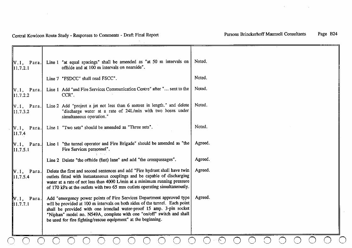
Central Kowloon Route Study - Responses to Comments - Draft Final Report
IV. I, Para. 11.7.2.1
IV. I, Para. 11.7.2.2
IV. I, Para. 11.7.3.2
Line I "at equal spacings" shall be amended as "at 50 m intervals on offside and at 100 m interVals on nearside" .
Line 7 "FSDCC" shall read FSCC".
Line I Add "and Fire Services Communication Centre" after" ... sent to the CCR".
Line 2 Add "project a jet not less than 6 metres in length." and delete "discharge water at a rate of 24Lfmin with two hoses under simultaneous operation."
1v.1, Para.1 Line I "Two sets" should be amended as "Three sets". 11.7.4
Noted.
Noted.
Noted.
Noted.
Noted.
iv. l , para.1 Line I "the tunnel operator and Fire Brigade" should be amended as "the I Agreed. 11.7.5.1 Fire Services per~onnel".
iv.l, Para. 11.7.5.4
iv.l, Para. 11.7.7.1
Line 2 Delete "the offside (fast) lane" and add "the crosspassages".
Delete the first and second sentences and add "Fire hydrant shall have twin outlets fitted with instantaneous couplings and be capable of discharging water at a rate of not less than 4000 Lfmin at a minimum running pressure of 170 kPa ·at the outlets with two 65 mm outlets operating simultaneously.
Add "emergency power points of Fire Services Department approved type will be provided at lOO m intervals on both sides of the tunnel. Each point shall be provided with one ironclad water-proof IS amp. 3-pin socket "Niphan" model no. N549A, complete with one "on/off" switch and shall be used for fire fighting/rescue equipment" at the beginning.
Agreed.
Agreed.
Agreed.
Parsons Brinckerhoff Maunsell Consultants Page B24
00000 Ci 0 o 0 00000000 000000

(\ r r n n , !' n n , (' (\ , (' , (\ n o
Central Kowloon Route Study - Responses to Comments - Draft Final Report
"Socket outlets" should read "emergency power points". Agreed.
V.l, Para.l Line 1 Add 'on both sides" after •... at an interval of 100 metres". 1 L7.8.5
Agreed.
V.l, Para. 11.7.8.6
V.l, Para 19.6.2
V.l, Para 19.13.1
V.l, Para 19.14.1
Manual fire alarms, emergency power points, fire hydrants and hose reels shall also be housed in niches in the tunnel walls.
Noted.
Door contact switches shall be provided such that when the door is opened, I Noted. an alarm will be given to the control room indicating the location of the niche involved. Fire hydrant niches and hose reel niches should be sited adjacent to the cross-passages.
Illuminated signs indicating emergency telephones and fire extinguishers 1 Agreed. shall be easily discernible along the tunnel. Signage of Pedestrian cross-passages shall be provided. Such signs should be self-illuminated/photoilluminated graphics indicating the location and purpose of the cross-passages, or exit signs bearing the word and characters "FIRE EXIT" in block letters and characters of not less than 125 mm high with 15 mm wide strokes over/alongside each cross-passage doorway at a height of not more than 2.5 m from road surface.
The tunnel wall lining/fmishes should conform to RSS 476 Part 7, Class 11 Agreed. or 2.
Emergency telephones shall be provided on both sides at 100 m intervals in 1 Agreed. tunnels.
Line 4 & 7 "Fire Services Department Control Centre' should read "Fire 1 Agreed. Services Communication Centre".
o o 0 o o () ,0 () o
Parsons Brinckerhoff Maunsell Consultants Page B25
....

Central Kowloon Route Study - Responses to Comments - Draft Final Report
/V.l, Para. 19.14.2
Break glass fire alarm units shall be provided at 50 m intervals on offside and at 100 m intervals on nearside.
Agreed.
/V.l, Para.1 Line3 19.14.3
"Fire hydrants shall be located at a regular spacing" shall be I Agreed. amended as "Fire hydrant shall have twin outlets fitted with instantaneous couplings at 100 m intervals".
/V.l, Para.1 Line 1 19.14.4
"at a regular spacing" should be amended as "at 50 m I Agreed. intervals" .
IV.l, Para. 19.14.5
IV. 1, Para. 19.14.6
IV.l, Para. 19.14.8
IV.2, Fig. 081
IV.2, Fig. 085
Three sets of 4.5 kg CO2 fire extinguishers shall be provided at 100 m intervals on both sides of each tunnel.
Cross-passages shall be equipped with self-closing doors having fire resisting period of not less than two hours.
Foam blanketing system (for nadir sump) shall be provided in accordance with NFPA 11 standard and the lower explosive limit should be set at 0.8 %.
Foam blanketing systems provided for the 2 petrol interceptors in the tunnel shall be indicated on drawings.
Niche C & D "Break glass Niche" shall read "Break glass fire alarm point Niche" .
Agreed.
Agreed.
Agreed.
Agreed.
Agreed.
Parsons Brinckerhoff Maunsell Consultants Page B26
Niche C shall be provided at 50m intervals. Niches B and D provide Hose Reels and Break Glass facilities at 50m from Niche C, thus eliminating the need for tighter spacing of Niche C.
The emergency power socket in Niche D shall be of the FSD approved type. I Noted. Details should be submitted at detailed design stage.
o 0 0 0 0 o 0 o o o 0 000 o o o o 0 0 0 o 0

,'\ 1:' (' (' n , (' (\ (\ (\ 0, '- on o o n
'"_/ () (i (\, (\, n '\,
Central Kowloon Route Study - Responses to Comments - Draft Final Report Parsons Brinckerhoff Maunsell Consultants
IV.2, Fig. 087 I The supply and exhaust operating modes of the fans are considered not I Noted. Details should be submitted at detailed design stage. compatible with some of the fire and traffic scenarios. Further elaboration of the control system is therefore required and details shall be submitted for FSD comment/approval.
Orban Services Department
(Ref. (49) USDP 38/402/88 III dated 27 October 1992)
The recommended CKR alignment and associated proposals are noted. So I Noted. far as U.C. facilities, both existing and planned, being affected by the proposed alignment are concerned, I think we can leave all options open at this stage, though I still hope that some of the affected U. C. facilities and planned projects could be avoided from the actual alignment after further refinements possibly during the detailed design stage, or as much of the construction impact as possible could be reduced with further mitigation measures being developed. Any subsequent refinements, mitigation measures and above all, the ultimate implementation details, are of course subject to detailed assessment by this Department in consultation with the Architectural Services Department (ASD) and approval as appropriate from the Urban Council in due course.
Specifically your report has identified the Ko Shan Theatre, Ko Shan Road I Noted. Park, the "G' site on Ko Shan Road, the Hoi Sham Park, the 'DO' site earmarked for an extension of Hoi Sham Park to its south, as being affected by the proposed alignment. Another U .C. planned project, viz. Lo Lung Hang Park (U.C. Capital Project 155CR) on top of the planned reservoir area now occupied by the Fat Kwong Street Temporary Housing Area also appears to be within the influence of CKR because of a proposed vent building on the same site (para. 2.5.3.3 Volume 3 refers), but there appears to be no mention about possible impacts on this U .C. project, and likewise
'-
o o
Page B27

Central Kowloon Route Study - Responses to Conunents - Draft Final Report
whetber it would affect tbe existing U .C. playground on tbe Ho Man Tin East Service Reservoir deck and anotber U. C. planned project, viz. Ho Man Tin Recreation Ground (035CR in U .C. Capital Works Progranune), botb are witbin tbe former's inunediate vicinity (see plan attached).
Parsons Brinckerhoff Maunsell Consultants
A more immediate concern is tbe problems of noise nuisance and traffic I To be examined further during detailed design. disturbance during construction period affecting tbe operation of tbe Ko Shan Theatre. This issue must be addressed in greater deptb witb ASD participation so as to decide on tbe mitigation measures necessary to ensure minimum inconvenience to tbe users and tbe public.
I am still awaiting comments from tbe concerned parties on tbe question of I Noted. development rights below ground surface at location where CKR passes underneatb tbe USD 'G' site (GEIWHL's memo (7) in WHL 14/4/3 V dated 13.10.92, addressed to DLO/KE, BLD, and copied to you refers).
Yau Tsim/Mong Kok District Office
(Ref. (15) in MKDO 1/830 IT dated 28 October 1992)
I have no conunent to make on tbe draft final report except tbe following minor points :-
V. I Par a.1 (i) "Shek Luen Road" should be "Shek Lung Street". 1.3.2
Noted.
(ii) As advised by tbe Director of Agriculture and Fisheries, tbe earliest I Noted. possible date for relocation of tbe Fruit Market is 1998. It seems ratber difficult to relocate some of tbe market facilities for access to tbe school because tbis might be objected strongly be tbe fruit market operators. One possible solution is to build a series of footbridges across
00 0 0 0 o 0 o o 000000 o 0 o 0 0 0
Page B28
o 0

,~ (' (', (' (1 ", (\, (' (', (' (\ n fI fI .n I) o () I) ,n o o n '-~
" _/
Central Kowloon Route Study - Responses to Comments - Draft Final Report Parsons Brinckerhoff Maunsell Consultants Page B29
Reclamation Street into the school compound to facilitate access by the students.
Secretary for the Treasury
(Ref. (4) in FIN C9/32 (92) IV dated 28 October 1992)
Thank you for your memo.
The financial assessment has not attempted to assess the financial viability of the CKR as a privatized project. In the light of the estimated development costs and the probable resource constraints, you may wish to consider the merits of a study on possible privatization options.
My detailed comments on Volume 1 of the DFR are set out below:
The assessment of the financial viability of the CKR as a privatised project is outside the scope of the present study. The possibility of a study on privatisation is noted.
V.l, Table 3.~ It is not clear hQw the second figure in the final line of each of the three I Table has been revised. calculations (1.05, 1.17 and 0.607) is derived.
V.l, Tabl 10.1
V.l, Para 13.1.4.3
V.l, Para 18.1.2
Some of the figures for the Aberdeen, Cross Harbour and Lion Rock I Table amended. Tunnels do not appear to be correct.
The Cost of rehousing may be attributable to the CKR as both a Privately-I Rehousing costs cannot be estimated with any accuracy at this time as funded and publicly-fun<\ed project. It would be useful to estimate the likely details of occupants are unknown. costs of this commitment, particularly in terms of Table 18.6.
Unless there is any overriding reason, the tolling strategy should be based on maximizing the revenue to Government. This point would have to be discussed in detail between Transport Branch and Finance Branch at' the appropriate time.
Noted. It appears from comments on the DFR that this is not accepted by all sections of Government. A separate study should be made on tolling levels and tolling policy.
'i\,;,.

Central Kowloon Route Study - Responses to Comments - Draft Final Report
1v.1, Para. 18.4.2 (e)
Financing costs would be a consideration in assessing the financial viability of a privatized CKR.
Parsons Brinckerhoff Maunsell Consultants Page B30
Noted. Consideration of a privatized tunnel is outside the scope of this study.
1v·1, 18.6
Tablel It may be useful to show the cashflow excluding land acquisition costs and I Noted. land revenues.
V.I, 2.4.3
Para.
Mass Transit Railway Corporation
(Ref. EC/260/0614 (99) dated 28 October 1992)
I. The section of the proposed cut and cover road tunnels (two single cell) where they cross the future MTR East Kowloon Line tunnels at Ma Tau Wai Road should be on piles such that MTRC can tunnel underneath without affecting your road tunnels.
V.I, Para.1 2. 12.2.2
We have no objection in principle to the proposed amended location of the future MTR vent shaft provided relevant Government departments have no objection and the land is reserved for purpose.
V.I, Para. 12.1
(a) The railway tunnel is now expected to be a reinforced concrete box formed in open cut or in a strutted excavation and not utilising diaphragm walls.
(b) The tunnel box will not have a piled foundation and will be liable to long term settlement. The major part of this settlement will have occurred by the start of Phase I road construction (January 1997) but further settlement can be expected.
(c) At the time of road construction, the tunnel will be completed and the road works will be subject to the Railway Protection requirements.
Noted. This requirement should be confirmed during detailed design as the EKL alignment is under review in the Railway Development Study.
Noted.
Noted. Text amended.
Noted. It is understood that this a design change which occurred after preparation of the CKR Draft Report.
Noted. The tunnel should be designed to allow for future bored piling nearby.
o 0 0 0 0 o 0 o o 000000 o 0 o 000 o 0

f'. c;. (' (' (" (1 0, o o 0, o o n ."\ , ) o .0 o on () !~ o
I
,
Central Kowloon Route Study - Responses to Comments - Draft Final Report
V.2, Fig. 078 3. Our comments regarding the minimum clearance between pipe piles and existing MTR tunnels as well as that between MTR tunnels and hand dug caissons had been given in our letter dated 28/8/92. Meeting was held on 28/9/92 and your letter dated 9110192 recorded the discussion. However, the agreed amendments have not been incorporated in Figure No. 078 and the clearance indicated in the Figure are still exceeding our tolerable limit.
Government Secretariat Secretary for Transport
(Ref. (22) in TRAN 4/061127 (92) V dated 28 October 1992)
Please note my folIowing comments on Volumes I and 3 of the Draft Final Report :
(A) Volume I : Engineering Feasibility and Preliminary Design
V.I, Para. 44 Summary and Recommendations (2)
V.I, 9.1.1
Para
The toll rates in 1992 prices should also be given for comparison.
The toll rates in 1992 prices should also be given. A toll of $20.54 (1990 prices) is assumed in year 2011. Explanation is required as regards to the reasons for adopting this level of toll and not other toll options for the Central Kowloon Route, giving that no tolled tunnel in the territory is now charging an amount of this magnitude. The resultant traffic impacts on the parallel routes in Kowloon should be critically assessed with the problem areas highlighted in the Draft Final Report. Detailed information on the impacts apart from that presented in Para. 18.1.1.15 should be given.
"'---_/ -j
Parsons Brinckerhoff Maunsell Consultants Page B31
Figure No. 078 to be amended in the Final Report: (Figure has been renumbered to 033)
Noted.
The Central Kowloon Route Study is an engineering study and was only required to investigate the feasibility of collecting tolls. Recommendations on toll levels are outside the scope of the study. The quoted toll level 'Was selected following a working group meeting when it was indicated 'that revenues should be maximised.
'-
o

Central Kowloon Route Study - Responses to Comments - Draft Final Report Parsons Brinckerhoff Maunsell Consultants
tv.l, Para. 11.2.3.3
(a) Does the peak hour traffic composition refer only to the morning peak scenario or both the morning and evening peaks?
The peak hour composition refers to the AM peak.
V.3, Para. 2.5.6.1
(b) It would give a clearer picture of the traffic mix if the volume of I Para. amended. individual vehicle category is also expressed as a percentage of the total hourly flow.
(c) Non-franchised buses are used to operate public bus services in the case I Noted. of the residents' services. The term "Non-franchised bus" should best be replaced by "Private bus" for clarify.
(B) Volume 3 : Planning. Environment and Urban Landscape Assessment
(a) The_design year of the traffic forecasts should be indicated. Is it year 20111
The design year is 2011.·
(b) In arriving at the traffic predictions, the consultants have adopted a toll I Please refer to response to Para 9 .1.1. of $15 (1986 prices) for the Central Kowloon Route in year 2011. Explanation is considered necessary on the selection of $15 toll and not alternative values. Please also see the comments on Para. 9.1.1 of Volume 1.
(c) The ea.stbound traffic flow on the Central Kowloon Route in both the I Refer Volume I 3.3.4' morning and evening peak hours is predicted to be much higher than the westbound flow. An account on the flow pattern is needed.
V.3, Para'! See Comments on Para. 11.2.3.3 of Volume 1. 2.5.6.2
o 0 0 0 0 o 0 o o o o
Para. amended.
o o o o o 0 o 000
Page B32
o o

n C (\ , (\ (\ .n c (\ (\ n ~
n '1 .'1
" . Central Kowloon Route Study - Responses to Comments - Draft Final Report
IV. 3, Para.1 Elaboration on the percentage figures is required. 112.5·6.3
V.l, Para. 12.5.1.2
V.I, Para. 12.5.3.1
V.I, Para. 12.5.3.2
CE/MS. Drainage"services Department
(Ref. (74) in D(MS) 1015/31 dated 30 October 1992)
This memo serves as a co-ordinated reply from Consultants Management and Mainland South Divisions of DSD.
(a) It is not a normal practice to use steel pipe for sewage conveyance, the Consultants should elaborate on this issue to ensure that pipe deterioration should be kept to a minimum.
(b) The Consultants should provide justifications that the 900 mm dia. sewer along Bailey Street is capable of intercepting all the flow from the upstream sewers in Ma Tau Wai Road, otherwise it is not true to state such sewer is intended to intercept all the flow from the upstream sewers in Ma Tau Wai Road.
(c) There is no PWP item for upgrading the sewer in Bailey Street and abandoning the main sewer along Ma Tau Wai Road between Bailey Street and Wing. Kwong Street.. Furthermore, as recommended in Working Paper No. 3 of the North and South Kowloon Sewerage Master Plan Study, the main sewer along Ma Tau Wai Road should be retained. The Consultants are also reminded that the main sewer along Ma Tau Wai Road also acts as a carrier sewer to serve the developments. in the vicinity of Ma Tau Wai Road.
() j o o o o o o n o o
Parsons Brinckerhoff Maunsell Consultants Page B33
Noted.
Noted. It is recommended that the proposed sewer be moved slightly west so that conventional pipework can be used.
CE/MS, DSD comments on Working Paper 2 ref D(MS) 1015/40K date? noted that the 900mm sewer is intended to intercept all the flow from the upstream sewers. The North and South Kowloon Sewerage Master Plan Study DFR Fig. No. 20.12.1 show no upgrading is required.
Noted. The North and South Kowloon Sewerage Master Plan Study DFR has taken into consideration the Central Kowloon Route tunnel and recommends (para 20.6.4) that the sewer in question be decommissioned.
I
."
.,\

, Central Kowloon Route Study - Responses to Comments - Draft Final Report Parsons Brinckerhoff MaunseII Consultants Page B34
V. I, Para 19.9.6
V.I,Para 19.9.7
V.I, Paras 1.1.1 to 1.1.5
(d) Stormwater drainage diversion should be designed in accordance with CE Manual as any variation to the existing drainage system would affect the hydraulic performance of the whole system. The Consultants should also carry out a Drainage Impact Assessment if connection and diversion of the existing system are required.
Noted. Detailed drainage impact assessment should be carried out during detailed design.
(e) Same as above, foul sewer diversion should be designed in accordance I Noted. with CE Manual.
Planning Department
(Ref. K-RnT/I IO II dated 30 October 1992)
I refer to your above memo and attach our consolidated comments on the captioned from DPO/K and CTprrrD of Plan D.
(i) (a) It is recognised that much of the Background described here was drawn directly from the project Brief.
(b) It would be preferable to outline the actual policy substance in the Background section, which has emerged and been endorsed subsequent to the Brief being written.
(c) Although the purpose of this Study has not changed there is now a clear positive logic for this investigation being conducted at this time.
(d) The CKR has become an integral part of a coherent development
The report introduction is intended to give the reasons behind the commissioning of the study and the study requirements and not to try and summarise Government policies which have developed since commencement of the Study. The points made are noted.
o 0 000 o 0 o o o 0 o 0 o 0 o 0 o 000 o o

(" c (\ , (' o (\ ('1 n o (\ () 'j
() (\
Central Kowloon Route Study - Responses to Comments - Draft Final Report
strategy for the Kowloon peninsula.
(e) The policy substance starts with the decision to relocate the airport from Kai Tak to Chek Lap Kok.
(t) Implicit in this policy decision is the new airport access infrastructure, the Airport Core Programme (ACP) including the section of Route 3 known as the West Kowloon Expressway (WKE).
(g) In order that the WKE could proceed, the location of its principal junctions had to be determined which would be compatible with both development on the reclamation and metropolitan area transport linkages.
(b) These were drawn from the structural guidelines promulgated in Metroplan which have been accepted by the highest Authority.
(i) The South-East Kowloon Development Statement Study (SEKS) is now in progress examining the potentials for urban renewal in To Kwa Wan/Hung Horn together with the phasing of early development of Kai Tak/Kowloon Bay. Many of the opportunities for development in these areas will be predicated on the available linkage and layout of the CKR and the NSH.
o o o o 00 o () ,~,
Parsons Brinckerhoff Maunsell Consultants
0) In response to this coherent development strategy the Transportl The CKR Study was commissioned by Highways Department.
I
Authority have advanced t.1-te Engineering Feasibility and Preliminary Design of the CKR.
(k) The purpose of the advancement is to provide the Transport Authority with the option to re-prioritise the projects in its resource
,"
() c
Page B35
11

Central Kowloon Route Study - Responses to Comments - Draft Final Report
:.7:.
allocation programme in response to developing needs. It is not the function of this study to undertake, or to assume a re-prioritisation of the CKR, merely to create the option.
(I) This provides a clear, positive ~ationale for undertaking this project at this time.
Parsons Brinckerhoff~aunseII Consultants
(m) Many of the aspects mentioned in the Brief were the pro's and I The CKR Report is an engineering report not a policy report. con's that went towards the formulation of a coherent developme nt strategy and continued reference to these in the Final Report is retrogressive.
(n) Comparison of the CTS-2 findings (1986-89) with subsequent components of Metroplan is totally inappropriate. The CTS-2 endeavour added greatly to the coherence of a territorial development strategy formulated around ·retention of Kai Tak. It does not serve this project to mention CTS-2 without reference to the TDS on which it was based.
(0) Even reference to the CTS-2 update of 1992 will not serve this project. The update was conducted under the guidelines of an interim TDS incorporating PADS, Metroplan and the residue of plans for the New Towns. It is recognised that this interim ~evelopment scenario is lacking in coherence and the TDS is currently undergoing a major Review.
(P) The TDS Review is likely to be complete within the next year and will provide the guidelines for subsequent annual CTS-reviews.
(q) It is unnecessary to speculate at this juncture whether, or not this will lead to a re-prioritisation of projects.
Page B36
00 C o 0 o 0 o o o 0 o 0 o 0 0 0 0 0 0 0 0--0

.~ (\ r .~ r ,'1 0, r r 0, o '1 0, I) I) 0 /"~, 1)01) ,'1 -' -
Central Kowloon Route Study - Responses to Comments - Draft Final Report Parsons Brinckerhoff Maunsell Consultants
V.I, Para. 2.21 (ii)
1v.1, Para.1 (iii) 12.3.2
IV. I, Para.1 (iv) 3.1.1
IV. I, Para·1 (v) 3.1.6
V.I, Paras.1 (vi) 3.1.11 & 3.1.12
(r) As the CKR is not a local network improvement, but represents a major strategic development initiative it is desirable that the Background section of this Final Report places the project in context.
In view of the foregoing para. 2.2.2 is a prudent recommendation but I Noted. para. 2.2.1 merely stems from the inputs. Given a firm context this sub-para could be more positive.
It has been suggested throughout this project that the eastern 1 Noted and agreed. approaches would need to be reviewed in the context of SEKS. This remains true and it would not belittle the merits of this Study to acknowledge this point here.
The first sentence is acceptable. Re the second sentence, some of us I Noted. are aware of the innovative advice emanating from sectoral studies with which MVA have been associated. It is, however, desirable to cede, that government has promulgated a development strategy, Metroplan, albeit adopting ideas where appropriate from sectoral studies.
The necessity to firm up the western end is accepted. However the I Noted and agreed. eastern end needs to be looked at in terms of programme and the types of demand to be attracted to the route rather than assuming that all movements need to be accommodated.
The assumptions given here are accepted, but it would have been I Noted, the CKR is not dependent on the schemes noted. prudent to state that the CKR could well operate under different permutations subject to later development needs.
'-
o 0
Page B37

Central Kowloon Route Study - Responses to Comments - Draft Final Report
V.I, Paras., (vii) 3.2 and 3.3
We have no difficulty accepting the traffic forecasting methodology I Noted. adopted to fulfil the engineering objectives of this study. The CTS-2 and even the CTS-2 update trip data is, however, subject to future annual review. The available trip data from this source for various design years should not be quoted as if these were incontrovertible. Forecast needs change and lead to re-prioritisation of projects. Paras. 3.3.12 to 3.3.20 go some way to redressing the perception of long term CTS forecasts. In the interests of this project these comments might well have appeared at the beginning of section 3.3. leading to the logical adoption of CTS data to meet the engineering objectives of thi~ study only.
Parsons Brinckerhoff Maunsell Consultants Page B38
V.I, Chapterl (viii) This section is interesting. No data are quoted on PIA's on say 10 Boundary Street, or any of the other principal E-W routes. It used
to be a legitimate aspect of a new road study to estimate the reduction in PIA's that could be expected.
The CKR Study is not a "new road study" but an engineering feasibility study of a generally accepted route.
V.I, Chapte~ (ix) 13
The land requirement issues are complex and the consultant has I Noted. expressed these in a form compatible with the Transport Authority proceeding independently under the Roads (Works, Use and Compensation) Ordinance. While not yet available, other possible institutional mechanisms to promote urban renewal and the implementation of Metroplan are actively under consideration, in SEKS. As we are promoting the CKR as an integral part of Metroplan there is every reason why implementation of the CKR should be considered in the light of alternative mechanisms. While it would be unreasonable to expect these to be explored in the present context, it would be useful to raise a flag in this section.
o 0 000 o 0 00 0 0 0 0 0 8 0 0 000000

(' (', ,~~
(', "--j
I'
" (' ~" o o ,r, (\ c! -,_/
'~
(\ '-'
n n o o !) '- o 00 ,'I
.~ o o
Central Kowloon Route Study - Responses to Comments - Draft Final Report Parsons Brinckerhoff Maunsell Consultants Page B39
V;I,Chapterl (x) 14
V.I, Chapte~ (xi) 18
.It is not clear whether this Section on programme has been prepared under advice from the Transport Authority on currently planned allocation of resources, or whether it is a possible tactical engineering programme to implement a development strategy. The CTS-2 update (1992) was forced to exclude the CKR from the 2001 reference network for budgetary reasons, based on the relatively low SYRR achieved in the economic analysis. As you pointed out in Section 3 a 10% variation is well within the forecasting error. The construction of the CKR would only permit a 10%, or so, growth on the screen-line A-A crossings over which' growth has been totally constrained by lack of capacity since as long ago as 1981. Viewed in the strategic context of the screen-line A-A, the SYRR form of economic analysis may not be doing justice to the merits of the CKR. This is perhaps an issue which should be drawn out here, but the allocation of limited resources cannot be pre-emptied.
The programme has been based on the assumption'that resources would be available.
(a) Again this Section on Financial Assessment may have been I Agreed. written before consideration was given to the Traffic Forecasting Overview, Given that Screen-line A-A is only some 5 km long between Hung Hom and the hills and, presumably because of demand saturation, has shown no growth characteristics over the last decade, if the CKR was provided, the screen-line flows might reasonably be expected to increase rapidly over the first year of operation utilising the available new capacity. Would it not be a useful indicator to quote historical and current flows on the various E-W routes in Table 18.3 expressed in terms of both directional a.m. and p.m. peaks and AAWT? These data are available and would illustrate how reasonable, or unreasonable, is the concept of overspill to "alternative routes" .
"
'-
o

Central Kowloon Route Study - Responses to Comments - Draft Final Report
(b) Given a range of potential tolls on the CKR there may well be a resistance level above which few people would choose the route. Given traffic conditions on parallel routes this potential demand cannot overspill and trips are either suppressed, diverted to an alternative destination or forced to change mode.
(c) The objective of the development strategy including the CKR is to promote trip-making between east and west Kowloon in the expectation that this will moderate the growth in trip-making along north-south desire-lines. This concept is entirely contrar y to the CTS-2 ethos which perceives the need to strengthen the N-S corridors in response to demand growth trends. This is the fundamental reason why we have been unhappy about using the CTS-2 forecasts to justify, or otherwise, providing the CKR.
Parsons Brinckerhoff Maunsell Consultants Page B40
Noted.
Noted. The CKR Study is an Engineering Feasibility Study and examination of development strategy concepts and justification for providing CKR are outside the scope of the study.
(d) In tactical operational terms we have no objection to the I Noted.
11
Transport Authority imposing a toll regime on the CKR, but this should not approach the public resistance level and prejudice realisation of the development strategy.
(e) Clearly this all has a bearing on the Financial Assessment. There is a range of possible outcomes which has not been addressed in this section. All are potentially more favourable to t)le CKR.
(t) We have no objection to you exploring what might be the downside of the financial· assessment but we feel that this should not stand alone as a facet of the project which might be regarded by some as more important than realising the wider planning goals.
Noted.
Noted. The assessment of wider planning goals is again not within the scope of an Engineering Feasibility Study.
CJ C] 0-0 0 -0 0 -0-0 o 0 o 0 0 0 o 0 o 0 0 0 o o

n (\ (\' (\.' (', " ", '- , -'
n n \'- /
(\ (\, n n nnoooo O()O,O
Central Kowloon Route Study - Responses to Comments - Draft Final Report
V.l, General
V.l, General
V.l, Para. 13.2 & 14.3.: (b)
(xii) We have no comments on the engineering aspects of this project I Noted. other than we are pleased to understand that it appears to be feasible.
(xiii) Most of the above comments relate to the context of this study rather I Noted. than the content. From the territorial planning point of view we regard it as important that the context of this project is clearly understood by those who may read the Final Report. We feel that some sections and paragraphs in the draft need to be re-modelled to establish the context appropriately.
The suggestion of relocating some market facilities for the access to the schools require careful attention. Should there be slippage in the relocation programme for the Fruit Market. Government might be faced with objection from the market operators to relocate part of the market facilities. DAF should be consulted in this respect.
Noted.
Parsons Brinckerhoff Maunsell Consultants
V.3, Para.1 (i) The Action Areas as recommended in WKDS have been amended. Please update your information on the relevant Action Areas with the attached plans
Noted. The Final Report will be amended accordingly. 1.2.1.2
o 0
. Page B41
V.3, Para. 1.3.2.3
(ii) According to the Urban Area Development Programme - 1992 Edition, the 'G' site at Ko Shan Road is under UCCWP item 192 CR to be undertaken by USD for an IRC. The project is scheduled to start in July 1993 and complete in July 1995. In the lack of detailed design requirement for the CKR, it is doubtful whether the IRC could be constructed to allow the CKR to pass underneath it. View of DUS should be sought.
Noted. It would be possible to establish requirements, such as detailed tunnelalignIllent, at this time if required.
V.3, Para. 1.41 (iii) I would reiterate that the chance for route protection under the Town I Noted. Planning Ordinance for the CKR is remote. The major reasons have been set down in the memo (20) in TPB/DfK2/200 from D of Plan
'-

Central Kowloon Route Study - Responses to Comments - Draft Final Report
o 0
to AGC attached herewith for your information. They are summarised as follows :-
(a) Designation of affected areas as "CDA" is problematic because:
(1) The boundary of the affected areas is not certain.
(2) There is no proposed scheme for the "CDA".
(3) No agency has been identified for the redevelopment.
(b) Gazettal of the route on the OZP under Town Planning Ordinance is impracticable because:
(1) There is no compensation for the parties affected under the Ordinance.
(2) There is no commitment from Government to resume the land affected by the route. Therefore, public objection is expected.
(3) From above, getting approval of the route gazettal from the Town Planning Board is unlikely.
Therefore, the suggestion of incorporating the CKR on the OZP at the same I Noted. time as the OZPs are amended to account for the findings of the Review of Building Density and Height Restrictions in Kowloon and New Kowloon is doubtful.
000 o 0 o 0 o 0 o o o
Parsons BrinckerhoffMaunsell Consultants Page B42
o o 0 o o 0 0 0 0

", (\ (\ , ' (\, '-
(\ o (\ (\' (\ (1 (1 n
Central Kowloon Route Study - Responses to Comments - Draft Final Report
11v.3, Tablesl (iv) 1.2, 1.6 & 1.7
iv.3, Para.1 (v) ~.6.2.1O
~.3' Paras.1 (vi) .6.2.34, .6.2.37 & .6.2.40
The domestic and non-domestic plot ratios of 6.5 and 12 respectively as suggested in Metroplan should be adopted for the purpose of assessing the redevelopment potential.
Figure 2.21 should read Figure 2.20.
I am concerned about whether there is any lI\eans to reduce noise generated from the vent shafts at the west portal, Fat Kwong Street and the east portal. The "necessary features" for noise reduction should be spelt out in the subject paras. and should not be left open for resolution at detailed design of the ventilation buildings.
Please clarify which open space fronting the school building would be removed during construction of the CKR.
1~.3' Para·1 (vii) 3.2.2.3
.3, Para. 3.3 (viii) Given the height of the ventilation building, the skyline of the areas in the vicinity would be very much dominated by that structure. Careful architectural treatment should be provided.
n () o !) 00 () o n o
Parsons Brinckerhoff Maunsell Consultants Page B43
Plot ratios permissible under the current Building (planning) Regulations have been used in the assessment. As the text notes, future plot ratios in this area will be governed by the findings of the ongoing Review of Building Density and Height Restrictions in Kowloon and New Kowloon.
Noted.
The noise requirements for the ventilation buildings are subject to statutory controls and will have to meet these in order to operate. On this basis, assessment is superfluous, as there is statutory protection provided. The noise levels must meet defined criteria, or the facilities cannot be operated.
The actual situation can only be determined during the detailed design, which is beyond the scope of this Study.
The courtyards between the school buildings and the walls along the footpaths.
Noted and agreed. This treatment will need to be specified at detailed design stage.
~.3, Para.1 (ix) My comments on para. 1.3.2.3 is relevant. I Noted. 3.4.4.2
IV.3, 13.6.5
para.1 (x) It is suggested that the temporary wall for the toll plaza should be I Noted and agreed. landscaped with planting to minimise impact on the Hoi Sham Park.
..\;.
o

Central Kowloon Route Study - Responses to Comments - Draft Final Report
Planning Department (Ref. K-RlTI/llO II dated 4 November 1992)
Furtber to my memo on 30.10.92 of the same series, I would like to forward additional comments on the captioned for your consideration.
11v.1, Paras·1 (i) 13.4.4, 14.6, 18.3.1 and 18.4.3
These paragraphs touch on redevelopment in the area around the tunnel. In some paragraphs it is proposed to assist urban renewal by LDC and in others, it is proposed to help finance the CKR project.
In the context of the West Kowloon Development Statement, which is tasked to translate the Metroplan objectives into specific guidelines for district planning, the concerned sites are envisaged to link with other marginally viable or non-viable urban renewal sites to form viable redevelopment packages. Site availability is also predicted on the assumption that the affected properties wiil be resumed under the CKR project. The arrangements for disposal and the implementation agents should better be determined in the light of the WKDS proposals, which are now being finalised for approval by relevant government committees. Sites falling within the study area of the South East Kowloon Development Statement should also be considered in the context of the urban renewal strategy for the broad district.
Parsons Brinckerhoff Maunsell Consultants Page B44
We have not seen the West Kowloon Development Statement Reports and therefore cannot comment on the recommendations to be proposed therein. The CKR is concerned primarily with minimising land requirements for the project and identifying development packages which could be available for sale in conjunction with the tunnel construction progranune. If they can be linked in with other development proposals for WKDS, there may be significant advantages to be gained.
The statements regarding the assistance to be given to LDC relate to the opportunities created for urban redevelopment in this vicinity and the removal of the blight on the already identified comprehensive development area. It is stated throughout the report that the cost incurred in acquiring land for the construction of the CKR can be offset by the creation of development sites as a result of adopting the cut-and-cover tunnelling method.
11v.3, Para·1 (ii) 1.2.1.2c
The Draft Final Technical Report of the WKDS has already been I The comments are noted and would be updated. issued. The information about the urban renewal action area needs to be updated accordingly.
Iv. 3, Para.1 The development parameters for the redevelopment sites should be in line I The comments and noted but the timing of the CKR project is undetermined
C) 0 0 0 0 o 0 o 0 o o o O-uD o 0 o o o 0 o 0

0. (' (' n n (\ (' nn()·(),f)OOO o 0 ('. r , --" o () Of)
Central Kowloon Route Study - Responses to Comments - Draft Final Report Parsons Brinckerhoff Maunsell Consultants Page B45
1.2.3.4 and 1.3.3.3
with the Development Statement proposals. The Metroplan Density Guidelines for Type 3 area should be applied, in line with recommendations of the Metroplan Selected Strategy.
and therefore we have adopted the existing' planning guidelines Le. the existing zoning for each site.
11v.3, Para. 1.4.3.1
The use and implementation agent for the redevelopment sites should more appropriately be determined in the context of the urban renewal strategy of the respective Development Statements.
Environmental Protection Department (Ref. EPZ/K7/03 dated 2 November 1992)
Please find attached appendix detailing part of the comments from this department on the three volumes of the draft final report of the Central Kowloon Route Study for your action. The remaining comments are essentially from our noise policy group which will be sent to you shortly.
I would like to remind you of the requirement for you to submit a Executive Summary (ES) after the issue of the Final Report. This document will be open to the public for inspection and will be crucial document in District Board presentation, if any. Hence, we would like to comment on the draft of the ES once it is prepared.
Comments are noted.
11v.1, Table! 1. 19.3
Please note that the EPD Tunnel Air Quality requirement for N02 I Agreed. does not specify " the time average for "IS min." or "I hour". As a
IV.l, Para.1 2. 19.18.4
result, they should be deleted in the Design Standards Memorandum of the CKR.
Please delete the term "Standard B" as it is not being used in the I Agreed. recent PIARC Report 1991.
IV.3, Para.1 3. In the Consultants' reply to our comments on the advanced copy of I Text amended.
'-

Central Kowloon Route Study - Responses to Comments - Draft Final Report
12.5.10.11 the captioned report, I was told that the background concentrations were derived from the line source simulation instead of an arbitrary one. As a result, please amend the text "for simplicity .... " accordingly.
V.3, Para.1 Please rewrite the paragraph as follows: 2.8.1.3
2nd line rock/rubble (12%), ferrous metal (3.5%) ... Currently the only accepting recoverable material is ferrous scrap, usually in the form of reinforcements bars, which has a secondary market in Hong Kong.
4th line The majority of the waste is landfilled. It is expected that most construction waste, after sorting at source, will be disposed of at public dumps after the commencement of Construction Wastes Diversion Scheme.
7th line .... Construction wastes, method of implementing such schemes, and potential markets for recyclable prodlicts.
Noted.
V.3, paras'l The use of the excavated materials for reclamations is considered the best I Noted. 2 . 8 . 1 . 4 & option among the other options proposed and is highly favoured. 2.8.2.5
V.3, Para. !2.8.2.8
The Chemical Waste Regulation provided under the WDO will also apply on the disposal of the hazardous waste if such wastes are also classifiable as chemical wastes under the ordinance. That is the disposal of the hazardous materials will need to comply write both or either of the WDO/DGO if they apply.
o 0·0 0 0 o 0 o 0 o o o 0
Noted.
o
Parsons Brinckerhoff Maunsell Consultants Page B46
000 o 000 o 0

r, (' (' (', (' r n (\, 1', 1', (\, ,f\, ,11 i) (I (j 0 o r'j () ,'] o (I
Central Kowloon Route Study - Responses to Comments - Draft Final Report
IV.3, Para. 1.3.2.3
IV.3, Paras. 1.3.2.3 &1 1.3.2.5
IV.3, Para. 1.3.3.1
V.3, Para. 1~.3.2.2 las sentence
V.3, Para. 12.3.2.5
:V .3, TablE ,2.3.2
Environmental Planning Department. Noise Policy Group
(4 November 1992)
What are the recommendations on mitigation measures to abate the construction noise impact upon the Ko Shan Park and Theatre?
The block under construction referred in Wing Kwong Street fronting the eastern portal was indicated as a commercial use in Figure 150 in Volume 2. Would Plan D and the Consultant to confirm its actual use. It is a R in the present OZP (S/K9/6A).
What is the degree of noise impact in the site D residential development referred in Table 1.22. Any design constraint in term of noise?
Please rephrase the wording on "safety" factor, section 4.2.13 in the revised Chapter 9 of the HKPSG is a design factor to avoid further creeping of the existing background. Please refer to our previous comments in the advanced copy draft.
The noise descriptor should be (5 minute).
It should be noted the issuance of CNP is the sole discretion of the Noise Control. Authority based on their assessment on the construction noise
Parsons Brinckerhoff Maunsell Consultants Page B47
Refer para 2.6.1.32. The impacts at Ko Shan Park have been discussed in detail with USD.
The redevelopment is residential with shops/car parking under a podium.
This study is concerned with the feasibility of the Central Kowloon Route, not detailed planning issues within the urban areas. The issue of noise at this site will need to be addressed at some stage, but falls outside the scope of this study.
Noted. Response provided for same comment on the Advanced KDF.
Noted.
Noted.
'-

Central Kowloon Route Study - Responses to Comments - Draft Final Report Parsons Brinckerhoff Maunsell Consultants Page B48
IV.3, Para. 12.3.2.7
Iv.3, Para. 2.4.0.2
V.3, Para. 12.6.1.2
V.3, Para. 2.6.1.4
V.3, Para. 2.6.1.5
V.3, Para. 2.6.1.11
V.3, Para. 2.6.1.21
impact from the information given in the application for the relevant CNP.
Acoustic design of fixed noise source should follow 4.2.13 in the revised 1 Noted. Chapter 9 of the HKPSG.
The proposed diaphragm wall construction method is strongly supported. I Noted.
One of the objective of the EA study is to quantitatively assess the I Estimates of potential noise will be included in the Final Report. construction noise impact. Though detail information may not be available at this stage, the consultant professional experience should make a reasonable judgement of the likely activities involved. The consultant is required to assess the likely construction noise impact to complete the study.
As indicated in previous meetings, existing background noise levels are considered relevant and would be useful. Please refer to the EA study brief of its requirement.
Consultation with the WKP consultant should be sought on the planning program of the occupation intake of the said R and assessment of the noise impact should there be any,during the CKR construction.
The said hydraulic shear and grab plants are available in Hong Kong. Please refer to our previous comments in the previous advanced copy.
What are the activities involved e.g. office, classroom teaching, inside the Salvation Army Headquarters? Is there any central air-conditioning system
Noted. Response provioed for same comment on the Advanced DFR.
The area of concern is over lOOm from the CKR. The level of construction activity involved in construction of elevated road sections will be less than for construction of tunnel sections. The impacts are not likely to be severe. There will be statutory protection under the terms of the Noise Control Ordinance.
Noted. The use of Contractors willing to provide this equipment will have environmental benefits. It is recommended that preference is given to contractors who use such equipment; however, the award of contracts for this work is a Government issue.
Such details for individual buildings in the study area are not known. Means for protection from construction impacts are given in the relevant
o 0 000 o 0 0000000000 000000

(\: r C:'(\ I' [" (1 (' r\ ,f\, 1', (\, [,,) 0 0 0 o I) 0 ,) o 0
Central Kowloon Route Study - Responses to Comments - Draft Final Report
1~,3, Para. 1.6.1.28
r,3, Para. .6.1.29
1v.3, Para. . 6.1.20
1v.3, Para. .6.1.31
1
1v.3, Para. ~.6.1.32
1
1v.3, Para. ~.6.1.33
in this building?
The statement is unfounded. If mitigation measures can work, they should be applied. Please rephrase.
The contractual clause should be flexible enough and certain degree of responsibility on site noise control for the R.E. to manipulate should be sought.
See 2.6.1.11 and their applications would be strongly supported.
The Consultant should clearly indicate their recommended mitigation measures against construction noise impact to the three schools and the anticipated aural environment after such measures inside the classroom.
Comments in para. 1.3.2.3 are relevant. What is the construction n~ise implication to Ko Shan Park and Theatre? Does it simply the noise environment would not be suitable for the normal operation of the Ko Shan Park and Theatre during the 4 years construction period. USD should be consulted.
The NCO does not imply the requirement of noise monitoring. The Consultant may misinterpret section 4 of the TM which is a compliance check/testing against the conditions specified in the CNP. What is the
Parsons Brinckerhoff Maunsell Consultants Page B49
section of the Report, and will apply regardless of internal layout and use of individual buildings.
Noted. It is not the intention to discount any practical mitigation measure. This paragraph will be rephrased.
Noted for design/contract stage of the project.
Noted .
This matter has been the subject of considerable discussions with the affected parties throughout the Study period. In addition to the measures given in paragraph 2.6.1.31, HyD have agreed to provision of insulation the form of double glazing and air conditioning. In general terms, 6mm glass with a 12mm separation will provide a -29 dB(A) reduction in noise levels; 6mm glass with a 200mm separation can provide a -45 dB(A) attenuation in noise. The actual benefit achieved within the classrooms will depend on the designs proposed.
Providing evening and night time work is not adopted (as recommended in this Study), evening performances at the theatre should not be disrupted. The issue of disruption to the park has already been discussed with USD.
Noted. Contract conditions normally require a Contractor to provide a noise meter on site for use by the Engineer or representative, this will be • recommended through example contract clauses. It is envisaged that
' ...

Central Kowloon Route Study - Responses to Comments - Draft Final Report
Consultant recommendation on the monitoring requirement? See our previous comment in 2.6.1.31 in the previous advance draft copy.
IV.3, Para. 1~·6.2.4
The first statement is incorrect. Prevailing background noise around existing NSRs would give good reference/indication of the degree of noise impact from the proposed works. Background noise measurement at relevant existing NSRs would be required. This requirement has been indicated to the Consultant several time before. Please proceed as soon as possible.
[
.3, Paras. The Consultant's worries have been included in the West Kowloon
I . 6 . 2 . 5 & Reclamation EA Study. To avoid misleading the reader on the mentioned .6.2.6 EAs, please delete or rephrase these paragraphs.
o
I
V.3, Para. 2.6.2.8
jV.3, Paras. :2.6.2.9 & i2.6.2.13
o o
The statement warrants a background noise measurement in this area. The noise impact from the future N-S highway would be deal with in the future under a separate EA study. The last statement is unfounded.
There are still two E sites indicated in Figure ISO, Volume 2. They should be relocated otherwise noise assessment should include these NSRs. Did Plan D confirm their relocations in previous meeting?
o o o o o o o o o o
Parsons Brinckerhoff Maunsell Consultants Page B50
monitoring will be undertaken as a check on the contractor as and when considered necessary by the Engineer or Contract Administrator. Potential problems can be addressed through discussions with the Contractor to establish the cause of problems and the necessary action to over come these.
As the CKR is in tunnel, noise measurements above the road alignment cannot be of relevance, the first statement is correct. The requirements for monitoring were agreed between the Consultants and EPD. These will be provided in the Final Report.
These study findings provide a description of the likely future conditions in the area and are considered important so that the relative impact of the CKR can be judged in context within the area. The referenced paragraphs are consistent with the findings of the other studies in the area, which have been referenced in accordance with the Terms of Reference.
The quoted figures will be updated to be reflect the data presented in WKC Final Report, rather than those in the WKC D FR.
Noted. This was agreed with EPD.
Initial assessment of impacts from the NSH was undertaken as part of the Central Kowloon Traffic Study. This is the basis of the last statement, which is therefore not unfounded.
These sites are to be relocated.
o o o o o o o o o o

('\ (\, (I (\ I' (\' (\ n n (\, I' n '. ~ -" -~
Central Kowloon Route Study - Responses to Comments - Draft Final Report
V.3, Para. 2.6.2.10
V.3, Para. 2.6.2.14
V.3, Para. 2.6.2.17
V.3, Para. 2.6.2.18
V.3, Para. 2.6.2.19
Typo errors in Figure referred.
The Consultants approach is strongly supported. Noise contours of the Eastern Portal should be included in the report to indicate the noise impact.
Why a.m. peak is employed for the assessment rather than the p.m. figures which indicate higher traffic flow? The quoted flow figures are significantly lower than those predicted in the CKTS as mentioned in para. I. 1.4 in Volume I.
As indicated in para. 3.1.3 in Volume I, the toIling is only one of the viable scheme, noise impact from other schemes should also be assessed. Simple correction factors for the variation-in traffic flow and speed could reflect the implication. HyD and the engineering Consultant should be notified upon these constraints.
The transport study indicated a flow speed of 70 kph and should be employed as the design/assessment parameter rather than 55 kph assumed.
Typo errors on Figures referred. Comments in paras. 2.6.2.17 and 18 are relevant.
f\. C) o o o o o o () o
Parsons Brinckerhoff MaunseIl Consultants Page B51
Noted.
The reason for not generating noise contours is that no sensitive uses are planned for the areas to the east of Yuk Yat Street. The contours will not therefore be used. To the west of Yuk Yat Street, the approach is to establish noise levels at individual receivers, because contours will become misleading beyond the first row of buildings.
Noted, updated traffic figures indicate higher PM flows. Previous traffic analyses indicated little difference between the peaks. The figures will be updated accordingly.
This issue has been addressed previously. There is only one scheme proposed, although there are stilI a number of operational parameters that will be decided at a later stage. It is accepted that changes will occur over the years leading up to operation of this facility. The need for a review closer to this period was identified.
70 kmlh is the design speed within the tunnel. The traffic consultants advised that 55 kmlh is a reasonable typical speed on the approach roads and around the toll plaza to adopt for the purposes of noise assessment.
Noted.
v . 3 , Par a .1 The statement is incorrect except the first sentence. Please delete or I This statement is based on data presented in WKC DFR. This will be
'-
o

Central Kowloon Route Study - Responses to Comments - Draft Final Report
112.6.2.21 Istatement
2ndl rephrase this para. to avoid misleading the reader on those mentioned EAs done.
V.3, Para. 12.6.2.23
V.3, Para. 2.6.2.24
V.3, Para. 2.6.2.25
The last sentence is misleading. Please rephrase or delete. Comments in para. 2.6.2.21 are relevant.
What is the height of this/these shielding element(s) in term of mPD? Their exact position should be indicated so that HyD or relevant departments would take them into consideration as a mitigation measure. If they are not accepted, other mitigation measures would be required.
As indicated in Figures 2.24 and 25, NSRs at floor level greater than 16 would exceed HKPSG. The Consultant should assess the required height of the G and C/P noise shielding building in mPD to complete the assessment.
Parsons Brinckerhoff Maunsell Consultants Page B52
updated to represent the data presented in the WKC Final Report.
Even with full mitigation on the WKC the contribution of noise at the Six Streets Scheme will be approximately 5 dB(A) higher than the contribution from the CKR. This difference would mean the contribution from the CKR would be undetectable to the human ear. Paragraph 2.6.2.23 provides a description of future baseline noise levels in the area, and is not considered misleading.
The required heights will be provided. Please note that exact locations cannot be given at this stage. This is a feasibility study only. Concepts adopted by the designer may differ from those indicated in this Report, as is the case with all such Studies. Exact positions will only be known when detailed designs are proposed.
There are limited number of mitigation options available. If shielding elements are not acceptable the other practical option would be provision of pervious surfacing. HyD have indicated that this can be used if necessary. Other measures would include provision of double glazing and building insulation. It is accepted that Government current policy regards this as a last resort measure, but in the case of the CKR where only a very small number of properties may be affected, this measure should not be totally discounted.
Noted, to be provided.
U-O-O-O 0-0-0-0 0 0 0 0 0 0 0 0 0 0000 o 0

I) c (' o (i '--- / c c (! (1 c (! (1
'-- /
(! ,,~ o o o o o o o n , -' o
Central Kowloon Route Study - Responses to Comments - Draft Final Report
V.3, Para., 2.6.2.26
V.3, Para. 2.6.2.28 & Table 2.6.11
V.3, Table 2.6.12
From planning angle, noise emitter should be treated/designed to offer no constraint to the noise sensitive land use. In the case here, to incorporate noise tolerant buildings fronting the western portal is one of the feasible solution. See comment in 2.6.2.25. To induce design constraint to noise sensitive land use should be avoided whenever possible.
Comments in paras. 2.6.2.17 and 18 are relevant. The noise impact are underestimated. The use of noise tolerant building fronting the portal should be considered as one of the measures to abate the traffic noise. The exact position and required height in mPD should be assessed.
The shieldingibarrier noise reduction effect resulted from the complete shielding scenarios were found performed unusual. The effect reflected at lower floor levels e.g. in NSRs 06, 07, performed not as good as those at higher floor levels! Please elaborate. Generally, lower floor levels within the shadow zone of the barrier performs far better than those position near the illuminated zone. I have reservation on the accuracy of the noise figures shown in these tables.
As the proposed R redevelopment fronting the Eastern Portal would be subject to traffic noise impact, assessment would be required to substantiate the proposal is viable.
Parsons Brinckerhoff Maunsell Consultants Page B53
This represents a simplistic approach to the problems of integrating transport infrastructure within a dense environment. The aim is to minimise impacts wherever possible, through means associated with road design, alignment and construction. The solutions to minimising environmental impacts from transportation requires an integrated approach from all concerned parties in order to mitigate future problems. No one single party can solve all the problems. This issue should be viewed in the context of what the CKR has achieved in terms of 'self mitigation'. A 2km road has been proposed, which runs through areas with some of the highest population densities on earth. The only potential impact are on a small number of existing flats around the eastern portal, and a small area on the West Kowloon reclamation. The WKR planning team were aware of possible impacts imposed by the CKR, this has been accepted as a constraint that has to be tolerated in order to meet the overall objectives for the area.
Noise calculations require revision to take account of peak PM flows. Methodologies will be checked to ensure accuracy. Recommended heights will be provided: Please see response to 2.6.2.24 with regard to location of structures.
As stated many times previously, planning aspects !U'e included within this study to establish the viability of the scheme and constraints imposed, and opportunities afforded by ,the CKR. It is agreed that the development would require some form of noise assessment, however this should form the requirements of the planning and development processes of this site. This study provides concepts only, detailed assessment of viability is beyond the scope of this study.
''-
o

Central,Kowloon Route Study - Responses to Comments - Draft Final Report
o
V.3, Tabl~ What is the assessment methodology employed for the 80% effectiveness? 2.6.13
V.3, Para., 2.6.2.29
V.3, Para 2.6.2.30
V.3, Para 2.6.2.31
V.3, Paras 2.6.2.34, 37 .s 40
V.3, Others
o o
Consultant's views are supported. How to abate this nuisance? Please elaborate different noise mitigation measures for design team to consider. Noise tolerant building as shielding element should be considered as a measure.
Concurred with Consultant's view. This supports our previous request on background noise measurements. In fact electronic tolling would possibly speed up the flow as the required stop at the toll booth as a barrier would disappear.
Agreed. It should also be noted that the acoustic design should follow section 4.2.13 in the HKPSG.
It is advised to consider the use of maximum sound power level (Lw). Would there be any adverse aerodynamic regenerative noise problem at the discharge end of the stack?
What is the traffic noise impact from the proposed 5 years interim traffic arrangement scheme to the surrounding NSRs? Please elaborate.
o o o o o o o o o o
Parsons Brinckerhoff Maunsell Consultants Page B54
This item is be removed from the Final Report.
The nuisance problem is endemic to all Hong Kong, and is not limited to traffic using this road. Nuisance arises basically as a result of poorly maintained vehicles, in the form of squealing brakes, ineffective exhaust systems and poor driving techniques (eg. revving engines unnecessarily, excessive use of horns). All these issues require solution at source. This scheme is concerned with feasibility of an east-west route through Kowloon, not the solution of all Hong Kong's inherent traffic nuisance problems.
Noted. See response provided for the same issue raised on the Advanced DFR.
As previously stated, the noise requirements for the ventilation buildings are subject to statutory controls and these will have to be met if the buildings are to operate. On this basis, assessment is superfluous,as there is statutory protection provided.
The ventilation buildings have large diameter stack discharges (in the case of the Fat Kwong Street this will be approximately 7m). This means that exhaust flow is likely to be laminar and will not generate significant regenerative noise. Noise from the powered plant will dominate, which can be silenced to the required degree to meet the terms of the NCO.
The Study requires assessment for a specified design year. It should be noted that traffic flows will be lower during the interim phase.
o o o o o o o o o o

!) o (1 o o o n '-- "
n ,-- o o o o
Central Kowloon Route Study - Responses to Comments - Draft Final Report
V.I &2
.;.:-
Vol3 2.6.1.25
These volumes are mainly on the engineering and drawing aspects. I have no comment.
Environmental Protection Department (Ref (33) in EP21K7/03 IV)
In order not to further deteriorate the already high ambient noise level, recent planning studies have established that the construction noise level of 75 dB(A) is the maximum practicable daytime limit to be imposed as a contract requirement irrespective of the prevailing background environment. Any proposed relaxation of the noise limit is not supported.
o o o o o o o o () 0
Parsons Brinckerhoff Maunsell Consultants Page B55
The requirement for a 75 dB(A) is known, and supported where it can be practically achieved. However, in the specific case of the CKR, it will be necessary to work very close to existing properties, particularly during the demolition phase and construction of the diaphragm walls for the cut and cover tunnel. Both tasks require the use of breakers (although not continuously), which will cause high noise levels at receivers. The diaphragm wall approach for tunnelling is recommended because the majority of excavation and materials handling can be undertaken below the protection of the top slab, which has obvious benefits for noise and dust mitigation. The alternative construction technique would involve sheet piling for the tunnel walls followed by open excavation and tunnel construction. The piling would be subject to the requirements of the appropriate Technical Memorandum, and hence would not be subject to the 75 dB(A) requirement. Piling over an extended period would undoubtedly cause more disruption and nuisance to local residents than the occasional use of breakers as required by the diaphragm wall construction method. In addition the excavation and tunnel formation would not have protection from a top slab and would be likely to cause greater nuisance to local residents. The fact remains that a contractor building this tunnel could not guarantee to meet a 75 dB(A) maximum noise level, and hence such a limit has not been recommended within this study. If such a limit were to be imposed in contract documentation, it is unlikely that the tunnel could be constructed .
......
() '--.--

Central Kowloon Route Study - Responses to Commerlts- Draft Final Report Parsons Brinckerhoff Maunsell Consultants Page B56
Vol3 2.6.2.5 2.6.2.21
Vol3 2.6.2.24
Vol3 F·6.2.28
l~thers
o 0
Please rephrase some sentences in these two paragraphs, e.g. "The level will be high, whether or not the proposed WKE mitigation measures ... " and " ... high noise levels from the WKC", which may imply the EAs of those projects have not been done well.
If the exact positions of the barriers CantlOt be specified at this stage, the future designer should at least be advised to locate them as close as possible to the noise source.
These paragraphs state the facts as presented in endorsed study reports, and are considered important to judge the impacts from the CKR in correct context. There is no implied criticism of the EAs. The wording, as used, has been carefully considered to present the facts as they stand, and it is not the intention to undertake further changes.
Noted.
According to the ExCo directive (Ref: XCC(89) 157), indirect technical I Noted. remedies (double glazing and building insulation) for residential premises affected by new road should not be provided as a matter of general principle but should be considered on the merits of each case and presented to the ExCo for consideration. Therefore, direct technical remedies should continue ,to be provided wherever practicable.
See comment on 2.6.2.24. Noted.
For the sake of completeness, would be Consultant recommend further study I Noted. This recommendation will be made. to be provided at the later stage to address the traffic noise impact and propose neceSsary mitigation measures of the proposed 5 years interim traffic arrangement scheme if the aforesaid assessment is beyond the scope of this study?
-, -~/.
00 0 o 0 o 0 0 '~-O',O 0 -'0" 0 o .. 0 o 0'0 0 0····0