Recent Developments and Future Challenges in Incremental ...
Upload
khangminh22Category
view
0download
0
Sealed Versions
INCREMENTAL LINEAR ENCODERS

02
High-precision linear measuring systems and industrial electronics "Made in Austria" for cutting-edge positioning solutions
RSF Elektronik, Corporate Head Quarters Tarsdorf, Austria
RSF Elektronik, Manufacturing Subsidiary Chotešov, Czech Republic
RSF Elektronik is one of the world's leading companies in the field of electronic linear meas-uring systems and it offers an extensive portfolio which includes almost all designs which are required by the market. The typical resolutions or measuring steps range from a few micrometres down to the nanometre range. Another core element of the product range are high-precision and resistant graduations which are manufactured in thin-layer technol-ogy on glass or other carrier substrates. RSF Elektronik also develops customized cable systems for the widest range of sectors and areas of application, and these are manufactured by the Chotešov subsidiary. In order to safeguard the company's high quality standard, a com-prehensive quality assurance and environmental management system – certified according to DIN EN ISO 9001 and DIN EN ISO 14001 – has been put in place. Thanks to the company's extensive distribution network, optimum customer service is guaranteed in practically all regions.

03
TABLE OF CONTENTS
GENERAL DESCRIPTION
OVERVIEW
LINEAR ENCODERS, MODELS
ADDITIONAL SEALED
LINEAR ENCODERS, SPECIAL MODELS
DISTRIBUTION CONTACTS
Design and Operation ................................................................................... 04Output Signals ............................................................................................... 06Connecting Cables, Shielding ....................................................................... 07 Switch Signal Output ..................................................................................... 08Accuracy ........................................................................................................ 09
Selection Guide, Nomenclature ............................................................... 10 –13
Technical Data ........................................................................................ 14 –15MSA 770, MSA 870 ...................................................................................... 16MSA 710, MSA 810 ...................................................................................... 17MSA 720, MSA 820 ...................................................................................... 18MSA 730, MSA 830 ...................................................................................... 19MSA 771, MSA 871 ...................................................................................... 20MSA 711, MSA 811 ...................................................................................... 21MSA 721, MSA 821 ...................................................................................... 22MSA 731, MSA 831 ...................................................................................... 23MSA 470, MSA 570 ....................................................................................... 24MSA 471, MSA 571 ....................................................................................... 25MSA 411, MSA 511 ....................................................................................... 26MSA 421, MSA 521 ....................................................................................... 27
MSA 431, MSA 531 ....................................................................................... 28
MSA 170 for tight Mounting Environment ...................................................... 29
MSA 373, MSA 374, MSA 375 with Selfguiding, for Presses
and Bending Machines .................................................................................. 30
Male and female Connectors, Pin Assignments ........................................... 32
Air Pressure Unit DA 400 ............................................................................. 33
Exposed and Sealed Linear Encoders,
Rotary Encoders, Probes .............................................................................. 34
Addresses ..................................................................................................... 36
ACCESSORIES
PRODUCT DIRECTORY

04
DESIGN AND OPERATION
The Linear Encoders from RSF are all-purpose. They are suited for manual applications; yet they are also particular-ly suitable for closed-loop drive systems.
Owing to their sealed design, the Linear Encoders of the MSA 4, MSA 5, MSA 7 and MSA 8 series are predestined for usage in machine tools. They are also very well suited for appli-cations in automation and production technology, in which a protection for scale and reading head is required.
MSA 4, MSA 5, MSA 7 and MSA 8 represent a systematic advancement of tried-and-tested systems and feature improved construction details. During de-velopment, RSF paid particular attention to the optimization of system accuracy. We achieved this goal thanks to the perfect combination of several individual components. Beyond that, details that are stressed more intensively were built to be more robust so as to heighten long-term stability.
Measuring systems are made up of two components: extrusion and reading head. Preferably, the extrusion is to be mounted on the moveable part of the linear axis, and the reading head to the fixed part (cable duct) of the linear axis.The extrusion consists of a stable aluminum profile, fastening elements, a scale and sealing lips.Drip caps at the profile and specially for-med sealing lips prevent the intrusion of dust, filings and liquids into the extrusion.
The fiber-reinforced sealing lips made of fluororubber (Viton®) are highly lubricant-resistant and coolant-resistant. High velocities are feasible due to the high degree of rigidity, coupled with the ideally formed blade area of the reading head. Optionally, a sealing air inlet for a greater demand for tighter sealing is on offer.
The scale is fastened by dint of a flexible adhesive film in the profile, which com-pensates for the differing linear expansi-on between the glass or glass ceramics and the aluminum. Thus a reproducible thermal behavior is ensured (symmetri-cal expansion or shortening of the scale to the profile in case of temperature changes). The scale can be fixed addi-tionally in the profile in order to adjust the thermal zero point to each measu-ring requirement. Expansion differences between aluminum profile and machine slide are evened out by flexible fastening elements.
Depending on the model, the reading head is available with cable or device connector plug. The reading head houses the evaluation electronics. The reading carriage includes a reticle and the optoelectronics for signal generating. Reading head and reading carriage are coupled to each other.
Hall-sensors are integrated in the reading head, which generate switch signals for an additional position detection or enable a selection of
reference marks. They are activated by magnets that can be optionally positio-ned in any way on the extrusion by the customer.
The reading carriage evens out align-ment deviations between extrusion and machine guide. It rolls by dint of roller bearings on the scale and is pressed down by magnets that affect the ferro-magnetic tapes on the extrusion (magnet guide). Hence there are no forces between reading head and extrusion that could stress guide parts of the linear axis. Moreover, the extrusion is not subjected to any bending strain.
In the measuring direction, reading carriage and reading head are connec-ted by a wear-free and maintenance-free magnetic coupling. A ferromagnetic ball rolling freely between two magnetic plates makes for a connection that is very stiff in the measuring direction, yet flexible in all other degrees of freedom. Thus any deviation (within the tolerance) will be evened out by the ideal mounting of the measurement system.
The combination of magnetic guide and magnetic coupling allows for generous mounting tolerances without any negative influence on accuracy. Hence substantial benefits are achieved in comparison to traditional technologies.

05
Scale unit
Transmissive singlefield scanning
A high accuracy grating is deployed as scale graduation. Depending on the model, glass (α 8,5 x 10⁻⁶/K) or glass ceramics (α 0 x 10-6/K) is employed as base.
The grating is the consistent series of lines and spaces of the same width. The width of one line and one space is called a grating pitch (T).
Parallel to the grating, there are one or more reference marks (RI) on a second track. Within the measuring length, any position is possible and additional reference marks can be chosen at will in a distance of 50 mm.
Linear Encoders with a suffix "K" in the model designation are equipped with distance-coded reference marks. After traveling a distance of 20 mm at maximum, the absolute tool position is available with these models. By dint of the optical scanning, a position-accurate evaluation of the reference marks is ensured.
The incremental Linear Encoders work according to an imaging photoelectric measuring principle with a transmissive singlefield scanning.
The regulated light of an infrared LED is collimated by a condenser lens, passes through the grid of the reticle and the scale and generates a periodic intensity distribution on the structured sensor.
The sensor generates sinusoidal signals of the highest quality that prove to be widely insensitive to possible contamina-tions, which can never be entirely ruled out despite all technical precautions.
The regulation of the LED ensures a constant light output, guaranteeing stability in the case of temperature fluctuations as well as with long-run operation.

06
OUTPUT SIGNALS
Voltage signals (1 Vpp)
„Positive counting direction“
Square-wave signals „differential“
Recommended Line Receiver circuit
Sinusoidal voltage signals 1Vpp (drawing shows “positive counting direction”)Two sinusoidal voltage signals A1 and A2 and one reference mark signal(all with inverted signals).
Power supply: +5 V ±5 %, max. 150 mA (unloaded)Track signals (differential voltage A1 to A1 resp. A2 to A2 ): Signal amplitude 0.6 Vpp to 1.2 Vpp; typ. 1 Vpp (with terminating impendance Zo = 120 Ω between A1 to A1 resp. A2 to A2)
Reference mark (differential voltage RI to RI): Square-wave pulse with an amplitude of 0.8 to 1.2 V; typ. 1 V (with terminating impedance Zo = 120 Ω between RI to RI) Advantage:High traversing speed with long cable lengths possible
Square-wave signals (drawing shows “positive counting direction”) With a Schmitt-Trigger (for times 1) or interpolation electronics (for times 2, -5, -10, -20, -25, -50 or -100) the photoelement output signals are converted into two square-wave signals that have a phase shift of 90°. Output signals either can be "single ended" or Line Driver "differential" (RS 422).The resolution equates to the distance between two edges of the square-wave signals.
The controls/DRO´s must be able to detect each edge of the square-wave signals.The minimum edge separation amin is listed in the technical data and refers to ameasurement at the output of the interpolator (inside the scanning head).Propagation-time differences in the Line Driver, the cable and the Line Receiverreduce the edge separation.
Propagation-time differences:Line Driver: max. 10 nsCable: 0.2 ns per meterLine receiver: max. 10 ns refered to the recommended Line Receiver circuit
To prevent counting errors, the controls/DRO´s must be able to process the resulting edge separation.
Example: amin = 125 ns, 10 m cable125 ns - 10 ns - 10 x 0.2 ns - 10 ns = 103 ns
Power supply: +5 V ±5%, max. 180 mA (unloaded)
Advantage:- Noise immune signals- No further subdividing electronics necessary

07
According to the specific signal outputs of the Encoder, several connectors are possible. Standard cable length is 3 m.The PUR-cable jacket is a special thermo- plastic, resistant to commercial coolants and lubricants.Cables should be protected with a metallic armour if exposed to a harsh environment like „hot metal chips“.The cables can be used in the following temperature ranges:fixed cable mounting: –20 °C to +70 °C continuous flexing: –5 °C to +70 °C
Shielding
Detachable connecting cable MSA 5 and MSA 8
Cable length is graduated up to 9 m (other lengths on request)
Max. permissible cable length according to power supply MSA 4, MSA 5, MSA 7 and MSA 8
Definition of cable length
Cable outlet left side possible on request
cable length
CONNECTING CABLE, SHIELDING
Shielded PUR-cable, Ø: 4.3 mmBending radius fixed mounting: > 10 mm, continuous flexing: > 50 mm Torsion: > 300.000 cycles Drag chain: > 5.000.000 cycles

08
According to factory default setting the actuator magnets are placed at the beginning (S1) and at the end (S2) of measuring length.The magnets can be moved by the customer.
SWITCH SIGNAL OUTPUT

09
The accuracy of the Linear Encoders is classified with a „± tolerance“ in µm/m (e.g. ±5 µm/m).
The accuracy refers to any meter within the measuring length. For measuring lengths less than 1000 mm, the accuracy specificationapplies to the whole measuring length.
For best system accuracy, the encoder should be mounted near themachining level and as parallel as possible to the motion direction.
Example of a typical calibration chart for a MSA 810 scale:
ACCURACY

10
SCALE OVERVIEW
SELECTION GUIDE
The Linear Encoders of the MSA 4 and MSA 7 series are equipped with a fixed connecting cable. Alternatively RSF offers the MSA 5 and MSA 8 series with a detachable connecting cable. Depending on the electrical versionthe detachable connecting cable is available in graduated lengths up to 9 m (other lengths on request).
The Linear Encoders MSA 7xx and MSA 8xx series are characterized by a considerably improved thermal behavior.Flexible fastening elements at the scale unit compensate repeatably the length-extension resp. -contraction, which appears due to temperature variations at the machine.
With a fixed fastening element (left side, middle or right side) a datum-point (thermal fixed-point)is defined.Additionally it is also possible to fix the scale inside of the extrusion.
MSA 7XX.XX-X XX
Small cross section
Max. measuring length:
up to 3040 mm
(only at 20 µm grating pitch)
Connecting cable
System height: 46 resp. 54 mm
MSA 7x0
MSA 7x1
MSA 8XX.XX-X XX
Small cross section
Max. measuring length:
up to 3040 mm
(only at 20 µm grating pitch)
Detachable connecting cable
System height: 49 resp. 57 mm
MSA 8x0
MSA 8x1
MSA 4XX.XX-X XX
Large cross section
Max. measuring length:
up to 3040 mm
(only at 20 µm grating pitch)
Detachable connecting cable
System height: 77 resp. 75 mm
MSA 470
MSA 4x1
MSA 5XX.XX-X XX
Large cross section
Max. measuring length:
up to 3040 mm
(only at 20 µm grating pitch)
Detachable connecting cable
System height 77 resp. 75 mm
MSA 5x1
MSA 570
11
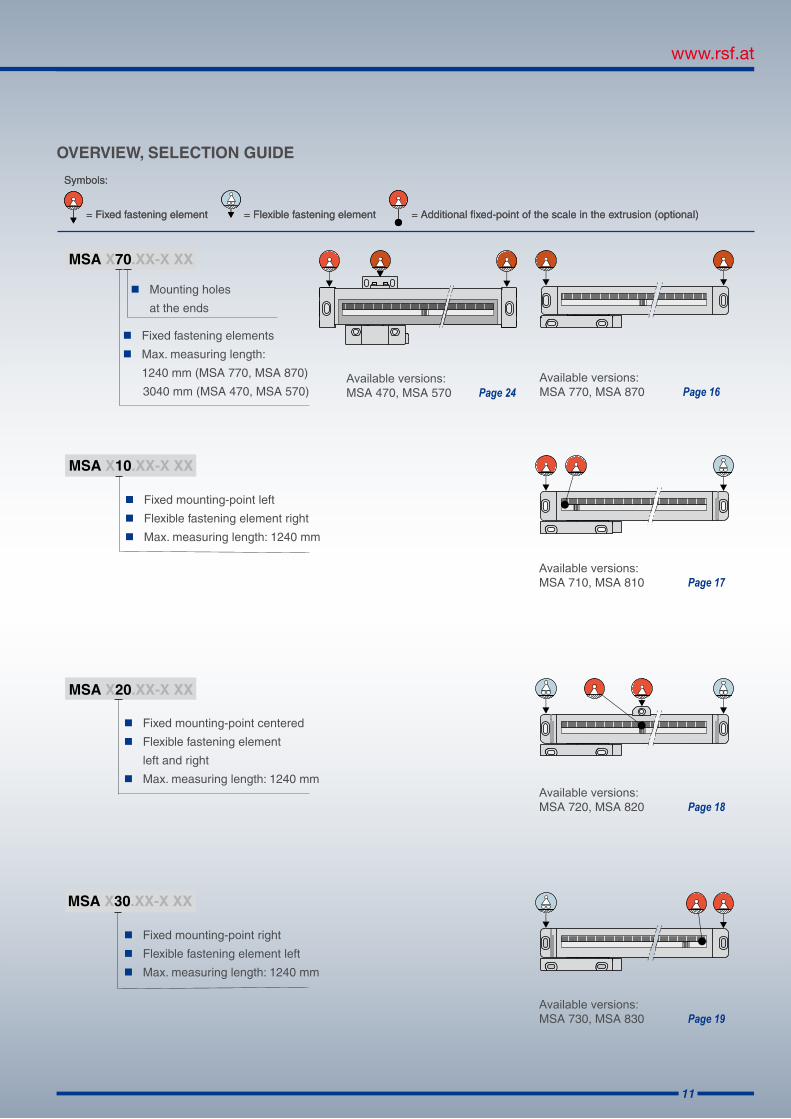
OVERVIEW, SELECTION GUIDE
Symbols:
= Fixed fastening element = Flexible fastening element = Additional fixed-point of the scale in the extrusion (optional)
MSA X70.XX-X XX
MSA X20.XX-X XX
MSA X30.XX-X XX
MSA X10.XX-X XX
Mounting holes
at the ends
Available versions:MSA 710, MSA 810
Page 17
Available versions:MSA 720, MSA 820
Page 18
Available versions:MSA 730, MSA 830
Page 19
Available versions:MSA 770, MSA 870
Page 16
Available versions:MSA 470, MSA 570
Page 24
Fixed fastening elements
Max. measuring length:
1240 mm (MSA 770, MSA 870)
3040 mm (MSA 470, MSA 570)
Fixed mounting-point left
Flexible fastening element right
Max. measuring length: 1240 mm
Fixed mounting-point centered
Flexible fastening element
left and right
Max. measuring length: 1240 mm
Fixed mounting-point right
Flexible fastening element left
Max. measuring length: 1240 mm
Symbols:
= Fixed fastening element = Flexible fastening element = Additional fixed-point of the scale in the extrusion (optional)

12
OVERVIEW, SELECTION GUIDE
MSA X21.XX-X XX
MSA X31.XX-X XX
MSA X11.XX-X XX
MSA X71.XX-X XX
Mounting holes along the scale unit
Fixed mounting-point left
All other fastening
elements flexible
Max. measuring length: 3040 mm
(only at 20 µm grating pitch)
Fixed mounting-point centered
All other fastening
elements flexible
Max. measuring length: 3040 mm
(only at 20 µm grating pitch)
Fixed mounting-point right
All other fastening
elements flexible
Max. measuring length: 3040 mm
(only at 20 µm grating pitch)
MSA 771, MSA 871 Page 20
MSA 711, MSA 811 Page 21
MSA 721, MSA 821 Page 22
MSA 731, MSA 831 Page 23
MSA 471, MSA 571 Page 25
MSA 411, MSA 511 Page 26
MSA 421, MSA 521 Page 27
MSA 431, MSA 531 Page 28
Fixed fastening elements
Max. measuring length: 3040 mm
(only at 20 µm grating pitch)
Symbols:
= Fixed fastening element = Flexible fastening element = Additional fixed-point of the scale in the extrusion (optional)

13
Output signals and integrated subdividing
0 = sinusoidal voltage signals 1 Vpp2 = square-wave signals, times 13 = square-wave signals, times 24 = square-wave signals, times 205 = square-wave signals, times 25
6 = square-wave signals, times 57 = square-wave signals, times 108 = square-wave signals, times 509 = square-wave signals, times 100
MSA XXX . XX-X XX
MSA XXX . XX-X XX
MSA XXX . XX-X XX
MSA XXX . XX-X XX
MSA 730 . 63-1 PF
NOMENCLATURE
Grating pitch
0 = 8 µm1 = 10 µm3 = 20 µm
)Reachable system resolution [µm] = : 4 grating pitch [µm]
subdividing(
Version of the switch signal (only for Linear Encoders with actuator magnets)
-0 = without switch signals-1 = TTL output (active high)-2 = open collector output (active high impedance)-3 = TTL output (active low)-4 = open collector output (active low)
Possible options
K = distance-coded reference marks N = all reference marks active P = air inlet M5 F = fixed point-bonding scale with extrusion B = glass ceramic scale
Example
Small cross section, reading head with connecting cable, mounting holes at the ends,fixed mounting point right, flexible fastening element left
Square-wave signals, integrated subdividing times 5
Grating pitch 20 µm
Switch signal with TTL output (activ high)
Air inlet, fixed point-bonding scale with the extrusion

14
TECHNICAL DATA MSA 4, MSA 5, MSA 7, MSA 8 SERIES
Scale model
electronic version
Output signals
System resolution
[µm]
Accuracy grades [µm/m]
Grating pitch [µm]
Integrated interpolation
Max. velocity
[m/s]
Max. output frequency
[kHz]
MSA xxx.03 1 Vpp
dep. on external interpolation
±3, ±5 20 -- 2.0 100
MSA xxx.01 1 Vpp
dep. on external interpolation
±3, ±5 10 -- 2.0 200
MSA xxx.00 1 Vp
dep. on external interpolation
±2, ±3, ±5 8 -- 2.0 250
Edge separation amin
MSA xxx.23 5.0 ±3, ±5 20 times 1 2.00 1.25 µs
MSA xxx.33 2.5 ±3, ±5 20 times 2 2.00 625 ns
MSA xxx.63 1.0 ±3, ±5 20 times 5 2.00 250 ns
MSA xxx.73 0.5 ±3, ±5 20 times 10 1.92 250 ns
MSA xxx.61 0.5 ±3, ±5 10 times 5 1.92 250 ns
MSA xxx.71 0.25 ±3, ±5 10 times 10 0.96 250 ns
MSA xxx.51 0.1 ±3, ±5 10 times 25 0.77 125 ns
MSA xxx.81 0.05 ±3, ±5 10 times 50 0.38 125 ns
MSA xxx.30 1.0 ±2, ±3, ±5 8 times 2 2.00 250 ns
MSA xxx.70 0.2 ±2, ±3, ±5 8 times 10 0.77 250 ns
MSA xxx.80 0.04 ±2, ±3, ±5 8 times 50 0.30 125 ns
MSA xxx.90 0.02 ±2, ±3, ±5 8 times 100 0.15 125 ns

15
Standard measuring lengths (ML): [mm]
70, 120, 170, 220, 270, 320, 370, 420, 470, 520, 570, 620, 670, 720, 770, 820, 870, 920, 970, 1040, 1140, 1240, 1340, 1440, 1540, 1640, 1740, 1840, 1940, 2040, 2240, 2440, 2640, 2840, 3040 (only possible with 20 µm grating pitch), (8 or 10 µm grating pitch only possible up to measuring length 1140 mm)(other measuring lengths on request)
Scale unit: Glass scale (α 8.5 x 10⁻⁶/K) Glass ceramic scale (α 0 x 10-6/K) up to ML 1440 mm (longer measuring lengths on request)
Location of reference mark (RI):
Distance-coded reference mark (K) after travelling max. 20 mm the absolute position is available
Optional: one reference mark at any location additional reference marks can be selected by distances of n x 50 mm
Required moving force: With standard sealing lips: < 2.0 N
With low drag respectively without any sealing lips: < 0.1 N
Environmental sealing acc. EN 60529:
With standard sealing lips: IP 53
With DA 400: IP 64 (see Page 33)
Permissible vibration: 100 m/s2 (40 up to 2000 Hz)
Permissible shock: 200 m/s2 (8 ms)
Permissible temperature: –20 °C up to +70 °C (storage) 0 °C up to +50 °C (operation)
Weight of Linear Encoder (approx.):
MSA 470, MSA 570: 460 g + 2.5 g/mm (ML)MSA 4x1, MSA 5x1: 295 g + 2.5 g/mm (ML)+ 175 g (reading head without cable)
MSA 7xx , MSA 8xx: 75 g + 0,57 g/mm (ML)+ 50 g (reading head MSA 7xx without cable)+ 65 g (reading head MSA 8xx without cable)
Weight of cable (approx.): 30 g/m
Power supply: Sinusoidal voltage signals 1 Vpp +5 V ±5 %, max. 150 mA (unloaded)
Square-wave signals via Line Driver +5 V ±5 %, max. 180 mA (unloaded)
RoHS-conformity: The Linear Encoders of the MSA 4, MSA 5, MSA 7 and MSA 8 series comply with the guideline of the RoHS-directive 2011/65/EU on the restriction of the use of certain hazardous substances in electrical and electronic equipment

16
Dimensions, mounting tolerances MSA 770:
Dimensions, mounting tolerances MSA 870:
MSA 870
MSA 770
MSA 770, MSA 870

17
MSA 810
Dimensions, mounting tolerances MSA 710:
Dimensions, mounting tolerances MSA 810:
MSA 710
MSA 710, MSA 810

18
MSA 820
Dimensions, mounting tolerances MSA 720:
Dimensions, mounting tolerances MSA 820:
MSA 720
MSA 720, MSA 820

19
Dimensions, mounting tolerances MSA 730:
Dimensions, mounting tolerances MSA 830:
MSA 830
MSA 730
MSA 730, MSA 830

20
MSA 871
Dimensions, mounting tolerances MSA 771:
Dimensions, mounting tolerances MSA 871:
MSA 771
MSA 771, MSA 871

21
MSA 811
Dimensions, mounting tolerances MSA 711:
Dimensions, mounting tolerances MSA 811:
MSA 711
MSA 711, MSA 811

22
Dimensions, mounting tolerances MSA 721:
Dimensions, mounting tolerances MSA 821:
MSA 721, MSA 821
MSA 821
MSA 721

23
MSA 831
Dimensions, mounting tolerances MSA 731:
Dimensions, mounting tolerances MSA 831:
MSA 731, MSA 831
MSA 731

24
Dimensions, mounting tolerances MSA 470:
MSA 470
MSA 570
MSA 470, MSA 570
Dimensions MSA 570:

25
Dimensions, mounting tolerances MSA 571:
Dimensions MSA 571:
MSA 571
MSA 471
MSA 471, MSA 571

26
MSA 511
MSA 411
MSA 411, MSA 511
Dimensions MSA 511:
Dimensions, mounting tolerances MSA 411:

27
MSA 521
Dimensions, mounting tolerances MSA 421:
MSA 421
MSA 421, MSA 521
Dimensions MSA 521:

28
MSA 531
Dimensions, mounting tolerances MSA 431:
MSA 431
MSA 431, MSA 531
Dimensions MSA 531:

29
Standard measuring lengths (ML): [mm]50, 70, 120, 170, 220, 270, 320, 370, 420, 470, 520
Scale unit: Glass scale (α 8.5 x 10⁻⁶/K)
Location of reference mark (RI):- Distance-coded reference mark (K) after travelling max. 20 mm the absolute position is available
- One reference mark in the middle of measuring length, or 10 mm from either end of measuring length (excluding ML 50 mm)
- Optional: one reference mark at any location, additional reference marks can be selected by distances of n x 25 mm
Required moving force: < 1 N
Environmental sealing acc. EN 60529: IP 53- With DA 400: IP 64 (see page 33)
Scale model
electronic version
Output signals
System resolution
[µm/m]
Accuracy grades [µm/m]
Grating pitch [µm]
Integrated interpolation
Max. velocity
[m/s]
Max. output frequency
[kHz]
MSA 170.03 1 Vpp
dep. on external interpolation
±3, ±5 20 -- 1.0 50
Edge separation amin
MSA 170.23 5.0 ±3, ±5 20 times 1 1.0 3.3 µs
MSA 170.63 1.0 ±3, ±5 20 times 5 1.0 500 ns
MSA 170.73 0.5 ±3, ±5 20 times 10 1.0 300 ns
MSA 170.53 0.2 ±3, ±5 20 times 25 0.64 300 ns
MSA 170.83 0.1 ±3, ±5 20 times 50 0.32 300 ns
Permissible vibration: 100 m/s2 (40 to 2000 Hz)
Permissible shock: 150 m/s2 (8 ms)
Permissible temperature: –20 °C to +70 °C (storage), 0 °C to +50 °C (operation)
Weight (approx.): 20 g + 0.17 g/mm (ML) +35 g (reading head without cable)
Power supply: +5 V ±5 % max. 75 mA (unloaded) 1 Vpp, max. 120 mA (unloaded)
RoHS-conformity:The Linear Encoders of the MSA 170 series comply with the guideline of the RoHS- directive 2011/65/EU on the restriction of the use of certain hazardous substances in electrical and electronic equipment
MSA 170

30
Standard measuring lengths (ML): [mm]70, 120, 170, 220, 270, 320, 370, 420, 470, 520, 620, 720, 770,820, 920, 1040, 1140, 1240 (other ML on request)
Scale unit: Glass scale (α 8.5 x 10⁻⁶/K)
Free positionable actuator magnets for special functions:The position of the two switch-points (S1 und S2) can be selected by the customer within measuring length.
Location of reference mark (RI):- One reference mark in the middle of measuring length, or 35 mm from either end of measruring length
- Optional: one reference mark at any location, additional reference marks can be selected by distances of n x 50 mm
Required moving force: < 1 N
Environmental sealing acc. EN 60529: IP 53- With DA 400: IP 64 (see page 33)
Permissible vibration: 150 m/s2 (40 to 2000 Hz)Permissible shock: 300 m/s2 (8 ms)
Permissible temperature: –20 °C to +70 °C (storage), 0 °C to +50 °C (operation)
Weight (approx.): 250 g + 1.34 g/mm (ML) + 210 g (reading head without cable)
Power supply: +5 V ±5 %, max. 120 mA (unloaded)
RoHS-conformity:The Linear Encoders of the MSA 373, 374, 375 series comply with the guideline of the RoHS- directive 2011/65/EU on the restriction of the use of certain hazardous substances in electrical and elec-tronic equipment.
ACCESSORY: CB8-150 COUPLING BAR (ONLY FOR MSA 373 AND MSA 375)
Axis distance: 150 mm (other axis distances on request)Included in delivery: 2 hexagone socket screws M8 x 20 ISO 4762 for mounting
Scale model
electronic version
Output signals
System resolution
[µm/m]
Accuracy grades [µm/m]
Grating pitch [µm]
Integrated interpolation
Max. velocity
[m/s]
Max. output frequency
[kHz]
MSA 37x.65 5 µm ±10 100 times 5 1,0 1.6 µs
MSA 37x.55 1 µm ±10 100 times 25 1,0 800 ns
MSA 373
MSA 373, MSA 374, MSA 375

31
ACCESSORY: CB8-150 COUPLING BAR (ONLY FOR MSA 373 AND MSA 375)
MSA 373
MSA 374 MSA 375

32
SUB MIN-D Connector LD15 15-pin (weight: 25 g)
Pin assignment (view on pins)
Sensor: The sensor-Pins are bridged in the chassis with the particular power supply
*Version without switch signals (version 0) = nc
Shield is additionally connected with the chassis
Connector L121 12-pin(weight: 75 g)
Female connector K121 12-pin
Female connector KM121 12-pin
Pin assignment male connector (view on pins)
CONNEI
Sensor: The sensor-pins are bridged in the chassis with the particular power supply
Shield is additionally connected with the chassis
Connector L120 12-pin(weight: 20 g)
Female connector K120 12-pin
Shield is additionally connected with the chassis
*Version without switch signals (version 0) = nc
Pin assignment male connector (view on pins)
DIN
MALE AND FEMALE CONNECTORS, PIN ASSIGNMENTS
L120, K120
Pin A B C D E F G H J K L M
Sinusoidal voltage signals 1 Vpp
nc 0 V A1 A1 A2 S1* RI RI S2* +5 V A2 nc
Square-wave signals via Line Driver
nc 0 V T1 T1 T2 S1* RI RI S2* +5 V T2 US
LD15
Pin 1 2 3 4 5 6 7 8 9 10 11 12 13 14 15
Sinusoidal voltage signals 1 Vpp
nc 0 Vsensor
nc RI A2 A1 +5 Vsensor
+5 V 0 V S1* S2* RI A2 A1 shield
Square-wave signals via Line Driver
nc 0 Vsensor
US RI T2 T1 +5 Vsensor
+5 V 0 V S1* S2* RI T2 T1 shield
L121, K121, KM121
Pin 1 2 3 4 5 6 7 8 9 10 11 12
Sinusoidal voltage signals 1 Vpp
A2 +5 Vsensor
RI RI A1 A1 nc A2 nc 0 V 0 V sensor
+5 V
Square-wave signals via Line Driver
T2 +5 Vsensor
RI RI T1 T1 US T2 nc 0 V 0 V sensor
+5 V

33
AIR PRESSURE UNIT DA 400
For applications where the Linear Encoders are used in harsh environments (e.g. oil and coolants), RSF offers a method of extra protection beyond the enclosed unit´s standard set of sealing lips.
An air inlet can be provided for filtered air to be input into the scale spar. A limiting flow restrictor helps set the optimum overpressure airflow inside the scale spar to further prevent oil and coolants from entering the seal.
To ensure fail-safe operation of the Linear Encoder, only „clean“ and pretreated air should be put into the scale housing.
The scale cavity should have a flow rate of about 7 to 10 l/min (per Linear Encoder). The setted overpressure (adjustable from 0.5 to 3 x 10⁵ Pa) depends on the number of the connected Linear Encoders (max. 10 Linear Encoders) and the design of the compressed-air supply.
DA 400 consists of three filter stages (prefilter, fine filter and activated carbon filter) and a pressure regulator with pres-sure gauge.
To reach the promised accuracy of the measuring system, the air temperature has to be +20 °C.

34
PRODUCT DIRECTORY
MS 2x SeriesReflective scanning Linear Encoder with integrated mounting control (only MS 25, MS 26)Easy mounting; no test box or oscilloscope needed Quality of the scanning signals is directly visible at the reading head via a 3-coloured LED Two independent switch signals for individual special functions Position of reference mark selectable High insensitivity against contaminationHigh traversing speedIntegrated subdividing: up to times 100 interpolationMax. measuring length
Glass scale: 3140 mmSteel tape scale: 20 000 mm
MS 30, MS 31 SeriesReflective scanning Linear EncoderTwo independent switch signals for individual special functions Position of reference mark selectableSmall dimensionsEasy mounting as a result of large mounting tolerancesHigh traversing speedHigh insensitivity against contaminationIntegrated subdividing: up to times 100 interpolationMax. measuring length Glass scale: 3140 mm Steel tape scale: 11 940 mm
MS 82 SeriesInterferential Linear EncoderTwo switch tracks for individual special functionsNon-contact reflective scanningHigh traversing speedSmall dimensionsScale unit: glass scale or ROBAX® glass cramic scale with phasse grating Max. measuring length Glass scale: 3140 mm Glass ceramic: 1840 mm
MS 45 SeriesReflective scanning Linear Encoder with integrated mounting control Easy mounting; no test box or oscilloscope needed Quality of the scanning signals is directly visible at the reading head via a 3-coloured LEDSmall dimensionsEasy mounting as a result of large mounting tolerancesHigh insensitivity against contaminationHigh traversing speedIntegrated subdividing: up to times 100 interpolationMax. measuring length Steel tape scale: 30 000 mm
MS 14 SeriesReflective scanning Linear Encoder with integrated mounting Easy mounting; no test box or oscilloscope needed Quality of the scanning signals is directly visible at the reading head via a 3-coloured LEDExtremely small dimensionsEasy mounting as a result of large mounting tolerancesHigh insensitivity against contaminationHigh traversing speedIntegrated subdividing: up to times 100 interpolationMax. measuring length Steel tape scale: 20 000 mm
MSR 40Modular Rotary Encoder with steel tape scale Different versionsFull-circle or segment version Grating pitch: 200 µm Accuracy of the grating (stretched): ±30 µm/m High rotational speed resp. circumferential speed Integrated subdividing: up to times 100 interpolation
MSR 20Segment version Grating pitch: 40 µmAccuracy of the grating (stretched): ±15 µm/mHigh circumferential speedIntegrated subdividing: up to times 100 interpolation
DG 118, DG 120Rotary Encoder for universal applicationStandard line/rev.: graduated from 100 to 5400
DIT 10, DIT 30, DIT 48Precision Measuring ProbesFor universal applicationsStroke length: 10, 30, 48 mmMounting on shaft sleeveMounting with two tapped holes on body (DIT 30, DIT 48)With cable lifterIntegrated pneumatic lifter optionalSealing bellows optional (DIT 30, DIT 48)

35
Precision GraduationsLength graduations on glass, chromium coatedLength graduations on steel tape, gold coated or polished surfaceCircular graduations on glass, chromium coatedGraticules Antireflex coatings Coatings
Cable SystemsIndividual cable designHybrid cableTrailing cableSystem solutionsFunction control
UFC 430 USB-Interface-Module USB-interface acc. to spec. 2.0 Available inputs: 1 Vpp max. 200 kHz or TTL (RS 422) max. 500 kHzInterpolation: up to times 400 for measuring systems with output 1 Vpp and up to times 4 for measuring systems with square-wave Line Driver signalsThree 15-pin Sub-D female connectors for 3 encoder inputs 32 Bit counter with preset and latch register
IFC 430R Encoder-interface-card PC interface board for quadrature encoder signal evaluation: times 1, -2 or -4Latch logic for measured values Three counter channels à 32 bit, one load and two latch registers for each channelPC busSignal edge separation: up to 100 ns Demo program with examples and driver software
MSA 65x, MSA 35xSealed Linear EncodersFor retrofit of machine toolsLarge mounting tolerances Guided by ball bearingsDistance-coded reference marks Two sets of sealing lips for additional contamination protection (only MSA 352)Mounting holes on the extrusion ends (MSA 650, MSA 35x)Mounting holes on top of the extrusion - improves vibration rating (MSA 651) Mounting supports (MSA 35x)Max. measuring lengths: MSA 650: 1740 mm MSA 651: 2240 mm MSA 35x: 3040 mm
Z 300 Digital Readoutsfor universal applicationNumber of alphanumeric axis: 2 or 3 Monochrome flat screenClearly readable displayRobust cast aluminum housing Splash-proof fulltravel keypadPractice-oriented functionsStandard version for turning, drilling or milling machine

Date 08/2013 Art.Nr. 1082066-01 Doc.Nr. D1082066-00-A-01 Technical adjustments in reserve!
A-5121 Tarsdorf +43 (0)6278 / 8192-0 FAX +43 (0)6278 / 8192-79 e-mail: [email protected] internet: www.rsf.at
Ges.m.b.H.
Certified acc. toDIN EN ISO 9001
DIN EN ISO 14001
Linear EncodersDigital ReadoutsPrecision Graduations Cable Systems
DISTRIBUTION CONTACTS
AustriaCorporate
Head Quarters
RSF Elektronik Ges.m.b.H.A-5121 Tarsdorf
+43 (0) 62 78 81 92-0 +43 (0) 62 78 81 92-79
e-mail: [email protected]: www.rsf.at
China RSF Elektronik GmbH Tian Wei San Jie,Area A, Beijing Tianzhu Airport Industrial ZoneShunyi District101312 BeijingP.R. China
+86 (0) 10 80 42 02 88 +86 (0) 10 80 42 02 90
e-mail: [email protected]: www.rsf.cn
Korea HEIDENHAIN LTD. 202 Namsung Plaza, 9th Ace Techno Tower, 130, Digital-Ro, Geumcheon-Gu, Seoul, Korea 153-782
+82 (0) 2 20 28 74 30e-mail: [email protected]: www.rsf.co.kr
USA HEIDENHAIN CORPORATION333 East State ParkwaySchaumburg, IL 60173-5337
+1 847 490 11 91e-mail: [email protected]: www.rsf.net
HEIDENHAIN (GB) Ltd.200 London RoadBurgess HillWest Sussex RH15 9RD
+44 (0)1444 238550 +44 (0)1444 870024
e-mail: [email protected]
HEIDENHAIN FRANCE sarl2 Avenue de la Christallerie92310 Sèvres
+33 1 41 14 30 00 +33 1 41 14 30 30
e-mail: [email protected]
United Kingdom
France
Switzerland RSF Elektronik (Schweiz) AGVieristrasse 14CH-8603 Schwerzenbach
+41 44 955 10 50 +41 44 955 10 51
e-mail: [email protected]: www.rsf.ch
HEIDENHAIN ITALIANA S.r.l.Via Asiago, 1420128 Milano (MI)
+39 02 27075-1 +39 02 27075-210
e-mail: [email protected]
Italy
Slovenia RSF Elektronik prodaja, d.o.o.Jozeta Jame 14SI-1210 Ljubljana
+386 (0) 1 519 88 80 +386 (0) 1 519 88 80
e-mail: [email protected]
Copyright © 2022 FDOKUMEN