HRM and Workplace Motivation: Incremental and Threshold Effects
Upload
khangminh22Category
view
2download
0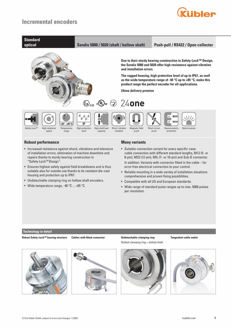
1kuebler.com
IP-40°... +85°C
© Fritz Kübler GmbH, subject to errors and changes. 11/2021
Incremental encoders
Push-pull / RS422 / Open collectorStandardoptical Sendix 5000 / 5020 (shaft / hollow shaft)
Optical sensor
Due to their sturdy bearing construction in Safety-Lock™ Design, the Sendix 5000 and 5020 offer high resistance against vibration and installation errors.
The rugged housing, high protection level of up to IP67, as well as the wide temperature range of -40 °C up to +85 °C, make this product range the perfect encoder for all applications.
24one delivery promise
Safety-LockTM High rotationalspeed
Temperaturerange
High protection level
High shaft loadcapacity
Shock / vibrationresistant
Magnetic fieldproof
Short-circuitproof
Reverse polarityprotection
Robust performance• Increased resistance against shock, vibrations and tolerance
of installation errors, elimination of machine downtime and repairs thanks to sturdy bearing construction in “Safety-LockTM Design”.
• Ensures highest safety against field breakdowns and is thus suitable also for outside use thanks to its resistant die-cast housing and protection up to IP67.
• Undetachable clamping ring on hollow shaft encoders.• Wide temperature range, -40 °C ... +85 °C.
Many variants• Suitable connection variant for every specific case:
cable connection with different standard lengths, M12 (5- or 8-pin), M23 (12-pin), MIL (7- or 10-pin) and Sub-D connector.
In addition: Variants with connector fitted in the cable – for error-free electrical connection to your control.
• Reliable mounting in a wide variety of installation situations: comprehensive and proven fixing possibilities.
• Compatible with all US and European standards.• Wide range of standard pulse ranges up to max. 5000 pulses
per revolution.
Technology in detail
Undetachable clamping ring
Slotted clamping ring + slotted shaft
Cables with fitted connectorRobust Safety-Lock™ bearing structure Tangential cable outlet

2 kuebler.com © Fritz Kübler GmbH, subject to errors and changes. 11/2021
Order codeShaft version
8.5000Type
. X X X X . XXXXa b c d e
We offer for all encoders configured with the underlined preferential options our free of charge 24one delivery promise.
Orders placed on working days before 9AM CET are manufactured and ready for dispatch the same day. The 24one delivery promise is limited to 20 pieces per delivery.
Incremental encoders
Push-pull / RS422 / Open collectorStandardoptical Sendix 5000 / 5020 (shaft / hollow shaft)
a Flange 5 = synchro flange, IP66/IP67 ø 50.8 mm [2“] 6 = synchro flange, IP65 ø 50.8 mm [2“] 7 = clamping flange, IP66/IP67 ø 58 mm [2.28“] 8 = clamping flange, IP65 ø 58 mm [2.28“] A = synchro flange, IP66/IP67 ø 58 mm [2.28“] 1)
B = synchro flange, IP65 ø 58 mm [2.28“] 1)
C = square flange, IP66/IP67 63.5 mm [2.5“] D = square flange, IP65 63.5 mm [2.5“] G = Euro flange, IP66/IP67 ø 115 mm [4.53“] 2)
1 = servo flange, IP66/IP67 ø 50.8 mm [2“] 3)
2 = servo flange, IP65 ø 50.8 mm [2“] 3)
3 = square flange, IP66/IP67 52.3 mm [2.06“] 3)
4 = square flange, IP65 52.3 mm [2.06“] 3)
E = servo flange, IP66/IP67 ø 63.5 mm [2.5“] 3)
F = servo flange, IP65 ø 63.5 mm [2.5“] 3)
b Shaft (ø x L), with flat 1 = ø 6 x 10 mm [0.24 x 0.39“] 2 = ø 1/4 x 5/8“ (6.35 x 15.875 mm) 6 = ø 8 x 15 mm [0.32 x 0.59“] 3 = ø 10 x 20 mm [0.39 x 0.79“] 4 = ø 3/8 x 5/8“(9.5 x 15.875 mm) B = ø 11 x 33 mm [0.43 x 1.30“], with feather key shaft slot 4)
5 = ø 12 x 20 mm [0.47 x 0.79“]
7 = ø 1/4 x 7/8“ 3)
8 = ø 3/8 x 7/8“ 3)
c Output circuit (with inverted signal) / supply voltage 4 = RS422 / 5 V DC 1 = RS422 / 5 ... 30 V DC 2 = push-pull (7272 compatible) / 5 ... 30 V DC 5 = push-pull / 10 ... 30 V DC
3 = open collector / 5 ... 30 V DC 3)
8 = push-pull (7272 compatible), without capacitor / 5 ... 30 V DC 1) 3) 6)
d Type of connection – cable 1 = axial cable, 1 m [3.28‘] PVC A = axial cable, special length PVC *) 2 = radial cable, 1 m [3.28‘] PVC B = radial cable, special length PVC *)
Type of connection – connector P = axial M12 connector, 5-pin 5)
R = radial M12 connector, 5-pin 5)
3 = axial M12 connector, 8-pin 4 = radial M12 connector, 8-pin 7 = axial M23 connector, 12-pin 8 = radial M23 connector, 12-pin Y = radial MIL connector, 10-pin W = radial MIL connector, 7-pin 5)
9 = radial MIL connector, 6-pin 3) 5)
Type of connection – connector with cable L = radial cable with M12 connector, 8-pin, special length PVC *) M = radial cable with M23 connector, 12-pin, special length PVC *) N = radial cable with Sub-D connector, 9-pin, special length PVC *)
*) Available special lengths (connection types A, B, L, M, N): 0.3, 0.5, 1, 2, 3, 4, 5, 6, 8, 10, 12, 15, 20 m [0.98, 1.64, 3.28, 6.56, 9.84, 13.12, 16.40, 19.69, 26.25, 32.80, 39.37, 49.21, 65.62‘] order code expansion .XXXX = length in dm ex.: 8.5000.814A.1024.0030 (for cable length 3 m)
e Pulse rate 1, 2, 4, 5, 10, 12, 14, 20, 25, 28, 30, 32, 36, 50, 60, 64, 80, 100, 120, 125, 150, 180, 200, 240, 250, 256, 300, 342, 360, 375, 400, 500, 512, 600, 625, 720, 800, 900, 1000, 1024, 1200, 1250, 1500, 1800, 2000, 2048, 2500, 3000, 3600, 4000, 4096, 5000 (e.g. 100 pulses => 0100)
Optional on request - other pulse rates - Ex 2/22 (not for type of connection L, M, N) 7)
- surface protection salt spray Salt spray tested as standard type (deliverable as from 1 unit) 8.5000.73X4.XXXX-C
1) 24one type only in conjunction with shaft type 1.2) Only in conjunction with shaft type B.3) US version.4) Only in conjunction with flange type G.5) Without inverted signal.6) Attention: no CE types!7) For the cable connection type, cable material PUR.

3kuebler.com© Fritz Kübler GmbH, subject to errors and changes. 11/2021
Incremental encoders
Push-pull / RS422 / Open collectorStandardoptical Sendix 5000 / 5020 (shaft / hollow shaft)
a Flange 1 = with spring element, long, IP66/IP67 2 = with spring element, long, IP65 3 = with torque stop, long, IP66/IP67 4 = with torque stop, long, IP65 7 = with stator coupling, IP66/IP67 ø 65 mm [2.56“] 8 = with stator coupling, IP65 ø 65 mm [2.56“] C = with stator coupling, IP66/IP67 ø 63 mm [2.48“] D = with stator coupling, IP65 ø 63 mm [2.48“]
5 = with stator coupling, IP66/IP67 ø 57.2 mm [2.25“] 1)
6 = with stator coupling, IP65 ø 57.2 mm [2.25“] 1)
b Through hollow shaft 1 = ø 6 mm [0.24“] 2 = ø 1/4“ 9 = ø 8 mm [0.32“] 4 = ø 3/8“ 3 = ø 10 mm [0.39“] 5 = ø 12 mm [0.47“] 6 = ø 1/2“ A = ø 14 mm [0.55“] 8 = ø 15 mm [0.59“] 7 = ø 5/8“
c Output circuit (with inverted signal) / supply voltage 4 = RS422 / 5 V DC 1 = RS422 / 5 ... 30 V DC 2 = push-pull (7272 compatible) / 5 ... 30 V DC 5 = push-pull / 10 ... 30 V DC
3 = open collector / 5 ... 30 V DC 1)
8 = push-pull (7272 compatible), without capacitor / 5 ... 30 V DC 1) 2)
d Type of connection – cable 1 = radial cable, 1 m [3.28‘] PVC A = radial cable, special length PVC *) E = tangential cable, 1 m [3.28‘] PVC F = tangential cable, special length PVC *)
Type of connection – connector R = radial M12 connector, 5-pin 3)
2 = radial M12 connector, 8-pin 4 = radial M23 connector, 12-pin 6 = radial MIL connector, 7-pin 7 = radial MIL connector, 10-pin
Type of connection – connector with cable H = tangential cable, 0.3 m [0.98‘] PVC, incl. M12 connector, 8-pin for central fastening L = tangential cable with M12 connector, 8-pin, special length PVC *) M = tangential cable with M23 connector, 12-pin, special length PVC *) N = tangential cable with Sub-D connector, 9-pin, special length PVC *)
*) Available special lengths (connection types A, F, L, M, N): 0.3, 0.5, 1, 2, 3, 4, 5, 6, 8, 10, 12, 15, 20 m [0.98, 1.64, 3.28, 6.56, 9.84, 13.12, 16.40, 19.69, 26.25, 32.80, 39.37, 49.21, 65.62‘] order code expansion .XXXX = length in dm ex.: 8.5020.234A.1024.0030 (for cable length 3 m)
e Pulse rate 1, 2, 4, 5, 10, 12, 14, 20, 25, 28, 30, 32, 36, 50, 60, 64, 80, 100, 120, 125, 150, 180, 200, 240, 250, 256, 300, 342, 360, 375, 400, 500, 512, 600, 625, 720, 800, 900, 1000, 1024, 1200, 1250, 1500, 1800, 2000, 2048, 2500, 3000, 3600, 4000, 4096, 5000 (e.g. 100 pulses => 0100)
Optional on request - other pulse rates - Ex 2/22 (not for type of connection E, F, H, L, M, N) 4)
- surface protection salt spray Salt spray tested as standard type (deliverable as from 1 unit) 8.5020.18X2.XXXX-C 8.5020.1AX2.XXXX-C
Order codeHollow shaft
8.5020 . X X X X . XXXXType a b c d e
We offer for all encoders configured with the underlined preferential options our free of charge 24one delivery promise.
Orders placed on working days before 9AM CET are manufactured and ready for dispatch the same day. The 24one delivery promise is limited to 20 pieces per delivery.
1) US version.2) Attention: no CE types!3) Without inverted signal.4) For the cable connection type, cable material PUR.
4 kuebler.com
SW7 [0,28]0,25
8 0,31
0,16
0,287
m8
4
M4 R
30 1,18
0,16
15
15,5
[0.6
1]
]87.1[
15 [0
.59]
2,54
[0.5
9]
]68.1[ 2,74
D1
H7
© Fritz Kübler GmbH, subject to errors and changes. 11/2021
Incremental encoders
Push-pull / RS422 / Open collectorStandardoptical Sendix 5000 / 5020 (shaft / hollow shaft)
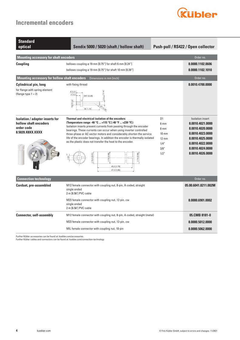
Connection technology Order no.
Cordset, pre-assembled M12 female connector with coupling nut,8-pin,A coded, straightsingle ended 2 m [6.56‘] PVC cable
05.00.6041.8211.002M
M23 female connector with coupling nut,12-pin,cwsingle ended 2 m [6.56‘] PVC cable
8.0000.6901.0002
Connector, self-assembly M12 female connector with coupling nut,8-pin,A coded, straight (metal) 05.CMB 8181-0
M23 female connector with coupling nut,12-pin,cw 8.0000.5012.0000
MIL female connector with coupling nut,10-pin 8.0000.5062.0000
Further Kübler accessories can be found at: kuebler.com/accessoriesFurther Kübler cables and connectors can be found at: kuebler.com/connection-technology
Mounting accessory for shaft encoders Order no.
Coupling bellows coupling ø 19 mm [0.75“] for shaft 6 mm [0.24“]
bellows coupling ø 19 mm [0.75“] for shaft 10 mm [0.39“]
8.0000.1102.0606
8.0000.1102.1010
Mounting accessory for hollow shaft encoders Dimensions in mm [inch] Order no.
Cylindrical pin, longfor flange with spring element(flange type 1 + 2)
with fixing thread 8.0010.4700.0000
Isolation / adapter inserts for hollow shaft encoders order code 8.5020.X8XX.XXXX
Thermal and electrical isolation of the encoders(Temperature range -40 °C ... +115 °C [-40 °F ... +239 °F] )Isolation inserts prevent currents from passing through the encoder bearings. These currents can occur when using inverter controlled three-phase or AC vector motors and considerably shorten the service life of the encoder bearings. In addition the encoder is thermally isolated as the plastic does not transfer the heat to the encoder.
D1
6 mm
8 mm
10 mm
12 mm
1/4“
3/8“
1/2“
Isolation insert
8.0010.4021.00008.0010.4020.00008.0010.4023.00008.0010.4025.00008.0010.4022.00008.0010.4024.00008.0010.4026.0000

5kuebler.com© Fritz Kübler GmbH, subject to errors and changes. 11/2021
Incremental encoders
Push-pull / RS422 / Open collectorStandardoptical Sendix 5000 / 5020 (shaft / hollow shaft)
Mechanical characteristics
Technical data
Maximum speed IP65 12000 min-1
6000 min-1 (continuous) IP66/IP67 6000 min-1
3000 min-1 (continuous)
Mass moment of inertia shaft version approx. 1.8 x 10⁻⁶ kgm2 hollow shaft version approx. 6 x 10⁻⁶ kgm2
Starting torque IP65 < 0.01 Nm at 20 °C [68 °F] IP66/IP67 < 0.05 Nm
Shaft load capacity radial 100 N axial 50 N
Electrical characteristicsOutput circuit RS422 RS422 Push-pull Push-pull Push-pull Open collector (TTL compatible) (TTL compatible) (HTL/TTL universal, (7272 compatible, (7273) 7272 compatible) without capacitor) Order code 1 4 5, 7 2 8 3
Supply voltage 5 ... 30 V DC 5 V DC (±5 %) 10 ... 30 V DC 5 ... 30 V DC 5 ... 30 V DC 5 ... 30 V DC
Power consumption (no load) typ. 40 mA typ. 40 mA typ. 50 mA typ. 50 mA typ. 50 mA 100 mA max. 90 mA max. 90 mA max. 100 mA max. 100 mA max. 100 mA
Permissible load / channel max. +/- 20 mA max. +/- 20 mA max. +/- 20 mA max. +/- 20 mA max. +/- 20 mA 20 mA sink at 30 V DC
Pulse frequency max. 300 kHz max. 300 kHz max. 300 kHz max. 300 kHz 4) max. 300 kHz max. 300 kHz
Signal level HIGH min. 2.5 V min. 2.5 V min +V - 1.0 V min. +V - 2.0 V min. +V - 2.0 V LOW max. 0.5 V max. 0.5 V max. 0.5 V max. 0.5 V max. 0.5 V
Rising edge time tr max. 200 ns max. 200 ns max. 1 μs max. 1 μs max. 1 μs
Falling edge time tf max. 200 ns max. 200 ns max. 1 μs max. 1 μs max. 1 μs
Short circuit proof outputs 5) yes 6) yes 6) yes yes yes 6) yes
Reverse polarity protection yes no yes no no no of the supply voltage
UL approval file no. E224618
CE compliant acc. to EMC guideline 2014/30/EU RoHS guideline 2011/65/EU
1) With connector: -40 °C [-40 °F], cable fixed: -30 °C [-22 °F], cable moved: -20 °C [-4 °F].2) For MIL connectors: 2500 m/ s2
3) For MIL connectors: 100 m/ s2
4) Max. recommended cable length 30 m [98.43‘].5) If supply voltage correctly applied.6) Only one channel allowed to be shorted-out: at +V= 5 V DC, short-circuit to channel, 0 V, or +V is permitted. at +V= 5 ... 30 V DC, short-circuit to channel or 0 V is permitted.
Weight approx. 0.4 kg [14.11 oz]
Protection acc. to EN 60529 without shaft seal IP65 with shaft seal IP66/IP67
Working temperature range -40 °C 1) ... +85 °C [-40 °F 1) ... +185 °F]
Material shaft stainless steel
Shock resistance acc. to EN 60068-2-27 3000 m/s2, 6 ms 2)
Vibration resistance acc. to EN 60068-2-6 300 m/s2, 10 ... 2000 Hz 3)

6 kuebler.com
11
12
3
4 56
7
89
10 12
AB
CD
E
AB
CDE
F
GH
IJ
AB
CD
E
FG F
AB
CD
E
AB
CDE
F
GH
IJ
AB
CD
E
FG F
AB
CD
E
AB
CDE
F
GH
IJ
AB
CD
E
FG F
© Fritz Kübler GmbH, subject to errors and changes. 11/2021
Incremental encoders
Output circuit Type of connection Cable (isolate unused cores individually before initial start-up)
5000: 1, 2, A, B Signal: 0 V +V 0 Vsens +Vsens A B 0 H 1, 2, 3, 4, 5, 8
5020: 1, A, E, F Core color: WH BN GY PK RD BU GN YE GY PK BU RD shield
Output circuit Type of connection M12 connector, 8-pin
5000: 3, 4, L Signal: 0 V +V A B 0 H 1, 2, 3, 4, 5, 8
5020: 2, H 2), L Pin: 1 2 3 4 5 6 7 8 PH 1)
Output circuit Type of connection M12 connector, 5-pin
5000: P, R Signal: 0 V +V A B 0 H 1, 2, 3, 4, 5, 8
5020: R Pin: 1 2 3 4 5 PH 1)
Output circuit Type of connection M23 connector, 12-pin
5000: 7, 8, M Signal: 0 V +V 0 Vsens +Vsens A B 0 H 1, 2, 3, 4, 5, 8
5020: 4, M Pin: 10 12 11 2 5 6 8 1 3 4 PH 1)
Output circuit Type of connection MIL connector, 7-pin
5000: W Signal: 0 V +V +Vsens A B 0 H 1, 3, 4, 5, 8
5020: 6 Pin: F D E A B C G
Output circuit Type of connection MIL connector, 10-pin
5000: Y Signal: 0 V +V +Vsens A B 0 H 1, 2, 3, 4, 5, 8
5020: 7 Pin: F D E A G B H C I J
Output circuit Type of connection MIL connector, 6-pin
5000: 9 Signal: 0 V +V A B 0 H 1, 3, 4, 5, 8
Pin: A B E D C
Output circuit Type of connection Sub-D connector, 9-pin
5000: N Signal: 0 V +V A B 0 H 1, 2, 3, 4, 5, 8
5020: N Pin: 9 5 1 6 2 7 3 8 PH 1)
1) PH = shield is attached to connector housing.2) With type of connection H shield is not attached to connector housing.
Terminal assignment
MIL connector, 10-pin MIL connector, 6-pinMIL connector, 7-pin Sub-D connector, 9-pin
Top view of mating side, male contact base
M12 connector, 8-pinM12 connector, 5-pin M23 connector, 12-pin
+V: Supply voltage encoder +V DC0 V: Supply voltage encoder ground GND (0 V)0 Vsens / +Vsens: Using the sensor outputs of the encoder, the voltage present can be measured and if necessary increased accordingly.
A, : Incremental output channel AB, : Incremental output channel B0, : Reference signalPH H: Plug connector housing (shield)
Push-pull / RS422 / Open collectorStandardoptical Sendix 5000 / 5020 (shaft / hollow shaft)

7kuebler.com
Fritz Kübler GmbHZähl- und Sensortechnik78054 VS-Schwenningen
= Check item Prüfmaß
-0,2+0,2
Ra 1,6
3x120°
40 1,57
57,4
2,26 2,
81
0,13
43,7 1,72
L
3
47 h7
30
250
,8
0,12
30,45
1,85
1,84
1,2
46,7
71,4
1,8547
0,123
3,3
64 2,52
D
71,4
2,81
1,3935,2
2,0953,2
90,4
3,56
F
1 2 3
E
D
C
B
A
87654321
A
B
C
D
E
4 Z1036
Size: Title:/Benennung:
Type:
Blatt
8.5000.6XX4/Y
Werkstoff:Scale:
1:1
8.5000.5XX3/Y
Material:
Drawingnumber:/Zeichnungsnummer:
Format: A3
Oberfläche:
handlungen verpflichten zu Schadenersatz. 210
24802810
20.06.1601.08.1323.07.09 da
los
1
vervielfältigt noch Dritten zugänglich gemacht oder
/
Surface:
al
Das Urheberrecht an dieser Zeichnung verbleibt uns.
2768-m-H
Date
Sie darf ohne unsere vorherige Zustimmung weder DIN ISO
Bearb.Approv. by
auf andere Weise mißbraucht werden. Zuwieder-
Rev. No./Änd. Nr.Revision Name
10.09.04
Date
Drawn by
Rev. St.
hlName
Maßstab:
Gepr.
5000Typ:
This document is property of Fritz Kübler GmbH, use of this document without written permission is prohibited.
General tolerances
Allgemeintol.
Sheet/
1
1
Ausführung mit MIL-Stecker
M3, 6 [0,24] tief1
[1,1
8]
D Passung L6[0,24] h7 10[0,39]8[0,32] h7 15[0,59]10[0,39] f7 20[0,79]12[0,47] h7 20[0,79]
1/4" h7 5/8"3/8" h7 5/8"1/4" h8 7/8"3/8" h8 7/8"
-0,2+0,2
Ra 1,6
= Check item Prüfmaß
3x120°
481,
89 2,95
75
0,39
38,5 1,52
943,
7
10
46,5 1,83
1
58
1,46
0,39
L
2,28
501,
97
21
37
0,8310
36
f8[1
,42]
D
13,3 0,52
2 3
E
D
C
B
A
87654321
A
B
C
D
E
F
1 4
3
01.08.13
Date
16.07.0923.07.09
20.06.16
210 1404
Date:
All rights reserved in the event of the grant of a patent, utility model or design.Scale:
Rev.Nr.
Offenders will be held liable for the payment of damages.
www.kuebler.comECN
Product family:
Fritz Kübler GmbH
communication of its contents to others without express authorization is prohibited. The reproduction, distribution and utilization of this document as well as the
2768-m-H
1Sheet:
A3
1Z1129
Size:
Drawing number:
8.5000.7XX2/YTitle:
8.5000.8XX1/Y
Material:
50001:1
Approv. by:
Drawn by
losaldada
28102480
This document is property of Fritz Kübler GmbH
General tolerances
DIN ISO
/
M3, 6 [0,24] tief1
Ausführung mit MIL-Stecker
D Passung L6[0,24] h7 10[0,39]8[0,32] h7 15[0,59]10[0,39] f7 20[0,79]12[0,47] h7 20[0,79]
1/4" h7 5/8"3/8" h7 5/8"1/4" h8 7/8"3/8" h8 7/8"
© Fritz Kübler GmbH, subject to errors and changes. 11/2021
Incremental encoders
Synchro flange, ø 50.8 [2] Flange type 5 and 6
1 3 x M3, 6 [0.24] deep
Dimensions shaft versionDimensions in mm [inch]
MIL-connector version
MIL-connector version
Clamping flange, ø 58 [2.28]Flange type 7 and 8
1 3 x M3, 6 [0.24] deep
Push-pull / RS422 / Open collectorStandardoptical Sendix 5000 / 5020 (shaft / hollow shaft)
D Fit L6 [0.24] h7 10 [0.39]8 [0.32] h7 15 [0.59]10 [0.39] h7 20 [0.79]12 [0.47] h7 20 [0.79]
1/4“ h7 5/8“3/8“ h7 5/8“1/4“ h8 7/8“3/8“ h8 7/8“
D Fit L6 [0.24] h7 10 [0.39]8 [0.32] h7 15 [0.59]10 [0.39] h7 20 [0.79]12 [0.47] h7 20 [0.79]
1/4“ h7 5/8“3/8“ h7 5/8“1/4“ h8 7/8“3/8“ h8 7/8“

8 kuebler.com
Fritz Kübler GmbHZähl- und Sensortechnik78054 VS-Schwenningen
= Check item Prüfmaß
-0,2+0,2
Ra 1,6
3x120°
421,
65
943,
7
2,2256,5
2,95
75
38,5 1,52
[1,9
7]
0,16
1,3333,75
1,97
max
.50
0,83
D
L
max.21
h7
50
2,28
58
0,123
0,123
4
47 1,85
1
2 3
E
D
C
B
A
87654321
A
B
C
D
E
F
1 4
Drawingnumber:/Zeichnungsnummer:
1
Size: A3
/Z1130
Format:
Type:Werkstoff:
8.5000.AXX2/Y8.5000.BXX1/Y
Oberfläche:
Blatt
handlungen verpflichten zu Schadenersatz. 3210
24802810
20.06.1601.08.1323.07.0916.07.09 da
daallos
Surface:
vervielfältigt noch Dritten zugänglich gemacht oder
auf andere Weise mißbraucht werden. Zuwieder-
Das Urheberrecht an dieser Zeichnung verbleibt uns.
2768-m-H
Sie darf ohne unsere vorherige Zustimmung weder DIN ISO
12.10.05Drawn byBearb.Approv. by
Revision Rev. No./Änd. Nr. Date
Datehl
Name
Gepr.
Rev. St.
Name
Maßstab:1:1
Scale:
5000
Material:
Typ:
Title:/Benennung:
This document is property of Fritz Kübler GmbH, use of this document without written permission is prohibited.
General tolerances
Allgemeintol.
Sheet/
1
Ausführung mit MIL-Stecker
1 3xM4, 6 [0,24] tief D Passung L
6[0,24] h7 10[0,39]8[0,32] h7 15[0,59]10[0,39] f7 20[0,79]12[0,47] h7 20[0,79]
1/4" h7 5/8"3/8" h7 5/8"1/4" h8 7/8"3/8" h8 7/8"
Fritz Kübler GmbHZähl- und Sensortechnik78054 VS-Schwenningen
= Check item Prüfmaß
-0,2+0,2
Ra 1,6
[1,2
5]
0,28
D
h7
31,7
5
2,5
63,5
1,03
max
.50
1,97
26,25
21
L
0,830,37,5
39,5
7,1
1,56
50,8
2
Ausführung mit MIL-Stecker
96,7
53,
81
0,3
1,9349
3,06
77,7
5
7,5
31 1,22
2,06
52,4
5,50,2
2
3
E
D
C
B
A
87654321
A
B
C
D
E
F
1 2 41 /
Drawingnumber:/Zeichnungsnummer:
Oberfläche:Surface:
Size: A3Format:
Type:
Z1131
8.5000.CXX1/Y
Blatt
handlungen verpflichten zu Schadenersatz. 210
24802810
20.06.1601.08.1323.07.09 da
allos
auf andere Weise mißbraucht werden. Zuwieder-vervielfältigt noch Dritten zugänglich gemacht oder Sie darf ohne unsere vorherige Zustimmung weder Das Urheberrecht an dieser Zeichnung verbleibt uns.
2768-m-H
12.10.05
DIN ISO
Bearb.Drawn by
Gepr.Approv. by
Revision Rev. No./Änd. Nr. Date
Datehl
Name
1:1
Rev. St.
Name
Maßstab:5000
Scale: Werkstoff:Material:
Typ:
Title:/Benennung:
8.5000.DXX2/Y
This document is property of Fritz Kübler GmbH, use of this document without written permission is prohibited.
General tolerances
Allgemeintol.
Sheet/
1
D Passung L6[0,24] h7 10[0,39]8[0,32] h7 15[0,59]10[0,39] f7 20[0,79]12[0,47] h7 20[0,79]
1/4" h7 5/8"3/8" h7 5/8"1/4" h8 7/8"3/8" h8 7/8"
© Fritz Kübler GmbH, subject to errors and changes. 11/2021
Incremental encoders
Push-pull / RS422 / Open collectorStandardoptical Sendix 5000 / 5020 (shaft / hollow shaft)
Dimensions shaft versionDimensions in mm [inch]
Square flange, 63.5 [2.5]Flange type C and D
Synchro flange, ø 58 [2.28]Flange type A and B
1 3 x M4, 6 [0.24] deep
MIL-connector version
MIL-connector version
D Fit L6 [0.24] h7 10 [0.39]8 [0.32] h7 15 [0.59]10 [0.39] h7 20 [0.79]12 [0.47] h7 20 [0.79]
1/4“ h7 5/8“3/8“ h7 5/8“1/4“ h8 7/8“3/8“ h8 7/8“
D Fit L6 [0.24] h7 10 [0.39]8 [0.32] h7 15 [0.59]10 [0.39] h7 20 [0.79]12 [0.47] h7 20 [0.79]
1/4“ h7 5/8“3/8“ h7 5/8“1/4“ h8 7/8“3/8“ h8 7/8“

9kuebler.com
Fritz Kübler GmbHZähl- und Sensortechnik78054 VS-Schwenningen
= Check item Prüfmaß
-0,2+0,2
Ra 1,6
0,28
2,28
6,4
50,8
2,15
54,6
2,4361,6
8
85h5
0,16
2
58
3 0,12
0,31
4
11
31 1,22
36 1,42
11k6 1,333
0,43
0,52
7
13,25
0,63
0,25
16
6 0,24
[3,94]
115 4,53100 ±0,1
6,6
0,26
6x60°
E
F
1 2 3
E
D
C
B
A
87654321
A
B
C
D
4
Drawingnumber:/Zeichnungsnummer:
Z1469
Incremental Encoder
Werkstoff:
Size:
8.5000.GBX7.XXXX
Scale:
1:1
Name
Title:/Benennung:Typ:Type:
Format: A3
Oberfläche:
handlungen verpflichten zu Schadenersatz. 210
24362480
28.5.1310.1.1312.7.10 da
ihBlatt
vervielfältigt noch Dritten zugänglich gemacht oder
al
1 /
Surface:
auf andere Weise mißbraucht werden. Zuwieder-
Das Urheberrecht an dieser Zeichnung verbleibt uns.
2768-m-H
Sie darf ohne unsere vorherige Zustimmung weder DIN ISO
Bearb.Approv. by
Revision Rev. No./Änd. Nr. Date
Date12.7.10Drawn by
Gepr.
Name
da
Rev. St.
Maßstab:
5000
Material:This document is property of Fritz Kübler GmbH, use of this document without written permission is prohibited.
General tolerances
Allgemeintol.
Sheet/
1
1 215342Set beigelegt
[3,3
5]
[0,4
3]
Keine Tabelle
1
Fritz Kübler GmbHZähl- und Sensortechnik78054 VS-Schwenningen
= Check item Prüfmaß
-0,2+0,2
Ra 1,6
41,3 1,6338,1 1,5
3x120°
45°
4x90°
Ausführung mit MIL-Stecker
2
1
6-32 UNC x 0,21"deep
1 4-40 UNC x 0,24" deep
2 3
E
D
C
B
A
87654321
A
B
C
D
E
F
1 4
Drawingnumber:/Zeichnungsnummer:
1
Size: A3
/Z1541
Format:
Type:Werkstoff:
8.5000.1XX3/4/Y8.5000.2XX3/4/Y
Oberfläche:
Blatt
handlungen verpflichten zu Schadenersatz. 10 2480
2810
20.06.1601.08.13 al
los
Surface:
vervielfältigt noch Dritten zugänglich gemacht oder
auf andere Weise mißbraucht werden. Zuwieder-
Das Urheberrecht an dieser Zeichnung verbleibt uns.
2768-m-H
Sie darf ohne unsere vorherige Zustimmung weder DIN ISO
20.06.13Drawn byBearb.Approv. by
Revision Rev. No./Änd. Nr. Date
Dateal
Name
Gepr.
Rev. St.
Name
Maßstab:1:1
Scale:
5000
Material:
Typ:
Title:/Benennung:
This document is property of Fritz Kübler GmbH, use of this document without written permission is prohibited.
General tolerances
Allgemeintol.
Sheet/
1
[1,2
5]
1,81
46
D
L
31
,75
h7
0,12,54
1,85
47
0,5213,25
50,8
2
0,12,54
60,7 2,3943,7 1,72
3,3 0,13
1
2
35,2 1,39
71,4
2,81
0,13
2,0953,2
250
,8
3,3
90,4
3,56
D Passung L6[0,24] h7 10[0,39]8[0,32] h7 15[0,59]10[0,39] f7 20[0,79]12[0,47] h7 20[0,79]
1/4" h7 5/8"3/8" h7 5/8"1/4" h8 7/8"3/8" h8 7/8"
© Fritz Kübler GmbH, subject to errors and changes. 11/2021
Euro flange, ø 115 [4.53]Flange type G
1 Feather key attached
Incremental encoders
Push-pull / RS422 / Open collectorStandardoptical Sendix 5000 / 5020 (shaft / hollow shaft)
Dimensions shaft versionDimensions in mm [inch]
Servo flange, ø 50.8 [2] Flange type 1 and 2
1 4-40 UNC x 6 [0.24] deep2 6-32 UNC x 5 [0.2] deep
MIL-connector version
D Fit L6 [0.24] h7 10 [0.39]8 [0.32] h7 15 [0.59]10 [0.39] h7 20 [0.79]12 [0.47] h7 20 [0.79]
1/4“ h7 5/8“3/8“ h7 5/8“1/4“ h8 7/8“3/8“ h8 7/8“

10 kuebler.com
Fritz Kübler GmbHZähl- und Sensortechnik78054 VS-Schwenningen
= Check item Prüfmaß
-0,2+0,2
Ra 1,6
50,8 2
2 3
E
D
C
B
A
87654321
A
B
C
D
E
F
1 4
Drawingnumber:/Zeichnungsnummer:
1
Size: A3
/Z1540
Format:
Type:Werkstoff:
8.5000.3XX1/2/Y8.5000.4XX1/2/Y
Oberfläche:
Blatt
handlungen verpflichten zu Schadenersatz. 10 2480
2810
20.06.1601.08.13 al
los
Surface:
vervielfältigt noch Dritten zugänglich gemacht oder
auf andere Weise mißbraucht werden. Zuwieder-
Das Urheberrecht an dieser Zeichnung verbleibt uns.
2768-m-H
Sie darf ohne unsere vorherige Zustimmung weder DIN ISO
19.06.13Drawn byBearb.Approv. by
Revision Rev. No./Änd. Nr. Date
Dateal
Name
Gepr.
Rev. St.
Name
Maßstab:1:1
Scale:
5000
Material:
Typ:
Title:/Benennung:
This document is property of Fritz Kübler GmbH, use of this document without written permission is prohibited.
General tolerances
Allgemeintol.
Sheet/
1
Ausführung mit MIL-Stecker
2
1
6-32 UNC x 0,21"deep
1 4 [0,16]
35,2 1,39
0,13
72,1
52,
84
91,1
53,
59
3,353,2 2,09
[1,2
5]
43,7 1,72
0,52
max
.50
0,83
1,97
max.21
D
3,3 0,130,37,7
13,25
31
,75
h7
L
1
2
52,3
2,06
44,4
51,
75D Passung L
6[0,24] h7 10[0,39]8[0,32] h7 15[0,59]10[0,39] f7 20[0,79]12[0,47] h7 20[0,79]
1/4" h7 5/8"3/8" h7 5/8"1/4" h8 7/8"3/8" h8 7/8"
Fritz Kübler GmbHZähl- und Sensortechnik78054 VS-Schwenningen
= Check item Prüfmaß
-0,2+0,2
Ra 1,6
47,6
31,
88
3x120°
F
1 2 3
E
D
C
B
A
87654321
A
B
C
D
E
4
8.5000.EXX3/4/YSize:
Drawingnumber:/Zeichnungsnummer:
Type:
Blatt
8.5000.FXX3/4/Y
Werkstoff:Scale:
1:1 Typ:Title:/Benennung:
Format:
Z1542
A3
Oberfläche:
handlungen verpflichten zu Schadenersatz. 10 2480
2810
20.06.1601.08.13 al
los1
vervielfältigt noch Dritten zugänglich gemacht oder
/
Surface:
auf andere Weise mißbraucht werden. Zuwieder-
2768-m-H
Date
Sie darf ohne unsere vorherige Zustimmung weder DIN ISO
Bearb.Approv. by
Revision
Das Urheberrecht an dieser Zeichnung verbleibt uns.
DateRev. No./Änd. Nr.
20.06.13Drawn by
Name
Gepr.
alName
Maßstab:
5000
Rev. St.
Material:This document is property of Fritz Kübler GmbH, use of this document without written permission is prohibited.
General tolerances
Allgemeintol.
Sheet/
1
Ausführung mit MIL-Stecker
1 1 6-32 UNC
[1,2
5]
7,5 0,3
0,12,65 0,1
h7 31
,75
1,56
0,52
1,81
46
D
13,25
2,32
58,8
7
63,5
L
2,5
39,5
2,65
56,5 2,22
49 1,93
3,06
77,7
5
96,7
53,
81
0,37,5
31 1,22
1
D Passung L6[0,24] h7 10[0,39]8[0,32] h7 15[0,59]10[0,39] f7 20[0,79]12[0,47] h7 20[0,79]
1/4" h7 5/8"3/8" h7 5/8"1/4" h8 7/8"3/8" h8 7/8"
© Fritz Kübler GmbH, subject to errors and changes. 11/2021
Incremental encoders
Push-pull / RS422 / Open collectorStandardoptical Sendix 5000 / 5020 (shaft / hollow shaft)
Dimensions shaft versionDimensions in mm [inch]
MIL-connector version
MIL-connector version
Square flange, 52.3 [2.06] Flange type 3 and 4
1 ø 4 [0.16] 2 6-32 UNC x 5 [0.2] deep
Servo flange, ø 63.5 [2.5] Flange type E and F
1 6-32 UNC x 5 [0.2] deep
D Fit L6 [0.24] h7 10 [0.39]8 [0.32] h7 15 [0.59]10 [0.39] h7 20 [0.79]12 [0.47] h7 20 [0.79]
1/4“ h7 5/8“3/8“ h7 5/8“1/4“ h8 7/8“3/8“ h8 7/8“
D Fit L6 [0.24] h7 10 [0.39]8 [0.32] h7 15 [0.59]10 [0.39] h7 20 [0.79]12 [0.47] h7 20 [0.79]
1/4“ h7 5/8“3/8“ h7 5/8“1/4“ h8 7/8“3/8“ h8 7/8“

11kuebler.com
-0,2+0,2
Ra 1,6
= Check item Prüfmaß
3x12
0°
42 1,65
33,7 1,33
2
empfohlenes Drehmoment für Klemmring 0,6Nm
4mm
1 M3, 6 [0,24] tief
3
Nur DrehmomentstützeEmpfehlung: Zylinderstift nach DIN7,
Ausführung MIL-Stecker
F
1 2 3
E
D
C
B
A
87654321
A
B
C
D
E
4
34
17.06.13
Date
07.12.0722.07.09
28.06.16
21 1404
Date:
www.kuebler.comECNRev.Nr.
Offenders will be held liable for the payment of damages. All rights reserved in the event of the grant of a patent, utility model or design.
Scale: Product family:
Fritz Kübler GmbH
communication of its contents to others without express authorization is prohibited. The reproduction, distribution and utilization of this document as well as the
2768-m-H
11Sheet:
A3Size:
Z1022Drawing number:
Incremental Encoder
8.5020.23X2/7Title:
Material:
5020
1:1
Approv. by:
Drawn by
losaldada
28102480
This document is property of Fritz Kübler GmbH
General tolerances
DIN ISO
/
1 2
[0,1
6]
37,9 1,49
0,09
-0
,02
3
,99
0,55
2,4
14
D
2,81
71,4
3,56
90,4
1,4336,2
1,7243,7
54,2 2,13
3
0,82
1,81
46
1,26
32
1,3534,2
1,4837,5
331,
3
31,7
51,
25
50,8
2
21
max
.
44,7 1,76
D Passung6[0,24] H78[0,32] H710[0,39] H712[0,47] H714[0,55] H715[0,59] H7
1/4" H73/8" H71/2" H75/8" H7
Fritz Kübler GmbHZähl- und Sensortechnik78054 VS-Schwenningen
= Check item Prüfmaß
-0,2+0,2
Ra 1,6
8.KIH50
Empfohlenes Drehmoment für Klemmring 0,6Nm
für
1
für 8.5020
0,87
22
0,45
3,39
2,95
1,81
40 1,57
75
86
11,4
46
D
E
F
1 2 3
E
D
C
B
A
87654321
A
B
C
D
4
Title:/Benennung:
Z1539
8.KIH50.4XX2
Werkstoff:
Size:
8.5020.33X2
Scale:
1:1
Name
Material:
Typ:Type:
Drawingnumber:/Zeichnungsnummer:
Format: A3
Oberfläche:
handlungen verpflichten zu Schadenersatz. 10 2480
2810
21.06.1618.06.13 al Blatt
vervielfältigt noch Dritten zugänglich gemacht oder
1 /
Surface:
los
Das Urheberrecht an dieser Zeichnung verbleibt uns.
2768-m-H
Sie darf ohne unsere vorherige Zustimmung weder DIN ISO
Bearb.Approv. by
auf andere Weise mißbraucht werden. Zuwieder-
Rev. No./Änd. Nr.Revision
Date18.06.13
Date
Drawn by
Name
al
Rev. St.
Maßstab:
Gepr.
5020
This document is property of Fritz Kübler GmbH, use of this document without written permission is prohibited.
General tolerances
Allgemeintol.
Sheet/
1
1
1,1830
250,8
4,9 1,
9549
,6
1,35
34,2 0,
19
44,7
1,76
D Passung8[0,32] H710[0,39] H712[0,47] H714[0,55] H715[0,59] H7
D Passung6[0,24] H78[0,32] H710[0,39] H712[0,47] H714[0,55] H715[0,59] H7
1/4" H73/8" H71/2" H75/8" H7
© Fritz Kübler GmbH, subject to errors and changes. 11/2021
Flange with spring element, long Flange type 1 and 2
1 3 x M3, 6 [0.24] deep2 Slot spring element,
recommendation: cylindrical pin DIN 7, ø 4 [0.16]3 Recommended torque for the
clamping ring 0.6 Nm
Flange with torque stop, longFlange type 3 and 4
1 Recommended torque for the clamping ring 0.6 Nm
Dimensions hollow shaft versionDimensions in mm [inch]
Incremental encoders
MIL-connector version
Push-pull / RS422 / Open collectorStandardoptical Sendix 5000 / 5020 (shaft / hollow shaft)
D Fit6 [0.24] H78 [0.32] H710 [0.39] H712 [0.47] H714 [0.55] H715 [0.59] H7
1/4“ H73/8“ H71/2“ H75/8“ H7
Recommended fit for shaft on customer side is g6.
D Fit6 [0.24] H78 [0.32] H710 [0.39] H712 [0.47] H714 [0.55] H715 [0.59] H7
1/4“ H73/8“ H71/2“ H75/8“ H7
Recommended fit for shaft on customer side is g6.

12 kuebler.com
-0,2+0,2
Ra 1,6
= Check item Prüfmaß
3x 1
20°
30°
37
1,46
461,
81
65 2,56
1 empfohlenes Drehmoment für Klemmring 0,6Nm
Date
18.06.1328.06.16
10 2480
2810
Date:
www.kuebler.comECNRev.Nr.
Offenders will be held liable for the payment of damages. All rights reserved in the event of the grant of a patent, utility model or design.
Scale: Product family:
Fritz Kübler GmbH
communication of its contents to others without express authorization is prohibited. The reproduction, distribution and utilization of this document as well as the
2768-m-H
11Sheet:
A3Size:
Z1537Drawing number:
8.5020.83X2Title:
Material:
5020
1:1
Approv. by:
Drawn by
losal
This document is property of Fritz Kübler GmbH
General tolerances
DIN ISO
/
D4,3
0,17
74 2,91
1
34,2
13,3
1,35
0,28
1,81
0,52
50,2
46
1,98
7
50,8
2
D Passung6[0,24] H78[0,32] H710[0,39] H712[0,47] H714[0,55] H715[0,59] H7
1/4" H73/8" H71/2" H75/8" H7
Fritz Kübler GmbHZähl- und Sensortechnik78054 VS-Schwenningen
= Check item Prüfmaß
-0,2+0,2
Ra 1,6
3x 1
20°
30°
57,15 2,25
31,5
1,24
54,6
2,15
65 2,56
1
34,2
2
0,28
50,8
50,2
0,5213,25
7
301,
18
D3,2
0,13
A
87654321
A
B
C
D
E
F
1 2 3
E
D
C
B
4
Date20.06.13
2768-m-H
Drawn by
Das Urheberrecht an dieser Zeichnung verbleibt uns.
auf andere Weise mißbraucht werden. Zuwieder-
Surface:
Sie darf ohne unsere vorherige Zustimmung weder DIN ISO
Bearb.Approv. by
Revision Rev. No./Änd. Nr. Date Name
alName
1:1
Scale: Werkstoff:Type:
Format: A3
Oberfläche:
handlungen verpflichten zu Schadenersatz. 10 2480
Gepr.
vervielfältigt noch Dritten zugänglich gemacht oder
2810
Rev. St.
Maßstab:
5020
Material:
Typ:
28.06.1621.06.13
Title:/Benennung:
8.5020.5/63X4 Drawingnumber:/Zeichnungsnummer:
allos
Z1543
Size:
Blatt1 /
This document is property of Fritz Kübler GmbH, use of this document without written permission is prohibited.
General tolerances
Allgemeintol.
Sheet/
1
1 empfohlenes Drehmoment für Klemmring 0,6Nm
D Passung6[0,24] H78[0,32] H710[0,39] H712[0,47] H714[0,55] H715[0,59] H7
1/4" H73/8" H71/2" H75/8" H7
-0,2+0,2
Ra 1,6
= Check item Prüfmaß
25°
40°
0,12
3,1
632,
48
2,68
68
D
1
45,2 1,78
34,2 1,35
301,
18
552,
17
73,5
2,89
0,020,5
37,5 1,48
für 8.5020
Empfohlenes Drehmoment für Klemmring 0,6Nm1
für 8.KIH50
für 8.5026
2 3
E
D
C
B
A
87654321
A
B
C
D
E
F
1 4
Date
18.06.1321.06.16
10 2480
Date:
All rights reserved in the event of the grant of a patent, utility model or design.Scale:
Rev.Nr.
Offenders will be held liable for the payment of damages.
www.kuebler.comECN
Product family:
Fritz Kübler GmbH
communication of its contents to others without express authorization is prohibited. The reproduction, distribution and utilization of this document as well as the
2768-m-H
1Sheet:
A3
1Z1538
Size:
Drawing number:
8.5020.C3X2Title:
8.KIH50.DXX2
Material:
5020 KIH501:1
Approv. by:
Drawn by
losal
2810
This document is property of Fritz Kübler GmbH
General tolerances
DIN ISO
/
D Passung8[0,32] H710[0,39] H712[0,47] H714[0,55] H715[0,59] H7
D Passung6[0,24] H78[0,32] H710[0,39] H712[0,47] H714[0,55] H715[0,59] H7
1/4" H73/8" H71/2" H75/8" H7
D Passung10[0,39] H712[0,47] H715[0,59] H7
1/4" H73/8" H71/2" H7
© Fritz Kübler GmbH, subject to errors and changes. 11/2021
Incremental encoders
Push-pull / RS422 / Open collectorStandardoptical Sendix 5000 / 5020 (shaft / hollow shaft)
Dimensions hollow shaft versionDimensions in mm [inch]
Flange with stator coupling, ø 63 [2.48]Flange type C and D
1 Recommended torque for the clamping ring 0.6 Nm
Flange with stator coupling, ø 57.2 [2.25]Flange type 5 and 6
1 Recommended torque for the clamping ring 0.6 Nm
Flange with stator coupling, ø 65 [2.56]Flange type 7 and 8
1 Recommended torque for the clamping ring 0.6 Nm
D Fit6 [0.24] H78 [0.32] H710 [0.39] H712 [0.47] H714 [0.55] H715 [0.59] H7
1/4“ H73/8“ H71/2“ H75/8“ H7
Recommended fit for shaft on customer side is g6.
D Fit6 [0.24] H78 [0.32] H710 [0.39] H712 [0.47] H714 [0.55] H715 [0.59] H7
1/4“ H73/8“ H71/2“ H75/8“ H7
Recommended fit for shaft on customer side is g6.
D Fit6 [0.24] H78 [0.32] H710 [0.39] H712 [0.47] H714 [0.55] H715 [0.59] H7
1/4“ H73/8“ H71/2“ H75/8“ H7
Recommended fit for shaft on customer side is g6.

13kuebler.com
-0,2+0,2
Ra 1,6
= Check item Prüfmaß
3x 120° 33,7 [1.33]
42
1,65
1 M3, 6 [0.24] tief
3 Empfohlenes Drehmoment für Klemmring 0,6Nm
4 Schirm ist nicht am Stecker aufgelegt
2 Nut für Federelement Empfehlung: Zylinderstift nach DIN7 4
2 1
4
37,9 [1.49]
3,99
-0,0
2 [0
,16]
0,092,414
0,
55
D
3
18.06.13
Date
23.07.0912.07.10
15.06.16
210
Date:
All rights reserved in the event of the grant of a patent, utility model or design.
ECNRev.Nr.
Offenders will be held liable for the payment of damages.
www.kuebler.com
Scale: Product family:
Fritz Kübler GmbH
communication of its contents to others without express authorization is prohibited. The reproduction, distribution and utilization of this document as well as the
2768-m-H
11Sheet:
A3Size:
Z1341Drawing number:
8.5020.25XE/HTitle:
Material:
5020
1:1
Approv. by:
Drawn by
losaldada
28102480
This document is property of Fritz Kübler GmbH
General tolerances
DIN ISO
/
3
50,8
2
35,8 1,4139,1 1,54
1,25
31
,75
46,3 1,82
max
.33
1,3
D Passung6[0,24] H78[0,32] H710[0,39] H712[0,47] H714[0,55] H715[0,59] H7
1/4" H73/8" H71/2" H75/8" H7
© Fritz Kübler GmbH, subject to errors and changes. 11/2021
Incremental encoders
Dimensions hollow shaft versionDimensions in mm [inch]
Push-pull / RS422 / Open collectorStandardoptical Sendix 5000 / 5020 (shaft / hollow shaft)
Flange with spring element, long and tangential cable outletType of connection E, F and H
1 3 x M3, 6 [0.24] deep2 Slot spring element,
recommendation: cylindrical pin DIN 7, ø 4 [0.16]3 Recommended torque for the
clamping ring 0.6 Nm4 Shield is not applied on connector
D Fit6 [0.24] H78 [0.32] H710 [0.39] H712 [0.47] H714 [0.55] H715 [0.59] H7
1/4“ H73/8“ H71/2“ H75/8“ H7
Recommended fit for shaft on customer side is g6.
Copyright © 2022 FDOKUMEN