Incremental Model-to-Text Transformation
196
Incremental Model-to-Text Transformation Babajide Jimi Ogunyomi Doctor of Philosophy University of York Computer Science March, 2016
-
Upload
khangminh22 -
Category
Documents
-
view
1 -
download
0
Transcript of Incremental Model-to-Text Transformation

Incremental Model-to-TextTransformation
Babajide Jimi Ogunyomi
Doctor of Philosophy
University of YorkComputer Science
March, 2016


Abstract
Model-driven engineering (MDE) promotes the use of abstractions to simplify the de-
velopment of complex software systems. Through several model management tasks
(e.g., model verification, re-factoring, model transformation), many software develop-
ment tasks can be automated. For example, model-to-text transformations (M2T)
are used to realize textual development artefacts (e.g., documentation, configuration
scripts, code, etc.) from underlying source models.
Despite the importance of M2T transformation, contemporary M2T languages lack
support for developing transformations that scale. As MDE is applied to systems
of increasing size and complexity, a lack of scalable M2T transformations and other
model management tasks hinders industrial adoption. This is largely due to the fact
that model management tools do not support efficient propagation of changes from
models to other development artefacts. As such, the re-synchronisation of generated
textual artefacts with underlying system models can take considerably large amount of
time to execute due to redundant re-computations.
This thesis investigates scalability in the context of M2T transformation, and proposes
two novel techniques that enable efficient incremental change propagation from models
to generated textual artefacts. In contrast to existing incremental M2T transformation
technique, which relies on model differencing, our techniques employ fundamentally
different approaches to incremental change propagation: they use a form of runtime
analysis that identifies the impact of source model changes on generated textual arte-
facts. The structures produced by this runtime analysis, are used to perform efficient
incremental transformations (scalable transformations). This claim is supported by the
results of empirical evaluation which shows that the techniques proposed in this thesis
can be used to attain an average reduction of 60% in transformation execution time
compared to non-incremental (batch) transformation.


Contents
Abstract iii
Contents v
List of Figures ix
List of Tables xi
Acknowledgements xv
Declaration of Authorship xvii
1 Introduction 11.1 Model-Driven Engineering (MDE) . . . . . . . . . . . . . . . . . . . . . 21.2 Software Evolution in MDE . . . . . . . . . . . . . . . . . . . . . . . . . 21.3 Motivation . . . . . . . . . . . . . . . . . . . . . . . . . . . . . . . . . . . 3
1.3.1 Example . . . . . . . . . . . . . . . . . . . . . . . . . . . . . . . . 41.4 Research Aims . . . . . . . . . . . . . . . . . . . . . . . . . . . . . . . . 41.5 Hypothesis and Objectives . . . . . . . . . . . . . . . . . . . . . . . . . . 51.6 Research Scope . . . . . . . . . . . . . . . . . . . . . . . . . . . . . . . . 61.7 Research Methodology . . . . . . . . . . . . . . . . . . . . . . . . . . . . 6
1.7.1 Analysis . . . . . . . . . . . . . . . . . . . . . . . . . . . . . . . . 61.7.2 Design and Implementation . . . . . . . . . . . . . . . . . . . . . 71.7.3 Testing . . . . . . . . . . . . . . . . . . . . . . . . . . . . . . . . 7
1.8 Thesis Structure . . . . . . . . . . . . . . . . . . . . . . . . . . . . . . . 8
2 Literature Review 112.1 Model Driven Engineering . . . . . . . . . . . . . . . . . . . . . . . . . . 11
2.1.1 Metamodels and Models . . . . . . . . . . . . . . . . . . . . . . . 122.1.2 Modeling Languages . . . . . . . . . . . . . . . . . . . . . . . . . 132.1.3 Model Driven Architecture (MDA) . . . . . . . . . . . . . . . . . 142.1.4 MOF – Meta Object Facility . . . . . . . . . . . . . . . . . . . . 142.1.5 EMF – Eclipse Modeling Framework . . . . . . . . . . . . . . . . 152.1.6 XMI - XML Metadata Interchange . . . . . . . . . . . . . . . . . 16
v

Contents vi
2.1.7 Epsilon - Extensible Platform of Integrated Languages for ModelManagement . . . . . . . . . . . . . . . . . . . . . . . . . . . . . 17
2.2 Model Transformations . . . . . . . . . . . . . . . . . . . . . . . . . . . . 172.2.1 Model to Model Transformation (M2M) . . . . . . . . . . . . . . 18
2.2.1.1 Transformation Language Technologies . . . . . . . . . 19Query View Transformation - QVT
. . . . . . . . . . . . . . . . . . . . . . . . . . 19Triple Graph Grammars - TGG
. . . . . . . . . . . . . . . . . . . . . . . . . . 192.2.1.2 Specification of a Model-to-Model Transformation . . . 192.2.1.3 Model-to-Model Trnasformation Languages . . . . . . . 21
2.2.2 Model-to-Text Transformation (M2T) . . . . . . . . . . . . . . . 222.2.2.1 Template-based M2T Transformation Execution . . . . 232.2.2.2 Specification of a Model-to-Text Transformation . . . . 242.2.2.3 M2T Transformation Languages . . . . . . . . . . . . . 262.2.2.4 Overview of a M2T Module in EGL. . . . . . . . . . . . 28
2.2.3 Discussion . . . . . . . . . . . . . . . . . . . . . . . . . . . . . . . 302.3 Scalability in MDE . . . . . . . . . . . . . . . . . . . . . . . . . . . . . . 312.4 Software Evolution . . . . . . . . . . . . . . . . . . . . . . . . . . . . . . 33
2.4.1 Software Evolution Techniques . . . . . . . . . . . . . . . . . . . 342.5 Incremental Model Transformation . . . . . . . . . . . . . . . . . . . . . 36
2.5.1 Incremental M2M Transformation . . . . . . . . . . . . . . . . . 382.5.2 Incremental M2T Transformation . . . . . . . . . . . . . . . . . . 41
2.5.2.1 Analysis of Incrementality in M2T Languages . . . . . . 422.5.3 Discussion . . . . . . . . . . . . . . . . . . . . . . . . . . . . . . . 45
2.6 Incrementality in other areas of Software Engineering . . . . . . . . . . . 472.6.1 Incremental Compilation . . . . . . . . . . . . . . . . . . . . . . . 472.6.2 Incremental Evaluation of OCL Constraints . . . . . . . . . . . . 492.6.3 Incremental Updating of Relational Databases . . . . . . . . . . . 502.6.4 Discussion . . . . . . . . . . . . . . . . . . . . . . . . . . . . . . . 51
2.7 Summary . . . . . . . . . . . . . . . . . . . . . . . . . . . . . . . . . . . 51
3 Analysis and Hypothesis 533.1 Problem Analysis . . . . . . . . . . . . . . . . . . . . . . . . . . . . . . . 533.2 Incremental Transformation Phases and Techniques . . . . . . . . . . . . 57
3.2.1 Change Detection . . . . . . . . . . . . . . . . . . . . . . . . . . . 573.2.2 Impact Analysis . . . . . . . . . . . . . . . . . . . . . . . . . . . 603.2.3 Change Propagation . . . . . . . . . . . . . . . . . . . . . . . . . 613.2.4 Discussion . . . . . . . . . . . . . . . . . . . . . . . . . . . . . . . 62
3.3 Summary . . . . . . . . . . . . . . . . . . . . . . . . . . . . . . . . . . . 63
4 Signatures 654.1 Overview . . . . . . . . . . . . . . . . . . . . . . . . . . . . . . . . . . . 654.2 Extending M2T transformation languages with Signatures. . . . . . . . . 664.3 Signature Calculation Strategies. . . . . . . . . . . . . . . . . . . . . . . 68
4.3.1 Automatic Signatures. . . . . . . . . . . . . . . . . . . . . . . . . 684.3.2 User-defined Signatures. . . . . . . . . . . . . . . . . . . . . . . . 70

Contents vii
4.4 Implementation of Signatures in EGL. . . . . . . . . . . . . . . . . . . . 714.4.1 Extending EGL with Signatures. . . . . . . . . . . . . . . . . . . 724.4.2 Runtime analysis for User-defined Signatures . . . . . . . . . . . 794.4.3 Feature-based User-defined Signatures . . . . . . . . . . . . . . . 80
4.5 Discussion . . . . . . . . . . . . . . . . . . . . . . . . . . . . . . . . . . . 814.6 Summary . . . . . . . . . . . . . . . . . . . . . . . . . . . . . . . . . . . 82
5 Property Access Traces 835.1 Overview . . . . . . . . . . . . . . . . . . . . . . . . . . . . . . . . . . . 845.2 Design . . . . . . . . . . . . . . . . . . . . . . . . . . . . . . . . . . . . . 855.3 Extending EGL with Property Access Traces . . . . . . . . . . . . . . . 875.4 Offline Transformation in EGL. . . . . . . . . . . . . . . . . . . . . . . . 88
5.4.1 Offline Transformation Execution Example. . . . . . . . . . . . . 905.5 Online Transformation in EGL . . . . . . . . . . . . . . . . . . . . . . . 92
5.5.1 Design . . . . . . . . . . . . . . . . . . . . . . . . . . . . . . . . . 935.5.2 Change Detection in Online Transformation. . . . . . . . . . . . 955.5.3 Online Transformation Execution . . . . . . . . . . . . . . . . . . 975.5.4 Transaction Boundaries for Online Transformation. . . . . . . . . 985.5.5 Online Transformation Execution Example. . . . . . . . . . . . . 99
5.6 Discussion . . . . . . . . . . . . . . . . . . . . . . . . . . . . . . . . . . . 1015.7 Limitations of Property Access Traces . . . . . . . . . . . . . . . . . . . 1025.8 Summary . . . . . . . . . . . . . . . . . . . . . . . . . . . . . . . . . . . 103
6 Evaluation 1056.1 Evaluation Strategy . . . . . . . . . . . . . . . . . . . . . . . . . . . . . 105
6.1.1 Evaluating the Soundness of a Source-Incremental Technique . . 1066.1.1.1 Correctness . . . . . . . . . . . . . . . . . . . . . . . . . 1076.1.1.2 Source-Minimality . . . . . . . . . . . . . . . . . . . . . 1086.1.1.3 Target-Minimality . . . . . . . . . . . . . . . . . . . . . 108
6.1.2 Evaluating Performance and Scalability . . . . . . . . . . . . . . 1096.1.2.1 Runtime Efficiency . . . . . . . . . . . . . . . . . . . . . 1096.1.2.2 Space Efficiency . . . . . . . . . . . . . . . . . . . . . . 110
6.1.3 Evaluating the Practicality of a Source-Incremental Technique . . 1116.1.4 Case Studies . . . . . . . . . . . . . . . . . . . . . . . . . . . . . 111
6.1.4.1 Selection of Case Studies . . . . . . . . . . . . . . . . . 1116.1.4.2 Analysis of Selected Case Studies . . . . . . . . . . . . . 114
6.2 Signatures . . . . . . . . . . . . . . . . . . . . . . . . . . . . . . . . . . . 1156.2.1 Automatic Signatures . . . . . . . . . . . . . . . . . . . . . . . . 115
6.2.1.1 Soundness . . . . . . . . . . . . . . . . . . . . . . . . . . 1156.2.2 User-defined Signatures . . . . . . . . . . . . . . . . . . . . . . . 117
6.2.2.1 Soundness . . . . . . . . . . . . . . . . . . . . . . . . . . 1176.2.2.2 Performance and Scalability . . . . . . . . . . . . . . . . 1196.2.2.3 Practicality . . . . . . . . . . . . . . . . . . . . . . . . . 120
6.2.3 User-defined Signatures Experiment . . . . . . . . . . . . . . . . 1216.2.4 Discussion . . . . . . . . . . . . . . . . . . . . . . . . . . . . . . . 122
6.3 Property Access Traces . . . . . . . . . . . . . . . . . . . . . . . . . . . . 1236.3.1 Soundness . . . . . . . . . . . . . . . . . . . . . . . . . . . . . . . 123

Contents viii
6.3.2 Performance and Scalability . . . . . . . . . . . . . . . . . . . . . 1256.3.3 Practicality . . . . . . . . . . . . . . . . . . . . . . . . . . . . . . 1286.3.4 Offline Transformation Experiments . . . . . . . . . . . . . . . . 1286.3.5 Online Transformation Experiments . . . . . . . . . . . . . . . . 1326.3.6 INESS Experiment . . . . . . . . . . . . . . . . . . . . . . . . . . 136
6.4 Discussion . . . . . . . . . . . . . . . . . . . . . . . . . . . . . . . . . . . 1396.5 Summary . . . . . . . . . . . . . . . . . . . . . . . . . . . . . . . . . . . 142
7 Conclusion and Future Work 1437.1 Thesis Contributions . . . . . . . . . . . . . . . . . . . . . . . . . . . . . 1447.2 Future Work . . . . . . . . . . . . . . . . . . . . . . . . . . . . . . . . . 147
7.2.1 Exploit more space efficient approach to persistence . . . . . . . 1477.2.2 Automatic replay of model evolution . . . . . . . . . . . . . . . . 1477.2.3 Property access traces for M2M Transformation . . . . . . . . . . 1487.2.4 Transaction boundaries for Online Transformation . . . . . . . . 1487.2.5 Strategy for breaking large monolithic templates . . . . . . . . . 149
7.3 Concluding Remarks . . . . . . . . . . . . . . . . . . . . . . . . . . . . . 149
A Pongo Experiment: Online Transformation 151
B Generating Synthetic Input Models for a Pongo Experiment 153
C Feature based user-defined Signatures Implementation 157
Bibliography 161

List of Figures
2.1 Example of a metamodel showing some university domain concepts . . . 122.2 Example of a simplified university model that conforms to the metamodel
in Figure 2.1 . . . . . . . . . . . . . . . . . . . . . . . . . . . . . . . . . 132.3 MDA’s layers of abstraction [1] . . . . . . . . . . . . . . . . . . . . . . . 152.4 Part of Ecore Metamodeling Language taken from [2] . . . . . . . . . . . 162.5 Example of a Model-to-Model Transformation . . . . . . . . . . . . . . . 182.6 Overview of Model Transformation Process taken from [3] . . . . . . . . 202.7 Example model of a social network. . . . . . . . . . . . . . . . . . . . . . 232.8 Example outputs of executing the transformation in Listing 2.2 on the
input model in Figure 2.7(b). . . . . . . . . . . . . . . . . . . . . . . . . 252.9 Module invocation in EGL M2T Language. . . . . . . . . . . . . . . . . 282.10 Overview of transformation execution using EGX. . . . . . . . . . . . . . 302.11 Example of University model that conforms to metamodel in Figure 2.1 432.12 Text Generation from a Model . . . . . . . . . . . . . . . . . . . . . . . 44
4.1 UML sequence diagram describing how Signatures are used to determinewhether or not a TemplateInvocation should be executed. . . . . . . . . 67
4.2 Extended Module invocation in EGL. . . . . . . . . . . . . . . . . . . . . 724.3 Extended OutputBuffer for Automatic Signatures. . . . . . . . . . . . . 734.4 Example input model for the transformation in Listing 4.4. . . . . . . . 754.5 Evolved input model. . . . . . . . . . . . . . . . . . . . . . . . . . . . . . 75
5.1 Overview of Property Access Trace. . . . . . . . . . . . . . . . . . . . . . 855.2 Example input model for the transformation in Listing 5.2. . . . . . . . 915.3 Expansion of the property access trace for the p1-trans rule invocation. . 915.4 Overview of Online transformation using Property Access Trace. . . . . 955.5 Overview of user-driven transaction boundary in online transformation
mode. . . . . . . . . . . . . . . . . . . . . . . . . . . . . . . . . . . . . . 985.6 Online Property Access Trace generated by the invocation of rule Per-
sonToTweets on P1, P2, and P3. . . . . . . . . . . . . . . . . . . . . . . 995.7 Property Access Trace generated by the invocation of rule PersonToTweets
on P1. . . . . . . . . . . . . . . . . . . . . . . . . . . . . . . . . . . . . . 100
6.1 Overview of Re-constructing GmfGraph model Evolution. . . . . . . . . 1336.2 Overview of online execution of Pongo on GmfGraph. . . . . . . . . . . 1346.3 Comparison of Pongo M2T execution in online, offline, non-incremental
modes on 11 versions of GmfGraph model. . . . . . . . . . . . . . . . . . 136
ix


List of Tables
2.1 Language Comparisons . . . . . . . . . . . . . . . . . . . . . . . . . . . . 42
4.1 Table showing signatures generated using Automatic generation strategyduring the first execution of the transformation. . . . . . . . . . . . . . . 76
4.2 Table showing signatures generated using Automatic generation strategyafter modifying the input model. . . . . . . . . . . . . . . . . . . . . . . 76
4.3 Table showing signatures generated using User-defined generation strat-egy during the first execution of the transformation. . . . . . . . . . . . 78
4.4 Table showing signatures generated using User-defined generation strat-egy after the input model is modified. . . . . . . . . . . . . . . . . . . . 78
5.1 Table showing event types that are recognised by EMF’s notificationmechanism. . . . . . . . . . . . . . . . . . . . . . . . . . . . . . . . . . . 97
5.2 Change notifications triggered by the modification of the input model inFigure 4.4. . . . . . . . . . . . . . . . . . . . . . . . . . . . . . . . . . . . 101
6.1 Evaluation Projects. . . . . . . . . . . . . . . . . . . . . . . . . . . . . . 1146.2 Case study analysis based on Evaluation questions. . . . . . . . . . . . . 1146.3 Results of using non-incremental and incremental generation through
user-defined signatures for the Pongo M2T transformation, applied to11 historical versions of the GmfGraph Ecore model. (Inv. refers toinvocations) . . . . . . . . . . . . . . . . . . . . . . . . . . . . . . . . . . 121
6.4 Results of using non-incremental and offline property access traces forincremental M2T transformation for the Pongo M2T transformation,applied to 11 historical versions of the GmfGraph Ecore model. . . . . . 129
6.5 Results of using non-incremental and incremental offline M2T transfor-mation for the Pongo M2T transformation, applied to increasingly largerproportions of changes to the source model. . . . . . . . . . . . . . . . . 131
6.6 Results of using non-incremental and property access traces for onlineincremental M2T transformation for the Pongo M2T transformation,applied to 11 historical versions of the GmfGraph Ecore model. . . . . . 135
6.7 Comparison of a non-incremental, incremental transformation using prop-erty access traces in offline and online modes for the Pongo M2T transfor-mation, applied to 11 historical versions of the GmfGraph Ecore model.(Inv. refers to invocations) . . . . . . . . . . . . . . . . . . . . . . . . . . 136
6.8 Results of using property access traces for offline incremental M2T trans-formation of INESSM2T transformation compared to the non-incrementalexecution of the transformation. . . . . . . . . . . . . . . . . . . . . . . . 138
6.9 Summary of the space requirements for the INESS transformation. . . . 139
xi

List of Tables xii
A.1 Results of using non-incremental and incremental online M2T transfor-mation for the Pongo M2T transformation, applied to increasingly largerproportions of changes to the source model. . . . . . . . . . . . . . . . . 151

In memory of my mum, Mrs. Olufunke Anthonia Ogunyomi
xiii


Acknowledgements
First and foremost, I give thanks to God. For it was by his grace that I embarked on
this adventure, and it is by his faithfulness that I have reached here today. However, I
am also highly indebted to several individuals who were of tremendous help.
Profound gratitude goes to my supervisors, Dr. Louis Rose and Dr. Dimitris Kolovos.
They have invested a great deal of time and knowledge in providing guidance throughout
the duration of this work. Without their support, this thesis could not have been
actualised. I have stood on the shoulders of giants.
I’d also like to thank my assessors. Dr. Alan Wood for his invaluable feedback through-
out this work, and Dr. Steffen Zschaler for providing suggestions to improve this thesis.
Special thanks to Professor Richard Paige for his support, which include reviewing my
first paper, providing opportunities for industrial collaboration, and conference atten-
dance.
Thanks to office colleagues: Simos Gerasimou, Gabriel Costa Silva, Dr. Yasmin Rafiq,
Dr. Thomas Richardson, Dr. Colin Paterson, and all members of the Enterprise
Systems group for the several interesting discussions.
Very special thanks to my father, Solomon Ogunyomi, for his unreserved support, un-
derstanding, and for recognising and helping me to realize my potentials. Thanks to my
sisters Yemi and Tomi, and my brother, Femi for all their support and encouragement
over the years.
Very profound gratitude goes to my wife, Maryann Popoola, for her patience, and
continuous, tireless, steadfast support throughout this period. You were an ever-present
help during the low times, and a fervent companion during the high times. Thanks to
you and our daughter, Anjolaoluwa, for understanding my absences, even at weekends.
xv


Declaration of Authorship
I declare that the contents of this thesis are the outcome of my own research that
was conducted between October 2012 and November 2015. This work has not previ-
ously been presented for an award at this, or any other University. All sources are
acknowledged as References. Parts of this thesis have been previously published in the
following:
• On the use of Signatures for Source-Incremental Model-to-Text Trans-
formation. Babajide Ogunyomi, Louis M. Rose, Dimitris S. Kolovos. Proceed-
ings of the 17th International Conference on Model-Driven Engineering Languages
and Systems (MoDELS 2014), Valencia, Spain, September 28 - October 3, 2014.
• User-defined Signatures for Source Incremental Model-to-text Trans-
formation. Babajide Ogunyomi, Louis M. Rose, Dimitris S. Kolovos. Proceed-
ings of the Workshop on Models and Evolution co-located with ACM/IEEE 17th
International Conference on Model Driven Engineering Languages and Systems
(MoDELS 2014), Valencia, Spain, Sept 28, 2014.
• Property Access Traces for Source Incremental Model-to-Text Trans-
formation. Babajide Ogunyomi, Louis M. Rose, Dimitris S. Kolovos. Proceed-
ings of the 11th European Conference on Modelling Foundations and Applications
(ECMFA 2015), Held as Part of STAF 2015, L’Aquila, Italy, July 2015.
xvii


Chapter 1
Introduction
Software is ubiquitous. Its use cuts across many industries and different platforms.
Software is relied on by health practitioners, aircraft manufacturers, defence, social
media etc. With such reliance on software also comes demand for increasingly more
sophisticated software which is essentially a confederation of systems with intricate in-
terconnections, e.g., enterprise systems. Diversification of operating environments and
heterogeneity of development tools have led to an increase in the complexity of software
systems. However, the complexity of such software systems has made it difficult for de-
velopers and other stakeholders to specify, design and implement them. In response to
the challenge of developing complex systems, the entire history of software engineering
has been of the rise in levels of abstraction [4]. For example, the main motivation for
the development of high-level programming languages was to bridge the gap between
human understanding and computer. As software increased in complexity, it became
more difficult to develop and maintain them in low-level programming languages [5].
Before the introduction of compilers, developers had to write software in a format di-
rectly interpretable by computers. Since then, assembly programming languages (e.g.,
PL360 [5]) have given way to high-level programming languages such as object-oriented
languages [6] (e.g., C++, Java). Raising levels of abstraction continues to be used to
tackle software complexity because it enables developers to focus on essential aspects
of a problem while less attention is on implementation details. Model-driven engineer-
ing is founded on the same principle, raising levels of abstraction to improve software
quality and productivity.
1

Chapter 1. Introduction 2
1.1 Model-Driven Engineering (MDE)
MDE is a software engineering discipline with the aim of bridging the gap between the
conceptual complexity of software systems and their implementation. MDE aims to
reduce system complexity by raising levels of abstraction and increasing the ability to
automate software development tasks, e.g., analysis, coding, testing, etc. Appropriate
abstractions of systems reduces complexity, eases understanding, and reduces the risk
of errors in large systems [7]. In MDE system complexity is addressed through the
use of models. Models are abstract representations expressed through high-level con-
cepts of the system domain. Through model management techniques such as model
transformation, validation, merging, weaving, etc., several software development tasks
can be automated. This results in the improvement of software quality because design
flaws can be detected early through model analysis, and it also reduces development
time [8–10]. For example, systems can be realized through automatic code generation,
translation of models to other types of representations, etc.
Model transformation is a commonly applied model management technique in MDE.
Model transformation is the process of translating elements in source models to other
forms of representations through defined translation specification. A transformation
specification comprises transformation rules which define mappings between source and
target models. There are two types of model transformations: model-to-model (M2M)
and model-to-text (M2T). M2M transformations translate models to other types of
model representations. On the other hand, M2T transformations produce textual arte-
facts. M2T transformation is an important model management task whose applications
include model serialization, visualization, code and document generation [11].
1.2 Software Evolution in MDE
Software evolution describes the changes that are applied to a software system over
time [12]. Its study includes understanding the factors that are commonly responsible
for software changes, activities and techniques used to accommodate the changes, and
the costs associated with the evolution. Changes are inevitable in the life cycle of
software systems. About 75% of changes to software are due to changing development
environments and emergence of new user requirements [13]. Accommodation of changes
to software however incurs costs associated with the analysis of required change and
its impact, implementation of the change, revalidation and testing, and the possible
introduction of errors into the software product [14, 15]. As such, Sommerville describes
software evolution as a necessary, but expensive process [16, Chapter 21].

Chapter 1. Introduction 3
In MDE, models assume prominent roles where they are treated as first class artefacts of
a software development process [17]. Other artefacts of a system development process,
e.g., code, documentation, other system representations, depend on the source models.
Whenever the underlying models of a system evolve, other dependent artefacts have to
evolve accordingly [18]. Specifically, models and other artefacts need to be continually
kept in sync (typically through model transformations) in order to maintain consis-
tency across all artefacts. However, despite the benefits of MDE, model management
tasks such as model transformations scale poorly. As sizes of models increase, model
management tools lack the capability to cope without degradation in performance [19].
Similarly, when models evolve transformation tools do not support efficient propagation
of the changes which results in redundant re-computations. This has been the subject
of much research work in the context of M2M transformation. However, lack of scal-
ability remains an open research problem in M2T, and it is the focus of this research
project.
1.3 Motivation
As MDE is applied to systems of increasing size and complexity, a lack of scalability
in M2T (and other) transformation languages hinders industrial adoption. Contem-
porary M2T tools do not support source-incrementality, hence they are not amenable
to efficient change propagation. Source-incrementality is a special type of incremental
transformation in which only affected parts of a transformation are re-executed. In
the absence of source-incrementality, a transformation engine responds to input model
changes by re-executing the transformation in its entirety (i.e., on all parts of the input
model). Consequently, the amount of time expended by a transformation engine during
an initial execution of a transformation is the same as the amount of time expended
re-executing the same transformation, even when only a small fraction of the input
model is changed. As such, they are impractical in an environment where changes are
frequent.
Ideally, the re-execution of a transformation should be limited to the affected parts of
the input model in order to reduce redundant re-computations, and potentially trans-
formation re-execution time. The amount of time and effort required to re-generate
text files from models when changes occur to the models, should be proportional to the
magnitude and impact of the change(s), rather than to the sizes of the input models.
A transformation tool must be able to cope with the propagation of changes from large
models to dependent artefacts with minimal redundant re-computations and without
diminishing performance. However, efficient propagation of changes from models to

Chapter 1. Introduction 4
generated artefacts remains a prominent challenge in M2T transformation implemen-
tations.
1.3.1 Example
The initial motivating example for this research is the INESS EU funded project (EC
FP7, grant #218575) which used M2T transformation to generate code from UML mod-
els (in the railway domain). Specifically, it entailed automatic generation of PROMELA
([20]) and mCRL2 ([21]) code from the UML input model. The input model was about
20 MB on disk. The generated code was the implementation of an automated analyser
for UML models of railway junctions to determine inconsistencies between requirements
and system properties that are defined by railway engineers [22].
A subset of the M2T transformation which was responsible for the generation of mCRL2
code required about 7 hours to execute. Observations during the INESS project re-
vealed that the M2T transformation required the same amount of time to re-establish
consistency between the source model and the generated code, even when small changes
were applied to the underlying source model. This is because the implementation lan-
guage of the transformation did not support source-incremental transformations. In
addition to this, a single part of the transformation was responsible for generating
considerable large proportion (99%) of the generated code. Such monolithic design
hinders the applicability of incremental techniques to transformations because in such
scenarios, change impact is often 100%, i.e., all dependent artefacts are affected by the
changes.
1.4 Research Aims
The primary focus of this research is to investigate and identify bottlenecks in M2T
transformation methods, design and implement suitable method(s) that would allow
for increased efficiency of M2T transformations. Typical M2T languages and tools
that the author has found in literature and in the development community (Eclipse
and Visual Studio platforms), only support either target incrementality and/or user
edit-preserving incrementality.

Chapter 1. Introduction 5
1.5 Hypothesis and Objectives
The primary focus of this research is to investigate and identify bottlenecks in M2T
transformation methods, design and to develop suitable technique(s) that would allow
for increased efficiency of M2T transformations. Typical M2T transformation engines
operate as follows. They re-execute by running the transformation against all source
model elements irrespective of the effect of the changes. This often leads to the re-
generation of files whose contents are not altered by the source model changes. Such
re-execution strategy at best only compares newly generated output with the contents of
a previously generated file to determine whether to overwrite the previously generated
file. It is important to note that at the point when the transformation engine decides
whether to overwrite a file, redundant re-transformation has already occurred.
Ideally, an incremental transformation should be selective - only changed model ele-
ments and affected parts of the transformation should be re-executed. This will elim-
inate redundant re-transformations and re-generation of files which have not been im-
pacted by the change(s) to the source model(s). This ideal is only achievable through
source-incremental transformations that restrict re-execution to the changed parts of
the source model. Hence, we define a scalable transformation as one in which the
re-execution time following a change in its input model is proportional to the impact
of the change rather than to the size of the input model. Transformations that fully
exercise an entire input model regardless of the impact of the input model changes, do
not scale with respect to transformation re-execution time.
Therefore, the hypothesis of this thesis is stated thus:
• Contemporary approaches to M2T transformations can be extended with novel
and practicable techniques which enable correct and efficient source-incremental
transformations without sacrificing the expressiveness of the M2T language.
• There exists a threshold of the proportion of model changes at which source-
incremental execution ceases to be more efficient than non-incremental execution
of a M2T transformation.
Based on this hypothesis, the objectives of this thesis are:
1. To investigate scalability in the context of M2T transformations.
2. To design algorithm(s) that will enable source-incrementality in M2T transfor-
mation languages.

Chapter 1. Introduction 6
3. To implement the source-incremental algorithm(s) in an existing M2T language.
4. To use the implemented source-incremental algorithm(s) to provide evidence that
source-incrementality can be used to achieve scalable M2T transformations.
1.6 Research Scope
This section defines the scope and boundaries of this research work. As discussed in
Section 2.3, there has been a lot of research into addressing scalability issues in MDE.
Given the importance of model transformations, substantial effort has been devoted to
addressing scalability problems in model transformations by improving the efficiency of
the transformation processes through incremental transformations. However, research
into incremental M2M transformation has received more focus than incremental M2T
transformation. Despite the potential benefits modelling management processes (e.g.,
code generation) stand to gain from incremental M2T, less research attention has been
directed at M2T transformation.
For reasons stated in Section 2.2.3, we believe that M2T and M2M transformations
are fundamentally different and address different concerns. For instance, a typical
M2T transformation produces unstructured artefacts, whereas, M2M transformations
commonly produce other models which are structured. Therefore, incremental M2M
techniques are unlikely to be optimal for M2T languages, and vice-versa.
In light of the above, this research is limited to providing source-incremental techniques
that can be applied to M2T languages, and does not consider finding a general solution
that can be applied to both M2T and M2M languages.
1.7 Research Methodology
To evaluate the validity of the hypothesis, a typical software engineering process was
adopted. An initial analysis of incrementality in model transformation languages was
followed by several iterations of design, implementation, and testing.
1.7.1 Analysis
The analysis phase entailed identifying recent M2T transformation languages, and com-
monly used M2T transformations in modelling tools which use M2T transformation
(e.g., GmfCodegen is used to generate boilerplate code for graphical model editors).

Chapter 1. Introduction 7
Furthermore, during the analysis, experiments were performed to determine to what
extent the identified M2T languages support incrementality, the results of which are
discussed in Section 2.5.2.1. The results of the analysis have motivated the hypothesis
and objectives of the thesis.
1.7.2 Design and Implementation
Following a successful analysis phase which led to the identification of the research
challenges, the first phase of the design involved analysing the architecture of typical
M2T transformation engines as specified in the MOFM2T RFP, which many M2T lan-
guages are based on, in order to identify common practical limitations which may have
been imposed by the OMG specification. For example, most recent M2T languages are
template-based. The design phase also included several iterations of devising new algo-
rithms to provide with which M2T transformation engines can be extended to support
incrementality. The design of each algorithm was followed by several modifications and
improvements.
Given that the design was iterative, it followed that the implementation of devised al-
gorithms was also iterative. The implementation involved analysing the architecture of
a selected M2T transformation language which was then extended with the algorithms.
For example, extending the transformation engine to enable transformation execution
recording.
1.7.3 Testing
Similar to the design and implementation phase, testing occurred in several iterations,
and tests were conducted immediately after the completion of each implementation
instalment. In other words, testing completed a cycle of design-implement-test with
several modifications preceding design activities. The tests were conducted using sev-
eral case studies including real-life M2T transformations, and in some instances syn-
thetic input models. The case-studies were varied in order to have a wide range of
complex M2T transformations and ensure that limitations of the proposed incremental
techniques are identified.

Chapter 1. Introduction 8
1.8 Thesis Structure
Chapter 2 presents a review of related literature. The review is structured into six
sections. Section 2.1 presents a general overview of MDE and explores common ter-
minology and technology that underpin model management processes. Section 2.2
discusses model transformations. Section 2.3 focuses on scalability concerns in MDE.
In the context of model transformations, scalability issues arise as a result of evolving
source models. As such, Section 2.4 presents an overview of software evolution, with
respect to the cost and techniques for propagating changes across development arte-
facts. Section 2.5 reviews incremental model transformation and explores incremental
techniques in M2M transformation. It also explores a research gap in the context of in-
crementality in M2T transformations. Finally, Section 2.6 explores incremental change
propagation techniques in other areas of software engineering including compiler tech-
nologies, maintenance of materialized database views, etc.
Chapter 3 summarizes the reviewed literature in Chapter 2. From the reviewed litera-
ture, incrementality in the context of M2M transformations is largely solved following
several years of research work in that context. Accordingly, Section 3.1 focuses on
open research gaps (i.e., incremental change propagation) in M2T transformations.
Section 3.2 discusses incremental transformation phases and techniques that can be
applied at each phase.
Chapter 4 presents the Signatures, a novel technique for addressing the lack of support
for source-incrementality in M2T languages. A signature is a template proxy that
is derived from the evaluation of volatile parts of a template that is used to limit
the re-execution of a M2T transformation to modified subsets of the source model.
Section 4.1 presents a general overview of the signatures technique. Section 4.2 discusses
the core concepts that underpin the signatures technique. It also discusses the way
in which existing template-based M2T languages can be extended with support for
signatures, and a prototypical implementation of signatures. Accordingly, Section 4.4
presents the implementation of the signatures method in an existing M2T language
(EGL [11]). Lastly, Sections 4.5 and 4.6 conclude by summarizing the practicability,
and the limitations of applying Signatures to M2T transformations.
Chapter 5 presents another novel technique (Property access traces) for enabling source-
incremental transformations in M2T languages. Property access traces contain concise
and precise information collected during the execution of a M2T transformation and
can be used to detect which templates need to be re-executed in response to a set of
changes in the input model(s). Section 5.1 presents an overview of the property access
traces technique. Section 5.2 describes the major concepts that make up the property

Chapter 1. Introduction 9
access traces technique. Section 5.3 discusses the way in which an existing template-
based M2T language (i.e., EGL) can be extended with support for property access
traces. Section 5.4 describes the of property access traces in offline mode, that is, re-
execution of a transformation only when reflection of changes is required in previously
generated artefacts. Subsequently, Section 5.5 discusses the use of property access
traces in online mode, that is, instant incremental change propagation. Section 5.6
discusses the differences between offline and online transformation executions using
property access traces. Sections 5.7 and 5.8 discuss the limitations of property access
traces, and summarizes the practicability of the technique.
Chapter 6 describes the strategy that is used to evaluate the effectiveness of source-
incremental techniques. Specifically, Section 6.1 discusses the evaluation methods. The
evaluation methods include testing whether an incremental M2T transformation engine
possesses a set of established crucial properties (which are discussed in Section 3.1).
Also, the evaluation method includes assessing the performance of an incremental trans-
formation engine along two dimensions: runtime and space efficiency. Thus, Section 6.1
also presents and analyses three M2T transformation case studies which are used to
perform empirical evaluation of the techniques proposed in this thesis. Having defined
the evaluation methods and criteria, Sections 6.2 and 6.3 presents the evaluation of the
proposed techniques in this thesis based on the evaluation criteria. It also discusses
the results of the experiments performed on the case studies including the execution
of our motivating example (i.e., INESS project). Finally, Section 6.4 provides further
analysis of the results of the experiments, especially with respect to performance of
the transformation engine which was extended with novel techniques proposed in this
thesis.
Chapter 7 concludes by summarizing the findings and contributions of this research,
and providing direction for further work in this area.


Chapter 2
Literature Review
This chapter presents a critical review of related work and current state-of-the-art of
model transformation. Section 2.1 presents background study about MDE and fo-
cuses on terminologies and technologies that are commonly used in MDE. Section 2.2
reviews model transformations including the categories of model transformation, the
underlying principles behind model transformations, as well as reasons they are consid-
ered an important model management process. Section 2.3 discusses current challenges
in MDE with particular focus on the lack of support for the construction of scalable
model management tasks. Specifically, it presents scalability as a major obstacle to the
continued adoption of MDE in practice. Sections 2.4 presents a general overview of
software evolution and discusses incremental change propagation between development
artefacts in the context of MDE. Accordingly, Section 2.5 presents incremental change
propagation using model transformations. Section 2.5.1 presents a critical review of
incremental change propagation techniques in M2M languages. Section 2.5.2 explores
the state-of-the-art of M2T languages with respect to support for incremental change
propagation, and identifies a research gap in M2T transformation. Finally, Section 2.6
discusses common incremental change propagation techniques in other areas of software
engineering.
2.1 Model Driven Engineering
Model driven engineering (MDE) is a software engineering approach in which models
are the primary artefacts throughout the engineering process. In MDE, models assume
more prominent roles than they do in traditional software engineering approaches, in
which they are more often used for communication purposes. This definition is consis-
tent with Mens’s definition which describes MDE as a software engineering discipline
11

Chapter 2. Literature Review 12
that relies on models as first class entities with the aim to develop, maintain and evolve
software by performing model transformations [24]. MDE is based on a successful soft-
ware engineering technique: raising the level of abstraction of software design specifi-
cation [9, 25–27]. Higher levels of abstraction enable separation of system specification
from implementation details and provide the following benefits: reduced development
time and improved software quality achieved through the automation of repetitive de-
velopment tasks (e.g., code generation, system verification, etc.) [26, 28]. In order
to understand the benefits of MDE, we first need to explore its underlying principles
and terminologies which include models and metamodels, model driven architecture,
modelling platforms, languages, exchange format.
2.1.1 Metamodels and Models
Metamodels and models are the building blocks of MDE. In MDE, problem simpli-
fication or system abstraction is achieved through the use of models. A metamodel
defines the abstract syntax of a modelling notation [29]. It captures the concepts of
a domain, and based on the elements contained in the metamodel, a model is used to
express a system in that particular domain. In essence, any model defined based upon
the domain concepts captured in a metamodel must conform to the metamodel to be
considered valid [30, 31]. Metamodels define semantics and constraints associated with
domain concepts [32]. It is important to note that metamodels represent models as in-
stances of some more abstract models. A metamodel is yet another abstraction which
highlights the properties of the model itself. For example, consider figure 2.2, which is
a minimal representation of a University domain. The model M in Figure 2.2 conforms
to the metamodel MM shown in Figure 2.1, i.e., all elements in M are actually defined
in MM . However, the definition of a model is not restricted to a single metamodel, a
model can derive its elements from multiple metamodels.
Figure 2.1: Example of a metamodel showing some university domain concepts
Models are described as the primary artefact of a development process on which other
artefacts are dependent. A model is an abstraction of a system or its environment,
or both. Models can also be regarded as abstract representations of the real world.

Chapter 2. Literature Review 13
According to Cadavid, a model is a composition of concepts, relationships, and well-
formedness [33]. Concepts describe the attributes of the domain being modelled. Re-
lationships describe the connectedness of the concepts. Well-formedness describes ad-
ditional properties that restrict the way domain concepts can be assembled to form a
valid model. Bezivin describes a model as an abstraction of the real system which can
be used to reason about the system and answer questions about it [34]. The usefulness
of a model boils down to the extent to which it helps stakeholders take appropriate
actions in order to reach and maintain a system’s goal [24]. According to these defi-
nitions, it is clear that the primary purpose of models is to reduce system complexity
through abstraction. MDE promotes this concept in that it allows developers to focus
on the domain problem while minimal attention can be paid to the eventual underlying
implementation technology by simplifying complex problems to reasonable extents.
Figure 2.2: Example of a simplified university model that conforms to the meta-model in Figure 2.1
2.1.2 Modeling Languages
In software engineering, modelling languages are usually oriented to describing orthogo-
nal aspects of a system through different sets of symbols and diagrams, so as to reduce
the risk of misunderstanding. The standard metamodeling language defined by the
OMG is MOF. However, Ecore, the metamodeling language of EMF has become the
de-facto standard primarily because it is tailored to Java for implementation and the
Eclipse platform which has a huge user base [29].
A modeling language is made up of three parts:
• Abstract syntax describes the structure of the language and the way different
primitives can be combined together, independent of any particular representation
or encoding.
• Concrete syntax describes specific representations of the modeling language, cov-
ering encoding and/or visual appearance issues. The concrete syntax can be
either textual or graphical. It is what the designer usually looks up as a reference
in modelling activities.

Chapter 2. Literature Review 14
• Semantics describes the meaning of the elements defined in the language and the
meaning of the different ways of combining them.
There are 2 broad categories of modeling languages: General Purpose Modelling Lan-
guage (GPML) and Domain Specific Modeling Language (DSL). DSMLs are designed
for specific domains (e.g., online financial services, avionics, warehouse management,
etc.), context, or company to ease the task of people that need to describe elements
in that particular domain. Examples of DSMLs include SQL for relational databases,
VDHL for hardware description languages, HTML for web development. A DSML
captures all the elements necessary to construct models in specific domains. These
elements are a metamodel, a graphical or textual representation of concepts specified
through metamodel, the semantics associated with the domain concepts [33]. In con-
trast to DSLs, GPMLs represent tools that can be applied across multiple domains for
modelling purposes. For example, UML, Petri-nets or state machines.
2.1.3 Model Driven Architecture (MDA)
The MDA is an open vendor-neutral approach to developing complex systems which
are prone to business and technological changes. It defines standards for: models and
modeling languages; representing and exchanging models (XMI); specifying constraints
(OCL); specifying transformation on models [35]. MDA is a framework based on the
UML and other industry standards for visualising, storing and exchanging software
designs and models. It allows developers to build systems based on their knowledge
of the core business logic and data without much consideration for the underlying
implementation technology. It encourages the creation of models at different levels of
abstraction, persisted in standard formats such as XMI1.
As shown in Figure 2.3, the MDA stack is comprised of 4 levels of abstraction; M0
representing real world objects; M1, the model level contains instance objects whose
classes are defined in M2, and finally, there is M3 the highest level of abstraction which
is a meta-metamodel.
2.1.4 MOF – Meta Object Facility
OMG’s MOF is a semi-formal approach to defining models and metamodels. It was
developed to provide a standard metamodeling language and enable systematic mod-
el/metamodel interchange and integration [36]. As such it sits at the top of the four-tier1http://en.wikipedia.org/wiki/XML_Metadata_Interchange

Chapter 2. Literature Review 15
Figure 2.3: MDA’s layers of abstraction [1]
MDA stack. MOF was introduced because of the need to have a standardized meta-
model across the software development landscape [33].
2.1.5 EMF – Eclipse Modeling Framework
EMF2 is a framework that enables the definition of metamodels and instantiation of
models conforming to the defined metamodels. The metamodels are defined using Ecore
metamodeling language. Ecore is an implementation of EMOF. Like MOF, Ecore sits
at the M3 level of the MDA stack (Figure 2.3). EMF brings modeling to Eclipse and
is fast becoming the de-facto standard for Eclipse based modeling tools [37]. In EMF
metamodels are defined using the Ecore metamodeling language. The EMF model is a
specification of the data model which can take any of the following forms: UML class
diagrams, XML Schema [38]. Figure 2.4 represents a high level overview of Ecore. In
Ecore every object is an EObject. However, the root element of an Ecore metamodel is
an EPackage. Other metamodel elements include EDataTypes, EClasses, EAttributes,
EReferences. The Ecore model consists of the following key concepts: [2]
• EClass models entities in a domain. Classes are identified by name and usually
contain any number of features, i.e., EAttributes and EReferences. For example, a
Student class in the metamodel (Figure 2.2) has a ‘name’ attribute and a reference
to a Module.2http://eclipse.org/modeling/emf/

Chapter 2. Literature Review 16
Figure 2.4: Part of Ecore Metamodeling Language taken from [2]
• EAttribute models attribute of an EClass. It represents the leaf components of
instances of an EClass’s data. EAttributes are identified by name and have a
data type.
• EReference models associations between classes. Associations can be bidirec-
tional with a pairing opposite reference. A stronger type of association called
containment is also supported, in which a class contains another.
• EDataType models simple types and acts as a wrapper which denotes primitive
or object types. It represents the type of an attribute.
2.1.6 XMI - XML Metadata Interchange
Given that there exists a number of different technical spaces (XML which uses XML
Schema as meta-metamodel, MDA which uses MOF as its meta-metamodel), it is
pertinent that there also exists a standardised mechanism for modeling frameworks
and tools to interoperate or exchange data in order to bridge technical spaces [39].
OMG’s response to this need was the creation of XMI, which was designed to enable
tool interoperability. For example, a UML model in XML format created using a UML
modeling tool can be parsed into an XMI document which can then be imported into
a different modeling tool.

Chapter 2. Literature Review 17
2.1.7 Epsilon - Extensible Platform of Integrated Languages for ModelManagement
Epsilon is a model management tool for analysing and manipulating models in specific
ways [23]. It features a host of task-specific languages for different model management
operations. For example, EOL (Epsilon Object Language) is used for direct model
manipulation, including creating new models, querying, updating, and deleting model
elements [40]. EOL also forms the core of other languages in the Epsilon suite of lan-
guages. Other Epsilon languages include:3 ETL (Epsilon Transformation Language),
for model-to-model transformation, EGL (Epsilon Generation Language), for model-
to-text transformation, Flock used for model migration.
2.2 Model Transformations
Model transformation is the process of translating one model (source) to other rep-
resentative forms (typically, another model (target)). Model transformation has been
characterized as the heart and soul of MDE [10]. Model refactoring, merging, weaving,
code generation from models, etc., would not be possible without transformation theory
and tools [10, 41]. Model transformations are applied in MDE to serve various purposes
which include model quality enhancement, expression of platform-independent models
as platform-specific models, automating software evolution, identifying software pat-
terns, reverse engineering models, etc [42].
Model transformation specifications are most often defined through a set of transfor-
mation rules. Transformation rules declaratively specify how source metamodel types
are mapped to corresponding target metamodel types (see example in Listing 2.1).
Many transformation languages derive their expressiveness from OCL (Object con-
straint language). OCL enables formal specification of model properties in expressive
formats [43]. Mappings between source and target model elements are expressed in
OCL-like expressions. A transformation specification can contain multiple rule defini-
tions. Many transformation languages have mechanisms for controlling the execution
order of rules, referred to as rule scheduling. Rule scheduling can be implicit or ex-
plicit [44]. Implicit rule scheduling relies on automatic realisation of relations between
rules. Explicit scheduling allows manual specification of rule execution order.
Model transformations can be classified by the types of target produced by the transfor-
mation. A transformation can produce a target which is a model or produce a target3http://www.eclipse.org/epsilon/doc/book/
Chapter 2. Literature Review 18
that is textual. When the target of a model transformation is a model, the trans-
formation is a model-to-model transformation (M2M). On the other hand, when the
target produced from a transformation is textual in nature, then it is a model-to-text
transformation (M2T).
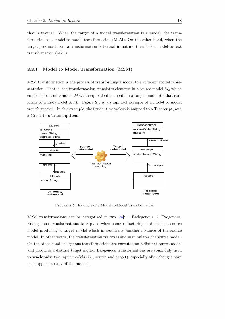
2.2.1 Model to Model Transformation (M2M)
M2M transformation is the process of transforming a model to a different model repre-
sentation. That is, the transformation translates elements in a source model Ms which
conforms to a metamodel MMs to equivalent elements in a target model Mt that con-
forms to a metamodel MMt. Figure 2.5 is a simplified example of a model to model
transformation. In this example, the Student metaclass is mapped to a Transcript, and
a Grade to a TranscriptItem.
Figure 2.5: Example of a Model-to-Model Transformation
M2M transformations can be categorised in two [24]: 1. Endogenous, 2. Exogenous.
Endogenous transformations take place when some re-factoring is done on a source
model producing a target model which is essentially another instance of the source
model. In other words, the transformation traverses and manipulates the source model.
On the other hand, exogenous transformations are executed on a distinct source model
and produces a distinct target model. Exogenous transformations are commonly used
to synchronise two input models (i.e., source and target), especially after changes have
been applied to any of the models.

Chapter 2. Literature Review 19
2.2.1.1 Transformation Language Technologies
Given the central role model transformation plays in MDE approaches generally, it is
important to understand the technology that transformation languages are built upon.
Query View Transformation - QVT
QVT was developed as the standard transformation language by the OMG [45]. The
aims of the language include providing a mechanism for querying MOF-based models,
creation of views from models, creation of expressive definition of transformations,
hence the name Query, View, Transformation [46]. A query is an expression that is
evaluated over a model. The result is one or more instances of types defined in the
source model. A view is a model which is completely derived from another model.
A transformation is the generation of target model(s) from source model(s) based on
defined transformation which can contain a number of rules.
There are two parts to the QVT language. A declarative part which is made up
of relational and core languages. The relational language enables complex pattern
matching over input models [47]. On the other hand, the core language enables pattern
matching over a primitive set of variables. The imperative QVT language, otherwise
called QVT Operational enables implementation of transformation rules that are not
applicable in a relational language.
Triple Graph Grammars - TGG
TGGs declaratively define the relation between two models [45]. In addition to source
and target models, they define a correspondence model which serves as a mapping be-
tween source and target model elements such that an Object in the corresponding model
is made up of at least one source model element and target model element. Graph trans-
formation rules match left hand side model elements with corresponding right model
elements. Graph-based transformations are commonly implemented in M2M languages
(e.g., VIATRA [48]) because they allow explicit specification of transformation [49].
Unlike QVT based transformation languages TGG supports bidirectional transforma-
tions [50].
2.2.1.2 Specification of a Model-to-Model Transformation
A M2M transformation comprises of transformation definition, transformation rule(s),
source and target models. A transformation definition is a set of transformation rules.
Transformation rules define how specific set of source model elements are to be mapped

Chapter 2. Literature Review 20
Figure 2.6: Overview of Model Transformation Process taken from [3]
to equivalent set of target model elements [51]. Figure 2.6 captures a typical M2M
transformation.
• The transformation process involves having a source model that conforms to one
or more source metamodels. Most transformation tools will automatically check
the conformance of the source model to its metamodel before running transfor-
mation rules on it.
• The transformation engine reads the source model.
• The transformation engine executes the transformation rules.
• The transformation engine having applied the rules to the source model elements,
writes to the target model.
Listing 2.1 is an example of a M2M transformation specification that is based on the
metamodels described in Figure 2.5.
1 rule Grade2TranscriptItem2 transform g: University!Grade3 to t: Records!TranscriptItem {4 t.moduleCode = g.module.code;5 t.mark = g.mark;6 }
Listing 2.1: M2M transformation definition based on Figure 2.5 specified inETL
In this transformation, a rule is defined which translates each object of metaclass Grade
in a model that conforms to the University metamodel to a corresponding object of
metaclass TranscriptItem in a model that conforms to the Records metamodel. A
TranscriptItem object derives its properties (i.e., moduleCode and mark) from a Grade
object.

Chapter 2. Literature Review 21
There are three types of M2M transformation language styles: declarative, imperative,
and hybrid [24].
• Declarative languages express mappings between source and target model ele-
ments using mathematical relations. They are usually easy to use because they
execute in a black box manner, i.e., they automate model traversals, rule execu-
tion scheduling [52]. There are two types of declarative languages: relational and
graph transformations. As the name implies, relational transformation languages
are based on relations between source model elements and target model elements.
On the other hand, graph transformation languages express mappings between
source and target model elements through graph patterns [53].
• Imperative languages explicitly specify how transformations are performed. They
can be applied to more complex transformations where there is need for imperative
manipulation from an executable language [51].
• Hybrid languages are a combination of declarative and imperative approaches.
They leverage the expressiveness and conciseness of the declarative style and
through imperative characteristics enable the execution of complex transforma-
tions. Examples of such hybrid transformation languages include Atlas transfor-
mation language (ATL) [54], Epsilon transformation language (ETL) [55].
2.2.1.3 Model-to-Model Trnasformation Languages
ATL. Atlas Transformation Language is designed as a hybrid transformation lan-
guage containing a mixture of declarative and imperative structures [54]. The declar-
ative features of ATL allows matching of source to target model elements while its
imperative features enable more complex operations e.g., creation of model elements.
There are two types of declarative rules in ATL: matched and lazy. Matched rules are
automatically executed on the input model while lazy rules are explicitly called from
another rule as specified by the transformation developer.
ETL. Epsilon Transformation Language is a hybrid transformation language [55].
It uses its imperative constructs which are similar to the imperative programming
language features (e.g., loops, variables) for complex transformations. Its imperative
features are based on Epsilon’s object language (EOL) [40]. In addition, ETL supports
transformation execution on models defined using different metamodeling technologies.
This is achieved through Epsilon’s model connectivity (EMC [56]) layer which serves
as a common interfacing facility for diverse modeling technologies e.g., EMF, MDR,

Chapter 2. Literature Review 22
XML, etc. ETL transformations are organised into modules. Each module contains
transformation rules which expresses how source model elements are translated into
target model elements.
VIATRA. VIATRA is a graph-based model transformation language. It employs
mathematical relations to specify precise rule based graph transformation definitions,
and it uses abstract state machines to manipulate models [57]. Execution flows of
transformations are expressed as state machines. It offers advanced constructs for
performing recursive graph traversals and multi-level metamodeling.
Tefkat. Tefkat is a QVT-based declarative model transformation language [52]. A
Tefkat transformation specifies a set of constraints over a set of source and target
models. The constraints are evaluated to determine how the source model elements
are mapped onto equivalent target model elements. For example, a constrain might be
used to determine whether an equivalent of a source model element already exists in
the target model.
XTend. XTend is an imperative model transformation language, and it is one of
oAW’s (OpenArchitectureWare) [58] suite of model management languages. oAW is a
modeling platform for defining and manipulating models. Transformations rules imple-
mented in XTend declare imperative sections which contain expressions for translating
model elements [59]. Given its imperative nature, rule expressions can be chained (the
result of each execution piped into the next from left to right), and execution order has
to be explicitly specified by the transformation developer.
2.2.2 Model-to-Text Transformation (M2T)
Model to text transformation is an important model management process of generating
text (e.g., application code) from models [11, 60]. However, with M2T transformation,
as defined in [61], generation is not limited to code: the transformation process can
produce any kind of textual artefact including documentation, requirements specifica-
tions, manuals etc., because the generated text is independent of the target language.
Unlike M2M transformation, the targets of M2T transformations are textual, and most
often of arbitrary structure which do not conform to any metamodel.
There are two categories of M2T transformations:

Chapter 2. Literature Review 23
1. Visitor-based: This approach entails providing a visitor mechanism to traverse
the internal representation of a model and write text to a stream [62, 63]. An
example of such visitor-based language is Jamda [64]. Jamda represents UML
models with a set of object classes. Through dedicated APIs (e.g., Java metadata
interface [65]), it can access and manipulate models, while it employs a visitor
mechanism to generate text.
2. Template-based: Templates are text files which represent the eventual output
of a model-to-text transformation which contain placeholders. The placeholders
represent variables that are to be filled with data fetched from the source model.
Text templates are usually made up of static and dynamic sections. As seen in
2.2, static sections contain text that is written verbatim as part of a transforma-
tion output and dynamic sections contain sections with the place holders. The
dynamic sections are also enclosed in special command tags (e.g [% %], <% %>).
In contrast to the visitor-based approach, the structure of a template resembles
closely the syntax of the target language. The majority of recent M2T languages
support template-based text generation.
2.2.2.1 Template-based M2T Transformation Execution
A M2T transformation is specified using a Module, which comprises one or more Tem-
plates. A Template comprises a set of Parameters, which specify the data on which a
template must be executed; and a set of Expressions, which specify the behaviour of the
template. In addition to the typical types of expression used for model management
(e.g., accessing or updating the properties of a model element, iterating over associ-
ated model elements, etc.), M2T transformation languages provide two further types
of expressions: TemplateInvocations, which are used for invoking other templates; and
FileBlocks, which are used for redirecting generated text to a file. A TemplateInvocation
is equivalent to in situ placement of the text produced by the Template being invoked.
(a) Metamodel. (b) Model.
Figure 2.7: Example model of a social network.

Chapter 2. Literature Review 24
Consider, for example, the M2T transformation in Listing 2.2, which produces sections
of HTML pages of the form shown on the right-hand side of Figure 2.7. This M2T
transformation comprises three templates: generateSections (lines 3-10), personToDiv
(lines 12-25), and tweetToDiv (lines 27-34). All of the templates accept one parameter
(a Network object, a Person object and a Tweet object, respectively). The first tem-
plate invokes the second (third) template on line 5 (line 8) by passing an instance of
Person (Tweet). Note that the second and third templates both redirect their output
to a file named after the Person or the hashtag of the Tweet on which they are invoked
(lines 13 and 28).
1 [module generateHTML(Netwrok)]2
3 [template public generateSections(n : Network)]4 [for (p : Person | t.persons)]5 [personToDiv(p)/]6 [/for]7 [for (t : Tweet | n.tweets)]8 [tweetToDiv(t)/]9 [/for]
10 [/template]11
12 [template public personToDiv(p : Person)]13 [file (p.name)/]14 <div>15 <p>Number of followers: [p.followers->size()/]</p>16 <p>Number of following: [p.follows->size()/]</p>17 <h2>What’s trending?</h2>18 [for(f : Person | p.followers)]19 [for(t : Tweet | f.tweets)]20 [t.hashtag/]21 [/for]22 [/for]23 </div>24 [/file]25 [/template]26
27 [template public tweetToDiv(t : Tweet)]28 [file (t.hashtag)/]29 <div>30 Hashtag: [t.hashtag/]31 Re-tweeted [t.retweets->size()/] times32 </div>33 [/file]34 [/template]
Listing 2.2: Example of a template-based M2T transformation, specified inOMG MOFM2T syntax.
2.2.2.2 Specification of a Model-to-Text Transformation
Execution of a M2T transformation specification (i.e., a Module) is performed by a
transformation engine. A transformation engine takes as input a source model and a
Module, and outputs text. Execution begins by creating a TemplateInvocation from an
initial Template and Parameter Values. The TemplateInvocation is executed by eval-
uating the expressions of its Template in the context of its Parameter Values. During

Chapter 2. Literature Review 25
Figure 2.8: Example outputs of executing the transformation in Listing 2.2 on theinput model in Figure 2.7(b).
the evaluation of a TemplateInvocation, additional TemplateInvocations can be created
and evaluated in the same manner, and any FileBlocks are evaluated by writing to disk
the text generated when evaluating the expressions contained within the FileBlock. For
example, execution of the of the M2T transformation in Listing 2.2 would proceed as
follows:
1. Load the source model.
2. Create and evaluate a TemplateInvocation for the primary template, generateSec-
tions (see line 1), passing the only Network object in the source as a parameter
value.
3. For each of the Person contained in the Network :
(a) Create and evaluate a TemplateInvocation for the personToDiv template,
passing the current Person object as a parameter value.
(b) Emit html text for the person div (lines 14-24) to a text file with the same
name as the Person.
4. For each of the Tweets contained in the Network :
(a) Create and evaluate a TemplateInvocation for the tweetToDiv template,
passing the current Tweet object as a parameter value.
(b) Emit html text for the tweet div (lines 29-32) to a text file with the name
of the file set to the hashtag of the Tweet.

Chapter 2. Literature Review 26
2.2.2.3 M2T Transformation Languages
Template Transformation Toolkit (T4). A T4 text template like many other
template languages is a mixture of text blocks and control logic that generate any form
of textual artefact from models4. The generation engine of T4 is largely dependent on
the .NET framework and languages [66]. Thus, the control logic is written as fragments
of program code in Visual C# or Visual Basic. The T4 template engine can generate
any type of textual artefact. T4 transformations are executed on UML-based models.
One key shortcoming of T4 is that it does not support the idea of mixing generated
code with user-written text.
The run-time environment allows the developer to embed Visual Studio statements
(e.g., <#= DateTime.Now #>) in the template, which are executed when the trans-
formation is run. In addition, T4 supports instantiation of objects defined in the other
files (e.g .cs files) in the project space, in the same manner they would be accessed in
non-template files.
Acceleo. Acceleo is based on three separate components: the compiler; the genera-
tion engine; the tooling. It is capable of reading any model produced by any EMF-based
model. A transformation written in Acceleo is made up of modules, source model(s)
and target files. A module can consist of several templates describing necessary pa-
rameters to generate text from models. A main template serves as the entry point of
the transformation execution and is indicated by the presence of a @main at the top
of the template’s body.
Epsilon Generation Language (EGL). EGL [11] inherits concepts and logic from
EOL (Epsilon Object Language) [40]. EGL is a M2T language developed at the Uni-
versity of York. It is the text generation language of Epsilon’s suite of model man-
agement languages. At its core lies a parser which generates an abstract syntax tree
comprising static and dynamic output nodes for a given template. Unlike Acceleo, the
EGL transformation engine has a dedicated transformation rule execution coordina-
tion mechanism (EGX). In addition to coordinating rule execution, EGX enables the
generation of multiple files from a single template.
1 rule Student2Transcript
2 transform s : Student {
3 template :‘record.egl’
4 target : s.name + ‘.txt’
5 }
Listing 2.3: EGX example
4http://msdn.microsoft.com/en-gb/library/vstudio/bb126445.aspx.

Chapter 2. Literature Review 27
It inherits its imperative constructs from EOL, provides data types which are similar
to Java’s and supports user-defined methods on metamodel types.
Xpand. Xpand is a statically typed template language whose main features are aspect
oriented programming, model transformation and validation5 with some limitations on
types of operations it can perform. It also logs link information between source and
target elements in between code generations.
MOFScript. MOFScript was an initial proposal to the OMG for their model-to-text
RFP, which was developed by Sintef and was supported by the EU Modelware project.
MOFScript was developed in response to the need to standardize M2T transformation
languages. It works with any MOF-based model e.g UML, RDBMS, WSDL, BPMN
etc., and it is heavily influenced by QVT. A MOFScript transformation is composed of
one or more modules, with each module containing transformation rules. A MOFScript
rule is a specialisation of QVT-Merge operational mappings and MOFScript construc-
tions are specialisations of QVT-Merge constructions [67]. Transformations can be
imported and re-used by other transformations.
Java Emitter Templates (JET). JET can be used to generate text from EMF-
based models. It creates Java implementation classes from EMF models. The Java
implementation classes are then used to write text output. The implementation class
has a ‘generate’ method used to obtain string result. In other words, the transformation
is from Java objects to text. Command tags in JET are called scriplets, denoted by
< %% >, they can contain any Java code6. Unlike EGL and Acceleo, JET does not
support models implemented using MOF.
Velocity. The Velocity projects by Apache include: Velocity Engine7 which is a tem-
plating engine that allows a template language to reference objects defined in Java
code. Velocity transformation language (VTL) is written in Java enabling easy embed-
ding in other Java applications. Velocity makes use of XML transformations. Velocity
templates extract data from XML files which are used in generating text files. The
generator is created by implementing Java classes called descriptors representing each
node in the XML file.5http://www.eclipse.org/modeling/m2t/?project=xpand6http://www.vogella.com/articles/EclipseJET/article.html7http://velocity.apache.org/engine/releases/velocity-1.7/

Chapter 2. Literature Review 28
Freemarker. Freemarker8 is a template language that is based on Java. It was de-
signed specifically for generating web pages. Like Velocity, it has minimal programming
capabilities. Thus, it also requires Java programs to prepare the model data.
2.2.2.4 Overview of a M2T Module in EGL.
In the previous sections, we provided a general overview of template-based M2T trans-
formations are defined, and described some common template-based M2T languages.
In this section we describe how a modern M2T transformation language implements
a model transformation module from a transformation execution perspective. Hence,
this section discusses the way in which a M2T transformation engine might implement
mechanisms for coordinating rule invocations and for directing transformation output
to file. The rest of this section describes the implementation of a transformationModule
in EGL.
Figure 2.9 represents an overview of the implementation of a M2T transformation in
EGL. The transformation engine emits the contents of static sections verbatim (does
not require applying any logic) while text emitted from the dynamic sections are the
result of logic operations, and performing model queries. The dynamic output buffer is
responsible for outputting text generated from dynamic sections while the static output
buffer holds text from the static sections of a template. An instance of a RuleInvocation
is the execution of a template on a specific model element. RuleInvocations have context
types which indicate the type of a model element on which a transformation rule can
be invoked. In a typical EGL transformation, each instance of a created RuleInvocation
is executed on only one model element, and generates a single file.
Figure 2.9: Module invocation in EGL M2T Language.
8http://freemarker.sourceforge.net/docs/

Chapter 2. Literature Review 29
1 pre {2 var cssClass = "gold";3 }4
5 rule personToDiv6 transform aPerson : Person {7 guard: aPerson.followers.size() > 0;8
9 parameters {10 var params : new Map;11 params.put("cssClass", cssClass);12
13 return params;14 }15
16 template : "personToDiv.egl"17 target : aPerson.handle + ".txt"18 }19
20 rule tweetToDiv21 transform aTweet : Tweet {22 guard: aTweet.retweets.size() > 0;23
24 parameters {25 var params : new Map;26 params.put("cssClass", cssClass);27
28 return params;29 }30
31 template : "tweetToDiv.egl"32 target : aTweet.hashtag + ".txt"33 }
Listing 2.4: Example of an EGX M2T program
In general, M2T transformation processes do not end at the generation of text but re-
quire a further step of writing the generated text to files. Most M2T languages provide
mechanisms for writing generated text to files and manipulate the local file system.
EGX is a recent extension to EGL that provides a co-ordination mechanism for di-
recting the output of executing templates to files. An overview of a transformation
execution using EGX is shown in Figure 2.10. The contents and destination of gener-
ated files are determined at runtime. Listing 2.4 shows a typical EGX transformation
module which is equivalent to the MOFM2T module earlier described in Listing 3, but
contains additional pre and post blocks. An EGX module can comprise any number
of transformation rule blocks, a pre and a post block. A transformation rule block
defines how an input model element can be transformed into fragments of text con-
tained in a generated file. Each transformation rule block also specifies the context
type which indicates the type of model elements a rule can be invoked upon. In addi-
tion, a transformation rule block also includes expressions that define other properties
of the transformation (e.g., template, guard, target, parameters). The template ex-
pression returns the EGL template on which the rule is to be invoked; the guard is a
constraint which returns a boolean and limits the application of the rule to the condi-
tions specified in the guard expression; the target expression is resolved to the name

Chapter 2. Literature Review 30
and destination of the generated file; parameters is a collection of variables consumed
by the transformation during the execution of a template. A pre block contains state-
ments that must be executed before rule invocations and typically define variables that
are passed to the transformation engine when a template is executed. A post block
on the other hand contains instructions (e.g., pretty print directive) that are executed
after the transformation engine might have finished executing templates.
Figure 2.10: Overview of transformation execution using EGX.
2.2.3 Discussion
M2M and M2T transformations are based on the same principles and are employed to
achieve similar goal. For example, they are used to translate source models to other
dependent artefacts. Both take as input, models and some specification of transforma-
tion rules. Despite their similarities, they differ in implementation, and as such have
different concerns from a research perspective. Notably, most M2T transformations
specifications are template based. Templates contain executable code written in the
transformation language which are often imperative and computationally complete in
order to perform complex calculations on models and other input parameters. M2T
transformation engines also possess mechanisms for manipulating strings, escaping spe-
cial text delimiters, whitespace handling, and writing text to files. On the other hand,
M2M transformations are often specified in blocks of declarative code that explicitly
maps source model elements to corresponding target elements. Although a subset
of M2M transformation languages support imperative constructs, they do not handle
some of the unique requirements of M2T languages e.g., parsing texts or redirection of
generated text to files.

Chapter 2. Literature Review 31
2.3 Scalability in MDE
Software engineering continues to witness a rise in levels of abstraction introduced into
system design as a result of growing complexity of software systems. MDE as a soft-
ware engineering discipline promotes this trend and promises improved productivity
and better quality software [69]. Although the past decade has seen increasing num-
bers of industry practitioners adopting MDE techniques, further adoption of MDE is
stymied by scalability concerns. Scalability is a major stumbling block to the adoption
of MDE [70]. For example, as model sizes increase, MDE techniques such as model
transformation, validation, do not scale because some of the existing modeling tools
cannot operate on large models without noticeable degradation in performance. In a
study on the experiences of industry practitioners on their use of MDE, Mohagheghi
et. al. [71] identified that often the lack of scalable model management operations was
a prominent concern in industry.
Kolovos et. al. [72] identified three aspects in which the lack of scalability in MDE
poses challenges to both the academic community and industry: 1. managing volume
increase, 2. collaborative work, and 3. incremental change propagation. With respect to
managing volume increase, as models grow from containing hundreds of model elements
to containing millions of model elements, it is important that modeling tools scale
accordingly. For example, facilities for persisting large models should be robust enough
to support efficient persistence of models (following model modification or creation)
regardless of the size of the models.
A related concern of the lack of capacity of modeling tools to cope with large, evolving
models is that it discourages collaborative work. According to Bergmann et. al., scala-
bility challenges prevent collaborative work, and represent a prominent threat to MDE
adoption [73]. As with traditional software engineering approaches, in MDE, the abil-
ity of development teams to access and work on the same set of development artefacts
while the consistency of such artefacts is not compromised is important. However, the
lack of mature tools and infrastructure which will enable large model persistence and
efficient access (read and write) to models can hamper collaboration among develop-
ers. Especially considering that in a typical software engineering environment, different
developers may need to access and modify the same models.
In the context of model transformations, typical concerns of industry practitioners are
captured in statements such as [72]:
1. I would like to use model transformation. When I make a small change in my
large source model, it is important that the change is incrementally propagated

Chapter 2. Literature Review 32
to the target model. I don’t want the entire target model to be regenerated every
time.
2. I use code generation (M2T). However, when I make a small change in my large
source model, I don’t want all the code to be regenerated.
In light of these statements, it is apparent that scalability concerns arise as a result of
evolving software. Since in MDE models are considered primary artefacts of the devel-
opment process on which other development artefacts depend, changes often initially
emerge from source models. As such, when models evolve, other dependent artefacts
have to evolve accordingly. To tackle the issue of scalability, MDE tools need to sup-
port incrementality [26] or efficient propagation of changes in a manner that reduces
redundant re-computations. The question or challenge is how can these changes be
propagated across artefacts in an efficient manner. In the context of model transfor-
mations, this challenge has been the subject of much research. However, much of this
research has been on incremental M2M transformations while very little has been on
incremental M2T.
Reactive model query and transformation have been recommended as a research di-
rection to tackle scalability issues in model transformations [74]. Research in this
direction is published in [73] by Bergmann et. al. They focus on managing model
evolution in the context of inter-related MDE development tasks in a single workflow
on an industrial scale. For instance, a workflow might include verification of models
using OCL constraints, M2M transformations, M2T transformations, design rule vali-
dation, etc. In such workflows, it is desirable that all model management tasks can be
incrementally executed when underlying source models evolve. Considering the inter-
dependencies among the model management tasks, the execution of one task might
interfere with the execution of others. Therefore, incremental re-synchronization of the
source models with other development artefacts (produced by different tasks) requires
careful consideration. For example, the re-execution of an endogenous M2M transfor-
mation can invalidate the results of an incremental verification of the source model. As
such, they suggest a reactive transformation framework that is based on the reactive
programming paradigm [75]. The framework triggers re-execution of relevant model
management tasks in the correct sequence (to limit interference) as changes occur in
the source model.
Before reviewing literature regarding incremental change propagation through model
transformation, a more general overview of software evolution is needed. This is es-
sential to understand what factors are responsible for software evolution, the costs as-
sociated with it, along with common software evolution techniques, and how all these
relate to software evolution in MDE.

Chapter 2. Literature Review 33
2.4 Software Evolution
Software evolution can be described as any software development activity that neces-
sitates the propagation of changes from one or more development artefacts to other
dependant artefacts, in order to ensure consistency across all artefacts of the software
development process. Change propagation is central to software evolution, and it can
be described as the changes required to other entities of a software system to ensure a
consistent view of the software system after changes are applied to particular entities
of the software system [76]. In empirical studies [77–79] of software evolution, as much
as 70% of software development effort is reported to be devoted to software evolution
activities.
Given the importance of software evolution, it has been the subject of much research
work. According to one of the software evolution laws introduced by Lehman [80] in
1970, actively used software systems must continually change to accommodate new
requirements of its stakeholders. The chief factors responsible for software changes
are [78, 81]:
• Changing user requirements.
• Changing technology.
• Changing organisational culture.
Rarely do software life cycles end at deployment; there are several activities that are
on-going so long as the software remains in use. These include providing bug fixes,
patches, adding new features, etc. According to a study of 8000 projects reported by
the Standish Group, modifications applied to the projects were as a result of changing
user requirements [81]. 75% of changes to software are due to changing development
environments and emergence of new user requirements [13]. Most software development
work is primarily focused on enhancing and adapting existing system. Commonly,
software undergoes evolution in order to keep it up-to-date with continuously evolving
customer needs [82].
With such enhancements come increased system complexity and costs [83]. Kemerer
observes that there is a direct correlation between software complexity (considering
software size, modularity, branching) and maintenance costs [84]. Accommodation of
changes to software comes at huge costs – analysis of required change and its impact,
implementation of the change. Costs associated with software evolution are not lim-
ited to these. Revalidation and testing are additional important activities which are
necessary to prevent introduction of bugs into the system. Every evolution of a system

Chapter 2. Literature Review 34
can result in a cycle of analysing the new requirements, performing an impact analysis
of the changes required, revalidation of the system, and testing. The cost imposed by
software evolution activities is aptly captured by Sommerville’s description of software
evolution as a necessary expensive process that requires a lot of time to locate places
where components need to change or affected by a change to another component, time
consuming efforts to implement and test the software [16, Chapter 21].
Often, much of the costs associated with software evolution are as a result of performing
redundant activities during change propagation. For instance, every time a change is
applied to a component of a software system, performing complete system tests when
unit tests will suffice, will incur unnecessary computation cost, potentially waste devel-
opment time, and erode the efficiency of the development process. This is commonly
referred to as batch processing in software engineering.
An alternative approach is incremental change propagation. Incremental change prop-
agation processes are restrictive (i.e., only changes and the components affected by the
changes are considered during change propagation) and can result in more efficient de-
velopment process. Incremental change propagation plays an essential role in software
evolution, particularly in an agile environment [85, 86]. Section 2.5 will elaborate on
incremental change propagation and how it has been applied to improve efficiency in
several aspects of software engineering including compiler, relational databases, etc.
2.4.1 Software Evolution Techniques
The previous section provided the taxonomy of software evolution, and this section
will discuss common techniques used to manage software evolution. While software
evolution can be classified according to various factors (e.g., the cause of the change,
when the change occurred, etc.), a common characteristic of all types of change is that
other activities are initiated in response to changes. Typically, the process of addressing
software change will involve the following activities [12]:
Change identification. This can be very helpful in addressing changes to software
especially when the change is only first obvious in one of the software development
artefacts. For example, Linux’s “make” utility is used to automatically detect which
parts of C/C++ programs have been modified by comparing the timestamps of the
source files against the timestamps of object files.
Impact analysis. Impact analysis is an evaluation of how changes would affect the
internal consistency of an evolving system, and other associated systems or sub-systems

Chapter 2. Literature Review 35
and identification of modifications necessary to preserve the consistency of the system.
It is the process of determining the effect a change is going to have on a system [87].
Having identified what has changed in a system or what needs to be changed, the next
thing is to identify what impact this change will have on other parts of the system,
and propagate this change to the identified parts. In the example of the make utility,
the compiler selects which source files that need to be re-compiled based on the times-
tamps of the source files and the object files. This kind of mechanism saves a lot of
re-compilation time particularly for large projects. The importance of identifying de-
pendencies within software system components in order to carry out meaningful impact
analysis are highlighted in [88–90].
Change propagation. Change propagation refers to a phenomenon where a change
to one part of the system creates a need for changes in other parts of the software
system [90, 91]. Internal dependencies or relations between software components also
play a vital role in evaluating the impact of software change. For example, a study of
a Health Management System (HMS) by Sjøberg found relations between components
of the system to have grown by 139% affecting all relations suggesting prior knowledge
of interconnection between the system components might not be adequate to inform
effecting changes [92].
Implement change. At this point, the change is applied to the system by implement-
ing the change. Activities at this stage need be done with caution because processes at
this stage can introduce bugs into the software and render it dysfunctional, requiring
more time to fix.
Re-verify system. After translating identified changes to the software, it is critical
to have the software system re-evaluated in order to ensure it meets its new requirements
and continues to provide previous features that have not been removed.
The points outlined above are crucial software evolution activities which can come at
very high costs to the developers because of the time, effort, and resources expended
during analyses, implementation and re-verification. As previously discussed, often
small changes to an artefact result in cyclic re-execution of these processes (i.e., change
analysis, implementation, re-verification). At the same time it often results in redun-
dant re-computations because changes don’t always impact on the full system. Often,
not every artefact modification may necessitate the re-construction of other develop-
ment artefacts, hence, ideally, only affected artefacts or system components should be
re-constructed.

Chapter 2. Literature Review 36
In this section we have considered a broad view of software evolution and discussed fac-
tors that cause software to change. In addition, we discussed the costs associated with
software evolution activities and outlined techniques that are commonly applied during
software evolution. The next section will provide an expanded discussion of software
evolution in the context of MDE with particular focus on model transformation.
2.5 Incremental Model Transformation
As discussed in the previous section, software evolution is an inevitable software engi-
neering phenomenon because of a number of reasons (e.g., changing user requirements).
In the context of MDE, since models are used to represent several aspects of a system,
including user requirements, constraints, configuration, etc., whenever the underlying
models of a system are modified, other dependent artefacts (e.g., system code, other
models, etc.) need to be evolved accordingly. Synchronization of system artefacts is
typically achieved through model transformations. For example, M2T transformation
for textual artefacts and M2M transformation for other model-based artefacts.
As discussed in Section 2.3, the lack of support for scalable model management tasks
such as efficient change propagation has hampered the adoption of MDE techniques in
industry. In a model-based system (software that has been constructed using a model-
driven approach), changes typically first manifest in the underlying model(s) of the
system. In response to model modifications, other artefacts of the development require
updates based on the model changes. The propagation of changes from one model
to other artefacts is often achieved through model transformations. It can be manual
(instantiated by the developer) or automatic.
There are two established strategies for propagating changes in model transformations:
batch and incremental. Batch transformation entails re-executing a transformation
in its entirety without consideration for what the changes are nor what the effect
of the changes will be on other artefacts. In other words, the batch transformation
strategy ignores the software evolution activities (i.e., change detection, impact analysis,
change implementation) discussed in Section 2.4.1. There are obvious deficiencies in this
strategy: it results in redundant re-computations, time and resource wasting [93, 94].
Model transformation which requires re-computing the whole transformation when only
a small fraction of the source model changed do not scale very well [18]. Conversely,
incremental change propagation strategies are typically based on narrowing the scope
(change detection) of re-execution of a transformation to only the affected parts of
the source models (impact analysis). In general, incrementality in software engineering
refers to the process of reacting to changes in an artefact in a manner that minimises the

Chapter 2. Literature Review 37
need for redundant re-computations. Turnaround time for small incremental changes
are important metrics of concern for model transformations [9]. Hence, incremental
model transformation has been the subject of much research.
Czarnecki [64] describes three types of incrementality: target, source, and user edit-
preserving incrementality. These descriptions are based on the following properties of
the model evolution: 1.) source of change (either source or target model), 2.) selective
change propagation, 3.) data preservation.
Target incrementality refers to the process of updating a target artefact based on
the changes made to a source model. It entails re-executing a transformation on the
entirety of a source model which produces a new target model that is then merged
with previous target model. Target incremental transformations are very similar to
batch transformations in that the transformation is executed in its entirety, but dif-
fers by merging new content with pre-existing artefacts whereas batch transformation
overwrites the pre-exiting artefacts. The transformation engine relies on trace link
information to determine which element in the target requires updating and which ele-
ments in the source model requires transforming and creating in the target. Trace links
contain historical data of previous transformations with which the transformation en-
gine can map elements in a source to elements in the target [95]. Target incrementality
does not take into consideration, the amount of source model elements that need to be
examined.
Source incrementality improves on target incrementality by seeking to eliminate the
need to perform a merge. It limits the execution of a transformation to only changed
parts of source models. This ensures only affected artefacts of the transformation are
re-constructed. As such, change detection and impact analysis are important steps per-
formed by a source-incremental transformation algorithm. This can improve efficiency
especially when the source models are large, complex (with associations between model
elements). Furthermore, because the source incrementality limits the re-execution of
transformations to affected parts of the transformation, it enables incremental trans-
formations that scale by the magnitude of input model changes (or the impact of the
changes) rather than by the size of the source model.
However, the effectiveness (extent to which the source incremental algorithm can reduce
redundant re-computations) depends largely on the level of granularity (e.g file, model
element, model element feature). For example, if the granularity or unit of change is
an entire model, the transformation can be re-executed on that particular model (e.g.,
by comparing the timestamp of the model file to the time of the last execution of the
transformation). However, change consideration at such a high level can result in an

Chapter 2. Literature Review 38
overly pessimistic transformation. That is, the impact analysis is imprecise and thus,
is less effective in reducing redundant re-computations.
User edit-preserving incrementality enables the preservation of manually crafted
changes in generated artefacts. For example, in the context of M2T this is a desirable
feature for transformation engines considering that not all transformations yield a fully
working system and instead leaves gaps to be plugged by hand-written code. In practice,
there is sometimes a need to edit generated text, make some change to the source
model(s), and then run the transformation again. It is crucial that this chain of events
does not result in loss of user-edited text.
In addition to these types of incrementality, there are two execution modes of an in-
cremental algorithm which are based on the application of an incremental execution:
offline and online (or live). In offline mode, an incremental algorithm is applied to a
transformation on demand (after the source model update). In this mode, the transfor-
mation is re-executed only when re-synchronization of artefacts is required after model
editing, for example, whenever a new version of the source model is available. On the
other hand, in online mode, incremental re-executions of transformations are performed
on-the-fly (during the source model update). In contrast to offline mode which requires
a new version of a source model, in online mode changes are propagated as they occur
in the source model. This characteristic is particularly useful in a development environ-
ment where changes are frequent and immediate feedback of the effects of the source
model changes are important.
2.5.1 Incremental M2M Transformation
M2M transformation scenarios can comprise several source and target models which
need to be synchronised. Typically, synchronising models involve applying updates
from the source model to the target model. One approach is to re-run the entire
transformation against the source model to produce a new target model which is then
merged with the previous target model. Another approach is to compare the source
model with a previous version after each change to in order to detect differences (or
a delta model). The transformation is then executed against the delta producing a
difference target model that is then merged with the previous target model producing
a new target model.
A live updating approach is proposed in [96] which uses a tree to represent the trace of a
transformation execution. Each node represents either a source or target element, and
the edges are rules. The transformation context exists as a whole and is maintained
throughout all transformation executions. Thus, as changes are made to the source

Chapter 2. Literature Review 39
model, the changes reflect in the tree and the target is deduced from the tree. For
example if an element is added to the source, the transformation searches for a matching
rule and model element in the tree. If it finds one, it updates the node, otherwise, it
spawns another edge and node in the tree. This way, the transformation eliminates
the need of a merge algorithm for merging incremental targets. The advantage of this
method is that the amount of computation required is proportional to the size of the
input changes and the output changes [96]. The drawback however is that it maintains
the transformation context for every execution. Considering that this grows as the
source model grows, it can be an issue for large, complex transformations. Another
possible drawback of this technique is that its efficiency depends on the tree search
algorithm. Finally, when changes are made to transformation rules, it can render
parts of the transformation context invalid because of rule mis-matches, for example,
r : a→ a′ is changed to r : a→ b′
In [97], an incremental M2M transformation technique with Triple Graph Grammars
(TGG) is presented. The algorithm exploits dependencies between transformation rules
to achieve incrementality. It stores traceability information to maintain consistency
between source and target models. Additionally, the correspondence model has a cor-
respondence node with a self-association which connects each correspondence node to
its predecessors. Thus, a rule in TGG specifies a correspondence mapping between the
elements of the source and the target models. A graph grammar rule is applied by
substituting the left hand side (LHS) with the right hand side (RHS) if the pattern on
the LHS can be matched to a pattern in the correspondence model [97]. A directed
edge from the correspondence node to the created target element is inserted each time
a rule is successfully applied. This reflects the dependencies and execution order of the
rules. So, by traversing the directed acyclic graph created by the correspondence nodes,
inconsistencies between the source and target models can be determined, which is done
by retrieving the rule which was used to create the correspondence node and checking if
it still matches the current situation. If any inconsistency is detected due to a deletion
in the source for example, it deletes the created target element and the correspondence
node. This way, the algorithm achieves incrementality by not re-running the trans-
formation against the entire source model but it incurs a cost in all correspondence
nodes by comparing it with patterns in the source model. A potential drawback to
this approach lies in the amount of space required to maintain an intermediate model
which grows by every transformation execution because it stores the source-rule-target
information.
A similar TGG-based incremental transformation technique is later proposed by Giese
et. al [98]. This technique requires TGG rules to be deterministic and assumes only
source model modification. In contrast to [97], it supports live change propagation.

Chapter 2. Literature Review 40
To detect model element modifications, an event listener is attached to each model
element in the source. Whenever an element is modified, its associated correspondence
node is put in a transformation queue. Thereafter, the queue is processed by executing
specific synchronization rules on the elements contained in the queue. Synchronization
rules are responsible for maintaining consistency between associated source and target
models by first checking the structure of the matching source and target elements before
checking checking attribute equality.
A different incremental graph-based transformation technique called incremental pat-
tern matching is presented Ráth et. al. [99]. Graph patterns are atomic units of model
transformations which define constraints that nust be satisfied for model manipulation
to take place. In case of incremental pattern matching, graph patterns are defined
on model elements, and whenever the model is modified, graph patterns are updated.
This approach is based on the RETE algorithm. RETE is an efficient algorithm for
comparing large collections of patterns to collections of objects [100]. Transformation
information is represented as tuples and nodes. Tuples contain model elements. Nodes
refer to patterns and store tuples that conform to a pattern. When changes are ap-
plied to a model element, update signals are sent through outgoing edges, then each
receiving node updates its stored tuples, and where applicable, more update signals are
generated and propagated through the graph.
Bergmann et. al. [101] presents a fundamentally different approach which defines the
concept of change history models. Change history models are essentially a log of ele-
mentary model changes derived from performing simple operations on model elements.
Basically, the change history models are are trace models which contain sequences of
model manipulation operations. So, whenever a change is applied to the model, the
change history model is updated and associated rule is invoked. Since this technique
focuses on bi-directional transformation (i.e., transformation in which target elements
can also be translated to source elements), a change history model of the target model
is also tracked. Incrementality is achieved by mapping the change history model of the
source and target models based on a generic metamodel that captures model manipu-
lation operations, e.g., createElement, setAttribute. A distinct feature of this technique
is that transformation mapping takes place between model manipulation operations in
the change history model of both source and target models rather than on the source
and target models. The drawback of this technique is that because transformation can
be executed in two directions, the order of model manipulation operations in change
history logs must be preserved.
Jouault and Tisi [93] propose an incremental technique for ATL that is based on creating
bindings of OCL expressions to model elements. The bindings represent dependency

Chapter 2. Literature Review 41
information between specific rules and OCL expressions evaluated during the execution
of the rules. With the dependency information, when changes are applied to the source
model, exact rules which consume the modified model elements can be determined, and
the rule re-executed on such elements. This technique is different to the ones described
above in that it relies on tracking transformation execution information. However, it
exhibits a crucial limitation. It does not track imperative statements. As such, model
elements accessed within imperative blocks can not be monitored. This compromises
the correctness of the transformations that are executed with this incremental engine.
Of the reviewed incremental M2M transformation techniques, three ([96–98]) are purely
declarative in nature. As such they are not amenable to transformations that require
complex operations. On the other hand, three of the techniques ([93, 99, 101]) com-
bine declarative and imperative constructs. However, they do not support incremental
execution of imperative parts, instead [101] and [99] re-execute all imperative parts,
hence, they are overly pessimistic and limit the benefits of incrementality. On the other
hand [93] completely ignores imperative parts, thus it compromises the correctness of
the transformation.
2.5.2 Incremental M2T Transformation
The types of incrementality described in the previous section have differing charac-
teristics. For example, target incrementality re-executes a transformation in its en-
tirety while source incrementality limits transformation re-execution to a subset of the
source model. User-edit preservation prevents loss of manually crafted contents. The
primary objective of an incremental algorithm in the context of the requirements of
scalable transformations (discussed in Section 2.3) is to reduce or eliminate redundant
re-computations.
Based on the execution strategy of target incremental algorithms, they can only par-
tially fulfil this objective. The efficiency of target incremental algorithms is largely
dependent on the physical machine (e.g., read/write speeds of hard drives) on which
the transformation is executed. This is because target incrementality prescribes that a
transformation is wholly re-executed before the outputs of template re-executions are
compared to previously generated artefacts to determine whether the newly generated
contents should be written to disk. However, since the re-execution of the transforma-
tion has already taken place, by the time comparisons of the outputs of the re-executed
templates are compared to the contents of pre-existing artefacts, potentially redundant
re-computations have also been performed. Source incremental algorithms on the other
hand can minimize redundant re-computations because they limit the re-execution of

Chapter 2. Literature Review 42
transformations to changed parts of the source model. Hence, user edit preservation
can be used in conjunction with source incrementality, because when hand-written text
is added to generated artefacts, there is no need to run the transformation until changes
are made to the source model.
2.5.2.1 Analysis of Incrementality in M2T Languages
As none of the reviewed literature analyses incrementality in M2T languages, this sec-
tion discusses and evaluates three M2T languages’ support for incrementality. The
three languages chosen are T49, EGL, and Acceleo. EGL and Acceleo were chosen
because they are open source, supported and actively used in research, moreover, EGL
is developed at York, and Acceleo is an implementation of OMG’s M2T standard [102].
T4 was chosen because its also freely available and popular among Visual Studio de-
velopers10. The languages were applied to an example of incremental transformation,
which has been developed specifically for this analysis. The same example metamodel
and source model were used for each change scenario, the behaviour of each language
was observed. The result of the analysis is summarised in Table 2.1 and explained in
the remainder of this section.
Table 2.1: Language Comparisons
Language Source Target User edit preservingAcceleo 7 3 3
EGL 7 3 3
T4 7 3 7
Consider the model displayed in Figure 2.11 which conforms to the metamodel shown
in Figure 2.1. The model consists of two instances each of Student and Module, and
three instances of Grade. Initially, the template shown in Listing 2.5 is executed on the
source model and it generates student transcripts shown in Figure 2.12. In subsequent
iterations of this transformation, the source model is modified before re-executing the
transformation.
In the first iteration, the chosen M2T languages’ support for user-edit preservation is
assessed. As such, the previously generated transcripts are edited by manually adding
some text to the protected region. Afterwards, each Grade is modified by changing
its marks, and the template is re-executed. Subsequently, in the second iteration,
support for target incrementality is assessed. So, the IDs of both students (s1 and s2 )
are changed and a new student s3 is created. A target incremental transformation9http://msdn.microsoft.com/en-gb/library/vstudio/bb126445.aspx
10http://www.olegsych.com/2007/12/text-template-transformation-toolkit/

Chapter 2. Literature Review 43
engine would regenerate both transcripts and an additional transcript for s3. Finally,
to assess support for source incrementality we restricted the model modification to a
single model element (s1’s address) and wrote text to the generated transcripts (outside
the protected regions). Given these types of changes, ideally a source-incremental
transformation engine will not regenerate any of the transcripts because: 1.) the first
change is model-based and the changed model element property is irrelevant to the
transformation, and 2.) the second change is non-model based and is outside of a
protected region, so the transformation engine should not be aware of this change.
Figure 2.11: Example of University model that conforms to metamodel in Figure 2.1
1 [comment encoding = UTF-8 /]2 [module student(‘university’)]3
4 [template public generateElement(aStudent : Student)]5 [comment @main /]6 [file (aStudent.name.concat(‘.txt’), false, ‘UTF-8’)]7 Transcript8 -------------9 Student name: [ aStudent.name /]
10 ID: [ aStudent.id /]11
12 Module (Grades)13 [for (g : Grade | aStudent.grades) separator(‘\n’)]14 [g.module.name /] [g.mark /]15 [/for]16
17 Remarks:18 [protected (‘notes’)]19
20 [/protected]21 [/file]22 [/template]
Listing 2.5: Text Generation from university model in Figure 2.11 specified inAcceleo

Chapter 2. Literature Review 44
Figure 2.12: Text Generation from a Model
With respect to user-edit preservation, T4 does not support mixing generated text with
hand-crafted text. EGL provides a special startPreserve tag with which it supports the
preservation of user edits. This instructs the transformation engine to tag a protected
region by appending a start marker for a protected region to the output buffer. The
command takes two arguments: id (that uniquely identifies a protected region) and
an enabled boolean parameter. The protected region is ended by an endPreserve com-
mand. Thus, any text manually written into the protected regions are preserved during
subsequent transformations. Similarly, Acceleo (see Listing 2.5) preserves modifications
of generated text by providing a ‘protected’ tag which provides the same functionality
as the startPreserve tag in EGL.
In terms of target incrementality, all M2T languages under assessment support regen-
eration of text contents and overwriting the contents of previously generated files with
the new content (if old and new contents differ). They also support the generation of
new files when new model elements that are relevant to the transformation context are
added to the source model.
With respect to source incrementality, T4, Acceleo and EGL do not provide support
for source incrementality. After generating student transcripts (i.e., paul smith.txt from
s1, andy brown.txt from s2, we modified the source model by changing the address of
s1. Note that this change is an irrelevant change in the context of this transformation
since the Student2Transcript template does not consume the address of a student.
In order to compare the contents of the files without relying on only the files access
attributes (last accessed or modified time), we added arbitrary text to the previously
generated transcripts. After re-executing the transformation, both student transcripts
were re-generated despite the fact that the change applied to the source model could

Chapter 2. Literature Review 45
not have altered the contents of the generated transcripts. By adding arbitrary text
to the generated transcript before re-executing the transformation, we could determine
that the transformation engine always re-executed the templates before comparing their
contents with the contents of previously generated files. Without the arbitrary text,
simply inspecting the access properties of the generated files would not have revealed
that the files were regenerated.
The above observations clearly indicate that T4, Acceleo and EGL exhibit the same
characteristics with respect to target incrementality. Subsequent transformation results
in writing data from all elements of the source model regardless of which model elements
were modified required updating in the target, to an output buffer. Afterwards, the text
of the buffer is compared to the contents of the output from previous transformation,
and if the texts are not equal, the output buffer is written to disk to overwrite the
existing target.
2.5.3 Discussion
With respect to incremental M2M transformation, most of the reviewed techniques
first perform change detection by creating change history logs as source models are
edited. Change history logs are beneficial in that they enable computation of changes
without having to perform model differencing. Model differencing used for incremental
transformation in tools such as QVTr [103] and Xpand (M2T) suffers from two main
drawbacks. Firstly, model differencing requires at least two versions (old and new) of
an input model, hence, it is memory intensive. Secondly, computing differences can be
computationally more expensive than a batch re-execution because it requires at least
two full model traversals. As such, the efficiency of transformation engines that use
model differencing is largely dependent on the underlying modeling framework.
Although many incremental M2M languages use change history logs, and are not suscep-
tible to the frailties of model differencing, the blanket application of incremental M2M
techniques to M2T is not feasible because both types of transformations have different
concerns, discussed in Section 2.2.3. Generally, M2M languages may be limited in their
ability to handle unique features of M2T languages (e.g., handling protected regions,
white spaces, escape direction, etc.). With respect to TGGs, as seen in the previous
section, there has been considerable work on incrementality for triple-graph grammars
– see [104] for a recent comparison – but TGGs are inherently declarative thus, they
are generally not Turing-complete (although some do provide fallback mechanisms),
whereas most M2T languages are Turing-complete, and hence, support complex model
operations.

Chapter 2. Literature Review 46
Furthermore, in M2T transformation languages rule execution scheduling is implicit
whereas most M2M transformation languages (e.g., ETL, ATL, BOTL [105], etc.) allow
explicit rule scheduling. Explicit rule scheduling has dedicated constructs to explicitly
control the execution order of transformation rules. For example, in ATL and ETL, a
transformation rule can be invoked directly inside another rule by annotating it as lazy.
Such explicit declaration of rule scheduling thus presents an additional layer of process-
ing for incremental M2M transformation languages. Specifically, in addition to change
detection and impact analysis, rule dependency analysis also require careful consider-
ation. However, considering that M2M transformations can be endogenous, handling
rule dependency in the context of incrementality is not straightforward. As discussed
in Section 2.5.1, of the reviewed incremental M2M transformation languages that have
imperative features (i.e., [101], [99], [93]), none supports incremental execution of im-
perative parts of a transformation because of transformation rule dependency. Given
that rule scheduling in M2T transformation engines is implicit, template execution
paths are usually deterministic, hence may require a different approach.
Despite the above discussion, it is conceivable that M2T transformations can be im-
plemented as sets of M2M transformations with an additional unparsing step that
translates the output of such M2M transformations to the appropriate textual syntax
of the target language. For example, generating Java code from a UML class diagram
using such an approach will proceed in the following steps: a model that conforms to
the metamodel of the target language (e.g., JaMoPP11 metamodel in the case of Java
code) is produced from the input UML model; and an unparser translates the generated
target model to Java’s textual syntax. The implementation of such a strategy would
entail defining a metamodel, a parser (to support encoding static parts of the output of
the transformation using the typically, more concise concrete syntax of the target lan-
guage), static analysers (to resolve references), and an unparser for the target language.
All of these steps present additional significant overheads to the transformation devel-
opment process. Since unlike the case with Java, a metamodel of the target language
may not already exist. Additionally, static analysers and unparsers for complex target
languages do not already exist for major modeling platforms (e.g., Eclipse/EMF).
In addition to the above, from a practical standpoint, expressing M2T transformations
as M2M transformations would require re-engineering M2M languages to accommodate
common M2T features such as protected regions ([102]), which is far from straightfor-
ward.
Finally, because M2M languages are predominantly declarative in nature, current in-
cremental M2M techniques only focus on the support of incremental execution of only11http://www.jamopp.org/index.php/JaMoPP

Chapter 2. Literature Review 47
declarative language parts [106]. In contrast, most M2T transformation languages are
hybrid, and support complex calculations through imperative constructs. Hence, effec-
tive incremental techniques in M2T cannot ignore imperative parts of a transformation.
2.6 Incrementality in other areas of Software Engineering
The next sections of this report will discuss other areas where active work have been
done in order to address challenges brought about by incremental change.
2.6.1 Incremental Compilation
A typical software project often contains several source code files with some dependen-
cies among the source code files. Often changes to such software might involve any
number of these source files. The number of changed source files, however does not de-
termine the extent of the effect of such changes. Typically, the developer would have to
re-compile the entire source files even for changes where re-compiling only the changed
and related source files would suffice, resulting in a waste of development time. The
cost of making a minor change to a large system may be so significant that it inhibits
the growth and evolution of the system [107].
The answer to this problem was to devise a mechanism that will allow source files to
be compiled incrementally. A simple approach is to determine the minimal separately
compilable unit and recompile the smallest such unit after a change [108]. For line-
oriented languages such as BASIC, it means recompiling a single statement, for Pascal
recompiling a procedure [108]. However, for more complex languages like C++ or Java,
it could mean recompiling several files. An example of a mechanism for incremental
compilation is the make utility. The programmer defines dependencies between source
files in a makefile allowing the compiler to construct a directed acyclic graph (DAG) of
dependencies [109], and based on timestamp analysis of the source files, the compiler
re-compiles the changed files and their dependent files. However, this mechanism suffers
two shortcomings [109]:
1. The dependencies are specified manually and hence the specification is prone to
error.
2. The comparisons of timestamps ignores specific change types. For example,
declaring a new function in a C++ header file may not necessarily affect all
dependent source files if only one of the source files will make use of this new
function, yet all the related source files will be recompiled.

Chapter 2. Literature Review 48
An incremental compilation algorithm for Java programs which has two core data struc-
tures is propesed in [109]: a SourceDependency which stores dependency information
between source code files and a ClassDatebase that contains all class files generated by
the compiler including the last compilation time. At first run of the compilation, the
compiler creates a SourceSet (set of source files) and a ClassSet (set of class files). On
subsequent compilations, all source files with newer timestamps than the stored last
finishing time are added to a DeltaSourceSet. By comparing the ClassDatebase with
the SourceSet, a DeletedSourceSet, AddedSourceSet and ChangedSourceSet are also de-
rived. While the corresponding class files of files in the DeletedSourceSet are deleted, all
source files in the AddedSourceSet and ChangedSourceSet are added to queue of source
files to be compiled or re-compiled. Afterwards, for every source file in the queue, the
compiler compares a newly generated class file with its pre-existing class file in the
ClassSet. If the difference is not null, the newly generated class file of the source file
overwrites its pre-existing class file in the ClassSet and updates the SourceDependency
and ClassDatebase. The compiler also retrieves the dependent files of the source file
and adds them to the queue.
A similar recompilation algorithm, the Smart recompilation [107] works almost exactly
as the incremental compilation for Java programs [109] in that it also relies on con-
ducting a change analysis to determine the impact of a change. It however differs in a
few ways, the first of which is that it does not rely on timestamps for change analysis
and secondly, its granularity reaches to declarations in the source files. The first time a
source file is compiled, it creates and maintains a history log of all declarations in the
source file along with a reference list of other declarations in other source files that it
depends on. If a change is made to any source file, it checks for new declarations in the
file not in the history log, creating an add set of declarations. It also creates a deleted
set (DeleteSet) of declarations which contains declarations in the log, no longer in the
source file and it creates a modified declarations set that contains declarations in the
source file which is different to the same declaration in the log. Finally it determines
which source files to recompile by checking if any declaration in its set of references
and declarations are also in any one of the derived added, deleted and modified sets.
Magpie is an integrated interactive programming environment for Pascal which uses
an incremental compilation technique [110]. For static analysis, Magpie’s unit of incre-
mentality is a single character within a fragment. A fragment corresponds to either a
statement body, variable declaration, constant definition, function definition of a Pas-
cal program. During static analysis, each fragment of the text is completely tokenised
with special token markers to indicate unscanned portion of text or incomplete tokens.
Tokens are leafs of the parse trees which can also be non-terminals or terminals with
no associated token. Since any single editing change is bounded to a single fragment,

Chapter 2. Literature Review 49
rather than the entire program, the resulting parse is incremental as it is limited to
that fragment. This can potentially lead to a drastically reduced recompilation time,
especially for large programs, because it limits recompilation to only the changed bits
of a program file. However, like the Smart recompilation algorithm [107], due to the
low level of granularity, it could also lead to an increased recompilation time because
the lower the level of granularity, the higher the number of elements that have to be
analysed to find changes. Although, smaller granularities provide more accurate infor-
mation, they may be too detailed and voluminous [111]. For example, if the granularity
was at the file level, the analysis will be to the order of the number of files, granularity
levels below this can drastically increase this number. Thus, there can be situations
where re-computation cost of an entire program file may be more efficient than the
incremental approach. Additionally, due to the very low level of granularity, Magpie
consumes a lot more storage space for the internal representation of the Pascal program
[110].
2.6.2 Incremental Evaluation of OCL Constraints
MDE processes such as text generation and transformation involve querying models
and performing well-formedness validation on the source models. Query evaluation en-
tails a matching process where searches are conducted for model elements that satisfy
the constraints defined in the query. An example of this is demonstrated by the guard
block of an EGX transformation rule (See listing 2.3). Performing these related oper-
ations (querying and validation) on large models frequently can cause transformation
execution time to become significantly high[96].
Incremental pattern matching (INC) is one approach to reducing the execution time
of queries on large models [19]. INC stores the results of queries in a cache which are
incrementally updated as changes are made to the source models. As a result, query
results are fetched quicker than searching the source models again. EMF-IncQUERY
[112] achieves the same goal by providing an interface for each declared pattern retriev-
ing all matches of a pattern or by retrieving only a restricted set of matches. Like INC,
queried patterns are cached and updated as changes are applied to the source mod-
els. The difference is that patterns are defined in the source model. A graph pattern
represents constraints that have to be fulfilled by a subset of the instance model[112].
In a related effort, [113], propose an incremental integrity check algorithm which seeks
to consider as few entities as possible when assessing integrity check violations. Integrity
checking is the process of checking if then execution of an operation would violate any
given integrity constarint. For example, an integrity constraint for the Student concept

Chapter 2. Literature Review 50
in Figure 2.11 might enforce that no student is registered on more than four courses per
term. [113]’s algorithm defines a new integrity check by choosing an entity that most
likely will be affected by a change event such as adding a new module to a student’s
list of modules, then it computes the instances of this entity (Student) that may have
been affected by this change event and finally an incremental expression is defined by
refining the body of the original integrity check to be applied over only the relevant
instances of the entity.
2.6.3 Incremental Updating of Relational Databases
Database mining is another area of research where the concept of incrementality ap-
pears to have received some attention because discovering association rules in large
databases plays an important role in data mining activities. Thus, defining efficient
incremental algorithms to update and manage association rules are equally important.
Association rules refer to patterns identified in a data set, or if/then statements that
help identify relationships between data that appear to be unrelated in a relational
database. Database updates may introduce new association rules which may invalidate
existing ones [114]. So, after a period of updating a database, new association rules
need to be identified by scanning through the entire database.
The naive approach is to run the association rule mining algorithm on the entire up-
dated database. Since the efficacy of an incremental algorithm lies in reducing the
number of data sets to be considered, [114] propose a Fast update (FUP) algorithm
which works by first determining the difference database (db), followed by scanning
the db to find data sets with a support value larger than a predefined threshold value.
For a data set X, its support value is defined as the percentage of transactions in the
database which contain X.
Incremental re-computation of relational expressions is a relevant area of relational
database management research. In the event of database updates, some derived data,
integrity constraints and materialized views may become invalid resulting in a need
to recompute queries. However, recomputing all queries and relational expressions
can be very costly and could result in failure to meet performance requirements [115].
Qian [115] proposes an algorithm for incremental re-computation of relational expres-
sions. Whenever an update takes place, an incremental set of relational expressions
is derived by finding the difference set between previous relational expressions set and
the new set (as a result of the update). For example, consider a database with a ‘de-
partment’ relation and another relation (a view) which contains departments whose
employee salaries are greater than the department’s budget. So, when an employee is

Chapter 2. Literature Review 51
added to the department relation, rather than run the view queries, the added employee
salary is simply added to the view. A potential problem with this approach however is
that the difference set of a relation has to be computed, which can be time consuming,
and in some instances an update may have no effect on other relations.
2.6.4 Discussion
As shown in the previous section, incrementality is common research theme in several
areas of software engineering including maintenance of materialized database views,
compiler technology, etc. Many of the reviewed incremental approaches have also ex-
hibited similar characteristics; they are based on methods for computing deltas over
considered artefacts. However, they differ in how the deltas are computed. For example,
Liang uses timestamps of compiled Java classes to determine whether a source file has
been modified. Cheung [114] computes stateful (compares two versions of an artefact)
deltas from databases to detect changes. Other incremental approaches ([113, 115]) cre-
ate change history logs as artefacts are being edited. The change history logs provide
two benefits: the logged changes can be analysed and propagated live (on-the-fly) or
they can be applied on-demand whenever the developer requires re-execution of a task.
Live re-execution of tasks allow immediate feedback and synchronization of artefacts,
however, it often requires the optimization of the change logs. For example, removing
logs relating to update of an object that is subsequently deleted.
2.7 Summary
This chapter presented the fundamental concepts regarding the use of MDE practices in
software development activities, and highlighted the potential benefits (e.g., increased
productivity, improved efficiency, etc.) of MDE. In addition, this chapter reviewed soft-
ware evolution and discussed common factors that necessitate the evolution of software,
and the pattern of activities that have been observed to be commonly used to manage
the evolution of software.
Furthermore, this chapter provided a detailed review of the maintenance challenges
posed by changing artefacts of model-based software development, and how incremental
model transformation can be used to propagate changes from input models to other
dependent artefacts.
From the reviewed literature, we identified a major research problem: the lack of sup-
port for scalable model transformations in M2T. This presents a potential stumbling

Chapter 2. Literature Review 52
block to efficient change propagation. Although there has been substantial research ef-
fort at addressing scalability issues in M2M transformation through source-incremental
techniques, most M2T transformation languages do not support source-incrementality.
Also, from the reviewed literature, there is no evidence suggesting that the existing
source-incremental techniques in M2M are amenable to M2T languages. However, we
provided arguments that because M2T and M2M transformations address different
concerns, incremental M2M techniques may not be amenable to M2T languages.
In the next chapter, we will analyse the research challenges posed by incrementality in
M2T transformation and demonstrate through an example M2T transformation how
source-incrementality can be used to achieve efficient change propagation.


Chapter 3
Analysis and Hypothesis
Chapter 2 presented a detailed review of incremental model transformations. The
review of the literature revealed that significantly more research has been conducted on
incremental M2M transformation than incremental M2T transformation. In the review
different forms and approaches to incremental model transformation were discussed and
open challenges requiring further research were identified. Section 3.1 of this chapter
summarizes these challenges. Section 3.2 discusses incremental transformation phases
and techniques that can be applied at each phase.
3.1 Problem Analysis
The primary benefits of MDE include improved software quality and short turnaround
time. However, the validity of this assertion is threatened by the lack of tools that
support model management tasks (e.g., model transformation) that scale. During
a software development life cycle, the evolution of input models often necessitates
the re-synchronisation of generated artefacts with the evolved input models. Re-
synchronisation of dependent artefacts with evolved input models is often achieved
through the re-execution of a transformation in its entirety (batch transformation).
Batch transformation often results in a wasteful change propagation process because
resources are expended on the re-execution of potentially redundant computations, par-
ticularly when only a small portion of the input model is changed.
Since a batch transformation engine propagates changes by re-executing a transfor-
mation in its entirety, the re-execution time required by such a transformation engine
is directly proportional to the size of the input models. In the worst case scenario,
whenever irrelevant changes (changes which do not alter the output of a transforma-
tion) are applied to an input model, the transformation engine still requires the same
53

Chapter 3. Analysis and Hypothesis 54
amount of time to re-execute the transformation as it did during the first execution.
As stated in [18, 26], model transformations which require complete re-execution when
only a small fraction of the source model changes, do not scale very well. Since batch
transformation re-executions scale linearly with the size of the input model, as the
size of the input model increases (e.g., adding twice as many model elements), the
transformation engine performs a full traversal and query of the input model. Many
of such model queries can be potentially unnecessary if the metamodel types of the
added elements are not relevant to the transformation specification (i.e., none of the
transformation rules apply to the metamodel type of the elements). In the worst case
scenario, if all the model changes are relevant, the time required to re-execute such
a transformation increases by the proportion of change to the input model size. As
such, the re-execution time and space requirements of a batch transformation scales
by the size of the input model. Accordingly, we define a scalable transformation as
one in which the re-execution time and space utilization following the re-generation of
artefacts (after the input model is modified) are proportional to the impact of the input
model changes. Arguably, reducing or eliminating the amount of redundant computa-
tion that takes place during transformation re-executions can improve the efficiency of
propagating changes from input models to dependent artefacts.
Furthermore, in M2T transformation, naively re-executing a transformation in batch
mode typically fails to remove obsolete files generated in previous transformation in-
vocations. A batch transformation engine cannot remove obsolete generated files from
transformation output directories because the transformation re-execution does not
care about detecting specific changes that have been applied to the input models. On
the other hand, a source-incremental transformation engine can detect and remove ob-
solete generated files by re-executing the transformation on only changed parts of the
input model. The ability of a transformation engine to re-execute a transformation on
only the changed parts of an input model is therefore, crucial.
Despite the prevalent use of M2T transformation in MDE, most contemporary M2T
languages do not possess the capability to re-generate textual artefacts based on only
the changes that have been applied to source models. As discussed in Section 2.5,
only source-incrementality enables a transformation engine to perform such selective
transformation in order to reduce redundant re-computations.
In light of the above, this thesis explores the following hypothesis:
• Contemporary M2T transformation languages can be extended with novel and
practicable techniques which enable correct and efficient source-incremental trans-
formations without sacrificing the expressiveness of the M2T language.

Chapter 3. Analysis and Hypothesis 55
• There exists a threshold of the proportion of model changes at which source-
incremental execution ceases to be more efficient than non-incremental execution
of a M2T transformation.
Many model management tasks are actualised through tools which are results of several
years of research [23]. MDE tools (e.g., Epsilon, ATL, VIATRA) enable the automation
of model management tasks and orchestration of tasks in heterogeneous development
environments. Therefore, given the importance of tools in model management pro-
cesses, the compatibility of the proposed source-incremental techniques with existing
M2T languages is important. This prevents re-inventing the wheel since most existing
M2T tools are products of rigorous research. In addition to this, backwards com-
patibility will allow pre-existing implementations of M2T transformations to benefit
from source-incremental executions, and also maintain the expressiveness of the M2T
languages.
Practicable source-incremental techniques should allow the transformation engine to
support black box executions of transformations. That is, the incremental execution
of transformations should be transparent to the transformation developer, and ideally
not require extensive amounts of human intervention. In addition to this, source-
incremental transformation techniques should not impose unreasonable costs on the
transformation engine. For example, the RAM space cost incurred by the transforma-
tion engine should not exceed amounts of space typically available on modern machines.
Additionally, the output produced by applying source-incremental techniques to the ex-
ecution of a M2T transformation should be indistinguishable from the output produced
by executing the same M2T transformation using a batch transformation technique on
a clean output directory.
Furthermore, efficient source-incremental transformation techniques should require less
time to execute compared to a batch execution of an equivalent M2T transformation.
However, considering that source-incremental transformation engines expend time ini-
tially on change detection, impact analysis, and change propagation, it is conceivable
that for high-impact changes (i.e., changes that require a large proportion of templates
to be re-executed), a batch re-execution of a transformation can require less time com-
pared to a source-incremental execution.
In light of the shortcomings of a batch transformation engine, and transformation en-
gines that only support target incrementality1, efficient incremental transformation1Target incrementality does not address the fundamental scalability challenge: transformations
re-executions do not scale with respect to the size of the change of the input model.

Chapter 3. Analysis and Hypothesis 56
can arguably only be achieved through source-incrementality alone, when the preserva-
tion of user-crafted text is not taken into consideration, and a combination of source-
incrementality and user-edit preservation when preservation of user-crafted text is im-
portant. Hence, the main criteria for assessing the effectiveness of an incremental
transformation engine are:
Correctness: The output of an incremental execution of a M2T transformation must
be correct, i.e., the output must contain the same generated artefacts (excluding obso-
lete ones) as the generated artefacts of a batch execution of the same transformation. In
addition, the contents of the files must be the same as the contents of a corresponding
file produced by a non-incremental execution of the same transformation.
Source-minimality: The re-execution of a transformation should be constrained to
only parts of the input model that are affected by the change(s). The main characteristic
of source-incrementality is that it is a selective re-execution of only rule invocations that
are relevant to the changes that are applied to an evolved model.
Time-efficiency: The processes of detecting changes, impact analysis, change propa-
gation which constitute the steps of a source-incremental technique must be compara-
tively more efficient than a non-incremental execution. In other words, the execution
of the additional steps that enables source-incrementality must not take longer than a
non-incremental transformation engine would require to re-execute the same transfor-
mation.
Target-minimality: Target-minimality describes the ability of a transformation en-
gine to maintain a clean transformation output directory by removing any previously
generated artefact that has become obsolete due to input model changes, e.g., the dele-
tion of a model element. The transformation engine must be able to detect polluting
generated artefacts of the transformation. This can be important in particular for
transformations that generate application code. For example, obsolete source files can
result in uncompilable application code.
Based on the research hypothesis and the criteria for effective incremental transforma-
tion engines outlined above, we will investigate the following questions:
Q1: Can source-incremental M2T transformations produce outputs that are indistin-
guishable from the outputs of equivalent non-incremental M2T transformations?
Q2: To what extent does source-incrementality enable M2T transformation engines
to reduce the amount of redundant re-computations which are performed by non-
incremental engines?

Chapter 3. Analysis and Hypothesis 57
Q3: Can source-incrementality guarantee the removal of previously generated obsolete
artefacts? As discussed later in Section 6.1.1.3, maintaining clean transformation
output directories can be an important consideration for M2T transformations,
e.g., for M2T testing, code generation.
Q4: Under what circumstances are source-incremental executions of M2T transforma-
tions more time-efficient (i.e., are faster) than non-incremental M2T transforma-
tion engines?
Q5: How much more memory and disk space cost does the source-incremental execu-
tion of M2T transformations incur compared to non-incremental M2T transfor-
mations?
Q6: How is the performance of a source-incremental M2T engine affected by increasing
the magnitude of input model changes?
Q7: How is the performance of a source-incremental M2T engine affected by increasing
input model sizes?
3.2 Incremental Transformation Phases and Techniques
We anticipate that source incrementality in M2T can be achieved by designing algo-
rithms that are based on the software evolution techniques discussed in Section 2.4.
Thus, the main steps of a source-incremental transformation algorithm can be decom-
posed into three phases which are executed in sequence: change detection, impact
analysis, and change propagation.
3.2.1 Change Detection
Change detection is the process whereby the transformation engine first seeks to iden-
tify model elements that have been modified since the last successful execution of a
transformation. Typically, when an input model is modified, it entails the application
of three types of change operations: addition, deletion, and modification of model el-
ements. Addition operations occur when a new model element has been created in
the input model. Deletion operations occur when a model element is deleted from an
input model. Modification operations refer to any kind of change that alters the state
of a pre-existing model element. For example, setting the value of a model element’s
feature. Modification operations could also be as a result of the addition of a model
element (new or pre-existing) to a list-based feature of another model element, or as a
result of the deletion of a model element which refers to another model element.

Chapter 3. Analysis and Hypothesis 58
Change detection can be achieved in the following ways: using model differencing
algorithms, and change history logs (that are created during model editing). In-
cremental transformation techniques such as Xpand2 (for M2T) favour model dif-
ferencing for detecting changes while many M2M approaches, employ change history
logs [93, 98, 99, 116].
Model Differencing. In a model differencing approach, the original and evolved
models are compared to obtain a difference model. A difference model comprises model
elements from the evolved model element that contain modifications, with respect to
the original model. Once the model difference is obtained, an incremental transforma-
tion engine re-executes the transformation on the difference model instead of the entire
evolved model. The effectiveness of model differencing techniques is largely dependent
on the ability of the underlying modelling framework to compute difference models in
an efficient manner. In contrast to change recording, model differencing is performed
before the execution of the transformation, and it does not depend on receiving no-
tifications about changes from an underlying modelling framework. However, despite
its popularity, its effectiveness can be limited by two factors: memory overhead and
computationally expensive model traversals. Firstly, in order to compute a difference
model, at least two versions of the model need to be loaded into memory. While this
requirement might be a reasonable compromise for achieving incrementality, it requires
that an older version of the model is always available, which might not be guaranteed.
Secondly, model differencing requires two model traversals. It is conceivable that the
amount of time required to compute difference models will be directly proportional
to the sizes of the models. Therefore, even for small changes on large models, com-
puting difference models might become computationally expensive to the point that
re-executing a transformation in non-incremental mode might execute faster.
Operation-based Change Recording. Operation based change recording algo-
rithms are based on recording model element access operations performed during trans-
formation execution. Recording model element property accesses at runtime ensures
that only relevant parts (accessed model element properties) of a model are monitored
and considered for change propagation. Before the re-execution of a transformation,
model changes can be computed by querying the model to determine which recorded
model element access operations evaluate to different values. Unlike model differencing,
only one version of the input model is required to compute model differences. Another
advantage of this approach over model differencing is that it can applied in an online
(or live) transformation context.

Chapter 3. Analysis and Hypothesis 59
In an online context, model evolution is monitored by a tool. The transformation engine
depends on the tool to provide notifications of changes as they occur in the model.
Change notifications are sent to the transformation engine as they occur, and based
on the transformation configuration, the transformation engine might immediately re-
execute the transformation or queue the change notifications for processing at a later
time. Change recording affords the transformation engine the ability to perform live
(immediate) re-execution of transformation. A challenge with change recording is that
it enforces a dependency of the transformation engine on the underlying modelling
framework to provide change notifications. Furthermore, the change notification tool
cannot determine which changes are relevant to a transformation and which are not,
hence, the transformation engine can be inundated with irrelevant change notifications
which it will have to filter out.
Change History Logs. Change history logs are computed from modification oper-
ations on model elements. A change history log is derived from a sequence of change
operations performed on model elements. It contains relevant information such as model
elements and the model element properties that are modified. With such data, affected
model elements can be determined without the need to perform model differencing.
Furthermore, unlike model differencing, only one version of an input model is required.
However, this approach can be limited by its reliance on the underlying modelling
framework to monitor change operations on input model elements. Another potential
drawback of this approach is that the change log can contain irrelevant changes (i.e.,
changes that are irrelevant to the transformation context), and may require additional
processing to optimize (For example, removing duplicate change log items).
Timestamps. Timestamp based algorithms can be used to detect changes in software
artefacts. Liang [109] presents an example of the use of timestamp analysis strategy for
incremental compilation of Java programs. Another example is the make utility used
in C/C++ projects, where the compiler selects source files that need to be re-compiled
based on the timestamps of the source files and the make file. This kind of mechanism
allows the identification of changed artefacts in software projects. This approach can be
used for model transformations as well - selective re-transformation can be performed
against model elements whose timestamps are newer than that of the templates that
use them. However, it is impractical because current modelling frameworks do not
commonly support timestamps at that level of granularity (i.e., model elements).

Chapter 3. Analysis and Hypothesis 60
3.2.2 Impact Analysis
Impact analysis is another important process that is carried out by a source-incremental
transformation engine. Through impact analysis, the transformation engine determines
which transformation rule invocation will result in the generation of different contents
compared to the output of the same rule invocation during a previous transformation
execution. In [70], Kolovos observes that source incrementality is difficult especially
when the transformation involves complex calculations. Complex transformations may
introduce additional variables while generating text and often invoke complex queries
on models, creating numerous paths in both model traversing and text generation.
Such complex calculations make it difficult to define and maintain links between model
elements and generated artefacts. This can make it especially difficult to propagate
changes to generated artefacts accurately. Additionally, since it is possible to manually
edit generated artefacts, preserving manual editions on subsequent re-transformations
would require effort identifying, for example, precise location of the edits, updating
dynamic sections only.
In addition to challenges posed by complex operations, in order to perform a pre-
cise impact analysis, transformation templates must be closed and not contain non-
deterministic constructs. A closed template takes its data only from input models,
which means that the generated text is dependent only on input model data. An ex-
ample of a template that is not closed is shown in Listing 3.1. The template contains
code that accesses data from a database resource (line 7), and in this case the data
returned from the resource is beyond direct monitoring by the transformation engine.
A deterministic template is one in which we can always predict which parts of the input
models the template will access. Non-determinism may be introduced into a template
(for example Listing 3.2) through the use of programming language constructs that
can cause the template to generate random contents or cause the execution flow of a
template to proceed in unpredictable paths. For example, the use of random num-
ber generators and access to a genuinely unordered features collection, Java collections
(e.g., HashMap) whose access order is unpredictable.
1 Course Report for [%= aCourse.name %]2 Lecturer: [%= aCourse.lecturer %]3
4 Number of students:[%= aCourse.grades.size() %]5 Average mark:[%=aCourse.grades.collect(mark).sum()/aCourse.grades.size() %]6
7 This report was generated from [%= readDataFromDatabase %]
Listing 3.1: Example of a non-stateless M2T template specified in EGL syntax

Chapter 3. Analysis and Hypothesis 61
1 Course Report for [%= aCourse.name %]2 Lecturer: [%= aCourse.lecturer %]3
4 [% var student = aCourse.grades.random().student;5 if(student.isHomeStudent()) {6 ...7 }8 else {9 ...
10 }11 %]
Listing 3.2: Example of a non-deterministic M2T template specified in EGLsyntax
Static Analysis. Static analysis is commonly applied to detect syntax errors and
perform optimizations at program design time. During static analysis the structure
of the program is analysed without executing the program. The information assessed
by a static analyser, for example, includes variable initializations and usages of the
variables. Given the program traversal path knowledge obtained from static analysis,
applying static analysis to M2T templates is plausible since information such as model
element property accesses can be pre-determined by a static analyser before executing
a template. However, as discussed by Fairley, there are theoretical and practical limi-
tations to static analysis [117]. A primary theoretical limitation is that it is impossible
to determine a complete set of possible program execution paths for an arbitrary pro-
gram, written in a Turing-complete language, and executed on arbitrary input data.
According to decidability theory [118], in the general case it is impossible to algorithmi-
cally examine an arbitrary program and determine whether it will execute a particular
statement.
On a practical note, contemporary M2T languages are normally dynamically-typed and
support features, such as dynamic dispatch that inhibit precise static analysis. For in-
stance, static analysis cannot fully determine all possible execution paths nor usage of
variables in templates that contain unknown types (either variables or functions). In
addition, in languages that support random generators, it is impossible to always accu-
rately pre-determine the execution path of the program before runtime. For example,
consider the template in Listing 3.3, line 1 selects a random person, and the execution
branches into the if statement or the else block depending on some properties of a
randomly selected person.
3.2.3 Change Propagation
Change propagation takes place once the transformation engine has been able to identify
relevant model element changes and determine which files need to be re-generated.

Chapter 3. Analysis and Hypothesis 62
1 var person = persons.random();2 [% if(person.followers.size() > 100) { %]3 ...4 [% else { %]5 ...6 [% } %]7 [% } %]
Listing 3.3: Example of a EGL template with unpredictable execution path.
Change propagation strategies are not discussed in the literature possibly because it
seems to be a straightforward process, considering that it is the last step after change
detection and impact analysis. However, change propagation poses a difficult challenge
of its own.
Since M2T transformations are parametrized, i.e., a template invocation is a function
that takes a template, a set of model elements, and other variables as arguments (see
MOFM2T example in Listing 2.2); as the set of model elements passed to a template
invocation are determined at runtime, change detection and impact analysis are not
adequate to ensure efficient re-synchronisation of generated artefacts with input models.
Careful consideration has to be put into how template invocations are re-executed based
on the outcome of change detection and impact analysis. Ideally, the transformation
engine should also possess the capability to map the re-execution of affected template
invocations to specific model elements.
Co-ordination mechanism. In order to address the challenge discussed above, a co-
ordination mechanism that orchestrates rule invocation executions and explicitly maps
a single instance of a template invocation to a model element is conceivable. Such a co-
ordination mechanism as implemented in EGL is discussed in Section 2.2.2.4. It enables
the establishment of a traceable link between a template invocation and specific model
elements. Hence, the results (i.e., model elements and template invocations) of change
detection can be re-executed independent of non-affected parts of the transformation.
3.2.4 Discussion
To the best of our knowledge, Xpand2 is the only contemporary M2T language that
supports source incremental transformation. Incremental generation in Xpand uses a
combination of trace links and model differencing techniques. Difference models are
used to determine the changed subset of input models, and trace links are used to
specify how source model elements are mapped to generated files. Once the difference
model is constructed, impact analysis is performed to determine which changed model2http://eclipse.org/modeling/m2t/?project=xpand

Chapter 3. Analysis and Hypothesis 63
elements are used in which templates. A template is re-executed if it consumes a model
element that has changed. The efficiency of the approach to incrementality employed by
Xpand is heavily dependent on the effectiveness of the underlying modelling framework
in performing model differencing. In Chapter 6 which is dedicated to evaluation of
the proposed source-incremental techniques in this thesis, we compare (with respect
to transformation execution time) the source-incremental techniques proposed in this
thesis with the incremental technique of Xpand.
As discussed in Section 3.2, typical incremental transformation execution is performed
in three dependent phases in the following order: change detection, impact analysis,
and change propagation. From the reviewed literature in Chapter 2, many incremen-
tal transformation techniques (mainly M2M transformations) employ operation-based
monitoring of model evolution through which they create change history logs over mod-
els. In many cases the change history logs are sufficient for determining what changes
have been applied to input models. In response to model changes, impact analysis
entails analysing the change history logs to determine which transformation rules invo-
cations require re-execution. Finally, change propagation is performed by re-executing
relevant parts of the transformation, and applying updates to the target models. This
approach follows a sequential execution of three steps in which impact analysis is de-
pendent on change detection, and change propagation on impact analysis. A potential
drawback of this approach is that change detection can be imprecise and detect changes
that are irrelevant to the transformation. Hence, impact analysis can potentially be
a long-running process which diminishes the runtime efficiency of the transformation
engine.
3.3 Summary
This chapter provided detailed discussions on the research challenges related to the
inability of M2T tools to achieve scalable transformations by supporting incremen-
tality. It also established the hypothesis and objectives of the thesis. The following
chapters will discuss the designs and implementations of the source-incremental tech-
niques proposed in this thesis, and will evaluate these techniques against the proposed
hypothesis.
Through a review of literature we identified scalability as a challenge in MDE, and inves-
tigated this challenge in the context of M2T transformations. We explored the current
state of support for incrementality in M2T by analysing contemporary M2T languages
(i.e., Acceleo, EGL, T4), and identified the lack of support for source-incrementality by
M2T transformation tools as a major contributing factor to their inability to achieve

Chapter 3. Analysis and Hypothesis 64
scalable transformations. We also provided M2T specific definitions for the types of
incremental model transformations. Our investigations led to the development of two
different techniques, Signatures (Chapter 4) and Property access traces (Chapter 5) for
enabling source incremental M2T transformations.


Chapter 4
Signatures
In the previous chapter, through analysis we established that an important criterion
for an incremental transformation engine is that it provides source minimality, i.e., the
ability to re-execute only template invocations whose output is likely to differ from the
output that was obtained from a previous execution, based on the changes applied to an
input model. This chapter presents one of the novel approaches to source-incrementality
developed in this thesis - Signatures. Signatures are concise and lightweight proxies for
templates that indicate whether or not a change to an input model can alter the output
of a template. Instead of re-evaluating a template, the transformation engine under-
takes a less computationally expensive operation of evaluating template signatures.
The work on Signatures was published in [119, 120].
Section 4.1 provides an overview of the Signatures technique. Section 4.2 describes
the key concepts that make up the Signatures. Section 4.3 discusses the two signa-
ture generation algorithms termed Automatic and User-defined signatures. Section 4.4
presents the implementation of the signatures technique in an existing M2T language
(EGL). Section 4.5 compares automatic and user-defined signatures. Lastly, Section 4.6
concludes by summarizing the practicability, and the limitations of the Signatures tech-
nique.
4.1 Overview
Signatures are concise and lightweight proxies for templates that indicate whether or not
a change to an input model will alter the output of a template. Signatures are computed
during runtime, and contain subsets of the output obtained from the output of template
invocations. Each signature value is a representation of the output of the invocation
65

Chapter 4. Signatures 66
of a template on a specific model element which can be used to determine whether the
output of re-executing a template invocation will produce a different output, without
re-executing all parts of the template.
The Signatures technique entails a two step approach to incremental model transfor-
mation. Change detection and impact analysis are combined into a single process (first
step). In the second step, the transformation engine re-generates and/or creates files
based on the outcome of the first step. The transformation engine using the signatures
technique detects changes by re-computing and evaluating signatures, a process that
entails querying only model elements that are relevant to the transformation, i.e., the
transformation engine only checks for changes to the properties of model elements that
are consumed by the transformation.
Since signature values are representative of the outputs of template invocations whose
outputs are partly derived from model elements, they are sensitive to model element
changes that may necessitate re-execution of the template invocations. So, instead of
re-evaluating a template in its entirety, the transformation engine undertakes a less
computationally expensive operation of evaluating template signatures. When a trans-
formation is first executed, signatures are calculated and written to non-volatile storage.
When a transformation is re-executed in response to changes to the source model, the
signatures are recomputed and compared to those from the previous execution. A tem-
plate invocation is re-executed only if its current signature differs from its previous
signature. The efficiency of the signatures technique in providing source-incrementality
is premised on the assumption that recomputing signatures, which only requires ex-
ecuting a subset of a template is less computationally expensive than re-executing a
template in its entirety.
4.2 Extending M2T transformation languages with Signa-
tures.
Given a template-based M2T language with the execution model described in Sec-
tion 2.2.2.4, an extension to provide source-incrementality via signatures involves the
addition of the following three concepts:
• A Signature is a value that consistently represents the text generated by a
TemplateInvocation, and is used by a source incremental transformation engine
to determine whether or not a TemplateInvocation needs to be re-evaluated.

Chapter 4. Signatures 67
TransformationEngine
6. new(template, parameterValues)
SignatureStore SignatureCalculator
TemplateInvocation
2. calculate(template, parameterValues)
5. hasChanged
[ hasChanged ]
opt
8. dispose()
1. load(module, configuration)
3. signature
4. store(signature)
7. execute()
loop
Figure 4.1: UML sequence diagram describing how Signatures are used to determinewhether or not a TemplateInvocation should be executed.
• A SignatureCalculator is an algorithm for computing a Signature from a Tem-
plateInvocation. The choice of algorithm for calculating signatures is left to the
implementor, but two suitable algorithms have been designed and implemented
(Section 4.4). Note that any algorithm for calculating a signature must be less
computationally expensive than executing the TemplateInvocation (i.e., produc-
ing the generated text from the template), otherwise the time gained through
incrementality will diminish as a non-incremental execution will execute faster
than the incremental execution.
• A SignatureStore is responsible for storing the Signatures calculated during
the evaluation of a M2T transformation, and makes these Signatures available to
the transformation engine during the next evaluation of the M2T transformation
on the same source model. The way in which Signatures are stored is left to
the implementor, but some possible solutions are flat files, an XML document,
or a database. A SignatureStore must be capable of persisting Signatures be-
tween invocations of a M2T transformation (in non-volatile storage). Moreover,
a SignatureStore must be efficient: any gains achieved with a source incremental
engine might be compromised if the SignatureStore cannot efficiently read and
write Signatures.

Chapter 4. Signatures 68
Adding support for signatures to a template-based M2T language involves extending
the transformation engine with additional logic that invokes a SignatureCalculator and
a SignatureStore (Figure 4.1). During initialisation, the transformation engine requests
that the SignatureStore prepares to access any existing Signatures for the current M2T
transformation (Module) and the current Configuration (i.e., source model, file system
location for the generated files, etc). Whenever the transformation engine would or-
dinarily create a TemplateInvocation from a Template and a set of ParameterValues,
it instead asks the SignatureCalculator to calculate a Signature from the Template
and ParameterValues (step 2). The transformation engine stores the Signature using
the SignatureStore (step 4). The SignatureStore returns a Boolean value (hasChanged)
which indicates whether or not the Signature differs from the Signature already con-
tained in the SignatureStore from any previous evaluation of this M2T transformation
(step 5). If the Signature has changed, a TemplateInvocation is created and executed
(steps 6 and 7). The transformation engine informs the SignatureStore (step 8) when
the transformation completes, so that it can write the Signatures to non-volatile stor-
age.
4.3 Signature Calculation Strategies.
As briefly discussed above, a SignatureCalculator is an algorithm for computing a Sig-
nature. The remainder of this section describes two calculation algorithms: automatic
and user-defined. In both cases, Signature values comprise (i) data obtained from
the ParameterValues and Template (as discussed below), and (ii) a hash of the Tem-
plate. The latter is included to ensure that the transformation engine can detect and
re-execute templates that have been modified by the transformation developer.
4.3.1 Automatic Signatures.
A straightforward algorithm for calculating signatures is to concatenate the text gener-
ated by evaluating only the dynamic sections of a template, ignoring any static sections
and any file output blocks. This algorithm is likely to be less computationally expensive
than a typical evaluation of the template because fewer statements are evaluated and
no disk access is required. For example, consider the templates shown in Listing 4.1,
the automatic signature calculation algorithm would compute signatures from the dy-
namic sections of the templates (personToDiv and tweetToDiv), which is equivalent to
the code in Listing 4.2.

Chapter 4. Signatures 69
1
2 // Signature personToDiv(p : Person)3 [template public personToDiv(p : Person)]4 [file (p.name)/]5 <div>6 <p>Number of followers: [p.followers->size()/]</p>7 <p>Number of following: [p.follows->size()/]</p>8 <h2>What’s trending in your network?</h2>9 [for(f : Person | p.followers)]
10 [for(t : Tweet | f.tweets)]11 [t.hashtag/]12 [/for]13 [/for]14 </div>15 [/file]16 [/template]17
18 // Signature for tweetToDiv(t : Tweet)19 [template public tweetToDiv(t : Tweet)]20 [file (t.hashtag)/]21 <div>22 Hashtag: [t.hashtag/]23 Re-tweeted [t.retweets->size()/] times24 </div>25 [/file]26 [/template]
Listing 4.1: Example using automatic signatures for the personToDiv andtweetToDiv templates in Listing 2.2, specified in OMG MOFM2T syntax.
1
2 // Signature personToDiv(p : Person)3 [template public personToDiv(p : Person)]4 [file (p.name)/]5 [p.followers->size()/]6 [p.follows->size()/]7 [for(f : Person | p.followers)]8 [for(t : Tweet | f.tweets)]9 [t.hashtag/]
10 [/for]11 [/for]12 [/file]13 [/template]14
15 // Signature for tweetToDiv(t : Tweet)16 [template public tweetToDiv(t : Tweet)]17 [file (t.hashtag)/]18 [t.hashtag/]19 [t.retweets->size()/]20 [/file]21 [/template]
Listing 4.2: A stripped version which contains only the dynamic sections ofthe template in Listing 4.1, from which automatic signatures are computed for
personToDiv and tweetToDiv templates.
The evaluation of the dynamic sections of the templates shown in Listing 4.2 will result
in different signature values for every model element that each template is invoked
upon. In other words, the signature value computed as a result of the invocation of
personToDiv on person p1 will be different from the signature value computed from
the invocation of the same template on person p2 and p3. Suppose that the name of
person p1 is changed from p1 to p_1. When the transformation is next executed, a new

Chapter 4. Signatures 70
signature whose value differs from the value of the signature computed during an initial
execution of the transformation is computed for the invocation of personToDiv on p1
as a result of the modification of p1 ’s name. On the other hand, this model change
does not affect the values of the signatures computed from the template invocation of
personToDiv on persons p2 and p3, nor does it affect the signature values computed
from the template invocation of tweetToDiv on the tweet object (i.e., t1 ). Hence, only
the template invocation of personToDiv is re-executed on p1 by the transformation
engine.
4.3.2 User-defined Signatures.
User-defined signatures is an alternative signature generation algorithm that allows
transformation developers to specify the expressions that are used to calculate Signa-
tures. User-defined signatures are implemented by adding additional language con-
structs to a M2T template language, which allows developers to explicitly specify
signature expressions for templates. In contrast to automatic signatures, it is a less
transparent (more intrusive) approach which relies heavily on the developer’s in-depth
knowledge of the transformation. Ideally, a user-defined signature accesses precisely
the same model elements (and precisely the same properties of those model elements)
as the template for which the signature is a proxy. The responsibility for ensuring the
signatures are representative of the templates rests with the transformation developer.
User-defined signatures can be more lightweight than automatic signatures. Since au-
tomatic signatures are computed from the dynamic sections of templates, they often
comprise all model element features that are accessed in templates, and their sizes are
dependent on the size of the output of individual dynamic sections, and the proportion
of dynamic sections in the templates. On the other hand, user-defined signatures can be
more precise and concise because they can include only model element features which
the transformation developer considers the transformation to be sensitive to. Moreover,
user-defined signatures give more control to the developer than automatic signatures.
Given the transformation developer’s knowledge of the transformation, fewer model el-
ement features which are most liable to modification, can be specified in a user-defined
signature expression.
For example, for the transformation in Listing 4.3 user-defined signatures are used
on lines 3 and 20. Each signature computed from these two lines accesses the same
model element features that are accessed during the execution of the respective tem-
plate. The signature expression instructs the transformation engine to compute the
signature using the expression provided by the developer. The signature when the

Chapter 4. Signatures 71
1 // User-defined signature personToDiv(p : Person)2 [template public personToDiv(p : Person)]3 [signature : Sequence{p.handle, p.followers, p.follows, p.followers.tweets.collect()}]4 [file (p.handle)/]5 <div>6 <p>Number of followers: [p.followers->size()/]</p>7 <p>Number of following: [p.follows->size()/]</p>8 <h2>What’s trending in your network?</h2>9 [for(f : Person | p.followers)]
10 [for(t : Tweet | f.tweets)]11 [t.hashtag/]12 [/for]13 [/for]14 </div>15 [/file]16 [/template]17
18 // User-defined signature for tweetToDiv(t : Tweet)19 [template public tweetToDiv(t : Tweet)]20 [signature : Sequence{t.hashtag, t.retweets.collect()}]21 [file (t.hashtag)/]22 <div>23 Hashtag: [t.hashtag/]24 Re-tweeted [t.retweets->size()/] times25 </div>26 [/file]27 [/template]
Listing 4.3: Example of user-defined signature in a template-based M2Ttransformation, specified in OMG MOFM2T syntax.
personToDiv template is executed on person p1 (in Figure 2.7(b)) will evaluate to
Sequence{{“p1”},{},{“p2”},{}}, which is a complete reflection of the property ac-
cesses made in the template. Although the computed signature value is equivalent to
the signature generated using the automatic signature generation strategy, the user-
defined signature expression could also have included fewer model element properties
which the developer knows are most susceptible to changes. In this case, the developer
must ensure the inclusion of all model element features whose modification are likely
to require re-execution of the template. The user-defined signature strategy is likely
to be more time-efficient than the automatic signature strategy, because no analysis
or invocation of a template is necessary to calculate signatures. Section 4.5 provides
detailed comparison of automatic and user-defined signatures.
4.4 Implementation of Signatures in EGL.
To evaluate the efficacy of our approach, we extended a contemporary M2T transforma-
tion language, the Epsilon Generation Language (EGL), with support for signatures.
EGL was chosen because it follows the typical template-based M2T execution mode
(outlined in Section 2.2.2.2), and hence was suitable for extension to support signa-
tures. Moreover, EGL is an active, open source project that is maintained by the two
supervisors (Dr. Louis Rose and Dr. Dimitris Kolovos) of this research project.

Chapter 4. Signatures 72
4.4.1 Extending EGL with Signatures.
The modifications applied to EGL to support signature-based source incrementality
follow the design described in Section 4.2. The implementation includes a Signature-
Calculator that uses either automatic or user-defined signatures (Section 4.3).
Similar to the description of the execution of a M2T transformation in Section 2.2.2.4,
in EGL, the transformation engine creates RuleInvocations by looping through a set of
model elements that are of the same type as the context type specified in a rule. Using
the automatic signature generation strategy, as the transformation engine executes a
template on a model element, it creates a Signature object and computes the value
of the signature by concatenating the text outputs of the evaluation of the dynamic
sections of the template. On the other hand, using the user-defined signature calculation
strategy, the signature is computed by evaluating the signature expression specified in
the transformation rule. The signatures values are pairs of the form < e, s >, where
e is the model element represented by its unique id within its container model, and s
is the signature, which is a list of Strings. After the completion of the transformation
execution, signatures are persisted in non-volatile store (SignatureStore).
Our implementation provides two types of SignatureStore: one persists Signatures in
a relational database, and the other in a set of XML documents. Initial experimen-
tation has shown that relational database store typically outperforms the XML store.
Our SignatureStore assumes that parameter values can be serialised. For example, we
assume that model elements have identifiers, so that we can avoid storing model ele-
ments in our SignatureStore. We defer responsibility for providing identifiers for model
elements to the underlying modelling technology (e.g., plain XML, EMF). To date,
we have used our EGL implementation with modelling technologies that can identify
Figure 4.2: Extended Module invocation in EGL.

Chapter 4. Signatures 73
elements via their position in a document (e.g., XPath for XML models) and that can
identify elements via a generated UUID (e.g., XMI IDs for EMF models).
In addition to implementing the SignatureStore, we extend an EGL module by over-
riding the default output buffer1 of EGL. The OutputBuffer provides methods for ap-
pending, removing text to/from the buffer, and for merging newly generated text with
previously generated text. As described in Section 2.2.2.4, EGL provides a parser which
generates an abstract syntax tree that comprises static and dynamic section nodes from
a template. The OutputBuffer writes the output of both static and dynamic sections
to memory. For automatic signatures, since only the content of the dynamic nodes are
relevant for calculating and re-evaluating signature values, we modify the logic of the
default OutputBuffer through a DynamicSectionOutputBuffer (see Figure 4.3). The
DynamicSectionOutputBuffer overrides the printdyn method of IOutputBuffer, and ap-
pends the output of each dynamic section into a SignaturesValueList. The Signatures-
ValuesList pre-empts changes in signature values which are undetectable by performing
only string comparisons.
Determining if a signature’s value has changed is a string comparison operation, and the
order in which each text that is part of a signature’s value is stored is important, oth-
erwise a string comparison might be inadequate to determine signature value changes.
For instance, suppose an element’s (person) signature is person.height + person.age.
Assuming person’s height and age are 2 and 3 respectively, person’s initial signature
will be “23”. If person is later modified such that its height becomes an empty string
and its age becomes 23, person’s new signature would be “23” (string concatenation of
“” and “23”), which is the same as its previous signature. In order to ensure effective
signature value comparison, each component of a signature is contained in a collection1The OutputBuffer is an internal mechanism of EGL that is responsible for writing the results of
the evaluation of template statements during template execution
Figure 4.3: Extended OutputBuffer for Automatic Signatures.

Chapter 4. Signatures 74
(e.g., { “2”, “3”} compared to {“23”}) to mitigate against situations where a change in a
model element’s attributes would not alter its signature if the signature was stored as
flat strings (e.g., “23”). Since more than one RuleInvocation can be created on the same
model element during the execution of a transformation, the SignatureStore also stores
information regarding rules (e.g., in the RDBMS implementation, rules were repre-
sented as table names). In other words, as depicted in Figure 4.2, each model element
has a Signature with respect to each template that was executed against it. Dur-
ing subsequent executions of the transformation, the transformation engine retrieves
the persisted signatures, and before re-executing a template on a model element, it
computes a new signature for the model element, and it compares it with the stored
signature value. The result of the comparison of the stored and newly computed sig-
nature values indicates as to whether the output of re-executing a template is likely to
be different from the output that was previously generated when the template was last
executed. If the newly computed signature value differs from the retrieved signature
value, only then will the transformation engine re-execute the template.
Signatures Example.
To assess the practicality of signatures, this section demonstrates the use of, and results
obtained from running a M2T transformation in EGL using automatic and user-defined
signatures to provide source incrementality. Before going into detailed discussions about
the execution of the transformation, a description of a M2T transformation scenario
that could benefit from incremental transformation is provided. The transformation
scenario is a contrived albeit realistic example which takes as input a model of a social
network. Figure 4.4 represents a minimal model of persons on Twitter, showing the
connections between each individual and their tweets. Connections between persons can
be a ‘followed’ or ‘following’ relationship. However, the connections are not necessarily
bi-directional, i.e., that P1 follows P3 does not mean P3 is a follower of P1.
Suppose that when a person logs into their Twitter account, the Twitter home page has
a section that displays a list of recent tweets or trending topics posted from persons
directly connected to the person. Assume that the sections of the home page that
displays lists of recent tweets and trending topics are automatically generated from the
Twitter model via M2T transformation. It is conceivable that from time to time, a
person’s network of followers and followings will change, as such the contents of the
web page section that displays the tweets from a person’s followers will require re-
generation. This represents an ideal situation for incremental M2T transformation as
some execution time can potentially be saved by only re-generating contents for persons
whose connections or tweets from their connections have changed. The example in this
section is based on this scenario.

Chapter 4. Signatures 75
Figure 4.4: Example input model for the transformation in Listing 4.4.
Figure 4.5: Evolved input model.
1
2 rule PersonToTweets3 transform aPerson : Person {4 template : "PersonToTweets.egl"5 target : aPerson.name + ".txt"6 }
Listing 4.4: Example of an EGX M2T program.
Automatic Signature Execution.
Listing 4.4 is an EGX program that defines one transformation rule: Person2Tweets
which is invoked to generate the contents of a section of a web page. The minimal
version of the input model consumed by the EGX program is shown in Figure 4.4 which
conforms to the metamodel in Figure 2.7(b) and consists of three Person objects and
three Tweet objects. The template (Line 4) specified in the EGX program (Listing 4.4)
is shown in Listings 4.5.
During the first execution of the transformation, three RuleInvocations are created
on each person object (i.e., P1, P2, P3) in the input model. The transformation
engine will query the SignatureStore to retrieve any previously stored signatures that

Chapter 4. Signatures 76
1
2 <div>3 <h2>What’s trending in your Group?</h2>4 [% for (Tweet t in aPerson.followers.tweets) { %]5 [%= t.hashTag %]6 [% } %]7 </div>
Listing 4.5: Example of an EGL template used in Line 4 of the EGX programin Listing 4.4.
emanated from the same transformation. Table 4.1 shows the results of executing the
transformation. Since it is the first execution of the transformation, none of the related
model elements (in this case, Person objects) have a stored signature. Therefore the
transformation computes signatures for each Person object by concatenating the text
output from the text-emitting dynamic sections of the template, and generates three
files from all Person objects. The template (Listing 4.5) has only one text-emitting
dynamic section (i.e., [%= t.hashTag %]).
ModelElement
Rule Prev. Signature New Signature Template
P1 PersonToTweets - { {{UKDecides2015},{iOS8.3}} } PersonToTweets.eglP2 PersonToTweets - { {{NuclearDeal}} } PersonToTweets.eglP3 PersonToTweets - { {{}} } PersonToTweets.egl
Number of files generated: 3
Table 4.1: Table showing signatures generated using Automatic generation strategyduring the first execution of the transformation.
Assume the input model is modified such that Person P2 ’s tweets T1 and T2 are
deleted as shown in Figure 4.5. Following this change, the transformation engine com-
putes new signatures for each Person object and compares the new signature values
with the previously stored signature values. As depicted in Table 4.2, only Person
P1 ’s signature is affected by the change that was applied to the input model. Thus
only the file generated from Person P1 is re-generated.
ModelElement
Rule Prev. Signature New Signature Template
P1 PersonToTweets { {{UKDecides2015},{iOS8.3}} } { {} } PersonToTweets.eglP2 PersonToTweets { {{NuclearDeal}} } { {{NuclearDeal}} } PersonToTweets.eglP3 PersonToTweets { {{ }} } { {{ }} } PersonToTweets.egl
Number of files generated: 1
Table 4.2: Table showing signatures generated using Automatic generation strategyafter modifying the input model.
Limitations of Automatic Signatures.
Despite limiting the re-execution of a transformation to only parts of the transforma-
tion that are affected by changes (as seen in the previous section), and potentially

Chapter 4. Signatures 77
reducing the execution time of transformations, this algorithm does not always pro-
duce signatures that are consistent with the text generated by their corresponding
TemplateInvocations. A signature is consistent with a template if it completely reflects
the variable parts of template. Computed signatures can be inconsistent when a dy-
namic section of a template does not contribute text to the contents of a generated file,
but is used to control the path of the template’s execution. For example, consider the
template in Listing 4.6. Here, the aPerson.tweets.size feature indirectly contributes
to the generated text. The Signature calculated by the automatic algorithm would
be equivalent to evaluating the ‘hashTags’ of tweets of aPerson’s followers, which is
not sensitive to all possible changes to a Person object that can result in a different
text being generated. Suppose that the model evolves as described in the previous
section, the signature of Person P1 using automatic signature generation will remain
unchanged despite the change to the model, and the obvious need to re-generate the
text file for Person P1 because the transformation engine using automatic signatures
cannot detect the change to the number of followers a person object has, and thus, no
template invocation is performed.
User-defined Signature Execution.
The transformation example described in the previous section can be modified to use
user-defined signature calculation strategy by adding the following code: ([signature :
Sequence{aPerson.followers.tweets.hashtag}]) to the EGX program in Listing 4.4.
The evaluation of this user-defined signature expression will result in exactly the same
signatures (as shown in Table 4.3) that were computed using the automatic generation
strategy since the expression includes all model element features that are accessed in
the template. Also, when the transformation is re-executed on the evolved input model,
a similar outcome will be obtained - only one file will be re-generated.
1
2 <div>3 <h2>What’s trending in your network?</h2>4 [% for (Tweet t in aPerson.followers.tweets) { %]5 [%= t.hashTag %]6 [% } %]7 [% if(aPerson.tweets.size() == 0 ) { %]8 You have no tweets of your own.9 [% } else { %]
10 You have some tweets of your own.11 [% } %]12 </div>
Listing 4.6: Use of a dynamic section to control the flow of execution, whichcauses the automatic signature calculation strategy to produce a non-consistent
signature.

Chapter 4. Signatures 78
The remainder of the discussion in this section will focus on how user-defined signatures
can be used to address the inability of automatic signatures to produce signatures
that are sensitive to model element features whose values are not directly part of the
generated text. Given the template in Listing 4.6 which the automatic signature finds
problematic because of the model element feature access in the conditional statement
(line 7), a user-defined signature can be applied to generate signatures that will be
sensitive to all possible relevant changes to the input model. For instance, the signature
expression (line 4 of Listing 4.7) includes a collection of a person’s tweets, and the
‘hashTags’ of tweets by a person’s followers. The computed signatures before and after
the input model is modified are shown in Tables 4.3 and 4.4 respectively.
1
2 rule PersonToTweets3 transform aPerson : Person {4 signature : Sequence{aPerson.followers.tweets.hashTag + aPerson.tweets.isEmpty()}5 template : "PersonToTweets.egl"6 target : aPerson.name + ".txt"7 }
Listing 4.7: Example of an EGX M2T program using User-defined signatureto address insensitive automatic signatures.
ModelElement
Rule Prev. Signature New Signature Template
P1 PersonToTweets - { {{UKDecides2015},{iOS8.3}},True } PersonToTweets.eglP2 PersonToTweets - { {{NuclearDeal}},False } PersonToTweets.eglP3 PersonToTweets - { {{ }},False } PersonToTweets.egl
Number of files generated: 3
Table 4.3: Table showing signatures generated using User-defined generation strat-egy during the first execution of the transformation.
ModelElement
Rule Prev. Signature New Signature Template
P1 PersonToTweets { {{ UKDecides2015 },{iOS8.3}},True } { {{ }},True } PersonToTweets.eglP2 PersonToTweets { {{NuclearDeal}},False } { {{NuclearDeal}},True } PersonToTweets.eglP3 PersonToTweets { {{ }},False } { {{ }},False } PersonToTweets.egl
Number of files re-generated: 2
Table 4.4: Table showing signatures generated using User-defined generation strat-egy after the input model is modified.
As seen in Table 4.4, the computed user-defined signatures are sensitive to the changes
applied to the input model despite the model feature access in the conditional statement
in Listing 4.6. As such, files are re-generated from person P1 and person P2. The
automatic signature strategy on the other hand would have resulted in the regeneration
of the file from only P1 crucially skipping regeneration of the file from P2 because it
would have been unaware of the deletions of tweets T1 and T2.
Limitations of User-defined Signatures
Despite the effectiveness of user-defined signatures at addressing the incompleteness of

Chapter 4. Signatures 79
automatic signatures, they are not without drawbacks. Obviously, the specification and
maintenance of correct signatures can be difficult for large and complex transformations,
requiring human time and effort. User-defined signatures are also prone to human
error. For example, a transformation author might specify a signature expression that
is incomplete. An incomplete signature expression omits at least one property access
made in the template, and cannot be relied upon to produce signatures that are true
reflections of the property accesses made in a template. A correct signature captures
all necessary property accesses in a template and is sensitive to changes to the model
that will alter the output of a template.
Furthermore, writing signature expressions for templates that access a large number
of model element properties can result in very long lists of attributes in the signature
expression, which may be difficult to manage. The prospect of having to manually scan
through a long list of properties in a signature expression to check the expression’s
completeness can be daunting.
We address these challenges by applying runtime analysis of templates to provide help-
ful hints to the developer, which the developer can use to assess the correctness and
completeness of their signature expressions.
4.4.2 Runtime analysis for User-defined Signatures
As discussed in Section 3.2.2, contemporary M2T languages limit the applicability of
static analysis techniques to the languages, because most M2T languages are dynam-
ically typed and support features such as dynamic dispatch [120]. We have applied
runtime analysis of templates to determine model element properties accessed in a
template during transformation execution. The runtime analysis compares the model
element features which make up a user-defined signature expression with the model
element features that are actually accessed within a template. If the model element
features accessed during template execution differ from the model element features con-
tained in signature expression, the transformation engine can notify the developer of
the potentially incomplete signature expression. For example, if a template accesses
the name of a person p1, and the user-defined signature expression for the template
does not include p1.name, the transformation can flag this off as a potential omission
by the developer. These notifications are useful hints to the developer for assessing the
correctness and completeness of the specified signature expression composition. Model
element feature access hints are particularly useful during the initial transformation
execution, because the first transformation execution is not incremental, but the hints

Chapter 4. Signatures 80
help the developer to immediately assess the signature expression, perhaps still with
limited knowledge of the transformation.
In addition to this, property access hints can capture model element property accesses
used to control template execution flow. For instance, in the example shown in List-
ing 4.6, the runtime analysis will capture and suggest to the developer to include
‘person.followers’ in the signature expression.
4.4.3 Feature-based User-defined Signatures
Given the difficulty of specifying signature expressions that can generate complete and
correct signatures, and the challenge of maintaining such expressions in the face of an
evolving complex model, writing user-defined signature specifications could be aided
by providing syntactic shortcuts that can be used to concisely generate a signature for
a model element.
A feature-based user-defined signature derives signature values by serialising a model el-
ement: all of the attribute and reference values contained in the model element are con-
verted into a collection of strings. For primitive attribute types, the feature-based sig-
nature method returns the string literal of the attribute, while for object type attributes
and references, it recursively traverses the object tree returning the signature of each
object (see implementation details in Appendix C). For example, invoking the feature-
based signature method on person p1 in the input model (Figure 4.4) will result in the
generation of the following signature Sequence{{“p1”},{“Mary”},{“p3”},{“p2”}}.
Feature based user-defined signatures guarantee that all possible structural feature
changes to a model element are captured in the signature value. However, it can also
result in full traversals of input models, particularly if there is much inter-dependency
between model elements. Traversing every model element in the process of computing
the signature for a single model element can be very costly. In order to prevent the
traversal of an entire model, the algorithm is restricted to model element references that
are at the same hierarchical level in the model tree. Another potential downside of the
feature-based signature method is that because it traverses all structural features of a
model element, the computed signature value of a model element will include features
which may not contribute directly or indirectly to the text generated from a model
element. In this case the feature-based signature method causes the signature approach
to be pessimistic, resulting in re-generation of files without new or different contents.
Although the feature-based signature method can cause the transformation engine to
perform additional computation compared to a user-defined signature expression, from

Chapter 4. Signatures 81
the perspective of a developer its a more convenient method because it allows a more
concise specification of user-defined signature expressions.
4.5 Discussion
In the previous sections, we described how M2T languages can be extended with sig-
natures to achieve source-incrementality. In this section, we will elaborate on the
differences that exist between automatic and user-defined signatures.
Recall that the applicability of automatic signatures is limited to templates which do
not make model element property accesses in ways that the accessed model element
properties do not directly contribute text to the output of the template. User-defined
signatures, when specified correctly, are capable of detecting changes to all model el-
ement properties even when they are accessed within conditional statements. An ad-
vantage of user-defined signatures over automatic signatures is that they can contain
more information which makes them more sensitive to model element property changes
(e.g., model element properties used to direct template execution paths).
Since user-defined signatures are computed from expressions which are more specific
(i.e., they contain only model element properties whose modification may alter the
output of a template), it is conceivable that these expressions will execute faster than
automatic signatures which are computed from dynamic sections of templates. Auto-
matic signatures are less concise because they can potentially include duplicate model
queries since it is possible for multiple dynamic sections to access the same parts of
an input model. Moreover, the dynamic sections of a template may also include other
transformation parameters that are executed along with the model queries, which may
result in longer execution time compared to executing only model queries in user-defined
signature expressions.
Furthermore, automatic and user-defined signatures differ from a usability perspec-
tive. Automatic signatures are transparent to the transformation developer and do not
require user intervention (i.e., there is no additional effort in specifying them, and en-
suring their correctness), and as such, they are not prone to human error. In contrast,
user-defined signatures are prone to human error but afford the developer more control.

Chapter 4. Signatures 82
4.6 Summary
This chapter presented a novel approach, termed Signatures, for providing source in-
crementality in M2T languages. By combining runtime impact analysis and constraint-
based change detection, signatures restrict the re-evaluation of template invocations to
subsets of the transformation that are affected by model changes. Hence, it reduces
pessimism and improves source-minimality. Since impact analysis is performed at run-
time, it is context-aware (i.e., link between template invocation and model element
is known), only the changes that are relevant to the transformation are detected. A
demonstration of the Signatures technique was provided through an incremental M2T
generation of text from a model representing a social network. The implementation of
the Signatures technique on top of the EGL M2T language has demonstrated the fea-
sibility of the technique and its portability to other contemporary M2T languages such
as Acceleo or Xpand. Two strategies (automatic and user-defined) for generating sig-
natures were presented. Automatic signatures compute signatures from the dynamic
sections of templates. User-defined signatures require transformation developers to
specify expressions from which signatures are computed.
An important limitation of the automatic signature generation strategy was discussed
along with how user-defined signatures can be used to address the limitation. A com-
plete evaluation of the technique is given in Chpater 6, which contains the results of
empirical evaluation of the signatures method using well developed case studies.
Given the shortcomings of the automatic signature generation strategy and the chal-
lenges associated with specifying correct user-defined signature expressions, the next
chapter will present another novel technique (Property Access Traces) for source in-
crementality which is based on the analysis of transformation execution traces. Unlike
user-defined signatures, the use of property access traces is fully automated and is not
limited by the shortcomings of signatures.


Chapter 5
Property Access Traces
In Chapter 3 we identified source incrementality as an important criterion for an in-
cremental transformation engine, and in the previous chapter, we proposed a novel
approach (Signatures) for providing source-incrementality in M2T languages. How-
ever, through an example, we also highlighted the shortcomings of signatures, which
are: automatic signatures can be insensitive to changes to model elements that do not
directly contribute text to the output of a template; user-defined signatures can be dif-
ficult to define and manage. This chapter presents another novel technique - property
access traces that does not demonstrate these shortcomings. The work on property
access traces was published in [121].
Property access traces contain concise and precise information collected during the
execution of a M2T transformation and can be used to detect which templates need
to be re-executed in response to a set of changes in the input model(s). Instead of re-
evaluating a template, the transformation engine evaluates the property accesses that
were obtained from the last successful execution of a transformation. The basis of this
approach is that the process of evaluating property accesses is a computationally less
expensive operation compared to re-evaluating a template.
Section 5.1 provides an overview of the property access trace technique. Section 5.2
describes the major concepts that make up the property access traces technique and
discusses the way in which an existing template-based M2T language (i.e., EGL) can be
extended with support for property access traces. Section 5.4 describes property access
traces in an offline mode, when the transformation engine is required to determine
model changes at runtime. Section 5.5 discusses the use of property access traces in
an online mode to achieve immediate propagation of changes as they occur in the
input model, as well as how instant change detection is realised in the online mode.
Additionally, Section 5.6 provides a discussion about the differences between offline
83

Chapter 5. Property Access Traces 84
and online transformation executions using property access traces, and also highlights
conditions under which property access traces cannot be relied upon to provide source-
incrementality. Section 5.7 discusses the limitations of property access traces. Finally,
Section 5.8 concludes the chapter by summarizing the practicability, as well as the
limitations of the technique introduced in this chapter.
5.1 Overview
Property access traces provide a lightweight and effective mechanism for recording an
M2T transformation’s execution information which can be then used to detect relevant
changes in the source model, and to determine which parts of the transformation need to
be re-executed against which model elements. When a transformation is first executed,
model element property accesses are recorded and persisted in non-volatile storage. A
property access trace contains properties of model elements that are accessed during
transformation execution, and maps them to the property accesses to the template
invocations that triggered them. In subsequent executions of the transformation, the
property access trace is used to detect whether the source model has changed, and
to re-execute only template invocations that are potentially affected by those source
model changes.
In contrast to automatic signatures which can be insensitive to changes to model el-
ements features that contribute to template execution control flow, but not to the
output, property access traces can automatically detect changes of interest to model
elements features regardless of whether the features contributes text to a template’s out-
put or not. Furthermore, unlike automatic signatures (Chapter 4) which are computed
from expressions (which may include parameters other than model element proper-
ties) contained in the dynamic sections of templates, property access traces are more
precise and only record data from the execution of model queries. For example, the
signature computed from this statement [% = title.concat(aPerson.name)%], is the
returned value of concatenating the value of a template variable (title) with the value
of a model element’s property (aPerson.name), whereas a property access trace is com-
puted from only the model element property contained in the expression, in this case
(aPerson.name).
Property access traces can be applied to a transformation language to provide incremen-
tality in one of two modes: online, and offline. In the offline mode, the transformation
engine terminates after an execution, and re-executes a transformation only when a new
version of the input model is available. However, as will be discussed in Section 5.5, it
is also possible to apply property access traces to enable immediate change propagation

Chapter 5. Property Access Traces 85
(online transformation). In the online transformation mode, a transformation engine
can re-execute a transformation as the changes occur in its input model(s). Although
both modes are founded on the same principle, there are subtle differences between the
two modes. For example, the online mode requires that the transformation engine has
access to model changes without having to perform change detection, while in offline
mode, the transformation engine performs change detection. The remainder of this
chapter introduces the general principles of property access traces, and then discusses
the offline and online modes in detail.
5.2 Design
Supporting property access traces involves extending the execution engine of a M2T
language with four new concepts. Property access traces comprise transformation in-
formation that is derived from model elements and from the templates that are invoked
on those model elements. A PropertyAccessRecorder observes the execution of a tem-
plate, capturing information about which parts of the input model are accessed by
the template. We use the term PropertyAccess to refer to the information captured
by a PropertyAccessRecorder, and give a more precise for PropertyAccess below. The
recorded PropertyAccess(es) which make up a PropertyAccessTrace are then persisted
in non-volatile storage by a PropertyAccessStore. Figure 5.1 illustrates the conceptual
organisation of the information contained in a PropertyAccessTrace.
Figure 5.1: Overview of Property Access Trace.

Chapter 5. Property Access Traces 86
• A PropertyAccess is a triple of the form < e, p, v >, where e is the unique
identifier1 of the model element, p is the name of the property, and v is the
value of the property. The way in which model element identifiers are computed
varies, depending on the underlying modelling technology (e.g., XMI IDs or rel-
ative paths for EMF XMI models). There are two types of property accesses
– NamedPropertyAccesses and FeatureCallAccesses. NamedPropertyAccesses are
derived from direct operations on model elements, and they are classified by the
type of model element feature (i.e., AttributeAccesses and ReferenceAccesses)
that is accessed and the type of value that they store. AttributeAccesses store a
string value and are used when the accessed property type is a primitive. An At-
tributeAccess is derived when a model element’s feature is accessed in a template
(e.g., the execution of this statement: person.name). ReferenceAccesses store the
unique identifiers of the referenced model elements and are obtained when the fea-
ture of a model element that is accessed is an association between two classes or
between two instances of a class (e.g., person.followers). Lastly, a FeatureCallAc-
cess is derived from expressions that access instances of a metamodel type, rather
than properties of a model element (e.g., Person.all, Person.allInstances). Fea-
tureCallAccesses return a collection that contains the unique identifiers of the
objects.
• A PropertyAccessTrace (Figure 5.1) captures which transformation rules are
invoked on which source model elements and, moreover, which PropertyAccesses
resulted from each invocation of a transformation rule (a RuleInvocation) in Fig-
ure 5.1).
• A PropertyAccessRecorder is responsible for recording PropertyAccesses dur-
ing the execution of a template, and for updating the PropertyAccesses when
a change in the value of a PropertyAccess is detected. It is important to note
that since property access traces contain data about input model elements only,
changes to the transformation specification are not considered (See section 5.7 for
a discussion on known limitations of this approach).
• A PropertyAccessStore is responsible for storing the PropertyAccesses provided
to it by the PropertyAccessRecorder. The PropertyAccessStore is also responsible
for making PropertyAccesses (that were stored during a previous transformation
execution) available to the transformation engine. We use an embedded RDBMS
to store property accesses, but other options (e.g., graph databases, XML docu-
ments, etc.) are also possible. A PropertyAccessStore must be capable of per-
sisting, in non-volatile storage, the property access trace information between1uniquely identifies a model element in its containing model

Chapter 5. Property Access Traces 87
invocations of a M2T transformation. The main requirement for a PropertyAc-
cessStore is performance: any gains achieved with a source incremental engine
might be compromised if the PropertyAccessStore cannot efficiently read and write
property access traces.
During the initial execution of a transformation, the PropertyAccessRecorder creates
PropertyAccesses from the features of model elements that are accessed during the ex-
ecution of each rule. The collected PropertyAccesses are organised by RuleInvocation
by the transformation engine to form a PropertyAccessTrace and stored by the Prop-
ertyAccessStore. When changes are then made to the input model(s), in subsequent
executions of the M2T transformation, the transformation engine retrieves the previ-
ous PropertyAccessTrace from the PropertyAccessStore. Whenever the transformation
engine would ordinarily invoke a transformation rule, it instead retrieves each relevant
PropertyAccess from the PropertyAccessTrace and queries the model to determine if
the value of any of the PropertyAccesses has changed. Only when a value has changed
is the transformation rule invoked. The PropertyAccessTrace is updated and stored if
any values have changed.
5.3 Extending EGL with Property Access Traces
In order to demonstrate the feasibility of property access traces, we extended a template-
based M2T language (EGL) [11]. The modifications applied to EGL to support source-
incrementality based on property access traces follows the design described in Sec-
tion 5.2.
EGL’s transformation engine inherits an internal ExecutionListener from EOL (see
Section 2.1.7). The ExecutionListener provides two methods: aboutToExecute and
finishedExecuting, both of which take as part of arguments an abstract syntax tree
(AST) of an EOL statement (e.g., ASTs derived from parsing a template and trans-
lating each statement to an EOL equivalent). In order to record property accesses
on model elements during template executions, a PropertyAccessExecutionListener ex-
tends the default ExecutionListener, and can capture model element based property
access executions including the model element id, property name, and the result of
the execution of the AST in the finishedExecuting method. The PropertyAccessExecu-
tionListener triggers execution notifications to the instances of PropertyAccessRecorder
accessed through an EgxModule. The code snippet in Listing 5.1 demonstrates how the
PropertyAccessExecutionListener can be utilised to record property accesses during a
template execution.

Chapter 5. Property Access Traces 88
1 module.getContext().getExecutorFactory().addExecutionListener(new IExecutionListener() {2 Object type = null;3
4 @Override5 public void finishedExecuting(AST ast, Object result, IEolContext context) {6 if (ast.getType() == EolParser.POINT) {7 if (isAllInstances(ast) && type instanceof EolModelElementType){8 FeaturePropertyAccess featureCallSpa = new FeaturePropertyAccess(((
EolModelElementType) type).getName(), ast.getSecondChild().getText());9 featureCallSpa.setPropertyValue(Integer.toString(((Collection<?>)result).size()));
10 featureCallSpa.setElementId(((EolModelElementType) type).getName());11 featureCallStore.add(featureCallSpa);12 }13 }14 type = result;15 }16 }
Listing 5.1: Using ExecutionListener to record property accesses.
In addition to recording property accesses in templates, our implementation can mon-
itor changes to transformation parameters defined outside, but accessed within tem-
plates. For example, there are some additional EGX language constructs that can
access source models (such as pre and post blocks which are executed before and after
the entire transformation). Recall that EGX (Section 2.2.2.4) is an orchestration sub-
language of EGL which provides mechanisms for co-ordinating template execution. As
shown in Listing 2.4, a transformation can define global variables in the pre and post
blocks, which are then used during template invocations. It is important to note how-
ever, that not all templates would necessarily access the pre and post block variables.
As such, changes to variables defined in these blocks present additional concerns for an
incremental transformation engine. The first concern is detecting changes in the pre
and post blocks, and the second concern is finding and re-executing only the templates
that access the changed pre and post block variables.
The data recorded by the property access recorder constitutes an instance of a property
access. Upon completion of the execution of the rule invocations, a mapping of model
elements to template invocations, which in turn links to a set of property accesses is
created. This precise data obtained during the transformation execution is the property
access trace. The property access recorder transmits the property access trace to the
property access store which is responsible for persisting the property access trace in
non-volatile storage.
5.4 Offline Transformation in EGL.
In the offline mode, during the execution of a transformation in EGL, the transfor-
mation engine creates RuleInvocations by looping through all transformation rules and

Chapter 5. Property Access Traces 89
executing template invocations on model elements of the same metamodel type as spec-
ified in the transformation rule. Since more than one RuleInvocation can be created on
the same model element during the execution of a transformation, the PropertyAccess-
Store also stores information regarding transformation rules, such that each property
access has links to respective template invocations and each template invocation to
a rule invocation. It is important to note that templates often contain multiple ac-
cesses to the same model element feature. Therefore, in order to minimize the space
requirements for persisting a property access trace, only unique property accesses are
recorded.
During subsequent executions of the transformation, the transformation engine retrieves
the persisted property access trace, and before re-executing a template on a model
element, it examines the values of associated property accesses that were retrieved
from the property access store by querying the input model to determine whether there
has been any modification of any of the model element features that were accessed
during the previous execution of the template. If the current value of at least one
template invocation’s property access differs from the retrieved value of such property
access, only then will the transformation engine re-execute the template.
The execution of a transformation in the offline mode proceeds as follows:
1. Create and store a property access trace upon the first execution of the transfor-
mation.
2. Receive modified version of input model.
3. Retrieve stored property access trace.
4. Analyse retrieved property access trace to determine changes.
5. Re-execute template invocations affected by changes in input model.
6. Update property access trace based on re-executed template invocations.
After creating and storing property accesses from an initial transformation execution
(step 1), the transformation engine, in subsequent transformation executions (receives
a modified version of the input model in step 2), and retrieves the previous Prop-
ertyAccessTrace from the PropertyAccessStore (step 3). Whenever the transformation
engine would ordinarily invoke a transformation rule, it instead retrieves each relevant
PropertyAccess from the PropertyAccessTrace and queries the model to determine if
the value of any of the PropertyAccesses has changed (step 4). Only when a value
has changed is the transformation rule invoked (step 5). The PropertyAccessTrace is

Chapter 5. Property Access Traces 90
updated and stored if any values have changed (step 6). Steps 5 and 6 are optional, as
they only take place if the analysis in step 3 results in the re-execution of any template
invocation.
5.4.1 Offline Transformation Execution Example.
The demonstration of the offline transformation in this section is based on the example
M2T transformation that was presented in Section 4.4.1 (the listings and input model
are repeated on this page for reader convenience). The transformation consists of an
EGL template (Listing 5.2), and receives as input, a minimal model of a Twitter network
(Figure 5.2). The template features the use of a model element property to direct its
execution path, thus, the automatic signature calculation strategy could not be used
to guarantee the computation of signatures that are sensitive to changes to model
element properties that are accessed within conditional statements. This limitation of
the automatic signatures led to the implementation of user-defined signatures. However,
as discussed in Section 4.4.1 with the aid of the Twitter example, while user-defined
signatures are capable of addressing the limitations of automatic signatures, they are
not transparent to the developer and require in-depth knowledge of the transformation,
and more effort in keeping the signature expressions up to date. In this section, we
demonstrate offline transformation execution using property access traces and show
that property access traces do not exhibit the limitations of the signatures technique.
During the first execution of the transformation, the transformation engine computes
and stores the property access trace shown in Figures 5.6 and 5.3. When the M2T
transformation is executed again, the transformation engine retrieves the property ac-
cess trace, and queries the parts of the model that were previously accessed by the
transformation, such as the hashtag of a tweet object. Only when the value of any
property differs from the value stored in a property access is the containing rule invo-
cation re-executed.
1
2 <div>3 <h2>What’s trending in your network?</h2>4 [% for (Tweet t in aPerson.followers.tweets) { %]5 [%= t.hashTag %]6 [% } %]7 [% if(aPerson.tweets.size() == 0 ) { %]8 You have no tweets of your own.9 [% } else { %]
10 You have some tweets of your own.11 [% } %]12 </div>
Listing 5.2: Example of a template demonstrating the use of property accesstraces.

Chapter 5. Property Access Traces 91
Figure 5.2: Example input model for the transformation in Listing 5.2.
Figure 5.3: Expansion of the property access trace for the p1-trans rule invocation.
For example, the p1-trans rule invocation (Figure 5.3) indicates that if all of the fol-
lowing constraints hold, then the rule invocation needs not be re-executed:
1. p1.followers == {p2} – due to ra1
2. p2.tweets == {t1, t2} – due to ra2
3. t1.hashtag == “UKDecides2015” – due to aa1
4. t2.hashtag == “iOS8.3” – due to aa2
5. p1.tweets == { } – due to ra3
Note that the highlighted property accesses (i.e., aa1, aa2, ra2) in Figure 5.3 store
the old values of these property accesses. After the input model is modified as shown

Chapter 5. Property Access Traces 92
in Figure 4.5, whereby t1 and t2 are deleted, the transformation engine evaluates
the constraints listed above. Of these constraints, conditions #2, #3, and #4 will
no longer hold: p2.tweets will now evaluate to {} (empty list), and both t1.hashtag,
t2.hashtag to null. Consequently, the transformation engine will re-execute the p1-trans
rule invocation.
We have not shown the complete property access trace for the p2 and p3 rule invoca-
tions, but they are very similar in structure to the p1-trans rule invocation in Figure 5.3.
The property accesses for p2-trans result in the following constraints:
1. p2.followers == {p3}
2. p3.tweets == {t3}
3. t3.hashtag == “NuclearDeal”
4. p2.tweets == {t1, t2}
while the property accesses for p3-trans result in the following constraints:
1. p3.followers == {p1}
2. p1.tweets == { }
3. p3.tweets == {t3}
From these constraints, it is clear that the deletion of t1 and t2 does not require a
re-execution of the p3-trans rule invocation as none of the constraints above depend on
t1 or t2, or any of their properties. An important advantage of using property access
traces in offline mode over the signatures technique presented in chapter 4 is that the
property accesses recorded during a transformation execution contain all model element
features that are accessed in a template including accesses in conditional statements
which makes them sensitive to all relevant model element changes.
5.5 Online Transformation in EGL
So far, we have assumed that M2T transformations are only re-executed when a new
version of an input model is available, and we have demonstrated how signatures (Chap-
ter 4) and property access traces can be used to limit the incremental re-execution of a
transformation to only the template invocations affected by model changes. However,

Chapter 5. Property Access Traces 93
so far, we have not considered scenarios where instant synchronisation of generated
artefacts with changing input model may be more beneficial than waiting for the model
editing to complete before the transformation is re-executed. An online transformation
is one that enables synchronisation of generated artefacts with input models while the
input models are being modified. Online transformation can be particularly important
for modelling tools which require instant propagation of model changes to generated
artefacts to ensure consistency. In this section, we discuss how property access traces
can be used to support online transformations.
In offline M2T transformation we assume that the model editing process happens in
a black box, and we can only have access to the latest version of the transformation’s
input model. However, modelling frameworks and tools commonly offer model-element-
level change notification facilities (e.g. EMF’s Notification framework) which can be
leveraged to eliminate the need for post-fact change detection and facilitate online in-
cremental M2T transformation. In the online transformation mode, the entire transfor-
mation context is maintained in memory and as changes are made to the input model,
the changes are readily analysed to identify their impact, and relevant rule invocations
are re-executed on the fly. For example, in projects where frequent, instant synchro-
nisation and consistency checking are necessary. Commonly, modelling tools that are
used to construct graphical editors for modelling languages (e.g., Eugenia [37]) perform
M2T transformations which generate source code (e.g., implementation classes that
adapt the model classes for editing) for the editor. For example, each time an input
model is modified, Eugenia updates an intermediate model (genmodel) through a M2M
transformation before re-executing the M2T transformation that generates the editor
from the intermediate model. As the construction of a model editor involves several
iterations which contain minor tweaks, immediate re-synchronisation of the editor code
with the genmodel is desirable, and can potentially reduce development time, since the
developer can instantly assess the effects of the changes on the model editor. Another
important advantage of online change propagation is that theoretically, it is likely to
be more time-efficient than the offline transformation mode because the transformation
engine does not need to perform change detections, and hence, a complete traversal of
the input model is not needed.
5.5.1 Design
Although online and offline transformation using property access traces are founded
on the same principle, which is recording property accesses on model elements during
template invocations and using the recorded data to limit the re-execution of a trans-
formation to relevant template invocations, there exists subtle differences between the

Chapter 5. Property Access Traces 94
two modes: 1. In the offline mode change detection is performed by the transformation
engine in a batch mode, whereas in the online mode, the transformation engine is no-
tified of model-element-level changes, and 2. Impact analysis in offline mode requires
full model and property access trace traversals, while in online mode, only a subset of
the property access trace is examined.
In the offline mode, change detection entails querying the input model to determine
whether the values of relevant property accesses have changed. In the online mode,
change notifications are provided by the underlying model editor. It follows that in the
online mode, a property access does not need to include the value of the property since
the transformation does not require this information to determine whether the value
of a model element’s feature has been modified or not. Therefore, a property access
becomes a pair of the form < e, p >, where e is the model element id, p is the model
element’s property name.
Furthermore, online transformation introduces the notion that model element changes
are external and an indirect concern of the transformation engine since the transfor-
mation engine does not have to compute them. Therefore, model element change is
conceptualized as an external entity that is consumed by the transformation engine
much like a transformation parameter. Hence, in addition to PropertyAccessTrace,
PropertyAccessRecorder, PropertyAccess, and PropertyAccessStore, a further concept is
introduced:
• A Change comprises a model element’s id and the name of the property of the
modified model element (i.e., a pair of the form < e, p >) and it is structurally
equivalent to a property access. It is used to determine which rule invocations
require re-execution.
An overview of online transformation using property access traces is presented in Fig-
ure 5.4. In online propagation mode, the execution of a transformation proceeds as
follows:
1. The transformation engine determines which input models to observe.
2. The model editor triggers change notifications as the user edits the model.
3. The transformation engine receives change notifications for an input model as
they occur.
4. The transformation engine analyses the change notifications to find relevant rule
invocations.

Chapter 5. Property Access Traces 95
5. The transformation engine re-executes related rule invocations.
Since a transformation configuration may contain more than one input model, in step 1,
before the initial execution of a transformation, the transformation engine determines
which input models are relevant to the transformation. Typically, these are models that
are loaded into the transformation context. In step 2, modifications to observed model
elements will trigger change notifications by the underlying modelling framework which
are forwarded to the transformation engine (in step 3). In step 4, the transformation
queries the property access trace for each change notification to determine which rule
invocations are affected by the change. Finally, in step 5 the affected rule invocations
are re-executed.
Figure 5.4: Overview of Online transformation using Property Access Trace.
5.5.2 Change Detection in Online Transformation.
Change detection is core to online transformation using property access traces. However
not all modelling platforms provide mechanisms for observing and obtaining change
notifications as changes are applied to models (e.g., a non-structured XML editor does
not have a mechanism for providing change feedback). EMF provides an API which the
online mode leverages to access changes as they occur in the input model. Hence, our
implementation of online transformation using property access traces in EGL is based
on EMF. However, before discussing details of change detection in our implementation
of online transformation in EGL, we first describe the notification mechanism of EMF
and types of change events that trigger change notifications.
A comprehensive list of change event types is provided in Table 5.1. Some EMF change
events result from changes that are irrelevant to M2T transformations (for example,
EMF produces change notifications when an adapter is removed from a model element).
Our approach filters out notifications for such irrelevant events. When a feature of

Chapter 5. Property Access Traces 96
a model element is modified, the modification could be state-changing or non state-
changing. State-changing events alter the state of a model element while non state-
changing events have no effect on the model element (e.g., adding an adapter to a model
element). In case of modification of one of the ends of a bidirectional reference, change
notifications are produced also for its opposite end. Of the change event types, MOVE
and REMOVING_ADAPTER are the only non-state-changing event types.
Because the EMF notification mechanism observes fine-grained changes, it is highly
sensitive and hence, reliable. Given the sensitive nature of the adapters, they often
result in extraneous change notifications. For instance, while a change event from
the perspective of a transformation developer might be perceived as a unit change
(modification of a feature one model element), multiple change notifications might be
triggered. For example, the creation of a new model element might be considered
as a unit. However, this change operation may likely involve setting some features
(e.g., name) of the newly created model element, and result in the creation of multiple
notifications for what appears to be a unit change operation.
Also, while many of the change events may appear straightforward, many of them also
result in extraneous change notifications, which are changes within change(s). For ex-
ample, the creation of a model element may result in the following change notifications:
1. Addition of the newly created model element to a resource,
2. Insertion of a value (newly created model element) to an already existing model
element e.g., adding the newly created model element to a package (or root ele-
ment),
3. Setting the name (a feature) of the created model element.
Of these three change notifications, only the first and the second notifications are
relevant because they may cause the transformation engine to generate new files if the
transformation contains one or more rules that are applicable to the metamodel type
of the created model element. On the other hand, because the third notification is for
a property of a new model element that did not exist at a previous execution, it could
not have contributed text to the output of a previous execution. In this case, the pre-
processing intuitively does not send notifications for property changes made to newly
created model elements. The number of extraneous change notifications will tend to
escalate when model elements that are values in a list-based feature of another model
element are deleted because such change operations will result in multiple REMOVE and
REMOVING_ADAPTER change events.

Chapter 5. Property Access Traces 97
Event Type DescriptionADD Indicates insertion of a value into a list-based feature of a model element.ADD_MANY Indicates insertion of multiple values into a list-based feature of a model element.MOVE Indicates a change in the position of a value in a list-based feature of a model element.REMOVE Indicates the removal of a value from a list-based feature of a model element.REMOVE_MANY Indicates the removal of multiple values from a list-based feature of a model element.REMOVING_ADAPTER Indicates the removal of an adapter from a model element.SET Indicates a feature of a model element has been set.UNSET Indicates a feature of a model element has been unset.
Table 5.1: Table showing event types that are recognised by EMF’s notificationmechanism.
5.5.3 Online Transformation Execution
In our implementation of online transformation in EGL, before the initial execution of
a transformation, EMF adapters are added the input model and all its model elements.
An EMF adapter observes model elements to which it has been attached and provides
notifications when changes occur to them. Likewise, when a new model element is
created, an adapter is automatically attached to it. A change notification contains the
following information: the model element whose feature was modified, and the modi-
fied feature of the model element. Each change notification is an instance of a Change
object. There are two possibilities for handling change notifications: immediately trans-
mit each notification as it arrives or batch the change notifications. The first approach
can result in the transformation engine being inundated with irrelevant change notifi-
cations while the second approach allows preprocessing of the change notifications to
remove irrelevant notifications. Our implementation follows the latter approach. This
changes the transformation execution workflow described in Section 5.5.1; step 2 will
entail batching change notifications before they are forwarded to the transformation
engine.
However, batching change notifications in this manner introduces a concern, which
is how the transformation engine determines when new sets of change notifications
are available for the transformation execution to resume. In other words, transac-
tion boundaries (Section 5.5.4) need to be defined to enable seamless transformation
re-execution. A transformation session entails the initialization of a transformation,
the execution of the transformation, a number of input model modifications, and the
re-execution of the transformation. A transformation session ends when the transfor-
mation developer exits the transformation process.
After receiving the change notifications, the transformation engine checks the in-memory
property access trace to determine which rule invocations it needs to re-execute based
on the changes it has received. Since a change is structurally equivalent to a property

Chapter 5. Property Access Traces 98
access, the transformation engine can determine rule invocations that are related to
each change by using the property access trace.
5.5.4 Transaction Boundaries for Online Transformation.
Batching change notifications before forwarding them to the transformation engine can
eliminate redundant impact analysis and change propagation activities, but determining
how large batches of changes should be is challenging. There are at least two options
for establishing transaction boundaries for online transformation:
1. Queue-based transaction. Change notifications can be queued when the trans-
formation engine is executing a transformation, and change notifications may be
retrieved and processed only when the transformation engine is not currently ex-
ecuting a transformation. However, queueing change notifications may not be
sufficient, careful considerations also have to be made of change operations that
reverse previous changes (e.g., undo last edit).
2. With a user-driven approach, the transaction boundary is determined by the
transformation developer and the behaviour of a transformation engine is con-
trolled by the developer. The transformation engine re-executes a transformation
only when directed to do so by the user. This is a simple and pragmatic approach.
It also caters for frequent change-and-undo operations because the developer can
carry out any number of model modifications and re-execute the transformation
when they are done with the changes.
Figure 5.5: Overview of user-driven transaction boundary in online transformationmode.

Chapter 5. Property Access Traces 99
5.5.5 Online Transformation Execution Example.
In this section, we demonstrate the way in which property access traces achieve source-
incremental M2T transformation in the online mode. The demonstration is based on
the same transformation example described in Section 4.4.1 and used in Section 5.5.5.
Executing the transformation for the first time results in a property access trace that
is equivalent to the one shown in Figure 5.6. However, it is important to note that
the property access trace for p1-trans (Figure 5.3) now features less data, because the
values of the property accesses are no longer needed to perform impact analysis.
Figure 5.6: Online Property Access Trace generated by the invocation of rule Per-sonToTweets on P1, P2, and P3.
Executing the transformation on the simple Twitter model in Figure 4.4 causes the
HTML report-generating rule to be invoked once on each person, P1, P2, and P3.
As such, the resulting property access trace comprises three rule invocation objects
(Figure 5.6). Each rule invocation object comprises several property accesses, which
are recorded during the execution of the template in Listing 4.6.
Let us consider the properties accessed during the invocation of the template on P1.
The p1-trans rule invocation (Figure 5.7) comprises several attribute and reference
access objects and is constructed as follows. Firstly, the p1.followers.tweets traversal
expression (line 3 of Listing 4.6) creates two property accesses: the ra1 reference access
for p1.followers and the ra2 for p2.tweets (since p2 is the only follower of p1 ). Since p2
has two tweets (i.e., T1 and T2 ), the template accesses t1.hashTag and t2.hashTag
(line 5), and creates the aa1 and aa2 attribute accesses respectively. Finally, the
p1.tweets expression (line 7) creates the ra3 reference access. The boxes with a dashed
border in Figure 5.7 highlight the relationship between property access objects in the

Chapter 5. Property Access Traces 100
trace and the expressions in the template (Listing 4.6). Note that each property access
stores a reference to the model element from which it is obtained.
Figure 5.7: Property Access Trace generated by the invocation of rule Person-ToTweets on P1.
The input model in Figure 4.4 contains three Person objects and three Tweet objects.
After the initial transformation execution, the input model is modified such that two
tweet objects are deleted (Figure 4.5), then the transformation is re-executed. In the
online transformation mode, the transformation engine records all property accesses
as they are made when a template is executed. The resulting property accesses are
stored, and used during subsequent executions to determine which rule invocations
will result in generation of new files, deletion of obsolete files, and/or re-generation of
pre-existing files. The property access trace constructed after the initial execution of
this transformation is captured in Figure 5.6. An expanded property access trace for
the invocation of p1-trans is shown in Figure 5.7. In the online transformation mode,
model changes can be batched before being forwarded to the transformation engine
or each change notification may be forwarded to the transformation engine just as it
occurs. For this example, we assume that change notifications are batched.
The change notifications triggered by the evolution of the input model are shown in
Table 5.2. Clearly, there is a duplication of the change notification of ‘tweets’ feature of
P2. This is because ‘tweets’ is a multi-valued feature and each time a tweet is removed
from that list, a change notification is triggered. A pre-processing step removes the
duplicate notification before the change notifications are sent to the transformation

Chapter 5. Property Access Traces 101
engine. Therefore, only three change notifications are sent to the transformation engine
for further analysis.
Model Element Changed Feature Event TypeP2 tweets REMOVEP2 tweets REMOVET2 - REMOVING_ADAPTERT1 - REMOVING_ADAPTER
Table 5.2: Change notifications triggered by the modification of the input model inFigure 4.4.
Upon receiving the change notifications, the transformation engine analyses the changes
against the property access trace that was generated during the initial execution of
the transformation. From Figure 5.7, the p1-trans rule invocation will be re-executed
(based on the change notification of REMOVE tweets on P2 ), as will the p2-trans rule
invocation because they are the only rule invocations that access the tweets feature
of P2. On the other hand, the other change notifications (i.e., REMOVING_ADAPTER on
T1 and T2 as a result of the deletion of T1 and T2 from the model) do not result
in re-execution of any rule invocation. However, if there was a rule invocation that
applies to the metamodel type of T1 and T2, the transformation engine would have
deleted any previously generated files from T1 and T2 because the files would have
been obsolete.
5.6 Discussion
This chapter described the offline and online transformation modes, and provided de-
tailed demonstrations of the execution of a transformation in both modes using property
access traces. In this section, we highlight and discuss the differences between online
and offline transformation execution using property access traces, and also discuss con-
ditions under which property access traces cannot be applied to a M2T language for
source-incrementality.
Firstly, change detection in the offline mode is conducted by the M2T transformation
engine, while in the online mode, changes are detected by the tool used to edit the input
model and are forwarded to the transformation engine at zero computation cost to the
transformation engine. However, in the offline mode, the transformation engine has to
determine the changes that have been applied to the input model by querying the input
model and comparing the results of these queries with a property access trace from the
last execution of the transformation. As such, in offline mode, property accesses must

Chapter 5. Property Access Traces 102
contain the values of corresponding model element properties, and hence offline mode
is less efficient with respect to space than online mode.
Online mode also has greater efficiency with respect to time when compared to offline
mode. This is because in offline mode, the initial execution of the transformation
is terminated, and resumed after a modified version of the input model is available.
Recall that during a transformation execution, the transformation engine loops through
all transformation rules, creates rule invocations and executes template invocations
on each model element of the metamodel type specified in each transformation rule.
Therefore, in offline mode, determining whether or not a template invocation needs to
be re-executed requires the evaluation of O(n) constraints where n is the number of
property accesses for that template invocation. On the other hand, in online mode,
determining which rule invocations to re-execute only requires the analysis of previously
recorded property accesses which is an O(1) operation since the transformation context
is maintained in memory and the property accesses are maintained in a map of property
accesses to sets of rule invocations (that accesses that property). Offline transformation
scales by the size of property accesses, while online transformation scales by the size of
the input model changes.
Determining which parts of the transformation to re-execute is possible because we
require that transformation templates have two characteristics: they must be closed and
deterministic (Section 3.2.2). A closed template takes its data only from input models,
which means that the generated text is dependent only on data that we can observe. A
deterministic template is one in which we can always predict which parts of the input
models the template will access. Under these conditions, property accesses can be
used to determine whether or not a re-invocation of a template will produce a different
output after the input models have been changed. A similar correctness argument is
made for the incremental model consistency checking approach in [122]. Provided that
changes are limited to the input model, the templates do not contain non-deterministic
constructs, and the transformation specification has not changed, then property access
traces contain sufficient information to perform source-incremental transformation.
5.7 Limitations of Property Access Traces
Property access traces exhibit some limitations. Firstly, they can become over-sensitive
to changes to parameters contained in unordered collections. Consider a template
(e.g., [%= Person.followers.tweets.hashtag %]) that only prints out the ‘hashtags’
of a person’s followers’ tweets. The PropertyAccessRecorder records several property

Chapter 5. Property Access Traces 103
accesses, including a property access of hashtag on each Tweet in the collection Per-
son.followers.tweets. If in a change event, a Tweet is removed and re-added to the
collection Person.followers.tweets, these modification operations will result in the same
set of Person.followers.tweets, albeit with a different order, since the re-added Tweet is
inserted at the end of the collection. This will cause the template to be re-executed un-
necessarily. The order of collections are important for accurate comparison of modified
structural features of a model element. Our current implementation does a string com-
parison of the values of property accesses recorded from calls that return a collection of
structural features, and cannot detect if mere re-ordering of collections is a significant
change event.
Another limitation of online transformation mode is the lack of change notifications for
derived features. Derived features are features (EAttributes or EReferences) the values
of which are computed from other model elements or model element features.
For example, in EMF, modification of derived features is not guaranteed to trigger
change notifications. Therefore, responsibility then falls on the metamodel developer
to ensure that changes to derived attributes and references produce change notifica-
tions. As a result, the performance of modelling tools that depend on EMF’s change
notification API is impeded by the need to specially process derived features [123].
5.8 Summary
This chapter presented property access traces, a novel approach which uses information
derived from transformation execution for providing source incrementality in M2T lan-
guages. Evidence of the practicality of the property access traces technique was provided
by the implementation of property access traces in EGL to provide source incremen-
tality. Furthermore, in order to provide evidence of the viability of property access
traces, a demonstration of the property access trace technique was provided through an
incremental M2T generation of text from a model representing a social network.
In this chapter, we demonstrated how property access traces can be used to provide
source-incrementality in scenarios which the signatures technique found problematic.
Unlike signatures (Chapter 4), property access traces contain adequate information
including model element properties that are used to determine the execution path of a
template without directly contributing text to the output of the template invocation. As
such, property access traces are sensitive to all possible model element changes that are
relevant to a transformation. Through an incremental generation example, this chapter
demonstrated how property access traces can be used to achieve source incrementality,

Chapter 5. Property Access Traces 104
where the automatic signature strategy failed to generate signatures that are sensitive to
changes in model elements whose features are accessed in conditional statements. Also,
in contrast to the user-defined signatures, property access traces are fully automatic,
and are not prone to human error.
Additionally, we presented another dimension to source-incrementality by showing that
property access traces can be used in an online mode to achieve more immediate change
propagation.
In addition, we highlighted the differences between online and offline transformation
modes using property access traces. In offline mode, the transformation engine is re-
quired to detect the changed parts of an input model, but it does not have any de-
pendency on the modelling framework. However, in the online mode, more immediate
change propagation is made possible by the availability of change notifications provided
by the underlying modelling framework (i.e., EMF). Thus, the online transformation
mode is limited to modelling frameworks that can provide change notifications, whereas
offline transformation mode has no dependency on the modelling framework for change
notifications. Another difference between the offline and online transformation modes
is that in online mode, the property accesses do not have to contain the values of the
corresponding model element property whereas in offline mode, model element property
values are essential for detecting changes.
As with the signatures technique, further evaluation of the use of property access traces
against other requirements of a source-incremental transformation language are pre-
sented in to Chapter 6 which contains the results of empirical evaluation of the property
access traces using real-life M2T case studies.


Chapter 6
Evaluation
Chapter 2 discussed the way in which MDE is considered to increase efficiency in
software development, and how issues such as poor scalability threaten the adoption
of MDE despite its benefits. Chapter 3 provided in-depth analysis of scalability in the
context of M2T transformations, and also established a set of important criteria for a
source-incremental M2T transformation engine.
This chapter evaluates the source-incremental techniques proposed in Chapters 4 and 5
of this thesis, with respect to the research hypothesis which states that: contemporary
approaches to M2T transformations can be extended with novel and practicable tech-
niques which enable correct and efficient source-incremental transformations without
sacrificing the expressiveness of the M2T language. This evaluation is done in regards
to scalability. As described in Section 1.5, a scalable transformation is one in which the
re-execution time following a change in its input model is proportional to the impact
of the change rather than to the size of the input model.
6.1 Evaluation Strategy
This section describes the methods used to evaluate the soundness, performance, and
practicality of source-incremental techniques. Based on an analysis of these qualities,
we determine that empirical evaluation is necessary for some parts of the evaluation.
As such, we considered three case studies for the evaluation. We present and analyse
these case studies in Section 6.1.4.1.
105

Chapter 6. Evaluation 106
6.1.1 Evaluating the Soundness of a Source-Incremental Technique
We express the soundness of a source-incremental technique based on three attributes
(i.e., source-minimality, correctness, and target-minimality) of an incremental trans-
formation engine as outlined in Section 3.1. In this section, we describe how these
attributes are assessed in the source-incremental techniques proposed in Chapter 4
(Signatures) and Chapter 5 (Property Access Traces). A possible method of evaluating
the soundness of these techniques is to devise formal proofs. For example, the cor-
rectness of the algorithms can be proven by establishing a set of formal constraints on
the properties of the transformation language. However, this would require defining the
semantics of the host language of the M2T transformation in a formalism that supports
the development of mathematical proofs (e.g., relational algebra), which is beyond the
scope of this research. An alternative evaluation approach would be to extensively
test the implementation of the source-incremental techniques. Ideally, this would in-
volve a considerable number of case studies which have varying degrees of complexity
and possess different characteristics in order to provide confidence in the results of the
evaluation. However, it is infeasible to perform experiments on all existing M2T trans-
formations because of time constraints and limited number of appropriate case studies.
Therefore, we employ a combination of analytical arguments and testing of the imple-
mentations of signatures and property access traces via two M2T transformation case
studies.
Exploring the soundness of a source-incremental transformation will seek to investigate
the following questions:
Q1: Can source-incremental M2T transformations produce outputs that are indistin-
guishable from the outputs of equivalent non-incremental M2T transformations?
Q2: To what extent does source-incrementality enable M2T transformation engines
to reduce the amount of redundant re-computations which are performed by non-
incremental engines?
Q3: Can source-incrementality guarantee the removal of previously generated obsolete
artefacts? As discussed later in Section 6.1.1.3, maintaining clean transformation
output directories can be an important consideration for M2T transformations.
Methods for investigating each of this questions are discussed below.

Chapter 6. Evaluation 107
6.1.1.1 Correctness
In this section, we describe methods used for evaluating the correctness of a source-
incremental transformation engine and explore the part of the hypothesis which stated
that contemporary approaches to M2T transformations can be extended with novel and
practicable techniques which enable correct and efficient source-incremental transforma-
tions without sacrificing the expressiveness of the M2T language..
The correctness of a M2T transformation can be tested by assessing whether it has
produced the expected number of artefacts (not more, not less). Secondly, correctness
can further be affirmed by checking the contents of the generated artefacts – the trans-
formation is correct if it satisfies the following constraints: it does not omit expected
file contents and it does not introduce data outside of the transformation specification
(i.e., input model, templates, template parameters).
Generally, in software engineering testing activities, it is common for the verification
process to include some form of experimentation, often with input data in order to
observe the behaviour and outcome of a program under test. A common assumption of
software testing is that there is an oracle - a mechanism for determining whether the
output of a program is correct or not [124]. A common form of oracle is to compare some
predetermined output with the actual output of a program execution. A similar ap-
proach can be applied to testing the correctness of source-incremental M2T transforma-
tion engines. Assessing the correctness of the output produced by a source-incremental
transformation engine is straightforward since the same transformation can be executed
by a non-incremental transformation engine, and the outputs of both engines can then
be compared. If the output of a source-incremental execution of a M2T transformation
differs from the output of its corresponding non-incremental execution, then, the output
of the source-incremental execution is incorrect by definition. In a two-step process,
the testing checks these constraints: 1. does the transformation output directory gen-
erated by the source-incremental execution contain at least all the artefacts generated
by the non-incremental execution? 2. are the contents of the generated artefacts the
same for both source-incremental and non-incremental executions? For the first con-
straint, testing must account for the fact that non-incremental transformation engines
do not have the capability to remove previously generated obsolete artefacts from the
transformation output directory. On the other hand, a source-incremental transfor-
mation engine removes previously generated but now obsolete artefacts. Therefore, in
order to make direct comparisons of the transformation output directories of a source-
incremental and non-incremental transformation engines, the transformation output
directory of the non-incremental transformation must be empty before the execution
of the transformation.

Chapter 6. Evaluation 108
6.1.1.2 Source-Minimality
In Section 3.1 we established that source-minimality is a desirable attribute that a
source incremental transformation engine may possess in order to efficiently support
incremental re-executions of M2T transformations. Source-minimality limits the re-
execution of a transformation to only a subset of template invocations whose output
is affected by changes applied to input model elements. Consequently, it reduces the
execution time of a transformation by eliminating redundant template executions.
Evaluating source-minimality involves determining whether an incremental transfor-
mation engine is performing any redundant re-computations as a result of re-executing
template invocations which are irrelevant to the input model changes. By being source-
minimal, an incremental transformation engine must re-execute only necessary template
invocations. A way to assess source-minimality is to record the percentage of template
re-invocations that end up producing the same content as their previous invocation.
6.1.1.3 Target-Minimality
As discussed in Section 3.1, target-minimality is the ability of the incremental trans-
formation engine to maintain a transformation output directory that is consistent with
the input model by disposing previously generated artefacts that have become obsolete
following changes to the input model. In other words, the transformation output di-
rectory does not contain any generated artefact that can no longer be traced back to
the input model.
In order to assess target-minimality in incremental M2T transformation engines, the
output directory of the non-incremental execution of a M2T transformation can be com-
pared with the output directory produced by the incremental execution of the same
M2T transformation by a source-incremental transformation engine. After changing
the input model, an M2T transformation is executed in non-incremental mode with
an empty output directory. The same M2T transformation is executed by the source-
incremental M2T transformation engine, however, with the same output directory main-
tained throughout all transformation iterations. At every transformation iteration, the
contents of the output directory of the incremental execution of the M2T transfor-
mation is compared with the contents of the output directory of the non-incremental
execution of the M2T transformation. The source-incremental transformation engine is
target-minimal if after every pair of transformation executions, the output directories
of both transformation execution modes contain the same generated artefacts.

Chapter 6. Evaluation 109
6.1.2 Evaluating Performance and Scalability
In this section we describe how performance and scalability of a source-incremental
technique with respect to runtime and space efficiency can be assessed. As stated in
the research hypothesis, source-incremental execution of a transformation requires less
time compared to the execution of the same transformation in non-incremental mode.
Commonly, incremental model transformation approaches tend to trade-off space cost
for computation time [106]. Although, space consumption is of a lesser concern due to
considerable increases in recent years of the space capabilities of computing machines;
nonetheless, our performance evaluation will be based on two parameters: transfor-
mation execution time and space consumption. We use this evaluation to answer the
following question about runtime efficiency:
Q4: Under what circumstances are source-incremental executions of M2T trans-
formations more time-efficient (i.e., are faster) than non-incremental M2T
transformation engines?
Additionally, we describe how source-incremental techniques can be assessed for scal-
ability. In particular, we explore whether source-incremental transformations scale by
the size of the input model or by the impact of a change. This evaluation will help
answer the following questions:
Q5: How much more memory and disk space cost does the source-incremental
execution of M2T transformations incur than non-incremental M2T trans-
formations?
Q6: How is the performance of a source-incremental M2T engine affected by
increasing magnitude of input model changes?
Q7: How is the performance of a source-incremental M2T engine affected by
increasing input model sizes?
6.1.2.1 Runtime Efficiency
Evaluating runtime efficiency aims to answer the question whether transformation ex-
ecution time is always less than the transformation execution time of the same trans-
formation using a non-incremental approach. In general, runtime efficiency depends on
the size of the model changes, and the impact the changes have on the transformation,
as only affected model elements and corresponding rule invocations are processed [125].

Chapter 6. Evaluation 110
As discussed in Section 3.2.1, an effective source-incremental transformation engine
expends time and resources: initially detecting changes to the input model, performing
impact analysis, and change propagation. Each of these activities need to be executed
in an efficient manner. However, there are important trade-offs to be considered when
optimising for runtime efficiency. For instance, it is important that change detection
algorithms are precise in order to ensure source-minimality, which in effect may result
in a long-running change detection process. Conversely, imprecise impact analysis can
cause a source-incremental transformation technique to become non source-minimal. At
the same time, a precise, but computationally expensive impact analysis can degrade
the performance of a source-incremental technique.
In summary, inefficient source-incremental transformation executions can become the
bottleneck of the transformation, nullifying any gains in runtime efficiency. Therefore,
this evaluation will be used to assess the runtime efficiency of the source-incremental
techniques proposed in this thesis. An incremental execution of a transformation is ex-
pected to execute faster than a non-incremental execution of the transformation. How-
ever, considering the additional overheads (e.g., time) incurred by a source-incremental
transformation engine as a result of change detection and impact analysis, during an ini-
tial execution of a transformation, a non-incremental transformation will likely execute
faster than a source-incremental transformation because of the additional processing
undertaken by the source-incremental engine. The initial execution of a transformation
cannot be incremental, though information pertaining to the transformation which is
collected during the initial execution of the transformation are crucial to subsequent in-
cremental executions of the transformation. This suggests that if a source-incremental
transformation results in the re-execution of all possible template invocations (for ex-
ample, when all relevant model elements are modified), then, a non-incremental trans-
formation will execute faster than the source-incremental transformation. This is so
because the non-incremental transformation engine only performs a change propaga-
tion process (i.e., execution of template invocations) while the source-incremental en-
gine performs change detection and impact analysis in addition. Accordingly, this
evaluation will also seek to investigate the second part of the hypothesis which states
that there exists a threshold of the proportion of input model changes at which source-
incremental execution ceases to be more efficient than non-incremental execution of a
M2T transformation..
6.1.2.2 Space Efficiency
Although improved runtime efficiency is considered an important aim of incremental-
ity, such improvements are typically achieved by a trade-off of computation cost with

Chapter 6. Evaluation 111
space cost. For example, an incremental transformation engine that uses the signatures
technique (Chapter 4) or the property access traces technique (Chapter 5) will incur
space costs for persisting signature values and property access traces on disk. As such,
careful consideration for space efficiency is also important, especially if the memory and
disk space footprint of an incremental technique is proportional to the sizes of the input
models or the subsets of the input model exercised by a M2T transformation. Space ef-
ficiency can be assessed through two parameters: memory and disk space consumption.
Thus, we evaluate the space efficiency of signatures through an experiment described in
Section 6.2.3 and the space efficiency of property access traces in the offline and online
incremental modes through experiments in Sections 6.3.4 and 6.3.5 respectively.
6.1.3 Evaluating the Practicality of a Source-Incremental Technique
The practicality of a source-incremental technique can be explored by subjecting the
source-incremental technique to pragmatic considerations. It can be assessed in two
ways. Firstly, by determining whether the source-incremental technique imposes any
practical limitations on M2T transformations. For example, determining whether the
space requirements of the source incremental technique tend to exceed the amount of
space that is available on a typical modern software development machine. Secondly,
the practicality of a source-incremental technique can be assessed by determining if it
generally requires additional effort on the part of a developer.
6.1.4 Case Studies
Sections 6.1.1, 6.1.2, and 6.1.3 above highlighted essential qualities that can be used
to assess the effectiveness of source-incremental techniques and described how these
qualities can be evaluated. Accordingly, we conduct empirical evaluations of signatures
and property access traces through experiments on selected M2T case studies. This
section describes the case studies that are used for empirical evaluation.
Experiments Set-up. The experiments that were performed during the evaluation
work were executed on a MacBook Pro OS X Yosemite (2.5 GHz Intel Core i5, 8 GB
1600 MHz DDR3).
6.1.4.1 Selection of Case Studies
In order to evaluate the implemented source-incremental techniques, a set of M2T
transformations have been selected. Based on the characteristics of the case studies, we

Chapter 6. Evaluation 112
further analyse them in Section 6.1.4.2 to determine their suitability for investigating
questions Q1 - Q7. The results of these analyses are presented in Table 6.1. We
define one strict requirement that each candidate M2T transformation has to fulfil and
two optional requirements that may or may not be fulfilled by the candidate M2T
transformations:
• R1: The transformation (referring to input models and transformation templates)
must have existed and/or evolved independently of the techniques developed dur-
ing this research. This is an important requirement which was set to avoid bias
and provide evidence that the source-incremental techniques presented in this
thesis have not been optimised for the selected case studies.
• R2: The transformation must be implemented in EGL/EGX. Since EGX is the
only M2T language that has been extended with the proposed source-incremental
techniques, it follows that the M2T transformations used for the evaluation are
implemented in EGL and EGX.
Given the popularity of Epsilon (the modelling platform on which EGL/EGX is
built), it was envisaged that there would be many M2T projects implemented
in EGL. However, considering that EGX is a recent extension to EGL, it was
also expected that many of the publicly available EGL transformations were not
implemented in EGX, and therefore require porting to an EGX implementation.
As such, this requirement is two-fold: it has to be implemented in EGL (strict),
and it can use EGX for rule-based template coordination (optional).
• R3: The transformation must contain example models (historical versions of
models) which have evolved over time. This requirement is necessary in order to
simulate the evolution of input models over the life cycle of a software development
and avoid validity concerns that may arise as a result of bias if changes are
artificially introduced into input models.
This is an optional requirement because it is conceivable that existing input model
versions of the M2T transformations may not be amenable to investigating ques-
tions that are related to varying the size of the input models and magnitudes of
input model changes, as is required for investigation.
Three case studies were considered (and two were ultimately selected) for the evaluation
described in this chapter. We analysed publicly-available M2T transformations which
have a substantial number of templates, and more than one version of the input models.
The three case studies identified via this method are described below:

Chapter 6. Evaluation 113
• INESS was an EU funded project (EC FP7, grant #218575) which used M2T
transformation to generate code from UML models. The aim of the INESS project
was to develop an automated tool for analysing UML models (railway domain)
of interlockings to determine inconsistencies between requirements and system
properties that are defined by railway engineers [22]. A major component of
the INESS project entailed the automatic generation of PROMELA ([20]) and
mCRL2 ([21]) code from a UML input model. The transformation comprises
32 templates written in an older version of EGL (prior to the implementation
of EGX as a transformation execution coordination facility). Suitability for
study: INESS transformation satisfies requirement R1, does not meet R2, and
only partially satisfiesR3 because it is implemented in a previous version of EGL.
Overall, it is deemed to be a suitable case study (but needs to be ported to EGX).
• Pongo1 is a M2T transformation, implemented in EGL, that generates data map-
per layers for MongoDB, a non-relational database. Pongo consumes an Ecore
model that describes the types and properties of the objects to be stored in
the database, and generates Java code that can be used to interact with the
database via the user-defined types and properties (without needing to use the
MongoDB API). Pongo was developed by one of the supervisors of this research
(Dr. Kolovos). The evaluations will use Pongo v0.5, which was released prior
to our implementation of source incrementality in EGL. To replicate the effects
of using a source incremental transformation engine throughout the lifetime of a
development project, we used Pongo to generate Java code from the 11 versions
the GmfGraph Ecore model obtained from the public Subversion repository2 of
the GMF team. GMF defines metamodels (i.e., the GmfGraph models used as
input models in this experiment) for graphical, tooling, and mapping definition
models. Each version of the model (GmfGraph) contains a number of changes
introduced during iterations of the development of GMF. We selected GmfGraph
due to the availability of historical versions, and because it was not developed at
York. Suitability for study: Overall, it is deemed to be a suitable case study
(satisfies all requirements).
• EmfCodegen [126] facilitates the generation of Java code from Ecore models. For
each class in an input model, a Java interface, getters and setters methods, includ-
ing factory implementations to instantiate the classes are generated. The M2T
transformation of EmfCodegen is implemented in JET. It is believed that the
code generation process in EmfCodegen facility, though not incremental would1https://code.google.com/p/pongo/2https://git.eclipse.org/c/gmf-tooling

Chapter 6. Evaluation 114
have been well optimised due to their widespread use and popularity. For exam-
ple, EmfCodegen is used in modelling tools such as Eugenia [37]. However, the
M2T transformation in EmfCodegen could benefit from source-incrementality by
reducing the amount of time it to re-generate graphical model editor code when
input metamodels are evolved. Suitability for study: Not suitable, as it does
not satisfy requirements R2 and R3.
ProjectsINESS Pongo
Templates (#) 32 5Lines of code (#) 7093 329Language EGL EGLModel Type UML EcoreModel Size 20 MB 32 Kb - 1.2 MB
Table 6.1: Evaluation Projects.
6.1.4.2 Analysis of Selected Case Studies
As shown in Table 6.1, the M2T case studies vary in size (i.e., in terms of the size of
the transformation, number of templates, total lines of code, input model type, number
of rules). Considering the number of templates and lines of code, Pongo is smaller
compared to INESS. Another property of M2T transformation which has not been
considered is the use of complex model queries (e.g., navigational, selection-filtering
queries) in its templates. However, both selected M2T transformations make significant
use of complex model queries.
QuestionsQ1 Q2 Q3 Q4 Q5 Q6 Q7
Pongo 3 3 3 3 3 3 3
INESS 3 3 3 3 3 7 3
Table 6.2: Case study analysis based on Evaluation questions.
As shown in Table 6.2, considering the evaluation objectives outlined at the beginning of
this chapter, both case studies can be used for investigating all of the research questions,
except for Q6 which can only be investigated via Pongo (as discussed below). Using
these two case studies, we have conducted three sets of experiments.
The experiments using Pongo were conducted in two phases. In the first phase, we
investigate only: Q1, Q2, Q3, Q4, and Q5 using existing versions of GmfGraph models

Chapter 6. Evaluation 115
which describes a typical model evolution that is observed in a realistic software devel-
opment life cycle. In the second phase of Pongo experiments, we investigate Q6 and Q7
which specifically require manipulating input model sizes and magnitude of the changes
applied to the input models. Q6 is meant to assess the behaviour of the transformation
engine when the number of changes applied to the input model is increased each time
the input model evolves. Similarly, Q7 assesses the behaviour of the transformation
engine when the size of the input model is increased as it evolves. Hence, in phase two
of the Pongo experiments, manually crafted input models with contrived changes are
used.
Thereafter, in order to demonstrate that our proposed approaches scale well with com-
plex M2T transformations, we perform an experiment with the INESS transformation
which is the most complex of our case studies. Thus, INESS will be used to investigate
all questions except Q6 since the input model for the INESS transformation is realistic
and large. Given the size of the INESS input model, it will be challenging to intro-
duce specific changes which the transformation will be sensitive to, as this will entail
pre-determining what parts of the input model are exercised by the transformation.
6.2 Signatures
In this section we evaluate the effectiveness of using signatures (Chapter 4) in a source-
incremental M2T transformation approach based on the qualities discussed in Sec-
tion 6.1. The evaluation is performed on both variants of signatures: automatic and
user-defined signatures.
6.2.1 Automatic Signatures
In this section we explore the effectiveness of the automatic signatures technique by
investigating their soundness, performance, and practicality.
6.2.1.1 Soundness
Correctness. Evaluating the soundness of automatic signatures involves establish-
ing that there is a subset of M2T transformations for which automatic signatures will
produce the correct output, and also establishing that there is a subset of M2T trans-
formations for which automatic signatures will not produce the correct output. In
attempting to do this, we established that there is a subset of transformations for
which automatic signatures cannot be relied upon to produce the correct output.

Chapter 6. Evaluation 116
Recall that in Chapter 4, we demonstrated through contrived examples how automatic
signatures can be used to extend a M2T language in order to provide source-incremental
transformations as long as the transformation templates do not access model element
properties that do not directly contribute text to the output of a template. Therefore,
we argue that so long as this condition is fulfilled, automatic signatures are complete
proxies to template invocations, and are thus sensitive to all types of changes that may
alter the output of template invocations. In other words, automatic signatures can
guarantee the correctness of the output of a source-incremental transformation engine
whenever the aforementioned condition is satisfied.
However, given our knowledge of the limitations of automatic signatures and considering
that automatic signatures are not applicable to a subset of M2T transformations (which
exhibit the known limitations of automatic signatures, see Section 4.4.1), we further
explore their correctness to determine if the known limitations of automatic signatures
are a common feature in real-life M2T transformations. Thus, the second part of
evaluating the correctness of automatic signatures involves manually inspecting the
transformation templates in our case studies to determine if automatic signatures can be
effectively applied to these case studies. The analysis involves assessing the composition
of the case studies to determine whether automatic signatures would be applicable
in real-life scenarios. In particular, we examine the templates in each case study to
determine if they contain any of the known inhibiting features of automatic signatures.
Following the analyses of the templates in the Pongo transformation, no use of the
inhibiting features of automatic signatures were observed. However, the templates
contained in INESS transformation make several uses of model element accesses in
conditional statements which only direct the execution path of the templates without
contributing text to the output of the templates. A code snippet of one of these
templates from the INESS transformation is shown in Listing 6.1.
The outcome of our investigation into the soundness of automatic signatures is that
it is not sound in the general case. Although we have not considered other soundness
attributes (i.e., source-minimality, target-minimality), without adequate guarantees of
correctness, source-minimality and target-minimality are of considerable less signifi-
cance. As such, in light of the results of the analysis of the INESS transformation,
it is justifiable to assume that because automatic signatures are not applicable to the
INESS transformation, they may also not be applicable to other real-life M2T trans-
formations. Therefore, in the rest of this section, we do not evaluate the performance
and practicality of automatic signatures. Instead, we proceed to evaluate user-defined
signatures.

Chapter 6. Evaluation 117
1 for (st in self.type.stateVariables) {2 if (self.type.transitionBlocks.select(t|t.isTypeOf(SignalTransitionBlock) and3 t.targetState.container.isDefined() and t.targetState.stateVariable = st).first.
isDefined()) {4 body := body + s + ’if\n’;5 }6
7 for (tb in self.type.transitionBlocks.select(t|t.isTypeOf(SignalTransitionBlock) and8 t.targetState.container.isDefined() and t.targetState.stateVariable = st)) {9 trace(tb, body);
10 body := body + s + ’::(msg_name == ’ + tb.name + ’) && ’;11 body := body + self.generateTransitionBlock(s, tb);12 endTrace(tb, body);13 }14
15 if (self.type.transitionBlocks.select(t|t.isTypeOf(SignalTransitionBlock) and16 t.targetState.container.isDefined() and t.targetState.stateVariable = st).first.
isDefined()) {17 body := body + s + ’::else -> skip;\n’;18 body := body + s + ’fi;\n’;19 }20 }
Listing 6.1: Snippet of PROMELA2CODE_First_Template.egl taken fromINESS transformation.
6.2.2 User-defined Signatures
As discussed in the previous section, a major drawback of automatic signatures is
that they are insensitive to changes to model elements properties that do not directly
contribute text to the output of a template. In order to address the shortcoming of
automatic signatures we implemented user-defined signatures (Section 4.4.1). While
automatic signatures are completely transparent to the transformation developer, user-
defined signatures are derived from expressions specified by the developer. In the next
section we provide analytical arguments about the soundness, performance, and prac-
ticality of user-defined signatures before discussing the results obtained from executing
the Pongo M2T transformation using user-defined signatures in Section 6.2.3.
6.2.2.1 Soundness
Correctness. The correctness of the output of an incremental transformation engine
that uses user-defined signatures is largely dependent on the transformation developer
specifying correct signature expressions. A correct signature expression is one that eval-
uates to a signature value that is sensitive to all possible model element changes that
may alter the output of a template execution. Based on the transformation developer’s
in-depth knowledge of the transformation configuration, care is taken to include all
model element properties whose change are likely to result in re-execution of the tem-
plate. User-defined signatures are guaranteed to produce correct output if the signature

Chapter 6. Evaluation 118
expressions are correctly specified. Results of the experiment discussed in Section 6.2.3
support this claim.
Target-Minimality. As described in Section 2.2.2.4, the EGX transformation en-
gine first creates rule invocations, thereafter, it executes templates on model elements
of the metamodel type specified in each transformation rule. Therefore, a signature
is a proxy to the execution of a template on a specific model element, such that each
model element has a signature value (with respect to a template that was executed
on the model element). Given the sequential execution pattern of the EGX transfor-
mation engine, a post-transformation execution analysis of the stored signatures will
reveal which model elements have related signatures that were not accessed in the most
recent transformation execution. Considering that all existing model elements which
are relevant to the transformation will have a related stored signature, if there exists a
signature whose corresponding model element no longer exists (e.g., due to deletion),
then, the transformation engine can remove any files previously generated from the
model element.
Towards Source-Minimality. Ideally, if signature expressions are correct, then, the
transformation engine should be source-minimal because the signature values are sensi-
tive to changes that may affect the output of their corresponding templates. However,
the execution logic contained in templates may inhibit source-minimality. For exam-
ple, the template in Listing 6.2, multiple execution paths can produce the same output
when re-executed.
1
2 //scenario 1: irrelevant property access3 [% if(aPerson.following.size() > 0) { %]4 //do-nothing5 [% } %]6
7 //scenario 2: possibly the same output irrespective of change8 [% signature = Sequence{aPerson.handle} %]9 [% if(aPerson.handle == "Bob.Bob") { %]
10 foo11 [% } %]12 [% else if(aPerson.handle == "Alice.Alice") { %]13 bar14 [% } %]15 [% else { %]16 foo17 [% } %]
Listing 6.2: Example of a template that cause user-defined signatures tobecome non source-minimal, specified in EGL syntax
In scenario 1, any changes to aPerson.following.size on line 3 will result in an unneces-
sary re-execution of the template. However, the developer can specify a static signature

Chapter 6. Evaluation 119
value for this template which will always evaluate to the same value each time the trans-
formation is executed. Alternatively, they can omit aPerson.following.size() from the
template’s signature. Thus, the template is never re-executed. Scenario 2 completely
breaks source-minimality because multiple execution paths of the template can result
in the same output (foo). Despite the fact that the signature expression on line 8 is
correct and sensitive to changes to aPerson.handle, any value of aPerson.handle other
than Alice.Alice will produce foo. With correctly specified signature expressions and
in the absence of template logic such as is demonstrated by Listing 6.2, incremental
transformation engines can achieve source-minimality through user-defined signatures.
6.2.2.2 Performance and Scalability
In this section we evaluate the performance and scalability of user-defined signatures.
In terms of performance, user-defined signatures cause a transformation engine to incur
space costs, but we argue that this space cost does not impose any practical limitations
on the transformation engine. We also evaluate the performance of transformation en-
gines based on runtime efficiency. Finally, we evaluate the scalability of transformations
performed by transformation engines that use user-defined signatures.
Space Efficiency. Persisting signature values in external storage imposes a space
cost on the transformation engine. This space cost is proportional to the size of the
signature values. Considering that user-defined signatures are reflections of the model
element properties that are accessed during template execution, it is expected that as
the number of unique model element properties increase, so do the space requirements.
As we have seen in the user-defined signature expression examples in Section 4.4.1,
user-defined signatures are precise, since they comprise of only model element proper-
ties accessed in templates. Moreover, user-defined signature expressions, when written
according to best practice, do not contain duplicate model element properties. The
preciseness of user-defined signature expressions implies that the computed signature
values are concise, hence, the space requirements are expected to be minimal. We
provide evidence supporting this claim based on experimental results in Section 6.2.3.
Runtime Efficiency. As discussed in Section 3.1, the overall effectiveness of an in-
cremental transformation engine depends on whether it efficiently performs change
detection and impact analysis. If change detection and impact analysis processes are
excessively expensive, then, non-incremental execution of transformations may execute
faster than the incremental execution. For user-defined signatures, change detection

Chapter 6. Evaluation 120
and impact analysis are performed in the same step by re-evaluating signature expres-
sions to determine whether the output of a template execution will be different from the
output a previous execution of the same template. The re-evaluation of user-defined sig-
natures is expected to be a less computationally expensive operation than re-executing
the template because user-defined signature expressions contain fewer model element
queries than their corresponding template.
Scalability. In this section we evaluate the scalability of incremental M2T trans-
formations that make use of user-defined signatures based on the number of unique
model element properties accessed in templates. The higher the number of model ele-
ment properties, the more model element properties are required to compute a correct
signature, thereby potentially increasing the complexity of user-defined signature ex-
pressions. The higher the complexity of user-defined signature expressions, the longer
the time required to compute signature values. Therefore, the number of model element
properties in a template directly affects the overall runtime efficiency of the incremental
transformation engine. Apart from runtime efficiency, as discussed in the previous sec-
tion, the space efficiency of user-defined signatures scales by the size of signature values
(which depends on the number of model element property accesses in templates).
6.2.2.3 Practicality
An incremental transformation engine should be transparent to the transformation
developer, and also guarantee confidence in the correctness of the output produced by
the incremental transformation engine. Ideally, in providing support for incrementality,
the transformation engine should not require developer intervention. Although user-
defined signatures may be applicable to simple M2T transformations, the effort and
time that will be required to maintain user-defined signature expressions will arguably
increase with the complexity of M2T transformations.
In order to guarantee confidence in the correctness of the incremental transformation,
user-defined signatures present an additional concern to the transformation developer.
The transformation developer must first ensure that user-defined signature expressions
are correct, and maintain their correctness as the transformation evolves.
In light of the above observations, user-defined signatures are applicable to M2T trans-
formations, but they are not practical, especially when applied to complex M2T trans-
formations. This is mainly because they can be difficult to specify and laborious to
maintain when the transformation specification changes.

Chapter 6. Evaluation 121
6.2.3 User-defined Signatures Experiment
In this section we describe the experiments conducted using user-defined signatures for
the incremental execution of the Pongo M2T transformation and we discuss the results
of the empirical evaluation.
Pongo Experiment: User-defined Signatures
In this experiment an empirical evaluation of user-defined signatures is conducted by
executing the Pongo M2T transformation on 11 versions of GmfGraph model in both
incremental and non-incremental modes. The results (Table 6.3) show the difference in
number of template invocations and total execution time between non-incremental and
incremental execution using user-defined signatures, for each version of the GmfGraph
model.
Non-Incremental User-defined SignaturesVersion Changes (#) Inv. (#) Time (s) Inv. (#) Time (s; %)1.23 - 72 1.79 72 2.05 (124%)1.24 1 73 1.72 6 1.12 (68%)1.25 1 73 2.01 2 0.71 (43%)1.26 1 74 2.03 6 0.65 (39%)1.27 10 74 1.97 44 1.08 (63%)1.28 10 74 1.95 44 1.32 (79%)1.29 14 74 1.94 50 1.17 (69%)1.30 24 77 2.02 72 1.38 (78%)1.31 1 77 1.86 1 1.26 (72%)1.32 1 77 1.95 1 0.57 (33%)1.33 3 79 2.00 8 0.45 (24%)
21.24 11.76 (55%)
Table 6.3: Results of using non-incremental and incremental generation throughuser-defined signatures for the Pongo M2T transformation, applied to 11 historical
versions of the GmfGraph Ecore model. (Inv. refers to invocations)
Space Efficiency. With respect to memory utilization, each instance of a signature
required 56 bytes of memory (on average). The maximum memory utilization observed
during the Pongo experiment was 4.42 Kb during the last iteration (i.e., the execu-
tion of the transformation on version 1.33 of GmfGraph). With respect to disk space
utilization, the maximum space requirement during the execution of the Pongo trans-
formation was 80 Kb. Reduced disk space utilization can be achieved by optimizing
(e.g., normalization of the signature store) the database structure.
Runtime Efficiency. As shown in Table 6.3, in the first execution of the transforma-
tion, the incremental execution mode required 24% more time than the non-incremental

Chapter 6. Evaluation 122
mode. This is expected because in incremental mode, the transformation engine must
perform an additional task while executing templates. Specifically, during the first exe-
cution of the transformation, it must evaluate signature expressions and still execute all
the templates since there are no previously stored signatures. However, in subsequent
re-executions of the transformation, the transformation engine limits the execution of
the transformation to templates with signature values different from previously stored
signature values, which results in a reduction in the execution time of the transfor-
mation. For instance, during the execution of the transformation on version 1.24 of
GmfGraph, the incremental execution re-executed 6 templates compared to 73 by the
non-incremental mode, and required about 68% of the execution time required by the
non-incremental execution. In a project for which Pongo was applied once for each
version of the GmfGraph, we observed upto 76% (see last row of Table 6.3) reduction
in total execution time.
Correctness. The correctness of the output of the incremental transformation en-
gine was assessed through the Pongo experiment. We established that the output of
the incremental transformation engine on Pongo using user-defined signatures were
indistinguishable from the output of the non-incremental execution of Pongo. After
the execution of the transformation on each version of the GmfGraph model in both
incremental and non-incremental modes, we compared the output of the incremen-
tal mode with the output of the non-incremental mode for equality. Note that each
non-incremental transformation execution started with an empty directory in consider-
ation for generated obsolete artefacts that might have been deleted by the incremental
transformation engine due to target minimality.
6.2.4 Discussion
For the Pongo experiment, user-defined signatures were computed based on structural
features of each model element. However, in order to avoid the painstaking process
of manually writing model element features to be included in the signature expres-
sion, we used the automatic feature-based user-defined signature generation strategy
described in Section 4.4.3. The implication of this is that we compromised precise-
ness and source-minimality. Since the feature based user-defined signature generation
strategy computes signatures from all structural features of model elements, the gener-
ated signatures are overly pessimistic to changes and may lead to unnecessary template
re-executions.
The alternative would be to manually write user-defined signature expressions, which
is generally onerous and time-consuming. This is particularly problematic for Pongo,

Chapter 6. Evaluation 123
1
2 [% for(r in c.eReferences.select(r|r.isMany)) { %]3 [%= r.eType.getJavaName() %]4 ...5 [% } %]
Listing 6.3: Snippet of code taken form eclass2class.egl in Pongotransformation.
where the templates have high numbers of unique model element property features, in-
cluding references to other model elements. As such a user-defined signature would have
required fine-grained features by identifying important features of the model elements,
and the features of the referenced model elements. For instance, consider the code
snippet from eclass2class.egl template in Pongo transformation shown in Listing 6.3.
A precise user-defined signature expression must include specific model element feature
accesses made on c (c is the model element on which the template is being executed),
and importantly on the accesses made on the contents of c.eReferences (e.g., r.eType).
With respect to space efficiency, during the experiment, we recorded the memory and
disk space utilization of the transformation engine for processing signatures and per-
sisting signatures in disk. We observed a peak memory utilization of 4.03 Kb while the
recorded maximum disk space utilization during each execution of the transformation
was about 80 Kb.
6.3 Property Access Traces
In this section we evaluate the soundness, performance, and scalability of using prop-
erty access traces in both offline and online transformation modes. We first provide
shared analytical arguments for the correctness, source-minimality, and practicality of
property access traces, since offline and online transformation modes using property ac-
cess traces are similar. Thereafter, we present separate empirical evaluations for both
transformation modes, using the selected M2T case studies, and also provide further
evidence backing the claims we make in our arguments about soundness, performance,
and scalability.
6.3.1 Soundness
In this section, we explore the soundness of property access traces by arguing that they
can be used to achieve source-minimality in incremental M2T transformation engines.
The other soundness attributes (i.e., correctness and target-minimality) described in
Section 6.1.1 will be assessed through experimentation via case studies.

Chapter 6. Evaluation 124
Towards Source-Minimality. As discussed in Section 6.1.1.2, evaluating complete
source-minimality is challenging for complex transformations because it is difficult to
pre-determine the impact of model changes. However, for property access traces, the-
oretically, since a property access trace comprises only model element features that
are accessed in the transformation templates (closed templates), and considering that
re-execution of the templates will perform the same actions as in previous template
invocation (assuming determinism, see Section 5.6), property access traces are always
guaranteed to be source-minimal. Changes in the values of properties of model elements
that have not been accessed in the previous transformation cycle are guaranteed not to
trigger unnecessary re-execution of templates.
In addition to checking whether templates fulfil determinism and closed properties, in
determining whether property access traces are source-minimal or not, we examine a
property access - output mapping property of a template invocation. Given a template
invocation execution such that: PA ← TI → O, where:
• PA is a property access
• TI is a template invocation
• O is the output of the template invocation
In order to guarantee source-minimality, each execution of the template invocation on
PA with a distinct value must produce a distinct output. In other words, if PA ←TI → O, and PA
′ ← TI → O, then, TI represents a template invocation that is not
source-minimal since it produces the same output regardless of the changes made to a
property access. Examples of such templates that exhibit non source-minimality are
shown in Listing 6.4.
1
2 //scenario 1: irrelevant property access3 [% if(aPerson.tweets.size() == 0) { %]4 //do-nothing5 [% } %]6
7 //scenario 2: possibly the same output irrespective of change8 [% if(aPerson.tweets.size() == 1) { %]9 foo
10 [% } %]11 [% else if(aPerson.tweets.size() == 2) { %]12 bar13 [% } %]14 [% else { %]15 foo16 [% } %]
Listing 6.4: Example of a non source-minimal template specified in EGLsyntax

Chapter 6. Evaluation 125
In scenario 1 of Listing 6.4, the template invocation accesses a model element’s feature
(line 3) but does not use its value in the generated text. In this example, the property
access trace generated from executing this template causes the transformation engine
to be overly pessimistic because whenever the number of tweets of aPerson changes,
the transformation engine determines it needs to re-execute the template based on the
property access trace and the new value of aPerson.tweets.size(). Likewise, in scenario
2 of the same Listing (6.4), any change that causes the size of a aPerson’s tweets to
be any number other than two, produces the same output (foo) due to the closing else
block (line 14).
In such scenarios, a property access trace can result in an unnecessary re-execution
of the template when the template code is structured such that blocks of code which
access model element property do not alter the output of a template irrespective of
whether the value of a property access is modified.
In summary, provided transformation templates are closed, deterministic, and devoid
of the type of code structure described above, property access traces can be used to
eliminate redundant re-computations.
6.3.2 Performance and Scalability
In this section, we first assess the performance of property access traces with respect
to space and runtime efficiency. Then, we assess the scalability of the offline and
online transformation modes along three dimensions: model size, number of property
accesses, and the magnitude of input model changes. We conclude each discussion with
comparisons of offline and online incremental executions of the selected transformations.
Space Efficiency. Property access traces impose space costs that are proportional to
the number of unique model element features accessed by the transformation. In prin-
ciple, the sizes of property access traces do not impose a practical limitation, because
recorded property access traces are only a fraction of the actual input model. However,
we carefully considered the factors that may affect the sizes and memory footprint of
the persisted traces. Since property accesses are recorded from template invocation
executions, the size of recorded traces will vary by transformation and depend on fac-
tors such as the average number of property accesses per template, the proportion of
dynamic to static sections in templates, model size, repeated property accesses.
Arguably, the higher the number of property accesses in a transformation’s templates,
the larger the property access trace. The number of property accesses in templates

Chapter 6. Evaluation 126
could also be a reflection of the ratio of dynamic to static sections in the templates.
For example, since property accesses are recorded from the execution of model query
expressions in dynamic sections of templates, higher dynamic to static ratios could be an
indication of more property accesses. However, as discussed in Section 5.4, considering
that templates can contain duplicate accesses to model element features, only unique
property accesses are stored in order to minimise space requirements. Another related
factor is the size of the input model. In principle, the size of a property access trace
is not necessarily related to the size of the input model, but in practice it often is (as
we will highlight in our experimental results in Section 6.3.6). It can be assumed that
the larger the input model, the more model elements and model element features are
accessed by a transformation, and hence, the larger the space that will be required to
store and process property access traces.
In light of the above, the actual effect of the average number of property accesses
per template, the proportion of dynamic to static sections in templates, model size,
repeated property access on the space costs of property access traces depends on the
nature of the transformation. We discuss the results of the experiments conducted with
our case studies in relation to space costs in Section 6.4 by focusing on actual memory
and physical disk costs incurred during the execution of the case studies.
In concluding space efficiency evaluation, we compare the offline and online transfor-
mation modes. Recall from Chapter 5 that in offline transformation mode, a property
access comprises the id of a model element, name of an accessed feature, and the value
of the accessed feature. In contrast, in online transformation mode, a property access
includes only the id of a model element, and the name of an accessed property (but
not the value). Therefore, the space cost incurred during online transformation is less
than during offline transformation.
Runtime Efficiency. An important consideration in evaluating the runtime effi-
ciency of property access traces is the complexity of the incremental algorithm. An
analysis of the incremental algorithm will provide insights into the runtime perfor-
mance and scalability of the technique. In analysing the complexity of property access
traces, we also need to consider the way in which the transformation engine that em-
ploys property access traces executes a transformation, and whether a transformation
is executed in online or offline mode. Therefore, we briefly recap the transformation
execution process of EGX.
As described in Section 2.2.2.4, during the execution of an EGX transformation, the
transformation engine creates a rule invocation for every rule specified in the transfor-
mation specification. Then, for each rule invocation, it creates template invocations for

Chapter 6. Evaluation 127
every model element of the correct metamodel type (as specified in the transformation
rule) by traversing the input model.
In the offline mode, the transformation engine must detect model changes and perform
impact analysis by inspecting the previously stored property access trace, and querying
the input model to determine whether the value of each model element feature of
interest has been changed. Therefore, in the offline mode, determining whether or
not a template invocation needs to be re-executed requires the evaluation of O(n)
constraints where n is the number of property accesses for that template invocation,
and it also requires a full traversal of the input model3. This implies that in the offline
mode, the transformation scales according to the proportion of the input model that
is exercised by the transformation and the size of the property access trace. On the
other hand, because in the online mode, the transformation engine does not need to
detect model changes, and the in-memory representation of property access trace is
a map of property accesses to sets of rule invocations (that accesses that property),
performing impact analysis only entails looking up a property access in the map which
is an O(1) operation (the map is keyed by a combination of model element id and an
accessed feature name). Online transformation using property access traces scales by
the impact of the input model changes. Later in Section 6.3.4 we discuss the effect of
this on the runtime efficiency of property access traces using experiments based on our
case studies.
Scalability. We assess the scalability of M2T transformations using property access
traces based on three factors: input model size, number of property access traces,
and the magnitude of input model changes. As discussed in the previous section, the
extent to which the input model size affects the runtime and space requirements of
an incremental engine using property access traces depends on the proportion of the
input model that is exercised by the transformation. For example, consider two M2T
transformations, the first of which consumes a large input model, but only accesses a
small subset of it (e.g., 1%). On the other hand, the second transformation consumes
a much smaller input model but accesses it in its entirety. We will argue that the
transformation engine, due to the second M2T transformation having fully exercised
the its input model will incur more space cost than the space cost requirements for
the first M2T transformation. Based on this argument, M2T transformations that use
property access traces scale by the effective input model (proportion of the input model
that is relevant to the transformation) size, and not by the size of the input model.3Ideally, a full model traversal is unnecessary because the previously stored property access trace
contains information about model elements and properties that the transformation exercises. However,a full traversal is required because the input model has to be loaded into memory, and current modellingframeworks do not support arbitrary access.

Chapter 6. Evaluation 128
So far, we have considered two factors which contribute to the scalability of M2T
transformations in terms of space efficiency. The number of input model changes only
affects the runtime efficiency of the M2T transformations because it represents the
impact that the changes can have on the transformation. In general, the larger the
number of input model changes, the higher the impact of the changes (i.e., the more
template re-executions required). Also, in general, the lower the number of template
executions, the lower the transformation re-execution time. As such, in general, M2T
transformations using property access traces scale by the impact of the input model
changes.
Empirical evidence in support of the claims made above is presented in Section 6.3.6
where we perform experiments with the INESS transformation.
6.3.3 Practicality
Property access traces rely on recording specific model element feature accesses in-
between executions to enable source-incrementality. In general, property access traces
are practical because they do not require human intervention. This is evident in our
application of property access traces to real-life M2T transformation experiments in
Sections 6.3.4 and 6.3.5.
However, it is important to note that in the online transformation mode, the transfor-
mation engine is reliant on receiving change notifications from the underlying modelling
framework (e.g., EMF). Therefore, in the absence of change notifications, online trans-
formation is infeasible.
6.3.4 Offline Transformation Experiments
In this section we describe the experiments conducted using property access traces in
the offline transformation mode and discuss the results of the empirical evaluation.
The results of the experiments presented in this section are twofold. Firstly, we evaluate
the soundness of property access traces by applying the technique to Pongo M2T in
the offline transformation mode. The first part (Pongo Experiment I) will investigate
property access traces in relation to questions Q1 - Q4. In the second part (Pongo
Experiment II, in Section 6.3.4) of the experiments, we investigate the degree to which
the performance of a source-incremental transformation engine is affected by increasing
the magnitude of input model changes (Q6 ).

Chapter 6. Evaluation 129
Pongo Experiment I: Offline Transformation
In this experiment an empirical evaluation of offline incremental transformation is con-
ducted by executing the Pongo M2T transformation on 11 versions of GmfGraph model
in both incremental and non-incremental modes. The results (Table 6.4) show the dif-
ference in the number of template invocations and total execution time between non-
incremental and source-incremental execution using property access traces in the offline
mode, for each version of the GmfGraph model.
Non-Incremental IncrementalVersion Elements Changed (#) Invocations (#) Time (s) Invocations (#) Time (s; %)1.23 - 72 1.79 72 2.29 (128%)1.24 1 73 1.72 6 0.49 (28%)1.25 1 73 2.01 2 0.50 (25%)1.26 1 74 2.03 6 0.53 (26%)1.27 10 74 1.97 44 0.95 (48%)1.28 10 74 1.95 44 0.93 (48%)1.29 14 74 1.94 14 0.56 (29%)1.30 24 77 2.02 38 0.94 (47%)1.31 1 77 1.86 0 0.49 (26%)1.32 1 77 1.95 0 0.48 (25%)1.33 3 79 2.00 8 0.57 (29%)
21.24 8.73 (41%)
Table 6.4: Results of using non-incremental and offline property access traces forincremental M2T transformation for the Pongo M2T transformation, applied to 11
historical versions of the GmfGraph Ecore model.
Runtime Efficiency. For the first invocation of the transformation (version 1.23),
the source-incremental mode of execution took 28% longer to execute than the non-
incremental mode because the former incurs an overhead as it must record property
accesses for every template invocation and store the property access trace for the trans-
formation. In every subsequent invocation of the transformation, the incremental mode
of execution required between 25% and 48% of the execution time required by the non-
incremental mode. In a project for which Pongo was applied once for each version of
the GMF project, we observed a reduction of up to 75% in total execution time (see
highlighted row in Table 6.4). The overall reduction in execution time (12.51s) is mod-
est, but this is partly explained by the relatively small size of the Pongo transformation
(6 EGL templates totalling 329 lines of code), and of the GmfGraph model (averaging
65 classes).
Target-Minimality. The evolution of the input model (i.e., GmfGraph) from version
1.29 to 1.30 included the deletion of a model element on which a template invocation
had previously been executed. In other words, the model element deletion is of rel-
evance to the transformation. Given the presence of model element deletions in the
evolution cycle of GmfGraph model, Pongo M2T is a suitable project for assessing

Chapter 6. Evaluation 130
the target-minimality criterion. During the execution of the transformation on version
1.29 of the input model, FigureMarker.java and FigureHandle.java files were gener-
ated from FigureMarker and FigureHandle classes respectively following the execution
of rule EClass2Class on FigureMarker and FigureHandle. In the following iteration,
the deletion of both FigureMarker and FigureHandle from the input model caused the
transformation engine to remove both FigureMarker.java and FigureHandle.java files
from the transformation output directory. The ability of the transformation engine to
detect a deletion requiring the removal of obsolete files is possible because the stored
property access trace contains enough information about each model element and cor-
responding template invocations. Moreover, the transformation engine performs a full
model traversal during each transformation execution. Using the stored property access
trace, it is able to identify model elements it accessed during a previous transformation
execution which are not part of the evolved version of the input model.
Correctness. During each iteration, after the execution of the transformation (i.e.,
in non-incremental and incremental modes), the outputs of the transformations were
compared for equality. Considering that the non-incremental transformation is unable
to remove obsolete files from the transformation output directory, each non-incremental
execution started with an empty output directory. As described in Section 6.1.1.1 the
output of the non-incremental transformation execution is the oracle for testing the
correctness of the source-incremental transformation execution. Therefore, an unpol-
luted transformation destination directory of the non-incremental execution is required
to perform accurate comparison of the transformation (non-incremental and source-
incremental) outputs. Expectedly, since Pongo M2T templates are closed and deter-
ministic, the results obtained from this experiment indicate that the output produced
by using property access traces were consistent with the output of the non-incremental
execution.
Pongo Experiment II: Offline Transformation
In order to explore the second part of the hypothesis which states that: there exists
a threshold of the proportion of model changes at which source-incremental execution
ceases to be more efficient than non-incremental execution of a M2T transformation.,
we attempt to answer question Q6 through a second experiment involving the Pongo
transformation.
Note that this experiment differs slightly to the first Pongo experiment in Section 6.3.4.
There, we applied the transformation to GmfGraph models. Here, we applied Pongo to
synthetic Ecore models. Recall that a major requirement of Q6 is that the magnitude

Chapter 6. Evaluation 131
of changes made to the input model is varied, therefore, we needed to orchestrate the
evolution of the input model. Also, recall that the GmfGraph models are different
versions that evolved naturally. As such, we created an input model which we manip-
ulated over several iterations to investigate whether property access traces continue to
be effective as the proportion of change in the input model increases. In particular, we
sought to identify how large a change to the input model would have to be in order
for incremental transformation to become slower than non-incremental transformation
due to the overhead incurred in querying its property access trace.
The input models were constructed via a script that generated classes with identical
structure (a constant number of attributes and no associations). The models comprised
1000 classes, and each class had 3 attributes (see Appendix B). We executed Pongo on
the model, made changes to the model, and re-executed Pongo in incremental offline and
non-incremental modes. At every iteration, we varied the proportion of change made
to the model. We changed the model by modifying a subset of all classes (by renaming
each class in that subset and one of its attributes). We chose this type of modification
because, as developers of the input model, we knew that the transformation would be
sensitive to these changes. Moreover, since there are no inter-dependencies between
the input model classes, we knew that there was only one-to-one mapping of model
elements and files generated from each model element. In other words, we selected this
type of modification to avoid changing the model in a way that had a very small or a
very large impact on the generated artefacts.
Non-Incremental IncrementalChanges (Elements #; %) Templ. Invocations (#) Time (s) Templ. Invocations (#; %) Time (s)- 1000 5.10 1000 6.201 (0.1%) 1000 4.97 1 (0.10%) 2.3210 (1%) 1000 5.79 10 (1.00%) 2.3520 (2%) 1000 4.77 20 (2.00%) 2.31100 (10%) 1000 5.62 100 (10.00%) 2.48300 (30%) 1000 5.53 300 (30.00%) 3.21600 (60%) 1000 4.94 600 (60.00%) 5.64700 (70%) 1000 5.01 700 (70.00%) 5.73800 (80%) 1000 4.98 800 (80.00%) 6.52
Table 6.5: Results of using non-incremental and incremental offline M2T transfor-mation for the Pongo M2T transformation, applied to increasingly larger proportions
of changes to the source model.
As shown in Table 6.5, our results suggest that source incremental transformation
using property access traces requires less computation until a significant proportion
(threshold) of the input model is changed. In this case, that threshold was reached
when approximately 60% of the input model was changed (see the highlighted row
in Table 6.5). This corresponds to 1200 changes, as 2 changes were applied to each
changed model element. The threshold will be different for other transformations, and
will depend on factors such as the amount of property accesses in templates, and the
complexity of model queries in the templates.

Chapter 6. Evaluation 132
For property access traces, incremental offline transformation provides the base per-
formance of the technique. We envisaged that the threshold at which non-incremental
transformation engine will out-perform an incremental transformation engine for this
experiment on Pongo will be higher than 60% in the online transformation mode. To
test this assumption, we performed the same experiment in the online transformation
mode, and observed that for the Pongo transformation, the incremental transformation
engine out-performed the non-incremental transformation engine until about 90% of the
input model was changed. (see Appendix A for full results). The difference in threshold
points for incremental offline and online transformations using property access traces
is expected given that in the online transformation mode, the transformation engine
does not compute model changes.
6.3.5 Online Transformation Experiments
As discussed in Section 5.6, online incremental transformation using property access
traces is fundamentally similar to the offline variant. Accordingly, the discussions on
analytical evaluation of the soundness, performance, and practicality of property access
traces addressed both offline and online transformation modes. Therefore, in this sec-
tion, we only present empirical evaluation specific to incremental online transformation.
Pongo Experiment III: Online Transformation
The evolution of GmfGraph represents various re-structuring and re-factoring steps that
normally occur during a development project. As already discussed in Section 6.1.4.1,
GmfGraph was chosen as the input model for the Pongo M2T transformation experi-
ments because it has evolved independently of the source-incremental techniques pro-
posed in this thesis. The existence of naturally existing changes removes a poten-
tial source of bias from our evaluation. Moreover, it allows us to investigate source-
incremental M2T in a realistic context.
Performing experiments on online transformation using property access traces requires
that the input model is modified concurrently as the execution of the transformation.
Therefore, experiments that simulate real life evolution of an input model present a
challenge: reverse engineering the input model to derive changes applied to an older
version of the input model at each evolution iteration. In GmfGraph, for example,
reverse engineering the input models will enable the extraction of changes in-between
two versions (a newer version and the version immediately preceding it) of the input
model. This is followed by the application of the derived changes to older version of

Chapter 6. Evaluation 133
the input model during transformation execution, in order to observe the behaviour of
the transformation engine during online transformation.
Figure 6.1: Overview of Re-constructing GmfGraph model Evolution.
To evaluate property access traces in online transformation mode using Pongo M2T,
we first had to re-construct the changes that existed in-between the 11 versions of
GmfGraph. This is a manual process which is depicted in Figure 6.1. In the first step,
we determined the differences between an input model and its preceding version. This
was done using the EmfCompare([127]) tool which computes a difference model by
comparing two models. EmfCompare has a graphical user interface which shows the
differences between two models in both textual and tree view formats. In the next step,
we manually encoded the changes identified via model differencing as an EOL script
that could be used to evolve model from its current version to the next version.
Considering that our experiment replays the evolution of the input models, it is im-
portant to note that during this process, the changes between the versions of the input
model are batched before being forwarded to the transformation engine (as depicted
in Figure 6.2). As described in Section 5.5.4, we simulate an event-driven transaction
boundary whereby change notifications are forwarded to the transformation engine only
after the developer saves the model. This is based on the assumption that during the
evolution of each version of the input model, the changes were applied in a single mod-
ification session because this information is not stored in either version of the model.
Moreover, it is impossible to determine exactly what changes were done and undone
during the real evolution of the input model.
Another important observation was that because the EMF change notification mech-
anism is fine-grained, change notifications were being triggered for every create, set,
update, and delete statement in the EOL scripts. Many of these change notifications
were however extraneous. For instance, the evolution of version 1.24 to 1.25 is captured
in Listing 6.5. Despite the fact that there exists only a single change between version

Chapter 6. Evaluation 134
Figure 6.2: Overview of online execution of Pongo on GmfGraph.
1.24 and 1.25 (one additional element), the modification script contains five modifica-
tion (creating, setting attributes and references values) operation statements (lines 4
- 10), triggering five change notifications. However, following an analysis of the change
notifications, only two change notifications are relevant to the transformation. The
relevant change notifications are the creation of an EAttribute (i.e., affixedParentSide)
and the modification of the eStructuralFeatures of Node (line 10). As a modification
script is executed on an original version of the input model, change notifications are
sent to the transformation engine, and the transformation is re-executed.
1 var node = gmfgraph!EClass.all.selectOne(dt | dt.name == "Node");2 var direction = gmfgraph!EEnum.all.selectOne(dt | dt.name == "Direction");3
4 var affixAttr = new gmfgraph!EAttribute;5
6 //modifications7 affixAttr.name = "affixedParentSide";8 affixAttr.setEType(direction);9 affixAttr.setDefaultValueLiteral("NONE");
10 node.eStructuralFeatures.add(affixAttr);
Listing 6.5: EOL script containing change operations executed on v1.24 ofGmfGraph model which produces v1.25.
The results of the Pongo M2T transformation using property access traces in the online
transformation mode are presented in Table 6.6. Expectedly, the total execution time of
the transformation in online transformation mode is less than the total execution time
observed for the non-incremental execution of the transformation. The online transfor-
mation mode required about 25% of the total execution time of the non-incremental
transformation. Likewise, the total number of template invocations in the online trans-
formation mode is about 28% of the total template invocations executed during the
non-incremental transformation.

Chapter 6. Evaluation 135
Non-Incremental IncrementalVersion Elements Changed (#) Invocations (#) Time (s) Invocations (#) Time (s; %)1.23 - 72 1.79 72 2.42 (135%)1.24 1 73 1.72 6 0.14 (8%)1.25 1 73 2.01 2 0.06 (3%)1.26 1 74 2.03 6 0.13 (6%)1.27 10 74 1.97 44 0.65 (33%)1.28 10 74 1.95 44 0.63 (32%)1.29 14 74 1.94 14 0.20 (10%)1.30 24 77 2.02 38 0.79 (39%)1.31 1 77 1.86 0 0.03 (1%)1.32 1 77 1.95 0 0.02 (1%)1.33 3 79 2.00 8 0.24 (12%)
824 21.24 234 (28%) 5.31 (25%)
Table 6.6: Results of using non-incremental and property access traces for onlineincremental M2T transformation for the Pongo M2T transformation, applied to 11
historical versions of the GmfGraph Ecore model.
Although as shown in Figure 6.3, a similar pattern of execution times is observed for the
execution of the transformation in both online and offline modes, the online execution
required less time compared to the offline execution. The difference in execution time
is due to the fact that the transformation engine in the online mode does not need to
compute model changes. Furthermore, in the online mode, the transformation engine
does not have to query the input model to determine whether the value of a model
element property has changed, hence, it can perform impact analysis quicker than in
offline mode. Expectedly, since in the online transformation mode, the transformation
engine receives change notifications from the model editor, change detection is achieved
at no computation cost to the transformation engine. Additionally, in offline mode the
transformation engine performs a full traversal of the input model and analyzes an entire
stored property access trace in order to determine template invocations that require
re-execution. In other words, offline mode requires the evaluation of O(n) constraints
where n is the number of property access traces. On the other hand, during impact
analysis in the online mode, the transformation engine only analyzes the stored property
access traces, which is an O(1) operation. This is shown clearly in the highlighted rows
in Table 6.7 when during the evolution of the model from version 1.30 to 1.31, and
1.31 to 1.32, which comprised single changes to the input models, the transformation
engine in offline mode still took approximately 0.5 seconds despite the fact that the
changes were irrelevant to the transformation (i.e., did not result in the re-execution of
any template invocation). On the other hand, the online mode took significantly less
time (about 0.02 seconds).

Chapter 6. Evaluation 136
Non-Incremental Incremental (Offline) onlineVersion Changes (#) Inv. (#) Time (s) Inv. (#) Time (s; %) Inv. (#) Time (s; %)1.23 - 72 1.79 72 2.29 (128%) 72 2.42 (135%)1.24 1 73 1.72 6 0.49 (28%) 6 0.14 (8%)1.25 1 73 2.01 2 0.50 (25%) 2 0.06 (3%)1.26 1 74 2.03 6 0.53 (26%) 6 0.13 (6%)1.27 10 74 1.97 44 0.95 (48%) 44 0.65 (33%)1.28 10 74 1.95 44 0.93 (48%) 44 0.63 (32%)1.29 14 74 1.94 14 0.56 (29%) 14 0.20 (10%)1.30 24 77 2.02 38 0.94 (47%) 38 0.79 (39%)1.31 1 77 1.86 0 0.49 (26%) 0 0.03 (1%)1.32 1 77 1.95 0 0.48 (25%) 0 0.02 (1%)1.33 3 79 2.00 8 0.57 (29%) 8 0.24 (12%)
21.24 8.73 (41%) 5.31 (25%)
Table 6.7: Comparison of a non-incremental, incremental transformation using prop-erty access traces in offline and online modes for the Pongo M2T transformation,applied to 11 historical versions of the GmfGraph Ecore model. (Inv. refers to invo-
cations)
Figure 6.3: Comparison of Pongo M2T execution in online, offline, non-incrementalmodes on 11 versions of GmfGraph model.
6.3.6 INESS Experiment
Having explored the research hypothesis in the previous sections by investigating ques-
tions Q1 - Q7, we use the INESS experiment as further supporting evidence that prop-
erty access traces are amenable to complex incremental transformations. In order to
demonstrate that property access traces scale well with complex M2T transformations,
we perform an experiment with the INESS transformation which is the most complex
of our case studies. Note that we do not consider user-defined signatures for this exper-
iment because of the amount of time and effort it would require to manually analyse
and specify correct signature expressions, and the practical limitations of signatures
discussed in Sections 4.4.1 and 4.4.1.

Chapter 6. Evaluation 137
It is important to note that for this experiment, only one version of the input model
is available. This is because the INESS project team did not manage artefacts of the
project through a version control system. Nonetheless, the INESS transformation is
suitable for investigating questions Q1 - Q5, and in particular Q7. Recall that so
far, our experiments have involved M2T transformations with relatively smaller input
models compared to the input model of INESS transformation. Therefore, we use the
INESS transformation to assess whether property access traces can cope with large
input models such as that consumed by the INESS transformation.
As discussed in Section 1.3.1, the INESS M2T transformation did not lend itself to
efficient propagation of input model changes to the generated artefacts. A subset of
the transformation which was responsible for the generation of mCRL2 code required
about 7 hours to re-execute, even when only a single change is applied to the input
model. This is because the EGL transformation engine (at that time) did not support
source-incremental M2T transformations.
For our experiment, we only consider the subset of INESS M2T transformation that
generated mCRL2 code because it represents a bottleneck of the transformation. It
is also a complex part of the transformation: the input model from which mCRL2
code was generated was about 20 MB and contained about 119 621 model elements.
Additionally, the transformation comprised 6 templates, 2 of which do not generate any
text.
During the first iteration, we executed the transformation in incremental and non-
incremental modes. In subsequent iterations, we methodically introduce changes into
the input model before re-executing the transformation in both non-incremental and
incremental modes. The input model comprised of two major parts that are accessed by
the transformation templates. The first part contained Route, Signals, TimeEvent, and
DataType definition classes. The second part contained ProcessType and ProcessRoute
class objects. Since the input model is made up of two main parts, in the second
iteration, we modify a particular subset of the input model (i.e., the part containing
ProcessType objects) by randomly selecting a ProcessType model element. In the
third iteration, we randomly selected and modified an element from the second part of
the input model (i.e., an ObjectProcess element), in addition to modifying a randomly
selected ProcessType object as was done in the second iteration. In the fourth iteration,
we applied an additional change to an ObjectProcess element. Finally, during the fifth
iteration, we combined modifications from the second through the fourth iterations
with the modification of a randomly selected Signal object from the second part of
the input model. Hence, the final iteration comprised changes that apply to both
parts of the input model. Since the domain of the INESS transformation is out of our

Chapter 6. Evaluation 138
expertise, the modification strategy was determined via exploration. This modification
strategy ensured that we only modify parts of the input model that are relevant to the
transformation. We assumed that the modifications simulate the kind of changes that
the original project team would have carried out. All the model element modifications
were straightforward updates of a property of the model elements (e.g., changing the
name of an ObjectProcess element). We describe the results of the experiment in
relation to Q7 below.
Non-Incremental IncrementalIteration Elements Changed (#) Invocations (#) Time (s) Invocations (#) Time (s; %)1 - 4 25 072 4 50 218 (200%)2 1 4 25 511 1 5.23 (0.02%)3 2 4 24 122 2 10.77 (0.04%)4 3 4 24 901 3 11.10 (0.04%)5 4 4 25 227 4 51 017 (202%)
Table 6.8: Results of using property access traces for offline incremental M2T trans-formation of INESS M2T transformation compared to the non-incremental execution
of the transformation.
The results shown in Table 6.8 provide further evidence that property access traces
can be used to reduce the amount of time required to propagate model changes to
generated artefacts. Apart from this, the results also provide interesting insight into
the nature of the INESS transformation; the amount of time required to re-execute the
transformation in incremental mode during iteration 5 is 200% of the time expended
re-executing the transformation during iteration 4. Considering that only one addi-
tional file is re-generated during iteration 5 compared to iteration 4, there is a disparity
in the re-execution time observed during iterations 4 and 5. This disparity is due to
the fact that the INESS transformation includes a long-running, monolithic template
(mCRL2_procs_v2.egl) from which a large file was generated. The re-execution of
the mCRL2_procs_v2.egl template accounted for more than 99% of the total execu-
tion time of the transformation. Precisely, it required about 14 hours to execute in
incremental mode, and generated a file that is about 25 MB on disk.
As the main purpose of the INESS M2T experiment was to demonstrate that property
access traces are tractable with respect to space and memory usage for M2T transfor-
mations of high complexity (e.g., transformations that consume large input models),
we describe our observations during the experiment in terms of memory and disk space
utilization. As summarized in Table 6.9, a total of 88,011 unique property accesses due
to access operations made on 32,117 model elements, were recorded during the execu-
tion of the transformation. This figure indicates that about 27% of the input model
elements are accessed while about 73% (proportion of model element features) of the
input model is not accessed by the transformation. Note that this figure remained un-
changed throughout the five iterations because the input model modifications did not

Chapter 6. Evaluation 139
include deletions of model elements. The average memory utilization recorded during
the execution of INESS M2T was 4.22 MB. The property access trace was persisted in
a database file which occupied about 19.7 MB of disk space.
Input model Property Access TraceSize (MB) Elements (#) Features (#) Size (MB) Elements (#) PA (#) Memory (MB)20 119 621 481 147 19.7 32 117 (27%) 88 011 (18%) 4.22
Table 6.9: Summary of the space requirements for the INESS transformation.
In conclusion, based on the results of the INESS M2T experiment and our observations
of the space required for this experiment, there is evidence that the performance of
a source-incremental M2T transformation engine using property access traces is not
related to the size of the input model, but instead, it depends on the size of the exercised
part of the model. As we have seen from the INESS M2T experiment, the property
access trace generated from an input model of 20 MB required about 19.7 MB to be
persisted on disk and 4.22 MB to be processed in memory. These space utilization
figures are considered reasonable compromises for increased runtime efficiency given
that modern software development machine commonly have hundreds of gigabytes of
disk space and several gigabytes of RAM.
6.4 Discussion
Our experiments suggested that property access traces and signatures improve the
scalability of M2T transformations. From our results, the time required to incremen-
tally propagate changes from input models to generated artefacts depended on the
impact of the changes made to the models. For instance, in the Pongo experiment
(Section 6.3.4), the incremental execution of the transformation did not cease to be
more efficient than the non-incremental execution until about 60% of the templates
required re-execution. As such, small changes can be efficiently propagated across
generated artefacts without re-executing the transformation in its entirety. However,
achieving source-incrementality comes with trading additional memory costs for com-
putation costs. This is a common compromise in incremental computation techniques
in software engineering. In general, the memory requirements of a property access trace
depends on the number of property accesses contained in the trace. For instance, in the
Pongo M2T experiments on GmfGraph models (Section 6.3.4), the average number of
property accesses was 797 which represents about 38 kB in memory cost. In contrast,
the average number of property accesses for the same Pongo transformation executed
on the synthetic Person model (Section 6.3.4) was 9998, with a memory consumption
of 470 kB. This difference in memory requirements of the same transformation when

Chapter 6. Evaluation 140
executed on different sets of input models supports our argument in Section 6.3.2 that
property access traces scale by the number of property accesses. Furthermore, the disk
space required to persist a property access trace depends on the number of property
accesses contained in the trace. However, property access traces generated in online
transformation mode require less disk space compared to property access trace gener-
ated in offline mode. This is because, in the online transformation mode, a property
access does not include the value of the property access, and so occupies less space on
disk. For instance, the average disk space consumption of the execution of Pongo M2T
on GmfGraph models in the online mode was 236 kB, in contrast to 252 kB in offline
mode. Similarly, the execution of Pongo M2T on the Person model in the online mode
required 2.1 MB of disk space, in contrast to 2.4 MB in the offline mode.
The scalability benefits of property access traces and signatures can be explained by
considering their approach to change detection. With respect to change detection, both
signatures and property access traces (in offline transformation mode) employ similar
strategies. Change detection is performed at runtime through a computationally less
expensive operation compared to techniques such as model differencing which require
loading two versions of an input model, and at least three full model traversals. For
example, Xpand’s source-incremental M2T transformation engine uses model differ-
encing to detect input model changes. However, the efficiency of such incremental
transformation engine is heavily dependent on the effectiveness and the efficiency of
the underlying modelling framework to compute model differences. For instance, com-
puting model diffs for all the versions of GmfGraph models used for the Pongo M2T
transformation took about 1.3 seconds (average) using EmfCompare which is the same
tool that Xpand uses to compute model diffs. This figure which represents the time
taken to perform only a part of the computation done by Xpand’s incremental trans-
formation engine exceeds the total time taken to execute each Pongo transformation
on all versions of the same GmfGraph models (see Table 6.7).
Finally, we compare online property access traces, offline property access traces, and
signatures. We make recommendations about the suitability of each technique given
different conditions. Online and offline property access traces differ in the way that they
perform change detection. Online property access traces depend on an external change
notification mechanism whereas the offline variant computes changes by directly query-
ing the latest version of the model. Given this difference, it follows that in the absence
of a change notification mechanism, only the offline transformation mode is feasible.
Apart from a practical consideration such as the availability of change notifications,
the nature of the development environment is also an important factor. For example,

Chapter 6. Evaluation 141
incremental online transformation may be more suitable in an environment where in-
put model changes are frequent, and continuous and immediate change propagation is
important.
Despite the effectiveness of property access traces as demonstrated through analytical
arguments and empirical evaluation, they cannot be used if a property access recording
mechanism is not in place or cannot be added to the M2T transformation language. In
such cases, signatures can be a viable alternative. Although signatures have practical
and theoretical limitations (Sections 4.4.1 and 4.4.1), they do not require a recording
mechanism and hence can potentially be implemented for many more M2T languages
than property access traces.
Threats to Validity.
The evaluation and experiments have considered two case studies which represent ends
of a broad spectrum of M2T transformations; Pongo is relatively more complex than
INESS with respect to the complexity of the transformation templates (i.e., Pongo
templates comprise of complex filtering model queries), and INESS is more complex
with respect to the size of its input model. Although the case studies are real-world M2T
transformations, we recognise that further confidence can be derived from the evaluation
if the experimentation included a wider range of case studies. However, as discussed in
Section 6.1.4.1, not all potential case studies are implemented in EGL/EGX, and hence,
they could not have been used for the experiments. An alternative strategy would be to
automatically orchestrate synthetic M2T transformations by automatically generating
source models, templates, followed by iterations of modifying the source models. This
would potentially allow a greater exploration of the search space.
Automatic generation of models can be accomplished through tools such as Crepe [128].
However, modeling tools do not provide mechanisms for automatic template generation.
Moreover, the generation of templates present the following challenges: 1.) generation
of unique templates such that no two templates in the transformation contain exactly
the same contents, 2.) varying the degree to which the generated templates exercise
the source model in order to improve confidence in the coverage of the metamodel
(ideally, some templates would access a small percentage of the model while some may
fully exercise the input model), 3.) the generated templates should comprise model
queries that range from simple accesses to relatively more complex queries such as
filtering, 4.) the generated templates must be syntactically correct in order to be
executable, 5.) ensuring that the automatically orchestrated transformations are going
to be representative of real-world transformations. More generally, EGL/EGX does
not have the facility to support automatic template generation and mutation, and as

Chapter 6. Evaluation 142
at the time of writing (June 2016), no known modeling framework supports template
generation.
6.5 Summary
In this chapter, we employed various evaluation methods to investigate the extent to
which signatures and property access traces address the challenge of achieving scalable
M2T transformation via automated and practical source-incrementality. Through anal-
ysis and experimentation on real M2T transformations, we have been able to identify
the limitations of using signatures for source-incrementality. In particular, automatic
signatures cannot guarantee the correctness of the output of a transformation engine,
and user-defined signatures may be impractical because they require considerable de-
veloper effort. We also demonstrated that property access traces can achieve source-
incrementality in a scalable and practical manner, for M2T languages that have the
capability to monitor property accesses during template execution.


Chapter 7
Conclusion and Future Work
This thesis investigated scalability in MDE in the context of M2T transformations.
Although MDE is described as a practical method of designing and improving software
systems with increased productivity [9, 129], often MDE techniques such as model
transformation do not scale. As such, much research has sought to address the scala-
bility challenges of M2M transformations. However, since M2M transformations have
distinct characteristics (e.g., the output of a M2M is a structured model while M2T
typically produces text with arbitrary structure), both types of transformations present
different types of challenges for incrementality (see Section 2.5.3). Little of the research
on incremental transformation has been on M2T transformation, and M2T transforma-
tion tools do not support source-incremental transformations. This thesis has addressed
this gap by exploring the following hypothesis:
Contemporary approaches to M2T transformations can be extended with
novel and practicable techniques which enable correct and efficient source-
incremental transformations without sacrificing the expressiveness of the
M2T language.
There exists a threshold point at which a source-incremental technique ceases
to be more efficient than a non-incremental technique when executed on the
same transformation.
In light of the research hypothesis, the following objectives were defined in Section 1.4:
• To investigate scalability in the context of M2T transformations.
• To design algorithm(s) that will enable source-incrementality in M2T transfor-
mation languages.
143

Chapter 7. Conclusion 144
• To implement the source-incremental algorithm(s) in an existing M2T language.
• To use the implemented source-incremental algorithm(s) to provide evidence that
source-incrementality can be used to achieve scalable M2T transformations.
7.1 Thesis Contributions
The main contributions of this thesis in the context of the challenges of M2T transfor-
mations and the research hypothesis are summarised below.
Investigation of scalability in the context of M2T. Through a review of liter-
ature we identified scalability as a challenge in MDE, and investigated this challenge
in the context of M2T transformations. However, as we were unable to find litera-
ture that analysed state-of-the-art of M2T in the context of scalability, one of the first
steps taken during this research was to conduct a thorough analysis of contemporary
M2T languages. We explored the current state of support for incrementality in M2T by
analysing contemporary M2T languages (i.e., Acceleo, EGL, T4), and identified the lack
of support for source-incrementality by M2T transformation tools as a major contribut-
ing factor to their inability to achieve scalable transformations. We also provided M2T
specific definitions for the types of incremental model transformations. Furthermore,
we argued that source-incremental transformation is the incremental transformation
method most likely to improve the scalability of transformations because it reduces
redundant re-computations during transformation re-execution. Our investigations led
to the development of two different techniques, Signatures (Chapter 4) and Property
access traces (Chapter 5) for enabling source incremental M2T transformations.
In contrast to typical incremental model transformation techniques which rely on model
differencing, Signatures and Property access traces employ fundamentally different ap-
proaches to source-incrementality. Model differencing approaches detect input model
changes by comparing the old and new versions of the input model which has two main
shortcomings: it requires at least two model traversals, and the old version of the input
model may not be available. Signatures and property access traces offer different strate-
gies for change detection. Signatures detect input model changes by only comparing
signature values. Property access traces detect changes by either querying the input
model at transformation runtime or by accessing input model changes as the changes
occur.
Signatures based source-incremental technique. The first of the techniques de-
rives string proxies (signatures) for the output of template executions. A signature
comprises necessary data that can be used to determine whether the re-execution of

Chapter 7. Conclusion 145
a template will produce different output compared to the output of a previous execu-
tion of the template. Signatures are persisted between transformation executions, and
whenever a signature evaluates to a value that is different from its previous value, only
then is the corresponding template re-executed. As a result, only templates affected
by input model changes are re-executed. Therefore, limiting the number of template
re-executions, and reducing the transformation re-execution time. This signatures tech-
nique is premised on the assumption that re-evaluating a template proxy will require
less time to execute compared to re-executing a template.
Signatures perform change detection and impact analysis at runtime. Performing
change detection at runtime ensures that the transformation engine does not employ
a potentially more computational expensive operation (e.g., model differencing) which
would require loading two versions of an input model and two full model traversals. Sig-
natures require only the most recent version of an input model and one model traversal
to detect model changes, and perform impact analysis. We devised and implemented
two strategies for generating signatures: automatic and user-defined. Automatic sig-
natures derive their values from the dynamic text-outputting sections of templates.
However, automatic signatures cannot be applied to M2T transformations that use
parts of the input model only to control the execution path of a template. To address
this drawback of automatic signatures, we implemented user-defined signatures. User-
defined signatures are computed from expressions which are specified by transformation
developers. Although user-defined signatures are not inhibited by the drawbacks of au-
tomatic signatures, they require developer intervention and can be difficult to maintain
especially for large and complex transformations. In contrast, automatic signatures
are easy to use because they are completely transparent to the developer and do not
require developer intervention but they are limited to subset of M2T transformation
that do not use model elements only to control template execution path.
Through empirical experiments we observed an average reduction of 45% in transforma-
tion execution time compared to non-incremental (batch) transformation. Furthermore,
we identified subsets of M2T transformations and defined characteristics of such M2T
transformations for which the signatures technique is amenable.
Property access traces for source-incremental M2T. The second technique (prop-
erty access traces) produces structures that are based on recording access operations on
model elements as templates are executed. The property access trace comprises model
element features that are accessed during template executions along with template ex-
ecutions in which these model element features are consumed. Property access traces
require a template execution observer mechanism for recording transformation execu-
tion information. Like signatures, the property access trace is persisted in non-volatile

Chapter 7. Conclusion 146
storage between transformation executions. So, when the input model is modified, in-
stead of re-executing templates, the transformation engine analyses the property access
trace by querying the input model to determine whether the modification(s) applied
to specific model elements are relevant to any of the transformation’s template, and
determine which templates require re-execution. A template is only re-executed if it
consumes a model element feature whose value has been changed since the last ex-
ecution of the transformation. We applied property access traces to different M2T
transformations, and observed an average reduction of 60% in the time required to
re-execute the transformation compared to the time required in non-incremental mode.
Incremental online transformation for immediate propagation of input model
changes. Online transformations allow for immediate feedback and re-synchronisation
of model dependent artefacts, and are particularly important in a development environ-
ment where changes are frequent and feedback is urgent. Although online incremental
model transformation has previously been investigated in the context of M2M trans-
formation [96], it had not previously been investigated for M2T transformations. We
adapted property access traces to make them amenable to online M2T transforma-
tions. For online transformation, property access traces do not contain the value of
recorded model element features. Online transformation using property access traces
also required listening for input model changes via model editors. These two important
modifications to property access traces eliminate the step of querying input models to
determine input model changes. It is important to note that these changes did not
alter the fundamental principle that underlies property access traces.
Investigation to determine whether source-incrementality enables scalable
M2T transformations. We demonstrated the feasibility of signatures and property
access traces by extending an existing M2T transformation language. Furthermore, we
applied the proposed source-incremental techniques to real-life M2T transformations,
and provided evidence through empirical evaluation that source-incrementality can be
used to develop scalable M2T transformations. As a part of this work, we defined a set
of criteria for source-incremental M2T and a set of strategies for evaluating a source-
incremental approach against these criteria. Our evaluation criteria included testing
the soundness, performance, and practicality of incremental techniques. Soundness
describes the correctness, source-minimality and target-minimality. In addition, we
proposed assessing the performance and scalability of incremental techniques along
two dimensions: runtime and space complexity. With respect to runtime efficiency and
space requirements, incremental M2T techniques should enable the propagation of input
model changes to generated artefacts in less time than non-incremental techniques. In
terms of space requirements, incremental M2T techniques should incur memory and
disk space costs such that they are still practicable. Finally, we defined the practicality

Chapter 7. Conclusion 147
of an incremental transformation as the extent to which the technique operates without
intervention from the developer.
Through empirical evaluation we provided evidence that the source-incremental tech-
niques proposed in this research are amenable to real life M2T transformations (e.g.,
the case studies presented in Chapter 6). For instance, during our empirical investiga-
tion of the INESS M2T transformation (which is the motivating example for this work),
we observed a reduction in execution of up to 99% compared to the non-incremental
execution of the transformation, while memory and space consumption were within
20% and 100% of the input model.
7.2 Future Work
There are different ways in which the proposed source-incremental techniques presented
in this research work can be further enhanced and extended. Some of the identified
areas of interests requiring further investigation are discussed below.
7.2.1 Exploit more space efficient approach to persistence
As discussed in Section 6.1.2, it is typical for incremental techniques in different areas
of software engineering to impose a trade-off of space for runtime efficiency. Our im-
plementations of signatures and property access traces used a relational database. In
order to minimize space utilisation and avoid duplication of data, relational databases
allow normalization of data. However, normalization tends to diminish the efficiency of
reading data from the database because of join operations [130]. It will be interesting
to investigate whether other persistence mechanisms, such as a graph database will
incur less disk space cost, without compromising the performance of the store, i.e., the
efficiency of writing and retrieving signatures and property access traces from the store.
Graph databases offer faster data retrieval speeds for linked data because the latency
of the graph query is proportional to the size of the graph that is exercised by a query.
7.2.2 Automatic replay of model evolution
Automatic replay of model evolution entails analysing two versions of a model and re-
constructing modification operations which can be applied to either of the two versions
in order to make them structurally equivalent. Potential applications of this mecha-
nism include assessing the behaviour of transformation engines when certain types of
changes are applied to models (e.g., when a root level element is modified, its impact

Chapter 7. Conclusion 148
can trickle down to other model elements), and testing incremental model transfor-
mations techniques. This further investigation was motivated by our evaluation work
on real-life M2T transformations, and by our illustration of online incremental M2T
transformation. With regard to our case study requirement R3 (Section 6.1.4.1), it was
important to re-construct model modifications when experiments are performed off site,
and different versions of an input model are available. Currently, the re-construction of
input model evolution is a manual process which includes writing modification scripts
after identifying differences that exist between versions of an input model. Obviously,
this can be a repetitive, painstaking, and error-prone process, especially when the two
versions of the input model are substantially different.
An automated mechanism compares two input models, determines the differences be-
tween the models, and outputs not only the differences but constructs modifications
statements that emulate the differences between the models. Thereafter, the modifica-
tion statements can be replayed while relevant observations (e.g., change notifications)
about the transformation are made. Arguably this automated mechanism will aid the
process of testing model transformations.
7.2.3 Property access traces for M2M Transformation
Although M2M and M2T transformations are closely related, they differ significantly in
that each type transformation exhibit some distinct characteristics, hence they have dif-
ferent concerns. For example, M2T transformations targets typically do not conform to
a metamodel, and normally produce targets (text) with arbitrary structure. In contrast,
M2M transformation targets are normally structured models. In addition, a typical
M2M transformation engine supports rule dependency and often transformations are
endogenous. A combination of rule dependency and endogenous transformation makes
it difficult to readily apply property access traces to M2M languages. This is because an
endogenous transformation modifies the model during transformation execution, and
since there is inter-dependence among rules, the value of a previously accessed model
element feature can be modified before being accessed by another rule. Nonetheless,
further investigation is required to explore the possibility of applying source-incremental
techniques (e.g., property access traces) to incremental M2M transformations.
7.2.4 Transaction boundaries for Online Transformation
Considering that in online mode, the transformation engine requires a way of deter-
mining when to re-execute a transformation after it has received changed notifications;

Chapter 7. Conclusion 149
it is necessary to establish a transaction boundary, in order to ensure that the transfor-
mation is re-executed at the appropriate time. Determining transaction boundaries is
challenging because the transformation engine waits while model editing is in progress,
and it re-executes the transformation when editing has ended. However, distinguishing
a temporary pause in model editing from an end to editing is non-trivial. Although
in Chapter 5 we considered two approaches: immediate change propagation and user-
driven control - further research is needed to identify the efficacy of other approaches
([131–133]) used in database transaction management.
7.2.5 Strategy for breaking large monolithic templates
Currently, M2T transformations that possess single large monolithic transformation
templates do not lend themselves to source-incrementality because every change to the
input model that affects the template, will cause the template to be re-executed in its
entirety. In order to make large monolithic templates amenable to source-incremental
techniques, they must be decomposed into a number of smaller templates whose outputs
are merged at the end of the transformation. So, instead of re-executing a large template
in its entirety, only smaller templates derived from it are re-evaluated upon changes.
Whenever the output of any of the smaller templates is altered due to an input model
change, its output is substituted into the appropriate section in the overall output file.
This can be achieved by building a mechanism to support decomposing large monolithic
transformation templates into smaller components.
7.3 Concluding Remarks
Software evolution pervades the entire history of software engineering. The challenges
associated with propagating changes from one development artefact to other dependent
artefacts has been the subject of many research endeavours; as has the need to devise
effective methods for efficient and incremental change propagation. Incrementality is
not just a concern of MDE, it applies to other areas of software engineering including
databases, incremental compilers, system verification, etc. Achieving incrementality
is vital for reducing redundant computation and increasing the scalability of software
engineering tools and techniques.
However, achieving efficient and practical source-incrementality is challenging because
it often imposes trade-offs; between time efficiency and automation (e.g., user-defined
signatures require human intervention), between time efficiency and space consumption.
For instance, more space (RAM and hard disk), is utilized for processing and persisting

Chapter 7. Conclusion 150
trace information used for change detection and impact analysis compared to the space
requirements of a batch transformation execution.
In addition to this, source-incremental transformation techniques are premised on the
assumption that the underlying modelling frameworks support the use of non-reusable
unique identifiers for model elements, and thus support establishing links between model
elements and relevant transformation execution data, that are used for change detection
and impact analysis. Similarly, source-incremental techniques that are based on change
recording are reliant on the modelling framework to provide change notifications. Ad-
ditionally, source-incremental techniques that are based on transformation execution
recording are not amenable to M2T transformations which contain non-deterministic
constructs.
This thesis has explored the state of the art of M2T transformations. We also devised
and implemented two novel techniques for providing source-incrementality in M2T lan-
guages. In addition, we established a set of requirements which can be used to assess the
effectiveness of incremental transformation techniques. Furthermore, through rigorous
analysis and empirical experiments, we demonstrated the effectiveness of our proposed
techniques. Finally, as a result of our findings, we have provided impetus for further
research in the subject of incremental model transformation.


Appendix A
Pongo Experiment: Online
Transformation
We performed this experiment to determine if the performance of property access traces
in online mode is affected by increasing the magnitude of input model changes. We
applied Pongo to manually-crafted input models which were modified by making two
changes to each model element in a subset of the model elements. We observed that
property access traces in online transformation mode out-performed non-incremental
transformation until about 90% of the input model elements were modified (Table A.1).
Non-Incremental IncrementalChanges (Elements #; %) Templ. Invocations (#) Time (s) Templ. Invocations (#; %) Time (s)- 1000 5.10 1000 5.931 (0.1%) 1000 4.97 1 (0.10%) 0.2510 (1%) 1000 5.79 10 (1.00%) 0.2020 (2%) 1000 4.77 20 (2.00%) 0.51100 (10%) 1000 5.62 100 (10.00%) 0.93300 (30%) 1000 5.53 300 (30.00%) 1.81600 (60%) 1000 4.94 600 (60.00%) 2.97700 (70%) 1000 5.01 700 (70.00%) 3.55800 (80%) 1000 4.98 800 (80.00%) 4.31900 (90%) 1000 4.70 900 (90.00%) 4.84
Table A.1: Results of using non-incremental and incremental online M2T transfor-mation for the Pongo M2T transformation, applied to increasingly larger proportions
of changes to the source model.
151


Appendix B
Generating Synthetic Input Models
for a Pongo Experiment
In this experiment, we constructed input models which are consumed by the Pongo
transformation. The input models were constructed via a script (Listing B.1) that
generated classes with identical structure (a constant number of attributes and no
associations). The generated models comprised 1000 classes, and each class had 3
attributes. We annotate the first element in the model as the collection class for Mongo
DB.
Following the creation of the input model, we execute the transformation, and in sub-
sequent iterations we apply specific changes before re-executing the transformation in
incremental mode. We used the EOL script in Listing B.2 to modify the class name
and the age attribute of the class for a specific number of model elements. The number
of modified model elements was steadily increased during each iteration.
Finally, in Listing B.3 we use an Ant script to orchestrate the creation of the input
model, execution of the transformation, modification of the input model, and transfor-
mation re-execution steps.
153

Appendix B. Synthetic Input Model for Pongo Experiment 154
1
2 var package = new EPackage;3
4 package.name = "person";5 package.nsURI = "person.model";6 package.nsPrefix = "person";7
8 var eString = new EDataType;9 eString.name = "EString";
10 eString.instanceClassName = "java.lang.String";11
12 for (j in 1.to(1000)) {13 var firstAttr = new EAttribute;14 firstAttr.name = "age";15 firstAttr.setEType(eString);16
17 var secondAttr = new EAttribute;18 secondAttr.name = "dob";19 secondAttr.setEType(eString);20
21 var thirdAttr = new EAttribute;22 thirdAttr.name = "name";23 thirdAttr.setEType(eString);24
25 var class = new EClass;26 class.name = "Person" + j;27 class.eStructuralFeatures.add(firstAttr);28 class.eStructuralFeatures.add(secondAttr);29 class.eStructuralFeatures.add(thirdAttr);30
31
32 package.eClassifiers.add(class);33 package.eClassifiers.add(eString);34 }35
36 var e = new EAnnotation;37 e.source = "db";38
39 package.eClassifiers.first.getEAnnotations.add(e);
Listing B.1: Input model constructed using EOL script

Appendix B. Synthetic Input Model for Pongo Experiment 155
1
2 var n : Integer;3 n = number_of_changes;4
5 if(n = 1)6 change = "b";7 else if(n = 4)8 change = "c";9 else if(n = 5)
10 change = "d";11 else if(n = 10)12 change = "e";13 else if(n = 20)14 change = "f";15 else if(n = 100)16 change = "g";17 else if(n = 300)18 change = "h";19 else if(n = 600)20 change = "i";21 else if(n = 700)22 change = "j";23 else if(n = 800)24 change = "k";25 else if(n = 900)26 change = "l";27 else if(n = 1000)28 change = "m";29
30
31 var st : Integer = 1;32 var e : Integer = 0;33
34 var ec : Sequence;35 ec = EClass.all(); //gets all person objects in the source model36
37 if(st <> 0){38
39 for (i in Sequence{st..n}) {40 var c = ec.random();41 if(ec.size() > 0){42 e = ec.indexOf(c);43 var a = c.EAllAttributes;44 a.first.name = a. first.name + change;45 c.name = c.name + change;46 ec.removeAt(e);47 }48 else49 break;50 }51
52 }
Listing B.2: Input model modified using EOL script

Appendix B. Synthetic Input Model for Pongo Experiment 156
1 <project name="project">2 <taskdef resource="net/sf/antcontrib/antcontrib.properties"/>3
4 <target name="LoadPersonModel">5 <epsilon.emf.loadModel name="ECore" modelfile="person-model.ecore" metamodeluri="
qdmodel" read="false" store="true" />6 </target>7
8 <target name="LoadEcoreModel">9 <epsilon.emf.register file="src/metamodel/Ecore.ecore" />
10 <epsilon.emf.loadModel name="Ecore" modelfile="src/metamodel/Ecore.ecore" metamodeluri="http://www.eclipse.org/emf/2002/Ecore" read="true" store="false" />
11 </target>12
13 <target name="createModel" depends="LoadPersonModel">14 <epsilon.eol src="src/scripts/create_model.eol">15 <model ref="Person" />16 </epsilon.eol>17 </target>18
19
20 <target name="non-incr-transformation" depends="LoadPersonModel">21 <epsilon.egl incremental="false" src="src/templates/pongo.egx" >22 <model ref="Person" />23 </epsilon.egl>24
25 <epsilon.eol src="src/scripts/modify_model.eol">26 <parameter name="number_of_changes" value="${var}" />27 <model ref="Person" />28 </epsilon.eol>29 </target>30
31 <target name="run-non-incr-transformation">32 <foreach list="1,4,5,10,20,100,300,600,700,800,900,1000,-1" param="var" target="non-
incr-transformation">33 </foreach>34 </target>35
36
37 <!-- incremental execution -->38 <target name="incremental-transformation" depends="LoadPersonModel">39 <epsilon.eol src="src/scripts/modify_model.eol">40 <parameter name="number_of_changes" value="${var}" />41 <model ref="Person" />42 </epsilon.eol>43 </target>44
45 <target name="run-incremental-transformation">46 <foreach list="1,4,5,10,20,100,300,600,700,800,900,1000,-1" param="var" target="
incremental-transformation-1">47 </foreach>48 </target>49
50 <target name="incremental-transformation-1" depends="LoadPersonModel">51 <epsilon.egl incremental="true" incrementalid="pongo-1" src="src/templates/pongo.egx"
>52 <model ref="Person" />53 </epsilon.egl>54
55 <epsilon.eol src="src/scripts/modify_model.eol">56 <parameter name="number_of_changes" value="${var}" />57 <model ref="Person" />58 </epsilon.eol>59 </target>60
61 </project>
Listing B.3: Ant script used to orchestrate model creation, modification, andtransformation execution

Appendix C
Feature based user-defined
Signatures Implementation
This appendix contains the implementation of the featured based user-defined signa-
tures in Chapter 4. By using this feature, user-defined signatures can be correctly
specified without the rigour of specifying a potentially long list of model element fea-
tures nor the concerns of specifying a correct user-defined signature expression. The
asSignatureFromPrimitive method takes as arguments, the model element for which
the value of its specified attribute is to be computed, and the name of a non-reference
attribute of the model element, which is an EStructuralFeature. The values of non-
primitive eStructuralFeatures that are references to the model element are computed
in the asSignatureCall method which takes three arguments (i.e., a reference (EObject
obj ), an array of references to the reference (visitedRefs), and a depth (an integer vari-
able)). visitedRefs is a list of model elements that are references to the model element
that itself is a reference to the model element (subject model element) whose signature
is being computed. This reference list contains unique model elements whose signatures
have been computed as part of the signature of the subject model element. The depth
argument is used to prevent visiting all references in the model during computation.
For example, a depth of 1 limits the computation of the signature to direct references of
the subject model element. Finally, the asSignature method takes only one argument
(i.e., the model element for whose signature is to be computed) and returns a list of
Strings computed from executing the asSignatureCall method.
157

Appendix C. Feature based user-defined signatures. 158
1
2 package org.eclipse.epsilon.egx.manualsignature;
3
4 import java.util.ArrayList;
5 import java.util.Collection;
6 import org.eclipse.emf.ecore.EAttribute;
7 import org.eclipse.emf.ecore.EEnumLiteral;
8 import org.eclipse.emf.ecore.EObject;
9 import org.eclipse.emf.ecore.EReference;
10 import org.eclipse.emf.ecore.EEnum;
11 import org.eclipse.emf.ecore.EStructuralFeature;
12 import org.eclipse.emf.ecore.EcoreFactory;
13
14 public class ManualSignature {
15
16 public String asSignatureFromPrimitive(EObject obj, EStructuralFeature attr) {
17 if(attr != null) {
18 if(attr.eClass().getName().equals("EEnumLiteral"))
19 {
20 return ((EEnumLiteral)attr).getLiteral();
21 } else {
22 return obj.eGet(attr) + "";
23 }
24 }
25 return "";
26 }
27
28 public ArrayList<String> asSignatureCall(EObject obj, ArrayList<Object> visitedRefs, int
depth) {
29 ArrayList<String> signature = new ArrayList<String>();
30 if (obj == null || depth > 1) {
31 return null;
32 }
33
34 depth = depth + 1;
35 visitedRefs.add(obj);
36
37 if (obj.eClass().getName() == "EGenericType")
38 return new ArrayList<String>();
39
40 for(EAttribute attr : obj.eClass().getEAllAttributes()) {
41 if (! attr.isDerived() ) {
42 if (attr.isMany()) {
43 ArrayList<String> signaturesOfAllValues = new ArrayList<String>();
44 for (EObject val : attr.eContents()){
45 signaturesOfAllValues.add(this.asSignatureFromPrimitive(attr,(EAttribute)val))
;
46 }
47 signature.addAll(signaturesOfAllValues);
48 } else {
49 signature.add(this.asSignatureFromPrimitive(obj, attr));
50 }
51 }
52 }

Appendix C. Feature based user-defined signatures. 159
53
54 for (EReference r : obj.eClass().getEAllReferences()) {
55 if (! r.isDerived()) {
56 if(r.isMany() ) {
57 ArrayList<EObject> refs = new ArrayList<EObject>();
58 refs.addAll((Collection<? extends EObject>) obj.eGet(r));
59 for(EObject ref : refs) {
60 if (! visitedRefs.contains(ref) && ref != null) {
61 ArrayList<String> refSigHold = new ArrayList<String>();
62 refSigHold = this.asSignatureCall(ref, visitedRefs, depth);
63 signature.addAll(refSigHold == null ? new ArrayList<String>() : refSigHold);
64 }
65 }
66 } else {
67 EObject ref = (EObject) obj.eGet(r);
68 if (! visitedRefs.contains(ref) && ref != null) {
69 ArrayList<String> refSigHold = new ArrayList<String>();
70 refSigHold = this.asSignatureCall(ref, visitedRefs, depth);
71 signature.addAll(refSigHold == null ? new ArrayList<String>() : refSigHold);
72 }
73 }
74 }
75 }
76
77 return signature;
78
79 }
80
81 public ArrayList<String> asSignature(EObject o) {
82 return this.asSignatureCall(o, new ArrayList<Object>(), 0);
83 }
84
85 }
Listing C.1: Feature-based user-defined signatures implemented in Java


Bibliography
[1] Jean Bézivin. In search of a basic principle for Model Driven Engineering. No-
vatica Journal, Special Issue, 5:21–24, 2004.
[2] Dave Steinberg, Frank Budinsky, Ed Merks, and Marcelo Paternostro. EMF:
Eclipse Modeling Framework. Addison-Wesley Professional, 2008.
[3] Jean Bézivin. From Object Composition to Model Transformation with the MDA.
In Proceedings of TOOLS, volume 1, pages 350–354, 2001.
[4] Anthony Anjorin, Marius Paul Lauder, Michael Schlereth, and Andy Schürr.
Support for Bidirectional Model-to-Text Transformations. Electronic Communi-
cations of the EASST, 36, 2010.
[5] Donald A Bell and Brian A. Wichmann. An Algol-like Assembly Language for a
Small Computer. Software: Practice and Experience, 1:61–72, 1971.
[6] Bhanu Prasad Pokkunuri. Object Oriented Programming. ACM Sigplan Notices,
24:96–101, 1989.
[7] Benoit Baudry, Sudipto Ghosh, Franck Fleurey, Robert France, Yves Le Traon,
and Jean-Marie Mottu. Barriers to Systematic Model Transformation Testing.
Communications of the ACM, 53(6):139–143, 2010.
[8] Thomas Weigert and Frank Weil. Practical experiences in using Model-Driven
Engineering to develop trustworthy Computing Systems. In Sensor Networks,
Ubiquitous, and Trustworthy Computing, 2006. IEEE International Conference
on, volume 1, pages 8–pp. IEEE, 2006.
[9] Bran Selic. The pragmatics of Model-Driven Development. Software, IEEE, 20
(5):19–25, 2003.
[10] Shane Sendall and Wojtek Kozaczynski. Model transformation: The heart and
soul of Model-driven Software Development. Software, IEEE, 20(5):42–45, 2003.
161

Bibliography 162
[11] Louis M. Rose, Richard F. Paige, and Dimitrios S. Kolovos. The Epsilon Gen-
eration Language. In Proc. ECMDA-FA, volume 5095 of LNCS, pages 1–16.
Springer, 2008.
[12] Tom Mens. Introduction and Roadmap: History and Challenges of Software Evo-
lution. Springer, 2008.
[13] Keith H Bennett and Václav T Rajlich. Software Maintenance and Evolution: a
roadmap. In Proceedings of the Conference on the Future of Software Engineering,
pages 73–87. ACM, 2000.
[14] Shawn A Bohner. Software Change Impact Analysis. 1996.
[15] Michael W Godfrey and Qiang Tu. Evolution in Open Source Software: A case
study. In Software Maintenance, International Conference on, pages 131–142.
IEEE, 2000.
[16] Ian Sommerville. Software Engineering. Addison-Wesley, Boston, Massachussets,
9th edition, 2006.
[17] Robert France and Bernhard Rumpe. Model-driven Development of Complex
Software: A research roadmap. In 2007 Future of Software Engineering, pages
37–54. IEEE Computer Society, 2007.
[18] Holger Giese and Robert Wagner. From Model Transformation to Incremental
Bidirectional Model Synchronization. Software & Systems Modeling, 8(1):21–43,
2009.
[19] Gábor Bergmann, András Ökrös, István Ráth, Dániel Varró, and Gergely Varró.
Incremental Pattern matching in the VIATRA Model Transformation System. In
Proceedings of the third international workshop on Graph and Model Transforma-
tions, pages 25–32. ACM, 2008.
[20] Gerard J Holzmann. The SPIN model checker: Primer and reference manual,
volume 1003. Addison-Wesley Reading, 2004.
[21] Jan Friso Groote, Aad Mathijssen, Michel Reniers, Yaroslav Usenko, and Muck
Van Weerdenburg. The Formal Specification Language mCRL2. Citeseer, 2007.
[22] Louis Rose. INESS WP D4 (Progress Report). Technical report, University of
York, 2011.
[23] Richard F Paige and Dániel Varró. Lessons learned from building Model-Driven
Development tools. Software & Systems Modeling, 11(4):527–539, 2012.

Bibliography 163
[24] Tom Mens and Pieter Van Gorp. A Taxonomy of Model Transformation. Elec-
tronic Notes in Theoretical Computer Science, 152:125–142, 2006.
[25] Parastoo Mohagheghi, Wasif Gilani, Alin Stefanescu, and Miguel A Fernandez.
An Empirical Study of the State of the Practice and Acceptance of Model-Driven
Engineering in four Industrial Cases. Empirical Software Engineering, 18(1):89–
116, 2013.
[26] Bran Selic. What will it take? A view on adoption of Model-based methods in
practice. Software & Systems Modeling, 11(4):513–526, 2012.
[27] Atkinson, Colin and Kuhne, Thomas. Model-Driven Development: a Metamod-
eling Foundation. Software, IEEE, 20(5):36–41, 2003.
[28] Anthony Anjorin, Marius Paul Lauder, Michael Schlereth, and Andy Schürr.
Support for Bidirectional Model-to-Text Transformations. In Support for Bidi-
rectional Model-to-Text Transformations., 2010.
[29] Marco Brambilla, Jordi Cabot, and Manuel Wimmer. Model-Driven Software
Engineering in Practice. Morgan & Claypool, 2012.
[30] Richard F Paige, Phillip J Brooke, and Jonathan S Ostroff. Metamodel-based
Model Conformance and Multiview Consistency Checking. ACM Transactions
on Software Engineering and Methodology, 16(3):11, 2007.
[31] Jean Bézivin. Model Driven Engineering: An emerging Technical Space. In
Generative and Transformational Techniques in Software Engineering, pages 36–
64. Springer, 2006.
[32] Douglas C Schmidt. Guest editor’s introduction: Model-driven Engineering.
Computer, 39(2):0025–31, 2006.
[33] Juan Cadavid, Benoit Combemale, and Benoit Baudry. Ten years of Meta-Object
Facility: an Analysis of Metamodeling Practices. Rapport de recherche RR-7882,
INRIA, February 2012. URL http://hal.inria.fr/hal-00670652.
[34] Bézivin, Jean and Jouault, Frédéric and Rosenthal, Peter and Valduriez, Patrick.
Modeling in the Large and Modeling in the Small. In Model Driven Architecture,
pages 33–46. Springer, 2005.
[35] Ivan Kurtev. State of the art of QVT: A model Transformation Language stan-
dard. In Applications of Graph Transformations with Industrial Relevance, pages
377–393. Springer, 2008.

Bibliography 164
[36] Iman Poernomo. The Meta-Object Facility typed. In Proceedings of the 2006
ACM symposium on Applied Computing, pages 1845–1849. ACM, 2006.
[37] Dimitrios S Kolovos, Louis M Rose, Saad Bin Abid, Richard F Paige, Fiona AC
Polack, and Goetz Botterweck. Taming EMF and GMF using model transfor-
mation. In Model Driven Engineering Languages and Systems, pages 211–225.
Springer, 2010.
[38] Enrico Biermann, Karsten Ehrig, Christian Köhler, Günter Kuhns, Gabriele
Taentzer, and Eduard Weiss. Graphical definition of in-place transformations
in the Eclipse Modeling Framework. In Model Driven Engineering Languages
and Systems, pages 425–439. Springer, 2006.
[39] Christian Heide Damm, Klaus Marius Hansen, Michael Thomsen, and Michael
Tyrsted. Tool integration: Experiences and issues in using XMI and Compo-
nent Technology. In Technology of Object-Oriented Languages. Proceedings. 33rd
International Conference on, pages 94–107. IEEE, 2000.
[40] Dimitrios S Kolovos, Richard F Paige, and Fiona AC Polack. The Epsilon Object
Language (EOL). In Model Driven Architecture–Foundations and Applications,
pages 128–142. Springer, 2006.
[41] Richard F. Paige and Louis M. Rose. Lies, Damned Lies and UML2Java. Journal
of Object Technology, 12(1), 2013.
[42] Kolahdouz-Rahimi, Shekoufeh and Lano, Kevin and Pillay, S and Troya, J and
Van Gorp, Pieter. Evaluation of Model Transformation Approaches for Model
Refactoring. Science of Computer Programming, 85:5–40, 2014.
[43] Mark Richters and Martin Gogolla. On formalizing the UML object constraint
language OCL. In Conceptual modeling–ER’98, pages 449–464. Springer, 1998.
[44] Kurtev, Ivan and Van Den Berg, Klaas and Jouault, Frédéric. Evaluation of
Rule-based Modularization in Model Transformation Languages illustrated with
ATL. In Proceedings of the 2006 ACM symposium on Applied computing, pages
1202–1209. ACM, 2006.
[45] Joel Greenyer and Ekkart Kindler. Comparing Relational Model Transforma-
tion Technologies: implementing Query/View/Transformation with Triple Graph
Grammars. Software and Systems Modeling, 9:21–46, 2010.
[46] Pierre-Alain Muller. Model Transformations. Computer, 2:M3, 2005.

Bibliography 165
[47] Emilio Soler, Juan Trujillo, Eduardo Fernandez-Medina, and Mario Piattini. A
set of QVT Relations to Transform PIM to PSM in the Design of Secure Data
Warehouses. In Availability, Reliability and Security, The Second International
Conference on, pages 644–654. IEEE, 2007.
[48] Dániel Varró. Automated Program generation for and by Model Transformation
Systems. Applied Graph Transformation, pages 161–174, 2002.
[49] Tom Mens, Pieter Van Gorp, Dániel Varró, and Gabor Karsai. Applying a
Model Transformation Taxonomy to Graph Transformation Technology. Elec-
tronic Notes in Theoretical Computer Science, 152:143–159, 2006.
[50] Alexander Königs. Model Transformation with Triple Graph Grammars. InModel
Transformations in Practice Satellite Workshop of MODELS, page 166, 2005.
[51] Dimitrios Kolovos. An Extensible Platform for Specification of Integrated Lan-
guages for Model Management. PhD thesis, The University of York, United
Kingdom, 6 2008.
[52] Michael Lawley and Jim Steel. Practical Declarative Model Transformation with
Tefkat. In Satellite Events at the MoDELS 2005 Conference, pages 139–150.
Springer, 2006.
[53] David Akehurst and Stuart Kent. A Relational Approach to defining Transfor-
mations in a Metamodel. In UML 2002 The Unified Modeling Language, pages
243–258. Springer, 2002.
[54] Jouault, Frédéric and Kurtev, Ivan. Transforming Models with ATL. In Satellite
events at the MoDELS 2005 Conference, pages 128–138. Springer, 2006.
[55] Dimitrios S Kolovos, Richard F Paige, and Fiona AC Polack. The Epsilon Trans-
formation Language. In Theory and Practice of Model Transformations, pages
46–60. Springer, 2008.
[56] Dimitrios S Kolovos, Richard F Paige, and Fiona AC Polack. Eclipse Develop-
ment Tools for Epsilon. In Eclipse Summit Europe, Eclipse Modeling Symposium,
volume 20062, page 200, 2006.
[57] Balogh, András and Varró, Dániel. Advanced Model Transformation Language
Constructs in the VIATRA2 Framework. In Proceedings of the 2006 ACM sym-
posium on Applied computing, pages 1280–1287. ACM, 2006.
[58] Markus Völter. openArchitectureWare: a flexible Open Source Platform for
Model-Driven Software Development. In Proceedings of the Eclipse Technology
eXchange workshop (eTX) at the ECOOP 2006 Conference, 2006.

Bibliography 166
[59] Haase, Arno and Völter, Markus and Efftinge, Sven and Kolb, Bernd. Introduc-
tion to openArchitectureWare 4.1. 2. In MDD Tool Implementers Forum, 2007.
[60] Manoli Albert, Javier Muñoz, Vicente Pelechano, and Óscar Pastor. Model to
Text Transformation in practice: Generating code from rich Associations Specifi-
cations. In Advances in Conceptual Modeling-Theory and Practice, pages 63–72.
Springer, 2006.
[61] Jon Oldevik, Tor Neple, and Jan Øyvind Aagedal. Model abstraction versus
model to text transformation. Computer Science at Kent, page 188, 2004.
[62] Markus Scheidgen. Model Patterns for Model Transformations in Model Driven
Development. In Proceedings of the Joint Meeting of The Fourth Workshop on
Model-Based Development of Computrer-Based Systems and The Third Interna-
tional Workshop on Model-based Methodologies for Pervasive and Embedded Soft-
ware, Potsdam, Germany, March 30, 2006, Proceedings, pages 149–158, 2006.
[63] Sebastien Jeanmart, Yann-Gael Gueheneuc, Houari Sahraoui, and Naji Habra.
Impact of the Visitor Pattern on Program Comprehension and Maintenance. In
Proceedings of the 2009 3rd International Symposium on Empirical Software En-
gineering and Measurement, pages 69–78. IEEE Computer Society, 2009.
[64] Krzysztof Czarnecki and Simon Helsen. Feature-based survey of Model Transfor-
mation approaches. IBM Systems Journal, 45(3):621–645, 2006.
[65] John D Poole. Model-Driven Architecture: Vision, Standards and emerging Tech-
nologies. In Workshop on Metamodeling and Adaptive Object Models, ECOOP,
volume 50, 2001.
[66] Oleg Sych. T4: Text template transformation toolkit, December 2007. URL http:
//www.olegsych.com/2007/12/text-template-transformation-toolkit/.
[Online: http://www.olegsych.com/2007/12/text-template-transformation-
toolkit/. Accessed 12-Nov-2012].
[67] Ragnhild Van Der Straeten, Tom Mens, and Stefan Van Baelen. Challenges in
Model-Driven Software Engineering. In MoDELS Workshops, pages 35–47, 2008.
[68] Martin Feilkas. How to Represent Models, Languages and Transformations. In
Proceedings of the 6th OOPSLA workshop on Domain-specific Modeling, pages
169–176, 2006.
[69] Kusel, A and Schönböck, J and Wimmer, M and Kappel, G and Retschitzegger,
W and Schwinger, W. Reuse in Model-to-Model Transformation Languages: are
we there yet? Software & Systems Modeling, 14:537–572, 2013.

Bibliography 167
[70] Dimitrios S. Kolovos, Richard F. Paige, and Fiona A.C. Polack. Scalability: The
holy grail of Model Driven Engineering. In ChaMDE 2008 Workshop Proceedings,
pages 10–14, 2008.
[71] Parastoo Mohagheghi, Miguel A. Fernández, Juan A. Martell, Mathias Fritzsche,
and Wasif Gilani. MDE Adoption in Industry: Challenges and Success Criteria.
In Models in Software Engineering, Workshops and Symposia at MODELS 2008,
Toulouse, France, September 28 - October 3, 2008., pages 54–59, 2008.
[72] Dimitrios S Kolovos, Richard F Paige, and Fiona AC Polack. The grand challenge
of Scalability for Model Driven Engineering. In Models in Software Engineering,
pages 48–53. Springer, 2009.
[73] Bergmann, Gábor and Dávid, István and Hegedüs, Ábel and Horváth, Ákos and
Ráth, István and Ujhelyi, Zoltán and Varró, Dániel. Viatra 3: A Reactive Model
Transformation Platform. In Theory and Practice of Model Transformations,
pages 101–110. Springer, 2015.
[74] Dimitrios S. Kolovos, Louis M. Rose, Richard F. Paige, Esther Guerra, Jesús
Sánchez Cuadrado, Juan De Lara, István Ráth, Dániel Varró, Gerson Sunyé, Mas-
simo Tisi. MONDO: Scalable Modelling and Model Management on the Cloud,
2014. URL http://ceur-ws.org/Vol-1400/paper10.pdf. [Online: http://ceur-
ws.org/Vol-1400/paper10.pdf. Accessed 17-Oct-2015].
[75] Engineer Bainomugisha, Andoni Lombide Carreton, Tom van Cutsem, Stijn
Mostinckx, and Wolfgang de Meuter. A survey on Reactive Programming. ACM
Computing Surveys (CSUR), 45:52, 2013.
[76] Ahmed E Hassan and Richard C Holt. Replaying Development History to assess
the Effectiveness of Change Propagation Tools. Empirical Software Engineering,
11(3):335–367, 2006.
[77] Meir M Lehman. Programs, Life cycles, and laws of Software Evolution. Proceed-
ings of the IEEE, 68(9):1060–1076, 1980.
[78] Norman F. Schneidewind. The state of Software Maintenance. IEEE Transactions
on Software Engineering, 13:303–310, 1987.
[79] Rajiv D Banker, Srikant M Datar, Chris F Kemerer, and Dani Zweig. Software
Complexity and Maintenance Costs. Communications of the ACM, 36(11):81–94,
1993.
[80] Israel Herraiz, Daniel Rodriguez, Gregorio Robles, and Jesus M Gonzalez-
Barahona. The Evolution of the laws of Software Evolution: a discussion based

Bibliography 168
on a systematic literature review. ACM Computing Surveys (CSUR), 46(2):28,
2013.
[81] Dean Leffingwell. Calculating your Return on Investment from more effective
Requirements Management. American Programmer, 10(4):13–16, 1997.
[82] Dan Turk, Robert France, and Bernhard Rumpe. Limitations of Agile Software
Processes. In Third International Conference on eXtreme Programming and Agile
Processes in Software Engineering (XP 2002), pages 43–46, 2002.
[83] Meir M Lehman and Juan F Ramil. Software Evolution—Background, Theory,
Practice. Information Processing Letters, 88(1):33–44, 2003.
[84] Chris F Kemerer. Software Complexity and Software Maintenance: A survey of
Empirical Research. Annals of Software Engineering, 1(1):1–22, 1995.
[85] Vaclav Rajlich and Prashant Gosavi. Incremental Change in Object-Oriented
Programming. Software, IEEE, 21(4):62–69, 2004.
[86] Febbraro, Neal and Rajlich, Václav. The Role of Incremental Change in Agile
Software Processes. In Agile Conference, 2007, pages 92–103. IEEE, 2007.
[87] Li Li and A Jefferson Offutt. Algorithmic analysis of the impact of changes to
Object-oriented Software. In Proceedings. of International Conference on Soft-
ware Maintenance, pages 171–184. IEEE, 1996.
[88] Zhifeng Yu and Václav Rajlich. Hidden dependencies in Program Comprehen-
sion and Change Propagation. In Program Comprehension, 2001. IWPC 2001.
Proceedings. 9th International Workshop on, pages 293–299. IEEE, 2001.
[89] Anne Etien and Camille Salinesi. Managing Requirements in a Co-evolution
Context. In Requirements Engineering, pages 125–134, 2005.
[90] Vaclav Rajlich. A model for change propagation based on Graph Rewriting. In
Proceedings of International Conference on Software Maintenance, pages 84–91.
IEEE, 1997.
[91] Tom Mens, Jim Buckley, Matthias Zenger, and Awais Rashid. Towards a tax-
onomy of Software Evolution. In Proceedings of the International Workshop on
Unanticipated Software Evolution, 2003.
[92] Dag Sjøberg. Quantifying Schema Evolution. Information and Software Technol-
ogy, 35(1):35–44, 1993.

Bibliography 169
[93] Frédéric Jouault and Massimo Tisi. Towards incremental execution of ATL trans-
formations. In Theory and Practice of Model Transformations, pages 123–137.
Springer, 2010.
[94] Sven Johann and Alexander Egyed. Instant and incremental transformation of
models. In Proceedings of the 19th IEEE International Conference on Automated
Software Engineering, pages 362–365. IEEE Computer Society, 2004.
[95] Krzysztof Czarnecki and Simon Helsen. Classification of Model Transformation
Approaches. In Proceedings of the 2nd OOPSLA Workshop on Generative Tech-
niques in the Context of the Model Driven Architecture, volume 45, pages 1–17.
USA, 2003.
[96] David Hearnden, Michael Lawley, and Kerry Raymond. Incremental Model Trans-
formation for the Evolution of Model-driven Systems. In Model Driven Engineer-
ing Languages and Systems, pages 321–335. Springer, 2006.
[97] Holger Giese and Robert Wagner. Incremental Model Synchronization with Triple
Graph Grammars. In Model Driven Engineering Languages and Systems, pages
543–557. Springer, 2006.
[98] Holger Giese, Stephan Hildebrandt, and Stefan Neumann. Model synchronization
at work: keeping SysML and AUTOSAR Models Consistent. In Graph Transfor-
mations and Model-driven Engineering, pages 555–579. Springer, 2010.
[99] István Ráth, Gábor Bergmann, András Ökrös, and Dániel Varró. Live model
transformations driven by incremental pattern matching. In Theory and Practice
of Model Transformations, pages 107–121. Springer, 2008.
[100] Charles L Forgy. Rete: A fast algorithm for the many pattern/many object
pattern match problem. Artificial intelligence, 19:17–37, 1982.
[101] Bergmann, Gábor and Ráth, István and Varró, Gergely and Varró, Dániel.
Change-driven Model Transformations. Software & Systems Modeling, 11(3):
431–461, 2012.
[102] Inc. Object Management Group. MOF Model To Text Transformation Language
(MOFM2T) 1.0, 2008. URL http://www.omg.org/spec/MOFM2T/1.0/PDF/.
[103] Song, Hui and Huang, Gang and Chauvel, Franck and Zhang, Wei and Sun,
Yanchun and Shao, Weizhong and Mei, Hong. Instant and Incremental QVT
Transformation for Runtime Models. In Model Driven Engineering Languages
and Systems, pages 273–288. Springer, 2011.

Bibliography 170
[104] Leblebici, Erhan and Anjorin, Anthony and Schürr, Andy and Hildebrandt,
Stephan and Rieke, Jan and Greenyer, Joel. A Comparison of Incremental Triple
Graph Grammar Tools. Electronic Communications of the EASST, 67, 2014.
[105] Frank Marschall and Peter Braun. Model Transformations for the MDA with
BOTL. In Proceedings of the Workshop on Model Driven Architecture: Founda-
tions and Applications, pages 25–36, 2003.
[106] Angelika Kusel, Juergen Etzlstorfer, Elisabeth Kapsammer, Philip Langer,
Werner Retschitzegger, Johannes Schoenboeck, Wieland Schwinger, and Manuel
Wimmer. A Survey on Incremental Model Transformation Approaches. In Models
and Evolution Workshop Proceedings, page 4. Citeseer, 2013.
[107] Walter F Tichy. Smart recompilation. ACM Transactions on Programming Lan-
guages and Systems, 8(3):273–291, 1986.
[108] Steven P. Reiss. An approach to Incremental Compilation. SIGPLAN Not., 19
(6), 1984.
[109] You Liang and Lu Yansheng. An Incremental Compilation Algorithm for the
Java programming language. In Computer Science & Education (ICCSE), 2012
7th International Conference on, pages 1121–1124. IEEE, 2012.
[110] Mayer D Schwartz, Norman M Delisle, and Vimal S Begwani. Incremental com-
pilation in Magpie. In ACM SIGPLAN Notices, volume 19, pages 122–131. ACM,
1984.
[111] Václav Rajlich and Prashant Gosavi. A case study of unanticipated Incremental
Change. In International Conference on Software Maintenance, pages 442–451.
IEEE, 2002.
[112] Gábor Bergmann, Ákos Horváth, István Ráth, Dániel Varró, András Balogh,
Zoltán Balogh, and András Ökrös. Incremental Evaluation of Model Queries
over EMF Models. In Model Driven Engineering Languages and Systems, pages
76–90. Springer, 2010.
[113] Jordi Cabot and Ernest Teniente. Incremental Evaluation of OCL Constraints.
In Advanced Information Systems Engineering, pages 81–95. Springer, 2006.
[114] David W Cheung, Jiawei Han, Vincent T Ng, and CY Wong. Maintenance of dis-
covered association rules in large databases: An incremental updating technique.
In Data Engineering, 1996. Proceedings of the Twelfth International Conference
on, pages 106–114. IEEE, 1996.

Bibliography 171
[115] Xiaolei Qian and Gio Wiederhold. Incremental Recomputation of Active Rela-
tional Expressions. Knowledge and Data Engineering, IEEE Transactions on, 3
(3):337–341, 1991.
[116] Ali Razavi, Kostas Kontogiannis, Chris Brealey, and Leho Nigul. Incremental
Model Synchronization in Model Driven Development Environments. In Proceed-
ings of the 2009 Conference of the Center for Advanced Studies on Collaborative
Research, pages 216–230. IBM Corporation., 2009.
[117] Richard E Fairley. Tutorial: Static Analysis and Dynamic Testing of Computer
Software. Computer, (4):14–23, 1978.
[118] Jacques Cohen. Computer-assisted Microanalysis of Programs. Communications
of the ACM, 25(10):724–733, 1982.
[119] Babajide Ogunyomi, Louis M. Rose, and Dimitrios S. Kolovos. User-defined Sig-
natures for Source Incremental Model-to-text Transformation. In Proceedings
of the Workshop on Models and Evolution co-located with ACM/IEEE 17th In-
ternational Conference on Model Driven Engineering Languages and Systems,
Valencia, Spain, Sept 28., pages 32–41, 2014.
[120] Babajide Ogunyomi, Louis M Rose, and Dimitrios S Kolovos. On the Use of Sig-
natures for Source Incremental Model-to-text Transformation. In Model-Driven
Engineering Languages and Systems, pages 84–98. Springer, 2014.
[121] Babajide Ogunyomi, Louis M. Rose, and Dimitrios S. Kolovos. Property Ac-
cess Traces for Source Incremental Model-to-Text Transformation. In Modelling
Foundations and Applications - 11th European Conference, Held as Part of STAF,
L’Aquila, Italy, July 20-24., pages 187–202, 2015.
[122] Alexander Egyed. Automatically Detecting and Tracking Inconsistencies in Soft-
ware Design Models. Software Engineering, IEEE Transactions on, 37(2):188–
204, 2011.
[123] István Ráth, Ábel Hegedüs, and Dániel Varró. Derived features for EMF by
integrating Advanced Model Queries. In Modelling Foundations and Applications,
pages 102–117. Springer, 2012.
[124] Dennis Peters and David L Parnas. Generating a Test Oracle from Program
Documentation: work in progress. In Proceedings of the 1994 ACM SIGSOFT
International Symposium on Software Testing and Analysis, pages 58–65. ACM,
1994.

Bibliography 172
[125] Erhan Leblebici, Anthony Anjorin, Andy Schürr, Stephan Hildebrandt, Jan
Rieke, and Joel Greenyer. 13th International Workshop on Graph Transformation
and Visual Modeling Techniques. Electronic Communications of the EASST, 67,
2014.
[126] Nick Baetens. Comparing Graphical DSL Editors: AToM3, GMF, MetaEdit.
University of Antwerp, 2011.
[127] Dimitrios S Kolovos, Davide Di Ruscio, Alfonso Pierantonio, and Richard F Paige.
Different Models for Model Matching: An Analysis of Approaches to Support
Model Differencing. In Comparison and Versioning of Software Models, ICSE
Workshop on, pages 1–6. IEEE, 2009.
[128] Dionysios Efstathiou and James R. Williams and Steffen Zschaler. Crepe Com-
plete: Multi-objective Optimization for Your Models. In Proceedings of the First
International Workshop on Combining Modelling with Search- and Example-Based
Approaches co-located with 17th International Conference on Model Driven En-
gineering Languages and Systems. Valencia, Spain, September 28, 2014., pages
25–34.
[129] István Ráth, Gergely Varró, and Dániel Varró. Change-driven Model Transfor-
mations. In Model Driven Engineering Languages and Systems, LNCS, pages
342–356. Springer, 2009.
[130] Chad Vicknair, Michael Macias, Zhendong Zhao, Xiaofei Nan, Yixin Chen, and
Dawn Wilkins. A Comparison of a Graph Database and a Relational Database: a
data provenance perspective. In Proceedings of the 48th annual Southeast regional
conference, page 42. ACM, 2010.
[131] Michael J Carey, Rajiv Jauhari, and Miron Livny. On Transaction Boundaries in
Active Databases: A Performance Perspective. Knowledge and Data Engineering,
IEEE Transactions on, 3(3):320–336, 1991.
[132] Gary DWalborn and Panos K Chrysanthis. Supporting Semantics-based Transac-
tion Processing in Mobile Database Applications. In Reliable Distributed Systems,
1995. Proceedings., 14th Symposium on, pages 31–40. IEEE, 1995.
[133] Dennis McCarthy and Umeshwar Dayal. The Architecture of an Active Database
Management System. In ACM Sigmod Record, volume 18, pages 215–224. ACM,
1989.