Indentation stiffness of repair tissue after autologous chondrocyte transplantation

This% is%the%author’s%copy%of%a%paper%subsequently%published% in%the%Journal%of%the%European%Ceramic%
Society%(http://dx.doi.org/10.1016/j.jeurceramsoc.2014.04.002)%
In#situ#quantitative(three!dimensional*
characterisation+of#sub!indentation(
cracking(in(polycrystalline-alumina"
Yelena&Vertyaginaa,1,&Mahmoud&Mostafavi
b,2&,&Christina&Reinhard
c,&Robert&Atwood
c,&James&Marrow
a,d&
a&Department&of&Materials,&The&University&of&Oxford&
b&Department&of&Mechanical&Engineering,&The&University&of&Sheffield,&UK&
c&Diamond&Light&Source,&Harwell&Science&and&Innovation&Campus,&Oxfordshire,&UK&
dOxford&Martin&School,&The&University&of&Oxford,&UK&
Abstract(The&threeLdimensional&deformation&beneath&a&Vickers&indentation&in&polycrystalline&alumina&
has& been& measured,& in& situ,& by& digital& volume& correlation& of& high& resolution& synchrotron& XLray&
computed& tomographs.& & The&displacement& fields&at& the&peak& indentation& load&and&after&unloading&
are&used&to&study&the&shape&and&orientation&of&subLsurface&cracks&induced&by&the&indentation;&lateral&
cracking& due& to& residual& stresses,& bounded&by& a& system&of& radial& cracks,& is& revealed.& & For& the& first&
time,&it&is&shown&that&radial&cracks&have&mixed&mode&opening&displacements,&which&are&affected&by&
the&relaxation&of&residual&stresses&via&lateral&cracking.&&This&novel&technique&may&find&applications&in&
the&study&of&surface&damage&by&abrasive&wear&in&brittle&materials.&&
Keywords:&indentation;&digital&volume&correlation;&alumina;&crack.&
1 Introduction(Understanding& indentation&cracking& in&hard,&brittle&materials& such&as& structural& ceramics& is&
important,&since& indentation&damage&contributes&to&certain& forms&of&wear& [1L3].& & In& the&process&of&
indentation& a& system& of& subLsurface& cracks& of& various& shapes& and& character& is& generated& to&
accommodate&the&indentation&strain.& &A&significant&residual&plastic&deformation&zone&can&also&form&
under&an&indentor;&this&may&strongly&modify&the&residual&stress&field&in&the&surrounding&elastic&area&
once&the&load&is&removed,&which&can&further&develop&cracking&under&the&contact&[4,&5].&&The&removal&
of&material& from&abraded&surfaces&can&depend&on&the&shape&and&orientation&of& indentation&cracks,&
and&also&the& indentationLinduced&residual&stresses&that&act&on&them;&hence,&quantitative&studies&of&
these& are& necessary.& & Whilst& it& is& routine& to& examine& the& surfaces& of& indented& materials& to&
characterise& the& extent& and& patterns& of& surface& cracking,& there& are& very& few& observations& of&
indentation& cracking& below& the& surface& [5L7].& & Such& studies& are& usually& destructive,& and& may&
therefore& modify& the& residual& stress& state& during& their& observation& [8].& & Optical& microscopy& of&
transparent& materials& can& detect& significant& cracks& nonLdestructively,& but& cannot& visualise& clearly&
small&defects&directly&below&the& indentation&due&to& the&deformation&of& the&surface.& &Surface&crack&
lengths& are& readily& measured,& but& there& are& very& few& measurements& of& the& crack& opening&
displacements,&which&have&a&size&of&the&order&of&a&fewµmeters&[9].&&A&precise,&nonLdestructive&
method& is& required& to& study& and& measure& indentation& cracks,& in& order& to& validate& models& of&
&&&&&&&&&&&&&&&&&&&&&&&&&&&&&&&&&&&&&&&&&&&&&&&&&&&&&&&&&&&&&
1&Corresponding&author.&Tel.:&+44&7580225833.&ELmail&address:&[email protected]&
2& This& work& was& performed&while&M.&Mostafavi& was& a& James&Martin& Research& Fellow& in& the& Oxford&Martin&
School&at&the&University&of&Oxford.&
This% is%the%author’s%copy%of%a%paper%subsequently%published% in%the%Journal%of%the%European%Ceramic%
Society%(http://dx.doi.org/10.1016/j.jeurceramsoc.2014.04.002)%
indentation& damage& and& wear& [10,& 11].& & Such& a& method& should& also& provide& information& on& the&
residual&stresses&that&remain&after&indentation.&
One&method&for&studying&the&internal&structure&of&materials&is&computed&XLray&tomography,&
which& can&be&applied&with& subLmicron& resolution& to&materials& that&are&opaque& to&visible& light;& the&
obtained&3D&datasets&can&be&analysed&by&digital&image&correlation&methods&to&measure&the&full&field&
displacements& that& arise& from& damage& and& cracking& [12,& 13].& This& combined& tomography/image&
correlation&methodology& has& been& applied& here,& for& the& first& time,& to& investigate& its& suitability& to&
study&the&cracks&that&develop&in&a&model&brittle&material,&polycrystalline&alumina,&during&indentation&
by&a&pyramidal&Vickers&diamond.&
2 Material(and(Experiment(Polycrystalline&Al2O3&was& selected& as& a&model& brittle&material;& its& nominal& properties&were&
99.5%& purity,& density& 3.8&g/cm3,& Young’s& modulus& 350& GPa,& flexural& strength& 375& MPa& and& 1& kg&
Knoop&hardness&13.7.&&Synchrotron&XLray&computed&tomography,&of&a&cuboid&3&mm&x&3&mm&x&4&mm&
high,&&was&performed&at&the&Diamond&Light&Source,&Joint&Engineering,&Environmental&and&Processing&
beamline& (I12& L& JEEP),& with& 4500& radiographic& projections& over& a& 180°& rotation& at& an& XLray& beam&
energy&of&53&keV;&each&projection&had&a&field&of&view&of&3.6&mm&x&2.4&mm.&&The&sample&to&detector&
distance&was&approximately&300&mm,&and&the&duration&of&each&scan&was&3&hours.&&The&filtered&backL
projection&reconstructed&tomograms,&with&a&nominal&voxel&size&of&0.9&µm,&contained&image&defects&
in& the& form& of& the& concentric& ‘ring& artefacts’;& these& are& caused& by& instrumental& factors& and& can&
adversely& influence& image& correlation& analysis& of& displacements;& we& used& a& combined& FourierL
wavelet& algorithm& [14]& for& their& effective& elimination.& & The& sample&dimension&was& larger& than& the&
field&of&view&in&some&projections,&however&no&local&or®ion&of&interest&tomography&reconstruction&
methods&were&used.& & The& indentation&was& applied& to& the& asLreceived& (i.e.& asLsintered,& unLcut)& top&
surface&of&the&sample&under&displacement&control&using&a&Vickers&pyramidal&diamond.& &The&sample&
was&imaged:&(i)&‘before’&indentation&(with&a&10&N&indentation&load&to&fix&the&sample&position);&(ii)&in&
situ&at&the&maximum&indentation&load&of&330&N,&and&(iii)&after&removal&of&the&load.&&The&peak&load&of&
330&N&dropped&to&300&N&during&the&tomography&scan.&
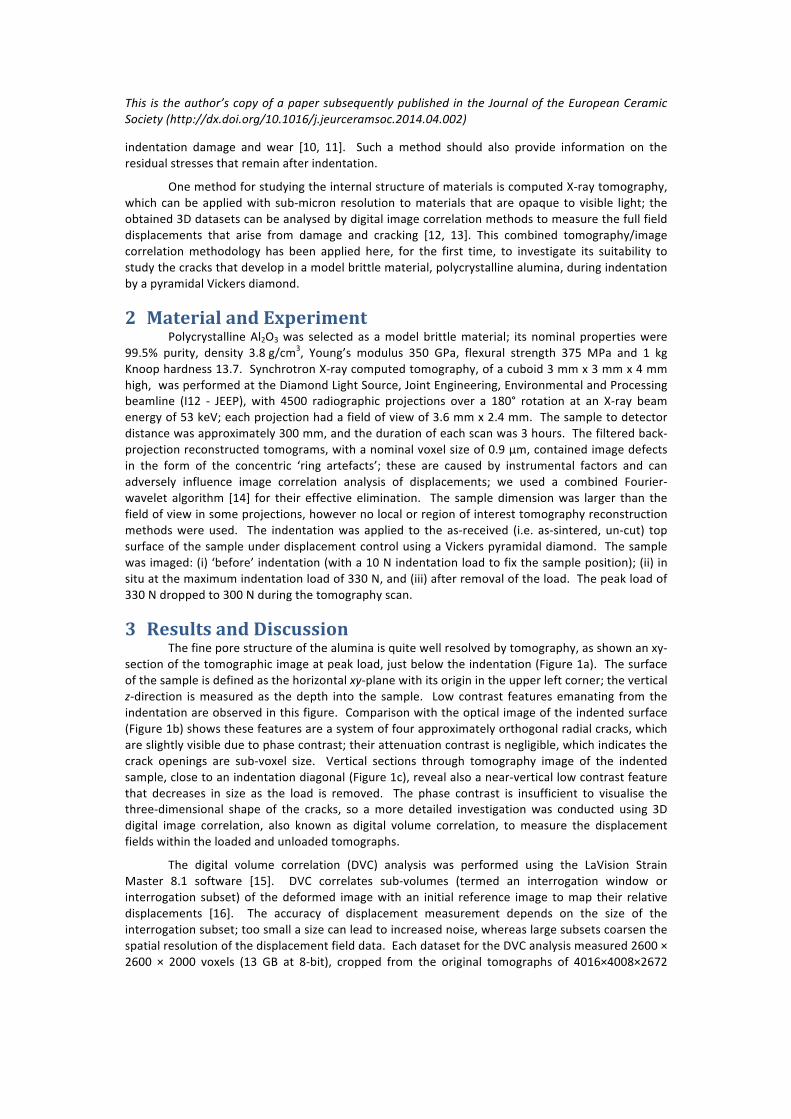
3 Results(and(Discussion(The&fine&pore&structure&of&the&alumina&is&quite&well&resolved&by&tomography,&as&shown&an&xyL
section&of&the&tomographic&image&at&peak&load,&just&below&the&indentation&(Figure&1a).&&The&surface&
of&the&sample&is&defined&as&the&horizontal&xyLplane&with&its&origin&in&the&upper&left&corner;&the&vertical&
zLdirection& is&measured&as& the&depth& into& the& sample.& & Low&contrast& features&emanating& from& the&
indentation&are&observed&in&this&figure.&&Comparison&with&the&optical&image&of&the&indented&surface&
(Figure&1b)&shows&these&features&are&a&system&of&four&approximately&orthogonal&radial&cracks,&which&
are&slightly&visible&due&to&phase&contrast;&their&attenuation&contrast&is&negligible,&which&indicates&the&
crack& openings& are& subLvoxel& size.& & Vertical& sections& through& tomography& image& of& the& indented&
sample,&close&to&an&indentation&diagonal&(Figure&1c),&reveal&also&a&nearLvertical&low&contrast&feature&
that& decreases& in& size& as& the& load& is& removed.& & The& phase& contrast& is& insufficient& to& visualise& the&
threeLdimensional& shape& of& the& cracks,& so& a&more& detailed& investigation&was& conducted& using& 3D&
digital& image& correlation,& also& known& as& digital& volume& correlation,& to&measure& the& displacement&
fields&within&the&loaded&and&unloaded&tomographs.&
The& digital& volume& correlation& (DVC)& analysis& was& performed& using& the& LaVision& Strain&
Master& 8.1& software& [15].& & DVC& correlates& subLvolumes& (termed& an& interrogation& window& or&
interrogation& subset)& of& the&deformed& image&with& an& initial& reference& image& to&map& their& relative&
displacements& [16].& & The& accuracy& of& displacement& measurement& depends& on& the& size& of& the&
interrogation⊂&too&small&a&size&can&lead&to&increased&noise,&whereas&large&subsets&coarsen&the&
spatial&resolution&of&the&displacement&field&data.&&Each&dataset&for&the&DVC&analysis&measured&2600&×&
2600& ×& 2000& voxels& (13& GB& at& 8Lbit),& cropped& from& the& original& tomographs& of& 4016×4008×2672&
This% is%the%author’s%copy%of%a%paper%subsequently%published% in%the%Journal%of%the%European%Ceramic%
Society%(http://dx.doi.org/10.1016/j.jeurceramsoc.2014.04.002)%
voxels& (160& GB& as& 32& bit& data).& & Coarse& rigid& body& translations& between& datasets& were& corrected&
before&DVC&analysis&by&visual&matching&and®istration&of& image&slices& in&an&xy&plane&close&to& the&
indented&surface.&&The&image&correlation¶meters&found&to&be&optimal&for&these&data&were&a&256&
×&256&×&256&voxel& interrogation&subset,&with&50%&overlap&and&2&passes,& followed&by&a&128&×&128&×&
128&interrogation&subset,&with&75%&overlap&and&3&passes.&&Smaller&interrogation&subsets&substantially&
increased&the&noise&in&the&displacement&field,&by&a&factor&of&almost&2.&&The&overlap&is&the&fraction&of&
the& previous& interrogation& subset& that& is& included& in& an& adjacent& subset& during& the& analysis.& & The&
displacements&are&obtained&iteratively&as&the&number&of&passes&of&the&interrogation&subset&through&
the& data& is& increased.& & The& output& data& were& the& 3D& full& field& displacements,& strains& (i.e.&
displacement& field& gradients)& and& also& the& correlation& coefficient& for& each& interrogation& window;&
these&values&are&reported&at&the¢re&of&the&interrogation&window,&hence&the&data&closest&to&the&
surface&are&at&a&representative&depth&of&z=&57.6&µm&(i.e.&64&voxels).&&The&first&tomography&scan&(at&10&
N)&was&used&as&the&reference&for&the&DVC&analysis&of&both&the&peakLloaded&and&unLloaded&scans.&
There&is&an&inevitable&rigid&body&rotation&of&the&sample&between&successive&scans&due&to&the&
effects&of&mechanical&loading&in&a&system&that&is¬&infinitely&stiff.&&This&was&removed&by&geometrical&
transformation&of& the&DVCLobtained&displacement& field,& setting& the& relative&displacement&between&
samples&to&zero&at&their&base;&a&position&that&was&remote&from&the&indentation&and&its&deformation&
field.&&The&displacement&vector&reference&system&then&becomes&better&aligned&with&the&axes&of&the&
sample& and& the& indentation& loading& by& fine& correction& of& the& rigid& body& movements.& & This& is&
particularly&important&when&the&measured&displacements&are&small&[17].& &To&do&this,&the&rigid&body&
rotation& was& decomposed& into& a& sequence& of& six& shear& transformations;& one& can& determine& two&
shear&angles&for&each&planar&slice&or&layer&along&axes&lying&in&this&plane.&&A&similar&transformation&is&
applied& to& all& layers& in& the& orthogonal& planes,& resulting& in& a& body& rotation;& the& use& of& all& six&
conforming&shears&rotates&the&body&around&all&three&axes&[18L20].&&The&transformations&are&applied&
to& the& displacement& field& dataset,& and& because& it& is& considerably& smaller& than& the& tomography&
dataset&(by&a&factor&of&up&to&1/1283&in&this&case),&this&method&is&computationally&more&efficient&than&
correction& by& rotation& of& one& of& the& tomography& images.& There& is& also& no& requirement& for&
interpolation&of&the&image&data.&
The&displacement&measurement&uncertainty,&estimated&as&the&standard&error&after&rotation&
correction&from&a®ion&of&negligible&deformation&that&was&remote&from&the&indentation,&was&0.28&
μm& for& the& loaded& state& and& 0.45& μm& for& the& final& unloaded& state& (i.e.& ~0.3& and& 0.5& voxel&
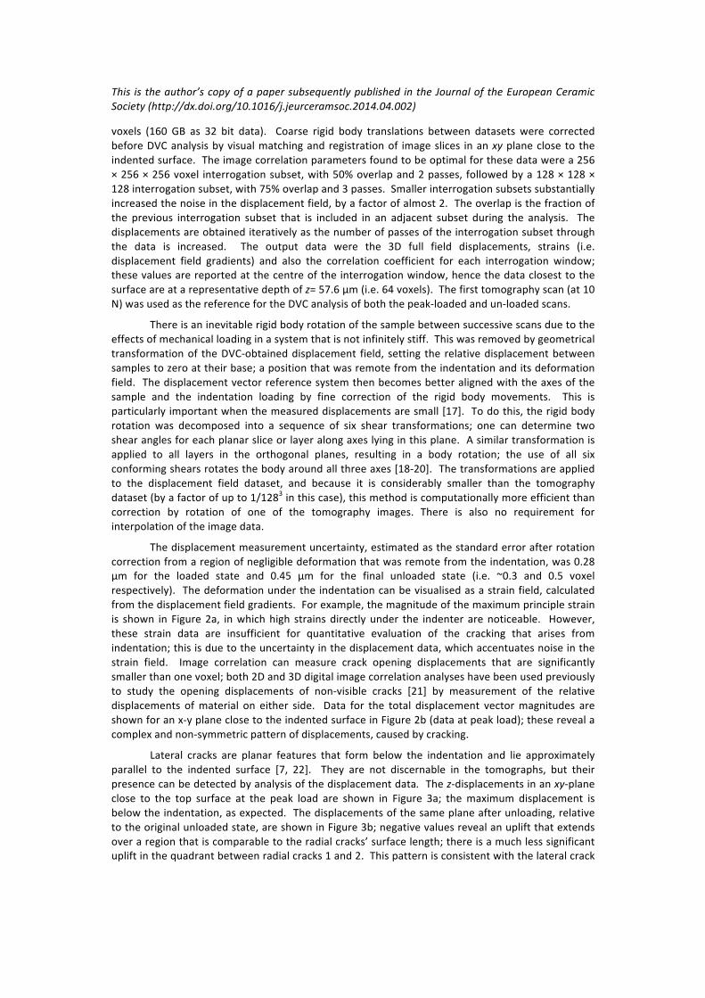
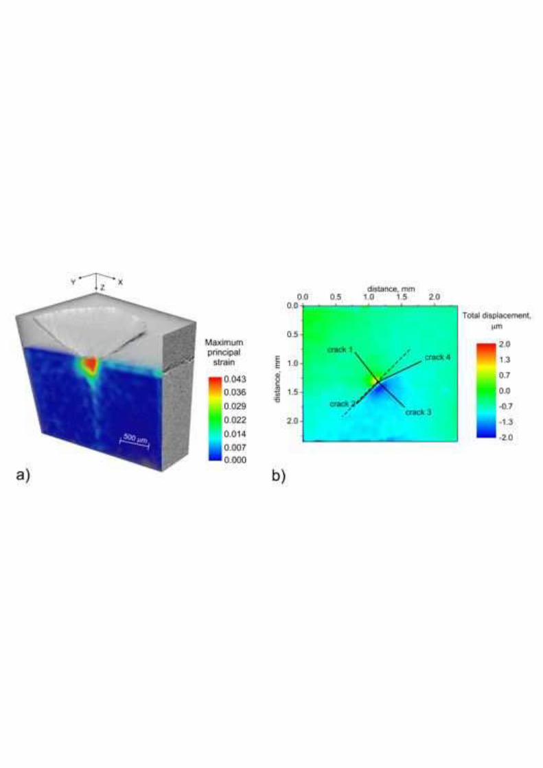
respectively).& &The&deformation&under&the&indentation&can&be&visualised&as&a&strain&field,&calculated&
from&the&displacement&field&gradients.&&For&example,&the&magnitude&of&the&maximum&principle&strain&
is& shown& in& Figure&2a,& in&which&high& strains& directly& under& the& indenter& are¬iceable.& &However,&
these& strain& data& are& insufficient& for& quantitative& evaluation& of& the& cracking& that& arises& from&
indentation;&this&is&due&to&the&uncertainty&in&the&displacement&data,&which&accentuates&noise&in&the&
strain& field.& & Image& correlation& can& measure& crack& opening& displacements& that& are& significantly&
smaller&than&one&voxel;&both&2D&and&3D&digital&image&correlation&analyses&have&been&used&previously&
to& study& the& opening& displacements& of& nonLvisible& cracks& [21]& by& measurement& of& the& relative&
displacements& of&material& on& either& side.& & Data& for& the& total& displacement& vector&magnitudes& are&
shown&for&an&xLy&plane&close&to&the&indented&surface&in&Figure&2b&(data&at&peak&load);&these&reveal&a&
complex&and&nonLsymmetric&pattern&of&displacements,&caused&by&cracking.&&&
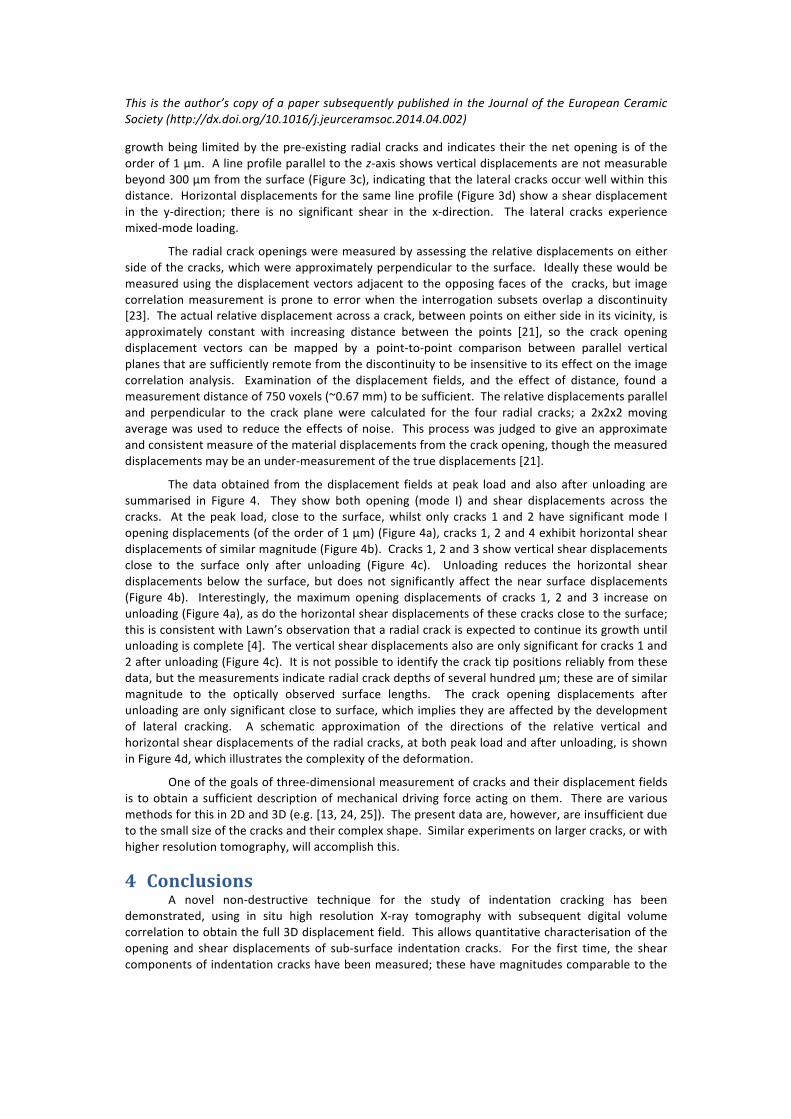
Lateral& cracks& are& planar& features& that& form& below& the& indentation& and& lie& approximately&
parallel& to& the& indented& surface& [7,& 22].& & They& are& not& discernable& in& the& tomographs,& but& their&
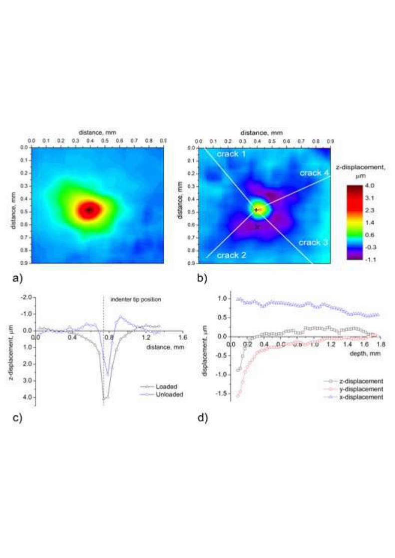
presence&can&be&detected&by&analysis&of&the&displacement&data.%%The&zLdisplacements&in&an&xyLplane&
close& to& the& top& surface& at& the& peak& load& are& shown& in& Figure& 3a;& the&maximum& displacement& is&
below&the&indentation,&as&expected.&&The&displacements&of&the&same&plane&after&unloading,&relative&
to&the&original&unloaded&state,&are&shown&in&Figure&3b;&negative&values&reveal&an&uplift&that&extends&
over&a®ion&that&is&comparable&to&the&radial&cracks’&surface&length;&there&is&a&much&less&significant&
uplift&in&the&quadrant&between&radial&cracks&1&and&2.&&This&pattern&is&consistent&with&the&lateral&crack&
This% is%the%author’s%copy%of%a%paper%subsequently%published% in%the%Journal%of%the%European%Ceramic%
Society%(http://dx.doi.org/10.1016/j.jeurceramsoc.2014.04.002)%
growth&being& limited&by& the&preLexisting& radial&cracks&and& indicates& their& the&net&opening& is&of& the&
order&of&1&µm.&&A&line&profile¶llel&to&the&zLaxis&shows&vertical&displacements&are¬&measurable&
beyond&300&µm&from&the&surface&(Figure&3c),&indicating&that&the&lateral&cracks&occur&well&within&this&
distance.&&Horizontal&displacements&for&the&same&line&profile&(Figure&3d)&show&a&shear&displacement&
in& the& yLdirection;& there& is& no& significant& shear& in& the& xLdirection.& & The& lateral& cracks& experience&
mixedLmode&loading.&
The&radial&crack&openings&were&measured&by&assessing&the&relative&displacements&on&either&
side&of&the&cracks,&which&were&approximately&perpendicular&to&the&surface.& & Ideally&these&would&be&
measured&using&the&displacement&vectors&adjacent&to&the&opposing&faces&of&the& &cracks,&but& image&
correlation&measurement& is&prone& to&error&when& the& interrogation& subsets&overlap&a&discontinuity&
[23].&&The&actual&relative&displacement&across&a&crack,&between&points&on&either&side&in&its&vicinity,&is&
approximately& constant& with& increasing& distance& between& the& points& [21],& so& the& crack& opening&
displacement& vectors& can& be& mapped& by& a& pointLtoLpoint& comparison& between& parallel& vertical&
planes&that&are&sufficiently&remote&from&the&discontinuity&to&be&insensitive&to&its&effect&on&the&image&
correlation& analysis.& & Examination& of& the& displacement& fields,& and& the& effect& of& distance,& found& a&
measurement&distance&of&750&voxels&(~0.67&mm)&to&be&sufficient.&&The&relative&displacements¶llel&
and& perpendicular& to& the& crack& plane& were& calculated& for& the& four& radial& cracks;& a& 2x2x2&moving&
average&was&used&to&reduce&the&effects&of&noise.& &This&process&was& judged&to&give&an&approximate&
and&consistent&measure&of&the&material&displacements&from&the&crack&opening,&though&the&measured&
displacements&may&be&an&underLmeasurement&of&the&true&displacements&[21].&&&
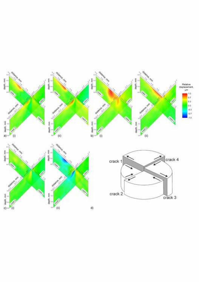
The&data&obtained& from& the&displacement& fields& at&peak& load&and&also& after&unloading&are&
summarised& in& Figure& 4.& & They& show& both& opening& (mode& I)& and& shear& displacements& across& the&
cracks.& & At& the&peak& load,& close& to& the& surface,&whilst& only& cracks& 1& and&2&have& significant&mode& I&
opening&displacements&(of&the&order&of&1&µm)&(Figure&4a),&cracks&1,&2&and&4&exhibit&horizontal&shear&
displacements&of&similar&magnitude&(Figure&4b).&&Cracks&1,&2&and&3&show&vertical&shear&displacements&
close& to& the& surface& only& after& unloading& (Figure& 4c).& & Unloading& reduces& the& horizontal& shear&
displacements& below& the& surface,& but& does& not& significantly& affect& the&near& surface&displacements&
(Figure& 4b).& & Interestingly,& the&maximum& opening& displacements& of& cracks& 1,& 2& and& 3& increase& on&
unloading&(Figure&4a),&as&do&the&horizontal&shear&displacements&of&these&cracks&close&to&the&surface;&
this&is&consistent&with&Lawn’s&observation&that&a&radial&crack&is&expected&to&continue&its&growth&until&
unloading&is&complete&[4].&&The&vertical&shear&displacements&also&are&only&significant&for&cracks&1&and&
2&after&unloading&(Figure&4c).&&It&is¬&possible&to&identify&the&crack&tip&positions&reliably&from&these&
data,&but&the&measurements&indicate&radial&crack&depths&of&several&hundred&µm;&these&are&of&similar&
magnitude& to& the& optically& observed& surface& lengths.& & The& crack& opening& displacements& after&
unloading&are&only&significant&close&to&surface,&which&implies&they&are&affected&by&the&development&
of& lateral& cracking.& & A& schematic& approximation& of& the& directions& of& the& relative& vertical& and&
horizontal&shear&displacements&of&the&radial&cracks,&at&both&peak&load&and&after&unloading,&is&shown&
in&Figure&4d,&which&illustrates&the&complexity&of&the&deformation.&
One&of&the&goals&of&threeLdimensional&measurement&of&cracks&and&their&displacement&fields&
is& to&obtain&a& sufficient&description&of&mechanical&driving& force&acting&on& them.& &There&are&various&
methods&for&this&in&2D&and&3D&(e.g.&[13,&24,&25]).&&The&present&data&are,&however,&are&insufficient&due&
to&the&small&size&of&the&cracks&and&their&complex&shape.&&Similar&experiments&on&larger&cracks,&or&with&
higher&resolution&tomography,&will&accomplish&this.&
4 Conclusions(A& novel& nonLdestructive& technique& for& the& study& of& indentation& cracking& has& been&
demonstrated,& using& in& situ& high& resolution& XLray& tomography& with& subsequent& digital& volume&
correlation&to&obtain&the&full&3D&displacement&field.&&This&allows&quantitative&characterisation&of&the&
opening& and& shear& displacements& of& subLsurface& indentation& cracks.& & For& the& first& time,& the& shear&
components&of&indentation&cracks&have&been&measured;&these&have&magnitudes&comparable&to&the&
This% is%the%author’s%copy%of%a%paper%subsequently%published% in%the%Journal%of%the%European%Ceramic%
Society%(http://dx.doi.org/10.1016/j.jeurceramsoc.2014.04.002)%
opening& displacements,& which& are& approximately& 1& µm.& & Lateral& cracks,& also& with& opening&
displacements&of&approximately&1&µm,&develop&with&unloading&and&are&bounded&by&the&radial&cracks&
that&formed&on&loading.&&It&is&proposed&that&this&technique&of&crack&characterisation&is&well&suited&to&
the&study&of&indentation&and&role&of&residual&stresses&on&damage&development&during&abrasive&wear&
in&brittle&materials.&
5 Acknowledgements(This& work& was& carried& out& with& the& support& of& the& Diamond& Light& Source;& the& authors&
acknowledge& the& beam& time& award& at& the& Joint& Engineering,& Environmental& and& Processing& (I12)&
beamline& (Experiment& EE7730)& and& the& help& of& Dr& D.M.& Collins,& Dr& H.& Çetinel& and&Mr& S.& Barhli& to&
conduct&the&experiment.&&MM&and&TJM&gratefully&acknowledge&the&support&of&Oxford&Martin&School,&
MM&acknowledges&the&support&of&Linacre&College,&Oxford&through&a&Junior&Research&Fellowship&and&
YV& acknowledges& the& support& of& EDF& Energy& UK.& & The&Manchester& XLRay& Imaging& Facility& (Dr& S.A.&
McDonald&and&Professor&P.M.&Mummery)&are&thanked&for&the&loan&of&the&loading&rig.&&Professor&R.I.&
Todd,&The&University&of&Oxford,& is& thanked& for&valuable&discussions.& &Almath&Crucibles&are& thanked&
for&supplying&the&alumina.&
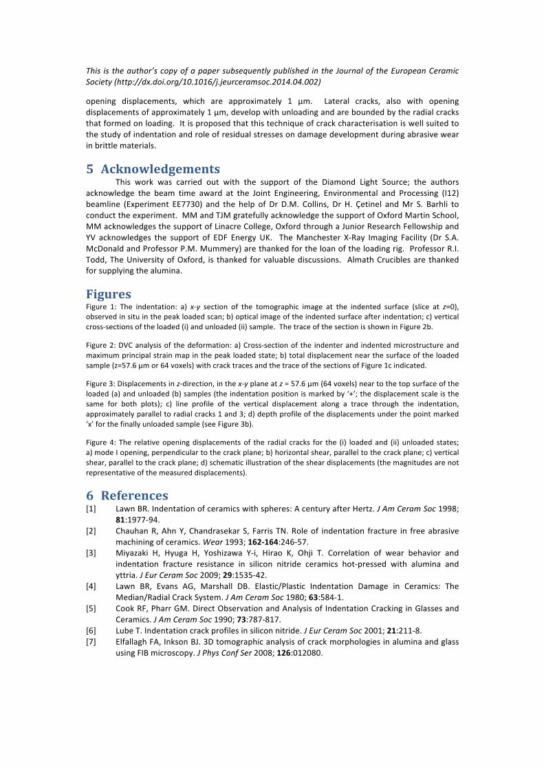
Figures(Figure& 1:& The& indentation:& a)& xIy& section& of& the& tomographic& image& at& the& indented& surface& (slice& at& z=0),&
observed&in&situ&in&the&peak&loaded&scan;&b)&optical&image&of&the&indented&surface&after&indentation;&c)&vertical&
crossLsections&of&the&loaded&(i)&and&unloaded&(ii)&sample.&&The&trace&of&the§ion&is&shown&in&Figure&2b.&
Figure&2:&DVC&analysis&of&the&deformation:&a)&CrossLsection&of&the& indenter&and& indentedµstructure&and&
maximum&principal&strain&map&in&the&peak&loaded&state;&b)&total&displacement&near&the&surface&of&the&loaded&
sample&(z=57.6&μm&or&64&voxels)&with&crack&traces&and&the&trace&of&the§ions&of&Figure&1c&indicated.&
Figure&3:&Displacements&in&zLdirection,&in&the&xIy&plane&at&z%=&57.6&µm&(64&voxels)&near&to&the&top&surface&of&the&
loaded&(a)&and&unloaded&(b)&samples&(the&indentation&position&is&marked&by&‘+’;&the&displacement&scale&is&the&
same& for& both& plots);& c)& line& profile& of& the& vertical& displacement& along& a& trace& through& the& indentation,&
approximately¶llel&to&radial&cracks&1&and&3;&d)&depth&profile&of&the&displacements&under&the&point&marked&
‘x’&for&the&finally&unloaded&sample&(see&Figure&3b).&
Figure&4:& The& relative&opening&displacements&of& the& radial& cracks& for& the& (i)& loaded&and& (ii)& unloaded& states;&
a)&mode&I&opening,&perpendicular&to&the&crack&plane;&b)&horizontal&shear,¶llel&to&the&crack&plane;&c)&vertical&
shear,¶llel&to&the&crack&plane;&d)&schematic&illustration&of&the&shear&displacements&(the&magnitudes&are¬&
representative&of&the&measured&displacements).&
6 References([1]& Lawn&BR.&Indentation&of&ceramics&with&spheres:&A¢ury&after&Hertz.&J%Am%Ceram%Soc&1998;&
81:1977L94.&
[2]& Chauhan&R,&Ahn&Y,&Chandrasekar&S,& Farris&TN.&Role&of& indentation& fracture& in& free&abrasive&
machining&of&ceramics.&Wear&1993;&162%164:246L57.&
[3]& Miyazaki& H,& Hyuga& H,& Yoshizawa& YLi,& Hirao& K,& Ohji& T.& Correlation& of& wear& behavior& and&
indentation& fracture& resistance& in& silicon& nitride& ceramics& hotLpressed& with& alumina& and&
yttria.&J%Eur%Ceram%Soc&2009;&29:1535L42.&
[4]& Lawn& BR,& Evans& AG,& Marshall& DB.& Elastic/Plastic& Indentation& Damage& in& Ceramics:& The&
Median/Radial&Crack&System.&J%Am%Ceram%Soc&1980;&63:584L1.&
[5]& Cook&RF,&Pharr&GM.&Direct&Observation&and&Analysis&of& Indentation&Cracking&in&Glasses&and&
Ceramics.&J%Am%Ceram%Soc&1990;&73:787L817.&
[6]& Lube&T.&Indentation&crack&profiles&in&silicon&nitride.&J%Eur%Ceram%Soc&2001;&21:211L8.&
[7]& Elfallagh&FA,&Inkson&BJ.&3D&tomographic&analysis&of&crack&morphologies&in&alumina&and&glass&
using&FIBµscopy.&J%Phys%Conf%Ser&2008;&126:012080.&

This% is%the%author’s%copy%of%a%paper%subsequently%published% in%the%Journal%of%the%European%Ceramic%
Society%(http://dx.doi.org/10.1016/j.jeurceramsoc.2014.04.002)%
[8]& Guo& S,& Todd& RI.& Quantitative& optical& fluorescence& microprobe& measurements& of& stresses&
around& indentations& in& Al2O3& and& Al2O3/SiC& nanocomposites:& The& influence& of& depth&
resolution&and&specimen&translucency.&Acta%Mater&2011;&59:2637L47.&
[9]& Kruzic& JJ,& Ritchie& RO.& Determining& the& Toughness& of& Ceramics& from& Vickers& Indentations&
Using& the& CrackLOpening& Displacements:& An& Experimental& Study.& J% Am% Ceram% Soc& 2003;&
86:1433L6.&
[10]& Qasim&T,&Ford&C,&Bush&MB,&Hu&X,&Lawn&BR.&Effect&of&offLaxis&concentrated&loading&on&failure&
of&curved&brittle&layer&structures.&J%BIiomed%Mater%Res%B&2006;&76:334L9.&
[11]& Holmberg& K,& Laukkanen& A,& Ronkainen& H,& Wallin& K,& Varjus& S.& A& model& for& stresses,& crack&
generation&and&fracture&toughness&calculation&in&scratched&TiNLcoated&steel&surfaces.&Wear&
2003;&254:278L91.&
[12]& Mostafavi&M,&Baimpas&N,&Tarleton&E,&Atwood&RC,&McDonald&SA,&Korsunsky&AM,%et%al.&ThreeL
dimensional&crack&observation,&quantification&and&simulation&in&a&quasiLbrittle&material.&Acta%
Mater&2013;&61:6276L89.&
[13]& Limodin& N,& Réthoré& J,& Buffière& JLY,& Gravouil& A,& Hild& F,& Roux& S.& Crack& closure& and& stress&
intensity& factor& measurements& in& nodular& graphite& cast& iron& using& threeLdimensional&
correlation&of&laboratory&XLrayµtomography&images.&Acta%Mater&2009;&57:4090L101.&
[14]& Münch&B,&Trtik&P,&Marone&F,&Stampanoni&M.&Stripe&and&ring&artifact&removal&with&combined&
waveletLFourier&filtering.&Opt%Express&2009;&17:8567L91.&
[15]& DaVis.&User's&Manual.&Gottingen:&LaVision&GmbH;&2012.&
[16]& Bay&BK,& Smith& TS,& Fyhrie&DP,& Saad&M.&Digital& volume& correlation:& ThreeLdimensional& strain&
mapping&using&xLray&tomography.&Exp%Mech&1999;&39:217L26.&
[17]& Mostafavi&M,& Vertyagina& Y,& Reinhard& C,& Bradley& R,& Jiang& X,& Galano&M,% et% al.& 3D& studies& of&
indentation& by& combined& XLray& tomography& and& digital& volume& correlation.& Key% Eng% Mat&
2014;&592%593:14L21.&
[18]& Paeth&AW.&A&fast&algorithm&for&general&raster&rotation.&Proc%Graph%Interf&1986;&77L81.&
[19]& Toffoli&T,&Quick&J.&ThreeLDimensional&Rotations&by&Three&Shears.&Graph%Model%Im%Proc&1997;&
59:89L95.&
[20]& Chen&B,&Kaufman&A.&3D&Volume&Rotation&Using&Shear&Transformations.&Graph%Models&2000;&
62:308L22.&
[21]& Mostafavi& M,& McDonald& SA,& Çetinel& H,& Mummery& PM,& Marrow& TJ.& Flexural& strength& and&
defect& behaviour& of& polygranular& graphite& under& different& states& of& stress.& Carbon& 2013;&
59:325L36.&
[22]& Marshall&DB,&Lawn&BR,&Evans&AG.&Elastic/Plastic&Insentation&Damage&in&Ceramics:&The&Lateral&
Crack&System.&J%Am%Ceram%Soc&1982;&65:561L6.&
[23]& Bernard& G,& Hild& F,& S.& R.& FiniteLElement:& displacement& field& analysis& from& digital& images:&
application&to&PortevinLLe&Chatelier&Bands.&Exp%Mech&2006;&46:789L803.&
[24]& Becker& TH,& Mostafavi& M,& Tait& RB,& Marrow& TJ.& An& approach& to& calculate& the& JLintegral& by&
digital&image&correlation&displacement&field&measurement.&Fatigue%Fract%Eng%M&2012;&35:971&
–&84.&
[25]& Rethore& J,& Roux& S,& Hild& F.& An& extended& and& integrated& digital& image& correlation& technique&
applied&to&the&analysis&of&fractured&samples.&Eur%J%Comput%Mech&2009;&18:285L306.&
&
&

Copyright © 2022 FDOKUMEN