Improving verification accuracy by synthesis of locally enhanced biometric images and deformable...
19
Signal Processing 87 (2007) 2746–2764 Improving verification accuracy by synthesis of locally enhanced biometric images and deformable model Richa Singh, Mayank Vatsa, Afzel Noore Lane Department of Computer Science and Electrical Engineering, West Virginia University, USA Received 12 October 2006; received in revised form 10 May 2007; accepted 11 May 2007 Available online 25 May 2007 Abstract In this paper, we propose a 2-stage preprocessing framework which consists of image enhancement and deformation techniques to increase the verification performance of image-based biometric systems. In the preprocessing framework, first the quality of biometric image is enhanced and then a deformation model is applied to minimize the variation between the two images to be matched. The proposed SVM image quality enhancement algorithm selects good quality regions from different globally enhanced images and combines them to generate a single high-quality feature-rich image. The proposed deformation algorithm is based on phase congruency information and locally minimizes the variations between two images while retaining the features required for recognition. The proposed algorithms are validated using face and iris biometrics as the two case studies. For performance evaluation, different face and iris recognition algorithms are chosen and the verification accuracy is computed using non-homogenous face and iris databases. Experimental results show that the performance of face and iris recognition algorithms are significantly improved when the input images are preprocessed using the proposed enhancement and deformation algorithms. r 2007 Elsevier B.V. All rights reserved. Keywords: Quality enhancement; Support vector machine; Deformation; Phase congruency; Face recognition; Iris recognition 1. Introduction In biometrics, quality refers to the intrinsic physical data content. National Institute of Stan- dards and Technology defines biometric quality as the accuracy with which physical characteristics are represented in a given biometric data [1,2]. The performance of a biometric system depends on the quality of images collected as either a reference or a live sample. The irregularities present in the image have significant impact on the recognition perfor- mance. Irregularities can be classified based on variations in image characteristics and based on intrinsic geometric changes. Irregularities such as blur, noise, and improper illumination belong to image-based irregularities and can be removed by applying image enhancement algorithms. Irregula- rities due to geometric deformation belong to intrinsic irregularities and can be corrected using deformation techniques. Image-based irregularities can be removed by controlling the environment in which images are ARTICLE IN PRESS www.elsevier.com/locate/sigpro 0165-1684/$ - see front matter r 2007 Elsevier B.V. All rights reserved. doi:10.1016/j.sigpro.2007.05.009 Corresponding author. Tel.: +1 304 293 0405; fax: +1 304 293 8602. E-mail addresses: [email protected] (R. Singh), [email protected] (M. Vatsa), [email protected] (A. Noore).
-
Upload
richalucknowescorts -
Category
Documents
-
view
0 -
download
0
Transcript of Improving verification accuracy by synthesis of locally enhanced biometric images and deformable...

ARTICLE IN PRESS
0165-1684/$ - se
doi:10.1016/j.si
�Correspondfax: +1304 293
E-mail addr
mayankv@csee
(A. Noore).
Signal Processing 87 (2007) 2746–2764
www.elsevier.com/locate/sigpro
Improving verification accuracy by synthesis of locally enhancedbiometric images and deformable model
Richa Singh, Mayank Vatsa, Afzel Noore�
Lane Department of Computer Science and Electrical Engineering, West Virginia University, USA
Received 12 October 2006; received in revised form 10 May 2007; accepted 11 May 2007
Available online 25 May 2007
Abstract
In this paper, we propose a 2-stage preprocessing framework which consists of image enhancement and deformation
techniques to increase the verification performance of image-based biometric systems. In the preprocessing framework,
first the quality of biometric image is enhanced and then a deformation model is applied to minimize the variation between
the two images to be matched. The proposed SVM image quality enhancement algorithm selects good quality regions from
different globally enhanced images and combines them to generate a single high-quality feature-rich image. The proposed
deformation algorithm is based on phase congruency information and locally minimizes the variations between two images
while retaining the features required for recognition. The proposed algorithms are validated using face and iris biometrics
as the two case studies. For performance evaluation, different face and iris recognition algorithms are chosen and the
verification accuracy is computed using non-homogenous face and iris databases. Experimental results show that the
performance of face and iris recognition algorithms are significantly improved when the input images are preprocessed
using the proposed enhancement and deformation algorithms.
r 2007 Elsevier B.V. All rights reserved.
Keywords: Quality enhancement; Support vector machine; Deformation; Phase congruency; Face recognition; Iris recognition
1. Introduction
In biometrics, quality refers to the intrinsicphysical data content. National Institute of Stan-dards and Technology defines biometric quality asthe accuracy with which physical characteristics arerepresented in a given biometric data [1,2]. Theperformance of a biometric system depends on the
e front matter r 2007 Elsevier B.V. All rights reserved
gpro.2007.05.009
ing author. Tel.: +1 304 293 0405;
8602.
esses: [email protected] (R. Singh),
.wvu.edu (M. Vatsa), [email protected]
quality of images collected as either a reference or alive sample. The irregularities present in the imagehave significant impact on the recognition perfor-mance. Irregularities can be classified based onvariations in image characteristics and based onintrinsic geometric changes. Irregularities such asblur, noise, and improper illumination belong toimage-based irregularities and can be removed byapplying image enhancement algorithms. Irregula-rities due to geometric deformation belong tointrinsic irregularities and can be corrected usingdeformation techniques.
Image-based irregularities can be removed bycontrolling the environment in which images are
.

ARTICLE IN PRESSR. Singh et al. / Signal Processing 87 (2007) 2746–2764 2747
captured, using improved sensors, and applyingeffective algorithms for recognition and matching.Most of the image enhancement algorithms [3–7],are globally applied on the entire biometric image.While these algorithms enhance regions of theimage with poor quality, they also change thecharacteristics of the image that are of acceptable orhigh quality. Moreover, the poor quality of animage may be due to multiple irregularities such asexcessive noise, poor illumination, or motionartifacts introduced during image capture. Forexample, a face image may contain noise in someparts of the image with improper illumination andalso have red-eye effect. The challenge in enhancingsuch images is to locally segment the affectedregions from the image and apply appropriateenhancement algorithms. The selection of a parti-cular algorithm to enhance a region of degradedimage can be challenging, time consuming, andnot pragmatic for real-time applications. There isalso uncertainty on the type of irregularity thatexists in any given image. To address thesechallenges, we propose an image enhancementalgorithm that first applies selected well knownenhancement algorithms on the original image togenerate different globally enhanced images. Sup-port vector machine (SVM) based learning algo-rithm then identifies the local good quality regionsfrom each of the globally enhanced images andsynergistically combines them to form a singleimage. This image contains high quality feature-rich enhanced regions that can be used by biometricrecognition algorithms to improve the recognitionperformance.
Another factor which affects the recognitionperformance is the intrinsic irregularities i.e., thevariation or deformation present in the query andreference image. Deformation correction is requiredbecause biometric images such as fingerprint, iris,and face are non-rigid. For the same individual,fingerprint images captured under different pressureor on different surfaces can introduce non-linearelastic variability in image features [8]. Similarvariations are encountered when an iris image iscontracted or dilated [9], or a face image is capturedwith varying expressions [10,11]. Very limitedresearch exists on deformation of 2D face imageswhereas 3D face modeling has been an activeresearch area [11,12]. Most of the researchers forexpression modeling in 2D do not show therecognition performance [13,14]. One of the majorconstraints is that the modeling or deformation
algorithm should not affect or alter the featuresrequired for face recognition. Chellappa et al. [15]have used mesh-based transformation to correct thedeformation and improve the recognition perfor-mance. Their algorithm corrects the variation whichare caused by different configurations of mouth butis less effective to changes in facial appearance dueto deformation in other areas of the face. Similarly,researchers have proposed different techniques tocompensate the effect of deformation in irisrecognition. Wildes et al. [16] used registration-based unwrapping technique, Daugman [5] unwrapsthe iris into dimensionless polar coordinate system,and Ma et al. [6] unwraps the image to a fixed size tocompensate for deformation. However, these defor-mation algorithms need correct detection and theerror of few pixels may affect the process ofdeformation correction. This paper shows theefficacy of using deformable models to accommo-date these variations in an individual image given a
priori knowledge about the characteristics anddegree of variability in size and shape of differentbiometric features of interest. Specifically, we usephase congruency-based deformable model on theenhanced image to minimize the variation between areference image and a query image.
Thus, in this paper, we propose a 2-stagepreprocessing framework to improve the recognitionperformance of image-based biometrics. The pro-posed preprocessing framework involves enhancingthe quality of the input image and then applyingdeformation algorithm to minimize any variationbetween the images to be matched. The proposedpreprocessing framework can be applied to anyimage-based biometrics to improve the recognitionperformance. In this paper, we use face and irisimages as case studies to validate the proposedalgorithms. For validation, we have selected differentface and iris recognition algorithms and prepared anon-homogenous combined database for both faceand iris. The database contains 1050 classes withseven images per class. We evaluate the performanceby computing the recognition accuracy of originalimages using the proposed 2-stage preprocessingalgorithm.
Section 2 presents the proposed image qualityenhancement algorithm for face and iris images. InSection 3, we describe the proposed deformationmodel using phase congruency in face and iris images.Section 4 summarizes the recognition algorithms,databases, and the experimental results for validation.Section 5 describes the computational complexity

ARTICLE IN PRESSR. Singh et al. / Signal Processing 87 (2007) 2746–27642748
of the proposed enhancement and deformationalgorithm.
2. Synthesizing a single high quality image from
globally enhanced multiple images
Images collected in an uncontrolled environmentmay suffer in quality due to different irregularitiessuch as blur, noise, and improper illumination,causing degradation in the recognition performance.Fig. 1 shows sample face images captured underuncontrolled environment that contain differenttypes of irregularities. Usually, irregularities suchas blurriness and noise are observed in local regionsof the image. As shown in Fig. 2, global enhance-ment algorithms remove specific irregularities froma poor quality image. Furthermore, global enhance-ment algorithms may also affect the good qualityregions present in the biometric image whichdegrades the recognition performance. Identifyingand isolating these local regions in an image canbe tedious, time consuming, and not pragmatic.
Fig. 1. Face images with irregularities such as noise, blur, and
improper illumination.
Original Face Imagewith MultipleIrregularities
(Noise + Illumination)
Face Image afterGlobal Noise
Removal
Face Image afterGlobal Correction
for Illumination
Fig. 2. Global enhancement algorithms applied on face images
with multiple irregularities.
To confine the image quality enhancement to localregions in the image, we propose a quality enhance-ment algorithm in which we first concurrently applya set of enhancement algorithms globally to thewhole image and then locally select the good qualityregions to generate the enhanced image.
Let I be the original image and the functionenhanceðIÞ represents the image enhancement algo-rithm such as blur removal and denoising togenerate the enhanced image I i.
I i ¼ enhanceðIÞ. (1)
By selecting several known image enhancementalgorithms, a set of quality enhanced images I i isgenerated. From each globally enhanced image andthe original image, a SVM-based learning algorithmidentifies locally enhanced regions and synergisti-cally combines them to form a single high qualityimage.
SVM starts with the goal of separating the datawith a hyperplane and extends this to non-lineardecision boundaries [17]. SVM is a classifier thatperforms classification by constructing hyperplanesin a multidimensional space and separating the datapoints into different classes. To construct anoptimal hyperplane, SVM uses an iterative trainingalgorithm which maximizes the margin between twoclasses. However, some researchers have shown thatmargin maximization does not always lead tominimum classification error [18]. Sometimes thetraining data points are not clearly separable andthey are characterized as fuzzy separable data. Inbiometrics, poor quality images and images contain-ing noise due to sensor often lead to incorrectclassification and hence can be considered as fuzzydata. To address the challenges, researchers haveproposed an attractive alternative to SVM thatoffers much more natural setting for parameterselection which is a critical issue in biometricapplications. This class of SVM is known as dualn-SVM (2n-SVM) [19]. The proposed learningalgorithm uses 2n-SVM to train and classify thegood and bad quality regions from the original andthe enhanced images. Dual n-SVM (2n-SVM) isbriefly described as follows:
Let fxi; yig be a set of N data vectors with xi 2
Rd ; yi 2 ½þ1;�1�; and i ¼ 1; . . . ;N. xi is the ithdata vector that belongs to a binary class yi. Theobjective of training 2n-SVM is to find the hyper-plane that separates the two classes with the widest

ARTICLE IN PRESSR. Singh et al. / Signal Processing 87 (2007) 2746–2764 2749
margins, i.e.,
wjðxÞ þ b ¼ 0 (2)
is subjected to
yiðwjðxÞ þ bÞXðr� ciÞ; ciX0 (3)
to minimize
1
2kwk2 �
Xi
Ciðnr� ciÞ, (4)
where r is the position of the margin and n is theerror parameter. jðxÞ is the mapping function usedto map the data space to the feature space, andprovide generalization for the decision function thatmay not be a linear function of the training data.Ciðnr� ciÞ is the cost of errors, w is the normalvector, b is the bias, and ci is the slack variable forclassification errors. The error parameter n can becalculated using nþ and n�, which are the errorparameters for training the positive and negativeclasses, respectively.
n ¼2nþn�nþ þ n�
; 0onþo1 and 0on�o1. (5)
Error penalty Ci is calculated as
C ¼Cþ if yi ¼ þ1;
C� if yi ¼ �1:
((6)
Here,
Cþ ¼ nþ 1þnþn�
� �� ��1, (7)
C� ¼ n� 1þn�nþ
� �� ��1(8)
and nþ and n� are the number of training points forthe positive and the negative classes, respectively.The 2n-SVM training can be formulated as
maxðaiÞ
�1
2
Xi;j
aiajyiyjKðxi;xjÞ
( ), (9)
where
0paipCi,Xi
aiyi ¼ 0,
Xi
aiXn, ð10Þ
i; j 2 1; . . . ;N and kernel function is
Kðxi; xjÞ ¼ jðxiÞjðxjÞ, (11)
Kðx;xiÞ ¼ expkx� xik
2
2s2
� �. (12)
Kernel, Kðxi;xjÞ, is the Radial Basis Function asdescribed in Eq. (12). The 2n-SVM uses iterativedecomposition training algorithm originally pro-posed by Chew et al. [19]. The optimizationalgorithm performs pairwise decomposition tosimplify the problem to two decision variables.The solution is obtained by solving the subproblemsanalytically, thus reducing the computational com-plexity. More details on the optimization algorithmcan be found in [19]. The proposed enhancementalgorithm comprises of training the 2n-SVM andthen using the trained 2n-SVM for classification andintegration. The training and the classificationalgorithms are described next.
2.1. 2n-SVM training
Labeled training samples are used to train 2n-SVM and classify pixels of the input image as goodor bad. Different regions from selected referenceinput and enhanced images are labeled as good orbad and these labeled regions are used for trainingthe 2n-SVM. The algorithm for 2n-SVM training isdescribed below.
Step 1: Training images are decomposed to l
levels by the discrete wavelet transform (DWT)which gives 3l detailed subbands and one approx-imation band.
Step 2: The activity level of wavelet coefficients iscomputed over a small window of size 3� 3 byprocessing each coefficient separately and thenaveraging the wavelet coefficients for the windowunder consideration. The activity level is computedfor different regions in the detailed subbands andapproximation band of the images.
Step 3: The activity level of wavelet coefficients isthen provided as input to the 2n-SVM for trainingand determining the quality. Thus the training data,xi, are the activity levels from several good and badregions, and yi are the corresponding labels.Further, the values of error parameters nþ and n�are computed as follows:
nþ ¼nþ
nþ þ n�, (13)
n� ¼n�
nþ þ n�, (14)
where nþ is the number of good activity levels andn� is the number of bad activity levels.

ARTICLE IN PRESS
Fig. 3. Face images with (a) no enhancement, (b) global enhancements, (c) SVM synthesized enhancement.
Fig. 4. Example of face images used for training 2n-SVM (a)
good quality images, (b) bad quality images.
R. Singh et al. / Signal Processing 87 (2007) 2746–27642750
Step 4: The 2n-SVM is trained using Eq. (9). Theoutput of trained 2n-SVM is a non-linear hyper-plane which assigns label G or 1 to the good qualitycoefficients, and B or 0 to the bad qualitycoefficients.
2.2. 2n-SVM classification and integration
Trained 2n-SVM is used to classify the pixels fromthe input image and to generate a new feature-richimage. The globally enhanced images along with theoriginal input image are decomposed to l levelDWT. The 2n-SVM classifier is then used to classifythe coefficients of different bands as good or bad.A decision matrix Decision is generated to store thequality of each coefficient in terms of G and B. Atany position ðx; yÞ, if the 2n-SVM output Oðx; yÞ ispositive then that coefficient is labeled as G;otherwise it is labeled as B.
Decisionðx; yÞ ¼G if Oðx; yÞ40;
B if Oðx; yÞo0:
((15)
This operation is performed on all images and thedecision matrix is generated corresponding to theoriginal and globally enhanced images. At everylocation ðx; yÞ, the average of every coefficientwhose label is G is retained and the coefficientswith label B are discarded. In this manner, theenhanced detailed subbands and approximationband are generated. Finally, a single feature-richhigh quality enhanced image is obtained by apply-ing inverse DWT on the enhanced bands.
2.3. Case 1: Synthesis of high quality face image
The proposed quality enhancement algorithm isapplied to both face and iris to generate feature-richhigh quality face and iris image. In this subsection,
we show the performance of the algorithm with faceimage as the case study. We select enhancementalgorithms which are applicable to face images andconcurrently apply these algorithms to generateglobally enhanced face images. We observed thatblur, noise, illumination variation, and red eye effectare the most common image-based irregularitieswhich can occur during capture of face images in anuncontrolled environment. For example, face imagein Fig. 3(a) is affected by noise, improper illumina-tion, and red-eye effect.
We first train the 2n-SVM using training databaseas described in Section 2.1. Fig. 4 shows an exampleof good and bad quality training face images. Facialregions are labeled as good and bad using thequality assessment algorithm described in [20].These labels are then manually verified and theerrors during automated labeling are corrected. The2n-SVM is then trained using the correctly labeledtraining database. This trained 2n-SVM is used forquality enhancement of face images as described inSection 2.2.
ARTICLE IN PRESS
Fig. 6. Example of iris images used for training 2n-SVM (a) good
quality images, (b) bad quality images.
R. Singh et al. / Signal Processing 87 (2007) 2746–2764 2751
For enhancement, appropriate enhancementfunctions are chosen and applied on the originalface image. If F is the original face image, theglobally enhanced face images are:
F1 ¼ deblurðF Þ,
F2 ¼ denoiseðF Þ,
F3 ¼ redeyeðF Þ,
F4 ¼ retinexðF Þ. ð16Þ
The deblur function [21] is used to remove blur fromthe image, the denoise function [22] removes thenoise present in the image, the redeye function [23]is used for red-eye reduction in the face image, andfinally the retinex function [24] is used for illumina-tion correction in the face images. The originalimage F, and the enhanced images F 1, F 2, F3, andF4 are provided as input to the trained 2n-SVM tosynthesize a single feature-rich high quality faceimage. An example of the original face image,different globally enhanced images, and the SVMenhanced single face image is shown in Fig. 3.Additional examples of face image quality enhance-ment are shown in Fig. 5.
Fig. 5. Examples of face images with (a) irregularities, (b) SVM
synthesized enhancement.
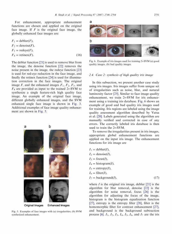
2.4. Case 2: synthesis of high quality iris image
In this subsection, we present another case studyusing iris images. Iris images suffer from unique setof irregularities such as noise, blur, and naturalluminosity factor [25]. Similar to face image qualityenhancement, we train 2n-SVM for iris enhance-ment using a training iris database. Fig. 6 shows anexample of good and bad quality iris images usedfor training. Iris regions are labeled using the imagequality assessment algorithm described by Vatsaet al. [20]. Labels generated using the algorithm aremanually verified and corrected in case of anyerrors. The correctly labeled iris database is thenused to train the 2n-SVM.
To remove the irregularities present in iris images,appropriate global enhancement functions areapplied on the input iris image. The enhancementfunctions for iris image are
I1 ¼ deblurðIÞ,
I2 ¼ denoiseðIÞ,
I3 ¼ focusðIÞ,
I4 ¼ histogramðIÞ,
I5 ¼ entropyðIÞ,
I6 ¼ filterðIÞ,
I7 ¼ backgroundðIÞ, ð17Þ
where I is the original iris image, deblur [21] is thealgorithm for blur removal, denoise [22] is thealgorithm for noise removal, focus [26] is thealgorithm for adjusting the focus of the image,histogram is the histogram equalization function[27], entropy is the entropy filter [28], filter is thehomomorphic filter for contrast enhancement [27],and background is the background subtractionprocess [6]. I1, I2, I3, I4, I5, I6, and I7 are the iris

ARTICLE IN PRESSR. Singh et al. / Signal Processing 87 (2007) 2746–27642752
images obtained when the above global enhance-ment operations are applied to the original irisimage I. These enhanced images and the originalimage are provided as input to the 2n-SVM basedclassification and integration algorithm described inSection 2.2 to synthesize a single high qualityfeature-rich iris image. An example of the originaliris image, different globally enhanced images, andthe SVM enhanced single iris image is shown inFig. 7. Additional examples of iris image qualityenhancement are shown in Fig. 8.
Fig. 7. Iris images with (a) no enhancement, (b) global
enhancements, (c) SVM synthesized enhancement.
Fig. 8. Examples of iris images with (a) irregula
3. Phase congruency-based deformable model for
biometric images
As discussed in Section 2, the first step of theproposed 2-stage preprocessing framework is imagequality enhancement. Quality enhancement algo-rithm removes the irregularities present in thebiometric image. However, biometric images beingnon-rigid, can also suffer from geometric deforma-tions by perspective irregularities. Face and irisimages can have deformation due to variation inangles of the object with respect to the camera.Another source of deformation can be due tophysical changes. For example, fingerprints cap-tured at different instances vary due to the amountof pressure applied, iris patterns can vary due tocontraction or dilation of the pupil, and face imagescan vary because of different facial expressions.Applying suitable deformation correction algorithmcan minimize the variations between two images.
The major challenge with deformation algorithmsis determining the correspondence between twoimages. In this section, we propose a biometricimage deformation correction algorithm which usesphase congruency to detect edge and corner features[29]. These features are used to establish correspon-dence between two images. The edge and cornerdetection algorithm uses the principal moments ofthe phase congruency information [29]. It is adimensionless quantity invariant to illuminationand is expressed as
Cðx; yÞ ¼
Pnwnðx; yÞbAnðx; yÞðcosðfnÞ � j sinðfnÞjÞ � TcP
nAnðx; yÞ þ �,
(18)
where Anðx; yÞ represents the amplitude and fn
represents the difference between phase Pnðx; yÞ andthe average phase angle Pðx; yÞ of the given imageIðx; yÞ. wnðx; yÞ is the weighting factor, T is the
rities, (b) SVM synthesized enhancement.

ARTICLE IN PRESSR. Singh et al. / Signal Processing 87 (2007) 2746–2764 2753
threshold for the estimated noise influence, and � isa constant incorporated to avoid division by zero.
The moment of phase congruency and thevariation in moments with different orientationgives the edge and corner features. At each point inthe image, we compute parameters a, b, and c forthe moment analysis.
a ¼XðCðyÞ cosðyÞÞ2, (19)
b ¼ 2XðCðyÞ cosðyÞÞðCðyÞ sinðyÞÞ, (20)
c ¼XðCðyÞ sinðyÞÞ2, (21)
where CðyÞ refers to phase congruency valuedetermined at orientation y. We compute the phasecongruency for eight different orientations (y) at 45�
intervals. The minimum moment, Mmin, and themaximum moment, Mmax, are calculated as
Mmin ¼12
aþ c�
ffiffiffiffiffiffiffiffiffiffiffiffiffiffiffiffiffiffiffiffiffiffiffiffiffiffib2� ða� cÞ2
q� �, (22)
Mmax ¼12
aþ cþ
ffiffiffiffiffiffiffiffiffiffiffiffiffiffiffiffiffiffiffiffiffiffiffiffiffiffib2þ ða� cÞ2
q� �. (23)
The information provided by the minimum and themaximum moments is used to determine the edgeand corner features. If the maximum moment ofphase congruency at a point is large, then that pointis identified as an edge and if the minimum momentis large, then that point is identified as a corner.Also, the number of corner points for every image isdifferent. The optimal set of corresponding cornerpoints in the reference and the query images formthe control points for deformation correction. Thisoptimal set of control points is selected using thelocal correlation technique. A window of size 7� 7and 9� 9 pixels is chosen around the corner points,respectively, in the reference and the query image.The window size for the query image is greater thanthe window size for the reference image to providetolerance to the errors which may occur in comput-ing the corner points. One to many correlation isthen performed on both the images, i.e., everywindow of the reference image is correlated withevery window of the query image and the pairs withthe maximum correlation output/peak are selected.
ðCP1i ;CP
2j Þ ¼ maxðWinðCP1
i Þ �WinðCP2j ÞÞ
for all i; j, ð24Þ
where CP1i is the ith corner point for the reference
image, and CP2j is the jth corner point for the query
image, Win denotes the window function, � is thecorrelation operator, and max selects the pair thathas maximum correlation value. From all thecontrol point pairs, we empirically select only thosepairs that have correlation of more than 0.85(maximum value of correlation is 1). Lowering thethreshold causes the inclusion of incorrect controlpoint pairs, while increasing the threshold causesthe exclusion of genuine control point pairs. Boththese conditions affect the deformation model anddegrade the recognition performance. We thus haveN pairs of control points fðpiÞ; ðyiÞg for the twoimages, where pi 2 R2, yi 2 R, i ¼ 1; . . . ;N. Ourgoal is to obtain a continuous function f : R2
! R
with f ðpiÞ ¼ yi, and i ¼ 1; . . . ;N. The proposeddeformation function is a weighted function whichdepends on the distance between correspondingcontrol points in the two images,
f ðpÞ ¼XN
i¼1
W iðpÞf iðpÞ, (25)
where p is the center of gravity of the control pointspi, f i is the continuous function for ith pair ofcontrol points, and W i : R
2! R is the correspond-
ing weight function. For a smooth and continuousfunction, the following conditions are applied:
W iðpiÞ ¼ 1;X
W iðpÞ ¼ 1; W iðpÞX0,
i ¼ 1; . . . ;N. ð26Þ
In this deformation function, weights are chosen toreflect the relation between the correspondingcontrol points of the two images. The weights arecomputed as,
W iðpÞ ¼maxðRi � dðp; piÞÞ
Ridðp; piÞ
� �2, (27)
where dðp, piÞ is the distance between p and pi, andRi is the element of influence matrix, R.The elements of the influence matrix represent thedeformation effect of the region in which the controlpoint is located. The influence matrix varies forevery individual at different instances. The follow-ing subsections discuss the computation of theinfluence matrix and deformation correction withface and iris images as the case study.
3.1. Case study 1: Deformation of face images
The proposed deformation function can be usedfor any image-based biometrics. The only parameterwhich is dependent on the biometric trait is the

ARTICLE IN PRESSR. Singh et al. / Signal Processing 87 (2007) 2746–27642754
influence matrix, R. This matrix computes theweights using Eq. (27). In this subsection, weshow the performance of the proposed defor-mation correction algorithm with case study onface images.
We divide the face into three different regionsdepending on the properties of different muscleswhich cause facial motion and expressions. Fromthe anatomy of human face, the deformation indifferent facial regions depend on the skin, muscles,and skull. For any expression or facial motion, themouth region shows maximum deformation fol-lowed by the nose and eye regions. As shown inFig. 9, face is divided into three regions: eye, noseand mouth.
We propose a distance rule which uses theanatomy of the human face to generate the influencematrix, Rface. First, the edge and corner phasecongruency map is computed for the reference andthe query face image. The corresponding cornerpoints in the query and reference images are thensearched using the local correlation algorithmdescribed in Section 3. The three facial regions arerepresented as RE, RN, and RM for eye, nose, andmouth, respectively. In each of the three regions, wecompute the difference in the location of twocorresponding corner points. For example, if thecorner point in query face image is at ðx1; y1Þ,and the corresponding corner point in referenceface image is at ðx2; y2Þ, then the distance
d ¼
ffiffiffiffiffiffiffiffiffiffiffiffiffiffiffiffiffiffiffiffiffiffiffiffiffiffiffiffiffiffiffiffiffiffiffiffiffiffiffiffiffiffiffiffiffiffiðx1 � x2Þ
2þ ðy1 � y2Þ
2q
. The elements in the
influence matrix, Rface, depend on the distance of
Eye Region,RE
Nose Region,RN
Mouth Region,RM
Fig. 9. Face image is divided into three regions based on the
degree of anatomical variability.
two corresponding corner points and are computedas follows:
Let dE, dN, and dM be the distance of the controlpoint pairs belonging to eye, nose, and mouthregions, respectively. Let n1 be the number ofcontrol point pairs present in the eye region. Forith control point pair, the element of influencematrix in eye region, REi
, is computed using
REi¼
dEiPn1i¼1dEi
� CE, (28)
where CE is a constant. Similar to eye region,elements of the influence matrix for nose and mouthregions are computed using
RNi¼
dNiPn2i¼1dNi
� CN, (29)
RMi¼
dMiPn3i¼1dMi
� CM, (30)
where n2 and n3 are the number of control pointpairs present in the noise and mouth region,respectively. Also, n1 þ n2 þ n3 ¼ N (total numberof control pairs), and CN and CM are the constants.
The constant factors, CE, CN, and CM are used tocontrol the weights assigned during deformation.The values of these constants are chosen using thetwo constraints CE þ CN þ CM ¼ 1 and CEoCN
oCM. The first condition ensures that the weightsfor the control points of eyes, nose, and mouth arenormalized in the range of 0 to 1. The secondconstraint is applied to ensure that the weightassigned to the control points in the mouth region isgreater than the weight assigned in the eye and noseregions. Weights are assigned in this order becausemaximum deformation occurs in the mouth regionsfollowed by the nose region and the eye region. Inour experiments, we empirically selected CE ¼ 0:2,CN ¼ 0:3, and CM ¼ 0:5. Further, the values of RE,RN, and RM are used to form an influence matrixRface by arranging these values according tocoordinate positions of the reference face image.This influence matrix is then used to compute theweights in Eq. (27), and the query face image isdeformed with respect to the reference face image.
Fig. 10 shows the intermediate images involved inthe proposed face deformation correction algo-rithm. Fig. 10(a) shows the reference face image,query face image, and the difference between thetwo images. The difference image clearly showsthat the face images are not registered and haveless overlap region due to variation in expression.

ARTICLE IN PRESS
Fig. 10. Illustrating the steps involved in non-linear face
deformation correction.
Fig. 11. Examples showing query face image, reference face
image, and deformation corrected query face image.
Middle Region, Rmid
Outer Region, Rout
Inner Region, Rin
Fig. 12. Iris image divided into three regions.
R. Singh et al. / Signal Processing 87 (2007) 2746–2764 2755
Fig. 10(b) shows the edge and corner phasecongruency of reference and query face images.Fig. 10(c) shows the corresponding control pointsand Fig. 10(d) shows the reference face image,deformed query face image and the difference inthese two image. This difference image shows thatafter applying the deformation correction algo-rithm, the difference between the two images isminimized. Additional examples of face deforma-tion correction generated using the proposed algo-rithm are shown in Fig. 11.
3.2. Case study 2: Deformation of iris images
The effectiveness of the proposed deformationcorrection algorithm is further validated using iris
images as the second case study. The same conceptof computing the influence matrix is applied tocorrect the deformation in the iris images. We dividethe iris image into three regions, inner region Rin
near the pupil, middle region Rmid, and outer regionRout. Fig. 12 shows the three regions of an irisimage. These regions are divided based on theassumption that, in iris, most of the deformation isdue to contraction and dilation of the pupil. Similarto face image deformation, we first compute thecorner points using phase congruency. The corre-sponding corner points or the control points in thereference and query images are then computed byusing local correlation technique and the distancebetween them is calculated. Circular shift is alsoapplied while finding the maximum local correlationin order to compensate for the problems due toshifting and rotation of iris. The elements of theinfluence matrix, Riris, depend on the distancebetween the corresponding control points. Similarto face deformation, we locally compute theelements of influence matrix in regions Rin, Rmid,and Rout. Let n1, n2, and n3 be the number of control

ARTICLE IN PRESSR. Singh et al. / Signal Processing 87 (2007) 2746–27642756
point pairs in the inner, middle, and outer regions,respectively. For jth control point pair in each ofthese regions, the elements are computed using
Rinj¼
d injPn1j¼1d inj
� Cin, (31)
Rmidj¼
dmidjPn2j¼1dmidj
� Cmid, (32)
Routj ¼doutjPn3j¼1doutj
� Cout, (33)
where n1 þ n2 þ n3 ¼ N (total number of controlpoints) and Cin, Cmid, and Cout are constants. Sincethe pupil contracts and dilates, the maximumdeformation is observed in the inner region and itdecreases towards the outer boundary of the iris.Based on this observation, we apply the constraint,Cin4Cmid4Cout, to assign higher weights to the
Fig. 13. Illustrating the steps involved in n
inner region followed by the middle and outerregions. As before, we apply the normalizationconstraint Cin þ Cmid þ Cout ¼ 1 and we set thevalues as Cin ¼ 0:5, Cmid ¼ 0:3, and Cout ¼ 0:2.The values of Rin, Rmid, and Rout are used to formthe influence matrix Riris by arranging these valuesaccording to coordinate positions of the referenceiris image. The influence matrix, Riris, is then used tocompute the weights of control points for queryimage and deform the query image with respect tothe reference iris image using Eqs. (25)–(27). Fig. 13illustrates the iris deformation correction process.Fig. 13(a) shows the reference and query images andtheir difference. Fig. 13(b) shows the phase con-gruency of these iris images. Fig. 13(c) identifies thecorresponding corner points and finally Fig. 13(d)shows the original reference image, the deformationcorrected query image, and the difference betweenthese two images. The difference images inFig. 13(a) and (d) show that after applying the
on-linear iris deformation correction.

ARTICLE IN PRESS
Fig. 14. Examples showing query iris image, reference iris image, and deformation corrected query iris image.
R. Singh et al. / Signal Processing 87 (2007) 2746–2764 2757
proposed deformation correction algorithm, thedifference between the reference and the queryimage is minimized. Additional examples of irisdeformation correction are shown in Fig. 14.
4. Performance evaluation of proposed 2-stage
preprocessing framework
The proposed 2-stage preprocessing frameworkcan be applied to improve the performance of anyimage-based biometrics such as face, fingerprint, oriris. In this paper, we have chosen face and iris astwo case studies for validation because the perfor-mance of both these biometric traits are significantlyaffected due to poor image quality and deformation.Face images can have different types of irregularitiessuch as noise and blur. They also have deformationin features due to different facial expressions.Similarly, iris images also contain different irregula-rities and have deformation due to contraction,dilation, or varying angles of sight. The verificationalgorithms, the databases used for validation, andthe experimental results for both the case studies aredescribed in the following subsections.
4.1. Case study 1: Performance evaluation with face
recognition
For evaluating the performance of the proposed2-stage preprocessing framework with face images,the face is detected from the image using triangle-based face detection algorithm [30]. The detectedface is enhanced using the proposed SVM enhance-ment algorithm described in Section 2, and defor-mation is corrected using the proposed phasecongruency-based algorithm described in Section3. We used three existing face recognition algo-rithms for validation: principal component analysis(PCA) [31], local feature analysis (LFA) [32], andtexture-based face recognition algorithm [33].PCA [31] is an appearance-based face recognition
algorithm. It needs sufficient representative trainingdata and is very sensitive to illumination, pose, andappearance. LFA [32] refers to a class of algorithmsthat extracts a set of geometrical metrics anddistances from facial images and uses these featuresas the basis for representation and comparison.Texture-based face recognition algorithm [33,34]proposed by the authors extracts the phase featuresfrom the input face image using 2D log polar Gabortransform.
There are different face databases available inpublic domain and each has certain special char-acteristics. For evaluating the performance on alarge database with different and challenging varia-tions, we combined images from nine different facedatabases to create a non-homogenous combinedface (NHCF) database of 1050 classes. AR facedatabase [35] contains face images with varyingillumination and accessories, CMU–AMP [36]database contains images with wide range ofexpressions, and FERET database [37] has faceimages with different variations over a time intervalof 3–4 years. CMU–PIE [38] contains images withvariation in illumination and facial expressions.AT&T database [39] contains images with facialexpressions and slight head rotation. Notre Dameface database [40,41] comprises of images withdifferent lighting and facial expressions over aperiod of one year. Equinox database [42] hasimages captured under different illumination con-ditions with accessories and expressions. Yaledatabase [43] contains an extensive set of illumina-tion conditions with variations in pose, and IITKface database [44] has images with different back-ground, illumination conditions, expressions, pose,and occlusions. The camera used to prepare thesedifferent databases are also different. To the best ofour knowledge, there is no database available inpublic domain which embodies all these differentimage and device characteristics. The NHCFdatabase combines face images from nine different

ARTICLE IN PRESSR. Singh et al. / Signal Processing 87 (2007) 2746–27642758
databases which is helpful in evaluating theperformance of face recognition algorithms forchallenging scenarios.
We selected face images from 1050 individualssuch that for each individual there are at least sevenfrontal or near-frontal images. Table 1 lists thedatabases used and the number of classes selectedfrom the individual databases. We divided theimages into two sets: (1) gallery-probe data set,and (2) training data set. Gallery-probe data set isused to evaluate the performance of the facerecognition algorithms and training data set is usedto train the 2n-SVM based quality enhancementalgorithm. In the gallery-probe data set, we choseseven images of each individual without applyingany constraints on facial expressions, illumination,other irregularities, and accessories such as glasses,caps or hats. Thus for the gallery-probe data set,7350 face images are selected pertaining to 1050classes. Fig. 15 shows sample images from thegallery-probe data set. For performance evaluation,one neutral and non-illuminated frontal face imageper individual is chosen as the gallery and the
Table 1
Composition of the non-homogenous combined face (NHCF)
database
Face database Number of classes
AR [35] 120
CMU–AMP [36] 10
FERET [37] 300
CMU–PIE [38] 65
AT&T [39] 40
Notre Dame [40,41] 315
Equinox [42] 90
Yale [43] 10
IITK [44] 100
Total (NHCF) 1050
Fig. 15. Example of face images for the gallery-probe data set (a) imag
database [38].
remaining six face images are used for testing. Afterselecting seven images for gallery-probe data set,remaining images from each class are used for thetraining data set. In the training data set, there are3961 good quality face images and 9527 bad qualityimages which are used to train the enhancementalgorithm.
For evaluating the performance of the proposedpreprocessing framework, first the verificationaccuracy is computed for the original face image.The original image is then enhanced by applyingglobal enhancement algorithms such as deblurring,denoising, redeye removal, and retinex enhance-ment. The verification accuracy is computed forthese globally enhanced images. Finally, the pro-posed algorithms are applied to obtain the locallysynthesized enhanced image, and the subsequentdeformed image. Fig. 16 shows an example of
es from Yale face database [43], (b) images from CMU–PIE face
Fig. 16. Examples of enhanced gallery face image, enhanced
query face image, and enhanced query image deformed with
respect to the enhanced gallery image.
ARTICLE IN PRESS
Table 2
Comparison of face verification accuracy using the proposed local image enhancement algorithm and the deformation model with existing
enhancement algorithms
Verification accuracy
PCA [31] (%) LFA [32] (%) Texture [33] (%)
Original face image 20.7 39.6 89.1
Deblurred image [21] 21.3 40.2 90.6
Denoised image [22] 21.5 40.3 90.7
Redeye removed image [23] 20.9 39.7 89.4
Retinex enhanced image [24] 22.8 41.2 92.1
Proposed SVM enhanced image 26.5 45.3 93.9
Proposed SVM enhanced image 30.3 48.1 96.7
with deformation correction
Verification accuracy is computed at 0.01% false accept rate (FAR).
0 1 2 3 4 50
2
4
6
8
10
12
False Accept Rate(%)
Fals
e R
ejec
tion
Rat
e(%
)Original ImageDeblurred ImageDenoised ImageRedeye Removed ImageRetinex Enhanced ImageSVM Enhanced ImageSVM Enhanced Deformed Image
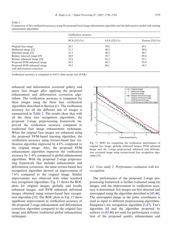
Fig. 17. ROC for comparing the verification performance of
original face image, globally enhanced images, SVM enhanced
image and the 2-stage preprocessed enhanced and deforma-
tion corrected image using texture-based face recognition algo-
rithm [33].
R. Singh et al. / Signal Processing 87 (2007) 2746–2764 2759
enhanced and deformation corrected gallery andquery face images after applying the proposedenhancement and deformation correction algo-rithms. The verification accuracy is computed forthese images using the three face verificationalgorithms described in Section 4.1. The verificationaccuracy for all the different sets of images issummarized in Table 2. The results show that withall the three face recognition algorithms, theproposed 2-stage preprocessing framework im-proved the verification accuracy compared totraditional face image enhancement techniques.When the original face images are enhanced usingthe proposed SVM-based learning algorithm, theverification accuracy using texture-based face ver-ification algorithm improved by 4.8% compared tothe original image. Also, the proposed SVMenhancement algorithm improves the verificationaccuracy by 2–4% compared to global enhancementalgorithms. With the proposed 2-stage preproces-sing framework that includes enhancement anddeformation correction, the same texture-based facerecognition algorithm showed an improvement of7.6% compared to the original image. Similarimprovement was observed with other standardface recognition algorithms. Fig. 17 shows the ROCplots for original images, globally and locallyenhanced images, and SVM enhanced deformedimages obtained using texture-based face recogni-tion algorithm [33]. The ROC plots in Fig. 17 showsignificant improvement in verification accuracy ofthe proposed 2-stage enhancement and deformationcorrection algorithm compared to the original faceimage and different traditional global enhancementtechniques.
4.2. Case study 2: Performance evaluation with iris
recognition
The performance of the proposed 2-stage pre-processing framework is further evaluated using irisimages, and the improvement in verification accu-racy is determined. Iris images are first detected andunwrapped using the algorithm described in [45,46].The unwrapped image in the polar coordinates isused as input to different preprocessing algorithms.Daugman’s iris recognition algorithm [5,47], Tan’salgorithm [6] and the algorithm proposed byauthors in [45,46] are used for performance evalua-tion of the proposed quality enhancement and
ARTICLE IN PRESSR. Singh et al. / Signal Processing 87 (2007) 2746–27642760
deformation correction algorithm. Daugman’s irisrecognition algorithm [5,47] is based on the texturalfeatures extracted from the 2D Gabor wavelet. Thealgorithm extracts the phase features using neuralnetwork type architecture of 2D Gabor wavelets.These features are further quantized and matchedby comparing hamming distances. Tan’s iris recog-nition algorithm [6] constructs 1D intensity signalwhich contains the majority of local variations ofthe iris. Gaussian–Hermite moments of such in-tensity signals are used as the distinguishingfeatures. The dimensionality of features is reducedand the features are classified using the NearestNeighbor Classifier. Vatsa’s iris recognition algo-rithm [45,46] uses the textural and topologicalfeature for recognition. The textural features areextracted using 1D log polar Gabor transform andthe topological features are extracted using Eulernumber. The textural features are matched using thehamming distance and the topological features arematched using the Mahalanobis distance measure.
Similar to the non-homogenous face database, wecombined five iris databases available in publicdomain to create a non-homogenous combinediris (NHCI) database with diverse characteristics.CASIA Version 3 database [48] contains eye images
Table 3
Composition of the non-homogenous combined iris (NHCI)
database
Iris database Number of classes
CASIA version 3 [48] 420
ICE [50] 240
UBIRIS [49] 240
MILES [51] 100
IITK [52] 50
Total (NHCI) 1050
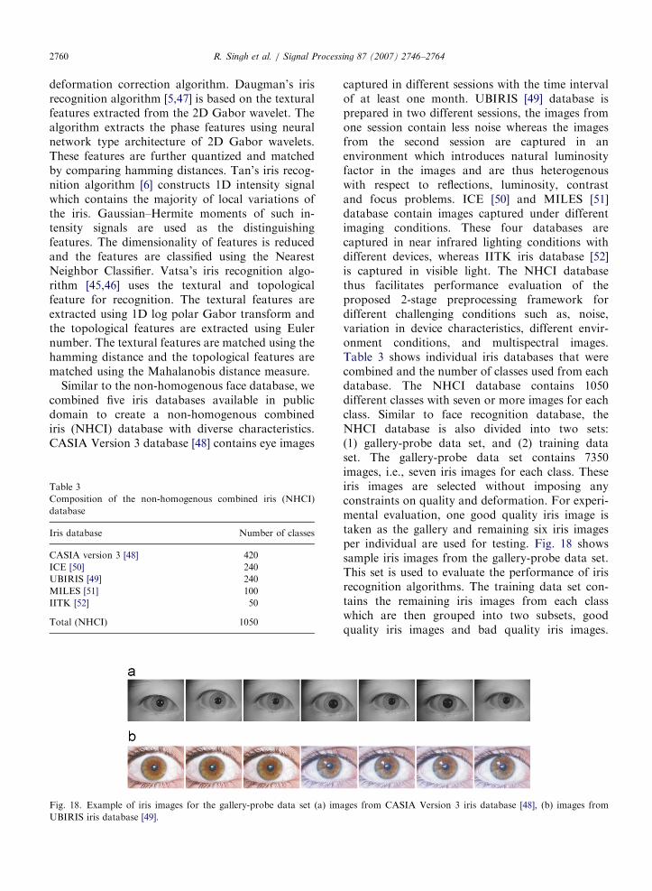
Fig. 18. Example of iris images for the gallery-probe data set (a) im
UBIRIS iris database [49].
captured in different sessions with the time intervalof at least one month. UBIRIS [49] database isprepared in two different sessions, the images fromone session contain less noise whereas the imagesfrom the second session are captured in anenvironment which introduces natural luminosityfactor in the images and are thus heterogenouswith respect to reflections, luminosity, contrastand focus problems. ICE [50] and MILES [51]database contain images captured under differentimaging conditions. These four databases arecaptured in near infrared lighting conditions withdifferent devices, whereas IITK iris database [52]is captured in visible light. The NHCI databasethus facilitates performance evaluation of theproposed 2-stage preprocessing framework fordifferent challenging conditions such as, noise,variation in device characteristics, different envir-onment conditions, and multispectral images.Table 3 shows individual iris databases that werecombined and the number of classes used from eachdatabase. The NHCI database contains 1050different classes with seven or more images for eachclass. Similar to face recognition database, theNHCI database is also divided into two sets:(1) gallery-probe data set, and (2) training dataset. The gallery-probe data set contains 7350images, i.e., seven iris images for each class. Theseiris images are selected without imposing anyconstraints on quality and deformation. For experi-mental evaluation, one good quality iris image istaken as the gallery and remaining six iris imagesper individual are used for testing. Fig. 18 showssample iris images from the gallery-probe data set.This set is used to evaluate the performance of irisrecognition algorithms. The training data set con-tains the remaining iris images from each classwhich are then grouped into two subsets, goodquality iris images and bad quality iris images.
ages from CASIA Version 3 iris database [48], (b) images from

ARTICLE IN PRESS
Table 4
Comparison of iris verification accuracy using the proposed local image enhancement algorithm and the deformation model with existing
enhancement algorithms
Verification accuracy
Daugman [5] (%) Tan [6] (%) Vatsa [45] (%)
Original iris image 97.1 97.0 97.2
Deblurred image [21] 97.3 97.2 97.5
Denoised image [22] 97.4 97.3 97.6
Focus corrected image [26] 97.4 97.3 97.5
Histogram equalized image [27] 97.2 97.2 97.3
Entropy normalized image [28] 97.4 97.3 97.8
Homomorphic filtered image [27] 97.3 97.2 98.0
Background subtracted image [6] 97.4 97.4 97.9
Proposed SVM enhanced image 97.9 97.8 98.5
Proposed SVM enhanced image 98.8 98.6 99.2
with deformation correction
Verification accuracy is computed at 0.01% FAR.
Fig. 19. Examples of enhanced gallery iris image, enhanced query iris image, and enhanced query image deformed with respect to the
enhanced gallery image.
0 0.5 1.0 1.5 2.0 2.5 3.00
0.5
1.0
1.5
2.0
2.5
3.0
False Accept Rate(%)
Fals
e R
ejec
tion
Rat
e(%
)
Original ImageDeblurred ImageDenoised ImageFocus Corrected ImageHistogram Equalized ImageEntropy Normalized ImageHomomorphic Filtered ImageBackground Subtracted ImageSVM Enhanced ImageSVM Enhanced Deformed Image
Fig. 20. ROC for comparing the verification performance of
original iris image, globally enhanced images, SVM enhanced
image, and the 2-stage preprocessed enhanced and deformation
corrected image using iris recognition algorithm [45].
R. Singh et al. / Signal Processing 87 (2007) 2746–2764 2761
There are 4840 good quality iris images and 7160bad quality iris images used to train the 2n-SVM ofthe proposed enhancement algorithm.
The experimental setup for evaluating the perfor-mance with iris recognition is similar to that usedfor face recognition. We first compute the verifica-tion accuracy of the original iris images. Theseimages are then enhanced using traditional en-hancement algorithms applicable to iris images. Theproposed SVM image quality enhancement algo-rithm is applied to synthesize high quality images asdescribed in Section 2. The verification accuracy iscomputed for the globally enhanced images and theSVM enhanced images. In the second stage, theproposed deformation correction algorithm is ap-plied on the locally synthesized iris images and theverification performance of the deformation cor-rected images is computed. Fig. 19 shows anexample of gallery and probe iris images, and theenhanced and deformed images obtained by apply-ing the proposed enhancement and deformationcorrection algorithms. The results are summarized
in Table 4 and Fig. 20. Table 4 shows that theverification accuracy of the three iris recognitionalgorithms is approximately 97.0% using the

ARTICLE IN PRESSR. Singh et al. / Signal Processing 87 (2007) 2746–27642762
original images. The verification accuracy increasesby 0.1–0.7% with globally enhanced images. Theaccuracies are increased by approximately 1% whenthe proposed SVM-based local enhancement algo-rithm is used for preprocessing. Also, the proposedSVM enhancement algorithm improves the verifica-tion accuracy by around 0.5% compared to globalenhancement algorithms. Further, there is improve-ment of 0.7–0.9% when the SVM enhanced image issubjected to deformation correction using theproposed deformation correction algorithm. Theproposed 2-stage preprocessing framework thusimproves the performance of iris verification by1.6–2%. Fig. 20 shows the ROC plots obtainedusing the iris recognition algorithm by Vatsa et al.[45]. ROC plots show that the proposed SVM-basedenhancement technique and the proposed 2-stageenhancement and deformation correction techni-ques improve the verification performance of irisimages compared to the original images and globalenhancement algorithms.
5. Computational complexity
In this section, we discuss the computationalcomplexity of the proposed quality enhancementand deformation correction algorithm. The com-plexity analysis is divided into three parts:
�
2n-SVM training: Let n be the set of data vectorsused for training. According to Chew et al. [19],the complexity of training 2n-SVM is OðnÞ. � Quality enhancement: Let the size of the imagebe x� y. The complexity depends on theindividual global quality enhancement algo-rithms which is OðxyÞ.
� Deformation: The computational complexity ofthe proposed deformation correction algorithmdepends upon the size of image and total numberof control points N. The complexity of thedeformation correction algorithm is OðxyþNÞ.Since N5xy, the complexity is OðxyÞ.
From the above analysis, it is evident that thecomputational complexity of the proposed qualityenhancement and deformation correction algorithmdepends on the size of input image. For example,the time required for quality enhancement anddeformation correction on a detected face image ofsize 256� 192 is 8.4 s. For detected and unwrappediris image of size 60� 240, the time taken forquality enhancement and deformation correction is
6.1 s. The time is computed on a P-IV 3.2GHzcomputer under Matlab environment.
6. Conclusion
In this paper, we proposed a 2-stage preprocessingframework to improve the performance of image-based biometrics by incorporating enhancement anddeformation correction before feature extraction andmatching. For image enhancement, we proposed aSVM-based algorithm which selects good qualitylocal regions from different globally enhanced imagesand synergistically combines them to generate a highquality feature-rich image. The proposed imageenhancement algorithm can be used to removemultiple irregularities present locally in the imagewithout affecting the good quality regions. We thenproposed the phase congruency based deformationcorrection algorithm which deforms the query imagewith respect to the reference image to minimize anyvariations between the two images. The proposedframework can be applied with any of the recognitionalgorithms to enhance the verification accuracy. Tovalidate the proposed 2-stage preprocessing frame-work, we selected face and iris images as the two casestudies. Experimental results show that the proposed2-stage preprocessing framework improves the ver-ification performance of face and iris images by 7.6%and 1.6%, respectively.
Acknowledgments
The authors would like to thank Dr. A.R.Martinez, CVRLUniversity of Notre Dame, RoboticsInstitute CMU, NIST, CMU AMP ResearchLab, AT & T Laboratories Cambridge, EquinoxCorporation, CVC Yale University, CASIA (China),Miles Research (USA), U.B.I. (Portugal), and IITKanpur (India) for providing the face and irisdatabases used in this research. Authors also thankthe reviewers for their constructive and helpfulcomments. This research is supported in part througha grant (Award No. 2003-RC-CX-K001) from theOffice of Science and Technology, National Instituteof Justice, Office of Justice Programs, United StatesDepartment of Justice.
References
[1] E. Tabassi, C. Wilson, C. Watson, Fingerprint image
quality, NIST Research Report, NISTIR7151, 2004.

ARTICLE IN PRESSR. Singh et al. / Signal Processing 87 (2007) 2746–2764 2763
[2] A. Hicklin, R. Khanna, The role of data quality in biometric
systems, Technical Report, Mitretek Systems, 2006.
[3] L. Hong, Y. Wan, A.K. Jain, Fingerprint image enhance-
ment: algorithm and performance evaluation, IEEE Trans.
on Pattern Anal. Mach. Intell. 20 (8) (1998) 777–789.
[4] R. Gross, V. Brajovic, An image preprocessing algorithm for
illumination invariant face recognition, in: Proceedings of
the 4th International Conference on Audio- and Video-
Based Biometric Person Authentication, vol. 2688, 2003,
pp. 10–18.
[5] J. Daugman, The importance of being random: statistical
principles of iris recognition, Pattern Recognition 36 (2)
(2003) 279–291.
[6] L. Ma, T. Tan, Y. Wang, D. Zhang, Efficient iris recognition
by characterizing key local variations, IEEE Trans. Image
Process. 13 (6) (2004) 739–750.
[7] J. Huang, Y. Wang, J. Cui, T. Tan, Noise removal and
impainting model for iris image, in: Proceedings of the
International Conference on Image Processing, 2004,
pp. 869–872.
[8] A. Ross, S. Dass, A.K. Jain, A deformable model for
fingerprint matching, Pattern Recognition 38 (1) (2005)
95–103.
[9] X. Ming, T. Xu, Z. Wang, Using multimatching system
based on a simplified deformable model of the human iris for
iris recognition, J. Bionics Eng. 1 (3) (2004) 183–190.
[10] A. Yuille, D. Cohen, P. Halliman, Feature extraction from
faces using deformable templates, Int. J. Comput. Vision 8
(1992) 99–111.
[11] X. Lu, A.K. Jain, Deformation analysis for 3D face
matching, in: Proceedings of Workshop on Applications of
Computer Vision, 2005, pp. 99–104.
[12] X. Lu, A.K. Jain, Deformation modeling for robust 3D face
matching, Proc. IEEE Conf. Comput. Vision Pattern
Recognition 2 (2006) 1377–1383.
[13] Z. Liu, Y. Shan, Z. Zhang, Expressive expression mapping
with ratio images, in: Proceedings of SIGGRAPH, 2001,
pp. 271–276.
[14] B. Leroy, I.L. Herlin, L.D. Cohen, Face identification by
deformation measure, Proc. of Int. Conf. Pattern Recogni-
tion 3 (1996) 633–637.
[15] M. Ramachandran, S. Zhou, D. Jhalani, R. Chellappa, A
method for converting smiling face to a neutral face with
applications to face recognition, Proc. IEEE Int. Conf.
Acoust. Speech Signal Process. 2 (2005) ii/977–ii/980.
[16] R. Wildes, J. Asmuth, G. Green, S. Hsu, R. Kolczynski, J.
Matey, S. McBride, A machine vision system for iris
recognition, Mach. Vision Appl. 9 (1) (1996) 1–8.
[17] V.N. Vapnik, The Nature of Statistical Learning Theory,
Springer, Berlin, 1995.
[18] P.-H. Chen, C.-J. Lin, B. Scholkopf, A tutorial on nu-
support vector machines, Appl. Stochastic Model Bus. Ind.
21 (2005) 111–136.
[19] H.G. Chew, C.C. Lim, R.E. Bogner, An implementation of
training dual-n support vector machines, in: L. Qi, K.L. Teo,
X. Yang (Eds.), Optimization and Control with Applica-
tions, Kluwer, Dordrecht, 2005, pp. 157–182.
[20] M. Vatsa, R. Singh, A. Noore, SVM based adaptive
biometric image enhancement using quality assessment, in:
B. Prasad and S.R.M. Prasanna (Eds.), Speech, Audio,
Image and Biomedical Signal Processing using Neural
Networks, Springer, Germany, 2007 (in press).
[21] S.K. Kang, J.H. Min, J.K. Paik, Segmentation based
spatially adaptive motion blur removal and its application
to surveillance systems, Proc. Int. Conf. Image Process. 1
(2001) 245–248.
[22] R. Malladi, J.A. Sethian, Image processing via level set
curvature flow, Proc. Nat. Acad. Sci. 92 (15) (1995)
7046–7050.
[23] R. Schettini, F. Gasparini, F. Chazli, Modular procedure for
automatic red eye correction in digital photos, in: Proceed-
ings of Color Imaging IX: Processing, Hardcopy, and
Applications, vol. 5293, 2004, pp. 139–147.
[24] E.H. Land, J.J. McCann, Lightness and retinex theory, J.
Opt. Soc. Am. 61 (1) (1971) 1–11.
[25] N.D. Kalka, J. Zuo, V. Dorairaj, N.A. Schmid, B. Cukic,
Image quality assessment for iris biometric, in: Procee-
dings of SPIE Conference on Biometric Technology for
Human Identification III, vol. 6202, 2006, pp. 61020D-
1–62020D-11.
[26] D.G. Sheppard, K. Panchapakesan, A. Bilgin, B.R. Hunt,
M.W. Marcellin, Removal of image defocus and motion blur
effects with a nonlinear interpolative vector quantizer, in:
Proceedings of IEEE Southwest Symposium on Image
Analysis and Interpretation, 1998, pp. 1–5.
[27] R.C. Gonzalez, R.E. Woods, Digital Image Processing,
second ed., Prentice-Hall, Englewood Cliffs, NJ, 2002.
[28] P.J.N. Kapur, A.K.C. Wong, A new method for gray-level
picture thresholding using the entropy of the histogram,
Comput. Vision Graphics Image Process. 29 (1985) 273–285.
[29] P.D. Kovesi, Image features from phase congruency, Videre:
J. Comput. Vision Res. 1 (3) (1999).
[30] S.K. Singh, D.S. Chauhan, M. Vatsa, R. Singh, A robust
skin color based face detection algorithm, Tamkang J. Sci.
Eng. 6 (4) (2003) 227–234.
[31] M. Turk, A. Pentland, Eigenfaces for recognition, J.
Cognitive Neurosci. 3 (1991) 72–86.
[32] P. Penev, J. Atick, Local feature analysis: a general statistical
theory for object representation, Network: Comput. Neural
Syst. 7 (1996) 477–500.
[33] R. Singh, M. Vatsa, A. Noore, Textural feature based face
recognition for single training images, IEE Electron. Lett. 41
(11) (2005) 23–24.
[34] R. Singh, Unconstrained face recognition for law enforce-
ment applications, Master’s Thesis, West Virginia Univer-
sity, 2005.
[35] A.R. Martinez, R. Benavente, The AR face database,
Computer Vision Center, Technical Report 24, 1998.
[36] hhttp://amp.ece.cmu.edu/projects/FaceAuthentication/down
load.htmi.
[37] P.J. Phillips, H. Moon, S. Rizvi, P.J. Rauss, The FERET
evaluation methodology for face recognition algorithms,
IEEE Trans. Pattern Anal. Mach. Intell. 22 (10) (2000)
1090–1104.
[38] T. Sim, S. Baker, M. Bsat, The CMU pose, illumination, and
expression database, IEEE Trans. Pattern Anal. Mach.
Intell. 25 (12) (2003) 1615–1618.
[39] F. Samaria, A. Harter, Parameterization of a stochastic
model for human face identification, in: Proceedings of 2nd
IEEE Workshop on Applications of Computer Vision, 1994,
pp. 138–142.
[40] X. Chen, P.J. Flynn, K.W. Bowyer, Visible-light and
infrared face recognition, in: Proceedings of ACM Work-
shop on Multimodal User Authentication, 2003, pp. 48–55.

ARTICLE IN PRESSR. Singh et al. / Signal Processing 87 (2007) 2746–27642764
[41] P.J. Flynn, K.W. Bowyer, P.J. Phillips, Assessment of time
dependency in face recognition: an initial study, in:
Proceedings of Audio- and Video-Based Biometric Person
Authentication, 2003, pp. 44–51.
[42] hhttp://www.equinoxsensors.com/products/HID.htmli.
[43] A. Georghiades, D. Kriegman, P. Belhumeur, From few to
many: generative models for recognition under variable pose
and illumination, IEEE Trans. Pattern Anal. Mach. Intell.
23 (6) (2001) 643–660.
[44] M. Vatsa, R. Singh, A. Srivastava, P. Gupta, Image
database for biometrics personal authentication system,
Proc. Int. Conf. Comput. Vision Pattern Recognition Image
Process. (2003) 704–707.
[45] M. Vatsa, Reducing false rejection rate in iris recognition by
quality enhancement and information fusion, Master’s
Thesis, West Virginia University, 2005.
[46] M. Vatsa, R. Singh, A. Noore, Reducing the false rejection
rate of iris recognition using textural and topological
features, Int. J. Signal Process. 2 (1) (2005) 66–72.
[47] J. Daugman, Statistical richness of visual phase information,
Int. J. Comput. Vision 45 (1) (2001) 25–38.
[48] CASIA-Iris Version 3, hhttp://www.cbsr.ia.ac.cn/IrisData
base.htmi.
[49] H. Proena, L.A. Alexandre, UBIRIS: a noisy iris image
database, in: Proceedings of 13th International Conference
on Image Analysis and Processing, vol. 1, 2005, pp. 970–977.
[50] X. Liu, K.W. Bowyer, P.J. Flynn, Experiments with an
improved iris segmentation algorithm, in: Fourth IEEE
Workshop on Automatic Identification Advanced Techno-
logies, 2005, pp. 118–123.
[51] hhttp://www.milesresearch.com/i.
[52] hhttp://www.cse.iitk.ac.in/users/biometrics/i.