
Improving the efficiency of parallel alternating directions algorithm for time dependent problems
Upload
khangminh22Category
view
4download
0
This report is submitted in partial fulfillment of the requirements for the degree of Bachelor of Computing and Mathematical Sciences with Honours (BCMS(Hons))
at The University of Waikato.
COMP520-13C (HAM)
© 2013 Adam Coxhead
Improving the Security and Efficiency of Network Clients
Using OpenFlow
Adam Coxhead

Abstract
With the complexity and scale of networks these days some of the earlier proto-cols have started to show their age, presenting vulnerabilities and inefficienciesin the way they run. As a result research and solutions are being put in placeto address certain aspects of these protocols, be this extensions to the pro-tocol itself or extensions to the devices within the network. OpenFlow is aopen network protocol that is an implementation of a relatively new conceptin computer network design, Software Defined Networking (SDN). It allowsfor the separation of the control plane of a switch and enables it to be movedinto an application running in software. This results in far more software ori-ented approach to network design and control of switches. This project aimsto use this new flexibility that OpenFlow provides to explore ways in which theweaknesses apparent with certain protocols in todays networking environmentin order to improve their efficiency and security. It focuses on reducing theneed for the broadcast of Address Resolution Protocol (ARP) requests as wellas looking into an alternative method to the Spanning Tree Protocol (STP).

Acknowledgements
Firstly I would like to thank my supervisor Dr. Richard Nelson for the supportand guidance that was given throughout the project. I would also like to thankthe following members of the WAND group, Shane Alcock, Brendon Jones andBrad Cowie for answering questions as well as their help in proof reading thisreport. Finally I would like to thank Christopher Lorier and Joe Stringer fortheir support when I was learning my way around OpenFlow and the Ryuframework.

Contents
Abstract ii
Acknowledgements iii
1 Introduction 1
2 Background 32.1 Software Defined Networking and OpenFlow . . . . . . . . . 32.2 Address Resolution Protocol . . . . . . . . . . . . . . . . . . 62.3 Spanning Tree Protocol . . . . . . . . . . . . . . . . . . . . . 82.4 Implementation Tools . . . . . . . . . . . . . . . . . . . . . . 102.4.1 Open vSwitch . . . . . . . . . . . . . . . . . . . . . . . . . 102.4.2 Ryu . . . . . . . . . . . . . . . . . . . . . . . . . . . . . . 10
3 Investigation 113.1 Address Resolution Protocol . . . . . . . . . . . . . . . . . . 113.1.1 Current Extensions and Implementations . . . . . . . . . . 113.1.2 OpenFlow Solutions . . . . . . . . . . . . . . . . . . . . . 123.2 STP . . . . . . . . . . . . . . . . . . . . . . . . . . . . . . . 133.2.1 STP Extensions and Successors . . . . . . . . . . . . . . . 133.2.2 OpenFlow Solutions . . . . . . . . . . . . . . . . . . . . . 15
4 Implementation 174.1 Address Resolution Protocol . . . . . . . . . . . . . . . . . . 174.1.1 Controller Redirection . . . . . . . . . . . . . . . . . . . . 184.1.2 ARP Proxy OpenFlow . . . . . . . . . . . . . . . . . . . . 214.2 Loop Prevention and Equal Cost Multipath Forwarding . . . 214.2.1 Loop prevention Module . . . . . . . . . . . . . . . . . . . 244.2.2 Equal Cost Multipath Forwarding . . . . . . . . . . . . . . 264.2.3 Shortest Path Algorithm . . . . . . . . . . . . . . . . . . . 27

Contents v
4.2.4 MAC Learning and Path Choice . . . . . . . . . . . . . . . 294.2.5 Flow Distribution . . . . . . . . . . . . . . . . . . . . . . . 294.2.6 Link State Changes . . . . . . . . . . . . . . . . . . . . . . 30
5 Evaluation and Discussion 315.1 ARP . . . . . . . . . . . . . . . . . . . . . . . . . . . . . . . 315.1.1 Controller Redirection . . . . . . . . . . . . . . . . . . . . 315.1.2 ARP Proxy Controller . . . . . . . . . . . . . . . . . . . . 335.2 Loop Prevention and ECMF . . . . . . . . . . . . . . . . . . 355.2.1 Evaluation . . . . . . . . . . . . . . . . . . . . . . . . . . . 365.2.2 Comparisons . . . . . . . . . . . . . . . . . . . . . . . . . 405.3 Project and OpenFlow Limitations . . . . . . . . . . . . . . 445.3.1 Design Choice Limitations . . . . . . . . . . . . . . . . . . 445.3.2 OpenFlow Limitations . . . . . . . . . . . . . . . . . . . . 45
6 Conclusions 476.1 Contributions Made . . . . . . . . . . . . . . . . . . . . . . . 476.2 Future work . . . . . . . . . . . . . . . . . . . . . . . . . . . 486.3 Conclusion . . . . . . . . . . . . . . . . . . . . . . . . . . . . 49
References 50
A ARP Redirection and Proxy in OpenFlow 53A.1 ARP response script . . . . . . . . . . . . . . . . . . . . . . 53A.2 ARP Proxy controller . . . . . . . . . . . . . . . . . . . . . . 54
B Loop prevention and ECMF 56B.1 Loop prevention module - Tree calculation . . . . . . . . . . 56B.2 ECMF - shortest paths between pair of switches calculation . 57

List of Figures
2.1 OpenFlow 1.0 Protocol and Switch . . . . . . . . . . . . . . . . . . 52.2 Openflow 1.2 Multi-table Switch . . . . . . . . . . . . . . . . . . . 62.3 Simple STP Configured Network . . . . . . . . . . . . . . . . . . . 9
4.1 ARP behaviour comparison . . . . . . . . . . . . . . . . . . . . . . 184.2 DHCP and ARP responder host make up . . . . . . . . . . . . . . 204.3 Controller composition . . . . . . . . . . . . . . . . . . . . . . . . . 234.4 Link disabling comparison - STP vs Loop prevention . . . . . . . . 254.5 Packet forwarding comparison - STP vs ECMF . . . . . . . . . . . 27
5.1 Loop prevention module runtime - Ring topology . . . . . . . . . . 375.2 Loop prevention module runtime - Partial mesh . . . . . . . . . . . 385.3 ECMF module runtime - Ring topology . . . . . . . . . . . . . . . 395.4 ECMF module runtime - Partial mesh . . . . . . . . . . . . . . . . 39

List of Tables
5.1 Comparisons between STP and OpenFlow approaches . . . . . . . 425.2 Comparisons between Projects approach and STP successors . . . 43

List of Acronyms
ARP Address Resolution Protocol
ASIC Application-Specific Integrated Circuit
BPDU Bridge Protocol Data Unit
DAI Dynamic ARP Inspection
DHCP Dynamic Host Configuration Protocol
ECMF Equal Cost Multipath Forwarding
IP Internet Protocol
IPv4 Internet Protocol Version 4
IS-IS Intermediate System to Intermediate System
LLDP Link Layer Discovery Packet
SDN Software Defined Networking
MAC Media Access Control
MSTP Multiple Spanning Tree Protocol
OMAPI Object Management Application Programming Interface
OVS Open vSwitch
RSTP Rapid Spanning Tree Protocol
SPB Shortest Path Bridging
STP Spanning Tree Protocol
TRILL Transparent Interconnection of Lots of Links
TTL Time To Live
VSTP VLAN Spanning Tree Protocol

Chapter 1
Introduction
With the scale and complexity of networks growing rapidly over the last num-ber of years, some of the flaws with existing protocols have become moreapparent due to the higher demand placed upon them. As a result solutionsimproving both the security and efficiency of such protocols in order to tailorthem more to the requirements of existing networks are much desired. Withthe introduction of Software Defined Networking (SDN) [4] network researchershave been presented with a new level of flexibility and control in the design ofnetworks, along with new unique outlook on what switches can be made to do.This is achieved through SDN defining a way in which the control plane of aswitch could be decoupled from the data plane, allowing for it to be moved intoan application running on a remote host. OpenFlow[22] is one of the most pop-ular realisations of SDN allowing for this separation to be achieved, presentingnetwork researchers a new method in which to explore network design.
The aim of this project is to use the view OpenFlow provides to explore theways it can potentially be used to to address some of the weaknesses apparentin existing protocols. It focuses on two main protocols used within currentnetworks, these are the Address Resolution Protocol (ARP) and the SpanningTree Protocol (STP). This project explores ways in which the broadcastingof ARP packets can be reduced or eliminated though the use of an Open-Flow enabled network, resulting in the reduction of processing overhead onthe network as a whole, as well as lowering the potential for malicious packetsto be sent in response to an ARP request. This project also aims to createan alternative to STP using the logically centralised and controllable view ofa network provided by OpenFlow. It aims to introduce both load balancingacross the network as well as shortest path forwarding into this alternative,

Chapter 1 Introduction 2
giving it much more desirable features than STP. The approaches taken bythis project are restricted to those that are transparent to the end hosts onthe network i.e. the end hosts themselves require no modification to theirknowledge of the target protocol in order to continue functioning as normal.
This report first introduces the background and core workings of ARP andSTP in Chapter 2. In Chapter 3, some of the current solutions taken bynetwork device vendors and researches alike to address some of the weaknessesthat have become apparent in these protocols have been discussed. Chapter4 presents ways in which these same weaknesses could be addressed in anOpenFlow enabled network by presenting both OpenFlow inspired networkdesigns and the constructed OpenFlow controllers. Finally, Chapter 5 is theevaluation of these approaches by comparing them to the existing techniques,as well as discussing how they could be deployed and what the limitations oftheir deployment may be.

Chapter 2
Background
There are a number of concepts and protocols important to the developmentof the controllers for this project, with the idea of SDN and OpenFlow beingat the forefront of this. The concept of SDN and its practical application isdescribed in Section 2.1. This concept crucial as it forms the basis from whichthis project is built. Following this, Section 2.2 addresses the ARP and gives itsgeneral background and behaviour. Section 2.3 introduces STP, again givingits background and behaviour. Lastly, Section 2.4 describes the tools used toboth implement and test the solutions found.
2.1 Software Defined Networking and OpenFlowNetwork switches are comprised of two planes, the data plane, which is respon-sible for the forwarding of packets and the control plane, which is responsiblefor making the more complex forwarding decisions. On a traditional switchthese two planes are tightly coupled and exist within the same unit. SDN isthe concept of abstracting or separating the control plane of a switch from thedata plane. This allows for this control plane to be moved into a software ap-plication on a remote machine. SDN provides a control plane at a higher levelof abstraction then the traditional approach i.e. software can be written todetermine the configurations of the switches being controlled. The name givento this remote application is the controller. According to [4] SDN enables thedesign of highly scalable and flexible networks that are readily adaptable toto the needs of the network administrator. SDN enables a new, more softwareoriented and programmatic approach to the design and building of new net-works. As well as a higher level, more open view of the complex forwarding.

Chapter 2 Background 4
This is achieved because the controller is now running in a remote host andin software. As a result it is not bound by the same limitations of hardware.The controllers function can then be modified and extended easily withoutthe need of changing the Application-Specific Integrated Circuit (ASIC)’s orexisting hardware of the switch.
OpenFlow is a realisation of SDN, it achieves the seperation of planes outlinedby defining a protocol by which the separated control plane (controller) cancommunicate with the data plane. OpenFlow also provides a switch specifi-cation allowing for the configuration of the switch via the protocol. It wasoriginally intended as a way for researchers to run experimental protocols inexisting networks by allowing the separation of the experimental traffic fromthe production network traffic [22]. However as shown by [20], the advantagesof OpenFlow may lead to uses beyond research. The main idea behind Open-Flow is to provide an open API for the configuration of a switch regardless ofthe vendor or underlying hardware. It allows for a controller to be logicallycentralised in a network, providing a basis on which new approaches can betaken in the configuration of switches to improve upon features of existingnetworks.
Figure 2.1 presents a visual representation of an OpenFlow switch. The switchconsists of three main parts, a flow table, a secure channel and finally theability to speak the OpenFlow protocol. The flow table is the part of theswitch that is used to determine a packet’s destination and decides how theswitch forwards it on. The flow table is constructed from flow entries, eachentry firstly contains a rule (matcher) used to determine whether a packetpertains to a particular flow. In a simple case, a rule may be a match onboth the source and destination Media Access Control (MAC) addresses heldwithin an Ethernet header. In this case any packet containing the same sourceand destination address would belong to the same flow and as such handled inthe same manner. Secondly each entry also contains a set of actions to applywhen a packet matches a rule. In a basic case this action can be as simple asforwarding the packet out of a particular port of the switch. Lastly each flowentry has a set of statistics, these statistics keep track of information like howmany packets have matched a particular rule or how long the entry has existed.In this particular case a “flow” is defined as the set of packets that match aparticular rule. Any flow that does not match the currently established rulesheld within the flow table of the switch can then be sent to the controller,

Chapter 2 Background 5
which in turn decides what to do with it. The OpenFlow protocol allows acontroller to insert, modify and remove these flow table entries allowing forthe dynamic reconfiguration of switches.
Figure 2.1: OpenFlow 1.0 Protocol and Switch
The specification for OpenFlow has progressed through four versions to thisdate[9][10][11][12]. OpenFlow specification 1.0 was the initial specification andit brought forward the core aspects of OpenFlow. This specification is still themost common and widely supported version of OpenFlow. From OpenFlow

Chapter 2 Background 6
version 1.1 onwards the biggest change with relation to this project has beenthe introduction of multiple flow tables. This can be used to reduce the num-ber of rules that need to be added to a switch as well as allowing for morecomplex forwarding actions. The single table approach described in the initialspecification of OpenFlow requires a unique entry for each pair of source anddestination MAC addresses. Therefore resulting in a flow entry complexity ofO(n2) with respect to the number of hosts on a network. The multi-tabled ap-proach of OpenFlow version 1.2 allows for a table specific to the set of sourceMAC addresses and another for the set of destination MAC addresses. Thusreducing the complexity outlined down to O(2n). OpenFlow version 1.2 is theOpenFlow version that has been used for the controllers in this report.
Another significant change contained within the OpenFlow 1.2 specification, inrelation to this project, is the idea of having instructions as opposed to actions.An instruction is a wrapper around an action. An instruction can apply a givenset of actions or it can be a pointer to another table with each table definingthe own flow behaviour. The interaction between tables is illustrated in Figure2.2 and shows a Switch under the OpenFlow 1.2 specification.
Figure 2.2: Openflow 1.2 Multi-table Switch
2.2 Address Resolution ProtocolARP[26] is the protocol by which hosts discover each other on a local network.It allows for the mapping of Internet Protocol Version 4 (IPv4) addresses toan Ethernet MAC address. ARP’s core functionality consists of two types of

Chapter 2 Background 7
packets, ARP requests and ARP responses.
The ARP request is a packet that is broadcast to the entire local network.It is effectively a “who is” packet, its purpose is to resolve the MAC addressfor a particular IPv4 address. The Ethernet frame of the ARP request hasthe MAC address of the requesting host as the source and the special MACaddress ff:ff:ff:ff:ff:ff as the destination. This destination indicates to all theswitches in the network to forward the packet out every port except the portit received it on. Every host in the network will see a ARP request packetand check its payload to see if it refers to them. The ARP response packet issent from the target host to the original host in response to the request. Itlets the original host know the Ethernet MAC address of the target so thatthey are able to communicate with each other over the local network. Eachhost on the network keeps a table or cache of the responses it has received andrefers to this cache so it does not have to broadcast every time it wants tocommunicate. Entries in this cache have a timeout associated with them andwhen they become invalid the request stage is performed again.
The problem with ARP is a combination of the naive way that ARP handles re-sponses and the broadcast of its request. The need for the request to broadcastto be the entire network has some downsides. One such issue is that anyonecan see these requests. This presents a problem if there are malicious hosts onthe network, as malicious hosts can generate a forged response allowing it toassume the identity of the requested machine. The act of broadcasting also hasits own effects on the network such as introducing some processing overhead atboth end hosts and intermediary networking devices. For intermediary devicesthis overhead will be incurred because each one has to forward these broadcastpackets out all enabled ports, requiring the device to create duplications of thepacket. In the case of the end hosts, this processing overhead is a result ofhaving to process each ARP request in case the host is required to respond.
This project looks to reduce or remove the need for these ARP requests to bebroadcast. It also aims to determine the impact on security of the approachestaken.

Chapter 2 Background 8
2.3 Spanning Tree ProtocolLoops in a modern switched network can seriously degrade quality and per-formance of the entire network. This is due to the fact that broadcast packetsget forwarded out every port of a switch. A loop will result in a broadcastpacket being infinitely circulated throughout the network, which substantiallyincreases the load on all devices. If more than one loop exists in a networkthen this issue is magnified resulting in an exponential replication of packets.However, due to the requirements of modern networks, single points of failureare undesired. Thus redundant links are introduced to allow for potential linkfailures.
STP[23] is a protocol that has been designed to allow for redundant links to beadded to networks without incurring the adverse effects that switching loopscause. The core idea behind STP is to take a looped Layer 2 network andfind a tree that represents a loop free topology of that network. The ports ofa switch not included within this tree are set to a blocking (disabled) statemeaning they cannot forward nor receive packets. Each port of a switch startsin a blocked state, from there the following stages are taken by STP to producea topology similar to that of the one illustrated in Figure 2.3:
• Stage 1 - Root switch selectionSTP works by first electing a root switch in the network, this is theswitch with the lowest switch ID. All switches start by assuming theyare the root switch, then “hello” Bridge Protocol Data Unit (BPDU)sare exchanged between switches. When a switch receives a BPDU itcompares its own ID to the ID of the switch that sent it. If the IDwithin the BPDU is smaller than the ID of itself then that switch selectsthe sender of the BPDU as its root switch.
• Stage 2 - Root port assignmentOnce the root switch has been selected, all other switches select a singleone of its ports that is part of the shortest path back to the root. Thisport is known as the Root Port(RP) of a switch.
• Stage 3 - Designated port assignmentThe root switch becomes the designated switch on each of its ports. Eachof the other switches advertises itself as a designated switch on each ofits ports along with advertising the distance it is from the root switch.

Chapter 2 Background 9
If a switch receives an advertisement on one of its ports where the cost isless the cost of itself back to the root switch, then it will stop advertisingitself as the designated switch on that port.
• Stage 4 - Port state assignmentAll Root Ports are moved into an forwarding state. At the same time anyport for which a switch is the designated switch that port is also broughtinto the forwarding state, these ports are known as a Designated Port(DP). All other ports are moved into a blocking state.
Figure 2.3: Simple STP Configured Network
The possible port states used in STP are:
1. Forwarding: Allow the forwarding of packets.
2. Backup: Disallow the forwarding of packets.
3. Pre-Forwarding: Disallow the forwarding of packets right now. How-ever, if an event does not revert it to a Backup state set it to Forwardingin a short time.
4. Pre-Backup: Allow the forwarding of packets right now. However, ifan event does not revert it to a Forwarding state set it to Backup in ashort time.
The biggest advantage of STP is that its configuration is automatic. In otherwords if one of the active links fail then STP will notice this and will bringup one of the redundant links without any manual effort of the network ad-

Chapter 2 Background 10
ministrator. However there are three main disadvantages to the original STPapproach. One is that the convergence time of STP (the time it takes for a linkfailure to be detected and all the necessary port modifications to be made) istoo long. This convergence time for STP is typically between 30 to 50 seconds.Secondly, the links STP disables are not used for any traffic thus nothing isin place to balance the load across the local network. Lastly, STP does notguarantee using the shortest cost path between any two switches.
2.4 Implementation Tools
2.4.1 Open vSwitch
Open vSwitch (OVS)[25] is an open source virtual switching fabric. It allowsfor the creation of complete virtual Layer 2 networks on a single machineand has been designed to be a production quality multilayer switch. OVShas native support for OpenFlow version 1.0 and since the release of OVSversion 1.9.0, experimental support for the later OpenFlow versions (1.1, 1.2and 1.3). There is a major limitation around building a real physical networkof OpenFlow switches for this project and that is the cost of setting up largeenough networks to test the scalability. In light of this limitation OVS hasbeen selected as the method for testing and evaluating the functionality of theOpenFlow controllers designed in this project.
2.4.2 Ryu
There are a number of OpenSource OpenFlow controller development frame-works, some examples of these frameworks include NOX[16], POX[21], Beacon[7],Floodlight[8] and Ryu[28]. Most of these controllers support only the inititalversion of OpenFlow with the exception of Ryu. Ryu includes support forall of the OpenFlow versions discussed in Section 2.1. It is because of thissupport that Ryu has been chosen as the framework for this project. Ryuis a component-based SDN framework which provides software componentsalong with a well defined API in order to make it easy for developers to createnew network management and control applications. Ryu supports a numberof protocols for managing networking devices. In this project Ryu has beenused to design and implement the various OpenFlow controllers to achieve theprojects goals.

Chapter 3
Investigation
3.1 Address Resolution ProtocolThis section is focused on discussing work that has already been done in re-lation to improving upon the default behaviour of ARP. It addresses someof the proposed extensions to the ARP along with the implementations takenby current networking devices. The extensions and designs described hereare limited to those that are relevant to this project, that is approaches thatshare similar concepts or ones that rely on similar features within the network.Lastly this section also looks at an OpenFlow based approach taken by POXto address the broadcasting of ARP.
3.1.1 Current Extensions and Implementations
A number of traditional approaches to solving ARP’s security issues lie inextending the protocol itself. Examples of this are the proposed solutions,Genuine ARP(G-ARP)[6] and Secure ARP(S-ARP)[3]. Both look at extendingthe ARP protocol to allow for the authentication of ARP traffic at the endhosts, in an effort to prevent cache poisoning. Neither of these approaches istransparent, they both require the end hosts to be running these updated ARPprotocols to get the increased security. Both of these proposed solutions aredesigned to be backwards compatible with the original ARP protocol. This isso that any host that does not understand the updated protocol will still be ableto decode the ARP packet, it will however just ignore the extra authenticationsegment at the end of the packet.
In terms of transparent or on-device approaches, there is Dynamic ARP Inspection

Chapter 3 Investigation 12
(DAI). DAI is an approach implemented by a network device in order to vali-date the ARP traffic received on a device. It works by snooping the DynamicHost Configuration Protocol (DHCP) traffic on a network and saving theInternet Protocol (IP) address to MAC address bindings based off this in-formation to a database. DHCP is the protocol by which hosts on the networkare dynamically assigned IP addresses. By watching the messages passed fromthe DHCP server to the end hosts the devices learn which hosts have beenassigned which addresses. From there the ports of the devices are manuallyassigned to be in one of two states, trusted or untrusted. ARP packets arrivingin on a trusted port are handled as usual and processed straight away. On theother hand, packets arriving on an untrusted port have to go through a valida-tion process. This process involves checking the database to validate that theinformation within the received ARP packet is consistent with the informationthat was learned from the DHCP snooping process. Only packets that vali-date are forwarded on, all others are dropped by the device. DHCP snoopingonly works for the dynamically configured hosts. Statically configured hostsrequire manual entries to include their information for the validation period.Cisco and Juniper, two of the leading network device vendors, have their ownimplementations of DAI.
Proxy ARP is an on-device transparent approach aimed at reducing the broad-cast of ARP. It is also implemented by both of the previously mentionednetwork vendors. Proxy ARP is when a centralised network device is taskedwith the responsibility of storing a cache of IPv4 to MAC entries. Instead offlooding the ARP request when it arrives, the device responds with a forgedresponse emulating the correct one. This is done only if the device is able tobased off the information held within its cache. This reduces the processingoverhead at the end hosts by way of reducing the ARP packets broadcasts.Though a trusted device is responsible for the ARP responses, in this case thesecurity is not greatly improved as the device learns where hosts are based onthe networks traffic.
3.1.2 OpenFlow Solutions
One of the existing OpenFlow development frameworks POX [21], has exploredusing OpenFlow to reduce the need to broadcast ARP. Within POX, there isa module called arp responder.py which represents an OpenFlow re-imaginingof the proxy ARP approach described in the previous section. The module

Chapter 3 Investigation 13
works by installing flows onto switches to redirect all ARP traffic up to thecontroller. It uses this traffic to learn about where hosts are on the network,storing what it learns for later use. When an ARP request arrives at thecontroller, this module looks up the requested IP in its table and if possiblegenerates the appropriate response forwarding it back to the original host.If the module has yet to learn about the host the request is handled in theusual manner, in which the request is broadcast to entire network. Thus ifthe controller knows about a host already then it will not need to broadcastthe ARP request packet. Instead, by creating the response itself it reducesprocessing overhead on a network and reduces the amount of processing eachhost has to do.
3.2 STP
3.2.1 STP Extensions and Successors
Rapid Spanning Tree Protocol (RSTP)[17] was the first extension to the orig-inal STP designed to address the weaknesses in STP convergence time after alink failure. It did this by refining the port states as well as introducing severalnew port roles. The port states of RSTP are:
1. Discarding: packets are dropped on a port in this state.
2. Learning: packets are not forwarded but the switch is learning whichhosts are connected.
3. Forwarding: the state in which packets are forwarded.
The port roles of RSTP include the traditional roles within STP along withnew Alternative and Backup port roles. An Alternative port is a role assignedto a port that exists on the best alternative path for getting to the Root switch.The Backup port role is assigned to a port to reserve it as a backup path to anetwork segment in which the switch already has a connection to. The benefitof having these two extra port states is ports in these roles can be movedinto a forwarding state quickly with less down time when compared to STP,which moves ports in to an inbetween port state for a set time. The defaultconvergence of RSTP is approximately 6 seconds. This is the time taken for 3“hello” BPDUs to be sent between switches. This default value can be reducedso typically RSTP takes less than 6 seconds to converge. In 2004 the IEEE

Chapter 3 Investigation 14
grandfathered STP and replaced it with RSTP.
Following the introduction of RSTP two further extensions, Multiple SpanningTree Protocol (MSTP) and VLAN Spanning Tree Protocol (VSTP)[18] havebeen introduced. Both MSTP and VSTP are extensions to RSTP in order toimprove its use in a multiple VLAN environment. These protocols however,are not relevant to the aims of this project. STP has recently also receivedtwo potential successors Shortest Path Bridging (SPB)[19] and TransparentInterconnection of Lots of Links (TRILL)[24]. SPB and TRILL appear to bedesigned for use in larger networks as well as offering additional features suchas load balancing, shortest path forwarding and a more scalable approach toswitch port configuration. These approaches target the network inefficacy andnonoptimal switching behaviour that STP and its current extensions exhibit.
TRILL effectively introduces Layer 3 elements into a Layer 2 network in orderto improve upon the weaknesses of STP. This is done by having the switchesrunning a link state protocol known as Intermediate System to IntermediateSystem (IS-IS). IS-IS is a Layer 3 protocol designed to flood link state informa-tion among a network of routers, so that every router can build up knowledgeof the network topology. The result of this is that the routers can then se-lect the best or optimum path for IP traffic. In the case of TRILL we haveswitches instead of routers running this protocol, which can be done becauseIS-IS does not require any Layer 3 knowledge in order to run. As such theswitches themselves build up a knowledge base of the local network. Once thisknowledge base is built the switch can then make decisions to allow traffic totake the optimal paths. To calculate these optimal paths IS-IS uses Dijkstra’salgorithm to find the shortest paths between switches. This has also been ex-tended to include multi-pathing, allowing a switch to load balance traffic acrosspaths of the same cost. TRILL handles switching loops via a combination of anew Time To Live (TTL) field introduced to a frame which prevents packetsfrom continuing to circulate the network as well as reverse path forwarding.Reverse path forwarding is when the switch determines the reverse path of abroadcast packet based on its source address, any broadcast packets receivedwith the same source as the original not arriving from this path are dropped,this eliminates loops. The main drawback with TRILL is that it requires newASICs for switches in order for it to run, due to the switch having to preforma new form of lookup for traffic. As TRILL requires new ASICs, to implementin on a network would require the replacement of the networks current Layer

Chapter 3 Investigation 15
2 switches. However, as it has designed to be backwards compatible not allthe switches of a network need to be replaced. The number of TRILL en-abled switches determines how effective the load balancing and optimal pathswitching is in the network.
SPB is a recent STP successor only being approved by the IEEE in May2012[19]. Like TRILL it works by using the IS-IS protocol to exchange infor-mation between switches so that each individual switch has a knowledge baseof the network. Again it is capable of multi-path forwarding and forwardsdown the shortest path based on the IS-IS calculation. Unlike TRILL it is de-signed to be compatible with existing switch ASICs. SPB handles loops withjust the reverse path forwarding calculation.
Both of these successors are designed to allow for better utilisation of a net-work, as well as allow for better scalability through the use of the IS-IS proto-col. IS-IS has been proven to scale to large networks due to its use in layer 3routing before it was adopted to these two approaches. AVAYA’s comparisonbetween SPB and TRILL[1] gives a detailed comparison between the featuresand design of these two protocols underlining their background as well as theactual implementations.
3.2.2 OpenFlow Solutions
Within the OpenFlow frameworks, POX and NOX have both had modulesadded to them to allow for their controllers to produces the same loop preven-tion features of STP. These modules aim to recreate the feature set of STPallowing an OpenFlow controlled network to handle loops. However, no extrawork has been done in either of these modules to incorporate any additionalfeatures. A detailed overview of how it works in the NOX source code has beengiven here [14]. It is important to note that even though this NOX modulerecreates the same feature set as STP it goes about it in an entirely differentway due to use of OpenFlow’s logically centralised controller. The other thingto take from this approach is that it puts the ports into an OpenFlow ver-sion 1.0 defined state known as NO FLOOD. The benefits of this NO FLOODstate is that it does not disable the port entirely but rather disables it onlyfor broadcast traffic. The result of this is that the ports can still be used forforwarding non-broadcast traffic.
A shortest path forwarding implementation using OpenFlow[27] has also pre-

Chapter 3 Investigation 16
sented an alternative to STP along with comparing itself with the two suc-cessors TRILL and SPB. This shortest path approach looks at building uponthe basic STP module of NOX by introducing a separate traffic forwardingmodule. In this implementation the controller learns about the topology ofthe network, then for each new flow that enters the controller the shortestpath between its source and destination is calculated. The controller installsthe appropriate flow rules along all the switches in this calculated path beforethe packet is forwarded on. The weakness for this approach are that thereis no form of load balancing being down as well as the fact that there is noimmediate link failover or path re-configuring when a link goes down.
Chapter 4
Implementation
4.1 Address Resolution ProtocolAs previously mentioned in Section 2.2, this project looked at using Open-Flow to explore transparent solutions for reducing or removing the broadcastof Address Resolution Protocol (ARP) packets from Layer 2 networks. Thefocus on addressing this aspect of ARP was chosen as it provided a good basisin which to form familiarity with both Ryu’s environment as well as learningabout the OpenFlow protocol and Open vSwitch (OVS). ARP is also a rel-atively simple protocol to understand conceptually providing a good startingpoint for this exploration.
This project addresses the previously outlined issues with ARP in two ways:
• Controller Redirection and DHCPUses the OpenFlow controller to forward all ARP requests to a particularhost running a script to create the ARP response.
• Proxy ARP ControllerInvolves using the controller as a proxy for ARP requests, interceptingand responding to ones it is able to, similar to the one used in POX.
These implementations expressed have been designed with the assumption ofa fully OpenFlow controlled network. The goal of these implementations is forthem to be transparent to the end hosts. This is so the end hosts knowledge ofthe ARP protocol would not need to be changed in order for it to work. As thiswas the introductory stage in the project it was decided to focus on a singleswitch network while a background and familiarity were being developed.

Chapter 4 Implementation 18
To extend the approach that uses the controller to redirect the ARP packetsto a multi-switch network would require minimal work. Using OpenFlow’sprogrammatic nature we could directly program the location of the trustedDynamic Host Configuration Protocol (DHCP) server into the controller. Thecontroller would need some additional checks in order to preform the droppingof ARP responses not originating from the trusted host.
For the proxy ARP approach, the controller could be extended by includingan additional forwarding module similar to the one discussed in Section 4.2.2to allow for for multiple switches.
4.1.1 Controller Redirection
This approach combines OpenFlow flow control with a separate host runningas a DHCP server. This separate host has a script running locally, listen-ing specifically for ARP requests and generating the appropriate responses.Though this approach uses more than just OpenFlow to achieve its goal, it isthrough the flexibility of OpenFlow’s flow control that this is possible in thisinstance. Figure 4.1 shows the conceptual differences between the traditionalapproach and the approach taken by this project. Figure (a) demonstrates thetraditional behaviour of ARP in the case of Host A attempting to find Host Bon the network. The red arrows indicate the ARP request from A, this requestis sent to all of the hosts on the network. The blue arrow indicates a response,in this case it is the response sent from B back to A. Figure (b) demonstrates
Figure 4.1: ARP behaviour comparison

Chapter 4 Implementation 19
the controller redirection approach. In this case the ARP request has been for-warded only to the host running the DHCP server and response script. Thishost generates the response that B would have responded with and sends itback to A.
In this project implementation the DHCP server running on the host was anISC-DHCP server[5]. The ISC-DHCP server was chosen because it allows forthe querying of the server via the Object Management Application Program-ming Interface (OMAPI) protocol in order to discover the Internet Protocol(IP) addresses it has leased as well as which Media Access Control (MAC) itleased it to. This allows for a script to be running on the host that listensfor ARP responses. When it receives one it can query the server in order toconstruct an appropriate response and send it back to the requesting host.This script is presented in Appendix A.1 and makes use of two python mod-ules in order allow for this querying and ARP response construction. Theseare Scapy[2] and Pypureomapi[15]. Scapy is a powerful interactive packet ma-nipulation program. It is able to forge or decode packets for a wide numberof protocols, send them on the wire, capture them and match requests andreplies. Pypureomapi allows a python script to query an ISC-DHCP serverfor the necessary information to create a replica response. By combining thesetwo module we are able to have the script listen for queries. When one arrives,the script can decode the request and use the data to query the DHCP servervia OMAPI. Once it receives the response, the script then uses this infor-mation in order to craft the appropriate response packet. Figure 4.2 gives avisual representation of the trusted host and how the DHCP server and scriptinteract.

Chapter 4 Implementation 20
Figure 4.2: DHCP and ARP responder host make up
This python script allows for the designated DHCP server host to be respon-sible for all ARP traffic handling. The next stage of this approach was toeliminate the broadcast of ARP which was quite simple using OpenFlow. TheOpenFlow controller designed for this task was programmed to have a specificport on a switch which it expected the DHCP host to be connected to. Oncethis port was defined and the server host was plugged in, all of the ARP trafficwas redirected through the controller to this DHCP host. This meant thatARP no longer had to be broadcast to the entire network. Instead it was onlyforwarded to a single host. To help improve security, the controller introducedmore flow rules that forwarded all ARP responses not originating from theDHCP server host port to the controller to be dropped. Due to the controllerintercepting all requests, no host should need to generate ARP replies. Thismeans all replies not from this trusted port can be considered unsolicited andtherefore potentially malicious.
Hosts with statically configured addresses requires some manual entry. Theeasiest way to get statically configured hosts complying with this ARP responseimplementation is to use the approach taken by most large current networksthat have a high quantity of statically addressed hosts. This is to have DHCPserver to reserve and hand out the desired addresses to the hosts, thus theDHCP server still knows where these hosts are.

Chapter 4 Implementation 21
4.1.2 ARP Proxy OpenFlow
This controller was designed and implemented to be a comparison point forthe ARP redirection controller explained above. The implementation of thiscontroller was very similar to the one implemented in POX because it alsoexplored an OpenFlow implementation to the Proxy ARP currently existingin networking equipment. Its job was to learn and build a table or cache of themapping of host MAC to IP addresses. The mappings were learned throughthe forwarding of all ARP requests to the controller. The controller was alsoin charge of responding to all ARP requests when it knew the requested hostsinformation. The major difference was that this controller was coded withOpenFlow version 1.2 in mind, unlike the POX implementation which is builtfor OpenFlow version 1.0. Appendix A.2 shows the code responsible for han-dling the ARP responses. The learning of the mapping between MAC addressesand IP addresses is also slightly different in the fact that it does not just limitit self to the ARP requests. This controller also examines all the other flowsthat get forwarded onto the controller as well. This is due to the fact thatit was designed to be a self contained module i.e. it had this functionality aswell as performing the other jobs of a switch. Unlike the POX one which isdesigned to be run in conjunction with another module in order to get switchbehaviour.
This controller served as a good starting point for getting familiar with theRyu framework as well as learning some of the concepts around OpenFlowspecifically version 1.2.
4.2 Loop Prevention and Equal Cost MultipathForwarding
The alternative to spanning tree presented in this report focuses on using thecentralised view that OpenFlow provides to handle loop prevention as well ashandling the forwarding of non-broadcast traffic. The most crucial part tousing OpenFlow for this task was having an OpenFlow controller that coulddynamically discover the network topology as well as detect link and switchfailures.
Ryu already has topology discovery module included in its source code. Thistopology discovery module worked by registering every switch and each port

Chapter 4 Implementation 22
on that switch when it first communicates with the Ryu controller. Oncea switch was registered, the controller would periodically generate Link LayerDiscovery Packet (LLDP)s which were then sent out each port. When the Ryucontroller received one of these packets it was able to examine the contents todiscover from which switch and port the packet originated. As the controllerknows which switch and port this packet was received on it is able to discoverthe links of the network. These LLDP packets are sent every five seconds. Ifthe controller does not receive one of these packets on a given link within 10seconds that link is assumed to have gone down and the controller will updateitself.
One of the initial requirements for being able to design the alternative toSpanning Tree Protocol (STP) was updating the Ryu topology discovery mod-ule to OpenFlow version 1.2. This is because the module was originally codedfor OpenFlow version 1.0 with plans by the developers to be extended to laterversions in the future. Once updated this code was able to discover loops onan OpenFlow version 1.2 enabled network.
The next step was planning the structure of the approach. It was decided thatthe approach to be taken would be similar to the NOX shortest path forward-ing implementation in [27] in terms of splitting the job of loop prevention andpacket forwarding into two separate modules. The loop prevention module isresponsible calculation of the loop free topology as well as pushing the con-figurations to the switches. Where as the forwarding module was designed tohandle the decisions for forwarding of unicast traffic in the network.

Chapter 4 Implementation 23
Figure 4.3: Controller composition
Figure 4.3 describes the traffic flow between the switch and the controller andhow the modules responded. The normal traffic (non-broadcast) is sent to thecontroller and is then passed of to the forwarding module. This module makesa decision on how to forward the packet and passes it back to the switch toforward on. This module is also responsible for installing the flow rules tothe switch for these packets. On the other hand we have the loop preventionmodule which when required sends and removes rules from the switches toprevent loops.
Based on the discussion of the shortest path NOX implementation in [27] itwas decided that this project’s implementation would look into adding loadbalancing of the traffic between paths in order to build upon the shortcomingsof the NOX implementation.
This projects solution was built as an extension to the existing Ryu topology

Chapter 4 Implementation 24
discovery code. In essence if the packet received by the controller was anythingother than a LLDP packet it was passed off to another module for processing.
4.2.1 Loop prevention Module
This module aim is to prevent the negative effects of loops, however to do it insuch a way that does not disable the actual ports like in STP. This is so thatnon-broadcast or unicast traffic can still make use of them to better utilisethe network. As previously mentioned, OpenFlow version 1.0 introduced itsown version of port states. Most notable of these was the NO FLOOD statewhich is a port state that prevents broadcast traffic being forwarded out of aport. Non-broadcast traffic however, can still flow freely through ports in thisstate. Unfortunately this feature was removed from OpenFlow 1.1 onwards.Therefore because this project was using OpenFlow 1.2 this loop preventionapproach uses flow rules on the switch to drop broadcast packets on certainports.
When the controller is initially started each one of the switches that registerwith it gets a single flow rule added which causes the switch to drop all broad-cast traffic on every port. After an initial stand off period, to allow time forall switches to register and the topology discovery code to discover links, thecontroller makes a call to the loop prevention module. The loop preventionmodule then looks at the topology learned by the controller to find a loopfree tree. Unlike STP which has to pass messages between switches in orderto determine this, we have a controller which is central to the network andknows about all the links. To find this loop free topology a simple A* searchalgorithm is applied over the links in the network.

Chapter 4 Implementation 25
Figure 4.4: Link disabling comparison - STP vs Loop prevention
Figure 4.4 show the comparison between the disabled links and tree learned inboth the STP and this loop prevention module. This example assumes Switch1 has been selected as the root. The dotted lines represent disabled links andthe red links represent the tree learned for each method.
It was intended for this algorithm to expand the lowest cost paths first usingthe link speed as the cost metric. However, OVS does not associate a linkspeed with its virtual links. Instead, a simple file was used to define the costsof links. With the controller assigning a default link cost for any link that doesnot have an entry in this file. The search keeps track of which switches havebeen visited. The second time a switch is visited the ports associated with thelink used to get there are added to the list of ports that cause loops. Once thefull network has been explored the controller iterates through all the switches,first removing the original rule that blocks all broadcast traffic, then adding arule to drop broadcast traffic for each port included in the list of ports thatcause loops. This result in broadcast storms being prevented, but keeps theports in an active state. Appendix B.1 shows the python implementation ofthis search algorithm run by the controller.

Chapter 4 Implementation 26
It is worth mentioning that the initial rule added to a switch and the stand offperiod only ever happens when the controller is first starting. Once the initialtopology has been learned then it is not necessary for the controller to standoff again. A link up topology change event results in a rule being added to aswitch to drop broadcast traffic only on the new link, similar to STP switchports coming up in a Blocked state. This is just in case the link results ina switching loop. After this rule has been added the loop prevention modulere-calculates the loop free tree and updates the switches accordingly. A linkdown event just requires a recalculation of a new loop free tree.
4.2.2 Equal Cost Multipath Forwarding
Once loop prevention has been handled without disabling ports, more interest-ing things can be done with traffic such as guaranteed shortest path forwardingor load balancing. An OpenFlow controller can be programmed to control traf-fic as the network administrator sees fit and therein lies the biggest potentialof OpenFlow. For this part of the project it was decided to focus on having thecontroller do shortest path calculations as well as utilising more of the linksof a network via a method which will be referred to as Equal Cost MultipathForwarding (ECMF). ECMF looks for the shortest paths (lowest cost paths)between any two switches. Equal lowest cost paths are stored in the controllerand flows are divided up equally among them, allowing for more of the networkto be utilised.

Chapter 4 Implementation 27
4.2.3 Shortest Path Algorithm
Figure 4.5: Packet forwarding comparison - STP vs ECMF

Chapter 4 Implementation 28
The Ryu module built for this project works as follows: After the initial standoff period (discussed in Section 4.2.1), the forwarding controller module usesthe topology learned by the discovery stage to calculate all the possible lowestcost paths between each pair of switches on the network. The shortest pathcalculation algorithm used in this module is similar to Dijkstra’s algorithm. Itworks by expanding the lowest cost links first and as soon as the destinationis reached the path taken and its cost is recorded. The algorithm continuesexpanding paths until the cost of getting to the destination exceeds that ofthe original path. Any and all paths that are of equal cost to this originalcost are also saved. Figure 4.5 gives a comparison between the traditionalSTP behaviour of forwarding packets and the ECMF approach taken for thisproject. Again Switch 1 is the root switch in both diagrams. The dottedline represents a disabled link and the red tree represents the (broadcast)enabled links in the network. The blue arrow indicates the path that canbe taken by flows originating from a host on Switch 2 destined for a host onSwitch 7. As can be seen the STP can only traverse the active links of thenetwork resulting in traffic taking a less than optimal path. In the case ofthe ECMF approach, flows are able to be sent via either of the two shortestpaths discovered. Appendix B.2 shows the algorithm currently implementedfor finding the shortest path between a pair of switches.
It is important to note that because the centralised controller does all thecalculations for each switch, this algorithms complexity is quite high. This iswhen compared to Shortest Path Bridging (SPB) or Transparent Interconnec-tion of Lots of Links (TRILL) where the shortest path calculations are beingdone separately at each switch. The shortest path calculation used for thisECMF module is suited for parallelisation however the implementing of suchlies outside the project’s scope. This shortest path calculation step is doneafter this initial stand off period as well as after any topology state change.
Initially it was explored as to whether the controller should just do this shortestpath calculation only for every new flow entering the controller, limiting thescope of the search to that between the source switch and the switch thedestined host is connected to. However, it was decided that it was better tohave a larger calculation time at the start in favour of shorter lookup times forpath decisions on new flows, as topology state changes are rare. This differsfrom the NOX shortest path forwarding implementation[27] which calculatesa path at the arrival of a new flow to the controller.

Chapter 4 Implementation 29
4.2.4 MAC Learning and Path Choice
For these paths to be useful the controller needs to learn where hosts are on thenetwork and to which switch they are physically connected. This was achievedby determining which ports of the switch are trunk ports (ports connectingto other switches). The controller will map a hosts MAC to a switch onlywhen the port the traffic was received on does not belong to this trunk portset. By doing this we can map host addresses to switches so when a new flowcomes arrives at the controller the destination switch or last switch in the pathcan be located based off the destination MAC address. Once the destinationhas been determined the source and destination can be used to look up thepossible paths for the flow. The controller selects one of the paths, if multipleexist, using a simple counter which is incremented after every selection thusdistributing flows down different paths of the network. To stop these flowsbeing sent to the controller again, the controller installs new flow rules ontothe switches along the path so that every new packet that is part of this flowwill follow the original.
4.2.5 Flow Distribution
Two methods were implemented for the distribution of flows in the network,each with a slightly different partitioning of flows between equal cost paths.The first method includes a full-path based split between flows, meaning thatflows were evenly distributed between the possible paths (set of links) from thesource to destination. The other method was a per-switch interface based split,this meant that at each switch the flows were evenly distributed between all thepossible ports or interfaces that existed in one of the shortest paths betweenthe source and destination. The difference between them is marginal but worthimplementing. In the case of a simple network where there are three possibleshortest paths between the source switch and destination switch, labeled P1,P2 and P3 respectively. Assuming there is a switch that has two interfaces I1and I2, where I1 belongs to the path P1 and I2 belongs to the paths P2 andP3. In the case of full-path split two thirds of the flows will go down I2 andthe remaining third down I1. In comparison, the interface based split resultsin the flows being distributed evenly between I1 and I2.

Chapter 4 Implementation 30
4.2.6 Link State Changes
When a topology change occurs (such as a new link coming up) shortest pathsare recalculated. Alternatively if a link is to go down an extra step is takenbefore recomputing all the shortest paths. This extra step requires the con-troller to remove all the flows that used the link that went down from the pairof switches that the link connected. This is so that new packets in the flowwill be sent to the controller when they arrive at these switches, then the rulesfor a new path can be installed. This particular feature was to address theissue with no path recalculation under link failure discussed in the previouslymentioned shortest path forwarding approach in NOX.

Chapter 5
Evaluation and Discussion
5.1 ARPTwo factors were chosen to focus on when evaluating the controllers and designsput forward for this project. The first looks at how much of the AddressResolution Protocol (ARP) broadcast traffic is reduced and or eliminated.The second factor is how the approaches taken impact on the security of ARP.This section aims to discuss and evaluate the controllers created in terms of theabove factors. In relation the transparency requirement expressed earlier, bothof these approaches have been coded to have some level of transparency to theend hosts. However, one of the approaches does require some configuration toone of the network services in order to be used. In the case of the viability oftheir deployment, all of the approaches discussed in this chapter require a fullyOpenFlow enabled network. This is a network in which each of the switchesis configurable via the OpenFlow protocol.
5.1.1 Controller Redirection
Evaluation
As previously outlined in section 4.1.1, this approach involved a combinationof two parts. A Dynamic Host Configuration Protocol (DHCP) server andARP response script running on a trusted host and an OpenFlow controllermodifying the behaviour of both ARP requests and responses on the network.
Given the assumption that all hosts on the network are handed an addressfrom the DHCP server on the trusted host, including machines with staticallyassigned addresses, then this approach eliminates the need for all ARP broad-

Chapter 5 Evaluation and Discussion 32
cast traffic within a local network. This is because all ARP broadcasts arenow unicasted to the trusted host instead of being flooded by the switch. Asa result the processing overhead on a network which was discussed earlier isreduced. Another result of this is the intermediary OpenFlow switches in thenetwork have a reduced load on them as they no longer need to spend timeflooding ARP requests.
In relation to a production network, network administrators would likely wantto further extended to include some redundancy such as further trusted DHCPhosts in combination with some DHCP fail over mechanism. This would allowfor the load balancing of ARP traffic within the local network as well as providea backup should links fail. Another extension to this approach would be, ratherthan having all switches controlled by a single controller, the network could besplit up into islands. One OpenFlow controller would be in charge of a singleisland. This can be done as the OpenFlow controllers only need to know whichport the trusted host will be sending packets, they do not require any furtherknowledge of the network and thus can be run independently.
As discussed in the implementation of the redirection of ARP approach, ex-tending this approach to drop all responses not originating from the trustedhost resulted in a positive impact on one of the particular vulnerabilities ofARP. This is because the controller has the notation of trusted hosts, thus anyresponse not from this trusted host has been assumed to be an unsolicited re-sponse and therefore potentially malicious. This controller could be extendedfurther to allow for further trusted hosts such as core services if needed. It isthe combination of the singular tasking of ARP responses to a trusted hostalong with the re-defining of ARP behaviour provided by the OpenFlow con-troller that has allowed for this security improvement of ARP.
There are two main requirements needed for the introduction of the ARP redi-rection method into a network, other than then just having OpenFlow enabledswitches. These are that the host running the DHCP server has to be modi-fied so that it is running the response script discussed, along with the DHCPserver(s) having to be one that talks the Object Management Application Pro-gramming Interface (OMAPI) protocol. This limits its use to networks runningthe linux ISC-DHCP server. It is due to these requirements that this approachis not fully transparent. Though the hosts do not need to change their under-standing of the ARP protocol, the DHCP servers utilised within the network

Chapter 5 Evaluation and Discussion 33
do require some modifications in order to gain improvements to the securityand efficiency this approach provides.
Comparisons
The closest current method taken with existing network gear at Layer 2 tothe controller redirection approach is Dynamic ARP Inspection (DAI). Thiscontroller redirection implementation does share certain similarities and ideaswith DAI building upon some of the concepts introduced. However, at a muchhigher level of abstraction thus resulting in a practical implementation that isunique. Unlike DAI the OpenFlow switch itself does not instrument any formof complex validation process instead assigns one port as a trusted port anddrops any responses not originating from that port. This removes a lot of thework at the switch level.
Of the two OpenFlow methods explored by this project, this one is certainlythe more secure of the two and fully eliminates the need to broadcast ARPtraffic within the network. Therefore in terms of the evaluation factors focusedon by this report, this approach is certainly the stronger of the two. It doeshowever, have the limitations described above and thus only applicable tocertain kinds of networks.
5.1.2 ARP Proxy Controller
Evaluation
Unlike controller redirection implementation, this controller has been designedto be fully self contained i.e. just one system responsible for ARP as opposedto the two factor step taken above. Also unlike the controller discussed aboveit does not fully eliminate the need to broadcast the ARP request packets as itrequires a host to be learned about in advance before responding. If a host hasyet to be learned then it must fall back to the traditional behaviour of ARPin order to maintain a connected network. It learns about host locations byobserving their ARP requests and storing a mapping of the source information.Once all hosts have been learnt, then the broadcast traffic is eliminated fromthe local network.
This approach is more focused on reducing the ARP broadcast traffic on thenetwork and offers very little in the way of security, though it does reducethe need for the broadcast of ARP requests so it does marginally reduce the

Chapter 5 Evaluation and Discussion 34
potential for a malicious ARP response. The reason for this is that this im-plementation relies on learning the location of hosts based on the traffic onthe network which at this stage has no way of checking the validity of theaddresses. However certain measures could be put in place to introduce moresecurity into this application. This could be having the controller allow for onlya single Internet Protocol (IP) to Media Access Control (MAC) pairing to belearnt on a port. Then making the controller drop any traffic from this port,where the frame information does not match what was learn. Alternatively,the location of the significant hosts could be statically programmed into thecontroller, making it less likely for a malicious host to assume their identity.As this particular focus of the project was to gain familiarity neither of theseapproaches were explored but both would make good instances of future work.
ARP proxying is already enabled in current networks, as such this approachcould certainly be deployed in a network and requires no further modificationsto the underlying network, as the changes are only limited to the switchesthemselves.
Comparison
It is important to note that this particular approach is very similar to theexisting POX code implementation and likewise shares traits with the alreadyexisting method implemented in current switches known and Proxy ARP. Rel-ative the POX implementation there are a number of changes, most significantof these is that this implementation has been written under the 1.2 versionspecification of OpenFlow as opposed to the 1.0 version specification usedin POX. The other significant difference was that this was constructed in aentirely different framework, Ryu. This approach was geared more towardslearning how Ryu works and how it is put together as the POX implementa-tion offered a basis to learn off. As previously pointed out in another chapterthis has also been designed to be a singular switching module. It is in chargeof both the ARP response as well as the switching of the network. This beingdifferent to the POX module which is designed to run in conjunction withother modules in order to create a switched network.
Due to its reliance on learning where hosts are in the network in order to reduceARP broadcast, this method does not offer the same kind of security boost asthe controller redirection approach. It also does not entirely eliminate the needto broadcast ARP requests, as such the other approach certainly looks like the
Chapter 5 Evaluation and Discussion 35
more promising. This method is certainly the most transparent between thetwo outlined thus would require less work to implement.
5.2 Loop Prevention and ECMFWith the limitations imposed by the virtual network, testing the resultingsolutions on simulated real network traffic fell outside the scope of this project.Therefore the evaluation of this implementation was focused more on howthese approaches would scale to larger networks and the performance of thealgorithms used. Three factors of the solution presented were focused on inthe evaluation. The first was number of rules having to be introduced toswitches. The second was the time it took to calculate the loop free tree forthe network. The last was the time it took to calculate all the multiple shortestpaths between every switch in the network.
The following discusses how these factors affect the performance and scalabilityof this implementation:
• Number of rulesWith every new rule addition to a switch, the time taken to match a flowin the switch increases. This also means the time taken for the switch tomake the desicion to pass a flow up to the controller increases.
• Tree calculation timeThis factor impacts more on the scalability of this approach. This isbecause it contributes to the convergence time, the longer this takes torun the longer the wait time for new flows to be forwarded after a linkstate change.
• Shortest path calculationsThis factor is similar to the above, it contributes to the convergence timeof the network. The longer it takes to run the longer wait time on thenetwork for forwarding new flows.
The runtime of the loop prevention algorithm as well as the Equal Cost Mul-tipath Forwarding (ECMF) algorithm were tested on two different networkdesign topologies. These were a ring topology which consists of a ring ofswitches which only has a single loop created by connecting the last switch upto the first. The second was a partial mesh network created by building a tree

Chapter 5 Evaluation and Discussion 36
of n switches and then creating a random number of loops between the lasttwo frontiers. The result of constructing a topology in this way is a guaranteedminimum path length between the first and last switch, while also potentiallycreating multiple equal paths between them. Originally it was discussed to testthis on a full mesh (every switch has a unique link to every other switch) net-work as well, however due to the fact that every switch already has a shortestpath of length one to each other switch, it was decided that it was not applica-ble to what the ECMF module was trying to achieve. A number of tests wererun with a varying number of switches and by extension a varying number oflinks in both the ring and partial mesh topologies in order to discover the scal-ability of the controller for a given number of switches. It is worth mentioningat this point that it was discovered that Ryu’s topology discovery code at thetime of building the module can not detect explicit loops. These are loops thatoccur on a single switch by connecting one port of the switch to the anotheron the same switch. This is a potential problem, however as an explicit loopis one that offers no benefit to the network in terms of redundancy and is easyto track down then the threat of it becomes somewhat lessened.
All experiments presented in this were carried out a single machine with thefollowing specifications:
• OS: Ubuntu Release 12.10 (quantal) 64-bit
• CPU: Intel Quad Core i5-3570K CPU 3.40GHz
• RAM: 16Gb DDR3
• SSD:Samsung 840 Series 120GB SATA3 SSD
5.2.1 Evaluation
Rules
The number of rules having to be introduced to each OpenFlow switch is acomparison factor against other OpenFlow implementations, it is not compa-rable to the non-OpenFlow methods. As OpenFlow version 1.2 was used inthe construction of controllers for this project the total number of rules is keptlow relative to the OpenFlow version 1.0 specification. This is due to a pointdiscussed earlier in this report as OpenFlow 1.2 scales at O(2n) as opposedto OpenFlow 1.0’s O(n2). Because of this increased scalability, the designdecision to introduce loop prevention rules to switches still results in a more
Chapter 5 Evaluation and Discussion 37
scalable alternative in terms of rules introduced to a switch, when compared toa simple forwarding module under the OpenFlow 1.0 specification. The totalnumber of rules having to be introduced per switch can be modeled by thefollowing equation:
Rules = 2h + li (5.1)
were:
• h = total number of hosts on the network
• li = number of ports belonging to loops on switch i
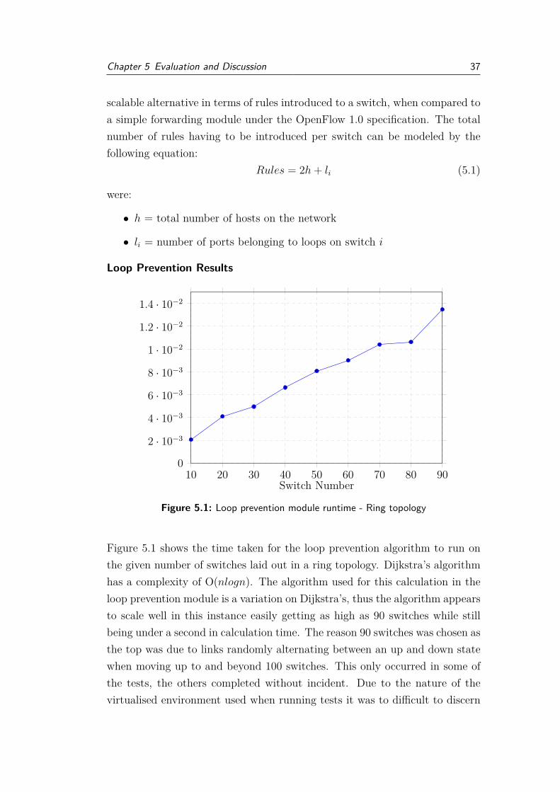
Loop Prevention Results
10 20 30 40 50 60 70 80 900
2 · 10−3
4 · 10−3
6 · 10−3
8 · 10−3
1 · 10−2
1.2 · 10−2
1.4 · 10−2
Switch Number
Figure 5.1: Loop prevention module runtime - Ring topology
Figure 5.1 shows the time taken for the loop prevention algorithm to run onthe given number of switches laid out in a ring topology. Dijkstra’s algorithmhas a complexity of O(nlogn). The algorithm used for this calculation in theloop prevention module is a variation on Dijkstra’s, thus the algorithm appearsto scale well in this instance easily getting as high as 90 switches while stillbeing under a second in calculation time. The reason 90 switches was chosen asthe top was due to links randomly alternating between an up and down statewhen moving up to and beyond 100 switches. This only occurred in some ofthe tests, the others completed without incident. Due to the nature of thevirtualised environment used when running tests it was to difficult to discern

Chapter 5 Evaluation and Discussion 38
what caused this link fluctuation. Whether it was a side effect of having somany virtual Open vSwitch (OVS) switches running on a single machine, theRyu topology code not being able to handle that many switches, or links orif it was in fact an artifact of the overhead introduced when running the loopprevention and ECMF modules.
10 15 20 25 30 35 40 45 500
2 · 10−3
4 · 10−3
6 · 10−3
8 · 10−3
1 · 10−2
1.2 · 10−2
1.4 · 10−2
Switch Number
Figure 5.2: Loop prevention module runtime - Partial mesh
Figure 5.2 is the results of the loop prevention algorithm when run on thepartial mesh topology. There is a larger amount of links introduced via theintroduction of an individual switch to this network as well the existence ofmultiple loops, as such the link fluctuations were apparent much sooner occur-ring occasionally at 60 switches.

Chapter 5 Evaluation and Discussion 39
ECMF Results
10 20 30 40 50 60 70 80 900
0.2
0.4
0.6
0.8
Switch Number
Figure 5.3: ECMF module runtime - Ring topology
Figure 5.3 is the results from finding all the shortest paths between switches inthe ring topology. The slope of this graph is what was expected due to fact thecontroller is singularly responsible for calculating the shortest paths betweenall pairs of switches. Again this calculation is not run often as it only needsto be run every time there is a link change, so the computation times impacton the network is small.
10 15 20 25 30 35 40 45 500
0.1
0.2
0.3
0.4
0.5
Switch Number
Figure 5.4: ECMF module runtime - Partial mesh
Chapter 5 Evaluation and Discussion 40
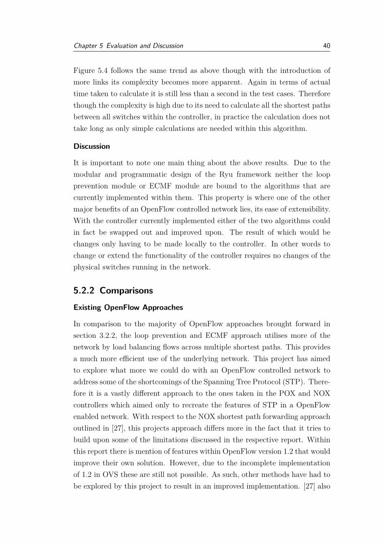
Figure 5.4 follows the same trend as above though with the introduction ofmore links its complexity becomes more apparent. Again in terms of actualtime taken to calculate it is still less than a second in the test cases. Thereforethough the complexity is high due to its need to calculate all the shortest pathsbetween all switches within the controller, in practice the calculation does nottake long as only simple calculations are needed within this algorithm.
Discussion
It is important to note one main thing about the above results. Due to themodular and programmatic design of the Ryu framework neither the loopprevention module or ECMF module are bound to the algorithms that arecurrently implemented within them. This property is where one of the othermajor benefits of an OpenFlow controlled network lies, its ease of extensibility.With the controller currently implemented either of the two algorithms couldin fact be swapped out and improved upon. The result of which would bechanges only having to be made locally to the controller. In other words tochange or extend the functionality of the controller requires no changes of thephysical switches running in the network.
5.2.2 Comparisons
Existing OpenFlow Approaches
In comparison to the majority of OpenFlow approaches brought forward insection 3.2.2, the loop prevention and ECMF approach utilises more of thenetwork by load balancing flows across multiple shortest paths. This providesa much more efficient use of the underlying network. This project has aimedto explore what more we could do with an OpenFlow controlled network toaddress some of the shortcomings of the Spanning Tree Protocol (STP). There-fore it is a vastly different approach to the ones taken in the POX and NOXcontrollers which aimed only to recreate the features of STP in a OpenFlowenabled network. With respect to the NOX shortest path forwarding approachoutlined in [27], this projects approach differs more in the fact that it tries tobuild upon some of the limitations discussed in the respective report. Withinthis report there is mention of features within OpenFlow version 1.2 that wouldimprove their own solution. However, due to the incomplete implementationof 1.2 in OVS these are still not possible. As such, other methods have had tobe explored by this project to result in an improved implementation. [27] also

Chapter 5 Evaluation and Discussion 41
states that the flow rules are not removed when a link failure is detected. Inthis project’s implementation this is addressed by the controller removing allflow rules from the pair of switched connected by the failed link. This meansthat flows following the old path will eventually hit the affected switches andbe sent back up to the controller so a new path can be calculated and old rulesoverwritten. In terms of rules introduced on the switches contained within anetwork, all previously discussed implementations have used OpenFlow ver-sion 1.0. The rule scalability of this project’s approach is much improved aswell as this project allows for more extensibility due the use of the multipleflow tables.

Chapter 5 Evaluation and Discussion 42
STP: Successors and Extensions
STP RSTP Shortest PathOpenFlow [27]
ECMF Open-Flow
Convergence 30-50s Less than 6 s Not given Approx. 11sShortest path Not guaranteed Not guaranteed Yes Yes,uses a search
algorithm to de-termine in ad-vance
Loop prevention Calculate tree,ports not in-cluded aredisabled
Calculate tree,ports not in-cluded disabled
Tree calculated,not includedports put intoNO FLOODstate
Tree calculated,flow rules intro-duced to dropbroadcast trafficon ports not in-cluded in tree
Broadcast traffic Can only traveldown enabledpaths
Unicast traffic Only travelsdown enabledpaths
Only travelsdown enabledpaths
Follow a singleshortest pathbetween sourceand destination
Can traveldown any of theshortest pathsbetween sourceand destination
Load balancing No No No Yes, flows al-ternated downequal cost paths
Hardware No new hard-ware needed
No new hard-ware needed
Yes, full Open-Flow enablednetwork needed
Yes, full Open-Flow enablednetwork needed
Table 5.1: Comparisons between STP and OpenFlow approaches
Table 5.1 gives a comparison between the ECMF and loop prevention imple-mentation outlined in this project and previously implemented variations ofSTP as well as a comparison against the shortest path OpenFlow approachdiscussed in [27]. Note the ll seconds mentioned in the convergence time forthe ECMF. This time factors in the 10 seconds it takes for the default Ryu
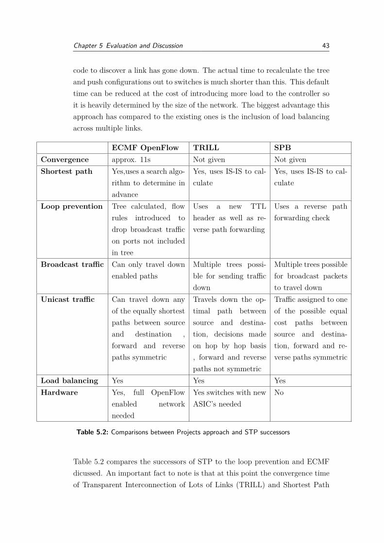
Chapter 5 Evaluation and Discussion 43
code to discover a link has gone down. The actual time to recalculate the treeand push configurations out to switches is much shorter than this. This defaulttime can be reduced at the cost of introducing more load to the controller soit is heavily determined by the size of the network. The biggest advantage thisapproach has compared to the existing ones is the inclusion of load balancingacross multiple links.
ECMF OpenFlow TRILL SPBConvergence approx. 11s Not given Not givenShortest path Yes,uses a search algo-
rithm to determine inadvance
Yes, uses IS-IS to cal-culate
Yes, uses IS-IS to cal-culate
Loop prevention Tree calculated, flowrules introduced todrop broadcast trafficon ports not includedin tree
Uses a new TTLheader as well as re-verse path forwarding
Uses a reverse pathforwarding check
Broadcast traffic Can only travel downenabled paths
Multiple trees possi-ble for sending trafficdown
Multiple trees possiblefor broadcast packetsto travel down
Unicast traffic Can travel down anyof the equally shortestpaths between sourceand destination ,forward and reversepaths symmetric
Travels down the op-timal path betweensource and destina-tion, decisions madeon hop by hop basis, forward and reversepaths not symmetric
Traffic assigned to oneof the possible equalcost paths betweensource and destina-tion, forward and re-verse paths symmetric
Load balancing Yes Yes YesHardware Yes, full OpenFlow
enabled networkneeded
Yes switches with newASIC’s needed
No
Table 5.2: Comparisons between Projects approach and STP successors
Table 5.2 compares the successors of STP to the loop prevention and ECMFdicussed. An important fact to note is that at this point the convergence timeof Transparent Interconnection of Lots of Links (TRILL) and Shortest Path

Chapter 5 Evaluation and Discussion 44
Bridging (SPB) is relatively unknown. This is likely attributed to their slowpick up and the fact they have yet to be deployed fully in a production network.At this stage Cisco have their own version of SPB currently in development.Though the convergence times are not yet fully realised, these two successorsto STP have been designed with the idea of large, high density datacenters inmind so their convergence time is likely by necessity to be very low.
This loop prevention and ECMF approach is not quite at a level were it couldscale as well as the potential successors of STP. This can be attributed tothe link failure detection of OpenFlow not being done locally on the switchesthus the convergence time is higher as well as reliance on the single controllerfor controlling the entire network. Having distributed OpenFlow controllers,which is further discussed in section 5.3.2 would certainly improve the viabilityof the outlines approach. The major advantage of OpenFlow over these twoproposed solutions is that it is far more extensible. If there is some desiredforwarding behaviour wanting to be introduced to the network, it could beadded by including an additional module to the controller allowing for easilycustomised forwarding. This extension would be significantly easier than mod-ifying the switches in current networks to achieve the same effect, which maynot always be possible depending on the desired behaviour.
To conclude the approach covered in this project offers features highly desiredin modern networks which are absent from the older, currently used protocolRapid Spanning Tree Protocol (RSTP) as well as the other OpenFlow approachdiscussed. However, compared to the currently proposed successors TRILL andSPB, there is still some work to be done in relation to the OpenFlow protocolin order to gain enough footing to provide a potential alternative.
5.3 Project and OpenFlow Limitations
5.3.1 Design Choice Limitations
Most of the design choices of this project stem from the limited OpenFlowversion 1.2 support in OVS. Once OVS has implemented more of OpenFlowversion 1.2, the ARP redirection controller could be extended to make use ofthe ability to introduce rules to the switches to drop packets based on theARP response opcode. By implementing this in a real environment and notwith OVS the loop prevention and ECMF module could be extended to using
Chapter 5 Evaluation and Discussion 45
the link speed and capabilities of a link in order to determine its cost ratherthan the arbitrary assignment via a static file which is currently implemented.The introduction of these features would allow for much cleaner and improvedcontrollers.
5.3.2 OpenFlow Limitations
Though OpenFlow does have a lot of upsides to its approach and conceptthere are also certain limitations to its use. One of the most apparent is theintroduction of a delay between the switch and controller. Though this delay isalso apparent in the traditional tightly coupled switch due to the slower speedof the control plane, the effect here is somewhat larger due to the physicalseparation of these two planes. For small to medium networks this delay is notsuch a problem and the extensibility and abstraction that OpenFlow providesin terms of the switch configuration more than cover for this downside.
One of the other major limitations to OpenFlow which impacts on the loop pre-vention and ECMF approach more significantly is having a single controllercontrolling the entire network. Though it is great to have a logically cen-tralised view of the network in terms of controllability, in current implemen-tation OpenFlow introduces a single point of failure into the network. As hasalready been discussed, due to the nature of networks this is somewhat unde-sired and it would not be recommended running an entire network of a singlecontroller for this reason.
This particular issue has already been realised within the OpenFlow commu-nity and work is already being done to address this. In terms of the OpenFlowspecifications, OpenFlow 1.2 does introduce the idea of having a master andslave controller setup, allowing for fast fail over should one controller go downand adding potential for load balancing. OVS does partially implement thisfeature however the implementation only allows for a backup inactive slave tobe used rather than two active ones. Due to this, splitting the loop preventionand ECMF code across multiple controllers was not explored as OVS doesnot yet allow for this. However, this is not the only approach taken, [29] isone example of research being done to allow for a more scalable OpenFlowenabled network. It looks at introducing a distributed system of OpenFlowcontrollers to allow for the handling of more flows in the network. This alsoenables further redundancy in terms of the OpenFlow control.

Chapter 5 Evaluation and Discussion 46
Adapting the loop prevention and ECMF approach to an distributed set ofOpenFlow controllers would be largely beneficial for the approach. Not onlybecause it would allow more flows to be handled but also because it allowsfor the work for both the sending and receiving of the topology discoveryLink Layer Discovery Packet (LLDP)s to potentially be distributed betweenthese controllers. Allowing for the topology discovery module to handle morelinks and switches. This approach would also allow for the reduction of the linkexpiry timer in the Ryu topology discovery code as well. This link expiry timeris the time taken for two of the LLDP messages to be sent. Currently this isset to 5 seconds to prevent too much load on the controller as it is generatingall of the LLDP for each switch. Using a distributed network would allowfor this to be smaller and thus ultimately reduce the convergence time. Atthis stage this loop prevention and ECMF approach would only be suited tosmaller networks but given a distributed system as described above its reachwould extend to larger networks and would result in a much more scalablesolution. The work required to achieve such a system lies outside the scope ofthis project, but would certainly be a major factor in future work.

Chapter 6
Conclusions
6.1 Contributions MadeThis project has explored the ways in which OpenFlow can be used to addresssome of the weakness of existing protocols that have started to become morevisible as the size and complexity of networks has increased. Two designsaddressing the overhead and security of Address Resolution Protocol (ARP)have been implemented and evaluted. These are:
• ARP Redirection and ResponseThe implementation in which the OpenFlow controller has be designedto forward traffic to a trusted host running an ISC-DHCP server in orderto generate trusted ARP responses. This allows the controller to dropany other ARP responses as they are unsolicted and therefore potentiallymalicious.
• ARP ProxyThis implementation is an re-imagining of the approaches already dis-cussed in Section 3.1 for the Ryu framework. It allows the controller tobecome responsible for generating the ARP responses eliminating muchof the overhead caused by the broadcast of ARP requests on the network.
Along with these proposed OpenFlow designs to reducing the negative effectsof ARP, this project has also looked into how the same OpenFlow principlescan be used design an alternative to Spanning Tree Protocol (STP). Discussingwhat the advantages and drawbacks of this approach would be. The designput forward by this project was:
• Loop prevention and Equal Cost Multipath Forwarding (ECMF)

Chapter 6 Conclusions 48
An implementation that takes the default Ryu topology discovery codeand uses the information learned to introduce rules to the OpenFlowswitches to prevent loops in order to keep all ports active. It also im-plements a forwarding module to distribute flows across shortest equalpaths between the source and destination, allowing for a load balancednetwork along with a network that guarantees shortest paths between allswitches on the network.
All approaches put forward have been evaluated and compared against boththe existing solutions and the more popular proposed successors discussed inChapter 3.
6.2 Future workOpenFlow is a rapidly growing, constantly evolving entity. This is due toits flexibility and the increased interest in virtualisation. New features arebeing introduced to the specifications on an regular basis. As a result it ishard to predict whether features may be added that benefit the approachesoutlined in this project or not and how exactly they might benefit it. In thetime of writing this report the specification for OpenFlow version 1.4[13] wasreleased and is currently under ratification. This new OpenFlow specificationre-introduces port states such as NO FLOOD that were removed in version 1.1.Once Ryu has been updated to support OpenFlow version 1.4 this would allowthe loop prevention code to be updated from its current rule based approachto dropping broadcast traffic, to a port based approach to handle the loops.This would reduce the rules needing to be introduced to the switch as well assimplifying the loop prevention process.
There were a number of design limitations that could be addressed once OpenvSwitch (OVS) has implemented more of OpenFlow version 1.1 and up, suchas redesigning the controller for the ARP redirection approach to allow for flowentries to match on the ARP operation code held within a packet. This wouldallow for the switches themselves to drop responses from untrusted ports asopposed to forwarding them up to the controller therefore reducing the loadon the controller.
The other major piece of work to be done would be to redesign the loop preven-tion code to allow it to be easily extended to a distributed OpenFlow controller

Chapter 6 Conclusions 49
environment as discussed in Section 5.3.2. This would be the most valuable ex-tension to the loop prevention and Equal Cost Multipath Forwarding (ECMF)controller presented in this project.
6.3 ConclusionThis project has focused on using the flexibility OpenFlow provides via its cen-tralised software controller along with the dynamic reconfiguration of switchesto explore potential solutions to the shortcomings of existing network pro-tocols. It has focused on the design of solutions that do not require a fullreconfiguration of a network in order to deploy, but rather ones that requireonly minimal changes to the underlying network in order to gain improve-ments. Given the limitations discussed, it would be possible to introduce bothof the proposed ARP solutions to an OpenFlow enabled network. However,the loop prevention and ECMF controller, although allowing for certain desir-able features, would only be suitable for smaller network environments due tothe single point of failure currently introduced by OpenFlow as well as designsnot yet fully realised in an OpenFlow environment.

References
[1] AVAYA. Compare and Contrast SPB an TRILL, 2011.http://www.avaya.com/uk/resource/assets/whitepapers/SPB-TRILL Compare Contrast-DN4634.pdf (Accessed October 2013).
[2] P. Biondi. Scapy.www.secdev.org/projects/scapy/ (Accessed October 2013).
[3] D. Bruschi, A. Ornaghi, and E. Rosti. S-arp: a secure address resolutionprotocol. Computer Security Applications Conference, pages 66–74, 2003.
[4] O. M. E. Committee. Software-Defined Networking: The New Normfor Networks, 2012. https://www.opennetworking.org/sdn-resources/sdn-library/whitepapers (Accessed October 2013).
[5] Internet Systems Consortium. ISC DHCP: Enterprise grade solution forconfiguration needs, 2013. https://www.isc.org/downloads/dhcp/ (Ac-cessed October 2013).
[6] S. Dangol, S. Selvakumar, and M. Brindha. Genuine arp (garp): a broad-cast based stateful authentication protocol. ACM SIGSOFT SoftwareEngineering Notes, 36:1–10, 2011.
[7] David Erickson. The Beacon OpenFlow Controller. In HotSDN. ACM,2013.
[8] Project Floodlight. Floodlight, 2013.https://github.com/floodlight/floodlight (Accessed October 2013).
[9] Open Networking Foundation. OpenFlow Switch Specification1.0.0, Dec 2009. https://www.opennetworking.org/sdn-resources/onf-specifications/openflow (Accessed October 2013).
[10] Open Networking Foundation. OpenFlow Switch Specification1.1.0, Feb 2011. https://www.opennetworking.org/sdn-resources/onf-

References 51
specifications/openflow (Accessed October 2013).
[11] Open Networking Foundation. OpenFlow Switch Specification1.2, Dec 2011. https://www.opennetworking.org/sdn-resources/onf-specifications/openflow (Accessed October 2013).
[12] Open Networking Foundation. OpenFlow Switch Specification1.3.0, Jun 2012. https://www.opennetworking.org/sdn-resources/onf-specifications/openflow (Accessed October 2013).
[13] Open Networking Foundation. OpenFlow Switch Specification1.4, Aug 2013. https://www.opennetworking.org/sdn-resources/onf-specifications/openflow (Accessed October 2013).
[14] G. Gibb. OpenFlow: Basic Spanning Tree.http://archive.openflow.org/wk (Accessed October 2013).
[15] H. Grohne and T. Szczepanek. Pypureomapi: ISC DHCP OMAPI proto-col implementaion in Python. code.google.com/p/pypureomapi (AccessedOctober 2013).
[16] N. Gude, T. Koponen, J. Pettit, B. Pfaff, M. Casado, N. McKeown, andS. Shenker. Nox: towards an operating system for networks. SIGCOMMComput. Commun. Rev., 38(3):105–110, jul 2008.
[17] IEEE. 802.1D Bridging Standard, IEEE Standard for Local andmetropolitan area networks: Media Access Control (MAC) Bridges, 2004.incorporates 802.1w (RSTP).
[18] IEEE. 802.1Q VLAN standard, IEEE Standards for Local and metropoli-tan area networks: Virtual Bridged Local Area Networks, 2006. incorpo-rates 802.1v (VSTP) and 802.1s (MSTP).
[19] IEEE. 802.1aq-2012, IEEE Standard for Local and metropolitan AreaNetworks: Media Access Control (MAC) Bridges and Virtual BridgedLocal Area Networks, 2012.
[20] M. Jarschel, S. Oechsner, D. Schlosser, R. Pries, S. Goll, and P. Tran-Gia. Modeling and performance evaluation of an openflow architecture.In Proceedings of the 23rd International Teletraffic Congress, ITC ’11,pages 1–7, 2011.
[21] M. McCuley. Pox. https://github.com/noxrepo/pox (Accessed October

References 52
2013).
[22] N. McKeown, T. Anderson, H. Balakrishnan, G. Parulkar, L. Peterson,J. Rexford, S. Shenker, and J. Turner. Openflow: enabling innovation incampus networks. SIGCOMM Comput. Commun. Rev., 38(2):69–74, mar2008.
[23] R. Perlman. An Algorithm for Distributed Computation of a SpanningTree in an Extended LAN. SIGCOMM ’85 Proceedings of the ninth sym-posium on Data communications, 15:44–53, 1985.
[24] R. Perlman, D. Eastlake, D. Dutt, S. Gai, and A. Ghanwani. RoutingBridges (RBridges): Base Protocol Specification. RFC6325, 2011, July.
[25] B. Pfaff, J. Pettit, T. Koponen, K. Amidon, M. Casado, and S. Shenker.Extending Networking into the Virtualization Layer. HotNets, 8:22–23,2009.
[26] D. Plummer. Ethernet Address Resolution Protocol: Or Converting Net-work Protocol Addresses to 48.bit Ethernet Address for Transmission onEthernet Hardware. Internet RFC 826, 1982.
[27] J. Soeurt and Hoogendoorn I. Shortest path forwarding using openflow.Master’s thesis, University of Amsterdam, 2012.
[28] Nippon Telegraph and Telephone Corporation. Ryu, a component-basedsoftware-defined networking framework, 2013. http://osrg.github.io/ryu(Accessed October 2013).
[29] A Tootoonchian and Y Ganjali. HyperFlow: A Distributed Control Planefor OpenFlow, April 2010.

Appendix A
ARP Redirection and Proxy inOpenFlow
A.1 ARP response script1 import thread ing2 import time3 import pypureomapi45 from scapy . a l l import ∗67 KEYNAME=” defomapi ”8 BASE64 ENCODED KEY=”DaJqBjuYJH1Fb54WdOmA==”9
10 d h c p s e r v e r i p=” 0 . 0 . 0 . 0 ”11 port = 7911 # Port o f the omapi s e r v i c e1213 c l a s s ArpResponse ( thread ing . Thread ) :14 de f i n i t ( s e l f , pkt ) :15 s e l f . pkt = pkt16 super ( ArpResponse , s e l f ) . i n i t ( )1718 de f run ( s e l f ) :19 a = ARP( )20 a . op = 221 a . psrc = s e l f . pkt [ARP] . pdst22 a . pdst = s e l f . pkt [ARP] . psrc23 a . hwdst = s e l f . pkt [ARP] . hwsrc24 try :25 # connect to DHCP se rve r

Appendix A ARP Redirection and Proxy in OpenFlow 54
26 o = pypureomapi . Omapi( dhcp se rve r ip , port ,KEYNAME, BASE64 ENCODED KEY)
27 # f i n d mac address from a g iven IP28 mac = o . lookup mac ( a . psrc )29 a . hwsrc = mac30 # crea t e ARP response31 p = Ether ( dst=s e l f . pkt [ARP] . hwsrc ) / a32 p r i n t ” Src : %s , Ip : %s , Dst %s , Ip : %s ”
% ( a . hwsrc , a . psrc , a . hwdst , a . pdst )33 sendp (p)34 except pypureomapi . OmapiErrorNotFound :35 p r i n t ”%s i s c u r r e n t l y not a s s i gned ” % ( a .
psrc )36 except pypureomapi . OmapiError , e r r :37 p r i n t ”an e r r o r occured : %r ” % ( err , )3839 de f a r p r e q u e s t r e p l y ( pkt ) :40 i f ARP in pkt and pkt [ARP] . op == 1 :41 ArpResponse ( pkt ) . s t a r t ( )4243 s n i f f ( prn=a r p r e q u e s t r e p l y , f i l t e r=’ arp ’ , s t o r e =0)
A.2 ARP Proxy controller1 de f map get ( s e l f , s rc , dst , ev ) :2 pkt = packet . Packet ( array . array ( ’B ’ , ev . msg . data ) )3 d = None4 # ge t arp header so we can use i t s va l u e s5 f o r p in pkt :6 i f p . protocol name == ’ arp ’ :7 d = p8 try :9
10 e = ethe rne t . e the rne t ( s r c , s e l f . ip to mac [ d . d s t i p ] , e the r .ETH TYPE ARP)
11 a = arp . arp (1 , e the r . ETH TYPE IP , 6 , 4 , 2 , s e l f . ip to mac [ d .d s t i p ] , d . d s t ip , src , s e l f . mac to ip [ s r c ] )
12 b pkt = packet . Packet ( )13 b pkt . add protoco l ( e )14 b pkt . add protoco l ( a )15 b pkt . s e r i a l i z e ( )16 p r i n t ” from : ” , h a d d r t o s t r ( s e l f . ip to mac [ d . d s t i p ] ) , d .
d s t i p17 p r i n t ” to : ” , h a d d r t o s t r ( s r c ) , s e l f . mac to ip [ s r c ]

Appendix A ARP Redirection and Proxy in OpenFlow 55
18 return b pkt1920 except KeyError :21 p r i n t ” not yet l ea rned ”2223 return None2425 # . . . . . . . . . Packe t in method Snippet . . . . . . . . . . . #2627 i f e th type == ether .ETH TYPE ARP:28 r ep ly = s e l f . map get ( src , dst , ev )29 i f ( r ep ly == None) :30 out por t = o fp ro to .OFPP FLOOD31 e l s e :32 a c t i o n s = [ datapath . o f p r o t o p a r s e r . OFPActionOutput ( in por t ,
max len=0) ]33 out = datapath . o f p r o t o p a r s e r . OFPPacketOut (34 datapath=datapath , b u f f e r i d=0 x f f f f f f f f , i n p o r t=
o fp ro t o v1 2 .OFPP ANY,35 a c t i o n s=act ions , data=rep ly . data )36 datapath . send msg ( out )37 re turn

Appendix B
Loop prevention and ECMF
B.1 Loop prevention module - Tree calculation1 whi l e l en ( queue ) > 0 :2 # return l i n k / path wi th l owe s t co s t3 cur rent path = queue . pop ( s e l f . g e t l o w e s t c o s t ( queue ) )4 cur r en t dp id = current path [ 1 ]5 i f cu r r ent dp id in v i s i t e d s w i t c h e s :6 cont inue7 #otherw i s e add i t to the l i s t o f v i s i t e d sw i t che s8 v i s i t e d s w i t c h e s . add ( cur r ent dp id )9 t ry :
10 a l l d a t a p a t h s . remove ( cur r ent dp id )11 except :12 p r i n t ” t ry ing to remove : ” , cu r r ent dp id1314 # f i n d s the l owe s t co s t path to t h i s sw i t ch15 l o w e s t c o s t p o r t = s e l f . f i n d l o w e s t c o s t p o r t ( path to swi tch ,
cu r r ent dp id ) [ 1 ]16 # ignore the in por t o f the l owe s t co s t path , so t h a t i t i s
inc luded in spanning t r e e17 i g n o r e l i n k s [ cu r r en t dp id ] . append ( l o w e s t c o s t p o r t )18 # fo r a l l po r t s on sw i t ch f i n d s unexp lored l i n k s19 f o r port in s e l f . topo logy [ cu r r en t dp id ] :20 i f port in i g n o r e l i n k s [ cu r r en t dp id ] :21 cont inue22 dst dp = s e l f . topo logy [ cu r r en t dp id ] [ port ] [ s e l f .DEST DP]23 d s t p o r t = s e l f . topo logy [ cu r r ent dp id ] [ port ] [ s e l f .DEST PORT]24 i f not s e l f . up both ways ( current dp id , port , dst dp ,
d s t p o r t ) :25 cont inue

Appendix B Loop prevention and ECMF 57
26 # i f the de s t sw i t ch has been v i s i t e d a l r eady then drop thel i n k
27 i f dst dp in v i s i t e d s w i t c h e s :28 d r o p l i n k s [ cu r r en t dp id ] . append ( port )29 d r o p l i n k s [ dst dp ] . append ( d s t p o r t )30 cont inue31 e l s e :32 # compute the co s t o f t a k ing t h i s l i n k and add i t to the queue33 c o s t t o h e r e = current path [ 0 ]34 r e v e r s e c o s t = s e l f . met r i c s [ d p i d t o s t r ( dst dp ) ] [
p o r t n o t o s t r ( d s t po r t ) ]35 p o r t c o s t = s e l f . topo logy [ cu r r ent dp id ] [ port ] [ s e l f .LINK METRIC
]36 t o t a l c o s t = p o r t c o s t + r e v e r s e c o s t + c o s t t o h e r e37 queue . append ( [ t o t a l c o s t , dst dp , d s t po r t ] )38 path to sw i t ch [ dst dp ] . append ( [ t o t a l c o s t , d s t p o r t ] )
B.2 ECMF - shortest paths between pair ofswitches calculation
1 de f f i n d s h o r t e s t p a t h s ( s e l f , i n i t i a l d p i d , f i n a l d p i d ) :2 v i s i t e d s w i t c h e s = s e t ( [ i n i t i a l d p i d ] )3 i n i t i a l n e i g h b o u r s = [ ]4 por t s = [ ]5 # the s e t o f ne i gbours we can reach from the src datapath6 f o r port in s e l f . topo logy [ i n i t i a l d p i d ] :7 d s t sw i t ch = s e l f . topo logy [ i n i t i a l d p i d ] [ port ] [ s e l f .DEST DP]8 i f d s t sw i t ch not in v i s i t e d s w i t c h e s :9 d e s t i n a t i o n = s e l f . topo logy [ i n i t i a l d p i d ] [ port ]
10 co s t = d e s t i n a t i o n [ s e l f .LINK METRIC]11 i n i t i a l n e i g h b o u r s . append ( [ cost , [ c o s t ] , [ i n i t i a l d p i d , port ]+
d e s t i n a t i o n [ : −1 ] ] )1213 paths = s e l f . s e a r c h f o r d e s t i n a t i o n ( v i s i t e d s w i t c h e s ,
i n i t i a l n e i g h b o u r s , f i n a l d p i d )14 re turn paths1516 de f s e a r c h f o r d e s t i n a t i o n ( s e l f , v i s i t e d s w i t c h e s , neighbours ,
f i n a l d p i d ) :17 pa th s t o take = [ ]18 l e a s t c o s t = 019 whi l e l en ( ne ighbours ) != 0 :20 # ge t the path to ne ighbour ing sw i t ch

Appendix B Loop prevention and ECMF 58
21 path to ne ighbour = neighbours . pop ( s e l f . s e l e c t n e i g h b o u r (ne ighbours ) )
22 l a s t p a t h = len ( path to ne ighbour )−123 ne ighbour dpid = path to ne ighbour [ l a s t p a t h ] [ 2 ]24 # i f we havent h i our t a r g e t ye t then record t h a t we have
v i s i t e d t h i s sw i t ch25 i f ne ighbour dpid != f i n a l d p i d :26 v i s i t e d s w i t c h e s . add ( ne ighbour dpid )27 i f path to ne ighbour [ l a s t p a t h ] [ 4 ] == ”UP” :28 i f ne ighbour dpid == f i n a l d p i d :29 # i f t h i s i s the f i r s t time we had the pa i r i n g then we
want to capture a l l e qua l co s t paths30 i f path to ne ighbour [ 0 ] == l e a s t c o s t or l e a s t c o s t == 0 :31 # caching d i s cove r ed paths32 pa th s t o take . append ( path to ne ighbour )33 l e a s t c o s t = path to ne ighbour [ 0 ]34 # e l s e re turn the path t h a t we are up to35 e l s e :36 re turn pa th s t o take37 # take the path to t h i s ne ighbour and add an entry to each o f
i t s ne ighbours38 f o r port in s e l f . topo logy [ ne ighbour dpid ] :39 path = s e l f . topo logy [ ne ighbour dpid ] [ port ]40 d s t sw i t ch = path [ s e l f .DEST DP]41 i f d s t sw i t ch not in v i s i t e d s w i t c h e s :42 ne ighbours . append ( s e l f . extend path ( path to ne ighbour , path ,
l a s t pa th , port ) )4344 # when only equa l co s t paths e x i s t between sw i t che s t h i s code
w i l l g e t h i t45 return pa th s t o take
Copyright © 2022 FDOKUMEN