Improving Spectrum Efficiency Using Micro-ACKs
12
Frame Retransmissions Considered Harmful: Improving Spectrum Efficiency Using Micro-ACKs Jiansong Zhang ∗ Microsoft Research Asia and HKUST Beijing, China [email protected] Haichen Shen ∗ Microsoft Research Asia and Tsinghua University Beijing, China v-hashen @microsoft.com Kun Tan Microsoft Research Asia Beijing, China [email protected] Ranveer Chandra Microsoft Research Redmond, WA, USA [email protected] Yongguang Zhang Microsoft Research Asia Beijing, China [email protected] Qian Zhang HKUST Hong Kong, China [email protected] ABSTRACT Retransmissions reduce the efficiency of data communication in wireless networks because of: (i) per-retransmission packet head- ers, (ii) contention overhead on every retransmission, and (iii) re- dundant bits in every retransmission. In fact, every retransmission nearly doubles the time to successfully deliver the packet. To im- prove spectrum efficiency in a lossy environment, we propose a new in-frame retransmission scheme using μACKs. Instead of waiting for the entire transmission to end before sending the ACK, the re- ceiver sends smaller μACKs for every few symbols, on a separate narrow feedback channel. Based on these μACKs, the sender only retransmits the lost symbols after the last data symbol in the frame, thereby adaptively changing the frame size to ensure it is success- fully delivered. We have implemented μACK on the Sora platform. Experiments with our prototype validate the feasibility of symbol- level μACK. By significantly reducing the retransmistion overhead, the sender is able to aggressively use higher data rate for a lossy link. Both improve the overall network efficiency. Our experimen- tal results from a controlled environment and an 9-node software radio testbed show that μACK can have up to 140% throughput gain over 802.11g and up to 60% gain over the best known retrans- mission scheme. Categories and Subject Descriptors C.2.1 [COMPUTER-COMMUNICATION NETWORKS]: Net- work Architecture and Design—Wireless communication General Terms Algorithms, Design, Experimentation, Performance ∗ This work is done when Jiansong Zhang is a researcher and Haichen Shen is a research intern in Microsoft Research Asia. Permission to make digital or hard copies of all or part of this work for personal or classroom use is granted without fee provided that copies are not made or distributed for profit or commercial advantage and that copies bear this notice and the full citation on the first page. To copy otherwise, to republish, to post on servers or to redistribute to lists, requires prior specific permission and/or a fee. MobiCom’12, August 22–26, 2012, Istanbul, Turkey. Copyright 2012 ACM 978-1-4503-1159-5/12/08 ...$15.00. Keywords Retransmission, Error Recovery, Feedback, μACK, WLAN 1. INTRODUCTION Packets transmissions over a wireless medium are lossy. Losses typically occur because of interference, fading or noise, which in turn causes poor signal to interference and noise ratio (SINR) at the receiver. A low SINR reduces the probability of successfully decoding all bits in the packet. In existing data networks, such as Wi-Fi or cellular, the onus of recovering a lost packet is with the link layer of the OSI stack. The physical layer (PHY) may include some redundancy, i.e., channel coding, in a frame to correct erroneous bits. But when the errors cannot be recovered, the frame will be retransmitted by the MAC layer. The sender usually relies on an acknowledgment (ACK) packet from the receiver to detect transmission failures. For exam- ple, in IEEE 802.11, if the sender does not receive the ACK packet within a fixed timeout period, it retransmits the entire frame. This frame retransmission is costly. First, each retransmitted frame requires both PHY and MAC headers, which can consume up to 100 bytes. While MAC header can be transmitted using high modulation, the PHY header is sent at the lowest rate and usually includes a sequence of training symbols (preamble) for synchro- nization and channel estimation. In 802.11g, this header overhead can add up to 52 μs. Second, the sender needs to re-contend for the medium to retransmit the packet. Depending on the number of ad- ditional contending nodes, the sender has to perform backoff, pos- sibly several times, before the frame can be successfully delivered to the receiver. For each unsuccessful retransmission, the sender needs to wait for an ACK timeout before it can detect the loss. All reduce the link efficiency in a noisy wireless channel. Finally, re- transmitting the entire frame may unnecessarily send redundant bits that may have already been received correctly by the receiver. In previous work, Jamieson, et. al., tried to address the last issue by selectively requesting only erroneous bits in retransmission [12]. But the first two issues remain unexplored. In this paper, we propose a system that does away with frame- level retransmissions. After a sender gets access to a medium, we dynamically adjust the length of the packet (up to a maximum limit) to ensure that it is reliably delivered. In a zero-loss network the packet length is unchanged; while in a lossy network we pad the
-
Upload
khangminh22 -
Category
Documents
-
view
1 -
download
0
Transcript of Improving Spectrum Efficiency Using Micro-ACKs
Frame Retransmissions Considered Harmful:Improving Spectrum Efficiency Using Micro-ACKs
Jiansong Zhang∗
Microsoft Research Asia andHKUST
Beijing, [email protected]
Haichen Shen∗
Microsoft Research Asiaand Tsinghua University
Beijing, Chinav-hashen
@microsoft.com
Kun TanMicrosoft Research Asia
Beijing, [email protected]
Ranveer ChandraMicrosoft ResearchRedmond, WA, USA
Yongguang ZhangMicrosoft Research Asia
Beijing, [email protected]
Qian ZhangHKUST
Hong Kong, [email protected]
ABSTRACTRetransmissions reduce the efficiency of data communication inwireless networks because of: (i) per-retransmission packet head-ers, (ii) contention overhead on every retransmission, and (iii) re-dundant bits in every retransmission. In fact, every retransmissionnearly doubles the time to successfully deliver the packet. To im-prove spectrum efficiency in a lossy environment, we propose a newin-frame retransmission scheme using µACKs. Instead of waitingfor the entire transmission to end before sending the ACK, the re-ceiver sends smaller µACKs for every few symbols, on a separatenarrow feedback channel. Based on these µACKs, the sender onlyretransmits the lost symbols after the last data symbol in the frame,thereby adaptively changing the frame size to ensure it is success-fully delivered. We have implemented µACK on the Sora platform.Experiments with our prototype validate the feasibility of symbol-level µACK. By significantly reducing the retransmistion overhead,the sender is able to aggressively use higher data rate for a lossylink. Both improve the overall network efficiency. Our experimen-tal results from a controlled environment and an 9-node softwareradio testbed show that µACK can have up to 140% throughputgain over 802.11g and up to 60% gain over the best known retrans-mission scheme.
Categories and Subject DescriptorsC.2.1 [COMPUTER-COMMUNICATION NETWORKS]: Net-work Architecture and Design—Wireless communication
General TermsAlgorithms, Design, Experimentation, Performance
∗This work is done when Jiansong Zhang is a researcher andHaichen Shen is a research intern in Microsoft Research Asia.
Permission to make digital or hard copies of all or part of this work forpersonal or classroom use is granted without fee provided that copies arenot made or distributed for profit or commercial advantage and that copiesbear this notice and the full citation on the first page. To copy otherwise, torepublish, to post on servers or to redistribute to lists, requires prior specificpermission and/or a fee.MobiCom’12, August 22–26, 2012, Istanbul, Turkey.Copyright 2012 ACM 978-1-4503-1159-5/12/08 ...$15.00.
KeywordsRetransmission, Error Recovery, Feedback, µACK, WLAN
1. INTRODUCTIONPackets transmissions over a wireless medium are lossy. Losses
typically occur because of interference, fading or noise, which inturn causes poor signal to interference and noise ratio (SINR) atthe receiver. A low SINR reduces the probability of successfullydecoding all bits in the packet.
In existing data networks, such as Wi-Fi or cellular, the onus ofrecovering a lost packet is with the link layer of the OSI stack. Thephysical layer (PHY) may include some redundancy, i.e., channelcoding, in a frame to correct erroneous bits. But when the errorscannot be recovered, the frame will be retransmitted by the MAClayer. The sender usually relies on an acknowledgment (ACK)packet from the receiver to detect transmission failures. For exam-ple, in IEEE 802.11, if the sender does not receive the ACK packetwithin a fixed timeout period, it retransmits the entire frame.
This frame retransmission is costly. First, each retransmittedframe requires both PHY and MAC headers, which can consumeup to 100 bytes. While MAC header can be transmitted using highmodulation, the PHY header is sent at the lowest rate and usuallyincludes a sequence of training symbols (preamble) for synchro-nization and channel estimation. In 802.11g, this header overheadcan add up to 52 µs. Second, the sender needs to re-contend for themedium to retransmit the packet. Depending on the number of ad-ditional contending nodes, the sender has to perform backoff, pos-sibly several times, before the frame can be successfully deliveredto the receiver. For each unsuccessful retransmission, the senderneeds to wait for an ACK timeout before it can detect the loss. Allreduce the link efficiency in a noisy wireless channel. Finally, re-transmitting the entire frame may unnecessarily send redundant bitsthat may have already been received correctly by the receiver. Inprevious work, Jamieson, et. al., tried to address the last issue byselectively requesting only erroneous bits in retransmission [12].But the first two issues remain unexplored.
In this paper, we propose a system that does away with frame-level retransmissions. After a sender gets access to a medium, wedynamically adjust the length of the packet (up to a maximum limit)to ensure that it is reliably delivered. In a zero-loss network thepacket length is unchanged; while in a lossy network we pad the
frame, on the fly, with the bits that are received erroneously atthe receiver. Therefore, the receiver can recover the errors insidea frame, instead of waiting for another frame retransmission. Sincethe retransmitted symbols do not have additional PHY/MAC head-ers or contention overhead, they significantly reduce the cost of er-ror recovery. As we show in Section 6, our system can be 140%more efficient than 802.11, and up to 60% better than the existingbest known retransmission scheme [12].
We achieve this in-frame error recovery by introducing a narrow-band feedback channel, similar to the control channels proposedin RI-BTMA [21] and other schemes [16]. However, instead oftransmitting a simple tone (or signature signal), in our system, thereceiver uses the control channel to send modulated acknowledg-ments to the sender for received symbols. We call these tightly syn-chronized symbol-level acknowledgments as micro-ACKs (µACKs).
Implementing the µACK system imposes several challenges. First,the forward and feedback radios should be tightly synchronized.The receiver needs to dynamically generate µACKs based on thedecoding results of the data symbols. The sender needs to re-encodeerroneous bit based on µACK feedbacks. This needs to occur inreal-time in the order of a few symbol durations (tens of µs). Sec-ond, the receiver needs to reliably determine the data symbols thatare correct or in error. Previous work [12] uses PHY hints to iden-tify erroneous symbols. Although useful in several scenarios, thisscheme is not reliable when the link is operating at the modulation’sthreshold SNR, i.e., when retransmissions are more likely to occur.
This paper presents the design, implementation, and evaluationof µACK. µACK uses a multi-radio architecture with multiple RFfront-ends tightly integrated onto one control board. We furtherexploit a new side-channel inside 802.11 OFDM PHY to transmita CRC-checksum along with a group of data symbols to facilitateerror detection without adding additional overhead. Finally, we de-sign and evaluate the PHY schemes for both, the side control chan-nel and the µACK feedbacks. We show the µACK PHY design issimple, yet reliable for their purpose in our system.
We implement µACK using a high speed software radio plat-form [18]. Experiments with our prototype validate that symbol-level µACK is practically feasible. We also show that with µACK,the retransmission overhead can be significantly reduced, therebyimproving spectrum efficiency. Furthermore, we believe that theidea of µACK has wider applicability, beyond error recovery. Forexample, using µACK, a sender can detect collisions before the en-tire transmission is complete, and therefore it can abort earlier tosave channel time, similar to [16]. Also, the µACK feedback chan-nel can be used as an extended busy-tone [6], and therefore canmitigate hidden and expose terminal problems.
The rest of paper is organized as follows. Section 2 motivatesour work with an analysis of the retransmission overhead. Sec-tion 3 presents the detailed design of µACK. We further analyzeµACK in Section 4. After describing our implementation of µACKusing a high-speed SDR platform in Section 5, we evaluate the per-formance of µACK in Section 6. Section 7 discusses related workand Section 8 concludes.
2. OVERHEAD OF RETRANSMISSIONSAlthough retransmissions help recover a packet, they add sig-
nificant redundancy and overhead, thereby reducing spectrum effi-ciency. In this section we present a simple model to quantify thisoverhead, which motivates the need for the µACK mechanism.
Model: We consider the impact of retransmissions on IEEE 802.11gnetworks, although the results can similarly be extrapolated for802.11a/n/b networks. In 802.11g, the timing parameters are, tslot =
9µs, tSIFS = 10µs, and tDIFS = 2tslot + tSIFS = 28µs. Thecontention overhead, determined empirically from Atheros cards istCW = tslot·CWmin
2= 8tslot per packet. Each OFDM data sym-
bol is 4 µs.Using the model presented in [9], at modulation rate R, 4·R data
bits are encoded in a symbol. The frame is broken down and en-coded in symbols of duration tsymb = 4µs, where each frame ispreceded by a 20 µspreamble, and a 6 µs signal extension. Usingall these values, the time to transmit a packet of size sdata bits atdata rate R Mbps, without any retransmissions is:
Tdata(R) = tCW + tDIFS + tDATA + tSIFS + tACK
= 72µs+ 28µs
+(20µs+ tsymb⌈sdata/(4R)⌉+ 6µs) + 10µs
+(20µs+ tsymb⌈sack/(4Rack)⌉+ 6µs)
= 162 + 4·(⌈sdata/(4R)⌉+ ⌈sack/(4Rack)⌉)µs
When there are r retransmissions, the time to transmit a packetis:
TReTx =
r∑i=0
Tdata(Ri)
≥ 162(r + 1) + 4(r + 1)·(⌈sdata/(4R)⌉+⌈sack/(4Rack)⌉)µs
As we see, retransmissions delay the total time to transmit theframe due to the following:
• Redundant bits (TRedundancy): These are bits that are cor-rectly received by the receiver, yet are part of the retransmis-sion. Depending on the number of bits in error, this adds any-where from 0 (all bits are lost) to (4r·(⌈(sdata − 1)/(4R)⌉)when only 1 bit is decoded error.
• Contention (TContention): A retransmission has to contendfor the medium with all other nodes in the medium, just like afresh transmission. This adds the DIFS and contention over-head, for a total of: (100·(r − 1)) µs.
• Header overhead (THeader): Since the retransmission isjust like a new frame, it has to include all training symbols,the PHY and MAC header, as well as an ACK frame. Thisadds another ((r − 1)·(62 + ⌈sack/(4Rack)⌉)) µs.
• Lower data rate (TDataRate): Bits in the retransmission areusually sent using a lower data rate. In most common im-plementations, the retransmission data rate is one rate lowerthan the original data rate [2]. For example, when the originalpacket is sent at 18 Mbps, and the retransmission at 12 Mbps,the extra overhead is: (r − 1) ∗ (Tdata(12)− Tdata(18)).
To get a quantitative feel of these numbers, we present the over-head for a single retransmission in Table 2. We change the packetsize and data rate, and note that the retransmission consumes moretime than the original transmission because retransmissions are sentat a lower data rate. The contention overhead is assumed to be100 µs. It will be much larger in congested environments. Also,TRedundancy is assumed to be the worst case, i.e., all but one bitis erroneously decoded. As expected, the contention and headeroverheads are a much larger fraction of the retransmission over-head when the packets are small in size, or the data rates are higher.This fraction is likely to dominate in IEEE 802.11n MIMO net-works with much higher data rates. To summarize, even one re-transmission more than doubles the delivery time of a packet, andalso reduces the spectrum efficiency because of the factors high-lighted above.
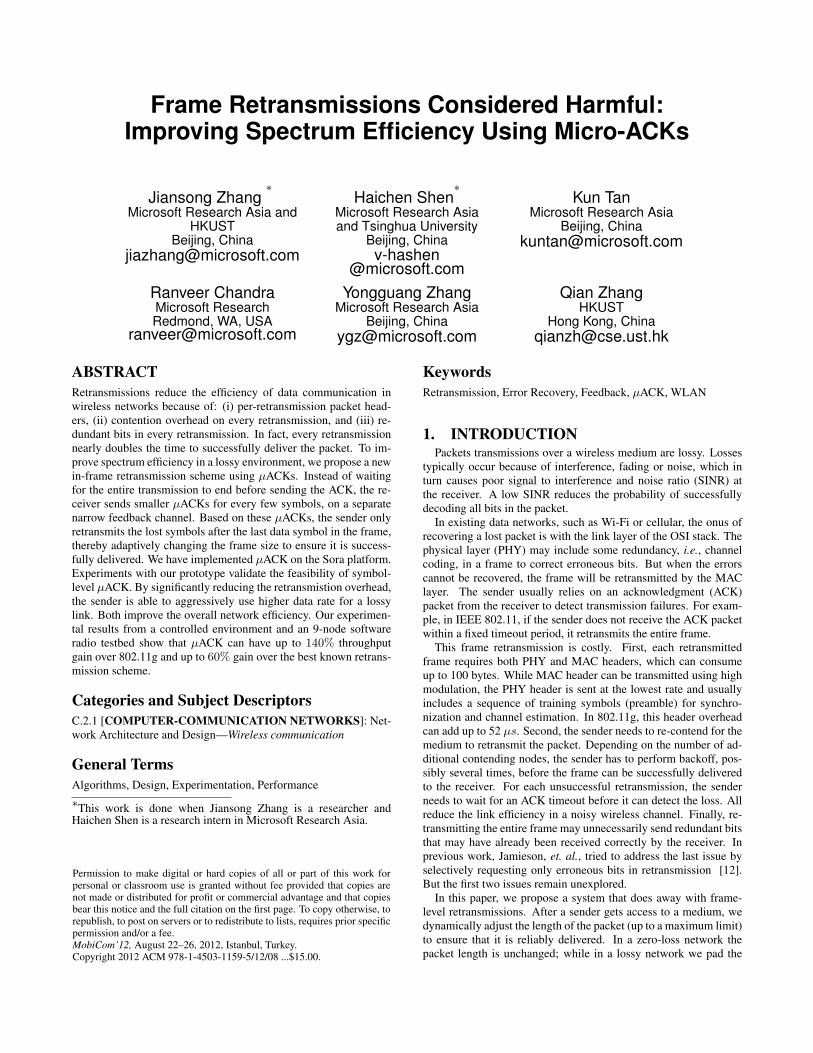
(Pkt size, Data Rate) Tdata(µs) TReTx − Tdata(µs)TRedundancy
TReTx
TContentionTReTx
THeadersTReTx
TDataRateTReTx
(1500, 54) 389 417 0.53 0.24 0.16 0.07(1500, 9) 1500 2166 0.61 0.05 0.03 0.31(500, 54) 241 250 0.30 0.40 0.26 0.04(500, 9) 611 833 0.53 0.12 0.09 0.26
Table 1: The overhead introduced by one retransmission on changing packet size (in bytes) and the data rate (in Mbps) of theoriginal transmission, and the fraction of overhead introduced by each of the four factors. Contention and packet headers dominatefor smaller packets, while redundancy is the largest overhead otherwise.
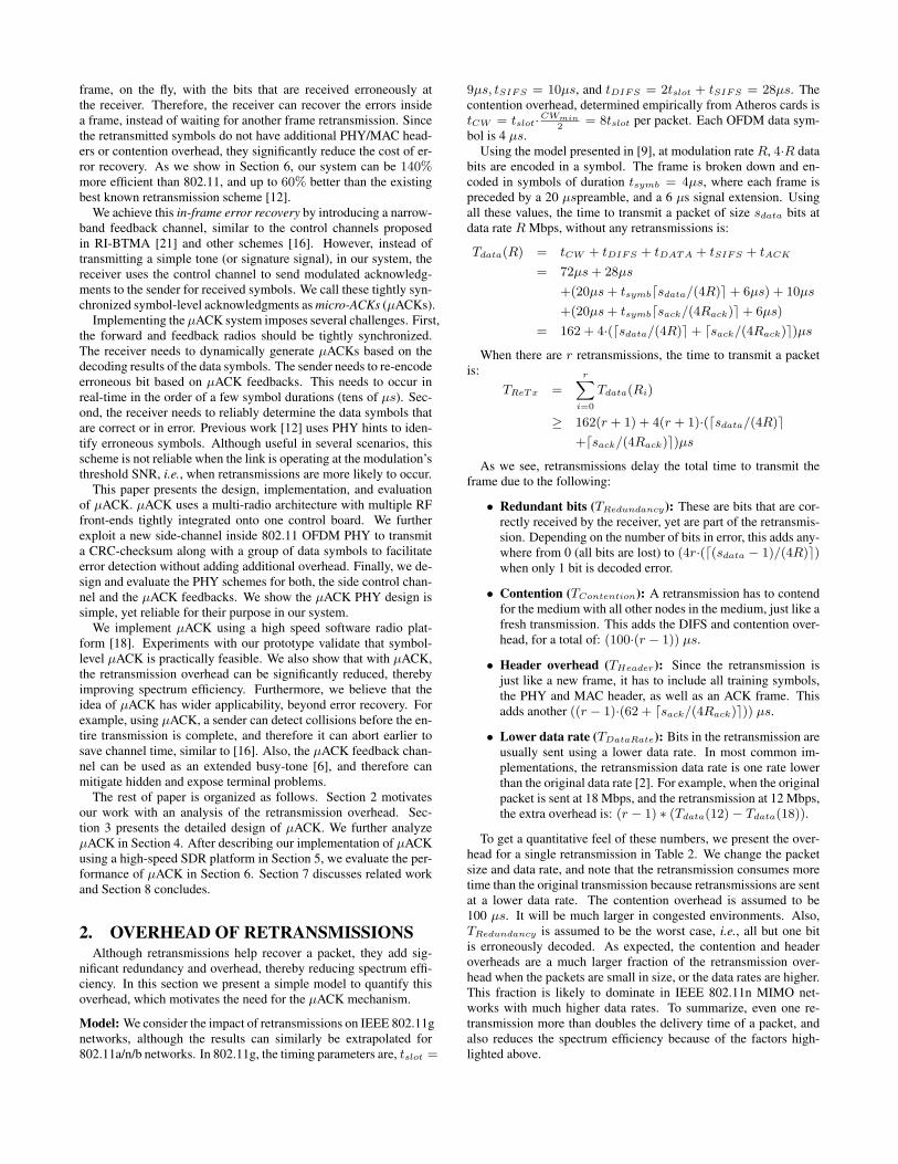
Preamble
preamble uACK uACK uACK EOSuNACK
GOS 1 GOS 3 GOS 4 GOS 2GOS 2
t
GOS: group of symbols: erroneous symbol � at receiver
Figure 1: Illustration of a frame transmission in µACK system.
3. µACK DESIGNIn this section, we present our system, that eliminates packet re-
transmission and thereby mitigates the overhead in recovering er-rors. The receiver decodes each incoming data symbol and dy-namically determines if the symbol is correct or in error. For agroup of successfully decoded symbols, the receiver will send anacknowledgment (ACK) to the sender; otherwise, if erroneous sym-bols are detected, an negative acknowledgment (NACK) is sent.These ACK/NACK are transmitted back to the sender using a sep-arate narrow-band feedback channel, which is tightly synchronizedto the feed-forward data communication channel. Since the ACK/-NACKs are at symbol level, we call them micro-ACKs/NACKs (orµACKs/ µNACKs). The sender monitors the feedback channel andmarks the symbols that get NACKs. Then, when all data symbolshave been sent, the sender re-encodes these symbols and appendsthem after the last data symbol. The sender continually re-encodesthe lost symbols until it receives an acknowledgment of the entireframe from the receiver or a predefined maximum limit has reached.In this way, an µACK sender recovers all transmission errors insidea frame, instead of relying on different retransmission frames.
Figure 1 illustrates a frame transmission in µACK system. Inthe wide-band feed-forward (FF) channel, the sender sends datasymbols to the receiver after a preamble. The receiver, after syn-chronizing to the preamble, starts immediately a feedback frame tothe sender in a narrow-band feedback (FB) channel. Each symbolof the feedback frame acknowledges (or negatively acknowledges)a group of data symbols (GOS) in the feed-forward channel. Ifthe sender gets a NACK, it will mark the corresponding GOS aslost. Lost GOSes are re-encoded and appended after the last GOS.As shown in Figure 1, the second GOS contains errors. Then, itis re-encoded after GOS 4, the last group of symbols of the frame.When the entire frame is correctly received, i.e., passed CRC check,the receiver will send back an end-of-stream (EOS) symbol to thesender, which, on receiving EOS, terminates the frame transmis-sion. If the sender does not yet receive an EOS, but also does nothave any GOS marked lost, it will simply re-encode a GOS fromthe very beginning (see details in Section3.3).
We now present the µACK feedback design. Based on this de-sign, in Section 3.2 we describe the error and collision detection atthe sender. We then describe in details the µACK in-frame errorrecovery protocols in Section 3.3. We discuss other applications
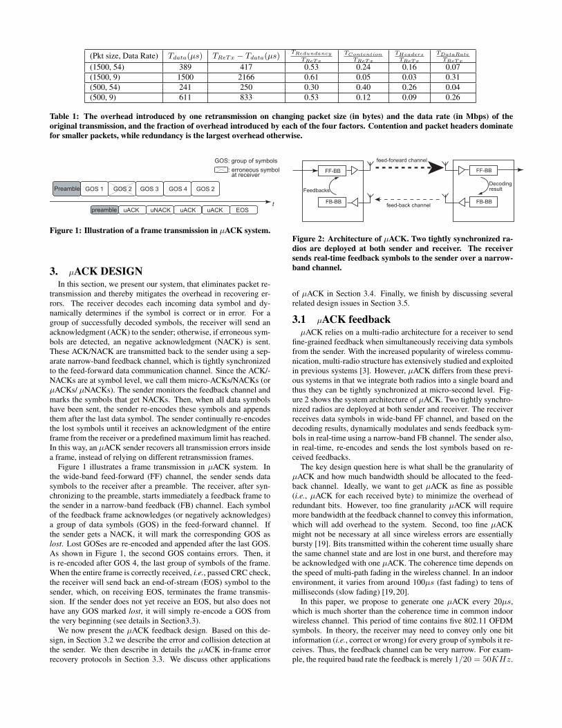
feed-forward channel
feed-back channel
FF-BB
FB-BBFB-BB
FF-BB
Decoding �resultFeedbacks
Figure 2: Architecture of µACK. Two tightly synchronized ra-dios are deployed at both sender and receiver. The receiversends real-time feedback symbols to the sender over a narrow-band channel.
of µACK in Section 3.4. Finally, we finish by discussing severalrelated design issues in Section 3.5.
3.1 µACK feedbackµACK relies on a multi-radio architecture for a receiver to send
fine-grained feedback when simultaneously receiving data symbolsfrom the sender. With the increased popularity of wireless commu-nication, multi-radio structure has extensively studied and exploitedin previous systems [3]. However, µACK differs from these previ-ous systems in that we integrate both radios into a single board andthus they can be tightly synchronized at micro-second level. Fig-ure 2 shows the system architecture of µACK. Two tightly synchro-nized radios are deployed at both sender and receiver. The receiverreceives data symbols in wide-band FF channel, and based on thedecoding results, dynamically modulates and sends feedback sym-bols in real-time using a narrow-band FB channel. The sender also,in real-time, re-encodes and sends the lost symbols based on re-ceived feedbacks.
The key design question here is what shall be the granularity ofµACK and how much bandwidth should be allocated to the feed-back channel. Ideally, we want to get µACK as fine as possible(i.e., µACK for each received byte) to minimize the overhead ofredundant bits. However, too fine granularity µACK will requiremore bandwidth at the feedback channel to convey this information,which will add overhead to the system. Second, too fine µACKmight not be necessary at all since wireless errors are essentiallybursty [19]. Bits transmitted within the coherent time usually sharethe same channel state and are lost in one burst, and therefore maybe acknowledged with one µACK. The coherence time depends onthe speed of multi-path fading in the wireless channel. In an indoorenvironment, it varies from around 100µs (fast fading) to tens ofmilliseconds (slow fading) [19, 20].
In this paper, we propose to generate one µACK every 20µs,which is much shorter than the coherence time in common indoorwireless channel. This period of time contains five 802.11 OFDMsymbols. In theory, the receiver may need to convey only one bitinformation (i.e., correct or wrong) for every group of symbols it re-ceives. Thus, the feedback channel can be very narrow. For exam-ple, the required baud rate the feedback is merely 1/20 = 50KHz.
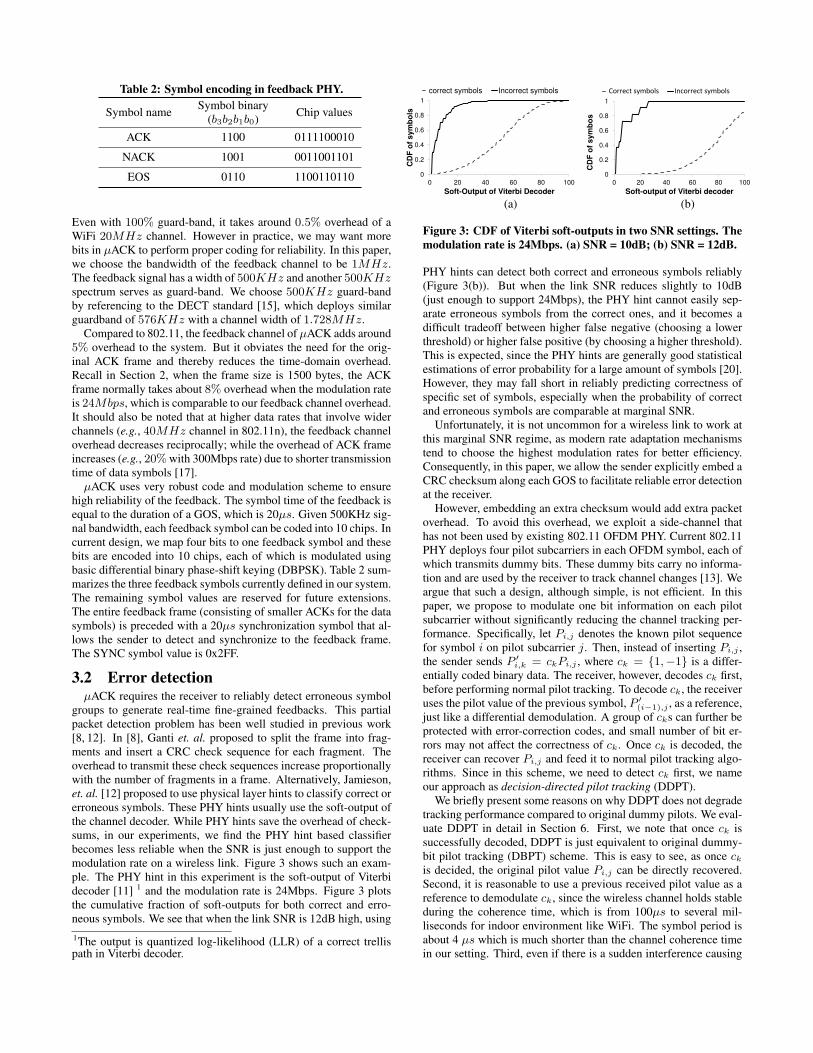
Table 2: Symbol encoding in feedback PHY.
Symbol name Symbol binary(b3b2b1b0) Chip values
ACK 1100 0111100010
NACK 1001 0011001101
EOS 0110 1100110110
Even with 100% guard-band, it takes around 0.5% overhead of aWiFi 20MHz channel. However in practice, we may want morebits in µACK to perform proper coding for reliability. In this paper,we choose the bandwidth of the feedback channel to be 1MHz.The feedback signal has a width of 500KHz and another 500KHzspectrum serves as guard-band. We choose 500KHz guard-bandby referencing to the DECT standard [15], which deploys similarguardband of 576KHz with a channel width of 1.728MHz.
Compared to 802.11, the feedback channel of µACK adds around5% overhead to the system. But it obviates the need for the orig-inal ACK frame and thereby reduces the time-domain overhead.Recall in Section 2, when the frame size is 1500 bytes, the ACKframe normally takes about 8% overhead when the modulation rateis 24Mbps, which is comparable to our feedback channel overhead.It should also be noted that at higher data rates that involve widerchannels (e.g., 40MHz channel in 802.11n), the feedback channeloverhead decreases reciprocally; while the overhead of ACK frameincreases (e.g., 20% with 300Mbps rate) due to shorter transmissiontime of data symbols [17].
µACK uses very robust code and modulation scheme to ensurehigh reliability of the feedback. The symbol time of the feedback isequal to the duration of a GOS, which is 20µs. Given 500KHz sig-nal bandwidth, each feedback symbol can be coded into 10 chips. Incurrent design, we map four bits to one feedback symbol and thesebits are encoded into 10 chips, each of which is modulated usingbasic differential binary phase-shift keying (DBPSK). Table 2 sum-marizes the three feedback symbols currently defined in our system.The remaining symbol values are reserved for future extensions.The entire feedback frame (consisting of smaller ACKs for the datasymbols) is preceded with a 20µs synchronization symbol that al-lows the sender to detect and synchronize to the feedback frame.The SYNC symbol value is 0x2FF.
3.2 Error detectionµACK requires the receiver to reliably detect erroneous symbol
groups to generate real-time fine-grained feedbacks. This partialpacket detection problem has been well studied in previous work[8, 12]. In [8], Ganti et. al. proposed to split the frame into frag-ments and insert a CRC check sequence for each fragment. Theoverhead to transmit these check sequences increase proportionallywith the number of fragments in a frame. Alternatively, Jamieson,et. al. [12] proposed to use physical layer hints to classify correct orerroneous symbols. These PHY hints usually use the soft-output ofthe channel decoder. While PHY hints save the overhead of check-sums, in our experiments, we find the PHY hint based classifierbecomes less reliable when the SNR is just enough to support themodulation rate on a wireless link. Figure 3 shows such an exam-ple. The PHY hint in this experiment is the soft-output of Viterbidecoder [11] 1 and the modulation rate is 24Mbps. Figure 3 plotsthe cumulative fraction of soft-outputs for both correct and erro-neous symbols. We see that when the link SNR is 12dB high, using1The output is quantized log-likelihood (LLR) of a correct trellispath in Viterbi decoder.
0
0.2
0.4
0.6
0.8
1
0 20 40 60 80 100
CD
F o
f s
ym
bo
ls
Soft-Output of Viterbi Decoder
correct symbols Incorrect symbols
0
0.2
0.4
0.6
0.8
1
0 20 40 60 80 100
CD
F o
f s
ym
bo
s
Soft-output of Viterbi decoder
Correct symbols Incorrect symbols
(a) (b)
Figure 3: CDF of Viterbi soft-outputs in two SNR settings. Themodulation rate is 24Mbps. (a) SNR = 10dB; (b) SNR = 12dB.
PHY hints can detect both correct and erroneous symbols reliably(Figure 3(b)). But when the link SNR reduces slightly to 10dB(just enough to support 24Mbps), the PHY hint cannot easily sep-arate erroneous symbols from the correct ones, and it becomes adifficult tradeoff between higher false negative (choosing a lowerthreshold) or higher false positive (by choosing a higher threshold).This is expected, since the PHY hints are generally good statisticalestimations of error probability for a large amount of symbols [20].However, they may fall short in reliably predicting correctness ofspecific set of symbols, especially when the probability of correctand erroneous symbols are comparable at marginal SNR.
Unfortunately, it is not uncommon for a wireless link to work atthis marginal SNR regime, as modern rate adaptation mechanismstend to choose the highest modulation rates for better efficiency.Consequently, in this paper, we allow the sender explicitly embed aCRC checksum along each GOS to facilitate reliable error detectionat the receiver.
However, embedding an extra checksum would add extra packetoverhead. To avoid this overhead, we exploit a side-channel thathas not been used by existing 802.11 OFDM PHY. Current 802.11PHY deploys four pilot subcarriers in each OFDM symbol, each ofwhich transmits dummy bits. These dummy bits carry no informa-tion and are used by the receiver to track channel changes [13]. Weargue that such a design, although simple, is not efficient. In thispaper, we propose to modulate one bit information on each pilotsubcarrier without significantly reducing the channel tracking per-formance. Specifically, let Pi,j denotes the known pilot sequencefor symbol i on pilot subcarrier j. Then, instead of inserting Pi,j ,the sender sends P ′
i,k = ckPi,j , where ck = {1,−1} is a differ-entially coded binary data. The receiver, however, decodes ck first,before performing normal pilot tracking. To decode ck, the receiveruses the pilot value of the previous symbol, P ′
(i−1),j , as a reference,just like a differential demodulation. A group of cks can further beprotected with error-correction codes, and small number of bit er-rors may not affect the correctness of ck. Once ck is decoded, thereceiver can recover Pi,j and feed it to normal pilot tracking algo-rithms. Since in this scheme, we need to detect ck first, we nameour approach as decision-directed pilot tracking (DDPT).
We briefly present some reasons on why DDPT does not degradetracking performance compared to original dummy pilots. We eval-uate DDPT in detail in Section 6. First, we note that once ck issuccessfully decoded, DDPT is just equivalent to original dummy-bit pilot tracking (DBPT) scheme. This is easy to see, as once ckis decided, the original pilot value Pi,j can be directly recovered.Second, it is reasonable to use a previous received pilot value as areference to demodulate ck, since the wireless channel holds stableduring the coherence time, which is from 100µs to several mil-liseconds for indoor environment like WiFi. The symbol period isabout 4 µs which is much shorter than the channel coherence timein our setting. Third, even if there is a sudden interference causing
erroneous detection of ck, which is BPSK modulated with properchannel coding, we note that in this case the original pilot trackingalgorithm may also not perform well, since the interference may al-ready corrupt the tracking results. Therefore, the symbols, in eitherDDPT or DBPT, suffer a strong interference and fail to decode any-way. Finally, to prevent the decision errors from propagating, weperform DDPT only within a GOS. For the first symbol in a GOS,we always insert normal pilot bits, while modulating informationonly on the remaining four symbols.
With DDPT, µACK can embed up to 16 bits on the pilot subcar-riers of a GOS. In this design, we use a simple Hamming (16,11)code to protect this side-channel. There, we have eleven informa-tion bits. Ten bits are used to encode a CRC-10 checksum, which isused in B-ISDN and ATM networks. The other bit is used to indi-cate whether or not the GOS contains retransmission metadata (de-tailed in next section). We note that the Hamming code is slightlyweaker than the 1/2 code used for 6Mbps rate in 802.11, and mayhave higher bit error rate (Section 6.1.2). In our future work, wewill investigate a better coding scheme for the pilot side channel.
Upon decoding a GOS, the receiver computes a CRC checksumof the decoded bits and compares it to the one embedded in the pilotsubcarriers. If they match, the receiver sends out a positive µACK;otherwise it sends a negative µACK.
3.3 In-frame recovery protocolBased on the error detection and feedback mechanisms discussed
earlier, µACK can perform in-frame recovery of erroneous sym-bols. The in-frame recovery protocol works in the following way.
After detecting a preamble, the receiver starts to transmit the syn-chronization symbol on the feedback channel. Then, for each GOSit receives, the receiver will send a µACK or µNACK based on thecorrectness of the GOS. All correctly received data are kept in anassembly buffer. If all received data pass the frame CRC-check, thereceiver sends an EOS symbol to notify the sender. If after that, thereceiver continues receiving GOS, possibly due to the corruption ofthe EOS symbols, it simply returns another EOS.
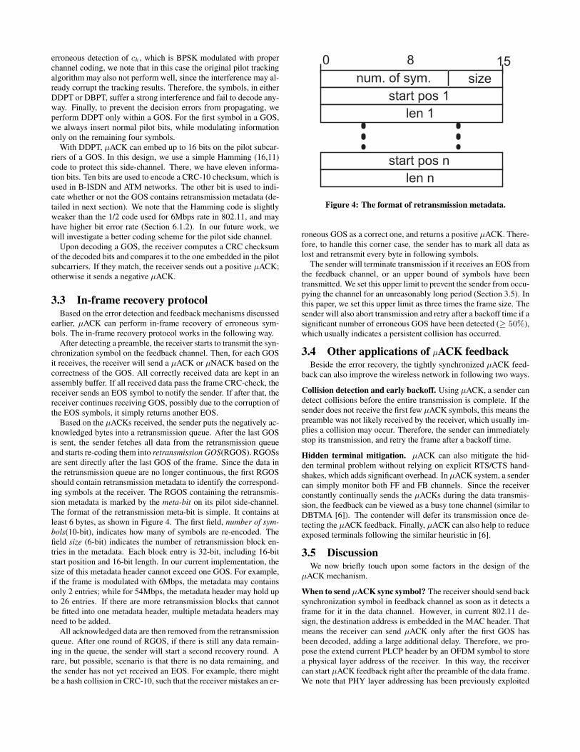
Based on the µACKs received, the sender puts the negatively ac-knowledged bytes into a retransmission queue. After the last GOSis sent, the sender fetches all data from the retransmission queueand starts re-coding them into retransmission GOS(RGOS). RGOSsare sent directly after the last GOS of the frame. Since the data inthe retransmission queue are no longer continuous, the first RGOSshould contain retransmission metadata to identify the correspond-ing symbols at the receiver. The RGOS containing the retransmis-sion metadata is marked by the meta-bit on its pilot side-channel.The format of the retransmission meta-bit is simple. It contains atleast 6 bytes, as shown in Figure 4. The first field, number of sym-bols(10-bit), indicates how many of symbols are re-encoded. Thefield size (6-bit) indicates the number of retransmission block en-tries in the metadata. Each block entry is 32-bit, including 16-bitstart position and 16-bit length. In our current implementation, thesize of this metadata header cannot exceed one GOS. For example,if the frame is modulated with 6Mbps, the metadata may containsonly 2 entries; while for 54Mbps, the metadata header may hold upto 26 entries. If there are more retransmission blocks that cannotbe fitted into one metadata header, multiple metadata headers mayneed to be added.
All acknowledged data are then removed from the retransmissionqueue. After one round of RGOS, if there is still any data remain-ing in the queue, the sender will start a second recovery round. Arare, but possible, scenario is that there is no data remaining, andthe sender has not yet received an EOS. For example, there mightbe a hash collision in CRC-10, such that the receiver mistakes an er-
0 8 15num. of sym.
start pos 1len 1
start pos nlen n
size
Figure 4: The format of retransmission metadata.
roneous GOS as a correct one, and returns a positive µACK. There-fore, to handle this corner case, the sender has to mark all data aslost and retransmit every byte in following symbols.
The sender will terminate transmission if it receives an EOS fromthe feedback channel, or an upper bound of symbols have beentransmitted. We set this upper limit to prevent the sender from occu-pying the channel for an unreasonably long period (Section 3.5). Inthis paper, we set this upper limit as three times the frame size. Thesender will also abort transmission and retry after a backoff time if asignificant number of erroneous GOS have been detected (≥ 50%),which usually indicates a persistent collision has occurred.
3.4 Other applications of µACK feedbackBeside the error recovery, the tightly synchronized µACK feed-
back can also improve the wireless network in following two ways.
Collision detection and early backoff. Using µACK, a sender candetect collisions before the entire transmission is complete. If thesender does not receive the first few µACK symbols, this means thepreamble was not likely received by the receiver, which usually im-plies a collision may occur. Therefore, the sender can immediatelystop its transmission, and retry the frame after a backoff time.
Hidden terminal mitigation. µACK can also mitigate the hid-den terminal problem without relying on explicit RTS/CTS hand-shakes, which adds significant overhead. In µACK system, a sendercan simply monitor both FF and FB channels. Since the receiverconstantly continually sends the µACKs during the data transmis-sion, the feedback can be viewed as a busy tone channel (similar toDBTMA [6]). The contender will defer its transmission once de-tecting the µACK feedback. Finally, µACK can also help to reduceexposed terminals following the similar heuristic in [6].
3.5 DiscussionWe now briefly touch upon some factors in the design of the
µACK mechanism.
When to send µACK sync symbol? The receiver should send backsynchronization symbol in feedback channel as soon as it detects aframe for it in the data channel. However, in current 802.11 de-sign, the destination address is embedded in the MAC header. Thatmeans the receiver can send µACK only after the first GOS hasbeen decoded, adding a large additional delay. Therefore, we pro-pose the extend current PLCP header by an OFDM symbol to storea physical layer address of the receiver. In this way, the receivercan start µACK feedback right after the preamble of the data frame.We note that PHY layer addressing has been previously exploited

in [16,23], and we can use similar approach to dynamically allocatethem inside a wireless network.
Range Mismatch: An important requirement is to ensure that theFB channel has a similar range as the FF channel. Otherwise, thehidden/exposed terminal problem will become worse. To ensure thesame range, both the channels are in the same band, i.e. either 2.4GHz or 5 GHz. Furthermore, we leverage prior work on channelwidths [4] to adjust the transmit power of the FB channel such thatits range matches the FF channel.
Rate Anomaly: Packet fairness of IEEE 802.11 hurts the perfor-mance of high data rate nodes in the presence of low data ratenodes [22]. µACKs can make the situation worse since a trans-mission with large number of bit errors will effectively increase itspacket size and occupy the medium for a longer period of time,thereby hurting the performance of transmissions over completelyreliable links. To solve this problem, we (i) limit the maximumtime a node can occupy the medium including retransmissions, and(ii) reduce the probability of a node that just occupied the mediumfor a long time from immediately regaining access, similar to thetechnologies proposed in [22].
Rate Adaptation: Using µACK, a sender can get a good estimateof the BER on the link at any time. Therefore, it is possible todynamically pick the best rate for each symbol inside a frame. Weleave this as our future work.
FB channel allocation: In current two-radio implementation ofµACK, we statically assign a narrow FB channel for every FF chan-nel. However, in the future, the frequency of the FB channel in awireless network may be dynamically selected to avoid potentialnoisy channels. All FB channel may be allocated to a specific por-tion of spectrum band. For example, in US, the 11 MHz of FBspectrum (for the 11 channels) can be allocated in the unused chan-nels 12 and 13 of IEEE 802.11b in 2.4GHz band. This spectrum isonly available for low-power operation, but given that our ACK islow bandwidth, and hence lower power, we expect to be within theFCC regulations for these channels. Alternatively, we may split aportion of existing 802.11 channel for µACK FB use. For example,we may allocate the upper (or lower) 1MHz of 20MHz WiFi chan-nel to feedback, while the remaining 19MHz spectrum is used forFF data communication. Finally, we note that in the future, withfull-duplex technology [5], we expect µACK may have single radiodesigns and the feedback can be sent using the same frequency asthe FF channel.
Frame duration field setting: In 802.11 standard, the MAC headercontains a duration field that records the expected frame transmis-sion time plus the ACK. A contender after decoding the field willdefer according to the value in this field to avoid possible collisionto the ACK frame. For µACK, since the sender may dynamicallypad the frame with retransmission symbols, the transmission dura-tion may not be known before hand and cannot be accurately set.However, we note that µACK does not need this duration field forcorrect protocol behavior. This is because of the following two rea-sons. First, µACKs are sent in a different feedback channel. There-fore, it is safe for a contending sender to pick up the medium im-mediately after the FF data channel is sensed idle. Second, as dis-cussed in Section 3.4, µACK can effectively detect collisions andmitigate hidden terminals using the feedback. Therefore, it doesnot need the traditional RTS/CTS handshake, which further relieson this frame duration field to reserve channel time.
4. ANALYTICAL STUDYWe build on the model presented in Section 2 and analyze the
performance of the µACK technique. We also compare its perfor-mance to Wi-Fi and the most closely related work, PPR [12].
Model: Suppose the symbol error rate is es and a frame containsNs symbols. Assuming the OFDM symbols are independent, theframe error probability is ef = 1−(1−es)
Ns . To compare differenttechniques, we define retransmission overhead (RO) as the fractionof additional time to successfully transmit a frame.
RO = (TReTx − Tdata)/Tdata
= TReTx/Tdata − 1,
where TReTx is the time taken to successfully deliver the packet atthe receiver including retransmissions. So, the RO is zero if thereis no loss, and greater than zero if there is any retransmission. Inour model, we assume the sender will persistently retransmit thelost packet until it is successfully received. We note this is onlyan approximation to practical systems that may only retry up to a amaximum number (e.g., four times in 802.11). A complete modelthat considers this maximum retransmission number will be our fu-ture work.
Wi-Fi: The expected number of frame retransmissions for Wi-Fiis:
Kwifi = 1 ∗ (1− ef ) + 2 ∗ ef (1− ef ) + ...
+k ∗ e(k−1)f (1− ef ) + ...
= 1/(1− ef )
Therefore, extending the formulation of Section 2:
TReTx = Tdata(R) +
Kwifi∑i=1
Tdata(Ri).
where Ri is the data rate used for the ith retransmission packet.
PPR: We assume that there is no retansmission aggregation in PPRfor latency reduction. Also, we do not model the dynamic pro-gramming algorithm that PPR uses to compute the optimal trunksto retransmit. Modeling such a dynamic algorithm is non-trivial. Sowe leave it as our future work. Here, we just try to build an approx-imate model: We assume PPR retransmits only erroneous bits andwe don’t consider the overhead of CRC-checksum for the runs ofgood bits. Clearly, our approximate model captures an performanceupper bound of PPR.
Based on this simplification, we can compute the size of the kth
retransmission frame, sk, in PPR as
sk = ess(k−1).
The frame error rate of the kth retransmission is:
ef (k) = 1− (1− es)(sk).
Therefore,
TReTx = Tdata(R) +
∞∑k=1
(k−1∏i=0
ef (i)
)T kdata(Rk),
where T kdata(Rk) is the air-time to send the kth retransmission (sk
symbols) with rate Rk.
10−4
10−3
10−2
10−1
100
0
50
100
150
200
Symbol error rate
Re
tra
ns
mis
sio
n o
ve
rhe
ad
(%
)
802.11
PPR
uACK
Figure 5: Retransmission overhead versus the symbol loss rateon the wireless link. The packet size is 1500B and the data rateis 54Mbps.
µACK: In our system, the erroneous symbols are directly appendedat the end of the frame. The number of retransmitted symbols is
Nrx = Ns·∞∑i=1
(eis) = Nses/(1− es)
Let l is the average burst length of erros. Then, the expected framesize in µACK is
Ndata = Ns +Nrx + λNrx/l,
where λ is the metadata overhead to describe a burst loss in µACK(Section 3.3). Finally, we can derive the expected air-time to senda frame using µACK,
TReTx(R) = tCW + tDIFS + tDATA + tµACK_delay
= 72µs+ 28µs
+(20µs+ tsymb⌈Ndata/(4R)⌉+ 6µs)
= Tdata(R) + tsymb(⌈Nrx(1 + λ/l)/(4R)⌉)−Tack + tµACK_delay,
where Tack = tSIFS+tACK is the ACK overhead and tµACK_delay
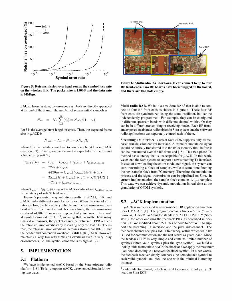
is the latency of µACK feedback.Figure 5 presents the quantitative results of 802.11, PPR, and
µACK under different symbol error rates. When the symbol errorrates are low, the link is very reliable and the retransmission over-head is also low. As the link becomes lossy, the retransmissionoverhead of 802.11 increases exponentially and soon hits a wallat symbol error rate of 10−2, meaning that no matter how manytimes it retransmits, the packet cannot be delivered. PPR reducesthe retransmission overhead by resending only the lost bits. There-fore, the retransmission overhead increases slower than 802.11, butthe header and contention overhead is still high. µACK, however,maintains a very low retransmission overhead even in very lossyenvironments, i.e., the symbol error rate is as high as 1/2.
5. IMPLEMENTATION
5.1 PlatformWe have implemented µACK based on the Sora software radio
platform [18]. To fully support µACK, we extended Sora in follow-ing two ways:
Sora RCB
RF front-endMulti-radio RAB
Figure 6: Multiradio RAB for Sora. It can connect to up to fourRF front-ends. Two RF boards have been plugged on the board,and there are two slots empty.
Multi-radio RAB. We built a new Sora RAB2 that is able to con-nect to four RF front-ends as shown in Figure 6. These four RFfront-ends are synchronized using the same oscillator, but can beindependently programmed. For example, they can be configuredin different spectrum bands with different channel widths. Or theycan be in different transmitting or receiving modes. Each RF front-end exposes an abstract radio object in Sora system and the softwareradio applications can separately control each of them.
Streaming Tx interface. Current Sora SDK supports only frame-based transmission control interface. A frame of modulated signalshould be entirely transferred into the RCB memory first, before itcan be transmitted over the RF front-end [18]. This two-phase Txmethod has a latency that is unacceptable for µACK. In this work,we extend the Sora system to support a new streaming Tx interface.Instead of downloading the entire modulated signal, the system canstart transmitting a block of samples, while at same time fetchingthe next sample block from PC memory. Therefore, the modulationprocess and the signal transmission can be pipelined on Sora. Incurrent implementation, the sample block contains 1.4 µs samples.This way, we can achieve dynamic modulation in real-time at thegranularity of OFDM symbols.
5.2 µACK implementationµACK is implemented as a user-mode SDR application based on
Sora UMX API [1]. The program contains two exclusive threads(ethread). One ethread runs the standard 802.11 OFDM PHY (Soft-WiFi); the other one runs the feedback PHY as described in Sec-tion 3.1. We modified about 250 lines of code to SoftWiFi to sup-port the streaming Tx interface and the pilot side-channel. Thefeedback channel occupies 1MHz frequency, within which 500KHzis used for communication and the rest serves as guard-band. Sincethe feedback PHY is very simple and contains limited number ofsymbols (three valid symbols plus the sync symbol), we build alookup table to modulate µACK feedback and we apply the maximum-likelihood decoding to a received feedback symbol. In other words,the feedback receiver simply compares the demodulated symbol toeach valid symbols and pick the one with the minimal Hammingdistance.2Radio adaptive board, which is used to connect a 3rd party RFboard to Sora RCB.
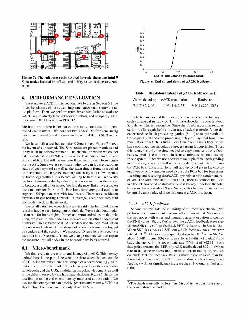
Figure 7: The software radio testbed layout: there are total 9Sora nodes located in offices and lobby in an indoor environ-ment.
6. PERFORMANCE EVALUATIONWe evaluate µACK in this section. We begin in Section 6.1 the
micro-benchmark of our system implementation on the software ra-dio platform. Then, we perform trace-driven simulation to evaluateµACK in a relatively large networking setting and compare µACKto original 802.11 as well as PPR [12].
Method. The micro-benchmarks are mainly conducted in a con-trolled environment. We connect two nodes’ RF front-end usingcables and manually add attenuation to create different SNR on thelink.
We have built a test-bed contains 9 Sora nodes. Figure 7 showsthe layout of our testbed. The Sora nodes are placed in offices andlobby in an indoor environment. The channel on which we collectdata is centered at 2422MHz. This is the least busy channel in ouroffice building, but still has uncontrollable interference from neigh-boring APs. Since we use software radio, we can log the decodingstatus of each symbol as well as the exact time a frame is receivedor transmitted. The large PC memory can easily hold a few minutesof frame logs without loss before writing to hard disk. We verifythe links between nodes by selecting one node in turn as the senderto broadcast to all other nodes. We find the most links have a packetloss rate between 10 ∼ 40%. Few links have very good quality tosupport 48Mbps data rate with few losses. There are also hiddenterminals in our testing network. In average, each node may findone hidden node in the network.
We try all data rates on each link and identify the best modulationrate that has the best throughput on the link. We use this best modu-lation rate for both original frames and retransmissions on the link.Then, we pick up one node as a receiver and all other nodes senda saturate unicast traffic to it. All senders use the best modulationrate measured before. All sending and receiving frames are loggedon senders and the receiver. We measure 10 runs for each receiver;each run last 30 seconds. Then, we change the receiver and repeatthe measure until all nodes in the network have been covered.
6.1 Micro-benchmarkWe first evaluate the end-to-end latency of µACK. This latency
defined here is the period between the time when the last sampleof a GOS is transmitted and first sample of a corresponding µACKthat is received by the sender. This latency includes the demodula-tion/decoding of the GOS, modulation the acknowledgment, as wellas the delay incurred by the hardware platform. Figure 8 shows thedistribution of the end-to-end latency measured at the sender. Wecan see that our system can quickly generate and return µACK in ashort delay. The mean value is only about 17.5 µs.
0
0.1
0.2
0.3
0.4
0.5
0.6
0.7
0.8
0.9
1
0 10 20 30 40
CD
F
End-to-end Latency (microsecond)
Figure 8: End-to-end delay of µACK feedback.
Table 3: Breakdown latency of µACK feedback (µs).
Viterbi decoding µACK modulation Hardware
7.5 (5.82, 8.06) 1.96 (1.4, 2.23) 9.103 (8.22, 10.5)
To better understand the latency, we break down the latency ofeach component in Table 3. The Viterbi decoder introduces about8µs delay. This is reasonable. Since the Viterbi algorithm requirescertain trellis depth before it can trace-back the results 3, the de-coder needs to finish processing symbol (i+1) to output symbol i.Consequently, it adds the processing delay of 2 symbol time. Themodulation of µACK is trivial, less than 2 µs. This is because wehave optimized the modulation process using lookup tables. Thus,this latency is only the time needed to copy samples of one feed-back symbol. The hardware platform contributes the most latencyin our system. Since we use a software radio platform, both sendingand receiving a symbol will introduce a delay about 1.4µs to passthe PCIe bus. Therefore, there will add up to 5.4 µs in the end-to-end latency as the samples need to pass the PCIe bus for four times- sending and receiving data/µACK symbols at both sender and re-ceiver. The Sora Fast Radio Link (FRL) used to connect the RCBand the RF front-end contributes the rest latency. Together, the totalhardware latency is about 9 µs. We note this hardware latency canbe significantly reduced if we implement µACK in silicon.
6.1.1 µACK feedbackSecond, we evaluate the reliability of our feedback channel. We
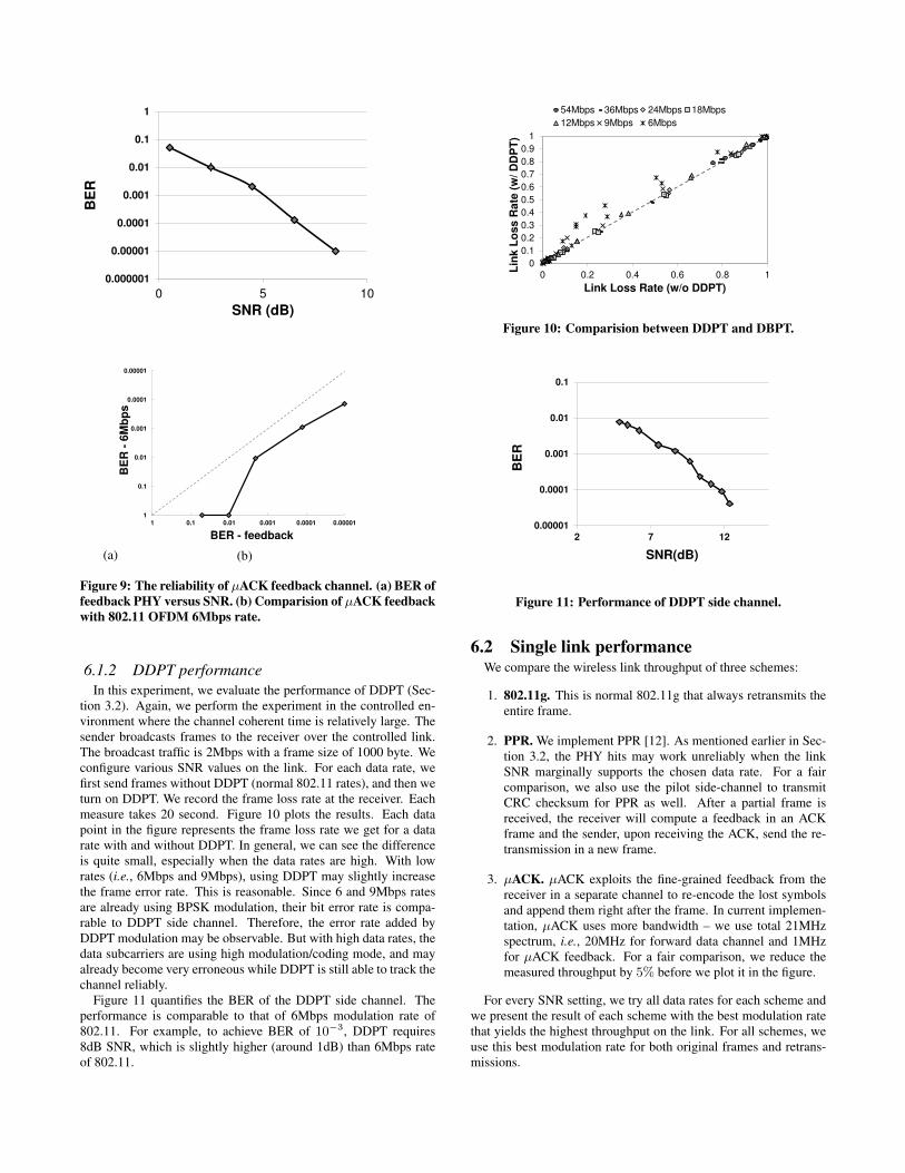
perform this measurement in a controlled environment. We connectthe two nodes with wires and manually adds attenuation to controlthe SNR value. Figure 9(a) shows the µACK feedback error rateversus SNR curve of our feedback PHY as discussed in Section 3.1.When SNR is as low as 2.5dB, our µACK feedback has a low errorrate of 10−2. The error rate quickly drops to 10−4 when SNR isabout 6.5dB. Figure 9(b) compares the reliability of µACK feed-back channel with the lowest data rate (6Mbps) of 802.11. Eachdata point presents the BER of µACK feedback and 802.11 6Mbpsrate in the same wireless link condition. From the figure, we canconclude that the feedback PHY is much more reliable than thelowest data rate used in 802.11, and adding such a fine-grainedfeedback will not significantly increase the end-to-end symbol errorratio.
3(The depth is usually no less than 5K, K is the constraint size ofthe convolutional encoder.
0.000001
0.00001
0.0001
0.001
0.01
0.1
1
0 5 10
BE
R
SNR (dB)
(a)
0.00001
0.0001
0.001
0.01
0.1
1
0.000010.00010.0010.010.11
BE
R -
6M
bp
s
BER - feedback
(b)
Figure 9: The reliability of µACK feedback channel. (a) BER offeedback PHY versus SNR. (b) Comparision of µACK feedbackwith 802.11 OFDM 6Mbps rate.
6.1.2 DDPT performanceIn this experiment, we evaluate the performance of DDPT (Sec-
tion 3.2). Again, we perform the experiment in the controlled en-vironment where the channel coherent time is relatively large. Thesender broadcasts frames to the receiver over the controlled link.The broadcast traffic is 2Mbps with a frame size of 1000 byte. Weconfigure various SNR values on the link. For each data rate, wefirst send frames without DDPT (normal 802.11 rates), and then weturn on DDPT. We record the frame loss rate at the receiver. Eachmeasure takes 20 second. Figure 10 plots the results. Each datapoint in the figure represents the frame loss rate we get for a datarate with and without DDPT. In general, we can see the differenceis quite small, especially when the data rates are high. With lowrates (i.e., 6Mbps and 9Mbps), using DDPT may slightly increasethe frame error rate. This is reasonable. Since 6 and 9Mbps ratesare already using BPSK modulation, their bit error rate is compa-rable to DDPT side channel. Therefore, the error rate added byDDPT modulation may be observable. But with high data rates, thedata subcarriers are using high modulation/coding mode, and mayalready become very erroneous while DDPT is still able to track thechannel reliably.
Figure 11 quantifies the BER of the DDPT side channel. Theperformance is comparable to that of 6Mbps modulation rate of802.11. For example, to achieve BER of 10−3, DDPT requires8dB SNR, which is slightly higher (around 1dB) than 6Mbps rateof 802.11.
0
0.1
0.2
0.3
0.4
0.5
0.6
0.7
0.8
0.9
1
0 0.2 0.4 0.6 0.8 1
Lin
k L
oss R
ate
(w
/ D
DP
T)
Link Loss Rate (w/o DDPT)
54Mbps 36Mbps 24Mbps 18Mbps
12Mbps 9Mbps 6Mbps
Figure 10: Comparision between DDPT and DBPT.
0.00001
0.0001
0.001
0.01
0.1
2 7 12
BE
R
SNR(dB)
Figure 11: Performance of DDPT side channel.
6.2 Single link performanceWe compare the wireless link throughput of three schemes:
1. 802.11g. This is normal 802.11g that always retransmits theentire frame.
2. PPR. We implement PPR [12]. As mentioned earlier in Sec-tion 3.2, the PHY hits may work unreliably when the linkSNR marginally supports the chosen data rate. For a faircomparison, we also use the pilot side-channel to transmitCRC checksum for PPR as well. After a partial frame isreceived, the receiver will compute a feedback in an ACKframe and the sender, upon receiving the ACK, send the re-transmission in a new frame.
3. µACK. µACK exploits the fine-grained feedback from thereceiver in a separate channel to re-encode the lost symbolsand append them right after the frame. In current implemen-tation, µACK uses more bandwidth – we use total 21MHzspectrum, i.e., 20MHz for forward data channel and 1MHzfor µACK feedback. For a fair comparison, we reduce themeasured throughput by 5% before we plot it in the figure.
For every SNR setting, we try all data rates for each scheme andwe present the result of each scheme with the best modulation ratethat yields the highest throughput on the link. For all schemes, weuse this best modulation rate for both original frames and retrans-missions.
0
10
20
30
40
50
60
0 10 20 30
Mo
du
lati
on
Ra
te (
Mb
ps
)
SNR(dB)
uACK PPR 802.11g
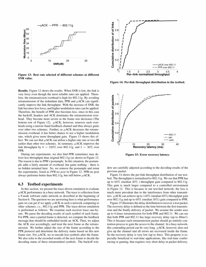
Figure 13: Best rate selected of different schemes at differentSNR value.
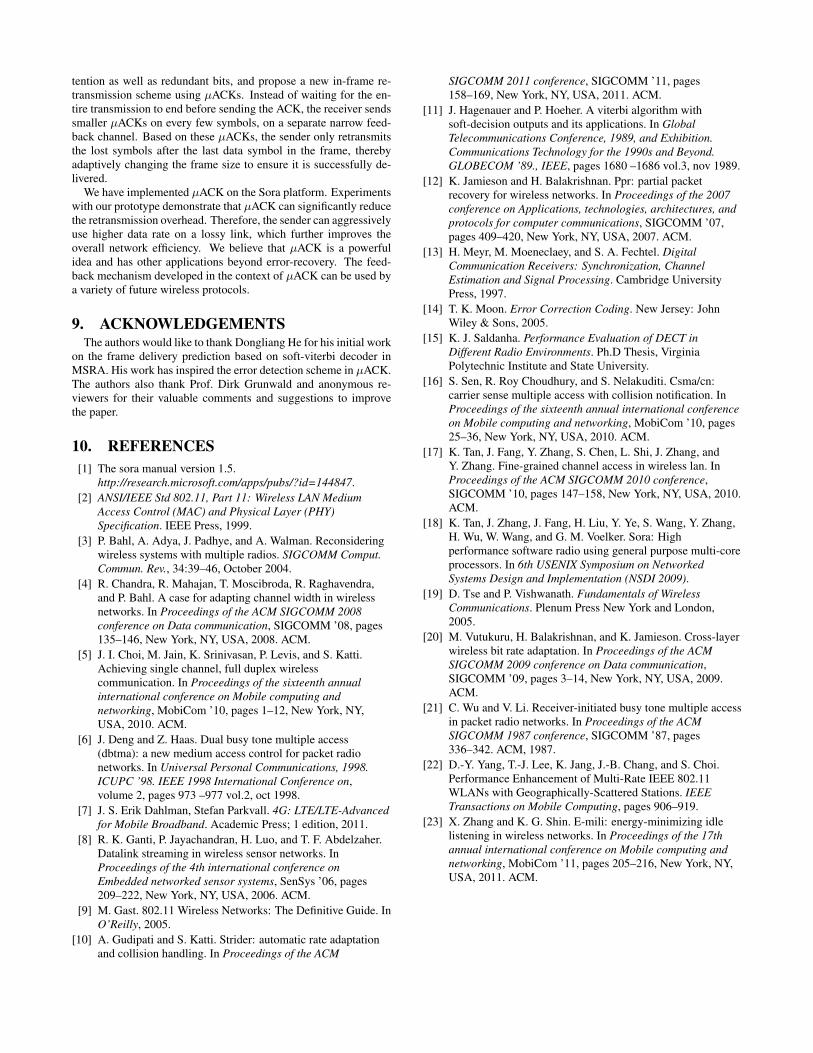
Results. Figure 12 shows the results. When SNR is low, the link isvery lossy even though the most reliable rates are applied. There-fore, the retransmission overhead is high for 802.11g. By avoidingretransmission of the redundant data, PPR and µACK can signifi-cantly improve the link throughput. With the increase of SNR, thelink becomes less lossy, and higher modulation rates can be applied.Therefore, the benefit of PPR also becomes less, since in this casethe backoff, headers and ACK dominates the retransmission over-head. They become more severe as the frame size decreases (Thebottom row of Figure 12). µACK, however, removes such over-heads using a narrow-band feedback channel and thus always gainsover other two schemes. Further, as µACK decreases the retrans-mission overhead, it has better chance to use a higher modulationrate, which gives more throughput gain. Figure 13 shows this ef-fect. We can see that µACK can utilize a higher rate one or two dBearlier than other two schemes. In summary, µACK improves thelink throughput by 8 ∼ 220% over 802.11g, and 5 ∼ 30% overPPR.
During our experiments, we also find PPR sometimes may de-liver less throughput than original 802.11g (as shown in Figure 12.The reason is due to PPR’s postample. In this situation, the postam-ple adds a fairly amount of overhead, but gains nothing – there isno hidden terminal here. So, we remove the postample and rerunthe experiments, listed as PPR-no post in Figure 12. PPR-no postalways performs better than 802.11g, but still below µACK.
6.3 Testbed experimentsIn this section, we present the trace-driven emulation to evaluate
µACK performance in a busy network. The trace is collection froma 9-node software radio network as described at the beginning ofSection 6. The question we are answering here is what performancegain we can get if we apply µACK in such a network comparing toother schemes, i.e., 802.11g and PPR. The trace-driven emulationis performed as follows: We examine each receiver trace one-by-one. We parse the decoding results of each symbol of each frame.For PPR, once a partial frame is detected, we compute the feedbackmessage that should be embedded inside an ACK. Then, we adjustthe ACK size accordingly, and treat the next frame as the retrans-mission. We further adjust the size of the frame according to thePPR protocol and determine the delivery status based on this newframe size. For µACK, we re-encode lost symbols after the frame.We also refer to the recorded results of the next frame to decide thedecoding status of these retransmitted symbols. The backoff win-
1 1.5 2 2.5 3 3.5 40
0.2
0.4
0.6
0.8
1
Per−link normalized throughput
Cu
mu
lati
ve d
istr
ibu
tio
n o
f o
f lin
ks
uACK over 802.11
PPR over 802.11
Figure 14: Per-link throughput distribution in the testbed.
0 10 20 30 400
0.2
0.4
0.6
0.8
1
Recovery latency (ms)
Cu
mu
lati
ve d
istr
ibu
tio
n o
f p
ackets
802.11
ppr
uack
Figure 15: Error recovery latency.
dow are carefully adjusted according to the decoding results of theprevious packet.
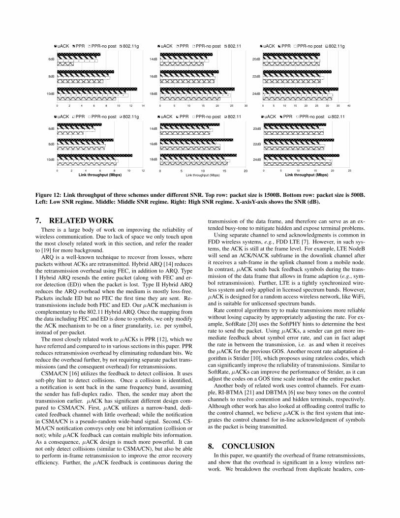
Figure 14 shows the per-link throughput distribution of our test-bed. The throughput is normalized to 802.11g. We see that PPR hasup to 60% (median 20% ) throughput gain compared to 802.11g.This gain is much larger compared to a controlled environmentin Figure 12. This is because in our test-bed network, the loss ismuch more prevalent due to the interference from other transmit-ters. µACK can achieve up to 140% (median 60%) throughput gainover 802.11g and up to 60% (median 30%) gain compared to PPR.
Figure 15 illustrates the delay distribution to recover a lost packet.The recovery delay is defined as the time between the first transmis-sion and the finally delivery of packet. We assume the sender usesup to 4 times retransmission for both PPR and 802.11. We can seethat both PPR and 802.11 has large recovery delay (up to 40ms!).This is because each retransmission packet should go entirely con-tention process to gain the access to the channel. In a busy network,this contending period can be very long. µACK, however, does notgive up the channel and all errors are recovered inside the frame.So the recovery delay is very low (up to 4ms). This property is es-pecially beneficial to real-time applications, like real-time confer-encing or gaming, that requires very short delay in packet delivery.
0 2 4 6 8 10 12 14
6dB
8dB
10dB
uACK PPR PPR-no post 802.11g
0 5 10 15 20 25 30
14dB
16dB
18dB
uACK PPR PPR-no post 802.11
0 5 10 15 20 25 30 35 40
20dB
22dB
24dB
uACK PPR PPR-no post 802.11g
0 2 4 6 8 10 12
6dB
8dB
10dB
Link throughput (Mbps)
uACK PPR PPR-no post 802.11g
0 5 10 15 20
14dB
16dB
18dB
Link throughput (Mbps)
uACK PPR PPR-no post 802.11
0 5 10 15 20 25
20dB
22dB
24dB
Link throughput (Mbps)
uACK PPR PPR-no post 802.11
Figure 12: Link throughput of three schemes under different SNR. Top row: packet size is 1500B. Bottom row: packet size is 500B.Left: Low SNR regime. Middle: Middle SNR regime. Right: High SNR regime. X-axisY-axis shows the SNR (dB).
7. RELATED WORKThere is a large body of work on improving the reliability of
wireless communication. Due to lack of space we only touch uponthe most closely related work in this section, and refer the readerto [19] for more background.
ARQ is a well-known technique to recover from losses, wherepackets without ACKs are retransmitted. Hybrid ARQ [14] reducesthe retransmission overhead using FEC, in addition to ARQ. TypeI Hybrid ARQ resends the entire packet (along with FEC and er-ror detection (ED)) when the packet is lost. Type II Hybrid ARQreduces the ARQ overhead when the medium is mostly loss-free.Packets include ED but no FEC the first time they are sent. Re-transmissions include both FEC and ED. Our µACK mechanism iscomplementary to the 802.11 Hybrid ARQ. Once the mapping fromthe data including FEC and ED is done to symbols, we only modifythe ACK mechanism to be on a finer granularity, i.e. per symbol,instead of per-packet.
The most closely related work to µACKs is PPR [12], which wehave referred and compared to in various sections in this paper. PPRreduces retransmission overhead by eliminating redundant bits. Wereduce the overhead further, by not requiring separate packet trans-missions (and the consequent overhead) for retransmissions.
CSMA/CN [16] utilizes the feedback to detect collision. It usessoft-phy hint to detect collisions. Once a collision is identified,a notification is sent back in the same frequency band, assumingthe sender has full-duplex radio. Then, the sender may abort thetransmission earlier. µACK has significant different design com-pared to CSMA/CN. First, µACK utilizes a narrow-band, dedi-cated feedback channel with little overhead; while the notificationin CSMA/CN is a pseudo-random wide-band signal. Second, CS-MA/CN notification conveys only one bit information (collision ornot); while µACK feedback can contain multiple bits information.As a consequence, µACK design is much more powerful. It cannot only detect collisions (similar to CSMA/CN), but also be ableto perform in-frame retransmission to improve the error recoveryefficiency. Further, the µACK feedback is continuous during the
transmission of the data frame, and therefore can serve as an ex-tended busy-tone to mitigate hidden and expose terminal problems.
Using separate channel to send acknowledgments is common inFDD wireless systems, e.g., FDD LTE [7]. However, in such sys-tems, the ACK is still at the frame level. For example, LTE NodeBwill send an ACK/NACK subframe in the downlink channel afterit receives a sub-frame in the uplink channel from a mobile node.In contrast, µACK sends back feedback symbols during the trans-mission of the data frame that allows in frame adaption (e.g., sym-bol retransmission). Further, LTE is a tightly synchronized wire-less system and only applied in licensed spectrum bands. However,µACK is designed for a random access wireless network, like WiFi,and is suitable for unlicensed spectrum bands.
Rate control algorithms try to make transmissions more reliablewithout losing capacity by appropriately adjusting the rate. For ex-ample, SoftRate [20] uses the SoftPHY hints to determine the bestrate to send the packet. Using µACKs, a sender can get more im-mediate feedback about symbol error rate, and can in fact adaptthe rate in between the transmission, i.e. as and when it receivesthe µACK for the previous GOS. Another recent rate adaptation al-gorithm is Strider [10], which proposes using rateless codes, whichcan significantly improve the reliability of transmissions. Similar toSoftRate, µACKs can improve the performance of Strider, as it canadjust the codes on a GOS time scale instead of the entire packet.
Another body of related work uses control channels. For exam-ple, RI-BTMA [21] and DBTMA [6] use busy tones on the controlchannels to resolve contention and hidden terminals, respectively.Although other work has also looked at offloading control traffic tothe control channel, we believe µACK is the first system that inte-grates the control channel for in-line acknowledgment of symbolsas the packet is being transmitted.
8. CONCLUSIONIn this paper, we quantify the overhead of frame retransmissions,
and show that the overhead is significant in a lossy wireless net-work. We breakdown the overhead from duplicate headers, con-
tention as well as redundant bits, and propose a new in-frame re-transmission scheme using µACKs. Instead of waiting for the en-tire transmission to end before sending the ACK, the receiver sendssmaller µACKs on every few symbols, on a separate narrow feed-back channel. Based on these µACKs, the sender only retransmitsthe lost symbols after the last data symbol in the frame, therebyadaptively changing the frame size to ensure it is successfully de-livered.
We have implemented µACK on the Sora platform. Experimentswith our prototype demonstrate that µACK can significantly reducethe retransmission overhead. Therefore, the sender can aggressivelyuse higher data rate on a lossy link, which further improves theoverall network efficiency. We believe that µACK is a powerfulidea and has other applications beyond error-recovery. The feed-back mechanism developed in the context of µACK can be used bya variety of future wireless protocols.
9. ACKNOWLEDGEMENTSThe authors would like to thank Dongliang He for his initial work
on the frame delivery prediction based on soft-viterbi decoder inMSRA. His work has inspired the error detection scheme in µACK.The authors also thank Prof. Dirk Grunwald and anonymous re-viewers for their valuable comments and suggestions to improvethe paper.
10. REFERENCES[1] The sora manual version 1.5.
http://research.microsoft.com/apps/pubs/?id=144847.[2] ANSI/IEEE Std 802.11, Part 11: Wireless LAN Medium
Access Control (MAC) and Physical Layer (PHY)Specification. IEEE Press, 1999.
[3] P. Bahl, A. Adya, J. Padhye, and A. Walman. Reconsideringwireless systems with multiple radios. SIGCOMM Comput.Commun. Rev., 34:39–46, October 2004.
[4] R. Chandra, R. Mahajan, T. Moscibroda, R. Raghavendra,and P. Bahl. A case for adapting channel width in wirelessnetworks. In Proceedings of the ACM SIGCOMM 2008conference on Data communication, SIGCOMM ’08, pages135–146, New York, NY, USA, 2008. ACM.
[5] J. I. Choi, M. Jain, K. Srinivasan, P. Levis, and S. Katti.Achieving single channel, full duplex wirelesscommunication. In Proceedings of the sixteenth annualinternational conference on Mobile computing andnetworking, MobiCom ’10, pages 1–12, New York, NY,USA, 2010. ACM.
[6] J. Deng and Z. Haas. Dual busy tone multiple access(dbtma): a new medium access control for packet radionetworks. In Universal Personal Communications, 1998.ICUPC ’98. IEEE 1998 International Conference on,volume 2, pages 973 –977 vol.2, oct 1998.
[7] J. S. Erik Dahlman, Stefan Parkvall. 4G: LTE/LTE-Advancedfor Mobile Broadband. Academic Press; 1 edition, 2011.
[8] R. K. Ganti, P. Jayachandran, H. Luo, and T. F. Abdelzaher.Datalink streaming in wireless sensor networks. InProceedings of the 4th international conference onEmbedded networked sensor systems, SenSys ’06, pages209–222, New York, NY, USA, 2006. ACM.
[9] M. Gast. 802.11 Wireless Networks: The Definitive Guide. InO’Reilly, 2005.
[10] A. Gudipati and S. Katti. Strider: automatic rate adaptationand collision handling. In Proceedings of the ACM
SIGCOMM 2011 conference, SIGCOMM ’11, pages158–169, New York, NY, USA, 2011. ACM.
[11] J. Hagenauer and P. Hoeher. A viterbi algorithm withsoft-decision outputs and its applications. In GlobalTelecommunications Conference, 1989, and Exhibition.Communications Technology for the 1990s and Beyond.GLOBECOM ’89., IEEE, pages 1680 –1686 vol.3, nov 1989.
[12] K. Jamieson and H. Balakrishnan. Ppr: partial packetrecovery for wireless networks. In Proceedings of the 2007conference on Applications, technologies, architectures, andprotocols for computer communications, SIGCOMM ’07,pages 409–420, New York, NY, USA, 2007. ACM.
[13] H. Meyr, M. Moeneclaey, and S. A. Fechtel. DigitalCommunication Receivers: Synchronization, ChannelEstimation and Signal Processing. Cambridge UniversityPress, 1997.
[14] T. K. Moon. Error Correction Coding. New Jersey: JohnWiley & Sons, 2005.
[15] K. J. Saldanha. Performance Evaluation of DECT inDifferent Radio Environments. Ph.D Thesis, VirginiaPolytechnic Institute and State University.
[16] S. Sen, R. Roy Choudhury, and S. Nelakuditi. Csma/cn:carrier sense multiple access with collision notification. InProceedings of the sixteenth annual international conferenceon Mobile computing and networking, MobiCom ’10, pages25–36, New York, NY, USA, 2010. ACM.
[17] K. Tan, J. Fang, Y. Zhang, S. Chen, L. Shi, J. Zhang, andY. Zhang. Fine-grained channel access in wireless lan. InProceedings of the ACM SIGCOMM 2010 conference,SIGCOMM ’10, pages 147–158, New York, NY, USA, 2010.ACM.
[18] K. Tan, J. Zhang, J. Fang, H. Liu, Y. Ye, S. Wang, Y. Zhang,H. Wu, W. Wang, and G. M. Voelker. Sora: Highperformance software radio using general purpose multi-coreprocessors. In 6th USENIX Symposium on NetworkedSystems Design and Implementation (NSDI 2009).
[19] D. Tse and P. Vishwanath. Fundamentals of WirelessCommunications. Plenum Press New York and London,2005.
[20] M. Vutukuru, H. Balakrishnan, and K. Jamieson. Cross-layerwireless bit rate adaptation. In Proceedings of the ACMSIGCOMM 2009 conference on Data communication,SIGCOMM ’09, pages 3–14, New York, NY, USA, 2009.ACM.
[21] C. Wu and V. Li. Receiver-initiated busy tone multiple accessin packet radio networks. In Proceedings of the ACMSIGCOMM 1987 conference, SIGCOMM ’87, pages336–342. ACM, 1987.
[22] D.-Y. Yang, T.-J. Lee, K. Jang, J.-B. Chang, and S. Choi.Performance Enhancement of Multi-Rate IEEE 802.11WLANs with Geographically-Scattered Stations. IEEETransactions on Mobile Computing, pages 906–919.
[23] X. Zhang and K. G. Shin. E-mili: energy-minimizing idlelistening in wireless networks. In Proceedings of the 17thannual international conference on Mobile computing andnetworking, MobiCom ’11, pages 205–216, New York, NY,USA, 2011. ACM.