A batch-fabricated and electret-free silicon electrostatic vibration energy harvester
Upload
khangminh22Category
view
1download
0
Citation: Costanzo, L.; Lo Schiavo, A.;
Vitelli, M. Improving the
Electromagnetic Vibration Energy
Harvester Performance by Using a
Double Coil Structure. Appl. Sci. 2022,
12, 1166. https://doi.org/
10.3390/app12031166
Academic Editors: Adel Razek and
Alfio Dario Grasso
Received: 16 December 2021
Accepted: 20 January 2022
Published: 23 January 2022
Publisher’s Note: MDPI stays neutral
with regard to jurisdictional claims in
published maps and institutional affil-
iations.
Copyright: © 2022 by the authors.
Licensee MDPI, Basel, Switzerland.
This article is an open access article
distributed under the terms and
conditions of the Creative Commons
Attribution (CC BY) license (https://
creativecommons.org/licenses/by/
4.0/).
applied sciences
Article
Improving the Electromagnetic Vibration Energy HarvesterPerformance by Using a Double Coil StructureLuigi Costanzo , Alessandro Lo Schiavo * and Massimo Vitelli
Dipartimento di Ingegneria, Università degli Studi della Campania “Luigi Vanvitelli”, 81031 Aversa, Italy;[email protected] (L.C.); [email protected] (M.V.)* Correspondence: [email protected]
Abstract: The power generation capability of an electromagnetic vibration energy harvester aug-mented with an additional coil was investigated and compared with that of a standard single coilelectromagnetic energy harvester. A single degree of freedom model and the corresponding equiva-lent electric circuit were employed for the analysis of the standard and of the augmented harvesters.The harvester model was validated by means of an accurate experimental characterization of a com-mercial electromagnetic harvester, i.e., the model-D by ReVibe. The electric circuits for the standardand for the augmented harvesters were implemented by electronic components and experimentallytested to determine the maximum power they are able to generate in four test conditions. Resultsfrom simulations and from experiments showed significant improvement of the power extractionperformance exhibited by the double coil energy harvester, particularly at frequencies lower than theharvester mechanical resonance frequency.
Keywords: energy harvester; electronic optimization circuit; micro power generators; Internet ofThings device’s supply
1. Introduction
Internet of Things (IoT) devices are an effective, sustainable, and cheap solution forimplementing wireless sensor networks and for the monitoring of transportation vehicles,of industrial implants (Industry 4.0), of the environment and of smart cities [1]. Such devicesare frequently employed in places or infrastructure where a wired energy supply is notpresent, or its distribution is not economically convenient. In these cases, a solution for theenergy supply of IoT devices is represented by disposable batteries which, however, arecharacterised by high maintenance costs, high environmental impact and low reliability.An alternative solution is represented by energy harvesting systems [2,3] that are ableto convert into electricity otherwise wasted forms of energy, without suffering from theproblems of disposable batteries [4]. For this reason, energy harvesting systems have foundapplication in very different fields such as, for example, trains [5], backpacks [6], tiles [7],logistics, construction, mining, aviation, military and industry 4.0 [8,9].
Among the energy harvesting systems, resonant vibration harvesters, which are able toconvert into electricity the mechanical energy from ambient vibrations, are particularly attrac-tive due to the wide availability of vibrations into the environment. These harvesters usuallyexploit a piezoelectric material or the electromagnetic effect [10,11]. Resonant electromagneticharvesters are able to generate higher power with respect to resonant piezoelectric harvesterseven if, like resonant piezoelectric harvesters, they are able to efficiently operate only whenthe vibration frequency is near to their resonance frequency. Unfortunately, in most practicalcases, the ambient vibrations are frequency-varying or exhibit a random behavior with anenergy content that is distributed over a wide frequency spectrum [12].
For these reasons, many research efforts have been made to increase the energyefficiency of resonant electromagnetic harvesters by resorting to harvester arrays [13,14],
Appl. Sci. 2022, 12, 1166. https://doi.org/10.3390/app12031166 https://www.mdpi.com/journal/applsci

Appl. Sci. 2022, 12, 1166 2 of 17
non-linear harvesters [15,16], and various electrical or mechanical tuning techniques [17].Electrical tuning techniques aim to match the harvester with its optimal load impedance,frequency by frequency, by using properly controlled active power electronic circuitsaccording to the maximum power transfer theorem [18,19]. Mechanical tuning techniquesattempt to regulate some mechanical parameters to adapt the resonance frequency tothe vibration frequency [20]. In particular, the resonance frequency of the device can beadjusted by rotating a spring [21], or by exploiting a magnetorheological elastomer [22],a magnetic force [23,24] or a suitable actuator [25,26]. Among the tuning techniques, theidea presented in [27] and based on a double coil electromagnetic harvester seems veryattractive for its potential.
Thus, in this paper the performance of a resonant electromagnetic energy harvestercharacterized by a double coil is investigated and the power extraction capabilities ofthis harvester are compared with those of a standard single coil resonant electromagneticharvester. The latter device exploits the time-varying relative displacement between amagnet and a coil caused by the ambient vibrations to generate electrical energy. On theother hand, a double coil electromagnetic energy harvester is equipped with an additionalcoil, which is electromagnetically coupled with the magnet and is in relative motion withrespect to both the magnet and the primary coil.
Here, the double coil electromagnetic harvester was modeled as a single degree offreedom system and its equivalent electric circuit was exploited to predict by simulationsthe maximum power that the harvester was able to generate. Moreover, experimental testswere performed on a commercial single coil electromagnetic harvester, the model-D byReVibe, in order to characterize its behavior and to extract the parameters of its singledegree of freedom model. Such a model was used to implement the equivalent electriccircuits of both a single coil and of a double coil harvester, by using electronic componentsmounted on a solder-less breadboard. Then, experimental tests were performed in orderto compare the power delivered to their optimal loads by the two types of harvester. Testresults showed that the double coil harvester was able to significantly increase the powerefficiency at frequencies lower than the mechanical resonance frequency.
2. Double Coil Electromagnetic Harvester
In order to predict the maximum power that can be extracted by a standard single coilharvester and by a double coil electromagnetic harvester, the single degree of freedom mod-els of both harvesters are presented here. Firstly, the single coil electromagnetic harvester isstudied and then the double coil harvester is analyzed.
A standard single coil electromagnetic harvester is made up of a vibrating case whichhouses a permanent magnet linked to a spring system and a coil fixed to the housing andconnected to the electrical load, as shown in Figure 1. When a vibration is applied to thecase, the spring system makes the permanent magnet moving out of phase with respectto the coil and the relative displacement between the magnet and the coil leads to theconversion of mechanical energy into electrical energy.
During its movement, the permanent magnet is subject to the viscous damping forceof the medium, to the elastic force of the spring and to the electromagnetic (Lorentz) forcedue to the interaction between the current flowing into the coil and the induction field ofthe magnet. If a single degree of freedom model is employed for the sake of simplicity,Newton’s second law can be written as [28]
m..x(t) + c
.x(t) + ks x(t) + θ iLOAD(t) = −m
..y(t) (1)
where..y(t) denotes the acceleration of the case, x(t) the relative displacement between
the magnet and the coil, m the magnet mass, c the viscous damping coefficient, ks theequivalent stiffness of the spring system, and iLOAD(t) the electrical current flowing intothe coil. θ is the electromechanical coupling coefficient of the coil that takes into account its

Appl. Sci. 2022, 12, 1166 3 of 17
geometrical properties, its number of turns and the magnetic field strength, as shown indetail in [28]. This current is due to the electromotive force (e.m.f.) induced in the coil:
ε(t) = θ.x(t) (2)
and flows through the coil resistance and inductance as well as through the electrical loadconnected to the coil. Equations (1) and (2) can be represented by the equivalent electriccircuit shown in Figure 2, where k = m/θ, Rm = θ2/c, Lm = θ2/ks, Cm = m/θ2, being RCand LC the resistance and the inductance of the coil, respectively [17].
Appl. Sci. 2022, 12, 1166 3 of 18
Figure 1. Schematic representation of a standard single coil resonant electromagnetic vibration energy harvester.
During its movement, the permanent magnet is subject to the viscous damping force of the medium, to the elastic force of the spring and to the electromagnetic (Lorentz) force due to the interaction between the current flowing into the coil and the induction field of the magnet. If a single degree of freedom model is employed for the sake of simplicity, Newton’s second law can be written as [28] 𝑚 𝑥(𝑡) + 𝑐 𝑥(𝑡) + 𝑘 𝑥(𝑡) + 𝜃 𝑖 (𝑡) = −𝑚 𝑦(𝑡) (1)
where 𝑦(𝑡) denotes the acceleration of the case, 𝑥(𝑡) the relative displacement between the magnet and the coil, 𝑚 the magnet mass, 𝑐 the viscous damping coefficient, 𝑘 the equivalent stiffness of the spring system, and 𝑖 (𝑡) the electrical current flowing into the coil. 𝜃 is the electromechanical coupling coefficient of the coil that takes into account its geometrical properties, its number of turns and the magnetic field strength, as shown in detail in [28]. This current is due to the electromotive force (e.m.f.) induced in the coil: 𝜀(𝑡) = 𝜃 𝑥(𝑡) (2)
and flows through the coil resistance and inductance as well as through the electrical load connected to the coil. Equations (1) and (2) can be represented by the equivalent electric circuit shown in Figure 2, where 𝑘 = 𝑚/𝜃, 𝑅 = 𝜃 /𝑐, 𝐿 = 𝜃 /𝑘 , 𝐶 = 𝑚/𝜃 , being 𝑅 and 𝐿 the resistance and the inductance of the coil, respectively [17].
Figure 2. Equivalent circuit of a standard single coil resonant electromagnetic vibration energy harvester.
When the single coil electromagnetic harvester is driven by a sinusoidal vibration at frequency 𝜔 = 2 𝜋 𝑓 , i.e. 𝑦(𝑡) = 𝐴 sin(2 𝜋 𝑓 𝑡), the average power that can be delivered to the load can be predicted by applying the phasor method to the equivalent circuit in Figure 2, i.e.,
NS
x(t)
y(t)
Coil
MagnetSpringsystem
+
_k·ӱ(t) Rm Lm Cm ε(t)
iLOAD(t) Lc Rc
+
_vLOAD(t)Load
Figure 1. Schematic representation of a standard single coil resonant electromagnetic vibrationenergy harvester.
Appl. Sci. 2022, 12, 1166 3 of 18
Figure 1. Schematic representation of a standard single coil resonant electromagnetic vibration energy harvester.
During its movement, the permanent magnet is subject to the viscous damping force of the medium, to the elastic force of the spring and to the electromagnetic (Lorentz) force due to the interaction between the current flowing into the coil and the induction field of the magnet. If a single degree of freedom model is employed for the sake of simplicity, Newton’s second law can be written as [28] 𝑚 𝑥(𝑡) + 𝑐 𝑥(𝑡) + 𝑘 𝑥(𝑡) + 𝜃 𝑖 (𝑡) = −𝑚 𝑦(𝑡) (1)
where 𝑦(𝑡) denotes the acceleration of the case, 𝑥(𝑡) the relative displacement between the magnet and the coil, 𝑚 the magnet mass, 𝑐 the viscous damping coefficient, 𝑘 the equivalent stiffness of the spring system, and 𝑖 (𝑡) the electrical current flowing into the coil. 𝜃 is the electromechanical coupling coefficient of the coil that takes into account its geometrical properties, its number of turns and the magnetic field strength, as shown in detail in [28]. This current is due to the electromotive force (e.m.f.) induced in the coil: 𝜀(𝑡) = 𝜃 𝑥(𝑡) (2)
and flows through the coil resistance and inductance as well as through the electrical load connected to the coil. Equations (1) and (2) can be represented by the equivalent electric circuit shown in Figure 2, where 𝑘 = 𝑚/𝜃, 𝑅 = 𝜃 /𝑐, 𝐿 = 𝜃 /𝑘 , 𝐶 = 𝑚/𝜃 , being 𝑅 and 𝐿 the resistance and the inductance of the coil, respectively [17].
Figure 2. Equivalent circuit of a standard single coil resonant electromagnetic vibration energy harvester.
When the single coil electromagnetic harvester is driven by a sinusoidal vibration at frequency 𝜔 = 2 𝜋 𝑓 , i.e. 𝑦(𝑡) = 𝐴 sin(2 𝜋 𝑓 𝑡), the average power that can be delivered to the load can be predicted by applying the phasor method to the equivalent circuit in Figure 2, i.e.,
NS
x(t)
y(t)
Coil
MagnetSpringsystem
+
_k·ӱ(t) Rm Lm Cm ε(t)
iLOAD(t) Lc Rc
+
_vLOAD(t)Load
Figure 2. Equivalent circuit of a standard single coil resonant electromagnetic vibrationenergy harvester.
When the single coil electromagnetic harvester is driven by a sinusoidal vibration atfrequency ωVIB = 2 π fVIB, i.e.,
..y(t) = AVIB sin(2 π fVIB t), the average power that can
be delivered to the load can be predicted by applying the phasor method to the equivalentcircuit in Figure 2, i.e.,
PLOAD =
∣∣ILOAD∣∣2
2·RLOAD (3)
where ILOAD is the phasor of the load current iLOAD(t) and RLOAD is the resistive partof the load. According to the maximum power transfer theorem, the maximum averagepower is delivered to the load when its impedance is equal to the complex conjugate of thesource impedance, i.e.,
.ZLOAD =
.ZOPT = ROPT + j·XOPT where,
ROPT(ωVIB) =θ2·ω2
VIB·c(ks −m·ω2
VIB)2
+ (ωVIB·c)2+ Rc (4)

Appl. Sci. 2022, 12, 1166 4 of 17
XOPT(ωVIB) =θ2·ωVIB·
(m·ω2
VIB − ks)(
ks −m·ω2VIB)2
+ (ωVIB·c)2− Xc(ωVIB) (5)
being Xc(ωVIB) = ωVIB LC. When the load is equal to that in (4) and (5), the extractedpower in (3) becomes:
POPT(ωVIB) = PLOAD(ROPT , XOPT , ωVIB)=18·
A2VIB·m2·ω2
VIB·θ2
Rc·[(
ks −m·ω2VIB)2
+ (ωVIB·c)2]+ c·(ωVIB·θ)2
(6)
Equation (6) shows that the harvester exhibits a resonant behavior, characterized bythe resonance frequency fRES and the angular frequency ωRES given by:
ωRES = 2 · π · fRES =
√ks
m(7)
At fRES the harvester supplies the maximum power PMAX to the optimal load
PMAX = POPT(ωRES) =18·
A2VIB·m2·θ2
Rc·c2 + c·θ2 (8)
A typical trend of the average power delivered to the optimal load is shown in Figure 3.
Appl. Sci. 2022, 12, 1166 4 of 18
𝑃 = |𝐼 |2 ∙ 𝑅 (3)
where 𝐼 is the phasor of the load current 𝑖 (𝑡) and 𝑅 is the resistive part of the load. According to the maximum power transfer theorem, the maximum average power is delivered to the load when its impedance is equal to the complex conjugate of the source impedance, i.e., 𝑍 = 𝑍 = 𝑅 + 𝑗 ∙ 𝑋 where, 𝑅 (𝜔 ) = 𝜃 ∙ 𝜔 ∙ 𝑐(𝑘 − 𝑚 ∙ 𝜔 ) + (𝜔 ∙ 𝑐) + 𝑅 (4)
𝑋 (𝜔 ) = 𝜃 ∙ 𝜔 ∙ (𝑚 ∙ 𝜔 − 𝑘 )(𝑘 − 𝑚 ∙ 𝜔 ) + (𝜔 ∙ 𝑐) − 𝑋 (𝜔 ) (5)
being 𝑋 (𝜔 ) = 𝜔 𝐿 . When the load is equal to that in (4)–(5), the extracted power in (3) becomes: 𝑃 (𝜔 ) = 𝑃 (𝑅 , 𝑋 , 𝜔 ) = 18 ∙ 𝐴 ∙ 𝑚 ∙ 𝜔 ∙ 𝜃𝑅 ∙ (𝑘 − 𝑚 ∙ 𝜔 ) + (𝜔 ∙ 𝑐) + 𝑐 ∙ (𝜔 ∙ 𝜃)
(6)
Equation (6) shows that the harvester exhibits a resonant behavior, characterized by the resonance frequency 𝑓RES and the angular frequency 𝜔RES given by:
𝜔RES = 2 ⋅ 𝜋 ⋅ 𝑓RES = 𝑘𝑚 (7)
At 𝑓RES the harvester supplies the maximum power 𝑃 to the optimal load 𝑃 = 𝑃 (𝜔 ) = 18 ∙ 𝐴 ∙ 𝑚 ∙ 𝜃𝑅 ∙ 𝑐 + 𝑐 ∙ 𝜃 (8)
A typical trend of the average power delivered to the optimal load is shown in Figure 3.
Figure 3. Typical trend of the maximum average power, 𝑃 , as a function of the vibration fre-quency, 𝜔 , according to Equation (6), for a standard single coil electromagnetic harvester.
In a double coil electromagnetic harvester, shown in Figure 4a, an additional second coil, which is rigidly connected to the fixed reference frame of the first coil, is added to a standard single coil electromagnetic harvester. The additional second coil is electrically connected to an additional electrical load. In practical applications, both the load of the first coil and the load of the second coil are implemented through ac/dc converters to transform the ac output voltage into a dc voltage used to supply a storage system, which can be a rechargeable battery or a supercapacitor. Note that for a double coil electro-magnetic harvester, the storage system is the same for the two loads, so that the effective power extracted by the harvester is the sum of the power extracted by the first coil and of
Figure 3. Typical trend of the maximum average power, POPT, as a function of the vibration frequency,ωVIB, according to Equation (6), for a standard single coil electromagnetic harvester.
In a double coil electromagnetic harvester, shown in Figure 4a, an additional second coil,which is rigidly connected to the fixed reference frame of the first coil, is added to a standardsingle coil electromagnetic harvester. The additional second coil is electrically connected toan additional electrical load. In practical applications, both the load of the first coil and theload of the second coil are implemented through ac/dc converters to transform the ac outputvoltage into a dc voltage used to supply a storage system, which can be a rechargeable batteryor a supercapacitor. Note that for a double coil electromagnetic harvester, the storage systemis the same for the two loads, so that the effective power extracted by the harvester is thesum of the power extracted by the first coil and of the power extracted by the second coil.An example of a possible installation of the double coil harvester on a freight wagon, whichas known does not have a power supply from the locomotive or from the overhead powerline, is shown in Figure 4b. The first coil (positioned at the bottom of Figure 4a) is rigidlyconnected to the vibrating chassis of the bogie (positioned at the top of Figure 4b) and thesecond coil (positioned at the top of Figure 4a) is rigidly connected to the frame of the wheelaxles (positioned at the bottom of Figure 4b).

Appl. Sci. 2022, 12, 1166 5 of 17
Appl. Sci. 2022, 12, 1166 5 of 18
the power extracted by the second coil. An example of a possible installation of the dou-ble coil harvester on a freight wagon, which as known does not have a power supply from the locomotive or from the overhead power line, is shown in Figure 4b. The first coil (positioned at the bottom of Figure 4a) is rigidly connected to the vibrating chassis of the bogie (positioned at the top of Figure 4b) and the second coil (positioned at the top of Figure 4a) is rigidly connected to the frame of the wheel axles (positioned at the bottom of Figure 4b).
(a)
(b)
Figure 4. (a) Schematic representation of a double coil resonant electromagnetic vibration energy harvester. (b) Possible installation on a fright wagon.
NS
xD(t)
y(t)
First Coil
Second Coil
Springsystem
Magnet
Figure 4. (a) Schematic representation of a double coil resonant electromagnetic vibration energyharvester. (b) Possible installation on a fright wagon.
In the double coil electromagnetic harvester, the permanent magnet is subject to anadditional electromagnetic force due to the second coil. Thus, Newton’s second law inEquation (1) can be now written as
m..xD(t) + c
.xD(t) + ks xD(t) + θ1 iLOAD_1(t) + θ2 iLOAD_2(t) = −m
..y(t) (9)
where xD(t) is the relative displacement between the magnet and the first coil in the doublecoil harvester, iLOAD_1(t) and iLOAD_2(t) are the electrical currents flowing into the firstand the second coil, respectively. θ1 and θ2 are the electromechanical coupling coefficientsof the first and of the second coil respectively, which depend on their geometric properties,

Appl. Sci. 2022, 12, 1166 6 of 17
their number of turns and the magnetic field strength [28]. Note that, in the double coilharvester, the relative displacement between the magnet and the second coil is xD(t) + y(t).Therefore, the electromotive forces (e.m.f.) induced in the two coils can be written as:
ε1(t) = θ1.xD(t) (10)
ε2(t) = θ2[ .xD(t) +
.y(t)
]=
θ2
θ1ε1(t) + θ2
.y(t) (11)
If, without any loss of generality, a second additional coil with the same parameters asthe first coil (same coil resistance Rc2 = Rc1, same coil inductance Lc2 = Lc1 and same elec-tromechanical coupling coefficient θ2 = θ1 = θ) is considered, according to Equations (9)–(11)the double coil electromagnetic harvester can be modeled by the equivalent electric circuit inFigure 5. By exploiting the equivalent circuit in Figure 5, it is possible to calculate the averagepower delivered to the load connected to the first coil, PLOAD_1, and the power delivered tothe load connected to the second coil, PLOAD_2. These two powers depend on both the loadsconnected to the first and to the second coil, and their maximum values, which depend on thevibration frequency, will be called in the following POPT_1 and POPT_2.
Appl. Sci. 2022, 12, 1166 7 of 18
Figure 5. Equivalent circuit of a double coil resonant electromagnetic vibration energy harvester whose second additional coil has the same parameters of the first coil (𝑅 = 𝑅 , 𝐿 = 𝐿 and 𝜃 = 𝜃 = 𝜃).
3. Commercial Harvester Characterization A commercial single coil electromagnetic energy harvester was characterized to
obtain the parameters of its equivalent circuit, which will be used in the next Section to perform simulations and experimental tests.
The photo and the block diagram of the experimental setup employed for the har-vester characterization are shown in Figure 6a and in Figure 6b, respectively. In particu-lar, the electromagnetic harvester model-D by ReVibe, the photo of which is shown in Figure 6c and the technical parameters reported in Figure 6d, is mounted on the shaker Sentek VT-500. The driving current of the shaker is generated by the LA-800 Power Am-plifier and the driving signal of the power amplifier is provided by the controller Spi-der-81 by Crystal Instruments that implements the closed loop vibration control by measuring the acceleration of the vibration generated by the shaker.
+
_Rm Lm Cm ε1(t)
iLOAD_1(t) Lc1 Rc1
+
_vLOAD_1(t)
Second Coil Load
First Coil Load
Lc2Rc2
+
_vLOAD_2(t)
+_
θ2·y(t)·
k·ӱ(t)
iLOAD_2(t)
+
_ε2(t)
Figure 5. Equivalent circuit of a double coil resonant electromagnetic vibration energy harvesterwhose second additional coil has the same parameters of the first coil (Rc2 = Rc1, Lc2 = Lc1 andθ2 = θ1 = θ.
It is interesting to observe that the presence of the voltage generator θ2.y(t) is the
key difference between the standard single coil electromagnetic harvester and the con-sidered double coil electromagnetic harvester. Thanks to the presence of such a voltagegenerator θ2
.y(t), the sum of the maximum average powers delivered to the two loads,
POPT_1 + POPT_2, can exceed the power delivered to the load of a single coil electromag-netic harvester, POPT . Therefore, it is possible to define the power gain due to the ad-ditional coil as a function of the frequency displacement from the resonance frequency∆ f = ( fVIB − fRES)/ fRES as:
ηP(∆ f ) =POPT_1(∆ f ) + POPT_2(∆ f )
POPT(∆ f )(12)
Simulation and experimental results reported in Section 4 show that the power gaincan be significantly greater than 1.

Appl. Sci. 2022, 12, 1166 7 of 17
3. Commercial Harvester Characterization
A commercial single coil electromagnetic energy harvester was characterized to obtainthe parameters of its equivalent circuit, which will be used in the next Section to performsimulations and experimental tests.
The photo and the block diagram of the experimental setup employed for the harvestercharacterization are shown in Figure 6a,b, respectively. In particular, the electromagneticharvester model-D by ReVibe, the photo of which is shown in Figure 6c and the technicalparameters reported in Figure 6d, is mounted on the shaker Sentek VT-500. The drivingcurrent of the shaker is generated by the LA-800 Power Amplifier and the driving signal ofthe power amplifier is provided by the controller Spider-81 by Crystal Instruments thatimplements the closed loop vibration control by measuring the acceleration of the vibrationgenerated by the shaker.
Appl. Sci. 2022, 12, 1166 8 of 18
(a) (b)
(c) (d)
Figure 6. (a) Characterization setup for the electromagnetic energy harvester model-D by ReVibe. (b) Block diagram of the characterization setup. (c) Photo of the harvester. (d) Technical parameters of the harvester as reported in the datasheet.
To test the open circuit behavior of the considered electromagnetic harvester, a si-nusoidal vibration having a constant acceleration equal to 𝐴 = 1 g and a varying frequency was applied to the harvester with open output terminals. The measured am-plitude of the open-circuit voltage 𝑣 (𝑡) is reported in Figure 7a.
Moreover, to test the behavior of the harvester feeding different resistive loads, a sinusoidal vibration with a constant acceleration equal to 𝐴 = 1 g and a varying fre-quency was applied to the harvester with the output terminals connected to different load resistors, i.e., 𝑅 = 1200 Ω, 𝑅 = 1000 Ω and 𝑅 = 820 Ω. The measured voltage amplitudes and the measured average powers delivered to the loads are reported in Figure 7b and Figure 7c, respectively, and are in line with data declared by the har-vester manufacturer [8].
Figure 6. (a) Characterization setup for the electromagnetic energy harvester model-D by ReVibe.(b) Block diagram of the characterization setup. (c) Photo of the harvester. (d) Technical parametersof the harvester as reported in the datasheet.
To test the open circuit behavior of the considered electromagnetic harvester, a sinu-soidal vibration having a constant acceleration equal to AVIB = 1 g and a varying frequencywas applied to the harvester with open output terminals. The measured amplitude of theopen-circuit voltage vOC(t) is reported in Figure 7a.
Moreover, to test the behavior of the harvester feeding different resistive loads, a sinu-soidal vibration with a constant acceleration equal to AVIB = 1 g and a varying frequencywas applied to the harvester with the output terminals connected to different load resistors,i.e., RLOAD = 1200 Ω, RLOAD = 1000 Ω and RLOAD = 820 Ω. The measured voltage ampli-tudes and the measured average powers delivered to the loads are reported in Figure 7b,c,respectively, and are in line with data declared by the harvester manufacturer [8].
The above measurements allowed us to deduce that the mechanical resonance frequency,i.e., the frequency at which the open-circuit voltage reaches the maximum amplitude value,is equal to fRES = 98.5 Hz. Moreover, they allowed us to determine the amplitude of theopen-circuit voltage at the resonance frequency, VOC_MAX(1 g) = 19.9 V, the open-circuit 3-dB

Appl. Sci. 2022, 12, 1166 8 of 17
bandwidth, B3dB = 2.6 Hz and the optimal load resistance, RLOAD_MAX = 1000 Ω, which isthe resistance that allows the maximum average power extraction at the resonance frequency.
Appl. Sci. 2022, 12, 1166 9 of 18
(a)
(b)
(c)
Figure 7. Measurements carried out on the commercial harvester model-D by ReVibe. (a) Open-circuit voltage amplitude; (b) output voltage amplitude for different loads; (c) extracted av-erage power for different loads.
The above measurements allowed us to deduce that the mechanical resonance fre-quency, i.e., the frequency at which the open-circuit voltage reaches the maximum am-plitude value, is equal to 𝑓 = 98.5 Hz. Moreover, they allowed us to determine the amplitude of the open-circuit voltage at the resonance frequency, 𝑉 _ (1𝑔) = 19.9 V, the open-circuit 3-dB bandwidth, 𝐵 = 2.6 Hz and the optimal load resistance, 𝑅 _ = 1000 Ω, which is the resistance that allows the maximum average power extraction at the resonance frequency.
The resistance and the inductance of the coil of the considered electromagnetic harvester were measured by using the LCR Meter U1733C by Keysight Technologies. It resulted as 𝑅 = 300 Ω and 𝐿 = 135 mH.
VIB
AVIB = 1 g
50 100 150 200fVIB Hz0246810
V LOAD V
RLOAD = 1200RLOAD = 1000RLOAD = 820
P LOAD mW
Figure 7. Measurements carried out on the commercial harvester model-D by ReVibe. (a) Open-circuitvoltage amplitude; (b) output voltage amplitude for different loads; (c) extracted average power fordifferent loads.
The resistance and the inductance of the coil of the considered electromagnetic har-vester were measured by using the LCR Meter U1733C by Keysight Technologies. It resultedas RC = 300 Ω and LC = 135 mH.
By exploiting the above measurements, the parameters of the equivalent circuit of thesingle coil electromagnetic harvester model-D by ReVibe were deduced. In detail, fromthe analytical expression of the optimal load resistance obtained by the maximum powertransfer theorem,
RLOAD_MAX =
√(Rm + Rc)
2 + (2π fRES·Lc)2 (13)

Appl. Sci. 2022, 12, 1166 9 of 17
it was possible to calculate Rm = 700 Ω. From the expression of the maximum open-circuitvoltage amplitude at the resonance frequency under 1 g acceleration,
VOC_MAX = k·AVIB·Rm (14)
it was deduced that k = 28 mA/g. From the open-circuit 3 dB bandwidth,
B3dB =1
Rm·Cm(15)
the capacitance value Cm = 87.5 µF was obtained. Finally, from the expression of theresonance frequency fRES
fRES =1
2·π·√
Lm·Cm(16)
it was calculated that Lm = 29.9 mH. All the parameters of the equivalent circuit of theconsidered electromagnetic harvester are summarized in Table 1.
Table 1. Parameters of the equivalent circuit of the tested commercial electromagnetic harvester.
Parameter Value
k 28 mA/gRm 700 ΩLm 29.9 mHCm 87.5 µFRc 300 ΩLc 135 mH
To validate the accuracy of the equivalent circuit in emulating the behavior of theconsidered commercial harvester, the equivalent circuit was implemented by using elec-tronic components mounted on a solderless breadboard, in the Thevenin alternativeform shown in Figure 8 that is equivalent to that in Figure 2. The inductance Lm wasimplemented through an active circuit based on operational amplifiers, i.e., the An-toniou inductance-simulation circuit. By using the automatic measurement option ofthe oscilloscope DSOX1204G-D1200BW1A by Keysight Technology the transfer functionGCIRCUIT( fVIB) = VP/VG was obtained for RLOAD = 1000 Ω, as shown in Figure 9a. VPand VG are the voltages with respect to ground of points P and G, respectively (Figure 8).GCIRCUIT( fVIB) can be expressed as a function of the complex quantities VOC and VLOAD,previously measured on the commercial harvester (Figure 7):
GCIRCUIT( fVIB) =VPVG
=VOC −VLOAD
VOC= 1− VLOAD
VOC(17)
Appl. Sci. 2022, 12, 1166 11 of 18
Figure 8. Alternative Thevenin form of the equivalent circuit of a single coil resonant electromag-netic vibration energy harvester.
(a)
(b)
Figure 9. Comparison of measurements performed on the considered commercial harvester and on its equivalent circuit. (a) Oscilloscope screenshot of the gain and phase of the transfer function 𝐺 of the equivalent circuit. (b) Transfer functions 𝐺 measured on the commercial harvester and on the implemented equivalent circuit.
4. Simulation and Experimental Results
iLOAD(t)
RLOAD
+
_vLOAD(t)
P
+
_vOC(t)Rm
Lm
CmLc
Rc
G
VIB
CIRCUIT
Commercial HarvesterEquivalent Circuit
Figure 8. Alternative Thevenin form of the equivalent circuit of a single coil resonant electromagneticvibration energy harvester.

Appl. Sci. 2022, 12, 1166 10 of 17
Appl. Sci. 2022, 12, 1166 11 of 18
Figure 8. Alternative Thevenin form of the equivalent circuit of a single coil resonant electromag-netic vibration energy harvester.
(a)
(b)
Figure 9. Comparison of measurements performed on the considered commercial harvester and on its equivalent circuit. (a) Oscilloscope screenshot of the gain and phase of the transfer function 𝐺 of the equivalent circuit. (b) Transfer functions 𝐺 measured on the commercial harvester and on the implemented equivalent circuit.
4. Simulation and Experimental Results
iLOAD(t)
RLOAD
+
_vLOAD(t)
P
+
_vOC(t)Rm
Lm
CmLc
Rc
G
VIB
CIRCUIT
Commercial HarvesterEquivalent Circuit
Figure 9. Comparison of measurements performed on the considered commercial harvester andon its equivalent circuit. (a) Oscilloscope screenshot of the gain and phase of the transfer functionGCIRCUIT of the equivalent circuit. (b) Transfer functions GCIRCUIT measured on the commercialharvester and on the implemented equivalent circuit.
Therefore, the transfer function GCIRCUIT( fVIB) measured on the implemented equiv-alent circuit and that calculated by using the measurements on the commercial harvesterwere compared, as shown in Figure 9b. The comparison shows a very good agreement ofthe electrical behaviors of the commercial harvester and of the equivalent circuit.
4. Simulation and Experimental Results
Simulations and experimental tests were performed to show that the double coilelectromagnetic harvester is able to deliver an amount of energy significantly greater thanthat provided by a standard single coil electromagnetic harvester.
Firstly, numerical simulations of the circuit of the single coil harvester shown inFigure 2 and of the circuit of the double coil harvester shown in Figure 5 were performed.The parameters used for the single coil harvester are those obtained by the experimentalcharacterization of the commercial harvester reported in the previous section. The parame-ters used for the double coil harvester are the same as for the single coil harvester with the
Appl. Sci. 2022, 12, 1166 11 of 17
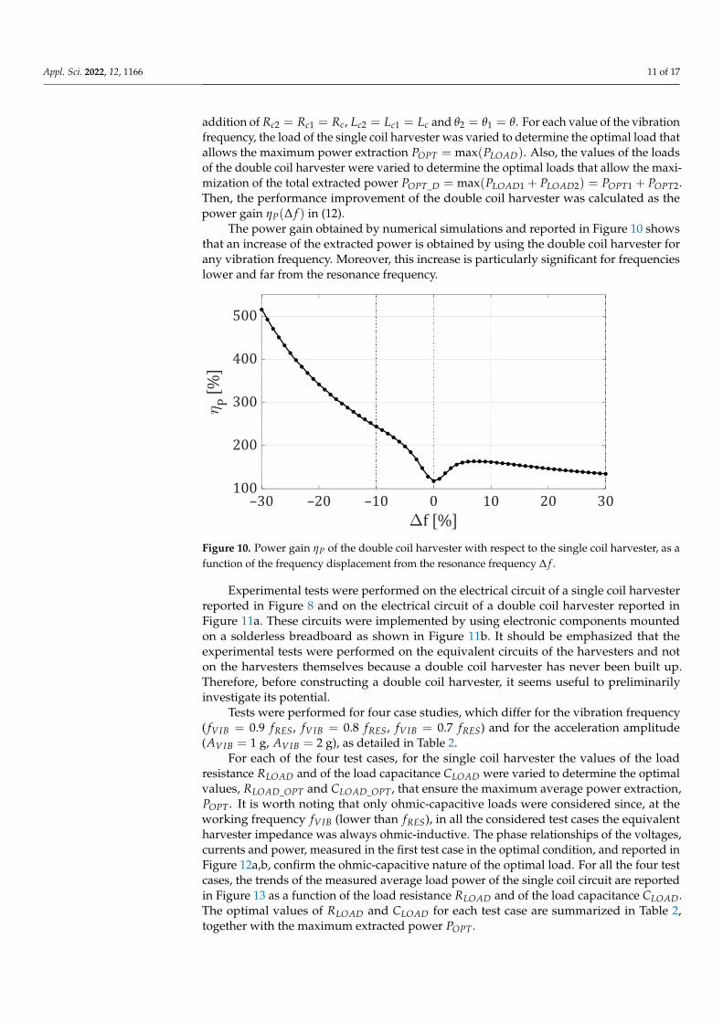
addition of Rc2 = Rc1 = Rc, Lc2 = Lc1 = Lc and θ2 = θ1 = θ. For each value of the vibrationfrequency, the load of the single coil harvester was varied to determine the optimal load thatallows the maximum power extraction POPT = max(PLOAD). Also, the values of the loadsof the double coil harvester were varied to determine the optimal loads that allow the maxi-mization of the total extracted power POPT_D = max(PLOAD1 + PLOAD2) = POPT1 + POPT2.Then, the performance improvement of the double coil harvester was calculated as thepower gain ηP(∆ f ) in (12).
The power gain obtained by numerical simulations and reported in Figure 10 showsthat an increase of the extracted power is obtained by using the double coil harvester forany vibration frequency. Moreover, this increase is particularly significant for frequencieslower and far from the resonance frequency.
Appl. Sci. 2022, 12, 1166 12 of 18
Simulations and experimental tests were performed to show that the double coil electromagnetic harvester is able to deliver an amount of energy significantly greater than that provided by a standard single coil electromagnetic harvester.
Firstly, numerical simulations of the circuit of the single coil harvester shown in Figure 2 and of the circuit of the double coil harvester shown in Figure 5 were performed. The parameters used for the single coil harvester are those obtained by the experimental characterization of the commercial harvester reported in the previous section. The pa-rameters used for the double coil harvester are the same as for the single coil harvester with the addition of 𝑅 = 𝑅 = 𝑅 , 𝐿 = 𝐿 = 𝐿 and 𝜃 = 𝜃 = 𝜃. For each value of the vibration frequency, the load of the single coil harvester was varied to determine the optimal load that allows the maximum power extraction 𝑃 = max (𝑃 ). Also, the values of the loads of the double coil harvester were varied to determine the optimal loads that allow the maximization of the total extracted power 𝑃 _ = max(𝑃 +𝑃 ) = 𝑃 + 𝑃 . Then, the performance improvement of the double coil harvester was calculated as the power gain 𝜂 (Δ𝑓) in (12).
The power gain obtained by numerical simulations and reported in Figure 10 shows that an increase of the extracted power is obtained by using the double coil harvester for any vibration frequency. Moreover, this increase is particularly significant for frequencies lower and far from the resonance frequency.
Figure 10. Power gain 𝜂 of the double coil harvester with respect to the single coil harvester, as a function of the frequency displacement from the resonance frequency Δ𝑓.
Experimental tests were performed on the electrical circuit of a single coil harvester reported in Figure 8 and on the electrical circuit of a double coil harvester reported in Figure 11a. These circuits were implemented by using electronic components mounted on a solderless breadboard as shown in Figure 11b. It should be emphasized that the experimental tests were performed on the equivalent circuits of the harvesters and not on the harvesters themselves because a double coil harvester has never been built up. Therefore, before constructing a double coil harvester, it seems useful to preliminarily investigate its potential.
Tests were performed for four case studies, which differ for the vibration frequency ( 𝑓 = 0.9 𝑓 , 𝑓 = 0.8 𝑓 , 𝑓 = 0.7 𝑓 ) and for the acceleration amplitude (𝐴 = 1g, 𝐴 = 2g), as detailed in Table 2.
P
Figure 10. Power gain ηP of the double coil harvester with respect to the single coil harvester, as afunction of the frequency displacement from the resonance frequency ∆ f .
Experimental tests were performed on the electrical circuit of a single coil harvesterreported in Figure 8 and on the electrical circuit of a double coil harvester reported inFigure 11a. These circuits were implemented by using electronic components mountedon a solderless breadboard as shown in Figure 11b. It should be emphasized that theexperimental tests were performed on the equivalent circuits of the harvesters and noton the harvesters themselves because a double coil harvester has never been built up.Therefore, before constructing a double coil harvester, it seems useful to preliminarilyinvestigate its potential.
Tests were performed for four case studies, which differ for the vibration frequency( fVIB = 0.9 fRES, fVIB = 0.8 fRES, fVIB = 0.7 fRES) and for the acceleration amplitude(AVIB = 1 g, AVIB = 2 g), as detailed in Table 2.
For each of the four test cases, for the single coil harvester the values of the loadresistance RLOAD and of the load capacitance CLOAD were varied to determine the optimalvalues, RLOAD_OPT and CLOAD_OPT , that ensure the maximum average power extraction,POPT . It is worth noting that only ohmic-capacitive loads were considered since, at theworking frequency fVIB (lower than fRES), in all the considered test cases the equivalentharvester impedance was always ohmic-inductive. The phase relationships of the voltages,currents and power, measured in the first test case in the optimal condition, and reported inFigure 12a,b, confirm the ohmic-capacitive nature of the optimal load. For all the four testcases, the trends of the measured average load power of the single coil circuit are reportedin Figure 13 as a function of the load resistance RLOAD and of the load capacitance CLOAD.The optimal values of RLOAD and CLOAD for each test case are summarized in Table 2,together with the maximum extracted power POPT .

Appl. Sci. 2022, 12, 1166 12 of 17Appl. Sci. 2022, 12, 1166 13 of 18
(a)
(b)
Figure 11. (a) Alternative form of the equivalent circuit of a double coil electromagnetic harvester. (b) Experimental implementation of the electromagnetic harvesters by using electronic compo-nents.
For each of the four test cases, for the single coil harvester the values of the load re-sistance 𝑅 and of the load capacitance 𝐶 were varied to determine the optimal values, 𝑅 _ and 𝐶 _ , that ensure the maximum average power extraction, 𝑃 . It is worth noting that only ohmic-capacitive loads were considered since, at the working frequency 𝑓 (lower than 𝑓 ), in all the considered test cases the equivalent harvester impedance was always ohmic-inductive. The phase relationships of the volt-ages, currents and power, measured in the first test case in the optimal condition, and reported in Figure 12a,b, confirm the ohmic-capacitive nature of the optimal load. For all the four test cases, the trends of the measured average load power of the single coil circuit
iLOAD_1(t)
RLOAD_1
+
_vLOAD_1(t)
P
+
_vOC(t)Rm
Lm
CmLc
Rc
G
CLOAD_1
LcRc
RLOAD_2
+
_vLOAD_2(t)CLOAD_2
_
θ·y(t)·
iLOAD_2(t)
+
Figure 11. (a) Alternative form of the equivalent circuit of a double coil electromagnetic harvester.(b) Experimental implementation of the electromagnetic harvesters by using electronic components.

Appl. Sci. 2022, 12, 1166 13 of 17
Table 2. Experimental tests on the electrical circuits of single coil and double coil harvesters.
Test Case n. 1 n. 2 n. 3 n. 4
Test conditions
∆ f −10% −20% −20% −30%
fVIB 0.9·fRES 0.8·fRES 0.8·fRES 0.7·fRES
AVIB 1 g 1 g 2 g 2 g
Single coil harvester
RLOAD_OPT 388 Ω 388 Ω 388 Ω 388 Ω
CLOAD_OPT 1 µ 1 µ 1 µ 1 µ
POPT 2.36 mW 0.56 mW 2.19 mW 0.84 mW
Double coil harvester
RLOAD_1_OPT 558 Ω 558 Ω 558 Ω 558 Ω
CLOAD_1_OPT 1 µ 1 µ 1 µ 1 µ
POPT_1 2.16 mW 0.53 mW 2.19 mW 0.79 mW
RLOAD_2_OPT 558 Ω 558 Ω 558 Ω 558 Ω
CLOAD_2_OPT 1 µ 1 µ 1 µ 1 µ
POPT_2 3.14 mW 1.19 mW 5.03 mW 3.33 mW
POPT_D =POPT_1 + POPT_2
5.3 mW 1.72 mW 7.22 mW 4.12 mW
Power Gainη = POPT_D/POPT
Experiments 224% 307% 330% 490%
Simulations 244% 342% 342% 515%
Appl. Sci. 2022, 12, 1166 14 of 18
are reported in Figure 13 as a function of the load resistance 𝑅 and of the load ca-pacitance 𝐶 . The optimal values of 𝑅 and 𝐶 for each test case are summa-rized in Table 2, together with the maximum extracted power 𝑃 .
Moreover, for each of the four test cases, for the double coil harvester the values of the first load resistance 𝑅 _ , the first load capacitance 𝐶 _ , the second load re-sistance 𝑅 _ , and the second load capacitance 𝐶 _ were varied to determine the optimal values that ensure the maximum power extraction, 𝑃 _ = max (𝑃 _ +𝑃 _ ). For the first test case, oscilloscope screenshots of the voltages, currents and power measured in the optimal condition of the double coil harvester are reported in Figure 12c,d. For all the four test cases, the trends of the measured average load power of the double coil circuit are reported in Figure 14 as a function of the load resistances and load capacitances. The optimal values of the load resistances and capacitances for each test case are summarized in Table 2, together with the maximum average extracted powers.
Starting from the maximum average powers extracted from the single coil harvester and from the double coil harvester in each test case, it is possible to calculate the power gain 𝜂 = 𝑃 _ /𝑃 , i.e., the performance improvement for the double coil harvester. Experimental values for the power gain are reported in Table 2, together with the corre-sponding values obtained by the simulations reported in Figure 10. Experimental tests confirm the simulations’ results and validate the performance improvement that the double coil harvester can provide.
(a) (b)
(c) (d)
Figure 12. Oscilloscope screenshots obtained in the optimal conditions for the first test case. Test for the single coil circuit in Figure 8: (a), input voltage 𝑣 (𝑡) (yellow line) and instantaneous load power 𝑝 (𝑡) (blue line); (b) load voltage 𝑣 (𝑡) (yellow line) and load current 𝑖 (𝑡) (blue line). Test for the double coil circuit in Figure 11a: (c) input voltage 𝑣 (𝑡) (yellow line), additional voltage 𝜃𝑦(𝑡) (red line), instantaneous power on the first load 𝑝 _ (𝑡) (blue line), and instan-taneous power on the second load 𝑝 _ (𝑡) (green line); (d) first load voltage 𝑣 _ (𝑡) (yellow
Figure 12. Oscilloscope screenshots obtained in the optimal conditions for the first test case. Testfor the single coil circuit in Figure 8: (a), input voltage vOC(t) (yellow line) and instantaneous loadpower pOPT(t) (blue line); (b) load voltage vLOAD(t) (yellow line) and load current iLOAD(t) (blueline). Test for the double coil circuit in Figure 11a: (c) input voltage vOC(t) (yellow line), additionalvoltage θ
.y(t) (red line), instantaneous power on the first load pOPT_1(t) (blue line), and instantaneous
power on the second load pOPT_2(t) (green line); (d) first load voltage vLOAD_1(t) (yellow line), firstload current iLOAD_1(t) (blue line), second load voltage vLOAD_2(t) (red line), and second load curreniLOAD_2(t) (green line).

Appl. Sci. 2022, 12, 1166 14 of 17
Appl. Sci. 2022, 12, 1166 15 of 18
line), first load current 𝑖 _ (𝑡) (blue line), second load voltage 𝑣 _ (𝑡) (red line), and second load current 𝑖 _ (𝑡) (green line).
(a) (b)
Figure 13. Measured average load power for the single coil circuit in Figure 8, in the four test cases. (a) Power as a function of the load resistance for the optimal load capacitance. (b) Power as a func-tion of the load capacitance for the optimal load resistance.
(a) (b)
(c) (d)
Figure 14. Measured load average power for the double coil circuit in Figure 11a, in the four test cases. (a) Power as a function of RLOAD_1 for the optimal values of CLOAD_1, RLOAD_2 and CLOAD_2. (b) Power as a function of CLOAD_1 for the optimal values of RLOAD_1, RLOAD_2 and CLOAD_2. (c) Power as a function of RLOAD_2 for the optimal values of CLOAD_2, RLOAD_1 and CLOAD_1. (d) Power as a function of CLOAD_2 for the optimal values of RLOAD_2, RLOAD_1 and CLOAD_1.
Table 2. Experimental tests on the electrical circuits of single coil and double coil harvesters.
LOAD
Test case n. 1Test case n. 2Test case n. 3Test case n. 4
LOAD
Test case n. 1Test case n. 2Test case n. 3Test case n. 4
LOAD_1
LOAD_1
LOAD_2 Test case n. 1Test case n. 2Test case n. 3Test case n. 4
LOAD_1
Test case n. 1Test case n. 2Test case n. 3Test case n. 4
LOAD_2
Test case n. 1Test case n. 2Test case n. 3Test case n. 4
LOAD_2
Test case n. 1Test case n. 2Test case n. 3Test case n. 4
Figure 13. Measured average load power for the single coil circuit in Figure 8, in the four test cases.(a) Power as a function of the load resistance for the optimal load capacitance. (b) Power as a functionof the load capacitance for the optimal load resistance.
Moreover, for each of the four test cases, for the double coil harvester the values of thefirst load resistance RLOAD_1, the first load capacitance CLOAD_1, the second load resistanceRLOAD_2, and the second load capacitance CLOAD_2 were varied to determine the optimalvalues that ensure the maximum power extraction, POPT_D = max(PLOAD_1 + PLOAD_2).For the first test case, oscilloscope screenshots of the voltages, currents and power measuredin the optimal condition of the double coil harvester are reported in Figure 12c,d. For allthe four test cases, the trends of the measured average load power of the double coil circuitare reported in Figure 14 as a function of the load resistances and load capacitances. Theoptimal values of the load resistances and capacitances for each test case are summarizedin Table 2, together with the maximum average extracted powers.
Starting from the maximum average powers extracted from the single coil harvesterand from the double coil harvester in each test case, it is possible to calculate the powergain ηP = POPT_D/POPT , i.e., the performance improvement for the double coil harvester.Experimental values for the power gain are reported in Table 2, together with the corre-sponding values obtained by the simulations reported in Figure 10. Experimental testsconfirm the simulations’ results and validate the performance improvement that the doublecoil harvester can provide.
Finally, note that an increase in the extracted power can also be obtained by increasingthe number of turns of the single coil standard harvester. In particular, if the number ofturns is doubled (e.g., by inserting the additional coil, equal to the first coil, in series withit) the electromechanical coupling coefficient θ and the electrical equivalent resistance Rc ofthe resulting coil are doubled. Therefore, according to Equation (6), the extracted powerPSERIES with the two series-connected coils is confined between once and twice that (POPT)of the original standard harvester. In particular, for small values of Rc, PSERIES tends toPOPT ; for large values of Rc, PSERIES tends to twice POPT . On the other hand, the double coilharvester investigated here is able to extract a power greater than twice POPT , as shown inTable 2. In particular, the power gain can be about five times greater than that of a standardsingle coil harvester.

Appl. Sci. 2022, 12, 1166 15 of 17
Appl. Sci. 2022, 12, 1166 15 of 18
line), first load current 𝑖 _ (𝑡) (blue line), second load voltage 𝑣 _ (𝑡) (red line), and second load current 𝑖 _ (𝑡) (green line).
(a) (b)
Figure 13. Measured average load power for the single coil circuit in Figure 8, in the four test cases. (a) Power as a function of the load resistance for the optimal load capacitance. (b) Power as a func-tion of the load capacitance for the optimal load resistance.
(a) (b)
(c) (d)
Figure 14. Measured load average power for the double coil circuit in Figure 11a, in the four test cases. (a) Power as a function of RLOAD_1 for the optimal values of CLOAD_1, RLOAD_2 and CLOAD_2. (b) Power as a function of CLOAD_1 for the optimal values of RLOAD_1, RLOAD_2 and CLOAD_2. (c) Power as a function of RLOAD_2 for the optimal values of CLOAD_2, RLOAD_1 and CLOAD_1. (d) Power as a function of CLOAD_2 for the optimal values of RLOAD_2, RLOAD_1 and CLOAD_1.
Table 2. Experimental tests on the electrical circuits of single coil and double coil harvesters.
LOAD
Test case n. 1Test case n. 2Test case n. 3Test case n. 4
LOAD
Test case n. 1Test case n. 2Test case n. 3Test case n. 4
LOAD_1
LOAD_1
LOAD_2 Test case n. 1Test case n. 2Test case n. 3Test case n. 4
LOAD_1
Test case n. 1Test case n. 2Test case n. 3Test case n. 4
LOAD_2
Test case n. 1Test case n. 2Test case n. 3Test case n. 4
LOAD_2
Test case n. 1Test case n. 2Test case n. 3Test case n. 4
Figure 14. Measured load average power for the double coil circuit in Figure 11a, in the four testcases. (a) Power as a function of RLOAD_1 for the optimal values of CLOAD_1, RLOAD_2 and CLOAD_2.(b) Power as a function of CLOAD_1 for the optimal values of RLOAD_1, RLOAD_2 and CLOAD_2. (c) Poweras a function of RLOAD_2 for the optimal values of CLOAD_2, RLOAD_1 and CLOAD_1. (d) Power as afunction of CLOAD_2 for the optimal values of RLOAD_2, RLOAD_1 and CLOAD_1.
5. Conclusions
For the first time, the power extraction capability of a double coil electromagneticharvester was experimentally compared with that of a standard single coil electromagneticharvester. The validity of the single degree of freedom model used for the comparison wasverified by experimental tests on a commercial electromagnetic harvester. The comparisonwas performed by simulations and by experiments on the electrical circuits modelingthe harvester’s behavior. The circuits were implemented through electronic componentsmounted on a solderless breadboard. The experimental results showed that the double coilelectromagnetic harvester is able to increase the power delivered to the optimal load forany vibration frequency, but the gain is particularly significant at frequencies lower thanthe harvester resonance frequency.
The double coil electromagnetic harvester investigated in this paper is characterizedby significant advantages with respect to the other techniques proposed in the literature toincrease the energy efficiency of electromagnetic harvesters. In particular, the double coilharvester is able to significantly improve the extracted power as in the case of harvesterarrays, non-linear harvesters and mechanical tuning techniques. However, its size is smallerthan harvester arrays, its complexity is less than that of non-linear harvesters, and it doesnot need additional actuators as in the case of mechanical tuning techniques. Moreover,the double coil harvester exploits the electrical load matching like the electrical tuning

Appl. Sci. 2022, 12, 1166 16 of 17
techniques, but it achieves higher performance than the standard application of an electricaltuning technique.
Author Contributions: Conceptualization, L.C., A.L.S. and M.V.; methodology, L.C., A.L.S. and M.V.;software, L.C., A.L.S. and M.V.; validation, L.C., A.L.S. and M.V.; formal analysis, L.C., A.L.S. andM.V.; investigation, L.C., A.L.S. and M.V.; resources, L.C., A.L.S. and M.V.; data curation, L.C., A.L.S.and M.V.; writing—original draft preparation, L.C., A.L.S. and M.V.; writing—review and editing,L.C., A.L.S. and M.V.; visualization, L.C., A.L.S. and M.V.; supervision, L.C., A.L.S. and M.V.; projectadministration, L.C., A.L.S. and M.V.; funding acquisition, L.C., A.L.S. and M.V. All authors haveread and agreed to the published version of the manuscript.
Funding: This research was partially funded: by the research program “VALERE: VAnviteLli pErla RicErca” by Università degli Studi della Campania “Luigi Vanvitelli”, under grant PE-15/204/E-PASSION, and by the funding program “Valorizzazione di Brevetti tramite il finanziamento diprogetti Proof of Concept” by the Italian Ministero per lo Sviluppo Economico (MISE), under grant#NOACRONYM-PoCn1-TEMELEV.
Conflicts of Interest: The authors declare no conflict of interest.
References1. Delle Femine, A.; Gallo, D.; Landi, C.; Lo Schiavo, A.; Luiso, M. Low power contactless voltage sensor for low voltage power
systems. Sensors 2019, 19, 3513. [CrossRef] [PubMed]2. Kazmierski, T.J.; Beeby, S. Energy Harvesting Systems; Springer: New York, NY, USA, 2011.3. Newell, D.; Duffy, M. Review of power conversion and energy management for low-power, low-voltage energy harvesting
powered wireless sensors. IEEE Trans. Power Electron. 2019, 34, 9794–9805. [CrossRef]4. Harb, A. Energy harvesting: State-of-the-art. Renew. Energy 2011, 36, 2641–2654. [CrossRef]5. Costanzo, L.; Lin, T.; Lin, W.; Lo Schiavo, A.; Vitelli, M.; Zuo, L. Power electronic interface with an adaptive MPPT technique for
train suspension energy harvesters. IEEE Trans. Industrial Electron. 2021, 68, 8219–8230. [CrossRef]6. Costanzo, L.; Liu, M.; Lo Schiavo, A.; Vitelli, M.; Zuo, L. Backpack energy harvesting system with maximum power point tracking
capability. IEEE Trans. Ind. Electron. 2022, 69, 506–516. [CrossRef]7. Cascetta, F.; Lo Schiavo, A.; Minardo, A.; Musto, M.; Rotondo, G.; Calcagni, A. Analysis of the energy extracted by a harvester
based on a piezoelectric tile. Curr. Appl. Phys. 2018, 18, 905–911. [CrossRef]8. Welcome to the World of Vibrations. Available online: https://www.revibeenergy.com/ (accessed on 15 December 2021).9. Perpetuum Technology. Available online: https://perpetuum.com/technology/ (accessed on 15 December 2021).10. Costanzo, L.; Lo Schiavo, A.; Vitelli, M. Active interface for piezoelectric harvesters based on multi-variable maximum power
point tracking. IEEE Trans. Circuits Syst. I Reg. Pap. 2020, 67, 2503–2515. [CrossRef]11. Costanzo, L.; Lo Schiavo, A.; Vitelli, M. Design guidelines for the perturb and observe technique for electromagnetic vibration
energy harvesters feeding bridge rectifiers. IEEE Trans. Ind. Appl. 2019, 55, 5089–5098. [CrossRef]12. Brignole, O.; Cavaletti, C.; Maresca, A.; Mazzino, N.; Balato, M.; Buonomo, A.; Costanzo, L.; Giorgio, M.; Langella, R.; Lo Schiavo, A.; et al.
Resonant Electromagnetic Vibration Harvesters Feeding Sensor Nodes for Real-Time Diagnostics and Monitoring in Railway Vehiclesfor Goods Transportation: A Numerical-Experimental Analysis. In Proceedings of the 2016 IEEE International Power Electronics andMotion Control Conference (PEMC 2016), Varna, Bulgaria, 25–30 September 2016; pp. 456–461.
13. Tang, L.; Yang, Y.; Soh, C.K. Toward broadband vibration-based energy harvesting. J. Intell. Mater. Syst. Struct. 2010, 21, 1867–1897.[CrossRef]
14. Zhu, D.; Tudor, M.J.; Beeby, S.P. Strategies for Increasing the operating frequency range of vibration energy harvesters: A review.Meas. Sci. Technol. 2010, 21, 1–29. [CrossRef]
15. Andò, B.; Baglio, S.; Bulsara, A.R.; Marletta, V.; Pistorio, A. Experimental and theoretical investigation of a nonlinear vibrationalenergy harvester. Procedia Eng. 2015, 120, 1024–1027. [CrossRef]
16. Xie, L.; Du, R. Frequency tuning of a nonlinear electromagnetic energy harvester. ASME J. Vib. Acoust. 2013, 136, 011010:1–011010:7.[CrossRef]
17. Costanzo, L.; Vitelli, M. Tuning techniques for piezoelectric and electromagnetic vibration energy harvesters. Energies 2020, 13, 527.[CrossRef]
18. Bowden, J.A.; Burrow, S.G.; Cammarano, A.; Clare, L.R.; Mitcheson, P.D. Switched-mode load impedance synthesis to parametri-cally tune electromagnetic vibration energy harvesters. IEEE ASME Trans. Mechatron. 2015, 20, 603–610. [CrossRef]
19. Toh, T.T.; Wright, S.W.; Mitcheson, P.D. Resonant frequency tuning of an industrial vibration energy harvester. J. Phys. Conf. Ser.2014, 557, 012128. [CrossRef]
20. Sutrisno, I.W.; Wahied, A.G. A review on frequency tuning methods for piezoelectric energy harvesting systems. J. Renew. Sustain.Energy 2012, 4, 062703. [CrossRef]
21. Lee, B.C.; Chung, G.S. Frequency tuning design for vibration-driven electromagnetic energy harvester. IET Renew. Power Gener.2015, 9, 801–808. [CrossRef]

Appl. Sci. 2022, 12, 1166 17 of 17
22. Sun, W.; Jung, J.; Wang, X.Y.; Kim, P.; Seok, J.; Jang, D.Y. Design, simulation, and optimization of a frequency-tunable vibrationenergy harvester that uses a magnetorheological elastomer. Adv. Mech. Eng. 2015, 7, 147421:1–147421:6. [CrossRef]
23. Mansour, M.O.; Arafa, M.H.; Megahed, S.M. Resonator with magnetically adjustable natural frequency for vibration energyharvesting. Sens. Actuators A Phys. 2010, 163, 297–303. [CrossRef]
24. Aboulfotoh, N.A.; Arafa, M.H.; Megahed, S.M. A self-tuning resonator for vibration energy harvesting. Sens. Actuators A Phys.2013, 201, 328–334. [CrossRef]
25. Heit, J.; Christensen, D.; Roundy, S. A Vibration Energy Harvesting Structure, Tunable over a Wide Frequency Range UsingMinimal Actuation. In Proceedings of the ASME 2013 Conference on Smart Materials, Adaptive Structures and IntelligentSystems (SMASIS 2013), Snowbird, UT, USA, 16–18 September 2013.
26. Eichhorn, C.; Tchagsim, R.; Wilhelm, N.; Woias, P. A smart and self-sufficient frequency tunable vibration energy harvester.J. Micromech. Microeng. 2011, 21, 104003. [CrossRef]
27. Balato, M.; Costanzo, L.; Lo Schiavo, A.; Vitelli, M. Vibration Energy Harvester, Optimized by electronically Emulated Mechanical TuningTechnique. PCT Application Number PCT/EP2019/056601, International Publication No. WO2019/175413A1, 19 September 2019.
28. Elvin, N.G.; Elvin, A.A. An experimentally validated electromagnetic energy harvester. J. Sound Vib. 2011, 330, 2314–2324.[CrossRef]
Copyright © 2022 FDOKUMEN