Comparison of different numerical Laplace inversion methods ...

Abstract—The implementation of a dynamic inversion based controller of the pressure controlling tank located in the primary circuit of the Paks Nuclear Power Plant (NPP) in Hungary is presented in this paper The implemented controller has a distributed structure including measurement and control PLCs, a continuous power controller and a special supervisor module. The hardware and software design and implementation meet the safety-critical requirements imposed by the special nature of the controlled plant
I. INTRODUCTION he proper design, implementation and retrofit of equipments in nuclear power plants (NPPs) are of
primary importance both form the economical and the safe operation of such safety critical plants. Although there are some papers in the literature reporting the design or implementation of such controllers (see e.g. [11] for and LPV model-based control of the steam generator water level in an NPP), the individual differences in the technology and in the available sensor, actuator and computer system architecture, hardware and software conditions, each application presents a challenge from both control and system technological point of view.
The pressure controller, the subject of our study, has been implemented at the Paks Nuclear Power Plant (NPP), that is the only nuclear power plant in Hungary. The plant operates four VVER-440/213 type reactor units with a total nominal (electrical) power of approx. 2000 MWs. About 40 percent of the electrical energy generated in Hungary is produced here. Because of its age and importance, the need for extending the lifespan of the plant has arisen. This includes retrofitting the control system that has been designed and put into operation in the seventies. The aim was to design a controller of this pressure controlling tank using a simple dynamic model with parameters identified from measured data when the old on-off type controller is in operation.
Because of the safety critical nature of the plant, a hierarchical, modular real-time distributed architecture seemed to be necessary as an implementation platform. Such architecture and technology is an emerging area in the automotive and aero-space industry (see e.g. [12] for a
This work has been supported in part by the Control Engineering Research Group of the Budapest University of Technology and Economics.
I. Varga, G. Szederkényi and J. Bokor are with Computer and Automation Research Institute, Hungarian Academy of Sciences Budapest, H-1111, Hungary (email: {ivarga, szeder, bokor}@sztaki.hu).
recent overview of the technology) – another safety critical field, but its application in the nuclear power plant control technology is far less advanced because of the more conservative nature of such applications.
This paper presents the whole innovation chain that has resulted in the successful operation of a dynamic inversion based controller of the pressurizer unit in the primary circuit of the Paks NPP, from the theoretical principles to the final hardware and software design and implementation.
II. PROCESS MODELLING AND IDENTIFICATION The VVER is a pressurized water reactor, that keeps the
pressure of the primary circuit high enough such that the coolant cannot boil. The task of the pressurizer is to keep this pressure within a predefined range. The pressurizer is a vertical tank within which there is hot water at a temperature of about 325 °C and steam above. If the primary circuit pressure decreases, electric heaters switch on automatically in the pressurizer. Due to the heating, more steam will evaporate and this leads to a pressure increase. If the increasing pressure in the pressurizer reaches a certain limit, firstly the heaters are turned off and then cold water is injected into the tank (if needed) to reduce the pressure down to the predefined range [7]. The power of the electric heater is the system input, and its controlled and measured output is the pressure in the tank.
A. Engineering model Modelling of industrial vaporizers, expansion tanks and
alike depends heavily on the modelling goal. Most of the commercially available dynamic models are implemented in steady-state or dynamic simulators (see e.g. [1]) and are used for equipment design and retrofitting purposes. The models used for these purposes are typically in the form of partial differential equations that are discretized in space to have a lumped version. This way a high dimensional (with 10-100 state variables) complicated dynamic model is obtained that is unnecessarily complex for control applications. Therefore, a simplified lumped dynamic model is constructed for identification and control design purposes based on first engineering principles [8] that captures the most important dynamics of the pressurizer. A similar approach has been used in [9] to construct a dynamic model of industrial steam boilers.
The manipulable input to the system is the external
Implementation of Dynamic Inversion-Based Control of a Pressurizer at the Paks NPP
István Varga, Gábor Szederkényi, Péter Gáspár, József Bokor
T
17th IEEE International Conference on Control ApplicationsPart of 2008 IEEE Multi-conference on Systems and ControlSan Antonio, Texas, USA, September 3-5, 2008
WeA03.2
978-1-4244-2223-4/08/$25.00 ©2008 IEEE. 79

heating, all the other input variables are regarded as disturbances. Then we can list the disturbances with physical meaning as follows. The pressure of saturated vapor in the gas phase of the tank depends strongly on the water temperature in a nonlinear (exponential) way.
The method of the model design has been presented in former paper in detail [6][5]. The validity range of the model is the usual operating domain of the pressurizer, i.e. 315°C - 350°C. In pressure terms, this means the interval between 105.65 and 137.09 bar.
B. Continuous time state-space model Based on engineering model we can write the system
model in the following standard state-space form dEuBxAx ++= , (1) where the state vector T
WTTx ] [= , the manipulable input
[0,4]∈u . The value of u originally represented the number of heating elements turned on, and therefore it could only have integer values, but the actuator reconstruction made it possible to set the heating power continuously. The disturbance input vector is T
lossI WTd ] [= . Additionally, the matrices in (1) are the following
⎥⎥⎥⎥
⎦
⎤
⎢⎢⎢⎢
⎣
⎡
−
−−
pW
W
pW
W
p
W
p
W
CK
CK
McK
McK
Mm
A = (2)
,10
0= ,
0=
⎥⎥⎥⎥
⎦
⎤
⎢⎢⎢⎢
⎣
⎡
−⎥⎥⎥
⎦
⎤
⎢⎢⎢
⎣
⎡
pW
p
HE
C
Mm
EMcW
B (3)
Table I. shows the variables and the parameters. The physically measurable output of the system is the pressure in the pressurizer but we assume that the nonlinear physical relationship h between the water temperature and the pressure is known and invertible, i.e.
)(= 11 phx − .
C. Model structure validation and identification The input and output measurements were obtained from
the central data acquisition system of the plant. The original pressure measurements were taken using different sampling
intervals between 1 and 15s based on the changing rate of the signal. These measurements were resampled for identification with a constant sampling time of 5s using 3rd order spline interpolation. The exact on/off switching times of the heating units were also recorded in the computer system, from which the actual heating input power could be easily reconstructed.
For the model structure validation, a heating power and pressure measurement record of about 5.55 hours were used. The input of the system consisted of 10 switchings between two discrete values of the manipulable input. It is important to note that the constraints of the industrial operating environment seriously limited the type of applicable input signals.
During the measurements, the disturbance variables were known and constants.
To validate the proposed model structure (2)-(3), a particularly useful tool is the elementary subsystem (ESS) representation of the discrete time transfer function of the system. The ESS structure estimation algorithm was originally proposed by [10]. The recursive estimation algorithm is started from an overestimated structure and its parameters. By using a prediction error method, a maximum likelihood estimator finds the smallest required model structure and its parameters. Because of the advantageous parametrization, the method has excellent convergence properties.
The identification results showed that the effective identification of the structure (2)-(3) is possible only if we can separate the dynamics of the water and the tank wall temperature by using some prior engineering information.
D. Model parameter estimation For the parameter estimation, exactly the same 5.55 hour
long data set was used as for the model structure validation. The model parameters could be classified into the
following 3 groups from an identification point of view: • Parameters with known values: WHE, cp, M, m • Parameter with an acceptable initial guess: Wloss • Parameters with completely unknown values: CpW,
KW . The parameter estimation and model validation has been demonstrated in former papers in detail [6],[5]. After the estimation procedure, the following numerical values were obtained for the matrices of the scaled model:
.102.03150
0102.92761=
,0
103.16315=
,5.152275.15227
4.456844.4656610=
8
3
3
3
⎥⎦
⎤⎢⎣
⎡
⋅−⋅
⎥⎦
⎤⎢⎣
⎡ ⋅
⎥⎦
⎤⎢⎣
⎡−
−⋅
−
−
−
−
E
B
A
(4)
TABLE I. VARIABLES AND PARAMETERS
T water temperature °C Tw tank wall temperature °C cp specific heat of water J/kg°C m mass flow rate of water kg/s TI inlet water temperature °C M mass of water kg
CpW heat capacity of the wall J/°C WHE power of one electric heater W KW wall heat transfer coefficient W/°C
Wloss heat loss of the system W
80

III. THE CONTROL METHOD The implemented controller satisfies two related
requirements: it regulates the pressure at a given set-point with possibly minimum variance, and it also provides emergency handling operation if the pressure is below or above certain safety threshold levels. The regulation is performed by a dynamic inversion based controller that is designed based on the above described dynamic model, while the emergency handling is realized by simple logical operations.
A. Dynamic inversion based control During the controller design the control goal was to
stabilize the pressure at a prescribed reference value (usually 123-124 bars (around 327°C) under normal operating conditions. The sampling time was 10s in the system. The controller design method consists of two tasks:
• inner loop: discrete time dynamic inverse based controller,
• outer loop: controller for improving stability, disturbance rejection and noise suppression.
The inner loop controller design starts from the discretized version of the continuous-time model:
,=
=2
221
212
1
212
111
11
losskwkkk
IkTkukkk
WBxaxax
TBuBxaxax
−+
+++
+
+ (5)
where xk1,xk
2 are the sampled value of T and TW, respectively.
From the constraint of tracking a reference value x1,r one can obtain the following relations:
.=
=,2,
221,
212,
1
,2,12
1,11
1,1
nomlosskw
rk
rk
rk
nomIkT
rku
rk
rk
rk
WBxaxax
TBuBxaxax
−+
+++
+
+ (6)
Since x1,r is constant in time:
nomI
ku
Tk
u
r
u
rk
nomlosskw
rkk
TBB
Bax
Bau
WBxaa
,121,11
,1,21221
1=
=
−−−
−++
τ
ττ (7)
The scheme of the inversion based controller is illustrated in Figure 1. It is assumed that there are disturbances w for the values of Wloss and there exist a measurement noise v. Applying the input vuu r += (where v is a new external input) we obtain the tracking error
system
kdkkk
kdkukkk
dDeaeae
dBvBeaeae
++
+++
+
+
222
121
21
212
111
11
=
= (8)
with [ ]Tkkk wd ν= and [ ].10=,1000
= dd DB ⎥⎦
⎤⎢⎣
⎡
The dynamics of this error system can be shaped using an outer loop controller based e.g. on an H∞ criterion (see also [2]).
B. Emergency logic The amount of heating and cooling changes with the pressure change. The next figure shows the heater’s switching on and off diagrams, as well as the water injection flow rate as a function of the pressure.
It can be noticed, that continuous control is realized only in the neighborhood of normal operation pressure (base pressure +4 bar) of ± 1 bar. Outside the normal operation range, the traditional switching emergency logic has remained.
IV. THE CONTROLLER ARCHITECTURE It is widely accepted that it is advantageous to solve control problems in high complexity systems using a decentralized, hierarchical structure. Thus, modern controller implementations are often based on decentralized and embedded computer systems. We have also followed this principle in designing the architecture of our control system.
A. Design considerations A key part of the decentralized system is the
communication media between the individual subsystems. In order to increase safety, it's essential that the control system contains redundancy. Redundancy in itself can be quite effective in handling certain faults, but there exist reconfigurable fault tolerant solutions that represent a higher degree of safety. If a fault occurs in such systems, the redundant elements are re-grouped following a centralized or decentralized scheme, and the whole system can continue
25Water (ton/h)201510
5
Base
+1 +2 +3 +4 +5 +6 +7 +8 +9 +10 +11 +12180
Pressure (bar)
360
540 Switching off diagram
720 Switching on diagram
900
1080
1260
1440
1620 Heating Power (kW)
Fig. 2. Switching diagram
inv1
2
vx̂Fu 22
1x̂2x̂
12122222 xAxAx :
11
121211111xCz
uBxAxAx :
2x1xz
C
v
rv v u
Fig. 1. Inversion based tracking
81
its operation in a more or less degraded way. Depending on the degree of degradation, one can decide for the continued operation (possibly with a parallel repair), or for the shutdown of the plant. Using a reconfigurable redundant system, it is generally possible to safely handle more serious faults than the ones that are treatable by simple redundant solutions.
B. Functional description Based on the above considerations, the implemented
control system is a partially reconfigurable redundant system that was designed, implemented and put into operation on the 1st, 3rd and 4th units of the NPP during the 2004-2006 period.
The measurement of the physical variables is taking place locally and the measurement includes some pre-processing, filtering and credibility test. The measurement results are transferred to the computer system in a compressed format via digital network communication. The operation of the actuators is local, too, based on the input signals that are also transmitted through a digital network. To increase reliability, the actuation is completed with a checkback, the result of which is returned to higher levels of the controller hierarchy through the network.
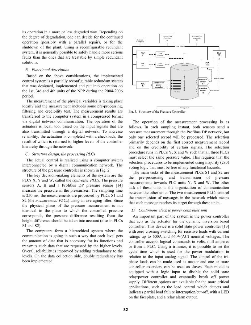
C. Structure design, the processing PLCs The actual control is realized using a computer system
interconnected by a digital communication network. The structure of the pressure controller is shown in Fig. 2.
The key decision-making elements of the system are the PLCs X, Y and W, called the controller PLCs. The pressure sensors A, B and a Profibus DP pressure sensor [14] measure the pressure in the pressurizer. The sampling time is 250 ms, the measurements are processed by PLCs S1 and S2 (the measurement PLCs) using an averaging filter. Since the physical place of the pressure measurement is not identical to the place to which the controlled pressure corresponds, the pressure difference resulting from the height difference should be taken into account (also in PLCs S1 and S2).
The computers form a hierarchical system where the communication is going in such a way that each level gets the amount of data that is necessary for its functions and transmits such data that are requested by the higher levels. Overall reliability is improved by adding redundancy to the levels. On the data collection side, double redundancy has been implemented.
The operation of the measurement processing is as
follows. In each sampling instant, both sensors send a pressure measurement through the Profibus DP network, but only one selected record will be processed. The selection primarily depends on the first correct measurement record and on the credibility of certain signals. The selection procedure runs in PLCs Y, X and W such that all three PLCs must select the same pressure value. This requires that the selection procedures to be implemented using majority (2v3) voting logic that must be free of any functional hazards.
The main tasks of the measurement PLCs S1 and S2 are the pre-processing and transmission of pressure measurements towards PLC units Y, X and W. The other task of these units is the organization of communication between the other units. The two measurement PLCs control the transmission of messages in the network which means that each message reaches its target through these units.
D. Continuous electric power controller unit An important part of the system is the power controller
that acts as the actuator for the dynamic inversion based controller. This device is a solid state power controller [13] with zero crossing switching for resistive loads with current ratings up to 600A and 660V(AC) nominal voltages. The controller accepts logical commands in volts, mill amperes or from a PLC. Using a trimmer, it is possible to set the cycle time which is used for the power modulation in relation to the input analog signal. The control of the tri-phase loads can be made used as master and one or more controller extenders can be used as slaves. Each model is equipped with a logic input to disable the solid state relay/power controller and eventually break off power supply. Different options are available for the more critical applications, such as the load control which detects and indicates partial load failure interruption/cut-off, with a LED on the faceplate, and a relay alarm output.
Pres
suriz
er ta
nk
Primary circuit
Reactor Unit Computer
A
Reactor Unit Computer
B
Heaters
Cool water
Valve controller
Valve controller
TCP/IP Ethernet
Profibus DP/PA
PLCY
PLCW
Continuouspower
controller
PLCX
PLCS1
PLCS2
Pressure sensor
A
Pressure sensor
B
ServiceComputer
Fig. 3. Structure of the Pressure Controller
82

V. IMPLEMENTATION AND SYSTEM SAFETY The design and implementation of control loops in nuclear power plants, especially in their primary circuit is a rather complex task. The safety requirements have very high priority during the design and construction of such systems. On the other hand, the continuity of the operation must be maintained and certain production criteria should be met at the same time.
A. The control PLCs The Y, X, and W control PLCs contain the control
algorithm and these devices drive the real actuators: the continuous electric power controller unit and the valve controllers for the emergency operations. These field-bus controllers are capable of supporting all I/O modules. The Y, X, W devices automatically configure themselves, creating a local process image which may include analog, digital or specialty modules. They are programmable according to IEC 61131-3 using 512 KB program memory, 128 KB data memory and 24 KB retentive memory. The 32-bit based CPU is capable of multitasking and has a battery backed real-time clock. The controller offers many different application protocols which can be used for data acquisition or control (MODBUS, ETHERNET /IP) or for system managing and diagnostics (HTTP, BootP, DHCP, DNS, SNTP, FTP, SNMP and SMTP). This fieldbus controller is suitable for data rates 100 Mbit/s via TCP/IP network. Protection against unauthorized access is also possible with full TCP /IP functionality. When the security option is switched on, only predefined clients can communicate with the controller.
B. Operation modes The system operates in two modes: in normal, and test
modes. The safety and availability of the industrial processes is guaranteed by a specially designed monitoring and control equipment. The reliability of the supervisory systems is possibly even more important than of the monitored process itself. The inherent redundancy of the safety-critical supervisory systems offers a good opportunity for on-line testing by using the test mode.
In the course of on-line testing the technical staff can make sure to the right operability of the pressure controller, too. In addition, there is an opportunity in the supervisory system to adjust an optional reference pressure value.
The supervisor computer has a test software module, which is able to manage the test script files. The test language provides a unified test description that can be used on different test platforms present in the control equipments of the primary circuit. To provide a common interface to the users it was necessary to create a unified syntax (and general semantics, as far as possible) in all of these test environments.
In order to be compatible with the supervisory system and to fit to the distributed environment of the pressure controller, different operating modes have been defined and can be activated in each PLC (either controller or measurement, that are summarized in Fig. 3.
The four operating modes (S1, S2, S3, S4) and their functionality is as follows. • S1: In “Silence mode” the conditions for normal
operation are not met. The system’s outputs in this case stay passive.
• S2: In “Normal mode” all conditions for the PLC’s normal operation are given. The system’s outputs are active in this case.
• S3: In “Inactive test mode” the system is under test and the outputs are passive.
• S4: In “Active test mode” the system is under test, but the outputs in this case are active.
C. Human computer interface In Fig. 2., the 'Reactor Unit Computer A and B' indicate
the unit computers already existing in the computer system of the primary circuit, that is connected to the pressure
TEST
START
ACTIVE
TEST
S1 S2S4S3
OK&PS&AUTYN
YN Y N
YN
Fig. 4. Operating mode selection scheme
TABLE II.
CONDITIONS AND OPERATING MODES OK the controller inside check is ok PS the power supply is ready
TEST test mode request AUT the operator switch off manual mode ACT system output active S1 silent mode S2 normal mode S3 test mode (inactive) S4 test mode (active)
83
control system in order to display information about the current conditions and its operation. There is an iFix SCADA system operating on these Unit Computers and they are connected to the Y and W PLCs through a Mobdus over TCP/IP protocol. They receive the information about the conditions of the pressure control system, to be displayed to the operating personnel.
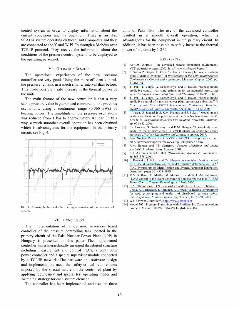
VI. OPERATION RESULTS The operational experiences of the new pressure
controller are very good. Using the more efficient control, the pressure remains in a much smaller interval than before. This made possible a safe increase in the thermal power of the units.
The main feature of the new controller is that a very stable pressure value is guaranteed compared to the previous oscillations, using a continuous range (0-360 kWs) of heating power. The amplitude of the pressure oscillations was reduced from 1 bar to approximately 0.1 bar. In this way, a much smoother overall operation has been obtained which is advantageous for the equipment in the primary circuit, see Fig. 4.
VII. CONCLUSION The implementation of a dynamic inversion based
controller of the pressure controlling tank located in the primary circuit of the Paks Nuclear Power Plant (NPP) in Hungary is presented in this paper The implemented controller has a hierarchically arranged distributed structure including measurement and control PLCs, a continuous power controller and a special supervisor module connected by a TCP/IP network. The hardware and software design and implementation meet the safety-critical requirements imposed by the special nature of the controlled plant by applying redundancy and special test operating modes and switching strategy for each system element.
The controller has been implemented and used in three
units of Paks NPP. The use of the advanced controller resulted in a smooth overall operation, which is advantageous for the equipment in the primary circuit. In addition, it has been possible to safely increase the thermal power of the units by 1-2 %.
REFERENCES [1] APROS. APROS - the advanced process simulation environment,
VTT industrial systems, 2005. http://www.vtt.fi/tuo/63/apros/. [2] Z. Szabó, P. Gáspár, J. Bokor, “Reference tracking for Wiener systems
using Dynamic inversion”, in Proceedings of the 13th Mediterranean Conference on Control and Automation. Limassol. Cyprus. 2005. pp. 1190-1194.
[3] T. Péni, I. Varga, G. Szederkényi, and J. Bokor, “Robust model predictive control with state estimation for an industrial pressurizer system” Hungarian Journal of Industrial Chemistry 33:89-96, 2005
[4] T. Péni, I. Varga, G. Szederkényi, and J. Bokor, “Robust model predictive control of a nuclear power plant pressurizer subsystem” in Proc. of the 25th IASTED International Conference Modeling, Identification, and Control, Lanzarote, Spain, pp. 167-172, 2006
[5] I. Varga, G. Szederkényi, K.M. Hangos, and J. Bokor, “Modeling and model identification of a pressurizer at the Paks Nuclear Power Plant”, 14th IFAC Symposium on System Identification, Newcastle, Australia, pp. 678-683, 2006.
[6] Cs. Fazekas, G. Szederkényi, and K.M. Hangos, “A simple dynamic model of the primary circuit in VVER plants for controller design purposes”, Nuclear Engineering and Design, to appear, 2007.
[7] Paks Nuclear Power Plant. VVER - 440/213 - the primary circuit, 2005. http://www.npp.hu /mukodes /tipusok /primer-e.htm.
[8] K.M. Hangos and I.T. Cameron, “Process Modelling and Model Analysis” Academic Press, London, 2001.
[9] K.J. Aström and R.D. Bell, “Drum-boiler dynamics”, Automatica, 36:363–378, 2000.
[10] L. Keviczky, J. Bokor, and Cs. Bányász. A new identification method with special parametrization for model structure determination. In 5th IFAC Symposium on Identification and System Parameter Estimation, Darmstadt, pages 561–568. 1979.
[11] M.V. Kothare,. B. Mettler, M. Morari,P. Bendotti, C.-M. Falinower, “Level control in the steam generator of a nuclear power plant”, IEEE Trans. Control Systems Technology, 8: 55-69, 2000.
[12] H.A. Thompsona, D.N. Ramos-Hernandeza,, J. Fua, L. Jianga, I. Choia, K. Cartledgeb, J. Fortuneb, A. Brown, “A flexible environment for rapid prototyping and analysis of distributed real-time safety-critical systems”, Control Engineering Practice, 15: 77–94, 2007
[13] W212 Power ControllerS, http://www.gefran.com [14] Model 3051 Pressure Transmitter with Profibus–PA Communications
Protocol. Manual. 00809-0100-4797 English Rev. BA.
0 1 2 3 4 5 6 7 8 9 10122.2
122.4
122.6
122.8
123
123.2
123.4
123.6
123.8
time [h]
prim
ary
circ
uit p
ress
ure
[bar
]
old controllernew controller
Fig. 5. Pressure before and after the implementation of the new control scheme
84
Copyright © 2022 FDOKUMEN