Impact of finger posture on mapping from muscle activation to joint torque
9
Impact of finger posture on mapping from muscle activation to joint torque Derek G. Kamper a,b, * , Heidi C. Fischer a , Erik G. Cruz a a Sensory Motor Performance Program, Rehabilitation Institute of Chicago, 345 E. Superior Street, Chicago, IL 606011, USA b Department of Biomedical Engineering, Illinois Institute of Technology, Chicago, IL, USA Received 30 August 2005; accepted 16 November 2005 Abstract Background. The mapping from muscle activation to joint torque production can be difficult to determine for the multi-articular muscles of the fingers. This relationship was examined in vivo as a function of posture in the index finger. Methods. Five healthy adults participated in an experiment in which the seven muscles of the index finger were sequentially elec- trically stimulated using intramuscular electrodes. Each muscle was stimulated at 12 different finger postures consisting of specified flexion of the metacarpophalangeal, proximal interphalangeal, and distal interphalangeal joints, while fingertip forces and moments were recorded. Findings. Repeated measures analysis of variance revealed that joint torques resulting from the stimulation were significantly dependent upon finger posture (p < 0.05). The magnitude of the change in joint torque across postures was generally greater than 60%. This value is much larger than the difference attributable to the increase in active muscle force that occurs at longer muscle length, in accordance with the force–length curve (10–20% for the estimated length changes). In addition, the relative distribution of the joint torques generated by a given muscle activation was dependent upon finger posture for the intrinsic muscles and the long finger flexors (p < 0.05); the ratio of one joint torque to another varied with posture for these muscles, in some cases by more than 50%. Interpretation. Joint torque is a product of both muscle force and the corresponding moment arm. As the change in active muscle force was limited, these data suggest that substantial changes in muscle moment arms occur with posture. Therefore, this postural dependence should be considered when constructing biomechanical models of the hand or planning tendon transfers for the fingers. Ó 2005 Elsevier Ltd. All rights reserved. Keywords: Index finger; Moment arm; Joints 1. Introduction The mapping of muscle force to joint torques is a fun- damental problem for biomechanics research. Human motor control is predicated upon muscles producing moments about the joints, thereby resulting in either rotation of the joint or opposition to an external load. Thus, to analyze or predict the impact of a given muscle on task performance, knowledge of the moment arm mathematically relating muscle force to joint torque is required. Both the magnitude of the moment arm and its direction relative to the force vector must be known, as not only may the distance between the muscle tendon and the joint vary, but the direction of the tendon force with respect to the joint coordinate system may change as well. These quantities can be difficult to measure, especially for the finger muscles which cross multiple joints and travel through anatomical pulleys, in the form of 0268-0033/$ - see front matter Ó 2005 Elsevier Ltd. All rights reserved. doi:10.1016/j.clinbiomech.2005.11.005 * Corresponding author. Address: Sensory Motor Performance Program, Rehabilitation Institute of Chicago, 345 E. Superior Street, Chicago, IL 606011, USA. E-mail address: [email protected] (D.G. Kamper). www.elsevier.com/locate/clinbiomech Clinical Biomechanics 21 (2006) 361–369
Transcript of Impact of finger posture on mapping from muscle activation to joint torque

www.elsevier.com/locate/clinbiomech
Clinical Biomechanics 21 (2006) 361–369
Impact of finger posture on mapping from muscle activationto joint torque
Derek G. Kamper a,b,*, Heidi C. Fischer a, Erik G. Cruz a
a Sensory Motor Performance Program, Rehabilitation Institute of Chicago, 345 E. Superior Street, Chicago, IL 606011, USAb Department of Biomedical Engineering, Illinois Institute of Technology, Chicago, IL, USA
Received 30 August 2005; accepted 16 November 2005
Abstract
Background. The mapping from muscle activation to joint torque production can be difficult to determine for the multi-articularmuscles of the fingers. This relationship was examined in vivo as a function of posture in the index finger.
Methods. Five healthy adults participated in an experiment in which the seven muscles of the index finger were sequentially elec-trically stimulated using intramuscular electrodes. Each muscle was stimulated at 12 different finger postures consisting of specifiedflexion of the metacarpophalangeal, proximal interphalangeal, and distal interphalangeal joints, while fingertip forces and momentswere recorded.
Findings. Repeated measures analysis of variance revealed that joint torques resulting from the stimulation were significantlydependent upon finger posture (p < 0.05). The magnitude of the change in joint torque across postures was generally greater than60%. This value is much larger than the difference attributable to the increase in active muscle force that occurs at longer musclelength, in accordance with the force–length curve (10–20% for the estimated length changes). In addition, the relative distributionof the joint torques generated by a given muscle activation was dependent upon finger posture for the intrinsic muscles and the longfinger flexors (p < 0.05); the ratio of one joint torque to another varied with posture for these muscles, in some cases by more than50%.
Interpretation. Joint torque is a product of both muscle force and the corresponding moment arm. As the change in active muscleforce was limited, these data suggest that substantial changes in muscle moment arms occur with posture. Therefore, this posturaldependence should be considered when constructing biomechanical models of the hand or planning tendon transfers for the fingers.� 2005 Elsevier Ltd. All rights reserved.
Keywords: Index finger; Moment arm; Joints
1. Introduction
The mapping of muscle force to joint torques is a fun-damental problem for biomechanics research. Humanmotor control is predicated upon muscles producingmoments about the joints, thereby resulting in eitherrotation of the joint or opposition to an external load.
0268-0033/$ - see front matter � 2005 Elsevier Ltd. All rights reserved.doi:10.1016/j.clinbiomech.2005.11.005
* Corresponding author. Address: Sensory Motor PerformanceProgram, Rehabilitation Institute of Chicago, 345 E. Superior Street,Chicago, IL 606011, USA.
E-mail address: [email protected] (D.G. Kamper).
Thus, to analyze or predict the impact of a given muscleon task performance, knowledge of the moment armmathematically relating muscle force to joint torque isrequired. Both the magnitude of the moment arm andits direction relative to the force vector must be known,as not only may the distance between the muscle tendonand the joint vary, but the direction of the tendon forcewith respect to the joint coordinate system may changeas well.
These quantities can be difficult to measure, especiallyfor the finger muscles which cross multiple joints andtravel through anatomical pulleys, in the form of
362 D.G. Kamper et al. / Clinical Biomechanics 21 (2006) 361–369
annular and cruciform ligaments (Hentz and Chase,2001). Thus, one approach for the development of bio-mechanical models is to use constant values for magni-tude and relative direction of the moment arm (Estekiand Mansour, 1997; Sancho-Bru et al., 2001). Themoment arm is estimated by the perpendicular distancefrom the tendon to the joint center. This distance canbe determined through geometrical methods employ-ing magnetic resonance or other imaging modalities(Fowler et al., 2001; Rugg et al., 1990; Wretenberget al., 1996).
This distance, however, may change as the jointrotates (Landsmeer, 1961). Efforts have been made toquantify this change in moment arm magnitude usingthe tendon displacement method, in which the momentarm is estimated from the relationship between jointrotation and the resulting tendon displacement. Thisrelationship can either be measured directly in cadavericspecimens (Murray et al., 2000; Storace and Wolf, 1979;An et al., 1983) or computed mathematically (Lands-meer, 1961; Lee and Rim, 1990). A number of bio-mechanical models have adopted this approach (Leeand Rim, 1990; Brook et al., 1995).
The direction of the moment arm relative to the forcevector may also vary with finger posture, however. Thisis especially true for multi-articular muscles, in whichthe reaction forces resulting from muscle contractionat a more distal joint closer to the attachment point pro-duce the moments at more proximal joints (Zajac andGordon, 1989; Zajac, 2002). Indeed, the previous studiesthat have described changes in moment arms with pos-ture have tended to focus on the effects of rotation ofa single joint rather than rotation of multiple jointscrossed by the tendon (Landsmeer, 1961; Maganaris,2004; Wretenberg et al., 1996; An et al., 1983). In addi-tion, multiple tendons insert into the dorsal aponeurosisof the extensor hood, which, in turn, has multiple inser-tions sites into the finger phalanges. While past research-ers have used a force net, Winslow’s tendinous rhombus,to estimate the distribution of forces in the extensorhood and to calculate the resulting moment arms fromthe geometry of the net (Valero-Cuevas et al., 1998; San-cho-Bru et al., 2001, 2003), the directions and positionsof forces in this net can change as finger posture changes(Garcia-Elias et al., 1991).
An alternative method of estimating moment armsmay prove more appropriate. The direct load measure-ment technique, in which a load is applied through themuscle and tendon and the resulting forces andmoments in the distal segment are recorded, is seeminglymore accurate (An et al., 1984). The moment arm can becomputed from the known applied force and the result-ing joint torque. The direct load technique is also wellsuited to the examination of moment arms at differentjoint configurations (Lauer et al., 1999; Aruin et al.,1987).
We quantified the extent to which changes in anglesof the finger joints impacted the mapping of muscle acti-vation to joint torque for all 7 muscles of the index fin-ger using the direct load measurement. As tissueproperties and structural integrity are crucial to thismapping, we performed these experiments in vivo. Iso-metric muscle force was produced through electricalstimulation of the muscle (Lauer et al., 1999), whilethe resulting forces and moments were measured at thefingertip. This relationship was tested for 12 differentfinger postures. As muscle activation rather than forcewas controlled, the resulting magnitude of the muscleforce could change with joint posture. Indeed, the activeisometric force produced by stimulation of isolated mus-cle is a function of muscle length (Zajac, 1989). A com-puter model was thus created to estimate the change inforce for each muscle across the 12 postures. We antici-pated that finger posture would significantly affect jointtorque production and that the changes would be dueprimarily to changes in moment arms.
2. Methods
2.1. Muscle stimulation
Five subjects participated in the study. Subject agesranged from 22 to 36 years. All subjects gave informedconsent, in accordance with the Helsinki Declaration,and the Institutional Review Board of NorthwesternUniversity approved the experimental protocol. Theindex finger of the left (non-dominant) hand wasassessed in all five subjects.
Two 55-lm stainless steel intramuscular electrodeswere inserted into each of the seven muscles actuatingthe index finger: first compartment of the flexor digito-rum superficialis (FDS), first compartment of the flexordigitorum profundus (FDP), first compartment of theextensor digitorum communis (EDC), extensor indicis(EI), medial head of first dorsal interosseous (FDI), firstpalmar interosseous (FPI), and the first lumbrical(LUM). For FDS, FDP, and EDC, the first compart-ment corresponds with the muscle slip whose tendon ter-minates on the index finger. Electrode insertion siteswere determined in accordance with the literature (Bur-gar et al., 1997; Reilly et al., 2004). Ultrasonographywas occasionally used to guide insertion when musclepalpation or landmark detection proved difficult. Insome instances, the muscles were first located usingtungsten needle microelectrodes (60 mm/5 KX, Freder-ick Haer & Co., Inc., Bowdoinham, ME, USA), inaccordance with published procedures (Burgar et al.,1997; Keen and Fuglevand, 2004). In all cases electrodeinsertion was guided by audial feedback from musclecontraction. Proper placement was confirmed byappropriate finger motion in response to imposed
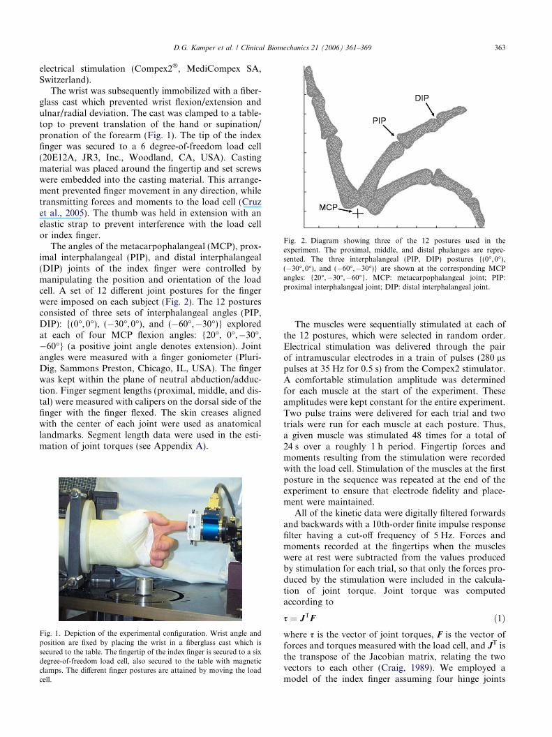
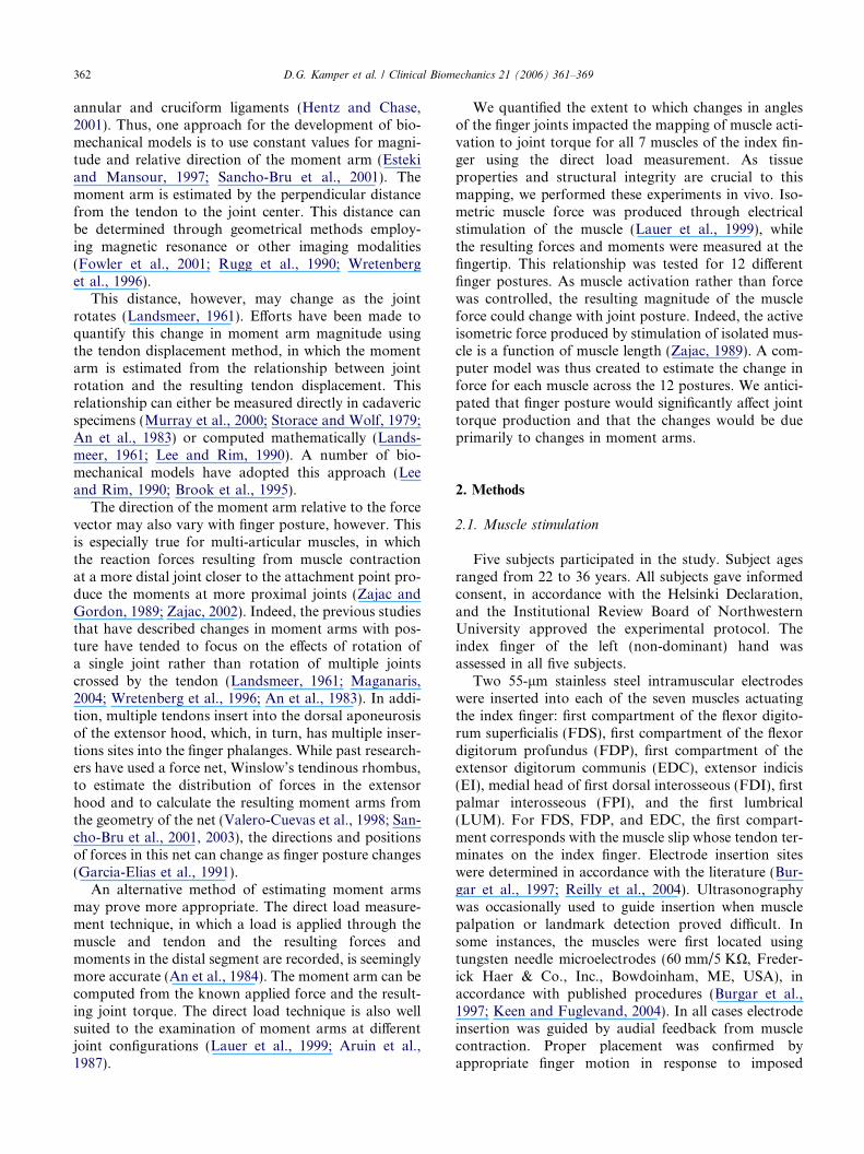
Fig. 2. Diagram showing three of the 12 postures used in theexperiment. The proximal, middle, and distal phalanges are repre-sented. The three interphalangeal (PIP, DIP) postures {(0�, 0�),(�30�, 0�), and (�60�,�30�)} are shown at the corresponding MCPangles: {20�,�30�,�60�}. MCP: metacarpophalangeal joint; PIP:proximal interphalangeal joint; DIP: distal interphalangeal joint.
D.G. Kamper et al. / Clinical Biomechanics 21 (2006) 361–369 363
electrical stimulation (Compex2�, MediCompex SA,Switzerland).
The wrist was subsequently immobilized with a fiber-glass cast which prevented wrist flexion/extension andulnar/radial deviation. The cast was clamped to a table-top to prevent translation of the hand or supination/pronation of the forearm (Fig. 1). The tip of the indexfinger was secured to a 6 degree-of-freedom load cell(20E12A, JR3, Inc., Woodland, CA, USA). Castingmaterial was placed around the fingertip and set screwswere embedded into the casting material. This arrange-ment prevented finger movement in any direction, whiletransmitting forces and moments to the load cell (Cruzet al., 2005). The thumb was held in extension with anelastic strap to prevent interference with the load cellor index finger.
The angles of the metacarpophalangeal (MCP), prox-imal interphalangeal (PIP), and distal interphalangeal(DIP) joints of the index finger were controlled bymanipulating the position and orientation of the loadcell. A set of 12 different joint postures for the fingerwere imposed on each subject (Fig. 2). The 12 posturesconsisted of three sets of interphalangeal angles (PIP,DIP): {(0�, 0�), (�30�, 0�), and (�60�,�30�)} exploredat each of four MCP flexion angles: {20�, 0�,�30�,�60�} (a positive joint angle denotes extension). Jointangles were measured with a finger goniometer (Pluri-Dig, Sammons Preston, Chicago, IL, USA). The fingerwas kept within the plane of neutral abduction/adduc-tion. Finger segment lengths (proximal, middle, and dis-tal) were measured with calipers on the dorsal side of thefinger with the finger flexed. The skin creases alignedwith the center of each joint were used as anatomicallandmarks. Segment length data were used in the esti-mation of joint torques (see Appendix A).
Fig. 1. Depiction of the experimental configuration. Wrist angle andposition are fixed by placing the wrist in a fiberglass cast which issecured to the table. The fingertip of the index finger is secured to a sixdegree-of-freedom load cell, also secured to the table with magneticclamps. The different finger postures are attained by moving the loadcell.
The muscles were sequentially stimulated at each ofthe 12 postures, which were selected in random order.Electrical stimulation was delivered through the pairof intramuscular electrodes in a train of pulses (280 lspulses at 35 Hz for 0.5 s) from the Compex2 stimulator.A comfortable stimulation amplitude was determinedfor each muscle at the start of the experiment. Theseamplitudes were kept constant for the entire experiment.Two pulse trains were delivered for each trial and twotrials were run for each muscle at each posture. Thus,a given muscle was stimulated 48 times for a total of24 s over a roughly 1 h period. Fingertip forces andmoments resulting from the stimulation were recordedwith the load cell. Stimulation of the muscles at the firstposture in the sequence was repeated at the end of theexperiment to ensure that electrode fidelity and place-ment were maintained.
All of the kinetic data were digitally filtered forwardsand backwards with a 10th-order finite impulse responsefilter having a cut-off frequency of 5 Hz. Forces andmoments recorded at the fingertips when the muscleswere at rest were subtracted from the values producedby stimulation for each trial, so that only the forces pro-duced by the stimulation were included in the calcula-tion of joint torque. Joint torque was computedaccording to
s ¼ JTF ð1Þwhere s is the vector of joint torques, F is the vector offorces and torques measured with the load cell, and JT isthe transpose of the Jacobian matrix, relating the twovectors to each other (Craig, 1989). We employed amodel of the index finger assuming four hinge joints
364 D.G. Kamper et al. / Clinical Biomechanics 21 (2006) 361–369
(Brand and Hollister, 1993) representing the followingdegrees-of-freedom: MCP flexion–extension and MCPabduction–adduction/internal–external rotation, PIPflexion–extension, and DIP flexion–extension (Valero-Cuevas, 2000).
The two MCP rotational axes were assumed to befixed with respect to the metacarpal bone, with flex-ion–extension followed by ‘‘abduction–adduction’’ (seeAppendix A). The MCP joint does not have a trueabduction–adduction axis of rotation, but ratherrotates along an arc whose radius of curvaturedecreases with increasing MCP flexion, as describedby Brand and Hollister (Brand and Hollister, 1993).Thus, as the MCP joint is flexed, the motion approxi-mates internal–external rotation about the long axisof the finger rather than abduction–adduction (as anaming convention, we will still use MCP abduction–adduction for this axis). This MCP abduction–add-uction axis is non-orthogonal with respect to theflexion–extension axis (Brand and Hollister, 1993).For this study, the axis was assumed to be rotated by20� in the extension direction, in accordance with theliterature (Valero-Cuevas, 2000). Using this model, wecomputed the Jacobian for each finger posture fromthe measured joint angles and segment lengths of thefinger (see Appendix A).
Each joint torque was then averaged across a 50-mswindow centered at the point of maximum resultantforce during the stimulation period. The joint torquevalues were averaged across all four stimulation periods,thereby yielding a single torque value for each degree-of-freedom at each posture for each subject. Thus, a totalof 48 torque observations per muscle were analyzedfor each subject.
The joint torques for a given muscle were then nor-malized by the maximum value obtained across all 48of these observations. For example, for the FDI musclethe maximum torque was recorded for MCP abduction;therefore, all of the joints torques for the FDI musclewere normalized by this peak MCP abduction value.In this manner, data from different subjects could becompared.
A repeated measures analysis of variance was per-formed for each muscle with the within-subject indepen-dent factors consisting of joint degree-of-freedom(DOF, 4 levels: MCP abduction/adduction, MCP flex-ion/extension, PIP flexion/extension, and DIP flexion/extension), MCP angle (MCP, four levels: 20�, 0�,�30�, and �60�), and interphalangeal posture (IP, threelevels: (0�, 0�), (�30�, 0�), and (�60�,�30�)). The Green-house-Geisser correction was employed as Mauchley’stest indicated possible violation of the sphericityassumption. Post-hoc Tukey tests were performed todetermine distinct levels of main effects found to be sig-nificant. Eta-squared (g2) values were computed to esti-mate the variance explained by each factor.
2.2. Musculotendon length
Change in musculotendon length was estimated foreach muscle for the range of finger postures employedin the stimulation experiment using a computer modelof the forearm and index finger created in the SIMM�
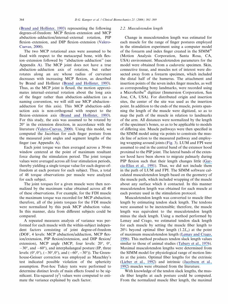
(Motion Analysis Corporation, Santa Rosa, CA,USA) environment. Musculotendon parameters for themodel were obtained from a cadaveric specimen. Skin,connective tissue, and muscles not of interest were dis-sected away from a forearm specimen, which includedthe distal half of the humerus. The attachment andinsertion points of the seven index finger muscles, as wellas corresponding bony landmarks, were recorded usinga MicroScribe� digitizer (Immersion Corporation, SanJose, CA, USA). For distributed origin and insertionsites, the center of the site was used as the insertionpoint. In addition to the ends of the muscle, points span-ning the length of the muscle were digitized, so as tomap the path of the muscle in relation to landmarksof the arm. All distances were normalized by the lengthof the specimen’s bones, so as to be applicable to modelsof differing size. Muscle pathways were then specified inthe SIMM model using via points to constrain the mus-cle line of action to the measured pathway and employ-ing wrapping around joints (Fig. 3). LUM and FPI wereassumed to end in the central band of the extensor hoodproximal to the PIP joint. The lateral bands of the exten-sor hood have been shown to migrate palmarly duringPIP flexion such that their length changes little (Gar-cia-Elias et al., 1991). Thus, we did not include themin the path of LUM and FPI. The SIMM software cal-culated musculotendon length based on the geometry ofthe muscle path, which included wrapping of the muscleabout any surface which it contacted. In this mannermusculotendon length was obtained for each muscle ateach posture used in the stimulation protocol.
Musculotendon length was converted to muscle fiberlength by estimating tendon slack length. The tendonswere assumed to be inextensible; therefore, the musclelength was equivalent to the musculotendon lengthminus the slack length. Using a method performed byLemay and Crago, we estimated tendon slack lengthfor each muscle by setting the muscle fiber length to20% beyond optimal fiber length (1.2Lo) at the pointof maximum musculotendon length (Lemay and Crago,1996). This method produces tendon slack length valuessimilar to those of animal studies (Tabary et al., 1976).Maximal musculotendon lengths were determined fromthe SIMM model for physiological range of motion lim-its at the joints. Optimal fiber lengths for the extrinsic(Lieber et al., 1992) and intrinsic (Jacobson et al.,1992) muscles were obtained from the literature.
With knowledge of the tendon slack lengths, the mus-cle fiber lengths at each posture could be computed.From the normalized muscle fiber length, the maximal
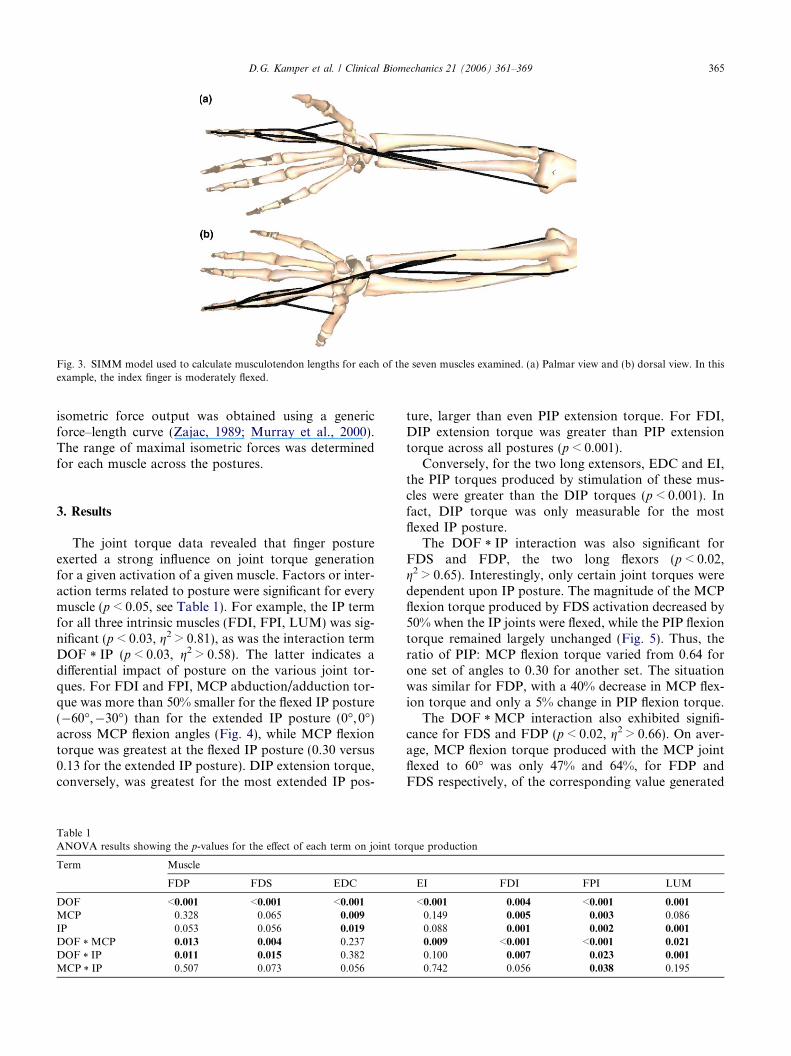
Fig. 3. SIMM model used to calculate musculotendon lengths for each of the seven muscles examined. (a) Palmar view and (b) dorsal view. In thisexample, the index finger is moderately flexed.
D.G. Kamper et al. / Clinical Biomechanics 21 (2006) 361–369 365
isometric force output was obtained using a genericforce–length curve (Zajac, 1989; Murray et al., 2000).The range of maximal isometric forces was determinedfor each muscle across the postures.
3. Results
The joint torque data revealed that finger postureexerted a strong influence on joint torque generationfor a given activation of a given muscle. Factors or inter-action terms related to posture were significant for everymuscle (p < 0.05, see Table 1). For example, the IP termfor all three intrinsic muscles (FDI, FPI, LUM) was sig-nificant (p < 0.03, g2 > 0.81), as was the interaction termDOF * IP (p < 0.03, g2 > 0.58). The latter indicates adifferential impact of posture on the various joint tor-ques. For FDI and FPI, MCP abduction/adduction tor-que was more than 50% smaller for the flexed IP posture(�60�,�30�) than for the extended IP posture (0�, 0�)across MCP flexion angles (Fig. 4), while MCP flexiontorque was greatest at the flexed IP posture (0.30 versus0.13 for the extended IP posture). DIP extension torque,conversely, was greatest for the most extended IP pos-
Table 1ANOVA results showing the p-values for the effect of each term on joint to
Term Muscle
FDP FDS EDC
DOF <0.001 <0.001 <0.001MCP 0.328 0.065 0.009
IP 0.053 0.056 0.019
DOF * MCP 0.013 0.004 0.237DOF * IP 0.011 0.015 0.382MCP * IP 0.507 0.073 0.056
ture, larger than even PIP extension torque. For FDI,DIP extension torque was greater than PIP extensiontorque across all postures (p < 0.001).
Conversely, for the two long extensors, EDC and EI,the PIP torques produced by stimulation of these mus-cles were greater than the DIP torques (p < 0.001). Infact, DIP torque was only measurable for the mostflexed IP posture.
The DOF * IP interaction was also significant forFDS and FDP, the two long flexors (p < 0.02,g2 > 0.65). Interestingly, only certain joint torques weredependent upon IP posture. The magnitude of the MCPflexion torque produced by FDS activation decreased by50% when the IP joints were flexed, while the PIP flexiontorque remained largely unchanged (Fig. 5). Thus, theratio of PIP: MCP flexion torque varied from 0.64 forone set of angles to 0.30 for another set. The situationwas similar for FDP, with a 40% decrease in MCP flex-ion torque and only a 5% change in PIP flexion torque.
The DOF * MCP interaction also exhibited signifi-cance for FDS and FDP (p < 0.02, g2 > 0.66). On aver-age, MCP flexion torque produced with the MCP jointflexed to 60� was only 47% and 64%, for FDP andFDS respectively, of the corresponding value generated
rque production
EI FDI FPI LUM
<0.001 0.004 <0.001 0.001
0.149 0.005 0.003 0.0860.088 0.001 0.002 0.001
0.009 <0.001 <0.001 0.021
0.100 0.007 0.023 0.001
0.742 0.056 0.038 0.195
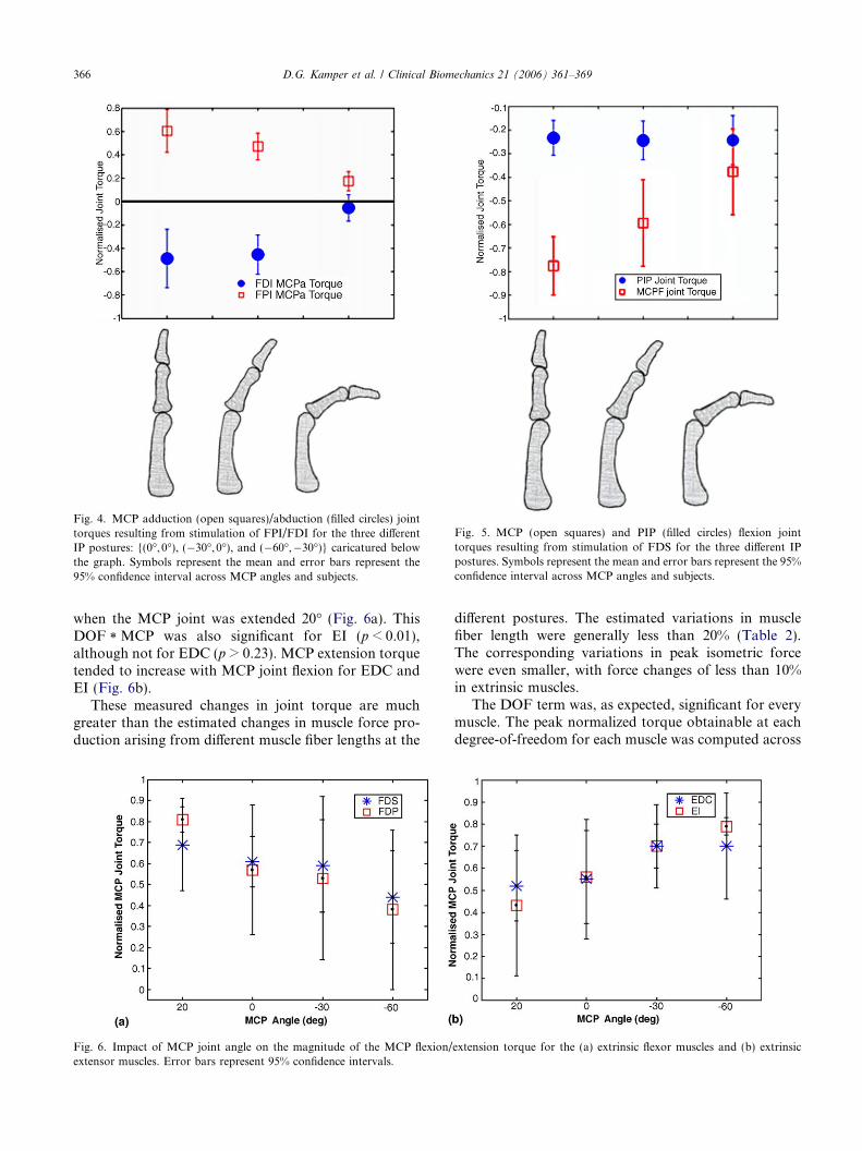
Fig. 5. MCP (open squares) and PIP (filled circles) flexion jointtorques resulting from stimulation of FDS for the three different IPpostures. Symbols represent the mean and error bars represent the 95%confidence interval across MCP angles and subjects.
Fig. 4. MCP adduction (open squares)/abduction (filled circles) jointtorques resulting from stimulation of FPI/FDI for the three differentIP postures: {(0�, 0�), (�30�, 0�), and (�60�,�30�)} caricatured belowthe graph. Symbols represent the mean and error bars represent the95% confidence interval across MCP angles and subjects.
366 D.G. Kamper et al. / Clinical Biomechanics 21 (2006) 361–369
when the MCP joint was extended 20� (Fig. 6a). ThisDOF * MCP was also significant for EI (p < 0.01),although not for EDC (p > 0.23). MCP extension torquetended to increase with MCP joint flexion for EDC andEI (Fig. 6b).
These measured changes in joint torque are muchgreater than the estimated changes in muscle force pro-duction arising from different muscle fiber lengths at the
Fig. 6. Impact of MCP joint angle on the magnitude of the MCP flexion/extensor muscles. Error bars represent 95% confidence intervals.
different postures. The estimated variations in musclefiber length were generally less than 20% (Table 2).The corresponding variations in peak isometric forcewere even smaller, with force changes of less than 10%in extrinsic muscles.
The DOF term was, as expected, significant for everymuscle. The peak normalized torque obtainable at eachdegree-of-freedom for each muscle was computed across
extension torque for the (a) extrinsic flexor muscles and (b) extrinsic
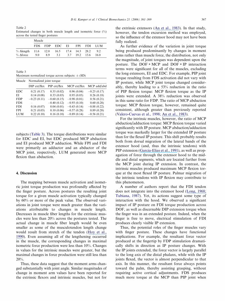
Table 2Estimated changes in both muscle length and isometric force (%)across the tested finger postures
Muscle
FDS FDP EDC EI FPI FDI LUM
% Dlength 11.6 12.0 16.5 17.4 14.3 28.2 9.2% Dforce 9.0 8.9 3.1 3.7 19.2 13.6 16.0
Table 3Maximum normalized torque across subjects: ± (SD)
Muscle Normalized joint torque
DIP ext/flex PIP ext/flex MCP ext/flex MCP add/abd
EDC 0.21 (0.17) 0.35 (0.02) 0.96 (0.04) �0.25 (0.17)EI 0.14 (0.08) 0.33 (0.03) 0.95 (0.03) 0.26 (0.18)FDP �0.23 (0.11) �0.60 (0.15) �0.98 (0.01) 0.56 (0.21)FDS – �0.40 (0.12) �0.93 (0.10) 0.60 (0.28)FDI 0.16 (0.07) 0.04 (0.01) �0.43 (0.14) �0.88 (0.22)FPI 0.21 (0.03) 0.10 (0.06) �0.57 (0.28) 0.89 (0.20)LUM 0.22 (0.10) 0.16 (0.10) �0.89 (0.14) �0.56 (0.21)
D.G. Kamper et al. / Clinical Biomechanics 21 (2006) 361–369 367
subjects (Table 3). The torque distributions were similarfor EDC and EI, but EDC produced MCP abductionand EI produced MCP adduction. While FPI and FDIwere primarily an adductor and an abductor of theMCP joint, respectively, LUM generated more MCPflexion than abduction.
4. Discussion
The mapping between muscle activation and isomet-ric joint torque production was profoundly affected bythe finger posture. Across postures the resulting jointtorque for a given muscle activation typically changedby 60% or more of the peak value. The observed vari-ations in joint torque were much greater than the vari-ations attributable to changes in muscle length.Decreases in muscle fiber lengths for the extrinsic mus-cles were less than 20% across the postures tested. Theactual change in muscle fiber length would be evensmaller as some of the musculotendon length changewould result from stretch of the tendon (Hoy et al.,1990). Even assuming all of the lengthening occurredin the muscle, the corresponding changes in maximalisometric force production were less than 10%. Changesin values for the intrinsic muscles were greater, but themaximal changes in force production were still less than20%.
Thus, these data suggest that the moment arms chan-ged substantially with joint angle. Similar magnitudes ofchange in moment arm values have been reported forthe extrinsic flexors and intrinsic muscles, but not for
the extrinsic extensors (An et al., 1983). In that study,however, the tendon excursion method was employed,so the influence of the extensor hood may not have beenfully realized.
As further evidence of the variation in joint torquebeing produced predominantly by changes in momentarms rather than muscle force, the distribution, not onlythe magnitude, of joint torques was dependent upon theposture. The DOF * MCP and DOF * IP interactionterms were significant for all of the muscles, excludingthe long extensors, EI and EDC. For example, PIP jointtorque resulting from FDS activation did not vary withIP posture, while MCP joint torque changed consider-ably, thereby leading to a 53% reduction in the ratioof PIP flexion torque: MCP flexion torque as the IPjoints were extended. A 38% reduction was observedin this same ratio for FDP. The ratio of MCP abductiontorque: MCP flexion torque, however, remained quiteconsistent, although greater than previously reported(Valero-Cuevas et al., 1998; An et al., 1983).
For the intrinsic muscles, however, the ratio of MCPabduction/adduction torque: MCP flexion torque variedsignificantly with IP posture. MCP abduction/adductiontorque was markedly larger for the extended IP posturethan for the flexed IP posture. This shift probably resultsboth from dorsal migration of the lateral bands of theextensor hood (and, thus the intrinsic tendons) withPIP extension (Garcia-Elias et al., 1991), as well as prop-agation of force through the extensor hood to the mid-dle and distal segments, which are located further fromthe MCP joint during IP extension. In contrast, theintrinsic muscles produced maximum MCP flexion tor-que at the most flexed IP posture. Palmar migration ofthe intrinsic tendons with IP flexion may contribute tothis phenomenon.
A number of authors report that the FDI tendondoes not integrate into the extensor hood (Long, 1968;Tubiana, 1987). Yet, its actions suggest some type ofinteraction with the hood. We observed a significantimpact of IP posture on FDI torque production acrossDOF, as well as discernable DIP extension torque whenthe finger was in an extended posture. Indeed, when thefinger is free to move, electrical stimulation of FDIproduces clearly visible IP extension.
Thus, the potential roles of the finger muscles varywith finger posture. These changes have functionalimplications. For example, the resultant force vectorproduced at the fingertip by FDP stimulation dramati-cally shifts in direction as IP posture changes. Withthe IP joints extended, the force vector is largely parallelto the long axis of the distal phalanx, while with the IPjoints flexed, the vector is almost perpendicular to thataxis. In this manner, the resultant force always pointstoward the palm, thereby assisting grasping, withoutrequiring active cortical adjustments. FDS producesmuch more torque at the MCP than PIP joint when
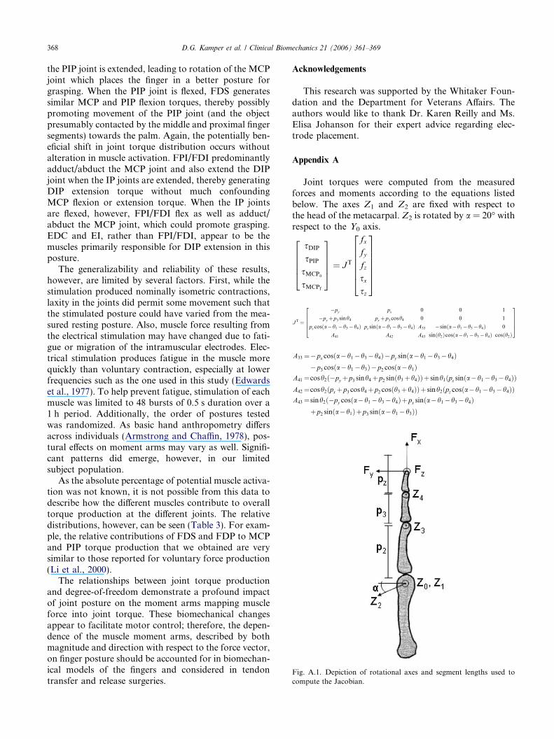
Fig. A.1. Depiction of rotational axes and segment lengths used tocompute the Jacobian.
368 D.G. Kamper et al. / Clinical Biomechanics 21 (2006) 361–369
the PIP joint is extended, leading to rotation of the MCPjoint which places the finger in a better posture forgrasping. When the PIP joint is flexed, FDS generatessimilar MCP and PIP flexion torques, thereby possiblypromoting movement of the PIP joint (and the objectpresumably contacted by the middle and proximal fingersegments) towards the palm. Again, the potentially ben-eficial shift in joint torque distribution occurs withoutalteration in muscle activation. FPI/FDI predominantlyadduct/abduct the MCP joint and also extend the DIPjoint when the IP joints are extended, thereby generatingDIP extension torque without much confoundingMCP flexion or extension torque. When the IP jointsare flexed, however, FPI/FDI flex as well as adduct/abduct the MCP joint, which could promote grasping.EDC and EI, rather than FPI/FDI, appear to be themuscles primarily responsible for DIP extension in thisposture.
The generalizability and reliability of these results,however, are limited by several factors. First, while thestimulation produced nominally isometric contractions,laxity in the joints did permit some movement such thatthe stimulated posture could have varied from the mea-sured resting posture. Also, muscle force resulting fromthe electrical stimulation may have changed due to fati-gue or migration of the intramuscular electrodes. Elec-trical stimulation produces fatigue in the muscle morequickly than voluntary contraction, especially at lowerfrequencies such as the one used in this study (Edwardset al., 1977). To help prevent fatigue, stimulation of eachmuscle was limited to 48 bursts of 0.5 s duration over a1 h period. Additionally, the order of postures testedwas randomized. As basic hand anthropometry differsacross individuals (Armstrong and Chaffin, 1978), pos-tural effects on moment arms may vary as well. Signifi-cant patterns did emerge, however, in our limitedsubject population.
As the absolute percentage of potential muscle activa-tion was not known, it is not possible from this data todescribe how the different muscles contribute to overalltorque production at the different joints. The relativedistributions, however, can be seen (Table 3). For exam-ple, the relative contributions of FDS and FDP to MCPand PIP torque production that we obtained are verysimilar to those reported for voluntary force production(Li et al., 2000).
The relationships between joint torque productionand degree-of-freedom demonstrate a profound impactof joint posture on the moment arms mapping muscleforce into joint torque. These biomechanical changesappear to facilitate motor control; therefore, the depen-dence of the muscle moment arms, described by bothmagnitude and direction with respect to the force vector,on finger posture should be accounted for in biomechan-ical models of the fingers and considered in tendontransfer and release surgeries.
Acknowledgements
This research was supported by the Whitaker Foun-dation and the Department for Veterans Affairs. Theauthors would like to thank Dr. Karen Reilly and Ms.Elisa Johanson for their expert advice regarding elec-trode placement.
Appendix A
Joint torques were computed from the measuredforces and moments according to the equations listedbelow. The axes Z1 and Z2 are fixed with respect tothe head of the metacarpal. Z2 is rotated by a = 20� withrespect to the Y0 axis.
sDIP
sPIPsMCPa
sMCPf
26664
37775 ¼ JT
fxfyfzsxsz
2666664
3777775
JT ¼
�py px 0 0 1
�py þp3 sinh4 px þp3 cosh4 0 0 1
pz cosða�h1�h3�h4Þ pz sinða�h1�h3�h4Þ A33 �sinða�h1�h3�h4Þ 0
A41 A42 A43 sinðh2Þcosða�h1�h3�h4Þ cosðh2Þ
26664
37775
A33 ¼�px cosða�h1�h3�h4Þ�py sinða�h1�h3�h4Þ�p3 cosða�h1�h3Þ�p2 cosða�h1Þ
A41 ¼cosh2ð�py þp3 sinh4þp2 sinðh3þh4ÞÞþ sinh1ðpz sinða�h1�h3�h4ÞÞA42 ¼cosh2ðpxþp3 cosh4þp2 cosðh3þh4ÞÞþ sinh2ðpz cosða�h1�h3�h4ÞÞA43 ¼sinh2ð�py cosða�h1�h3�h4Þþpx sinða�h1�h3�h4Þ
þp2 sinða�h1Þþp3 sinða�h1�h3ÞÞ
D.G. Kamper et al. / Clinical Biomechanics 21 (2006) 361–369 369
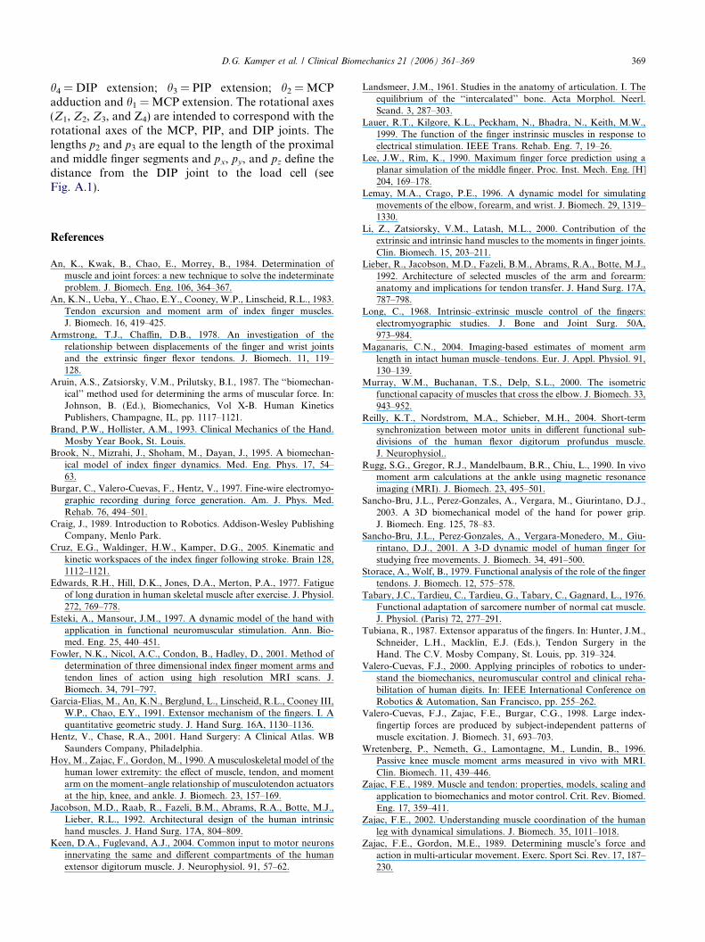
h4 = DIP extension; h3 = PIP extension; h2 = MCPadduction and h1 = MCP extension. The rotational axes(Z1, Z2, Z3, and Z4) are intended to correspond with therotational axes of the MCP, PIP, and DIP joints. Thelengths p2 and p3 are equal to the length of the proximaland middle finger segments and px, py, and pz define thedistance from the DIP joint to the load cell (seeFig. A.1).
References
An, K., Kwak, B., Chao, E., Morrey, B., 1984. Determination ofmuscle and joint forces: a new technique to solve the indeterminateproblem. J. Biomech. Eng. 106, 364–367.
An, K.N., Ueba, Y., Chao, E.Y., Cooney, W.P., Linscheid, R.L., 1983.Tendon excursion and moment arm of index finger muscles.J. Biomech. 16, 419–425.
Armstrong, T.J., Chaffin, D.B., 1978. An investigation of therelationship between displacements of the finger and wrist jointsand the extrinsic finger flexor tendons. J. Biomech. 11, 119–128.
Aruin, A.S., Zatsiorsky, V.M., Prilutsky, B.I., 1987. The ‘‘biomechan-ical’’ method used for determining the arms of muscular force. In:Johnson, B. (Ed.), Biomechanics, Vol X-B. Human KineticsPublishers, Champagne, IL, pp. 1117–1121.
Brand, P.W., Hollister, A.M., 1993. Clinical Mechanics of the Hand.Mosby Year Book, St. Louis.
Brook, N., Mizrahi, J., Shoham, M., Dayan, J., 1995. A biomechan-ical model of index finger dynamics. Med. Eng. Phys. 17, 54–63.
Burgar, C., Valero-Cuevas, F., Hentz, V., 1997. Fine-wire electromyo-graphic recording during force generation. Am. J. Phys. Med.Rehab. 76, 494–501.
Craig, J., 1989. Introduction to Robotics. Addison-Wesley PublishingCompany, Menlo Park.
Cruz, E.G., Waldinger, H.W., Kamper, D.G., 2005. Kinematic andkinetic workspaces of the index finger following stroke. Brain 128,1112–1121.
Edwards, R.H., Hill, D.K., Jones, D.A., Merton, P.A., 1977. Fatigueof long duration in human skeletal muscle after exercise. J. Physiol.272, 769–778.
Esteki, A., Mansour, J.M., 1997. A dynamic model of the hand withapplication in functional neuromuscular stimulation. Ann. Bio-med. Eng. 25, 440–451.
Fowler, N.K., Nicol, A.C., Condon, B., Hadley, D., 2001. Method ofdetermination of three dimensional index finger moment arms andtendon lines of action using high resolution MRI scans. J.Biomech. 34, 791–797.
Garcia-Elias, M., An, K.N., Berglund, L., Linscheid, R.L., Cooney III,W.P., Chao, E.Y., 1991. Extensor mechanism of the fingers. I. Aquantitative geometric study. J. Hand Surg. 16A, 1130–1136.
Hentz, V., Chase, R.A., 2001. Hand Surgery: A Clinical Atlas. WBSaunders Company, Philadelphia.
Hoy, M., Zajac, F., Gordon, M., 1990. A musculoskeletal model of thehuman lower extremity: the effect of muscle, tendon, and momentarm on the moment–angle relationship of musculotendon actuatorsat the hip, knee, and ankle. J. Biomech. 23, 157–169.
Jacobson, M.D., Raab, R., Fazeli, B.M., Abrams, R.A., Botte, M.J.,Lieber, R.L., 1992. Architectural design of the human intrinsichand muscles. J. Hand Surg. 17A, 804–809.
Keen, D.A., Fuglevand, A.J., 2004. Common input to motor neuronsinnervating the same and different compartments of the humanextensor digitorum muscle. J. Neurophysiol. 91, 57–62.
Landsmeer, J.M., 1961. Studies in the anatomy of articulation. I. Theequilibrium of the ‘‘intercalated’’ bone. Acta Morphol. Neerl.Scand. 3, 287–303.
Lauer, R.T., Kilgore, K.L., Peckham, N., Bhadra, N., Keith, M.W.,1999. The function of the finger instrinsic muscles in response toelectrical stimulation. IEEE Trans. Rehab. Eng. 7, 19–26.
Lee, J.W., Rim, K., 1990. Maximum finger force prediction using aplanar simulation of the middle finger. Proc. Inst. Mech. Eng. [H]204, 169–178.
Lemay, M.A., Crago, P.E., 1996. A dynamic model for simulatingmovements of the elbow, forearm, and wrist. J. Biomech. 29, 1319–1330.
Li, Z., Zatsiorsky, V.M., Latash, M.L., 2000. Contribution of theextrinsic and intrinsic hand muscles to the moments in finger joints.Clin. Biomech. 15, 203–211.
Lieber, R., Jacobson, M.D., Fazeli, B.M., Abrams, R.A., Botte, M.J.,1992. Architecture of selected muscles of the arm and forearm:anatomy and implications for tendon transfer. J. Hand Surg. 17A,787–798.
Long, C., 1968. Intrinsic–extrinsic muscle control of the fingers:electromyographic studies. J. Bone and Joint Surg. 50A,973–984.
Maganaris, C.N., 2004. Imaging-based estimates of moment armlength in intact human muscle–tendons. Eur. J. Appl. Physiol. 91,130–139.
Murray, W.M., Buchanan, T.S., Delp, S.L., 2000. The isometricfunctional capacity of muscles that cross the elbow. J. Biomech. 33,943–952.
Reilly, K.T., Nordstrom, M.A., Schieber, M.H., 2004. Short-termsynchronization between motor units in different functional sub-divisions of the human flexor digitorum profundus muscle.J. Neurophysiol..
Rugg, S.G., Gregor, R.J., Mandelbaum, B.R., Chiu, L., 1990. In vivomoment arm calculations at the ankle using magnetic resonanceimaging (MRI). J. Biomech. 23, 495–501.
Sancho-Bru, J.L., Perez-Gonzales, A., Vergara, M., Giurintano, D.J.,2003. A 3D biomechanical model of the hand for power grip.J. Biomech. Eng. 125, 78–83.
Sancho-Bru, J.L., Perez-Gonzales, A., Vergara-Monedero, M., Giu-rintano, D.J., 2001. A 3-D dynamic model of human finger forstudying free movements. J. Biomech. 34, 491–500.
Storace, A., Wolf, B., 1979. Functional analysis of the role of the fingertendons. J. Biomech. 12, 575–578.
Tabary, J.C., Tardieu, C., Tardieu, G., Tabary, C., Gagnard, L., 1976.Functional adaptation of sarcomere number of normal cat muscle.J. Physiol. (Paris) 72, 277–291.
Tubiana, R., 1987. Extensor apparatus of the fingers. In: Hunter, J.M.,Schneider, L.H., Macklin, E.J. (Eds.), Tendon Surgery in theHand. The C.V. Mosby Company, St. Louis, pp. 319–324.
Valero-Cuevas, F.J., 2000. Applying principles of robotics to under-stand the biomechanics, neuromuscular control and clinical reha-bilitation of human digits. In: IEEE International Conference onRobotics & Automation, San Francisco, pp. 255–262.
Valero-Cuevas, F.J., Zajac, F.E., Burgar, C.G., 1998. Large index-fingertip forces are produced by subject-independent patterns ofmuscle excitation. J. Biomech. 31, 693–703.
Wretenberg, P., Nemeth, G., Lamontagne, M., Lundin, B., 1996.Passive knee muscle moment arms measured in vivo with MRI.Clin. Biomech. 11, 439–446.
Zajac, F.E., 1989. Muscle and tendon: properties, models, scaling andapplication to biomechanics and motor control. Crit. Rev. Biomed.Eng. 17, 359–411.
Zajac, F.E., 2002. Understanding muscle coordination of the humanleg with dynamical simulations. J. Biomech. 35, 1011–1018.
Zajac, F.E., Gordon, M.E., 1989. Determining muscle’s force andaction in multi-articular movement. Exerc. Sport Sci. Rev. 17, 187–230.