Impact of Electromagnetic Stirring on the Gas Metal Arc ...
28
Page 1/28 Impact of Electromagnetic Stirring on the Gas Metal Arc Welding of an MAR-M247 Superalloy Yu-Chih Tzeng National Defense University Cheng-Yu Lu Nation Kaohsiung University of Science and Technology RenYu Chen ( [email protected] ) National Cheng Kung University Research Article Keywords: electromagnetic stirring, gas tungsten arc welding, MAR-M247, superalloy Posted Date: September 21st, 2021 DOI: https://doi.org/10.21203/rs.3.rs-902021/v1 License: This work is licensed under a Creative Commons Attribution 4.0 International License. Read Full License
-
Upload
khangminh22 -
Category
Documents
-
view
5 -
download
0
Transcript of Impact of Electromagnetic Stirring on the Gas Metal Arc ...

Page 1/28
Impact of Electromagnetic Stirring on the Gas MetalArc Welding of an MAR-M247 SuperalloyYu-Chih Tzeng
National Defense UniversityCheng-Yu Lu
Nation Kaohsiung University of Science and TechnologyRenYu Chen ( [email protected] )
National Cheng Kung University
Research Article
Keywords: electromagnetic stirring, gas tungsten arc welding, MAR-M247, superalloy
Posted Date: September 21st, 2021
DOI: https://doi.org/10.21203/rs.3.rs-902021/v1
License: This work is licensed under a Creative Commons Attribution 4.0 International License. Read Full License

Page 2/28
AbstractIn this paper, the impact of electromagnetic stirring (EMS) on the gas metal arc welding (GATW) of anMAR-M247 superalloy was investigated. Results revealed that, without electromagnetic stirring, it waseasy for carbides in the heat-affected zone (HAZ) of the weld bead to liquefy during welding, leading toweld bead cracks. Electromagnetic stirring re�ned the grains in the HAZ and the weld bead, leading tograin strengthening and subsequently resulting in the effective improvement in the hardness of the weldbead. In addition, electromagnetic stirring signi�cantly facilitated the formation of the weld bead by theremoval of large inclusions which in turn effectively improved crack resistance at the joint. It alsoaccelerated the �oating up of gas holes thereby reducing the generation of gas hole defects.
1. IntroductionMAR-M247 is a typical cast polycrystalline nickel-based superalloy, which was developed by MartinMarietta in the late 1970s [1]. It exhibits excellent castability at high temperatures, as well as satisfactorycreep resistance and hot corrosion resistance [2–9]; it is the main material used for the fabrication of gasturbine blades in the aviation and energy industries [8, 10]. The MAR-M247 superalloy exhibits anextremely complex composition, comprised of several solid-solution strengthening elements andprecipitation-hardening elements [7, 11–13]. Its microstructure mainly comprises austenite γ-phase base,γ' strengthening phase, γ-γ' eutectic structure [14–17], and various borides and carbides crystallized bysolidi�cation [14]. The Ni base exhibits limited solubility to these trace elements. The trace elementsinteract with Ni in the base during welding, to form a low-melting-point eutectic phase, and segregate atthe grain boundaries, leading to the precipitation of brittle carbides [18–20] during welding, resulting inclear hot cracks on the weld bead. This is also one of the main reasons that MAR-M247 is not applicablefor repair welding.
Generally, the Ni-base superalloys (e.g., Hastelloy x) can be welded by fusion welding, such as Gastungsten arc welding (GTAW), gas metal arc welding (GMAW), shield metal arc welding (SMAW), andsubmerged arc welding (SAW)[10]. However, owing to the poor thermal conductivity, strong viscosity ofthe liquid metal, and low oxidation resistance of the alloy elements [18], the molten pool of the MAR-M247 superalloy cannot be wetted and developed as easily as the molten pool of steel. Therefore, theformation of the weld bead is poor, its penetration is shallow, and �uidity cannot be improved even withan increase in the current, although the hot crack sensitivity of the weld bead can be increased by anincrease in the current. GTAW is typically used for the welding of Ni-based superalloys [22] exhibiting aclean surface after welding. However, if the welding heat input is high during the implementation of multi-pass welding, the eutectic structure of the low-melting-point weld head at the grain boundaries of the HAZis prone to liquefaction under welding stress, leading to defects in the HAZ, which can includeliquefaction defects, weld bead defects, humped weld bead defects, weld erosion, and gas holes.Therefore, it is crucial to employ a modi�ed welding method to solve this processing problem.

Page 3/28
Laser welding [23], electron-beam welding [24], friction stir welding [25, 26], and other advanced weldingmethods generate less welding stress, thereby helping to reduce welding hot cracks; however, thesewelding methods are not yet practically applicable in repair welding. Recently, electromagnetic welding(EMS) has come to be recognized as an effective method for facilitating bead formation, as well asenhancing the microstructure and mechanical properties of the weld [27–33]. EMS can effectivelydecrease welding defects, such as weld erosion, hump beads, gas holes, and cracks during fusionwelding. In 1971, Tseng and Savage [34] reported that electromagnetic stirring can improve the shapecoe�cient of the GTAW weld bead and reduce its sensitivity to hot cracking, consequently improvingcrack resistance. Under the application of an external magnetic �eld, the proportion of coarse grains inthe weld bead decreased, and �ne equiaxed grains were formed. The average grain size decreased,thereby enlarging the grain boundary area and enhancing the strengthening effect of the grainboundaries. Consequently, joint strength was improved. The addition of a magnetic �eld could facilitateoptimization of the distribution of inclusions in the weld bead. Inclusions are dispersed in the metal of theweld bead as second-phase particles, which serve as the base for the nucleation of weld bead grains.Magnetic stirring on the other hand can alleviate the segregation of alloying elements in the molten pool,thereby considerably reducing the tendency of hot cracking. In addition, it can change the mass transferand heat transfer processes of the molten pool [27] and the orientation of grain growth. Large angle grainorientations can increase the energy required for the development of hot cracks, thereby effectivelyhindering their expansion. Currently, ESM magnetic �eld control technology has been developed for metalwelding, including stainless steel [35–39], alµminµm alloys [32, 40–43], and magnesiµm alloys [44–47],but it has not been employed for welding of the MAR-M247 superalloy. Therefore, in this study, the effectsof GTAW with an EMS device on the mechanical properties and microstructure of the MAR-M247superalloy are explored.
2. ExperimentsTable 1 summarizes the composition of the MAR-M247 superalloy used in this experiment, and Fig. 1shows the equipment comprising the GTAW device along with the EMS device. The EMS metal is �xed ona welding gun, and EMS is powered by the magnetic-�eld power-supply equipment, which can adjust themagnitude of the current and the frequency of the external magnetic �eld. The GTAW welder is anautomatic welding machine, which utilizes an automatic wire feeding device and can automaticallydigitalize and adjust the wire feeding speed, movement speed, arc height, current, and voltage, to stabilizethe welding parameters for the welding process.
Table 1Chemical composition of the Mar-M247 superalloy
Alloy C Cr Co W Mo Ta Al Ti Hf Zr B Ni
Mar-M247 0.15 8.4 11.0 10.0 0.7 3.0 5.5 1.0 1.5 0.05 0.015 Bal.

Page 4/28
The welding methods (Fig. 2) selected herein are (1) bead-on-plate (BOP) and (2) V-shaped butt welding.In the BOP welding test, the alloy specimen is wire cut into 100 mm × 60 mm × 6 mm plates (Fig. 2 (a)),and welding is executed both with and without a Turbaloy@625 solder for analysis of the differences.Three-pass overlay welding is carried out using the Turbaloy@625 solder and another plate. In the v-buttwelding test, the MAR-M247 superalloy ingot is cut into V-shaped joints. The joints are grooved by wirecutting, with a side angle of 45° and a plate spacing of 5 mm (Fig. 2 (b)). Before welding, the joints areground down with sandpaper to remove any oxide �lm from the surface and in the groove. After grinding,the joints are cleaned with acetone, and v-butt GTAW and GTAW + EMS are conducted. Before v-buttwelding, the v-butt plate was subjected to a vacuum solution treatment at 1185°C for 2 h, followed bycooling to room temperature in an argon gas atmosphere, to eliminate residual stress from the specimen.After welding, the v-butt welding specimens were subjected to a vacuum solid solution treatment at1185°C for 2 h, followed by cooling to room temperature with argon. Subsequently, after 20 h of arti�cialaging in a vacuum at 871℃ the material is allowed to cool to room temperature in the furnace.
The heat input temperatures of GATW and GATW + EMS during welding are measured using an infraredthermometer. The alloy microstructure is observed using an optical microscope (Olympus BX60M). Themetallographic specimens are treated by coarse grinding, �ne grinding, and polishing. After polishing, themicrostructure of the alloy is observed under different magni�cations. Scanning electron microscopy(SEM, JEOL JAM-35Cf, acceleration voltage set at 15 kV) is employed to observe the morphology of theweld bead and fracture surface. The observations are utilized to understand the microstructure andfracture mechanism of the weld bead. Energy-dispersive spectrometry (EDS) is employed for semi-quantitative analysis of intermetallic compounds of the alloy and X-ray analysis is employed for thedetection and location of welding defects. Wire cutting and slow cutting machines are used to sample thedefects. After sampling, metallographic defects are observed and analyzed by SEM, and EDS and X-rayanalysis are employed to analyze the composition surrounding the defects to understand their causes.
The Vicker’s hardness test is employed to measure the hardness (load of 500 gf and a loading time of 10s) and analyze changes in the mechanical properties of the materials after welding. The 10-ton MTSuniversal testing machine is utilized for tensile testing, which is conducted in the stroke control mode.Throughout the entire process, the tensile test speed rate is divided into two sections: initially, it is 0.2mm/min, and when the strain is equal to 1%, it is switched to 2 mm/min.
3. Conclusions And Discussion
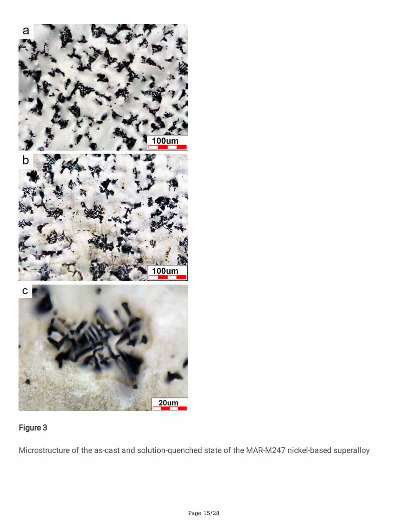
3.1. Microstructural analysisFigure 3 shows the microstructure of the as-cast and solution-quenched state of the MAR-M247 nickel-based superalloy. From the as-cast state (Fig. 3 (a)), the microstructure of MAR-M247 is mainlycomposed of the austenite γ phase and a number of Chinese script shaped carbides. However, we �nd nosigni�cant difference between the as-cast state and solution-quenched state (Fig. 3 (b)), indicating that

Page 5/28
the solution-quenched heat treatment does not produce signi�cant changes in the morphology of Chinesescript shaped carbides and that the carbides can reach up to 50 µm to 100 µm in size (Fig. 3 (c)).
Figure 4 shows the SEM microstructure of the solution-quenched state MAR-M247 nickel-basedsuperalloy. The microstructure of the solution-quenched state MAR-M247 austenite γ phase is clearlyobserved in the SEM images (as shown in Fig. 4(a)). In addition to the large number of Chinese scriptshaped carbides, the �ne γ' strengthening phase, rose-shaped γ-γ' eutectic structure, and thick plated γ'phase also are found (as shown in Fig. 4(b), 4(c) and 4(d)). Figure 5 shows the results of EPMA analysisof the Chinese script shaped carbides which are mainly composed of Ti, Ta, and Hf.
3.2. BOP welding analysisFigure 6 shows the arc shapes of GTAW and electromagnetic stirring assisted GTAW. The GATW carriedout without an external electromagnetic �eld exhibits a bell-shaped arc (Fig. 6 (a)), while GATW + EMSexhibits a meteor-shaped arc (Fig. 6 (b)). Figure 7 shows weld bead structure of the solution-quenchedstate MAR-M247 superalloy welded by bead-on-plane (BOP) welding. There are notably clear waves in theGATW weld bead, while the GATW + EMS weld bead is gentler and smoother, indicating that the quality ofthe GATW weld bead can be signi�cantly improved by the application of an electromagnetic �eld.
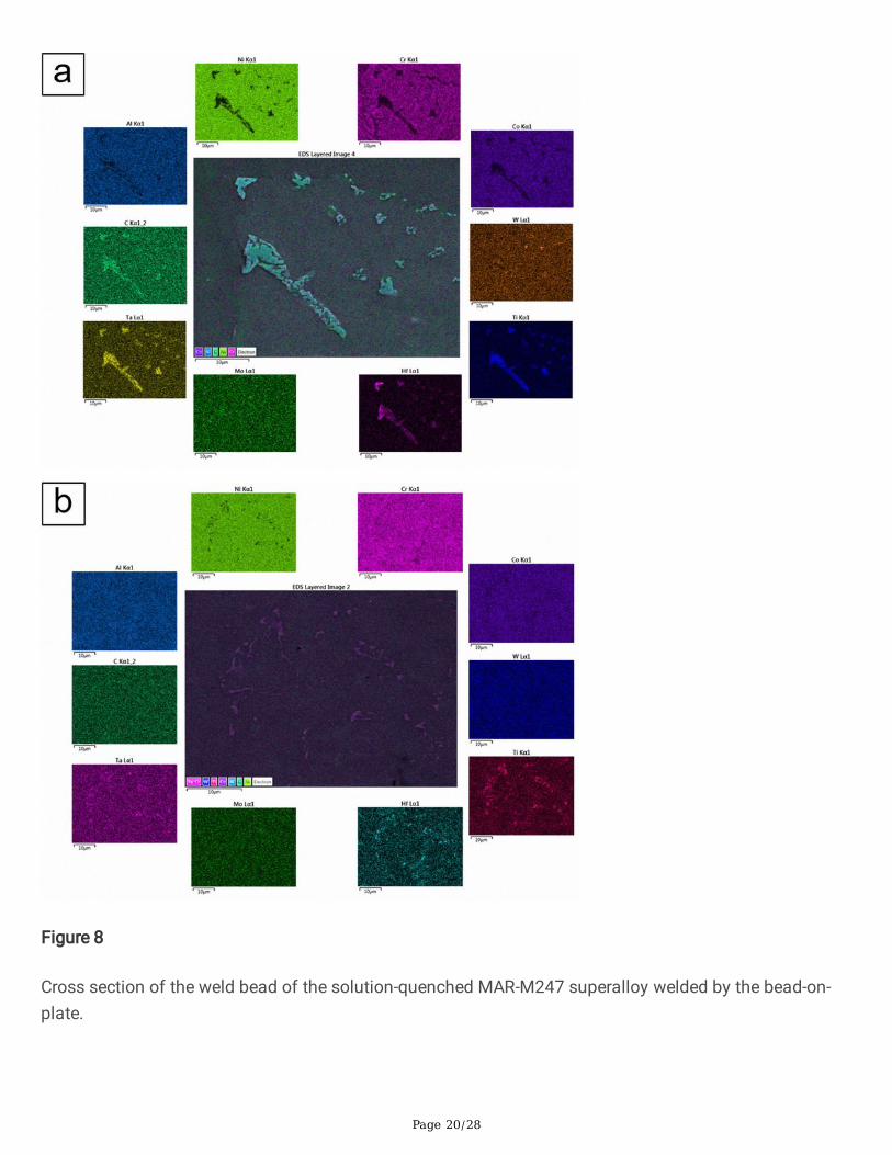
The microstructure of the weld bead and HAZ of the solution-quenched state MAR-M247 superalloywelded without solder is also observed (the image of marked 1 and 2 in Fig. 7). From the image ofmarked 1 in Fig. 7, it can be seen that the Chinese script shaped carbides in the weld bead molten zone ofthe GATW specimen are up to 50 µm in size, while those in the weld bead zone of the GATW + EMSspecimen are signi�cantly down to 10−15 µm (as shown in Fig. 7 within marked 2). This result indicatesthat the application of an external magnetic �eld can help to re�ne the Chinese script shape carbides inthe molten zone of the weld bead. In addition, the composition of the Chinese script shaped carbides inthe weld bead is analyzed by EPMA, and the results revealed them to be mainly comprised of Ti, Ta, andHf (Fig. 8).
Figure 9 shows a cross-section of the solution-quenched state MAR-M247 superalloy welded with BOPwelding. As can be observed in the �gure, the weld bead height of the GAWT and GATW + EMS specimensis 1.48 mm, but the weld bead widths of the GAWT and GATW + EMS specimens are 6.91 mm and 5.61mm, respectively, indicating that GAWT + EMS can effectively narrow the weld bead width andsubsequently increase the weld bead formation coe�cient from 4.66 to 3.79. The lower the weld beadformation coe�cient, the better the repair quality.
Figure 10 shows a cross-section of the microstructure of the GATW and GATW + EMS bead-on-plate weldbead and HAZ of the solution-quenched MAR-M247 superalloy welded with 625 solder. The width of thecolumnar grains of GATW is 25 µm, while that of GATW + EMS is only 15 µm. Notably, coarse grains ~ 200 µm in size are observed in the HAZ of the GATW specimen, but not in that of the GATW + EMSspecimen, indicating that the application of magnetic �eld can lead to an effective reduction of the grainsize in the molten zone and HAZ.

Page 6/28
3.3. BOP three-pass overlay weldingFigure 11 shows the appearance and X-ray inspection analysis chart of the GATW and GATW + EMSspecimens after three-pass overlay welding. As can be observed from the �gure, the width of the weldbead with a coverage of 50% after three-pass overlay welding is 9 mm, while that for GATW + EMS isclearly narrower, 7.7 mm. X-ray analysis reveals the presence of clear cracks in the GATW, but not in theGATW + EMS specimens, indicating that GATW + EMS can effectively reduce the generation of weldinghot cracks in the MAR-M247 superalloy.
The pattern of cracks produced by GATW three-pass overlay welding (Fig. 12) is observed usingmetallographic microscopy. It can be seen that Chinese script shaped carbides liquefy around the cracksduring welding solidi�cation, supposedly one of the main causes of welding cracks. The SEM imageswith EDS analysis (as shown Fig. 13) also show the cracks to be �lled with Chinese script shapedcarbides.
3.4. Impact of EMS on the weld bead temperatureFigure 14 shows the instantaneous temperature of the HAZ during the GATW and GATW + EMS weldingprocess measured using an infrared thermometer. As can be oved from the �gure, the effect of the arc onthe instantaneous temperature of the HAZ of the MAR-M247 specimen during the welding process ofGATW is observed at ~ 1600°C, while the instantaneous temperature during GATW + EMS can drop to ~ 1113°C, indicating that the effect of the heat input source of the arc on the HAZ can be considerablyreduced by the application of the external electromagnetic �eld speeding up the cooling rate of the weldpool. It is speculated that this is the main reason for the re�nement of the carbide size and grain size inthe HAZ.
3.5. Analysis of mechanical properties in V-shape buttwelding tests
3.5.1. HardnessThe hardness of v-butt welded specimens is measured along the center line of the welding cross sectionof the MAR-M247 superalloy welded with GATW and GATW + EMS. Figure 15 shows the results obtainedfrom hardness measurements. As shown in Fig. 16, the GATW and GATW + EMS welded joint can bedivided into three zones: the weld zone, the heat affected zone, and the base metal. The hardness of theweld zone of the GATW and GATW + EMS specimen exhibits the same trend. The hardness is lowest inthe center of the weld zone center and increases with the distance from the center. High hardness is stillexhibited in the base metal zone because it is far away from the weld zone and not much affected by thewelding heat input source. Note that the hardness values of the HAZ and weld zone center of the GATW + EMS specimen are signi�cantly greater than those produced by GATW. In addition, the results revealedthat the GATW + EMS hardness is better than that of GATW because GATW + EMS can effectively re�nethe grains in the HAZ and the weld zone, re�ecting the grain strengthening effect.

Page 7/28
3.5.2. Tensile propertiesFigure 16 shows the tensile mechanical properties of the GATW and GATW + EMS welded specimens ofthe MAR-M247 superalloy after heat treatment. The Young’s modulus, yield strength, tensile strength, andductility of the GATW-welded specimens are 191 GPa, 785 MPa, 891 MPa, and 2.5%, respectively, whilethose of the GATW + EMS-welded specimens are 199 GPa, 800 MPa, 930 MPa, and 3.4%, respectively.The results revealed that the magnetic �eld can effectively improve the tensile mechanical properties ofGATW weldments, which match the Engine Material Speci�cation EMS-55447 [48].
3.5.3. Tensile fracture surfaceFigure 17 shows the tensile fracture surfaces of the GATW and GATW + EMS-welded specimens of theMAR-M247 superalloy. As can be seen in the �gure, there is a clearly observable cleavage surface on thefracture surface of the GATW-welded specimen, while the fracture surface of the GATW + EMS specimenis mainly a dimpled structure, indicating that the ductility of the GATW + EMS-welded specimen is betterthan that of the GATW-welded specimen, which is consistent with the results observed from the tensileproperty analysis.
4. Conclusion1. The as-cast state MAR-M247 matrix is mainly composed of the austenite γ phase, and the γ’ phase,
Chinese script shaped carbides, γ-γ’ eutectic structures, and thick-plate γ‘. These carbides are mainlycomposed of Ti, Ta, and Hf, which are widely and evenly distributed in the MAR-M247 matrix.Furthermore, the solid-solution heat treatment does not lead to any signi�cant change in themorphology of the Chinese script shaped carbides in the MAR-M247 alloy.
2. The results revealed that without the application of the electromagnetic �eld, a bell-shaped GATW arcis observed, and carbides in the HAZ of the GATW weld bead are easily lique�ed due to the input ofconsiderable heat during welding, thereby leading to welding cracks. Results also revealed thatGATW + EMS exhibited a meteor-shaped arc, which can considerably decrease the weld beadtemperature, improve the WRFF coe�cient, and reduce the generation of hot cracks.
3. GATW + EMS can dramatically reduce the effect of the arc heat input source on the weldedworkpieces, and can further re�ne the size of carbides in the weld bead as well as the size of grainsin the HAZ, effectively improving the mechanical properties.
DeclarationsFunding (information that explains whether and by whom the research was supported)
Not applicable
Con�icts of interest/Competing interests (include appropriate disclosures)

Page 8/28
I would like to declare on behalf of my co-authors that the work described was original research that hasnot been published previously, and not under consideration for publication elsewhere, in whole or in part.To the best of our knowledge, the named authors have no con�ict of interest, �nancial or otherwise.
Availability of data and material (data transparency)
Not applicable
Code availability (software application or custom code)
Not applicable
Ethics approval (include appropriate approvals or waivers)
Not applicable
Consent to participate (include appropriate statements)
Not applicable
Consent for publication (include appropriate statements)
Not applicable
Authors' contributions (optional: please review the submission guidelines from the journal whetherstatements are mandatory)
Dr. Tzeng Yu-Chih: Conceptualization, Methodology, Investigation, Supervision, Funding acquisition,Validation, Writing - review & editing. Dr. Lu Cheng-Yu: Conceptualization, Investigation & Validation. Allauthors equally contributed the overall manuscript. Dr. Chen Ren-Yu: Conceptualization, Investigation,Methodology, Writing - original draft, Writing - review & editing.
References1. M. Morinaga, N. Yukawa, H. Adachi, H. Ezaki, (1984) New PHACOMP and its applications to alloy
design, Superalloys 1984, 523-532. https://doi.org/10.7449/1984/Superalloys_1984_523_532
2. M. Kvapilova, J. Dvorak, P. Kral, K. Hrbacek, V. Sklenicka, (2019) Creep behaviour and life assessmentof a cast nickel–base superalloy MAR–M247, High Temperature Materials and Processes, 38(2019),590-600. https://doi.org/10.1515/htmp-2019-0006
3. P.R.S. Azevedo e Silva, R. Baldan, C.A. Nunes, G.C. Coelho, A.M.d.S. Costa, (2013) Solution heat-treatment of Nb-modi�ed MAR-M247 superalloy, Materials Characterization, 75, 214-219. https://doi.org/10.1016/j.matchar.2012.11.006
4. H.S. Whitesell, R.A. Overfelt, (2001) In�uence of solidi�cation variables on the microstructure,macrosegregation, and porosity of directionally solidi�ed Mar-M247, Materials Science and
Page 9/28
Engineering: A, 318(1-2), 264-276. https://doi.org/10.1016/s0921-5093(01)01264-3
5. M. Okada, M. Tsutsumi, T. Kitamura, R. Ohtani, (2010) Initiation and Growth of Small Cracks inDirectionally Solidi�ed Mar‐M247 under Creep‐Fatigue. Part I: Effect of Microstructure, Fatigue &Fracture of Engineering Materials & Structures, 21(6), 741-750. https://doi.org/10.1046/j.1460-2695.1998.00540.x
�. H. Bor, C. Chao, C. Ma, (1997) The in�uence of magnesium on carbide characteristics and creepbehavior of the Mar-M247 superalloy, Scripta materialia, 38(2), 329-335. https://doi.org/0.1016/S1359-6462(97)00444-2
7. R. Baldan, P.R.S. Azevedo e Silva, C.A. Nunes, G.C. Coelho, (2013) Aging of a New Niobium-Modi�edMAR-M247 Nickel-Based Superalloy, Journal of Materials Engineering and Performance, 22(8), 2337-2342. https://doi.org/10.1007/s11665-013-0531-1
�. H.Y. Bor, C.N. Wei, R.R. Jeng, P.Y. Ko, (2008) Elucidating the effects of solution and double ageingtreatment on the mechanical properties and toughness of MAR-M247 superalloy at high temperature,Materials Chemistry and Physics, 109(2-3), 334-341. https://doi.org/10.1016/j.matchemphys.2007.11.041
9. Y. Hagedorn, J. Risse, W. Meiners, N. Pirch, K. Wissenbach, R. Poprawe, Processing of nickel basedsuperalloy MAR M-247 by means of High Temperature-Selective Laser Melting (HT-SLM),Proceedings of the 6th International Conference on Advanced Resarch in Virtual and RapidPrototyping, 2013, pp 291-295. https://doi.org/10.1201/b15961-54
10. M. Kaufman, (1984) Properties of cast Mar-M-247 for turbine blisk applications, Superalloys 1984,43-52. https://doi.org/10.7449/1984/Superalloys_1984_43_52
11. M.-c. Liu, G.-m. Sheng, H.-j. He, Y.-j. Jiao, (2017) Microstructural evolution and mechanical propertiesof TLP bonded joints of Mar-M247 superalloys with Ni-Cr-Co-W-Ta-B interlayer, Journal of MaterialsProcessing Technology, 246, 245-251. https://doi.org/10.1016/j.jmatprotec.2017.03.021
12. M. Rahimian, S. Milenkovic, I. Sabirov, (2013) Microstructure and hardness evolution in MAR-M247Ni-based superalloy processed by controlled cooling and double heat treatment, Journal of Alloysand Compounds, 550, 339-344. https://doi.org/10.1016/j.jallcom.2012.10.129
13. M.V. Nathal, L.J. Ebert, (1985) The in�uence of cobalt, tantalum, and tungsten on the microstructureof single crystal nickel-base superalloys, Metallurgical Transactions A, 16(10), 1849-1862. https://doi.org/10.1007/bf02670372
14. K.L. Gasko, G.M. Janowski, B.J. Pletka, (1988) The in�uence of γ-γ′ eutectic on the mechanicalproperties of conventionally cast MAR-M247, Materials Science and Engineering: A, 104, 1-8. https://doi.org/10.1016/0025-5416(88)90400-4
15. R. Baldan, R.L.P. da Rocha, R.B. Tomasiello, C.A. Nunes, A.M. da Silva Costa, M.J.R. Barboza, G.C.Coelho, R. Rosenthal, (2013) Solutioning and Aging of MAR-M247 Nickel-Based Superalloy, Journalof Materials Engineering and Performance, 22(9), 2574-2579. https://doi.org/10.1007/s11665-013-0565-4

Page 10/28
1�. J.-H. Liao, H.-Y. Bor, C.-N. Wei, C.-G. Chao, T.-F. Liu, (2012) In�uence of microstructure and itsevolution on the mechanical behavior of modi�ed MAR-M247 �ne-grain superalloys at 871°C,Materials Science and Engineering: A, 539, 93-100. https://doi.org/10.1016/j.msea.2012.01.059
17. 17. S. Milenkovic, I. Sabirov, J. Llorca, (2012) Effect of the cooling rate on microstructure andhardness of MAR-M247 Ni-based superalloy, Materials Letters, 73, 216-219. https://doi.org/10.1016/j.matlet.2012.01.028
1�. Ł. Rakoczy, M. Grudzień, A. Zielińska-Lipiec, (2018) Contribution of microstructural constituents onhot cracking of MAR-M247 nickel based superalloy, Archives of Metallurgy and Materials, 63, https://doi.org/10.24425/118926
19. S.R. Yeratapally, J.D. Hochhalter, T.J. Ruggles, M.D. Sangid, (2017) Investigation of fatigue crackincubation and growth in cast MAR-M247 subjected to low cycle fatigue at room temperature,International Journal of Fracture, 208(1-2), 79-96. https://doi.org/10.1007/s10704-017-0213-3
20. S. Eckmann, C. Schweizer, (2017) Characterization of fatigue crack growth, damage mechanismsand damage evolution of the nickel-based superalloys MAR-M247 CC (HIP) and CM-247 LC underthermomechanical fatigue loading using in situ optical microscopy, International Journal of Fatigue,99, 235-241. https://doi.org/10.1016/j.ijfatigue.2017.01.015
21. M. Reza Abedi, S. Hamed;, R. Hossein, (2016) The Effect of Repair Welding Number on Microstructureof Hastelloy X Fabricated via TIG Process, International Journal of Materials Science andApplications, 5(2), 43-48. https://doi.org/10.11648/j.ijmsa.20160502.12
22. Q. Wang, D.L. Sun, Y. Na, Y. Zhou, X.L. Han, J. Wang, (2011) Effects of TIG Welding Parameters onMorphology and Mechanical Properties of Welded Joint of Ni-base Superalloy, Procedia Engineering,10, 37-41. https://doi.org/10.1016/j.proeng.2011.04.009
23. Z. Li, S.L. Gobbi, K.H. Richter, (1997) Autogenous welding of Hastelloy X to Mar-M 247 by laser,Journal of Materials Processing Technology, 70(1-3), 285-292. https://doi.org/10.1016/s0924-0136(97)02939-7
24. B. Böttger, M. Apel, T. Jokisch, A. Senger, Phase-�eld study on microstructure formation in Mar-M247during electron beam welding and correlation to hot cracking susceptibility, IOP Conference Series:Materials Science and Engineering, 2020, IOP Publishing, p 012072. https://doi.org/10.1088/1757-899X/861/1/012072
25. O.N. Senkov, D.W. Mahaffey, S.L. Semiatin, C. Woodward, (2014) Inertia Friction Welding of DissimilarSuperalloys Mar-M247 and LSHR, Metallurgical and Materials Transactions A, 45(12), 5545-5561. https://doi.org/10.1007/s11661-014-2512-x
2�. D.W. Mahaffey, O.N. Senkov, R. Shivpuri, S.L. Semiatin, (2016) Effect of Process Variables on theInertia Friction Welding of Superalloys LSHR and Mar-M247, Metallurgical and MaterialsTransactions A, 47(8), 3981-4000. https://doi.org/10.1007/s11661-016-3600-x
27. H. Wu, Y. Chang, L. Lu, J. Bai, (2017) Review on magnetically controlled arc welding process, TheInternational Journal of Advanced Manufacturing Technology, 91(9-12), 4263-4273. https://doi.org/10.1007/s00170-017-0068-9

Page 11/28
2�. S.Y. Jiang, X.W. Wang, H.M. Chen, P. Liu, The impact of adscititious longitudinal magnetic �eld onCO2 welding process, Advanced Materials Research, 2012, Trans Tech Publ, pp 1447-1450. https://doi.org/10.4028/www.scienti�c.net/AMR.538-541.1447
29. T. Watanabe, H. Nakamura, K. Ei, (2010) Grain re�nement by TIG welding with electromagneticstirring - a study of solidi�cation control of austenitic stainless steel weld metal, WeldingInternational, 3(4), 312-317. https://doi.org/10.1080/09507118909447649
30. Y.C. Lim, X. Yu, J.H. Cho, J. Sosa, D.F. Farson, S.S. Babu, S. McCracken, B. Flesner, (2013) Effect ofmagnetic stirring on grain structure re�nement Part 2 – Nickel alloy weld overlays, Science andTechnology of Welding and Joining, 15(5), 400-406. https://doi.org/10.1179/136217110x12720264008231
31. S.-L. Jeng, D.-P. Su, J.-T. Lee, J.-Y. Huang, (2020) The Impact of EMS on the TemperatureFluctuations, Appearance, and Microstructure of GTA Stainless Steel Welds, Metals, 10(1),118. https://doi.org/10.3390/met10010118
32. Y. Liu, Q. Sun, J. Liu, S. Wang, J. Feng, (2015) Effect of axial external magnetic �eld on cold metaltransfer welds of aluminum alloy and stainless steel, Materials Letters, 152, 29-31. https://doi.org/10.1016/j.matlet.2015.03.077
33. S.-L. Jeng, D.-P. Su, J.-T. Lee, J.-Y. Huang, (2018) Effects of Electromagnetic Stirring on the CastAustenitic Stainless Steel Weldments by Gas Tungsten Arc Welding, Metals, 8(8),630. https://doi.org/10.3390/met8080630
34. T. Tsang, D. Savage, (1971) The effect of arc oscillation in either transverse or longitudinal directionhas bene�cial effect on the fusion zone microstructure and tends to reduce sensitivity in hotcracking, Welding J, 50(11), 777-786.
35. R. Chen, P. Jiang, X. Shao, G. Mi, C. Wang, (2017) Effect of static magnetic �eld on microstructuresand mechanical properties of laser-MIG hybrid welding for 304 stainless steel, The InternationalJournal of Advanced Manufacturing Technology, 91(9-12), 3437-3447. https://doi.org/10.1007/s00170-017-0006-x
3�. M. Malinowski-Brodnicka, G. Den Ouden, W. Vink, (1990) Effect of electromagnetic stirring on GTAwelds in austenitic stainless steel, Welding journal, 2(2), 52s-59s.
37. G.R.M. Arturo, L.M.V. Hugo, G.H. Rafael, B.B. Egberto, G.S.J. Antonio, (2015) ElectrochemicalCharacterization of AISI 2205 Duplex Stainless Steel Welded Joints with Electromagnetic Interaction,Procedia Materials Science, 8, 950-958. https://doi.org/10.1016/j.mspro.2015.04.156
3�. F.F. Curiel, R. García, V.H. López, J. González-Sánchez, (2011) Effect of magnetic �eld applied duringgas metal arc welding on the resistance to localised corrosion of the heat affected zone in AISI 304stainless steel, Corrosion Science, 53(7), 2393-2399. https://doi.org/10.1016/j.corsci.2011.03.022
39. M. Shoichi, M. Yukio, T. Koki, T. Yasushi, M. Yukinori, M. Yusuke, (2013) Study on the application forelectromagnetic controlled molten pool welding process in overhead and �at position welding,Science and Technology of Welding and Joining, 18(1), 38-44. https://doi.org/10.1179/1362171812y.0000000070

Page 12/28
40. V.V. Avilov, A. Gumenyuk, M. Lammers, M. Rethmeier, (2013) PA position full penetration high powerlaser beam welding of up to 30 mm thick AlMg3 plates using electromagnetic weld pool support,Science and Technology of Welding and Joining, 17(2), 128-133. https://doi.org/10.1179/1362171811y.0000000085
41. B.P. Pearce, H.W. Kerr, (1981) Grain re�nement in magnetically stirred GTA welds of aluminum alloys,Metallurgical Transactions B, 12(3), 479-486. https://doi.org/10.1007/bf02654317
42. W.D. Gri�ths, D.G. McCartney, (1997) The effect of electromagnetic stirring on macrostructure andmacrosegregation in the aluminium alloy 7150, Materials Science and Engineering: A, 222(2), 140-148. https://doi.org/10.1016/s0921-5093(96)10527-x
43. Z.H. Gao, J. Xu, Z.F. Zhang, M.O. Tang, Effect of annular electromagnetic stirring on microstructureand mechanical property of 7075 aluminium alloy, Materials Science Forum, 2013, Trans Tech Publ,pp 75-81. https://doi.org/10.4028/www.scienti�c.net/MSF.749.75
44. Y. Chen, F.F. Sui, K.L. Cong, X.Q. Yan, G.Y. Zhang, S.K. Guan, Effects of shielding gas and magnetic�eld on characteristics of AZ31 magnesium alloy by TIG welding, Materials Science Forum, 2012,Trans Tech Publ, pp 1186-1196. https://doi.org/10.4028/www.scienti�c.net/MSF.704-705.1186
45. Q. Yao, Z. Luo, Y. Li, F.Y. Yan, R. Duan, (2014) Effect of electromagnetic stirring on the microstructuresand mechanical properties of magnesium alloy resistance spot weld, Materials & Design, 63, 200-207. https://doi.org/10.1016/j.matdes.2014.06.004
4�. X.-l. Zhang, T.-j. Li, H.-t. Teng, S.-s. Xie, J.-z. Jin, (2008) Semisolid processing AZ91 magnesium alloyby electromagnetic stirring after near-liquidus isothermal heat treatment, Materials Science andEngineering: A, 475(1-2), 194-201. https://doi.org/10.1016/j.msea.2007.04.049
47. Y. Chen, L. Zhang, W. Liu, G. Wu, W. Ding, (2016) Preparation of Mg–Nd–Zn–(Zr) alloys semisolidslurry by electromagnetic stirring, Materials & Design, 95, 398-409.https://doi.org/10.1016/j.matdes.2016.01.131
4�. H.Y. Bor, C.G. Chao, C.Y. Ma, (1999) The effects of Mg microaddition on the mechanical behavior andfracture mechanism of MAR-M247 superalloy at elevated temperatures, Metallurgical and MaterialsTransactions A, 30(3), 551-561. https://doi.org/10.1007/s11661-999-0047-3
Figures

Page 13/28
Figure 1
Schematic representation illustrating the assistance of the external magnetic �eld to GATW welding.

Page 14/28
Figure 2
Welding methods: (a) bead-on-plate welding (BOP); (b) v-butt welding.
Page 15/28
Figure 3
Microstructure of the as-cast and solution-quenched state of the MAR-M247 nickel-based superalloy

Page 16/28
Figure 4
MAR-M247: (a) as-cast; (b) solution-quenched; and (c) Chinese script shaped carbide microstructure.

Page 17/28
Figure 5
SEM microstructure of the solution-quenched MAR-M247 superalloy: (a) basic microstructure; (b) Chinesescript shaped carbide; (c) thick-plate microstructure of the γ' phase; (d) rose-shaped γ-γ' eutectic structure.

Page 18/28
Figure 6
EPMA compositional analysis of Chinese script shaped carbides.

Page 19/28
Figure 7
Solution-quenched MAR-M247 with Bead-on-plate welding and the microstructure of the weld bead andHAZ zone without using a Turbalay@625 solder. Marked 1 in the �gure is the OM image of the GTAW.Marked 2 in the �gure is the OM image of the GTAW+EMS.
Page 20/28
Figure 8
Cross section of the weld bead of the solution-quenched MAR-M247 superalloy welded by the bead-on-plate.

Page 21/28
Figure 9
EPMA compositional analysis: (a) GATW weld bead Chinese script shaped carbide, and (b) GATW + EMSweld bead Chinese script shaped carbide.

Page 22/28
Figure 10
Microstructure of the weld bead and HAZ of GATW and GATW+ EMS on the specimens of solution-quenched MAR-M247 superalloy welded with using a Turbalay@625 solder.

Page 23/28
Figure 11
Three-pass overlay weld and X-ray analysis: (a) GATW; and (b) GATW + EMS.

Page 24/28
Figure 12
Welding crack morphology in the three-pass GATW overlay.
Figure 13
(a)SEM images and (b) energy dispersive spectrometer (EDS) analysis for the crack within three-passGATW overlay.

Page 25/28
Figure 14
Instantaneous temperature of GATW and GATW + EMS arc passing through the central point of the HAZof the welded workpiece measured using an infrared thermometer during the welding process.

Page 26/28
Figure 15
Hardness value of GATW and GATW + EMS welding along the center line of the welding cross section.

Page 27/28
Figure 16
Tensile mechanical properties of GATW and GATW + EMS welded specimens of the MAR-M247superalloy after heat treatment.

Page 28/28
Figure 17
Tensile fracture surface of (a) GATW; and (b) GATW + EMS-welded specimens of the MAR-M247superalloy.