Imaging of the retinal nerve fibre layer for glaucoma
9
Imaging of the retinal nerve fibre layer for glaucoma K A Townsend 1 , G Wollstein 1 , and J S Schuman 1,2,3 1 UPMC Eye Center, Eye and Ear Institute, Ophthalmology and Visual Science Research Center, Department of Ophthalmology, University of Pittsburgh School of Medicine, Pittsburgh, Pennsylvania, USA 2 Department of Bioengineering, Swanson School of Engineering, University of Pittsburgh, Pittsburgh, Pennsylvania, USA 3 Center for the Neural Basis of Cognition, Carnegie Mellon University and University of Pittsburgh, Pittsburgh, Pennsylvania, USA Abstract Background—Glaucoma is a group of diseases characterised by retinal ganglion cell dysfunction and death. Detection of glaucoma and its progression are based on identification of abnormalities or changes in the optic nerve head (ONH) or the retinal nerve fibre layer (RNFL), either functional or structural. This review will focus on the identification of structural abnormalities in the RNFL associated with glaucoma. Discussion—A variety of new techniques have been created and developed to move beyond photography, which generally requires subjective interpretation, to quantitative retinal imaging to measure RNFL loss. Scanning laser polarimetry uses polarised light to measure the RNFL birefringence to estimate tissue thickness. Optical coherence tomography (OCT) uses low- coherence light to create high-resolution tomographic images of the retina from backscattered light in order to measure the tissue thickness of the retinal layers and intraretinal structures. Segmentation algorithms are used to measure the thickness of the retinal nerve fibre layer directly from the OCT images. In addition to these clinically available technologies, new techniques are in the research stages. Polarisation-sensitive OCT has been developed that combines the strengths of scanning laser polarimetry with those of OCT. Ultra-fast techniques for OCT have been created for research devices. The continued utilisation of imaging devices into the clinic is refining glaucoma assessment. In the past 20 years glaucoma has gone from a disease diagnosed and followed using highly subjective techniques to one measured quantitatively and increasingly objectively. Glaucoma is a disease that is identified biologically by the death of retinal ganglion cells. The axons of these cells make up the retinal nerve fibres that gather at the optic nerve head and form the anterior-most layer of the retina. As retinal ganglion cells are lost, through processes not yet fully understood, the retinal nerve fibres are also lost, and this layer thins. These defects can often be observed during fundus examination of patients, or in red-free fundus photographs of the optic disc and surrounding retina. Areas of retinal nerve fibre layer (RNFL) loss are less brightly reflective, and can show up as dark bands radiating out from the disc, following the typical arcuate paths of the nerve fibre bundles. However, Correspondence to: Professor J S Schuman, UPMC Eye Center, Eye and Ear Institute, Department of Ophthalmology, University of Pittsburgh School of Medicine, 203 Lothrop Street, Suite 816, Pittsburgh, PA 15213, USA; [email protected]. Competing interests: JSS receives royalties for intellectual property licensed by Massachusetts Institute of Technology to Carl Zeiss Meditec. GW received research funding from Carl Zeiss Meditec and Optovue. JSS received honoraria from Carl Zeiss Meditec, Heidelberg Engineering and Optovue. KAT reports no conflicts. NIH Public Access Author Manuscript Br J Ophthalmol. Author manuscript; available in PMC 2010 July 20. Published in final edited form as: Br J Ophthalmol. 2009 February ; 93(2): 139–143. doi:10.1136/bjo.2008.145540. NIH-PA Author Manuscript NIH-PA Author Manuscript NIH-PA Author Manuscript
Transcript of Imaging of the retinal nerve fibre layer for glaucoma

Imaging of the retinal nerve fibre layer for glaucoma
K A Townsend1, G Wollstein1, and J S Schuman1,2,31UPMC Eye Center, Eye and Ear Institute, Ophthalmology and Visual Science Research Center,Department of Ophthalmology, University of Pittsburgh School of Medicine, Pittsburgh,Pennsylvania, USA2Department of Bioengineering, Swanson School of Engineering, University of Pittsburgh,Pittsburgh, Pennsylvania, USA3Center for the Neural Basis of Cognition, Carnegie Mellon University and University ofPittsburgh, Pittsburgh, Pennsylvania, USA
AbstractBackground—Glaucoma is a group of diseases characterised by retinal ganglion celldysfunction and death. Detection of glaucoma and its progression are based on identification ofabnormalities or changes in the optic nerve head (ONH) or the retinal nerve fibre layer (RNFL),either functional or structural. This review will focus on the identification of structuralabnormalities in the RNFL associated with glaucoma.
Discussion—A variety of new techniques have been created and developed to move beyondphotography, which generally requires subjective interpretation, to quantitative retinal imaging tomeasure RNFL loss. Scanning laser polarimetry uses polarised light to measure the RNFLbirefringence to estimate tissue thickness. Optical coherence tomography (OCT) uses low-coherence light to create high-resolution tomographic images of the retina from backscattered lightin order to measure the tissue thickness of the retinal layers and intraretinal structures.Segmentation algorithms are used to measure the thickness of the retinal nerve fibre layer directlyfrom the OCT images. In addition to these clinically available technologies, new techniques are inthe research stages. Polarisation-sensitive OCT has been developed that combines the strengths ofscanning laser polarimetry with those of OCT. Ultra-fast techniques for OCT have been createdfor research devices. The continued utilisation of imaging devices into the clinic is refiningglaucoma assessment. In the past 20 years glaucoma has gone from a disease diagnosed andfollowed using highly subjective techniques to one measured quantitatively and increasinglyobjectively.
Glaucoma is a disease that is identified biologically by the death of retinal ganglion cells.The axons of these cells make up the retinal nerve fibres that gather at the optic nerve headand form the anterior-most layer of the retina. As retinal ganglion cells are lost, throughprocesses not yet fully understood, the retinal nerve fibres are also lost, and this layer thins.These defects can often be observed during fundus examination of patients, or in red-freefundus photographs of the optic disc and surrounding retina. Areas of retinal nerve fibrelayer (RNFL) loss are less brightly reflective, and can show up as dark bands radiating outfrom the disc, following the typical arcuate paths of the nerve fibre bundles. However,
Correspondence to: Professor J S Schuman, UPMC Eye Center, Eye and Ear Institute, Department of Ophthalmology, University ofPittsburgh School of Medicine, 203 Lothrop Street, Suite 816, Pittsburgh, PA 15213, USA; [email protected] interests: JSS receives royalties for intellectual property licensed by Massachusetts Institute of Technology to Carl ZeissMeditec. GW received research funding from Carl Zeiss Meditec and Optovue. JSS received honoraria from Carl Zeiss Meditec,Heidelberg Engineering and Optovue. KAT reports no conflicts.
NIH Public AccessAuthor ManuscriptBr J Ophthalmol. Author manuscript; available in PMC 2010 July 20.
Published in final edited form as:Br J Ophthalmol. 2009 February ; 93(2): 139–143. doi:10.1136/bjo.2008.145540.
NIH
-PA Author Manuscript
NIH
-PA Author Manuscript
NIH
-PA Author Manuscript

imaging of the en face view of the retinal nerve fibre layer (RNFL) can only provideinformation primarily about location and width of the defects, but not specific quantitativeinformation about the depth or extent of the tissue loss. Additionally, diffuse loss leading tooverall RNFL thinning can be much harder to detect on a red-free view, and identification ofdefects on standard colour photographs can be challenging. Fundus photography can providegood qualitative information about glaucomatous damage indicators such as ONH cuppingand the presence of optic disc haemorrhages, but more recent advances in ocular imagingtechnology promise to provide much more objective and quantitative information about thehealth and thickness of the retinal never fibre layer. This review aims to cover thetechnologies currently available clinically for imaging of the RNFL, as well as newtechniques that show great potential for future clinical utility.
SCANNING LASER POLARIMETRYThis imaging technique, demonstrated ex vivo in 1990 and demonstrated in vivo inglaucoma in 1995,1 2 takes advantage of the optical properties of the parallel bundled retinalnerve fibres. The neural axons are essentially a series of thin cylinders with diameterssmaller than the wavelength of near-infrared visible light. Because of their size, and perhapsalso related to the intracellular arrangement of structures such as microtubules andmitochondria, the tissue is birefringent, such that reflected polarised light undergoes a phaseshift corresponding to the amount of birefringent tissue through which it passed. In the eyethis is proportional to the thickness of the RNFL. This phase shift can be mapped across theretina by scanning the light across the area of interest, in this case the region centred on theONH. Measurements of the retinal birefringence can be mapped as estimated RNFLthickness based on a conversion from 0.67 nm of retardation equal to 1 µm of fibre.2Compensation is made for the birefringence elsewhere in the eye, such as that inherent in thecornea, lens, retinal pigment epithelium and sclera, so that the confounding influence ofthese structures on the retinal measurements is minimised.
Numerous papers have been published establishing the relationship between the phase shiftand true RNFL thickness in both healthy patients and patients with glaucomatous loss,3 4and the measurements were found to be reproducible within a time period when structuralchange has not occurred.5 6 Since these basics of the technology were established, manystudies have tested the ability of both the early clinical device, the Nerve Fibre Analyzer(Laser Diagnostic Technologies, San Diego, California), and the current device used mostpredominantly clinically, the GDx (Carl Zeiss Meditec, Vista, California).7–11 The GDxcompensates for corneal birefringence with either the Variable Cornea Compensation (GDxVCC) or the more advanced Enhanced Corneal Compensation (GDx ECC).12 The newerGDx ECC has been shown to produce more reproducible results and allow for more accuratediscrimination of glaucoma.13–15 The GDx provides a variety of parameters derived fromthe RNFL measurements, but Nerve Fibre Indicator, a support vector–machine-derivedalgorithm, has been reported as providing the best discrimination for glaucoma.8 10
Scanning laser polarimetry has been somewhat less commonly used compared with otherocular imaging techniques, in large part to the fact that it is measuring RNFL thicknessindirectly, making it susceptible to confounding by non-RNFL birefringence. Cornealcompensation is a very important factor to consider, and while the new GDx-ECC methodhas improved image acquisition and better compensation of non-RNFL birefringence,12 1415 issues may still arise. Opacities in the ocular media can greatly affect the ability to createmeaningful measurements, resulting in abnormal retardation patterns.16 Because of theselimitations, scanning laser polarimetry has not received the same level of attention anddevelopment for retinal nerve fibre measurement as optical coherence tomography (OCT).
Townsend et al. Page 2
Br J Ophthalmol. Author manuscript; available in PMC 2010 July 20.
NIH
-PA Author Manuscript
NIH
-PA Author Manuscript
NIH
-PA Author Manuscript

An example of typical scans with the GDx-ECC, as well as a scan resulting in abnormalretardation patterns can be seen in fig 1.
CONFOCAL SCANNING LASER OPHTHALMOSCOPYConfocal scanning laser ophthalmoscopy (CSLO) is a technique used primarily fortopographic mapping of the retinal surface, in particular, the ONH. CSLO does also providean estimation of RNFL thickness around the ONH. This is estimated by measuring thedistance between the reference plane and the surface along the contour line. Because thismeasurement is based on an arbitrarily designated reference plane, rather than true RNFLmeasurement, its value is limited. Glaucoma discrimination has been shown to be poorer forthis parameter than the more commonly used ONH parameters from the Heidelberg RetinaTomograph (HRT, Heidelberg Engineering GmBH; Heidelberg, Germany), the CSLOclinically employed most often.17 18 The RNFL information is available on some of thestandard clinical printouts of the Heidelberg Retina Tomograph, including comparison witha normative database; however, because the measurement is made very differently than withGDx or OCT, interdevice comparison is difficult.19 20
OPTICAL COHERENCE TOMOGRAPHYOCT is a technology frequently employed for clinical imaging of the RNFL. The firstiteration of the technology, time domain OCT (TD-OCT), was published in 1991,21 andfrom that one article the OCT literature has blossomed to over 1100 publications using OCTin 2007 alone. More than 10 000 ophthalmic OCT devices have been sold globally to date(C Ritter, Carl Zeiss Meditec, Inc, personal communication). This technique uses low-coherence interferometry to examine light backscattered from the layers of the retina, orother tissues of interest. By evaluating the interference pattern of light back-reflected fromthe sample interacting with light reflected from a mirror mounted on a reference arm thattraverses a known distance corresponding to the scanning distance through the retina, theposition and intensity of the retinal light reflection can be mapped along a line through asingle point through the depth of the retina. This single line is known as an A-scan. Many ofthese A-scans can be acquired side by side along a line scanned transversely across theretina, providing a cross-sectional view or a slice through the layers of the retina, fromwhich the tissue layer thicknesses can then be measured directly. The RNFL is one of thelayers with the greatest reflectance, due to the structure of the fibres being perpendicular tothe direction of the light beam, and it being the anterior most layer of the retina. This allowsit to be automatically segmented and measured by accurately computer algorithms.22
To quantify the total amount of retinal nerve fibre entering the optic nerve head, a protocolof a circular scan centred on the optic nerve head with a diameter of 3.4 mm is performed.This diameter is now known to fortuitously place the circle in an area where the retinalnerve fibre thickness is most stable. Originally this circle size was arbitrarily chosen to beoutside the disc margin, even in the case of large discs, and to avoid peripapillary atrophybut close enough to allow sampling in the thick peripapillary RNFL close to the ONH.23
From this, the thickness of the RNFL can be measured directly and compared over time tolook for thickness defects and changes. The visualisation of the RNFL by OCT can be seenin fig 2. Comparison with a normative database can aid in identifying overall thinning of thelayer, as well as identification of focal defects. Additionally, thickness values can beaveraged both globally, 360° around the circle, and sectorally, in quadrants or other smallersectors such as clock hours. The global thickness values are found to have goodreproducibility within single visits or a few days, and the sectoral measurements, whilebeing somewhat less reproducible than the global RNFL thickness, are still sufficientlyreproducible to be used diagnostically, and provide valuable information about localised
Townsend et al. Page 3
Br J Ophthalmol. Author manuscript; available in PMC 2010 July 20.
NIH
-PA Author Manuscript
NIH
-PA Author Manuscript
NIH
-PA Author Manuscript

defects.24 These averaged measurements have been tested in a multitude of studies acrossmany populations of subjects and have been well established as one of the best predictors ofglaucomatous disease.25–31
TD-OCT, which measures the time of flight of backscatterd light in order to assess tissuethickness, is somewhat limited in its speed, as data are collected pixel by pixel for each A-scan. TD-OCT acquires 400 A-scans/s, so it can be used to collect no more than one to threecircular OCT scans with 256 A-scans/OCT at a time, because otherwise movement artefactsmake it too difficult to acquire accurate data. Additionally, with TD-OCT there is no clearway to definitively know how accurate the centration of the circumpapillary scanning circleis once the scan has been acquired. A photograph of the circle placement is made after theOCT scans are acquired, but movement can affect the accuracy of that location, since thescan is not acquired simultaneously. Variability in circle placement is known to affectglobal, and especially sectoral retinal thickness measurements.32
The newest clinical iteration of OCT technology is spectral domain OCT (SD-OCT), whichpermits much faster scanning than TD-OCT. SD-OCT commercially available devicesproduce 24 000–55 000 A-scans/s.33 SD-OCT may also provide a better axial resolutionthan TD-OCT, at 3–6 µm compared with 10–15 µm for TD-OCT, as many SD-OCT devicesuse a broad bandwidth light source to achieve low coherence. SD-OCT works by collectingall backscattered light frequencies simultaneously (hence “spectral domain”). Eachfrequency of light represents a different tissue depth, so the frequencies of reflections can bemapped to the various retinal layers. Because of this, each A-scan can be acquired nearlyinstantaneously, rather than requiring mechanical scanning of a reference arm to mapthrough the depth of the retina as is done for TD-OCT. This is the source of the largeincrease in speed that SD-OCT is able to achieve. This decreased acquisition time allows forrapid scanning which can provide high-density OCT tomograms, as well as complete 3Ddata sets (3D OCT). 3D OCT may be useful for imaging in of the macula and optic nerve. Inthe case of the ONH and surrounding peripapillary area, postprocessing and the creation of avirtual 3.4 mm circle can be performed. The 3D dataset was resampled and segmented toprovide precise placement around the centre of the optic nerve head. This also allows moreconsistent placement over time, which produces more reproducible measurements and mayenable finer assessment of progressive RNFL thinning. Individual circles can still bescanned around the optic nerve head similarly to TD-OCT using SD-OCT, and the higherresolution and speed will allow for faster circle acquisition, which may minimise motionartefacts compared with TD-OCT.
Segmentation across the 3D data set can also provide a RNFL thickness map across thescanned area, similar to the map provided by scanning laser polarimetry; however, OCTmeasures thickness more directly and is subject to less confounding and fewer artefacts.This thickness map can be used to identify overall thinning or wedge-shaped focal defectsqualitatively and quantitatively, and their progression can be monitored objectively. Themap may also provide identification of small defects that might be missed because they onlybecome statistically significant beyond the 3.4 mm circle. A comparison of the informationfrom a data circle from TD-OCT and a 3D data set from SD-OCT can be seen in fig 2. Newtechnologies for visualisation of the 3D data set may help the ability of OCT to visualisedefects qualitatively as well. For example, 3D data sets can be sliced in planes parallel to thesurface of the retina, creating what is known as C-scans or c-mode images.34 Software isavailable to select data in flat planes but also those contoured for the retina (or other tissueunder study), to allow for more accurate selection of specific layers. This allowsvisualisation of the tissue layer of interest. The technology for processing SD-OCT datasetsis still in development, so many new methods of visualising and analysing the 3D OCT datasets are yet to come; the clearest analogy is to the early days of MRI.
Townsend et al. Page 4
Br J Ophthalmol. Author manuscript; available in PMC 2010 July 20.
NIH
-PA Author Manuscript
NIH
-PA Author Manuscript
NIH
-PA Author Manuscript

FUTURE TECHNOLOGYA technology that is beginning to generate interest in glaucoma imaging research but has notyet been adapted to the clinic is polarisation-sensitive OCT.35 36 This technique combinessome of the benefits of both scanning laser polarimetry and OCT. It is believed that becausethe RNFL is the most birefringent layer in the retina, the combination of the high axialresolution of the OCT coupled with OCT measurement of tissue birefringence could allowfor a greater contrast between the RNFL and the other layers of the retina, potentiallyenabling more precise measures of the RNFL thickness. An additional benefit is the retinalsurface can be used as a reference, so corneal compensation is not an issue using PS-OCT.35 The total amount of phase retardation measured is represented by RNFLbirefringence×RNFL thickness×2, since the light performs a double pass through the RNFL.37–39 The amount of birefringence has not been found to vary as a function of circular scanradius, meaning that the number of nerve fibres is what affects the polarisation, not just thethickness. However, birefringence has been shown to be a function of position around theONH, with high birefringence in the superior and inferior.37–39 This means that directconversion of phase retardation to RNFL thickness may induce error if birefringence isassumed to be constant across the retina. Much greater knowledge of typical birefringencepatterns will need to be understood before this technology can have clinical relevance.
A next-generation OCT technology known as swept-source OCT (SS-OCT) is currently ofgreat interest in the ocular imaging research community but has not yet been implementedclinically. Swept-source OCT is similar to SD-OCT, in that the location of the reflection isencoded in the frequency of the light. However, rather than detecting a single broadbandreflection, a swept-source laser is used to cover the range of frequencies one at a time. Thismethod, while currently providing axial resolution more on the level of TD-OCT, is evenfaster than SD-OCT, acquiring at a rate of >200 000 A-scans/s.40 41 This allows for theacquisition of 3D data sets with virtually no motion artefacts, which may be present in SD-OCT, and may allow more averaging of images, which can increase the signal-to-noise ratio.SS-OCT may provide the ability to image over greater areas of the retina, and still havefewer motion artefacts than SD-OCT. Currently, swept-source laser technology is nottechnically or financially viable for clinical use, but optoelectronic advances may make thismore clinically useful.
RNFL imaging is performed using a relatively new set of technologies and is of greatrelevance to the field of glaucoma. The ability to make objective, quantitative measurementsof the RNFL is an important technique for assessing glaucomatous damage and progression.OCT, SLP and CSLO techniques are available for clinical use, and continue to be developedand investigated intensively for improved glaucoma diagnostic utility. Imaging of the retinadoes not render fundus photography and clinical examination obsolete, but instead providesa valuable tool for gaining objective, quantitative knowledge of the structural damage foreach glaucoma patient.
AcknowledgmentsFunding: Supported in part by National Institutes of Health contracts R01-EY13178-09, R01-EY11289-23 andP30-EY08098-20 (Bethesda, Maryland), The Eye and Ear Foundation (Pittsburgh, Pennsylvania) and unrestrictedgrants from Research to Prevent Blindness, Inc. (New York).
REFERENCES1. Weinreb RN, Shakiba S, Zangwill L. Scanning laser polarimetry to measure the nerve fibre layer of
normal and glaucomatous eyes. Am J Ophthalmol 1995;119:627–636. [PubMed: 7733188]
Townsend et al. Page 5
Br J Ophthalmol. Author manuscript; available in PMC 2010 July 20.
NIH
-PA Author Manuscript
NIH
-PA Author Manuscript
NIH
-PA Author Manuscript

2. Weinreb RN, Dreher AW, Coleman A, et al. Histopathologic validation of Fourier-ellipsometrymeasurements of retinal nerve fiber layer thickness. Arch Ophthalmol 1990;108:557–560.[PubMed: 2322159]
3. Morgan JE, Waldock A, Jeffery G, et al. Retinal nerve fibre layer polarimetry: histological andclinical comparison. Br J Ophthalmol 1998;82:684–690. [PubMed: 9797673]
4. Tuulonen A, Airaksinen PJ. Polarimetry of the retinal nerve fiber layer. Curr Opin Ophthalmol1996;7:34–38. [PubMed: 10163319]
5. Junghardt A, Schmid MK, Schipper I, et al. Reproducibility of the data determined by scanninglaser polarimetry. Graefes Arch Clin Exp Ophthalmol 1996;234:628–632. [PubMed: 8897055]
6. Leung CK, Cheung CY, Lin DS, et al. Longitudinal variability of optic disc and retinal nerve fiberlayer measurements. Invest Ophthalmol Vis Sci 2008;49:4886–4892. [PubMed: 18539940]
7. Brusini P, Salvetat ML, Parisi L, et al. Discrimination between normal and early glaucomatous eyeswith scanning laser polarimeter with fixed and variable corneal compensator settings. Eur JOphthalmol 2005;15:468–476. [PubMed: 16001380]
8. Da Pozzo S, Iacono P, Marchesan R, et al. Scanning laser polarimetry with variable cornealcompensation and detection of glaucomatous optic neuropathy. Graefes Arch Clin Exp Ophthalmol2005;243:774–779. [PubMed: 15756574]
9. Nicolela MT, Martinez-Bello C, Morrison CA, et al. Scanning laser polarimetry in a selected groupof patients with glaucoma and normal controls. Am J Ophthalmol 2001;132:845–854. [PubMed:11730647]
10. Reus NJ, Lemij HG. Diagnostic accuracy of the GDx VCC for glaucoma. Ophthalmology2004;111:1860–1865. [PubMed: 15465547]
11. Weinreb RN, Zangwill L, Berry CC, et al. Detection of glaucoma with scanning laser polarimetry.Arch Ophthalmol 1998;116:1583–1589. [PubMed: 9869785]
12. Saito H, Tomidokoro A, Yanagisawa M, et al. Scanning laser polarimetry with enhanced cornealcompensation in patients with open-angle glaucoma. J Glaucoma 2008;17:24–29. [PubMed:18303380]
13. Bowd C, Tavares IM, Medeiros FA, et al. Retinal nerve fiber layer thickness and visual sensitivityusing scanning laser polarimetry with variable and enhanced corneal compensation.Ophthalmology 2007;114:1259–1265. [PubMed: 17289147]
14. Mai TA, Reus NJ, Lemij HG. Retinal nerve fiber layer measurement repeatability in scanning laserpolarimetry with enhanced corneal compensation. J Glaucoma 2008;17:269–274. [PubMed:18552611]
15. Reus NJ, Zhou Q, Lemij HG. Enhanced imaging algorithm for scanning laser polarimetry withvariable corneal compensation. Invest Ophthalmol Vis Sci 2006;47:3870–3877. [PubMed:16936099]
16. Hoh ST, Greenfield DS, Liebmann JM, et al. Factors affecting image acquisition during scanninglaser polarimetry. Ophthalmic Surg Lasers 1998;29:545–551. [PubMed: 9674004]
17. Burgansky-Eliash Z, Wollstein G, Bilonick RA, et al. Glaucoma detection with the Heidelbergretina tomograph 3. Ophthalmology 2007;114:466–471. [PubMed: 17141321]
18. Deleon-Ortega JE, Arthur SN, McGwin G Jr, et al. Discrimination between glaucomatous andnonglaucomatous eyes using quantitative imaging devices and subjective optic nerve headassessment. Invest Ophthalmol Vis Sci 2006;47:3374–3380. [PubMed: 16877405]
19. Iester M, Mermoud A. Retinal nerve fiber layer measured by Heidelberg retina tomograph andnerve fiber analyzer. Eur J Ophthalmol 2005;15:246–254. [PubMed: 15812768]
20. Nagai-Kusuhara A, Nakamura M, Fujioka M, et al. Association of retinal nerve fibre layerthickness measured by confocal scanning laser ophthalmoscopy and optical coherence tomographywith disc size and axial length. Br J Ophthalmol 2008;92:186–190. [PubMed: 18227200]
21. Huang D, Swanson EA, Lin CP, et al. Optical coherence tomography. Science 1991;254:1178–1181. [PubMed: 1957169]
22. Ishikawa H, Piette S, Liebmann JM, et al. Detecting the inner and outer borders of the retinal nervefiber layer using optical coherence tomography. Graefes Arch Clin Exp Ophthalmol2002;240:362–371. [PubMed: 12073059]
Townsend et al. Page 6
Br J Ophthalmol. Author manuscript; available in PMC 2010 July 20.
NIH
-PA Author Manuscript
NIH
-PA Author Manuscript
NIH
-PA Author Manuscript

23. Gabriele ML, Ishikawa H, Wollstein G, et al. Peripapillary nerve fiber layer thickness profiledetermined with high speed, ultrahigh resolution optical coherence tomography high-densityscanning. Invest Ophthalmol Vis Sci 2007;48:3154–3160. [PubMed: 17591885]
24. Budenz DL, Fredette MJ, Feuer WJ, et al. Reproducibility of peripapillary retinal nerve fiberthickness measurements with Stratus OCT in glaucomatous eyes. Ophthalmology. 2007
25. Badala F, Nouri-Mahdavi K, Raoof DA, et al. Optic disk and nerve fiber layer imaging to detectglaucoma. Am J Ophthalmol 2007;144:724–732. [PubMed: 17868631]
26. Hougaard JL, Heijl A, Bengtsson B. Glaucoma detection by Stratus OCT. J Glaucoma2007;16:302–306. [PubMed: 17438424]
27. Manassakorn A, Nouri-Mahdavi K, Caprioli J. Comparison of retinal nerve fiber layer thicknessand optic disk algorithms with optical coherence tomography to detect glaucoma. Am JOphthalmol 2006;141:105–115. [PubMed: 16386983]
28. Schuman JS, Hee MR, Arya AV, et al. Optical coherence tomography: a new tool for glaucomadiagnosis. Curr Opin Ophthalmol 1995;6:89–95. [PubMed: 10150863]
29. Wollstein G, Ishikawa H, Wang J, et al. Comparison of three optical coherence tomographyscanning areas for detection of glaucomatous damage. Am J Ophthalmol 2005;139:39–43.[PubMed: 15652826]
30. Wollstein G, Paunescu LA, Ko TH, et al. Ultrahigh-resolution optical coherence tomography inglaucoma. Ophthalmology 2005;112:229–237. [PubMed: 15691556]
31. Wollstein G, Schuman JS, Price LL, et al. Optical coherence tomography longitudinal evaluationof retinal nerve fiber layer thickness in glaucoma. Arch Ophthalmol 2005;123:464–470. [PubMed:15824218]
32. Gabriele ML, Ishikawa H, Wollstein G, et al. Optical coherence tomography scan circle locationand mean retinal nerve fiber layer measurement variability. Invest Ophthalmol Vis Sci2008;49:2315–2321. [PubMed: 18515577]
33. Drexler W, Fujimoto JG. State-of-the-art retinal optical coherence tomography. Prog Retin EyeRes 2008;27:45–88. [PubMed: 18036865]
34. Ishikawa H, Kim J, Friberg TR, et al. Three dimensional optical coherence tomography (3D-OCT)image enhancement with segmentation free contour modeling C-mode. Invest Ophthalmol Vis Sci.Published Online First: 24 October 2008. doi:10.1167/iovs.08-2703.
35. Cense B, Chen TC, Park BH, et al. In vivo depth-resolved birefringence measurements of thehuman retinal nerve fiber layer by polarization-sensitive optical coherence tomography. Opt Lett2002;27:1610–1612. [PubMed: 18026517]
36. Yamanari M, Miura M, Makita S, et al. Phase retardation measurement of retinal nerve fiber layerby polarization-sensitive spectral-domain optical coherence tomography and scanning laserpolarimetry. J Biomed Opt 2008;13:014013. [PubMed: 18315371]
37. Cense B, Chen TC, de Boer JF. In vivo thickness and birefringence determination of the humanretinal nerve fiber layer using polarization-sensitive optical coherence tomography. Bull Soc BelgeOphtalmol 2006:109–121. [PubMed: 17265793]
38. Cense B, Chen TC, Park BH, et al. Thickness and birefringence of healthy retinal nerve fiber layertissue measured with polarization-sensitive optical coherence tomography. Invest Ophthalmol VisSci 2004;45:2606–2612. [PubMed: 15277483]
39. Cense B, Chen TC, Park BH, et al. In vivo birefringence and thickness measurements of the humanretinal nerve fiber layer using polarization-sensitive optical coherence tomography. J Biomed Opt2004;9:121–125. [PubMed: 14715063]
40. Choma MA, Hsu K, Izatt JA. Swept source optical coherence tomography using an all-fiber 1300-nm ring laser source. J Biomed Opt 2005;10:44009. [PubMed: 16178643]
41. Srinivasan VJ, Huber R, Gorczynska I, et al. High-speed, high-resolution optical coherencetomography retinal imaging with a frequency-swept laser at 850 nm. Opt Lett 2007;32:361–363.[PubMed: 17356653]
Townsend et al. Page 7
Br J Ophthalmol. Author manuscript; available in PMC 2010 July 20.
NIH
-PA Author Manuscript
NIH
-PA Author Manuscript
NIH
-PA Author Manuscript

Figure 1.Scanning laser polarimetry (SLP) birefringence maps. The map on the left represents atypical healthy patient’s SLP scan (GDx, Carl Zeiss Meditec, Dublin, California), showingbright thick superior and inferior nerve bundles. The centre map represents a patient withsignificant nerve fibre loss due to glaucoma. The map on the right displays an abnormalbirefringence pattern due to error caused by ocular opacity resulting in poor image quality.The retinal nerve fibre layer thickness colour scale is included. I, inferior; N, nasal; S,superior; T, temporal.
Townsend et al. Page 8
Br J Ophthalmol. Author manuscript; available in PMC 2010 July 20.
NIH
-PA Author Manuscript
NIH
-PA Author Manuscript
NIH
-PA Author Manuscript
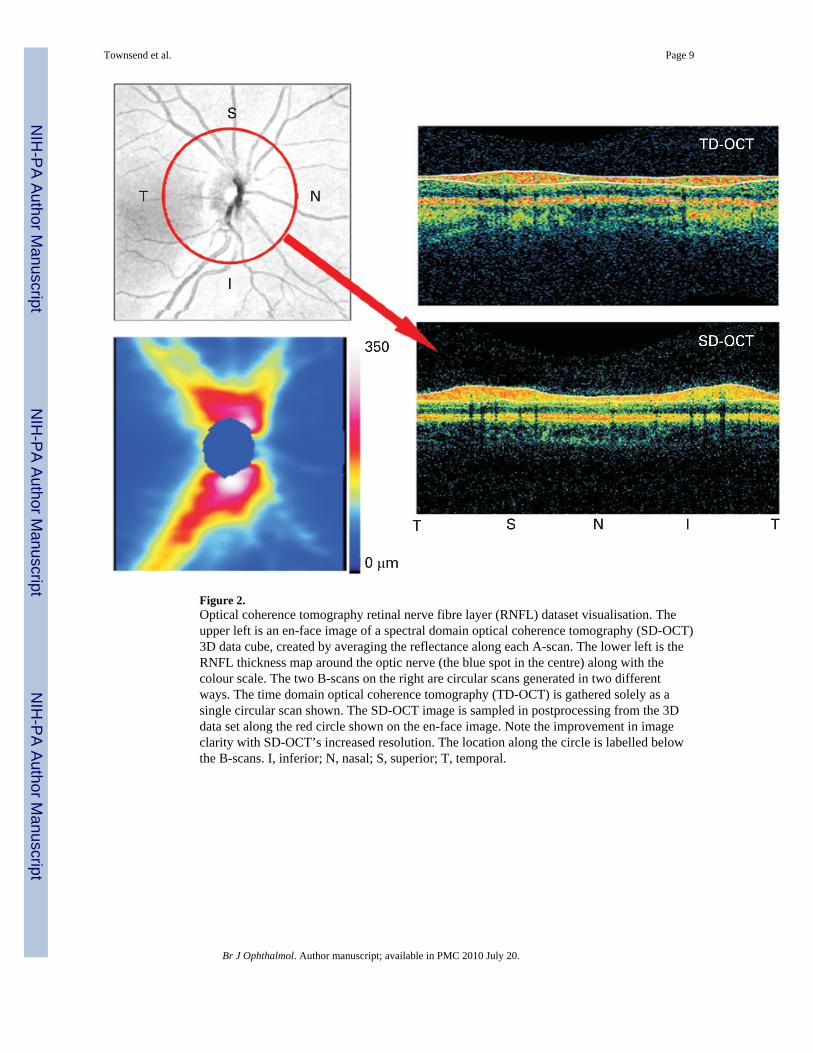
Figure 2.Optical coherence tomography retinal nerve fibre layer (RNFL) dataset visualisation. Theupper left is an en-face image of a spectral domain optical coherence tomography (SD-OCT)3D data cube, created by averaging the reflectance along each A-scan. The lower left is theRNFL thickness map around the optic nerve (the blue spot in the centre) along with thecolour scale. The two B-scans on the right are circular scans generated in two differentways. The time domain optical coherence tomography (TD-OCT) is gathered solely as asingle circular scan shown. The SD-OCT image is sampled in postprocessing from the 3Ddata set along the red circle shown on the en-face image. Note the improvement in imageclarity with SD-OCT’s increased resolution. The location along the circle is labelled belowthe B-scans. I, inferior; N, nasal; S, superior; T, temporal.
Townsend et al. Page 9
Br J Ophthalmol. Author manuscript; available in PMC 2010 July 20.
NIH
-PA Author Manuscript
NIH
-PA Author Manuscript
NIH
-PA Author Manuscript