Image rendering tool for integrated circuit layout in Python
7
HAL Id: hal-03471381 https://hal.archives-ouvertes.fr/hal-03471381 Submitted on 8 Dec 2021 HAL is a multi-disciplinary open access archive for the deposit and dissemination of sci- entific research documents, whether they are pub- lished or not. The documents may come from teaching and research institutions in France or abroad, or from public or private research centers. L’archive ouverte pluridisciplinaire HAL, est destinée au dépôt et à la diffusion de documents scientifiques de niveau recherche, publiés ou non, émanant des établissements d’enseignement et de recherche français ou étrangers, des laboratoires publics ou privés. IC-Layout Render: Image rendering tool for integrated circuit layout in Python João R. Raposo de O. Martins, Francisco Alves, Pietro Maris Ferreira To cite this version: João R. Raposo de O. Martins, Francisco Alves, Pietro Maris Ferreira. IC-Layout Render: Image rendering tool for integrated circuit layout in Python. 2021. hal-03471381
-
Upload
khangminh22 -
Category
Documents
-
view
1 -
download
0
Transcript of Image rendering tool for integrated circuit layout in Python
HAL Id: hal-03471381https://hal.archives-ouvertes.fr/hal-03471381
Submitted on 8 Dec 2021
HAL is a multi-disciplinary open accessarchive for the deposit and dissemination of sci-entific research documents, whether they are pub-lished or not. The documents may come fromteaching and research institutions in France orabroad, or from public or private research centers.
L’archive ouverte pluridisciplinaire HAL, estdestinée au dépôt et à la diffusion de documentsscientifiques de niveau recherche, publiés ou non,émanant des établissements d’enseignement et derecherche français ou étrangers, des laboratoirespublics ou privés.
IC-Layout Render: Image rendering tool for integratedcircuit layout in Python
João R. Raposo de O. Martins, Francisco Alves, Pietro Maris Ferreira
To cite this version:João R. Raposo de O. Martins, Francisco Alves, Pietro Maris Ferreira. IC-Layout Render: Imagerendering tool for integrated circuit layout in Python. 2021. �hal-03471381�

IC-Layout Render: Image rendering tool for integratedcircuit layout in Python
João R. R. O. Martins1, 2, Francisco Alves1, 2, and Pietro M.Ferreira1, 2
1 Université Paris-Saclay, CentraleSupélec, CNRS, Lab. de Génie Électrique et Électronique deParis,91192,Gif-sur-Yvette,France 2 Sorbonne Université, CNRS, Lab. de Génie Électrique etÉlectronique de Paris, 75252, Paris, France
DOI: 10.5281/zenodo.5618268
Software
• Release• Repository
Submitted: N/APublished: N/A
LicenseAuthors of papers retaincopyright and release the workunder a Creative CommonsAttribution 4.0 InternationalLicense (CC BY 4.0).
Summary
Graphic Design System (GDSII) from (Calma Company, 1987) is a common database fileformat to stream out integrated circuit (IC) masks, also called layout, before fabrication. Beingan essential part of circuit development, designers are often familiarized in how to generate thisbinary file on computer-aided design (CAD) tools. This output file contains planar geometricshapes which represent physical 3D layers from a specific process design kit (PDK). CommercialPDK usually presents more than 50 layers, which are 2D visualized in CAD tools.
Reading a layout in those CAD tools is not a simple task, however high-quality graphical imageis available in such tool. Thus, an IC designer is capable to understand the data representationand point out improvements for the IC. Nevertheless, IC documentation is often delivered in alower quality 2D image depicted in a PDF file. Once the PDF is generated; the circuit layoutbecomes hardly readable even for experienced IC designers.
Scientific communications require accurate and repeatable results to be considered priorpublication. In microelectronics research field, a layout picture is mandatory. While illustrationsshould be a vectorial graph like, IC layout is often depicted from a low-quality bitmap obtainedfrom a screenshot or an image saving through the CAD tool. In this scenario, having anaccurate, readable, and reproducible layout result are a challenge. Most publications illustrateIC layouts in lower standards than the other illustration results, which hinds the requiredphysical solution to address state-of-the-art IC performance.
The tool icLayoutRender aims to a user-friendly transcription of a GDSII file in a pdf file. De-veloped in Python 3, the image rendering requires an input GDSII file <cellName.gds> and thePDK layer color file <LayerColor_PDK.map> to produce an output PDF file <cellName.pdf>.The GDSII layers will be rendered using the available PDK layer colors. Missing layers will beneglected.
The tool icLayoutRender does:
1. confirm the entered values;
2. convert the .gds to a .tex file;
3. call LuaTeX or pdflatex to generate a .aux, and .pdf
The tool icLayoutRender requires:
1. Python3 installed with devel options;
2. gdspy, pandas, math, and GDSLatexConverter (Vollmer, 2020) Python libraries installed;
3. TexLive for a Linux installation, or MikTEX for a Windows installation;
4. tikz LaTEX package to compile the output *.pdf file.
João R. R. O Martins, Francisco Alves, and Pietro M. Ferreira, (2021). IC-Layout Render: Image rendering tool for integrated circuit layout inPython. Open Source Software. https://doi.org/10.5281/zenodo.5618268
1
Several examples using icLayoutRender are freely available on the official website. Layer colorfile generation is also explained in the user manual, as installation procedure and the tooloperation in Linux and Windows. The icLayoutRender image rendering tool has been usedin recent scientific communication (Martins et al., 2021) and the illustration readability isremarkable.
Overview of icLayoutRender tool
In commercial CAD tools, the GDSII file is obtained following a common procedure File->Export->Stream. The output stream file should be named as <cellName.gds> and selectedas the top cell to be exported from an available layout. The GDSII file should be saved in thesame folder as the proposed tool for a user-friendly operation.
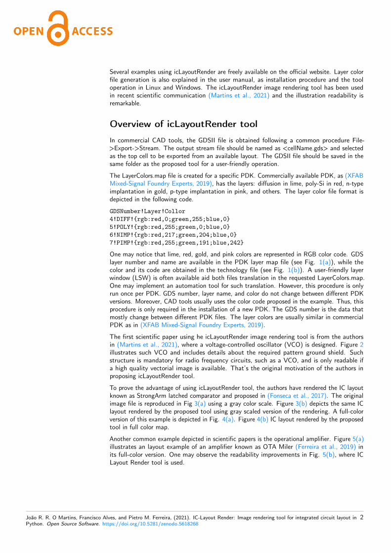
The LayerColors.map file is created for a specific PDK. Commercially available PDK, as (XFABMixed-Signal Foundry Experts, 2019), has the layers: diffusion in lime, poly-Si in red, n-typeimplantation in gold, p-type implantation in pink, and others. The layer color file format isdepicted in the following code.
GDSNumber!Layer!Collor4!DIFF!{rgb:red,0;green,255;blue,0}5!POLY!{rgb:red,255;green,0;blue,0}6!NIMP!{rgb:red,217;green,204;blue,0}7!PIMP!{rgb:red,255;green,191;blue,242}
One may notice that lime, red, gold, and pink colors are represented in RGB color code. GDSlayer number and name are available in the PDK layer map file (see Fig. 1(a)), while thecolor and its code are obtained in the technology file (see Fig. 1(b)). A user-friendly layerwindow (LSW) is often available aid both files translation in the requested LayerColors.map.One may implement an automation tool for such translation. However, this procedure is onlyrun once per PDK. GDS number, layer name, and color do not change between different PDKversions. Moreover, CAD tools usually uses the color code proposed in the example. Thus, thisprocedure is only required in the installation of a new PDK. The GDS number is the data thatmostly change between different PDK files. The layer colors are usually similar in commercialPDK as in (XFAB Mixed-Signal Foundry Experts, 2019).
The first scientific paper using he icLayoutRender image rendering tool is from the authorsin (Martins et al., 2021), where a voltage-controlled oscillator (VCO) is designed. Figure 2illustrates such VCO and includes details about the required pattern ground shield. Suchstructure is mandatory for radio frequency circuits, such as a VCO, and is only readable ifa high quality vectorial image is available. That’s the original motivation of the authors inproposing icLayoutRender tool.
To prove the advantage of using icLayoutRender tool, the authors have rendered the IC layoutknown as StrongArm latched comparator and proposed in (Fonseca et al., 2017). The originalimage file is reproduced in Fig 3(a) using a gray color scale. Figure 3(b) depicts the same IClayout rendered by the proposed tool using gray scaled version of the rendering. A full-colorversion of this example is depicted in Fig. 4(a). Figure 4(b) IC layout rendered by the proposedtool in full color map.
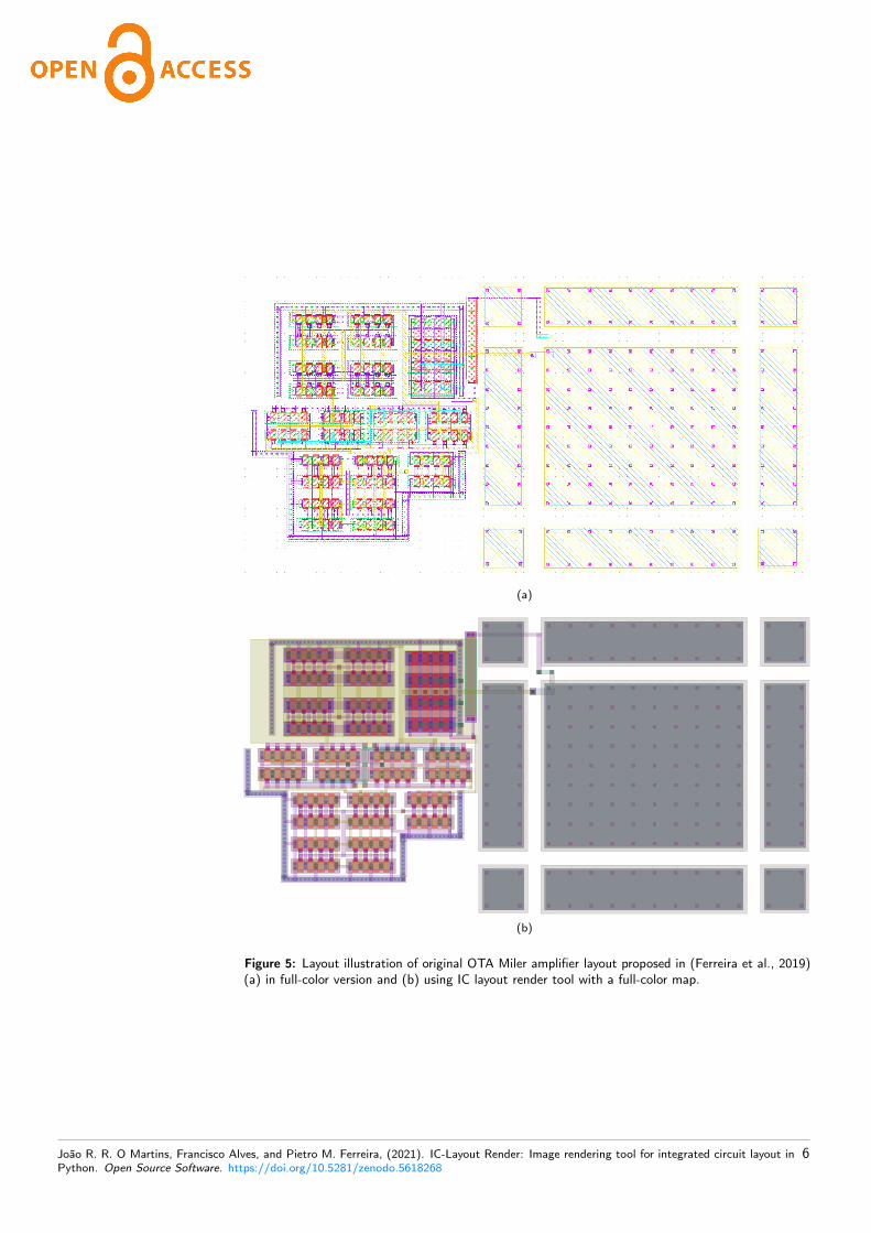
Another common example depicted in scientific papers is the operational amplifier. Figure 5(a)illustrates an layout example of an amplifier known as OTA Miler (Ferreira et al., 2019) inits full-color version. One may observe the readability improvements in Fig. 5(b), where ICLayout Render tool is used.
João R. R. O Martins, Francisco Alves, and Pietro M. Ferreira, (2021). IC-Layout Render: Image rendering tool for integrated circuit layout inPython. Open Source Software. https://doi.org/10.5281/zenodo.5618268
2

(a)
(b)
Figure 1: Layer colors map creation using a commercial PDK, where one can verify (a) the layernumbers and (b) the layer colors.
Conclusion
Scientific communications require accurate and repeatable results, where microelectronicsresearch field requires a high-quality layout illustration. The proposal demonstrated a user-friendly tool to a GDSII transcription in a vectorial graph quality image saved as a pdf file. Allillustration examples in this work were obtained from an IC design using the PDK of (XFABMixed-Signal Foundry Experts, 2019). However, layer maps can be easily adapted to anycommercial PDK. One may assert the illustration quality by increasing zoom over Fig. 2, 3and 4 in the PDF file or by printing them in a poster-sized version. The vectorial graphicalrendering is obtained by the proposal in which standard tools are unable to attain.
References
Calma Company. (1987). GDSII™ Stream Format Manual (February). http://bitsavers.informatik.uni-stuttgart.de/pdf/calma/GDS_II_Stream_Format_Manual_6.0_Feb87.pdf
Ferreira, P. M., Martins, J. R. R. O., Mostafa, A., & Juillard, J. (2019). Process-Voltage-Temperature Analysis of a CMOS-MEMS Readout Architecture. Proc. IEEE Design, Test,Integration & Packaging of MEMS/MOEMS, 1–4. https://doi.org/10.1109/DTIP.2019.8752699
Fonseca, A. V., Khattabi, R. E., Afshari, W. A., Barúqui, F. A. P., Soares, C. F. T., &Ferreira, P. M. (2017). A Temperature-Aware Analysis of Latched Comparators forSmart Vehicle Applications. Proc ACM IEEE Symp. Integr. Circuits Syst. Design, 1–6.https://doi.org/10.29292/jics.v13i1.8
João R. R. O Martins, Francisco Alves, and Pietro M. Ferreira, (2021). IC-Layout Render: Image rendering tool for integrated circuit layout inPython. Open Source Software. https://doi.org/10.5281/zenodo.5618268
3

Figure 2: Layout illustration of a VCO from (Martins et al., 2021), including a pattern ground shield.
Martins, J. R. O. R., Alves, F., & Ferreira, P. M. (2021). A 237 ppm / °C L-Band ActiveInductance Based Voltage Controlled Oscillator in SOI 0.18 µm. Proc ACM IEEE Symp.Integr. Circuits Syst. Design, 1–6. https://doi.org/10.1109/SBCCI53441.2021.9529990
Vollmer, R. (2020). GDSLatexConverter. https://github.com/Aypac/GDSLatexConverter
XFAB Mixed-Signal Foundry Experts. (2019). XH018 - 0.18 Micron Modular Analog MixedHV Technology (pp. 1–22). https://www.xfab.com/technology/cmos/018-um-xh018/
João R. R. O Martins, Francisco Alves, and Pietro M. Ferreira, (2021). IC-Layout Render: Image rendering tool for integrated circuit layout inPython. Open Source Software. https://doi.org/10.5281/zenodo.5618268
4

(a)
(b)
Figure 3: Layout illustration of StrongArm latched comparator proposed in (Fonseca et al., 2017)(a)as its original illustration and (b) using IC layout render tool with gray scale color map.
(a)
(b)
Figure 4: Layout illustration of StrongArm latched comparator proposed in (Fonseca et al., 2017)(a)in full-color version and (b) using IC layout render tool with a full-color map.
João R. R. O Martins, Francisco Alves, and Pietro M. Ferreira, (2021). IC-Layout Render: Image rendering tool for integrated circuit layout inPython. Open Source Software. https://doi.org/10.5281/zenodo.5618268
5
(a)
(b)
Figure 5: Layout illustration of original OTA Miler amplifier layout proposed in (Ferreira et al., 2019)(a) in full-color version and (b) using IC layout render tool with a full-color map.
João R. R. O Martins, Francisco Alves, and Pietro M. Ferreira, (2021). IC-Layout Render: Image rendering tool for integrated circuit layout inPython. Open Source Software. https://doi.org/10.5281/zenodo.5618268
6