Image-ray tracing for joint 3D seismic velocity estimation and ...
16
Image-ray tracing for joint 3D seismic velocity estimation and time-to-depth conversion Einar Iversen 1 and Martin Tygel 2 ABSTRACT Seismic time migration is known for its ability to generate well-focused and interpretable images, based on a velocity field specified in the time domain. A fundamental requirement of this time-migration velocity field is that lateral variations are small. In the case of 3D time migration for symmetric elementary waves e.g., primary PP reflections/diffractions, for which the incident and departing elementary waves at the reflection/diffraction point are pressure P waves, the time-migration velocity is a function depending on four variables: three coordinates specify- ing a trace point location in the time-migration domain and one angle, the so-called migration azimuth. Based on a time-migra- tion velocity field available for a single azimuth, we have devel- oped a method providing an image-ray transformation between the time-migration domain and the depth domain. The transfor- mation is obtained by a process in which image rays and isotropic depth-domain velocity parameters for their propagation are esti- mated simultaneously. The depth-domain velocity field and im- age-ray transformation generated by the process have useful ap- plications. The estimated velocity field can be used, for example, as an initial macrovelocity model for depth migration and tomog- raphic inversion. The image-ray transformation provides a basis for time-to-depth conversion of a complete time-migrated seis- mic data set or horizons interpreted in the time-migration do- main. This time-to-depth conversion can be performed without the need of an a priori known velocity model in the depth domain. Our approach has similarities as well as differences compared with a recently published method based on knowledge of time- migration velocity fields for at least three migration azimuths. We show that it is sufficient, as a minimum, to give as input a time-migration velocity field for one azimuth only. A practical consequence of this simplified input is that the image-ray trans- formation and its corresponding depth-domain velocity field can be generated more easily. INTRODUCTION Time migration prestack or poststack is a well-established and routinely applied procedure to obtain time-domain images from seismic reflection data. For simple velocity models, time migration is characterized by its ability to obtain focused images in the time do- main. Depth migration, on the other hand, can produce focused structural images in the depth domain for complex velocity varia- tions. The main advantage of the time-migration procedure is that it produces fairly interpretable images quickly and inexpensively. Ex- cept for strong lateral velocity variations, time migration is very ro- bust with respect to inaccuracies of the time-domain velocity model. This is to be compared with the much more involved depth migra- tion, especially prestack, which requires, besides a well-designed depth-domain velocity model, significantly more computational ef- fort. As compared with common-midpoint CMP stacking, which es- sentially produces seismic data sets corresponding to a simulated ze- ro-offset ZO acquisition, the time migration process generates data sets with features that are identified more easily with structures in the depth domain. In particular, triplications typical for unmigrated im- ages of synclinal structures naturally unfold to synclinals after time migration. For any time-domain imaging procedure, the image of a reflector is called a reflecting horizon. For the same reflector in the depth do- main, the overall characteristics, kinematic and dynamic, of its cor- responding reflecting horizon will depend strongly on the acquisi- tion configuration and imaging procedure that is employed. In accor- dance with the ray methods that will be used throughout, we envis- Manuscript received by the Editor 14 December 2006; revised manuscript received 14 November 2007; published online 7 May 2008. 1 NORSAR, Kjeller, Norway. E-mail: [email protected]. 2 State University of Campinas UNICAMP, Applied Mathematics Department, IMECC, Campinas, Brazil. E-mail: [email protected]. © 2008 Society of Exploration Geophysicists. All rights reserved. GEOPHYSICS, VOL. 73, NO. 3 MAY-JUNE 2008; P. S99–S114, 10 FIGS., 2 TABLES. 10.1190/1.2907736 S99
-
Upload
khangminh22 -
Category
Documents
-
view
1 -
download
0
Transcript of Image-ray tracing for joint 3D seismic velocity estimation and ...

Image-ray tracing for joint 3D seismic velocityestimation and time-to-depth conversion
Einar Iversen1 and Martin Tygel2
ABSTRACT
Seismic time migration is known for its ability to generatewell-focused and interpretable images, based on a velocity fieldspecified in the time domain. A fundamental requirement of thistime-migration velocity field is that lateral variations are small.In the case of 3D timemigration for symmetric elementarywaves�e.g., primary PP reflections/diffractions, for which the incidentand departing elementary waves at the reflection/diffractionpoint are pressure �P� waves�, the time-migration velocity is afunction depending on four variables: three coordinates specify-ing a trace point location in the time-migration domain and oneangle, the so-called migration azimuth. Based on a time-migra-tion velocity field available for a single azimuth, we have devel-oped a method providing an image-ray transformation betweenthe time-migration domain and the depth domain. The transfor-mation is obtained by a process inwhich image rays and isotropicdepth-domain velocity parameters for their propagation are esti-
mated simultaneously. The depth-domain velocity field and im-age-ray transformation generated by the process have useful ap-plications. The estimated velocity field can be used, for example,as an initialmacrovelocitymodel for depthmigration and tomog-raphic inversion. The image-ray transformation provides a basisfor time-to-depth conversion of a complete time-migrated seis-mic data set or horizons interpreted in the time-migration do-main. This time-to-depth conversion can be performed withoutthe need of an a priori knownvelocitymodel in the depth domain.Our approach has similarities as well as differences comparedwith a recently published method based on knowledge of time-migration velocity fields for at least three migration azimuths.We show that it is sufficient, as a minimum, to give as input atime-migration velocity field for one azimuth only. A practicalconsequence of this simplified input is that the image-ray trans-formation and its corresponding depth-domain velocity field canbe generatedmore easily.
INTRODUCTION
Time migration �prestack or poststack� is a well-established androutinely applied procedure to obtain time-domain images fromseismic reflection data. For simple velocity models, time migrationis characterized by its ability to obtain focused images in the time do-main. Depth migration, on the other hand, can produce focusedstructural images in the depth domain for complex velocity varia-tions. The main advantage of the time-migration procedure is that itproduces fairly interpretable images quickly and inexpensively. Ex-cept for strong lateral velocity variations, time migration is very ro-bust with respect to inaccuracies of the time-domain velocitymodel.This is to be compared with the much more involved depth migra-tion, especially prestack, which requires, besides a well-designed
depth-domain velocity model, significantly more computational ef-fort.As compared with common-midpoint �CMP� stacking, which es-
sentially produces seismic data sets corresponding to a simulated ze-ro-offset �ZO� acquisition, the timemigration process generates datasetswith features that are identifiedmore easilywith structures in thedepth domain. In particular, triplications typical for unmigrated im-ages of synclinal structures naturally unfold to synclinals after timemigration.For any time-domain imaging procedure, the image of a reflector
is called a reflecting horizon. For the same reflector in the depth do-main, the overall characteristics, kinematic and dynamic, of its cor-responding reflecting horizon will depend strongly on the acquisi-tion configuration and imaging procedure that is employed. In accor-dance with the ray methods that will be used throughout, we envis-
Manuscript received by the Editor 14December 2006; revisedmanuscript received 14November 2007; published online 7May 2008.1NORSAR,Kjeller, Norway. E-mail: [email protected] of Campinas �UNICAMP�,AppliedMathematicsDepartment, IMECC,Campinas, Brazil. E-mail: [email protected].
© 2008 Society of ExplorationGeophysicists.All rights reserved.
GEOPHYSICS,VOL. 73, NO. 3 �MAY-JUNE2008�; P. S99–S114, 10 FIGS., 2TABLES.10.1190/1.2907736
S99

age the reflector as a smooth continuumof independent point scatter-ers �or point diffractors� which, because of illumination by seismicwaves, are excited and emit energy toward the surface. Under thisformulation, the image of a reflector can be understood as the ensem-ble of the individual �time-domain� images of the point scatterersthat constitute the �depth-domain� reflector. A review of basic for-mulas constituting the 3DKirchhoff prestack time-migration proce-dure is given inAppendixA.The basic goal of time migration is to focus the seismic energy
into interpretable time-domain images. Concerning accuracy, espe-cially with respect to reflector positioning, quite a long struggle ex-ists in the literature on the pros and cons of prestack and poststacktime migration. As a rule, the widespread use of time migration is atestimony of its practical usefulness �see, for example, Yilmaz,2001�. Sound criticism of time migration, both in theoretical andpractical aspects, can be found in, for example, Black and Brzos-towski �1994�, Whitcombe �1994� and, more recently, Robein�2003, Chapter 8�.The time-migration process is quite robust with respect to pertur-
bations of the time-migration velocity model. However, becausetime migration commonly is based on a hyperbolic traveltime ap-proximation, its applicability is limited to velocity models withsmall lateral variations �Yilmaz, 2001�. Historically speaking, “ide-al” or “complete” time migration has been considered a process po-sitioning the reflecting horizons “vertically above” their correspond-ing reflectors in the depth domain. More specifically, the horizontalcoordinates of each point scatterer on a reflector thenwould coincidewith the horizontal coordinates �trace location� of its associatedtime-migrated image. For this idealized process, it is assumed thatthe connection between each point scatterer at the reflector and itstrace location at the surface can be realized by a vertical ray. As aconsequence, the transformation of the traveltime coordinate of apoint on a time-migrated reflecting horizon to the depth coordinateof its associated point scatterer at the reflector �the so-called time-to-depth conversion�would be achieved by a simple scaling operation,namely,multiplication of half the traveltime by an appropriate �aver-age�mediumvelocity along the vertical ray.The above concept of a complete time migration, although useful
as a theoretical framework, is not realistically possible.As explainedinHubral �1977�, the closest feasible alternative is to have a transfor-mation that uses image rays �and not vertical rays� to connect thepoint scatterers at the reflector to their corresponding trace locationsat the surface. For an arbitrary point scatterer on the reflector, the im-age ray can be defined as a ray connecting the scatterer to the mea-surement surface in such a way that the slowness vector is normal tothat surface. This definition allows the medium below the measure-ment surface to be either isotropic or anisotropic. Likewise, the nor-mal ray can be defined as a ray connecting the point scatterer to themeasurement surface in such a way that the slowness vector is nor-mal to the reflector �Iversen, 2006�. As also described in Hubral�1977�, assuming an isotropic velocity model, the following dualityexists for normal rays and image rays that connect surface measure-ment to a given reflector scatterer. The former is normal to the reflec-tor, whereas the latter is normal to themeasurement surface.In spite of widespread use in seismic processing, time migration
also encounters criticism and concern about its application. BlackandBrzostowski �1994� reportmispositions of events evenwith cor-rect velocity and propose a general correction scheme, called reme-dial migration. Whitcombe �1994� pointed out that although timemigration produces useful, better interpretable images of reflectors,
the time-migrated section is not the best option for subsequent depthconversion. He proposes instead to demigrate the interpreted time-migrated horizons into the unmigrated domain and use normal raysfor depth conversion. According to Whitcombe �1994�, the methodcombines the good interpretable properties of time migration withthe better positioning provided by depthmigration.From the very definition of time migration, the most consistent
depth conversion would be along image rays in such a way that thedepth velocities needed for the image-ray tracing would be obtaineddirectly from the given time-migration velocity field.Amethod thatdoes exactly that was presented recently by Cameron et al. �2006,2007�. Besides time-migrated data, the method requires in its 3Dversion that the time-migrated velocity field is available for at leastthree directions along the measurement surface. This requirementmight impose some limitations to the applications of the method inpractice.Our objective is to present theory and numerical examples for a
3D image-ray tracing and velocity-estimation algorithm in which itis sufficient to know the time-migration velocity field in a single di-rection only. Our approach is similar to that of Cameron et al. �2006,2007�, but the range of practical applications is extended. A discus-sion on the actual differences between the two approaches is provid-ed inAppendixB.
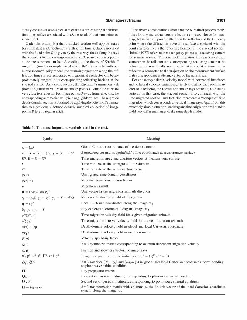
NOMENCLATURE
Tomake the mathematical derivations easier to follow, lists of themost important symbols used in the text are displayed in Table 1.Lowercase and uppercase letters i and I used as subscripts can havethe values i � 1,2,3, and I � 1,2, respectively. For three-compo-nent vectors, we use standard notation, for example, a, whereas fortwo-component vectors, a bar is printed above the symbol, as in a.Vectors are considered equivalently as column matrices. To distin-guish between matrices of size 3�3 and 2�2, we use notations AandA, respectively. The notationAT is used for the transpose of thematrix A, and A�T is a shorthand notation for A�1T
. For cases inwhich ambiguity can arise, a superscript in the form �q� on vectors/matrices serves as a label for the coordinate system under consider-ation.The 3�1 columnvector containing the first partial derivativesand the 3�3 matrix containing the second partial derivatives of ascalar field W with respect to the variables, x � �xi�, are written inthe forms
�W
�x� � �W
�xi� and
� 2W
�x2� � � 2W
�xi�xj� . �1�
KIRCHHOFF TIME AND DEPTH MIGRATION
In the following,we review the basics ofKirchhoff time and depthmigration as needed in this article.
Depth migration
A good understanding of how time migration can be carried outcan be gained by examining its relationship to Kirchhoff depth mi-gration, as applied to a single stacked section. Such a procedure is re-ferred to as 2D Kirchhoff poststack depth migration. For a givendepth-domain macrovelocity model and a given point in the depthdomainD to be imaged, theKirchhoff depth-migration operation ba-
S100 Iversen and Tygel
sically consists of a weighted sum of data samples along the diffrac-tion time surface associated with D, the result of that sum being as-signed atD.Under the assumption that a stacked section well approximates
�or simulates� a ZO section, the diffraction time surface associatedwith the fixed point D is given by the two-way times along the raysthat connectD to the varying coincident �ZO� source-receiver pointsat the measurement surface. According to the theory of Kirchhoffmigration �see, for example, Tygel et al., 1996�, for a sufficiently ac-curate macrovelocity model, the summing operation along the dif-fraction time surface associated with a point at a reflector will be ap-proximately tangent to its corresponding reflecting horizon in thestacked section. As a consequence, the Kirchhoff summation willprovide significant values at the image points D which lie at or arevery close to a reflector. For image pointsD away from reflectors, thecorresponding summationwill yield negligible values.Themigrateddepth-domain section is obtained by applying theKirchhoff summa-tion to a previously defined densely sampled collection of imagepointsD �e.g., a regular grid�.
The above considerations show that the Kirchhoff process estab-lishes for any individual depth reflector a correspondence �or map-ping� between each point scatterer on the reflector and the tangencypoint where the diffraction traveltime surface associated with thepoint scatterer meets the reflecting horizon in the stacked section.Hubral �1977� refers to these tangency points as “scattering centersfor seismic waves.” The Kirchhoff migration thus associates eachscatterer on the reflector to its corresponding scattering center at thereflecting horizon. Finally, we observe that any point scatterer on thereflector is connected to the projection on the measurement surfaceof its corresponding scattering center by the normal ray.For an isotropic depth-velocity model with horizontal interfaces
and no lateral velocity variations, it is clear that for each point scat-terer on a reflector, the normal and image rays coincide, both beingvertical. In this case, the stacked section also coincides with thetime-migrated section, and that also represents a “complete” timemigration, which corresponds to vertical image rays.Apart from thisextremely simple situation, stacking and timemigration are bound toyield very different images of the same depthmodel.
Table 1. The most important symbols used in the text.
Symbol Meaning
x � �xi� Global Cartesian coordinates of the depth domain
s, r, x � �s � r�/2, y � �s � r�/2 Source/receiver and midpoint/half-offset coordinates at measurement surface
xM, a � x � xM Time-migration apex and aperture vectors at measurement surface
t Time variable of the unmigrated time domain
tM Time variable of the migrated time domain
�x,t� Unmigrated time-domain coordinates
�xM,tM� Migrated time-domain coordinates
� Migration azimuth
u � �cos � ,sin � �T Unit vector in the migration azimuth direction
� � �� i�, � I � xIM, � 3 � T � tM /2 Ray coordinates for a field of image rays
q � �qi� Local Cartesian coordinates along the image ray
�q,� 3�, � 3 � T Ray-centered coordinates along the image ray
vM�xM,tM� Time-migration velocity field for a given migration azimuth
vdixM ��� Time-migration interval velocity field for a given migration azimuth
v�x�, v�q� Depth-domain velocity field in global and local Cartesian coordinates
v��� Depth-domain velocity field in ray coordinates
F��� Velocity spreading factor
M�x� 3�3 symmetric matrix corresponding to azimuth-dependent migration velocity
x, p Position and slowness vectors of image rays
x0, p0, v0, e10, �0, and �0 Image-ray quantities at the initial point �0 � �xI
M0,tM0 � 0�
Q1�x�, Q1
�q� 3�3 matrices ��xi/�� j� and ��qi/�� j� in global and local Cartesian coordinates, correspondingto plane-wave initial condition
� Ray-propagator matrix
Q1, P1 First set of paraxial matrices, corresponding to plane-wave initial condition
Q2, P2 Second set of paraxial matrices, corresponding to point-source initial condition
H � �e1 e2 e3� 3�3 transformation matrix with columns ei, the ith unit vector of the local Cartesian coordinatesystem along the image ray
3D image-ray tracing S101

Time migration
Timemigration can be carried out by a simple modification to theabove-described Kirchhoff poststack depth migration. After stack-ing along the diffraction traveltime surface of a given depth pointD,all we need to do is to assign the stacking result �the migration out-put� to the apex of the diffraction traveltime surface instead of as-signing it to the original depth point D, as would be done in theKirchhoff depth-migration counterpart. A geometric outline of theprocedure is depicted in Figure 1. The reasoning for the approach issimple: The apex of the diffraction traveltime surface for a pointscattererD represents the stationary traveltime from that point to themeasurement surface.As a consequence, the image ray fromD is theone that has that stationary traveltime.An underlying assumption of the procedure is that the diffraction
traveltime surface is sufficiently well behaved so that a clear apexexists. In the absence of abrupt lateral velocity variations, each dif-fraction traveltime surface can be approximated well by a hyperbo-loid in the vicinity of its apex. It is then possible to formulate a time-migration procedure that is based on time-domain computationsonly, so that dependency on a depth-domain macrovelocity can beavoided. Consider for simplicity a single unmigrated zero-offsetsectionwhere the inline coordinate is x and the two-way time is t. Foreach given point �xM,tM� in the time-migrated section to be con-structed, introduce the hyperbolic traveltime function,
�tD�x��2 � �tM�2 �4
�vM�2�x � xM�2, �2�
along which seismic data for the samples �x,t� in the given unmi-grated zero-offset section are stacked. The quantity vM � vM�xM,tM�in equation 2 is the time-migration velocity or, in short, themigrationvelocity.We remark that equation 2 is relevant for 2D poststack timemigration only and is included here only to introduce briefly the un-derlying philosophy behind the time-migration concept. For a de-scription of a corresponding equation that governs 3D prestack timemigration, the reader is referred toAppendixA.Abasis for anyKirchhoff time-migration procedure �2D/3D/post-
stack/prestack� is the knowledge of amigration velocity field. Let usemphasize that an in-depth description of the various methods toperform time migration and migration-velocity analysis is outsidethe scope of the present paper. For that, the reader is referred to, forexample, Yilmaz �2001�. Here, we only briefly indicate how the mi-gration velocity can be obtained.One commonoption in the pastwasto use the stacking �NMO� velocity that previously had been deter-mined for obtaining the CMP-stacked section and eventually applyan ad hoc scaling factor to it. For dipping structures, an approach of-ten considered asmore adequate has been to use asmigration veloci-ty an NMO velocity corrected for dip moveout �DMO�; see Hale�1984�.An example of amodern, automatedmigration-velocity esti-mation scheme is reported in Fomel �2003�. A discussion on recentapproaches of time-migration velocity analysis and their use in prac-tical applications is given in Robein �2003�.
TIME-TO-DEPTH CONVERSION
The final aim of kinematic seismic imaging is to position reflec-tors correctly in the depth domain. In this way, time-domain imagessuch as CMP-stacked or time-migrated sections represent interme-diate, although very useful, results. A subsequent operation thattransforms a time-domain seismic data set into its correspondingdepth-domain data set is referred to as time-to-depth conversion.Assume for simplicity that the measurement surface is a horizon-
tal plane located at zero depth. In an analogy to previous notation, letthe unmigrated data set be described by the coordinates �x1,x2,t�,where the first two coordinates, x1 and x2, specify the location of theCMPon the measurement surface, and the third coordinate t is time.Time-to-depth conversion of an unmigrated data set requires thatnormal rays can be traced from the measurement surface. This ispossible if information from the time-domain data set as well as ade-quate structural assumptions for the subsurface allows one to derivea suitable depth-domain velocitymodel and the initial directions andtwo-way times of the normal rays. In this situation, an event locatedin the point �x1,x2,t� of the unmigrated data set is converted fromtime to depth by constructing the normal ray that starts at the com-mon midpoint �x1,x2,x3 � 0� and proceeds to its end point, deter-mined by the criterion that half of the given two-way time of theevent t/2 is consumed.Under the assumption of a 3D isovelocity layered model with
smoothly curved interfaces, Hubral and Krey �1980� propose a re-cursive algorithm to recover the layer velocities, as well as the posi-tions and curvatures of the interfaces, from knowledge of the travel-time function and the first two derivatives with respect to the coinci-dent source-receiver horizontal location of each reflecting horizon inthe unmigrated data set.Geometrically, the first derivatives of travel-time are related to the direction of incidence of the normal ray in theemergence point on the measurement surface. The second deriva-tives are related to the radii of curvature of the so-called normal-inci-dence point �NIP�wave in this emergence point.
Inlinecoordinate
Reflector
peD
hte
miT
Imageray
Normalray
Time-migratedhorizon
Unmigratedhorizon
Diffractioncurve
Figure 1. Geometric outline of time-migration procedure in the sim-ple 2D poststack situation.Adiffraction pointD on a reflector �blue�in the depth domain is connected by a normal ray �solid red� to acommon midpoint C on the measurement surface. An image ray�solid green� connects pointD to the projected apex pointM belong-ing to a diffraction curve �dashed black�, which is tangent to the un-migrated horizon �the time-domain counterpart of the reflector,shown in red� at point C. The time-migrated horizon �green� repre-sents the continuum of all diffraction-curve apexes related in thisway to the unmigrated horizon.
S102 Iversen and Tygel

In a manner analogous to the previous considerations, time-to-depth conversion of time-migrated seismic data will be possible ifthe information in the time-domain data allows one to trace imagerays in the depth domain.An advantage of such a process, comparedwith the previous case involving the unmigrated data set, is that im-age rays have a known initial condition, namely, that the initial slow-ness vector is perpendicular to the measurement surface. For eachpoint �x1M, x2
M, tM� in the time-migration domain, the time-to-depthconversion moves the event at this point along the image ray thatstarts at �x1 � x1
M, x2 � x2M, x3 � 0� on the measurement surface
and proceeds into the depth domain until half of the given time, tM /2,is consumed. For a 3D isovelocity layered macrovelocity model inthe depth domain, Hubral and Krey �1980� describe an algorithm totransform along image rays the locations, dips, and curvatures forhorizon points in the time-migration domain to corresponding loca-tions, dips, and curvatures for horizon points in the depth domain.Ageneralization of this algorithm to include heterogeneous layers isdescribed by Iversen et al. �1987, 1988�.
THEORY
In this section, we explain howwe can trace image rays into depthand simultaneously estimate the velocity along them from knowl-edge of a 3D time-migration velocity field in an arbitrary single di-rection along themeasurement surface.We observe that the requiredsingle-direction velocities are extracted from an underlying full 3Dtime-migration velocity field.
Coordinate systems
The construction of image rays, as envisaged by ourmethodology,relies mainly on the concepts and results of standard kinematic anddynamic ray tracing, as described, for example, in Červený �2001�.In thisway, it is instrumental to introduce, besides a global depth-do-main Cartesian coordinate system, x � �xi�, additional coordinatesystems that will be associatedwith the image rays.The first of these to bementioned here is the coordinate system as-
sociated with the time-migration domain, �x1M,x2M,tM�. Closely con-nected to the latter is the ray coordinate system � � �� i�, which de-fines the image rays issued from all trace locations of the time-mi-grated seismic data set. This means that the first two coordinates aredefined as � 1 � x1
M and � 2 � x2M. For the variable along the ray � 3,
we shall use the one-way traveltime, denoted by the symbol T. Inother words, we have � 3 � T � tM /2. The 3D curvilinear spaceformed by the ray coordinates is referred to as the ray domain. Final-ly,we shall need also the ray-centered coordinate system, �q1,q2,� 3�,introduced by Popov and Pšenčík �1978�, and a corresponding localCartesian coordinate system, q � �qi�, which is attached to each in-dividual point on the image ray. The vectorial function x��� de-scribes a mapping of a point � in the ray coordinate system onto apoint x in the global Cartesian coordinate system. Because this map-ping is based on construction of image rays, we refer to it as image-ray transformation.
Input data
For the combined image-ray tracing and depth-domain velocityestimation, we assume the knowledge of a single-direction time-mi-gration velocity function, vM � vM�xM,tM,� �, extracted from a full3D time-migration velocity field. Here, xM � �x1M,x2M�T specifies atrace in the time-migrated data set, tM denotes the two-waymigration
time, and � is the angle specifying the direction along which the mi-gration velocity is given. This angle is referred to in the following asthemigration azimuth or, in brief, azimuth.Prior to applying our ray-tracing method, it is practical to convert
the time-migration velocity by Dix’s method to the so-called time-migration interval velocity,
vdixM ��� � � d
dtM �tM�vM�2�1/2� � d
dT�T�vM�2�1/2
. �3�
The function vdixM must possess only weak variations with respect to
the lateral coordinates � 1 and � 2. In addition, it is essential for thestability of the ray-tracing procedure that vdix
M and its derivatives�vdix
M /�� i and � 2vdixM /��� I�� J� are smooth functions of all three coor-
dinates� i.
Kinematic ray tracing
Abasis for kinematic ray tracing in 3D isotropic elastic media canbe formulated by the ordinary differential equations �see, for exam-ple,Červený, 2001, section 3.1.1�
dx
dT� v2�x�p ,
dp
dT� � v�1�x�
�v�x. �4�
Evaluation of the above kinematic ray-tracing equations requiresknowledge of the velocity, v�x�, and its gradient, �v/�x, which wedo not have direct access to.As shownbelow, however,wewill over-come this by further analysis that involves the dynamic ray-tracingsystem.
Dynamic ray tracing
The dynamic ray-tracing system, in 3D isotropic elastic media,now is formulated in ray-centered coordinates. For a fixed image ray,we consider the attached local Cartesian coordinate system q. Foreach coordinate qi, we associate a corresponding unit basis vector ei.These unit vectors constitute the columns of an orthonormal trans-formationmatrix
H � �e1 e2 e3� . �5�
The matrix H can be computed in any point along the ray if we in-clude within the system of ray differential equations the followingequation
de1dT
� �v2�e1 ·dp
dT�p , �6�
where dp/dT is given by the second relation in equation 4. Knowingthe vector e3 � p/p and the vector e1 resulting from numerical in-tegration including equation 6, the vector e2 is obtained easily by thecross product
e2 � e3 � e1. �7�
3D image-ray tracing S103
In the following, we use the standard formulation of complete dy-namic ray tracing in terms of 4�4 matrices in ray-centered coordi-nates
d�
dT� S�, �8�
with the initial condition
�0 � �I 0
0 I� . �9�
Here,� is the ray propagatormatrixwith submatrices of size 2�2,
� � �Q1 Q2
P1 P2� . �10�
As is well known, the first and second set of paraxial matrices,�Q1,P1� and �Q2,P2�, can be interpreted as plane-wave �or telescop-ic� and point-source components of the propagator matrix � �see,for example, Červený, 2001�. Because image rays correspond to aninitial plane wave, the relevant set of paraxial matrices is �Q1,P1�.MatrixS in equation 8 has the definition
S � � 0 v2I
� v�1V 0�, where V � � � 2v
�qI�qJ� . �11�
Relating time- and depth-domain velocity functions
To simplify the notation, we shall consider in the following threevelocity functions, all of them denoted by the letter v, and distin-guished solely by their arguments: v�x�, v���, and v�q�. More spe-cifically, v�x� and v��� will designate the depth-domain velocity inglobal Cartesian coordinates and ray coordinates, respectively. In astandard forward ray-tracing application, that is, when image raysare computed froma knownvelocity field v�x�, the velocity v��� canbe obtained for each ray �for which the first two components, �� �� 1,� 2�T are fixed� simply by assigning the value v�x� at each po-sition x on the ray to the corresponding coordinate vector �. Finally,for any selected point on the ray, v�q� defines the velocity in the localCartesian coordinate system.As shown in Appendix C, the ray-domain velocity v��� will be
given by
v��� � vdixM ���F��� , �12�
whereF, referred to as the velocity spreading factor, is given by
F��� �uTQ2
�1Q1u
�uTQ2�1Q2
�Tu�1/2 . �13�
In the 2D situation, the factorF reduces to the simple formula
F��� � Q1, �14�
where Q1 is the scalar that corresponds in 2D propagation to the 2�2 transformation matrix Q1, which refers to the 3D situation.
Equation 14 is equal to the one given in Cameron et al. �2006, 2007�.We note that although vdix
M is directly available as input, the factorF depends on quantities belonging to dynamic ray tracing along theimage ray.Thismeans our image-ray constructionmust contemplatea simultaneous solution of the kinematic and dynamic ray-tracingsystems.
Derivatives of velocity functions
We now address the problem of determining the velocity deriva-tives �v/�x and � 2v/� q2 that are needed in the kinematic and dy-namic ray-tracing systems formulated above. These will be given interms of the ray-domain velocity derivatives, �v/�� and � 2v/� �2,respectively. The latter derivatives are related closely to the corre-sponding derivatives of our input time-migration interval velocityfield vdix
M .For first-order derivatives, a simple application of the chain rule
of advanced calculus yields
�v�� i
��xk
�� i
�v�xk
�15�
and introduces thematrix
Q1�x� � � �xi
�� j� �16�
of the transformation between ray coordinates ��j� and global Carte-sian coordinates �xi�. Furthermore, one can relate matrix Q1
�x� to itscounterpart, Q1
�q� � ��qi/�� j�, in local Cartesian coordinates by thetransformation
Q1�x� � HQ1
�q�, where Q1�q� � Q1
0
0
0 0 v� . �17�
We recall that H is the 3�3matrix given by equation 5, andQ1 is the2�2 upper left submatrix of the 4�4 ray-centered propagator ma-trix� of equation 10. Under the assumption that the inverse matrix,�Q1
�x���1 � ��� i/�xj� exists �or, equivalently, that det Q�x��0�,equation 15 can be recast as
�v�x
� �Q1�x���T �v
��. �18�
The existence of the inversematrix �Q1�x���1 for all considered val-
ues of the ray-coordinate vector � ensures a one-to-one correspon-dence between ray coordinates and depth-domain coordinates, x� x��� and � � ��x�. Thus, in this particular situation, each pointin the depth domain is connected to the measurement surface by atmost one image ray only, and the image-ray field does not containcaustic points. We remark in passing that the condition det Q1
�x��0has to be fulfilled in any implementation of the image-ray construc-tion considered here. To obtain the relationship between the secondderivatives of velocity in ray coordinates and local Cartesian coordi-nates, the chain rule needs to be applied twice.
S104 Iversen and Tygel
As shown inAppendixD,we have
� 2v�qN�qM
��� I
�qN
�� J
�qM� � 2v
�� I�� J�
� 2qK
�� I�� J
�v�qK
�� MNM
�v�T, �19�
whereMNM � � 2T/�qN�qM.At this point, it is essential to emphasizethat conventional dynamic ray tracing for a single ray does not allowcomputation of derivatives of qK of orders two and higher.Hence,wecan conclude that if the procedure is to be based on computationsalong a single ray only, we have to assume that such derivatives havenegligible values. Given that this assumption is satisfied, equation19 can be approximated by the simplermatrix expression,
� 2v
� q2� Q1
�T � 2v
� �2Q1
�1 � M1�v�T, �20�
where M1 � � 2T/� q2 � P1Q1�1. Equations 18 and 19 �or equation
20� provide the link between the first and second derivatives of ve-locitywith respect to ray coordinates and the corresponding velocityderivativeswith respect to globalCartesian coordinates and ray-cen-tered coordinates, respectively. As seen in the next section, this link
will be crucial for the image-ray tracing and velocity-estimation al-gorithm that is proposed here.
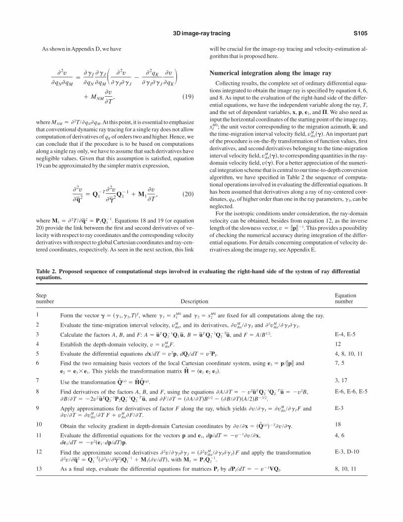
Numerical integration along the image ray
Collecting results, the complete set of ordinary differential equa-tions integrated to obtain the image ray is specified by equation 4, 6,and 8.As input to the evaluation of the right-hand side of the differ-ential equations, we have the independent variable along the ray, T,and the set of dependent variables, x, p, e1, and�. We also need asinput the horizontal coordinates of the starting point of the image ray,xI
M0; the unit vector corresponding to the migration azimuth, u; andthe time-migration interval velocity field, vdix
M ���. An important partof the procedure is on-the-fly transformation of function values, firstderivatives, and second derivatives belonging to the time-migrationinterval velocity field, vdix
M ���, to corresponding quantities in the ray-domain velocity field, v���. For a better appreciation of the numeri-cal integration scheme that is central to our time-to-depth conversionalgorithm, we have specified in Table 2 the sequence of computa-tional operations involved in evaluating the differential equations. Ithas been assumed that derivatives along a ray of ray-centered coor-dinates, qK, of higher order than one in the ray parameters, � I, can beneglected.For the isotropic conditions under consideration, the ray-domain
velocity can be obtained, besides from equation 12, as the inverselength of the slowness vector, v � p�1. This provides a possibilityof checking the numerical accuracy during integration of the differ-ential equations. For details concerning computation of velocity de-rivatives along the image ray, seeAppendix E.
Table 2. Proposed sequence of computational steps involved in evaluating the right-hand side of the system of ray differentialequations.
Stepnumber Description
Equationnumber
1 Form the vector � � �� 1,� 2,T�T, where � 1 � x1M0 and � 2 � x2
M0 are fixed for all computations along the ray.
2 Evaluate the time-migration interval velocity, vdixM , and its derivatives, �vdix
M /�� I and � 2vdixM /�� I�� J.
3 Calculate the factors A, B, and F: A � uT Q2�1Q1 u, B � uT Q2
�1Q2�Tu, and F � A/B1/2. E-4, E-5
4 Establish the depth-domain velocity, v � vdixM F. 12
5 Evaluate the differential equations dx/dT � v2p, dQI/dT � v2PI. 4, 8, 10, 11
6 Find the two remaining basis vectors of the local Cartesian coordinate system, using e3 � p/p ande2 � e3�e1. This yields the transformation matrix H � �e1 e2 e3�.
7, 5
7 Use the transformation Q�x� � HQ�q�. 3, 17
8 Find derivatives of the factors A, B, and F, using the equations �A/�T � � v2uT Q2�1Q2
�T u � �v2B,�B/�T � �2v2 uTQ2
�1P2Q2�1Q2
�T u, and �F/�T � ��A/�T�B1/2 � ��B/�T��A/2�B�3/2.E-6, E-6, E-5
9 Apply approximations for derivatives of factor F along the ray, which yields �v/�� I � �vdixM /�� I F and
�v/�T � �vdixM /�T F � vdix
M �F/�T.E-3
10 Obtain the velocity gradient in depth-domain Cartesian coordinates by �v/�x � �Q�x���T�v/��. 18
11 Evaluate the differential equations for the vectors p and e1, dp/dT � �v�1�v/�x,de1/dT � �v2�e1 ·dp/dT�p.
4, 6
12 Find the approximate second derivatives � 2v/�� I�� J � �� 2vdixM /�� I�� J� F and apply the transformation� 2v/� q2 � Q1
�T�� 2v/� �2�Q1�1 � M1��v/dT�, with M1 � P1Q1
�1.E-3, D-10
13 As a final step, evaluate the differential equations for matrices PI by dPI/dT � � v�1VQI. 8, 10, 11
3D image-ray tracing S105

Initial conditions for tracing the image rayTo solve the kinematic and dynamic ray-tracing systems, initial
conditions have to be provided.These consist of initial values, x0,p0,e10, and �0, given for the initial ray coordinate vector �0
� �� 10,� 2
0,� 30�T. Assuming for simplicity a planar horizontal datum
surface, x3 � 0, for the time-migrated data, we set � 10 � x1
M0, � 10
� x2M0 as the horizontal coordinates of the starting point of the image
ray. The given pair �x1M0,x2M0� also specifies the trace location in thetime-migrated data set that corresponds to the image ray to be con-structed. The initial traveltime of the image ray is� 3
0 � T 0 � 0.Because the initial slowness vector of an image ray p0 is always
perpendicular to the measurement surface, the two horizontal slow-ness vector components will both be zero, that is, p1
0 � p20 � 0. The
vertical slowness vector component is given by the inverse ray-do-main velocity, p3
0 � 1/v0, at the trace location �x1M0,x2M0� and zeromigration time, tM0 � 2T0 � 0. Furthermore, one can show �Ap-pendix E� that the factor F in equation 13 has the limit one when themigration time approaches zero. Hence, equation 12 yields the ini-tial ray-domain velocity as
v0 � vdixM ��0� . �21�
Given the above specifications, the kinematic initial conditions forthe image ray read
x0 � �x1M0,x2
M0,0�T and p0 � �0,0, 1v0�T
. �22�
The initial unit vector e10 of the ray-centered coordinate system can
be chosen quite freely within the horizontal plane. One option is toalign it with themigration azimuth direction, in otherwords, to spec-ify e1
0 � �cos � ,sin � ,0�T. The initial ray-propagator matrix, �0, isthe 4�4 identitymatrix given by equation 9.
NUMERICAL EXAMPLES
In this section,we consider, as a first illustration of themethod, ex-amples based on a 3Dmodel of the subsurface. Three cross sectionsthrough the P-wave velocity field of this model are shown in Figure2. The velocity field contains mild lateral variations and is smooththroughout; that is, it has no interfaces, discontinuities, or areaswithout data.To obtain input data for the numerical tests, image rays were
traced a one-way time T � 2 s downward from a planar measure-ment surface, located at depth x3 � 0 km. Figure 3 shows imagerays projected into the three global Cartesian coordinate directions.One can observe deviations of rays from the vertical. Nevertheless,the velocity variations responsible for these deviations do not intro-duce triplications and caustics in the image-ray field. To facilitatedisplay and comparisons of velocities, positions, and their errors, weshow in the following all results as functions of the coordinates ofthe time-migration domain. As an introduction to this type of dis-play, consider Figure 4,which shows the “true” depth-domain veloc-ity posted along the generated image rays.
1.0
2.0
3.0
4.0
Horizontal coordinate x2 (km)
2.0 4.0 6.0 8.0
Horizontal coordinate x1 (km)2.0 4.0 6.0 8.0 10.0 12.0
1.0
2.0
3.0
4.0
Horizontal coordinate x1 (km)
2.0 4.0 6.0 8.0 10.0 12.0
8.0
6.0
4.0
2.0
1500
1600
2000
2300
2500
2800
1700
1800
1900
2100
2200
2400
2600
2700
2900
3000
3100
yticoleV
m()s/
2300
2325
2425
2500
2550
2350
2375
2400
2450
2475
2525
2575
2600
yticoleV
m()s /
eD
tphk()
m
eD
tphk()
m
l atno zir oH
idroo cetanx 2
)mk(
Figure 2. Depth-domain velocity used for generating input data forthe tests. Top: section x2 � 5 km. Middle: section x1 � 7 km. Bot-tom: depth slice x3 � 2 km.
1.0
2.0
3.0
4.0
Horizontal coordinate x2 (km)
2.0 4.0 6.0 8.0
Horizontal coordinate x1 (km)2.0 4.0 6.0 8.0 10.0 12.0
1.0
2.0
3.0
4.0
Horizontal coordinate x1 (km)
2.0 4.0 6.0 8.0 10.0 12.0
8.0
6.0
4.0
2.0
htpeD
)mk(
htpeD
)mk(
l atnoz iroH
idrooce tanx 2
)mk(
Figure 3. Projections of image rays in �top� x2 direction, �middle� x1direction, and �bottom� x3 direction.
S106 Iversen and Tygel

By calculating the ray-propagator matrix along the rays, we ob-tained as a by-product the matrix of second derivatives of the one-way diffraction time, which contains information about migrationvelocity for any azimuth � . Thereafter, we specifically selected themigration velocity field corresponding to the azimuth � � 0° �Fig-ure 5� and converted it to a time-migration interval velocity field�Figure 6�, using Dix’s method �see equation 3�. The reason for cal-culating the input data in this way was to attain control of errors re-sulting from the image-ray transformation alone.We remark in pass-ing that an equivalent approach to obtaining time-migration intervalvelocities is to use equationC-11.The experiments were conducted with two transformations relat-
ing the time and depth domains. One approach was established byneglecting all lateral variations of the time-migration interval veloc-ity. Because this action results in vertical image rays, we refer to it asvertical-ray transformation. The other approach is based on themethodology for the image-ray transformation presented in this pa-per but with the underlying assumption that the derivatives of ray-centered coordinates along a ray, qK, of higher order than one in theray parameters,� I, can be neglected.Considering first the vertical-ray transformation, Figure 7 shows
errors in the estimation of the position �xi� for a selected time slice,tM � 2 s. The corresponding errors resulting from the image-raytransformation are shown in Figure 8. The latter displays can be
latnoziroH
idroocetanx 2
)mk(
Horizontal coordinate x1 (km)2.0 4.0 6.0 8.0 10.0 12.0
8.0
6.0
4.0
2.0
0.0
1.0
2.0
3.0
4.0
Horizontal coordinate x2 (km)2.0 4.0 6.0 8.0
yaw-o
wT
ite
m)s(
Horizontal coordinate x1 (km)
0.0
1.0
2.0
3.0
4.0
yaw-o
wT
ite
m)s(
2.0 4.0 6.0 8.0 10.0 12.0
1500
1600
2000
2300
2500
2800
1700
1800
1900
2100
2200
2400
2600
2700
2900
3000
3100
yticoleV
m()s/
2300
2325
2425
2500
2550
2350
2375
2400
2450
2475
2525
2575
2600
yticoleV
m()s/
Figure 4. Depth-domain velocity as a function of time-domain coor-dinates. Top: section x2 � 5 km. Middle: section x1 � 7 km. Bot-tom: time slice tM � 2 s.
latnoziroH
id roocetanx 2
)mk (
Horizontal coordinate x1 (km)2.0 4.0 6.0 8.0 10.0 12.0
8.0
6.0
4.0
2.0
0.0
1.0
2.0
3.0
4.0
Horizontal coordinate x2 (km)2.0 4.0 6.0 8.0
yaw-o
wT
ite
m)s(
Horizontal coordinate x1 (km)
0.0
1.0
2.0
3.0
4.0
yaw-o
wT
ite
m)s(
2.0 4.0 6.0 8.0 10.0 12.0
1500
1600
2000
2300
2500
2800
1700
1800
1900
2100
2200
2400
2600
2700
2900
3000
3100
yticoleV
m()s/
ytic ol eV
m()s /
1900
1925
2025
2100
2150
1950
1975
2000
2050
2075
2125
2175
2200
Figure 5. Time-migration velocity as a function of time-domain co-ordinates. Top: section x2
M � 5 km. Middle: section x1M � 7 km.
Bottom: time slice tM � 2 s.
latnoziroH
idroocet anx 2
)mk (
Horizontal coordinate x1 (km)2.0 4.0 6.0 8.0 10.0 12.0
8.0
6.0
4.0
2.0
0.0
1.0
2.0
3.0
4.0
Horizontal coordinate x2 (km)2.0 4.0 6.0 8.0
yaw-o
wT
ite
m)s(
Horizontal coordinate x1 (km)
0.0
1.0
2.0
3.0
4.0
yaw-o
wT
ite
m) s(
2.0 4.0 6.0 8.0 10.0 12.0
1500
1600
2000
2300
2500
2800
1700
1800
1900
2100
2200
2400
2600
2700
2900
3000
3100
yticoleV
m()s/
2300
2325
2425
2500
2550
2350
2375
2400
2450
2475
2525
2575
2600
yticoleV
m()s/
Figure 6. Time-migration interval velocity as a function of time-do-main coordinates. Top: section x2
M � 5 km. Middle: section x1M
� 7 km.Bottom: time slice tM � 2 s.
3D image-ray tracing S107

oziroH
latnidrooc
etanx 2
)mk (
Horizontal coordinate x1 (km)2.0 4.0 6.0 8.0 10.0 12.0
8.0
6.0
4.0
2.0
latnoziroH
idroocetanx 2
)mk(
Horizontal coordinate x1 (km)2.0 4.0 6.0 8.0 10.0 12.0
8.0
6.0
4.0
2.0
latnoziroH
idroocetanx 2
)mk(
Horizontal coordinate x1 (km)2.0 4.0 6.0 8.0 10.0 12.0
8.0
6.0
4.0
2.0
-24
-21
-9
0
6
15
-18
-15
-12
-6
-3
3
9
12
18
21
24
reffiD
ecneni
ecna tsid)
m(
Figure 7. Vertical-ray transformation approach. Depth-domain posi-tion errors for time slice tM � 2 s. Coordinates �top� x1, �middle� x2,and �bottom� x3.
oziroH
latnidrooc
etanx 2
)mk (
Horizontal coordinate x1 (km)2.0 4.0 6.0 8.0 10.0 12.0
8.0
6.0
4.0
2.0
latnoziroH
idroocetanx 2
)mk(
Horizontal coordinate x1 (km)2.0 4.0 6.0 8.0 10.0 12.0
8.0
6.0
4.0
2.0
latnoziroH
idroocetanx 2
)mk(
Horizontal coordinate x1 (km)2.0 4.0 6.0 8.0 10.0 12.0
8.0
6.0
4.0
2.0
-24
-21
-9
0
6
15
-18
-15
-12
-6
-3
3
9
12
18
21
24
reffiD
ecneni
ecna tsid)
m(
Figure 8. Image-ray transformation approach. Depth-domain posi-tion errors for time slice tM � 2 s. Errors of coordinates �top� x1,�middle� x2, and �bottom� x3.
S108 Iversen and Tygel

interpreted as estimated time-to-depth conversion errors for a virtualflat horizon in the time-migration domain. A possibility of directcomparison between the vertical-ray and image-ray transformationsis provided in Figure 9. It can be concluded that errors arising fromthe applied image-ray transformation are smaller than those of thevertical-ray transformation, particularly with regard to the error inlateral positioning. In Figure 10, one can compare the accuracy ofthe depth-domain velocities obtained by the two approaches.Again,the image-ray transformation generally yields smaller errors.We re-mark, however, that this approach is quite sensitive to the smooth-ness of the first- and second-order derivatives of the time-migrationinterval velocity field.
CONCLUSIONS
Starting from a given 3D time-migration velocity field, availablefor a single migration azimuth, we have presented an efficientscheme to trace image rays and simultaneously to estimate the veloc-ity along them.The obtained velocities can provide, after regulariza-tion, a depth-domain velocity field that can be useful for many seis-mic applications. These include, for example, the use of the estimat-ed velocity field as a macrovelocity model for depth migration or asan initial model for tomographic inversion. The proposed schemealso provides the basis for time-to-depth conversion without theneed for a priori information of the depth-domain velocitymodel.
oziroH
la tnidrooc
e tanx 2
)mk (
Horizontal coordinate x1 (km)2.0 4.0 6.0 8.0 10.0 12.0
8.0
6.0
4.0
2.0
latnoziroH
idroocetanx 2
)mk(
Horizontal coordinate x1 (km)2.0 4.0 6.0 8.0 10.0 12.0
8.0
6.0
4.0
2.0
latnoziroH
idroocetanx 2
)mk(
Horizontal coordinate x1 (km)2.0 4.0 6.0 8.0 10.0 12.0
8.0
6.0
4.0
2.0
-24
-21
-9
0
6
15
-18
-15
-12
-6
-3
3
9
12
18
21
24
reffiD
ecneni
ecna tsid)
m(
Figure 9. Vertical-ray versus image-ray transformation approaches.Depth-domain position differences for time slice tM � 2 s. Differ-ences in coordinates �top� x1, �middle� x2, and �bottom� x3.
oziroH
latnidrooc
etanx 2
)mk (
Horizontal coordinate x1 (km)2.0 4.0 6.0 8.0 10.0 12.0
8.0
6.0
4.0
2.0
latnoziroH
idroocetanx 2
)mk(
Horizontal coordinate x1 (km)2.0 4.0 6.0 8.0 10.0 12.0
8.0
6.0
4.0
2.0
latnoziroH
idroocetanx 2
)mk(
Horizontal coordinate x1 (km)2.0 4.0 6.0 8.0 10.0 12.0
8.0
6.0
4.0
2.0
-40
-30
10
40
-20
-10
0
20
30 reffiD
neecni
levc oyt im(
) s/
Figure 10. Comparisons of depth-domain velocities for time slicetM � 2 s. Error using �top� vertical-ray and �middle� image-raytransformation. Bottom: difference between vertical-ray and image-ray transformations.Velocity differences in the top,middle, and bot-tom subfigures correspond, respectively, to the position differencesin Figures 7–9.
3D image-ray tracing S109

We have benefited greatly from recent investigations that estab-lish the link between the time-migration interval velocity and thecorresponding velocity along the image ray. The resulting algorithmfor 3D image-ray tracing into depth uses a time-migration velocityfield known in three azimuths. In this paper, besides reviewing theliterature, we have introduced an alternative algorithm, which re-quires knowledge of the time-migration velocity field in only a sin-gle azimuth.As a consequence, we foresee that our approach will beeasier to use in practice.The newalgorithmhas been applied and dis-cussed on a 3D synthetic example. An overall impression from thisfirst test is that errors generated by the developed image-ray transfor-mation are smaller than those of the classic vertical-ray transforma-tion, particularly concerning lateral positioning.The present scheme is bound to yield best results whenever time
migration provides sufficient focusing and a reliable time-migrationvelocity field.As itsmain advantage, it delivers a direct estimation ofthe depth-domain velocity with aminimumof user interaction/inter-vention.Themethod is very efficient as compared, for example,withfull prestack depthmigration and associated estimation of depth-do-main velocity parameters. The constraints or limitations of the pro-posed procedure are those basically inherited by the use of time mi-gration, the raymethod, and Dix’s type velocity inversions. For ade-quate ray-tracing implementation, the time-migration interval ve-locity function and its first-and second-order derivatives all need tobe “sufficiently smooth.”Moreover, the resolution in the velocity es-timation is expected to be poor for deep and/or thin “layers.” As anadditional condition for effective implementation, care should betaken so that the image-ray field has no triplications and caustics.
ACKNOWLEDGMENTS
We thank F. Adler, S. Fomel, I. Pšenčík, J. A. Sethian, and oneanonymous reviewer for constructive criticism and helpful sugges-tions. E. Iversen acknowledges support from the Research Councilof Norway �project 174549/S30�, StatoilHydro, and NORSAR. Inparticular, he is grateful to his colleagues K. Åstebøl and H. Gjøyst-dal for a fruitful collaboration on the topic of time-to-depth conver-sion along image rays in the late 1980s. The work performed at thattime was not published as a regular paper, but essential results werepresented at an EAEG meeting and in a NORSAR report �these arecited in the reference list of this paper as Iversen et al., 1987, andIversen et al., 1988, respectively�. M. Tygel acknowledges supportfrom the National Council of Scientific and Technological Develop-ment �CNPq�, Brazil, and the Research Foundation of the State ofSão Paulo �FAPESP�, Brazil. This work also has been supported bythe sponsors of theWave Inversion Technology �WIT� Consortium,Karlsruhe, Germany.
APPENDIX A
3D KIRCHHOFF PRESTACK TIME MIGRATION
As explained in the introduction, Kirchhoff time migration andtime-migration velocity analysis are realized in the same way as aCMP stacking and velocity analysis, under the use of an appropriatetraveltime operator. This operator is the hyperbolic diffraction trav-eltime defined below. For more information on the conceptual andpractical aspects of time migration, we refer to Hubral and Krey�1980�, Yilmaz �2001�, andRobein �2003�.
HYPERBOLIC DIFFRACTIONTIME APPROXIMATION
Let s and r denote the three-component position vectors for thesource and receiver, respectively. In addition, define s � �s1,s2�T
and r � �r1,r2�T, and assume s3 � r3 � 0. We also introduce themidpoint vector, x � �x1,x2�T, and the half-offset vector, y� �y1,y2�T. Observe that for the cause of clarity, we do not distin-guish the notation of midpoint vector components and global Carte-sian coordinates. The vectors s and r are expressed in terms of thevectors x and y by
s � x � y, r � x � y . �A-1�
Let vector xM define a location onto which contributions from trace�s, r�will bemigrated. Introducing themigration aperture vector a as
a � x � xM , �A-2�
we canwrite
s � xM � a � y, r � xM � a � y . �A-3�
One-way times from a diffraction point xD in the subsurface to thesource and receiver points s and r now can be expressed by the sec-ond-order approximations
ts�s,xD� � ts�xM,xD� � �ps�x��T�s � xM�
�1
2�s � xM�TMs�x��s � xM� , �A-4�
tr�r,xD� � tr�xM,xD� � �pr�x��T�r � xM�
�1
2�r � xM�TMr�x��r � xM� . �A-5�
The vectors ps�x� and pr�x� have components
pIs�x� �
� ts
� sI, pI
r�x� �� tr
� rI, �A-6�
evaluated at s � xM and r � xM, respectively. The 2�2 matricesMs�x� andMr�x� have elements
�Ms�x��IJ �� 2ts
� sI� sJ, �Mr�x��IJ �
� 2tr
� rI� rJ, �A-7�
also evaluated for s � xM and r � xM, respectively.A second-order approximation to the diffraction time now can be
formed as
tD�s, r,xD� � ts�s,xD� � tr�r,xD� . �A-8�
We assume that traveltimes ts and tr correspond to the same elemen-tary wave mode, for example, a direct P-wave. This means thatts�xM,xD� � tr�xM,xD�, ps�x� � pr�x�, and Ms�x� � Mr�x�. For conve-nience, the latter quantities thus are written in the following withoutsuperscripts s and r. Assume in addition that xM is a stationary pointfor the diffraction time. This has the consequence
ps�x� � pr�x� � 2p�x� � 0. �A-9�
By squaring equation A-8, neglecting terms of order three andhigher, and applying the transformations in equation A-3, we obtainthe following hyperbolic approximation to the diffraction time:
S110 Iversen and Tygel

tD�xM,tM, a, y�2 � tM2� 2tM�aT M�x��xM,tM� a
� yT M�x��xM,tM�y� . �A-10�
Here, tM is the two-way time between the points xD and xM, i.e.,
tM � 2t�xM,xD� . �A-11�
Equation A-10 is equivalent to equation 11.4 in Hubral and Krey�1980�, the only difference being that the half-offset vector is definedwith opposite sign.Introducing the notation u�� � � �cos � ,sin � �T, let us nowwrite
a � au�� a�, y � yu�� y� , �A-12�
with a � a and y � y and define the direction-dependentmigra-tion velocity by the equation
�vM�xM,tM,� ��2 �2
tMu�� �T M�x��xM,tM� u�� �, �A-13�
in accordance with equation 11.3 of Hubral and Krey �1980�. Thisyields
tD�xM,tM,a,y,� a,� y�2 � tM2�
4a2
�vM�xM,tM,� a��2
�4y2
�vM�xM,tM,� y��2. �A-14�
Equation A-14 describes a diffraction time approximation relevantfor a full 3Dprestack timemigration.We see that a 3Dprestack time-migration velocity field is equivalent to the knowledge of the 2�2symmetric matrixM�x��xM,tM� at each point �xM,tM� of the time-mi-grated volume. In other words, the three independent elements ofthatmatrix need to be known at each time-migrated point.In the particular situation that the half-offset vector y is always
parallel to the aperture vector a, inwhichwe canwrite � � � a � � y,equationA-14 is recast in the simple form
tD�xM,tM,a,y,� �2 � tM2�
4�a2 � y2��vM�xM,tM,� ��2
. �A-15�
The above equation provides the diffraction-time approximation rel-evant for 2D prestack time migration. In the zero-offset situation �y� 0�, equations 2 andA-15 are equivalent.
APPENDIX B
COMPARISON WITH THE APPROACHOF CAMERON ET AL. (2007)
The time-to-depth conversion procedure presented in this paperis based on the knowledge ofmigration velocity,vM�xM,tM,� �, corre-sponding to a single azimuth � . Cameron et al. �2007� presented adifferent time-to-depth conversion approach, relying on the com-plete information of the variation of migration velocity with azi-muth. This information is contained in thematrixM�x��xM,tM�.WhenmatrixM�x� is known for all relevant locations in the domain �xM,tM�,one easily can obtain the inversematrix
N�x� � M�x��1, �B-1�
aswell as the derivatives
W �dN�x�
dT� 2
dN�x�
dtM . �B-2�
MatrixW, constituting the input data for the time-to-depth conver-sion in the approach of Cameron et al. �2007�, is related to depth-do-main velocity v andmatrixQ1
�x� by �see their equation 27�
W � v2�Q1�x�T
Q1�x���1. �B-3�
Introducing a unit azimuth direction vector u and using the aboveequation, one canwrite
v2 � uTWEu , �B-4�
wherematrixE is defined as
E � Q1�x�T
Q1�x�. �B-5�
EquationB-4 can be comparedwith our result
v2 � �vdixM �2F2. �B-6�
Equations B-4 and B-6 represent two bases for time-to-depthconversion and velocity estimation.The approach based on equationB-4, described by Cameron et al. �2007�, uses as input matrix W.The dynamic ray tracing required for calculation of matrix E in-volves calculation of matrices Q1 and P1, which means calculationof the second set of paraxial matrices is not required. The approachdescribed in this paper, which is based on equationB-6, uses as inputthe time-migration interval velocity vdix
M for a selected azimuth direc-tion u. The dynamic ray-tracing procedure needed for calculation offactorF, however, requires calculation of both sets of paraxialmatri-ces, �QI,PI�.
APPENDIX C
VELOCITY SPREADING FACTORFOR THE IMAGE RAY
Derivations for velocity spreading along the image ray in the 2Dand multiazimuth 3D situations were given in Cameron et al. �2006,2007�. In this appendix, we derive equation 13 for the velocityspreading factor F pertaining to the single-azimuth 3D case. Ourstarting point is equation A-13, relating the azimuth-dependent mi-gration velocity vM�xM,tM,� �, to the 2�2 matrix, M�x��xM,tM�, ofsecond derivatives of one-way �upward� traveltime. Introducing theone-way, downward, migrated time T � tM /2 and simplifying thenotation, we canwrite
T �vM�2 �1
uTM�x�u, �C-1�
where u is the direction vector for the migration azimuth used to ob-tain the migration velocity vM. One can relate matrixM�x� to the cor-responding matrixM2
↑ expressed in the ray-centered coordinates forthe upward direction of the image ray, as follows,
M�x� � I*M2↑I*, �C-2�
where
I*� ��1 0
0 1� . �C-3�
3D image-ray tracing S111

Inserting M2↑ � P2
↑Q2↑�1
and applying the relations for backwardpropagation of the ray propagator matrix in Iversen �2006�, we ob-tain
M�x� � I*�I*Q1TI*��I*Q2
TI*��1I*� Q1TQ2
�T � Q2�1Q1.
�C-4�
The last operation is a consequence of the fact that matrix M�x� issymmetric. Considering again equation C-1, the migration velocitytherefore can be calculated from the equation
T �vM�2 �1
uTQ2�1Q1u
. �C-5�
Substituting equationC-5 into theDix velocity equation 3,we obtainthe important relation
�vdixM �2 �
d
dT� 1
uTQ2�1Q1u
� � �
uT d
dt�Q2
�1Q1�u
�uTQ2�1Q1u�2
.
�C-6�
To compute the derivative in the above equation, we observe thatfor an isotropicmedium, the differential equation for paraxialmatrixQI, for I � 1,2, is
dQI
dT� v2PI and also
dQI�1
dT� � v2QI
�1PIQI�1. �C-7�
The rightmost equationwas obtained under the application of the ge-neric formula
dA�1
dT� � A�1dA
dTA�1, �C-8�
which results from differentiating both sides of the identity A�1A� I, followed by application of the leftmost equationC-7. Using thechain rule and taking into account equationC-7, we get
d
dT�Q2
�1Q1� � v2��Q2�1P2Q2
�1Q1 � Q2�1P1�
� �v2Q2�1�P2Q2
�1 � P1Q1�1�Q1
� �v2Q2�1Q2
�T, �C-9�
wherewe have used the identity
P2Q2�1 � P1Q1
�1 � Q2�TQ1
�1, �C-10�
which is a property of the ray-propagator matrix �see, for example,Červený, 2001, equation 4.3.16�. Substitution into the Dix velocityformula C-6 yields
�vdixM �2 � v2
uTQ2�1Q2
�Tu
�uTQ2�1Q1u�2
. �C-11�
fromwhich
F2 �v2
�vdixM �2
��uTQ2
�1Q1u�2
uTQ2�1Q2
�Tu. �C-12�
Extracting the square root from both sides yields equation 13, givenin themain text.
APPENDIX D
RELATING THE DERIVATIVESOF VELOCITY IN RAY COORDINATES
AND LOCAL CARTESIAN COORDINATES
As in the algorithmderived byCameron et al. �2007�, our schemerequires us to connect the derivatives of velocity in ray and localCar-tesian coordinates. More specifically, we need relations between thederivatives of the velocity functions v�� 1,� 2,� 3� and v�q1,q2,q3�.First-order derivatives in the two coordinate systems are connectedby
�v�� i
��qk
�� i
�v�qk
. �D-1�
Further differentiation yields
� 2v�� i�� j
��qk
�� i
�ql
�� j
� 2v�qk�ql
�� 2qk
�� i�� j
�v�qk
. �D-2�
Wemultiply both sides of equationD-2 by derivatives ��� i/�qn� and��� j/�qm�. The result is
� 2v�qn�qm
��� i
�qn
�� j
�qm� � 2v
�� i�� j�
� 2qk
�� i�� j
�v�qk
� .�D-3�
The derivatives needed specifically for dynamic ray tracing are� 2v/�qN�qM. Recognizing that �� 3/�qN � 0 and that �v/�q3� v�1�v/�T, we obtain
� 2v�qN�qM
��� I
�qN
�� J
�qM� � 2v
�� I�� J�
� 2qK
�� I�� J
�v�qK
�� v�1�� I
�qN
�� J
�qM
� 2q3�� I�� J
�v�T. �D-4�
In a similar way as for velocity v, one can relate derivatives oftraveltime T in ray coordinates and local Cartesian coordinates, asfollows:
�T
�� i�
�qk
�� i
�T
�qk, �D-5�
� 2T
�� i�� j�
�qk
�� i
�ql
�� j
� 2T
�qk�ql
�� 2qk
�� i�� j
�T
�qk. �D-6�
In the following, we consider only ray coordinates � I. Moreover, werecognize that traveltime T is constant along a wavefront, whichmeans that �T/�qK � 0 and � 2T/�� I�� J � 0. Consequently, equa-tionD-6 can be restated as
0��qK
�� I
�qL
�� J
� 2T
�qK�qL�
� 2q3�� I�� J
�T
�q3. �D-7�
Applying the definition MKL � � 2T/�qK�qL and inserting �T/�q3� v�1, we obtain
S112 Iversen and Tygel
� 2q3�� I�� J
� � v�qK
�� I
�qL
�� JMKL. �D-8�
The last result is substituted into equationD-4, which yields
� 2v�qN�qM
��� I
�qN
�� J
�qM� � 2v
�� I�� J�
� 2qK
�� I�� J
�v�qK
�� MNM
�v�T. �D-9�
Therefore, for a situation in which the effect of the derivatives� 2qK/�� I�� J is negligible,we can use inmatrix form the approxima-tion
� 2v
� q2� Q1
�T � 2v
� �2Q1
�1 � M1�v�T, �D-10�
whereM1 � P1Q1�1.
APPENDIX E
COMPUTATION OF VELOCITY DERIVATIVESALONG THE IMAGE RAY
In this appendix, we describe an approach for computation of thefirst and second derivatives, �v/�� and � 2v/��2, at each ray coordi-nate vector �, that are required for our image-ray tracing scheme.Twice differentiation of equation 12 yields
�v�� i
��vdix
M
�� iF � vdix
M �F
�� i�E-1�
and
� 2v�� i�� j
�� 2vdix
M
�� i�� jF � � �vdix
M
�� i
�F
�� j�
�vdixM
�� j
�F
�� i�
� vdixM � 2F
�� i�� j. �E-2�
Because vdixM and its derivatives are known, our problem reduces to
finding the derivatives of the velocity-spreading factor F, given byequation 13. The factor F depends on matricesQ1 andQ2 of the dy-namic ray-tracing system. In view of the discussion related to equa-tion 19, it is clear that for a time-to-depth-conversion procedurebased on tracing single image rays, one has to make the approxima-tion that the derivatives of factor F with respect to � I, along a givenray, are neglected. As a consequence, only the derivatives in equa-tions E-1 and E-2 ofFwith respect toT survive.One can show finally that our integration procedure does not rely
on the second derivatives � 2v/�T2, which means calculation of thesecond derivative � 2F/�T2 is not required. Equations E-1 and E-2therefore can be restated as
�v�� I
��vdix
M
�� IF,
�v�T
��vdix
M
�TF � vdix
M �F
�T
and
� 2v�� I�� J
�� 2vdix
M
�� I�� JF . �E-3�
Given the above approximations, we are reduced thus to the calcula-tion of �F/�T. For thatmatter, it is convenient to introduce the quan-tities
A � uTQ2�1Q1u and B � uTQ2
�1Q2�Tu , �E-4�
fromwhichwe canwriteF and �F/�T as �see equation 13�
F �A
B1/2 and�F
�T�
�A
�TB1/2 �
A
2B3/2�B
�T. �E-5�
It remains for us to obtain �A/�T and �B/�T. Working similarly tothe derivation of equationC-9, we readily find
�A
�T� � v2uTQ2
�1Q2�Tu � �v2B
and
�B
�T� �2v2uTQ2
�1P2Q2�1Q2
�Tu . �E-6�
It must be noted that the above formulas for factor F and its deriva-tive �F/�T cannot be used for zeromigration time, forwhichB � 0.Wefind, however, that a second-order approximation for the factorFin the vicinity ofT � 0 is given by
F � 1�1
2vT2 uT � 2v
� � 2u , �E-7�
which yields, atT � 0,
F � 1,�F
�T� 0. �E-8�
In the 2D situation, we have
F � Q1,�F
�T�
dQ1
dT� v2P1, �E-9�
which is reduced to equation E-8 in the limit of zero time because atthat time,Q1 � 1 and P1 � 0.
REFERENCES
Black, J. L., andM.A. Brzostowski, 1994, Systematics of time-migration er-rors: Geophysics, 59, 1419–1434.
Cameron,M. K., S. Fomel, and J. A. Sethian, 2006, Seismic velocity estima-tion and time to depth conversion of time-migrated images: 76th AnnualInternationalMeeting, SEG, ExpandedAbstracts, 3066–3070.
——–, 2007, Seismic velocity estimation from timemigration: Inverse Prob-lems, 23, 1329–1369.
Červený, V., 2001, Seismic ray theory: CambridgeUniversity Press.Fomel, S., 2003, Time migration velocity analysis by velocity continuation:Geophysics, 68, 1662–1672.
Hale, D., 1984, Dip-moveout by Fourier transform: Geophysics, 49,741–757.
Hubral, P., 1977, Timemigration—Some ray theoretical aspects: Geophysi-
3D image-ray tracing S113

cal Prospecting, 25, 738–745.Hubral, P., and T. Krey, 1980, Interval velocities from seismic reflection timemeasurements: SEG.
Iversen, E., 2006, Amplitude, Fresnel zone, andNMOvelocity for PPand SSnormal-incidence reflections: Geophysics, 71, no. 2,W1–W14.
Iversen, E., K.Åstebøl, andH.Gjøystdal, 1987, Time-to-depth conversion of3D seismic interpretation data by use of “dynamic image ray”: 49thAnnu-al International Meeting, EuropeanAssociation of Exploration Geophysi-cists, ExtendedAbstracts, 16.
——–, 1988, 3D time-to-depth conversion of interpreted time-migrated hori-zons by use of the paraxial image ray method: Internal report, NORSAR,Norway.
Popov, M. M., and I. Pšenčík, 1978, Computation of ray amplitudes in inho-mogeneous media with curved interfaces: Studia Geophysica et Geoda-etica, 22, 248–258.
Robein, E., 2003, Velocities, time-imaging and depth-imaging in reflectionseismics: Principles andmethods: EAGE.
Tygel,M., J. Schleicher, and P. Hubral, 1996, Aunified approach to 3-D seis-mic reflection imaging, Part II: Theory: Geophysics, 61, 759–775.
Whitcombe, D. N., 1994, Fast model building using demigration and single-step raymigration: Geophysics, 59, 439–449.
Yilmaz, Ö., 2001, Seismic data analysis: Processing, inversion, and interpre-tation of seismic data, v. 1 and 2: SEG.
S114 Iversen and Tygel