
Illumination-Invariant Color Recognition for Mobile Robot Navigation
6
Illumination-Invariant Color Recognition for Mobile Robot Navigation Mohamed Abdellatif and Nabeel H. AL-Salem University of Qatar, Faculty of Engineering, Mechanical Engineering Department, P.O.Box: 2713, Doha, Qatar [email protected] and [email protected] Abstract: The changes of the ambient illumination can significantly disturb the color measurement in the image. Abdellatif 1,2) introduced a new approach for color constancy by measuring the illumination from the reflection of a camera-attached surface “nose”. We developed a real time color constancy system based on his theory and used it to navigate an experimental mobile robot in following a colored target. Experiments show that the perceived color of a target is relatively constant, which enabled the mobile robot to track and follow the target. Keywords: Color Constancy, Color Recognition, Autonomous Robots, Robot Navigation, Color Vision. 1. Introduction The color of an object is an extremely useful cue for object recognition. An observed color in the image is related to the object surface color as well as the color of the ambient illumination. The dependence on the illumination color, which is known to exhibit significant changes, is problematic for color recognition. The color constancy is known as the talent of perceiving color as a surface property despite the changes of illumination color on the surface. Color constancy processing is important, since it delivers images whose colors are invariant to the changes in the illumination color incident on the scene. The process of color constancy is usually divided into two steps, first is to measure the illumination color in the scene and the second is to use that measure to derive the surface color as it should appear under a canonical white illuminant. The literature of color constancy is quite large and is an active research area since the appearance of early color vision systems. In the literature, several computational techniques exist, but they are computationally expensive and not feasible for practical applications 4,5,7,8,9,10) . A new spatial color constancy method was recently introduced by Abdellatif et al. 1) , using a camera-attached surface “nose” which is visible in the image for spatial measurement of illumination color in the scene. The most interesting point in the nose camera system is that it is applicable for several classes of scenes. Besides, it is a real time color correction system, compared to hours taken by the Retinex method 4,5) . It was reported that the nose image represents the illumination color directly when either the GWA is satisfied or highlights appear inside a local scene area. Both sources of information about the illumination color had been previously used in the literature separately 4,5,7,8,9) . The parallel dependence on the GWA or highlights increases the method feasibility for a large class of scenes. However, the system size was big, in which a 16 cm long nose occupying 25% of the image was used. The system big size resulted from the need for spatial representation of the illumination color. Later on, Abdellatif 2) , developed a small and practical simple system and reported good correction results. The system size was significantly reduced by employing an additional constraint of spatial uniformity of the illumination color in the scene. This assumption is true for a large class of real scenes which is illuminated by a single color light source. The nose-camera system was constructed so that the nose image appears as a corner notch as shown in Fig.1. Fig.1. The main and nose images. The new imaging system measure the global uniform illumination color in the scene from the direct reflection of the nose image. The illumination color effect is then globally discounted in the image using the single nose color. The performance of the new system was reported to be excellent for both indoor and outdoor scenes. One major application that demands good color constancy system is color recognition for mobile robot navigation 3,6) . In this research we designed a new nose-camera system and installed it on a small experimental mobile robot. The mobile robot is required to move in an indoor flat terrain which contains a colored target. The mobile robot is requested to track and follow the target even when the illumination color changes through the following course. - 3311 - SICE Annual Conference 2005 in Okayama, August 8-10, 2005 Okayama University, Japan PR0001/05/0000-3311 ¥400 © 2005 SICE
Transcript of Illumination-Invariant Color Recognition for Mobile Robot Navigation
Illumination-Invariant Color Recognition for Mobile Robot Navigation
Mohamed Abdellatif and Nabeel H. AL-Salem
University of Qatar, Faculty of Engineering,
Mechanical Engineering Department, P.O.Box: 2713, Doha, Qatar [email protected] and [email protected]
Abstract: The changes of the ambient illumination can significantly disturb the color measurement in the image. Abdellatif 1,2) introduced a new approach for color constancy by measuring the illumination from the reflection of a camera-attached surface “nose”. We developed a real time color constancy system based on his theory and used it to navigate an experimental mobile robot in following a colored target. Experiments show that the perceived color of a target is relatively constant, which enabled the mobile robot to track and follow the target. Keywords: Color Constancy, Color Recognition, Autonomous Robots, Robot Navigation, Color Vision.
1. Introduction The color of an object is an extremely useful cue for object recognition. An observed color in the image is related to the object surface color as well as the color of the ambient illumination. The dependence on the illumination color, which is known to exhibit significant changes, is problematic for color recognition. The color constancy is known as the talent of perceiving color as a surface property despite the changes of illumination color on the surface. Color constancy processing is important, since it delivers images whose colors are invariant to the changes in the illumination color incident on the scene. The process of color constancy is usually divided into two steps, first is to measure the illumination color in the scene and the second is to use that measure to derive the surface color as it should appear under a canonical white illuminant. The literature of color constancy is quite large and is an active research area since the appearance of early color vision systems. In the literature, several computational techniques exist, but they are computationally expensive and not feasible for practical applications4,5,7,8,9,10). A new spatial color constancy method was recently introduced by Abdellatif et al. 1), using a camera-attached surface “nose” which is visible in the image for spatial measurement of illumination color in the scene. The most interesting point in the nose camera system is that it is applicable for several classes of scenes. Besides, it is a real time color correction system, compared to hours taken by the Retinex method 4,5). It was reported that the nose image represents the illumination color directly when either the GWA is satisfied or highlights appear inside a local scene area. Both sources of information about the illumination color had been previously used in the literature separately4,5,7,8,9). The parallel dependence on the GWA or highlights increases the method feasibility for a large class of scenes. However, the system size was big, in which a 16 cm long nose occupying 25% of the image was used. The system big
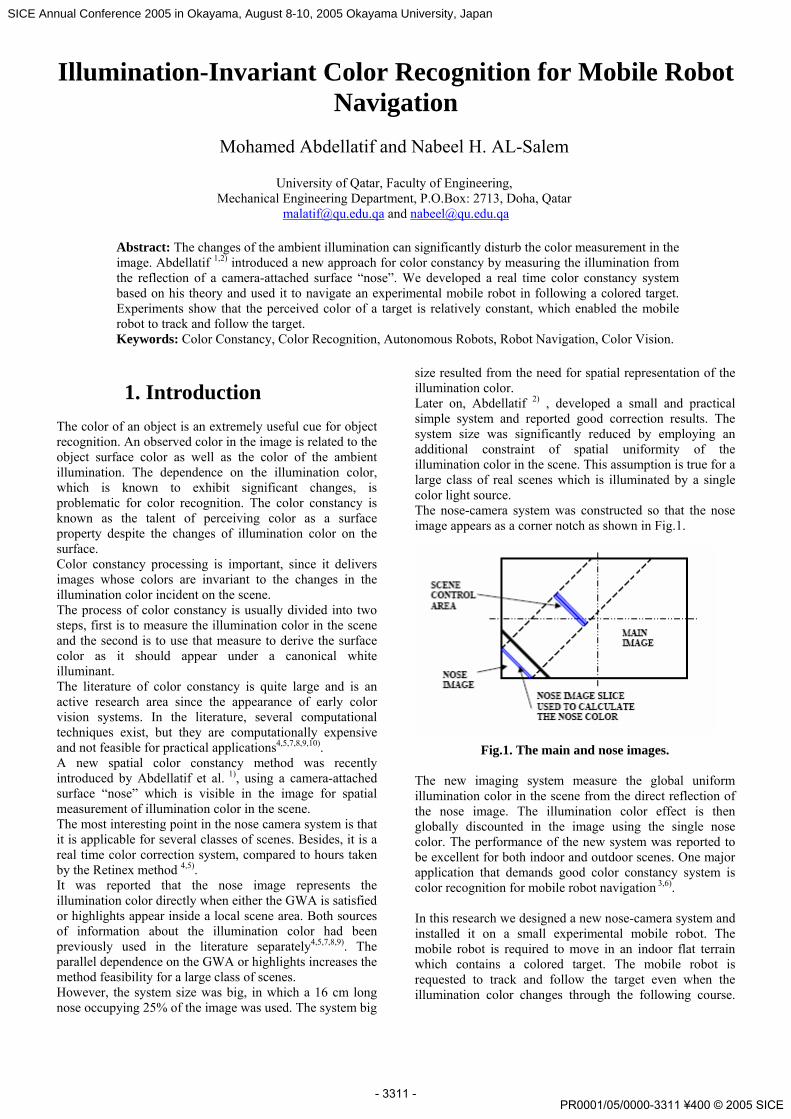
size resulted from the need for spatial representation of the illumination color. Later on, Abdellatif 2) , developed a small and practical simple system and reported good correction results. The system size was significantly reduced by employing an additional constraint of spatial uniformity of the illumination color in the scene. This assumption is true for a large class of real scenes which is illuminated by a single color light source. The nose-camera system was constructed so that the nose image appears as a corner notch as shown in Fig.1.
Fig.1. The main and nose images. The new imaging system measure the global uniform illumination color in the scene from the direct reflection of the nose image. The illumination color effect is then globally discounted in the image using the single nose color. The performance of the new system was reported to be excellent for both indoor and outdoor scenes. One major application that demands good color constancy system is color recognition for mobile robot navigation 3,6). In this research we designed a new nose-camera system and installed it on a small experimental mobile robot. The mobile robot is required to move in an indoor flat terrain which contains a colored target. The mobile robot is requested to track and follow the target even when the illumination color changes through the following course.
- 3311 -
SICE Annual Conference 2005 in Okayama, August 8-10, 2005 Okayama University, Japan
PR0001/05/0000-3311 ¥400 © 2005 SICE
The new imaging system is used to enhance the visual detection of colors which then enables the robust recognition of the target surface color. The target color is measured and known a priori to the robot control system. We, then test the color invariance by altering the lighting conditions incident to the target and observe the detection, segmentation and the consequent robot motion. Our motivation in this research is to exploit the potential of using the new imaging system for robot navigation. This paper is arranged as follows, Section 2 describes briefly the color measurement model from scene and nose reflections in the image. In Section 3, the control system for vehicle navigation from image measurements is described. In Section 4 the results of an experimental program for correcting color images and following the target are presented. Conclusions are finally given in Section 5.
2. Measurement Model 2.1. Color Image Formation
When the illumination light hits surfaces of the scene, the CCD camera collects the scene reflection through the lens. The color image is formed on the camera plane and the incident radiation is integrated both spatially and spectrally through the elements of its CCD sensor elements and hence responses measured at each pixel can be described by the following equation ( ) ( ) ( )∫∫∫= λλλ ddYdXFYXEcyxI c ..,,,, (1)
Where: I (x, y, c) is the intensity of the image observation corresponding to (x, y) location in the image. c ≡ (r, g, b) is the conventional vector representation of color attributes corresponding to (Red, Green, Blue). and E (X, Y, λ) is the scene incident radiation. (x, y), are the image coordinates measured in pixels, (X,Y) are the world coordinates λ is the wave length of light and FC (λ) is the spectral response function of the camera optics and sampling filters giving the color c ≡ (r, g, b). Equation 1, is the imaging model and shows that every pixel in the image provide a color vector of three integrals, that is RGB, in response to the scene reflection over three different spectral bands of the visible spectrum. A digitizer interface for the video signal of eight bit resolution is used. The color vector is thus (0,0,0) for completely dark locations, and (255, 255, 255) for the brightest objects of the scene. The camera electronics will sample the video signal according to the following equation
( ) ( ) bcyxIacyxk r += ,,.,, γ (2) The camera radiometric calibration is performed to estimate the offset b in each pixel and then discounting it from the raw image. The global photo-electric conversion exponent, γ is also calculated for the whole image. The calibration is done according to the following equation
( ) ( ) γ1
),,(,, bcyxkcyxk r −= (3)
The nose image color is then averaged spatially in the nose image and used as a reference for correcting all pixel colors in the image, hence the corrected color is obtained using the following formula :
( ) ( ) illuC KSFyxKyxK /,, =′′ (4) where ( )yxK , denote the color responses in a main image
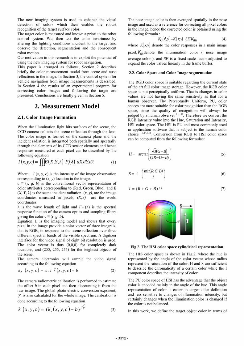
pixel, illuK denote the illumination color ( nose image average color ), and SF is a fixed scale factor adjusted to expand the color values linearly in the frame buffer. 2.2. Color Space and Color Image segmentation The RGB color space is suitable regarding the current state of the art full color image storage. However, the RGB color space is not perceptually uniform. That is changes in color values are not having the same sensitivity as that for a human observer. The Perceptually Uniform, PU, color spaces are more suitable for color recognition than the RGB space, since the quality of recognition will always be judged by a human observer 11,12). Therefore we convert the RGB intensity value into the Hue, Saturation and Intensity, HSI color space. The HSI is PU and most commonly used in application software that is subject to the human color choice 13,14,15). Conversion from RGB to HSI color space can be computed from the following formulae:
( )⎟⎟⎠
⎞⎜⎜⎝
⎛
−−−
=)2(
3arctanBGR
BGH (5)
( )⎟⎠⎞
⎜⎝⎛−=
IBGRS ,,min1 (6)
3/)( BGRI ++= (7)
Fig.2. The HSI color space cylindrical representation.
The HIS color space is shown in Fig.2, where the hue is represented by the angle of the color vector whose radius represent the saturation of the color. H and S are sufficient to describe the chromaticity of a certain color while the I component describes the intensity of color.
The PU color space of HSI has the advantage that the object color is encoded mainly in the angle of the hue. This angle representation of color is easier in target color definition and less sensitive to changes of illumination intensity, but certainly changes when the illumination color is changed if the color is not balanced.
In this work, we define the target object color in terms of
- 3312 -
limiting hue angles and limiting saturation values. The target is detected in the image by a selection criterion based on the boundaries of chromaticity zone are described by the following constraints:
⎟⎠⎞⎜
⎝⎛ ≈∈ hl hhh , (8) ⎟
⎠⎞⎜
⎝⎛ ≈∈ hl sss
The segmentation process is then based on the color chromaticity as follows
[ ]elsesatisfiedisEqif
yxseg0
)8(255),(
==
(9)
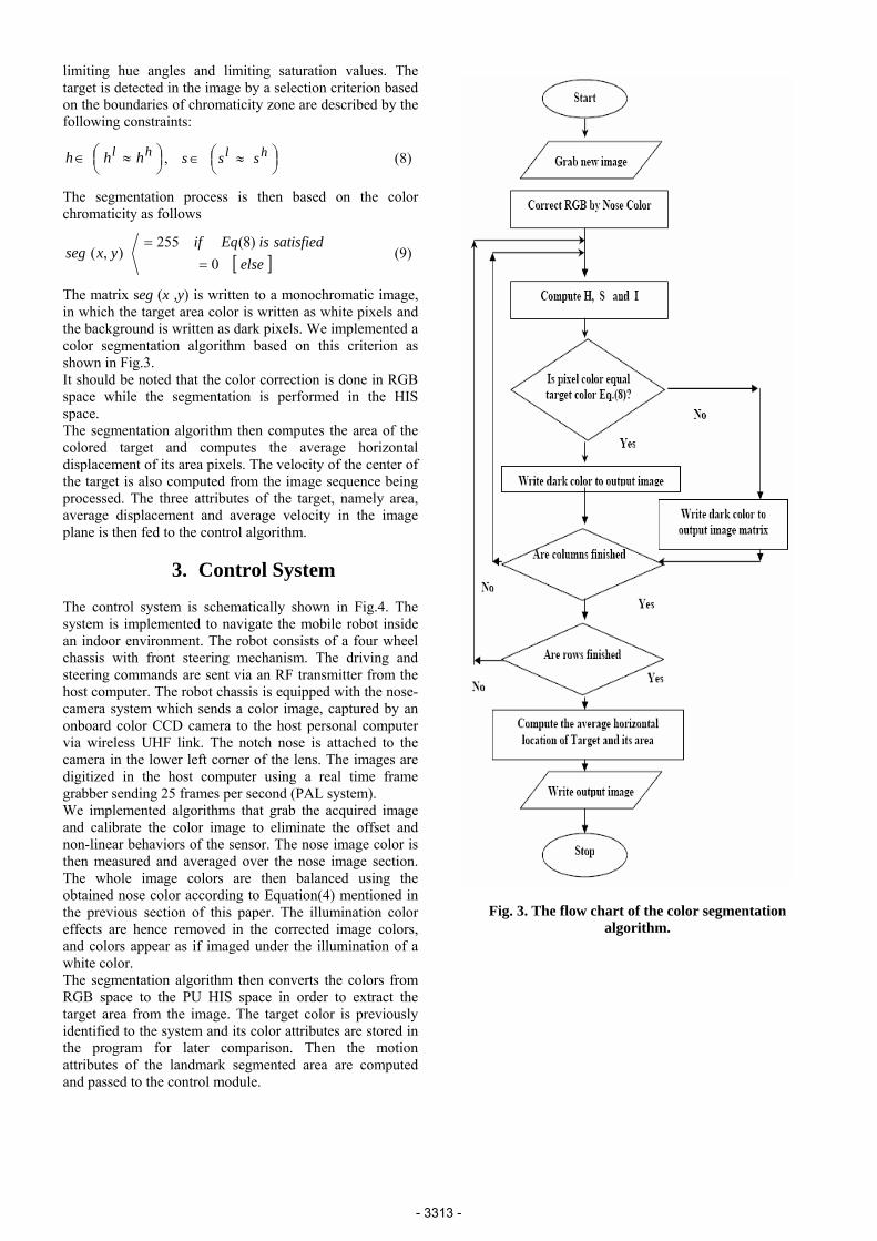
The matrix seg (x ,y) is written to a monochromatic image, in which the target area color is written as white pixels and the background is written as dark pixels. We implemented a color segmentation algorithm based on this criterion as shown in Fig.3. It should be noted that the color correction is done in RGB space while the segmentation is performed in the HIS space. The segmentation algorithm then computes the area of the colored target and computes the average horizontal displacement of its area pixels. The velocity of the center of the target is also computed from the image sequence being processed. The three attributes of the target, namely area, average displacement and average velocity in the image plane is then fed to the control algorithm.
3. Control System
The control system is schematically shown in Fig.4. The system is implemented to navigate the mobile robot inside an indoor environment. The robot consists of a four wheel chassis with front steering mechanism. The driving and steering commands are sent via an RF transmitter from the host computer. The robot chassis is equipped with the nose-camera system which sends a color image, captured by an onboard color CCD camera to the host personal computer via wireless UHF link. The notch nose is attached to the camera in the lower left corner of the lens. The images are digitized in the host computer using a real time frame grabber sending 25 frames per second (PAL system). We implemented algorithms that grab the acquired image and calibrate the color image to eliminate the offset and non-linear behaviors of the sensor. The nose image color is then measured and averaged over the nose image section. The whole image colors are then balanced using the obtained nose color according to Equation(4) mentioned in the previous section of this paper. The illumination color effects are hence removed in the corrected image colors, and colors appear as if imaged under the illumination of a white color. The segmentation algorithm then converts the colors from RGB space to the PU HIS space in order to extract the target area from the image. The target color is previously identified to the system and its color attributes are stored in the program for later comparison. Then the motion attributes of the landmark segmented area are computed and passed to the control module.
Fig. 3. The flow chart of the color segmentation
algorithm.
- 3313 -
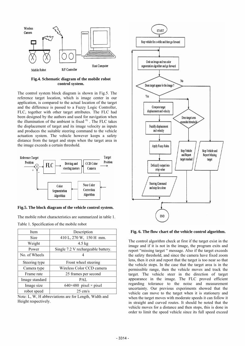
Fig.4. Schematic diagram of the mobile robot control system.
The control system block diagram is shown in Fig.5. The reference target location, which is image center in our application, is compared to the actual location of the target and the difference is passed to a Fuzzy Logic Controller, FLC, together with other target attributes. The FLC had been designed by the authors and used for navigation when the illumination of the ambient is fixed 6) . The FLC takes the displacement of target and its image velocity as inputs and produces the suitable steering command to the vehicle actuation system. The vehicle however keeps a safety distance from the target and stops when the target area in the image exceeds a certain threshold.
Fig.5. The block diagram of the vehicle control system. The mobile robot characteristics are summarized in table 1.
Table 1. Specification of the mobile robot
Item Description Size 410 L, 270 W, 150 H mm.
Weight 4.5 kg Power Single 7.2 V rechargeable battery.
No. of Wheels 4
Steering type Front wheel steering Camera type Wireless Color CCD camera Frame rate 25 frames per second
Image standard PAL Image size 640×480 pixel × pixel robot speed 25 cm/s
Note: L, W, H abbreviations are for Length, Width and Height respectively.
Fig. 6. The flow chart of the vehicle control algorithm. The control algorithm check at first if the target exist in the image and if it is not in the image, the program exits and report “missing target “ message. Also if the target exceeds the safety threshold, and since the camera have fixed zoom lens, then it exit and report that the target is too near so that the vehicle stops. In the case that the target area is in the permissible range, then the vehicle moves and track the target. The vehicle steer in the direction of target appearance in the image. The FLC proved efficient regarding tolerance to the noise and measurement uncertainty. Our previous experiments showed that the vehicle can move to the target when it is stationery and when the target moves with moderate speeds it can follow it in straight and curved routes. It should be noted that the vehicle moves for a distance and then stops, this is done in order to limit the speed vehicle since its full speed exceed
- 3314 -
100 cm/sec which is very high in mobile robot applications. Therefore, the move and stop style limit the average speed to 25 cm/sec which is the norm for several mobile robot experiments.
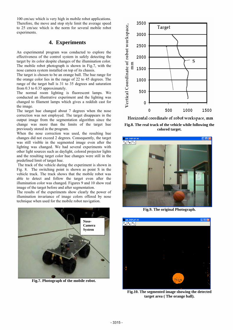
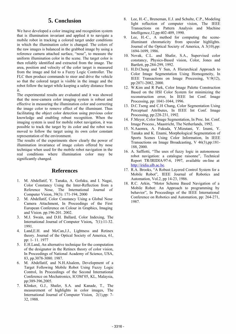
4. Experiments An experimental program was conducted to explore the effectiveness of the control system in safely detecting the target by its color despite changes of the illumination color. The mobile robot photograph is shown in Fig.7, with the nose camera system installed on top of its chassis. The target is chosen to be an orange ball. The hue range for the orange color lies in the range of 22 to 45 degrees. The range of the target ball is 31 to 35 degrees and saturation from 0.3 to 0.35 approximately. The normal room lighting is fluorescent lamps. We conducted an illustrative experiment and the lighting was changed to filament lamps which gives a reddish cast for the image. The target hue changed about 7 degrees when the nose correction was not employed. The target disappears in the output image from the segmentation algorithm since the change was more than the limits of the target hue previously stored in the program. When the nose correction was used, the resulting hue changes did not exceed 2 degrees. Consequently, the target was still visible in the segmented image even after the lighting was changed. We had several experiments with other light sources such as daylight, colored projector lights and the resulting target color hue changes were still in the predefined limit of target hue. The track of the vehicle during the experiment is shown in Fig. 8. The switching point is shown as point S in the vehicle track. The track shows that the mobile robot was able to detect and follow the target even after the illumination color was changed. Figures 9 and 10 show real image of the target before and after segmentation. The results of the experiments show clearly the power of illumination invariance of image colors offered by nose technique when used for the mobile robot navigation.
Fig.7. Photograph of the mobile robot.
Fig.8. The real track of the vehicle while following the colored target.
Fig.9. The original Photograph.
Nose-Camera System
Fig.10. The segmented image showing the detectedtarget area ( The orange ball).
- 3315 -
5. Conclusion
e have developed a color imaging and recognition system
experimental results are evaluated and it was showed
rly the power of
. M. Abdellatif, Y. Tanaka, A. Gofuku, and I. Nagai,
2. Global Nose
3. , Color Indexing, The
4. .H. and McCan,J.J., Lightness and Retinex
5. ternative technique for the computation
6. .Alsalem, Development of a
7. afer, S.A. and Kanade, T., The
8. , Breneman, E.J. and Schulte, C.P., Modeling
9. puting the scene-
10. Shafer, S.A., Supervised color
11. Hierarchical Approach to
12. olor Image Palette Construction
13. Segmentation Using
14. ation, In Proc. Int. Conf.
15. Y.
16. , “The uses of fuzzy logic in autonomous
Wthat is illumination invariant and applied it to navigate a mobile robot in tracking a colored target under conditions in which the illumination color is changed. The colors of the raw images is balanced in the grabbed image by using a reference camera attached surface, “nose”, to measure the uniform illumination color in the scene. The target color is then reliably identified and extracted from the image. The area, position and velocity of the color target is measured from the image and fed to a Fuzzy Logic Controller. The FLC then produce commands to steer and drive the vehicle so that the colored target is visible in the image and the robot follow the target while keeping a safety distance from it. Thethat the nose-camera color imaging system is robust and effective in measuring the illumination color and correcting the image color to remove effect of the illuminant. Thus facilitating the object color detection using previous color knowledge and enabling robust recognition. When the imaging system is used for mobile robot navigation, it was possible to track the target by its color and the robot was moved to follow the target using its own color constant representation of the environment. The results of the experiments show cleaillumination invariance of image colors offered by nose technique when used for the mobile robot navigation in the real conditions where illumination color may be significantly changed.
References
1Color Constancy Using the Inter-Reflection from a Reference Nose, The International Journal of Computer Vision, 39(3): 171-194, 2000 M. Abdellatif, Color Constancy Using aCamera Attachment, In Proceedings of the First European Conference on Colour in Graphics, Imaging and Vision. pp.196-201. 2002. M.J. Swain, and D.H. BallardInternational Journal of Computer Vision, 7(1):11-32. 1991. Land,Etheory. Journal of the Optical Society of America, 61, pp: 1- 11. 1977 E.H.Land, An alof the designator in the Retinex theory of color vision, In Proceedings of National Academy of Science, USA, 83, pp.3078-3080. 1987. M. Abdellatif, and N.HTarget Following Mobile Robot Using Fuzzy Logic Control, In Proceedings of the Second International Conference on Mechatronics, ICOM’05, KL, Malaysia, pp:389-396,2005. Klinker, G.J., Shmeasurement of highlights in color images, The International Journal of Computer Vision, 2(1),pp: 7-32, 1988.
Lee, H.-C.light reflection of computer vision, The IEEE Transactions on Pattern Analysis and Machine Intelligence,12,pp:402-409, 1990. Lee, H.-C., A method for comilluminant chromaticity from specular highlights. Journal of the Optical Society of America, A 3(10),pp: 1694-1699, 1986. Novak, C.L. andconstancy, Physics-Based vision, Color, Jones and Bartlett, pp.284-299, 1992. H.D.Cheng and Y Sun, AColor Image Segmentation Using Homogeneity, In IEEE Transactions on Image Processing, V:9(12), pp:2071-2082, 2000. W.Kim and R Park, CBased on the HSI Color System for minimizing the reconstruction error, In IEEE Int Conf. Image Processing, pp: 1041-1044, 1996. D.C.Tseng and C.H Chang, ColorPerceptual Attributes, In IEEE Int Conf. Image Processing, pp:228-231, 1992. F.Meyer, Color Image SegmentImage Process., Maastricht, The Netherlands, 1992. N.Aaemra, A. Fukuda, Y.Mizutani, Y. Izumi, Tanaka and K. Enami, Morphological Segmentation of Sports Scenes Using Color Information, In IEEE Transactions on Image Broadcasting, V 46(3),pp:181-188, 2000. A. Saffiottirobot navigation: a catalogue raisonne”, Technical Report TR/IRIDIA/97-6, 1997, available on-line at http://iridia.ulb.ac.be. R.A. Brooks, “A Robu17. st Layered Control System for a
18. Navigation of a
Mobile Robot”, IEEE Journal of Robotics and Automation, Vol.2, pp 14-23, 1986. R.C. Arkin, “Motor Schema BasedMobile Robot: An Approach to programming by behavior”, In Proceedings of the IEEE International Conference on Robotics and Automation, pp: 264-271, 1987.
- 3316 -