
II SweepEx Rotary Broom Serial #170301-Higher #SWB-320
28
Rotary Broom SWB-320 Owner's Manual Original Instructions March 1, 2019 Lit. No. 72356, Rev. 00 CAUTION Read this document before operating or servicing the rotary broom. This document supersedes all editions with an earlier date. This document is for SweepEx ® SWB-320 rotary brooms with serial numbers beginning with 170301 and higher.
-
Upload
khangminh22 -
Category
Documents
-
view
1 -
download
0
Transcript of II SweepEx Rotary Broom Serial #170301-Higher #SWB-320

Rotary BroomSWB-320
Owner's ManualOriginal Instructions
March 1, 2019Lit. No. 72356, Rev. 00
CAUTIONRead this document before operating or servicing the rotary broom.
This document supersedes all editions with an earlier date.
This document is for SweepEx® SWB-320 rotary brooms withserial numbers beginning with 170301 and higher.

Lit. No. 72356, Rev. 00 March 1, 2019

Lit. No. 72356, Rev. 00 3 March 1, 2019
TABLE OF CONTENTS
PREFACE ..................................................................................................................................................................5Owner's Information ............................................................................................................................................5
SAFETY ....................................................................................................................................................................6OPERATING INSTRUCTIONS .................................................................................................................................9
General Safety ....................................................................................................................................................9Operating in Winter .............................................................................................................................................9Component Vocabulary ....................................................................................................................................10Operator Controls .............................................................................................................................................11Starting/Stopping Motor ....................................................................................................................................12Adjusting Handlebar Height ..............................................................................................................................13Transporting ......................................................................................................................................................14Adjusting Discharge Direction...........................................................................................................................15Sweeping ..........................................................................................................................................................16Debris Collector Box (Optional Accessory) ......................................................................................................17Debris Shield (Optional Accessory) ..................................................................................................................18
MAINTENANCE ...................................................................................................................................................... 19Oil and Gas ....................................................................................................................................................... 19Tire Pressure ....................................................................................................................................................20Adjusting Control Cables .................................................................................................................................. 21Replacing/Changing Brushes ...........................................................................................................................22Maintenance Plan .............................................................................................................................................25Cleaning ............................................................................................................................................................26
TROUBLESHOOTING ............................................................................................................................................27

Lit. No. 72356, Rev. 00 March 1, 2019

Lit. No. 72356, Rev. 00 5 March 1, 2019
PREFACE
This manual has been prepared to acquaint you with the safety information, operation, and maintenance of your new rotary broom. Please read this manual carefully and follow all recommendations. This will help ensure pro table and trouble-free operation of your rotary broom. Keep this manual accessible. It is a handy reference in case minor service is required.
When service is necessary, bring your rotary broom to your distributor. They know your rotary broom best and are interested in your complete satisfaction.
Register your rotary broom online at www.sweepexproducts.com
OWNER'S INFORMATION
Owner's Name: _______________________________________________________________________
Date Purchased: ______________________________________________________________________
Outlet Name: ______________________________________________ Phone: ___________________
Outlet Address: _______________________________________________________________________
Engine Model: _______________________________________ Weight: ____________________ lb/kg
Rotary Broom Serial #: ________________________________ Engine Serial #: _________________

Lit. No. 72356, Rev. 00 6 March 1, 2019
SAFETY
SAFETY DEFINITIONS
NOTE: Indicates a situation or action that can lead to damage to your rotary broom or other property. Other useful information can also be described.
CAUTIONIndicates a potentially hazardous situation that, if not avoided, may result in minor or moderate injury. It may also be used to alert against unsafe practices.
WARNINGIndicates a potentially hazardous situation that, if not avoided, could result in death or serious personal injury.
LABELS
Please become familiar with the labels on the rotary broom.
NOTE: If labels are missing or cannot be read, see your sales outlet.
Code De nitionYY 2-Digit YearMM 2-Digit MonthDD 2-Digit DayLL 2-Digit Location Code
#### 4-Digit Sequential NumberSWB320 Part Number
2017
170301041234SWB320
Serial Number Label
3.3130 lb
SWB-320
B&S 550E
DANGER ZONE
DANGER ZONE
Keep all bystanders away from the rotary broom at least 30 feet (10 meters), as depicted in the diagram below.
WARNINGFlying objects; Keep safe distance from the rotary broom when engine is running.

Lit. No. 72356, Rev. 00 7 March 1, 2019
PERSONAL SAFETY
• Wear only snug- tting clothing while working on your rotary broom.
• Do not wear jewelry or a necktie, and secure long hair.
• Wear safety goggles to protect your eyes from dirt, dust, and ying debris.
• Be aware of and avoid pinch points when assembling and operating. Pinch points can exist around levers and when putting two parts together (during assembly).
SAFETY
SAFETY PRECAUTIONS
Improper assembly and operation could cause personal injury and/or equipment and property damage. Read and understand labels and this Owner's Manual before assembling, operating, or making adjustments.
The rotary broom is intended exclusively for use for brushing operations in property maintenance and snow clearance. Examples of intended use are: snow clearing; sidewalk, driveway, and parking lot cleaning (with multi-purpose brushes); spring debris clean-up; dethatching; clearing debris from arti cial turf; and leaf clean-up (with multi-purpose brushes).
NOTE: Lubricate grease ttings after each use. Use a good quality multipurpose grease.
WARNING• Always make sure personnel are clear of
areas of danger when using equipment.• Before working with the rotary broom,
secure all loose- tting clothing and unrestrained hair.
• Do not climb onto or ride on rotary broom.
CAUTION• Do not operate a rotary broom in need of
maintenance.• Before operating the rotary broom,
reassemble any parts or hardware removed for cleaning or adjusting.
• Before operating the rotary broom, remove materials such as cleaning rags, brushes, and hand tools from the rotary broom.
• Tighten all fasteners according to the Torque Chart. Refer to Torque Chart for the recommended torque values.

Lit. No. 72356, Rev. 00 8 March 1, 2019
1/4-20 109 1541/4-28 121 1715/16-18 150 2125/16-24 170 2403/8-16 269 3763/8-24 297 4207/16-14 429 6067/16-20
9/16-129/16-185/8-115/8-183/4-103/4-167/8-97/8-14 474 669
644 9091-81-12 704 995
1/2-131/2-20
11.913.724.627.343.6
26.953.393148
49.469.877.9
106.4120.0
8.49.717.419.230.835.049.455.275.385.0
M6 x 1.00
M12 x 1.75
M8 x 1.25
M14 x 2.00
M10 x 1.50M27 x 3.00
M22 x 2.50
M30 x 3.50
M24 x 3.00
M20 x 2.5011.119.538.567107
7.761377811391545
4504285627961117
M33 x 3.50M36 x 4.00
21012701
14681952
325
M16 x 2.00 231167M18 x 2.50 318222
Recommended Fastener Torque Chart
Size SizeTorque (ft-lb)
Grade5
Grade8
Metric Fasteners Class 8.8 and 10.9
These torque values apply to fastenersexcept those noted in the instructions.
Torque (ft-lb)Grade
5Grade
8
Size SizeTorque (ft-lb)
Class8.8
Class10.9
Torque (ft-lb)Class
8.8Class10.9
Inch Fasteners Grade 5 and Grade 8
FIRE AND EXPLOSION
VENTILATION
NOISE
Noise emission values comply with EC guideline 98/37/EWG or 2006/42/EG.The measurement was carried out with the rotary broom at standstill with driven brushes on an asphalted road.• The sound pressure level at the ear: Lp user = 87 dB.• The sound power level: LW = 102 dB.• Measuring devices used comply with DIN 45634.
VIBRATION
Hand-arm vibration values comply with VDI 2057, Sheet 2.The measurement was carried out on asphalted road.• Vibrations were measured in three axes on the
handlebars: X, Y, and Z axes, see DIN 45675, Part 8. The value for 60 seconds duration was determined.
• Measurement results: 60s effective value = 9.9 m/s2
• Measuring device used complies with DIN 45675.• Rotary broom in operating condition:
Warmed up, retracted rotary broom under full load.
Brush height adjustment: standard Fuel tank: approx. 50% full Brush axle: middle position
SAFETY
WARNINGGasoline is highly ammable and gasoline vapor is explosive. Never smoke while working on vehicle. Keep all open ames away from gasoline tank and lines. Wipe up any spilled gasoline immediately.
WARNINGEngine exhaust contains lethal fumes. Breathing these fumes, even in low concentrations, can cause death. Never operate an engine in an enclosed area without venting exhaust to the outside.
TORQUE CHART
CAUTIONRead instructions before assembling. Fasteners should be nger tight until instructed to tighten according to the torque chart. Use standard methods and practices when assembling the rotary broom, including proper personal protective safety equipment.

Lit. No. 72356, Rev. 00 9 March 1, 2019
OPERATING IN WINTER
Check regularly that the air lter is dry. If the air lter has become wet, let it dry overnight. There is a possibility of the engine not starting due to a clogged air lter.
Spray the throttle cable with silicone spray at both ends and the throttle linkage before operating to prevent the cable or throttle mechanism from freezing up.
Silicone spray attracts dust and binds it to the rotary broom. It is only a suitable lubricant in wintry and snowy conditions.
Do not spray silicone spray on hot engine. It could cause a re. Follow the instructions on the spray can.
Before putting the rotary broom away, sweep it clear of snow.
Avoid freezing the rotary broom. Store the rotary broom in a frost-free room.
Remove foam pre- lter.
Use SAE 5W-30 motor oil.
GENERAL SAFETY
Do not operate the rotary broom in an unsafe manner. Make yourself familiar with the surroundings before starting work in a new location. The working surroundings include any obstacles in the work area or on roads, the ground load-bearing capacity, and any necessary workplace safety precautions in live traf c.
Take precautions to ensure that the rotary broom is only operated in a safe and functional condition. Only operate the rotary broom if all protective and safety devices are present and working.
Check the rotary broom for externally visible damage and faults before operation. If malfunctions occur stop the rotary broom and secure it immediately. Repair malfunctions immediately. Only start the rotary broom from the operator's position. Ensure that no one can be endangered by starting the rotary broom before switching it on or operating it.
Check that braking, steering, and brushing are fully functional before operation.
Before operating the rotary broom, always check that accessories are tted correctly.
Always observe applicable traf c regulations before operating on public roads, paths, or parks, and ensure that the rotary broom is in a condition suitable for use in traf c.
Always ensure that suitable lighting is available before working in poor light or darkness. Always keep a suf cient distance between the rotary broom and drop-offs, holes, or slopes.
Do not permit any method of working which will affect the stability of the rotary broom.
Never traverse across slopes; always travel up and down, not across.
Adjust the speed to suit the conditions on inclines. Change gear before the incline, not on it. Always secure the rotary broom against rolling away and unauthorized operation before leaving it unattended.
GENERAL SAFETY/OPERATING IN WINTER

Lit. No. 72356, Rev. 00 10 March 1, 2019
ReceiverBar
Brush AngleAdjustment
Engine
Drive Wheel
CasterWheels
Brushes
Handlebar
Throttle Control
Brush LeverMovementLever
COMPONENT VOCABULARY
OPERATING INSTRUCTIONS

Lit. No. 72356, Rev. 00 11 March 1, 2019
OPERATOR CONTROLS
OPERATING INSTRUCTIONS
WARNINGThe handlebar can get stuck inside long sleeves. This could prevent the drive from disengaging and result in injury. Set the bar lower if wearing long sleeves or tightly button the sleeves.
WARNINGAvoid injury and damage; Make completely sure that there are no persons or objects within the danger zone.
CAUTIONIf the brushes are switched ON and the rotary broom is not in gear, the rotary broom can roll backwards. The handlebar must be securely engaged at the required height.
Drive
Brushes
Throttle
1. Press the drive lever to move the rotary broom forward.
2. Engage both levers to operate the drive and the brushes.

Lit. No. 72356, Rev. 00 12 March 1, 2019
OPERATING INSTRUCTIONS
STARTING/STOPPING MOTOR
NOTE: Before starting the motor, ensure there is suf cient oil. The motor is not lled with oil when the rotary broom is delivered.
Starting the Motor
Move the throttle control to the "Choke" position.
WARNINGEngine exhaust contains lethal fumes. Breathing these fumes, even in low concentrations, can cause death. Never operate an engine in an enclosed area without venting exhaust to the outside.
Pull the starter coil. Stand behind the handlebars. Do not press any levers.
Lit. No. 72356, Rev. 00 13 March 1, 2019
OPERATING INSTRUCTIONS
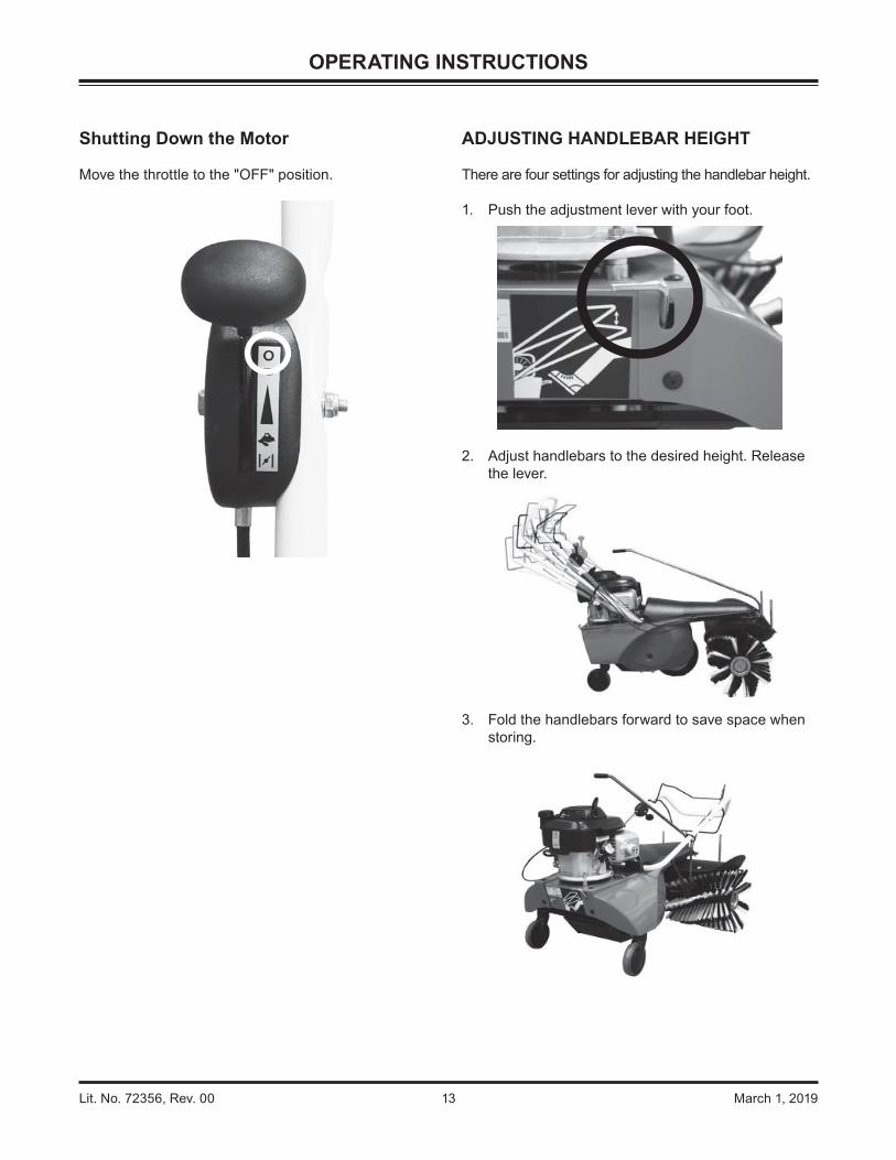
Shutting Down the Motor
Move the throttle to the "OFF" position.
ADJUSTING HANDLEBAR HEIGHT
There are four settings for adjusting the handlebar height.
1. Push the adjustment lever with your foot.
2. Adjust handlebars to the desired height. Release the lever.
3. Fold the handlebars forward to save space when storing.

Lit. No. 72356, Rev. 00 14 March 1, 2019
OPERATING INSTRUCTIONS
TRANSPORTING
Carrying
Position hands to hold the front of the broom as shown below.
Securing for Transport
1. Position the strap at the front of the broom as shown.
2. Position the straps at the rear of the broom as shown.
3. To save space when transporting, fold the handlebars forward.

Lit. No. 72356, Rev. 00 15 March 1, 2019
ADJUSTING DISCHARGE DIRECTION
There are four settings available for the discharge direction: three primary positions and a sideways position when using the optional accessories.
Forward Discharge Direction:
The swept material will heap up in front of the brushes. You should give preference to angled brush settings.
To adjust brush angle: Lift the lever. Turn the brush in the desired direction. Release the lever, and ensure that the lever is latched in place.
Right Discharge Direction:
With an angled setting, the material will be swept to one side.
Left Discharge Direction:
Sideways Discharge Direction(available with optional accessories):
A sideways setting is recommended if using the optional debris collector box and optional debris shield. This will allow sweeping against a wall or curb.
OPERATING INSTRUCTIONS
Debris Collector Box
Debris Shield
Lit. No. 72356, Rev. 00 16 March 1, 2019
OPERATING INSTRUCTIONS
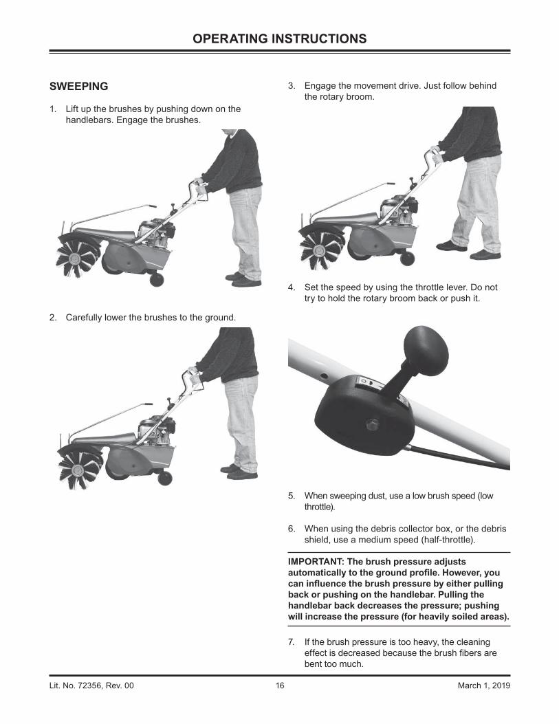
SWEEPING
1. Lift up the brushes by pushing down on the handlebars. Engage the brushes.
2. Carefully lower the brushes to the ground.
3. Engage the movement drive. Just follow behind the rotary broom.
4. Set the speed by using the throttle lever. Do not try to hold the rotary broom back or push it.
5. When sweeping dust, use a low brush speed (low throttle).
6. When using the debris collector box, or the debris shield, use a medium speed (half-throttle).
IMPORTANT: The brush pressure adjusts automatically to the ground pro le. However, you can in uence the brush pressure by either pulling back or pushing on the handlebar. Pulling the handlebar back decreases the pressure; pushing will increase the pressure (for heavily soiled areas).
7. If the brush pressure is too heavy, the cleaning effect is decreased because the brush bers are bent too much.
Lit. No. 72356, Rev. 00 17 March 1, 2019
OPERATING INSTRUCTIONS
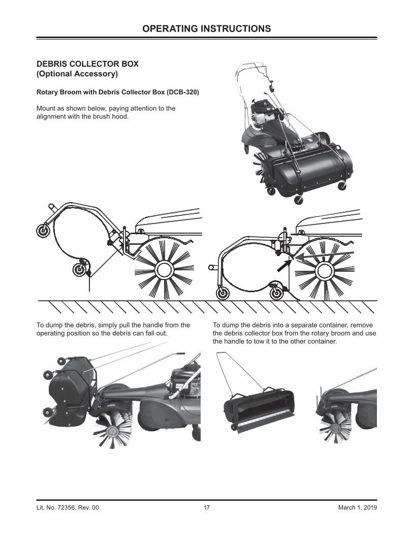
DEBRIS COLLECTOR BOX(Optional Accessory)
Rotary Broom with Debris Collector Box (DCB-320)
Mount as shown below, paying attention to the alignment with the brush hood.
To dump the debris, simply pull the handle from the operating position so the debris can fall out.
To dump the debris into a separate container, remove the debris collector box from the rotary broom and use the handle to tow it to the other container.

Lit. No. 72356, Rev. 00 18 March 1, 2019
DEBRIS SHIELD(Optional Accessory)
Rotary Broom with Optional Debris Shield (PCA-320)
1. Slide one fender washer over each receiver bar.
OPERATING INSTRUCTIONS
2. Slide the debris shield over the receiver bars.
3. Installation is complete.
Fender Washers
Receiver Bar

Lit. No. 72356, Rev. 00 19 March 1, 2019
MAINTENANCE
OIL AND GAS
Capacities:
Oil: 0.47 qt (0.44 L)Gasoline: 0.20 qt (0.76 L)
Use 86 octane or higher unleaded gasoline.
1. Remove oil cap; wipe dipstick clean.
2. Replace dipstick in the oil ller neck; do not screw down.
3. Remove dipstick; check oil level. The oil should be up to the upper marking.
4. If oil level is low, ll up to the upper marking on the dipstick with the recommended oil (see Briggs & Stratton owner's manual).
5. See marking on the dipstick for ll level.
Oil
Gas
Fill Level

Lit. No. 72356, Rev. 00 20 March 1, 2019
MAINTENANCE
TIRE PRESSURE
IMPORTANT: If the tire pressure is too low, the inner tube will rub against the wheel and be damaged. Over-in ation can cause the tire to burst. Check the tire pressure for both the support and drive wheels regularly.
1. Lock the handlebar at the front-most setting.
2. Tip the rotary broom backward to rest on the handlebar and the rear wheels. Have a second person hold the rotary broom in this position.
3. Turn the wheel counterclockwise to expose the valve stem.
4. In ate the tire to 35 psi (2.5 bar), or for sweeping rough surfaces, 30 psi (2 bar).
WARNINGUse safety glasses and gloves when in ating and installing the tires. Use manual pump only to in ate. Refer to the tire sidewall for manufacturer's recommended pressure. Do not exceed the maximum in ation pressure.

Lit. No. 72356, Rev. 00 21 March 1, 2019
MAINTENANCE
ADJUSTING CONTROL CABLES
IMPORTANT: It may be necessary to reset the cables after rotary broom has been operating for a few hours. The cables need reset if the levers move more than one-third of the lever's travel without resistance.
1. With a 10 mm wrench, loosen the nut that holds the cable to the handlebar. Pull the cable down. Retighten the nuts.
2. The levers should move one-third of the total travel without resistance. The lever should be operating the cable for the other two-thirds.
3. The drive wheel should just turn when the lever is not engaged.

Lit. No. 72356, Rev. 00 22 March 1, 2019
3. Remove the nut and pull off the brush.
4. Remove the axle with the second brush.
MAINTENANCE
REPLACING/CHANGING THE BRUSHES
IMPORTANT: Check the brushes after every 20 hours of use. The brushes must be replaced if you are no longer satis ed with the brushing result, or if the brush diameter is below 8-5/8" (220 mm).
1. Use two 17 mm wrenches to loosen the nut on the left brush (when viewed from the front).
2. Tip the rotary broom up. Have a second person stabilize the rotary broom.
Lit. No. 72356, Rev. 00 23 March 1, 2019
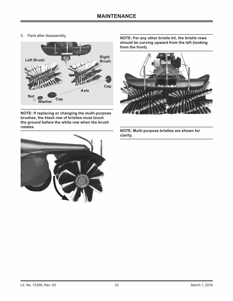
5. Parts after disassembly.
NOTE: If replacing or changing the multi-purpose brushes, the black row of bristles must touch the ground before the white row when the brush rotates.
Left BrushRightBrush
Cap
Cap
AxleNut
Washer
MAINTENANCE
NOTE: For any other bristle kit, the bristle rows should be curving upward from the left (looking from the front).
NOTE: Multi-purpose bristles are shown for clarity.

Lit. No. 72356, Rev. 00 24 March 1, 2019
8. Fit the left-hand brush over the axle.
9. Install the cap and washer, ensuring the tabs and slots are aligned.
10. Tighten the locknut to fasten the brushes.
MAINTENANCE
6. Assemble the right-hand brush with the axle to the rotary broom.
7. The tab on the cap-gear should t into the slot of the brush cylinder.
Tab
Slot

Lit. No. 72356, Rev. 00 25 March 1, 2019
MAINTENANCE
MAINTENANCE PLAN/CLEANING
Before every use
After the following operating hours: After 3 month min.
At least annually
After every
cleaning5 10 25 50 100
Check screws and nuts C
Check motor oil level, re ll if necessary C
First motor oil change S
All further motor oil changes S S
Check air lter C
Clean air lter element, earlier if necessary M M
Replace air lter element, earlier if necessary M
Replace fuel hoses S(2 years)
Clean cool air screen M
Clean baf e plate, cooling ribs, earlier if necessary S
Clean spark plugs, adjust gap S
Replace spark plugs S
Clean exhaust M
Lubricate all moving parts M M
Check hand lever play setting C
Check brush wear, earlier if necessary C
Stretch chain drive C S
S = Maintenance by Specialist C = Check by Operator M = Maintenance by Operator
NOTE: Store the rotary broom properly. Contact the local dealer for suitable storage practices in your geographic location.

Lit. No. 72356, Rev. 00 26 March 1, 2019
CLEANING
• To keep your rotary broom in good condition, clean it regularly.
• Remove loose dirt or dust with a car wash brush. Wash plastic surfaces with water and soap. Use normal car cleaning soap. Rinse off all cleaners thoroughly with clean water.
• To give plastic parts a gloss nish, use a plastics care product.
• Observe the instructions on the cleaning solution package.
• Use glycerine as a corrosion protection for heavily soiled parts.
• Do not use pressure washers. The high pressure may force water into bearings, seals, and the motor, causing damage.
MAINTENANCE

Lit. No. 72356, Rev. 00 27 March 1, 2019
TROUBLESHOOTING
FAULT POSSIBLE CAUSE FAULT REMEDYMotor will not start Fuel tank empty Fill fuel tank
Throttle lever not set to choke when motor is cold Set throttle lever to choke
Spark plug leads not connected Connect spark plug leads
Fuel line blocked Send fuel line to dealer for cleaning
Motor receiving wrong air due to loose carburetor Tighten xing screws
Fuel valve closed on motor Open fuel valve on motor
Motor will not start; gasoline smell
Motor is receiving too much fuel Set throttle lever to full speed, not to choke
Air lter dirty Clean air lter
Motor running badly; mis res
Motor running with choke activated Move throttle lever out of choke position
Spark plug leads loose Allow motor to cool and connect spark plug leads rmly
Air lter soiled Clean air lter
Air bleed hole in fuel tank ller cap blocked Replace fuel tank ller cap
Fuel line blocked
Clean fuel lines
Replace fuel lines
Run fuel system cleaner through tank of gas
Carburetor not correctly adjusted Adjust carburetor/Send to dealer
Motor overheating See fault "Motor Overheating"
Motor mis res at high speed
Spark plug gap not correct Adjust spark plug gap/Send to dealer
Carburetor not correctly adjusted Adjust carburetor/Send to dealer
Motor overheating Oil level too low Re ll motor oil
Air cooling system restricted Send to dealer/Adjust air cooler grille & cooling ribs
Air lter dirty Clean air lter
Carburetor not correctly adjusted Adjust carburetor/Send to dealer
Motor often stops during turnover
Throttle lever not set to choke when motor is cold Set throttle lever to choke
Spark plug gap not correct Send carburetor to dealer for adjustment
Air lter dirty Clean air lter
Motor has lost power Air lter soiled Clean air lter
Compression too low Send to dealer for adjustment
Motor will not stop Motor stop lever not correctly adjusted See Briggs & Stratton owner's manual/Send to dealer
Perpetual squeaking when brushes switched on
Switch lever not completely pressed down Press switch lever completely down
Control cable not correctly adjusted Readjust brush control cable
Brushes do not turn, or stop moving under load
Switch lever not completely pressed down Press switch lever completely down
Control cable not correctly adjusted Readjust brush control cable
Toothed belts defective Send to dealer
Rotary broom will not move forward
Movement control cable not correctly adjusted Re-adjust control cable
Tension on toothed belt between motor and gearbox too low
Send to dealer
Rotary broom leaves unbrushed central strip
Discharge direction forward with worn brushes Turn the discharge direction to the side
Brushes worn Replace brushes
Bad brushing results Brushes wrongly mounted Mount brushes correctly; observe working direction
Brush pressure too high Readjust support wheel; Reduce brush pressure
Brushes not genuine SweepEx® parts Use only SweepEx brushes
Brushes not suitable for application Contact Customer Service to determine correct brush kit
Bad brushing results with debris collector box
Debris collector box not tted correctly, sealing lip above brush cover
Mount swept material container correctly

Copyright © 2019 Douglas Dynamics, LLC. All rights reserved. This material may not be reproduced or copied, in whole or in part, in any printed, mechanical, electronic, lm, or other distribution and storage media, without the written consent of TrynEx International, LLC. Authorization to photocopy items for internal or personal use by TrynEx International outlets or rotary broom owner is granted.
TrynEx International reserves the right under its product improvement policy to change construction or design details and furnish equipment when so altered without reference to illustrations or speci cations used. TrynEx International may require or recommend optional equipment for rotary brooms. TrynEx International offers a limited warranty for all rotary brooms and accessories. See separately printed page for this important information. The following is a registered (®) trademark of Douglas Dynamics, LLC: SweepEx®.
Printed in U.S.A.
A DIVISION OF DOUGLAS DYNAMICS, LLC
TrynEx International, LLC531 Ajax DriveMadison Heights, MI 48071-2429www.sweepexproducts.com
Lit. No. 72356, Rev. 00 March 1, 2019
This product conforms to EU Machinery Directive 2006/42/EC.