![Highly Efficient Inverted Organic Solar Cells Through Material and Interfacial Engineering of Indacenodithieno[3,2-b]thiophene-Based Polymers and Devices](https://static.fdokumen.com/doc/165x107/6312a9f2b033aaa8b20fbd19/highly-efficient-inverted-organic-solar-cells-through-material-and-interfacial-engineering.jpg)
Identifying a Threshold Impurity Level for Organic Solar Cells: Enhanced First-Order Recombination...
10
www.afm-journal.de FULL PAPER © 2011 WILEY-VCH Verlag GmbH & Co. KGaA, Weinheim 3083 www.MaterialsViews.com wileyonlinelibrary.com Adv. Funct. Mater. 2011, 21, 3083–3092 Sarah R. Cowan, Wei Lin Leong, Natalie Banerji, Gilles Dennler, and Alan J. Heeger* 1. Introduction Recent reports in the literature show polymer bulk heterojunc- tion (BHJ) solar cells demonstrate continuing promise: solar cells with near 100% internal quantum efficiency [1] and with 6%–8% power conversion efficiencies [1–3] have been demon- strated. There are many challenges to overcome on the way to competitively efficient devices, including the need for a detailed knowledge of charge transport and loss mechanisms in the complex phase-separated BHJ systems. Nevertheless, many of the perceived drawbacks of polymer materials such as atmos- pheric sensitivity [4,5] and high band gap [1–3,6–9] are being over- come, both in the lab and in field testing. The BHJ material is commonly implemented by casting a polymer:fullerene blend from solution, resulting in distributed junctions between the polymer donor and fullerene acceptor interfaces. The fullerene derivatives [6,6]-phenyl-C 61 - butyric acid methyl ester (PC 60 BM) and [6,6]-phenyl-C 71 -butyric acid methyl ester (PC 71 BM) have been widely used as the electron-accepting material. Small amounts of these fullerene materials have been found to quench luminescence in the highly absorptive and fluorescent sem- iconducting polymer materials. [10] When mixed in large fraction, charge transfer from the polymer to the fullerene deriva- tive is efficient, ultrafast, and largely irre- versible. [10–15] Ultrafast and highly effi- cient charge transfer is essential to high efficiency BHJ solar cell operation. In 1985, H. W. Kroto, R. F. Curl, R. E. Smalley, et al. detected C 60 in carbon vapor from laser ablation of graphite. [16] Since the synthesis of macroscopic quantities of C 60 , C 70 , and the higher fullerenes in the early 1990s, [17,18] fullerenes and soluble fullerene adducts have become highly studied research materials. The synthesis of PC 60 BM in 1995 [19] led to the first polymer:fullerene bulk heterojunction solar cell [20] within the year. Use of polymers or other small molecules as the electron-accepting material have not yet been as successful. [21,22] [6,6]-phenyl-C 84 -butyric acid methyl ester (PC 84 BM) became briefly interesting as a solar cell acceptor [23] due to its strong, broad absorption, and relatively high mobility. [24] However, it was abandoned as an acceptor due to observed loss of photocur- rent and increased recombination. The electronic effect of traps and disorder – material prop- erties inherent to polymer blend systems – has been studied in relation to the performance of organic light-emitting diodes, [25] organic thin-film transistors, [26] and organic photo- voltaics. [22,27–29] However, the role of impurities in the recom- bination process and the attainable open circuit voltage has only received moderate attention. In 2007, Blom and coworkers observed the modification of the open circuit voltage and its light intensity dependence due to trap-limited electron transport and trap-assisted recombination. [29] In this work, we explore the effect of impurities via the controlled introduction of the PC 84 BM molecule and propose a simple model which takes into account the density of trap states and the intensity-dependence Identifying a Threshold Impurity Level for Organic Solar Cells: Enhanced First-Order Recombination Via Well- Defined PC 84 BM Traps in Organic Bulk Heterojunction Solar Cells Small amounts of impurity, even one part in one thousand, in polymer bulk heterojunction solar cells can alter the electronic properties of the device, including reducing the open circuit voltage, the short circuit current and the fill factor. Steady state studies show a dramatic increase in the trap-assisted recombination rate when [6,6]-phenyl C 84 butyric acid methyl ester (PC 84 BM) is introduced as a trap site in polymer bulk heterojunction solar cells made of a blend of the copolymer poly[N-9’’-hepta-decanyl-2,7-carbazole-alt-5,5-(4’,7’- di-2-thienyl-2’,1’,3’-benzothiadiazole) (PCDTBT) and the fullerene deriva- tive [6,6]-phenyl C 61 butyric acid methyl ester (PC 60 BM). The trap density dependent recombination studied here can be described as a combination of bimolecular and Shockley–Read–Hall recombination; the latter is dramatically enhanced by the addition of the PC 84 BM traps. This study reveals the impor- tance of impurities in limiting the efficiency of organic solar cell devices and gives insight into the mechanism of the trap-induced recombination loss. DOI: 10.1002/adfm.201100514 Dr. S. R. Cowan, Dr. W. L. Leong, Dr. N. Banerji, Prof. A. J. Heeger Center for Polymers and Organic Solids University of California Santa Barbara, California, 93106, USA E-mail: [email protected] Dr. G. Dennler IMRA Europe 220, rue Albert Caquot - BP 213 06904 SOPHIA- ANTIPOLIS Cedex, France
-
Upload
independent -
Category
Documents
-
view
3 -
download
0
Transcript of Identifying a Threshold Impurity Level for Organic Solar Cells: Enhanced First-Order Recombination...
www.afm-journal.de
FULL P
APER
www.MaterialsViews.com
Sarah R. Cowan , Wei Lin Leong , Natalie Banerji , Gilles Dennler , and Alan J. Heeger *
Identifying a Threshold Impurity Level for Organic Solar Cells: Enhanced First-Order Recombination Via Well-Defi ned PC 84 BM Traps in Organic Bulk Heterojunction Solar Cells
Small amounts of impurity, even one part in one thousand, in polymer bulk heterojunction solar cells can alter the electronic properties of the device, including reducing the open circuit voltage, the short circuit current and the fi ll factor. Steady state studies show a dramatic increase in the trap-assisted recombination rate when [6,6]-phenyl C 84 butyric acid methyl ester (PC 84 BM) is introduced as a trap site in polymer bulk heterojunction solar cells made of a blend of the copolymer poly[N-9’’-hepta-decanyl-2,7-carbazole-alt-5,5-(4’,7’-di-2-thienyl-2’,1’,3’-benzothiadiazole) (PCDTBT) and the fullerene deriva-tive [6,6]-phenyl C 61 butyric acid methyl ester (PC 60 BM). The trap density dependent recombination studied here can be described as a combination of bimolecular and Shockley–Read–Hall recombination; the latter is dramatically enhanced by the addition of the PC 84 BM traps. This study reveals the impor-tance of impurities in limiting the effi ciency of organic solar cell devices and gives insight into the mechanism of the trap-induced recombination loss.
1. Introduction
Recent reports in the literature show polymer bulk heterojunc-tion (BHJ) solar cells demonstrate continuing promise: solar cells with near 100% internal quantum effi ciency [ 1 ] and with 6%–8% power conversion effi ciencies [ 1–3 ] have been demon-strated. There are many challenges to overcome on the way to competitively effi cient devices, including the need for a detailed knowledge of charge transport and loss mechanisms in the complex phase-separated BHJ systems. Nevertheless, many of the perceived drawbacks of polymer materials such as atmos-pheric sensitivity [ 4 , 5 ] and high band gap [ 1–3 , 6–9 ] are being over-come, both in the lab and in fi eld testing.
The BHJ material is commonly implemented by casting a polymer:fullerene blend from solution, resulting in distributed
© 2011 WILEY-VCH Verlag GmbH & Co. KGaA, WeinheimAdv. Funct. Mater. 2011, 21, 3083–3092
DOI: 10.1002/adfm.201100514
Dr. S. R. Cowan , Dr. W. L. Leong , Dr. N. Banerji , Prof. A. J. Heeger Center for Polymers and Organic SolidsUniversity of CaliforniaSanta Barbara, California, 93106, USA E-mail: [email protected] Dr. G. Dennler IMRA Europe 220, rue Albert Caquot - BP 213 06904 SOPHIA-ANTIPOLIS Cedex, France
junctions between the polymer donor and fullerene acceptor interfaces. The fullerene derivatives [6,6]-phenyl-C 61 -butyric acid methyl ester (PC 60 BM) and [6,6]-phenyl-C 71 -butyric acid methyl ester (PC 71 BM) have been widely used as the electron-accepting material. Small amounts of these fullerene materials have been found to quench luminescence in the highly absorptive and fl uorescent sem-iconducting polymer materials. [ 10 ] When mixed in large fraction, charge transfer from the polymer to the fullerene deriva-tive is effi cient, ultrafast, and largely irre-versible. [ 10–15 ] Ultrafast and highly effi -cient charge transfer is essential to high effi ciency BHJ solar cell operation.
In 1985, H. W. Kroto, R. F. Curl, R. E. Smalley, et al. detected C 60 in carbon vapor from laser ablation of graphite. [ 16 ]
Since the synthesis of macroscopic quantities of C 60 , C 70 , and the higher fullerenes in the early 1990s, [ 17 , 18 ] fullerenes and soluble fullerene adducts have become highly studied research materials. The synthesis of PC 60 BM in 1995 [ 19 ] led to the fi rst polymer:fullerene bulk heterojunction solar cell [ 20 ] within the year. Use of polymers or other small molecules as the electron-accepting material have not yet been as successful. [ 21 , 22 ] [6,6]-phenyl-C 84 -butyric acid methyl ester (PC 84 BM) became briefl y interesting as a solar cell acceptor [ 23 ] due to its strong, broad absorption, and relatively high mobility. [ 24 ] However, it was abandoned as an acceptor due to observed loss of photocur-rent and increased recombination.
The electronic effect of traps and disorder – material prop-erties inherent to polymer blend systems – has been studied in relation to the performance of organic light-emitting diodes, [ 25 ] organic thin-fi lm transistors, [ 26 ] and organic photo-voltaics. [ 22 , 27–29 ] However, the role of impurities in the recom-bination process and the attainable open circuit voltage has only received moderate attention. In 2007, Blom and coworkers observed the modifi cation of the open circuit voltage and its light intensity dependence due to trap-limited electron transport and trap-assisted recombination. [ 29 ] In this work, we explore the effect of impurities via the controlled introduction of the PC 84 BM molecule and propose a simple model which takes into account the density of trap states and the intensity-dependence
3083wileyonlinelibrary.com

FULL
PAPER
3
www.afm-journal.dewww.MaterialsViews.com
Figure 1 . a) Energy level diagram of the device components with the LUMO level of PC 84 BM (dotted line) within the band gap of the BHJ; b) schematic illustration of the addition of PC 84 BM in small mass fraction to the polymer bulk-heterojunction solar cell; legend shows the chemical structure of PC 84 BM and PC 60 BM.
PC84BM
PC60BM
Semiconducting polymer
b.
4.8 eV5.0 eV
5.5 eV
6.1 eV
3.6 eV
8.1 eV
ITOP
ED
OT:
PS
S
PC
DT
BT
PC60BM TiOx
Al4.65 eV
4.3 eV
4.3 eV
4.3 eV
a.
PC84BM
of two competing recombination processes: bimolecular and trap-assisted recombination. The present work is specifi cally designed to provide a road map toward optimizing material synthesis/purifi cation for organic photovoltaics. We identify a threshold impurity level at which impurities begin to affect the device characteristics via the controlled introduction of an impurity energy state in the interfacial band gap.
The LUMO level of PC 84 BM is 0.35 eV lower than that of PC 60 BM (4.3 eV), [ 23 ] as shown in Figure 1 a. In the dilute con-centrations used in this study, 0.01%, 0.1%, and 1% (and pos-sibly even 10%) by weight, the PC 84 BM molecule is expected to function as a localized electron trap within the fullerene com-ponent of the BHJ material, pictured in Figure 1 b. The struc-ture of PC 60 BM and the likely confi guration of the d2 isomer of PC 84 BM [ 23 ] are included in the Figure 1 b legend.
The presence of PC 84 BM in the BHJ matrix composed of the copolymer poly[N-9’’-hepta-decanyl-2,7-carbazole-alt-5,5-(4’,7’-di-2-thienyl-2’,1’,3’-benzothiadiazole) (PCDTBT) and PC 60 BM is expected to increase charge trapping and recombination. Sev-eral physical processes may be facilitated by a trap state in the interfacial band gap:
1. Photons may be absorbed directly into the trap state energy. An excitation in the trap state may relax to the ground state or if charge separation occurs, the excitation may be converted to charge carriers.
2. Excitations in the polymer may be separated at a polymer: trap site interface, creating charge in the trap state.
3. Mobile charge carriers in the BHJ may be trapped by the im-purity depending on the capture cross section of the trap.
Once trapped, the charge has a fi nite probability of de-trapping via a photon- or phonon-assisted transition back to the LUMO level or a fi nite probability of recombination to the ground state. The trapping/de-trapping process has been observed in ongoing time-resolved transient photoconductivity studies and impedance spectroscopy measurements, [ 30 ] and will be clarifi ed on the ultrafast time scale in this paper.
The presence of band tails in disordered organic materials means that thermalization of mobile charge likely precedes
© 2011 WILEY-VCH Verlag G084 wileyonlinelibrary.com
a recombination event because these two processes occur at largely different time scales – femto/picoseconds [ 31 , 32 ] vs. nano/microseconds, respectively. [ 32–34 ] Because a recombination event necessarily involves an electron and hole, recombination rates are related to the spatial correlation between the two charge species. Unequal charge density of electrons and holes or a lack of spatial correlation between the charge species due to material disorder can lead to a recombination process rate-limited by one charge species. Classical studies of recombination from inor-ganic materials which describe recombination through a single defect state in the energy gap (Shockley-Read-Hall) [ 35–37 ] and from multiple energy levels like those found in disordered mate-rials (Sah-Shockley) [ 38 ] will be discussed further in this paper. Recombination, trap-assisted or otherwise, in which electrons and holes have equal rates of recombination are characterized as second order, while trap-assisted or rate-limited recombina-tion in which electrons and holes have unequal recombination rates can be characterized by a lower order. [ 39 ]
In order to study the recombination mechanism in detail, by tailoring both charge trapping and recombination dynamics, we probe this system via steady state current-density voltage ( J–V ) measurements, intensity dependent J–V measurements, internal photon-to-electron conversion effi ciency, and steady-state and time-resolved absorption measurements at short cir-cuit and near open circuit where recombination plays a domi-nant role.
2. Increase in Recombination Due to Addition of PC 84 BM Trap States
Figure 2 a shows the J–V curves under 100 mW cm − 2 AM1.5G illumination from a fi ltered xenon lamp for representative devices constructed from PCDTBT:PC 60 BM containing the PC 84 BM impurity. Figure 2 b shows the J–V curves in the dark for the same devices. The device structure is depicted in the inset in Figure 2 b. Details of device fabrication and testing pro-cedures are included in the Experimental Section. The extracted parameters from the J – V curves for these devices are listed in
mbH & Co. KGaA, Weinheim Adv. Funct. Mater. 2011, 21, 3083–3092

FULL P
APER
www.afm-journal.dewww.MaterialsViews.com
Figure 2 . a) Steady state current density vs. voltage ( J – V ) curves for BHJ solar cell devices with small amounts of PC 84 BM trap states under illumination by a 100 mW cm − 2 solar simulator (lines are guides to the eye). b) Steady state dark current density vs. voltage in the dark (lines are fi ts to the Shockley diode equation) for BHJ solar cell devices with small amounts of PC 84 BM trap states. Inset: Device structure of the BHJ PCDTBT:PC 60 BM solar cells used in this study.
4
Table 1. Light J – V characteristics for the devices used in this study.
Material J sc [mA cm − 2 ]
FF V oc [V]
PCE [%]
m
PCDTBT:PC 60 BM pristine
(m 84 :m 60 = 0:1)
7.31 0.61 0.83 3.67 1.15
PCDTBT:PC 60 BM with PC 84 BM
(m 84 :m 60 = 1:10,000)
7.29 0.57 0.82 3.42 1.27
PCDTBT:PC 60 BM with PC 84 BM
(m 84 :m 60 = 1:1,000)
6.71 0.59 0.82 3.22 1.34
PCDTBT:PC 60 BM with PC 84 BM
(m 84 :m 60 = 1:100)
4.71 0.40 0.77 1.47 1.47
PCDTBT:PC 60 BM with PC 84 BM
(m 84 :m 60 = 1:10)
1.82 0.34 0.64 0.40 1.62
Table 2. Dark J–V fi t parameters for the devices used in this study.
Material J o [mA cm − 2 ]
n R S [ Ω ]
R SH [ Ω ]
RMS error [mA cm − 2 ]
PCDTBT:PC 60 BM pristine
(m 84 :m 60 = 0:1)2.0 × 10 − 10 1.41 6.6 5.90 × 10 5 0.082
PCDTBT:PC 60 BM with PC 84 BM
(m 84 :m 60 = 1:10,000)1.0 × 10 − 9 1.54 7.4 6.05 × 10 5 0.127
PCDTBT:PC 60 BM with PC 84 BM
(m 84 :m 60 = 1:1,000)4.0 × 10 − 9 1.65 18.3 5.00 × 10 5 0.090
PCDTBT:PC 60 BM with PC 84 BM
(m 84 :m 60 = 1:100)2.6 × 10 − 8 1.80 37.0 3.80 × 10 5 0.098
PCDTBT:PC 60 BM with PC 84 BM
(m 84 :m 60 = 1:10)7.2 × 10 − 7 2.00 82.0 2.30 × 10 4 0.051
Table 1 . The PC 84 BM is added in mass fraction to the dissolved PCDTBT:PC 60 BM solution, in the mass ratios indicated in Figure 2 : pristine, 1 part in 10 000, 1 part in 1 000, 1 part in 100, and 1 part in 10. PC 84 BM in lower weight concentrations, e.g., m 84 :m 60 = 1:10,000, are observed to have virtually no electronic effect on device performance. Devices made with m 84 :m 60 = 1:1,000 show a small but observable reduction in short circuit current, J sc , and fi ll factor, FF . When the PC 84 BM concentration increased to the ratio of m 84 :m 60 = 1:100 and m 84 :m 60 = 1:10, the short circuit current, fi ll factor, and the open circuit voltage are signifi cantly reduced indicating enhanced recombination
© 2011 WILEY-VCH Verlag GmAdv. Funct. Mater. 2011, 21, 3083–3092
loss. Although the J–V curve for devices made with m 84 :m 60 = 1:10 are included in Figure 2 a–b, we note that aggregation and associated changes in morphology would be expected at this high concentration of PC 84 BM.
The Shockley diode model modifi ed for organic solar cells [ 40 ] is fi t to the measured dark J–V current of these devices in Figure 2 (b). The fi t parameters to the diode dark current are listed in Table 2 . Details of the dark current fi tting are included in the Supplementary Information. Analysis of the dark current from these devices confi rms the qualitative analysis of the illu-minated J–V measurement. The shunt resistance decreased by a factor of 25 while the series resistance increased by a factor of 12 by adding 10% by weight of the PC 84 BM molecule.
Under forward bias, the diode dark current is mainly shaped by recombination. An effi cient diode will have a high turn-on voltage above the band gap and effi ciently conduct charge injected from the contacts. Practical diodes see a more limited charge injection effi ciency due to charge trapping and recom-bination effects. The slope of the dark J–V characteristic above the turn-on voltage depends on two parameters: the diode ide-ality factor, n , and the reverse saturation current, J o . Both para-meters are observed to increase signifi cantly with increasing concentrations of PC 84 BM, indicating that the addition of the trap state reduces the “quality” of the BHJ diode. The diode ide-ality factor, which phenomenologically describes the exponenti-ality of the diode dark current in forward bias, increases from n = 1.4 ± 0.2 in the pristine device to n = 2.0 ± 0.2 in the 10%
bH & Co. KGaA, Weinheim 3085wileyonlinelibrary.com
FULL
PAPER
3086
www.afm-journal.dewww.MaterialsViews.com
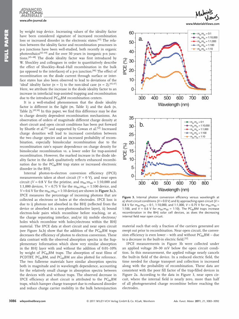
Figure 3 . Internal photon conversion effi ciency versus wavelength at a) short circuit conditions ( V = 0.0 V) and b) approaching open circuit ( V = 0.8 V for m 84 :m 60 = 0:1, 1:10,000, and 1:1,000, V = 0.75 V for m 84 :m 60 = 1:100, and V = 0.6 V for m 84 :m 60 = 1:10). The PC 84 BM traps increase recombination in the BHJ solar cell devices, as does the decreasing internal fi eld near open circuit.
300 400 500 600 700 800
0
10
20
30
40
50
60
IPC
E (%
)
Wavelength (nm)
m84
:m60
= 0:1 m
84:m
60 = 1:10,000
m84
:m60
= 1:1,000 m
84:m
60 = 1:100
m84
:m60
= 1:10
a.
300 400 500 600 700 800
0
5
10
15
20
25
30
35
b.IP
CE
(%)
Wavelength (nm)
m84
:m60
= 0:1 m
84:m
60 = 1:10,000
m84
:m60
= 1:1,000 m
84:m
60 = 1:100
m84
:m60
= 1:10
by weight trap device. Increasing values of the ideality factor have been considered signature of increased recombination loss or increased disorder in the electronic states. [ 41 ] The rela-tion between the ideality factor and recombination processes in p-n junctions have been well-studied, both recently in organic photovoltaics [ 42–44 ] and for over 50 years in inorganic p-n junc-tions. [ 45–48 ] The diode ideality factor was fi rst introduced by W. Shockley and colleagues in order to quantitatively describe the effect of Shockley–Read–Hall recombination in the bulk (as opposed to the interfaces) of a p-n junction. [ 46 ] The effect of recombination on the diode current through surface or inter-face states has also been observed to lead to deviations of the ‘ideal’ ideality factor ( n = 1) to the non-ideal case ( n = 2). [ 45 , 47 ] Here, we attribute the increase in the diode ideality factor to an increase in interfacial trap-assisted trapping and recombination due to the introduced PC 84 BM recombination centers.
It is a well-studied phenomenon that the diode ideality factor is different in the light ( m , Table 1 ) and the dark ( n , Table 2 ). [ 49 , 50 ] In this paper, we fi nd this difference may be due to charge density dependent recombination mechanisms. An observation of orders of magnitude different charge density at short circuit and open circuit conditions has been put forward by Shuttle et al. [ 51 ] and supported by Cowan et al. [ 52 ] Increased charge densities will lead to increased correlation between the two charge species and an increased probability of recom-bination, especially bimolecular recombination due to the recombination rate’s square dependence on charge density for bimolecular recombination vs. a lower order for trap-assisted recombination. However, the marked increase in the diode ide-ality factor in the dark qualitatively refl ects enhanced recombi-nation due to the PC 84 BM trap states or increased electronic disorder in the BHJ.
Internal photon-to-electron conversion effi ciency (IPCE) measurements taken at short circuit ( V = 0 V), and near open circuit ( V = 0.8 V for the pristine, and m 84 :m 60 = 1:10,000 and 1:1,000 devices, V = 0.75 V for the m 84 :m 60 = 1:100 device, and V = 0.6 V for the m 84 :m 60 = 1:10 device) are shown in Figure 3 a,b. IPCE measures the percentage of incoming photons that are collected as electrons or holes at the electrodes. IPCE loss is due to i) photons not absorbed in the BHJ (refl ected from the device or absorbed in a non-photoconductive layer), ii) bound electron-hole pairs which recombine before reaching, or at, the charge separating interface, and/or iii) mobile electrons/holes which recombine with holes/electrons within the BHJ material. The IPCE data at short circuit and near open circuit (see Figure 3 a,b) show that the addition of the PC 84 BM traps decreases the effi ciency of photon to electron conversion. These data contrast with the observed absorption spectra in the Sup-plementary Information which show very similar absorption in the BHJ layer with and without the addition of 0.01–10% by weight of PC 84 BM traps. The absorption of neat fi lms of PCDTBT, PC 84 BM, and PC 60 BM are also plotted for reference. The two fullerene materials have similar absorption spectra both in magnitude and in wavelength dependence, accounting for the relatively small change in absorption spectra between the devices with and without traps. The observed decrease in IPCE effi ciency at short circuit is attributed to the PC 84 BM traps, which hamper charge transport due to enhanced disorder and reduce charge carrier mobility in the bulk heterojunction
© 2011 WILEY-VCH Verlag Gmwileyonlinelibrary.com
material such that only a fraction of the carriers generated are swept out prior to recombination. Near open circuit, the conver-sion effi ciency is even lower – with and without PC 84 BM – due to a decrease in the built-in electric fi eld. [ 32 ]
IPCE measurements in Figure 3 b were collected under an applied voltage 20–30 mV below the open circuit condi-tion. In this measurement, the applied voltage nearly cancels the built-in fi eld of the device. In a reduced electric fi eld, the time needed for charge transport and collection is increased along with the probability of recombination. These data are consistent with the poor fi ll factor of the trap-fi lled devices in Figure 2 a. According to the data in Figure 3 , near open cir-cuit, where the internal fi eld is nearly zero, more than half of all photogenerated charge recombine before reaching the electrodes.
bH & Co. KGaA, Weinheim Adv. Funct. Mater. 2011, 21, 3083–3092
FULL P
APER
www.afm-journal.dewww.MaterialsViews.com
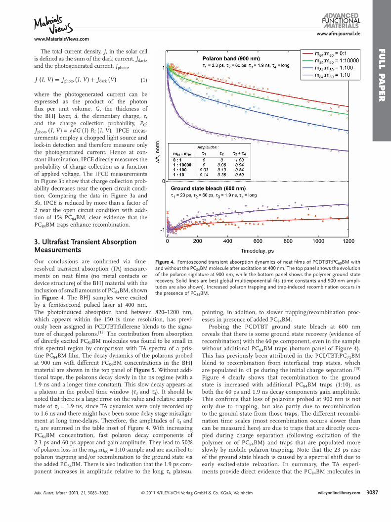
Figure 4 . Femtosecond transient absorption dynamics of neat fi lms of PCDTBT:PC 60 BM with and without the PC 84 BM molecule after excitation at 400 nm. The top panel shows the evolution of the polaron signature at 900 nm, while the bottom panel shows the polymer ground state recovery. Solid lines are best global multiexponential fi ts (time constants and 900 nm ampli-tudes are also shown). Increased polaron trapping and trap-induced recombination occurs in the presence of PC 84 BM.
The total current density, J , in the solar cell is defi ned as the sum of the dark current, J dark , and the photogenerated current, J photo ,
J (I, V ) = Jphoto (I, V ) + Jdark (V ) (1)
where the photogenerated current can be expressed as the product of the photon fl ux per unit volume, G , the thickness of the BHJ layer, d , the elementary charge, e , and the charge collection probability, P C : Jphoto (I, V ) = edG (I) PC (I, V ) . IPCE meas-urements employ a chopped light source and lock-in detection and therefore measure only the photogenerated current. Hence at con-stant illumination, IPCE directly measures the probability of charge collection as a function of applied voltage. The IPCE measurements in Figure 3 b show that charge collection prob-ability decreases near the open circuit condi-tion. Comparing the data in Figure 3 a and 3 b, IPCE is reduced by more than a factor of 2 near the open circuit condition with addi-tion of 1% PC 84 BM, clear evidence that the PC 84 BM traps enhance recombination.
3. Ultrafast Transient Absorption Measurements
Our conclusions are confi rmed via time-resolved transient absorption (TA) measure-ments on neat fi lms (no metal contacts or device structure) of the BHJ material with the inclusion of small amounts of PC 84 BM, shown in Figure 4 . The BHJ samples were excited by a femtosecond pulsed laser at 400 nm.
The photoinduced absorption band between 820–1200 nm, which appears within the 150 fs time resolution, has previ-ously been assigned in PCDTBT:fullerene blends to the signa-ture of charged polarons. [ 15 ] The contribution from absorption of directly excited PC 84 BM molecules was found to be small in this spectral region by comparison with TA spectra of a pris-tine PC 84 BM fi lm. The decay dynamics of the polarons probed at 900 nm with different PC 84 BM concentrations in the BHJ material are shown in the top panel of Figure 5 . Without addi-tional traps, the polarons decay slowly in the ns regime (with a 1.9 ns and a longer time constant). This slow decay appears as a plateau in the probed time window ( τ 3 and τ 4 ). It should be noted that there is a large error on the value and relative ampli-tude of τ 3 = 1.9 ns, since TA dynamics were only recorded up to 1.6 ns and there might have been some delay stage misalign-ment at long time-delays. Therefore, the amplitudes of τ 3 and τ 4 are summed in the table inset of Figure 4 . With increasing PC 84 BM concentration, fast polaron decay components of 2.3 ps and 60 ps appear and gain amplitude. They lead to 50% of polaron loss in the m 84 :m 60 = 1:10 sample and are ascribed to polaron trapping and/or recombination to the ground state via the added PC 84 BM. There is also indication that the 1.9 ps com-ponent increases in amplitude relative to the long τ 4 plateau,© 2011 WILEY-VCH Verlag GAdv. Funct. Mater. 2011, 21, 3083–3092
pointing, in addition, to slower trapping/recombination proc-esses in presence of added PC 84 BM.
Probing the PCDTBT ground state bleach at 600 nm reveals that there is some ground state recovery (evidence of recombination) with the 60 ps component, even in the sample without additional PC 84 BM traps (bottom panel of Figure 4 ). This has previously been attributed in the PCDTBT:PC 71 BM blend to recombination from interfacial trap states, which are populated in < 1 ps during the initial charge separation. [ 15 ] Figure 4 clearly shows that recombination to the ground state is increased with additional PC 84 BM traps (1:10), as both the 60 ps and 1.9 ns decay components gain amplitude. This confi rms that loss of polarons probed at 900 nm is not only due to trapping, but also partly due to recombination to the ground state from those traps. The different recombi-nation time scales (most recombination occurs slower than can be measured here) are due to traps that are directly occu-pied during charge separation (following excitation of the polymer or of PC 84 BM) and traps that are populated more slowly by mobile polaron trapping. Note that the 23 ps rise of the ground state bleach is caused by a spectral shift due to early excited-state relaxation. In summary, the TA experi-ments provide direct evidence that the PC 84 BM molecules in
mbH & Co. KGaA, Weinheim 3087wileyonlinelibrary.com
FULL
PAPER
30
www.afm-journal.dewww.MaterialsViews.com
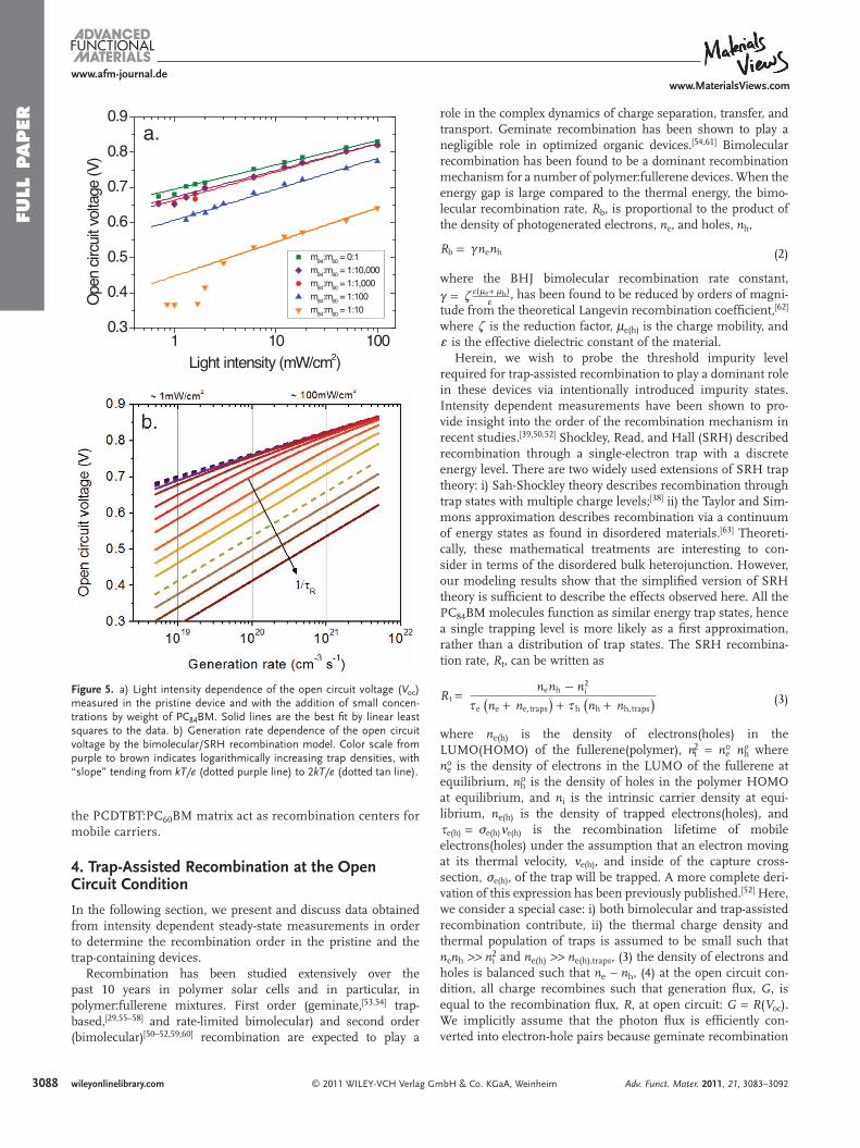
Figure 5 . a) Light intensity dependence of the open circuit voltage ( V oc ) measured in the pristine device and with the addition of small concen-trations by weight of PC 84 BM. Solid lines are the best fi t by linear least squares to the data. b) Generation rate dependence of the open circuit voltage by the bimolecular/SRH recombination model. Color scale from purple to brown indicates logarithmically increasing trap densities, with “slope” tending from kT/e (dotted purple line) to 2 kT/e (dotted tan line).
1 10 1000.3
0.4
0.5
0.6
0.7
0.8
0.9Op
en ci
rcuit v
oltag
e (V)
Light intensity (mW/cm2)
m84:m60 = 0:1 m84:m60 = 1:10,000 m84:m60 = 1:1,000 m84:m60 = 1:100 m84:m60 = 1:10
a.
b.
the PCDTBT:PC 60 BM matrix act as recombination centers for mobile carriers.
4. Trap-Assisted Recombination at the Open Circuit Condition
In the following section, we present and discuss data obtained from intensity dependent steady-state measurements in order to determine the recombination order in the pristine and the trap-containing devices.
Recombination has been studied extensively over the past 10 years in polymer solar cells and in particular, in polymer:fullerene mixtures. First order (geminate, [ 53 , 54 ] trap-based, [ 29 , 55–58 ] and rate-limited bimolecular) and second order (bimolecular) [ 50–52 , 59 , 60 ] recombination are expected to play a
© 2011 WILEY-VCH Verlag G88 wileyonlinelibrary.com
role in the complex dynamics of charge separation, transfer, and transport. Geminate recombination has been shown to play a negligible role in optimized organic devices. [ 54 , 61 ] Bimolecular recombination has been found to be a dominant recombination mechanism for a number of polymer:fullerene devices. When the energy gap is large compared to the thermal energy, the bimo-lecular recombination rate, R b , is proportional to the product of the density of photogenerated electrons, n e , and holes, n h ,
Rb = (nenh (2)
where the BHJ bimolecular recombination rate constant, ( = . e(:e+ :h)
g , has been found to be reduced by orders of magni-
tude from the theoretical Langevin recombination coeffi cient, [ 62 ] where . is the reduction factor, μ e(h) is the charge mobility, and g is the effective dielectric constant of the material.
Herein, we wish to probe the threshold impurity level required for trap-assisted recombination to play a dominant role in these devices via intentionally introduced impurity states. Intensity dependent measurements have been shown to pro-vide insight into the order of the recombination mechanism in recent studies. [ 39 , 50 , 52 ] Shockley, Read, and Hall (SRH) described recombination through a single-electron trap with a discrete energy level. There are two widely used extensions of SRH trap theory: i) Sah-Shockley theory describes recombination through trap states with multiple charge levels; [ 38 ] ii) the Taylor and Sim-mons approximation describes recombination via a continuum of energy states as found in disordered materials. [ 63 ] Theoreti-cally, these mathematical treatments are interesting to con-sider in terms of the disordered bulk heterojunction. However, our modeling results show that the simplifi ed version of SRH theory is suffi cient to describe the effects observed here. All the PC 84 BM molecules function as similar energy trap states, hence a single trapping level is more likely as a fi rst approximation, rather than a distribution of trap states. The SRH recombina-tion rate, R t , can be written as
R t =
nenh − n2i
Je ne + ne,traps
)+ J h nh + nh,traps
)
(3)
where n e(h) is the density of electrons(holes) in the LUMO(HOMO) of the fullerene(polymer), n i 2 = n e o n h
o where n e o is the density of electrons in the LUMO of the fullerene at equilibrium, n h o is the density of holes in the polymer HOMO at equilibrium, and n i is the intrinsic carrier density at equi-librium, n e(h) is the density of trapped electrons(holes), and Je(h) = Fe(h)<e(h) is the recombination lifetime of mobile electrons(holes) under the assumption that an electron moving at its thermal velocity, <e(h) , and inside of the capture cross-section, Fe(h) , of the trap will be trapped. A more complete deri-vation of this expression has been previously published. [ 52 ] Here, we consider a special case: i) both bimolecular and trap-assisted recombination contribute, ii) the thermal charge density and thermal population of traps is assumed to be small such that n e n h > > n i 2 and n e(h) > > n e(h),traps , (3) the density of electrons and holes is balanced such that n e ∼ n h , (4) at the open circuit con-dition, all charge recombines such that generation fl ux, G , is equal to the recombination fl ux, R , at open circuit: G = R(V oc ). We implicitly assume that the photon fl ux is effi ciently con-verted into electron-hole pairs because geminate recombination
mbH & Co. KGaA, Weinheim Adv. Funct. Mater. 2011, 21, 3083–3092
FULL P
APER
www.afm-journal.dewww.MaterialsViews.com
has been shown to play a small role in two polymer:fullerene devices. [ 54 ] We note that this assumption may be less relevant as the concentration of PC 84 BM increases. Under these assump-tions, the effective recombination rate may be written as
R (Voc) = G =
noc
JR+ (n2
oc
(4)
where n oc is the charge density at open circuit and JR = Je + Jh . Equation (4) can be solved for the charge density at open circuit in terms of the recombination rate coeffi cients and the genera-tion rate, G , of electron-hole pairs:
(noc)2 =
1
4(2J 2R
1 + (1 + 4(GJ 2R)
−2 1 + 4(GJ 2R
)1/ 2)
(
(5)
Under illumination and at the open circuit condition, the open circuit voltage, V oc , equals the difference between the quasi-Fermi levels within the polymer and fullerene phase-separated domains:
Voc = 1
e
(E fullerene
LUMO − E polymerHOMO
)
−kT
eln
(nenh
Nc Nv
) (6)
where N c(v) is the density of conduction states at the band edge of the polymer and fullerene, k is the Boltzmann coeffi cient, T is the absolute temperature. The form of the equation for V oc , assuming purely bimolecular recombination, has been extensively shown to be a universal equation for optimized polymer:fullerene solar cells. [ 52 , 60 ] For a bulk recombination process incorporating both bimolecular recombination and trap-assisted recombination, V oc can be expressed as a combina-tion of Equation (5) and (6) . A simplifi ed case of SRH recombi-nation predicts a slope of *Voc = 2kT/e in the plot of V oc versus the natural logarithm of the light intensity, rather than a slope of *Voc = kT/e as shown previously for bimolecular recombi-nation. [ 52 , 60 ] Here, we probe the intensity-dependent electronic characteristics of the two processes acting simultaneously.
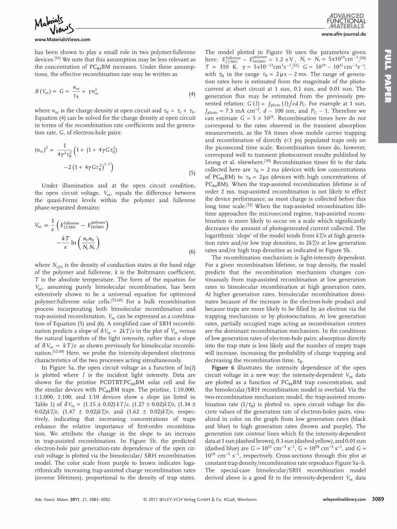
In Figure 5 a, the open circuit voltage as a function of ln( I ) is plotted where I is the incident light intensity. Data are shown for the pristine PCDTBT:PC 60 BM solar cell and for the similar devices with PC 84 BM traps. The pristine, 1:10,000, 1:1,000, 1:100, and 1:10 devices show a slope (as listed in Table 1 ) of *Voc = (1.15 ± 0.02) kT/e , (1.27 ± 0.02) kT/e , (1.34 ± 0.02) kT/e , (1.47 ± 0.02) kT/e , and (1.62 ± 0.02) kT/e , respec-tively, indicating that increasing concentrations of traps enhance the relative importance of fi rst-order recombina-tion. We attribute the change in the slope to an increase in trap-assisted recombination. In Figure 5 b, the predicted electron-hole pair generation-rate dependence of the open cir-cuit voltage is plotted via the bimolecular/ SRH recombination model. The color scale from purple to brown indicates loga-rithmically increasing trap-assisted charge recombination rates (inverse lifetimes), proportional to the density of trap states.
© 2011 WILEY-VCH Verlag GAdv. Funct. Mater. 2011, 21, 3083–3092
The model plotted in Figure 5 b uses the parameters given here: E fullerene
LUMO − E polymerHOMO = 1.2 e V , Nc = Nv = 5x1019cm−3 , [ 50 ]
T = 310 K, ( = 5x10⁻¹³cm3s−1 , [ 51 ] G = 1019 − 1021 cm−3s−1 , with τ R in the range JR = 2:s − 2 ms . The range of genera-tion rates here is estimated from the magnitude of the photo-current at short circuit at 1 sun, 0.1 sun, and 0.01 sun. The generation fl ux may be estimated from the previously pre-sented relation: G (I) = Jphoto (I)
/ed PC . For example at 1 sun,
J photo = 7.3 mA cm − 2 , d ∼ 100 nm, and P C ∼ 1. Therefore we can estimate G = 5 × 10 21 . Recombination times here do not correspond to the rates observed in the transient absorption measurements, as the TA times show mobile carrier trapping and recombination of directly ( < 1 ps) populated traps only on the picosecond time scale. Recombination times do, however, correspond well to transient photocurrent results published by Leong et al. elsewhere. [ 30 ] Recombination times fi t to the data collected here are JR = 2 ms (devices with low concentrations of PC 84 BM) to JR = 2:s (devices with high concentrations of PC 84 BM). When the trap-assisted recombination lifetime is of order 2 ms, trap-assisted recombination is not likely to effect the device performance, as most charge is collected before this long time scale. [ 32 ] When the trap-assisted recombination life-time approaches the microsecond regime, trap-assisted recom-bination is more likely to occur on a scale which signifi cantly decreases the amount of photogenerated current collected. The logarithmic ‘slope’ of the model tends from kT/e at high genera-tion rates and/or low trap densities, to 2 kT/e at low generation rates and/or high trap densities as indicated in Figure 5 b.
The recombination mechanism is light-intensity dependent. For a given recombination lifetime, or trap density, the model predicts that the recombination mechanism changes con-tinuously from trap-assisted recombination at low generation rates to bimolecular recombination at high generation rates. At higher generation rates, bimolecular recombination domi-nates because of the increase in the electron-hole product and because traps are more likely to be fi lled by an electron via the trapping mechanism or by photoexcitation. At low generation rates, partially occupied traps acting as recombination centers are the dominant recombination mechanism. In the conditions of low generation rates of electron-hole pairs, absorption directly into the trap state is less likely and the number of empty traps will increase, increasing the probability of charge trapping and decreasing the recombination time, τ R .
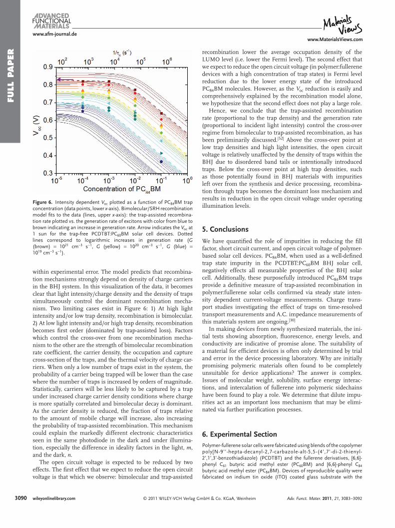
Figure 6 illustrates the intensity dependence of the open circuit voltage in a new way: the intensity-dependent V oc data are plotted as a function of PC 84 BM trap concentration, and the bimolecular/SRH recombination model is overlaid. Via the two-recombination mechanism model, the trap-assisted recom-bination rate (1/ τ R ) is plotted vs. open circuit voltage for dis-crete values of the generation rate of electron-holes pairs, visu-alized in color on the graph from low generation rates (black and blue) to high generation rates (brown and purple). The generation rate contour lines which fi t the intensity-dependent data at 1 sun (dashed brown), 0.1 sun (dashed yellow), and 0.01 sun (dashed blue) are G = 10 21 cm − 3 s − 1 , G = 10 20 cm − 3 s − 1 , and G = 10 19 cm − 3 s − 1 , respectively. Cross-sections through this plot at constant trap density/recombination rate reproduce Figure 5 a–b. The special-case bimolecular/SRH recombination modelderived above is a good fi t to the intensity-dependent V oc data
mbH & Co. KGaA, Weinheim 3089wileyonlinelibrary.com
FULL
PAPER
309
www.afm-journal.dewww.MaterialsViews.com
Figure 6 . Intensity dependent V oc plotted as a function of PC 84 BM trap concentration (data points, lower x -axis). Bimolecular/SRH recombination model fi ts to the data (lines, upper x -axis): the trap-assisted recombina-tion rate plotted vs. the generation rate of excitons with color from blue to brown indicating an increase in generation rate. Arrow indicates the V oc at 1 sun for the trap-free PCDTBT:PC 60 BM solar cell devices. Dotted lines correspond to logarithmic increases in generation rate ( G (brown) = 10 21 cm − 3 s − 1 , G (yellow) = 10 20 cm − 3 s − 1 , G (blue) = 10 19 cm − 3 s − 1 ).
within experimental error. The model predicts that recombina-tion mechanisms strongly depend on density of charge carriers in the BHJ system. In this visualization of the data, it becomes clear that light intensity/charge density and the density of traps simultaneously control the dominant recombination mecha-nism. Two limiting cases exist in Figure 6 : 1) At high light intensity and/or low trap density, recombination is bimolecular. 2) At low light intensity and/or high trap density, recombination becomes fi rst order (dominated by trap-assisted loss). Factors which control the cross-over from one recombination mecha-nism to the other are the strength of bimolecular recombination rate coeffi cient, the carrier density, the occupation and capture cross-section of the traps, and the thermal velocity of charge car-riers. When only a low number of traps exist in the system, the probability of a carrier being trapped will be lower than the case where the number of traps is increased by orders of magnitude. Statistically, carriers will be less likely to be captured by a trap under increased charge carrier density conditions where charge is more spatially correlated and bimolecular decay is dominant. As the carrier density is reduced, the fraction of traps relative to the amount of mobile charge will increase, also increasing the probability of trap-assisted recombination. This mechanism could explain the markedly different electronic characteristics seen in the same photodiode in the dark and under illumina-tion, especially the difference in ideality factors in the light, m , and the dark, n .
The open circuit voltage is expected to be reduced by two effects. The fi rst effect that we expect to reduce the open circuit voltage is that which we observe: bimolecular and trap-assisted
© 2011 WILEY-VCH Verlag G0 wileyonlinelibrary.com
recombination lower the average occupation density of the LUMO level (i.e. lower the Fermi level). The second effect that we expect to reduce the open circuit voltage (in polymer:fullerene devices with a high concentration of trap states) is Fermi level reduction due to the lower energy state of the introduced PC 84 BM molecules. However, as the V oc reduction is easily and comprehensively explained by the recombination model alone, we hypothesize that the second effect does not play a large role.
Hence, we conclude that the trap-assisted recombination rate (proportional to the trap density) and the generation rate (proportional to incident light intensity) control the cross-over regime from bimolecular to trap-assisted recombination, as has been preliminarily discussed. [ 52 ] Above the cross-over point at low trap densities and high light intensities, the open circuit voltage is relatively unaffected by the density of traps within the BHJ due to disordered band tails or intentionally introduced traps. Below the cross-over point at high trap densities, such as those potentially found in BHJ materials with impurities left over from the synthesis and device processing, recombina-tion through traps becomes the dominant loss mechanism and results in reduction in the open circuit voltage under operating illumination levels.
5. Conclusions
We have quantifi ed the role of impurities in reducing the fi ll factor, short circuit current, and open circuit voltage of polymer-based solar cell devices. PC 84 BM, when used as a well-defi ned trap state impurity in the PCDTBT:PC 60 BM BHJ solar cell, negatively effects all measurable properties of the BHJ solar cell. Additionally, these purposefully introduced PC 84 BM traps provide a defi nitive measure of trap-assisted recombination in polymer:fullerene solar cells confi rmed via steady state inten-sity dependent current-voltage measurements. Charge trans-port studies investigating the effect of traps on time-resolved transport measurements and A.C. impedance measurements of this materials system are ongoing. [ 30 ]
In making devices from newly synthesized materials, the ini-tial tests showing absorption, fl uorescence, energy levels, and conductivity are indicative of promise alone. The suitability of a material for effi cient devices is often only determined by trial and error in the device processing laboratory. Why are initially promising polymeric materials often found to be completely unsuitable for device applications? The answer is complex. Issues of molecular weight, solubility, surface energy interac-tions, and intercalation of fullerene into polymeric sidechains have been found to play a role. We determine that dilute impu-rities act as an important loss mechanism that may be elimi-nated via further purifi cation processes.
6. Experimental Section Polymer-fullerene solar cells were fabricated using blends of the copolymer poly[N-9’’-hepta-decanyl-2,7-carbazole-alt-5,5-(4’,7’-di-2-thienyl-2’,1’,3’-benzothiadiazole) (PCDTBT) and the fullerene derivatives, [6,6]-phenyl C 61 butyric acid methyl ester (PC 60 BM) and [6,6]-phenyl C 84 butyric acid methyl ester (PC 84 BM). Devices of reproducible quality were fabricated on indium tin oxide (ITO) coated glass substrate with the
mbH & Co. KGaA, Weinheim Adv. Funct. Mater. 2011, 21, 3083–3092

FULL P
APER
www.afm-journal.dewww.MaterialsViews.com
following structure: ITO-coated glass substrate/poly(3,4 ethylenedioxythiophene):poly(styrenesulfonate) (PEDOT:PSS)/polymer:fullerene blend/titanium sub-oxide (TiO x )/aluminum (Al).
PCDTBT:PC 60 BM blend fi lms were cast from a solution of PCDTBT:PC 60 BM (1:4) in an anhydrous 1,2-dichlorobenzene: chlorobenzene solvent mixture (3:1) with a polymer concentration of 7 mg/mL. Small amounts of PC 84 BM were dissolved in a low concentration solution with chlorobenzene, and pipetted into the BHJ solution in substitution for a small portion of the chlorobenzene solvent. Glass/ITO substrates were cleaned by sonication for 10 min each in soapy deionized water, deionized water, acetone, and isopropanol. Substrates were then heated above 100 ° C overnight to evaporate the water and residual solvent. Substrates were UV-ozone plasma treated for 60 min prior to PEDOT:PSS deposition. PEDOT:PSS, acquired from H. C. Starkas Clevios PH, was fi ltered with a 0.45 micrometer PTFE fi lter and spun onto the substrate in air at 5000 RPM for 40 sec. The PEDOT:PSS fi lm was then annealed in air at 140 ° C for 10 min to evaporate the solvent (water). BHJ fi lms were cast and annealed in a nitrogen environment. The polymer:fullerene solutions were spin cast with no fi ltration at 3500 RPM and annealed after casting at 70 ° C for 10 min. An amorphous solution-processable TiO x layer was spin cast in air onto all the devices as a buffer layer and an optical spacer. [ 64 ] The TiO x fi lm was annealed in air at 80 ° C for 10 min to oxidize the TiOx precursor fi lm and to evaporate solvent. A 100 nm aluminum electrode was vacuum-deposited at pressure 3 × 10 − 6 torr, and devices were not annealed after deposition of the aluminum electrode. Long term illumination at 1 sun intensity in our device test rig heats devices to 35 ° C. Devices were encapsulated for testing in air with a UV-curable epoxy and covered with a glass slide. Encapsulated devices degraded 15% over the six month test period, with the majority of degradation occurring in the fi rst 2 weeks.
Current density–voltage ( J–V ) characteristics of the devices were measured using a Keithley 236 Source Measure Unit. Solar cell performance used a Newport Air Mass 1.5 Global (AM 1.5G) full spectrum solar simulator with an irradiation intensity of 100 mW cm − 2 . The 100 mW cm − 2 spectrum of incident light was spectrum and intensity matched with an Ocean Optics USB4000 spectrometer calibrated for absolute intensity via a deuterium tungsten halogen calibration standard lamp with NIST-traceable calibration from 350–1000 nm. The intensity of the lamp was modulated with a series of 2 neutral density fi lter (NDF) wheels of 6 fi lters apiece, allowing for 35 steps in intensity from 0.4 mW cm − 2 –100 mW cm − 2 . Intensity of light transmitted through each fi lter combination was independently measured via the Ocean Optics USB4000 spectrometer calibrated for absolute intensity. Error is introduced while modulating the full solar spectrum with “grey” fi lters, which non-linearly reduce the solar spectrum, especially at high fi lter optical densities. Scatter in the data specifi c to the density fi lters result in error in the fi t of V oc vs ln( I ) of ± 0.001–equivalent to an uncertainty of ± 12 degrees in temperature or ± 0.04 in the “slope.” Therefore, external temperature measurement is necessary to reduce experimental error in the fi tting – as previously implemented. [ 52 ]
IPCE measurements were performed with a PV Measurements, Inc. QEW7 Solar Cell QE Measurement System. In the IPCE measurement, illumination intensity mimics the 100 mW cm − 2 AM1.5G spectrum, as calibrated with a silicon reference cell from λ = 300–800 nm. Absorption measurements were performed with a Beckman Coulter UV-visible spectrophotometer on fi lms on slide glass. A piece of slide glass was used as a reference sample and subtracted from the absorption of the organic fi lm on slide glass.
Transient absorption (TA) spectra were recorded for the spin-cast solid samples using femtosecond pulsed laser pump-probe spectroscopy. The 400 nm pump beam was generated by frequency doubling the 800 nm output of a Ti:sapphire laser system with a regenerative amplifi er providing 100 fs pulses at a repetition rate of 1 kHz. The pump intensity per pulse was kept low, around 30 μ J cm − 2 , in order to minimize annihilation and other intensity-dependent processes due to high laser power. The probe beam in the visible and near-infrared range (400–1100 nm) consisted of a white light continuum, generated by passing a portion of the 800 nm
© 2011 WILEY-VCH Verlag GAdv. Funct. Mater. 2011, 21, 3083–3092
[ 1 ] S. H. Park , A. Roy , S. Beaupre , S. Cho , N. Coates , J. S. Moon , D. Moses , M. Leclerc , K. Lee , A. J. Heeger , Nat. Photonics 2009 , 3 , 297 .
[ 2 ] H.-Y. Chen , J. Hou , S. Zhang , Y. Liang , G. Yang , Y. Yang , L. Yu , Y. Wu , G. Li , Nat. Photonics 2009 , 3 , 649 .
[ 3 ] J. Hou , H.-Y. Chen , S. Zhang , R. I. Chen , Y. Yang , Y. Wu , G. Li , J. Am. Chem. Soc. 2009 , 131 , 15586 .
[ 4 ] J. A. Hauch , P. Schilinsky , S. A. Choulis , R. Childers , M. Biele , C. J. Brabec , Sol. Energy Mater. Sol. Cells 2008 , 92 , 727 .
[ 5 ] E. Voroshazi , B. Verreet , T. Aernouts , P. Heremans , Sol. Energy Mater. Sol. Cells 2011 , 95 , 1303 .
[ 6 ] C. P. Chen , S. H. Chan , T. C. Chao , C. Ting , B. T. Ko , J. Am. Chem. Soc. 2008 , 130 , 12828 .
[ 7 ] J. H. Hou , H. Y. Chen , S. Q. Zhang , G. Li , Y. Yang , J. Am. Chem. Soc. 2008 , 130 , 16144 .
[ 8 ] Z. Zhu , D. Waller , R. Gaudiana , M. Morana , D. Muhlbacher , M. Scharber , C. Brabec , Macromolecules 2007 , 40 , 1981 .
[ 9 ] Y. Lee , T. P. Russell , W. H. Jo , Org. Electron. 2010 , 11 , 846 . [ 10 ] N. S. Sariciftci , L. Smilowitz , A. J. Heeger , F. Wudl , Science 1992 ,
258 , 1474 .
amplifi ed Ti:sapphire output through a 1 mm thick sapphire plate. The probe intensity was always less than the pump intensity and the spot size was much smaller (about 0.4 mm diameter). The probe pulses were time delayed with respect to the pump pulses using a computerized translation stage. The probe beam was split before the sample into a signal beam (transmitted through the sample and crossed with the pump beam) and a reference beam. The signal and reference were detected with a pair of 163 mm spectrographs (Andor Technology, SR163) equipped with a 512 × 58 pixels back-thinned CCD (Hamamatsu S07030-0906) and assembled by Entwicklungsbüro Stresing, Berlin. To improve sensitivity, the pump light was chopped at half the amplifi er frequency, and the transmitted signal intensity was recorded shot by shot. It was corrected for intensity fl uctuations using the reference beam. The transient spectra were averaged until the desired signal-to-noise ratio was achieved. The polarization of the probe pulses was at magic angle relative to that of the pump pulses. All spectra were corrected for the chirp of the white-light probe pulses. The FWHM of the response function was about 150 fs. Samples were kept under dynamic vacuum ( < 10 − 4 mbar) during the TA measurements.
Supporting Information Supporting Information is available from the Wiley Online Library or from the author.
Acknowledgements This research was supported by the US Army General Technical Services (LLC/GTS-S-09-1-196) and the Department of Energy (DOE ER46535). S. Cowan was supported by the Center for Energy Effi cient Materials, an Energy Frontier Research Center funded by the U.S. Department of Energy, Offi ce of Science, Offi ce of Basic Energy Sciences under award Number DE-SC0001009. The authors thank Dr. Robert Street and Dr. Anshuman Roy for many important comments and discussions, and S. Cowan thanks Dr. Jay Hyun Lee for discussions regarding dark current fi tting. N. Banerji thanks the Swiss National Science Foundation for Fellowship support (fellowship for prospective researchers PBGEP2-125859). The materials used for the fabrication of the solar cells were provided by Dr. D. Waller of Konarka Technologies.
Received: March 8, 2011 Published online: June 21, 2011
mbH & Co. KGaA, Weinheim 3091wileyonlinelibrary.com
FULL
PAPER
3092
www.afm-journal.dewww.MaterialsViews.com
[ 11 ] A. A. Bakulin , J. C. Hummelen , M. S. Pshenichnikov , P. H. M. van Loosdrecht , Adv. Funct. Mater. 2010 , 20 , 1653 .
[ 12 ] C. J. Brabec , G. Zerza , G. Cerullo , S. De Silvestri , S. Luzzati , J. C. Hummelen , S. Sariciftci , Chem. Phys. Lett. 2001 , 340 , 232 .
[ 13 ] B. Kraabel , J. C. Hummelen , D. Vacar , D. Moses , N. S. Sariciftci , A. J. Heeger , F. Wudl , J. Chem. Phys. 1996 , 104 , 4267 .
[ 14 ] S. Morita , A. A. Zakhidov , K. Yoshino , Solid State Commun. 1992 , 82 , 249 .
[ 15 ] M. Tong , N. E. Coates , D. Moses , A. J. Heeger , S. Beaupre , M. Leclerc , Phys. Rev. B 2010 , 81 , 125210 .
[ 16 ] H. W. Kroto , J. R. Heath , S. C. Obrien , R. F. Curl , R. E. Smalley , Nature 1985 , 318 , 162 .
[ 17 ] F. Diederich , R. Ettl , Y. Rubin , R. L. Whetten , R. Beck , M. Alvarez , S. Anz , D. Sensharma , F. Wudl , K. C. Khemani , A. Koch , Science 1991 , 252 , 548 .
[ 18 ] W. Kratschmer , L. D. Lamb , K. Fostiropoulos , D. R. Huffman , Nature 1990 , 347 , 354 .
[ 19 ] J. C. Hummelen , B. W. Knight , F. Lepeq , F. Wudl , J. Yao , C. L. Wilkins , J. Org. Chem. 1995 , 60 , 532 .
[ 20 ] G. Yu , J. Gao , J. C. Hummelen , F. Wudl , A. J. Heeger , Science 1995 , 270 , 1789 .
[ 21 ] M. M. Koetse , J. Sweelssen , K. T. Hoekerd , H. F. M. Schoo , S. C. Veenstra , J. M. Kroon , X. N. Yang , J. Loos , Appl. Phys. Lett. 2006 , 88 , 083504 .
[ 22 ] M. M. Mandoc , W. Veurman , L. J. A. Koster , M. M. Koetse , J. Sweelssen , B. de Boer , P. W. M. Blom , J. Appl. Phys. 2007 , 101 , 104512 .
[ 23 ] F. B. Kooistra , V. D. Mihailetchi , L. M. Popescu , D. Kronholm , P. W. M. Blom , J. C. Hummelen , Chem. Mat. 2006 , 18 , 3068 .
[ 24 ] K. Shibata , Y. Kubozono , T. Kanbara , T. Hosokawa , A. Fujiwara , Y. Ito , H. Shinohara , Appl. Phys. Lett. 2004 , 84 , 2572 .
[ 25 ] H. Meyer , D. Haarer , H. Naarmann , H. H. Horhold , Phys. Rev. B 1995 , 52 , 2587 .
[ 26 ] Z. Chiguvare , V. Dyakonov , Phys. Rev. B 2004 , 70 . [ 27 ] J. M. Frost , F. Cheynis , S. M. Tuladhar , J. Nelson , Nano Lett. 2006 , 6 ,
1674 . [ 28 ] C. R. McNeill , N. C. Greenham , Appl. Phys. Lett. 2008 , 93 . [ 29 ] M. M. Mandoc , F. B. Kooistra , J. C. Hummelen , B. de Boer ,
P. W. M. Blom , Appl. Phys. Lett. 2007 , 91 , 263505 . [ 30 ] W. L. Leong , S. R. Cowan , A. J. Heeger , Adv. Energy Mat. 2011 , doi:
10.1002/aenm.201100196. [ 31 ] N. Banerji , S. Cowan , M. Leclerc , E. Vauthey , A. J. Heeger , J. Am.
Chem. Soc. 2010 , 132 , 17459 . [ 32 ] S. R. Cowan , R. A. Street , S. Cho , A. J. Heeger , Phys. Rev. B 2011 , 83 ,
035205 . [ 33 ] N. S. Christ , S. W. Kettlitz , S. Valouch , S. Zufl e , C. Gartner , M. Punke ,
U. Lemmer , J. Appl. Phys. 2009 , 105 , 104513 . [ 34 ] M. Punke , S. Valouch , S. W. Kettlitz , N. Christ , C. Gartner , M. Gerken ,
U. Lemmer , Appl. Phys. Lett. 2007 , 91 , 071118 .
© 2011 WILEY-VCH Verlag wileyonlinelibrary.com
[ 35 ] W. Shockley , W. T. Read Jr ., Phys. Rev. B 1971 , 4 , 502 . [ 36 ] R. N. Hall , Physical Review 1951 , 83 , 228 . [ 37 ] R. N. Hall , Physical Review 1952 , 87 , 387 . [ 38 ] C.-T. Sah , W. Shockley , Physical Review 1958 , 109 , 1103 . [ 39 ] A. Maurano , R. Hamilton , C. G. Shuttle , A. M. Ballantyne , J. Nelson ,
B. O’Regan , W. Zhang , I. McCulloch , H. Azimi , M. Morana , C. J. Brabec , J. R. Durrant , Advanced Materials 2010 , 22 , 4987 .
[ 40 ] H. Hoppe , N. S. Sariciftci , J. Mater. Res. 2004 , 19 , 1924 . [ 41 ] C. Vanberkel , M. J. Powell , A. R. Franklin , I. D. French , J. Appl. Phys.
1993 , 73 , 5264 . [ 42 ] N. C. Giebink , G. P. Wiederrecht , M. R. Wasielewski , S. R. Forrest ,
Phys. Rev. B 2010 , 82 , 155305 . [ 43 ] P. Schilinsky , C. Waldauf , J. Hauch , C. J. Brabec , J. Appl. Phys. 2004 ,
95 , 2816 . [ 44 ] C. Waldauf , M. C. Scharber , P. Schilinsky , J. A. Hauch , C. J. Brabec ,
J. Appl. Phys. 2006 , 99 , 104503 . [ 45 ] C.-T. Sah , IRE Trans. Electron Devices 1962 , ED-9 , 94 . [ 46 ] C.-T. Sah , R. N. Noyce , W. Shockley , Proc. IRE 1957 , 45 , 1228 . [ 47 ] M. A. Wolf , M. Wolf , IEEE Trans. Electron Devices 1984 , 31 , 684 . [ 48 ] D. Zhu , J. R. Xu , A. N. Noemaun , J. K. Kim , E. F. Schubert ,
M. H. Crawford , D. D. Koleske , Appl. Phys. Lett. 2009 , 94 , 081113 . [ 49 ] M. A. Hamdy , R. L. Call , Sol. Cells 1987 , 20 , 119 . [ 50 ] L. J. A. Koster , V. D. Mihailetchi , R. Ramaker , P. W. M. Blom , Appl.
Phys. Lett. 2005 , 86 , 123509 . [ 51 ] C. G. Shuttle , B. O’Regan , A. M. Ballantyne , J. Nelson ,
D. D. C. Bradley , J. R. Durrant , Phys. Rev. B 2008 , 78 , 113201 . [ 52 ] S. R. Cowan , A. Roy , A. J. Heeger , Phys. Rev. B 2010 , 82 , 245207 . [ 53 ] M. Hallermann , S. Haneder , E. Da Como , Appl. Phys. Lett. 2008 , 93 ,
053307 . [ 54 ] R. A. Street , S. Cowan , A. J. Heeger , Phys. Rev. B 2010 , 82 ,
121301 . [ 55 ] A. Liu , S. Zhao , S. B. Rim , J. Wu , M. Konemann , P. Erk , P. Peumans ,
Adv. Mater. 2008 , 20 , 1065 . [ 56 ] V. D. Mihailetchi , L. J. A. Koster , J. C. Hummelen , P. W. M. Blom ,
Phys. Rev. Lett. 2004 , 93 , 216601 . [ 57 ] R. A. Street , M. Schoendorf , Phys. Rev. B 2010 , 81 , 205307 . [ 58 ] D. Veldman , O. Ipek , S. C. J. Meskers , J. Sweelssen , M. M. Koetse ,
S. C. Veenstra , J. M. Kroon , S. S. van Bavel , J. Loos , R. A. J. Janssen , J. Am. Chem. Soc. 2008 , 130 , 7721 .
[ 59 ] C. Groves , N. C. Greenham , Phys. Rev. B 2008 , 78 , 155205 . [ 60 ] L. J. A. Koster , E. C. P. Smits , V. D. Mihailetchi , P. W. M. Blom , Phys.
Rev. B 2005 , 72 , 085205 . [ 61 ] K. Maturova , S. S. van Bavel , M. M. Wienk , R. A. J. Janssen ,
M. Kemerink , Nano Lett. 2009 , 9 , 3032 . [ 62 ] M. P. Langevin , Ann. Chim. Phys. 1903 , 28 , 433 . [ 63 ] J. G. Simmons , G. W. Taylor , Phys. Rev. B 1971 , 4 , 502 . [ 64 ] A. Roy , S. H. Park , S. Cowan , M. H. Tong , S. N. Cho , K. Lee ,
A. J. Heeger , Appl. Phys. Lett. 2009 , 95 , 013302 .
GmbH & Co. KGaA, Weinheim Adv. Funct. Mater. 2011, 21, 3083–3092