IBM Communications Server for Data Center Deployment on ...
194
IBM Communications Server for Data Center Deployment on Linux Version 7.1 Administration Guide IBM SC31-6771-05
-
Upload
khangminh22 -
Category
Documents
-
view
1 -
download
0
Transcript of IBM Communications Server for Data Center Deployment on ...
IBM Communications Server for Data CenterDeployment on LinuxVersion 7.1
Administration Guide
IBM
SC31-6771-05
Note
Before using this information and the product it supports, be sure to read the general information underAppendix E, “Notices,” on page 163.
Seventh Edition (January 2021)
This edition applies to IBM Communications Server for Data Center Deployment on Linux, Version 7.1, program number5725-H32, and to all subsequent releases and modifications until otherwise indicated in new editions or technicalnewsletters.
Order publications through your IBM representative or the IBM branch office serving your locality. Publications are notstocked at the address below.
IBM welcomes your comments. A form for readers' comments is provided at the back of this publication. If the form hasbeen removed, you may send your comments to the following address:
• International Business Machines Corporation• Department CGMD• P.O. Box 12195• Research Triangle Park, North Carolina• 27709-2195• U.S.A.
If you prefer to send comments electronically, use one of the following methods:
• IBMLink: CIBMORCF at RALVM17• IBM Mail: USIB2HPD at IBMMAIL• Internet: [email protected]• Fax: 1-800-227-5088
When you send information to IBM, you grant IBM a nonexclusive right to use or distribute the information in any way itbelieves appropriate without incurring any obligation to you.© Copyright International Business Machines Corporation 1998, 2021.US Government Users Restricted Rights – Use, duplication or disclosure restricted by GSA ADP Schedule Contract withIBM Corp.
Contents
Tables................................................................................................................. vii
Figures................................................................................................................. ix
About this book.................................................................................................... xiWho should use this book........................................................................................................................... xiHow to use this book................................................................................................................................... xi
Organization of this book....................................................................................................................... xiTypographic conventions...................................................................................................................... xiiGraphic conventions............................................................................................................................ xiii
What is new for this release...................................................................................................................... xiiiNew functions...................................................................................................................................... xiiiFunctions that have been retired.........................................................................................................xiv
Where to find more information................................................................................................................ xiv
Chapter 1. SNA terms and concepts....................................................................... 1Systems Network Architecture....................................................................................................................1Basic SNA concepts..................................................................................................................................... 1
Network types.........................................................................................................................................1SNA nodes.............................................................................................................................................. 2Connectivity............................................................................................................................................ 4Transaction programs.............................................................................................................................4Application programming interfaces..................................................................................................... 5Network accessible units....................................................................................................................... 5Sessions.................................................................................................................................................. 7Conversations......................................................................................................................................... 8Modes......................................................................................................................................................9Route selection.....................................................................................................................................10Class of service.....................................................................................................................................10
Basic APPN concepts.................................................................................................................................10APPN node types..................................................................................................................................11APPN control point............................................................................................................................... 12Locating resources............................................................................................................................... 13Session routing..................................................................................................................................... 16Branch Extender...................................................................................................................................21
Accessing subarea networks from APPN networks..................................................................................22
Chapter 2. Administering CS Linux....................................................................... 25Overview of CS Linux administration.........................................................................................................25
Administration responsibilities............................................................................................................ 25Administration tools............................................................................................................................. 26Administration permissions................................................................................................................. 30
Planning for CS Linux configuration...........................................................................................................31Planning worksheets............................................................................................................................ 31Task sheets...........................................................................................................................................31
Enabling and disabling CS Linux on the local system............................................................................... 32Setting environment variables for use by CS Linux............................................................................. 32Specifying the Path to CS Linux Programs...........................................................................................32Enabling CS Linux servers.................................................................................................................... 32
iii

Disabling CS Linux servers................................................................................................................... 34Using the Motif administration program................................................................................................... 34
Invoking the Motif administration program.........................................................................................34Resource windows............................................................................................................................... 35Resource dialogs.................................................................................................................................. 40Status dialogs....................................................................................................................................... 41Help windows....................................................................................................................................... 42
Using the command-line administration program....................................................................................43
Chapter 3. Basic configuration tasks.................................................................... 45Configuring client/server functions........................................................................................................... 45Configuring the node..................................................................................................................................46
Node configuration parameters........................................................................................................... 46Additional configuration.......................................................................................................................47
Configuring logging.................................................................................................................................... 47
Chapter 4. Defining Connectivity Components...................................................... 49Defining DLCs, ports, and connection networks....................................................................................... 49
DLC, connection network, and port configuration parameters........................................................... 50Additional configuration.......................................................................................................................53
Defining link stations................................................................................................................................. 53Link station configuration parameters.................................................................................................54Additional configuration.......................................................................................................................59
Defining DLUR PUs.....................................................................................................................................59DLUR PU configuration parameters..................................................................................................... 60Parameters for passthrough DLUR for downstream nodes.................................................................60Additional configuration.......................................................................................................................61
Chapter 5. Configuring dependent LUs..................................................................63Defining LU Types 0-3................................................................................................................................63
LU Types 0-3 configuration parameters.............................................................................................. 63Additional configuration.......................................................................................................................64
Defining LU pools....................................................................................................................................... 65LU pool configuration parameters....................................................................................................... 65
Chapter 6. Configuring APPC communication....................................................... 67Defining local LUs.......................................................................................................................................67
Local LU configuration parameters...................................................................................................... 68Additional configuration.......................................................................................................................69
Defining remote nodes.............................................................................................................................. 69Remote node configuration parameters..............................................................................................70Additional configuration.......................................................................................................................70
Defining partner LUs.................................................................................................................................. 70Partner LU configuration parameters.................................................................................................. 71Defining link station routing for a partner LU.......................................................................................72Additional configuration.......................................................................................................................73
Defining TPs............................................................................................................................................... 73TP invocation parameters on a server................................................................................................. 74TP definition parameters......................................................................................................................76
Defining modes and classes of service..................................................................................................... 77Mode configuration parameters...........................................................................................................79Additional configuration.......................................................................................................................81
Defining CPI-C side information................................................................................................................ 81CPI-C configuration parameters.......................................................................................................... 81Additional configuration.......................................................................................................................82
Configuring APPC security......................................................................................................................... 83Configuring session security................................................................................................................ 83
iv
Configuring conversation security....................................................................................................... 83Configuring a security access list.........................................................................................................84
Chapter 7. Configuring user applications.............................................................. 85
Chapter 8. Configuring passthrough services........................................................ 87Configuring TN server................................................................................................................................ 87
Configuring TN server access records................................................................................................. 88Configuring TN server association records..........................................................................................90
Configuring TN Redirector......................................................................................................................... 90Configuring TN Redirector access records.......................................................................................... 91
Configuring SNA gateway.......................................................................................................................... 94Downstream LU configuration parameters..........................................................................................94Additional configuration.......................................................................................................................95
Configuring DLUR....................................................................................................................................... 95TN Server and TN Redirector: additional security information................................................................ 96
Chapter 9. Managing CS Linux from NetView........................................................ 97Using the host NetView program...............................................................................................................97
NetView screen display........................................................................................................................97Changing the size of the command input area.................................................................................... 98Overview of RCF command syntax...................................................................................................... 98Uppercase characters and escape characters.................................................................................... 99
Using SPCF................................................................................................................................................. 99Restrictions on administration commands used with SPCF............................................................... 99Examples of SPCF commands........................................................................................................... 100
Using UCF.................................................................................................................................................100UCF command syntax........................................................................................................................ 101Permitted commands.........................................................................................................................101Example of a UCF command..............................................................................................................101Output from Linux system commands.............................................................................................. 101Canceling a command........................................................................................................................102UCF security....................................................................................................................................... 102
Chapter 10. Managing CS Linux client/server systems........................................ 105Changing client/server configuration...................................................................................................... 105
Moving clients into a different domain.............................................................................................. 106IP networking requirements................................................................................................................... 106
IPv4 and IPv6 addressing..................................................................................................................107Host names in client/server configuration........................................................................................ 107Setting up IP port numbers................................................................................................................107LAN access timeout........................................................................................................................... 108
HTTPS access for Remote API Clients.................................................................................................... 109Managing Remote API Client on Windows..............................................................................................109
Enabling a Remote API Client on Windows.......................................................................................110Viewing status of a Remote API Client on Windows......................................................................... 110Disabling a Remote API Client on Windows...................................................................................... 111Remote API Client on Windows configuration.................................................................................. 111Tracking SNA LU resources used by clients on a domain of servers................................................ 122Mapping hard-coded LU aliases on Client applications to LU aliases in a domain of servers......... 123
Managing Remote API Clients on AIX or Linux.......................................................................................124Enabling and disabling Remote API Clients on AIX or Linux............................................................ 125Client network data file (sna_clnt.net).............................................................................................. 125Tracking SNA LU resources used by clients on a domain of servers................................................ 128Mapping hard-coded LU aliases on Client applications to LU aliases in a domain of servers......... 128
Defining Client TPs...................................................................................................................................130
v
Appendix A. Configuration planning worksheets.................................................131Node worksheets.....................................................................................................................................131
APPN network node........................................................................................................................... 131APPN end node.................................................................................................................................. 132APPN branch network node...............................................................................................................132LEN node............................................................................................................................................ 133
Connectivity worksheets......................................................................................................................... 133SDLC................................................................................................................................................... 134Token Ring.......................................................................................................................................... 136Ethernet..............................................................................................................................................137QLLC (X.25).........................................................................................................................................139Multipath Channel.............................................................................................................................. 140Enterprise Extender (HPR/IP)............................................................................................................141
Passthrough services worksheets...........................................................................................................142DLUR on the local node......................................................................................................................142Passthrough DLUR for downstream nodes........................................................................................143SNA gateway...................................................................................................................................... 143TN server............................................................................................................................................ 144TN Redirector..................................................................................................................................... 145
User application support worksheets..................................................................................................... 146APPC................................................................................................................................................... 146CPI-C.................................................................................................................................................. 1495250................................................................................................................................................... 1503270................................................................................................................................................... 150LUA......................................................................................................................................................151
Appendix B. Configuring an invokable TP from the command line........................153File format for an invokable TP definition............................................................................................... 154
Appendix C. Configuring TN3270 LU models for DDDLU.......................................159
Appendix D. How to send your comments to IBM................................................ 161Email feedback template.........................................................................................................................161If you have a technical problem..............................................................................................................161
Appendix E. Notices...........................................................................................163Trademarks.............................................................................................................................................. 164
Bibliography...................................................................................................... 167CS Linux version 7.1 publications........................................................................................................... 167Systems Network Architecture (SNA) publications................................................................................168Host configuration publications.............................................................................................................. 168z/OS Communications Server publications............................................................................................ 169TCP/IP publications................................................................................................................................. 169X.25 publications.....................................................................................................................................169APPC publications................................................................................................................................... 169Programming publications...................................................................................................................... 169Other IBM networking publications........................................................................................................ 169
Index................................................................................................................ 171
vi
Tables
1. Typographic Conventions............................................................................................................................ xii
2. Standard Mode and COS Names.................................................................................................................78
3. Using Escape Characters in RCF Commands............................................................................................. 99
vii

viii
Figures
1. SNA Subarea Network................................................................................................................................... 3
2. Multiple and Parallel Sessions...................................................................................................................... 8
3. Communication between Transaction Programs and Logical Units............................................................ 9
4. Portion of a Sample APPN Network............................................................................................................11
5. LEN Node Directory..................................................................................................................................... 14
6. End Node Directory..................................................................................................................................... 15
7. Network Node Directory..............................................................................................................................15
8. Network Topology Database in Network Nodes.........................................................................................17
9. APPN Network Using a Shared-Access Transport Facility......................................................................... 19
10. Definitions Needed for Direct Links from Node EN1 to Every Node in an APPN Network......................20
11. Definitions Needed for Direct Links Using a Virtual Node........................................................................21
12. Branch Extender........................................................................................................................................22
13. CS Linux Domain Window......................................................................................................................... 36
14. Node Window............................................................................................................................................ 37
15. CS Linux Tool Bar.......................................................................................................................................39
16. Sample Dialog........................................................................................................................................... 40
17. Sample Status Dialog................................................................................................................................ 42
18. Sample Help Window................................................................................................................................43
19. Example of a NetView Screen...................................................................................................................98
ix

x
About this book
This book is a guide for enabling, configuring, and managing IBM Communications Server for Data CenterDeployment on Linux, program product number 5725-H32, an IBM®software product that enables acomputer running Linux to exchange information with other nodes on an SNA (Systems NetworkArchitecture) network.
There are two different installation variants of IBM Communications Server for Data Center Deploymenton Linux, depending on the hardware on which it operates:
CS LinuxCS Linux operates on the following:
• 64-bit AMD64/Intel EM64T workstations running Linux (x86_64)• IBM Power computers running Linux (ppc64le)
CS Linux for IBM ZCS Linux for IBM Z operates on IBM Z mainframes running Linux for IBM Z (s390x).
In this book, the name CS Linux is used to indicate either of these two variants, and the term "CS Linuxcomputer" is used to indicate any type of computer running CS Linux, except where differences aredescribed explicitly.
This book applies to Version 7.1 of CS Linux.
Who should use this bookThis book is intended for System Administrators and application programmers who use CS Linux.System Administrators
System Administrators install CS Linux, configure the system for network connection, and maintainthe system. They should be familiar with the hardware on which CS Linux operates and with the Linuxoperating system. They must also be knowledgeable about the network to which the system isconnected and understand SNA concepts in general.
Application programmersApplication programmers design and code transaction and application programs that use the CS Linuxprogramming interfaces to send and receive data over an SNA network. They should be thoroughlyfamiliar with SNA, the remote program with which the transaction or application programcommunicates, and the Linux operating system programming and operating environments.
More detailed information about writing application programs is provided in the manual for each API.For additional information about CS Linux publications, see the Bibliography.
How to use this bookThis guide explains how to enable, configure, and manage CS Linux.
Organization of this bookThis book is organized as follows:
• Chapter 1, “SNA terms and concepts,” on page 1, provides an overview of SNA and APPN ( AdvancedPeer-to-Peer Networking) concepts.
• Chapter 2, “Administering CS Linux,” on page 25, describes the CS Linux administration tools andexplains how to prepare for CS Linux configuration, how to enable and disable the CS Linux software ona server, and how to use the Motif and the command-line administration programs.
Who should use this book
© Copyright IBM Corp. 1998, 2021 xi
• Chapter 3, “Basic configuration tasks,” on page 45, explains how to perform basic configuration tasksfor CS Linux servers, including configuring client/server operations, configuring the SNA node, andconfiguring message logging for CS Linux.
• Chapter 4, “Defining Connectivity Components,” on page 49, explains how to configure connectivity forthe CS Linux node.
• Chapter 5, “Configuring dependent LUs,” on page 63, explains how to configure dependent LUs (logicalunits) for LU types 0-3 and LU pools.
• Chapter 6, “Configuring APPC communication,” on page 67, explains how to configure APPC (advancedprogram-to-program communications).
• Chapter 7, “Configuring user applications,” on page 85, explains how to configure user applications.• Chapter 8, “Configuring passthrough services,” on page 87, explains how to configure passthrough
services, which support communication between host systems and local systems that are not directlyconnected.
• Chapter 9, “Managing CS Linux from NetView,” on page 97, explains how to use the CS Linux remotecommand facility (RCF) to manage CS Linux and run commands on CS Linux nodes from a host runningNetView.
• Chapter 10, “Managing CS Linux client/server systems,” on page 105, explains how to configure andmanage IBM Remote API Clients.
• Appendix A, “Configuration planning worksheets,” on page 131, provides configuration worksheets forCS Linux.
• Appendix B, “Configuring an invokable TP from the command line,” on page 153, provides informationabout the command-line utility that enables a user or the writer of a TP installation program to define aninvokable TP.
• Appendix C, “Configuring TN3270 LU models for DDDLU,” on page 159, describes the tn3270dev.datfile, which allows you to change the mapping between a TN3270 client device type and the LU modelused at the host when the client is using DDDLU.
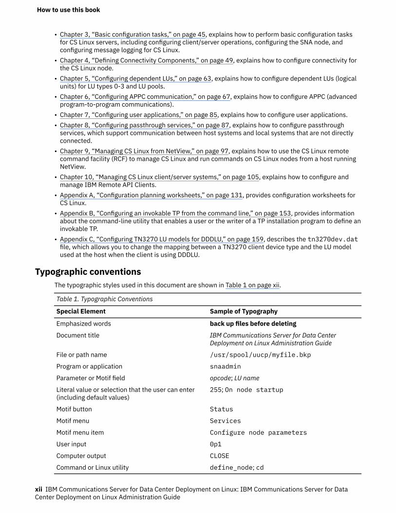
Typographic conventionsThe typographic styles used in this document are shown in Table 1 on page xii.
Table 1. Typographic Conventions
Special Element Sample of Typography
Emphasized words back up files before deleting
Document title IBM Communications Server for Data CenterDeployment on Linux Administration Guide
File or path name /usr/spool/uucp/myfile.bkp
Program or application snaadmin
Parameter or Motif field opcode; LU name
Literal value or selection that the user can enter(including default values)
255; On node startup
Motif button Status
Motif menu Services
Motif menu item Configure node parameters
User input 0p1
Computer output CLOSE
Command or Linux utility define_node; cd
How to use this book
xii IBM Communications Server for Data Center Deployment on Linux: IBM Communications Server for DataCenter Deployment on Linux Administration Guide
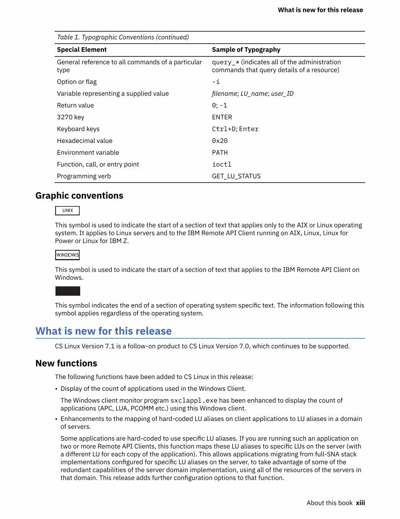
Table 1. Typographic Conventions (continued)
Special Element Sample of Typography
General reference to all commands of a particulartype
query_* (indicates all of the administrationcommands that query details of a resource)
Option or flag -i
Variable representing a supplied value filename; LU_name; user_ID
Return value 0; -1
3270 key ENTER
Keyboard keys Ctrl+D; Enter
Hexadecimal value 0x20
Environment variable PATH
Function, call, or entry point ioctl
Programming verb GET_LU_STATUS
Graphic conventions
This symbol is used to indicate the start of a section of text that applies only to the AIX or Linux operatingsystem. It applies to Linux servers and to the IBM Remote API Client running on AIX, Linux, Linux forPower or Linux for IBM Z.
This symbol is used to indicate the start of a section of text that applies to the IBM Remote API Client onWindows.
This symbol indicates the end of a section of operating system specific text. The information following thissymbol applies regardless of the operating system.
What is new for this releaseCS Linux Version 7.1 is a follow-on product to CS Linux Version 7.0, which continues to be supported.
New functionsThe following functions have been added to CS Linux in this release:
• Display of the count of applications used in the Windows Client.
The Windows client monitor program sxclappl.exe has been enhanced to display the count ofapplications (APC, LUA, PCOMM etc.) using this Windows client.
• Enhancements to the mapping of hard-coded LU aliases on client applications to LU aliases in a domainof servers.
Some applications are hard-coded to use specific LU aliases. If you are running such an application ontwo or more Remote API Clients, this function maps these LU aliases to specific LUs on the server (witha different LU for each copy of the application). This allows applications migrating from full-SNA stackimplementations configured for specific LU aliases on the server, to take advantage of some of theredundant capabilities of the server domain implementation, using all of the resources of the servers inthat domain. This release adds further configuration options to that function.
What is new for this release
About this book xiii
• Addition of a poll timer between domain servers.
This function allows faster failover and recovery in a multi-server client-server configuration.• Ability to define LU 0-3 ranges with two decimal digits in the name.
This function allows more flexibility in naming pools of LUs.• Support for tn3270 Intrusion Detection Service.
This function permits interworking with the enhancement to VTAM to detect certain violations of the3270 data stream.
• Docker container support.
This function allows the Linux, AIX or Windows Remote API client to run within Docker containers.• Support for latest encryption ciphers.
The tn3270 server and tn redirector in the product support the TLS 1.0, 1,1, 1.2 and 1.3 encryptionstandards and their associated algorithms and cipher suites. See the README file for the latestencryption support.
• Allow IPv6 connection network links to use hex address.
When defining a Connection Network on an IPv6 network for HPR/IP, an additional parameter can bespecified to indicate if the IP addressing for the Connection Network will use IPv6 DNS names only orIPv6 addresses only. The default is to use IPv6 DNS names only.
• Support Ubuntu versions of Linux.
The product can now be used with Ubuntu Linux in addition to RedHat Enterprise Linux and SUSE LinuxEnterprise Server. See the README file for the latest O/S support.
• Support ppc64le versions of Linux on IBM Power.
The product can now be used with IBM Power computers running ppc64le Linux.• Ability to configure Ethernet device names for LLC2 DLCs.
RHEL typically uses names of the form ens32 etc., previously only names of the form eth0, eth1,etc. were supported.
Functions that have been retiredSupport for 32-bit Intel workstations running Linux (i686).
IBM Power computers running ppc64 Linux, note that support is now provided for IBM Power computersrunning ppc64le Linux.
Where to find more informationSee the Bibliography for other books in the IBM Communications Server for Data Center Deployment onLinux library, as well as books that contain additional information about topics related to SNA andworkstations.
Where to find more information
xiv IBM Communications Server for Data Center Deployment on Linux: IBM Communications Server for DataCenter Deployment on Linux Administration Guide
Chapter 1. SNA terms and concepts
This chapter defines Systems Network Architecture (SNA) terms and concepts that are important tounderstanding and using CS Linux. For information about CS Linux, its capabilities, and how it implementsthe different SNA concepts described, see IBM Communications Server for Data Center Deployment onLinux Quick Beginnings. If you are already familiar with SNA and CS Linux, you can begin with Chapter 2,“Administering CS Linux,” on page 25.
This chapter is divided into the following parts:
• “Systems Network Architecture” on page 1 provides a definition of SNA.• “Basic SNA concepts” on page 1 explains terms and concepts that apply to any SNA network.• “Basic APPN concepts” on page 10 explains terms and concepts that apply only to SNA networks that
support Advanced Peer-to-Peer Networking (APPN).• “Accessing subarea networks from APPN networks” on page 22 introduces terms and concepts that
apply to networks that combine SNA and APPN.
Note: This chapter is not intended as a complete reference to SNA concepts. Detailed information aboutSNA can be found in the SNA publications listed in the Bibliography.
Systems Network ArchitectureSystems Network Architecture (SNA) is an IBM data communication architecture that specifies commonconventions for communicating among a wide variety of hardware and software data communicationproducts. This architecture consists of two kinds of definitions: formats that define the layout of messagesexchanged by network components, and protocols that define the actions that network components takein response to messages.
An SNA network is a collection of computers that are linked together and communicate using SNA.
Originally, SNA was designed to enable communications with a host computer. Each network orsubnetwork was controlled by the host; other computers communicated directly with the host, but notwith each other. This older, host-controlled style of network is often referred to as subarea SNA. SNA hassince been extended to support direct peer-to-peer communications between computers in the network,without requiring a host. This newer, peer-level networking is APPN.
Many SNA networks have elements of both subarea and peer-to-peer networking. As networks migratefrom subarea SNA to APPN, an APPN-capable host may act to control older systems while also acting as apeer to newer systems. Similarly, a single computer may access both peer computers (in an APPNnetwork) and an older host; its communications with the host are controlled by the host, but itscommunications with other computers are peer-to-peer and do not involve the host.
Basic SNA conceptsSNA defines the standards, protocols, and functions used by devices - from mainframes to terminals - toenable them to communicate with each other in SNA networks.
SNA functions are divided into a hierarchical structure of separate layers, each performing a specific set offunctions. This division of network functions into layers enables network devices to share information andprocessing resources without having detailed information about each device on the network. A user at aworkstation can communicate with another user without knowing anything about the physical devices onthe network or the connections between those devices.
Network typesSNA supports the following types of networks:
Systems Network Architecture
© Copyright IBM Corp. 1998, 2021 1
• A subarea network is a hierarchically organized network consisting of subarea nodes and peripheralnodes. Subarea nodes, such as hosts and communication controllers, handle general network routing.Peripheral nodes, such as terminals, attach to the network without awareness of general networkrouting.
• A peer network is a cooperatively organized network consisting of peer nodes that all participate ingeneral network routing.
• A mixed network is a network that supports both host-controlled communications and peercommunications.
Note: Linux systems running CS Linux can act as a peripheral node in a subarea network, as a peer node ina peer network, or both at the same time.
SNA nodesIn SNA networks, a node is a Linux system or other device - with associated software components - thatimplements SNA protocols and has at least one communication path to another node in the network. Eachnode manages its end of the network communication paths, and uses SNA protocols to communicate withthe node at the other end of each path.
Because subarea networks and peer networks define the relationships among nodes differently, they alsouse different terms for node types (to describe the roles that nodes play in the network).
Node types in a subarea networkSNA subarea networks support the following node types:
• Subarea nodes control communication and network resources for all attached nodes. SNA classifiessubarea nodes according to their capabilities and the amount of control they have over other nodes:
– Type 5 nodes provide SNA functions that control network resources, support transaction programs,support network operators, and provide end-user services. Because these functions are oftenprovided by host processors, type 5 nodes are also known as host nodes. The devices and resourcescontrolled by a type 5 subarea node constitute the domain of that node.
– Type 4 nodes provide SNA functions that route and control the flow of data in a part of the network.Because these functions are often provided by communication controllers, type 4 nodes are alsoknown as communication controller nodes.
• Peripheral nodes serve subordinate roles in subarea networks. For example, a peripheral node cansupport 3270 emulation or dependent LU 6.2 communication. Peripheral nodes are devices such asdistributed processors, cluster controllers, or workstations; they are also classified into type 2.0 andtype 2.1 nodes:
– Type 2.0 nodes are always controlled by a type 4 or 5 node. They cannot establish communicationwith other nodes without the participation of a type 4 or 5 node. Type 2.0 nodes are referred to asdependent nodes.
– Type 2.1 nodes can act as dependent nodes, but they can also communicate directly with other type2.1 nodes.
Note: Linux computers running CS Linux can function as type 2.1 or type 2.0 nodes.
A type 4 or 5 subarea node to which a peripheral node is attached acts as a boundary node. It performs aboundary function by translating between the network addresses used by a subarea node and the localaddresses used by a peripheral node.
A simple subarea network includes the following components:
HostA host is a mainframe computer compatible with the original IBM System/370. A host is traditionally atype 5 node. However, CS Linux for IBM Z runs on a host computer as a type 2.1 or 2.0 node.
Basic SNA concepts
2 IBM Communications Server for Data Center Deployment on Linux: IBM Communications Server for DataCenter Deployment on Linux Administration Guide
Communication controllerA communication controller, also known as a front-end processor (FEP), is a separate processorattached to the host. It manages the host's communications with other computers.
Communications linkA communications link connects the host site with an end-user site. The users are usually on aseparate site from the host, so the two sites need to be connected by a communications link.
Terminal controllerAt the remote end of the communications link is a terminal controller, also known as a clustercontroller. It is responsible for controlling the use of the link, and routes data to the terminals. Themost well-known IBM terminal controllers are the 3174 and 3274.
TerminalsUsers run host applications or submit work to the host from terminals. The best-known IBM terminalis the 3270. A terminal can be connected through a terminal controller or directly connected to acommunication controller.
PrintersPrinters such as the IBM 3287 can also be attached to the terminal controller. They can receive outputfrom the host.
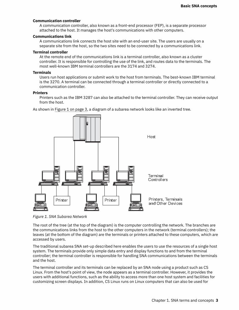
As shown in Figure 1 on page 3, a diagram of a subarea network looks like an inverted tree.
Figure 1. SNA Subarea Network
The root of the tree (at the top of the diagram) is the computer controlling the network. The branches arethe communications links from the host to the other computers in the network (terminal controllers); theleaves (at the bottom of the diagram) are the terminals or printers attached to these computers, which areaccessed by users.
The traditional subarea SNA set-up described here enables the users to use the resources of a single hostsystem. The terminals provide only simple data entry and display functions to and from the terminalcontroller; the terminal controller is responsible for handling SNA communications between the terminalsand the host.
The terminal controller and its terminals can be replaced by an SNA node using a product such as CSLinux. From the host's point of view, the node appears as a terminal controller. However, it provides theusers with additional functions, such as the ability to access more than one host system and facilities forcustomizing screen displays. In addition, CS Linux runs on Linux computers that can also be used for
Basic SNA concepts
Chapter 1. SNA terms and concepts 3
other tasks not related to SNA (unlike the terminal controller, which is used solely for communicationswith the host).
Node types in a peer networkPeer networks do not classify nodes hierarchically, as is done in a subarea network. Exchanges with othernodes are not controlled by a host or other centralized processor. Instead, any node can establishcommunication with any other node.
A peer network is composed of type 2.1 nodes. The nodes in a peer network can serve the following roles:
• APPN network nodes (NNs) identify the locations of network resources, determine routes for sessionsbetween these resources, route sessions, and serve end nodes (EN) and low-entry networking (LEN)nodes directly attached to the network node. The domain of an APPN network node consists of itselfand any end nodes for which it provides network services.
• APPN end nodes can access remote resources without requiring that those resources be configured onthe end node. An end node can communicate with adjacent nodes on its own, but requires the servicesof a network node server to access nonadjacent nodes. The domain of an APPN end node includes onlyitself.
• APPN branch network nodes allow the APPN network to be separated into branches to simplify itstopology and reduce network management overheads. They provide network node functions to endnodes in a branch separated from the main APPN network, while acting as end nodes in the mainnetwork itself. For more information, see “Branch Extender” on page 21.
• Low-entry networking nodes (LEN nodes) are type 2.1 nodes that do not support APPN functions. Theycan communicate with adjacent nodes in an APPN network, but do not participate in the APPN network.In a LEN node, all potential sessions with remote LUs must be predefined, either specifically or througha single default entry indicating that all remote LUs reside in an adjacent network node that can beaccessed using a certain link. The domain of a LEN node includes only itself.
For more information about peer-oriented node types, see “APPN node types” on page 11.
ConnectivityFor two nodes to communicate, each node must have a combination of hardware and software thatsupports data flow between the nodes. The hardware component consists of an adapter at each node andthe transmission medium that connects the two adapters. The software component provides control ofthe hardware and the data exchanged over it.
Each node connected to a network has one or more link stations, which are the hardware and software ina node that control data flow to a specific adjacent node. To establish communication between twoadjacent nodes, one of the link stations must first activate the link between the nodes.
Transaction programsPrograms that exchange information across the SNA network are called transaction programs (TPs).
Following are examples of application programs that can include SNA TPs:
• Emulation programs• File transfer• Database transaction processing• Network management• Centralized data services
The TP accesses the network through a logical unit (LU) that establishes and maintains a session with apartner LU on another node. For more information about logical units, see “Logical units” on page 5.
Note: CS Linux includes sample TPs for most supported APIs. For more information on sample TPs, referto the programmer's guide for the API. You can also purchase SNA TPs as part of other products or createyour own TPs (see “Application programming interfaces” on page 5).
Basic SNA concepts
4 IBM Communications Server for Data Center Deployment on Linux: IBM Communications Server for DataCenter Deployment on Linux Administration Guide
Application programming interfacesSNA TPs are written using application programming interfaces (APIs). APIs provide specific subroutinesthat enable SNA TPs to access SNA functions, such as those for exchanging data and performing controlfunctions. These subroutines enable an SNA TP to communicate with another SNA TP on a remote node.
CS Linux includes the following APIs on all platforms:
• APPC - LU type 6.2 only• CPI-C (Common Programming Interface for Communications) - LU type 6.2 only• CSV (Common Service Verb) API• LUA API
In addition, CS Linux includes the following proprietary programming interfaces:
• MS (Management Services) API (only for AIX or Linux systems)• NOF (Node Operator Facility) API
Network accessible unitsCommunication between a TP and the SNA network occurs through network accessible units or NAUs(formerly called "network addressable units"), which are unique network resources that can be accessed(through unique local addresses) by other network resources.
SNA provides the following types of NAUs:
• Physical units (see “Physical units” on page 5)• Logical units (see “Logical units” on page 5)• Control points (see “Control points” on page 6)
Note: Because TPs are considered users of the network, not components, they are not classified as NAUs.
Physical unitsEach SNA node contains a physical unit (PU). The PU manages resources (such as link resources) andsupports communication with a host.
Note: On type 2.1 nodes (which can be APPN nodes), the control point provides PU services in addition toproviding other services (see “Control points” on page 6). Two type 2.1 nodes (such as CS Linux nodes)can communicate directly, without requiring the services of a host to establish communications.
Logical unitsEach SNA node contains one or more logical units (LUs). An LU provides a set of functions that are used byTPs and end users to provide access to the network. LUs communicate directly with local TPs and devices.
SNA defines several types of LUs, each optimized for a specific class of applications. LUs of different typescannot communicate with each other, but LUs of the same type can communicate even though they resideon different kinds of systems.
For example, a TP running on a Linux system can communicate with a TP on an AS/400 computer as easilyas it can with a TP on another Linux system, as long as both TPs use the same LU type.
CS Linux supports the following LU types:
LU 6.2 (for APPC, 5250, APPC Application Suite, and CPI-C)LU 6.2 supports program-to-program communication in a distributed data processing environment.The LU 6.2 data stream is either an SNA general data stream (GDS), which is a structured-field datastream, or a user-defined data stream. LU 6.2 can be used for communication between two type 5nodes, a type 5 node and a type 2.0 or 2.1 node, or two type 2.1 nodes. (Type 2.1 nodes can serve asAPPN nodes.)
Basic SNA concepts
Chapter 1. SNA terms and concepts 5
This LU type provides more functions and greater flexibility than any other LU type. Unless you areconstrained by existing hardware or software, LU 6.2 is the logical choice when developing newapplications.
Note: Only LU 6.2 can provide independent LU functions.
LU 3 (for 3270 printing)LU 3 supports application programs and printers using the SNA 3270 data stream.
For example, LU 3 can support an application program running under Customer Information ControlSystem (CICS) and sending data to an IBM 3262 printer attached to an IBM 3174 EstablishmentController.
LU 2 (for 3270 displays)LU 2 supports application programs and display workstations communicating in an interactiveenvironment using the SNA 3270 data stream. Type 2 LUs also use the SNA 3270 data stream for filetransfer.
For example, the LU 2 protocol can support 3270 emulation programs, which enable workstations toperform the functions of IBM 3270-family terminals. In addition, LU 2 is used by other programs tocommunicate with host applications that normally provide output to 3270 display devices. Such TPsenable the workstation to achieve a form of cooperative processing with the host.
LU 1 (for SCS printing and RJE)LU 1 supports application programs and single- or multiple-device data processing workstationscommunicating in an interactive, batch-data transfer, or distributed data processing environment. Thedata streams used by LU type 1 conform to the SNA character string or Document ContentArchitecture (DCA).
For example, LU type 1 can support an application program running under Information ManagementSystem/Virtual Storage (IMS/VS) and communicating with an IBM 8100 Information System. Thisenables an operator to correct a database that the application program maintains.
Applications that use LU 1 are often described as remote job entry (RJE) applications.
LU 0 (for LUA)LU 0, an early LU definition, supports primitive program-to-program communication. Certain hostdatabase systems, such as IMS/VS (Information Management System/Virtual Storage) and somepoint-of-sale systems for the retail and banking industries (such as the IBM 4680 Store SystemOperating System) use LU 0. Current releases of these products also support LU 6.2 communication,which is the preferred protocol for new applications.
Note: For information about the data streams used by SNA logical units, refer to Systems NetworkArchitecture Technical Reference.
Control pointsA control point (CP) is an NAU that manages network resources within its domain, controlling resourceactivation, deactivation, and status monitoring. The CP manages both physical resources such as links,and logical information such as network addresses.
SNA defines the following types of network control points:
System services control pointOn a type 5 node, the CP is called a system services control point (SSCP). It manages and controls thenetwork resources in a subarea network. For example, an SSCP can use a directory of networkresources to locate a specific LU under its control, and can establish communication between two LUsin its domain. An SSCP can also cooperate with other SSCPs to establish connectivity between LUs indifferent subarea domains.
The SSCP also provides an interface to network operators at the host system, who can inspect andcontrol resources in the network.
Basic SNA concepts
6 IBM Communications Server for Data Center Deployment on Linux: IBM Communications Server for DataCenter Deployment on Linux Administration Guide
Physical unit control pointOn type 4 nodes and type 2.0 nodes in a subarea network, the control point is called a physical unitcontrol point (PUCP).
Control pointOn type 2.1 nodes, the control point provides both PU and LU functions, such as activating local linkstations, interacting with a local operator, and managing local resources. It can also provide networkservices, such as partner LU location and route selection for local LUs.
In a subarea network, the CP on a CS Linux node acts as a type 2.0 PU. It communicates with an SSCPon a host and does not communicate with other CPs in the subarea network.
When participating in an APPN network, the CP exchanges network control information with the CPs inadjacent nodes. The CP can also function as an independent LU of type 6.2. The CP acts as the defaultLU for TPs on the local node. For more information about the APPN control point, see “APPN controlpoint” on page 12.
SessionsNAUs communicate with NAUs in other nodes over temporary logical communication channels calledsessions. Before two TPs can communicate, their LUs must establish a session. The LU that manages thesession on the local node is the local LU; the LU that manages the session on the remote node is thepartner LU.
Session typesCS Linux is primarily concerned with the following types of sessions:
LU-LU sessionsIn order for two TPs to communicate, the LUs that support the TPs must first establish an LU-LUsession. In general, a session is established when a TP in one SNA node tries to communicate with aTP in another node and no existing session between the LUs on the two nodes is available.
SSCP-LU sessionsA dependent LU (see “Dependent and independent LUs” on page 8) must have an active SSCP-LUsession with an SSCP on a type 5 node before it can have a session with an LU in the subarea network.Once an SSCP-LU session is active, a dependent LU can solicit an LU-LU session.
SSCP-PU sessionsBefore an SSCP-LU session can be established, the PU controlling the LU must have an active SSCP-PU session with an SSCP on a type 5 node. The SSCP-PU session is used to pass control data andnetwork management data between the PU and SSCP.
CP-CP sessionsIn an APPN network, adjacent nodes establish CP-CP sessions. These sessions are used to search fora resource in the APPN network and to maintain topology information (see “APPN control point” onpage 12).
Logical unit attributes for sessionsLogical units have attributes that determine how they interact during LU-LU sessions. These attributes aredetermined by the architecture of SNA. LUs can be primary or secondary, and dependent or independent.
Primary and secondary LUsTo establish a session, one LU requests session activation by sending a BIND request to another LU:
• A primary LU is the LU that sends the BIND request for a given LU-LU session.• A secondary LU is the LU that receives the BIND request.
Peer networks do not use a fixed hierarchy of nodes and do not have predetermined primary or secondaryLUs.
Basic SNA concepts
Chapter 1. SNA terms and concepts 7

Note: In a peer network, an independent LU that is participating in multiple sessions (see “Multiple andparallel sessions” on page 8) can act as a primary LU for one session and a secondary LU in another.
Dependent and independent LUsAll type 0, 1, 2, and 3 LUs are dependent LUs. Type 6.2 LUs can be configured as either dependent orindependent LUs.
• A dependent LU (also known as an SSCP-dependent LU) requires the services of an SSCP to establish asession with another LU. An SSCP-LU session must be established before a dependent LU-LU sessioncan be established.
A dependent LU can be in session only with LUs on an SNA host. Because of this restriction, dependentLUs usually use subarea networks (also known as host-mediated networks). However, the dependent LUrequester (DLUR) function enables session traffic from dependent LUs to flow over APPN networks. Formore information about DLUR, see “Accessing subarea networks from APPN networks” on page 22.
A dependent LU on a peripheral node is always the secondary LU.• An independent LU can establish sessions with other independent LUs without the aid of an SNA host.
LU 6.2 is the only LU type that can be independent.
An independent LU can act as a primary or as a secondary LU when establishing a session.
Multiple and parallel sessionsAn independent LU can participate in sessions with more than one remote LU at the same time (multiplesessions).
An independent LU can also participate in parallel sessions, or multiple concurrent sessions with thesame remote LU.
Dependent LUs (including dependent LU 6.2) cannot have multiple sessions.
LUs with multiple and parallel sessions are shown in Figure 2 on page 8. LUA and LUB have parallelsessions. LUA also has multiple sessions: two with LUB and one with LUD. LUD has multiple sessions withLUA and LUC.
Figure 2. Multiple and Parallel Sessions
ConversationsThis section applies to LU 6.2 only.
Once a session is established between two LUs, the LU-LU session supports the exchange of informationbetween two TPs, which have the exclusive use of the session to execute a transaction. This exchange of
Basic SNA concepts
8 IBM Communications Server for Data Center Deployment on Linux: IBM Communications Server for DataCenter Deployment on Linux Administration Guide
information is called a conversation. Only one conversation can use a particular session at a time, butsessions are serially reusable (many conversations can use the same session, one after another).
To initiate a conversation, a source TP sends a request to its LU, asking it to allocate a conversation with aremote TP. The invoking TP (or source TP) initiates the conversation, like the calling party in a telephoneconversation. The invokable TP or target TP (the remote TP) is the partner in the conversation, like theparty who receives a telephone call.
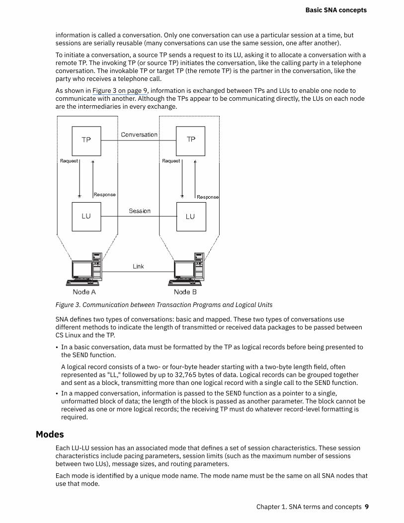
As shown in Figure 3 on page 9, information is exchanged between TPs and LUs to enable one node tocommunicate with another. Although the TPs appear to be communicating directly, the LUs on each nodeare the intermediaries in every exchange.
Figure 3. Communication between Transaction Programs and Logical Units
SNA defines two types of conversations: basic and mapped. These two types of conversations usedifferent methods to indicate the length of transmitted or received data packages to be passed betweenCS Linux and the TP.
• In a basic conversation, data must be formatted by the TP as logical records before being presented tothe SEND function.
A logical record consists of a two- or four-byte header starting with a two-byte length field, oftenrepresented as "LL," followed by up to 32,765 bytes of data. Logical records can be grouped togetherand sent as a block, transmitting more than one logical record with a single call to the SEND function.
• In a mapped conversation, information is passed to the SEND function as a pointer to a single,unformatted block of data; the length of the block is passed as another parameter. The block cannot bereceived as one or more logical records; the receiving TP must do whatever record-level formatting isrequired.
ModesEach LU-LU session has an associated mode that defines a set of session characteristics. These sessioncharacteristics include pacing parameters, session limits (such as the maximum number of sessionsbetween two LUs), message sizes, and routing parameters.
Each mode is identified by a unique mode name. The mode name must be the same on all SNA nodes thatuse that mode.
Basic SNA concepts
Chapter 1. SNA terms and concepts 9
Route selectionTo establish an LU-LU session, a route must be calculated between the nodes where the two LUs reside. Aroute is an ordered sequence of links and nodes that represents a path between the two nodes.
SNA networks support the following methods of route selection:
• For subarea networks, you must predefine all routes between subarea nodes.• For peer networks that do not support APPN, type 2.1 nodes can support sessions only with adjacent
nodes; their sessions cannot be routed through intermediate nodes.• For APPN networks, SNA can compute routes dynamically at the time of session initiation, using a class
of service specified for the mode used by the session (see “Class of service” on page 10).
The High-Performance Routing (HPR) feature of APPN provides the following functions:
• Rapid Transport Protocol (RTP) minimizes cycles and storage requirements for routing network layerpackets through intermediate nodes on a session route.
• Automatic network routing (ANR) enables APPN networks to automatically reroute sessions if a portionof the originally computed route fails.
Class of serviceClass of service (COS) is a definition of the transport network (data link control and path control)characteristics - such as route security, transmission priority, and bandwidth - that the local node can useto establish a particular session. The COS definition assigns relative values to factors such as acceptablelevels of security, cost per byte, cost per connect-time, propagation delay, and effective capacity.
In a subarea network, a COS is derived from the mode associated with a session, as defined in the hostsystem.
APPN network nodes use the COS to compute session routes between independent LUs. For moreinformation about session routing in APPN networks, see “Session routing” on page 16.
Basic APPN conceptsAdvanced Peer-to-Peer Networking (APPN) is a network architecture that supports distributed networkcontrol. It makes networks easy to configure and use, provides centralized network management, andsupports flexible connectivity.
An APPN network is composed of type 2.1 nodes. Each node in the network is connected by a link to atleast one other node in the APPN network. CP-CP sessions are established over each of these links toadjacent nodes (nodes in the same network that can establish direct links without going through a thirdnode). All of the nodes in an APPN network share a common network name.
APPN nodes can include processors of various sizes, such as the Application System/400 (AS/400), PCsrunning Communications Server for Data Center Deployment running Linux, systems using VirtualTerminal Access Method (VTAM®), and Linux servers running CS Linux.
APPN provides the following functions:
• Support for APPN network nodes and end nodes as well as non-APPN peer nodes (see “APPN nodetypes” on page 11)
• APPN control point functions (see “APPN control point” on page 12)• Directory services to support finding specific logical units (see “Locating resources” on page 13)• Topology and routing services to support session establishment using intermediate session routing
(ISR), automatic network routing (ANR), or connection networks (CNs) (see “Session routing” on page16 and “APPN connection networks” on page 20)
Note: An APPN node can also be connected to a subarea network, serving as both an APPN node in a peernetwork and a peripheral node in a subarea network.
Basic APPN concepts
10 IBM Communications Server for Data Center Deployment on Linux: IBM Communications Server for DataCenter Deployment on Linux Administration Guide
APPN node typesThe following types of nodes can be part of an APPN network:
• Network nodes (see “APPN network nodes” on page 11)• End nodes (see “APPN end nodes” on page 12)
In addition, low-entry networking (LEN) nodes can be connected to an APPN network, but they do not useAPPN features (see “LEN nodes” on page 12).
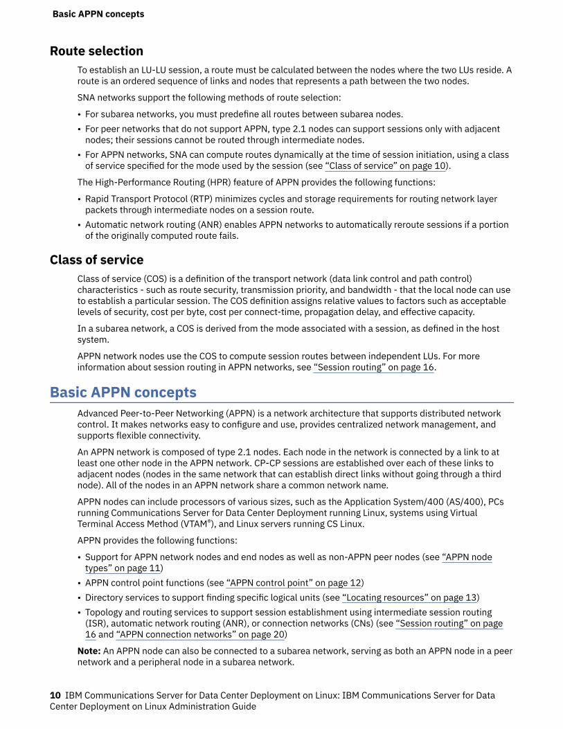
A sample APPN network is shown in Figure 4 on page 11.
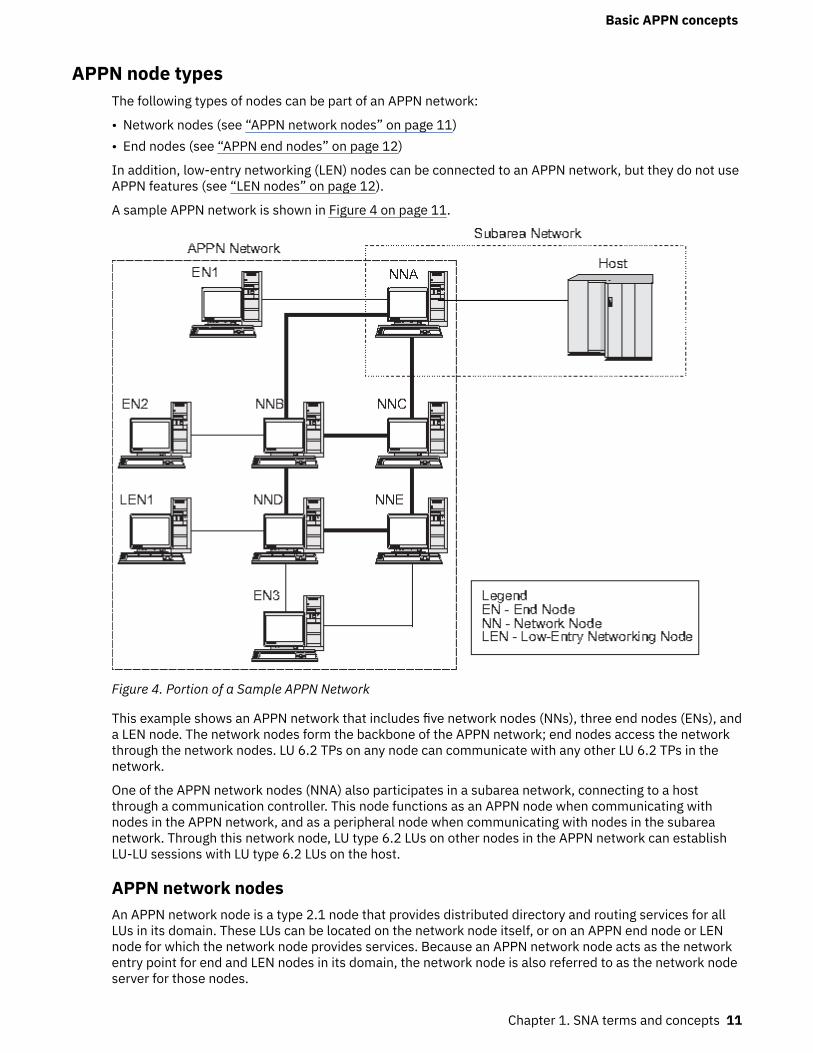
Figure 4. Portion of a Sample APPN Network
This example shows an APPN network that includes five network nodes (NNs), three end nodes (ENs), anda LEN node. The network nodes form the backbone of the APPN network; end nodes access the networkthrough the network nodes. LU 6.2 TPs on any node can communicate with any other LU 6.2 TPs in thenetwork.
One of the APPN network nodes (NNA) also participates in a subarea network, connecting to a hostthrough a communication controller. This node functions as an APPN node when communicating withnodes in the APPN network, and as a peripheral node when communicating with nodes in the subareanetwork. Through this network node, LU type 6.2 LUs on other nodes in the APPN network can establishLU-LU sessions with LU type 6.2 LUs on the host.
APPN network nodesAn APPN network node is a type 2.1 node that provides distributed directory and routing services for allLUs in its domain. These LUs can be located on the network node itself, or on an APPN end node or LENnode for which the network node provides services. Because an APPN network node acts as the networkentry point for end and LEN nodes in its domain, the network node is also referred to as the network nodeserver for those nodes.
Basic APPN concepts
Chapter 1. SNA terms and concepts 11
A network node provides the following services:
• LU-LU session services for its local LUs• Directory searches and route selection for all LUs in its domain• Intermediate session routing (see “Intermediate routing” on page 18)• Routing for management services (MS) data, such as alerts, between a served end node and an MS focal
point
APPN end nodesAn APPN end node is a type 2.1 node that serves as an end point in an APPN network. It maintainsdirectory information only for local resources. An APPN end node can independently establish sessionsbetween local LUs and LUs on adjacent nodes. For sessions with LUs on nodes not directly connected tothe end node, an end node requests routing and directory information from its network node server usingCP-CP sessions.
APPN end nodes can register their local LUs with their network node server. This capability means thenetwork operator at the network node server does not have to predefine the names of all LUs on theattached end nodes to which the network node provides services.
An APPN end node can be attached to multiple network nodes (see EN3 in Figure 4 on page 11), but it canhave CP-CP sessions active with only one network node at a time - its network node server. The othernetwork nodes can be used only to provide intermediate routing for the end node or as substitute networknode servers if the main network node server becomes unavailable.
An APPN end node can also have a direct link to another APPN end node or a LEN node, but CP-CPsessions are never established between two end nodes.
LEN nodesA low-entry networking node (LEN node) is a type 2.1 node that uses independent LU 6.2 protocols, butdoes not support CP-CP sessions. It can be connected to an APPN network node or end node, but doesnot support APPN functions.
An APPN network node can provide routing services for an attached LEN node, enabling the LEN node toparticipate in an APPN network without requiring link stations to be defined between the LEN node and allof the nodes in the APPN network.
LUs in the APPN network with which the LEN node may want to establish sessions must be defined to theLEN node as if they reside on the LEN node's network node server. The LEN node establishes sessionswith LUs on its network node server. The network node routes the session through the APPN network tothe node in the network where the LU actually resides. LUs on the LEN node must be predefined to thenetwork node that serves the LEN node. LU resources on LEN nodes (unlike those on end nodes) cannotbe registered on the network node server.
An APPN end node cannot provide intermediate routing. When a LEN node's only link is to an APPN endnode, the LEN node can communicate only with LUs on the end node through the direct link between thetwo nodes.
APPN control pointAn APPN control point is a set of functions that manages node resources and supports both physical unitand logical unit functions on a type 2.1 node. An APPN CP directs local node functions (such as activatingand deactivating adapters and links), provides directory and topology information, and assists LUs insession initiation and termination.
Adjacent nodes in an APPN network use a pair of parallel CP-CP sessions to exchange networkinformation and to provide directory and route selection services. Both sessions of a given pair must beactive in order for the partner CPs to begin and sustain their interactions. Different node types use thesesessions differently, as follows:
Basic APPN concepts
12 IBM Communications Server for Data Center Deployment on Linux: IBM Communications Server for DataCenter Deployment on Linux Administration Guide
• Two parallel CP-CP sessions are established between an APPN network node and each adjacentnetwork node. These CP-CP sessions are used to exchange directory, topology, and managementservices data.
• Two parallel CP-CP sessions are established between an APPN end node and the adjacent networknode acting as the server for the end node. These CP-CP sessions are used to exchange directory,topology, and management services data.
• LEN nodes do not support CP-CP sessions.
The functions provided in CP-CP sessions vary based on the types of nodes involved, as follows:
• All CP-CP sessions conduct directory searches.• CP-CP sessions between an end node and a network node provide the following functions:
– Registering resources.– Routing management services data (such as alerts) between the end node and a focal point.– Routing topology data from each end node to its network node servers. This information can be used
by the network node server to compute a route that does not flow through the network node server.• CP-CP sessions between adjacent network nodes exchange topology information. As a result of this
exchange, each network node creates an internal network topology database.
When setting up a node, you must define the CP name. The CP is also an LU that can support usersessions, and it can be the only LU defined in your node, if you so choose.
Locating resourcesTo support communication between TPs, CS Linux first establishes a session between the logical unitsthat control those TPs. APPN enables the CP on a node to locate LUs throughout the APPN networkwithout requiring that the node have any configuration information for the remote LU. The APPN functionthat dynamically locates LUs in the network is called directory services. Once a resource has beenlocated, a route for the session is calculated through the APPN network.
Resource namesEach node has a unique name consisting of two parts: a network name and a control point name. Togetherthey constitute a fully qualified CP name. This name identifies each node to all other nodes in thenetwork. Similarly, each logical unit is identified by a fully qualified LU name, consisting of a network nameand LU name.
Note: For more information about network naming conventions, refer to IBM Communications Server forData Center Deployment on Linux Quick Beginnings.
Directory servicesEach APPN node maintains a directory of network resources. Directory services is the component of thenode CP that manages the local directory database and, in a network node, searches for networkresources throughout an APPN network.
When the node is initialized, it includes the following information:
• Node type (APPN network node, APPN end node, or LEN node)• Network ID of node• CP name of node
Each node directory maintains entries for resources (LUs and CPs), including each resource's fullyqualified name, type, and registration status. The specific resources stored in each local directory dependon the node type:
• A LEN node maintains a directory that includes its own LUs. It must also be configured with directoryentries for all of its possible partner LUs. LUs in the APPN network with which the LEN node may want toestablish sessions must be defined to the LEN node as if they reside on the LEN node's network node
Basic APPN concepts
Chapter 1. SNA terms and concepts 13
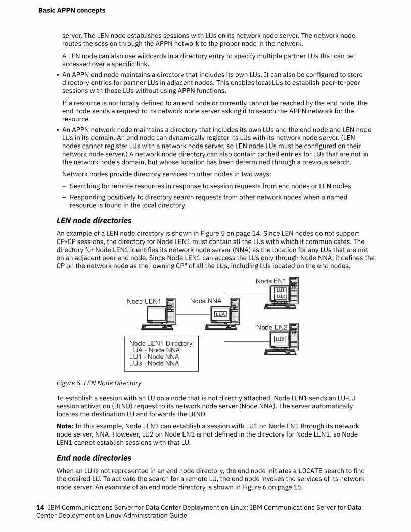
server. The LEN node establishes sessions with LUs on its network node server. The network noderoutes the session through the APPN network to the proper node in the network.
A LEN node can also use wildcards in a directory entry to specify multiple partner LUs that can beaccessed over a specific link.
• An APPN end node maintains a directory that includes its own LUs. It can also be configured to storedirectory entries for partner LUs in adjacent nodes. This enables local LUs to establish peer-to-peersessions with those LUs without using APPN functions.
If a resource is not locally defined to an end node or currently cannot be reached by the end node, theend node sends a request to its network node server asking it to search the APPN network for theresource.
• An APPN network node maintains a directory that includes its own LUs and the end node and LEN nodeLUs in its domain. An end node can dynamically register its LUs with its network node server. (LENnodes cannot register LUs with a network node server, so LEN node LUs must be configured on theirnetwork node server.) A network node directory can also contain cached entries for LUs that are not inthe network node's domain, but whose location has been determined through a previous search.
Network nodes provide directory services to other nodes in two ways:
– Searching for remote resources in response to session requests from end nodes or LEN nodes– Responding positively to directory search requests from other network nodes when a named
resource is found in the local directory
LEN node directoriesAn example of a LEN node directory is shown in Figure 5 on page 14. Since LEN nodes do not supportCP-CP sessions, the directory for Node LEN1 must contain all the LUs with which it communicates. Thedirectory for Node LEN1 identifies its network node server (NNA) as the location for any LUs that are noton an adjacent peer end node. Since Node LEN1 can access the LUs only through Node NNA, it defines theCP on the network node as the "owning CP" of all the LUs, including LUs located on the end nodes.
Figure 5. LEN Node Directory
To establish a session with an LU on a node that is not directly attached, Node LEN1 sends an LU-LUsession activation (BIND) request to its network node server (Node NNA). The server automaticallylocates the destination LU and forwards the BIND.
Note: In this example, Node LEN1 can establish a session with LU1 on Node EN1 through its networknode server, NNA. However, LU2 on Node EN1 is not defined in the directory for Node LEN1, so NodeLEN1 cannot establish sessions with that LU.
End node directoriesWhen an LU is not represented in an end node directory, the end node initiates a LOCATE search to findthe desired LU. To activate the search for a remote LU, the end node invokes the services of its networknode server. An example of an end node directory is shown in Figure 6 on page 15.
Basic APPN concepts
14 IBM Communications Server for Data Center Deployment on Linux: IBM Communications Server for DataCenter Deployment on Linux Administration Guide
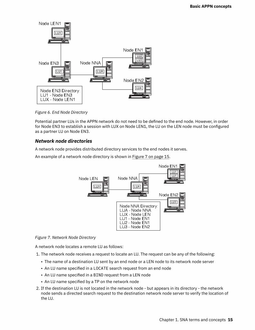
Figure 6. End Node Directory
Potential partner LUs in the APPN network do not need to be defined to the end node. However, in orderfor Node EN3 to establish a session with LUX on Node LEN1, the LU on the LEN node must be configuredas a partner LU on Node EN3.
Network node directoriesA network node provides distributed directory services to the end nodes it serves.
An example of a network node directory is shown in Figure 7 on page 15.
Figure 7. Network Node Directory
A network node locates a remote LU as follows:
1. The network node receives a request to locate an LU. The request can be any of the following:
• The name of a destination LU sent by an end node or a LEN node to its network node server• An LU name specified in a LOCATE search request from an end node• An LU name specified in a BIND request from a LEN node• An LU name specified by a TP on the network node
2. If the destination LU is not located in the network node - but appears in its directory - the networknode sends a directed search request to the destination network node server to verify the location ofthe LU.
Basic APPN concepts
Chapter 1. SNA terms and concepts 15
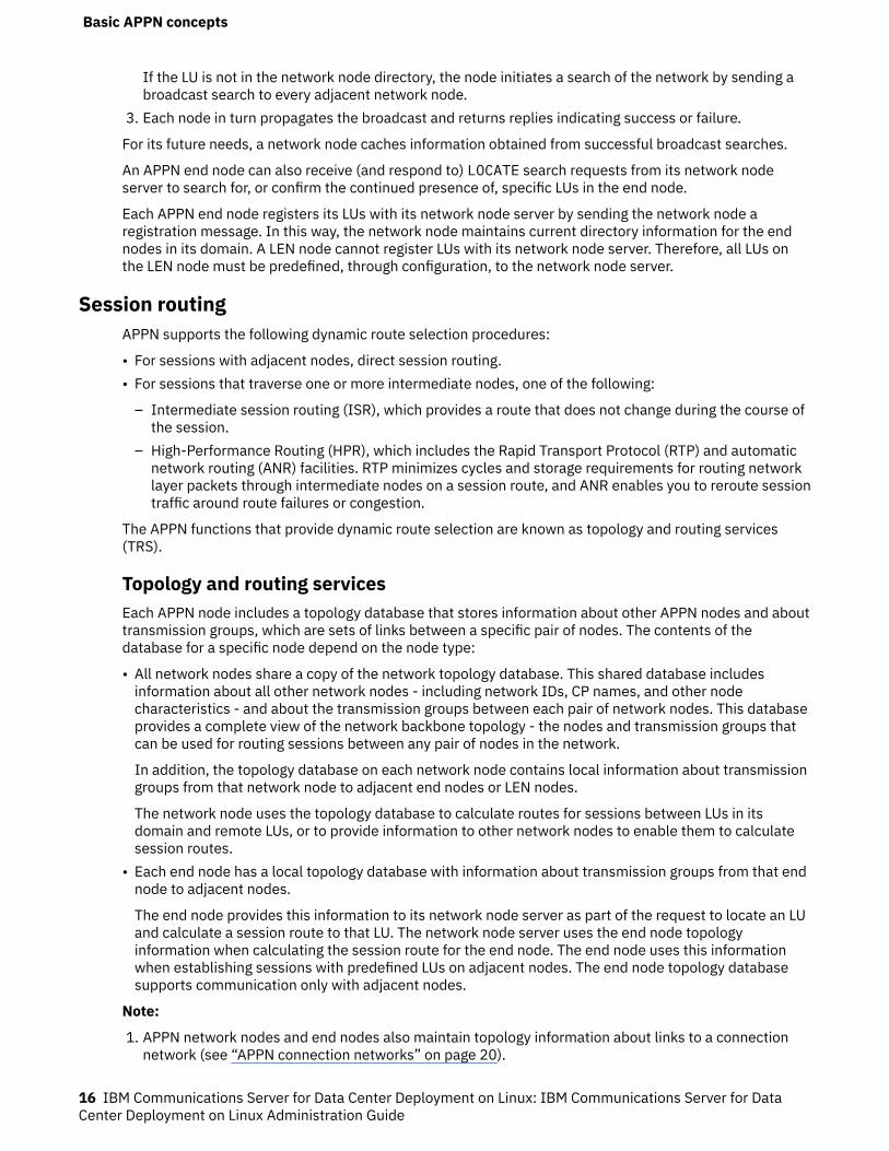
If the LU is not in the network node directory, the node initiates a search of the network by sending abroadcast search to every adjacent network node.
3. Each node in turn propagates the broadcast and returns replies indicating success or failure.
For its future needs, a network node caches information obtained from successful broadcast searches.
An APPN end node can also receive (and respond to) LOCATE search requests from its network nodeserver to search for, or confirm the continued presence of, specific LUs in the end node.
Each APPN end node registers its LUs with its network node server by sending the network node aregistration message. In this way, the network node maintains current directory information for the endnodes in its domain. A LEN node cannot register LUs with its network node server. Therefore, all LUs onthe LEN node must be predefined, through configuration, to the network node server.
Session routingAPPN supports the following dynamic route selection procedures:
• For sessions with adjacent nodes, direct session routing.• For sessions that traverse one or more intermediate nodes, one of the following:
– Intermediate session routing (ISR), which provides a route that does not change during the course ofthe session.
– High-Performance Routing (HPR), which includes the Rapid Transport Protocol (RTP) and automaticnetwork routing (ANR) facilities. RTP minimizes cycles and storage requirements for routing networklayer packets through intermediate nodes on a session route, and ANR enables you to reroute sessiontraffic around route failures or congestion.
The APPN functions that provide dynamic route selection are known as topology and routing services(TRS).
Topology and routing servicesEach APPN node includes a topology database that stores information about other APPN nodes and abouttransmission groups, which are sets of links between a specific pair of nodes. The contents of thedatabase for a specific node depend on the node type:
• All network nodes share a copy of the network topology database. This shared database includesinformation about all other network nodes - including network IDs, CP names, and other nodecharacteristics - and about the transmission groups between each pair of network nodes. This databaseprovides a complete view of the network backbone topology - the nodes and transmission groups thatcan be used for routing sessions between any pair of nodes in the network.
In addition, the topology database on each network node contains local information about transmissiongroups from that network node to adjacent end nodes or LEN nodes.
The network node uses the topology database to calculate routes for sessions between LUs in itsdomain and remote LUs, or to provide information to other network nodes to enable them to calculatesession routes.
• Each end node has a local topology database with information about transmission groups from that endnode to adjacent nodes.
The end node provides this information to its network node server as part of the request to locate an LUand calculate a session route to that LU. The network node server uses the end node topologyinformation when calculating the session route for the end node. The end node uses this informationwhen establishing sessions with predefined LUs on adjacent nodes. The end node topology databasesupports communication only with adjacent nodes.
Note:
1. APPN network nodes and end nodes also maintain topology information about links to a connectionnetwork (see “APPN connection networks” on page 20).
Basic APPN concepts
16 IBM Communications Server for Data Center Deployment on Linux: IBM Communications Server for DataCenter Deployment on Linux Administration Guide
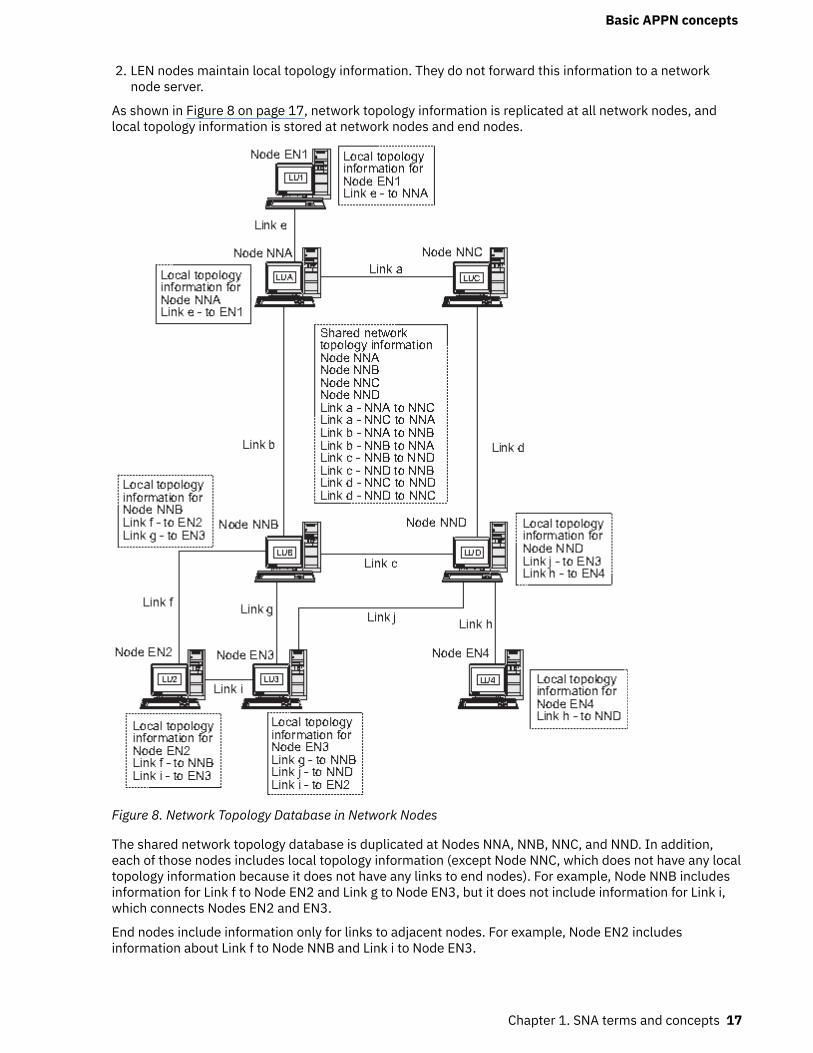
2. LEN nodes maintain local topology information. They do not forward this information to a networknode server.
As shown in Figure 8 on page 17, network topology information is replicated at all network nodes, andlocal topology information is stored at network nodes and end nodes.
Figure 8. Network Topology Database in Network Nodes
The shared network topology database is duplicated at Nodes NNA, NNB, NNC, and NND. In addition,each of those nodes includes local topology information (except Node NNC, which does not have any localtopology information because it does not have any links to end nodes). For example, Node NNB includesinformation for Link f to Node EN2 and Link g to Node EN3, but it does not include information for Link i,which connects Nodes EN2 and EN3.
End nodes include information only for links to adjacent nodes. For example, Node EN2 includesinformation about Link f to Node NNB and Link i to Node EN3.
Basic APPN concepts
Chapter 1. SNA terms and concepts 17
Topology database updatesAPPN network nodes use CP-CP sessions to exchange network topology information when a resource(such as a node or a link between two network nodes) is activated or deactivated, or when thecharacteristics of an existing resource change. When such a change occurs, a network node generates atopology database update (TDU) that contains node identification, node and link characteristics, andupdate sequence numbers identifying the resource to be updated and the changes for the resource. EachTDU is sent to all active network nodes to ensure that the network topology database is kept currentthroughout the network.
Route selection in an APPN networkAPPN directory services locates a specific session partner; topology and routing services calculates theoptimal session route after the session partner has been located in the network. Each network nodeprovides route selection services for sessions originated by its own LUs and by LUs at the end nodes orLEN nodes that it serves. A network node uses its own local topology information, plus information fromthe shared network topology database, to dynamically calculate routes between nodes.
Once the session partner has been located, the network node performs the following steps to select aroute:
1. Obtains required characteristics for the session route.
The LU requesting the session specifies a mode name that identifies session characteristics. Theassociated mode identifies a class of service that specifies requirements for the links used to routesession traffic.
2. Obtains all transmission groups and network nodes for possible routes:
• If the session request comes from an end node, the end node provides information about links it hasto its network node server and to a connection network, if one exists.
• If the session partner is not on an adjacent node, the network node server for the LU requesting thesession uses the network topology database to identify network nodes and intermediatetransmission groups in the route to the session partner.
• If the session partner is on an end node, the end node (or its network node server) providesinformation about the link between the network node server and that end node (or the link betweenthe end node and a connection network).
3. Excludes all network nodes and transmission groups that do not meet the specified characteristics forthe session route.
4. Computes the optimal route for the session.
Depending on the specified class of service, the route calculation algorithm computes a weight value foreach node and logical link and then totals the weights for each route. To select the optimal path, thenetwork node computes the current least-weight route from the node containing the originating LU to thenode containing the destination LU.
Intermediate routingIntermediate routing enables an APPN network node to receive and route data destined for another node.The origin and destination of the data can be an end node, another network node, or a LEN.
Intermediate routing supports sessions between LUs that are not on adjacent nodes. After a route hasbeen selected for a session, APPN network nodes in the route use intermediate routing to forward sessiondata to the next node in the route.
Resource characteristics maintained by the topology database can include congestion status. If a networknode becomes heavily congested, the network node can relay this information to other network nodes inthe network, making the congested network node less likely to be included in session routes calculatedfor new sessions.
APPN provides two types of intermediate routing:
Basic APPN concepts
18 IBM Communications Server for Data Center Deployment on Linux: IBM Communications Server for DataCenter Deployment on Linux Administration Guide
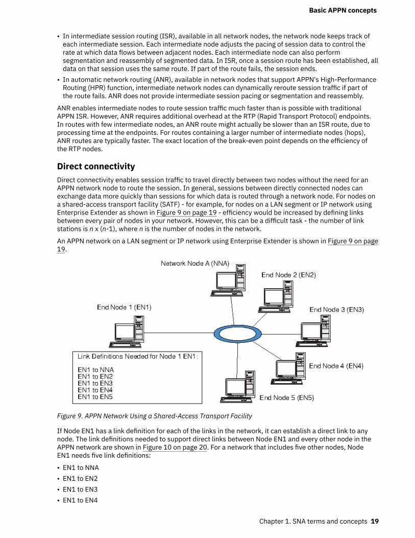
• In intermediate session routing (ISR), available in all network nodes, the network node keeps track ofeach intermediate session. Each intermediate node adjusts the pacing of session data to control therate at which data flows between adjacent nodes. Each intermediate node can also performsegmentation and reassembly of segmented data. In ISR, once a session route has been established, alldata on that session uses the same route. If part of the route fails, the session ends.
• In automatic network routing (ANR), available in network nodes that support APPN's High-PerformanceRouting (HPR) function, intermediate network nodes can dynamically reroute session traffic if part ofthe route fails. ANR does not provide intermediate session pacing or segmentation and reassembly.
ANR enables intermediate nodes to route session traffic much faster than is possible with traditionalAPPN ISR. However, ANR requires additional overhead at the RTP (Rapid Transport Protocol) endpoints.In routes with few intermediate nodes, an ANR route might actually be slower than an ISR route, due toprocessing time at the endpoints. For routes containing a larger number of intermediate nodes (hops),ANR routes are typically faster. The exact location of the break-even point depends on the efficiency ofthe RTP nodes.
Direct connectivityDirect connectivity enables session traffic to travel directly between two nodes without the need for anAPPN network node to route the session. In general, sessions between directly connected nodes canexchange data more quickly than sessions for which data is routed through a network node. For nodes ona shared-access transport facility (SATF) - for example, for nodes on a LAN segment or IP network usingEnterprise Extender as shown in Figure 9 on page 19 - efficiency would be increased by defining linksbetween every pair of nodes in your network. However, this can be a difficult task - the number of linkstations is n x (n-1), where n is the number of nodes in the network.
An APPN network on a LAN segment or IP network using Enterprise Extender is shown in Figure 9 on page19.
Figure 9. APPN Network Using a Shared-Access Transport Facility
If Node EN1 has a link definition for each of the links in the network, it can establish a direct link to anynode. The link definitions needed to support direct links between Node EN1 and every other node in theAPPN network are shown in Figure 10 on page 20. For a network that includes five other nodes, NodeEN1 needs five link definitions:
• EN1 to NNA• EN1 to EN2• EN1 to EN3• EN1 to EN4
Basic APPN concepts
Chapter 1. SNA terms and concepts 19
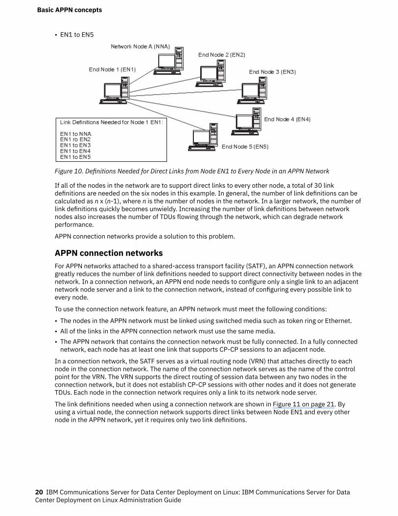
• EN1 to EN5
Figure 10. Definitions Needed for Direct Links from Node EN1 to Every Node in an APPN Network
If all of the nodes in the network are to support direct links to every other node, a total of 30 linkdefinitions are needed on the six nodes in this example. In general, the number of link definitions can becalculated as n x (n-1), where n is the number of nodes in the network. In a larger network, the number oflink definitions quickly becomes unwieldy. Increasing the number of link definitions between networknodes also increases the number of TDUs flowing through the network, which can degrade networkperformance.
APPN connection networks provide a solution to this problem.
APPN connection networksFor APPN networks attached to a shared-access transport facility (SATF), an APPN connection networkgreatly reduces the number of link definitions needed to support direct connectivity between nodes in thenetwork. In a connection network, an APPN end node needs to configure only a single link to an adjacentnetwork node server and a link to the connection network, instead of configuring every possible link toevery node.
To use the connection network feature, an APPN network must meet the following conditions:
• The nodes in the APPN network must be linked using switched media such as token ring or Ethernet.• All of the links in the APPN connection network must use the same media.• The APPN network that contains the connection network must be fully connected. In a fully connected
network, each node has at least one link that supports CP-CP sessions to an adjacent node.
In a connection network, the SATF serves as a virtual routing node (VRN) that attaches directly to eachnode in the connection network. The name of the connection network serves as the name of the controlpoint for the VRN. The VRN supports the direct routing of session data between any two nodes in theconnection network, but it does not establish CP-CP sessions with other nodes and it does not generateTDUs. Each node in the connection network requires only a link to its network node server.
The link definitions needed when using a connection network are shown in Figure 11 on page 21. Byusing a virtual node, the connection network supports direct links between Node EN1 and every othernode in the APPN network, yet it requires only two link definitions.
Basic APPN concepts
20 IBM Communications Server for Data Center Deployment on Linux: IBM Communications Server for DataCenter Deployment on Linux Administration Guide
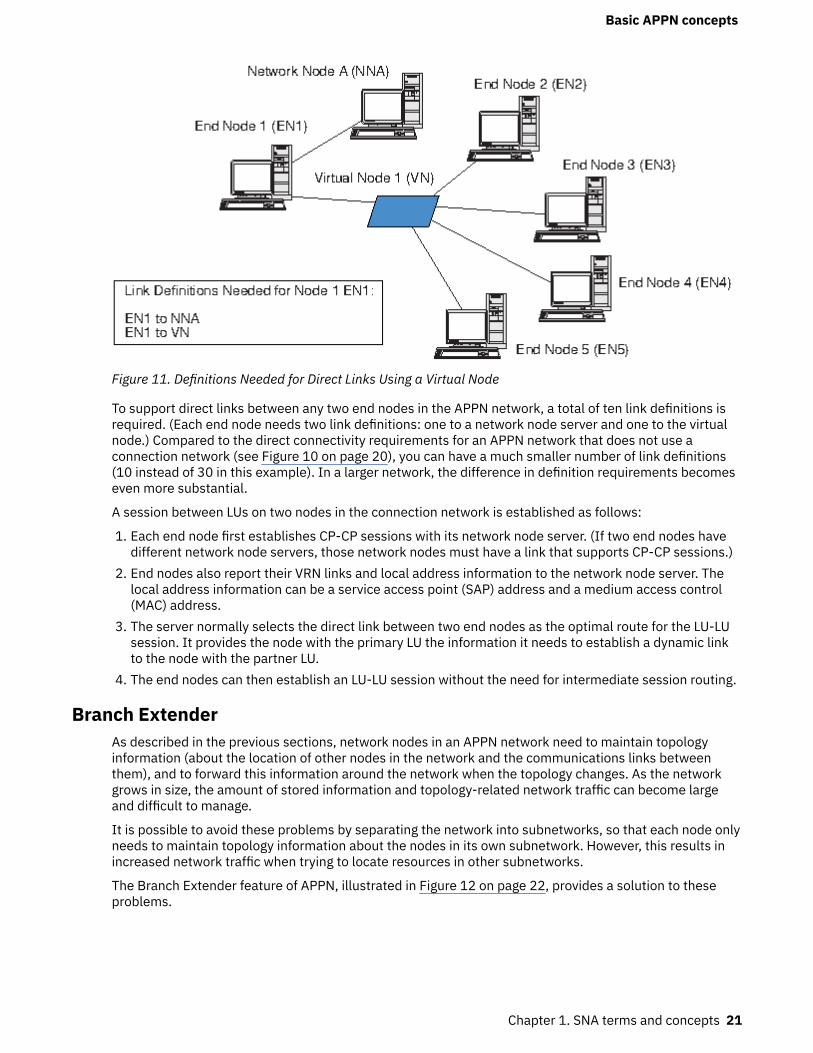
Figure 11. Definitions Needed for Direct Links Using a Virtual Node
To support direct links between any two end nodes in the APPN network, a total of ten link definitions isrequired. (Each end node needs two link definitions: one to a network node server and one to the virtualnode.) Compared to the direct connectivity requirements for an APPN network that does not use aconnection network (see Figure 10 on page 20), you can have a much smaller number of link definitions(10 instead of 30 in this example). In a larger network, the difference in definition requirements becomeseven more substantial.
A session between LUs on two nodes in the connection network is established as follows:
1. Each end node first establishes CP-CP sessions with its network node server. (If two end nodes havedifferent network node servers, those network nodes must have a link that supports CP-CP sessions.)
2. End nodes also report their VRN links and local address information to the network node server. Thelocal address information can be a service access point (SAP) address and a medium access control(MAC) address.
3. The server normally selects the direct link between two end nodes as the optimal route for the LU-LUsession. It provides the node with the primary LU the information it needs to establish a dynamic linkto the node with the partner LU.
4. The end nodes can then establish an LU-LU session without the need for intermediate session routing.
Branch ExtenderAs described in the previous sections, network nodes in an APPN network need to maintain topologyinformation (about the location of other nodes in the network and the communications links betweenthem), and to forward this information around the network when the topology changes. As the networkgrows in size, the amount of stored information and topology-related network traffic can become largeand difficult to manage.
It is possible to avoid these problems by separating the network into subnetworks, so that each node onlyneeds to maintain topology information about the nodes in its own subnetwork. However, this results inincreased network traffic when trying to locate resources in other subnetworks.
The Branch Extender feature of APPN, illustrated in Figure 12 on page 22, provides a solution to theseproblems.
Basic APPN concepts
Chapter 1. SNA terms and concepts 21
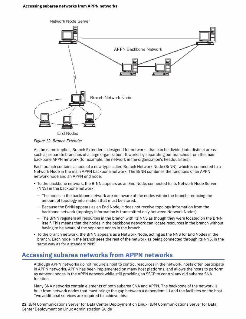
Figure 12. Branch Extender
As the name implies, Branch Extender is designed for networks that can be divided into distinct areassuch as separate branches of a large organization. It works by separating out branches from the mainbackbone APPN network (for example, the network in the organization's headquarters).
Each branch contains a node of a new type called Branch Network Node (BrNN), which is connected to aNetwork Node in the main APPN backbone network. The BrNN combines the functions of an APPNnetwork node and an APPN end node.
• To the backbone network, the BrNN appears as an End Node, connected to its Network Node Server(NNS) in the backbone network:
– The nodes in the backbone network are not aware of the nodes within the branch, reducing theamount of topology information that must be stored.
– Because the BrNN appears as an End Node, it does not receive topology information from thebackbone network (topology information is transmitted only between Network Nodes).
– The BrNN registers all resources in the branch with its NNS as though they were located on the BrNNitself. This means that the nodes in the backbone network can locate resources in the branch withouthaving to be aware of the separate nodes in the branch.
• To the branch network, the BrNN appears as a Network Node, acting as the NNS for End Nodes in thebranch. Each node in the branch sees the rest of the network as being connected through its NNS, in thesame way as for a standard NNS.
Accessing subarea networks from APPN networksAlthough APPN networks do not require a host to control resources in the network, hosts often participatein APPN networks. APPN has been implemented on many host platforms, and allows the hosts to performas network nodes in the APPN network while still providing an SSCP to control any old subarea SNAfunction.
Many SNA networks contain elements of both subarea SNA and APPN. The backbone of the network isbuilt from network nodes that must bridge the gap between a dependent LU and the facilities on the host.Two additional services are required to achieve this:
Accessing subarea networks from APPN networks
22 IBM Communications Server for Data Center Deployment on Linux: IBM Communications Server for DataCenter Deployment on Linux Administration Guide
• Dependent LU server (DLUS) on the host provides access to the old SSCP functions and interfaces to theAPPN network.
• Dependent LU requester (DLUR) on a network node or end node provides a means of transportingsession traffic from dependent LUs to a host through an APPN network. This function enablesdependent LU sessions to take advantage of the more versatile routing functions provided by APPN.
This combination of DLUR and DLUS (generally known simply as DLUR) allows dependent LU traffic to betransported over the APPN backbone. Existing SNA applications that use dependent LUs can be retainedwithout modification, while taking advantage of APPN's network management, dynamic resource location,and route selection capabilities. In this way, DLUR provides a useful migration path from subarea SNA toAPPN.
The dependent LU does not need to reside on the node that provides the DLUR function. If the DLURfunction is provided by a network node, the dependent LU can be on an adjacent network node, end node,or LEN node. If the DLUR function is provided by an end node, the dependent LU must be on the end nodeitself.
Accessing subarea networks from APPN networks
Chapter 1. SNA terms and concepts 23

Accessing subarea networks from APPN networks
24 IBM Communications Server for Data Center Deployment on Linux: IBM Communications Server for DataCenter Deployment on Linux Administration Guide
Chapter 2. Administering CS Linux
For an overview of CS Linux administration and the different administration tools provided, see “Overviewof CS Linux administration” on page 25.
The first step in administering CS Linux is configuring the node and its resources. Begin by planning forconfiguration as described in “Planning for CS Linux configuration” on page 31.
Before you can configure CS Linux, you must enable the CS Linux software as described in “Enabling anddisabling CS Linux on the local system” on page 32.
When CS Linux is enabled, you can run the Motif administration program (see “Using the Motifadministration program” on page 34). The Motif administration program guides you through theconfiguration needed to support SNA communication using CS Linux. The Motif administration program isthe recommended administration tool, because it minimizes the configuration information you need toprovide and guides you through each step you must perform to support different types of communication(such as 3270 or APPC communication).
Alternatively there is a WebAdmin package, a separately downloadable tool, which provides a Webbrowser interface to manage, configure and query status information. This tool provides secure access sothat the administrator can have read/write access or just read access to SNA information.
There is also a command-line administration program as described in “Using the command-lineadministration program” on page 43.
For each administration task, this guide provides information you can use for either Motif or command-line administration. Other configuration methods are discussed in “Administration tools” on page 26.
Overview of CS Linux administrationAs the CS Linux administrator, you are responsible for installing the CS Linux software and for managingits resources. Before beginning CS Linux administration, you must understand the main features of the CSLinux product (see IBM Communications Server for Data Center Deployment on Linux Quick Beginnings).This section describes the administration tasks you must perform and the tools you can use to performthem.
Administration responsibilitiesTo administer the CS Linux system, you need to do the following:
1. Define the resources of the CS Linux system, as required by the user programs that will be running.Work with the administrators of the host or peer computers with which CS Linux communicates, toensure that the CS Linux configuration matches that of the remote system.
2. Initialize the CS Linux software.3. Optionally, modify the configuration dynamically as your requirements change - by adding or removing
resources, or by activating and deactivating the defined resources.4. Monitor the status of active resources and gather diagnostics information to diagnose any problems
that occur.5. Optionally, create application programs or shell scripts to automate standard management operations.
These tasks are normally performed by a System Administrator at the site where the CS Linux system isinstalled. However, CS Linux also provides the service point command facility (SPCF), which enables anoperator using the NetView program to perform Steps 2 and 3 remotely by issuing managementcommands at the NetView console. For more information about SPCF, see Chapter 9, “Managing CS Linuxfrom NetView,” on page 97.
Overview of CS Linux administration
© Copyright IBM Corp. 1998, 2021 25
Administration toolsCS Linux provides a range of tools for administering the system. Depending on your requirements, youmay not need to use all of them. This section summarizes the functions provided by each of these tools.
Note:
1. This document provides general information about CS Linux administration, which you can performusing any of the tools described in this section. For most purposes, the Motif administration program isrecommended, because it provides context-sensitive guidance for node configuration andmanagement.
2. For information about controlling who can use the CS Linux administration tools and the range ofadministration functions they can use, see “Administration permissions” on page 30.
CS Linux includes the following administration tools:
• Motif administration program (see “Motif administration program” on page 26).• Web administration program (see “Web administration package” on page 27).• Command-line administration program (see “Command-line administration program” on page 28, or
refer to IBM Communications Server for Data Center Deployment on Linux Administration CommandReference).
• Service point command facility (see “Remote command facility” on page 28).• Configuration files (see “Configuration files” on page 28).• Diagnostic tools (see “Diagnostic tools” on page 30).
All of the CS Linux administration tools use the NOF API. You can also use that API to write your ownadministration tools. For more information, see “NOF applications” on page 30.
Motif administration programThe easiest way to define and modify the CS Linux configuration is to use the Motif administrationprogram (xsnaadmin). This program provides a graphical user interface from which you can view andmanage CS Linux resources.
Note: The Motif administration program xsnaadmin may be used to monitor CS Linux operations in realtime, but with some performance impact. On Linux for IBM Z LPARs, there is no directly attached terminal,so xsnaadmin will dynamically update the display using X-Windows protocol. This will add additionalnetwork traffic and CPU utilization to the system. For larger network configurations, it is better to use thecommand line adminstration tool or the Web Administration package. These update via query and do notcreate dynamic traffic that would have an impact.
For systems that support direct terminal hardware, the Motif administration program xsnaadmin will notimpact the performance too much. However, any impact to the system performance is dependent on whatis being displayed and how often the display is being updated.
The following management operations are available:
• Defining CS Linux resources• Starting and stopping a node and its connectivity resources• Changing the configuration of defined resources• Querying the configuration of defined resources and their current status if they are active• Deleting resources
The Motif administration program can be used to manage both node resources (for any server on the LAN,as long as the CS Linux software is running on that server) and domain resources. For each type ofcommunications (such as 3270 or APPC), the program guides you in setting up the configuration of therequired resources.
Note: The windows and dialogs in the Motif administration program may differ from those shown in thisguide, depending on the choices you make on a particular dialog.
Overview of CS Linux administration
26 IBM Communications Server for Data Center Deployment on Linux: IBM Communications Server for DataCenter Deployment on Linux Administration Guide
The Motif administration program includes help screens that provide overview information for SNA and CSLinux, reference information for CS Linux dialogs, and guidance for performing specific tasks.
Before starting the Motif administration program, make sure the CS Linux software is enabled (for moreinformation, see Chapter 2, “Administering CS Linux,” on page 25). As with any X/Motif application, youmay also need to set up the DISPLAY environment variable to indicate a suitable X server.
To start the Motif administration program in the background, issue the following command:
xsnaadmin &
All started CS Linux servers are shown on the main screen. For those that have already been configured,the program enables you to select a node, and then displays the selected node's configuration. Otherwise,the program prompts you to select a node and leads you through the required steps to define it.
For more information about how to use the Motif administration program to define and manage CS Linuxresources, see “Invoking the Motif administration program” on page 34, or refer to the help screensprovided by the program.
Note: The Motif administration program enables you to set up all required parameters for standard CSLinux configurations. For advanced parameters, the Motif administration program supplies default values.You need to supply only the essential configuration information, which enables you to set up SNAcommunications quickly and easily.
The other CS Linux administration tools, including command-line configuration, and NOF applicationprograms, provide access to a wider range of configuration parameters and options than those shown inthe Motif administration program. In most cases, however, you can perform all needed configuration fromthe Motif administration program, because it exposes the key fields you need to configure and hides thefields that most users should not need to modify. The default values supplied by command-lineconfiguration may differ from those supplied by the Motif administration program, because the Motifprogram can choose values more intelligently based on the context of the configuration task you areperforming.
If you need to use these additional functions, you can still use the Motif administration program to set upthe basic configuration, and use the other administration tools to specify the additional functions. Whenyou later use the Motif administration program to manage the modified configuration, the program retainsthe changes you made using the other tools, although the additional functions you have configured arenot displayed in the Motif program.
Web administration package
The Web Administration package is an administration tool that is downloadable from the CS Linux supportweb page https://www.ibm.com/support/pages/web-administration-package. This package provides thescripts and instructions for allowing remote Web browser access to administration functions for CS Linux.
Using a Web server, like Apache or the IBM HTTP Server, this package provides remote access to theadministration functions such as query, status, start and stop which you normally find on the Motif-basedxsnaadmin GUI. This package is designed to provide the administrator with a secure and safe method forremote administration of the CS Linux resources. The same package will run on Intel, Power and IBM Zplatforms that are supported by CS Linux.
This package uses Perl-CGI and Perl scripts to execute the administration functions. Almost all Webbrowsers work well with this package. The commands executed to query and manage resources are foundin the snaadmin command line tool (refer to “Command-line administration program” on page 28).
The Web Administration package provides access to resources controlled in Node and Domain,Connections, Host Resources, TN3270E Server, APPC, APPN, Query, Status and Diagnostic panels. Withthese Web interfaces, you can query any resource on the node or get status of sessions, links, LUs andnode conditions.
The Web pages provide the interfaces to display link, PU and node conditions. You can start or stop thenode, links and PUs as needed.
Overview of CS Linux administration
Chapter 2. Administering CS Linux 27
Host connectivity resources can be displayed in the same manner as the command line administrationcalls, with additional displays that are concise for management purposes. Enhanced displays for links,pools of LUs, PUs, and TN3270E server sessions are available.
Remote access is protected by User ID and password authentication using Linux supplied passwordprotection packages. The WebAdmin program provides two URL sites for access, one is a read/write sitethat allows one to configure, start/stop and capture trace as well as query information. The other is a readonly access to view status.
Command-line administration programThe command-line administration program, snaadmin, enables you to issue commands to manageindividual CS Linux resources. You can use snaadmin either directly from the Linux command prompt orfrom within a shell script.
Commands can be issued to a specific CS Linux node to manage the node's resources, to the SNA networkdata file to manage controller and backup servers, or to the domain configuration file to manage domainresources.
All administration commands can be issued on a server. However, there are restrictions on whichcommands can be issued on an IBM Remote API Client.
• On Windows clients there is no snaadmin program, so no commands can be issued.• On AIX and Linux clients you can issue any query or status command. Some other administration
commands, defined in IBM Communications Server for Data Center Deployment on LinuxAdministration Command Reference, explicitly say that they can be issued from an IBM Remote APIClient. Otherwise these commands are available only from a server.
You can get help for command-line administration by using any of the following commands:
• snaadmin -h provides basic help for command-line administration and usage information forcommand-line help.
• snaadmin -h -d provides a list of commands that can be supplied to the snaadmin program.• snaadmin -h command provides help for the named command.• snaadmin -h -d command provides detailed help for the named command, including a list of theconfiguration parameters that can be specified with the command.
Refer to IBM Communications Server for Data Center Deployment on Linux Administration CommandReference for more information.
Remote command facilityThe remote command facility (RCF) provides the following facilities to support the administration of CSLinux from a NetView console on a host:
• Service point command facility (SPCF) enables an operator at a host NetView console to manage CSLinux from NetView by issuing CS Linux administration commands.
• UNIX command facility (UCF) enables the NetView operator to issue standard Linux commands on theCS Linux computer.
For more information about RCF, see Chapter 9, “Managing CS Linux from NetView,” on page 97.
Configuration filesConfiguration information for the CS Linux system is held in the following text files:
Node configuration fileThe /etc/opt/ibm/sna/sna_node.cfg file contains information about CS Linux node resourcesfor a specific node. This file resides on the computer where the node runs. It includes informationabout the node's resources and specifies which resources are active when CS Linux is started on thenode.
Overview of CS Linux administration
28 IBM Communications Server for Data Center Deployment on Linux: IBM Communications Server for DataCenter Deployment on Linux Administration Guide
This file provides an initial definition of the resources that are available; you can then use the otheradministration tools to modify the running node's resources as your requirements change. Anymodifications you make are automatically saved to the file, so that the modified configuration can beused again when the node is stopped and restarted.
Domain configuration fileThe /etc/opt/ibm/sna/sna_domn.cfg file contains information about CS Linux domain resources(resources not associated with a particular local node). The controlling copy of this file resides on thecontroller server.
Invokable TP data fileThe /etc/opt/ibm/sna/sna_tps file contains information that CS Linux needs to start invokable(target) TPs, and can also provide other information (such as the level of security required to accessthe TP). This file resides on the computer where the TPs run.
For more information about this file, see “Defining TPs” on page 73.
Environment parameters fileThe /etc/opt/ibm/sna/environment file contains environment variables that are provided to CSLinux when it starts to alter its behaviour. These are detailed in an appendix to the IBMCommunications Server for Data Center Deployment on Linux Administration Command Reference.
Log filter configuration fileThe /etc/opt/ibm/sna/logfilter.txt file specifies log messages that should not be capturedby CS Linux. This is documented in the filtering logging section of IBM Communications Server for DataCenter Deployment on Linux Diagnostics Guide.
You can modify the configuration using the Motif administration program, the command-lineadministration program, or the NOF API. All of these tools make the required changes to the nodeconfiguration file or domain configuration file as appropriate. Because configuration information is storedas plain text, you can also modify the file directly using a standard ASCII text editor such as vi, or bymeans of a shell script using Linux utilities such as awk or sed. Any changes to configuration files using atext editor must be made before starting CS Linux. Refer to IBM Communications Server for Data CenterDeployment on Linux Administration Command Reference for more information about CS Linuxconfiguration file format.
Note: CS Linux configuration is a dynamic process; it is not necessary to define the entire configurationbefore starting the CS Linux software. The configuration file provides an initial definition of the availableresources, but you can add, delete, or modify resources as necessary while the CS Linux software isrunning. CS Linux stores the current definition so that you can use it again when you need to restart thesystem.
The following files contain information about the CS Linux client/server network:
SNA network data fileThe /etc/opt/ibm/sna/sna.net file contains information about which server is the controller, andwhich servers can act as backup servers. This binary file resides on the controller server. You canmodify the contents of this file using the administration programs or the NOF API.
For more information about this file and how to modify it, see “Configuring client/server functions” onpage 45.
Client network data fileThe sna_clnt.net file contains information about how to access CS Linux servers, required by anIBM Remote API Client. This text file resides on the client computer. You can modify the contents ofthis file using a standard ASCII text editor.
For more information about this file and how to modify it, see “Client network data file (sna_clnt.net)”on page 125. For information about configuring the equivalent information on a Windows client, seeChapter 10, “Managing CS Linux client/server systems,” on page 105.
Overview of CS Linux administration
Chapter 2. Administering CS Linux 29
NOF applicationsThe CS Linux NOF API provides the same management functions as the command-line administrationprogram, enabling you to define and manage CS Linux resources. This means that you can write your ownapplication programs to administer CS Linux.
Refer to IBM Communications Server for Data Center Deployment on Linux NOF Programmer's Guide formore information.
Diagnostic toolsCS Linux provides several diagnostics tools to help you diagnose and correct problems encounteredduring CS Linux operation:
• Any component detecting a problem or an exception (an abnormal condition that may indicate thecause of a problem) writes an entry to an error log file. In addition, all significant system events can berecorded in an audit log file. You can determine which types of events (problems, exceptions, or audits)are recorded. In a client/server network configuration, you can specify global settings for the types ofevents to record on all servers, and then override these on individual servers if necessary.
• CS Linux also maintains a usage log file, which is used to record information about the current and peakusage of CS Linux resources.
• You can specify the names and directories of the files used to hold each type of log information; ifpreferred, you can send both error and audit log information to the same file. On a client/server system,you can send messages from all servers to a central log file on one server (central logging), or send logmessages to separate files on each server.
• Log files are generated as text files, and can be viewed using a standard ASCII text editor such as vi.• You can choose full logging (which includes details of the cause of the log, and any action required, in
the log file for each message), or succinct logging (which includes only a summary of the source of thelog and the message text). When using succinct logging, you can use the snahelp command-line utilityto obtain the full cause and action text for a particular message number if you need further information.
• If you find that a particular event is occurring frequently and so the log file is filling up with manyinstances of the same log message, you can set a filter to specify that one or more specific logmessages should be logged only once. Any subsequent instances of the same log message will beignored and will not be written to the log file.
• For some error conditions, CS Linux sends a message to the Linux console to warn the operator, inaddition to writing a problem message to the error log file.
• Many components can produce a trace file that records the activity of that component. Tracing degradesthe performance of CS Linux components, and so is normally disabled.
• Using command-line utilities, you can filter trace files to extract specific information, and then formatthe trace information to interpret its contents or to produce a summary of message flows. Theformatted output files can be viewed using a standard ASCII text editor such as vi.
• CS Linux can generate alerts and send them to the NetView program at a host computer. These alertscan be any of the following:
– Link alerts from connectivity components, to provide information about connection problems– Alerts supplied by an application program using the MS API
Refer to IBM Communications Server for Data Center Deployment on Linux Diagnostics Guide forinformation about CS Linux log messages, using CS Linux trace facilities, and interpreting trace files.
For information about using the MS API, refer to IBM Communications Server for Data Center Deploymenton AIX or Linux MS Programmer's Guide.
Administration permissionsThe CS Linux administration tools are intended for use by a restricted group of "SNA administrators" whohave permission to manage SNA resources. To achieve this, the executable files are owned by the system
Overview of CS Linux administration
30 IBM Communications Server for Data Center Deployment on Linux: IBM Communications Server for DataCenter Deployment on Linux Administration Guide
administrator login root with a group ownership of sna. Only users who are members of the group snacan modify, start, or stop CS Linux resources; any user who is to have SNA administrator permissionsmust be a member of this group.
In the standard CS Linux installation, users who are not members of the group sna cannot run the CSLinux administration tools at all. If appropriate, you can allow these users to run the tools in read-onlymode, so that they can view configuration and status information but cannot modify, start, or stopresources. To do this, use chmod to give read and execute permission for any user to the appropriateexecutable file or files:
Administration Tool Executable File(s)
Motif administration program /opt/ibm/sna/bin/X11/xsnaadmin
Command-line administration program /opt/ibm/sna/bin/snaadmin
Any user can then run the appropriate administration tool and view information, but CS Linux will stillprevent users not in the sna group from modifying, starting, or stopping resources.
Note: If you modify file permissions as described above, you will need to repeat this procedure afterinstalling CS Linux PTFs or new releases.
Planning for CS Linux configurationBefore you make any configuration changes it is very important to plan thoroughly. Changes that youmake can cause disruption, not only to the users of your local node but possibly to users all around thenetwork.
You may find it useful to draw a diagram of any changes that you are making to the topology of thenetwork. If you are adding or removing connections to other nodes, draw a picture showing your node andthe other nodes. You can use the Motif administration program to gather configuration information aboutall of the existing connections and add that information to your diagram.
When you add new resources to your diagram, it is easy to see whether they duplicate existing ones, orwhether any names clash. Similarly, your diagram can help you decide which resources you need toremove and help you avoid deleting essential ones.
If you are configuring a Client/Server CS Linux system with more than one node, ensure that you includeall the CS Linux nodes and their connectivity resources in your diagram.
Once you determine the changes you need to make, you can collect the configuration information that youneed. You can use the task sheets in the online help files for the Motif administration program, or theplanning worksheets described in “Planning worksheets” on page 31, to guide you in collectingconfiguration information for specific CS Linux functions.
Planning worksheetsBefore you begin to configure resources for CS Linux, gather all of the configuration data for the newresources. To record all of the information for a particular function or application that you need to support,use the planning worksheets in Appendix A, “Configuration planning worksheets,” on page 131.
You will probably need to gather configuration information from several sources, such as networkadministrators, host administrators, application programmers, and end users.
If you are trying to connect to another node, the administrator at that node is a key contact. Theadministrator for a node can tell you names, addresses and characteristics of all the resources on thatnode. Often, you will need to ensure that matching configuration parameters are entered at the local nodeand the remote node.
Task sheetsThe online help screens in the Motif administration program contain task sheets that provide guidance forspecific configuration tasks. The task sheets contain pointers to all of the help screens for the dialogs that
Planning for CS Linux configuration
Chapter 2. Administering CS Linux 31
you will use to enter the configuration information. You can use these to browse the help and see exactlywhat data you must collect.
The task sheets also refer to more detailed help for each of the individual windows and dialogs that youmust use to enter configuration information. Those help screens explain each field that you must fill in orselect.
Enabling and disabling CS Linux on the local systemThis section explains how to enable and disable the CS Linux software on the Linux server.
You must enable the CS Linux software before you can use any CS Linux tools (including the Motifadministration program). Normally, the software is enabled automatically after you install CS Linux, but ifnecessary you can enable it manually.
Setting environment variables for use by CS LinuxCS Linux uses a number of environment variables to control its operation, which must be set before youenable the CS Linux software on the server. The simplest way to manage these is to set them in a text filethat CS Linux reads on startup.
In the CS Linux configuration directory, /etc/opt/ibm/sna, create a text file named environment, andset each environment variable in a separate line. For example:
export LANG=en_USexport PATH='$PATH:/opt/ibm/sna/bin'export LD_LIBRARY_PATH=/usr/lib:/opt/ibm/sna/libexport LD_RUN_PATH=/usr/lib:/opt/ibm/sna/lib
Specifying the Path to CS Linux ProgramsCS Linux executable programs are stored in a directory specific to CS Linux; when you run the programs,you need to specify the path to this directory. You can specify the path either by adding the directory toyour PATH environment variable before you run the programs for the first time, or by including thedirectory name each time you run the programs.
The Motif administration program is stored in the directory /opt/ibm/sna/bin/X11, and the otherprograms are stored in the directory /opt/ibm/sna/bin. If you add these directories to the definition ofthe PATH environment variable in your .login or .profile file, CS Linux locates the programsautomatically. Alternatively, you can specify the directory name when you run the program, as in thefollowing examples:
/opt/ibm/sna/bin/sna start
/opt/ibm/sna/bin/snaadmin query_node
/opt/ibm/sna/bin/X11/xsnaadmin
The sample command lines shown in this manual assume that you have added the directories to yourPATH environment variable, and do not include the directory names.
Enabling CS Linux serversThis section describes how to enable CS Linux on a computer that was installed as a server (that is, withthe SNA node components installed). If you are enabling CS Linux on a client, see “Enabling and disablingRemote API Clients on AIX or Linux” on page 125.
You must enable CS Linux on the local system before you can configure or manage the local node (eitherlocally or from a remote CS Linux node).
To enable the CS Linux software, enter the following command at the Linux command prompt:
Enabling and disabling CS Linux on the local system
32 IBM Communications Server for Data Center Deployment on Linux: IBM Communications Server for DataCenter Deployment on Linux Administration Guide
sna start [ -s ] [ -m kernel_memory_limit] [ -t ]
Note: When you use the sna start command, the CS Linux software uses the directory from which youissued the command as its current working directory, and maintains one or more open file descriptors inthat directory. This means that you will not be able to unmount the file system containing that directorywhile the CS Linux software is running. To avoid problems, you should start the CS Linux software from adirectory on a filesystem that does not need to be unmounted; for example, you could use cd / to changeto the root directory before using the sna start command.
When you install CS Linux, the installation utility automatically updates the startup file /etc/rc.d/init.d/snastart to include the sna start command. This ensures that CS Linux is startedautomatically at system startup. If you do not want CS Linux to be started automatically, you can removeor comment out this line, and then follow the instructions in this section to enable the CS Linux softwaremanually.
The parameters and options for the sna start command are as follows:
-sSpecifies that CS Linux should not write messages to the system console. If you do not use this option,CS Linux writes messages to the console when it ends, and also writes the text of certain error logmessages to the console as well as to the log file.
-m kernel_memory_limitSpecifies the maximum amount of kernel memory, in kilobytes, that CS Linux should use at any time.(Kernel memory is used for internal data structures.) If a component of CS Linux attempts to allocatekernel memory that would cause the total amount of memory currently allocated to CS Linuxcomponents to exceed this limit, the allocation attempt fails.
If you do not use this option, kernel memory usage is not limited.
-tActivates tracing on all interfaces between kernel components, and also client/server tracing. (Thisoption does not turn on DLC tracing.) Tracing enables you to diagnose problems that occur duringstartup. If you do not use this option, tracing is inactive at all interfaces; you can then activate it onspecific interfaces as required, using the command-line administration program snaadmin.
Tracing on all interfaces degrades the performance of CS Linux components. After the software isenabled, you can use the command-line administration program snaadmin to stop tracing on anyinterfaces where it is not required. For more information about tracing, refer to IBM CommunicationsServer for Data Center Deployment on Linux Diagnostics Guide.
CS Linux writes messages to standard error (normally your terminal's screen) to indicate that it isinitializing, and to indicate whether initialization completes successfully.
If initialization fails, the messages include information about the cause of the error, and (whereappropriate) additional information such as the Linux operating system error message. The text written tostandard error may also include a message indicating that you can find further information in the error logfile. The sna start command then ends with a nonzero exit code that indicates the nature of the error.
For more information about exit code values, refer to IBM Communications Server for Data CenterDeployment on Linux Diagnostics Guide.
Advanced options for the sna start commandIn some cases, particularly when you are testing out new CS Linux configurations, you may want to startCS Linux with a configuration that you have saved to a temporary file (rather than with the standardconfiguration in the files /etc/opt/ibm/sna/sna_node.cfg and /etc/opt/ibm/sna/sna_domn.cfg). To do this, you can use the following additional options on the sna start command:
-n node_config_file -d domain_config_file
Enabling and disabling CS Linux on the local system
Chapter 2. Administering CS Linux 33

node_config_file is the full pathname of the file to which you have saved node configuration (insteadof /etc/opt/ibm/sna/sna_node.cfg), and domain_config_file is the full pathname of the file towhich you have saved domain configuration (instead of /etc/opt/ibm/sna/sna_domn.cfg).
Note: These options are not intended for general use. Do not use them unless you have a specificrequirement to do so.
The snagetpd command will not operate correctly when CS Linux is running with these options, becauseit always collects information from the standard configuration files. Before using snagetpd, ensure thatyou are running with the standard configuration files by starting CS Linux without these options.
Disabling CS Linux serversDisabling the CS Linux software on a server automatically stops the CS Linux node and its associatedconnectivity components. Disabling CS Linux also stops any other processes (such as a 3270 emulationprogram) from using CS Linux resources on this server.
In general, you should stop individual services as users finish using them, and only disable the systemwhen there is no CS Linux activity. Disabling the CS Linux software on a client stops any programs runningon the client from accessing CS Linux facilities.
If you need to disable CS Linux while users are active, warn users that CS Linux is stopping, and give themtime to finish their activities before you disable the software. Use the Motif administration program or thecommand-line administration program to view details of active users.
If a 3270 emulation program is using LUs on the node when you disable the CS Linux software, all 3270emulation sessions using these LUs end. The program continues to run, but the user cannot use thesessions until the software is re-enabled. Applications using the APPC, CSV, LUA, NOF, or MS APIs arenotified by a COMM_SUBSYSTEM_ABENDED return code, and CPI-C applications by aCM_PRODUCT_SPECIFIC_ERROR return code.
To disable the CS Linux software, enter the following command at the Linux command prompt:
sna stop
If CS Linux is disabled successfully, sna stop returns an exit code of 0. Any other exit code indicates thatan error occurred and that the CS Linux software was not disabled. Refer to IBM Communications Serverfor Data Center Deployment on Linux Diagnostics Guide for more information about exit code values.
Using the Motif administration programThe Motif administration program provides a user-friendly interface for configuring CS Linux. This programis the recommended tool for administering CS Linux, because it guides you through the configurationprocess and minimizes the information you need to provide to create a workable configuration.
You can also use the Motif administration program to manage the CS Linux system while it is active. Theadministration program enables you to make and apply changes to the configuration while CS Linux isactive. You can add, modify, and remove resources (in most cases, even when the node and its resourcesare active), and use the modified configuration immediately for continued operation.
The Motif administration program displays up-to-date status information through the same interface thatis used for configuration, providing easy access to status information for both domain and node resources.
Alternatively, you can use CS Linux commands for configuration and system management. A summary ofconfiguration and management commands is provided in “Using the command-line administrationprogram” on page 43.
Invoking the Motif administration programTo use the Motif administration program for CS Linux, first make sure that CS Linux is enabled asdescribed in “Enabling CS Linux servers” on page 32. (As with any X/Motif application, you may also needto set up the DISPLAY environment variable to indicate a suitable X server.)
Using the Motif administration program
34 IBM Communications Server for Data Center Deployment on Linux: IBM Communications Server for DataCenter Deployment on Linux Administration Guide
To start the Motif administration program running in the background, issue the following command:
xsnaadmin &
In a client/server environment, CS Linux displays the Domain window.
For a standalone system, CS Linux normally displays the Node window. However, if you have not yetconfigured the local node, it displays a help screen offering help with configuring the node for the firsttime.
Note: This guide uses the term window to describe Motif windows that display information about CS Linuxresources. A window can contain one or more sections, or panes. A dialog is a Motif window on which youcan enter information.
Resource windowsThe Domain window and the Node window show most of the information you need and provide easyaccess to additional information. From those windows, you can easily display information about resourcesin your local network.
The Domain window shows all defined nodes, and enables you to add, delete, start, and stop nodes.Double-clicking on any node brings up the Node window for that node.
The Node window shows all the key resources for a particular node.
The menus in the Domain and Node windows provide the following functions:
SelectionThe functions in this menu relate to the node that is currently selected in the Domain window or theitem that is currently selected in the Node window. From this menu, you can start or stop the node orzoom on it to display its Node window. When you select an item in the Node window, you can control,modify, or delete the item using controls in this menu, or add a new item in the currently selectedpane.
ServicesThis menu provides easy access to all the dialogs required to configure the node for common tasks.Using this menu, you can add or modify resources or get help for configuration and managementtasks.
DiagnosticsYou can control logging and tracing from items in this menu.
WindowsYou can easily access other windows from this menu. These windows include the following:
• LU Pools window• CPI-C Destination Names window
Depending on the resources you select and the options you choose, the administration program canpresent additional resource windows, configuration dialogs, or status logs. You will also see contextdialogs that enable you to select a specific resource to configure, confirmation dialogs that ask you toconfirm a choice, and message pop-ups that provide feedback or error information. Each window anddialog also includes a help option.
Domain windowThe Domain window shows each active SNA node in the CS Linux domain for the system you are using. (Anode does not appear in the Domain window if CS Linux is not running on the node.) Each node isidentified using the name of the system. The Domain window also shows the current status of each nodein the domain.
Note: If a server is unexpectedly missing from the list of nodes in the Domain window, verify that theserver is switched on and that the CS Linux software is running on the server. If necessary, start the CSLinux software on that node using the sna start command (see “Enabling CS Linux servers” on page32).
Using the Motif administration program
Chapter 2. Administering CS Linux 35
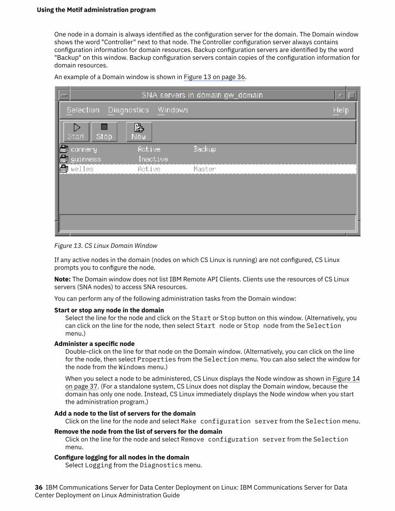
One node in a domain is always identified as the configuration server for the domain. The Domain windowshows the word "Controller" next to that node. The Controller configuration server always containsconfiguration information for domain resources. Backup configuration servers are identified by the word"Backup" on this window. Backup configuration servers contain copies of the configuration information fordomain resources.
An example of a Domain window is shown in Figure 13 on page 36.
Figure 13. CS Linux Domain Window
If any active nodes in the domain (nodes on which CS Linux is running) are not configured, CS Linuxprompts you to configure the node.
Note: The Domain window does not list IBM Remote API Clients. Clients use the resources of CS Linuxservers (SNA nodes) to access SNA resources.
You can perform any of the following administration tasks from the Domain window:
Start or stop any node in the domainSelect the line for the node and click on the Start or Stop button on this window. (Alternatively, youcan click on the line for the node, then select Start node or Stop node from the Selectionmenu.)
Administer a specific nodeDouble-click on the line for that node on the Domain window. (Alternatively, you can click on the linefor the node, then select Properties from the Selection menu. You can also select the window forthe node from the Windows menu.)
When you select a node to be administered, CS Linux displays the Node window as shown in Figure 14on page 37. (For a standalone system, CS Linux does not display the Domain window, because thedomain has only one node. Instead, CS Linux immediately displays the Node window when you startthe administration program.)
Add a node to the list of servers for the domainClick on the line for the node and select Make configuration server from the Selection menu.
Remove the node from the list of servers for the domainClick on the line for the node and select Remove configuration server from the Selectionmenu.
Configure logging for all nodes in the domainSelect Logging from the Diagnostics menu.
Using the Motif administration program
36 IBM Communications Server for Data Center Deployment on Linux: IBM Communications Server for DataCenter Deployment on Linux Administration Guide
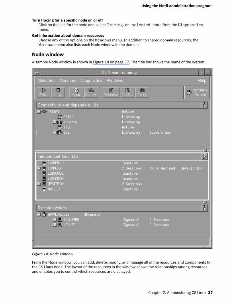
Turn tracing for a specific node on or offClick on the line for the node and select Tracing on selected node from the Diagnosticsmenu.
Get information about domain resourcesChoose any of the options on the Windows menu. In addition to shared domain resources, theWindows menu also lists each Node window in the domain.
Node windowA sample Node window is shown in Figure 14 on page 37. The title bar shows the name of the system.
Figure 14. Node Window
From the Node window, you can add, delete, modify, and manage all of the resources and components forthe CS Linux node. The layout of the resources in the window shows the relationships among resourcesand enables you to control which resources are displayed.
Using the Motif administration program
Chapter 2. Administering CS Linux 37
The Node box in the top-right corner of the Node window indicates whether the node is Active orInactive.
Any ports, local LUs, and remote nodes that are defined on the node are always displayed. The Nodewindow shows each link station below its parent port, and each dependent LU below its parent linkstation. It also shows partner LUs below local LUs and below remote nodes.
The body of the Node window is split into the following panes for the different types of resources for thenode:
Connectivity paneThe top pane of the Node window lists connectivity resources for the node, including ports, linkstations or PUs on each port, and dependent LUs on a specific link station or PU. For each resource,this window shows current status information.
Independent Local LUs paneThe middle pane shows independent LUs for the node. For each LU, this window also displaysinformation about sessions using the LU.
Remote Systems paneThe lower pane shows information about remote nodes and partner LUs. It also shows sessioninformation for each remote node or partner LU.
To change the relative sizes of the panes, click and drag on the boundaries between panes.
You can select a pane by clicking in it. You can also select specific resources within a pane by clicking onthe line for the resource. To view or modify the configuration for an item, you can double-click on the item.(You can also use the buttons and menus on this window to access configuration information for specificresources.)
For each item listed, resources that belong to that item are nested within the information for that item. Forexample, link stations are grouped under the port to which they belong. You can click on the Expand
button next to an item to show the resources for that item if they are not currently displayed, or click
on the Contract button to hide the resources for an item.
You can perform the following administration tasks from the Node window:
Start or stop a resourceSelect the resource and click on the Start or Stop button. (Alternatively, you can select Startitem or Stop item from the Selection menu.)
Add a new resource for an itemSelect the item and click on the New button (or select New from the Selection menu). For example,to add a link station for a port, select the port and click on the New button.
Delete a resourceSelect the resource and click on the Delete button (or select Delete from the Selection menu).
View or modify the configuration for any resourceSelect the resource and click on the Properties button (or select Properties from theSelection menu).
Get status information for any resourceSelect the resource and click on the Status button (or select Status from the Selection menu).
Copy the configuration for any resourceSelect the resource and click on the Copy button (or select Copy from the Selection menu).
In addition, you can choose specific configuration tasks for the node from the Services menu, controllogging (for the domain) and tracing (for the node) from the Diagnostics menu, and view or modifydomain resources by selecting one of the items on the Windows menu.
Using the Motif administration program
38 IBM Communications Server for Data Center Deployment on Linux: IBM Communications Server for DataCenter Deployment on Linux Administration Guide
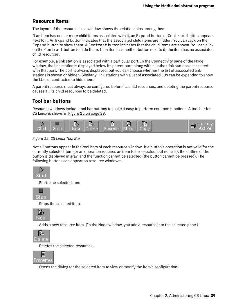
Resource itemsThe layout of the resources in a window shows the relationships among them.
If an item has one or more child items associated with it, an Expand button or Contract button appearsnext to it. An Expand button indicates that the associated child items are hidden. You can click on theExpand button to show them. A Contract button indicates that the child items are shown. You can clickon the Contract button to hide them. If an item has neither button next to it, the item has no associatedchild resources.
For example, a link station is associated with a particular port. In the Connectivity pane of the Nodewindow, the link station is displayed below its parent port, along with all other link stations associatedwith that port. The port is always displayed, but you can choose whether the list of associated linkstations is shown or hidden. Similarly, link stations with a list of associated LUs can be expanded to showthe LUs, or contracted to hide them.
A parent resource must always be configured before its child resources, and deleting the parent resourcecauses all its child resources to be deleted.
Tool bar buttonsResource windows include tool bar buttons to make it easy to perform common functions. A tool bar forCS Linux is shown in Figure 15 on page 39.
Figure 15. CS Linux Tool Bar
Not all buttons appear in the tool bars of each resource window. If a button's operation is not valid for thecurrently selected item (or an operation requires an item to be selected, but none is), the outline of thebutton is displayed in gray, and the function cannot be selected (the button cannot be pressed). Thefollowing buttons can appear on resource windows:
Starts the selected item.
Stops the selected item.
Adds a new resource item. (In the Node window, you add a resource into the selected pane.)
Deletes the selected resources.
Opens the dialog for the selected item to view or modify the item's configuration.
Using the Motif administration program
Chapter 2. Administering CS Linux 39
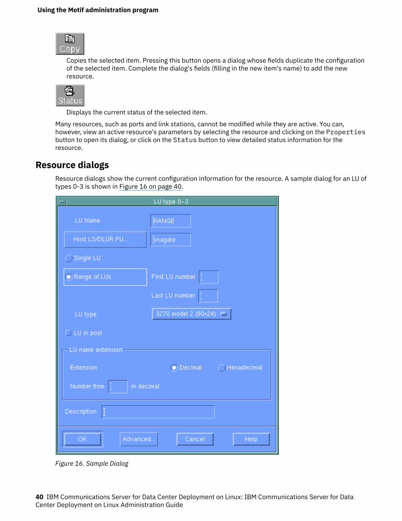
Copies the selected item. Pressing this button opens a dialog whose fields duplicate the configurationof the selected item. Complete the dialog's fields (filling in the new item's name) to add the newresource.
Displays the current status of the selected item.
Many resources, such as ports and link stations, cannot be modified while they are active. You can,however, view an active resource's parameters by selecting the resource and clicking on the Propertiesbutton to open its dialog, or click on the Status button to view detailed status information for theresource.
Resource dialogsResource dialogs show the current configuration information for the resource. A sample dialog for an LU oftypes 0-3 is shown in Figure 16 on page 40.
Figure 16. Sample Dialog
Using the Motif administration program
40 IBM Communications Server for Data Center Deployment on Linux: IBM Communications Server for DataCenter Deployment on Linux Administration Guide

Resource dialogs guide you through the configuration process and supply default values wheneverpossible. For example, when you add a dependent LU, the Motif administration program automatically fillsin the LU number field with an available LU number on the link station you specify. If you do not supply arequired value, the program presents a message pop-up that indicates the information you need toprovide.
Most dialogs provide a Description field; the information you enter there is displayed on the window wherethe resource is displayed.
If you are permitted to change the information in a resource dialog (when you are adding a new item ormodifying an existing one), the dialog includes OK and Cancel buttons. Press the OK button when you arefinished, or the Cancel button to exit without changing the configuration for the resource.
If you cannot change the information in a resource dialog (for example if the resource's configurationcannot be modified while it is active), the dialog includes a Close button instead of an OK button. Clickthis button when you are finished viewing the information in the dialog.
For context-sensitive help on the dialog, click on the Help button.
Note: The basic Motif dialogs expose only the key configuration fields; CS Linux supplies default values foradvanced fields. To access advanced configuration parameters, click on the Advanced button. If youdecide to adjust advanced parameters, complete the basic dialog before opening the advanced dialog,because that dialog can change depending on the values you enter for basic parameters. For informationabout advanced configuration fields, see the online help for the Motif administration program.
Status dialogsWhen you select a resource and click on the Status button, the Motif administration program showsdetailed status information for the resource, as shown in Figure 17 on page 42.
Using the Motif administration program
Chapter 2. Administering CS Linux 41
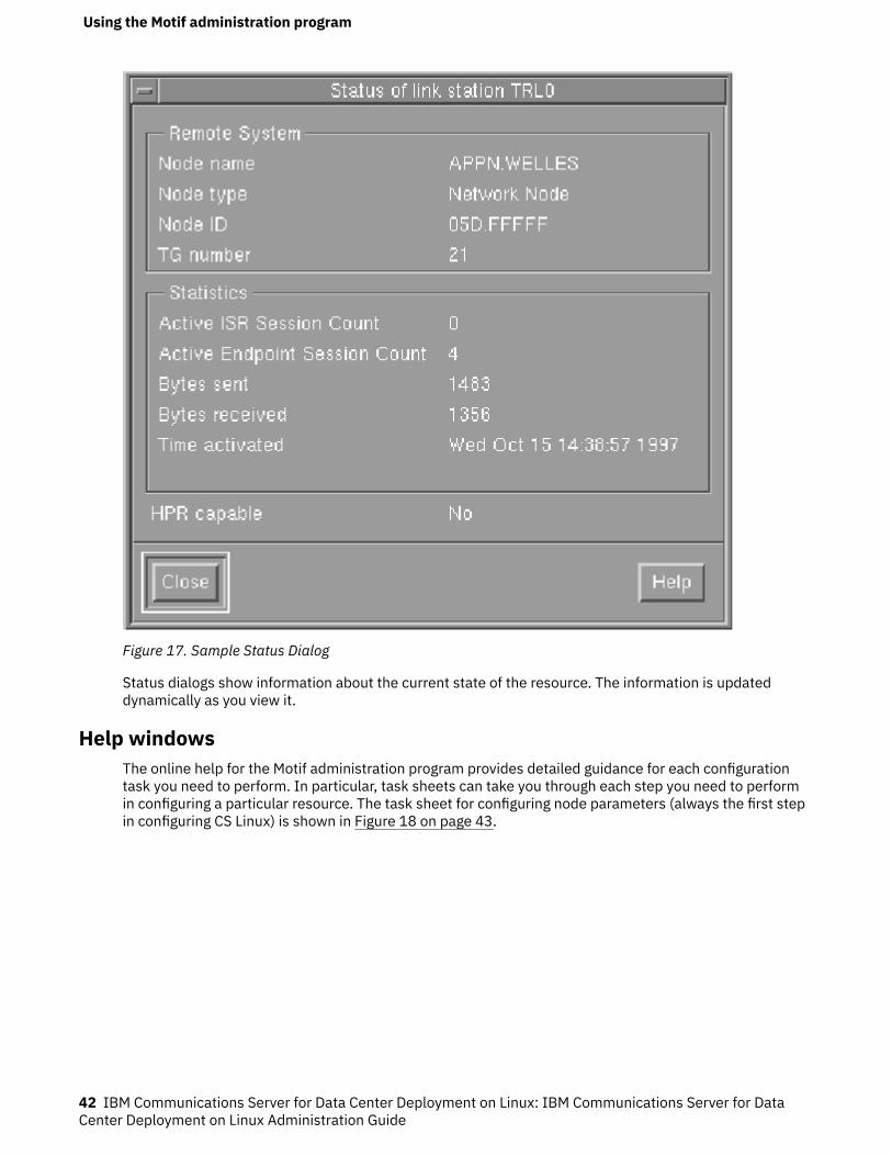
Figure 17. Sample Status Dialog
Status dialogs show information about the current state of the resource. The information is updateddynamically as you view it.
Help windowsThe online help for the Motif administration program provides detailed guidance for each configurationtask you need to perform. In particular, task sheets can take you through each step you need to performin configuring a particular resource. The task sheet for configuring node parameters (always the first stepin configuring CS Linux) is shown in Figure 18 on page 43.
Using the Motif administration program
42 IBM Communications Server for Data Center Deployment on Linux: IBM Communications Server for DataCenter Deployment on Linux Administration Guide
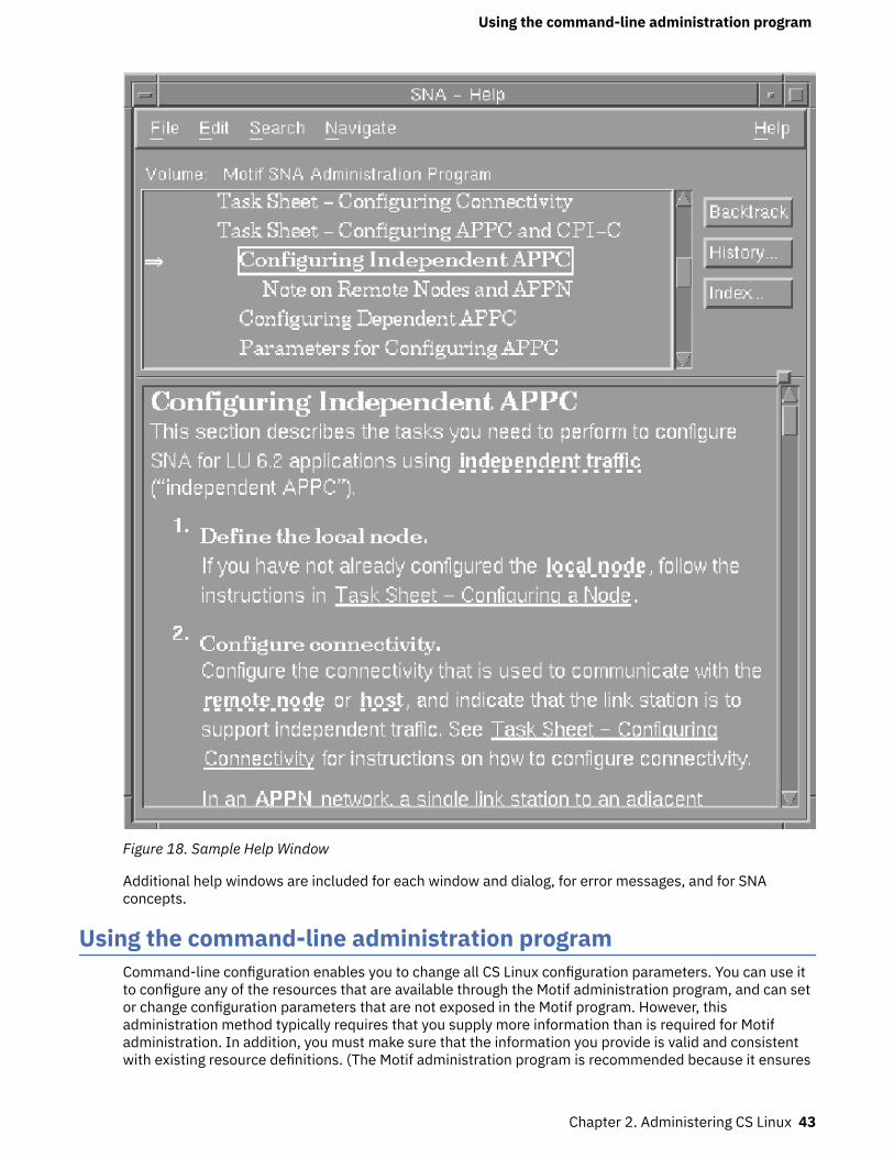
Figure 18. Sample Help Window
Additional help windows are included for each window and dialog, for error messages, and for SNAconcepts.
Using the command-line administration programCommand-line configuration enables you to change all CS Linux configuration parameters. You can use itto configure any of the resources that are available through the Motif administration program, and can setor change configuration parameters that are not exposed in the Motif program. However, thisadministration method typically requires that you supply more information than is required for Motifadministration. In addition, you must make sure that the information you provide is valid and consistentwith existing resource definitions. (The Motif administration program is recommended because it ensures
Using the command-line administration program
Chapter 2. Administering CS Linux 43
the data you enter is consistent. In addition, it can infer many configuration values based on menu anddialog choices, and fill in values based on available definitions.)
Most administration commands are used with the snaadmin command-line administration program. Youcan issue snaadmin commands in the following form:
snaadmin command, parameter1=value1, parameter2=value2, .... {subrecord_name1}, sub_param1=sub_value1, sub_param2=sub_value2...
You can get help for snaadmin command-line administration by using any of the following commands:
• snaadmin -h provides basic help for command-line administration and usage information forcommand-line help.
• snaadmin -h -d provides a list of commands that can be supplied to the snaadmin program.• snaadmin -h command provides help for the named command.• snaadmin -h -d command provides detailed help for the named command, including a list of theconfiguration parameters that can be specified with the command.
Some commands can be issued from an IBM Remote API Client, provided the command includes the -noption to specify a server name. Such a command has the same effect as if it were issued at the namedserver.
The remainder of this section summarizes administration commands for different types of resources.Some of the types of commands listed are as follows:
status_*Provides summary information for types of resources.
define_*Creates a new define_* record in the configuration file, or replaces an existing record for the sameresource with the new definition.
delete_*Removes the corresponding define_* record from the file.
query_*Returns information from the configuration file on the appropriate component, but does not modifythe file.
set_*Controls management functions such as tracing and logging parameters.
For complete information about command-line configuration, refer to IBM Communications Server forData Center Deployment on Linux Administration Command Reference.
Using the command-line administration program
44 IBM Communications Server for Data Center Deployment on Linux: IBM Communications Server for DataCenter Deployment on Linux Administration Guide
Chapter 3. Basic configuration tasks
This chapter provides an overview of configuration tasks and explains how to configure the CS Linux node.It also explains how to configure controller and backup servers when CS Linux is used in a client/serverenvironment.
Configuring client/server functionsThis section is relevant only if you installed CS Linux to run in a client/server environment (with multipleCS Linux nodes in the same network).
Many resources, such as ports and LUs, are configured on an individual node. These are known as "noderesources."
Other resources, are common to all nodes; only one definition for the resource is maintained for the entiredomain. Such resources are known as "domain resources." Domain resource definitions are stored only onthe controller server for the domain, and are accessible from all the nodes in the domain.
Note: A standalone CS Linux system has only one server; that server always acts as the controller.
In a client/server environment, a server can be marked as a configuration server; CS Linux maintains a listof these configuration servers. The first server listed is the controller server, and any other servers listedare backup servers. The servers are listed in order, so that the second server listed (the first backupserver) takes over if the controller server is unavailable, the third server listed (the second backup server)takes over if neither the controller nor the first backup server is available, and so on.
When any of the nodes in the domain are active, the first available configuration server in the domain (thefirst server that can be contacted and has CS Linux software running) becomes the controller server. If thecurrent controller becomes unavailable (because it cannot be contacted, perhaps due to a networkfailure, or because the SNA software running on it is stopped), the next available configuration server inthe list becomes the new controller.
CS Linux can run without a controller. This happens if none of the servers in the configuration server listcan be contacted. If this happens, you can view and configure node resources only on the servers that canbe contacted.
Note: You cannot directly indicate which node acts as the controller server; the controller server isselected based on the order in which nodes are added to the configuration server list. If you wish to movea server to the top of the list, remove all other nodes from the list and then add them again.
You can also use the following administration commands to query, add, and delete configuration servers:
query_sna_netLists the servers in the file.
add_backupAdds a new server to the end of the list.
delete_backupRemoves a server from the list. You can use the delete_backup command to delete either thecontroller server (so that the second server listed takes over as controller) or a backup server (so thatit can no longer act as the controller).
Note: You cannot delete a server if it is the only server listed on which the CS Linux software is running,because in this case there is no other server that can take over as the controller server. At least oneenabled controller server is required in a client/server configuration.
CS Linux uses the local hostname setting when it starts up to identify the node. It may be required to usea DNS alias name instead. To set the CS Linux server's name to a DNS alias name, set the followingstatement:
export SNA_SERVER_NAME=DNS_alias_name_for_server
Configuring client/server functions
© Copyright IBM Corp. 1998, 2021 45
in the environment file /etc/opt/ibm/sna/environment.
Clients are available for Windows, AIX and the different Linux platforms. In addition, the client can run in acontainer or AIX WPAR.
Chapter 10, “Managing CS Linux client/server systems,” on page 105 provides information aboutadvanced Client/Server configuration, including how to move clients and servers into different CS Linuxdomains and how to configure the details of client operation.
Configuring the nodeThe first step in configuring CS Linux on a system is to configure the local node. Node configurationprovides the basic information that the node needs in order to participate in an APPN network. You mustconfigure the node before you can define connectivity or other resources for the node.
If the node has already been configured, you must stop the node before changing the node configuration.
To configure the node, use one of the following methods:
Motif administration programSelect Configure node parameters from the Services menu on the Node window.
Command-line administration programIssue the define_node command.
Advanced parameters for node configuration provide control over sessions with undefined partner LUs,reporting of security failures, and limited resource timeouts.
Node configuration parametersYou need the following information for node configuration:
APPN supportLevel of APPN support for the node:
• If your network is not an APPN network, configure the node as a LEN node.• To participate in an APPN network in which another node provides session routing services, or to
use DLUR only on the local node, configure the node as an end node.• To provide intermediate routing services in an APPN network, or to provide passthrough DLUR
services to downstream nodes, configure the node as a network node.• To provide session routing services to other nodes in a branch network that are not part of the main
APPN backbone network, configure the node as a branch network node.
Control point nameFully qualified control point name for the local node. Because this name may need to be configured onother nodes in the network, consult with your SNA network planner to determine the name.
When you define the control point, CS Linux automatically defines a local LU with the same name. ThatLU can act as a default local LU for the node.
Control point aliasLocal alias for the default local LU. Supply this value if the default local LU is used by independent LU6.2 LUs.
Node IDIdentifier for the PU on the local node. Supply a value only if the node will be used for dependenttraffic using the default (control point) LU.
When defining a node, it can have a virtual DNS name that does not match the local host name. Use theSNA_SERVER_NAME environment variable, described in the IBM Communications Server for Data CenterDeployment on Linux Administration Command ReferenceAppendix, in the /etc/opt/ibm/sna/environment file.
Configuring the node
46 IBM Communications Server for Data Center Deployment on Linux: IBM Communications Server for DataCenter Deployment on Linux Administration Guide
Additional configurationAfter configuring the node, continue with the following configuration tasks:
• Configure connectivity as described in Chapter 4, “Defining Connectivity Components,” on page 49.• Configure node resources (LUs) as described in Chapter 6, “Configuring APPC communication,” on page
67 or Chapter 7, “Configuring user applications,” on page 85.• Configure applications as described in Chapter 7, “Configuring user applications,” on page 85.
Configuring loggingCS Linux writes log messages describing abnormal events (and, optionally, normal events) to log files.When you try to diagnose a problem, the first place to look is in the log files, because the log messagesprovide information about the cause of the problem and the action you should take.
CS Linux logs messages for the following categories of event:
ProblemAn abnormal event that degrades the system in a way perceptible to a user (such as abnormaltermination of a session).
ExceptionAn abnormal event that degrades the system but that is not immediately perceptible to a user (suchas a resource shortage), or an event that does not degrade the system but may indicate the cause oflater exceptions or problems (such as receiving an unexpected message from the remote system).
AuditA normal event (such as starting a session).
CS Linux also maintains a usage log file, which is used to record information about the current and peakusage of CS Linux resources.
To distinguish between logs relating to normal and error conditions, the different message categories arelogged to different files. Problem and exception messages are logged to the error log file; audit messagesare logged to the audit log file.
If you find that a particular event is occurring frequently and so the log file is filling up with manyinstances of the same log message, you can set a filter to specify that one or more specific log messagesshould be logged only once. Any subsequent instances of the same log message will be ignored and willnot be written to the log file. This filtering applies to all types of logs: audit, exception, and problem logs.For more information about filtering logging, refer to IBM Communications Server for Data CenterDeployment on Linux Diagnostics Guide.
CS Linux also provides a backup mechanism to prevent log files from becoming too large and consumingdisk resources. When a log file reaches the maximum permitted size, CS Linux copies its current contentsto a backup file and then clears the log file.
By default, CS Linux uses the following log files:
Error log file/var/opt/ibm/sna/sna.err
/var/opt/ibm/sna/bak.err (backup)
Audit log file/var/opt/ibm/sna/sna.aud
/var/opt/ibm/sna/bak.aud (backup)
Usage log file/var/opt/ibm/sna/sna.usage
/var/opt/ibm/sna/bak.usage (backup)
You can view the log files using a text editor or other Linux system utilities:
Configuring logging
Chapter 3. Basic configuration tasks 47
viView the file in a text editor. This allows you to move through the file forwards or backwards, and tosearch for particular entries.
pgView a file one page at a time. This utility is simple and easy to use but useful only if the log file issmall.
tailView the tail (end) of a file. The end of the file is where the most recent log messages are. Use thisutility with the -f option to monitor the log file while the system is running.
If you selected succinct rather than verbose logging, you can use the snahelp command to determinethe cause and action information for a particular message number.
For most purposes, the default settings for logging are sufficient, but you can make the following types ofchanges:
• Indicate what categories of messages are to be logged.
Problem messages are always logged and cannot be disabled. Logging is normally disabled for the othertwo message categories, but you can enable it if necessary.
• Specify the level of detail in logging messages.• Specify central logging for the domain or local logging for each node• Change log file names and sizes.
To configure logging, use one of the following methods:
Motif administration programSelect Logging from the Diagnostics menu on the Node window or the Domain window.
Command-line administration programIssue one of the following commands:
• set_central_logging• set_global_log_type• set_log_type• set_log_file
The Logging dialog in the Motif administration program affects log settings throughout the domain. Usingthe command line, you can override the domain settings by configuring local log settings on a particularmachine.
In addition to providing control over logging, the Motif administration program provides node-level controlover tracing. The command-line interface provides greater control over both logging and tracing functions.For more information about logging and tracing, refer to IBM Communications Server for Data CenterDeployment on Linux Diagnostics Guide.
Configuring logging
48 IBM Communications Server for Data Center Deployment on Linux: IBM Communications Server for DataCenter Deployment on Linux Administration Guide
Chapter 4. Defining Connectivity Components
In order for the CS Linux node to communicate with other nodes, you must configure connectivity with atleast one adjacent node. A connecting link can be configured to carry dependent traffic, independenttraffic, or both.
You can have adapter cards for one or more link protocols installed in your computer. Much of theinformation you need to enter to configure connectivity depends on the link protocol you are using. Theremote node must also have an adapter card of the same type you choose, or there must be a bridge orrouter between the local and remote nodes. For a list of the link protocols supported by CS Linux, see“Defining DLCs, ports, and connection networks” on page 49.
To configure a link, you need to define a port as described in “Defining DLCs, ports, and connectionnetworks” on page 49. In addition (in most cases), you must configure a link station as described in“Defining link stations” on page 53. If LUs on the local node are to communicate with a host using DLUR,you must also define a DLUR PU on the local node as described in “Defining DLUR PUs” on page 59.
When using the Motif administration program, a data link control (DLC) is automatically configured as partof the configuration for the port. In addition, you have the option of defining the port as part of aconnection network. When using command-line configuration, this configuration is separate from portconfiguration.
The information required for link configuration depends on the link protocol, whether your network is anAPPN network, and on whether the link is for dependent traffic, independent traffic, or both. In addition,the links that you need to configure depend on what kind of communication you need to support:
LUAIf you are going to use LUA, you need to configure a link to the host computer. The link must beconfigured for dependent traffic, and it must be configured on the host computer as well as on the CSLinux node, so consult your SNA network planner.
Using CPI-C or APPCIf you are going to use CPI-C or APPC and your network is not an APPN network, you need to configurelinks to all the adjacent nodes that you want to access. These links must be configured forindependent traffic, and they must be configured on the adjacent nodes as well as on the CS Linuxnode, so you may need to consult your SNA network planner.
Operating as an APPN NodeIf the CS Linux node is an end node or network node in an APPN network, the number of links that youneed to configure can be greatly reduced. You can configure links to one or more adjacent networknodes and access all nodes in the APPN network using these links. If you want to access otheradjacent nodes directly, you can configure links to them too - this is not usually necessary, but it cangive better performance. If the adjacent nodes are connected by a LAN segment or IP network usingEnterprise Extender, direct links can be set up dynamically so you don't need to configure them - justmake sure that you configure the network as a connection network when you define the port.
The benefits of APPN networking are always available for and independent APPC, but they do notapply to LUA unless you use DLUR. (DLUR supports communications between a host and dependentLUs on the local node or on downstream nodes in an APPN network.) You can use DLUR only if yourhost supports DLUS, so you should consult your SNA network planner if you are interested in usingDLUR.
Defining DLCs, ports, and connection networksA port represents the local end of a communications link as a unique access point in the network. Eachport is associated with a specific link protocol, which can be any of the following:
• SDLC• Token ring
Defining DLCs, ports, and connection networks
© Copyright IBM Corp. 1998, 2021 49
• Ethernet• X.25 or QLLC (qualified logical link control)• Multipath Channel (MPC) (CS Linux on System z only)• Enterprise Extender (HPR/IP)
You can configure more than one port that uses a particular link protocol. In general, a port correspondsto a single physical access point such as an adapter card, but some link protocols (such as token ring)enable you to define multiple ports for a single adapter. The different ports are distinguished by addresses(such as the SAP number).
When you use the Motif administration program to define a port for a particular link protocol, CS Linuxautomatically defines a DLC for the port if a DLC of that type has not already been defined. For command-line configuration, you must define the port and DLC using different commands.
In an APPN network using token ringlink protocols, you can also use the SAP Configuration dialog toindicate that the port is part of a connection network.
If you are using SNA gateway, you can define a template that is used to generate definitions for implicitlink stations (link stations that are not explicitly configured). Implicit link stations can supportdownstream LUs. If implicit PU fields are modified while the port is active, the changes affect any implicitlink station instances generated after the change.
To configure a port, connection network, and DLC, use one of the following methods:
Motif or Web administration programSelect Connectivity and New port from the Services menu on the Node window.
Command-line administration programTo configure a DLC:
define_type_dlc
To configure a port:
define_type_port
In these commands, type indicates the link protocol type (sdlc, tr, ethernet, qllc, mpc, ip).
To configure a connection network:
define_cn
Advanced port configuration parameters provide control over BTU size, the number of active linkspermitted, generation of implicit downstream LUs, and settings for dynamic link stations.
DLC, connection network, and port configuration parametersThe following parameters are required for port configuration. (When you use the Motif administrationprogram, port configuration also supplies information about the DLC and enables you to assign a port to aconnection network.)
SNA port nameThe locally known name of the port.
Adapter card numberThis field is not used for Enterprise Extender ports.
A number that identifies the adapter card to use, if you have more than one card of the same type inthis computer.
Port numberThis field is not used for Enterprise Extender ports.
Defining DLCs, ports, and connection networks
50 IBM Communications Server for Data Center Deployment on Linux: IBM Communications Server for DataCenter Deployment on Linux Administration Guide
The number of the port to be used, if the adapter card can support more than one port. The range ofvalid port numbers is from 0 to the number of ports supported by the adapter card minus one. For thefirst port on the adapter card, enter 0.
This field applies only if the adapter card can support more than one port.
Initially activeWhether to activate the port automatically when the node is started. This setting enables link stationsthat use the port to be activated in response to requests from adjacent nodes or on demand by thelocal node. (Activating the port does not activate any link stations; link stations are activatedseparately.)
The following sections describe additional port parameters that are specific to the link type. No additionalport parameters are required for QLLC.
Additional port parameters for SDLCLine details
The following parameters describe the type of SDLC connection:Type
Select one of the following values:Leased Line
A dedicated line is used for the SDLC link between this computer and the remote system.Switched incoming
The standard telephone network is used for incoming calls.
For a nonprimary port (as indicated by the Link role field), you also need to configure the polladdress (for outgoing calls, that address is configured on the link station). The poll address is aone-byte address (C1 by default) that needs to match the poll address configured at theremote link station. When active, the port responds to frames sent with this poll address.
For a primary port, you do not need to configure a poll address; the port uses the poll addressspecified by the remote link station on the incoming call. For other types of ports, the polladdress is configured on each link station.
Switched outgoingThe standard telephone network is used for outgoing calls.
Link roleSelect a value that describes the role of the local node for link stations defined on this port. InSDLC communication, one end manages the link and is called the primary link station. The otherend is the secondary link station.
Use one of the following values for this field:
SecondaryThe other end of the link is to be the controller and the remote system is configured to beprimary. This is nearly always the case if you are configuring a link to a host system.
PrimaryThis port is to act as the SDLC controller of the link, and the remote system is configured to besecondary.
NegotiableFor maximum flexibility, this setting enables the two ends to negotiate which end performs theprimary role. Choose this value if you do not know which role is configured for the remotesystem.
You can use this setting for a peer link, but be aware that negotiating the role causes a shortdelay when the link is activated.
Primary Multi-dropThe link is leased and this port is to act as controller of a multi-drop link to several secondarynodes.
Defining DLCs, ports, and connection networks
Chapter 4. Defining Connectivity Components 51
Use this setting when you want to configure several link stations from the local node todifferent remote nodes (for example, for links to downstream nodes). Each of these othernodes must be configured as secondary, and you must be using a leased line.
Secondary Multi-PUThe local port is one of the secondary stations on a multi-drop link controlled by the port onthe remote system.
Consult your SNA network planner if you do not know how to configure any of these parameters.
Additional port parameters for Token Ring and EthernetLocal SAP number
The address of the SAP, usually 04for Intel and OSA2 adapters.. Use a different value only if you needto use more than one SAP on the card. For an OSA-Express adapter, the local SAP number must matchthat defined in the OSA/SF for the I/O device addresses that correspond to the ethX interface on thisLinux image.
The SAP number must be a multiple of 4.
If you do not know what value to enter for this field, contact your SNA network planner.
Define on connection networkWhether the SAP is to access the LAN as a connection network. Defining a connection networkenables links between nodes on the connection network to be started dynamically, without priorconfiguration.
This field applies only if the local node is not a LEN node, because LEN nodes cannot use connectionnetworks.
CN nameThe name of the connection network. You do not need to enter the CN name unless you specified theDefine on connection network option to define the SAP on a connection network. The CN name is usedas the name of a virtual routing node in order to establish links between the nodes on the connectionnetwork.
Specify the same CN name on all nodes on the connection network.
Ethernet typeThis field applies only to Ethernet links.
Whether the network is a standard Ethernet network or an IEEE 802.3 network.
Device nameThis field applies only to Ethernet links.
The name of the Ethernet device, if this is specified the adapter number is ignored. For example, onRHEL systems a value of device_name=ens32works with the default x86_64 installation. Thisparameter is not available in xsnaadmin.
Additional port parameters for Enterprise Extender (HPR/IP)Local IP interface
This is an optional field. It allows you to specify the local IP network interface to be used for the port,if you have access to multiple IP networks. If you have access to only one IP network, you can leavethis field blank.
If you need to specify the interface, you can use any of the following.
• An interface identifier (such as eth0 or en0).• An IPv4 dotted-decimal address (such as 193.1.11.100).• An IPv6 colon-hexadecimal address (such as 2001:0db8:0000:0000:0000:0000:1428:57ab
or 2001:db8::1428:57ab).
Defining DLCs, ports, and connection networks
52 IBM Communications Server for Data Center Deployment on Linux: IBM Communications Server for DataCenter Deployment on Linux Administration Guide
To determine the interface identifier, run the command ipconfig - a on the server where the card isinstalled. This lists the interface identifiers and their associated IP addresses.
ProtocolWhether links on this port use IPv4 or IPv6 addresses.
Define on connection networkWhether the adapter card is to access the LAN as a connection network. Defining a connectionnetwork enables links between nodes on the connection network to be started dynamically, withoutprior configuration.
This field applies only if the local node is not a LEN node, because LEN nodes cannot use connectionnetworks.
CN nameThe name of the connection network. You do not need to enter the CN name unless you specified theDefine on connection network option to define the port on a connection network. The CN name is usedas the name of a virtual routing node in order to establish links between the nodes on the connectionnetwork.
Specify the same CN name on all nodes on the connection network.
Additional port parameters for implicit linksMaximum active template instances
Specify the maximum number of link station instances to be generated from the template.Configure downstream LUs for implicit PU access
Whether to configure downstream LUs that use this PU (see “Configuring SNA gateway” on page 94).HPR supported on implicit links
Whether to support High-Performance Routing on implicit link stations.Link level error recovery on implicit links
Whether to send HPR traffic on implicit links using link-level error recovery.
Additional parameters for connection networksIPv6 Address Only
When defining a Connection Network on an IPv6 network for HPR/IP, this parameter can be specifiedto indicate if the IP addressing for the Connection Network will use IPv6 DNS names only or IPv6addresses only. The default is to use IPv6 DNS names only.
Additional configurationAfter performing the port configuration, continue with the following configuration tasks:
• To define a link station on a port you have configured, see “Defining link stations” on page 53.• To define a DLUR PU, see “Defining DLUR PUs” on page 59.• To support APPC communication, see Chapter 6, “Configuring APPC communication,” on page 67.
Defining link stationsTo communicate with other nodes in an SNA network, you must configure the characteristics of a linkstation (LS) to an adjacent node in the SNA network. Before you can define a link station, you must definea port for the adapter (and link protocol) you are using. Most of the information needed to configure a linkstation is the same, whatever protocol is being used.
A link station represents the logical path through the SNA network between the CS Linux local node and aremote computer. The remote computer can be any of the following:
• A host computer, on which CS Linux accesses a host program using 3270 or LUA communications (oruses APPC or CPI-C for program-to-program communications)
Defining link stations
Chapter 4. Defining Connectivity Components 53
• A peer computer, with CS Linux and the remote computer communicating as equal partners (the typicalarrangement in an APPN network)
• A downstream computer that uses the CS Linux SNA gateway feature or DLUR feature in order to accessa host
A link station is associated with a specific port; you can define one or more link stations on each port.
Each link station that supports dependent traffic has an associated PU (physical unit). Because PUs areassociated with link stations, CS Linux does not treat them as separate resources; they are configured aspart of link station configuration, and are started and stopped as part of starting and stopping linkstations. Link stations are shown in the connectivity section of the Node window; PUs are not shown inany window.
Note: In most circumstances, you need to add a link station to the port. However, if you want to use adynamically created link station for downstream SNA gateway or for APPC traffic only, for situations inwhich the link is always activated from the remote node, you do not need to explicitly configure one.
If a remote node attempts to connect to the local node, but no link station is defined that matches theaddress specified on the incoming call, CS Linux can define one implicitly if a suitable port has beendefined on the local node. This dynamically created link station appears in the connectivity section of theNode window for the duration of the connection.
To configure a link station, use one of the following methods:
Motif or Web administration programSelect Connectivity and New link station from the Services menu on the Node window.
Command-line administration programIssue the following command:
define_type_ls
In this command, type indicates the link protocol type (sdlc, tr, ethernet, qllc, mpc, ip).
Advanced parameters for link stations provide additional control over transmission characteristics, XIDexchange, optional link facilities, compression for LU 0-3 sessions using the link, and reactivationprocedures.
Link station configuration parametersIn Motif, the Link Station Configuration dialog contains the following sections, each containing differentcategories of configuration parameters:
Link stationUse this area of the dialog to provide information that is required for all link stations, whether theysupport LU traffic for dependent LUs, independent LUs, or both. For descriptions of the parameters inthis section, see “Common link station parameters” on page 54.
Independent LU trafficProvide this information only if you are using the link station for independent traffic. For descriptionsof the parameters in this section, see “Parameters for independent LU traffic” on page 57.
Dependent LU trafficProvide this information only if you are using the link station for dependent traffic. For descriptions ofthe parameters in this section, see “Parameters for dependent LU traffic” on page 58.
Common link station parametersThe following parameters are required for all link stations, whether they support dependent traffic,independent traffic, or both.
For more information about the parameters on this dialog, refer to the online help or to IBMCommunications Server for Data Center Deployment on Linux Administration Command Reference.
Defining link stations
54 IBM Communications Server for Data Center Deployment on Linux: IBM Communications Server for DataCenter Deployment on Linux Administration Guide
NameA name to identify the link station locally.
SNA port nameThe port that is to be used to access the adjacent node.
ActivationMethod used to activate the link station. Specify one of the following methods:By administrator
The link station is activated only on the request of a local System Administrator.On node startup
The link station is started automatically when the node starts up.On demand
The link station is started automatically when required to provide connectivity for an application.
Link stations are activated separately from ports, so the link station must be activated even if the portis already active. Activating the port does not itself activate any link stations, and configuring the portto be initially active does not mean that any of its link stations are activated automatically when thenode starts up. However, activating a port does make it possible to activate link stations. A link stationcannot be activated unless the ports are active on both the local node and the adjacent node.
If the link is one for which you are charged for usage, avoid activating the link unnecessarily, in orderto keep the cost down.
If you are not sure how to set this field, consult your SNA network planner.
LU trafficThe type of LU traffic to flow over the link. This choice determines what other parameters are neededfor link definition.
This parameter is not used for an Enterprise Extender (HPR/IP) link, because this link type supportsonly independent traffic.
AnyThe link station can be used for both independent and dependent LU traffic. For this option, youmust supply values for the fields described in “Parameters for independent LU traffic” on page57 and “Parameters for dependent LU traffic” on page 58, in addition to those described in thissection.
Independent onlyThe link station can be used only for independent LU traffic. For this option, you must supplyvalues for the fields described in “Parameters for independent LU traffic” on page 57, in additionto those described in this section.
Dependent onlyThe link station can be used only for dependent LU traffic. For this option, you must supply valuesfor the fields described in “Parameters for dependent LU traffic” on page 58, in addition to thosedescribed in this section.
You also need to provide addressing information for contacting the adjacent node. The type of addressinginformation needed depends on the DLC type of the port. If you do not supply an address for the remotenode, the link station acts as a nonselective listening link station, accepting incoming calls from anyremote node.
Additional link station parameters for SDLCPoll address
The poll address of the remote station. Specify the address as a two-digit (one-byte) hex value,typically starting at C1. A primary link station polls the remote station using this value. A secondarylink station responds to polling with this value. The poll address is entered differently depending onthe link role:
• If the link is a point-to-point link (not multi-drop), the address C1 is normally used.
Defining link stations
Chapter 4. Defining Connectivity Components 55

• If the parent port for this link is switched incoming, the poll address is configured on the port andcannot be configured independently for each link station.
• If you are configuring a primary switched outgoing link station, and you do not know the poll addressof the remote secondary with which you wish to communicate, you can specify a poll address of0xFF on the primary. This value enables the node to accept responses from a secondary, regardlessof the poll address it has configured. 0xFF is not a valid address for a nonprimary link or a link that isnot switched outgoing.
• If you are using a multi-drop configuration, all the secondary link stations that communicate withthe same primary must have different poll addresses.
The poll addresses at both ends of the link must match. Contact your SNA network planner if you donot know the address configured at the remote system.
On a VTAM host, the poll address is configured as the ADDR= parameter in the VTAM PU definition.
On an AS/400 system, the poll address is the STNADR parameter of the Line Description.
Additional link station parameters for Token Ring and EthernetMAC address
The MAC address of the remote station, entered as a series of hexadecimal digits. The MAC addressuniquely identifies the adapter card on the remote system.
If you do not know what value to use, consult your SNA network planner.
If the remote end of this link is a VTAM host, you can find its MAC address in the MACADDR=parameter of the VTAM Port definition.
If you are configuring a link to an AS/400 system, the MAC address is the ADPTADR parameter in theLine Description.
SAP numberThe SAP number of the port on the remote computer. The SAP number distinguishes betweendifferent links using the same adapter card. This is a hex number, normally 04. It must be a multiple of4.
If you do not know what value to use, consult your SNA network planner.
If the remote end of this link is a VTAM host, the SAP number is the SAPADDR= parameter of the VTAMPU definition.
If you are configuring a link to an AS/400 system, the SAP number is the SSAP parameter in the LineDescription.
Additional link station parameters for X.25 (QLLC)Remote X.25 address
If the link is a switched virtual circuit, enter the DTE address of the remote DTE as a series ofhexadecimal digits.
If the link is a permanent virtual circuit, enter the channel ID that identifies the virtual circuit the linkstation is to use. Channel IDs are numbered from 1 up to a maximum of 1024. If you have only onepermanent virtual circuit, its channel ID is likely to be 1.
Additional link station parameters for MPCMPC group
The MPC (MultiPath Channel) group name specified in the MPC driver configuration to identify aparticular channel.
Defining link stations
56 IBM Communications Server for Data Center Deployment on Linux: IBM Communications Server for DataCenter Deployment on Linux Administration Guide
Additional link station parameters for Enterprise Extender (HPR/IP)Remote IP host name
Remote host name of the destination node for this link. The hostname can be any of the following; theprotocol parameter on the port that this link uses determines whether the address should be in IPv4or IPv6 format.
• An IPv4 dotted-decimal address (such as 193.1.11.100).• An IPv6 colon-hexadecimal address (such as 2001:0db8:0000:0000:0000:0000:1428:57ab
or 2001:db8::1428:57ab).• A name (such as newbox.this.co.uk).• An alias (such as newbox).
If you specify a name or alias, the Linux system must be able to resolve this to a fully qualified name(either using the local TCP/IP configuration or using a Domain Name server).
Parameters for independent LU trafficYou need the following information to configure this link station for use by independent LUs (LUs of type6.2 for use by APPC, 5250, or CPI-C applications):
Remote node nameThe fully qualified CP name of the remote node.
If the remote system is a VTAM host, you can find the network name (the first eight characters of thefully qualified name) in the NETID parameter of the VTAM start list. The last eight characters are in theSSCPNAME parameter of the VTAM start list.
Note: If you enter the name of a new remote node, you can add a definition for the remote node toenable you to define partner LUs on the new remote node. If the local node is a LEN node, you do notneed to specify the remote node type, and the Remote node type field does not apply.)
To define a new remote node in this way, specify the remote node type as a value other thanDiscover, as well as specifying the remote node name.
Alternatively, you can specify Discover and leave the remote node name empty. This means that anyadjacent node can use the link station. The Discover option is not available if the local node is a LENnode.
Remote node typeThe level of APPN support on the remote node that is accessed through this link station (onlyapplicable if the local node is an end node or network node).
If you do not know whether the remote node is a LEN node or end node or whether it is a networknode, you can choose Discover. Discovering the level of APPN support on the remote node can delaylink activation slightly, so if you do know the type it is better to specify it. This also helps to ensurenetwork configuration consistency.
You cannot choose Discover if the link station is activated on demand.
If the local node is a LEN node, this field does not apply.
Branch link typeThe type of link to the remote node that is accessed through this link station (only applicable if thelocal node is a branch network node).
If the remote node is a network node within the main APPN backbone, choose Uplink (tobackbone). If the remote node is an end node within the branch, choose Downlink (withinbranch).
If the remote node is configured to be a network node, the branch link type is automatically set toUplink (to backbone) and you cannot change it.
Defining link stations
Chapter 4. Defining Connectivity Components 57
Parameters for dependent LU trafficThese parameters do not apply to an Enterprise Extender (HPR/IP) link, because this link type supportsonly independent traffic.
Configuring a link station for dependent LU traffic automatically creates an appropriate PU with the samename as the link station.
You need the following information to configure a link station for use by dependent LUs (LUs of type 0-3for 3270 or LUA applications):
Local node IDA value to identify the local node in the SNA network.
You can usually use the same node ID (the default value) for all the links on the same node. However,if you need more than 255 dependent LUs to access a specific host, you must configure multiple linkstations to the host, each with up to 255 dependent LUs, and each with a different local node ID.
To ensure that the remote node is configured to recognize the local node ID, contact your SNAnetwork planner.
In a VTAM configuration, the first three digits should match the IDBLK parameter in the PU definition,and the last five should match the IDNUM parameter.
On an AS/400 system, the node ID is configured in the EXCHID parameter.
Remote node IDThe node ID for the remote link station (optional; only applicable if you need to restrict access to thislink station). If you specify the remote node ID, the link is activated only if the node ID of the remotenode matches the value specified in this definition. This can be useful if you have several link stationsconfigured on a switched port, because it enables the link stations to be distinguished when they areactivated by the remote nodes. Link stations can also be distinguished by the CP name of the remotenode, but for remote nodes that do not send their CP name when activating a link, the remote node IDmust be used instead.
If you do not specify the remote node ID, the node ID of the remote node is not checked when the linkis activated.
Remote node roleThe role of the remote (adjacent) node:Host
The link station supports dependent LUs (such as 3270 LUs) that are used for sessions with a hostcomputer (the most common case). If the link is to a node that provides host connectivity usingSNA gateway or DLUR, the adjacent node role should still be set to Host, even though the link isnot directly to a host computer.
Downstream (SNA gateway)The link station is to a downstream node that will communicate with a host using the SNA gatewaycapabilities of the local node (to the host, the LUs on the downstream node appear to reside onthe local node).
Downstream (DLUR)The link station is to a downstream node that will communicate with a host using the DLURcapabilities of the local node. (To the host, the LUs on the downstream node appear to reside onthe local node.)
Such links can be used only if the local node is an APPN network node.
Downstream PU nameThe PU name associated with the downstream node. This value must match the PU name that isconfigured for the downstream node on the host computer. If you do not know the value to use for thisname, consult your SNA network planner.
Defining link stations
58 IBM Communications Server for Data Center Deployment on Linux: IBM Communications Server for DataCenter Deployment on Linux Administration Guide
This field applies only if you specified that this link station is to a downstream PU that willcommunicate with a host using the DLUR capabilities of the local node. You can indicate this byspecifying Downstream (DLUR) for the Remote node role field.
For more information, see “Defining DLUR PUs” on page 59.
Upstream DLUS nameThe fully qualified LU name of the host LU that supports DLUS (the LU server that the downstream PUis to access). If you do not know the value to use for this name, consult your SNA network planner.
This field applies only if you specified that this link station is to a downstream PU that willcommunicate with a host using the DLUR capabilities of the local node. You can indicate this byspecifying Downstream (DLUR) for the Remote node role field.
Additional configurationAfter performing the link station configuration, continue with the following configuration tasks:
• To define a DLUR PU, see “Defining DLUR PUs” on page 59.• To configure passthrough services, see Chapter 8, “Configuring passthrough services,” on page 87.• To support specific user applications, see Chapter 7, “Configuring user applications,” on page 85.• To support APPC communication, see Chapter 6, “Configuring APPC communication,” on page 67.
Defining DLUR PUsNormally, a dependent LU session requires a direct communications link to the host computer. If manynodes (including a host node) are connected together in an APPN network, some of them may not have adirect connection to the host, but only an indirect connection through another node. It is not possible toestablish dependent LU sessions to the host from LUs in these indirectly connected nodes.
Dependent LU requester (DLUR) is an APPN feature designed to overcome this limitation.
This section explains how to configure a DLUR PU that provides connectivity to a host computer.Configuring a DLUR PU enables the local node to provide DLUR services.
DLUR on an APPN node (such as a node running CS Linux) works in conjunction with dependent LU server(DLUS) at the host, to route sessions from dependent LUs on the DLUR node across the APPN network tothe DLUS host. The route to the host can span multiple nodes and can take advantage of APPN's networkmanagement, dynamic resource location, and route calculation facilities. DLUR must be available on thenode where the LUs are located, and DLUS must be available on the host node, but DLUR is not requiredon any intermediate nodes in the session route.
If the CS Linux DLUR node is a network node, it can also provide passthrough DLUR facilities fordependent LUs on downstream computers connected to the CS Linux node. These LUs can use DLUR onthe CS Linux node to access the host across the network, in the same way as for LUs internal to the node.
To provide passthrough DLUR services to a downstream node, you must first configure (on the local node)the PU name associated with the downstream node. This value must match the PU name that isconfigured for the downstream node on the host computer.
To configure a DLUR PU, use one of the following methods:
Motif or Web administration programSelect Connectivity and New DLUR PU from the Services menu on the Node window.
Command-line administration programIssue the following command:
define_internal_pu
Normally a DLUR PU cannot be redefined without removing any associated LUs and deleting the DLUR PU.However, if the node ptf_flag OVERWRITE_INTERNAL_PU_PARAMETERS has been set then the command-
Defining DLUR PUs
Chapter 4. Defining Connectivity Components 59
line administration program can be used to redefine a DLUR PU with associated LUs with the nodeinactive.
DLUR PU configuration parametersThe following parameters are required for DLUR PU configuration:
PU NameFor each DLUR PU on the local node, specify a PU name. This name should match the PU nameconfigured on the host. (CS Linux sends both the PU name and PU ID to the host to identify the PU.The host normally identifies the PU by its PU name, or by the PU ID if it cannot find a matching PUname.)
DLUS NameThe fully qualified LU name of the host LU that supports DLUS.
In order to use DLUR, the DLUR component of CS Linux has to establish an LU-LU session with theDLUS on the host.
Contact your SNA network planner to determine the name of the host LU.
Backup DLUS NameThis parameter is optional. The fully qualified LU name of a backup host LU that can be used if the onespecified by DLUS Name is unavailable.
Contact your SNA network planner to determine the name of the host LU.
PU IDThe PU ID of the PU on the local node that supports connectivity to the host. The PU ID comprises twohexadecimal strings, one of three digits (known as the block number), and one of 5 digits.
Each dependent LU is associated with a PU. Both the PU and the LU are configured on the hostcomputer. For each PU, you need to define a DLUR PU on the CS Linux node. The PU ID must matchthe PU ID configured at the host for this PU.
In many cases the PU ID is the same as the node ID, so the node ID is the default. However, if youneed more than 255 dependent LUs to access a specific host, you need to configure multiple DLURPUs, each with up to 255 dependent LUs, and each with a different PU ID.
If you are not sure how to set this field, consult your SNA network planner.
In a VTAM configuration, the first three digits should match the IDBLK parameter in the PU definition,and the last five digits should match the IDNUM setting.
Initially activeWhether the DLUR PU is to be activated automatically when the node is started. If you do not set thisoption, the DLUR PU must be started manually.
Compression supportedWhether data compression is supported for LU 0-3 sessions using this PU. If you set this option,compression will be used if the host requests it. If you do not set this option, compression will not beused.
Retry contacting DLUS indefinitelyWhether CS Linux retries the attempt to contact the DLUS if it fails on the first attempt. If you set thisoption, CS Linux will retry indefinitely if the first attempt fails. If you do not set this option, it will onlyretry once.
Parameters for passthrough DLUR for downstream nodesYou need the following information in order to configure CS Linux to use passthrough DLUR to transporttraffic between dependent LUs on downstream nodes and a host:
Downstream PU nameThe PU name associated with the downstream node. The PU name must match the PU nameconfigured on the host computer.
Defining DLUR PUs
60 IBM Communications Server for Data Center Deployment on Linux: IBM Communications Server for DataCenter Deployment on Linux Administration Guide
A downstream node can support multiple PUs. In this case, each downstream PU is associated with adifferent link, so you need to configure multiple links between the CS Linux DLUR node and thedownstream node, and you need to know the downstream PU name for each link.
Consult your SNA network planner to find out the PU names associated with the downstream nodes.
DLUS nameThe fully qualified LU name of the host LU that supports the DLUS. In order to use DLUR, the DLURcomponent of CS Linux has to establish an LU-LU session with the DLUS on the host.
Consult your SNA network planner to find out the LU name for the host DLUS server.
Additional configurationAfter configuring DLUR, continue with the following configuration tasks:
• To configure LUs for DLUR, see “Configuring DLUR” on page 95.• To configure other passthrough services, see Chapter 8, “Configuring passthrough services,” on page
87.• To support specific user applications, see Chapter 7, “Configuring user applications,” on page 85.• To support APPC communication, see Chapter 6, “Configuring APPC communication,” on page 67.
Defining DLUR PUs
Chapter 4. Defining Connectivity Components 61

Defining DLUR PUs
62 IBM Communications Server for Data Center Deployment on Linux: IBM Communications Server for DataCenter Deployment on Linux Administration Guide
Chapter 5. Configuring dependent LUs
This chapter provides instructions for configuring LUs and LU pools to support user applications that use3270, TN3270and LUA communications. To use these, you must configure dependent LUs.
Before you can configure the resources described in this chapter, you must perform the followingconfiguration:
• Configure the node as described in “Configuring the node” on page 46.• Configure connectivity as described in Chapter 4, “Defining Connectivity Components,” on page 49. For
3270, TN3270and LUA, you must configure the link to support dependent LU traffic.
You do not need to configure a direct link to the host if you are using upstream SNA gateway or DLUR.For more information, see “Configuring SNA gateway” on page 94 and “Defining DLUR PUs” on page59.
Defining LU Types 0-3You must configure dependent LUs of types 0-3 to support communication with a host system. You canuse the information in this section to define an LU to support 3270 or LUA. You can also define a range ofLUs, to configure multiple LUs of the same type in a single operation.
To configure an LU of types 0-3, use one of the following methods:
Motif or Web administration programSelect one of the following from the Services menu on the Node window.
• 3270 and either New 3270 display LU or New 3270 printer LU• LUA and New LUA LU• TN server and New host LU
Command-line administration programIssue one of the following commands:
define_lu_0_to_3
define_lu_0_to_3_range
You can use the advanced dialog to restrict access to a specific SSCP, or to specify an inactivity timeout.
LU Types 0-3 configuration parametersThe following parameters are required for LU types 0-3 configuration:
LU nameAn LU name of 1-8 characters (for a single LU) or a base name of 1-5 characters (for a range of LUs, aprefix is added to the base name to form all of the names for the LUs that are defined).
The LU name is used only locally; it does not need to correspond to a name defined on the host.
Host LS/DLUR PUThe link station that provides the link to the host. The LU definition belongs to the link station youselect. (If the dependent LU resides on a node that supports DLUR, this field identifies the DLUR PUthat provides connectivity to the host.)
LU numbersAn LU number or range of LU numbers. LU numbers can be from 1-255.
The LU numbers must correspond to those in the host VTAM configuration. If you do not know whatnumbers are configured on the host, consult your SNA network planner.
Defining LU Types 0-3
© Copyright IBM Corp. 1998, 2021 63
LU typeOne of the following LU types (depending on the type of LU you are configuring):
• For a 3270 display LU, specify the appropriate model based on the screen size:
– 3270 model 2 (80x24)– 3270 model 3 (80x32)– 3270 model 4 (80x43)– 3270 model 5 (132x27)
• For a printer LU, specify one of the following:
– 3270 printer– SCS printer
• If you do not know the LU type, if the LU is used to support SNA gateway from the local node to thehost (an upstream LU), or if the LU is for an LUA application, specify Unrestricted (unknown forcommand-line configuration).
The LU type should match the configuration of the LU at the host. If necessary, the LU type configuredat the host takes precedence.
Depending on the value you specify, CS Linux sends one of the following strings to the host in theDDDLU NMVT, to match the values used in the standard VTAM tables:
• 3270002 for 3270 model 2• 3270003 for 3270 model 3• 3270004 for 3270 model 4• 3270005 for 3270 model 5• 3270DSC for 3270 printer• 3270SCS for SCS printer• 3270000 for RJE workstation• 327000n for Unrestricted with a TN3270 client, where n is the model number (2-5) provided by
the client• 327000@ for Unrestricted with an LUA client
If you are using this LU with TN Server and DDDLU at the host, the LU may not be configured at thehost. In this case, the LU type you specify here is used to define the LU on the host dynamically.Specify Unrestricted (unknown for command-line configuration) if you want the LU model type tobe defined to match the type requested by the downstream TN3270 client. CS Linux normallydetermines the LU model using a standard mapping from the terminal type (device type) specified bythe client; if you need to change this mapping, you can do this using the tn3270dev.dat file asdescribed in Appendix C, “Configuring TN3270 LU models for DDDLU,” on page 159.
LU in poolWhether the LU is assigned to an LU pool.
Note: If you assign this LU to an LU pool, and assign a user's session to this LU, the user's sessionuses this LU if it is available; otherwise it uses any free LU from the pool, as though you had assigned itto the LU pool instead of the specific LU. If you want the user to use only a specified LU, so that theuser's session cannot be established if the LU is already in use, ensure that the LU is not in a pool.
Pool nameThe name of the LU pool.
Additional configurationAfter performing the LU type 0-3 configuration, continue with the following configuration tasks:
Defining LU Types 0-3
64 IBM Communications Server for Data Center Deployment on Linux: IBM Communications Server for DataCenter Deployment on Linux Administration Guide
• To use a pool of dependent LUs for a 3270 display, for TN3270 or for LUA, define the LU pool asdescribed in “Defining LU pools” on page 65.
• For TN3270, define TN3270 client access records as described in “Configuring TN server” on page 87.
Defining LU poolsFor 3270, TN3270 and LUA, you can define LU pools to simplify user configuration and provide greaterflexibility in establishing host sessions.
Note: You can assign a user's session either to a specific LU or to an LU pool.
• If you assign the user's session to a specific LU that is in a pool, the session uses this LU if it is available;otherwise it uses any free LU from the pool, as though you had assigned it to the LU pool instead of thespecific LU.
• If you want the user to use only a specified LU, so that the user's session cannot be established if the LUis already in use, ensure that the LU is not in a pool.
LU pools can even span multiple CS Linux servers - just define LU pools with identical names on thedifferent servers. If a server fails or is taken out of service, clients that use the LU pool can then use adifferent server. Using LU pools also simplifies client configuration and makes it easy to increase capacityby adding another server or by adding LUs on an existing server.
You can view all of the LU pools for the CS Linux domain using the LU Pools window. This window lists theLU pools configured in the system, and enables you to select LUs to add to an LU pool. The individual LUsin an LU pool are listed below the LU pool.
An LU is identified as follows:
• 3270 display LU• Unrestricted LU• SCS Printer• 3270 Printer
Do not mix LUs of different types in the same pool (for example, do not put display and printer LUs into thesame pool). It is unlikely that you will need a pool of printer LUs unless you are supporting TN3270Eclients.
To configure an LU pool, use one of the following methods:
Motif or Web administration programSelect LU Pools from the Windows menu on the Node window, then choose New to add a pool.
Command-line administration programIssue the following command:
define_lu_pool
LU pool configuration parametersThe following parameters are required for LU pool configuration:
NameA name to identify the LU pool. This field applies only when you are adding a new LU pool. You cannotchange the name of an existing pool.
Assigned LUsLUs to be assigned to the pool. An LU can only be a member of one pool.
Defining LU pools
Chapter 5. Configuring dependent LUs 65

Defining LU pools
66 IBM Communications Server for Data Center Deployment on Linux: IBM Communications Server for DataCenter Deployment on Linux Administration Guide
Chapter 6. Configuring APPC communication
APPC applications, 5250 emulation programs, and CPI-C applications all require that you configure APPCfirst. An APPC application uses the node's LU type 6.2 resources to communicate with another APPC orCPI-C application on a host or peer computer, using a specified mode.
If the applications use CPI-C, you may need to do additional CPI-C configuration after configuring APPC. ACPI-C application uses the node's LU type 6.2 and mode resources to communicate with another APPC orCPI-C application on a host or peer computer. You define the same resources for a CPI-C application asfor an APPC application. In addition, if the TP on the CS Linux computer is the invoking TP (the TP thatstarts the conversation), you may need to define one or more side information entries for it, as describedin “Defining CPI-C side information” on page 81. Each of these entries provides information on a partnerTP, the LU and mode resources used to access it, and any security information required.
The configuration steps for APPC depend on whether the LU 6.2 traffic is dependent or independent.Unless the remote node is a host, you must use independent traffic. If the remote node is a host, you canuse either dependent or independent traffic.
Before you can configure APPC communication, you must perform the following configuration:
• Configure the node as described in “Configuring the node” on page 46.• Configure connectivity as described in Chapter 4, “Defining Connectivity Components,” on page 49.
Note: In an APPN network, a single link station to an adjacent network node can be used tocommunicate with any remote node in the network, so you do not need to configure a separate linkstation to each remote node.
In many cases, APPC applications can use the control point LU on both the local and remote nodes, and astandard mode. In this case, your configuration is ready for APPC without any further configuration.
The following steps can be used to configure APPC communication on the local node. Depending on thetypes of the local and remote nodes, and on your application, you may not need to perform these steps.
1. Define a local LU as described in “Defining local LUs” on page 67.2. Define a remote node as described in “Defining remote nodes” on page 69.3. Define a partner LU as described in “Defining partner LUs” on page 70.4. Define an invokable TP as described in “Defining TPs” on page 73.5. Define a mode as described in “Defining modes and classes of service” on page 77.6. Define CPI-C side information as described in “Defining CPI-C side information” on page 81.7. Define APPC security as described in “Configuring APPC security” on page 83.8. To configure 5250 communication, see Chapter 7, “Configuring user applications,” on page 85.
In addition, if you are running the same APPC or CPI-C application on two or more client computers, youmay need to override the local LU alias or TP name that it specifies. This allows you to assign two or morecopies of the application to use different local LUs without changing the application, or to distinguishbetween two or more copies of the same application. For more information, see “Mapping hard-coded LUaliases on Client applications to LU aliases in a domain of servers” on page 128 for Remote API Clients onAIX or Linux, or “Mapping hard-coded LU aliases on Client applications to LU aliases in a domain ofservers” on page 123 for Windows clients.
Defining local LUsIn many cases, applications can use the local node's control point LU, which is automatically definedwhen you configure the node. This is the default LU - if your application does not specify a particular LU, itcan use this one. If the application uses the default LU, you do not need to define a local LU. Check thedocumentation for your APPC application, or contact the application programmer.
Defining local LUs
© Copyright IBM Corp. 1998, 2021 67
If you are configuring dependent LUs of type 6.2 for use with APPC or CPI-C applications, you may wish todefine them as members of the default pool. An application that does not specify a particular local LU isassigned an unused LU from the pool of LUs defined as default LUs.
You can define dependent LU 6.2s as default LUs (and you can define default LUs on more than node). Anapplication requesting a default LU can be assigned to any of these LUs as available; the LU does not haveto be on the same computer as the application. However, if you are defining partner LUs for theapplications, the partner LUs must be defined on all nodes where default LUs are defined, so that theapplication can contact the correct partner LU using any of the default local LUs defined on any node.
Independent APPC and 5250 use independent LUs. Each LU-LU session involves a local LU and a partnerLU. For the local LU, you can use the predefined default LU associated with the node control point, or youcan configure new local LUs. The partner LU need not be configured at all if the CS Linux node is an endnode or network node in an APPN network, because APPN can locate partner LUs dynamically. However,you do have to configure the partner LU if your network is not an APPN network or if the node is a LENnode. In this case, you must configure the remote node where the partner LU resides, then define thepartner LU on the remote node. (If the partner LU is the default LU on the remote node, you do not need todefine it explicitly because it is added automatically when you define the remote node.)
To configure an APPC local LU, use one of the following methods:
Motif or Web administration programSelect APPC and either New independent local LU or New dependent local LU from theServices menu on the Node window.
Command-line administration programIssue the following command:
define_local_lu
You can use the advanced dialog to specify sync point support, attach routing characteristics, whetherpassword substitution should be used, restrictions on SSCP access, the system name associated with theLU, and security.
Local LU configuration parametersThe following parameters are required for local LU configuration:
LU nameThe LU name of the local LU.
If you do not know what name to use, consult your SNA network planner.
This LU name is the second part of the fully qualified LU name of the local LU. The first part of the fullyqualified LU name (the network name) is always the same as the first part of the CP name of the localnode.
LU aliasThe LU alias of the LU. If you do not enter an alias, the LU name is used as the alias.
Host LS/DLUR PUThe name of the host link station or DLUR PU to which the LU belongs. (This field applies only if the LUis a dependent LU.)
LU numberThe LU number of the dependent LU. (This field applies only if the LU is a dependent LU.)
Member of default poolWhether to make the LU a member of the default dependent APPC LU pool. An application that doesnot specify a particular local LU to use is assigned an available LU from the default pool.
This field applies only if the LU is a dependent LU.
System nameThe DNS computer name for a Remote API client that is associated with the LU. Any LU6.2 Attachesreceived (from remote APPC applications issuing Allocate) are routed to this computer name.
Defining local LUs
68 IBM Communications Server for Data Center Deployment on Linux: IBM Communications Server for DataCenter Deployment on Linux Administration Guide

This field applies only if the configuration is client/server.
Additional configurationAfter performing the local LU configuration, continue with the following configuration tasks:
• To define a remote node, see “Defining remote nodes” on page 69.• To define a partner LU, see “Defining partner LUs” on page 70.• To define an invokable TP, see “Defining TPs” on page 73.• To define a mode, see “Defining modes and classes of service” on page 77.• To define CPI-C side information, see “Defining CPI-C side information” on page 81.• To define APPC security, see “Configuring APPC security” on page 83.• To configure 5250 communication, see Chapter 7, “Configuring user applications,” on page 85.
Defining remote nodesYou must define a remote node (and the partner LUs on the node) in the following situations:
• If the local node is a LEN node, you must define all of the remote nodes and any partner LUs on theremote node with which it communicates using APPC. A LEN node is not able to dynamically locatepartner LUs; the remote node definition enables it to do so.
• If the remote node is a LEN node and the local node is a network node that acts as the LEN node'snetwork node server, you must define the LEN node (and its partner LUs) as a remote node on thenetwork node server. This definition enables nodes in the rest of the APPN network to locate LUs on theLEN node.
• If the remote node is in a different APPN network, you must define the remote node because it cannotbe dynamically located.
If you need to define the remote node and did not do so when you were defined the link station, you mustdo so before you can use APPC communications over the link.
When you add a remote node definition, a partner LU with the same name as the remote node isautomatically added; this is the control point LU for the remote node. If your application uses this partnerLU, you do not need to add another partner LU, although you may want to add an LU alias for the partnerLU. To add an alias, double click on the partner LU and enter the alias in the Partner LU Configurationdialog.
If both the local node and the remote node are end nodes or network nodes and are part of an APPNnetwork, partner LUs are located dynamically when needed. In this case, do not define the remote nodewhere the LUs are located, because defining the node can cause the protocols in APPN that dynamicallylocate LUs to malfunction.
To prevent this malfunction, CS Linux does not permit you to define a remote node with which it has CP-CP sessions active (or with which it has had CP-CP sessions in the past). Additionally, if you havepreviously defined a remote node and CS Linux establishes CP-CP sessions with it, the entry istemporarily converted into a dynamic one. You should correct the fault by deleting the remote nodedefinition when the node is inactive.
To configure a remote node, use one of the following methods:
Motif or Web administration programSelect APPC and New remote node from the Services menu on the Node window.
Command-line administration programTo define a remote node, issue the following command:
define_directory_entry
To define a partner LU, issue the following command:
Defining remote nodes
Chapter 6. Configuring APPC communication 69
define_partner_lu
Remote node configuration parametersThe following parameter is required for remote node configuration:
Node's SNA network nameThe fully qualified CP name of the remote node. The value entered on this dialog must match the CPname configured at that remote node.
Additional configurationAfter performing the remote node configuration, continue with the following configuration tasks:
• To define a partner LU, see “Defining partner LUs” on page 70.• To define an invokable TP, see “Defining TPs” on page 73.• To define a mode, see “Defining modes and classes of service” on page 77.• To define CPI-C side information, see “Defining CPI-C side information” on page 81.• To define APPC security, see “Configuring APPC security” on page 83.• To configure 5250 communication, see Chapter 7, “Configuring user applications,” on page 85.
Defining partner LUsIf both the local node and the remote node are network nodes, or if one is a network node and the other isan end node, and your application uses an LU name to refer to the partner LU, there is no need to definethe partner LU, because it can be dynamically located using APPN. However, if your application uses an LUalias to refer to its partner LU, you should add a partner LU alias definition.
If either the local node or the remote node is a LEN node, you must define the partner LU as a child of theremote node, because a LEN node cannot take part in dynamic location of LUs. If your application usesthe control point LU of the remote node as its partner LU, the control point LU was defined automaticallywhen you defined the remote node.
You can use wildcards to configure multiple partner LUs that are all located on the same remote node andwhose names start with the same characters. Using wildcards means that you do not need to configureeach partner LU individually.
To configure a partner LU, use one of the following methods:
Motif or Web administration programYou can use the Motif administration program to add a partner LU alias, add a definition of a partnerLU on a specific remote node, or define multiple partner LUs using wildcards. Select APPC, Newpartner LUs, and one of the following from the Services menu on the Node window.
• Partner LU alias• Partner LU on remote node• Wildcard partner LU on remote node
Command-line administration programTo define a partner LU, issue the following command:
define_partner_lu
To define a LEN node as a partner LU, issue the following commands:
define_adjacent_len_node
define_directory_entry
Defining partner LUs
70 IBM Communications Server for Data Center Deployment on Linux: IBM Communications Server for DataCenter Deployment on Linux Administration Guide
Partner LU configuration parametersThe following parameters are required for partner LU configuration:
Partner LU nameThe fully qualified LU name of the partner LU. This name must match the name that is configured atthe remote node for this LU. If you do not know what that name is, consult your SNA network planner.
This field applies when you define partner LU on a specific remote node or when you define a partnerLU alias.
Wildcard partner LU nameA name that matches the fully qualified LU names of multiple partner LUs. (This field applies only ifyou define partner LUs using wildcards.) The wildcard partner LU name consists of two strings, each of1-8 characters:
• The first string can be a complete SNA network name that matches the first part of the fully qualifiedpartner LU names exactly, or a wildcard prefix that matches the beginning of the network name forthe partner LUs. If you supply a wildcard prefix as the value for the first string, leave the secondstring blank. For example, a wildcard entry of A would match all LUs in the SNA networks named A,ANT, or APPN (but not BUFFALO or ZEBRA).
• If you supply a complete SNA network name for the first string, you can also enter a value for thesecond string. (You cannot specify the second string without supplying a valid SNA network namefor the first string.) The second string is treated as a wildcard prefix, which must match the start ofthe second part of the fully qualified partner LU names. For example, a wildcard entry of A.F wouldmatch partner LUs names A.FRED or A.FREDDY (but not APPN.FRED or A.B).
If you leave both strings blank, the wildcard partner LU definition matches any partner LU name.
AliasA locally displayable alias for the partner LU. You do not have to specify an LU alias if there is no localapplication that refers to the partner LU using an LU alias.
This field applies when you define partner LU on a specific remote node or when you define a partnerLU alias.
Uninterpreted NameThe uninterpreted name used by dependent local LUs when requesting the host to start an LU-LUsession between the partner LU and the local LU. This name enables the partner LU name configuredlocally (and used by applications) to differ from the partner LU name configured on the host.
The default uninterpreted name is the second part of the partner LU name. This is correct in mostcases. If in doubt, consult your SNA network planner.
This field applies when you define partner LU on a specific remote node or when you define a partnerLU alias.
Supports parallel sessionsWhether the partner LU can support more than one session at a time. In most cases, the partner LUsupports many sessions at one time, but some LEN nodes do not support parallel sessions.
This field applies when you define partner LU on a specific remote node or when you define a partnerLU alias.
LocationThe fully qualified CP name of the node on which the partner LU resides, or of a node that can provideaccess to the partner LU. If you supply the name of a remote node that has not yet been defined, youneed to define it if you cannot discover the node dynamically.
This field applies only if you define a partner LU on a specific remote node.
Defining partner LUs
Chapter 6. Configuring APPC communication 71
Defining link station routing for a partner LUYou can use link station routing to identify the location of a partner LU by the link station that is used toreach it.
Note:
1. Link station routing is not required in an APPN network, where resources can be located dynamically.You are not recommended to use link station routing in an APPN network because it bypasses thenormal APPN routing mechanisms.
2. You cannot use link station routing with an Enterprise Extender (HPR/IP) link station. This is becauseall traffic on this link type must flow over an RTP connection, which is not fixed to a particular linkstation and can switch to a different path.
To configure link station routing for a partner LU, use one of the following methods:
Motif or Web administration programSelect APPC, New partner LUs, and Partner LU on link station from the Services menuon the Node window.
Command-line administration programIssue the following command:
define_ls_routing
Link station routing parametersThe following parameters are required for link station routing configuration:
LU nameThe name of the local LU that controls the link station (if the partner LU is to be located through aspecific link station).
LS nameThe name of the link station.
Partner LU nameEither the fully qualified LU name of the partner LU or a wildcard name:
• A fully qualified LU name consists of two strings, each of 1-8 characters.
This name must match the name that is configured at the remote node for this LU. If you do notknow what that name is, consult your SNA network planner.
• A wildcard partner LU name matches the fully qualified LU names of multiple partner LUs. Thewildcard partner LU name consists of two strings, each of 1-8 characters:
– The first string can be a complete SNA network name that matches the first part of the fullyqualified partner LU names exactly, or a wildcard prefix that matches the beginning of thenetwork name for the partner LUs. If you supply a wildcard prefix as the value for the first string,leave the second string blank. For example, a wildcard entry of A would match all LUs in the SNAnetworks named A, ANT, or APPN (but not BUFFALO or ZEBRA).
– If you supply a complete SNA network name for the first string, you can also enter a value for thesecond string. (You cannot specify the second string without supplying a valid SNA network namefor the first string.) The second string is treated as a wildcard prefix, which must match the startof the second part of the fully qualified partner LU names. For example, a wildcard entry of A.Fwould match partner LUs names A.FRED or A.FREDDY (but not APPN.FRED or A.B).
If you leave both strings blank, the wildcard partner LU definition matches any partner LU name.
Use partner LU name as a wildcardWhether to use the partner LU name as a wildcard, rather than as a literal fully qualified LU name.
Defining partner LUs
72 IBM Communications Server for Data Center Deployment on Linux: IBM Communications Server for DataCenter Deployment on Linux Administration Guide
Additional configurationAfter performing the partner LU configuration, continue with the following configuration tasks:
• To define an invokable TP, see “Defining TPs” on page 73.• To define a mode, see “Defining modes and classes of service” on page 77.• To define CPI-C side information, see “Defining CPI-C side information” on page 81.• To define APPC security, see “Configuring APPC security” on page 83.• To configure 5250 communication, see Chapter 7, “Configuring user applications,” on page 85.
Defining TPsThis section explains how to define an APPC TP.
In most cases, you do not need to define TPs that run on the CS Linux system; but you do need toconfigure a TP definition in the following cases:
APPC CharacteristicsIf the TP on the CS Linux computer is the invoking TP (or source TP - the TP that starts the APPCconversation) and you do not need to restrict access to the TP, you do not need to define the TP. Youcan, however, define an APPC TP, as described in “TP definition parameters” on page 76, to specifythe following characteristics:
• To define conversation security for the TP.• To indicate whether the TP uses basic or mapped conversations.• To specify sync point processing.• To specify handling of PIP data.
Invokable TPsTo enable a TP to be started automatically in response to an incoming allocation request, define it asan invokable TP as described in “TP invocation parameters on a server” on page 74.
An invokable TP (or target TP) is one that is started in response to an incoming allocation request. Youmust create a TP definition for an invokable TP. An invokable TP can be an APPC TP that issuesRECEIVE_ALLOCATE, or a CPI-C application that issues Accept_Conversation or Accept_Incoming.
Note: In this manual, the phrase "Receive_Allocate" is used to indicate any of these three API calls.
You can also define an invokable TP to route incoming allocation requests to a running TP.
For an invokable TP, you can also specify a timeout value, to limit the wait for an allocation request.(You can only configure this option using command-line administration.)
CS Linux uses the invokable TP definition for the following purposes:
• When a TP issues Receive_Allocate, CS Linux searches for an invokable TP definition with theappropriate TP name. If the definition exists, and includes a value for the Receive_Allocate timeout,CS Linux uses this value when processing the Receive_Allocate; otherwise it uses the default (notimeout, which causes the TP to wait indefinitely).
• When an incoming Allocate request arrives at the target system, and the requested TP is not alreadyrunning with a Receive_Allocate outstanding, CS Linux searches for a TP definition with the TP namespecified on the incoming Allocate. If the definition exists, CS Linux uses the information in thisdefinition to start the TP (if multiple instances are permitted or the TP is not already running), or todetermine that it should queue the incoming Allocate (if the TP is already running and multipleinstances are not permitted ).
If necessary, you can configure both types of definitions for the same TP (for example, to defineconversation security for an invokable TP).
To configure a TP definition, use one of the following methods:
Defining TPs
Chapter 6. Configuring APPC communication 73
To define APPC characteristics:Use either of the following methods:Motif or Web administration program
Select APPC and Transaction Programs from the Services menu on the Node window. WhenCS Linux displays the TP window, select the bottom pane and click on the New button, or select anexisting TP definition and click on the Properties button.
Command-line administration programIssue the snaadmin define_tp command.
To define an invokable TP:The configuration methods for servers and clients are different:
• On a server, use either of the following methods:Motif or Web administration program
Select APPC and Transaction Programs from the Services menu on the Node window.When CS Linux displays the TP window, select the top pane and click on the New button, orselect an existing invokable TP definition and click on the Properties button.
Command-line administrationIssue the snatpinstall command.
•
On an IBM Remote API Client on AIX or Linux, issue the snatpinstall command.
•
On a Windows client, change to the directory where the client software was installed, and issue thetpinst32 command. (This command applies to both 32-bit and x64 versions of Windows.)
For information about using the snatpinstall or tpinst32 command, see Appendix B, “Configuring aninvokable TP from the command line,” on page 153.
TP invocation parameters on a serverThis section describes the parameters required by the Motif administration program or the command-lineadministration program when configuring an invokable TP on a server. For information about configuringan invokable TP on a client, see Appendix B, “Configuring an invokable TP from the command line,” onpage 153.
The following parameters are required for a TP that can be invoked on the local node:
TP nameA TP name in one of the following forms:Application TP
If the TP is a user application, supply the name as normal characters (up to 64 characters inlength).
Service TPIf the TP is an SNA service transaction program, enter the name in hexadecimal (up to eighthexadecimal digits, representing 4 bytes).
You can define multiple APPC invokable TPs that have the same TP name, provided each TP definitionspecifies a different LU alias. You cannot do this for CPI-C invokable TPs, because you cannot specifya particular LU alias to use; each CPI-C invokable TP must have a different name.
Parameters are for invocation on any LU/on specific LUIf the TP is an APPC TP, this parameter specifies whether to make the TP invokable on any LU or onlyon a specific LU. By default, the TP can be invoked on any LU.
Defining TPs
74 IBM Communications Server for Data Center Deployment on Linux: IBM Communications Server for DataCenter Deployment on Linux Administration Guide

Note: If the TP is a CPI-C application, this field must be set to make the TP invokable on any LU. CPI-Cdoes not support accepting incoming Attaches from a particular local LU; attempting to specify thisoption for a CPI-C application will cause errors in routing the incoming Attach to the TP.
LU aliasThis field must not be used if the TP is a CPI-C application. If the TP is an APPC application, it appliesonly if you specify that the parameters for this TP definition are for invocation on any LU.
The local LU alias from which the TP is to accept incoming Attaches. This name must match the nameof a local APPC LU on the CS Linux node. If you do not specify an LU alias, the TP accepts incomingAttaches from any local LU.
If a non-blank LU alias is specified, the TP must use the extended form of the RECEIVE_ALLOCATEverb and specify this LU alias as a parameter to the verb. This enables CS Linux to route the incomingAttach to the correct TP. For more information about the different forms of RECEIVE_ALLOCATE, referto IBM Communications Server for Data Center Deployment on AIX or Linux APPC Programmer's Guide.If you need to permit the TP to determine the correct LU alias at run-time rather than building it intothe application, you can do this by setting an environment variable to contain the appropriate LU alias(using the Environment parameter), and designing the application to read this environment variable inorder to determine how to issue RECEIVE_ALLOCATE.
You can define multiple TPs that have the same TP name, provided each TP definition specifies adifferent LU alias.
Multiple instances supportedIf you do not select this option, the TP is a queued TP. Any incoming Allocate requests arriving whilethe TP is running are queued until the TP issues another Receive_Allocate, or until it finishes runningand can be restarted. An incoming Allocate request is routed to this TP only if it is received by an LUthat is configured to route incoming Allocate requests to this computer, or if it is received by an LU onthis computer that has no routing information configured.
If you select this option, the TP is a nonqueued TP. CS Linux starts a new copy of the TP each time anincoming Allocate request arrives for it. A nonqueued TP cannot be started by an operator; it is alwaysstarted automatically by CS Linux. For a nonqueued TP, CS Linux permits more than one copy of the TPto be running at a time. All copies run with the same user and group IDs and the same workingdirectory, as defined by the User ID and Group ID parameters. If the TP writes to files on the localsystem, you need to ensure that different copies of the TP do not overwrite each other's files.
After a nonqueued TP has ended a conversation, it may terminate, or it may issue anotherRECEIVE_ALLOCATE. For frequently-used programs, this provides a way of avoiding the performanceoverhead of starting a new instance of the program for each conversation. Each time an Attach isreceived for a nonqueued, automatically started TP, CS Linux checks whether there is already aRECEIVE_ALLOCATE outstanding from an instance of this TP. If so, this TP is used for the incomingconversation; otherwise, CS Linux starts a new instance of the program.
Route incoming Allocates to running TPThis option applies only if multiple instances are not supported.
Select this option if the TP is a broadcast queued TP. Any incoming Allocate requests arriving while theTP is running are queued until the TP issues another Receive_Allocate, or until it finishes running andcan be restarted. When the TP is started, information about the TP is broadcast to all servers on theLAN; if an LU on another computer receives an incoming Allocate request and has no routinginformation configured, it can dynamically locate the TP and route the Allocate request to it.
Using this option avoids having to configure explicit routing information on LUs, and enables load-balancing by running more than one copy of the same TP on different computers. However, if you wantto avoid broadcasting information in order to reduce LAN traffic, or if you need to ensure that incomingAllocate requests arriving at a particular LU are always routed to the same copy of the TP, do notselect this option.
Full path to TP executableThe full path and file name of the executable file for this TP.
Defining TPs
Chapter 6. Configuring APPC communication 75
The file must have execute permission for the user specified by the User ID parameter. In addition, ifthe executable file is to be run with User ID set to root, the file must be owned by root and must havesetuid and setgid permission in order to be started automatically by CS Linux.
ArgumentsAny command-line arguments to be passed to the TP, separated by spaces. The arguments are passedto the TP in the same order as they appear here.
This value is optional. If it is not included, the TP is invoked without any command-line arguments.
User IDThe user ID that CS Linux uses to start the TP. This line is required, and must be specified. The IDmust be a valid Linux login ID on the CS Linux computer.
The TP is started in the home directory associated with this user ID. This home directory is also thedefault path for trace files and any other files accessed by the TP (unless the application overrides itby specifying a full path). If the application specifies a file name without a path, CS Linux searches forthe file in this home directory; if the application specifies a file name with a relative path, CS Linuxsearches for the file in the specified directory relative to this home directory.
The executable file for the TP, specified by the Full path to TP executable parameter, must haveexecute permission for the specified user. In addition, if User ID is set to root, the file must be ownedby root and must have setuid and setgid permission in order to be started automatically by CSLinux.
Group IDThe group ID that CS Linux uses to start the TP. This must be a valid Linux group ID on the CS Linuxcomputer.
This parameter is optional. If it is not included, the default is sna.
Standard inputSpecify the full path name of the standard input file or device used by the TP.
This parameter is optional. If it is not included, the default is /dev/null.
Standard outputSpecify the full path name of the standard output file or device used by the TP.
This parameter is optional. If it is not included, the default is /dev/null.
Standard errorSpecify the full path name of the standard error file or device used by the TP.
This parameter is optional. If it is not included, the default is /dev/null.
EnvironmentSpecify any environment variables required by the TP.
Each variable is specified in the form environment_variable=value, and can be up to 255 characterslong. The string environment_variable=value must not contain space or tab characters before or afterthe = character.
In the Motif administration program, if you need to specify more than one environment variable (up toa maximum of 64), separate them using the | character. The variables are set in the same order asthey appear here.
If the TP is a CPI-C application, note that you cannot set the environment variable APPCLLU using thisfield. The local LU cannot be specified for an automatically-loaded CPI-C application.
This field is optional. If it is not included, no environment variables are used.
TP definition parametersYou can configure an APPC TP to specify conversation security, conversation type, sync level, andhandling of PIP data. The following parameters are required to define a TP for APPC communication:
Defining TPs
76 IBM Communications Server for Data Center Deployment on Linux: IBM Communications Server for DataCenter Deployment on Linux Administration Guide
TP nameA TP name in one of the following forms: Application TP
If the TP is a user application, supply the name as normal characters (up to 64 characters inlength).
Service TPIf the TP is an SNA service transaction program, supply the name in hexadecimal (up to eighthexadecimal digits, representing 4 bytes).
Conversation level security requiredSelect this option if an allocation request must include a valid user name and password (or anindicator that the password has already been verified). If you do not select this option, no verificationis required.
Restrict accessSelect this option if the user name must be included on a security access list. This field applies only ifthe Conversation level security required option is selected.
Security access listName of a security access list that contains user IDs permitted to access this TP. If the Restrict accessoption is selected, you must provide this value.
Conversation typeSpecify whether the TP accepts only basic conversations, only mapped conversations, or either typeof conversation.
Sync levelSpecify the levels of confirm synchronization that the TP accepts. For more information on confirmsynchronization, refer to the IBM Communications Server for Data Center Deployment on AIX or LinuxAPPC Programmer's Guide. Select one of the following values:
• None• Confirm• Sync-point• None or Confirm• None, Confirm or Sync-point
PIP allowedSelect this option if the TP accepts PIP data (Program Initialization Parameters).
Defining modes and classes of serviceA mode specifies a set of characteristics that a local LU (LU type 6.2) uses to communicate with itspartner LU. These characteristics include information about the way data is transmitted between the twoLUs (such as maximum RU lengths and pacing window sizes), and about whether the LUs can establishparallel sessions.
In addition, you may need to specify requirements for the communication path between the LUs, such asenforcing a certain level of network security, minimizing transmission time, or avoiding the use ofexpensive communication links. You can define these requirements using a class of service (COS), whichspecifies minimum and maximum acceptable values for characteristics such as transmission time,transmission cost, and network security. The COS also specifies weightings associated with differentranges of these values. This enables the node to calculate the best route across the network when two ormore routes to the same remote LU are available.
If the CS Linux node is a network node, the definition of each mode includes the name of the required COSfor that mode. If the CS Linux node is a LEN node or end node, you do not need to associate a COS withthe mode; the COS name is determined dynamically.
SNA defines a number of standard modes and associated COSs that cover the requirements of mostsystems; you generally do not need to define additional modes and COSs. You need to define a mode only
Defining modes and classes of service
Chapter 6. Configuring APPC communication 77
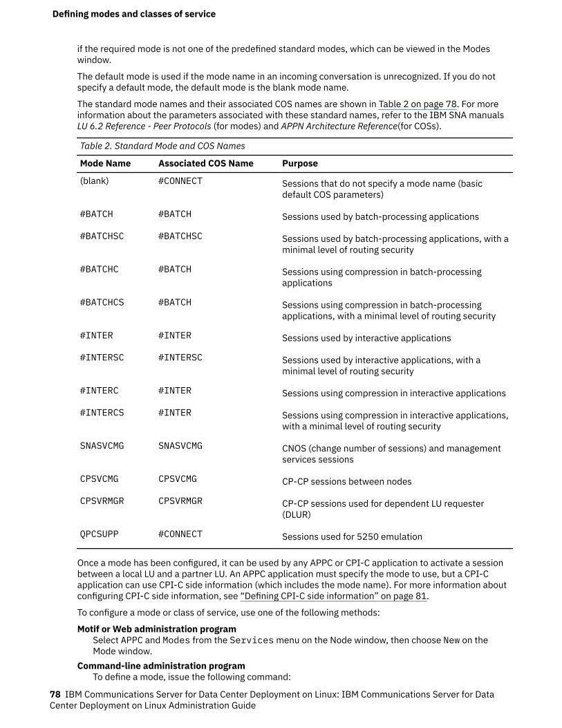
if the required mode is not one of the predefined standard modes, which can be viewed in the Modeswindow.
The default mode is used if the mode name in an incoming conversation is unrecognized. If you do notspecify a default mode, the default mode is the blank mode name.
The standard mode names and their associated COS names are shown in Table 2 on page 78. For moreinformation about the parameters associated with these standard names, refer to the IBM SNA manualsLU 6.2 Reference - Peer Protocols (for modes) and APPN Architecture Reference(for COSs).
Table 2. Standard Mode and COS Names
Mode Name Associated COS Name Purpose
(blank) #CONNECT Sessions that do not specify a mode name (basicdefault COS parameters)
#BATCH #BATCH Sessions used by batch-processing applications
#BATCHSC #BATCHSC Sessions used by batch-processing applications, with aminimal level of routing security
#BATCHC #BATCH Sessions using compression in batch-processingapplications
#BATCHCS #BATCH Sessions using compression in batch-processingapplications, with a minimal level of routing security
#INTER #INTER Sessions used by interactive applications
#INTERSC #INTERSC Sessions used by interactive applications, with aminimal level of routing security
#INTERC #INTER Sessions using compression in interactive applications
#INTERCS #INTER Sessions using compression in interactive applications,with a minimal level of routing security
SNASVCMG SNASVCMG CNOS (change number of sessions) and managementservices sessions
CPSVCMG CPSVCMG CP-CP sessions between nodes
CPSVRMGR CPSVRMGR CP-CP sessions used for dependent LU requester(DLUR)
QPCSUPP #CONNECT Sessions used for 5250 emulation
Once a mode has been configured, it can be used by any APPC or CPI-C application to activate a sessionbetween a local LU and a partner LU. An APPC application must specify the mode to use, but a CPI-Capplication can use CPI-C side information (which includes the mode name). For more information aboutconfiguring CPI-C side information, see “Defining CPI-C side information” on page 81.
To configure a mode or class of service, use one of the following methods:
Motif or Web administration programSelect APPC and Modes from the Services menu on the Node window, then choose New on theMode window.
Command-line administration programTo define a mode, issue the following command:
Defining modes and classes of service
78 IBM Communications Server for Data Center Deployment on Linux: IBM Communications Server for DataCenter Deployment on Linux Administration Guide
define_mode
To change the default mode, issue the following command:
define_defaults
To define a class of service, issue the following command:
define_cos
Mode configuration parametersThe following parameters are required for mode configuration:
NameThe name of the mode you are defining. The mode name is a string of 1-8 characters.
APPC applications that use this mode, including both local and remote applications, may also use thisname, so check the name with your application developer (or refer to your product documentation fora third-party application).
COS nameThe name of the class of service for this mode. The name is a string of 1-8 characters. Usually you cansimply specify #INTER for modes used for interactive data exchange and #BATCH for modes used forbulk data transfer.
This field applies only to a network node.
If you do not know what value to specify, consult your SNA network planner.
Session limitsUse the following fields to specify session limits:Initial session limit
The maximum number of sessions (up to the maximum session limit) that a pair of LUs can haveusing this mode, unless a different maximum is negotiated using CNOS.
Normally, use the value 8 for this field. If you are in doubt, consult your SNA network planner orAPPC application developer (or for a third-party application, the product documentation).
Maximum session limitThe maximum number of sessions (up to 32,767) permitted between a pair of LUs using thismode, even with CNOS negotiation.
This field is usually set to the same value as the initial session limit. If you are in doubt, consultyour SNA network planner or APPC application developer (or for a third-party application, theproduct documentation).
Minimum contention winner sessionsThe number of sessions (up to the session limit) that CS Linux must reserve for use by the local LUas the contention winner.
This field can usually safely be set to 0, but if you are not sure, consult your SNA network planner.
The sum of the minimum contention winner sessions and the minimum contention loser sessionsmust not exceed the initial session limit.
Minimum contention loser sessionsThe minimum number of sessions that CS Linux must reserve for use by the local LU as thecontention loser. Together with the value in the Minimum contention winner sessions field, thisvalue determines how to resolve contention for a session.
This can usually safely be set to 0, but if you are not sure, consult your SNA network planner.
The sum of the minimum contention winner sessions and the minimum contention loser sessionsmust not exceed the initial session limit.
Defining modes and classes of service
Chapter 6. Configuring APPC communication 79
Auto-activated sessionsThe number of sessions (up to the minimum contention winner count) that are automaticallyactivated after CNOS negotiation has taken place for a session between a local LU and partner LUusing this mode. Specifying a value for this field enables an LU that uses this mode to startsessions automatically in response to a request from a TP for a conversation to be allocatedimmediately.
Receive pacing windowUse these fields to specify how many RUs can be received before an SNA pacing response is sent:Initial window size
The initial setting for the number of request units (RUs) that the local LU can receive before it mustsend a pacing response to the remote LU. This can be safely set to 4.
Setting it higher can improve performance in some circumstances, but doing so also increasesmemory usage.
Maximum window sizeThe maximum number of request units (RUs) that the local LU can receive before it must send apacing response to the remote LU.
This value is optional. If it is not supplied, the maximum receive pacing window is unlimited. If avalue is supplied, it is used to limit the size of the receive pacing window for adaptive pacing. Ifadaptive pacing is not used, this value is ignored.
The pacing window can be from 0 through 32767 bytes. A value of 0 specifies an unlimited window.
If the adjacent node supports only fixed pacing, these values determine the fixed-pacing window size;but the adjacent node can still set a window size through negotiation. If the adjacent node usesadaptive pacing, these values set the initial window size.
Specify timeoutSelect this option if you want to specify the number of seconds (0 - 65535) that an LU 6.2 sessionusing this mode must be inactive before it can time out. Changing this value affects only sessions thatare activated using this definition (not sessions that are already active).
If you use a value of 0, sessions are timed out as soon as they become free.
Restrict maximum RU sizeSelect this option if you want to specify the maximum RU size, which determines how much data isbuffered before being sent to the partner LU.
The upper limit can be from 256 through 62440 bytes. You can safely set the upper limit to 1024bytes. Setting it higher can improve performance in some circumstances, but doing so also increasesmemory usage.
The lower limit can be 0 or a value from 256 through the upper limit you specify.
If the value in this field is different from the RU size defined for the remote node, the size used for asession with that node can be negotiated to establish an appropriate RU size for the session. Theactual value cannot be lower than the lower limit field.
These numbers, together with the send and receive pacing values, can be used to tune the session-level throughput between the local and partner LUs. If you do not know what values to use, start withthe default values and adjust them as needed to maximize throughput.
Compression supportedWhether data compression is supported for sessions using this mode. If you do not set this option,compression will not be used.
If you set this option, you can specify the maximum compression levels to be used for inbound dataand for outbound data. These are separate options so that you can specify different levels for the twodirections, or use compression in one direction but not in the other. In each direction, you can selectNone for no compression, or one of the values RLE (minimum compression), LZ9, or LZ10 (maximumcompression).
Defining modes and classes of service
80 IBM Communications Server for Data Center Deployment on Linux: IBM Communications Server for DataCenter Deployment on Linux Administration Guide
Reset to SNA defined valuesIf you are modifying a standard mode using the Motif dialog, you can click on this button to reset thevalues of the mode parameters to the SNA-defined values.
Additional configurationAfter performing the mode configuration, continue with the following configuration tasks:
• To define CPI-C side information, see “Defining CPI-C side information” on page 81.• To define APPC security, see “Configuring APPC security” on page 83.• To configure 5250 communication, see Chapter 7, “Configuring user applications,” on page 85.
Defining CPI-C side informationIf you are supporting a CPI-C application that uses CPI-C symbolic destination names, you need to definethe CPI-C side information. The side information associates the symbolic destination name withinformation about the partner TP, partner LU, mode, and security for the conversation.
To determine the symbolic destination name for CPI-C, consult the application developer (or for a third-party application, consult the product documentation).
To configure CPI-C side information, use one of the following methods:
Motif or Web administration programSelect APPC and CPI-C from the Services menu on the Node window.
Command-line administration programIssue the following command:
define_cpic_side_info
CPI-C configuration parametersFor each CPI-C symbolic destination name used by the application, collect the following information:
NameThe symbolic destination name used by the CPI-C applications (also known as TPs) that you want torun. This name can be 1-8 characters in length.
The application developer (or for a third-party application, the product documentation) can providethis name.
Local LUThe local LU for any conversations initiated by TPs using this side information using one of thefollowing methods:Local LU alias
An alias for a local LU.Use default LU
Specify this option to use a member of the default pool (if one exists) or the node control point LU(if no default pool is defined).
If the APPCLLU environment variable is set, the local LU information you supply is ignored, and the LUspecified for the environment variable is used instead.
Partner LUEither an alias or the fully qualified partner LU name for conversations initiated by local TPs using thisside information. The partner LU must be an LU that is configured on the computer that runs thepartner TP.
ModeThe name of the APPC mode that is to be used to access the partner LU. In most cases, the mode isone of the following predefined modes:
Defining CPI-C side information
Chapter 6. Configuring APPC communication 81
• A blank name• #BATCH• #BATCHSC• #INTER• #INTERSC• QPCSUPP
Partner TPThe name of the transaction program with which the CPI-C application communicates:
• If the TP is a user application, specify the name as normal characters (up to 64 characters inlength).
• If the TP is a service TP, specify the name in hexadecimal (up to 8 hexadecimal digits, representing4 bytes).
The application developer (or for a third-party application, the product documentation) can providethis information.
SecurityThe level of conversation-level security you want to use. The options are as follows:None
The partner TP does not require security parameters to be checked.Same
The partner TP uses security, but accepts verification by the local TP of the user ID and passwordprovided by the initiating TP. If you choose a security level of Same, you also need to specify avalid user ID that is accepted by the partner TP.
ProgramThe partner TP requires a User ID and password. If you choose a security level of Program, youneed to specify a valid user ID and password that are accepted by the partner TP.
Program strongThe partner TP requires a user ID and password. Both the local and remote nodes must supportsecurity enhancements so that the password is encrypted.
Refer to the documentation for the CPI-C application or consult the application programmer to findout what security parameters to use.
User IDIf you have chosen a security level of Same, Program, or Program strong, specify a user ID to besent on the initiating message to the remote application. This value must match a user ID that theapplication is defined to accept.
This user ID is not related to Linux login user IDs on either the local or the remote node. If the remotenode is running CS Linux, the user ID must be configured on the remote node using the ConversationSecurity Configuration dialog.
PasswordIf the security level is specified as Program or Program strong, specify a password to be sentwhen the conversation is allocated. This value must match the password defined at the remoteapplication for use with the supplied user name.
This password is not related to Linux login passwords on either the local or the remote node. If theremote node is running CS Linux, the password must be configured on the remote node using theConversation Security Configuration dialog.
Additional configurationAfter performing the CPI-C configuration, continue with the following configuration tasks:
• To define APPC security, see “Configuring APPC security” on page 83.
Defining CPI-C side information
82 IBM Communications Server for Data Center Deployment on Linux: IBM Communications Server for DataCenter Deployment on Linux Administration Guide
• To configure 5250 communication, see Chapter 7, “Configuring user applications,” on page 85.
Configuring APPC securityYou can perform the following configuration tasks for APPC security:
• Configuring session security as described in “Configuring session security” on page 83• Configuring conversation security as described in “Configuring conversation security” on page 83• Configuring security access lists as described in “Configuring a security access list” on page 84
Configuring session securitySession-level security is used to validate LU-LU sessions. Each definition consists of a local LU name, apartner LU name, and a password.
CS Linux uses the password to validate sessions between the local LU and partner LU. (The passwords arenot related to Linux logon passwords.)
To configure session security, use one of the following methods:
Motif or Web administration programSelect APPC, Security, and Session-level security from the Services menu on the Nodewindow.
Command-line administration programIssue the following command:
define_lu_lu_password
Session security configuration parametersThe following parameters are required for session security configuration:
Local LUThe LU name of the local LU. The name is a string of 1-8 characters.
Partner LUThe fully qualified LU name of the partner LU.
PasswordA password that CS Linux can use to validate sessions between the local LU and the partner LU. Thepassword is an EBCDIC formatted character string (represented as a 16-digit hexadecimal number)that is used to create a key, which is exchanged when the session is established. This password is notrelated to Linux login passwords on either the local or the remote node.
Additional configurationAfter performing the session security configuration, continue with the following configuration tasks:
• To configure conversation security, see “Configuring conversation security” on page 83.• To configure 5250 communication, see Chapter 7, “Configuring user applications,” on page 85.
Configuring conversation securityConversation security is used to validate incoming conversations. Each definition consists of a user ID anda password. This user ID is not related to Linux login user IDs on either the local or the remote node.
To configure conversation security, use one of the following methods:
Motif or Web administration programSelect APPC, Security, and Conversation-level security from the Services menu on theNode window.
Configuring APPC security
Chapter 6. Configuring APPC communication 83
Command-line administration programIssue the following command:
define_userid_password
Conversation security configuration parametersThe following parameters are required for conversation security configuration:
User IDThe user ID to be accepted in an incoming conversation from a remote node. The user ID can be up to10 characters long.
PasswordThe password to be accepted in an incoming conversation from a remote node. The password can beup to 10 characters long.
Additional configurationAfter configuring conversation security, you can configure 5250 communication as described in Chapter 7,“Configuring user applications,” on page 85.
Configuring a security access listYou can define an APPC security access list to control access to an LU or TP (or both). This list can bereferred to by the definition for an APPC local LU or TP.
To configure a security access list, use one of the following methods:
Motif or Web administration programSelect APPC, Security, and Conversation-level security from the Services menu on theNode window, then select the Security Access Lists pane and choose New.
Command-line administration programIssue the following command:
define_security_access_list
Security access list configuration parametersThe following parameters are required for security access list configuration:
NameName of the security access list. The definition for an APPC TP or local LU can use this name to referto the access list.
Users in access listThe names of users included in the security access list.
Additional configurationAfter performing the security access list configuration, continue with the following configuration tasks:
• Configure TP access as described in “Defining TPs” on page 73.
Configuring APPC security
84 IBM Communications Server for Data Center Deployment on Linux: IBM Communications Server for DataCenter Deployment on Linux Administration Guide
Chapter 7. Configuring user applications
This chapter provides instructions for configuring SNA resources to support user applications that use anyof the following communication: 3270, 5250, and LUA. The SNA resources required by such applicationsare LUs.
For 3270, LUA, and dependent APPC communication, you must configure dependent LUs. Forindependent APPC and 5250 communication, you can use the default control point LU (definedautomatically when you configure the local node) or define independent LUs.
Before you can configure the resources described in this chapter, you must perform the followingconfiguration:
• Configure the node as described in “Configuring the node” on page 46.• Configure connectivity as described in Chapter 4, “Defining Connectivity Components,” on page 49. For
3270, LUA, and dependent APPC communication, you must configure the link to support dependent LUtraffic. For independent APPC and 5250 communication, the link must support independent LU traffic.
You do not need to configure a direct link to the host if you are using upstream SNA gateway or DLUR.For more information, see “Configuring SNA gateway” on page 94 and “Defining DLUR PUs” on page59.
The following list describes the configuration tasks required for each type of user application:
3270 applicationsFor 3270 communication, configure the following resources:
1. For a 3270 display or printer, define a dependent LU as described in “Defining LU Types 0-3” onpage 63.
2. To enable 3270 displays to select from a pool of LUs, define an LU pool as described in “DefiningLU pools” on page 65. If a display uses a dedicated LU, you can skip this step.
5250 applicationsFor 5250 communication, configure the following resources:
1. Configure the node for APPC communication:
a. If you can use the local node's control point LU, you do not need to configure a local LU. If youneed a local LU definition (for example, to use session security), define the local LU asdescribed in “Defining local LUs” on page 67.
b. If the local node is a LEN node, you must define the AS/400 system as a remote node asdescribed in “Defining remote nodes” on page 69.
If the local node is an APPN end node or network node, you can use the control point LU on theAS/400 system as a partner LU, so you do not need to configure any other partner LUs.
You do not need to define any modes, because 5250 uses the standard mode QPCSUPP.
LUA applicationsTo support an LUA application, configure the following resources:
1. Define a dependent LU as described in “Defining LU Types 0-3” on page 63.2. To enable an LUA application to select from a pool of LUs, define an LU pool as described in
“Defining LU pools” on page 65. If the application uses a dedicated LU, you can skip this step.
In addition, if you are running the same LUA application on two or more client computers, you mayneed to override the LUA LU name that it specifies. This allows you to assign two or more copies of theapplication to use different local LUs without changing the application. For more information, see“Mapping hard-coded LU aliases on Client applications to LU aliases in a domain of servers” on page128 for Remote API Clients on AIX or Linux, or “Mapping hard-coded LU aliases on Client applicationsto LU aliases in a domain of servers” on page 123 for Windows clients.
Configuring user applications
© Copyright IBM Corp. 1998, 2021 85

An LUA application uses the LU 0-3 resources of the node to communicate with a host application. Youdo not need to define any additional resources.
Configuring user applications
86 IBM Communications Server for Data Center Deployment on Linux: IBM Communications Server for DataCenter Deployment on Linux Administration Guide
Chapter 8. Configuring passthrough services
Passthrough services on a server running CS Linux enable communication between an SNA host and localsystems that are not directly connected to the host.
CS Linux includes TN server support for TN3270, TN3287, and TN3270E clients, collectively referred toas "TN3270 clients." To configure this function, see “Configuring TN server” on page 87.
CS Linux also includes TN Redirector support for passthrough TCP/IP host access to TN3270, TN3270E,TN5250 and VT clients, referred to collectively as "Telnet clients". To configure this function, see“Configuring TN Redirector” on page 90.
SNA gateway provides connectivity between the host and local systems. You can configure LUs on thelocal node to support this function (see “Configuring SNA gateway” on page 94) or you can define atemplate that is used to support downstream LUs that have not been explicitly configured (see “DefiningDLCs, ports, and connection networks” on page 49).
DLUR supports dependent LU sessions between the host and nodes in an APPN network. To configure thisfunction, see “Configuring DLUR” on page 95.
Configuring TN serverTN server enables TN3270 clients to communicate with a host through an intermediate CS Linux nodethat implements the TN server. The TN3270 clients connect to the TN server using TCP/IP, and use LUsdefined on the TN server. The TN server LUs establish sessions with LUs at the host to support TN3270sessions for the clients.
Before you can configure TN server, you must perform the following configuration tasks:
• Define the local node as described in “Configuring the node” on page 46.• Configure a port and link station for dependent traffic between the local node and the host, as described
in Chapter 4, “Defining Connectivity Components,” on page 49.• Define the TN3270 LUs on the local node that are used for communication with the host. To add the
LUs, see “Defining LU Types 0-3” on page 63.• If you are going to use any LU pools, define them as described in “Defining LU pools” on page 65.
To configure TN server, perform the following tasks:
• Configure a TN server access record for each TN3270 client who will use the server, or a default recordthat enables any client to access the server (see “Configuring TN server access records” on page 88).
• If you are supporting TN3270E or TN3287 clients, you can define an association record for display andprinter LUs (see “Configuring TN server association records” on page 90). This record enables aTN3270E or TN3287 client to select a specific printer (by selecting the associated display LU). Theclient must be authorized to select an LU in the TN server access record.
Additional options for TN server enable you to force printer responses, specify a keep-alive method for allTN3270 sessions, and specify how to access the external LDAP server that holds a revocation list used tocheck authorization for TN3270 clients. To access these options, use the Services menu on the TNServer window.
Note: Before configuring TN Server, you should review the information in “TN Server and TN Redirector:additional security information” on page 96, which describes a protocol change that may affectinterworking with some TN3270 clients or Telnet clients.
Configuring TN server
© Copyright IBM Corp. 1998, 2021 87
Configuring TN server access recordsTN server access records indicate which TN3270 clients can access the TN server and which LUs theyshould use. Each access record identifies a TN3270 client that is permitted to access the TN server, theTCP/IP port that the client connects to, and the LU or LU pool that the client uses.
You can also define a default record that enables access by any TN3270 client (with the same LUs or LUpools for all clients).
TN3270 clients can use the TN server only when the node, port, and link station are active.
To configure a TN server access record, use one of the following methods:
Motif or Web administration programSelect TN server from the Services menu on the Node window, and TN server from thesubmenu. On the resulting window, select the TN Server Client Access Permissions pane and chooseNew.
Command-line administration programIssue the following command:
define_tn3270_access
Note: If you define a TN server access record using the command-line administration program,snaadmin, or a NOF application, you can use the listen_local_address parameter to specify an address onthe local TN Server computer to which the TN3270 client will connect. If you do this, the access recordwill not be displayed in the Motif administration program, so you cannot use that program to view ormanage it. You can still manage it using the command-line administration program or a NOF application.
TN server access record configuration parametersThe following parameters are required for TN server access record configuration:
TN3270 client addressThe address that identifies the TN3270 client to which the access record applies:Default record
Permit access by any TN3270 client.TCP/IP name or alias
Permit access by a named TN3270 client. If you know the TCP/IP name of the client, select thisoption and enter the name. On many computers, you can find out the computer's TCP/IP nameusing the hostname command.
TCP/IP addressPermit access from a specific TCP/IP address. If you know the TCP/IP address of the TN3270client, select this option and enter the address. This can be either of the following.
• An IPv4 dotted-decimal address (such as 193.1.11.100).• An IPv6 colon-hexadecimal address (such as2001:0db8:0000:0000:0000:0000:1428:57ab or 2001:db8::1428:57ab).
Support TN3270EThe level of TN3270 support provided by the node:TN3270
Support only the TN3270 protocol. Selecting this option disables server support for TN3270Eprotocols, even if they are supported on the client.
TN3270ESupport both TN3270 and TN3270E protocols (the default).
TN3270 and TN3287 protocols are always supported, regardless of which option you choose.
For an AS/400 TN3270 client, this option must be set to TN3270E.
Configuring TN server
88 IBM Communications Server for Data Center Deployment on Linux: IBM Communications Server for DataCenter Deployment on Linux Administration Guide
TCP/IP port numberThe TCP/IP port number (on the TN server) for the port to which the TN3270 client connects.
Note: TCP/IP ports are completely unrelated to SNA ports.
The well-known port number for the TN3270 service is 23. If you choose a different port number thatis not in use on the TN server, you also need to configure that port number on the TN3270 clients (orstart the TN3270 clients using an option to specify the port number). Port numbers above 2000 arelikely to be available. Port numbers in the range 256-1023 may give slightly better security, but aremore likely to be in use.
If you want a TN3270 client to be able to use more than one LU or LU pool, define multiple accessrecords, each with a different TCP/IP port number, so that you can identify the different LUs or LUpools by specifying different port numbers.
Display LU assignedThe name of the LU that the TN3270 client accesses when it is active. The LU must be a dependent LUon the local node. You can specify the name of an LU pool rather than the name of a particular LU.
Printer LU assignedThe name of the default printer LU or LU pool for clients that use this access record. This LU must bedefined as a dependent LU on the local node.
Allow access to specific LUSpecify this option to enable TN3270E and TN3287 clients to request a specific LU for a session. (Thisoption is not available to TN3270 clients.)
SSL secure sessionSpecify this option to indicate that this session uses Secure Sockets Layer (SSL) to access the server.
This option is available only if you have installed the additional software required to support SSL onthe server; otherwise you cannot select it.
Note: If this session's TCP/IP port number parameter indicates that it uses the Telnet daemon'sTCP/IP port, do not use SSL for this session. If you use SSL on a session that uses the Telnet daemon'sTCP/IP port, Telnet clients will not be able to use telnet to access the CS Linux computer while thenode is active.
Perform client authenticationThis option appears only if you have selected the SSL secure session option.
Specify this option to indicate that the TN Server requires the session to use client authentication. Theclient must send a valid certificate (information identifying it as a valid client authorized to use the TNServer).
As well as checking that the certificate is valid, the TN Server may also need to check the certificateagainst a certificate revocation list on an external LDAP server, to ensure that the user's authorizationhas not been revoked. In this case, you also need to use the TN Server Advanced Parameters dialog tospecify how to access this server.
Security levelIndicates the SSL security level required for this session. The session will use the highest securitylevel that both client and server can support; if the client cannot support the requested level ofsecurity or higher, the session will not be started.
This option appears only if you have selected the SSL secure session option.
Possible values are:
Authenticate OnlyCertificates must be exchanged, but encryption will not be used. This option is typically used toavoid the overhead of encryption when the client is connecting across a secure intranet.
Authenticate MinimumThe client must request a certificate from the server to check its validity; encryption is notrequired (but can be used if the client requests it).
Configuring TN server
Chapter 8. Configuring passthrough services 89
40 Bit MinimumThe client must support at least 40-bit encryption.
56 Bit MinimumThe client must support at least 56-bit encryption.
128 Bit MinimumThe client must support at least 128-bit encryption.
168 Bit MinimumThe client must support at least 168-bit encryption.
256 Bit MinimumThe client must support at least 256-bit encryption.
Note: Using encryption requires additional software to be installed with CS Linux; see IBMCommunications Server for Data Center Deployment on Linux Quick Beginnings for more information.Depending on your location, you may not be able to use all the encryption levels listed because thesoftware required to support them is not available in your country.
Additional configurationAfter performing the TN server access configuration, continue with the following configuration tasks:
• Configure TN server association records as described in “Configuring TN server association records” onpage 90.
Configuring TN server association recordsA TN server association record defines an association between a printer LU and display LU, so that theTN3270E or TN3287 protocol can connect the two. If the access record for the client permits selection ofa specific LU, this record enables a client to select a specific printer by specifying the associated displayLU.
To configure a TN server association record, use one of the following methods:
Motif or Web administration programSelect TN Server from the Services menu on the Node window, then select the AssociationRecords pane on the TN Server window and choose New.
Command-line administration programIssue the following command:
define_tn3270_association
TN server association record configuration parametersThe following parameters are required for TN server association record configuration:
Display LUThe name of the display LU (which must be defined on the local node).
Printer LUThe name of the printer LU (which must be defined on the local node). Do not specify a printer LU thathas been entered on another TN server association record.
Configuring TN RedirectorTN Redirector enables TN3270, TN3270E, TN5250 and VT clients, collectively known as Telnet clients, tocommunicate with a host through an intermediate CS Linux node that implements the TN redirector. Theclients connect to the TN redirector using TCP/IP; the TN redirector then establishes a separate TCP/IPconnection to the host.
To configure TN Redirector, perform the following tasks:
Configuring TN Redirector
90 IBM Communications Server for Data Center Deployment on Linux: IBM Communications Server for DataCenter Deployment on Linux Administration Guide
• Configure a TN Redirector access record for each Telnet client who will use the server, or a defaultrecord that enables any client to access the server (see “Configuring TN Redirector access records” onpage 91).
Note: Before configuring TN Redirector, you should review the information in “TN Server and TNRedirector: additional security information” on page 96, which describes a protocol change that mayaffect interworking with some TN3270 clients or Telnet clients.
Configuring TN Redirector access recordsTN redirector access records indicate which Telnet clients can access the TN redirector over a TCP/IP link.Each access record identifies a Telnet client that is permitted to access the TN redirector, the TCP/IP portthat the client uses to connect to CS Linux, the TCP/IP port that CS Linux uses to connect to the host, andthe SSL security settings. You can also define default records that enable access by any client.
If you want to permit any client to use the TN redirector and you want all clients to use the same hostaccess configuration, you can define a default record.
Telnet clients can use the TN redirector only when the node is active.
To configure a TN redirector access record, use one of the following methods:
Motif or Web administration programSelect TN server from the Services menu on the Node window, and TN server from thesubmenu. On the resulting window, select the TN Redirector Client Access Permissions pane andchoose New.
Command-line administration programIssue the following command:
define_tn_redirect
Note: If you define a TN redirector access record using the command-line administration program,snaadmin, or a NOF application, you can use the listen_local_address parameter to specify an address onthe local TN Server computer to which the TN3270 client will connect. If you do this, the access recordwill not be displayed in the Motif administration program, so you cannot use that program to view ormanage it. You can still manage it using the command-line administration program or a NOF application.
TN Redirector access record configuration parametersTN redirector access record configuration consists of two groups of parameters, for the client and hostTCP/IP connections.
The client parameters are as follows:
Telnet client addressThe address that identifies the Telnet client to which the access record applies:Default record
Permit access by any Telnet client.TCP/IP name or alias
Permit access by a named Telnet client. If you know the TCP/IP name of the client, select thisoption and enter the name. On many computers, you can find out the computer's TCP/IP nameusing the hostname command.
TCP/IP addressPermit access from a specific TCP/IP address. If you know the TCP/IP address of the client, selectthis option and enter the address. This can be either of the following.
• An IPv4 dotted-decimal address (such as 193.1.11.100).• An IPv6 colon-hexadecimal address (such as2001:0db8:0000:0000:0000:0000:1428:57ab or 2001:db8::1428:57ab).
Configuring TN Redirector
Chapter 8. Configuring passthrough services 91
TCP/IP port numberThe TCP/IP port number (on the TN server) for the port to which the client connects.
Note: TCP/IP ports are completely unrelated to SNA ports.
You also need to configure this port number on the clients (or start the clients using an option tospecify the port number). Port numbers above 2000 are likely to be available. Port numbers in therange 256-1023 may give slightly better security, but are more likely to be in use.
SSL secure sessionSpecify this option to indicate that this session uses Secure Sockets Layer (SSL) to access the server.
This option is available only if you have installed the additional software required to support SSL onthe server; otherwise you cannot select it.
Perform client authenticationThis option appears only if you have selected the SSL secure session option.
Specify this option to indicate that the TN Server requires the session to use client authentication. Theclient must send a valid certificate (information identifying it as a valid client authorized to use the TNServer).
As well as checking that the certificate is valid, the TN Redirector may also need to check thecertificate against a certificate revocation list on an external LDAP server, to ensure that the user'sauthorization has not been revoked. In this case, you also need to use the TN Server AdvancedParameters dialog (accessed from the Services menu on the TN Server window) to specify how toaccess this server.
Security levelIndicates the SSL security level required for the client session. The session will use the highestsecurity level that both client and server can support; if the client cannot support the requested levelof security or higher, the session will not be started.
This option appears only if you have selected the SSL secure session option.
Possible values are:
Authenticate OnlyCertificates must be exchanged, but encryption will not be used. This option is typically used toavoid the overhead of encryption when the client is connecting across a secure intranet.
Authenticate MinimumThe client must request a certificate from the server to check its validity; encryption is notrequired (but can be used if the client requests it).
40 Bit MinimumThe client must support at least 40-bit encryption.
56 Bit MinimumThe client must support at least 56-bit encryption.
128 Bit MinimumThe client must support at least 128-bit encryption.
168 Bit MinimumThe client must support at least 168-bit encryption.
256 Bit MinimumThe client must support at least 256-bit encryption.
Note: Using encryption requires additional software to be installed with CS Linux; see IBMCommunications Server for Data Center Deployment on Linux Quick Beginnings for more information.Depending on your location, you may not be able to use all the encryption levels listed because thesoftware required to support them is not available in your country.
The destination host parameters are as follows:
AddressThe address that identifies the host to which the access record applies:
Configuring TN Redirector
92 IBM Communications Server for Data Center Deployment on Linux: IBM Communications Server for DataCenter Deployment on Linux Administration Guide
TCP/IP name or aliasAccess to a named host. If you know the TCP/IP name of the host, select this option and enter thename. On many computers, you can find out the computer's TCP/IP name using the hostnamecommand.
TCP/IP addressAccess to a specific TCP/IP address. If you know the TCP/IP address of the host, select this optionand enter the address. This can be either of the following.
• An IPv4 dotted-decimal address (such as 193.1.11.100).• An IPv6 colon-hexadecimal address (such as2001:0db8:0000:0000:0000:0000:1428:57ab or 2001:db8::1428:57ab).
TCP/IP port numberThe TCP/IP port number that the TN Redirector uses to access the host.
Note: TCP/IP ports are completely unrelated to SNA ports.
You also need to configure this port number on the host. Port numbers above 2000 are likely to beavailable. Port numbers in the range 256-1023 may give slightly better security, but are more likely tobe in use.
SSL secure sessionSpecify this option to indicate that TN Redirector uses Secure Sockets Layer (SSL) to access the host.
This option is available only if the host supports SSL.
Security levelIndicates the SSL security level required for the host session. The session will use the highest securitylevel that both host and server can support; if the host cannot support the requested level of securityor higher, the session will not be started.
This option appears only if you have selected the SSL secure session option.
Possible values are:
Authenticate OnlyCertificates must be exchanged, but encryption will not be used. This option is typically used toavoid the overhead of encryption when the host connection is across a secure intranet.
Authenticate MinimumThe host must request a certificate from the server to check its validity; encryption is not required(but can be used if the host requests it).
40 Bit MinimumThe host must support at least 40-bit encryption.
56 Bit MinimumThe host must support at least 56-bit encryption.
128 Bit MinimumThe host must support at least 128-bit encryption.
168 Bit MinimumThe host must support at least 168-bit encryption.
256 Bit MinimumThe host must support at least 256-bit encryption.
Note: Using encryption requires additional software to be installed with CS Linux; see IBMCommunications Server for Data Center Deployment on Linux Quick Beginnings for more information.Depending on your location, you may not be able to use all the encryption levels listed because thesoftware required to support them is not available in your country.
Configuring TN Redirector
Chapter 8. Configuring passthrough services 93
Configuring SNA gatewayNormally, a dependent LU session requires a direct communications link to the host computer. However, anode running CS Linux that has a direct communications link to the host can also provide SNA gatewayfacilities to LUs on downstream computers, enabling them to access the host over the communicationslink from the CS Linux node. The downstream computer must contain an SNA PU type 2.0 or 2.1 tosupport dependent communication with the host. For example, the downstream computer could beanother computer running CS Linux in a standalone configuration.
Using the SNA gateway feature, all the data transferred between the host and the downstream computeris routed through the CS Linux local node. This enables a downstream computer to share a hostconnection with CS Linux or with other downstream computers, instead of requiring a direct link. Forexample, you can set up several downstream computers connected to CS Linux over a local token ringnetwork, so that they all access the same long-distance SDLC leased line from CS Linux to the host.
Using SNA gateway also simplifies the configuration at the host. The host configuration needs to includeonly the CS Linux computer and its host communications link; the LUs at the downstream computers areconfigured as part of the resources of the CS Linux computer. The host computer is not aware that SNAgateway is being used.
Before configuring SNA gateway, you must perform the following configuration tasks:
• Define the local node as described in “Configuring the node” on page 46.• Configure a port and link station for dependent traffic between the local node and the host, as described
in Chapter 4, “Defining Connectivity Components,” on page 49. Also, configure ports and link stationsfor dependent traffic between the local node and the downstream nodes. For downstream links, you canconfigure a template on the port to support implicit downstream LUs (LUs that are not explicitly definedon the local node).
• Define the LUs on the local node that are used for communication with the host (the upstream LUs).Upstream LUs, including Dependent LU 6.2 LUs, must be defined using the LU Type 0-3 Configurationdialog, specifying an LU type of unrestricted (unknown). To add the LUs, see “Defining LU Types 0-3” onpage 63.
• If you are going to use any LU pools, define them as described in “Defining LU pools” on page 65.
To enable SNA gateway, you must configure LUs on the local node to support sessions with downstreamworkstations. (If you configured a template on the port to support implicit downstream LUs, you may notneed to define downstream LUs explicitly.) The LUs defined on the local node are referred to as"downstream LUs." To configure downstream LUs, you need the LU numbers that are used on thedownstream nodes, and the name of the host LU. (The LUs that are defined on the downstream nodes canbe any dependent LU type.)
To configure downstream LUs, use one of the following methods:
Motif or Web administration programSelect SNA gateway and New downstream LU from the Services menu on the Node window.
Command-line administration programIssue one of the following commands:
define_downstream_lu
define_downstream_lu_range
Downstream LU configuration parametersThe following parameters are required for downstream LU configuration:
Downstream LU nameA name for each downstream LU. The LU name is used only to identify the LU locally, and does notneed to match any configuration on the downstream node.
Configuring SNA gateway
94 IBM Communications Server for Data Center Deployment on Linux: IBM Communications Server for DataCenter Deployment on Linux Administration Guide
If you are defining a range of LUs, specify a base name of 1-5 characters. CS Linux adds a three-digitdecimal string to the base name to create an LU name for each LU number you specify.
Downstream PU nameThe name of the link station to the downstream node.
LU numberThe LU number must match the LU number defined on the downstream node. Contact your SNAnetwork planner if you do not know what LU number to use.
You can configure several LUs with consecutive LU numbers by defining a range of LUs.
Upstream LU nameThe name of the host LU or a pool of LUs with which the downstream LUs will communicate.
Delayed logonTo reduce the user startup time, CS Linux displays a logon screen without assigning an upstream LU; a3270 user must hit a key before the user is associated with an upstream LU.
Allow timeoutTo reduce the number of LUs required, an LU without an active PLU-SLU session is disassociated fromthe upstream LU after this number of seconds.
Additional configurationAfter performing the downstream LUs for SNA gateway configuration, continue with the followingconfiguration tasks:
• To configure user applications, see Chapter 7, “Configuring user applications,” on page 85.
Configuring DLURNormally, a dependent LU session requires a direct communications link to the host computer. If manynodes (including a host node) are connected together in an APPN network, some of them may have anindirect connection through another node instead of a direct connection to the host. Without a directconnection, it is not possible to establish dependent LU sessions to the host from LUs in these indirectlyconnected nodes.
Dependent LU requester (DLUR) is an APPN feature designed to overcome this limitation. DLUR can beconfigured on an APPN node (such as a node running CS Linux). It works in conjunction with dependentLU server (DLUS) at the host, to route sessions from dependent LUs on the DLUR node across the APPNnetwork to the DLUS host.
The route to the host can span multiple nodes and can take advantage of APPN's network management,dynamic resource location, and route calculation facilities. DLUR must be available on the node where theLUs are defined, and DLUS must be available on the host node, but you do not have to enable DLUR on anyintermediate nodes in the session route.
Note: You cannot configure DLUR on a LEN node.
If the CS Linux DLUR node is a network node, it can also provide passthrough DLUR facilities fordependent LUs on downstream computers connected to the CS Linux node. (Only network nodes supportthis function.) These downstream LUs can use DLUR on the CS Linux node to access the host across thenetwork, in the same way that LUs internal to the node do.
Note: You cannot configure passthrough DLUR on an end node.
The tasks you need to perform to configure DLUR depend on whether the dependent LUs are on the localnode or on downstream nodes.
To configure DLUR support on the local node, you must perform the following configuration tasks:
1. Define the local node as described in “Configuring the node” on page 46. If you are providingpassthrough DLUR support for downstream nodes, define the node as an APPN network node.
Configuring DLUR
Chapter 8. Configuring passthrough services 95
2. Configure connectivity to the APPN network. APPN connectivity requires at least a port and link stationfor independent traffic between the local node and the adjacent APPN network node, as described inChapter 4, “Defining Connectivity Components,” on page 49.
3. Define a DLUR PU on the local node as described in “Defining DLUR PUs” on page 59. (The DLUR PUsupports connectivity to the host.)
4. To configure DLUR to support LUs on the local node, you must add the LUs on the local node, asdescribed in Chapter 7, “Configuring user applications,” on page 85. The LUs can be configured tosupport 3270 display, 3270 printer, or LUA. Depending on the requirements of the user applicationssupported by the LUs, you may also need to perform further configuration.
To configure passthrough DLUR support for downstream nodes, you must perform the followingconfiguration tasks:
1. Define the local node as an APPN network node (see “Configuring the node” on page 46).2. Configure connectivity to the downstream nodes. Configure ports and link stations for dependent
traffic between the local node and each downstream node, as described in Chapter 4, “DefiningConnectivity Components,” on page 49. (You do not need to define a DLUR PU to support DLUR fordownstream nodes.)
3. A downstream node can support multiple PUs. In this case, each downstream PU is associated with adifferent link, so you need to configure multiple links between the CS Linux DLUR node and thedownstream node, and you need to know the downstream PU name for each link.
TN Server and TN Redirector: additional security informationThis section provides additional information about a protocol change to maintain SSL security for TNServer and TN Redirector connections, which may affect interworking with some TN3270 clients or Telnetclients.
CS Linux includes the function described in RFC 5746, http://tools.ietf.org/html/rfc5746 (implemented inversion 8 of the GSKIT package), which corrects a security vulnerability for handshake renegotiation onSSL secured TN3270 and TN Redirector connections. However, if a client does not implement thisprotocol and attempts to use renegotiation, it is possible that a secured connection from the client willfail.
If you encounter problems with TN3270 and TN Redirector connections from clients that do notimplement the RFC 5746 protocol, it is possible to alter the behaviour of CS Linux to revert to the oldoperation before this protocol change (permitting renegotiation).To do this, set the environment variableGSKIT_RENEGOTIATION in the shell before starting CS Linux or use the environmentfile /etc/opt/ibm/sna/environment:
• To permit renegotiation, set GSKIT_RENEGOTIATION=FULL orGSKIT_RENEGOTIATION=ABBREVIATED according to the requirements of the client.
• To prevent renegotiation, set GSKIT_RENEGOTIATION=NONE .• If you do not set the environment variable, CS Linux does not permit renegotiation.
Note: If you intend to allow renegotiation, you must refer to http://web.nvd.nist.gov/view/vuln/detail?vulnId=CVE-2009-3555 and ensure that you are aware of the possible security problem that it describes.
TN Server and TN Redirector: additional security information
96 IBM Communications Server for Data Center Deployment on Linux: IBM Communications Server for DataCenter Deployment on Linux Administration Guide

Chapter 9. Managing CS Linux from NetView
CS Linux includes a remote command facility (RCF) that operates in conjunction with the NetViewprogram at a host computer, enabling a NetView operator to issue commands from the host NetViewprogram to the CS Linux computer. (For a brief overview of NetView and RCF commands, see “Using thehost NetView program” on page 97.)
The CS Linux RCF provides the following two functions:
• Service point command facility (SPCF) enables a NetView operator to issue CS Linux administrationcommands from NetView using the same syntax as for the command-line administration programsnaadmin. This facility is described in “Using SPCF” on page 99.
• UNIX command facility (UCF) enables a NetView operator to issue Linux operating system commandsfrom NetView. This facility is described in “Using UCF” on page 100.
Both of these functions can be accessed from the NetView console in the same way, and the overallsyntax for issuing the commands is the same.
Using the host NetView programThe CS Linux RCF operates in conjunction with the NetView program at a host computer. The host must berunning NetView Version 1 Release 2, or a later version; CS Linux does not support NetView Version 1Release 1.
To use the NetView program, you need the following:
• Login ID and password for the host NetView program (contact your host personnel for this information)• Service point name for CS Linux, defined at the host for the NetView program (contact your host
personnel for this information)• DLC, port, and link station to access the host computer on which the NetView program is running
You may want to test the RCF function by using 3270 emulation to access NetView from CS Linux insteadof accessing it directly from the host. In this case, you also require the following:
• 3270 LU configured at the host• 3270 session using this LU
Consult your host administrator to obtain the necessary configuration information.
To access the NetView program, follow these steps:
1. Ensure that the CS Linux software is started, using a node configuration file that includes a definition ofRCF access parameters (the define_rcf_access record).
2. If you are accessing the NetView program using 3270 emulation, start the 3270 emulation programand activate the session to the host.
3. Follow the instructions given to you by the host administrator for starting NetView and logging on. (Thesequence of operations may vary with different versions of NetView.)
4. Issue SPCF or UCF commands as required.5. If you are using 3270 emulation to access NetView, follow the instructions in your 3270
documentation for ending 3270 emulation when you have finished issuing commands.
NetView screen displayThe layout of the NetView screen varies with different versions of NetView at different hosts. A typicallayout is shown in Figure 19 on page 98.
Using the host NetView program
© Copyright IBM Corp. 1998, 2021 97
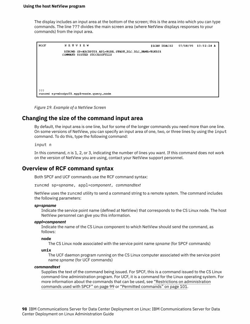
The display includes an input area at the bottom of the screen; this is the area into which you can typecommands. The line ??? divides the main screen area (where NetView displays responses to yourcommands) from the input area.
Figure 19. Example of a NetView Screen
Changing the size of the command input areaBy default, the input area is one line, but for some of the longer commands you need more than one line.On some versions of NetView, you can specify an input area of one, two, or three lines by using the inputcommand. To do this, type the following command:
input n
In this command, n is 1, 2, or 3, indicating the number of lines you want. If this command does not workon the version of NetView you are using, contact your NetView support personnel.
Overview of RCF command syntaxBoth SPCF and UCF commands use the RCF command syntax:
runcmd sp=spname, appl=component, commandtext
NetView uses the runcmd utility to send a command string to a remote system. The command includesthe following parameters:
sp=spnameIndicate the service point name (defined at NetView) that corresponds to the CS Linux node. The hostNetView personnel can give you this information.
appl=componentIndicate the name of the CS Linux component to which NetView should send the command, asfollows:node
The CS Linux node associated with the service point name spname (for SPCF commands)unix
The UCF daemon program running on the CS Linux computer associated with the service pointname spname (for UCF commands)
commandtextSupplies the text of the command being issued. For SPCF, this is a command issued to the CS Linuxcommand-line administration program. For UCF, it is a command for the Linux operating system. Formore information about the commands that can be used, see “Restrictions on administrationcommands used with SPCF” on page 99 or “Permitted commands” on page 101.
Using the host NetView program
98 IBM Communications Server for Data Center Deployment on Linux: IBM Communications Server for DataCenter Deployment on Linux Administration Guide
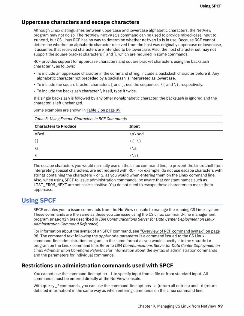
Uppercase characters and escape charactersAlthough Linux distinguishes between uppercase and lowercase alphabetic characters, the NetViewprogram may not do so. The NetView netvasis command can be used to provide mixed-case input toruncmd, but CS Linux RCF has no way to determine whether netvasis is in use. Because RCF cannotdetermine whether an alphabetic character received from the host was originally uppercase or lowercase,it assumes that received characters are intended to be lowercase. Also, the host character set may notsupport the square bracket characters [ and ], which are required in some commands.
RCF provides support for uppercase characters and square bracket characters using the backslashcharacter \, as follows:
• To include an uppercase character in the command string, include a backslash character before it. Anyalphabetic character not preceded by a backslash is interpreted as lowercase.
• To include the square bracket characters [ and ], use the sequences \( and \), respectively.• To include the backslash character \ itself, type it twice.
If a single backslash is followed by any other nonalphabetic character, the backslash is ignored and thecharacter is left unchanged.
Some examples are shown in Table 3 on page 99.
Table 3. Using Escape Characters in RCF Commands
Characters to Produce Input
ABcd \a\bcd
[ ] \( \)
\a \\a
\[ \\\(
The escape characters you would normally use on the Linux command line, to prevent the Linux shell frominterpreting special characters, are not required with RCF. For example, do not use escape characters withstrings containing the characters * or $, as you would when entering them on the Linux command line.Also, when using SPCF to issue administration commands, be aware that constant names such asLIST_FROM_NEXT are not case-sensitive. You do not need to escape these characters to make themuppercase.
Using SPCFSPCF enables you to issue commands from the NetView console to manage the running CS Linux system.These commands are the same as those you can issue using the CS Linux command-line managementprogram snaadmin (as described in IBM Communications Server for Data Center Deployment on LinuxAdministration Command Reference).
For information about the syntax of an SPCF command, see “Overview of RCF command syntax” on page98. The command text following the appl=node parameter is a command issued to the CS Linuxcommand-line administration program, in the same format as you would specify it to the snaadminprogram on the Linux command line. Refer to IBM Communications Server for Data Center Deployment onLinux Administration Command Referencefor information about the syntax of administration commandsand the parameters for individual commands.
Restrictions on administration commands used with SPCFYou cannot use the command-line option -i to specify input from a file or from standard input. Allcommands must be entered directly at the NetView console.
With query_* commands, you can use the command-line options -a (return all entries) and -d (returndetailed information) in the same way as when entering commands on the Linux command line.
Using SPCF
Chapter 9. Managing CS Linux from NetView 99
To provide security, you can set up the CS Linux configuration so that only certain types of commands arepermitted from SPCF. For example, you can permit remote users to issue query_* commands, but not toactivate or deactivate CS Linux components. You can control access separately for each of the followinggroups of commands:
• define_*, set_*, delete_*, add_*, and remove_* commands, and also init_node• query_* commands• "Action" commands: start_*, stop_*, activate_*, deactivate_*, and also aping,initialize_session_limit, change_session_limit, and reset_session_limit
For more information about setting up security options for SPCF, refer to the description of thedefine_rcf_access command in IBM Communications Server for Data Center Deployment on LinuxAdministration Command Reference.
Examples of SPCF commandsThe following example shows how you could issue the define_lu_0_to_3 command using SPCF. Thisexample uses backslash characters to indicate uppercase letters in the two character strings LU$01 andPU2. There is no need to make the characters in the constant name 3270_display_model_2 uppercase,because the snaadmin program accepts this string in lowercase.
runcmd sp=myspname, appl=node, define_lu_0_to_3, lu_name=\l\u$01,
nau_address=1, pu_name=\p\u2, lu_model=3270_display_model_2
The following example shows how you could issue the query_lu_0_to_3 command using SPCF. The -aoption indicates "return all entries," so there is no need to specify an LU name or PU name. The -d optionindicates "return detailed information," so there is no need to specify this using the list_optionsparameter. These two options act in exactly the same way as for the snaadmin program.
runcmd sp=myspname, appl=node, -a -d query_lu_0_to_3
Using UCFUCF enables a NetView operator to issue Linux commands on a computer running CS Linux by typing thecommand text at the NetView console, and to view output from these commands. The facility is notrestricted to commands related to CS Linux; subject to the restrictions in “Permitted commands” on page101, any type of command can be issued.
By using UCF, a remote operator can monitor activity on the CS Linux computer, diagnose problems, andin some cases take corrective action.
You can specify whether CS Linux supports UCF by using the define_rcf_access command (refer toIBM Communications Server for Data Center Deployment on Linux Administration Command Reference). Ifthe configuration specifies that UCF is supported, CS Linux starts the UCF daemon program when thenode is started. The UCF daemon processes Linux commands from the UCF by starting a new Linux shellfor each command and running the command in that shell. If UCF support is not included, CS Linux doesnot start this program.
The configuration specifies the name of the UCF user, which must be a valid login name on the CS Linuxcomputer. The UCF shell is started using the shell program, login ID, permissions, and .loginor .profile specified for that user. (If no shell program is specified, /bin/sh is used.) This means thatthe normal Linux system security features can be used to restrict the UCF user's access to files andcommands, and therefore to limit the range of commands available from UCF.
For more information about setting up the UCF configuration, refer to the description of thedefine_rcf_access command in IBM Communications Server for Data Center Deployment on LinuxAdministration Command Reference.
Using UCF
100 IBM Communications Server for Data Center Deployment on Linux: IBM Communications Server for DataCenter Deployment on Linux Administration Guide
UCF command syntaxThe syntax of a UCF command is as follows:
runcmd sp=spname, appl=unix, unix_command
NetView uses the runcmd utility to send a command to a remote system. The command includes thefollowing parameters:
sp=spnameSpecify spname, which is the name of your service point as defined at NetView. The host NetViewpersonnel can give you this information.
appl=unixInstruct NetView to send the command to the UCF daemon program on the CS Linux computerassociated with the service point name spname.
unix_commandSupply the Linux operating system command. This command is entered as you would enter it on theLinux command line, except for the escape characters to indicate uppercase letters or square bracketcharacters (as described in “Overview of RCF command syntax” on page 98).
The escape characters you would normally use on the Linux command line, to prevent the Linux shellfrom interpreting special characters, are not required with UCF. For example, do not use escapecharacters with strings containing the characters * or $, as you would when entering them on theLinux command line.
Permitted commandsThe UCF is designed for use with commands that complete (whether or not any output is produced)without any further interaction from the user. For example, you can issue the command cat filename,which completes after displaying the contents of filename, or mv filename1 filename2, which completeswith no output unless an error occurs.
Output generated by a UCF command is returned to UCF when the Linux operating system commandcompletes. This leads to the following restrictions:
• Any output generated after the command completes is not returned to UCF. For example, if you issue acommand followed by & to run it in the background, UCF receives the operating system message givingthe process ID of the background command, but does not receive any subsequent output that isgenerated. Similarly, you can use UCF to start a daemon process, but you cannot see any outputgenerated by the process.
• The UCF cannot be used with a command that requires further input from the user before it completes(for example, a command such as vi filename that starts an interactive process, or a command such astail -f filename that does not complete until it is stopped by the user).
Because all Linux commands run with the login ID and permissions of the configured UCF user, the validcommands are limited by the access rights of the UCF user's login. In particular, root or superusercommands are not permitted. For more information, see “UCF security” on page 102.
Example of a UCF commandThe following is an example of a UCF command as you would enter it from NetView:
runcmd sp=myspname, appl=unix, grep \temp \(ab\)*.c >\t\e\m\p.out
The command that would run on the Linux computer is:
grep Temp [ab]*.c >TEMP.out
Output from Linux system commandsWhen a command is issued successfully, the following messages are displayed on the NetView screen:
Using UCF
Chapter 9. Managing CS Linux from NetView 101
= = = EXECUTING UNIX COMMAND = = =(any output from the command, including error messages)= = = UNIX COMMAND COMPLETED = = =
These messages may not appear on the NetView screen at the same time. The EXECUTING UNIXCOMMAND message appears as soon as the UCF daemon program receives the command and returnscontrol to the NetView operator. Any output from the command is sent to NetView as it is produced, andmay appear as a series of separate messages; the UNIX COMMAND COMPLETED message appears whenthe Linux command has finished and its shell has ended.
If the output from the Linux command contains tab characters, CS Linux converts each tab to a spacecharacter before sending the output to NetView. Otherwise the output is sent unchanged.
If you issue a command when a previous command is still in progress (that is, before the UNIX COMMANDCOMPLETED message is received), the following message is displayed:
= = = COMMAND QUEUED = = =
The second command is queued, and is executed when the previous command has completed.
Canceling a commandUCF provides a method of canceling a command that is still in progress. This can be used to stop thecurrent command from executing, or to cancel an interactive command such as vi filename that cannotcomplete without further input. It is equivalent to using an interrupt sequence such as Ctrl + C to stopa process running on a terminal, or using the Linux kill command to stop the process.
In addition to canceling the command that is currently executing, CS Linux cancels any commands thatare queued after it.
The command syntax is the same as for the Linux command, with the string ux-cancel instead of thecommand text. For example:
runcmd sp=myspname, appl=unix, ux-cancel
For each outstanding command (the one currently executing and any queued commands), the followingmessage is displayed:
= = = UNIX COMMAND CANCELLED = = =
This message indicates that the Linux shell in which the command was running has been stopped. FurtherLinux commands can be issued as necessary.
If a command starts a daemon process on the Linux computer, this process may not be stopped by ux-cancel. You may need to use the Linux kill command (either on a terminal or by using UCF) to stopsuch a process explicitly.
If no UCF command is running when ux-cancel is used, UCF displays the following message:
NO OUTSTANDING COMMANDS
In this case, the ux-cancel command is ignored. No action is necessary. This message can be displayedwhen the ux-cancel command is issued after the previous command finishes but before the UNIXCOMMAND COMPLETED message is received.
UCF securityBecause the UCF enables a remote operator to issue commands on the Linux computer and to receiveoutput from these commands, it is important to consider the security implications. For example, you needto ensure that the operator cannot access private information or issue Linux commands that can disruptother users.
The CS Linux configuration includes a specific Linux system user name as the UCF user; this must be avalid login ID on the CS Linux computer. All UCF commands run with this user's ID, and therefore with theaccess permissions of this user.
Using UCF
102 IBM Communications Server for Data Center Deployment on Linux: IBM Communications Server for DataCenter Deployment on Linux Administration Guide

It is intended that you use the normal security features provided by Linux to restrict the commands theUCF user can access, in order to permit only those commands you consider reasonable for use from UCF.The following guidelines may be useful:
• The UCF user name should be one that is used solely for UCF; you should not use an existing login thatis also used for other purposes. This makes it easier to define the privileges of this user to include onlythose that are reasonable for UCF; it also enables you to identify processes that were started using UCF.
• You may need to restrict the users and groups for which the UCF user can change a user ID or group ID.In particular, the UCF user must not be permitted to do the following:
– Become root or superuser.– Use the group ID system, which enables access to the snaadmin program. (The functions of this
program should be accessed using SPCF, as described earlier in this chapter, instead of UCF.)
Using UCF
Chapter 9. Managing CS Linux from NetView 103

Using UCF
104 IBM Communications Server for Data Center Deployment on Linux: IBM Communications Server for DataCenter Deployment on Linux Administration Guide

Chapter 10. Managing CS Linux client/server systems
CS Linux can operate as a standalone system with all SNA components and applications on a single Linuxsystem, or can operate as part of a client/server domain. A client/server domain includes both servers(SNA nodes) and IBM Remote API Clients (which can access SNA connectivity through a server).
In a domain with multiple CS Linux servers, one server holds the controlling copy of the CS Linux domainconfiguration file. This server is known as the controller server. You can define other servers in the domainto be backup servers. The domain configuration file is copied to backup servers - either when they arestarted, or when the controlling copy is changed - so that all backup servers hold a copy of the latestinformation.
Remote API Clients can be computers running AIX, Linux, Linux for Power, Linux for IBM Z, or MicrosoftWindows. Remote API Clients can also run in containers on AIX, Linux or Windows systems; this providesSNA APIs for applications that run in containers like Web Application Server using Java-for-CPI-Capplications. The container must have a DNS name to help the domain servers resolve the IP address ofthe containers. (CS Linux server cannot be installed into a container because of kernel dependencies.)
Servers and clients communicate across the CS Linux domain using TCP/IP; both IPv4 and IPv6addressing are supported. A client can access one or more servers at the same time, and can runconcurrent applications as needed. For information about the networking requirements for a client/serverconfiguration, see “IP networking requirements” on page 106.
The TCP/IP connections used between clients and servers may flow across physical LANS, WANs, orvirtual paths between servers running under VM. In the CS Linux books, the term LAN is used for all ofthese.
For Remote API Clients on AIX or Linux, you must supply information about the CS Linux network andservers. For information about this function, and for instructions on enabling and disabling the CS Linuxsoftware on clients, see “Managing Remote API Clients on AIX or Linux” on page 124.
All administration commands can be issued on a server. However, there are restrictions on whichcommands can be issued on AIX and Linux clients.
• You can issue any query or status command on a an AIX or Linux client.• Some other administration commands, defined in IBM Communications Server for Data Center
Deployment on Linux Administration Command Reference, explicitly say that they can be issued from anIBM Remote API Client. Otherwise these commands are available only from a server.
For Windows clients, you must supply information that CS Linux can use to enable the client software. Ifyou plan to have invokable TPs on the Windows client, you must also supply information about the TPs.For information about these functions, and for instructions on enabling and disabling the CS Linuxsoftware on a Windows client, see “Managing Remote API Client on Windows” on page 109.
Administration commands, defined in IBM Communications Server for Data Center Deployment on LinuxAdministration Command Reference, cannot be issued from a Windows client.
Changing client/server configurationWhen you install the CS Linux software, as described in IBM Communications Server for Data CenterDeployment on Linux Quick Beginnings, it is initially installed in standalone mode (with all components ona single Linux computer). If you want to run CS Linux as a client/server system, you can then configure
Changing client/server configuration
© Copyright IBM Corp. 1998, 2021 105
one server to be the controller server, and configure any other servers as backup servers. (You arerecommended to configure all servers other than the controller as backup servers.)
CS Linux includes a command-line application program, snanetutil, to make a server part of a client/server domain. To do this, use the following command on each server (starting with the controller server):
sna stopsnanetutil controller_name [domain_name]sna start
The parameters in the snanetutil command are as follows.
controller_nameThe name of the controller server in the domain to which the server belongs. If you are moving theserver into an existing domain, this must match the name of the existing controller server in thatdomain.
domain_nameThe name of the domain to which the server belongs. This parameter is optional; if you do not specifyit, CS Linux uses the default domain name ibmcs_domain.
To configure each server other than the controller as a backup server, issue the following command. Youcan do this on the backup server itself or on the controller server, but the CS Linux software must berunning on the controller server in either case.
snaadmin add_backup, backup_name=server_name
server_name is the name of the server that you want to add as a backup server.
CS Linux uses the local hostname setting when it starts up to identify the node. It may be required to usea DNS alias name instead. To set the CS Linux server's name to a DNS alias name, in the environmentfile /etc/opt/ibm/sna/environment, set the following statement:
export SNA_SERVER_NAME=DNS_alias_name_for_server
You can also use the snanetutil program to move the server out of an existing domain so that it runs asa standalone system.
Note: Do not use this option unless you want to stop running CS Linux as a client/server system and use itsimply as a standalone node. If you remove all the servers from an existing domain, any clients left in thatdomain will be unable to access SNA resources.
To move a server out of its domain so that it runs as a standalone system, use the following command:
snanetutil -d
Moving clients into a different domainThe snanetutil program allows you to move servers between different client/server domains. If youwant to move clients between domains, you need to do this by modifying the client configuration.
On each Remote API Client on Windows that is to be moved, use the Client Configuration Utility to changethe domain parameter to match the new domain name. See “Remote API Client on Windowsconfiguration” on page 111 for more information.
On each Remote API Client on AIX or Linux that is to be moved, change the domain entry in theConfiguration section of the client network data file to match the new domain name. See “Clientnetwork data file (sna_clnt.net)” on page 125 for more information.
IP networking requirementsRemote API Clients can communicate with CS Linux servers using TCP/IP, or using HTTPS via aWebSphere server. See “HTTPS access for Remote API Clients” on page 109 for more details about usingHTTPS connections.
IP networking requirements
106 IBM Communications Server for Data Center Deployment on Linux: IBM Communications Server for DataCenter Deployment on Linux Administration Guide
Before you can run the Remote API Client, you must configure TCP/IP port addresses on both the clientsand servers in your network. If you encounter problems with the default port assignments, you may needto resolve conflicts as described in “Setting up IP port numbers” on page 107.
In addition, you may wish to set clients up so that the TCP/IP connection is dropped automatically whenthe client is finished using CS Linux, as described in “LAN access timeout” on page 108.
Server to server keep-alive polling between each pair of servers is used to allow changes in the domaintopology to be detected quicker. The default poll time is 5 seconds, and this can be altered using theparameter SNA_SLIM_SERVER_POLL=nnn (0-7200 seconds) in the environmentfile /etc/opt/ibm/sna/environment, a value of 0 indicates no polling.
IPv4 and IPv6 addressingComputers in a CS Linux client/server domain can use either IPv4 or IPv6 addresses, but all servers in thedomain must use the same addressing format (IPv4 or IPv6).
• If the servers use IPv4, clients must also use IPv4.• If the servers use IPv6, clients can use either IPv6 or IPv4.
For more details of how to set up and use IPv4 and IPv6 addressing, see IBM Communications Server forData Center Deployment on Linux Quick Beginnings.
Host names in client/server configurationCS Linux uses fully-qualified IP hostnames for its internal communications between servers and clients.Normally the local system can determine these names from network configuration (such as DNS). If this isnot possible, you should use a fully-qualified name (such as newbox.this.co.uk)rather than an alias(such as newbox) whenever a hostname is required in configuration.
The local server name for each computer is taken from the /etc/hosts file. The entry in this file mustspecify the IP address first, then the fully-qualified name, and finally the alias, for example:
9.42.108.28 newbox.this.co.uk newbox
If the server is multi-homed (for example, if it has two or more TCP/IP network interfaces so that itappears with different IP addresses), the entries in the /etc/hosts file must specify the same IP namefor all addresses, so that the name can be resolved correctly for all network interfaces. For example:
9.42.108.28 newbox.this.co.uk newbox9.42.80.127 newbox.this.co.uk newbox
You also need to include the line multi on in the /etc/host.conf file to indicate that the server ismulti-homed.
Setting up IP port numbersCS Linux uses both TCP/IP and UDP/IP communications to send client/server data across the LAN. Bydefault, it uses the port number 1553 for both types of communications. For most installations, this portnumber should be suitable; you do not need to change it.
If you encounter problems enabling the CS Linux software, check the error log file for messages indicatingthat the port number used by CS Linux clashes with the port number used by another program. If you findsuch messages, take the following steps:
1. Check the /etc/services file on the computer where the error occurred, to see if another program islisted as using the port number 1553 for either TCP/IP or UDP/IP communications. If this is the case,first try to change the other program to use a different port.
2. If you cannot do this, or if no program is listed as using port 1553, find another port number that is notlisted in the file as being used by any program. Check the /etc/services file on all other CS Linuxcomputers in the same domain, to ensure that the number is not used on any other computer.
IP networking requirements
Chapter 10. Managing CS Linux client/server systems 107
3. In the /etc/services file on each computer in the domain, add two lines in the following form:
sna-cs nnnn/tcpsna-cs nnnn/udp
The nnnn entry is the new port number. This must be set to the same value on all computers in the CSLinux domain.
4.
If your CS Linux domain includes Windows clients, add the same two lines to the services file oneach Windows computer. The services file is in the same format as the Linux file, and is generallystored in the home directory of the Windows TCP/IP software; see your Windows TCP/IPdocumentation for more information if necessary.
5. Re-enable the CS Linux server and Remote API Client software.
Note: You are advised to use a firewall to protect port 1553 on the server (or the new port number youhave specified for client/server communications), to prevent unauthorized access. Both TCP and UDPtraffic should be permitted to and from other CS Linux servers and Remote API Clients, but no othercomputers should be permitted to access the port.
LAN access timeoutIf the client is communicating with CS Linux servers across a network for which connection charges arepayable, you may want to ensure that the TCP/IP connection from the client is dropped automaticallyafter applications on the client have stopped using CS Linux resources. This does not automaticallydisable the SNA software on the client; it remains active, and attempts to re-establish contact with aserver if an application requires it at a later time.
The lan_access_timeout parameter (in the sna_clnt.net file for a Remote API Client on AIX or Linux, orthe Registry for a Remote API Client on Windows) enables you to disable the SNA software on the client.The TCP/IP connection is dropped when none of the following events have occurred on the client for thespecified time:
• APPC or CPI-C conversations active (or attempts to start a conversation)• LUA sessions active• CSV TRANSFER_MS_DATA verbsfrom a Windows client• MS verbs (Linux clients only)• NOF verbs (except the query_central_logger or query_node_all verbs)• Administration commands (except the following events, which do not cause the client to restart the
connection):
– Error or audit messages logged by the client (these are logged locally on the client, even if centrallogging is being used)
– The administration commands query_central_logger or query_node_all (these return theinformation that was available before the TCP/IP connection was dropped, and so may not match thecurrent status of the LAN)
– The NOF verbs query_central_logger or query_node_all (as for the equivalent administrationcommands)
In particular, the TCP/IP connection is dropped if you enable the SNA software but do not start any CSLinux applications on the client within the specified timeout.
When one of these events occurs while the TCP/IP connection is down, the client re-starts the attempt tocontact a server, as described for the * and servername parameters in “Client network data file(sna_clnt.net)” on page 125, or “Servers” on page 114.
IP networking requirements
108 IBM Communications Server for Data Center Deployment on Linux: IBM Communications Server for DataCenter Deployment on Linux Administration Guide
Incoming Attaches for invoked TPs on this client cannot be accepted while the TCP/IP connection isdown; the Attach is rejected as though the target system were inactive. This means that automaticallystarted TPs on the client are not available if no other applications on the client are running and the TCP/IPconnection has timed out. However, operator-started TPs on the client can be used at any time, because aReceive_Allocate verb issued by the TP re-establishes the TCP/IP connection.
HTTPS access for Remote API ClientsIf you are running a client/server system in which Remote API Clients connect to CS Linux servers usingHTTPS, you will need a computer running WebSphere Application Server to provide HTTPS access fromthese clients to the servers. For instructions on how to install and configure this server, see IBMCommunications Server for Data Center Deployment on Linux Quick Beginnings.
If you add new servers to the CS Linux domain and you want Remote API Clients to be able to accessthese servers using HTTPS, you will need to update the WebSphere server configuration file to includethese servers. This file is named snahttpsrv.cfg, and is stored on the WebSphere server in thedirectory specified by the USER_INSTALL_ROOT environment variable. If you are not sure where this is,take the following steps.
1. Start the WebSphere administration console.2. In the administration console menu bar, choose Environment, Manage WebSphere Variables.3. Look for the USER_INSTALL_ROOT variable in this list, and note its value (which is the path of a
directory on the WebSphere server). The list of environment variables may span two or more pages, soyou may need to use the Next button to scroll through the list.
Edit the configuration file using a text editor to include a list of all CS Linux servers that can be accessedby Remote API Clients using HTTPS. Each server must be specified on a separate line of the file, in thefollowing format:
server=servername.domainname.com
On each Remote API Client that will access the new server, you also need to add the new server name tothe list of servers in the client network data file (or in the Windows Registry for a Windows Client). See thesection for the appropriate client type later in this chapter.
Managing Remote API Client on Windows
CS Linux enables machines running Microsoft Windows to act as clients in the CS Linux domain. The CSLinux client software includes API libraries that are compatible with Microsoft Host Integration Server, theWindows Open Systems Architecture (WOSA), and the interfaces provided by IBM PersonalCommunications and Communications Server for Windows. This enables applications written for theseimplementations to run unchanged on the Remote API Client on Windows.
The Remote API Client on Windows supports the following WOSA APIs:
• Windows APPC• Windows CPI-C• Windows LUA• Windows CSV
For more information about Windows SNA APIs, see the documentation provided with Microsoft HostIntegration Server.
SNA network information, and other information required by the Remote API Client on Windows, is held inthe Windows Registry.
The client must be enabled before you can use CS Linux applications or emulation programs on the client.For more information, see “Enabling a Remote API Client on Windows” on page 110. When the client is
HTTPS access for Remote API Clients
Chapter 10. Managing CS Linux client/server systems 109
enabled, it contacts a server running CS Linux over the TCP/IP network in order to access CS Linuxfeatures.
The operation of the client is also controlled by the information in the Windows Registry. The WindowsRegistry contains information about the following:
• Configuration information specific to Remote API Clients on Windows• Servers that the client can access• Logging and tracing options for applications running on the client• Additional options for CPI-C and CSV applications running on the client• Invokable TPs (APPC or CPI-C) that can run on the client
The most commonly used parameters can also be modified using the Client Configuration Utility, which isthe preferred method for modifying them. For more information, see “Remote API Client on Windowsconfiguration” on page 111.
Note: If the client uses HTTPS to access its servers, you will need to modify the client configuration tospecify the names of these servers and the WebSphere server providing HTTPS access to them before youcan use the client. See “Remote API Client on Windows configuration” on page 111 for more information.
Some legacy SLI applications on Windows were written to handle a full SNA stack implementation wherea return code a COMM_SUBSYSTEM_XXX indicates that the SNA stack is no longer running or available.When migrating to a Remote API client/server implementation this message can occur when there is aTCP/IP connection outage, but recovery of the socket is possible. To prevent such applications treatingthis condition as fatal, it is possible to configure the Remote API Client to map these three return codes toLUA_SESSION_FAILURE. To configure this, create a file slicommmap in the Remote API client installdirectory (typically c:\ibmcs\w64cli).
Enabling a Remote API Client on WindowsThe Remote API Client on Windows runs as a Windows service. The installation program configures it tostart automatically when the computer starts. If necessary, you can start it manually in either of thefollowing ways.
• Start the client service from the Services applet under Control Panel, Administrative Tools.• Type net start sxclient from a command window or from the Start / Run icon.
The client then uses the information in the Windows Registry, defined using the Client Configuration Utilityand described in “Remote API Client on Windows configuration” on page 111, to locate a server runningCS Linux.
Note: If you are using Microsoft Windows Vista, you need to run net start sxclient from a commandprompt that has administrator authority. To access this command prompt, use the right-hand mousebutton on the Command Prompt icon, select 'Run as administrator', and type the administrator passwordat the prompt.
Viewing status of a Remote API Client on WindowsThe Client Monitor places an icon in the system tray that displays the Client's status when you move themouse pointer over it. The Monitor is set up to run automatically when the computer starts, but you canalso run it manually in either of the following ways:
• From the Start menu, choose Client Monitor from the Remote API Client on Windows program group.• From a command prompt, change to the directory where the client software is installed, and run thesxclappl command.
The Client Monitor normally displays information in the language that you selected when installing theclient software. If you prefer to see this information in a different language, you can do this by starting theClient Monitor from a command prompt: change to the directory where the client software is installed,and then to the subdirectory corresponding to your preferred language, before running the sxclappl
Managing Remote API Client on Windows
110 IBM Communications Server for Data Center Deployment on Linux: IBM Communications Server for DataCenter Deployment on Linux Administration Guide
command. For example, to see the information in French, run the sxclappl command from the fr_FRsubdirectory below the directory where the client software is installed.
The Client Monitor shows the status as one of the following:
Not ActiveThe client has not been started.
Not ConnectedThe client has been started, but has not yet made contact with a server (or has lost contact).
Server_Name (nnn)The client is connected to the named server. nnn specifies the count of applications (APPC, LUA,PCOMM etc.) using this Windows client. The maximum number of applications that can be supportedis given by the parameter maximum_process_count which is described in the IBM CommunicationsServer for Data Center Deployment on Linux Administration Command Reference. The sxclsvce.exeservice and the monitor program itself count as applications so the minimum value is 2 when noapplications are running.
Disabling a Remote API Client on WindowsBefore disabling the client, ensure that all CS Linux applications (3270 and 5250 emulation programs, orapplications using the CS Linux APIs) on the client have been stopped.
To disable the client, stop the Client service in one of the following ways.
• Stop the Client service from the Services applet under Control Panel, Administrative Tools.• Type net stop sxclient from a command window or from the Start / Run icon.
On a computer running Windows Terminal Services, this means that all users are prevented from usingthe client.
Note: If you are using Microsoft Windows Vista, you need to run net stop sxclient from a commandprompt that has administrator authority. To access this command prompt, use the right-hand mousebutton on the Command Prompt icon, select 'Run as administrator', and type the administrator passwordat the prompt.
Remote API Client on Windows configurationOn Remote API Clients on Windows, configuration information is held in the Windows Registry. TheRegistry contains SNA network information(similar to the information held in the client network data fileon Remote API Clients on AIX or Linux). It also contains some additional configuration information that isspecific to Remote API Clients on Windows.
Note: Configuration information for a CPI-C application (the local TP name and local LU alias) can bespecified either in environment variables or in the registry. You may need to use environment variables ifyou are using Windows Terminal Server and need to run multiple copies of the same application usingdifferent local LUs. For more details, see “Appl_Name” on page 121.
The Client Configuration Utility provides a simple way of modifying the most commonly used clientconfiguration parameters, and is the preferred method for modifying these parameters. You can start thisprogram in either of the following ways:
• From the Start menu, choose Configuration Utility from the Remote API Client on Windows programgroup.
• From a command prompt, change to the directory where the client software is installed, and run thesxclconf command.
The Configuration Utility normally displays information in the language that you selected when installingthe client software. If you prefer to see this information in a different language, you can do this by startingthe Configuration Utility from a command prompt: change to the directory where the client software isinstalled, and then to the subdirectory corresponding to your preferred language, before running the
Managing Remote API Client on Windows
Chapter 10. Managing CS Linux client/server systems 111

sxclconf command. For example, to see the information in French, run the sxclconf command fromthe fr_FR subdirectory below the directory where the client software is installed.
The program displays the same Configuration window that was displayed in the initial install process.Refer to the Remote API Client on Windows installation chapter in IBM Communications Server for DataCenter Deployment on Linux Quick Beginningsfor more details of how to modify these configurationparameters.
Note: After changing the client configuration parameters, you need to stop and restart the client beforeyour changes take effect. For details of how to do this, see “Disabling a Remote API Client on Windows”on page 111 and “Enabling a Remote API Client on Windows” on page 110.
In the Registry, the information is contained in values configured under subkeys of the following key:
\\HKEY_LOCAL_MACHINE\SOFTWARE\SNA Client\SxClient\Parameters
The possible values for each Registry subkey are as follows:
Configuration domain = domain_name maximum_process_count = nn maximum_header_count = nn maximum_element_count = nn invoked_tps = YES | NO lan_access_timeout = nn poll_timer = nn broadcast_attempt_count = nn server_lost_timeout = nn client_start_timeout = nn
Servers Server1 = * | [ webservername : [ portnumber : ] ]servername1 Server2 = [ webservername : [ portnumber : ] ]servername2 . . . Server9 = [ webservername : [ portnumber : ] ]servername9Logging exception_logging_enabled = YES | NO audit_logging_enabled = YES | NO log_directory = directory error_file = error_filename backup_error_file = backup_error_filename error_file_wrap_size = error_file_size audit_file = audit_filename backup_audit_file = backup_audit_filename audit_file_wrap_size = audit_file_size succinct_errors = YES | NO succinct_audits = YES | NO
API_tracing file1 = trace_filename_1 file2 = trace_filename_2 flip_size = filesize truncation_length = length all_api = YES | NO appc = YES | NO cpic = YES | NO csv = YES | NO rui = YES | NO nof = YES | NO
CS_tracing file1 = cs_trace_filename_1 file2 = cs_trace_filename_2 flip_size = filesize admin_msg = YES | NO datagram = YES | NO data = YES | NO send = YES | NO receive = YES | NO
Internal_tracing file1 = internal_trace_filename_1 file2 = internal_trace_filename_2 flip_size = filesize trace_level = nn
Managing Remote API Client on Windows
112 IBM Communications Server for Data Center Deployment on Linux: IBM Communications Server for DataCenter Deployment on Linux Administration Guide
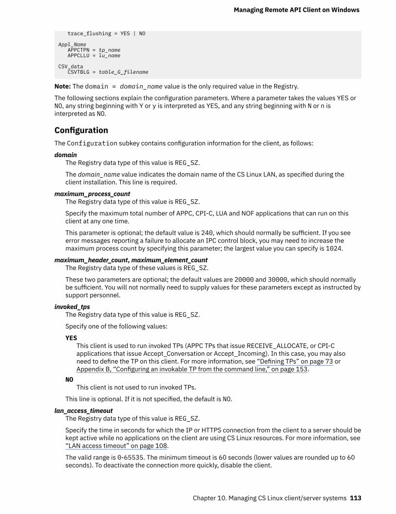
trace_flushing = YES | NO
Appl_Name APPCTPN = tp_name APPCLLU = lu_name
CSV_data CSVTBLG = table_G_filename
Note: The domain = domain_name value is the only required value in the Registry.
The following sections explain the configuration parameters. Where a parameter takes the values YES orNO, any string beginning with Y or y is interpreted as YES, and any string beginning with N or n isinterpreted as NO.
ConfigurationThe Configuration subkey contains configuration information for the client, as follows:
domainThe Registry data type of this value is REG_SZ.
The domain_name value indicates the domain name of the CS Linux LAN, as specified during theclient installation. This line is required.
maximum_process_countThe Registry data type of this value is REG_SZ.
Specify the maximum total number of APPC, CPI-C, LUA and NOF applications that can run on thisclient at any one time.
This parameter is optional; the default value is 240, which should normally be sufficient. If you seeerror messages reporting a failure to allocate an IPC control block, you may need to increase themaximum process count by specifying this parameter; the largest value you can specify is 1024.
maximum_header_count, maximum_element_countThe Registry data type of these values is REG_SZ.
These two parameters are optional; the default values are 20000 and 30000, which should normallybe sufficient. You will not normally need to supply values for these parameters except as instructed bysupport personnel.
invoked_tpsThe Registry data type of this value is REG_SZ.
Specify one of the following values:
YESThis client is used to run invoked TPs (APPC TPs that issue RECEIVE_ALLOCATE, or CPI-Capplications that issue Accept_Conversation or Accept_Incoming). In this case, you may alsoneed to define the TP on this client. For more information, see “Defining TPs” on page 73 orAppendix B, “Configuring an invokable TP from the command line,” on page 153.
NOThis client is not used to run invoked TPs.
This line is optional. If it is not specified, the default is NO.
lan_access_timeoutThe Registry data type of this value is REG_SZ.
Specify the time in seconds for which the IP or HTTPS connection from the client to a server should bekept active while no applications on the client are using CS Linux resources. For more information, see“LAN access timeout” on page 108.
The valid range is 0-65535. The minimum timeout is 60 seconds (lower values are rounded up to 60seconds). To deactivate the connection more quickly, disable the client.
Managing Remote API Client on Windows
Chapter 10. Managing CS Linux client/server systems 113
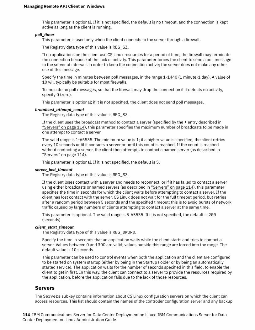
This parameter is optional. If it is not specified, the default is no timeout, and the connection is keptactive as long as the client is running.
poll_timerThis parameter is used only when the client connects to the server through a firewall.
The Registry data type of this value is REG_SZ.
If no applications on the client use CS Linux resources for a period of time, the firewall may terminatethe connection because of the lack of activity. This parameter forces the client to send a poll messageto the server at intervals in order to keep the connection active; the server does not make any otheruse of this message.
Specify the time in minutes between poll messages, in the range 1-1440 (1 minute-1 day). A value of10 will typically be suitable for most firewalls.
To indicate no poll messages, so that the firewall may drop the connection if it detects no activity,specify 0 (zero).
This parameter is optional; if it is not specified, the client does not send poll messages.
broadcast_attempt_countThe Registry data type of this value is REG_SZ.
If the client uses the broadcast method to contact a server (specified by the * entry described in“Servers” on page 114), this parameter specifies the maximum number of broadcasts to be made inone attempt to contact a server.
The valid range is 1-65535. The minimum value is 1; if a higher value is specified, the client retriesevery 10 seconds until it contacts a server or until this count is reached. If the count is reachedwithout contacting a server, the client then attempts to contact a named server (as described in“Servers” on page 114).
This parameter is optional. If it is not specified, the default is 5.
server_lost_timeoutThe Registry data type of this value is REG_SZ.
If the client loses contact with a server and needs to reconnect, or if it has failed to contact a serverusing either broadcasts or named servers (as described in “Servers” on page 114), this parameterspecifies the time in seconds for which the client waits before attempting to contact a server. If theclient has lost contact with the server, CS Linux does not wait for the full timeout period, but retriesafter a random period between 5 seconds and the specified timeout; this is to avoid bursts of networktraffic caused by large numbers of clients attempting to contact a server at the same time.
This parameter is optional. The valid range is 5-65535. If it is not specified, the default is 200(seconds).
client_start_timeoutThe Registry data type of this value is REG_DWORD.
Specify the time in seconds that an application waits while the client starts and tries to contact aserver. Values between 0 and 300 are valid; values outside this range are forced into the range. Thedefault value is 10 seconds.
This parameter can be used to control events when both the application and the client are configuredto be started on system startup (either by being in the Startup Folder or by being an automaticallystarted service). The application waits for the number of seconds specified in this field, to enable theclient to get in first. In this way, the client can connect to a server to provide the resources required bythe application, before the application fails due to the lack of those resources.
ServersThe Servers subkey contains information about CS Linux configuration servers on which the client canaccess resources. This list should contain the names of the controller configuration server and any backup
Managing Remote API Client on Windows
114 IBM Communications Server for Data Center Deployment on Linux: IBM Communications Server for DataCenter Deployment on Linux Administration Guide
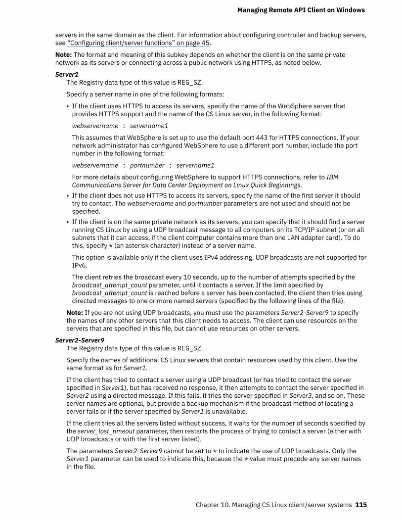
servers in the same domain as the client. For information about configuring controller and backup servers,see “Configuring client/server functions” on page 45.
Note: The format and meaning of this subkey depends on whether the client is on the same privatenetwork as its servers or connecting across a public network using HTTPS, as noted below.
Server1The Registry data type of this value is REG_SZ.
Specify a server name in one of the following formats:
• If the client uses HTTPS to access its servers, specify the name of the WebSphere server thatprovides HTTPS support and the name of the CS Linux server, in the following format:
webservername : servername1
This assumes that WebSphere is set up to use the default port 443 for HTTPS connections. If yournetwork administrator has configured WebSphere to use a different port number, include the portnumber in the following format:
webservername : portnumber : servername1
For more details about configuring WebSphere to support HTTPS connections, refer to IBMCommunications Server for Data Center Deployment on Linux Quick Beginnings.
• If the client does not use HTTPS to access its servers, specify the name of the first server it shouldtry to contact. The webservername and portnumber parameters are not used and should not bespecified.
• If the client is on the same private network as its servers, you can specify that it should find a serverrunning CS Linux by using a UDP broadcast message to all computers on its TCP/IP subnet (or on allsubnets that it can access, if the client computer contains more than one LAN adapter card). To dothis, specify * (an asterisk character) instead of a server name.
This option is available only if the client uses IPv4 addressing. UDP broadcasts are not supported forIPv6.
The client retries the broadcast every 10 seconds, up to the number of attempts specified by thebroadcast_attempt_count parameter, until it contacts a server. If the limit specified bybroadcast_attempt_count is reached before a server has been contacted, the client then tries usingdirected messages to one or more named servers (specified by the following lines of the file).
Note: If you are not using UDP broadcasts, you must use the parameters Server2-Server9 to specifythe names of any other servers that this client needs to access. The client can use resources on theservers that are specified in this file, but cannot use resources on other servers.
Server2-Server9The Registry data type of this value is REG_SZ.
Specify the names of additional CS Linux servers that contain resources used by this client. Use thesame format as for Server1.
If the client has tried to contact a server using a UDP broadcast (or has tried to contact the serverspecified in Server1), but has received no response, it then attempts to contact the server specified inServer2 using a directed message. If this fails, it tries the server specified in Server3, and so on. Theseserver names are optional, but provide a backup mechanism if the broadcast method of locating aserver fails or if the server specified by Server1 is unavailable.
If the client tries all the servers listed without success, it waits for the number of seconds specified bythe server_lost_timeout parameter, then restarts the process of trying to contact a server (either withUDP broadcasts or with the first server listed).
The parameters Server2-Server9 cannot be set to * to indicate the use of UDP broadcasts. Only theServer1 parameter can be used to indicate this, because the * value must precede any server namesin the file.
Managing Remote API Client on Windows
Chapter 10. Managing CS Linux client/server systems 115
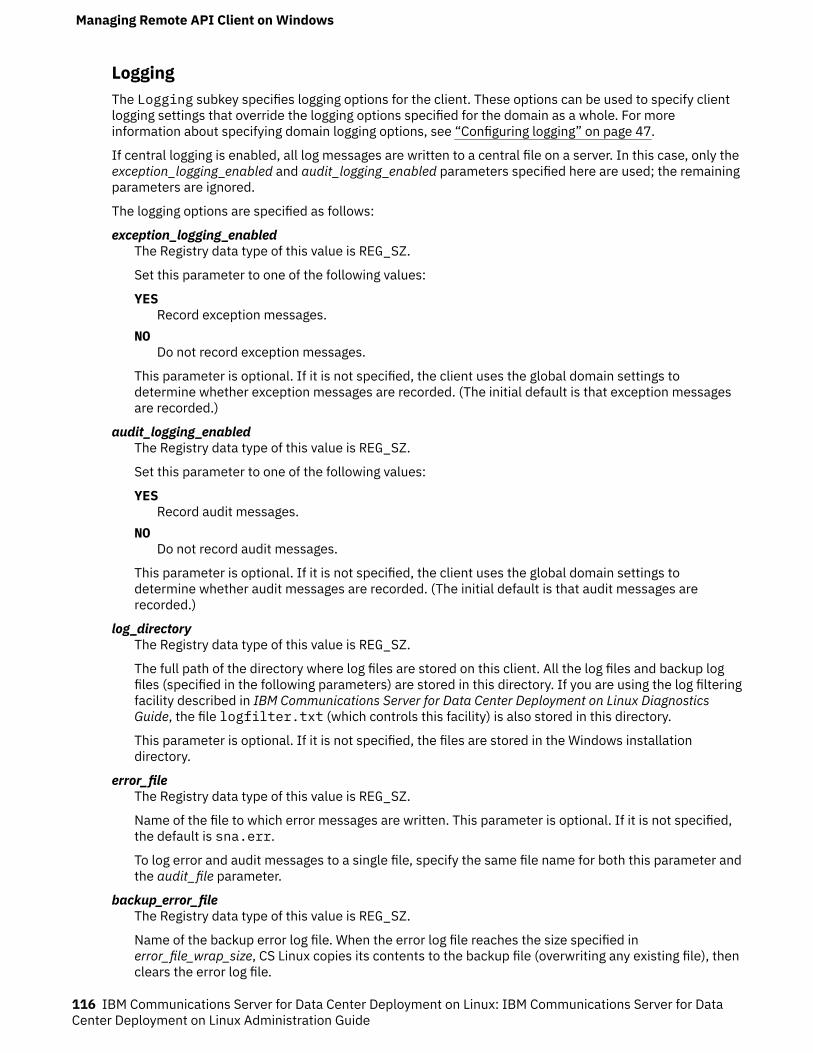
LoggingThe Logging subkey specifies logging options for the client. These options can be used to specify clientlogging settings that override the logging options specified for the domain as a whole. For moreinformation about specifying domain logging options, see “Configuring logging” on page 47.
If central logging is enabled, all log messages are written to a central file on a server. In this case, only theexception_logging_enabled and audit_logging_enabled parameters specified here are used; the remainingparameters are ignored.
The logging options are specified as follows:
exception_logging_enabledThe Registry data type of this value is REG_SZ.
Set this parameter to one of the following values:
YESRecord exception messages.
NODo not record exception messages.
This parameter is optional. If it is not specified, the client uses the global domain settings todetermine whether exception messages are recorded. (The initial default is that exception messagesare recorded.)
audit_logging_enabledThe Registry data type of this value is REG_SZ.
Set this parameter to one of the following values:
YESRecord audit messages.
NODo not record audit messages.
This parameter is optional. If it is not specified, the client uses the global domain settings todetermine whether audit messages are recorded. (The initial default is that audit messages arerecorded.)
log_directoryThe Registry data type of this value is REG_SZ.
The full path of the directory where log files are stored on this client. All the log files and backup logfiles (specified in the following parameters) are stored in this directory. If you are using the log filteringfacility described in IBM Communications Server for Data Center Deployment on Linux DiagnosticsGuide, the file logfilter.txt (which controls this facility) is also stored in this directory.
This parameter is optional. If it is not specified, the files are stored in the Windows installationdirectory.
error_fileThe Registry data type of this value is REG_SZ.
Name of the file to which error messages are written. This parameter is optional. If it is not specified,the default is sna.err.
To log error and audit messages to a single file, specify the same file name for both this parameter andthe audit_file parameter.
backup_error_fileThe Registry data type of this value is REG_SZ.
Name of the backup error log file. When the error log file reaches the size specified inerror_file_wrap_size, CS Linux copies its contents to the backup file (overwriting any existing file), thenclears the error log file.
Managing Remote API Client on Windows
116 IBM Communications Server for Data Center Deployment on Linux: IBM Communications Server for DataCenter Deployment on Linux Administration Guide
This parameter is optional. If it is not specified, the default is bak.err.
To log error and audit messages to a single file, specify the same file name for both this parameter andthe backup_audit_file parameter.
error_file_wrap_sizeThe Registry data type of this value is REG_DWORD.
The maximum size of the log file specified by error_file. When a message written to the file causes thefile size to exceed this limit, CS Linux copies the current contents of the log file to the backup log file,then clears the log file. This means that the maximum amount of disk space taken up by error log filesis approximately twice the value of the error_file_wrap_size parameter.
This parameter is optional. If it is not specified, the default is 1000000 (bytes). If you are logging errorand audit messages to the same file, this parameter must be set to the same value as theaudit_file_wrap_size parameter.
audit_fileThe Registry data type of this value is REG_SZ.
Name of the file to which audit messages are written. This parameter is optional. If it is not specified,the default is sna.aud.
To log error and audit messages to a single file, specify the same file name for both this parameter andthe error_file parameter.
backup_audit_fileThe Registry data type of this value is REG_SZ.
Name of the backup audit log file. When the audit log file reaches the size specified inaudit_file_wrap_size, CS Linux copies its contents to the backup file (overwriting any existing file),then clears the audit log file.
This parameter is optional. If it is not specified, the default is bak.aud.
To log error and audit messages to a single file, specify the same file name for both this parameter andthe backup_error_file parameter.
audit_file_wrap_sizeThe Registry data type of this value is REG_DWORD.
The maximum size of the log file specified by audit_file. When a message written to the file causes thefile size to exceed this limit, CS Linux copies the current contents of the log file to the backup log fileand clears the log file. This means that the maximum amount of disk space taken up by audit log filesis approximately twice the value of the audit_file_wrap_size parameter.
This parameter is optional. If it is not specified, the default is 1000000 (bytes). If you are logging errorand audit messages to the same file, this parameter must be set to the same value as theerror_file_wrap_size parameter.
succinct_errorsThe Registry data type of this value is REG_SZ.
Specifies whether to use succinct logging or verbose logging in the error log file. This setting applies toboth exception logs and problem logs. You can specify either of the following values:
YESUse succinct logging: each message in the log file contains a summary of the message headerinformation (such as the message number and log type) and the message text string andparameters. To obtain more details of the cause of the log and any action required, you can usethe snahelp utility on a computer running Linux.
NOUse verbose logging: each message in the log file includes a full listing of the message headerinformation, the message text string and parameters, and additional information on the cause ofthe log and any action required.
Managing Remote API Client on Windows
Chapter 10. Managing CS Linux client/server systems 117
This parameter is optional. If it is not specified, the default is taken from the previousset_global_log_type command issued to the controller server (or set using the Motifadministration program). The initial default, before any set_global_log_type command has beenissued, is to use succinct logging.
If you are using central logging, the choice of succinct or verbose logging for messages from allcomputers is determined by the setting of this parameter on the server acting as the central logger;this setting may either be from the set_global_log_type command, or from a set_log_typecommand issued to that server to override the default.
succinct_auditsThe Registry data type of this value is REG_SZ.
Specifies whether to use succinct logging or verbose logging in the audit log file. The permitted valuesand their meanings are the same as for the succinct_errors parameter.
API_tracingThe API_tracing subkey specifies API tracing options for applications running on the client. For moreinformation about tracing, refer to IBM Communications Server for Data Center Deployment on LinuxDiagnostics Guide. The tracing options are specified as follows:
file1The Registry data type of this value is REG_SZ.
The full path name of the trace file, or of the first trace file if tracing is to two files (see the descriptionof the file2 parameter).
This parameter is required if you want to enable API tracing.
file2The Registry data type of this value is REG_SZ.
The full path name of the second trace file. This parameter is optional; to indicate that tracing is to onefile instead of two files, do not include this line.
If both file1 and file2 are specified, tracing is to two files. When the first file reaches the size specifiedby the flip_size parameter, the second file is cleared, and tracing continues to the second file. Whenthis file then reaches the size specified by flip_size, the first file is cleared, and tracing continues to thefirst file. This ensures that tracing can continue for long periods without using excessive disk space;the maximum space required is approximately twice the value of the flip_size parameter.
flip_sizeThe Registry data type of this value is REG_DWORD.
The maximum size of the trace file. If two file names are specified, tracing switches between the twofiles when the current file reaches this size. If only one file name is specified, this parameter isignored; the file size is not limited.
This parameter is optional. If it is not specified, the default is 1000000 (bytes).
truncation_lengthThe Registry data type of this value is REG_DWORD.
The maximum length, in bytes, of the information written to the trace file for each message. If amessage is longer than this, CS Linux writes only the start of the message to the trace file, anddiscards the data beyond truncation_length. This enables you to record the most importantinformation for each message but avoid filling up the file with long messages.
This parameter is optional. If it is not specified, CS Linux does not truncate messages (all the datafrom each message is written to the file).
all_apiThe Registry data type of this value is REG_SZ.
Managing Remote API Client on Windows
118 IBM Communications Server for Data Center Deployment on Linux: IBM Communications Server for DataCenter Deployment on Linux Administration Guide

To trace messages for all APIs, set this parameter to YES. In this case, CS Linux ignores theparameters from appc through nof.
To disable tracing for all APIs, set all_api and all of the parameters from appc through nof to NO.
To trace only messages for specific APIs, set all_api to NO, and use the parameters from appc throughnof to indicate which APIs to trace.
This parameter is optional. If it is not specified, the default is NO.
appcThe Registry data type of this value is REG_SZ.
To trace APPC API messages, set this parameter to YES; otherwise, set it to NO.
This parameter is optional. If it is not specified, the default is NO. If the all_api parameter is set toYES, this parameter is ignored, and APPC messages are traced.
cpicThe Registry data type of this value is REG_SZ.
To trace CPI-C API messages, set this parameter to YES; otherwise, set it to NO.
This parameter is optional. If it is not specified, the default is NO. If the all_api parameter is set toYES, this parameter is ignored, and CPI-C messages are traced.
csvThe Registry data type of this value is REG_SZ.
To trace CSV API messages, set this parameter to YES; otherwise, set it to NO.
This parameter is optional. If it is not specified, the default is NO. If the all_api parameter is set toYES, this parameter is ignored, and CSV messages are traced.
ruiThe Registry data type of this value is REG_SZ.
To trace LUA RUI messages, set this parameter to YES; otherwise, set it to NO.
This parameter is optional. If it is not specified, the default is NO. If the all_api parameter is set toYES, this parameter is ignored, and LUA RUI messages are traced.
nofThe Registry data type of this value is REG_SZ.
To trace NOF API messages, set this parameter to YES; otherwise, set it to NO. NOF messages are notused directly by applications on Windows clients, but are used internally by CS Linux components inobtaining configuration information.
This parameter is optional. If it is not specified, the default is NO. If the all_api parameter is set toYES, this parameter is ignored, and NOF messages are traced.
CS_tracingThe CS_tracing subkey specifies options for client/server tracing (tracing on messages between theclient and CS Linux servers). For more information about tracing, refer to IBM Communications Server forData Center Deployment on Linux Diagnostics Guide. The tracing options are specified as follows:
file1The Registry data type of this value is REG_SZ.
The full path name of the trace file, or of the first trace file if tracing is to two files (see the descriptionof the file2 parameter).
This parameter is required if you want to enable client/server tracing; you also need to set thetrace_flags parameter.
file2The Registry data type of this value is REG_SZ.
Managing Remote API Client on Windows
Chapter 10. Managing CS Linux client/server systems 119

The full path name of the second trace file. This parameter is optional; to indicate that tracing is to onefile instead of two files, do not include this line.
If both file1 and file2 are specified, tracing is to two files. When the first file reaches the size specifiedby the flip_size parameter, the second file is cleared, and tracing continues to the second file. Whenthis file then reaches the size specified by flip_size, the first file is cleared, and tracing continues to thefirst file. This ensures that tracing can continue for long periods without using excessive disk space;the maximum space required is approximately twice the value of the flip_size parameter.
flip_sizeThe Registry data type of this value is REG_DWORD.
The maximum size of the trace file. If two file names are specified, tracing switches between the twofiles when the current file reaches this size. If only one file name is specified, this parameter isignored; the file size is not limited.
This parameter is optional. If it is not specified, the default is 1000000 (bytes).
admin_msgThe Registry data type of this value is REG_SZ.
To trace internal messages relating to client/server topology, set this parameter to YES; otherwise, setit to NO.
This parameter is optional. If it is not specified, the default is NO.
datagramThe Registry data type of this value is REG_SZ.
To trace datagram messages, set this parameter to YES; otherwise, set it to NO.
This parameter is optional. If it is not specified, the default is NO.
dataThe Registry data type of this value is REG_SZ.
To trace data messages, set this parameter to YES; otherwise, set it to NO.
This parameter is optional. If it is not specified, the default is NO.
sendThe Registry data type of this value is REG_SZ.
To trace all data messages sent from the client to the server, set this parameter to YES; otherwise, setit to NO.
This parameter is optional. If it is not specified, the default is NO.
receiveThe Registry data type of this value is REG_SZ.
To trace all data messages received by the client from the server, set this parameter to YES;otherwise, set it to NO.
This parameter is optional. If it is not specified, the default is NO.
Internal_tracingThe Internal_tracing subkey specifies options for tracing the internal operation of the client. Formore information about tracing, refer to IBM Communications Server for Data Center Deployment on LinuxDiagnostics Guide. The tracing options are specified as follows:
file1The Registry data type of this value is REG_SZ.
The full path name of the trace file, or of the first trace file if tracing is to two files (see the descriptionof the file2 parameter).
Managing Remote API Client on Windows
120 IBM Communications Server for Data Center Deployment on Linux: IBM Communications Server for DataCenter Deployment on Linux Administration Guide
This parameter is required if you want to enable internal tracing; you also need to set the trace_levelparameter.
file2The Registry data type of this value is REG_SZ.
The full path name of the second trace file. This parameter is optional; to indicate that tracing is to onefile instead of two files, do not include this line.
If both file1 and file2 are specified, tracing is to two files. When the first file reaches the size specifiedby the flip_size parameter, the second file is cleared, and tracing continues to the second file. Whenthis file then reaches the size specified by flip_size, the first file is cleared, and tracing continues to thefirst file. This ensures that tracing can continue for long periods without using excessive disk space;the maximum space required is approximately twice the value of the flip_size parameter.
flip_sizeThe Registry data type of this value is REG_DWORD.
The maximum size of the trace file. If two file names are specified, tracing switches between the twofiles when the current file reaches this size. If only one file name is specified, this parameter isignored; the file size is not limited.
This parameter is optional. If it is not specified, the default is 1000000 (bytes).
trace_levelThe Registry data type of this value is REG_DWORD.
The level of detail included in the trace. The range of valid values is from 0 (all tracing) to 20 (notracing).
This parameter is optional. If it is not specified, the default is 20 (no tracing).
trace_flushingThe Registry data type of this value is REG_SZ.
If this parameter is set to YES, each trace statement is flushed to disk immediately. This slowsoperation considerably, but ensures that trace data is not lost if a crash occurs.
This parameter is optional. If it is not specified, the default is NO.
Appl_NameThe Appl_Name subkey specifies options for a CPI-C application.
Note: These options can be specified either in environment variables or in the registry. CS Linux checksthe environment variable first, and uses this information if it is specified; it uses the registry entry only ifthe environment variable is not specified. You may need to use environment variables if you are usingWindows Terminal Server and need to run multiple copies of the same application using different localLUs.
To set these options in the registry for one or more applications, include a section in this format for eachapplication, and replace the Appl_Name variable with the application program's executable name (notincluding the .exe file name extension).
For more information about CPI-C, refer to IBM Communications Server for Data Center Deployment on AIXor Linux CPI-C Programmer's Guide.
The options are specified as follows:
APPCLLUThis option can be specified using the APPCLLU environment variable instead of in the registry.
The Registry data type of this value is REG_SZ.
The name of the local LU that this application uses.
This parameter is optional. If it is not specified, the application attempts to use the default LU (the LUassociated with a local node's control point).
Managing Remote API Client on Windows
Chapter 10. Managing CS Linux client/server systems 121
APPCTPNThis option can be specified using the APPCTPN environment variable instead of in the registry.
The Registry data type of this value is REG_SZ.
The TP name of the application. This name is used in log and trace files to identify the application. Foran invoked application (one that issues Accept_Conversation), it is also used to match the TP name onan incoming Allocate request with the correct application; the invoked application can also use theSpecify_Local_TP_Name call to specify additional names to be matched with incoming Allocaterequests.
This parameter is optional. If it is not specified, the default is CPIC_DEFAULT_TPNAME.
CSV_dataThe CSV_data subkey specifies options for applications that use the CSV interface. It applies only toapplications that use the CONVERT verb to perform character conversion with a user-defined conversiontable (Table G). For more information about the CONVERT verb, refer to IBM Communications Server forData Center Deployment on AIX or Linux CSV Programmer's Guide.
If no applications on the client use this function, you do not need to include this section.
The only option in this section is as follows:
CSVTBLGThe Registry data type of this value is REG_SZ.
The full path name of the file containing the user-defined Table G conversion table. This parameter isrequired if CSV applications need to perform Table G character conversion (there is no default);otherwise it is optional.
Tracking SNA LU resources used by clients on a domain of serversAn APPC application may require two or more conversations with its partner application in order tocomplete a task, especially if the partner application cannot complete its processing immediately. Forexample, application A sends data to application B for processing that will take some time to complete,and terminates without waiting for the results. At a later time, when it has completed the processing,application B starts a new conversation with application A to return the results.
If an application that operates in this way runs on two or more clients, CS Linux needs to ensure that thenew conversation is routed back to the original client that made the request. In particular, if the clientapplication uses LUs in an LU pool, it needs to maintain an association with the LU that it used for theoriginal request, so that the new conversation can be routed from this LU to the correct client application.
In order to use this function, you need to set the CLI_OVERWRITE_SYS_NAME option in the ptf_flagsparameter of the define_node command for the node that owns the LU pool. Then use a standard texteditor to create a file named tpnamehost, in the directory where the client software is installed. The filecan be empty: CS Linux only checks whether the file exists, and does not take any notice of the contents.
If the tpnamehostfile exists on the client:
• CS Linux modifies the sys_name of the LU used by the application to match this IP hostname. Thisensures that, when the partner application requests a new conversation using this LU, CS Linux willconnect it with the application running on the specified client (the application that made the originalrequest using this LU).
• CS Linux also takes the TP name specified by the application, and appends a % character followed by theIP hostname of the client computer. This modified TP name string is then used in logging and tracing forthe application running on this client, so that you can distinguish between two or more copies of theapplication on different clients.
Note: When you create the tpnamehost file on the client, ensure that there is not already a file namedtpnameipv4 in the same location. (The use of this file is described in “Overriding the local TP Name todistinguish between TPs running on different clients” on page 124.) If both files exist, the
Managing Remote API Client on Windows
122 IBM Communications Server for Data Center Deployment on Linux: IBM Communications Server for DataCenter Deployment on Linux Administration Guide

tpnameipv4file takes precedence: CS Linux appends the IP address and not the IP hostname, and doesnot create an association between the client application and its LU.
Mapping hard-coded LU aliases on Client applications to LU aliases in adomain of servers
If you are running the same APPC, CPI-C or LUA application on two or more Remote API Clients onWindows, you may need to override the local LU alias, LUA LU name or TP name that it specifies. Thisallows you to assign two or more copies of the application to use different local LUs without changing theapplication, or to distinguish between two or more copies of the same application. (For information aboutthe equivalent function on a Remote API Client on AIX or Linux, see “Mapping hard-coded LU aliases onClient applications to LU aliases in a domain of servers” on page 128.)
The lualiasmap.txt file on a Remote API Client on Windows defines a mapping between the LUspecified by an application running on this client and the actual LU that the application should use. Thisallows you to run the same application on two or more clients and force them to use different LUs.
• For an APPC application, it maps between the local LU alias specified by the application on theTP_STARTED verb and the local LU that the application on this client should use.
• For a CPI-C application, it maps between the local LU alias (which may be specified by the applicationusing Set_Local_LU_Name, or taken from the CPI-C configuration) and the local LU that the applicationon this client should use.
• For an LUA application, it maps between the lua_luname parameter specified by the application on theRUI_INIT or RUI_INIT_PRIMARY verb and the LU of type 0-3 that the application on this client shoulduse. This mapping has no effect if the application uses the extended form of RUI_INIT, in which itidentifies the LU by its PU name and LU number rather than by its LU name.
If you need to use this function, use a standard text editor to create an ASCII text file named lualiasmap.txt, in the directory where the client software is installed.
Each line of the file contains two 8-character strings separated by a single space. The first string muststart in column 1, and is the local LU alias or LUA LU name specified by the application (padded withspaces if it is shorter than 8 characters). The second string must start in column 10 (after the first 8-character string followed by a space), and is the actual local LU or LU of type 0-3 that the application onthis client should use. The file can contain a maximum of 256 lines (the previous version of the Windowsclient had a maximum of 64), this allows for a full PU of 255 LUs to be mapped.
The following is an example mapping file.
MyAppLU1 APPCLu5MyAppLU2 APPCLu6LUALU3 NewLUA11LUALU4 NewLUA12
In this example:
• An APPC or CPI-C application running on this client that specifies the local LU alias MyAppLU1 orMyAppLU2 will be mapped to use the actual local LU with lu_alias APPCLu5 or APPCLu6.
• An LUA application running on this client that specifies the LU name LUALU3 or LUALU4 will be mappedto use the actual LU of type 0-3 named NewLUA11 or NewLUA12. Note the additional spaces in thesetwo entries, because the LU name specified by the application is shorter than 8 characters.
In addition, the following characters can be used in the lualiasmap.txt file:
• + character - Some legacy LUA applications (such as LANDP) ignore the returned session_id and thereturned LU on an RUI_INIT() response. When this happens, the mapping does not take effect. If thefirst line of the lualiasmap.txt file contains a + character in position 1 then the LU mapping will beapplied to all RUI_*() verbs issues by the application (not just the RUI_INIT()).
Managing Remote API Client on Windows
Chapter 10. Managing CS Linux client/server systems 123
• * character - Wildcard suffices can be specified in the lualiasmap.txt file. Multiple LU aliases can bemapped to a single LU (or pool) name using an * in the first string, for example a line like
pref* LUALU
maps any alias started with pref to that single LU. Multiple aliases can also be mapped using * in bothpositions, for example a line like
alias* LUNAM*
will map alias01 to LUALU01 or alias7 to LUALU7 etc. Prefixes can be different lengths as long asthe names are limited to 8 characters. A * in the second position only is not supported.
• - character - When an application attempts to open a session using an LU alias that is not recognised onthe server (or indeed any server), the RUI_INIT() verb will be transmitted from the client to the serverand the error returned to the client. In some cases the application will retry and do not with severalunrecognised LU aliases. This causes unnecessary traffic and CPU utilization. If a - is placed in column10 (instead of the second string) this can be prevented. This can be used together with the * wildcardsyntax,.for example a file like
alias1 alias1alias2 alias2* -
allows only the two aliases alias1 and alias2 to be sent to the server (the mapping can be a no-op asin this example). An RUI_INIT() or TP_STARTED() specifying any other alias would be rejected from theclient library code without sending the message to the server
Overriding the local TP Name to distinguish between TPs running on differentclientsThe tpnameipv4 file on a Remote API Client on Windows instructs CS Linux to modify the TP namespecified by an APPC or CPI-C application running on the client, so that each client uses a unique TPname (distinguished by its IPv4 address). This allows you to run the same application on two or moreclients and force them to use different TP names so that you can distinguish between them. (The TP namespecified by the application is used only as a local identifier and does not need to match any parameter inthe CS Linux configuration, so the application runs in the same way as it would with its original TP name.)
• For an APPC application, the TP name is specified by the application on the TP_STARTED verb.• For a CPI-C application, the TP name may be specified by the application using Specify_Local_TP_Name
or Set_CPIC_Side_Information, or taken from the CPI-C configuration.
If you need to use this function, use a standard text editor to create a file named tpnameipv4, in thedirectory where the client software is installed. The file can be empty: CS Linux only checks whether thefile exists, and does not take any notice of the contents.
If the tpnameipv4file exists on the client, CS Linux takes the TP name specified by the application, andappends an underscore character followed by the IP address of the client computer. This modified TPname string is then used in logging and tracing for the application running on this client, so that you candistinguish between two or more copies of the application on different clients.
Managing Remote API Clients on AIX or Linux
The Remote API Client can run on AIX, Linux, Linux for Power, or Linux for IBM Z.
Client information for a Remote API Client on AIX or Linux is stored in the sna_clnt.net file, which iscreated when you install the SNA software on the client. That file must be present before you can enablethe client software.
Managing Remote API Clients on AIX or Linux
124 IBM Communications Server for Data Center Deployment on Linux: IBM Communications Server for DataCenter Deployment on Linux Administration Guide
Note: If the client uses HTTPS to access its servers, you will need to modify the sna_clnt.net file tospecify the names of these servers and the WebSphere server providing HTTPS access to them before youcan use the client. See “Client network data file (sna_clnt.net)” on page 125 for more information.
Enabling and disabling Remote API Clients on AIX or LinuxTo enable the Remote API Client software on AIX or Linux, enter the following command at the commandprompt:
sna start [ -t ]
When you install the client, the installation utility automatically updates the startup file /etc/rc.sna(AIX) or /etc/rc.d/init.d/snastart (Linux) to include the sna start command. This ensures thatthe client is started automatically at system startup. If you do not want it to be started automatically, youcan remove or comment out this line, and then follow the instructions in this section to enable thesoftware manually.
The only option is as follows:
-tActivates client/server tracing. This enables you to diagnose problems that occur during the client'sattempt to connect to a server. If you do not use this option, client/server tracing is inactive at allinterfaces; you can then activate it as required, using the command-line administration programsnaadmin.
This option is equivalent to selecting the Set all tracing on field in the Motif administration program,except that it does not enable DLC tracing.
Tracing degrades the performance of CS Linux components. After the software is enabled, you can usethe command-line administration program snaadmin to stop tracing when it is no longer required. Formore information about tracing, refer to IBM Communications Server for Data Center Deployment onLinux Diagnostics Guide.
To stop the Remote API Client, enter the following command at the command prompt:
sna stop
Client network data file (sna_clnt.net)The sna_clnt.net file defines the CS Linux facilities available on a Remote API Client on AIX or Linux,and the servers the client can access. (For information about the equivalent file on a Windows client, seeChapter 10, “Managing CS Linux client/server systems,” on page 105.)
It also includes information about setting up the IP port numbers that CS Linux uses for client/servercommunications. The default port numbers should be suitable in most cases; you need to refer to thisinformation only if CS Linux logs error messages indicating that there is a port number clash with anotherprogram on the same computer.
A client computer does not hold a copy of the domain configuration file or the SNA network data file; itholds only the information it needs to access servers on the CS Linux LAN, and relies on a server toprovide the necessary configuration information.
The SNA network information required is held in the file sna_clnt.net, which is stored in thedirectory /etc/sna on AIX or /etc/opt/ibm/sna on Linux. This file is set up during the clientinstallation process; it is an ASCII text file that can be modified later as required using a standard texteditor.
Note: After changing the parameters in this file, you need to stop and restart the client before yourchanges take effect. For details of how to do this, see “Enabling and disabling Remote API Clients on AIXor Linux” on page 125.
Managing Remote API Clients on AIX or Linux
Chapter 10. Managing CS Linux client/server systems 125
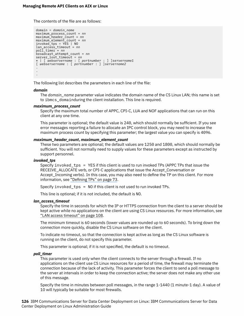
The contents of the file are as follows:
domain = domain_namemaximum_process_count = nnmaximum_header_count = nnmaximum_element_count = nninvoked_tps = YES | NOlan_access_timeout = nnpoll_timer = nnbroadcast_attempt_count = nnserver_lost_timeout = nn* | [ webservername : [ portnumber : ] ]servername1[ webservername : [ portnumber : ] ]servername2...
The following list describes the parameters in each line of the file:
domainThe domain_name parameter value indicates the domain name of the CS Linux LAN; this name is setto ibmcs_domainduring the client installation. This line is required.
maximum_process_countSpecify the maximum total number of APPC, CPI-C, LUA and NOF applications that can run on thisclient at any one time.
This parameter is optional; the default value is 240, which should normally be sufficient. If you seeerror messages reporting a failure to allocate an IPC control block, you may need to increase themaximum process count by specifying this parameter; the largest value you can specify is 4096.
maximum_header_count, maximum_element_countThese two parameters are optional; the default values are 1250 and 1800, which should normally besufficient. You will not normally need to supply values for these parameters except as instructed bysupport personnel.
invoked_tpsSpecify invoked_tps = YES if this client is used to run invoked TPs (APPC TPs that issue theRECEIVE_ALLOCATE verb, or CPI-C applications that issue the Accept_Conversation orAccept_Incoming verbs). In this case, you may also need to define the TP on this client. For moreinformation, see “Defining TPs” on page 73.
Specify invoked_tps = NO if this client is not used to run invoked TPs.
This line is optional; if it is not included, the default is NO.
lan_access_timeoutSpecify the time in seconds for which the IP or HTTPS connection from the client to a server should bekept active while no applications on the client are using CS Linux resources. For more information, see“LAN access timeout” on page 108.
The minimum timeout is 60 seconds (lower values are rounded up to 60 seconds). To bring down theconnection more quickly, disable the CS Linux software on the client.
To indicate no timeout, so that the connection is kept active as long as the CS Linux software isrunning on the client, do not specify this parameter.
This parameter is optional; if it is not specified, the default is no timeout.
poll_timerThis parameter is used only when the client connects to the server through a firewall. If noapplications on the client use CS Linux resources for a period of time, the firewall may terminate theconnection because of the lack of activity. This parameter forces the client to send a poll message tothe server at intervals in order to keep the connection active; the server does not make any other useof this message.
Specify the time in minutes between poll messages, in the range 1-1440 (1 minute-1 day). A value of10 will typically be suitable for most firewalls.
Managing Remote API Clients on AIX or Linux
126 IBM Communications Server for Data Center Deployment on Linux: IBM Communications Server for DataCenter Deployment on Linux Administration Guide
To indicate no poll messages, so that the firewall may drop the connection if it detects no activity,specify 0 (zero).
This parameter is optional; if it is not specified, the client does not send poll messages.
broadcast_attempt_countIf the client uses the broadcast method to contact a server (specified by * instead of the first servername), this parameter specifies the maximum number of broadcasts to be made in one attempt tocontact a server. The minimum value is 1; if a higher value is specified, the client retries every 10seconds until it contacts a server or until this count is reached. If the count is reached withoutcontacting a server, the client then attempts to contact a named server.
This parameter is optional; if it is not specified, the default is 5.
server_lost_timeoutIf the client loses contact with a server and needs to reconnect, or if it has failed to contact a serverusing either broadcasts or named servers, this parameter specifies the time in seconds for which theclient waits before beginning or restarting the attempt to contact a server. If the client has lost contactwith the server, CS Linux does not wait for the full timeout period, but retries after a random periodbetween 5 seconds and the specified timeout; this is to avoid bursts of network traffic caused by largenumbers of clients attempting to contact a server at the same time.
This parameter is optional; if it is not specified, the default is 200 seconds.
server namesSpecify the names of one or more CS Linux servers that contain resources used by this client. This listshould contain the names of the controller configuration server and any backup servers in the samedomain as the client. For information about configuring controller and backup servers, see“Configuring client/server functions” on page 45. It must also contain the names of any other serversthat this client needs to access. The client can use resources on the specified servers, but cannot useresources on other servers.
Enter the server names in one of the following formats:
• If the client uses HTTPS to access its servers, specify the name of the WebSphere server thatprovides HTTPS support and the name of the CS Linux server, in the following format:
webservername : servername1
This assumes that WebSphere is set up to use the default port 443 for HTTPS connections. If yournetwork administrator has configured WebSphere to use a different port number, include the portnumber in the following format:
webservername : portnumber : servername1
For more details about configuring WebSphere to support HTTPS connections, refer to IBMCommunications Server for Data Center Deployment on Linux Quick Beginnings.
• If the client does not use HTTPS to access its servers, specify the name of the first server it shouldtry to contact. The webservername and portnumber parameters are not used and should not bespecified.
• If the client is on the same private network as its servers, you can specify that it should find a serverrunning CS Linux by using a UDP broadcast message to all computers on its TCP/IP subnet (or on allsubnets that it can access, if the client computer contains more than one LAN adapter card). To dothis, specify * (an asterisk character) instead of the first server name.
This option is available only if the client uses IPv4 addressing. UDP broadcasts are not supported forIPv6.
The client retries the broadcast every 10 seconds, up to the number of attempts specified by thebroadcast_attempt_count parameter, until it contacts a server. If the limit specified bybroadcast_attempt_count is reached before a server has been contacted, the client then tries usingdirected messages to one or more named servers (specified by the following lines of the file).
Managing Remote API Clients on AIX or Linux
Chapter 10. Managing CS Linux client/server systems 127
Note: If you are not using UDP broadcasts, you must specify the names of all servers that this clientneeds to access. The client can use resources on the servers that are specified in this file, but cannotuse resources on other servers.
If the client tries all the servers listed without success, it waits for the time specified byserver_lost_timeout above, and then restarts the process of trying to contact a server (either with UDPbroadcasts or with the first server listed).
In addition to the sna_clnt.net, an additional file server.current is stored in the same directory(/var/sna on AIX or /var/opt/ibm/sna on Linux). This is a text file containing the name of the server,if any, to which the client is currently connected. You can check this file to determine which server isacting as the client's connection point into the domain.
Tracking SNA LU resources used by clients on a domain of serversAn APPC application may require two or more conversations with its partner application in order tocomplete a task, especially if the partner application cannot complete its processing immediately. Forexample, application A sends data to application B for processing that will take some time to complete,and terminates without waiting for the results. At a later time, when it has completed the processing,application B starts a new conversation with application A to return the results.
If an application that operates in this way runs on two or more clients, CS Linux needs to ensure that thenew conversation is routed back to the original client that made the request. In particular, if the clientapplication uses LUs in an LU pool, it needs to maintain an association with the LU that it used for theoriginal request, so that the new conversation can be routed from this LU to the correct client application.
In order to use this function, you need to set the CLI_OVERWRITE_SYS_NAME option in the ptf_flagsparameter of the define_node command for the node that owns the LU pool. Then use a standard texteditor to create a file named tpnamehost, in the directory /etc/sna on AIX or /etc/opt/ibm/sna onLinux. The file can be empty: CS Linux only checks whether the file exists, and does not take any notice ofthe contents.
If the tpnamehostfile exists on the client:
• CS Linux modifies the sys_name of the LU used by the application to match this IP hostname. Thisensures that, when the partner application requests a new conversation using this LU, CS Linux willconnect it with the application running on the specified client (the application that made the originalrequest using this LU).
• CS Linux also takes the TP name specified by the application, and appends a % (percentage sign)character followed by the IP hostname of the client computer. This modified TP name string is thenused in logging and tracing for the application running on this client, so that you can distinguishbetween two or more copies of the application on different clients.
Note: When you create the tpnamehost file on the client, ensure that there is not already a file namedtpnameipv4 in the same location. (The use of this file is described in “Overriding the local TP name todistinguish between TPs running on different clients” on page 130.) If both files exist, thetpnameipv4file takes precedence: CS Linux appends the IP address and not the IP hostname, and doesnot create an association between the client application and its LU.
Mapping hard-coded LU aliases on Client applications to LU aliases in adomain of servers
If you are running the same APPC, CPI-C or LUA application on two or more Remote API Clients on AIX orLinux, you may need to override the local LU alias, LUA LU name or TP name that it specifies. This allowsyou to assign two or more copies of the application to use different local LUs without changing theapplication, or to distinguish between two or more copies of the same application. (For information aboutthe equivalent function on a Windows client, see “Mapping hard-coded LU aliases on Client applicationsto LU aliases in a domain of servers” on page 123.)
Managing Remote API Clients on AIX or Linux
128 IBM Communications Server for Data Center Deployment on Linux: IBM Communications Server for DataCenter Deployment on Linux Administration Guide
The lualiasmap.txt file on a Remote API Client on AIX or Linux defines a mapping between the LUspecified by an application running on this client and the actual LU that the application should use. Thisallows you to run the same application on two or more clients and force them to use different LUs.
• For an APPC application, it maps between the local LU alias specified by the application on theTP_STARTED verb and the local LU that the application on this client should use.
• For a CPI-C application, it maps between the local LU alias (which may be specified by the applicationusing Set_Local_LU_Name, or taken from the CPI-C configuration) and the local LU that the applicationon this client should use.
• For an LUA application, it maps between the lua_luname parameter specified by the application on theRUI_INIT or RUI_INIT_PRIMARY verb and the LU of type 0-3 that the application on this client shoulduse. This mapping has no effect if the application uses the extended form of RUI_INIT, in which itidentifies the LU by its PU name and LU number rather than by its LU name.
If you need to use this function, use a standard text editor to create an ASCII text file namedlualiasmap.txt, in the directory /etc/sna on AIX or /etc/opt/ibm/sna on Linux.
Each line of the file contains two 8-character strings separated by a single space. The first string muststart in column 1, and is the local LU alias or LUA LU name specified by the application (padded withspaces if it is shorter than 8 characters). The second string must start in column 10 (after the first 8-character string followed by a space), and is the actual local LU or LU of type 0-3 that the application onthis client should use. The file can contain a maximum of 256 lines (the previous version of the Unix clienthad a maximum of 64), this allows for a full PU of 255 LUs to be mapped.
The following is an example mapping file.
MyAppLU1 APPCLu5MyAppLU2 APPCLu6LUALU3 NewLUA11LUALU4 NewLUA12
In this example:
• An APPC or CPI-C application running on this client that specifies the local LU alias MyAppLU1 orMyAppLU2 will be mapped to use the actual local LU with lu_alias APPCLu5 or APPCLu6.
• An LUA application running on this client that specifies the LU name LUALU3 or LUALU4 will be mappedto use the actual LU of type 0-3 named NewLUA11 or NewLUA12. Note the additional spaces in thesetwo entries, because the LU name specified by the application is shorter than 8 characters.
In addition, the following characters can be used in the lualiasmap.txt file:
• + character - Some legacy LUA applications (such as LANDP) ignore the returned session_id and thereturned LU on an RUI_INIT() response. When this happens, the mapping does not take effect. If thefirst line of the lualiasmap.txt file contains a + character in position 1 then the LU mapping will beapplied to all RUI_*() verbs issues by the application (not just the RUI_INIT()).
• * character - Wildcard suffices can be specified in the lualiasmap.txt file. Multiple LU aliases can bemapped to a single LU (or pool) name using an * in the first string, for example a line like
pref* LUALU
maps any alias started with pref to that single LU. Multiple aliases can also be mapped using * in bothpositions, for example a line like
alias* LUNAM*
will map alias01 to LUALU01 or alias7 to LUALU7 etc. Prefixes can be different lengths as long asthe names are limited to 8 characters. A * in the second position only is not supported.
• - character - When an application attempts to open a session using an LU alias that is not recognised onthe server (or indeed any server), the RUI_INIT() verb will be transmitted from the client to the serverand the error returned to the client. In some cases the application will retry and do not with severalunrecognised LU aliases. This causes unnecessary traffic and CPU utilization. If a - is placed in column
Managing Remote API Clients on AIX or Linux
Chapter 10. Managing CS Linux client/server systems 129
10 (instead of the second string) this can be prevented. This can be used together with the * wildcardsyntax,.for example a file like
alias1 alias1alias2 alias2* -
allows only the two aliases alias1 and alias2 to be sent to the server (the mapping can be a no-op asin this example). An RUI_INIT() or TP_STARTED() specifying any other alias would be rejected from theclient library code without sending the message to the server
Overriding the local TP name to distinguish between TPs running on differentclientsThe tpnameipv4 file on a Remote API Client on AIX or Linux instructs CS Linux to modify the TP namespecified by an APPC or CPI-C application running on the client, so that each client uses a unique TPname (distinguished by its IPv4 address). This allows you to run the same application on two or moreclients and force them to use different TP names so that you can distinguish between them. (The TP namespecified by the application is used only as a local identifier and does not need to match any parameter inthe CS Linux configuration, so the application runs in the same way as it would with its original TP name.)
• For an APPC application, the TP name is specified by the application on the TP_STARTED verb.• For a CPI-C application, the TP name may be specified by the application using Specify_Local_TP_Name
or Set_CPIC_Side_Information, or taken from the CPI-C configuration.
If you need to use this function, use a standard text editor to create a file named tpnameipv4, in thedirectory /etc/sna on AIX or /etc/opt/ibm/sna on Linux. The file can be empty: CS Linux only checkswhether the file exists, and does not take any notice of the contents.
If the tpnameipv4file exists on the client, CS Linux takes the TP name specified by the application, andappends an underscore character followed by the IP address of the client computer. This modified TPname string is then used in logging and tracing for the application running on this client, so that you candistinguish between two or more copies of the application on different clients.
Defining Client TPsFor information about defining TPs on a Remote API Client system, see “Defining TPs” on page 73 orAppendix B, “Configuring an invokable TP from the command line,” on page 153.
Defining Client TPs
130 IBM Communications Server for Data Center Deployment on Linux: IBM Communications Server for DataCenter Deployment on Linux Administration Guide
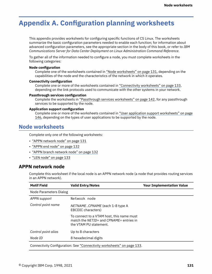
Appendix A. Configuration planning worksheets
This appendix provides worksheets for configuring specific functions of CS Linux. The worksheetssummarize the basic configuration parameters needed to enable each function; for information aboutadvanced configuration parameters, see the appropriate section in the body of this book, or refer to IBMCommunications Server for Data Center Deployment on Linux Administration Command Reference.
To gather all of the information needed to configure a node, you must complete worksheets in thefollowing categories:
Node configurationComplete one of the worksheets contained in “Node worksheets” on page 131, depending on thecapabilities of the node and the characteristics of the network in which it operates.
Connectivity configurationComplete one or more of the worksheets contained in “Connectivity worksheets” on page 133,depending on the link protocols used to communicate with the other systems in your network.
Passthrough services configurationComplete the worksheets in “Passthrough services worksheets” on page 142, for any passthroughservices to be supported by the node.
Application support configurationComplete one or more of the worksheets contained in “User application support worksheets” on page146, depending on the types of user applications to be supported by the node.
Node worksheetsComplete only one of the following worksheets:
• “APPN network node” on page 131• “APPN end node” on page 132• “APPN branch network node” on page 132• “LEN node” on page 133
APPN network nodeComplete this worksheet if the local node is an APPN network node (a node that provides routing servicesin an APPN network).
Motif Field Valid Entry/Notes Your Implementation Value
Node Parameters Dialog
APPN support Network node
Control point name NETNAME.CPNAME (each 1-8 type AEBCDIC characters)
To connect to a VTAM host, this name mustmatch the NETID= and CPNAME= entries inthe VTAM PU statement.
Control point alias Up to 8 characters
Node ID 8 hexadecimal digits
Connectivity Configuration: See “Connectivity worksheets” on page 133.
Node worksheets
© Copyright IBM Corp. 1998, 2021 131
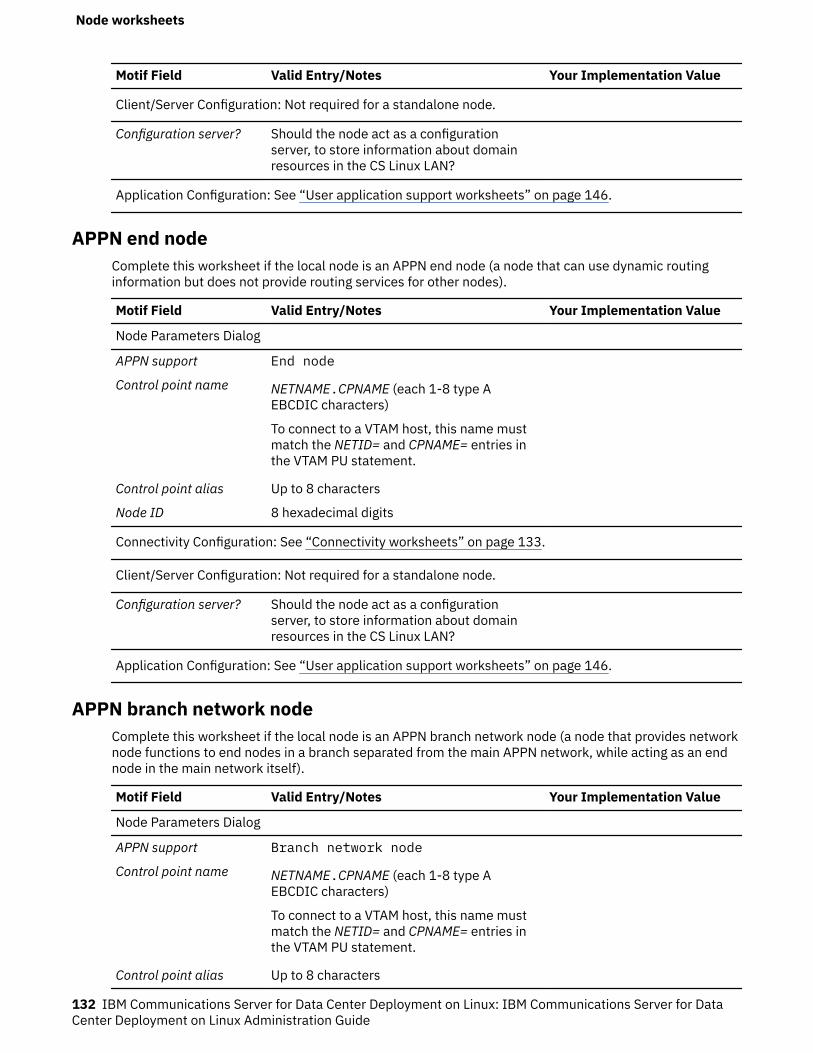
Motif Field Valid Entry/Notes Your Implementation Value
Client/Server Configuration: Not required for a standalone node.
Configuration server? Should the node act as a configurationserver, to store information about domainresources in the CS Linux LAN?
Application Configuration: See “User application support worksheets” on page 146.
APPN end nodeComplete this worksheet if the local node is an APPN end node (a node that can use dynamic routinginformation but does not provide routing services for other nodes).
Motif Field Valid Entry/Notes Your Implementation Value
Node Parameters Dialog
APPN support End node
Control point name NETNAME.CPNAME (each 1-8 type AEBCDIC characters)
To connect to a VTAM host, this name mustmatch the NETID= and CPNAME= entries inthe VTAM PU statement.
Control point alias Up to 8 characters
Node ID 8 hexadecimal digits
Connectivity Configuration: See “Connectivity worksheets” on page 133.
Client/Server Configuration: Not required for a standalone node.
Configuration server? Should the node act as a configurationserver, to store information about domainresources in the CS Linux LAN?
Application Configuration: See “User application support worksheets” on page 146.
APPN branch network nodeComplete this worksheet if the local node is an APPN branch network node (a node that provides networknode functions to end nodes in a branch separated from the main APPN network, while acting as an endnode in the main network itself).
Motif Field Valid Entry/Notes Your Implementation Value
Node Parameters Dialog
APPN support Branch network node
Control point name NETNAME.CPNAME (each 1-8 type AEBCDIC characters)
To connect to a VTAM host, this name mustmatch the NETID= and CPNAME= entries inthe VTAM PU statement.
Control point alias Up to 8 characters
Node worksheets
132 IBM Communications Server for Data Center Deployment on Linux: IBM Communications Server for DataCenter Deployment on Linux Administration Guide
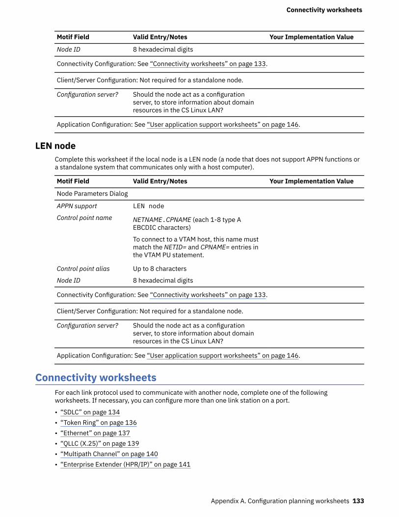
Motif Field Valid Entry/Notes Your Implementation Value
Node ID 8 hexadecimal digits
Connectivity Configuration: See “Connectivity worksheets” on page 133.
Client/Server Configuration: Not required for a standalone node.
Configuration server? Should the node act as a configurationserver, to store information about domainresources in the CS Linux LAN?
Application Configuration: See “User application support worksheets” on page 146.
LEN nodeComplete this worksheet if the local node is a LEN node (a node that does not support APPN functions ora standalone system that communicates only with a host computer).
Motif Field Valid Entry/Notes Your Implementation Value
Node Parameters Dialog
APPN support LEN node
Control point name NETNAME.CPNAME (each 1-8 type AEBCDIC characters)
To connect to a VTAM host, this name mustmatch the NETID= and CPNAME= entries inthe VTAM PU statement.
Control point alias Up to 8 characters
Node ID 8 hexadecimal digits
Connectivity Configuration: See “Connectivity worksheets” on page 133.
Client/Server Configuration: Not required for a standalone node.
Configuration server? Should the node act as a configurationserver, to store information about domainresources in the CS Linux LAN?
Application Configuration: See “User application support worksheets” on page 146.
Connectivity worksheetsFor each link protocol used to communicate with another node, complete one of the followingworksheets. If necessary, you can configure more than one link station on a port.
• “SDLC” on page 134• “Token Ring” on page 136• “Ethernet” on page 137• “QLLC (X.25)” on page 139• “Multipath Channel” on page 140• “Enterprise Extender (HPR/IP)” on page 141
Connectivity worksheets
Appendix A. Configuration planning worksheets 133
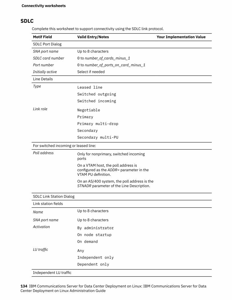
SDLCComplete this worksheet to support connectivity using the SDLC link protocol.
Motif Field Valid Entry/Notes Your Implementation Value
SDLC Port Dialog
SNA port name Up to 8 characters
SDLC card number 0 to number_of_cards_minus_1
Port number 0 to number_of_ports_on_card_minus_1
Initially active Select if needed
Line Details
Type Leased line
Switched outgoing
Switched incoming
Link role Negotiable
Primary
Primary multi-drop
Secondary
Secondary multi-PU
For switched incoming or leased line:
Poll address Only for nonprimary, switched incomingports
On a VTAM host, the poll address isconfigured as the ADDR= parameter in theVTAM PU definition.
On an AS/400 system, the poll address is theSTNADR parameter of the Line Description.
SDLC Link Station Dialog
Link station fields
Name Up to 8 characters
SNA port name Up to 8 characters
Activation By administrator
On node startup
On demand
LU traffic Any
Independent only
Dependent only
Independent LU traffic
Connectivity worksheets
134 IBM Communications Server for Data Center Deployment on Linux: IBM Communications Server for DataCenter Deployment on Linux Administration Guide
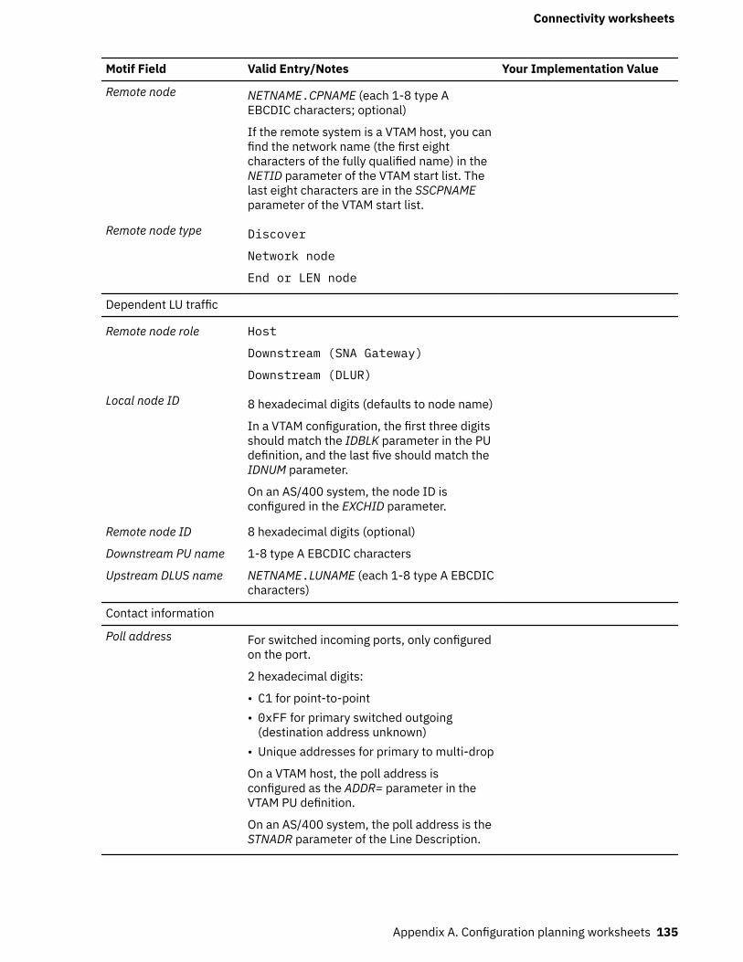
Motif Field Valid Entry/Notes Your Implementation Value
Remote node NETNAME.CPNAME (each 1-8 type AEBCDIC characters; optional)
If the remote system is a VTAM host, you canfind the network name (the first eightcharacters of the fully qualified name) in theNETID parameter of the VTAM start list. Thelast eight characters are in the SSCPNAMEparameter of the VTAM start list.
Remote node type Discover
Network node
End or LEN node
Dependent LU traffic
Remote node role Host
Downstream (SNA Gateway)
Downstream (DLUR)
Local node ID 8 hexadecimal digits (defaults to node name)
In a VTAM configuration, the first three digitsshould match the IDBLK parameter in the PUdefinition, and the last five should match theIDNUM parameter.
On an AS/400 system, the node ID isconfigured in the EXCHID parameter.
Remote node ID 8 hexadecimal digits (optional)
Downstream PU name 1-8 type A EBCDIC characters
Upstream DLUS name NETNAME.LUNAME (each 1-8 type A EBCDICcharacters)
Contact information
Poll address For switched incoming ports, only configuredon the port.
2 hexadecimal digits:
• C1 for point-to-point• 0xFF for primary switched outgoing
(destination address unknown)• Unique addresses for primary to multi-drop
On a VTAM host, the poll address isconfigured as the ADDR= parameter in theVTAM PU definition.
On an AS/400 system, the poll address is theSTNADR parameter of the Line Description.
Connectivity worksheets
Appendix A. Configuration planning worksheets 135

Token RingComplete this worksheet to support connectivity using the token ring link protocol.
Motif Field Valid Entry/Notes Your Implementation Value
Token Ring SAP Dialog
SNA port name Up to 8 characters
Token ring card number 0 to number_of_cards_minus_1
Local SAP number Hexadecimal (multiple of 4)
Initially active Select if needed
Define on connectionnetwork
Select if needed
CN name NETNAME.CNNAME (each 1-8 type AEBCDIC characters)
Token Ring Link Station Dialog
Link station fields
Name Up to 8 characters
SNA port name Up to 8 characters
Activation By administrator
On node startup
On demand
LU traffic Any
Independent only
Dependent only
Independent LU traffic
Remote node NETNAME.CPNAME (each 1-8 type AEBCDIC characters; optional)
If the remote system is a VTAM host, you canfind the network name (the first eightcharacters of the fully qualified name) in theNETID parameter of the VTAM start list. Thelast eight characters are in the SSCPNAMEparameter of the VTAM start list.
Remote node type Discover
End or LEN node
Network node
Dependent LU traffic
Remote node role Host
Downstream (SNA Gateway)
Downstream (DLUR)
Connectivity worksheets
136 IBM Communications Server for Data Center Deployment on Linux: IBM Communications Server for DataCenter Deployment on Linux Administration Guide
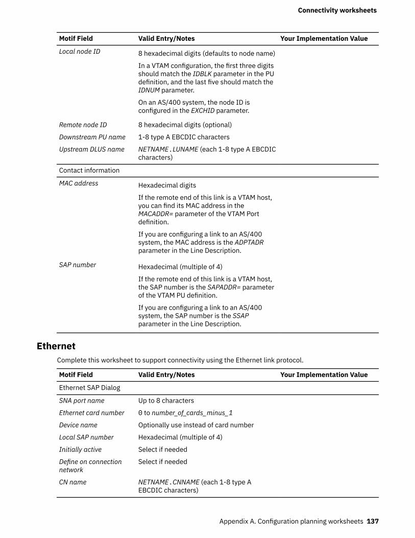
Motif Field Valid Entry/Notes Your Implementation Value
Local node ID 8 hexadecimal digits (defaults to node name)
In a VTAM configuration, the first three digitsshould match the IDBLK parameter in the PUdefinition, and the last five should match theIDNUM parameter.
On an AS/400 system, the node ID isconfigured in the EXCHID parameter.
Remote node ID 8 hexadecimal digits (optional)
Downstream PU name 1-8 type A EBCDIC characters
Upstream DLUS name NETNAME.LUNAME (each 1-8 type A EBCDICcharacters)
Contact information
MAC address Hexadecimal digits
If the remote end of this link is a VTAM host,you can find its MAC address in theMACADDR= parameter of the VTAM Portdefinition.
If you are configuring a link to an AS/400system, the MAC address is the ADPTADRparameter in the Line Description.
SAP number Hexadecimal (multiple of 4)
If the remote end of this link is a VTAM host,the SAP number is the SAPADDR= parameterof the VTAM PU definition.
If you are configuring a link to an AS/400system, the SAP number is the SSAPparameter in the Line Description.
EthernetComplete this worksheet to support connectivity using the Ethernet link protocol.
Motif Field Valid Entry/Notes Your Implementation Value
Ethernet SAP Dialog
SNA port name Up to 8 characters
Ethernet card number 0 to number_of_cards_minus_1
Device name Optionally use instead of card number
Local SAP number Hexadecimal (multiple of 4)
Initially active Select if needed
Define on connectionnetwork
Select if needed
CN name NETNAME.CNNAME (each 1-8 type AEBCDIC characters)
Connectivity worksheets
Appendix A. Configuration planning worksheets 137
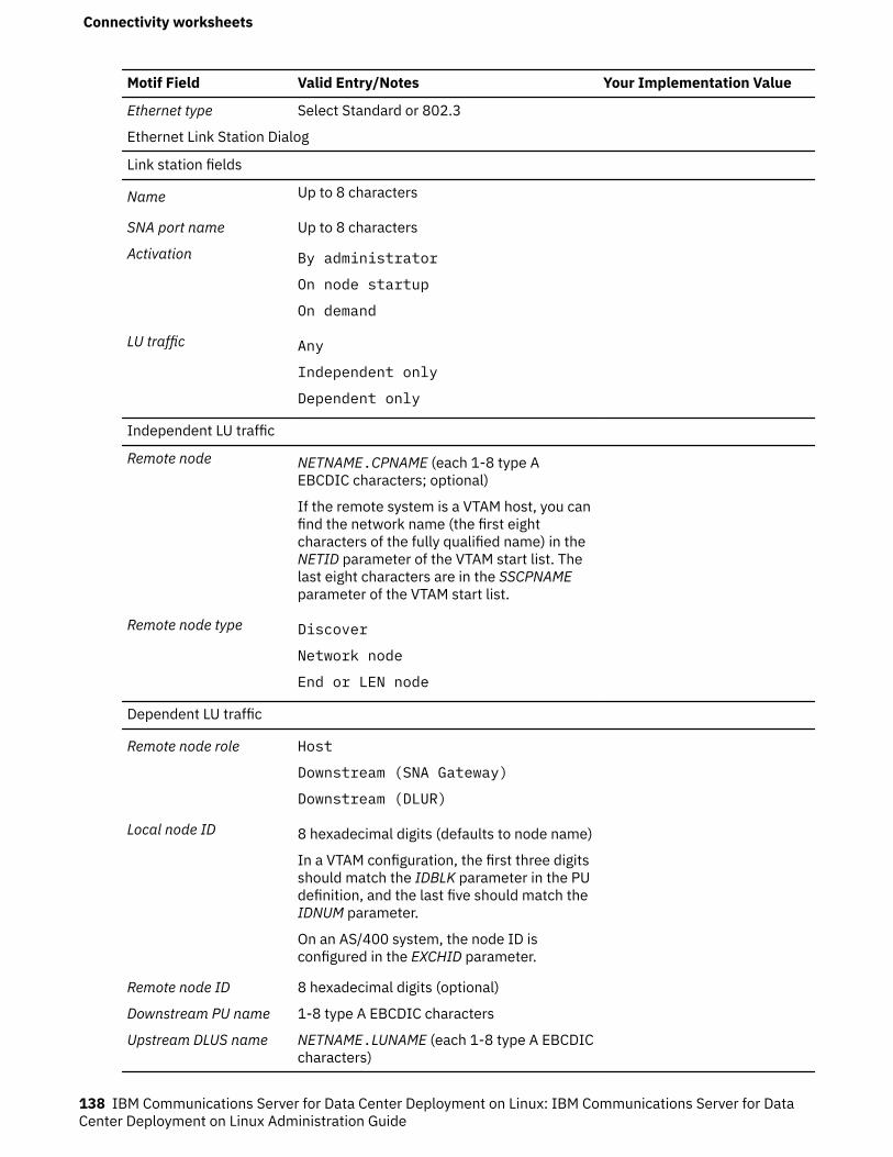
Motif Field Valid Entry/Notes Your Implementation Value
Ethernet type Select Standard or 802.3
Ethernet Link Station Dialog
Link station fields
Name Up to 8 characters
SNA port name Up to 8 characters
Activation By administrator
On node startup
On demand
LU traffic Any
Independent only
Dependent only
Independent LU traffic
Remote node NETNAME.CPNAME (each 1-8 type AEBCDIC characters; optional)
If the remote system is a VTAM host, you canfind the network name (the first eightcharacters of the fully qualified name) in theNETID parameter of the VTAM start list. Thelast eight characters are in the SSCPNAMEparameter of the VTAM start list.
Remote node type Discover
Network node
End or LEN node
Dependent LU traffic
Remote node role Host
Downstream (SNA Gateway)
Downstream (DLUR)
Local node ID 8 hexadecimal digits (defaults to node name)
In a VTAM configuration, the first three digitsshould match the IDBLK parameter in the PUdefinition, and the last five should match theIDNUM parameter.
On an AS/400 system, the node ID isconfigured in the EXCHID parameter.
Remote node ID 8 hexadecimal digits (optional)
Downstream PU name 1-8 type A EBCDIC characters
Upstream DLUS name NETNAME.LUNAME (each 1-8 type A EBCDICcharacters)
Connectivity worksheets
138 IBM Communications Server for Data Center Deployment on Linux: IBM Communications Server for DataCenter Deployment on Linux Administration Guide
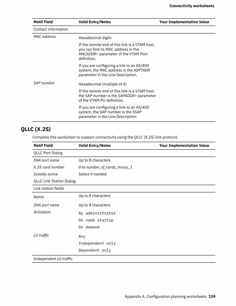
Motif Field Valid Entry/Notes Your Implementation Value
Contact information
MAC address Hexadecimal digits
If the remote end of this link is a VTAM host,you can find its MAC address in theMACADDR= parameter of the VTAM Portdefinition.
If you are configuring a link to an AS/400system, the MAC address is the ADPTADRparameter in the Line Description.
SAP number Hexadecimal (multiple of 4)
If the remote end of this link is a VTAM host,the SAP number is the SAPADDR= parameterof the VTAM PU definition.
If you are configuring a link to an AS/400system, the SAP number is the SSAPparameter in the Line Description.
QLLC (X.25)Complete this worksheet to support connectivity using the QLLC (X.25) link protocol.
Motif Field Valid Entry/Notes Your Implementation Value
QLLC Port Dialog
SNA port name Up to 8 characters
X.25 card number 0 to number_of_cards_minus_1
Initially active Select if needed
QLLC Link Station Dialog
Link station fields
Name Up to 8 characters
SNA port name Up to 8 characters
Activation By administrator
On node startup
On demand
LU traffic Any
Independent only
Dependent only
Independent LU traffic
Connectivity worksheets
Appendix A. Configuration planning worksheets 139
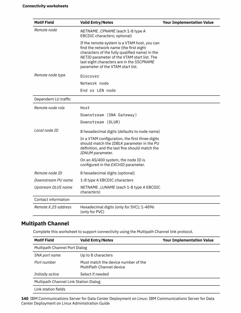
Motif Field Valid Entry/Notes Your Implementation Value
Remote node NETNAME.CPNAME (each 1-8 type AEBCDIC characters; optional)
If the remote system is a VTAM host, you canfind the network name (the first eightcharacters of the fully qualified name) in theNETID parameter of the VTAM start list. Thelast eight characters are in the SSCPNAMEparameter of the VTAM start list.
Remote node type Discover
Network node
End or LEN node
Dependent LU traffic
Remote node role Host
Downstream (SNA Gateway)
Downstream (DLUR)
Local node ID 8 hexadecimal digits (defaults to node name)
In a VTAM configuration, the first three digitsshould match the IDBLK parameter in the PUdefinition, and the last five should match theIDNUM parameter.
On an AS/400 system, the node ID isconfigured in the EXCHID parameter.
Remote node ID 8 hexadecimal digits (optional)
Downstream PU name 1-8 type A EBCDIC characters
Upstream DLUS name NETNAME.LUNAME (each 1-8 type A EBCDICcharacters)
Contact information
Remote X.25 address Hexadecimal digits (only for SVC); 1-4096(only for PVC)
Multipath ChannelComplete this worksheet to support connectivity using the Multipath Channel link protocol.
Motif Field Valid Entry/Notes Your Implementation Value
Multipath Channel Port Dialog
SNA port name Up to 8 characters
Port number Must match the device number of theMultiPath Channel device
Initially active Select if needed
Multipath Channel Link Station Dialog
Link station fields
Connectivity worksheets
140 IBM Communications Server for Data Center Deployment on Linux: IBM Communications Server for DataCenter Deployment on Linux Administration Guide
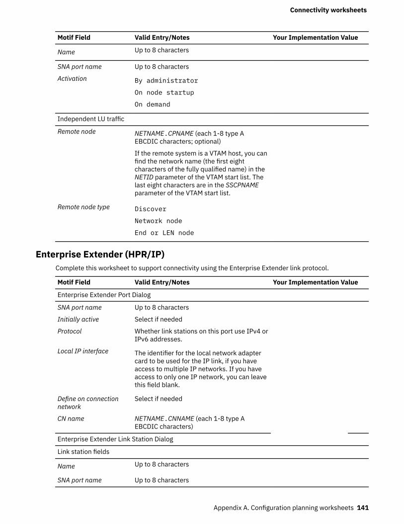
Motif Field Valid Entry/Notes Your Implementation Value
Name Up to 8 characters
SNA port name Up to 8 characters
Activation By administrator
On node startup
On demand
Independent LU traffic
Remote node NETNAME.CPNAME (each 1-8 type AEBCDIC characters; optional)
If the remote system is a VTAM host, you canfind the network name (the first eightcharacters of the fully qualified name) in theNETID parameter of the VTAM start list. Thelast eight characters are in the SSCPNAMEparameter of the VTAM start list.
Remote node type Discover
Network node
End or LEN node
Enterprise Extender (HPR/IP)Complete this worksheet to support connectivity using the Enterprise Extender link protocol.
Motif Field Valid Entry/Notes Your Implementation Value
Enterprise Extender Port Dialog
SNA port name Up to 8 characters
Initially active Select if needed
Protocol Whether link stations on this port use IPv4 orIPv6 addresses.
Local IP interface The identifier for the local network adaptercard to be used for the IP link, if you haveaccess to multiple IP networks. If you haveaccess to only one IP network, you can leavethis field blank.
Define on connectionnetwork
Select if needed
CN name NETNAME.CNNAME (each 1-8 type AEBCDIC characters)
Enterprise Extender Link Station Dialog
Link station fields
Name Up to 8 characters
SNA port name Up to 8 characters
Connectivity worksheets
Appendix A. Configuration planning worksheets 141
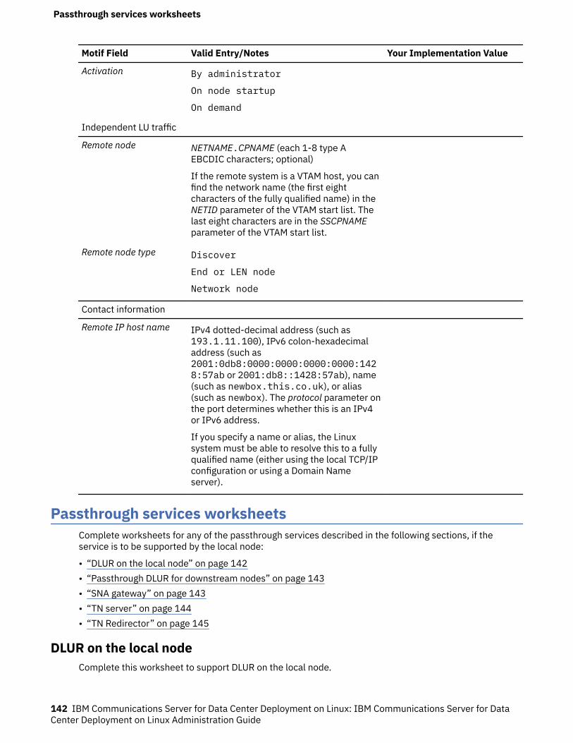
Motif Field Valid Entry/Notes Your Implementation Value
Activation By administrator
On node startup
On demand
Independent LU traffic
Remote node NETNAME.CPNAME (each 1-8 type AEBCDIC characters; optional)
If the remote system is a VTAM host, you canfind the network name (the first eightcharacters of the fully qualified name) in theNETID parameter of the VTAM start list. Thelast eight characters are in the SSCPNAMEparameter of the VTAM start list.
Remote node type Discover
End or LEN node
Network node
Contact information
Remote IP host name IPv4 dotted-decimal address (such as193.1.11.100), IPv6 colon-hexadecimaladdress (such as2001:0db8:0000:0000:0000:0000:1428:57ab or 2001:db8::1428:57ab), name(such as newbox.this.co.uk), or alias(such as newbox). The protocol parameter onthe port determines whether this is an IPv4or IPv6 address.
If you specify a name or alias, the Linuxsystem must be able to resolve this to a fullyqualified name (either using the local TCP/IPconfiguration or using a Domain Nameserver).
Passthrough services worksheetsComplete worksheets for any of the passthrough services described in the following sections, if theservice is to be supported by the local node:
• “DLUR on the local node” on page 142• “Passthrough DLUR for downstream nodes” on page 143• “SNA gateway” on page 143• “TN server” on page 144• “TN Redirector” on page 145
DLUR on the local nodeComplete this worksheet to support DLUR on the local node.
Passthrough services worksheets
142 IBM Communications Server for Data Center Deployment on Linux: IBM Communications Server for DataCenter Deployment on Linux Administration Guide
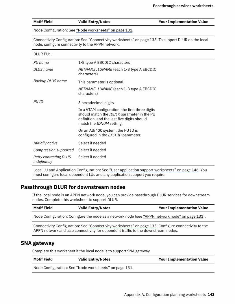
Motif Field Valid Entry/Notes Your Implementation Value
Node Configuration: See “Node worksheets” on page 131.
Connectivity Configuration: See “Connectivity worksheets” on page 133. To support DLUR on the localnode, configure connectivity to the APPN network.
DLUR PU: .
PU name 1-8 type A EBCDIC characters
DLUS name NETNAME.LUNAME (each 1-8 type A EBCDICcharacters)
Backup DLUS name This parameter is optional.
NETNAME.LUNAME (each 1-8 type A EBCDICcharacters)
PU ID 8 hexadecimal digits
In a VTAM configuration, the first three digitsshould match the IDBLK parameter in the PUdefinition, and the last five digits shouldmatch the IDNUM setting.
On an AS/400 system, the PU ID isconfigured in the EXCHID parameter.
Initially active Select if needed
Compression supported Select if needed
Retry contacting DLUSindefinitely
Select if needed
Local LU and Application Configuration: See “User application support worksheets” on page 146. Youmust configure local dependent LUs and any application support you require.
Passthrough DLUR for downstream nodesIf the local node is an APPN network node, you can provide passthrough DLUR services for downstreamnodes. Complete this worksheet to support DLUR.
Motif Field Valid Entry/Notes Your Implementation Value
Node Configuration: Configure the node as a network node (see “APPN network node” on page 131).
Connectivity Configuration: See “Connectivity worksheets” on page 133. Configure connectivity to theAPPN network and also connectivity for dependent traffic to the downstream nodes.
SNA gatewayComplete this worksheet if the local node is to support SNA gateway.
Motif Field Valid Entry/Notes Your Implementation Value
Node Configuration: See “Node worksheets” on page 131.
Passthrough services worksheets
Appendix A. Configuration planning worksheets 143
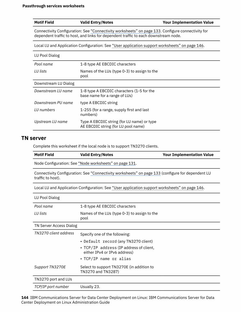
Motif Field Valid Entry/Notes Your Implementation Value
Connectivity Configuration: See “Connectivity worksheets” on page 133. Configure connectivity fordependent traffic to host, and links for dependent traffic to each downstream node.
Local LU and Application Configuration: See “User application support worksheets” on page 146.
LU Pool Dialog
Pool name 1-8 type AE EBCDIC characters
LU lists Names of the LUs (type 0-3) to assign to thepool
Downstream LU Dialog
Downstream LU name 1-8 type A EBCDIC characters (1-5 for thebase name for a range of LUs)
Downstream PU name type A EBCDIC string
LU numbers 1-255 (for a range, supply first and lastnumbers)
Upstream LU name Type A EBCDIC string (for LU name) or typeAE EBCDIC string (for LU pool name)
TN serverComplete this worksheet if the local node is to support TN3270 clients.
Motif Field Valid Entry/Notes Your Implementation Value
Node Configuration: See “Node worksheets” on page 131.
Connectivity Configuration: See “Connectivity worksheets” on page 133 (configure for dependent LUtraffic to host).
Local LU and Application Configuration: See “User application support worksheets” on page 146.
LU Pool Dialog
Pool name 1-8 type AE EBCDIC characters
LU lists Names of the LUs (type 0-3) to assign to thepool
TN Server Access Dialog
TN3270 client address Specify one of the following:
• Default record (any TN3270 client)• TCP/IP address (IP address of client,
either IPv4 or IPv6 address)• TCP/IP name or alias
Support TN3270E Select to support TN3270E (in addition toTN3270 and TN3287)
TN3270 port and LUs
TCP/IP port number Usually 23.
Passthrough services worksheets
144 IBM Communications Server for Data Center Deployment on Linux: IBM Communications Server for DataCenter Deployment on Linux Administration Guide
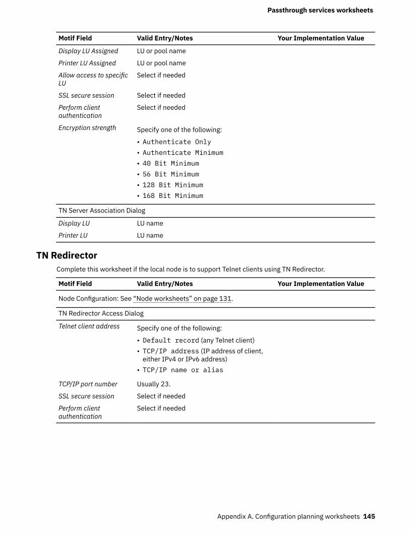
Motif Field Valid Entry/Notes Your Implementation Value
Display LU Assigned LU or pool name
Printer LU Assigned LU or pool name
Allow access to specificLU
Select if needed
SSL secure session Select if needed
Perform clientauthentication
Select if needed
Encryption strength Specify one of the following:
• Authenticate Only• Authenticate Minimum• 40 Bit Minimum• 56 Bit Minimum• 128 Bit Minimum• 168 Bit Minimum
TN Server Association Dialog
Display LU LU name
Printer LU LU name
TN RedirectorComplete this worksheet if the local node is to support Telnet clients using TN Redirector.
Motif Field Valid Entry/Notes Your Implementation Value
Node Configuration: See “Node worksheets” on page 131.
TN Redirector Access Dialog
Telnet client address Specify one of the following:
• Default record (any Telnet client)• TCP/IP address (IP address of client,
either IPv4 or IPv6 address)• TCP/IP name or alias
TCP/IP port number Usually 23.
SSL secure session Select if needed
Perform clientauthentication
Select if needed
Passthrough services worksheets
Appendix A. Configuration planning worksheets 145
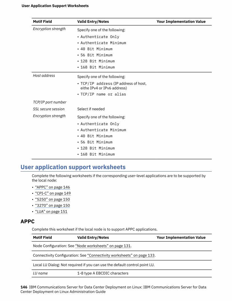
Motif Field Valid Entry/Notes Your Implementation Value
Encryption strength Specify one of the following:
• Authenticate Only• Authenticate Minimum• 40 Bit Minimum• 56 Bit Minimum• 128 Bit Minimum• 168 Bit Minimum
Host address Specify one of the following:
• TCP/IP address (IP address of host,eithe IPv4 or IPv6 address)
• TCP/IP name or alias
TCP/IP port number
SSL secure session Select if needed
Encryption strength Specify one of the following:
• Authenticate Only• Authenticate Minimum• 40 Bit Minimum• 56 Bit Minimum• 128 Bit Minimum• 168 Bit Minimum
User application support worksheetsComplete the following worksheets if the corresponding user-level applications are to be supported bythe local node:
• “APPC” on page 146• “CPI-C” on page 149• “5250” on page 150• “3270” on page 150• “LUA” on page 151
APPCComplete this worksheet if the local node is to support APPC applications.
Motif Field Valid Entry/Notes Your Implementation Value
Node Configuration: See “Node worksheets” on page 131.
Connectivity Configuration: See “Connectivity worksheets” on page 133.
Local LU Dialog: Not required if you can use the default control point LU.
LU name 1-8 type A EBCDIC characters
User Application Support Worksheets
146 IBM Communications Server for Data Center Deployment on Linux: IBM Communications Server for DataCenter Deployment on Linux Administration Guide
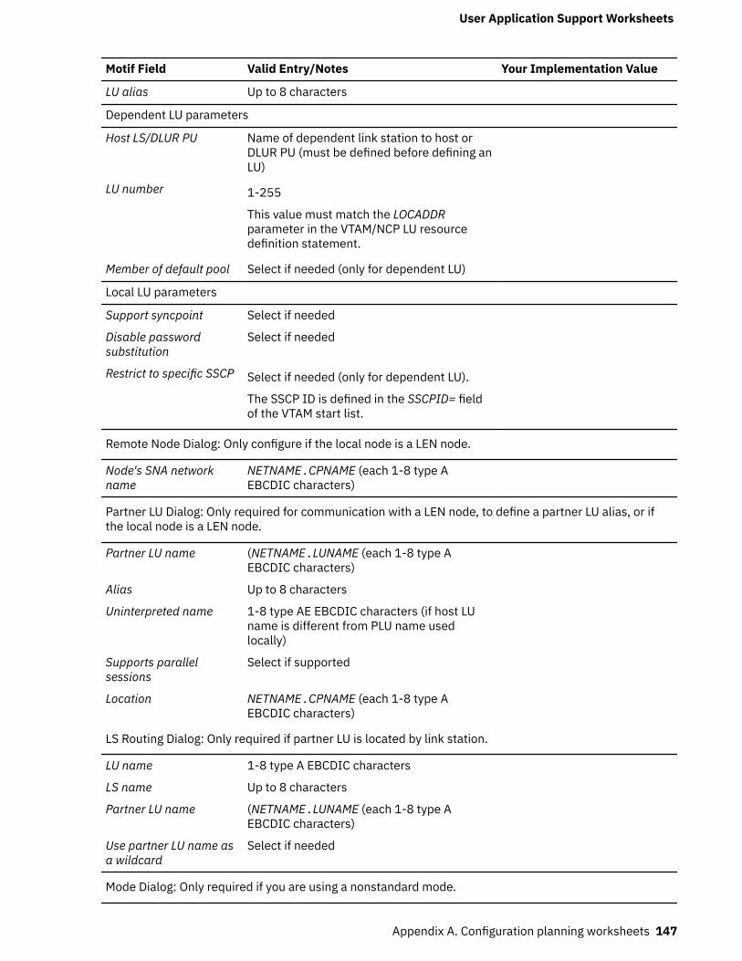
Motif Field Valid Entry/Notes Your Implementation Value
LU alias Up to 8 characters
Dependent LU parameters
Host LS/DLUR PU Name of dependent link station to host orDLUR PU (must be defined before defining anLU)
LU number 1-255
This value must match the LOCADDRparameter in the VTAM/NCP LU resourcedefinition statement.
Member of default pool Select if needed (only for dependent LU)
Local LU parameters
Support syncpoint Select if needed
Disable passwordsubstitution
Select if needed
Restrict to specific SSCP Select if needed (only for dependent LU).
The SSCP ID is defined in the SSCPID= fieldof the VTAM start list.
Remote Node Dialog: Only configure if the local node is a LEN node.
Node's SNA networkname
NETNAME.CPNAME (each 1-8 type AEBCDIC characters)
Partner LU Dialog: Only required for communication with a LEN node, to define a partner LU alias, or ifthe local node is a LEN node.
Partner LU name (NETNAME.LUNAME (each 1-8 type AEBCDIC characters)
Alias Up to 8 characters
Uninterpreted name 1-8 type AE EBCDIC characters (if host LUname is different from PLU name usedlocally)
Supports parallelsessions
Select if supported
Location NETNAME.CPNAME (each 1-8 type AEBCDIC characters)
LS Routing Dialog: Only required if partner LU is located by link station.
LU name 1-8 type A EBCDIC characters
LS name Up to 8 characters
Partner LU name (NETNAME.LUNAME (each 1-8 type AEBCDIC characters)
Use partner LU name asa wildcard
Select if needed
Mode Dialog: Only required if you are using a nonstandard mode.
User Application Support Worksheets
Appendix A. Configuration planning worksheets 147

Motif Field Valid Entry/Notes Your Implementation Value
Name 1-8 type A EBCDIC characters
COS name 1-8 type A EBCDIC characters
Session limits
Initial session limit Up to maximum session limit; recommendedvalue is 8
Maximum session limit Up to 32767
Minimum contentionwinner sessions
Up to maximum session limit; recommendedvalue is 0.
Minimum contentionloser sessions
Recommended value is 0.
Auto-activated sessions 0 to minimum_contention_winners
Receive pacing window
Initial window size Recommended value is 4
Maximum window size Optional
Session timeout
Maximum RU size Recommended upper limit is 1024.
Compression supported
Max inboundcompression
None
RLE
LZ9
LZ10
Max outboundcompression
None
RLE
LZ9
LZ10
Session Security Dialog: Only required if session security is required for sessions between a specificlocal and partner LU.
Local LU 1-8 type A EBCDIC characters
Partner LU 1-8 type A EBCDIC characters
Password 16-digit hexadecimal number
TP Invocation Dialog: Only required if local TP is to be started in response to requests from remotesystems.
TP name User application: up to 64 ASCII characters
Service TP: up to 8 hexadecimal digits
Restrict to specific LU Select if needed
LU alias Up to 8 characters
User Application Support Worksheets
148 IBM Communications Server for Data Center Deployment on Linux: IBM Communications Server for DataCenter Deployment on Linux Administration Guide
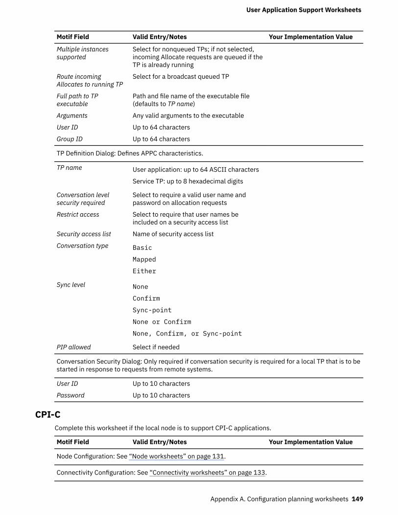
Motif Field Valid Entry/Notes Your Implementation Value
Multiple instancessupported
Select for nonqueued TPs; if not selected,incoming Allocate requests are queued if theTP is already running
Route incomingAllocates to running TP
Select for a broadcast queued TP
Full path to TPexecutable
Path and file name of the executable file(defaults to TP name)
Arguments Any valid arguments to the executable
User ID Up to 64 characters
Group ID Up to 64 characters
TP Definition Dialog: Defines APPC characteristics.
TP name User application: up to 64 ASCII characters
Service TP: up to 8 hexadecimal digits
Conversation levelsecurity required
Select to require a valid user name andpassword on allocation requests
Restrict access Select to require that user names beincluded on a security access list
Security access list Name of security access list
Conversation type Basic
Mapped
Either
Sync level None
Confirm
Sync-point
None or Confirm
None, Confirm, or Sync-point
PIP allowed Select if needed
Conversation Security Dialog: Only required if conversation security is required for a local TP that is to bestarted in response to requests from remote systems.
User ID Up to 10 characters
Password Up to 10 characters
CPI-CComplete this worksheet if the local node is to support CPI-C applications.
Motif Field Valid Entry/Notes Your Implementation Value
Node Configuration: See “Node worksheets” on page 131.
Connectivity Configuration: See “Connectivity worksheets” on page 133.
User Application Support Worksheets
Appendix A. Configuration planning worksheets 149

Motif Field Valid Entry/Notes Your Implementation Value
APPC Configuration: See “APPC” on page 146.
CPI-C Destination Dialog
Symbolic destinationname
1-8 characters
Local LU Alias (up to 8 characters) or fully qualifiedname (NETNAME.LUNAME, each 1-8 type AEBCDIC characters)
Partner LU Alias (up to 8 characters) or fully qualifiedname (NETNAME.LUNAME, each 1-8 type AEBCDIC characters)
Mode Type A EBCDIC string
Partner TP name User application: up to 64 characters
Service TP: up to 8 hexadecimal digits, forexample 06F3F0F1 (do not use 0x or
)
Security None
Same
Program
User ID Only for security level of Same or Program(not related to user login ID)
Password Only for security level of Program (notrelated to user login password)
5250Complete this worksheet if the local node is to support 5250 communications.
Motif Field Valid Entry/Notes Your Implementation Value
Node Configuration: See “Node worksheets” on page 131.
Connectivity Configuration: See “Connectivity worksheets” on page 133 (configure for independenttraffic).
APPC Configuration: See “APPC” on page 146.
3270Complete this worksheet if the local node is to support 3270 communications.
Motif Field Valid Entry/Notes Your Implementation Value
Node Configuration: See “Node worksheets” on page 131.
Connectivity Configuration: See “Connectivity worksheets” on page 133 (configure for dependenttraffic).
User Application Support Worksheets
150 IBM Communications Server for Data Center Deployment on Linux: IBM Communications Server for DataCenter Deployment on Linux Administration Guide
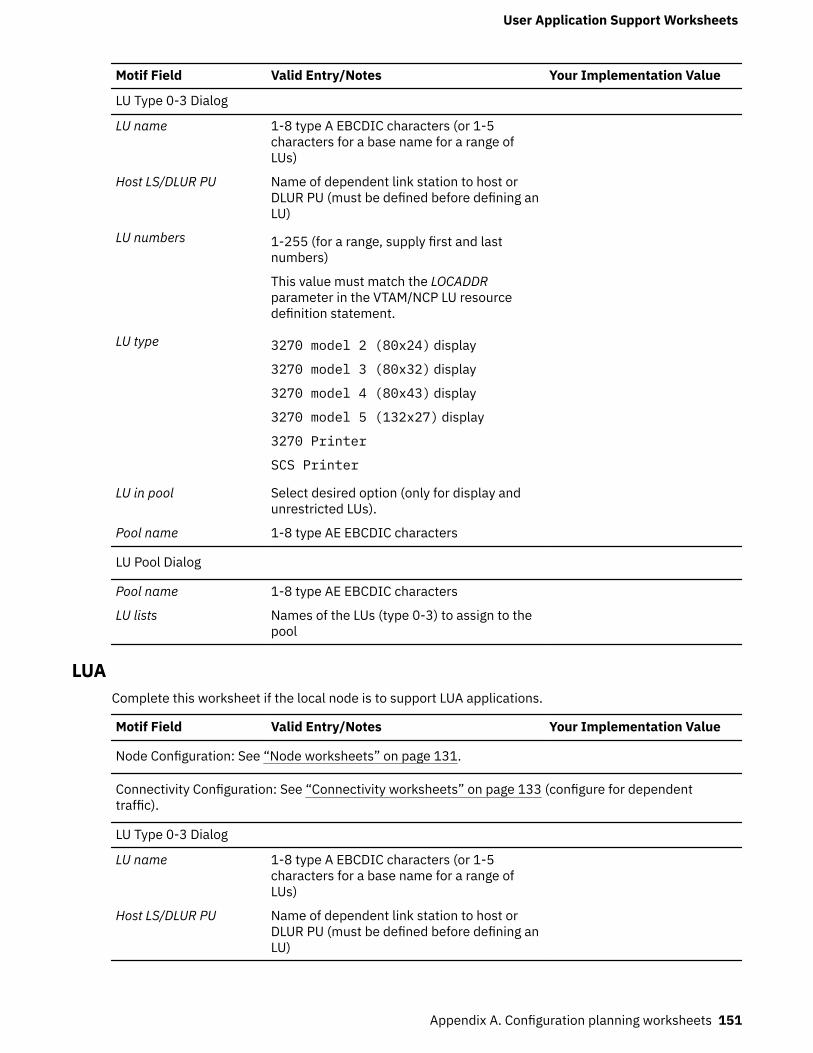
Motif Field Valid Entry/Notes Your Implementation Value
LU Type 0-3 Dialog
LU name 1-8 type A EBCDIC characters (or 1-5characters for a base name for a range ofLUs)
Host LS/DLUR PU Name of dependent link station to host orDLUR PU (must be defined before defining anLU)
LU numbers 1-255 (for a range, supply first and lastnumbers)
This value must match the LOCADDRparameter in the VTAM/NCP LU resourcedefinition statement.
LU type 3270 model 2 (80x24) display
3270 model 3 (80x32) display
3270 model 4 (80x43) display
3270 model 5 (132x27) display
3270 Printer
SCS Printer
LU in pool Select desired option (only for display andunrestricted LUs).
Pool name 1-8 type AE EBCDIC characters
LU Pool Dialog
Pool name 1-8 type AE EBCDIC characters
LU lists Names of the LUs (type 0-3) to assign to thepool
LUAComplete this worksheet if the local node is to support LUA applications.
Motif Field Valid Entry/Notes Your Implementation Value
Node Configuration: See “Node worksheets” on page 131.
Connectivity Configuration: See “Connectivity worksheets” on page 133 (configure for dependenttraffic).
LU Type 0-3 Dialog
LU name 1-8 type A EBCDIC characters (or 1-5characters for a base name for a range ofLUs)
Host LS/DLUR PU Name of dependent link station to host orDLUR PU (must be defined before defining anLU)
User Application Support Worksheets
Appendix A. Configuration planning worksheets 151
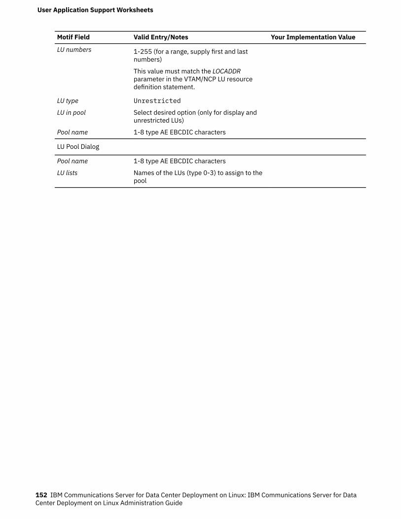
Motif Field Valid Entry/Notes Your Implementation Value
LU numbers 1-255 (for a range, supply first and lastnumbers)
This value must match the LOCADDRparameter in the VTAM/NCP LU resourcedefinition statement.
LU type Unrestricted
LU in pool Select desired option (only for display andunrestricted LUs)
Pool name 1-8 type AE EBCDIC characters
LU Pool Dialog
Pool name 1-8 type AE EBCDIC characters
LU lists Names of the LUs (type 0-3) to assign to thepool
User Application Support Worksheets
152 IBM Communications Server for Data Center Deployment on Linux: IBM Communications Server for DataCenter Deployment on Linux Administration Guide
Appendix B. Configuring an invokable TP from thecommand line
CS Linux includes a command-line utility that enables a user or the writer of a TP installation program todefine an invokable TP. You can run this utility on a server or client.
The syntax of the command is different depending on whether you are defining, removing, or querying TPdefinitions, and is different for a Remote API Client on Windows.
Before using the tpinst32 command, change to the directory where the client software is installed.
The tpinst32 command normally displays information in the language that you selected when installingthe client software. If you prefer to see this information in a different language, change to the subdirectorycorresponding to your preferred language before running the command. For example, to see theinformation in French, change to the fr_FR subdirectory below the directory where the client software isinstalled.
Define an invokable TP:
snatpinstall -a file_name
tpinst32 -a file_name
Note: The tpinst32 command applies to both 32-bit and x64 versions of Windows.
This command adds one or more TP definitions from the specified file_name. If the TP named in thefile has already been defined, the information in the file replaces the existing definition. Forinformation about the required file format, see “File format for an invokable TP definition” on page154.
Remove an invokable TP definition:
snatpinstall -r -t TP_name [ -l LU_alias ]
This command removes the entry that has the specified TP name and (if more than one APPC TP isdefined with the same TP name) the specified LU alias. Omit the option -l LU_alias if the entry is fora CPI-C application, or if there is only one APPC TP defined with the specified TP name.
tpinst32 -r -t TP_name
This command removes the entry that has the specified TP name.
© Copyright IBM Corp. 1998, 2021 153
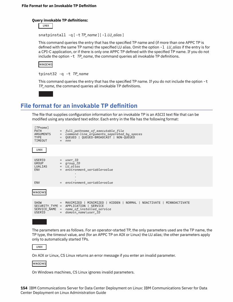
Query invokable TP definitions:
snatpinstall -q [ -t TP_name ] [ -l LU_alias ]
This command queries the entry that has the specified TP name and (if more than one APPC TP isdefined with the same TP name) the specified LU alias. Omit the option -l LU_alias if the entry is fora CPI-C application, or if there is only one APPC TP defined with the specified TP name. If you do notinclude the option -t TP_name, the command queries all invokable TP definitions.
tpinst32 -q -t TP_name
This command queries the entry that has the specified TP name. If you do not include the option -tTP_name, the command queries all invokable TP definitions.
File format for an invokable TP definitionThe file that supplies configuration information for an invokable TP is an ASCII text file that can bemodified using any standard text editor. Each entry in the file has the following format:
[TPname]PATH = full_pathname_of_executable_fileARGUMENTS = command-line_arguments_separated_by_spacesTYPE = QUEUED | QUEUED-BROADCAST | NON-QUEUEDTIMEOUT = nnn
USERID = user_IDGROUP = group_IDLUALIAS = LU_aliasENV = environment_variable=value . . .ENV = environment_variable=value
SHOW = MAXIMIZED | MINIMIZED | HIDDEN | NORMAL | NOACTIVATE | MINNOACTIVATESECURITY_TYPE = APPLICATION | SERVICESERVICE_NAME = name_of_installed_serviceUSERID = domain_name\user_ID
The parameters are as follows. For an operator-started TP, the only parameters used are the TP name, theTP type, the timeout value, and (for an APPC TP on AIX or Linux) the LU alias; the other parameters applyonly to automatically started TPs.
On AIX or Linux, CS Linux returns an error message if you enter an invalid parameter.
On Windows machines, CS Linux ignores invalid parameters.
File Format for an Invokable TP Definition
154 IBM Communications Server for Data Center Deployment on Linux: IBM Communications Server for DataCenter Deployment on Linux Administration Guide
TPnameThe name of the TP (1-64 characters, with no embedded space characters). The TP name specified onthe Receive_Allocate, or on the incoming Allocate request, is matched against this name. If the TP isan automatically started TP, it must specify this TP name on the Receive_Allocate when it starts up, toenable CS Linux to route the incoming Attach to the correct TP.
This name must be enclosed within square brackets. The name can be specified as an ASCII string,enclosed in double quotation marks (for example, ["TPNAME1"]). Alternatively, it can be specified asa hexadecimal array representing the EBCDIC characters of the TP name (for example,[<53504E414D45F1>]) or as a combination of the two (for example, [<3f>"TP1"]). In thisexample, the first character is the unprintable character 0x3f, and the following characters are"TP1".
CS Linux converts a supplied ASCII string to EBCDIC, but does not perform any conversion on ahexadecimal string (which is assumed to be in EBCDIC already). It then pads the name with EBCDICspaces on the right (to a total of 64 characters) before matching against the specified TP name.
PATHThe path and file name of the executable file for this TP.
This line is optional. If it is not included, CS Linux assumes that the executable file name is the sameas the TP name. If you specify a file name with no path, the default path for AIX or Linux systemsis /etc/opt/ibm/sna; for a Windows client, CS Linux uses the normal Windows mechanisms forlocating the executable file.
ARGUMENTSAny command-line arguments to be passed to the TP, separated by spaces. These arguments arepassed to the TP in the same order as they appear on the command line.
This line is optional. If it is not included, the TP is invoked without any command-line arguments.
TYPESpecify one of the following values:QUEUED
The TP is a queued TP. Any incoming Allocate requests arriving while the TP is running are queueduntil the TP issues another Receive_Allocate, or until it finishes running and can be restarted. Anincoming Allocate request is routed to this TP only if it is received by an LU that is configured toroute incoming Allocate requests to this computer.
QUEUED-BROADCASTThe TP is a broadcast queued TP. Any incoming Allocate requests arriving while the TP is runningare queued until the TP issues another Receive_Allocate, or until it finishes running and can berestarted. When the TP is started, information about the TP is broadcast to all servers on the LAN;if an LU on another computer receives an incoming Allocate request and has no routinginformation configured, it can dynamically locate the TP and route the Allocate request to it.
Using QUEUED-BROADCAST instead of QUEUED avoids having to configure explicit routinginformation for LUs, and enables load-balancing by running more than one copy of the same TP ondifferent computers. However, if you want to avoid broadcasting information in order to reduceLAN traffic, or if you need to ensure that incoming Allocate requests arriving at a particular LU arealways routed to the same copy of the TP, you should use QUEUED.
NON-QUEUEDThe TP is a nonqueued TP. CS Linux starts a new copy of the TP each time an incoming Allocaterequest arrives for it. Do not specify the TIMEOUT parameter for a nonqueued TP.
A TP defined as nonqueued cannot be started by an operator; it is always started automatically byCS Linux. Do not specify NON-QUEUED if the TP is to be operator-started. If a user attempts tostart a nonqueued TP, CS Linux rejects the Receive_Allocate because no incoming Allocaterequest is waiting for it.
File Format for an Invokable TP Definition
Appendix B. Configuring an invokable TP from the command line 155
After a nonqueued TP has ended a conversation, it may terminate, or it may issue anotherReceive_Allocate. For frequently-used programs, this provides a way of avoiding the performanceoverhead of starting a new instance of the program for each conversation. Each time an Attach isreceived for a nonqueued, automatically started TP, CS Linux checks whether there is already aReceive_Allocate outstanding from an instance of this TP. If so, this TP is used for the incomingconversation; otherwise, CS Linux starts a new instance of the program.
If you use NON-QUEUED, more than one copy of the TP can be running at a time. If the TP writes tofiles, you need to ensure that different copies of the TP do not overwrite each other's files. To dothis, use one of the following methods:
• Ensure that the TP appends data to an existing file instead of creating the file (so that all copiesof the TP append data to the same file)
• Design the TP to generate file names at run-time, based on the process ID with which the TP isrunning (so that each copy of the TP writes to a different file).
This line is optional. If it is not included, or if an invalid value is specified, the default is QUEUED.
TIMEOUTThe maximum length of time, in seconds, that a Receive_Allocate call issued by the TP should block ifthere is no incoming Allocate request pending. If no incoming Allocate is received in this time, the callfails with a return code indicating "State check - Allocate not pending."
A timeout value of 0 indicates that the call always fails unless an incoming Allocate is already pendingwhen the call is issued. A timeout value of -1 indicates that the call waits indefinitely for an incomingAllocate and does not time out.
This line is optional. If it is not included, or if an invalid value (a non-numeric value) is specified, thedefault is -1 (infinite).
Do not specify this parameter if the TYPE parameter is set to NON-QUEUED. CS Linux uses a timeoutvalue of 0 for nonqueued TPs, because the TP is always started in response to an incoming Allocateand so there is always one pending.
USERIDSpecify the user ID that CS Linux uses to start the TP. The TP is started in the home directoryassociated with this user ID. This home directory is also the default path for trace files and any otherfiles accessed by the TP (unless the application overrides it by specifying a full path). If the applicationspecifies a file name without a path, CS Linux searches for the file in this home directory; if theapplication specifies a file name with a relative path, CS Linux searches for the file in the specifieddirectory relative to this home directory.
This line is required, and must be specified. The ID must be a valid login ID on the CS Linux computer;it can be up to 64 characters, unless your AIX or Linux configuration restricts user names to fewercharacters.
The executable file for the TP, specified by the PATH parameter, must have execute permission for thespecified user. In addition, if USERID is set to root, the file must be owned by root and must havesetuid and setgid permission in order to be started automatically by CS Linux.
GROUPSpecify the group ID that CS Linux uses to start the TP. This must be a valid group ID on the CS Linuxcomputer; it can be up to 64 characters, unless your AIX or Linux configuration restricts group namesto fewer characters.
This line is optional; if it is not included, the default is other.
LUALIASSpecify the local LU alias from which the TP is to accept incoming Attaches.
Note: This parameter can be used only if the TP is an APPC TP. If the TP is a CPI-C application, do notspecify this parameter. CPI-C does not support accepting incoming Attaches from a particular local
File Format for an Invokable TP Definition
156 IBM Communications Server for Data Center Deployment on Linux: IBM Communications Server for DataCenter Deployment on Linux Administration Guide

LU; specifying an LU alias (even a blank LU alias) for a CPI-C application will cause errors in routing theincoming Attach to the TP.
This is an eight-character name that must match the name of a CS Linux local APPC LU.
To indicate that the TP accepts incoming Attaches from any local LU, set this parameter to two doublequotation mark characters, "", indicating a blank LU alias. If the invokable TP data file contains morethan one entry for the same TP name, only one of these entries can specify a blank LU alias; each ofthe others must specify a different explicit LU alias. CS Linux matches an incoming Attach for this TPname to a TP specifying the appropriate LU alias, if possible, or to a TP specifying a blank LU alias if noLU alias match can be found.
If a non-blank LU alias is specified in the file, the TP must use the extended form of the APPCRECEIVE_ALLOCATE verb and specify this LU alias as a parameter to the verb. This enables CS Linuxto route the incoming Attach to the correct TP. For more information about the different forms ofRECEIVE_ALLOCATE, refer to IBM Communications Server for Data Center Deployment on AIX or LinuxAPPC Programmer's Guide. If you need to permit the TP to determine the correct LU alias at run-timerather than building it into the application, you can do this by setting an environment variable tocontain the appropriate LU alias (using the ENV parameter), and designing the application to read thisenvironment variable in order to determine how to issue RECEIVE_ALLOCATE.
This line is optional; if it is not included, the default is to accept incoming Attaches from any local LU,and the TP can use either form of the APPC RECEIVE_ALLOCATE verb.
ENVSpecify any environment variables required by the TP. Each variable is specified in the formenvironment_variable=value on a separate ENV line. Up to 64 ENV lines can be included; the variablesare set in the same order as they appear here.
The string environment_variable=value must not contain space or tab characters before or after the =character.
SHOWThis parameter applies only if the application is a GUI application; it is ignored if the application is aconsole application. Specify how the application should be displayed when it is started. Thisparameter is passed to the application, and not processed by CS Linux; it is the application'sresponsibility to interpret it and act on it. You can enter any of the following values:MAXIMIZED
The application is maximized.MINIMIZED
The application is minimized.HIDDEN
The application does not appear on the screen.NORMAL
The application is displayed at its normal size and position.NOACTIVATE
The application is displayed at its normal size and position, and the focus remains on thepreviously active window. This application's window does not become the active window.
MINNOACTIVATEThe application is minimized, and the focus remains on the previously active window.
This parameter is optional. If it is not included, the default is NORMAL.
SECURITY_TYPESpecify the security type of the TP executable:APPLICATION
The TP executable is started as an application using the CreateProcess system call.
File Format for an Invokable TP Definition
Appendix B. Configuring an invokable TP from the command line 157
SERVICEThe TP executable is started as a service using the StartService system call. In this case, theservice must have been previously installed with the Service Control Manager using the namespecified by the SERVICE_NAME parameter.
This value refers to a TP running as a Windows Service (not to an SNA service TP with a nameconsisting of 4 characters specified in hexadecimal). Windows allows only one copy of a Service tobe running at a time, and so the TYPE parameter should not be set to NON-QUEUED; if you specifythis value, the value QUEUED-BROADCAST will be used instead.
SERVICE_NAMEThe name of the service installed with the Service Control Manager. This parameter is only used if theSECURITY_TYPE is SERVICE.
USERIDSpecify the domain and user ID that the client should use to start the TP when the SECURITY_TYPE isAPPLICATION. The format for this parameter is domain_name\user_ID if the Windows Clientcomputer is part of a domain, or computer_name\user_ID (indicating the Windows Client's owncomputer name instead of a domain name) if the Windows Client computer is not part of a domain.
The client attempts to start the TP in the specified user's logon session. If USERID is blank orunspecified, the TP is started in the console session. If the specified user is not logged on, or no useris logged on at the console, the TP is not started and the CS Linux server is notified of the failure.
Note the following points about the format of these entries:
• You can include a comment line by including # as the first character of the line; CS Linux then ignoresthis line. CS Linux also ignores completely blank lines.
• Each parameter=value entry must be on one line; it cannot contain line-break characters. The maximumlength of a line is 255 characters; additional characters are ignored.
• White space (space characters and tab characters) at the start or end of a line, or before or after the =character, is ignored (except in the string environment_variable=value for the ENV parameter).
• Each TP definition begins with the line identifying the TP name, and ends with the end of the file or thenext TP name.
• Except for the ENV line, which can occur up to 64 times, do not specify the same parameter more thanonce for the same TP. If you do specify the same parameter more than once, only the last instance ofeach keyword is used.
File Format for an Invokable TP Definition
158 IBM Communications Server for Data Center Deployment on Linux: IBM Communications Server for DataCenter Deployment on Linux Administration Guide
Appendix C. Configuring TN3270 LU models forDDDLU
When a TN3270 client connects to the host through the CS Linux TN Server using DDDLU, CS Linux needsto send information to the host about the LU model required by the client. It normally determines the LUmodel using a standard mapping from the terminal type (device type) specified by the client.
If you need to change the mapping between TN3270 device types and LU models, you can do this usingthe tn3270dev.dat file. A sample version of this file is provided in /opt/ibm/sna/samples. Copy this fileinto /etc/opt/ibm/sna, and make your changes there using a standard ASCII text editor such as vi. Thechanges will take effect next time you restart CS Linux.
Each line in the file represents the mapping between a TN3270 device and the LU model string thatshould be sent to the host for this device. It consists of the following entries, separated by spaces.
• The first entry is the single character Y if this mapping is for a TN3270E client (using the TN3270extensions), or N if it is for a standard TN3270 client.
• The second entry is the terminal type (device type) specified by the client. This is a text string ofmaximum 40 characters; the valid characters are letters A-Z, numbers 0-9, / and -.
• The third entry is the 7-character LU model string that CS Linux sends to the host to identify the correctLU model for this client.
The sample file provided with CS Linux includes mappings for 18 standard device types in both TN3270and TN3270E versions (36 entries in all).
• If you need to specify a different LU model string for one or more of these standard devices, change thethird entry on the appropriate line of the file to specify the required 7-character string.
• If you need to support additional device types that are not included in the sample file, add a new line tothe file for each device type, using the format described above.
Configuring TN3270 LU models for DDDLU
© Copyright IBM Corp. 1998, 2021 159

Configuring TN3270 LU models for DDDLU
160 IBM Communications Server for Data Center Deployment on Linux: IBM Communications Server for DataCenter Deployment on Linux Administration Guide
Appendix D. How to send your comments to IBM
We appreciate your input on our publications. Feel free to comment on the clarity, accuracy, andcompleteness of the information or provide any other feedback that you have.
Use one of the following methods to send your comments:
1. Use the feedback link at the bottom of Knowledge Center.2. Use the feedback template below and send us an email at "[email protected]"3. Mail the comments to the following address:
IBM CorporationAttention: MHVRCFS Reader's CommentsDepartment H6MA, Building 7072455 South RoadPoughkeepsie, NY 12601-5400US
Email feedback templatePlease cut and paste the template below into your email. Then fill in the required information.
• My name:• My Company, University or Institution:• The URL of the topic or web page you are commenting on:• The text of your comment
If you are willing to talk to us about your comment, please feel free to include a phone number and thebest time to reach you.
When you send comments to IBM, you grant IBM a nonexclusive right to use or distribute the commentsin any way appropriate without incurring any obligation to you.
IBM or any other organizations use the personal information that you supply to contact you only about theissues that you submit.
If you have a technical problemDo not use the feedback methods that are listed for sending reader's comments. Instead, take one of thefollowing actions:
• Contact your IBM service representative• Call IBM technical support• Visit the IBM support portal at https://www.ibm.com/support/home/.
© Copyright IBM Corp. 1998, 2021 161

162 IBM Communications Server for Data Center Deployment on Linux: IBM Communications Server for DataCenter Deployment on Linux Administration Guide

Appendix E. Notices
This information was developed for products and services offered in the U.S.A. IBM may not offer theproducts, services, or features discussed in this document in other countries. Consult your local IBMrepresentative for information on the products and services currently available in your area. Any referenceto an IBM product, program, or service is not intended to state or imply that only that IBM product,program, or service may be used. Any functionally equivalent product, program, or service that does notinfringe any IBM intellectual property right may be used instead. However, it is the user's responsibility toevaluate and verify the operation of any non-IBM product, program, or service.
IBM may have patents or pending patent applications covering subject matter described in thisdocument. The furnishing of this document does not give you any license to these patents. You can sendlicense inquiries, in writing, to:
• IBM Director of Licensing• IBM Corporation• North Castle Drive• Armonk, NY 10504-1785• U.S.A.
For license inquiries regarding double-byte (DBCS) information, contact the IBM Intellectual PropertyDepartment in your country or send inquiries, in writing, to:
• IBM World Trade Asia Corporation• Licensing• 2-31 Roppongi 3-chome, Minato-ku• Tokyo 106, Japan
The following paragraph does not apply to the United Kingdom or any other country where suchprovisions are inconsistent with local law: INTERNATIONAL BUSINESS MACHINES CORPORATIONPROVIDES THIS PUBLICATION "AS IS" WITHOUT WARRANTY OF ANY KIND, EITHER EXPRESS ORIMPLIED, INCLUDING, BUT NOT LIMITED TO, THE IMPLIED WARRANTIES OF NON-INFRINGEMENT,MERCHANTABILITY OR FITNESS FOR A PARTICULAR PURPOSE. Some states do not allow disclaimer ofexpress or implied warranties in certain transactions, therefore, this statement may not apply to you.
This information could include technical inaccuracies or typographical errors. Changes are periodicallymade to the information herein; these changes will be incorporated in new editions of the publication.IBM may make improvements and/or changes in the product(s) and/or the program(s) described in thispublication at any time without notice.
Any references in this information to non-IBM Web sites are provided for convenience only and do not inany manner serve as an endorsement of those Web sites. The materials at those Web sites are not part ofthe materials for this IBM product and use of those Web sites is at your own risk.
IBM may use or distribute any of the information you supply in any way it believes appropriate withoutincurring any obligation to you.
Licensees of this program who wish to have information about it for the purpose of enabling: (i) theexchange of information between independently created programs and other programs (including thisone) and (ii) the mutual use of the information which has been exchanged, should contact:
• IBM Corporation• P.O. Box 12195• 3039 Cornwallis Road• Research Triangle Park, NC 27709-2195• U.S.A.
© Copyright IBM Corp. 1998, 2021 163
Such information may be available, subject to appropriate terms and conditions, including in some cases,payment of a fee.
The licensed program described in this information and all licensed material available for it are providedby IBM under terms of the IBM Customer Agreement, IBM International Program License Agreement, orany equivalent agreement between us.
Any performance data contained herein was determined in a controlled environment. Therefore, theresults obtained in other operating environments may vary significantly. Some measurements may havebeen made on development-level systems and there is no guarantee that these measurements will be thesame on generally available systems. Furthermore, some measurements may have been estimatedthrough extrapolation. Actual results may vary. Users of this document should verify the applicable datafor their specific environment.
Information concerning non-IBM products was obtained from the suppliers of those products, theirpublished announcements or other publicly available sources. IBM has not tested those products andcannot confirm the accuracy of performance, compatibility or any other claims related to non-IBMproducts. Questions on the capabilities of non-IBM products should be addressed to the suppliers ofthose products.
This information contains examples of data and reports used in daily business operations. To illustratethem as completely as possible, the examples include the names of individuals, companies, brands, andproducts. All of these names are fictitious and any similarity to the names and addresses used by anactual business enterprise is entirely coincidental.
COPYRIGHT LICENSE: This information contains sample application programs in source language, whichillustrates programming techniques on various operating platforms. You may copy, modify, and distributethese sample programs in any form without payment to IBM, for the purposes of developing, using,marketing or distributing application programs conforming to the application programming interface forthe operating platform for which the sample programs are written. These examples have not beenthoroughly tested under all conditions. IBM, therefore, cannot guarantee or imply reliability, serviceability,or function of these programs. You may copy, modify, and distribute these sample programs in any formwithout payment to IBM, for the purposes of developing, using, marketing or distributing applicationprograms conforming to IBM's application programming interfaces.
Each copy or any portion of these sample programs or any derivative work must include a copyright noticeas follows: © (your company name) (year). Portions of this code are derived from IBM Corp. SamplePrograms. © Copyright IBM Corp. 2000, 2005, 2006, 2007, 2008, 2021. All rights reserved.
TrademarksThe following terms are trademarks of the IBM Corporation in the United States or other countries orboth:
164 IBM Communications Server for Data Center Deployment on Linux: IBM Communications Server for DataCenter Deployment on Linux Administration Guide
• ACF/VTAM• Advanced Peer-to-Peer Networking• AIX• Application System/400• APPN• AS/400• CICS• DATABASE 2• DB2• Enterprise System/3090• Enterprise System/4381• Enterprise System/9000• ES/3090• ES/9000• eServer• IBM• IBMLink
• IMS• MVS• MVS/ESA• Operating System/2• Operating System/400• OS/2• OS/400• PowerPC• PowerPC Architecture• S/390• System/390• System p5• System z• System z9• VSE/ESA• VTAM• WebSphere
The following terms are trademarks or registered trademarks of other companies:
Java and all Java-based trademarks are trademarks of Sun Microsystems, Inc., in the United States, othercountries, or both.
UNIX is a registered trademark in the United States and other countries licensed exclusively through TheOpen Group.
Intel and EM64T are trademarks of Intel Corporation.
AMD64 is a trademark of Advanced Micro Devices, Inc.
Linux is a trademark of Linus Torvalds.
RedHat and RPM are trademarks of Red Hat, Inc.
SuSE Linux is a trademark of Novell.
Ubuntu is a trademark of Canonical Limited.
Microsoft, Windows, Windows 10, Windows Server 2012, Windows Server 2016, Windows Server 2019and the Windows logo are trademarks of Microsoft Corporation in the United States, other countries, orboth.
Other company, product, and service names may be trademarks or service marks of others.
Appendix E. Notices 165

166 IBM Communications Server for Data Center Deployment on Linux: IBM Communications Server for DataCenter Deployment on Linux Administration Guide
Bibliography
The following IBM publications provide information about the topics discussed in this library. Thepublications are divided into the following broad topic areas:
• CS Linux, Version 7.1• Systems Network Architecture (SNA)• Host configuration• z/OS Communications Server• Transmission Control Protocol/Internet Protocol (TCP/IP)• X.25• Advanced Program-to-Program Communication (APPC)• Programming• Other IBM networking topics
For books in the CS Linux library, brief descriptions are provided. For other books, only the titles and ordernumbers are shown here.
CS Linux version 7.1 publicationsThe CS Linux library comprises the following books. In addition, softcopy versions of these documents areprovided on the CD-ROM. See IBM Communications Server for Data Center Deployment on Linux QuickBeginningsfor information about accessing the softcopy files on the CD-ROM. To install these softcopybooks on your system, you require 9-15 MB of hard disk space (depending on which national languageversions you install).
• IBM Communications Server for Data Center Deployment on Linux Quick Beginnings (GC31-6768 andGC31-6769)
This book is a general introduction to CS Linux, including information about supported networkcharacteristics, installation, configuration, and operation. There are two versions of this book:
– GC31-6768 is for CS Linux on the i686, x86_64, and ppc64 platforms– GC31-6769 is for CS Linux for IBM Z.
• IBM Communications Server for Data Center Deployment on Linux Administration Guide (SC31-6771)
This book provides an SNA and CS Linux overview and information about CS Linux configuration andoperation.
• IBM Communications Server for Data Center Deployment on Linux Administration Command Reference(SC31-6770)
This book provides information about SNA and CS Linux commands.• IBM Communications Server for Data Center Deployment on AIX or Linux CPI-C Programmer's Guide
(SC23-8591)
This book provides information for experienced `C' or Java™programmers about writing SNA transactionprograms using the CS Linux CPI Communications API.
• IBM Communications Server for Data Center Deployment on AIX or Linux APPC Programmer's Guide(SC23-8592)
This book contains the information you need to write application programs using Advanced Program-to-Program Communication (APPC).
• IBM Communications Server for Data Center Deployment on AIX or Linux LUA Programmer's Guide(SC23-8590)
© Copyright IBM Corp. 1998, 2021 167
This book contains the information you need to write applications using the Conventional LU ApplicationProgramming Interface (LUA).
• IBM Communications Server for Data Center Deployment on AIX or Linux CSV Programmer's Guide(SC23-8589)
This book contains the information you need to write application programs using the Common ServiceVerbs (CSV) application program interface (API).
• IBM Communications Server for Data Center Deployment on AIX or Linux MS Programmer's Guide(SC23-8596)
This book contains the information you need to write applications using the Management Services (MS)API.
• IBM Communications Server for Data Center Deployment on Linux NOF Programmer's Guide (SC31-6778)
This book contains the information you need to write applications using the Node Operator Facility(NOF) API.
• IBM Communications Server for Data Center Deployment on Linux Diagnostics Guide (SC31-6779)
This book provides information about SNA network problem resolution.• IBM Communications Server for Data Center Deployment on AIX or Linux APPC Application Suite User's
Guide(SC23-8595)
This book provides information about APPC applications used with CS Linux.• IBM Communications Server for Data Center Deployment on Linux Glossary (GC31-6780)
This book provides a comprehensive list of terms and definitions used throughout the CS Linux library.
Systems Network Architecture (SNA) publicationsThe following books contain information about SNA networks:
• Systems Network Architecture; Format and Protocol Reference Manual - Architecture Logic for LU Type 6.2(SC30-3269)
• Systems Network Architecture; Formats (GA27-3136)• Systems Network Architecture; Guide to SNA Publications (GC30-3438)• Systems Network Architecture; Network Product Formats (LY43-0081)• Systems Network Architecture; Technical Overview (GC30-3073)• Systems Network Architecture; APPN Architecture Reference (SC30-3422)• Systems Network Architecture; Sessions between Logical Units (GC20-1868)• Systems Network Architecture; LU 6.2 Reference - Peer Protocols (SC31-6808)• Systems Network Architecture; Transaction Programmer's Reference Manual for LU Type 6.2
(GC30-3084)• Systems Network Architecture; 3270 Datastream Programmer's Reference (GA23-0059)• Networking Blueprint Executive Overview (GC31-7057)• Systems Network Architecture; Management Services Reference (SC30-3346)
Host configuration publicationsThe following books contain information about host configuration:
• ES-9000, ES-3090 IOCP User's Guide Volume A04 (GC38-0097)• 3174 Establishment Controller Installation Guide (GG24-3061)• 3270 Information Display System 3174 Establishment Controller; Planning Guide (GA27-3918)• OS/390 Hardware Configuration Definition (HCD) User's Guide (SC28-1848)
168 IBM Communications Server for Data Center Deployment on Linux: IBM Communications Server for DataCenter Deployment on Linux Administration Guide

z/OS Communications Server publicationsThe following books contain information about z/OS Communications Server:
• z/OS V1R7 Communications Server: SNA Network Implementation Guide (SC31-8777)• z/OS V1R7 Communications Server: SNA Diagnostics (Vol 1: GC31-6850, Vol 2: GC31-6851)• z/OS V1R6 Communications Server: Resource Definition Reference (SC31-8778)
TCP/IP publicationsThe following books contain information about the Transmission Control Protocol/Internet Protocol(TCP/IP) network protocol:
• z/OS V1R7 Communications Server: IP Configuration Guide (SC31-8775)• z/OS V1R7 Communications Server: IP Configuration Reference (SC31-8776)• z/VM V5R1 TCP/IP Planning and Customization (SC24-6125)
X.25 publicationsThe following books contain information about the X.25 network protocol:
• Communications Server for OS/2 Version 4 X.25 Programming (SC31-8150)
APPC publicationsThe following books contain information about Advanced Program-to-Program Communication (APPC):
• APPC Application Suite V1 User's Guide (SC31-6532)• APPC Application Suite V1 Administration (SC31-6533)• APPC Application Suite V1 Programming (SC31-6534)• APPC Application Suite V1 Online Product Library (SK2T-2680)• APPC Application Suite Licensed Program Specifications (GC31-6535)• z/OS V1R2.0 Communications Server: APPC Application Suite User's Guide (SC31-8809)
Programming publicationsThe following books contain information about programming:
• Common Programming Interface Communications CPI-C Reference (SC26-4399)• Communications Server for OS/2 Version 4 Application Programming Guide (SC31-8152)
Other IBM networking publicationsThe following books contain information about other topics related to CS Linux:
• SDLC Concepts(GA27-3093)• Local Area Network Concepts and Products; LAN Architecture (SG24-4753)• Local Area Network Concepts and Products; LAN Adapters, Hubs and ATM (SG24-4754)• Local Area Network Concepts and Products; Routers and Gateways (SG24-4755)• Local Area Network Concepts and Products; LAN Operating Systems and Management (SG24-4756)• IBM Network Control Program Resource Definition Guide (SC30-3349)
Bibliography 169

170 IBM Communications Server for Data Center Deployment on Linux: IBM Communications Server for DataCenter Deployment on Linux Administration Guide
Index
Numerics3270
LU configuration 63pool configuration 65worksheet 150
5250worksheet 150
AActivation parameter 55Adapter card number parameter 50adjacent node 10administration
responsibilities 25tools 26
Advanced Peer-to-Peer Networking (APPN) 1Alias parameter 71alias, partner LU 70Allow access to specific LU parameter 89Allow timeout parameter 95ANR
description 10, 16dynamic rerouting 19
APIdescription 5included with CS Linux 5proprietary 5
API tracingRemote API Client on Windows 118
APPCconfiguration 67security 83worksheet 146
APPCLLURemote API Client on Windows 121
APPCTPNRemote API Client on Windows 121
applicationprogram 4worksheets 131
application programming interface (API) 5Application System/400 (AS/400) 10APPN
branch network node 4, 132connection network 20control point 12description 1, 10end node 4, 12, 132functions 10network 10, 19network example 11network node 4, 11, 131node types 11route selection 18
APPN support parameter 46
Arguments parameter 76AS/400 (Application System/400) 10Assigned LUs parameter 65audit log file 30Auto-activated sessions parameter 80automatic network routing (ANR) 10, 16
BBackup DLUS Name parameter 60backup server 45, 105basic conversation 9BIND request 7boundary node 2Branch Extender 21Branch link type parameter 57branch network node 4Branch Network Node 21broadcast search 16
Ccentral logging 30characters, in RCF commands 99CICS (Customer Information Control System) 6class of service (COS) 10client
ARGUMENTS parameter 155defining TP on 130invokable TP configuration 153managing 105network data file 29networking requirements 107PATH parameter 155SECURITY_TYPE parameter 157SERVICE_NAME parameter 158SHOW parameter 157TIMEOUT parameter 156TPname parameter 155TYPE parameter 155
Client Configuration Utility, Windows 111client/server
configuration 45tracing 119, 125
cluster controller 3CN (connection network) 10CN name parameter 52, 53command-line administration program
command types 44description 28from a client 44help 44using 43
commandsmodifying configuration servers 45
comments on publicationsending feedback 161
Index 171
communication controller 3communication controller node 2communications link 3compression supported parameter 60, 80configuration
APPC communication 67APPC security 83connection network 49connectivity 49CPI-C side information 81dependent LU 63DLC 49DLUR 95files 28node 46passthrough services 87port 49security access list 84SNA gateway 94tasks 45TN Redirector access records 91TN server access records 88TN server association records 90TP 73
configuration serveradding 45removing 45
Configure downstream LUs for implicit PU access parameter53connection network
additional configuration needs 53APPN 20configuration 49, 50configuration methods 50description 10IPv6 Address Only 53topology information 16
connectivityconfiguration 49description 4direct 19worksheets 131, 133
control data 7control point (CP) 6, 7Control point alias parameter 46Control point name parameter 46controller server
specifying 105conversation
description 8security 83
Conversation level security required parameter 77conversation security
configuration methods 83parameters 84
Conversation type parameter 77COS
description 10purpose 77types 78
COS name parameter 79CP (control point) 6, 7CP-CP session 7
CPI-C (Common Programming Interface forCommunications)
side information 81worksheet 149
CPI-C side informationadditional configuration needs 82configuration methods 81parameters 81, 82
CSVTBLGRemote API Client on Windows 122
Customer Information Control System (CICS) 6
Ddata file
client network 29domain configuration 29environment 29invokable TP 29logfilter 29node configuration 28SNA network 29TP definition 29
data link control (DLC) 49DCA (Document Content Architecture) 6DDDLU
LU model for TN3270 159Define on connection network parameter 52, 53Delayed logon parameter 95dependent LU
configuring 63description 8
dependent LU server (DLUS) 23dependent node 2Destination host address parameter 92Device name 52diagnostic tools 30dialog 35direct connectivity 19directed search 15directory
end node 14for CS Linux executable programs 32LEN node 13, 14network node 14, 15
disabling the CS Linux softwareRemote API Client on Windows 111
disabling the software 34Display LU assigned parameter 89Display LU parameter 90DLC
additional configuration needs 53configuration 49, 50configuration methods 50
DLURadditional configuration needs 61configuration 95description 23worksheet 142
DLUR downstream nodes 60DLUR PU
configuration methods 59parameters 60
DLUS
172 IBM Communications Server for Data Center Deployment on Linux: IBM Communications Server for DataCenter Deployment on Linux Administration Guide

DLUS (continued)description 23
DLUS Name parameter 60, 61Document Content Architecture (DCA) 6domain
configuration file 29description 2
domain namechanging 105
domain resources 45Domain window 35Downstream LU name parameter 94downstream LUs for SNA gateway
additional configuration needs 95configuration methods 94parameters 94, 95
Downstream PU Name parameter 58, 60
EEN (end node) 4enabling the CS Linux software
on a server 32problems during initialization 33Remote API Client on Windows 110
enabling the SNA softwareRemote API Client on AIX or Linux 125
end nodeAPPN 12description 4directory 14in sample APPN network 11
Enterprise Extender (HPR/IP)port configuration 50worksheet 141
ENV parameter 157environment
data file 29Environment parameter 76error log file 30escape characters, RCF 99Ethernet
port configuration 50worksheet 137
Ethernet type parameter 52
Ffeedback
email template 161sending reader comments 161
FEP (front-end processor) 3formats 1front-end processor (FEP) 3full logging 30Full path to TP executable parameter 75fully qualified CP name 13fully qualified LU name 13
GGDS (general data stream) 5general data stream (GDS) 5
Group ID parameter 76GROUP parameter 156
Hhelp
command-line administration program 44Motif administration program 42
High-Performance Routing (HPR) 10, 16host 2Host LS/DLUR PU parameter 63, 68host node 2HPR
description 10, 16HPR supported on implicit links parameter 53HTTPS 109
IIMS/VS (Information Management System/Virtual Storage) 6independent LU
configuration 67description 8
Information Management System/Virtual Storage (IMS/VS) 6Initial session limit parameter 79Initial window size parameter 80Initially active parameter 51, 60intermediate routing 18intermediate session routing (ISR) 16, 19internal tracing
Remote API Client on Windows 120invokable TP
data file 29defining to CS Linux 73using snatpinstall 153
invoking TP 9, 73IP address formats 107IP port numbers 107IPv4 address 107IPv6 address 107IPv6 Address Only 53ISR 16, 19
Kkernel components, tracing 33kernel memory limit 33
LLAN access timeout 108LAN tracing
on a client 125LEN node
description 4, 12directory 13, 14features 11worksheet 133
Line details parameter 51Link level error recovery on implicit links parameter 53link station
additional configuration needs 59configuration 53, 54
Index 173
link station (continued)description 4parameters 55–59
Link station name parameter 72link station routing
parameters 72Linux client
domain name 126maximum_element_count 126maximum_header_count 126maximum_process_count 126
Linux commands 97Local IP interface parameter 52local LU
additional configuration needs 69configuration methods 68defining 67description 7parameters 68
Local LU alias parameter 81Local LU name parameter 72Local LU parameter 81, 83local node
LU 7Local node ID parameter 58Local SAP number parameter 52local topology database 16locating resources 13Location parameter 71log files
configuring 47types 47
log messages 30logfilter
data file 29logging
Remote API Client on Windows 116logical record 9logical unit (LU) 5low-entry networking (LEN) node 4LS (link station) 53LU
description 5types 5
LU 0description 6
LU 1 6LU 2 6LU 3 6LU 6.2
configuration 67description 5
LU alias parameter 68, 75LU alias, overriding 123, 128LU in pool parameter 64LU name parameter 63, 68LU number parameter 63, 68, 95LU pool
configuration methods 65defining 65parameters 65viewing 65
LU traffic parameter 55LU type parameter 64
LU types 0-3additional configuration needs 64configuration methods 63parameters 63, 64
LU-LU session 7LUA
configuration 63pool configuration 65worksheet 151
LUA LU name, overriding 123, 128LUALIAS parameter 157lualiasmap.txt 123
MMAC (medium access control) 21MAC address parameter 56Management Services (MS) 12Management Services (MS) API 5mapped conversation 9Maximum active template instances parameter 53Maximum RU size parameter 80Maximum session limit parameter 79Maximum window size parameter 80medium access control (MAC) 21Member of default pool parameter 68Minimum contention loser sessions parameter 79Minimum contention winner sessions parameter 79mixed network 2, 22mode
additional configuration needs 81configuration 78, 79description 9parameters 79–81standard 78
Mode parameter 81Motif administration program
description 26dialog 40, 41Domain window 35help 42invoking 34Node window 37resource items 39resource windows 35tool bar buttons 39using 34
MPCport configuration 50
MPC group parameter 56MS (Management Services) 12Multipath Channel
worksheet 140Multipath Channel (MPC)
port configuration 50Multiple instances supported parameter 75multiple sessions 8
NName parameter
CPI-C symbolic destination 81link station 55
174 IBM Communications Server for Data Center Deployment on Linux: IBM Communications Server for DataCenter Deployment on Linux Administration Guide

Name parameter (continued)LU pool 65mode 79security access list 84
NAP (network access process) 109NAU (network accessible unit) 5NetView
changing size of command input area 98commands 97description 97program 97screen display 97service point 97version numbers 97
networkmanagement 97mixed 22topology database 16types 1
network access process (NAP) 109network accessible unit (NAU) 5network addressable unit 5network data file
description 29Remote API Client on AIX or Linux 125
network management data 7network node
directory 14, 15sample configuration 11
network node server 4, 11NN (network node) 4node
additional configuration needs 47configuration file 28configuration methods 46parameters 46peer 2peripheral 2purpose 46SNA 2subarea 2types 2, 4worksheets 131
Node ID parameter 46Node Operator Facility (NOF) API 5node resources 45Node window 37Node's SNA network name parameter 70NOF (Node Operator Facility) API 30
Pparallel sessions 8Parameters are for invocation on any LU parameter 74partner LU
additional configuration needs 73alias, defining 70configuration methods 70multiple, defining with wildcards 70parameters 71remote node, defining 70
Partner LU name parameter 71, 72Partner LU parameter 81, 83Partner TP parameter 82
passthrough DLUR 60passthrough services
configuring 87worksheets 131, 142
Password parameter 82–84path for CS Linux executable programs 32peer network
node types 4route selection 10
peer-to-peer communications 1peripheral node 2physical unit (PU) 5physical unit control point (PUCP) 7PIP allowed parameter 77planning worksheets 31Poll address parameter 55Pool name parameter 64port
additional configuration needs 53configuration 49, 50parameters 50–53
Port number parameter 50primary LU 7Printer LU assigned parameter 89Printer LU parameter 90printers 3problem determination aids
logging 47overview 30
Protocol parameter 53protocols 1PU
description 5for DLUR 59
PU ID parameter 60PU Name parameter 60PUCP (physical unit control point) 7
QQLLC
port configuration 50worksheet 139
RRapid Transport Protocol (RTP) 10, 16RCF
command syntax 98facilities 28valid characters 99
reader commentsmethods of sending feedback 161
Receive pacing window parameter 80Remote API Client on AIX or Linux
broadcast_attempt_count 127invoked_tps 126lan_access_timeout 126management 124overriding LU alias, LUA LU name or TP name 128poll_timer 126server names 127server_lost_timeout 127
Index 175

Remote API Client on Windowsadmin_msg 120all_api 118API tracing information 118appc 119APPCLLU 121APPCTPN 122audit_file 117audit_file_wrap_size 117audit_logging_enabled 116backup_audit_file 117backup_error_file 116broadcast_attempt_count 114Client Configuration Utility 111client_start_timeout 114client/server tracing information 119configuration 111configuration information 113CPI-C application data 121cpic 119csv 119CSV application data 122CSVTBLG 122data 120datagram 120disabling 111domain 113enabling 110error_file 116error_file_wrap_size 117exception_logging_enabled 116file1 118file1 (CS_tracing) 119file1 (Internal_tracing) 120file2 118file2 (CS_tracing) 119file2 (Internal_tracing) 121flip_size 118flip_size (CS_tracing) 120flip_size (Internal_tracing) 121internal tracing information 120invoked TPs 113lan_access_timeout 113log_directory 116logging information 116maximum_element_count 113maximum_header_count 113maximum_process_count 113nof 119poll_timer 114receive 120rui 119send 120server information 115server_lost_timeout 114Server1 115Server2-Server9 115status 111succinct_audits 118succinct_errors 117trace_flushing 121trace_level 121truncation_length 118
Remote API Clients on Windows
Remote API Clients on Windows (continued)overriding LU alias, LUA LU name or TP name 123
remote command facility (RCF) 28remote job entry (RJE) 6remote node
additional configuration needs 70configuration methods 69defining 69LU 7Node's SNA network name parameter 70partner LU 70
Remote node ID parameter 58Remote node name parameter 57Remote node role parameter 58Remote node type parameter 57Remote X.25 address parameter 56request unit (RU) 80Reset to SNA defined values parameter 81resource names 13resources, locating 13Restrict access parameter 77Restrict maximum RU size parameter 80Retry contacting DLUS indefinitely parameter 60RJE (remote job entry) 6route 10Route incoming Allocates to running TP parameter 75route selection 10, 16, 18RTP
description 10, 16endpoints 19
RU (request unit) 80
SSAP (service access point) 21SAP number parameter 56SATF
direct connectivity 19in APPN network 20
SDLCport configuration 49worksheet 134
secondary LU 7Secure Sockets Layer (SSL)
client authentication 89, 92data encryption 89, 92server authentication 89, 92, 93
securityAPPC 83conversation 83session 83UCF 100, 102
security access listadditional configuration needs 84configuration methods 84parameters 84purpose 84
Security access list parameter 77Security parameter 82SEND function 9server
adding 45disabling 34enabling 32
176 IBM Communications Server for Data Center Deployment on Linux: IBM Communications Server for DataCenter Deployment on Linux Administration Guide

server (continued)relationship to client 105removing 45
service access point (SAP) 21service point 97service point command facility (SPCF) 28, 97session
description 7routing 16types 7
session securityadditional configuration needs 83configuration methods 83parameters 83
Session timeout parameter 80shared-access transport facility (SATF) 19SNA
APPN concepts 10basic concepts 1description 1hierarchical structure 1layers 1network 1network data file 29, 125network types 1subarea 1
SNA gatewaypurpose 94worksheet 143
SNA network informationRemote API Client on Windows 111
SNA port name parameter 50, 55sna_clnt.net file 125snaadmin program 28snanetutil program 106source TP 9, 73SPCF
command syntax 98commands 99description 28, 97
Specify timeout parameter 80SSCP (system services control point) 6SSCP-dependent LU 8SSCP-LU session 7SSCP-PU session 7Standard error parameter 76Standard input parameter 76Standard output parameter 76start command 33status
Remote API Client on Windows 111stop command 34subarea network
description 2example 3node types 2route selection 10
subarea node 2subarea SNA 1succinct logging 30Support TN3270E parameter 88Supports parallel sessions parameter 71Sync level parameter 77System name 68
system services control point (SSCP) 6
Ttarget TP 9, 73task sheets 31TCP/IP port number parameter 89, 92, 93TDU (topology database update) 18technical problems
methods of resolving 161Telnet client address parameter 91terminal 3terminal controller 3TN Redirector
access record 91access record parameters 91–93worksheet 145
TN serveraccess record 88, 90access record parameters 88, 89association record 90association record parameters 90worksheet 144
TN3270 clientDDDLU 159LU model for DDDLU 159
TN3270 client address parameter 88token ring
port configuration 49worksheet 136
topology and routing services (TRS) 16topology database update (TDU) 18topology information
connection network 16local 17
TPAPPC definition parameters 77client 130configuration 73configuration methods 73description 4invocation parameters 74–76invokable 9, 73invoking 9, 73source 9, 73target 9, 73
TP configuration parametersENV 157GROUP 156LUALIAS 157USERID, AIX or Linux 156USERID, Windows 158
TP name parameter 74, 77TP name, overriding 123, 128trace file 30tracing
client/server 125LAN 125
tracing kernel components 33transaction program (TP) 4transmission group 16transport network 10troubleshooting 30TRS (topology and routing services) 16
Index 177
type 2.0 node 2type 2.1 node 2type 4 node 2type 5 node 2
UUCF
access to files 102canceling a command 102command syntax 98, 101daemon program 100description 28, 97output 101permissions 100permitted commands 101sample command 101security 100, 102user 100user name 102using 100valid commands 101
UDP/IP communications 107Uninterpreted Name parameter 71UNIX command facility (UCF) 28Upstream DLUS name parameter 59Upstream LU name parameter 95Use default LU parameter 81user application support worksheets 146User ID parameter 76, 82, 84USERID parameter
AIX or Linux 156Windows 158
Users in access list parameter 84ux-cancel command 102
Vversion numbers, NetView 97version, IP address 107virtual routing node (VRN) 20Virtual Terminal Access Method (VTAM) 10VRN
description 20VTAM (Virtual Terminal Access Method) 10
WWeb administration package
description 27WebSphere Application Server 109Wildcard partner LU name parameter 71wildcards 70window
CPI-C Destination Names 35description 35Domain 35LU Pools 35menus 35Node 35, 37resource 35resource items 39tool bar buttons 39
Windows clientnetwork access process (NAP) 109
Windows Open Systems Architecture (WOSA) 109worksheets 31WOSA (Windows Open Systems Architecture) 109
Xxsnaadmin program 26
178 IBM Communications Server for Data Center Deployment on Linux: IBM Communications Server for DataCenter Deployment on Linux Administration Guide


IBM®
SC31-6771-05