i ·-I l I I I - Navy Radio
225
i . ! i · - I l I I l i I . I l -I • I . . . . . . . . . ,- ,- ,-. COMMUNICATIONS NAVSEA 0967 -LP.0001 0 FCIG FIELD CHANGE IDENTIFICATION GUIDE 3-1 POLICY a. The Naval Ship's Technical Man- ual, Chapter 400, which establishes the policy for alterations and modifications to electronic equipment, defines alter- ations as any change in design, materi- al, number, location, or relationship of the component parts of an assembly regardless of whether it is undertaken separately from, incident to, or in con- junction with, repairs . b. Field changes to electronic equipments are developed for the purpose _of improving the equipments performance, operational characteristics, or mainte- nance features; or correcting safety de- ficiencies. Field Changes are approved only after deteining that the effort and cost involved is warranted by the improved results achieved. Recoenda- tions for field changes may originate from any of several sources including the Fleet, naval shipyards, contractors, project managers, and equipment project engineers. Regardless of the manner in which field changes are initiated, final approval is given by the responsible Systems Command after coordination with other Coands and project managers, as appropriate. c. Field changes are the means by which approved and authorized altera- tions or modifications are made to elec- tronic equipments. These changes are mandatory and shall be accomplished on equipment affected in accordance with instructions contained in the field change bulletin. 3-2 OECTIVE a. The objective of this guide is to provide a current list of electronic equipment field changes under the tech- nical control of the Naval Sea Systems Coand and the Naval Electronics Sys- tems Command. It includes information which enables technical personnel to determine the applicability and accom- plishment status of field changes. ORIGINAL ' . 1 b. This guide does . not indicate availability of either the field change or technical manual correction material within the supply system. c. The availability of publication material regarding field changes, can be ascertained by referring to "NAVY STOCK LIST of FORMS and PUBLICATIONS", NAVSUP Publication 2002. d. In similar manner, kit availa- bility can be ascertained from the Navy Management Data List (NL) published by Department of Defense. 3-3 DEFINITIONS a. Field Change - an authorized modification or alteration made to Navy electronic equipment. b. Field Change Kit - consists of a publication package and may or may not include parts. c. Field Change Bulletin - a pub- lication which provides a list of the material supplied and/or required step- by-step instructions to accomplish a field change, and instructions for re- cording and reporting its accomplishment. d. Interim Change - a temporary correction to a technical manual or other publications, normally consisting of published instructions for making mi- nor pen-and-ink corrections, but may al- so inc�ude insert pages and artwork. Interim changes in this guide are iden- tified by the letter "T", followed by a dash (-) and the assigned change numbers and publication number; for example, T-2 NS0967-LP-035-0012. (NS indicates NAV- SEA cog number and indicates NAVELEX cog number.) e. Permanent Change - a revision for permanent incorporation into a tech- nical manual or other publication. It supersedes and incorporates interim changes which have not been previously covered by a permanent change. Perma- ,-
-
Upload
khangminh22 -
Category
Documents
-
view
0 -
download
0
Transcript of i ·-I l I I I - Navy Radio

i . !
i ·-I l
I I l i
I . I
l -I • I
.. . .. . .. . ,- ,- ,-.
COMMUNICATIONS NAVSEA 0967 -LP.00(}-()01 0 FCIG
FIELD CHANGE IDENTIFICATION GUIDE
3-1 POLICY
a. The Naval Ship's Technical Manual, Chapter 400, which establishes the policy for alterations and modifications to electronic equipment, defines alterations as any change in design, material, number, location, or relationship of the component parts of an assembly regardless of whether it is undertaken separately from, incident to, or in conjunction with, repairs .
b. Field changes to electronic equipments are developed for the purpose
_of improving the equipments performance, operational characteristics, or maintenance features; or correcting safety deficiencies. Field Changes are approved only after determining that the effort and cost involved is warranted by the improved results achieved. Recommendations for field changes may originate from any of several sources including the Fleet, naval shipyards, contractors, project managers, and equipment project engineers. Regardless of the manner in which field changes are initiated, final approval is given by the responsible Systems Command after coordination with other Commands and project managers, as appropriate.
c. Field changes are the means by which approved and authorized alterations or modifications are made to electronic equipments. These changes are mandatory and shall be accomplished on equipment affected in accordance with instructions contained in the field change bulletin.
3-2 OBJECTIVE
a. The objective of this guide is to provide a current list of electronic equipment field changes under the technical control of the Naval Sea Systems Command and the Naval Electronics Systems Command. It includes information which enables technical personnel to determine the applicability and accomplishment status of field changes.
ORIGINAL
' .
3-1
b. This guide does. not indicate availability of either the field change or technical manual correction material within the supply system.
c. The availability of publication material regarding field changes, can be ascertained by referring to "NAVY STOCK LIST of FORMS and PUBLICATIONS", NAVSUP Publication 2002.
d. In similar manner, kit availability can be ascertained from the Navy Management Data List (NMDL) published by Department of Defense.
3-3 DEFINITIONS
a. Field Change - an authorized modification or alteration made to Navy electronic equipment.
b. Field Change Kit - consists of a publication package and may or may not include parts.
c. Field Change Bulletin - a publication which provides a list of the material supplied and/or required stepby-step instructions to accomplish a field change, and instructions for recording and reporting its accomplishment.
d. Interim Change - a temporary correction to a technical manual or other publications, normally consisting of published instructions for making minor pen-and-ink corrections, but may also inc�ude insert pages and artwork. Interim changes in this guide are identified by the letter "T", followed by a dash (-) and the assigned change numbers and publication number; for example, T-2 NS0967-LP-035-0012. (NS indicates NAVSEA cog number and NE indicates NAVELEX cog number.)
e. Permanent Change - a revision for permanent incorporation into a technical manual or other publication. It supersedes and incorporates interim changes which have not been previously covered by a permanent change. Perma-
,-

. . . .
COMMUNICATIONS NAVSEA 0967-LP-GOQ-0010 FCIG
nent changes in this guide are identified by the letters CH (or Chg.) followed by a dash and the assigned number and publication number; for example, CH-3 NS096 7-LP-042-0073 or Chg. 3 NS0967-LP-042-007J.
f. Publications Material - the instruction) information required to accoP:·pl:�h a field change and the data required to correct applicable manuals, drawings, charts, and other equipment systems publications.
g. Publications Package - a collection of publications material in a single cover or envelope.
3-4 FIELD CHANGE TYPES AND CLASSIFICATION
Field changes are identified by number and applicable equipment designation. They are classified by type and class designations which appear in the main body of the field change bulletin.
a. Types of Field Changes. Field changes are designated as Type I, Type II, Type III, or Type IV. The type designation affords an abbreviated method of indicating material and publication matter contained·in a field change kit. It is not intended that Planned Maintenance System (PMS) documentation be included as part of the Publications material or publications package. If corrections are needed, updated PMS, identified to the appropriate field change, will be provided directly to the ship for use and incorporation as part of the ship's authorized PMS package. PMS documentation will be updated and distributed in accordance with OPNAVINST 4790.4.
(1) A Type I Field Change Kit consists of a publications package, containing field change bulletins, publications correction material and all parts, material, and special tools required to accomplish the change to one equipment and to revise existing equipment nameplates, publications, and charts.
(2) A Type II Field Change Kit consists of only the publication
ORIGINAL 3-11
material required to accomplish the field change to the equipment(s) and to revise the existing equipment publication and charts. The Type II field change information may be in the form of a publications package or may be promulgated by means of a published article. Type II field changes may require that parts Le requisitioned from stock.
(3) A Type III Field Change Kit consists of a publication package, containing field change bulletins and publications correction material, and only a portion of the parts, mater�als, and special tools required to accomplish the field change to one equipment and to revise existing nameplates, publications, and charts.
(4) A Type IV Field Change Kit consists of only the publications material required to accomplish the field change to the equipment(s) and to revise existing equipment publications and charts. The Type IV field change information will be in the form of a publications package, but may be promulgated in advance by means of a published article. Type IV field ch.?nges do not require the use of parts, materials, or special tools.
b. Classes of Field Changes. Ther� are three class designations (A, B, and C) for field changes, one of which is assigned to each field change kit. They provide an abbreviated method of indicating the funding and installation re-sponsibility.
(1) A Class A field change is approved for forces afloat or station personnel accomplishment; no installation funding is required.
NOTE
Approval of Class A field changes for forces afloat accomplishment indicates only that the work content is within their technical capability. The Class A designation applied to certain field changes does not constitute installation authorization, nor limit
. . '

• ..j
I i
I I ! '
... -. .
,-. .
,-
COMMUNICATIONS NAVSEA 0967 -LP.OOG-001 0 FCIG
accom�lishment to forces afloat; authorization and level of accomplishment are considered to be a forces afloat prerogative. On this basis, no NAVSEA installation funding (for industrial assistance in accomplishing Class A changes) is provided or budgeted,
(2) A Class B field change requires Fleet installation funding. Changes to shipboard equipment are approved for accomplishment by Naval Shipyards, tenders or repair facilities under conditions stated in the field change bulletin, when authorized by type com� manders. Changes to NAVSEA-cognizant technical training equipment at Navy training activities are approved for accomplishment and funded for installation by the Chief of Naval Education and Training.
NOTE
Except for Class B Field changes presently under procurement, in the supply system, or in Fleet installation planning stage, this type of field change will no longer be issued.
(3) A Class C field change normally requires industrial assistance for installation, and requires the appropriate Systems Command installation funding. This class of field change includes, but is not limited to, changes of an operational improvement nature which are to be authorized and accomplished by SHIPALT in the Fleet Modernization Plan. Changes to NAVSEA-cognizant technical training equipment at Navy training activities are approved for accomplishment and funded for installation by cognizant Navy Program/ Project/Ship Logistic Managers,
3-5 INSTRUCTIONS REGARDING
ACCOMPLISHMENT
a. Accomplishment of applicable field changes is essential to the proper functioning, identity, and logistic support of electronics equipment.
ORIGINAL 3-111
b. Record of Accomplishment: Personnel accomplishing a field change shall record its completion by stamping (or imprinting) the number of this field change on the Field Changes Accomplished Plate (COG I S/N 0264-LP-085-000). If the Record of Field Changes Card, NAVSEA 537 (COG I S/N 0105-LF-601-0000), is used, recoru the accomplishment of this field change on the card in addition to stamping (or imprinting) the field change number on the Field Changes Accomplished Plate.
c. Report of Accomplishment (Shipboard Equipment): Personnel accomplishing a field change shall report its completion by completing a copy of the Ship's Maintenance Action Forms (2-Kilo), OPNAV 4790/2K, in accordance with Volume 2 of the Ship's 3-M Manual, OPNAVINST 4790.4.
d. Report of Accomplishment (ShoreBased Equipment: Personnel accomplishing a field change shall report its completion in accordance with the 3-M Manual for the Naval Security Group (NAVSECGRUINST 4790.4); the 3-M Manual for Shore Naval Communications (COMNAVTELCOMINST 4790.1A); or as otherwise directed in the Field Change Bulletin.
3-6 USE OF THE GUIDE
a. Equipment designations .are arranged alphanumerically. Periodically, the FCIG will be updated by the issuing of revised pages.
b. Field change dat� is arranged in the guide in the following manner:
(1) Field Change Number,
(2) Field Change Title,
(3) Correction Material - interim changes, permanent changes, and revisions to existing equipment publications, supplementary publications, and new publications.
(4) Field Change Type and Class (e.g. 1-A means Type 1, Class A).
... -

/
I .I I I
; · :
... ...
·, . ... .. .
COMMUNICATIONS NA VSEA 0967 -LP-ooo-o01 0 FCIG
(5) �odifying Activity - dependent upon type and class: "FA" indicates that the change is authorized for accomplishment at the organizational level, or higher (i.e.), Intermediate or Depot level); "YF" indicates that the change is authorized for accomplishment only at the Intermediate or Depot level, depending on the specific terms as specified in the Field Change Bulletin. The number following the "FA" or "YF" is the estimated manhours needed to accomplish the change.
(6) Field Change Bulletin Publication Stock.Number.
(7) National Stock Number -assigned to a particular field change kit. NSN's ending with C and Cl-C4 have been cancelled. "None" indicates Type l field change not converted to NSN, or Type 2 not requiring NSN. (NSN's are not currently being entered into the FCIG.)
(8) Equipment Identification Code (EIC) - used in newer inserts as a means to functionally identify systems and subassemblies.
(9) Current data entered into the FCIG in place of both the NSN and EIC is the date status of the Field Change Bulletin. "Prelim" indicates that the Field Change Bulletin is in its preliminary (or draft) status. A numeric month-year date (e.g., 08-77 is August 1977) indicates that the Field
Change Bulletin is final and stocked with that issue date.
(10) Serial - numbers or applicable conditions of specific equipments affected by a particular field change.
(11) Identity - information applicable to each field change for use in determining its accomplishment.
3-7 AS BREVIA TIONS
a. Except for those listed below, the abbreviations used in this FCIG were taken from Military Standard Abbrevia-
ORIGINAL 3-iv
tions for Use on Drawings, Specifications, Standards and in Technical Documents MIL-STD-12.
CH Permanent Change to Technical Manual
EIB Electronics Information Bulletin
EIC Equipment Identification Code FA Forces Afloat
FC Field Change FCB Field Change Bulletin NS NAVSEA
NE NAVELEX
T Interim Change
YF Yard Forces ( ) Series
3-8 CORRECTIONS
A. Recommendations for correction of errors and the addition of perti�ent information to this guide should be reported to the Technical Data and Publications Section (SEC 6181C), Naval Ship Engineering Center, via Comment Sheet or other suitable correspondence. Include in the correspondence:
(l) Designation of affectecl equipment.
(2) Locatiun of error by page and line.
(3) Description of error and indication of wl�t correction should be made.

/
I I
I ·.I . I
._,
! I
I I I I .,
I .
I
I .. I
i
·I ·; I I
I
.... . .
.... . . . .
... ...-
COMMUNICATIONS NS0967 -LP-000-00 10 FCIG
1-18 PERISCOPE: Replace Patching Diagram Plate on Cover of Unit 10.
Correction Material: Chg. I dtd 2 Aug 78 to TM, NS0924-LP-062·3010 dtd I Sep 76; and Chg. I dtd 2 Aug 78 to TM, NS0924-LP-062-3060 dtd I Sep 76.
I·A FA-I NS0924-LP-062-3120• EIC LEOG, LEOJ
SERIAL: Type 188 and Type 180 Periscopes, all serial numbers. IDENTITY: On the front cover of the Patch Panel (Unit 10), verify that the plate shows one patching diagram. The original plate contained four patching diagrams. NOTES: • ACN Ill in EIB 006 applies.
1·23211: Provision for Variable Muting for Associated Loudspeakers and Handset
Correction Material: None A FA-I NS98354 2N5820-3JJ.
3080 SERIAL: All IDENTITY: R-209, a variable SOOO ohm, 2 watt pot, is mounted behind front panel.
1·23211-A: Same as 1-23211
1·23211-B: Same as 1-23211
1-23496: Elimination of Audio Feedback Correction Material: T-1 to NS9S006 A FA-I NS98928
SERIAL: All None
IDENTITY: Presence of R-405 and filing of trailing edge of impulse cam .
1·23497: Addition of Wiring of Power to Antenna Coupler CU-255/UR
Correction Material: T-1 to NS900,777 B FA-I NS98322
SERIAL: All None
IDENTITY: Connect white and red wire between pin D of J. 101 and term 19 of term board E-101, and white and black wire between pin F and term 18 reviewed from rear of unit.
1-23500: Cancelled
2-23500: Elimination of Audio Feedback. Correction Material: T-2 TO NS95393 A FA-I NS98857
SERIAL: All IDENTITY: Presence of R-205 and K-202.
1-AM-215/U: Installation of Tube Retaining Clips Correction Material: T-1 to NS900,995 A FA-l.S NS98163 F5895-311-
2797 SERIAL: All open bridges IDENTITY: All installed on open bridges and p1lot houses.
2-AM-215/U: Removal of Station Selector Switch Electrically
YF-1 NS98759 None
ORIGINAL A-1
SERIAL: Channel selector switch does not function
I·AM·215AIU: Same as 2-AM-215/U
1-AM-2158/U: Same as 2-AM-215/U
1-AM-413/G: Replacement of SY3 Rectifier Tube VI07 With Solid State Rectifiers Type IN561
Correction Material: T-1 to NS0967-151-4013
2-A YF-2 NS0967-151-4020 None SERIAL: All (Shore)
IDENTITY: Loosen the two fasteners on front panel of amplifier and allow front panel to swing open on its hinges. Observe that the SY3 rectifier tube socket XV-1 07 has been removed. Two solid state rectifiers can be seen mounted on (4) terminal studs secured to a 2-inch by 1-3/4 inch by 1/16 inch aluminum plate covers, the chassis hole previously occupied by rectifier tube socket XV-107.
I·AM-413A!G: Same as 1-AM-413/G
1-AM-4138/G: Same as l·AM-413/G
l-AM-413C/G: Same as 1-AM-413/G
l·AM-413D/G: Same as 1-AM-413/G
I·AM-420/U: Overload Protection, Provide 2-A FA-().5
SERIAL: All None
IDENTITY: 6 amp line fuses Fl03 and F104 replaced with 2 amp fuses.
2-AM-420/U: Replacement of Capacitor C 123 Correction Material: T-3 to NS91517 2-A FA-<i.5 NS98123S None
SERIAL: All
IDENTITY: Absence of capacitor C-123, replace by two 300 Kohm capacitors.
l·AM-421/U: Same as I·AM-420/U
I·AM-1365/URT: Improvement of Operation Correction Material: T-1 to NS93563 2-A FA-0.5 NS981330
SERIAL: I through 306, except 303
l·AM-2123A(V)/U: Lowering of 5 MHz Output Levels Correction Material: T- to NS0967-225-9010
None
II-A FA-2 EIB 907 EIC QROFOOO IDENTITY: This field change may be identified by the presence of an 8.2k resistor as the va.lue of A 1 A6R I in each SMHz power amplifier (PIN CS141-987) module.
1-AM-2289/FSA-17: Installation of Mounting Bracket for Connectors JJ and J2
Correction Material: None 1-A FA-1.5 NS0967-153-2010
SERIAL: 1-36 None
IDENTITY: Markings on the cabinet near the SO pin connec-

/
• I I
. I ' I i
. .
.... -. .
....-
.. . .... -
COMMUNICATIONS N$0967 -LP-000-00 10 FCIG
tors should be J l and 12, markings on the chassis should be PI and P2.
l-AM-2505/URA-31: Pending
1-AM-2865/SYA-l(V): Pulse Amplifier • Incorporation of Factory Field Bulletin and Unit Field Change
Correction Material: Incorporated in Technical Manual 2-A FA-I NS0967-950-0020 None
SERIAL: All IDENTITY: Field change number stamped on the Field Change Accomplished plate.
l·AM·3377/SYA-4(V): Pulse Amplifier; Incorporation of Factory Field Bulletins as a Unit Field Change
Correction Material: None 2-A NA NS0967-950.0020 None
SERIAL: All IDENTITY: Change number stamped on the Field Change Accomplished plate.
2·AM·3377/SYA-4(V): Wiring Change in -15 VDC Power
Control Relay Correction Material: None 2-A FA-2 NS0967-950.0020 None
SERIAL: A I thru A20 IDENTITY: Change number stamped on the Field Change Accomplished plate.
3·AM-3377/SYA-4(V): Improve Thumb Screw Retaining Hardware
Correction Material: None 2-A FA-I NS0967-950-0020
SERIAL: AI thru AS and AlO None
IDENTITY: Field change number stamped on the Field Change Accomplished plate.
4-AM·3377/SYA·4(V): 28V Wiring Sequence Improvement Correction Material: T-1, NS0967-950-1013 to NS0967-950-
1010 2-A FA-I
SERIAL: All NS0967-950-1030
IDENTITY: Presence of -28 volts at TP22 on the card in slot J 104 with the card in slot J 105 removed.
5-AM-3377/SYA-4(V): Under Development (10-72)
6-A1\1-3377/SYA-4(V): TACS/TADS Hardware Change Correction Material: T-2, NS0967-950-1014 to NS0967-950-
IOIO 1-A FA-3 NS0967-950-1050 EIC P804000
SERIAL: All serial numbers IDENTITY: Remove the access panel above the A5 power control panel and disconnect connector A4-PIO. Remove cards from A I -J83 and A2-J83 and check for continuity between A4-PI0-79 and AI-J83-69, between A4-PI0-80 and A2-J83-69, between A4-PI0-67 and A l-183-70, and between A4-PI0-68 and A2-J83-70. If continuity exists between these four sets of points, this field change has been accomplished.
1-AM-3712/SRC-16: Same as 3-AN/SRC-16
ORIGINAL A-2
l·AM-3712/SRC-16: Same as 12-AN/SRC-16(XN-l)
l·AM-3712A/SRC-16: Same as 12-AN/SRC-16(XN-I)
1-AM-3729/SR: Audio Amplifier; Reduction of Excessive Heating
Correction Material: T-1, NS0967-105-8011 to TM, NS0967-105-80JO
2-A FA-0.5 NS0967-105-8030 None SERIAL: Equipments not modified at factory IDENTITY: Noting the presence of a 15-ohm resistor installed in series with pin 4 of connector 13.
1·AM-3799/SRC-23(V): Same as 12-AN/SRC-16(XN-1)
2-AM-3799/SRC-23(V): Incorporation of Factory Modification Bulletins
Correction Material: Included in Technical Manual
II-A FA-18 EIC QD6EOOO
SERIAL: All units built under contract NObsr 95244 IDENTITY: Refer to factory modifications 30, 31, 33, 34, 36, 37, 38, 39, 41, 42, and 43.
l·AM-4385/UYA-lOCV): Same as 18-0A-7639/UYA-I(V) except SERIAL: A I thru A5
1-AM-4%9/UGA-4: Incorporate Slow Attack Time Capability (modifies equipment to AM-4469A/UGA-4(V))
Correction Material: Ch. I, NS0967-053-2001 to N$0967-053-2000
1-A FA-2 N$0967-053-2030 SERIAL: All equipment serial numbers IDENTITY: The added printed circuit module located between R44 and Rl4 indicates accomplishment of this field change.
1-AM-4534/UY A-4(V): Incorporation of HAC Maintenance Bulletins as a Unit Field Change
Correction Material: None 4-A FA NS0967-238-7340 EIC FU09000
SERIAL: Refer to table I of field change IDENTITY: Observing field change number I on Field Change Accomplished plate.
2-AM-4534/UYA-4(V): Incorporation of HAC Maintenance Bulletins, Group II, as a Unit Field Change
Correction Material: Delineated in the applicable maintenance bulletins
2-A FA-15.5 NS0967-238-7530 EIC PSODOOO SERIAL: Serial numbers as shown in table I of field change IDENTITY: Observing field change number 2 on Field Change Accomplished plate.
3-AM-4534/UY A-4(V): Correct Timing of Unblanking Signal Correction Material: Incorporated in the Revised TM li-A FA-1.0 N$0967-562-6080 EIC QM06000
SERIAL: C-25, GI-G6, HI, ll-I5 and 17 IDENTITY: This field change can be identified by using a card extender and ohmmeter to check for zero ohms resistance between TPIS of the (1537645) P.C. card AI6J24 and

t
I
! • I
I
: I
i I I , ! ! I
.... . .
.... . .
... . ... .
COMMUNICA liONS NS0967-LP-000-0010 FCIG
pin 21 of the (IS00381-IOO) P.C. card in AI6J21. (Refer to the card location decal on the inside surface of the right hand front door for card locations.)
4-AM-4534/UY A-4(V): LVPS Change
Correction Material: Included in revised technical manual 1-A FA-3 N$0967-238-7820
SERIAL: C2S, Gl thru G6, Hl, 11-110, K l , K2 IDENTITY: Remove Hyperion Power Supply, 390034 located in a.rea 9 and area 10 of all units listed under Serial, except the MOD Test Set TS-2460/UY A-4(\1) which has the power supply located in area 12, and note the presence of C-27 a 68 ufd, IS volt capacitor between pins 6 and 10 of JS. NOTES: Field change bulletin dtd 23 Jan 73 supersedes field change bulletin dtd 14 Mar 72.
5·AM-4534/UYA-4(V): Resistor Change to Isolator Logic Gate Card (1537552-100)
Correction Material: T-1, NS0967-238-7101 to NS0967-238-7100
1-A FA-12 N$0967-238-7870 EIC QM06000 SERIAL: Serial numbers AI thru A4, 81 thru 83, 8SCI, C l thru C25, G l thru G6, HI, I I thru 110 IDENTITY: Verify the new value of R l , R29, and RS7 on the isolator logic gate card 1537552-100. The new value of this resistor is 3.9K. Location for this card in the equipment is areas A2, A3, A4, 19 or J22.
6-AM-4534/UY A-4(\1): T ACS/T ADS Hardware Changes Correction Material: T-4, NS0967-238-7124 to NS0967-238-
7120 I·A FA-40 N$0967-238-7990 EIC QM06000
SERIAL: All serial numbers
IDENTITY: Remove the 1537643-100 cards from A876 and AI6J20 of the central Pulse Amplifier/Symbol generator and inspect for incorporation of the card modifications indicated in step 4 of the procedure.
7-AM-4534/UY A-4(\1): Capability to Generate Dashed Lines Correction Material: None 1-A FA-16 N$0967-238-7840 EIC QM06000
SERIAL: AI thru A4, 81 thru 83, C l thru C24, and BSCI IDENTITY: Refer to the card location decals, located on the inside surfaces of equipment cabinet doors, and checking for the following: Two input gate cards (PIN 1550381) should be installed in card slots A8J5 and AI6J21.
8-AM-4534/UY A-4(V): Standardization of Power Supplies Correction Material: None required
1-A FA-4 N$0967-238-7860 EIC QM06000 SERlAL: G I and G2
IDENTITY: Inspecting the front panel of the 390034.{)11 Power Supplies located in areas A9 and AIO of the equipment affected for elongation of the front panel mounting holes.
9-AM-4534/UY A-4(V): Correct Counter Enable Reset II·A FA- l l E18 861 EIC QM06000
SERIAL: Serial numbers AI thru A3, 81 thru 83, Cl thru C25, El, G l thru G6, HI, II thru 110, J l , Kl, K2, Ml and BSCI
ORIGINAL A-3
IDENTITY: Use a card extender and ohmmeter and make the following continuity checks: A8J2-TPI8 to A8J4-18 • OPEN; A8J2-TPI8 to A8J4-18 ·SHORT.
10-AM-4534/UY A-4(\1): Elimination of Double Pulse Output From 1537642 Card
Correction Material: T-4, NS0967-238-7115 to NS0967-238-7110; T-1, NS0967-238-7771 to NS0967-238-7770
1-A FA-2 NS0967-238-7960 SERIAL: Serial numbers AI lhru A3, 81 thru 83, Cl thru C25, 8SCI, OJ, E l , G l thru G6, HI, II thru 110, J l , J2, K l , K2, L l thru L31, M l thru M3, N 4 IDENTITY: Remove delayed clock generator card, 1537642, from slots A7J6 and AI5J20 (for AM-4534 symbol generator) or from slot ASJ6 (for AM-4968 symbol generator) and note that card is marked '1537642-101.' Also note that components C l , C2, Q2, R4 and R6 have been removed. NOTES: See EIB 922 for corrections to this field change bulletin.
11-AM-4534/UY A-4(V): Under Development (07-77)
12-AM-4534/UYA-4<V): Reset Counter Enable with PIS. (EI8 965).
Correction Material: EIB 965 4-A FA-6 El8 965 EIC QM06
SERIAL: All AM-4534 and AM-4968/UY A-4(V) Pulse Am· plifier-Symbol Generators installed in conjuncuon with MU-605/UY A-4(\1) Refresh Memory Unit. IDENTITY: Verify continuity (short) between A8J2-TP18 and A8J4-18 and between A16J24-TP18 and A16J22-18. Verify continuity (open) between A8J2-TP16 and A8J4-18 and between AI6J24-TPI6 and AI6J22-18. NOTES: Prerequisite Field Changes: 9-AM-4534/UYA-4(V) or 3-AM-4968/UY A·4(V).
1-AM-4968/UY A-4(V): Incorporation of HAC Maintenance Bulletins, Group I, as a Unit Field Change
Correction Material: None 4-A FA-I NS0967-238-7360 EIC FU09000
SERIAL: As indicated in table I of this field change IDENTITY: Observing field change number II on the Field Change Accomplished plate.
2-AM-4968/UY A-4(V): Same as S·AM-4534/UY A-4(V) except SERIAL: AI, Bl IDENTITY: Verify the new value of Rl, R29, and RS7 on the isolator logic gate card 1537552-100. The new value of this resistor is 3.9K. Location for this card in the equipment is Areas A2, 19, A3, J22.
3-AM-4968/UY A-4(V): Same as 9-AM-4534/UYA-4{\f) except SERIAL: AI thru A4 and 81 IDENTITY: A6J2-TP18 to A8J4-18 • OPEN; A6J2-TP16 to A6J4-18 · SHORT.
4-AM-4968/UY A-4(V): Same as 10-AM-4534/UY A-4(V) except SERIAL: AI thru A4, 81
5-AM-4968/UYA-4{V): Same as 12-AM-4534/UY A-4(V)

'.·
·l . I •j
i I
I I I
. . ... . .. ... ,-
COMMUNICATIONS NS0967 -LP-000-00 10 FCIG
l-AM-6382/UYA-4(V): TACS/TADS Hardware Changes Correction Material: To be supplied 1-A FA-40 NS0967-LP-483-4030 EIC P806000
SERIAL: Serial numbers AI, A2, B l , B2, Cl thru C3, D l thru D 3 IDENTITY: Use card extenders and ohmmeter t o make the following continuity checks - Location: Left-hand card box, Check Point: A2A IJS-62 to A2A 114-45, Indication: Short -Location: Right-hand card box, Check Point: A7AIJI8-62 to A 7 A IJ22-45, Indication: Short.
2-AM-6382/UY A-4(V): ODA Width Change and Address Stacking
Correction Material: None required 1-A FA-65 NS0967-483-4020 EIC QM06000
SERIAL: AI, A2, B l , B2, C l thru C3, D l , D2, and HAC 10 IDENTITY: Remove data register assembly (1579977) and check for incorporation of the card modifications indicated in the procedure.
3-AM-6382/l.JYA-4{V): Under Development (12-74)
4--AM-6382/l.JYA-4{V): CPA/SYM Gen Clock Synchronization
Correction Material: To be provided 1-A FA-8 NS0967-LP-483-4040
SERIAL: AI, A2, Bl, B2, CI-C3, Dl-D3 IDENTITY: In the AM-6382/l.JYA-4(V), check conunulty (zero ohms) between A2AIJIS - l l and A2AIJI0-2S and be· tween A7A2Jll-37 and A7AIJJ6-25, and check continuity (open) between A2A IJ 10-3 and A2A lJ 10-25 and between A7AIJ16-4 and A7AIJ16-25.
5-AM-6382/UY A-4(V): Correct I/0 Cable Noise Correction Material: Changes to TMs required (To be Sup
plied)
1-A FA-12 NS0967-LP-483-4050 SERIAL: El thru E7 IDENTITY: Gain access to areas A2 and A7 and verify that there are no terminal lugs containing 12 wires connected to A2-EIO, A2-El2, A7-EIO, and A7-El2.
6-AM-6382/l.JY A-4{V): Provide Circle and Ellipse Display Capability.
Correction Material: To be provided. 1-A FA-40 SE687-AB-FCB-OIO E1C QM06
SERIAL: All serial numbers IDENTITY: Verify that the following four {4) printed circuit boards have been installed: Logic boards (p/n 1610000-126) in slots A2AIA4, A2A2A4, A7AIA22, and A7A2A22. NOTES: Concurrent Field Changes: I -AM-6382/l.JYA-4{V) and I I -OJ-194(V)IUY A-4(V)
7-AM-6382/UY A-4(V): Reduce Power Supply Overvoltage Sensitivity
Correction Material: To be provided 1-A FA-I NS0967-LP-483-4060
SERIAL: AM-6382: AI, A2, Bl, B2, CI-C3, DI-D3, El-Ell. CV-2834: AI-A7, Bl-B3, Cl, Dl, D2. OU-91{V)I : A l -A4, Bl, Cl. OU-91(V}2: AI-A4, Bl, B2, Cl, C2. OU-91{V)3: AI, Bl. OU-9J(V)6: A I . OU-91{V)IO: AI. SM-441(V)4: Gl.
ORIGINAl
IDENTITY: Capacitor Cl2, of the 5.7SV Regulator Card in Power Supply PP-6909/UY A-4{V), should be I S uF; 20VDC (type CSRI3EIS6KM).
1-AM-6675/URT: Operational and Safety Improvements.
Correction Material: To be provided. 1-C YF-13 NE0967-LP-S78-2020 EIC Q748
SERIAL: All serial numbers. IDENTITY: Verify that PP bias knob has been removed and that a fuse for T l PRIMARY has been installed on the front panel (fuse should be identified as T l PRIMARY on the front panel).
1-AM-6691A/WSC-l(V): Installation of Air Leakproof Connector Adaptors in AM-669JA/WSC-I (V).
Correction Material: Chg. to TM NE0967-LP-614-00IO. 1-A FA-I NE0967-LP-614-00SO EIC QP4S
SERIAL: All serial numbers. (Accomplishment will be on a as-needed bases.)
IDENTITY: Verify that air-leakproof connector adaptors have been installed on the three RF ports of the diplelter.
1-AN/APA-llSA: Modification to Decrease the ISO NM
Sweep to 70 NM and to Assign a New Nomenclature to the
Indicator
Correction Material: To be supplied at a later date
1-A FA-I NS0967-266-6150 SERIAL: All MA TCU-owned equipment. (Only MA TCUowned equipment affected.)
IDENTITY: Presence of 70 NM sweep position on the indicator.
1-AN/ ARC-1: Dynamotor Interference, Reduction Correction Material: T-1 to AN16-30ARCI-3; T-1 to
AN08-30ARCJ-3
A FA-2 NS98778
SERIAL: 1-8911
None
IDENTITY: C-801 changed to 10,000 mmfd. An 8,200 mmfd cap. installed bet. hi-voltage brush terminals and dynamotor 'thru' volt.
A-4
2-AN/ARC-1: Guard reception, modif Correction Material: T-1 to NS900,145
NS98215
SERIAL: All ID ENTITY: Several capacitors and one resistor added to G.C. RF amp strip. C-253X in parallel with C-253 at pin I of X-123. Guard channel strip must be removed to identify.
3-AN/ARC-1: 115 VAC Operation Adaptation to AN/ARCIX
Correction Material: Ch. I to ANI6-30ARCI-3 C FA-2 NS98543 FS820-302-
SERIAL: BUSHIPS IDENTITY: PP-1092/U installed.
1-AN/ARC-1A: Same as 3-AN/ARC-1 except Correction Material: Ch. I to AN16-30ARCI-7
5522

. ! , . . . · .
' I
·I I
. .
... -
. .
....
. .
...-
COMMUNICATIONS NS0967 -LP-000-00 10 FCIG
2-AN/ARC-1A; Same as 2-AN/ARC-1
1-AN/BRA-4: Replace Resistors R-11� and R-123 in Oscillator
Sub-Assemblies Z-1 S I to Z·l 56 Correction Material: T-2 to NS93023 1-A FA-3 NS98984
SERIAL: 2-22
None
IDENTITY: R-115, IO�K resistor replaced with 473K resistor and R-123, 155K resistor replaced with 154K.
1-AN/BRA-88: Au.xiliary Floating Wire Antenna Modification. Nomenclature changed to AN/BRA-8C.
Correction Material: ANIBRA-8C TM, NS0967-S6S-4010 3-A FA-40 NS0967-LP-208-4020 EIC QIOJ
SERIAL: AN/BRA-88 VLF/LF Buoy Antenna Groups on hulls SS.tJN 608 thru SSBN 659.
IDENTITY: Verification of accomplishment is detennined by ensuring proper electrical connection of floating wire end seal assembly in buoy and by establishing positive signal response with floating wire in water. In addition, a visual inspection of the nest area, where the buoy is located, will show modification to the doors adding a cutout in both doors allowing 140 ft. o( RG 284/U buoyant cable from the buoy to protrude through the opening and extend over the side. NOTES: SHIPALT SSBN 1359 must be accomplished prior to or concurrent with this field change. (Refer to NA VSHIPS Dwg. SSBN-409-4491181.)
l·AN/BRA-18: Installation of Ball Check Valve Correction Material: See Note 1·8 FA-8 See Note
SERIAL: All except SSN-637 and SSBN classes
FS827-T1S-7020
IDENTITY: FC-1 stamped on the master nameplate. NOTES: No correction material or NA VSHIPS bulletin published separately. Sections 3.4.2 and 3.4.3 of NA VSHIPS 0967-325-8010 give installation instructions and are provided in kit only.
1·ANIBRA·24A: Antenna Mount MT-4632/BRA-24A Installation
Correction Material: Ch. I, NS0967-30J-2012 to NS0967-301-2010
3-C FA-12 NS0967-301-2020 EIC Q808000 SERIAL: All serial numbers. Serial numbers Fl thru F6 and G I thru G 16 were corrected by an identical production change. IDENTITY: Presence of antenna mount between static seal and housing proper of AN/BRA-24A. This increases the overall height by approximately 5 inches.
1-AN/BRN-4: Same as 1-AN/SRN-14
1-AN/BRR-3: Replacing Connectors J607, J608, J609 and J610
with Connector J618 Correction Materia.!: Ch. 2 to NS937 I 6, Ch. I to
NS93716.61. Ch. I to NS93716.42 1-A FA-2 NS981479 2NS820-064-
6248 SERIAL: AI through A9 and 81 through 899
ORIGINAL A-5
IDENTITY: One nine pin connector replaces four coaxial connectors for the loop antenna cable.
2-AN/BRR-3: Change in Value of Resistor R�30 Correction Material: T- to NS93716 2-A FA-4 NS0967-o63-6070 None
SERIAL: All IDENTITY: Proper recording of the field change number on the Field Change Accomplished plate.
3-AN/BRR-3: Installation of Three-Wire Power Connector for Chassis Grounding through the Line Cord
Correction Material: None required 2-A FA· I NS0967-o63-6080 EIC QB06000
SERIAL: Equipment serials I thru 34 IDENTITY: Presenc� of a three-pin connector as J605.
4-AN/BRR-3: Resistor R-626 Replacement Correction Material: T- to NS0967-o63-6010 2-A FA· I EJB 881 EIC QB06000
SERIAL: All IDENTITY: Note the wattage value of resistor R-626. If the component is a SW resistor, the change has been installed.
S-AN/BRR-3: Coherent FSK Demodulator Modification Correction Material: Supplementary Technical Manual I-A FA-24 NS0967-LP-063-6090 QB06000
SERIAL: All serial numbers IDENTITY: Note the field change plate mounted on the re· ceiver and the presence of the coherent FSK demodulator.
6-AN/BRR-3: Under Development (02-77)
1·AN/BRR-3A: Same as 2-AN/BRR-3
2-AN/BRR·3k Same as 4-AN/BRR-3
3-AN/BRR-3A: Same as 5-AN/BRR-3
4-AN/URR-3A: Under Development (02-77)
1·ANIBST-1: Replace PPE Cables in SECT Launchers Correction Material: None II-A FA-20 NE0967-376-9!50 EIC QE09000
SERIAL: SSBNs only. Cables WII thru W20 of the AN/ BST-1 SECT installations on all SSBNs must be inspected visually to determine if PPE cables are present, since hull numbers which have PPE cables are not accurately known. IDENTITY: PPE cables have molded connectors which are covered with a black, opaque, molding compound. Replacement cables are molded with a clear, transparent, yellowish molding compound.
2-AN/BST-1: Replace Depth Sensing Elements (DSE) Mark 4 and Mark S MOD 0 with MOD I
Correction Material: Included in technical manual 1-A FA-4 NE0967-376-9160 EIC QE09000
SERIAL: Mark 4, serial number Bl-841 (MCN 201-241, PIN 1845691), Mark 5, serial number Bl-88 (MCN 201-208, PIN 2138517). (NOTE: The MCN is a Manufacturer's Control Number which appears on each unit.)

. I I
I I ' J •I
I i
.. . .... .... ....
. . ....
COMMUNICA liONS NS0967 ·LP-000-00 1 0 FCJG
IDENTITY: Nameplate of DSE will indicate that it is a Mark 4 MOD I or Mark 5 MOD I unit rather than a MOD 0 unit.
3·ANIBST·1: Replace Timer Unit, Mark 26 MOD 0 with Mark 26 MOD I
Correction Material: Included in technical manual I·A FA-I NE0967-376-9170 EIC QE09000
SERIAL: All timers Mark 26 MOD 0, serials 1-108 (MCN 201-308), Contract N00039-C-70-1504. (NOTE: The MCN is a Manufacturer's Control Number which appears on each unit.) IDENTITY: Modified timer nameplate data indicates Mark 26 MOD I. Also a readily visible warning nameplate is installed on the front of the timer.
4-AN/BST-1: Replace Cadmium-Plated Bolts in Buoy Base
Plate and in Antenna Cover with Monel Bolts Correction Material: Included in technical manual ll-A FA-3• NE0967-376-9180 EIC QE09000
SERIAL: Buoy Mark 9 MOD 0, serial numbers B-1 through B90. (See Tab A for cross-reference sheet on buoy numbers.) IDENTITY: Monel parts are silver grey, smooth, and slightly shiny when new. Cadmium-plated parts are dull gold color, like gold anodized aluminum, when new, rusty when old. NOTES: • Assuming buoy is in the shop.
5-AN/BST-1: Replace Tilt Switch on Buoy Transmitter Mark 68 MODO
Correction Material: Included in technical manual II-A FA-2• N£0967-376-9190 EIC QE09000
SERIAL: Buoy serial numbers B-1 through B-58, however til! switches will have been replaced in many of these buoys. IDENTITY: Original tilt switch was made of a grayishbrown, laminated melamine. (NOL PIN 243342) new switch is white, molded delrin, has the same number with revision letter 'K' (or later). NOTES: • Assuming buoy is in shop and opened for annual maintenance.
6·ANIBST-1: Replace Antenna, Emergency Transmitter, Mark 41 MOD 0 with Modified Antenna
Correction Material: Included in technical manual II-A FA-t• N£0967-376-9200 EIC QE09000
SERIAL: Buoy Mark 9 Mod 0, serial numbers B-1 through B· 79. (See Tab A for buoy serial number cross-reference.) IDENTITY: Replacement antenna base is stamped with a 1/4 inch high 'M'. See attached photographs. NOTES: • Assuming buoy is in shop and opened for annual maintenance.
7-AN/BST-1: Replace Cadmium-Plated Explosive Bolt Safety Shield with Stainless Steel Safety Shield
Correction Material: Included in technical manual II-A FA-t• NE0967-376-9210 EIC QE09000
SERIAL: Launcher Mark 129 MOD 0
IDENTITY: Monel and stainless steel parts are silver-gray, smooth, and slightly shiny when new. Cadmium-plated parts are dull gold color, like gold anodized aluminum, when new. Additionally new parts are stamped as follows: Stainless Steel Safety Shield - 2.501992 Rev G (or later); Monel Wrench Plate · 2498350 Rev E (or later); Stainless Steel Base - 2498352 Rev F (or later).
ORIGINAL A-6
NOTES: • Assuming the launcher is open for annual maintenance.
8-AN/BST-1: Remove Safepins, Safepin Monitor Switches, and Cables and Associated Circuitry
Correction Material: T-1, NE0967-376-9014 to N£0967-376-9010; T-1, N£0967-376-9034 to N£0967-376-9030; T-1, NE0967-376-904S to N£0967-376-9040
Il-A FA-2 N£0967-376-9220 ElC QE09000 SERIAL: Launcher Spring Assembly Safepin, Safepin Monitor Switch, Safepin Monitor Cable (WI4, Wl5, WI9, and W20). IDENTITY: Safepins, safepin monitor switches, safepin monitor cables have been removed, safepin monitor cable receptacles in the hull feed-thrus have been capped and safepin portion of control unit verification control has been blanked out.
9-AN/BST-1: Modify Detonator Resistance Test Set Mark 532 MOD 0 to Measure Greater Range of Resistance
Correction Material: T-1, NE0967-376-9102 to N£0967-376-9100
II-A FA-2 N£0967-376-9230 EIC QE09000 SERIAL: All serial numbers (Bl thru B l l ) Test Set Mark 532 MOD O IDENTITY: Remove test set, remove back panel, locate resis
tors on terminal board on back of rotary switches. Check R I (9-19) I 10 ohms, R.5 (6-16) 147 ohms, R9 (2-12) 2.15 ohms, RIO (3-13) 2.26 ohms.
JO-AN/BST-J: Modification to Hull Penetrator Cable W3, P/ 0 Electrical Check Test Set MK531, MOD 0
Correction Material: T- to N£0967-LP-376-9090 1-A FA NE0967-LP-376-9240 EIC QE09000
SERIAL: Perform modification on Hull Penetrator Cable W3 which is supplied as part of electrical check test set MK531 MOD 0, all serial numbers IDENTITY: The original hull penetrator cable W3 is a single piece of cable approximately 5 feet long. The modified cable consists of two lengths of cable, one approximately 6 feet long and the other approximately I foot long. The two pieces of the modified cable can be joined with the Portsmouth M24231/3·001 and M2431113-001 connectors.
11-AN/BST-1: Addition of Test Band to Gauge of Pressure Switch Test Set Mark 526 Mod 0
Correction Material: Revised TM's, NS0967-LP-376-9030 dtd I May 75, NS0967-LP-376-9040 dtd I Apr 75, and NS0967-LP-376-9050 dtd I Feb 76
1-A FA-I NS0967-LP-376-9250 None SERIAL: Pressure Switch Test Set Mark 526 Mod 0 serial numbers Bl thru B l 2 and C l thru C20. IDENTITY: Installation of green segment labeled 'Mark 8' on test gauge face.
1-AN/CRT-3: Operating Frequency Change Correction Material: T-1 to AN16-30CRT3-2 1-A FA-1.5 NS0967-190-5010
SERIAL: All on ships
2N5820-302-4110
IDENTITY: Switchplate reads new frequency 8364 KC. NOTES: Stock number less crystal 9N5955-267-6155.

I
l I ! · . 1 I i j I
'
I I
I 1
- I l '
. . ·, ,- ,-
. . ,-
. . ,-
COMMUNICA liONS N$0967 ·LP-·000-00 10 FCIG
2·AN/CRT-3: Replacement of Radioactive Knobs and Dials on T-74/CRT-3
NS98l803 2NS820-763-1133
IDENTITY: Absence of the radioactive luminous material on the selector switch knob, selector switch nameplate, and the operating instruction plate.
l·AN/FCC-3: Resistor in Receiver Change Correction Material: T-l to NS91901 l-A FA-9 NS984l9
SERIAL: 1-69 IDENTITY: Two !OK watt wirewound resistors are installed in the 'B' power supply as filter resistors.
2-AN/FCC-3: Resistor in Frequency Converters Replacement Correction Material: T-1 to NS91901 1-A FA-9 NS98420
SERIAL: l-103 IDENTITY: R2635 in plate circuit of V-2604B is 240K
3-AN/FCC-3: Modification of DC Amplifier Circuit in Transmitter
Correction Material: T-1 to NS91901 l-A FA-9 NS98421
SERIAL: 1-40 IDENTITY: Neon glow lamp between pin I of V-03A and pin 7 of V -03B.
4-AN/FCC-3: Change Wide Band Channels to Narrow Channels
Correction Material: None A FA-2 NS989SS
SERIAL: When designated by CNO
1·AN/FCC7: Same as 1-AN/FCC-3 except SERIAL: 1-4
2-AN/FCC-7: Same as 2-AN/FCC-3 except SERIAL: 1-9
3-AN/FCC-7: Same as J-AN/FCC3 except SERIAL: 1-29
1-AN/FCC8: Same as I·AN/FCC-3 except SERIAL: 1-14
2-AN/FCC-8: Same as 2-AN/FCC-J except SERIAL: 1-14
None
1-AN/FCC-16: Additional Wiring for Transmitlers T-711/FC and Receivers J-109
Correction Material: T-1, NS0967-226-001 1 to TM. NS0967-226-00IO (formerly NS94057)
2-A F A-4 NS0967-226-0030 None SERIAL: All IDENTITY: Inspection of jacks number J-309 in the transmit· ters and J-109 in the receivers. The field change places jumpers between terminals 2 and 3 of these jacks.
ORIGINAL A-7
2-AN/FCC-16: VFTG Terminal Equipment; Modification of Transmitter Drawer T-70( )/FCC-16
2-A None
SERIAL: All IDENTITY: Field change number stamped on Field Change Accomplished plate.
1·AN/FCC37: Adds Low Level Interface Capability Correction Material: Included in Supplement to NS0967-
432-4010 3-A FA-SO NS0967-432-4040 EIC Q3FSOOO
SERIAL: All serial numbers IDENTITY: New component boards added to TK-201 and LK-401 have a switch designated Sl.
l·AN/FCC-38: Adds Low Level Interface Capability Correction Material: Included in Supplement to N$0967-
432-4010 3-A FA-87 N$0967-432-5040
SERIAL: AU EIC Q3F6000
IDENTITY: Added component boards to TK-201 and LK-401 have a switch designated Sl.
l·AN/FCC39: Same as 1-AN/FCC-38 except
EIC Q3F7000
l·AN/FCC-56: Adds Low Level Interface Capability Correction Material: Included in Supplement to NS0967-
432-4010 3-A FA-50 NS0967-432-6040
SERIAL: All EIC Q3F8000
IDENTITY: New component boards added to TK-202 and LK402 have a switch designated Sl.
l·AN/FCC-66: Pilot Light Addition to Panel Front Correction Material: T- to N$0967-279-4010 2-A FA-I EIB 873
SERIAL: All serial numbers IDENTITY: Presence of pilot light on the face of the test panel.
1-AN/FCC-69: Same as 1-AN/FCC-66 except Correction Material: T- to NS0967-292-SOIO
l·AN/FCC-70: Same as 1-AN/FCC-66 except Correction Material: T· to NS0967-292-SOIO
l·AN/FGA·ll: Replace Top Rack Adapter, Rheostat Mtg. Door, Rheostat Door and Sub-Panel Guard, and Rheostat Mtg. on Control Monitor C-8043/FGA-12
Correction Material: None I·A FA-6 NS0967-228-9030
SERIAL: lA through 6A; all others corrected by production ·change IDENTITY: Rheostat door, guard, and mounting vented by '25, 63, and 56-1/2 inch dia. holes, respectively, and top rack .adapter equipped with an exhaust fan.
l·AN/FGA-18(V): Hubbing Repeater TH-83/FGC Correction Material: Chg 1, NS0967-302-1011 to NS0967-

.. . '
,-. .
,-. .
,. . .
COMMUNICATIONS NS0967 -LP-000-00 10 FCIG
302-1010
1-A FA-16 NS0967-302-1030
IDENTITY: Patch Board will be installed on top of unit, instead of at bottom as in the original.
1-AN/FGC-5: Continuity Circuit Modification
A FA-8 NS98242 F5820-325-7445
SERIAL: All
IDENTITY: New switches, S-1401 and S-1402, are installed with nameplates, S-1401 is mounted in rcvr signal dist near left-rear corner. S-1402 is mounted in signal xmtr dist near left-rear corner.
1-AN/FGC-11: Conversion to AN/SGC-2 TTY Correction Material: TM for AN/FGC-11, NS91523 A FA-8 NS98975 F5815-642-
6917
SERIAL: All on ships
IDENTITY: (a) Typing unit BP22!247 converted from pulling to holding magnet selector; from type arrangement No. 247 to No. 210; automatic carriage return and line feed feature added, and the mechanical stop is omitted; (b) MU-27 motor unit (governed) is replaced with MU-4 motor unit (synch); (c) Keystop arrangement converted from 'LE'; (d) New nameplate converts set to 'AN/SGC-2.'
1-AN/FGC-60(V): Modification for Low Level Operation
Correction Material: Use the following TM Supplements: NE0967-437-8010 for AN/FGC-60/1, 8020 for AN/FGC-60/ 9, 8030 for AN/FGC-60/19, 8040 for AN/FGC-60/22, 8050 for AN/FGC-60/23A, 8060 for AN/FGC-60/24, 8070 for AN/FGC-60/25, 8080 for AN/FGC-60/44, 8090 for AN/ FGC-60/50, 8100 for AN/FGC-60/53, 8110 for AN/FGC-60/
· 53A, 8120 for AN/FGC-60/2000, 8130 for AN/FGC-60/2390. 1-A FA-25 NE0967-437-8140 EIC Q30ROOO
SERIAL: All serial numbers of each of the following AN/ FGC-60(V) models: AN/FGC-60/1; AN/FGC-60/44; AN/ FGC-60/9; AN/FGC-60/50; AN/FGC-60/19; AN/FGC-60/ 53; AN/FGC-60/22; AN/FGC-60/53A; AN/FGC-60/23A; AN/FGC-60/2000; AN/FGC-60/24; AN/FGC-60/2390; AN/ FGC-60/25 IDENTITY: Replacement of the or - 130 volt VU meter with a 'low-level' or - 3-volt VU meter on the front panel of the voice frequency carrier terminal.
l-AN/FGC-73(V): Heading Monitor Thru BT
Correction Materia.!: T-3 to NS94492
2-A FA-2.5 NS0967-982-6020
SERIAL: All
2-AN/FGC-73(V): Modification of OA-4042/FGC-73(V) Con
sole, Routing Set and C-4248/FGC-73(V) Reperforator Con
sole
Correction Material: T-3, NS0967-982-0013 to TM, NS0967-982-00IO (formerly NS94472)
2-A FA-3 NS0967-982-0020 SERIAL: All
IDENTITY: Presence of a 20-position switch and a pushbutton switch mounted on the front panel of Patch Drawer and
ORIGINAL A-8
in the OA-4042/FGC-73(V) and by a toggle switch mou"nted on the side of the C-4248/FGC-73(V).
3-AN/FGC-73(V): Provide Technical Explanation and Manual Revision
Correction Material: T-3, NS0967-216-3011 to TM, NS0967-216-3010 (formerly NS94472)
2-A FA-I NS0967-982-0020 None SERIAL: All known equipment used for Navy Communications
IDENTITY: Field change number stamped on Field Change Accomplished plate.
4-AN/FGC-73(V): Provide Information Necessary to Accom·
plish NOT Function Programming in OA-4042/FGC-73(V)
Correction Material: None
2-A FA-45 NS0967-982-0020 None
SERIAL: All
IDENTITY: Patch input in AI Minilock, Position no. 4 in OA-4042.
S-AN/FGC-73(V): Programming 'NOT' Functions and
'PATCH BACKS' Correction Material: None
2-A NS0967-982-0020
SERIAL: All (when applicable)
None
IDENTITY: Equipment not affected - operational change only.
6-AN/FGC-73(V): Emergency Code Bypass Operation
Correction Material: T-3, NS0967-216-3011 to TM, NS0967-216-3010 (formerly NS94472)
SERIAL: All IDENTITY: Pushbutton installed adjacent to Reset Button.
7-AN/FGC-73(V): Punch Control Drawer - Replacement of Resistors R-1 and R-4 and Installation of Capacitor C-3
Correction Material: T-4, NS0967-2 16-3012 to NS0967-216-3010
2-A YF-2 SERIAL: All
NS0967-216-3110
IDENTITY: Inspection of the punch control drawer for presence of the 1 1 -watt resistors, Rl and R4, and capacitor C3.
8-AN/FGC·73(V): Incorporates Standby Console OA-8140/ FGC-73(V) and Accessories to Supplement and Update AN/
FGC-73(V) Systems
1-A FA-30 NS0967-216-3090 SERIAL: 23 sets to be modified for OA-8140/FGC-73(V) and JANAP-128
IDENTITY: Addition of OA-8140/FGC-73(V) Console and IBI40397 and IBI40398 Drawers with P.C. Boards for JANAP-128 only.
9-AN/FGC-73(V): Modification Kit No. I (Provides Remote
Readers, Tape Flow Monitor and Format Checks, Crescent Code for Security and Precedence and ZCZC Garble Protec
tion)
1-A FA-75 N$0967-216-3120 None
SERIAL: Bl thru Bl4
,.

· . .. ·'
. l '
. , I
.. . .
... - ... - ... - ...-
COMMUNICATIONS NS0967 -LP-000-00 l 0 FCIG
IDENTITY: The OJ-105/FGC-73C(Y) console will have the Display Panel, T.F.M. and Reader Control Assembly located in the rear of the local reader, connectors and printed circuit boards for the Crescent Code, printed circuit board for the ZCZC Garble, and provisions for three Remote Readers.
10.ANIFGC-73(V): Modification Kit No. lA (Provides
Remote Readers, Tape Flow Monitor and Format Checks,
Crescent Code, and ZCZC Garble Protection) Correction Mate.rial: None
1-A FA-75 NS0967-2 16-3!30
SERIAL: AN/FGC-73(V) using Consoles 0A-4042/FGC-73(V) and 0A-8140/FGC-73(V) IDENTITY: Nomenclature changed to AN/FGC-73B(V), OA-4042/FGC-73(V) to OJ-104/FGC-73B(V), and C-4248/ FGC-73(V).
ll-ANIFGC-73(V): Modification Kit No. 2 Format Stripper
MX-8173/FGC Correction Material: None
1-A FA-12 NS0967-216-3140 EIC F29POOO SERIAL: All C-4248B/FGC-73(V) and C-4248C/FGC-73(V) Consoles
IDENTITY: The Stripper Assembly is housed and operates in Reperforator Console C-42488/FGC-73(V) and/or C-4248C/ FGC-73(V). For location, see figure 1-1 in the Preliminary Instruction Manual for the Format Stripper supplied with F.C. Kit.
1-AN/FGC·73A(V): Modification to Accept JANAP-128
Correction Material: Change I, NS0967-075-4002 to Tech
nical Manual NS0967-075-4000
1-A FA-65 NS0967-075-4001
SERIAL: Bl through 814
IDENTITY: Addition of new printed circuit board numbers 140627-501 (Qty. 1), 140628-501 (Qty. 5), and 140629-501 (Qty.
I)
Z·ANIFGC·73A(V): Same as 9-AN/FGC-73(V) except (Modi
fies equipment to AN/FGC-73C)
1-ANIFGC·73B(V}: Address Counter Printed Circuit Board
Modification
Correction Material: T-1, NS0967-327-901 1 to NS0967-327-9010 (Volume I) and T-1, NS0967-871-5561 to NS0967-871-5560 (Volume II)
2-A FA-I NS0967-327-9030 SERIAL: All series equipment serials
IDENTITY: Presence of red strapping wire described in this modification
1-ANIFGC73C(V): Same as 1-AN/FGC-73B(V)
1-ANIFGC-73D(V): Same as l-AN/FGC-73B(V)
1-AN/FGC-74: Installation of 194895 Mod Kit (Converts unit
code to 7.42 unit code and 60, 75, and 100 WPM speeds)
Correction Material: T-1 to NS94460
NS981562 None
ORIGINAl A-9
1-�/FGC74X: Same as 1-AN/FGC-74
1-ANIFGR-5: Installation of 194274 Mod Kit (Converts 60, 75, 100 WPM speeds nonpolar operation using the 194273 and 194274 Mod Kits respectively.)
Correction Material: T-5 to NS94158
NS98l.S61 None
1-AN/FGR-SA: Same as 1-AN/FGR-5
1-ANIFGR-6: Same as 1-AN/FGR-5
1-AN/FGR-6A: Same as 1-AN/FGR-6
1-ANIFGT-4: Installation of 194273 Mod Kit (Converts 60, 75, 100 WPM speeds nonpolar operation using the 1942?3 and
194274 Mod Kits respectively.) Correction Material: T-2 to NS94158
NS98l.S61 None
2-ANIFGT-4: Same as 1-TT-333/UG except 3-A FA-30 NS0967-287-7050 EIC F29UOOO
1-ANIFGT-7: Modification to Permit Simplified Bit Order Programming
Correction Material: Included in Change I to NE0967-426· 2050
1-A FA-I NS0967-426-2060 SERIAL: All serial numbers IDENTITY: Centerlab switch PA-1027 mounted on power supply module A.
1·ANIFGT-7A: Same as 1-AN/FGT-7
l·AN/FRA-3: Improve Reliability and Reduce Outage Time Correction Material: T-2 to NS92792(A); T-1 to NS92955;
T-1 to NS91639(A)
2-A FA-24 NS981277 None
SERIAL: All (remotely controlled) IDENTITY: Substitution of brass rigid sleeve coupling in the Antenna Selector SA-256/FRA-3 with a precision type uni
versal joint and a square high carbon steel shaft.
1-AN/FRA-11: Handles on racks, provide 1-A FA NS981099
SERIAL: All
IDENTITY: Handles on rack mounted components.
2-AN/FRA-11: C-1443/FRA-11 wiring to jack panel, chg Correction Material: T-1 to NS92273
None
2-A FA NS98895 None SERIAL: All
IDENTITY: R-557, lOOk installed in all three jack panels.
3-ANIFRA·ll: Addition of a Jack for the Pull-Down Speaker Plug
Correction Material: T-8, NS0967-135-5019 to TM, NS0967-135-5010 (formerly NS92273)
2-A FA-I NS0967·135-5120 None

• '
.
i . I
j • I
I i I
.... . . ..
....
COMMUNICATIONS NS0967 -LP-000-00 1 0 FCIG
SERIAL: All shore equipment IDENTITY: A telephone jack will be installed on the top of Control Indicator C-1443/FRA-11.
4-AN/FRA-11: Replacement of Electrolytic Capacitors in AM-1042/FRA-11 and PP-1143/FRA-11
Correction Material: T-8, NS0967-135-5019 to TM, NS0967-135-5010 (formerly NS92273)
2-A FA-2 NS0967-135-5120 None SERIAL: All shore (70 equipments) IDENTITY: If the large filter (electrolytic) capacitors in AM-1042/FRA-J l and PP-1143/FRA-11 are mounted in octal sockets, this field change has been accomplished.
5-AN!FRA-11: Replacement of Impedance Matching Transformers Which Drive Individual Channel Speaker Amplifiers
Correction Material: T-8, NS0967-135-5019 to TM, NS0967-135-5010 (formerly NS92273)
2-A FA-10 NS0967-135-5120 None SERIAL: All shore equipments IDENTITY: Locate one of AM-413( )/G amplifiers being used as a Primary and Emergency Speaker Amplifier. Trace its input cable to its source. If this source consists of on 'L' pad, this field change has been accomplished.
6-AN/FRA-11: Addition of 600-ohm Termination for AM-413/ G Amplifier Position
Correction Material: T-S. NS0967-135-5019 to TM, NS0967-135-5010 (formerly NS92273)
2-A. FA-I NS0967-135·5120 None SERIAL: Shore (approx. 60 equips.), using AM-413/G amplifiers IDENTITY: Remove the panel containing the VU meter on each Control Indicator Console. If a 620-ohm resistor is installed, this field change has been completed.
7-AN/FRA·ll: Addition of Quick Disconnect Feature to pp. 1 142/FRA-1 I and SB-389/FRA-1 1
Correction Material: T-3 to NS92273 3-A FA-6 NS0967-135-5050
SERIAL: All shore equipment (approx. 70) None
IDENTITY: Six (6) socket connections will be present on the rear panel of the SB-389/FRA-1 I. Two (2) socket type connections will be present on the rear panel of each PP- 1 142/ FRA-Il.
8-AN/FRA-11: Provides Transmitter and Receiver Audio Mixing for Position Recording
Correction Material: Ch. I to NS92273 3-A FA-3 NS0967-135-5060 None
SERIAL: All IDENTITY: Look in Cabinet No. I from the rear. An open 'cage' containing several (3-5) printed circuit boards will be observed at approximately eye level.
9-AN/FRA-11: Provides Transmitter and Receiver Audio Mbting for Position Recording of Control Monitor C-1980/ FRA- I l
Correction Material: T-5 to NS92273 3-A FA-2 NS0967-135-5070
SERIAL: All shore (70) None
IDENTITY: Remove the chassis from its case far enough to expose the speaker. If a printed circuit board containing nine (9) resistors is mounted immediately to the right of the speaker, this field change has been accomplished.
10-AN/FRA-11: Provides Quick Disconnect Cabling and Chassis Slides
Correction Material: Ch. 2 to NS92273 I·A FA-2 NS0967-135-5080
SERIAL: All None
IDENTITY: The SB-390/FRA-1 1, AM-1044/FRA-11 and AM-1041/FRA-11 will be mounted on slides.
ll-AN/FRA-11: Relocation of Transmitter Line Isolation Transformers to SB-390/FRA-11
Correction Material: Ch. 2 to NS92273 3-A FA-16 NS0967-135-5090 None
SERIAL: All shore (70) (To be accomplished only during rehabilitation or overhaul and concurrently with FC 10.) IDENTITY: Sixteen transformers will be mounted on the top s.ide of the SB-390/FRA-11 chassis.
12-AN/FRA-11: Provides Pre-Wired Wiring Harnesses for Relay Panel Assemblies Mounted in Equipment Cabinet No. 2
Correction Materia.!: Ch. 3 to NS92273 3-A FA-8 N$0967-073-3130 None
SERIAL: All Control Monitor Group AN/FRA-1 I equipment that have not yet been installed. IDENTITY: Look into Cabinet No. 2 from the rear. All con· nections to the terminal board mounted on the rear of the RE-166 chassis will be made through a 18 lug Fanning Strip.
13-AN/FRA-11: Provides a Audio Frequency Monitor (ID· 1 185/FRA)
3-A FA-I N$0967-135-5100 None SERIAL: All Control Monitor Group AN/FRA-I l equip· ments. IDENTITY: Audio Frequency Monitor (ID- 11 85/FRA) will be moumed in AN/FRA-Il equipment cabinet No. I.
14-AN/FRA-11: Provides Updated Audio Patching System With Monitor Jacks
Correction Material: Ch. 4 to NS92273 l-A FA-20 NS0285-077-1100 None
SERIAL: All Control Monitor Groups, AN/FRA-Il IDENTITY: If cabinet number one (I) contains a total of ten (10) patch strips with four (4) wire wrap terminal blocks mounted horizontally directly behind them, this field change has been accomplished.
15-AN/FRA-11: Provide Front Panel High Voltage Test Points
Correction Material: T-9, NS0967-135-5201 to NS92273 2-A FA-I NS0967-135-5130 None
SERIAL: Applies to PP-1143/FRA-11 power supplies. IDENTITY: Presence of two test points on front panel marked J603 (250 VDC) and J604 (ground).
1-AN/FRA-16: Circuit Addition and Equipment Protection 1-B YF-16 NS98106J None
SERIAL: All
ORIGINAL A-10
....

.. i
I ,
i . I I i
I
- I ·I I
- I !
' .I !
.· I
! I
• I I
· I r
I i
. I
.. . ... -
. . ... -
.. . ... -
. .
COMMUNICATIONS NS0967 -LP-000-001 0 FCIG
IDENTITY: FIOI, FI02, FI03, Fl04 are 250 volt fuses.
1-A."''/FRA-19(V): Same as 1-AN/FRA-501 except
Correction Material: T-1, NS0967-210-3011 to TM, NS0967-210-3010 (formerly NS93238)
2-AN/FRA-19{V}: Replacement of Primary Power Cables and
Connectors
Correction Material: T-5, NS0967-069-6015 to NS0967-069-60!0
2-A FA-8 SERIAL: All
NS0967-069-6050
IDENTITY: Noting that MS series, 3-pin connectors are used with the primary power cables on each equipment.
1-AN/FRA-44(XN-2): Modification of OFF Lines for AN/ FRA-54A(V) Compatibility (Modifies equipment to OA-8587/
FRA-54A(V))
Correction Material: Included in new Technical Manual for OA-8587/FRA-54A(V), NAVSHIPS 0967-380-7010
1-A FA-8 NS0967-269-2300
SERIAL: All serial numbers of OFF Line equipments AN/ FRA-44(XN-2) and AN/FRA-44(XN-3) - I I equipments
IDENTITY: Presence of RP-l84/FRA-54A(V) in the cabinet configuration.
1-AN/FRA-44(XN-3): Same as 1-AN/FRA-44(XN-2)
1-AN/FRA-501: Replacement of Resistors R-53, R-55 and R-
57 in Remote Controls C-5027/FRA-501 through C-5031/
FRA-501 and C-5027A/FRA-50l through C-5031A/FRA-501
Correction Material: T-3, NS0967-069-6013 to TM, NS0967-069-6010 (formerly NS92600B)
2-A FA-2 NS0967-210-3020 None SERIAL: Remote control units associated with AN/FRA-501, -501A, AN/FRA-19(V) IDENTITY: A 68,000-ohm resistor connected between pins 3 and 6 on tube sockets XV-I, XV-3 and XV-5.
2-AN/FRA-501: Same as 2-AN/FRA-19(V)
1-AN/FRC-6: Chassis Modification to Fit Tube Type 5933 2-A FA-I NS981 1 3 1 None
SERIAL: All
IDENTITY: No visible means
1-AN/FRC-6A: Same as 1-AN/FRC-6
1-AN/FRC-37: Elimination of High Failure Rate of Cathode
Filament Choke L-312
Correction Material: T-1, NS0367-129-5013 to NS0367-129-5010
2-A FA-I SERIAL: All
NS0367-129-5030 EIC QNOOOOO
IDENTITY: Modified tube socket utilized in the cathode fila-ment circuit of tube V311.
1-AN/FRC-59: Modification to Provide Continuous Meter
Monitoring Circuits Correction Material: Not required 2-A FA-8 NS0967-198-6020 None
SERIAL: Equipments installed in locations that require transporting of test equipment to points accessible only by small
ladders or where cranes or pulleys are used.
IDENTITY: Presence of additional rack panel installed in place of the audio panel, which is relocated at the bottom of
the rack.
1-ANIFRC-149(V): (LC-8E) Change Resistors IA5PSIA5R3
and 1A5PS2A5R3 from 0.5 Watts to 2.5 Watts
Correction Material: T-1, NS0967-326-4011 to NS0967-326-4010
2-A FA-I
SERIAL: All
NS0967-326-4050
IDENTITY: On printed circuit boards 1A5PSIA5 and IA5PS2A5 resistor R3 should be 2.5 watts.
1-AN/FRM-3: Radiation Reduction
Correction Material: T-1 to NS91320(A); T-2 to NS900,708; T-1 to NS900,477
SERIAL: All
IDENTITY: Coaxial connectors J608, 9 and 10 added in con
verter.
1-AN/FRN-12A: Addition of Balancing Controls in IPA and
PA Stages Correction Material: None
1-A FA-4 NS981427
SERIAL: All
None
2-AN/FRN-12A: VOR Omni Range (simultaneous voice and
ident, transmission)
Correction Material: T-3 to T.O. 31R4-2 FRN-12-2
2-A FA-I NS0967-198-9050 None
SERIAL: All Navy owned
3-AN/FRN-12A: Modification to Prevent Operation of Keyer
Motor while Equipment is in Stand-by Condition
Correction Material: T-3 to T.O. 31R4-2 FRN-12-2 2-A FA-3 NS0967-198-9050 None
SERIAL: All IDENTITY: Presence of a SPST momentary contact switch S-1401, having replaced the original DPST switch.
4-AN/FRN-12A: Replacement of AS-494/FRN-12A type An·
tenna System with the Adjustable Fixed Loop Type
Correction Material: T-2 to T.O. 31R4-2FRNI2-l 2-B FA-600 NS981643
SERIAL: All VOR omni-range equipments
IDENTITY: Presence of a fixed-loop type antenna in lieu of a squirrel-cage type antenna.
5-AN/FRN-12A: Provision for Fail-Safe Circuit for Remote
Monitor Amplifier AM-325/FRN-12
Correction Material: T- to NS94467
1-A YF-4 NS981749
SERIAL: All equipments which utilize type AM-325 amplifier
IDENTITY: A bridge type selenium rectifier, mounted near L4701, inside AM-325/FRN-12, is plainly visible when the
front panel is opened.
6-AN/FRN-12A: Modification to Remove the Voltage from
ORIGINAL A-ll
... -.

.. -
I I I
. I 1 I
. . ... .. -
. . .. .
COMMUNICATIONS NS0967 -LP-000-00 10 FCIG
Blower Fan BL-3201 when rear panel of Cabinet of the Con
trol Monitor Group CY-810/FRN-12A or CY-1495/MRN-9 is removed
Correction Material: T- to NS94467 2-A FA-2 NS0967-198-9050
SERIAL: All
None
IDENTITY: Blower Fan BL-3201 will not operate when rear panel of Cabinet CY-810/FRN-12A or CY-1495/MRN-9 is re· moved. Installation should be accomplished immediately.
1-AN/FRN-17: R305, R306, and ped sw pin, rep! Correction Material: T-1 to NS92334(A)
A F A·l NS98665 None
SERIAL: 1-38
IDENTITY: Steel ped sw pin screws into magnetic disc.
1-AN/FRN-24: Installation of 120 Cycle Filter Correction Material: T-2 to NS93291
I·A FA-I NS981482 None
SERIAL: All IDENTITY: The presence of filter mounted on left side of transmitter control C-2516/FRN-24 to the rear of L-201/C-201.
2-AN/FRN-24: Modification to Provide Wiring Diagrams,
Remote Alarm Indication for Local Unit Failure, and Restora·
tion of Transmitter Carrier Function after Power Failure
Correction Material: T-3, NS0967-154-8013 to NS0967-154-8010 (NS93291)
1-A FA-15 NS0967-154-8030 2Z5825-936-
9082 SERIAL: C-2517/FRN-24, C-2516/FRN-24 and AN/FRN-24 · All IDENTITY: Presence of an amber and a white indicating light on the front panel of the Transmitter (Remote) Control C-2517/FRN-24. The absence of an adjustment screw on the top of the armature of relays K205 and K206 in drawer C-2516/FRN-24.
3-AN/FRN-24: Interface A TIS with AN/FRN-24 UHF Homing Beacon (Using Sound Recording/Reproducing Set
AN/GSH-39). Correction Material: Chg. 2, NE0967-LP-154-80!2, to TM,
NS0967-154-8010 (formerly NS93291). 1-A FA-I NS0967-154-8040
SERIAL: All AN/FRN-24 installations using A TIS. (Shore installations only). IDENTITY: Verify installation of a wire connected between terminal 5 of T-203 and ground (chassis) within the C-2516/ FRN-24 Local Control Unit.
1-AN/FRQ-15(V): Replacement of HF Receiver and Control.
Correction Material: Change 3, NE0967-281-6013, to TM, NE0967-28!-6010.
1-A FA NE0967-LP-281-6020 EIC QB6Y
SERIAL: All serial numbers .
IDENTITY: Verify installation of new receiver (p/n RACAL RA6775-4) mounted from the rear of the console immediately above the power supplies. The old receiver (p/n 8772097-8) was located immediately below the oscilloscope.
1-AN/FRR-10: AGC Improvement 2-A FA-3 NS98870
SERIAL: 1-33
2-AN/FRR-10: Replacement of Two Watt Carbon Resistors Correction Material: T-3 to NS92144 2-A FA-3 NS981346 None
SERIAL: All (AM-450B, 451B, 452B, 453B/FRR-24) IDENTITY: Presence of two wirewound resistors on terminal board B-IOI in lieu of six carbon resistors.
1-AN/FRR-21: Provision for Silicon Diode Rectifiers and Zener Diode Voltage Regulator in Lieu of Electron Tube Type 6x4 and Ballast Tube Type I HT4
Correction Material: T -4 to NS92211
1-A FA-I NS981356 2N5820-856-0078
SERIAL: All IDENTITY: V1601, Vl602, and Rl605 replaced by the diode rectifier unit.
1-AN/FRR-22: Same as 1-AN/FRR-21
1-AN/FRR-23: Same as 1-AN/FRR-21
1-AN/FRR-26: Never procured
1-AN/FRR-27: Never procured
1-AN/FRR-30: Never procured
1-AN/FR.R-31: Never procured
1-AN/FRR-49(V): Modification Kit (R-5007/FRR-502) Correction Material: T-2 to NS92786(A) 1-A FA NS981228 F5820-783-
6504
SERIAL: All IDENTITY: Foil-cal nameplate affixed immediately below existing nameplate.
2-AN/FRR-49(V): Addition of Output Load Resistor Correction Material: T-3 to NS92786A 2-A F A-1 NS981329 None
SERIAL: All Radio Receivers R-5007/FRR-502 IDENTITY: Presence of a 2-watt, 2000-ohm resistor connector across terminals 2 and 3 on the inside of terminal strip E-1.
3-ANIFRR-49(V): Addition of Crystal Oven to Improve the
Receiver Frequency Stability Correction Material: T-4 to NS92786(A)) 2-A FA-2 NS981366 None
SERIAL: RF Tuners: TN-5010/FRR; 5011, �012, 5014 IDENTITY: RF tuners with this field change have a bracket assembly, for the crystal oven, externally mounted on the
front panel.
4-AN/FRR-49(V): Modification for Use with 0-1207/URC Frequency Synthesizer and CV-1758/URR Single-Side Converter
Correction Material: T-5 to NS92786A
ORIGINAl A-12
·,

.. -
i I
I I
·i
l
I
- I !
. . .. -
. . . . .. - ..-
COMMUNICATIONS NS0967 -LP-000-00 10 FCIG
2-A YF-1.5 NS981786 None SERIAL: R-5007/FRR-502 and R-5007A/FRR-502 and R.F. Tuners TN-5010/FRR-502, TN-5011/FRR-502, TN-5012/ FRR-502, TN-5014/FRR-502. All equipment used for SSB operation w/o-1207/URC, CV-1758/URR IDENTITY: Each r-f tuner with this field change has BA6 Tubes for the 1st and 2nd r-f stages instead of 6AK5 and/or 6AG5 tubes. Each R-5007A/FRR-502 with this field change has capacitor C-107 and C-109 removed and a wire jumper in· stalled between pin 7 of VIOl and J-100.
5-AN/FRR-49(\'): Same as 2-ANIFRA-19(V) except Correction Material: T-6, NS0967-114-2015 to NS0967-114-
2010
l·AN/FRR-58A: Mechanical Modification to Improve Performance
Correction MateriaJ: T-1, NS0367- J66-3011 to TM, NS0367-166-3010
I·A FA-2 NS0367-166-3030 SERIAL: All equipment
l·AN/FRR-59: Same as 1-AN/WRR-2
2-AN/FRR-59: Elimination of Shock Hazard to Personnel Correction Material: T-1, NS0967-105-2015 to NS0967-106-
2010 (NS93550(A)) and T-5, NS0967-137-3015 to NS0967-137-3010 (NS94715)
4-A FA-I NS0967-106-2040 SERIAL: All equipments
IDENTITY: Proper recording of the field change number on the field changes accomplished plate.
3-AN/FRR-59: Same as 3-AN/WRR-2 except
ElC QBOFOOO
l·AN/FRR-59A: Same as 2-AN/FRR-59
2-ANIFRR-59A: Same as 3-AN/WRR-2 except
EIC QBOGOOO
3-AN/FRR-59A: Radio Receivers - Fuse Value Changes to Protect Power Supplies
2-A FA-I EIB 877 SERIAL: All serial numbers
EIC QBOGOOO
IDENTITY: Fuses F-601 and F-65 1 are 1-1/2 Ampere 'fast blow· type (F02A-250V !.SA).
l·AN/FRR-598: Same as 2-AN/FRR-59
2·ANIFRR-59B: Same as 3-AN/WRR-2 except
EIC QBOHOOO
l·AN/FRR-60(V): (Commercial designations DOR-SA and DDR-SB); Replacement of Cathode Resistors in Voltage Regulator Section of PP-3341/FRR-60(V) (HFP-1) Power Supply
Correction Material: To TM for AN/FRR-60(V); NS No. pending
2·A YF-1 None SERIAL: All equipments (serial numbers less than 19544) IDENTITY: Pull out the HFP-1 power supply chassis drawer. Remove top cover. Examine te.rrninaJ boards TB8001 and TB8002. The values of R8010, R8011, R8019, R8020 should be 18 ohms, 2 watts, 5% tolerance.
2·AN/FRR-60(V): Increased Output of the Audio Sync Tone
Correction Material: T- to TM for AF Amplifier Model HFA-1 (AM-3296/FRR-60(V) Issue date I S April 1963)
2-A FA-I EIB 769 EIC FF9TOOO SERIAL: Only those equipments located in high noise environments IDENTITY: Absence of resistors R7118 and R71 19 and the presence of a jumper in place of R 7 I 18 in the HFA drawer.
l·AN/FRR-87: Increase I-F Bandwidth on Selected Equipments
Correction Material: Ch. I, NE0967-LP-468-701 1 to NE0967-LP-468-7010
1-A FA-3 NE0967-LP-468-7030 EIC QB45000 SERIAL: One only of three AN/FRR-87's installed in the AN/FRR-93 IDENTITY: The new filter assemblies are marked with part numbers 89199-0003278-5,-6,-7, and -8 in receivers I, 2, 3, and 4, respectively. Labels are affixed to receiver modules and to front panel of AN/FRR-87's to indicate wideband i-f filters have been instaJied.
l·AN/FRR-502: Same as 2-AN/FRR-49(V)
2-AN/FRR-502: Same as 3-AN/FRR-49(V)
3-AN/FRR-502: Same as 4-AN/FRR-49(V)
4-AN/FRR-502: Same as 2-AN/FRA-19(V) except Correction Material: T-6, NS0967-1 14-201 5 to NS0967-114-
2010
1-AN/FRT-5: Operational Characteristic Improvement 2·A FA None
SERIAL: All
2-AN/FRT-5: Current Limiting Resistor for K-401A Change Correction Material: T-5, NS0967- 198-2015 to TM,
NS0967-198-2010 (formerly NS91183)
2-A FA-I NS0967-198-2030 None SERIAL: All
3-AN/FRT-5: RF Oscillator Modification
Correction Material: T-5, NS0967-198-2015 to TM, NS0967-198-2010 (formerly NS9 1 1 83)
2-A FA-8 NS0967-198·2030 None SERIAL: All
4-AN/FRT-5: Power Supply Modification
Correction Material: T-5, N$0967-198-2015 to TM, NS0967-198-2010 (formerly NS91 183)
2-A FA-8 NS0967-198·2030 None SERIAL: All
ORIGINAL A-13
. .
·l
. i l I
I I
j I i ;
... -. .
... - ...-
. . ... -
COMMUNICATIONS NS0967 -LP-000-00 10 FCIG
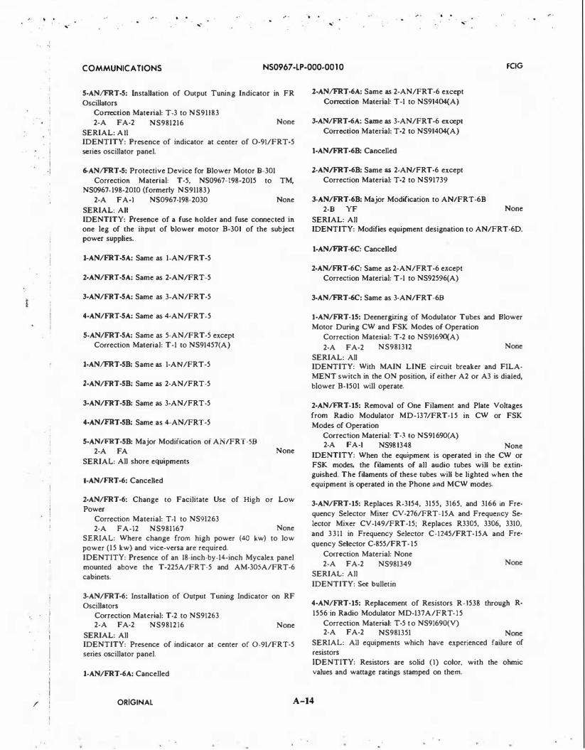
5-AN/FRT-5: Installation of Output Tuning Indicator in FR
Oscillators Correction Material: T-3 to NS91183
2-A FA-2 NS981216
SERIAL: AU
None
IDENTITY: Presence of indicator at center of 0-91/FRT-5 series oscillator panel.
6-AN/FRT-5: Protective Device for Blower Motor B-301
Correction Material: T-5, NS0967-198-2015 to TM, NS0967-198-2010 (formerly NS91183)
2-A FA-I NS0967-198-2030 None
SERIAL: All IDENTITY: Presence of a fuse holder and fuse connected in one leg of the input of blower motor B-301 of the subject power supplies.
1-AN/FRT·5A: Same as 1-AN/FRT-5
2-AN/FRT-5A: Same as 2-AN/FRT-5
3-AN/FRT·5A: Same as 3-AN/FRT-5
4-AN/FRT-5A: Same as 4-AN/FRT-5
5·AN/FRT-5A: Same as 5-AN/FRT-5 except Correction Material: T-1 to NS91457(A)
1-AN/FRT-58: Same as 1-AN/FRT-5
2-AN/FRT-58: Same as 2-AN/FRT-5
3-AN/FRT-58: Same as 3-AN/FRT-5
4-ANIFRT-58: Same as 4-AN/FRT-5
5-AN/FRT-58: Major Modification oi AN/FRT-58 2-A FA
SERIAL: All shore equipments
1-AN!FRT-6: Cancelled
None
2-AN/FRT-6: Change to Facilitate Use of High or Low Power
Correction Material: T-1 to NS91263 2-A FA-12 NS981167 None
SERIAL: Where change from high power (40 kw) to low power (15 kw) and vice-versa are required.
IDENTITY: Presence of an 18-inch-by-14-inch Mycalex panel mounted above the T-225A/FRT-5 and AM-305A/FRT-6
cabinets.
3-AN/FRT -6: Installation of Output Tuning Indicator on RF Oscillators
Correction Material: T-2 to NS91263 2-A FA-2 NS9812i6 None
SERIAL: All IDENTITY: Presence of indicator at center of 0-91/FRT-5 series oscillator panel.
1-AN/FRT-6A: Cancelled
2.·AN/FRT-6A: Same as 2-AN/FRT-6 except
Correction Material: T-1 to NS91404{A)
3-AN/FRT-6A: Sa.me as 3-AN/FRT-6 except
Correction Material: T-2 to NS91404{A)
t-ANIFRT-68: Cancelled
2-ANIFRT-68: Same as 2-AN/FRT-6 except
Correction Material: T-2 to NS91739
3-AN/FRT-68: Major Modification to AN/FRT-68
2-B YF
SERIAL: All
None
IDENTITY: Modifies equipment designation to AN/FRT-6D.
t-ANIFRT-6C: Cancelled
2·AN/FRT-6C: Same as 2-AN/FRT-6 except
Correction Material: T-1 to NS92596(A)
3·AN/FRT-6C: Same as 3-AN/FRT-68
1-AN/FRT-15: Deenergizing of Modulator Tubes and Blower
Motor During CW and FSK Modes of Operation
Correction Material: T-2 to NS91690(A)
2-A FA-2 NS981312 None
SERIAL: All IDENTITY: With MAIN LINE circuit breaker and FILA· MENT switch in the ON position, if either A2 or A3 is dialed,
blower B-1501 will operate.
2-AN/FRT-15: Removal of One Filament and Plate Voltages
from Radio Modulator MD-137/FRT-15 in CW or FSK
Modes of Operation
Correction Material: T-3 to NS91690(A) 2-A FA-I NS981348 None
IDENTITY: When the equipment is operated in the CW or FSK modes, the filaments of all audio tubes will be extin· guished. The filaments of these tubes will be lighted when the equipment is operated in the Phone and MCW modes.
3-AN/FRT-15: Replaces R-3154, 3155, 3165, and 3166 in Fre
quency Selector Mixer CV-276/FRT-15A and Frequency Se
lector Mixer CV-149/FRT-15; Replaces R3305, 3306, 3310,
and 3311 in Frequency Selector C-1245/FRT-15A and Fre
quency Selector C-855/FRT- 15
Correction Material: None
2-A FA-2 NS981349
SERIAL: All
IDENTITY: See bulletin
None
4-AN/FRT-15: Replacement of Resistors R-1538 through R·
1556 in Radio Modulator MD-137A/FRT-15
Correction Material: T-5 to NS91690(V) 2-A FA-2 NS981351 None
SERIAL: All equipments which have experienced failure of
resistors
IDENTITY: Resistors are solid (I) color, with the ohmic
values and wattage ratings stamped on them.
ORIGINAL A-14

• . ·,-
' "!
I
I . I
I .I I i I
I · i
I · I '
.. .
,-. .
·,- ,-
COMMUNICATIONS NS0967 -LP-000-00 10 FCIG
5-AN/FRT-15:
Correction Material: T-6 to NS91690(A) 1-C YF-50 NS981405 None
1-AN/FRT-15A: Wiring Change to Deenergize Modulator Tubes and Blower Motor During CW and FSK Modes of Op
eration Correction Material: T-3 to NS91848(A) 2-A FA-2 NS981 165
SERIAL: All None
IDENTITY: With MAIN LINE circuit breaker and FILAMENT switch in the ON position, if either A2 or A3 is dialed, blower B-1501 will operate.
2-AN/FRT-15A: Same as 1-AN/FRT-1 5 except
Correction Material: T -4 to NS91848(A)
3-AN/FRT-15A: Same as 3-AN/FRT-15 except Correction Material: T-5 to NS91845(A)
4-AN/FRT-15A: Same as 4-AN/FRT-15 except
Correction Material: T-6 to NS91848(A)
5-AN/FRT-15A: Same as 5-AN/FRT-5
SERIAL: 1-95 IDENTITY: C-901 and C-902 are changed to 200 mmf.
3-AN/FRT-18: Same as 2-AN/FRT-17 except
Correction Material: T-6 to NS92018
4-AN/FRT-18: Same as 3-AN/FRT-17
5-AN/FRT-18: Disabling of Modulator Section When Trans
mitter is Not Used for A-3 Emission
Correction Material: T-8, NS0967-099-2013 to TM, NS0967-099-2010 (formerly NS92018)
2-A FA-I NS0967-099-2060 None
SERIAL: When transmitter is not expected to be used for A-3 type of emission
IDENTITY: Accomplishment can readily be detected by the absence of vacuum tubes in the modulator section of the transmitter.
1-AN/FRT-19: Antenna Helix Tuning Relay Modification
Correction Material: None 1-A FA-2 NS98677 F5820-590-
9840 SERIAL: AU
IDENTITY: Contact pres springs mtd on ant helix tuning 1-AN/FRT-17: Removal and Replacement of C417, L603, relay.
R609, and R610 Correction Material: T-3 to NS91963 1-A FA-1.5 NS98574
SERIAL: 1-159
F5820-325-7483
IDENTITY: R-609 and R-610 (adjacent to C-601) removed from CU-362 and C-417 changed from 100 mmf to 47 mmf (mounted on TB-405) in AM-766.
2-AN/FRT-17: Remote Control Voice
Correction Material: T-5 to NS91963 1-A FA-I NS981098
SERIAL: All None
IDENTITY: Terminal 6 on sw S813F removed from ground and connected to terminal 5.
3-AN/FRT-17: Change to RF Power Amplifier Sub-Assembly
Chassis Correction Material: None 2-A FA-I N$0967-099-2050
SERIAL: All None
IDENTITY: Presence of two machine screws installed on top front sides of drawer for easy removal of top bracket.
1-AN/FRT-18: Caps in AM-897/FRT, modif Correction Material: T-3 to NS92018 A FA-2 NS98558 None
SERIAL: BUSHIPS I, 3-44 IDENTITY: Addition of capacitors C-963 thru C968
2-AN/FRT-18: Removal of C-417, C901, C902, L603, chg;
R609, R610 Correction Material: T -4 to NS92018 1-A FA-2 NS98575 F5820-568-
7818
2-AN/FRT-19: Radio Transmiuer Circuit and Mechanical Modification
Correction Material: T -4, NS0967-238-3011 to TM, NS0967-238-3010 (formerly NS92117)
N$0967-238-3030
SERIAL: All installed
1-AN/FRT-24: Ground Switch S-102 Drive Shaft and Install C-106A
Correction Material: T -4 to NS92223(A) 2-A FA-2 NS0967-1 17-0040 None
SERIAL: All
IDENTITY: The insulated flexible shaft coupling 0-121 on modified equipments, has been replaced by noninsulated flexible shaft coupling.
2-AN/FRT-24: Improving Reliability of Channel Indicator Circuits in Transmiuer AN/FRT-24
2-A FA-2 NS0967-1 17-0060 None SERIAL: All IDENTITY: Substitution of a two watt resistor for a one watt resistor (R-161) in the Auto tune System.
3-AN/FRT-24: Replacement of R-149 in T-440/FRT-24 to
Reduce Excessive Radiation Correction Material: T-5, NS0967-1 17-0011 to TM,
NS0967-117-00IO (formerly NS92223(A)) 2-A FA-I NS0967-117-0050 None
SERIAL: T-440/FRT-24 Serial 224 and higher, and T-440A/ FRT-24 all IDENTITY: R-149 is a 2000 ohms resistor.
4-AN/FRT-24: Provision for Lifting Handles for the Side
ORIGINAL A-15

j . ·'
I
I I
j I I !
·, ... -
. . . . ... - ... -
. . ...-
COMMUNICATIONS NS0967 -LP-000-00 1 0 FCIG
Panels of the Transmitter Cabinet Correction Material: None required 2-A YF-1 NS0967-117-0050
SERIAL: All
None
IDENTITY: Close observation of the chrome trim strips on the side panels of the transmitter will reveal that the center trim strip on each side panel has been separated from the side panel by means of 3/4 inch spacers .
5-AN/FRT·24: (C-1362/FRT-24), VU Meter Readings
Correction Material: None 2-A FA-I NS0967-117-0050
SERIAL: All
None
IDENTITY: Recording of field change number on Field Change Accomplished plate.
1-AN/FRT-25: Same as 3-AN/FRT-15 except
Correction Material: T-1 to NS92431
2-AN/FRT-25: Same as 5-AN/FRT-15
1-AN/FRT-27: Same as 6-AN/FRT-5 except
Correction Material: T-3, NS0967-198-5012
1-AN/FRT-27A: Protection of the Secondary of the 1500
Power Supply
Correction Material: T-1, NS0967-033-8044 to NS0967-033-8040
1-A FA-4 NS0967-033-8050
SERIAL: All serial numbers
EIC QEOWOOO
IDENTITY: In units 3 and 6, a phenolic or plastic base with 3 fuses will be mounted on the right side wall. The fuses will be separated from the plastic by ceramic stand-offs, and held to the base by fuseclips.
1-AN/FRT-39: Convenience Outlet Correction Material: T-1, NS0967-l01-9012 to TM,
NS0967-101-9010 (formerly NS94430)
2-A FA-I NS0967-101-9040
SERIAL: All IDENTITY: Proper recording of the >�ppropriate field change number on the Field Change Accomplished plate.
1-AN/FRT-39A: Removal of Capacitors Correction Material: T-1, NS0967-l01-9012 to TM,
NS0967-101-9010 (formerly NS94430)
2-A FA-3 NS0967-101-9040 None
SERIAL: Equipment delivered and not modified. IDENTITY: Capacitors C-2007 thru C-2014 have been removed.
2-AN/FRT·39A: Same as 1-AN/FRT-39
1-AN/FRT-398: Same as l-AN/FRT-39A except
Correction Material: NS93699
2-AN/FRT-398: Same as 1-AN/FRT-39
1·AN/FRT-39C: Same as 1-AN/FRT-39
1-AN/FRT-390: Same as 1-AN/FRT-39
1-ANIFRT-39N: Replace Resistor R-108 and Fuse F-103 on the Standing Wave Control Unit (SWCU)
Correction Material: T-1, NS0967-377-3011 to NS0967-377-3010; T-1, NS0967-377-4011 to NS0967-377-4010
2-A FA-2 NS0967-377-3030 EIC QEOOOOO SERIAL: All AN/FRT-39s and ANIFRT-40s which contain the SWCU. IDENTITY: This field change may be identified by R-108 being a four watt value and F-103 being rated at 0.250 amp.
1-AN/FRT-40: Same as 1-ANIFRT-39A except Correction Material: NS93167
2-AN/FRT-40: Same as 1-AN/FRT-39
1-AN/FRT-40A: Same as 1-AN/FRT-39
2-ANIFRT-40A: Installation of Operative VSWR Overload Protection Circuit
Correction Material: Ch. I, NS0967- 158-9011 to NS0967-158-9010
2-A FA-4 NS0967-158-9030 EIC QE6COOO SERIAL: AN/FRT-40A - all serial numbers; AN/FRT-408 -all serial numbers; AN/FRT-40C - all serial numbers IDENTITY: Upon completion of this field change, SWR meter M8205 will be a type containing two indicator pointers.
1-AN/FRT-408: Same as 1-AN/FRT-39
2-AN/FRT-408: Same as 2-AN/FRT-40A
1·AN/FRT-40C: Same as 2-AN/FRT-40A
1·ANIFRT-40J: Same as I-ANIFRT-39N except Correction Material: T-1, NS0967-377-3011 to NS0967-37i-
3010; T-1, NS0967-377-401 1 to NS0967-377-4010
1-AN/FRT-61: Engineering Design Changes Correction Material: T- to NS94592
NS981686
1-AN/FRT-67: Same as 1-AN/FRT-64
2-AN/FRT-67: Replacement of Main Circuit Breakers in Units 22, 33, 35, 36, and 37
Correction Material: The Technical Manuals for AN/ FRT-67, VLF Radio Transmitter (U), Australia have been revised according to their respective Change Notice, dated 20 October 1970.
1-A FA-80 NS0967-384-5080 SERIAL: All equipments IDENTITY: This field change has been accomplished if the circuit breakers in Units 22, 33, 35, 36, and 37 are ITE Types CJ3B400, CJ3B250, CF3B030 and CF3B090.
1-AN/FRT-728: Eliminate Network Vibration Correction Material: T-1, NS0967-238-9011 to NS0967-238-
90!0
ORIGINAL A-16

� . J
i i · I I i . ,
.. . .. . . . ,- ,- ,-
COMMUNICATIONS NS0967 -LP-000-00 10 FCIG
1-A FA-4 NS0967-238-9050
SERIAL: All serials
EIC QEOWOOO
IDENTITY: In units 3 and 6, Cl, C2, and C3, are placed between two plastic panels (6 x 5 x 1/4)
2-AN/FRT-728: Protects the Secondary of the Power Amplifier Screen Supply
Correction Material: T-1, NS0967-238-9012 to NS0967-238-9010
1-A FA-4 NS0967-238-9060
SERIAL: All serials
EIC QEOWOOO
IDENTITY: In units 3 and 6, a phenolic or plastic base with 3 fuses will be mounted top of CR2. The fuses will be separated from the plastic by ceramic stand-offs, and held to the base by fuseclips. See figure 3.
1-AN/FRT-83(V): Replacement of the Side Carrier Generator (A9) With A Side Carrier Generator Simulator (A20) in the Modulator-Synthesizer, MD-777/FRT
Correction Material: Change I , NS0967-292-9031 to NS0967-292-9030
1-A FA-I NS0967-292-9110 EIC QEOOOOO SERIAL: All equipment serial numbers IDENTITY: This field change eliminates the use of the (4) ISB (4 independent sidebands) function of the sideband selector switch. To insure that the field change has been adequately incorporated, select the (4) ISB mode of the sideband selector switch and note: although the functional characteristics of the (4) ISB mode have been eliminated, the transmitter fail light should remain off indicating no fault. All other modes should function normally.
2-AN/FRT-83(V): Modification for Independent Control of the Two 115V AC Branch Circuits Controlled by Circuit Breaker
8AlCB3 Correction Material: T-1. NS0967-292-9012 to NS0967-292-
9010; T-1, NS0967-292-9062 to NS0967-292-9060
2-A FA-4 NS0967-292-9120 EIC QE6NOOO
SERIAL: All serial numbers IDENTITY: The 1 1 5 VAC supply to outlet strip 8A3 will be from a separate external source and controlled by circuit breaker 8A I CB4.
3-AN!FRT-83(V): Modification of Frequency Shift Keyer KY-655/FRT
Correction Material: T-1, NS0967-292-9021 to NS0967-292-9020
II-A FA-2 NS0967-292-9140 EIC QE6NOOO
SERIAL: All serial numbers IDENTITY: Noting that with the mode switch in the CW position, CW mode operation is permitted using any of the input signal levels indicated on the TTY input selector switch.
4-AN/FRT-83(V): Internal, External Frequency Standard MD-777/FRT
Correction Material: T-1, NS0967-292-9031 to NS0967-292-9030
4-A FA-I NS0967-292-9130 EIC QE6NOOO
SERIAL: All serial numbers
IDENTITY: Upon loss of the external frequency standard, the STANDARD FAIL light on the MD-777/FRT will illuminate, and the transmitter will continue to function, due to automatiC switch-over to the internal standard.
S.AN!FRT-83(V): Improved Antenna Interlock
Correction Material: T-2, NE0967-292-9013 to NE0967-292-9010
IV-A FA-I NE0967-292-9150 EICQE6NOOO
SERIAL: All serial numbers
IDENTITY: Upon opening the antenna interlock the STAND BY light on the modulator synthesizer will remain illuminated .
6-AN!FRT-83(V): Replacement of the Bridge Rectifiers
(2A I CR2/2A I CR3)
Correction Material: T-3, NS0967-292-9014 to NS0967-292-9010
III-A FA-I NS0967-292-9160 EIC QE6NOOO
SERIAL: All serial numbers IDENTITY: The presence of the two new type bridge rectifiers in Power Supply PP-6067/FRT can be identified by noting the part number 130072 014 SCJ on the printed circuit board of the bridge rectifiers.
7-AN/FRT-83(V): Transmitting Set Cooling Correction Material: Ch. 2, NE0967-LP-292-9015 to
NE0967-LP-292-9010; Ch. 3, NE0967-LP-292-9034 to NE0967-LP-292-9030; Ch. 2, NE0967-LP-292-9063 to NE0967-LP-292-9060
3-A FA-24 NE0967-LP-292-9170 EIC QE6NOOO
SERIAL: All serial numbers IDENTITY: Air intake/alarm panel 8A6 installed at top of cabinet rack in place of blank panel.
1-AN/FRT-84(V): Same as 1-AN/FRT-83
2-AN/FRT-84{V): Same as 3-AN/FRT-83(V) except
EIC QE6POOO
3-AN/FRT-84(V): Addition of Circuit Breaker 8AICB3
Correction Material: T-1, NS0967-293-0012 to NS0967-293-00IO; T-1, NS0967-293-0022 to NS0967-293-0020
1-A FA-4 NS0967-293-0070 EIC QE6POOO
SERIAL: All serial numbers IDENTITY: The 1 1 5 VAC supply to outlet strip 8A3 will be from a separate external source, protected and controlled by circuit breaker 8AICB3.
4-AN!FRT-84{V): Same as 4-AN/FRT-83(V) except
EIC QE6POOO
5-AN/FRT-84(V): Improved Antenna Interlock
Correction Material: T-2, NE0967-293-0013 to NE0967-293-00IO
IV-A FA-I NE0967-293-0080 EICQE6POOO
SERIAL: All serial numbers
IDENTITY: Upon opening the antenna interlock the
ORIGINAL A-17

' I !
. . . . . .
COMMUNICATIONS NS0967-LP-000-00 1 0 FCIG
STANDBY light on the modulator synthesizer will remain illuminated.
6-AN/FRT-84(V): Same as 6-AN/FRT-83(V) except
Correction Material: T-3, NS0967-293-0014 to NS0967-293-00IO and EIC QE6POOO
7-ANIFRT-84(V): Transmitting Set Cooling
Correction Material: Ch. 2, NE0967-LP-293-0015 to NE0967-LP-293-00IO; Ch. 2, NE0967-LP-293-0023 to NE0967-LP-293-0020; Ch. 4, NE0967-LP-292-9035 to NE0967-LP-292-9030
I-A FA-24 NE0967-LP-293-9170 SERIAL: All serial numbers
EIC QEOOOOO
IDENTITY: Air/intake/alarm panel 8A6 instaHed at top of cabinet rack in place of blank panel.
1-AN/FRT-85(V): Same as 3-AN/FRT-83(V) except
EIC QE6QOOO
2-AN/FRT-85(V): Same as 4-AN/FRT-83(V) except
EIC QE6QOOO
1-AN/FRT-86(V): Same as 1-AN/FRT-83
2-AN/FRT-86(V): Same as 3-AN/FRT-83(V) except
EIC QE6ROOO
3-AN/FRT-86(V): Same as 4-AN/FRT-83(V) except
EIC QE6ROOO
1-AN/FSA-17: NS981659-Virginia Elec. 87707. Refer to page
24.
1-AN/FSC-l(V): Replacement of Keying Relay Panel and Mis
cellaneous Changes Correction Material: None 1-B YF-16 NS98987
SERIAL: Stations 10-13 None
IDENTITY: Addition of Power Supply and Keying Relay Panels.
2-AN/FSC-l(V): SECRET
3-AN/FSC-l(V): Addition of Dummy Load G-269646
Correction Material: None 1-A YF- 16 NS98I038
SERIAL: 10-13 None
IDENTITY: G-269646 installed with transmitter AN/FRT-24
1-AN/FSH-7(V): Capstan Motor Protection Fuse
Correction Material: T-1, NS0967-266-5011 to TM, NS0967-266-5010
II-A YF-1 NS0967-266-5040
SERIAL: AN/FSH-7 (RD-310 and RD-311) equipments
IDENTITY: Presence of double fuse clip on left side and
single fuse clip on right side of the preamplifier chassis (A9AI).
2-AN/FSH-7(V): Heat Sink and Zener Assembly Transistor Replacement
Correction Material: T-2, NS0967-266-5012 to TM, NS0967-266-5010
II-A YF-1 NS0967-266-5050 SERIAL: AN/FSH-7 (RD-310 and RD-311 equipments) IDENTITY: Presence of a standoff mounted transistor in the heat sink and zener assembly (A7A2Q2, A7A3Q2) and a 2N3773 transistor in the A 7 A2Q I and A 7 A3Q I position of the assembly.
3-AN/FSH-7(V): Resistor Replacement in Power Supply Chassis
Correction Material: T-3, NS0967-266-5013 to TM, NS0967-266-5010
II-A YF-1 NS0967-266-5060 SERIAL: AN/FSH-7 (RD-310 and RD-31 1 ) equipments IDENTITY: Presence of a 3 watt, wirewound resistor in R4, R5, and R6 position in the Power Supply Chassis (AS) of the AN/FSH-7(V) equipment.
4-AN/FSH-7(V): Installation of High Vacuum Inhibit Switch Correction Material: T-4, NS0967-266-5014 to TM,
NS0967-266-5010 2-A FA-I NS0967-266-5070
SERIAL: All IDENTITY: Single pole single throw toggle switch on the
left side of A6TBI.
5-AN/FSH-7(V): Relay Replacement in 30 VDC Circuit Switch
Correction Material: T-5, NS0967-266-5015 to TM, NS0967-266-5010
1-A NS0967 -266-5080 SERIAL: AN/FSH-7 (RD-310 and RD-311) equipments
IDENTITY: Location of an SPST toggle switch.
6-AN/FSH-7(V): Reproduce Monitor Switch Reinforcement Correction Material: None 2-A FA-I NS0967-266-5130
SERIAL: AN/FSH-7 (RD-310 and RD-3 11) equipments.
7-AN/FSH-7(V): Access to Heat Sink and Zener Assemblies on Chassis A 7
Correction Material: None 2-A FA-2 NS0967-266-5090
SERIAL: RD-310/FSH-7(V) and RD-311/FSH-7(V) • All serial numbers IDENTITY: The front panel on A 7 chassis can be opened to
a working position for maintenance on the Heat Sink and Zener Unit Transistor (QI) can be replaced by the removal of two (2) mounting screws.
8-AN/FSH-7(V): Multiple Tape Loop Buffer Correction Material: None 2-A FA-2 NS0967-266-5 100
SERIAL: RD-310/FSH-?(V) and RD-31 1/FSH-7(V) - All
serial numbers
ORIGINAL A-18

-. .
- i
,-. .
,-. . .. ·
...- ,-
COMMUNICATIONS NS0967 -LP-000-00 10 FCJG
IDENTITY: The storage bin roller (A9MP30) will be replaced with a fixed part having a wedge type cut-out encountering the tape as it comes from the storage bin.
9-AN/FSH-7(V): Installation of Resistor in Heat Sink and
Zener Assembly
Correction Material: T-7, NS0967-266-5017 to NS0967-266-5010
2-A FA-0.5 NS0967-266-5110
SERIAL: RD-310/FSH-7(V) and RD-311/FSH-7(V) - All serial numbers
IDENTITY: Presence of a 100 ohm resistor between the Qlbase/Q2-emitter junction and ground on the A 7 A2 and A 7 A3 assemblies.
10-AN/FSH-7(V): Reproduce Transfer Switch Indicator
Correction Material: T-8, NS0967-266-5018 to NS0967-266-5010
2-A FA-2 NS0967-266-5120
SERIAL: RD-310/FSH-7(V) and RD-311/FSH-7(V) - All serial numbers
IDENTITY: Presence of a lamp indicator immediately to the right of the 'THREAD/READY' indicator on the control paneL
11-AN/FSH-7(V): Adjustable Capstan Motor Lamp with
Holder
Correction Material: T-9, NS0967-266-5019 to NS0967-266-5010
2-A FA-0.5 NS0967-266-5130
SERIAL: RD-310/FSH-7(V) and RD-31 1/FSH-7(V) - All serial numbers
IDENTITY: Presence of an adjustable type lamp holder within the housing of the capstan motor. There are no external indications of accomplishment.
12-ANIFSH-7(V): Conversion of Equipment to Operate at 30
IPS and Accept NRL 'Universal' Head (This field change is
the same as 19-AN/FLR-Il(V) which appears in the Counter
measures EIMB Handbook.) Correction Material: J:-lone required
3-A FA-80 NS0967-046-3390
SERIAL: All None
IDENTITY: The tape recorders in the system will operate at 30 ips and will be equipped with the NRL 'Universal' head. All Time Distribution Panels will be equipped with a switch for obtaining one pulse at 15 minute or 30 minute intervals.
13-ANIFSH-7(V): Replacement of Potted Computer (A7A4-
A7A5), Converter (A7A6-A7A7), and Control (A7A8-A7A9)
Modules with Repairable Unpotted Units
Correction Material: T-10, NE0967-266-5203 to NE0967-266-5010, Supp. Tech Man NE0967-266-5150
II-A YF-1 NE0967-266-5140
SERIAL: RD-310/FSH-7(V) and RD-31 1/FSH-7(V) - All serial numbers
IDENTITY: Presence of exposed components on printed circuit boards in lieu of potted modules at positions A 7 A4,
A7A5, A7A6, A7A7, and A7A8 and A7A9 in the AN/FSH-7(V) equipments.
14-AN!FSH-7(V): Maintenance Switch for the AN/FSH-7(V)
Equipment
Correction Material: T-11, NS0967-266-5204 to NS0967-266-5010
II-A YF-1 NS0967 -266-5170
SERIAL: All serial numbers
IDENTITY: A7Al4SI is a DPST switch. The labeling on Sl (Fault Transfer Switch) located on Logic A Card (A7Al4) will indicate 'MAINT' in the out position.
15-AN!FSH-7(V): Component Change to Improve Time Fol
lowing Error
Correction Material: T- to N$0967-266-65010
II-A FA-I EIB 861
SERIAL: All serial numbers
IDENTITY: Presence of a .015 ufd capacitor across resistor Rl on terminal A7AL
16-AN/FSH-7(V): Modification of the XDS3 Lamp Socket
Mounting Plate
Correction Material: None
II-A FA-.75 EIB 863
SERIAL: All serial numbers
IDENTITY: Ability to reposition the lamp socket mounting
plate when the mounting plate securing screws have been loosened.
17-AN/FSH-7(V): Modification of Reel Knobs A9MP25
Correction Material: To TM NS0967-266-5010 published in EIB 867
II-A FA-2 •see note
SERIAL: All serial numbers
IDENTITY: Presence of set screws vice a rolled pin holding
the reel hub to the shaft. NOTES: *None assigned - A field change kit consisting of Naval Research Laboratory (NRL) Technical Memorandum 5470-300a NRL Prob R06-03 dated 26 Sept. 1973, and necessary parts was furnished to the cognizant activities. A field change number was assigned for configuration purposes only.
18-AN/FSH-7(V): Improve Response of Tape Control SignaL
Correction Material: NE 0967-266-5010 per EIB 895
2-A FA-4 EIB 895
SERIAL: All serials
IDENTITY: A7Al5 C24 is 1.0 ufd. A2Al5 R7 is 2.2 ohms. A2Al5AlR4 is 6.8 ohms.
19-AN!FSH-7(V}: Modification of AN/FSH-7(V) to Provide
Tape Loop Operation
Correction Material: T-13, NE0967-266-5207 to STM, NE0967-266-5010, and new STM, NE0967-LP-266-5190
1-A FA-16 NE0967-LP-266-5180 EIC QKll
SERIAL: All serial numbers
IDENTITY: Changes plainly visible on front of tape deck A9: large rectangular panel of tape monitor in upper left-hand corner, and precision plate carrying erase head and new tape guide rollers above the reproduce station.
1-AN!FSQ-59(V): Modification to Distribution Amplifier AM-
ORIGINAL A-19

. . ...
. .
..- .. . ...
COMMUNICATIONS NS0967 -LP-000-00 10 FCIG
4874/FSQ-59(V) 1-A FA-8 NS0967-269-2120
SERIAL: All equipment
l-ANIFSQ·59(V): Modification to Distribution Amplifier AM-4874/FSQ-59(V)
1-A FA-8 NS0967-269-2190 SERIAL: All AM-4874/FSQ-59(V) Distribution Amplifiers
3·ANIFSQ·59(V): Modification to Outstation Processor Group OL-17(V)/FSQ-59(V) Teletypewriter Buffer Cabinet
1-A FA-4 NS0967-269-2200 IDENTITY: Presence of switch ABI-OPU on the Teletypewriter Buffer Cabinet panel located between TT-552(AI) and TT-553(A2).
4-ANIFSQ-59(V): Modification to Cabinets CY -6308/F and
CY -6318/FSQ-59(V) Correction Material: None required I-A FA-0.5 NS0967-26S-2210
SERIAL: All equipment serial numbers IDENTITY: Presence of cam stop on latch assembly.
5-ANIFSQ-59(V): Modification to C-7431/FSQ·59(V) Control Panel
Correction Material: Ch. I, NE0967-LP-269-2111 to TM, NE0967-LP-269-2110
1-A FA-2 NE0967-LP-269-2220 EIC QKI3 SERIAL: All C-7431/FSQ-59(V) serial numbers IDENTITY: The audible alarm unit is mounted abutting the C-7431/FSQ-59(V) control panel container.
1-AN/FTA-15A: Signaling Tone Output Level Correction Material: T-1, NS0967-035-7001 to NS0967-035-
7000 2-A FA-0.5 NS0967-035-7020
SERIAL: All equipments IDENTITY: Checking the value of R26 on card A2A4. 15,000 ohms indicates this field change has been accomplished.
l·AN/FYA·7(V): Same as 4-AN/FSQ-59(V)
1-AN/GIC-17(V): Installation of Input Protection Fuses Correction Material: T-1, NS0967-169-801 1 to
NS0967-169-8010 1-A FA-2 NS0967-169-8020
SERIAL: All serial numbers
TM,
IDENTITY: Two fuseholders are installed on front panel below handset holder.
2-AN/GIC-17(V): Installation of Recorder Audio Output Circuit
Correction Material: T-2, NS0967-169-8012 to TM, NS0967-169-8010
1-A FA-30 NS0967-169-8030 SERIAL: All serial numbers IDENTITY: Presence of a BNC connector on rear of case labeled 'Recorder Audio-J9.'
1-AN/GMQ·l: Replacement of NT291529 Timer Fans
A FA-2 NS98164 None
SERIAL: 1-125 IDENTITY: A phosphor-bronze fan is installed replacing steel fan inside timer unit.
l·AN/GMQ-2: Ceilometer Equipment SERIAL: 1-125
1-AN/GRA-34: Shon Alarm Circuitry and Simplification of Alignment Procedure
Correction Material: Change I to NS93121(A) 1-A FA-16 NS981094
SERIAL: 1-447
F5820-542-7137
IDENTITY: Tube XVIIO in monitor chassis changed from a 5654 to a 6AS6W, and resistor R-1327 (sw. chassis) removed.
l-AN/GRA-34: Operational and Maintenance Improvements Correction Material: None 1-A YF-5 N$0967-134-2050 None
SERIAL: All IDENTITY: Presence of screen covers on all four sides of monitor and screen guard over blower motor.
3-AN/GRA-34: Installation of Product Improvements 2-A FA-2 NS0967-134-2060 F5825-970-
3694
SERIAL: 1-452
4-AN/GRA-34: Replaces SA-544/GRA-34, Antenna Transfer Switching Unit to Prevent Transmission into an open line (SA-544/GRA-34 becomes SA-544A/GRA-34)
Correction Material: T- to NS9312l(A) 1-A YF-2 NS0967-134-2070
SERIAL: All IDENTITY: The new Antenna Transfer Switching Unit has no manual switching knobs on front; Antenna-On-Air indicators and monitor panel are located on front panei.
1-AN/GRA-40: Addition of Receptacle for Motor Control Cable
Correction Material: T-1 to NS93595 2-A FA-8 NS981507 None
SERIAL: All IDENTITY: At Radio Frequency Tuner TN-357/GRA-40, note the addition of a receptacle box in the entrance hole provided for the motor control cable stuffing tube.
1-AN/GRA-60: Replacement of Diodes CR-213 and CR-214 (INI341)
Correction Material: T-1 to NS94118 and NS94118.61 1-A FA-5 NS981684 F5825-056-
7147
SERIAL: All IDENTITY: The new diode has the identification number INI202 stamped on it.
1-AN/GRA·61: Same as 1-AN/GRA-60
l·AN/GRC-9: Cancelled
1-AN/GRC-27: Panel J-390/GR Modification
ORIGINAL A-20

- .. i . j
I i
·i
i I I
. , . , I
I
.. . . .
COMMUNICATIONS NS0967 -LP-000-00 1 0 FCIG
Correction Material: T-1 to T.O. 16-30GRC27, T-1 to T.O. 16-30GRC27-4
2-B FA-4 NS98435
SERIAL: All w/CU-255/UR
IDENTITY: Tenninal Strips E-710 and E-71 I
2·AN/GRC-27: Shock and Vibration Improvement
Correction Material: T-6 to NS92774
2-A FA-2 NS98750
SERIAL: All on ships
F5820-642-6985
None
IDENTITY: Modifies equipments to AN/GRC-27A
NOTES: F.C. 5 must be accomplished in conjunction with this field change.
3-AN/GRC-27: Conversion of Power Supply from Intermittent
to Continuous Operation
Correction Material: T-1 to T.O. 16-350AI04-3
1-B YF-8 NS98654 2N5820-336-1664
SERIAL: All with MD-129/GR
IDENTITY: Required if air inlets on front panel are louvered metal cans filled with steel wool.
NOTES: F.C. 6 must be accomplished in conjunction with this field change.
4-AN/GRC-27: Modification to Permit Continuous Operation
Correction Material: T-4 to T.O. 16-350A 104-3; T-5 to T.O. 16-350AI04-4
l·A YF-4 NS0967-031-8080 2N5825·665-
1246
SERIAL: 2146-2149, 2151, 2153, 2155, 2156, and 2161
IDENTITY: Required if P.A. blower is gear driven and has black bakelite housing.
5-AN/GRC-27: Ground Mounting Rack Modification
3-A YF-4 NS0967-031-8090 2N5820-669-7922
SERIAL: All on ships
IDENTITY: Equipments becomes AN/GRC-27A.
NOTES: F.C. 2 must be accomplished in conjunction with this field change.
6-AN/GRC-27: MD-129/GR, Cross Brace Modification
2-A YF-3 NS0967-031-8100 2N5820-642-7928
SERIAL: 2154-2773
IDENTITY: Required if brace across rear of mod power supply is 1/2' diameter rod.
NOTES: F.C. 3 must be accomplished in conjunction with
this field change.
7-AN/GRC-27: T-217/GR, Modification for Continuous Oper
ation
2-A FA-6 NS0967-031-81 10 F5820-642-
8-AN/GRC-27: Driver, Continuous Operation Modification
2-A FA-3 NS0967-031-8120 F5820-665-2399
SERIAL: 1-2145
IDENTITY: F.C. required if driver motor is gear driven.
9-AN/GRC-27: Method for Securing Covers
Correction Material: None
FA
SERIAL: All
NS0967-031-8130 None
10-AN/GRC-27: Additional Protection Against B Shorts in
Receiver
Correction Material: T- to TM, NS0967-031-8010 (fonnerly NS92774)
2-A FA-I NS0967-03 1-8150 None
SERIAL: All
IDENTITY: Presence of a fuse clip mounted on inside wall of audio amplifier chassis of receiver.
11-AN/GRC-27: Change in Keying Circuit to Assure Motor
Positive Operation of Relay Kl405
Correction Material: T- to TM, NS0967-031-8010 (fonnerly NS92774)
2-A FA-0.5 NS0967-031-8150 None
SERIAL: All equipments not previously modified
IDENTITY: Resistor Rt464 is 30 ohms instead of 20 ohms.
12-AN/GRC-27: Modifies Wiring of MD-129A and R278B
Correction Material: T-9, NS0967-03 1-8011 to TM,
NS0967-031-8010 (formerly NS92774)
3-A FA-8 NS0967-031-8160 None
SERIAL: All
IDENTITY: A small nameplate stating: 'MODIFIED: for
normal operation, Jl405 must have shorted plug attached' shall be affixed just below equipment nameplate on the MD-129A Modulated Power Supply, and a small nameplate stating
'MODIFIED: for nonnal operation J1215 must have shorted plug attached' shall be affixed on the left side of the hinged
door of the R278B Frequency Selector, just below the knurled captive screw.
13-AN/GRC-27: Modified Main Crystal Oscillator Ovens in
Transmitter and Receiver to Prevent Overheating
Correction Material: T-10, NS0967-031-8012 to TM,
NS0967-03 1-8010 (fonnerly NS92774)
1-A FA-2 NS0967-031-8140
SERIAL: All
2N5820-937-
0140
IDENTITY: Presence of disc type capacitor (item I) in crys
tal oscillator oven.
1-AN/GRC-27A: Same as 1-AN/GRC-27
7924 2·AN/GRC-27A: Same as 2-AN/GRC-27
SERIAL: 2146-2161
IDENTITY: Required if R-1226, 470 ohm, watt is not in
stalled in upper rear corner of large phenolic tenninal board in left mid section of transmitter.
3-AN/GRC-27A: Same as 3-AN/GRC-27
4-AN/GRC-27A: Same as 4-AN/GRC-27
ORIGINAL A-21

·.,
. ! i !
I I , I I i
I
I -- I I
! I
� I
. .
... ... ...
COMMUNICATIONS NS0967 -LP-000-00 10 FCIG
5-AN/GRC27A: Same as 5-AN/GRC-27
6-AN/GRC-27A: Same as 6-AN/GRC-27
7-AN/GRC-27A: Same as 7-AN/GRC-27
8-AN/GRC27A: Same as 8-AN/GRC-27
9-AN/GRC-27A: Same as 9-AN/GRC27
10-AN/GRC-27A: Same as 10-AN/GRC-27
11·AN/GRC-27A: Same as 11-AN/GRC-27
12·AN/GRC-27A: Same as 12-AN/GRC-27
13-AN/GRC-27A: Same as 13-AN/GRC-27
J4-AN/GRC-27A: Installation of Elapsed Time Indicator Correction Material: T-12, NS0967-031-8015 to
NS0967-031·8010 (formerly NS92774) TM,
1-A FA-4 NS0967-031-8160 2F5820..Q56-1323
SERIAL: Equipments installed on selected ships (see field change bulletin) IDENTITY: Presence of an elapsed time indicator on front panel of Modulator Power Supply (MD-l29A/GR).
1-AN/GRD-6: Rheostats for Ballast Tubes Rl419, Rl420 to Improve Reliability Substitute
Correction Material: T-1 to NS92712(A) I·A FA-4 NS981012
SERIAL: All IDENTITY: Variable resistors replace ballast tubes.
None
l-AN/GRD-6: Addition of Resistors R-5013 and R-5014 in Power Supply Synchronizer PP-1186/GRD-6
Correction Material: T-5, NS0967-210-4015 to TM, NS0967-210-4010 (formerly NS92712A)
2-A FA-I NS0967-210-4060 None SERIAL: All equipments PP-1186/GRD-6
IDENTITY: Presence of 270K ohm resistors between termi· nals 2 and 3 of relay K-4902 and between terminals 3 and 4 of relay K-4903.
3-AN/GRD-6: Modification of Power Supply System to Provide a Common Power Source to Antenna Arrays
Correction Material: T -4 to NS92712{A) 2-A FA-10 NS981626 None
SERIAL: All
IDENTITY: A 'phase shift relay switch' and a 'goniometer switch' located in the AF patch panel.
4-AN/GRD-6: Modification of North-Pulse and Bearing-Tone Generating Systems in AN/GRD-6 Goniometers
1-A YF-4 NS981640 None SERIAL: AS-697/GRD-6 and AS-779/GRD-6, all serials IDENTITY: The pulse transformer is mounted on the pulse amplifier chassis. The tone wheel and armature wheel are mounted on the same end of the goniometer shaft.
1-AN/GRN-9: Humidity Control to Transmission Line Filter Z-11 56 or Z-1157
Correction Material: T-2 to NS92986 1-A FA-I NS981048
SERIAL: 1-65
F5820-543-1775
IDENTITY: Dehumidifier crystals placed in control duplexer C-2226/GRN-9.
2-AN/GRN-9: Modification to Deactivate the Identification Call Keyer when Equipment is in STANDBY status
Correction Material: T -4, NS0967-073-5012 to TM, NS0967-073-5010 (formerly NS92986A)
I·A FA-4 NS0967-073-5080 SERIAL: Coder Indicator KY-235/URN in all Radio Sets AN/GRN-9 IDENTITY: Keyer wheel will not rotate when master switch, SilO!, on Control Duplexer C-2226/GRN-9 is in STANDBY position.
3-AN/GRN·9: Modification to Stabilize the North and Auxiliary Reference Pulses
Correction Material: T-5, NS0967-073-5013 to TM, NS0967-073-5010 (formerly NS92986A)
2·A FA-3 NS0967-073-5100 SERIAL: Coder Indicator KY-235/URN IDENTITY: Presence of a IN69 diode between terminals 20 and 21 of TB-698, a IN69 diode berween terminals 26 and 27 of TB-698 and a 120,000-ohm resistor between terminals 22 and 61 ofTB-698.
4-AN/GRN-9: Modification to Secure the Wiring Harness on Control Duplexer C-2226/GRN-9, C-2226/GRN-9A, C-2412/ GRN-98, and C-2225A/SRN-6A
Correction Material: None required II-A FA-2 NS0967-073-5130
SERIAL: All serial numbers IDENTITY: Presence of cable clamp on terminal board TBIIOI.
l·AN/GRN·9A: Same as 1-AN/GRN-9
2·AN/GRN·9A: Same as 2-AN/GRN-9
3·AN/GRN·9A: Same as 3-AN/GRN-9 except Correction Material: T-12, NS0967-031-8015 to TM,
NS0967-031-8010
4-AN/GRN-9A: Installation of Klystron Aging Switch Correction Material: T-3 to NS0967-073-5013 1-A FA-3 NS0967-073-5090
SERIAL: All IDENTITY: The presence of a NORMAL/AGE switch on the hinged fuse panel of Power Supply Group Cabinet CY-2189/GRN-9A.
S·AN/GRN-9A: Same as 4-AN/GRN-9
I·AN/GRN·9B: Installation of RF Filter Cavity Cover 2-A FA-0.5 NS981053 None
SERIAL: 6-19, 21·26, 29, 31, 33
ORIGINAL A-22
. .
.. .

. i I
. I I I !
. . ·, . . . ·, . ,. ,-
COMMUNICATIONS NS0967 -LP-000-00 10 FCIG
IDENTITY: Filter cover over filter cavity is C-2412.
2-AN/GRN-98: Operational Improvement for Reduction of
Radiated Noise
Correction Material: None 1-A FA-4 NS0967-073-6060
SERIAL: I thru 149
None
IDENTITY: Presence of cable separator board assembly.
3-AN/GRN-98: Operational Improvement for Reduction of
Radiated Noise
Correction Material: None 1-A FA-3 NS981183
SERIAL: I thru 100
None
IDENTITY: Presence of reference symbol E1478 on underside of video chassis .
4-AN/GRN-98: Reduction of Radiated Noise
Correction Material: Change I to NS93177(A)
1-A FA-10 NS981363
SERIAL: Equipments on NObsr 75819
IDENTITY: Presence of RF Shield Box.
F5825-856-1861
S-AN/GRN-98: Installation of Frequency Multiplier Oscillator
High Voltage Protective Shield
Correction Material: None 1-A FA-I NS981404 None
SERIAL: CV -650/GRN-98 IDENTITY: Presence of protective shield over R1471 in the video chassis in the frequency multiplier oscillator drawer.
6-AN/GRN-98: Modification to Deactivate the Identification
Call Keyer when the Equipment is in Standby Status
Correction Material: T-1, NS0967-073-6012 to TM,
NS0967-073-6010 (formerly NS93177A)
1-A FA-7 NS0967-073-6100 SERIAL: Coder Indicator KY-248/GRN-98 in all Radio Sets AN/GRN-98
IDENTITY: Keyer wheel will not rotate when master switch, SllOI, on Control Duplexer C-2412/GRN-98 is in STANDBY position.
7-AN/GRN-98: Modification to Stabilize the North and Auxil
iary Reference Pulses
Correction Material: T-2, NS0967-073-6014 to TM,
NS0967-073-6010 (formerly NS93177A)
2-A FA-3 NS0967-073-5100 None
SERIAL: KY-248/GRN-98 Coder Indicator
IDENTITY: Presence of IN69 diode between terminals 20 and 2 1 of TB 698, a IN69 diode between terminals 26 and 27 of TB 698, and a 120,000-ohm resistor between terminals 22 and 61 of TB 698.
8-AN/GRN-98: Modification of S609 in Keyer KY-248/GRN-
98
Correction Material: T-2, NS0967-073-6014 to TM,
NS0967-073-6010 (formerly NS93177A)
2-A YF NS0967-073-5100
SERIAL: All supplied with Keyer KY-248/GRN-98
IDENTITY: A jumper will be found between contacts 6 and 7 of S-609.
9-AN/GRN-98: Installation of Klystron Aging Switch Correction Material: T-2, NS0967-073-6012 1-A FA-3 NS0967-073-6150
SERIAL: All IDENTITY: Presence of a NORMAL/AGE switch on the fuse panel of Power Supply Group Cabinet CY-2374/GRN-98.
10-AN/GRN-98: Same as 4-AN/GRN-9
11-AN/GRN-98: Tacan Radio Set · Correct Wiring Deficiency in Loss of Phase Relay Circuitry
Correction Material: None required II-A FA-I NS0967-073-6220 EIC L603000
SERIAL: All IDENTITY: This change can be identified by an A WG No. 16 wire connected between K-901, pin I, and K-902, pin I.
l·AN/GRN-9C: Interference Shield Kit Installation Correction Material: None
1-A FA-4 NS98 1 l l 5
SERIAL: 1-21 less I I IDENTITY: Shield installed around CV-673/GRN-9C
None
2-AN/GRN-9C: Special Wrench and Mounting Clip for Klystron Tuning
Correction Material: Change I to NS93208(A) 1-A FA-I NS981218 F5825-789-
1069
SERIAL: 1-342
3-AN/GRN-9C: Replacement of Capacitors C331 and C335 to Improve Adjacent Channel Rejection
Correction Material: Change I to NS93208(A) 1-A FA-I NS981219 F5825-789-
1070
SERIAL: 200, 205, 207, and 212
4-AN/GRN-9C: Replacement of R 1788 to Eliminate Drop in North Reference Burst
Correction Material: Change I to NS93208(A) 1-A FA-0.5 NS981220 F5825-789-
1071 SERIAL: 1-26, 28-129, 131-167, 180-221, 223-258, 260-277, 288-293, 295-300, 302, 304, 308, 315, 317-342
S-AN/GRN-9C: Installation of High Voltage Protective Shield Correction Material: None 1-A FA-I NS981396 None
SERIAL: All AN/GRN-9C on NAS IDENTITY: Presence of protective shield on video chassis.
6-AN/GRN-9C: Operational Improvements Correction Material: None 1-A FA-I NS981462
SERIAL: Sets installed at Naval Air Station None
IDENTITY: Presence of an elongated hole on right hand side of shield over the RF section in the frequency multiplier oscil-
ORIGINAL A-23

l · I i i
I j ;
·, . ... - ... -
. . ... -
COMMUNICATIONS NS0967 -LP-000-00 10 FCIG
lator and also the presence of a larger diameter raised surface on the top cover of the shield over the RF section in the frequency multiplier oscillator.
7-AN/GRN-9C: Modification to Deactivate the Identification
Call Keyer when the Equipment is in Standby Status Correction Material: T-3, NS0967-109-1014 to TM,
NS0967-109-IOIO (formerly NS93208A)
1-A FA-5 NS981795
SERIAL: Coder Indicator KY-248A/GRN-9B in all Radio Sets AN/GRN-9C IDENTITY: Keyer wheel will not rotate when master switch, S801, on Control Duplexer C-2412A/GRN-9B is in the standby position.
8-AN/GRN-9C: Modification to Improve Reliability and Prevent Terminal Board Damage in Coder-Indicator KY-248A/
GRN-99 Power Supply Correction Material: T- to NS93208(A) 2-A FA-I NS None
SERIAL: All
IDENTITY: Substitution of 1/2-watl resistors (R752 and R753) in subject power supply with 2-watt resistors.
9-AN/GRN-9C: Modification to Eliminate Spurious Triggering of North Gate Generator in Coder-Indicator KY-248A/GRN-9B
Correction Material: T-6, NS0967-109-1016 to TM, NS0967-109-1010 (formerly NS93208A)
2-A YF-1 NS0967-073-5 100 None SERIAL: All indicators Coder · KY-248A/GRN-9B
IDENTITY: A IN457 diode will be located on TB608 between terminals 7 and 57.
10-AN/GRN-9C: Replacement of Blower Protect Fuses Correction Material: T-3. NS0967-073-7012 1-A YF-1 NS0967-073-7240
SERIAL: All
IDENTITY: The presence of a 3.0 ampere fuse in fuseholders XF-901, XF-902, XF-903, and XF-904 and the presence of a 2.5 ampere fuse in fuseholders XF-1006, XF-1007, and XF-1008, and XF-1010.
ll-AN/GRN-9C: Installation of Klystron Aging Switch
Correction Material: T-4, N$0967-073-7014 1-A FA-3 NS0967-073-7250
SERIAL: All
IDENTITY: Presence of a NORMAL/AGE switch on the hinged fuse panel of Power Supply Group Cabinet CY •
2374A/GRN-9C.
12-AN/GRN-9C: Replacement of Rl772 and Rl785 to Im
prove Reliability by Increasing the Safety Factor of the Components
Correction Material: T-7, NS0967-109-1017 to TM, NS0967-109-1010
2-A FA-I NS0967-109-1020 SERIAL: Only to the Frequency Multiplier Oscillator CV ·
673/GRN-9C IDENTITY: By the presence of 3500 ohms, 10 watt resistors
on TB-1705 across terminals 10 and 5 1 and across terminals I I and 52.
1-AN/GRR-23: Wiring Change to Crystal Controlled Oscillator Assembly Heater
Correction Material: EIB 931 4-A FA-2 EIB 931
SERIAL: All serial numbers IDENTITY: HRI and HR2 each have two white wires. Upon completion of this field change, one white wire of HR I is connected to the collector lug Q4 and one white wire of HR2 is connected to terminal E13 of the oven control circuit card assembly 8004390 I. The other white wires of HRI and HR2 are spliced together near the Q4 end of the inner chassis 800439201.
1-AN/GRR-24: Same as 1-AN/GRR-23
1-AN/GRT-20: PA Plate Circuit Modification Correction Material: T- to NS0967-LP-344-IOIO 2-A FA-I EIB 899
SERIAL: All serial numbers IDENTITY: Remove the bottom cover of the transmitter and note the presence of a fuse block located near R-36.
2-AN/GRT-20: Keying Relay Replacement. (EIB 904, 917, 921, 930).
Correction Material: T- to NE0967-344-JOJO 2-A FA-I EIB 904 EIC QEOOOOO
SERIAL: All serial numbers IDENTITY: Note the K3 relay on the A 7 section. If the relay is a plug-in type, this change has already been accomplished.
1-AN/GRT-21: Same as 1-AN/ORR-23
1-AN/GRT-22: Modification for Beacon Operation Correction Material: To be supplied I-A FA-4 NS0967-429-5040
SERIAL: Only those installations using the AN/GRT-22 transmitting set as a UHF homing beacon IDENTITY: Modifications to Exciter Unit T-1 109/GRT-22 as follows: a. Installation of optional component module A3, tone oscillator and power amplifier control assembly, PIN 8007526G I. b. Legended tape noting conversion for beacon operation, on front panel of exciter unit.
2-AN/GRT-22: Same as 1-AN/GRR-23
1-AN/GYK-3(V): Installation of Additional Storage Capacity Correction Material: T-1, NS0281-074-5005; Change 3,
NS0281..074-5603; Change 3, NS0281-074-5618; Change 3, NS028 I -074-5632
1-C YF-720 NS0281-074-5010 SERIAL: All sites
None
IDENTITY: The addition of new operating units will be ap· parent.
2-AN/GYK-J(V): Installation of Bleeder Resistor m RD-278/ OYK-3(V)
II-A FA-I EIB 870 SERIAL: All serial numbers
ORIGINAL A-24
. . ... -

' . ,.
I · I I
!
i
I I
.. . ... ,.
. . ,.
.. .
COMMUNICATIONS NS0967 -LP-000-00 10 FCIG
IDENTITY: Presence of a 10 megohm 2 watt resistor across terminals AIA9FL5-1 and A1A9FL6-1.
3-AN/GYK-3(V): This field change formerly issued as 1-0A-7436/GYK-3(V) and is to be accomplished and reported accomplished as 1-0A-7436/GYK-3(V).
1-AN/MRN-9: Same as l-AN/FRN-12A
2-AN/MRN-9: Same as 2-AN/FRN-12A except Correction Material: T-3, NS0967-099-0013 to NS0967-099-
00!0 (formerly NS92411(A))
3-AN/MRN-9: Same as 5-AN/FRN-12A
4-AN/MRN-9: Same as 6-AN/FRN-12A
5-AN/MRN-9: Replaces Keyer-Oscillator Group OA-535/ MRN-9
Correction Material: T-4, NS0967-199-0014 to NS0967-199-00IO; T-1, NS0967-199-0031 to NS0967-199-0030
1-A FA-24 NS0967-199-0090 SERIAL: All AN/MRN-9 equipments IDENTITY: Presence of A.F. Oscillator 0-99/FRN-12 located next to Transmitter Control C-611/FRN-12 in the Transmitter Cabinet CY-1493/MRN-9.
1-AN/MRN-18: Elimination of One Set of Test Equipment. Correction Material: None. 2-C YF-4 NS981377
SERIAL: All; only during shipyard overhaul. IDENTITY: Presence of one set only of test equipment.
2-AN/MRN-18: Power Phase Indicator for TACAN Van. Correction Material: Preliminary Instruction Book
(BUWEPS Publication, no NA VSHIPS No. assigned). 1-A YF-3 NS0967-200-4030
SERIAL: All Mobile TACAN Vans in use by the Naval System. IDENTITY: The presence of the Phase Indicator Box on the Antenna Hoist Control Unit.
3-AN/MRN-18: Replacement of HD-372/U and HD-506/M Air Conditioners.
Correction Material: Use commercial TM, From 510.08Nl. 3-A FA-12 NE0967-LP-200-4040 EIC
LLI5,LL16 SERIAL: All serial numbers of mobile TACAN AN/MRN-18 and AN/MRN-21 Radio Sets. IDENTITY: Installation of commercial air conditioner PF 60-25E in place of HD-372/U or HD-506/M air conditioner.
1-AN/MRN-21: Elimination of One Set of Test Equipment Correction Material: None 2-C YF-4 NS981377 None
SERIAL: All only during shipyard overhaul IDENTITY: Presence of one set only of test equipment.
2-AN/MRN-21: Same as 2-AN/MRN-18
3-AN/MRN-21: Same as 3-AN/MRN-18.
1-AN!PRC25: Modification to Battery Box CY-2562/PRC-25 (Part of Radio Sets AN/PRC-25, AN/PRC-77)
Correction Material: None required II-A FA-I NE0967-LP-542-4020
SERIAL: All EIC QDICOOO
IDENTITY: Presence of the relief valve on the battery case.
1-AN/PRC-41: Battery Warning Decal on Transit Case CY-3883/PRC-41
Correction Material: T- to NS93714 2-A FA�.5
2-AN/PRC-41: Modification of AC Power Cable CX-8687/ PRC-41 to Add Ground Wire
Correction Material: T- to NS94755(B) SERIAL: Equipments used with PP-3700/PRC-41 Power Supply
3-AN/PRC-41: Cancelled. Superseded by field change 4-AN/ PRC-41.
4-AN/PRC-41: Improved Modification to Preclude Shorting of Electrical Contacts. (Supersedes and cancels Field Change 3-AN/PRC-41, originally appearing in EIB 864.) (EIB 929)
Correction Material: EIB 929 II-A FA-I EIB 929 EIC QD1M
SERIAL: All IDENTITY: Installation of a standard rubber grommet over the end of both tthe positive and negative electrical contacts (Jl and 13) in the receiver-transmitter case (CY-3884/PRC-41) as viewed from the bottom of the case.
1-AN/PRC-77: Same as 1-AN/PRC-25 except
EIC QDIXOOO
1-AN/PRC-96: Replacement Lithium Battery Unit. Correction Material: Chg. I to NE0967-LP-588-4010. 1-A FA-I NE0967-LP-588-4020 EIC QD7N
SERIAL: All serial numbers. IDENTITY: Verify that the battery unit (IAIBT1) is a single lithium battery unit vice two identical battery cells.
1-AN/SAT-2: Provide Emission Status Correction Material: T-1, NS0967-069-9011 to NS0967-069-
9010 2-C FA-3 NS0967-069-9040 EIC QAONOOO
SERIAL: Applicable to all AN/SA T-2 Infra-Red equipment installed aboard ships with the AN/SSQ-54 Emission Status Indicator Set IDENTITY: The presence of TWO relays, mounted in the C-1356/SA T-2, Control Unit and TWO relays mounted in or ad
jacent to the Yardarm Blinker Lamp System Power Junction Box.
1-AN/SAT·2A: Provide Emission Status Indication Correction Material: T-1, NS0967-004-6001 to TM,
NS0967-004-6000 1-C FA-3 NS0967-004-6020
SERIAL: All Infra-Red equipment installed aboard ships with the AN/SSQ-54 Emission Status Indicator
ORIGINAL A-25
.....

/
' .
. }
f I i i
I I
- I i I
.. -.. . .. .
..- .. - .. -
COMMUNICA liONS NS0967 -LP-000-00 10 FCIG
IDENTITY: Presence of TWO relays mounted in the C-1356/ SAT Control Unit and TWO relays mounted in or adjacent to the Yardarm Blinker Lamp System Power Junction Box.
1-AN/SGC-1: Change the Value of R-180 from 680 Ohms to
240 Ohms Correction Material: T-1, NS0967-1 16-201 1 to NS0967-116-
2010; T-4, NS0967-1 1 6-3012 to NS0967-1 16-3010
2-A FA-I NS0967-1 16-2050
SERIAL: All
IDENTITY: R-180 is 240 ohms.
1-AN/SGC-1A: Modification for 20 Milliamp Operation
Correction Material: T-2 to NS91503 2-B YF-2 NS98691 None
SERIAL: Only when 20 rna operation required
IDENTITY: A DPST switch installed near the top and to the
right of the front panel.
2-AN/SGC-IA: Remove Resistor R-182 from the Receive Bias
Circuit
Correction Material: T-3, NS0967-1 16-3011 to NS0967-116-
3010
4-A FA-I NS0967-1 16-3040 EIC F203000
SERIAL: Those equipments manufactured by David Bogen,
Inc., under Contract NObsr 57206
IDENTITY: Presence of a yellow wire on pin 2 of XV104.
3-AN/SGC-1A: Same as 1-AN/SGC-1
1-AN/SIA-114B: Correct Wiring Error in General Alarm Cir
cuit
Correction Material: T-1, NS0365-287-9001 to NAVSHIPS 365-2879
2-A FA-0.5 NS0365-287-9010
SERIAL: All mfr. by Dynalec Corp.
EIC RBOOOOO
IDENTITY: R8 (R308) is connected to C7 (C307)
1-AN/SIA-115: Same as 1-AN/SIA-114B except
Correction Material: T-1, NS0965-050-7011 to NS0965-050-7010 SERIAL: SB-406/SRA and SB-407/SRA associated w/AN/
SRA-13, -14, -15, and -16
IDENTITY: Presence of a toggle switch located directly below the blower signal lamp 1-201 on the fuse panels SB-406/ SRA and SB-407/SRA.
1-AN/SIA-116: Same as I-AN/SIA-114B except
Correction Material: T-1, NS0965-023-9011 to NS0965-023-
9010 and 2-A FA-0.5 NS0365-287-9010 EIC RB2AOOO
1-AN/SIA-1178: Same as l-AN/SIA-1 14B except
Correction Material: T-1, NS0965-068-IOII to NS0965-068-IOIO
1-AN/SIA-125A: Eliminate Squeal in Output Circuit
Correction Material: T- to NS0965-IOI-3010
2-A FA-0.5 EIB 873 SERIAL: Those equipments manufactured by Monmouth In
dustries
IDENTITY: Presence of a 3 ohm resistor connected between
terminals 2 and 5 of A 10 I.
1-AN/SIC-1: Replacement of Cabinet and Addition of Load Resistance
Correction Material: Change I to NS92165(A)
1-A FA-8 NS98636
SERIAL: 1-67
F5830-332-1 8 1 1
IDENTITY: Elect. equip. cab CY-1173A replaced w/CY-
183A.
2-AN/SIC-1: Channel 'lockout' feature, elimination
Correction Material: None
2-A FA-2 NS981010
SERIAL: All
None
IDENTITY: A jumper wire connects terminals 1 149-1159 to
ground in console OA-365/SIC-1.
1-AN/SRA-12: Front Panel Replacement (Modifies equipment to AN/SRA-128}
Correction Material: Change 3 to NS92206
1-A FA-2 NS981209 F5915-752-
1008
SERIAL: 1001 thru 1307 and 2160 thru 2184 (NObsr 75181)
1-AN/SRA-13: Modification of Fuse Panels SB-406/SRA and
SB-407/SRA
Correction Material: T-1 to NS92746 2-A FA NS981347 None
SERIAL: SB-406/SRA and SB-407/SRA associated w/AN/
SRA-13, -14, -15 and -16 IDENTITY: Presence of a toggle switch located directly below the blower signal lamp 1-201 on the fuse panels SB-406/ SRA and SB-407/SRA.
1-AN/SRA-14: Same as 1-AN/SRA-13
1-AN/SRA-15: Same as 1-AN/SRA-1 3
1-AN/SRA-16: Same as 1-AN/SRA-13 except
Correction Material: T-2 to NS92839
1-AN/SRA-18: Connections to Overload Relay of C-1360/ SRT
Correction Material: T-1 to NS92540(A)
2-A FA-I NS98862
SERIAL: 1-250
None
IDENTITY: Relocate overload relay K-123 to terminal
number 3.
2-AN/SRA-18: Interconnecting Cables Simplification · Correction Material: Change 2 to NS92540(A)
2-A F A-3 NS98956 None SERIAL: All
3-AN/SRA-18: Modification of Antenna Transmission Line
Fitting W-3:501 and W-3502
Correction Material: Change 3 to NS92540(A) 2-A FA-8 NS98961 None
SERIAL: 1-250
ORIGINAL A-26

. . ,-
· I
/
. . ,-
·, . ,-
. . ,-
COMMUNICA liONS NS0967 -LP-000-00 10 FCIG
IDENTITY: Replacement of coaxial cable R-F terminal with MX-2034/UR.
4-AN/SRA-18: Replacement of Antenna Transmission Line Fittings W-301, W3501 and W3502
Correction Material: Change 5 to NS92540(A)
1-A FA-3 NS981178 2N5820-682-2723
SERIAL: All IDENTITY: Insulators IL-59/UR used as antenna transmis
sion line fittings.
5-AN/SRA-18: Improvement for Mounting of Switch S-307 in
Radio Frequency Tuner TN-229/SRT
Correction Material: None
2-A FA-2 NS981238
SERIAL: All
None
IDENTITY: Presence of a No. 8 flat washer mounted at the
top of each standoff under the switch mounting plate.
6-AN/SRA-18: Replacing Electromagnetic Actuators B303,
B3501, and B3502, replacing sliding short and guide shoe E305
and 0376, and replacing mounting screws for C3501
Correction Material: T-10 to NS92540{A) and T-2 to
NS9212l(A)
1-A FA-16 NS981284 None
SERIAL: All
IDENTITY: Presence of nylon screws in capacitor C3501 and nylon guide shoes for electromagnetic actuator E305.
7-AN/SRA-18: Obsolete
8-AN/SRA-18: Same as 1 1-AN/WRT-1
l-AN/SRA-18A: Same as 6-AN/SRA-18
1-AN/SRA-22: Elimination of Continuing Equipment Failures
Due to 'Operator Tuning Errors' Correction Material: None
2-A FA-2 NS0967-136-6050 None
SERIAL: 1-353
IDENTITY: Toggle switch mounted on C-2698/SRA-22 next to fuse holder.
2-AN/SRA-22: Protection of Antenna Coupler CU-714/SRA-
22 Against Possible Damage Due to Antenna Systems w/High
Standing Wave Ratios Correction Material: Change 3 to NS0967-136-6010
1-A FA-3 NS0967-136-6060 F582D-078-
5510
SERIAL: I thru 1133 approximately IDENTITY: Presence of VSWR circuit board mounted on terminal of meter MI.
3-AN/SRA-22: Fuse Failure in AN/URC-32( )
Correction Material: T-2, NS0967-136-6012 to TM, NS0967-136-6010 (formerly NS93286)
2-A FA-0.5 NS0967-136-6070 None
SERIAL: Coupler Control C-2698/SRA-22, part of Antenna Control Group AN/SRA-22, serial numbers I through 1 132,
when used with AN!URC-32A or when used with AN/URC-
32 having an AN/SRA-22 with a VSWR protective circuit
addition.
IDENTITY: When the C-2698/SRA-22 ground connection to
pin 16·-6 has been removed.
4-AN/SRA-22: Pressurization of CU-714/SRA-22
Correction Material: None
2-A FA-I NS0967-136-6070
SERIAL: All
IDENTITY: Presence of D-30 psi gauge mounted on the right front of the CU-714/SRA-22.
5-AN/SRA-22: Protection of Antenna Coupler CU-714/SRA-
22 Against Possible Damage Due to Overdriving of Mechani
cal Stops
Correction Material: To be included in revised manual
1-A FA-8 NS0967-136-6080 2N5820-919-9324
SERIAL: All
IDENTITY: Presence of a two-wafer switch mounted on shaft of coil potentiometer R-6.
6-AN/SRA-22: Interchanging Brass Bolt with Nylon Bolt in
CU-714/SRA-22
Correction Material: T-2, NS0967-136-6012 to TM, NS0967-136-6010 (formerly NS93286)
2-A FA-I NS0967-136-6070
SERIAL: All IDENTITY: Presence of the nylon bolt (IH-58)
7-AN/SRA-22: Antenna Coupler Group - Replacement of TUNE-OPERATE Switch
Correction Material: Change 3 to NS93286
2-A FA-4 NS0967-136-6070 SERIAL: All
None
IDENTITY: Presence of a 4PDT TUNE-OPERATE switch.
8-AN/SRA-22: Terminal Board Protective Cover for Antenna Coupler
Correction Material: None required 2-A FA-0.5 NS0967-136-6070 None
SERIAL: I thru 350 IDENTITY: Presence of a protective cover measuring 12-1/4 x 1-1/4 with 3/8' beveled sides mounted over terminal board
TB-5.
9-AN/SRA-22: Protection of CU-714/SRA-22 Against
Damage Due to Arcing of 1S9 H.V. Switch and JC7 H.V. Capacitors
Correction Material: T-3, NS0967-136-6014 to NS0967-136-6010
2-A FA-2 SERIAL: All
NS0967-136-6120
IDENTITY: Noting the location of IE8 and IEJ6 on top of
IS9, figure I.
10-AN/SRA-22: Installation of Elapsed Time Indicator Correction Material: T-1, NS0967-136-6011 to TM,
NS0967-136-6010 (formerly NS93286 and NS0967-071-7010)
1-A NS0967-136-6090 2F5985-061-
7641
ORIGINAL A-27

r
I - i I I
- ! i i
i
I ! I I
. . ,- ,-
. . ... ,-
COMMUNICATIONS NS0967 -LP-000-00 10 FCIG
SERIAL: DD-706, 708, 709, 729, 790, 840, 848, 876; DL-5, DLG-18, 33; MS0-426, 432, 435, 455, 460, 468, 470, 491, 519; SS-425, 522; SSN-596, 613
IDENTITY: Presence of elapsed time indicator on the front panel of CU-714/SRA-22.
11-AN/SRA-22: Protection of Antenna Coupler CU-714/SRA-
22 Against Self-Destruction from Heat in its Most Inefficient
Operating Condition
Correction Material: Change I, N$0967-136-6012 to TM, NS0967-136-6010 (formerly NS93286 and NS0967-071-7010)
1-B FA-4 NS0967-l36-6030 2F5985-089-4489
SERIAL: All
IDENTITY: Presence of Beryllium Oxide sleeve on Ferrite Core IH7 and emergency repair decal on CU-714/SRA-22.
12-AN/SRA-22: Adapting Coupler Control C-2699/SRA-22
for use with Coupler Adapter MX-4845/SRA-34
Correction Material: T-2, NS0967-l36-6013 to NS0967-136-6010
1-A FA-3 NS0967-136-6110
SERIAL: Equipments as required for interface with AN/ SRC-16 Antenna Matrix {NTDS ships only)
IDENTITY: Presence of decal over old ANT-LOAD switch
S6 showing BYPASS-MATRIX and change of nomenclature
from C-2698 to C-2698A.
13-AN/SRA-22: Rapid Replacement of Drive Motors
Correction Material: T-4, NS0967-136-6015 to NS0967-136-
6010
1-C FA-4 NS0967-136-6130
SERIAL: All serial numbers
EICQ91KOOO
IDENTITY: Presence of half turn clamp devices on the front
ring recess of the drive motors.
1-AN/SRA-23: Replacement of Roller Shear Pins in Coupler
Selector Switch
Correction Material: None required
2-A FA-0.5 NS0967-981-3020 None
SERIAL: All C-2530/SRA-23 associated with AN/SRA-23
IDENTITY: By visual inspection and comparison.
1-AN/SRA-33: Relocation of Tiepoints El and E2 in C-4586/
SRA-33 Power Supply
Correction Material: None required
II-A FA-I NS0967-037-8030
SERIAL: All
EIC Q91QOOO
IDENTITY: This field change can be identified by the lack of
tie points beside the chassis lettering 'EI' and 'E2.'
2-AN/SRA-33: Improve Reliability of AN/SRA-33 and
Reduce Failure of Motor Tachometer.
Correction Material: To be provided.
1-C FA-8 NE0967-LP-037-8040
SERIAL: All serial numbers.
EIC Q9!Q
IDENTITY: Verify installation of the following components
in Control Power Supply C-4586/SRA-33: R21 (300 ohm fixed wire wound); k9 (RFID SPDT, NSN !NS945-0C-241-5830); CR!4, CR!S, CRI6, and CR17 (Type !N3611 diode).
1-AN/SRA-34A(V): Antenna Coupler ARC Alann
1-C FA-12 NS0967-304-3130 EIC QD4LOOO
SERIAL: Antenna Coupler CU-1169/SRC-16
IDENTITY: Addition of a dash number (-4) after the MCN
number of the listed units or module.
1-AN/SRA-38: Modification to Audio Jacks
Correction Material: Ch. I, NE0967-LP-303-8611 to NE0967-LP-303-8610
1-A FA-4 NE0967-LP-303-8620 EIC Q91VOOO
SERIAL: All serial numbers
IDENTITY: Removal of spring loaded covers on audio jacks.
1-AN/SRA-39: Same as 1-AN/SRA-38 except
EIC Q9!WOOO
1-AN/SRA-40: Same as 1-AN/SRA-38 except
EIC Q91XOOO
1-AN/SRA-42: LORAN Antenna Coupler and Amplifier In
stallation
Correction Material: Ch. I, NE0967-274-901 1 to NE0967-274-9010; T-1, NE0967-274-9031 to NE0967-274-9030
1-A FA-6 NE0967-274-9040 EIC LIOJOOO
SERIAL: All serial numbers
IDENTITY: Presence of RF amplifier circuit board on each AN/SRA-42 RF tuner (TN-443/SRA-42).
2-AN/SRA-42: Pressurization of Antenna Tuner
Correction Material: New manual supplied
1-A FA-8 NE0967-LP-274-9050 EIC LIOJOOO
SERIAL: All serial numbers
IDENTITY: Presence of tank fill valve on antenna tuner and
low pressure indicator lamp on antenna control unit.
1-AN/SRA-43: Pressurization of Antenna Tuner
Correction Material: Ch. I, NE0967-LP-269-4011 10 NE0967-LP-269-4010
1-A FA-6 NE0967-LP-269-4030 EIC Q91YOOO
SERIAL: All serial numbers
IDENTITY: Presence of tank fill valve on antenna tuner and
low pressure indicator lamp on antenna control unit.
1-AN/SRA-49: Diversity Antenna Inputs and Modification to
Audio Jacks (Modifies equipment to AN/SRA-49A)
Correction Material: Ch. I, NE0967-LP-303-861 1 to NE0967-LP-303-8610
I-A FA-8 NE0967-LP-303-8630 EIC Q91ZOOO
SERIAL: All serial numbers
IDENTITY: Presence of additional DA-515/U load.
1-AN/SRA-51: Wiring Change to Power Input Connector 212
Correction Material: T-3, NS0967-299-4015 to NS0967-299-4010
IV-A FA-I NS0967 -299-4040 EIC Q931000
SERIAL: All serial numbers
IDENTITY: This field change can be identified (and may
have a.lready been accomplished by the manufacturer) by
ORIGINAL A-28

·, ....
. . ....
. . ....
. . ....
COMMUNICATIONS NS0967 -LP-000-00 1 0 FCIG
measuring continuity of zero (0) ohms between pin 'B' of power connector 212 and ground.
2-AN/SRA-51: Antenna Support Cone Installation Correction Material: T-1, NS0967-299-4012 to NS0967-299-
4010 1-A FA-4 NS0967-299-4030 EIC Q931000
SERIAL: All serial numbers IDENTITY: Presence of a two foot high gray cone which surrounds and supports the lower portion of the whip antenna.
1-AN/SRA-56: Low Power Tuning Modification Correction Material: Addendum I, NS0967-284-6013 to
NS0967-284-6010 1-A FA-10 NS0967-284-6020 EIC Q933000
SERIAL: All Navy owned equipments IDENTITY: Presence of power level selector switch on the front panel of individual antenna coupler: CU-1772/SRA-56, CU-1774/SRA-57, or CU-1776/SRA-58.
2-AN/SRA-56: Inter-Drawer Comparability Modification. Correction Material: Cbg. to TM, NE0967-284-6010
1-A FA-I NE0967-284-6030 EIC Q933,Q934,Q935
SERIAL: All serial numbers of AN/SRA-56, 57, and 58. IDENTITY: Verify that relay (IAIKI) is installed below XDS3 on the back of the front panel. NOTES: Prerequisite Field Change: FC 1-AN/SRA-56,57,58 must be installed prior to or concurrent with FC 2-AN/SRA-56,57,58.
1-AN/SRA-57: Same as 1-AN/SRA-56 except
EIC Q934000
1-AN/SRA-58: Same as 1-AN/SRA-56 except
EIC Q935000
J-AN/SRA-60: Antenna Reinforcement Correction Material: T-1, NE0967-421-4011 to NE0967-
421-40!0 I-C YF-40 NE0967-421-4020 EIC Q94XOOO
SERIAL: All serial numbers IDENTITY: Presence of fiberglass support struts inside the antenna.
2-AN/SRA-60: Improve Reliability of Vacuum Relays A4K I and A4K2
Correction Material: Ch. I, NE0967-421-4012 to NE0967-421-4010
1-A FA-6 N£0967-421-4030 EIC Q94XOOO SERIAL: All serial numbers IDENTITY: Presence of a resistor and capacitor on standoff insulators on the back panel of the drawer adjacent to plug Pl.
1-AN/SRC-10: MX-1583/SRC, install for remote opration Correction Material: T-2 to TM 11-286 C FA-4 NS98518(B) F5820-642·
7918
SERIAL: All on ships IDENTITY: Presence of MX-1583/SRC NOTES: FC k.its include old bulletins so NS98518K must be ordered.
2-AN/SRC-10: Type BNG conn, repl w/type N
2-A FA-2 NS98573(A)
SERIAL: All IDENTITY: Installation of type N connector.
3-AN/SRC-10: Metal-cal nameplates, apply A FA-1/3 NS98688
SERIAL: All
FS820-332-1907
2N5820-348-4936
IDENTITY: Appearance of metal-cal nameplate on the righthand mounting foundation.
1-AN/SRC-10X: Same as 1-AN/SRC-10
2-AN/SRC-10X: Same as 2-AN/SRC-10
3-AN/SRC-10X: Same as 3-AN/SRC-10
1-AN/SRC-IOY: Same as 2-AN/SRC-10
2-AN/SRC-10Y: MX-1986/SRC, install adaptor
A FA-3 NS98762 2N5820-501-4576
SERIAL: Equips to be integrated into shipboard radio remote cont. system IDENTITY: Presence of MX-1986/SRC.
3-AN/SRC-10Y: Same as 3-AN/SRC-10
4-AN/SRC-10Y: Installation of an Adapter Box on Load Resistor Adapter Unit
Correction Material: Not required 2-A FA-8 NS0967-153-3070 None
SERIAL: Equips where auxiliary Radio Receivers R-108, 109, or 1 10/GRC are not used, and AC Power Supply PP-1175/ SR is used (Part of FC 2-AN/SRC-IOY) IDENTITY: Presence of an additional box mounted to the
terminal box on rack of subject radio sets.
1-AN/SRC-11: Installation of MX-1583/SRC for Remote Operation
Correction Material: T-2 to TMI I-286 C YF-4 NS98518(B)
SERIAL: All on ships IDENTITY: Presence of MX-1583/SRC
FS820-642-7918
NOTES: FC k.its include old bulletins so NAVSHIPS 98518K must be ordered.
2-AN/SRC-11: Replacement of Type BNC Connectors with Type N
2-A FA-2
SERIAL: All
NS98573(A)
IDENTITY: Installation of type N connector
F5820-332-1907
ORIGINAL A-29

,- ,- ,- ,.
COMMUNICATIONS NS0967 -LP-000-001 0 FCIG
3-AN/SRCll: Application of Metal-cal Nameplates
A FA-0.5 NS98688 F5820-348-4936
SERIAL: All IDENTITY: Appearance of metal-cal nameplate on the right hand mounting foundation
1-AN/SRC-llX: Same as 1-AN/SRC-11
2-AN/SRC-llX: Same as 2-AN/SRC-1 1
3-AN/SRC-llX: Same as 3-AN/SRC-1 1
1-AN/SRC-llY: Same as 2-AN/SRC-1 1
2-AN/SRC-llY: Installation of Adaptor MX-1986/SRC
Correction Material: See NS98762 A FA-3 NS98762 2N582�501-
4576
SERIAL: Equips to be integrated into shipboard radio remote cont. system
IDENTITY: Presence of MX-1986/SRC.
3-AN/SRCUY: Same as 3-AN/SRC-11
4-AN/SRC-HY: Same as 4-AN/SRC-IOY
1-AN/SRC-12: Installation of MX-1583/SRC for Remote Op
eration
c YF-4 NS98518(8)
SERIAL: All on ships
IDENTITY: Presence of MX-1583/SRC
F582�642-7918
NOTES: FC kits include old bulletins so NAVSHIPS 98518-K must be ordered.
2-AN/SRC-12: Replacement of Type BNC Connectors with Type N
2-A FA-2 NS98573(A)
SERIAL: All
IDENTITY: Installation of type N connector.
3-AN/SRC-12: Installation of Metal-Cal Nameplates
F582�332· 1907
A FA-0.5 NS98688 F582�348-4936
SERIAL. All
IDENTITY: Appearance of metal-cal nameplate on the right hand mounting foundation.
1-AN/SRC12X: Same as 1-AN/SRC-12
2·AN/SRCI2X: Same as 2-AN/SRC-12
3-AN/SRC-12X: Same as 3-AN/SRC-12
1-AN/SRC-12Y: Same as 2-AN/SRC-12
2·AN/SRC-12Y: Installation of Adaptor MX-1986/SRC
Correction Material: See NS98762
A FA-3 NS98762 F582�SOI-4576
SERIAL: Equips to be integrated into shipboard radio remote cont. system IDENTITY: Presence of MX-1986/SRC
3-AN/SRCllY: Same as 3-AN/SRC-12
4-AN/SRC-llY: Same as 4-AN/SRC-IOY
1-AN/SRC13: Installation of MX-1583/SRC for Remote Operation
Correction Material: T-2 to TMII-611 C YF-4 NS98518(8)
SERIAL: All on ships IDENTITY: Presence ofMX-1583/SRC
F582�642-7918
NOTES: FC kits include old buiJetins so NAVSHlPS 98518-K must be ordered.
2-AN/SRC-13: Replacement of Type BNC Connectors with Type N
2-A FA-2 NS98573(A) FS82�332-
1907 SER1AL: All IDENTITY: Installation of type N connector.
3-AN/SRC-13: Installation of Metal-Cal Nameplates A FA-0.5 NS98688 FS82�348-
4936 SERIAL: All IDENTITY: Appearance of metal-cal nameplate on the right hand mounting foundation.
1-AN/SRC-13X: Same as 1-AN/SRC-13
2-AN/SRCI3X: Same as 2-AN/SRC-13
3-AN/SRC·13X: Same as 3-AN/SRC- 13
1-AN/SRC-lJY: Same as 2-AN/SRC-13
2-AN/SRCIJY: Installation of Adaptor MX-1986/SRC Correction Material: See NS98762 A FA-3 NS98762 F5820-501-
4576 SERIAL: Equips to be integrated into shipboard radio remote cont. system IDENTITY: Presence of MX-1986/SRC.
3·AN/SRC13Y: Same as 3-AN/SRC-13
4-AN/SRC-13Y: Same as 4-AN/SRC-IOY
1-AN/SRC14: Installation of MX-1583/SRC for Remote Op
eration Correction Material: T-2 to TMll-611 C YF-4 NS98518(B)
SERlAL: All on ships IDENTITY: Presence of MX-1583/SRC
F5820-642-7918
ORIGINAL A-30

I - 1
,
j · ]
·, . ,-
·, . ·, . ,- ..-
·, . ,-
COMMUNICATIONS NS0967 -LP-000-00 10 FCIG
NOTES: FC kits include old bulletins so NA VSHIPS 98519-K must be ordered.
2-AN/SRC-14: Replacement of Type BNC Connectors with Type N
2-A FA-2 NS98573(A) F5820-332-
1907 SERIAL: All IDENTITY: Installation of type N connector.
3-AN/SRC-14: Installation of Metal-Cal Nameplates A FA-1/3 NS98688 F5820-348-
4936 SERIAL: All IDENTITY: Appearance of metal-cal nameplate on the right hand mounting foundation.
1-AN/SRC-14X: Same as 1-AN/SRC-14
2-AN/SRC-14X: Same as 2-AN/SRC-14
3-AN/SRC-14X: Same as 3-AN/SRC-14
1-AN/SRC-J4Y: Same as 2-AN/SRC-14
2-AN/SRC-14Y: MX-1986/SRC, install adaptor
Correction Material: See NS98762 A FA-3 NS98762 F5820-501-
4576 SERIAL: Equips to be integrated into shipboard radio remote cont. system
IDENTITY: Presence of MX-1986/SRC.
3-AN/SRC-14Y: Same as 3-AN/SRC-14
4-AN/SRC-14Y: Same as 4-AN/SRC-IOY
1-AN/SRC-15: Installation of MX-1583/SRC
Correction Material: T-2 to TM11-611 1-C YF-4 NS98518(B)
SERIAL: All on ships IDENTITY: Presence of MX-1583/SRC
F5820-642-7918
NOTES: FC kits include old bulletins so NA VSHIPS 985 I 8-K must be ordered.
2-AN/SRC-15: Replacement of Type BNC Connector with Type N
A FA-2 NS98573(A)
SERIAL: All permanently installed aboard ships IDENTITY: Installation of type N connector.
3-AN/SRC-15: Installation of Metal-Cal Nameplates
F5820-332-1907
1-A FA-0.5 NS98688 F5820-348-4936
SERIAL: All
IDENTITY: Appearance of metal-cal nameplate on the right hand mounting foundation.
1-AN/SRC-15X: Same as 1-AN/SRC-1 5
2-AN/SRC-lSX: Same as 2-AN/SRC-15 except SERIAL: All
3-AN/SRC-15X: Same as 3-AN/SRC-15
1-AN/SRC-lSY: Same as 2-AN/SRC-1 5 except SERIAL: All
2-AN/SRC-15Y: Installation of MX-1986/SRC
Correction Material: See NS98763(A) A FA-3 NS98763(A)
SERIAL: All
IDENTITY: Presence of MX-1986/SRC.
3-AN/SRC-15Y: Same as 3-AN/SRC-15 except
F5820-501-4576
SERIAL: Equips to be integrated into shipboard radio remote cont. system
4-AN/SRC-15Y: Same as 4-AN/SRC-10Y
1-AN/SRC-16: Communications Central; Incorporation of System Modification Bulletins as a Unit Field Change
Correction Material: None
2-A NA N$0967-207-9130
SERIAL: AI thru Al6 None
IDENTITY: Change number stamped on the Field Change
Accomplished plate.
2-AN/SRC-16: Convert Indicator Wiring Change Correction Material: T-1, NS0967-086-301 I to TM,
NS0967-085-3010 (formerly NS94717(A))
2-A FA-I NS0967-207-9130 None
SERIAL: All IDENTITY: Noting that there is a wire connected to pin 10 of J20 on the Converter-Indicator chassis and that there is a -1 following t.he MCN number oi Relay Unit Al7, CPN 528-0320-005.
3-AN/SRC-16: Blower Motor Wiring Change Correction Material: Not required 2-A FA-0.5 NS0967-207-9130
SERIAL: All None
IDENTITY: Noting that the white wire from blower motor B l on cabinet AM-3712/SRC- 1 6 is not connected to ground.
4-AN/SRC-16: Communications Central; Incorporation of System Modification as a Field Change
Correction Material: None 2-A FA-I NS0967-086-3110
SERIAL: I thru 16
IDENTITY: Change number stamped on the Field Change Accomplished plate.
5-AN/SRC-16: Communications Central; Installation of Two Switches on Front of Remote Switching Units for Purpose of Paralleling the STBY-OPR Pushbutton Switches Inside the Unit
Correction Material: T-I, N$0967-086-3092 2-A FA-2 NS0967-086-3110
SERIAL: All
ORIGINAL A-31

. . ....
. . .... ... . ....
COMMUNICATIONS NS0967 -LP-000-00 10 FCIG
IDENTITY: Observing that the Remote Switching Control Unit has had two switches added to the front panel.
6-AN/SRC-16: Communications central; Replacing Cross Point Relays
1-A FA-4 NS0967-086-3120
SERIAL: AI thru A16
IDENTITY: The purpose of this change is to replace the 416 defective cross point relays on a I for I basis. The Collins Radio Company will furnish the required parts and labor to install the change.
NOTES: Assignment of field change number is for equipment serial numbers A I thru A 16.
7-AN/SRC-16: Communications Central; Incorporation of Fac
tory Field Bulletin T-34 as a Field Change
I·A FA·I NS0967.Q86-3140
SERIAL: A I thru Al6 except serials A2 and AIS which have modified by Collins Radio Co. IDENTITY: Field change number stamped on the Field Change Accomplished plate and also observing that the · 7 has been added to the Radio Transmitter MCN (manufacturer's control number).
8-AN/SRC-16: Deleting a Diode from the Antenna Coupler
Control Module Correction Material: T-1, NS0967-086-3051 to TM,
NS0967.Q86-3050 (formerly NS94717(A))
2-A FA·I NS0967.Q86-3 1SO
SERIAL: All AN/SRC-16 equipment with manufacturer's control number (MCN) 561 and below
IDENTITY: Observing that ·I has been added after the manufacturer's control number.
9-AN/SRC-16: Addition of Cover to Circuit Breaker CBI in
2-6 me Multicoupler Cabinets A6 and AS Correction Material: T-2, NS0967-086-3012 to TM,
NS0967·086·3010 (formerly NS91717(A)) I·B FA-I N$0967·086·3160
SERIAL: AI thru Al6
IDENTITY: Observe that a cover has been added to primary power circuit breaker, CBI, in the 2-6 me Multicoupler Cabinets Unus A6 and A8.
10·AN/SRC·I6: Same as 6-AN/SRC-16(XN-t)
11-AN/SRC-16: Radio Frequency Emission Status
Correction Material: T-3, NS0967-086-3016 to NS0967-086-3010, T-2, NS0967.Q86-3035 to NS0967-086-3030, T-2. NS0967.Q86-30SS to NS0967.Q86-3050; T-1. NS0967-086-3064 to N$0967-086-3060
l·A FA-16 NS0967-086-3170 EIC FHI3000 SERIAL: All equipments
IDENTITY: Locate connector 18 mating jack to the keyer subassembly A2 mounted on the control compartment door of equipment cabinets 6AI and 8AI. Observe that (I) IN647 diode has been added between JS-4 and standoff insulator E3, (I} IN647 diode between J8-4 and standoff insulator E4, (I} IN647 diode between JS-7 and standoff insulator E4 and (I) diode between 18-7 and standoff insulator E5.
12·AN/SRC·l6: FSK Oscillator Output Impedance Change Correction Material: T-2, NS0967.Q86-3025 to NS0967-086-
3020; T-8, NS0967.Q86-3402 to N$0967-086-3060 1-C FA-4 NS0967-086·32SO EIC QD3JOOO
SERIAL AN/SRC-16 Unit IA4; Oscillator 0-655/URC modules AI, A2, A3, and A4 IDENTITY: The Collins part number of Oscillator 0-655/ URC is changed from 591-5584-004 to 591·5584-025.
13·Al'i/SRC·16: FSK Current Loop Modification Correction Material: T-9, N$0967.086-3403 to NS0967.Q86-
3060 1-C FA-2 NS0967-086-3260 EIC QD3JOOO
SERIAL: AI thru Al7 and Bl thru 84 IDENTITY: Resistors R9 thru Rl2 are 690 ohms, 6 wntts.
14-AN/SRC-16: Antenna Coupler ARC Alarm Correction Material: T -4, NS0967-207-9114 to NS0967·207-
9110; T-7, NS0967-086-3501 to NS0967.Q86-30SO; T-10, NS0967.Q86-3404 to N$0967-086-3060
1-C FA-36 NS0967-086-3270 EIC QD3JOOO SERIAL: CU-1169/SRC·I6 and CU· l i 70/SRC-16 Antenna Couplers IDENTITY: Addition of a dash number after the MCN number of the listed unit or module: CU-1169/SRC·I6 -4: CU· 1170/SRC-16 -2; and CU-1170/SRC-16 parallel assembly -4.
15·AN/SRC·16: AN/SRC-16(U) and AN/URT-23 Interface Correction Material: Supplemental Technical Manual,
NS0967-086-3210 l·C FA·160 NS0967-086·3280 EIC QD3JOOO
SERIAL: AN/SRC-16(U) electrical equipment cabinet 7: All serial numbers and associated antenna coupler control C-4658/ SRC-16(U) when installed with AN/URT-23. IDENTITY: Loosen two thumbscrews that secure the Relay Assembly RE-757/SRC-16 (right de matrix) to the cabinet. Press to the right on thumb latch lever, pull out the slide· mounted right de matrix and extend to its maximum position. Make electrical continuity check between Pin One of 7A2AS9/J261 thru 7AS9A95/J309 and 7A2A63/J26S thru 7A59A99/J313.
16-AN/SRC-16(U): Increase RF Power Capabilities to JKW Average
Correction Material: Supplemental Technical Manual, N$0967-086-3210
1-C YF-40 NS0967-086-3290 EIC QD3JOOO SERIAL: Antenna Coupler CU-1170/SRC-16U. All serial numbers when installed with AN/URT-23 Radio Transmitting Sets IDENTITY: Tum four thumb screws counterclockwise until thumbscrews are loose. Push up on two thumb latch levers and pull antenna coupler from cabinet as far as it will come. Remove unit dust cover by loosening eleven quaner fasteners. Both Phillips and a flat-blade screwdriver are required. Inspect the tank assemblies and observe that the perforated dust cover has been installed.
17·AN/SRC·16: Transmit Audio Mo011oring Jacks Correcuon Material: T-3, N$0967-086-3036 to NS0967-086-
3030; T -4, N$0967-086-3067 to �50967-086-3060
ORIGINAL A-32

!
I I
' . ,
. . ,-
. . .. -
.. . ,-
. . ..-
COMMUNICATIONS NS0967-LP-·000-0010 FCIG
1-A FA-8 NS0967-086-3300 EIC QDJJOOO SERIAL: Equipments A-I thru A-17, B-1 thru B-4 IDENTITY: Observe the six (6) test jacks installed on front of Radio Transmitter T-916/SRC-16.
18-AN/SRC-16: RF/DC Matrix Operation from an External 28 Volt DC Sou.rce
Correction Material: T-5, NS0967-086-3059 to NS0967-086-3050; T-5, NS0967-086-3068 to NS0967-086-3060
1-A FA-8 NS0967-086-3310 EIC QD3JOOO SERIAL: All serial numbers IDENTITY: Addition of new jack (J-42), lower right side on back of cabinets 6A I and 8A I.
l·AN/SRC-16(XN-l): Communication Central - Incorporation of System Modification Bulletin as a Unit Field Change
Correction Material: Incorporated in revised publications 2-A NA NS0967-207-9130 None
SERIAL: A I thru A8 IDENTITY: Change number stamped on the Field Change Accomplished plate.
2-AN/SRC-16(XN-1): Audio Patching Adaptor Unit 6 Wiring Change
Correction Material: T-1, NS0967-207-9013 to TM, NS0967-207-9010 (formerly NS94288)
2-A FA-I NS0967-207-9130 None SERIAL: All IDENTITY: Performing the continuity test specified in the field change.
3-AN/SRC16(XN-l): Addition of Doppler Shift Simulator Correction Material: None required 1-A FA-I NS0967-056-9220 F5820-940-
8779 SERIAL: All IDENTITY: Not applicable
4-AN/SRC-16(XN-1): Communication Central; Incorporation of Factory Field Bulletin T-22 (AN/SRC-16(U) as a field change)
Correction Material: None 1-A FA-I NS0967-207-9140
SERIAL: I thru 8 IDENTITY: Change number stamped on the Field Change Accomplished plate and also by observing that the -3 has been added to the Radio Transmitter MCN (manufacturer's control number).
5-AN/SRC-16(XN-1): Same as 8-AN/SRC-16 except Correction Material: T-1, NS0967-207-9021 to TM,
NS0967-207-9020 (formerly NS94288, Vol. II)
6-AN/SRC-16(XN-1): Communication Central; Paralleling of K21 Relay Contacts in the Antenna Coupler Control Module A3
Correction Material: T-1, NS0967-207-9011 to NS0967-207-9110 (TM for AN/SRC-16(XN-1)), T-3, NS0967-086-3056 to NS0967-086-3050 (TM for AN/SRC-16), NS0967-176-3010 (TM for AN/SRA-34(V)), and NS0967-098-2020 (TM for AN/SRM-14)
2-A FA-2 NS0967-086-3180 SERIAL: All AN/SRC-16(XN-I), also all Antenna Coupler Control Modules, Collins Radio part No. 528-0049-006 and
528-0049-005, both in equipment and in shipboard supply should be modified IDENTITY: Observing that the individual module modifications have been accomplished.
7-AN/SRC-16(XN-1): Replace Obsolete 1N39B Diode Correction Material: T-1, NS0969-0IO-OOI I to TM,
NS0969-0IO-OOIO, T-3, NS0967-207-91 1 3 to TM, NS0967-207-9110
II-A FA-2 NS0967-207-9150 EIC FH9NOOO SERIAL: Applies to equipment only upon failure of the obsolete diodes (IN39B) IDENTITY: Observing that the IN39B diodes have been replaced by IN914 diodes, and that the prescribed circuit changes have been accomplished.
8-AN/SRC-16(XN-1): FSK Oscillator Output Impedance Change
Correction Material: T-1, NS0967-207-9121 to NS0967-207-9120
1-C FA-4 NS0967-207-9160 EIC QDJLOOO SERIAL: AN/SRC-16(XN-l), Unit 6, Audio Patching Adapter Modules A27 thru A30 and Oscillator 0-655/URC IDENTITY: The Collins part number of Oscillator 0-655/ URC is changed from 591-5584-004 to 591-5584-025.
9-AN/SRC-16(XN-l): FSK Current Loop Modification Correction Material: T-2, NS0967-207-9122 to NS0967-207-
9120 1-C FA-2 NS0967-207-9170 EIC QDJLOOO
SERIAL: Unit 6 Audio Patching Adapter IDENTITY: Addition of -5 after the MCN number on AN/ SRC-16(XN-1) emit 6 Audio Patching Adapter.
10-AN/SRC-16(XN·l): Same as 14-AN/SRC-16 except
EIC QDJLOOO
11-AN/SRC-16(XN-1): 60 Hz Operation with C-1138/UR Correction Material: T-3, NS0967-207-9123 to NS0967-207-
9120 1-C FA-3 NS0967-207-9180
SERIAL: Unit 6 Audio Patching Adapter EIC QDJLOOO
IDENTITY: Addition of -4 after the MCN number on Unit 6 Audio Patching Adapter.
12-AN/SRC-16(XN-l): Voltmeter Terminai Covers Correction Materia): T-2, NS0967-207-9102 to NS0967-207-
9100; T-7, NS0967-086-3401 to NS0967-086-3060 I-A FA-I NS0967-207-9190 EIC QD3LOOO
SERIAL: Radio Frequency Amplifier AM-3799/SRC-23(V), AM-3712/SRC-16, AM-3712A/SRC-16 and Unit 3 of AN/ SRC-16(XN-l). All serial numbers. IDENTITY: Open front doors, release the four snap fasteners on the meter panel at top of cabinet, lower meter panel and observe that a silicon rubber cover is installed on the rear portion of meters M I and M2.
ORIGINAL A-321

I . . .,
. . .... ....
. . ....
COMMUNICATIONS NS0967 -LP-000-00 1 0 FCIG
l·AN/SRC-16A: AN/SRC-16A and ANIURT-23 Interface
Correction Material: Included in CTM for C-46580/SRC-16
2-C FA-100 NS0967-086-3220 EIC FH9MOOO
SERIAL: AN/SRC-16A Electrical Equipment Cabinet 7: Serial number A4, AS, Bl and the associate Antenna Coupler Control C-4658/SRC-16
IDENTITY: Inspection of the circuit as outlined in the proce· dures.
2·AN/SRC-16A: Increase RF Power Capabilities to IKW
Average
Correction Material: Included in CTM for C-46580/SRC-16 Unit (Modified)
2-C FA-40 NS0967-086-3230 EIC FH9MOOO
SERIAL: Antenna Coupler CU-1 1 70/SRC-16
IDENTITY: Inspection of the circuit as outlined in the procedures.
3-AN/SRC-16A: Radio Frequency Emission Status
Correction Material: Included in NS0967-086-3010, NS0967-086-3030, NS0967-086-3050, and NS0967-086-3060
1-A FA-16 NS0967-086-3240 EIC QD3KOOO
SERIAL: All serial numbers
IDENTITY: Locate connector JS mating jack to the keyer subassembly A2 mounted on the Control Compartment Door of Equipment Cabinets 6AI and SAl. Observe that (I) IN647 diode has been added between JS-4 and standoff insulator E3, (I) IN647 diode between JS-4 and standoff insulator E4 and (I) JN647 diode between J8-7 and standoff insulator E5.
4-AN/SRC-16A: Same as 12-AN/SRC-16 except
5-AN/SRC-16A: Same as 13-AN/SRC-16 except
SERIAL: AI thru A6, 81 and 82
6-AN/SRC-16A: Same as 14-AN/SRC-16 except
7-AN/SRC-16A: Same as 17-AN/SRC- 16 except
SERIAL: Equipments A-I thru A-6, 81 and 82
8-AN/SRC-16A: Same as 18-AN/SRC-16 except
EIC QD3KOOO
ElC
QD3KOOO
EIC QD3KOOO
EIC QD3KOOO
EIC
QD3KOOO
1-AN/SRC-17: Incorporation of Manson Field Change System Numbers as a Unit Field Change
Correction Material: Incorporated in revised publication
2-A NA SERIAL: A I thru A l l
IDENTITY: Change number stamped on the Field Change Accomplished plate.
l·AN/SRC-20: Modific.ation of C-3866/SRC to Make System Compatible with C-1138 Control Unit
Correction Material: T-5, N$0967-032-5007 to TM, NS0967-032-SOOO (formerly NS94695A)
2-A FA-2.5 NS0967-032-5070 None SERIAL: All not previously modified IDENTITY: Two wires (white with red and blue tracers) connected to F-205.
2-AN/SRC-20: Provide MCW Keying for Homing Beacon Installations. (This field change is no longer required.)
Correction Material: TM changes no longer required. T-1, NS0967-0S0-7041 and T-2, NS0967-050-7042 to field change bulletin.
2-C YF-11 NS0967-050-7040
SERIAL: All used for Homing Beacon application. (tr this field change has not been installed, do not install.) IDENTITY: Absence of wire on pin 5 of K802 in Modulator Audio Amplifier Assembly.
NOTES: T-1, NS0967-050-7041 originally appeared in EIB 682. T-2, NS0967-050-7042, originally appeared in EIB 751.
3-AN/SRC-20: Modification of PP-2702/URC-9 to Provide Improved Operation During Shock and Vibration
Correction Material: T-5, NS0967-032-5007 10 TM, NS0967-032-5000
2-A FA-I NS0967-032-5070 SERIAL: All not previously modified
None
IDENTITY: Use of JN561 in place of IN560 for CR-1501 thru CR-1504.
4-AN/SRC-20: Modification of Line Fuses Main F-204 and Radio Set F-206 to Provide Safety of Operations
Correction Material: T- to NS94695(A) (NS0967-032-5000) 2-A FA-2 NS0967-032-5070 None
SERIAL: All IDENTITY: Presence of DYMO-MITE Tape Writer Label· ing on the front of the C-3866/SRC.
5-AN/SRC-20: Changes Added to AN/SRC-20. Adapts Equipment to Withstand Shock and Vibration
Correction Material: T-3, NS0967-032-5004 1-A FA-3 NS0967-032-5100 2N5820,986-
7729 SERIAL: All
IDENTITY: Presence of clamps in RT-581/URC-9 Guide Pins in C-3866/SRC and screw lock pins for P-401 of Servo Amplifiers in AM-1565.
6-AN/SRC-20: Reduces Failure of Contacts in Relay K-601 Correction Material: T -4, NS0967-032-5005 to TM,
NS0967-032-SOOO 1-A FA-I NS0967-032-5060
ORIGINAL A-34
....

.. i i
I i
·i ! i . i
. ;
.. .... ....
. . ... .
. . .
COMMUNICATIONS NS0967 -LP-000-00 10 FCIG
SERIAL: All IDENTITY: Presence of 100 ohm resistor, a I microfarad capacitor, and insulated terminal stud installed vertically alongside the case of Relay K-602 in the Relay Filter unit of Receiver Transmitter RT-581/URC-9.
7-AN/SRC-20: Installation of Elapsed Time Indicator Correction Material: T-1, NS0967-032-5001 to TM,
NS0967-032-5000 1-A FA-8 NS0967-032-5080 2F5820-056-
1334 SERIAL: Equipments on selected ships. (See field change bulletin.) IDENTITY: Presence of an elapsed time indicator on front panel of Power Supply PP-2702/URC-9.
8-AN/SRC-20: Reduce Failure of Indicator Lamps DS201 and DS202
Correction Material: T-1, NS0967-125-60 1 1 to TM, NS0967-125-6010
1-A FA-I
SERIAL: All
NS0967-125-6110 2Z5820-928-5011
IDENTITY: The presence of a 15 ohm resistor between terminal 6 of T201 and ground.
9-AN/SRC-20: Ruggedize Drawer Slide Correction Material: None required 1-A FA-I NS0967-125-6120 2Z5820-019-
2897 SERIAL: All equipments manufactured by Collins Radio Co. under Contract Numbers NObsr 87290 and 89509 IDENTITY: Presence of reinforcing blocks on the tilt control mechanisms (item 1c and item 1d).
10-AN/SRC-20: Protects RF and PA Assembly from Excessive Heat
Correction Material: T-3, NS0967-125-6013 to TM, NS0967-125-6010 (Vol. I)
1-A FA-1.5 NS0967-125-6130 EIC FH15000 SERIAL: All serial numbers IDENTITY: Presence of a thermal sensing device in the center of PA tube cover plate on RF-PA Assembly.
11-AN/SRC-20: Reduces Failure of Contacts in Relays K801 and K802
Correction Material: T-4, NS0967-125-6014 to TM, NS0967-125-6010
1-A FA-4 NS0967-125-6140 EIC FH15000 SERIAL: All IDENTITY: The presence of a 15K ohm resistor and a 0.2 mfd capacitor connected between terminals I and 10 of socket XK801 in the RT-581 unit, and a 12 mfd capacitor with a 300 ohm resistor installed near Pl501 in the PP-2702 power supply.
12-AN/SRC-20: Installation of Standby and Emitting Status Monitoring Relays
Correction Material: T-5, NS0967-125-6016 to TM, NS0967-125-6010
2-C FA-10 NS0967-125-6150 EIC FH15000
SERIAL: All equipments installed aboard ships with AN/ SSQ-54 Emission Status Indicator Set
IDENTITY: The presence of a 3 terminal connector installed at the rear of AN/URC-9 case between Jl404 and S1401.
13-AN/SRC-20: AM-1565/SRC High Voltage Protection Correction Material: T-6, NS0967-125-601 7 to TM,
NS0967-125-6010
2-A FA-I NS0967-125-6160 EIC FH15000
SERIAL: All equipments IDENTITY: Installation of a TNC series connector in place of the normally used BNC connector at Jack J-3 in the AM-1565/SRC RF Amplifier. The TNC connector is a screw thread adaption of the original BNC connector.
14-AN/SRC-20: Same as 7-AN/URC-9
15-AN/SRC-20: Removal of Voltage Regulator from FMO Oscillator
Correction Material: T-12, NS0967-125-6305 to NS0967-125-6010; T-4, NE0967-125-6204 to NE0967-125-6200; T-1, NS0967-305-4012 to NS0967-125-4010; T-3, NS0967-125-6043 to NS0967-125-6040
2-A FA-I NS0967-125-6230 EIC QD3ROOO SERIAL: All serial numbers and also to all frequency multiplier oscillator FMO assemblies which are held as stock or allowance spares IDENTITY: If a zener diode (CR201) and a 1000 ohm resistor (R-218) are not visibly mounted on a bracket near tube V-202.
16-AN/SRC-20: Reduce Coil Failures of Relay K-601 and
Standardize the Grid Bias Voltage of the Power Amplifier in
the RT-581/URC9 Correction Material: T-9, NS0967-125-6302 to NS0967-125-
6010; T-2, NS0967-125-6202 to NS0967-125-6200 1-A FA-I NS0967-125-6190 EIC QD3ROOO
SERIAL: All serial numbers IDENTITY: Presence of a 220 ohm, 2 watt resistor and a 100 mfd capacitor connected to terminal 5 of relay K-601 in the relay filter assembly, also the presence of a 1N2975RB zener diode in the Power Supply PP-2702/URC-9. Some equipments may already have the IN2975RB diode installed.
17-AN/SRC-20: Reduction of Coil Failures, Relays K202, 203, 204 in Radio Set Control Unit C-3866/SRC
Correction Material: T-10, NS0967-125-6303 to NS0967-125-6010; T-3, NS0967-125-6203 to NS0967-125-6200
1-A FA-2 NS0967-125-6210 EIC QD3ROOO SERIAL: All. (Does not apply to AN!URC-9( )) IDENTITY: Presence of a 20 ohm 30 watt resistor and a 150 MF electrolytic capacitor mounted on the rear underside of the C-3866/SRC chassis adjacent to relay K204.
18-AN/SRC-20: Same as 10-AN/URC-9 except
EIC QD3ROOO
19-AN/SRC-20: Servo Balance Control Access Holes (EIB 980).
Correction Material: None required.
ORIGINAL A-35
...-

. . ...
' I
. . . .. ....
·, . ....
COMMUNICATIONS NS0967 -LP-000-00 10 FCIG
2-A FA-I EIB 980 EIC QD3R, QD6H
SERIAL: All serial numbers of AN/URC-20 and AN/URC-20A. IDENTITY: Verify that access holes to servo banance controls have been cut in the bottom cover of AM-1565/URC.
1·AN/SRC-20A: Same as 10-AN/URC-9
2-AN/SRC-20A: Reduction of Coil Failures, Relays K202, 203, 204 and Reduction of Indicator Lamp Failures DS201 and
DS202 in Radio Set Control Unit C-3866/SRC Correction Material: T-2. NS0967-378-2012 to NS0967-378·
2010
I·A FA-3 NS0967-378-2060
SERIAL: All serial numbers
EIC QD6HOOO
IDENTITY: Presence of a 20 ohm 30 watt resistor and a 150 MF electrolytic capacitor mounted on the rear underside of the C-3866/SRC chassis adjacent to relay K204. Also the presence of a 1 5 ohm 2 watt resistor between terminal 6 of T201 and ground.
3-AN/SRC-20A: In the RT-581A!URC-9: I. Reduce Coil Fail· ure of Relay K601 and Standardize the Grid Bias Voltage of
the Power Amplifier. 2. Reduce Failure of K802 Relay Con· tacts
Correction Material: T-3. NS0967-378-2013 to NS0967-378· 2010; T-1, NS0967-378-3011 to NS0967-378-3010
1-A FA NS0967-378-2070 EIC QD6HOOO
SERIAL: All serial numbers IDENTITY: 15K ohm resistor and a 0.2 MFD capacitor connected between terminals I and 10 of XK801 in the audio amplifier and modulator assembly in RT-581A/URC-9. A 1N2975RB zener diode installed for circuit symbol CR1514 in the power supply PP-2702/URC-9.
4-AN/SRC-20A: AM-1565/URC High Voltage Connector
Protection Correction Material: T-4, NS0967-378-2014 to NS0967-378·
2010 1-A FA-I NS0967-378-2080
SERIAL: All serial numbers
ElC
QD6HOOO
IDENTITY: This field change is identified by observing a
TNC high voltage connector in place of the normally used
BNC type at J-3 in the AM-1565/URC. The TNC is a screw thread connector, the BNC is a bayonet type connector.
S-AN/SRC-20A: Wiring Change, Elimination of Potential
Safety Hazard Correction Material: Has been included in Technical Man·
uals, NS0967-438-9010 and NS0967-438-9020 2-A FA-2 NS0967-438-9060 EIC
QD6HOOO
SERIAL: All serial numbers IDENTITY: Removing the RT-581AIURC-9 from its case and with an AC voltmeter set to the 250 volt scale, check for presence of an AC voltage between pin r of J-1401 and the case with power switch S-1503 of Power Supply PP-2702/
URC in the OFF position. Switches S-204 and S-206 of Control Unit C-3866/SRC should be in the ON position. No voltage should be readable on the meter.
6-AN/SRC-20A: Same as 19-AN/SRC-20.
1-AN/SRC-21: Same as 1-AN/SRC-20
2-AN/SRC-21: Same as 2-AN/SRC-20
3-AN/SRC-21: Same as 3-AN/SRC-20
4-AN/SRC-21: Same as 4-AN/SRC-20
5-AN/SRC-21: Changes Added Adapts Equipment to With
stand Shock and Vibration Correction Material: T-3, NS0967-032-5004 to TM,
NS0967-032-5000
1-A FA-2
SERIAL: All
NS0967-032-5050 2N5820-986-7746
IDENTITY: Presence of plug clamping plate in RT-581/ URC-9 and Guide Pins in back panel to rear of C-3866/SRC.
6-AN/SRC-21: Same as 6-AN/SRC-20
7-AN/SRC-21: Installation of Elapsed Time Indicator 1-A FA-4 NS0967-032-5090 2F5820-056-
1366
SERIAL: Equipments on selected ship. (See field change bul· letin.)
IDENTITY: Presence of an elapsed time indicator on front panel of Power Supply PP-2702/URC-9.
8-AN/SRC-21: Same as 8-AN/SRC-20
9-AN/SRC-21: Same as 10-AN/SRC-20
10-AN/SRC-21: Same as 1 1-AN/SRC-20
ll·AN/SRC-21: Same as 12-AN/SRC-20 except 2-C FA-10 NS0967-125-6150 EIC FRI6000
ll·AN/SRC-21: Same as 7-ANIURC-9
13-AN/SRC-21: Same as 15-AN/SRC-20 except 2-A FA-I NS0967-125-6230 EIC QD3SOOO
14-AN/SRC-21: Same as 16-AN/SRC-20 except
EIC QD3SOOO
15-AN/SRC-21: Same as 17-AN/SRC-20 except
ElC QD3SOOO
16-AN/SRC-21: Same as 10-ANIURC-9 except
EIC QD3SOOO
l·AN/SRC-21A: Same as 10-ANIURC-9
ORIGINAL A-36
. .
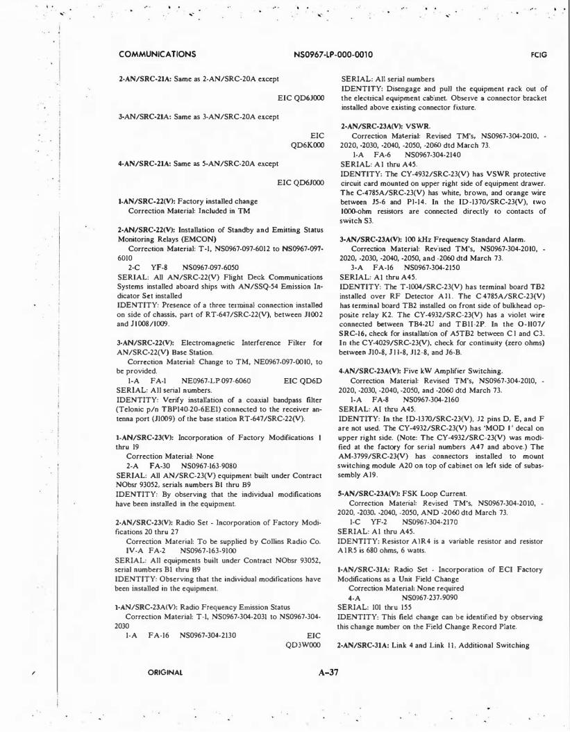
' .
....
• .
. . ..
....
COMMUNICA liONS NS0967 -LP-000-001 0 FCIG
2·AN/SRC-21A: Same as 2-AN/SRC-20A except
EIC QD6JOOO
3-AN/SRC-llA: Same as 3-AN/SRC-20A except
4-AN/SRC-21A: Same as 5-AN/SRC-20A except
EIC QD6KOOO
EIC QD6JOOO
l·AN/SRC-22(V): Factory installed change
Correction Material: Included in TM
2-AN/SRC-22(V): Installation of Standby and Emitting Status Monitoring Relays (EMCON)
Correction Material: T-1, NS0967-097-6012 to NS0967-097-6010
2-C YF-8 N$0967-097-6050
SERIAL: All AN/SRC-22(V) Flight Deck Communications Systems installed aboard ships with AN/SSQ-54 Emission Indicator Set installed IDENTITY: Presence of a three terminal connection installed on side of chassis, part of RT-647/SRC-22(V), between 11002 and 11008/1009.
3-AN/SRC-22(V): Electromagnetic Interference Filter for
AN/SRC-22(V) Base Station.
Correction Material: Change to TM, NE0967-097-0010, to be provided.
1-A FA-I NE0967-LP-097-6060 EIC QD6D SERIAL: All serial numbers.
IDENTITY: Verify installation of a coaxial bandpass filter (Telonic p/n TBPI40-20-6EEI) connected to the receiver antenna port {11009) of the base station RT-647/SRC-22(V).
l·AN/SRC-23(V): Incorporation of Factory Modifications thru 19
Correction Material: None
2-A FA-30 NS0967-163-9080
SERIAL: All AN/SRC-23(V) equipment built under Contract NObsr 93052, serials numbers B I thru B9
IDENTITY: By observing that the individual modifications
have been installed in the equipment.
2·AN/SRC-23(V): Radio Set • Incorporation of Factory Modifications 20 thru 27
Correction Material: To be supplied by Collins Radio Co. IV-A FA-2 NS0967-163-9100
SERIAL: All equipments built under Contract NObsr 93052, serial numbers B I thru 89
IDENTITY: Observing that the individual modifications have been installed in the equipment.
l-AN/SRC-23A(V): Radio Frequency Emission Status Correction Material: T-1, NS0967-304-2031 to NS0967-304-
2030 1-A FA-16 NS0967-304-2130 EJC
QD3WOOO
SERIAL: All serial numbers
IDENTITY: Disengage and pull the equipment rack out of the electrical equipment cabinet. Observe a connector bracket installed above existing connector fixture.
2-AN/SRC·23A(V): VSWR.
Correction Material: Revised TM's, NS0967-304-2010, 2020, -2030, -2040, -2050, -2060 dtd March 73.
1-A FA-6 NS0967-304-2140
SERIAL: A I thru A45.
IDENTITY: The CY-4932/SRC-23(V) has VSWR protective circuit card mounted on upper right side of equipment drawer. The C-4785A/SRC-23(V) has white, brown, and orange wire between 15-6 and Pl-14. In the ID-1370/SRC-23(V), two 1000-ohm resistors are connected directly to contacts of switch S3.
3-AN/SRC-23A(V): 100 kHz Frequency Standard Alarm. Correction Material: Revised TM's, NS0967-304-2010,
2020, -2030, -2040, -2050, and -2060 dtd March 73. 3-A FA-16 NS0967-304-2!50
SERIAL: A I thru A45.
IDENTITY: The T-1004/SRC-23(V) has terminal board TB2 installed over RF Detector A l l . The C-4785A/SRC-23(V) has terminal board TB2 installed on front side of bulkhead opposite relay K2. The CY-4932/SRC-23(V) has a violet wire connected between TB4-2U and TBII-2P. In the 0-1107/ SRCI6, check for installation of A5TB2 between C l and C3. In the CY -4029/SRC23(V), check for continuity (zero ohms)
between JIQ-.8, J l l-8, 112-8, and J6-B.
4-AN/SRC-23A(V): Five kW Amplifier Switching.
Correction Material: Revised TM's, NS0967-304-2010,
2020, -2030, -2040, -2050, and -2060 dtd March 73. I·A FA-8 NS0967-304-2160
SERIAL: AI thru A45.
IDENTITY: In the ID-1370/SRC-23(V). J2 pins D, E, and F are not used. The CY -4932/SRC-23(V) has 'MOD I ' decal on upper right side. (Note: The CY-4932/SRC-23(V) was modified at the factory for serial numbers A47 and above.) The AM-3799/SRC-23(V) has connectors installed to mount switching module A20 on top of cabinet on left side of subassembly Al9.
5-AN/SRC-23A(V): FSK Loop Current.
Correction Material: Revised TM's, NS0967-304-2010, 2020, -2030, -2040, -2050, AND -2060 dtd March 73.
1-C YF-2 NS0967-304-2170 SERIAL: A I thru A45.
IDENTITY: Resistor AIR4 is a variable resistor and resistor A I R 5 is 680 ohms, 6 watts.
l-AN/SRC·31A: Radio Set • Incorporation of ECI Factory
Modifications as a Unit Field Change Correction Mate.rial: None required
4-A NS0967-237-9090
SERIAL: 101 thru 155
IDENTITY: This field change can be identified by observing
this change number on the Field Change Record Plate.
2-AN/SRC-31A: Link 4 and Link II, Additional Switching
ORIGINAL A-37
. .

l
. .
• . . l
/
. ' '
. r
. . . . .. . . ..
COMMUNICATIONS NS0967 -LP-000-00 10 FCIG
Correction Material: T-1, NS0967-237-9021 to NS0967-237-9020
3-A FA-2 NS0967-237-9080
SERIAL: Equipment serials 101 thru 155
IDENTITY: Remove radio set control (JAI) C-7743/SRC-3JA from electrical equipment cabinet (JA7). Visually check for two mounting brackets (JA7A4) secured to right hand side of interface compartment. See figure 5-99, page 5-129, Technical Manual, NA VSHIPS 0967-237-9020 for interface compartment and module IA7A4.
3-AN/SRC-31A: Replacement of Blower Electric (JA4Bl)
Correction Material: T-2, NS0967-237-9022 to NS0967-237-9020
1-A FA-2 NS0967-237-9110
SERIAL: AN/SRC-31A serial numbers 101-155. AN/SRC-31B serial numbers A I-A20 and BI-B30.
IDENTITY: Loosen ten (10) retaining screws on the front of Radio Frequency Amplifier AM-4342/GRC-1 12 (lA4). Remove drawer from Radio Set AN/SRC-31( ) cabinet CY-654J/SRC-31A and place on work bench. Visually check nameplate on blower, electrical (1A4BI) for manufacture part number 19A2406.
4-AN/SRC-31A: Replace Handset Connector IAIMP3Jl
Correction Material: T-3, NS0967-237-9023 to NS0967-237-9020
1-A FA-2 NS0967-237-9120
SERIAL: AN/SRC-31A serial numbers 101-155. AN/SRC· 31B serial numbers A 1-A20 and BI-B30.
IDENTITY: Visual check for handset connector MS-3102-
RI4S-5S {1AIMP3JI) mounted on plate, located on front of Radio Set Control (lA I). (See figure 5-31, page 5-70, vol. 2 of 3, NAVSHIPS 0967-237-9020 for location of IAIMP3Jl.)
S·AN/SRC·31A: IPA Balanced Doubler Modifications
Correction Material: Included in new manuals
1-C YF-12 NS0967-237-9130
SERIAL: 101 thru 155. All equipments will be the same after this field change has been installed.
IDENTITY: Remove Receiver R-1485/SRC-JI and note the presence of TP5 (orange) on Amplifier-Oscillator IA3A2A2AJ. This field change affects depot repair assem· blies; therefore, any further disassembly for checking purposes is not authorized.
6-AN/SRC-3IA: FSK Detector Modification
Correction Material: Included in new manuals
I·C YF-4 NS0967-2J7-9140
SERIAL: Numbers 101 thru 155. All of the equipment population will be the same after this field change has been accomplished.
IDENTITY: Check front panel of Radio Receiver R-1485/ SRC-JI for designation plate. This field change affects a depot repair assembly; therefore, no disassembly for checking pur· poses is authorized.
7·AN/SRC-31A: Product Improvement
Correction Material: Included in new manuals
1-A YF-8 NS0967-2J7-9150
SERIAL: 101 thru 155. All of the equipment population will
be the same after this field change has been accomplished.
IDENTITY: Remove P.A. IA4 assembly and note the pres· ence of connector IA4JI8.
8-AN/SRC-31A: External Frequency Standard, Power Supply
and Acce�;sory Kit Modifications
Correction Material: Included in new manuals
I·A YF·JO NS0967-2J7-9160
SERIAL: AN/SRC-JIA serial numbers 101-155. AN/SRC JIB sedrisu numbers AI-A20 and Bl-B30.
IDENTITY: Check upper left comer of Radio Set for EXT.STI). indicator. Check Receiver (IAJ) and Synthesizer (IA5) front panels for VFO out BNC jack.
9-AN/SRC·31A: Servo System Modifications
Correc:tion Material: Included in new manuals
l·A FA-18 NS0967-237-9170
SERIAL: AN/SRC-31A serial numbers 101-155. AN/SRC· 31B serial numbers AI·A20 and Bt-B30.
IDENTITY: Identification plate marked with field change number on units tAt, IAIA2, IA7, IA7A5, lAS, and IA8A2.
10.AN/S�tC31A: LINK I I Interface Card Modification.
Correction Material: Included in Field Change Bulletin. I·A FA-2 NE0967-LP-237-9180 EIC
QD43,WD6G
SERIAL: AN/SRC-31A serial numbers 101-155. AN/SRC· JIB se.riaU numbers AI·A20 and BI-BJO (BI-B30 had field change accomplished during production).
IDENTITY: Heat sinks have been removed from Q2 and Q3 of IA9A2 and from Q8 and Q9 of IA9Al.
l·AN/SRC-31B: Link 4 and Link I I , Additional Switching
Correction Material: T-1, NS0967-237-9021 to NS0967-237· 9020
1-A FA-2 NS0967-237-9100 EIC QD43000
SERIAL: All serial numbers: AI-A20 and BI-B30 .
IDENTITY: Remove radio set control (IAI) C-7743/SRCJIA from electrical equipment cabinet (lA 7). Visually check for two (2:) mounting brackets (IA7A4) secured to right hand side of interface compartment. See figure 5-99, page 5-129, Technical Manual NA VSHIPS 0967-237-9020 for interface compartment and module 1A7A4.
2-AN/SRC·31B: Same as J-AN/SRC-31A
3·AN/SRC-31B: Same as 4-AN/SRC-JIA
4-AN/SRC-JIB: Same as 8-AN/SRC-3IA
5-AN/SRC-JIB: Same as 9-AN/SRC-3IA
6·AN/SRC-31B: Same as 10-AN/SRC-3IA.
l·AN/SRC-40: Mute II Interface Modification.
Correction Material: Revised TM, NS0967-LP-619-5010, will reflect this field change.
1-C YF-8 NS0967-LP-619-5020 EIC QD74
SERIAL: All serial numbers.
ORIGINAL A-38

, . ..
/
I · i
j I j
. i I I
I !
!
I I
I
. . .. -
. . .. -
. . .. . .. - .. -
COMMUNICATIONS NS0967 -LP-000-00 10 FCIG
IDENTITY: Verify installation of a ten-pin connector IJ9 (Type MS-31145-12-IOS) located on the back and below the three-pin power connector IJ I.
2-AN/SRC-40: MUTE II Interface Connector change. Correction Material: EJB 007
4-A FA-I EIB 007 EIC QD74
SERIAL: All serial numbers.
IDENTITY: Verify that a jumper wire has been installed between pins C and D of IJ9. NOTES: Prerequisite Field Change: 1-AN/SRC-40.
1-AN/SRC-42: LORAN Antenna Coupler and Amplifier In
stallation
Correction Material: Chg. I , NE0967-274-9011 to NE0967-274-9010; T-1, NE0967-274-9031 to NE0967-274-9030
1-A FA-6 NE0967-274-9040 EIC LIOJOOO SERIAL: All serial numbers
IDENTITY: Presence of RF amplifier circuit board on each AN/SRA-42 RF tuner (TN-443/SRA-42)
1-AN/SRD-7: Primary Power Source Modification
Correction Material: Change I to NS92349(A)
A FA-8 NS98943 2N5825-543-
0739 SERIAL: All
1-AN/SRM-13: Incorporation of Factory Modification Bulletin No. I as a Field Change
Correction Material: Supplied as a Permanent Change to NA VSHIPS 95757
2-A FA-I NS0969-098-1050 SERIAL: A I thru A22
2-AN/SRM-13: Remounting Jack J51
Correction Material: None required
2-A FA-I NS0969-098-1050
None
None SERIAL: B2 thru B7 - Equipments built under Contract NObsr 95099
IDENTITY: Observing that the silk screening underneath the top panel for plug J51 has been removed.
1-AN/SRM-14: Incorporation of Factory Modification Bulletin No. I as a Field Change
Correction Material: To be supplied as a Permanent Change to NS95757
2-A FA-I NS0969-098-1050 None SERIAL: A I thru A22
2-AN/SRM-14: Electronic Circuit Plug-In Unit Test Set - In
stallation of Protective Fuse Correction Material: T-1, NS0969-098-2013 to NS0969-098-
2010; T-2, NS0969-098-2024 to NS0969-098-2020
2-A FA-I NS0969-098-2060 EIC QR03000 SERIAL: All equipment serial numbers
IDENTITY: Noting the absence of 28 Vdc between J42 and J43 upon removal of fuse A5F6. (See figure 5-1, NAVSHIPS 0969-098-20 10.)
1-AN/SRN·6: Superseded by 4-0A-1545/SRN-6
2-AN/SRN-6: Modification to Stabilize the North and Auxiliary Reference Pulses
Correction Material: T-5, NS0967-073-5013 to TM, NS0967-073-5010 (formerly NS92986(A))
2-A FA-3 NS0967-073-5100 SERIAL: Applies only to Coder KY-235/URN IDENTITY: Presence of a 1N69 diode between terminals 20 and 21 of TB-698, a IN69 diode between terminals 26 and 27 of TB-698, and a 120,000 ohm resistor between terminals 22 and 61 of TB-698.
3·AN/SRN-6: Elimination of Spurious AC Signals Present in KY-235/URN
Correction Material: T-6, NS0967-073-5014 to TM, NS0967-073-5010 (formerly NS92986(A))
2-A FA-2 NS0967-073-6100 None SERIAL: All IDENTITY: The presence of a No. 18 stranded black nylon insulated wire connected to the various tube sockets and grounded at TB-604-8 in KY-235/URN video chassis.
4-AN/SRN-6: Installation of Klystron Aging Switch Correction Material: T-7, NS0967-073-5016 to TM,
NS0967-073-5010 (formerly NS92986(A)) 1-A FA-3 NS0967-073-5110 EIC DLOIOOO
SERIAL: All equipments
IDENTITY: Presence of a NORMAL/ AGE switch on the hinged fuse panel of Power Supply Group Cabinet CY-2189/ SRN-6.
5-AN/SRN-6: Pre-Trigger Generator Installation Correction Material: T-1, NS0967-073-5017 to NS0967-073-
5010; NS0967-073-5021 to N$0967-073-5020; T-1, NS0967-073-5031 to NS0967-073-5030
1-A FA-4 NS0967-073-5120 EIC L601000 SERIAL: All shipboard equipment only
IDENTITY: A pre-trigger assembly is mounted on the bottom rear of the KY-235/URN.
6-AN/SRN-6: TACAN Test Equipment Protection Correction Material: T- to NS0967-073-5020 4-A FA-I EIB 871 EIC L601000
SERIAL: All serial numbers IDENTITY: Presence of three wires on TB904(13) and three wires on TB904(14).
7-AN/SRN-6: Modification to Deactivate Identification Call Keyer when Equipment is in Standby Status
Correction Material: T-2, NS0967-LP-073-5022 to NS0967-LP-073-5020 and T-9, NS0967-LP-073-6302 to NS0967-LP-073-6010.
1-A FA-4 NS0967-LP-073-5140 EIC L601000 SERIAL: All serial numbers IDENTITY: Keyer wheel will not rotate when master switch SIIOI in control duplexer C-2225/SRN-6 or C-2225A/SRN-6 is in the STANDBY position.
8-AN/SRN-6: Modification to Secure C-2225/SRN-6 and C-2225A/SRN-6
Correction Material: None required 2-A F A-2 EIB 93 I
ORIGINAL A-39
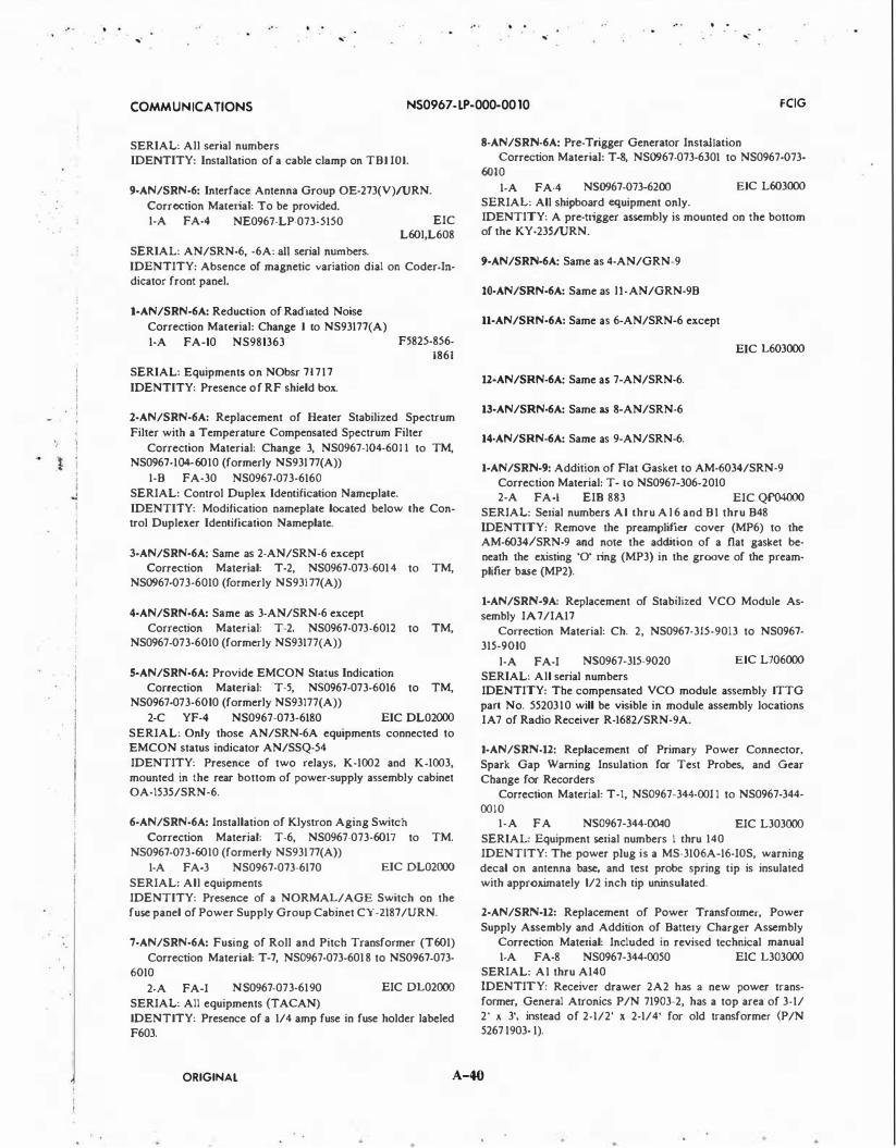
·.
.. · .... .... ....
.. . ....
COMMUNICATIONS NS0967 -LP-000-00 10 FCIG
SERIAL: All serial numbers IDENTITY: Installation of a cable clamp on TBI IOI.
9-AN/SRN-6: Interface Antenna Group OE-273(V)!URN.
Correction Material: To be provided. 1-A FA-4 NE0967-LP-073-5150
SERIAL: AN/SRN-6, -6A: all serial numbers.
EIC L60l,L608
IDENTITY: Absence of magnetic variation dial on Coder-Indicator front panel.
l·AN/SRN-6A: Reduction of Radiated Noise
Correction Material: Change I to NS93177(A)
1-A FA-10 NS981363
SERIAL: Equipments on NObsr 71717
IDENTITY: Presence of RF shield box.
F5825-856-1861
2-AN/SRN-6A: Replacement of Heater Stabilized Spectrum
Filter with a Temperature Compensated Spectrum Filter
Correction Material: Change 3, NS0967-104-601 1 to TM, NS0967-104·-6010 (formerly NS93177(A))
1-B FA-30 NS0967-073-6160 SERIAL: Control Duplex Identification Nameplate. IDENTITY: Modification nameplate located below the Control Duplexer Identification Nameplate.
3-AN/SRN-6A: Same as 2-AN/SRN-6 except Correction Material: T-2, NS0967-073-6014 to TM,
NS0967-073-6010 (formerly NS93177(A))
4-AN/SRN-6A: Same as 3-AN/SRN-6 except Correction Material: T-2, NS0967-073-6012 to TM,
NS0967-073-6010 (formerly NS93177(A))
S·AN/SRN-6A: Provide EMCON Status Indication Correction Material: T-5, N$0967-073-6016 to TM,
NS0967-073-6010 (formerly NS93177(A))
2-C YF-4 NS0967-073-6180 EIC DL02000
SERIAL: Only those AN/SRN-6A equipments connected to EMCON status indicator AN/SSQ-54 IDENTITY: Presence of two relays, K-1002 and K-1003, mounted in the rear bottom of power-supply assembly cabinet OA-1535/SRN-6.
6-AN/SRN-6A: Installation of Klystron Aging Switch Correction Material: T-6, NS0967-073-6017 to TM.
NS0967-073-6010 (formerly NS93177(A))
1-A FA-3 NS0967-073-6170 EIC DL02000
SERIAL: All equipments IDENTITY: Presence of a NORMAL/AGE Switch on the fuse panel of Power Supply Group Cabinet CY-2187/URN.
7·AN/SRN-6A: Fusing of Roll and Pitch Transformer (T601) Correction Material: T-7, NS0967-073-6018 to NS0967·073-
6010
2-A FA-I N S0967 -073-6190 EIC DL02000
SERIAL: All equipments (TACAN) IDENTITY: Presence of a 1/4 amp fuse in fuse holder labeled F603.
8-AN/SRN-6A: Pre-Trigger Generator Installation Correction Material: T-8, NS0967-073-6301 to NS0967-073-
6010
1-A FA-4 N$0967-073-6200
SERIAL: All shipboard equipment only.
EIC L603000
IDENTITY: A pre-trigger assembly is mounted on the bottom of the KY-235/URN.
9-AN/SRN-6A: Same as 4-AN/GRN-9
10-AN/SRN-6A: Same as li-AN/GRN-9B
11-AN/SRN-6A: Same as 6-AN/SRN-6 except
EIC L603000
12·AN/SRN-6A: Same as 7-AN/SRN-6.
13-AN/SRN-6A: Same as 8-AN/SRN-6
14-AN/SRN-6A: Same as 9-AN/SRN-6.
1-AN/SRN-9: Addition of Flat Gasket to AM-6034/SRN-9 Correction Material: T- to NS0967-306-2010 2-A FA-I EIB 883 EIC QP04000
SERIAL: Serial numbers AI thru Al6 and B1 thru B48 IDENTITY: Remove the preamplifier cover (MP6) to the AM-6034/SRN-9 and note the addition of a nat gasket be· neath the existing '0' ring (MP3) in the groove of the preamplifier base (MP2).
l-AN/SRN-9A: Replacement of Stabilized VCO Module As· sembly IA7/IA17
Correction Material: Ch. 2, NS0967-315-9013 to NS0967-315-9010
l·A FA-I N$0967-315-9020 EIC L706000
SERIAL: All serial numbers IDENTITY: The compensated VCO module assembly ITTG part No. 5520310 will be visible in module assembly locations I A 7 of Radio Receiver R-1682/SRN-9A.
1·AN/SRN·l2: Replacement of Primary Power Connector, Spark Gap Warning Insulation for Test Probes, and Gear Change for Recorders
Correction Material: T-1, NS0967-344-00I I to NS0967-344-00IO
1-A FA N$0967-344-0040 EIC L303000 SERIAL: Equipment serial numbers I thru 140 IDENTITY: The power plug is a MS-3106A-16-IOS, warning decal on antenna base, and test probe spring tip is insulated with approximately 1/2 inch tip uninsulated.
2-AN/SRN-12: Replacement of Power Transformer, Power Supply Assembly and Addition of Battery Charger Assembly
Correction Material: Included in revised technical manual 1-A FA-8 NS0967-344-0050 EIC L303000
SERIAL: A1 thru A140 IDENTITY: Receiver drawer 2A2 has a new power trans· former, General Atronics P/N 71903-2, has a top area of 3-1/ 2' x 3', instead of 2-1/2' x 2-1/4' for old transformer (P/N 5267 1903- 1 ).
ORIGINAL A-40

.. .
... -
. !
i l
.. .
... -. . . .
...- ... -
COMMUNiCATIONS NS0967 -lP-000-00 10 FCIG
1-AN/SRN-14: Modification for Navigational System Interface
Correction Material: T-1, NS0967-869-9011 to NS0967-869-
9010; T-1, NS0967-869-9031 to NS0967-869-9030
2-A FA-0.5 NS0967-869-9060 EIC L300000
SERIAL: All equipments
IDENTITY: Presence of hookup wire between pin 2 on con
nector IAIA2XA25 and pin 174 on terminal board
I AIA2TBI.
1-AN/SRN-15: Pre-Trigger, Identity Switch Cover and Test
Cable Modification
Correction Material: Ch. I, NE0967-434-3011 to NE0967-
434-3010
1-A FA-10 NE0967-434-3030 EIC QPOOOOO
SERIAL: All serial numbers
IDENTITY: A new connector J8(40) is installed on the rear panel of RT.
NOTES: For AN/SRN-15A installations: This field change should be installed and reported accomplished as Field
Change 1-AN/SRN-15.
2-AN/SRN-15: Antenna Motor Drive Assembly IA9, IAIO
Transformer Replacement
Correction Material: Ch. 2, NE0967-434-3012 to NE0967-
434-3010
1-A FA-8 NS0967 -434-3040
SERIAL: All serial numbers
EIC QP04000
IDENTITY: In C-9146/SRN-15 (unit I) observe that trans
former Tl in assemblies IA9 and IAIO are P/N 006876.
NOTES: For AN/SRN-15A installations: This field change
should be installed and reported accomplished as field change
2-AN/SRN-15.
3-AN/SRN-15: Sealing and Dampening Improvements to AS-
2822/SRN-15
Correction Material: Ch. 3, NE0967-434-3013 to NE0967-
434-3010
1-A FA-8 NE0967-434-3050
SERIAL: All serial numbers
EIC QP04000
IDENTITY: Addition of the shock·blocks and the unit assem
bly number decal on the support yoke provide immediate
visual indication.
NOTES: For AN/SRN-15A installations: This field change
should be installed and reported accomplished as field change
3-AN/SRN-15.
4-AN/SRN-15: 15/135 Hz All-Band System Operation Modifi
cation (Modifies equipment to AN/SRN-15A)
Correction Material: Ch. 4 NE0967-434-3013 to NE0967-
434-3010
1-C YF-40 NE0967-LP-434-3060 EIC L633000
SERIAL: All serial numbers
IDENTITY: Installation of new AS-4036/SRN-ISA antenna,
and part number change on Beacon-Transponder Set Control
from 006520 to 006520-04. Name tags on the above four listed
equipments indicate their assigned nomenclature as a result of
this field change.
5-AN/SRN-15: Antenna Motor Driver Overload Protection
and Transponder Standby Indication
Correction Material: Ch. I , NE0967-LP-434-301 S to TM,
NE0967-LP-434-3010 dtd 30 Sep 72
1-A FA-8 NE0967-LP-434-3070 EIC L633
SERIAL: All serial numbers of AN/SRN-15 and AN/SRN-
15A.
IDENTITY: Presence of (I) supplemental circuit board as
semblies IA9AI and IAIOAl in Unit I , 19156 ASSY 005520;
(2) ferrite leads on emitter leads of driver transistors IA9Q5,
IA9Q8, I AIOQ5, and IAIOQS; and (3) jumper from IA3RI6
(LH lead, component side) to IA3PI, pin 25.
1-AN/SRN-15A: Same as 1-AN/SRN-15. (lnstaJied, and re
ported accomplished, as field change 1-AN/SRN-15.)
2-AN/SRN-15A: Same as 2-AN/SRN-15. (Installed, and re
ported accomplished, as field change 2-AN/SRN-15.)
3-AN/SRN-15A: Same as 3-AN/SRN-15. (Installed, and re
ported accomplished, as field change 3-AN/SRN-15.)
4-AN/SRN-15A: Not Applicable.
5-AN/SRN-15A: Same as S-AN/SRN-15.
1-AN/SRR-4: Elimination of Rotary SA-215/U, Failure
Correction Material: None
FA
SERIAL: All
NS981 108 None
2-AN/SRR-4: Replace of RF Head and Addition of Test Jack
Correction Material: Change 3 to NS91410(A)
1-B YF NS98967 F5820-605-
SERIAL: All (Modifies Equip to AN/SRR-48)
3-AN/SRR-4: Improvement of AEW System Checkout
Correction Material: T-2 to NS91410(A)
9326
2-A FA-4 NS981338 None
SERIAL: All
IDENTITY: Train designator MK2 MODS mounted on the
bulkhead with cable entering the Data Converter CV-121/
SRR-4 of the AN/SRR-4. With the AN/SRR-4 energized, the
Train Designator MK2 MODS will be energized.
l-AN/SRR-4A: Same as 1-AN/SRR-4 except
Correction Material: None
2-AN/SRR-4A: Same as 2-AN/SRR-4
3-AN/SRR-4A: Same as 3-AN/SRR-4
1-AN/SRR-11: Provide Silicon Diode Rectifiers and Zener
Diode Voltage Regulator in Lieu of Electron Tube Type 6X4
and Ballast Tube Type IRT4.
Correction Material: T-6 to NS91875(A)
1-A FA-I NS981356 2N5820-856-
0078
SERIAL: All
IDENTITY: Vl601, Vl602, and Rl605 are replaced by the
diode rectifier unit.
ORIGINAL A-41
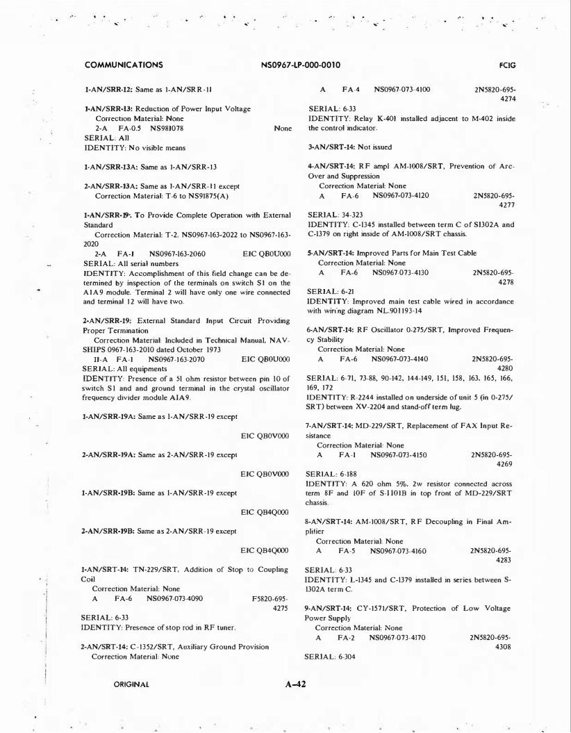
. . .. - .. - ...
. . ...
COMMUNICATIONS NS0967 -LP-000-00 10 FCIG
1-AN/SRR-12: Same as 1-AN/SRR-11
1-AN/SRR-13: Reduction of Power Input Voltage
Correction Material: None 2-A FA-0.5 NS98I078
SERIAL: All
IDENTITY: No visible means
1-AN/SRR-13A: Same as 1-AN/SRR-13
2-AN/SRR-13A: Same as 1-AN/SRR-1 1 except
Correction Material: T-6 to NS91875(A)
None
1-AN/SRR-19: To Provide Complete Operation with External
Standard
Correction Material: T-2, NS0967-163-2022 to NS0967-163-2020
2-A FA-I NS0967-163-2060
SERIAL: All serial numbers
EIC QBOUOOO
IDENTITY: Accomplishment of this field change can be determined by inspection of the terminals on switch S I on the AIA9 module. Terminal 2 will have only one wire connected and terminal 12 will have two.
2-AN/SRR-19: External Standard Input Circuit Providing
Proper Termination
Correction Material: Included in Technical Manual, NAYSHIPS 0967-163-2010 dated October 1973
II-A FA-I NS0967-163-2070 EIC QBOUOOO
SERIAL: All equipments
IDENTITY: Presence of a 51 ohm resistor between pin 10 of
switch S l and and ground terminal in the crystal oscillator frequency divider module AIA9.
1-AN/SRR-19A: Same as 1-AN/SRR-19 except
EIC QBOVOOO
2-AN/SRR-l9A: Same as 2-AN/SRR-19 except
EIC QBOVOOO
1-AN/SRR-198: Same as 1-AN/SRR-19 except
EIC QB4QOOO
2-AN/SRR-198: Same as 2-AN/SRR-19 except
EIC QB4QOOO
1-AN/SRT-14: TN-229/SRT, Addition of Stop 10 Coupling
Coil Correction Material: None
A FA-6 NS0967-073-4090
SERIAL: 6-33
IDENTITY: Presence of stop rod in RF tuner.
F5820-695-4275
2-AN/SRT-14: C-1352/SRT, Auxiliary Ground Provision
Correction Material: None
A FA-4
SERIAL: 6-33
NS0967-073-4100 2N5820-695-4274
IDENTITY: Relay K-401 installed adjacent to M-402 inside the control indicator.
3-AN/SRT-14: Not issued
4-AN/SRT-14: RF amp! AM-1008/SRT, Prevention of Arc
Over and Suppression
Correction Material: None
A FA-6 NS0967-073-4120
SERIAL: 34-323
2N5820-695-4277
IDENTITY: C-1345 installed between term C of SI302A and C-1379 on right inside of AM-1008/SRT chassis.
5-AN/SRT-14: Improved Parts for Main Test Cable
Correction Material: None
A FA-6 N$0967-073-4130
SERIAL: 6-21
2N5820-695-
4278
IDENTITY: Improved main test cable wired in accordance with wiring diagram NL.901 193-14
6-AN/SRT-14: RF Oscillator 0-275/SRT, Improved Frequen
cy Stability
Correction Material: None
A FA-6 NS0967-073-4140 2N5820-695-4280
SERIAL: 6-71, 73-88, 90-142, 144-149, 151, 158, !63, 165, 166, 169, 172
IDENTITY: R-2244 installed on underside of unit 5 (in 0-275/ SRT) between XV-2204 and stand-off term lug.
7-AN/SRT-14: MD-229/SRT, Replacement of FAX Input Re
sistance
Correction Material: None A FA-I NS0967-073-4150
SERIAL: 6-188
2N5820-695-4269
IDENTITY: A 620 ohm 5%, 2w resistor connected across term SF and !OF of S-I IOIB in top front of MD-229/SRT chassis
8-AN/SRT-14: AM-1008/SRT, RF Decoupling in Final Am·
plifier
Correction Material: None A FA-5 NS0967-073-4160
SERIAL: 6-33
2N5820-695-4283
IDENTITY: L-1345 and C-1379 installed in series between S-
1302A term C.
9-AN/SRT-14: CY-1571/SRT, Protection of Low Voltage
Power Supply
Correction Material: None
A FA-2 NS0967-073-4170
SERIAL: 6-304
2N5820-695-4308
ORIGINAl A-42

I I · I l
.. ....
. . ... -
. . ..-
. . ....
COMMUNICATIONS NS0967 -ll'-000-00 10 FCIG
IDENTITY: Replacement of connector assy. protective cover located in electrical equip cabinet CY-1571/SRT, also add jumper on term board E-607.
19-AN/SRT-14: Modification for Mounting Relay K-3004 Correction Material: None
2-A FA-2 NS0967.073-4190 None
SERIAL: All IDENTITY: Presence of bakelite strip mounted underneath relays K-3004 and K-3005.
ll·AN/SRT-14: Improvement for the Mounting of Switch S-307 in Radio Frequency Tuner TN-229/SRT
Correction Material: None 2-A FA-2 NS0967.073-4200 None
SERIAL: All IDENTITY: Presence of No. 8 flat washer mounted at the top of each standoff under the switch mounting plate.
12-AN/SRT-14: Cancelled
13-AN/SRT-14: Relocation of Resistor to Eliminate Heat Hazard
Correction Material: None 2-A FA-3 NS0967.073-4230
SERIAL: All
None
IDENTITY: Resistor R-1045 is now mounted to the right of resistors R-1129 and R-1087.
14-AN/SRT-14: Improving the Performance of Transmitter Using Receiver-Transmitter AN/WRA-1 for SSB
Correction Material: T-10, NS0967.Q73-4016 to TM. NS0967-073-40!0 (formerly NS9212l(A))
2-A FA-I NS0967.Q73-4272 None SERIAL: All using AN/WRA-1 for SSB IDENTITY: Substitution of the SPOT toggle switch S-1305 with a DPDT toggle switch.
15-AN/SRT-14: Modification of Radio Modulator MD-229/ SRT (LLRM) for Prevention of Malfunction of Antenna Switching Relay, K-1306 and KEYING RELAY K-1101
Correction Material: T-5 to NS9212l(A) 2-A FA-2 NS0967-073-4260 None
SERIAL: All IDENTITY: Wiring changes in Radio Modulator MD-229/ SRT (LLRM) and RF Amplifier AM-1008/SRT (RFA) and an additional resistor (200 ohm) mounted on blank terminal of El004 between R-1058 and R-106
16-AN/SRT-14: Guard for Cabinet Heater Switch Correction Material: T-10, NS0967-073-4016 to TM.
NS0967-073-4010 (formerly NS92121(A)) 2-A FA-0.5 NS0967.073-4272 None
SERIAL: All IDENTITY: Presence of a guard installed over cabinet heater switch S3002.
17-AN/SRT-14: Simplification of Interconnecting Cables Correction Material: T-10, NS0967.073-4016 to TM,
NS0967.073-4010 (formerly NS9212l(A)) 2-A FA-5 NS0967.073-4272 None
SERIAL: All IDENTITY: Absence of Junction Box Assembly on Antenna Coupler CU-372/SRT.
18-AN/SRT-14: Same as 4-AN/SRA-18
19-AN/SRT-14: Same as 6-AN/SRA-18
20-AN/SRT-14: Replacement of Relay K 1101 and K 1306 Correction Material: T-10, NS0967-073-4016 to TM,
NS0967.073-4010 (formerly NS9212l(A)) 2-A FA-2 NS0967-073-4272 None
SERIAL: All IDENTITY: The existence of standoff post under relay KIIOI in Radio Modulator MD-229/SRT, and of the angle bracket mount for relay K 1306 in Radio Frequency Amplifier AM· 1008/SRT.
21-AN/SRT-14: Cancelled
22-AN/SRT-14: Field Conversion to Power Supply PP-1094/ SRT (L VPS) to Use Silicon Diode
Correction Material: T-10, NS0967.073-4016 to TM, NS0967.Q73-4010 (formerly NS92121(A))
2-A FA-2.5 NS0967-073-4272 None
SERIAL: All IDENTITY: Absence of electron tubes and selenium rectifier in the PP-1094/SRT (LVPS).
23-AN/SRT-14: Modification to FSK Circuit Correction Material: T- to NS0967-073-4010 IV-A FA-2 EIB 863 EIC QEIIOOO
SERIAL: All serial numbers IDENTITY: Locate resistor R-1094 in the Radio Modulator M0-229/SRT and observe that one lead of the resistor has been connected to pin 6 of V-1017.
1-AN/SRT·l4A: Same as 1-AN/SRT-14
2-AN/SRT-14A: Same as 2-AN/SRT-14
3·AN/SRT-14A: Not issued
4-AN/SRT·14A: Same as 4-AN/SRT-14
S-AN/SRT·14A: Same as 5-AN/SRT-14
6-AN/SRT-14A: Same as 6-AN/SRT-14
7-AN/SRT-14A: Same as 7-AN/SRT-14
8-AN/SRT·14A: Same as 8-AN/SRT-14
9·AN/SRT-14A: Same as 9-AN/SRT-14
10.AN/SRT-14A: Same as 10-AN/SRT-14
11-AN/SRT·l4A: Same as 1 1-AN/SRT-14
12-AN/SRT-14A: Cancelled
ORIGINAL A-43
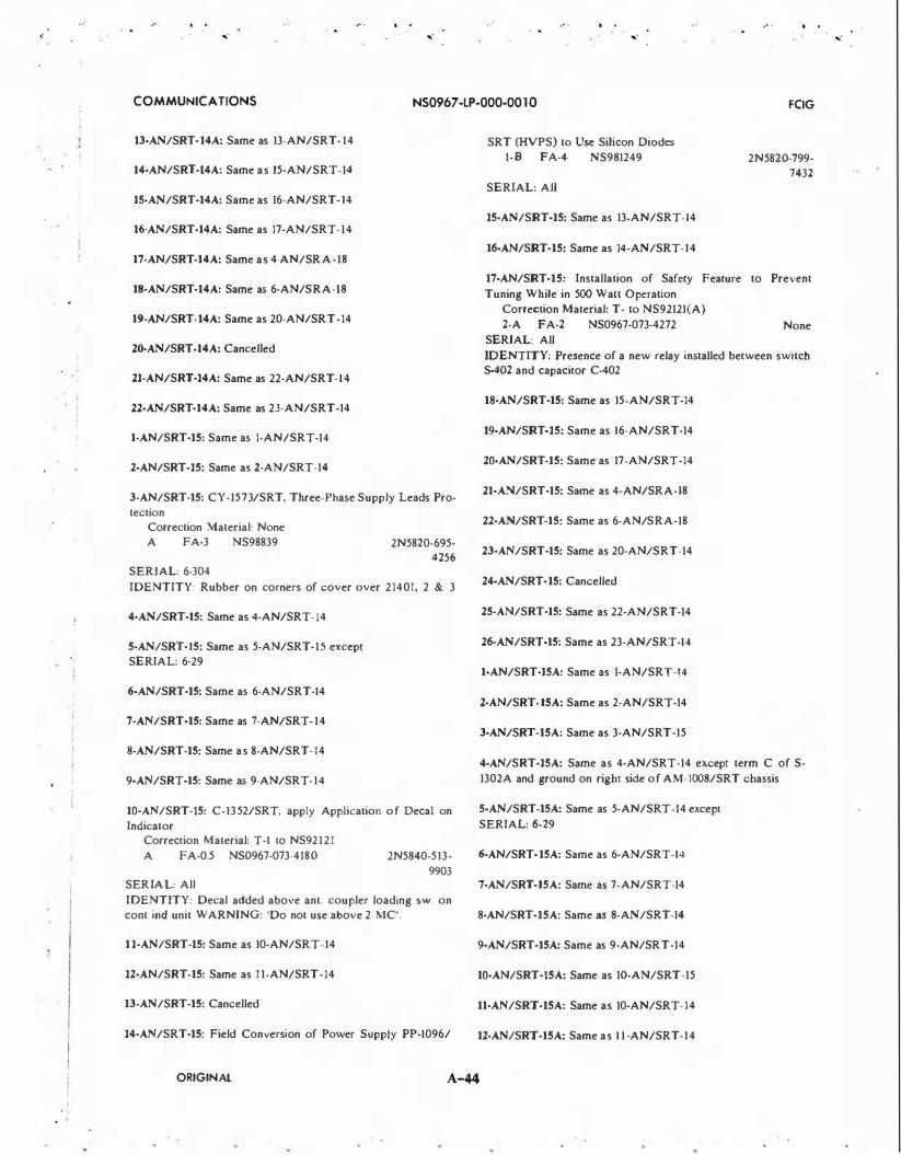
.. -. .
.. -. .
.. -. .
COMMUNICATIONS NS0967-LP-000-0010 FCIG
13-AN/SRT-14A: Same as 13-AN/SRT- 14
14-AN/SRT·l4A: Same as 15-AN/SRT-14
15·AN/SRT-14A: Same as 16-AN/SRT-14
16-AN/SRT·14A: Same as 17-AN/SRT-14
17-AN/SRT-14A: Same as 4-AN/SRA-18
18.-AN/SRT-14A: Same as 6-AN/SRA-18
19-AN/SRT·14A: Same as 20-AN/SRT-14
20·AN/SRT·14A: Cancelled
21-AN/SRT-14A: Same as 22-AN/SRT-14
22-AN/SRT-14A: Same as 23-AN/SRT-14
1-AN/SRT-15: Same as 1-AN/SRT-14
2-AN/SRT-15: Same as 2-AN/SRT-14
3-AN/SRT-15: CY-1573/SRT, Three-Phase Supply Leads Protection
Correction Material: None A FA-3 NS98839
SERIAL: 6-304
2N5820-695· 4256
IDENTITY: Rubber on corners of cover over 21401, 2 & 3
4-AN/SRT-15: Same as 4-AN/SRT- 14
5-AN/SRT-15: Same as 5-AN/SRT-15 except SERIAL: 6-29
6-AN/SRT-15: Same as 6-AN/SRT-14
7-AN/SRT-15: Same as 7-AN/SRT-14
8-AN/SRT-15: Same as 8-AN/SRT- 14
9-AN/SRT-15: Same as 9-AN/SRT- 14
10-AN/SRT-15: C-1352/SRT, apply Application of Decal on Indicator
Correction Material: T-1 to NS92121 A FA-0.5 NS0967-073-4180 2N5840-513-
9903 SERIAL: All
IDENTITY: Decal added above ant. coupler loading sw. on com ind unit WARNING: 'Do not use above 2 MC'.
11-AN/SRT-15: Same as 10-AN/SRT-14
12-AN/SRT-15: Same as 1 1-AN/SRT-14
13-AN/SRT-15: Cancelled
14-AN/SRT-15: Field Conversion of Power Supply PP-1096/
SRT (HVPS) to Use Silicon Diodes 1-B FA-4 NS981249
SERIAL: All
15-AN/SRT-15: Same as 13-AN/SRT-14
16-AN/SRT-15: Same as 14-AN/SRT-14
2N 5820-799-7432
17-AN/SRT-15: Installation of Safety Feature to Prevent
Tuning While in 500 Watt Operation Correction Material: T- to NS92121(A) 2-A FA-2 NS0967-073-4272 None
SERIAL: All
IDENTITY: Presence of a new relay installed between switch S-402 and capacitor C-402
18-AN/SRT-15: Same as 15-AN/SRT-14
19-AN/SRT-15: Same as 16-AN/SRT-14
20-AN/SRT-15: Same as 17-AN/SRT-14
21-AN/SRT-15: Same as 4-AN/SRA-18
22-AN/SRT-15: Same as 6-AN/SRA-18
23-AN/SRT-15: Same as 20-AN/SRT-14
24-AN/SRT-15: Cancelled
25-AN/SRT-15: Same as 22-AN/SRT-14
26-AN/SRT-15: Same as 23-AN/SRT-14
1-AN/SRT-15A: Same as 1-AN/SRT-!4
2·AN/SRT-15A: Same as 2-AN/SRT-14
3-AN/SRT-15A: Same as 3-AN/SRT-15
4-AN/SRT·15A: Same as 4-AN/SRT-14 except term C of S-1302A and ground on right side of AM- 1008/SRT chassis
5-AN/SRT-15A: Same as 5-AN/SRT-14 except
SERIAL: 6-29
6-AN/SRT-15A: Same as 6-AN/SRT-14
7-AN/SRT-15A: Same as 7-AN/SRT-14
8-AN/SRT-15A: Same as 8-AN/SRT-14
9-AN/SRT-t5A: Same as 9-AN/SRT-14
10-AN/SRT-15A: Same as 10-AN/SRT-15
11-AN/SRT·15A: Same as 10-AN/SRT-14
12·AN/SRT-15A: Same as 1 1 -AN/SRT-14
ORIGINAL A-44
... -

. . . I I
I I
i I I
I
. I I I
• I
.. . . . .. -
COMMUNICA liONS
13-AN/SRT-15A: Cancelled
14-AN/SRT-15A: Same as 13-AN/SRT-14
1S-AN/SRT-15A: Same as 17-AN/SRT-15
16-AN/SRT·15A: Same as 15-AN/SRT-14
17·AN/SRT·15A: Same as 16-AN/SRT-14
18-AN/SRT-lSA: Same as 17-AN/SRT-14
19·AN/SRT-15A: Same as 4-AN/SRA-18
20-AN/SRT-15A: Same as 6-AN/SRA-18
21-AN/SRT·lSA: Same as 20-AN/SRT-14
22·AN/SRT-15A: Same as 14-AN/SRT-15
23-AN/SRT-15A: Cancelled
24-AN/SRT-lSA: Same as 22-AN/SRT-14
25·AN/SRT-15A: Same as 23-AN/SRT-14
1-AN/SRT-16: Same as 1-AN/SRT-14
:Z.AN/SRT-16: Same as 2-AN/SRT-14
3-AN/SRT-16: Same as 3-AN/SRT-15
4-AN/SRT-16: Same as 4-AN/SRT-14
5-AN/SRT-16: Same as 5-AN/SRT-14 except
SERIAL: 6-24
6-AN/SRT-16: Same as 6-AN/SRT- 14
7-AN/SRT-16: Same as 7-AN/SRT-14
8-AN/SRT-16: Same as 8-AN/SRT-14
9-AN/SRT-16: Same as 9-AN/SRT-14
10-AN/SRT-16: Same as 10-AN/SRT-15
11-AN/SRT-16: Same as 10-AN/SRT-14
12-AN/SRT-16: Same as 1 1-AN/SRT-14
13·AN/SRT-16: Cancelled
14-AN/SRT-16: Same as 14-AN/SRT-15
15-AN/SRT-16: Same as 13-AN/SRT-14
16-AN/SRT-16: Same as 14-AN/SRT-14
17-AN/SRT-16: Same as 17-AN/SRT-15
ORIGINAL
NS0967 -LP-000-00 10
. . ...
18-AN/SRT-16: Same as 15-AN/SRT-14
19-AN/SRT-16: Same as 16-AN/SRT-14
20-AN/SRT-16: Same as 17-AN/SRT-14
21-AN/SRT-16: Same as 4-AN/SRA-18
22-AN/SRT-16: Same as 6-AN/SRA-18
23-AN/SRT-16: Same as 20-AN/SRT-14
24-AN/SRT-16: Cancelled
25-AN/SRT-16: Same as 22-AN/SRT-14
26-AN/SRT-16: Same as 23-AN/SRT-14
1·AN/SRT-16A: Same as 1-AN/SRT-14
2-AN/SRT-16A: Same as 2-AN/SRT-14
3-AN/SRT-16A: Same as 3-AN/SRT-1 5
4-AN/SRT·l6A: Same as 4-AN/SRT-14
5-AN/SRT-16A: Same as 5-AN/SRT-14 except
SERIAL: 6-24
6·AN/SRT·16A: Same as 6-AN/SRT-14
7-AN/SRT·16A: Same as 7-AN/SRT-14
8-AN/SRT-16A: Same as 8-AN/SRT-14
9·AN/SRT·16A: Same as 9-AN/SRT-14
IO·AN/SRT-16A: Same as 10-AN/SRT-15
ll·AN/SRT·l6A: Same as 10-AN/SRT-14
12-AN/SRT-16A: Same as 1 1-AN/SRT-14
13-AN/SRT-16A: Cancelled
14-AN/SRT-16A: Same as 13-AN/SRT-14
15·AN/SRT-16A: Same as 17-AN/SRT- 15
16·AN/SRT-16A: Same as 15-AN/SRT-14
17-AN/SRT·I6A: Same as 16-AN/SRT- 14
18-AN/SRT-ltiA: Same as 17-AN/SRT-14
19-AN/SRT-16A: Same as 4-AN/SRA-18
20·AN/SRT-16A: Same as 6-AN/SRA-18
21·AN/SRT-16A: Same as 20-AN/SRT-14
A-45
. . . ...
FCIG

I I i
. I I
... .. -
. .
.. -
COMMUNICATIONS NS0967 -LP-000-00 10 FCIG
22·AN/SRT-16A: Same as 14-AN/SRT-16
23-AN/SRT-16A: Cancelled
l4-AN/SRT-16A: Same as 22-AN/SRT-14
25-AN/SRT-16A: Same as 23-AN/SRT-14
l·AN/SSM-4A: Test Program Cards Correction Material: Change I, NS0967- 164-101 I to
NS0967-164-1010; Change I , NS0967-164-1051 to NS0967-164-1050
1-A FA-0.5 NS0967-164-1060 EIC WH03000 SERIAL: Equipments A I thru A6, Bl thru B4, Cl thru C7, and D I thru D6 IDENTITY: Remove the cover from unit one (TS-1923A/ SSM-4) by releasing the catches and lifting. Check program cards in files for REV. A in upper right hand comer.
l·AN/SSQ-29(U): Same as 1-AN/SSQ-29(XN-2)
2·AN/SSQ·29<U): Same as 3-AN/SSQ-29(XN-2) except Correction Material: NA VSHIPS 94315
3-AN/SSQ·29(U): Data Terminal Set; Incorporation of Equip· ment Modification Bulletins as a Unit Field Change
Correction Material: None 2-A NA NS0967-048-8130 None
SERIAL: A I thru A22 IDENTITY: Change number stamped on the Field Change Accomplished plate.
4-AN/SSQ-29(U): Eliminates 2MS of Extra AGC Frames Correction Material: T-2, NS0967-048-8023 to TM,
NS0967-048-8020, Vol. II, and T-1, NS0967-048-8052 to TM, NS0967-048-8050, Volume V
1-A FA-I NS0967-048-8140 SERIAL: All IDENTITY: The change can only be identified by checking the wiring changes called for in the procedure.
5·AN/SSQ·29<U): Selectable Net Busy Reinitiate Timing Correction Material: T-4, NS0967-048-8016 to NS0967-048-
8010; T-3, NS0967-048-8024 to NS0967-048-8020; T-1, N$0967-048-8043 to NS0967-048-8040; T-2, NS0967-048-8054 to NS0967-048-8050; T-1, NS0967-048-8063 to NS0967-048-8060; T-1, NS0967-048-8121 to NS0967-048-8120
I·A FA-4 NS0967-048-8160 EIC QJ05000 SERIAL: Serial numbers A I thru A22 and Bl thru B4 IDENTITY: Extend right hand unit (IA3) of Data Terminal Group OA-4477/SSQ-29 (Unit 1). At the A06 card rack observe that a printed circuit card with a five position rotary switch marked 'NET BUSY TIME IN SECONDS' is in· stalled in the A22 card slot.
l·AN/SSQ·29(XN·2): Modification to Permit on NTDS Sta· tion to Conduct the 'A' link POFA Independently
Correction Material: None 1-A FA-2 NS981754
SERIAL: All (5 equipments)
IDENTITY: Change number stamped on Field Change Accomplished plate.
2-AN/SSQ·29<XN·2): Tone Suppression for Single Station POFA
Correction Material: T-1, NS0967-208-8014 to TM, NS0967-208-8010 (formerly NS94315)
2-A FA-2 N$0967-048-8130 None SERIAL: All IDENTITY: Observation of S-4 on the IAIAOI Panel.
3-AN/SSQ-29(XN·2): Modification to Allow 'Transmit Stan' After Completion of Self Check at Control Panel IA3AOI
Correction Material: T-2, NS0967-048-8013 to TM, NS0967-048-8010 (formerly NS94718A)
2-A FA-I NS0967-048-8130 None SERIAL: All IDENTITY: Operating the e!Juipment 'Reset' and 'Transmit Start' switches at control panel IA3AOI and observing if equipment starts transmitting.
4-AN/SSQ-29(XN·2): Data Terminal • Incorporation of System Modification Bulletin as a Unit Field Change
Correction Material: Incorporated in revised publications 2-A NS0967-048-8130 None
SERIAL: AI thru A8 IDENTITY: Change number stamped on the Field Change Accomplished plate.
S·AN/SSQ-29(XN·2): Data Terminal • Modification of the SYNC MODE switch
Correction Material: T-1, NS0967-208-8014 to TM, NS0967-208-8010 (formerly NS94315)
2-A FA-I NS0967-048-8130 None SERIAL: All IDENTITY: Observing that Wafer 'A' of SYNC MODE Switch located on the Control Panel of Unit 2 has been modified by the changes listed under procedures in this field change. To further insure that this modification has been accomplished, perform the Electrical Test directed by this change.
6·AN/SSQ-29(XN-2): Unit I Rack 3 Wiring Change Correction Material: T- to NS943 15 2-A FA· I None
SERIAL: All (XN-2) equipment IDENTITY: Noting that there is a wire connected between IA3A04A8 Pin N and IA3A03A2, Pin A.
7-AN/SSQ-29(XN·2): Replacement of Hold-Down Bars for Mullimodule Panels in Rack I
Correction Material: None re!Juired 2-A FA-2 NS0967-169-0070
SERIAL: All IDENTITY: Checking the Field Change Accomplished plate.
8-AN/SSQ·29(XN·2): Selectable Net Busy Reinitiate Timing Correction Material: T-4, NS0967-207-8017 to NS0967-207-
8010; T-2, NS0967-207-8033 to NS0967-207-8030; T-1, NS0967-207-8041 to NS0967-207-8040
I-A FA-4 NS0967-207-8070 EIC QJ06000
ORIGINAL A-46
·.

,
,-
. . i
I l I I
. . ,-
. . ,- ,-
COMMUNICATIONS NS0967 -LP-(>00-00 10 FCIG
SERIAL: Serial numbers I thru 8 IDENTITY: Extend the righthand unit (IA3) of the terminal equipment unit (Unit I of Data Terminal Set AN/SSQ·29(XN· 2)). At the A06 card rack observe that a printed circuit card with a 5-position rotary switch marked 'NET BUSY TIME IN SECONDS' is installed in the A22 card slot.
1-AN/SSR-1: Add Wires to Harness in TD-1063 Correction Material: Revised TM, NE0967-LP-54!-9010
dtd Apr 76 and Ch. I, NE0967-LP-541-902l to NE0967-LP-541-9020 dtd Sep 74
3-A FA-2 NE0967-LP-541-9070 SERIAL: Selected serial nos only. IDENTITY: -20 VDC present on pin 3 of P4 and PS (equipment energized) in the demultiplexer drawer.
2-AN/SSR-1: Install Switch for Disabling Blanker Circuits. Correction Material: Contained in FCB, NE0967-LP-541-
9080. 3-A FA-3 NE0967-LP-541-9080 EIC
QP34,QP47 SERIAL: All serial numbers of AN/SSR-1 and AN/SSR-IA. IDENTITY: Verify installation of switch assembly (5AIA6SI) located inside MD-900 drawer unit.
1-AN/SSR·1A: Same as 2-AN/SSR-1.
1-AN/SSW-1: Relocation of Air Filters to Outside Back of Cabinet
Correction Material: None 1-A FA-2 NS0285-075-5500 F5820-868-
9859 SERIAL: AEG-1 thru AEG-22 (AN/SSW-lA); ALL (AN/ SSW-I) IDENTITY: The presence of two air filters mounted on the outside rear of the cabinet.
1-AN/SSW-JA: Same as I-AN/SSW-I
2-AN/SSW-IA: Inhibits Carrier Output Pulse when the equipment is in the Standby Condition
<::orrection Material: T-2, NS0967-074-1012 to NS0967-074-IOJO (Volume I); T-2, NS0967-074-1021 to NS0967..074-1020 (Volume II); T-2, NS0967..074-1031 to NS0967-074-1030 (Volume Ill); T-3, NS0967-232-8013 to NS0967-232-8010; T-2, NS0967-232-8022 to NS0967-232-8020; T-1, NS0967-232-8031 to NS0967-232-8030
I·A FA-3 NS0967-074-1040 SERIAL: All (CI thru C8) IDE�TITY: Locate terminal board TB2 in the Monitor Test Panel SB-1860/SSW-IA (IA2 and IA4) and observe that a diode, IN277, IA2CR14 (IA4CR14) has been added on the 4th pair of terminals from the left side between R-85 and R-87.
3-AN/SSW-lA: Cancelled
4-AN/SSW·1A: 'CMSG' Signal Output Modification Correction Material: T -4, NS0967.Q74-1014 to NS0967..074-
IOIO (Vol. I); T -4, NS0967.Q74-1024 to NS0967..074-1020 (Vol. 2); T-3, NS0967.Q74-1032 to NS0967-074-1030 (Vol. 3)
I-A FA-I NS0967..074-1060 EIC QHOSOOO
SERIAL: All serial numbers IDENTITY: Loosen four screws on Converter CV-1458/ SSW-lA (lA I) (lAS) and e.xtend the drawer. Loosen two re· taining screws on converter-generator (control message) card. Remove card and observe that capacitor C-22 is removed, and capacitor C-30 is removed and replaced with a wire jumper.
5-AN/SSW-lA: Operation CAINS/SINS Mode (Equipment nomenclature changed to AN/SSW-IE)
Correction MateriaJ: New technical manuals to be provided
1-C YF-9 NS0967-LP.Q74-1070 SERIAL: Designated by procuring activity. IDENTITY: New nameplates installed - AN/SSW-IE, CV-1458C/SSW-IA, and SB-1860C/SSW-IA. New assemblies in· stalled - C-4476C/SSW-IA, and AM-6528/SSW-10.
1-AN/SSW-lB: Same as 2-AN/SSW-IA
2-AN/SSW-1B: Cancelled
3-AN/SSW-1B: Same as 4-AN/SSW-IA except
EIC QH06000
1-AN/SSW-lC: Same as 2-AN/SSW-IA
2-AN/SSW-1C: Relocation of Air Filters to Outside Rear of
Cabinet Correction Material: T-1, NS0967-232-8011 to NS0967-232-
8010 I-A FA-1.5 NS0967-232-8060
SERIAL: Serial numbers Cl thru C-8
EIC QH07000
IDENTITY: The presence of two air filters mounted on the outside rear of the cabinet.
3·AN/SSW-1C: Cancelled
4-AN/SSW-1C: Modification to Permit Operation of the AN/ SSW-IC in the SINS/CAINS Waypoint Data Insertion System Modifies
Correction Material: New Technical Manual being supplied
1-C 5-/D NS0967-232-8080 EIC QH07000 SERIAL: Only those equipments designated by the procuring activity IDENTITY: The old nameplates will be replaced by new nameplates designating the new nomenclatures of the equipments and units of the equipment. Two Pulse Amplifiers AM-6528/SSW-ID will be added in the lower section of the equipments. See figure A.
5·AN/SSW-1C: Same as 4-AN/SSW-IA except Correction Material: T -4, NS0967-232-8014 to NS0967-232·
8010 (Vol. I); T-3, NS0967-232-802.3 to NS0967-232-8020 (Vol. 2); T-2, NS0967-232-8032 to N$0967-232-8030 (Vol. 3), and
EIC QH06000
1-AN/SSW-10: Incorporate Safety Device for Amplifier,
ORIGINAL A-47
. .

/
. . ,.
. . ,.
. . ,.
. . ,.
COMMUNICATIONS NS0967 -LP-000-00 10 FCIG
Pulse AM-6528/SSW-ID
Correction Material: Included in new manual
1-A FA-4 NS0967-555-4050
SERIAL: All serial numbers IDENTITY: Loosen four (4) captive screws on Pulse Amplifier AM-6528/SSW-I D and slide drawer forward. Visually check for bracket with fuseholders F2 and F3 located on left side of drawer directly behind front panel.
1-AN/SSW-1E: Same as 1-AN/SSW-ID
1-AN/SY A-3(MOD 1): Converter, Digital to Analog (IDAC· MK-9) • Incorporation of Factory Field Service Orders as a Unit Field Change
Correction Material: None 2-A None
SERIAL: I and 2
IDENTITY: Change number stamped on the Field Change Accomplished Plate.
1-AN/TRC-131: Permits Operation from AC Power Source Correction Material: None 1-A FA-3 NS0967-159-4020
SERIAL: All None
IDENTITY: Power adapter is in yellow enclosure stenciled 'CONVERTER, POWER', located on exterior front wall of AN/TRC-131, below the window level, and adjacent to the external connection panel.
2-AN/TRC-131: Addition of Two UHF Transceiver AN/
ARC-51 A 1-A YF-50 NS0967-159-4030
SERIAL: A 1 thru A20
3-AN/TRC-131: Addition of One VHF Transceiver AN/ VRC-46
l·A YF-50 NS0967-159-4040 SERIAL: A2, A3, A16, A17, AIS, Al9, and A20
1-AN/TRN-14: Wiring Modification to Plug and Jack {PI/Jl) of the High Voltage Power Supply Module (2A2A2)
Correction Material: T-2, NS0967-223-1012 to NS0967-223-IOIO (formerly NS95733)
2-A FA-I NS0967-223-1040 SERIAL: All
2-AN/TRN-14: Installation of Drain Plug
Correction Material: T-1, NS0967-223-1011 to TM, NS0967-223-1010 (formerly NS95753)
1-A FA-3 NS0967-223-1050 SERIAL: AN/TRN-14 - All equipments procured under Contract NObsr 85416 ONLY. IDENTITY: The presence of a drain plug on the bottom surface of the antenna.
3-AN/TRN-14: Wiring Modification to the Keyer Motor Correction Material: T-2, NS0967-223-1012 to NS0967-223-
IOIO (formerly NS95753) 2-A FA-4 NS0967-223-1040
SERIAL: 1 thru 22 procured under Contract NObsr 85416
IDENTITY: This field change can be identified by placing the equipment in standby mode; if the keyer wheel does not rotate, this field change has been accomplished.
4-AN/TRN-14: Improve Ventilation Reliability; Power Amplifier Protection, Circuit; Modulator Circuitry Improvement
Correction Material: T-3, NS0967-223-1013 to TM, NS0967-223-IOIO
1-A FA NS0967-223-1060 SERIAL: All equipments IDENTITY: See field change bulletin
5-AN/TRN-14: Installation of Safety Shield
Correction Material: T-4, NS0967-223-1017 to NS0967-223-IOIO (formerly NS95753)
1-A FA-I NS0967-223-1070
SERIAL: All IDENTITY: Plexiglass cover over chassis C-4473, control coder receiver.
1-AN/TRN-28: Transmitter Improvement
Correction Material: T-1, NE0969-131-602J to NE0969-131-6020; T-1, NE0969-13 1-603 1 to NE0969-131-6030
Ill-A FA-4 NS0969-1 3 1-6050
SERIAL: All serial numbers IDENTITY: In A3 unit: CR9 connected between Q7 collector and terminal E29 on chassis. CRS is connected at junction of R29 and R30 to common collectors of pass transistors.
2-AN/TRN-28: Overload Protection for -5V Zener Regulator. Correction Material: To be provided.
2-C FA-12 NE0969-LP-131-6060 EIC PD57 SERIAL: All serial numbers. IDENTITY: Verify installation of a type IN5338B diode (CR26) and a 110 ohm, lOW resistor (R37) in the elevation (2A3AI), azimuth (IA3AI), and spare transmitters.
3-AN/TRN-28: Voltage Regulator for ADP. Correction Material: To be provided. 1-C YF-5 NE0969-LP-131-6070
SERIAL: All serial numbers. EIC PD57
IDENTITY: Verify insta.llation of Ql (Transistor 2NI724A) in I A8A I and 2A8A I. The new transistors replace CR2 and are insulated from the chassis by an insulating washer.
4-AN/TRN-28: Lightning Protection Modification. Correction Material: To be provided.
1-C YF-72 NE0969-LP-131-6080 EIC PD57
SERIAL: All serial numbers. IDENTITY: Verify installation of Lightning Protection Card (p/n 430077-8) in the main junction box containing the remote site cabling at the RA TCC site.
5-AN/TRN-28: Addition of Pitch Axis Level Sensor Adjustment Circuitry
Correction Material: To be provided 1-C YF-5 NE0969-LP-131-6090
SERIAL: AN/TRN-28 and AN/TRN-28A: All serial numbers. IDENTITY: Verify that PC card (AIL p/n 506687-1} is in
ORIGINAL A-48

. i
! -l , I
. . i
• i I
.. . ..
,. . . . .
,. .,.
COMMUNICATIONS NS0967 -LP-000-00 10 FCIG
slot A II of Azimuth Coder-Monitor (2A4). Prior to this field change, PC card (AIL p/n 395761·1) was in slot A II.
6-AN/TRN-28: Replacement of Angle Data Pickoffs (ADP's).
Correction Material: To be provided.
l·C YF-12 NE0969-LP-131-6100
SERIAL: AN/TRN-28 and AN/TRN-28A: All serial num· bers.
IDENTITY: Verify that the ADP's (!AlAI and 2AIAI) are AIL p/n 500480.3 vice p/n 39483-2.
NOTES: Field Change 7-AN/TRN-28, 4-AN/TRN-28A must be accomplished concurrently with this field change.
7-AN/TRN-28: Elevation Coder-Monitor Changes. Correction Material: To be provided.
1-C YF-12 NE0969-LP-131-6110
SERIAL: AN/TRN-28 and AN/TRN-28: All serial numbers.
IDENTITY: Verify that PC card (AIL p/n 5063334-1) is in
slot A l l of the Elevation Coder-Monitor (IA4). Prior to the change, PC card (AIL p/n 395752-1) was in slot A l l .
NOTES: Field Change 6-AN/TRN-28, 3-AN/TRN-28A must be accomplished concurrently with this field change.
1-AN/TRN-28A: Same as 1-AN/TRN-28 except
SERIAL: AOOl and A002 (Radio Transmitter T-1191/TRN-28 serial numbers 005, 007, 017, and 018)
2-AN/TRN-28A: Same as 5-AN/TRN-28.
3-AN/TRN-28A: Same as 6-AN/TRN-28.
4-AN/TRN-28A: Same as 7-AN/TRN-28.
1-AN/TSA-11: Installation of Silicon Bridge Rectifier in Lieu of Selenium Bridge Rectifier
Correction Material: T-1, NS0967-211-00II to TM, NS0967-21 1-00IO (formerly NS92943)
2-A FA-4 NS0967-211-0020
SERIAL: All Perkins No. 28-30 WXM, 28-volt power supplies used in conjunction with Air Traffic Control Group AN/TSA-11
IDENTITY: Presence of a silicon bridge rectifier, instead of the selenium bridge rectifier in the power supply.
1-AN/TSC-54: To Provide Redundant Transmitter Capability
by Installation of OG-163/G Radio Frequency Amplifier
Group. Correction Material: To be provided. 3-C YF NE0967-LP-550-J050
SERIAL: All serial numbers. IDENTITY: To be provided.
1-AN/TXC-18: Half-Speed Modification A FA-12
SERIAL: All None
IDENTITY: Equipment model changed to TT-41/TXC-IB.
1-AN/UCC-l(V): Replacement of Resistors I A2A I R44, IA2AIR46, JA2AIR47 and Transistor IA2AIQ14
Correction Material: T-1, NS0967-172-2012 to TM, NS0967-172-2010
I·A FA-3 NS0967-172-204Q EIC F2AIOOO
SERIAL: Frequency Shift Converter CV-1522(P)/UCC-I(V)
IDENTITY: Resistor IA2AIR44 is 1100 ohms. Resistor IA2AIR46 is 1600 ohms, Resistor 1A2AIR47 is 680 ohms, Resistor IA2AIR49 is 1000 ohms, and Transistor IA2AIQ14 is a type 2N3439.
2-AN/UCC-l(V): Rewire AGC Test Point; Delete Resistor
IA2-R4 and Capacitor 1A2AI�C9
Correction Material: T-2, NS0967-172-2013 to NS0967-172-2010
2-A FA-3 NS0967-172-2050 EIC F2Al000
SERIAL: All Frequency Shift Converters CV-!522(P)
IDENTITY: Presence of a blue wire on the collector of transistor 1A2Al-QIO.
1-AN/UCC-IA(V): Same as 2-AN/UCC-I(V) except
2-A FA-3 NS0967-172-2050 EIC F2A2000
SERIAL: Frequency Shift Converters CV-1522A(P)
2-AN/UCC-lA(V): Replacement of Resistors IA2AIR40,
IA2AIR44, lA2AlR46, 1A2AIR49, and Transistor
IA2AIQ14
Correction Material: T-2, NS0967-106-1012 to NS0967-106-IOIO
1-A FA-3 NS0967-106-1050 EIC Q318000
SERIAL: All Frequency Shift Converters CV-1522A(P)/ UCC-I(V)
IDENTITY: Resistor 1A2AIR40 is 1600 ohms; resistor IA2AIR44 is 1000 ohms; resistor lA2AlR46 is 5600 ohms; resistor .IA1AIR49 is 1000 ohms; and transistor IA2AlQI4 is a type 2N3439.
1-AN/UCC-IC(V): Installs Jumper Wire on S2 of Test Set,
Telegraph TS-2232/UCC-IC(V)
Correction Material: None 2-A FA-I NS0967-046-9040 None
SERIAL: TS-2232/UCC-IC(V) serial numbers A003 thru A090
IDENTITY: The jumper wire connects terminal 2RIO of S2 to terminal 2R4 of S2. Switch S2 must be examined to determine whether this wire has been installed.
2-AN/UCC-IC(V): Reverse Resistors IA3AIR14 and
1A3AIRI5 on Controi-Attenuator C-6554/UCC-IC(V)
Correction Material: T- to NS0967-046-9010 2-A FA-I NS0967-046-9040 None
SERIAL: C-6554/UCC-lC(V) serial numbers A009 thru A587
IDENTITY: Refer to NS0967-046-9010, Figure 5-3; Rl4 should be MIL type RWP20F2000F and R l 5 should be MIL type RWP20Fl500F.
3-AN/UCC-lC(V): Install Wire to Provide a Chassis Ground
for Pin U of J8
Correction Material: T-1, NS0967-046-9012 to NS0967-046-9010
2-A FA-I NS0967-046-9060
SERIAL: All ANIUCC-IC(V) Telegraph Terminal Cabinets
CY -4639/UCC-1 C(V)
IDENTITY: Presence of a black wire on pin U of J8.
ORIGINAL A-49

.. . .. . ... - ... -
. . ... -
. . ... -
COMMUNICATIONS NS0967 -I.P-000-00 1 0 FCIG
4-AN!UCC-1C(V): Install a Wire to Connect the AGC Detec· tor Output to Pin R of Test Connector Jl on CV-1920(P)/ UCC-IC(V) and CV-1920A(P)!UCC-IC{V)
Correction Material: T-3, NS0967-046-9014 to NS0967-046-9010
2-A FA-I NS0967-046-9100 SERIAL: All CV-1920(P)!UCC-IC(V) and CV-1920A(P)/ UCC-IC{V) Frequency Shift Converters IDENTITY: Presence of a red wire on Pin R of the test con
nector IA2Al-J-1.
5-AN!UCC-1C(V): Replacement of Capacitor IA2AICII, IA2AIC19 and Addition of Resistor IA2AIR34
Correction Material: T-2, NS0967-046-9013 to TM, NS0967-046-9010
1-A FA-2 NS0967-046-9070 EIC F2A3000 SERIAL: All Frequency Shift CV -1920A(P)/UCC-1 C(V) IDENTITY: Capacitor IA2AIC11 2.7 uf, Capacitor
IA2AIC19 1.0 uf and Resistor IA2AIR34 510 Kohms.
6-AN!UCC-1C(V): Replacement of Resistors I A2A I R 16, IA2AIR29 and IA2AIR30
Correction Material: T-3, NS0967-046-9014 to TM,
NS0967-046-9010 1-A FA-2 N$0967-046-9090 EIC F2A3000
SERIAL: Converters for AN!UCC-IC(V) · CV-1920(P)/ UCC-.IC{V) - All IDENTITY: Resistor IA2AIR16 is Honeywell Part No.
262414-9, IA2AIR29 is 1100 ohms and IA2AIR30 is 750 ohms.
1-AN!UCC-lD(V): Replacement of Resistors IA2AIR17 and IA2AIR37
Correction Material: T-1, NS0967-239-401 1 to TM, NS0967-239-4010
1-A FA-2 N$0967-239-4060
SERIAL: All equipments AN/UCC-JD(V) and CV-1920A(P)!UCC-IC(V) used in high level installations only. (EIB 991)
IDENTITY: Resistor IA2AIR17 is 620 ohms and Resistor IA2AIR37 is 510 ohms.
2-AN/UCC-1D(V): Same as 4-AN!UCC-IC(V) except Correction Material: T-3, N$0967-239-4013 to TM,
NS0967-239-4010 SERIAL: AIL EIB 991
3-AN/UCC-ID(V): Replacement of Capacitor 1A2AICII, IA2AIC19 and Resistor IA2AIR34
Correction Material: T-2, N$0967-239-4012 to TM, NS0967-239-4010
1-A F.A-2 N$0967-239-4070 EIC F2B7000
SERIAL: All Frequency Shift CV-1920A(P)JUCC-1C(V). EIB 991. IDENTITY: Capacitor IAlAICII 2.7 uf, Capacitor IA2AIC19 1.0 uf and Resistor IA2AIR34 510 Kohms.
4-AN/UCC-JD(V): Installation of Capacitor IA2CI Correction Material: T-4, NS0967-239-4014 to NS0967-239-
4010
1-A FA-3 NS0967-239-4080 EIC Q31 BOOO
SERIAL: All Frequency Shift CV-1920A(P)JUCC-IC(V). (Applicable to high level installations only. EIB 991) IDENTITY: Presence of Capacitor IA2Cl .25 MFD.
5-AN!UCC-lD(V): Remove Capacitor IA2AIC28 and Resistor I A2A I R22 on CV -1920A(P)!UCC-l C(V)
Correction Material: T-5, N$0967-239-4016 to NS0967-239-4010
4-A FA-I NS0967-239-4090 SERIAL: Applicable to all equipments used in high level installations only. EIB 991 IDENTITY: Unit CV-1920A(P)JUCC-IC(V), note blank space between IA2AIQ6 and IA2AIQ9 and a blank space between IA2AIR17 and IA2AIR20.
1-AN/UGA-3: MM Exchanges HV Power Supply on Oscilloscope Circuit
Correction Material: NS0967-046-701 1 tO TM, N$0967-046-7010 (formerly NS94318)
1-A FA-50 NS0967-046-7030 2F5805-903-1218
SERIAL: All thru 30 except for 5, 20, 26, 27, and 28 which have been modified at factory IDENTITY: The new power supply (Millen 90902M) has six terminals which are wired directly to the oscilloscope and to the IISV power input. The bracket and octal socket mounting for the original supply (Millen 90902) will have been removed. See figure 5-24 in the Technical Manual NS94316 for location.
2-AN/UGA-3: Adds Bafne and Replaces Power Plugs and Re
ceptacles Correction Material: Change 4, NS0967-046-7014, NS0967-
046-7010 (Volume I) and NS0967-046-7020 (Volume ll) (for
merly NS94316, Vols. I and ll) 1-A FA-6 NS0967-046-703 J
SERIAL: All serial numbers IDENTITY: Figure 5-26 in the Technical Manual shows the rear of the Converter-Shift Register front panel without the bafne. When this field change is completed, aluminum plate will cover l8TI (center bottom) and the power supply terminal board (bottom left). The area of the dust cover above this location will be perforated. Figure l of the field change shows the rear view of the converter-shift Register with the change completed. 24Jl and 24J4 formerly had socket-type contacts and have been replaced by pin-type equivalents.
l-AN/UGA-3A: Same as 2-AN/UGA-3
1-AN/UGA-4: Incorporate Distribution Amplifier Capability
(Modifies equipment to ANJUGA-4A) Correction Material: Change I , NS0967-053-2001 to
NS0967-053-2000
1-A FA-I NS0967-053-2020
SERIAL: All equipment serial numbers IDENTITY: A modification plate on the cabinet door identi· fies the equipment as AN/UGA·4A. The added terminal blocks, TB4 and TB-5 are visible on the rear of the cabinet.
1-AN/UGA-5: Regenerative Repeater - TH-73/UGA-5 Wiring
Modification and Automatic Mode Checking Correction Material: T- 1, NS0967-204-301 1 to TM.
ORIGINAL A-50

. . ... -
. . . . ... - ....
. . ....-
COMMUNICATIONS NS0967 -LP-000-00 l 0 FCIG
NS0967-204-3010 IV-A FA-0.5 NS0967-204-3020 EIC FR04600
SERIAL: This field change applies to all TH-73/UGA-5 serials IDENTITY: Absence of jumper wire between terminals I and 3 card A II (80060070), and absence of diode (CR8) on card A 14 (80060080).
1-AN/UGC-lA: Modification of Oscillator Power Supply Unit
0-872/UGC-IA
Correction Material: None 2-A FA-I NS0967-978-2020
SERIAL: A I through Al4
None
IDENTITY: When equipment is operating properly and all circuits conform to the diagrams and schematics shown in the applicable technical manuals.
2-AN/UGC-lA: Modification to Disable Alarm and Lockup
Circuits Correction Material: T-1, NS0967-978-2012 to TM,
NS0967-978-2010 (formerly NS94376A)
2-A FA-I NS0967-978-2020 None
SERIAL: All Receiver Code Converters CV-1218/UGC-IA which are part of Terminal Telegraph AN/UGC-JA IDENTITY: Operation should be normal when the LockupTraffic Alarm Disable switch is in the Alarm Disable position except that in-frame and out-of-frame conditions will be apparent only by monitoring the circuits.
3-AN/UGC-lA: Provide 7.00 Unit Code Operation 6th Bit Delete Function, Maintain Relationship of Clock Pulses Crys
tal Frequency
Correction Material: NS94376(A) 1-A FA-10 NS0285-080-0800 F5805-910-
4150
SERIAL: All IDENTITY: New style frequency meter which has markings in both bands and words per minute and a modification label over this meter.
1-AN/UGC-5: Conversion of AN/UGC-5 to AN/UGC-6 1-A FA-8 NS981281 F5815-857·
1069
SERIAL: All IDENTITY: Nameplate designates equipment as AN/UGC6.
2-AN/UGC-5: Installation of 193936 (MK-764/UG) Modification Kit
Correction Material: T· to NS93534
1-A NS0967-109-4050 F5815-066-4354
SERIAL: LP6 and up
3-AN/UGC-5: Incorporate a Separable Connector in the Wiring to the Back-Space-Magnet L3400
Correction Material: T-5 to NS93534 2-A FA-I NS981733 None
SERIAL: All IDENTITY: Inspection of the wiring between the perforator back-space magnet, L3400, and TBI02 will disclose that a sep·
arable piug and receptacle have been installed in the wiring to the back-space magnet, L3400.
4-AN/UGC-5: Cancelled
5-AN/UGC-5: Wiring Change to the Fan on Low Level
Equipment to Eliminate a Possible Safety Hazard. (EIB 963).
Correction Material: None required. 2-A FA-I EIB 963 EIC Q3HH
SERIAL: All serial numbers of the following Automatic Send-Receive low-level teletype equipment: AN/UGC-5, 58, 5C with MK-1087/UG; AN/UGC-6, 6A, 68, 6E, 6F, 6J, 6K, 6L with MK-1088/UG; AN/UGC-13, 16 with MK-1089/UG; and all AN/UGC-48, 48A, 48BY, 49, 49X, 54, 90, 90X. IDENTITY: Verify that cable assembly (teletype part no. 326760) contains the in-line fuse holder. The in-line fuse holder was formerly installe'd as part of the connector cable (teletype part no. 326373) on the opposite side of the cabinet.
1-AN/UGC-5A: Same as 2-AN/UGC-5
2-AN/UGC-5A: Same as 3-AN/UGC5
1-AN/UGC-5AX: Same as 2-AN/UGC-5
2-AN/UGC-5AX: Same as 3-AN/UGC-5
1-AN/UGC-58: Same as 5-AN/UGC-5
EIC Q3JT
1-AN/UGC-5C: Same as 5-AN/UGCS
EIC Q3JU
1-AN/UGC-5X: Same as 2-AN/UGC-5
2-AN/UGC-5X: Same as 3-AN/UGC-5
1-AN/UGC-6: Provides for Full Duplex Operation of Equip
ment and Eliminates Line Relays Correction Material: Change I to NS93534
2-B FA-6 NS981500 None
SERIAL: All IDENTITY: Four (4) signal lines will be coming into the equipment.
2-AN/UGC-6: Installation of 194028 Mod. Kit (Converts equip. from 7.42 unit code to 7.00 unit code with synchronous
pulsed transmission and 45.5, 50, 75 BAUD speeds) Correction Material: T-3 to NS93534
2-A FA-3 NS981560(A) F5815-981-
3249
3-AN/UGC-6: Same as 2-AN/UGC-5
4-AN/UGC-6: Same as 3-AN/UGC-5
5-AN/UGC-6: Modified, Teletypewriter Set, with Adapter -
Incorporation of Factory Field Service Orders as a Unit Field
ORIGINAL A-51

· '
. .
.. - .. -. .
...
COMMUNICATIONS NS0967 -LP-000-00 10 FCIG
Change Correction Material: None
2-A NS0967-972-8040 None SERIAL: I thru 20 modified teletypewriter set with adapter IDENTITY: Change number stamped on Field Change Accomplished plate.
6-AN/UGC6: Cancelled
7-AN/UGC-6: Elimination of Personnel Hazard Correction Material: T-7, NS0967-062-6013 to TM,
N$0967-062-6010 (formerly NS93534) 2-A FA..0.5 NS0967..Q62-6050 None
SERIAL: Teletypewriters which have the Front Panel Control panel for the auxiliary reperforator as shown on page 42 of Temp. Corr. T-2 to NA VSHIPS 93534 IDENTITY: Presence of an Oran'ge lead on terminal 4 and a Blue lead on terminal 5 of Switch I 55023.
8-AN/UGC-6: Teletypewriter adapter clear RDUC function code
2-A FA-I NS0967-062-6050 None
SERIAL: All IDENTITY: Checking electrical continuity between card jacks JJ2-7 and J-40B-IO.
9-AN/UGC-6: Teletypewriter Sets modified with Adapter for AN/USQ-20(V) - Bypass Thermal Relay
Correction Material: T- to NS94084 and NS94 104 2-A FA-2 NS0967-076-7040
SERIAL: All equipments modified with adapter IDENTITY: Presence of a 250770 printed circuit card in card jack JI3C.
JO-AN/UGC-6: (Modified with AN/USQ-20 Adapter) - Retention of Filter Assembly
Co rrection Material: None required 2-A FA-0.5 NS0967-062-6060
SERIAL: Equipments (modified with AN/USQ-20 Adapter) used in NTDS configurations IDENTITY: Visual inspection and noting that two screws have been inserted into the filter-holder frame. thereby securing the frame to the filter housing.
l J-AN/UGC-6: Normal Input Keying Kit Correction Material: None required 3-A FA-20 NS0967-062-6080
SERIAL: All IDENTITY: Installation of decal adjacent to nameplate.
12-AN/UGC-6: Reliability Improvement Correction Material: T-5, NS0967-972-8015 to NS0967-972-
8010 4-A FA-2.5 NS0967-972-8050 EIC F247000
SERIAL: All equipments modified with Adapters for AN/ USQ-20(V) IDENTITY: Checking electrical continuity between bus bar TB04 and J42C-06. Continuity indicates this field change: has been accomplished.
13-AN/UGC-6: Modification of Typing Perforator and Typing
Reperforator to Provide Fully Perforated Tape.
Correction Material: None required.
1-A FA-16 NE0967-LP-972-8060 EIC Q31N
SERIAL: All ANIUGC-6, -6A, -6B, -6E, -6F, ·61, -6K, and •
6L systems utilized with NA VMACS A systems or with other systems requiring fully perforated tape. IDENTITY: Tape out of the typing perforator and typing reperforator fully perforated.
J4·AN/UGC-6: Same as 5-AN/UGC-5
EIC Q31N
J-AN/UGC·6A: Same as 2-AN/UGC-6
2·AN/UGC·6A: Same as 2-AN/UGC-5
3-AN/UGC·6A: Same as 3-AN/UGC-5
4-AN/UGC-6A: Cancelled
5-AN/UGC-6A: Same as 7-AN/UGC-6
6-AN/UGC·6A: Same as I 1-AN/UGC-6
7-AN/UGC-6A: Same as 13-AN/UGC-6.
EIC Q31P
8-AN/UGC-6A: Same as 5-AN/UGC-5
EIC Q3JP
1·AN/UGC-6AX: Same as 2-AN/UGC-6
2-AN/UGC-6AX: Same as 2-AN/UGC-5
3-AN/UGC·6AX: Same as 3-AN/UGC-5
4-AN/UGC-6AX: Cancelled
S-AN/UGC-6AX: Same as 7-AN/UGC-6
6-AN/UGC-6AX: Same as 1 1-AN/UGC-6
1-AN/UGC-68: Same as 2-AN/UGC-6
2-AN/UGC-6B: Same as 2-AN!UGC-5
3-AN/UGC-68: Same as 3-AN/UGC-5
4-AN/UGC68: Cancelled
5-AN!UGC-68: Same as 7-AN/UGC-6
6-AN/UGC6B: Same as 1 1-AN!UGC-6
7-AN/UGC-68: Same as 13-AN!UGC-6.
EIC Q31R
ORIGINAL A-52
.. -

· I I
.. -. .
.. -. .
.. - .. -
COMMUNICATIONS NS0967 -lP-000-00 10 FCIG
8-AN/UGC-68: Same as 5-AN/UGC-5
EIC Q3JR
t-AN/UGC-6C: Same as 2-AN/UGC-6
l·AN!UGC-6C: Same as 2-AN/UGC-5
3-AN!UGC-6C: Same as 3-AN!UGC-5
4-AN/UGC-6C: Cancelled
5-AN!UGC-6C: Same as 7-AN!UGC-6
6-AN!UGC-6C: Same as 11-AN/UGC-6
t-AN!UGC-6E: Same as 13-AN/UGC-6.
EIC Q3JU
2-AN!UGC-6E: Same as 5-AN!UGCS
EIC Q31U
3-ANIUGC6E: Modification (Update) of AN!UGC-6E to AN/UGC-6K. (Nomenclature changed to AN/UGC-6K.)
Correction Material: Use of AN!UGC7K TM's. 2-C YF-10 NE0967-LP-972-8070
SERIAL: All serial numbers. IDENTITY: Verify that the following equipment ID plates are installed: AN!UGC-6K replaces AN/UGC-6E, SB-2611/ UG replaces SB-1061/UG, LESU96 replaces LESU12, and LP14WY/AJG replaces LPIRN/AJE.
l-AN!UGC6F: Same as 13-AN/UGC-6.
EICQ31V
2-AN!UGC-6F: Same as 5-AN/UGC-5
EIC Q31V
3-AN!UGC-6F: Modification (Update) of ANIUGC-6F to ANIUGC-6K. (Nomenclature changed to AN!UGC-6K.)
Correction Material: Use of ANIUGC-6K TM's 2-C YF-10 NE0967-972-8080 EIC Q3JV
SERIAL: All serial numbers. IDENTITY: Verify that the following equipment 10 plates are istalled: AN!UGC-6K replaces AN!UGC-6F, SB-261 1 / UG replaces SB-1061/UG, and LESU96 replaces LESUJ2. NOTES: The modification which provides the number symbol (#) for upper case 'H' mu�• he accomplished prior to the installation of this field change. (See EIB 800 for information.)
l-ANIUGC·6G: Modificauon to Update AN!UGC-60 to AN/ UGC-6K. (Nomenclature changed to ANIUGC-6K.)
Correction Material: Use of AN!UGC6K TM's. 2-C YF-10 NE0967-LP-972-8090
SERIAL: All serial numbers. IDENTITY: Verify that the following equipment ID plates are installed: AN!UGC-6K replaces AN/UGC-60, SB-2611/
UG replaces SB-1061/UG, LESU96 replaces LESUJ2, and LPI4WY/AJG replaces LPJ4RN/AGH. NOTES: The modification which provides the number symbol (#) for upper case 'H' must be accomplished prior to the installation of this field change. (See EJB 800 for information.)
l·ANIUGC-6J: Same as 13-AN/UGC-6.
EIC Q3IY
l·ANIUGC-6J: Same as 5-AN/UGC-5
EIC Q3JX
3-ANIUGC-6J: Modification to Update AN!UGC-6J to AN/ UGC-6K. (Nomencl�ture changed to AN!UGC-6K.)
Correction Material: Use of AN/UGC-6K TM's. 2-C YF-2 NE0967-LP-972-8100
SERIAL: All serial numbers. IDENTITY: Verify that the AN/UGC-61 equipment 10 plate has been replaced with the AN/UGC-6K ID plate. NOTES: The mofiification which provides the number symbol (f/) for upper case 'H' must be accomplished prior to the installation of this field change. (See EIB 800 for information.)
1-AN/UGC6K: Same as 1 1-AN/UGC-6
2-ANIUGC-6K: Same as 13-AN/UGC-6.
EJC Q3IZ
3-ANIUGC-6K: Same as 5-AN/UGC-5.
EIC Q3JY
1-AN/UGC-6L: Same as 13-AN/UGC-6.
EtC Q330
2-AN/UGC-6L: Same as 5-AN/UGC-5.
EIC Q330
1-ANIUGC-6X: Same as 2-AN!UGC-6
2-ANIUGC-6X: Same as 2-AN/UGC-5
3-ANIUGC-6X: Same as 3-AN/UGC-5
4-ANIUGC-6X: Cancelled
5-ANIUGC-6X: Same as 7-AN/UGC-6
6-ANIUGC6X: Same as 11-AN/UGC-6
1-ANIUGC7: Same as 2-AN!UGC-5
2-AN/UGC· 7: Same as 3-AN/UGC-5
3-AN/UGC-7: Cancelled
ORIGINAL A-53

i ! i . I
J
! 1 I I . I J ·I I ! i \ I I
i .J
·, . ·, . . . .. .
COMMUNiCATiONS NS0967 -lP-000-00 10 FCIG
1-AN/UGC-7X: Same as 2-AN/UGC-S
2-AN/UGC-7X: Same as 3-AN/UGC-S
3-AN/UGC-7X: Cancelled
1-AN/UGC-8: Same as 2-AN/UGC-S
2-AN/UGC-8: Same as 3-AN/UGC-5
3-AN/UGC-8: Cancelled
1-AN/UGC-8X: Same as 2-AN/UGC-5
2-AN/UGC-8X: Same as 3-AN/UGC-5
3-AN/UGC-8X: Cancelled
1-AN/UGC-13: Cancelled
2-AN/UGC-13: Same as 8-AN/UGC-6 ex.cept Correction Material: T-1, NS0967-076-7012
3-AN/UGC-13: Same as 9-AN/UGC-6
4-AN/UGC-13: Same as 10-AN/UGC-6
5-AN/UGC-13: Reliability Improvement. (EIB 737). Correction Material: T-4, NS0967-Q76-701S to NS0967-Q76-
7010 4-A FA-3 NS0967-Q76-7030 EIC F241000
SERIAL: AN/UGC-13 (MOD) equipments modified with Adapters for AN/USQ-20(V). IDENTITY: Checking electrical continuity between Bus Bar TB04 and J42C-06. Continuity indicates this field change has been accomplished.
·
6-AN/UGC-13: Switch Safety Shield Correction Material: None Required 1-A FA-! NS0967-076-7050 EIC QK05000
SERIAL: ANIUGC-13(MOD): All serial numbers. IDENTITY: Open the top of the teletypewriter and observe that the switches located on the left side of the cover have a plastic shield over the wired side.
7-AN/UGC-13: Low Level Modification Correction Material: Included in technical manual 1-C YF-120 NS0967-Q76-7090 EIC Q39UOOO
SERIAL: AN/UGC-13 (MOD) equipments as designated by Naval Ship Engineering Center. IDENTITY: Placement of the maintenance control panel at space location other than under the transmitter distributor.
8-AN/UGC-13: NTDS Teletype Unit Code Standardization and Nomenclature Change. (Nomenclature changed to OJ-212(V)J/UYK.)
Correction Material: T-1, NS0967-LP-Q76-7011, to NS0967-LP-076-7010, and T-2, NE0967-LP-972-7022, to NE0967-LP-972-7020.
1-A FA-5 NS0967-LP-076-7140 EIC Q33C SERIAL: AN/UGC-13(MOD): All serial numbers.
IDENTITY: Remove the four screws that secure the page printer. Remove page printer and observe the set of gears that make up the Intermediate Gear Mechanism. Verify that gears, bearing teletype part number 159284, 159285, and 163440 have replaced gears with numbers 163463, 163464, and 163460 respectively.
9-AN/UGC-13: Same as 5-AN/UGC-5.
EIC Q3LP
1-AN/UGC-15: Same as 3-AN/UGC-5
2-AN/UGC-15: Same as 2-AN/UGC-5
3-AN/UGC-15: Cancelled
1-AN/UGC-15X: Same as 3-AN/UGC-S
2-AN/UGC-15X: Same as 2-AN/UGC-5
1-AN/UGC-16: Installation of 1999915 Mod. Kit (Converts equip. from 7.00 unit code to 7.42 unit code and 60, 75, and 100 WPM speeds)
Correction Material: T-2 to NS93534
NS98!562(A)
SERIAL: All IDENTITY: See bulletin
2-AN/UGC-16: Same as 3-AN/UGC-5
3-AN/UGC-16: Same as 2-AN/UGC-5
4-AN/UGC-16: Cancelled
5-AN/UGC-16: Same as 7-AN/UGC-6
6-AN/UGC-16: Same as 11-ANIUGC-6
7-AN/UGC-16: Same as 5-AN/UGC-5.
l-AN/UGC-16A: Same as 1-AN/UGC-16
2-AN/UGC16A: Same as 3-AN/UGC-5
3-AN/UGC16A: Same as 2-AN/UGC-S
4-AN/UGC-16A: Cancelled
5-AN/UGC-16A: Same as 7-AN/UGC-6
6-ANIUGC-16A: Same as 1 1-AN/UGC-6
2N5815-073-9423
EIC Q3JP
1-AN/UGC-17: Installation of 194267 Mod. Kit (Converts equip. to 7.42 unit code and 60, 75, and 100 WPM both transmitting and receiving)
Correction Material: T- to NS93789
ORIGINAL A-54

' .
. . ... -
.. . ... -
. . ·,
... - ..-
COMMUNICATIONS NS0967 -LP-000-001 0 FCIG
1-A FA-I NS981570
1-AN/UGC-18: Same as 1-AN/UGC-16
2-AN/UGC-18: Same as 3-AN/UGC-5
3-AN/UGC-18: Same as 2-AN/UGC-5
None
1-AN/UGC-ZO: Positive Polarization of Copylight Connector Correction Material: T-1, NS0967-059-9021 to TM,
NS0967-059-9020
1-A FA-I NS0967-059-9050 SERIAL: AN/UGC-20 equipments, serial number 922 and below IDENTITY: A connector guide bracket is added to mounting
hardware of the male copy light connector.
2-AN/UGC-20: Same as 2-AN/UGC-5 (see EIB 709) except
SERIAL: Navy Stunt Boxes (LP6 and up)
IDENTITY: Installation of 199823 Modification Identification Plate on the Typing Unit (LP) front plate.
3-AN/UGC-20: Normal Input Keying Kit
Correction Material: None required 3-A FA-14 NS0967-059-9070
SERIAL: All IDENTITY: Installation of decal adjacent to nameplate.
4-AN/UGC-20: Modification to Update AN/UGC-20 and ANIUGC-20A to ANIUGC-20B. (Nomenclature changed to
AN/UGC-208.) Correction Material: Use of ANIUGC-20B TM's.
2-C YF-12 NE0967-LP-059-9090 EIC Q33J, Q33K
SERIAL: AN/UGC-20 and AN/UGC-20A, all serial numbers.
IDENTITY: Verify that the following equipment ID plates are installed: LPI56WY/AJG replaces either the LPII IRN/ A Y or LPIIIRN/ AJG, and ANIUGC-20B replaces either AN/UGC-20 or 20A. NOTES: Prerequisite Field Changes: I and 2-AN/UGC-20. Also, the modification which provides number symbol (#) for upper case 'H' for AN/UGC-20 and 20A. (See EIB 800 for information.)
1·AN/UGC-20A: Replace Keyboard and Distributor Correction Material: None
1-A YF-10 NS0967-059-9060 EIC Q33KOOO SERIAL: Equipment serials used as part of the AN/USC-13 communications set
IDENTITY: An identification label, identifying the modification is attached to the equipment base, adjacent to and to the left of the equipment nameplate.
1-AN/UGC-20X: Same as 1-AN/UGC-20 except SERIAL: All AN/UGC-20X equipments, serial number 93 and below
1-AN/UGC-25: Same as 1-AN/UGC-20 except SERIAL: All AN/UGC-25 equipments, serial number 1215 and below
2-AN/UGC-25: Same as 2-AN/UGC-5
3-ANIUGC25: Modification to Update AN/UGC-25 to AN/ UGC-25A. (Nomenclature changed to ANIUGC-25A.)
Correction Material: Use of ANIUGC-25A TM's
2-C YF-1 NE0967-LP-972-9080
SERIAL: All serial numbers. IDENTITY: Verify that the following equipment ID plates
are installed: AN!UGC-25A replaces AN/UGC-25 and LPII JWY/AJG replaces LPIIIRN/AY.
NOTES: Field change 2-AN/UGC-25 and the modification
which provides the number symbol (#) for upper case 'H' must be accomplished prior to the installation of this field change. (See EIB 800 for information.)
1·ANIUGC-25X: Same as 1-AN/UGC-20 except
SERIAL: All ANIUGC-25X equipments, serial number 103 and below
1-AN/UGC-41: Inclusion of Maintenance Fixture, MITE PIN 37200, with Maintenance and Adjustment Tools
1-A FA-0.5 NS0967-066-1080
SERIAL: All IDENTITY: Nameplate, 'Modification by Addition of Field Change No. I, Contract M00027-67-C-0020,' installed on Keyboard Cover.
1-AN/UGC-43: Same as 1-AN/UGC-20 except
SERIAL: All AN/UGC-43 equipments, serial number 5 I and below
2-AN/UGC-43: Same as 2-AN/UGC-5
1-AN/UGC-48: Same as 5-AN/UGC-5.
EIC Q3FS
1-AN/UGC-48A: Same as 5-AN/UGC-5.
EIC Q3ND
1-AN/UGC-48BY: Same as 5-AN/UGC-5.
EIC Q3QG
1-AN/UGC-49: Same as 5-AN!UGC-5.
EIC Q3FU
1-AN/UGC-49X: Same as 5-AN/UGC-5.
EIC Q3QH
1-AN/UGC-54: Same as 5-AN!UGC-5.
EIC Q3QJ
1-AN/UGC-90: Same as 5-AN!UGC-5.
EIC Q3JZ
ORIGINAL A-55

_ , i
. .
' .i
.. I i
I · I . !
. . ....
. . . . ... ..-
COMMUNICATIONS NS096i -LF-000-00 10 FCiG
1·ANIUGC-90X: Same as 5-ANIUGC-5.
EIC Q3QK
1-ANIUGH-1: Elimination of Potential Shock Hazard Correction Material: T-1, NE0967-139-40 l l to NE0967-
139-4010 4-A FA-2 NE0967-139-4030 EIC QCOKOOO
SERIAL: All equipments IDENTITY: Noting that the power input connector is a Hubbell 3 wire twist-lock connector.
1-ANIUNQ-7: Cancelled
1·AN/UNQ·7A: Cancelled
t-AN/UNQ-78: Cancelled
1·ANIUNQ-7C: Cancelled
l·ANIUNQ-7D: Recorder-Reproducer - Correction of Wiring Errors on Extender Board
Correction Material: T-1, NS0965.Ql6-5001 to TM for ANIUNQ-70, NS0967-016-5000
4-A FA-I NS0965.Ql6-5030 SERIAL: All IDENTITY: By noting that on J-1; c and b, and g and h are reversed from original drawing 92Dl074, Fig 6-24
2-ANIUNQ·7D: Provide Mechanical Support of Control Unit Correction Material: None 1-A FA-I NS0965-016-5040 EIC RJ15000
SERIAL: All equipment.s IDENTITY: Presence of one hole on each side of the front of the control unit case.
3·ANIUNQ-7D: Provide Rapid Start Time Correction Material: T-2, NS0965-016-5002 to NS0965-016-
5000 2-A FA-0.5 NS0965-016-5050 EIC M70POOO
SERIAL: Those equipments used for certain ECM recording applications IDENTITY: Noting that capstan rotates regardless of setting of mode selector switch.
4-ANIUNQ-7D: Installation of Permanent Ground Lead on Tape Transport
Correction Material: None 2-A F A-1 EIB 793
SERIAL: AI thru A373, Bl thru 838, Cl thru C32, and Dl thru D53 IDENTITY: Presence of ground strap on power supply assembly terminal board TBI, terminal marked llSVAC AUX GND.
l·ANIUNQ-7E: Same as 4-ANIUNQ-7D except SERIAL: AI thru A58 and Dl thru Bl6
l·ANIUNQ-8(V): Signal Data Recorder-Reproducer Set; Removal of Tape Lifter Studs
Correction Material: None
2-A FA-0.5 SERIAL: A I thru A38 IDENTITY: Removing the switch cover assembly and noting that the tape lifter stud on each of the two capstan roller assemblies has been removed.
2-ANIUNQ-8(V): Installation of Fuse Holder in Actuator Assembly
Correction Material: T-1, NS0965-012-6003 to NS0965-012-6000
1-A FA-0.5 NS0965-012-6030 SERIAL: All IDENTITY: Fuse holder mounted on top of supply reel motor.
1-AN/UPN-7: Provide Uniformity of ANIUPN-7; Improve Performance
Correction Material: Change 1 to NS91602 3-A FA-24 NS98586
SERIAL: 4-104
F5825-325-7492
IDENTITY: Capacitor Cl46.01 mfd, connected between the positive 105 volt terminal of TB102 and ground of the IF strip.
2-AN/UPN-7: Elimination of Hi-V Corona Correction Material: Change I to NS91602 1-A FA-4 NS98587
SERIAL: 4-124, 126-152, 154-166, 168, 170
F5825-325-7491
IDENTITY: Separates lead connecting T-601-7 and plate cap of V -617 instead of original harness leads.
3-AN/UPN-7: Reduction of Random Triggering Correction Material: Change 2 to NS91602 1-A FA-0.5 NS98631
SERIAL: All
F5825-3 11-3303
IDENTITY: Installs C-211, one end of which connects to R-204.
4-ANIUPN-7: Installation HV Safety Device Correction Material: None 2-A FA-4 NS98995
SERIAL: All None
IDENTITY: Plexiglass 'DANGER 4000 VOLTS' sign above osc and xfmr terminals.
1-AN/UPN-12: Addition of LORAN C Receiver to LORAN Receiving Sets (modified to ANIUPN-15)
Correction Material: Correct maintenance standards for MSB NS92988.42A and CTM NS94378
2-A FA-5 NS981452 2N5825-560-7213
SERIAL: All required to receive LORAN C signals IDENTITY: Modification nameplate attached near the unit nameplate.
2-AN/UPN-12: Addition of Ventilating Fan Protective Screen Correction Material: None required 2-A FA-2 None
ORIGINAL A-56
. . .. -

I .. I
I i
l I 1 i
· I I
i I
.I I !
· ;
' i
. I � I
I I I
I I
. .. .. ·, . ... -
. . ... -
. .
COMMUNICA liONS NS0967 -LP-000-00 10 FCIG
SERIAL: All IDENTITY: Presence of a protective screen mounted inside the power supply over the ventilating fan .
3-ANIUPN-12: Protective Covers for High Voltage Terminals Correction Material: None Required 2-A FA None
SERIAL: All IDENTITY: Presence of a bakelite panel installed over the forward rear comer of terminal board TB202 in the Loran Indicator chassis. Portions of this field change have been provided on certain equipment by the manufacturer. All AN/ UPN-12( ) equipments should be checked and where necessary, modified to incorporate the safety measure detailed herein.
4-AN/UPN-12: Replacement of V232, 5696 Thyratron with a 5727/2D21W Thyratron
Correction Material: T- to NS92988 and 5- to NS94247 2-A FA-I
SERIAL: All AN/UPN-12 Loran Receivers IDENTITY: Presence of type 5727/2D2 1W tube in the V-232 tube socket.
5-AN/UPN-12: Replacement of Blower Motor Impeller and/ or Correction of Blower Motor Rotation
Correction Material: T-4 to NS92988 (NS0280-434-2006); T-3 to NS94247 (NS0280-765-7001)
1-A FA-4 NS0285-078-0900 F5825-919-9322
SERIAL: All IDENTITY: Inspection of power supply blower should reveal that the hub impeller and the concave side of the impeller blades are facing the motor. With the chassis in the horizontal service position the air flow should be in an upward direction.
6-AN/UPN-12: Wiring Change to Amplifier-Detector-Power Supply Chassis
Correction Material: T-10, NS0967-038-0IOJ to NS0967-038·0010; T-Il, NS0967-038-2009 to NS0967-038-2000
2-A FA-I NS0967-038-0090 EIC DF20000 SERIAL: All equipments IDENTITY: Presence of a jumper wire connection between terminal 10 and the terminal junction of R705 and R711 on terminal board TB703.
1-ANIUPN-JZA: Same as 1-AN/UPN-12
2-AN/UPN-J2A: Same as 2-AN/UPN-2
3-AN/UPN-12A: Same as 3-AN/UPN-12
4-AN/UPN-12A: Same as 4-AN/UPN- 12
5-AN/UPN-12A: Same as 5-AN/UPN-12
6-AN/UPN-12A: Same as 6-AN/UPN-12 except
EIC DF22000
1-AN/UPN-128: Same as 1-AN/UPN-12
2-AN/UPN-128: Same as 2-AN/UPN-12
3-AN/UPN-128: Same as 3-AN/UPN-12
4-AN/UPN-128: Same as 4-AN/UPN-12
5-AN/UPN-128: Same as 5-AN/UPN-12
6-AN/UPN-128: Prevention of; Loss of Master Pedestal Correction Material: T- to NS94247
2-A FA-I SERIAL: All AN/UPN-12B and AN/UPN-15B LORAN receivers experiencing loss of Master Pedestal when switching the 'L-R' Switch to 'L' position IDENTITY: The value of R361 being 6.8 megohms.
7-AN/UPN-128: Same as 6-AN/UPN-12 except
EIC DF23000
l·AN/UPN-12C: Same as 1-AN!UPN-12
2-AN/UPN-12C: Same as 2-AN!UPN-12
3-AN/UPN-12C: Same as 3-AN!UPN-12
4-AN/UPN-12C: Same as 4-AN/UPN-12
5-AN/UPN-12C: Same as 5-AN!UPN-12
6-AN/UPN-J2C: Same as 6-AN/UPN-12 except
ElC DF24000
1-AN/UPN-15: Improve Power Supply Units
NS981799 SERIAL: All AN!UPN-12 serial numbers modified by FC I· AN/UPN-12 IDENTITY: 5RYWGA tube replaced with a 6AR6 tube
2-AN/UPN-15: Same as 2-AN/UPN-12
3-AN/UPN-15: Same as 3-AN/UPN- 12
4-AN/UPN-15: Same as 4-AN/UPN-12
5-AN/UPN-15: Same as S·AN/UPN-12
6-AN/UPN-15: Cancelled
7-AN/UPN-15: Same as 6-AN/UPN- 12 except
EIC DFISOOO
J-AN!UPN-15A: Same as 1-AN/UPN-15
2-AN/UPN-15A: Same as 2-AN/UPN-12
3-AN/UPN-15A: Same as 3-AN/UPN-12
ORIGINAL A-57
... -

,. . . . .
,.
COMMUNICATIONS NS0967-LP-000-0010 FCIG .
4-AN/UPN-1SA: Same as 4-AN/UPN-12
5·AN/UPN-1SA: Same as 5-AN/UPN-12
6-ANIUPN-15A: Same as 6-AN/UPN-12
7-AN/UPN-15A: Same as 6-AN/UPN-12 except
EIC DF16000
1-AN/UPN-158: Same as 1-AN/UPN-15
2-AN/UPN-158: Same as 2-AN/UPN-12
3-AN/UPN-158: Same as 3-AN/UPN-12
4-AN/UPN-158: Same as 4-AN/UPN-12
5-AN/UPN-158: Same as 5-AN/UPN-12
6-AN/UPN-158: Same as 6-AN/UPN-15
7-AN/UPN-158: Same as 6-AN/UPN-128
8-AN/UPN-158: Same as 6-AN/UPN-12 except
EIC DF17000
l·AN!UPN-15C: Same as 1-AN/UPN-15
2-AN/UPN-JSC: Same as 2-AN/UPN-12
3-AN/UPN-15C: Same as 3-AN/UPN-12
4·AN/UPN-15C: Same as 4-AN/UPN-12
5·AN!UPN-15C: Same as 5-AN/UPN-12
6-AN/UPN-15C: Same as 6-AN/UPN-15
7-AN/UPN-ISC: Same as 6-AN/UPN-12 except
EIC DFJ8000
1-AN/URA-8A: Improve Operation of Voltage Regulator Tubes
Correction Material: T-5 to NS91490; T-2 to NS91278
NS0967-141-6040 SERIAL: All IDENTITY: R-730 is changed from 33K to IOK (located on TB E-701)
2·AN/URA-8A: Modification of Circuits to Increase TTY Loop Current When Using AN/URA-8A, 88
Correction Material: T-3 to NS91278 2-A FA-6 NS98 1 1 8 7 None
SERIAL: All
3·AN/URA-8A: Replacement of Resistor R-231 Correction Material: Manual Obsolete
2-A FA-0.5 NS0967- 141-6060 SERIAL: All IDENTITY: Presence of 100,000 ohm resistor R231
l·AN/URA-88: Same as 1-AN/URA-SA
2-AN/URA-88: Same as 2-ANIURA-8A except Correction Material: T-6 to NS91490
3-AN/URA-88: Same as 3-AN/URA-SA except Correction Material: T-3, NS0967-141-901 I to NS0967-141-
9010 (formerly NS9J490)
NS0967-141-6060
4-AN/URA-88: Disabling of Thermostatic Switch (SI201) Correction Material: T-3, NS0967-141-9011 to NS0967-141-
9010 (formerly NS91490) 2-A FA-0.5 NS0967-141-9060
SERIAL: All IDENTITY: Presence of two wires on one terminal of Sl201
1-AN!URA-17: Replacing CRT Shield Correction Material: T-2 to NS94028 1-A FA-I NS98151 I
SERIAL: A-1 through A-10
2-AN/URA-17: Replacement of Resistor R-71 in -48 Volt DC Power Supply
Correction Material: T-2 to NS94028 2-A FA-0.5 NS981512 None
SERIAL: AI through Al55 IDENTITY: R-71 is a 2700 ohm resistor
3-AN/URA-17: Replacement of R-20 and R-22 Correction Material: T-2 to NS94028 2-A FA-0.5 NS9815l3
SERIAL: A I through A245 IDENTITY: R-20 and R-22 are 2200 ohm resistors
4-AN/URA-17: Cancelled
None
5-AN/URA-17: Replacement of Cable Clamp Bracket Correction Material: T-4 to NS0967-034-9012 (formerly
NS94028) 1-A FA-0.5 NS0967-034-9090 2N5821-926-
2624 SERIAL: All IDENTITY: Cable clamp bracket for cable Jl-Pl having extension on it preventing catch from falling down on Q4 or Q5.
6-AN/URA-17: Replacement of Wide-Shift Bandpass Filter FL I and Wide-Shift Discriminator Filter FL3
Correction Material: T-7, NS0967-034-9015 to TM, NS0967-034-9010
1-A FA-2 NS0967-034-9010 EIC F208000 SERIAL: All equipment IDENTITY: Widt:-shift filter, FLI and wide-shift discriminator filter, FL3 are 2000 Hz center frequency.
7-AN/URA-17: Installation of Warning Decal
ORIGINAL A-58
. .

I '
I I i
• . ·. 1
/
. I �
- ! I
... . . .. · . .
... ... . .
..-
COMMUNICA liONS NS0967 -LP-000-00 10 FCIG
Correction Material: None required 1-A FA-0.2 NS0967-034-9120
SERIAL: All serial numbers EIC Q340000
IDENTITY: Note the following in the Frequency Shift Converter CV -483( ). Extend converter chassis assembly. Locate cathode-ray tube (V-1). There should be a warning DECAL on the tube shield.
8-AN/URA·17: Install Diodes and a Capacitor to Provide a Low Level Polar Output
Correction Material: T-8, NS0967-034-9016 to NS0967-034-9010; T-1, NS0967-340-0011 to NS0967-34-00IO
II-A FA-2 NS0967-034-9130 EIC Q340000 SERIAL: Must be installed only in those equipments that are used in Low Level Polar Systems IDENTITY: Withdrawing the converter chassis from the cabinet to permit access to the right-hand terminal board TB-2. The field change is verified by the presence of a jumper wire between TB-2 terminal 50 and the junction of R64 and a capacitor.
l·AN/URA-17A: Same as 5-AN!URA-17
2-AN!URA-17A: Same as 6-AN!URA-17
3-AN/URA-17A: Same as 7-AN/URA-17 except
4·ANIURA-17A: Same as 8-AN/URA-17 except
l·AN/URA-178: Same as 7-AN/URA-17 except
EIC Q3AGOOO
EIC Q3AGOOO
EIC Q3AHOOO
2-AN/URA-178: Same as 8-AN!URA-17 except
EIC Q3AHOOO
l·AN/URA-17C: Same as 7-AN!URA-17 except
EIC Q3AJOOO
2·AN/URA-17C: Same as 8-AN/URA-17 except
EIC Q3AJOOO
1-AN!URA·17D: Same as 7-AN!URA-17 except
EIC Q3CKOOO
1-AN/URA·24: Addition of Protective Circuitry for Excessive VSWR and Excessive PWR Input Overload
1-A FA-8 NS981145 None
SERIAL: All IDENTITY: Supplementary chassis mounted between side plates on top of control-indicator chassis
1-AN/URA-25: Same as 1-AN!URA-24
1-AN!URA-27: Addition of Jumper to S-101A in Monitor Control Unit Model A TS-MCU-2
Correction Material: See field change bulletin II·A FA-I NE0967-543-1020 EIC Q936000
SERIAL: All Antenna Coupler Groups procured under con· tracts NObsr-75916, 75917, 81 106, and 81394 IDENTITY: Presence of a short jumper between pins 8 and 9 of switch S-IOIA.
1-AN!URA-38: Provides Power Supply and Motor Brake Cir·
cuit Reliability Correction Material: T-3, NS0967-204-0016 to TM,
NS0967-204-00IO
1-A FA-4 NS0967-204-0060
SERIAL: All serial numbers IDENTITY: Anti-Turn Plate on Connector J-2
2Z5820-459· 9052
2·AN/URA-38: Provides Spark Gap Reliability and Case Pressurization
Correction Material: Ch. 2, NS0967-204-0015 to TM, NS0967-204-00IO; T-1, NS0967-204-0071 to EFCB NS0967-
204-0070
1-A FA-4 NS0967-204-0070 EIC Q94FOOO
SERIAL: All serial numbers IDENTITY: Presence of Circuit Breaker and Adjacent Label indicating 'RESET', 'ALARM', and 'OFF SWITCH TO MANUAL' on Front Panel
3-AN!URA-38: Improved Flipper Contacts and Servo Alignment in AN!URA-38, -38A
Correction Material: Change 3, NS0967-204-0017 to NS0967-204-0010; Change I, NS0967-297-6011 to NS0967-297· 6010
1-A FA-4 NS0967 · 204-0080
SERIAL: All serial numbers IDENTITY: Presence of trimmer pots on servo PC boards.
4-AN/URA-38: Ceramic Antenna Insulator Correction Material: Ch. 5, NE0967-204-0019 to NE0967-
204-00IO
I·A FA-2 NE0967-204-0090
SERIAL: All serial numbers
EIC Q94FOOO
IDENTITY: Presence of ceramic antenna insulator {IAIEI) having marking 'BERRYLLIUM OXIDE'.
5-AN!URA-38: Improve Reliability of Blower Motor and Pressure Switch
Correction Material: Ch. 3, NE0967-204-0014 to NE0967-204-00IO
I-A FA-3 NE0967-204-0100 SERIAL: All serial numbers
EIC Q94FOOO
IDENTITY: Pipe plug in hole of old pressure switch (lAISI) and adjustable type pressure relief valve (1A lMP3).
l·AN/URA-38A: Same as 3-AN!URA-38
2-AN/URA·38A: Same as 2-AN/URA-38
ORIGINAL A-59
. .

';:
/
. J
I I I I
. !
. . ·, . ... - ... - .... ...-
COMMUNICATIONS NS0967-LP-000-0010 FCIG
3-AN!URA-38A: Same as 1-AN!URA-38
4-AN!URA-38A: Same as 4-AN!URA-38 except Correction Material: Ch. 2, NE0967-297-6012 to NE0967-
297-6010, and
ElC Q94TOOO
5-AN!URA-38A: Same as 5-AN!URA-38 except Correction Material: Ch. 3, NE0967-297-6014 to NE0967-
297-6010, and
1-AN/URA-53: Same as 5-AN/URA-17
1-AN!URC-7: Mike Volt Supply Modification
FA-I NS98564
EIC Q94TOOO
2N5820-325·
SERIAL: Radio Sets AN/URC-9 which utilize Power Supply PP-2702/URC-9. This field change is not applicable to AN/ URC-9Y or AN/URC-9A Y.
6-AN/URC-9: Same as 12-AN/SRC-20 except
2-C FA-10 NS0967-125-6150 EIC FH24000
7-AN/URC-9: Wiring Change, Elimination of Potential Safety Hazard
Correction Material: T-7, NS0967-125-6019 to NS0967-125-6010
2-A FA-2 NS0967-125-6170 EIC FH24000
SERIAL: All equipments IDENTITY: This field change may be identified by removing the RT-581/URC from its case and, with an AC voltmeter set to the 250 volt scale, check for presence of an AC voltage between pin r of Jl401 and the case with power switch S l 503 of the Power Supply PP-2702/URC in the OFF position. Switches S-204 and S-206 of Control Unit C3866 should be in
7470 the ON position. No voltage should be readable on the meter. SERIAL: 407-1083 IDENTITY: New resistor, R-310, 56 ohms is installed be· tween J-303-C and R-307.
2-AN/URC-7: Modification of 52 Ohm Output Correction Material: T-2 to NS91931
2-B YF-12 N$981185 None
SERIAL: Only when used with multicoupler having 52 ohm input impedance IDENTITY: CI03 replaced by fixed capacitor decade.
1-AN/URC-9: Changes Added to AN/URC-9 Adapts Equipment to Withstand Shock and Vibration
Correction Material: T-3, NS0967-032-5004 to TM, N$0967-032-5000
1-A FA-I NS0967-972-4020 2N5820-986-7728
SERIAL: All
IDENTITY: The presence of plug cover plates in Radio Transmitter RT-581/URC-9.
2-AN/URC-9: Same as 6-AN/SRC-20
3-AN!URC-9: Provide MCW Keying for Homing Beacon Installations. (THIS FIELD CHANGE I S NO LONGER REQUIRED.)
Correction Material: TM changes no longer required. T-1, NS0967-050-7041 and T-2, N$0967-050-7042 to FCB for 2-AN/SRC-20,-21 apply to this FCB, NS0967-972-4030.
2-C YF-11 NS0967 -972-4030 SERIAL: All used for homing beacon application. (If this field change has not been installed, do not install.) IDENTITY: Absence of a wire on pin 5 of K-802 in Modulator Aud.io Amplifier Assembly. Decal 'MCW MOD P-801' affixed to RF-581/URC-9 Assembly Plug P-801.
NOTES: T-1, NS0967-050-7041, originally appeared in EIB 682. T-2, NS0967-050-7042, originally appeared in EJB 751.
4-AN/URC-9: Same as IO-AN/SRC-20
5-AN/URC-9: Same as 1 1 -AN/SRC-20 except
8-AN/URC-9: Same as 15-AN/SRC-20 except 2-A FA-I EIB 794 EIC QD47000
9-AN/URC-9: Same as 16-AN/SRC-20
10-AN/URC-9: Modification to Reduce Internal Operating Temperature
Correction Material: T-14, N$0967-125-6307 to NS0967-125-6220
1-A FA-2 NS0967-125-6220
SERIAL: All serial numbers
EIC QD47000
IDENTITY: Presence of an air filter in the outboard sidewall of the PP-2702/URC-9 power supply compartment, holes drilled in the heat shield of the RT-581/URC-9 transceiver compartment, and a reduced exhaust port in the outboard sidewall of the RT-581/URC-9 transceiver compartment.
1-AN!URC-9A: Same as 10-AN/URC-9
2-AN!URC-9A: Same as 3-AN/SRC-20A except
EIC QD6KOOO
3-AN/URC-9A: Wiring Change, Elimination of Potential Safety Hazard
Correction Material: Included in TM, NS0967-439-00IO, dated I January 1973
2-A FA-2 NS0967-378-3080 EIC QD6KOOO
SERIAL: All serial numbers IDENTITY: Removing the RT-581A/URC-9 from its case and with an AC voltmeter set to the 250 volt scale, check for presence of an AC voltage between pin r of J-1401 and the case with power switch S-1503 of Power Supply PP-2702/ URC in the OFF position. The main power source switch should be in the ON position. No voltage should be readable on the meter.
l-AN/URC-9AY: Same as 1-AN/URC-9
ORIGINAL A-60

I "j -· ! I
. , I !
i i
. . .... -
. . .....
. . . . ....-. ......
COMMUNICATIONS NS0967 -LP-000-00 10 FCIG
2-AN/URC-9A Y: Same as 6-AN/SRC-20
3-AN/URC-9AY: Same as 1 0-AN/SRC-20
4-AN/URC-9A Y: Same as 15-AN/SRC-20 except 2-A FA-I EIB 794 EIC QD48000
5-AN/URC-9AY: Same as 10-AN/URC-9 except
EIC QD48000
1-AN/URC-9Y: Same as 1-AN/URC-9
2-AN/URC-9Y: Same as 6-AN/SRC-20
3-ANIURC-9Y: Same as 10-AN/SRC-20
4-ANIURC-9Y: Same as 15-AN/SRC-20 except 2-A FA-I EIB 794 EIC QD49000
S-AN/URC-9Y: Same as 10-AN!URC-9 except
EIC QD49000
1-AN/URC-16: Additional Covers for Audio Receptacles Correction Material: None A FA-0.5 NS98757
SERIAL: All
None
IDENTITY: Appearance of two connector caps SNSN N17-C-945002-688, FSN N5935-549-1175 on each transmitter receiver RT-66/GRC, RT-67/GRC, RT-68/GRC and on each control box C-375/VRC.
2-AN/URC-16: Installation of Metal-Cal Nameplates
A FA-I NS98689 F5820-348-4935
SERIAL: All IDENTITY: Nameplate added to equip; 'Type-serial nos'
l-ANIURC-16X: Same as 1-AN/URC-16
2-ANIURC-16X: Same as 2-AN/URC-16
1-AN/URC-16Y: Same as 1-AN/URC-16
2-AN/URC-16Y: Same as 2-AN/URC-16
1-AN/URC-17: Same as 1-AN/URC-16
2-AN/URC-17: Same as 2-AN/URC-16
1-AN/URC-17X: Same as 1-AN!URC-16
2-AN/URC-17X: Same as 2-AN/URC-16
l-AN/URC-17Y: Same as 1-AN/URC-16
2-AN/URC-17Y: Same as 2-AN/URC-16
1-AN/URC-18: Same as 1-AN/URC-16
2-AN/URC-18: Same as 2-AN/URC-16
l-AN!URC-18X: Same as 1-AN/URC-16
2-ANIURC-18X: Same as 2-AN/URC-16
1-AN!URC-18Y: Same as 1-AN/URC-16
2-AN!URC-18Y: Same as 2-AN/URC-16
1-AN/URC-32: See Field Change Bulletin 1-A FA-12 NS981265
SERIAL: I thru 359
2N5820-799-8788
2-AN/URC-32: Replacement of Fuse F-3 in High Voltage Power Supply
Correction Material: None
2-A FA-0.5 NS981323 None
SERIAL: I thru 631 IDENTITY: Substitution of the 4-1/2-inch l-amp fuse F-3 with a 1-1/2-inch amp sand packed fuse.
3-AN/URC-32: Modification of Junction Box J-1007/U Correction Material: T-1 to NS93285(A) 2-A FA NS981324
SERIAL: I thru 629
4-AN!URC-32: Internal Wiring Correction Correction Material: None
None
2-A FA-0.5 NS981325 None SERIAL: Low voltage Power Supply PP-2154/U when used with a primary power input of 230V AC IDENTITY: Visual inspection of the wiring in Power Supply PP-2154/U.
5-AN!URC-32: Modification of Power Amplifier AM-2061/ URT for Grid-Block Keying to Reduce Failure of High Voltage Power Supply Fuse F-3
Correction Material: Correction included in Supp 2 of NS93285A
2-A FA-3 NS981341A None SERIAL: I thru 662 produced under NObsr 75279 and 81220 IDENTITY: Addition of insulated wires connect to the contact tenninals of relay K-2.
6-AN!URC-32: Additional Air Supply Valve for Power Amplifiers
Correction Material: None 2-A FA-0.5 NS981384 2N5820-937-
7210
SERIAL: I through 359 IDENTITY: Availability of two air valves on the air duct immediately behind the power amplifier unit, and the availability of two mating air access holes on the rear chassis plate of the power amplifier.
7-AN!URC-32: CW /FSK Unit (CU-730/URC) Modifications Correction Material: None 2-A FA-2 NS981474
SERIAL: I through approximately 690 None
ORIGINAL A-61

j '
. ! !
. I I
.. -. . .. .
.. - .. . . .
...
COMMUNICATIONS NS0967 -LP-000-00 10 FCIG
IDENTITY: Presence of an addition IN198 diode in the teletype input line between terminal of J-1 and R-11.
8-AN!URC-32: Power Amplifier Keying Modification to Reduce Fuse (F3) Failures
Correction Material: Supp 2 to NS93285A
2-A FA-1 NS981475 None SERIAL: AN/URC-32 I through 821 and KWT-6(8) serials I through 79 IDENTITY: Addition of a 270K ohm resistor and a type INJ98 diode connected to relay K2 in Power Amplifier AM-2061/URT.
9-AN!URC-32: Addition of Ground Wire in High Voltage Power Supply for Positive Grounding of Switch S-1
Correction Material: T-3 to NS93285(A) 2-A FA-0.5 NS981476 None
SERIAL: I through 900 IDENTITY: Presence of a 10 inch bonding wire bolted to the S I subchassis and carried back and bolted to the back plate of the Power Supply PP-2153/U.
10-AN!URC-32: Elimination of Troubles with CW Keying Correction Material: T-10 to NS93285(A) 2-A FA-2 NS981584 None
SERIAL: I through 822
11-AN!URC-32: Control and Drive of AN!URC-32 from Transmitter Group AN!URA-3(XN-l)
Correction Material: Supp. 2 to NS93285(A)
1-A FA-5 NS981487 None SERIAL: Equipments using AN/WRA-5(XN-l) as the excit· ing unit IDENTITY: The transmitter transfer control will be mounted on or near AN!URC-32. Modifications nameplate will be mounted on AN/URC-32.
lla-AN/URC-32: Same as 5a-AN/WRT-2
12-AN!URC-32: Replacement of Resistor R-22 in Power Amplifier AM-2061/URT
Correction Material: Included in revised publications 2-A FA NS0967-066-7190
SERIAL: All AN!URC-32's from Ser 661 up, and Ser I to 661 that have applied FC 5-AN!URC-32, AN!URC-32A Ser I through 20, All KWT-6(8)
13-AN!URC-32: Modernization, Improved Operation, and Increased Operational Availability of Hand Set Adapter Unit and Low Voltage Power Supply
Correction Material: None required 1-A FA-I NS0967-066-7200 2N5820-953-
9130 SERIAL: I through 981 IDENTITY: In Low Voltage Power Supply, replacement of TB I and TB2 and the connection of leads to new terminal boards.
14-AN!URC-32: Modernization, Improved Operation, Increased Operational Availability of High Voltage Power
Supply Correction Material: None required 1-A FA-45 NS981639
SERIAL: I through 664
15-AN!URC-32: Addition of Wire Jumper Correction Material: None
2N5820-953-9131
2-A FA-I NS0967-066-7190 None SERIAL: All when used w/CU-737/URC Antenna Network 18(U-2) for the KWT-6(8) having a VSWR protective circuit addition IDENTITY: Presence of wire jumper between terminals TBK-15 and TBH-6 in J-1007/U or 153H-3.
16-AN!URC-32: Power Amplifier Driver Stage Tube Oscillation
Correction Material: None required 2-A FA-0.5 NS0967-066-7190
SERIAL: All None
IDENTITY: When buss wires between pins 2 and 9 on tube sockets XV-I and XV-2 have been removed.
17-AN!URC-32: Modification of RF Amplifier AM-2061/ URC
Correction Material: T-2, NS0967-066-7242 to NS0967-066-7240
1-B FA-8 NS0967-066-7240 2F5820-926-0170
SERIAL: I thru 981 IDENTITY: Presence of two access holes for adjustment of screen voltage tap switch. Presence of a button plug covering access hole for adjustment of ALC circuit, on front panel.
18-AN/URC-32: Modification of Junction Box (11007) (153H-2) for 600 Ohms Output
2-A FA-I NS0967-066-7190 SERIAL: All
19-AN/URC-32: Modification of Keying Circuit Correction Material: T· to NS93285, NS93285(A), and
NS93285(B) 2-A FA-I N$0967-066-7190
SERIAL: AN/URC-32 (ser 822 and above), AN/URC-32A, •
32B which do not have a jumper wire connected between TBJ-15 and TBH-14, KWT-6(8) serial numbers 80 and above IDENTITY: The jumper wire connected between TBJ-15 and TBH-14.
20-AN!URC-32: Wiring Change to Receiver Overload Protective Device
Correction Material: T- to NS93285, NS93285(A), and NS93285(B)
2-A FA-I N$0967-066-7190 SERIAL: All IDENTITY: The shorted BNC connector on relay K l.
21-AN/URC-32: Modification to the Radio Frequency Ampli· fier, AM-2061/URT, RF Input Receptacle, 2Jl, and Plug 15W2PI
Correction Material: NS93285, NS93285(A), NS93285(B)
ORIGINAL A-62

I · I
I I I
I
-I !
l .!
I
. . . . · .. . . . ·
... -·,
..... . .
... -
COMMUNICATIONS NS0967 -LP-000-00 1 0 FCIG
2-A FA-I SERIAL: All
NS0967-066-7190
IDENTITY: Installation of TNC series connector. The TNC connector is a screw thread adaptation of the original BNC connector.
22-AN/URC.32: Modification to Low Voltage Power Supply PP-2154/U Diode Rectifiers IOCR6 and 10CR7
2-A FA-I NS0967-066-7190 SERIAL: All AN/URC-32 (I thru 981) IDENTITY: By determining that IOCR6 and IOCR7 are IN3190 diodes.
23-AN/URC-32: Modification of Frequency Generator CV-731/URC to Accept Frequency Converter CV-1749( )fUR
Correction Material: Included in revised TM 1-B FA-8 NS0967-066-7300 2F5820-933-
5156 SERIAL: All IDENTITY: Presence of Jack (J8) installed on the upper right side of Frequency Generator CV-731/URC, main chassis.
24-AN/URC-32: Addition of Constant Voltage Transformer 2T2
Correction Material: T-6, NS0967-066-7103 1-A FA-2 NS0967-066-7310 2N5820-937-
0143 SERIAL: All IDENTITY: Presence of constant voltage transformer 2T2 mounted inside the right vertical main frame of the electrical equipment rack MT-2092/U when facing the front of the equipment.
25-AN/URC-32: Installation of Elapsed Time Indicator Correction Material: T-3, NS0967-066-701 1 to TM,
NS0967-066-7010, Volume I (formerly NS93285B, Volume I); T-3, NS0967-066-7031 to TM, NS0967-066-7030, Volume I I I (formerly NS93285B, Volume III)
1-A FA-2 NS0967-066-7330 2N5820-244-5167
SERIAL: All equipments aboard the following ships: DD-706, 708, 709, 729, 790, 840, 848, 876, DL-5, DLG-18, 33, MS0-435, 455, 460, 468, 470, 491, 519, SS-425, and SSN-596, 613 IDENTITY: Presence of an elapsed time indicator on front panel of the AM-2062( )IURC Amplifier and Control Unit.
26-AN/URC.32: Rotation of 2V3 Tube Socket Chimney Located in RF Amplifier AM-2061/URT
Correction Material: None 4-A FA-2 NS0967-066-7340
SERIAL: All None
IDENTITY: Observing that the tube clamp clip on the right side of 2V3 is located approximately 3/4' above 2C33 instead of just beside 2C33.
27-AN/URC-32: Insta.llation of Standby and Emitting Status Monitoring Relays
Correction Material: T-4, NS0967-066-7013 to TM, NS0967-066-7010; T-4, NS0967-066-7032 to TM, NS0967-066-7030
2-C FA-4 NS0967-066-7350 EIC FH43000
SERIAL: All equipments installed aboard ships with AN/ SSQ-54 Emission Status Indicator Set IDENTITY: Presence of two relays installed on the part.ition between the Receiver Protective Device and the te.rminal strip blocks in the J-1007/U Junction Box.
28-AN/URC-32: Modification to FSK Circuit Correction Material: T-10, NS0967-066-7017 to NS0967-
066-7010 (TM); T-1, NS0967-066-7061 to NS0967-066-7060 (MSB); and T-2, NS0967-066-7072 to NS0967-066-7070 (ORM)
II-A FA-I NS0967-066-7360 EIC
QD4HOOO SERIAL: All equipments IDENTITY: Presence of an 8200 ohm resistor in series with diode 5CR6.
l-AN/URC-32A: Same as 12-ANIURC-32
2-AN/URC-32A: Same as 16-AN/URC-32
3-AN/URC-32A: Same as 17-AN/URC-32 except SERIAL: I thru 90
4-AN/URC-32A: Same as 18-AN/URC-32
5-AN/URC-32A: Same as 19-AN/URC-32
6-AN/URC-32A: Same as 20-AN/URC-32
7-AN/URC-32A: Same as 21-AN/URC-32
8-AN/URC-32A: Same as Sa-AN/WRT-2
9-AN/URC-32A: Same as 23-AN/URC-32 except SERIAL: I thru 681
10-AN/URC-32A: Same as 24-AN/URC-32
11-AN/URC-32A: Same as 25-AN/URC-32
12-AN/URC-32A: Same as 26-ANIURC32
13-AN/URC-32A: Same as 27-AN/URC-32 except
EIC FH44000
14-ANIURC-32A: Same as 28-ANIURC32 except
EIC QD4JOOO
1-AN/URC-328: Same as 18-AN/URC-32
2-AN/URC-328: Same as 19-AN/URC-32
3-AN/URC-328: Same as 20-AN/URC-32
4-AN/URC-328: Same as 21-AN/URC-32
5-AN/URC-328: Same as 5a-AN/WRT-2
6-AN/URC-328: Provide an Equipment Chassis Ground to the
ORIGINAL A-63

i . , I I
. . ,.
. . ,.
. . ,.
. . ,.
COMMUNICATIONS NS0967 -LP-000-00 10 FCIG
'Key line' of the CV -1749( )/UR for Remote Operation Correction Material: T-8, NS0967-066-7015 to TM,
NS0967-066-7010 2-C FA-2 NS0967-066-7320
SERIAL: All serial numbers.
2N5820-937· 7210
IDENTITY: A micro-miniature relay has been installed adja· cent to filter FL I located in the CV-1749( )/UR assembly.
7-AN/URC-328: Same as 24-AN/URC-32
8-AN/URC-328: Same as 25-AN/URC-32
9-AN/URC-328: Same as 26-AN/URC-32
10-AN/URC-328: Same as 27-AN/URC-32 except 2-C FA-4 . NS0967-066-7350 EIC FH45000
11-AN/URC-328: Same as 28-AN/URC-32 except
EIC QD4KOOO
1-AN/URC-35: Improved Reliability of the Audio Amplifier Transistors Q9 and QIO
Correction Material: T-2, NS0967-287-5012 to NS0967-287-5010
1-A FA-2 NS0967-287-5040 EIC QD4LOOO SERIAL: All serials with unmodified IF/ AF amplifier assembly IA2A2. See Identification of Accomplishment. IDENTITY: Audio amplifier transistors Q9 and QIO, located on PCB IA2A2A2 of the IF/AUDIO amplifier electronic assembly, have been changed from 2NI183A to JAN 2Nil31.
Z-AN/URC-35: Improved Antenna Overload Protection Circuitry
Correction Material: Supplement I , NE0967-287-5013 to NE0967-287·5010
1-A FA-1.5 NE0967-287-5050 EIC QD4LOOO SERIAL: All serial numbers IDENTITY: Four diodes mounted on underside of antenna overload protection assembly circuit board cover IA2A9A2.
3-AN/URC-35: Modification to Install Replacement Push-to· Talk Relay
Correction Material: See EIB 923 II-A FA-2 EIB 923
SERIAL: All serial numbers IDENTITY: The replacement PTT relay (IA2KI) has eight solder terminals in a rectangular configuration and is mounted 'piggy back' on top of Antenna Transfer Relay K2.
1-ANIURC-3SA: Same as 1-AN/URC-35 except Correction Material: T-1, NS0967-380-5011 to NS0967-380·
5010 and EIC QD6LOOO
2-ANIURC-35A: Remove Capacitors 2A2AICIO and 2A2A IC33 to Increase Starting Reliability of DC to DC Converter Assembly
Correction Material: T-2, NS0967-380-5013 to NS0967-380-5010; T-1, NS0967-878-6011 to NS0967-878-6010
IV-A FA-0.5 NS0967-380-5050 EIC QD6LOOO SERIAL: All ANIURC35As. Affected units are AM-3007/ URT with Foxtrot (F) prefix serial numbers manufactured on Contract N00039-68-C-1585 IDENTITY: Withdraw AM-3007/URT from its case and note that capacitors 2A2AICIO and 2A2AIC33 are not installed. 2A2AlC33 is bracket mounted just behind front panel at right side of AM-3007/URT. 2A2AICIO is bracket mounted just behind front panel at left side of AM-3007/URT.
3·ANIURC-3SA: Same as 3-AN/URC-35
1-AN/URD-2: Replacement of Resistor R-235 in Receiver R· 256/URD-2
Correction Material: T-1 to NS91198 A FA-0.5 NS98152
SERIAL: 1-34
F5825-301-8893
IDENTITY: R-235 (75K 2 watts) replaced by two resistors connected in parallel (each 150K 2 watt).
2-ANIURD-2: Replacement of Resistors in R-256/URD-2 Correction Material: T-2 to NS91198 A FA-0.5 NS98210 F5825-301-
9014
SERJAL: 1-79 less 68 and 76 IDENTITY: R-164, R-165 and R-166 are replaced by one resistor, R-164 (1,000 ohms 8 watt).
3-ANIURD-2: Modification of Dial Drive Mechanism m R-256/URD-2
Correction Material: None A FA-2 NS9821 1
SERIAL: 1-50
F5825-301-8991
IDENTITY: New type stop is on dial drive or evidence of twin leads to pins 4 and 6 of X-103 being unsoldered during field change.
4-AN/URD-2: Addition of Ground Jumper in T-202/URD-2 Correc.tion Material: T-2 to NS91198 A FA-I NS98212 F5825-301-
9034
SERIAL: 1-123 IDENTITY: A grounding lug is placed on copper clip on rear of capacitor C-30 I .
5-AN/URD-2: Replacement of Resistors to Reduce the Requirements for Closely Matched Vacuum Tubes
Correction Material: T -4 to NS91198
2-A FA-2 NS981262 None
SERIAL: All IDENTITY: Substitution of 100-kw resistors for 50-kw resis· tors (R-191), (R-192), etc. in the deflection-modulation circuitry.
S-ANIURD-2A: Same as 5-AN/URD-2 except Correction Material: T-1 to NS91521
1-AN/URD-4: Filtering Modification in R-353/URD-4 Correction Material: None
ORIGINAL A-64

-. ·'
! ! !
. ; I I !
·, .
,-. .
-,-.. . .. .
,- , •.
COMMUNICATIONS NS0967 -LP-000-00 1 0 FCIG
A FA-I SERIAL: 1-30
NS98441 None
IDENTITY: Jumper from pin 9 of TB-601 to pins 2 of K-605
2-AN/URD-4: Filtering Modification Correction Material: None A FA-I NS98520
SERIAL: 31-50, 52, 54-56 None
IDENTITY: R-615 connected in parallel with L-607 (located on TB 601) indicates accomplishment.
3-AN/URD-4: Modification to Improve Equipment Correction Material: T-5 to NS91912(A) A FA-3 NS98637 F5825-32$�
7507C SERIAL: 1-253
IDENTITY: Remove monitor from receiver and capacitor C-453 between tie point near XV -407 and ground. Capacitor changed to 1 5 mmfd, 500 vdcw. In azimuth-indicator, R-1058 attached to pin 6 and 4 of XV-919 is changed to 91K, 2W.
4-AN/URD-4: Modification to Protect Relay K-403 Correction Material: T-4 to NS91912(A)
SERIAL: 1-·409
5-AN/URD-4: Modification to High Voltage Circuit Operation Correction Material: Change I to NS91912(A) 2-A FA-2 NS98932 None
SERIAL: Improved HI voltage transformer T903 installed from STK.
6-AN/URD-4: Reduction of Internal Heat Generation in Azimuth Indicator and Power Supply Units
Correction Material: T-10, NS0967-108-4012 to TM, NS0967-108-4010 (formerly NS91912(A))
2-A FA-I NS0967-108-4100 None
SERIAL: I through 615 IDENTITY: Substitution of rectifier tube types 5R4 and 6X4 with diode types IN1238 and IN2490 in the Azimuth Indicator and Power Supply Units.
7-AN/URD-4: Installation of Nameplates (Converts to AN/ URD-4B)
1-A FA-12 NS981279 F5820-448-6670
SERIAL: All ship equipment
8-AN/URD-4: Rapid Access to Intake Air Filter and Discontinued Use of Exhaust Air Filter in Receiver Cabinet
Correction Material: T-4 to NS0967-108-6010 dtd May 1974 and T-12 to NS0967-108-4010 dtd May 1974
II-A FA-2 NS0967-108-4120 EIC N90POOO SERIAL: All equipments
IDENTITY: Noting that knurled head thumb screws are used to fasten intake air filter covers on the rear of receiver cabinet.
l-AN/URD-4A: Replacement of High Voltage Rectifiers Correction Material: T-3, NS0967-108-6013 to NS0967-108-
6010; T-1, NS0967-108-6051 to NS0967-108-6050 2-A FA-I NS0967-108-6060 EIC N90QOOO
SERIAL: All AN/URD-4A, -4C, and -4D equipments usipg Type IP-540/URD-4A Azimuth Indicator IDENTITY: Noting that V926 and V927 are solid state rectifiers, type 4302715.
2-AN/URD-4A: Same as 8-AN/URD-4 except Correction Material: T-4 to NS0967-108-6010 dtd May
1974 and T-12 to NS0967-108-4010 dtd May 1974
NS0967-108-4120 EIC N90QOOO
1-AN/URD-48: Same as 1-AN/URD-4
2-AN/URD-48: Same as 2-AN/URD-4
3-AN/URD-48: Same as 3-ANIURD-4
4-AN/URD-48: Same as 4-AN/URD-4
5-AN/URD-48: Same as 5-AN!URD-4
6-AN/URD-48: Same as 6-AN/URD-4
7-AN!URD-48: Same as 8-AN/URD-4 except Correction Material: T-4 to NS0967-108-6010 dtd May
1974 and T-12 to NS0967-108-4010 dtd May 1974
NS0967-108-4120 EIC N90ROOO
1-AN/URD-4C: Same as l-ANIURD-4A except 2-A FA-I NS0967-108-6060 EIC N90TOOO
2-AN/URD-4C: Same as 8-ANIURD-4 except
Correction Material: T-4 to NS0967-108-6010 dtd May 1974 and T-12 to NS0967-108-4010 dtd May 1974
NS0967-108-4120 EIC N90TOOO
l-AN/URD-4D: Same as I-ANIURD-4A except 2-A FA-I NS0967-108-6060 EIC N90TOOO
2-AN/URD-4D: Same as 8-AN/URD-4 except Correction Material: T-4 to NS0967-108-6010 dtd May
1974 and T-12 to NS0967-108-4010 dtd May 1974
NS0967-108-4120 EIC N90TOOO
1-AN/URN-3: Operation and Maintenance Improvements Correction Material: T-3 to NS92348
B YF-75 NS98690 F5821-501-
J308 SERIAL: 18-400
IDENTITY: Part I: TIOOI is FTR p/n. Part II: Beam pulse 7 usee vice 9 usee. Part III: Z-604, Z-605, Z-606, Z-607 and V-624 have been removed. Part IV: C-1406, C-1415 and C-1421 have mechanical locks. Part V: Series resistor for front panel lamps. Lamp changed to IOC7/l DC types.
2-AN/URN-3: Installation of 1350 CPS Tone Chassis Correction Material: T-12 to NS92348
ORIGINAL A-65

- I
':·i . � i 1
·, . ,-
. . ·, . ,- ,-
COMMUNICATIONS NS0967 -LP-000-00 10 FCIG
1-A FA-6 NS98830 F5840-695-9577
SERIAL: 203, 205, 207, 209-21 1, 213-215, 217, 218, 240, 242, 244, 246, 266-270, 273-296, 298, 300, 302, 304, 306-3 12, 314, 316, 318, 320, 322-330,332, 334, 336, 338, 340-364, 366, 368, 370, 372, 374, 376, 378, 380, 382, 384, 386-413, 416-471, 479-550, 564-571, 626-648.
IDENTITY: ID tone chassis mounted on RH side of KY-101/ URN-3.
3-AN!URN-3: Replacement of Tone Identity Keyer Assembly and Addition of High Voltage Protective Circuit
Correction Material: T-13 to NS92348 1-A FA-8 NS98831 F5840-695-
9578
SERIAL: 203, 205, 207, 209-211, 213-215, 217, 218, 240, 242,
244, 246, 266-270, 273-296, 298, 300, 302, 304, 306-312, 314,
316, 318, 320, 322-330, 332, 334, 336, 338, 340-364, 366, 368,
370, 372, 374, 376, 378, 380, 382, 384, 386-413, 416-471, 479-550, 564-571, 626-648.
IDENTITY: (I) ID keyer motor (B-602) mounted in horizontal plane vice vertical. (2) HVPS protective circuit mounted on LH side of PP-956/URN-3.
4-AN/URN-3: 1350 Cycle Tone Circuit Modification
Correction Material: T-15 to NS92348
1-A FA-0.5 NS98893 F5840-543-0085
SERIAL: See bulletin IDENTITY: R-774 is 68 kilohms 1/2 watt; R-764 is I megohm 1/2 watt.
5-AN!URN-3: Electrical Relocation of C-1310 in Amplifier
Modulator AM-847/URN-3 Correction Material: Change I to NS92348(A)
2-A FA-I NS98894 None
SERIAL: I through 651
IDENTITY: Rewiring of C-1310
6-AN/URN-3: Ventilate and Correct Output for Special Test
Equipment Correction Material: T-1 to NS92348(A)
2-A FA-9 NS98950 None
SERIAL: All
IDENTITY: Part I: Cooling ducts in power supply/test set
cabinet have vent openings in upper half. Part II: R-723 on TB-619 now 560 ohms, /-5%, l/2w; R724 on TB-619 now 120 ohms, /-5%, l/2w. Part III: R-453 between J-407 and TP-404 now 6.8K, /-5%, 1/2w; R-454 between J-40 and gnd strap of XV-405 now 2.7k, /-5%, l/2w. Part IV: Lead No. 26 goes to No. 310 on TB-1001.
7-AN/URN-3: Cancelled
8-AN/URN-3: Installation of Capacitor Shields
Correction Material: None
2-A FA-0.5 NS98958 None
SERIAL: See bulletin IDENTITY: Shield over C-1232 in Amp. Mod. AM-847/
URN-3. Shields over C-1469 and C-1470 in FMO video chassis.
9-AN/URN-3: Replacement of Keyer Motor B-602 in Coder
Indicator
Correction Material: T -4 to NS92348(A)
1-A YF-4 NS981177 2N5825-682-
2724
SERIAL: All shore equipments
IDENTITY: B-603 is Holtzer-Cabot Part #RBC-2505.
10-AN!URN-3: Update Kit for AN/URN-3 to AN/SRN-6
Performance (converts to AN!URN-3A) 1-B YF-40 NS981255 F5820-799-
8589
SERIAL: All on NObsr 57103
IDENTITY: Freq Multiplier-Oscillator is CV-1012/URN; Amplifier Modulator is AM-1701A/URN; Duplexer is CU-787/URN.
11-AN/URN-3: Replacement of Frequency Multiplier Oscilla
tor CV-273/URN-3 with Frequency Multiplier-Oscillator CV-
1064/URN-3
Correction Material: Change 3 to NS92348(A)
1-A FA-16 NS981285 F5820-474-
2825
IDENTITY: All units not uprated by Field Change 10-AN/ URN-3. Frequency Multiplier-Oscillator is CV-1064/URN.
12-AN/URN-3: Replacement of Filter Thermostat Heater Coil 1-A FA-3 NS981331 2N5825-893-
3728
SERIAL: Bandpass filters: Z4001 (Low Band) and Z4002
(High Band) supplied with FC 10-AN/URN-3 on NObsr
75769 and 81447 - Bandpass filters: Z4001, serials 2001 thru
2049; Z4002, serials 1001 thru 1049 supplied with FC 10-AN/
URN-3
IDENTITY: Replacement heater coil will read 800 ohms vice 2200 ohms for original coil.
13-AN/URN-3: Operational and Maintenance Improvements
Correction Material: T-7 to NS92348(A)
1-A FA-10 NS981412 2N5825-973-0695
SERIAL: AN/URN-3, -3(XN-3), -3(XN-5) - All serial numbers - Part I - AN/URN-3 (All serial numbers) - Not applicable to ANIURN-3(XN-3) and ANIURN-3(XN-5) serial numbers I through 54
IDENTITY: Part I - Presence of small keyer motor (B-603)
mounted in horizontal plane in Coder-Indicator KY-101/ URN-3 in lieu of large keyer motor (B601) mounted in verti
cal plane. Part II - Presence of plate assembly CBTL D-
2 133927 -I mounted vertically on the left side of High Voltage Power Supply PP-956/URN-3, adjacent to V-1904 and V-1906.
14-AN/URN-3: Update the AN/URN-3 to the AN/GRN-9
Series and AN/SRN-6 Series Performance
Correction Material: Change 4 to NS92348(A)
1-B YF-64 NS981413 None
SERIAL: All
IDENTITY: The amplifier-modulator will have a new identi
fication plate - AM-7101AIURN.
ORIGINAL A-66
·, ,-

t • • 10 • • • •
,. .... ..... , ..
. . . I
. . · 1
. ' I
. i I
I I
COMMUNICATIONS NS0967-LP-000-0010 FCIG
15-AN/URN-3: Cancelled
16-AN/URN-3: Restoration of 2700 Hertz Oscillator Correction Material: T-2, N$0967-052-6022 to NS0967.0S2-
6020 (V or. 11)
2-A FA-2 NS0967-052-6280 None
SERIAL: All units not having FC 4 installed at time of production
IDENTITY: Installation of V-60l type 5751 tube .
17-AN/URN-3: Corrects Erratic Operation of Switch S-607 Correction Material: T-9, NS0967-052-6302
1-A YF-1 NS0285-081-0900
SERIAL: All IDENTITY: The presence of backing plates adjacent to both the normally open contact leaf and normally closed contact leaf of S-607.
1-AN/URN-J<XN-J): Same as 13-AN/URN-3
1-AN/URN-J<XN-5): Same as 13-AN/URN-3
1·ANIURN·3A: Same as 5-AN/GRN-9B except
SERIAL: All shore equipment (70)
2-AN/URN-JA: Cancelled
3-AN/URN-JA: Repair of Spectrum Filters Z-4001 and Z-4002
l·A FA-6 NS981662 2N5825-045-9662
SERIAL: All
4-ANIURN-3A: Same as 16-AN/URN-3
5-ANIURN·3A: Same as 17-AN/URN-3
6-AN/URN-3A: Installation of Temperature Sensitive Fuse in
the Spectrum Filter Heater Circuit
Correction Material: T-10 to NS0967-052-6210 l·A FA-3 NS0967-052-6200 2F5825-999-
1245
SERIAL: All with Z4001 or Z4002 (heated type) IDENTITY: Presence of metal strap ends on terminals 3 and 4 of the heater wiring terminal block.
7-AN/URN-JA: Improve Pressure Seals ofT ACAN Spectrum Filters Z-4001 and Z-4002
Correction Material: NS0967-052-6230 (NS92348A) 3-C FA-40 NS0967-052-6220 2N5825-919·
9323 SERIAL: All bandpass filters Z-4001 (Hi-Band) and Z-4002 (Lo-8and) used with ANIURN-3A IDENTITY: The presence of 4 aluminum guide rod covers vice the original plastic covers, the replacement of the front panel heater assembly with an insulated aluminum panel cover.
8-AN/URN.JA: Cancelled
t-ANIURN·JA: Replaces Heater Stabilized Spectrum Filter
with a Temperature Compensated Spectrum Filter Correction Material: Change 5, NS0967-052-6303 to
NS0967-{)52-6010 (formerly NS92348(A)) 1-8 FA-16 N$0967-{)52-6240 2F5825-915-
1655
SERIAL: CU-787/URN Duplexer (a unit of Radio Set AN/ URN-3A) 28 equipments (unspecified serial numbers)
IDENTITY: Modification nameplate located below the duplexer identification nameplate.
10-AN/URN-JA: Installation of Dehumidifier 0-4001 Correction Material: T-12, NS0967-052-6304 to TM,
NS0967-{)52-6010 (formerly NS92348(A)) l·A FA-2 NS0967-{)52-6400 2Z5820-L00-
1107
SERIAL: All with Z4001 or Z4002 (heated type). IDENTITY: The presence of one dehumidifier within Du· plexer, CU-787/URN-3A.
11-AN/URN·JA: Correction of Temporary Overload Condition PP-2S02/URN-3A
Correction Material: T-11, NS0967-052-6306 to NS0967-0S2-6010
2-A YF-2 SERIAL: All
NS0967-0S2-6440
IDENTITY: Presence of a 4uf capacitor mounted on the drawer frame member in front of C-1807 and wired in parallel with C-1812.
12-AN/URN-JA: Pre-Trigger Generator Installation Correction Material: T-5, NS0967-052-6306 to NS0967-052-
6010; T-1, NS0967-{)52-6024 to NS0967-052-6020; T-1, NS0967-{)52-6031 to NS0967-052-6030
1-A FA-4 NS0967-052-6450 EIC L605000 SERIAL: All shipboard equipment only IDENTITY: A pre-trigger assembly is mounted on the 1350 identity tone chassis of the KY-101/URN-3.
1-AN/URN-20: Provisions for Initial Debugging and Updating for AN/URN-20 TACAN
Correction Material: Included in revised technical manual 1-A FA-8 NS0967-041-0160 EIC L606000
SERIAL: AN/URN-20, OA-7203/URN-20 and 0A-7203A/ URN-20 - A I thru A45 (see bulletin for specific equipments affected) IDENTITY: Proper recording of the appropriate field change number on the Field Change Accomplished plate.
.2-AN/URN-20: Modification to AN/URN-20 TACAN Correction Material: Change 3 (NS0967-041-0013) to TM,
NS0967-041-00IO (Volume I), Change 2 (NS0967-041-0032) to TM, NS0967-041-0030 (Volume Ill), Chan,e 3 (NS0967-041-0043) to TM, NS0967-041-0040 (Volume IV)
1-A FAaS NS0967-041-{)150 EIC L606000 SERIAL: A I thru A30, A32 thru A38, A42, A4S thru A47, B I thru 89, 811 and Bl2 IDENTITY: Presence of component board IA3A I (ITTFL PIN 237305501) on upper left side of Control Drawer IA3.
3-AN/URN-20: Modification to AN/URN-20 T ACAN Correction Material: Change 5, NS0967-041-0016 to
ORIGINAL A-67

/
. .
. j
. ,
i
I · I I I I I
j j I
... . . ,. ... ..-
COMMUNICATIONS NS0967-LP-000-0010 FCIG
NS0967-041-00IO, and Change 3, NS0967-041-0053 to NS0967-041-0050
1-A FA-4 NS0967-041-0170 EIC L606000 SERIAL: A I thru A28, A32, A34 thru A38, A42, A45 thru A47, and B l thru 88. All other TS-2268/URN-20(V)'s were corrected by an identical production change prior to shipment IDENTITY: Configuration letter 'B' stamped after the ITTFL Pan Number 7804G I, on the rear of the top surface of the drawer assembly when the drawer is extended from the cabinet.
4-AN/URN-20: Replaces Klystron Grid Modulator Correction Material: Change 3 (NS0967-041-0023) to TM,
NS0967-041-0020, Change 7 (NS0967-041-0018) to TM, NS0967-041-00IO, Change 4 (NS0967-041-0034) to TM, NS0967-041-0030, Change 5 (NS0967-041-0045) to TM, NS0967-04 1-0040
1-A FA-12 NS0967-041-0180 EIC L606000 SERIAL: AI thru A45 IDENTITY: The new KGM Transformer Driver Printed Circuit Board I A I A I 5 is mounted on the lower right side of R.F. Assembly I A I.
5-AN/URN-20: Provide EMCON Status Indicator AN/SSQ-54
Correction Material: T-1, NS0967-041-0035 to TM, NS0967-041-0030; T-1, NS0967-041-0046 to TM, NS0967-041-0040
2-C YF-4 NS0967-041-0190 EIC L606000 SERIAL: Only those AN/URN-20 equipments connected to EMCON status
IDENTITY: Presence of two relays, K-4 and K-5 in the C-6636/URN-20 Control Indicator.
6-AN/URN-20: Generation of a Pre-Trigger Correction Material: Change 10, NS0967-041-0303 to
NS0967-041-00IO; Change 6, NS0967-04i-0027 to NS0967-041-0020; Change 7, NS0967-041-0039 to N$0967-041-0030; Change 8. NS0967-041-0401 to NS0967-041-0040; Change 5, NS0967-04 1-0073 to NS0967-041-0070; Change 4, NS0967-041-0314 to NS0967-041-0310; Change 2, NS0967-303-92 12 to NS0967-303-9210; T-1, NS0967-303-9222 to NS0967-303-9220
1-A FA-8 NS0967-041-0200 EIC L606000 SERIAL: A l thru A47. Bl thru 815 IDENTITY: Jack IA2JI9 is installed in the receiver coder IA2.
7-AN/URN-20: General Upgrading of the AN/URN-20 TACAN
Correction Material: Change 3, NS0967-041-0313 to NS0967-041-0310; Change 9, NS0967-04J-0302 to NS0967-041-0010; Change 5, NS0967-041-0026 to NS0967-041-0020; Change 6, NS0967-041-0038 to NS0967-041-0030; Change 7, NS0967-041-0049 to NS0967-041-0040; Change 5, NS0967-041-0085 to NS0967-041-0080; Change I, NS0967-303-92 1 1 to NS0967-303-9210; Change I, NS0967-303-9221 to NS0967-303-9220.
1-A FA-25 NS0967-041-0210 SERIAL: AI thru A47 and Bl thru Bl5
EI C L606000
IDENTITY: Refer to individual parts of the field change bulletin.
8-AN/URN-20: Replacement of IAIAI5 With One of Improved Mechanical Design
Correction Material: Change 2, NS0967-041-0302 to NS0967-041-0310
1-A FA-6 NS0967-041-0250 EIC L606000
SERIAL: A2, Al5, A20, A46, A47, and Bl thru Bl5 IDENTITY: The AN!URN-20(V) Transformer Driver Board (IAIA15) is a plug module vice a board mounted to the IAI drawer frame with all inputs, outputs and supplies soldered directly to the board.
1-AN/URN-2()(V)l: Modification of IAIT3 Plastic Protective Shield
Correction Material: None Required
4-A FA-2 EIB 772
SERIAL: A2, Al5, A20
IDENTITY: Adjustment of IAIA9C37 is accessible above filament transformer plastic protective shield.
2-AN/URN-2()(V)l: Correction of Repetition Rate Generator Deficiency
Correction Material: T- to NS0967-041-0040 II-A FA-I EIB 883 EIC L608000
SERIAL: All serial numbers
IDENTITY: Presence of a 0.25 ufd 400 VDC capacitor in· stalled as C2 on the 2A4A4 card.
3-AN/URN-20(V)J: Plexiglass Cover for Azimuth SERVO Assembly
Correction Material: T-1, NS0967-LP-041-0402 to NS0967-LP-041-0040; T-1, NS0967-LP-424-0041 to NS0967-LP-424-0040
1-A FA-2 NS0967-LP-041-0430 SERIAL: All serial numbers
EIC L606000
IDENTITY: Clear plexiglass cover mounted on the 2A4A2 1 azimuth SERVO assembly.
4-AN/URN-20(V)l: Improvement of Frequency Multiplier-Oscillator l A IA9/2A4A25.
Correction Material: T-1, NE0967-LP-041-0402, to TM. NE0967-LP-041-0040.
2-C YF-4 NE0967-LP-549-8 130 EIC L609 SERIAL: All serial numbers of the ANIURN-20(V)l and ANIURN-20(V)2. IDENTITY: Inside the Frequency Multiplier-Oscillator (FMO), C4 is 47pF and L9 and Ll3 have been replaced with 470 ohm, 1/4 watt resistors (R24 and R29).
5-AN/URN-20(V)J: Changing of the Klystron Clamp Brackets. Correction Material: None required. 3-A FA-2 NE0967-LP-549-8140 EIC L608
SERIAL: AN!URN-20(V)I, -20(V)2, -20B(V)l, and -20B(V)2: all serial numbers. IDENTITY: Verify that the suppon clamp which straps around the neck of the klystron has a mounting base 7.75 inches wide. Previous base width is about 6 inches
.
6-AN/URN-20(V)1: Interface Antenna Group OE-273(V)/ URN.
Correction Material: To be provided.
ORIGINAL A-68

.. '
: i ; I
:I . . ,
/
. I I I
. I I
J l I I l
. . .... ... -. . .
... ... . .
...-
COMMUNICATIONS NS0967 -LP-000-00 10 FCIG
1-A FA-8 NE0967-LP-549-8150 EIC L608,L609
SERIAL: AN/URN-20(V)1: A1-A45. AN/URN-20(V)2: A46, A47, Bl-BJS. IDENTITY: Verify installation of X/Y MODE switch on upper right-hand corner of TMC cabinet.
l-AN/URN-20(V)2: Power Distribution and Switching Box Correction Material: T-1, NS0967-041-0315 to NS0967-041·
0310 1-A FA-30 NS0967-041-0260
SERIAL: A46, A47, Bl thru Bl5 EIC L606000
IDENTITY: Presence of switching box mounted on right side of TMC cabinet.
2-AN/URN-20(V)2: Same as 2-AN/URN-20(V)I except
3-ANIURN-20(V)2: Same as 3-AN/URN-20(V)I
4-ANIURN-20(V)2: Same as 4-AN/URN-20(V)I.
5·ANIURN-20(V)2: Same as 5-AN/URN-20(\')I.
6-AN/URN-ZO(V)l: Same as 6-AN/URN-20(V)I.
EIC L609000
EJC L609
EIC L609
1-AN/URN-20B(V)1: Same as 2-ANIURN-20(V)I except Correction Material: To NS0967-424-0040
EIC L60BOO
2·AN/URN-20B(V)1: Same as 3-AN/URN-20(V)I
3-AN/URN·20B(V)1: Same as 5-AN/URN-20(V)I.
EIC L60B
4-AN/URN-20B(V)1: Interface for Antenna Group OE-273(V)IURN
Correction Material: To be provided 1-A FA-10 NE0967-LP-424-0150 EIC
L60B,L60C SERIAL: All serial numbers of AN/URN-ZOB(V)I and · 20B(V)2 which utilize Antenna Group OE-273(V)/URN IDENTITY: Verify that an X/Y MODE switch i.s installed on the upper right-hand corner of the TMC cabinet.
J-ANIURN-20B(V)2: Same as 2-AN/URN-ZO(V)I except
EIC L60COOO
2-ANIURN-20B(V)2: Same as 3-AN/URN-20(V)I
3·AN/URN-20B(V)2: Same as 5-AN/URN-20(V)l.
EIC L60C
4-AN/URN·Z�B(V)l: Same as 4-ANIURN-20B(V)I
l·ANIURR·l3: Addition of Parasitic Suppression Resistor Correction Material: T-1 to NS91270 A FA-2 NS98342 F5820-302-
0979 SERIAL: 1-1631 IDENTITY: A new resistor, R-126, 10 ohms is inserted be· tween pin 6 of V-1068 and the top end of the primary of L-115.
2·AN/URR·l3: Cancelled
3-AN/URR-13: Application of Metal-Cal Nameplates Correction Material: None A FA·l NS98527 F5820-568-
7817 SERIAL: All IDENTITY: Decal type nameplate added to right hand door of receiver, also, to front bottom inside cabinet.
4-AN/URR-13: Addition of Protective Covers to Preselector Correction Material: T-4 to NS91270 1-A FA-2.5 NS98880
SERIAL: All IDENTITY: Covers on preselector
5A·ANIURR·l3: Ventilation Improvement Correction Material: T-5 to NS91270 2-A F A·2 NS9811 53(A)
SERIAL: All without FC 2
FS820-646-4763
None
IDENTITY: Presence of Connector J-301 on blower motor leads.
6-AN/URR-13: Noise Reduction Correction Material: T-8, NS0967-072-8012 to TM,
NS0967-072-80IO (formerly NS91270) 2-A FA·I NS0967-072-8070 None
SERIAL: When used in conjunction with Control Monitor Group AN/FRA-I l IDENTITY: Presence of a shielded lead between resistor R-236 and pin 7 of V -207.
l·AN/URR·l3A: Same as 1-ANIURR-13 except Correction Material: T-2 to NS91535 and
SERIAL: 1-507
2·AN/URR·13A: Cancelled
3·ANIURR-13A: Same as 3-AN/URR-13
4-AN/URR·l3A: Same as 4-AN/URR-13 except Correction Material: T-5 to NS91535
5A-ANIURR·l3A: Same as SA-AN/URR-13 except Correction Material: T-6 to NS91535
6·AN/URR·l3A: Same as 6-AN/URR-13 except Correction Material: T-9, NS0967-973-00I I to TM,
NS0967-973-0010 (formerly NS9I535)
ORIGINAL A-69

I I I
. 1 I I !
I I
I
. . .... .... ....
. . ....
COMMUNICATIONS NS0967 -LP-000-00 1 0 FCIG
l-AN/URR-138: Same as 1-AN/URR-13 except Correction Material: T-8, NS0967-072-3011 to TM,
NS0967-072-3010 (formerly NS91829) and SERIAL: 1-600
2-AN!URR-138: Cancelled
3-AN/URR-138: Same as 3-AN/URR-13 Correction Material: None
4-AN/URR-138: Same as 4-AN/URR-13 except Correction Material: T-2 to NS0967-072-3010
SA-AN/URR-138: Same as 5A-AN/URR-13 except Correction Material: T-3 to NS0967-072-3010
6-AN/URR-138: Same as 6-AN/URR-13 except Correction Material: T-8, NS0967-072-3011 to TM,
NS0967-072-3010 (formerly NS91829)
1-AN/URR-22: Provision for Filter Capacitors with Insulated Covering
2-A FA-0.5 NS981321 None SERIAL: All IDENTITY: Presence of insulating plastic coating on capacitors C-166 and C-167.
1-AN/URR-27: Cancelled
2-AN/URR-27: Application of Metal-Cal Nameplates Correction Material: None A FA-I NS98527 F5820-568-
7817 SERIAL: All
IDENTITY: Decal type nameplate added to right-hand door of receiver and to front bottom inside cabinet.
3-AN/URR-27: Addition of Protective Covers to Preselector Correction Material: T-2 to NS91771 1-A FA-2.5 NS98880 F5820-646-
SERIAL: All IDENTITY: Covers on preselector
4A-AN/URR-27: Ventilation Improvement Correction Material: T-3 to NS91771
4763
2-A FA-2 NS981 153(A) None SERIAL: All without FC No. I IDENTITY: Presence of Connector J-301 on blower motor leads.
l·AN/URR-28(XN-l): Modifications of Ventilating Blower As· sembly
FA-4 NS98555
SERIAL: All (1-10)
2-AN/URR-28(XN-1): Same as 2-AN/URR-27
F5820-665-3354
3-AN/URR-28(XN-l): Interchange of R250 and R251
Correction Material: See NS98758 2-A FA-0.5 NS98758
SERIAL: All None
IDENTITY: R-250 will be I meg and R-251 will be I.S meg if accomplished.
1-AN/URR-35: Cancelled
2-AN/URR-35: Same as 2-AN/URR-27
3·AN/URR·35: Same as 3-ANIURR-28(XN-I)
4-AN/URR-35: Same as 3-AN/URR-27 except Correction Material: T-4 to NS91906
SA-AN/URR-35: Same as 4A-AN/URR-27 except Correction Material: T-6 to NS91906
6-AN/URR-35: Reduction of Noise in Silencer Stage Correction Material: T-8, NS0967-089-4012 to TM,
NS0967-089-4010 (formerly NS91906) 2-A FA-I NS0967-089-4070 None
SERIAL: All IDENTITY: Presence of a shielded lead connected between - ·
resistor R-246 and switch S-501 and a similar shielded lead between switch S-501 and potentiometer R-247.
l-AN/URR-35A: Cancelled
2-AN/URR-35A: Same as 2-AN/URR-27
3-AN/URR-35A: Same as 3-ANIURR-28(XN-1)
4-AN/URR-35A: Same as 3-AN/URR-27 except Correction Material: T-4 to NS92022
SA-ANIURR-35A: Same as 4A-AN/URR-27 except Correction Material: T-6 to NS92022
6-ANIURR-35A: Same as 6-AN/URR-35 except Correction Material: T-9, NS0967-971-1012 to TM,
NS0967-971-1010 (formerly NS92022)
1-AN/URR-358: Same as 3-AN!URR-28(XN-1) except SERIAL: 1-792
2-AN/URIR-358: Same as 3-AN/URR-27
3-AN/URIR-358: Same as 6-AN/URR-35 except Correction Material: T-9, NS0967-971-1012 to TM,
NS0967-971-1010 (formerly NS92022)
1-AN/URR-44: Same as 1-AN/URR-22
l·AN/URT-2 tbru 9-AN/URT-2: Cancelled
10-AN/URT-2: Addition of Production Change Correction Material: None B YF-18 NS98657
SERIAL: All w/o 'M'
F5820-569-3490
ORIGINAL A-70

l - I I
'>'
J · '
. , I
. . ... -
·, . .. · .. ... - ...- ... -
COMMUNICATIONS NS0967 -LP-000-00 1 0 FCIG
IDENTITY: Metal-cal nameplate near original nameplate of each unit.
11-AN/URT-2: Production Change Improvement
Correction Material: Change I to NS91833(A)
1-B FA-19 NS98875 2N5820-543-0153
SERIAL: All IDENTITY: Changes nomenclature to AN/URT-2A, AN/ URT-3A, and AN/URT-4A.
1-AN/URT-3 tbru 10-AN/URT-3: Cancelled
11-AN/URT-3: Same as 10-AN/URT-2 except
Correction Material: None
12-AN/URT-3: Same as 1 1 -AN/URT-2
1-AN/URT-4 tbru 10-AN/URT-4: Cancelled
11-AN/URT-4: Same as 10-AN/URT-2
12-AN/URT-4: Same as 1 1 -AN/URT-2
1-AN/URT-7: Improvement of Operation
Correction Material: See NS98630
1-A FA-4 NS0967-114-9020 2N5820-346-
4680
SERIAL: All, except those equipments on which Field Changes 3 and 5-AN/URT-7 are installed.
IDENTITY: Installation of type AN/3106A-12S male and female connectors (P-404 and P-405) in series with the blower motor power cord and located within the blower motor compartments.
NOTES: This field change is identical to 4-AN/URT-7 except for the maintenance precautions nameplate: the reference to checking the brushes of the blower in Field Change 4-AN/ URT-7 is deleted.
2-AN/URT-7: Addition of Metal-Cal Nameplates
Correction Material: None 1-A FA-I NS0967-1 14-9030
SERIAL: All, except those equipments on which Field Change 3-AN/URT-7 is installed
IDENTITY: Installation of high voltage warning decals on C-410 and C-412, and installation of a maintenance precautions nameplate on the right-hand access door. The maintenance precautions nameplate instructs personnel to clean the air filter and check the brushes of the blower motor.
NOTES: This field change is identical to 4-AN/URT-7 except for the ma.intenance precautions nameplate: the reference to checking the brushes of the blower in Field Change 4-AN/ URT-7 is deleted.
3-AN/URT-7: Improvement of Operation
Correction Material: Change 4 to NS91684
1-B FA-4 NS0967-114-9040
SERIAL: All
2F4140-691-2207
IDENTITY: The phenolic retaining plates securing the plate
caps of the high voltage rectifiers (V-401 and V-402) are replaced with aluminum retaining plates.
NOTES: Field Change 1-AN/URT-7, NS0967-1 14-9020 (formerly NS98630), must be accomplished prior to the installation of this field change.
4-AN/URT-7: Application of Warning and Caution Instruction
Plates
Correction Material: None
1-A FA-I NS0967-1 14-9050 None
SERIAL: All equipments on which Field Change 3-AN/ URT-7 is installed and Field Change 2-AN/URT-7 is not installed.
IDENTITY: Installation of high voltage warning decals on C-410 and C-412, and installation of a maintenance precautions nameplate on the right-hand access door. The ma.intenance precautions nameplate instructs personnel to clean the air filter, only.
NOTES: This field change is identical to 2-AN/URT-7 except for the maintenance precautions nameplate: in Field Change 2-AN/URT-7, the nameplate instructs personnel to check the brushes of the blower motor in addition to cleaning the air filter.
5-AN/URT-7: Improvement of Operation
Correction Material: Included in field change kit
1-A FA-4 NS0967-I 1 4-9060 2N5820-893-2625
SERIAL: All equipments on which Field Change 3-AN/ URT-7 is accomplished and Field Change 1-AN/URT-7 is not accomplished.
IDENTITY: Installation of thermal relay K-404 (K-105 for TED series) located adjacent selenium rectifier CR-401, installation of 4300-ohm, 1/2-watt resistor (R-195) connected between terminal 2 of transformer T-102 and terminal post adjacent T-102, and installation of 0.5 uF, 600-volt capacitor (C-195) mounted on top rear of the front panel of the modulator unit. NOTES: This field change is identical to 1-AN/URT-7 with the exception that this field change does not include connectors P-·404 and P-405. These connectors are not required if 3-AN/URT-7 is installed. See, also, 'notes' of 1-AN/URT-7.
6-AN/URT-7: Cancelled
7-AN/URT-7: Installation of Standby and Emitting Status
Monitoring Relays
Correction Material: T-8, NS0967-97l-5012 to TM, NS0967-971-5010; T-1, NS0967-071-0012 to TM, NS0967-071-00IO
2-C YF-8 NS0967-971-5060 EIC FK13000
SERIAL: All equipments installed aboard ships with AN/ SSQ-54 Emission Status Indicator Set
IDENTITY: Keying Relay K-101 has been changed to a 4 PDT sealed type.
l·AN!URT-7A: Same as 1-AN/URT-7 except
SERIAL: All, except those equipments on which Field Changes 3 and 5-AN/URT-7A are installed.
ORIGINAL A-71

. .
....
.. .
.... . .
... . . .
....
COMMUNICATIONS NS0967 -LP-000-00 1 0 FCIG
IDENTITY: Installation of type AN/3106A-12S male and female connectors (P-404 and P-405) in series with the blower motor power cord and located within the blower motor com· partment.
NOTES: This field change is identical to 5-AN/URT-7A with the exception that S-ANIURT-7A does not include the blower motor connectors (P-404 and P-405). Field Change 3-AN/ URT-7A replaced the original blower motor with one of extended life. If 3-ANIURT-7A is installed, then 5-AN/URT-7A should be accomplished instead of I-AN/URT-7A.
2·AN/URT-7A: Same as 2-AN/URT-7 except
SERIAL: All, except those equipments on which Field Change 3·AN/URT-7A is installed.
NOTES: This field change is identical to 4-AN/URT-7A except for the maintenance precautions nameplate: the reference to checking the brushes of the blower motor in Field Change 4-AN/URT-7A is deleted.
3·AN/URT-7A: Same as 3-AN/URT-7
4-AN/URT-7A: Same as 4-AN/URT-7 except
SERIAL: All equipments on which Field Change 3-AN/
URT-7A is installed and Field Change 2-AN/URT-7A is not installed. NOTES: This field change is identical to 2-AN/URT-7A
except for the maintenance precautions nameplate: in Field Change 2-AN/URT-7A, the nameplate instructs personnel to check the brushes of the blower motor in addition to cleaning the air filter.
5-AN/URT-7A: Same as 5-AN/URT-7 except
SERIAL: All equipments on which Field Change 3-AN/ URT-7A is accomplished and Field Change 1-AN/URT-7A is not accomplished.
NOTES: This field change is identical to 1-AN/URT-7A with the exception that this field change does not inciude connectors P-404 and P405. These connectors are not required if 3-AN/URT-7A is installed. See, also, 'notes' of l-AN/URT-7A.
6-AN/URT-7A: Cancelled
7·AN/URT·7A: Same as 7-AN/URT-7 except
2-C YF-8 NS0967-97 1-5060 EIC FK41000
l·AN/URT-78: Same as 1-AN/URT-7 except
SERIAL: All, except, those equipments on which Field Changes 3 and 5-AN/URT-78 are installed.
IDENTITY: Installation of type AN/3106A-12S male and female connectors (P-404 and P-405) in series with the blower motor power cord and located within the blower motor compartment. NOTES: This field change is identical to 5-AN/URT-78 with the exception that 5-ANIURT-7B does not include the blower motor connectors (p-404 and 405). Field Change 3-AN/URT-78 replaced the original blower motor with one of extended life. If 3-AN/URT-78 is installed. then 5-AN/URT-78 should be accomplished instead of 1-AN/URT-78.
2-AN/URT-78: Same as 2-AN/URT-7 except
SERIAL: All, except those equipments on which Field Change 3-AN/URT-78 is installed.
NOTES: This field change is identical to 4-AN/URT-78 except for the maimenance precautions nameplate: the reference to checking the brushes of the blower motOr in Field Change 4-AN/URT-78 is deleted.
3-AN/URT-78: Same as 3-AN/URT-7
4-AN/URT-78: Same as 4-AN/URT-7 except
SERIAL: All equipments on which Field Change 3-AN/
URT-78 is installed and Field Change 2-AN/URT-78 is not installed.
NOTES: This field change is identical to 2-AN/URT-78 except for the maintenance precautions nameplate: in Field Change 2AN/URT-78, the nameplate instructs personnel to check the brushes of the blower motor in addition to cleaning the air filter.
S·AN/URT-78: Same as 5-AN/URT-7 except
SERIAL: All equipments on which Field Change 3-AN/ URT-78 is accomplished and Field Change 1-AN/URT-7B is not accomplished.
NOTES: This field change is identical to IAN/URT-78 with the exception that this field change does not include connectors P-404 and P-405. These connectors are not required if 3-AN/URT-78 is installed. See, also, 'notes' of 1-AN/URT-78.
6-AN/URT-78: Cancelled
7-AN/URT-78: Same as 7-AN/URT-7 except
2-C YF-8 NS0967-971-5060 EIC FK4AOOO
l·AN/URT-7C: Same as 3-AN/URT-7 except
Correction Material: Change 2 to NS92832
2·AN/URT-7C: Cancelled
3-AN/URT-7C: Same as 7-AN/URT-7 except
2-C YF-8 NS0967-971-5060 EIC FK43000
1-AN/URT-70: Same as 7-AN/URT-7 except
2-C YF-8 NS0967-971-5060 EIC FK44000
l·AN/URT-18: Same as 4-AN/URC-32
l·AN/URT-18: Protective screen for the air duct exhaust
Correction Material: None
2-A FA-2 NS0967-207-1040 None
SERIAL: Where the air exhausted duct on top of the linear power amplifier is normally left open and the air is exhausted directly into the room
IDENTITY: Presence of a protective screen installed over the exhaust duct of the linear power amplifier of the AN/URT-18.
3-AN/URT-18: Modification of keying circuit
2-A FA-0.5 NS0967-207-!040 None
SERIAL: Only to equipments whose antenna systems do not provide a DC ground for the keying circuit
ORIGINAL A-72

! I I
' I
I
. . .. - .. - ... ...
COMMUNICA liONS NS0967 -LP-000-00 10 FCJG
IDENTITY: The presence of a ground lead, added by this field change, on terminal 4 of the DR-TUNE-PA TUNE-OPERATE switch (59).
4-AN/URT-18: Same as 10-AN/URC-32 except Correction Material: T-2 to NS93541
SERIAL: I through 1761
S-AN/URT-18: Same as 7-AN/URC-32
6-AN/URT-18: Modification to FSK Circuitry Correction MatenaL T-3, NS0967-207-1013 to NS0967-207-
IOIO II-A FA-I NS0967-207-1050
SERIAL: All serial numbers
EIC QEIMOOO
IDENTITY: Presence of an 8200 ohm resistor in series with diode 5CR6.
1-AN/URT-23(V): Installation of Standby and Emitting Status Monitoring Relays
Correction Material: T-2. NS0967-191-7013 to TM, NS0967-191-7010
2-C FA-6 NS0967-19J-7050 EIC FK64000
SERIAL: All equipments installed aboard ships with AN/ SSQ-54 Emission Status Indicator Set IDENTITY: Two relays and receptacle installed on rear of AM-3924(P)/URT Case.
2-AN/URT-23(V): Elimination of Shock Hazard on Power Input Filter IA2FL-1
Correction Material: T-3, NS0967- 191-7014 to TM, NS0967-191-7010; T-1, NS0967- 19l-706J to NS0967-191-7060
1-A FA-2 NS0967-191-7060 EIC FK64000 SERIAL: Equ•pments procured under NObsr 93367 and N00039-68-C-1584, No.'s A 1-8336 IDENTITY: Phenoloc cover over terminals of power input Filter IA2FL-l marked DANGER HIGH VOLTAGE.
3-AN/URT-23(V): Addition of Elapsed Time Indicator (0-9999 hrs) Observable on Front of Panel of AM-3924(P)/URT (P/0 AN/URT-23(V))
Correction Matenal: T-1, NS0967-879-5011 to NS0967-879-5010; T-4, NS0967- 191-7016 to NS0967-191-7010
1-A FA-2 NS0967-191-7070 EJC QEINOOO SERIAL: All serial numbers
IDENTITY: Presence of a miniature elapsed time indicator,
located in the upper right corner area of the front panel of the AM-3924(P)/URT, and to the right of the RF output meter. when facing the front of the ANIURT-23(V) 10 question.
4-ANIURT-23(V): Removal of 220,000 Ohm Bleeder Resistors from Power Supplies PP-3916/UR and PP-3917/UR
Correction Material: T-7, NS0967-191-7101 to NS0967-191-7010
4-A FA-I SERIAL: All
NS0967-191-7080
IDENTITY: Absence of the 220,000 ohm bleeder resistors 2AIAIR3 thru R7 in PP-3916/UR and IAIA8A2RI thru RS in PP-3917/UR.
S-AN/URT-13(V): Same a.s 12-AN/WRC- 1 except Correction Material: T-1, NS0967-200-301 1 and EIC
QEINOOO
6-AN/URT-23(V): Modification to FSK Circuit Correction Material: T-1, NS0967-032-001 1 to NS0967-032-
0010 (TM for T-827/URT); T-1, NS0967-032-0031 to NS0967-032-0030 (MSB for T-827/URT}; T-2, NS0967-200-3012 to NS0967-200-3010 (TM for T-8278/URT); T-1, NS0967-200-3031 to N$0967-200-3030 (MSB for T-827B/URT)
II-A FA-I NS0967-191-7110 EIC QEINOOO SERIAL: All
IDENTITY: Observing that a 51,000 ohms. 1/2 watt resistor (R30) is connected between 2A2A9AIE5 and the junction of 2A2A9AIR28, 2A2A9AIQ2 base and 2A2A9AIR7.
7-AN/URT-23(V): Addition of Fuse and Relay in AM· 3924{P)/URT and Replacement of High Voltage Rectifier Stacks in PP-3916/UR and PP-3917/UR.
Correction Material: T-7, NS0967-191-7301 to NS0967-191-7010; T-2, NS0967-879-5013 to NS0967-879-5010
1-A FA-5 NS0967·191-7100 EIC QEINOOO SERIAL: All serial numbers IDENTITY: Presence of an additional fuseholder on the front panel of AM-3924(P)/URT. Presence of a small vacuum relay near large plug IA2P3 in AM-3924{P)/URT. Presence of two new type high voltage bridge rectifier stacks in PP-3916/UR and PP-3917/UR power supplies. NOTES: FCB, NS0967-LP-191-7100, dtd 8 March 77 supersedes FCB, NS0967-LP-191-7100, dtd 10 July 72.
8-AN/URT-23(V): Same as 7-AN/WRC- I B except
EIC QEINOOO
9-AN/URT·23(V): Removal of PA BIAS Control Knob on Front Panel and Modification of Metal Cover Plate in AM-3924{P)/URT
Correction Material: T-10, NS0967-19 1-7306 to NS0967-191-7010; T-4, NS0967-879-5016 to NS0967-879-5010
4-A FA-I NS0967-191-7140 EIC QEINOOO SERIAL: All
IDENTITY: Note the absence of the PA BIAS control knob under the front panel access door, and a small slot cut out of the right-hand edge of the metal cover plate over the power amplifier tubes in the AM/3924(P)/URT.
10-AN/URT-23(V): Replacement and Relocation of Interlock Switches in AM-3924(P)IURT and Addition of Terminal Board and Interlock Covers in PP-3916/UR
Correction Material: T-9, NS0967-191-7305 to NS0967-191-7010; T-3, NS0967-879-5014 to NS0967-879-5010
1-A FA-8 NS0967- 191-7120 EIC QEINOOO SERIAL: All serial numbers IDENTITY: Presence of covers on terminal boards 2Al-TBI and 2A2-TBI in PP-3916/UR and interlock switches on right side of case for AM-3924(P)/UR.
11-AN/URT-23(V): Cooling Modification and Suppression of High Voltage Transient in PP-3916/UR Power Supply.
Correction Material· Revised TM's, NE0967-LP-191·7010
ORIGINAL A-73

. : I
., '
"I '
I ! I
• !
!
. .
... . . ·, .
... - . ...
COMMUNICATIONS NS0967 -LP-000-00 1 0 FCIG
dtd 07-75, for AN/URT-23(V) equipment serial numbers pre
fixed with letter 'A'; and NE0967-LP-879-5010 dtd 07-75, for AN/URT-23(V) equipment serial numbers prefixed with letter
'B'.
1-A FA-8 NE0967-191-7130 EIC QEINOOO
SERIAL: All serial numbers equipped with Power Supply PP-3916/UR
IDENTITY: An air filter and a 'FAN, I/4A' label are mount
ed on the front panel of the PP-3916/UR power supply. A
blower package is installed on the left side of the case alongside the power transformers within the PP-3916/UR.
NOTES: See EIB 9 1 9 for correction to FCB.
12-AN/URT-23(V): Cooling of PP-3917/UR and AM-3924(P)/
URT
Correction Material: None required
IV-A FA-2 EIB 887 EIC QEINOOO
SERIAL: All serial numbers
IDENTITY: Presence of two 3/4 inch diameter holes in the AM-3924(P)IURT chassis left wall plenum.
13-AN/URT-23(V): Modification to Install Replacement Push
to-Talk Relay 3A2K4
Correction Material: See EIB 927
II-A FA-2 EIB 927 None
SERIAL: All serial numbers prefixed with 'A' or 'B'
IDENTITY: Push-to-Talk Relay 3A2K4 has eight solder terminals in a rectangular configuration and is mounted on two 1/2-inch hex spacers.
14-AN/URT-23(V): Removal of High Voltages from 66 Pin
Connector. (See EIB 952.)
Correction Material: Corrections to NE0967-879-5010 included in FCB, NE0967-LP-191-7150.
l·A FA-8 NE0967-LP-191-7150 EIC QEIN
SERIAL: All serial numbers of AN/URT-23(V) equipped with PP-3916/UR Power Supply.
IDENTITY: Installation of 10-lug terminal board and high
voltage standoff near K l on underside of AM-6909/URT chassis. Nomenclature of AM-3924(P)/URT changed to AM-
6909/URT.
NOTES: Prerequisite field change: 10-AN/URT-23(V).
15-AN/URT-23(V): Addition of High Voltage Filter Capaci
tor.
Correction Material: To be provided.
1-A FA-2 NE0967-LP-191-7160 EIC QEIN
SERIAL: All AN/URT-23(V) Radio Transmitting Sets used with PP-3917/UR 400Hz Power Supply.
IDENTITY: Verify installation of 0.5uF, 3000 VDC capacitor inside PA screen grid chamber.
1-AN/URT-23A(V): Modification to RA TT Circuit
Correction Material: T- to NS0967-428-00IO
II-A FA-I EIB 888
SERIAL: All serial numbers
IDENTITY: This field change may be identified by a 51,000
ohm, 1/2 watt resistor (R26), connected between A2A9A I E5
and the junction of A2A9AIR6, A2A9A IR24, and the base of A2A9AIQ2 in T-827F/URT.
2-ANIURT-23A(V): Modification to Install Replacement Push
to-Talk Relay. (EIB 922, 923, 957, 982.)
Correction Material: See EIB 922, 923.
2-A FA-2 EIB 922, 957, 982
SERIAL: All serial numbers
IDENTITY: The replacement relay (3A2K4) has eight solder terminals in a rectangular configuration and mounted on two 1/2-in. hex spacers.
3-ANIURT-23A(V): Improved Performance of APC/PPC
Board IAIA6. (EIB 941 and 950.)
Correction Material: EIB 941.
2-A FA-2 EIB 941, 950 EIC QE4K
SERIAL: All serial numbers.
IDENTITY: Transistor type 2NI309 replaces type 2N2905A
in I A I A6Q7. Installation of a shielded pair of wires on the rear of the PWR control on the AM-3924A(P)/URT.
4-AN/URT-23A(V): Replacement and Relocation of Interlock
Switch in AM-3924A(P)IURT and addition of High Voltage
filter capacitor.
Correction Material: Chg. 2, NE0967-LP-456-9012, to TM, NE0967-LP-456-9010 and Chg. I , NE0967-LP-428-00II, to TM, NE0967-LP-428-00IO.
l·A FA-12 NE0967-LP-456-9050 EIC QE4K
SERIAL: All serial numbers.
IDENTITY: Verify installation of interlock switches on right side of case of AM-3924A(P)/URT, and fuse for Tl primary located on front panel of AM-3924AIURT adjacent to blower intake.
l·AN/URT-24: Installation of STANDBY and EMITTING
Status Monitoring Relays
Correction Material: T-1, NS0967-LP-878-5011 to NS0967-
LP-878-5010
2-C FA-6 NS0967-LP-878-5070
SERIAL: Applies to all AN/URT-24 equipments installed aboard ships with the AN/SSQ-54 Emission Status Indicator
Set
IDENTITY: Presence of two additional relays in upper left corner of J-1265/U interconnection box.
2-AN/URT-24: Modification of FSK Circuit
Correction Material: T-1, NS0967-LP-878-401 1 to NS0967-LP-878-4010 (TM for T-827D/URT); T-1, NS0967-LP-878-4051 to NS0967-LP-878-4050 (RSB for T-827D/URT)
2-A FA-I NS0967-LP-878-5080
SERIAL: All equipments
IDENTITY: Observing that a 51,000 ohm, 1/2 watt resistOr (R30) is connected between 2A2A9AlE5 and the junction of
2A2A9AIR28, 2A2A9AIQ2 base and 2A2A9AIR7.
3-AN/URT-24: Same as 2-AN/URC-35A
4-AN/URT-24: Modification to Install Replacement Push-to
Talk Relay
Correction Material: See EIB 923
II-A YF-2 EIB 923
SERIAL: All serial numbers
IDENTITY: The replacement PTT relay (IA2K4) has eight
ORIGINAL A-74
..-

_j
.. -�
.. . .. ·, . ,-
.. ,-
. .
COMMUNICATIONS NS0967 -LP-000-00 10 FCIG
solder terminals in a rectangular configuration and is mounted on two 1/2-in. hex spacers.
l-AN/URT-24A: Same as l-AN/URT-23A(V)
2-AN/URT-24A: Same as 2-AN/URT-23A(V)
l-AN/USH-23(V): Reduction of Compromising Emanations.
Correction Material: Corrections to TM, NE0967-LP-546-1010, to be supplied.
1-A FA-2 NE0967-LP-546-1020 EIC WL3F SERIAL: All serial numbers.
IDENTITY: On the 110 board of each drive (four drives max.), verify that diodes B79 and 881 each have a ferrite bead on the anode side.
l-AN/USQ·36<V>: Incorporation of Factory Modifications 4,
5, 8, 19, 21, 22, 23, 25, 29 and 30 Correction Material: None
2-A FA-24 NS0967-163-8120
SERIAL: C2, C5, C6 and C7, built under Contract NObsr 93283 and serial D2, built under Contract NObsr 95244
IDENTITY: Observing that the individual modifications have been installed in the equipment.
2-AN/USQ-36(V): Data Terminal Set - Incorporation of Fac
tory Modifications 31, 32, 33, 34, 35, 36, and 37
Correction Material: Included in technical manual
4-A FA-4 NS0967-163-8140 EIC QH08000
SERIAL: Equipment serial numbers B-1 thru B-4, C-1 thru C-7, and D-1 thru D-20
IDENTITY: By observing that the individual modifications have been installed in the equipment.
3-AN/USQ-36(V): MJ-1 and MJ-2 Test Cards, Installation
Correction Material: T-3, N$0967-163-8!23 to NS0967-163· 8120; T-1, NS0967-163-8012 to N$0967- 163-8010; T-2, NS0967-163-8043 to N$0967-163-8040; T-1, N$0967-163-8052 to NS0967-163-8050
1-A FA-I NS0967-163-8150 EIC QH08000
SERIAL: Equipments Bl thru B4, Cl thru C7, Dl thru 032, and E1 thru E3
IDENTITY: Extend the wire rack 2A I C-6706/U (right wire rack) to the service position. Locate card cage 2AOIA04-AOA02 and 2AOIA04-A04 (the first card cage from top of rack.) Observe that the MJ-1 and MJ-2 cards have been installed.
4-AN/USQ-36(V): Selectable Net Busy Reinitiate Timing
Correction Material: T-2, NS0967-163-80!3 to NS0967-163-8010; T-1, NS0967-163-8022 to N$0967- 163-8020; T-3, N$0967-163-8044 to NS0967-163-8040; T-2, N$0967-163-8053 to NS0967-163-8050; T-1, NS0967-163-8062 to NS0967-163· 8060; T-4, NS0967-163-8124 to NS0967-163-8120
I-A FA-4 NS0967-163-8160 EIC QH08000
SERIAL: Serial numbers Bl through 87, Cl through C7, Dl through D32 and El through E3
IDENTITY: Extend the data control unit 2 (C-6706/U) equipment rack. Observe that the net busy card is installed in card jack 2AIAI2A03.
1-AN/UXC-2: Thermostat SI002 mtg bkt, rep!
Correction Material: None
A FA-0.5 NS98590
SERIAL: 1-65
F5805-325-7494
IDENTITY: To replace thermostat mounting bracket with an improved type.
2-AN/UXC-2: Exhaust blower 83001, install
Correction Material: Change I to NS92153
A FA-4 NS98622
SERIAL: 1-25
IDENTITY: Presence of B3001
3-AN/UXC-2: Inductor LIOOI, rep!
Correction Material: None
A FA-0.5 NS98653
SERIAL: 1-25
F5805-31 1 -3300
F6625-642-6059
IDENTITY: Presence of radio frequency coil Ll001 SNSN N l 6-C-76763-1239
1-AN/UXH-2: Modification of Wiring
2-A FA-0.5 NS0967-098-7070
SERIAL: I through 1 1 8 None
IDENTITY: Changes in connections at pins 2 and 7 of XC· 219 and the addition of a jumper lead from pin 4 of XV -206 and pin 7 of XC-219.
2-AN/UXH-2: Reducing Radiation of AN/UXH-2 Equipment
(Modifies Equipment to ANIUXH-2A)
Correction Material: Sup. I to NS93158(A)-l
1-A FA NS0967-098-7080 F5815-226·
5716 SERIAL: Serials 119 and up
IDENTITY: Equipment becomes ANIUXH-2A.
1-ANIUYA·S(XN-I)(V): Replace Time Meter
Correction Material: Change 2, NS0967-306-4052 10 N$0967-306-4050
1-C YF-5 NS0967-306-4070 SERIAL: Cl through Cl2
EIC QKOQOOO
IDENTITY: Installation of ELAPSED TIME meters IAIAIMI and IA2AIMI.
2-AN/UYA-S(XN·l)(V): Audible Alarm Filter and HCC Plate
Timing Modification
Correction Material: Ch. 3, NS0967-306-4053 to NS0967-306-4050
1-C FA-16 NS0967-306-4080
SERIAL: All serial numbers Cl thru Cl2
EIC
QKOQOOO
IDENTITY: Addition of back pan wiring and two FTN-3 modules in 1105 and 1106 of the CMC plate assembly No. 398-12877-1 in location IAIA2Al2. Addition of back pan wiring
and a BOT module in position J004 of the HCC plate assembly No. 398-12874.
1-AN/UY A-9(V): Cabinet Cooling Modification and Deflection
ORIGINAL A-75
,-

/'
. , ' . '
. . . .
COMMUNICATIONS NS0967 -LP-000-00 10 FCIG
Amplifier High Reliability Component Change. Correction Material: To be provided. 1-A FA-2 N£0967-LP-317-1040
SERIAL: All serial numbers.
EIC QU39
IDENTITY: The louver at the lower rear section of the input/output convener cabinet will be replaced with an external fan. The two section air filter in front of the louver located on the left side of the Data Display Unit cabinet will be replaced with a large single section air filter and the louver section cut out. The louver section on the right side of the Data Display cabinet will also be cut out. The deflection amplifier heat sink assembly circuit boards No. 1732 1688 will have resistors NlR5, N2R5 and N2R6 changed from values 0.25 ohms or - 10%. 12 watts to 0.25 ohms or - 1%, 25 watts. Transistors NIQ3, NIQ4, N2Q3, and N2Q4 will be changed from types 1720 0536 to 2N5959.
l-AN/UYK-20(V): Add Switch Guard Assembly.
Correction Material: None required. 1-A FA-I NE0967-LP-598-1070
SERIAL: All serial numbers.
EIC
QKOV,QK35
IDENTITY: The new guard shield is clear in color and mounts on the front of the computer.
2·AN/UYK-2()(V): Shock and Vibration Improvements.
Correction Material: None required. 1-A FA-2 NE0967-LP-598-1620 EIC QKOV
SERIAL: AN/UYK-20(V) and ANIUYK-20X(V): All serial numbers prefixed with 'A' and 'AA'.
IDENTITY: Verify that improved shock-block alignment hardware has been installed in the upper right-hand area as viewed from the front of the cabinet. The new shock block has a beveled nylon lifting (or guide) block which mates with a notch in the new shock bar to help align the holes for the securing bolts.
l-AN/UYK-20X(V): Same as 1-ANIUYK-20(V)
2-AN/UYK·20X(V): Same as 2-AN/UYK-20(V).
l·AN/VRC-2: Freq mg chg: makes AN/VRC-26( ) Correction Material: T-1 to TMII-607
2-A FA-8 NS98617
SERIAL: All at NAS IDENTITY: Freq range changed
l·AN/VRC-2X: Same as 1-AN/VRC-2
F5820-325-7500
1-AN/VRC-32: Installation of Power Rheostat in the AN/
VRC-32 Transceivers 2-A FA-I 981229
SERIAL: All
None
IDENTITY: Power rheostat installed immediately in front of vibrator located in the AN/VRC-32 power supply.
1-AN/VRC-33: Modification of Squelch Circuit Correction Material: T-2, NS0967-210-8012 to TM,
NS0967-210-8010 (formerly NS92922(A)) 2-B FA-I NS0967-210-8020 None
SERIAL: All IDENTITY: Installation of a 1-meg resistor connector in series with a neon glow lamp and resistor R-44 to pin I of v. 12 in the receiver.
t-AN/VRC-33A: Same as 1-AN!VRC33
l·AN/VRC-37: Provide for Ignition Switch Power Control
Correction Material: T- to NS93302
2-A FA NS
SERIAL: All IDENTITY: An insulated wire connected between terminal 52 of J402 in Radio Set Control C-2405/URC and accessories terminal of vehicle ignition switch; AN/VRC-42. An insulated wire connected between terminal 4 of TS-401 mobile control box 624-4 and accessories terminal vehicle ignition switch and AN/VRC-51. Presence of an external relay installed as shown in figure Fs-2 ofNAVSHIPS 94121.
1-AN/VRC-42: Same as 1-AN/VRC-37 except
Correction Material: T- to NS93557
1-AN/VRC-46: Installation of Capacitor in Isolation Amplifier
Stage of R T-524/VRC
Correction Material: None
2-A FA-0.5 NS0967-375-1080
SERIAL: All serials below 31033 IDENTITY: Applies to RT-524/VRC, A6400 assembly, a .001 ufd capacitor connected between terminal one and terminal two of P6401.
J-AN/VRC-51: Removing Stray Capacitive Coupling Between
Plate Lead of V-12 and Grid Lead ofV-IOA
Correction Material: T-1, NS0967-210-9012 to TM, NS0967-210-9010 (formerly NS94121)
2-A FA-I NS0967-210-9020
SERIAL: All IDENTITY: Check to see if resistor R-33 has been relocated and if the grid lead from R-33 to pin 2 of V-IDA has been re· routed.
2-AN/VRC-51: Same as 1-AN/VRC-37 except
Correction Material: T- to NS94121
1-AN/VRC-51X: Same as 1-AN/VRC-51
J-AN/VRC-60: Addition of Pin Jacks to Front Panel
Correction Material: T-1, NS0967-210-6011 to TM, NS0967-210-6010 (formerly NS94966)
2-A FA-0.5 NS0967-210-6020 None
SERIAL: All IDENTITY: Presence of two pin jacks on the front panel of the receiver/control unit, R-1240/VRC-60.
l-AN/VRQ·3: Type BCN conn, repl w/type N
2-A FA-2 NS98573
SERIAL: All permanently installed on ACG, AKA, APA, APD, LCU, LSIL, LSFF, LSSL, LSMR. LST & LSV ships
IDENTITY: BNC type connector changed to N type connector.
ORIGINAL A-76
. .

/
. , !
. . ,.
. . ,. ,.
COMMUNICATIONS NS0967 -LP-000-00 10 FCIG
1-AN/WPN-5: Same as 1-AN/SPN-38
2-AN/WPN-5: Same as 2-AN/SPN-38
3-AN/WPN-5: Same as 3-AN/SPN-38
4-AN/WPN-5: Same as 4-AN/SPN-38
5-AN/WPN-5: Same as 5-AN/SPN-38 except (Equipment no
menclature change to AN/WPN-5A)
NOTES: Prerequisite Field Change.s: 1-AN/WPN-5, 2-AN/ WPN-5, and 3-AN/WPN-5
1-AN/WRA-1: Adding B Line Fuse to Receiver-Transmitter
and Addition of Tuning Meter to Transmission Line Coupler M U4 ��
SERIAL: All AN/WRA-1/TBL Field Change Kits manufac· tured by Naval Repair Facility, San Diego, California
IDENTITY: Fuse located within the receiver-transmitter and a meter installed on the transmission line coupler.
1-AN/WRA-J(XN-1): Same as l l-AN!URC-32
2·AN/WRA·3(XN·1): Same as 5-AN/WRT-2
1-AN/WRC-1: (Initial Production Units) - Production Wiring
Change
Correction Material: T-3, NS0967-971-0013 to TM, NS0967-971·0010 (formerly NS94840A)
2-A FA-4 NS0967-971-0050 None
SERIAL: All equipments procured under NObsr 87614
IDENTITY: Proper recording of the field change number on Field Change Record Plate.
2-AN/WRC-1: Superseded by 2A-AN/WRC-I
2A-AN/WRC-1: Fibergiass Shield for High Voltage Protection 1-A FA-I NS0967-034-20l0 F5820-999-
8869 SERIAL: All equipments on General Dynamics/Electronics Contracts NObsr-87614 and NObsr-89368
IDENTITY: All AM-3007/URT R.F. Amplifiers modified per
this field change may be identified by the presence of the epoxy impregnated fiber glass plate immediately back of the amplifier front panel and over the heat sink casting into which both amplifier vacuum tubes are mounted.
3-AN/WRC-1: Reliability Increase of AF Amplifier Output Circuit
Correction Material: T-1, NS0967-970-9012 to TM, NS0967-970-9010 (formerly NS94841(A))
2-A FA-I NS0967-97l-0050 None SERIAL: A and B series serial numbers produced under NObsrs 87614 and 89368
IDENTITY: Observing that R37 has been changed to 100
ohms and R29 is shunted by a .01 mfd capacitor on the A2 boards of the lower and upper sideband IF I A F Amplifier Electronic Assemblies (I A2A2).
4-AN/WRC-1: Reduction of Panel Lamp Failures
Correction Material: T-5, NS0967-970-9016 to TM.
NS0967-970-9010 (formerly NS9484l(A))
2-A FA-0.5 NS0967-971-0060
SERIAL: All serial numbers of the A, B, and C series, produced under BUSHIPS Contracts NObsr-87614, 89368, and 93015
IDENTITY: Observing that R2 has been changed to 120
ohms on the AS power supply board located on the bottom left rear side of the receiver main frame.
5-AN/WRC-1: Installation of Elapsed Time Indicator
Correction Material: T-4, NS0967-97 l-0014 to NS0967-971-0010 (formerly NS94840(A))
TM,
1-A FA-2 NS0967-97l-0080 2F5820-056-1383
SERIAL: Equipments installed aboard the following ships: DD-706, 708, 709, 729, 790, 840, 848, 876; DL-5; DLG-18; 33; MSO 426, 432, 435, 455, 460, 468, 470, 491, 519; SS-425, 522; SSN-596 and 613
IDENTITY: Presence of an elapsed time indicator in front panel of the RF Amplifier assembly on the T-827/URT chassis and the R-1051/URR chassis.
6-AN/WRC-1: Protection of 12 Volt Power Supply
Correction Material: T-5, NS0967-971-0015 to TM, NS0967-971-00l0
1-A FA-8 NS0967-971-0090 2N5820-086-
4884 IDENTITY: Presence of indicating fuseholder on front cover of J-1265/U Interconnection Box.
7-AN/WRC-1: Installation of Standby and Emitting Status Monitoring Relays
Correction Material: T-7, NS0967-971-0017 to TM. NS0967-971-0010 (formerly NS94840(A))
2-C FA NS0967-971-0IOO EIC FH37000 SERIAL: All equipments installed aboard ships with AN/ SSQ-54 Emission Status Indicator Set
IDENTITY: Presence of two additional relays in upper corner of J-1265/U Interconnection Box.
8-AN/WRC-1: Improve Switching Circuit Reliability in the
DC-TO-DC Converter
Correction Material: T-8, NS0967-971-0019 to TM, NS0967-971-00IO
1-A FA-2 NS0967-971-0110 EIC FH37000 SERIAL: Equipments AI thru A28, B l thru 8306, and C l rhru C322
IDENTITY: Presence of two 2N3792 transistors mounted on rhe bottom of the DC-TO-DC converter base plate.
9-AN/WRC-1: Improved Antenna Overload Protection Cir
cuitry Correction Material: Supplement #1, NS0967-970-9018 to
NS0967-970-9010
I·A FA-I NS0967-971..()14Q EIC QD4TOOO
SERIAL: All serial numbers of AN/WRC-1, AN/WRC-18, R-1051/URR, and R-10518/URR. IDENTITY: Four diodes mounted on underside of antenna overload protection printed circuit board cover A2A9A2.
10-AN/WRC-1: Elimination of Diode to Prevent Burnout of
ORIGINAL A-77
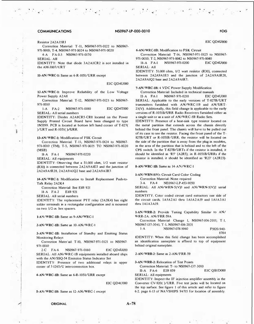
I
I l I I
1
. . ,.
. . ,.
. . .. . . ...
COMMUNICATIONS NS0967 -LP-000-00 10 FCIG
Resistor 2A2A 15R I
Correction Material: T-11, NS0967-971-0122 to NS0967-
971-00JO; T-4, NS0967-971-0024 to NS0967-971-0020
4-A FA-0.5 NS0967-971-0170
SERIAL: All
IDENTITY: Note that diode 3A2AICR2 is not installed in
the AM-3007/URT
11-AN/WRC-1: Same as 6-R-1051/URR except
EIC QD4UOOO
12-AN/WRC-1: Improve Reliability of the Low Voltage
Power Supply A2A8
Correction Material: T-12, NS0967-971-0123 to NS0967-
971-00IO
1-A FA-2 NS0967-971-0180
SERIAL: All serial numbers
EIC QD4TOOO
IDENTITY: Diodes A2A8CR5-CR8 located on the Power Supply Printed Circuit Board have been changed to type
IN5199. PCB is located at bottom left hand corner of T-827(
)IURT and R-1051( )!URR.
13-AN/WRC-1: Modification of FSK Circuit
Correction Material: T-13, NS0967-971-0124 to . NS0967-971-00IO (TM); T-5, NS0967-971-0025 TO NS0967-971-0020
(MSB)
II-A FA-I NS0967-971-0220
SERIAL: All equipments
IDENTITY: Observing that a 51,000 ohm, 112 watt resistor
(R30) is connected between 2A2A9AIE5 and the junction of
2A2A9AIR28, 2A2A9AIQ2 base and 2A2A9AIR7.
14-AN/WRC-1: Modification to Install Replacement Push-to
Talk Relay 2A2K4
Correction Material: See EIB 921
II-A FA-2 EIB 921
SERIAL: All serial numbers
IDENTITY: The replacement PTT relay (2A2K4) has eight
solder terminals in a rectangular configuration and is moumed
on two 1/2-in. hex spacers.
1-AN/WRC-18: Same as 9-AN/WRC-1
2-AN/WRC-18: Same as 10-AN/WRC-1
3-AN/WRC-18: Installation of Standby and Emitting Status
Monitoring Relays
Correction Material: T-10, NS0967-971-0121 10 NS0967-
971-00IO
2-C FA-6 NS0967-971-0160 EIC QD4UOOO
SERIAL: All AN/WRC-IB equipments installed aboard ships
with the AN/SSQ-54 Emission Status Indicator Set
IDENTITY: Presence of two additional relays in upper
corner of J-1265/U interconnection box.
4-AN/WRC-18: Same as 6-R-1051/URR except
EIC QD4UOOO
5-AN/WRC-18: Same as 12-AN/WRC- 1 except
EIC QD4UOOO
6-AN/WRC-18: Modification to FSK Circuit
Correction Material: T-14, NS0967-971-0125 to NS0967-
971-0010; T-2, NS0967-971-0042 to NS0967-971-0040
II-A FA-I N$0967-971-0200 EIC QD4UOOO
SERIAL: All
IDENTITY: 51,000 ohm, 1/2 watt resistor (R30), connected
between 2A2A9AIE5 and the junction of 2A2A9AIR28,
2A2A9AlQ2 base and 2A2A9AlR7.
7-AN/WRC-18: 4 VDC Power Supply Modification
Correction Material: Included in technical manuals
II-A FA-I NS0967-971-0210 EIC QD4UOOO
SERIAL: Applicable to the early versions of T-8278/URT
transmitters furnished with AN/WRC-l B and ANIURT-23(V). Additionally, this field change is applicable to the early
versions of R-10518/URR Radio Receivers furnished either as
a single unit or as a unit of AN/WRC-18 Radio Sets.
IDENTITY: Presence of a heat-sink type resistor located on
the metal partition that extends across the chassis directly
behind the front panel. The chassis will have to be pulled out of its case to see the resistor. Facing the front panel of the T-
8278/URT or R-10518/URR, the resistor will be located on
the side of the partition that is away from the plug-in modules,
in the area of the partition that is behind and to the left of the
CPS switch. In the T-8278/URTs if the resistor is installed, it
should be identified as 'RS' (A2R5); in R-10518/URRs if the
resistor is installed, it should be identified as 'R23' (A2R23).
8-AN/WRC-18: Same as 14-AN/WRC-1
1-AN/WRN-S(V): Circuit Card Color Coding
Correction Material: None required
3-A FA-4 NE0967-LP-453-9050
SERIAL: All AN/WRN-5(V)I and AN/WRN-5(V)2 serial
numbers
IDENTITY: Color coded circuit card extractors one side of
the circuit cards, 1AlA2AI thru 1AlA2Al9 and 1AlA3AI
thru IAIA3AJ9.
1-AN/WRR-2: Provide Tuning Capability Similar to AN/
WRR-2A, AN/FRR-59A
Correction Material: Change I, NS0967-106-2011; T-1,
NS0967-137-3041; T-1, NS0967-106-2031 1-A NS0967-078-5060 F5820-940·
8784
IDENTITY: When this field change has been accomplished
an identification nameplate is affixed to top of equipment
behind original nameplate.
2-AN/WRR-2: Same as 2-AN/FRR-59
3-AN/WRR-2: Relocation of Test Points
Correction Material: T- to NS0967-137-3010
II-A FA-6 EIB 859 EIC Q81DOOO
SERIAL: All equipments
IDENTITY: Inspect the IF injection amplifier assembly in the
Converter CV-920( )/URR. Five test jacks will be located on
the top surface. See figure I of this article and refer to figure
6-2. page 6-13 of NA VSHIPS 94715 for location of assembly.
ORIGINAL A-78

j -1
i
I I
I
>;:j
.� i
. !
! . _ j ! -.i
I I
. . ... -
.. . ... -
. . ... -
,: . . ... -
COMMUNICATIONS NS0967 -LP-000-00 1 0 FCIG
l·AN/WRR-2A: Same as 2-AN/FRR-59
2-AN/WRR-2A: Same as 3-AN/WRR-2 except
EIC QBIEOOO
3-AN/WRR-2A: Same as 3-AN/FRR-59A except
EIC QBIEOOO
l-AN/WRR-2B: Same as 2-AN/FRR-59
2-AN/WRR-28: Same as 3-AN/WRR-2 except
EIC QBIFOOO
1-AN/WRR-3: Improved RF Oscillator Stabilization Correction Material: T-1, NS0967-055-00I3 to TM,
NS0967-055-00IO (formerly NS94543) 2-A FA-2 NS0967-055-0040 None
SERIAL: B-1 thru B-4, B-6 thru B-14 and 8384 IDENTITY: Checking the value of resistor R403. Resistance should be 1200 ohms.
2-AN/WRR-3: Reduction of 120 Hertz Noise Interference
Correction Material: T-2, NS0967-035-1013 to NS0967-035-1010
4-A FA-I
SERIAL: All
NS0967-055-0060
IDENTITY: Note that pin 8 of JIIOI is connected to the shield of coaxial cable which is connected to pin 6 of J I 101.
l·AN/WRR-3A: Same as 2-AN/WRR-3
l·AN/WRR-3B: Same as 2-AN/WRR-3
J-AN/WRT-1: Relocation of Resistors R-737 and R-738 Correction Material: T-1 to NS93484(A)
2-B FA-4 NS981314 None SERIAL: I through 137
2-AN/WRT-1: Modification of Wiring Correction Material: T-2 to NS93483(A) 2-A FA-0.5 NS981315 None
SERIAL: I through 100 and 102
3-AN/WRT-1: Cancelled
4-AN/WRT-1: Disable PA Screen Voltage Keying Correction Material: T-3 to NS93483(A) 2-A FA-0.5 NS981337
SERIAL: I through 144 None
IDENTITY: Buss wire jumper installed between TB-801-1 and TB-801-2.
5-AN/WRT-1: Oven Insulation and Bandswitch Replacement Correction Material: NS93483.42 I-A FA-45 NS0967-972-0090
SERIAL: I through 155 IDENTITY: Any neoprene coated fiberglass insulation mate· rial replaced with clean uncoated fiberglass. This uncoated fi-
berglass can be detected by the uniform canary yellow color of both sides of the fiberglass as opposed to neoprene coated fiberglass which has one surface of light tan, burnt brownish or black color. The neoprene coating also feels still to the touch.
6-AN/WRT-1: Lock-in Performance Improvement at Exact 100 KC Points
Correction Material: T-4 to NS93483(A) 1-A FA-1.5 NS981468
SERIAL: 142 through 307
2N5820-064-5768
IDENTITY: R720 and R721 in the frequency comparator subchassis of the Electrical Frequency Control C-2861/WRT-1 will be changed from 220 ohm 1/2 watt to 2.2K 1/2 watt. Resistors R605 and R606 will be changed from 200 ohm 1/2 watt to 820 ohm 1/2 watt. Diode mounting board, E665, with four
type IN457 diodes, CR627, CR628, CR629, and CR630, mounted on it will be located just above terminal board TB602A in the comparator subchassis.
7-AN/WRT-1: Eliminating Key-Up Radiation in Radio Trans·
mitter Correction Material: T-6, NS0967-050-5015 to TM,
N$0967-050-5010 (formerly NS93483A) 2-A FA-I NS0967-050-5080
SERIAL: All serial numbers in which key-up radiation is found a problem IDENTITY: Substitution of 680-ohm resistors R511, R512, and R513 in Power Supply AM-2198/WRT-1 with 820-ohm 2·
watt resistors.
8-AN/WRT-1: Cancelled
9-AN/WRT-1: Replacing Defective Ledex Switch Actuator Symbol 83303
Correction Material: None
1-A FA-4 N$0285-077-2000 2N5820-788-8420
SERIAL: Radio Frequency Tuners TN-345/WRT-1 Ser A I , A3, A4, AS, AIO thru Al6, A21, A22, A24, and A26 (15
units) IDENTITY: Tuners in which the deficiency has been corrected will be marked with a letter R stamped on the exterior of the drive end casting adjacent to pressure gauge M3301.
10-AN/WRT-1: Tone Generator - (After completion of field
change, nomenclature becomes Radio Transmitting Set AN/
WRT-IA) Correction Material: None required
1-A FA-6 NS0967-050-51 1 0 2N5820-918· 1602
SERIAL: (50 equipments at random). Accomplish this change on transmitters requiring aircraft capabilities only. The number of field changes available are limited.
IDENTITY: Those equipments which have this field change installed have a five-position EMISSION SELECTOR Switch nameplate on the front panel of Amplifier-Power Supply AM-2198A/WRT-I .
11-AN/WRT-1: R.F. Tuners; Venting o f Guide Shoe
ORIGINAL A-79

.. , I I I
.,
. . ·, .
. ..
COMMUNICATIONS NS0967 -LP-000-00 10 FCIG
2-A FA-0.5 NS0967-972-0160
SERIAL: All None
IDENTITY: Presence of a 1/32' hole in the guide shoe.
12-AN/WRT-1: Modification of FSK Keyer Circuit
Correction Material: T-7 to NS0967-972-001 5 to NS0967-972-00IO
2-A FA-I NS0967-972-0150
SERIAL: All Amplifier-Power Supplies AM-2198/WRT-1 and AM-2198A/WRT-IA, except those sets with serial numbers D I and up, as this change was included in the manufacture of these sets. IDENTITY: Substitution of the 200 ohm resistor (R508) with a 1000 ohm, 14 watt resistor.
13-AN/WRT-1: Installation of Standby and Emitting Status
Monitoring Relays
Correction Material: T-4, NS0967-972-0017 to NS0967-972-00IO
2-A FA-12 NS0967-972-0180 EIC QFIUOOO SERIAL: All equipments installed aboard ships with AN/ SSQ-54 Emission Status Indicator Set
IDENTITY: Two relays mounted on the chassis frame adjacent to the bus switch S-501 located in the top center section of AM-2198/WRT-1.
14-AN/WRT-1: Rewiring of Fuse F502 to the Primary of
Transformer T503 Correction Material: T-6, NS0967-050-5012 to NS0967-050-
SOIO 2-A FA-2 NS0967-050-5 120 EIC QEIVOOO
SERIAL: All equipments
IDENTITY: Presence of label above fuse F502 which reads 'PRIMARY FUSE T-503 2 AMP.'
15-AN/WRT-1: Modification :o FSK Circuit
Correction Material: T-9, NS0967-972-0204 to NS0967-972-00JO (TM); T-4, NS0967-972-0044 to NS0967-972-0040 (MSB)
IV-A FA-I NS0967-972-02l0 EIC QEIUOOO SERIAL: All equipments
IDENTITY: Observing that the wires on terminals 13 and 14 of terminal board (TB) 450 have been reversed as indicated by lead markings.
16-AN/WRT-1: Provides C-R-E-S Mounting Clamp Assem
blies for TN-345/WRT and CU-760/WRT-1 Correction Material: T-1, NS0967-050-5011 to NS0967-050-
5010 I-A FA-4 NS0967-912-0l90
SERIAL: All serial numbers EICQEJUOOO
IDENTITY: Presence of slotted hex bolts in clamp assemblies.
17-AN/WRT-1: Ceramic Antenna Insulator
Correction Material: T-7, NS0967-050-5013 to NS0967-050-50JO; T-10, NS0967-972-0205 to NS0967-972-00JO
I-A FA-8 NS0967-972-0200 EIC QEJUOOO SERIAL: All serial numbers
IDENTITY: Presence of ceramic antenna insulators having marking 'BERYLLIUM OXIDE' on both TN-345/WRT-1( ) and CU-760/WRT-1( ).
18-AN/WRT-1: Modification to Component Mounting Boards E303 and E451
Correction Material: None required II-A FA-2.5
SERIAL: All serial numbers EIC QEIUOOO
IDENTITY: Note that resistors R349, R350, and R479 are mounted on standoff terminals.
19-AN/WRT-1: Installation of Safety Ground Wire Correction Material: None required
II-A FA-I EIB 888 EIC QEIUOOO SERIAL: All equipments
IDENTITY: Presence of a wire connected to the ground lug associated with K-206 on the front panel and secured to the main chassis by R-203 mounting hardware.
1-AN/WRT-1A: Modification for MCW Operation Correction Material: T- to NS95900(A) 2-A FA-0.5 NS0967-972-0050
SERIAL: All when used as Low Frequency Beacons IDENTITY: Presence of a jumper connected between S-508A-l and S-590A-S in the AM-2198A/WRT-1.
2-AN/WRT-IA: Same as 12-AN/WRT- 1 except
Correction Material: T-2, NS0967-972-0014 to NS0967-972-00IO
3-AN/WRT-1A: Same as 1 1 -AN/WRT-1
4-AN/WRT-1A: Installation of Standby and Emitting Status
Monitoring Relays Correction Material: T-3, NS0967-972-0016 to TM,
NS0967-972-00IO 2-C FA-12 NS0967-972-0170 EIC FK86000
SERIAL: All equipments installed aboard ships with AN/ SSQ-54 Emission Status Indicator Set IDENTITY: Two relays mounted on the chassis frame adjacent to the bus switch S-50 I located in the top center section of AM·2198A/WRT-IA.
S-AN/WRT-1A: Same as 15-AN/WRT-1 except
EIC QEIVOOO
6-AN/WRT·1A: Same as 16-AN/WRT-1 except Correction Material: T-8, NS0967-972-0202 to NS0967-972-
00IO and
EIC QEIVOOO
7-AN/WRT-IA: Same as 17-AN/WRT-1 except Correction Material: T-10, NS0967-972-0205 to NS0967-
972-00IO and
EIC QEIVOOO
8-AN/WRT-IA: Same as 18-AN/WRT- 1 except
EIC QEIVOOO
9-AN/WRT-1A: Same as 19-AN/WRT-1 except
ORIGINAl A-80

I
. . .....
. . ...-
. . ... -
. . ... -
COMMUNICATIONS NS0967 -lP-000-00 10 FCIG
EIC QEIVOOO
1-AN/WRT-lB: Same as 15-AN/WRT-1 except
EIC QEOOOOO
2-AN/WRT-lB: Same as 17-AN/WRT-1 except
EIC QE4EOOO
3-AN/WRT-lB: Same as 18-AN/WRT-1 except
EIC QE4EOOO
4-AN/WRT-lB: Same as 19-AN/WRT-1 except
EIC QE4EOOO
1-AN/WRT-2: Modification of Printed Circuit Boards E-1301
and E-1303
Correction Material: T-1 to NS93319A
2-A FA-3 NS981280
SERIAL: I through 234
2-AN/WRT-2: Removal of Diodes CR-1342 and CR-1343
Correction Material: T-2 to NS93319A
2-B FA-0.5 NS981317
SERIAL: I through 355
3-AN/WRT-2: Cancelled
None
None
4-AN/WRT-2: Oven Insulation and Bandswitch Replacement
Correction Material: NS93483.42
1-A FA-40
SERIAL: I through 417 RFO Insulation: F5820-856-3451 RFO Bandswitch: F5820-856-3450 EFC Insulation: FS820-856-3449 EFC Bandswitch: F5820-856-3448
IDENTITY: Any neoprene coated fiberglass insulation mate
rial replaced with clean uncoated fiberglass. This uncoated fiberglass can be detected by the uniform canary yellow color of both sides of the fiberglass as opposed to neoprene coated fiberglass which has one surface of light tan, burnt brownish
or black color. The neoprene coating also feels still to the touch.
5-AN/WRT-2: Control and Drive of Radio Transmitting Set
AN/WRT-2 from Transmitter Group AN/WRA-3(XN-1)
Correction Material: Supp. I to NS93319(A)
1-A FA-16 NS0967-067-3080
SERIAL: Equipments authorized which use AN/WRA-3(XNI) as the exciting unit
IDENTITY: Transmitter-Transfer Control C-4359(XN-l/ WRT-2) mounted near Radio Transmitting Set AN/WRT-2.
SA-AN/WRT-2: Control and Drive of Radio Transmitting Set
from Transmitter Group AN/WRA-3(XN-1)
Correction Material: Supplement 5 to NS93285(A), Supplement 2 to NS93319(A)
1-A FA-21 NS0967-067-3080 2N5820-884-2120
SERIAL: Only those equipments using the AN/WRA-3(XN
I) for external excitation
IDENTITY: Transmitter-Transfer Control mounted on or
near Radio Transmitting AN/WRT-2 or Radio Set AN!URC-
32.
6-AN/WRT-2: Information Relative to this change is included
in Secret Manual NS94546
7-AN/WRT-2: Replacement of Thermostatic Switches S-305
and S-602
Correction Material: T-4 to NS93319(A)
1-A FA-4 NS981685 2N5820-056-
7148
SERIAL: All equipments now installed and intended for in
stallation in nuclear-powered submarines
IDENTITY: The new thermostatic switches are conta.ined in
4-sided aluminum capsules which are 1/2' x 1/2' x 9'. The cap
sules are mounted in the same general area of the equipment as the initially installed thermostatic switches.
8-AN/WRT-2: Cancelled
9-AN/WRT-2: Replacement of Defective Ledex Switch Actu
ator, Symbol 83303
Correction Material: None
1-A FA-6 NS0967-073-3120 2N5820-788-8421
SERIAL: Radio Frequency Tuners TN-342/WRT-2 Ser C l , A2(C2)*, A3(C3)*, C7 through Cl3, A 1 5 (CIS)*, A l 6 (Cl6)*, C l 7 through C20, C22, and C26 (20 unit)
IDENTITY: Tuners in which the deficiency has been corrected will be marked with a letter 'R' stamped on the exterior of
the drive and casting adjacent to pressure gauge M3301.
10-AN/WRT-2: Relocation of Phase Splitter Capacitor C862
for Tuner Blower Motor
Correction Material: T-9, NS0967-073-3017 to TM,
NS0967-073-3010 (formerly_
NS933!9A)
2-A FA-4 NS0967-050-5080 None SERIAL: All
IDENTITY Absence of the Blower Motor Capacitor formerly mounted on the right rear lower corner • to the immediate right of Relay K804 - of the Radio Frequency Amplifier chas
sis.
11-AN/WRT-2: Replacement of RG-58/U Neutralizing Cable
with RG-141A/U
Correction Material: T-5 to NS93319(A) NS0280-515-
701 I
1-A FA-I NS0285-079-0200 2N5820-909-
3901
SERIAL: I through 702, HI through 8 1 5 1 , Cl through C20
IDENTITY: Presence of RG-141A!U cable between C909 and C882 in Radio Frequency Amplifier drawer. The RG-141A!U can be identified by its light color and rough to the touch fiberglass jacket. The RG-58/U is dark in color and has
smooth finish.
12-AN/WRT-2: Replacement of 90 Phase Shift Network FL·
ORIGINAL A-81

·, .
... -. .
... -.. .
... -
COMMUNICATIONS NS0967 -LP-000-00 10 FCIG
603 Correction Material: T-7, NS0967-073-3015
1-A FA NS0967-073-3150
SERIAL: I through 60 IDENTITY: New network FL-603 is marked with Westing
house Drawing #376A439HOI
13-AN/WRT-2: Power Amplifier Cathode Current Equalizing
Correction Material: T-8, NS0967-073-3016 1-A FA N$0967-073-3160 None
SERIAL: I through 263
IDENTITY: Location of cathode bias adjust potentiometers on left side cover plate of PA compartment in the AM-21211
WRT-2.
14-AN/WRT-2: Replacement of Printed Circuit Board E-1404
with New Board E-1412 Correction Material: T-6 to NS0967-073-3014 (formerly
NS93319(A))
I-A FA-I NS0967-073-3170
SERIAL: I through 154
IDENTITY: The new 425 cps Test Oscillator, Printed Circuit Board E-1412 does not have L-1401 and transistor Q-1411 mounted on the right front corner.
15-AN/WRT-2: Elimination of Constant Keyed Condition in
FSK Mode
Correction Material: T-11, NS0967-073-3019 to NS0967-
073-3010
2-A FA-0.5 NS0967-073-3200
SERIAL: I through 263, AI through AI78 and D I through
D327
IDENTITY: Tune AN/WRT-2 using the normal tuning pro
cedure. Unkey transmitter. Position the EMISSION SELECTOR switch on AM-2122/WRT-2 to the FSK position, and if
a keyed condition results, the field change has not been ac
complished.
16-AN/WRT-2: Same as I 1-AN/WRT-1
17-AN/WRT-2: Coil Form Improvement
Correction Material: T-10, NS0967-073-3018 to TM,
NS0967-073-3010; T-1, NS0967-073-3181 to NS0967-073-3180
1-A FA-4 NS0967-073-3180 2N5820-879-
7671
SERIAL: All
IDENTITY: Installation of improved coil form L3302 AL T
A.
18-AN/WRT-2: FSK Termination Modification and Mark
Space Equalization
Correction Material: T-13, NS0967-073-3201 to TM,
NS0967-073-3010
1-A FA-4 NS0967-073-3190 2N5820-054-
3465 SERIAL: All - NOTE: AN/WRT-2 Series, Serial Nos. I thru
122 will receive kit!\ with item 7 of MATERIAL RE
QUIRED supplied directly from the manufacturer
IDENTITY: Two potentiometers marked SPACE and
MARK located above E1401 under the cover plate on the
right side of Amplifier Power Supply AM-2122/WRT-2.
19-AN/WRT-2: Replaces Transistor Q502, (2N95, 2N1330) and
Resistor R505 (33,000 ohms, 2W)
Correction Material: T-14, NS0967-073-3202 to TM,
NS0967-073-3010 (formerly NS93319(A)) 1-A FA-I NS0967-073-3210 2N5820-226-
3108
SERIAL: I through 702
IDENTITY: Addition of a mounting plate with replacement transistor Q502 (2N657) mounted in clip and resistor R505 (on
resistor board E507) changed to a higher resistance value of 39,000 ohms. Change is located in Amplifier-Power Supply AM-2122/WRT-2.
20-AN/WRT-2: Frequency Comparator Mixer Diode Replace
ment on Circuit Board E601
Correction Material: T-I 5, NS0967-073-3203 to TM, NS0967-073-3010 (formerly NS93319(A))
1-A FA-3 NS0967-073-3220 2N5820-226-3109
SERIAL: I through 702, BI through Bl51, and CI thru Cl29
IDENTITY: Diodes CR601 through CR604 on E60I are Type IN914. Circuit Board E601 is located under cover, left
side of the Electrical Frequency Control C-2764/WRT-2.
21-AN/WRT-2: Addition of Capacitors CI363 and CI364 on
Circuit Board EI301; 10:1 Frequency Divider
Correction Material: T-16, NS0967-073-3204 to TM,
NS0967-073-3010 (formerly NS933I9(A))
1-A FA-3 NS0967-073-3230 2N5820-226-3 1 1 2
SERIAL: I through 444 IDENTITY: Addition of capacitors CI363 (.OJ uf) and C l364
(470 uuf) on circuit board EI301 of the Electrical Frequency
Control C-2764/WRT-2.
22-AN/WRT-2: Provide Stainless Steel Mounting Clamp As
semblies for TN-342/WRT-2 RF Tuners
Correction Material: T-17, NS0967-073-3205 to TM,
NS0967-073-3010 (formerly NS93319(A))
1-A FA-I NS0967-073-3240 2Z5820-1 19-1291
SERIAL: TN-342/WRT-2 - all serial numbers
IDENTITY: The retainer straps of the clamp assembly are secured with slotted hexagon head cap screws instead of socket
head cap screws.
23-AN/WRT-2: Modification of PA Grid Bias and Screen
Voltage Circuits. Addition of Bunon Hole-Plug
Correcction Material: T-18, NS0967-073-3206 to TM, NS0967-073-3010 (formerly NS93319(A))
1-C FA-24 NS0967-073-3250 EIC FKI5000
SERIAL: All serial numbers
IDENTITY: Three zener diodes, type IN3007B and a 500
ohm resistor installed in AM-2122/WRT-2. Four PA bias adjust controls installed on left side cover of AM-2121/WRT-
2. Button hole plug installed on top of 1850V high voltage
protective cover of AM-2121/WRT-2.
24-AN/WRT-2: Installation of Standby and Emiuing Status
Monitoring Relays
Correction Material: T-19, NS0967-073-3207 to TM,
ORIGINAl A-82
. . ... -

' '
· I
'
i
I I · I
. . ... ....
. ' ...
. .
COMMUNICATIONS NS0967 -LP-000-00 1 0 FCIG
NS0967-073-3010
2-C FA-12 NS0967473-3260 EIC FKISOOO SERIAL: All equipments installed aboard ships with AN/ SSQ-54 Emission Status Indicator Set IDENTITY: Two relays mounted on the chassis frame adjacent to the bus switch SSOI located in the top center section of AM-2122/WRT-2.
25-AN/WRT-2: Rewiring of Fuse F502 to the Primary of Transformers T-503
Correction Material: T-1, NS0967-073-301 1 to NS0967-073-3010
2-A FA-2 N$0967-073-3270 EIC
QEIWOOO SERIAL: All equipments except those with serial numbers Cl thru C458 IDENTITY: Presence of a label above fuse F502 which reads 'PRIMARY FUSE T503 2 Amp.'
26-AN/WRT-2: Modafication to FSK Operation Correction Matenal: T-2, NS0967-073-3012 to NS0967-073-
3010 IV-A FA-I NS0967-073-3280
SERIAL: All equipments
EIC QEIWOOO
IDENTITY: Observing that the labeled wires on terminal 20 and 21 of terminal board (TB) 14018 have been reversed.
27-AN/WRT-2: Installation of Safety Ground Wire Correction Material: None required IJ-A FA-I
SERIAL: All equipments
EIC QEIWOOO
IDENTITY: Presence of a wire connected to the ground lug associated with K-206 on the front panel and secured to the main chassis by R-203 mounting hardware.
1-AN/WRT 4(XN-3): Simplification of Driver Neutralization Procedure
Correction Material: T-1. NS0967-063-8014 to NS0967-063-8010
II-A FA-2 NS0967-063-8060 EIC QQOAOOO SERIAL: All serial numbers IDENTITY: Presence of a toggle switch on a bracket secured to the tube shield of VS above the cable clamp.
2-AN/WRT-4(XN-3): Radio Transmitting Set • Simplification of Driver Neutralization Procedure
Correction Material: T-2. NS0967-063-8015 to NS0967-063-8010
II-A FA-2 SERIAL: All
N$0967-063-8070 EIC QQOAOOO
IDENTITY: Thas field change can be identified by the presence of a toggle switch on a bracket secured to the tube shield of V5 above the cable clamp.
1-AN/WSC-S(V): Running Time Meter l A l A l M I Wiring Change
Correction Matenal: T-1, NE0967-LP-455-001 1 to NE0967-LP-455-0010
4-A FA-I NE0967-LP-455-0020 EIC QPOA
SERIAL: All serial numbers
IDENTITY: Upon removal of fuse IAlAIFl from meter panel, Radio Set AN/WSC-5(V) becomes inoperative.
2-AN/WSCS<V): Filter Support Screen Wire Installation
Correction Material: T-2, NE0967-LP-455-0012 to NE0967-LP-455-0010
I-A FA-I NE0967-LP-455-0030 EIC QPOA SERIAL: All serial numbers
IDENTITY: The support screen wire is installed behind the mesh air filter.
1-AN/WSN-t(V)l: Addition of EMI Filters to Navigation
Control Console
Correction Material: Ch. I . NS0967-LP-529-6011 to N$0967-LP-529-6010; Ch. I , NS0967-LP-529-7011 to NS0967-LP-529-7010
1-C FA-16 NS0967-LP-529-6020 SERIAL: Serial number A I (Single), A l 3 (Dual Control Console, Tooling). (Previously accomplished by Autonetics.) IDENTITY: Note installation of warning plate at top center of console and EMI filters tnstalled behind control panels.
2-AN/WSN-l(V)l: Elimination of Noise on Clock 4-Line AN/
WSN-l(V)I and AN/WSN-l(V)2
Correction Material: Chg. 2, NS0967-LP-529-7012, to NS0967-529-7010, and Chg. 2, NS0967-LP-529-6012, to NS0967-529-6010.
1-C YF-16 NS0967-LP-529-6030 EIC L90F
SERIAL: AN/WSN-l(V)J serial AI; AN/WSN-l(V)2 serial AI thru A30.
IDENTITY: Installation of 10095-201-1 Capacitor Assembly on 85162-201-21 Test Panel Assembly.
3-AN/WSJ'-l(V)l: Modification of Control Panel to Install
Replaceable Display Digits
Correction Material: Ch. 2. NS0967-LP-529-6012 to TM. NS0967-LP-529-6010 and Ch. 2, NS0967-LP-529-7012 to TM, NS0967-LP-529-7010
1-C YF-16 NS0967-LP-529-6040 EIC L90F SERIAL: AN/WSN-I(V)I serial AI. AN/WSN-I(V)2 serial AI thru Al3.
IDENTITY: Part number of control panel is 68728-501-11 and the pan number of the subassembly is 68728-501-205.
4-AN/WSN-l(V)l: Addauon of Synchro Conversion Limiting
AN/WSN-l(V)l and AN/WSN-I(V)2.
Correction Material: Chg. 3, NS0967-LP-529-7013, to TM, NS0967-529-7010. and Chg. 3, NS0967-LP-529-6013, to TM. NS0967-529-6010.
1-C YF-4 N$0967-LP-529-6050 EIC L90F SERIAL: AN/WSN-l(V)I serial AI. AN/WSN-l(V)2 serial Al-A30. lDENTITY: Installation of eight RHB250V, 1/4 amp fuses on 85162-201-31 Test Panel Assembly.
1-AN/WSN-l(V)2: Same as 1-AN/WSN-I(V)I except
SERIAL: AI thru Al2 (Dual)
2-AN/WS�-l(V)l: Same as 2-AN/WSN-l(V)l
ORIGINAL A-83
...

/
.. . ... -
. .
... -
. .
... -
COMMUNICATIONS NS0967-LP-000-0010 FCIG
3-AN/WSN-l(V)2: Same as 3-AN/WSN-I(V)I
4-AN/WSN-l(V)2: Same as 4-AN/WSN-I(V)J.
1-AN/WSQ-2: Removal of Pump Noise Monitor Alarm Func
tion
Correction Material: Advanced Change Notice eluded in field change kit
No. I in-
IV-A FA-2 N$0967-892-9020
SERIAL: All serial numbers
EIC
WK5FOOO
IDENTITY: Front panel alarm lights 1101 de-energized under
all conditions.
I-ANALYZER MARK IV-N, DISSOLVED OXYGEN: Printed Circuit Board Upgrading.
Correction Material: New TM, NS0967-LP-IOI-7010 dtd
Aug 77. 2-A FA-I NS0965-LP-JOI-7020
SERIAL: All serial numbers.
IDENTITY: The new amplifier board can be identified by capacitor C-5 with a value of 0.1 uF. The new switch board can
be identified by the addition of transformer T-2. The new alarm circuit board can be identified by the change of location
of potentiometers P-4 and P-5 requiring opening of cabinet to make adjustments.
1-AS-390/SRC: Replacement of RG-81/U Feedline Correction Material: None
1-A FA-I NS981176
SERIAL: All
IDENTITY: Presence of new coaxial feedline
F5985-724-
8126
1-AS-4688/B: Substitution of an Improved or Modified 'Spark Plug'
Correction Material: None
2-A FA-I NS0967-953-9020 SERIAL: See field change
None
IDENTITY: Visually checking to see that the spark plug installed is the new improved type described herein.
1-AS-493/U: Pressure Proofing
Correction Material: T-1 to NS91569 A FA-2 NS98325
SERIAL: 1-30
IDENTITY: Pressure proof lines
F5895-346-
4652
1-AS-535/8: Replacement of Spacers 0-301 and 0-302 Correction Material: None A FA-2 NS98584 F5985-324-
2068 SERIAL: 1-64
1-AS-2112/FRC: Installation of Antenna Positioner Telephone
Ringer Circuit Correction Material: T-1, NS0967-174-0241 to TM.
NS0967-l74-0240
1-A FA-I NS0967-174-0340 SERIAL: All equipments
IDENTITY: Presence of a chassis mounted push-button switch and toggle type switch mounted adjacent to the sound powered telephone jackbox. Presence of a chassis mounted push-button switch mounted on the side of the Main Junction Box located inside the antenna positioner.
1-AS-2187/FRC: Rotator Clutch Tension Check
Correction Material: None required
III-A FA-3 N$0967-434-2050
SERIAL: Serials A· I through A-I 15
IDENTITY: Visual Tension Check
2-AS-2187/FRC: Erection Boom Guy Installation
Correction Material: Change I. NE0967-434-201 I to NE0967-434-2010
11-C YF-10 NS0967-434-2060 EIC Q151000
SERIAL: AI thru A i l S
IDENTITY: Visual inspection · Observe that two stiffener plates and one support plate have been added to the T-strut and flange.
1-AS-3018/WSC-l(V): Exchange Cam Clamp on Sector
Switch Cam Assembly from Round to Special Hexagonal.
Correction Material: None required.
1-A FA-2 NE0967-LP-467-9040 EIC QISS
SERIAL: NOOOI-N0298.
IDENTITY: When examining the cam assembly through the access opening in the elevation housing, a hexagonal clamp rather than a round clamp indicates accomplishment of this field change.
2-AS-3018/WSC-l(V): Painting Caution Label.
Correction Material: None required. 3-A FA-I NE0967-LP-467-9050
SERIAL: All serial numbers. EIC QI5S
IDENTITY: Presence of painting caution label on the ground screen cover plate indicates acmplishment of this field change.
3-AS-3018/WSC-1(V): RF Overide Block Interlock.
Correction Material: Chg. 3, NE0967-LP-467-9013, to TM, NE0967-LP-467-90JO.
4-A FA-2 NE0967-LP-467-9080 EIC QP30
SERIAL: All serial numbers. IDENTITY: Check continuity, SAFETY switch at 'PWR
ON' position: For single AN/WSC-3 ·· zero ohms between
IA6Pl·M and IA6PI-N; and between IA6P3-M and IA6P I·
N. For stacked AN/WSC-3 cabinet ·· zero ohms between P8-M and PS·N, and between P6·M and P6-N.
4-AS-3018/WSC-l(V): Change Safety Switch on Antenna Ped· estal.
Correction Material: EIB 005 2-A FA-2 EIB 005
SERIAL: All serial numbers.
EIC QP30
IDENTITY: Verify that the antenna safety switch IAIA2WISI and/or IA2A2WISI contains a dust!mois1ure boot.
1-AS-3018A/WSC·l(V): Change Safety Switch on Antenna Pedestal.
Correction Material: EIB 005
ORIGINAL A-84
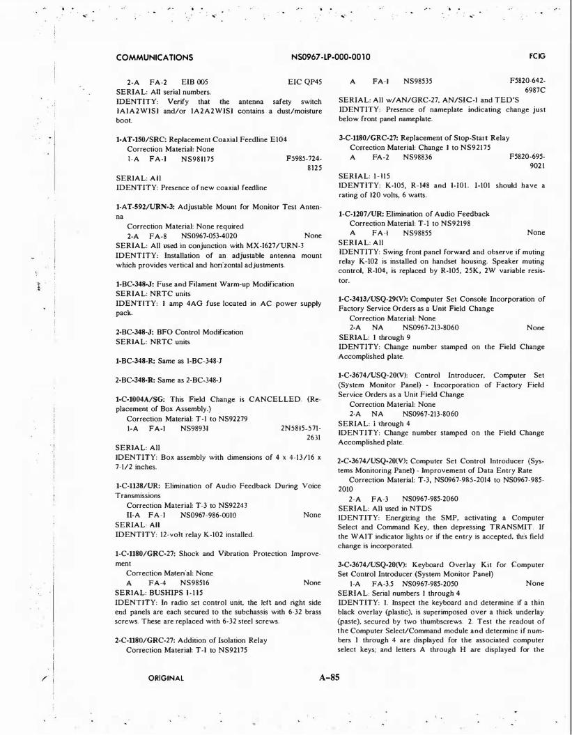
I i I
· I . i
I I
r
I
I
.. .....
.. . . .....
. . .. . ..... .....
COMMUNICATIONS NS0967 -LP-000-00 10 FCIG
2-A FA-2 EIB 005 EIC QP45
SERIAL: All serial numbers.
IDENTITY: Verify that the antenna safety switch IAIA2WISI and/or IA2A2WISI contains a dust/moisture boot.
1-AT-150/SRC: Replacement Coaxial Feedline E104
Correction Material: None
1-A FA-I NS981175 F5985-724-8125
SERIAL: All IDENTITY: Presence of new coaxial feedline
1-AT-592/URN-3: Adjustable Mount for Monitor Test Anten
na
Correction Material: None required
2-A FA-8 NS0967-053-4020 None
SERIAL: All used in conjunction with MX-1627/URN-3
IDENTITY: Installation of an adjustable antenna mount
which provides vertical and horizontal adjustments .
1-BC-348-J: Fuse and Filament Warm-up Modification
SERIAL: NRTC units
IDENTITY: I amp 4AG fuse located in AC power supply pack.
2-BC-348-J: BFO Control Modification
SERIAL: NRTC units
1-BC-348-R: Same as 1-BC-348-J
2-BC-348-R: Same as 2-BC-348-J
1-C-1004A/SG: This Field Change is CANCELLED. (Re
placement of Box Assembly.)
Correction Material: T-1 to NS92279
1-A FA-I NS98931 2N5815-571-2631
SERIAL: All
IDENTITY: Box assembly with dimensions of 4 x 4-13/16 x
7-1/2 inches.
1-C-1138/UR: Elimination of Audio Feedback During Voice
Transmissions
Correction Material: T-3 to NS92243
II-A FA-I NS0967-986-00IO
SERIAL: All
IDENTITY: 12-vo1t relay K-102 installed.
None
J-C-1180/GRC-27: Shock and Vibration Protection Improve
ment
Correction Material: None
A FA-4 NS98516
SERIAL: BUSHIPS 1-115
None
IDENTITY: In radio set control unit, the left and right side end panels are each secured to the subchassis with 6-32 brass screws. These are replaced with 6-32 steel screws.
2-C-1180/GRC-27: Addition of Isolation Relay
Correction Material: T-1 to NS92175
A FA-I NS98535 F5820-642-
6987C
SERIAL: All w/AN/GRC-27, AN/SIC-I and TED'S
IDENTITY: Presence of nameplate indicating change just below front panel nameplate.
3-C-1180/GRC-27: Replacement of Stop-Start Relay
Correction Material: Change I to NS92175
A F A-2 NS98836
SERIAL: 1-115
F5820-695-9021
IDENTITY: K-105, R-148 and 1-101. I-101 should have a
rating of 120 volts, 6 watts.
1-C-1207/UR: Elimination of Audio Feedback
Correction Material: T-1 to NS92198 A FA-I NS98855
SERIAL: All
None
IDENTITY: Swing front panel forward and observe if muting relay K-102 is installed on handset housing. Speaker muting control, R-104, is replaced by R-105, 25K, 2W variable resis-
tor.
1-C-3413/USQ-29(V): Computer Set Console Incorporation of
Factory Service Orders as a Unit Field Change
Correction Material: None 2-A NA NS0967-213-8060 None
SERIAL: I through 9 IDENTITY: Change number stamped on the Field Change
Accomplished plate.
1-C-3674/USQ-20(V): Control Introducer, Computer Set
(System Monitor Panel) - Incorporation of Factory Field
Service Orders as a Unit Field Change
Correction Material: None
2-A NA NS0967-213-8060
SERIAL: i through 4 IDENTITY: Change number stamped on the Field Change
Accomplished plate.
2-C-3674/USQ-20(V): Computer Set Control Introducer (Systems Monitoring Panel) - Improvement of Data Entry Rate
Correction Material: T-3, NS0967-985-2014 to NS0967-985-2010
2-A FA-3 N$0967-985-2060
SERIAL: All used in NTDS IDENTITY: Energizing the SMP, activating a Computer Select and Command Key, then depressing TRANSMIT. If the WAIT indicator lights or if the entry is accepted, this field change is incorporated.
3-C-3674/USQ-20(V): Keyboard Overlay Kit for !:omputer Set Control Introducer (System Monitor Panel)
1-A FA-3.5 N$0967-985-2050 None
SERIAL: Serial numbers I through 4 IDENTITY: I. Inspect the keyboard and determine if a thin black overlay (plastic), is superimposed over a thick underlay (paste), secured by two thumbscrews. 2. Test the readout of the Computer Select/Command module and determine if numbers I through 4 are displayed for the associated computer select keys; and letters A through H are displayed for the
ORIGINAL A-85

I
.1
! i
. '
.. . . . .. . ,- '"'" ,- ....-
COMMUNICATIONS NS0967 -LP-000-00 1 0 FCIG
computer command keys. 3. Test the left most identifier/code module and determine if numbers 0 through 9 are displayed. 4. If all the above displays as stated in this field change has been accomplished, proceed to the routing instructions of this bulletin.
1-C-3674AIUSQ-20(V): Computer Set Control Introducers (Systems Monitor Panels) Spacer for Cable Clearances
Correction Material: None required 2-A FA-4 NS0967-213-8060
SERIAL: A I through AS None
2-C-3674A/USQ-20(V): Systems Monitoring Panel; Improvement of Data Entry Rate
Correction Material: T-3, NS0967-985-2014 to NS0967-985-2010
2-A FA-3 NS0967-985-2060 SERIAL: A-I used in NTDS IDENTITY: Energizing the SMP, activating a Computer Select and Command Key, then depressing TRANSMIT. If the WAIT indicator lights or if the entry is accepted, this field change is incorporated.
3·C-3674A/USQ-20(V): Changeable Legend Key Caps for Computer Set Control Introducer
Correction Material: Change 2, NS0967-985-2013 to TM, NS0967-985-2010 (formerly NS94089(A))
I-A FA-2.5 NS0967-985-2040 SERIAL: AI - A30 and B l - B61 IDENTITY: If yellow caps are installed on the Computer Select Keys; green caps are on the Command Keys; red caps are on the Identifier and Code Keys; and the Computer Select/Command Display contains alpha-numeric coding.
4-C-3674AIUSQ-20(V): Permit Setting Proper Computer Select Bits where Computers 'C' and 'D' are connected as 'A' and 'B' in a 4 Computer 2SMP Configuration
Correction Material: T-4, NS0967-985-201 5 to NS0967-985-2010 (formerly NS94089(A))
2-A FA-I NS0967-985-2090 SERIAL: A 7 and other serial numbers as designated by NA VSEC where computers 'C' and 'D' are connected to the SMP as 'A' and 'B' IDENTITY: Continuity between TB4D2 and TB4C5 in logic chassis 6 indicating that logic element 12KOI has been bypassed.
1-C-367SIUSQ-20(V): Control Introducer Computer Set (System Monitor Panel) Computer Incorporation of Factory Field Change Service Orders as a Field Unit Change
Correction Material: None 2-A NA NS0967-213-8060
SERIAL: I and 2 IDENTITY: Change number stamped on the Field Change Accomplished plate.
2-C-367S/USQ-20(V): Same as 2-C-3674/USQ-20(V)
3-C-367S/USQ-20(V>: Same as 3-C-3674/USQ-20(V)
1-C-367SA/USQ-20(V): Same as 1-C3674A/USQ-20(V) except
SERIAL: A I through A 1 3
2-C-367SA/USQ-20(V): Same as 2-C-3674A/USQ-20(V)
3-C-367SA!USQ-20(V): Same as 3-C-3674A/USQ-20(V) except SERIAL: A l -A24 and Bl-B3
4-C-367SAIUSQ-20(V): Incorporation of UNIVAC Field Change Order MPL-653 as a Field Change
Correction Material: None
1-C FA-40 NS0967-985-2100 EIC FR04000 SERIAL: Applies to equipments when a two-computer system is converted to a three-computer system IDENTITY: Observing that the third indicator panel is not blank.
1-C-4386/TSQ-18: Modification of Radar Set Control C-4386/
TSQ-18
NS0967-266-6370 SERIAL: All serial numbers IDENTITY: Presence of 270 pF capacitor {C IS) and 500 pF capacitor (CI7) in countdown blocking oscillator of C-4386/ TSQ-18 Radar Set Control.
1-C-4621/SR: Provision for Simplex and Duplex Operation Capability
Correction Material: T-1, NS0967-213-9012 to TM, NS0967-213-9010 (formerly NS94794)
2-A FA-2 NS0967-213-9030 None SERIAL: All (Where both simplex and duplex operation is desired) IDENTITY: Installation of a SIMPLEX-DUPLEX toggle switch on the control panel.
2-C-4621/SR: Keyline Ground Removal. (EIB 909, 911, 922) Correction Material: EIB 909
2-A FA-3 EIB 909
SERIAL: All
EIC QCLCOOO
IDENTITY: This field change may be identified by the relay installed adjacent to C-111 and TB-102.
1-C-6683/UYK: Changeable Legend Key Caps for Computer
Set Control In1roducer (System Monitor Panel) Correction Material: Change 2, NS0967-985-2013 to TM,
NS0967-985-2010
1-A FA-2.5 N$0967-985-2030 SERIAL: A I and A2 IDENTITY: This field change is installed if yellow caps are installed on the computer select keys; green caps are on the command keys; red caps are on the identifier and code keys; and the computer select/command display contains alpha/numeric coding. Inspect the Field Change Record Plate and determine if this change number is recorded on it.
2-C-6683/UYK: Improvement of Data Entry Rate Correction Material: T-4, NS0967-985-2015 to N$0967-985-
2010 2-A FA-3 N$0967-985-2090
SERIAL: All equipments EIC FROEOOO
ORIGINAL A-86

i • . l ; I
. ,
. j !
I
. . .. . .. ...-
. . ... -
. . ... -
COMMUNICATIONS NS0967 -LP-000-00 10 FCIG
IDENTITY: Energizing the SMP, activating a Computer Select and Command key, then depressing TRANSMIT. If the WAIT indicator lights or if the entry is accepted, this field change is incorporated.
1-C-7147/UYK: Changeable Legend Key Caps for Computer
Set Control Introducer (System Monitor Panel) Correction Material: Change 2, NS0967-985-2013 to TM,
NS0967-985-2010 1-A FA-2.5 NS0967-985-2070
SERIAL: A I and A2 EIC FRODOOO
IDENTITY: This field change is installed if yellow caps are installed on the computer select keys; green caps are on the command keys; red caps are on the identifier and code keys; and the computer select/command display contains alpha-numeric coding. Inspect the Field Change Record Plate and determine if this change number is recorded on it.
2-C-7147/UYK: Improvement of Data Entry Rate
Correction Material: T-4, NS0967-985-2015 to NS0967-985-2010
2-A FA-3 NS0967-985-2909 SERIAL: All equipments
EIC FRODOOO
IDENTITY: Energizing the SMP, activating a Computer Select and Command key, then depressing TRANSMIT. If the WAIT indicator lights or if the entry is accepted, this field change is incorporated.
1-C-7400/UYA-4(V): Replace Pan Head Screws
Correction Material: None 1-A FA-I NS0967-238-7300
SERIAL: A6, AIO through A14 EIC FU09000
IDENTITY: Checking for Oat head screw holding the 12 connector in place. If these countersunk screws appear, this field change has been accomplished.
1-C-8086/U: Motor Generator Controller {UNIVAC 1553); In
corporation of Factory Field Change Orders (MPLs) as a Unit
Field Change Correction Material: Correct NS0967-303-8910 in accord
ance with instructions in MPL-312 2-A NA NS0967-303-8920 EIC FR05700
SERIAL: As designated in Table I of field change bulletin
IDENTITY: Noting that terminal board TB-6 in the controller has been replaced by an RF filter block.
2-C-8086/U: Regulator and Over/Under Voltage Protection
Correction Material: Supplement I, NS0967-303-89l l to TM for KATO 810-34321-01 Transistor Switching Voltage Regulator, NS0967-303-8910, and Supplement 2, NS0967-303· 8912 to TM for KATO 511-01020-00 Overvoltage - Undervoltage Assy., NS0967-303-8910
I-A FA-22 NS0967-303-8930 EIC QM38000
SERIAL: All (FC 1-C-8086/U must be accomplished prior to the installation of this field change)
IDENTITY: Presence of Over/Under Voltage Assy, part number 511-01020-00, and a 4PDT relay in the upper right· hand side of the controller.
J-C-8120(P)/G: Insure Proper Data Transmission in the Joint
Uniform Military Pay Systems (JUMP). Correction Material: Changes required. 1-A FA-2 NE0967-LP-324-0550
SERIAL: 1-1046. EIC QHOA
IDENTITY: On PC card AIA36(SM-E-546807), verify that integrated circuits Z21 and Z22 are p/n's 7580K and 7090K, respectively.
1-C-8979/URT-30: Audible Alarm Mounting Change to the Front Panel.
Correction Material: TM, NE0967-421-9070, dtd 30 April 74.
1-A FA-4 NE0967-LP-421-9150 SERIAL: AI-A4. IDENTITY: Modified units are identified with a nameplate with part number 619-1703-002.
2-C-8979/URT-30: Incorporation of Diverter Assembly for Fan Noise Reduction into Control-Power Supply.
Correction Material: T-1, NE0967-LP-421-9073, to TM, NE0967-LP-421-9070; T-1, NE0967-LP-421-9062, to TM, NE0967-LP-421-9060.
1-A FA-I NE0967-LP-421-9170 EIC QEIR SERIAL: A I thru A4 (contract N00039-70-C-1507), Bl thru B27 (contract N00039-74-C-0152).
IDENTITY: The louvered front entry-type airvent replaced by a bottom-entry airduct (diverter).
J-C-9597/WSC-l(V): Removal of Capacitors Suspected of Having Delamination Tendency
Correction Materia.!: None Required 3-A FA- I NE0967-LP-467-9030 EIC QP08
SERIAL: Serial numbers NOI37 thru N0156 and N0! 58. IDENTITY: A statement 'CAP OK' appearing near the nameplate of the C-9597/WSC-I(V) Antenna Control should indicate acccomplishment of this field change. If one-microfarad capacitors C9, CIO, Cl7, and CIS of Switch Assemblies IA6AI and IA6A2 are imprinted with initials 'WC' and date code '75-21', then this field change has not been accomplished.
2-C-9597/WSC-l(V): Installation of Transient Voltage Suppression Diodes in Antenna Control C-9597/WSC-I(V)
Correction Material: Change 2, NE0967-LP-467-9012, dtd Jun 1974, to TM, NE0967-LP-467-9010.
1-A FA-2 NE0967-LP-467-9060 EIC QP30 SERIAL: All serial numbers IDENTITY: Verify installation of ten type IN4245 diodes (IA6CRI thru IA6CRIO) between terminals XI and X2 of relays IA6Kl thru IA6KIO. Verify installation of a grounding terminal stud located at I A6E I.
3-C-9597/WSCl(V): RF Override Block Interlock Correction Material: Change 3, NE0967-LP-467-9013, to
TM, NE0967-LP-467-90IO. 1-A FA-2 NE0967-LP-467-9070 EJC QP30
SERIAL: All serial numbers. IDENTITY: Associated transimtter unit (AN/WSC-3) will not key when Antenna Control C-9597/WSC-I{V) is in OVRD RF BLK and associated AS-3018/WSC-I{V) SAFETY switch is placed in the SAFE position. NOTES: Prerequisite Field Change: 3-AS-3018/WSC-l(V).
ORIGINAL A-87

. . .. .-
.. . ... -
. . ... -
.. .
COMMUNICATIONS NS0967 -LP-000-00 10 FCIG
1-C9597A/WSC-l(V): Instailation of Ground for 28V DC
Return.
Correction Material: Chg. to TM, NE0967-LP-614-00IO.
1-A FA-2 NE0967-LP-614-0080 EIC QP45
SERIAL: All serial numbers.
IDENTITY: Verify that a ground lug has been installed between TBI and TB2.
2-C-9597A/WSC·l(V}: Installation of Chassis Grounding Stud.
Correction Material: Chg. to TM, NE0967-LP-614-00IO
1-A FA-I NE0967-LP-614-0090 EIC QP45
SERIAL: All serial numbers. (Accomplishment on a asneeded bases.)
IDENTITY: Verify that a 1/4-20 ground stud has been in
stalled at the rear of the antenna control.
1-C-USQ-2()(V): Format Control Unit - Incorporation of Fac
tory Field Service Order No. 196 as a Unit Field Change.
Correction Material: Incorporated in the revised publications
2-A NA
SERIAL: I and 2
EIB 654 None
IDENTITY: Change number stamped on the Field Change Accomplished plate.
1-CCAG-7029-A: Simultaneous/Independent Switch Provision
Correction Material: T-1, NE0969-157-9011 to NE0969-157-9010
II-A YF-4 N$0969-157 -9020
SERIAL: All serial numbers
IDENTITY: A switch in the lower left corner of the CCAQ-7029-ADC, dual channel adapter, labeled 'Simultaneous Oper
ation' and 'Independent Operation'
1-CP-642/USQ-2()(V): Incorporation of Factory Field Service
Orders as a Unit Field Change
Correction Material: Corrections to applicable technical manuals have been incorporated in revised publications
2-A FA-2 NS0967-096-6030 None
SERIAL: Equipments on which all changes have not been ac
complished (16 at present)
IDENTITY: See field change bulletin.
J-CP-642A/USQ-20(V): Computer · Incorporation of Factory
Field Service orders as Unit Field Change
Correction Material: None
1-A NA NS0967-096-6030 None
SERIAL: Equipments 19 through 27 and AI through All
IDENTITY: Change number stamped on the Field Change
Accomplished plate.
2-CP-642AIUSQ-20(V): Digital Data Computer Switch Lamp
Assembly Replacement
Correction Material: T· to NS94101A
1-A FA-5.5 N$0367-007-7080 None
SERIAL: 19 through 27 and A I and subsequent, used in
NTDS installations only
IDENTITY: If Indicator Lens on computer console can be unscrewed for removal of lamp, this change has been accomplished.
3-CP-642A/USQ-20(V): Universal Computer; Provision Load· ing Bootstrap Program from Magnetic Tape Capability
1-A FA-12.5 N$0367-007-7080 None SERIAL: 19 through 27; A I and subsequent, installed in NTDS complexes.
IDENTITY: Observing the wired program indicators on the computer ma.intenance panel. When the computer is placed in
the 'ON' condition the wired program 'C' light should be lit. This indicates wired program magnetic tape Bootstrap has been installed.
NOTES: If it is determined this change has been accomplished proceed to Routine Instructions, Step No. 2.
4-CP-642A/USQ-20(V): RD-294 Magnetic Tape Unit Bootstrap Compatibility
Correction Material: None required
1-A FA-8 N$0367-007-7090 EIC
QKOGOOO SERIAL: 21, 22, 23 and others as designed by NA VSEC
IDENTITY: This field change has been accomplished if Boot
strap Program 'C', addresses 00000 through 00017 contain the following instructions: 0. 13470, 00010; I. 13470, 00007; 2.
73470, 00006; 3. 17470, 00037; 4. 13470, 00017; 5. 62440, 00005; 6. 11030, 00107; 7. 12674, 00011; 10. 20036; 00000; I I. 71620, 001 1 1; 12. 61000, 00010; 13. 17470, 00037; 14. 21030, 00110; 15.
60500, 00000; 16. 61720, 00107; 17. 00001, 62611
S-CP-642A/USQ-20(V): Expanded Addressing Modification
Correction Material: Supplement to NS0367-LP-007-7010
thru NS036 7-LP-007-7040 I·A YF-216 NS0367-007-7100 EIC QK06000
SERIAL: Equipments as designated by NA VSEC
IDENTITY: This change has been accomplished if the control indicator panel utilizes a memory modification indicator panel replacing the X register and the D-register.
6-CP-642A/USQ-20(V): Real Time Clock ControL
Correction Material: Supplements to NS0367-007-7010, 7020, • 7030, and -7040 will be provided.
I-A FA-R NS0367-LP-007-7110 EIC QK05
SERIAL: As designated by NA VSEC. IDENTITY: Verify that card locations A38, A39, A40, 839, and B40 of chassis A2 contain card types 070, 080, 080, 5520, and 2880, repectively. Functional Check: Verify that each of the RTC push-button indicators (MASTER, SLAVE, and
INTERNAL)on the front panel will light and remain lit when depressed, and the other two are extinguished.
NOTES: Prequisite Field Change: 5-CP-642AIUSQ-20(V).
1-CP-642B/USQ-20(V): Computer (UNIVAC 1212/1212A); Incorporation of Factory Field Change Orders (MPLs) as a
Unit Field Change
Correction Material: Included in Technical Manual
2-A FA-I NS0967-033-1180
SERIAL: See EIB 723 IDENTITY: By either visual inspection, testing, and/or rec
ords of accomplishment.
2-CP-642B/USQ-20(V): Switchlamp Assembly Replacement Correction Material: T-1 to Commercial Manual PX3290-3-
ORIGINAL A-88
...-

I t
I
I · I I I
I I '
I i i
. I I
I
. . ... -
. . .. ... - ... -
COMMUNICATIONS NS0967 -LP-000-00 10 FCIG
1-A FA-8 NS0967-033-1170 SERIAL: AI, 2, 3, 4, Bl-861, CI -C7, DI-DI7, UNIVAC S/N 1-48 except 9, 12, 16, 25, 26, 42 IDENTITY: This change has been accomplished if the lenses of the switch lamp assemblies listed in the procedures of this field change bulletin can be unscrewed to allow lamp replacement.
3-CP-642B/USQ-20(V): Computer Reliability Improvement Correction Material: T-1, NS0967-280-4051 to NS0967-280-
4050
4-A FA-2 NS0967-280-4070 EIC FR04KOO SERIAL: AI, Cl thru C7, Dl thru D21, D25 thru D34, D36, D47, D48, and/or UNIVAC serial nos. I thru 8, 10, I I , 13 thru 15, 17 thru 24, 27 thru 41, 43 thru 76, and 86 IDENTITY: Check for electrical continuity between 6104-86 and 6J13E-14. Continuity indicates this field change has not been accomplished.
4-CP-6428/USQ-20(V): Computer Bootstrap Configuration Correction Material: None 2-A FA-I NS0967-033-1200
5-CP-642B/USQ-20(V): Bootstrap Program I I I Capability Correction Material: T-1, NS0967-280-401 1 to NS0967-280-
4010; T-1, NS0967-2S0-4021 to NS0967-280-4020; T-1, NS0967-280-4041 to NS0967-280-4040
1-A FA-8 NS0967-280-4090 EIC QK05099 SERIAL: All serial numbers IDENTITY: This field change has been accomplished if main memory addresses 00540 through 00577 can be utilized with the STOP switch (SIS) in its 'Lock-Up' position.
6-CP-642B/USQ-20(V): To prevent Noise Pick-up in Pulse Reset Amplifiers
Correction Material: None required i-A FA-4 NS0967-2S0-4100 EIC QK05099
SERIAL: Navy serial numbers 81 through 814, 817, 821, 822, 823, 830, 836, Cl through C7, Dl through D34, D36, D40, D47, UNIVAC Serial numbers I through 77, 86 and 87 IDENTITY: Visual inspection of chassis AS and verifying that twisted pair wire is present in accordance with the wire changes listed under procedure.
7-CP-6428/USQ-20(V): Reduce Amplitude of the Recovery Pulse of the Pulse Reset Amplifiers
Correction Material: None 1-A FA-4 NS0967-2S0-4120 EIC QK05099
SERIAL: Navy serial numbers I through 4, Bl t.hrough 861, Cl through C7, Dl through D79; UNIVAC serial numbers I
through 125 IDENTITY: Remove bottom cover of chassis AS and verify that a fixed ceramic dielectric capacitor of 820 PF /-10%, 200V, with insulation sleeving has been installed between J35G-I3 and ground for Navy serials I through 4 and between J4IF-15 to J40G-OI for all other serials.
8-CP-642B/USQ-20(V): Correct Operation of Master Clock when Operating in Marginal Clock Condition
Correction Material: T- to NS0967-308-6010 2-A FA-I NS0967-280-4130 EIC QKOHOOO
SERIAL: Equipment serial numbers 81 through 861 IDENTITY: Visual inspection of chassis AS and verifying that no connections are made to card jack E39 pin 12.
9-CP-642B/USQ-20(V): Termination of 1/0 Cable Shielding Correction Material: None required 2-C YF-20 NS0967-2S0-4140 EIC QK05099
SERIAL: Equipments used in the Message Processing Distribution System (MPDS) IDENTITY: This field change has been accomplished if continuity exists between pins 45 and 69 of the 1/0 jacks (J I through J33 on top of the computer) and chassis ground, with the 1/0 cables removed.
10-CP-642B/USQ-20(V): Prevent Corrosion of Power Supply Connections
Correction Material: None required 1-A FA-I6 NS0967-280-4150 EIC QK05099
SERIAL: NAVY equipment SIN AI, 2, 3, 4, Bl through 861, Cl through C7, Dl through D59. D61 through D64. UNIVAC equipment SIN I through 105 IDENTITY: Presence of a lockwasher inserted between the terminal lug and the hex nut (as shown in Figure I) on Ll-1, Ll-2, L2-l, L2-2, L3-1, L3-2, Tl-31, Tl-32 and T3-31 of the power supply chassis IA25 at the bottom of the computer.
ll-CP-642B/USQ-20(V): Correct Operation of the Master Clock
Correction Material: None 1-A FA-6 NS0967-280-4160
SERIAL: Serial numbers 81 thru 861
EIC QK05000
IDENTITY: Scope the master clock using the following test points on chassis 5; T815-07(01), TBI5-N8(02), T815-08(03), and T814-08(04). The master clock should have a cycle time of 680NS /-15NS for normal clock and marginal condition and phase pulse width of 130NS /-15NS for normal clock and 120NS /-15NS for marginal clock The time between phases should be a minimum of 20NS at the one volt level. Printed circuit module 7002013 should be at A5J36E and A5J37G.
12-CP-642B/USQ-20(V): Replace 7104991 Driver Amplifiers Correction Material: T-1, NS0967-308-6011 to NS0967-308-
6010 1-A FA-I NS0967-308-6030 EIC QK05000
SERIAL: Equipment serial numbers AI, 2, 3, 4, Bl thru 861, Cl thru C7, Dl thru Dl23 (UNIVAC S/N I thru 182, Sylvania S/N I thru 61). IDENTITY: This change has been installed if the PC card at location J35E of each memory chassis (A9 thru A13) is revision 8 or later. The revision letter is located on the connector of the PC card following the part number (e.g. 7104991-00B).
13-CP-6428/USQ-20(V): Enable Skip of Repeat Instruction Correction Material: T-1, NS0967-308-602 1 to N$0967-308-
6020
1-A FA-2 NS0967-30S-6040 EIC QK05000
SERIAL: Navy serials I thru 4, BI thru 861, Cl thru C7, Dl thru DI06 and UNIVAC serials I thru 159 IDENTITY: Load the following program into the computer: XXXX0-12700 00020; XXXXI-11500 00001; XXXX2-7000000100; XXXX3-12000 00000; XXXX4-71700 00020;
ORIGINAL A-89

,.
I I ;
·, ,. ,. ,.
COMMUNICATIONS NS0967 -lP-000-00 10 FCIG
XXXXS-61500 00000; XXXX6-61700 00000. Set address of first instruction of the above program in the 'P' register. Select STOP switches 5 and 7. Set RUN mode and depress START switch. The field change has been accomplished if a 7-STOP occurs. A 5-STOP indicates this field change has not been accomplished.
14-CP-642B/USQ·20(V): Computer - Remove Test Points from Outputs of 7002581 PC Cards in Control Memory
Correction Material: T- to NS0967-308-6020 4-A FA-3 EIB 861 EIC QK05000
SERIAL: Serial numbers I thru 4, Bl thru 861, Cl thru C7, Dl thru Dl33 and UNIVAC serial numbers I thru 201 IDENTITY: Visual inspection of chassis A8 and verifying that the test point wires have been removed from test points T815-I02 thru TBIS-105, TBJO-JOI thru TBIO-J08, T810-I06 thru TBI0-108, TBIO-KOI thru TBIO-K08, and TBIQ..LOI thru TBIO-L07.
15-CP-6428/USQ·20(V): Warning Temperature Shutdown with Battle Short
Correction Material: T-2, NS0967-308-6012 to NS0967-308-6010; T-2, NS0967-308-6022 to NS0967-308-6020
1-A FA-6 NS0967-308-6060 EIC QK05000 SERIAL: All serial numbers IDENTITY: Presence of wire installed between IAI4K3-17 and IA14K l-T3.
16·CP-642B/USQ-20(V): Expanded Addressing Modification Correction Material: Supplement to NS0967-LP-308-6010
and NS0967-LP-308-6020 I·C YF-216 NS0967-LP-308-6070 EIC QK05000
SERIAL: Equipmcnts as designated by NA VSEC IDENTITY: This change has been accomplished if the control indicator panel utilizes a memory modification indicator panel replacing rhe X-register and the D-register.
17-CP-642B/USQ-20(V): Add Test Point to 40Nil Logic Ele· ment in Command Enable Circuirs. (EIB 923, 930)
Correction Marerial: None 2-A FA-I EIB 923, 930
SERIAL: Bl thru B-61, Cl thru C7, D l thru Dl31, Dl33, Dl34, Dl38, and Dl40. (Univac serial numbers I thru 198.) IDENTITY: Perform continuity check between A6 TB19-L07 and Card Jack A6 J62F-14 on Logic Chassis A6. Zero ohms indicares change has been accomplished.
18-CP-642B/USQ·20(V): Real Time Clock Control. Corrccrion Marerial: Supplements to NS0967-308-6020, and
-6040 will be provided. 1-A FA-8 NS0967-LP-308-6080 EIC QK05
SERIAL: As designated by NAVSEC. IDENTITY: Verify thai card liocations BS, B6, 87, CS, and D34 of chassis AS conrain card types 2070, 2050, 2060, 5520, and 2020, respectively. Functional Check: Verify that each of the RTC push-button indicators (MASTER, SLAVE, AND INTERNAL) on the front panel will light and remain lit when depressed, and the other two are extinquished. NOTES: Prerequisite Field Change: 16-CP-642B/USQ-20(V).
l-CP-719A/GYK·4(V): Digital Data Computer - Incorporation
of a Bit Position Coding Scheme
Correction Material: T-2, N$0967-436-6035 to NS0967-436· 6030
4-A FA-I SERIAL: All
NS0967-436-6110
IDENTITY: The idenrification of computers number I and 2 shall be accomplished as follows: (I) Locate logic 'D' cards in Burroughs Computer Unit Number 6 at rack location AI, row location 100, slot location 20 (All20) and observe new wire from pin 55 to pin 14. (2) In Burroughs Computer Unit Number 7, slot location 21 (AII21), observe new wire from pin 55 to pin 14.
l·CP-789(V)/UYK: Same as 1-CP-789/UYK except 2-A FA NS0967-059-5140 EIC FROBOOO
2-CP-789(V)/UYK: Installation of Air Baffle Plate
Correction Material: None 1-A FA-I NS0967-059-5300
SERIAL: All CP-789(V)/UYK equipments that are under Navy cognizance
IDENTITY: Observe after opening up chassis A2 and extending it fully, that a metal plate is attached to the right air blower output of blower B-1 and rests upon the top of the upper side of the chassis extender assembly.
3-CP-789(V)/UYK: Incorporation of UNIVAC Field Change Order (FCO) MPL-698 as a Navy Field Change
Correction Material: None required 2-C YF-8 NS0967-059-5430 EIC QKOCOOO
SERIAL: Serial numbers 814, Bl5, 818, 821, B46, 854 and B68 IDENTITY: Observing the l/0 control panel (lA IA3) and verifying that toggle switch, SYNC/ON/OFF, and toggle swirch SYNC EXT /I NT are installed.
4-CP-789(V)/UYK: Incorporation of UNIVAC Field Change Order (FCO) MPL-513 as a Navy Field Change
Correction Material: None required
2-C YF-200 NS0967-059-5430 EIC QKOCOOO IDENTITY: Observing the 1/0 control panel (IAIA3) and verifying that the 18 even numbered output channels (CE Register) Pushbutton/Indicators are installed.
5-CP-789(V)/UYK: Provide Additional Bootstrap Capability Correction Material: T-1, NS0967-059-5001 to N$0967-059·
5000; T-1, NS0967-059-5011 to NS0967-059-5010
l·A FA-1.5 NS0967-059-5400 EIC QKOCOOO SERIAL: All serial numbers
IDENTITY: On the upper right logic drawer (IA2), observe the two rows of switches at the bottom. The middle switch in the bottom row will be labeled ·AUTO RECOVERY· above the switch and 'AUXILIARY LOAD· below the switch.
1-CP-789/UYK: Com purer (UNIVAC 12 18); Incorporation of
Factory Field Change Orders (MPLs) as a Unit Field Change Correction Material: Included in revised technical manual 2-A FA NS0967-059-5140 EIC FROAOOO
SERIAL: As designated in table shown in field change IDENTITY: Visual inspecrion and testing.
ORIGINAL A-90
. .

, . . . I
l I .I
· l I ·! i
. I
· I
I I I . I •j I
I I I
.. . .. . ...
COMMUNICATIONS NS0967 -LP-000-00 10 FCIG
2-CP-789/UYK: Provide a 'COMPUTER RUN' Status Signal
for FCS MK74 MOD 4 Correction Material: None
I·A FA-4 NS0967�59-5130 EIC FROAOOO SERIAL: AS and A9 and other serials specifically designated by the Naval Ship Engineering Center where this requirement may subsequently arise IDENTITY: Presence of a Phillips Advance Relay Type MV2C-120D-II mounted above IA5TB2.
l·CP-800/SYQ: Wiring Change to Chassis Mechanical Power Box
Correction Material: T-1, NS0967-291-IOII to NS0967-291· 1010
4-A FA-I NS0967-291-I030 EIC QKOJOOO SERIAL: Equipment serial numbers I through 45
IDENTITY: Presence of socket contact installed in pin five position of connector Jl.
l-CP-967(V)/UYK: Addition of Protective Cover
Correction Material: T-4, NS0967-312-0024 to NS0967-312-0020
2-A FA-I NS0967-312-0150 SERIAL: Serial numbers A I thru A69
EIC QKOPOOO
IDENTITY: Pull the chassis from the cabinet far enough to verify that a plexiglass cover has been installed covering voltage distribution assembly IA4A4 on the right side of the chas· sis.
l·CP-967(V)l/UYX: Slow Interface Driver Overvoltage Protection (SIDOP) Circuit
Correction Material: T-1, NS0967-3 12-00I I to NS0967-312· 0010; T-3, NS0967-312-0023 to NS0967-312-0020
1-A FA-2 NS0967-312-0140 EIC QK06000 SERIAL: Serial numbers A I thru A49 (All other serial numbers were corrected by an identical production change)
IDENTITY: The circuit PWB assembly is mounted on terminals E12 and E14 of the power distribution board (IA4A4).
1·CP-967(V)2/UYK: Same as 1-CP-967(V)I/UYK
1-CP-1071/WR: Correction of Shield Terminating Connection
to Preclude Potential Hazard Not Affecting Normal Operation Correction Material: None
IV-A FA-4 NS0967-LP-421-9140 EIC QM4MOOO
SERIAL: Equipment serials AI thru A26 and A28 thru A55. 81, 82, 84 thru 88, BIO, 812, 813, 814, 816 thru 820, 822 thru B31, B33, B35, B37 thru B40, 859, 860
IDENTITY: The modified units can be identified by referring to the retrofit connection configuration of figure 68 and noting the wires that are connected to pin E6. The wire connections of the modified units should be of the same configura· tion as that noted in figure 68.
2-CP-1071/WR: Incorporation of Magnetic Tape Transport Modified Connectors and Processor Guide Pins for Improved Alignment.
Correction Material: T-1, NE0967-LP-421-9034, to TM, NE0967-421-9030 (NAVAIR TM 16-35CP1072- 1)
1-A FA-4 NE0967-LP-421-9220 EIC QM4M,
QQ4G SERIAL: CP-1071/WR: AI-A26, A28-A55, Bl-Bl47 and CIC68. CP-1072/AR: AI-A3, A5-A22, Bl-839, Cl-Cl6, 001, 002, GXU-1 and JEXOOI. RD-350/URC: A I·AI54, Bl-8297, CI-C84, 001, 002, GXU-1 AND JEXOOI.
IDENTITY: CP-1071/WR and CP-1072/AR: Verify that four guide pins, protruding upward adjacent to the magnetic tape transport mating connectors, have been installed. RD-350/ URC: Verify that a red-lettered caution label has been applied to the top of the unit. Caution label reads, in part, '2. FC J. RD-350/URC (CPN 619-6660-001) installed. Use only in processor with four protruding guide pins per FC 2-1071/WR or FC 1·1072/AR.'
1-CP-8979/URT-30: Audible Alarm Mounting Change to the Front Panel
Correction Material: Included in manual
I-A FA-4 NE0967-LP-421-9150 EIC QE1ROOO SERIAL: Serial equipment numbers A I thru A4 IDENTITY: Audible location on the power supply panel and nameplate with part number 619-1703-002.
l·CU-255/UR: Elimination of Auto Tuning Feature and Facilit.ate Manual Tuning; Provide Positive Locking Device for
Coupler Tuning Control 1-A FA-3 NS981062 F5985-542-
7093 SERIAL: All not requiring auto tuning
IDENTITY: Auto tuning feature eliminated by moving gears 0-713 and 0-714 to a position on the shaft where the autotune doesn't operate.
I·CU-284/UR: Prevention of Coupling Loop Disengagement Correction Material: None 2-A FA-I NS0967-212-7020 None
SERIAL: All IDENTITY: Presence of a setscrew in the tuned cavity enclosure that retains the Connector-Adapter UG-30/U.
1-CU-352/BRR: Replacement of Antenna Loop Selector Switch S-101
Correction Material: Change 3 to NS92182 2-A FA-12 NS981296
SERIAL: All None
IDENTITY: Presence of 'WHIP' position on the antenna loop selector switch nameplate.
1-CU-355(XN-l)/UR: Modification for Use With Radio Set Control
Correction Material: See NS98872 8 YF-8 NS98872
SERIAL: 1-·44 None
IDENTITY: An-3102A-18-IP replaced w/J301 on sw pan.
1-CU-691/U: Access Holes for RF Power Adjustment Correction Material: None 2-A FA-2 NS0967-212-7020 None
SERIAL: All
IDENTITY: Four Holes with snap buttonhole plugs located
ORIGINAL A-SH
. .

.I ,r ! !
. . ..
. . .. .
... - ... -
. .
...-
COMMUNICATIONS NS0967 -LP-000-00 10 FCIG
opposite the control shafts of potentiometers R-110, R-Ill, R-1 12, and R-113.
2-CU-691/U: Replacement of Knobs Correction Material: NS93235A (NS0280-495-4001) 1-A FA-0.5 NS0285-080-0200 F5985-903-
0300
SERIAL: All IDENTITY: The new knobs have a safety clutch and a fixed spinner.
1-CU-692/U: Same as 1-CU-691/U except IDENTITY: Two holes with snap buttonhole plugs located opposite the control shafts of potentiometers R-110 and R-Ill.
2-CU-692/U: Replaces Knobs Correction Material: NS93243A (NS0280-496-4001)
1-A FA-0.5 NS0285-080-0300 None SERIAL: All IDENTITY: The new knobs have a safety clutch and a fixed spinner.
1-CU-737/URC: Change of Connections and Cable Routing to
Changeover Relay K-1 Correction Material: T-1 to NS93628 2-A FA-2 NS981478 None
SERIAL: Applies primarily to sublime installations where it is operationally desirable to utilize the associated antenna system for a receiver that may be operated on a frequency other than that of the associated transmitter IDENTITY: Repositioning of the relay K-1 on the mounting.
2-cU-737/URC: SWR Protector Modification Correction Material: None required 1-A FA-3 NS0967-214-1030
SERIAL: i through 574 approximateiy
2N5820-078-5510
IDENTITY: Presence of an indicator light and reset bulton installed on front panel and labelled XMT ANT ALARM and XMT ANT RESET.
3-CU-737/URC: Modification to VSWR Protection Device Correction Material: T-1, NS0967-214-IOII 2-A FA-I NS0967-214-1040 None
SERIAL: All installed on submarines
IDENTITY: Presence of a transmitter antenna alarm light and a transmitter antenna reset switch on the front of the CU-737/ URC.
1-CU-872A/U: Failure Rate Reduction of Rectifiers CRI thru CR4
Correction Material: T-2, NS0967-214-0012 to TM, NS0967-214-00IO (formerly NS94490)
2-A FA-2 N$0967-2 14-1040 None SERIAL: All IDENTITY: Proper recording of the appropriate field change number on Field Change Record Plate.
2-CU-872A/U: Wiring Circuit Changes Correction Material: None 2-A FA-2 NS0967-214-1040
SERIAL: All IDENTITY: Proper recording of the appropriate field change number on Field Change Record Plate.
3-CU-872A/U: Meter M-1, Failure Rate Reduction
Correction Material: T-3, NS0967-214-0013 to NS0967-214-00IO
2-A FA-0.5 NS0967-214-0030
SERIAL: All IDENTITY: Field change number on the field change record observing that shielded wire is connected to meter terminal M-1.
4-CU-872A/U: Antenna Coupler Noise Level Reduction Correction Material: T-3, N$0967-214-0013 to NS0967-214-
00IO 2-A FA-I
SERIAL: All NS0967-214-0030
IDENTITY: Field Change Record card or an observation to confirm that star type lockwashers were utilized in securing the component mounting sockets, grounding lugs or other grounding points to the chassis.
5-CU-872A/U: Meter M-1, Failure Rate Reduction
Correction Material: T-3, NS0967-214-0013 to NS0967-2 14-00IO
2-A FA-0.5 NS0967-214-0030
SERIAL: All IDENTITY: Field change number on the Field Change Record card and observing that there is a capacitor across the terminals of meter M-1.
1-CU-937/UR: Pressurization of Antenna Coupler CU-937/UR Correction Material: T-1, NS0967-287-501 1 to TM.
NS0967-287-5010; T-9, NS0967-971-0120 to TM, NS0967-971-00IO
1-A FA-2 NS0967-97 1-0130 EIC FD23000
SERIAL: All equipments IDENTITY: Presence of pressure gauge on front panel of CU-937/UR.
2-CU-937/UR: Installation of Pressure Relief Valve. Correction Material: Chg. 3, NE0967-LP-971-0126, to TM,
NS0967-971-00IO, and T-3, NE0967-LP-287-5014, to TM, N$0967-287-5010.
1-A FA-I NE0967-LP-971-0230
SERIAL: All serial numbers.
EIC Q93Y
IDENTITY: Verify installation of a pressure relief valve on
the front panel.
NOTES: Prerequisite Field Change: 1-CU-937/UR.
1-CU-1169/SRC-16: Leadscrew Clamp and Switch Ac ator Modification. (EIB 854, 865, 918)
Correction Material: Will be done by installing team after completion of modifications
1-A FA-2 N$0967-LP-304-3200 EIC Q94LOOO SERIAL: All equipments under Contract NObsr-95244 IDENTITY: Refer to Collins Factory Modification Bulletin #32: Remove the two RF circuit assemblies in accordance with Technical Manual for AN/SRA-34A(V), (NA VSHIPS 0967-304-3010, Chapter C, Paragraph 5-4.1.) Remove dust
ORIGINAL A-92

I ; . '
I !
. I ·. j . I
I ·i
I
I i
. . ,.
. . ,.
COMMUNICATIONS NS0967 -LP-000-00 1 0 FCIG
cover and locate switches S8 and S9. Observe that the actu· ator anns are steel springs in lieu of aluminum.
I·CU·I382A/FRR: Cancelled
1-CU-13828/FRR: Cancelled
1-CU-1396/BRA-16: EMI!EMC Reduction in CU-1396/BRA· 16.
Correction Material: Change to TM, NS0967.064-7010. l·A FA-8 SEl lO-AL-FCB-010 EIC Q96J
SERIAL: All serial numbers. IDENTITY: Verify that an insulated standoff haS been installed at IA IJ47. Previously, there was no standoff. NOTES: Prerequisite Change: ShipAlt SSBN 1612 Rl.
1-CU-1441/BRR: Replaces Navigation Module and Adds Connector Housing
1-C FA-16 NS0967-215-4050 EIC FD73000 SERIAL: Equipment serial numbers through 79. All other sets corrected by an identical production change IDENTITY: The new navigation module has two connectors on the rear (not one) and contains seven printed circuit cards (not three). The multicoupler has an added connector housing on the rear connector panel.
2-CU-1441/BRR: Replaces Low Noise Loop Amplifiers Correction Material: Included in technical manual 1-A FA-2 NS0967-215-4060 EIC Q943000
SERIAL: I through 79 IDENTITY: New low noise loop amplifiers are identical and have both a transformer and filter assembly mounted between the printed circuit card and back plate. The old amplifiers have only a transformer assembly.
3-CU-1441/BRR: Replaces Floater Assembly, Unit lAI and Modifies Navigation Assembly, Unit lAS
Correction Material: To be supplied 1-A FA-3 NS0967-215-4070 EIC Q943000
SERIAL: Serial numbers I through 123 IDENTITY: The new floater module has a front panel meter whereas the original equipment floater module does not.
1-CU-1441A/BRR: Modify Floater Assembly, Unit !AI. Correction Material: Change 3, NS0967-LP-215-4013, to
TM, NS0967-LP-215-4010 1-A FA-10 NS0967-LP-215-4080
SERIAL: Serial numbers I thru 134. IDENTITY: Installation of a surge protection circuit board in the rear below the chassis and installation of back-to-back ca· pacitor assemblies below the chassis and on PC-2 and PC-5 circuit boards of the Floater Module. NOTES: See EIB 945 for changes to the FCB prerequisite Field Change: 3-CU-1441/BRR, which convertS equipment to CU-!441A/BRR.
1-CU-1559/SRC: Panel Meter and Test Cable Modifications Correction Material: Ch. I, NE0967-238-0011 to NE0967-
238-00IO; Ch. I, NE0967-238-0021 to NE0967-238-0020; Ch. I, NE0967-238-0031 to NE0967-238.0030; Ch. I, NE0967-238-0051 to NE0967-238-0050
1-A FA-6 NS0967-238-0060 SERIAL: All serial numbers IDENTITY: Identification plate marked with field change number on units AI, CY-6240/SRC and A2 thru AS, FR-173/ SRC.
1-CU-2065/BRR: Coupler Modifications Correction Material: Ch. I, NS0967-LP-484-301 1 to
NS0967-LP-484-3010 1-A FA-10 NS0967-LP-484-3020 EIC Q953000
SERIAL: Serial numbers I thru 47 IDENTITY: The modified coupler has an isolation transformer on the left outside of the case; a surge protection board inside the case on the right; and back-to-back capacitor assemblies below the chassis and on PC-2 circuit board.
2-CU-2065/BRR: EMI/EMC Reduction in CU-2065/BRR Coupler.
Correction Material: Change to TM, NS0967-484-3010 1-A FA-2 SEI IO-AK-FCB-010 EIC Q953
SERIAL: All serial numbers IDENTITY: Verify that a black nylon insulator has been installed at Jl. Previously, there was no standoff. NOTES: Prerequisite Changes: Field Change 1-CU-2065/BRR and ShipAit SSBN 1612 Rl.
1-CV-172A/U: Modification of Frequency Shift Converter CV-172A/U to Accommodate 60/120 RPM Operation of Associated Facsimile Equipment (Modifies equipment to CV • 1066/UX)
Correction Material: T-2 to NS91628 1-A FA-2 NS981510 F5815-973-
0135 SERIAL: All modified to accommodate 60/120 rpm facsimile equipment for 60 to 120 rpm operation IDENTITY: The modified equipment has a label affixed to the front panel, upper right-hand corner stating that equipment has been modified to CV-1066/UX for 60 or 120 rpm operation.
t-CV-591/URR: Installation of a Protective Cover Over Screw Terminal 10 on TBE-1
Correction Material: None 2-A FA-I NS0967-051-2050
SERIAL: All
None
IDENTITY: Nylon cable strap covering screw terminal 10 on TBE-1 on the outside rear apron on chassis.
2-CV-591/URR: Single Side Band Convertor - Replacement of a Primary Power Cable and Connectors
Correction Material: NS93112 2-A FA-I NS0967-051-2050 None
SERIAL: All IDENTITY: Presence of a MS series, 3 pin connectors for the power cable .
1-CV-591A/URR: Addition of Output Load Resistor Correction Material: T-1 to NS9321 0 2-A FA-0.5 NS0967-051-2020
SERIAL: All
None
ORIGINAL A-93

·i I I
. .
....
. .
....
. . . .
COMMUNICATIONS NS0967-LP-000-00101 FCJG
IDENTITY: Presence of a 2-watt 2000-ohm resistor connected across terminals 5 and 6 on the inside of terminal strip E-1.
2-CV-591AIURR: Same as 1-CV-591/URR
3-CV-591AIURR: Power Connection Modification Correction Material: T-4. NS0967-051-2014 to TM,
NS0967-051-2010 {formerly NS93210) 2-A FA-I NS0967-051-2050 None
SERIAL: I through 20854 IDENTITY: Pi ns A and C of J2 and P2 being connected to 1 1 5 V AC with Pin B of J2 and P2 connected to ground.
4-CV-591AIURR: Elimination of Undesirable Side-Band Switching
Correction Material: T-4, NS0967-05 1-2014 to TM, NS0967-051-2010 {formerly NS93210)
2-A FA-I NS0967-051-2050 None SERIAL: All IDENTITY: Noting that momentary removal of power does not cause side band switching.
5-CV-591AIURR: Reduction of Heat and Power Supply Failures
Correction Material: T-2 to NS93210 (NS0967-05 1-2012) 1-A FA-2 NS0967-051-2060 2N582J-930-
3415 SERIAL: AIJ IDENTITY: Presence of a IN2389 Silicone Rectifier in VIO Socket. Also tubes V8 (616) and V9 (I2AU7) have been removed from sockets.
6-CV-591AIURR: Reduction of 17KC Feed-Thru Correction Material: T-3 to NS0967-051-2013 1-A FA-I NS0967-05 1-2070
SERIAL: All shipboard installed equipments
2NS820-937-0142
IDENTITY: Presence of Choke L3 mounted on underside of chassis between R60 and Socket XV5.
1-CV-760/(XN-1): Cancelled
2-CV-760/(XN-1): Cancelled
1-CV-760/(XN-2}: To be Provided
2-CV-760/(XN-2): Cancelled
l-CV-760/SS: Incorporation of Factory Field Change Service Orders as a Unit Field Change
Correction Material: Incorporated in revised publication 2-A FA-I NS0967-104-6030
SERIAL: I and 2 and A I through A4 IDENTITY: Change number stamped on the Field Change Accomplished plate.
2-CV-760/SS: Signal Data Converter (Video Processor) - Correction of Wiring Errors
Correction Material: None 2-A FA-2 NS0967-104-6030 None
SERIAL: AI through A6
IDENTITY: Visual inspection of the Panel-Control Indicator, chassis A2AIA2, and determine if a wire exist.s between A2-BI6 and A2-BI7. Secondly with the CV-760/SS in operation, place the AN/SPS-1 2 radar outer range switch to 64 miles and the AN/SPS-37A radar inner range switch to 32 miles. Check th•e output of 07551 (J19-D-II) with an oscilloscope to determine: if the output is a ' I ' at 32 miles and remains so until the 32 mile overlap is complete. At 64 miles the output returns to a '0' (zero volts).
3-CV-760/SS: Video Processor Logic Chassis Change Correction Material: T-1, NS0967-104-6012 to TM,
NS0967-1,04-60IO (NS4099)
2-A FA-4 NS0967- 104-6030 None
SERIAL: All equips where AN/SPS-43, 43A, AN/SPS-37, 37A, or AN/SPS-37A/SPA-63 Radar Set are installed as part of NTDS configuration IDENTITY: Check for continuity between STB-3-16 and J5028-9.
4-CV-760/SS: Signal Data Converter (Video Processor) - Duplexer Rellease Remote Modification
Correc:tion Material: T- to NS94099
2-A FA-2 NS None
SERIAL: I, 2, AI through Al6 IDENTITY: Removing the circuit cards located at JSAS and J5A2. Test for continuity from JSAS-10 to J5A29. If continuity exists this change has not been accomplished.
5-CV-760/SS: Signal Data Converter (Video Processor) -Remove Voltage from Unused Data Lines
Correction Material: T- to NS94099 2-A FA-2 NS
SERIAL: I. 2, A I through A 16 used in the NTDS IDENTITY: Checking the Video Processor Output Channel Jacks A3J.4 for Computer A and A3J5 fer Computer B. With the Video Processor Power on. no voltage will be present on pins 31, 32, 47, 71, and 72. Prior to this field change, these unused data lines were tied to -15 VDC.
6-CV-760/SS: Signal Data Converter (Video Processor) Oscilloscope E:11.1emal Trigger Input
Correcmion Material: None 2-A IFA-2 EIB 754 ElC FU02000
SERIAL: .Equipments serials I, 2, and AI through A l l IDENTITY: Visually checking for a jumper wire between SI4C-IO amd SI4C-II of the Panel Scope Input switch. The presence of a jumper wire indicates this field change has been accomplish:ed.
7-CV-760/SS: Signal Data Converter; Proper Operation of
Memory Test Functions Correction Material: T-2, NS0967-104-6023 to NS0967-104-
6020 {Vol. II) 2-A FA-4 NS0967- 104-6060 EIC FU02000
SERIAL: II, 2. and A I through A 1 7 IDENTITY: Checking continuity between card jack 5A22 pin 15 and test point STB I F2.
1-CV-1056/SYA-l(VJ: Analog to Digital Converter - Incorpo-
ORIGINAL A-94

. ! i I
. • .
I · I
I i l
. . . . ·, . . .
COMMUNJCA TIONS NS0967 -LP-000-00 10 FCIG
ration of Factory Field Bulletins as a Unit Field Change Correction Material: Incorporated in the revised publica-
tion 2-A NA
SERIAL: All NS0967-959-1020 None
IDENTITY: Change number stamped on the Field Change Accomplished plate.
2-CV-1056/SY A-1(V): Modification of Range Mark Generator Correction Material: T- to NS93737(A) 2-A FA-I NS0967-959-4040
SERIAL: All IDENTITY: Noting that Rl5 on the Range Mark Generator printed circuit card PIN 577491 is 820 ohms resistor.
1-CV-1057/SYA-J(V): Incorporation of Factory Field Change Bulletins as a Unit Field Change
Correction Material: None 2-A NA NS0967-959-1020 None
SERIAL: All serials with 'A' prefix IDENTITY: Change number stamped on the Field Change Accomplished plate .
2-CV-1057/SYA-HV): Same as 2-CV-1056/SYA-l(V)
J-CV-1123/USQ-20(V): Converter, Digital Data (Keyset Central) - Incorporation of Factory Field Service Orders as a Unit Field Change
Correction Material: None 2-A FA NS0967-076-4050
SERIAL: I through 6 and A 1 through A5
2-CV-1123/USQ-20<V): Overtemperature Alarm Audible Activation Capability
2-A FA-I N$0967-076-4050 None SERIAL: I through 8 and AI through Al8 IDENTITY: Appropriate marking on the Field Change Accomplished plate.
3-CV-1123/USQ-20(V): Converter, Digital Data (Keyset Central)
Correction Material: None 2-A FA-I NS0967-076-4050
SERIAL: AI through Al4 None
IDENTITY: Visual inspection in the converter drawer Al2 at the Ratio Angle Tie in Logic Assembly at location A32. This card will bear an 'A' Suffix on the Sperry part number, and diodes will be present at CR-85 and CR-86.
3a-CV-1123/USQ-20(V): Converter, Digital Data (Keyset Central)
Correction Material: T-2, NS0967-076-4011 to · TM, NS0967-076-4010 (formerly NS94105)
2-A FA-I NS0967-076-4050 None SERIAL: I through 8 IDENTITY: Visual inspection in the converter drawer Al2 at location A32 on the Ratio Angle Tie-in Assembly, there will be a diode between Pl-12 and P2-l5 and another diode between PJ-13 and P2-15, if this change has been accomplished.
4-CV-1123/USQ-20<V): Digital Data Converter (Keyset Cen-
tral) Correction Material: None 2-A NS0967-076-4050
SERIAL: I through 8 and AI through A20 None
IDENTITY: Inspection of the field change record plate for this field change number, also by inspection of the wiring on chassis A2A IA2 jacks A6, A 7, AS, A9, pins 10 and I I and/or chassis A2AIAI jacks C-15, C-17, E-15, E-17.
5-CV-1123/USQ-20(V): Kit to Expand Radar Input to 30 BITS Correction Material: T-1 to NS94093(A) (NS0967-076-
4011) 1-A FA-12 NS0967-076-4070
SERIAL: Ser I through 8 and AI through A34 IDENTITY: Visual inspection of chassis AIAIAI and determine if circuit jacks J25G through 1300, and JJ7F, J18F contain circuit modules.
6-CV-1123/USQ-20(V): Plug-in Module Color Code Correction Material: T-6, NS0967-284-2015 1-A FA-12 N$0967-076-4080 EIC FR04000
SERIAL: Multiplexer and Analog to Digital Converter part of CV ·I 123/USQ-20{V), all serial numbers IDENTITY: Presence of color coded modules in the Multiplexer and Analog to Digital Converter.
7-CV-112.3/USQ-20(V): Provide Reference for the AN!UYM-2 Test Set
Correction Material: T -4, NS0967-076-4014 to N$0967-076-4010
1-A FA-3 NS0967 -07 6-4090 SERIAL: All serial numbers
EIC QK0508A
IDENTITY: A three contact male connector will be located at the lower right cover of the multiplexer drawer (Chassis A2A2).
8-CV·ll23/USQ-20(V): 'Danger High Voltage' Warning Correction Material: None required 1-A FA-2 NS0967-076-4100 EIC QM13000
SERIAL: All serial numbers IDENTITY: A Red and White 'DANGER HIGH VOLTAGE' decal on the metal cap of 17, 18, and J9 on the left side of the power supply drawer A2A2.
1-CV-ll58/USQ-20(V): Digital to Digital Converter (USC-2 Link Adapter) Incorporation of Factory Field Service Orders as a Unit Field Change
Correction Material: None 2-A NA NS0967-998-9020 None
SERIAL: I through 6 IDENTITY: Change number stamped on the Field Change Accomplished plate.
1-CV-1320/SYA-4(V): Analog to Digital Converter • Incorporation of Factory Field Bulletins as a Unit Field Change
Correction Material: Incorporated in revised Technical Manual
2-A NA N$0967-959-1020 None SERIAL: All IDENTITY: Change number stamped on the Field Change Accomplished plate.
ORIGINAL A-95

. . .. - ... .. .
. .
COMMUNICATIONS NS0967 -LP-000-00 1 0 FCIG
2-CV-1320/SYA-4(V): Improved Grounding Method in RAC's
Reduces Sweep Disturbance
Correction Material: T- to NS94634(A)
2-A FA-0.5 NS0967-959-3020
SERIAL: AI through A12
IDENTITY: Field change number stamped on Field Change Accomplished plate.
3-CV -1320/SY A-4(V): Modification to Prevent Erratic Sweeps
Correction Material: None 1-A FA-5 NS0967-959-3030 ElC DQ02800
SERIAL: A I through A 12 IDENTITY: Noting on IOMC counter flip-flop cards that ca· pacitor C2, C8, Cl4, C20, and C26 have been removed and transistor Ql, Q5, Q9, Ql3, and Q17 have been changed to 2N964 type transistors.
4-CV-1320/SYA·4(V): Modification to Prevent Spoking of Sweeps
Correction Material: T -4, NS0967-183-4027 to TM, NS0967-J83-4020
1-A FA-3 NS0967-959-3040 EIC DQ02700
SERIAL: AI through A12 IDENTITY: Noting that AN/SYA-4(V) Data Display Equipment is utilizing cards of the new design 580684- 110 and 580695-110 in the slots that previously required the 580684-100
and 580695-100.
5-CV-1320/SYA-4(V): Improved Frequency Response of 580695-110 P.C.
Correction Material: T-7, NS0967-183-4101 to NS0967-183-4020
1-A FA-0.5 N$0967-959-3050 EIC P804900
SERIAL: Equipment numbers AI through Al2
IDENTITY: Noting on the counterclock regenerator card, 580695-1 10, that CR24, a IN3063 diode was replaced by a 100
PF capacitor and a IN3063 diode is now in parallel with R2.
1-CV-1321/SYA·4(V): Analog to Digital Converter - Incorporation of Factory Field Change Bulletins as a Unit Change
Correction Material: Incorporated in revised publications 2-A NA NS0967-959-1020 None
SERIAL: A I through A39 IDENTITY: Change number stamped on the Field Change Accomplished plate.
2-CV-1321/SYA-4(V): Same as 2-CV-1320/SYA-4(V) except Correction Material: T- to NS94633(A) and
SERIAL: A I through A82
3-CV-1321/SYA-4(V): Replaces Coarse Control Cam in the
Servo Gear Train Assembly
Correction Material: None 1-A FA-2 NS0967-182-0013
SERIAL: All IDENTITY: This field change can be identified by measuring the cam width: Should be 3/16' thick Vice 1/8'
4-CV-1321/SYA-4(V): Same as 2-CV-1979/SYA-4(V) eJtcept 1-A FA-2 NS0967-046-1030 EIC DQ02800
S-CV-1321/SYA-4(V): Same as 3-CV-1 320/SYA-4(V) eJtcept
1-A FA-5 NS0967-959-3030 EIC DQ02900
SERIAIL: A I through A82
6-·CV-1321/SYA-4(V): Same as 4-CV-1320/SYA-4(V) eJtcept
1-A FA-3 N$0967-959-3040 EIC DQ02800
SERIAL: A I and A82
7·CV-1321/SYA-4(V): Same as 5-CV-1320/SYA-4(V) eJtcept
I-A FA-0.5 NS0967-959-3050 EIC P804AOO
SERIAL: A I through A82
8-CV -13.21/SY A-4(V): Removal of Circuit Breaker CB-1
Correction Material: T-2, NS0967-182-00!5 to NS0967-182· 0010
2-A FA-1.0 N$0967-959-3060
SERIAL: All serial numbers
EIC P80KOOO
IDENTITY: Noting absence of CB-1 in the synchro-to-digital convertc:r (575528).
9.CV-1321/SYA-4(V): Advance Assignment
10-CV-t:321/SYA-4<V): ASMD Servo Modification (60 Hz) and Addition of North Crossing Reset and Self Test Capabili
ty Corr·ection Material: Supplemental Technical Manual 1-A FA-24 NS0967-!82-0040 EIC P804000
SERIAL: Equipments selected by NA VSEC 6175002
IDENTITY: Pull out the cardboJt drawer and observe the in· stallation of servo assembly 36!035-001 in card slot 113 of area A I. For location of the 361035-011 assembly, refer to the card location on the top, main drawer guide.
11.CV-t:J21/SYA-4(V): Solid State Servo Conversion
Corr•ection Material: To be supplied 1-A FA-I NS0967-LP-182-0070
SERIAL: All serial numbers IDENTIITY: Check to see that the servo assembly is a 361289-011
t-CV-1Sl9/SRC-16(U): FSK Polarity Reversal Comection Material: T-1, NS0967-086-3024 to NS0967-086-
3020; lf-6, NS0967-086-3069 to NS0967-086-3060; T-2,
N$0967-086-3202 to N$0967-086-3200 I-A FA-4 NS0967-086-3320 EIC QD3JOOO
SERIAL: Serials A-1 thru Al7, Bl and B2 (AN/SRC-16(U)); serials A-I thru A-6, Bl and B2 (AN/SRC-16A)
IDENTIITY: Loosen the four thumb screws at the corners on the front panel of converter-indicator. Press the thumb releases located near the top of each handle, and pull the unit straight -out of the control cabinet to the stops where the slide rails will lock. Observe that the transistor inverter circuit board ha.s been installed left of the (CRT) VI.
l-CV-1545/SYA-4(V): Digital To Digital Converter; Standardization of
Correction Material: None 2-A FA-3 NS0967-959-I020
SERIAL: A I through AS
None
IDENTITY: Presence of card assembly 581364 in A2. slot 31
ORIGINAL A-96

.. , !
j - ,
! - ,
I I i
. . ,.
. . ,. ,-
. .
COMMUNICA liONS NS0967 -LP-000-00 10 FCIG
of the affected equipment and card number '581364' indicated on the Card Replacement Chart.
2-CV-I545/SYA-4(V); Data Display Group - Changes required for proper operation with Radar Set AN/SPS-48
l·A FA-40 NS0285-081-1100 SERIAL: A2 through A9 IDENTITY: On Height Size, Check J44 in denection control unit in A38. If it contains a blocked nip-nip assembly (the Nos. 590600), this field change has been previously accomplished.
3-CV-J545/SYA4(V); Improved Grounding Method in RCA's Correction Material: T-2, NS0967-138-2011 2-A FA-0.5 NS0967-138-2080
SERIAL: A I through A9
IDENTITY: Checking for the presence of black jumpers from 40 to 42 on slots 48 and 49 of the 575519 box (A2).
4·CV·I545/SYA-4(V): Correct Fluctuating Digital Theta Due to Roll and Pitch
Correction Material: Change I to NS95748 (HAC P/N 575550-901)
1-A FA-16 NS0967-138-2070 SERIAL: A I through A9
IDENTITY: Prior accomplishment of this change may be identified by visual inspection of the A I unit for the presence of the toggle switch marked with NORMAL and HORIZON positions located in the upper center portion of the front panel, presence of digital cards in slots 47 through 51, and a modification decal or marking adjacent to the A I unit serial number indicating installation of HAC FB 122.
5-CV-154S/SYA-4<V): Provide Additional Output Jacks for 'Two KCMX' Type Installations
Correction Material: T-3, NS0967-138-2012 to TM, NS0967-138-2010
1-A FA NS0967-138-2090 SERIAL: C l and C2 IDENTITY: Inspecting A5 connector housing for the presence of Connectors J lA, J7A, and JSA are electrically in parallel with connectors J I, J7, and J8. If these connectors have been added, this change has been accomplished.
6-CV-1545/SYA-4(V): Same as 3-CV-1320/SYA-4(V) except 1-A FA-5 NS0967-959-3030 EJC DQ02FOO
SERIAL: A I through A9
7-CV-1545/SYA-4(V): Same as 4-CV-1320/SYA-4(V) except 1-A FA-3 NS0967-959-3040 EIC DQ02000
SERIAL: A I through A9
8-CV-1545/SYA-4(V); Same as 5-CV-1320/SYA-4(V) except 1-A FA-0 5 NS0967-959-3050 EIC P804GOO
SERIAL: AI through A9
1-CV-1979/SY A-4(V): Replaces Coarse Control Cam in the Servo Gear Train Assembly
Correction Material: None l·A FA-2 NS0967-046-1020 None
SERIAL: All
IDENTITY: This field change can be identified by measuring the cam width: Should be 3/16' thick vice 1/8'.
2-CV-1979/SYA-4(V): Modification of Switch (SI) Actuator Correction Material: None 1-A FA-2 NS0967-046-1030
SERIAL: All equipments
EIC DQ02MOO
IDENTITY: Presence of a hard nylon roller on the switch actuator.
3-CV-1979/SYA-4(V): Same as 3-CV-1320/SYA-4(V) except
1-A FA-O.S N$0967-959-3030 EIC DQ02MOO
SERIAL: A I through A3
4-CV-1979/SYA-4(V): Same as 4-CV-1320/SYA-4(V) except 1-A FA-3 NS0967-959-3040 EIC DQ02000
SERIAL: A I through A3
S-CV-1979/SYA-4(V): Same as 5-CV-1320/SYA-4(V) except 1-A FA-0.5 N$0967-959-3050 EIC P804NOO
SERIAL: AI through A3
l·CV-1980A/USQ-20<V): Blower Motor and Air Filter Assembly Installation
1-A FA-2 N$0967-306-9060 SERIAL: All serials
EIC FR04000
IDENTITY: A blower motor, filter assembly and housing is located on the left rear of the converter top cover.
2-CV·1980A/USQ-20(V): Capacitor Addition to Scott 'T' Transformer
1-A FA-2 NS0967-306-9070 EIC FR04000 SERIAL: All equipments
IDENTITY: Capacitors C5, C6, C7, and C8 are mounted on a board in the front, right hand corner of the converter.
I-CV-I980B/USQ-20(V): Blower MotOr and Filter Assembly Installation
Correction Material: None required
l-A FA-3 NS0967-306-7060 SERIAL: All serials
dtd 01-69
IDENTITY: A metal housing containing a filter and fan is mounted on top of the converter cabinet.
2-CV-I980B/USQ-20<V): Digital 10 Analog Converter Logic Board Resistor Change
Correction Material: Included in technical manual 1-A FA-0.5 EIB 735 EIC FR04000
SERIAL: All serials
IDENTITY: Noting a 3.3K ohm resistor in place of a 15K ohm resistor in the R23 position of logic board /12.
3-CV-1980BIUSQ-20(V); Ribbon Cable Protector Installation Correction Material: None 1-A FA-2 NS0967-306-7080
SERIAL: All EIC FR04000
IDENTITY: A tenon bar is mounted on heat radiating fins of power supply number I.
ORIGINAL A-97
,-

., . I
. I I
j
• • • .. • • t .
,.. ,... ..... , ..
COMMUNICATIONS NS0967-LP-000-001 0 FCIG
4-CV-1980BIUSQ-20(V): Switch Card, Current Limiting
Correction Material: None
1-A FA-2 NS0967-306-7090 SERIAL: All serial numbers
EIC FR04000
IDENTITY: A fuse is installed on circuit card No. 101-1466-1 between the collector of Q-8 and the circuit board as shown in figure 1-C.
5-CV-1980BIUSQ-20(V): Power Supply Cover Modification
Correction Materia.!: None
1-A FA-5 NS0967-J06-7100 EJC QKOSOOO IDENTITY: Lower portion of perforated cover is held by spring clips instead of screws.
l-CV-2019/UYA·l(V): Improvement of Coarse Control CAM
Correction Material: None
1-A FA-2.5 N$0967-078-7400
SERIAL: All serial numbers
IDENTITY: CV-2019/UYA-l(V) - This field change can be identified by removing the Servo Gear Train Assembly, 104437, from area A I of the converter and measuring the
coarse control cam width which should be 3/16 inch vice 1/8 inch and by noting a hard nylon roller on the microswitch actuator. For location of the servo gear train assembly, refer to the assembly location diagram on page 3-98 of NA VSHIPS 0967-078-7140. For location of the cam and switch actuator, refer to figures I and 2.
2-CV -2019/UY A·l(V): ASMD Servo Modification ( 400 Hz)
and Addition of North Crossing Reset and Self Test Capabili
ty Correction Material: Supplement Technical Manual
NA VSEA 0967-LP-078-7440 1-A FA-16 NS0967-LP-078-7450 EIC QMOSOOO
SERIAL: Equipments selected by NAVSEC 6175002 IDENTITY: Pull out the cardbox drawer and observe the installation of serve assembly 361035-021 in card slot J 13 of area AI. For location of the 361035-021 assembly, refer to the card location decal on the top main drawer guide.
3-CV-2019/UYA·1(V): Same as 1 1-CV-1321/SYA-4(V) except
SERIAL: All serials
1-CV-2036(V)IUSQ-20(V): Digital Data Converter (KCMX);
Change Orders (MPLs) as a Unit Field Change
Correction Material: Included in revised publication.
4-A FA-I N$0967-051-5200 EIC FR04NOO
SERIAL: AI through A l 8
IDENTITY: Visual inspection, testing, and/or record of accomplishment
2-CV-2036(V)/USQ·20(V): Increase Digital Output Channel 4 (Doc-4) Time Out Delay
Correction Material: T-1, NS0967-051-5131 to NS0967-05 1-5130; T-2, NS0967-051-5 1 1 2 to NS0967-051-5!30
1-A FA-I NS0967-051-5160 SERIAL: A-10, A-12 and other equipments as designated by NAVSEC
IDENTITY: Presence of 710-4860 card as replacement for 710-4850 card in location 35A I A2034 of chassis 2.
3-CV-20136(V)/USQ-2(}(V): Digital Data Converter (KCMX);
Incorporation of Factory Field Orders (FCO/MPLs) as Field
Changes
Con·ection Material: None Required II-A FA-19 NS0967-051-5310 EIC QK0509C
SERIAlL: Equipments A I through A38
IDENTlTY: Overtemp Sensor (A6S3) has only one (I) wire on each pin.
4-CV-20J6(V)/USQ-20(V): Correct Fuse Wiring
Correction Material: None required
IV-A FA-I NS0967-051-5320 EIC QK05000
SERIAIL: Serial numbers AI thru A80, A91, BJ thru 813 IDENTITY: Open the power supply drawer PSI at the bottom of the unit. Locate fuseholder PSIXFI (left front),
remove fuse and replace cap. With a voltmeter measure from the fuseholder cap to chassis ground. No voltage reading indicates this change has been accomplished. Approximately 20 volts will be indicated if the change has not been accomplished.
5-CV-2036(V)/USQ-20(V): AN/UYM-2 Analog/Digital Con
verter Test Set Interface
Corr·ection Material: T-3, NS0967-05 1-5115 to NS0967-051-51 10; T-2, NS0967-051-5124 to NS0967-051-5 120: T-2, NS0967-051-5134 to NS0967-051-5130
l-A FA-20 NS0967-05 1-5350 EIC QM 17000
SERIAl .. : All serial numbers
IDENTITY: Note that a three-contact connector and a sixcontact connector are mounted on the front panel in the upper right quadrant of the Multiplexer-Converter Assembly A4.
6-CV-2036(V)/USQ-20(V): Prevent DIC Interrupt from Merg
ing with DIC Data
Correction Material: Changes to TM, NS0967-LP-OS !-5130 and TM, NS0967-LP-577-0030 required.
1-A FA-2 NS0967-051-5360 EIC QK05000 SERIAL: CV-2036(V): AI-A81, A91. CV-325J(V): Al-A25.
IDENTITY: Electrical continuity exists between the following poirllts on chassis 3 (A2A I): J34F-06 - J32B- l l ; J32B- l l -J31A-IS; J32B-15 - J33B-10; J33B-15 - J31 B-09; TBOI-Fl8 •
J32B-15.
NOTES: FCB dtd IS March 77 supersedes FCB dtd 20 May 73.
7-CV-2036(V)/USQ-2()(V): Improve EIC/EOC Interrupt Sta
bility
Correction Material: None required
1-A FA-2 NS0967-051-S370 EIC QK05000 SERIAL: CV-2036(V): Al-A74. CV-3253(V): Al-AS. IDENTITY: The following two wires present in chassis 6(A3A2): FROM J25A·I0-2 TO J23A-06·2; FROM J23A-12-2 TO JIIA-12-2. NOTES: FCB dtd I 5 March 77 supersedes FCB dtd 25 April 73.
8·CV • 20.36(V)/USQ-20(V): DIC/DOC-Time-Out Delay
Changes
Correction Material: Included in Technical Manual
l·A FA-1 NS0967-051-5380 EIC QKOSOOO
ORIGINAL A-98

/
. .
. !
i ' !
·i
I
.. -
. .
.. -
.. .. -
.. .
..-
COMMUNICATiONS NS0967 -lP-000-001 0 FCIG
SERIAL: CY-2036(V) and CY-3253(Y): Serial numbers designated by NA VSEC.
IDENTITY: Presence of a time-out delay printed circuit card, other than a UNIVAC PIN 7104850, in one or more of the
sixteen (16) DIC/DOC delay circuits, at the chassis locations listed under Procedure Step 2 of the FC Bulletin.
NOTES: FCB dtd 15 March 77 supersedes FCB dtd 24 August 73.
9-CV-2036(V)/USQ-20(V): Correct Test Point Wiring
Correction Material: None required. 1-A FA-I NS0967-051-5390 EIC QK05000
SERIAL: CY-2036(Y): Al-A78. CY-3253(V): Al-Al7.
IDENTITY: Presence of a wire between TB02-E32-l and Jl2G-07-l of chassis A3AI(5).
NOTES: FCB dtd 15 March 77 supersedes FCB dtd 25 May 73.
IO-CV-2036(V)IUSQ-20(V}: Change to Slow-Blow Fuses
Correction Material: None 1-A FA-I NS0967-051-5400 EIC QK05000
SERIAL: Serial numbers A I thru A61 and A67 IDENTITY: Fuses F5, F6, F7 in power supply PSI are
changed from normal blow to slo-blow.
11-CV-2036(V)IUSQ-20(V): Prevent Noise Induced Enables Correction Material: Changes to TM, NS0967-LP-051-5120
and TM, NS0967-LP-577-0020, required.
1-A FA-I NS0967-051-5410 EIC QK05000
SERIAL: CY-2036(Y): Al-A59. CY-3253(Y): Al-A4.
IDENTITY: In A IA2 (chassis 2), verify installation of jumper
wire between pins 5 and 6 at card locations BIB and J32B. In A3A2, verify installation of a 40uF capacitor (C2) between
pins 15 and 19. In A3A2, verify that resistor Rl4 has been changed from 33 ohms to 470 ohms.
NOTES: FCB dtd 15 March 77 supersedes FCB dtd 26 June
73.
l-CV-2095(V)/UY A-4(V): Same as 5-0A-7979(Y)/UY A-4(V) except
SERIAL: CY-2095(Y)IIUYA-4(Y) - AI, Bl, and Dl; CV-2095(Y)2/UYA-4(V) - AI; CV-2095(Y)3/UYA-4(Y); CV-2095(Y)4/UY A-4(Y) - A I thru A3; CV-2095(V)5/UY A-4(Y) -AI, Bl, and B3; CY-2095(Y)6/UYA-4(V) - Bl
2-CV-2095(V)/UYA-4(V): Same as 6-0A-7979(Y)IUYA-4(Y)
except
SERIAL: CY-2095(Y)JIUYA-4(Y) - AI and Bl; CV-2095(V)2/UYA-4(Y) - AI; CV-2095(V)3/UYA-4(Y) - AI; CV-2095(V)4/UYA-4(V) - A I thru A3; CY-2095(V)5/UYA-4(V) - B2 and B3; CV-2095(V)6/UYA-4(V) - Bl
3-CV-2095(V)/UYA-4(Y): Improved Coarse Control Cam Correction Material: None required
1-A FA-2 NS0967-238-7230 SERIAL: CV-2095(V)l/UYA-4(Y) - AI and Bl; CV-2095(Y)2/UYA-4(Y) - AI; CV-2095(V)3/UYA-4(V) - AI;
CY-2095(V)4/UYA-4(V) - AI thru A3; CV-2095(V)5/UYA-
4(Y) - A I and B3 IDENTITY: 581353-100 Analyzer, Servo assembly located in
the TS-2460/UY A-4 Test Set Electronic Circuit Plug-In.
581306-100 Gear Train Assembly located in each CY-2095(V)/UYA-4(Y) Converter Group.
4-CV-2095(V)/UYA-4(V): Incorporation of HAC Maintenance
Bulletins, Group I, as a Unit Field Change
Correction Material: None
4-A NS0967-238-7360 EIC FU09000
SERIAL: As indicated in Table I of this field change
IDENTITY: Observing F.C. #4 on the Field Change Record
plate.
5-CV-2095(V)/UYA-4(V): Incorporation of HAC Maintenance
Bulletins, Group II, as a Unit Field Change
Correction Material: None Required
2-A FA-33 NS0967-238-7630 EIC P80ROOO
SERIAL: Equipment serial numbers as shown on table I of field change. All other serial numbers were modified by identi
cal production changes
IDENTITY: Checking the equipment for the identification features specified on table I.
6-CV -2095(V)/UY A-4(V): Input/Output Adapter Additions
Correction Material: None
1-A FA-16 NS0967-238-7850 EIC QM06000
SERIAL: A I (NObsr 95440), B-1 thru B-10 (NObsr-93313), C-1 thru C-7 (N00024-69-C-l l l l ), and D-1 thru D-3 (N00024-71-
C-1229)
IDENTITY: Peripheral equipment simulator installed and
Field Change #6 nameplate located on left door.
7-CV-2095(V)/UYA-4(V): Wiring Change to Synchro Convert
ers
Correction Material: In new technical manual
4-A FA-2 EIB 899 EJC QM06000
SERIAL: CY-2095(Y)l/UYA-4(Y) - AI, Bl, Dl thru D22, El thru E4, Gl, G2, HI thru H7, II, and I2; CY-2095(Y)2/ UYA-4(V) - AI, Bl thru B8, and Cl; CV-2095(V)4/UYA-4(Y) - AI thru A3, and Bl; CY-2095(V)5/UYA-4(Y) - A I , Bl thru BIO, Cl thru C7, Dl thru D3, and El; CY-2095(V)6/
UYA-4(Y) - A I thru A4, Bl, B2, and Cl thru C6
IDENTITY: Read zero ohms resistance between the following locations: A3Jl7-23 to AJJI0-52, A5JI0-81 to A5JI0-51, AJJI0-81 to AJJI0-5·1.
8-CV-2095(V)/UYA-4(V): Same as 4-AM-4534/UYA-4(Y)
except
SERIAL: CY-2095(V)l/UYA-4(Y) - El thru E4, Gl, G2, HIH7, II, 12; CY-2095(V)2/UYA-4(V) - Cl; CV-2095(V)4/ UYA-4(V) - Bl; CY-2095(V)5/UYA-4(Y) - B6 thru BIO, Cl thru C7, Dl, D2, 03, El; CY-2095(V)6/UYA-4(V) - B2, ClC6
9-CV-2095(V)/UY A-4(V): ASMD Servo Modification (400 Hz)
and Addition of North Crossing Reset and Self Test Capabili
t y
Correction Material: Supplement #I, NS0967-238-7072 to TM, NS0967-238-7070
I-A FA-50 NS0967-562-6070 EJC QM06000
SERIAL: Serial numbers selected by NA VSEC, Code 6175002
ORIGINAL A-99
..

; i I · I ! . I '
. . ,.
. . ,.
. . . . ,. ,.
COMMUNICATiONS NS0967 -LP-000-00 l 0 FCIG
IDENTITY: Open left front door and observe installation of servo assembly 361035-021 in one or more synchro RAC positions of the affected unit. For information on synchro RAC positions and card slot locations, refer to pages 4--0-4 and 4-0-5
of NA VSHIPS 0967-238-7070 dated 25 May I 972 and to the card location decal on the inside surface of the left front door.
10-CV-209S(V)/UYA-4(V): ASMD Servo Modification (60 Hz)
and Addition of North Crossing Reset and Self Test Capabili·
ty
Correction Material: Supplement #I, NS0967-238-7072 to NS0967-238-7070
1-A FA-50 NS0967-562-6040 EIC QM06000
SERIAL: Serial numbers selected by NAVSEC, Code 6175D02
IDENTITY: Open left front door and observe installation of Servo Assembly 361035-0 1 1 in one or more synchro RAC positions of the affected unit. For information on synchro RAC positions and card slot locations refer to pages 4-0-4 and 4-0-5 of NA VSHIPS 0967-238-7070, dated 25 May 1972 and to the card location decal on the inside surface of the left front door.
11-CV-209S(V)/UYA-4(V): Under Development (8-72)
l2-CV-2095(V)/UYA-4(V): Under Development (8-72)
13-CV-209S(V)/UY A-4(V): Same as 8-AM-4534/UY A-4(V)
l4-CV-2095(V)/UYA-4(V): Add RAC Power Panel Wiring
Correction Material: None required
II-A FA-1.5 NS0967-562-6140 EIC QM06000
SERIAL: CV-2095(V)/UYA-4(V)- AI, Bl, Dl thru D22, E l thru E4, G l , G2, H I thru H9, I I , 12, Jt, J2; CV-2095(V)2/ UYA-4(V) - Bl thru B8, Cl, Dl. Et, Gl, G2, HI; CV-2095(V)3/UY A-4(V) - A I; CV-2095(V)4/UYA-4(V) - A I thru A3, Bl; CV-2095(V)S/UYA-4(V) - AI, B l thru BIO, C l thru C7, DI thru D3, El, G l thru G3; CV-2095(V)61UYA-4(V) . AI thru A4, Bl, B2, CI thru C6; CV-2095(V)8/UYA-4(V) ·
AI, A2; CV-2095(V)IOIUYA-4(V) . AI.
IDENTITY: Open the right front door of the Radar Azimuth Converter and verify that wires have been added in pins 10, I I , and 12 of connector J2 on the power control panel Al4.
IS-CV-2095(V)/UYA-4(V): Cancelled, Never Developed. (04-77)
16-CV-2095(V)/UYA-4(V): Addition of North Crossing Signal
Capability
Correction Material: T-1, NS0967-LP-238-7131 to NS0967-
LP-238-7130
1-A FA-32 NS0967-LP-562-62SO EIC QM06000
SERIAL: CV-2095(V)l/UYA-4(V) · AI, Bt, Cl, Dl thru D22, El thru E4, Gl, G2, I I and up; CV-2095(V)2/UYA-4(V)
• AI, B l thru B8, Cl, Fl, D l and up; CV-2095(V)3/UYA-4(V) - AI; CV-2095(V)4/UYA-4(V) · A I thru A3, Bl and up; CV-2095(V)5/UYA-4(V) · AI , B t thru BIO, Ct thru C7, Dt and up; CV-2095(V)61UYA-4(V) • AI thru A4, Bt, B2, Ct and up; CV -2095(V)8/UY A-4(V) - A I and up; CV -2095(V)9/ UYA-4(V) · A I thru A4, Bt, B2, Cl and up; CV-2095(V)IO/ UY A-4(V) · All
IDENTITY: Check the card box wiring to wire changes listed in the bulletin and check for the presence of a Theta Register Card in the J26 location in the affected RAC.
17-CV-2095(V)/UYA-4(V): Modification to MK-86 RAC
Correction Material: T-2, N$0967-238-7102 to NS0967-238-7100; T-2, N$0967-238-7772 to N$0967-238-7770
1-A FA-8 NS0967-238-7980 EIC QM60000
SERIAL: CV-2095(V)IO: AI, B l . CV-2095(V)l l: Al-Al8. CV-2844: A l-A6.
IDENTITY: Presence of a 25K ohm potentiometer (R 14) on the front chassis edge directly below switch S l (IX and 36X Mode switch) on synchro to digital converter assembly 360701-0 I I .
18-CV-2095(V)/UYA-4(V): Same as 1 1-CV - 1 321/SY A-4(V)
except
SERIAL: CV-2095(V)IIUYA-4(V) - AI, B l , Dl thru D22, E l thru E4, Gl, G2, H I thru H9, I t , 12, Jl, 12, K l , K2, Ll and L2; CV-2095(V)2/UYA-4(V) · B l thru B8, Cl, Dt, El, G l thru G30, HI, Ll, J t and 12; CV-2095(V)4/UYA-4(V) AI thru A3, and B l ; CV-2095(V)5/UYA-4(V) · AI, Bt thru BIO, Ct thru C7, Dl thru 03, Et, Gl thru G3, H I , H2, II, 12, and J l ; CV-2095(V)6/UYA-4(V) · B t , B2, C l thru C6, Dt, D2, Et, and E2; CV-2095(V)8/UYA-4(V) · A I and A2
19-CV-2095(V)/UYA-4(V): Additional I 537627 Card Capability
Correction Material: None
1-A FA-140 NS0967-LP-562-6190 EIC QM06000
SERIAL: CV-2095(V)t/UYA-4(V) · A I, B t , Dl thru 022, E l thru E4, Gt, G2, H I thru H9, 11, 12, J t , 12, Kl, and K2; CV-2095(V)2/UYA-4(V) - B l thru B8, Ct, Dt, El, G t thru G30, HI, It, HAC SIN 46; CV-209S(V)4/UYA-4(V) · AI thru A3, B l ; CV-2095(V)5/UYA-4(V) · AI, B t thru BIO, Cl thru C7, D l thru D3, El, G l thru G3, HI, HAC S/N 27; CV-209S(V)6/UYA-4(V) · A I thru A4, 81, B2. Cl thru C6, D l , D2, and E l ; CV-209S(V)IO/UYA-4(V) - Al. B l , and C l ; CV-2095(V)Il/UYA-4(V) · AI thru A29, HAC SIN 30; IO-CV-2095(V)!UY A-4(V) • HAC S/N I thru 4; CV -2844/UY A-4(V) • A I thru A6, HAC S/N I and 2; CV -3052/UY A·4(V) · A I thru A4; CV-3053/UYA-4(V) - A I, A2, HAC S/N 3 and 4;
CV-3054/UYA-4(V) - A I thru A12, Bl thru B4, HAC S/N 19 thru 22; 12-CV-3054/UYA-4(V) - HAC S/N I and 2; CV-3 1 2 1 /UYA-4(V) . AI; CV-3J22/UYA-4(V) - A I ; CV-2843/ UYA-4(V) - AI, Bl, and B2.
IDENTITY: Remove the 1537627-100 card/cards from the lo· cation/locations indicated for each equipment type indicated in procedure A step 2 and check for incorporation of the card modifications indicated in step 4 of procedure A.
20-CV-2095(V)/UYA-4(V): Remove Connector P l . (EIB 946).
Correction Material: Revised TM, NS0967-LP-238-7070 dtd 23 Aug 76.
4-A FA-I EIB 946 EIC QM06
SERIAL: All CV-2095(V)/UYA-4(V) Analog to Digital Con
verters with either Field Change 9- or 10-CV -2095(V)/UY A· 4(V) installed.
IDENTITY: Open the right front door and make the following observations: If this field change (FC 20) has NOT been accomplished, one or more of the plugs labeled A I I PI,
Al2PI, or Al3Pl will be disconnected from one or more of
ORIGINAL A-100

. '
I
I ·I . '
I !
. . .. -.
.. . ..-
. . .. . .. - .... -
COMMUNICATIONS NS0967 -LP-000-00 10 FCIG
the indicator units and will be hanging from the cable harness. (Plugs disconnected by either FC 9 or 10). FC 20 removes these disconnected plugs and their associated wiring from the cable harness.
NOTES: Prerequisite Field Change: FC 9 or IO-CV-2095(V)/ UYA-4{V).
21-CV-2095(V)IUYA-4(V): Improved Switch Actuator
Correction Material: To be incorporated into revised TMs
1-A FA-6 NS0967-LP-562-6360 EIC QM06
SERIAL: CV-2095(V)l/UYA-4(V): AI, Bl, Cl, DI-D22, ElE4, Gl, G2, Hl-H9, II, I2, Jl, J2, Kl, K2, Ll, L2. CV-2095(V)2/UYA-4(V): B I-BS, Cl, Dl, El, Gl-G30, HI, II , Jl, 12, Kl. CV-2095(V)4: A l -A3, Bl. CV-2095(V)5: AI, BI-BIO, Cl-C7, D l-03, El, Gl-G3, HI, H2, II, 12, Jl. CV-2095(V)6: Al-A4, Bl, B2, Cl-C6, Dl, D2, El, E2. CV-2095(V)8: AI, A2. CV-2843: AI. TS-2460: Al-A3, Bl, B2, Cl-C25, GI-GS, H I , 11-110, Jl, Kl-K30, Ll-L3, M l-MI5, NI-N4, PI, P2, Rl, R2.
IDENTITY: Locate Servo Gear Train Assemblies 581306-100 in the CV-2095(V) or CV-2843, or Servo Analyzer 581353-100 in the TS-2460: Remove the plate which covers the gear box on each servo assembly and note that the actuator for microswitch S I has a nylon roller vice a metallic roller.
NOTES: This filed change is NOT to be installed if Field Change 9, 10, II, 12 or 18-CV -2095(V)IUY A·4(V) or Field Change I or 2-CV-2843/UYA-4(V) is accomplished.
22-CV-2095(V)/UYA-4(V): Add Solid State RAC CV-3211.
Correction Material: Use Supplemental TM, NS0967-LP-605-3010 dtd Aug 1976.
1-A FA-24 NS0967-LP-562-6480 EIC QM06
SERIAL: All CV-2095(V)l, (V)2, (V)4, (V)5, (V)6, and (V)ll serial numbers not having Field Change 6, II, or 12-CV •
2095(V)IUY A-4(V) installed.
IDENTITY: Verify installation of CV-321 1/UY A-4(V) in Al6.
23-CV-2095(V)/UYA-4(V): Provide 48/52 RAC with MTI,
High Duty Cycle, Digital Theta.
Correction Material: To be provided.
1-A FA-8 N$0967-LP-562-6610 EIC QM06
SERIAL: CV-2095(V)5, (V)6, (V)8, (V)9, and (10): Specific serial numbers to be selected by NA VSEC.
IDENTITY: Verify installation of MTI Theta Ready circuit card (p/n 1610000-134) in A6JIO of CV-2095(V)5, (V)6, (V)8, and (V)9, or in A5JIO of CV-2095(V)IO.
24-CV -2095(V)/UY A-4(V): Under Development. (II· 77)
25-CV-2095(V)/UYA-4(V): Conversion of Non-ASMD RAC to Solid State.
Correction Material: To be provided.
1-C YF-50 SE690-AC-FCB-OIO EIC QM06
SERIAL: CV-2095(V)l , (V)2, (V)3, (V)4, (V)S, (V)6, (V)8,
and (V)9: All serial numbers.
IDENTITY: Verify that the Synchro Servo Ass�:mbiy in slot A I I is p/n 361289-011 and that circuit card in slot A 15 of the applicable Synchro Radar Azimuth Converter is p/n 1606 721-100.
26-CV -2095(V)/UY A-4(V): Under Development. ( 1 1 -77)
27-CV-2095(V)/UYA-4(V): Modify Theta Function Card
1535828
Correction Material: To be provided.
1-A FA-8 N$0967-LP-562-6560 EIC QM06
SERIAL: CV-2095(V)5: AI, BI-BJO, CI-C7, DI-D3, El, GlG3, HI, H2, II, 12, Jl, 12. CV-2095(V)6: AI-A4, Bl, B2, CI
C6, Dl, D2, El, E2, Gl, HI-H8. CV-209508: AI, A2. CV-2095(V}IO: AI, Bl, Cl, Dl, D2, El, E2. OU-9l(V)l: Al-A4, Bl, Cl. OU-9l(V)2: Al-A4, Bl, B2, Cl, C2. OU-9l(V)9: AI. OU-9l(V)l l : AI, A2. IDENTITY: This field change can be identified by checking that Rl is 82 ohms, R2 is 620 ohms, R3 is 9.1K ohms and VRI is a IN748A on the 1535828 card. The 1535828 card can be located by referring to the card location chart located on the inside of the equipment door.
28-CV-2095(V)/UYA-4(V): Addition of CV-3189 RAC. (See Note.)
Correction Material: To be provided. 1-A FA-48 SE690-AC-FCB-020 EIC QM06
SERIAL: CV-2095(V)l , (V)2, (V)3, (V)4, (V)5, (V)6, and
(V) l l : All serial numbers. Foreign Military Sales (FMS) CV-2095(V)/UY A-4(V) Type A and Type H: All serial numbers. IDENTITY: Verify that Radar Azimuth Converter CV-3189/
UYA-4(V), p/n 1622625-100, is installed in area Al6. NOTES: This field change is not to be accomplished if either field change 6, II , or 12-CV-2095(V)IUYA-4(V) is installed.
l-CV-2122/USQ-20(V): Blower Motor and Air Filter Assem
bly Installation Correction Material: None
1-A FA-2 N$0967-309-2050
SERIAL: A2 and A3 EIC FR04000
IDENTITY: A Blower Motor, Filter Assembly and housing is located on the left rear of the converter top cover.
l-CV-2356/UYA-4(V): Replace Pan Head Screws Correction Material: None 1-A FA-2 NS0967-238-7270
SERIAL: A6, AIO through Al4 EIC FU09000
IDENTITY: Inspection of adapter plates on rear of cabinet. If the Bendix connectors are held in place with countersunk flat head screws, this change has been accomplished.
2-CV-2356/UYA-4(V): Eliminate Ground Noise Interference Correction Material: None
2-A FA-2 NS0967-238-7280 SERIAL: A4, A6, A9 through A l l
EIC FU09000
IDENTITY: Inspection of the wired frame assembly for the wire changes specified in the field change bulletin.
3-CV-2356/UY A-4(V): Incorporation of Isolation Resistor Assembly
Correction Material: None
1-A FA-4 NS0967-238-7290 EIC FU09000 SERIAL: AI through Al4
IDENTITY: Inspecting the upper rear section of the center divider for the (1558936-100) Isolation Resistor Assembly shown in figure II. Also, inspect the (1 537595-100) Relay
ORIGINAL A-101

'•
1 I j
. . ,-
.. . ,-
. . ,-
. . ,-
COMMUNICATIONS NS0967 -LP-000-00 10 FCIG
Control Assembly located in A8Jl4 for temporary installation
of 5 1 ohm resistors in series with Kl, K2, K3, K4, and K5 relay outputs and connector pins 14, 20, 26, 34, and 42 respectively. If these resistors exist, remove them and connect the relay outputs to their designated output pins and install the Isolation Resistor Assembly per bulletin instructions.
4-CV-2356/UYA-4(V): Incorporation of HAC Maintenance
Bulletins as a Unit Field Change Correction Material: None 4-A FA-I NS0967-238-7350 EIC FU09000
SERIAL: Equipment as shown in Table of Field Change
Bulletin IDENTITY: Observing change number on the Field Change Record plate.
5-CV-2356/UYA-4(V): Incorporation of HAC Maintenance
Bulletins as a Unit Field Change Correction Material: Included in applicable maintenance
bulletins
4-A NS0967-238-7380 EIC FU09000
SERIAL: Equipment serial numbers as shown in Table I IDENTITY: Observing this change number on the Field Change Record plate.
6-CV-2356/UYA-4(V): Improve Frequency Stability of Local
Oscillator Correction Material: T-1, NS0967-238-7181 to NS0967-238-
7180; T-1, NS0967-238-7191 to NS0967-238-7190 1-A FA-6 NS0967-238-7370 EIC FU09000
SERIAL: A I through A 17 and B I IDENTITY: Installation of this field change can be identified by inspecting the 1558905-100 Local Oscillator assembly in Area A6, Jl4 for a field bulletin decal. Also inspect the card assembly for the existence of components R69, R70 (390 ohms, l/4w) C28, C29 (.I uf, 20%, 100 v) and the addition of insuiating tape under crystal Y i.
7-CV-2356/UYA-4(V): Radar Select Output Coding Modifica·
tion Correction Material: T-1, N$0967-238-7172 to NS0967-238-
7170 and T-2, NS0967-238-7182 to NS0967-238-7180 4-A FA-1.0 NS0967-238-7420 EIC FU09000
SERIAL: AI through Al7 and B l IDENTITY: Inspecting the area adjacent t o A25 P I O for a Field Bulletin Decal specifying this change, or by inspecting A25 PIO for the wire changes specified in this article.
8-CV-2356/UYA-4(V): Under Development (7-70)
9-CV-2356/UY A-4(V): Modify 1537595-100 Card for Configuration Control
Correction Material: T-3, NS0967-238-7183 to NS0967-238-7180; T-3, NS0967-238-7193 to NS0967-238-7190
1-A FA-8 NS0967-238-7740 EIC QM06000
SERIAL: Serials AI through Al7 and Bl through BIO IDENTITY: Removing the 1537595-100 relay control card from location A8J 14 and noting that diodes CR 12 through CR 1 8 and resistors R38 through R44 have been installed.
10-CV-2356/UYA-4(V): L VPS Change
Correction Material: None required
I·A FA-3 NS0967-238-7830 SERIAL: Equipment serials Cl through C9
EIC QM06000
IDENTITY: Remove the Hyperion power supply, 390034 lo· cated in area 9 and area 10 of the CV -2356/UY A-4{V), and note the presence of C-27, a 68 ufd, 1 5 volt capacitor between pins 6 and I 0 as indicated in figure I.
ll-CV-2356/UYA-4(V): Beacon Video Processor Control, Line Multiplex
Correction Material: T-2, NS0967-238-7173 to N$0967-238-7170
3-A FA-2 NS0967-238-7690
SERIAL: All IDENTITY: Presence of TB-1, component board assembly consisting of six IN277M diodes, on rear panel opposite connector P8. Resistor R2 (75 ohms) removed from card A6Al2.
12-CV-2356/UYA-4(V): Under Development {07-75)
1-CV-2363/USQ-2()(V): Installation of Voltage Protection
Plate Correction Material: None required 1-A FA-I N$0967-270-4020
SERIAL: I through 4
EIC QMIDOOO
IDENTITY: A 'DANGER HIGH VOLTAGE' warning plate is mounted on the rear of the door assembly over the fuse holder terminals for the main power 30 supply {Fl, F2, and F3).
1-CV-2460/SGC: Installation of VOX Closure Relay IAIIAI
K l Correction Material: T-1, NE0967-386-3011 to NE0967-
386-3010
I·A FA-8 NE0967-386-3020 SERIAL: Ali serial numbers
EIC Q3CFOOO
IDENTITY: Loosen the six retaining screws and withdraw
the front panel assembly from the cabinet. There should be a relay mounted vertically on the bottom rear bracket behind and to the right of the receive loop current rheostat.
2-CV-2460/SGC-1: Increases Compatibility with Respect to Variation in System Configurations
Correction Material: Ch. I, NE0967-386-3012 to NE0967-386-3010
III-A FA-1!3 NE0967-386-3030 EIC QC3FOOO
SERIAL: Serial numbers I thru 582 IDENTITY: A5RIO not present; A5Cl4 value, 0.33 mfd; A2R34 value, 3.3K ohms.
1-CV-2517A/UYK: Reference Voltage Wiring Change Correction Material: Included in Field Change Bulletin 4-A FA-I NS0967-310-1030 EIC QK07000
SERIAL: Equipment serials I through 24 of the converter IDENTITY: J4 pin E having no connection to it.
2-CV-2517AIUYK: Spare Fuse Value Correction Material: None required
1-A FA-I NS0967-310-1040
SERIAL: Equipment serials I through 30
EIC QK07000
ORIGINAL A-102

: I
I :
J
I i
I ;
. .
.. . . . ·, . . . .
COMMUNICATIONS NS0967 -LP-000-00 10 FCJG
IDENTITY: The spare fuse value will read 4, 2, 3, S, in lieu of I, 2, 3, 5.
3-CV·2517A/UYK: Circuit Card Retainers
Correction Material: None
I·A FA-0.5 NS0967-310-1050 SERIAL: 1 through 33
EIC QK07000
IDENTITY: Circuit card retainers for cards at locations JOIA through JOIE are identified by Manufacturer's Part Number 7082043-01 or 7082039-01 .
l·CV-25178/UYK: Wiring Change t o Reverse Sine and Cosine
Outputs
Correction Material: None required IV-A FA-I NS0967-444-7030
SERIAL: 3A, SA, 6A, 9A through 19A, 22A, 23A, 24A, 29A, 30A, 32A, 33A, 36A
IDENTITY: Verify the following wire colors on the following terminals of J2 and J4: W /BLK!RED on J2 - FF; W 1
BLK/YEL on J2 - M; W/BLK/BRN on J2 - GG; W/BLK/ GRN on J2 - G
2-CV-25178/UYK: Synchro Resolver Mode Switch Wiring
Change Correction Material: None required
II-A FA-2 NS0967-444-7030 SERIAL: l A through 37A
IDENTITY: Note jumpers between the following position terminals of S2 and S4: A I to A2, B I to B2, C I to C2, D I to D2 and E2 to E wiper-arm.
3-CV-25178/UYK: Drawer Protection Plate Correction Material: None required
1-A FA-I NS0967-444-7040
SERIAL: Serials A I thru A37 EICQMOOOOO
IDENTITY: Open front drawer of the cabinet and slide the drawer out to its fully extended position. Remove tray A 1 by unscrewing the screws along both sides of the tray and then sliding the tray to the rear to disengage the mother board connectors. Note that TBI, located on the inside right of the back cabinet panel, is not mounted directly on the cabinet panel but on a subassembly plate.
4-CV-25178/UYK: Power Amplifier Modification
Correction Material: T-1, NS0967-444-7011 to NS0967-444-7010
1-A FA-6 NS0967-444-7050 EIC QM06000
SERIAL: Equipment serials AI thru A37, and Bl thru B36
IDENTITY: Open front drawer of cabinet and remove circuit module tray assembly IAI. Remove power amplifier IA2 from lower portion of drawer assembly. Ascertain that there is a 150 ohm resistor connected across each of the following pairs of terminal posts: G and H; P and 0; U and W; and Y and X on card assembly IA2A I.
5-CV-25178/UYK: Power Supply Modification
Correction Material: T-2, N$0967-444-7012 to N$0967-444-7010
I-A FA-4 NS0967-444-7060 EIC QM06000 SERIAL: Equipment serials A I thru A37, B I thru 836
IDENTITY: Open front drawer of cabinet and remove circuit module tray assembly l A I. Remove power supply IA3 from lower portion of drawer assembly. Ascertain that items IA3AIC3, C4, and R6 have been removed from the IA3AI
circuit board.
6-CV-25178/UYK: ODR Line Driver Modification Correction Material: T-3, NS0967-444-7013 to N$0967-444-
7010 1-A FA-.2 N$0967-444-7070 EIC QM06000
SERIAL: Serial numbers AI thru A37, B l thru BIOS
IDENTITY: Open front drawer assembly and locate circuit card IAIA82 in the module tray (AI). Verify that the circuit card is stamped with manufacturer part number 783056D.
7-CV-25178/UYK: Modification to Drawer Fasteners Correction Material: None IV-A FA-I EIB 905
SERIAL: All serial numbers
EIC QM4HOOO
IDENTITY: Note that the two top center drawer retaining screws no longer exist.
8-CV-25178/UYK: Data Strobe Disable
Correction Material: To be provided II-A FA· I EIB 916
SERIAL: All equipment serial numbers
IDENTITY: Presence of a jumper wire between terminal points A I A67-14 and AIA68-5 on the underside of module tray assembly lA I.
9-CV-25178/UYK: Revised ODR Circuit Card.
Correction Material: Change to TM, NS0967-444-7010, to be provided.
1-A FA-I N$0967-LP-444-7080 EIC QM4H
SERIAL: All serial numbers prefixed with letters A, B, C, and D. IDENTITY: Open front drawer assembly and locate circuit card IAIA82 in module tray A I . Verify that the circuit card is stamped with manufacturer's part number 783056.
1-CV-2518/UYK: Circuit Card Retainers
Correction Material: None I·A FA-0.5 N$0967-313-9020
SERIAL: Equipments J through II
EIC QM3UOOO
IDENTITY: Circuit card retainers for cards at locations JOIA and JOIB are identified by Mfg. Part Numbers 7082043-01 and 7082039-0 I.
1-CV-2607/GG: Modification of STRAWHAT CV-2607/GG
Magnetic Tape Buffer P/N 6SI043034 to Correct Design
Error
Correction Material: Incorporated in NS0967-873-8010
II-A FA-I N$0967-873-8020 EIC QMOOOOO SERIAL: Serial numbers l thru 168
IDENTITY: Place 'WI3E' and '65104058' decals over existing W J 3 board marking S. Part No. 91920022 is now deleted.
1-CV-2819<XN-1)/UYA-4(V): Same as 19-CV-209S(V)/UYA-
ORIGINAl A-103

. .
... -
. . . .
... - ... -
COMMUNICATIONS NS0967 -LP-000-00 10 FCIG
4(V) except
SERIAL: CV-2819(XN-I)!UYA-4(V) . 001
1-CV-2834/UYA-4(V): Cancelled. (Reissued as Field Change 3-
CV-2834/UY A-4(V))
2-CV-2834/UYA-4(V): Under Development (01-76)
3-CV-2834/UY A-4(V): Incorporation of HAC Modifications
Correction Material: NS0967-LP-535-6010, dtd 26 1un 75,
reflects HAC modifications incorporated by this field change
4-A FA-14 EIB 924
SERIAL: A I -A7, Bl-83
IDENTITY: Continuity (zero ohms) between the following: 1 1 9-64 and J l7-64 (HAC MOD A), 12-46 and 13-46 (HAC MOD C), J22-59 and 112-79 (HAC MOD D), A314-32 and
A4122-31 (HAC MOD E), 11-63 and J8-25 (HAC MOD K),
AIJI-21 and A312-12 (HAC MOD N), 112-62 and 112-16
(HAC MOD P), J3-73 and J2-23 (HAC MOD Q), JI0-59 and
110-61 (HAC MOD R). Continuity (open) between Jl-82 and
119-82 (HAC MOD J). Jumper wire between the following:
E4 and E6 on card 1619033 slot 124 (HAC MOD F), U26-12
and U20-4 on card 1619038 slot 121 (HAC MOD G), U6-8
and U3-13 on card 1619032 slot J7 (HAC MOD H), U31-4
and U25-12 on card 1606418 slot 123 (HAC MOD I), U33-2
and U38-ll on card 1 619044 slot 120 (HAC MOD M), U26-9 and U29-9 on card 1 619047 slot Jl5 (HAC MOD 0). Card 1606425 added in slot Jl (HAC MOD B). Card 1606422 replaces card 1558906 in slots 19, 110 and J l l (HAC MOD L).
4-CV -2834/UY A-4(V): Under Development. ( 12-76)
5-CV-2834/UY A-4(V): Same as 7-AM-6382/UY A-4(V)
1-CV-2843/UYA-4(V): Under Development (05-72)
2-CV-2843/UYA-4(V): Under Development (05-72)
3-CV-2843/UYA-4(V): Same as I I-CV-1321/SYA-4(V) except
SERIAL: AI, Bl, and B2
4-CV-2843/UYA-4(V): Same as 21-CV-2095(V)!UYA-4(V).
1-CV-2844/UYA-4(V): Same as 17-CV-2095(V)!UYA-4(V)
1-CV-2953(P)/UYK: Replace Card Guides
Correction Material: T-1, NS0967-LP-483-7021, to NS0967-LP-483-7020 dtd Jun 72
1-A FA NS0967-LP-483-7030
SERIAL: CV-2953(P): AI-A6. CV-2954(P): A I , A2, A3.
IDENTITY: The new card guides are one sided except for
the last inch, next to the card connector, where it is ·u· shaped.
2-CV-2953<P>IUYK: Correct DD/DDI/RD Timing.
Correction Material: T-2, NS0967-LP-483-7022, to NS0967-
LP-483-7020
I -A FA-2 NS0967-LP-483-7050
SERIAL: CV-2953(P): AI thru A6, Bl, 82. CV-2954(P): AI,
A2, A3.
IDENTITY: Check for continuity (zero ohms) between IAIXA17-12 and IAIXA17-14, IA2XA30-26 and IA2XA26-28, IA2XA26-22 and IA2XA60-06, 2A2XA62-42 and 2A2XA30-04, and between 2A2XA89-IO and 2A2XA27-18.
3-CV-2953(P)/UYK: Wire Wrap Corrections
Correction Material: None Required.
1-A FA-I NS0967-LP-483-7070
SERIAL: CV-2953(P): AI thru A6, Bl, and B2. CV-2954(V):
AI, A2, A3.
IDENTITY: CV-2953(P): Check for continuity between XAI 10-024 and XA109-24 on the lA I chassis, between XA49-02 and XA-50-02 on the IA2 chassis, between 112-22 and 112-46 on the IA2 chassis, and between XA82-42 and XA-80-05 on the IA2 chassis. CV-2954(P): Check for continuity between
XA19-41 and CGI9 on the 2AI chassis.
4-CV-2953(P)/UYK: lnterconncetion Timing Change
Correction Material: T-4, NS0967-LP-483-7024, to NS0967-LP-483-7020
1-A FA-I NS0967-LP-483-7080
SERIAL: CV-2953(P): AI thru A6, Bl, and 82. CV-2954(P):
AI, A2, A3. IDENTITY: Check for continuity between XA 76-14 and
XA27-42 on the Processor Cabinet IA2, between CG-24 and AX55-15 on the Processor Cabinet 2AI, and between XA89-35 and XA71-24 on the Processor Cabinet 2A2
5-CV-2953(P)/UYK: Front Panel and Associated Parts Change.
Correction Material: T-5, NS0967-LP-483-7025, to TM
NS0967-LP-483-7020; T-2, NS0967-LP-483-701 2, to TM,
NS0967-LP-483-7010. 1-C YF-24 NS0967-LP-483-7090
SERI AL: CV-2953(P): AI thru A6, Bl, and B2. CV-2954(P):
AI, A2, A3.
IDENTITY: Chassis IAI and 2Al: Check the Power Control and Interlock Assembly (497848) IAIAI29 (located on rear of front panel) to see that CRIO, CRI2, CRI7, CRIB, and CRI9 have been changed from 'IN4148' to 'IN645' and that a wire
has been connected from terminal E9 to K2 (X-I).
6-CV-2953(P)/UYK: Internal Rebound Test Corrections.
Correction Material: T-6, NS0967-LP-483-7026, to NS0967-
LP-483-7020
1-A FA-I NS0967-LP-483-7100
SERIAL: A I thru A6, B I, B2, and C I thru C20. IDENTITY: Check for continuity between XA25-20 and
XA09-34 in chassis IA2.
7-CV-2953(P)/UYK: Internal Rebound Test Corrections. Correction Material: Revision of TM's, NS0967-LP-483-
7010 and -7020 dtd Jun 72. 4-A FA-I NS0967-LP-483-7120 EIC QM55
SERIAL: CV-2953(P) serial numbers A I thru A6 have been modified in the field. All other (subsequent) serial numbers
have been modified during production.
IDENTITY: Verify that capacitor C-3 has been removed
from PC boards IA2AI25 thru IA2AI 30. The type/part no. of boards before change is 2868495 rev. D and after change is 2868495 rev. E.
ORIGINAL A-104
.. .
....

. . .. -.
. . .. · ...
.. . . . . ..
COMMUNICATIONS NS0967 -LP-000-00 10 FCIG
8-CV-2953(P)/UYK: Addition of Card Decal(s).
Correction Material: ACN's to NS0967-LP-483-7020 and NS0967-LP-581-9020 to be provided.
1-CV-3054/UYA-4(\'): Same as II-CV-1321/SYA-4(V) except
SERIAL: AI thru Al7, Bl thru Bl3, and C l thru C6
1-A FA-I NS0967-LP-483-7130 EIC 1-CV-3056/UY A-4(V): ODA Width Change and Address
QM5T,QM55,QM5Sitacking
SERIAL: All serial numbers of CV-2953(P), CV-2953A(P), Correction Material: None required
and CV-2954(P). I-A FA-65 NS0967-483-4020 EIC QM06000
IDENTITY: Verify the installation of one additional card-lo- SERIAL: Serial number AI
cation decal for card XA129 of the CV-2953(P)!UYK and IDENTITY: Remove data register assembly (1579977) and
CV-2953A(P)/UYK and card XA62 for CV-2954(P)!UYK. check for incorporation of the card modifications indicated in
the procedure.
l-CV-2953A(P)/UYK: Elimination of Capacitor Interference.
Correction Material: ACN l/1 to TM, NS0967-LP-581-9020
1-A FA-2 NS0967-LP-581-9030 EIC QM5S
SERIAL: A 1 and A2.
IDENTITY: Circuit card (2868588) in location A2A41 thru A2A44 have revision letter 'G' after the assembly number vice 'F'.
2-CV-2953A(P)IUYK: Same as 8-CV-2953(P)/UYK.
1-CV-2954(P)/UYK: Same as I-CV-2953(P)IUYK.
2-CV-2954(P)/UYK: Correct Wiring Error
Correction Material: None Required.
1-A FA-I NS0967-LP-483-7040
SERIAL: B I thru B20
IDENTITY: Check for an open circuit between XA62-0S and XA26-09 in chassis 2A2.
3-CV-2954(P)/UYK: Same as 2-CV-2953(P)/UYK.
4-CV-2954(P)/UYK: Add Address 247 for On-Line Test.
Correction Material: T-1, NS0967-LP-483-701 1 , to NS0967-LP-483-7010 and T-3, NS0967-LP-483-7023, to NS0967-LP-483-7020.
1-A FA-I NS0967-LP-483-7060
SERIAL: AI, A2, A3, and Bl thru Bl9.
IDENTITY: Installation of cards in slots A46 thru A52 on chassis 2A I.
5-CV-2954(P)/UYK: Same as 3-CV-2953(P)/UYK
6-CV-2954(P)/UYK: Same as 4-CV-2953(P)/UYK.
7-CV-2954(P)!UYK: Same as 5-CV-2954(P)/UYK.
8-CV-2954(P)/UYK: Shorten Interconnecting Cable
Correction Material: None Reuired.
1-A FA-I NS0967-LP-483-7110 EIC QM5T
SERIAL: Determined by NA VSECNORDIV.
IDENTITY: The length of interconnecting cable between IA2J27 of CV-2953(P)/UYK and 2AIJ2 of CV-2954(P)/UYK is approximately 1 1.25 inches vice 19.25 inches (measured center plug to center plug).
9-CV-2954(P)/UYK: Same as 8-CV-2953(P)/UYK.
1-CV-3052/UYA-4(V): Under Development (07-75)
1-CV-3057/UYA-4(\'): Same as 1-CV-3056/UY A-4(V) except
SERIAL: AI thru AS, and Bl thru B4
1-CV-3067/WSC-.S(V): Modification of FM Crystal Offsets in Signal Data Converter CV -3067 /WSC-5(V).
Correction Material: Change 1, NE0967-LP-455-0014, to
TM, NE0967-LP-455-00IO dtd 16 Apr 73.
1-A FA-I NE0967-LP-455-0050 EIC QPOE
SERIAL: All serial numbers. IDENTITY: Verify the following FM transmit frequencies when the transmitter is keyed: 303.400 MHz for XMIT 9 and 303.425 MHz for XMITIO.
1-CV-3084/MSC-46(V): Reduce Thermal Stress on RF Oscilla
tor.
Correction Material: Chg. I, NE0967-LP-550-1051, to TM, NE0967-LP-550-1050; and Chg. I, NE0967-LP-550-1061, to TM, NE0967-LP-550-1060
1-A FA-32 NE0967-LP-550-I 180* EIC QPOZ
SERIAL: CV-3084/MSC-46(V) and CV-3084A/MSC-46(V):
all serial numbers.
IDENTITY: Modification Work Order (MWO) identification plate on the side of the converter near equipment identifica
tion plate indicates installation of this field change. NOTES: •Tri-Service Bulletin also identified by Army MWO 1 1-5895-883-30-2-1 and Air Force TCTO 3 1R5-2MSC46-506.
l-CV-3084A/MSC-46(V): Same as I-CV-3084/MSC-46(V).
l-CV-3085/MSC-46(V): Reduce Thermal Stress on RE Oscillator.
Correction Material: Chg. 1, NE0967-LP-550-ll51, to TM NE0967-LP-550-I 150; and Chg. I, NE0967-LP-550-1161, to TM, NE0967-LP-550-I 160.
1-A FA-12 NE0967-LP-550-1190* EIC QPOZ
SERIAL: CV-3085/MSC-46(V) and CV-3085A/MSC-46(V): all serial numbers. IDENTITY: Modification Work Order (MWO) identification plate on the side of the converter nea.r equipment identification plate indicates installation of this field change.
NOTES: *Tri-Service Bulletin also identified by Army MWO 1 1-5895-833-30-7-1 and Air Force TCTO 31R5-2MSC46-507.
l-CV-3085A/MSC-46(V): Same as 1-CV-3085/MSC-46(V).
1-CV-3122/UYA-4(V): ARO/CRT Symbol Flash Modification Correction Material: None required 1-A FA-4 NS0967-441-2030
SERIAL: AI EIC QM06000
ORIGINAL A-105

. . .• ;
... . . .. -
. . .. -
. .
COMMUNICATIONS NS0967 -LP-000-00 10 FCIG
IDENTITY: Presence of Cl4, CIS, and Cl6 on Random Access Memory, Dynamic, Card 16067SS-IOO.
l-CV-3211/UYA-4(V): Same as l l-CV-1321/SYA-4{V) except
SERIAL: I, 2, 3, and 4
2-CV·32ll/UYA-4(V): Under Development (06-77).
l·CV·3253(V)IUYK: Same as 6-CV-2036(V)!USQ-20(V)
2·CV-3253(V)IUYK: Same as 7-CV-2036(V)!USQ-20(V)
3-CV-3253(V)/UYK: Same as S-CV-2036(V)!USQ-20(V).
4-CV-3253(V)/UYK: Same as 9-CV-2036(V)!USQ-20(V).
S·CV·3253(V)/UYK: Same as l l-CV-2036(V)!USQ-20(V).
2·CV-32ll/UYA-4(V): Under Development (06-77)
1-CV-3325/UYK: Analog Switch Protection Resistor Redesign.
Correction Material: New TM's, NS0967-LP-604-SOIO, 5020, and 5030.
1-C YF-4 NS0967-LP-604-S040 EIC QM6K
SERIAL: AI, A2, A3, AS, AS, and Al3. (Plus eight Installation Repair Kits (IRP's).)
IDENTITY: Verify that the printed circuit boards mounted in the following locations have the part number indicated: A4A2A59, 60, 61, and 62; p/n 20231 E-1. A4A2A41, 42, 43, and 4S, thru 53; p/n 20241 F-1. A4A2A69; p/n 20275 F-1. A3A2A3 thru 7 and 32 thru 36; p/n 20131 D-1. A4A2A54; p/ n 20235 D-1.
2-CV-3325/UYK: Retrofit of DC Output Processor. Correction Material: New TM's, NS0967-LP-604-SOIO,
S020, and 5030.
1-A FA-2 NS0967-LP-604-SOSO EIC QM6K
SERIAL: AI, A2, A3, A5, and AS.
IDENTITY: Printed circuit board p/n 20215 is suffixed with 'F' in card locations A4A IA60, 62, 64, 66, 68, 70, 75, 77, 79, 81, S3, S5, and S7.
3-CV-3325/UYK: Retrofit of Synchro Input Conditioner (Type I & 2).
Correction Material: New TM's, NS0967-LP-604-50JO, 5020, and 5030.
I·A FA-4 NS0967-LP-604-5060 EIC QM6K SERIAL: AI, A2, A3, AS, AS, and Al3.
IDENTITY: Verify that printed circuit board p/n 202SI is re· place with p/n 20251-E in card locations A4A2A27 and A29 and printed circuit board p/n 20255 is replaced with p/n 2025S·E in card locations A4A2A2, AS, A7, A9, All, Al3, A17, A19, A21, A23, and A25.
4-CV-3325/UYK: Upper Drawer Slide Extension.
Correction Material: New TM's, NS0967-LP-604-5010, 5020, and 5030.
l·C YF-S NS0967-LP-604-5070 EIC QM6K SERIAL: A I and A2.
IDENTITY: Verify that upper drawer slides of drawers A3AI, A3A2, A4AI, and A4A2 are p/n 20014-B-1.
5-CV-3325/UYK: Address 141 Wiring Change. Correction Material: New TM's NS0967-LP-604-5010,
5020, and 5030. 2-C YF-4 NS0967-LP-604-5080 EIC QM6K
SERIAL: AI, A2, AS, AS, A9, and AIO. IDENTITY: Verify that a blue wire has been installed between backpla.ne terminals XA45-0S3 and XA45-055 of assembly p/n 20250.
6-CV-3325/UYK: AC Output Processor Mod. Correction Material: New TM's, NS0967-LP-604-5010,
5020, and 5030. 1-C YF- 12 NS0967-LP-604-5090 EIC QM6K
SERIAL: Al-A16. IDENTITY: Verify that resistors R4A and R4B on AC Output Processor Card (p/n 20211) are lOOK ohms vice 200K ohms.
7-CV-3325/UYK: Mod to Power Sequencer. Correction Material: New TM's, NS0967-LP-604-5010,
5020, and 5030. 1-C YF-4 NS0967-LP-604-5100 EIC QM6K
SERIAL: AI, A2, A3, AS, AS, Al3, A14, and Al5. IDENTITY: Verify addition of new assembly (p/n 20245) located on Connector Plate Assembly (p/n 20244-3) of JA4Al Card Cage Assembly.
8-CV-3325/UYK: End Around Test Timer Mod.
Correction Material: New TM's, NS0967-LP·604-5010, 5020, and 5030.
C YF-4 NS0967-LP-604-5110 EIC QM6K SERIAL: A I thru A 16. IDENTITY: Verify that the printed circuit card in location JA3AIA50 is p/n 20161.
9-CV-3325/UYK: Retrofit of Synchro Input Conditioner (Type I & 2).
Correction Material: New TMs, NS0967-LP-604-5010, · 5020, and ·5030.
I·A FA-4 NS0967-LP-604-5 120 EIC QM6K
SERIAL: AI, A2, A3, AS, AS, and A13. IDENTITY: Verify that PC board (p/n 20251) in locations A4A2A27 and A29 is rev. 'E' or higher, and that PC board in locations A4A2A2, AS, A7, A9, A l l , Al3, Al7, Al9, A21, A23, and A25 is p/n 20244 Rev. 'E'.
1-CV-3399/BYQ: Freq. X/Freq. 4 Wiring Change. Correction Material: New TM's, NS0967-LP-61 1 -5010,
5020, 5030, and 5040. 2-C YF·S NS0967-LP-611-5050 EIC QM6L
SERIAL: A 1-A3, A5-AS. IDENTITY: Verify that a red wire has been installed between backplane wiring terminals IA4XA12-077 and IA4XA13-077.
2·CV·3399/BYQ: Parity Error Wiring Mod. Correction Material: New TM's NS0967-LP-61 1-SOIO,
5020, 5030, and 5040. 2-C YF-8 NS0967-LP-61 1-S060 EJC QM6L
ORIGINAL A-106
,.

I . ;
j
· i
I i
.. . ... - ,-
. . ... - ...-
COMMUNICATIONS NS0967 -LP-000-00 10 FCIG
SERIAL: Al-A3, A6-A9, and A l l . IDENTITY: Verify that a red wire has been installed between XA2S-3 and XA49-29 of assembly A3A2.
3-CV-3399/BYQ: Clock Rewiring. Correction Material: New TM's, NS0967-LP-61 1-5010,
5020, 5030, and 5040. 2-C YF-S NS0967-LP-611-5070 EIC QM6L
SERIAL: AI, A2, and A3. IDENTITY: Verify that a red wire has been installed between backplane terminals IA4XAI3-77 and IA4XA16-93 of assembly p/n 21540.
4-CV-3399/BYQ: Master Clock/DTC Change. Correction Material: New TM's, NS0967-LP-611-5010,
5020, 5030, and 5040. 1-A FA-2 NS0967-LP-61 1-50SO EIC QM6L
SERIAL: A 1-A3, AS-A 13. IDENTITY: Verify that printed circuit board (p/n 21911) in slot IA3A2A29 has an M3S510/07101 IC in position UIO vice an 54S74/SS3B IC.
5-CV-3399/BYQ: Maintenance Panel Switch Protection. Correction Material: New TM's, NS0967-LP-611-5010,
5020, 5030, and 5040. 1-A FA-2 NS0967-LP-611-5090 EIC QM6L
SERIAL: Al-A3, A6-A9, A l l , and A13-A16. IDENTITY: Verify that the Control and Maintenance Panel conta.ins a protective cover over the switches of the front panel (p/n 210Sl). This protective cover is attached with four spacers at the four corners of the Control and Maintenance Panel.
6-CV-3399/BYQ: DMA/DSA Control 1 Timing Fix. Correction Material: New TM's, NS0967-LP-61 1-5010,
5020, 5030, and 5040. 1-A FA-I NS0967-LP-61 1-5100 EIC QM6L
SERIAL: Al-A3, A6-A9, All, Al3, and Al4. IDENTITY: Verify that the printed circuit card in location IA3A2A54 has a part number suffixed with a revision letter 'B' or higher.
7-CV-3399/BYQ: 24 Volt Power Supply Redesign. Correction Material: New TM's, NS0967-LP-61 1-5010,
5020, 5030, and 5040. 1-C YF-120 NS0967-LP-611-5110 EIC QM6L
SERIAL: AI-A3, A6-A9, All, and AI3-A16. IDENTITY: Verify that card slots IA4A25 and IA4A27 contain printed circuit card assemblies 2 I 791 and 21795, respectively. Previously both card slots contained card assemblies 21965.
8-CV-3399/BYQ: Mid Word 33 Alarm Mod. Correction Material: New TM's, NS0967-LP-61 1-5010,
5020, 5030, and 5040. 1-A FA-2 NS0967-611-5120 EIC QM6L
SERIAL: Al-A3, A6-A9, All, and AI3-A16. IDENTITY: Verify that circuit cards (p/n 21735) in locations IA4AI2 and IA4AI3 are suffixed with revision letter 'C-1' or · higher.
9-CV-3399/BYQ: Cavitation Data Stability and MS Sensor (t) Parity.
Correction Material: New TMs, NS0967-LP-611-5010, -5020, -5030, and -5040.
1-A FA-2 NS0967-LP-61 1-5130 EIC QM6L SERIAL: AI, A2, A3, A6, A7, AS, A9, and All. IDENTITY: Verify that PC board (p/n 21915) in slot A3A2AI is rev. 'A' or higher.
lO·CV-3399/BYQ: Control Program Memory Modification. Correction Material: New TMs, NS0967-LP-611-5010,
5020, -5030, and -5040. 1-A FA-2 NS0967-LP-61 1-5140 EIC QM6L
SERIAL: AI, A2, A3, A6, A7, AS, A9, A l l , Al3, A14, Al5, and A16. IDENTITY: Verify that PC board (p/n 21915) in slot 1A3A2AI is rev. 'B' or higher.
1-CXOF: Add S2K resistors across storage relay sockets SERIAL: All IDENTITY: S2K ohm resistors across storage relay sockets.
1-CY-4032A/SRA-34(V): Replace Diplex Cards with Improved Diplex Cards Having CI 73016 or CI 73023. (EIB 854, S65, 918)
Correction Material: Will be done by installing team after completion of modifications
1-A FA-I NS0967-LP-304-3200 SERIAL: All equipment built under Contract NObsr 95244. IDENTITY: Refer to Collins Factory Modification #36: (a) In electronic gate AIA4 of the Transmitter Adapter MX-4847B/SRA-34(V) and the Coupler Adapter MX-4845A/ SRA-34(V), resistors RIO, Rl3, Rl6, and Rl9 should be ISOO ohms vice 4700 ohms, and resistors Rll, Rl4, Rl7 and R20 should be 1000 ohms vice 1200 ohms. (b) In electronic gate AlAS, AIAIO, AIAI3, and A1AI5 of Electrical Equipment Cabinet CY-4032A/SRA-34(V), resistors RIO, Ri3, R16, and Rl9 should be ISOO ohms vice 4700 ohms, and resistors R l l , Rl4, R17, and R20 should be 1 1 00 ohms vice 1200 ohms.
1-CY-4033/SRA-34(V): Interface with AN/SRM-16(XG-1) Correction Material: Change I, NS0967-304-3013 to
NS0967-304-3010 3-C YF-168 NS0967-304·-3140 EIC Q94LOOO
SERIAL: Only those units installed with the AN/SRM-16(XG-I). IDENTITY: A sixty pin connector located on the right rear of the cabinet below Jl4 and the left of J22. Three NELC RAAB54110 circuit card assemblies installed in J 170, J 171, and J179 as well as a dual fuse block mounted on the card cage near the temperature alarm indicator.
2-CY-4033/SRA-34(V): Replacement of Rear Guide Pin Blocks with Stronger Blocks. (EIB 854, S65, 91S).
Correction Material: Will be done by installing team after completion of modifications
1-A FA-I NS0967-LP-304-3200 SERIAL: All equipments, built under Contract NObsr-95244 IDENTITY: Refer to Collins Factory Modification #35: (a) Extend the electrical equipment drawer assembly in accordance with instructions outlined in Chapter G, Paragraph 5-
ORIGINAL A-107

. . ... -
-·
I · I i I !
. . ... -
. . .. ... .- ...-
COMMUNICATIONS NS0967 -LP-000-00 10 FCIG
2.b(l) in NS0967-304-3010, TM for AN/SRA-34A(V). (b) Locate guide pin blocks at the lower right and lower left rear
comers of the drawer assembly. Observe that a heavy duty guide pin block has been installed.
1-DAK-1: Modulator Tube Balance Kit A FA-3 wllc.it
SERIAL: All
F5825-311-2536
IDENTITY: Rl27 (mod or balance) placed on front panel.
1-DAK-2: Same as 1-DAK-1
1-DAK-3: Same as 1-DAK-1
1-DAQ: Improved Loop Antenna, Install
B 12
SERIAL: All IDENTITY: Improved loop ant type eft 690838
1-DAS: Station sel trimmers, relocate A F A·4 SHIPS 225A
SERIAL: 1-5
F5820-509-2352
None
IDENTITY: Trimmers of st sw relocated to front of chassis.
1A·DAS:
1B-DAS:
2A·DAS: Time corrector ckt, chg A FA-I SHIPS 225A
SERIAL: 1-106
None
IDENTITY: On TBIOI, Rl34 is 91K (indicator unit)
28-DAS: Slow sweep length, increase A FA-2
SERIAL: 1-106
None
IDENTITY: Lead from R271 and R273 to pin 3 of X I 14 ind unit.
3-DAS: DAS to DAS-a, chg A FA-2 SHIPS 225A
SERIAL: 1-200
F5825-697-9262Cl
IDENTITY: Add trr toggle switch to indicator unit.
4-DAS: Indicator Iii ground lead, remove A FA-I SHIPS 225A
SERIAL: 1-200
None
IDENTITY: Fil gnd removed at socket Xl04 indicator unit.
5-DAS: Gain cont circuit, improve balance A FA-4 SHIPS 225A
SERIAL: 1-200 None
IDENTITY: Socket X113 (ind unit) bus wire from pins 2 to 5.
6-DAS: Gain and fine delay controls, chg A FA-4 SHIPS 225A
SERIAL: 1-200 None
IDENTITY: Yellow lead from TI05 removed from pin 6 of Xl26.
7-DAS: R-285, add A FA-0.5 SHIPS 225A
SERIAL: 1-200
None
IDENTITY: Add R28S, 3.9k between trr sw and Rl32 (ind unit).
8-DAS: Adjust 'plus B' to 280V (was 300) A FA-0.5
SERIAL: All
None
IDENTITY: Adjust bolt reg R309 to 280 instead of 300V.
9-DAS: DAS-a/DAS-2 to DAS-b/DAS-2b, chg A FA-2 w/kit
SERIAL: All
F5825-311· 280901
IDENTITY: Channels 3 and 4 cover channels I and 2.
10-DAS: 2 microsec monitor markers, add
B YF w/kit
SERIAL: SHORE MONITORS
None
IDENTITY: 2 usee markers provided for increased accuracy.
ll·DAS: Cancelled
l·DAS-1: DAS-1 to DAS-Ia, chg
A FA-2 NS900725
SERIAL: All
F5825-699-13S6Cl
IDENTITY: A pwr switch is installed on front panel.
2-DAS-1: DAS-la to DAS-Ib, chg A FA-2 NS9007S2
SERIAL: All
F5825-301-6485
IDENTITY: Pin 8 of V-6 is grounded and pin 5 of V-6 is connected to the end of R-30 that connects to the test jack. R-30 is connected between the test jack and pin 4 of V-7.
2A-DAS-1: Prr adjust (in lieu of FC #I) A FA-I NS900725
SERIAL: All
None
IDENTITY: Receiver band change switch has four positions labeled 1-23-4.
3-DAS-1: Receiver diode connection A FA-0.5 NS9007S2
SERIAL: All IDENTITY: New nameplates are standard type.
4-DAS-1: Nameplate chg
A FA-0.5 NS9007S2
SERIAL: 1-140 IDENTITY: Nameplates now read SO! to 640.
S-DAS-1: Grounding chg A FA-I NS900752
SERIAL: All
None
None
None
ORIGINAl A-108
. .

/
. .
' i
· !
·, . . .
COMMUNICATIONS NS0967 -LP-000-001 0 FCIG
IDENTITY: An insulated ground lead is added from S-4B (recvr on-off function switch) to the ground lug on socket X-17 on DAS-1 or X-117 on DAS-3.
6-DAS-1: Insulation of CI07/C207
A FA-I NS900752
SERIAL: All None
IDENTITY: Capacitors are bathtub type and are located m back right-hand comer. Mounted on insulated base.
7-DAS-1: Change of Slow Sweep Resistors Rl67 and R267
A FA-0.5 NS900752 None
SERIAL: All
IDENTITY: R-167 in DAS-1 or R-267 in DAS-3 is changed from 4, 700 to 3,300 ohms. Located under chassis, right side, mounted on terminal strip. (Third from back end of long strip, 2 watt).
8-DAS-1: Change of Capacitors C37 and Cl37
A FA-0.5 NS900752
SERIAL: All None
IDENTITY: Changed from 25 to 30 mmfd., located on pin 4 of V-33 or V-133.
1-Electromagnetic Underwater Log (Mfg. Litton Industries):
Access to Gear of Time Motor (B203) to Allow for Inspection and Facilities Proper Gear Mesh
11-C YF-8 NS0365-LP-292-00IO
SERIAL: All serial numbers manufactured by Litton Industries IDENTITY: A removable inspection plate located in area of time motor (B203). See figure I of bulletin for exact location.
2-Electromagnetic Underwater Log (Mfg. Litton Industries):
Gear Change in EM Log Indicator Transmitter (Mfg. Litton
Industries) Correction Material: None
II-A FA-2 NS0365-LP-292-0020 EIC LCOIOOO SERIAL: All serial numbers of Litton Industries Underwater Log (Electromagnetic type for 40-knot equipment) IDENTITY: Compound gear PCII, P/N B-311-506, now
composed of the following: Gear !28th-made of aluminum; Gear 48th-made of brass.
3-Electromagnetic Underwater Log (Mfg. Litton Industries): Replacement of Magnetic Amplifier, AR-560, in EM Log Indicator Transmitter (Litton)
Correction Material: None
II-A FA-4 NS0967-LP-292-0030 EIC LCOIOOO SERIAL: All serial numbers, Litton Underwater Log Equipment (Vacuum Tube Electromagnetic Type) IDENTITY: Note that magnetic amplifier, AR-560, has a black removable cover in lieu of gray sealed unit.
4-Electromagnetic Underwater Log (Mfg. Litton Industries):
Change in Indicator Transmitter Speed Servo Response Time to Eliminate Excessive Speed Pointer Oscillations
Correction Material: None II-A FA-2 NS0365-LP-292-0040 EIC LCOIOOO
SERIAL: All Litton Industries EM Log Indicator-Transmitters. Any ship and especially carriers experiencing excessive
pointer oscillations of speed indicator (oscillations appear to follow the roll period of the ship) should install this field change.
IDENTITY: Note servo motor B204 is attached to a mounting bracket. Also shaft of servo motor B204 has a extension
shaft on which a steel (CRES) pinion gea.r is mounted. Original pinion gear is made of nylon.
5-Electromagnetic Underwater Log (Mfg. Litton Industries):
Fusing of Power Transformer T503 Correction Material: NS0365-LP-292-0000 requires change.
1-A FA-3 NS0365-LP-292-0050 SERIAL: All serial numbers of the Litton Industries Underwater Log (Electromagnetic type for 40 knot equipment)
IDENTITY: The presence of a fuseholder with .5 amp fuse located to the left (facing equipment) of fuse F201 under the trimmer potentiometer assembly. Fuse is marked F202.
6-Electromagnetic Underwater Log (Mfg. Litton Industries):
Addition of Resistor R211A to Increase Range of Full Scale Adjustment Potentiometer R211.
Correction Material: EIB 931 2-A FA-I EIB 931 EIC LCOI
SERIAL: All serial numbers.
IDENTITY: Lower the Trimmer Potentiometer Assembly and note that a 47-ohm, 2-watt resistor is connected in series with R211.
1-F-1033/SG: Decrease Bias Distortion of Filter Output Correction Material: T-1, NS0960-0i9-2001 to NS0960.019-
2000
2-A FA-I NS0960-019-2010 SERIAL: All units used with shipboard land-line terminations
IDENTITY: The resistance value of R4 is 220 ohms.
1-FRA: Installation of C-120 A FA-I NS98662
SERIAL: 1-16
IDENTITY: Appearance of capacitor C-120.
1-H-169/U: Handset Modification
Correction Material: Not Required 2-A FA-I NS0967-971-0190
Non�
SERIAL: Handsets used with T-827/URT, AN/WRC-1, ANI URT-23(V), and C-1 138/UR IDENTITY: Absence of a loud receiver click when the T-827/URT is unkeyed.
1-H-SSOA/TSQ-18: Replacement of Valve Cores in Low and High Pressure Charging Valves
Correction Material: None 1-A FA-3 NS0967-266-6150
SERIAL: All Navy owned equipment serial numbers A-I thru A-109 IDENTITY: The threaded end of the new valve core is copper colored instead of gold.
1-ID-SOO(XN-1)/URN-3: Modification of Alarm Lamp Circuits Correction Material: None required
2-A FA-I NS0967-159-1060 None SERIAL: All
ORIGINAl A-109

·. ! I I
· I
. . . . ,. ,- ,. ,-
COMMUNICATIONS NS0967 -LP-000-00 10 FCIG
IDENTITY: Presence of a 125-volt, 6-wau lamp in place of lamp originally installed.
1-ID-917/USQ-20(V): Net Program Display - Incorporation Factory Field Service Orders as a Unit Field Change
Correction Material: Incorporate in revised publications 2-A NA None
SERIAL: I IDENTITY: Change number stamped on the Field Change Accomplished plate.
1-10-1365/U: Modification of the Secure System Controller ' for Push-to-Talk Mode of Operation
3-A FA-32 NS0967-192-3020 SERIAL: I thru 9, I I . 14, and 15. Serial numbers 10, 12, and 1 3 modified by contractor.
IDENTITY: The accomplishment may be identified by the additional words MODIFIED and PUSH-TALK on the front panel and by the rotary switch replacing the RESYNC toggle switch.
1-ID-1573/SPN-10: Under Development (09-77).
2-ID-1573/SPN-10: OPS-III Modification For Data Link Monitor OA-8435/SPN-10.
Correction Material: Revised TM, NE0967-LP-303-7010, to be issued.
1-C YF-40 NE0967-LP-303-7060 EIC PDOM
SERIAL: All serial numbers of ID-1573/SPN-10. MX-8107/ SPN-10, and OA-8435/SPN-10.
IDENTITY: DLM (Unit 32) PC cards in A 7 and AS locations are p/n 17-14680-1 instead of p/n 17-14560-1 , PC card in A6 location is p/n 17-14685-1 instead of p/n 17-14565-1, PC card in AJ9 location is p/n 17-14675-1 instead of p/n 17- 14520-1. NOTES: Prerequisite Field Changes: 1-ID-1 573/SPN-10. 1 -MX-8107/SPN-10, and 1-0A-R4:l5/SPN-10.
1-IP-11 17/UYA-4(V): Range Height Indicator Modification Correction Material: T-1, NS0967-535-5011 to NS0967-051-
5010; T-1, NS0967-238-7 131 to NS0967-238-7130
1-A FA-9 NS0967-535-5030 EIC QM06000 SERIAL: Serial numbers A I thru A 10 IDENTITY: Remove A3AI5 height register card (1613651-100) and check for addition of CR4 diode as indicated in the procedure.
2-IP-1ll7/UY A·4(V): Prevent Ghost Images on LED Numeri
cal Indicator. Correction Material: T-2, NS0967-LP-535-5012, to NS0967-
LP-535-5010 dtd 27 June 74, or T-2, NS0967-LP-555-6012, to NS0967-LP-555-6010 dtd 28 Feb. 74.
1-A FA-4 NS0967-LP-535-5040 SERIAL: IP-1117: Al-AI6, 81, 82, C l . IP-1180: A l-A4, 81.
IDENTITY: Disconnect A3JI9 from the left-hand card box and check for continuity between A3J 1 9 and 43 and between A3PI9 and 43.
3·1P-1117/UYA·4(V): Direct Computer Interface. Correction Material: To be provided. l·A FA-4 NS0967-LP-535-3050 ElC QM06
SERIAL: Al-AI6. 81. 82, and Cl-C5.
IDENTITY: Verify installation of Data Line Receiver PC card (p/n 1631457-100) in slots A3AI and A4Al5.
4-IP-1117/UYA-4(V): Same as 36-0J-194(V)IUYA-4(V)
1-IP-1166/UYA-4(V): Under Development ( 12-73)
2-IP-1166/UY A-4(V): Master Reset Switch Addition.
Correction Material: TM chg. required. 1-A FA-20 NS0967-LP-535-3030 EIC QM06
SERIAL: A3,BI,83-86,Cl-C6,DI,D2,El-El4; HAC serial no. I, I I , 12,32-36. IDENTITY: Installation of a MASTER RESET pushbutton switch mounted 10 the left of the ALARM ADVANCE switch on the Variable Function key panel located on the front control panel.
1-IP-1180/UYA-4(V): Same as I-IP- 1 1 1 7/UYA-4(V) except Correction Material: T-1, NS0967-555-601 1 to NS0967-555·
6010 and
SERIAL: Serial numbers A I thru A4
2·1P-J180/UYA-4(V): Same as 2-IP- 1 1 1 7/UY A-4(V).
l-1P-1304/UYA·4(V): Under Development. ( I I -77)
2-JP-t304/UYA-4(V): DDI Analog Card Sync Pulse Timing.
Correction Material: Changes to TM will be provided. I·A FA-8 NS0967-LP-562-65JO EIC QM06
SERIAL: Al-AI3. A I 5-A64, A76, A90, and 81-84. IDENTITY: On the Raster Control Card (p/n 1631443-100),
verify that resistor R 129 is 6.8k ohms (formerly 3.3k ohms) and capacitor C53 is 0.022 uF (formerly 0.047uF).
3-IP·1304/UYA-4(V): Alphanumeric Control ROM Update.
Correction Material: To be supplied. 1-A FA-2 NS0967-LP-562-6590 EIC QM06
SERIAL: AI-AI3l, B l-84. IDENTITY: Verify the following on the (A2) Alphanumeric Control Circuit card (163 1422-100): component A2U37 is p/n 43037A, A2U38 is p/n 43038A, A2U42 is p/n 43039A, and A2U43 is p/n 43040A.
1-J-2698/UR: Interconnecting Box - Reduction of Crosstalk
Correction Material: T-1. NS0967-190-3011 to NS0967-190-3010: T-1, NS0967-190-3021 to NS0967-190-3020
2-A FA-0.5 NS0967-190-3040 SERIAL: All equipments IDENTITY: Removing the cover of the J-2698/UR and noting the presence on terminal board T8-l of a 680 ohm resistor between terminals C and E and a 0.1 mfd. capacitor between terminals A and D.
1-K'WT-6(8): Power Amplifier Keying Modification to Reduce
Fuse (F3) Failures
Correction Material: None 2-A FA-I NS981475
SERIAL: KWT-6(8) Serial I through 79
None
IDENTITY: Addition of the 270K ohm resistor and a type INI98 diode connected to relay K-2 in the power amplifier AM-2061/URT.
ORIGINAL A-110

. I
- ·!
1 .• . -·
.... . .
,- ,-. .
,-
COMMUNICATIONS N$0967 -LP-000-00 1 0 FCIG
2-KWJ'-6(8): Addition of Ground Wire in High Voltage
Power Supply for Positive Grounding of Switch S-1 Correction Material: None
2-A FA-0.5 NS981476 None SERIAL: I through 88
IDENTITY: Presence of a 10 inch bonding wire bolted to the
S I subchassis and carried back and bolted to the back plate of the Power Supply PP-2153/U.
3-KWJ'-6(8): Same as 12-AN/URC-32
4-KWJ'-6(8): Same as 13-AN/URC-32 except SERIAL: I through 90
5-KWJ'-6(8): Same as 14-AN/URC-32 except SERIAL: 1 through 90
6-KWT-6(8): Same as 15-AN/URC-32
7-KWJ'-6(8): Same as 16-AN/URC-32
8-KWT-6(8): Same as 17-ANIURC-32 except
SERIAL: 1 through 10
9-KWJ'-6(8): Same as 18-AN/URC-32
10-KWJ'-6(8): Same as 19-AN/URC-32
11-Kwr-6(8): Same as 20-ANIURC-32
12-KWJ'-6(8): Same as 21-AN/URC-32
13-KWJ'-6(8): Same as 22-AN/URC-32 except SERIAL: I through 90
14-KWJ'-6(8): Same as 23-AN/URC-32 except SERIAL: All
15-KWJ'-6(8): Same as 24-AN/URC-32
16-KWT-6<8): Same as 25-AN/URC-32
17-KWT-6(8): Same as 26-ANIURC-32
18-KWT-6(8): Same as 27-AN/URC-32 except 2-C FA-4 NS0967-066-7350 EIC FH43000
1-KY-44A/FX: Change of Power Line Fuse to I Amp Slow Blow
Correction Material: T-1 to NS9 1 4 1 1 2-A FA-0.5 NS981085
SERIAL: All IDENTITY: F-1 and F-2 are one amp fuse.
1-KY-448/FX: Same as 1-KY-44A/FX
None
1-KY-58/CRT: Provision for Separate Input for FAX Signals Correction Material: Change I to NS91543 2 FA-3 NS98335
SERIAL: All
IDENTITY: Connector receptacle {J-I 13) is added on blister assembly E-122.
2-KY -58/CRT: Wiring Error Correction
Correction Material: None
2-A FA-{).5 NS0967-213-2050 SERIAL: All
None
IDENTITY: When wire No. Rain Amplifier - Oscillator AM-655/URT is connected to pin 5 of V-113 instead of lower lug ofR-181.
1-KY-75/SRT: Same as 1-KY-58/GRT
2-KY-75/SRT: Same as 2-KY-58/GRT
I·KY-83/S: Use with TDZ, TED, or AN/ARC-27 via NT
Radiophone Unit
Correction Material: Change I to NS91822(B)
2-A FA-2 NS98521
SERIAL: 1-50
F5820-642-7903
IDENTITY: Shielded wire, one end of which the inner conductor connects to terminal 3 of TB 101 and the other end connects to terminal 3 of TB 102.
3-KY-83A/S: Use with TDZ, TED. or AN/GRC-27 via NT Radiophone Unit
Correction Material: Correct the TM in accordance with Change I to NS91822B
A FA-2 N$98522 F5820-699-5504
SERIAL: 1-205
IDENTITY: Shielded wire, one end of which the inner conductor connects to terminal 3 of TB 101 and the other end connects to terminal 3 of TB 102.
1-KY-122/URN: HF and UHF Keying Compatibility and
UHF Tone Modulation Correction Material: T-4, NE0967-998-0014 to NE0967-
998-00IO 11-C YF-8 NE0967-998-0020
SERIAL: All serial numbers IDENTITY: The front panel of KY-122( )/URN push button start stop switch SI02 is replaced by UHF/HF toggle switch S201.
1-KY·122A/URN: Same as 1-KY-122/URN
I·KY-214/BRA-4: Information relative to this change is included in NS94546
1-KY-438/SYA-4(V); Under Development (01-72)
2-KY-438/SYA-4(V): Rewiring of ·y· Axis Noise Control FlipFlop
Correction Material: T- to NS0967-059-2020 IV-A FA-I EIB 882 EIC P84HOOO
SERIAL: All serial numbers
IDENTITY: Note a wire from J l l-7 to 111-5 and a wire from J l l - 1 1 to111-14.
ORIGINAL A-111

. . ·, . ..
COMMUNICATIONS NS0967 -LP-000-00 10 FCIG
1-KY-663/WRA-4: Replace IAIC2, IA2C2, IA3C2, IA4C2,
and IA5C2 Correction Material: T-1, NS0967-873-50 1 l to NS0967-873-
5010 1-A FA-2 NS0967-873-5060
SERIAL: All serial numbers. EIC QQ06000
IDENTITY: Verify that capacitors (IAIC2, IA2C2, IA3C2, lA4C2, and IA5C2) are lOuF instead of 47uF. (Capacitors were 47uF before this field change.)
2-KY-663/WRA-4: Install Bandpass Filler lFLI. Correction Material: T-2, NE0967-LP-873-5012, to TM,
NE0967-LP-873-5010.
l-A FA-2 NE0967-LP-873-5070 EIC QQ06
SERIAL: All serial numbers.
IDENTITY: lFLI is mounted on outside rear panel.
3-KY-663/WRA-4: Relocate FI and F2. Correction Material: T-3, NE0967-LP-873-5013, to
NE0967-LP-873-5010. 1-A FA-2 NE0967-LP-873-5080 EIC QQ06
SERIAL: All serial numbers. IDENTITY: Fuseholders, XFI and XF2, are mounted on out· side front panel.
1-KY-766/BRT-2: Wire CRI and CR2 into A2ATl Circuit. Correction Material: T-1, NE0967-LP-547-40 I l , to TM,
NE0967-LP-547-4010.
4-A FA-2 NE0967-547-4030 EIC QM4Y SERIAL: All serial numbers.
IDENTITY: CR I and CR2 are wired into A2A Tl circuit.
I-LS-458A/SIC: Power Supply Modification. Correction Material: To be provided. 1-A FA-I NS0967-LP-079-7020
SERIAL: All serial numbers. EIC Q64F
IDENTITY: On the Audio Amplifier board (iA3) • the corner of the board nearest terminal l - verify that a nylon flat washer is between the board and metal standoff and that a nylon screw secures the board to the standoff.
1-LS-468/S: Incorporation of Factory Field Change Bulletins as a Unit Field Change
Correction Material: Incorporated in the revised publica-lion
2-A FA-2 NS0967-213-2050 SERIAL: AI through A28
None
IDENTITY: Presence of a IOK ohm potentiometer in lieu of a I megohm potentiometer Gain Control.
2-LS-468/S: Modification of Audio Amplifier
Correction Material: T-1, NS0967-975-7011 to TM. NS0967-975-7010 (formerly NS93734(A))
2-A FA-I NS0967-975-7030 None SERIAL: All IDENTITY: Checking for presence of a IN270 diode between pins 72 and 78 on the 577014 card.
1-LS-482/SY A·4(V): Intercommunication Station - Incorporation of Factory Field Bulletins as a Unit Field Change
Correction Material: None
2-A NA NS0967-999-2040
SERIAL: A2 through A24 and A26 through A29
None
IDENTITY: Change number stamped on the Field Change Accomplished plate.
2-LS-482/SYA-4(V): Same as 2-0A-3069/SYA-I(V)
3-LS-482/SYA-4(V): Same as 14-0A-3953/SY A-4(V)
4-LS-482/SY A-4(V): Same as 31-0A-3953/SY A-2(V) except
SERIAL: A l-AI04, BI-B25, CI-Cl3 and
IDENTITY: Pull the chassis drawer out of the Intercommunication Station and observe the installation of a resistor-capacitor filter assembly on the top front end of the card retainer which secures the intercom amplifier 580637, and buzzer control, 580718.
S-LS-482/SYA-4(V): Add Secure Voice Capability.
Correction Material: Supplemental TM (TBS).
3-C YF-25 NS0967-LP-999-2050 EIC P804
SERIAL: LS-482 serial numbers AI-AI04, Bl-825, Cl-CI3. OA-3953 serial numbers Al-AI54, BI-BIS, CI-CII. OA-3955 serial numbers AI-Al43, BI-B20, CI-CI5, D l , D2.
IDENTITY: Installation of Audio Amplifier module (p/n 55802) and operation of Secure Voice control panel lights.
NOTES: Prerequisite field change: 4-LS-482/SY A-4(V).
6-LS-482/SYA-4(V): Under Development (09-75)
I-LS-518A/SIC: Power Supply Modification.
Correction Material: Chg. 4, NS0965-LP-I09-0014, to NS0965-LP-109-0010.
1-A FA-I NS0965-LP-109-0020 EIC Q64A, Q64E
SERIAL: All serial numbers of LS-518A/SIC and LS-5l9A/ SIC.
IDENTITY: Verify that the standoff spacer for the Power Supply-Amplifier Board (assembly IA3) is nylon (vice metal) at the corner of lA3 adjacent to transformer Tl.
2-LS-518A/SIC: Increase Amplifier Input Sensitivity and
Speaker Clarity.
Correction Material: Chg. 4, NS0965-LP-I09-0014, to NS0965-LP-109-00IO.
1-A FA-l NS0965-LP-109-0030 EIC Q64A, Q64E
SERIAL: All serial numbers of LS-518A/SIC and LS-519A/ SIC.
IDENTITY: Verify that resistor IA3R4 is 15 ohms (vice 3.3 ohms) and resistor IA3RI3 is 39K ohms (vice l8K ohms).
1-LS-519A/SIC: Same as 1-LS-518A/SIC.
2-LS·S19A/SIC: Same as 2-LS-518A/SIC.
1-LS-527/UYA-l(V): Improved Labels for the Intercommuni
cation Panels
Correction Material: None
1-A FA-2 NS0967-LP-078-7240
SERIAL: All serial numbers
ORIGINAL A-112

·, . ·, . . . .. - .. - .. - ..-
COMMUNICATIONS NS0967 -LP-000-001 0 FCIG
IDENTITY: Presence of labels on the Intercommunication Panel.
2-LS-527/UYA-l(V): Modification of Radio Control Circuits
for PUSH-TO-TALK 1-A FA-3 NS0967-078-7330 EIC FUOAOOO
SERIAL: AI through A19 (All intercommunication stations will be the same after this field change has been accomplished)
IDENTITY: New relays KIO and K 1 1 will be located on the
drawer chassis between the Sound Power switch and connec
tor 12.
3-LS-527/UYA-l(V): Add Secure Voice Capability.
Correction Material: Supplemental TM (TBS). 3-C YF-25 NS0967-LP-078-7610 EIC QM05
SERIAL: Selected by NA VSEC. IDENTITY: Installation of Audio Amplifier module (p/n
55802) and operation Secure Voice Control Panel lights.
4-LS-527/UY A-l(V): Under Development (09-75)
1-LS-537/UYA-4(V): Incorporation of HAC Maintenance Bul
letin as a Unit Field Change
Correction Material: Included in applicable maintenance bulletins
4-A NS0967-238-7380 EIC FU09000
SERIAL: A I through A23 IDENTITY: Observing this field change number on the Field
Change Record plate.
2·LS-537/UYA-4(V): Elimination of Communication Cross
Talk
Correction Material: T-2, NS0967-238-7112 to N$0967-238-7110
2-A FA-I NS0967-238-7540
SERIAL: All A and B serials
EIC QM06000
IDENTITY: Noting the etch change on Control P.C. Card 1548022 as indicated in step 3 of this field change.
3-LS-537 !UY A-4(V): Modification to Unload Radio Receive
Circuits Correction Material: Included in TM
1-A FA-8 NS0967-238-7390
SERIAL: All
EIC QM06000
IDENTITY: Noting the addition of a new relay (K-19) on the
intercom mode select printed circuit card assembly (1537682)
and that R38 and R42 are removed on the intercom amplifier and control P.C. card (1548022).
4-LS-537/UY A-4(V): Incorporation of HAC Maintenance Bul
letins, Group II, as a Unit Field Change
Correction Material: None required 2-A FA-8 N$0967-238-7600 EIC QM06000
SERIAL: Equipment serials A I through A21. All other serials
were modified by an identical production change.
IDENTITY: This field change can be identified by checking the front, top and rear access panels for installation of new wire impregnated silicone rubber RFI gaskets and spacers to prevent over compression of the gaskets.
5-LS-537/UY A-4(V): Convert Carbon to Dynamic Communi-
cations System
Correction Material: None required
I-A FA-8 NS0967-238-7610 EIC QM06000
SERIAL: Serial numbers AI through A21, Bl through B24
IDENTITY: Noting the addition of a new relay, Kl9 on the
'INTERCOM MODE SELECT', Printed Circuit Card Assembly (1537682), and that the following equipment card loca
tions contain a 1548022 P.C. Card.
6-LS-537/UY A-4(V): Correct Intercom Noise.
Correction Material: TM's to be revised.
1-A FA-ll NS0967-LP-562-6540* EIC QM06
SERIAL: LS-537: AI-A21, BI-B20, 824, CI-C3. LS-537A: A I -AI63A, Bl-B37, CI-C64, D l-D30, EI-E22, GI-G22. OA-7979(V}I: AI-AIO, Al4, AI6-AI9, A25-A27, 82-86. OA· 7979(V)2: AI, A2, Bl-84. 0A-7979(V}4: A1-A339, 81-878,
C l , C2, BSCI-8SC3. 0A-7979(V)5: AI-A6, 81, B2. OA-7979(V)6: AI·A29, 81-84. OA-7979(V)9: AI-A4. OA-7979(V}IO: AI-A161, 81-84, CI-C34, D1-D29. OA-7980: AI,
Bl, CI-C3, El. 0A-7980A: AI-A50, BI-BIO, CI-CI8, Dl-05,
El-E6. OA-7981A: A3, A4, 81-84. OJ-194(V)3: AI-A19, Bl
B231. OJ-194(V)4: AI-A7, 81, Cl. OJ-195: AI-A7, Bl, Cl. OJ-197: AI-A4, 81-827.
IDENTITY: For the LS-537, LS-537A: Verify installation of a zener diode type 1N29758 (AIVRI) and a 12-ohm, 3-watt,
wirewound resistor (A I R 7) on the left side exterior surface of power supply (AI). For the 0A-7979(V), OJ-194(V): Remove
the Intercom Amplifier and Control Card (1548022) from area AIOA31 and verify addition of ferrite beads (LI and L2) to
the leads of capacitor Cl2. For the OA-7980, 0A-7980A: Remove the Intercom Amplifier Control Card (1548022) from Area A9A2 and verify the addition of ferrite beads (LI and
L2) to the leads of capacitor C12. For the OA-7981A, OJ-195, OJ-197: Remove the Intercom Amplifier Control Card (1548022) from Area A9A2 and verify the addition of ferrite beads (LI and L2) to the leads of capacitor Cl2.
NOTES: Prerequisite Field Changes: 7-LS-537; 3-, 4-LS-537A;
22-0A-7979(V); 6-, 7-, 9-0A-7980; 6-, 7-0A-7980A; 8-, 9-, 13-0A-7981A. •FCB dtd 2 Aug 78 supersedes FCB dtd I April 78.
7-LS-537!UYA-4(V): Install -15 Volt Power Supply
Correction Material: None required
I-A FA-4 NS0967-238-7710 EIC QM06000
SERIAL: Serial numbers AI through A21, 81 through B20,
B24 and Cl through C3
IDENTITY: Removing the 20 screws securing the top access plate and observing that a 1500 ufd capacitor has been added
external to the rear of the power supply and is labeled C4.
8-LS-537/UYA-4(V): Add Secure Voice Capability.
Correction Material: New Supplemental TM, NS (TBS).
1-C YF-25 NS0967-LP-562-6410 EIC QM06
SERIAL: All serial numbers of LS-537, LS-537A, 0A-7979(V)1, (V)2, (V)4, (V)5, (V)9, (V)IO, (V)12, 0A-7981A, OJ-194(V)3, OJ-194(V)4, OJ-195, and OJ-197.
IDENTITY: Installation of Audio Amplifier Module (p/n
55802) and operation of the Secure Voice control panel lights.
9-LS-537/UY A-4(V): Correct IFF Emergency Alarm Wiring.
ORIGINAL A-113

. .
.. - ... . .
.. -
COMMUNICATiONS NS0967 -LP-000-00 10 FCIG
(EIB 977, 991)
Correction Material: None required. 4-A FA-I EIB 977 EIC QM06
SERIAL: All serial numbers of the LS-537. LS-537A applies to serials AI-A163, BI-B37, Cl-C64, DI-D30, El-E22, Gl· G26, H l -H58, 11-112, JJ.Jl I.
IDENTITY: Verify that the wire from TBI-7 is connected to J7 pin 45 vice J1 pin 39.
10-LS-537 /UY A-4(V): Add Secure Radio Channel Select Ca·
pability Correction Material: To be provided.
1-A FA-40 SE185-AA-FCB-OIO EIC QM06 SERIAL: LS-537: All serial numbers. LS-537A: All serial numbers.
IDENTITY: Observe the Intercom Select Panel and verify that the lamp in the center is labelled NO ACCESS, READY and has a green lens.
NOTES: Prerequisite Field Change: 8-LS-537 /UY A-4(V), 9-LS-537A/UY A-4(V).
1-LS-537A/UYA-4(V): Same as 8-0A-7979(V)IUYA-4(V)
except SERIAL: AI and A21
2-LS-537AIUYA-4(V): Incorporation of HAC Maintenance
Bulletins, Group I, as a Unit Field Change Correction Material: None 4-A NS0967-238-7360 EIC FU09000
SERIAL: As indicated in Table I of this field change
IDENTITY: Observing FC 2 on the Field Change Record plate.
3-LS-537AIUY A-4(V): Same as 2-LS-537/UYA-4(V)
4-LS-537A/UYA-4(V): Same as 3-LS-537/UYA-4(V) except
SERIAL: All A and B serials
5-LS-537A/UY A-4(V): Incorporation of HAC Maintenance
Bulletins, Group II as a Unit Field Change Correction Material: None required 2-A FA-8 EIB 791 EIC P817000
SERIAL: Equipment serials AI through Al63 and Bl through B20. All other serials were modified by an identical production change.
IDENTITY: This field change can be identified by checking the front, top and rear access panels for installation of new wire impregnated silicone rubber RFI gaskets and spacers to prevent over compression of the gaskets.
6-LS-537A/UYA-4(V): Same as 6-LS-537/UYA-4(V)
7-LS-537 A/UY A-4(V): K3 Contact Protection on the 1548022
Card
Correction Material: TM Change to NS0967-238-7120
II-A FA-0.5 EIB 862 EIC QM06000 SERIAL: All A and B serials
IDENTITY: Remove Intercom amplifier control card J-7 and note that a IN9!4 diode CR25 has been added between K9X2 and ground.
8-LS-537AIUYA-4(V): K2 and K3 Contact Protection of the 1548022 Card
Correction Material: T-2, NS0967-238-7122 to NS0967-238-7120
I·A FA-I NS0967-238-7930 EIC QM06000
SERIAL: Serial numbers Cl thru C64, El thru E21, and D l thru D30, G l thru G20, and H I thru HIO
IDENTITY: Remove intercom amplifier control card (1548022) at card location J-7 and note the addition of a 1N914 diode between K9X2 and ground.
9-LS-537A/UYA-4(V): Same as 8-LS-537/UYA-4(V)
10-LS-537AIUYA-4(V): Same as IO-LS-537AIUYA-4(V).
ll-LS-537AIUYA-4(V): Same as 9-LS-537/UYA-4(V).
1-LS-621/lUY A-4{V): Under Development (12-73)
1-MAR: Addition of Shockmounts Correction Material: None
B YF-4 NS98663 2N5820-3 1 J.
2122 SERIAL: 1-1400
IDENTITY: Shockmounts on NT-20379
2-MAR: Addition of Ballast Resistor R-530
Correction Material: None
A FA-1/4 NS98663 SERIAL: l-500
IDENTITY: Spare ballast resistor R-530.
None
3-MAR: Rc:placement ofTDR in Power Supply NT-20379
Correction Material: None
A FA-1/4 NS98769 2N5840-31 1 -
SERIAL: NT-20379 {1-500)
IDENTITY: Relay K-903 bearing type number 40258
4-MAR: Addition to Allowance of Equipment Spares
Correction Material: None
2504
A FA-1/4 NS98062 2N5820-642-
7215
SERIAL: !Equips with power supplies NT-20379 with numbers 501 and up
IDENTITY: Following spare items; I each of the following: C-963A/S, C-964A/S, E-906, F-907, J-902, L-915A/S, L-91 6
5-MAR: Addition of Noise Suppression Kit for Dynamotor
and Blowe,. Motor
Correcti;on Material: See NS98051
A FA-4 NS98051 2N5820-3J l -2394
SERIAL: All
IDENTITY: Installation of noise suppressor kit Z-601 and Z-804.
6-MAR: Addition of Bleeder Resistor in Electronic Noise Sup
pressor
Correction Material: T-1 to NS900, 719(A)
ORIGINAL A-114
·, . .. .

,.
I • I
. I I
.I
•j I i
i
. . ,.
. . ....
. . ....
. .
COMMUNICATIONS NS0967 -LP-000-00 10 FCIG
2-A FA-0.5 NS98224
SERIAL: All w/ctd-53518 noise suppr
F5820-340-3085
IDENTITY: Presence of R-1701 across terminals 15 and 16 on Z-1701 (not readily accessible).
1-MAY: Replacement of Whip Antenna and Tripier
Shunt and Installation of Channel Frequency Card Correction Material: See NS98263
Meter
A FA-I NS98263
SERIAL: All
2N5820-3 11-2825
IDENTITY: Channel frequency plate installed on front panel below system nameplate.
2-MA Y: Improvement of Alignment Procedures Correction Material: See NS98562
2-A FA-2 NS98562
SERIAL: All
2N5820-642-7904
IDENTITY: Presence of a new switch (S-202) in place of S-201 and colored paint marks on the tripler yokes and coils.
3-MAY: Replacement of Capacitors, C-127, C-129, C-235, C· 401
Correction Material: Change 3 to NS91392
1-A FA-3 NS981031
SERIAL: All IDENTITY: Accomplished
1-MAY-1: Same as 2-MAY
2-MAY-1: Same as 3-MAY
2N5820-615-9SOO
1-MD-855/WRR-7: Audible Alarm Location Change to the Front Panel
Correction Material: Included in Operation and Mainte-nance Manual
1-A FA-4 NS0967-421-9130 SERIAL: Serial numbers A I thru A 50
EIC QBlLOOO
IDENTITY: Relocation of audible alarm on the power supply panel and nameplate with part number 792-6371-002.
2-MD-855/WRR-7: Incorporation of Diverter Assembly for Fan Noise Reduction into Demodulator Power Supply.
Correction Material: T-1, NE0967-LP-421-9012, to TM, NE0967-LP-421-9010, and T-1, N£0967-LP-421-9043. to TM, NE0967-LP-421-9040.
1-A FA-I NE0967-LP-421-9180 EIC QBIL SERIAL: AI-A21 and A23 thru A51 (contract N00039-70-C-1507), and BI-8120 (contract N00039-74-C-0152).
IDENTITY: The louvered front-entry type of air vent is replaced by a bottom-entry type of airduct (diverter).
1-MD-856/ART-50: Modulator 'Constant Frequency Shift' and 'Modulation' Switch Modifications.
Correction Material: T-1, N£0967-LP-42 1-9083, to NE0967-LP-421-9080 dtd 30 April 74, and T-1, NE0967-LP-462-3041, to NE0967-LP-462-3040 dtd 30 July 76.
1-A FA-I NE0967-LP-421-9200 EIC QM4K
SERIAL: All VERDIN shore station MD-856/ ART-50 modulators. These modulators are assigned to AN/URT serial numbers AI thru A4, Bl thru BIS, and Bl7 tbru B27.
IDENTITY: The Constant Frequency Shift (CFS) switch S-3 has been changed from a three-position switch to a momentary action switch incorporating a switch to a guard engraved with the words 'WARNING SEE SO I'.
1-MD-1042/BRR-3: Replacement of 2-Wire AC Input Power
Receptacle, 1308, with 3-Wire Receptacle; and installation of
Additional Fuseholder, XF-302, and 1/4-A Fuse, F302, in Un
fused AC Input Line.
Correction Material: T-5, NE0967-LP-063-6015, to TM, NE0967-LP-063-6010 dtd Oct. 76.
1-A FA-2 NE0967-LP-063-6100 EIC QB06
SERIAL: All serial numbers of MD-1042/BRR-3 manufac
tured by the Naval Weapons Support Center, Crane, Indiana, which have been interfaced with AN/BRR-30 receivers.
IDENTITY: Verify that 1308 at the rear of the chassis is a 3-pin receptacle (vice 2-pin). Verify installation of fuse holder (XF-302) and 1/4-A fuse (F-302) on the front panel.
1-MK 1 MOD 0 MSR PORT T/S: Resolver Bridge Wiring
Change.
Correction Material: Provided in revised TM, NS0924-LP-036-9010.
1-A FA-2 NS0924-LP-036-9020 EIC L900 SERIAL: All serial numbers.
IDENTITY: Installation of a red warning decal on the front panel directly under the resolver bridge.
1-MK 1 MOD 0 SAISAC: Provide Compatibility Between
SAISAC and AlAS
Correction Material: T- to NS0924-009-4010
2-A FA-I EIB 859 EIC LAOIOOO
SERIAL: All serial numbers
IDENTITY: No connection between terminals 17 and 18 on TB3.
2-MK 1 MOD 0 SAISAC: Addition of Digital Data Output at
SAISAC Test Plug
Correction Material: T-1, NS0324-LP-062-IOOI to NS0324-LP-062-IOOO
1-A FA-2 NS0324-LP-062-1020 EIC LAOIOOO
SERIAL: SAISAC (all MKs and MODs) installed on all CV, CV A and CV A(N) having MK 3 MOD 4 (INTERIM) Ships Inertial Navigation Systems (SINS) to provide digital align· ment and waypoint data to aircraft. This currently includes the following carrier hull numbers: 43 and 59 thru 69 inclusjve.
IDENTITY: The presence of a relay and waveshaper module installed on the inside bottom of SAISAC.
1-MK 1 MOD 1 SAISAC TEST SET: Replaces Illuminating Panel with Improved Type
1-A FA-I NS0924-013-9020
SERIAL: All serial numbers EIC SN03000
IDENTITY: Note that (degrees XIO) is marked on the illuminating panel under the HEADING dial. (See figure 3-2, NS0967-0IJ-9010 for location of HEADING dial.)
ORIGINAL A-115
... .

/
. . ...
COMMUNICATIONS NS0967 -LP-000-00 10 FCIG
2-MK 1 MOD 1 SAISAC TEST SET: Compatibility to the Digital Configuration of the Aircraft Inertial Alignment System (AlAS)
Correction Material: T- to NS0924-013-9010 2-A FA-1.5 EIC LA03000
SERIAL: All serial numbers
1-MK 2 MOD 0 SAISAC: Same as 1-MK I MOD 0 SAISAC
2-MK 2 MOD 0 SAISAC: Same as 2-SAISAC M K I MOD 0 except
Correction Material: T-1, NS0924-LP-009-4012 to NS0924-LP-009-4010 and
EIC LA05000
1-MK 2 MOD 1 SAISAC: Same as 1 MK I MOD 0 SAISAC
2-MK 2 MOD 1 SAISAC: Same as 2-SAISAC M K 1 MOD 0 except
Correction Material: T-1, NS0924-LP-009-4012 to NS0924-LP-009-4010 and
EIC LA05000
1-MK 2 MOD 1 SINS: Cancelled
2-MK 2 MOD 1 SINS: Addition of Computer Test Set to Auxiliary Control Console (formerly Modification Instruction N7B-002)
Correction Material: None required to TM, NS0324-047-7010 thru NS0324-047-7120 dtd 3-29-68, or to Programming Documents NS0324-047-7130 thru NS0324-047-7380
1-A YF-28 NS0324-047-7410 EIC L901000 SERIAL: Auxiliary Control Console serial numbers OOIY and 002 thru 018 IDENTITY: Presence of Computer Test Set P/N 68021-501 mounted adjacent to Relay and Switch Drawer in upper lefthand side of Auxiliary Control Console PIN 65335-101-1 L
3-MK 2 MOD 1 SINS: Addition of VM-7 Velocity Meters Correction Material: Included in EFCB 3-A FA-10 NS0324-047-7420 EIC L901000
SERIAL: Binnacle (Stable Platform Unit) serial numbers 003, 004, 006, 008, 01 I , 014, 016, 017, and 018 (001, 007, 009, 012, and 013 modified during production)-IDENTITY: Installation of 65309-401-21 Gyro Wheel Power Supply in the 65548-101 (or -II) Navigation Console (65309-401-21 Gyro Wheel Power Supplies identified by installation of two 65950-502-21 Velocity Meter Electronic Control Amplifiers in slots A6 and A8), and insta.llation of two 65293-401-41 25V DC Power Supplies in slots A I and A3 of 65300-401-41 Power Supply Set.
4-MK 2 MOD 1 SINS: Modification of Auxiliary Control Console for Addition of Typewriter (formerly Modification Instruction N7B-004)
Correction Material: Use of NS0324-047-7120 dtd 29 March 1968
1-C YF-88 NS0324-047-7430 EIC L901000
SERIAL: Auxiliary Control Console serial numbers 002 thru 018 IDENTITY: Installation of connectors J l l and J12 on top right rear corner of 65335�101-21 Auxiliary Control Console.
5-MK 2 MOD 1 SINS: Polar Mode Reset and Autoloc Programs
Correction Material: Ch. I, NS0324-047-7011 to N$0324-047-7010; Ch. I, N$0324-047-7021 to NS0324-047-7020; Ch. I, NS0324-047-7031 to NS0324-047-7030; Ch. I, NS0324-047-7041 to NS0324-047-7040; Ch. I, N$0324-047-7051 to NS0324-047-7050; Ch. I, NS0324-047-7061 to NS0324-047-7060; Ch. 1, NS0324-047-7071 to NS0324-047-7070 Ch. I , NS0324-047-7081 to NS0324-047-7080; Ch. I, NS0324-047-7091 to NS0324-047-7090; Ch. I, NS0324-047-7101 to NS0324-047-7100; Ch. 1, NS0324-047-7 1 1 1 to NS0324-047-7110
1-A FA-I NS0324-047-7440 EIC L901000 SERIAL: MK 2 MOD I SINS having Binnacle (Stable Platform) serial numbers 003 thru 009, 011, 012, and 014 thru 018 IDENTITY: Use of MK 1 MOD I Spare VERDAN Polar Mode Reset Program, Autonetics tape PIN 2T0041-450-0000-AA.
6-MK 2 MOD 1 SINS: Modification of Navigation Console and Stable Platform and Housing
Correction Material: T-1, NS0324-047-7012 to NS0324-047-7010; T-1, N$0324-047-7021 to NS0324-047-7020; T-1, NS0324-047-7052 to NS0324-047-7050; T-1, NS0324-047-7061 to NS0324-047-7060; T-1, NS0324-047-7071 to N$0324-047-7070; T-1, NS0324-047-7081 to NS0324-047-7080; T-1, NS0324-047-7092 to NS0324-047-7090; T-1, NS0324-047-7101 to N$0324-047-7100; T-1, NS0324-047-71 1 1 to NS0324-047-7110
1-A FA-40 NS0324-047-7450 SERIAL: All serial numbers
EIC L901000
IDENTITY: Pull out the navigation control panel and note installation of 65102-306 indicator assembly and 66171-502 detector assembly.
7-MK 2 MOD 1 SINS: Alteration of 66433-301-11 or 66440-301-11 Stable Platform and Housing
Correction Material: T-2, N$0324-047-7013 to NS0324-047-7010; T-2, NS0324-047-7062 to NS0324-047-7060; T-2, N$0324-047-7072 to NS0324-047-7070; T-2, NS0324-047-7082 to NS0324-047-7080; T-2, N$0324-047-7093 to NS0324-047-7090; T-2, NS0324-047-7102 to NS0324-047-7100; T-2, N$0324-047-7112 to NS0324-047-7110
1-A FA-90 N$0324-047-7460 EIC L901000 SERIAL: 66433-301-11 or 66440-301-11 stable platform and housing (serial numbers as applicable) IDENTITY: Verify that connectors 171, J72, 173, and J74 are installed adjacent to slip ring assembly.
8-MK 2 MOD 1 SINS: Typewriter Mounting and Cooling Air Filter Change
Correction Material: T-3, NS0324-047-7014 to NS0324-047-7010; T-3, N$0324-047-7121 to NS0324-047-7120 (Typewriter Addendum)
1-A FA-20 NS0324-047-7470 EIC L901000 SERIAL: 55131-107 Typewriter System (serial numbers as applicable)
ORIGINAL A-116

·1 · I
•.
. . .. -
. . .. - ...
. . ..-
COMMUNICATIONS NS0967 -LP-000-00 10 FCIG
IDENTITY: Verify that two retainers are mounted on botcom of typewriter for ease of removal base assembly.
9-MK 2 MOD 1 SINS: Alteration of 65S48-IOI-41 Navigation Console and 66433-301·21 or 66440-301-21 Stable Platform and Housing
Correction Material: Ch. 2, NS0324-047-7015 to NS0324· 047-7010; Ch. I, NS0324-047-7022 to NS0324.047-7020; Ch. 2, NS0324..Q47-7053 to NS0324-047-7050; Ch. I, NS0324-047-7063 to NS0324-047-7060; Ch. I, NS0324-047-7073 to NS0324. 047-7070; Ch. I, NS0324.047-7083 to NS0324.047-7080; Ch. 2, NS0324-074-7094 to NS0324.047-7090; Ch. I, NS0324-047-7103 to NS0324-047-7100; Ch. I, NS0324-047-71 1 3 to NS0324. 047-71 10; Ch. I, NS0324-047-7122 to NS0324..Q47-7120
1-A FA-180 NS0324..Q47-7480 EIC L901000 SERIAL: 65548-101-41 navigation console and 66433-301-21 or 66440-301-21 stable platform unit (serial numbers as applicable) IDENTITY: Pull out platform detector group amplifier and note that part number is 65603-502-1.
10-MK 2 MOD 1 SINS: Modification to Update N7B-1 to N7B-2
Correction Material: Ch. 3, NS0324-047-7016 to NS0324-047-7010; Ch. 3, NS0324-047-7054 to NS0324-047-7050; Ch. 2, N$0324-047-7064 to NS0324-047-7060; Ch. 2, NS0324-047-7074 to NS0324..Q47-7070; Ch. 2, NS0324-047-7084 to NS0324-047·7080; Ch. 3, N$0324-047-7095 to NS0324-047-7090; Ch. 2, NS0324-047-7114 to NS0324-047-7110
1-C YF NS0324-047-7490 SERIAL: 65548-101-51 Navigation Console and 66433-301-31 or 66440-301-31 Stable Platform Unit (serial numbers as applicable). IDENTITY: Note installation of tape cables between the navigation console harness connectors and the drawers.
11-MK 2 MOD I SINS: Tape Reader Modification (p/n 56793-501 Reproducer).
Correction Material: Chg. I, NS0324-LP-047-7031, to TM, NS0324-LP-047-7030 dtd 29 March 68.
2-C YF-6 NS0324-LP-047-7500 EIC L90I,L903
SERIAL: 65335-101-21 Auxiliary Control Console (serial numbers as applicable). IDENTITY: Verify that the canister on the tape reader is p/n 36920-315.
1-MK 2 MOD lA SINS: Cancelled
2-::'\<IK 2 MOD JA SINS: Same as 2-MK 2 MOD I SINS except
EIC L903000
3-MK 2 MOO lA SINS: Same as 3-MK 2 MOD I SINS
except
EIC L903000
4-MK 2 MOD lA SINS: Same as 4-MK 2 MOD I SINS
except
EIC L903000
5-MX 2 MOD lA SINS: Same as 5-MK 2 MOD I SINS except
EIC L903000 SERIAL: MK 2 MOD lA SINS having Binnacle (Stable Platform) serial numbers 001 and 013 IDENTITY: Use of MK I MOD I Spare VERDAN Polar Mode Reset Program. Autonetics tape PIN 2T0041-460-0000· AA.
6-MK 2 MOD lA SINS: Same as 6-MK 2 MOD I SINS
7-MK 2 MOD lA SINS: Same as 7-MK 2 MOD I SINS
8·MK 2 MOD 1A SINS: Same as 8-MK 2 MOD I SINS
9-MK 2 MOD lA SINS: Same as 9-MK 2 MOD I SINS
10-MK 2 MOD JA SINS: Same as 10-MK 2 MOD I SINS
11-MK 2 MOD lA SINS: Same as 11-MK 2 MOD I SINS
1-MK 3 MOD 4 SINS: Improved Latitude Gimbal Heat Shield (formerly SPALT number BS34-I)
Correction Material: None required 1-C YF-48 NS0324-064-5710 EIC L905000
SERIAL: 101 thru 103 (104 thru 122 modified during production) IDENTITY: Presence of four sets of screws securing the bearing assemblies on each of the end plates which support the latitude heat shield.
2-MK 3 MOD 4 Sl:-o/S: Catch-All Modification (formerly
SPALT number BS34-2) Correction Material: None required to NS0324-064-5IIO,
5120, 5210, 5220, 5310. 5320, 5330, 5410 5420, and 5430 dtd 12-1-70; to NS0324-064-5500 dtd 9-30-65; or to NS0324-064-5610 and 5620 dtd 4-1·70
1-C YF-48 NS0324-064.5nO EIC L905000 SERIAL: 101 thru 103 (104 thru 122 mod1fied during production) IDENTITY: Power rating of 120-ohm resastor (R21) in the AEC Monitor Detector (P/N 1686932) changed from 1/4 watt to 1/2 watt.
3-MK 3 MOD 4 SINS: Breakpoint Jump Logic Changes (formerly SPAL T number BS34-3)
Correction Material: None required to NS0324-064-5410, 5420, and -5430 dtd 12-1-70; or to NS0324-064-561 0 and 5620 dtd 4-1-70
2-A FA-2 NS0324-064-5730 EIC L905000 SERIAL: 101 thru 114 ( 1 1 5 thru 122 modified during production) IDENTITY: Installation of jumper wire between 2A2J30-5 and 2A1P4-m in the Computer Set Group PIN 1687166.
4-MK 3 MOD 4 SlNS: Fuse Protection for Navigation Com-
ORIGINAL A-117

.. . .. . ·, ,.. ,.. , ..
COMMUNICATIONS NS0967 -LP-000-00 1 0 FCIG
puter Slip Ring Assembly (formerly SPAL T number BS34-4) Correction Material: None required to NS0324-064-5 1 10,
5120, 5210, 5220, 5310, 5320, 5330, 5410, 5420, and 5430 dtd 12-1-70
1-C YF-48 NS0324-064-5740
SERIAL: 101 thru 122
IDENTITY: Installation of Fuse Assemblies PIN 1512983-901 (FI thru F15), P/N 1 512983·902 (FI6 thru F30), and PIN 1 512983-903 (F34 thru F42) in the Navigational Computer As· sembly P/N 1 5 1 1 709.
5-MK 3 MOD 4 SINS: SINS/NTDS Digital Link Adapter
(formerly SPALT number BS34-5) Correction Material: Use of TM for SINS/NTDS Digital
Link Adapter MK I MOD 0, NS0924-006·5000 dtd 9-l-65 l-C YF-4 NS0324-064-5750 EIC L905000
SERIAL: 101, 102, 105, 108, and l l8
IDENTITY: Installation of new Line Driver Module P/N 16903 10 in receptacle 121 and new Harness Board module P/
N 1690308 in receptacle 122 of Computer Group B (2A5) tray.
6-MK 3 MOD 4 SINS: NTDS Power Supply Modification
(formerly SPAL T number BS34-6) Correction Material: SPALT BS34-6 Temporary Change
to NS0924-006-5000 dtd 9-1-65
1-C YF·I NS0324-064-5760 EIC L905000
SERIAL: MK I MOD 0 SINS/NTDS Digital Link Adapter serial numbers 1 0 1 and 102 (103 and 104 modified during production)
IDENTITY: Installation of type JN751A zener diode (CRI 10)
in Power Supply P/N 1602989.
7-MK 3 MOD 4 SINS: Red Lighting Modification (formerly SP AL T number BS34· 7)
Correction Material: None required to NS0324-064-5 1 10, 5 1 20, 5210. 5220. 5310. 5320, 5330, 5410, 5420, and 5430 dtd 12-1-70
I·A FA-8 NS0324-064-5770 SERIAL: 106 thru 1 1 7 and l l9 thru 122
EIC L905000
IDENTITY: Turn on system and visually inspect to see that
all indicator lights and displays are red.
8-MK 3 MOD 4 SINS: Computer Program Tapes (formerly SPALT number NS-34-8)
Correction Material: None required to NS0324-064-5ll0, 5120, 5210, 5220, 5410, 5420, and 5430 dtd 12-l -70; NS0324-
064-5500 dtd 9-30-55; or to NS0324-064-56l0 and 5620 dtd 4-1·
70 I·A FA-8 NS0324-064-5780
SERIAL: 101 thru 1 04 and 106 thru 122 EIC L905000
IDENTITY: Two each of system tapes and spare tapes, SPN 1514370 thru 1 514374 and 1 5 14414 have replaced SPN 1688081 thru 1688084, and 1513196.
9-MK 3 MOD 4 SINS: Module Clamp Redesign (formerly
SPAL T number BS36-5)
Correction Material: None required to TM (Vol I thru 4), NS0324-064-5 ll0, 5 1 20, 5220, 5310, 5320, 5330, 5410, 5420, and 5430 dtd 12-1-70
1-C YF-32 NS0924-022-l340 EIC L905000 SERIAL: 101 thru 122
IDENTITY: All modules in Control Set (EC-2) and Comput
er Set (EC- 1) are secured with spring-loaded clamps having allen-head set screws in contact with module frame.
10-MK 3 MOD 4 SINS: Water Speed Gear Train Slewing and Alarm Sensitivity (formerly SPALT number BS36-6)
Correction Material: None required to TM (Vol I thru 4),
NS0324-064-5 1 10, 5120, 5220, 5310, 5320, 5330, 5410, 5420, and 5430 dtd 12-1-70
l-C YF-8 NS0924-022-1350 EIC L905000
SERIAL: 101 thru 122
IDENTITY: Presence of transformer P/N 1514379 in base of control set cabinet.
ll·MK 3 MOD 4 SINS: Latitude Heat Shield and Monitor
Table Modification (formerly SPALT number NS36-14) Correction Material: Change 10 to NA VSHIPS 324-0645 l-C YF-48 NS0924-022-1420
IDENTITY: Amplifier Electronics P/N 151 1742-l modified to P/N 1 5 l l 742-3.
12-MK 3 MOD 4 SINS: SINS MK 3 MOD 7 conversion.
(Modifies MK 3 MOD 4 SINS to MK 3 MOD 7 SINS, formerly SPAL T number NS34-9)
Correction Material: Use of MK 3 MOD 7 SINS technical manual, NS0924-038-8010 series
1-C YF-3500 NS0324-064-5790 EIC L905000 SERIAL: MK 3 MOD 4 serial numbers 101, 102, 105, 108, 109, and 118"
IDENTITY: MINDAC Computer (EC-1) replaced with In· terface Adapter Unit and associated CP-642B/USQ-20(V) computer.
NOTES: "MK 3 MOD 4 serial numbers 101, 102, 105, 108, 109, and 1 1 8 are changed to 7101, 7102, 7105, 7108, 7109, and 7 1 1 8 when this field change is accomplished. System serial
numbers are engraved on the nameplate attached to the Binnacle end pane!.
l3·MK 3 MOD 4 SINS: Computer Program Tapes (NA V
REV AB, N-FIX RESET, EM LOG CAL, and DIAG TEST NO. 12A, formerly SPAL T number NS34-IO)
Correction Material: Ch. I, NS0924-037-30 1 1 to NS0924-037-3010; Ch. 2, NS0324-064-5122 to NS0324-064-5120; Ch. 2, NS0324-064-5212 to NS0324-064-5210; Ch. 2, NS0324-064· 5222 to NS0324-064-5220; Ch. 2, NS0324-064-56 l 2 to NS0324· 064-561 1 , and Ch. 2, NS0324-064-5622 to NS0324-064-5621
1-A YF-3500 NS0324-064-5800 EIC L905000
SERIAL: 101 thru 104 and 106 thru 122. (105 has been modi· fied to MK 3 MOD 7 SINS.)
IDENTITY: Tape AB Part I SPN 1514371 replaced with SPN 1514371-1 and Tape AB Part II SPN 15 14370 replaced
with SPN 15 14370-l .
14-MK 3 MOD 4 SINS: Computer Program Tapes (NA V Pt.
I Rev. AB-1, N-Fix Reset, 3-Fix Reset, Loran C and Off Line
Diagnostic Tapes)
Correction Material: Ch. 12, N$0324-064-51 1 3 to NS0324·
064-5 1 1 0 (Vol. I, Part 1); Ch. 12, NS0324-064-5l23 to NS0324· 064-5 120 (Vol. 1, Part 2); Ch. 12, NS0324-064-52 1 3 to NS0324·
064-5210 (Vol. 2, Part 1); Ch. 12, N$0324-064-5223 to NS0324-064-5220 (Vol. 2, Part 2): Ch. I I , NS0324-064-53 1 8 to NS0324-
ORIGINAL A-118

i i i I
I l '
. . . . ·, . ·, .
COMMUNICATIONS NS0967 -LP-000-00 10 FCIG
064-5310 (Vol. 3, Part I); Ch. II, NS0324-064-5327 to NS0324-
064-5320 (Vol. 3, Part 2); Ch. 11, NS0324-064-5339 to NS0324-064-5330 (Vol. 3, Part 3); Ch. 12, NS0324-064-5413 to NS0324-
064-5410 (Vol. 4, Part 1); Ch. 1 1 , NS0324-064-5421 to NS0324-
064-5420 (Vol. 4, Part 2); Ch. 12, NS0324-064-5433 to NS0324-
064-5430 (Vol. 4, Part 3); Ch. 3, NS0324-064-5611 to NS0324-
064-5610 (Vol. 6, Part I); Ch. 3, NS0324-064-5621 to NS0324-064-5620 (Vol. 6, Part 2)
1-A FA-8 NS0324-064-5810 EIC L905000
SERIAL: SPN 1514714-901 and 902 serial numbers 101 thru
104 and 106 thru 122
IDENTITY: Perform a visual check to determine that the following computer tapes are aboard: AB-1 PT I SPN 1514371-
2; AB PT 2 SPN 1514370-1; BB SPN 1514372-1; CB SPN 1514373-1; CC SPN 1514373-2; DB SPN 1514374-1; FB SPN
1514414-1; FB SPN 1514415-1; and GA SPN 1514416.
15-MK 3 MOD 4 SINS: Addition of Latching Alarms
Correction Material: Ch. 13, NS0324-064-5114 to N$0324-
064-5110; Ch. 13, NS0324-064-5124 to NS0324-064-5120; Ch.
13, NS0324-064-5214 to NS0324-064-5210; Ch. 13, NS0324-
064-5224 to NS0324-064-5220; Ch. 12, NS0324-064-5319 to NS0324-064-5310; Ch. 12, NS0324-064-5328 to NS0324-064-
5320; Ch. 12, NS0324-064-5340 to NS0324-064-5330; Ch. 13,
NS0324-064-5414 to NS0324-064-5410; Ch. 13, NS0324-064-
5434 to NS0324-064-5430
1-C YF-48 NS0924-022-1450 EIC L905000
SERIAL: All serial numbers
IDENTITY: The altered control panel P/N 1685121-1, -2, -3,
or -5 has the middle switch of the 'DATA INPUT' column
indicating 'LATCH ALARMS'.
16-MK 3 MOD 4 SINS: To be Provided
17-MK 3 MOD 4 SINS: SINS Monitor Table Improvements
Correction Material: Ch. 15, NS0324-064-51 1 6 to NS0324-
064-5! 10; Ch. !5, NS0324-064-5126 to NS0324-064-5120; Ch.
15, NS0324-064-5216 to NS0324-064-5210; Ch. 15, NS0324-
064-5226 to NS0324-064-5220; Ch. 14, NS0324-064-5902 to
NS0324-064-5310; Ch. 14, NS0324-064-5351 to NS0324-064-
5320; Ch. 14, NS0324-064-5342 to NS0324-064-5330; Ch. 15,
NS0324-064-5416 to NS0324-064-5410; Ch. 13, NS0324-064-
5423 to NS0324-064-5420; Ch. 15, NS0324-064-5436 10 NS0324-064-5430
1-C YF-168 NS0924-022-1480 EIC L905000
SERIAL: Part Number 15 14714-901 and -902, all serial num
bers
IDENTITY: Inspect switch S I. If it is a single switch in lieu
of a double switch, this field change has been accomplished.
18-MK 3 MOD 4 SINS: DOC Test Unit Removal.
Correction Material: Included in FCB, NS0924-022-1490.
1-A FA-4 NS0924-LP-022-1490 EIC L905
SERIAL: All serial numbers of SINS MK 3 MOD 4, MOD 6,
and MOD 7.
IDENTITY: Verify that a plenum chamber is mounted on top
of the DOC. The plenum chamber occupies the space formerly occupied by the Test Unit.
19-MK 3 MOD 4 SINS: Monitor Table Supplement.
Correction Material: For the MK 3 MOD 4 SINS: Chg.
16, NS0324-LP-064-5 117, to TM, NS0324-LP-064-5110; Chg.
16, NS0324-LP-064-5127, to TM, NS0324-LP-064-5120; Chg.
16, NS0324-LP-064-5217, to TM, NS0324-LP-064-5210; Chg.
16, NS0967-LP-064-5227, to TM, NS0324-LP-064-5220; Chg.
15, NS0324-LP-064-5352, to TM, NS0324-LP-064-5320; Chg.
16, NS0324-LP-064-5417, to TM, NS0324-LP-064-5410; Chg.
16, NS0324-LP-064-5437, to TM, NS0324-LP-064-5430 For
the MK 3 MOD 6 SINS: Chg. 10, N$0924-LP-022-1701, to TM, NS0924-LP-022-IOOO(CV A's); Chg. I I , NS0924-LP-022-1702, to TM, NS0924-LP-022-IOOO(SSN's); Chg. 5, NS0924-LP-022-1015, to TM, NS0924-LP-022-IOIO(CV A's); Chg. 10,
NS0924-LP-022-1801, to TM, NS0924-LP-022-1020(CV A's);
Chg. II, N$0924-LP-022-1802, to TM, NS0924-LP-022-
1020(SSN's); Chg. 5, NS0924-LP-022-1035, to TM, 0924-LP-022-1030; Chg. 5, NS0924-LP-022-1045, to TM, NS0924-LP-
022-1040; Chg. 4, NS0924-LP-022-1054, to TM, NS0924-LP-022-1050; Chg. 5, NS0924-LP-022-1065, to TM, NS0924-LP-
022-1060; Chg. 9, NS0924-LP-022-1 1 09, to TM, NS0924-LP-022-IIOO; Chg. 6, NS0924-LP-022-1 126, to TM, NS0924-LP-
022-1120(CVA's); Chg. 7, NS0924-LP-022-1 127, to TM,
NS0924-LP-022-1 120(SSN's); Chg. 5, NS0924-LP-022-1185, to TM, NS0924-LP-022-1180(SSN's).
1-A FA-I N$0924-LP-022-.1500 EIC L905,L906
SERIAL: All serial numbers of SINS MK 3 MOD 4 and MOD 6
IDENTITY: Verify that the AEC Heading Gimbal Servo
Amplifier, located in the 3A2 tray of the EC-2 (slot 1217), is
Sperry part number 1512047-7.
NOTES: Prerequisite Field Changes: I I and 13 thru 17-MK 3 MOD 4 SINS. 12 thru 18-MK 3 MOD 6 SINS.
20-MK 3 MOD 4 SINS: Improved Gimbal Servo. Correction Material: Chg. 17, NS0324-LP-064-5118, to
TM, NS0324-LP-064-51 10; Chg.l7, -5128, to TM, -5120; Chg.
17, -5218, to TM, -5201; Chg. 17, -5228, to TM, -5220; Chg.
iS, -5903, to TM, -5310; Chg. 16, -5353, to TM, -5320; Chg. 15, -5343, to TM, -5330; Chg. 17, -5418, to TM. -5410; Chg. I4, -5424, to TM, -5420; Chg. 17, -5438, to TM, -5430. Chg. 12, NS0924-LP-022-1703, to TM, NS0924-LP-022-1000; Chg.
12, -1803, to TM, -1020; Chg. 6, -1036, to TM, -1030; Chg. 6, •
1046, to TM, -1040; Chg. 6, -1066, to TM, 1060; Chg. 10, -
1901, to TM, -1 100; Chg. 6, -1 186, to TM, - 1 1 80.
1-C YF NS0924-022-1520 EIC
L905,L906
SERIAL: MK 3 MOD 4 SINS p/n 1511714-901, MK 3 MOD
6 SINS p/n 1513260-901 and -903.
IDENTITY: Check that the binnacle connector IJ9 on the FWD side of the binnacle has been capped.
NOTES: Prerequisite field changes: Field changes I I, 13, 14, 15, 16, 17, and 19-MK 3 MOD 4 SINS; field changes 12, 13,
14, 15, 16, 17, 18, and 20-MK 3 MOD 6 SINS.
21-MK 3 MOD 4 SINS: Data Output Console Elimination.
Correction Material: To be provided.
1-C YF-80 S9427-AA-FCB-OIO EIC L905, L906
SERIAL: MK 3 MOD 4 SINS: 103, 106, 107, 110-117, and 1 19-122. MK 3 MOD 6 SINS: 101, 102, 104-108, 110-116, 1 1 8 ,
120, 123, 125, 127, 128, and 130-135.
ORIGINAL A-119

. . ,- ,-
. . ,-
COMMUNICATIONS NS0967 -LP-000-00 10 FCIG
IDENTITY: Open the door to the Control Set Group (EC-2) cabinet and verify that the water speed and LCT gear train have been replaced by a solid state chassis.
NOTES: Prerequisite Field Change: For MK 3 MOD 4 SINS; II , 13-17, 19, and 20. For MK 3 MOD 6 SINS; 12-18, 20, and 21.
1-MK 3 MOD 6 SINS: Catch-All Modification for Cabinet In
stallation, Filter Accessibility, and Computer Wiring Correc
tion (formerly SPALT number BS36·1)
Correction Material: Ch. I, NS0924-022-1011 dtd 9-1-69 (supersedes NS0924-022-IOIO dtd 3-1-67); Ch. I, NS0924-022-1021 dtd 9-1-69 (supersedes NS0924-022-1020 dtd 3-1-67); Ch. I, NS0924-022-1031 dtd 9-1-69 to NS0924-022- 1030 dtd 3-1· 67); Ch. I, NS0924-022-1041 dtd 9-1-69 to NS0924-022-1040 dtd 3-1-67); Ch. I , N$0924-022-1051 to NS0924-022-1050 dtd 3-1-67); Ch. I, NS0924-022-1061 dtd 9-1-69 to NS0924-022-1060 dtd 3-1-67; Ch. I, NS0924-022-1071 dtd 9-1-69 (super
sedes NS0924-022-1070 dtd 3-1-67); Ch. I, NS0924-002-1081 dtd 9-1-69 (supersedes NS0924-022-1080 dtd 3-1-6 7); Ch. I, NS0924-022-1091 dtd 9-1-69 (supersedes NS0924-022-1090 dtd 3-1-67); Ch. I, NS0924-022-IIOI dtd 9-1-69 (supersedes
NS0924-022·1100 dtd 3-1-67); and Ch. I , NS0924-022-I I I I dtd 9-1-69 to NS0924-022-IIIO dtd 5-1-69
1-C YF-32 NS0924-022-1310 EIC L906000
SERIAL: 101 thru 107 (108 thru 118, 120 thru 125, 127 thru 130, and 132 thru 134 modified during production)
IDENTITY: Installation of new filter assembly, P/N 1693886 on the front side of terminal board plate (i.e., on the side with terminal boards). New filter assembly contains filters 2Z2 thru 2Z5.
2-MK 3 MOD 6 SINS: Module Test Set Cable Change (for
merly SPALT number BS36-3)
Correction Material: Ch. 2, NS0924-013-5012 dtd 9-1-70 (supersedes NS0924-013-5010 dtd 5-4-67); Ch. 2, NS0924-013-5022 dtd 9-1· 70 (supersedes NS0924-013-5020 dtd 5-4-67); Ch. 2, NS0924-01 3-5032 dtd 9-1-70 (supersedes NS0924-013-5030 dtd 5-4-67); Ch. 2, N$0924-013-5042 dtd 9-1-70 (supersedes NS0924-013-5040 dtd 5-4-67) and Ch. 2, N$0924-013-5052 dtd 9-1-70 (supersedes NS0924-013-5050 dtd 5-4-67)
1-A FA-I NS0924-022-1320 EIC L906000
SERIAL 101 thru 107 (108 thru 118, 120 thru 125, 127 thru 130, and 132 thru 134 modified during production)
IDENTITY 30-inch cables, w2, w3, w4, w5, and w7 replaced
with 20-foot cables.
3-MK 3 MOD 6 SINS: Module Test Set Modification (former·
ly SPALT BS36-4)
Correction Material: Ch. 2, NS0924-013-5012 dtd 9-1-70 (supersedes NS0924-01 3-5010 dtd 5-4-67), Ch. 2, NS0924-013-5022 dtd 9-1-70 (supersedes NS0924-013-5020 dtd 5-4-67); Ch. 2, N$0924-013-5032 dtd 9-1-70 (supersedes NS0924-013-5030 dtd 5-4-67), Ch. 2, NS0924-013-5042 dtd 9-1-70 (supersedes NS0924-013-5040 dtd 5·4-67) and Ch. 2, N$0924-013-5052 dtd
9-1-70 (supersedes NS0924-013-5050 did 5-4-67)
1-C YF-20 NS0924-022-1330 EIC L906000
SERIAL: 101 thru 104, 109 thru I I I, and 1 1 7 (118, 120 thru 125, 127 thru 130, and 132 thru 134 modified during produc
tion)
IDENTITY: PSR cards 2, 4, 16, 27, 31, 34, 38, 39, 41, 43, 44, 76, 77, and 78, Adaptors No. 6 and No. 14, and Cartridge As· sembly to be removed and modified at the factory. 'BS36-4' stamped on the SPALT Plate located near the Module Test
Set nameplate indicates accomplishment.
4-MK 3 MOD 6 SINS: Same as 9-MK 3 MOD 4 SINS except
Correction Material: None required to TM (Vol. I thru 10); NS0924-022-IOIO thru NS0924-022·1 1 00 dtd 5-1-70
YF-16 EIC L906000 SERIAl::: 101 thru 1 1 7 (118 thru 134 accomplished during production)
IDENTITY: All modules in Control Set (EC-2) are secured with spring-loaded clamps having allen-head set screws in contact with module frame.
5-MK 3 MOD 6 SINS: Same as 10-MK 3 MOD 4 SINS except
Correction Material: None required to TM (VoL I thru 10), NS0924·022-IOIO thru NS0924-022· I 100 dtd 5-1-70
EIC L906000 SERIAL: 101 thru 1 1 7 (I 18 thru 134 modified during produc
tion)
6-MK 3 MOD 6 SINS: Cancelled
7-MK 3 MOD 6 SINS: Module Test Set Catch-All Modifica
tion (formerly SPAL T number BS36-8) Correction Material: NS0924-013-5010 (Change 2),
NS0924-013-5020 (Change 2), NS0924-013-5030 (Change 2), NS0924-0J 3-5040 (Change 2), and NS0924-013-5050 (Change 2)
2-C FA-4* NS0924-022- 1 370 IDENTITY: This field change is accomplished at the contractors facility. 'BS36-8' on the SPALT accomplishment plate indicates accomplishment of this field change. NOTES: *Module Test Set, P/N 2684000 is to be returned to the contractor for modification. The remaining effort to reinstall the modified Module Test Set and update the documentation will require one man working 4 hours.
8-MK 3 MOD 6 SINS: PIPA Storage Container Alarm (formerly SPAL T number BS36-IO)
Correction Material: None required 2-C FA-I NS0924-022-1380
IDENTITY: 'BS36-10' appearing on the SPAL T accomplish· ment plate on the outside of the two PIP A Shipping and Storage containers, P/N 891079-2, indicates accomplishment of this field change.
9-MK 3 MOD 6 SINS: Drum Strobe Adjustment (formerly
SPALT number NS36-II) 1-C FA-8 NS0924-022-1390
IDENTITY: Installation of wires between the following: J6-27 and J2-6, 12-42 and 12-49, 12-49 and 16-05, 16-33 and 12-11, 12-46 and 12-48, and 12-48 and 16-14. Also, installation of two 430-ohm, 1/4-watt resistors Rl52 and Rl53: Rl52 connected between 1 I 35-1 and 1 I 35-11 and R 153 connected between 1134-1 and 1134-1 I.
ORIGINAL A-120
,.

,.
. . i
i i ! •'
'
i
. j -- I
I j I
I I 1 !
·, . ·, . ·,- .. -
. . .. -
·, .
COMMUNICATIONS NS0967 -LP-000-00 10 FCIG
10-MK 3 MOD 6 SINS: Module Test Set Programming Tape and Ancillary Changes (formerly SPAL T number NS36-12)
4-C FA-4* NS0924-022-1400 IDENTITY: This field change is accomplished at the contractors facility. 'N$36-12' on the SPALT accomplishment plate indicates accomplishment of this field change. NOTES: •Module Test Set, PIN 2686400, is to be returned to the contractor for modification. The remaining effort to reinstall the modified Module Test Set and update the
documentation will require one man working 4 hours.
11-MK 3 MOD 6 SINS: MINDAC Modification (formerly SPALT number NS36-13)
1-C YF-16 NS0924-022-1410 IDENTITY: Installation of jumper wire between TBI- l l and TB1-18 in the power paneL
12-MK 3 MOD 6 SINS: Same as 11-MK 3 MOD 4 SINS
except Correction Material: Change 3 to NS0924-022-IOIO thru
1100
IDENTITY: Amplifier Electronics PIN 1511742-902 modified to 1511742-4.
13-MK 3 MOD 6 SINS: Computer Program Tapes (NA V REV B and THETA D) (formerly SPALT number NS36-15)
Correction Material: T-1, NS0924-022-1015 to Change 4, NS0924-022-1014
1-A FA-8 N$0924-022-1430 IDENTITY: Nav Tapes, 1514056-11, 1514056-21, and 1514056-31, are replaced by Nav Tape 1 514617·13, Reset Tape 1514617-21, and Theta D Tape 1514517-31, respectively. OnLine Diagnostic Tapes 1514057-21, are replaced by On-Line Diagnostic Tapes 1514617-41.
14-MK 3 MOD 6 SINS: Computer Tape Revisions (Nav. Rev. C, AN/SRN-9A Short Count Doppler)
Correction Material: Ch. I, NS0924-022-1001 to NS0924· 022-1000; Ch. I, NS0924-022-1021 to NS0924-022-1020; Ch. I, NS0924-022-1121 to NS0924-022-1120; Ch. I, N$0924-022-1131 to NS0924-022-1 130; Ch. I, NS0924-022-1141 to NS0924-022-1140; Ch. I, NS0924-022-1151 to NS0924-022-1150; Ch. I, NS0924-022-1161 to NS0924-022-1160; Ch. I, NS0924-022-1171 to NS0924-022-1 170, and new TM NS0924-022-1180. (TM, NS0924-022-1010 is superseded by NS0924-022-1180 for SSN installations.)
1-A FA-8 NS0924-022-1440 EIC L906000 SERIAL: Serial numbers 101, 102, 104 thru 108, 110 thru 116, 118, 120, 123, 125, 127, 128 and 130 thru 135. (Field Change 13-MK 3 MOD 6 SINS must be accomplished prior to the installation of this field change.) IDENTITY: The following computer tapes are provided by this field change: Navigation Tape (SPN 1514617-14, replaces SPN 1514617-13), SKOR Reset Tape (SPN 1514617-22, replaces SPN 1514617-21), 2/3 Reset Calculation Tape (SPN 1514617-61), SRN-9A (SC) Printer Program (SPN 1514617-71), Theta D Data Reduction Tape (SPN 1514617-32, replaces SPN- 1514617-31), and EM-Log Calibration Tape (SPN 1514617-42).
15-MK 3 MOD 6 SINS: Same as 15-MK 3 MOD 4 SINS
except Correction Material: Ch. 2, N$0924-022-1002 to NS0924-
022-IOOO (CVA's); Ch. 3, NS0924-022-1003 to NS0924-022· 1000 (SSN's); Ch. I, NS0924-022-1011 to NS0924-022-1010 (CVA's); Ch. 2, NS0924-022-1022 to NS0924-022-1020 (CVA's}; Ch. 3, NS0924-022-1023 to NS0924-022-1020 (SSN's); Ch. l, NS0924-022-l031 to NS0924-022-1030; Ch. I, NS0924-022-1041 to NS0924-022-1040; Ch. I, NS0924-022-105l to NS0924-022-1050; Ch. 1, NS0924-022-1061 to NS0924-022-1060; Ch. 5, NS0924-022-1105 to NS0924-022-I l00; Ch. I, NS0924-022-ll8l to NS0924-022-1180 (SSN's) and
EIC L906000
16-MK 3 MOD 6 SINS: LORAN/SINS Interface Modifica
tion Correction Material: C.h. 4, N$0924-022-1004 to NS0924-
022-IOOO (CVA's); Ch. 5, N$0924-022-1005 to NS0924-022-JOOO (SSN's); Ch. 2, N$0924-022-1012 to NS0924-022-IOJO (CVA's); Ch. 4, NS0924-022-l024 to N$0924-022-1020 (CVA's); Ch. 5, N$0924-022-1025 to N$0924·022-1020 (SSN's); Ch. 2, NS0924-022-1032 to NS0924-022-1030; Ch. 2, NS0924-022-1042 to NS0924-022-1040; Ch. 2, N$0924-022-1062 to NS0924-022-1060; Ch. 5, NS0924-022-1075 to NS0924-022-1070; Ch. 3, N$0924-022-1083 to NS0924-022-1080; Ch. 5, NS0924-022-1095 to NS0924-022-1090; Ch. 6, NS0924-022· 1 106 to NS0924-022-IIOO; Ch. 2, NS0924-022-1 122 to NS0924· 022-1 120 (CVA's); Ch. 3, NS0924-022-1 123 to NS0924-022-1120 (SSN's); Ch. 2, NS0924-022-1132 to NS0924-022-IIJO (CVA's); Ch. 3, NS0924-022-1133 to NS0924-022-1130 (SSN's); Ch. 2, NS0924-022-1 142 to NS0924-022-1 140 (CV A's); Ch. 3, NS0924-022-1 143 to NS0924-022-I 140 (SSN's); Ch. 2, NS0924-022·1162 to NS0924-022-1 160 (CV A's); Ch. 3, NS0924-022-1163 to NS0924-022-1160 (SSN's); Ch. 2, NS0924-022-JJ82 to NS0924-022-1180 (SSN's)
1-C YF-48 NS0924-022-1460 EIC L906000 SERIAL: All serial numbe rs except 119, 122, 126, and 129. (Field changes 13, 14, and 15-MK 3 MOD 6 SINS must be accomplished prior to the installation of this field change.) IDENTITY: Examine the three indicator lights on the Remote Status Indicator (Alarm Box). They should read as follows: top • 'SINS READY', middle . 'SRN-9No.CALC', and bottom - 'LORAN CALC'.
17-MK 3 MOD 6 SINS: Same as 16-MK 3 MOD 4
18-MK 3 MOD 6 SINS: Same as 17-MK 3 MOD 4 SINS except
Correction Material: Ch. 8, NS0924-022-I008 to NS0924-022-l000; Ch. 9, NS0924-022-1009 to NS0924-022-IOOO; Ch. 4, NS0924-022-1014 to NS0924-022-IOIO; Ch. 8, NS0924-022-1028 to NS0924-022-1020; Ch. 9, NS0924-022-1029 to NS0924-022-1020; Ch. 4, NS0924-022-1034 to NS0924-022-1030; Ch. 4, NS0924-022-1044 to NS0924-022-l040; Ch. 3, NS0924-022-1053 to NS0924-022-1050; Ch. 4, NS0924-022-1064 to NS0924-022-1060; Ch. 8, NS0924-022-l 108 to NS0924-022-Il00; Ch. 4, NS0924-022-1184 to NS0924-022-1 180
EIC L906000
SERIAL: Part number 1513260-901, -902, -903, and -904 All serial Numbers
ORIGINAL A-121
,.

• . .
/
. ' !
,-. .
,-. .
,- ,-
COMMUNICATIONS NS0967 -lP-000-00 10 FCIG
19-MK 3 MOD 6 SINS: Same as 18-MK 3 MOD 4 SINS.
EIC L906
20-MK 3 MOD 6 SINS: Same as 19-MK 3 MOD 4 SINS.
21-MK 3 MOD 6 SINS: Same as 2(}.MK 3 MOD 4 SINS.
22-MK 3 MOD 6 SINS: Same as 21-MK 3 MOD 4 SINS.
1-MK 3 MOD 7 SINS: Update of MK 3 MOD 6 SINS Module Test Set (MOTS) to Test Interface Adapter Unit (IAU) Circuit Modules for MK 3 MOD 7 SINS
Correction Material: Supplement to Technical Manual NS0924-013-5060
1-A FA-4 NS0924-038-8220 EIC L90AOOO IDENTITY: Presence of a new nameplate on the tester case, tester front panel, and accessory case; new PSR cards and cable assembly inserted in the accessory case, and a new memory cartridge in the magnetic tape reader.
2-MK 3 MOD 7 SINS: Same as 15-MK 3 MOD 4 SINS except
Correction Material: T-2, NS0924-038-8022 to NS0924-038-8020; T-2, NS0924-038-8032 to NS0924-038-8030; T-2, NS0924-038-8042 to NS0924-038-8040; NS0924-038-8052 to
NS0924-038-8050; T-2, NS0924-038-8062 to NS0924-038-8060; T-2, NS0924-038-8082 to NS0924-038-8080; T-2, NS0924-038-8092 to NS0924-038-8090, and
EIC L90AOOO
3-MK 3 MOD 7 SINS: Same as 16-MK 3 MOD 4
4-MK 3 MOD 7 SINS: Same as 17-MK 3 MOD 4 SINS except
Correction Material: Ch. 3, NS0924-038-8013 to NS0924-038-8010; Ch. 4, NS0924-038-8034 to NS0924-038-8030; Ch. 4, NS0924-038-8044 to NS0924-038-8040; Cb. 4, N$0924-038-8054 to NS0924-038-8050; Ch. 4, NS0924-038-8064 to NS0924-038-8060; Ch. 3, NS0924-038-8073 to NS0924-038-8070; Ch. 4, NS0924-038-8084 to NS0924-038-8080; Ch. 4, NS0924-038-8094 to NS0924-038-8090 SERIAL: Part Number 1514564-t, -2, and -3 All Serial Numbers, and EIC L90AOOO
5-MK 3 MOD 7 SINS: Remote Waypoint Handling Capability, Addition of
Correction Material: T -4, NS0924-038-8014 to NS0924-038-8010; T-5, NS0924-038-8025 to NS0924-038-8020; T-5, NS0924-038-8035 to NS0924-038-8030; T-5, NS0924-038-8055 to NS0924-038-8050; T-5, NS0924-038-8065 to NS0924-038-8060
1-C FA-8 NS0924-038-8230 EIC L90AOOO SERIAL: Serial number A I I
IDENTITY: The remote I/0 console OA-7984/UYK (Type 1532 Input/Output console) is connected to channel 6 of the CP-642B computer and waypoint data edited at the remote I/ 0 console is outputted from the SSW-JC.
6-MK 3 MOD 7 SINS: Improved Velocity Resolution
Correction Material: TBS
1-C FA-168 N$0924-038-8240 EIC L90AOOO SERIAL: All serial numbers
IDENTITY: Presence of part numbers 151 1715-5, 151176(}.3, 151 1761-3, 151 1762-2, 1 5 1 1765-5, 1512121-2, 1686944-2, and 1512568-3.
7-MK 3 MOD 7 SINS: Same as 18-MK 3 MOD 4 SINS.
EIC L90A
8-MK 3 MOD 7 SINS: SINS/180X MSR Computer Program
Interface.
Correction Material: Chg. 6, NS0924-LP-038-8016, to TM NS0924-LP-038-8010; Chg. 7 -8027, to TM -8020; Chg. 8 -8038, to TM -8030; Chg. 6 -8046, to TM -8040; Chg. 7 -8057, to TM -8050; Chg. 7 -8067, to TM 8060; Chg. 5 -8075, to TM
-8070; Chg. 3 -8153, to TM -8150; Chg. 3 -8183, to TM -8180 (dtd 09-73).
1-A FA-I NS0924-LP-038-8250 EIC L90A
SERIAL: All serial numbers.
IDENTITY: Verify that the Sperry p/n of the magnetic computer tape is 1515611-13.
NOTES: Prerequisite Field Changes: 2,3,4,5, and 6-MK 3 MOD 7 SINS.
1-MK 4 MOD 1 UNDERWATER LOG EQUIPMENT: See
Field Change I-UNDERWATER LOG EQUIPMENT (Mfg.
Chesapeake Instrument Corp.)
NOTES: Equipment redesignated 'MK 4 MOD I UNDERWATER LOG EQUIPMENT' by accomplishment
of this field change. This field change was originally published as 1-MK 4 MOD I.
2-MK 4 MOD 1 UNDERWATER LOG EQUIPMENT: Insula
tion of Switch Contacts Correction Material: None required
2-A FA-I EIB 925
SERIAL: All serial numbers
IDENTITY: Electrical contacts of switches S501, S502, and S503 are covered with black (heat shrinkable) sleeving.
1-MK 5 MOD 0 MSR: Addition of Plexiglass Cover
Correction Material: None required
2-A FA-I NS0924-037-1030 SERIAL: All serial numbers
EIC L908000
IDENTITY: Presence of plexiglass covering over the terminal boards of the MSR.
2-MK 5 MOD 0 MSR: Provision of Filtered Air Cooling
Correction Material: None required
1-A FA-2.5 NS0924-037-l020 EIC L908000
SERIAL: All serial numbers
IDENTITY: Presence of a fan and filter attached to either the right or left side of the multispeed repeater cabinet.
3-MK 5 MOD 0 MSR: Servo Motor Disconnect Switch Correction Material: None required
1-A FA-2 NS0924-LP-307-1040
SERIAL: All serial numbers EIC L908000
ORIGINAL A-122

/
. .
'
i . ;
. !
' I
I I I
,- ,-. .
,-. .
,-
COMMUNICATIONS NS0967 -LP-000-00 10 fCIG
IDENTITY: Presence of a toggle switch located in the rear
upper corner near B9 of the servo repeater assemblies.
1-MK 5 MOD 1 UNDERWATER LOG EQUIPMENT: Re
placement of the Mechanical Integrator with an Electronic
Solid State Integrator to Improve Accuracy and Reliability of
Distance Traveled Indication
Correction Material: Supplementary Technical Manual No .
I, NS0965-022-8011, Supplementary Technical Manual No. I,
NS0365-292-50 13
1-A FA-4 N$0965-022-8020
SERIAL: All serial numbers of Litton Industries Underwater
Log Indicator-Transmitter (Part Number 66000001).
IDENTITY: Remove cover from Indicator-Transmitter and
observe area between the Distance Assembly and Dial Pedes
tal Assembly. If the Time Base Motor has been replaced with
an assembly consisting of four printed circuit boards, the
modification has been performed.
1-MK 6 MOD 0 EM LOG: Replacement of Zener Diode
A3A3CRI
Correction Material: T-2, NS0965-074-1012 to NS0965-074-
1010
1-A FA-I NS0965-074-1020
SERIAL: All serial numbers
EIC LCO!OOO
IDENTITY: Note the following on reference assembly A3A3
board: The zener diode CR I positioned between components
Cl and R2 is a type IN4962 in lieu of type IN965B.
2-MK 6 MOD 0 EM LOG: Installation of Bonding Jumper be
tween Speed and Distance Assembly (A3A4) and Indicator
Transmitter (A3) Housing
2-A FA-0.5 EIB 876 EIC LCOIOOO
SERIAL: All serial numbers
IDENTITY: Observe bonding jumper between distance motor
cable clamp located beneath the top hinge of A3A4 assembly
and the cable assembly clamp located on the left side of the
indicator-transmitter housing.
3-MK 6 MOD 0 EM LOG: Correct Wiring Error in 100
Knots/Turn, 60Hz Speed Synchro, A3A4B5
Correction Material: None
4-A FA-I EIB 882
SERIAL: All serial numbers
EIC LCOIOOO
IDENTITY: Verify that A3A4B5-SI lead is connected to
A3J5-D and A3A4B5-S3 lead is connected to A3J5-F.
4-MK 6 MOD 0 EM LOG: Wiring Change to 400 Hz Speed
Synchros
Correction Material: None
2-A FA-4 EIB 905 EIC LCOIOOO
SERIAL: Equipment serials installed in SSBN 640 Class Sub
marines (where two reference voltages are to be used with 400 Hz speed synchros).
IDENTITY: Note that internal wiring is connected to pins A, B, C and D of connector A3J3. Before field change, internal
wiring is connected only to pins A and B of A3J3.
5-MK 6 MOD 0 EM LOG: Replace Transistors Q7, Q8, and
Q9 on Stepper Motor Driver Assembly, A3AIA6, p/n 50163-
501.
Correction Material: T-1, NS096.5-LP-074-1011, to TM, NS0965-LP-074-1010.
2-C YF-1 N$0965-LP-074-1030 EIC LOOI
SERIAL: All serial numbers.
IDENTITY: On Stepper Motor Driver Assembly (A3AIA6),
transistors Q7, Q8, and Q9 are type 2N4150 mounted on a reg
ular transistor pad with a snap-on heat dissipater installed.
1-MK 6 MOD 0 MSR: Same as 1-MK 5 MOD 0 MSR except
EIC L909000
2-MK 6 MOD 0 MSR: Same as 1-MK 5 MOD 0 MSR except
EIC L909000
3-MK 6 MOD 0 MSR: Same as 3-MK 5 MOD 0 MSR except
EIC L909000
1-MK 9 MOD 0 DRAI: Add Diodes to Suppress Excessive
Line Transients. (Factory Field Modification No. NC-2-10.)
(F.C. number assigned for configuration control.)
1-A NA None required
SERIAL: I through 77
2-MK 9 MOD 0 DRAI: Change Idler Gear in Latitude and
Longitude Modules. (Factory Field Modification No. NC-2-
11.) (F.C. number assigned for configuration control.)
Correction Material: None
1-C NA None required
SERIAL: All
3-MK 9 MOD 0 DRAI: Test Point Panels for 3A5 (4A5), 3A6
(4A6) and 3A7 (4A7) Modules
Correction Material: Included in TM, N$0924-004-0000
dtd Jan. 73.
1-A FA-8 NS0924-004-0040 EIC LD08000
SERIAL: All serial numbers
IDENTITY: Test point panel brackets secured to 3A5TB-t,
3A6TB-2, 3A 7TB-4, and 3A 7TB-5
4-MK 9 MOD 0 DRAI: Improved Accessibility for Amplifier
AR-t of Own Ship Speed (N-S, E-W) Modules 3A3 and 3A4
Correction Material: None required
1-A FA-I N$0924-004-0050 EIC LDOSOOO
SERIAL: CV A, CV AN, SS, and SSBN MK 9 MOD 0/2
DRAI installations only
IDENTITY: Amplifiers AR-1 of Own Ships Speed Modules mounted to rear of modules on bracket assemblies with R I
and R2 clearly visible and accessible for screwdriver adjust
ment. See figure I .
5-MK 9 MOD 0 DRAI: Replace Motor Controller Circuit
Cards 3A5A6, 3A6A9, and 3A7A5/A l3
Correction Material: Included in TM, NS0924-004-0000
dtd Jan. 73.
1-A FA-5 NS0924-004-0070 EIC LD08000
SERIAL: All serial numbers
ORIGINAl A-123

I i i
... -. .
... - ... - ... -
COMMUNICATIONS NS0967-LP -000-001 0 FCIG
IDENTITY: The new motor controller has PIN 537-200-065A stamped on top of printed circuit card.
6-M.K 9 MOD 0 DRAI: Installation of Hanger Assemblies on
DC Step Motors 3A5Bl, 3A6B1, 3A7B1 and 3A7B5
Correction Material: Included in TM, N$0924-004-0000 dtd Jan. 73.
2-A F A-2 NS0924-004-0080 EIC LD08000 SERIAL: All serial numbers IDENTITY: The presence of hanger assemblies on de step motors 3A5Bl, 3A6B1, 3A7BI and 3A7B5.
7-MK 9 MOD 0 DRAI: Replacement of Capacitor 3A5Cl
Correction Material: None required
1-A FA-0.5 NS0924-004-0090 EIC LD08000
SERIAL: All serial numbers IDENTITY: The value of 3A5Cl is 33 uf vice 10 uf.
8-MK 9 MOD 0 DRAI: Elimination of Noise Pick-up on
Signal Returns Correction Material: None
2-A . FA-1 EIB 876 EIC LD08000
SERIAL: All serial numbers IDENTITY: Note the installation of jumper on 3A6 module: between TB3-I and TB5-3 and jumper on 3A 7 module: between TB2-2 and TBl-8.
1-MK 9 MOD 2 DRAI: Same as 1-MK 9 MOD 0 DRAI except
SERIAL: I through 20
2-MK 9 MOD 2 ORAl: Same as 2-MK 9 MOD 0 DRAI
3-MK 9 MOD 2 DRAI: Changes Spring Assembly on the 4A6
and 4A 7 Modules. (Factory Field Modification No. NC-2-9.)
(F.C. number assigned for configuration control.)
Correction Material: None
I-A NA None required
SERIAL: I through 20
4-MK 9 MOD 2 DRAI: Same as 3-MK 9 MOD 0 DRAI
except 1-A FA-8 NS0924-004-0040 EIC LDOAOOO
5-MK 9 MOD 2 DRAI: Same as 4-MK 9 MOD 0 DRAY
except
EIC LDOAOOO
6-MK 9 MOD 2 DRAI: Same as 5-MK 9 MOD 0 DRAI
except
EIC LDOAOOO
7-MK 9 MOD 2 DRAI: Same as 7-MK 9 MOD 0 DRAI
except
EIC LD08000
8-MK 9 MOD 2 DRAI: Same as 8-MK 9 MOD 0 DRAI
except
EIC LDOAOOO
1-MK 9 MOD 4 ORAl: Replacement of Stepper Motor Cou
pling Assemblies and Bearings Correction Material: None 1-A FA-2 NS0965-068-4020 EIC LDOBOOO
SERIAL: Equipments 1001 through 1088 inclusive IDENTITY: The presence of the new design couplings on the shaft of the Distance N-S, E-W, Latitude and Longitude assembly stepper motors. This coupling is recognized by its hardened steel adapter shaft vice the 'black' hard coated (anodized) aluminum adapter shaft. The new coupling also has a life time coating of lubrication.
2-MK 9 MOD 4 DRAI: Provision for 400HZ Reference Volt
age via ORAl to User Equipment Requiring OSS N-S, E-W and Latitude and Longitude Synchro Data
Correction Material: T-1, N$0965-068-4011 to NS0965-068-4010
1-A FA-0.5 NS0965-068-4030 EIC LDOBOOO
SERIAL: Equipment serial numbers 1001 through 1088 IDENTITY: Noting the presence of a 5 amp fuse in fuse holder, A2XFI on the DRAI front panel and jumper(s) installed at TB I as indicated in procedures.
3-MK 9 MOD 4 DRAI: Provision of Forced Air Cooling Correction Material: T-3, NS0965-068-4013 to NS0965-068-
4010
1-A FA-2 NS0965-068-4040 SERIAL: Serial numbers 1001 through 1137
EIC LDOBOOO
IDENTITY: The presence of a fan and filter attached to the natural airflow vent openings, right and left sides of ORAl.
4-MK 9 MOD 4 DRAI: DC Step-Motor Coupling Assemblies
with Oil Impregnated Bronze Bea.rings Correction Material: T-4, N$0965-068-4014 to NS0965-068-
4010
1-A FA-I N$0965-068-4050
SERIAL: All serial numbers
EIC LDOBOOO
IDENTITY: Presence of (I) the new design couplings on the shafts of the distance N-S, E-W coupling assemblies discernable by noting the bronze bearings visible in the area of the coupling springs and (2) metal-foil decals on the step transmitter outer cases delineating special lubrication procedures.
5-MK 9 MOD 4 DRAI: Addition of Solid State Step Transmit
ter (A2A9) for Distance N-S, E-W Step Outputs to Dead Reckoning Equipment
Correction Material: Supplement to Technical Manual for MK 9 MOD 4, NA VSHIPS 0965-068-4010, NA VSHIPS 0965-068-4070
1-A FA-4 N$0965-068-4060 EIC LDOBOOO SERIAL: While this field change is applicable to all serial numbers of DRAI MK 9 MOD 4, it is only mandatory for those DRAI M K 9 MOD 4 installations that are providing step inputs to the MK 6 MOD 4B Dead Reckoning Tracer (DRT). This DRT, manufactured by Chesapeake Instrument Corp., holds Technical Manual NAVSHIPS 0965-068-5010.
ORIGINAL A-124

• 0
. I
i
oi
I
I ·.I . I
.I
• 0
... - ... -•• 0
... - ... -
COMMUNICATIONS NS0967 -LP-000-00 10 FCIG
IDENTITY: The presence of solid state step transmitter (A2A9) located on module frame assembly (A2) in the area between the own ships heading module (A2A8) and terminal boards (A2TBI ) and (A2TB2).
1°MK 19 MOD 3 GYROCOMPASS: Installation of Azimuth Switching Capability
Correction Material: Ch. 1, NS0924oLPo063o 1011 to NS0924oLPo063-IOIO; Ch. I, NS0924-LP-063o201 1 to NS0924-LP-063o2010
I-A YF-16 NS0924oLPo063o2020 SERIAL: All serial numbers
IDENTITY: An instruction plate on the outside of the cabinet door stating that master compass and control cabinet have been modified in accordance with field change bulletin NS0924-LP-063-2020 will indicate the accomplishment of this modification.
1-MK 19 MOD 3A GYROCOMPASS: Same as 1-MK 19
MOD 3 GYROCOMPASS.
2-MK 19 MOD 3A GYROCOMPASS: Modification of Control Cabinet for use with Static Power Supply in lieu of Stand
by Supply.
Correction Material: Supplement to NS324o0348 and NS324-0585 to be provided.
1-A FA-24 NS0924-063-1020 EIC LBON
SERIAL: 319, 396, 426, 456, 457, and 507.
IDENTITY: Presence of a Static Power Supply, p/n 03956-1884695, mounted in the vicinity of and connected to the MK 19 MOD 3A Gyrocompass Control Cabinet.
1oMK 19 MOD 38 GYROCOMPASS: Installation of Azimuth
Switching Capability
Correction Material: Ch. I, NS0924-LP-063-301 l to NS0924-LPo063-3010
I-A YF-16 NS0924-LPo063o3020
SERIAL: All serial numbers IDENTITY: An instruction plate on the outside of the cabinet door stating that master compass and control cabinet have been modified in accordance with field change bulletin NS0924-LP-063-3020 indicates the modification has been accomplished.
1-MK 19 MOD 3C GYROCOMPASS: Installation of Azimuth Switching Capability
Correction Material: Ch. I , NS0924-LP-004-9005 to NS0924-LPo004-9000
I-A YF-16 NS0924-LP-004-9020
SERIAL: All serial numbers IDENTITY: An instruction plate on the outside of the cabinet door s tating that master compass and control cabinet have been modified in accordance with field change bulletin NA VSEA 0924-LP-004-9020 will indicate accomplishment of the modification.
2-MK 19 MOD 3C GYROCOMPASS: Installation of Static Power Supply Phase Lock Modification Kit (URGENT ACTION)
Correction Material: Ch. 4, NS0924oLPo004-9006 to NS0924-LP-004-9000
1-A FA-12 NS0924oLPo004-9030 SERIAL: Only systems interfaced with MK 1 1 4 tire control on DE1052ol077, DOG 28°36, DD 933, 940, 943, 950, and DEG I and 2 IDENTITY: Presence of modification consisting of 2 circuit boards mounted in bouom left corner of static power supply.
1-MK 19 MOD 3D GYROCOMPASS: Installation of Filter Circuit and Azimuth Pickoff Compensation Network in Control Cabinet
Correction Material: Ch. I, NS0924-038-20ll to NS0924-038-2010; Ch. I, NS0924-038-202l to NS0924-038-2020; Ch. I, NS0924-038-2041 to NS0924-038-2040
1-B YF-3 NS0924o038o2050 SERIAL: Cabinets serials 905 thru 919. All other MOD 3 equipments with higher serial numbers will have been so modified by identical production changes
IDENTITY: The part number 1886621 on the computer control indicates that the filter modification has been accomplished. The presence of the compensation network at the top of the control cabinet main terminal board (MTB) indicates that this modification has been accomplished.
1-MK 19 MOD 3R GYROCOMPASS: Same as 1-MK 1 9
MOD 3 GYROCOMPASS.
10-MK 2 MOD lA SINS: Same as lOoMK 2 MOD I SINS
1-MK 23 MOD C-3 GYROCOMPASS: Change in Design of
Power Supply Control Unit Relay Assembly p/n MP60-2-0l -3.
Correction Material: Chg. 2, NS0924-LP-006-7014, to TM, NS0924oLP-006o7010 dtd May 78.
1-A FA-I NS0924oLP-006o7020 EIC LB31
SERIAL: All serial numbers. IDENTITY: Verify installation of new relay assembly (A3) p/ n 03965°1886727. (Replaces relay assembly (A3) p/n MP60o2-0l-3.)
2-MK 23 MOD C-3 GYROCOMPASS: Installation of Protective Guard to Eliminate Shock Hazard at Terminal Board (A2AITBI).
Correction Material: Chg. 2, NS0924-LP-006o7014, to TM, NS0924oLPo006-7010, dtd May 66.
1-A FA-I NS0924oLPo006o7030 EIC LB31
SERIAL: All serial numbers. IDENTITY: Verify installation of a plexiglass protective shield with a 'DANGER HIGH VOLTAGE' decal attached over terminal board A 2A I TB I.
1-MK 27 MOD 0 GYROCOMPASS: Eliminate/Reduce Beat
Frequency Problem Inherent in some Gyrocompasses. Correction Material: ACN's to TM's, NS0924-LP-007-5010
and NS0924-LP-038-IOIO 1-C YF-5 NS0967-LP-038-1020 EIC
LBOV,LB33 SERIAL: All serial numbers of MK 27 MOD 0 and MOD I. IDENTITY: Verify that the interconnecting cable between the Electronic Control Assembly and the Master Unit has shielded wires that connect to terminals LC, LCC, and LCJo LC6 of TB I in the Electronic Control Assembly.
ORIGINAl A-125
,. . . . .
,- ,-. .
,.
COMMUNICATIONS NS0967 -lP-000-00 10 FCIG
1-MK 50 MOD 1A SYNCHRO SIGNAL AMPLIFIER: Instal
lation of a Circuit that prevents damage to the Synchro Signal
Amplifier Should the Input or Load Synchros be Removed
Erroneously. Installation of a Mechanical Gua.rd on the Gain
Switch Which Prevents the Gain Switch from Inadvertently
Being Changed.
Correction Material: Addendum I, NS0924-037-801 1 , to
NS0924-037-8010
l·A FA-3 NS0924-037-8020
SERIAL: All serial numbers of Chesapeake Instrument Cor
poration's Synchro Signal Amplifier, Solid State, MK 50,
MOD IA
IDENTITY: Simultaneously de-energize the input synchro,
the synchro signal amplifier, and the load synchros. Using a 7/
17 inch wrench, remove the eight hex head bolts that secures
the cover of the synchro signal amplifier to the case. Observe
the bottom and right side of the case. If a printed circuit board
is mounted to the case in either of the above locations, the
modification has been performed.
1-MK NC-2 MOD 0 PLOTTING SYSTEM: Addition of Am
biguity Detector Modification (Factory Field Modification
No. 1). (F.C. number assigned for configuration control.)
1-A NA None
SERIAL: 0001 thru 0006
2-MK NC-2 MOD 0 PLOTTING SYSTEM: Provide Separate
Reference Voltage Supplies for Range and Bearing Data (Fac
tory Field Modification No. 2). (F.C. number assigned for
configuration control.)
1-A NA
SERIAL: 0001 thru 0032
None
3-MK NC-2 MOD 0 PLOTTING SYSTEM: Install 'CAU
TION' Plate on Data Converter and Modify Plotting Table
Projector Illumination Circuit. (Factory Field Modification
No. 3 and No. 4). (F.C. number assigned for configuration
controL)
1-A NA
SERIAL: 0001 thru 0049
None
4-MK NC-2 MOD 0 PLOTTING SYSTEM: Modify E-W
Drive (Factory Field Modification No. 5). (F.C. number as
signed for configuration control.)
1-A NA None
SERIAL: 0001 thru 0059
5-MK NC-2 MOD 0 PLOTTING SYSTEM: Modify Plotting
Table Access Door Locks (Factory Field Modification No. 7).
(F.C. number assigned for configuration controL)
1-A NA None
SERIAL: 0001 thru 0074
6-MK NC-2 MOD 0 PLOTTING SYSTEM: Install Transient
Suppressors to the Power Circuits (Factory Field Modifica
tion No. 6). (F.C. number assigned for configuration controL)
1-A NA None
SERIAL: 0001 thru 0079
7-MK NC-2 MOD 0 PLOTTING SYSTEM: Prevent Stray
Light Beams Reflecting on Plotting Surface (Factory Field
Modification No. 8). (F.C. number assigned for configuration
control.)
I-A NA None
SERIAL: 0001 thru 0087
8-MK NC-2 MOD 0 PLOTTING SYSTEM: Remove Utility
Receptacle (J-5), Modify TPA Protective Shields and Provide
Fuse Protection for Range Scale Selector. (Factory Field
Modification) (F.C. number assigned for configuration con
trol.)
1-A NA None
SERIAL: All
9-MK NC-2 MOD 0 PLOTTING SYSTEM: Elimination of
TPA Lead Screw TRU-ARC Retainer Clamps
Correction Material: T-1, NS0324-054-000I to TM,
NS0324-054-0000
1-A FA-I NS0234-054-00 I 0
SERIAL: All equipments
IDENTITY: Presence of a collar with two set screws on the
ends of the TPA lead screws vice the TRU-ARC retainer
clamps.
10-MK NC2 MOD 0 PLOTTING SYSTEM: Adapters for
Lighting Configuration.
Correction Material: To be provided.
1-C YF-3 NS0324-LP-054-0020 EIC LDOL
SERIAL: All serial numbers
IDENTITY: Verify that an insert has been installed inside
each TPA lamp holder and that new bulb is a single base, type
S l 1 8 3 (NSN6240-00-019-3120). Original bulb had an extended
base.
1-MK NC-2 MOD 1 PLOTTING SYSTEM: Establishment of
Sufficient Clearance to Allow the Installation of
Design Target Plot Attachment (TPA) Projector
Correction Material: None required
4-A FA-2 NS0924-038-5020
SERIAL: All MK NC-2 MOD I equipments
the New
EIC
LDOMOOO
IDENTITY: On the inside of IA2 Lower South Panel. the
width of the angle bend should be approximately 13/16 inch
vice I -3/8 inch.
2-MK NC-2 MOD 1 PLOTTING SYSTEM: Installation of
Protective Angle Bracket (Guard) for E-W Flexible Cable and
Protective Handles for Null Adjust Control on DR!
Correction Material: T-1, NS0924-038-5013 to NS0924-038-5010
1-A FA-2 NS0924-038-5030 EIC
LDOMOOO
IDENTITY: The presence of an angle bracket over the E-W flexible cable. This bracket is visible when the North Panel of
Plotting Table is removed and the presence of handles pro
tecting the Null Adjust Control on DRI Front PaneL
1-MK NC-2 MOD lA PLOTTING SYSTEM: Improved
Design Brass Gears for Latitude/Longitude Assemblies.
Correction Material: T-2, NS0924-LP-036-2013. to TM,
NS0924-LP-036-2010 dtd Jan 69.
ORIGINAL A-126

· !
I I
! I
.. . . . ,- ,-
. .
COMMUNICATIONS NS0967 -LP-000-00 10 FCIG
1-A FA-2 NS0924-LP-036-2020 SERIAL: All serial numbers.
EIC LDON
IDENTITY: Gears (PC 27 and PC 77) of Latitude and N-S Distance Assembly and gears (PC 10 and PC 27) of Longitude and E-W Distance Assembly of MK NC-2 MOD lA DRI
now made of brass vice aluminum.
1-MK NC-2 MOD 2 ASW PLOITING SYSTEM: Addition of
Louvers to the Projection Cover and the Lower NW Panel;
Reversing the Projection Assembly Fan. (Factory Field Modification No. NC-2-2.) (F.C. number assigned for configuration
control.) 1-A NA None required
SERIAL: I through 20
2-MK NC-2 MOD 2 ASW PLOITING SYSTEM: Improve
Auto Tracking Accuracy in Geographic Mode (Factory Field
Modification No. NC-2-3.) (F.C. number assigned for configu
ration control.) 1-A NA None required
SERIAL: I through 26
3-MK NC-2 MOD 2 ASW PLOITING SYSTEM: Change Clamping between Range · Potentiometer and Gear on the
Cursor Panel Assembly. (Factory Field Modification No. NC-
2-6.) (F.C. number assigned for configuration control.) 1-A NA None required
SERIAL: 2, 5, 7, 12, 13, and 14
4-MK NC-2 MOD 2 ASW PLOITING SYSTEM: Resistor and
wiring changes to allow trimming in the 200 yd/in scale. (Factory Field Modification No. NC-2-7.) (F.C. number assigned
for configuration control.) 1-A NA None required
SERIAL: I through 10
5-MK NC-2 MOD 2 ASW PLOITING SYSTEM: Provide
Adequate Cool:ng to the Plotting Table Correction Material: T-1, N$0924-002-1003 to TM,
NS0924-002-1000
1-A FA-I N$0924-002-1020 SERIAL: All serial numbers
IDENTITY: Installation of Blowers on the East end and air filters on the West end of plotting table.
6-MK NC-2 MOD 2 ASW PLOITING SYSTEM: Not applica
ble
7-MK NC-2 MOD 2 ASW PLOTTING SYSTEM: Addition of Internal Test and Calibration Capability, Hinging the lA 10
Amplifier Panel and the Relocation of Range modules and TP A 'HOLD' Function
Correction Material: Supplement III, NS0924-002-1060 to TM, N$0924-002-1000
1-C YF-160 NS0924-002-1050
SERIAL: All serial numbers
IDENTITY: This field change has been accomplished if (I)
Lower hinged south range door and calibration doors installed. (2) Upper hinged west amplifier panel installed. (3)
Hold switches added to switch panel. (4) Lower hinged north range door installed.
8-MK NC-2 MOD 2 ASW PLOITING SYSTEM: Reduced
Fuse Rating for 30 VDC and 35 VDC Power Supplies of
Plotting Table
Correction Material: T-3, NS0924-1007 to N$0924-002-1000
1-A FA-I NS0924-002-1070
SERIAL: All serial numbers
IDENTITY: Presence of 2 ampere fuses vice 3 ampere fuses in fuse holder IA7XFI3 located on the illumination and fusing panel assembly (IA7).
9-MK NC-2 MOD 2 ASW PLOTTING SYSTEM: Relocate
Power Supply Assembly IAIA6
Correction Material: Revised Technical Manual
1-A FA-6 NS0924-002-1080 SERIAL: All serial numbers
IDENTITY: The power supply shall be located on the lower north range panel and shall be interconnected via a removable connector /plug arrangement.
1-MK NC-2 MOD 2 DRI-ASW PLOITING SYSTEM: In
crease Resolution of Low Range Scale (Factory Field Modifi
cation No. NC-2-1.) (F.C. number assigned for configuration
control.)
1-A NA None required
SERIAL: I through 10
1-MK NC-2 MOD 2A ASW PLOTTING SYSTEM: Same as 1-
MK NC-2 MOD 2 ASW PLOTTING SYSTEM
2-MK NC-2 MOD 2A ASW PLOTTING SYSTEM: Same as 2-
MK NC-2 MOD 2 ASW PLOTTING SYSTEM
3-MK NC-2 MOD 2A ASW PLOTTING SYSTEM: Same as 3-
MK NC-2 MOD 2 ASW PLOTTING SYSTEM
4-MK NC-2 MOD 2A ASW PLOTTING SYSTEM: Same as 4-
MK NC-2 MOD 2 ASW PLOTTING SYSTEM
5-MK NC-2 MOD 2A ASW PLOTTING SYSTEM: Same as 5-
MK NC-2 MOD 2 ASW PLOTTING SYSTEM
6-MK NC-2 MOD 2A ASW PLOTTING SYSTEM: Additional
TPA Synchro Target Inputs
Correction Material: Ch. 3, N$0924-002-1004 to TM, NS0924-002-l 000
1-C FA-20 NS0924-002-1040
SERIAL: Thirty-three systems installed on DE 1052 through DE 1084
IDENTITY: Changes in fuses Fl through F8 reference designations on Illumination and Fusing Panel (IA7) from RADAR
I REF, RADAR 2 REF, RADAR 3 REF, and SONAR REF to TPA I REF, TPA 2 REF, TPA 3 REF and TPA 4 REF
respectively.
7-MK NC-2 MOD 2A ASW PLOTTING SYSTEM: Same as 7-
MK NC-2 MOD 2 ASW PLOTTING SYSTEM
8-MK NC-2 MOD 2A ASW PLOTIING SYSTEM: Same as 8-
MK NC-2 MOD 2 ASW PLOTTING SYSTEM
ORIGINAl A-127

·� ;
. .
.. - ... -
.. .
.. -
COMMUNICATIONS NS0967 -LP-000-00 1 0 FCIG
9-MK NC-2 MOD 2A ASW PLOTTING SYSTEM: Same as 9-
MK NC-2 MOD 2 ASW PLOTTING SYSTEM.
10-MK NC-2 MOD 2A ASW PLOTTING SYSTEM: Reloca
tion of Bearing Module Assembly Potentiometer A2R5 for In
creased Accessibility. (EIB 945).
Correction Material: None required.
2-C YF-3 EIB 945
SERIAL: All serial numbers.
EIC LDOQ
IDENTITY: Remove lower east panel and note that potentiometer A2R5 on each bearing module is mounted horizontally with adjustable screw facing east side of plotter.
I-MODEL 319 ALDEN FACSIMILE RECORDER: Manual
Start/Stop Switch Addition to Front Panel
Correction Material: None
2-A FA-2 EIB 879
SERIAL: All serials
IDENTITY: Note a toggle switch, in lieu of a push button switch (START), below the automatic fast feed switch of the automatic rephase chassis.
I-MODEL 4580 VARO POWER SUPPLY: 5kW Power
Supply, Varo Model 4580, Modification (formerly SPALT
number BS36-2)
Correction Material: None required to TM, NS0962-007-8000 dtd 3-15-70
1-C YF-8 NS0962-007-8010 EIC L906000
IDENTITY: On Assembly 24764-1, C204 thru C206 changed to 0.0056 microfarad, 1000 VDC and diodes CR206 thru CR208 changed to type IN561. On Assembly 23680, diodes CRJ08 thru CR113 changed to type IN649.
2-MODEL 4580 VARO POWER SUPPLY: Varo Power
Supply Catch-ALL NAVAL T (formerly SPAL T number
BS36-9)
Correction Material: Changes to TM, NS0962-007-8000,
supplied in NA V ALT kit
1-C YF-8 NS0962-007-8020 EIC L906000
IDENTITY: Installation of 6.8k ohm, 5W, fixed wire-wound resistor (R-114) on right corner of Model 3172A control con· verter chassis, and removal of 30k-ohm bleeder resistors (for
merly R-114 thru R-116).
l·MT-2750/SY A-4(V): Base Data Display Console • Incorpora
tion of Factory Field Bulletins as a Unit Field Change
Correction Material: Incorporated in revised publications
2-A NA None
SERIAL: All
IDENTITY: Change number stamped on the Field Change Accomplished plate.
l-MT-2751/SYA-4(V): Base Video Display Console · lncorpo·
ration of a Factory Field Bulletin as a Unit Field Change
Correction Material: Incorporated in revised publications
SERIAL: A2 through A 7 and A9 through A 19
IDENTITY· Change number stamped on the Field Change
Accomplished plate.
1-MT-2752/SYA-4(V): Base, Data Readout Console - Incorpo·
ration of a Factory Field Bulletin as a Unit Field Change
2-A NA None
SERIAL: AS thru A36 and A39 thru A tOO IDENTITY: Change number stamped on the Field Change Accomplished plate.
l-MT-.3574<XN-1)/USQ-20(V): Improvement of Mounting Base
Circuit Breaker
Correction Material: None
1-A FA-8 NS0967-218-0020
SERIAL: I thru 3
IDENTITY: Circuit breakers CBI and CB2 of the mounting base are 5 amp instead of 1.25 amp.
2-MT-3574(XN-l)/USQ-20(V): AC Reference Dummy Load
Resistors
Correction Material: None
1-A FA-5 NS0967-218-0040
SERIAL: Only the mounting base used in Digital DSOT (Mounting Base No. I Position) on the following ships is affected: DLG 28 thru 34 and DLG(N) 35
IDENTITY: The presence of 5.1K or 4.7K resistors in lieu of 2.4K resistors at the following locations: R I, R2, R3, and R4 on TB22; R9, RIO, R l t , and R l 2 on TB 24.
3-MT-3574(XN-l)/USQ-20(V): Power Connector Cover
Correction Material: None
1-A FA-t NS0967-05 1-6870
SERIAL: All serial numbers of each series
EIC QK05000
IDENTITY: A connector cover cap is attached to external plugs PI I and Pl2.
4-MT-3574(XN-1)/USQ-20(V): Digital Data Relay Replace
ment.
Correction Material: ACN to TM required. 2-A FA-2 NS0967-LP-051-6880
SERIAL: All serial numbers.
EICQM3U
IDENTITY: Verify that relay S-11 is mfg. p/n 901-36C-48.
l-MT-3574(XN-2)/USQ-20(V): Same as l-MT-3574(XN-1)/
USQ-20(V) except
SERIAL: I
2-MT-3574(XN-2)/USQ-20(V): Same as 2-MT-3574(XN-1)/
USQ-20(V)
3-MT-3574(XN-2)/USQ-20(V): Same as 3-MT-3574(XN-I)/
USQ-20(V)
4-MT-3574(XN·2)/USQ-20(V): Same as 4-MT-3574(XN- 1)/
USQ-20(V).
EIC QM3V
l-MT-3574/USQ-20(V): Improvement of Mounting Base Cir
cuit Breaker
Correction Material: None
FA -8 NS0967 -21 8-0030
SERIAL: 5 through 20
ORIGINAL A-128
.. -

,.
I 'I I I I
I I
. .
.... . . ..
.... ....
COMMUNICA liONS NS0967 -LP-000-00 10 FCIG
IDENTITY: Circuit breakers C81 and C82 of the mounting base are 5 amp instead of 1.25 amp.
2-MT-3574/USQ-20(V): Same as 2-MT-3574(XN-l)/USQ-20(V)
3-MT-3574/USQ-2()(V): Replacement of OA Test Switch Correction Material: T-1, NS0967-051-6811 to NS0967-0SI-
6010 1-A FA-I NS0967-051-6860 EIC QK0509E
SERIAL: All serial numbers IDENTITY: When new switch is activated, there is no audible click.
4-MT-3574/USQ-20(V): Same as 3-MT-3574(XN-I)IUSQ-20(V)
5-MT-3574/USQ·20<V): Same as 4-MT-3574(XN-l)IUSQ-20(V).
EICQMIG
l·MT-3574AIUSQ·20<V): Same as l-MT-3574/USQ-20(V) except SERIAL: I through 2 1
2-MT-3574A/USQ-20(V): Same as 2-MT-3574(XN-1)/USQ-20(V)
3-MT-3574AIUSQ-20<V): Replacement of a Test Switch Correction Material: None 1-A FA-I NS0967-0SI-6850 EIC QKOSOOO
SERIAL: All serial numbers IDENTITY: When new switch is activated, there is no audible click.
4-MT-3574A/USQ-20(V): Same as 3-MT-3574(XN-1)/USQ· 20(V)
S-MT-3574A/USQ-20(V): Same as 4-MT-3574(XN-I)!USQ· 20(V).
EIC QM3S
1-MT-35748/USQ-20(V): Installation of A·C Reference Resistors
Correction Material: Included in Revised Technical Manual
3-A FA-5 NS0967-306-8020 EIC QKOSOOO SERIAL: Equipment used with the Analog MK 76 MWCS only. (EI8 970). IDENTITY: 4 terminal boards, each terminal board having (4) 2.4K ohm resistors mounted and each resistor connected across an A-C reference input in the bases affected. The resistor mounting boards are fastened to T8 IS, 20, 21, and 26.
2·MT-35748/USQ-20<V): Same as 3-MT-3574(XN-l)IUSQ· 20(Y)
3-MT-35748/USQ-20(V): Digital Data Relay Replacement Correction Material: T-1, NS0967-LP306-8011 to NS0967-
LP-306-8010 I-A FA-2 NS0967-LP-306-8030
SERIAL: All serial numbers EIC QKOSOOO
IDENTITY: Open the mounting base, locate K-1 3 and verify that it is stamped with Manufacturer Part Number T-8ar PIN 901-0534.
l·MT-4258/UYK: Provide additional Switch Locations. Correction Material: T-1, NS0967-LP-315-40Jt, to NS0967-
LP-315-4010. 1-A FA-8 NS0967-LP-315-4020 EIC P900
SERIAL: Designated by NA YSEC. IDENTITY: An additional rack to accommodate five switch units is added to the MT -4258/UYK. The MT-4258/UYK with field change I has provisions to accommodate 15 switch units. Without field change I only 10 switch units can be accomodated.
l-MU-602(V)/UYK: Unit Field Change. Correction Material: To be provided. 2-A FA-6 N$0967-LP-562-7030 EIC QUS8
SERIAL: 81, 83-85, CJ-C5. IDENTITY: FCO no. 30536 (all serial nos.): RFI Filter As· sembly identified by p/n 69746800-02 vice 69746800-01, Memory Chassis Assembly identified by p/n 69671600-02 vice 69671600-01, and Final Assembly identified by p/n 69671500-3 vice 69671500-2. FCO no. 30682 (all serial nos.): Continuity between Ut22-11 and U122-12 on LPM control board. FCO no. 30534 (serial nos. 81, 83-85): On the LPM control board, C-102 is a 180pF capacitor vice 3900pF. FCO no. 29946 (serial Bl only): Continuity between I.C. U68-2 and I.C. Ul22-2 on the LPM control board.
l-MU-605/UYA-4(V): Prevent CRT Damage When RMU
Power is Off Correction Mataial: New TM, NS0967-LP-599-70JO IV-A FA-I EIB 924
SERIAL: AI-At6 IDENTITY: Continuity (zero ohms) between A 1114-66 and A2J4-6 and between A2J 14-66 and A2J4-34.
2-MU-605/UY A-4(V): RMU Power Connector Change. Correction Material: To be provided. 1-A FA-4 NS0967-LP-599-7020 EIC QM06
SERIAL: Al-Al6, 81-821. IDENTITY: Gain access to the Power Relay Assembly A2, located on the rear of the cabinet door and verify that connector A212 on the right end of the panel is a male connector type MS181 59-2N and not a female connector; type MSI8160-2N.
3-MU-605/UY A-4(V): Prevent Simultaneous Energizing of Power Supplies. (EI8 949).
Correction Material: EI8 949 4-A FA-t EI8 949 EIC QM06
SERIAL: Al-A44, 81-835. IDENTITY: On the RMU Control Panel, verify that continuity between AIS3-l and AIS4-2 is zero ohms and that continuity between AIS3-2 and AIS4-2 is an open.
4-MU-605/UY A-4(V): ODA Pulse Width Change.
ORIGINAL A-129
....

....
/
.... ....
COMMUNICATIONS NS0967 -LP-000-00 10 FCIG
Correction Material: EIB 949. 4-A FA· I EIB 949 EIC QM06
SERIAL: Al-A44, Bl-B35. IDENTITY: Verify continuity (open) between AIJ20-83 and A 1120-74 and between A2J20-83 and A2J20-74.
5-MU-605/UY A-4(V): Provide Model IV Interface and lm· prove Cabinet Cooling.
Correction Material: To be provided. 1-C YF-40 SE687-AA·FCB.OIO EIC QM06
SERIAL: All serial numbers. IDENTITY: Verify that an air filter opening (approx. 6 in. X 9 in.) has been provided on the front door approx. 8 in. from the bottom. This area previously contained the equipment nameplate and field change plate which are relocated above the filter opening by this field change.
1-MX-802/MRC: Modification of Mike Input CKT in CMX· 50128 lnterphone Amplifier
Correction Material: None
A FA-I NS98159 None SERIAL: All IDENTITY: R-103 removed from input circuit of xfmr
1-MX-1583/SRC: Prevention of Inadvertent Keying Thru Radio-Phone Unit
A FA-I NS98518B SERIAL: All
None
IDENTITY: Jumper added between terminals 3 and 4 on terminal board E-101.
2-MX-1583/SRC: Remote Control Features Modification A FA-I NS985 18B None
SERIAL: All IDENTITY: R-101 now connects to terrn 3 of TB E-103, formerly R-101 was connected to wire from terrn I (TB E-103) to wiper contact of relay.
1-MX-1627/URN-3: Modification of ALC Circuitry and Fre· quency Multiplier CV-460/URN-3 Final Tripier Circuitry
Correction Material: Change I to NS92975(A) l·A FA-16 NE0967-LP.053-4020 2N5825-628·
0701 SERIAL: I through 26 (Equipments with serial numbers 27 and subsequent incorporated changes in production.) IDENTITY: R-372 (xmtr pulse shape) is installed.
2-MX-1627/URN-3: Installation of Anti-Single Phasing Resis· tor to Servo System. Wiring Modification of Blocking Oscillator (V301A) and Clipper (V302). Modifications to Frequency Multiplier CV-460/URN-3.
Correction Material: Change I to NS92975(A) I·A FA-8 NE0967-LP-053-4030 2N5825-628·
0702 SERIAL: I through 169 (Equipments with serial numbers 170 and subsequent incorporated the changes in production.) IDENTITY: R-222 (47k (add horseshoe symbol here)) in· stalled across S-201.
3-MX-1627/UR."'i-3: Installation of R.F. Interference Suppres-
sion Assembly Correction Mat.erial: Change 2 to NS92975(A) 1-A FA-6 NE0967-LP.OS3-4040 2N5825-628-
0703 SERIAL: Frequency multiplier CV-460/URN-3 serial num· bers 1-948 IDENTITY: CV-460/URN-3 has end-plate assembly with feed-thru capacitors and ferrite indicators.
4-MX-1627/URN..J: Installation of Plug-in Relays Correction Material: Change 3 to NS92975(A) 1-A FA-12 NE0967-LP.053-4050 2NS820-682-
2731 SERIAL: I through 705. (Equipments with serial numbers 706 and subsequent incorporated the changes in production.) IDENTITY: KIOI, K102, K103, KI04 and K301 are plug-in type relays.
5-MX-1627/URN-3: Part I · To Eliminate 1 5 CPS Instability. Part 2 • To improve reliability of PS Regulation. Part 3 • Ad· dition to Fail Safe Feature in case of B Minus Failure. Part 4 •
To Eliminate 15 CPS Instability applicable to Radio Receiver R-773/URN-3
I-A FA-16 NE0967-LP-053-4060 2N5820-543-J922
SERIAL: Pan I · I through 1004; Pan 2 · I through 861; Pa.n 3 • I through 1004, and Pan 4 • I through 948 IDENTITY: Part I: CJJ2 installed from TB-IOI- 19 to TB-101-39. Part El: Bus wire installed from TB-303-20 to TB-303-21. Part IV: Bus wire installed from L-505 (top) to around.
6-MX-1627/URN-3: Installation of RF Suppression Screens Correction Material: None 1-A YF-2 N£0967-LP-053-4080 None
SERIAL: All IDENTITY: Presence of screen covers on three sides of monitors.
7-MX-1627/URN-3: Modification of Main Delay Alarm and Identity Delay Alarm CircuitS
Correction Material: T-3 to N$0967-053-4013 l·A YF-2 N$0967-053-4070 None
SERIAL: All IDENTITY: A 27K ohm 1/2 watt resistor is soldered be· tween the lower arm of R-146 and a new grounding lug.
8-MX-1627/URN-3: Remove R.F. Suppression Screens. (EIB 959).
Correction Material: None required. 4-A FA-I EIB 959 EIC L604 or
L605 SERIAL: All serial numbers of MX-1627/URN-3 and MX-2229/GRA-34. IDENTITY: Verify that the R.F. suppression screens have been removed.
1-MX-1743/SRC: Wiring Changes Correction Material: T-1 to NS93084; T-1 to NS93237 2-A FA-4 NS981186 None
SERIAL All IDENTITY: Reversal of leads in the upper portion of R-604.
ORIGINAL A-130

/
. . .. . ... -
·, . . . ,- ,-
COMMUNICATIONS NS0967 -LP-000-00 10 FCIG
1-MX-1743A/SRC: Same as 1-MX-1743/SRC
1-MX-2229/GRA-34: Same as 1-MX-1627/URN-3
2-MX-2229/GRA-34: Same as 2-MX-1627/URN-3
3-MX-2229/GRA-34: Same as 3-MX-1627/URN-3
4-MX-2229/GRA-34: Same as 4-MX-1627/URN-3
5-MX-2229/GRA-34: Same as 5-MX-1627/URN-3
6-MX-2229/GRA-34: Same as 7-MX-1627/URN-3
7-MX-2229/GRA-34: Same as 8-MX-1627/URN-3.
EIC L630
1-MX-3195/USQ-20(V): Digital Data Introducer (Keyset Universal) Incorporation of Factory Field Service Orders as a
Unit Field Change
2-A NA NS0967-213-3020 None
SERIAL: I through 27
IDENTITY: Change number stamped on the Field Change Accomplished plate.
2-MX-3195/USQ-20(V): Digital Data Introducer (Keyset Uni
versal) - Corrective Action of Wire Placement and Gusset
Plate Fastening Correction Material: None
2-A FA-I NS0967-213-3020 None SERIAL: I through 31, AI through A6, and AS through A29
IDENTITY: Visual inspection of TB-1 noting that the terminal lugs have been bent sufficiently to permit adequate clearance from the outer case and self locking nuts have replaced the four nut-lockwasher assemblies on the four triangular gusset plate that attach the switching diode chassis to the vertical chassis supports.
3-MX-3195/USQ-2()(V): Keyset Keyboard Overlay Kit Correction Material: NS0285-081-1000 1-A FA-4 NS0967-213-3020
SERIAL: All
IDENTITY: Presence of thick black lucite overlay superimposed over a thick clear lucile underlay secured to the keyboard by two thumb screws.
4-MX-3195/USQ-20(V): Digital Data Introducer (Universal Keyset) • Improvement of Data Entry Rate
Correction Material: T- to NS94Q97(A) 2-A FA-3 NS None
SERIAL: All
IDENTITY: Energizing the keyset and activating the MESSAGE/WORD keys and then depressing TRANSMIT. If this entry is accepted, this field change is incorporated.
1-MX-4845A/SRA-34(V): Operation from External 28 VDC Power Source
Correction Material: T-1, NS0967-304-30ll to TM,
NS0967-304-3010 I-A FA-2 NS0967-304-3160 EIC Q94LOOO
SERIAL: All serial numbers
IDENTITY: Addition of new connector to outside rear plate and addition of relay board to inside rear plate.
2-MX-484SA/SRA-34(V): Coupler Adapter OPR/STBY I
TUNE Switch Modification
Correction Material: T-1, NE0967-LP-304-3011 to NE0967-LP-304-3010
1-A FA-0.5 N$0967-LP-304-3220 EIC Q94KOOO
SERIAL: All serial numbers
IDENTITY: Inspect AISl OPR/STBY/TUNE switch mounted on the front panel of MX-4845A/SRA-34(V) and observe that a SPDT center off switch has been installed in lieu of a spring loaded switch.
1-MX-4847B/SRA-34(V): Operational from External 28 VDC
Power Source
Correction Material: T-2, NS0967-304-3012 to NS0967-304-3010
I-A FA-2 N$0967-304-3170 EIC Q94LOOO
SERIAL: All serial numbers
IDENTITY: Addition of new connector to outside rear plate and addition of relay board inside rear of top plate chassis.
1-MX-7647(XN·l)/UPX: AC Coupled Input Card IAIA87
Correction Material: T-1, NS0967-302-6011 to NS0967-302-6010 and T-1, NS0967-384-801 I to NS0967-384-8010
3-A FA-5 NS0967-302-6030
SERIAL: All serial numbers
IDENTITY: The new printed circuit fits in the A87 slot of the defruiter.
1-MX-7961/G: Same as 2-0A-S39S/GRD-6
1-MX-8025/UY A-4(V): Same as 9-0A-7979(V)/UY A-4(V) except
SERIAL: A I and A2
1-MX-8054/UYA-4(V): Correct Wiring Error to High Frequency Driver and Addition of High Voltage to Test Panel
Correction Material: T-1, NS0967-23S-7191 to NS0967-238-7190
1-A FA-I NS0967-23S-74SO EIC QM06000
SERIAL: MX-S054/UYA-4(V) serials AI, A2, and A3
IDENTITY: The installation of this field change can be determined by a ohmmeter reading of zero ohms between J I I and
J 12 on the test panel.
1-MX-8055/UY A-4(V): Same as l-MX-S054/UYA-4(V) except
SERIAL: AI through AS and AIO through Al4
2-MX-8055/UY A-4(V): Mod Test Set Adapter Kit Update.
Correction Material: To be Provided.
1-A FA-I2 NS0967-LP-562-6550 EIC PS04,QM05
SERIAL: MX-8055: Al-AS, AIO-AI4, BI-B6, Cl, Dl, D2, and El. MX-8588: AI, Bl.
IDENTITY: Remove front test panel and visually inspect for installation of TB I electronic component board assembly on right-hand side of back cover.
ORIGINAL A-131

I
I I
j · I I
. . . . .... ....
.. . ,-
. . .... -
COMMUNICATIONS NS0967 -lP-000-00 1 0 FCIG
l·MX-8107/SPN-10: Under Development (09-77).
2-MX-8107/SPN-10: Same as 2-ID-1573/SPN-10.
1-MX-8430/URC-9: Improvement in Rigidity of Front Panel Correction Material: None 2-A FA-I NS0967-420-6030 EIC FH24000
SERIAL: All equipments IDENTITY: Presence of two pan head machine screws, one each installed slightly above and about 3/4 inch to the right of switch S601 and fuse holder XF602 on the front panel.
1-MX-8588/UYA-4(V): Same as I-MX-8054/UYA-4(V) except SERIAL: AI
2-MX-8588/UY A-4(V): Same as 2-MX-8055/UY A-4(V).
EIC QM05
1·MX-9767/UYA-4(V): Test Set Adapter Modification. Correction Material: To be provided. 1-A FA-8 NS0967-LP-562-6520 EIC QM06
SERIAL: AI-A36, Bl-826. IDENTITY: Verify installation of two switches adjacent to 11 on the Test Set Adapter: S1, toggle switch, labeled UPPER/ LOWER; and S2, rotory switch, labeled MODE.
1-NT-23524: Wiring Change Correction Material: T-1 to NS91791 2-A FA-2 NS
SERIAL: All TCS Adapter Units NT-23524 None
IDENTITY: When Audio Pad R603 has been properly connected and terminals 7 of TB602 and 8 of TB603 have been reversed.
1-NT-51007A: Cancelled
2-NT-51007A: Conversion to Dynamic Microphone and Receiver and Addition of Noise Cancelling Adapter
2-A FA-1/4 NS None
SERIAL: All IDENTITY: Removed parts, all black, replaced by light grey parts.
1-NT-66046: Modification to Installation Mounting Bolt Correction Material: None 2-A FA-4 None
SERIAL: All IDENTITY: Visual inspection will determine if this change has been accomplished.
1-NT-66047: Same as 1-NT-66046
1-NT-66143: Modification to Ground Plane Radials Correction Material: None 2-A FA-4 NS
SERIAL: All None
IDENTITY: Presence of safety wire installed on all four ground plane radials of the antenna.
1-0-714/UR: Fuse Rep!acement
2-A FA-I 14S None
SERIAL: TMC model CBE-1, component unit of transmitter AN/FRT-39F, Serial 19391 IDENTITY: Field change number stamped on Field Change Accomplished plate.
1·0·1207/URC: Battery Cover Modification Correction Material: T-1, N$0967-245-7011 2-A FA-4.5 NS0967-245-9020
SERIAL: All IDENTITY: Presence of a cover on the rear of the synthesizer as being part plexiglass for visual inspection of the battery.
1·0·1612/URC: Correction of Undesired Discharge of External Battery by the FTS.
Correction Material: T-1, NE0967-LP-421-9022, to TM, NE0967-LP-421-9020.
1-A FA-2 NE0967-LP-421-9190 EIC QM4E SERIAL: CPN 792-6653-001, serial nos. A-1 thru A-56. IDENTITY: Resistance between Pins C and D of J2 on rear
panel should be lOOK ohms or greater vice less than 400 ohms.
1-0A-365/SIC-1: Addition of Squelch Control for AN/GRC-27
Correction Material: None B FA-4 NS98423
SERIAL: First 5 delivt:red IDENTITY: Presence of R-F gain control.
F5820-311-3272
1·0A-553(XN-3)/URN-3: Same as 1-0A-591/URN-3
2·0A-553(XN-3)/URN-3: Same as 1-0A-591/URN-3
1-0A-553/URN-3: Same as 1-0A-591/URN-3
2-0A-553/URN-3: Same as 1-0A-591/URN-3
1-0A-591/URN-3: Replacing Low Band Central Array E-3202 or High Band Central Array E-3201
Correction Material: None required 1-A FA-3 NS98661 None
SERIAL: See bulletin
2-0A-591/URN-3: Improvement of Antenna Base AB-361/ URN-3
Correction Material: None required 2-A FA-2 NS98680
SERIAL: See bulletin
None
3-0A-591/URN-3: Modification to Disable Azimuth Servo System
2-A FA-0.5 NS981126 None
SERIAL: All shore station equipments IDENTITY: Decal denoting that azimuth servo switch must be in OFF position.
4-0A-591/URN-3: Cancelled
5-0A-591/URN-3: Installation of a BNC Receptacle for Meas-
ORIGINAl A-132

.
·.[ I
' j I I
j I I
. . .. - .... .... ...-
COMMUNICATIONS NS0967 -LP-000-00 10 FCIG
uring Tachometer Frequency
Correction Material: T-12, NS0967-052-6304 to TM, NS0967-052-6010 (formerly NS92.348A} SERIAL: All antenna groups utilizing C-1349/URN-3 IDENTITY: Presen� of BNC receptacle on the top of the cable entrance box of the C-1349/URN-3 Antenna Control Unit.
1-0A-592/URN-3: Same as 1-0A-59 1/URN-3
2-0A-592/URN-3: Same as 2-0A-591/URN-3
J..OA-592/URN-3: Same as 3-0A-591/URN-3
4-0A-592/URN-3: Cancelled
5-0A-592/URN-3: Same as 5-0A-591/URN-3
1-0A-878/URN-3: Cooling Modification in Control Antenna C-1700/URN-3
Correction Materia.!: Change I to NS92348(A}
1-A FA-16 NS98953 F5820-543-0982
SERIAL: I thru 18
IDENTITY: Ventilation blower motor and air switch circuit installed.
1-0A·878A/URN-3: Same as 1-0A-878/URN-3 except SERIAL: I thru 44
1-0A-1545/SRN-6: Replacing Antenna Balancing Weight Rivets with Toggle Bolts
Correction Material: None 1-A YF-8 NS981050 F5820-624-
4454 SERIAL: Antenna Group OA-1545/SRN-6; Antenna AS889 Serial No. 's. 002, 003, 004, 005, 006 IDENTITY: Toggle bolts replace rivets which hold the balancing weights to the modulating cylinder.
2-0A-1545/SRN-6: Modification Kits for Antenna Groups Correction Matenal: T-2 to NS92986(A) 1-A FA-3 NS98 12SO F5820-799-
7434 SERIAL: Serial Nos. I t.hrough n IDENTITY: No visual evidence that field change has been accomplished. Appropriate records should indicate accomplishment of this field change.
3-0A-1545/SRN-6: Replacing Pulser Plate Brushes wuh New Destgn Brushes. Spacer Clamps, Shims, and Springs as a Modification Kit
Correction Material: T-2 to NS92986(A)
1-A FA-I NS981251 F5820-799-
7429 SERIAL: I through 72
IDENTITY: No visual evidence of accomplishment. Appropriate records should reflect accomplishment of this field change.
4-0A-1545/SRN-6: Replacement to Mounting Bolts for Roll-
and-Pitch Sector Gears
Correction Material: None
2-A FA-I NS981275 SERIAL: AU
IDENTITY: The accomplishment of this field cha.nge may be identified by the presence of 1/2-inch mounting bolts used to secure the roll-and-pitch sector gears.
S·OA-1545/SRN-6: Protective Screen Bands Correction Material: None
2-A FA-0.5 NS0967-073-5110 SERIAL: All
IDENTITY: Screen mesh band, bolted around the antenna drive motor.
1-0A-1547/URN-3: Same as 1-0A-1545/SRN-6 except
SERIAL: Antenna AS891, Nos. OJ thru 06, 09 thru II, IS, 11, 18, 20, 21, 24, 26, 29, 33, 34, 36, 39, 41, 42, 43, 45, 46, 47, 48, so
2-0A-1547/URN-3: Same as 3-0A-591/URN-3
3-0A-1547/URN-3: Same as 2-0A-1545/SRN-6 except
SERIAL: I through 63
4-0A-1547/URN-3: Same as 5-0A-1545/SRN-6
1-0A-1548/URN-3: Same as I·OA-1 545/SRN-6 except
SERIAL: Antenna AS892 Nos. 01. 07, thru 69
2-0A-1548/URN-3: Same as 3-0A-591/URN-3
J-OA-1548/URN-3: Same as 5-0A-1545/SRN-6
I·OA-1801/SRN-6: Prevention of Antenna Tumbling from
Side to Side when Ship's Roll Reference is Lost
2-B FA-6 N$0967-886-7020
SERIAL: All shipboard antenna groups
IDENTITY: New relay aHd auto-transformer are connected between terminal boards TB6003, TB6004, TB6009, TB6016, and TB6017.
2-0A-1801/SRN-6: Installation of Lifting Handles on Antenna
Radome Correction Material: None reqmred
2-B FA-4 N$0967-886-7030 SERIAL: All equipments
EIC L601700
IDENTITY: Presence of lifting handles on the antenna radomes.
3-0A-1801/SR.'l-6: Electrical Lrmrtmg of Antenna RoU Cor
recton to 024 Degrees.
Correction Material: Chg. I , NS0967-886-701 1 to NS0967-886-7010.
1-A FA-2 NS0967-886· 7040 EIC L601000 SERIAL: All serial numbers.
IDENTITY: The Amphfier Group OA-2619/SRN-6 control panel (NAVSHIPS 0967-886-7010, page 3-0, figure 3-1) will have a red indicator marked 'ROLL LIMIT.' The location of this indicator will be just above the H27A phone J&Ck.
ORIGINAL A-133

I
I I
I I
....
. . . . .... ....
. . ....
COMMUNICATIONS NS0967 -LP-000-00 10 fCIG
4-0A-1801/SRN-6: Addition of a Front Panel Test Jack for Checking Antt!nna Speed
Correction Material: TM change to NS0967-886-7010 II-A FA-2 EIB 862 EIC L601000
SERIAL: All equipments IDENTITY: Presence of a BNC Jack labeled 'ANTENNA SPEED' located in the lower right corner of the hinged con· trol panel on Antenna Control Unit OA-2619/SRN-6.
S·OA-1801/SRN-6: Delete Roll Stabilization. (EIB 963). Correction Material: None required. 4-A FA-I EIB 963 EIC L601 or
L603 SERIAL: All serial nos. of OA-1801/SRN-6, OA-1801A/ SRN-6, and 0A-1801B/SRN·6. IDENTITY: Verify that terminal 4 of relays K6004 and K6007 have no wires attached.
l·OA-1801A/SRN-6: Same as 5-0A-1801/SRN-6
1-0A-18018/SRN-6: Same as 5-0A-1801/SRN-6.
l·OA-3069/SY A-HV): Decreasing the Voltage to the Read Out Device and Pushbutton Lamps
Correction Material: T-1, NS0967-961-7011 to TM, N$0967-961-7010 (NS93274A)
2-A FA-4 NS0967-961-6030 SERIAL: All IDENTITY: Presence of a wire connected to terminal I of Tl and terminals 12 and 15 of T2.
2-0A-3069/SY A·l(V): Improved Type Labels for the Inter· communication Panels
Correction Material: T-1, NS0967-961-6011 NS0967-961-6010 (NS93723B)
to TM,
2-A FA-2 NS0967-044- 1040 None SERIAL: Aii AN/SYA-I(V), AN/SYA-4(V) Consoles and LS-482/SY A-4(V) Intercommunication Station IDENTITY: Noting that the labels are attached underneath the front lucite plate of panel (A-6).
3-0A-3069/SY A-l{V): Same as 3-0A-3953/SY A-4(V) eJtcept SERIAL: All
4-0A-3069/SYA-l(V): Data Input Display Console · Incorporation of Factory Field Bulletins as a Unit Field Change
Correction Material: Incorporated in CfM N$0967-961-6040
2-A SERIAL: All
N$0967-961-6050 None
IDENTITY: Change number stamped on the Field Change Accomplished plate.
5-0A-3069/SY A·l(V): Same as 6-0A-3953/SYA-4(V)
6-0A-3069/SYA-l(V): Addition of Noise Controls in SIF Enable Unit
Corrt!ction Material: T-2, NS0967-96J-6013 to TM, NS0967-961-6010 (Vol. I); T-1, NS0967-961-6022 to TM. NS0967-961-6020 (Vol. II)
1-A FA-8 N$0967-961-6070
SERIAL: All use in Air Identification Position only IDENTITY: The SIF enable unit A 1 7 has a general purpose clocked flip-flop card, HAC PIN 576375, in slot J20
?·OA-3069/SY A-l(V): Change Hook Message Indicator for Selective Identification Feature (SIF) to Ball Tab Message Indicator
Correction Material: T· to NS93723(B} 2-A FA-0.5 N$0967-961-6090
SERIAL: All IDENTITY: Removing the Display Programmer (A72) and checking for the wiring changes as specified under Material Required.
8·0A-3069/SYA-1(V): Protection of SCR-1 in Intensity Unit Correction Material: T-1, NS0967-953- IOJI to TM,
NS0967-953-1010 (formerly NS93737(A)) SERIAL: Only those serial numbers which have been modi· fied with CRT resolution improvement, Hughes Aircraft Company Field Bulletin 204 IDENTITY: Presence of CR 10 (1N914) across R3 in the Intensity Unit (575044) A21.
9-0A-3069/SY A-l(V): Trackball X & Y Pickoff Wheel Improvement
Correction Material: None required
1-A FA-2 NS0967-961-6100
SERIAL: All
EIC DQJOOOO
IDENTITY: Presence of Stainless Steel Pickoff Wheels vice Aluminum Alloy.
10-0A-3069/SYA-l(V): Standardization of Bearing Lines Correction Material: T-4, NS0967-96I-6015 to NS0967-961-
60JO; T-3, NS0967-961-6024 to NS0967-961-6020; T-5, NS0967-961-7016 to NS0967-961-7010; T-2, N$0967-961-7023 to NS0967-961-7020; T-2, NS0367-140-2013 to NS0367-140-2010
2-A FA-5 NS0967-961-6110 EIC P801000
SERIAL: All equipments IDENTITY: Noting the presence of the wiring changes as listed in the procedure.
Jl-OA·3069/SYA-l(V): Capability to Display Unaddressed
PHAST Symbol Correction Material: T-5, NS0967-96J-6016 to NS0967-961-
6010; T-4, NS0967-961-6025 to N$0967-961-6020; T-6, NS0967-961-7017 to NS0967-961-7010; T-3, N$0967-961-7024 to NS0967-961-7020; T-3, NS0367-140-2014 to NS0367-140-2010
SERIAL: All equipment IDENTITY: Removing the display programmer, A27, and verifying that wiring connections have been added as follows: OA-3069/SYA-I(V); from Jl3-43 to JI0-58 and from J13-36 to JJ7-22.
12-0A-3069/SYA-l(V): Modification to Utilize the KY-438/
SYA-4(V) Correction Material: T-6, NS0967-961-6017 to NS0967-961-
6010; T-5. NS0967-961-6026 to NS0967-961-6020 1-A FA-40 NS0967-96J-6130 EIC P801000
ORIGINAL A-134

' !
' !
� I .i ·i I
I l !
. . . . .. · ·, . ·, .
COMMUNICA liONS NS0967 -LP-1000-00 10 FCIG
SERIAL: Only the OA-3069/SY A-l(V) installed aboard the USS LONGBEACH (CGN-9)
IDENTITY: A KY-438/SYA-4(V) video decoder installed in
area Al7.
l·OA-3070/SYA-l(V): Same as 1-0A-3069/SYA-l(V)
2-0A-3070/SYA-l(V): Same as 2-0A-3069/SYA-l(V)
3-0A-3070/SYA·l(V): Same as 3-0A-3953/SY A-4(V) except
SERIAL: All
4-0A-3070/SYA·l<V): Data Utilization Display Console · In
corporation of Factory Field Bulletins as a Unit Field Change
Correction Material: Incorporated in the CTM NS0967-
961-6040
2-A NA
SERIAL: All NS0967-961-6050 None
IDENTITY: Change number stamped on the Field Change Accomplished plate.
5-0A-3070/SYA·l(V): Same as 6-0A-3953/SYA-4(V)
6-0A-3070/SYA·l(V): Provision of Switching Remote Track
Symbols to DOTS Capability
Correction Material: T-1, NS0967-961-701 I to TM, NS0967-961-7010 (formerly NS93724A)
2-A FA-4 NS0967-183-4080 None SERIAL: All
IDENTITY: Noting that Remote Tracks can be changed to DOTS by depressing the Remote Tracks to DOTS button.
7-0A-3070/SYA·l(V): Enlargement of Own Ships Interceptor
Symbol Only
Correction Material: T-4, NS0967-961-7015 to NS0967-961· 7010; T-1, NS0967-961-7022 to NS0967-961-7020
2-A FA-I NS0967-961-7050
SERIAL: All equipments
IDENTITY: Noting that only Own Ships Interceptor Symbol
enlarges when the 'ENLARGE LOC CON INTCPTR'
Switch is turned to the ON position.
8-0A-3070/SYA-l(V): Same as 8-0A-3069/SYA-I(V)
9-0A-3070/SYA-l(V): Same as 9-0A-3069/SYA-l(V)
10-0A-3070/SYA-l(V): Modification to Utilize the KY-438/
SYA-4(V)
Correction Material: Included in Supp. Tech Manual, NS0967-965-5090
l·A FA-50 NS0967-961-7070 EIC DQIOOOO
SERIAL: Equipments as directed by NA VSECNORDIV. Serial numbers not affected will not have the Selective Identi· fication Feature Capability
IDENTITY: Presence of console SIF decal, as shown in figure 3 of FCB
ll·OA-3070/SY A-l(V}: Same as 10-0A-3069/SY A-l(V)
12-0A-3070/SYA·l(V): Same as 1 1-0A-3069/SYA-l(V) except
IDENTITY: Removing the display programmer, A27, and
verifying that wiring connections have been added as follows: OA-3070/SYA-l(V); from 132-70 to 117-32 and from Jl l-45 to
JSS-10.
1-0A-3071/SYA-J(V): Same as 2-0A-3069/SYA-I(V)
2-0A-3071/SYA-J(V): Video Display Height • Size Console •
Incorporation of Factory Field Change Bulletins as a Unit
Field Change
Correction Material: Incorporated in the CTM NS0967· 961-6040
2-A NA
SERIAL: All
NS0967-961-6050 None
IDENTITY: Change number stamped on the Field Change Accomplished plate.
l·OA-3072/SYA-J(V): Data Input Readout Console · Incorpo· ration of Factory Field Bulletins as a Unit Field Change
Correction Material: CTM NS0967-96J-6040
2-A NA NS0967-961-6050 None SERIAL: All
IDENTITY: Change number stamped on the Field Change Plate.
2-0A-3072/SYA-l(V): Standardization of Wiring in the Rea·
dout Cells
Correction Material: T-1, NS0967-961-901 I to TM, NS0967-961-9010 (formerly NS93727(A)), CTM, NS0967-961· 6040
2-A FA-1.5 NS0967-961-6050
SERIAL: All None
IDENTITY: Noting the absence of Readout errors when new films, applicable to the model II program, are installed.
l·OA-3073/SYA-l(V): Data Utilization Readout Console • In·
corporation of Factory Field Bulletins as a Unit Field Change
Correction Material: Incorporated in revised publication
2-A NS0967-961-9020 None
SERIAL: All
IDENTITY: Change number stamped on the Field Change Accomplished plate.
2-0A-3073/SYA-l(V): Same as 2-0A-3072/SYA· I(V)
1-0A-3074/SYA-l(V): Symbol Generator Group · Incorpora
tion of Factory Field Bulletin as a Unit Field Change
Correction Material: Incorporated in revised publication
2-A NA NS0967-961-9020 None SERIAL: All
IDENTITY: Change number stamped on the Field Change
Accomplished plate.
1·0A-3075(XN-1)/SPS-.33: Same as I·OA-3071/SYA-4(V)
1-0A-3953/SY A-4(V): Data Input Display Console • lncorpo
lration of Factory Field Bulletins as a Unit Field Change
Correction Material: None 2-A NA NS0967-957-2040 None
:SERIAL: A I through A 122
ORIGINAL A-13�5

I i . : I I I
" !
. . ... - ... - ... -
COMMUNICATIONS NS0967 -LP-000-00 10 FCIG
IDENTITY: Change number stamped on the Field Change Accomplished plate.
2-0A-3953/SYA-4(V): Same as 2-0A-3069/SY A-I(V)
3-0A-3953/SY A-4(V): Intensity Amplifier Reliability Improvement
Correction Material: T-1, NS0967-183-4012 to TM, NS0967-183-4010 (formerly NS94640(A))
2-A FA-1.5 NS0967-183-4050 None SERIAL: A I through A 151 IDENTITY: Removing the 575044 Unit from the console and checking for the additional parts as shown on Figures I and 2.
4-0A-3953/SY A-4(V): Replacement of Guide Pin Stud in Bullnose Link Mechanism
Correction Material: None
1-A FA-1.5 NS0285-08I-0700
SERIAL: All IDENTITY: Change number stamped on the Field Change Accomplished plate.
5-0A-3953/SY A-4(V): Same as 2-CV -1545/SY A-4(V) except
SERIAL: A I through Al53
6-0A-3953/SY A-4(V): Modification of Video Pre-Amplifier to Improve Intensity
2-A FA-I NS0967-183-4080 None SERIAL: Equipments which have been modified with CRT Resolution Improvement HAC IDENTITY: Noting that resistor R3 has been replaced by a
jumper wire on the Intensity Summing Amplifier Card 580625.
7-0A-3953/SY A-4(V): Correct Distortion in the Left-Half and Full Bar Symbols
Correction Material: T-2, NS0967-059-2014; T-2, N$0967-059-2023
2-A FA-I NS0967-059-2040 SERIAL: All equipments having an 'A', 'B', and 'C' prefix before the serial numbers
IDENTITY: Checking wiring changes as indicated in Field
Change.
8-0A-3953/SY A-4(V): Modification of Card Hold Down Bar Correction Material: None
2-A FA-I NS0967-059-2130
SERIAL: All IDENTITY: By cranking the console partially open and visually noting that portion of the card hold down bar on the A 1 6
and A22 card boxes has been removed.
9-0A-3953/SY A-4(V): Illegal Selective Identification Feature Enable Gate Prevention
Correction Material: T- to NS94629(A) 2-A FA-I NS0967-059-2140
SERIAL: All equipments which have the KY-438/SYA-4(V) Video Decoder (A 17) installed IDENTITY: Checking the Video Decoder (AI7) for wiring
change as specified in field change.
10-0A-3953/SY A-4(V): Alert Message Indicator Change for
Selective Identification Feature (SIF) Correction Material: T- to NS94629(A) 2-A FA-0.5 NS0967-059-2140
SERIAL: AI through Al51, 153, 154; B l through Bl8; Cl through C4 IDENTITY: By removing the Display Programmer (A27) and
checking for the wiring changes as specified in the field change.
U-0A-3953/SYA-4(V): Trackball X & Y Pickoff Wheel Im
provement Correction Material: None required 1-A FA-2 NS0967-059-2090
SERIAL: All serial numbers
IDENTITY: This field change can be identified by presence of Stainless Steel Pickoff Wheels vice Aluminum Alloy.
12-0A-3953/SY A-4(V): Correction of CRT Shield Stenciling Correction Material: None 1-A FA-0.5 NS0967-059-2030
SERIAL: All equipment IDENTITY: Presence of Decals indicating Pin Numbers installed on CRT Shield.
13-0A-3953/SY A-4(V): Ramp Generator Improvement Correction Material: T- to TM, NS94640(A) 2-A FA-I NS0967-059-2100
SERIAL: All equipment IDENTITY: Noting that a 68 pf capacitor is connected in parallel with R49 on ramp generator (580623).
14-0A-3953/SY A-4(V): NTDS Inter-Com Modification for CATCC
Correction Material: T-1, N$0967-238-5012 to TM, NS0967-238-5010 (formerly NS94637)
1-A FA-3.5 NS0967-059-2060 SERIAL: All in CA TCC IDENTITY: Visually observing the presence of the new Radio Push-to-Talk switch.
15-0A-.3953/SYA-4(V): Disable Offset Adder when Hook or Ball Tab Message is Received. (EIB 707, 715).
Correction Material: T-6, N$0967-059-201 8 to NS0967-059-2010; T-5, NS0967-059-2026 to NS0967-059-2020
2-A FA-2 NS0967-059-2150 SERIAL: All having an 'A', 'B', 'C', or 'D' prefix IDENTITY: Noting presence of additional wiring in symbol coordinate and offset drawer A26, as described under Procedure, step 2 of bulletin.
16-0A-3953/SY A-4(V): Replacement of Filament Circuit Breaker with Improved Type
Correction Material: None required 1-A FA-2 N$0967-059-21 1 0
SERIAL: All IDENTITY: Presence of HAC P/N 711520-101 (FSN
I N5925-979-9076) in position 025A29CB6.
17-0A-3953/SYA-4(V): Correction to Mechanization of the Offset Adder
Correction Material: T-6, NS0967-059-201 8 tO NS0967-059-
ORIGINAL A-136
... -

, ..
. . !
. i '
i ! l ! I i
- I -·
I
. . ..... .....
·, .
.... -.. .
COMMUNICATIONS NS0967 -LP-000-00 10 FCIG
2010; T-5, NS0967-059-2026 to NS0967-059-2020
4-A FA-2 NS0967-059-2150
SERIAL: All equipment IDENTITY: Noting the presence of wiring as shown on fig
ures 1 and 2 of field change.
18-0A-3953/SY A-4(V): Capability to Blink Special Category
Symbols
Correction Material: T-6, N$0967-059-2018 to NS0967-059-2010; T-5, N$0967-059-2026 to NS0967-059-2020; T-7,
N$0967-059-3018 to NS0967-059-3010; T-6, NS0967-059-3026 to N$0967-059-3020
FA-1.5 N$0967-059-2150
SERIAL: All equipment having 'A', 'B', 'C', or 'D' prefix before the serial number
IDENTITY: Noting that the special category symbols blink
when bit 1 7 of the Velocity/Category Word is true.
19-0A-3953/SY A-4(V): Protection of SCR-1 in Intensity Unit
Correction Material: T-5, NS0967-183-4016 to TM, NS0967-183-4010
I-A FA-I NS0967-059-2120
SERIAL: All serial numbers IDENTITY: Presence of CRIO (IN914) across R3 in the In
tensity Unit (575044) A21.
20-0A-3953/SY A-4(V): Utilize Console for Sweeps if Symbol Generator Fails
Correction Material: T-7, NS0967-059-2019 to TM, NS0967-059-2010 (Vol. I); T-6, 0967-059-2027 to TM, NS0967-059-2020 (Vol. 2); T-8, NS0967-059-3019 to TM, NS0967-059-
3010 (Vol. I); T-7, NS0967-059-3027 to TM, NS0967-059-3010
(Vol. 2)
1-A FA-5 NS0967-059-2130
SERIAL: All serial numbers IDENTITY: The Display Programmer (A27) has an added
general purpose pulse regenerator printer circuit card, HAC PIN 580603, in slot J53 of the Data Utilization Consoles.
21-0A-3953/SYA-4{V): Same as 3-CV-1320/SYA-4(V) except
1-A FA-5 NS0967-959-3030 EIC DQ02100
SERIAL: AI through AI 54 and Bl through B5
22-0A-3953/SY A-4(V): Provides a Reliable Output of the
580683 Card
Correction Material: T-3, NS0967-1 83-4026 to TM, NS0967-183-4020
1-A FA NS0967-059-2170 EIC DQ02100
SERIAL: A I through A I 54 and Bl through B5
IDENTITY: Installation of this change can be identified by noting on the 580683 card (slot 40) in the X and Y Deflection Control Units that Ql2 and Q15 are 2N2905, R5 is 100 ohms,
and C2 has been removed.
23-0A-3953/SYA-4(\'): Improve Accuracy of Digilog 'A'
Correction Material: T- to NS0967-183-4020 (Vol 2)
4-A FA-1.0 NS0967-059-2180 EIC DQ02100
SERIAL: All equipments IDENTITY: Noting on the Digilog A Card, 580696, that C39
is 1000 picrofarad and C40 is 820 picrofard.
24-0A-3953/SYA-4(V): Same as 4-CV -1320/SY A-4(V) except
1-A FA-3 NS0967-959-3040 EIC DQ02100
SERIAL: A I through A l 54, Bl through B5
25·0A-3953/SYA-4(V): Standardization of Bearing Lines Correction Material: T-8, N$0967-059-2200 to NS0967-059-
2010; T-7, NS0967-059-2028 to NS0967-059-2020; T-9, NS0967-059-3l00 to NS0967-059-3010; T-9, NS0967-059-3029
to N$0967-059-3020; T-1, NS0967-965-301 3 to NS0967-965-3010
2-A FA-0.5 NS0967-059-2190 EIC DQ02100
SERIAL: All equipments IDENTITY: Presence of wiring changes as listed under 'Procedure' in the field change bulletin
26-0A-3953/SYA-4(V): Modification to Display Fleet Center
Symbol
Correction Material: T-8, NS0967-059-2029 to NS0967-059-2020
2-A FA-0.5 NS0967-059-2210 EIC P804100
SERIAL: All equipments IDENTITY: Presence of the wiring changes as listed under
Procedures.
27-0A-3953/SYA-4(V): Same as 5-CV-1 320/SYA-4(V) except
1-A FA-0.5 N$0967-959-3050 EIC P804100
SERIAL: AI through A l54, B l through BIO
28-0A-3953/SY A-4(V): Prevent Auto Energizing of Console
after Power Loss
Correction Material: T-9, N$0967-059-2201 to NS0967-059-
2010 and T-9, NS0967-059-2301 to N$0967-059-2020
1-A FA-3.5 N$0967-059-2400 EIC P804100
SERIAL: OA-3953/SY A-4(V) • All A, B and C serial num-
bers IDENTITY: Noting the addition of the new reset switch on
the front panel of the Output Data Unit, A28.
29-0A-3953/SYA-4(V): Same as 5-LS-482/SY A-4(V) .
30-0A-3953/SY A-4(V): T ACS/T ADS Hardware Changes
Correction Material: T-9, NS0967-059-2201 to NS0967-059-2010; T-9, NS0967-059-2301 to N$0967-059-2020; T-3,
NS0967-965-3015 to NS0967-965-3010
1-A FA-10 NS0967-059-2440 EIC P804000
SERIAL: Serial numbers AI thru A154, Bl thru Bl8, and C l
thru CIO IDENTITY: Check in the console for the addition of a 580605 card in A27-J55. The 580605 card can be located by referring
to the card location chan installed on the top of the A27 card box drawer.
31-0A-3953/SYA-4(V): Improve Regulation of 28V P.S. ·
Correction Material: T-3, NS0967-238-5013 to NS0967-238-
5010
1-A FA-1.5 NS0967-059-2430 EIC P804000
SERIAL: Equipment serials Al-Al54, Bl-Bl8, Cl-Cll
IDENTITY: Open the hinged panel on the lower side of the console bullnose and observe the installation of a resistor-ca
pacitor filter assembly adjacent to J3 on lamp blinking control panel, AIO.
ORIGINAL A-137
. .....

/
. .
- i
,-.. .
,- ,- ,-
COMMUNICATIONS NS0967 -LP-000-00 10 FCIG
32-0A-3953/SYA-4(V): Symbol Switching Amplifier Modification
Correction Material: T-9, NS0967-183-4103 to NS0967-183-4010
I-A FA-2 NS0967-059-2450 EIC P804000 SERIAL: Serial numbers AI thru A l54, Bl thru 818, and Cl thru C l l IDENTITY: Note i n all AN/SYA-4(V) data display consoles the symbol switching amplifier P.C. cards (580638-100, located in area 16 slot 56 and area 22 slot 57, that R26, R29, and R45 are variable resistors. Also, the presence of a filter capacitor (3300 PF) from pin 76 (TP-20) to ground.
33-0A-3953/SY A-4(V): Prevent Burning of CRT Phosphor Correction Material: Included in Permanent Change to be
Supplied I-A FA-16 N$0967-LP-059-2460 EIC P804000
SERIAL: All serial numbers IDENTITY: Check the card box in area 22. An intensity compensator card, 162582-100, should be installed in J2.
34-0A-3953/SY A-4(V): Addition of DDEU Panel Correction Material: Incorporated into TMs 1-A FA-4 N$0967-LP-059-2470
SERIAL: A l -AI54, Bl-818, Cl-Cll. (Authority for installation directed by NAVSEC.) IDENTITY: Observe installation of DDEU, DI, Panel, PN 361292-0 1 1 in A I I .
35-0A-3953/SY A-4(V): Add Barred Alpha/Numeric Capability.
Correction Material: OA-3953: Chg. 4, NS0967-LP-059-2204, to TM, NS0967-LP-059-2010; Chg. 4, NS0967-LP-059· 2304, to TM, NS0967-LP-059-2020. OA-3955: Chg. 4, NS0967-LP-059<H06, to TM, NS0967-LP-059-3010; Chg. 4, N$0967-LP-059-3204, to TM, NS0967-LP-059-3020.
1-A FA-4 NS0967-LP-059-2490 EIC P804 SERIAL: All serial numbers. IDENTITY: OA-3953: Verify continuity between A27-12-04 and A27-12-07 (open) and between A27-13-61 and A27-12-04 (zero ohms). OA-3955: Verify continuity between A27-06-86 and A27-53-44 (open) and between A27-08-83 and A27-16-17 (zero ohms). NOTES: Prerequisite Field Change: 30-0A-3953/UY A-4(V) or 28-0A-3955/SY A-4(V).
36-0A-3953/SY A-4(V): Under Development (08-75)
37-0A-3953/SY A-4(V): DDI Addition. Correction Material: Use of TM for IP-1304/UYA-4(V),
SE675-A V-MMO-OIOIUYA-4(V). Other TM changes to be provided.
3-C YF-8 NS0967-LP-059-2500 EIC P804 SERIAL: All serial numbers of OA-3953/SY A-4(V) and OA-3955/SY A-4(V). IDENTITY: Verify installation of the DDI (Digital Display Indicator) IP-1 304/UYA-4(V), mounted beside the Data Input Display Console 0A-3953/SYA-4(V) or the Data Utilization Console OA-3955/SY A-4(V).
38-0A-3953/SYA-4(V): Prevent ALPHA from Disabling
Offset Adder. (EIB 936). Correction Material: EIB 936. 4-A FA-I EIB 936 EIC P804
SERIAL: A-1 thru A-154, B-1 thru B-18, C-1 thru C-10, and D-1. IDENTITY: Continuity (zero ohms) between A26J3-53 and A26J41-77 and between A26J41-73 and A26J42-82.
l-OA-39S4/SYA-4(V): Data Input Readout Console · Incorporation of Factory Field Bulletins as a Unit Field Change
Correction Material: Incorporated in revised publication 2-A NA NS0967-961-9020 None
SERIAL: All IDENTITY: Change number stamped on the Field Change Accomplished plate.
2-0A-39S4/SYA-4(V): Wiring of DIRO Lamps Correction Material: T-3, NS0967-LP-957-801 4 to NS0967-
LP-957-8010 I-A FA-8 NS0967-LP-957-8050
SERIAL: All serial numbers EIC P804000
IDENTITY: Note presence of the added wiring of this change.
l-OA-3955/SYA-4(V): Data Utilization Display Console - Incorporation of Factory Bulletins as a Unit Field Change
Correction Material: None 2-A NA NS0967-96J-9020 None
SERIAL: AI thru A l l 9 IDENTITY: Change number stamped on the Field Change Accomplished plate.
2·0A-3955/SYA-4(V): Same as 2-0A-3069/SYA-l(V)
3-0A-3955/SYA-4(V): Same as 3-0A-3953/SY A-4(V) except SERIAL: AI thru Al40
4-0A-3955/SYA-4(V); Same as 4-0A-3953/SY A-4(V)
5·0A-3955/SYA-4(V): Same as 2-CV-I545/SYA-4(V) except SERIAL: AI thru Al44
6-0A-3955/SYA-4(V): Same as 6-0A-3953/SY A-4(V)
7-0A-3955/SYA-4(V): Same as 7-0A-3953/SY A-4(V) except Correction Material: T-3, NS0967-059-30I4; T-3, NS0967-
059-3021
8-0A-3955/SY A-4(V): Enlargement of Own Ships Interceptor Symbol Only
Correction Material: T- to NS94630(A), Vols I & II 2-A FA-I NS0967-059-3060
SERIAL: AI through Al43, Bl through B20, and C l thiough Cl2 IDENTITY: By noting that Own Ships Interceptor Symbol enlarges only, when the 'ENLARGE LOC CON INTCPTR' switch is turned to the ON position.
9-0A-3955/SYA-4(V): Same as 8-0A-3953/SY A-4(V)
l0-0A-3955/SYA-4(V): Same as I 1-0A-3953/SYA-4(V)
ORIGINAL A-138

. .
·I '
.j
j I i I
. . ...
. . ..-
. . ... ...
COMMUNICATIONS NS0967 -lP-000-00 1 0 FCIG
11-0A·3955/SYA-4(V): Same as 12-0A-3953/SY A-4(V)
IZ·OA-3955/SYA-4(V): Same as 13-0A-3953/SY A-4(V)
13-0A·3955/SYA-4(V): Same as 14-0A-3953/SY A-4(V)
14-0A-3955/SYA-4(V): Same as 16-0A-3953/SYA-4(V)
15-0A·3955/SYA-4(V): Same as 18-0A-3953/SYA-4(V)
16-0A-3955/SY A-4(V): Adjustable Leader Accuracy Improvement
Correction Material: T-3, NS0967-183-4014 to TM, NS0967-183-4010
I·A FA-I NS0967-059-3040 SERIAL: All IDENTITY: Noting that R21 on the 580608 Summing Amplifier in all applicable AN/SYA-4{V) units is a 2.21K ohm resistor
17·0A·3955/SYA-4(V): Same as 19-0A-3953/SY A·4(V)
18-0A-3955/SY A-4(V): Provide Selective Identification Feature (SIF) in AN/SY A-4(V) Data Utilization Consoles
Correction Material: T-5, NS0967-0S9-3016 to TM, NS0967-059-3010 (Vol. I) and T-S, NS0967-0S9-302S to TM, NS0967-059-3020 (Vol. II)
I·A FA-75 NS0967-0S9-3050 SERIAL: Those serial numbers of the OA-39S5/SY A-4(V) as directed by NA VSEC IDENTITY: Presence of connectors 161 and J62 in Area 17.
19·0A-3955/SYA-4(V): Same as 20-0A-3953/SY A-4{V)
20·0A-3955/SYA-4(V): Same as 3-CV-1320/SYA-4(V) except 1-A FA-5 NS0967-959-3030 EIC DQ02300
SERIAL: AI thru Al43, Bl thru BIO
21·0A-3955/SYA-4(V): Same as 22-0A-3953/SY A-4(V) except I·A FA NS0967-0S9-2170 EIC DQ02100
22-0A-3955/SYA-4(V): Same as 23-0A-3953/SY A-4(V) except 4-A FA-I NS0967-059-2180 EIC DQ02300
23-0A·3955/SYA-4(V): Same as 4-CV -1320/SY A·4(V) except I·A FA-3 N$0967-959-3040 EIC DQ02300
SERIAL: AI thru Al43, Bl thru BIO
24-0A·3955/SYA-4(V): Same as 2S..QA-3953/SY A-4(V) except 2-A FA-0.5 NS0967-059-2190 EIC DQ02300
2S-OA-3955/SYA-4(V): Same as 5-CV-1320/SY A-4(V) except l·A FA-O.S NS0967-959-3050 EIC P804400
SERIAL: AI thru Al43, BIO
26-0A·3955/SYA-4(V): Same as 28-0A-3953/SYA-4(V) except Correction Material: T-12, NS0967-0S9-3103 to NS0967-
059-3010; T-10, NS0967-059-3201 to NS0967-059-3020 I-A FA-3.5 NS0967-059-2400 EIC P804400
27·0A-3955/SYA-4(V): Same as 5-LS-482/SY A-4(V).
28-0A·395S/SYA-4(V): Same as 30-0A-3953/SY A-4(V) except Correction Material: T-13, NS0967-059-3104 to NS0967-
059-3010; T-11, NS0967-0S9-3202 to NS0967-059-3020; T-3, NS0967-965-3015 to NS0967-059-3010 SERIAL: AI thru A143, Bl thru B20, and Cl thru CIS IDENTITY: Check in the OA-3955/console for the addition of a 580605 card in A27-J18. The 580605 card can be located by referring to the card location chart installed on the top of the A27 card box drawer.
29·0A-3955/SYA-4(V): Same as 31-0A-3953/SYA-4(V) except SERIAL: A I thru A143, Bl thru B20, Cl thru CIS
30-0A-3955/SYA·4(V): Same as 32-0A-3953/SY A-4(V) except SERIAL: A I thru Al43, Bl thru B20, and Cl thru CIS
31-0A-3955/SYA-4(V): Same as 33-0A-3953/SY A-4(V)
32-0A-3955/SY A-4(V): Addition of DDEU Panel Correction Material: Incorporated into TMs 1-A FA-4 NS0967-LP-059-2480
SERIAL: Al-AI43, BI-B20, Cl-CIS. (Authority for installation directed by NA VSEC.) IDENTITY: Observe installation of DDEU, DU, Panel, PN 361293-011, in AI I.
33-0A·395S/SYA-4(V): SAme as 35-0A-3953/SY A·4{V).
34-0A-3955/SY A-4(V): Add Secure Radio Channel Select Capability (Under Development)
3S·OA·3955/SYA-4(V): Same as 37-0A-3953/SY A-4(V).
1·0A-3956/SYA-4(V): Data Utilization Readout Console • In·
corporation of Factory Field Bulletins as a Unit Field Change Correction Material: None 2-A NA NS0967-96i-9020 None
SERIAL: All IDENTITY: Change number stamped on the Field Change Accomplished plate.
2-0A-3956/SY A-4(V): Data Utilization Readout Console - Re· location of Projection Indicators
Correction Material: Change I and T· to NS94632(A) 2-A FA-J.S N$0967-957-8030
SERIAL: All OA-3956/SY A-4(V) having 'A' or 'B' prefix serial numbers only IDENTITY: By checking the continuity between P37 and pin 93 and cell A9 lamp terminal 10.
3-0A-3956/SY A-4(V): Wiring of Duro Lamps Correction Material: T-2, NS0967-957-8013 ro TM,
NS0967-957-8010 1-A FA-8 NS0967-957-8040
SERIAL: All equipments EIC DQ02600
IDENTITY: Added wiring as indicated in field change.
l·OA-3957/SYA·4(V): Video Display Height Size Console Incorporation of Factory Field Bulletin as a Unit Field Change
Correction Material: None
ORIGINAL A-139

. I
. . ,- ,- ,-
. . ,-
COMMUNICATIONS NS0967 -LP-000-00 10 FCIG
2-A NA
SERIAL: All
NS0967-957-2040 None
IDENTITY: Change number stamped on the Field Change Accomplished plate.
2-0A-3957/SYA-4(V): Same as 2-0A-3069/SYA-l(V)
3-0A-3957/SYA-4(V): Same as 4-0A-3953/SYA-4(V)
4-0A-3957/SYA-4(V): Erratic Function Codes Improvement in
Height Size Console
2-A FA-4 NS0967-957-2070 None
SERIAL: A I thru A27
IDENTITY: Checking the Voltage on A-1, SW-2 terminal 4 for -28VDC.
5-0A-3957/SYA-4(V): Modification of Track Call-up Switches
2-A FA-3 N$0967-957-2070 None
SERIAL: All Height-Size Video Display Consoles having serials with 'A' prefix
IDENTITY: Ability to rotate Track Call-up Switches more than 360 degrees in either direction.
6-0A-3957 /SY A-4(V): Increase Bearing Gate to Allow All
Sweeps to Paint
Correction Material: T- to NS9463l(A), Vol. I, II and Tto NS95747, Vol. I and II
2-A FA-8 NS0967-957-2090
SERIAL: 0A-3957/SYA-4(V) A I thru A28
IDENTITY: Checking the presence of wiring changes as
specified in field change.
7-0A-3957/SYA-4(V): Replacement of Filament Circuit Break
er with Improved Type
Correction Material: None required
1-A FA-2 NS0967-957-2!00
SERIAL: All
IDENTITY: Presence of HAC P/N 7 1 1 520-109 in position 250A40CB4
8-0A-3957 /SYA-4(V): Modification to Prevent Computer
Lock-up
Correction Material: T-2, NS0967-965-3014 to NS0967-965-30!0; T-2, NS0967-957-201 3 to NS0967-957-20l0; T-2, NS0967-957-2023 to NS0967-957-2020; T-3, NS0967-l38-0015
to NS0967-138-0010; T-3, NS0967-138-0024 to NS0967-l38-0020
IV-A FA-1.0 NS0967-957-2l20 EIC P804500
SERIAL: All serials (also those OA-3957's modified to operate as OA-4755A/SYA-4(V))
IDENTITY: Noting that the -14 volts in area 35 and area 39 is controlled by the same circuit breaker (CB-2)
1-0A-3958/SY A-4(V): Symbol Generator Group - Incorpora
tion as a Unit Field Change
Correction Material: None
2-A NA NS0967-957-2070 None
SERIAL: A I thru AIO and Al2 thru Al5
IDENTITY: Change number stamped on the Field Change Accomplished plate.
2-0A-3958/SY A-4(V): Provision of Additional Symbols (HAC PIN 575713-902)
Correction Material: Include in NS94635(B) 1-A FA-8 NS0967-138-1050
SERIAL: AI thru AIO, Al2 thru A21, A24, A25, A27, Bl and B2, C2 thru C3. All subsequent equipments will be factory modified. IDENTITY: Check card slot 53 in the Symbol Driver Unblanking Units in Areas (A3) and (A5). If slot contains a (580605) card assembly this change has been previously accomplished. If number is (581307-1 10), the power supply portion of this change has not been accomplished.
3-0A-3958/SY A-4(V): Transmission of RHI Messages with
Various Azimuth and Elevation Angles (HAC PIN 57513-901) Correction Material: Included in Technical Manual
1-A FA-24 NS0967-138-1063 SERIAL: AI thru AIO, Al2 thru A21, A l 24, A25, A27, Bl, B2, C2 and C3. All subsequent equipments will be factory modified.
IDENTITY: If the front panel of the D.l.S. contains two rotary switches labeled SINE (DEG) and OPERATING MODE, and three toggle switches labeled HSI GRNG (DEG), 180, 90 and 45 then this field change has been previously accomplished. The Field Change Record Plate should also indicate prior accomplishment.
4-0A-3958/SY A-4(V): Correction to Card Location Chart
Correction Material: None required 2-A FA-0.5 NS0967-138-1070
SERIAL: AI thru A27 and Bl thru B2
IDENTITY: Visually noting that the card location charts for the area A3 and A5 units have been changed to reflect no uses of slot 53 and General Purpose Nor Gate, 580605, is used in
slot 57.
S-OA-3958/SY A-4(V): Reduction of Noise on Large Circles Correction Material: T-1, NS0967-138-1022 to TM,
NS0967-138-1020
1-A FA-I SERIAL: All
NS0967-138-1081
IDENTITY: This field change can be identified by presence of jumper cables having white sleeving with J21-72 to 131·72 inscribed, between 121-72 and 131-72 in A4 and A6 boxes.
6-0A-3958/SY A-4(V): Modification to Prevent Collapsing Symbols
Correction Material: T-2, NS0967-138-l013 to TM, NS0967-138-IOIO (formerly NS94635(B))
l·A FA-6 NS0967-138-l090 SERIAL: All serial numbers
IDENTITY: Inspecting equipment for wiring changes as
listed, and by the presence of proper triangle trapezoid waveforms.
7-0A-3958/SY A-4(V): Improve Rise Time of the Timing Gates
Correction Material: T-5, NS0967-138-1016 to TM, NS0967-138-IOIO; T-2, NS0967-138-1023 to TM, NS0967-!38-1020
1-A FA-8 NS0967-138-1100 EIC DQ02BOO
SERIAL: All equipments
ORIGINAL A-140

. .
I ·'
· . i
.... .... . .
.... ... .
COMMUNICA liONS NS0967 -LP-000-00 10 FCIG
IDENTITY: Presence of S80606 card (Digital Amplifier) in slot 49 in Area 3 and Area S of the Symbol Generator
8·0A-3958/SYA-4(V): Capability to Generate Dashed Lines Correction Material: T-6, NS0967-138-1017 to NS0967-138-
!0IO (formerly NS9463S(B), Volume I) and T-3, NS0967-138· 1024 to NS0967-138-1020 (formerly NS94635(B), Volume 2)
2-A FA-4.0 NS0967-138-1110 EIC DQ02BOO SERIAL: All equipments modified with Field Change 2-0A· 3958/SY A-4(V) IDENTITY: Presence of wiring changes
9-0A-3958/SY A-4(V): Improve Operation of Dashed Lines Correction Material: T-7, NS0967-!38-\018 to NS0967-138-
JOIO; T-4, NS0967-138-1025 to NS0967-138-1020 II-A FA-1.0 NS0967-138-1120 EIC P804000
SERIAL: All OA-39S8/SY A-4(V) Symbol Generators modified with Field Change S·OA-3958/SY A-4(V) IDENTITY: Remove the symbol driver, unblanking, size/ threat and decoding units A3 and AS and verify that wiring connections have been made as follows: Removed: From 17-84 to Jll-3 · Added: From J20-2 to J l l-3.
10-0A-3958/SYA-4(V): Under Development. (09-72)
1-0A-3958A/SYA-4(V): Symbol Generator Large Circle Gap Correction Material: See EIB 926 IV-A FA-4 EID 926
SERIAL: AI, A2, AS, A6, A9, A l l , Al4 thru Al7, Al9, A22 thru A2S, A21, B2, C2 thru C5 IDENTITY: Installation of jumper wires between DL-1 Tap I and Pin 2 and between Dl-1 Tap I and TPI3 on 580619 cards located in A3J47 and ASJ47.
2-0A-3958A/SY A-4(V): Add Barred A PHPA/Numeric Capabiltiy.
Correction Material: Chg. l, NS0967-LP-S63-6011, to TM, NS0967-LP-6010; Chg I, NS0967-LP-563-6021, to TM, NS0967-LP-563-6020.
1-A FA-24 NS0967-LP-563-6030 EIC P804 SERIAL: All serial numbers. IDENTITY: Installation of 580600 card in A2-41. Verify continuity between A3-5-67 and A3-2S-25 (open) and between A3-5-67 and A3-l l-03 (zero ohms). NOTES: Prerequisite Field Change: 10-0A-3958/SYA-4(V).
3-0A-39SSA/SYA-4(V): Correct ODR Timing. (EIB 958). Correction Material: EIB 95S. 4-A FA-I EIB 958 EIC PS04
SERIAL: AI-A27, B l , B2, Cl-CS. IDENTITY: Gain access to the wiring on card jacks on the Symbol Driver Unblanking, Size/Threat and Decoding Units A3 and AS. Verify continuity (zero ohms) between 116-47 and 119-25, and continuity (open) between J16-45 and J19-25, of both the A3 and AS units.
l·OA-3973(XN-1)/FRD-10(V): Modification to Automatic Indicator, Unit 19 of AN/FRD-IO(XN-2) to Control Relay Operations within the 0A-3970(XN-1)/FRD-10 RF Switching Equipment
Correction Material: To Technical Manual for AN/FRD·
IO{XN-2), NS0967-141-4020, NS0967-141-4030, and NS0967· 141-4040
II-A FA-3 EIB 870 SERIAL: Serial numbers A2, A3, A4, and AS ONLY IDENTITY: The presence of a toggle switch on the automat· ic indicator, unit 19, with the ON (up) position and the OFF (down) position marked BEAM and OMNI respectively.
1-0A-3973/FRD-IO(V): Modification to Automatic Indicator IP-693/FRD-IO(V) to Control Relay Operations within the OA-4434/FRD-IO(V) RF Switching Equipment
Correction Material: To Technical Manual for AN/FRD· IO{V), NS0967-141-3020, NS0967-141-3030, and NS0967-141· 3040
2-A FA-3 EIB 870 SERIAL: Serial numbers A2, A7, A9, Al4, A4, and AS ONLY IDENTITY: Presence of a toggle switch on the automatic indicator IP-693/FRD-IO{V) with the ON (up) and OFF (down) positions marked BEAM and OMNI respectively.
1-0A-4391/FSA-17: Install Fuse Alarm Circuit, CY-3790A/ FSA-17; Install Variable Load Balance, PP-3609A/FSA-17
Correction Material: Change I, NS0967-052-401 1 to TM, NS0967-0S2-4010 (formerly NS94757)
1-A FA-4 N$0967-052-4030 SERIAL: All serial numbers IDENTITY: Presence of terminal board, TB-1, on the rear cover of equipment cabinet CY-3790A/FSA-17
1-0A-4464/USQ-l()(V): Convener Group, Fire Control Data, used with NTDS/WDS MK- 1 1
Correction Material: None required 2-A FA-0.5 N$0967-057-1090
SERIAL: A I through A3 None
IDENTITY: Change number stamped on Field Change Accomplished plate.
2-0A-4464/USQ-20(V): Converter Group Fire Control Data 2-A FA-3 NS0967-057-1090 None
SERIAL: CV-1482/USQ-20(V) - Converter portion of 0A-4464/USQ-20{V) Serials A I through AS IDENTITY: Inspection of CV-1482/USQ-20(V) for accomplishment of wire changes.
3-0A-4464/USQ-20(V): Increase Resolution of Quantity RV-2 Correction Material: T-1 to NS95771 (NS0967-057-1011) 2-A FA·I NS0967-057- l l l 0 None
SERIAL: A I through AS IDENTITY: Check continuity from IAIA5Jl5-JJ2 to IAIASJ IS-4.
4-0A-�/USQ-2()(V): Implementation of PSNS Air Filter Modification Kit and Fort Instrument Co. Modification Kit SK-409-A4
Correction Material: Contained in Modification Kit 2-A FA-2 NS0967-057-1090 None
SERIAL: AI through A8 IDENTITY: Inspect Air Filter Bracket for presence of 3 mam powered fuses of 15 amps.
ORIGINAL A-141

. .
... -
. .
... -
.. .
... -
.. .
COMMUNICATIONS NS0967 -LP-000-00 10 FCIG
5-0A-4464/USQ·20(V): Chaff Passive Angle Track Status
Signal
Correction Material: T-2 to NS95 7 1 1 (NS0967-057-1012)
1-A FA-2 NS0967-057-1130
SERIAL: All
IDENTITY: Presence of Relay type J50E2P6AS-I in following existing sockets IXKI, IXK7, IXKI5, and IXK21.
6-0A-4464!USQ-20(V): Replacement of Power Supply Units
2AI, 2A3, 2A2, and 2A4 Zener Diode, CR2 and Bleeder Re·
sistor, R6
Correction Material: T -4, NS0967-057-1014 to NS0967-057-
1010 (NS9577 1)
1-A FA-I NS0967-057-1 140
SERIAL: A I through AS
IDENTITY: Observing that a Zener Diode Type I N4240 and
a 150 ohm, wirewound, 3 watt resistor are occupying CR2 and R6 component location positions in the Power Supplies
2AI, 2A3, 2A2, and 2A4 of the FCDC.
7-0A-4464/USQ-20(V): Fire Control Data Converter Test
Blocks
Correction Material: T-5, NS0967-057-1015 to TM,
NS0967-057-IOIO (Vol 1), T-1, NS0967-057-1051 to TM,
NS0967 -057 -I 050 (Vol. 5)
1-A FA-40 NS0967-057-1 1 50
SERIAL: A I through AS
IDENTITY: Addition of 3 wired test blocks located on the
wiring side of chassis I A I.
8-0A-4464/USQ-20(V): Addition of Spare Cards Storage Rack
in Converter Unit CV-14S2/USQ-20
Correction Material: None
1-A FA-2 NS0967-057-J 1 60
SERIAL: A I through A S
IDENTITY: Presence o f a Ready Spares Rack located in the
lower section of IA3 drawer in the Converter Unit, CV-14S2/ USQ-20.
9-0A-4464/USQ-20(V): Addition of New Signals for Immedi
ate Term CCM Fix
Correction Material: Change I, NS0967-057-1016 to
NS0967-057-IOIO (Vol. I). Change I, NS0967-057-1052 to
NS0967-057-1050 (Vol. 5), Change I, NS0967-057-1031 to
NS0967-057-1030 (Vol. 2)
3-A FA-20 NS0967-057-1170 EIC FQOSOOO
SERIAL: All equipments
IDENTITY: Presence of a relay subassembly consisting of eight relays in location I A2A I and relays in positions K3, KS,
and K19 on the relay plate in the lower right-hand corner of
the junction box.
1-0A-4755/SY A-4(V): Same as 2-0A-3069/SY A-I(V)
2-0A-4755/SYA-4{V): Same as 4-0A-3953/SY A-4(V)
3-0A-4755/SYA-4(V): Same as 4-0A-3957/SYA-4(V) except
SERIAL: AI through A l 7
4-0A-4755/SY A-4(V): Enter Height Enable Function Code
Changes
Correction Material: None
2-A FA-3 NS0967-13S-0060
SERIAL: A2 through A 1 7
None
IDENTITY: Noting that the function code for Enter Height is octal 1 5 and the functions code for Enable is octal 34.
5-0A-4755/SYA-4(V): Same as 2-CV - 1545/SY A-4(V) except
SERIAL: A2 through A 17
6-0A-4755/SYA-4<V): Same as 5-0A-3957/SYA-4(V)
7-0A-47SS/SYA-4(V): Video Display Height-Size Console
Incorporation of Factory Field Bulletins as a Unit Field
Change
Correction Material: Incorporated in revised publication
2-A FA-I NS0967- 13S-0060 None
SERIAL: All IDENTITY: Presence of a Jumper between contacts 25 and
27 and contacts 26 and 2S on card 5S0656 in Deflection Con
trol Unit Area A3SA IS.
8·0A-4755/SYA-4(V): Change RHI Low Altitude Scale to
12,000 Feet
Correction Material: T-1 to NS95757, Vol I and II
I-A FA-2 NS0967-13S-0120 HAC P/N
575250-9 10
SERIAL: All IDENTITY: Units incorporating this change will not auto
matically expand the height display to low allitude presenta
tion for targets having a predicted height greater than 12,000
feet, and contain a threaded detent plunger to engage the drag
ledge of the height roller wheel.
9-0A-4755/SYA-4(V): Same as 6-0A-3957/SY A-4(V) except
SERIAL: AI through Al7, BI through B4, Cl through C3
10-0A-4755/SY A-4(V): Logic Correction to ENTER
HEIGHT Buuon
Correction Material: None
2-A FA-1.0 NS0967-138-0130
SERIAL: AI through Al7, BI through 84. Cl through C3
IDENTITY: Removing the SAl Control Unit (A39) and
checking for the wiring changes as specified below.
11-0A-4755/SY A-4(V): Output Data Unit Lock-Up Correction
Correction Material: T- to NS95747, Vol I and II
2-A FA-I NS0967-138-0I30 SERIAL: AI through A17, Bl through 84, Cl through C3
IDENTITY: Proper operation of steps 1.5.1 5.3.4 through
1.5.1 5.3.6 of Height/Size Mode and Radar Test in the PX
IS99 POFA Manual.
12-0A-4755/SYA-4{V): Same as 7-0A-3957 /SY A-4(V)
13-0A-4755/SYA·4(V): Changes Required to Permit 4S HGT I Size to Operate with other Height Inputs
Correction Material: Included in Supplemental Techmcal
Manual, NA VSHIPS 0967-965-5070
1-A FA-80 NS0967-957-21 1 0
SERIAL: 8 1 and C4
ORIGINAl A-142
...-

,.
· ;
. '
. .
. I
l I
. . .. -
. .
.. -
. .
.. -
COMMUNICATIONS NS0967 -LP-000-00 1 0 FCIG
IDENTITY: Check RHI Video Control Panel. If R5 and R6 have been replaced by a relay (K2), this change has been previously accomplished. In all of the previous cases the field change identification plate should also indicate prior accomplishment.
14·0A-4755/SYA·4(V): Same as 8-0A-3957/SYA-4(V) except IV-A FA-1.0 NS0967-957-2120 EIC P804JOO
l·OA-47SSA/SYA-4(V): Modification of TRACK CALL-UP Switches
Correction Material: None required 4-A FA-3 NS0967-138-0030
SERIAL: AI, A2, and A3 in the USS ALBANY (CG 10) IDENTITY: Ability to rotate the TRACK CALL-UP switches more than 360 degrees in either direction.
l·OA-47SSA/SY A-4(V): Logic Correction to ENTER HEIGHT Button
Correction Material: None required 2-A FA-I NS0967-138-0030
SERIAL: A 1, A2, and A3 onboard the USS ALBANY (CG-10) IDENTITY: Removing the SAl Control Unit (A39) and checking for the wiring changes as specified in the field change.
3-0A-4755A/SYA-4(V): Output Data Unit Lock-up Correction Correction Material: None required 2-A FA-I NS0967-138-0030
SERIAL: AI, A2, A3 onboard the USS ALBANY (CG-10) IDENTITY: Proper operation of steps 1.5. 15.3.4 through 1.5.15.3.6 of Height/Size Mode and Radar Test in the PX 1899 POFA Manual.
4-0A-47SSA/SYA·4<V): Same as 8-0A-3957/SYA-4 except IV-A FA-l.O NS0967-957-2120 EIC P804MOO
S-OA-47SSA/SY A-4(V): Replaces Filament Circuit Breaker with Improved Type
Correction Material: None required
II-A FA-2 NS0967-138-0140 EIC P81MOOO SERIAL: Serial numbers AI, A2, and A3 in the USS ALBANY (CG-10) IDENTITY: Remove drawer retaining screws that secure the A39/A40 area and slide the area out to its limit. Remove the screws holding the protective cover plate in place (left side) and slide cover plate to one side. Observe that circuit breaker CB4 i.s HAC P/N 71 1520-109.
6-0A-47SSA/SYA-4(V): Improved Guide Pin Studs Correction Material: None required II·A FA-2 NS0967-l38-0150 EIC P81MOOO
SERIAL: Equipments A I, A2, and A3 in the USS ALBANY (CG-10) IDENTITY: Noting the new guide pin stud is threaded and is screwed into the bullnose housing.
7-0A-47SSA/SYA·4<V>: Improved Type Labels for the Intercommunications Panels
Correction Material: None required
II-A FA-2 NS0967-138-0160 EIC P8JMOOO
SERIAL: Equipment serials AI, A2. and A3 in the USS ALBANY (CG-10)
IDENTITY: Noting that the labels are attached underneath the front lucite plate of panel (A-6).
1·0A-4792/SRC-23(V): Access for External 28 VDC
Correction Material: T-1, NE0967-304-2042 to NE0967-304-2040; T-2, NE0967-304-2053 to NE0967-304-2050
I·A FA-3 NS0967-304-2190 EIC QD6EOOO
SERIAL: All serial numbers
IDENTITY: Visually check rear of Electrical Equipment Cabinet CY -4029/SRC·23(V) for addition of new connector, directly above existing connector 17. (See NA VSHIPS 0967-163-9040, Vol. 4, page K5-0, figure 5-l for locations of connectors.)
l·OA-7203/URN-20: Installation of Lifting Handles for Antenna Radome
Correction Material: None 2-B FA-4 NS0967-04l.Ql 10
:SERIAL: All
:IDENTITY: Presence of lifting handles on Antenna Radome
:�-OA· 7203/URN-20: Cancelled
J-OA-7203/URN-20: Electrical Limiting of Antenna Roll Correction to J. 24 Degrees
Correction Material: Change 6, NS0967-041-0085 to NS0967-041-0080; Change 2, NS0967-041-0132 to NS0967-041-0130
I-A FA-2 NS0967-041-0400 EIC L606000
SERIAL: All serial numbers
IDENTITY: The amplifier group control panel, below the bearing amplifier 'ON' switch, will have a red indicator marker ROLL LIMIT.
4�0A-7203/URN·20: Improvement of Antenna Roll Circuitry
Correction Material: Ch. 3, NS0967-04 1-0133 to NS0967-04J-Ol30
I-A FA-4 NS0967-04l-04l0 EIC PD30660
SERIAL: All equipments if FC-7-AN/URN-20 (NS0967-041-0210) has not been installed; (EIB 918).
IDENTITY: A subchassis, mounted within the antenna cont'rol unit and on the side of the 6A I servo-amplifier group, vvith identification of 6A lA 7. A transformer (TI) and two r-elays (K I and K2) will be mounted on this subchassis.
5-0A-7203/URN-20: Delete Roll Stabilization. (EIB 963).
Correction Material: None required. 4-A FA-I EIB 963
SERIAL: All serial nos. of OA-7203/URN-20, 0A-7203A/ URN-20 and -20(V), 0A-7203C/URN-20{V), OA-72030/ URN-20(V), OA-7203E/URN-20(V), and OA· 7203F/URN-2,0(V).
!iDENTITY: Verify that terminal B2 of relay 6K3 has no wires attached.
NOTES: EIC's L608, L609, L60B, or L60C.
l·OA-7203A/URN-20: Same as 1-0A-7203/URN-20
ORIGINAL A-143
..-
...
. i l
/
. .
.... ....
. .
....
COMMUNICATIONS NS0967 -LP-000-00 1 0 FCIG
2-0A· 7203A/URN·20: Cancelled
3·0A·7203A!URN·20: Same as 3-0A-7203/URN-20
4-0A-7203A/URN-20: Same as 4-0A-7203/URN-20 except
SERIAL: Certain equipments as designated
5·0A-7203A!URN-2()(V): Same as 5-0A-7203/URN-20.
l-OA· 7203C/URN-20: Same as 3-0A· 7203/URN-20
2·0A·7203C!URN-20(V): Same as 5-0A-7203/URN-20.
1-0A-72030/URN-20: Cancelled
2-0A· 7203D/URN·20(V): Same as 5-0A· 7203/URN-20 .
1-0A-7203E/URN-20(V): Same as 5-0A-7203/URN-20.
l·OA-7203F/URN·20(V): Same as 5-0A-7203/URN-20.
l·OA-7436/GYX-J(V): '0' RH '0' LH Console Switch Modifi
cation
Correction Material: See EIB 921
IV-A FA-I EIB 921 SERIAL: All serial numbers, except installation at NCS Rota, Spain
IDENTITY: Noting proper character print-out on the 'MONITOR • TTY for each modified switch pressed. (Modified switches are S-100 thru S-109 and S-200 thru S-209.)
2·0A· 7436/GYK-3(V): Console Switch Modification. (EIB
952).
Correction Material: TM changes not required.
4-A FA-I EID 952 EIC QK16
SERIAL: All serial numbers of OA-7436/GYK-3(V) 'Fix Va
lidator' Display Control Consoles.
IDENTITY: Verify that the 'Local' and 'Distribute' tiles (push-button switches) on the console are separated by one other switch. Before this field change, the switches were adjacent to each other.
1-0A-7490/SYA·4(V): Power Supply Modification
Correction Material: NS93737(A)
2-A FA-I NS0967-138-0060
SERIAL: All
None
IDENTITY: Proper operation of the over-temperature alarm
circuit.
1-0A·7491/SYA·4(V): Same as 1-0A-7490/SYA-4(V)
1-0A-7549/SYA-4(V): Same as 4-0A-3953/SYA-4(V)
2·0A-7549/SYA-4(V): Same as 2-0A-3069/SYA-l(V)
3-0A-7549/SYA·4(V): Same as 3-0A-3953/SYA-4(V)
4-0A· 7549/SY A-4(V): Same as 6-0A-3953/SY A·4(V)
S·OA-7549/SYA-4(V): Same as 8-0A-3953/SY A-4(V)
6-0A·7549/SYA-4(V): Same as l l-OA-3953/SYA-4(V)
7-0A·7549/SYA-4(V): Same as 12-0A-3953/SYA-4(V)
8-0A-7549/SYA-4(V): Same as 13-0A-3953/SYA-4(V)
9-0A-7549/SYA-4(V): Same as 14-0A-3953/SYA-4(V)
10·0A-7549/SYA-4<Vl: Same as 16-0A-3953/SYA-4(V)
11-0A· 7549/SY A-4(V): Same as 17-0A-3953/SY A-4(V)
12-0A· 7549/SYA-4(V): Same as 19-0A-3953/SY A-4(V)
13-0A-7549/SYA-4(V): Same as 20-0A-3953/SYA-4(¥)
14-0A· 7549/SY A-4(V): Same as 3-CV -1320/SY A-4(V) except
I·A FA-5 NS0967-959-3030 EIC DQ02000
SERIAL: AI
15-0A-7549/SYA-4(V): Same as 22-0A-3953/SYA-4(V) except
1-A FA NS0967-059-2170 EIC DQ02000
16-0A· 7549/SYA-4(V): Same as 23-0A-3953/SY A-4(V) except
4-A FA-I NS0967-057-2180 EIC DQ02000
17-0A-7549/SYA-4(V): Same as 4-CV-1320/SYA-4(V) except
l·A FA-3 N$0967-259-3040 EIC DQ02000
SERIAL: AI
18-0A· 7549/SY A-4<V): Same as 5-CV-I 320/SY A-4(V) except
I·A FA-0.5 N$0967-959-3050 EIC P804000
19-0A· 7549/SY A-4(V): Same as 28-0A-3953/SY A-4(V) except
1-A FA-3.5 NS0967-959-2400 EIC P804000
20-0A· 7549/SY A-4(V): Same as 32-0A-3953/SY A-4(V) except
SERIAL: A I
1-0A-7550/SYA-4(V): Same as 4-0A-3953/SY A-4(V)
2-0A-7550/SYA-4(V); Same as 2-0A-3069/SYA-l(V)
3-0A-7550/SYA-4(V): Same as 3-0A-3953/SY A·4(V)
4-0A-7550/SYA-4(V); Same as 6-0A-3953/SYA-4(V)
5-0A· 7550/SYA-4(V): Same as 8-0A-3953/SY A-4(V)
6-0A-7550/SYA-4(V): Same as 1 1 -0A-3953/SYA-4(V)
7-0A-7550/SYA-4(V): Same as 12-0A-3953/SY A-4(V)
8-0A-7550/SYA-4(V): Same as 13-0A-3953/SYA-4(V)
9-0A-7550/SYA·4(V): Same as 14-0A-3953/SYA-4(V)
10-0A-7550/SYA-4(V): Same as 16-0A-3953/SY A-4(V)
ll-OA-7550/SYA-4(V): Same as 16-0A-3955/SY A-4(V)
ORIGINAL A-144
. .

·I
. I I
.. . ·,-
. . ,- ....
COMMUNICATIONS NS0967 -LP-000-00 10 FCIG
12-0A-7550/SY A-4{V): Same as 19-0A-3953/SY A-4(V)
13-0A-7550/SYA-4{\'): Same as 20-0A-3953/SYA-4{V)
14-0A-7550/SYA-4{\'): Same as 3-CV-1320/SYA-4(V) except
1-A FA-5 NS0967-959-3030 EIC DQ02000
SERIAL: A I and A2
15-0A-7550/SYA-4{\'): Same as 22-0A-3953/SYA-4(V) except
1-A FA NS0967-059-2170 EIC DQ02000
16-0A-7550/SYA-4{\'): Same as 23-0A-3953/SYA-4(V) except
4-A FA-I NS0967-059-2180 EIC DQ02000
17-0A-7550/SYA-4{\'): Same as 4-CV-1320/SYA-4(V) except
1-A FA-3 NS0967-959-3040 EIC DQ02000
SERIAL: A I and A2
18-0A-7550/SYA-4(\'): Same as 5-CV-1320/SYA-4(V) except
1-A FA-0.5 NS0967-959-3050 EIC P804000
SERIAL: A I and A2
19-0A· 7550/SYA-4(V): Same as 28-0A-3953/SY A-4(V) except 1-A FA-3.5 NS0967-059-2400 EIC P804000
20-0A-7550/SYA-4(V): Same as 32-0A-3953/SYA-4(V) except
SERIAL: A I and A2
1-0A-7639/UY A-l(V): Modification to Intensify Amplifier
Connector Bracket
Correction Material: None
4-A FA-I NS0967-078-7250
SERIAL: All serial numbers IDENTITY: By visually noting that a portion of the intensity unit connector bracket on the intensity unit to facilitate disconnecting connectors PI and P2.
2-0A-7639/UY A·l(V): Intensity Amplifier Reliability Improve
ment Correction Material: T-1, NS0967-078-7191 to TM,
NS0967-078-7J90
1-A FA-1.5 NS0967-078-72JO
SERIAL: All IDENTITY: This field change can be identified by removing the intensity unit from the console and checking for the additional parts and wiring as specified in this change.
3-0A· 7639/UY A-l(V): Correction of CRT Shield Stenciling
Correction Material: None
1-A FA-0.5 NS0967-078-7230 SERIAL: All
IDENTITY: Presence of Decals indicating Pin Numbers, installed on CRT Shield.
4-0A-7639/UYA-l(V): Same as 1-LS-527/UYA-J(V)
5-0A-7639/UYA-l(V): Modification to Select Test Messages,
Own-Ship, Downed-Aircraft, and Test Dot Correction Material: Included in revised technical manual
1-A FA-6 NS0967-078-7260
SERIAL: All equipments, A 1 thru A36
IDENTITY: No symbols will appear when the data utilization console is in Function CODE TEST. In addition, the test pat
tern will be displayed after the console operator enters the DISPLAY TEST mode with !l.ll operational program selected.
6-0A-7639/UYA-l(V): Correction to Mechanization of the
Offset Adder
Correction Material: T-2, NS0967-078-7034 and 7044 to
N$0967-078-7030 (Vol. I) and 7040 (Vol. II)
4-A FA-2.0 NS0967-078-7350 SERIAL: All equipments
IDENTITY: Noting presence of the wiring changes as noted
in the field change bulletin.
7-0A-7639/UYA-l(V): Modification of Radio Control Circuits
for PUSH-TO-TALK
1-A FA-3 NS0967-078-7320 EIC FUOAOOO
SERIAL: All (AI thru A36) OA-7639/UYA-l(V) equipments
IDENTITY: New relays KIO and K l l will be located on the intercom panel of the Data Input OA-7642/UYA-l(V) (Dl),
Data Utilization OA-7639/UY A-l(V) (DU), and Height-Size
Video Display OA-7640/UYA-l(V) (HSI) consoles.
8-0A-7639/UYA-l(V): Trackball X & Y Pickoff Wheel Im
provement Correction Material: None
1-A FA-2 NS0967-078-7310
SERIAL: All equipments
EIC FUOAOOO
IDENTITY: Presence of stainless steel pickoff wheels vice
aluminum alloy.
9-0A-7639/UY A-l{V): Correct Arcing of Range Selector
Switch
Correction Material: T-1, NS0967-078-7013; T-1, N$0967-
078-7023; T-1, NS0967-078-7033; T-1, NS0967-078-7043
I-A FA-4 NS0967-078-7340 EIC FUOAOOO
SERIAL: All equipments
IDENTITY: Noting that the three capacitors on the Range
Panel have been replaced by three diodes.
10-0A-7639/UY A-l(V): Enlargement of Own Ship Interceptor
Symbol Only Correction Material: T-2, NS0967-078-7034 and 7044 to
NS0967-078-7030 (Vol. I) and 7040 (Vol. II) 2-A FA-I NS0967-078-7350 EIC FUOAOOO
SERIAL: All IDENTITY: Noting that only Own Ship Interceptor Symbol enlarges when the 'ENLARGE LOC CON INTCPTR' switch is turned to the ON position.
11-0A-7639/UY A-l(V): Rewiring of Remote Tracks '.' or ·s· Select Switch
Correction Material: T-3, NS0967-078-7035 to NS0967-078-7030 (Vol. I); T-3, N$0967-078-7045 to NS0967-078-7040 (Vol. II)
4-A FA-1.0 N$0967-078-7360 EIC FUOAOOO
SERIAL: All serials IDENTITY: Noting that remote tracks can be displayed as dots when all symbols are selected.
12-0A-7639/UYA-l(V): Improve Accuracy of Digilog 'A'
ORIGINAL A-145

.,
'.·
i I i I
·I I
i I
. . ,. ,. ,.
. . ,.
COMMUNICATIONS NS0967 -LP-000-00 10 FCIG
Correction Material: T-1, NS0967-078-7202 to NS0967-078· 7200
4-A FA-1.0 NS0967-078-7370 EIC FUOAOOO SERIAL: All equipments IDENTITY: Noting on the Digilog A Card 104696, that C39 is 1000 picofarad and C40 is 820 picofarad.
13-0A-7639/UYA-1(V): Disable Offset Adder when Hook or Ball Tab Message is Received
Correction Material: T-3, NS0967-078-7015 to NS0967-078· 7010; T-3, NS0967-078-7025 to NS0967-078-7020; T -4, NS0967-078-7036 to NS0967-078-7030; T-4, N$0967-078-7046 to NS0967-078-7040
2-A FA-2.0 NS0967-078-7380 EIC FUOAOOO SERIAL: All equipments IDENTITY: Noting presence of the wiring changes listed in the procedure.
14-0A-7639/UYA·1(V): Correct Error in •y• Axis Trackball Counter Logic
Correction Material: T-3, NS0967-078-7015 to NS0967-078· 7010; T-4, NS0967-078-7046 to NS0967-078-7040
4-A FA-1.0 NS0967-078-7380 EIC FUOAOOO SERIAL: All equipments IDENTITY: Presence of the wiring changes as listed under PROCEDURE.
15-0A-7639/UYA-l(V): Standardization of Bearing Lines Correction Material: T-5, NS0967-078-7037 to NS0967-078·
7030; T-5, N$0967-078-7047 to NS0967-078-7040; T -4, N$0967-078-7016 to NS0967-078-7010; T-4, N$0967-078-7026 to N$0967-078-7020
II·A FA-1.0 N$0967-078-7390 EIC QMOSOOO IDENTITY: Remove the display programmer, A28, and verify connections have been removed as follows: From 125· 48 to 125-59 and from 123-44 to 125-48 (OA-7639/UYA-1(V)); From 122-78 to 125-42 and from 125·42 to 126-80 (OA-7642/ UYA·1(V)).
16-0A-7639/UYA·l(V): Utilize Console for Sweeps if Symbol Generator Failed
Correction Material: T-6, NS0967-078-7038 to NS0967-078-7030; T-6, NS0967-078-7048 to NS0967-078· 7040
1-A FA-10 N$0967-078-7410 EIC QM05000 SERIAL: Serials A I thru A36 IDENTITY: Pull out the display programmer, A28, and note that a General Purpose pulse regenerator card, 104603, is installed in card slot 127. The General Purpose pulse regenerator can be located by referring to the assembly location diagram on page 3-315 of NA VSHIPS 0967-078-7030 for the OA-7639/UYA·I(V) and page 3-318 of NAVSHTPS 0967-078-7010 for the OA-7642/UYA-l(V).
17·0A·7639/UYA-1(V): Modification to Prevent Automatic Energizing of Console after Power Loss
Correction Material: T-7, N$0967-078-7039 to NS0967-078-7030; T-7, NS0967-078-7049 to NS0967-078-7040
I·A FA-3.5 NS0967-078-7420 EIC QM05000 SERIAL: AI thru A36 (0A-7639/UYA-1{V)) IDENTITY: Note the addition of the new reset switch on the lower right hand drawer, power control panel.
18-0A-7639/UY A·1M: T ACS!T ADS Hardware Changes Correction Material: T-1, NS0967-LP-078-7102 to NS0967-
LP-078-7100 1-A FA-44 N$0967-LP-078-7430 EIC QM05000
SERIAL: OA-7639/UYA-l{V} - AI thru A36 IDENTITY: Presence of a 580605-100/101 card in area A28 slot J2 of Data Input or Data Utilization Display Console. This field change may be identified in the pulse amplifier by making the following continuity checks. Remove the access panel above the A5 power control panel and disconnect A40Pl0. Remove cards from Al0J83 and A20J83 and check for continuity between A40Pl0-AP and A l0J83-69, between A40PIO·AZ and Al0J83-70, between A40PIO-BN and A20J83-69, and between A40Pl0-BP and A20J83-70. If continuity exists between these four sets of points, this field change has been installed.
19·0A-7639/UYA·1(V): Same as 3-LS-527/UYA-l(V}.
20·0A·7639/UYA-1(V): Add Secure Radio Channel Select Capability (Under Development)
21-0A-7639/UYA·l(V): Modify 104683 Card for Proper Sweep Enable
Correction Material: T- to NAVSEA 0967-LP-078-7200 IV-A FA-1.0 EIB 915
SERIAL: Al-A36 IDENTITY: This field change can be identified by removing the sweep/symbol control cards, 104683, from areas Al6137 and A22J38 and noting the capacitor C5, 47 picofarads, is in parallel with R9 and no capacitor is in parallel with R l l .
22··0A·7639/UYA·1(V): DOl Addition. Correction Material: Use of TM for IP-1304/UYA-4(V),
SE675-A V-MMO-OJO!UYA-4(V). Other TM changes to be provided.
!·C YF-8 NS0967-LP-078-7620 EIC QM05 SERIAL: All serial numbers of OA-7639/UYA-I(V) and OA· 7642/UYA·l(V). IDENTITY: Verify installation of DDI (Digital Display Indi· cator) IP-1304/UYA-4(V), mount either on top of or near the Data Input Display Console OA-7642/UYA-l(V) or the Data Utilization Display Console OA-7639/UYA-l(V).
1-0A-764{1/UYA-l(V): Same as 1-LS-527/UYA-l(V)
2·0A-764{l/UYA-l(V): Modification for Compatibility with both Elevation Data Conveners CV-1799/SPS-48, CV-1858/ SPS-48, and existing NTDS Radar Switchboard Inputs
Correction Material: Included in revised technical manual 1-A FA-16 NS0967-078-7270
SERIAL: All equipments A I thru AS IDENTITY: Placing the HSI console in the F.C. TEST mode, and the RHI RADAR selector switch in position 5. If depressing either of the RHI ENABLE pushbuttons results in a FUNCTION CODE of 34 (octal) as observed on the (A2) TEST PANEL, the field change has been incorporated.
3·0A-764{l/UYA-1(V): Same as 7-0A-7639/UYA-l(V)
4-0A-7640/UYA-l(V): Replaces Filament Circuit Breaker with
ORIGINAL A-146

. · ' . !
!
J :
. I . I
I
. - I
. . ...
. . . . ... ...
. . .. .
COMMUNICATIONS NS0967 -LP-000-00 10 FCIG
Improved Type Correction Material: T-1, NS0967-078-70SI to TM,
NS0967-078-7050 1-A FA-2 NS0967-078-7300
SERIAL: All equipments EIC FUOAOOO
IDENTITY: Presence of Circuit Brealcer, PIN 71 IS20-109 in position 3CBS .
5·0A-7640/UYA-1(V): Same as 17-0A·7639/UYA-I(V) except Correction Material: T-2, NS0967-078-70S4 to NS0967-078-
70SO; T-1, NS0967-078-7063 to NS0967-078-7060, and SERIAL: AI thru AS (OA-7640/UY A-I(V))
1-0A-7641/UYA-1(V): Modification to make the Countering Weapon Symbols and Engagement Status Symbols independent of each other
Correction Material: Included in revised technical manual 2-A FA·2 NS0967-078-7280
SERIAL: All equipments, A I thru AS IDENTITY: After installation, it is recorded and dated on the field change template located on the symbol generator group. Remove either assembly A3 or AS and check for the wiring changes specified in the bulletin.
1-0A-7642/UYA-1(V): Same as 1-0A-7639/UYA-l(V)
2-0A-7642/UYA-I(V): Same as 2-0A-7639/UYA-l(V)
3-0A-7642/UYA-l(V): Same as 3-0A-7639/UYA-l(V)
4-0A-7642/UYA-l(V): Same as I·LS-S27/UYA-I{V)
S-OA-7642/UYA-l(V): Modification to Select Test Messages, Own-Ship, Downed-Air·Draft, and Test Dot
Correction Material: Included in revised technical manual 1-A FA-6 NS0967-078-7290
SERIAL: All eq!-iipments A I thru A32 IDENTITY: No symbols will appear when the data input console is in F CODE TEST. In addition, the test pattern will be displayed after the console operator presses ENTER MODE and RADAR switch and sets DISPLAY FUNCTION switch to DISPLAY TEST mode, with an operational program selected.
6-0A-7642/UYA-t(V): Same as 6-0A-7639/UYA-I(V) except Correction Material: T·2, NS0967-078-7014 and 7024 to
NS0967-078-7010 (Vol. I) and 7020 (Vol. II)
7-0A· 7642/UY A·l(V): Same as 7-0A-7639/UY A· I(V)
8-0A-7642/UYA-t(V): Same as 8-0A-7639/UYA-l(V)
9-0A-7642/UYA·l(V): Same as 9-0A-7639/UYA-l(V)
10-0A-7642/UYA-1(V): Same as 6-0A-7639/UYA-l(V)
11-0A-7642/UY A-l(V): Same as 13·0A-7639/UYA-I(V) except
Correction Material: T- to NS0967-078-7010 (Vol. I) and NS0967-078-7020 (Vol. 2)
12-0A-7642/UYA-1(V): Same as 14-0A-7639/UYA-l(V) except
Correction Material: T- to NS0967-078-7020 (Vol. II)
13-0A-7642!UYA-1(V): Same as IS-OA-7639/UYA-I(V)
14-0A-7642/UY A·1<V): Same as 16-0A-7639/UYA-I(V) except SERIAL: A I through A32
1S·OA-7642/UYA-l(V): Same as 17-0A-7639/UYA-I(V) except
Correction Material: T-6, NS0967-078-7018 to NS0967-078-7010; T-6, NS0967-078-7028 to NS0967-078·7020, and SERIAL: A I thru A32 (OA-7642/UY A-I(V))
16·0A-7642/UYA·1(V): Same as 18·0A-7639/UYA·I(V) except SERIAL: A I thru A32
17-0A-7642/UYA-1(V): Modification to Display Fleet Center Symbol
Correction Material: T· to NS0967-078-7010 and NS0967-078-7020
II-A FA-I EIC QMOSOOO SERIAL: Serial numbers AI thru A32 IDENTITY: Open lower right drawer of console and verify that wiring changes have been accomplished in display programmer A28 as follows: Removed: 122·33 to 122-42 • Added: J22-33 to 122-48.
J8-0A-7642/UYA·1(V): Same as 3-LS-S27/UYA-l(V).
19-0A-7642/UYA-1(V): Add Secure Radio Channel Select Capability (Under Development)
20-0A-7642/UYA-1(V): Same as 2!-0A-7639/UYA-J(V) except SERIAL: AI-A32
21-0A-7642/UYA-l(V): Same as 22·0A-7639/UYA-I(V) .
l·OA-7979(V)/UYA-4(V}: Improved CRT Support Bracket Correction Material: None 1-A FA-I NS0967-238-7260
SERIAL: B I thru B4 (OA· 7979(V)2!UY A-4(V)), A4 thru A 14 (OA-7979(V)41UYA-4(V)) IDENTITY: Installation of this field change can be identified by inspecting equipment for an adjustable support bracket (P/ N 1568629) at the rear of the CRT shield.
2-0A-7979(V)/UY A-4(V): Wire Change to Dual Offset Correction Material: T-1, NS0967-238-7021 to NS0967-238·
7020 2-A FA-0.5 NS0967-238-7310
SERIAL: A I thru A6 (OA-7979(V)S!UY A-4(V)) IDENTITY: Checking for incorporation of wire changes
3-0A-7979(V)/UY A-4(V): Wire Change to Deflection Amplifi-er
Correction Material: T·l, NS0967-238-7021 to NS0967-238-
ORIGINAL A-147

'
i i I
. . I I
. . ... - ... -
COMMUNICATIONS NS0967 -LP-000-00 1 0 FCIG
7020 4-A FA-I N$0967-238-7310
SERIAL: OA-7979(V)I/UYA-4(V) • AI thru A28 and Bl thru B6; 0A-7979(V)2/UYA-4(V) · AI, A2 and Bl thru 86; 0A-7979(V)4/UY A-4(\') - A I thru A24; and OA-7979(V)5/ UY A-4(V) · A I thru A6 IDENTITY: Absence of wire W9450
4-0A-7979(V)IUY A-4(V): Wire Change to Dual Offset TV TURN ON
Correction Material: T-1, N$0967-238-7021 to NS0967-238-7020
2-A FA-0.5 N$0967-238-7310 SERIAL: PPI Console OA-7979(V)5/UY A-4(V) - Serial AI thru AS IDENTITY: Checking the wiring changes
S·OA-7979(V)/UYA-4(V): Component Change to the Encoder Read Amplifier
Correction Material: T-1, NS0967-238-7101 to TM, NS0967-238-7100, T-1, N$0967-238-7131 to TM. NS0967-238-7130
1-A FA-0.5 N$0967-238-7240 SERIAL: OA-7979(V)IIUYA-4(V) - AI thru A28 and Bl thru 86, 0A-7979(V)2/UYA-4(V) - AI, A2, Bl thru B4, OA-7979(V)4/UYA-4(V) • AI thru A22, OA-7979(V)5/UY A-4(V) - AI thru A6 IDENTITY: Inspect R52 on the Amplifier, Encoder Read (1537574-100) Card Assembly for a RC07GF362J (3.6K) resistor. If this appears, this change has been accomplished.
6-0A-7979(V)/UYA-4(V): Modification to Prevent Transient Voltages
Correction Material: T-2, NS0967-238-7102 to TM, NS0967-238-7100, T-2, NS0967-238-7132 to TM, NS0967-238-7130
1-A FA- I NS0967-238-7250 EIC FU09000 SERIAL: 0A-7979(V)I/UYA-4(V) - AI thru A28 and Bl thru 86, 0A-7979(V)2/UYA-4(V) - AI, A2, and B l thru B4, 0A-7979(V)4/UYA-4(V) - AI thru A6, OA-7979(V)5/UYA-4(V) · A I thru A6 IDENTITY: Visual inspection of the plug-in assembly, HAC I 537574-100, Encoder Read Amplifier cards and verifying that resistors RIO and R 15 of the card have a value of 68K ohms.
7-0A-7979(V)/UYA-4(V): Modification to Prevent Arcing in H.V. Power Supply (1537673)
Correction Material: None required l·A FA-I NS0967-238-7200 EIC FU09000
SERIAL: 0A-7979(V)l/UYA-4(V) • AI thru A28 and Bl thru 86, 0A-7979(V)2/UYA-4(V) - AI, A2, and Bl thru B4, 0A-7979(V)4/UYA-4(V) - AI thru A6, OA-7979(V)5/UYA-4(V) • A I thru A6 IDENTITY: The wire connected between TB-1-El and terrninal E46 of the High Voltage Power Supply is changed from 20GA, 600V insulated wire to 20KV, red insulated wire.
8-0A-7979(V)/UYA-4(V): Modification to Intercom Amplifier Control Card (1548022)
Correction Material: Included in technical manual I·A FA-0.5 NS0967-238-7210 EIC FU09000
SERIAL: OA-7979(V)IIUYA-4(V) - AI thru A49 and B l thru 85, 0A-7979(V)2/UYA-4(V) - AI, A2, B l thru B4, 0A-7979{V)4/UY A -4(V) - A I thru A6 IDENTITY: Checking for new addition Diode JAN IN756A
9-0A-7979(V)/UYA-4(V): Improved Keyset Panel Correction Material: None required 1-A FA-2 NS0967-238-7220 EIC FU09000
SERIAL: A I thru A6 (OA· 7979(V)5/UY A-4{V)) IDENTITY: This change can be identified by checking for Field Bulletin Decal Gl6 or by checking Keyset Control Panel for a newly added ground lug (E-2). If either of these appears, this change has been previously accomplished.
10·0A-7979(V)/UYA-4(V): Wire Change to the Number Entry Panel
Correction Material: None 4-A FA-1.0 NS0967-238-7310 EIC FU09000
SERIAL: OA-7979(V)l/UY A-4(V) · A I thru A28 and B l thru 86, OA-7979(V)2/UYA-4(V) - AI, A2 and Bl thru 84, OA-7979(V)4/UYA-4(V) · AI thru A6 IDENTITY: Checking wiring changes specified in field change
ll·OA-7979(V)/UYA-4(V): Incorporation of HAC Maintenance Bulletins Group I, as a Unit Field Change
Correction Material: None 4-A FA-I NS0967-238-7360 EIC FU09000
SERIAL: As indicated in Table I of this field change IDENTITY: Observing change number 1 1 on the Field Change Record plate.
12-0A· 7979(V)/UY A-4(V): Incorporation of HAC Maintenance Bulletins, Group II, as a Unit Field Change
Correction Material: Delineated in the applicable mainte·
nance bulletin 4-A EIC FU09000
SERIAL: Serial numbers as shown on Table I of Field change IDENTITY: Observing Field Change 12 on the Field Change Record Pla.te.
13·0A-7979(V)/UYA·4(V): Provide Video Output Test Point on Video Amplifier Card
Correction Material: T- to NS0967-238-7100, NS0967-238-7020, NS0967-238-7150
II-A FA·O.S EIC FU09000 SERIAL: OA-7979(V)I/UY A-4(V) · All A and B serials; 0A-7979(V)2/UYA-4(V) - All A and B serials; OA-7979(V)4/ UY A-4(V) - All A and B serials BSC-1, BSC-2, BSC-3; OA· 7979(V)5/UYA-4(V) • All A serials; OA-7981/UY A-4(V) · AI; OA-7981AIUYA-4(V) · All A and B serials IDENTITY: Observing the added wire on the Video Amplifier Card as specified in the procedure of the field change.
14-0A-7979(V)IlJYA-4(V): Relocate the Hook, Ball, Tab, and Sequence Buttons
Correction Material: T-3, NS0967-238-7023 to NS0967-238-7020; T-2, NS0967-238-7152 to NS0967-238-7150; T-3, NS0967-238-7013 to NS0967-238-7010
IV-A FA-3.0 N$0967-238-7470 EIC FU09000
ORIGINAL A-148
...-

• ,l
i
· I I
l
. . ,-
.. . ,-
. . ,-
. .
COMMUNICATIONS NS0967 -LP-000-00 1 0 FCIG
SERIAL: 0A-7979(V)l/UYA-4(V) - All A and B serials; 0A-7979(V)2/UY A-4(V) • All A and B serials; OA-7979(V)4/ UYA-4(V) · All A and B serials BSC-1, BSC-2, BSC-3; 0A-7979(V)S/UY A-4(V) · All A and B serials; OA-7979(V)6/ UYA-4(V) · All; OA-7981/UYA-4(V) · AI; 0A-7981AIUYA-4(V) - All A and B serials IDENTITY: Observing that the ball tab label is associated with action entry button number six.
15-0A· 7979(V)/UYA-4(V): Incorporation of HAC Mainte· nance Bulletins, Group III, as a Unit Field Change
Correction Material: Delineated in applicable maintenance bulletins
2-A FA-13 NS0967-238-75SO EIC QM06000 SERIAL: Serial numbers as shown in table I of field change IDENTITY: Observing field change number I S on the Field Change Record Plate.
16-0A-7979(V)/UYA-4(V): Same as 2-LS-537/UYA-4(V) except
Correction Material: T-2, NS0967-238-7112 to NS0967-238-7110
NS0967-238-7S40 SERIAL: All
17-0A-7979(V)/UYA-4(V): Same as 3-LS-537/UYA-4(V) except SERIAL: All (OA· 7979(V2)/UY A-4(V)) and All A and B serials, and BSC-1, BSC-2, and BSC-3 (OA-7979(V)4/UYA-4(V))
18-0A-7979(V)/UY A-4(V): Front Accessibility Modification Correction Material: Ch. I, NS0967-238-7024 to NS0967-
238-7020 1-A FA-8 NS0967-238-7490 EIC QM06000
SERIAL: 0A-7979(V)I!UYA-4(V) ser A-I thru A-28 and B-1 thru B-6, 0A-7979(V)2/UYA-4(V) ser A-1, A-2, and B-1 thru B-4, OA-7979(V)4!UYA-4(V) ser A-1 thru A-339, B-1 thru B· 78, C-1 and C-2, and BSC-1 thru BSC-3, OA-7979(V)S!UY A· 4(V) ser A-1 thru A-6 and B-1 and B-2, OA-7979(V)6!UY A· 4(V) ser A-1 thru A-29, B-1 thru B-4, and F-1 thru F-9, OA-7979(V)7/UYA-4(V) ser A-1 thru A-10, 0A-7979(V)8/UYA· 4(V) ser A-1 and F-1 thru F-5, 0A-7979(V)9/UY A-4(V) ser A-1 thru A-4, 0A-7979(V)IO/UYA-4(V) ser A-I thru A-161, and 0A-7979(V)l2/UYA-4(V) ser A-1 thru A-10. IDENTITY: Open card box door and check for the presence of the new brackets and mounting blocks that support and secure the card guides.
19-0A· 7979(V)/UY A-4(V): Provide the Fourth Module of 18 Cells in the Read-out
Correction Material: Included in Technical Manual, NS0967-238-7020
1-A FA-S NS0967-238-7500 EIC QM06000 SERIAL: To be Instailed in Equipments Assigned by NAYSHIPS IDENTITY: The fourth read-out is installed and accomplishment of the field change recorded on the Field Change Record Plate.
20-0A-7979(V)/UYA-4(V): Under Development. (07-71)
21-0A-7979(V)/UY A-4(V): Advance Assignment
22-0A-7979(V)/UY A-4(V): Same as 5-LS-537/UY A-4(V) except SERIAL: 0A-7979(V)I!UYA-4(V) • A I thru A28, Bl thru B6; OA-7979(V)5/UYA-4(V) • A1 thru A6, B1 and B2; OA· 7979 (V)6/UYA-4(V) · A I thru A29, Bl thru B4
23-0A-7979(V)/UYA-4(V): Make 0A-7979(V) and OJ-194(V)/ UY A-4 Compatible with AN/SYA-4(V)
Correction Material: Incorporated in Technical Manual 3-A FA-3 NS0967-LP-238-7670 EIC QM06000
SERIAL: All equipments instailed in AN/SY A-4(V) environment, as specified by NA VSEC 61728 IDENTITY: On consoles using Reformatter CV-2689(XN-l), note that the Radar Select S:witch has mechanical stops which prevent rotation of the switch beyond position 7. On all other consoles, note t.hat the part number for the P /C card in slot A9A6 is 1537724 vice 1537558.
24-0A· 7979(V)/UY A-4(V): Disable Offset Adder When Hook or Ball Tab Message is Received
Correction Material: Included in revised technical manual for AN/UY A-4(V)
1-A FA N$0967-238-7680 EIC P81ZOOO SERIAL: OA-7979(V)1/UYA-4 · All A and B serials, OA-7979(V)2/UY A-4 - All A and B serials; OA· 7979(V)4/UYA-4 - All A, C, BSC serials and serials Bl-B44; OA-7979(V)S/ UY A-4 • All A and B serials; OA· 7979(V)9/UY A-4 All A se· rials IDENTITY: A 15S0381 card should be installed in slot AIOJ27.
25-0A· 7979{V)/UYA-4(V): Incorporation of HAC Maintenance Bulletins, Group IV, as a Unit Field Change
Correction Material: Delineated in the applicable mainte· nance bulletins
II-A FA-16 NS0967-238-7780 EIC QM06000 SERIAL: 0A-7979(V)IOIUYA-4(V) serial A I thru AlSO and OA-7979(V)l2/UY A-4(V) serial A I thru A 10 IDENTITY: Diode CR20 on card 1579927-100 changed to
type I N752A and resistor R33 on card 1599306-100 changed from I watt to 3 watts.
26-0A-7979(V)/UYA-4(V): Wiring Change for Interface with New SAC
Correction Material: None IV-A FA-I EIB 906 EIC QM06000
SERIAL: Equipment serials A I thru A6 IDENTITY: Confirm that continuity (zero ohms) exists between AIOJ21, pin 72 and AIOJI4, pin 73.
27-0A-7979(V)/UYA-4(V): Same as 6-LS-537/UYA-4(V)
28-0A-7979(V)/UYA-4(V): Same as 8-LS-S37/UY A-4(V).
29-0A-7979(V)IUY A-4(V): Replace Action Entry Panel Mounting Screws
Correction Material: None Required
ORIGINAL A-149
,-

I'
... -
·.j ! i
. . ... - ... - ... -
COMMUNICATIONS NS0967 -LP-000-00 10 FCIG
I-A FA-• NS0967-238-7730 EIC QM06000
SERIAL: 0A-7979(V)l/UYA-4(V) - AI - A28, Bl - B6; 0A-
7979(V)2/UYA-4(V) - AI, A2, Bl - B4; OA-7979(V)4/UYA-4(V) - AI - A339, 81 - B78, Cl, C2, BSC-1, 8SC-2, 8SC-3;
0A-7979(V)5/UYA-4(V) - AI - A6, 81, 82; OA-7979(V)6/ UYA-4(V) - A2 - A29, 81 - B4; 0A-7979(V)9/UYA-4(V) - AI - A4; 0A-7979(V)IO!UYA-4(V) - AI - A161, 81 - 85, Cl -
C10; 0A-7979(V)12/UYA-4(V) · AI - A10, 81, 82; OA-7981A/UYA-4(V) - AI - A4, 81 - 84
IDENTITY: Remove several of the screws used to mount the ACTION ENTRY PANEL to the console and observe that the screws are stainless steel vice soft brass. Also note that the screws threads are not being stripped and the screws are relatively easy to remove.
NOTES: •2.0 per console.
30-0A-7979{V)/UY A-4(V): Advance Assignment
31-0A-7979(V)IUYA-4(V): TACS/TADS Hardware Changes
Correction Material: To be supplied
1-A FA-24 N$0967-441-2020 EIC QM06000
SERIAL: All serial numbers for OA-7979(V)I, (V)2, (V)4, (V)5, (V)9, (V)IO, (V)l2. All serial numbers for OJ-194(V)3, (V)4.
IDENTITY: OA-7979(V)l, (V)2, (V)4, (V)10, and OJ-194(V)3, (V)4: verify continuity (zero ohms) between A9J6-15 and A10J16-69, and between A9J6-60 and A9J5-80. 0A-7979(V)5, (V)9, (V)I2: verify continuity (zero ohms) between A9J6-15 and A10J16-48, and between A9J6-60 and A9J5-80.
NOTES: Prerequisite Field Changes: 24-0A-7979(V)!UYA-4(V) and 6-AM-4534/UY A-4(V). If operating in AN/SY A-4(V) system, field changes 6-AM-3377/SYA-4(V) and 10-0A-3958/SY A-4(V) must also be accomplished.
32-0A-7979(V)/UY A-4(V): Drainage for NTDS Console Heat
Exchangers
Correction Material: None required
IV-A FA-2 NS0967-562-6090 EIC QM06000
SERIAL: OA-7979(V)I!UYA-4(V) - AI - A28, 81 - 86; 0A-7979(V)2/UYA-4(V) - AI, A2, Bl - 84; 0A-7979(V)4/UYA-
4(V) - AI - A399, Bl - 878, 8SCI - BSC3; 0A-7979(V)5/ UYA-4(V) · A I · A6, Bl, 82; OA-7979(V)6/UYA-4(V) · A2 -A29, Bl · 84; 0A-7979(V)9/UYA-4(V) · AI - A4; OA-7979(V)IO!UYA-4(V) · AI - Al61, 81 · 85, Cl · C30; 0A-7979(V) 12/UY A -4(V) - A I - A 10, 8 I, 82
IDENTITY: Inspecting for the presence of a 3/16' drain hole on each end of the bottom surface of the heat exchanger housing.
33-0A-7979(V)/UY A-4(V): Reduce Leader Jitter
Correction Material: TM's have been changed.
1-A FA-2 NS0967-LP-562-6270 EIC QM06000
SERIAL: 0A-7979(V) IO: AI-AI61, 81-B5, Cl-C30. 0A-7979(V)I2: AI-AIO, 81, B2. OJ-194(V)3: AI-AI9, Bl-8122, CI-CI8. OJ-194(V)4: A I-A7, 81, Cl. OJ-196(XN-I): 001, 002.
IDENTITY: Remove the deflection summing amplifier (1599342-100) from slots A I IJ7 or A I I J 13 and verify that re
sistor R29 is 1.5 megohms, 1/4 watts. (For card location information, refer to the card location decal installed on the interior surface of the console front door.
34-0A-7979{V)/UYA-4(V): PPI/HS Spare Fuse Label Change
Correction Material: None required
IV-A FA-1.5 EIB 906 EIC QM06000
SERIAL: OA-7979(V)IO/UYA-4(V) - AI thru Al61, 81 thru 85, Cl thru C34, Dl thru D46 and El thru E27; 0A-7979(V)l2/UYA-4(V) - AI thru AJO and Bl thru B3
IDENTITY: The top six spare fuse positions are labeled on 0A-7979(V) and OJ-194(V)!UYA-4(V). The top nine spare fuse positions are labeled on OA-7980A/UY A-4(V).
35-0A-7979\V)/UY A-4(V): PPI RFI Change.
Correction Material: Incorporated into revised TM's.
1-A FA-7 N$0967-LP-562-6330 SERIAL: OA-7979(V)4: A39, A86, Alii, Al33, A l45-AJ54, Al69, Al74, AJ88, Al92, A193, A196, A204, A221, A229, A230, A238, A241-A243, A245, A247-A250, A254, A259, A297, A298, A302, A308, A309, A323, A334, B4, 81 1-814, 817, BIB, 827, 829-831, 841, 842, B44, 850, 854, 855, 857-862. 0A-7979(V)10: AI-A61, 81-85, CI-C30. OA-7979(V)I2: AI-AIO, 8I, B2. OJ-194(V)3: AI-AI9, BI-B27, CI-CI8. OJ-
194(V)4: AI-A7, Bl, Cl, DI-D4.
IDENTITY: OA-7979(V) and OJ-194(V): The console card box swings out a full 90 degrees without disconnecting the ground wires connected to A20EI. OJ-194(V) only: Open the console lid and check E. L. Dimming Control Panel Al7, located in the right-front corner, for the addition of resistor R9 and capacitor Cl.
36-0A-7979(V)/UY A-4(V): Capacitor Change for MED/
HIGH Voltage Power Supply Correction Material: T-1, NS0967-238-7761 to NS0967-238-
7760
1-A FA-• NS0967-238-7880 EIC QM06000
SERIAL: OA-7979(V)l/UYA-4(V) - AI thru A28, 81 thru B6; 0A-7979(V)2/UYA-4(V) - AI, A2, B l thru 84; OA-7979(V)4/UYA-4(V) - AI thru A339, Bl thru 878, Cl, C2, 8SCI, 8SC2, and BSC3; OA-7979(V)5/UYA-4(V) - Al thru A6, Bl, 82; 0A-7979(V)9/UYA-4(V) - AI thru A4
IDENTITY: Inspection of the Medium/High voltage power supply, area 12, and verifying that the capacitor in location AI2TBICI is .05 uf, 5KV.
NOTES: •2 per console.
37·0A-7979(V)/UY A-4(V): Use Bit 19 to Identify Offset
Correction Material: T-1, N$0967-238-7021 to N$0967-238-7020; T-7, NS0967-238-7127 to N$0967-238-7120
II-A FA-I N$0967-562-6110 EIC QM06000
SERIAL: AI-A10, Al4, AI6-A19, A25-A27, B2-B6 (OA-7979(V)I/UYA-4(V)); AI, A2, 81-84 (0A-7979(V)2/UYA-
4(V)); AI-A339, BI-B78, Cl, C2, 8SCI-BSC3 (OA-7979(V)4/ UYA-4(V)) IDENTITY: Use an ohmmeter to verify continuity between A10J27-TPI7 and A9J29-TP5.
38-0A-7979(V)/UYA-4(V): Provide A.E. Panel Illumination
with Radar Select Switch 'OFF'
Correction Material: Included in revised technical manual 1-A FA-2 NS0967-238-7890 EIC QM06000
SERIAL: OA-7979(V)IUYA-4(V) - AI-AIO, Al4, AJ6-AI9,
A25-A27, B2-86; 0A-7979(V)2/UYA-4(V) - AI, A2, 81-84;
OA-7979(V)4/UYA-4(V) - AI-A339, 81-844, BSI-BSC3, Cl-
ORIGINAL A-150

- I
·· I
I .
, I I i
. . ,- . . .. ·
,-. .
,- . . ,.
COMMUNICA liONS NS0967 -LP-•000-00 10 FCIG
C2; 0A-7979(V)51UYA-4(V) - AI-A6, Bl, B2; 0A-7979(V)9/ UYA-4(V) • Al-A4 IDENTITY: Select the 'OFF' position of the Radar select switch and observe that the action entry panel is illuminated when the enter mode and radar pushbutton is depressed.
39-0A-7979(V)/UY A-4(V): Prevent Burning of CRT Phosphor I-A FA-10 NS0967-LP-562-6240 EIC QM06000
SERIAL: 0A-7979(V)IIUYA-4(V) · AI thru AIO, Al4, Al6 thru Al9, A25 thru A27, B2 thru B6; OA-7979(V)21UYA· 4(V) · AI, A2, Bt thru 84; 0A-7979(V)41UYA-4(V) • At thru A339, 81 tbru B78, BSC-1 thru BSC-3, CJ and C2; 0A-7979{V)5/UY A-4(V) · AI thru A6, Bl and B2; OA-7979{V)6/ UYA-4(V) • AI thru A29, Bl thru B4, Fl thru F9; OA-7979(V)91UYA-4(V) · AI thru A4; OA-7979(V)IO/UY A-4(V) • AI thru Al61, Bt thru 85, Ct thru C30; 0A-7979(V)12/ UYA-4(\') - AI thru AIO, Bl thru 83 IDENTITY: Check the card box assembly for a 159987 card in A 1 1-J23; the I 59987 card can be located by referring to the card location chart installed on the inside of the card box door.
40-0A-7979(V)/UY A-4(V): Shield Card Removal Correction Material: T- to N$0967-238-7150, NS0967-238-
7760, NS0967-441-20JO IV-A FA-0.5
SERIAL: Serial numbers A I UYA-4(V)) and AI thru AIO, UYA-4(V))
EIC QM06000 thru Al47 (OA-7979(V)IO/ Bl and B2 (OA-7979(V)12/
IDENTITY: Absence of shield cards, HAC PIN 1557793, in the indicated equipment as follows: OA-7979(V)IUY A-4(V) •
AI IJ6, AIJJ14, and AIJJ20.
4l·OA·7979(V)/UYA-4(V): DDEU Logic Timing Change Correction Material: T-1, NS0967-238-7121 to NS0967-238-
7120; T-3, NS0967-238-7153 to N$0967-238-7150; T-1, NS0967-441-2011 to NS0967-441-2010
I·A FA-I NS0967-238-7910 EIC QM06000 SERIAL: 0A-7979(V)J0/UYA-4(V) · Serials AI thru Al61, 81 thcu 84, Cl thru C30; 0A-7979(V)I2/UYA-4{V) . Serials AI thru AIO, BJ, and B2 IDENTITY: Remove the I 579929 card from the subject console, locate flat pack Z17 and observe that pin 7 (count clockwise from the dot marking pin I) has been clipped from the nat pack body and the board etch.
42-0A· 7979(V)/UY A-4(V): Lines and Leaders Improvement Correction Material: None 1-A FA-1.5 NS0967-238-7920 EIC QM06000
SERIAL: 0A-7979(V)IIUYA-4(V) • AI thru A28, Bl thru B6; OA-7979(V)2/UY A-4{V) • A I, A2, B I thru B4; 0A-7979(V)4/UYA-4(V) • AI thru A339, 81 thru 878, BSC-1, BSC-2, BSC-3, Cl, and C2; OA-7979(V)SIUYA-4(V) . AI thru A6, 81, and 82; 0A-7979{V)6/UYA-4(V) . A2 thru A29, Bl thru 84; OA-7979{V)9/UYA-4(V) · A I thru A4 IDENTITY: Remove the 1-SV Digilog Reference Power Supply, 1537585, and verify that Q8 and Q9 are 2N3799, R20 is 390 ohms, R21 and R23 are 22K and R26 is 3K.
43-0A·7979(V)/UYA-4(V): Same as 7-LS-537AIUYA-4{V)
except SERIAL: 0A-7979(V2)/UYA-4(V) • All serials; OA· 7979(V4)/UYA-4{V) · All A and 8 serials, BSC-1 thru BSC-3, Cl and C2; OA-7979(V9)/UY A-4(V) · A I thru A4, and IDENTITY: Remove intercom amplifier control card AIO J. 31 (OA-7979(V2); AIO J-31 (OA-7979(V4)); AIO J-31 (OA· 7979(V9)) and note that a IN914 diode CR25 has been added between K9X2 and ground.
44-0A-7979(V)/UYA-4(V): Same as 8-LS-537AIUYA-4(V) except SERIAL: 0A-7979(V)IOIUYA-4(V) · AI thru A161, B l thru 84, Cl thru C34, Dl thru C23, and El thru E23; OA-7979(V)I2/UYA·4(V) · A I thru AIO, Bl, B2, and 83 IDENTITY: Remove intercom amplifier control card (1548022) at card location AIOJ31 and note the addition of a JN914 diode between K9X2 and ground.
45-0A-7979(V)/UY A-4(V): Advance Assignment
46-0A-7979(V}/UYA-4(V): ARC Protection of CRT Deflection and Intensity Drive Circuits
Correction Material: T-3, NS0967-238-7123 to NS0967-238-7120; T-2, N$0967-238-7762 to N$0967-238-7760; T-2, NS0967-441-2012 to NS0967-441-2010
I-A FA-20 N$0967-238-7950 EIC QM06000 SERIAL: OA-7979(V)IO/UYA-4(V) • AI thru Al61, Bl thru B4, Cl thru C34, and E9; 0A-7979(V)12/UYA-4(V) . AI thru AIO, Bl thru B3 IDENTITY: Remove the 1599306-100 CRT drive unit from A 18, the 1599311-100 coupler and bias network from A I 1129, and the 1599310-100 video amplifier from Al lJ27 and check for the modifications indicated in the procedure A and B of the field change bulletin.
47-0A-7979(V)/UY A-4(V): Modification to Console Lid Latch Mechanism
Correction Material: T-4, NS0967-238-7014 to NS0967-238-7010
I-A FA-I NS0967-238-7970 EIC QM06000 SERIAL: 0A-7979(V)l/UYA-4(V) - AI thru AIO, A14, Al6 thru Al9, A25 thru A27, 82 thru 86; OA-7979(V)2/UYA· 4(V) • AI, A2, Bl thru 84; OA-7979(V)4/UYA-4(V) • A I thru 339, B l thru 78, Cl, C2, 8SCJ thru 3; OA-7979{V)5/ UYA-4(V) • Al thru 6, Bl, 82; OA-7979(V)61UYA-4(V) • A2 thru 29, Bl thru 4; 0A-7979{V)9/UYA-4(V) · A I thru 4 IDENTITY: Lid Latch coil type tension spring is replaced by
.a tee shaped spring and maximum console lid opening is 105 vice 90.
48-0A· 7979(V)/UY A-4(V): Install Overtemperature and Alert Buzzer in Bullnose
Correction Material: T -4, N$0967-238-7025 to NS0967-238-7020; T-7, NS0967-238-7118 to NS0967-238-7110; T-3, NS0967-238-7763 to NS0967-238-7760
2-A FA-6 N$0967-562-6050 EIC QM06000 :SERIAL: OA-7979(V)IIUYA-4(V) · A I thru AIO, Al4, Al6 nhru A19, A2S th.ru A27 and B2 thru 86; 0A-7979(V)21UY A· 4(V) · AI, A2 and Bl thru 84; OA-7979(V)4/UYA-4(V) . AI rhru A339, B l thru B78, Cl, C2 and BSCI-3; 0A-7979(V)5/ IUYA-4(V) · AI thru A6, Bl and B2; 0A-7979(V)61UYA-4{V)
ORIGINAL A-15Jl

. . ..-
COMMUNICATIONS NS0967·LP-000·0010 fCIG
- A2 thru A29 and B l thru 84; OA-7979(V)9!UYA-4(V) · A I thru A4
IDENTITY' Presence of four buuer mounting screws in the. front right comer of the bullnose.
49-0A· 7979(\1)/UY A-4(V): Delete Video Bright Control Correction Material: T· to NS0967-238-7010, NS0967-238-
7020, NS0967-238-7760, NS0967-44l-2010 and APl
IV-A FA· I EJB 886 EIC QM06000
SERlAL: OA-7979(V)J/UYA-4(V) - AI thru AIO. Al4, Al6 thru A 19. A25 tbru A27, B2 thru 86; 0A-7979(V)2/UYA-4(V) • AI, A2. 81 thru 84; 0A-7979(V)4/UYA-4(V) · AI thru A339, BSCJ thru 8SC3, Bl thru 878, Cl and C2; OA-7979(V)S/UY A·4(V) • A I thru A6, B I and B2; OA· 7979(V)6/ UYA-4(V) · A2 thra A29, B l thru 84; 0A-7979(V)9/UYA-4(V) - A I thru A4; 0A-7979(V)JOIUYA·4(V) · AI thru Al61 , 8 1 thru B4, C l thru C34, D l thru 046, El thru E76; 0A-7979(V)12/UYA-4(V) - Al thru AJO, B l thru 83
50-0A· 7979(\1)/UY A-4{V): Improved Pick·Off Wheel�
Correction Material: None required 1-A 2. NS0967-LP-562-6150 EIC QM06000
SERIAL: All serial numbers · OA· 7979(V) I, (V)2. (Y)4, (V)5. (V)6, and (V)9/UY A-4(V) IDENTITY: Remove the trackball assembly from the plan position indicator display console or the operations summary console and verify that the large X and Y pickoff wheels (MPl and MP2) are stainless steel.
5I-OA-7979(V)/UYA-4(V): Inhibit Offset Message Blanking of
Sonar Sweep Correction Materi.al: To be �upplied 1-A FA-I EIB 911 ElC QM06000
SERIAL: 0A-7979(V)IO/UYA-4(V) - Serials AI thru Al61, B l thru B4 and CJ thru C30; OA-7979(V)I 2/UYA·4(V) - Serials AI thru AlOand B l . 82 IDENTITY: An ohmmeter reading of uro ohms between the points of the card box listed in th�se inStructions.
52·0A· 7979(V)/UYA-4(V): Ami-CondensatiOn Coaung for De
flection Amplifier Correction Material: T-4. NS0967-LP-441-2015 to NS0967·
LP-441-2010; T-5, NS0967-LP-138-7027 to NS0967-LP-238·
7020
l.A FA-26 NS0967-LP-562-6210 EIC QM06000 SERIAL: 0A-7979(V)l/UYA-4(V); AI·A9, A14-AI9, A25-A27, and 82-86; 0A-7979(V)2/UYA·4(V) · AI. A2 and 81 thru 84; OA· 7979(V)4/UY A-4(V) - A I thru A339. BSC I thru BSC3, Bl thru 878. Cl and C2; 0A-7979(V)5/UYA-4(V) -A I thru A6, B I and 82; OA· 7979(V)6/UYA-4(V) - A2 thru A29, B I thru 84. Fl thru F9; OA-7979(V)9/UY A-4(V) - A I thru A4; 0A-7979(V)JOIUYA-4(V) · A I thru Albl, 8 1 thru B4. Cl thru C34, OJ lhru 046. and El thru E76; OA· 7979(V)l2/UY A·4(V) · AI thru A 10 and 8 1 thru B 3 IDENTITY: Turn off console and primary power, Open top of cabinet and loosen eight retaining screws securing deflec· lion amplifier AI 8 (located in right rear corner) to cabinet . Carefully pull the deflection amplifier out of the air duct and observe that the printed circuit boards have a continuous transparent coating.
53-0A·7979(V)/UYA-4(V): Provide Touch Entry Capability. CorreclJon Material: TM. NS0967-LP-238· 7020, requires
change. 1-A FA-10 NS0967-LP-562-6470 EIC QM06
SERIAL� 0A-7979(V)l: Al-A28, B l -86. 0A-7979(V)2: AI, A2, 81-84, OA-7979(V)4: A I·A334, 81-878, BSC1-BSC3, Cl, C2. IDENTITY: Verify installation of Digjtal Data Entry Unit (DDEU) p/n 15i9919- 100, Unit AS.
54-0A· 7979(V)!UY A-4(V): Digital TV Lid Addition. Correction Material: Supplemental TM to be prepared. I·C YF-24 NS0967-LP-562-6460 EJC QM06
SERIAL: OA· 7979(V)l . (V)2, (V)4, (V)S. (V)9. (V)IO, and (V)Jl: All serial numbers. OJ-194(V)J 3Jld (V)4: all serial numbers. IDENTITY: The CRT readout on top of the console uses a display POFA.
55-0A-7979(V)IUYA-4(V): Add Secure Radio Channel SeJect Capability.
Corrtclton Material: To be provided. 1-C VF-40 SE686-AD-FC8-0IO ElC QM06
SERIAL: OA-7979(V)l, (V)2, (V)4, (\')5, (V)6, (V)9, (V)IO, and (V)I2: All serial numbers. !DENTITY: Observe the lntercom Select Panel and verify
that the lamp m the center is labelled NO ACCESS, READY and has a green lens. NOTES: P�erequisite field Change: 28-0A· 7979(V)/UY A-4(V),
56-0A·7979CVVUYA-4<Vl: Prevent lOR Hongup Correction MaLerial: To be provided 4-A PA-l 5 EI8 920
SERIAL 0A-7979(V) J· AI·A28, 81-86. 0A-7979(V)2· AI. A2. 81-84 OA-7979(V)4: A l ·A339. BSCI-BSC3. 81-878, Cl. C2. OA-7979(V)5: Al-A6, 81. B2 0A-7979(V)9: A l -AA. 0A-7979(V)IO: Al-AI61. Bl -84, C l -C34, 01·047, £1-£80, G l · G2. OA-71179(V)l2: AI-AIO. 81·93. C l . C2. OA-7981A: A l A4. B J-84. OJ-194(V); AI-A7, 0 1 , C l , 01-05, El. E2. OJ. 195: A l-A7. Bl. Cl. Dl . D2. OJ-197: A I-A4, B I -B30, Cl, 01. 02, El, E2, 0 1-04. IDENTITY Th1s lield change may be identified by performing the followmg. continuity checlcs m the card box w1ring: A9J2 Pin 53 to Al0J27 Pin 59 Short: AIOJ27 Pin 60 to A9J9 Pin bl Short.
57-0A·7979(V)/\JYA·4(V): Replnce Console Wiring ro Ehml-nate Personnel Haurd
Correction Material: None requ1red 1-A FA-1 NS0967-LP-562-6290
SERIAL· 0A-7979(V)IO: E78-.E80, Gl, 02. 0A-7979(V)J2: C l . C2. OJ-194(V)3: Gl -020, Hl-H I7. IDENTITY. Open console lid and inspect for red high-volt· age wire between Al 2Pl-65 (HVPS plug) and ALBP.l-20 (CRT drive unit plug). (Before this field change, the )ligh-vortage wire was orange, 16 gauge, 600 volts. Type B.)
58-0A-7979CV)/UYA·4(\/): Correct Sonar Sweep Fading!Ter· minate DL4
Correction Material: T-7. NS0967-LP-238-7128, to NS0967-
ORIGINAl A-152
I •

I • ,-
·j I I I
/
.. .
... - ,. ,.
COMMUNICATIONS NS0967 -LP-000-00 10 FCIG
LP-238-7120 dtd 2 May 72; and either T-6, NS0967-LP-238-7767, to NS0967-LP-238-7760 dtd 25 April 72, or T-9,
NS0967-LP-238-7779, to N$0967-LP-238-7770 dtd 25 April 72.
1-A FA-4 NS0967-LP-562-6300
SERIAL: OA-7979(V)IO: Al-A161, Bl-B4, Cl-C34, Dl-Dl3,
E68. 0A-7979(V)I2: AI-AIO, Bl-B3. OJ-195: AI-A7, Bl.
IDENTITY: Remove the 1579920-100 Clock Counter and Register cards from A IIJ I and J 19 of the OA-7979(V), or
from Al6AIJI and Jl9 of the OJ-195, and verify that C5, C7, Cit, C21, R9, RIO, Rll, Rl3, CRI, CR2, and Q4 have been
removed and that R58 (47 ohms) has been added to the base circuit of Q8.
59-0A-7979(V)/UY A-4(V): Under Development
60-0A-7979(V)IUY A-4(V): Correct Erratic Sweep.
Correction Material: T-9, NS0967-LP-238-7129, to NS0967-
LP-238-7120 dtd 2 May 72, and T-7, NS0967-LP-238-7768, to
NS0967-LP-238-7760 dtd 25 April 72, and T-5, NS0967-LP-441-2016, to NS0967-LP-441-2010 dtd 26 April 72, or T-10,
NS0967-LP-238-7773, to N$0967-LP-238"7770 dtd 25 April 72, and T-6, NS0967-LP-238-7157, to N$0967-LP-238-7150 dtd 26 April 72.
1-A FA-12 NS0967-LP-562-6340•
SERIAL: 0A-7979(V)IO: Al-A161, BI-B4, CI-C34, Dl-D47, EI-E27, E29-E68. OA-7979(V)I2: Al-AIO, BI-B3. OJ-195: Al-A7, Bl.
IDENTITY: 0A-7979(V): Continuity (zero ohms) between
AI IJ2-1 and AI IJ2-7 and between AIIJ18-1 and A I IJ18-7.
OJ-195: Continuity (zero ohms) between AI6AIJ2-I and AI6AIJ2-7 and between A16AIJ18-1 and AI6AIJ18-7.
NOTES: Prerequisite field Changes: 58-0A-7979(V)IUYA-
4(V) or 20-0J-195/UYA-4(V). •FeB dtd 19 July 78 supersedes FCB dtd 5 Nov 76.
61-0A-7979(V)/UYA-4(V): Improved Trackball Support Bear
ing.
Correction Material: Revised TM's.
1-A FA-I NS0967-LP-562-6390 EIC QM06
SERIAL: OA-7979(V)I: Al-A28, BI-B6. OA-7979(V)2: AI, A2, B1-B4. 0A-7979(V)4: AI-A339, Bl-878, Cl, C2, BSCI
BSC3. OA-7979(V)5: AI-A6, Bl, B2. OA-7979(V)6: AI-A29,
BI-B4. 0A-7979(V)9: Al-A4. 0A-7981A: A3, A4, B2-B4.
IDENTITY: The new trackball support bearing is a solid plas
tic type vice a roller or shaft mounted bearing.
62-0A-7979(V)/UYA-4(V): Install Four Button Trackball As
sembly.
Correction Material: Chgs. to TM, NS0967-LP-441-2010, to be provided.
1-A FA-24 NS0967-LP-562-6570 EIC QM06
SERIAL: 0A-7979(V)5/UY A-4(V) Display Consoles, serial
numbers Al-A6, Bl, and B2.
IDENTITY: Verify that the ball tab (center), hook, and se
quence switch functions are relocated to new Four Button
Ball Panel A6, (360736-1 1).
NOTES: Prerequisite Field Changes: 14-0A-7979(V)IUYA-
4(V).
63-0A-7979(V)/UY A-4(V): Under Development (06-77).
64-0A-7979(V)/UYA-4(V): Modification to Allow Keyset Data
Entry at Anytime. (EIB 955, 978).
Correction Material: EIB 955.
4-A FA-2 EIB 955, 978 EIC QM06
SERIAL: 0A-7979(V)2: Bl-B4. 0A-7979(V)5: Al-A6, Bl, B2.
OA-7979(V)l2: Al-AIO, BI-B3, Cl, C2.
IDENTITY: Remove the 1548038-100 card from A9AI8 and verify presence of jumper between Z21-9 and Z21-12. Verify continuity (zero ohms) between A9J20 pin 17 and A9J22 pin
71, A9J21 pin 17 and A9J22 pin 48 and A9J20 pin 20 and A9J22 pin 70. Verify open-circuit between A9J22 pin 48 and A9122 pin 70, A9J22 pin 70 and A9122 pin 71, A9122 pin 71
and A9J22 pin 84, and A9J19 pin 58 and A9Jt8 pin 77.
l-OA-7980/UYA-4(V): Same as 5-0A-7979(V)IUYA-4(V)
except
SERIAL: AI, A2, and Bl
2-0A-7980/UYA-4(V): Same as 6-0A-7979(V)/UYA-4(V)
except SERIAL: AI, A2, and Bl
3-0A-7980/UYA-4(V): Same as 8-0A-7979(V)IUYA-4(V)
except
SERIAL: AI and Bl
4-0A-7980/UYA-4(V): Incorporation of HAC Maintenance
Bulletins, Group I, as a Unit Field Change
Correction Material: None
4-A NS0967-238-7360 EIC FU09000
SERIAL: As indicated in Table I of this field change
IDENTITY: Observing FC-4 on the Field Change Record plate.
5-0A-7980/UY A-4(V): Incorporation of HAC Maintenance
Bulletins, Group III, as a Unit Field Change
Correction Material: Delineated in the applicable mainte
nance bulletins 2-A FA-12 NS0967-238-7560 EIC QM06000
SERIAL: Serial numbers as shown in table I of the field change
IDENTITY: Observing field change number 5 on the Field
Change Record plate.
6-0A-7980/UYA-4(V): Same as 2-LS-537/UY A-4(V) except Correction Material: T-2, NS0967-238-71 1 2 to NS0967-238-
7110
NS0967-238-7540
SERIAL: AI, A2, Bl
7-0A-7980/UYA-4(V): Same as 3-LS-537/UYA-4 except SERIAL: AI, A2, and Bl
8-0A-7980/UYA-4(V): Same as 18-0A-7979(V)/UYA-4(V)
except
Correction Material: Ch. 2, NS0967-238-7034 to NS0967-238-7030
SERIAL: A-1, A-2, B-1, C-1 thru C-3, D-1 and E-1
9-0A-7980/UYA-4(V): Same as 5-LS-537/UYA-4(V) except
ORIGINAL A-153

·I /
,. ,-. . . .
,. ...-
COMMUNICATIONS NS0967 -LP-000-00 1 0 FCIG
SERIAL: AI, A2, Bl, Cl, C2, C3, and E l
10-0A-7980/UYA-4(V): Elimination of Erase Pulse Flash Correction Material: Included in AN/UY A-4(V) Data Dis
play Technical Manuals I-A FA-3.S NS0967-238-7S90 EIC P837000
SERIAL: All serial numbers
IDENTITY: Removing the Delay Pulse Generator Card, IS37S98 from card slot A 1011 1 and noting the addition of transistors Ql3, Q14, and QIS and resistors R46 thru RS8. (The delay pulse generator card can be located by referring to the card location chart installed on the inside of the card box door.)
11-0A· 7980/UY A-4(V): Same as 32-0A-7979(V)/UY A-4(V) except SERIAL: AI, A2, Bl, Cl, C2, C3, Gl
12-0A-7980/UYA-4(V): Same as 47-0A-7979(V)IUYA-4(V)
except SERIAL: AI, A2, and Bl
13-0A-7980/UYA-4(V): Same as 48-0A-7979(V)IUYA-4(V) except
Correction Material: T-2, NS0967-238-703S to NS0967-238-7030 and SERIAL: 0A-7980/UYA-4(V) · AI, A2 and Bl
14-0A-7980/UY A-4(V}: Prevent IDR Hang-up Correction Material: See EIB 922 4-A FA-2 EIB 922
SERIAL: OA-7980: AI, Bl. 0A-7980A: Al-A50, Bl-BIO, ClCl8, Dl-05, El-E6, Gi-GS. IDENTITY: Remove the 1537593-100 card from card slot A8JIO and observe that a wire has been added between pin 22 and Z4 pin 13.
15-0A-7980/UYA-4(V): Provide Correct SPS-48 Reference
Voltage in Test Mode Correction Material: See EIB 928
4-A FA-4 EIB 928 SERIAL: OA-7980: Al-A2, Bl, Ci-C3, Dl, El, Fl-F4. 0A-7980A: AI-ASO, Bl-BIO, Ci-Cl8, Dl-D5, El-E6, Gi-GS. IDENTITY: Check for continuity (zero ohms) between P2-IOI and K2-D2 and between Pl-22 and K2-A3 wiring on the RHI-A panel.
16-0A-7980/UYA-4(V): Same as 6-LS-S37/UY A-4(V).
l-OA-7980A/UY A-4(V): Same as 5-0A-7979(V)/UY A-4(V) except SERIAL: A I thru A4, A6
2·0A-7980A/UYA-4(V): Same as 6-0A-7979(V)/UYA-4(V) except SERIAL: A I and A6
3-0A-7980A/UYA-4(V): Same as 8-0A-7979(V)/UYA-4(V) except SERIAL: AI and A6
4-0A-7980A/UY A-4(V): Incorporation of HAC Maintenance Bulletins, Group I, as a Unit Field Change
4-A NS0967-238-7360 EIC FU09000 SERIAL: As indicated in Table 1 of this field change IDENTITY: Observing FC-4 on the Field Change Record plate.
5-0A-7980A/UY A-4(V): Incorporation of HAC Maintenance
Bulletins, Group 11, as a Unit Field Change
Correction Material: Delineated in the applicable maintenance bulletins
2-A FA-1 2 NS0967-238-7560 EIC QM06000 SERIAL: Serial numbers as shown in table I IDENTITY: Observing field change number S on the Field Change Record plate.
6-0A-7980A/UYA-4(V): Same as 2-LS-S37/UYA-4(V) except Correction Material: T-2, NS0967-238-7ll2 to NS0967-238-
7ll0
NS0967-238-7540 SERIAL: AI thru ASO, Bl thru BJO
7-0A-7980AIUYA-4(V): Same as 3-LS-S37/UYA-4(V) except SERIAL: AI thru A50.and Bl thru BIO
8-0A· 7980A/UY A-4(V): Same as 10-0A-7980/UY A-4(V)
except
EIC P838000
9-0A-7980A/UYA-4(V): Same as 18-0A-7979(V)IUYA-4(V) except
Correction Material: Ch. 2, NS0967-238-7034 to NS0967-238-7030 SERIAL: A-I thru A-50, B-1 thru B-10, and C-1 thru C-18
10-0A-7980A!UY A-4(V): Advance Assignment
11-0A-7980A!UY A-4(V): Same as 6-LS-537/UYA-4(V)
12-0A-7980A/UYA-4(V): Same as 32-0A-7979(V)IUYA-4(V)
except SERIAL: Al-A50, BI-BIO, Cl-CIS, Dl-DS
13-0A-7980A/UY A-4(V): Same as 34-0A-7979(V)/UYA-4(V) except SERIAL: Cl thru CIS, Dl thru D5, and El thru E6
14-0A-7980A!UYA-4(V): Same as 7-LS-537AIUYA-4(V) except SERIAL: AI thru ASO and Bl thru BIO IDENTITY: Remove intercom amplifier control card A9J2 and note that a lN914 diode CR2S has been added between K9X2 and ground.
15-0A-7980A/UYA-4(V): Same as 8-LS-S37A/UYA-4(V) except SERIAL: 0A-7980A/UYA-4(V) · Cl thru CIS, Dl thru DS, El thru ES
ORIGINAL A-154
I ;. I
!! t
l I
. ; i I
i
I . -1
1 I I
. . .. -
·, . . . .. - .. -
COMMUNICATIONS NS0967 -LP-000-00 10 FCIG
IDENTITY: Remove intercom amplifier control card (1548022) at card location A9J2 and note the addition of a IN914 diode between K9X2 and ground.
16-0A-7980A!UY A-4(V): Same as 47-0A-7979(V)!UY A-4(V)
except
SERIAL: AI thru A50, and B l thru BIO
17-0A-7980AIUYA-4(V): Same as 48-0A-7979(V)/UYA-4(V)
except Correction Material: T-2, NS0967-238-7035 to NS0967-238-
7030 and
SERIAL: 0A-7980A/UY A-4(V) - A I thru A 50 and B I thru BIO
18-0A-7980A/UY A-4(V): Compatibility Change for AN/SY A-
4(V) Installation Correction Material: T-3, NS0967-LP-238-7036 to NS0967-
LP-238-7030 dtd 26 June 67.
1-A FA-12 NS0967-LP-562-6130
SERIAL: All serials installed in AN/SY A-4(V) environment, as specified by NA VSEC.
IDENTITY: Rotate the two radar select switches and note that the switches have mechanical stops which prevent rotation beyond radar position 7.
19-0A-7980A/UY A-4(V): Cancelled, Never Developed. (11-
76).
20-0A-7980AIUYA-4(V): Cancelled, Never Developed. (11-
77).
21-0A· 7980AIUY A-4(V): Same as 14-0A-7980/UY A-4(V)
22-0A-7980A/UY A-4(V): Modification to (S I) Radar Select
Switch
Correction Material: To be Provided
1-A FA-4 NS0967-LP-562-6350
SERIAL: All A, B, C serial numbers EIC QM06
IDENTITY: Gain access to area Al6 and note that above the rear area of A3 on the mounting bracket that TBI has ten terminals.
23-0A-7980AIUYA-4(V): Same as 15-0A-7980/UYA-4(V)
24-0A-7980AIUYA-4(V): 0A-7980A Compatibility Change for UY A-1 Installation.
Correction Material: None Required.
1-A FA-16 NS0967-LP-562-6380 EIC QM06 SERIAL: All serial numbers of 0A-7980AIUY A-4(V) installed in AN/UYA-l(V) environment as specified by NAVSEC.
IDENTITY: Rotate the radar select switches on the RHI AND SAl panels through positions 1 through II and verify that the corresponding radar positions are selected at the switchboard RHI and SAl channels.
1-0A-7981/UYA-4(V): Same as 5-0A-7979(¥)/UY A-4(V) except SERIAL: A I
2-0A-7981/UY A-4(V): Same as 6-0A-7979(V)IUY A-4(V) except
SERIAL: AI
3-0A-7981/UYA-4(V): Same as 8-0A-7979(V)!UYA-4(V) except
SERIAL: AI
4-0A-7981/UYA-4(V): Incorporation of HAC Maintel)ance
Bulletins, Group I, as a Unit Field Change
Correction Material: None
4-A NS0967-238-7360 EIC FU09000
SERIAL: As indicated in Table I of this field change IDENTITY: Observing F.C. #4 on the Field Change Record plate.
5-0A-7981/UYA-4(V): Same as 13-0A-7979(V)IUYA-4(V)
6-0A-7981/UYA-4(V): Same as 14-0A-7979(V)/UYA-4(V)
7-0A-7981/UYA-4(V): Incorporation of HAC Maintenance Bulletins, Group II, as a Unit Field Change
Correction Material: Delineated in the applicable maintenance bulletins
2-A FA-10 NS0967-238-7570 EIC QM06000
SERIAL: Serial numbers as shown in table I
IDENTITY: Observing field change number 7 on the Field Change Record plate.
8-0A-7981/UY A-4(V): Same as 2-LS-537/UY A-4(V) except
Correction Material: T-2, NS0967-238-7112 to NS0967-238-7110
NS0967-238-7540
SERIAL: AI
9-0A-7981/UYA-4(V): Same as 3-LS-537/UYA-4(V) except
SERIAL: AI
1-0A-7981A/UYA-4(V): Same as 5-0A-7979(V)IUYA-4(V) except
SERIAL: A I thru A4
2-0A-7981A/UYA-4(V): Same as 6-0A· 7979(V)IUY A-4(V) except SERIAL: AI thru A4
3-0A-7981A/UY A-4(V): Wire Changes for Correct Computer
Interface
Correction Material: None
2-A FA-2 NS0967-238-7330 SERIAL: A I thru A4
EIC FU09000
IDENTITY: Checking for incorporation of wire changes as specified below.
4-0A-7981A/UYA-4(V): Incorporation of HAC Maintenance Bulletins, Group I, as a Unit Field Change
Correction Material: None 4-A FA-I NS0967-238-7330 EIC FU09000
SERIAL: Refer to Table I of field change
ORIGINAL A-155

. . . . .. .
COMMUNICATIONS NS0967 -LP-000-00 10 FCIG
IDENTITY: Observe this change number on the Field Change Record plate.
S·OA-7981A/UY A-4(V): Same as 1 3-0A-7979(V)/UYA-4(V)
6-0A-7981A/UYA-4(V): Same as 14-0A-7979(V)IUYA-4(V)
7-0A-7981A/UYA-4(V): Incorporation of HAC Maintenance Bulletins, Group II, as a Unit Field Change
Correction Material: Delineated in the applicable maintenance bulletins
2-A FA-10 NS0967-238-7570 EIC QM06000
SERIAL: Serial numbers as shown in table I
IDENTITY: Observing field change number 7 on the Field Change Record plate.
8-0A-7981A/UYA-4(V): Same as 2-LS-537/UYA-4(V) except Correction Material: T-2, NS0967-238-71 1 2 to NS0967-238-
7110
NS0967-238-7540 SERIAL: B l thru B4
9-0A-7981A/UYA-4(V): Same as 3-LS-537/UYA-4(V) except SERIAL: B l thru B4
10-0A-7981A/UY A-4(V): Advance Assignment
11-0A-7981A/UYA-4(V): Same as 6-LS-537 /UY A-4(V)
12-0A-7981AIUYA-4(V): Resistor Change to SMC Trigger
Generator (1547996-100) Correction Material: Included in TM.
1-A FA-I NS0967-LP-562-6260 EIC QM06000 SERIAL: 0A-7981AIUYA-4(V) - Serial numbers A3, A4, B l thru B4. OJ-195: Al-A7.
IDENTITY: Remove the SMC trigger generator card (1547996) from slot AI7AIA8 and verify that resistor R6 is lOOK vice 15K ohms. Refer to card location decal on interior surface of right hand card box access door for location of affected card.
13-0A-7981A/UYA-4(V): Same as 5-LS-537/UYA-4(V) except
SERIAL: A I thru A4, B I thru B4
14-0A-7981A/UYA-4(V): Same as 29-0A-7979(V)/UYA-4(V)
except SERIAL: A I thru A4, B l thru B4
15-0A-7981A/UY A-4(V): TACS/T ADS Hardware Changes Correction Material: TBS I-A FA-24 NS0967-562-6010 EIC QM06000
SERIAL: All serial numbers
IDENTITY: Remove 1537558-100 or 1537724-100 display select and deflection control card assembly from AI6A3J22 of the OSC console and check for incorporation of card modifications indicated on the procedure. The 1537724-100 card is used instead of the 1537558-100 card in ANIUY A-4(V) OSC console operating in the AN/SY A-4(V) system.
16-0A-7981A/UYA-4(V): Same as 32-0A-7979(V)IUYA-4(V)
except
Correction Material: None required
NS0967-562-6090
SERIAL: AI-A4, BI-B4
17-0A-7981A/UY A-4(V): Correct Deflection Amplifier Oscil
lation
Correction Material: T-5, NS0967-238-7775 to NS0967-238-7770
I-A FA-2.5 NS0967-562-6100 EIC QM06000
SERIAL: A3, A4, Bl thru 84 (0A-7981A/UY A-4(V))
IDENTITY: Remove the PC card (HAC PIN 1548055-100) from area 19, slot 3, 4, 5, or 6 and verify that an 1800 PF capacitor is installed in the location for C35.
18-0A-7981A/UY A-4(V): OSC Wiring Changes.
Correction Material: Incorporated into revised TM's.
1-A FA-6 N$0967-LP-562-6310
SERIAL: 0A-7981A: A3, A4, Bl-B4. OJ-195: AI-A7, Bl. OJ-197: Al-A4.
IDENTITY: 0A-7981A: A two conductor, twisted, shielded, and jacketed wire is connected to AI2TB5 terminals A3, A4, and AS. OJ-195: Continuity checks between At6A3J21-40 and AI6A2JI0-9 (open), At6AIJII-25 and AI6A2JI0-9(zero ohms), Al6A4J25-35 and Al6A2J26-53 (open), Al6A4J25-35 and Al6A3JI4-71 (zero ohms), and Al6A3JI0-9 and A l6A3Jl4-74 (zero ohms). OJ-197: Continuity checks between A I6A4J25-35 and Al6A2J26-53 (open), Al6A4J25-35 and Al6A3J14-71 (zero ohms), and Al6A3JI0-9 and AI6A3Jl4-74 (zero ohms).
19-0A-7981AIUY A-4(V): Cancelled (04-77).
20-0A-7981A/UYA-4(V): Same as 38-0A-7979(V)IUY A-4(V)
except
SERIAL: Al-A4, Bl-B4
21-0A-7981AIUYA-4(V): Advance Assignment
22-0A-7981A!UY A-4(V): Same as 40-0A-7979(V)IUY A-4(V)
except
SERIAL: Bl (Modified to OJ-195 configuration) and
IDENTITY: 0A-7981AIUYA-4(V) - AI6AIJ6, Al6AIJI4 and A 16AIJ21.
23-0A-7981A!UYA-4(V): Same as 42-0A-7979(V)!UY A-4(V)
except
SERIAL: AI thru A4, Bl thru 84
24-0A-7981A/UY A-4(V): Same as 7-LS-537A/UYA-4(V)
except
SERIAL: A3, A4 and B2, B3 and B4 and
IDENTITY: Remove intercom amplifier control card Al7A2J3 and note that a IN914 diode CR25 has been added
between K9X2 and ground.
25·0A-7981A/UYA-4(V): Same as 8-LS-S37A/UYA-4(V) except
SERIAL: Bl
ORIGINAL A-156

. ·· l
.. . . . .... - .... -
. . .... -
.. . .... -
COMMUNICATIONS NS0967 -LP-000-00 10 FCIG
IDENTITY: Remove intercom amplifier control card
(1548022) at card location AI7A2J3 and note the addition of a
IN914 diode between K9X2 and ground.
26-0A-7981A/UY A-4(V): Operations Summary Console Im
provements
Correction Material: T-5, NS0967-238-7125 to NS0967-238-7120; T-4, NS0967-238-7155 to NS0967-238-7150
I-A FA-5 NS0967-562-6060 EIC QM06000
SERIAL: Serial numbers AI thru A4, Bl thru B4
IDENTITY: Spot checks of the memory card box, right-hand card box, and left-hand card box wiring changes listed in the
bulletin.
27-0A-7981A/UY A-4(V): Power Control Panel Improvements
Correction Material: T-7, NS0967-238-7777 to NS0967-238-
7770; T-5, NS0967-238-7156 to NS0967-238-7150
1-A FA-3 NS0967-LP-562-6120 EIC QM06000
SERIAL: OA-7981A: A3, A4, Bl thru B4. OJ-195: AI-A7, Bl, B2. OJ-197: Al-A4, Bl-B4, Cl.
IDENTITY: Open the power control panel, area 15, and
check for addition of capacitor C3 (330 uf, 50 VDC) mounted
on a support bracket to the right of 'E97'.
28-0A-7981AIUYA-4(V): Same as 50-0A-7979(V)IUYA-4(V) except . SERIAL: A3, A4 and B2 thru B4
29-0A-7981A/UY A-4(V): Same as 19-CV-2095(V)IUYA-4(V)
except SERIAL: 0A-7981A/UYA-4(V) - AI thru A4, Bl thru B4
30-0A-7981A/UYA-4(V): Same as 56-0A-7979(V)IUYA-4(V)
3I-OA-7981A/UYA-4(V): Same as 8-LS-537/UYA-4(V).
32-0A-7981A/UYA-4(V): Add Secure Radio Channel Select
Capability (Under Development)
33-0A-7981AIUY A-4(V): Digital TV Addition.
Correction Material: Use of TM for IP-1304/UYA-4(V), SE675-AV-MM0-010/UYA-4(V).
2-C YF-8 NS0967-LP-562-6600 EIC QM06 SERIAL: 0A-7981A: All serial numbers. OJ-195: All serial numbers. OJ-197: All serial numbers.
IDENTITY: Verify installation of Digital TV Indicator IP-1304/UYA-4(V), p/n 1631444-100, on the upper rear center of
the OCS lid.
34-0A-798IAIUYA-4(V): Correct OSC Hardware Problems.
Correction Material: To be provided.
1-A FA-40 NS0967-LP-562-6370 EIC QM06 SERIAL: OA-7981A: Al-A4, Bl-B4. OJ-195: AI-A7, Bl, Cl,
Dl, D2. OJ-197: Al-A4, BI-B30, Cl, Dl, D2, El, E2, GI-G4, Hl-H4. TS-2460: All serial numbers with 1537619 Mod Kit.
IDENTITY: On the 1547689 Circuit Regulator Assembly in the OSC Low Voltage Power Supply (LVPS), Verify that resistors R47 and R67 are 130 ohms, 2W, and that resistors R48 and R68 are 110 ohms, 2W.
35-0A-7981AIUYA-4(V): Same as 61-0A-7979(V)IUYA-4(V).
36-0A-7981A!UY A-4(V): Under Development. (01-77).
37-0A-798IA/UYA-4(V): Reliability, Maintainability and
Operability (RMD).
Correction Material: To be provided.
1-A FA-12 SE686-AB-FCB-010 EIC QM06
SERIAL: 0A-7981A: All serial numbers. OJ-195: All serial numbers. OJ-197: All serial numbers.
IDENTITY: Verify the following: The console lid locks open in the 60 degree position, the grounding strip on the Deflec
tion Amplif1er (p/n 1548055-100) is a solid strip, and the alert
buzzer is mounted on the right-rear underneath side of the
console lid.
38-0A-7981A/UY A-4(V): Under Development. (01-77).
39·0A-798IA/UY A-4(V): Remove Paint Behind Time To Go
Dial. (EIB 956).
Correction Material: Not required.
4-A FA-I EIB 956 EIC QM06
SERIAL: 0A-7981A: A3, A4, BI-B4. OJ-195: Al-A7, Bl, Cl, Dl, D2. OJ-197: Al-A4, Bl-B30, Cl, Dl, D2, El, E2, Gl-G4.
IDENTITY: An area of paint (measuring about 1/2 inches wide by 3/4 inches high) has been removed from a surface behind the left side of the TIME TO GO dial of the Symbol/ Track Control Panel.
4()-0A-7981AIUY A-4(V): OSC Reliability Improvements.
Correction Material: To be provided.
1-C YF-24 NS0967-LP-562-6490 EIC QM06
SERIAL: OA-7981A: BI-B4. OJ-195: AI-A7, Bl, Cl, Dl, 02, El, E2. OJ-197: Al-A4, Bl-B30, Cl, Dl, 02, El, E2, Gl-G4, HI-H20.
IDENTITY: Verify installation of jumper wires between Rl2
and pin 9 of the two 1549096-100 PC cards in left-hand card
box, and between Z29-10 and connector pin 81 of the
1547984-100 PC card in slot Al7AIAI4.
NOTES: Prerequisite Field Change: 34-0A-798 I AIUY A-4(V), 23-0J-195/UYA-4(V), 28-0J-197/UYA-4(V).
41-0A-798IAIUYA-4(V): Under Development (02-78).
42-0A-798IAIUY A-4(V): Correct Bauleshort Switch Wiring.
(EIB 975).
Correction Material: EIB 975.
4-A FA-I EIB 975 EIC QM06
SERIAL: OA-7981A: A3, A4, BI-B4. OJ-197: Al-A4, Bl-B30,
Cl, 01, D2, El, E2, Gl-G4, HI-H6.
IDENTITY: Verify that there is no wire connected to battleshort switch Al5Sl pin 3.
l-OA-7984(V)/UYK (UNIVAC 1532): Incorporation of
UNIVAC Field Change Orders MPL 201, 250, 265, 286, 297,
329, 333, 33SB, 380, 390, 393, 529, 552A, 552B, 613, and 695
Correction Material: Contained in FCO package
1-A FA-29 NS0967-307-3090 EIC HA88000
SERIAL: Serial numbers as designated by Table I of field change
IDENTITY: Check field change in EIB 843 or MPL for indication of accomplishment.
ORIGINAL A-157

. . ... ...
. . .. .
COMMUNICA liONS NS0967 -LP-000-00 1 0 FCIG
l-OA-8012A/SRC·23(V): Same as 2-AM-3799/SRC-23(V)
l-OA-8337(V)/UYA-4(V): Incorporation of HAC Maintenance
Bulletins, Group I, as a Unit Field Change
Correction Material: Delineated in the applicable maintenance bulletins
4-A FA EIC FU09000 SERIAL: Equipments as shown on Table I of field change
IDENTITY: Observing field change number on Field Change plate.
2-0A-8337(V)/UY A-4(V): Modification to Make 0A-8337(V)/
UYA-4(V) Compatible with AN/SYA-1, AN/SYA-4, and
AN!UY A-1 Programs
Correction Material: T-1, NS0967-238-7141 to N$0967-238-7140
2-A FA-I NS0967-238-7520 EIC QM06000
SERIAL: 0A-8337(V)l/UYA-4(V), serials AI thru A 12 when used with non ANIUYA-4(V) installations
IDENTITY: Checking for wire changes as indicated in step 3
under Procedures.
1-0A-8337(V)l/UY A-4(V): Cancelled
1-0A-8337/UYA..4(V): Cancelled
1-0A-8398/GRD-6: Same as 1-0A-8398/FRD-IO(V)
2-0A-8398/GRD-6: Improvement of CW Reception
Correction Material: Ch. 2, N$0967-265-8033 to NS0967-
265-8030; Ch. 2, NS0967-265-8082 to N$0967-265-8080
2-A FA-2 N$0967-265-8110
SERIAL: OA-8398/GRD-6; All serial numbers. (OA-8396/ FRD-lO(V) and OA-8397/FLR-9(V) equipments NOT affect
ed.)
1-0A-8435/SPN-10: Under Development (09-77).
2-0A-8435/SPN-10: Same as 2-10-1573/SPN- 10
l-OJ-167/UYA..4(V): Load Once Circuitry (Correction to).
Correction Material: ACN Ill 15 Aug. 77 to TM.
NA VSEA 0967-LP-443-9020. 1-A FA-2 NS0967-LP-443-9030 EIC QM06
SERIAL: All serial numbers. IDENTITY: Check for continuity between 6E-14 and 6F- l l . 6F-15 and 4F-6, TP3C-15 and 6F-15 on Chassis AS.
1-0J-172(V)/UYK: Incorporation of Manufacturers Field
Change Orders (ECO's) as a Unit Field Change
Correction Material: Renected in revised publication
1-C YF-• NS0967-323-3120 EIC QKOOOOO
SERIAL: Serial numbers as indicated in TABLE I of the field change bulletin
IDENTITY: Accomplishment of manufacturers (UNIVAC) Field Change Orders (FCO'�) may be determined by using the 'Quick Checks' listed in TABLE II of the field change bulletin.
NOTES: •variable - depending on which field change order is being installed.
2-0J-172(V)/UYK: Correct Printer Hangup Correcltion Material: To be provided
IV-A IFA-1 EIB 908 SERIAL: :Serial numbers B l thru B20 and B22 thru B26
IDENTITY: This field change can be identified by a wire connected between J !6C-l 0 and J 16C-08 in the control logic chassis 93A4.
3-0J-172(V)/UYK: Correct Duplexer/Master Clear Timing Problems.
Correction Material: Chg. I , NS0967-LP-323-3011, to TM, NS0967-LP-323-3010 dtd 18 Oct. 72; and Chg. I, NS0967-323-3021, to TM, NS0967-323-3020 dtd 18 Oct. 72.
1-A FA-20 NS0967-LP-323-3130 EIC QM4Z
SERIAL: lBl thru B103. IDENTITY: Check for continuity (zero ohms) between the following points in the logic chassis A4: HIA-34-2 and J31A-41-2, J07C-53-2 and 103-24-2, J27B-20-2 and J27B-17-2, J26C· 16-3 and J37C-05-3, J06A-40-3 and J09C-02-3, J03C-103 and J45A-29-3.
4-0J·172(V)/UYK: Prevent False Mag Tape lOR. (EIB 951)
Correction Material: EIB 951. 4-A FA-I EIB 951 EIC QM4Z
SERIAL: IB I thru B 116. IDENTITY: Verify installation of a wire connected between J39C-OI and J52C-04 in the control logic chassis 93A4. Prior to this field change. the wire was connected between J39C-Ol and J58A-4-6 of chassis 93A4.
5-0J-172(V)/UYK: Under Development. (06-78)
6-0J-172(V)/UYK: Stop Loop Box Cover Wear. Correction Material: Chg. 3, NS0967-LP-323-3033, co TM,
NS0967-LF'-323-3030 dtd. June 72; and Chg. 3, NS0967-LP-323-3043, to TM, NS0967-LP-323-3040 dtd. June 73.
1-A FA-I NS0967-LP-323-3160 EIC QM4Z
SERIAL: Bl-852, 856, B62. and B63. IDENTITY: Verify that the loop box cover assembly (p/n 7601743) has window assembly (p/n 7603587-00) installed which includes a metal insert wear plate.
7-0J-172(V)/UYK: Power Supply Module Identification. (ElB 003)
Correction Material: None required.
4-A FA-I EIB 003
SERIAL: Bl-B83, B99-Bl09.
EIC QM4Z
!DENTin(: Verify that the power supply module is identified by UNIVAC p/n 7073375-03, -05. -07, -II, or -13; has a serial number (inked on module adjacent to p/n) within 147-156, 284-302, 375-394, 612-623. 639-649, or 747-768; and does not have a nameplate identifying it as a PP-6395/UYK-7(V)
Power Supply.
l·OJ-194(V)/UY A-4(V): Same as 20-0A-7979(V)!UY A-4(V)
2-0J-194(V)/UYA..4(V): Same as 21-0A-7979(V)/UY A-4(V)
3-0J-194(Vl/UY A-4(V): Same as 3 I -OA-7979(V)/UY A-4(V)
4-0J-194(V)/UY A·4(V): Same as 32-0A-7979(V)/UY A-4(V)
ORIGINAL A-158
. . ...

I ' . . .. .
COMMUNICATIONS NS0967 -LP-000-00 10 FCIG
except
SERIAL: OJ-194(V)3: AI-AI9, BI-B71, CI-CI8. OJ-194(V)4: AI-A7, Bl, Cl.
5-0J-194(V)/UYA-4(V}: Add Display Control Panel Wiring. Correction Material: Incorporated into revised TM's.
I·A FA-I NS0967-LP-441-2050 EIC QM06 SERIAL: OJ-194(V)3 Serial no. AI·A19, BI-BI5, CI-CI7. OJ-194(V)4 Serial no. AI-A7, Bl, Cl. OJ-197 Serial no. AIA4, Bl.
IDENTITY: OJ-194(V): Connections are made to pins 32, 36, 53, 54, 143 and 144 of A3Pl. OJ-197: Connections are made to pins 31, 32, 33, 65, 66, and 67 of AIA3PI.
6·0J-194(V)IUY A-4(V): Same as 33-0A· 7979(V)IUY A-4(V)
7·0J-194(V}/UYA-4(V): Correct SAC Sweep Fading. Correction Material: Incorporated into revised TM's. 1-A FA-9 NS0967-LP-441-2040
SERIAL: OJ-194(V)3: AI·AI9, BI-B231, CI·CI8, DI-D48. OJ-194(V)4: Al-A7, 81, Cl, Dl·DS. OJ-197: Al-A4, Bl-830, Cl. IDENTITY: Remove the 1604637-100 Clock Control Counter and Register cards from slots A 1111 and Jl9 of the OJ-194(V) and (V)I, or from slots AI6AIJI and J19 of the OJ-197, and verify that C7, R21, CR2, R57 and Q4 have been deleted and that R58 (243 ohms) and R59 (47 ohms) are installed.
8-0J-194(V)/UY A-4(V): Same as 34-0A· 7979(V)IUY A-4(V)
except SERIAL: AI thru Al9, 81 thru 8265, Cl thru CIS, D l thru D92 and El thru EIO (OJ-194(V)3)) and AI thru A7, Bl, Cl and Dl thru D5 (OJ-194(V)4))
9-0J-194(V)/UY A-4(V): Correct Data Enable Correction Material: None
IV-A FA-1.5 EIB S61 EIC QM06000
SERIAL: A I thru A 19, B I thru B 15, C I thru C3 (OJ-194(V)3/UYA-4(V)), AI thru A 7 (OJ-194(V)4/UYA-4(V)) IDENTITY: Use a card extender and ohmmeter to make the following continuity checks: A 9131-22 to A 1513-95 - OPEN; A9J24-22 to A 1513-95 - SHORT.
10-0J-194(V)/UYA-4(V): Same as 35-0A-7979(V)/UY A-4(V)
ll-OJ-194(V)/UYA-4(V): Provide Circle and Ellipse Display Capability.
Correction Material: To be provided 1-A FA-40 SE696-AE-FC8-0IO
SERIAL: All serial numbers EIC QM06
IDENTITY: Verify that the following four (4) printed circuit boards have been installed: Circle-Ellipse Control (p/n 1606953-100) in slot AIOJ28, Ellipse Generators (p/n 1606775-100) in slots A I llS and A IIJ 12, and SIN/COS Generator (p/ n 1606774-100) in slot AI JJIO.
NOTES: Concurrent Field Changes: 3-0J- 194(V)/UYA-4(V) and 6-AM-6382/UY A-4(V).
l2-0J-194(V)/UYA-4(V): Same as 39-0A-7979(V)/UY A·4(V) except
SERIAL: OJ-194(V)3/UYA-4(V) - A I thru Al9, BI thru B272, C l thru CIS, Dl thru D92, and E l thru E32; OJ-194(V)4/UYA-4(V) - AI thru A7, Bl, CI, D l thru D5, E l and E2
13-0J-194(V)/UYA-4(V}: Same as 4 1-0A-7979(V)IUYA-4(V) except
SERIAL: OJ-194(V)3/UYA-4(V) - AI-AI9, Bl-8195, CI-CIS and OJ-194(V)4/UYA-4(V) - AI-A7, B l , Cl, OI-DS
14-0J·l94<V)/UYA-4(V): Same as 8-LS-537AIUYA-4(V) except SERIAL: OJ-194(V)3!UYA-4(V) - A I thru A19, Bl thru B231, Cl thru CIS, Dl thru 052; OJ-194(V)4/UYA-4(V) - AI thru A7, 81, Cl, Dl thru DS
IDENTITY: Remove intercom amplifier control card (1548022) at card location AIOJ3 1 (OJ-194(V)3, and AIOJ31 (OJ-I94(V)4) and note the addition of a IN9I4 diode between K9X2 and ground.
1S-OJ·194(V)/UYA-4<V): Same as 46-0A-7979(V)/UYA-4(V) except
SERIAL: OJ-194(V)3!UYA-4(V) • A I thru Al9, Bl thru 8231, Cl thru CIS, HAC SIN's 2S9-297, OJ-194(V)4/UYA-4(V) - AI thru A7, Bl, Cl, Dl thru 05
16-0J-194(V)/UYA-4(V): ARO/CRT Symbol Flash Modification
Correction Material: None required 1-A FA-4 NS0967-44l-2030
SERIAL: AI thru A7, 81, Cl, Dl thru 05 EIC QM06000
!DENTITY: Presence of Cl4, CIS, and Cl6 on random access memory, dynamic, card 1606758-100.
17-0J-194(V)/UYA-4(V): Same as 49-0A-7979(V)/UY A-4(V) except
SERIAL: OJ-194(V)3/UYA-4(V) • AI thru Al9, B l thru 8272, Cl thru CIS, Dl thru 092, El thru E37; OJ-194(V)4/ UYA-4(V) - AI thru A7, 81, Cl, Dl thru D5, El thru E2
18-0J-194(V)/UY A-4(V): Same as 23-0A-7979(V)IUY A·4(V)
19-0J-194(V)/UYA-4(V): Console Internally Generated and
Refreshed Symbols (CIGARS). Correction Material: To be provided.
1-C YF-40 SE686-AA·FC8-0IO EIC QM06 SERIAL: All serial numbers.
IDENTITY: Verify installation of the following printed circuit cards: Memory Input-Line/Leader Control (p/n 1631421-100 in slot A9A2, Random Access Memory (p/n 1621018-1 10 in slot A9A3, Circle/Ellipse Control (p/n 1631422-100 in slot AIOA15, and symbol Hybrid Attenuator (p/n 1631423-100) in slot Al1A11. NOTES: Prerequisite Field Change: 3-0J·I94(V)!UYA-4(V).
20-0J.J94(V)/UYA-4(V): Special Tracker Mode Implementation
Correction Material: T-1, NS0967-LP-238-7151 to NS0967-LP-238-7150
1-A FA-7 NS0967-LP-562-6180 ElC DQIOOOO
ORIGINAL A-159

.. -
' I
.
. j I I I
. .
.. - ... . . . . ·
..-
COMMUNICATIONS NS0967-LP-000-0010 FCIG
SERIAL: OJ-194{V)3/UY A-4(V) • Serials AI thru Al9, Cl thru CIS, D l thru D29; OJ-194{V)4/UYA·4(V) - Serials AI thru A7, Cl, 81, and Dl thru D5
IDENTITY: Check to see if the following wire changes have
been made: From: A9 J4 pin 36 to AIO 127 pin 33; From: A9 J4 pin 36 to A9 J4 pin 52.
21..0J-194(V)/UYA-4{V): Same as 51·0A-7979(V)IUYA-4{V) except SERIAL: OJ-194{V)3/UYA-4(V) - Serials AI thru Al9, 81
thru 8231, Cl thru CIS, and Dl thru Dll
22-0J-194(V)/UY A-4(V): Same as 52-0A-7979(V)IUY A·4{V) except SERIAL: OJ-194(V)3/UYA·4 - Serials AI thru Al9, 81 thru 8272, Cl thru CIS, D l thru D92 and El thru E37; OJ-194{V)4/UYA-4{V) · Serials AI thru A 7, 81, Cl, D l thru D5, El thru E2
23-0J-194(V)/UYA-4{V): Same as 54.0A-7979(V)/UYA-4(V).
24-0J-194(\')/UY A-4{V): Same as S-LS-537/UY A-4(V).
25-0J-194(V)/UY A-4{V): Add Secure Radio Channel Select
Capability. Correction Material: To be provided.
1-C YF-40 SE686-AC-FCB-O!O EIC QM06 SERIAL: OJ-194(V)3 and (V)4: All serial numbers. OJ-197/ UY A-4{V): All serial numbers. IDENTITY: Observe the Intercom Select Panel and verify that the lamp in the center is labelled NO ACCESS, READY and has a green lens. NOTES: Prerequisite field Change: 24-0J-194(V)/UY A-4(V), 19-0J-197/UYA-4{V).
26-0J-194(V)/UY A-4{V): Same as 56-0A-7979(V)/UY A-4(V)
27·0J-194(V)/UY A·4(V): Same as 57-0A· 7979(V)/UY A-4(V)
28-0J-194(V)/UY A-4(V): PPI Cable Routing Improvement
Correction Material: None IV-A FA-I EIB 917
SERIAL: Serial numbers AI thru Al9, 81 thru 8272, Cl thru CIS, D l thru D92, and El thru EIO IDENTITY: Remove the rear access plate or the card box as. sembly and observe that pin 73 of connector A20J5 is tied back to the harness and marked with an identifying tag.
29·0J-194(V)!UYA-4{V): AEGIS Lid Two Character to Three Character per Word.
Correction Material: TM's will be changes. 1-A FA-40 NS0967-LP-562-64SO
SERIAL: To be selected by NA VSEA. EIC QM06
IDENTITY: Installation of 1631447-100 card in ASIA! and 1631445-100 card in A50A3. Continuity (zero ohms) between A49Pl-95 and AI3J3-40 and between A49Pl-94 and AI3J3-25. NOTES: Prerequisite field change: 19-0J-194{V)/UYA-4(V).
30-0J-194(V)/UY A-4(V): Add Auto Reset to the DDEU. Correction Material: TM's will be changed. 1-A FA NS0967-LP-562-6430 EIC QM06
SERIAL: OJ-194(V)4 and OJ-197 serial numbers selected by NAVSEA..
IDENTITY: Check for continuity (zero ohms) between A9J25-73 and A5JI-97 and between A5Pl-60 and A2JI-44 of the OJ-194(V)4; between AI6A4JI3-25 and Al6A4JI5-79 and between AI6A4J20.73 and AI6A4JI5-76 of the OJ- 197.
NOTES: !Prerequisite field changes: 19-0A-194(V)4/UYA-4(V) and �4-0J-197/UYA-4{V).
31-0J·l94(V)!UYA-4(V): Modify Console to Allow Computer Reset of the Buzzer.
Correc.tion Material: TM's will be changed.
1-A FA-4 NS0967-LP-562·6440 EIC QM06
SERIAL: OJ-194(V)4 AND OJ-197 serial numbers selected by NAVSEA.
IDENTITY: Presence of a 2-Input Gate, PC card no. 1550381-100, in card slot AIOJ18 of the OJ-194(V)4 and in card slot Al6A4J4 of the OJ-197.
NOTES: I?rerequisite field changes: 19-0J-194{V)IUYA-4(V) and 14-0J-197/UY A-4(V).
32·0J·194(V)/UY A·4<V): Mod to CCAE Readout Module
Cover
Correction Material: Revised TM, NS0967-LP-441-2010 and NS0967-LP-238-7l50, will be issued reflecting this field change.
4-A FA-2 EIB 924 SERIAL: OJ-194(V)3/UYA-4(V): AI-AI9, 81 thru 8272, Cl· CIS, DI-D92, EI-E37, Gl-03, 012-020. OJ-194{V)4/UYA· 4{V): Al-A7, 81, C!, Dl-D5, El, E2. OJ-197: Al-A4, 81-830, Cl, Dl, 02, El, E2, G l-04.
IDENTITY: Remove readout assembly from decoder modules (PN 20258-01 or 20258-02) installed in the CCAE panel and observe that a portion of the readout assembly has been re
moved so that the top lip of the cover does not extend pa.st the end of the readout assembly.
33-0J·l94o(V)/VY A-4(V): Under Development. (04· 76).
34-0J-194{V)/UYA-4(V): CCAE Panel Optical Switch Modifi·
cation.
Correction Material: To be provided.
1-A .FA-8 NS0967-LP-562-6500 EIC QM06
SERIAL: OJ-194{V)3: Al·AI9, 81-8272, Cl-CIS, Dl-D92, El-£37, Gl-020, Hl-HI56. OJ-194(V)4: AI-A7, Bl, Cl, Dl-05, El, E2, Gl-013. OJ-197: AI-A4, 81·830, Cl, Dl, D2, El, £2, G 1-04, HI-H20.
IDENTITY: Verify that the CCAE Panel contains Optical Photocell switch instead of a mechanical screen switch which has metal vertical dividers between switches.
35-0J-1941(V)/UY A-4(V): Direct Computer Interface.
Correction Material: To be provided. 1-A :FA-12 NS0967-LP-562-6580 EIC QM06
SERIAL: OJ-194(V)3/UYA-4{V), OJ-194(V)4/UYA-4(V), and OJ-197/UYA-4(V): Serial number to be modified will be determined by NAVSEC 6178.
IDENTITY: Verify installation of Data Line Receiver Printed
Circuit Ca1rd (1631457-100) in A9Jl of OJ-l94(V)3 and (V)4, or in AI6A3JI ofOJ-197.
ORIGINAL A-160

';:
_ ,
. . I
• I !
I . l ! I I I I
.-1 i i !
. . .. -
.. . .. - .. - . ....
COMMUNICATIONS NS0967 -LP-000-00 10 FCIG
NOTES: Prerequisite Field Changes 19-0J-194(V)IUYA-4{V)
or 14-0J-197/UYA-4{V).
36-0J-194(V)IUY A-4(V): Prevent Oscillations in 1604622-100
card.
Correction Material: OJ-194(V): Use TM, NS0967-LP-238-
7130 dtd June 74. OJ-200: Use TM, NS0967-LP-238-7130 dtd
June 74, and Chg. 1, NS0967-LP-535-3011, to TM, NS0967-
LP-535-3010 dtd May 73. IP- 1 117: Use TM's, NS0967-LP-535-5010 dtd June 74, and NS0967-LP-238-7130 dtd June 74.
1-A FA-4 NS0967-LP-535-3040 EIC QM06
SERIAL: OJ-194(V)4: A1-A7, B1, Cl. OJ-200: AI. IP-11 17:
AI.
IDENTITY: Remove the Major Deflection Amplifier (p/n
1604622-100) from AIA3J7. 8, and 9, and A1A4J7, 8, and 9
for the IP-1117; from A3J22, 23, and 24, and A3J29, 30, and 31 for the OJ-200; or from A50J6, 7, 8, and ASIJ7, 8, and 9
for the OJ-194(V)4, and verify that R26 has been changed from 5.1K ohms to 200 ohms and that CIS (0.1 uFd) has been installed in parallel with R26.
37-0J-194(V}/UYA-4(V): Under Development. (06-77).
38-0J-194(V)/UYA-4(V): Under Development (11-77).
39-0J-194(V)/UYA-4(V): Under Development (1 1-77).
40-0J-194(V)IUY A-4(V): Same as 6-LS-537 /UY A-4(V).
41-0J-194(V)/UY A-4(V): Correct Microphone Wiring. (EIB
970).
Correction Material: None required.
4-A F A-1 EIB 970 EIC QM06
SERIAL: OJ-194(V)3/UYA-4(V) serial numbers G1-G20, H1-H53, and HS6.
IDENTITY: Verify continuity (zero ohms) between AlOJ32-61 and AlOBI-9 in the card box.
1-0J-195/UY A-4(V): Under Development (11-71)
2-0J-195/UYA-4(V): Same as 12-0A-7981A/UY A-4(V)
3-0J-195/UYA-4(V): Under Development (06-72)
4-0J-195/UY A-4(V): Same as 15-0A-7981A/UY A-4(V)
5-0J-195/UY A-4(V): Same as 32-0A-7979(V)IUY A-4(V)
except EQUIPMENT - OJ-195/UYA-4(V), SERIAL - AI -
A7
6-0J-195/UY A-4(V): Same as 17 -OA-7981 AIUY A-4(V) except
SERIAL: A I thru A 7, B I
7-0J-195/UYA-4(V): Same as 27-0A-7981A/UY A-4(V)
8-0J-195/UYA-4(V): Same as 18-0A-7981A/UYA-4(V)
9-0J-195/UYA-4(V): Correct CRT Modulation and Blooming.
Correction Material: Incorporated into revised TM's.
1-A FA-6 NS0967-LP-562-6320
SERIAL: OJ-195: Al-A7, Bl, Cl, D1, D2. OJ-197: AI-A4, BI-B30, Cl, D1, D2, El, E2, G1-G4.
IDENTITY: Remove Intensity Coupler AI6AIA27 and
verify that RIB is 3.3 megohms; Kl, K2, VR6, CR7, and Q1 have been removed; and a high voltage warning decal has been added to the back side of the card.
10-0J-195/UYA-4(V): Under Development (06-73)
ll-OJ-195/UYA-4(V): Same as 40-0A-7979(V)/UYA-4{V)
except
SERIAL: A I thru A 7 and
IDENTITY: OJ-195/UYA-4{V) - AI6A 1J6, AI6AIJI4 and AI6AIJ21
12-0J-195/UY A-4(V): Same as 41-0A-7979(V)IUYA-4(V)
except
SERIAL: A I thru A7, B 1 and B2
13-0J-195/UY A-4(V): Same as 8-LS-537A/UYA-4{V) except
SERIAL: A I thru A7, and B1
IDENTITY: Remove intercom amplifier control card
(1548022) at card location AI7A2J3 and note the addition of a
IN914 diode between K9X2 and ground.
14-0J-195/UY A-4(V): Same as 26-0A-7981AIUYA-4(V)
except
SERIAL: AI thru A7, and B, B2
15-0J-195/UY A-4(V): Same as 19-CV-2095(V)IUYA-4{V)
except
SERIAL: OJ-195/UYA-4(V) - A I thru A7, B l
16-0J-195/UYA-4(V): Same as 51-0A-7979(V)IUYA-4(V)
except
SERIAL: AI thru A7, Bl and B2
17-0J-195/UYA-4(V): Same as 8-LS-537/UYA-4(V).
18-0J-195/UYA-4(V): Under Development (08-75)
19-0J-195/UYA-4(V): Same as 56-0A-7979(V)IUYA-4(V)
20-0J-195/UYA-4(V): Same as 58-0A-7979(V)/UYA-4(V).
21-0J-195/UYA-4(V): Same as 33-0A-798!AIUYA-4(V).
22-0J-195/UYA-4(V): Same as 60-0A-7979(V)/UYA-4(V).
23-0J-195/UYA-4(V): Same as 34-0A-7981A/UYA-4(V).
24-0J-195/UY A-4(V): Under Development. (06-77).
25-0J-195/UY A-4(V): Same as 37-0A-7981A/UYA-4(V)
26-0J-195/UYA-4(V): Under Development. (01-77).
27-0J-195/UYA-4(V): Same as 39-0A-7981A/UYA-4(V).
28-0J -195/UY A-4(V): Same as 40-0A • 7981 A/UY A -4(V).
ORIGINAL A-161

. . ... - ... -
. . ... -
COMMUNICATIONS NS0967 -LP-000-00 10 FCJG
29-0J-195/UY A-4(V): Same as 6-LS-537 /UY A-4(V).
1-0J-196(XN-l)/UYA-4(V): Same as 33-0A-7979(V)IUYA-
4(V)
2-0J-196(XN-1)/UYA-4(V): Same as 49-0A-7979(V)!UYA-
4(V) except
SERIAL: I and 2
3-0J-196<XN·l)/UYA-4(V): Same as 52-0A-7979(V)/UYA-
4(V) except
SERIAL: I and 2
1-0J-197/UYA-4(V): Increase Computer Controlled Readout
Capability from 54 to 72 Readouts
Correction Material: To be supplied
I-A FA-24 NS0967-LP-562-6230 EIC QM06000
SERIAL: Equipments selected by NAVSEC 61728
IDENTITY: Note that the II XY-to-RO converter data readouts (fourth set of readouts from left side of console) have been replaced by 18 (computer controlled) auxiliary data readouts.
2-0J-197/UY A-4(V): Same as 15-0A-7981A/UY A-4(V)
3-0J-197/UYA-4(V): Same as 32-0A-7979(V)/UYA-4{V) except EQUIPMENT - OJ-197/UYA-4(V), SERIAL: AI
A4, 81 - 85
4-0J-197/UYA-4(V): Same as 5-0J-194(V)IUYA-4(V)
5-0J-197/UYA-4(V): Same as 17-0A-7981A/UYA-4(V) except
SERIAL: AI thru A4, 81 thru 84, Cl
6-0J-197/UYA-4(V): Same as 7-0J-194(V)!UYA-4(V)
7-0J-197/UYA-4(V): ODU Transfer ofTHDUR DATA
Correction Material: T- to NS0967-LP-238-7120 4-A FA-2 EI8 899 EIC QM06000
SERIAL: Serial numbers AI thru A4, Bl, B2, and Cl
IDENTITY: Confirm that continuity (zero ohms) exists between AI6A4J22 pin 75 and AI6A4J26 pin 81.
8-0J-197/UYA-4(V): Same as 27-0J-195/UYA-4(V)
9-0J-197/UYA-4(V): Same as 18-0A-7981A/UYA-4{V)
10-0J-197/UYA-4(V): Advance Assignment
11-0J-197/UYA-4(V): Same as 41-0A-7979(V)IUYA-4(V)
except
SERIAL: A I thru A4, Bl thru B25 and Cl
12-0J-197/UYA-4(V): Same as 8-LS-537A/UY A-4(V) except
SERIAL: A I thru A4, B l thru 832, and Cl
IDENTITY: Remove intercom amplifier control card (1 548022) at card location A I 7A2J3 and note the addition of a IN914 diode between K9X2 and ground.
13-0J-197/UY A-4(V): Same as 26-0A-7981A/UYA-4(V)
except
SERIAL: AI thru A4, Bl thru B26, and Cl
14-0J-197 /UY A-4(V): Advance Assignment
1S-OJ-197/UYA-4(V): Same as 20-0J-194(V)/UYA-4 except
SERIAL: A I thru A4, and Cl
16-0J-197/UY A-4(V): Same as 19-CV-2095(V)IUYA-4(V)
17-0J-197/UYA-4(V): Same as 51-0A-7979{V)IUYA-4(V)
except
SERIAL: A I thru A4, Bl thru B25 and Cl
18-0J-197/UY A-4(V): Same as 8-LS-537/UYA-4(V).
19-0J-197/UYA-4(V): Same as 25-0J-194(V)IUYA-4{V).
20-0J-197/UYA-4(V): Same as 56-0A-7979(V)IUYA-4(V).
21-0J-197/UYA-4(V): Same as 31-0J-194(V)/UYA-4(V)
22-0J-197/UYA-4(V): ORO Coding Change.
Correction Material: TM's will be changes.
1-A FA-4 NS0967-LP-562-6420
SERIAL: To be selected by NA VSEA
EIC QM06
IDENTITY: Disconnect AIPI and check for continuity (zero ohms) between AIPI-5 and AIJI3-32. Removal of 18 Readout Cells (P/N 1548135) located in AIA43 thru AIA60. Removal of Lamp Driver cards (P/N 1537590-100) located in AIA7
thru AIAI2.
NOTES: Prerequisite field change: 14-0J-197/UYA-4(V)
23-0J-197/UY A-4(V): Same as 30-0J-194(V)/UYA-4(V).
24-0J-197/UYA-4(V): Same as 33-798lA/UYA-4(V).
25-0J-197/UYA-4(V): Same as 9-0J-195/UYA-4(V).
26-0J-197/UYA-4(V): Same as 32-0J-194(V)IUYA-4{V).
27-0J-197/UYA-4(V): Same as 34-0J-194(V)IUYA-4(V).
28-0J-197/UYA-4(V): Same as 34-0A-7981A/UYA-4(V).
29-0J-197/UYA-4(V): Under Development. (04-76).
30-0J-197/UYA-4(V): Same as 37-0A-7981A/UYA-4(V).
31-0J-197/UYA-4(V): Under Development. (04-76).
32-0J-197/UYA-4(V): Under Development. (06-77).
33-0J-197/UYA-4(V): Same as 39-0A-7981A/UYA-4(V).
34-0J-197/UYA-4(V): Same as 40-0A-7981A/UYA-4(V).
35-0J-197/UYA-4(V): Under Development (1 1-77).
36-0J-197/UY A-4(V): Same as 6-LS-537/UYA-4(V).
ORIGINAL A-162
.·l I
I I I I
- I
. . .. -
. . .. -
. . .. -
. . ..-
COMMUNICATIONS NS0967 -LP-000-00 10 FCIG
37-0J-197/UYA-4(V): Same as 42..0A-7981A/UY A-4(V).
38-0J-197/UYA-4(V): Same as 35-0J-194(V)/UYA-4(V).
1-0J-200/UYA-4(V): Same as 8-LS-537A/UYA-4(V) except SERIAL: A I thru A2 IDENTITY: Remove intercom amplifier control card (1548022) at card location A312 and note the addition of a IN914 diode between K9X2 and ground.
U>J-200/UYA-4(V): Same as 36..QJ-194(V)/UYA-4(V)
l-OJ-212(V)l/UYK: By Pass Thermal Relay (KI) Correction Material: None 1-A FA-2 NS0967-076-7060 EIC QKOSOOO
SERIAL: All serial numbers IDENTITY: A 250770 printed circuit card in JI3C indicates this field change is accomplished.
2-0J-212(V)l/UYK: Secure Filter Assembly Correction Material: None 1-A FA-0.5 NS0967-076-7070
SERIAL: All se.rial numbers EIC QKOSOOO
IDENTITY: The presence of two screws in the filter frame indicate this field change has been accomplished.
3-0J-21Z(V)l/UYK: Clear RDUC Function Code Correction Material: None 1-A FA-I NS0967-076-7080
SERIAL: All serial numbers EIC QK05000
IDENTITY: Cont.inuity between JI2A-7 and J40B-10 indicates this field change has been accomplished.
4-0J-212(V)l/UYK: Switch Safety Shield Correction Material: None required I-A FA-I NS0967-076-7100
SERIAL: All serial numbers IDENTITY: Open the top of the Input-Output Console and observe that the switches located on the left side of the cover have a plastic shield over the wired side.
5-0J-212(V)J/UYK: NTOS Teletype Unit Code Standardization
Correction Material: T-1, NS0967-LP-076-701 I to NS0967-LP-076-7010; T-2, NE0967-LP-972-7022 to NE0967-LP-972-7020
1-A FA-5 NS0967-LP-076-7110 SERIAL: All serial numbers of new production OJ-212(V)J/ UYK Input-Output Consoles. This field change does not apply to OJ-212(V)l/UYK's modified form ANIUGC-1 3(MOD) by 8-AN/UGC-13. IDENTITY: Remove the four screws that secure the page printer. Remove page printer and observe the set of gears that make up the intermediate gear mechanism. Verify that gears, bearing teletype pan number 159284, 159285, and 163440 have replaced gears with the numbers 163463, 163464, and 163460 respectively. Re-install page printer. CAUTION: Only qualified personnel should anempt removal and replacement of page printer.
6-0J-212(V)l/UYK: Low Level Modification
Correction Material: TM, NS0967-530-8010 dtd 30 Oct 72, reflects this modification.
1-C YF-120 NE0967-LP-076-7130 EIC QKOS SERIAL: Designated by NA VSEC IDENTITY: Identification is made by the placement of the Maintenance Control Panel of space location other than under the Transmitter Distributer. NOTES: Prerequisite field changes: l , 2, 3, 4, and 5-0J-212(V)l/UYK.
l-OJ-212(V)2/UYK: Same as I..QJ-212(V)I/UYK
2-0J-212(V)2/UYK: Same as 2-0J-212(V)IIUYK
3-0J-212(V)2/UYK: Same as 3-0J-212(V)l/UYK
1-0J-287/UYK: Incorporation of Mfgr's Changes as a Unit Field Change. Philco Change No.'s 1-7, lA, 3A-6A. These changes should have been accomplished by field engineers.
Correction Material: Revised Publications 4-A FA-2 EIB 900
SERIAL: Al-AI2 IDENTITY: See EIB 900.
2-0J-287/UYK: Clear Carriage Return F.F. when out of Paper.
Correction Material: EIB 901 2-A FA-5 EIB 901
SERIAL: AI-A21 IDENTITY: Wire Connected between location 0307-03 anc;l 0405-04 in logic assembly IA1A2AI.
3-0J-287/UYK: Change Bias on Power Driver Board Correction Material: T-1, NS0967-LP-S35-8012, to NS0967-
LP-535-8010 dtd I Dec 73, and T-1, NS0967-LP-S35-8022, to NS0967-LP-S3S-8020 dtd I Dec 73.
1-A FA·I N$0967-LP-535-8030 SERIAL: A I thru A21 IDENTITY: Observe Power Driver Assembly (IAIA2A2) and verify that Rll, R27, R33, R45, R51, R71, R77 are 200 ohms; RS is 39 ohms; CR31 is Type IN966B; and C1 thru Cl2 are removed.
4-0J-287/UYK: Keyboard Printer, Print First Character. (EIB 945)
Correction Material: EIB 945 2-A FA-I EIB 945 EIC QM50
SERIAL: AI thru A21 and B l thru 821. IDENTITY: Check for continuity (zero ohms) between 05.{)9-05 and 08-02-06, and for an open between OS-09-05 and 05-02-1 1 in Logic Assembly IAIA2AI.
22-0J-197 /UY A-4(V): ORO Coding Change. Correction Material: TM's wo;; be changed. 1-A FA-4 NS0967-LP-562-6420 EIC QM06
SERIAL: To be selected by NA VSEA IDENTITY: Disconnect AIPI and check for continuity (zero ohms) between AIPI-S and AIJI3-32. Removal of 18 Readout Cells (PIN 1548135) located in AIAI43 thru AIA60. Removal of Lamp Driver cards (PIN 1537590-100) located in AIA7 thru AIAI2.
ORIGINAL A-163

I • I
l ' . :
!
. . . . . .
COMMUNICATIONS NS0967 -LP-000-00 10 FCIG
l·OL-91/FSH-10: Replace Fuse Fl in Signal Electronic and Relay Power Supply Assembly
Correction Material: Ch. I, NE0967-429-4051 to NE0967-429-4050
1-A YF- 1 NE0967-429-4080 SERIAL: Drum Recorder/Reproducer, Model 4201, Signal Electronic and Relay Power Supplies Assembly (!AI)
IDENTITY: The replacement fuse is a slow-blow 8 ampere, MIL Type F03A250V8A. (See figures 5-6 and 5-8, NAVELEX 0967-429-4050 for location.) Nameplate on front panel of Assembly !AI is changed to read 'Spare 8A SB' and 'Fl SA SB.'
t-ON-l43(V)3/USQ: Conversion of ON-143(V)3/USQ to ON-
143(V)4/USQ. (Nomenclature changed accordingly.) Correction Material: None required. 1-A FA-I NE0967-LP-614-7020 EIC QQ40
SERIAL: 6-10, 13, 15, 17, 19, 20, 30, 31, 32, 34, 35, 41, 42, 54-67, and 74-115. IDENTITY: Verify that the Red Card Cage (IA4) contains Vocoder cards 1Al3 and IA14. On the right side of the front panel, the nameplate should bear number 74E2Nl 1 6.
2-0N-143(V)3/USQ: Addition of Insulatin strip to Electronic Card Cages.
Correction Material: To be provided.
1-A FA-I NE0967-LP-614-7040 EIC QQ40 SERIAL: 6-10. Subsequent serial numbers will have this field change installed during production. IDENTITY: Verify that three plastic (sheet, laminated) insulators have been installed on the inside wall of the card cages: One insulator in the Red Card Cage adjacent to IA33 and two insulators in the Black Card Cage adjacent to IAI6 and IA18.
3-0N-143(V)3/USQ: Installation of Modified Power Line
Filter. Correction Material: To be Provided 1-A FA-2 NE0967-LP-614-7050
SERIAL: ON-143(V)3/USQ: All serial numbers. ON-143(V)4/USQ: All serial numbers thru 0553. ON-143(V)S/ USQ: All serial numbers thru A105. Subsequent serial numbers of ON-143(V)4/USQ and ON-143(V)SIUSQ will have this field change installed during production. IDENTITY: Verify installation of new power line filter (IWIOFLI): New filter p/n is 74E2N910; old p/n is 74E2N275.
4-0N-t43(V)3/USQ: Installation of Cable Retainer.
Correction Material: To be provided.
1-A FA-I NE0967-LP-614-7060
SERIAL: ON-143(V)3/USQ: All serial numbers thru 1 10. ON-143(V)5/USQ: AI and A2. RD-396(V)IU: All serial num
bers thru 053. Subsequent serial numbers of these three equip
ments will have this field change installed during production. IDENTITY: Verify installation of a cable retainer (p/n 74E2N869) located over the folded-over end of the ribbonwire harness behind interlock switch S I.
1-0N-143(V)4/USQ: Correct Incompatability with CV-3333. Correction Material: To be provided. 1-A FA-I NE0967-LP-614-7030
SERIAL: ON-143(V)4/USQ: 0120, 0121, 0124-0177, and 0239-0301. ON-143(V)5/USQ: AOOI-A007. Subsequent serial numbers of both equipments will have this field change installed during production. IDENTITY: Verify installation of new Secure Voice Module (IAI3). New module is p/n 74E2N895; replaced module is p/
n 74E2N384.
2-0N-143(V)4/USQ: Same as 3-0N-143(V)31USQ.
l-ON-t43(V)SIUSQ: Same as l-ON-143(V)4/USQ
2-0N-143(V)S/USQ: Same as 3-0N-143(V)31USQ.
3-0N-t43(V)S/USQ: Same as 4-0N-143(V)3/USQ
1-0S-54/URN-3: Providing a dummy load for the OS-54 Type Oscilloscope
Correction Material: None
2-A FA-0.5 NS0967-095-4020 None SERIAL: All
IDENTITY: A MX-554AIU will be auached to the front of the oscilloscope by a chain, in place of a dust cap for the vertical signal input.
2-0S-54/URN-3: Same as 2-0S-54A/URN-3 except Correction Material: T-4, NS0967-095-401 1 to NS0967.Q95·
4010
NS0967·095-4030
l-OS-54AIURN-3: Same as 1-0S-54/URN-3
I-OU-91(V)IUY A-4(V): Under Development (3-73)
2-0U-9l(V)/UY A·4<V): TACS/T ADS Hardware Changes Correction Material: TM, NS0967-LP-535-4020 dtd 23 Aug
76, reflects this field change
1-A FA-25 NS0967-LP-535-4110 SERIAL: OU-9l(V)J: AI·A4, Bl, Cl. OU-91(V)2: AI-A4, 81, 82, CJ, C2. OU-91(V)3: AI, 81. OU-91(V)6: AI.
IDENTITY: Verify continuity (zero ohms) between the following points in the left-hand card box. OU-9l(V)l, (V)2, (V)3 without FC I installed: from A2AIJ8-62 to A2AIJ4-45 and from A2A2J8-62 to A2AIJ4-42. OU-91(V)l , (V)2, (V)3 with FC I installed: from A2AIJ8-62 to A2AIJ4-42 and from A2A2J8-62 to A2A2J4-42. OU-9l(V)6: from A2AIJ7-62 to A2AIJ3-45 and from A2AIJ4-76 to A2AIJ3-51.
3-0U-91(V)/UYA-4{V): Under Development (9-73)
4-0U-9I(V)/UY A-4(V): Under Development (10-73)
5-0U-91(V)/UYA·4{V): Same as 16-0J-194(V)/UYA-4(V) except SERIAL: OU-9l(V)6/UYA-4(V) (CV-3122/UYA-4(V)) · A I (AI).
NOTES: Information in 0 parenthesis applies to the basic unit of the prime equipment being modified.
6-0U-91(V)/UY A-4{V): Same as 2-AM-6382/UYA-4(V) except
ORIGINAL A-164

! I
I I !
.. . ... -
. . .. . ... - ....
COMMUNICATIONS N$0967 -LP-000-00 1 0 FCIG
SERIAL: (Information in ( ) parenthesis applies to the basic unit of the prime equipment being modified.) OU-91(V)l/ UYA-4(V) (CV-3057/UYA-4(V)) - AI(Al), A2(A2), A3(A3), A4(A5), B l(B3); OU-91(V)2/UYA-4(V) (CV-3057/UYA-4(V)) - A l (A4), A2(A6), A3(A7), A4(A8), Bl(BI), and B2(B2); OU-91(V)3/UYA-4(V) (CV-3057/UYA-4(V)) - AI(B4); OU-91(V)6/UYA-4{V) (CV -3056/UYA-4(V)) - A l(A I)
7-0U-91(V)/UY A-4(V): Reimplement MSB of Digital Theta
Correction Material: T-1, N$0967-LP-535-4041 to NS0967-LP-535-4040; T-1, NS0967-LP-535-4051 to NS0967-LP-535-4050
1-A FA-1.5 NS0967-LP-535-4100 EIC QM06000
SERIAL: OU-91(V)l/UYA-4(V) (CV-3052/UYA-4(V)) -Al(AI), A2(A2), A3(A3), A4{A4), BI(BI); OU-9J(V)2/UYA-4(V) (CV-3053/UYA-4(V)) - AI(AI), A2(A2), A3(A3), A4(A4), Bl(BI), B2(B2)
IDENTITY: Using card extenders and an ohmmeter make the following continuity checks in the RAC channel indicated: CV-3052/UY A-4(V) (SPS-39 RAC). Refer to page 4-0-3 of NAVSEA 0967-LP-535-4040, dated 23 April 1974, for area location: Check Points J 15-29 to J 17-86 Open; J I 2-73 to J 17-86 Short. CV -3053/UY A -4(V) (SPS-48/52 RAC). Refer to page 4-0-3 of NAVSEA 0967-LP-535-4050, dated 23 April 1974, for area location: Check Points 113-71 to 113-79 Open; 113-71 to 113-17 Short.
8-0U-91(V)/UYA-4(V): Same as 19-CV-2095(V)/UYA-4(V)
9-0U-91{V)/UY A-4{V): Addition of CV -32 I I
Correction Material: Supplemental TM, NS0967-LP-605-3010 dtd 23 Aug 76, includes information supporting this field change
1-A FA-16 NS0967-LP-605-3020 EIC QM06
SERIAL: All serial numbers of OU-9l(V)J, (V)2, {V)3, (V)8, (V)9, (V)IO, and (V)Il/UYA-4(V).
IDENTITY: Verify that the CV-321 1/UYA-4(V) Radar Azimuth Converter (RAC) is installed in location A 7 A I.
10-0U-9l(V)/UYA-4(V): Same as I I-CV-1321/SYA-4(V)
except SERIAL: OU-91(V)IIUYA-4(V) - AI thru A4, Bl, and CJ; OU-91(V)2/UYA-4(V) - AI thru A4, Bl, 82, CJ and C2; OU-9J(V)3/UYA-4(V) - A l and Bl; OU-91(V)8/UYA-4(V) - AI
ll-OU-9l(V)/UY A-4(V): Same as 4-AM-6382/UY A-4(V)
except
1-A FA-4 NS0967-LP-483-4040
SERIAL: OU-91(V)l: Al-A4, BL OU-91(V)2: AI-A4, Bl, B2. OU-91(V)3: AI. OU-9J(V)6: AI.
IDENTITY: In the CV-3057/UYA-4{V) (P/0 OU-91(V)l, 2, and 3), check continuity (zero ohms) between A2AIJ15-15 and A2AIJI0-25 and check continuity (open) between A2AIJJ0-10 and A2AIJI0-25. In the CV-3056/UYA-4(V) (P/
0 OU-91{V)6, check for installation of a jumper wire between the plate thru holes (Z6-9 and Z2, where wire tO pin 37 connects) of the 1579981-100 Clock Pulse Generator Card, Slot A2AIA9.
12-0U-9)(V)/UYA-4(V): Add E3 Groundstrap for System
Ground Return Correction Material: None required
1-A FA-I NS0967-LP-535-4120 EIC QM06 SERIAL: OU-9\(V)l: AI thru A4, Bl, Cl. OU-91(V)2: AI thru A4, Bl, B2, Cl, C2. OU-9l(V)3: AI, Bl. OU-9l(V)6: AI. OU-9l{V)8: A I.
IDENTITY: Installation of ground strap between A7WIEIO and AIOE3.
13-0U-91CV)/UYA-4(V): Under Development. (01-77).
14-0U-9l(V)/UY A-4(V): Same as 7-AM-6382/UY A-4(V)
15-0U-91(V)/UY A-4(V): Under Development (08-77)
16-0U-9l(V)!UYA-4(V): Addition of CV-3189 RAC. Correction Material: To be provided. 1-A FA-40 SE690-AB-FCB-OIO
SERIAL: OU-91(V)l, (V)2, (V)3, (V)9, (V)!O, and (V)J 1: All serial numbers. IDENTITY: Verify that a Radar Azimuth Converter CV-3 I 89/UY A-4{V) has been installed in area A 7 A I. If Field Change 9-0U-9J(V)/UYA-4(V) is installed, the CV-3189/ UY A-4(V) will be in an area other than A 7 A I .
17-0U-9l(V)/UY A-4(V): Same as 27-CV-2095(V)/UYA-4(V).
18-0U-9l(V)/UYA-4(V): CEG, 5.75V Preload and Meter Centering.
Correction Material: ACN 1/2 to TM, NS0967-LP-535-4010 dtd 26 Jun 75, with Chg. I, NS0967-LP-535-4011 dtd 23 Aug 76 incorporated.
1-A FA-8 NS0967-LP-535-4130 SERIAL: OU-9J(V)I: AI-A4, Bl, Cl. OU-9J(V)2: Al-A4, Bl, B2, Cl. C2. OU-91(V)3: AI, Bl, Cl. OU-91(V)6: AI. OU-91(V)8: AI. OU-9J(V)9: AI. OU-91(V)IO: AI.
IDENTITY: Verify installation of A6RI and A6R2 (56 ohm resistors) 0n top front of A6 Control Relay Bracket. Verify installation of R 14 (2.5K ohm pot.) mounted on inside bottom of A3 Control PaneL
19-0U-9l(V)/UYA-4(V): Under Development (01-79).
1-PP-338/U: Modification of Power Supply to Provide Remote High Voltage Control
2-A FA-8 NS0967-213-1020 None
SERIAL: All in use with TDE transmitters at Naval Reserve Shore Installations
2-PP-338/U: Replacement of Circuit Breakers KIOI and K102 Correction Material: T-1 to NS91137 A FA-0.5 NS98207 F6130·549-
0823 SERIAL: All
IDENTITY: New circuit breakers, K-101 and K-102, are mounted on adaptor plates made to fit front panel mounting holes.
1-PP-765/U: Correction of VX-103 Wiring Correction Material: T-3 10 NS91 557
ORIGINAL A-165
...-

,.
·!
/
. . ,.
. . ,.
. . ,.
COMMUNICATIONS NS0967 -LP-000-00 10 FCIG
2-A FA-I
SERIAL: 1-483
NS98594 F613(}.325· 7495
IDENTITY: Pin I of tube socket XV-103 tied directly to ground.
l-PP-765A/U: Same as t-PP-765/U except SERIAL: 1-100
l-PP-782A/SAR-4: Addition of Adjustable Resistor in Power Supply
Correction Material: T-1 to NS92413
A FA-1/4 NS98670 None
SERIAL: 2056-2065, 2067-2068, 2072, 2073, 2077-2079, 2085-2102, 2552-2555 IDENTITY: Unit must be disassembled to identify. R-201, 2500 ohm ww, mounted nea.r input filter X-201. When removing panel from housing lift panel straight up to avoid damage to P204.
l·PP-1092/U: Installation of Thermal Time Delay Relay in Primary Circuit of T-2
Correction Material: None 2-A FA-2 NS0967-213-1020 None
SERIAL: Equipments when installed for use with AN/ ARCt, IA IDENTITY: Presence of a thermal time delay relay installed on the bottom of the power supply chassis adjacent to C-4.
1-PP-1211/U: Correction of Safety Hazard which Exists in
Power Supply PP-121 1/U when Connected to Radio Telegraph Transmitting Equipment TBL-12 and TBL-13
2-A FA-8 NS981198 None SERIAL: Combinations of Power Supply PP-1211/U and Radio Telegraph Transmitting Equipment TBL-12 and TBL-13 IDENTITY: Terminal board TB-101 has the word 'SWITCH' in place of 1 1 5 VAC.
l-PP-3495C/UG: Housing Assembly Replacement and Addition of Chassis Bottom Cover
Correction Material: T-1, NS0967-254-701 1 to TM, NS0967-254-7010
1-A FA-I NS0967-254-7040
SERIAL: All equipments IDENTITY: The housing assembly will completely cover the terminal board at the rear of the unit and the chassis bottom cover will completely cover the exposed wiring on the bottom of the unit.
1-PP-4665A/U: Preempt Circuit Disabling. (Nomenclature changed to PP-4665B/U.)
Correction Material: Revised TM, NE0967-LP-207-3140.
1-C YF-20 NE0967-LP-207-3760 SERIAL: All serial numbers of PP-4665A/U used in AN/ WLR-6(V) installations. IDENTITY: Selector switch has blank panel on left side, covering preempt test positions.
1-PP-4796/FSH-5: Recorder/Reproducer Set - Change in
Value of Fuse to Improve Protection for Secondary Circuits Correction Material: T- to NS0967-226-7010
II-A FA-I EIB 854 SERIAL: All serial numbers IDENTITY: Presence of a 2.5 ampere fuse at 24A4Fl.
1-PP-4995/UG: Provides a Visual Indication in the Event that Fuse F-2 Blows
Correction Material: None required II·A FA-I NS0967-459-J030 EIC Q300000
IDENTITY: Notice that the 2 amp fuse will have a light-indicating holder.
I-PRECISION BEARING UNIT (NAVORD Dwg. #2824239):
Clamp Screws Replacement Correction Material: None required 2-A FA-.5 NS0967-325-1030
SERIAL: All serial numbers IDENTITY: Screws holding synchro clamps are socket head (allen) vice phillips head.
I-PRECISION RANGE UNIT (NAVORD Dwg. #2679517):
Clamp Screws Replacement Correction Material: None required 2-A FA-.5 NS0967-325-1020
SERIAL: All serial numbers IDENTITY: Screws holding synchro clamps are socket head (allen) vice phillips head.
l·PT -490/UY A-4(\'): Incorporation of HAC Maintenance Bul· letin, Group I, as a Unit Field Change
Correction Material: Delineated in maintenance bulletin
4-A FA EIC FU09000
SERIAL: Equipments AI thru Al9, Cl and C20 IDENTITY: Inspect the 'CURSOR' and 'BEARING' knobs on the Plotting Board for the absence of the knob lock assembly 11nd by inspecting the area adjacent to the Plotting Board assembly number for Field Bulletin Decal indicating this change.
l·PT-490A/UYA-4(V): Reflection Plotter Dust Seal Correction Material: None required I·A FA-I NS0967-562-6030 EIC QM60000
SERIAL: Serial numbers AI thru A71, Bl thru 828, 830 thru 8179, Cl thru Cl4, Dl thru Dl96, D200 thru D233, D235 thru D241, D243, D245 thru D269, E I thru E36, and G·l thru G30. IDENTITY: Remove the reflection plotter panel and check that the dust shield is in place inside the CRT retaining ring against the CRT face.
1-PT-512/S: Improved Air Filtering System and Temperature Override Warning
Correction Material: T-1, NS0924-038-301! to NS0924-038-3010; T-1, NS0924-038-3021 to NS0924-038-3020
I·A FA·0.5 NS0924-038-3030 EIC LDOROOO
SERIAL: All serial numbers IDENTITY: The presence of two filters, 4-11/16' x 4-11/16' x 1/2' thick mounted directly to upper west panel assembly (I A I A I) and a caution decal attached directly above table power panel assembly (IAI A3A4).
ORIGINAL A-166

.. ,-
. i
i
I 'i
.. . . . .. · . . ,- ,- ,-
COMMUNICATIONS NS0967 -LP-000-00 1 0 FCIG
2-PT-512/S: Insulation of Projector Lamp Cover Assembly.
(EIB 939) Correction Material: None Required. 2-A F A-2 EIB 939 EIC LDOR
SERIAL: All serial numbers. IDENTITY: Installation of insulating paper fitted to the inside top of each of the five Lamp Cover Assemblies, 1A2A7Al , A2, A3, A4, and A5.
1-PU-383A/M: Improved Engine Speed Control and Shut
down 1-A YF-8 NS0969-0J0-4020
SERIAL: Navy owned equipments IDENTITY: New solenoid valve attached to governor.
1-PU-390/G: Improved Engine Speed Control and Shutdown Correction Material: NS93308 1-A YF-8 NS981496 None
SERIAL: 60 (All Navy owned) IDENTITY: New solenoid valve attached to governor.
1-PU-712/G: Addition of Automatic Transfer Function Correction Material: Ch. I, NE0967-450-601 I to NE0967-
450-6010 1-A FA-12 NE0967-450-6020
SERIAL: All Navy owned equipments IDENTITY: Presence of shore power connection board in load board compartment; presence of additional controls and indicators on local panels.
1-PU-722/G: Same as 1-PU-712/G
1-R-2748/FRR: Antenna Input Receptacle Correction Material: T-2, NS0967-995-00I I
NS0967-995-00IO
2-A FA-I
SERIAL: All
NS0967-995·0030
to TM,
None
IDENTITY: Presence of coaxial ant input receptacle.
2-R-2748/FRR: Addition of Crystal Ovens to Improve Re
ceiver Frequency Stability Correction Material: T-1 to NS91661 2-A FA-6 NS981456 None
SERIAL: Equipments used for SSB operation IDENTITY: Existence of the bracket assembly for the crystal oven on the crystal control unit (T-34) indicates accomplishment.
1-R-390/URR: Elimination of Spurious Radiation Correction Material: Included in NS981194 2-A FA-I NS0967-063-2060
SERIAL: All
F5820-078-5074
IDENTITY: Presence of a jumper between pins 2 and 7 of be socket XV603.
2-R-390/URR: Modification of RF and IF Subchassis Correction Material: Complementary Tech. Manual
NS95807 and TM 1 1-856 (T0-31RI-2URR-154)
2-C YF-8 NS981746 None SERIAL: All
IDENTITY: 39 Kohm resistor across terminals and 2 of T203. Resistor on TB502, RSSO is 220 ohms.
l·R·390A!URR: Same as 1-R-390/URR
2·R-390A/URR: Increase of Audio Output Level on Line Output Terminals
Correction Material: T-1 to TM-11-856A 2-A FA-0.5 NS0967-063-2070 None
SERIAL: All Ship Installed IDENTITY: Presence of two soldered jumper leads on terminal board TB-10 I.
3·R-390AIURR: Changes Electrical Access from Terminal Strips to 'AN' Type Connectors
Correction Material: T-1 to NS93053.42A, T-1 to NS93053 1-A FA-2 NS0967-063-2080 2N5820-078-
5074
SERIAL: All shipboard installed equipments IDENTITY: An aluminum connector channel, containing three 'AN' type receptacles J-901, and J-903, covers both TB-102 and TB-103 on the rear panel of the receiver. Also, a
power cord is no longer used.
4-R-390A!URR: Installation of Diode Load Test Jack Correction Material: T-4, NS0967-063-2014 to TM,
NS0967-063-2010 (formerly NS93053) 2-A FA-I NS0967-063-2140 None
SERIAL: All installed aboard ship IDENTITY: Presence of a green diode load test jack located on the front panel to the right of the PHONES jack.
5-R-390A!URR: Modification of Antenna Input Connections
Correction Material: T -4, NS0967-063-2014 to TM, NS0967-063-2010 (formerly NS93053)
2-A FA-I NS0967..Q63-2140 None
SERIAL: All installed aboard ship IDENTITY: Presence of shorting plug connected to J 104 on rear panel of receiver.
6-R-390A/URR: Internal Heat Reduction Correction Material: T-2, NS0967..063-2012 to TM,
NS0967..063-2010
1-A FA-2 NS0967-063-21 1 0
SERIAL: All shipboard equipment
2N5820-937-0141
IDENTITY: (1) The two rectifier tubes 26ZSW have been removed from their sockets; (2) New type heat dissipating tube shields have been installed on all tubes.
7-R-390A!URR: Reduction of Internal Interference Correction Material: T-3, NS0967-063-2013 to TM,
NS0967-063-2010 (N$93053) 1-A FA-3 NS0967-063-2120 225820-089-
9648 SERIAL: Shipboard installed equipments used in Supplementary Radio Spaces
IDENTITY: The presence of a 220K 1/2 watt resistor in place of the 56K resistor R702 in the Variable Frequency Oscillator assembly and a decal 'MODIFIED BY FC 7' affixed to the VFO assembly below the nameplate on the oven cover.
ORIGINAL A-167

· ..
. .., ·"i·
... -. .
... -. .
... - ...-
COMMUNICATIONS NS0967 -LP-000-00 10 FCIG
The presence of a decal 'MODIFIED BY PC 7' affixed to the chassis near the be socket XV207 (5654/6AK5W) on the R.F. Amplifier Subchassis.
8-R-390AIURR: Installation of Elapsed Time Indicator
Correction Material: T-5, NS0967-063-2015 to TM, NS0967-063-2010 (formerly NS93053)
1-A FA-2 NS0967-063-2130 2F5820-056-1384
SERIAL: Equipments installed aboard the following ships. DD-706, 708, 709, 729, 790, 840, 848, 876;DL-5; DLG-18, 33; MS0-426, 432, 435, 455, 460, 468, 470, 491, 519; SS-425, 522; SSN-596, and 613
IDENTITY: Presence of a an elapsed time indicator on front panel of Radio Receiver R-390A/URR.
1-R-1051/URR: Strengthening of R-1051/URR Radio Receiv
er Shock and Vibration Mount MT-3114/UR
Correction Material: None 1-A FA-0.5 NS981802 None
SERIAL: A I thru A28 and Bl thru (incomplete entry)
IDENTITY: All MT-3 1 14/UR shock and vibration mounts modified per change or corresponding production change may be identified by the presence of the neoprene reinforcements bands on the lower portion of the cylindrical elastomer columns of all four shock isolators.
2-R-1051/URR: Same as 3-AN/WRC-1
3-R·1051/URR: Same as 4-AN/WRC-1
4-R-1051/URR: Installation of Elapsed Time Indicator
Correction Material: T-4, NS0967-970-9014 to TM, NS0967-970-90JO (formerly NS94841(A))
1-A FA-I NS0967-970-9080 2N5820-874-0323
SERIAL: Equipments installed aboard the following ships: DD-706, 708, 709, 729, 790, 840, 848, 876; DL-5; DLG-18, 33; MSO 426, 432, 435, 455, 460, 468, 470, 491, 519; SS-425, 522; SSN-596 and 613
IDENTITY: Presence of an elapsed time indicator behind front panel and in front of support plate of Radio Receiver R-1051/URR.
5-R-1051/URR: Same as 9-AN/WRC-1
6-R-1051/URR: Improved Reliability of the Audio Amplifier
Q9 and QIO Correction Material: T-6, NS0967-970-9019 to NS0967-97Q.
9010 1-A FA-2 NS0967-970-9090 EIC QB38000
SERIAL: All serials (with unmodified IF/AF Amplifier Assembly A2A2 or A2A3)
IDENTITY: Audio Amplifier transistors Q9 and QJO, located on PCB A2 of the IF/AUDIO Amplifier Electronic Assembly, have been changed from 2N1183A to 2Nl131.
7-R-1051/URR: Same as 12-AN/WRC-1 except
Correction Material: T-7, NS0967-970-9012 and EIC
QB38000
1·R-1051UIURR: Same as 9-AN/WRC-1
2-R-1051EIIURR: Same as 6-R-1051/URR except
EIC QB3AOOO
3-R-1051EIIURR: Same as 12-AN/WRC-1 except Correc:tion Material: T-7, NS0967-970-9012 and EIC
QB3AOOO
4-R-1051Bl/URR: Same as 7-AN/WRC-18 except
EIC QE3AOOO
1-R-1051DI/URR: Same as 6-R-1051/URR except Correction Material: T-1, NE0967-878-3011 to NE0967-
878-3010
EIC QB4NOOO
2-R-10510+/URR: Relocate Audio Line Level Controls to Front Pan•el
Correction Material: Ch. I, NE0967-878-3012 to NE0967-878-3010
1-A IFA-1 NE0967-878-3060 EIC QB4NOOO SERIAL: All serial numbers IDENTITY: The front panel phone level control knobs will be replaced by concentric control knobs for line level and phone leve-l.
1-R-1052/FRR: Insulation of Audio Jacks from Ground Correction Material: T-2, NS0967-970-0012 to TM,
NS0967-97•0-00JO (formerly NS94448A) 2-A FA-1.5 NS0967-970-0060 None
SERIAL: All IDENTITY: Presence of Bush type insulator.
2-R-1052/F'RR: Replacement of Jacks J-2 and J-5 of Receiver R-1052/FR.R with Coaxial Switch DK Part No. 317-010202-6 and Minor Alterations to Receiver Wiring
Correction Material: T-1, NS0967-970-00I I to TM, NS0967-970- JO!O (formerly NS94448A)
3-A FA-I NS981740
SERIAL: All IDENTITY: Mounting hold for J-3 empty.
1-R-1053/FRR: Same as 1-R-1052/FRR
2-R-1053/FRR: Same as 2-R-1052/FRR
1-R-1738/WR: Marking of I.F. Module, Receiver. Correction Material: None Required.
2N5820-226-5717
4-A F'A-1 NE0967-LP-421-9160 EIC QBIL SERIAL: CPN 792-6377-001/-004 serial nos. PPI and PP2 and A I thr·u AS produced under contract no. N00039-70-C-1507; serial! nos. Cl thru Cl23 produced under contract N00039-74-C::>OI52. IDENTITY: 'R63' ink-stamped on module A5 (IF Amplifier)
2-R-1738/WR: Correction Receiver Cooling Problem. (EIB
ORIGINAl A-168

I
I · I
· I
.:
. . ,-
. . ,. ,.
. . ,.
COMMUNICATIONS NS0967·LP-000-0010 FCIG
982) 4-A FA-I EIB 982 EIC QB7U
SERIAL: PPI, PP2, Al-ASI, Bl-812. Cl-Cl22, Dl-D75, and I 50-162. IDENTITY: Verify that the inlet screen {CPN 620-2301-001) has been removed.
1-R-1842/WSC-S(V): Modification of FM Crystal Offsets in
Radio Receiver R-1842/WSC-S(V).
Correction Material: Change I, NE0967-LP-4SS.0014, to TM, NE0967-455-00JO dtd 16 Apr 1973.
1-A FA- I NE0967-LP-4S5.0060 EIC QPOH SERIAL: All serial numbers.
IDENTITY: Verify that FC 1-CV-3067/WSC-S(V) is accomplished and that FM voice test for REC9 and RECIO is operational. If FCI-CV-3067/WSC-S{V) is not installed and FCIR-1842/WSC-S(V) is installed, then voice test for REC9 and RECIO will not operate.
NOTES: Prerequisite Field Change: 1-CV-3067/WSC-S(V)
1-RAX: Not applicable
Z.RAK: Replacement of Powt>r Supply Resistors R-202, R-203,
R-204
Correction Material: See NS98729
A FA-2 NS98729
SERIAL: AJI
None
IDENTITY: Resistors R-202, R-203, and R-204 are changed to 2 watt to 4 watt.
3-RAK: Fusing Equipment Correction Material: See NS98729
A FA-2 NS98729
SERIAL: All None
IDENTITY: Switch on front of 20131 power unit turns re-ceiver otT.
4-RAK: Not applicable
1-RAK-1: Not applicable
2-RAK·1: Same as 2-RAK
3-RAK-1: Same as 3-RAK
4-RAK-1: Not applicable
l·RAK-2: Not applicable
Z.RAK-2: Same as 2-RAK
3·RAK-2: Same as 3-RAK
4-RAK-2: Not applicable
l·RAK-3: Not applicable
2-RAK-3: Same as 2-RAK
3-RAK-3: Same as 3-RAK
4-RAK·3: Not applicable
l·RAK-4: Not applicable
2-RAK-4: Same as 2-RAK
3-RAK-4: Same as 3-RAK
4-RAK-4: Not applicable
1-RAK-5: Not applicable
2-RAK·S: Same as 2-RAK
3-RAK-5: Same as 3-RAK
4-RAK·S: Not applicable
1-RAK-6: Provision for Concentric Antenna Jack Correction Material: See NS98729 B YF-3 NS98729
SERIAL: All
F5820-31 1 -2513
IDENTITY: Jack installed for use with standard antenna patch cords.
2-RAK-6: Same as 2-RAK
3-RAK-6: Same as 3-RAK
4-RAK-6: Modification for Use with NT66097 Loop Antenna Correction Material: None B YF-8 NS98053 F5820-31 1 -
SERIAL: All aboard subs 2413
IDENTITY: Presence of loop ant. NTii6097.
1-RAK·7 tbru 2-RAK-7: Not applicable
3-RAK-7: Same as 3-RAK
4-RAK·7: Same as 4-RAK-6
1·RAK·8 tbru 2-RAK·8: Not applicable
3-RAK·8: Same as 3-RAK
4-RAK-8: Same as 4-RAK-6
1-RAL: Not applicable
2·RAL: Replacement of Resistors R-202, R-203, R-204 in Power Supply
A FA-2 NS98729 None
SERIAL: All IDENTITY: Resistors R-202, R-203, and R-204 are changed from 2 watt to 4 watt.
3-RAL: Fusing Equipment Correction Material: See NS98729 A FA-2 NS98729 None
ORIGINAL A-169

. . .. - .. - ...
. .
COMMUNICA liONS NS0967 -lP-000-00 10 FCIG
SERIAL: All IDENTITY: Switch on front of 20131 power unit turns receiver off.
1-RAL-1: Not applicable
2-RAL-1: Same as 2-RAL
3-RAL-1: Same as 3-RAL
1-RAL-2: Not applicable
2-RAL-2: Same as 2-RAL
3-RAL-2: Same as 3-RAL
1-RAL-3: Not applicable
2-RAL-3: Same as 2-RAL
3-RAL-3: Same as 3-RAL
1-RAL-4: Not applicable
2-RAL-4: Same as 2-RAL
3-RAL-4: Same as 3-RAL
1-RAL·S: Not applicable
2-RAL-5: Same as 2-RAL
3-RAL-5: Same as 3-RAL
1-RAL-6: Provision for Concentric Antenna Jack COrrection Material: See NS98729 B YF-3 NS98729
SERIAL: All
F5820-3 1 1 · 2552
IDENTITY: Jack installed for use with standard antenna patch cords.
2-RAL-6: Same as 2-RAL
3-RAL-6: Same as 3-RAL
1-RAL-7: Not applicable
2-RAL-7: Not Applicable.
3-RAL-7: Same as 3-RAL
1-RAL-8: Not applicable
2-RAL-8: Not Applicable.
3-RAL-8: Same as 3-RAL
1-RA0-9: Provision for HF Oscillator Circuit Outlet Jack COrrection Material: T-1 to NS900,356
A FA-2 NS98193 F5820-501-2585
SERIAL: All used with rem dual panoramic adapter
IDENTITY: Two jacks on rear of chassis.
1-RBA: Installation of NT-49509 Plug Adapter Correction Material: See NS98730
A F A-2 N$98730
SERIAL: All
None
IDENTITY: Installs right angle connector on audio output cable.
2-RBA: Invert of Power Supply Filter Choke
A FA-I NS98730 None
SERIAL: Receivers with power supplies NT-20130 having serial numbers: 1-2008, 2012-2016, 2018-2021 , 2025, 2028-2033, 2038, 2041, 2050-2051, 2058, 2062, 2069, 2071-2075, 2078-2079, 2172, 2213, 2338, 2241, 2245-2246, 2249 2251-2253, 2255-2257, 2261-2263, 2289, 2293, 2295-2296, 2298-2299, 2303-2305, 2307, 2309-2310, 2313-2314, 2316-2317, 2320-2321, 2323-2326, 2328-2336, 2340-2341, 2345, 2347-2351, 2353, 2355-2399, 2400-2402, 2404-2416, 2419, 2471, 2473-2499, 2500-2527, 2529-2548, 2550-2589, 2591-2600 IDENTITY: Filter chokes are mounted upside down.
3-RBA: Rng extension
A FA-12 N$98265
SERIAL: All
2N5820-311· 2819
IDENTITY: On front panel of receivers, lower center, two new switches are installed. One labeled 'reception': the other labeled 'band extension on-off.·
1-RBA-1: Same as 1-RBA
2-RBA-1: Same as 2-RBA
3-RBA·l: Same as 3-RBA
1-RBA-2: Same as 1-RBA
2-RBA-2: Same as 2-RBA
3-RBA-2: Same as 3-RBA
1-RBA-3: Same as 1-RBA
2-RBA-3: Same as 2-RBA
3-RBA-3: Same as 3-RBA
1-RBA-5: Same as 1-RBA
2-RBA-5: Same as 2-RBA
3-RBA-5: Same as 3-RBA
1-RBA-6: Same as 1-RBA
2-RBA-6: Same as 2-RBA
ORIGINAL A-110
. ..

. i i j i !
! i . :
. ;
. . ,-
. . ... -
. . ... -
. . ...-
COMMUNICATIONS NS0967 -LP-000-00 1 0 FCIG
3-RBA-6: Same as 3-RBA
1-RBA-7: Not applicable
2-RBA-7: Not applicable
3-RBA-7: Same as 3-RBA
1-RBB: Installation of NT-49509 Plug-Adapter
A FA-2 NS98731/98732
SERIAL: All
F5820-31 1 -2768
IDENTITY: Right angle connector installed on audio output cable.
2-RBB: Invert of Power Supply Filter Choke
A FA-I NS98731/98732 None SERIAL: Receivers with power supplies NT-20130 having serial numbers: 1-2008, 2012-2016, 2018-2021, 2025, 2028-2033, 2038, 2041, 2050-2051, 2058, 2062, 2069, 2071-2075, 2078-2079, 2172, 2213, 2338, 2241, 2245-2246, 2249, 2251-2253, 2255-2257, 2261-2263, 2265, 2268-2270, 2272-2274, 2276-2279, 2281, 2286, 2293, 2295-2296, 2298-2299, 2303-2305, 2307, 2309-2310, 2313-2314, 2316-2317, 2320-2321, 2323-2326, 2328-2336, 2340-2341, 2345, 2347-2351, 2353, 2355-2399, 2400-2402, 2404-2416, 2419, 2471, 2473-2499, 2500-2527, 2529-2548, 2550-2589, 2591-2600 IDENTITY: Filter chokes are mounted upside down in power supply.
3-RBB: Band sw, improve A FA-3 NS98731/98732
SERIAL: All
None
IDENTITY: Stops removed from switch, bandswitching now continuous.
1-RBB-1: Same as 1-RBB
2-RBB-1: Same as 2-RBB
3-RBB-1: Same as 3-RBB
1-RBB-2: Same as 1-RBB
2-RBB-2: Same as 2-RBB
3-RBB-2: Not applicable
1-RBC: Same as 1-RBB
2-RBC: Same as 2-RBB
3-RBC: Same as 3-RBB
1-RBC-1: Same as 1-RBB
2-RBC-1: Same as 2-RBB
3-RBC-1: Same as 3-RBB except
SERIAL: 1-100
1-RBC-2: Same as 1-RBB
2-RBC-2: Same as 2-RBB
3-RBC-2: Not applicable
1-RBC-3 tbru 3-RBC-3: Not applicable
1-RBC-4 tbru 3-RBC-4: Not applicable
1-RBM: Not applicable
1-RBM-1: Not applicable
1-RBM-2: Not applicable
1-RBM-3: Not applicable
1-RBM-4: Shock-mounting
B YF-6 NS98066
SERIAL: All on ships
F5820-311-2460
IDENTITY: Receiver shock-mounted. NT -49120 receptacle for antenna. Type PC3F amphenol receptacle installed in rear of receiver for audio output.
1-RBM-5: Same as 1-RBM-4
1-RBO: Superseded by F.C. No. 3
2-RBO: Replacement of Power Manufacturer and
Tubes
Rectifier
Correction Material: See NS98049
A FA-2 NS98049
SERIAL: 1-3799
F5820-699-5475
IDENTITY: 6X5 rectifier is replaced by a 5Y3GT
3-RBO: Balanced Line Speaker Connection
Correction Material: See NS98745
A FA-3 NS98745
SERIAL: All
2N5820-31 1 -2537
IDENTITY: Check for insulating washer and earphone jack.
1-RB0-1: Superseded by F.C. No. 3
2-RB0-1: Not applicable
3-RB0-1: Same as 3-RBO
1-RB0-2: Superseded by F.C. No. 3
2-RB0-2: Not applicable
3-RB0-2: Same as 3-RBO
1-RBS: Cancelled
1-RCK: Addition of Tuning Set-up System A FA-2 NS98733
SERIAL: All None
ORIGINAL A-171

... -. .
... -.. ·
... -
COMMUNICATIONS NS0967 -LP-000-00 10 FCIG
IDENTITY: R-110 changed to 47K. Installation of a toggle switch on the side brace behind front panel and marked 'setting up' and 'operating'. Switch is connected to ground and junction of R-109 and R-110 at terminal 14 on TB E-104.
2-RCK: Noise Suppressor Wiring Correction A FA-I NS98733
SERIAL: All None
IDENTITY: Orange wire from screen of V-209 to the arm of R-240. The black ground wires should go the right outside terminal (looking at the back of R-240 with the Jugs down). The orange wire from R-266 should go the left outside terminal of R-240 (when looking at the back of R-240 with the lugs down).
3-RCK: Installation of NT -49509 Plug Adapter A FA-2 NS98733
SERIAL: All
F5820-642-6986
IDENTITY: NT-49059 plug used for audio lead (3 pin right angle leading plug).
4-RCK: Audio BW Increase for CCL Service A FA-0.5 NS98733
SERIAL: All in CCL service
F5820-318-3876
IDENTITY: Replace C-233, 700 mmf, across 2nd del. V(206A) with a 200 mmfd, 600v, capacitor. 1,000 mmfd. 600v capacitor added between plate of V -211 and ground.
1-RD-110/U: Installation of Automatic Tape Feed Model AT-2
Correction Material: None A FA-I NS98340
SERIAL: 1-150 charged to supp activity
F5835-624-6995
IDENTITY: Automatic tape feed back of recorder panel.
2-RD-110/U: Modification Tape Recorder to take 8-1/2' Tape
A FA-0.5 None
SERIAL: All
l-RD·219A/U: Conversion of Recorder/Reproducer to Provide 3-3/4 IPS and 15 IPS Fixed Speeds Operation
Correction Material: None l·A YF-10 NS0965-065-9020 See Note
SERIAL: RD-219/U equipments to be used for Subrad operations only. Nameplate saying RD-219w/F.C.I installed IDENTITY: Nameplate installed indicating that Field Change Kit No. I has been installed. The two-RD-219A/U recorder/ reproducers are required on board submarines for Subfox and Subrad operations. One Field Change Kit (TID Stock No. SOOOO-T4-90450-0I) is to be supplied only to those submarines having two RD-219AIU recorder/reproducers aboard. This Kit is required to convert one of the RD-2!9A/U recorder/ reproducers to the equivalent two speed RD-269/U recorder/ reproducer to be used for Subrad operations only. The remaining RD-219A/U recorder/reproducer should not be convened. In the event that only one RD-219A/U is installed, it is recommended that the conversion not be made. NOTES: TID-No.: SOOOO-T4-90450-0l
2-RD-219A/U: Conversion of RD-219AIU to RD-2198/U Correction Material: None required 1-A FA-3 NS0965-IOI-1030
SERIAL: All EIC M70ZOOO
IDENTITY: Presence of two speed control knobs on upper front panel.
l-RD-230/USQ-20(V): Signal Data Recorder/Reproducer (Flexowriter) • Incorporation of Factory Field Service Orders as a Unit Field Change
Correction Material: Incorporated in revised publication 2-A NA NS0967-975-4020 None
SERIAL: I through 8
IDENTITY: Change number stamped on the Field Change Accomplished plate.
l·RD·231/USQ-20(V): Signal Data Recorder/Reproducer (Paper Tape Unit) · Incorporation of Factory Field Service Orders as a Unit Field Change
Correction Material: Included in revised publication 2-A NA N$0967-975-4020 None
SERIAL: 1 through 28
IDENTITY: Change number stamped on the Field Change Accomplished plate.
2-RD-231/USQ-20(V): Signal Recorder/Reproducer (Paper Tape Unit) - Correction of Marginal Operation of Clutch and Brake Electromagnet.s
Correction Material: T-2, NS0967-975-4013 to TM, NS0967-975-4010 (formerly NS94085A)
2-A FA-3 N$0967-075-4020 None SERIAL: I through 16 and AI through A32
IDENTITY: Change number stamped on Field Change Accomplished plate.
3·RD-231/USQ-20(V): Replacement of Ferranti Reader with Digitronics Reader
Correction Material: Included in revised technical manual
1-A FA-10 NS0967-975-4030 EIC HA23000 SERIAL: Serial numbers as directed by Naval Ship Engineering Center IDENTITY: A digitronics reader will be mounted in place of the Ferranti reader.
4-RD-231/USQ·20(V): Ground I/0 Jacks. Correction Material: Included in TM. 1-A FA-2 NS0967-975-4040 EIC HA23,
QMIU SERIAL: 1 thru 25, A I thru ASS, UNIVAC SIN I thru 86. IDENTITY: Wiring added to A6J3 and A6J4 terminates at the El Grounding Stud.
l·RD-231AIUSQ-20(V): Same as 4-RD-231/USQ-20(V)
l-RD-237/USQ·20CV): Signal Data Recorder/Reproducer (Fiexowriter) · Incorporation of Factory Field Service Orders as a Unit Field Change
Correction Material: Incorporated in revised publication 2-A NA NS0967-975-4020 None
SERIAL: I
ORIGINAl A-172
. . ...

. .
• . . i
i
I
I
I
I · I
/
;
I
I I I
.... -. .
.. . . . .... - ....-
COMMUNICA liONS NS0967 -LP-000-001 0 FCIG
IDENTITY: Changed number stamped on the Field Change Accomplished plate.
2-RD-237/USQ-20(\'): Signal Data Recorder/Reproducer
(Fiexowriter) - Logic Chassis Filter Addition
Correction Material: T-2, NS0967-212-9012 to TM, NS0967-212-9010 (formerly NS94086A)
2-A FA-4 NS0967-975-4020 None
SERIAL: AI, A2 and #I (NObsr-87605)
IDENTITY: Inspection of location AIA2-J24C and determine if capacity assembly 251230-00 is installed in J24C.
1-RD-243/USQ-lO(V): Incorporation of Factory Field Service
Orders as a Unit Field Change
Correction Material: None
2-A FA-1/4 NS0967-973-8030 None
SERIAL: I through 1 8
IDENTITY: Change number stamped o n Field Change Accomplished plate.
2-RD-243/USQ-20(\'): Signal Data Recorder/Reproducer
(Magnetic Tape Unit), Overtemperature Alarm Audible Acti
vat.ion Capability
Correction Material: None
2-A FA-2 NS0967-973-8030
SERIAL: I through 17 and A I through A 50
None
IDENTITY: Appropriate markings on the Field Change Accomplished plate.
3-RD-2431USQ-20(V): Signal Data Recorder/Reproducer
(Magnetic Tape Unit) - Rewind Speed Change before begin
ning of Tape Stop
Correction Material: T-2, NS0967-973-8012 to TM, NS0967-973-8010 (formerly NS94091A)
2-A FA-4 NS0967-973-8030 None
SERIAL: All IDENTITY: Operate the tape transport in the rewind mode and observe if a slowdown in tape rewind speed occurs prior to tape reaching the BOT stop. This test must be performed
with the upper tape sensor arm riding upon the tape.
4-RD-2431USQ-20(V): Reproducer Noise Susceptibility
Change Correction Material: Incorporated in Change I to
NS9409l(A) (NS0967-973-8010)
2-A FA-2 NS0967-973-8030 None
SERIAL: I through 17, A I through 43 (Incorporated in all other units during production)
IDENTITY: Visual or continuity check between T-B2-C3, J24F-7, and J24G-l3 on chassis A2A2A l.
5-RD-243/USQ-20(V): Signal Data Recorder-Reproducer
(Magnetic Tape Unit) • Reduction of Noise Sensitive Lines
Correction Material: Incorporated in Change 1 to NS9409l(A)
2-A FA-2 NS0967-973-8030 None
SERIAL: I through 17, AI through A49, A-51, A-52 and A· 58
IDENTITY: Visual inspection of chassis A2A2A l (lower right-hand drawer, left chassis) and determine if capacitor as-
sembly (UNIVAC PIN) 7009453 00 has been installed in
J25F.
6-RD-2431USQ-20<V): Brush Replacement Blower Motors
Correction Material: None required
1-A FA-1 N$0967-973-8040
SERIAL: Al-A64, Bl-61 IDENTITY: UNIVAC SIN 1-17.
for Vacuum
None
7-RD-2431USQ-20(V): Pinch Roller Solenoid Assembly Replacement
Correction Material: Ch. l, NS0967-221-70l l to TM, NS0967-221-7010 (Vol. I)
1-A FA-6 NS0967-973-8050
SERIAL: All IDENTITY: Visually inspect each pinch roller solenoid assembly and note if a large flat leaf spring extends from the pinch roller to the far end of the solenoid assembly. (Refer to NS9409l(B), Vol. I, Figure 6-8.) This leaf spring is secured at the far end by three socket head (Allen type) screws. If this leaf spring exists, this change has not been accomplished.
8-RD-243/USQ-20(\'): Plastic Latch Pawls and Guide Blocks
Correction Material: None 1-A FA-2 NS0967-221-8040 EIC HACOOOO
SERIAL: Magnetic Tape Units, all serial numbers IDENTITY: Observe that the latch pawls are white plastic.
9-RD-243/USQ-20(V): Cover Door Braces Correction Material: None required
I-A FA-2 NS0967-221-8050 EIC QK05000
SERIAL: Navy serials A I thru A 100, B I thru 933, and UNIVAC serials 1 thru 140 IDENTITY: Visually verify that door braces are installed on each transport dust cover door.
10-RD-243/USQ-20(V): Replace EOT /BOT Lamp Assembly Correction Material: Ch. I, NS0967-LP-552-2021 to
NS0967-LP-552-2020; Ch. I, NS0967-LP-552-2031 to NS0967-LP-552-2030
1-A FA-8 NS0967-LP-552-2040 EIC HACOOOO
SERIAL: Navy serial numbers AI thru AlOO, Bl thru B33. UNIVAC serial numbers I thru 140 IDENTITY: Visually note the presence of a plastic vice aluminum EOT/BOT assembly at 22AIA5 MP61 and MP58 on tape transport.
1-RD-261/USQ-34(V}: Replacement of the Pinch Roller Solenoid Assemblies
Correction Material: Ch. 3, N$0967-476-6023 to NS0967-476-6020
1-A FA-6 NS0967-476-6040 EIC HABOOOO SERIAL: UNIVAC serial numbers through 45, NAVY serial numbers I through 14 and A-1 through A-31 IDENTITY: VisuaUy inspect the upper and lower pinch roller drive assemblies of both transports and determine if the pinch rollers are supported by an 'A' frame that is hinged on the end opposite the pinch roller. If this condition exists on both transports this change has been accomplished. The old style assemblies that are to be removed can be identified as shown in
ORIGINAL A-173

I
l .J
J
... ,- ,. ,.
COMMUNICATIONS NS0967-LP-000-0010 FCIG
NS0280-811-4087 (formerly NS94749, Volume II, page 241, Figure 5.3).
2·RD-261/USQ-34(V): Replacement of the EOT /BOT Assem
blies
Correction Material: T-1, N$0967-LP-476-6013 to NS0967-LP-476-6010; T-1, N$0967-LP-476-6024 to N$0967-LP-476-6020
1-A FA-8 NS0967 • LP-4 76-6050 EIC HABOOOO SERIAL: UNIVAC Model 1560 serial numbers I thru 45, Navy serial numbers I thru 14 and A· I thru A-31
IDENTITY: Visually note the presence of a plastic vice aluminum EOT /BOT assembly at 66A2ASA5 MP42 and MP43 on both transports.
l·RD-270(V)/UYK: Digital Data Recorder/Reproducer
(UNIVAC 1240); Incorporation of Factory Field Change
Orders (MPLs) as a Unit Field Change. (EIB 743).
Correction Material: Included in revised publication
2-A FA-I NS0967-059-5150 EIC FR05200
SERIAL: Navy serial numbers AO the A 10 and UNIVAC Serial number I thru 73 and 78 thru 89.
IDENTITY: Visual inspection, testing, and/or through records of accomplishment.
2-RD-270(V)/UYK: Add Filter Capacitors to Amplifier Elec
tronic Control -15V Power Supply
Correction Material: T·l, NS0967-059-5021 to TM, NS0967-059-5020
1-A FA-8 NS0967-059-5170
SERIAL: Equipment serials A I thru A68 EIC FR05200
IDENTITY: Presence of two 39uF capacitors mounted on diode plate assembly. (See figure 13, group assembly parts list for driver electronics diode plate assembly NS0967-0S9-5020 for location.)
3-RD-270(V)/UYK: Plastic Latch Pawls
Correction Material: None
1-A FA-2 NS0967-059-5190 EIC QL07300 SERIAL: All serial numbers that are under Navy cognizance
IDENTITY: Observe that the tape transport cover door latch pawls are made of white plastic.
4-RD-270(V)/UYK: Digital Data Recorder/Reproducer • Re
moval of Reel Brake Assembly
Correction Material: T-2, NS0967-059-5022 to NS0967-059-5020
IV-A FA-8 NS0967-059-5420
SERIAL: All equipments
EIC QM3EOOO
IDENTITY: Rotating reel hub (tape reel) by hand and feeling that reel hub rotates freely.
S-RD·270(V)/UYK: Correct Marginal Start Logic and Parity
Bit Errors
Correction Material: T-1, NS0967-059-5031 to NS0967-059-5030
1-A FA-4 NS0967-059-5390 EIC QK07300
SERIAL: Navy serial numbers A I thru A68 and Cl thru C3. UNIVAC serial numbers I thru 193
IDENTITY: Open chassis 23A3A! and remove P.C. cards at J28F and J22E. Meter continuity between J28F-15 and J22ES. If continuity exists, this change has been accomplished. Replace removed P.C. cards.
6-RD-270(V)/UYK: Correct Parity Bit Errors
Correction Material: T-1, NS0967-317-2021 to NS0967-3!7-2020
I-A FA-4 N$0967-3 17-2040
SERIAL: Navy serial numbers C-4 thru C-7 EIC QK07300
IDENTITY: Open chassis 23A3AIAI and remove P.C. cards at J28F and J22E. Meter continuity between J28F-IS and J22E-S. If continuity exists, this change has been accomplished. Replace removed P.C. cards.
l·RD-281(V)/UYK: Printer Circuit Card Polarized Capacitor
Replacement
Correction Material: None
1-A FA·I" N$0967-273-0040 EIC QKOIOOO
SERIAL: Equipments AI thru Al6, Bl thru B6 and C l
IDENTITY: Refer to figures I and 2 o f this field change and verify that capacitors are mounted as shown after rework.
NOTES: •Per Card.
2-RD-28t(V)/UYK: Add Sleeving to Elapsed Time Meter Ter
minals Correction Material: None
1-A FA-I NS0967·273-0050 EIC QK06000
SERIAL: All serial numbers of RD-281(V)/UYK and RD· 28l(XN-2)/UYK.
IDENTITY: Observing the elapsed time meter and verifying that heat shrink sleeving is installed over meter terminals.
3-RD·28l(V)/UYK: Power Supply Fuse Replacement
Correction Material: T-1. N$0967-273-0016 to NS0967-273-00JO
1-A FA-0.5 NS0967-273-0060 EIC QK06000
SERIAL: Equipment serials A I thru A 10 (all other serials were corrected by a production change)
IDENTITY: Decals are installed on Maintenance Panel showing new amperage for fuses.
4-RD·28l(V)/UYK: Disk Drive Assembly MX-8058/UYK
Slide Release Catches Correction Material: None
1-A FA-2 NS0967-273-0070 EIC QK06000
SERIAL: Equipment serials AI, A2, A4, A7, A9, and AIO
IDENTITY: Verify that tiller plugs are installed on the front edge of the slide release catches for the disk drive assembly MX-8058/UYK.
S-RD·281(V)/UYK: Recorder/Reproducer Magnetic Disk;
Fuse Replacement. (EIB 782) Correction Material: Include in revised TM, NS 0967-273-
0010.
2-A FA-I N$0967-273-0100 EIC
QMOROOO
SERIAL: Equipments AI thru Al6 and Bl thru 86
IDENTITY: Noting that the -3V fuse (OIBIFI), the 6V fuse
(OIBIF3) and spare (OIBIF12) are slow blow type fuses.
ORIGINAL A-174

-I i
i
.j - j
I
1 I ' i I l
. .
. . .. . ,- ... -
. . .. . ,- ·,-.
COMMUNICATIONS NS0967 -LP-000-00 1 0 FCIG
6-RD-281(V)/UYK: Install Mylar Tape
Correction Material: None
1-A FA-2 NS0967-273-0090 EIC QK06000
SERIAL: All serial numbers of RD-28l(V)IUYK and RD-28l(XN-l)IUYK
IDENTITY: Observe that mylar tape has been installed to neoprene pad on card covers in logic tray and neoprene pad under half board assemble on disk drive.
7·RD-281(V)/UYK: Incorporation of International Business
Machines Corporation (IBM) Engineering Change Number
590019 as a Field Change. (EIB 786)
Correction Material: None Required.
2-C YF-1 NS0967-273-0110
SERIAL: RD-28l(V): serial no. AI. RD-281(XN-2): serial nos. 4 and 5.
IDENTITY: Verify installation of card type 5800369 in board OIC-D2 at locations B7, L6, and H7.
8·RD-281(V)/UYK: Incorporation of International Business
Machines Corporation (IBM) Field Memo I as a Field
Change. (EIB 786)
Correction Material: None required
2-C FA-ll NS0967-273-0110
SERIAL: Serial numbers AI, A4, and A7
EIC QMOROOO
IDENTITY: Noting that capacitors mounted on logic cards 5800369, 5800370, 5901054, and 5801102 have an epoxy coating applied to and around the capacitors and over the printed circuit conductors.
9-RD-2.81(V)/UYK: Incorporation of International Business
Machines Corporation (IBM) Engineering Change Number
590028 as a Navy Field Change. (EIB 791)
Correction Material: None Required.
2-C YF-1 NS0967-273-0120
SERIAL: RD-28l(V): serial nos. AI thru AS. RD-281(XN-2): serial nos. 4 and 5.
IDENTITY: On the interrupt indicator area on panel OIC-B5, verify that the second indicator from the left on the top row is labeled 'R/W COMPL.' If the indicator is labeled 'SPR', this field change has not been accomplished.
NOTES: Prerequisite Field Changes: 7-RD-28J(V)IUYK or 2-RD-281 (XN-2)/UYK.
10-RD-281(V)/UYK: Incorporation of International Business
Machines Corporation (IBM) Engineering Change Number
590600 as a Navy Field Change. (EIB 797 and 804).
Correction Material: None Required.
2-C YF-5 NS0967-273-0130
SERIAL: RD-28J(V): serial nos. A I thru A4 and A6 thru Al6. RD-281(XN-2}: serial nos. 4 and 5.
IDENTITY: Verify that a wire is connected from M2B07 to L2BJ2 (net number ABII IOR4) on board OIC-Bl.
NOTES: Prerequisite Field Change: 9-RD-28J(V)IUYK for serial nos. A I thru A4 only or 3-RD-281{XN-2)/UYK.
11-RD-281(V)/UYK: Installation of Test Points
Correction Material: T-1, NS0967-273-0021 to NS0967-273-0020. dtd I Mar 71.
I-A FA-I N$0967-273-0140 EIC
QMOROOO SERIAL: AI thru Al6, Bl thru Bl2, Cl, 01, EJ, Fl, Gl thru 08, HI and H2, Jl
IDENTITY: Two test points mounted on the inside edge of
the power control assembly (OIA3), (OID3), (OIE3) and
(0103).
12-RD-28l(V)/UYK: Provide 32 Bit Capability Correction Material: Ch. 3, NS0967-LP-273-0013 to
NS0967-LP-273-00IO; Ch. 3, NS0967-LP-273-0024 to NS0967-LP-273-0020; Ch. 3, NS0967-LP-273-0033 to NS0967-LP-273-0030
1-C YF-8 NS0967-LP-273-0150 EIC QMOROOO
SERIAL: Equipment serials AI thru Al6, Bl thru Bl2, CJ, Dl, El, Fl, HI, and H2 IDENTITY: Observe that the word size selection switch on the operators control panel (C5) has 32 bit interface capability.
13-RD-28l(V)/UYK: Eliminate Noise on Photo Sensing Lines Correction Material: To be supplied
1-C YF-3 NS0967-LP-273-0160 EIC HC86000 SERIAL: AI thru Ai6, Bl thru Bl2, 01 thru 09, H3, and J2 IDENTITY: Observe that a .68uf capacitor is installed between the following points in the logic tray area OIC. A3L6-
BIO to A3L6-D08; A3L7-B05 to A3L7-D08; A3L7-B09 to A3M7-D08; A3H6-D06 to A3H7-D08; D3C4-B05 to D3C4-D08; D3C5-B08 to D3C4-D08 D3C4-BIO to D3D4-D08; D3C4-D06 to D3B4-D08; D3C4-B08 to D3E4-D08; D304-B09 to D3E4-D08; D3D5-D06 to D3D5-D08; D3E4-B05 to 0305-008.
14-RD-281(V)/UYK: Increase Range of 3V and 6V Power
Supplies
Correction Material: To be supplied 1-C YF-3 N$0967-LP-273-0170 EIC HC86000
SERIAL: AI thru Al6, Bl thru Bl2, Cl, 01, El, Fl, O l thru 013, 015, HI, H2, Jl, J2 and Kl
IDENTITY: Verify that a IK ohm resistor is installed between terminals 2 and 4 (area OIF/B) of the 3VDC power supply and between tenninals 3 and 4 (area OIF/0) of the 6VDC power supply.
l-RD-28l(XN-1)/UYK: Same as 6-RD-281(V)/UYK
1-RD·281(XN-2)/UYK: Same as 2-RD-28l(V)/UYK
2-RD·28l(XN-2}/UYK: Same as 7-RD-28l(V)/UYK.
3-RD-281(XN-2)/UYK: Same as 9-RD-281(V)/UYK
4-RD-28l(XN-2)/UYK: Same as IO-RD-28l(V)/UYK.
1-RD-293/UYK-S(V): Card-Reader-Punch-Interpreter
(UNIVAC 1549); Incorporation of Factory Field Change Orders (MPLs) as a Unit Field Change. (EIB 743).
Correction Material: Ch. I, NS0967-059-5081 to TM, NS0967-059-5080, Ch. I, NS0967-059-5091 to TM, N$0967-059-5090
2-A FA-I NS0967-059-5150 EIC FR05300
ORIGINAL A-175

. ;
. . ...
. . ...
. . ...
. .
COMMUNICATIONS NS0967 -LP-000-00 10 FCIG
SERIAL: Serial numbers AO thru A45 IDENTITY: Visual inspection, testing, and/or through records of accomplishment.
Z.RD-293/UYK-S(V): Convens RD-293/UYK-5(V) to RD-293B/UYK-5(V)
Correction Material: Included in new technical manual I·C FA-420 NS0967-059-5180 EIC FR05300
SERIAL: Equipments AO thru A67 and other serials specifically designated by NA VSEC where this requirement may arise IDENTITY: Observing the RPI subassembly (42A2) and verifying that the interpreter {42A2A6) has been deleted.
l·RD-2938/UYK-S(V): 14 Volt Regulator Resistor Replacement
Correction Material: T-1, NS0967-313-2011 to NS0967-3 13-2010
1-A FA-I N$0967-313-2030 EIC QK07400 SERIAL: Equipment serial numbers AO thru A67 IDENTITY: Accomplishment of this change can be identified by the presence of two 10 ohm 20 watt resistors at 42A2Al· R25 and 42A2Al-R26.
2-RD-2938/UYK-S(V): Strobing Feed Delay Correction Material: T-1, NS0967-313-2021 to NS0967-313-
2020 1-A FA-3 NS0967-313-2040 EIC QK07400
IDENTITY: Presence of a 7003590 PC card at 43A4Al-B36.
3-RD-2938/UYK-S(V): Eliminate Noise in RPI Clear Circuit Correction Material: Ch. I, NS0967-313-2011 to NS0967-
313-2010; Ch. I, NS0967-313-2021 to NS0967-313-2020 1-A FA-3 NS0967-313-2050 EIC QK07400
SERIAL: Serial numbers AO thru A67 IDENTITY: Visually observing the presence of two diodes on the back side of 42A4AL One diode is connected at card location from C i t pin I I to C l l pin I; the other diode is connected from C l l pin 10 to C l l pin L
4-RD-2938/UYK·S(V): Inhibit Memory During Phase Step Correction Material: Ch. I, NS0967-313-2011 to NS0967-
313-2010; Ch. I, NS0967-313-2021 to NS0967-313-2020 1-A FA-2 NS0967-313-2060 EIC QK07400
SERIAL: Serial numbers AO thru A67 IDENTITY: Visually noting the presence of a 470 ohm resistor connected at card location 42A4A2Jl4B. The resistor is connected between pins 4 and 7 of that ca.rd location.
1-RD-293C/UYK-S(V): Replace Stacker Door Spring Correction Material: None required 1-A FA-I NS0967-317-3040 EIC QK07400
SERIAL: Serial numbers Cl thru Cl5 (UNIVAC 75 thru 92) IDENTITY: Visually observing that the stacker door spring is wound in a clockwise direction.
2-RI).293CIUYK-5(V): Prevent O.D.R. from Dropping too Soon
Correction Material: Ch. I, NS0967-317-3021 to NS0967-317-3020
1-A FA-5 NS0967-317-3050 EIC QK07400
SERIAL: Serial numbers Cl thru C24 (RD-293CIUYK-5(V) and 74 thru 100 (UNIVAC))
IDENTITY: Visually observe the presence of a P.C. card (P/ N 7002060) at location AI9, and a P.C. card (PIN 7002070) at location A20 in chassis A4AJA6.
3-RD-293C/UYK-5(V): Interrupt IF Track Jam before Read Station I
Correc1tion Material: Ch. I, NS0967-317-3021 to NS0967-317-3020 (Supplied with FC 2-RD-293C/UYK-5(V))
1-A JFA-3 NS0967-317-3060 EIC QK07000 SERIAL: Serial numbers Cl thru C24 (UNIVAC serials 74 thru 100)
IDENTITY: Make a continuity check of '0' ohms betweeen 1458-06 and J2SA-1 L
4-RD-293C/UYK-S(V): Card Feed Delay Correction Material: None
I·A FA-8 NS0967-LP-317-3070 EIC QK07000 SERIAL: Navy serials Cl thru C35, UNIVAC serials 73 thru 112 IDENTITY: P.C. card (PIN 7002830) is in location J08A of chassis A4AIA6, and P.C. card (PIN 7003590) is in location J09A of chassis A4A IA6.
l·RD-294(V)/UYK: Magnetic Tape Unit (UNIVAC 1540/ 1540A; Incorporation of Factory Field Change Orders (MPLs) as .a Unit Field Change. (EIB 732).
Correctnon Material: Included in revised publication 2-A FA-I NS0967-059-5150
SERIAL: IN'avy serial numbers A I thru A8 and UNIVAC serial numbers I thru 78. IDENTITY: Certify the MPLs have been incorporated by either visual inspection, testing, and/or through records of accomplishme:nt.
2-RD-294(V)/UYK: Replacement of Metal Latch Pawls with Plastic Latch Pawls
Correction Material: None I·A FA-I NS0967-059-5500
SERIAL: All RD·294{V)IUYK equipments that are under Navy cognizance IDENTITY: Observe that the tape transport cover door latch pawls are made of white plastic.
3·RD-294(V)/UYK: Replacement of Fuse. (EIB 801). Correcti•on Material: Included in Technical Manual 2-A FA-I NS0967-059-5310 EIC
QM3HOOO SERIAL: Serials (UN IV A C) 1 thru 83; Navy serials A-1 thru A-9; and ADD-ON UNITS serials {UNIVAC) I thru 25; Navy serials AI thru A-12 IDENTITY: Inspection of F-3 of the tape transport electronic chassis to de:termine if this fuse is of the slowblow type.
4-RD-294<V)IUYK: Recorder/Reproducer, Digital Data (Magnetic Tape 1Unit) · Addition of Logic Test Point. (EIB 802).
Correction Material: None required. 2-A FA-2 NS0967-059-5320 EIC
QM3HOOO
ORIGINAL A-176
.. .

i l I
. . ·, .
COMMUNICATIONS NS0967 -LP-000-001 0 FCIG
SERIAL: UNIVAC serial numbers I thru 83; Navy serial numbers A-I thru A-9, A-29 and A-30
IDENTITY: Noting that continuity exist between the following points on chassis 22A12A2; TB2-G33 and J24G-09; TB2-FL2 and JI5E-!O; TB2-E12 and JI6G-14; P2-BOI and J15E-10.
5-RD-294(\')/UYK: Recorder/Reproducer, Digital Data (Mag
netic Tape Unit) - Correction of Test Point Wiring. (EIB 802).
Correction Material: None 2-A FA-I NS0967-059-5330 EIC
QM3HOOO
SERIAL: UNIVAC serials I thru 96; Navy serials A-1 thru A-9, A-ll thru A-14, A-23 thru A-34; and add-on unit (UN IV A C) serials I thru 38, 40 thru 42; Navy serials A-1 thru A-25
IDENTITY: Verify continuity between TB!-G3 and J20A-15 on chassis 22AIA17 and/or chassis 22A2AI7.
6-RD-294(V)/UYK: Reduce Heat Sensitivity in the Servo Am
plifier Card Assemblies
Correction Material: T-1. NS0967-441-6031 to NS0967-441-6030 (Potter S365-84 or UNIVAC PX-3873-0-2)
1-A FA-I NS0967-059-5340 EIC QKODOOO
SERIAL: All under Navy cognizance IDENTITY: Installation of 22uF, 35v capacitor (C623), 15k ohm, l/4w resistor (R625), and type IN270 diode (CR622) in Servo Amplifier card assemblies.
7-RD-294(\')/UYK: Correction of Wiring Errors. (EIB 812).
Correction Material: T-1, NS0967-441-6021 to N$0967-441-6020
2-A FA-I NS0967-059-5350 EIC QM3HOOO
SERIAL: All Navy and UNIVAC serial numbers.
IDENTITY: Check for continuity between the following terminals: J20E-15 to J24G-05; J27D-07 to J20E-10; No continuity from J27D-06 to J24G-05.
NOTES: Prerequisite Field Change: 1-RD-294(V)!UYK.
8-RD-294(V)/UYK: Replacement of Overtemperature Warning
Horn. (EIB 816).
Correction Material: Included in NS0967-441-6010 and NS0967-441-6020
2-A FA-I N$0967-059-5360 EIC QM3HOOO
SERIAL: UNIVAC · serial numbers 76 thru 97, Navy serials A9, All, A13, Al4, A27, A28, and A30 thru A35
IDENTITY: Visually inspect chassis AIA2 to determine if the overtemp hom (A2LS-1) is of square construction. Refer to NAVSHIPS 0967-441-6010 (PX-3334-1-4) figure 5-18, page 5-39, or PX3334-l-3, figure 5-14, page 21 for location. This horn is physically located directly above the EC-120 chassis, left side of the upper tape transport, slightly to the right and below the run time meters.
9-RD-294(V)/UYK: Addition of Spiral Cable Shields. (EIB
816).
Correction Material: None required.
2-A FA-2 NS0967-059-5370 EIC
QM3HOOO SERIAL: RD-294(V)!UYK, UNIVAC serials I thru 72, Navy serials AI thru AS, and Add-on Units UNIVAC serials I thru 13 IDENTITY: Inspect the cabling to chassis Al7 and determine if the cable to Al7Jl and AI7J5 are grouped and wrapped in a spiral sleeving of flexible plastic and that Al7J4 and AI7J6 are grouped and wrapped in a like manner. Spiral sleeving must also be on cables AI7J3 and AI7J2. Extend the power supply chassis PS-I, noting if the cable of A lOP! is covered with the spiral sleeving. If all the above is verified, proceed to routing instructions, as this change has been accomplished.
10-RD-294(V)/UYK: Replace Resistor (RI) in the Electronic
Drive Assembly Correction Material: T-2. NS0967-441-6032 to N$0967-441-
6030
1-A FA-6 NS0967-441-5380 EIC QKODOOO
SERIAL: All serial numbers that are under Navy cogni1.ance
IDENTITY: Open the tape transport door and the transport assembly exposing the control chassis (EC-120). Remove the two upper corner holddowns, the cross bar and the cover screws. Lift the cover and with the aid of a light source and inspection mirror. determine if a flat I ohm, 40w, resistor is mounted on the left side, front, behind the fuse plate assembly, above the transformer.
11-RD-294(V)/UYK: Add Test Point to Logic. (EIB 831). Correction Material: T-2. NS0967-441-6022 to NS0967-441-
6020
2-A FA-I NS0967-441-6040 EIC HCEOOOO
SERIAL: UNIVAC serials I thru 161, 163 (less 77, 78, 82, 103, 104, and 105 Navy serials AI thru All, Al3 thru A36, A38 thru A45 and A50 IDENTITY: With power removed from the basic unit. extend chassis A12AI and test for continuity from circuit location J20E-15 to TB2-G22. If continuity exists, this change has been accomplished.
12-RD-294(V)!UYK: Correction of Wiring Error. (EIB 833).
Correction Material: None required 4-A FA-I NS0967-441-6050 EIC
QM3HOOO SERIAL: UNIVAC serials I thru 75, Navy serials A I thru AS, A29; add-on unit serials I thru 19 and Navy serial A 12 IDENTITY: With power applied to the basic unit, on chassis A4, short TB4-7 to TB4-8. This should sound the overtemperature warning horn in the basic unit. With power applied to the basic unit and add-on unit short TB4-7 to TB3-8 in chassis A-4 of the add-on unit. The overtemperature warning horn should sound in the basic unit.
13-RD-294(V)IUYK: Install Holddowns on P13 and P14 on Chassis Al7
Correction Material: None 1-A FA-2 NS0967-059-5410 EIC
QM3HOOO
SERIAL: Navy serials A I thru A29; UNIVAC serials I thru 75
ORIGINAl A-177

,. . .
,. ,. ,.
COMMUNICATIONS NS0967 -LP-000-00 10 FCIG
IDENTITY: Extend chassis 22AlA 17 and inspect the connec· tors on Pl3 and Pl4, to determine if these connectors may be removed without unfastening holddowns. lf holddowns are in· stalled. this change is accomplished.
14-R1).294(V)/UYK: Improvement of Response Time.
Correction Material: To be provided. 0967-LP-441-6010, 6020, 6030 require change.
1-A FA-I N$0967-LP-441-6060 EIC QU38 SERIAL: A I thru A88, UNIVAC I thru 264.
IDENTITY: In chassis AI2AI, check that capacitors Cl and C2 are .OOiuf. (CI is connected between J31E-1 and J31E-5; C2 is connected between J32E-l and BIE-6).
15-RD-2.94(V)/UYK: Replace Fuses with Circuit Breaker.
Correction Material: To be provided. 0967-LP-441-6010, 6020, 6030 require change.
1-A FA-I NS0967-LP-441-6070 EIC QU38
SERIAL: RD-294(V)/UYK equipments with 400 Hz vacuum motors.
IDENTITY: Open the top transport and locate control box assembly A3A3 below the electronic chassis. The 6-amp fuses Fl, F2, and F3 have been replaced by a 3 phase circuit breaker if this field change is accomplished.
16-RD-294(V)/UYK: Electronically De-Skew Longitudinal
Parity when Writing. Correction Material: To be provided. 0967-LP-441-6010,
6020, 6030 require change.
1-A FA-12 N$0967-LP-441-6080 ElC QU38
SERIAL: A I thru A 74, A80 thru A84, UNIVAC I thru 220.
IDENTITY: PC ca.rd p/n 7002070 installed in location J 16A of chassis AI3A2.
17-RD-294(V)/UYK: Remove Shock Hazards. (EIB 991)
Correction Material: None required.
2-A FA-1 EIB 991 EIC QU38
SERIAL: All RD-294(V)/UYK Signal Data Recorder-Reproducers having 400-Hz vacuum motors.
IDENTITY: Verify continuity (zero ohms) between the vacuum motor shell and the equipment cabinet.
1-RD-312/TSQ-18: Improved Drive Coupler
Correction Material: T-1, NS0967-266-6051 to NS0967-266-6050
1-A FA-3 N$0967-266-6130
SERIAL: All Navy owned equipment serial numbers A-1 thru A-50
IDENTITY: Removal of original drive coupling (retainer, coupling and coupling supply) and the installation of a new type of drive coupling.
1-RD-396(V)/U: Installation of Modified Power Line Filter.
Correction Material: To be provided.
1-A FA-2 NE0967-LP-614-5020
SERIAL: All Serial numbers. EIC QC93
IDENTITY: Verify that the power line filter (IFLI)is p/n 74E2N910 vice 74E2N275.
2-RD-396(V)/U: Same as 4-0N-143(V)3/USQ
1-RD-397/U: Installation of Power Supply Modification Kit for RD-397/U.
Correction Material: T-1 to Interim TM NAFI TP 914.
I-A FA-4 NE0967-LP-614-6020 EIC QP33 SERIAL: Serial numbers I thru 79.
IDENTITY: Verify installation of a large capacitor (C6), mounted on a bracket on the outside of the back of the Power Supply Assembly chassis. The capacitor is approximately three inches long and should be below PSIJI.
2-RD-397/U: Installation of Modified Switch Actuator. Correction Material: None required.
1-A FA-I NE0967-LP-614·-6030 EIC QP33,QP48,QP49
SERIAL: RD-397: 0001-0128. RD-397A(V)I: A006-A027 and A031-A049. RD-397A(V)2: AOOI-A005. IDENTITY: The SPOT switch in the read head assembly will have a modified actuator. The modified actuator has white paint on the end of one s.ide (non-contacting side) which is visible through the head, when open.
1-RD-397A(V)1/U: Same as 2-RD-397/U.
1-RD-397A(V)2/U: Same as 2-RD-397/U.
1-RDO: Replacement of 28V Input Receptacle J-305 Correction Material: See NS98736 A FA-I NS98736 F5820-642-
6916 SERIAL: All
IDENTITY: New receptacle is 2 contact, male, polarized
2-RDO: Insertion of Preamplifier Stage Correction Material: None
A FA-6 NS98140
SERIAL: All
F5820-696-9046
IDENTITY: A 6AK5 and a 6J6 installed with associated com· ponents on a 3'x3' frame mounted above and to the right of p. 102 and above E-101.
3-RDO: Pulse Stretcher to Improve Audio Signal Correction Mate.rial: See NS98134 A FA-3 NS98134
SERIAL: All
F5820-310· 9265CI
IDENTITY: V-208 is changed from 6AB7 to 6SN7GT.
4-RDO: Installation of FM detector assembly Correction Material: T-1 to NS900,527 A FA-6 NS98213
SERIAL: All
IDENTITY: AM-FM switch installed.
1-RDR: Replacement of Shockmount Correction Material: See NS98735 B YF-1 NS98i35
SERIAL: All w/NT-10508 shockmounts
F5820-642-7000
F5840-311· 2412CI
IDENTITY: Presence of 4 barry type C-2060 shockmounts.
ORIGINAL A-178
. .

·, . .. -
. -' I
I j I
• I I
/
.. - . . .. - . . . ...
COMMUNICA liONS NS0967 -LP-000-00 10 FCIG
:Z-RDR: Addition of Dynamotor Noise Suppressor A FA-4 IB38464 F5820-311-
2409 SERIAL: All
3-RDR: Elimination of Danger in Electronic Noise Suppressor
Correction Material: None
2-A FA-0.5 NS98224 F5820-340-3085
SERIAL: All MAR/RDR's w/CTD-53518
IDENTITY: Presence of R-1701 across terminals 15 and 16 on Z-1701.
1-RDZ: Removal of C-149
Correction Material: See NS98737
A FA-0.5 NS98737
SERIAL: 1-896 None
IDENTITY: C-149, 5 mmfd capacitor connected between grid
and cathode pins 4 and 5 of oscillator tube V-101, is removed.
2-RDZ: Tuning Inductance, Adjustment
Correction Material: See NS98737
A FA-2 NS98737
SERIAL: 1-500
F5820-310-
9349CI
IDENTITY: A .010' sheet brass silver plated plate is clipped
over the tuning vane enclosed within L-606.
3-RDZ: Auto-tune Unit Bonding
Correction Material: See NS98737
A FA-0.5 w/kit
SERIAL: 1-2348
F5845-311-
2408CI
IDENTITY: Spring steel grounding clips (for pressure contact
with cover).
4-RDZ: IF Amplifier Modification to Improve Stability
Correction Material: See NS98737 A FA-1/3 NS98737 F5845-311-
2461 SERIAL: All
IDENTITY: Dummy load plugged into scanning jack behind
rcvr and metal shield over first I-F amp R-C strip inside,
bottom, rear.
5-RDZ: Cancelled
6-RDZ: Improved Alignment and Sensitivity Procedure
Correction Material: See NS98204 B YF-2 NS98204 F5820-346-
4678 SERIAL: All
IDENTITY: The link connecting plus and minus screws of
S203 is removed and discarded and wording 'Diode current' is relabeled (0) A VC (·) voltage.
7-RDZ: Replacement of IF Transformer
Correction Material: None A FA-4 NS98275
SERIAL: All
F5820-31 1-
2837CI
IDENTITY: The narrow-wide band pass selector knob and shaft is removed.
1-RDZ-1: Same as 1-RDZ except
SERIAL: (None stated)
2-RDZ-1: Same as 2-RDZ except
SERIAL: (None stated)
3-RDZ-1: Same as 3-RDZ except
SERIAL: 1-1100
4-RDZ-1: Same as 4-RDZ
5-RDZ-1: Cancelled
6-RDZ-1: Same as 6-RDZ
7-RDZ-1: Same as 7-RDZ
I-REA: Receiver Output Line Connection
A FA-2 NS98738
SERIAL: All None
IDENTITY: The lines to the receiver outputs are connected to the terminals 01 and 02 for channel A and to terminals 03
and G4 for channel B on Terminal panel 17 near bottom of
second bay.
:Z-REA: A VC Circuit Modification
A FA-2 NS98738
SERIAL: All None
IDENTITY: Resistor R22 and R23 two meg each replaced by one half meg; capacitors C7 and C8 four microfarads each by 16 microfarads.
1-REA-1: Same as I-REA
2-REA-1: Same as 2-REA
1-REK: Installation of Automatic Record Player
Correction Material: See NS98739
B YF-40 NS98739
SERIAL: All
F5820-699-
1366C2
IDENTITY: I of the single manual-change record player units replaced with automatic-change player.
1-RL-215/UG: Installation of Automatic Switch to Increase
Reliability of Motor
Correction Material: None
2-A FA-4 NS
SERIAL: All
IDENTITY: Presence of an automatic switch installed on the
base of the paper reeling machine.
1-R0-91/SSN: Replacement of Chart Drive Gear and Stud
(Shaft) MPIO and MP13
Correction Material: Ch. I to NS93264 1-A FA-I NS981128
SERIAL: All None
ORIGINAL A-179

< }
I
· J
. . ....
. . ... -
. . . . ,- ...-
COMMUNICATIONS NS0967 -LP-000-00 10 FCIG
IDENTITY: Stud, shaft MPJ3A with groove on shoulder installed.
2-R0-91/SSN: Addition of Ground Connection E-502A
1-A FA-1/4 NS981 137 None
SERIAL: 4 through 29; 501, 502 IDENTITY: Ground lead between cover assembly and main frame.
1-R0-280<XN-l)/UYK: Reduce Drive to Ribbon Drive Motors
Correction Material: Ch. 2, N$0967-076-8001 to NS0967-
076-8000 1-A FA-I NS0967-076-8010 EIC QM06000
SERIAL: Serials AI and A2
IDENTITY: Remove PC cards in chassis A 7 (lefihand chassis) at card location A 106 and A 78. Check for continuity of
zero (0) ohms from card jack A I06 pin 23 to card jack A 78
pin 26 and from card jack AI06 pin 2I to card jack A78 pin
27. If continuity exists, change has been accomplished.
l-R0-280(XN-2)/UYK: Same as I-R0-280(XN-1)/UYK except SERIAL: A I thru AS
IDENTITY: Remove cards in chassis A 7 (Iefthand chassis) at card location All5, A91, and AI20. Check for continuity of zero (0) ohms from card jack A 1 I 5 pin 23 to card jack A91 pin 14 and from card jack A l l 5 pin 21 to card jack A l 20 pin 29. If continuity exists, change has been accomplished.
1-R0-280/UYK: Line Printer, Data Processing - Offiine Inter
face Compatibility for MTU Correction Material: None required
11-C FA-16 NS0967-303-9920 EIC QK06000
SERIAL: AI, BIO, Cl, C2, C3, Dl, El, E2, E5, E6, E7, E9, EIO, E l l , F-1 thru F-7
IDENTITY: Observe the R0-280/UYK operator panel (A8A2) and verifying that a MTU fault indicator and a MTU on-switch arc:: instaiied in the upper left comer of the operator panel.
1-R0-302/UYK-S(V): Data Processing Line Printer (UNIVAC
1569); Incorporation of Factory Field Change Orders (MPL's)
as a Unit Field Change. (EIB 743). Correction Material: Ch. I, NS0967-059-5061 to TM,
NS0967-059-5060
2-A FA-I NS096 7-059-5150 SERIAL: Serial numbers AI thru A67.
EIC FR05400
IDENTITY: Visual inspection, testing, and/or through records of accomplishment.
2-R0-302/UYK-S(V): Eliminate Motor Relay Noise Correction Material: T-1, NS0967-059-5062 to NS0967-059-
5060 1-A FA-4 NS0967-059-5160
SERIAL: Equipment serials A I thru A68
EIC FR05400
IDENTITY: Presence of capacitors 43A3CI and C2 mounted on relay assembly 43A3. (See figure 7-27, NS0967-059-5061 for
locations.)
3-R0-302/UYK-S(V): Plastic Latch Pawls
Correction Material: None 1-A FA-3 NS0967-059-5200 EIC QK07500
SERIAL: All serial numbers under Navy cognizance
IDENTITY: Observe that the six cabinet door latch pawls are made of white plastic.
4-R0-302/UYK-S(V}: Replacement of Power ON-OFF switch.
Correction Material: T-2, NS0967-LP-059-5063, to NS0967-LP-059-5060.
I-A FA-2 NS0967-LP-059-5510
SERIAL: AO thru A67. IDENTITY: With Page Printer in the power on mode, remove power from unit by securing the bulkhead Main
Power Switch. When the Main Power Switch is energized the
unit will not automatically go through the power-on cycle
unless the Power-On Switch is depressed twice.
1-R0-302AIUYK-5(V): Replacement of Metal Latch Pawls with Plastic Latch Pawls
Correction Material: None required 1-A FA-3 NS0967-317-4030
SERIAL: Navy serial numbers C-1 through C-8
EIC QM3LOOO
IDENTITY: Open the three equipment access doors (one is located on top, over the page printer; two are on the front of
the unit). Note that the two latch pawls that are located on
each of these access covers are fabricated from a white plastic. If this condition exists, this change has been accomplished.
2-R0-302AIUYK-5(V): Replacement of Power ON-OFF
Switch. Correction Material: T-1, NS0967-LP-317-401 1 , to NS0967-
317-4010.
1-A FA-2 NS0967-LP-317-4040
SERIAL: Cl thru C7 and C27 IDENTITY: With the Page Printer in the power on mode, remove power from unit by securing the bulkhead Main Power Switch. When the Main Power Switch is energized the unit wiil not automatically go through the power-on cycie unless the Power On Switch is depressed twice.
1-R0-312/G: Modification of Card Punch, High Speed RO·
312/G to Add Automatic Motor Stop Feature.
Correction Material: Chg. I to TM, NS0967-324-0030
(Army TM 1 1-7440-217-15).
3-A FA-3 NS0967-324-0180 SERIAL: All equipment, except unserviceable equipment in depot stock.
IDENTITY: Verify installation of the motor stop assembly (p/n A57605-00J) mounted behind the left door of the cabinet. The motor stop assembly contains a MOTOR CONTROL switch with two positions (AUTOMATIC STOP and CON· TINUOUS RUN) and an elapsed time meter.
2-R0-312/G: Modification of Card Punch, High Speed R0-312/G to Install Terminal Board and Protective Covers.
Correction Material: Chg. 4, NS0967-324-0034, to TM, NS0967-324-0030 (Army TM 11-7440-217-15).
I-A FA-I NS0967-324-0280 SERIAL: All equipment, except unserviceable equipment m
depot stock.
IDENTITY: Verify installation of three protective shields: One over TBI and one over TB2 of power supply PSI, and
ORIGINAL A-180

':·
. I
i i I
·I , I .I
I I
I
. . .. . . . . .
COMMUNICATIONS NS0967 -LP-000-001 0 FCIG
the third over FL I on the rear wall of the enclosure (lefi side, as viewed from the front of the enclosure).
3-R0-312/G: Modification of Card Punch, High Speed R0-
312/G to Install Noise Reduction Front Panel and Punch
Cover.
Correction Material: Chg. 4, NS0967-324-0034, to TM, NS0967-324-0030 (Army TM 1 1-7440-217-15).
1-A FA-6 N$0967-324-0330
SERIAL: All equipment, except unserviceable equipment in depot stock.
IDENTITY: Verify installation of two noise-reduction cover assemblies. One (p/n A TE-D-0755) covers only the punch head assembly and is secured with three one-quaner-tum fasteners. The second (p/n A TE-D-0748) is the front panel cover assembly which is mounted over the first one and is serviced with ten one-quarter-turn fasteners.
4-R0-312/G: Modification of Card Punch, High Speed R0-
312/G to Conven to Federal Standard FIPS-14 Card Code.
Correction Material: Chg. 5, to TM NS0967-324-0030 (Army TM 1 1-7440-217-15).
2-A FA-3 NS0967-LP-324-0340
SERIAL: All equipment.
IDENTITY: Check continuity (zero ohms) between the following points on the logic assembly AI backplane: XAIO-C to XA8-21, XAIO-D to XA8-L, XAIO-N to XA8-D, XAIO-M to XA8-22, XAIO-V to XA9-8, XAIO-Y to XA9-6, XAI0-2 to XA9-M, XAI0-6 to XA8-7, XA!0-7 to XA8-8, XAl0-8 to XA9-4, XAl0-9 to XA9-U, XAI0-16 to XA9-7, XA10-21 to XA9-21, XAll-L to XA8-11, XAII-M to XA9-D, XAI 1-P to XA9-l l, XAll-Z to XA8-18, XAll-6 to XA9-AA, XAI I-7 to XA8-6.
5-R0-312/G: Modification of Card Punch, High Speed R0-
312/G to Install Vacuum and Pressure Gauges.
Correction Material: Chg. 7, NE0967-324-0037, to TM, NE0967-LP-324-0030.
2-A FA-I NE0967-LP-324-0350
SERIAL: All equimpent.
EIC QHOD
IDENTITY: Verify installation of two NPT tee fittings on rear of assembly A2 for connection of vacuum/pressure gauges. One tee is in line with the vacuum relief opening on the chassis and the vacuum relief valve; the second tee is in line with nozzle mixer on the chassis and the air filter. Each tee will have a l/4-inch NPT plug installed where the gauges are to be connected for testing.
1-R0-313/G: Modification of Card Punch, Low Speed R0-
313/G, to Add Automatic Motor Stop Feature.
Correction Material: Chg 4 to TM, NE0967-324-0040.
1-A FA-8 NE0967-324-0200 EIC QHOE
SERIAL: All R0-3!3/G card punches used with AN/FY A-71(V)l thru AN/FY A-7l(V)6 Digital Subscriber Terminals.
IDENTITY: Verify that the DSTE Motor Stop Assembly is General Dynamics p/n 00-001563-1 or p/n 00-001563-3. Verify installation of relay assembly A6 mounted on the right side within the cabinet, behind Power Supply Assy.
1-R0-367(XN-1)/UYK: Incorporation of Manufacturers'
Changes as a Unit Field Change Correction Material: T- to NS0967-LP-3 15-8010 and -8020 IV-A FA-2 EIB 903
SERIAL: Equipment serial numbers AI thru AIO and Bl thru B8 IDENTITY: See field change. The purpose of this field change is to identify 32 manufacturers' changes.
1-RP-161/UYK: Modify External Interrupt Enable (EIE) Correction Material: T-2 to N$0967-238-6010
2-A FA-0.5 N$0967-238-6012 EIC QK06000 SERIAL: Those card readers which interface with the CV-2036/USQ-20(V) (KCMX) or with computers that do not generate an EIE (i.e., CP-642A/USQ-20(V) and CP-642B/USQ-20(V)) IDENTITY: Jumper wire from pin 8 A2AI77 (21E4A) to ground.
2-RP-161/UYK: Stacker Sensing Assembly Correction Material: Ch. I, NS0967-LP-238-6013 to
NS0967-LP-238-60 10
1-A FA-2 NS0967-LP-238-6030 SERIAL: Serial numbers AI thru A26 IDENTITY: Assembly 398-13781-1, stacker sensor, replaces light block assembly 398-12716-1 (A8MP46) and sensor guide assembly 398-12751-1 (A8MP47). Stacker sensor assemblies have been supplied to all equipments except serial numbers A9, A 10, and A 14, and all equipments should be checked.
3-RP-161/UYK: AC Lost - Automatic Shutdown Correction Material: Ch. I, NS0967-238-6013 to NS0967·
238-6010 1-A FA-1.5 NS0967-LP-238-6040
SERIAL: Serial numbers AI thru A26 IDENTITY: View the A5 electronic power assembly from the front, the primary equipment circuit (CB2) breaker is a three-pole unit on the left of the location indicated in figure 5-6 in TM 0967-238-6010.
4-RP-161/UYK: Off-Line Timing Error Override Correction Material: Ch. I, N$0967-LP-238-6013 to
NS0967-LP-238-6010 I-A FA-1.5 NS0967-LP-238-6050
SERIAL: Serial numbers A I thru A26 IDENTITY: Two wires will have been added to the wiring side of the A2 electronic logic assembly between A2A259 to A2A237 and between A2A237-03 to A2A226-21.
5-RP-161/UYK: Strobe Disc Protection Correction Material: Ch. I, NS0967-238-6013 to NS0967-
LP-238-6010 I-A FA-1.5 NS0967-LP-238-6060
SERIAL: Serial numbers A I thru A26 IDENTITY: View the prismatic drum shaft in the top plate area of the card reader mechanism, the emulsion or down side of the strobe disc will be shiny from the coating.
6-RP-161/UYK: Automatic Reader Motor Off Correction Material: Ch. I, N$0967-LP-238-6013 to
NS0967-LP-238-6010 1-A FA-I N$0967-LP-238-6070
ORIGINAL A-181

I I I
,. ,. ,. . .
,.
COMMUNICATIONS NS0967 -LP-000-00 1 0 FCIG
SERIAL: Serial numbers A I thru A26 IDENTITY: Four wires will have been added to the wiring side of the A2 electronic logic assembly between A2A226-26, between A2A216-02 to A2A227-06, between A2A238-13 to A2A216-16, and between A2A216-17 to A2A2S9-II.
7-RP-161/UYX: RP-161 Modification (Interface) Correction Material: Ch. I, NS0967-LP-238-601 3 to
NS0967-LP-238·60 I 0
1-A FA-I NS0967-LP-238-6080
SERIAL: Serial numbers A I thru A26 IDENTITY: Module assembly part number 398-7386-2023 or equivalent will be in position A254 in the controller assembly A2 and wires (one each) will have been added between A2A177-10 to A2A186-10 and A2A186-8 to A2A254-6.
8-RP-161/UYK: External Interrupt Enable, Switched Correction Material: Ch. I, NS0967-LP-238-6013 to
NS0967-LP·238-6010
I-A FA-I NS0967-LP-238-6090 SERIAL: Serial numbers AI thru A26 IDENTITY: Viewing the A2 logic electronics assembly, the switch (A2SI) will be found mounted at the upper right hand side with a label identifying the function 'Central Processor Without External Interrupt Enable' abbreviated CPW /OEIE.
9-RP-161/UYX: Replace Thumbscrew Assembly Correction Material: Ch. I. NS0967-LP-238-6013 to
NS0967-LP-238-6010
I·A FA-2 NS0967-LP-238-6110
SERIAL: Serial numbers A4 thru A26 IDENTITY: Visually inspect the A2 logic electronic assembly and observe that the three (3) thumbscrews will be self-re· tained as shown in figure lA for serial numbers A4 and up· wards. Serial A3 was fitted with two (2) such assemblies locat· ed as shown in figure I B in field change bulletin.
10-RP-161/UYK: Incorporation of Manufacturers' Changes as a Unit Field Change
Correction Material: None required
4-A FA-I EIB 903 SERIAL: Equipment serial numbers A I thru A26
IDENTITY: See field change bulletin. The purpose of this field change is to identify 6 manufacturers' changes.
1-RT-728/APX-64(\'): Modification for Shipboard Use
Correction Material: Addendum to NA V AIR 16· 30APX64-3
1-A FA-12 NS0967-245-5010 SERIAL: Those equipments designated for shipboard instaiJa· tion and use
IDENTITY: Ascertaining that Receiver-Transmitter Case CY -6225/ APX-64(V) has been installed in the equipment rack to house the receiver-transmitter.
1-RT-859()/APX: Transponder--Removal of Elapsed Time Meter
Correction Material: T-1, NS0967-217-4022 to NS0967-217-4020, T-1, NS0967-217-4033 to NS0967-217-4030
2-A FA-2 NS0967-392-4050
IDENTITY: Substitute a plate in place of the elapsed time meter on the front of the equipment.
2-RT-8590/APX: Mode A Interface Modification Correction Material: Ch. I, NS0967-217-4031 to NS0967-
217-4030
I-A FA-10 NS0967-392-4040 EIC P603000
SERIAL: All units without Mode 4 capability, serial numbers DCN 0001 thru Q 549 under Contract NOOOI9-70-C-0370; and serial numbers BPAOOOI thru 10,877 under Contract NOW-66-0637 IDENTITY: After modification, units will be identified as RT-859A/APX-72. Addition of the flat pack micro-circuit on back of decoder (A2) and rewired card cage to accommodate redesigned processor (A I) and Mode 4 (A3) are evidence of accomplishment.
1-S-100: Modification for Improvement of Installation Maintenance Operation and Safety Features
Correction Material: T-2 to NS93127 l·A FA-64 NS98!033(A) F5895-724·
9679
SERIAL: All IDENTITY: JAN type plugs and receptacles on all interchas· sis cabling.
2-S-100: Modification of the Eldico S-100 for Operation with Antenna Tuning Group AN/SRA-25
YF-4 NS981152
SERIAL: All
3-S-100: Replacement of Resistor R-16 Correction Material: T-4 to NS93127 2-A FA-1/4 NS981161
SERIAL: Ail
F5820-665-0379
IDENTITY: R-16 in R-100 chassis is 5 wan rating.
1-SA-1218: Same as 8-MX-1627/URN
1-SA-420/URN-3: Replacement of Spacer Correction Material: None I·A FA-I N$981040
SERIAL: All
2NS820-543-1669
IDENTITY: Washer on CP6101 and DC6101 are brown ba· kelite.
1-SA-544/GRA-34: Replacement of Spacer Correction Material: None I·A FA-I NS981040
SERIAL: All
2N5820-543· 1669
IDENTITY: Washers on CP6101 and DC6101 are brown ba· kelite.
1-SA-734/SG: Modification for Operation in Low-Level Teletype Systems
Correction Material: T-2, NS0967-100-7012 to NS0967- I00-7010
ORIGINAl A-182

� i
. t
.... . .
...-.. .
.... ...-
COMMUNICATIONS NS0967 -LP-000-00 1 0 FCIG
2-A FA-2 NS0967-100-7020
SERIAL: All serials used in low-level teletype systems
IDENTITY: Absence of jumpers on jacks J-4 and J-5
1-SA-1070/SRA-34(V): Interface with AN/GRM-16(XG-l)
Correction Material: Ch. I, NS0967-304-3013 to NS0967-304-3010
3-C YF-20 NS0967-304-3150 SERIAL: Only those units installed with the AN/SRM-16(XG-l ) IDENTITY: Right-angle diode mounting bracket (with four IN3189 diodes) attached to the plate which secures the row control solenoids (labeled L26-L30). This bracket is visible on the right side when the unit is viewed from the bottom.
2-SA-1070/SRA-34(V): Dummy Stiletto Installation Correction Material: T-3, NS0967-304-3015 to NS0967-304-
3010 1-A FA-I NS0967-304-3180 EIC Q94LOOO
SERIAL: AN/SRA-34A(V) Antenna Coupler Group Serial A l thru A45 IDENTITY: Adhesive backed markers adhered to the cover of the SA-1070/SRA-34(V) quarter section RF switching unit.
3-SA-1070/SRA-34(V): Replace Switch Card Assemblies that have Defective Switch Springs. (EIB 854, 865, 918)
Correction Material: Will be done by installing team after completion of modifications
1-A FA-2 NS0967-LP-304-3200 EIC Q94LOOO SERIAL: All equipments built under contract NObsr 95244. IDENTITY: Refer to Collins Factory Modification. #40. Remove SA-1070/SRA-34(V) from cabinet. Manually push in the switch rods (STILETTOS) and observe that one of the switch contacts are open and the other contacts are closed. Check for improper switch operation when the switch rods are moved inward and outward. If improper switch operation is noted, this field change is not completed.
4-SA-1070/SRA-34(V): Pull Handle Installation Correction Material: Reflected in revised technical manual
for AN/SRA-34A(V) dated 27 March 1973 1-A FA-I NS0967-304-3190
SERIAL: All serial numbers IDENTITY: Open the door on the front of CY-4033/SRA-34(V) cabinet. Observe that a pull handle has been installed at each end of the SA-1070/SRA-34(V) stiletto drive unit.
1-SA-1596/F: RFI Modification
Correction Material: Ch. 3, NE0967-265-8044 to NE0967-265-8040; Ch. 3, NE0967-265-8053 to NE0967-265-8050; Ch. 3, NE0967-265-8063 to NE0967-265-8060
1-A YF-4 NS0967-265-8130 SERIAL: All serial numbers IDENTITY: Attachment of Field Change 1-SA-1596/F identification tag under nameplate on front of unit.
1-SA-1695/UYK: Addition of Bleeder Resistor
Correction Material: T-1, NS0967-312-0021 to NS0967-312-0020
2-A FA-1.5 NS0967-312-0130 EIC (see note)
SERIAL: All SA-1695/UYK units furnished with CP-967(V)/ UYK Computers IDENTITY: This field change can be identified by removing the upper and lower covers from the switching unit and verifying that a resistor of approximately 5.1K, 7 watts has been connected across the terminals of capacitor C I.
NOTES: EIC QKOIOOO, QK06000, QK07000
2-SA-1695/UYK: Switching Unit • Resistor Replacement Correction Material: T-5, NS0967-3 12-0025 to NS0967-312-
0020 11-A FA-I NS0967-312-0160 EIC QKOPOOO
IDENTITY: Note that the single resistor 2AIAIRI on terminal board 2AIAI has been replaced by two 47-ohm, 3-watt resistors 2AIAIRIA and 2AIAIRIB.
1-SA-2000/WSC-l(V): Automatic LOS/SA TCOM Switching for Switching Unit SA-2000/WSC-l(V).
Correction Material: Chg. 3, NE0967-LP-467-9013, to TM, NE0967-LP-467-9010
1-A FA-4 NE0967-LP-467-9090 SERIAL: All serial numbers.
EIC QP30
IDENTITY: Verify installation of relays IA5K5 and IA5K7.
NOTES: Prerequisite Field Changes: 3-C-9597/WSC-l{V).
2-SA-2000/WSC-l(V): Auxiliary receive Output Port. Correction Material: Chg. to TM, NE0967-LP-467-9010 3-A FA-I NE0967-LP-467-9100 EIC QP30
SERIAL: All serial numbers. (Accomplishment on an asneeded bases.) IDENTITY: Verify that a directional coupler (IA5DCI) has been installed at the input of relay IA5KJ.
NOTES: Prerequisite Field Change: 1-SA-2000/WSC-l(V), 3-C-9597/WSC-l(V), and 3-AS-3018/WSC-l(V).
l-SA-2000A/WSC-l(V): Removal of EMI Filter in Switching Unit SA-2000A/WSC-l(V).
Correction Material: Chg. to TM, NE0967-LP-614-0010. l-A FA-I NE0967-LP-6l4-0060 EIC QP45
SERIAL: All serial numbers. IDENTITY: Verify that the power cable goes directly to 112 without going through filter.
2-SA-2000A/WSC-l(V): Auxiliary Receive Output Port. Correction Material: Chg. to TM, NE0967-LP-614-0010 3-A FA-I NE0967-LP-614-0070 EIC QP45
SERIAL: All serial numbers. (Accomplishment on an asneeded basis.) IDENTITY: Verify that a directional coupler (IA5DCI) has been installed at the input of relay IA5K3.
1-SB-83/SRT: Installation of Knob Locking Device Correction Material: See NS98370 A FA-2 NS98370 2N5930-3l6-
9389 SERIAL: Vert mtd equip. IDENTITY: The knobs come in five colors, having locking bars mounted behind knobs.
2-SB-83/SRT: Installation of Knob Locking Device
ORIGINAL A-183

. .
....
. .
.... . ..
COMMUNICATIONS NS0967 • LP-000-00 1 0 FCJG
A FA-2 NS98398
SERIAL: Hor mtd equip.
F5840-568· 7816
IDENTITY: The knobs come in five colors, have locking bars mounted behind knobs.
3-SB-83/SRT: Cancelled
1-SB-315/U: Modification to Provide Key Adjustment ·speed Key• Jack and Lamp Replacement
Correction Material: T-1 to NS92038 2-A FA-4 NS98983 None
SERIAL: All IDENTITY: Control panel with key assembly having gap and tension adjustments. Addition of key jack; incandescent type bulb assembly.
1-SB-315A/U: Same as 1-SB-315/U
1-SB-1203/UG: Replacement of Calibration Resistor R-101 and Improvement of Meter Accuracy
Correction Material: T-1, NS0967-1 16-9011 2-A FA-2 NS0967-116-9020 None
SERIAL: All • but not SB-1203A/UG and SB-I210A/UGO IDENTITY: Ohmmeter measurement of the resistance of meter calibration resistor R-101 in SB-I203/UG and SB-1210AIUSQ, R-102 in TT-23/SG through TT-23E/SG and R-100 in TT-23F/SG.
1-SB-1210/UGQ: Same as 1-SB-1203/UG
1-SB-1299/USQ-lO(V): Prevention of Overtcavel of the Switch Handles on the Interconnecting Panels
Correction Material: None 2-A FA-1.5 NS0967-224-4020
SERIAL: I thru 9
None
IDENTITY: Presence of physical stops installed behind and below all ten switch handles on the interconnecting panel.
2-SB-1299/USQ·20(V): Replacement of 68 Pole Switches with 80 Pole Switches for WDS-MKI I System Compatibility
Correction Material: None 2-A FA-8 NS0967-224-4020 None
SERIAL: Interconnecting Panels SB#2 on DLG 28, -29, -30, -31, -32, -33, -34, and DLG(N)-35 IDENTITY: Noting the use of an 80 pole switch in lieu of a 60 pole switch in the locations specified in step I of this procedure.
3-SB·1299/USQ-2()(V): Provision of Additional Switch Locations
Correction Material: T-1, NS0967-224-4012 to NS0967-224-4010 (formerly NS94088)
1-A FA-6 NS0967-224-4030 SERIAL: Equipments as designated by the Naval Ship Engineering Center, where a need for additional switching capability exists. IDENTITY: Accomplishment is readily apparent by the provision for or installation of, fifteen switch units in the SB-1299/USQ-20(V).
4-SB-1299/USQ-20(V): Gang Adjacent Switch Units for Simultaneous Switching
Correction Materia.!: None required 1-A FA-I NS0967-224-4040
SERIAL: Serial numbers as designated by the Naval Ship Engineering Center IDENTITY: Presence of a bar ganging two adjacent switch units.
5-SB-1299/USQ-20(V): Insure Positive Switching and Prevent Stop Override
Correction Material: None 1-A FA-8 NS0967-224-4050
SERIAL: All equipments IDENTITY: If the stop plate is wider above the securing screws than below, this field change has been accomplished.
1·SB-1299A/USQ·20(V): Same as 3-SB-1299/USQ-20(V)
2·SB-1299AIUSQ·20(V): Same as 4-SB-1299/USQ-20(V)
3-SB·1299AIUSQ·20(V): Same as 5-SB-1299/USQ-20(V)
4-SB-1299AIUSQ-2()(V): Provide Third Active Position to 80 Pole Switches
Correction Material: T-2, NS0967-224-4013 to NS0967-224-4010
2-C YF-120 NS0967-224-4060 EIC QM17000
SERIAL: Equipments as directed by NA VSEC
IDENTITY: Observing that four (4) 90 pin connectors are on each switch module.
1-SB-1299B/USQ-2()(V): Same as 3-SB-1299/USQ-20(V)
2·SB-1299B/USQ-2()(V): Same as 4-SB-1299/USQ-20(V)
3-SB-1299BIUSQ·20<V): Same as 5-SB-1299/USQ-20(V)
4-SB-1299B/USQ-20(V): Same as 4-SB-1299A/USQ-20(V)
except
EIC QM30000
1-SB-1510/FRR: (S)
1·SB-1622/SYA-4(V): Communications Patching Panel of a Factory Field Bulletin as a Unit Field Change
Correction Material: Incorporated in revised publication 2-A NA NS0967-213-5020 None
SERIAL: All IDENTITY: Change number stamped on the Field Change Accomplished plate.
1-SB-1623/SY A-4(V): Radar Signal Distribution Switchboard •
Incorporation of a Factory Field Bulletin as a Unit Field Change
Correction Manual
2-A NA SERIAL: All
Material: Incorporated in revised Technical
NS0967-2 I 3-5020 None
ORIGINAL A-184
. .
... .

.. t .
- i
i l
·. j I
' . l
I
I j
I I !
· i
i . !
. . . . ..
COMMUNJCA TJONS NS0967 -LP-000-00 1 0 FCIG
IDENTITY: Change number stamped on the Field Change Accomplished plate.
2-SB-1623/SYA-4(V): Power Supply Regulator Modification Correction Material: T- to NS94640(A) 2-A FA-2 NS
SERIAL: AI thru A47 and Bl thru 85 all subsequent serial numbers of affected equipments have been factory modified. IDENTITY: By checking for the presence of capacitor C16 above contracts 7 thru I I on the power supply regulator card HAC PIN 1507119 in each of the two power supply units of Radar Distribution Switchboard.
3-SB-1623/SYA-4(V): Modification to Improve Operation of 580707 Card
Correction Material: T-6, NS0967-183-4029 to NS0967-183-4020
1-A FA-68 NS0967-963-3050 SERIAL: All serial numbers IDENTITY: Noting the following component removals and replacements: Removals (Cl, C2, C6, R4, and R7); Replacements: (QI and Q3 are now 2N2369 transistors. CR4 is a IN995 diode, R6 is a 680 ohm resistor.) NOTES: FCB, dtd 22 Mar 71 supersedes FCB dtd 22 Apr 70.
l-SB-188l(XN-l)/USQ-20(V): Same as 2-0A-3069/SY A-I(V)
2-SB-188l(XN-1)/USQ-20(V): Incorporation of Factory Field Bulletin as a Unit Field Change
Correction Material: None 2-A FA-0.5 NS0967-21 3-5020 None
SERIAL: AI thru AIO IDENTITY: Change number stamped on the Field Change Accomplished plate.
3-SB-188l(XN-l)/USQ-2()(V): Correction Wiring Error Correction Material: None 2-A FA-I NS0967-213-5020 None
SERIAL: A I thru A 10 IDENTITY: Indicators A4DS63A (FCS I Ready) and A40S60A (FCS 2 Ready) light up when the equipment is set up in both the 'End Around Test' mode and the 'Casualty' mode, and the respective pushbuttons A4A83S I (FCS I Destruct) and A4A8S I (FCS 2 Destruct) are depressed.
4-SB-188l(XN-l)IUSQ-20(V): Incorporation of UNIVAC Field Change Orders
Correction Material: Included in F.C. Kit Supplied by BSTR
2-A FA-8 NS0967-057-6100 None SERIAL: A I thru AS IDENTITY: Proper recording of Field Change number on Field Change Accomplished plate.
5-SB-188l(XN-l)/USQ-20<V): Interchange Lamp Filters 2-A FA-1/10 NS0967-057-6070 None
SERIAL: AI thru AIO IDENTITY: Amber filter in the •y SAFE' position and a green filter in the •y READY' position.
6-SB-188l(XN-l)IUSQ-2()(V): Weapons Control Panel Changes
Correction Material: T-1, N$0967-057-3690 2-A FA-2 NS0967-057-6070
SERIAL: All None
IDENTITY: By checking that the FCS Ready Lamp will illuminate when the NORMAL/CASUALTY Switch is in normal position.
7-SB-188l(XN-l)/USQ-20(V): FCS-1/DIRECTOR l, FCS-2/ DIRECTOR 2 and FCS-1/DIRECTOR-2, FCS-2/DIRECTOR I Split Indicator Lamps, Wiring Correction
Correction Material: T-2 to NS95777(A) (NS0967-057-6012)
2-A FA-0.5 NS0967-057-6120 None SERIAL: All DIRECTOR I, FCS-2/DIRECTOR 2, and FCS-1/DIRECTOR 2, DIRECTOR 2, FCS-2/DIRECTOR I split indicator lamps light correctly from signals originating in the fire control system, DIRECTOR I, FCS-2/DIRECTOR 2, and FCS-1/DIRECTOR 2, FCS-2/DIRECTOR I split indicator lamps light''correctly from signals originating in the fire control system.
8-SB-188l(XN-l)/USQ-20(V): Deletion of Launch Delay Synchro
Correction Material: T-3, NS0967-057-601 3 to TM, NS0967-057-6010
3-A FA-0.5 NS0967-057-6130 None SERIAL: All IDENTITY: Presence of a metal cover over the Launch Delay Synchro ring on the bullnose of the Weapons Control Panel.
1-SB-1881/USQ-2()(V): Same as 2-0A-3069/SYA-l(V)
2-SB-1881/USQ-20(V): Same as 2-SB-1881(XN-1)/USQ-20(V)
3-SB-1881/USQ-20(V): Same as 3-SB-1881(XN-l)/USQ-20(V) except SERIAL: I
4-SB-1881/USQ-20<V): Same as 4-SB-1881 (XN-1 )/USQ-20(V)
5-SB-1881/USQ-20<V): Same as 5-SB-1881(XN-1)/USQ-20(V) except SERIAL: A I thru A 10
6-SB-1881/USQ-20<V): Same as 6-SB-188J(XN-1)/USQ-20(V)
7-SB-1881/USQ-20(V): Same as 7-SB-1881(XN-1)/USQ-20(V)
8-SB-1881/USQ-2()(V): Same as 8-SB-1881(XN-I)IUSQ-20(V)
9-SB-1881/USQ-20<V): Weapons Control Panel Pushbutton Legend Change
Correction Material: T-4, NS0967-057-6015 to TM, NS0967-057-6010 (formerly NS95777(A))
1-A FA-1.0 NS0967-057-6140 SERIAL: AI thru AIO IDENTITY: For all serials except A-9, pushbutton legend changed from FCS5 Track/FCSI Guide, FCSS Track/FCS2 Guide, and 2 DIR SURF to FCSI HT (R) SURF, FCS2 HT (R) SURF, and HT (R) SURF respectively. Addition of HT
ORIGINAL A-185
. .

. . ....
i . '
.. - .. - ..-
COMMUNICATIONS NS0967 -LP-000-00 1 0 FCIG
(R)/2 DIR to the OFF indicator located in the FCS position. For Serial A-9 (DLG(N) 35) FCSI Track/FCS4 Guide, FCSI Track/FCS5 Guide will read FCS4 HT (R) SURF, FCS5 HT (R) SURF respectively. 2 DIR SURF will read HT (R) SURF and HT (R)/2 DIR added to the OFF indicator.
IO.SB-1881/USQ-20(V): WCP SB-1881/USQ-20(V) Safety Cover for 'Assign UB' Pushbutton
Correction Material: T-5, NS0967-057-601 6 to TM, NS0967-057-6010 (Vol. I), T-1, NS0967-057-6022 to TM, NS0967-057-6020 (Vol. II)
I-A FA-1.0 NS0967-057-6150 SERIAL: AI thru AIO IDENTITY: Safety cover present over 'ASSIGN UB' pushbutton.
1l..SB-1881/USQ·20(V): Weapons Control Panel and Wiring Change
Correction Material: T-6, NS0967-057-6017 to TM, NS0967-057-6010 (Vol. 1), T-2, NS0967-057-6023 to TM, NS0967-057-6020 (Vol. II)
I·A FA-1.0 NS0967-057-6160 SERIAL: AI (XN-1) AI thru AIO IDENTITY: Label on switch 41A25-Sl reads •y• back-up fuse disable vice •y• back-up fuse enable.
12-SB-1881/USQ·20<V): Install Indicator Standby Switch Correction Material: T-7, NS0967-057-6018 to NS0967-057-
6010; T-3, NS0967-057-6024 to NS0967-057-6020; T-1, NS0967-057-6051 to NS0967-057-6050
1-A FA-3 NS0967-057-6170 EIC QKOSOOO
SERIAL: All series and serial numbers IDENTITY: A two position toggle switch is located in the upper right hand corner of the console's upper panel.
13-SB-1881/USQ·20(V): Casualty Mode Master Clear Correction Material: T-4, NS0967-057-6025 to N$0967-057-
6020 1-A FA-8 NS0967-057-6180
SERIAL: A I (XN-1) and A I thru A 10.
EIC QK05000
IDENTITY: Logic cards present, and jacks wired in locations 21J29C, 21127C, and 21J28C.
14-SB-1881/USQ-20(V): DFCS/ ASMD Modification Correction Material: Revised Technical Manual I·C YF-400 NS0967-LP-057-6190 EIC QM31000
SERIAL: AI (XN-1), AI thru AIO IDENTITY: A 36 button matrix added to upper left comer of control-indicator panel (52A4).
15-SB-1881/USQ·20(V): System Ready and P.A.T. Mode Reversion to Automatic Addition to
Correction Material: Included in Technical Manual 1-A FA-8 NS0967-LP-057-6200
SERIAL: Serials AI (XN-1), and AI thru AIO IDENTITY: Classified
16-SB-1881/USQ·20(V): Wiring Change to UB Release Launcher Relay
Correction Material: Included in Technical Manual II-A FA-I
SERIAL: All serial numbers IDENTITY: Test point 32TB4 1-6 is at ground ('O'V) when the control signal 'UB Release Launcher' is not set. (Use Multimeter AN/PSM-4 or equivalent.)
17..SB-1881/USQ·20(V): Rail 'A' Inventory, Decrementation Correction Material: T-5, NS0967-LP-057-6026, to TM,
NS0967-LP-057-6020 dtd 21 Feb 75. 1-A FA-2 NS0967-LP..QS7-6210 EIC QM31
SERIAL: AI(XN-1), AI thru AIO IDENTITY: Continuity from 32J21C-13 to 32J14C-12 and from 32Jl4C-15 to 32F21C-7. NOTES: Prerequisite Field Change: 15-SB-1881/USQ-20(V)
18-SB-1881/USQ-2()(V): Mode Standardization. Correction Material: To be provided. 1-A FA-32 NS0967-LP-OS7-6220
SERIAL: All serial numbers.
EIC QKOS
IDENTITY: Verify that PC card in location 31JISB is a 250080 type.
l·SB-2622/USQ-20(V): Status Indication and Logic Drawer Wiring Modifications. (EIB 730, 816)
Correction Material: T-4, NS0967-051-5035 to NS0967-051-5030 (TM for 0A-7781/USQ-20(V))
4-A FA-3 NS0967-05!-S220 SERIAL: This field change applies to all SB-2622/USQ-20(V) serials assigned to DLG-16 Class (Conv.) only. IDENTITY: Noting that wires have been removed from pin 5 and added to pin I of the following relays: Kl40, K141, Kl37, Kl38, K 1 34, Kl35, K131, and Kl32. No direct wire connections exist between: (a) A3A2J20C - pin 13 and A2A2J14F · pin II (b) A3TB04 - B25 and A3A2J20C · pin 13. NOTES: FCB dtd May 1974 supersedes FCB dtd Jul 1969.
2..SB-2622/USQ-2()(V): Incorporation of UNIVAC Factory Change Orders (MPLs) as a Unit Field Change. (EIB 740, 745).
Correction Material: Corrections to the technical manual are contained within each MPL and will be reflected in re
vised publications 2-A FA-1 NS0967-05 1-5220
SERIAL: A I thru A 10
EIC FR04GOO
IDENTITY: UNIVAC Factory Change Orders (MPL's) 482, 483, and 512 are required to determine the installation of this field change.
3-SB-2622/USQ-20(V): Launcher Systems Module Pushbutton and Wiring Change
Correction Material: T-2, NS0967-051-5013, to TM, NS0967-05 1-5010; and T-2, NS0967-051-5033, to TM, NS0967-051-5030
1-A FA-1.0 NS0967-051-5170 SERIAL: A I thru AS
EIC FR04GOO
IDENTITY: Label on switch A 19 S I reads •y• back-up fuse disable vice •y• back-up fuse enable.
4-SB-2622/USQ-20(V): Status Group and Inventory Indicator Legend Change
Correction Material: T-5, NS0967-051-5016 to TM, NS0967-0SI-5010; T-3, NS0967-051-S034 to NS0967-05J-5030
ORIGINAL A-186

L• •'
... t I !
, I
. . ,.
. . .,.
. . .. . ,. ,-
COMMUNICATIONS NS0967 -LP-000-00 1 0 FCIG
1-A FA-I NS0967-05!-5210
SERIAL: AI thru A20
EIC FR04GOO
IDENTITY: Status group indicators and inventory readout in
dicate X(SM-1) vice X(BT).
5-SB-2622/USQ-20(\'): Fire Control System Indication Correction
Correction Material: None
1-A FA-I NS0967-051-5240 EIC FR04GOO
SERIAL: Equipments on board DLG-6 Class ships only
IDENTITY: Assign Fire Control Push Button Indicators Read 'Assign FCS-2' and 'Assign FCS-3'.
6-SB-2622/USQ-20(\'): •y• Override Circuitry Correction
Correction Material: T-5, NS0967-05 !-5036 to NS0967-051-
5030
1-A FA-2 NS0967-051-5260 EIC FR04GOO
SERIAL: Equipment serials A I thru A21
IDENTITY: •y• override light does not illuminate during •y•
ready condition.
7-SB-2622/USQ-20(\'): Code Warning Logic Change
Correction Material: T-6, NS0967-051-5037 to NS0967-051-5030
1-A FA-12 NS0967-051-5300 EIC QK05096
SERIAL: All serials assigned DLG 16 Class ships
IDENTITY: Logic Card locations A3A2JI7C and A3A2JI8C are not used.
8-SB-2622/USQ·lO(V): Status Indication and Logic Drawer
Wiring Modification. (EIB 817, 924)
Correction Material: T-7, NS0967-051-5038 to NS0967-051-
5030
4-A FA-3 NS0967-051-5330 EIC QK05096
SERIAL: Equipment serials onboard DLG-6 class ships
IDENTITY: Wires have been removed from pin 5 and added
to pin I of the following relays: KIOS, KI09, K i lO, Kll2, Kl21, Kl25, and K129. No direct wire connection exists be
tween A3A2J20C pin 13 and A3A2J14F pin I I; A3TB04-B-25
and A3A2J20C pin 13.
NOTES: EIB 924 corrects this FCB
9-SB-2622/USQ-20(V): Range Source Selection Priority
Correction Material: Included in new technical manual
1-A FA-200 NS0967-051-5420 EIC QK05000
SERIAL: All serials assigned DLG 6 Class (Conv.) and DLG 16 Class (Conv.)
IDENTITY: New logic cards in A22 thru A35.
IO-SB-2622/USQ-20(V): Incorporation of Continuous Wave
Acquisition and Track (CWA T) Functions for DLG 6 Class
Correction Material: T-9, NS0967-05 1-5701 to NS0967-051-5030
1-A FA-24 NS0967-051-5430 EIC QK05000
SERIAL: All serials assigned DLG 6 Class (Conv.)
IDENTITY: Status group labels such as: Pulse Master, Dopp
ler Master, SM-1 Ilium ROY, HT Ilium ROY, Guid ROY,
System Ready and TOT Engage are installed.
11-SB-2622/USQ-20(V): Incorporation of Continuous Wave
Acquisition and Track (CW AT) Functions for DLG 16 Class
Correction Material: T-10, NS0967-051-5702 to NS0967-05!-5030
1-A FA-24 NS0967-051-5440 EIC QK05000
SERIAL: All serials assigned DLG 16 Class (Conv.)
IDENTITY: Status group labels such as: Pulse Master .. Dopp· ler Master, SM-1 Ilium ROY, HT Ilium ROY, Guid ROY,
System Ready and TOT Engage are installed.
12-SB-2622/USQ-20(V): Classified
Correction Material: Included in Technical Manual
1-A FA-40 NS0967-LP-051-5480
SERIAL: All serial numbers
IDENTITY: Logic cards of the following types in locations
as follows: A3A2 J4B = 7002060; A3A2 J21B = 7002060;
A3A2 J22B = 7002930; A3A2 J23B = 7002030; A3A2 J24B
= 7002060; A3A2 J25B = 7002070; A3A2 J26B = 7002060; A3A2 J27B = 7002930; A3A2 J28B = 7002030; A3A2 J29B
= 7002060; A3A2 J30B = 7002060.
13-SB-2622/USQ-20(V): Correction to Automatic Cancelling Launcher Assignment Logic
Correction Material: New TM, NAVSEA 0967-LP-051-
5030 Rev. 1, dtd Jun 1975.
1-A FA-3 NS0967-LP-051-5490
SERIAL: All serials assigned DOG 37 Class through DOG 46.
IDENTITY: Classified.
l·SB-2624/USQ-20(V): Fire Control System Module Coast
Alert Lens Change
Correction Material: None
1-A FA-I NS0967-051-5070
SERIAL: 2 thru 6
IDENTITY: The SB-2624/USQ-20(V) indicates a 'Coast Alert' instead of 'Coast'.
2-SB-2624/USQ-20(V): Status Indication and Test Point Modifications (EIB 730, 816).
Correction Material: T-4, NS0967-051-5035 to NS0967-051-
5030 (TM for 0A-7781/USQ-20{V))
4-A FA-5 NS0967-051-5220
SERIAL: This field change applies to all SB-2624/USQ-20(V)
serials assigned to DLG-16 Class (Conv.) only.
IDENTITY: Noting that wires from pins 4 and 5 have been removed and relocated to pins 8 and I, respectively on relays
K20, K22, K40, K42, K60, K62, K80, and K82. No direct
wire connection exists between A3TBI-Cl6 and A3AIJ21D
pin 15, but a direct connection does exist between A3TBI-Cl6 and A3AlJ21D pin 13. NOTES: FCB dtd May 1974 supersedes FCB dtd Jul 1969.
3-SB-2624/USQ-20(V): Fire Control System Module - De
struct Circuitry Modifications Correction Material: T-1, NS0967-051-5011 to TM,
NS0967-051-5010; T-1, NS0967-051-503 1 to TM, NS0967-051-5030
1-A FA-3 NS0967-051-5080 EIC FR04HOO SERIAL: Serial A-4 (CG-10 ONLY) IDENTITY: On chassis A3A2AI, Components Rl, R2, R3, and R4 are 5.6K, 2W resistors vice 15K, 2W resistors.
ORIGINAL A-187

. . .... .... .... ... -
COMMUNICATIONS NS0967 -LP-000-00 1 0 FCIG
4-SB-2624/USQ-20(V): Replacement of Engraved Lenses and Colors on Fire Control Systems Module (FCSM)
Correction Material: UNIVAC Document U-8260 Rev I dtd 20 Nov 67
1-A FA-3 NS0967-051-5090 EIC FR04HOO
SERIAL: A-4 ONLY IDENTITY: Fire Control Systems Module shows status for eight (8) Fire Control Systems instead of four (4).
5-SB-2624/USQ-20(V): Incorporation of UNIVAC Factory Field Change Orders (MPLs) as a Unit Field Change (EIB 740, 745).
Correction Material: Corrections to the technical manual are contained with each MPL and will be reflected in revised publications.
2-A FA-I NS0967-05 1-5220 EIC FR04HOO
SERIAL: I thru 6 IDENTITY: UNIVAC Field Change Orders (MPL's) 480, 481, and 5 1 1 are required to determine the installation of this field change.
6-SB-2624/USQ-20(V): Addition of Status Groups 3 and 4 Indication Signals
Correction Material: T-3, NS0967-051-5014 to TM, NS0967-051-5010
1-A FA-2 NS0967-051-5180 EIC FR04HOO SERIAL: All equipments assigned to DLG 6, 7, 14 and 15 (Modernization). IDENTITY: Relays A3A2K84, K85, K86, K88, K89, and K90 are 26-volt relays vice 48-volt relays.
7-SB-2624/USQ-20(V): Status Indicator Lens Legend and Color Change
Correction Material: T-4, NS0967-05 1-5015 to NS0967-051-5010
1-A FA-I NS0967-051-5190 SERIAL: A I thru A6 IDENTITY: 37AIMP44E lens is amber.
EIC FR04HOO
8-SB-2624/USQ-20(V): Status Group and Inventory Indicator Legend Change
Correction Material: T-5, NS0967-051-5016 to TM, NS0967-051-5010; T-3, NS0967-05 I-5034 to TM, NS0967-051-5030
1-A FA-I NS0967-051-5230 SERIAL: AI, A2, A3, and AS thru AIO
EIC FR04HOO
IDENTITY: Status group I lights indicate (X(SM-1) vice
X(BT).
9-SB-2624/USQ-20(V): Addition of Alternate Air Target Select Order
Correction Material: T-6, NS0967-051-5017 to NS0967-051-5010
1-A FA-48 NS0967-051-5250 SERIAL: All serial numbers.
EIC FR04HOO
IDENTITY: A 4 button matrix is added to the lower right corner of bullnose.
10-SB-2624/USQ-20(V): (MPL-816) Wiring Correction (EIB 817).
Correction Material: None required
4-A FA-I NS0967-051-5340 SERIAL: Equipments AI thru Al6
EIC QK05097
IDENTITY: Noting that there is no direct wire connection between A3AI, J23F-12 and A3AIJIA-12.
11-SB-2624/USQ-20(V): Status Indicator Illumination (EIB-
817). Correction Material: T-8, NS0967-051-5039, to TM,
NS0967-051-5030. 4-A FA-I NS0967-051-5340 EIC QK05097
SERIAL: Equipment serials assigned to DLG-6 (CONV) Class ships IDENTITY: Wires from pins 4 and 5 have been removed and relocated to pins 8 and I respectively on relays Kl6, Kl7, K36, and K37. No direct wire connection exists between A3TBI-CI6 and A3AIJ21D pin 15, but a direct connection does exist between A3TBI-C16 and A3AIJ21D pin 13.
12-SB-2624/USQ-20{V): Incorporation of Continuous Wave Acquisition and Track (CW AT) Functions for DLG 6 Class
Correction Material: T-11, NS0967-051-5703 to NS0967-051-5030
1-A FA-24 N$0967-051-5450 EIC QK05000 SERIAL: All serial numbers assigned DLG 6 Class (Conv.) IDENTITY: Status group labels such as: Pulse Master, Doppler Master, SM-1 Ilium RDY, HT Ilium RDY, Guid RDY, System Ready, TGT Engage, Shore, Surface, LSASGD and CBT are installed.
13-SB-2624/USQ-20(V): Incorporation of Continuous Wave Acquisition and Track (CWAT) Functions for DLG 16 Class
Correction Material: T-12, NS0967-051-5704 to NS0967-051-5030
I-A FA-24 NS0967-05 1-5460 EIC QK05000 SERIAL: All serial numbers assigned DLG-16 Class (Conv.) IDENTITY: Status group labels such as: Pulse Master, Doppier Master, SM-1 Ilium RDY, HT Ilium RDY, Guid ROY, System Ready, TGT Engage, Shore, Surface, LSASGD and CBT installed.
J4-SB-2624/USQ-20(V): CBT Surface Select Correction Material: T-7, N$0967-LP-051-5018 to NS0967-
LP-051-5010
1-A FA-I N$0967-LP-051-5470 EIC QK05000 SERIAL: All serials DLG-6 and 16 Class Ships IDENTITY: FCSM keyboard will have only CBT and surface select engraved on the pushbutton lens.
15-SB-2624/USQ-20(V): Removal of LSM-2 Indication on DDG-37 Class Ships (Formerly DLG-6 Class), (EIB 918).
Correction Material: EIB 918 4-A FA-I EIB 918 EIC QM34
SERIAL: All SB-2624/USQ-20(V) (FCSMS) installed in DDG-37 class ships. IDENTITY: Observing that 'LSM-2 Off Line' is extinguished.
16-SB-2624/USQ-20(V): Incorporation of ASMD Functions. Correction Material: T-8, NS0967-LP-051-5019, to TM,
NS0967-LP-05 1-5010. 1-A FA-8 N$0967-LP-051-5500 EIC QM34
SERIAL: Serial number A4 only.
ORIGINAL A-188

l . i I
i i I
I
. .
,. . .
·,-. . ..
COMMUNICATIONS NS0967 -LP-000-00 10 FCIG
IDENTITY: Confidential
17-SB-2624/USQ-20(V): FSCM Keyset Label Change. Correction Material: T-1, NS0967-LP-OS!-SOII, to TM,
NS0967-LP-OSI-SOIO dtd Oct 7S. 1-A FA-I NS0967-LP-OSJ-SSIO EIC QKOS
SERIAL: SB-2624/USQ-20(V) serial numbers AS and Al4, only. IDENTITY: FSCM Keyboard will have pushbuttons 12, 13, and IS thru 20 blank. Button 14 will have 'Warfare Mode/ CANTCO' engraved on it.
l-SB·2780/UYA-4(V): Etch Change to the Data Multiplexer Card 15377S8-IOO
Correction Material: None required 4-A FA-1 NS0967-238-7320 EIC FU09000
SERIAL: AI thru AS, Bl, B2, C2, C3 and C7 IDENTITY: Checking to see if the etch has been removed between R 129 and the positive side of C36 on the Sweep Data Multiplexer Card.
2-SB-2780/UY A-4(V): Incorporation of HAC Maintenance Bulletins, Group I, as a Unit Field Change
Correction Material: Included in applicable maintenance bulletins
4-A EIC FU09000
SERIAL: Equipments as shown in Table I of the field change IDENTITY: Observing this field change number on the Field Change Record plate.
3-SB-2780/UY A-4(V): Prevent Loss of Switch Board Data Correction Material: T-2, NS0967-238-7012 to NS0967-238-
7010; T-1, NS0967-238-7062 to NS0967-238-7060; T-5, NS0967-238-7!05 to NS0967-238-7100; T-1, NS0967-238-7111 to NS0967-238-7110; T-3, NS0967-238-7133 to NS0967-238-7130
1-A FA-72 NS0967-238-7460 EIC QM06000 SERIAL: AI thru AS, Bl, B2, Cl thru C60, and Gl thru Gl2 IDENTITY: New diodes CR18, 19, and 20 are installed on each sweep data multiplexer card (1S377S8). The cards are located in slots J1, J2, 13, ]4, ]18, 119, 120, and 121 of area AS.
4-SB-2780/UY A-4(V): Correct Termination Label Correction Material: None required III-A FA-0.2 NS0967-238-7S80 EIC P83HOOO
SERIAL: AI thru AS, Bl, B2, Cl thru C60, Gl thru Gl2 and H I thru HS. All other units are to be corrected by an identica.l production change IDENTITY: Noting the following in the rear exterior area of the SB-2780/UY A-4(V) switchboard: Facing the back of the switchboard, locate hinged coaxial connector panel A32 in the lower right hand quadrant. The termination label direct.ly above the top row of coaxial connectors should read as follows: TERMINATE UNUSED COAX CONNECTORS Jll3 THROUGH JS2 WITH PLAIN DUST COVERS (711204-1). TERMINATE UNUSED COAX CONNECTORS JIS3 THROUGH J311 WITH 7S OHM TERMINATION CAPS (712260-24) .
5-SB-2780/UY A-4(V): RDDSB Spare Fuse Correction Material: None required
1-A FA-0.5 NS0967-LP-S62-6160 EJC QM06000 SERIAL: Serial numbers AI, A2, AS, Bl, B2, Cl thru C60, D2, El, E3, E4, Gl thru Gl2, HI thru H33, II, Jl, J2, Ll thru LS, and K I IDENTITY: Open right cabinet door of switchboard and observe a spare fuse clip marked '20A • installed at either the rig.ht side of the bracket at top rear of control panel AJS or the inside of cabinet door approximately two feet from bottom and one foot from the left edge.
6-SB-2780/UY A-4(V): Under Development. (02-73).
7-SB-2780/UY A-4(V): Under Development. (07-75).
8-SB-2780/UYA-4(V): Under Development. (03-76).
9-SB-2780/UY A-4(V): Provide -15V Unregulated Overload Protection.
Correction Material: To be provided. 1-A FA-8 NS0967-LP-S62-6620 EIC QM06
SERIAL: Al,A2,A5,BI,B2,Cl-C60,GJ-GI2,Hl-H33,I 1 ,J I,J2,K 1-K60,L 1-LS,M 1-M 19,N 1-N20,P 1-P3,R l-R24, and HAC 259-286. IDENTITY: Verify installation of fuse blocks A14TBI and Al4TB2.
1-SB-3266/U: Retaining Bar Correction Material: None required 1-A FA-3 N$0967-444-0020
SERIAL: All serial numbers IDENTITY: Loosen two retaining screws at top of door. Pull door forward and visually inspect for steel retaining bar across bottom of connector, plugs IPI through !P4.
1-SG-1016/U: Improvement of Frequency Range and Pulse Modulation, and Installation of Ruggedized Panel Meter and Chassis Braces.
Correction Material: Revised TM, NE 0967-LP-163-8010, dtd 26 Sep 75.
1-A FA-8 NE0969-LP-163-8020 EIC NDOO SERIAL: 100 thru 209, 211, 213, and 223 thru 234. (All other units were modified by an identical production change). IDENTITY: Panel meter IMI secured to front panel with two 6-32 binding-head screws through front panel into meter.
1-SM-319/SY A-4(V): Video Signals Simulator - Incorporation of Factory Field Bulletins as a Unit Field Change
Correction Material: None 2-A NA NS0967-213-4030 None
SERIAL: All IDENTITY: Change number stamped on the Field Change Accomplished plate.
2-SM-319/SYA-4(V): Reduction in Loading of Signal W80 Correction Material: T-1, NS0967-213-401 I to TM,
NS0967-213-4010 (formerly NS94641) 2-A FA-2 NS0967-213-4030 None
SERIAL: Al thru A3 IDENTITY: Removing lower access panels on the front and rear of the simulator and checking for the presence or wiring changes as specified in field change.
ORIGINAL A-189

....
. .
.... ....
COMMUNICATIONS NS0967 -LP-000-00 1 0 FCIG
3·SM-319/SYA-4(V): Video Signals Simulator Gate Unloading
Correction Material: T-1, NS0967-2134011 to TM, NS0967-2134010 (formerly NS94641)
2·A FA-1.5 NS0967-2134030 None
SERIAL: A I thru A3 IDENTITY: Checking for incorporation of wiring changes as specified in procedures of field change.
4-SM-319/SYA-4(\'): Simulation of 1.5 Degree Band Width
Correction Material: T-1, NS0967-213401 I to TM, NS0967·2134010 (formerly NS94641)
2-A FA-4 NS0967-213-4030 None SERIAL: A I thru A3 IDENTITY: Presence of 8 jumpers between pins on connec·
tor J-142.
S·SM·319/SYA-4(V): Cancelled
6-SM-319/SY A-4(V): Range Counter Modification
Correction Material: None 2-A FA-2 NS0967-213-4040
SERIAL: A I thru A3
None
IDENTITY: Checking for presence of 580722 Card Mode and
wiring changes as specified in this field change.
7·SM·319/SYA-4(V): Modification to Allow Proper Operation
with AN/SPS-48 Radar
Correction Material: T-5, NS0967-2134015 to NS0967-213·
4010 and T-2, NS0967-213-4022 to NS0967-2134020 (formerly NS94641, Volumes I and II)
4-A FA·l NS0967-213-4060
SERIAL: All IDENTITY: Checking for a jumper wire between J 149, pins
A and B, and the wiring changes specified in the Procedure.
l·SM-319A/SY A-4(V): Same as 2-SM-319/SY A-4(V) except
SERIAL: A I thru A 13
2·SM·319A/SY A-4(V): Same as 3-SM-319/SY A-4{V) except
SERIAL: I thru 7
3·SM-319A/SYA-4(V): Same as 4-SM-319/SYA-4(V) except
SERIAL: A I thru A23
4-SM-319A/SYA-4(V): Cancelled
S-SM·319A/SYA-4(V): Same as 6-SM-3 I 9/SY A-4(V) except
SERIAL: AI thru A20
6-SM-319A/SYA-4(V): Same as 7-SM-319/SYA-4(V)
7·SM·319A/SYA-4(V): Same as 3-CV -1320/SY A-4(V) except
SERIAL: A I thru A24, Bl and 82
8·SM-319A/SY A-4(V): Same as 4-CV -1320/SY A-4(V)
1-A FA-3 NS0967-959-3040 EIC DQ02000
SERIAL: AI thru A24, Bl and B2
9·SM·319A/SY A-4(V): Same as 5-CV-I 320/SY A-4(V) except
SERIAL: AI thru A24 and EIC P804LOO
IO·SM-319A/SYA-4(V): Delete Sine/Cosine Potentiometer.
(EIB 945)
Correction Material: EI8 945
4-A FA-I EIB 945 EIC P804
SERIAL: AI thru A27, 81 thru B3, and Cl thru C5
IDENTITY: In the Synchro Assembly Unit (581347-100) in area A-10, potentiometer Rl should be removed or disengaged from motor B2.
l·SM-425/UY A·l(V): Reduction in Loading Signal W0080
Correction Material: Ch. I, NS0967..{)78-7161 (Vol. I) TM;
Ch. I, NS0967-0967-078-7171 (Vol. II) TM
2-A FA-1.5 NS0967-078-7220 None
SERIAL: All serial numbers
IDENTITY: By removing the access panels on the front and rear of the simulator and checking for wiring changes as specified in this field change.
l·SM·44l(V)2/UYA-4(V): Same as 4-AM-4534/UYA-4(V)
except
SERIAL: Al thru A33, Bl thru B9, CI-C5, Dl
2.SM-441(V)2/UYA·4(V): Same as 5-AM-4534/UY A-4(V)
except
SERIAL: AI thru A33, Bl thru B9, Cl thru C5
IDENTITY: Verify the new value of Rl, R29, and R57 on the isolator logic gate card 1537552-100. The new value of this resistor is 3.9K. Location for this card in the equipment is Areas A3, J4, or J 19.
3·SM-441(V)2/UY A-4(\'): Same as 8-AM-4534/UY A-4(V)
except
SERIAL: A I thru A9
4-SM-44l(V)2/UY A·4(V): Noise Generator Improvement
Correction Material: T-6, NS0967-238-7126 to NS0967-238-
7120
IV ·A FA-0.5 NS0967-318-2030 EIC QM06000
SERIAL: Serial numbers AI thru A33 and Bl thru B9
IDENTITY: Remove the noise generator card from slot A5J21 and note that capacitors c. I and C 17 are installed with their positive ends adjacent to potentiometers R4 and R 76 re· spectively.
S·SM-+U(V)2/UY A·4(V): Delay Mode Tags
Correction Material: T- to N$0967-238-7120 and NS0967-31 8-2010
II-A FA-2 EIB 876 EIC QM06000
SERIAL: SM-441(V)2/UYA-4(V) - Serial numbers AI thru A33, 81 thru B9, Cl thru C5, Dl, El thru E2
IDENTITY: Check for zero ohms between area 6-114-5, 16,
75 and 7-120.8, 10, 9 respectively.
6-SM-44l(V)2/UY A-4(V): VSS Connector Change
Correction Material: None
l·A FA-0.5 NS0967-238-7900 EIC QM06000
SERIAL: Serial numbers A I thru A33, Bl thru 89, Cl thru C5, Dl, El and E2
IDENTITY: Determination of external connector A26J96 is
mated with internal connector A26P96 or inspecting for the
ORIGINAL A-190
....

,. . .
.... ... . .
....
COMMUNICATIONS NS0967 -LP-000-001 0 FCIG
presence of contact sockets (vice contact pins) stowed within the unused internal connector A26J96.
7-SM-44l(V)2/UY A-4(V): Same as 4-SM-441/UY A-4{\'} except SERIAL: A I thru A33 and Bl thru B9
8-5M-44l(V)2/UY A-4(V): Addition of a Card Connector and
Associated Wiring Correction Material: None 1-A FA-ll NS0967-312-2020 EIC QM06000
SERIAL: Serial numbers A2 thru A9
IDENTITY: Inspect the wired frame assembly for the pres· ence of an 86 pin card connector in area 7, slot 4. Also check for a Field Bulletin decal indicating this change adjacent to the top assembly number located on the inside of the right hand cabinet waH.
9-5M-44l(V)2/UY A-4<\'): Same as 19-CV -2095MIUY A-4{\')
except SERIAL: A I thru A33, Bl thru B9, Cl thru C5, 01, El, E2, G l thru G3, H I
10-SM-441(V)2/UY A-4(V): AIMS Diplexing Compatibility
Modification 1-A FA-I NS0967-LP-318-20SO EIC P&06000
SERIAL: As selected by NA VSEA
IDENTITY: Observe installation of a mode tags generator card, PN 1625291-100 in A6JI7. Also observe that the card location chart lists this card at A6JI7.
l·SM-441(V)3/UYA-4(V): Same as 5-AM-4534/UY A-4(V)
2·SM-441(V)3/UYA-4(V): Same as 5-SM-441M21UYA-4M
except SERIAL: AI. Bl-!38
3·SM-441(V)3/UYA-4<V): Same as 6-SM-441 (V)2/UY A-4(V)
except SERIAL: B I and 82
4-SM-441(V)3/UYA-4<V): Same as IO-SM-441(V)2/UYA-4(V)
S·SM -441 (V)3/UY A-4{V): Same as 19-CV · 2095(V)/UY A -4(V) except SERIAL: AI, Bl thru 830, Cl, 0 1 thru 03
6-SM-441(V)3/UY A-4{V): Under Development (03-78)
1-SM-441(V)4/UY A·4(V): Same as 4-AM-4534/UY A-4(V) except SERIAL: A I thru A6, Bl
2-SM-44t(V)4/UY A·4(V): Same as 5-AM-4534/UY A-4(V)
except SERIAL: A I thru A6, 8 I IDENTITY: Verify the new value of Rl, R29, and R57 on the isolator logic gate card 1537552-100. The new value of this resistor is 3.9K. Location for this card in the equipment is Areas A3, J4, or Jl9.
3·SM-441(V)4/UY A-4{V): Same as 5-SM-441(V)2/UY A-4(V) except SERIAL: A I tbru A6, B I
4-SM-441(V)4/UYA-4(V): Same as 6-SM-441M21UYA-4M except SERIAL: AI thru A6, Bl
5·SM-441(V)4/UYA-4(V): Same as 4-SM-441/UYA-4(V) except SERIAL: A I thru A6
6-SM-441(V)4/UYA-4(V): SPS-52 Simulation Module Conection Material: To be provided 1-C FA-80 NS0967-LP·318-2060
SERIAL: Serial numbers designated by NAVSEA IDENTITY: Installation of a Synchro-to-Digital Converter, PN 36113S-011, in A7J2 NOTES: This field change is to be installed concurrently with Field Change 22-0A-7980AIUY A-4{\').
7-5M-441(V)4/UY A-4{V): Same as IO-SM-44J(V)2/UYA-4(V)
8-SM-44I(V)4/UYA-4(V): Under Development (01-75)
9-5M-441(V)4/UYA-4(V): Same as 19-CV-2095MIUYA-4(V) except SERIAL: A l thru A6, Bl, B2, Cl thru C3, O J thru 03, HAC SIN 15
10-SM-441(V)4/UY A-4(V): Same as 7-AM-6382/UY A·4M
1-5M-441/UY A-4(\1): Incorporation of HAC Maintenance Bulletins, Group I, as a Unit Field Change
Conection Material: Delineated in the applicable Mainte· nance Bulletins
4-A NS0967-238-7400 EIC FU09000 SERIAL: All equipments
IDENTITY: Observing this change number on the Field Change Record Plate.
2-SM-441/UY A-4(\1): Incorporation of HAC Maintenance Bulletins, Group II, as a Unit Field Change
Correction Material: None II-A FA-1.5 NS0967-238-7810 EIC P83POOO
SERIAL: A I through A4
IDENTITY: Check identification features as follows: G85-Resistance between points AJJJ-69 to A2JII and A2JII-70 to A2J2-S7 reads zero ohms. HI-C6 on the 1537627 card in slot A2J26 is 560 picofarads.
3-sM-441/UY A·4(V): Same as 5-AM-4534/UY A-4{\'} except SERIAL: A I thru A4, Cl IDENTITY: Verify the new value of R, R29, and R57 on the isolator logic gate card 1537552-100. The new value of this resistor is 3.9K. Location for this card in the equipment is Areas A2, Jl, or J l l .
4-SM-441/UY A-4(\1): Modification t o Unload Range Marks Conection Material: T-1, N$0967-238-7082 to NS0967-238-
7080
ORIGINAL A-191
...

... .. -
. .
.. -
. .
.. -
COMMUNICATIONS NS0967 -LP-000-00 10 FCIG
2-A FA-2 NS0967-318-2040 EIC QM06000 SERIAL: Equipment serials A I thru A4 and CJ IDENTITY: Remove the Trigger Generator and converter PC card (1537762), and note that R49 (240 ohms) resistor is removed and R54 (75 ohms) resistor has been replaced by a jumper wire. Card location is A3J3 and A3J26.
5-SM-441/UYA-4(\f): Same as 19-CY-2095(V)IUYA-4{V) except
SERIAL: AI, A2, A4
1-SSB-1: Modification to Enable Operation from Standard
Naval Radio Remote System Correction Material: T-1 to NS92917 2-A FA-24 NS98982 None
SERIAL: All IDENTITY: 'Local-remote' coot sw added to front panel, additional xfmrs for power supply (lower chassis).
2-SSB-1: Modification for Operation with Antenna Tuning
Group AN/SRA-20 Correction Material: T-2 to NS92917
2-A YF-8 NS981008 None
SERIAL: Numbers 5601 and above U/N AN/SRA-20
IDENTITY: Plate current meter on front paneL AN/SRA-20 installed.
3-SSB-1: Addition of AGC Circuit Correction Material: T-3 to NS92917
2-A FA-16 NS981009 SERIAL: All
None
IDENTITY: Addition of front panel sw marked 'On-Ofr Automatic Gain ControL
4-SSB-1: Modification to Provide Safety Features to Equip which Present Hazards to Personnel
Correction Material: T -4 to NS92917
2-A FA-48 NS981019 None
SERIAL: All IDENTITY: Plastic safety shields installed over transistor coils, plate caps on P.A. tubes.
5-SSB-t: Addition of Plate Current Meter in Submarine Instal
lation Correction Material: T-5 to NS92917 2-A FA-2 NS981088
SERIAL: All installed on submarines IDENTITY: Plate current meter on front paneL
6-SSB-1: Addition of Shorting Wafers to Switch Correction Material: T-6 to NS92917 2-A F A-8 NS981304
SERIAL: All below 5700
None
None
1-TA-182/U: Installation of Ringing Circuit to Facilitate Troubleshooting
Correction Material: Included in NE0967-457-4020 2-A FA-I N£0967-457-4020
SERIAL: All equipment used in shipboard installations with Radio Set AN/GRC-10
IDENTITY: Presence of momentary action push switch in lower center of front panel and labelled 'TEST SWITCH'.
1·TAB-6: Provision for 600 Ohm Balanced Line with TN-199/
FRT Correction Material: Supplement to TM for TAB-6, -7;
NS900,379-l
B YF-40 NS98919 F5820-536-
2019
SERIAL: When CAY-52273 is available IDENTITY: Output of trans connects into a 2 wire transmission line which feeds a remote ant tuner.
1·TAB-7: Modification of 600 Ohm Balanced Line Output
CKT w/Remote Antenna Tuning Unit
Correction Material: See NS98348
B YF-40 NS98248
SERIAL: All IDENTITY: Remote antenna tuning unit, add
F5805-301-9!62
2-TAB-7: Provision for 600 Ohm Balanced Line with TN
!99AIFRT B YF-40 NS98919 F5820-536-
2019
SERIAL: When CAY -52273 is available IDENTITY: Output of trans connects into a 2 wire transmission line which feeds a remote antenna tuner.
1-TAJ-2: Not applicable
1-TAJ-3: Not applicable
1-TAJ-4: Not applicable
1-TAJ-5: Addition of Protective Cover for 3-l/2' Plate Meter
A FA-I NS981 104 None
SERIAL: All IDENTITY: Presence of protective cover
1-TAJ-6: Same as 1-TAJ-5
1-TAJ-8: Same as 1-TAJ-5
1-TAJ-9: Same as 1-TAJ-5
1-TAJ-10: Same as 1-TAJ-5
1-TAJ-14: Same as 1-TAJ-5
1-TAJ-15: Same a.s 1-TAJ-5
1-TAJ-18: Same as 1-TAJ-5
1-TAJ-19: Same as 1-TAJ-5
1-TAQ-5: Addition of Protective Cover for 3-1/2' Plate Meter A FA-I NS981104 None
SERIAL: All IDENTITY: Presence of protective cover.
ORIGINAL A-192

I �"I
I I
.. . ...
. . . . ,- ,. ,-
COMMUNICA liONS NS0967 -LP-000-001 0 FCIG
1·TAQ·6: Same as 1-TAQ-5
1-TAQ·9: Same as 1-TAQ-5
1-TAQ-10: Same as 1-TAQ-5
1-TBA thru 3-TBA: Not applicable
4-TBA: Modification of 0-5/FR Exciter Unit Correction Material: See NS98740 A FA-2 NS98740
SERIAL: All w/0-5/FR-units IDENTITY: FSK unit is used.
1-TBA-1 thru 3-TBA-1: Not applicable
4-TBA-1: Same as 4-TBA
1-TBA-2: Not applicable
2-TBA-2: Not applicable
3-TBA-2: High-speed Keying Correction Material: See NS98740 A FA-3 NS98740
None
None IDENTITY: TBA-2, an adjustable 22.5 volt keying line is brought in to pin I of 6SL7/GT through a 2.5 mh choke. TBA-6, former ground is removed from junction of R-125 and anothe.r resistor, 2000 ohm, and a capacitor .001 mfd is added from junction to ground.
4-TBA-2: Same as 4-TBA
1-TBA-3: Not applicable
2-TBA-3: Balanced Output Operation Correction Material: See NS9&740 A FA-5 NS98740
SERIAL: All w/dbl end ant. None
IDENTITY: C-105, C-143, and M-110 are removed. Antenna coupling unit, NT50118 is added.
3-TBA-3: Not applicable
4-TBA-3: Same as 4-TBA
l·TBA-4: Not applicable
2-TBA-4: Not applicable
3-TBA-4: Not applicable
4-TBA-4: Same as 4-TBA
1-TBA-5 thru 3-TBA-5: Not applicable
4-TBA-5: Same as 4-TBA
1-TBA-6: Modification of M-Ill By-pass Circuit Correction Material: See NS98740
SERIAL: All
IDENTITY: The low side of C-149 from the junction of MI l l and R-145 is grounded at the junction of C-148, C-I51, M -109, and M-Ill.
2-TBA-6: Same as 2-TBA-3
3-TBA-6: Same as 3-TBA-2 except SERIAL: All using HI speed keying.
4-TBA-6: Same as 4-TBA
1-TBA-7 thru 3-TBA-7: Not applicable
4-TBA-7: Same as 4-TBA
I·TBA-8 tbru 3-TBA·8: Not applicable
4-TBA-8: Same as 4-TBA
1-TBA-9 tbru 3-TBA-9: Not applicable
4-TBA-9: Same as 4· TBA
I·TBA-10: Same as 1-TBA-6
2-TBA-10: Same as 2-TBA-3
3-TBA-10: Not applicable
4-TBA-10: Same as 4-TBA
1-TBA-11: Same as 1-TBA-6
2-TBA-11 thru 3-TRA·ll: Not applicable
4-TBA-11: Same as 4-TBA
1-TBA-12 tbru 3-TBA-12: Not applicable
4-TBA-12: Same as 4-TBA
1-TBA-13 tbru 3-TBA-13: Not applicable
4-TBA-13: Same as 4-TBA
1-TBK: Not applicable
2-TBK: Paralleled High-Speed Keying
Correction Material: See NS98741 A FA-3 NS9874l
SERIAL: All w/HI speed keying None
IDENTITY: A keyer unit is mounted on lowermost shelf, left side, directly below M.O. unit.
3-TBK: Modification of 0-5/FR Exciter Unit
Correction Material: See NS98741 A FA-2 NS9874l
SERIAL: All w/0-5/FR units None
A FA-I NS98740 None IDENTITY: Presence of0-5/FR exciter unit.
ORIGINAL A-193
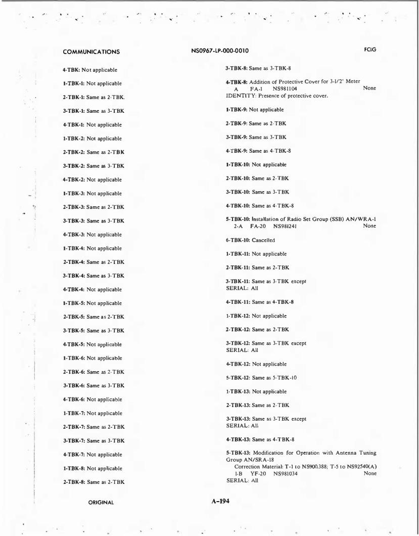
... - ... -
COMMUNICATIONS
4-TBK: Not applicable
1-TBK-1: Not applicable
2-TBK-1: Same as 2-TBK.
3·TBK-1: Same as 3-TBK
4-TBK-1: Not applicable
1-TBK-2: Not applicable
2-TBK-2: Same as 2-TBK
3-TBK-2: Same as 3-TBK
4-TBK-2: Not applicable
1-TBK-3: Not applicable
': 2-TBK-3: Same as 2-TBK
3-TBK-3: Same as 3-TBK
4-TBK-3: Not applicable
1-TBK-4: Not applicable
2-TBK-4: Same as 2-TBK
3-TBK-4: Same as 3-TBK
4-TBK-4: Not applicable
1-TBK-S: Not applicable
"i 2-TBK-S: Same as 2-TBK
3-TBK-S: Same as 3-TBK
4-TBK-5: Not applicable
1-TBK-6: Not applicable
2-TBK-6: Same as 2-TBK
3-TBK-6: Same as 3-TBK
4-TBK-6: Not applicable
1-TBK-7: Not applicable
2-TBK-7: Same as 2-TBK
3-TBK-7: Same as 3-TBK
4-TBK-7: Not applicable
1-TBK-8: Not applicable
2-TBK-8: Same as 2-TBK
ORIGINAL
. . ... - ... -
NS0967 -LP-000-00 10 FCIG
3·TBK·8: Same as 3-TBK-8
4-TBK-8: Addition of Protective Cover for 3-112' Meter
A FA-I NS981104 None
IDENTITY: Presence of protective cover.
1·TBK-9: Not applicable
2-TBK-9: Same as 2-TBK
3-TBK-9: Same as 3-TBK
4-TBK-9: Same as 4-TBK-8
1-TBK-10: Not applicable
2-TBK-10: Same as 2-TBK
3-TBK-10: Same as 3-TBK
4-TBK-10: Same as 4-TBK-8
S-TBK-10: Installation of Radio Set Group (SSB) AN/WRA-1
2-A FA-20 NS981241 None
6-TBK-10: Cancelled
1-TBK-11: Not applicable
2-TBK-11: Same as 2-TBK
3-TBK-11: Same as 3-TBK except SERIAL: All
4-TBK-11: Same as 4-TBK-8
1-TBK-12: Not applicable
2-TBK-12: Same as 2-TBK
3-TBK-12: Same as 3-TBK except SERIAL: All
4-TBK-12: Not applicable
5-TBK-12: Same as 5-TBK-10
1-TBK-13: Not applicable
2-TBK-13: Same as 2-TBK
3-TBK-13: Same a.s 3-TBK except SERIAL: All
4-TBK-13: Same as 4-TBK-8
S-TBK-13: Modification for Operation with Antenna Tuning Group AN/SRA-18
Correction Material: T-1 to NS900,388; T-5 to NS92540(A)
1-B YF-20 NS981034 None
SERIAL: All
A-194

l , I
. .
... .... ....
. .
... .
COMMUNICATIONS NS0967 -LP-000-00 10 FCIG
IDENTITY: Coaxial receptacle installed; cabling to control unit C-1360( )/SRT.
6-TBK-13: Same as 5-TBK-10
1·TBK·14: Not applicable
2-TBK-14: Same as 2-TBK
3-TBK-14: Same as 3-TBK except SERIAL: All
4-TBK-14: Not applicable
5-TBK-14: Same as 5-TBK-10
1·TBK·15: Not applicable
2-TBK-15: Same as 2-TBK
3-TBK-15: Same as 3-TBK except
SERIAL: All
4-TBK-15: Same as 4-TBK-8 except
SERIAL: All
1-TBK-16: Not applicable
2-TBK-16: Same as 2-TBK
3-TBK-16: Same as 3-TBK except
SERIAL: All
4-TBK-16: Same as 4-TBK-8 except
SERIAL: All
5-TBK-16: Same as 5-TBK-10
6-TBK-16: Cancelled
I·TBK-17: Meter M-107 Erroneous Label Correction Material: See NS98741
A FA-I NS98741
SERIAL: All under cont, NXSS 28616 None
IDENTITY: Meter M-107 is relabeled 'power ampl. plate current' replacing 'first ampl. plate current.'
2-TBK-17: Same as 2-TBK
3·TBK-17: Same as 3-TBK except SERIAL: All
4-TBK-17: Same as 4-TBK-8 except SERIAL: All
5-TBK-17: Same as 5-TBK-10
1-TBK-18: Same as 1-TBK-17
2-TBK-18: Same as 2-TBK
3-TBK-18: Same as 3-TBK except SERIAL: All
4-TBK-18: Same as 4-TBK-8 except SERIAL: All
S-TBK-18: Same as 5-TBK-13
6-TBK-18: Same as 5-TBK-10
1-TBK-19: Same as 1-TBK-19
2-TBK-19: Same as 2-TBK
3·TBK·19: Same as 3-TBK except SERIAL: All
4-TBK-19: Same as 4-TBK-8 except
SERIAL: All
5-TBK-19: Same as 5-TBK-10
1-TBK-20: Same as 1-TBK-17
2·TBK·20: Same as 2-TBK
3·TBK-l0: Same as 3-TBK except SERIAL: All
4-TBK-20: Same as 4-TBK-8 except SERIAL: All
5-TBK-20: Same as 5-TBK-13
6·TBK·20: Same as 5-TBK-10
1-TBL tbru 2-TBL: Not applicable
3·TBL: Installation of CU-1281/U Antenna Control Correction Material: None
B FA-0.5 NS98387 F5820-302-1206
SERIAL: All aboard subs
IDENTITY: Installation of C-1281/U on top transmitter.
4-TBL: Cancelled
1-TBL-1 tbru 2-TBL-1: Cancelled
3-TBL-1: Same as 3-TBL
4-TBL-1: Keying and Output Circuit Mod to Operate Antenna Control C-1670/UR
Correction Material: TM for C-1670/U, NS92566 B YF-7 NS98632 F5820.325-
6347 SERIAL: All IDENTITY: Installation of C-1670/U on top transmitter.
5-TBL-1: Cance.lled
ORIGINAL A-195

,- ,- ,.
COMMUNICATIONS NS0967 -LP-000-00 1 0 FCIG
1-TBL-l tbru 2-TBL-2: Not applicable
3-TBL-l: Same as 3-TBL
4-TBL-2: Same as 4-TBL-1
5-TBL-l: Cancelled
1-TBL-3 thru 2-TBL-3: Not applicable
3-TBL-3: Same as 3-TBL
4-TBL-3: Same as 4-TBL-1
5-TBL-3: Cancelled
1-TBL-4 tbru 2-TBL-4: Not applicable
3-TBL-4: Addition of Frequency Shifi Coupling Adapter
Correction Material: See NS98341
A FA-4 NS98341 N5820-665-
SERIAL: All
IDENTITY: Presence of MX-1262/URT.
4-TBL-4: Addition of Protective Meter Cover
A FA-I NS981 104
SERIAL: All
IDENTITY: Presence of protective cover.
5-TBL-4: SSB Adapter Kit 1-C YF-20 NS981043
SERIAL: All
IDENTITY: Installation of AN/WRA-SSB-Kit.
3553
None
N5820-543-1764
6-TBL-4: Modification to Permit Operation with Antenna
Tuning Group AN/SRA-18 or AN/SRA-18A Correction Material: T-1 to NS900,373
2-A FA-8 NS981200 None
SERIAL: Radio Transmitters CRV-52180, 52181, 52178, and 52179 IDENTITY: Antenna Tuning Group AN/SRA-18 or AN/ SRA-18A is installed and used with transmitter.
1-TBL-5: Not applicable
2-TBL-5: Not applicable
3-TBL-5: Same as 3-TBL-4
4-TBL-5: Same as 3-TBL
5-TBL-5: Same as 4-TBL-1
6-TBL-5: Same as 5-TBL-4
7-TBL-5: Modification to Permit Operation with Antenna
Tuning Group AN/SRA-18, AN/BRA-3 or AN/BRA-5 Correction Material: T-2 to NS900,381; T-6 to NS92540(A)
2-A FA-8 NS981060 None
SERIAL: Equip where use of an AN antenna tuner is desired or required
IDENTITY: Coaxial receptacle installed; cabling to control unit C-1360( )/SRT.
8-TBL-5: Cancelled
1-TBL-6: Modification of Band Change Switch Labeling Correction Material: See NS98742
A FA-0.5 NS98742 None
2-TBL-6: Not applicable
3-TBL-6: Same as 3-TBL-4
4-TBL-6: Same as 3-TBL
5-TBL-6: Same as 4-TBL-1
6-TBL-6: Same as 5-TBL-4
7-TBL-6: Same as 7-TBL-5
8·TBL-6: Cancelled
1-TBL-7: Same as 1-TBL-6
2·TBL·7: Not applicable
3-TBL-7: Same as 3-TBL-4
4-TBL-7: Same as 3-TBL
5· TBL-7: Same as 4-TBL· I
6-TBL-7: Same as 5-TBL-4
7-TBL-7: Same as 7-TBL-5
8-TBL-7: Cancelled
1-TBL-8: Not applicable
2-TBL-8: Audio Output JIOI, Correct Wiring
Correcnion Material: See NS98742 A JFA-1 NS98742
SERIAL: All
None
IDENTITY: If wires connected to top and bottom contacts, F.C., is nott applicable.
3-TBL-8: Same as 3-TBL-4
4-TBL-8: S·ame as 4-TBL-4
S·TBL-8: S:ame as 5-TBL-4
6-TBL-8: Same as 6-TBL-4
1·TBL-9: Not applicable
2-TBL-9: Same as 2-TBL-8
ORIGINAL A-196
,-

• f
• I
. . ,.
. . ,. ,.
COMMUNICA liONS NS0967-LP-000-0010 FCIG
3-TBL-9: Same as 3-TBL-4
4-TBL-9: Same as 4-TBL-4
S· TBL-9: Same as S· TBL-4
6-TBL-9: Same as 6-TBL-4
1·TBL·10 thru 2-TBL-10: Not applicable
3-TBL-10: Same as 3-TBL-4
4-TBL-10: Same as 3·TBL
S·TBL-10: Same as 4-TBL·l
6-TBL-10: Same as S-TBL-4
1-TBL-11 tbru 2-TBL-11: Not applicable
3-TBL-11: Same as 3-TBL-4
4·TBL·ll: Same as 3-TBL
S·TBL-11: Same as 4-TBL-1
6-TBL-11: Same as S·TBL-4
1·TBL-l2 tbru 2·TBL·J2: Not applicable
3-TBL-12: Same as 3-TBL-4
4-TBL-12: Same as 3-TBL
S·TBL-12: Same as 4-TBL·I
6-TBL-12: Same as 5-TBL-4
7-TBL-12: Same as 7-TBL·S
8·TBL-12: Correcting safety hazard which existS in Power Supply PP-1211/U when connected to Radio Telegraph Transmitting Equipment TBL-12 and TBL-13
2-A FA-8 NS98 1198 None
SERIAL: Combinations of Power Supply PP-1211/U and Radio Telegraph Transmitting Equipment TBL-12 and TBL-13. IDENTITY: Terminal board TB-101 has the word 'SWITCH' in place of 1 1 5 VAC.
9-TBL-12: Cancelled
1·TBIA3 tbru 2-TBL-13: Not applicable
3-TBL-13: Same as 3-TBL-4
4-TBL-13: Same as 3-TBL
5-TBL-13: Same as 4-TBL·I
6-TBL-13: Same as 5-TBL-4
7-TBL-13: Same as 7-TBL-5
8-TBL-13: Same as 8-TBL-12
9-TBL-13: Cancelled
1-TBM: Not applicable
2-TBM: Paralleled High-Speed Keying
Correction Material: See NS98748
A FA-3 NS98743
SERIAL: All w/parallel and HI speed keying
None
IDENTITY: Electronic keying unit added below the M.O. unit.
3·TBM: Modification of 0.5/FR Exciter Unit
Correction Material: See NS98748 A FA·2 NS98743
SERIAL: All w/0.5/FR unitS IDENTITY: FSK installed
1-TBM-1: Not applicable
2-TBM·l: Same as 2-TBM
3-TBM-1: Same as 3-TBM
1-TBM-2: Not applicable
2-TBM-2: Same as 2-TBM
3-TBM-2: Same as 3-TBM
J·TBM-3: Not applicable
2-TBM-3: Same as 2-TBM
3-TBM·3: Same as 3-TBM
1·TBM-4: Installation of Thyrite Peak Limiting Units
Correction Material: See NS98748
None
A FA-3 NS98743 F5820.311·
SERIAL: All IDENTITY: Installation of peak limiting thyrite units
2-TBM-4: Same as 2-TBM
3-TBM-4: Same as 3-TBM
J·TBM-5: Same as I·TBM·4
2· TBM-5: Same as 2-TBM
3-TBM-5: Same as 3-TBM
4-TBM-5: Addition of Protective Meter Cover
A FA-I NS981104
SERIAL: All
IDENTITY: Presence of protective cover.
2733
None
ORIGINAL A-197
,.

/
. i ' I
,-.. .
,- ,-. .
,-
COMMUNICATIONS NS0967 -LP-000-00 1 0
S-TBM-5: Modification for Operation with Antenna Tuning
Group AN/SRA-18
Correction Material: T-1 to NS900,388; T-5 to NS92540(A)
1-B YF-20 NS981034 None
SERIAL: All
IDENTITY: Coaxial receptacle installed; cabling to control unit C-1360( )/SRT.
1-TBM-6: Same as 1-TBM-4
2-TBM-6: Same as 2-TBM
3-TBM-6: Same as 3-TBM
4-TBM-6: Same as 4-TBM-5
1-TBM-7: Same as 1-TBM-4
2-TBM-7: Same as 2-TBM
3-TBM-7: Same as 3-TBM
4-TBM-7: Same as 4-TBM-5
5-TBM-7: Same as 5-TBM-5
6-TBM-7: Installation of Radio Set Group (SSB) AN/WRA-1
2-A FA NS981241 None
1-TBM-8: Same as 1-TBM-4
2-TBM-8: Same as 2-TBM
3-TBM-8: Same as 3-TBM
4-TBM-8: Same as 4-TBM-5
1-TBM-9: Same as 1-TBM-4
2-TBM-9: Same as 2-TBM
3-TBM-9: Same as 3-TBM
4-TBM-9: Same as 4-TBM-5
5-TBM-9: Same as 5-TBM-5
6-TBM-9: Same as 6-TBM-7
1-TBM-10: Same as 4-TBM-4
2-TBM-10: Same as 2-TBM
3-TBM-10: Same as 3-TBM
4-TBM-10: Same as 4-TBM-5
5-TBM-10: Cancelled
1-TBM-11: Same as 1-TBM-4
2-TBM-11: Same as 2-TBM
3-TBM-U: Same as 3-TBM
4-TBM-U: Same as 4-TBM-5
5-TBM-11: Same as 5-TBM-5
1-TBM-12: Not applicable
2-TBM-12: Same as 2-TBM
3-TBM-12: Same as 3-TBM
4-TBM-12: Same as 4-TBM-5
1-TBS: Providing Standby Circuit
Correction Material: None
1-A FA-2 NS98744
SERIAL: All
2-TBS: Install Transmission Line Filter CHW-53155
Correction Material: None
YF-3
SERIAL: All
NS98744
3-TBS: Improve Reliability of Relay K-101
Corectio- m al:
SERIAL: All
1-TBS-2: Same as 1-TBS
2-TBS-2: Same as 2-TBS
3-TBS-2: Same as 3-T.I:lS
1-TBS-3: Same as 1-TBS
2-TBS-3: Same as 2-TBS
3-TBS-3: Same as 3-TBS
1-TBS-4: Same as 1-TBS
2-TBS-4: Same as 2-TBS
3-TBS-4: Same as 3-TBS
1-TBS-5: Same as 1-TBS
2-TBS-5: Same as 2-TBS
3-TBS-5: Same as 3-TBS
1-TBS-6: Same as 1-TBS
2-TBS-6: Same as 2-TBS
3-TBS-6: Same as 3-TBS
ORIGINAL A-198
FCIG
F
None

I · I
. . .... .... .... , .
COMMUNICATIONS NS0967 -LP-000-00 10 FCIG
1-TBS.7: Same as 1-TBS
2-TBS-7: Same as 2-TBS
3-TBS-7: Same as 3-TBS
1-TCK: Brush Replacement Kit Correction Material: See NS98764 A FA..O.S NS98764
SERIAL: All None
IDENTITY: Replace brushes on 12V MIG set when worn.
2-TCK: Not applicable
1-TCX-1: Same as I·TCK
2-TCK-t thru 3-TCK-1: Not applicable
1-TCK-2: Same as l·TCK
2-TCK-2 thru 3-TCJC-2: Not applicable
l·TCK-3: Same as 1-TCK
2-TCJC.J: Nor applicable
3-TCK-3: Addition of Protect.ive Meter Cover 2-A FA-I NS981104
SERIAL: All before 6-24-44 IDENTITY: Presence of protective cover.
1-TCK-4: Same as 1-TCK
2-TCK-4: Replacement of Filament Transformer Correction Material: See NS98764 A F A-4 NS98764
SERIAL: All before 6-24-44
None
None
IDENTITY: Filament transformer, T-303, NT CG-30 1 1 1 1 replaced.
3-TCK-4: Nor applicable
t-TCK-5: Same as 1-TCK
2-TCK-5: Nor applicable
3-TCK-5: Same as 3-TCK-3
l·TCK-6: Not applicable
2-TCJC-6: Same as 2-TCK-4
3-TCK-6: Nor applicable
1-TCK-7: Same as 1-TCK
2-TCK-7: Not applicable
3-TCK-7: Same as 3-TCK-3
l·TCS: Modification of Relay Circuit
Correction Material: See NS98761 A FA-I NS98761
SERIAL: All None
IDENTITY: A jumper is connected across two outside bottom contacts of K-101.
2-TCS: Modification of Tap Switch Correction Material: See NS9876 I
A FA-2 NS98761 SERIAL: All
None
IDENTITY: Plugs are placed in blank holes in wafers on switches S-101, S-102, S-103, and S-104.
3-TCS: Modification of Loading Coils Correction Material: See NS98761 A FA-I NS98761
SERIAL: All None
IDENTITY: Drop of solder placed at each end of roller coil.
4-TCS: Nor applicable
5-TCS: Superseded by F.C. 9
6-TCS: Noise Limiter, Type-50159 Correction Material: See NS9876J B YF-3 NS98761
SERIAL: All None
IDENTITY: Coupling unit (noise limiter) added in 2nd del. stage in place of 12SQ7. Function sw. with 'NL' position, and nameplate added in place of recvr 'on-()fl' switch.
7-TCS: Cancelled
8-TCS: Replacement of R-303 and R-304 Correction Material: Sec NS98761
SERIAL: All IDENTITY: R-303 and R-304 are changed from 12.5K, 12 watt to 12K, 40 watt resistors.
9-TCS: Installation of Radio Interference Elimination Kit A FA-3 NS F5820-JOJ.
7657 SERIAL: All IDENTITY: FILTER, CA YH-10597, IS installed in 12V DC power line to dynamotor power supply.
10-TCS: Substitution of Aluminum Cabinet for Steel Correction Material: See NS98S24 A F A-2 NS98S24
SERIAL: As directed by BUSHIPS IDENTITY: Aluminum cabinets installed
1-TCS-1: Same as 1-TCS
2-TCS-1: Same as 2-TCS
3-TCS-t: Same as 3-TCS
4-TCS-1: Not applicable
F5820-302-4641
ORIGINAL A-199

'.
... -
COMMUNICATIONS
5-TCS-1: Superseded by F.C. 9
6-TCS-1: Same as 6-TCS
7-TCS-1: Cancelled
8-TCS-1: Same as 8-TCS
9-TCS-1: Same as 9-TCS
10-TCS-1: Same as 10-TCS
1-TCS·2: Same as 1-TCS
2-TCS-2: Same as 2-TCS
3-TCS-2: Same as 3-TCS
4-TCS-2: Not applicable
5-TCS-2: Superseded by F.C. 9
6-TCS-2: Same as 6-TCS
7-TCS-2: Cancelled
8-TCS-2: Same as 8-TCS
9-TCS-2: Same as 9-TCS
10-TCS-2: Same as 10-TCS
1-TCS-3: Same as 1-TCS
2-TCS-3: Same as 2-TCS
3-TCS-3: Same as 3-TCS
4-TCS-3: Not applicable
5-TCS-3: Superseded by F.C. 9
6-TCS-3: Same as 6-TCS
7-TCS-3: Cancelled
8-TCS-3: Same as 8-TCS
9-TCS-3: Same as 9-TCS
10-TCS-3: Same as 10-TCS
1-TCS-4: Same as 1-TCS
2-TCS-4: Same as 2-TCS
3-TCS-4: Same as 3-TCS
4-TCS-4: Not applicable
S·TCS-4: Superseded by F.C. 9
ORIGINAL
. . ... - ... -
NS0967 -LP-000-00 10
6-TCS-4: Same as 6-TCS
7-TCS-4: Cancelled
8-TCS-4: Same as 8-TCS
9-TCS-4: Same as 9-TCS
10-TCS-4: Same as 10-TCS
1·TCS-5: Same as 1-TCS
2-TCS-5: Same as 2-TCS
3-TCS-5: Same as 3-TCS
4-TCS-5: Not applicable
5-TCS-5: Superseded by F.C. 9
6-TCS-5: Same as 6-TCS
7-TCS-5: Cancelled
8-TCS-5: Same as 8-TCS
9-TCS-5: Same as 9-TCS
10-TCS-5: Same as 10-TCS
1-TCS-6: Same as 1-TCS
2-TCS-6: Same as 2-TCS
3-TCS-6: Same as 3-TCS
4-TCS-6: Not applicable
5-TCS-6: Superseded by F.C. 9
6-TCS-6: Same as 6-TCS
7-TCS-6: Cancelled
8-TCS-6: Same as 8-TCS
9-TCS-6: Same as 9-TCS
10-TCS-6: Same as 10-TCS
1-TCS-7: Same as 1-TCS
2-TCS-7: Same as 2-TCS
3-TCS-7: Same as 3-TCS
4-TCS-7: Not applicable
5-TCS-7: Superseded by F.C. 9
6-TCS-7: Same as 6-TCS
A-200
. .
... -
FCIG

....
COMMUNICATIONS
7-TCS-7: Cancelled
8-TCS-7: Same as 8-TCS
9-TCS-7: Same as 9-TCS
10-TCS-7: Same as 10-TCS
1-TCS-8: Same as 1-TCS
2-TCS-8: Same as 2-TCS
3-TCS-8: Same as 3-TCS
4-TCS-8: Not applicable
5-TCS-8: Superseded by F.C. 9
6-TCS-8: Same as 6-TCS
7-TCS-8: Cancelled
8-TCS-8: Same as 8-TCS
9-TCS-8: Same as 9-TCS
10-TCS-8: Same as 10-TCS
1-TCS-9: Same as 1-TCS
2-TCS-9: Same as 2-TCS
3-TCS-9: Same as 3-TCS
4-TCS-9: Cancelled
5-TCS-9: Superseded by F.C. 9
6-TCS-9: Same as 6-TCS
7-TCS-9: Cancelled
8-TCS-9: Same as 8-TCS
9-TCS-9: Same as 9-TCS
10-TCS-9: Same as 10-TCS
1-TCS-10: Same as 1-TCS
2-TCS-10: Same as 2-TCS
3-TCS-10: Same as 3-TCS
4-TCS-10: Cancelled
I
. I 5-TCS-10: Superseded by F.C. 9
i j
6-TCS-10: Same as 6-TCS
i '
7-TCS-10: Cancelled
ORIGINAL
...
NS0967 -LP-000-00 10 FCIG
8-TCS-10: Same as 8-TCS
9-TCS-10: Same as 9-TCS
10-TCS-10: Same as 10-TCS
1-TCS-11: Same as 1-TCS
2-TCS-11: Same as 2-TCS
3-TCS-11: Same as 3-TCS
4-TCS-11: Cancelled
5-TCS-11: Superseded by F.C. 9
6-TCS-11: Same as 6-TCS
7-TCS-11: Cancelled
8-TCS-11: Same as 8-TCS
9-TCS-11: Same as 9-TCS
10-TCS-11: Same as 10-TCS
1-TCS-12: Not applicable
2-TCS-12: Same as 2-TCS
3-TCS-12: Same as 3-TCS
4-TCS-12: Replacement of Motors and Generator
A FA-3 NS98761 None
SERIAL: 2632-2766, 3497-351 I, 39!2-43 1 1 , 5504-5703, 6554-6853
IDENTITY: High voltage generator, motors mfg type 230 0001 00 and 230 0002 00 are replaced
5-TCS-12: Superseded by F.C. 9
6-TCS-12: Same as 6-TCS
7-TCS-12: Cancelled
8-TCS-12: Same as 8-TCS
9-TCS-12: Same as 9-TCS
10-TCS-12: Same as 10-TCS
1-TCS-13: Not applicable
2-TCS-13: Same as 2-TCS
3-TCS-13: Same as 3-TCS
4-TCS-13: Not applicable
5-TCS-13: Superseded by F.C. 9
A-201

... -
COMMUNICATIONS
6-TCS-13: Same as 6-TCS
7-TCS-13: Cancelled
8-TCS-13: Same as 8-TCS
9-TCS-13: Same as 9-TCS
10-TCS-13: Same as 10-TCS
1-TCS-14: Not applicable
2-TCS-14: Same as 2-TCS
3-TCS-14: Same as 3-TCS
4-TCS-14: Cancelled
5-TCS-14: Superseded by F.C. 9
6-TCS-14: Same as 6-TCS
7-TCS-14: Not applicable
8-TCS-14: Same as 8-TCS
9-TCS-14: Same as 9-TCS
10-TCS-14: Same as 10-TCS
1-TCS-15: Not applicable
2-TCS-15: Same as 2-TCS
3-TCS-15: Same as 3-TCS
4-TCS-15: Not applicabit:
5-TCS-15: Superseded by F.C. 9
6-TCS-15: Same as 6-TCS
7-TCS-15: Cancelled
8-TCS-15: Same as 8-TCS
9-TCS-15: Same as 9-TCS
10-TCS-15: Same as 10-TCS
1-TCS-16: Not applicable
2-TCS-16: Same as 2-TCS
3-TCS-16: Same as 3-TCS
4-TCS-16: Not applicable
5-TCS-16: Superseded by F.C. 9
6-TCS-16: Same as 6-TCS
ORIGINAL
. .
... - ....
NS0967 -LP-000-00 10 fCIG
7-TCS-16: Cancelled
8-TCS-16: Same as 8-TCS
9-TCS-16: Same as 9-TCS
10-TCS-16: Same as 10-TCS
1-TCZ: Replacement of 28 Volt Generacor Brushes
Correction Material: None
A FA-0.5 NS98765
SERIAL: All w/21101 AC pwr units
F5820-310-9353C2
IDENTITY: New brushes are stamped 113 inw the side of the metal spring tab.
2-TCZ: Removal of Ground on Remote Control Col-23410
Correction Material: None
A FA-{).5 NS98765
SERIAL: All u/w std Navy rcvrs
None
IDENTITY: Removal of the ground from the input transformer in the remote control unit.
1-TCZ-1: Same as 1-TCZ except
SERIAL: All
2-TCZ-1: Same as 2-TCZ
1-TCZ-2: Not applicable
2-TCZ-2: Same as 2-TCZ
l·TD-855/WLR-6(Y): Wiring Change to Power Input Ground
Correction Material: T-1, NE0967-LP-207-3271 to
NE0967-207-3270
4-A FA-I
SERIAL: All
NE0967-LP-207-3710 EIC N81WOOO
IDENTITY: This field change may be identified by pin B on the power input connector (PS04) being the ground pin.
1-TD-901/U: Wiring Change to Provide One MPPS Output
During Switchover to Standby Oscillator
Correction Material: T- to NS0969-249-6010
4-A FA-I EIB 869 SERIAL: All serial numbers IDENTITY: Presence of a wire connected to pin A6 of A I A I02.
2-TD-901/U: Addition !PPM Output Driver Circuit Card
Correction Material: Supplement 2, NE0969-246-5012 to NE0969-246-5010
1-A FA-4 NS0969-246-5030 SERIAL: Only those equipments to be used with AN/GGCIS(V) Data Preparation Data
IDENTITY: The IPPM output driver circuit card will be installed in the spare card socket previously utilized to store
primed circuit card extt:nder (2119-40113-61).
1·TD-1066(XG-1)/SYQ·6(Y): Data Accumulation and Distribu
tion System (TD-1066) Power Control Panel Assembly and
A-202
....

i
. !
· ' I l '1 r I
. . ,.
. . .. . .. - , .
COMMUNICA liONS NS0967 -LP-000-00 1 0 FCIG
Temperature Alann Subassembly Indicator Change. Correction Material: Chg I, NS0967-LP-434-4591, to TM,
NS0967-LP-434-4590 dtd Apr 76. 1-A FA-3 NE0967-LP-434-4650 EIC QU13
SERIAL: Four equipments: one aboard CVN-68, one aboard CVN-69, one at FCDSSA, San Diego, and one planned for CVN-70. IDENTITY: Verify that new lamp assemblies (IAIA4XDSI thru S3, Sl3 thru Sl7, and IAIA5XDSI) contain bayonnettype lamps versus screw-in type.
1-TD-1097/WSC-S(V): Addition of R16 and Rl7 to Eliminate Oscillations in the 100 kHz Divider.
Correction Material: T-3, NE0967-LP-455-0013, to TM, NE0967-455-0010.
2-A FA-I NE0967-LP-455-0040 EIC QPOD SERIAL: Serial number N053 and subsequent. IDENTITY: Installation of a 1000-ohm resistor (R16) between the emitter and base of A4Ql, and a 68-ohm resistor (R17) between the emitter and base of A4Q2.
1-TDE: Mike Modification Kit B FA-2 F5820-31 1 -
2585CI SERIAL: 1-256, 393-441, 448-611, 612-880, 993-1 124, 1183-1248, 1250, 1293-1471, 1475 IDENTITY: Local microphone jack is installed in front panel.
2-TDE: Installation of Filament Warm-Up Circuit
B FA-3 NS98766 None
SERIAL: All IDENTITY: Warm-up circuit indicated by switch and filament power on indicating light on front panel of power supply section.
3-TDE: Installation of Improved Switch S-3708 A FA-2 NS98766 2N5820-3 1 1 -
2547 SERIAL: All IDENTITY: Section 'B' of switch S-307 (HFPA range selector switch) is replaced with section of newer type, section 'A· of same switch.
4-TDE: Modification to Pennit Operation with Antenna Tuning Group AN/SRA-I 8
2-A FA-8 NS98 1154 None SERIAL: Radio xmtrs 52267, 52267A IDENTITY: Antenna tuning group is installed and connected to xmtr.
1-TDE-1: Not applicable
2-TDE-1: Same as 2-TDE
3-TDE-1: Same as 3-TDE
4-TDE-1: Same as 4-TDE
1-TDE-2: Not applicable
2-TDE-2: Same as 2-TDE
3-TDE-2: Same as 3-TDE except
SERIAL: 1-340, 372, 835, 1046-1351
4-TDE-2: Same as 4-TOE
1-TDE-3: Not applicable
2-TDE-3: Same as 2-TDE
3-TDE-3: Not applicable
4-TDE-3: Same as 4-TDE
1-TDH: Transfer of Oscillator Assembly Correction Material: See NS98181
A FA-3 NS98181
SERIAL: All
F5820-3 10-9263
IDENTITY: Master oscillator replaced with one having 700 se.ries component part nos.
l·TDH: Modification of Switch S i l l Correction Material: None 2-A FA-2 NS981193
SERIAL: All
None
IDENTITY: Presence of spiral springs on contact lingers in the output network unit.
1-TDH-2: Same as 2-TDH
1-TDH-3: Same as 2-TDH
1-TDH-4: Same as 2-TDH
1-TDN: Not applicable
2-TDN: Safety Conversion
A FA-I NS900709
SERIAL: All
3-TDN: Not applicable
1-TDN-1: Not applicable
2-TDN-1: Same as 2-TDN
3-TDN-1: Not applicable
1-TDN-2: Frequency Shift Keying Conversion
A FA-10 NS900709
SERIAL: 1-20
2-TDN-2: Same as 2-TDN
3-TDN-2: Conversion to TDN-4
A FA-40 NS900709
SERIAL: 1-20
F5820-642-7917
F5820-642-6350
F5820-642-6942
ORIGINAL A-203
.. -

/
. . ... -
. . ... -
. . ,-
COMMUNICATIONS NS0967 -LP-000-00 10 FCIG
1-TDN-3: Same as 1-TDN-2 except SERIAL: 1-15
2-TDN-3: Same as 2-TDN
3-TDN-3: Not applicable
1-TDN-4: Same as 1-TDN-2
2-TDN-4: Same as 2-TDN
3-TDN-4: Not applicable
1-TDO: Transfer of Oscillator Assembly Correction Material: See NS98181 A FA-3 NS98181
SERIAL: All
F5820-310-9263
IDENTITY: New master oscillator. Collins 520 273400 or 520 273800.
1-TDQ: Change of Overload Relay K-303
Correction Material: None A FA-I
SERIAL: All
None
IDENTITY: The mounting holes in the bakelite base of K-303 are elongated to permit repositioning.
2-TDQ: Installation of Model TDQ Mission Line Filter Type CRV-53232
Correction Material: None
A FA-2 SERIAL: 1-2281
None
IDENTITY: Transmission line filter 53232 is installed in antenna output line and is mounted in top center of transmitter.
3-TDQ: Installation of Caution Nameplates for TDQ Transmit·
ter
Correction Material: None A FA-1/3
SERIAL: All IDENTITY: Presence of caution plate.
2N5820-311· 2538
4-TDQ: Provision for Extended Audio Range Communication
Control Link Service
A FA-I None
SERIAL: Anywhere necessary IDENTITY: Capacitors C-216, C-217, and C-218 disconnected from circuit but are left mounted in position. Equipment is then designated 'TDQ-A '.
1-TDT: Addition of Send-Receive Relay A F A-6 NS98768
SERIAL: All
None
IDENTITY: Ant relay added on top of wire 36 or term X-4.
2-TDT: Reduction of Voltage Surges on Rectifier Tubes A F A-2 NS98768 None
SERIAL: All IDENTITY: Wire no. 36 on X-4 term having wire no. 20
3-TDT: Replacement of Resistors R-10, R-11 and R-13
A FA-1 NS98768 F5820-334-
8784CI SERIAL: All
IDENTITY: RIO 8K, 40W; R l l IOK, SOW; R13, IOK, 90W
4-TDT: Installation of Blower Motor Reactor A FA-1 NS98768 None
SERIAL: All IDENTITY: 50-ohm reactor installed in series with motor TN-Fr43R
1-TDT-1: Same as 1-TDT
2-TDT-1: Same as 2-TDT
3-TDT-1: Same as 3-TDT
4-TDT-1: Same as 4-TDT
1-TDT-2: Same as 1-TDT
2-TDT-2: Same as 2-TDT
3-TDT-2: Same as 3-TDT
4-TDT-2: Same as 4-TDT
1-TDT-3: Same as 1-TDT
2-TDT-3: Same as 2-TDT
3-TDT-3: Same as 3-TDT
4-TDT-3: Same as 4-TDT
1-TDY: Addition of Stop-Start Resistor
FA-I SERIAL: All
2-TDY: Cancelled
3-TDY: Cancelled
NS
4-TDY: Modernization Kit
YF-12 SERIAL: All
None
5-TDY: Conversion of TOY to TDYa and TDY-1 to TDY-Ia
YF-112 NS9891 1 SERIAL: As directed b y BUSHIPS
6-TDY: Simplication of Monitor System
FA-6
SERIAL: All
7-TDY: Tube Injector Modification
ORIGINAL A-204

. . ,.
· I
j
/
,. ,.
COMMUNICA liONS NS0967 -LP-000-00 10 FCIG
FA-4 SERIAL: All
8-TDY: Replacement of Reflectors in Antenna System
YF-116 SERIAL: All
9-TDY thru ll·TDY: Cancelled
12-TDY: Addition of Second Magnetron Seal Blower
YF-5 NS9891 1 SERIAL: 1-150 (using 35ABL oscillators)
13-TDY tbru 14-TDY: Cancelled
15-TDY: Not applicable
16-TDY: Improved Conversion of TOY to TOY-a and TOY-I toTDY-la
YF-112 NS98911
SERIAL: As directed by BUSHIPS
17-TDY: Cancelled
l·TDY-1 tbru 4-TDY-1: Not applicable
5-TDY-1: Same as 5-TDY
6-TDY-1: Same as 6-TDY
7-TDY-1: Same as 7-TDY
8-TDY·1: Same as 8-TDY
9-TDY-1 thru 11-TDY-1: Cancelled
12·TDY·1: Same as 12-TDY
13-TDY-1 tbru 14-TDY-1: Cancelled
15-TDY-1: Replacement of Pump Seal Assembly
YF-2 SERIAL: 1-134
NS9891 1
16-Tt>Y-1: Same as 16-TDY
17-TDY-1: Cancelled
1-TDZ: Auto Tuning and Drawer Mechanism Modification Correction Material: Ch. I to NS900,809 B YF-60 NS98167 F5840-311·
2490 SERIAL: 1-100, 107-109, Ill, 113-124, 128-134, 136-137, 140 IDENTITY: Neoprene snubbers added at rear of drawers. Adds extra springs to contacts at rear of drawers.
2-TDZ: Allowance of Tender Spare Parts Modification
Correction Material: Ch. I to NS900,809 B YF-1 NS98168
SERIAL: IT, 2T-4T, and lOT None
IDENTITY: Snubber neoprene 2428-S added to tender spares.
3-TDZ: Installation of Protective Guard on Telephone Type Dial
Correction Material: None
A FA-I NS98169
SERIAL: 1-1000 IDENTITY: Guard is installed
F5840-311-2492
4-TDZ: Drawer Fasteners to Equipment Spare Parts Addition A FA-YF-1 NS98170 F5840-3 11-
SERIAL: 1-1000 IDENTITY: Drawer fasteners are in spares.
5-TDZ: Provision for Dial Cranks Correction Material: See NS98100 A FA NS98100
SERIAL: 1-3540
2495
FS820-3 1 1-
2617
IDENTITY: Crank to place over tuning knobs as aid in fast tuning.
6-TDZ: Provision for Noise Reduction Filter Correction Material: NS98180 A FA-YF-3 NS98180
SERIAL: All
F5820-3 10-9379
IDENTITY: New filt.er unit mounted on underside relay bath· tub located in right rear corner of lower chassis, consists of 4' square board on which various resistors are mounted.
7-TDZ: Modification for Automatic Operation of Antenna Coupler CU-255/URR
Correction Material: T-2 to NS900,809
2-B YF-4 NS98321 SERIAL: All IDENTITY: Coupler is usually mounted adjacent to TDZ, bulkhead mounted.
8-TDZ: Dial Lock for B and C Controls Correction Material: T-3 to N$900,809 A FA NS98377
SERIAL: All
F5820-311-3161
IDENTITY: Toggle dial lock will be installed on B and C controls.
1-TEB: Replacement of IPA Band Change A FA-2
SERIAL: All IDENTITY: IPA sw bears stk no. N16-S-!4010-2
1-TEC: Change of 3KV Plate Contactor K-1122 Correction Material: None
A FA-2 NS98770 SERIAL: All
None
None
ORIGINAL A-205

"':·'
.1
. J
. ;
. . ... - ... -
. . ... -
. . ... -
COMMUNICATIONS NS0967 -lP-000-00 10 FCIG
IDENTITY: JAN type 29678 contacts on relay K-1122.
1-TED: Same as 1-AN/URT-7 except SERIAL: All, except those equipments on which field changes 5 and 7-TED are installed. IDENTITY: Installation of type AN/3106A-12S male and female connectors (P-1 10 and P-Ill) in series with the blower motor power cord and located within the blower motor companment. NOTES: This field change is identical to 7-TED with the exception that 7-TED does not include the blower motor connectors (P-110 and P-Il l)- Field change 5-TED replaced the original blower motor with one of extended life. If 5-TED is installed, then 7-TED should be accomplished instead of ITED.
2-TED: Same as 2-AN/URT-7 except SERIAL: All, except those equipments on which field change 5-TED is installed. IDENTITY: Installation of high voltage warning decals on C-139 and C-187, and installation of a maintenance precautions nameplate on the right-hand access door. The maintenance precautions nameplate instructs personnel to clean the air filter and check the brushes of the blower motor. NOTES: This field change is identical to 6-TED except for the maintenance precautions nameplate: the reference to checking the brushes of the blower motor in field change 6-TED is deleted.
3-TED: Cooling Improvement Correction Material: Included with EFCB. 1-B YF-8 NS98930 F5820-536-
2413
SERIAL: Only to shore-installed TED equipment used as pan of AN/URN-12 IDENTITY: Original blower motor and fan (FI-101) and air filter removed from RF chassis, and an air duct and air tlow switch S-I l l (Rotron Model 2A) is mounted in their place. Cooling is now ducted into the RF chassis from an externally mounted blower.
4-TED: Improved Cooling and Adaptation for Use as Pan of
AN/FRN-24 1-B YF- 16 NS981020 None
SERIAL: Only to shore-installed TED equipment used as part of AN/FRN-24 IDENTITY: Original blower motor and fan (B-IOI) and air filter removed from RF chassis, and an air duct and air tlow switch S-I l l (Rotron Model 2A) is mounted in their place. Cooling is now ducted into the RF chassis from an externally mounted centrifugal fan HD-326/U.
5-TED: Same as 3-AN/URT-7 except Correction Material: Ch. 3 to NS91357
IDENTITY: The phenolic retaining plates securing the plate caps of the high voltage rectifiers (V - I l l and V -1 12) are replaced with aluminum retaining plates.
6-TED: Same as 4-AN/URT-7 except SERIAL: All equipments on which field change 5-TED is installed and field change 2-TED is not installed.
IDENTITY: Installation of high voltage warning decals on C-139 and C-187, and installation of a maintenance precautions nameplate on the right-hand access door. The maintenance precautions nameplate instructs personnel to clean the air
filter, only.
NOTES: This field change is identical to 2-TED except for the maintenance precautions nameplate: in field change 2-TED, the nameplate instructs personnel to check the brushes of the blower motor in addition to cleaning the air filter.
7-TED: Same as 5-AN/URT-7 except
SERIAL: All equipments on which field change 5-TED is accomplished and field change I-TED is not accomplished.
NOTES: This field change is identical to I-TED with the exception that this field change does not include connectors PI I 0 and P - 1 1 L These connectors are not required if 5-TED is installed. See, also, 'notes' of I-TED.
8-TED: Cancelled
9-TED: Provide TED-0 Transmitter in AN/FRN-24 Configu
ration with A TIS Capability.
Correction Material: TED: Chg. 4, NE0967-LP-1 14-7014, to TM, N$91357. TED-I: Chg. 3, NE0967-LP-114-9013, to TM, NS0967-l 14-9010{formerly NS91475). TED-2: Chg. 3, NE0967-LP-987-9013, to TM, NS0967-987-9010(fonnerly NS91585A). TED-3: Chg. 3, NE0967-LP-987-8013, to TM, NS0967-987-8010{formerly NS91796A). TED-4: Chg. 3, NE0967-LP-987-7013, to TM, NS0967-987-7010{formerly NS921 18). TED-6: Chg. 3, NE0967-LP-987-3013, to TM, NS0967-987-3010{formerly N$92320). TED-7: Chg. I, NE0967-LP-987-50l l , to TM, NS9270L TED-8: Chg. 2, NE0967-LP�84-8012, to TM, NS0967�84-8010{formerly NS92703). TED-9: Chg. 3, NE0967-LP�85-0013, to TM, NS0967-085-00IO{formerly N$92312).
!-A FA-4 NE0967-LP-085-0040
SERIAL: All TED, TED-1,-2,-3,-4,-6,-7,-8,-9 Transmitters used in AN/FRN-24 for A TIS. (Shore installations only).
IDENTITY: Verify installation of a 5100 ohm resistor connected to the MCW Level Adjust pot (R141) and a jumper wire across K 106-D in the Modulator unit.
NOTES: Prerequisite Field Change: 4-TED. (Field Change 4-TED should be accomplished on TED-1,-2,-3,-4,-6,-7,-8,-9 as well as TED.)
1-TED-1: Same as 1-AN/URT-7 except
SERIAL: All, except those equipments on which field changes 3 and 5-TED-1 are installed.
IDENTITY: Installation of type AN/3106A-12S male and female connectors (P-110 and P-11 I) in series with the blower motor power cord and located within the blower motor compartment.
NOTES: This field change is identical to 5-TED-1 with the exception that 5-TED-1 does not include the blower motor connectors (P-1 10 and P-1 II). Field chan,ge 3-TED-1 replaced
the original blower motor with one of extended life. If 3-
TED-1 is installed, then 5-TED-1 should be accomplished instead of 1-TED-L
2-TED-1: Same as 2-AN/URT-7 except
ORIGINAL A-206

' i
I l i
.j l
. . . . ,-
. . ,.
. . ,.
COMMUNICATIONS NS0967 -LP-000-00 1 0 FCIG
SERIAL: All, except those equipments on which field change 3-TED-1 is installed. IDENTITY: Installation of high voltage warning decals on C-139 and C-187, and installation of a maintenance precautions nameplate on the right-hand access door. The maintenance precautions nameplate instructs personnel to clean the air ftlter and check the brushes of the blower motor.
NOTES: This field change is identical to 4-TED-I except for the maintenance precautions nameplate: the reference to checking the brushes of the blower motor in field change 4-TED-1 is deleted.
3-TED-1: Same as 3-AN/URT-7 except Correction Material: Ch. I to NS91475
IDENTITY: The phenolic retaining plates securing the plate caps of the high voltage rectifiers (V-III and V-112) are replaced with aluminum retaining plates.
4-TED-1: Same as 4-AN/URT-7 except SERIAL: All equipments on which field change 3-TED-1 is installed and field change 2-TED-1 is not installed. IDENTITY: Installation of high voltage warning decals on C-139 and C-187, and installation of a maintenance precautions nameplate on the right-hand access door. The maintenance precautions nameplate instructs personnel to clean the air filter, only. NOTES: This field change is identical to 2-TED-1 except for the maintenance precautions nameplate: in field change 2-TED-1, the nameplate instructs personnel to check the brushes of the blower motor in addition to cleaning the air filter.
5-TED-1: Same as 5-AN/URT-7 except
Correction Material: T-1 to NS91475
SERIAL: All equipments on which field change 3-TED-1 is accomplished and field change I-TED-I is not accomplished. NOTES: This field change is identical to I-TED-I with the exception that this field change does not include connectors P-110 and P-I ll. These connectors are not required if 3-TED-1 is installed. See, also, 'notes' of I-TED-I.
6-TED-1: Cancelled
7-TED-1: Same as 9-TED
1-TED-2: Same as 1-AN/URT-7 except
SERIAL: All, except those equipments on which field changes 3 and 5-TED-2 are installed. IDENTITY: Installation of type AN/3106A-12S male and female connectors (P-1 10 and P-Ill) in series with the blower motor power cord and located within the blower motor compartment. NOTES: This field change is identical to 5-TED-2 with the exception that 5-TED-2 does not include the blower motor connectors (P-110 and P-Il l). Field change 3-TED-2 replaced the original blower motor with one of extended life. If 3-TED-2 is installed, then 5-TED-2 should be accomplished insted of 1-TED-2.
2-TED-2: Same as 2-AN/URT-7 except SERIAL: All, except those equipments on which field change 3-TED-3 is installed.
IDENTITY: Installation of high voltage warning decals on C-139 and C-187, and installation of a maintenance precautions nameplate on the right-hand access door. The maintenance precautions nameplate instructs personnel to clean the air filter and check the brushes of the blower motor.
NOTES: This field change is identical to 4-TED-2 except for the maintenance precautions nameplate: the reference to checking the brushes of the blower motor in field change 4-TED-2 is deleted.
3-TED-2: Same as 3-AN/URT-7 except Correction Material: Ch. 2 to NS91585(A)
IDENTITY: The phenolic retaining plates securing the plate caps of the high voltage rectifiers (V - I l l and V -112) are replaced with aluminum retaining plates.
4-TED-2: Same as 4-AN/URT-7 except SERIAL: All equipments on which field change 3-TED-2 is installed and field change 2-TED-2 is not installed.
IDENTITY: Installation of high voltage warning decals on C-139 and C-187, and in.stallation of a maintenance precautions nameplate on the right-hand access door. The maintenance precautions nameplate instructs personnel to clean the air filter only.
NOTES: This field change is identical to 2-TED-2 except for the maintenance precautions nameplate: in field change 2-TED-2, the nameplate instructs personnel to check the brushes of the blower motor in addition to cleaning the air filter.
5-TED-2: Same as 5-AN/URT-7 except
Correction Materia.!: T-4 to NS91585(A)
SERIAL: All equipments on which field change 3-TED-2 is accomplished and field change 1-TED-2 is not accomplished.
NOTES: This field change is identical to 1-TED-2 with the exception that this field chage does not include connectors P-110 and P-Ill. These connectors are not required if 3-TED-2 is installed. See, also, 'notes' of 1-TED-2.
6-TED-2: Cancelled
7-TED·l: Same as 9-TED
l·TED-3: Same as 1-AN/URT-7 except SERIAL: All, except those equipments on which field changes 3 and 5-TED-3 are installed. IDENTITY: Installation of type AN/3106A-12S male and female connectors (P-110 and P-Ill) in series with the blower motor power cord and located within the blower motor companment. NOTES: This field change is identical to 5-TED-3 with the exception that 5-TED-3 does not include the blower motor connectors (P-110 and P-Ill). Field change 3-TED-3 relaced the original blower motor with one of extended life. If 3-TED-3 is installed, then 5-TED-3 should be accomplished instead of 1-TED-3.
l·TED-3: Same as 2-AN/URT-7 except SERIAL: All, except those equipments on which field change 3-TED-3 is installed. IDENTITY: Installation of high voltage warning decals on C-139 and C-187, and installation of a maintenance precautions
ORIGINAL A-207

.... ... - ... -
COMMUNICATIONS NS0967 -LP-000-00 10 FCIG
nameplate on the right-hand access door. The maintenance precautions nameplate instructs personnel to clean the air filter and check the brushes of the blower motor.
NOTES: This field change is identical to 4-TED-3 except for the maintenance precautions nameplate: the reference to checking the brushes of the blower motor in field change 4-TED-3 is deleted.
3-TED-3: Same as 3-AN/URT-7 except
Correction Material: Ch. 2 to NS91796(A)
IDENTITY: The phenolic retaining plates securing the plate caps of the high voltage rectifiers (V - I l l and V -112) are replaced with aluminum retaining plates.
4-TED-3: Same as 4-AN/URT-7 except
SERIAL: All equipments on which field change 3-TED-3 is installed and field change 2-TED-3 is not installed.
IDENTITY: Installation of high voltage warning decals on C-139 and C-187, and installation of a maintenance precautions nameplate on the right-hand access door. The maintenance precautions nameplate instructs personnel to clean the air filter, only.
NOTES: This field change is identical to 2-TED-3 except for the maintenance precautions nameplate: in field change 2-TED-3, the nameplate instructs personnel to check the brushes of the blower motor in addition to cleaning the air filter.
5-TED-3: Same as 5-AN/URT-7 except
Correction Material: T-1 to NS91796(A)
SERIAL: All equipments on which field change 3-TED-3 is accomplished and field change 1-TED-3 is not accomplished.
NOTES: This field change is identical to 1-TED-3 with the exception that this field change does not include connectors PliO and P-I l l . These connectors are not required if 3-TED-3 is installed. See, also, 'notes' of 1-TED-3.
6-TED-3: Cancelled
7-TED-3: Same as 9-TED
1-TED-4: Same as 1-AN/URT-7 except
SERIAL: All, except those equipments on which field changes 3 and 5-TED-4 are installed.
IDENTITY: Installation of type AN/3106A-12S male and female connectors (P-110 and P-Ill) in series with the blower motor power cord and located within the blower motor compartment.
NOTES: This field change is identical to 5-TED-4 with the exception that 5-TED-4 does not include the blower motor connectors (P-110 and P-Il l). Field change 3-TED-4 replaced the original blower motor with one of extended life. If 3-TED-4 is installed, then 5-TED-4 should be accomplished instead of 1-TED-4.
2-TED-4: Same as 2-AN/URT-7 except
SERIAL: All, except those equipments on which field change 3-TED-4 is accomplished.
IDENTITY: Installation of high voltage warning decals on C-1 39 and C-187, and installation of a maintenance precautions nameplate on the right-hand access door. The maintenance
precautions nameplate instructs personnel to clean the air filter and check the brushes of the blower motor.
NOTES: This field change is identical to 4-TED-4 except for
the maintenance precautions nameplate: the reference to checking the brushes of the blower motOr in field change 4-TE0-4 is deleted.
3-TED-4: Same as 3-AN/URT-7 except Correction Material: Ch. 2 to NS92118
IDENTITY: The phenolic retaining plates securing the plate caps of the high voltage rectifiers (V - I l l and V -112) are replaced with aluminum retaining plates.
4-TED-4: Same as 4-AN/URT-7 except SERIAL: All equipments on which field change 3-TED-4 is installed and field change 2-TED-4 is not installed.
IDENTITY: Installation of high voltage warning decals on C-139 and C-187, and installation of a maintenance precautions nameplate on the right-hand access door. The maintenance precautions nameplate instructs personnel to clean the air filter, only. NOTES: This field change is identical to 2-TED-4 except for the maintenance precautions nameplate: in field change 2-TED-4, the nameplate instructs personnel to check the brushes
of the blower motor in addition to cleaning the air filter.
5-TED-4: Same as 5-AN/URT-7 except
Correction Material: T-2 to NS921 1 8 SERIAL: All equipments on which field change 3-TED-4 is accomplished and field change 1-TED-4 is not accomplished.
NOTES: This field change is identical to 1-TED-4 with the exception that this field chae does not include connectors P-I 10 and P-1 I I. These connectors are not required if 3-TED-4 is installed. See, also, 'notes' of 1-TE0-4.
6-TED-4: Cancelled
7-TED-4: Same as 9-TEO
1-TED-5: Same as 1-AN/URT-7 except SERIAL: All, except those equipments on which field changes 3 and 5-TED-5 are installed.
NOTES: This field change is identical to 5-TED-5 with the exception that 5-TED-5 does not include the blower motor connectors (P-404 and P-405). Field change 3-TED-5 replaced the original blower motor with one of extended life. If 3-TE0-5 is installed, then 5-TED-5 should be accomplished instead of 1-TED-5.
2-TED-5: Same as 2-AN/URT-7 except SERIAL: All, except those equipments on which field change 3-TED-5 is accomplished.
IDENTITY: Installation of high voltage warning decals on C-139 and C-187, and installation of a maintenance precaution.s nameplate on the right-hand access door. The maintenance precautions nameplate instructs personnel to clean the air filler and check the brushes of the blower motor.
NOTES: This field change is identical to 4-TED-5 except for the mai:1tenance precautions nameplate: the reference to checking the brushes of the blower motor in field change 4· TE0-5 is deleted.
ORIGINAL A-208
... -

. �
. .
. . ... - ... - .... ... -
COMMUNICATIONS NS0967 -LP-000-00 10 FCIG
3-TED-5: Same as 3-AN/URT-7 except
Correction Material: Ch. 3 to NS91357
IDENTITY: The phenolic retaining plates securing the plate caps of the high voltage rectifiers (V -I l l and V -112) are replaced with aluminum retaining plates.
4-TED-5: Same as 4-AN/URT-7 except
SERIAL: All equipments on which field change 3-TED-5 is installed and field change 2-TED-5 is not installed.
IDENTITY: Installation of high voltage warning decals on C-139 and C-187, and installation of a maintenance precautions nameplate on the right-hand access door. The maintenance precautions nameplate instructs personnel to clean the air filter, only.
NOTES: This field change is identical to 2-TED-5 except for the maintenance precautions nameplate: in field change 2-TED-5, the nameplate instructs personnel to check the brushes of the blower motor in addition to cleaning the air filter.
5-TED-5: Same as 5-AN/URT-7 except
Correction Material: None
SERIAL: All equipments on which field change 3-TED-5 is accomplished and field change 1-TED-5 is not accomplished.
NOTES: This field change is identical to 1-TED-5 with the exception that this field change does not include connectors P-404 and P-405. These connectors are not required if 3-TED-5 is installed. See, also, 'NOTES' of 1-TED-5.
6-TED-5: Cancelled
1-TED-6: Same as 1-AN/URT-7 except
SERIAL: All, except those equipments on which field changes 3 and 5-TED-6 are installed.
IDENTITY: Installation of type AN/3106A-12S male and female connectors (P-110 and P-I l l ) in series with the blower motor power cord and located within the blower motor compartment.
NOTES: This field change is identical to 5-TED-6 with the exception that 5-TED-6 does not include the blower motor connectors (P-110 and P-Il l). Field change 3-TED-6 replaced the original blower motor with one of extended life. If 3-TED-6 is installed, then 5-TED-6 should be accomplished instead of 1-TED-6.
2-TED-6: Same as 2-AN/URT-7 except
SERIAL: All, except those equipments on which field change 3-TED-6 is installed.
IDENTITY: Installation of high voltage warning decals on C-139 and C-187, and installation of a maintenance precautions nameplate on the right-hand access door. The maintenance precautions nameplate instructs personnel to clean the air filter and check the brushes of the blower motor.
NOTES: This field change is identical to 4-TED-6 except for the maintenance precautions nameplate: the reference to checking the brushes of the blower motor in field change 4-TED-6 is deleted.
3-TED-6: Same as 3-AN/URT-7 except
Correction Material: Change I to NS92320
IDENTITY: The phenolic retaining plates securing the plate
caps of the high voltage rectifiers (V - I l l and V -112) are replaced with aluminum retaining plates.
4-TED-6: Same as 4-ANIURT-7 except SERIAL: All equipments on which field change 3-TED-6 is installed and field change 2-TED-6 is not installed. IDENTITY: Installation of high voltage warning decals on C-139 and C-187, and installation of a maintenance precautions nameplate on the right-hand access door. The maintenance precautions nameplate instructs personnel to clean the air filter,
·only.
NOTES: This field change is identical to 2-TED-6 except for the maintenance precautions nameplate: in field change 2-TED-6, the nameplate instructs personnel to check the brushes of the blower motor in addition to cleaning the air filter.
5-TED-6: Same as 5-AN/URT-7 except Correction Material: Change 2 to NS92320
SERIAL: All equipments on which field change 3-TED-6 is accomplished and field change 1-TED-6 is not accomplished. NOTES: This field change is identical to 1-TED-6 with the exception that this field change does not include connectors PliO and P-I l l . These connectors are not required if 3-TED-6 is installed. See, also, 'notes' of 1-TED-6.
6-TED-6: Cancelled
7-TED-6: Same as 9-TED
1-TED-7: Same as 3-AN/URT-7 except Correction Material: Change I to NS92701
2-TED-7: Cancelled
3-TED-7: Same as 9-TED
1-TED-8: Same as 3-AN!URT-7 except
Correction Material: Change I to NS92703
2-TED-8: Cancelled
3-TED-8: Same as 9-TED
1-TED-9: Same as 9-TED
l-TH-39AIUGT: Low pass filter to suppress spurious signals Correction Material: T -4 (Included in Field Change Bulle
tin) N$0967-035-6020 I-A NS0967-035-6020
SERIAL: All units manufactured before Serial No. 19348 IDENTITY: Presence of a prepackaged filter network between terminal 7 on transformer T-2 and the turret terminal point for C-23.
2-TH-39AIUGT: Modification to FSK Circuit Correction Material: T-1, NS0967-035-6011 to NS0967-035-
6010 II-A FA-4
SERIAL: All NS0967-155-9030
IDENTITY: MARK HI-MARK LO switch mounted on the front panel.
ORIGINAL A-209

... -
I
I I
. .
... - ...-
COMMUNICATIONS NS0967 -LP-000-00 1 0 FCIG
3-TH-39AIUGT: Replacement of Under-Rated Resistor Correction Material: To Technical Manual NA VSHIPS
0967-155-9010 2-A FA-I EIB 858 EIC QEOHOOO
SERIAL: All·serial numbers IDENTITY: Note that cathode pin 3 of tube socket XV3 is a 22k ohm, 2 watt resistor (vice 22k ohm, 1/2 watt).
1-TH-398/UGT: Same as 2-TH-39AIUGT
1-TH-94/UGT: Same as 2-TH-39A/UGT
1-TN-229/SRT: Replacement of 8303, B3501, B3502, E305, and 0376
I·A FA-16 NS981284
2-TN-229/SRT: Same as 1 1-AN/WRT-1
1-TN-342/WRT-2: Same as 1-TN-345/WRT-1
None
l·TN-345/WRT-1: Elimination of Slipping Shaft Possibility on the Output Coupling of Tuner Drive Assembly
2-A FA-0.5 None SERIAL: All IDENTITY: Presence of a taper pin on the output coupling of MP-3301 (two speed drive assembly).
1-TS-890/URN-3: Modification of TS-890/URN-3 to upgrade performance to that of the TS-890AIURN-3 modifies equip· ment to TS-890C/URN
Correction Material: T-2 to NS9323 1 I·B YF-24 NS0967-105-4020
SERIAL: All
F5820-624-8826
IDENTITY: Nameplate marked 'Modified to TS-8900/URN-3'
2-TS-890/URN-3: Modification of RF Unit Cover to Facilitate Alinement
Correction Material: None 2·A FA-4 NS0969-076-8030
SERIAL: All IDENTITY: Presence of three snap hole plugs on right side cover of RF unit.
1-TS-890AIURN-3: Same as 2-TS-890/URN-3
1·TS-890C/URN-3: Same as 2-TS-890/URN-3
1-TS-891/URN-3: Rejection Rate of V6203 Reduction Correction Material: None 1-A FA-3 NS0967-012-2020 2ZA6625-LOQ.
1 104 SERIAL: I thru 50 (equipment with higher serials were modilied during production) IDENTITY: A 2.2K 1/2 w resistor connected from pin I of V6203 to TB6203 terminal 47 of video chassis.
1-TS-12168/UD: Mercury Level Provision Correction Material: T-1 to NS0969-085-301 1 (formerly
NS94165)
1-A FA-6 NS0969-085-3020 None SERIAL: 2 thru I I IDENTITY: A mercury level indicator light on operator's side of the equipment.
1-TS-1453/SYA-1(V): Electronic Circuit Plug-in Unit Tester •
Incorporation of Factory Field Bulletins as a Unit Field Change
Correction Material: Incorporated in revised publication 2-A FA-2 NS0967-923-9020 None
SERIAL: All IDENTITY: Field change number stamped on the Field Change Accomplished plate.
I·TS-1539/USQ-20CV): Keyset Universal Tester · Incorporation of Factory Field Service Orders as a Unit Field Change
Correction Material: Incorporated in revised publication 2-A NA NS0967-219-8020 None
SERIAL: I thru 7 IDENTITY: Change number stamped on the Field Change Accomplished plate.
2-TS-1539/USQ-20(V): Introducer Tester; Fuse Change Correction Material: T- to NS0967-219-8010 (NS94098(A)) 2-A FA-1/4
SERIAL: All IDENTITY: Visual inspection to see if the .375 amp normal blow fuses have been replaced with .375 amp 'slow blow' fuses.
1-TS-1780/SYA-4(V): Electronic Circuit Plug-In Unit Test Set • Incorporation of Factory Field Bulletins as a Unit Field Change
Correction Material: Incorporated in revised Technical Manual
2-A N$0967-923-7030 None SERIAL: A I thru A7 and A9 thru Al2 IDENTITY: Change number stamped on the Field Change Accomplished plate.
2-TS-1780/SYA-4(V): Modification to Allow Testing of the Pulse Amplifier Gate Card (580607-100)
Correction Material: T-1, N$0967-923-7013 to TM, NS0967-923-7010 (formerly NS94639) and T-4, NS0967-183-4015 to TM, NS0967-183-4010 (formerly NS94640(A))
1-A FA-2.5 NS0967-923-7040 SERIAL: All IDENTITY: Inspection of the equipment for the presence of wiring as shown on Figure I of the Field Change Bulletin.
3-TS-1780/SYA-4(V): Same as 4-CV-1320/SYA-4(V) except 1-A FA-3 NS0967-959-3040 EIC DQ02000
SERIAL: AI thru A25, Bl and 82
4-T5-1780/SYA-4(V): Same as 5-CV-1320/SYA-4(¥) except SERIAL: AI thru A25, Bl and B2 and EIC: P804EOO
S-TS-1780/SYA-4(V): Improvement of Coarse Control CAM Correction Material: None I·A FA-2 NS0967-923-7050 EIC P83QOOO
SERIAL: All serial numbers
ORIGINAL A-210
. :

i
I I I
. ,
. .
.,
. . . . .. .
COMMUNICATIONS NS0967 -LP-000-00 10 FCJG
IDENTITY: CAM width measurements should be 3116' vice 1/8', also presence of hard nylon roller on the switch actuator.
6-TS-17801SYA-4{V): Lamp Driver Test Module Construction
Correction Material: T-8, NS0967-183-4102 to NS0967-183-4010; T-2, NS0967-923-7015 to N$0967-923-7010
1-A FA-I NS0967-923-7060 EIC P83QOOO
SERIAL: All serial numbers
IDENTITY: Noting a test module for the lamp driver PC card.
2-TS-2302/UYA-l(V): Allow Proper Testing of 104624 Card.
Correction Material: To be provided.
1-A FA-6 SE685-AC-FCB-010
SERIAL: Al-A5 EICQM05
IDENTITY: Verify addition of new toggle switch (A9S7) on the DC Bridge and Servo Tester. The new switch is labeled CLOCK CONTROL with positions NORMAL and 104624 ONLY.
l·TS-2317/UYK-S(V): Inhibit Memory During Phase Step
Correction Material: None required I-A FA-2 NS0967-313-2070 EIC QK07000
SERIAL: Maintenance Panel serial numbers AO thru A67
IDENTITY: Make a continuity check of '0' ohms between PI pin 68 and ground with the 'High Speed Switch' (52) in the OFF position.
l·TS-2460/UYA-4{V): Same as 3-CV -2095(V)IUY A-4(V)
except
SERIAL: A I thru A4, Bl, B2, Cl, C2 and C5
2-TS-24601UYA-4{V): Incorporation of HAC Maintenance
Bulletins, Group I, as a Unit Field Change
Correction Material: None
4-A NS0967-238-7410
SERIAL: G26, CI-C2; G38; Al-A4; Bl-82, Cl-C8, G49, AlA4, Bl-82, CI-C9; G73; Al-A4, Bl-B2, Cl-Cl6
IDENTITY: No hardware change. If the Field Change Record Plate shows this field change number, then HAC Field Change Bulletins G26, G38, G49 and G73 have been inStalled.
3-TS-2460/UY A-4(V): Incorporation of HAC Maintenance
Bulletins, Group II, as a Unit Field Change Correction Material: None Required
NS0967-238-7620
SERIAL: Equipment serial numbers A I thru A4, Bl, 82, Cl thru C25 and G I thru G5
IDENTITY: Visually inspecting the logic control D card (1537627) which is provided as Mod Test Set Plug-in Assembly Al6. Capacitor C6 is changed from 1200 picofarads to 560 picofarads if the change has been accomplished.
4-TS-2460/UYA-4(V): Same as 4-AM-4534/UYA-4(V) except
SERIAL: G5, HI, Il-I10, Jl
S-TS-2460/UYA-4(V): Same as 42-0A-7979(V)IUYA-4(V)
except
SERIAL: AI thru A4, Bl, 82, Cl thru C25, Gl thru G5, HI, El thru E4, and I I
6-TS-2460/UYA-4{V): Test Set Noise Correction
Correction Material: T-1, NS0967-238-7052 to NS0967-238-7050; T-6, NS0967-238-71 1 7 to NS0967-238-7110; T-3, NS0967-238-7773 to NS0967-238-7770
1-A FA-10 NS0967-562-6020
SERIAL: A I thru A4, Bl, B2, Cl thru C25, Dl. E l thru E4, Fl thru F5, Gl thru G5, HI, II thru 110, Jl, K l thru K26, Ll thru L3, M I thru M6. IDENTITY: Verify that Rl and R2 of A2A3 (card pin 1537769) are 180 ohms, 112 W. On the front panel, verify that the wire between switch AIS97-3 and connector AIP8-5 is .shielded.
1-TS-24601UY A-4(V): MOD Test Set Cable and Tool Kit
Changes Correction Material: T-2, N$0967-LP-238-7053 to NS0967-
LP-238-7050; T-8, NS0967-LP-238-7778 to NS0967-LP-238-7770
I-A FA-4 NS0967-LP-562-6170 EIC QM06000 SERIAL: Serial numbers II thru I10, Kl thru K26, Jl, L l thru L3, Ml thru Ml3, N l , N2. HAC SIN's 102, 103, 105 and 1 12
IDENTITY: Check test cable W24 for wiring changes listed in the bulletin, and check for the additional five items in the tool kit.
8-TS-24601UYA-4(V): RHI Test Cable
Correction Material: Included in new technical manual
IV-A FA-1/2 EIB 899 EIC QM06000
SERIAL: Serial numbers M3, M4, M7, M8, MIO, and Nl IDENTITY: Establish continuity between W26 P2 pin 50 and W26 PI pin 93.
9·TS-24601l.JYA-4(V): Same as !Y-CV-2095(V)/UYA-4(V) except
SERIAL: AI thru A3, Bl, 82, Cl thru C25, Gl thru G5, HI, I I thru IIO, Jl, K l thru K26, Ll thru L3, Ml thru M3, Nl, N2, HAC SIN 102, 103, 105 thru 110
IO-TS-24601UYA-4(V): Addition of Ferrule Crimper and Dies Correction Material: None required 1-A FA-I NS0967-LP-562-6280 EIC QM06000
SERIAL: Procedure A: AI thru A3, Bl, 82, Clthru C25, G I thru G5, H I and I I ; Procedure B : 12 thru IIO, J l , K l thru K30, Ll thru L3, M I thru M5, M7 thru M12, Ml4, Ml5, and Nl thru N6 IDENTITY: Check test set tool kit A for addition of crimping die, Green, PIN 45066-3, and tool kit B for addition of crimping dies, brown, PIN 45064-3, and violet, PIN 45062-3, and crimping tool, PIN 59500.
l l-TS-24601UYA-4{V): Correct Test Module Discrepancies
Correction Material: T- to NS0967-LP-238-7050 IV-A FA-I EIB 915
SERIAL: Al-A4, Bl, 82, CI-C25, 01, El-E4, Fl-F5, Gl-G5, HI, I I-llO, Kl-K30, Ll-L3, MI-M15, NI-N6, PI, P2, Rl IDENTITY: This field change may be identified by checking for the following: I. Test Module No. 4 (A 13): PIN 1537723 •
ORIGINAL A-211

. I
I ··· I I
. . . . ....
.. .
�OMMUNICA TIONS NS0967 -LP-000-00 10 FCIG
Observe that the cathode of A 13CR2 is connected to A 13TB I termina.l 8B. 2. Test Module No. 5 (AI4): PIN 1537797 ·
Check for continu.ity between A14Jl-71 to A14J2-13 and AI4Jl-69 to A14J2-12. 3. Servo Test Module (A18): PIN
1537630 · Observe that connectors AISJI and A18J2 are ap· proximately 3/4' apart vice 1·3/4'
12-TS-2460/UYA4(V): Same as 21-CV-2095(V)IUYA-4(V)
13-TS-2460/UYA4(V): Same as 34-0A-7981AIUYA-4(V).
14-TS-2460/UY A4(V): Rework of W17 Test Set Cable.
Correction Material: Revised TM, NS0967-LP-238-7050, dtd 13 Feb 1976.
2-A FA-5 NS0967-LP-562-6400 SERIAL: AI-A4, Bl-B2, Cl-C25, Dl, El-E4, Fl-F5, Gl-05, HI, 11-110, Jl, Kl-K26, Ll-L3, Ml-Ml3, Ml5, and Nl-N3.
IDENTITY: Examine the W17 Test Set Cable to see if con· nectors Jl and P I have been interchanged. Convertor PI should have wires with male contact pins in holes 26, 44, 48, and 62. Connector J I should have wires with female contact pins in holes 26, 37, 70, and 85. Jl is 15/16-inch thick while PI contains a male jackscrew and is only 19/32-inch thick.
15-TS-2460/UY A-4(V): Add Load to W22 Test Cable.
Correction Material: Changes to TM will be provided.
I·A FA-4 N$0967-LP-562-6530 EIC QM06
SERIAL: 11-1 10, Jl, Kl-K30, Ll,L2,Ml-Ml5, Nl-N6, PI, P2, Rl-RI3, MSN 128-133.
IDENTITY: Remove back cover from the W22 Test Cable Assembly and verify installation of component board assembly (A3TBI) containing I I resistors. A3TBI is mounted above A2TBI.
1-TS-3389/URN: Strain Relief Clamps for Cable Assembly
W3. Correction Material: None required .
1-A FA·I NE0967-LP-467-6060
SERIAL: All serial numbers.
EIC L3II
IDENTITY: Verify that cable strain relief clamps have been installed on connectors on both ends of power cable, W3.
1-TS-3543/U: Wiring Change to Cable Data Input Circuit.
(EIB 975)
Correction Material: EIB 975
4-A F A-1 EIB 975 EIC WK6H
SERIAL: All TS-3543/U Digital Data Test Sets used in SNAIAS.
IDENTITY: Verify that four wires are terminated on the chassis ground termination lug JJIEI; three of the wires are connected to pins B, D. and F of 111.
1-TSEC/H0-5: Revision of Transmitter Distributor Wiring
FA-I NS98671
SERIAL: 13, 14, and 16
.2-TSEC/H0-5: Replacement of Magnetic Memory Units
I-A FA-6 NS981316
SERIAL: 28 thru 50
None
1-TSEC/KG-7: Revision of KGS-1/TSEC
FA-I NS98693 None
SERIAL: 21 thru 66
l-TSEC/KG-7: Revision of Circuitry Involving V-5102, V-
5202, V-5302, and V-5402 2-A FA-2 NS98915 None
SERIAL: TSEC/KG-7 component of TSEC/K0-5 procured on contract NObsr 52434 and 63116
3-TSEC/KG-7: Replacing Magnetic Memory Units 1-A FA-12 NS981248
SERIAL: 21 thru I l l
1-TT-23/SG: Cancelled
2-TT-23/SG: Protective Sleeves for Patch Cords Correction Material: None
None
2-A FA-! NS981276 2F5815-724-3453
SERIAL: All IDENTITY: Presence of synthetic rubber sleeves installed on each patchcord.
3-TT-23/SG: Improvement of Meter Accuracy Correction Material: T-1, NS0967-116-901l
NS0967-1 16-9010 (formerly NS981276) 2-A FA NS0967-l 16-9020
to TM,
F5815-724-
3453 SERIAL: All but not to SB-1203A/UG and SB-1210/UGQ
IDENTITY: Ohmmeter measurement of the resistance of meter calibration resistor, RIO! in SB-1203/UG and SB-1210AIUGQ, Rl02 in TT-23/SG through TT-23E/SG and RIOO in TT-23F/SG.
l·TT-23A/SG: Same as 3-TT-23/SG
2·TT-.23A/SG: Same as 2-TT-23/SG
1-TT-238/SG: Same as 3-TT-23/SG
2-TT-238/SG: Same as 2-TT-23/SG
1-TT-23C/SG: Same as 3-TT-23/SG
2·TT-23C/SG: Same as 2-TT-23/SG
1-TT-230/SG: Same as 3-TT-23/SG
2-TT-230/SG: Same as 2-TT-23/SG
l·TT-23E/SG: Same as 3-TT-23/SG
2·TT-23E/SG: Same as 2-TT-23/SG
1-TT-.23F/SG: Operational improvements 2·A FA-6 NS981257
SERIAL: All
None
IDENTITY: Absence of 130 ohm, I watt resistors on looping
and set jacks.
ORIGINAL A-212

I
I i I I
I
. . ·,
... - ... - .... ....
COMMUNICATIONS NS0967 -LP-000-00 10 fCIG
2·TI·23F/SG: Same as 2-Tf-23/SG
3-TI-23F/SG: Same as 3-Tf-23/SG
t-TI-47/UG: Keyboard and type pallet set, modif
Correction Material: T-3 to NS9l393 and T-3 to NS91713
1-A FA·3 NS983SO 2N581 5-302· 0990
SERIAL: All in ship or shore aerological service
IDENTITY: lnstaJiation of 'RE' weather type keyboard. Nomenclature change to TT-128/UG.
NOTES: Field change I is identical to field change 2 except that {I), the nomenclature of the equipment modified by field change 2 is not changed and (2), field change I applies only to the following equipments: TT -47/UG, TT-47AIUG, Tr-48/ UG, TT-48A/UG, TT-69/UG, TT-69A/UG, TT-70/UG, and TT-70AIUO.
2-TI-47/UG: Modification Kit MK-599/UG to Provide for
Aerological Weather Service
Correction Material: T-4 to NS91393; T-4 to NS91713; T-2 to NS92361; T-3 to NS93241
1-A FA-3 NS981424 FSSIS-893-
2490
SERIAL: Any of the teletypewriters installed in a ship or at a shore station which are to be used for aerological weather service.
IDENTITY: Installation of 'RE." weather type keyboard. NOTES: Field change 2 is identical to field cha.nge 1 except that (I), the nomenclature of the equipment modified by field change I is changed and (2), the field change bulletin for field change 2 has been expanded to include the following additional field changes: I·TT-47C/UG, I-TT-47D/UG, I-TT· 47E/UG, l-TT-48BIUG, l-TT-48C/UG, 1-TT-698/UG, 1-TT-69C/UG, I·TT-70C/UG, l-TT-70D/UG, 1-TT-171/UG, l·TT-171A/UG, 1-TT-1 76/UG, 1-Tr-176AIUG, and l-IT· 234/SGA-3.
3-TI-47/UG: Installation of MK-698/UG Mod Kit (Converts Equipment from 7.42 Unit Code to 7.00 Unit Code With Syn
chronous Pulsed Transmission and 45.5, 50, 75 BAUD Speeds)
Correction Material: T-5 to NS91393; T-5 to NS91713; T-5 to NS93241
NS981560A FSSJS-088· 6024
SERIAL: All
4-TI-47/UG: Installation of Automatic Type TT-437/UG (Replace MX-1115/UG or MX- 1 1 15A/UG)
Correction Material: T-6 to NS91393; T-7 to NS91713 1-A FA NS981769 FSBIS-682·
SERIAL: All
IDENTITY: Automatic typer TT-437/UG
5-TI-47/UG: Installation of Oscillating Rail Slide Plate
Correction Material: None Required 2-A FA-1/4 NS0967-1 16-9020
SERIAL: All
7763
IDENTITY: Presence of a plate between the oscillating rail slide clamp.
6-TI-47/UG: Installation of {195415) MK-810/UG Modification Kit to Provide 3-Speed Gearshift for Model 28 KSR or ROSet
Correction Material: T-7 to NS91393
1-A FA NS9817SS FS81S-051· 3824
7-TT-47/UG: Installation of 304599 (MK-821/UG) Modification Kit to Provide Manual Letters Shift
I·A FA-2 NS981770
SERIAL: All
8-TT-47/UG: Normal Input Keying Kit Correction Material: None Required 3-A FA-8 NS0967-109-4120
SERIAL: All IDENTITY: Installation of decal adjacent to nameplate.
l·TT-47AIUC: Same as 1 -TT-47/UG except IDENTITY: Modifies nomenclature to TT-128A/UG
2-TT-47AIUG: Same as 2-Tr-47/UG
3·TI·47A/UG: Same as 3-TT -47/UG
4-TI-47A/UG: Same as 4-TT-47/UG
S-TT-47AIUG: Same as S-TT-47/UG
6·TT-47AIUC: Installation of Code Bar Yield Mechanism Correction Material: None 2-A FA-2 NS028S-077-9100 None
SERIAL: All containing MX-1115A Automatic Typer with Ser. 8506 and below IDENTITY: Presence of springs on the I, 2, and common code bar shift bars.
7-TT-47AIUG: Installation of Oscillator Shift Knee Link Parts of New Design
Correction Material: None 2-A FA-3 NS0285-077-9300 None
SERIAL: All equipment containing MX-I IISA Automatic Typer with Ser. No. 1 1,500 and below IDENTITY: Presence of torsion spring 1/2 tum (hairpin shaped) in place of a torsion spring of approximately four turns to hold the knee links in their unbuckled position.
8·TT-47AIUG: Installation of Horizontal Positioning Knee Link Assemblies
Correction Material: None 2-A FA-2 N$0285-077-9300 None
SERIAL: All equipment containing MX-1115A Automatic Typer No. 11,500 and below IDENTITY: Presence of torsion springs in lieu of tension springs on the horizontal positioning knee link assemblies.
9-TT-47A/UG: Installation of Lubrication Assembly Correction Material: T-4 to NS92361; T-8 to NS91713
ORIGINAL A-213

. . ... ... ....
COMMUNICATIONS N$0967 -LP-000-00 1 0
2-A FA-0.5 NS0285-077-9400
SERIAL: All
1NS815-795-9335
IDENTITY: Presence of lubricator assembly mounted on selec. mechanism when viewing the automatic typer from the right side.
10-TI-47A/UG: Installation of One-Piece Non-Adjustable
Code Bar Shift Lever Guide Bracket
Correction Material: T-9 to NS91713; T-5 to NS92361 2-A FA-3 NS0285-077-9500 1N5815-823-
SERIAL: Below 61550 (Typing units)
IDENTITY: Code bar positioning mechanism.
1457
11-TI-47A/UG: Installation of Adjustable Type Box Carriage
Adjustment
Correction Material: T-10 to NS91713; T-6 to NS92361
2-A FA-2 NS0285-077-9600 IN5815-370-
SERIAL: Thru 16799 (Typing units)
IDENTITY: Type box mechanism.
1718
12-TI-47A/UG: Replacement of Range Finder Plate
Correction Material: T-Il to NS91713; T-7 to NS92361
2-A FA-1.5 NS0285-077-9700 None
SERIAL: All IDENTITY: New type range finder knob.
13-TI-47A/UG: Same as 8-TT-47/UG
1-11'-478/UG: Same as 3-TT -47/UG
2-11'-478/UG: Same as 8-TT-47/UG
l-TI-47C/UG: Snme as 2-TT-47/UG
2-TI-47C/UG: Same as 3-TT-47/UG
3-TI-47C/UG: Installation of 193936 (MK-764/UG) Modifica
tion Kit
l·A FA NS981719
SERIAL: LP6 and up
4-TI-47C/UG: Same as 8-TT -47/UG
1-TI-470/UG: Same as 2-TT-47/UG
2-TI-470/UG: Same as 3-TT-47/UG
3-11'-470/UG: Same as 3-TT-47CIUG
4-11'-470/UG: Same as 8-TT-47/UG
l-TI-47E/UG: Same as 2-TT-47/UG
2-TI-47E/UG: Same as 3-TT-47DIUG
3-TI-47E/UG: Same as 3-TT-47CIUG
F5815-066-4354
4-TI-47E/UG: Same as 8-TT-47/UG
1-TI-47F/UG: Same as 3-TT-47C/UG
2-TI-47F/UG: Same as 8-TT-47/UG
l-11'-47G/UG: Same as 3-TT-47C/UG
2-TI-47GIUG: Same as 8-TT-47/UG
1-TI-47H/UG: Cancelled
2-TI-47H/UG: Same as 3-TT-47CIUG
3-TI-47H/UG: Same as 8-TT-47/UG
1-11'-48/UG: Same as 1-TT-47/UG except NOTES: Modifies nomenclature to TT-129/UG
2-11'-48/UG: Same as 2-TT-47/UG
3-11'-48/UG: Same as 3-TT-47/UG
4-11'-48/UG: Same as 4-TT-47/UG
5-11'-48/UG: Same as 5-TT-47/UG
6-11'-48/UG: Same as 6-TT-47/UG
7-TI-48/UG: Same as 7-TT-47/UG
8-11'-48/UG: Same as 8-TT -47/UG
l-11'-48A/UG: Same as 1-TT-47/UG except IDENTITY: Nomenclature changed to TT-129A/UG.
2·11'-48A/UG: Same as 2-TT-47/UG
3-TI-48A/UG: Same as 3-TT-47/UG
4-TI-48A/UG: Same as 4-TT-47/UG
5-TI-48A/UG: Same as 5-TT-47/UG
6-TI-48A/UG: Same as 6-TT-47A/UG
7-TI-48A/UG: Same as 7-TT-47A!UG
8-TI-48A/UG: Same as 8-TT-47A/UG
9-TI-48A/UG: Same as 9-TT-47AIUG
10-TI-48A!UG: Same as IO-TT-47A/UG
11·11'-48AIUG: Same as 1 1 -TT -47A/UG
12-TI-48A/UG: Same as 12-TT -47AIUG
13-TI-48A/UG: Same as 8-TT-47/UG
1·11'-488/UG: Same as 2-TT -47/UG
ORIGINAL A-214
.. .
FCIG

. . i
. . .. · ,-
COMMUNICA liONS NS0967 -LP-000-00 10
2-TT-488/UG: Same as 3-TI-47/UG
3-TT-488/UG: Same as 3-TI-47C/UG
4-TT-488/UG: Same as 8-TI-47/UG
1-TT-48CIUG: Same as 2-TI -47C/UG except
NOTES: No FSN assigned
2-TT-48C/UG: Same as 3-TI -47C/UG except
NOTES: No FSN assigned
3-TT-48C/UG: Same as 3-TI -47C/UG
4-TT-48C/UG: Same as 8-Tr-47/UG
1-TT-48D/UG: Cancelled
2-TT-48DIUG: Same as 3-TI-47C/UG
3-TT-48D/UG: Same as 8-Tr-47/UG
1-TT-49/UG: Relocation of 1000-0hm Resistor on Base Termi
nal Block
A FA-I NS98500 None
SERIAL: 1-125
IDENTITY: Relocation of 1000 ohm 1/4w. resistor from base unit terminal block to series - parallel switch on typing unit.
1-TT-SO/UG: Same as 1-Tr-49/UG
1-TT-69/UG: Same as I-TT -47/UG except
IDENTITY: Nomenclature changed to Tr-130/UG
2-TT-69/UG: Same as 2-TI -47/UG
3-TT-69/UG: Same as 3-Tr-47/UG
4-TT-69/UG: Same as 4-Tr-47/UG
5-TT-69/UG: Same as 5-Tr-47/UG
6-TT-69/UG: Same as 6-Tr-47/UG
7-TT-69/UG: Same as 7-TI -47/UG
8-TT-69/UG: Same as 8-Tr-47/UG
1·1T-69A/UG: Same as 1-TI -47/UG
IDENTITY: Nomenclature changed to TI-130A/UG
2-TT-69AIUG: Same as 2-TI -47/UG
3-TT-69AIUG: Same as 3-TI-47/UG
4-TT-69AIUG: Same as 4-TI-47/UG
S-1T-69A/UG: Same as 6-TI-47A/UG
6-TT-69A/UG: Same as 7-Tr-47A/UG
7-TT-69A/UG: Same as 8-TI-47A!UG
8-TT-69AIUG: Same as 9-TI-47A/UG
9-TT-69A/UG: Same as 10-TI-47A!UG
10-TT·69AIUG: Same as 11-Tr-47A!UG
ll·TT·69A/UG: Same as 12-TI-47A!UG
12·TT·69AIUG: Same as 8-TI-47/UG
1-TT-698/UG: Same as 2-Tr-47/UG
2-TT-698/UG: Same as 3-TI-47/UG
3-TT-698/UG: Same as 3-TI-47C/UG
4-TT-698/UG: Same as 8-TI-47/UG
l-TT-69C/UG: Same as 2-TI-47/UG
2-TT-69C/UG: Same as 3-TI-47/UG
3-TT-69C/UG: Same as 8-TI -47/UG
1-TT-69D/UG: Cancelled
2·TT-69D!UG: Same as 3-TI -47C!UG
3-TT-69D/UG: Same as 8-TI -47/UG
1-TT-70/UG: Same as 1-TI-47/UG except IDENTITY: Nomenclature changed to Tr-131/UG
2-TT-70/UG: Same as 2-TI-47/UG
3-TT-70/UG: Same as 3-TI-47/UG
4-TT-70/UG: Same as 4-Tr-47/UG
5-TT-70/UG: Same as 5-Tr-47/UG
6-TT-70/UG: Same as 6-Tr-47/UG
7-TT-70/UG: Same as 7-Tr-47/UG
8-TT-70/UG: Same as 8-Tr-47/UG
l·TT-70AIUG: Same as 1-Tr-47/UG IDENTITY: Nomenclature changed to Tr-131A/UG
2·TT-70A/UG: Same as 2-Tr -47/UG
3-TT-70A/UG: Same as 3-TI-47/UG
4-TT-70A/UG: Same as 4-TI-47/UG
S-TT-70A/UG: Same as 5-TI-47/UG
6-TT-70AIUG: Same as 6-Tr-47A/UG
ORIGINAL A-215
FCIG

• t
....
COMMUNICATIONS
7-IT-70AIUG: Same as 7-TT -47AIUG
8·IT-70A/UG: Same as 8-TT-47A/UG
9-IT-70AIUG: Same as 9-TT-47A/UG
10-IT-70A/UG: Same as 10-TT -47A/UG
11-IT-70A/UG: Same as 1 1-TT-47A/UG
12-IT-70A/UG: Same as 12-TT-47A/UG
13-IT-70A/UG: Same as 8-TT-47/UG
1-IT-708/UG: Same as 3-lT-47/UG
2-IT-708/UG: Same as 8-TT-47/UG
l·IT-70C/UG: Same as 2-lT-47/UG
2·TI-70C/UG: Same as 3-TT-47/UG
3-IT-70C/UG: Same as 3-TT-47C/UG
4-IT-70C/UG: Same as 8-TT -47/UG
1-IT-700/UG: Same as 2-TT-47/UG
2-IT-700/UG: Same as 3-lT-47/UG except
NOTES: No FSN required
3-TI-700/UG: Same as 3-TT-47C/UG
4-TI-700/UG: Same as 8-TT -47/UG
1-TI·128A/UG: Same as 6-TT-47A/UG
2-TI-128A/UG: Same as 7-"IT-47A/UG
3-TI-J28A/UG: Same as 8-TT-47A/UG
4-TI-128AIUG: Same as 9-TT-47A/UG
S-lT-128A/UG: Same as JO-TT-47AIUG
6-TI-128A/UG: Same as l l-TT-47A/UG
7-TI-128A/UG: Same as 12-TT-47A/UG
1-TI-1288/UG: Cancelled
2-TI-1288/UG: Same as 3-TT -47C/UG
1-TI-129/UG: Same as 3-TT-47/UG
1·TI·129A/UG: Same as 3-TT-47/UG
2-IT-129A/UG: Same as 6-TT-47A/UG
3-IT-129A/UG: Same as 7-TT-47AIUG
ORIGINAL
. .
... -
. . ....
NS0967 -LP-000-00 10 FCIG
4-IT-129AIUG: Same as 8-TT-47A/UG
S·TI·129A/UG: Same as 9-TT-47A/UG
6-IT-129A/UG: Same as 10-TT -47A/UG
7-IT-129AIUG: Same as 1 1-TT -47AIUG
8-IT-129AIUG: Same as 12-TT -47A/UG
1-TI-130/UG: Same as 3-TT-47/UG
1-IT-130A/UG: Same as 3-lT-47/UG
2·TI·130A/UG: Same as 6-lT-47A/UG
3-IT·130A/UG: Same as 7-TT-47A/UG
4-TI-130AIUG: Same as 8-lT-47A/UG
S·TI-130A/UG: Same as 9-lT-47A/UG
6-TI·130A/UG: Same as 10-lT -47A/UG
7-TI-130A/UG: Same as 1 1-lT-47A/UG
8·TI·130A/UG: Same as 12-TT-47A/UG
1-TI-1308/UG: Same as 3-TT -47/UG
l·TI-130C/UG: Same as 3-lT-47/UG
1-TI·131A/UG: Same as 6-TT-47A/UG
2·IT-131A/UG: Same as 7-lT-47A/UG
3-TI-131A/UG: Same as 8-lT-47A/UG
4·TI·131A/UG: Same as 9-lT-47AIUG
5-TI-131A/UG: Same as IO-TT-47A/UG
6-TI·131A/UG: Same as 1 1-lT-47AIUG
7·TI·131A/UG: Same as 12-lT-47A/UG
1-TI-159/UG: Addition of Message Copy Holder
Correction Material: None
A FA-0.5 NS98391 F5815-333-2410
SERIAL: 1-150 IDENTITY: Copy holder fastens to teletype cover
1-TI-171/UG: Same as 2-lT -47/UG
2-TI-171/UG: Same as 4-TT-47/UG
3-TI-171/UG: Same as 7-TT-47/UG
4-TI-171/UG: Same as 6-TT-47A/UG
A-216

/
'
· I . ;
I ..
. . . . . . . . � � � �
COMMUNICATIONS NS0967 -LP-000-00 1 0 FCIG
S-IT-171/UG: Same as 7-IT-47A/UG
6-IT-171/UG: Same as 8-IT -47A/UG
7-IT-171/UG: Same as 9-IT-47A/UG
8-IT-171/UG: Same as 10.1T-47AIUG
9-IT-171/UG: Same as I I-IT -47A/UG
10-IT-171/UG: Same as 12-IT -47AIUG
l·IT·171A/UG: Same as 2-IT-47/UG
2·IT·l71A/UG: Same as 3-IT -47/UG
3·IT-171A/UG: Same as 3-1T-47C/UG
l·IT-1718/UG: Same as 3-IT -47C/UG
1-IT-176/UG: Same as 2-IT-47/UG
2-IT-176/UG: Same as 3-IT-47/UG except
NS981560A
3-IT-176/UG: Same as 5-IT-47/UG
4-IT-176/UG: Same as 7-IT-47/UG
S·IT-176/UG: Same as 9-IT-47AIUG
6-IT-176/UG: Same as 10-IT -47A/UG
7-IT-176/UG: Same as I I-IT -47A/UG
8-IT-176/UG: Same as 12-IT-47A/UG
9-IT-176/UG: Normal Input Keying Kit
Correction Material: None required 3-A FA-7 N$0967-173-7010
F5815.088-6025
IDENTITY: Installation of decal adjacent to nameplate.
1·IT·176A/UG: Same as 2-IT-47/UG
2·IT·I76A/UG: Same as 3-IT-47/UG except
NS981560A F5815-088· 6025
3-IT-176A/UG: Modification for Proper Break Key Operation Correction Material: None required
2-A FA-0.5 NS0967-116-9020 SERIAL: All
IDENTITY: When White/Green lead on pin 2 of the electri· cal service unit keyboard connector plug has been relocated to pin I.
4-IT-176AIUG: Same as 3-1T-47C!UG
5-IT-176A/UG: Same as 9-IT-176/UG
I·IT·176B/UG: Cancelled
2·IT-176B/UG: Same as 3-1T-47C/UG
3-IT-176B/UG: Same as 9-IT-176/UG
l·IT-176C/UG: Same as 9-IT-176/UG
1-IT-187/UG: Installation of 194031 Mod Kit (Converts equip.
from 7.42 unit code to 7.00 unit code with synchronous pulsed transmission and 45.5, 50, 75 BAUD speeds)
Correction Material: T-2 to NS92733(A)
NS981 560(A) F5815.008· 3250
Z·IT-187/UG: Installation of 195442 (MK-811/UG) and Modification Kits to Provide 3-Speed Gearshift for Model 28 Transmitter Dist. Bases (LXD)
Correction Material: T-3 to NS92733(A) I·A FA NS981756 F5815.051-
1·IT·I87AIUG: Same as 1-IT-187/UG
2·IT·l87A/UG: Normal Input Keying Kit Correction Material: None Required 3-A FA-6 NS0967-173-8050
SERIAL: All IDENTITY: Installation of decal on front panel.
3823
I·IT·l87B/UG: Installation of 199913 Mod Kit (Converts equip. from 7.00 unit code to 7.42 unit code 60, 75, 100 WPM
speeds) Correction Material: T-l to NS92733(A)
NS981562(A)
2·IT·I87BIUG: Same as 2-IT-187A/UG
2N5815-981· 3252
I·IT-192/UG: Installation of 194032 Mod Kit (Converts equip. from 7.42 unit code to 7.00 unit code with synchronous pulsed transmission and 45.5, SO, 75 BAUD speeds)
NS981 560(A) F5815-981-3252
2-IT-192/UG: Installation of Improved Main Shaft and Function Clutch Bearings
Correction Material: T-5 to NS93534 and T-1 to NS94456 2-A FA NS981707 None
.SERIAL: Equipments prior to Serial number 12,000 and 2,800 :IDENTITY: Field Change accomplishment tab instaUed adja•:ent to modified unit nameplate.
l·IT·I92A!UG: Same as 1-IT-192/UG
:l-IT-192AJUG: Cancelled
ORIGINAL A-217

i . I
I
·I ! I I
j I · I r ;
. .
,-
. .
,-• 0
,.
. .
,.
COMMUNICATIONS NS0967 -LP-000-00 10 FCIG
1-TI'-234/SGA-3: Same as 2-TT-47/UG
2-TI-234/SGA-3: Installation of 194029 Mod Kit (Converts equip. from 7.42 unit code to 7.00 unit code with synchronous pulsed transmission and 45.5, SO, 75 BAUD speeds)
NS98 1 560(B) SERIAL: All
1-TI-252/UG: Same as 2-TI-192/UG
1-TI-253/UG: Installation of Modification Kit 174235
1-A FA NS981334
None
F
2-TI-253/UG: Installation of 194030 Mod Kit (Converts equip. from 7.42 unit code to 7.00 unit code with synchronous pulsed transmission and 45.5, SO, 15 BAUD speeds)
NS981560(A)
3-TI-253/UG: Same as 2-TI-192/UG
l·TI·253A/UG: Cancelled
1-TI-261/UG: Same as 3-TI -47C/UG
2-TI-261/UG: Same as 7-TI-47/UG
1-'IT-265/UG: Same as 2-TI-192/UG
l·'IT-266/UG: Same as 2-TI-192/UG except SERIAL: Equipments prior to 2800
1-TI-267/UG: Same as 2-TI-192/UG except SERIAL: Equipments prior to 2800
F5815-981-3251
1·1T·268/UG: Increasing Value of Spike Suppression Resistors Correction Material: T-1 to NS93454 2-A FA-I NS981429 None
SERIAL: All IDENTITY: Substitution of the IK-ohm resistor with a resistor of 2K-ohm value.
1-TI-273/UG: Same as 1-TI-187/UG
1·1T·275/UG: Same as 7-TI-47/UG
1-TI-283/UG: Same as 7-TI-47/UG
1·TI-298B/UG: Modification Kit 'B' Keyboard Cover. Correction Material: Supplement I, NS0967-066-1012 1-A FA-8 NS0967.Q66-1070
SERIAL: All IDENTITY: Nameplate, Modification by Addition of FC-1, Contract MOC027, C0020, installed on keyboard cover.
2·TI-298B/UG: Same as 1-TI-299/UG
3-TI-2988/UG: Addition of Elapsed Time Meter Correction Material: T-2, NS0967.Q66-1013 to TM,
NS0967-066-IOIO (formerly NS95898)
1-A FA-I NS0967-066-1090 2N5815-226-2974
SERIAL: A-100, Al02, A410, A412, A413, B156, Bl61
IDENTITY: Presence of an elapsed t.ime meter on inner front left hand side of electrical chassis.
l(GG)·TI-298B/UG: Addition of Auxiliary Ground (Part of
FC l-TI-298B/UG; l-TI-299B/UG) Correction Material: None
2-A FA-I NS0967.Q66-IQ60
SERIAL: All A and B models of TI-298/UG and TI-299/ UG IDENTITY: See figure 3-1 on page 3-1 of technical manual, NS95898, which shows a view of the Marine Corps counterpart of Navy's Teletypewriter TI-2990/UG. At the right side of the front cover, on thee horizontal surface, approximately midway between the fastener stud, legend No. 2 and the copy window release, legend No. 4, mark the letters 'GG' in white paint or enamel. Each letter should be approximately within 3/4 in. sq. The decal for the FC No. I is intended to completely cover these letters.
1-TI-299/UG: Inclusion of Maintenance Fixture, MITE PIN
37200, with Maintenance and Adjustment Tools 1-A FA-0.15 NS0967-066-1080
SERIAL: All
1-TI-299A/UG: Addition of Guard and Lock Lever Assembly on Keyboard
1-A FA-2 NS0967-066- 1030
SERIAL: 70 equipments (all)
F5815-788-5780
2-TI-299A/UG: Incorporation of New and Redesigned Pro
duction Parts Correction Material: T-1 to NS0967-066-!040 (formerly
NS95898) 1-A FA NS0967-066-1040
SERIAL: All
IDENTITY: Decal containing notification of compliance affixed to the right side of the front cover just above the WARNING plate.
3-TI-299AIUG: Elimination of Potential Shock Hazard
Correction Material: None
2·A FA-.3 NS0967-066-1050 None SERIAL: All A and B models of Teleprinters TI-298/UG and Teletypewriters TI-299/UG IDENTITY: See figure 3-1 on page 3-1 of Technical Manual, NA VSHlPS 95898, which shows a view of the Marine Corps counterpart of Navy's TI-299( )lUG Teletypewriter. At the right side of the front cover, on the horizontal surface, approximately midway between the fastener stud, legend No. 2, and the copy window release, legend No. 4, mark the letters 'GG' in white paint or enamel. Each letter should be approximately within a 3/4 in. square. The decal for the full Field Change No. I is intended to completely cover these letters.
4-TI-l99A/UG: Same as 1-TI-299/UG
ORIGINAL A-218

'.:
� i
. . . . . .
COMMUNICATIONS NS0967-LP-000-0010 FCIG
S-TI-299AIUG: Same as 2-IT-2988/UG except SERIAL: A63
2-TI-2998/UG: Same as 1-IT-299/UG
3-TI-2998/UG: Same as 2-TT-2988/UG except SERIAL: A97, AI04, A444, A449, A411, A409, Bl62, and 108
l(GG)-TI-2998/UG: Same as l(GG)-TT-298BIUG
1-TI-333/UG: Universal Modification Kit Assemblies Correction Material: None 3-A FA-30 NS0967-287-7050
SERIAL: All equipments IDENTITY: Installation of decal on front panel of equipment.
l-TI-333AIUG: Modification Kit Assembly Correction Material: Included in Revised Technical
Manual 3-A FA-18 NS0967-287-7040
SERIAL: All IDENTITY: Installation of decal on front panel of equipment.
2-TI-333A/UG: Same as 1-IT-333/UG
1-TI-405/UG: Same as 1-TT-333/UG
1-TI-405A/UG: Same as 1-TT-333/UG
1-TI-462/UG: Same as 1-TT-333/UG
2-TI-462/UG: Modification Kit Assembly Correction Material: None 3-A FA-12 NS0967-875-5030
SERIAL: All equipments IDENTITY: Insialiation decal on front panel of equipment.
1-TT-624(V)IUG: Reliability Update Modifications for Teleprinters TT-624(V)IUG and TT-624(V)l!UG.
Correction Material: To be provided NE0967-LP-319-6010 requires change.
1-A FA-40 NE0967-LP-544-8010 EIC QU19 SERIAL: TT-624(V) Ser no. 680108A-OOJ thru 680108A-033. TT-624(V)I Ser no. 680109A-00l thru 680109A-003. IDENTITY: Hinged top cover installed on cabinet.
1-TI-624(V)l/UG: Same as 1-IT-624(V)IUG.
I-TYPE 7712: Secure Teletype Control Panel; Reduction of Signal Loop Resistance
Correction Material: To be provided II-A FA-1.5 NS0967-437-6020
SERIAL: Signal loops of the Type 7712 which contain TSEC/KWR-37 or TSEC/KG-14 equipments IDENTITY: Presence of jumper wires across the resistors in the affected loops.
I-TZU: Additional Circuit and Equipment Protection Provision
1-B YF-16 NS981061 None
SERIAL: All
IDENTITY: Fl and F2 are 25 amp fuses, F7 is .037 amp fuse.
1-UN: Not applicable
2-UN: Provision for Level Compensating Feedback Voltage Correction Material: See NS98295 A FA NS98295 None
SERIAL: All IDENTITY: Value of R-8 is increased from 150K to 200K ohms.
I-UNDERWATER LOG EQUIPMENT (Mfg. Chesapeake In
strument Corp.): Replacement with an Electronic Solid State Integrator to Improve Accuracy and Reliability of Distance Traveled Indicated
Correction Material: Supplementary Technical Manual No. I, NS0365-292-5013, Supplementary Technical Manual No. 2, NS0965-022-SOII
1-A FA-4 NS0365-292-5020 SERIAL: All serial numbers of Chesapeake InstrumentCorporation's Underwater Log Indicator/Transmitters (Part Number H-3076)
IDENTITY: Remove cover from Indicator-Transmitter and observe area between the Distance Assembly and Dial Pedestal Assembly. If the Time Base Motor has been replaced with an assembly consisting of four printed circuit boards, the modification has been performed. NOTES: Equipment redesignated 'MK 4 MOD I UNDERWATER LOG EQUIPMENT' by accomplishment of this field change. This field change was originally published as 1-MK 4 MOD I.
2-UNDERWATER LOG EQUIPMENT <Mfg. Chesape.ake Instrument Corp): Same as 2-MK 4 MOD I Underwater Log Equipment
1-UP: Twinning of Teletype Channels Correction Material: None A FA-2 NS98773
SERIAL: All None
IDENTITY: 'snd lp bat' sw on front of marking detectors
2-UP: Telephone Terminating Circuit Switching to Eliminate Feed Back
Correction Material: See NS98166 A FA-40-7 NS98166
SERIAL: All None
IDENTITY: Tel term ckt can be sw'd from 2 to 4 wire oper.
1-UQ: Addition of Wavemeter Reading Adjustment Resistor R260 in Transmitter A/N Type T-410/FRC
Correction Material: Change I to NS91845
A FA-I NS98561 F5820-325-
7469 SERIAL: 1-68 (OA-501/FRC) 1-68 (OA-502/FRC) IDENTITY: Resistor R260 added on back of meter panel.
2-UQ: Addition of Ground Strap on Modulator and Mixer Shaper Mounting Chassis NUS-1420B to Prevent Spurious
ORIGINAL A-219

·j !
·I i
. I I
.. - .. -. . . .
.. - ..-
COMMUNICA liONS NS0967 • LP-000-00 1 0 FCIG
Pulse Generation
Correction Material: Change I to NS91845
A FA-0.5 NS98567
SERIAL: All
F5820-325-7471C
IDENTITY: Jumper: Term F & A of J202 (spare channel mo
dulator)
3-UQ: Addition of Crystal Calibration Circuit and Interference
Reduction in OS-38/FRC
A FA-I NS98666 F6625-643-
SERIAL: 1-53
4-UQ: TCK Replacement Brush Kits
I-A FA-I NS98764
SERIAL: All
1896
None
5·UQ: Installation of PRE-IF Amplifier NUS-3179 and Modi
fication of Receiver Output Circuit to Reduce Noise Output
Correction Material: Change 3 to NS91845 A FA-3 NS98828 F5820-568·
SERIAL: All CNO & BUAER equity
6-UQ: Increase of Accuracy of Fading Margin Checks
Correction Material: Change 4 to NS91845
1963
A FA-I NS98832 F5820-568-2090
SERIAL: All
l·WIND DIRECtiON AND SPEED DETECTOR, TYPE F:
Protects Wind Speed Mechanism Against Airborne Particles
Correction Material: T-1, NS0365-280-4011 to NS0365-280·
4010
I-A FA-! NS0365-28G-4020
SERIAL: All equipment manufactured before January 1973. All later equipment corrected by identical production change
IDENTITY: The diameter of the forward end of the new
bearing flange is I inch compared with 0.75 inch for the origi· nat flange. See index 11, figure 7-1, NAVSHIPS 0365-280-4010 for location.
I-WIND SPEED TRANSMITTER, TYPE F: Protect Wind
Speed Transmitter Against Incorrect Application of 60Hz and
400Hz Power.
Correction Material: Chg .1 to TM, NS0965-LP-108-9010,
included in Field Change Bulletin, NS0965-LP-108-9020.
I·A FA-2 NS0965-LP-108-9020
SERIAL: All Type F Wind Speed Transmitters manufactured
before July 1975. (Equipment manufactured after July 1975 modified by an identical production change).
IDENTITY: Installation of relay KIOI on the Wind Speed Transmitter mounting plate (201).
1-YE-1: Installation of Matching Transformer Type CRY·
47194
FA-3
SERIAL: All
NS None
2-YE-1: Modification to Antenna Assembly Drive Unit Heater
Circuit
FA-I
SERIAL: All
NS None
3-YE-1: Addition of Capacitors to Gyroeslyn System
YF-2 NS
SERIAL: All
4-YE·l: Shorting of Interlock Switch S-114
FA-I NS
SERIAL: All
5-YE-1: Change in Value of Resistor R-503
FA-I NS
SERIAL: All
6-YE-1: Elimination of Interference in Equipments
FA-I
SERIAL: All
NS
7·YE·l: Modification of Motor Generator
None
None
None
Radio and Radar
None
YF-96 NS98556 None
SERIAL: All installed on submarines if operating on 230 volt
DC
8-YE-1: Antenna Modifications
FA-5
SERIAL: All
NS9R59�
l·YE-2: Same as l-YE· I
2· YE·2: Same as 2· YE-1
3-YE-2: Same as 3-YE-1
4-YE-2: Same as 4-YE-t
5· YE-2: Same as 5-YE-t
6-YE-2: Same as 6-YE-1
7-YE-2: Same as 7-YE-1
8·YE·2: Same as 8-YE-1
l·YE·3: Same as l-YE· I
2-YE-3: Same as 2-YE·l
3-YE-3: Same as 3-YE-1
4-YE-3: Same as 4-YE-1
None
ORIGINAL A-220

. I
. . .... ....
COMMUNICATIONS
5-YE·3: Same as 5· YE-1
6-YE-3: Same as 6-YE-1
7·YE·3: Same as 7-YE·l
8· YE·3: Same as 8· YE-1
1-YG: Change in Over-the-Bow Keying Circuit
FA-I
SERIAL: All
NS98835
2·YG: Hood for Barco Joint
YF-3
SERIAL: All
ORIGINAL
NS98835
. .
NS0967 -LP-000·00 10
...
J. YG: Cancelled
4-YG: Elirninalion of Keying Relay K-101
FA·3 SERIAL: All
NS98835
. .
....
FCIG
None
S·YG: Addition of True Bearing Control Unit CAIH·23408
None
YF-8 SERIAL: All
NS98835
6-YG: Improved Insulation for Resistors R-109 to R-112
FA-I SERIAL: 1·30
NS98835
l·YG·1: Same as 1-YG
2-YG-1 tbru 4-YG-1: Not applicable
5·YG·1: Same as S·YG
6-YG-1: Not applicable
A-221
None