MAGZ I N E - World Radio History
96
CONTENTS Vol. 8 FEBRUARY, 1920 No. 5 OPERATING PRINCIPLES OF ROTARY ENGINES 261 By Victor W. Pagé A MODEL STEAM ENGINE 266 By Oliver Savage GRINDING CONVEX LENSES 268 By Victor H. Todd A MODEL TRACTOR 269 By Edward F. McCabe MODEL LOCOMOTIVE DESIGN AND CONSTRUCTION 270 By Henry Greenky FUSELAGE DESIGN TO REDUCE RESISTANCE 274 LARGE MONOPLANES PRACTICAL 275 FITTING AND ADJUSTING CONNECTING ROD BEARINGS PART III 276 VAPORIZING LOW-GRADE FUEL 279 THE PROPER USE OF LATHE TOOLS 280 By George Shipston BUILDING A SMALL CRANK SHAPER 282 By Joseph Dante, Jr. FORD -MOTORED AIRPLANES PROVE PRACTICAL 286 By E. H. Holterman ELECTRICAL PROGRESS DIGEST 288 AN ELECTRICALLY EQUIPPED LIGHTER 289 PREPARATION AND USE OF PERMANGANATE SO- LUTIONS 290 By Albert T. Fellows AN EXPERIMENT IN PHYSICAL CHEMISTRY 292 READERS' WORKSHOPS PAGE 293 BUILDING A TWO -PASSENGER SEAPLANE-PART VI 294 THE EVERYDAY MOTORIST 297 SUPERCHARGERS AND SUPERCHARGING AVIATION ENGINES 299 By Major E. A. Hallett, U. S. A. A WAVEMETER FOR TUNING TRANSMITTERS 302 SIMPLE EXPERIMENTS IN SCIENCE FOR BEGIN- NERS 303 EVERYDAY SCIENCE NOTES 304 By Prof. T. O'Conor Sloane A 34 -INCH SPREAD MONOPLANE MODEL 307 By H. C. Ellis Tin; AMERICAN SOCIETY OF EXPERIMENTAL ENGINEERS 308 THE CONSTRUCTION OF A RADIO -FREQUENCY TRANSFORMER 310 THE RADIO DEPARTMENT 313 SOME DETAILS OF A NEW CONDENSER 314 EFFECTIVE CAPACITY TABLE 315 AN INTERESTING AUDION CONTROL Box 316 MEASURING THE NATURAL WAVELENGTH OF AN ANTENNA ..... 317 By H. W. Houk THE MANUFACTURE OF ARTIFICIAL SILK FROM COTTON WASTE AND WOOD CELLULOSE 320 By Werner A. Schildknecht, A. S. E. E. AN ENGINEER IN MODELDOM 345 By Dwight S. Simpson ADJUSTING BRACING WIRES SCIENTIFICALLY 350 Y MIkYtj1 I E kK MAGZ I N E 2 West 45th Street New York City Editor Managing Editor Radio Editor RAYMOND F. YATES Vzctoa W. PAO* M. B. Sum:~ Contributing Editor Psor. T. O'Cotroa SLOANts Advertising Manager STEPKZN Roamers Branch Advertising Office Suu & Iavtso, Peoples Gas Building, Chicago, Ill. Published Monthly by EVERYDAY MECHANICS COMPANY, Inc. New York, N. Y. Entered as second-class matter November 20, 1915 at the post office at New York, N. Y., under the Act of March 3. 1879. Subscription price $1.50 a ear in the United States and possession& Canada, 1 1.75; Foreign, $2.0 a year. Copyright, 1920, by Everyday Mechaseis Co., Inc Have You a Workshop? chap with a little workshop in the cellar, attic, shed or garage has a companion whose company he can always enjoy. It is a place where he can go to relax after a day's work; a place where quiet moments can be passed making things. EVERY normal man has the creative instinct in some form. To those mechanically inclined, the little workshop is a place provided with the very instruments of creation-tools. A screw -driver, a plane, a hammer or lathe is more than e mere convenient device for this or that operation. "Tools provide man with the means for satisfying his desire to build, to create. The man working diligently in his shop over a model boat or a new engine at 2 o'clock in the morning is not to be considered eccentric. He merely has a strong desire to produce something, end incidentally hs loves to use tools because they help him to satisfy this desire. The writer is acquainted with men who love tools in the strictest sense of the word. IT makes no difference whether a shop contains ten thousand or ten dollars' worth of tools. It is a shop just the same, and its owner will enjoy it regardless of its value. Probably the man who has just a few tools enjoys his shop more than the man who has every conceivable device to help him in his work. The chap with a few tools must use ingenuity; he must display resourcefulness to accomplish various difficult operations, and this he enjoys. True, his shop's capacity for work is not great, but he obtains just as much pleasure as the fellow with a complete outfit. THOSE who do not know the amount of good, wholesome pleasure that can be derived from a workshop should equip one. It is a place where one can go and forget worries and business. When one enters his little shop he enters a new realm. The very atmosphere is warm and hospitable, and every tool on the bench seems anxious to be used. Hours slip by rapidly. There is always something to do, something to make. THE man without a shop is a man who is unable to enjoy the hospitality of an unfailing friend and companion. RAYMOND FRANCIS YATES, Editor. Digitized by Google
-
Upload
khangminh22 -
Category
Documents
-
view
0 -
download
0
Transcript of MAGZ I N E - World Radio History
CONTENTS Vol. 8 FEBRUARY, 1920 No. 5
OPERATING PRINCIPLES OF ROTARY ENGINES 261 By Victor W. Pagé
A MODEL STEAM ENGINE 266 By Oliver Savage
GRINDING CONVEX LENSES 268 By Victor H. Todd
A MODEL TRACTOR 269 By Edward F. McCabe
MODEL LOCOMOTIVE DESIGN AND CONSTRUCTION 270 By Henry Greenky
FUSELAGE DESIGN TO REDUCE RESISTANCE 274
LARGE MONOPLANES PRACTICAL 275
FITTING AND ADJUSTING CONNECTING ROD BEARINGS PART III 276
VAPORIZING LOW-GRADE FUEL 279
THE PROPER USE OF LATHE TOOLS 280 By George Shipston
BUILDING A SMALL CRANK SHAPER 282 By Joseph Dante, Jr.
FORD -MOTORED AIRPLANES PROVE PRACTICAL 286 By E. H. Holterman
ELECTRICAL PROGRESS DIGEST 288
AN ELECTRICALLY EQUIPPED LIGHTER 289
PREPARATION AND USE OF PERMANGANATE SO- LUTIONS 290
By Albert T. Fellows
AN EXPERIMENT IN PHYSICAL CHEMISTRY 292
READERS' WORKSHOPS PAGE 293
BUILDING A TWO -PASSENGER SEAPLANE-PART VI 294
THE EVERYDAY MOTORIST 297
SUPERCHARGERS AND SUPERCHARGING AVIATION ENGINES 299
By Major E. A. Hallett, U. S. A.
A WAVEMETER FOR TUNING TRANSMITTERS 302 SIMPLE EXPERIMENTS IN SCIENCE FOR BEGIN-
NERS 303
EVERYDAY SCIENCE NOTES 304 By Prof. T. O'Conor Sloane
A 34 -INCH SPREAD MONOPLANE MODEL 307 By H. C. Ellis
Tin; AMERICAN SOCIETY OF EXPERIMENTAL ENGINEERS 308
THE CONSTRUCTION OF A RADIO -FREQUENCY TRANSFORMER 310
THE RADIO DEPARTMENT 313
SOME DETAILS OF A NEW CONDENSER 314 EFFECTIVE CAPACITY TABLE 315
AN INTERESTING AUDION CONTROL Box 316 MEASURING THE NATURAL WAVELENGTH OF AN
ANTENNA ..... 317 By H. W. Houk
THE MANUFACTURE OF ARTIFICIAL SILK FROM COTTON WASTE AND WOOD CELLULOSE 320
By Werner A. Schildknecht, A. S. E. E. AN ENGINEER IN MODELDOM 345
By Dwight S. Simpson
ADJUSTING BRACING WIRES SCIENTIFICALLY 350
Y MIkYtj1 I E kK MAGZ I N E 2 West 45th Street New York City
Editor Managing Editor Radio Editor RAYMOND F. YATES Vzctoa W. PAO* M. B. Sum:~
Contributing Editor Psor. T. O'Cotroa SLOANts
Advertising Manager STEPKZN Roamers
Branch Advertising Office Suu & Iavtso, Peoples Gas Building, Chicago, Ill.
Published Monthly by EVERYDAY MECHANICS COMPANY, Inc.
New York, N. Y.
Entered as second-class matter November 20, 1915 at the post office at New York, N. Y., under the Act of March 3. 1879.
Subscription price $1.50 a ear in the United States and possession& Canada, 1 1.75; Foreign, $2.0 a year.
Copyright, 1920, by Everyday Mechaseis Co., Inc
Have You a Workshop? chap with a little workshop in the cellar, attic, shed
or garage has a companion whose company he can always enjoy. It is a place where he can go to relax after a day's
work; a place where quiet moments can be passed making things.
EVERY normal man has the creative instinct in some form. To those mechanically inclined, the little workshop is a
place provided with the very instruments of creation-tools. A screw -driver, a plane, a hammer or lathe is more than e mere convenient device for this or that operation. "Tools provide man with the means for satisfying his desire to build, to create. The man working diligently in his shop over a model boat or a new engine at 2 o'clock in the morning is not to be considered eccentric. He merely has a strong desire to produce something, end incidentally hs loves to use tools because they help him to satisfy this desire. The writer is acquainted with men who love tools in the strictest sense of the word.
IT makes no difference whether a shop contains ten thousand or ten dollars' worth of tools. It is a shop just the same,
and its owner will enjoy it regardless of its value. Probably the man who has just a few tools enjoys his shop more than the man who has every conceivable device to help him in his work. The chap with a few tools must use ingenuity; he must display resourcefulness to accomplish various difficult operations, and this he enjoys. True, his shop's capacity for work is not great, but he obtains just as much pleasure as the fellow with a complete outfit.
THOSE who do not know the amount of good, wholesome pleasure that can be derived from a workshop should equip
one. It is a place where one can go and forget worries and business. When one enters his little shop he enters a new realm. The very atmosphere is warm and hospitable, and every tool on the bench seems anxious to be used. Hours slip by rapidly. There is always something to do, something to make.
THE man without a shop is a man who is unable to enjoy the hospitality of an unfailing friend and companion.
RAYMOND FRANCIS YATES, Editor.
Digitized by Google

i8 Everyday Engineering Magazine for February
EVERY PRACTICAL MAN'S LIBRARY SHOULD CONTAIN THE FOLLOWING BOOKS The Modern Gasoline Automobile, Its Design, Con-
struction, Operation. By Vteroa W. Pant, M.S.A.E. This is the most complete, practical and up-to-date treatise on gasoline automobiles and their component parts ever published. In the new revised and enlarged 1920 edition, all phases of automobile construction, operation and maintenance are fully and completely described and in language anyone can under- stand. 1,000 pages. 1,000 illustrations. Price, $4.00
The Model T Ford Car, Its Con- struction, Operation and Rtpalr, Including the Fordson Farm Trac- tor. The F. A. Sting and Light-
s rem and the Worm Drive 1- on Truck.
THE MOD: T
FORD CAR
o -o T
By Vic -roe W. Pact. This is the most com- plete and practical instruction book ever pub- lished on the Ford car and the Fordaon Trac- tor. Illustrated by specially made drawings and photographs All parts of the Ford Model T Car are described and illustrated in a comprehensive manner-nothing is left for the reader to guess at. The construction is fully treated and operating principle made clear to everyone. 425 pages, 150 illustrations.
Price, $1.50
How to Run an Automobile. By Vicro. W. Paot. This treatise gives concise instructions for starting and running all makes of gasoline autatabiles, how to are for then, and give distinctive features of control. Describes every step far shifting gears, controlling engines. 178 pages. 72 illa -
tioas. Price, $1.25
Automobile Welding with the Oxy-Acetylene Flame. By M. Kane Durmast. Explains in a simple manner apparatus to he used, its care, and how to construct necessary shop equipment. Proceeds then to the actual welding of all automobile parts, in a manner understanable by everyone. 167 pages, fully illustrated.
Price, 81.50
Abrasives and Abrasive Wheels. By lase B. Jacoaa. A new book for everyone interested in abrasives or grinding.. A careful reading of the book will not only make me- chanics better able to use abrasives intelligently, but it will also tell the shop superintendent of many short cuts and efficiency -increasing kinks. The economic advantage in using large grinding wheels are fully explained, together with many other things that will tend to give the superintendent or workman a keen insight into abrasive engineering. 340 pages, 200 illustrations. This is an indispensable book for every machinist. Price, $3.00
Automobile Repairing Made Easy. By VICTOR W. PACK. A thoroughly practical book containing complete directions for making repairs to all parts of the motor car mechanism. Written in a thorough but non -technical man- ner. This book also contains Special Instruc- tions on Electric Starting, Lighting and Ignition Systems, Tire Repairing and Rebuilding. Auto- genoas Welding Brazing and Solderin , Heat Treatment of Stteel Latest Timing Practice, Eight and Twelve-Ctylinder Motors etc. etc. You will never "Get Stuck" on a Job if you own this book. 1,000 specially made engravings on 500 plates. 1,056 pages (Sy4x8). 11 fold- ing plates. Price, $4.00
Machine Shop Arithmetic. By CotvIN-Caar5Y. Most popular book for shop men. Shows how all shop problems are worked out and "why." Includes change gears for cutting any threads; drills, taps, shrink and force fits; metric system of- measurements and threads. Used by all. causes of mechanics and for instruction in Y. M. C. A. and other schools Seventh edition. 131 pages. Pries gee
Steel: Its Selection, Annealing, Hardening and Tem- pering.
By E. R. M,AaxHAM. This work was formerly known as "The American Steel Worker," but on the publication of the new, revised edition, the publishers deemed it advisable to change its title to a more suitable one. This is the standard work on hardening, temper ing and annealing steel of all kinds This book tells how to select, awl how to work, temper, barden, and anneal steel for everything on earth. It is the standard book on selecting, hardening, and tempering all grades of steel. 400 pages. Very fully illustrated. Fourth edition. Price, $3.00
Saw Filing and Management of Saws. By Rosser Gazassaw. A practical hand book on filing swaging, hammering and the brazing of band saws, the speed, wor and power to run circular saw", etc. A bandy book for those who have charge of aws, or for those mechanics who do their own filing, as it deals with the proper shape and pitches of saw teeth of all kinds and gives many useful hints and rules for gumming, setting, and filing and is a practical aid to those who use saws for any p Third edition, revised and enlarged. Illustrated. Prlu, alas Brazing and Soldering. By Jams F. MOZART. The only book that shows you just how to handle any job of brazing or soldering that comes along ; it tells you what mixture to use, how to make a -ffurnace if you need one. Full of valuable kinks. The fifth edition of this book has just been published, and to it much new matter and a large number of tested formulas for all kinds of solders and fluxes have been added.
Price, 3óc Drafting of Cams. By Loots Rov a -ion. The laying out of cams is a serious problem unless you know how to go at it right. This puts you on the right road for practically any kind of cam you are likely to run app -against Third edition. File.. 3óc
House Wiring. By Taos"' W. Porn. Deacribinj and illustrating up-to-date meth- ods of installing electric light wiring. Intended for the electrician, helper and apprentice. Contains just the information needed for suc- cessful wiring of a building. 125 pages, fully illustrated, flexible cloth. Price, 75e
Electric Wiring, Diagrams and Switchboards. By Nswros HAaano with additions by Taowaa Pam. This is the only complete work issued showing and telling you what you should know about direct and alternating current wiring. It is a ready reference. The work is free from advanced technicalities and mathematic', arithmetic being used throughout. It is in every respect a -handy, well-writtea, instructive, comprehensive volume on wiring for the wire -man, foreman contractor or electrician. Second revised edition. 303 pages, 130 illustrations. Cloth. Price, $2.00
High Frequency Apparatus, Its Construction and Prac- tical Application.
By THOMAS STANt2Y Cuarta. The most comprehensive and thor- ough work on this interesting subject ever produced. The book is essentiallypractical in its treatment and It constitutes an accurate record of theresearches of its author over a period of several years, during which time dozens of coila were built and experimented with. 248 pages. Fully illustrated. Pries, 43.40
The Lathe-Its Design, Construction and Operation, With Practical Examples of Lathe Work.
By Oscan E. Psaaico. A new revised edition, and the only complete American work on the subject written bya man who knows not only how work ought to be done, but who aso knows how to do it, and how to convey this knowledge to others. It is strictly up-to-date in its descriptions and illustrations. A number of difficult machining operations are described at length and illustrated. The new edition has nearly 500 pages and 350 illustrations. Priest, $3.00
Henley's Twentieth Century Book of Recipes, Formu- las and Processes.
Edited by GAauNaa D. Htacox. The most valuable techno.chemial formula book published, including over 10,000 selected scientific, chemical, technological and practical recipes and processes. This book of 800 pages is the most complete book of recipes ever pub- lished, giving thousand of recipes forA the manufacture of valuable articles for everyday use. Hints, helps, practical ideas and secret processes are revealed within its pages It covers every branch of the useful arts in every respect. Contains an immgnse number of formulas that every one ought to have that are not found in any other work. New edition. Cloth. Price, 54.00
Starting, Lighting, and Ignition Sys- tems.
By Vicroa W. PAct. A practical treatise on modern starting and ignition system practice. This practical volume has been written with special reference to the requirements of the non -technical reader desiring easily understood explanatory matter relating to all types of auto- mobile ignition, starting and lighting systems. It can be understood by anyone even without electrical knowledge. Nearly 500 pages. 297 specially made engravings. New Edition.
Price, $2.50
p , MODERN
START.tuf tIW1TI!dS,
I11MTIOM1 SYtTLNS
4 _ .`
dllr Any of thew books seat prepaid on receipt of price. FREE-Our new 1920 Catalog of Practical Books soot fron on repaint
THE NORMAN HENLEY PUBLISHING COMPANY Dept. E. E. 2 West 45th Street, New York
Please mention EVERYDAY ENGINEERING MAGAZINE
Digitized by Google

Everyday Engineering Magazine for February 259
9
G t t rough
U 'h .
...
001
1, 'z : ,
.
_ ` `
.V\
,
k
ir . ,. .. :, y: . `. ' ,,, J T /r-
N;: : %.,. 1* 4. ,,:.Z 1 ) .; v \ . i .e. ,
f `: ,'
. \```` 1
3 - ; : - _-
[' 6
_...---- , N'l0 it
9 .. .G5 1
I9 00.006.0'...
fut
;
CLL by using your set of HAWKINS Electrical Guides Every Day. They tell you just what you need to know.
AWKINS fElectrical Guides
$1 a NUMBER $1 a MONTH
They will help you in electrical question that
READ THIS PARTIAL LIST OF CONTENTS No. I Contains 348 pagee, 388 WuetraUons. Electrical signs and symbols-ease and current electricity-primary oells- c nductors and insulators --resistance and ceaducUrity-magneWm-indu- Uon coils -dynamo principled --classes of dynamos-armatures- wIndings--oommutation-brusher, etc. No. 2 Contains 348 pages. 394 illustrations. Motor principles- armature reaction-motor starting-calculations--brake horse- power-selection and installation of dynamos and motors-gal- vanometers - standard cells - current measurement - resistance messurement-voltmeters-wattmeters-wat thour meters-operation of dynamos-operation of motors etc. Ns. 3 Contains 300 pages, 423 illustrations. Distribution systems -wires and wire calcutatlons-Inalde, outside and underground wiring-alga duhers-Ilgbtning protectlou-recUOers--storage bat- tery systems. etc. No. 4 Contains 270 pages, 379 illustrations. Alternating current principles- alternating current diagrams - the power factor - alternator principles ---alternator construction-windings, etc. Ns, 6 Contain 320 pages. 814 illustrations A. C. Motors-syn- chronous and induction motor principles-A. C. commutator motors- Induction motors - transformers: bosses, construction, connections, testa---eonrerters-rectillen, etc. No. 6 Contains 293 pages. 472 Illustrations. Alternating current systems-switehing devices-current breakers-relays-lightning protector apparatus--regulating condensers
dicating devices-meters-power factor lndicors-wave form measurement --switch boards. etc. Ne, 7 Contains 315 pages. 379 illustrations. Alternating current. wiring power stations-turbines: management, selection, location. erection, testing, running, care and repair-telephones, etc. Ns. 8 Contains 332 pages. 436 illustrations. Telmrraph-slmulta- meew telegraphy and telephony - wireless - electrolysis bells - electric lighting-photometry, etc - We. 9 Contains 322 pages. 627 illustrations. Electric railways- eleetric locomotives oar lighting-trolley car operation-mis- cellaneous applications-motion pictures-gas engine ignition- antosnobile welt -starters and lighting systems, electric vehicles. etc hie. 10 Contains 513 pages, 599 illustrations. Elevators --cranes -pumps --air mmpreseors-electrto heating-elertric welding- soldering and brazing-Industrial eleotrolyels-electro-plaUng- eleetro-therapsntics--S-rays, etc, Also a complete 126 page ready reference Index of the complete library. This Index has been planned to render easily accessible all the vast Information contained in the 10 electrical trddes There are over 13.500 mom references You
4
place electricity at your fingers' ends. They cover every subject, principle, theory, prob- lem, trouble, and way of doing things electri- cally. Every subject is indexed so that you can turn right to it. They are a study course and a reference guide in one, written in plain every day language-no wasted words-only what you need to know-full of up-to-the-minute electrical knowledge. The guides are a complete course in electrical en- gineering. every detail of the day's work. You can't ask an Hawkins Guides can't give you help on.
The WHOLE SET sent FREE for your inspection
The books are small enough to slip into your coat pocket- handsomely bound in flexible black covers.
You can carry each volume with you until you have mastered its con- tents. 3,500 pages of actual information and 4,700 illustrations. Once you see these books and put them into actual use you will never again want to be without them. Try it at our expense.
TO EARN MORE-LEARN MORE It will cost you nothing to receive these books-to look them over-ask
them all the questions you can think of-use them in your work-study them-pick up some information that will increase your earning ability. We will ship you the entire set of 10 volumes entirely FREE.
This is a sign of our confidence in the guides. Pure gold does not object to being tested. Keep them for seven days and if you do not decide that you can't get along without them, return them to us and owe us nothing.
When you decide to keep them you only have to pay $1.00 down and remit the balance of $9.00 on the easy payment of $1.00 a month till paid for.
Use the coupon to get the books. It will pay you many times over.
What Users Say: Become Superintendent
Hawkins (Wide.. ore worth double their price. I base been able to secure (higher pay and a better position with their aid.
K. W. Monard. Supt. Makin. Light h Power Plant.
Erskine. Minn. $5,000 Saved
The urn dollars I invested In Hasidim Electrical Guidee netted the company by whom 1 am employed somewhere around 30.000. The knowledge gained from your books
enabled me to save a transformer house. whores a year ago I should have thought myself In great danger and have run.
Use this letter as you please as I am truly thankful for having the little won- ders. A. L. Foster. Opher, Colo. Handy to Carry
The great beauty d them is that you can carry theta in your pocket. That suite me for 1 never want to be without them F. B. Collins.
Richardson Engineering Co., Hartford. Conn.
2nd what you want to know Instantly - 1 SrND NO MONEY- USE 1Kl COUPON
THEO. AUDEL & CO. 72 Fifth Ave., New York, N. Y.
THIS COUPON BRINGS THE GUIDES l__ _ _ _ _ _
t
THEO. AUOEL COMPANY 72 Fifth Avenue, N. Y.
Please submit me for examination --( o Hawkins Electrical Guides (price 31 r each), Ship at once. prepaid. the 10 num- ber. If satisfactory I agree to send you $1 within seven days cord to further mall you 11 each month until paid.
\-\ ,y1
Signature
Occupation
Employed by
Residence
Reference Feb.
Please mention EVERYDAY ENGINEERING MAGAZINE
Digitized by Google

260 Everyday Engineering Magazine for February.
Learn Mechanical Drafting Earn $35 to $100 A Week
"Get into the profession of big pay and Rapid Advancement with the help of the school that has started hundreds on the Road to Succeaa. I am ready to
s "'1
Learn at Home in Spare Time You don't have to stop work or leave home in order to become a
trained Draftsman. Through our practical Home Study Training we
teach you in your own home, and enable you to qualify as a practical Draftsman.
help you." Roy C. C l a f l i n, President Columbia School of
Drafting.
116
No Previous Training Required
Owing to the comprehensive nature of our course, you need no previous train- ing in the subject. Though you have never done any kind of drawing before, you can become a thorough Draftsman by following our instructions.'
Can Learn in Short Time by Our Methods
The reason for this is that we elimi- nate unnecessary theoretical work and concentrate upon the PRACTICAL problems such as confront the profes- sional Draftsman. We do not require you to spend months of your time on "preliminary" work, but start you on REAL DRAFTING at once. That is one reason why our students "make good" so readily.
Our Graduates Get to the Top
The universal success of our graduates as Professional Draftsmen, many of whom have advanced rapidly to positions of Chief Drafts- men, is evidence of the REAL VALUE of the training given by the COLUMBIA SCHOOL OF DRAFTING. Large numbers of our students have secured excellent posi- tions even before completing their courses. We gladly cooperate with our students and graduates in securing desirable positions, which has been easy for us owing to the many demands upon us to supply our' "product" for these positions.
Draftsmen Get $35 to $100 a Week
Our graduates have shown their ability to reach high salaries RAPIDLY. owing to their practical training. They secure excellent salaries AT THE START. as high as $2.000
year. Thr usual pay_ of Draftsmen is $]5 to $100 a week.
fr
The Demand is Greater
than the Supply The demand for properly trained Draftsmen has always been greater than the supply, but this is more so today than ever before, owing to greatly increased construction and mechan- ical development. The Draftsman is an es- sential connecting link in all engineering work. This great demand is indicated by the long lists of want ads for Draftsmen in the daily papers, especially those of industrial centers.
Specialists in Mechanical Drafting
The COLUMBIA SCHOOL OF DRAFTING not only trains Draftsmen by mail but also maintains a large local institution of the highest standing. For many rears it has been the leader in SPF,CIALIZIAG on the teach- ing of DRAFTING. This is an obvious ad vantage over teaching Drafting only as a side issue.
Drawing Outfit Furnished We supply all our students with a drafting outfit for use throughout the course. There is no extra charge for this, and it becomes your personal property when the course has been paid for in full.
Book of Particulars Sent Free
if you are interested in becoming a practical Draftsman through the thorough training of the COLUMBIA SCHOOL OF DRAFTI tiG, whereby you can enter a Profession in which your services will always be in demand. you are invited to write us for our free book of particulars, which describes our school and methods.
COLUMBIA SCHOOL OF DRAFTING Dent. 1082 -14th and T Ste.
Washington, D. C.
For your conrenience you can fill our and Mail This Coupon To -day
Columbia School of Drafting. Dept. 1082, 14th & T Sta., N.W.,
Washington. D. C.
Without obligation to me, please send me full particulars of your practical home study training in Drafting.
Please
Name
Address
City State
mention EVERYDAY ENGINEERING
ralffill11121111121112111111~11111111111~~
The Burgess BLUE BOOK For Practical Men and
Electrical Students I hen prepared a pseket.su* set* leek sere -
daily for the sraetloal s and lheae wise are taking up the study of etectrleler. It eestalas drawings and diagrams sf eleetrWl wseNsry and eesneetlsna Ewer tire hundred ferneries tee aeiculations. and emblems worked eat Merit' bew the formulae sn seed. This data Is take. from my perusal sets cock, which wan wade while es different dada of wee$. mad It will be found of raise to asasse cssaged la the eigetrle.l bushes. 'the drawings of connection for electrical apparatus Include Motor Starters and Start- ing Boxes, Overload and underlaid Release Duxes, Reversible Types, Elevator Control- lers, Tank Controllers, Starters for Print- ing Presa Motors, Automatic Controllers, Variable Field Types. Controllers for Mine Locomotives, Street Car Controllers, Con- nections for Reversing Switches, Motor and Dynamo Rules and Rules for Speed Regu- lation. Also. Connections for Induction Motors and Starters, Delta and Star Con- nections and Connections for Auto Trans- formers, and Transformers for Lighting and Power Purposes. The drawings also show 11 kinds of lighting circuits, including spa - clal controls where Three and Pour Way Switches are used.
The work on Calculations consists of Simple Electrical Mathematics, Electrical Units, Electrical Connections, Calculating Unknown Resistances, Calculation of Cur- rent In Branches of Parallel Circuits, How to Figure Weight of Wire, Wire Gauge Rules, Ohm's Law, Watt's Law, Information regarding Wire used for Electrical Pur- poses, Wire Calculations, Wiring Calcula - Dons, Illumination Calculations, Shunt In- struments and How to Calculate Resistance
1 of Shunts, Power Calcuution.% Efinetency Calculations, Measuring Unknown Resist- ances, Dynamo and Dynamo Troubles, Mo- tors and Motor Troubles, and Calculating Size of Pulleys.
Also Alternating Current Calculations in finding impedance, Reactance, inductance,
IFrequency, Alternations, Speed of Alter - m nators and Motors, Number of Poles in
Alternators or Motors, Conductance, Sus-
m
ceptance, Admittance, Angle of Lag and Power Factor, and formulae for use with 11:Line Transformers.
1 rats book ee rernmewded by sweeties'men /f is belay used In ferasloel
Schools. Eleetrteel eatabilsameat, farwtau Poem to luir employed to air* fine. /ndsutrial e,tabUaknents sloe Mein In their ~Somers. I The Burgess BLUE BOOK will he Mailed,
0 Geed
Postpaid, on Receipt of $1.00 dollar bill. mealy order or cheek I tee satlafaetiew sr will return year ...or I IIIt youfor
eoar e didedays. set to keep the bock after Wei-
information and Writs -ups on Electrical Subjects Supplied. Questions Answered.Problems Solved. inventions Perfected.
Burgess Engineering Co. Consulting Electrical Engineering
YORKE BURGESS, President 753 East 42nd St. Chicago, Ill.
ELECTRICITY Taught by a Practical Man if you are In d in a HOME STUDY COURSE, which la really an Engineer- ing Service, and well adapted to mass who are engaged in the electrical in. dustry, SEND FOR MY CATALOG. Superintendents, Chief Electricians and Foremen, who are Interested in the ~l- iars of their men, ARE INTERESTED iin what 1 have to offer. Students may
6, discontinue at any time, if dot satisfied, and their payments stop then. PRACTICAL MEN recommend this course. Seventy -fire percent of my students are engaged In practical work and find my M-
U well suited to their needs. Over 11 percent of my enrollment has been
a obtained from students.
Burgess Electrical School YORKE BURGESS. Superintendent
+ - 751 EAST 42nd STREET Chicago, Illinois
1IIl1MIltIRIiIR. l
MAGAZINE
Digitized by Google
PRACTICAL MECHANICS FOR EVERYDAY MEN
VOLUME 8
IGVIEJ.LVrli .111 FIREE R I IC MAGAZ I N E
Of' FEBRUARY, 1920
. .. ---
IT TELLS YOU HOW TO MAKE AND DO THINGS
NUMBER 5
Operating Principles of Rotary Engines A Non -technical Description of the Gnome and Le Rhone Revolving Cylinder,
Fixed Crankshaft Aviation Engines Detailing Principles of Operation and Features of Construction
By Victor W. Page, M. S. A. E.
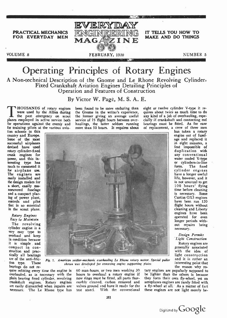
THOUSANDS of rotary engines were used by the Allies during the past emergency on scout
planes employed in active service both for operations against the enemy and for training pilots at the various avia- tion schools in this country and Europe. Some of the most successful airplanes devised have used rotary cylinder -fixed crank engines for power, and this in- teresting type has much to commend it for airplane use. The engines are easily installed and the design makes for a short, easily ma- noeuvered fuselage and a compact plac- ing of power plant, controls and pilot that is so essential in the scout plane.
Rotary Engines Easy to Maintain The revolving
cylinder engine is a very easy type to overhaul and keep in condition because it is simple . and compact in con- struction and prac- tically all bearings are of the anti -fric- tion type. These bearings do not re- quire refitting every time the engine is overhauled. as is necessary with the plain bearing fixed cylinder, revolving crankshaft engines. Rotary engines are easily dismantled when repairs are necessary. The Le Rhone type has
been found to be more enduring than the Gnome in the writer's experience, the former giving an average useful service of 75 flight hours between over- haulings, the latter seldom running more than 50 hours. It requires about
eight or twelve cylinder V -type it re- quires about twice as much time to do any kind of a job of overhauling, espe- cially if crankshaft and connecting rod bearings must be fitted. As for ease of replacement
/ 1i
t
}
Fig. 1. American soldier -mechanic overhauling Le Rhone rotary motor. Special puller shown was developed for removing engine supporting plates
60 man-hours, or two men working 30 hours to overhaul a rotary engine if new rings must be fitted, all parts thor- ounhly cleared, carbon removed and valves ground and have it ready for the test stand. With the conventional
a crew of three men has taken a rotary engine out of fusel- age and replaced it in eight minutes, a feat impossible of duplication with any conventional water cooled V -type or cylinders -in -line form. The fixed cylinder engines have a longer useful life, however, and it is not unusual to get 100 hours' flying time before cleaning is necessary. Some Curtiss OXS engines have been run 120 flight hours without cleaning and Liberty engines have been operated for even longer periods with- out repairs being necessary.
Design Permits Light Construction
Rotary engines are generally associated with the idea of light construction and it is rather an interesting point that the reason why ro-
tary engines are popularly supposed to be lighter than the others is because they form their own fly -wheel, yet on aeroplanes engines are rarely fitted with. a fly -wheel at all. As a matter of fact these engines are not light merely be -
261
Digitized by Google

262 Everyday Engineering Magazine for February
cause they are rotary motors, but are rotary motors because that design has been adopted as that most conducive to lightness and is most suited to an engine working in this way. The cylinders of a Gnome could be fixed and crankshaft revolve without in- creasing the weight to any extent if the engine operated on a more conventional cycle. There are two prime factors gov- erning the lightness of an engine, one be- ing the initial de- sign and the other the quality of the materials employed. The consideration of reducing weight by cutting away metal is a subsidiary method that ought not to play a part in standard practice, however useful it may be in special cases. In most ro- tary engines the lightness is entirely due to the initial design and to the mate- rials employed in manufacture. Thus, in the first case the engine is a radial engine, and has its seven or nine cylin- ders spaced equally around a crank - chamber that is no wider, or rather, longer, than would be required for any one of the cylinders.
This shortening of the crank -cham- ber not only effects a considerable sav- ing of weight on its own account, but there is a corresponding saving in the shafts and other members, the dimen- sions of which are governed by the size of the crank -chamber. With regards to materials, nothing but high-grade steel is used throughout, and most of the metal is forged chrome nickel steel. The steady running of these engines is largely due to the fact that there are lit- erally no reciprocating parts in the absolute sense, the apparent reciproca- tion between the pistons and cylinders being solely a relative reciprocation, since both travel in circular paths, that of the pistons, however, being eccentric by one-half of the stroke length to that of the cylinder.
While the rotary engine has many ad- vantages, on the other hand, the head resistance offered by a motor of this type is considerable; there is a large waste of lubricating oil, due to the cen- trifugal force which tends to throw the oil away from the cylinders; the gyro- scopic effect of the rotary motor is said to be detrimental to the best working of the single engine aeroplane if of short span, and, moveover, it requires about 7 per cent of the total power developed by the motor to drive the revolving cyl- inders around the shaft and overcome the air resistance. Of necessity, the
Fig. 2. View
compression of this type of motor, which is always air cooled, is rather low, and an additional disadvantage manifests itself in the fact that there is as yet no satisfactory way of entirely muffling the rotary type of motor.
of DH -5 airplane, showing how easily rotary motor is installed
Rotary Cylinder Engine of American Origin
The modern Gnome engine has been widely copied in various European countries, but the form on which its de- sign is based was originated in America, the early Adams -Farwell engine being
Fig. 3. Diagrams at A and B show why rotary cylinder engines operating on single crank should have odd number of cylinders. Gnome Monosoupape timing diagram shown
below
the pioneer form. It has been made in three, five and nine -cylinder types and forms of double these numbers. The simple or one -crank engines have an odd number of cylinders in order to secure evenly spaced explosions. In the
seven -cylinder the impulses come 102.8° apart. In the nine -cylinder form the power strokes are spaced 800 apart. The fourteen -cylinder engine is virtually two seven -cylinder types mounted togekher, the cranks being op-
posed just the same as in a double cylin- der horizontal mo- tor, the explosions coming 51.4 apart, while in the eigh- teen -cylinder model the power impulses come every 40° cyl- inder travel. Other rotary motors have been devised, such as the Le Rhone and the Clerget in France and copies of these types in other coun- tries. The speed of a rotary cylinder en- gine is limited to a greater degree than any other form, and it is not safe to run them over 1200
r.p.m. owing to stresses produced by centrifugal force at higher speeds. The writer has seen an engine under test "throw a cylinder" when run at 1500 r.p.m. for trial purposes.
Why an Odd Number of Cylinders Is Used
Many people doubtless wonder why single crank rotary engines are usually provided with an odd number of cylin- ders in perference to an even number. It is a matter of even torque, as can easily be understood from the accom- panying diagram. Fig. 3A represents a six -cylinder rotary engine, the radial lines indicating the cylinders. It is pos- sible to fire the charges in two ways if the engine is a four-cycle type, firstly in rotation, 1, 2, 3, 4, 5, 6, thus having six impulses in one revolution and none in the next; or alternately, 1, 3, 5, 2, 4, 6, in which case the engine will have turned through an equal number of de- grees between impulses 1 and 3, and 3 and 5, but a greater number between 5 and 2, even again between 2 and 4, 4 and 6, and a less number between 6 and 1, as will be clearly seen by reference to the diagram. Referring to Fig. 3B, which represents a seven -cylinder en- gine, if the cylinders fire alternately it is obvious that the engine turns through an equal number of degrees between each impulse, thus, 1, 3, 5, 7, 2, 4, 6, 1, 3, etc. Thus, supposing the engine to be revolving, the explosion takes place as each alternate cylinder passes, for instance, the point 1 on the diagram, and the ignition is actually operated in this way by a single contact brush that ditsributes the current to contact seg- ments on the distributor plate.
Digitized by Google

Everyday Engineering Magazine for February 263
Rotary Engines Easily Installed
When rotary engines are installed, simple steel stampings or "spiders" are attached to the fuselage to hold the fixed crankshaft. Inasmuch as the motor
being dispensed with on account of the trouble caused by that member on earli- est engines. The construction of this latest type follows the lines established in the earlier designs to some extent and it differs only in the method of charg-
or single -valve motor, and this valve also remains open a portion of the in- take stroke to admit air into the cylin- der and dilute the rich gas forced in from the crrnk-case interior. Aviators who have used the early form of Gnome
horn,. Ball Beonr 7 Po: kerSv."r
Piston.......... WWII] Cylinder
Wrist Pin .- Cow; d rng- -
Side Plate:....
~IN_ PtopeMer Sha ft rAollZ-. 11
Bearings -
Rotory Crank Cose ti ::_ mgr
-Ya/re Opera.: -.7 Rod
..Opera tin i RJd P,.-ar
Jr, .. hiutJr
,..Curren^SuR?'/B:.;+
1471.S1!...,¿2<-0,11
' /-- f%red
Crank Shaft
--Anchorage Plates./
- Boll Beonng
Valve Induction P;pe,
Rocker
frMusi Va/ve
Spark j Plug-
Air Cooled Cylinder.'
Lock Nut '. Threads to hold Cylinder
Crank Case'
' ,, -,'01.
-Piston
.-Air Cooling flanges
Wrist Pin
Connecting Rod
Connec#inyy Rod o' and Crank Shot?
Assembly
Corns
0 '` Valve Lift Rods
Pig. 6. Sectional view of Le Rhone rotary cylinder fixed crankshaft airplane engine, showing novel connecting rod arrangement and metkod of valve actuation
projects clear of the fuselage proper there is plenty of room back of the front spider plate to install the auxiliary parts, such as the oil pump, air pump and ignition magneto, and also the fuel and oil containers. The diagram given at Fig. 4 shows how a Gnome "monosou- pape" engine is in- stalled on the anchor- age plates, and it also outlines clearly the piping necessary to convey the oil and fuel and also the air - piping needed to put pressure on both fuel and oil tanks to in- sure positive supply of these liquids, which may be carried in tanks placed lower than the motor in some installations. The view of the DH5 biplane single -seater scout with rotary mo- tor installed but mo- tor cowling removed shows how simple this installation is, the engine in this case being a 110 h.p. Le Rhone.
Gnome "llfonosoupape" Type The latest type of Gnome engine is
known as the "mbnosoupape" type, be- cause but one valve is used in the cyl- inder head, the inlet valve in the piston
ing. The very rich mixture of gas and air is forced into the crank -case through the crankshaft, and enters the cylinder when the piston is at its lowest position, through the half -round openings in the
say that the inlet valve in the piston type was prone to catch on fire if any valve defect materialized, but the "monosoupape" pattern is said to be nearly free of this danger. The bore
of the 100 -horsepower nine -cylinder engine is 110 mm., the piston stroke 150 mm. Ex- tremely careful ma- chine work and fitting is necessary. In many parts tolerances of less than .0004" (four ten -thousandths of an inch) are all that are allowed. This is about one -sixth the thick- ness of the average human hair, and in other parts the size must be absolutely standard, no appre- ciable variation being allowable.
A still later devel- opment of the "mono- soupape" is a 150 - horsepower type with a special form of clack
device at B valve that has no valve spring. In other
details, with the exception of the con- necting rod arrangement, which is simi- lar to that of .the Le Rhone motor, it resembles the smaller model.
Gnome "?Konosoupape" Valve Timing In the present design of the Gnome
motor, a cycle of operations somewhat
Slide Operating... Link
Regulating ,il;do
Air Screen
_4I
'Air Entrance
Fuel E"rr.,nue-
A
Fuel Con+rol Bell Crank.
7rJ.rtl.7r .Piaht and
L.>tY Couplhng
Needle;e.sl,, j Sprrr.j
Ser.)y Noz:/e
' Fue! Regulating Needle
fue; Outlet
Fuel feed
'.Regulating Needle
"f. /ter Screen
B
Fig. 7. The Le Rhone carburetor at A and Fuel supply regulating
guiding flange and the small holes or ports machined in the Cylinder and clearly shown at Fig. 5. The return- ing piston covers the port, and the gas is compressed and fired in the usual way. The exhaust is through a large single valve in the cylinder head, which gives rise to the name "monosoupape,"
Digitized by G000te 1

- 264 Everyday Engineering Magazine for February
different from that employed in the or- dinary four-cycle engine is made use of. This cycle does away with the need for the usual inlet valve and makes the en- gine operatable with only a single valve, hence the name "monosoupape," or "single -valve." The cycle is as follows: A charge being com- pressed in the outer end of the cylinder, combustion cham- ber, it is ignited by a spark produced by the spark plug lo- cated in the side of this chamber, and the burning charge expands as the pis- ton moves down in the cylinder while the latter revolves around the crank- shaft. When the pis- ton is about half way down on the power stroke, the ex- haust valve, which is located in the cen- ter of the cylinder head, is mechani- cally opened, and during the following upstroke of the pis- ton and burned gases are expelled from the cylinder through the exhaust valve directly into the at- mosphere.
Instead of closing at the end of the exhaust stroke, or a few degrees ther -
after, the exhaust valve is held open for about two-thirds of the following inlet stroke of the piston, with the result that
cylinder, and as the piston continues to move inwardly, it is obvious that a par- tial vacuum is formed.
When the cylinder approaches with 20° of the end of the in- let half -revolution a series of small inlet ports all around the circumference of the cylinder wall is un- covered by the top edge of the piston, whereby the com- bustion chamber is placed in communi- cation with the crank chamber. As the pressure in the crank chamber is substan- tially atmospheric, and that in the com- bustion chamber is below atmospheric, there results a suc- tion effect which causes the air from the crank chamber to.flow into the com- bustion chamber. The air in the crank chamber is heavily charged with gaso- line vapor, which is due to the fact that a spray nozzle con- nected with the gaso- line supply tank is
located inside the chamber. The pro- portion of gasoline vapor in the air in the crank chamber is several times as great as the ordinary combustible mix- ture drawn from a carburetor into the
Aerie,
.-.ssw.
A.Iery (,c.eNa
,. eu
. desati Ind
,oa.,.<.. 6e9e fee Oil feed s.,. -,:g
, ; ,F W ese Pew
f . ehr ~min ; ~,11 P,. keel. Cowrie e.i..
a, P.., b coges
o A® G ,o,in.
Fig. 4. Diagrams explaining action of Gnome ignition system, oil complete power plant installation
fresh air is drawn through the exhaust valve into the cylinder. When the cylin- der is still 65° from the end of the inlet half -revolution, the exhaust valve closes. As no more air can get into the
pump and showing
No./
A69
ná8'1 r 1 r
No7
No 2 Rocker Actuator:,,
4423 Air Cooled Cylinder---
i1b4 Charging Ports
No6 hfaS
End View showing Location of Oil and Air Pumps and
Magneto ;End P/ate
Propeller flub ......
Nose
Wood Propeller-______
Planetary Timing Gears ---- Crankcase Front Halt"-'
Va/ve Plunger:
Short Rod-'
--Valve Rocker -- Va/ve Spring
Vo/ve Cage
Exhaust Va/ve
-'' Piston
,- Starting Gears (Helical Teeth)
Oil Pipe,,
Section A -B
, ': Engine -carrier Plates -- '111. -
------Non-rotating Current A P/ate
Supply.
Fuel i Nozzle
Crankcase , DT.
Rear Ha/f'Bake/ite Distributor Block
'-Thrust Bearing
Air Pump
Accessory Driving Gear
. Starting Shah
Stationary Crankshaft
-Oil Pipe
Fig. 5. Sectional view showing construction of American built Monosoupape Gnome engine
Digitized by Google

Everyday Engineering Magazine for February 265
cylinder. This extra -rich mixture is di- luted in the combustion chamber with the air which entered it through the ex- haust valve during the first part of the inlet stroke, thus forming a mixture of the proper proportion for complete com- bustion.
The inlet ports in the cylinder wall remain open until 20° of the compres- sion half -revolution has been com- pleted, and from that moment to near the end of the compression stroke the
dead center on the second revolution. Then for 45° of travel the charge with- in the cylinder is expanded, whereupon the inlet ports are uncovered and re- main open for 40° of cylinder.travel, 20° on each side of the inward dead center position.
Gnome Fuel System, Ignition and Lubrication
Gasoline is fed to the engine by means of air pressure at five pounds
Piston .
An B/A:ng
Yns,P:n.-I;;í. Re An
v: ,q Su r.v
Rod
lyIoslst Corn
a
.. Ask. ; R.nq
G:°a.e,
Into Com
Short had End red n[diurn Rod End Feet °n4-4-7 «+3 -c -g
a long
on RobedSt teat
Arrongemnnectirp .nt Roo EndsRtdbeoringson Ta
Diogron. Snowing Connecting Rod Assembly
Rocker Shaft Actuator.. RocA.r JnarlBeorinq'-'-';
Vol... RacA.r....-
frhaust Volve..'
Vol.,. Acluoling Rod .[]
Air Cooled Cyl.nder
tulcrum.,
Valveloperotinq., erer
Com , lollo.rer-
.Caen Gear In l erna
{ iu/crylni Cums
Com Drive
\Pinion
Internal Pinion
Valve
;Lock Aloe
Com Yollow.r
-Cams
'internal Pinion
internal Gear tired
Crank Shaft
Cam Plate Supporting Ball Bearings
Fig. 8. Interesting mechanical details of the Le Rhone rotary cylinder motor
gases are compressed in the cylinder. Near the end of the stroke ignition takes place and this completes the cycle.
The exact timing of the different phases of the cycle is shown in the dia- gram- at the bottom of Fig. 3. It will be seen that ignition occurs substan- tially 20° ahead of the outer dead cen- ter, and expansion of the burning gases continues until 85° past the outer dead center, when the piston is a little past half -stroke. Then the exhaust valve opens and remains open for somewhat more than a complete revoultion of the cylinders, or, to be exact, for 390° of cylinder travel, until 115° past the top
per square inch, which is produced by the air pump on the engine clearly shown at Fig. 4. A pressure gauge con- venient to the' operator indicates this pressure, and a valve enables the oper- ator to control it. No carburetor is used. The gasoline flows from the tank through a shut-off valve near the oper- ator and through a tube leading through the hollow crankshaft to a spray nozzle located in the crankcase. There is no throttle valve, and as each cylinder always receives the same amount of air as long as the atmospheric pressure is the same, the output cannot be varied by reducing the fuel supply, except
within narrow limits. A fuel capacity of 30 to 40 gallons is usually provided. The fuel consumption is at the rate of 12 U. S. gallons per hour.
The high-tension magnetos, with double cam or two break per revolution interrupter, is located on the thrust plate in an inverted position, and is driven at such a speed as to produce nine sparks for every two revolutions; that is, at 2% times engine speed. There is no distributor on the magneto. The high-tension collector brush of the magneto is connected to a distributor brush holder carried in the bearer plate of the engine. The brush in this brush holder is pressed against a distributor ring of insulating material molded in position in the web of a gear wheel keyed to the thrust plate, which gear serves also for starting the engine by hand. Molded in this ring of insulat- ing material -are nine brass contad sec- tors, connecting with contact screws at the back of the gear, from which bare wires connect to the spark -plugs. The distributor revolves at engine speed, in- stead of at half engine speed, as on or- dinary engines, and the distributor brush is brought into electrical connec- tion with each spark -plug every time the piston in the cylinder in which this
Fig. 9. Explaining Le Rhone motor action
spark -plug is located approaches the outer dead center. However, on the ex- haust stroke no spark is being generated in the magneto, hence none is produced at the spark plug.
Ordinarily the engine is started by swinging the propeller, but for emer- gency purposes, as in seaplanes or for a quick "get away," if a landing is made where it is not possible to start the motor by turning the propeller, a hand starting crank is sometimes pro- vided. This is supported in bearings
(Continued on page 310)
Digitized by Goocte f

266 Everyday Engineering Magazine for February
A Model Steam Engine Constructional Data for a Model With a Simple IValchert Valve Gear
By Oliver Savage
MODEL makers who have a desire to produce a workable steam en- gine, should not hesitate to set
about the task of building one merely because they do not have the facilities for making castings or patterns. Very workable and practical little engines can be produced by using a few extremely simple castings and different odds and ends found about the workshop. It is true that perfect engines cannot be built by the use of such materials but working models can be made that will operate just as successfully as models that re- quire a number of castings in their make-up. When engines are built with spare parts, the builder must use his own ingenuity in perfecting the design so that most of the available materials on hand can be used in the construc- tion.
The little engine constructed by the writer evolves the use of only five cast- ings and these are produced with very
the use of a small lapp grinder or disc grinder that can be mounted in the live spindle of the lathe. The flat surface should be tested for accuracy by the use of a machinist's square. By this the writer means that it should be squared up with the cylinder ends.
(
t...,_,..._.111...._.._....._......,....,..,..,.....,....W....
Few model makers or experimental engineers realise what neat and work- able model steam engines can be made in a few hours' time and by the use of simple materials and tools. The little engine pictured on this page and described in the text is an example of the work that can be accomplished by the use of odd materials and a few simple castings of brass, the patterns for which can be made by every me- chanic worthy of the MM. -EDITOR.
The cylinder heads are now faced off carefully in the lathe and divided with a protractor into six equal parts. After being punched, these members are
%-28 tap to receive the exhaust pipe which is held in this manner to avoid the use of solder. The hole for the ex- haust port is continued beyond the one - quarter inch with a inch drill One -quarter -inch copper tubing is used as the exhaust pipe.
By referring to the drawing it will be seen that the cylinder is provided with two projections. These are used in fast- ening the cylinder to the engine frame and they should be drilled out and tapped with a %-28 tap.
The engine valve is smoothed the same way as the top of the cylinder. The holes are then laid out on the steam chest cover and drilled and tapped to receive the cap screws. Where the valve rod enters the steam chest, a hole is made with a 5 -in. drill one-half way through. The hole is then continued with a %-inch drill. In this way a place is made for the packing which obviates the necessity of making a
Two views of the little steam engine described in this article. A careful study of the photographs will do much to assist the builder is the construction of the engine
simple patterns that can be made by any experimental engineer no matter how inexperienced he may be in the art of pattern making. The patterns can be taken to the local foundry and the cast- ings obtained for about one dollar. The castings should be made with hard brass.
The cylinder of the engine should be cast with a three-quarter hole and it will, of course, be necessary to employ a core box for this purpose. When the rough casting of the cylinder is received from the foundry, it is chucked in the lathe and the hole bored out to a diam- eter of one inch. After this is done, each end of the cylinder is faced off square. The flat portion of the cylinder upon which the steam chest rests must be filed square and finished as smoothly as possible, as much depends upon this particular operation. This operation can also be accomplished very nicely by
drilled with a %s -in. drill. When these holes have been drilled the cylinder heads can be used as a jig to drill the corresponding holes in the cylinder ends. The holes in the cylinder ends, however, should only be marked out by the aid of the cylinder ends. The holes should be drilled with a No. 36 drill. When this is done the holes in the cylin- der are tapped out with a 6-32 tap to receive the small cap screws which hold the heads to the cylinder ends.
Now the holes in the top of the cyl- inder are laid out and a %-in. drill run down about a quarter of an inch. An- other drill is then run in from each end to meet. Care should be taken in this operation to see that the holes do not break through into the exhaust port, as this would render the cylinder useless. The exhaust port is drilled out by drill- ing about half way in with a %-in. drill. This hole is then tapped with a
union, which always requires a lot of time and patience. Very small unions are also impractical unless they are made with the greatest precision.
The cylinder head is drilled in the same manner as the steam chest. In the case of the cylinder head a 5/16 -in. drill is used, first to drill the hole half way and this is followed with a 3/16 - in. drill. A little packing plate is then cut to shape from thin sheet brass and placed over the hole in the cylinder end to hold the packing in place. The same thing is done with the hole in the steam chest through which the valve rod passes. The shape of these little pieces can be seen by referring to the drawing on the opposite page.
The valve rod is threaded on one end to fasten the valve to it. The stroke of the valve is regulated by means of two screws which are shown in place on the
(Continued on page 342)
Digitized by Google

4--kx28Tc}p
Cyl. T
op View
Stearn
Cove
O
---2k'----- C
onn. Rod
_ O
6-32 T
q,
Cyl. E
nd V
iew
End V
iew
Steam
Chest
Slide
Rod
Slide V
alve
fng RingC
ove O
O
X
. Head
Conn.
-4%4' ---------
Valve
Rod
Rocker
--251s'- --
U
Valve R
od C
rank B
racket
Slide R
ods &
Rocker B
racket
O Ó
Conn. R
od to Rocker B
lock
Slide
Rod

268 Everyday Engineering Magazine for February
Grinding Convex Lenses By Victor H. Todd
T. the average person, and to many mechanics accustomed to working in metal, the process of
shaping and polishing a glass lens may seem quite beyond the powers of those who have not had some experi- ence. As a matter of fact, the making of a lens is a simple process, and is done easily on an ordinary turning lathe and does not require more skill than is required for turning out a per- fect metal article. The greatest asset required is patience and time, espe- cially on the final polishing. Of course, special glasses with bifocal curved sur- faces and the like are really the subject of the professional optician, but lenses such as those used for magnifying glasses are easily produced.
Assuming that a fairly high grade speed lathe is available, it is first neces- sary to make a few tools, which are easily produced by the ordinary me- chanic; a gauge, a gouge and a polish- ing fixture.
r 1
1
i
i 1
t L
.'í
Fig.) Brass Gauge for testing the
Convex surface of lens
circular segment out, and finish with a round fine file, exactly to the mark. Of course, if a cutter or other tool is avail- able, or if proper appliances are had for cutting a circle in the lathe, it will undoubtedly make a truer and neater job. In any case, the finished gauge should look like Fig. 1 and the curved part should be part of a perfect circle.
The next tool, the gouge, is not used directly in making the lens, but is used in making the polishing fixture. It may be made of an old flat file, or a chisel, or even a wide saw blade.
The end should be carefully ground to a convex shape so that it exactly fits the concave gauge, and must be so exact that when the two are held to- gether, toward the light, no light can be seen between them. It may be ground roughly on a coarse emery wheel and finished accurately on a finer one and at last by an oilstone. The cutting edge should not be flat like a chisel, but should be not less than 60 degrees,
Fig.4 Cross-section of mould
00
o Fig.5
Polishing Fixture Casted from Fig.4
Fig? Gouging Chisel,Front View.
Fig -3 Gouging Chisel,SideView.
First determine the length of the desired lens; whether it is to be plano - convex (that is, flat on one side and convex on the other) or double -convex (convex on both sides) and the diam- eter.
Suppose we wish to make a plano- convex lens, with one inch focal length, which will magnify 10 diameters. Take a pair of dividers and set for Y2 the focal length (/ in. in this case) and upon a thin sheet of brass strike a quar- ter or third of a circle. It may be advantageous to make a centre punch prick mark in the brass first, to get a true arc without the dividers slipping. If a double convex lens is desired, it would be necessary to set the dividers equal to the focal length and not one- half as in this case.
Now, with shears or narrow cold - chisel carefully cut the inner part of the
with the heel rounded off. The finished gouge should appear like Fig. 2 on a front view and an edge view like Fig. 3.
In order to make the polishing fix- ture, it is first necessary to make a wooden mould. Take a block of hard- wood, about a 2 -inch cube, plane one side smooth and with a sharp bit bore a hole, 1 inch in diameter, one-half inch deep, in the planed side. Then take a smaller bit and make the hole through the block. This last hole should be of a size most conveniently held in the lathe chuck. These two holes, of course, must be quite perpen- dicular, and if possible should be done in the lathe. A cross section of this wooden mould is shown in Fig. 4.
Next, melt some block tin or solder in a ladle, and, holding the block firmly on some firm smooth surface, pour it into the mould. On removing the cast-
ing it should present the appearance of Fig. 5. If the lathe is large enough to chuck the big end, the smaller part may be carefully trued up, so that it may be removed while shaping the lens, but we will assume it is -not, so the first thing to do is to shape the lens, and then complete the polishing fixture, as will be described later.
Select a good piece of crown glass, as near as possible to the size of the lens, and cement it to a wooden center as follows: Turn a piece of wood similar to Fig. 5, except turn the front side perfectly plane, so it runs true. Now get some hard shellac (sometimes called stick shellac) and heating it in a fire, or flame, smear the end of the stick,
.smoothly and evenly, but very thin. Hold the glass cautiously in or near the flame until it is hot enough to make the shellac melt and stick. Smear the glass smoothly and thinly. Then, hold- ing both the stick and glass in the flame quite close together until the shellac starts to run, press them firmly together, centering the glass as near as possible.. When cold, if this cementing has been done properly, the glass will break be- fore it will loosen from the stick.
Remove the slide rest and tail stock end chuck the stick with the glass on the end. It must be held very tightly so as not to work loose during the grind- ing process. Take a small emery wheel or piece of emery wheel and, setting the lathe in motion, hold the emery against the glass, first working it into a round shape and then grinding off the edges, gradually forming it into a convex shape. During the . grinding the glass should be wet frequently. This can be readily done by using a sponge soaked in water and held in the left hand while the emery is held in the right hand for grinding.'
The glass must not get hot enough to melt or loosen the shellac. After it has been worked into a smooth convex sur- face, stop the lathe and apply the brass gauge. This will immediately show where it must be ground in order to pro- duce the right curvature. The gauge test must be made quite frequently when nearing the proper shape. Finally, it must fit the gauge so that when held up to the light no light can be seen between the gauge and glass.
When this is reached, go over it with fine emery paper to remove all scratches left by the coarser emery, being very careful not to distort the shape. Follow this with a piece of very fine whetstone until it is smooth, free from coarse scratches and still gauges up accurately. This leaves the surface ready for polish- ing.
Grinding a lens of this size need not
Digitized by Google

Everyday Engineering Magazine for February 269
take very long unless a very thick piece of glass is used. It should not take over an hour or so. The hand very quickly acquires the knack of moving the stone around so as to give a smooth convex surface.
Remove the stick and glass and in- sert the moulded polishing tool in the chuck. Set the side rest squarely in front and proceed to turn the metal out of the center, using the gouge previous- ly made.
Turn until there is a smooth con- cavity in the end, a little larger than the proposed lens, then dip a piece of slightly moistened flannel cloth into "putty powder" (tin oxide) and polish this concavity, being very careful not to polish it out of shape. This must also fit the gauge perfectly.
Now tie a piece of thin doeskin or other firm and thin woolen cloth over the concavity, fastening it around the sides with a piece of string. Slightly moisten the cloth and put a small quan- tity of putty powder over it. Start it revolving and press the glass (still held on the end of the stick) into the con- cavity, which it will fit perfectly. Keep up the application of moisture and powder frequently. Do not let the glass get hot enough to melt the shellac. Do not hold the glass in only one position, but rock it around in every position, taking care that it fits in accurately in any position in the polisher. If the cloth gets worn through, replace it with new. When the polishing has pro- ceeded so far that the surface appears brilliant, and no scratches appear visi- ble to the naked eye, the dampening and application of powder should be stopped, and polishing continued with what powder remains worked into the cloth, or, if desired, a finer polishing powder may be substituted. The polish- ing should not take long if the glass was finished carefully with a very fine stone as directed. It should be con- tinued until a magnifying glass with a magnifying power of 10 diameters will not reveal the least scratch or rough- ness.
The lens may now be heated enough to melt the cement and removed. A little alcohol will remove all traces of shellac. If properly made, the lens will now give a clear, bright view of any object, and upon turning the glass in various positions no distortion will be noted.
It must be remembered that practice makes perfect and that this work re- quires a great deal of patience, as it is very tedious and the whole work may be spoiled in a few seconds by a little hurrying or impatience.
The average experimenter seems to have inherited fear of working with glass. If the directions outlined are followed, all will be well.
A Model Tractor By Edward F. McCabe
THE making of a farm tractor may be something new in the line of
models, yet there is no reason why any amateur handy with the scroll saw (which is used considerably in making the wheels) could not make this ma- chine in a few hours.
A piece of hard wood 6 x % x in. is used in making the frame on which the clock -work, radiator and gears to the rear wheels are mounted. The clock -work from any dock will do, but try to get a clock as small as possible.
It need have no alarm, as this is not used.
The rear wheels, which are 2% in. in diameter, are cut from lí in. hard wood, two pieces making one complete wheel. After sawing out the size of the wheel, the spokes must be cut out with a scroll saw, each piece having four spokes. Place the two pieces together so that the spokes in the first piece are just between those of the second and
F10.2
then glue. The small pieces of wood are glued in place. The front wheel is made of but one piece. Tin furnished the support from the frame to the front wheel.
The largest gear in the clock, which is connected with the spring, is used to drive the rear wheels, all other cogs being left in place except the balance wheel. Directly to the large gear is connected a small gear which can be taken from some other clock. This is soldered to the rear axle and fitted in the tin bearing, which is clearly shown in illustration No. 4..
The radiator is a lí in. piece of hard wood with tin fastened to its center with small brads. The hood is simply a strip of tin 4% ins. long and 3% ins. wide, bent to the proper shape.
To stop and start the motor a wire is fastened as shown, so that when it is turned to the left it comes in contact with a small cog and brings it to a stop. To wind, a long key is necessary, as it must reach through the left wheel. This model will give much enjoyment and is able to pull small wagons three times its size.
The tractor can be improved by ar- ranging a small steering wheel upon it together with a seat for the operator. The seat should be located at the back and the steering should be equipped with a long axle which will reach the front wheel.
FIO.I
F10. 3
Digitized by Google

270 Everyday Engineering Magazine for February
Model Locomotive Design and Construction By Henry Greenly, M. E.
Associate Member Institute Locomotive Engineers, England
N the "old country" the standard- ization of model locomotive parts
by the writer has been attended with a considerable degree of success and, as a result, many amateur model makers are now building satisfactory working models of their own general design where before they were limited to given types or held up by the fact that the supply of castings and accessories of interchangeable design was non-exis- tent. Of course, the war has retarded progress in this work, but lost time is now being made up.
For the past twenty years the writer has been designing models of locomo- tives of all sizes as well as model roll- ing stock and railroad equipment. These models have comprised the toy engines and accessories for gauges 1/ in., 1M in., and 2 ins., actuated by clockwork, steam and electricity such as were manufactured for the world's supply by the Germans in the Nurem- berg district of Bavaria and, through all the intermediate gauges, model loco- motives weighing anything from 5,000 to 6,500 lbs. capable of hauling 50 or 60 passengers, for 15 in. gauge public park and private garden railways. In numbers these models total some hun- dreds of different designs and naturally the result of this experience and from the data obtained from the many schemes tried out it has been possible to arrive at some measure of finality in the details of construction and to put forward a system of standardization.
The accompanying table will give the reader a little idea of the attributes of the various sizes which have had a vogue in the past. Several of them are so nearly alike-due to the parallel but in -co-ordinated efforts of British and German manufacturers, also amateur builders in pre-war days-that at this juncture the writer considers it wise to
J 1'
1 , I °
Mr. Henry Greenly
In this series of articles, Mr. o Henry Greenly, who was intro-
duced to our readers in the Au- gust number of "Everyday," will cover the standardization of model American locomotive parts. Mr. Greenly is consulting and design- ing engineer for a large English model manufacturer and his work can be relied upon as authorita- tive. The drawings are the work
3 of Mr. Greenly.-Enron.
drop several of them. This advice has already been accepted and, in the small sizes especially, British model makers seem quite satisfied with the following:
Toy Gauges-No. 0 (17s ins.) or 327 m. gauge; 77 m. scale. No. 1 (1g$ ins.) or 457 m. gauge; 107 m. scale.
and locomotives. If, in America, the personal interest in the various types and design of locomotives approaches anything like the dimensions it does in Great Britain, then such a doctrine would soon prove impossible. Amateurs in the latter country have their particu- lar "fancies." At the end of the last century the old Great Northern "single wheeler" with its 8 ft. driving wheel was the most popular engine, while the old Brunel broad gauge engines of the Great Western line had their devotees. The interest now is divided between the G.N.R. "Atlantic," a type of loco- motive imported from the States and the Great Central Railway Company's 4-6-0 inside connected engine "Sir Sam Fay," a class which embodies most of the traditions of British locomotive practice. The writer's particular fa- vorites in U. S. A. engines are those of the more recent machines built for the Pennsylvania Railroad, this pref- erence being due to their excellent ex- ternal proportions and to the scientific manner of their design.
Standard Cylinders for 2/ in. gauge models. With our Editor's permission it is the writer's intention to deal with "Character details" of various U. S. locomotives from a model maker's point of view and for the moment to give some attention to the design of what may be considered as the "heart of a working model," the cylinder-in the most popular and most suitable gauge of model locomotive for amateur building,
,r.
"Engineer Made" Models -2/ ins. Nominally half inch scale, actual- ly 17/32 in. to 1 foot. Gauge 4M ins. Scale 1 in. to the foot.
Passenger Carrying Locomotives - 7% in. gauge and 15 in. gauge as already tabulated.
It is not intended in these articles to preach anything in the nature of stand -
A model American lo- comotive built by an English model enthu- siast. The loco. is a
Baltimore and Ohio "Mallet," articulated. It was constructed by
Rene Bull
viz., 2/ ins. Before doing so, readers may be referred to the diagrams, Figs. 1, 2 and 3, which give the leading di- mensions in inches of a model 2/ ins. gauge, Atlantic 4-4-2 type engine. This locomotive can be fired with charcoal or alcohol (methylated spirit). It is also eminently suitable for amateur construction and for an outdoor model
Digitized by Goo,te

Everyday Engineering Magazine for February 271
railroad. The proportions, if adhered to more or less exactly, are bound to provide a successful model, given rea- sonably accurate workmanship with special attention to the cylinder details and to the steam tightness of the boiler.
The cylinder of a model locomotive must be made smaller than the scale equivalent. As working pressures can- not, from a practical point of view, be reduced to scale, in a 2/ in. gauge model which is roughly 1/24th full size, it would prove impossible to reduce 200 lbs. square inch to 1/24 of 200, owing to the increase in the proportion of condensation losses as an engine is reduced in size, a working pressure of from 50 to 60 lbs. is usually employed. The size of the cylinder and working pressure could be calculated from the point of view of tractive effort and ad- hesion weight, but such factors are governed by other considerations such as the reduction of working pressure due to the withdrawing of the steam. Readers will therefore welcome a sim- ple rule based on actual model experi- ence. With a normal boiler the size of the cylinder may be determined by the following formula:
Bore ,of cylinder in inches = 1.5 S -.125 where S is the scale of the model in inches to the foot.
FIG.2 FIG. 3
F I G. I
Fig. 1. Elevation giving leading standardised dimensions of a half -inch scale 254 in. gauge loco., Atlantic tyype. Fig. 2. Front view showing frame width
at cylinders. Fig. 3. Rear end giving cab and firebox dimensions.
Inches for Mode/
lblvt spr'ndld,
%///ii - N dab
STEAM PIPE I
4 ija I
i
6
,:
Standard
te
1111
13
31dia. Boiler at 5üabove Rails
- Saddle
^ Nast' No331 e ad j
Screw. ,,.
I g berw^- Main fro
3leeiSlre.s of Cylrs.
29152 berm/to Tires
rr
"half -inch" scale lot emotive
' 2 Va
cylinder
Gage
Fl6.4 (modern piston valve type)
For a 2/ in. gauge en- gine the scale may be taken as 17/32 in. or .531 in. and the result of the application of the formula gives .666 in., which is practically 11/16 in. The stroke of a model cylinder must as a rule, for spectacu- lar reasons, be some-
44" P
14
where near the scale equivalent and therefore requires no special cal- culation. Should any model locomotive engi-
Cenrres
neer wish to consider the size of the cylinder from ; .o the tractive effort point of view, he may take it that the steam pressure will be reduced at the cylinder to something like half of its nominal pressure, as he reads it at the boiler pressure gauge and that a trac- tive effort, on paper, of at least one-third of the adhesive weight may be provided for in a small model without risk of ex- cessive slipping.
16
In making a model of any existing prototype,
cross-section and end view
the dimensions a n d weight of which is known, the 2/ in gauge
Digitizsp by Google

272 Everyday Engineering Magazine for February
model will weigh at least .165 lbs. for every ton (American, 2;000 lb. ton) of the original. A model varies roughly as the cube of the scale and the recipro- cal of the above coefficient used in model work for 2% in. gauge is
1 lb. of model = 6.06 American tons of prototype.
In figuring out the adhesive weight it should be noted that it is best practice in arranging the spring gear of a work- ing model to crowd on to the driving and coupled wheels a little more weight than the equivalent at the expense of that carried by bogie and pony trucks.
So much for what may be termed theoretical considerations. The cylinder of an American engine are usually outside the frames with the valves above the pistons. In most modern prototypes piston valves are employed, but in model prac- tice such as not satisfactory under 17, in. or 1M in. in diameter and therefore, for 2% in. gauge engines may be entirely ruled out.
To preserve the external features of a piston valve cylinder a design similar to that shown in the accompanying full size drawings, Figs. 4 to 8, has been employed by the
OUMMY TAu. ROO
1
writer with success. The cylinder and steam chest is cast separately, gunmetal being usually employed. The end faces
-i-)r_'; . r.` ''_
Semi -finished American type model locomotive
are machined true after the two parts have been fitted together, preferably from the bore of the cylinder, the cast-
_ílf'// ///df?Y//A/< 4 lunna _f111 :f n IIII111111
- IIII®II ' _ c
-.11~ 1WD u
~a ~IL
FIG.5 COVCRING OR CICAOINC LATC
/1 .1
8 dlam
i 5/32"diam
N Alen --
ing being mounted on a mandrel for this purpose. The cylinder and steam chest are finished off to the correct profile by a lagging or cleaning strip of punished metal-blue or Russian iron, for example, looks very well. The valve is of the time honored "D" type and to provide for Walschaerts' or other type of radial valve gear the valve spin- dle is offset to the extent shown on the cross sectional drawings (see Figs. 4, 7 and 8).
The castings are arranged so that they may be moulded from metal pat- terns without coreboxes, the writer hav- ing found that for cylinders under 4 in. bore no advantage accrues from the
use of cores for cylinder bores. It is easier and cheaper in the long run, even for quantity .produc- tion to rough drill the cyl- inders at the outset, and to complete all further machin- ing operations from the bore.
All the steam passages are formed by drilling, the ports at the valve face being either chipped by hand or end -milled to the rectangu-
lar shape indicated in the plan view (Fig. 7). The steam passage should be two adjacent 3/32 in. holes, the
r
YI- FIG.7
nnoéoon OYYWm, \
3í6 41 19 -1
32
FIG.G FIG.9 Fig. 5. Longitudinal section of standard cylinders. Fig. 6. Elevation of standard cylinders. Fig. 7. Plan of steam
Fig. 9. Detail of slide valve and nut chest.
Digitized by Goo,Ie

Everyday Engineering Magazine for February 273
exhaust being a tapping hole for % in. copper pipe. The steam chest is held down to the cylinder castings by four
in. countersunk screws as shown in Figs. 6, 7 and 8, bosses being provided for these fastenings in the walls of the steam chest casting as indicated in the plan view, Fig. 7, and in cylinder cast- ing as shown at A, Fig. 6.
The valve spindle is supported at both ends. This arrangement being more or less essential where a radial valve gear is employed and where the spindle is not provided with an outer guide. . Both the packed and the
-i . 17 .--yaw - -
dOSSES FOq COV[R SCR [W3.
Foen ore / IV CSt(. SCREWS
451
j PITCM cone Le
FIG.8 Cross-section of cylinder on lire XY
dummy" glands are screwed into the ste::m chest. These glands may be made ou: of nickel bronze (German sil- ver) poll: hed bright or turned from brass Lar and then nickel plated. The cylinder covers are capped with spun or pressed sheet metal caps which are a snap fit on the main covers and may also be nickeled. The back cover sup- ports the slide bars, the stuffing box having an oval flange which is jig drilled at diametrically opposite cen- ters, 1 in. radius, to receive the shoul- dered -down spigots of the rectangular steel slide bars. The slide bars are then secured by nuts as shown in Fig. 5. The pistons may be made. in several styles and as the points involved in piston design and packing will be dis- cussed at a later date, reference to their construction may be deferred. How- ever, it is essential that the cylinder bore should be true to one-half a thou- sandth and the minimum and maxi- mum clearances (including tolerance and allowance) between piston and cylinder should fall between / and 1
thousandth of an inch. The piston and piston rod should be true in alignment. This is very essential. The front end of the cylinder should be bell -mouthed but to assist in obtaining perfect align- ment the spigot of the back cover should fit tightly in the parallel bore of the cylinder. Six countersunk screws are
used to attach the cover bosses, being provided where required in the cylinder castings to accommodate these screws as shown at B, in Fig. 6.
The slide valve is driven by a rect- angular nut fitting easily in a slot filed or machined in the back of the valves. The valve is set over, towards the in- side, as shown in the detail drawing in Fig. 9, and the nut is therefore drilled and tapped accordingly. This nut provided for an adjustment of the valve on its valve spindle and as this can only be accomplished within the limits of half a turn of the spindle, the thread chosen should be the finest available.
The writer has given considerable at- tention to superheating in models and also to the effects produced by various arrangements of exhaust nozzles (blast pipes). In the standard arrangement shown herewith (Fig. 3), an adjust- able nozzle is provided for. This ad- justment can be effected from the out- side and therefore experiments can he made with steam up. The blast pipe unit is a complete assembly and may be fitted on the running joint principle, sufficient length of thread being pro -
Q vided in one cylinder and on one arm '/Se of the blast pipe to make this possible. sruos The unit is made steam -tight by lock
nuts and a joint washer. The nozzle should be silver -soldered to the pipes.
Inside the smokebox the steam pipes (these are dual and joined to a com- mon superheater) should be bent to clear the jet of exhaust steam. A sys- tem of running joint is also suggested for fixing the ends of the steam pipes to the valve chest casting. A flanged nipple is screwed inside and outside with a thread of the same or nearly the same pitch. The inside thread should, of course, suit the % in. diameter steam pipe. A lock nut is also provided both the lock nut and the nipple being slight- ly countersunk on their adjacent faces to provide for a redlead grummet. To fix a steam pipe the nipple is screwed onto the pipe about double its normal or final distance. The pipe is then placed opposite the tapped hole in the valve chest casting and the nipple screwed in up to its flange, the joint being grummeted with some sewing cot- ton and red lead. The nipple, of course, screws off the pipe to its final position but the lock nut is run down to it and similarly grummeted to make the whole joint steam tight. This arrangement saves using a union and is more com- pact.
The cylinders are secured to the frames by four well fitting studs 5/32 in. in diameter. An additional support may also be provided by two bolts or studs fitting into a wall cast on the steam chest as shown in Fig. 4.
These studs or bolts also assist in securing the saddle casting to the main frames of the engine.
As the steam chest is none too roomy the corners of the slide valves may re- quire to be removed to provide for suf- ficient travel. To give additional clear- ance the lower portions of the bosses round the fixing screws may be chipped away on the inside. The diagrams here- with among other things give the ac- cepted standard dimensions of wheel tires for 2% in. gauge engines.
Inspection Lamp on Umbrella Stem
IN many places where an inspection must be made in dark locations, as,
for instance, back of pipes, or boilers, where an ordinary flashlight cannot be used to advantage, the lamp may be placed on the end of an old, disman- tled umbrella cane, with the battery strapped on the handle, as shown in the illustration. For the socket, take a piece of wood and drill a hole so that it will slip tightly over the end of the
Batlery
Wire soldered from battery shell to metal stem.
Umbrella Rib.
Wood--
cane. An empty thread spool will do nicely. Then wind several turns of No. 16 bare copper wire around the lamp base threads and tack it to the spool as shown in the insert. Connect a piece of lamp cord from this to the inner con- nection on the battery, and connect the shell to the metal umbrella stem. The push button controls the lamp in the regular way. If desired, a small mirror may be placed on the end, in addition to the lamp, and the two will reveal points which may be entirely inacces- sible in any other way.
VICTOR H. 'TODD.
New Process for Aluminum A new process has been perfected
which will do much to broaden the application of metallic aluminum. It does not produce a new alloy but merely gives aluminum new proper- ties. These new properties give alumi- num greater tensile strength and in- creased electrical conductivity. It is claimed that within a short time alumi- num will be replacing copper more than ever before as á conductor of electrical current. Aluminum is used to a great extent to -day in high voltage transmis- sion where resistance is not a large factor.
Digitized by Google
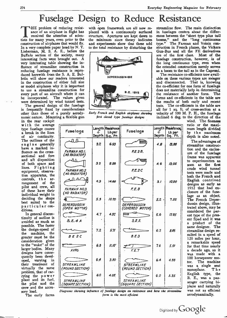
274 Everyday Engineering Magazine for February
Fuselage Design to Reduce Resistance THE problem of reducing resist-
ance of an airplane in flight has received the attention of scien-
tists for many years, even prior to the construction of airplanes that would fly. In a very complete paper head by N. Y. Lieberman, M. S. A. E., before the Buffalo section of the society, many interesting facts were brought out. A very interesting table showing the in- fluence of streamline construction in reducing fuselage resistance is repro- duced herewith from the S. A. E. Bul- letin will show our readers interested in the construction of either full size or model airplanes why it is important to use a streamline construction for every part of an aircraft where it can be incorporated. The values given were determined by wind tunnel tests.
The general design of the fuselage is frequently fixed by considerations other than those of a purely aerody- namic nature. Mounting a flexible gun in the rear cockpit with the average type fuselage causes a break in the lines of air continuity. The outlines of the engine generally have a marked in- fluence on the cross- sectional and fore and aft disposition of both space and lines. Fighting equipment, observa- tion apparatus, the controls, t h e ar- rangement of the pilot and crew, all of these have their individual weight in deciding the shape best suited to the particular con- ditions.
In general discon- tinuity of outline is avoided as much as possible. The faster the design -speed of the machine, the greater must be the consideration given to the "wake" of the larger bodies. Many designs have conse- quently been devel- oped, varying in their treatment of virtually the same problem, that of car- rying the power plant and its fuel, the pilot and the crew and the acces -
sory load. The early forms
with open framework are all now re- placed with a continuously surfaced structure. Apertures are kept down to the minimum since theory indicates and experiments show that these add to the total resistance by disturbing the
Early French and English airplanes showing first closed type fuselage designs
streamline flow. The main distinction in fuselages centers about the differ- ences between the "short type plus tail booms," and the "long continuous type." The Farman and Voisin con- struction in French planes, the Vickers Gun -Bus and all the FE derivatives are of the first dass. Most of the fuselage construction, however, is of the long continuous type, even when the extended construction merely serves as a boom to the tail as in the Caprmi.
The resistance co-efficients now avail- able on these various types are meager and. disconnected. That is, knowing the co -efficient for one form of fuselage does not materially help in determining the resistance of another form. The forms and co-efficients in the table are the results of both early and recent tests. The co-efficients in the table are all for 1 sq. ft. of cross-section at a velocity of 100 M. P. H., the fuselage indined 6 deg. to the direction of the
wind. The fineness ratio or the maxi -
Fuselage Length _
Depth
Resistatea Lb.per S. F+.
Fuselage Length
_ Depth
Resistance Ly per
Sq. Ft.
( 3.2
3 2
4.3
5.3
4.7
'
7.2
6.8
6.4
60
6 53
856
/4 89
1020
4.92
LW
//.10'
3.80
4.08
0.88
/305
/0. 00
7.55
1285
405
5. 9/
4.98
5.33
(--"...-1, 4.8
1E.2 B. FARMANNO./. (NO RAD/ATOR)
FARMAN N0.2 (NO RADIATOR)
(-----'5\119 4 6
FE. 2C
IT E.8
3 !
FARMAN NO.3 (NO RADIATOR)
OEPERDUSSIN (OPEN MOrr)R)
DEPPRDUSSIN (COVERED MOTOR)
5,2
Ce° S.E.4A
5. 6
SE.5.
*4lie 6.2
B.E3 8 E 2C
.
AVRG
.24 1_________- F. E.7
STREAMLINE (ROUND SECT/ON)
76
64
6.0
C STREAMLINE (ROUND SECT/ON)
C.___ -----
STREA ML INE (5QUARE.SECT/ON)
STREA ML /NE (SQUARE SECT/ON)
Diagrams showing influence of fuselage design on resistance and how the streamline form is the most efficient
mum length divided by the maximum depth is also noted.
The advantages of streamline construc- tion and the enclos- ure of the fuselage frame was apparent to experimenters as soon as the first crude wind tunnel tests were made and both the French and English contrived designs as early as 1912 that had en- closure of the fuse- lage as an object The French Deper- dussin design, illus- trated above, may be considered the par- ent type of the pres- ent Spad and it was a product of the same designer. The streamline design re- sulted in a speed of 120 miles per hour, a remarkable speed for that time nearly a decade ago, as it was made with a 100 horsepower mo- tor. The machine was a single seat monoplane. T h e English type, the B. E., was a pas- senger carrying bi- plane and naturally was not as efficient aerodynamically.
Digitized by Google

Everyday Engineering Magazine for February 275
Large Monoplanes Practical THE Zeppelin-Lindau flying boat
may be considered a very inter- esting development of the mono-
plane. It is equipped with an aggre- gate of over 1,000 horsepower, divided into four 260 horsepower motors. The machine has a span of 120 feet, carries fuel for twenty hours and complete armament and instrument equipment, yet is a monoplane with wire trussing at top and bottom of wings. The single hull under the wing may be termed a flying boat rather than a float. The fuselage which supports the tail sur- faces is placed above the wings and serves for attachment of the landing wire bracing. The total weight is twelve tons. This machine seems to discredit general belief in the aviation world that monoplanes can be built
tractor screw at the front end. Out- rigger floats of metal are placed at each side of the hull under the engine compartments in order to assist in car- rying the heavy load when the machine is at rest on the water and the hull settles low in the water. When the machine attains a certain speed, the main hull is sufficient to carry the load and the outrigger floats are lifted dear of the water.
These floats are of aerofoil form at the top, having a cambered upper sur- face and probably contribute some use- ful lift when the machine is in flight. There seems to be ample accommoda- tions on this craft, as mechanics can be carried in each engine nacelle, passen- gers or freight in the hull, and still more passengers and the_navigators in
four engines would be needed only when the machine was fully loaded and that after it had discharged its cargo or bombs and had used the greater part of its fuel that it would be sufficiently lightened to permit of flight with two of the motors. This craft was originally built for bombing purposes and was being tried out when the armistice was signed. It has now been turned over to the Allied Commission and several of the powers want the airship for experi- mental purposes. Latest reports indi- cate that the machine is an all metal construction, the wings being made of a metal frame and aluminum alloy sheet covering.
The Paris -London Air Express is now an established fad. The trip is
Po 't^ P ore* Ancf7tf
z
/L. F`
\ / ! . ,
The Zeppelin-Lindau monoplane flying boat is claimed to be the largest craft of this type ever constructed
only in small sizes with any degree of success and therefore any future de- velopment along these lines will be watched closely.
The general details of construction can be clearly understood by inspecting the accompanying illustration which has just been received from Germany and which depicts the giant craft out- side of its hangar. The power ,plant arrangement in two nacelles placed un- der the wings and over the hull, one at each side, is clearly shown. There is a pusher screw at the rear of each en- gine nacelle and the usual form of
the cabin on top of the planes which forms the front end of the fuselage. The machine probably has a useful load capacity, or at least six tons, and is a splendid example of pioneer work in aeronautical engineering because it is so unusual in design. It is evident that this machine was intended for long flights, as every provision seems to have been made for housing the pilots and the use of enclosed nacelles for the en- gines would permit mechanics to make minor power plant repairs while the airplane was in flight.
It is reasonable to assume that the
made in from 2% to 5 hours, depending on the type of airplane used, number of passengers carried and flying condi-. tions. The planes are to leave Paris and London simultaneously at noon and the fare in one direction is $100 or about four times that if the trip is made by rail and boat. Freight is to be car- ried, the rate varying from $1.25 to $2.50 per pound. De Haviland planes are used by one company and Handley Page types by another. The smaller planes will carry two passengers. The larger has accommodations for ten pas- sengers.
Dipitized by Google

276 Everyday Engineering Magazine for February
i
FITTING `
AND ADJUSTING
-=1111MIN=~11J BpVictor W. Page' M. S A.E
PART III. Refitting Bearings by Scraping
WHEN the bearings are not worn enough to require refit- ting, the lost motion can often
be eliminated by remov- ing one or more of the thin shims or liners ordi- narily. used to separate the bearing caps from the seat. These are shown at Fig. 2 A. Care must be taken that an even number of shims of the same thickness are re- moved from each side of the journal. If there is considerable lost motion after one or two shims have been removed, it will be advisable to take out more shims and to scrape the bearing to a fit before the bearing cap is tightened up. 'It may be necessary to dean up the crankshaft jour- nals as these may be scored, due to not having received clean oil.or hav- ing had bearings seize upon them. It is not dif- ficult to true up the crank -pins or main jour- nals if the score marks are not deep. A fine file and emery cloth may be used, or a lapping tool such as depicted at Fig. 2 B. The latter is pref- erable because the file and emery cloth will only tend to smooth the surface and there is al- Fig. 1. lUustr ways the danger of hav- ing the crankpins or journals out of round unless the work is done by an expert, while the lap will have the effect of restoring the crank to proper contour.
A lapping tool may be easily made. as shown at B, the blocks being of lead or hard wood. As the width of these are
about half that of the crank -pin, the tool may be worked from side to side as it is rotated. An abrasive paste com- posed of fine emery powder and oil is placed between the blocks, and the blocks are firmly clamped to the crank- pin. As the lead blocks bed down, the
THREE CORNERED SCRAPER
CONNECTING ROD
N
i
!--
.y
ROD BEARING 11 -Ai -7 CAP
I r1CAP
SCRAPING NUTS
TOOLS
1
CONNECTING
\ /.
ating method of scraping in connecting rod be used in this process
wing nut should be tightened to insure that the abrasive will be held with some degree of pressure against the shaft. A liberal supply of new abrading m tterial is placed between the lapping blocks and crankshaft from time to time and the old mixture' cleaned off with gaso-
arings and tools
1
CONNECTING
ROD BEARINGS
line I,efo.e new material is applied. It is necessary to maintain a side -to -
side movement of the lapping tool in order to have the process affect the whole width of the crank -pin equally. The lapping is continued until a smooth surface is obtained. If a crank -pin is
worn out of true to any extent the sure method of restoring it is to have it ground down to proper circular form by a competent mechanic having the necessary machine tools to carry
0 on the work accurately. A crank -pin truing tool that may be worked by hand is shown at Fig. 2 k, and if the auto- mobile owner or repair- man is possessed of the requisite mechanical skill, though he does not need to be an expert mechanic, it can be used to good advantage in truing roughened crank. pins and will do a good job.
This tool is of recent development, and is known as a "crankshaft equalizer." It is a hand - operated turning tool, carrying cutters which are intended to smooth down scored crank -pins without using a lathe. The feed may be ad- justed by suitable screws and the device' may be fitted to crank- pins and shaft journals of different diameters by other adjusting screws. This device is not hard to operate,
being merely clamped around the crank- shaft in the same manner as the lapping tool previously described, and after it has been properly adjusted it is turned around by levers provided for the pur- pose, the continuous rotary motion re- moving the metal just as a lathe tool
Digitized by Google

Everyday Engineering Magazine for February 277
would and with a perfectly smooth cut. Automobile owners and repairmen
who wish to save money during the overhauling period, may do so through the use of another recently devised hand tool for grinding crankshafts instead of doing that work on a lathe or other equipment required. This device, shown at Fig. 3, eliminates the lathe or grinder, the cost of experienced op- erators, and may be used upon a crankshaft without removing the latter from the engine. The working parts of the Atlas abrasive tool for grinding crank- shafts are as follows: 1. A hardened steel cut- ter which cuts in one direction only. 2. A bronze track bearing, opposite the cutter. This bearing cannot cut a ring in a pin like hard steel nor freeze against a pin from ex- cess friction like soft steel. 3. Adjustable abutment blocks- which slip up easily against the face of the crank- pin and hold the cutter and track in their prop- er working place.
Its work is claimed to be accurate to .001 in., fully as good as any machine shop will guarantee with a lathe. It works quickly, as an hour suffices to com- plete an entire crank- shaft. It is adjustable to fit any crankshaft up to 2/ in. diameter. The price is reasonable, Extra cutters, one used at a time, are only a few cents each. Each cutter will true up from ten to twenty pins or bearings, according to their condition.
After the crankshaft is trued the next opera- tion is to fit it to the main bearings or, rather to scrape these members to fit the shaft journal. In order to bring the brasses closer together, it may be nec- essary to remove a little metal from the edges of the caps to compensate for the lost motion. A very simple way of doing this is shown at Fig. 2 D. A piece of medium emery cloth is rested on the surface plate and the box or brass is pushed back and forth over that mem- ber by hand, the amount of pressure and rapidity of movement being deter- mined by the amount of metal it is nec-
essary to remove. This is better than filing, because the edges will be fiat and there will be no tendency for the bear- ing caps to rock when placed against the bearing seat. It is important to take enough off the edges of the boxes to in- sure that they will grip the crank tightly. The outer diameter must be
pins or crankshaft journals, they must be scraped to fit the various crankshaft journals. The process of scraping, while a tedious one, is not difficult, requiring only patience. and some degree of care to do a good job. The surface of the crank -pin is smeared with Prussian blue pigment which is spread evenly
over the entire sur- face. The bearings are then clamped together in the usual manner with the proper bolts, and the crankshaft re- volved several times to indicate the high spots on the bearing cap. At the start of the process of scrap- ing in, the bearing may seat only at a few points, as shown at Fig. 2 G. Continued scraping will bring the bearing surface as indicated at H, which is a considerable im- provement, while the process may be con- sidered complete when the brass indicates a bearing all over, as at I. The high spots are indicated by blue, as where the shaft does not bear on the bear- ing there is no color. The high spots are re- moved by means of a scraping tool of the form shown at Fig. 2 F, which is easily made from a worn-out file. These are forged to shape and ground hollow as indicated in the section and are kept propely sharp- ened by frequent rub- bing on an ordinary oil stone. To scrape properly, the edge of the scraper must be very keen. The straight and' curved half -round scrapers, shown at M and N, are used for bearings. T h e three -cornered scraper, outlined at O, is also used on curved surfaces, and is of
special value in rounding off sharp cor- ners. The straight or curved half -round type works well on soft -bearing metals, such as babbitt or white brass, but on yellow brass or bronze it cuts very slowly, and as soon as the edge becomes dull considerable pressure is needed to remove any metal, this calling for fre- quent sharpening.
When correcting errors on flat or curved surfaces by hand -scraping, it is
Shims.
Bearing Cap.. A
Hand/e...,,
Lead Blocks=
D
G
V
.-Brasses
G
--Stud
Binding Nut
Box--._,,, -; Binding
Nuts
Vise'
H
E
--Handle
Shank F
B/aa-'
'Scraper
Cutting Edge,
Section
i zT4'::......A... O
Brasses,
i `C/amp
Fig. 2. Tools and processes used in refitting engine bearings
checked with a pair of calipers during this operation to make sure that the sur- faces remain parallel, otherwise the bearing brasses will only grip at one end and with s.:ch insufficient support they will quickly work loose, both in the bearing seat and bearing cap.
Scraping Brasses to Ft To insure that the bearing brasses
will be a good fit on the trued -up crank-
Digif ed by Google

278 Everyday Engineering Magazine for February
desirable, of course, to obtain an evenly spotted bearing with as little scraping as possible. When the part to be scraped is first applied to the surfaCe- plate, or to a journal in the case of a
bearing, three or four "high" spots may be indicated by the marking material. The time required to reduce these high spots and obtain a bearing that is dis- tributed over the entire surface depends. largely upon the way the scraping is started. If the first bearing marks in- dicate a decided rise in the surface, much time can be saved by scraping larger areas than are covered by the bearing marks; this is especially true of large shaft and engine bearings, etc. An experienced workman will not only re- move the heavy marks, but also reduce a larger area; then, when the bearing is tested again, the marks will generally
base may be inverted on a suitable bench or stand and the boxes fitted by
CT.7 l ., , .
.i
ri
:om,
~MI
Fig. 3. Special tool for truing crankpins and shaft journals
placing the crankshaft in position, clamping down one bearing cap at a time and fitting each bearing in succes- sion until they bed equally, as shown at
CENTER SEARING CAP ^
IY
Fig. 4. Showing method of testinj main bearings when refitting the crankshaft by hand
be distributed somewhat. If the heavy marks which usually appear at first are simply removed by light scraping, these "point bearings" are gradually en- larged, but a much longer time will be required to distribute them.
The number of times the bearings must be applied to the journal for test- ing is important, especially when the box or bearing is large and not easily handled. The time required to distrib- ute the bearing marks evenly depends largely upon one's judgment in "read- ing" these marks. In the early stages of the scraping operation, the marks should be used partly as a guide for showing the high areas, and instead of merely scraping the marked spot the surface surrounding it should also be reduced, unless it is evident that the unevenness is local. The idea should be to obtain first a few large but generally distributed marks; then an evenly and finely spotted surface can be produced quite easily.
In fitting brasses, when these are of the removable type, two methods may be used. The upper half of the engine
by rocking
crankshaft may be saved if a prelimi- nary fitting of the bearing brasses is made by clamping them together with a carpenter's wood clamp, as shown at Fig. 2 J, and leaving the crankshaft at- tached to the bench as shown at C. The brasses are revolved around the -crank- shaft journal and are scraped to fit wherever high spots are indicated until they begin to seat fairly. When the brasses assume a finished appearance the final scraping should be carried on with all bearings in place and revolving the crankshaft to determine the area of the seating. When the brasses are prop- erly fitted they will not only show a full bearing surface, but the shaft will not turn unduly hard if revolved with a moderate amount of leverage.
Bearings of white metal or babbitt can be fitted tighter than those of bronze, and care must be observed in supplying lubricant, as considerably more than the usual amount is needed until the bearings are run in by several hours of test block work. Before the scraping process is started it is well to chisel an oil groove in the bearing as shown at Fig. 2 L. Grooves are very helpful in insuring uniform distribution of oil over the entire width of bearing and at the same time act as reservoirs to retain a supply of oil. The tool used is a round -nosed chisel, the effort being made to cut the grooves of uniform depth and having smooth sides. Care should be taken not to cut the grooves too deeply, as this will seriously reduce the strength of the bearing bushing. The shape of the groove ordinarily pro- vided is clearly shown at Fig. 2 G, and it will be observed that the grooves do not extend clear to the edge of the bear- ing, but stop about a quarter of an inch
CRANKSHAFT ''91
' `.-
CYLINDER OCK CASTING
CENTER MAIN BEARING
SCRAPER
Fig. 5. Showing method of scraping in journals
Figs. 4 and 5. From that time on the bearings should be fitted at the same time so the shaft will be parallel with the bottom of the cylinders. Consider- able time and handling of the heavy
main bearings to fit crankshaft
from that point. The hole through which the oil is supplied to bearing should be drilled through in such a way that it will communicate with the groove to insure positive distribution.
Digitized by Googte

Everyday Engineering Magazine for February 279
Vaporizing Low Grade Fuels THE great demand existing for
liquid fuels for use with internal combustion motors has resulted
in the producers including some of the fractions of lower volatility in the gaso- line used today to increase the volume of production to endeavor to cope with the demand. The new fuel is different from the gasoline sold in former years in that it does not vaporize as readily and engine designers have been forced to take this into consideration when new engines are designed. It is a reason- able assumption that the fuels sold for automobile use will not improve in quality as time goes on, so the new engines must be designed with heated manifolds or thermostatic cooling water control to insure sufficient heat as a guarantee of complete vaporization.
With a view to improving carbure- tion, the intake manifold of several power plants, in both overhead-valve and L -head types of engine, is cast en- tirely within the detachable cylinder head, connection with the carburetor being effected by an integral cross pas- sage between the third and fourth cylin- ders, to the opening of which is bolted a short elbow supporting the carburetor. A small portion of this elbow is in- tegral with the exhaust, forming a hot spot of limited proportions to assist in breaking up the fuel before it enters the manifold.
Care must be taken in designing the intake manifold system to secure the application of heat in just the correct proportion, i.e., to secure satisfactory performance on low grade fuels with- out undue thinning of the gases and consequent loss of power. That com- plete success has been attained in this
Method of arranging gas passages in cast aluminum head of Studebaker engine
Another well developed motor in which a number of new and valuable features are incorporated is shown in view herewith, the attention of the
IMTAI.E MAMiT050 E,/(1MEATEO AT Two ~TM&
r
14.ACK ARROWS SHOW DIRECTION OF IMTA1r GASES
WHITE ARROWS NOT. O.RECT.OI. O. E »TAUS T OASIS
Hot spot manifold of Allen car
reader being specially directed to the novel cylinder head construction.
The motor has a detachable alumi- num head in which are cast not only
shortens the distance from the carbure- tor to combustion chamber, but also allows intake passages to be heated di- rectly from the combustion chamber it- self. These intake passages are in- clined downward from the point of contact with the carburetor, so that any unvaporized particles of gasoline leav- ing the carburetor will be forced to flow down hill and into a position di- rectly in contact with the combustion chamber. The disadvantages of low grades of gasoline now in general use which prevent complete carburetion and result in the presence of a certain quan- tity of raw or unvaporized gasoline in the manifold are overcome by this type of construction. By the position of the valve openings, gases immediately upon passing through the valves'are directed against an unjacketed and therefore superheated portion of the combustion chamber head. This insurance of com- plete vaporization and perfect combus- tion contributes greatly to fuel economy and likewise prevents the impairment
A'/m/?f /laNB ran//tV0
F1naW! mldn,ra/a (Hood !or corovreloran nea/ei openmq,,,,,
t
_ ..,_...
IYea/ei snorter/ /Dr ~he IlrarCr
Law 4oeed adjustment
y1- /PO speed dgivslment
a
1011 -a
0
I,
D
~Col /ILú h+RT
+ ThhER/9uS'TAT LfXHAUSTP/Pf U/OTr1/RSTOVE
!;nf _[) : HCAL1
r i TM! -
\ dTT4014,4. t .
respect is witnessed by the perform- ance of one of these engines, 71 horse- power being developed on low grade fuels at 2600 engine revolutions, though the N. A. C. C. rating of the engine is only 29.4 horsepower.
How intake manifold is heated by having a portion cast with exhaust conduit on Reo cars
the usual water jackets, but also all passages of the horizontal intake mani- fold. The horizontal feed Stromberg carburetor is bolted directly to this head. The combination of the intake manifold with the motor head not only
of lubrication by the seepage of raw gasoline past the pistons into the oil reservoir.
The problem is not simply met by heating the mixture as means must be provided to insure just the proper de- gree of increase in temperature to se- cure maximum efficiency at all times. For this reason, hot and cold air con- trol is nearly always provided. This is done by altering the temperature of the primary air after it leaves the exhaust heated stove by manually regulated air intake shutters that permit cool air to enter and mix with the heated air in any desired proportions. In cold weather, it may be necessary to entirely close the cold air opening so only heated air will 'enter the carburetor, in hot weather the reverse procedure may be necessary.
Di9;iized by Google

280 Everyday Engineering Magazine for February
1058W111111!/i/ \\\`\911111 WIWi//i12,
PRACTICE
.
SHOP ' 1101111AlIIIIUfAl1111IU1111A11111111g1111IIUIIUUIIIIIÁIIIIII IIIWMYIIAWIIIIIIIIIIUIII IAllllU UIÁIIUItlA IIUiII11111111111UIlAUIUIIItUIIIUWII UTAIIIIAIIIII IIIIIIIIIIIIIIÁIIIII IIgUIIIIIIIIIIHIIIlU111U MÁIUIyjb4///lllll¡ÁIIIDI\\
The Proper Use of Lathe Tools By George Shipston
THE amateur lathe operator must thoroughly understand lathe tools before he can expect to accom-
plish successful metal turning. It is regrettable, but none the less true, that few mechanics understand their lathe tools as they should. This article has been prepared for those who desire fur- ther information along this line and the author hopes that it will be studied diligently by those who do not already fully understand the subject matter.
A complete set of lathe tools is shown in Fig. 1. The name of each tool suggests the nature of the work that it is to be used for. While few mechanics are in possession of the com- plete set of tools illustrated, as many as possible should be obtained as it is de- sirable to always use the right tool for the right job if good work is to be accomplished.
A few words about grinding tools may not come amiss, especially to those who now believe that it is only a matter of a few misdirected jabs against a grinding wheel. When a tool is being ground it should never be held against the grinding wheel until it becomes real
hot. It should not be allowed to reach a temperature where it cannot be held comfortably in the hand. The point of the tool should be occasionally im- mersed in a convenient receptacle of cold water while it is being ground. If the tool is allowed to become too hot it will lose its hardness and become use- less for further work.
The proper angles of the cutting edges of a tool should be maintained during the grinding process. If this is not done the tool cannot function prop- erly. The original angles must be pre- served throughout the entire life of the tool if good results are to be expected from its use. Figure 7 (A and B) illus- trates two examples of badly ground tools. At A the angle is much too sharp and the point of the tool would be in constant danger of breaking off. The case shown at B is equally bad. It will be seen that the effective cutting edge at B is much greater than that at A. The tool at B will require much more driving power for the lathe it is used on than the tool shown at A. It must always be remembered that the more the cutting edges of a tool approach a line
parallel with the axis of the work being turned, the greater the power necessary to run the lathe will be.
More experienced mechanics can pre- serve the original angles of a lathe tool after repeated grindings. However, this is merely a matter of extended experi- ence and the beginner cannot expect to do this. A small tool gauge should be used by those who lack the necessary experience. Such a small gauge is shown in Fig. 5.- Here it is being used to properly set a screw cutting tool at exact right angles to the work mounted between centers.
The matter of mounting a tool in the lathe is very important. If a properly ground tool is badly mounted good work cannot be accomplished. The height of a tool must first be deter- mined. Experience has proven that for all ordinary turning the lathe tool should be mounted about five degrees above the center of the work it is ex- pected to turn. This is shown graphic- ally in Fig. 4. This does not hold true in the case of screw cutting, however. In screw cutting, the lathe tool must be mounted so that the top of its cutting
FIG.6
FIG.3
F10.7 8
FIG.B
O
F10.4
FIG.9
Digitized by Goo,Ie

Everyday Engineering Magazine for February 281
edge will come at the exact center of the work. If this is not done accurate threads cannot be cut.
Another important consideration is the distance of the cutting edge of a tool from the supporting piece in the tool post. The greater this distance is the more tendency the tool will have to spring. This is depicted in Fig. 2. It is simply a matter of increasing the effective leverage. The tool should al - Ways be so mounted that its cutting edge will be as near to the supporting edge as practical. Care should also be taken to see that the tool is secured rigidly as possible to prevent chattering with its attending evils.
Some may think that the matter of mounting a cutting tool approximately at right angles to the work in the lathe is not important. This is by no means
A tool digging in in this manner will, in nine cases out of ten, either ruin the work being turned or the end of the tool will break off. In any event, something will happen which a real good mechanic would be thoroughly ashamed of.
Fig. 3 illustrates the methods used in England for mounting lathe tools. This was originated by Sir Joseph Whitworth. His object was to bring the cutting point of the tool on a level with its line of support. In this way any vertical pressure is sure tó force the tool away from the work. This practice is not followed greatly in America, al- though the writer has seen a few me- chanics that claim it to have many ad- vantages.
Side angle on a lathe tool refers to the angle at which the top is ground either to the right or left side. A tool
I 2 3 4
1 1 7 8 9 10
1. Left-hand side tool. 2. Right-hand side tool. 3. Right-hand bent tool. 4. Right-hand diamond point tool. 5. Left-hand diamond point tool. 6. Round nose tool. 7. Cutting off tool. 8. Threading tool. 9. Right-hand tool. 10.
Roughing tool. 11. Boring tool. 12. Inside threading tool
true, as the tool will have a tendency to cut in the manner shown if its angle is changed while the turning is being done. It will be seen that as the angle of the tool increases the distance of its cutting edges from the work also increases. This results in the effect illustrated in Fig. 6.
The matter of rake must be consid- ered. Many probably already under- stand that a tool with a positive rake should not be used to turn brass. For the benefit of those who do not, this part of the subject will be given attention. A tool with a positive rake is one which. has an angle that declines from the cut- ting edge and surface of the work being turned. A tool with a negative rake is one with a cutting edge that is at the lower end of an angle that inclines to the work. A tool with a positive rake must be used on steel and other metals of a similar nature. If such a tool is used on brass, however, it will have a tendency to "bite in." This is due to a property that is peculiar to the metal.
II 12
ground in this manner must have either a right-hand rake or a left-hand rake, depending upon the direction of the angle. The right-hand tool must always be used in cutting to the right and a left-hand tool for cutting to the left. Increasing the. rake makes it possible to decrease the driving power, as the tool will then have more of a tendency to screw its way along.
The chart shown in Fig. 9 is very interesting. It shows the power re- quired for making cuts of various depths in a piece of steel. The vertical figures represent the depth of the cut while the horizontal figures represent the number of pounds force required to make the cut. It has been found that steel requires about two and one-half times the power for cutting as does cast iron. Wrought iron, which is used con- siderably, requires about one and one- half times the power. These calcula- tions are based on experiments made with tools ground as correctly as possi- ble. More power would be required
if the tools were improperly ground. An ordinary boring tool is sketched
in Fig. 8. The same laws for outside turning do not hold true for inside turn- ing. This is to be expected, as the con- tour of the cutting surface is entirely different. In one case the tool is cutting on the outside 'of a circle and in the other case it is cutting on the inside of a circle. If the tool is mounted about five degrees above center for outside turning, just the reverse condition would hold true for inside turning or boring as it is called. In boring, the tool is best mounted so that its cutting edge will come a few degrees below the exact center of the work. Greatest cutting efficiency is realized at this particular point. The clearance of the tool as re- gards brass and steel is the same in boring as in outside turning.
The cutting edge of a boring tool must not be mounted too far from the tool post .or bottom support. If this is done the tool will spring and accurate work simply cannot be accomplished. The tool will have a tendency to spring in two directions. It will be pushed from the surface of the work and it will spring downward. The result of this will be a hole with a slight taper. The more the tool springs the greater the taper will be.
Forged lathe tools are either made of tool steel or crucible steel. These tools can be tempered by heating them slowly and evenly for a distance of about two inches from the cutting point. After the point becomes heated for the re- quired distance to a cherry red, it is picked up with a pair of tongs and the point immersed in a bath of cold water. The entire tool should not be im- mersed; merely its entire cutting edge. About one and One-half inches of the tools should be exposed to the cooling action of the water. When the point of the tool has become cool it is removed from the bath and carefully cleaned with carborundum cloth. The surface is then wiped with an oily rag. The heat in the shank of the tool will now drive the temper toward the cutting edge. After this edge becomes a dull brown straw color it is completely im- mersed in water.
When cutting steel, the mechanic should always take the precaution of properly lubricating the point of the tool to assist in cutting. This also offers a certain amount of protection to the cutting edges of the tool and prevents them from becoming dull. A good lubri- cating substance for long cuts and con- tinued work on steel can be made of very soapy water held in a receptacle above the tool, and allowed to drip on the point. For short cuts, a few drops of lubricating oil placed occasionally on the tool point will suffice.
Digilized by Google
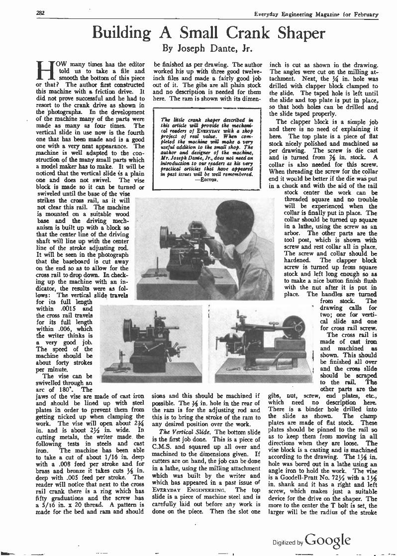
282 Everyday Engineering Magazine for February
Building A Small Crank Shaper By Joseph Dante, Jr.
HOW many times has the editor told us to take a file and smooth the bottom of this piece
or that? The author first constructed this machine with a friction drive. It did not prove successful and he had to resort to the crank drive as shown in the photographs. In the development of the machine many of the parts were made as many as four times. The vertical slide in use now is the fourth one that has been made and is a good one with a very neat appearance. The machine is well adapted to the con- struction of the many small parts which a model maker has to make. It will be noticed that the vertical slide is a plain one and does not swivel. The vise block is made so it can be turned or swiveled until the base of the vise strikes the cross rail, as it will not clear this rail. The machine is mounted on a suitable wood .
base and the driving mech- anism is built up with a block so that the center line of the driving shaft will line up with the center line of the stroke adjusting rod. It will be seen in the photograph that the baseboard is cut away on the end so as to allow for the cross rail to drop down. In check- ing up the machine with an in- dicator, the results were as fol- lows: The vertical slide travels for its full length within .0015 and the cross rail travels for its full length within .006, which die writer thinks is a very good job. The speed of the machine should be about forty strokes per minute.
The vise can be swivelled through an arc of 180'. The jaws of the vise are made of cast iron and should be lined up with steel plates in order to prevent them from getting nicked up when clamping the work. The vise will open about 2/ in. and is about 2/ in. wide. In cutting metals, the writer made the following tests in steels and cast iron. The machine has been able to take a cut of about 1/16 in. deep with a .008 feed per stroke and for brass and bronze it takes cuts % in. deep with .005 feed per stroke. The reader will notice that next to the cross rail crank there is a ring which has fifty graduations and the screw has a 5/16 in. x 20 thread. A pattern is made for the bed and ram and should
be finished as per drawing. The author worked his up with three good twelve - inch files and made a fairly good job out of it. The gibs are all plain stock and no description is needed for them here. The ram is shown with its dimen-
The little crank shaper described in this article will provide the mechani- cal readers of EVERYDAY with o shop project of real value. When com- pleted the machine will make a very useful addition to the small shop. The author and designer of the machine, Mr. Joseph Dante, Jr., does not need an
E introduction to our readers as his very practical articles that have appeared in past issues will be well remembered.
-EDITOR.
II _
a
_
sions and this should be machined if possible. The 1,1 in. hole in the rear of the ram is for the adjusting rod and this is to bring the stroke of the ram to any desired position over the work.
The Vertical Slide. The bottom slide is the first job done. This is a piece of C.M.S. and squared up all over and machined to the dimensions given. If cutters are on hand, the job can be done in a lathe, using the milling attachment which was built by the writer and which has appeared in a past issue of EVERYDAY ENGINEERING. The top slide is a piece of machine steel and is carefully láid out before any work is done on the piece. Then the slot one
inch is cut as shown in the drawing. The angles were cut on the milling at- tachment. Next, the / in. hole was drilled with clapper block clamped to the slide. The taped hole is left until the slide and top plate is put in place, so that both holes can be drilled and the slide taped properly.
The clapper block is a simple job and there is no need of explaining it here. The top plate is a piece of flat stock nicely polished and machined as per drawing. The screw is die cast and is turned from / in. stock. A collar is also needed for this screw. When threading the screw for the collar end it would be better if the die was put in a chuck and with the aid of the tail
stock center the work can be threaded square and no trouble will be experienced when the collar is finally put in place. The collar should be turned up square in a lathe, using the screw as an arbor. The other parts are the tool post, which is shown with screw and rest collar all in place. The screw and collar should be hardened. The dapper block screw is turned up from square stock and left long enough so as to make a nice button finish flush with the nut after it is put in place. The handles are turned
from stock. The drawing calls for two; one for verti- cal slide and one for cross rail screw.
The cross rail is made of cast iron and machined as shown. This should be finished all over
i- \ and the cross slide should be scraped to the rail. The other parts are the
gibs, nut, screw, end plates, etc., which need no description here. There is a binder hole drilled into the slide as shown. The clamp plates are made of flat stock. These plates should be pinned to the rail so as to keep them from moving in all directions when they are loose. The vise block is a casting and is machined according to the drawing. The 1/ in. hole was bored out in a lathe using an angle iron to hold the work. The vise is a Goodell -Pratt No. 72/ with a 1 in. shank and it has a right and left screw, which makes just a suitable device for the drive on the shaper. The more to the center the T bolt is set, the larger will be the radius of the stroke
1
Digitized by Google

Everyday Engineering Magazine for February 283
'DRIVING e.
SHAFT BRACKET C.I.
3'
r Tap DRN NG STROKE BLOCK C.I.F all over
r 1r- 11.
-{.-.
Hole
CONNECTING ROD M. 5.
tip
11' Hole WTop
GUIDE BLOCK M.S.
}'Hole
Top 'For knurled/.1 i thumb screw ,e ;'Tap Holes 30
,ABLE SLIDE FOR CROSS C.I.F. all over
SLIDE DUI -C.R.S.F (Two wanted)
RAIL
CONNECTING ROD SLEEVE
M. S Hrd.
DRIVING PULLEY C.I.
DRIVING SHAFT C. R.3. F.
STROKE ADJ. ROD C. R.5. F.
Nut and washer wanted or suitable large knurled nut
Toped hole or vide block
(NUT) M.S.F. (For Table Slids)
T BOLT FOR DRIVING BLOCK
M. 5.
CROSS RAIL- C.1. Finished all over
L Hole for
7>' ... >Z Thd. Bolt
i ant i nnnm nnnr / nuuut piuuuu u+ur -.
wit' Thd.
CROSS RAIL SCREW C. R.S. F.
TWO END PLATES FOR RAIL
\Fit Handle
TWO CLAMPS M. S.F.
T
Tap i' end of shaft and pulley
/0 ADJ. ROD CLAMP M.S.
Ir
yt GUIDE BLOCK
T. S.Hrd.
VISE BLOCK C.I. I+' For vise shank Fit t49.72}Goodell
& Pratt Vise
L~ -2t t+
1 %
ITf' Tap / CLAMP HANDLES
(Three) M.S.
.n /
SCREW
Clamp handles two for cross rails and one ter tise block.
Digitized by GoogIe

284 Everyday Engineering Magazine for February
Tap Hole for Top Grid
c
. S
BED -C.1.
This hole is for Adjusting Rod -
9i' I'-~+- I ------ I '-P+- I' -4n
' Top
I<
4;' '
4 Top hole for rod clomp
yc
11
Taped hole for vertical slide
é.Tap
I I
I.1-
TOP GIBS FOR RAM C.I. and Plato Steel
2" {'Thd
nnnnn uuuulÍ- -114Itt
-
VERTICAL SLIDE SCREW C.R.S.F #.-r
(One of' each )
COLLAR C.R.S.F.
i" Top
TOOL POST, COLLAR
AND SCRE
SLIDE GIB - M.S. Flat Stock
'Me
i I Hole
2i
9' RAM - C.I
;'Hole,
CLAPE BLOCK M.S.F.
Hole
Thd.
HANDLE M.S. (2 wonted )
nnnre } Thd. 2'
CLAPER BLOCK SCREW C.R. S.
TOP SLIDE-M.S.F.
**Top
TOP BRACKET M.S.F.
;"x }' C.B.
60
BOTTOM SLIDE - N.S.F.
Digitized by Goo,Ie
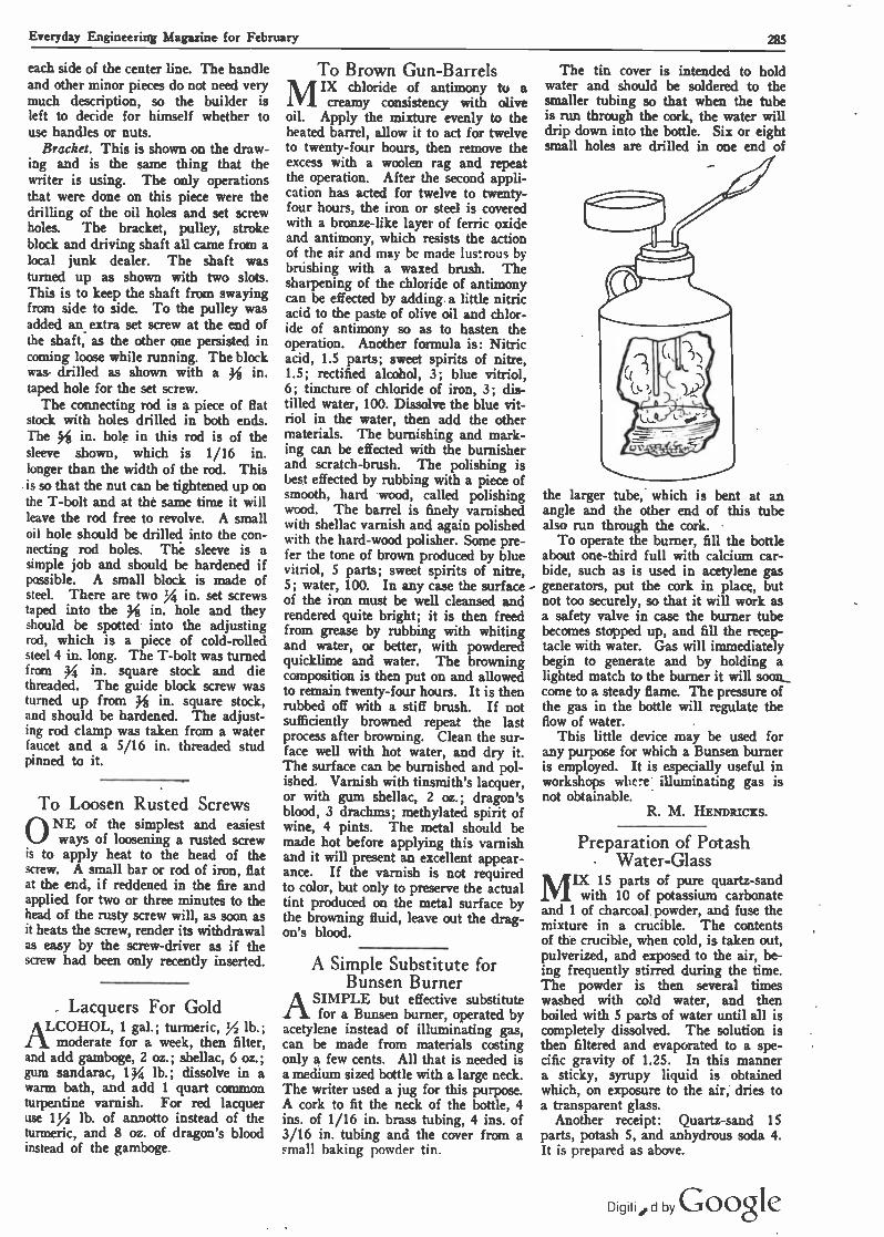
Everyday Engineering Magazine for February 285
each side of the center line. The handle and other minor pieces do not need very much description, so the builder is left to decide for himself whether to use handles or nuts.
Bracket. This is shown on the draw- ing and is the same thing that the writer is using. The only operations that were done on this piece were the drilling of the oil holes and set screw holes. The bracket, pulley, stroke block and driving shaft all came from a local junk dealer. The shaft was turned up as shown with two slots. This is to keep the shaft from swaying from side to side. To the pulley was added an extra set screw at the end of the shaft, as the other one persisted in coming loose while running. The block was- drilled as shown with a 14 in. taped hole for the set screw.
The connecting rod is a piece of flat stock with holes drilled in both ends. The S in. hole in this rod is of the sleeve shown, which is 1/16 in. longer than the width of the rod. This is so that the nut can be tightened up on the T -bolt and at the same time it will leave the rod free to revolve. A small oil hole should be drilled into the con- necting rod holes. The sleeve is a simple job and should be hardened if possible. A small block is made of steel. There are two Xi in. set screws taped into the in. hole and they should be spotted into the adjusting rod, which is a piece of cold -rolled steel 4 in. long. The T -bolt was turned from y4 in. square stock and die threaded. The guide block screw was turned up from lí in. square stock, and should be hardened. The adjust- ing rod clamp was taken from a water faucet and a 5/16 in. threaded stud pinned to it.
To Loosen Rusted Screws ONE of the simplest and easiest
ways of loosening a rusted screw is to apply heat to the head of the screw. A small bar or rod of iron, flat at the end, if reddened in the fire and applied for two or three minutes to the head of the rusty screw will, as soon as it heats the screw, render its withdrawal as easy by the screw -driver as if the screw had been only recently inserted.
_ Lacquers For Gold LCOHOL, 1 gal.; turmeric, Y2 lb.; [i moderate for a week, then filter,
and add gamboge, 2 oz.; shellac, 6 oz.; gum sandarac, 1 g lb.; dissolve in a warm bath, and add 1 quart common turpentine varnish. For red lacquer use 1/ lb. of annotto instead of the turmeric, and 8 oz. of dragon's blood instead of the gamboge.
To Brown Gun -Barrels
MIX chloride of antimony to a
creamy consistency with olive oil. Apply the mixture evenly to the heated barrel, allow it to act for twelve to twenty-four hours, then remove the excess with a woolen rag and repeat the operation. After the second appli- cation has acted for twelve to twenty- four hours, the iron or steel is covered with a bronze -like layer of ferric oxide and antimony, which resists the action of the air and may be made lus:rous by brúshing with a waxed brush. The sharpening of the chloride of antimony can be effected by adding. a little nitric acid to the paste of olive oil and chlor- ide of antimony so as to hasten the operation. Another formula is: Nitric acid, 1.5 parts; sweet spirits of nitre, 1.5; rectified alcohol, 3; blue vitriol, 6; tincture of chloride of iron, 3; dis- tilled water, 100. Dissolve the blue vit- riol in the water, then add the other materials. The burnishing and mark- ing can be effected with the burnisher and scratch -brush. The polishing is best effected by rubbing with a piece of smooth, hard wood, called polishing wood. The barrel is finely varnished with shellac varnish and again polished with the hard -wood polisher. Some pre- fer the tone of brown produced by blue vitriol, 5 parts; sweet spirits of nitre, 5; water, 100. In any case the surface - of the iron must be well cleansed and rendered quite bright; it is then freed from grease by rubbing with whiting and water, or better, with powdered quicklime and water. The browning composition is then put on and allowed to remain twenty-four hours. It is then rubbed off with a stiff brush. If not sufficiently browned repeat the last process after browning. Clean the sur- face well with hot water, and dry it. The surface can be burnished and pol- ished. Varnish with tinsmith's lacquer, or with gum shellac, 2 oz.; dragon's blood, 3 drachms; methylated spirit of wine, 4 pints. The metal should be made hot before applying this varnish and it will present an excellent appear- ance. If the varnish is not required to color, but only to preserve the actual tint produced on the metal surface by the browning fluid, leave out the drag- on's blood.
A Simple Substitute for Bunsen Burner
ASIMPLE but effective substitute for a Bunsen burner, operated by
acetylene instead of illuminating gas, can be made from materials costing only a few cents. All that is needed is a medium sized bottle with a large neck. The writer used a jug for this purpose. A cork to fit the neck of the bottle, 4 ins. of 1/16 in. brass tubing, 4 ins. of 3/16 in. tubing and the cover from a small baking powder tin.
The tin cover is intended to hold water and should be soldered to the smaller tubing so that when the tube is run through the cork, the water will drip down into the bottle. Six or eight small holes are drilled in one end of
the larger tube: which is bent at an angle and the other end of this tube also run through the cork.
To operate the burner, fill the bottle about one-third full with calcium car- bide, such as is used in acetylene gas generators, put the cork in place, but not too securely, so that it will work as a safety valve in case the burner tube becomes stopped up, and fill the recep- tacle with water. Gas will immediately begin to generate and by holding a lighted match to the burner it will soon... come to a steady flame. The pressure of the gas in the bottle will regulate the flow of water.
This little device may be used for any purpose for which a Bunsen burner is employed. It is especially useful in workshops where: illuminating gas is not obtainable.
R. M. HENntucxs.
Preparation of Potash Water -Glass
MIX 15 parts of pure quartz -sand
with 10 of potassium carbonate and 1 of charcoal. powder, and fuse the mixture in a crucible. The contents of the crucible, when cold, is taken out, pulverized, and exposed to the air, be- ing frequently stirred during the time. The powder is then several times washed with cold water, and then boiled with 5 parts of water until all is completely dissolved. The solution is then filtered and evaporated to a spe- cific gravity of 1.25. In this manner a sticky, syrupy liquid is obtained which, on exposure to the air, dries to a transparent glass.
Another receipt: Quartz -sand 15 parts, potash 5, and anhydrous soda 4. It is prepared as above.
Digitiíild by Google

286 Everyday Engineering Magazine for February
Ford Motored Airplane Proves Practical By E. H. Holterman
APOINT that is' interesting to many aviation enthusiasts, es- pecially those who are building
full sized airplanes of their own, is the use of a modi- fied Ford motor as power. The photographs herewith show a successful biplane built and flown by the writer that is equipped with a modified Ford engine and which flies very well in- deed when one considers the low horsepower. The motor shown weighs 195 lbs. after alterations have been made, but it is believed that this weight can be cut down in a new form the writer is ex- perimenting with. The pro- peller that seems to work the best is 6 ft. 6 in. in diame- ter by 4 ft. 6 in. pitch. The complete machine illus- trated weighs 580 lbs., which the writer considers unnecessarily heavy for such a small machine and which can be reduced to less than 500 lbs. by refinement of construction.
The main dimensions of the machine are 18 ft. length, 25 ft. spread, 4 ft. chord, 4 ft. 6 in. gap, and while official speed tests have never been made, from previous experience it is esti- mated it. will fly at least 45 miles per hour. One of the machines illustrated is without a 4 ft. overhang on the up- per wings which is shown in the other machine. This add- ed surface will give a better landing speed and will also enable the machine to get off the ground easier.
How to Rebuild Ford Motor
To rebuild a Ford Views at top show motor for use in an Woodstock, Vt. The airplane, I have plane to obtain mor
that the fol- lowing changes are necessary. First, get a Ford motor block that has been used enough to have smoothed the cylinder walls to a
Former Flying Instructor, U. S. Army
glossy finish, but has not been worn to an oval or "out of round" shape. Get a set of Lynite or other light mag-
Ford motored airplane flown successfully by E. H. Holterman of L1-2 is the machine after the overhang had been added to the top
re surface. The illustration of the modified motor shows method of installation in fuselage
nalium alloy pistons. In getting connecting rods, try to get them as near an equal weight as possible, as
they vary quite a bit in weight. Drill holes along the rods between the flanges to lighten them, and at least
two holes into the rods through the bearings for oil- ing. Balance them up equally after having fitted them to the crankshaft. The crankshaft should be well balanced also. The regular Ford camshaft may be used or one can put in a special, high speed shaft as desired. It is advisable to get some Dodge car valves, as they are a bit larger than the Ford valves. By ream- ing out the valve seats a bit the Dodge valves will fit nicely and give you more power. You can either put on an Atwater Kent timer with battery and cells or mount a small magneto for ignition as desired.
Special Precautions for Oiling
For the base or oil pan you can use the Ford crank case by cutting the rear end off so that it will come
within the flange of the crankshaft, and weld a piece on with a pocket for a piece of felt packing to keep the oil from coming out . The front end is cut off at the beginning of the oil case. Cut slots about three in- ches long in the in- spection plate be- tween the dip grooves of the con- necting rods to allow the oil to drop into the oil sump. This sump is nothing more than an oil re- ceptacle from which the oil is pumped through a tube on to the bearings. By tak- ing a copper pipe and attaching small nipples such as they use on shower baths so that the oil will be pumped directly on to the bearings,
you will have no trouble with bearings. A small gear pump attached to the oil sump (below your oil level) driven
Digitized by Google

Everyday Engineering Magazine for February 287
either by a chain or shaft and gears will keep a constant stream of oil to your bearings. A Zenith carbureter gives good results and is very light, hav- ing an aluminum manifold.
Mounting Nose Type Radiator If the motor is to be used as a trac-
tor, and you wish to have the radiator in the nose, an extension with two flanges will have to be made, one flange to be bolted to the flange on the crank- shaft, then a space of a few inches (cor-
r
Pilot Holterman in the Ford motored air plane built and flown by him
responding to radiator depth), then an- other flange, and if preferred a shaft extended from this second flange for the propeller. The cylinder head will either have to be machined off along the outlet "hump" and another piece welded on with the outlet for the water turned in the opposite direction, or else plug up the opening for the water and tap into the head at the opposite end. If the radiator is to be overhead or along the side, the cylinder head can be used as it is by making a simple connection, and no propeller extension will be nec- essary to go through the radiator. No water pump is needed. Keep the weight down on everything, taking off more when you think you have taken off as much as possible.
The building of such a machine is not beyond mechanical skill of the av- erage amateur, as the construction of practically all parts excepting altera- tions in the motor can be done with the ordinary wood working manual training equipment. The work of construction of such machines is made considerably easier by purchasing supplies which are available on the open market, these comprising everything from a complete set of blueprints to all of the metal fit- tings and wooden parts in completed or knockdown form. Modified motors may also be obtained from dealers who are making a specialty of this work.
Common Failings of Amateur Builders It has been my experience that the
common failing of amateur aircraft builders is to build their machine heavier than really needed because they
do not realize the necessity for light construction to insure successful flying with low powered motors. Those who have had experience in the Air Service have a realization of the strength and size of various structural parts, but most amateurs make them too large and of unsuitable materials. There is no reason for the use of heavy construc- tion in a small low powered airplane because the flying speed is low and the stresses on the parts are not severe. Particular attention should be given to paring down weight in small items, as these mount up to an astonishing total in the aggregate. Machines examined by the writer that have been built by amateurs have had ." bolts used where 3/16" or %" would have had ample strength, and fittings of IA" sheet metal when 1/16" gauge stock would have been amply strong. Aluminum should be used wherever possible in preference
FLEXIBLE PONTOONS FOR SHIP SALVAGE
IN view of the importance of salving ships sunk during the war, and of
the all-round costliness of the ordinary barges or lighters used for ship -lifting, special interest is attachable to the ex- periments recently carried out on the raising of the S.S. "Main." The S.S. "Main" was sunk by gunfire from a German submarine in Luce Bay. Sal- vage operations were undertaken by the Ardrossan Salvage Company, and Vickers' flexible pontoons were used.
Made of special canvas and cables, the completed pontoons weigh only 1
ton; but, when inflated with air and submerged in water, are capable of lifting 100 tons: Two of these pontoons were used, being fixed to the sternpost of the sunken ship and inflated by means of an air -compressor on a small tug. The vessel was successfully
it ezi=9"
-il
o
-w ..1 -a - \
41.
I.
`.
111
covy,tyt, u.d...00d & u.ao...od John F. McMahan, a Brooklyn, N. Y., aviation enthusiast and expert builder of model and full size airplanes, seated in the fuselage of airplane built by him which is to be powered with a Ford motor. He has previously built and sold a similar machine. The illustration shows many details of construction in both wings and fuselage framework
to heavier metals. Do not use heavy 19 strand wire cable and correspond- ingly large turnbuckles for taking loads that are way under the capacity of "aviator cord" cable or hard wire and lighter turnbuckles.
raised, and was beached for pumping. An advantage of these canvas pon-
toons is that, when not in use, they can be packed into a very small compass, and stored in the hold of the salvage ship until required.
Diltized by Goo*.

288 Everyday Engineering Magazine for February
Air From the Turbine Room Used for Heating rr HE temperature of a turbine room
in an electrical generating station is kept at a temperature much too high for the comfort of the operators. A large lighting company in Springfield, Mass., put a plan into operation which permits the utilization of this surplus heat in the -heating of various other departments of its organization. In the winter the air is drawn from be- neath the roof of the turbine room into the basement of the switch house where a blower discharges it through steam coil heaters. Another system of ducts collects the air and discharges it through ceiling registers into the switchboard room. In this way a com- fortable temperature is maintained in all departments.
Electricity In Agriculture THE prejudice of the German
farmers against electrical appli- ances has now been overcome, and they are being used for a 'variety of pur- poses.
Small progress has been made with electric ploughing machines, but the war has produced a great development of ploughs driven by petrol engines. Threshing -machines driven by electric motors have become extensively used, mechanical milking machines have been found capable of replacing milk- ing by hand, and electrically -heated hatching machines are coming into favor.
The stimulation of the growth of crops by subjecting them to electric radiation has not yet become practical owing to the lack of physiological knowledge of plant growth, and the absence of data from which the best voltage and form of current can be ascertained. It has, however, been demonstrated that the humidity of the air plays an important role in deter- mining the effect of the electric radia- tion. The use of artificial illumina- tion of crops certainly hastens growth, but the cost is such as to render it com- mercially useless. The drying of crops by electric heaters is effective, but too costly; on the other hand, the drying process has been carried out success- fully, for example, at Duisburg, by utilizing the waste heat of electric gen- erating stations. Promising experi- ments have also been performed at the Dresden Technical College in the arti- ficial heating of the ground by the waste heat of such stations.
\0`011111111/1//00 ,yU1; IIryjHi 1l I
, _ ; ELECTRICAL PROGRESS DIGEST, If llliIIIIIIIIIIIIIIIIIIIIIIIIIIIIIIIIIII1111 \
400111111110
150,000 h.p., and it is intended to transmit power to Madrid and Bilbao, and it is hoped that power from this station will be utilised by the northern and eastern railways of the peninsula.
Pupinized Short Telephone Cables
THE loading of short telephone cables with Pupin coils decreases
the damping, but does not necessarily increase the efficiency of the whole con- ducting circuit. There is a certain length of cable (between 3 and 6 km.) which may be called the critical length, above which the loading with induct- ance improves the efficiency. For lengths less than the critical value the efficiency depends greatly on whether a central battery or local battery is used. Furthermore, the efficiency of such short -loaded sections is determined to a great extent by the characteristics of the sections to which it is joined at both ends. If a short length of cable lies between to overhead sections, it is useless to pupinize it unless the ad- jacent overhead lines are also pupin- ized. If the cable is connected only at one end to overhead conductors and at the other end directly to the apparatus, the activity in the receiving and send- ing apparatus (with local battery) in- creases with moderate loading of the cable, but falls again with heavier loading, as long as the overhead line is not also pupinized. The longer the overhead line, the more certain is the gain achieved by loading the cable. On the other hand, with a central battery there is no object in pupinizing the cable unless the overhead line is simi- larly treated. If the short cable sec- tion is directly connected to apparatus at both ends and a local battery is used, the efficiency may be raised by moderate loading of the cable, but it will fall again with too great loading. On the other hand, if a central battery is used, the use of loading in a local service is undesirable under any cir- cumstances.
Projected Hydro -Electric Installations In Spain
ACCORDING to the Rivista Tecnica d'Elettricita, numerous applica-
tions have been lodged for concessions to construct hydro -electric generating stations in Spain.
The falls of the Iucar, near Va]entia, will supply to the town a power of 6,400 h.p. The hydro -electric station at Linares has been linked up by a 70,000 -volt line to the generating sta- tion of Penarroya. A company with a capital of 150 million francs has been formed to exploit the falls of the Douro, near the frontier between Spain and Portugal. The total available power is
II \
The Photo -Electric Cell In - Wireless Communication
THE photo -electric cell which has been described in the Physical Re-
view (2nd series Vol. VII No. 1) had recently been tried as a receptor of wireless signals with marked success. Experiments have been made in both receiving and transmitting. The tube not only holds possibilities as a re- ceptor, but as a producer of electrical oscillations as well. If the photo -elec- tric cell is developed to a point where it will be practical to apply it in a commercial way, the change will be a revolutionary one.
The photo -electric cell was developed by Kunz and Stebbins. It has an inner coating of an alkali metal (so- dium, potassium, etc.,) which is ren- dered sensitive, by the introduction of hydrogen while the tube is excited. This results in the formation of a hy- dride, which under, the action of light, changes the effective resistance of the tube.
The photo -electric cell has been em- ployed in many different ways. It has been used as a photometer in stellar photometry, physiology of plants, photo -chemistry and for the transmis- sion, reflection, and radiation of light. The cell is used in connection with a battery with a potential of from 120 to 200 volts, and a galvanometer of high sensitivity.
Use of Tungsten for Con- tact Points
PLATINUM for use as contact points has many advantages. It
is not oxidizable, is not attacked by acids or gases and is capable of with- standing great heat.
A writer in the London Electrician recently described his experiences with tungsten as a substitute for platinum. Tungsten is a metal that possesses near- ly all'the properties of platinum and it has been found to make very good contact points. The author of the ar- ticle experimented with vibrating con- tacts of tungsten on a heavy current circuit and after a considerable period found that they stood up nearly as well as platinum contacts. The author sug- gested the emnloyment of a sharp - pointed lower electrode.
Digitized by Google 1

Everyday Engineering Magazine for February 289
An Electrically - Equipped Lighter By William H. Easton
PENNSYLVANIA Railroad Lighter No. 151 enjoys the dis- tinction of being the first vessel
of her type to be equipped with electrically -operated winches ex- clusively. She is used for carry- ing express shipments around New York Harbor; and as this service is one in which time is an important factor her winches were arranged for electric drive, instead of the usual . steam en- gines, because it was believed that the use of electricity would materially reduce tht time re- quired for handling cargoes. She has now been in commission about two years, and experience goes to show that this idea was correct; for, although it is diffi- cult to carry out an accurate effi- ciency test in the handling of miscellaneous packages, it is generally conceded by those who are familiar with her work that No. 151 can take care of 300 tons while the average steam - operated lighter is disposing of 200 tons.
As shown by the illustration, No. 151 has two systems of booms, one forward consisting of a single main boom with a maximum capacity of 10 tons, and one aft, of the mast and yard type, with a' maximum ca- pacity of 2 tons. Most steam o
lighters of the capacity of No. 151 have only one boom system; but with electrical operation two can readily be employed because the motor -driven winches are so compact that they can be housed in a very small compartment. This corrtpartment is situated in the hull just forward of the pilot house; all the lines run down in front of the pilot house to their respective winches in most direct manner possible.
There are eight motors alto- gether, their purpose and size being shown in the following table:
equipped with magnetic brakes. Each motor is geared directly to its winch and the winches are arranged in two
The turbine -driven generator in
ttli i .
1
the hold of the lighter
I . Pá>%ra:ag
,. , a
a .-
I ~
The motor -driven winches aboard the lighter
1.
ii -
m SERVIQ
For Forward Boom- H.P. Main Hoist 24
' . Main Boom 24 Starboard Guy 15 Port Guy 15
For Aft Booms- Starboard Hoist 15
_ írs,: ' -'
Starboard Guy 15 Port Hoist is The ekctrically-equipped lighter Port Guy 15
These motors, shown in the photo- graph, are of the Westinghouse direct.. current crane type, totally enclosed and
rows, one being placed above the other. The control of the winches is located
in the pilot house. The four can-
trollers (one for each motor) for the forward boom are located at the for- ward end of the pilot house. For the
aft booms, there are two sets of controllers, one located at each side of the pilot house, either of which can be used. The object of this arrangement is to give the operator an unobstructed view of the operations of the booms under all conditions.
The controllers in the pilot house are of the type known as "master switches." They do not control motors directly, but con- trol the operation of a series of magnetically actuated switches, which make the actual connec- tions. These switches are mount- ed on panels located in the motor compartment, and some of them can be seen in the upper right-hand corner of the photo- graph. There are several ad- vantages of this arrangement. In the first place, the master switches handle only small cur- rents needed to energize the magnets and so are light in con- struction and easily handled. Secondly, the heavy cables carry- ing the motor currents are of minimum ' length, and do not have to be run up to the pilot house and down again. Finally, the magnet switches permit the use of automatic acceleration; that is, the operator is not obliged to operate the master switches slowly in order to pre- vent burning out the motors by applying the currents too sud- denly. He merely moves the handles at any speed he pleases, and the magnet switches then close in the proper order and at the proper rate. The motors are thus protected from injury, and all of their operations are car- ried out at the maximum speed consistent with safety. Each controller provides a number of motor speeds.
The current for operating the motors is generated by a 25 - kilowatt, 125 -volt Westinghouse turbine generator, shown in the top photograph. This unit con- sists of a high-speed turbine geared to a standard generator. It is operated by steam at pres- sures of from 75 to 250 lbs., and can be used either condens- ing or non -condensing. A gov-
ernor keeps the speed, and therefore the voltage, constant, and an emergency stop prevents accidents.
DigVed by Google

290 Everyday Engineering Magazine for February
_; - 1 , - EXPEDE.IJ ci:sTRr: J .`'
l¡lllllllllllo
The Preparation and Use of. Permanganate Solutions
By Albert T. Fellows
TO the amateur chemist strug- gling.along in his laboratory, the preparation and use of volumetric
solutions of potassium permanganate opens up a new field which is really a branch of quantitative analysis. Not only is it of value to him to know how to go about the determinations, but he also receives from carrying out these 'determinations a vast amount of prac- tical knowledge such as he would ob- tain only at college or any industrial laboratory. The procedure which the writer is about to describe is exactly
_the same as that used at any laboratory carrying on determinations of the vari- ous elements, and the best of it is that all of it can be done with a very small laboratory equipment and at slight ex- pense.
.
To make that which follows clearer and more interesting, let us first' look into the theoretical side of the matter. Potassium permanganate, when in an acid solution and when any oxidizable. matter is present, breaks down accord- ing to the .equation: 2KMnO* u K20 + 2MnO -I- 50. Thus, we see that every two molecules of permanganate is equivalent to five atoms of oxygen, and as two molecules of hydrogen is equivalent to one of oxygen (2H -I- O " H2O) the two molecules of perman- ganate is equal to 10 of H. Shortly we shall use these ten molecules of H, but for the present attention is directed to the five molecules of oxygen. Now bearing in mind that two molecules of permanganate equal ten molecules of hydrogen, and recalling our definition of a normal solution (it is upon this basis that we make our solutions) which is a solution that contains in one liter the weight of active constituent that will react with one gram of hydro- gen, and 316 gins. of permanganate, then our normal solution will contain 31.6 gms. per liter and the tenth nor- mal (N/10) the one usually employed, one -tenth of this or 3.16 gms. in 1000 ccs. of water. In one cc. there are 0.00316 gms. (move decimal point). Now let us prepare some of this solu- tion.
At this point our troubles begin. We
cannot weigh our permanganate out ac- curately and dissolve. it in a liter of water, as the salt cannot be obtained in such high purity, and even distilled water contains some readily oxidizable matter which is attacked by the per- manganate precipitating Mn02, which further hastens the decomposlition.
To overcome these difficulties we must weigh out about'3.3 gms. of pure potassium permanganate crystals and dissolve this amount in one liter of distilled water. This is then boiled for about five minutes and the solution allowed to stand in a bottle with a plug 6f cotton -6 the neck for five or six days, during which period the per- manganate has plenty of time to oxi- dize all the "organic matter which is present. -
After this, we carefully filter it through an asbestos pad (paper would
Funnel --
Porcelain Filter Plate-
Beveled Porcelain Filter Plate
Felt of Well Washed Asbestos
To Exhaust
,RubberStopper
Arrangmentfor Filtering Permanganate Solution
park -'Bottle
introduce more organic matter) into a brown glass stoppered bottle or even one which is painted black, as light hastens decomposition. A convenient method of filtering is to insert a two - hole rubber stopper in the bottle carry- ing a 6 -in. funnel and another tube con- nected to the exhaust. In the funnel is a /-in. porcelain filter plate sup- porting a well -washed felt of asbestos. By starting the exhaust the solution is thoroughly and quickly filtered.
Our real work should begin now that we have a pure solution of the per- manganate, but it is much too concen-
trated, so we must dilute it consider- ably. This is called standardizing and there are many methods. The one which is perhaps the easiest and quick- est from our standpoint follows: First prepare a N/10 solution of oxalic acid. After this, get the purest crystallized oxalic acid obtainable and weigh out 6.25 gms. and dissolve this in 1000 ccs. of H2O. This is slightly below its real value, for, to be exact, we should dis- solve 6.255 gins. of 100 per cent. oxalic acid in 1000 ccs. of H2O. Of course, 100 per cent. oxalic acid is not tó 'be had, and such.a high degree of accuracy will probably not be required for our
,purpose. Take ' 10 ccs. of this N/10 oxalic acid solution and transfer it to a beaker with a pipette and add '1 cc. of pure concentrated sulphuric acid. This warms up considerably, and be- fore it cools add the permanganate
}solution from a burrette in small quan- tities, shaking the flask after each ad- dition and toward the end reducing the flow to drops. When the last drop is added it imparts a pinkish tint to the solution which persists for / minute. Then carefully note the number of ccs. used and then dilute the test solution with 'a specially distilled water (water distilled as usual, but before beginning the distillation adding about one gram of potassium permanganate to get rid of the ever present organic matter). so that the permanganate solution .corre- sponds volume for . volume with , the N/10 oxalic acid solution at 25 deg. C.
To get it quite clear how the solution is diluted, let us take a practical ex- ample. First we took 1000 ccs. of pure potassium permanganate solution and 50 ccs. for the burrette and measured this accurately into the burrette. This left 950 ccs. in the bottle. As- suming that 9.5 ccs. of permanganate was sufficient to impart a pink tint to the acid for / minute, ' we must add 47.5 ccs. of the specially distilled water as the 9.5 ccs. of permanganate ought to be equal to the 10 ccs. of acid. Then we must add 0.05 ccs. for every 10 ccs. in the bottle, as there are
Digitized by Goo,Ie

Everyday Engineering Magazine for February 291
95 or 47.5 ccs. This is thoroughly mixed and a new test made till 10 ccs. of the acid just decolorizes the 10 ccs. of the permanganate. We must not forget to discard the contents of the burrette after each trial and to use a burrette having a glass stopcock, and above all to be scrupulously clean.
Now that we have our N/10 solution let us learn how to use it. Potassium permanganate may be used in volu- metric determinations of a number of elements, some of which are iron, cal- cium, manganese, phosphorus, molyb- denum, oxalic acid, hydrogen peroxide and red lead, etc.
As space is limited, let us take as an example an analysis of an iron ore, as the determination of iron is perhaps of the greatest importance. It is based upon the oxidizing action of the per- manganate to change iron in the ferrous condition to the ferric.
For analysis we take a 10 gm. sam- ple of ore, powder it and treat it with 10 ccs. of concentrated hydrochloric acid. Upon heating, the iron is dis- solved and a residue is left. This is filtered off and the filtrate is saved. Some of the iron in the filtrate is in the ferric condition and must be re- duced. This is accomplished by add- ing about 3 gms. of granulated zinc to the flask containing the iron solution and closed by a small funnel. Ten ccs. of concentrated sulphuric acid are added, and when all the zinc is dis- solved the solution is ready to be titrated.
Now we run in the permanganate solution very slowly (this is called titrating). The solution turns a yel- lowish tint as each drop of the crimson purple permanganate solution is quickly decolorized. At the end we must go very slowly, for the last drop imparts a pink tint to the whole solution for / minute. Now we note the number of ccs. con- sumed, and, as each cc. is equal to 0.005589 gms. of iron in the ferrous state, to find out how much iron' was in the solution we multiply the number of ccs. consumed by 0.005589 and the an- swer is the number of gms. of iron in the solution. For instance, if 45 ccs. were required to produce the pink tint, then there was 45 times 0.005589 or 0.240905 gms. of iron in the 10 gm. sample.
The following is the table we will use frequently in making our calcula- tions, the same as in the foregoing ex- ample.
One cc. of N/10 Potassium Perman- ganate is equal to: Potassium permanganate 0.0031606 Iron (ferrous) 0.005589 Ferrous carbonate. 0.011505 Ferrous oxide 0.007138 Ferrous sulphate anhydrous
FeSO, 0.015085 Ferrous sulphate 2Fe SO,
3H2 0.017767 Oxalic acid (crystallized) 0.006255
Now we see that these figures are the molecular weights of , the substance moved four places to the left, and we will be able to deduce them for our- selves.
If our answer is reported, as, say iron in ferrous sulphate, to find the amount of the element in the compound we use the following:
Fe in FeO is 0.77727% Fe in FeSO, is 0.36751% Fe in FeSO, 7H20 is 0.2008% Fe in FeSO,(NH)2S0,6H0 is
0.14239%
These percents are also easily found by means of solving a simple propor- tion, such as the following for exam- ple: Fe : FeO :: X : 100, by substi- tuting the atomic and molecular weights required.
Producing Low Temperatures
By G. E. Meredith
ANTING to test several sam- ples of insulating compounds under winter conditions, the
writer began to look up the subject of freezing mixtures, using materials at hand such as ice, sulphuric acid, caus- tic potash, etc. Several hand books were found with practically the same information in them, part of which is given below.
Snow or crushed ice two parts and salt (sodium chloride) one part. Tem- perature lowered approximately to 50 F.
Snow or crushed ice three parts, salt (sodium chloride) two parts and sal ammoniac (ammonium chloride) one part. Temperature lowered approxi- mately to -12° F.
Snow or crushed ice three parts and dilute sulphuric acid (oil of vitrol) two parts. Temperature lowered approxi- mately from 32° F. to -23° F.
Snow or crushed ice eight parts and muratic acid (hydrochloric acid) five parts. Temperature lowered approxi- mately from 32° F. to -27° F.
Snow or crushed ice three parts and caustic potash four parts. Tempera- ture lowered approximately from 32° F. to -51° F.
In testing the compound, it was in a quart glass jar and this was in turn placed inside a two -gallon earthen jar. The ice was packed between the jars and commercial battery acid 1.250° poured onto it. The temperature was lowered in the inner jar to 28° F. in a few minutes and the writer was able to hold it there for about one-half hour. This meant a lowering of the tempera- ture of 57° F. from room temperature.
The inner jar was a quart bottle with the top cut off. It was a rather novel sight to see the jar with a heavy layer of frost on it in the middle of July. The temperature of the solution was much lower than the inside of the inner jar, and by using a Dewar flask for the
ice and acid, a much lower temperature would be produced, as the radiation is cut down.
Finding the Flash Point of Kerosene
KEROSENE is a liquid which is being utilized more and more in
the household for both light and heat. A very large number of fires are laid
to the account of petroleum, and the danger is by no means small. The greater number of these fires are due to the overturning of lamps and oil stoves. In many of these cases the oil continues to burn fiercely after the stove or lamp has been upset. However, this should not be, for an oil is procurable on the market which would extinguish such a blaze. This oil is carefully frac- tionized and freed from the more vola- tile products. Furthermore, this oil does not cost any more than the more dangerous kind, and is fully as eco- nomical.
The problem of determining whether an oil is safe or not is one which is eminently fitted for the amateur chem- ist to solve. It is known as finding the flash point or the fire test of the oil.
The flashing point of kerosene may be approximately determined by pro- ceeding in the following manner: Pour a small quantity of the kerosene to be tested in a small crucible or evaporating dish. Then place the crucible upon a water -bath and a theremometer is sus- pended in the oil.
Heat the water carefully until the thermometer registers 30° C. (86° F.). At this temperature cautiously draw a lighted match across the surface of the liquid.
If the oil does not inflame, repeat the match test at each rise of S° C. until it does flash. Do not permit the oil to burn, but allow it to cool to the 5° point at which it was before it ignited. For example, at 45° C. a certain sample did not flash, at 50° C. it did flash. The analyst allows it to cool to 45° C. again and then very cautiously repeats it till at, say, 47° C. it flashes once more. The flashing point in this case is 47° C. and not 50° C.
Experience has shown that there is no danger with an oil possessing a flash- ing point of 40° C. (104° F.). The best grade oil sold in the United States is known as water white and flashes at 65.5° C. (150° F.). However, the writer understands that there are large quantities of oil on the market having a flashing point of from 24° to 40° C. Such oil constitutes a very great source of fire danger. The author has found no difficulty in procuring an oil with a fire test of from 60° to 62° C. The safe limit is 40° C. or 104° F. In certain countries this point has been fixed by law as the minimum.
Digitized by Google

292 Everyday Engineering Magazine for February
An Experiment in Physical Chemistry N the realm of physical chemistry
'theory is king. Demonstrations and experiments are few in num-
ber. But, those experiments which do appear are bound to be excellent ones. This is principally due to the fact that many of them have been devised and performed by the great masters such as Faraday, Fischer, Ostwald, Van't Hoff, Coehn, Haber and many others. Phy- sical chemistry is quantitative in nature not qualitative; it wants to know not only how, but how much.
The reader will recall that in his high-school chemistry, he learned that all thiosulphates (especially including the acid) are rather unstable and break down into sulphur, water and sulphur dioxide as expressed by the equation: Na, S,0,+2HC1=2NaC1+H2O + S + SO, or in an ionic equation simply H + S, 03 = HSO, + S. It will be advantageous for the experi- menter to repeat this qualitative experi- ment to refresh his memory.
Make a concentrated solution of the hypo. (as the sodium thiosulphate is commonly called) and add a few drops of concentrated hydrochloric acid. At first, nothing appears to take place, but after several seconds a white milky precipitate of sulphur is seen in the solution and the odor of sulphur dioxide is apparent.
From such experi- ments as these physical chemistry strives to draw broad generaliza- tions. These are almost always obtained by quantitative e x p e r i- ments. In this case, it is to prove that certain reactions take place in a time relation to the masses of the reacting substances. In other words, we are working in a sub -topic under the head of "The Law of Mass Action."
This particular experiment is easily adapted to the resources of the youthful scientist. The procedure is as follows: Weigh very carefully 0.1, 0.2, 0.3, and 0.5 gram of sodium thiosulphate (Na2S2085H2O) into four separate beakers. Add 100 cc's of distilled water to the salt in each beaker and allow it to dissolve. In three separate test tubes prepare dilute solutions of hydrochloric acid by adding 1 cc. of concentrated hydrochloric acid to 20 cc. of water. In a fourth test tube, place 1 cc. of the concentrated acid without
any water whatsoever in the tube. Arrange the beakers in a row accord-
ing to the hypo content, the test tubes so that the one containing the lcc. of concentrated acid is before the beaker with the highest hypo. content.
This is shown in the first photo- graph, the beakers containing the clear solutions are in back of their respective test, tubes and the piles of hypo. before the beakers graphically shows the quantity in solution.
The beakers after ekven minutes
If any of the readers fail to get identical results they ought not to feel discouraged for their results are prob- ably correct though differing from those above. This is inevitable since the purity of the sodium thiosulphate, the concentration of the acid, the tempera- ture and many other causes are bound to cause the results to vary.
Ostwald, Holleman and V. Oettin- gen, who have carefully studied this reaction, are all agreed that the sulphur is immediately formed on mixing the acid and salt solutions. They explain this peculiar phenomenon by assuming that the sulphur remains in solution until a definite concentration is reached or a certain change has taken place which causes the appearance of visible sulphur particles.
An older hypothesis is that the thio- sulphuric acid formed by the interaction of the acid and the salt remains en- tirely unchanged till the sulphur ap- pears, and the decomposition is started at this moment. However, this is incor- rect, for if we treat a dilute thiosulphate solution with the acid and neutralize this acid with a base before the sulphur
has started to deposit, it is found that the de- posit will appear in due time.
Holleman believes that a certain part of the free thiosulphuric acid must decompose, but the sulphur is in such a finely divided state that it cannot be detected till it has gath- ered together in larger particles. This is, by the way, a nice little opportunity for some serious research by the amateur chemist for who can tell but that one of the readers may be able to make, arms
useful contribution to the solution of this problem.
Those amateur chemists who limit their experimental work entirely to the realm of strict chemistry are missing much by not devoting some time to ex- periments in the fascinating field of physical chemistry. Physical chemistry is nearly as broad and interesting as the science of chemistry itself. It is only during the last half century that phy- sical chemistry has been elevated to the plane of a distinct and separate branch of science. Some very important dis- coveries have been made in this branch of science and more will be made.
.
The four test tubes and beakers with the sodium thiosulphate
Pour the four test tubes of acid into their respective beakers, noting the exact time. Carefully watch the beak- ers and at the first sign of a separation of sulphur 'note the exact time.
In the second photograph, the beak- ers are shown after eleven minutes have elapsed. One can see the last three beakers exhibit' varying degrees of mil- kyness, while the first is still perfectly clear.
For the beakers above illustrated, the following results were obtained:
No. 1 (extreme left) 19 minutes No. 2 8 " No. 3 6 " No. 4 (extreme right) 3
before them
Digitized by Goo,Ie
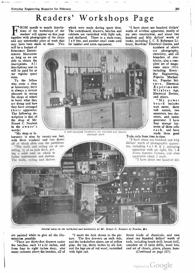
Everyday Engineering Magazine for February 293
Readers' Workshops Page FROM month to month descrip-
tions of the workshops of our readers' will appear on this page
together with photographs of the shops and any noteworthy piece of work that may have been made in them. This will be a feature of EVERYDAY ENGIN- EERING MAGAZINE as long as we are able to obtain the descriptions. A 11
descriptions sent in will be paid for at 'ur regular space rates.
To the fellow who owns a shop or laboratory, there is always a certain pleasure in seeing the shops of others to learn what they are doing and how they have arranged their apparatus. The following de- scription is that of the shop of Mr. Ernest C. Neubert in the owner's words:
"My shop or la- boratory is nine by twenty-one feet, with three windows and two doors, all of which slide into the partitions.
"The walls and ceiling are of car - siding, of an inch thick, giv- ing a solid wall on which to fasten instruments and shelves. The walls, ceiling and shelves
which were made during spare time. The switchboard, drawers, benches and cabinets are varnished with light oak, and shellaced. There is a dark -room, 7 x 9 feet, and another small room used for lumber and extra equipment.
m
A well equipped
I
I . I 1
'
d II e
"I have about one hundred dollars' worth of wireless apparatus, mostly of my own construction, and about two hundred and fifty dollars' worth of books, including I. C. S. Reference Li- brary, Hawkins' Electrical Guides, and
numbers of others
I '
laboratory for chemical and electro- chemical work
L
1
1ne
1
10
o
e I
o n photography, chemistry, and all brandies of elec- tricity; also a com- plete set of maga- zines since 1915. including Every - day Engineering, Popular Mechan- ics, Popular Sci- e n c e , Electrical Experimenter. Wireless Age, Electrical Review, and others.
"My power board includes watt meter, three volt meters, two ammeters, two rhe- ostats, and motor generator. I have four storage bat- teries of three cells each, and have made three good
Tesla coils from time to time. "I have about one hundred and fifty
dollars' worth of photographic appara- tus, including 4 x 5 B. & J. enlarging
apparatus with arc light, No. 1-A Ansco Speedex Camera, and other apparatus which I made.
"I have about one hundred dif-
K1 36 36 143
a005/15 5050
,_ _ ee -91
several views in the workshop and laboratory of Mr. Ernest C. Neubert of Neosho, Ma
are painted white to give all the illu- mination possible.
"There are thirty-five drawers under the benches, each 14 x 22 inches, and - from four to eight inches deep; also' many cabinets above the benches, all of
"I made the desk shown in the pic- ture. The five drawers on each side, and the bookshelves above, are of yellow pine; the top, thirty inches by six feet, and the legs are of red wood, varnished with light oak.
r
ferent kinds of chemicals, and own about one hundred dollars' worth of tools, including bench drill, breast drill, complete set of twist drills, wood bits, and set of chisels, pliers, planes, ham -
(Continued on page 327)
Digitized by Google

Everyday Engineering Magazine for February
STEP
KEEL SECTIONS Not To SCA1
PONTOON DETAI LS TWO-SEATER SEA -PLAN E
DESIGNEDB' C.E.MULLER M.A.E.
ERECTING 'MOULD
d
¡ - - g - k - P- , ~ 'S 1\4 ¡; i'
Q a --_}: _= k=z - - --';-- ---- -- = ---- ti
. SCALE OF FELT. '~' 1 2 I 3 4 p 5 I 6 7
P LAT E El G hT Al yr
FIe6
r*FADRIG
SECTIONS OFla- LOOR5- RIBS- DE K BEAMS
Al LONGITUDINAL
e
5LTION RU. MooRING ANOTowINO EYE STRAPS
I
A
FI . 4. - 2z-- -19 191.-4-19=>-I' 16` 14 cKSTR G-9?Irrenc. SPLY _> á
1= ,o;. -c. oo:f ooo, i ' I,i111
21 -ti STEP-f.
z or
tr)
i
W
ri
, --_ CCK BEAIti5
1rá0[7 ON JiRyT SOCKCTS 8¢Iro
DECKING Orea/
/
J' - . /<>j/P` -(
r- / o
/ r]
X 5E CT ON
ffibiAVA KEELSON CAP
+IQKG STRAP
/,
11
S-PLr- STRIi55 GwsoANoRly' eli ToCu+MPKNtGS
ToKCEL'NaD.STRtING r
(FLOOR - 'Al 5 1
ol
H R A. -B. RADIUS X
Q
PUN kR KEEL
Iry
DECK BEAMS AND FRAME STRUTS AT 2 SEGTION5 A:B. ONLY ARI: OLUCO ON BOTM Si ors
OF 5 PLY W.T. BuLx MEAD ERN
b-. PLY VENEER
1,1
iw:l1111 i1,i
'KEELSON
5TEM SPREADER
CMINE SECTIONS INOTT05cALE 0
u !'I_6 0 z
OPP Q Q
MARO Wo00 QyNNCRS
ji\n\\\\l.\\\\\ a JECTIONTMRU.C'D,^
O STEP BLOCK AND CAP ' , JI -w \ 2 Z r f-' ;r1
Blrp+'Mr\' . . OVALMu.pB VJooO CROWS
~ h á t á ,"\ i'
Q z ú ;
la W O CO Z u
DCCKEOG 5TRINeeR
4Q0 uc GLoTAPE
5 -PLY VCNCccz w+rLRTicNT KccLseN(SvRucC) .lZtK HEAD- 1 ONe Piece
LUED TAPE
STOP BLOCK
ó (t :3: .
BILGE STRINGERS
CHIN
DECK STRINGERS
SoTAPE
Digitized by Google

l. Everyday Engineering Magazine for February 2.
Building A Two -Passenger Seaplane By Charles E. Muller, M.A.E.
PART SIX
Pontoon Construction
Tt HIS subject is so large and fas- cinating that it is rather difficult to confine the types and processes
with specific instructions to the limits of this article. A brief classification of methods of planking will follow the de- scription of all the various components that enter into the construction of the pontoons for this two-seater seaplane, and no particular difficulty should be experienced in building them.
Keels and Keelsons
A study of the keel sections a -b -c -d and in Fig. 5, Plate 8, will give a fair idea of the more common and practical methods of constructing these members. Keelsons are illustrated in b -c and in
Consulting Aeronautical Engineer
of section permitted. When used with- out caps, thin, deep sections of spruce, white pine, Port Oxford and white cedar, yellow pine, an even bass wood are used.
Chine Stringers
Sections shown in sketches e, f, g, h, k and in Fig. 5 will illustrate the gen- eral methods of chine stringer construc- tion. Keels and chine stringers are usu- ally made of white ash, white oak or spruce. Ash is recommended for the floats. Chine and deck edge stringers are always, where possible, continuous members from stem to stern.
Bulkheads
. Owing to the 100 per cent over ca- pacity of flotation in these pontoons, they are each divided only into three watertight compartments by the two
ened to the bulkheads shown in Fig. 5. These are tapered one side only, the untapered side is glued and riveted to the bulkhead. White ash for frame floors, etc., is recommended, as this ma- terial will retain the screw threads bet- ter than the soft woods and stand the impacts better.
The false keel runner, shown at Fig. Q, is a hard wood strip sometimes shod with a brass strip to stand the wear and tear of sliding up the ways or on to the rafts. On light machines of this construction, ash or oak false keels will suffice without the metal strip, as they are so easily renewed. The false keel is continuous from the mooring eye strap to the stern. The chine, as the junction of the bottom and sides is called, is pro- tected by methods shown at e, f, g, h, k and r. That shown at r has been se- lected because it is simplest and very satisfactory in every way.
e a o 2
_ \ 3-L[G_ Suo BRAC[ 16.4. S.Tue,ry l' t o.LQ 0.
/ATTACM To O. BoT.1 Le.IecRoNa
c
TAIL SI41p Rueeew SHocK AesoROcR fATrwcNro To porn Loom [Roos . ASP, TAIL S.uo L'->SXIx 32'LoN6
,2st[[L BOLT
\iiits;;TRuT
- a2o,4clzoWnE
5 CpONZc are..zeo z y,J ;,,1 1 -LONG
SCcuR[p By 3 0 -
PIN H [CL428_
LANDING OCAR AXLE' 5MELISY TUBING l oS r (.5.
P
1
prtoVcll
80111--- /-
IZOuryOAB9S0RREElqTlCsn4 0( _ SFooT TRCAD_;
-1 DOLT \ . MCTAL. BAND
STaeLSNot lo.. _ .22----1".J
ASH TAi L 5110
Plate 9. Wheeled landing gear to be substituted for pontoons if desired
Fig. 5. They are employed to stiffen the float longitudinally, also strengthen the bottom to withstand the terrific im- pacts of landing shocks and the water pressure at high speeds. Sometimes more than one keelson is used for rigid- ity in wide floats and flying boats. The keelson is usually notched over the "floors" (this is the technical name given to the cross frames or ribs of the bottom structure), especially when the keelson extends to the bottom planking without using the cap strips.
For the pontoons described this is recommended, but the cap strips are cut in short lengths and are fitted between the floors, this locking them in position. Keelsons are made of various woods- the determining factor being the depth
main bulkheads of three-ply wood. It is made by (Marine) glueing three lam- inations of birch or beechwood, about /" thick recommended in this case, laid so the center layer grain runs 90 degrees to that of the outside layers. The bulkheads also serve as formers and stiffeners to the hulls and rigid an- chorages for the strut fastenings. They, in turn, are strengthened by battens di- agonally braced to chine stringers, and by knees of the same material, clamped to the center deck stringer and to the keelson by seam strips that are glued and riveted as shown at z in Fig. 5, Plate 8. A cross section of the floors, ribs and deck beams used throughout the pontoons is shown at Fig. 6. The only exceptions are where they are fast -
Step The step is made of 2" x 2" x 15"
white ash or oak, tapered from its lineal center to a %" edge with a rabbet for the planking and the bulkhead, as shown at n. The step clamp (cap strip) is made of same material 17a" x ly8" x 15", as per the cross section at n.
Filler Block and Skeg
This block, sometimes called the "dead wood wedge," may be added or be an integral part of the keelson. The skeg is of hard wood and it is used to fill in the recess behind the step, mak- ing a solid bearing for the after part of the runner. It should be very strong as often the seaplane is balanced on this
Digitied by Google

2% Everyday Engineering Magazine for February -
point to turn it or raise it to place small trucks under the floats. This differs from boat practice as the skeg, some- times called a shoe, is usually of metal attached to the dead wood extending sternward with a bearing for the rud- der and providing protection for the propeller.
The stern and stern spreaders are ash pieces shaped to strengthen the bow and stern, holding the chine and deck stringers rigidly.
Planking The planking is undoubtedly the
main step of the pontoon, bracing it in lieu of wiring and must be watertight. Taking advantage of the wide experi- mentation and practical testing of this type of machine, I strongly recommend the double skin, opposite diagonal planking for this flat back and flat side pontoon. Careful consideration has been given to the contraction and expansion due to the constant wetting and drying which these floats are subjected to un- der severe conditions. Available space only permits bring description of the commonly used methods that have proven satisfactory in actual service. They are divided into groups to assist the reader to gather a fundamental knowledge of planking.
GROUP I Deck Planking .
1. Single skin with seam strip back- ing.
2. Single skin outside-fabric cov- ering.
3. Double skin, inner one diagonal, outer one planked, fore and aft, fabric between.
4. Double skin, except outer skin is planked diagonally opposite.
5-6. Three-ply laminated wood with or without fabric covering.
GROUP II Bottom Planking
1. Single skin with seam strip back- ing.
2. Double skin, inner 45 degree diag- onal, out skin diagonally opposite, fabric between.
3. Double skin, diagonally opposite, fabric between.
4. Treble skin, two inner skins diag- onally opposite, outer planked lon- gitudinally, fabric between all skins.
5. Three-ply laminated wood.
GROUP III 1. Three-ply laminated wood. 2. Double skin, diagonally opposite,
fabric between. Planking woods used are white pine,
spruce, white cedar, Spanish cedar and mahogany.
Plank -Fastenings
Plank fastenings, for material of the thickness used in these floats are brass and copper rivets known as canoe riv- ets. These vary from C" long upward. When long rivets are used through stringers, or ribs, etc., a washer or burr' is used to rivet the end over. Short riv- ets can be driven in and turned over in alternating directions nearly as fast as wood screws and will not loosen up so readily. Wood screws will strip the thread in the wood if driven too hard but may be used advantageously in stringers, beams, etc. All wood screws used are of brass and have flat heads:
Fabric Covering
Fabric covering for the outside or be- tween layers for small floats must be very strong and light, but with sufficient body to hold the "Liquid Marine Glue" with which it is saturated when ap- plied. Linen covering used on airplane wings has proven very satisfactory, also silk and cotton have been used. The finishing room, where varnishing, painting, glueing, etc., are done, should be kept at not less than 65° minimum to 80° maximum. It should be dry and well ventilated. Follow explicity the di- rections sent with the special glue.
The planking is carefully sand- papered to a smooth finish, thoroughly brushed and a thin sizing coat of glue applied, when thoroughly dried. A sec- ond coat is then added over which the linen or silk is rapidly stretched, before the glue sets. By using Jeffery's Water- proof Liquid Glue, the need of hot irons is eliminated. Satisfactory results are produced by smoothing the fabric with a cold iron or block of wood. A third coat of glue is applied over the fabric, thoroughly covering it. The outside planking is then laid on. Sometimes the planking is sewn together with bronze wire instead of riveting. The wire stitching runs with the grain and is bedded in flush with the outside plank- ing, particularly in "treble skin" con- struction, where the outside plank is laid longitudinally.
A word of warning may not be amiss regarding the fabric covering. The shape of this pontoon is surely so sim- ple that if care be taken to eliminate all puckers and air pockets, by working them to the edges and copper tacking along the stringers, no difficulty will en- sue. The simple form described has been chosen with the requirements of the amateur builder in view.
Building the Pontoons
The erection mould, Fig. 1, is usually used where the pontoons are large like the N. C. flying boat hulls, or large sea- plane pontoons, but the smaller ones, like canoes, launches, and small boats, are built keel up. In this case ws save this time and expense if the two sides
be constructed on a temporary table top of W' x 20" wide x 14' long. This may also be used to form the chine and deck edged stringers on, if the side elevation Fig. 5 be carefully laid out, and blocks properly located and fastened.
A level floor may be used for the same purpose and also to lay out the deck stringers and keelson. Then the pon- toon sides are placed top edge down on horses or boxes, then fastened to the two watertight bulkheads next the keel- son and floors, followed by fitting the keelson cap and step. Great care must be taken to have the sides line up, which is best accomplished by the use of a 24 - inch steel square. A slight variation in these pontoons will manifest this dis- crepancy by a turning tendency in the water or a "weather helm" while flying. Check up carefully before planking. Be sure to glue and tape all stringers where planks are fastened. Start the planking at the step work aft to the stern, then from the step forward.
The planks forward of the step are steamed in the center and bent over the keelson cap to approximately 15 de- grees above the horizontal. Aft of the step, the planking is horizontal and easily applied, then place the step in position, glue and rivet to the bulkhead. then plank forward. If the forward planking is prepared in advance by being steam bent in excess of the re- quired 15 degrees over wood forms, half your construction troubles are elimi- nated. It is advisable to plank the two pontoons opposite right and left handed so that when set together they give the appearance of the so-called "Herring- bone."
The strut sockets must be made and bolted to the deck beams, supported by the bulkheads, before the deck is planked. It is advisable to have suit- able hand holes in the deck for inspec- tion of the interior and for pumping out the seepage. These hand holes must have watertight covers. If the lower wings are increased to a four -foot chord, the rear strut anchorage is lo- cated farther aft (approximately six inches), this necessitates the rear bulk- head and step being placed at the new position. As designed, the chord of the lower wing is two feet six inches, as outlined in Part I, August, 1919.
Wheeled Landing Gear
As previously stated, this machine may also be used for flying over land if sufficiently large bodies of water are not available for making the experimental flights. The details of a landing gear suitable for transforming the machine from a seaplane to an airplane that can take off from and alight on land is out- lined at Plate 9. The construction is very simple, in fact it is considerably easier to build a landing gear than it is to construct the pontoons.
Digitized by Google

Everyday Engineering Magazine for February 297
i
N11111U1N//lq,ri' \ap11I1111111111!//j//i
/ ('Q ?- r ..-: `-'5 / M ' / a EVERYDAY MOTORIST
Silencing Noisy Overhead Valves
ONE of the disadvantages advanced by those who do not favor the
overhead valve type of motor is that after these have been operated for a time they are apt to become noisy due to lost motion at the various points in the valve operating linkage. There is really no excuse for this lost motion in any engine that is properly taken care of and parts kept oiled. It is evident that many inexperienced motorists may neglect such essentials as push rod ad- justments to maintain the desired dear- ances between the ends of the rocker arms and valve stems. A number of methods for taking up this lost motion automatically are given in accompany- ing illustration. At A, a scissors spring bent up of spring wire is installed around the valve rocker bearing pins in such a way that one end of the spring fits under each valve rocker and keeps the other end of the lever in firm contact with the push rod. The system shown at B does the same thing except that a coil spring is inter- posed between the rocker arm and tap- pet rods. A piece of felt in the form of washer is placed over the end of the valve stem and is kept saturated with oil so that the end of the valve stem is constantly lubricated. In some engines of recent development the rock- er arms are mounted on a hollow shaft through which oil circulates, thus in- suring that this bearing will always be properly lubricated. A ball and socket joint is. used at the ends of the tappet rods which is not apt to wear as quickly as the old type yoke and pin connec- tion. In one modern engine a spring is placed between the rocker arms and by compressing this spring either rock- er arm may be pushed to one side and the push rod or tappet easily removed. With this type of valve operating mechanism if the caps or sockets on the tappet rods are kept full of oil there will be practically no noise in the valve operating mechanism. A simple fitting is shown at D consisting of a cap mem- ber designed to be installed on the top of the valve stems between that mem- ber and the end of the rocker arm. An oil cushion is interposed between dished plate and the top of the cap, the function of this being to absorb the shock of the rocker arm end and also to permit of a closer adjustment than would be possible if the rocker arm operated directly against the end of the valve stem.
Benzol as Fuel THE secretary of the Automobile
Association of Great Britain has sent out some figures tending to show the economy to British motorists of us- ing benzol as fuel. The figures con- verted into U. S. measure are as follows: Price of No. 1 gasoline to- day, 60 cents a U. S. gallon; price of N. B. A. benzol, 54 cents a gallon; initial saving, 6 cents. It must further be remembered that at least 15 per cent. more mileage can be obtained from
same time should not contain any ex- cess of alkali as this will injure the skin. The green soap which forms the base for this formula below, together with the ammonia water and oil of turpentine embody all the features men- tioned above. An abrasive or dirt cut- ter is very essential and finely pow- dered pumice stone is the best that can be used. Scenting oils are added to impart a pleasing odor to the prepara- tion. The ingredients are: Soft soap 90 ounces Ammonia water 6 ounces
A
Rocker Arms ,_ Arms
t
c
S Soil o
t -1
Removing Push Rod "'by Sliding Rocker Arm to One Side
'II IIII I
1(IIIInH..,,...
. .... iM.1,1,u1,,..
,All Cushion
o
Methods of sikncing overhead valve motors recently developed
benzol than from the best petrol, and that therefore the equivalent prices per gallon of benzol and gasoline are 45.5 cents for the former, as against 60 cents for the latter. On a yearly mile- age of 10,000 miles on a car doing 16 miles to the gallon this is equivalent to the saving of $90, to say nothing of the sweeter running and extra power said to be obtained from this fuel.
Cleaning Paste for Hands A satisfactory hand cleaning paste
for the home or shop worker should have incorporated a satisfactory de- tergent or cleaner of sufficient strength to attack grease, dyes or inks, as well as the more soluble dirt and at the
Turpentine, sufficient to form a stiff paste
Powdered pumice stone 30 ounces Fsspntial oil (either oil of
wintergreen or oil of sas- safras 3 ounces Mix the soap and ammonia water
and add the turpentine. Heat the mix- ture by using a double kettle to secure a water bath. Allow the mixture to heat until a jelly -like mass is formed and while still heated, add the pumice stone and stir well while adding, so that it will incorporate thoroughly without forming lumps. After all the pumice stone has been added, continue to stir for five minutes, at the same time, dropping in the essential oil.
Digitized by ÇioogIe

298 Everyday Engineering Magazine for February
that is to be used for perfuming. Set aside to cool for some five to ten minutes and while still syrupy, pour into containers.
Removing A Broken Stud WHEN the detachable cylinder
head type of motor, as shown at A in accompanying cut, is repaired, unless care is taken in tightening down the retaining nuts, one is apt to twist off a stud bolt where it goes into the cylinder block casting and usually it twists off flush with the casting so that its removal is not an easy matter with ordinary tools. One way is to drill a hole into the center of the stud and then using a specially fluted stud extractor and tap wrench, as shown at B. Some- times the broken portion may be so tightly rusted in the cylinder block that it must be drilled out. Special sets as shown at C may be obtained to fit the popular cars using this system of head construction. A bushing that acts as a guide for the tap drill is placed in the bolt hole and insures that the hole will be centered and not damage the thread in the head casting. The remaining portion of the stud is cleaned out with the tap, so a new
I-; IIIOIIIuiIlnuúlilll1111IIIIHI
Methods of removing broken stud from cylinder block
bolt or stud may be placed in the hole. Even such a simple thing as tightening down the head casting retention nuts may be improperly done. To insure an even bedding down of the head, it is advisable to screw down the nuts in the order indicated at D. Nut number 1 is the first to be screwed down because it is at the center of the casting, then num- bers 2 and 3 are tightened down, and the rest in the numerical order indi- cated to insure even clamping.
A Putting -on Tool HOW often at some time or other
have mechanics wished for some- thing in the way of a putting -on tool. As it is always easy if a piece is too large to remove metal in order to bring it to proper size this proposition does not worry even the poorest mechanics. But what is to be done if the piece is too small? A common method and a brutal one is to take center -punch and upset the surface of the metal in order that it shall be a tighter fit in the hole. A bushing or a rod, if not too small, is often treated in this manner and may be forced into the hole, but one resort -
o 6 e o10 o o 0 0
o * e
B Section at A -B
Effect of Center Punch Holes
Section at A -B
Effect of Knurling
Enlarging outside diameter of small bushing in an emergency
ing to such methods may seriously dis- tort the piece. A more effective method of "putting -on" is by means of a com- mon coarse knurl, knurling the bushing the entire circumference in several places. This will have the effect of ex- panding the outside diameter almost one -thirty-second of an inch if desired and is much neater and infinitely supe- rior to the use of prick -punch marks, which is an unsightly and unreliable method of increasing the effective di- ameter. The great advantage of knurl- ing is that the metal is equally and uni- formly expanded, does not look bad if for any reason the bushing or rod is withdrawn and what is more important for anything that must be a tight fit, it is not apt to work loose. Another method is to sweat some solder on the outside of the piece, this being easily done if the bushing is of brass or bronze. The layer of solder should be applied as uniformly as possible over the entire surface.
If the car engine employs the thermo- syphon system of cooling be sure to keep the cooling system filled with water. When the water falls below the inlet connection of the radiator then circulation is seriously retarded. Even the circulating pump system needs to have a full radiator at all times in order to insure the best results.
Utility of Wheel Puller THE wheel puller is a very use-
ful appliance. Special forms suit- ed for the general run of repair -shop work are shown herewith. The type shown at A is a two -armed puller hav- ing two sets of arms, the lower set may be attached to the upper arm as indi- cated. This makes it possible to handle work of relatively small diameter that is beyond reach of one set of arms as shown at B, or on work of large diam- eter that would be beyond the capacity or spread of the beam when used as at A. In this case a piece of wood is be- ing used as a spreader for the arms. It is relatively easy to move work near the end of the shaft, this involving the use of only one set of arms as shown at C. The use of the three -armed puller, which is a superior form for general service to that shown at C, inasmuch as it is not apt to rock over to one side or the other when the pressure is applied is shown at D.
When exploring the lower parts of the, chassis, check over the brake rods to see if they have pull springs to in- sure full release when intended as this will prevent bands dragging, and a hot brake drum will be avoided.
Showing use of two and three arm wheel and gear pullers
Excessive and continuous carboniza- tion in one cylinder of a multiple cylinder engine generally can be traced to a bad set of piston rings, which al- low too much lubricant to work by into the combustion chamber. The fitting of new rings is necessary in such cases to remedy the faulty condition.
The motorist should remember that ordinary vaseline is perhaps the best medium available for coating battery terminals and connectors. The vase - line acts to minimize corrosion from acid or water that may have been spilled on the sealing compound.
Digitized by Goo,Ie

Everyday Engineering Magazine for February 299
Superchargers and Supercharging Aviation Engines
A Concise Explanation of the Advantages of Supercharging to Maintain Sea -Level Horsepower in Aircraft Power
Plants at High Altitudes
By Major George E. A. Hallett, U.S.A., M. S. A. E.
HE need for aeronautical engines that will deliver the same power at 20,000 or even 30,000 ft. alti-
tude as they develop at sea level is very real and very great, in not only military but also in commercial aviation. Much success has already been attained with supercharging devices in this country and a certain amount of success in Europe. It must be admitted that there have been some failures also. Super- charging, as the term is generally used, means forcing a charge of greater vol- ume than that which is normally drawn into the cylinders by the suction of the pistons in conventional internal-com- bustion engines.
Why Supercharging Is Needed
At 20,000 ft. altitude the atmos- pheric pressure is roughly one-half that at sea level; hence about one-half the weight of charge is drawn into the en- gine and less than one-half the power is developed. At 25,000 ft. altitude less than 25 per cent. of sea -level power is delivered. If at these altitudes air is supplied to the carburetor at sea -level pressure, or approximately 14.7 lbs. per sq. in. absolute, the power developed by the engine becomes approximately the
Fig. 1-Root type blower
same as when running at sea level. The low atmospheric pressure and density at great altitudes offer greatly reduced resistance to high airplane speeds; hence the same power that will drive a plane at speed of 120 m. p. h. at sea level will drive it much faster at 20,000 ft., and still faster at 30,000 ft. alti- tude, and with approximately the same consumption of fuel per horsepower - hour.
There is little to be gained by super- charging at sea level to increase the power of a given size engine, because the clearance volume must be made
greater than normal to prevent pre- ignition, with consequent decrease in expansion ratio and comparatively poor fuel economy. The fact that the clear- ance volume is increased removes the possibility of the engine developing full power at great altitudes unless a super- charging capacity greater than anything heretofore considered feasible is avail- able. Supercharging, therefore, is most useful in maintaining sea -level horse- power in engines ascending to or work- ing at great altitudes.
Major Hallett is Chief of the Power Plant Section, Engineering Division, Air Service, Dayton, Ohio. The dis- cussion herewith is condensed from a paper presented at the Annual Meet - mg, January 7 and 8, 1920, of the Society of Automotive Engineers. Con- siderable interest obtains at the pres- ent time in supercharging aircraft engines, and it is believed that an authoritative exposition of this char- acter will prove of interest to all our readers, even those who are not spe- cially interested in aviation, because of the general engineering information it contains.
Forms of Superchargers
Superchargers usually take the form of a mechanical blower or pump, and, of course, require a driving gear of some kind. The type of blowers or compressors used to date include the reciprocating, Root displacement and centrifugal types. The reciprocating type was tried by the Royal Aircraft Factory early in the war, on an air- cooled R. A. F. engine, with practically no success. It seems that this type of blower was found to be comparatively heavy and also unsuitable, due to the pulsating pressure of the air delivered.
The Root type blower was tried by the Royal Aircraft Factory with little or no success. The trouble reported was "rough" running of the engine on ac- count of the pressure pulsations in the air discharged by the blower, which tended to overcharge some cylinders and undercharge others, thus causing un- even impulses. It is reported that me- chanical troubles also developed with this type of blower. George W. Lewis, of the National Advisory Committee for Aeronautics, is working on an improved
Root type blower, shown at Fig. 1. Here the pulsations in the air discharged are synchronized with the suction strokes of the engine. It will be interesting to note how this develops.
The centrifugal type of blower was used by Prof. Rateau, in France, early in the war. He employed the exhaust gases of the engine to drive a high- speed single -stage turbine direct con- nected to the centrifugal blower, shown in Fig. 2. Some success was had from the start, but he encountered many me- chanical troubles. It is claimed in re- cent reports that some fairly good re- sults are being obtained by the French.
The Royal Aircraft Factory experi- mented in 1916 and 1917 with a gear - driven centrifugal blower, but as soon as an endeavor was made to run it at speeds that would step-up the pressure to the 5 or 6 lbs. required, great diffi- culties were encountered on account of the inertia and momentum of the com- pressor rotor and the high-speed end of the gear -train, which resulted repeatedly in the breakage of the gears when the engine was accelerated or decelerated. To eliminate this trouble a friction clutch, designed to slip under excess torque, was tried, but only partial suc- cess was achieved, and the clutch itself
Fig 2-Centrifugal type blower
gave considerable trouble. Light flex- ible vanes were then tried on the com- pressor impeller, but this expedient has not proved successful to date. Similar experiments were conducted by the A. E. F. in France, but were concluded by the signing of the armistice.
The United States Air Service start- ed work on the Rateau type of turbo - compressor soon after we entered the war. The work was done under the supervision of E. H. Sherbondy, who
Digitized by Google

300 Everyday Engineering Magazine for February
worked in conjunction with the Rateau- Bateau-Smoot Co., which handled the Rateau patents in this country, and de- signed a turbo -compressor which seem- ingly embodied many improvements over the Rateau type. Three of these machines were built and given ground tests on Liberty engines. The arrange- ment of the engine and the supercharger is shown in Fig. 3. Considerable trouble was encountered due to over- heating of the exhaust -driven turbine, and even the use of a special heat - resisting metal in this part did not over- come the trouble. Soon after Mr. Sher- bondy began work on the turbo -com- pressor, Dr. S. A. Moss, chief of the turbine research department of the Gen- eral Electric Co., asked permission to carry on some work on the same gen- eral type. He built one turbo -com- pressor which was also a modification of the Rateau type but differed consid- erably from Mr. Sherbondy's machine. This device was tested on a Liberty engine at the summit of Pike's Peak and developed approximately sea -level horsepower there, at an altitude of 14,000 ft. It was capable of making the engine preignite at that height. The Moss supercharger, as first built, was of rather crude construction, and much mechanical trouble was encountered with all parts except the rotating ele- ment.
After the armistice was signed all work on the development of super- chargers was stopped. When the engi- neering division of the Air Service took over McCook Field and started to plan peace -time development, the super- charger situation was carefully consid- ered. It was decided that it was im- portant to continue development work along this line. It then became neces- sary to decide whether work should be continued on both the Sherbondy and the Moss machines, and, if not, which one should be developed. It was noted that although Dr. Moss' machine was comparatively crude, it contained some inherent advantages over the Sher- bondy type, and no way was seen to overcome the faults of the Sherbondy machine. Therefore, the latter was dropped and the General Electric Co. was given a contract to rebuild the old supercharger designed Dr. Moss. The new device is now being tested in actual flight and giving very interesting re- sults. Figures on the results obtained with the present Moss supercharger are naturally confidential. The indications are that the turbo -compressor is very durable and probably will outlast an aviation engine.
Carburetor Locations
There is still some question as to the best location for the carburetor in rela- tion to the blower in supercharged en- gines. Apparently all positions have been tried:
(1) It is possible to use the centrif- ugal type of blower as a carburetor by placing a fuel jet within its housing - and allowing the rotor to do the mixing. As the rotor usually runs over 20,000 r. p. m., it will certainly mix liquid fuel with air. This system would re- quire a manual fuel adjustment, such as is used with the Gnome engine, for different speeds. With this arrange- ment there would be danger of an ex- plosion in the blower in case the engine
-..w .. ...
Fig. 3-How turbine type air compressor u instdkd on Liberty 12 aircraft motor.
back -fire, because the mixture in the blower would be under pressure higher than atmospheric.
(2) The carburetor can be placed on the suction side of the blower. In this case the evaporation of the fuel will assist in cooling the charge during com- pression and the action of the compres- sor will improve the mixing of the fuel, but the danger from explosion remains to be overcome.
(3) When the carburetor is placed in the "normal" position and air is forced through it, it becomes necessary to
Fig. 5-Engine with built in supercharging piston construction
"balance" the float -chamber with super- charger pressure. This somewhat com- plicates the feeding of fuel. Pressure gas -feed systems are "banned" in mili- tary planes and in any case with a pressure system the tanks would have to be made comparatively heavy to withstand the pressure which would be used at great altitudes. Where gasoline pumps are used it is necessary to regu- late their discharge pressure as the plane ascends, because the fuel must reach the float -chamber at a pressure about 2%
lb. higher than that at the supercharger outlet. If the difference in fuel and float -chamber pressure is not kept in constant relation, the quality of the mixture fed to the engine will vary on account of the change in fuel level in the float -chamber. The engineering division has developed a very simple device that solves this problem effec- tively and is entirely automatic.
It would naturally seem at first thought that the extremely low tem- peratures always found at great alti- tudes would make possible the easy solution of cooling problems, but in reality the low density of the air re- duces its heat conductivity and capacity for heat absorption to such a point that a supercharged engine developing sea - level power at 20,000 ft. requires a little more cooling surface than it does when developing normal power at sea level.
The Liberty engine and many others run best with a water temperature of about 170 deg. Fahr. To maintain the cooling water at this temperature in the reduced atmospheric pressure at 25,000 ft. it is necessary to use several pounds of air pressure in the radiator to pre- vent the water from boiling away. Very effective radiator shutters are needed when the engine is throttled to make a descent from altitudes of over 20,000 ft. to prevent the water in the radiator from freezing before warmer air is reached.
Contrary to expectations, the Moss turbo -compressor now being tested at McCook Field does not complicate the pilot's controls. On a normal engine the pilot handles the throttle and the altitude carburetor control which thins down the mixture as he ascends. With the turbo -compressor the altitude con- trol becomes unnecessary up to the alti- tude at which the engine can no longer deliver sea -level power, but is used, as with a normal engine, if the plane is driven higher.
How Engine Speed Is Controlled
With the Moss turbo -compressor, when flying at low altitudes, the ex- haust pressure is allowed to "waste" through manually operated "gates" in the exhaust pipes. As the plane ascends the pilot closes these gates a little at a time, and after he reaches a great alti- tude he can speed and retard the plane by the use of these gates. He uses the throttle only in case he wants to de- scend rapidly, when he closes it. In our test flights, we have provided the pilot with a sealed altimeter connected only to the supercharger pressure, so that it shows to what altitude this pres- sure corresponds. When at great alti- tude the pilot closes the exhaust gates until the pressure in the carburetors causes the altimeter to show sea -level
Digitized by Google

Everyday Engineering Magazine for February 30I
pressure. This makes it unnecessary for him to do any calculating. If he makes the gage read lower than sea level, the engine will preignite. We have already been able to obtain sea - level pressure in the carburetors at well over 20,000 ft. The exact height can- not be mentioned at present.
Geary a step w ;peed dcampysar rorm--.,
N Gr:. - :_
Clutch-- - _I
Co+a .Air Inlet to
IM 57 to fnyine . Airornc+nnur
to
A
7urb'ne Make 1b Mar» ro /Asrnorpe pone /wire
r--_Abftr,,
.A i r~tiler ~tiler rr kf 9171P--j11I1Alf
Discharge
Cpr07xtp r.
roárea- Callknmar rp a :=1::=1aobcna FAry wn
Pig. 6-Showing difference between gear driven and exhaust gas driven superchargers
With a normal engine the falling off in power as the plane ascends does not cause as much of a drop in propeller speed as might be expected, because of the reduction in density of the air in which the propeller is working. Our best engines do not lose over 75 r. p. m. at 20,000 ft. When an engine is super- charged so that the power remains con- stant as the plane ascends, the propeller tends to "race" at great altitudes. Therefore it is necessary either to use a variable -pitch propeller -or to put on one that holds the engine speed down too low for best performance on the ground, but also does not allow the en- gine to race too much at great altitude. In our present tests we are using an oversize propeller and getting surpris- ingly good results, but we also have variable -pitch propellers about ready for test and should get much better per- formance with them.
There is an English make of super- charging engine in which air is com- pressed under the piston and by-passed through cylinder ports at the bottom of every stroke (see Fig. 5), supercharging at the end of the suction stroke and scavenging at the end of the exhaust stroke. It is claimed by the inventor that this scavenging makes possible the use of higher compression and greatly improves the fuel economy and brake mean effective pressure. It is believed that this engine will give rather limited supercharging and it may prove diffi- cult to control the mixing or stratifica- tion of the air and mixture at some speeds.
It is believed that supercharging en- gines of the type mentioned will neces-
sarily give a rather limited amount of supercharging. It is also believed that considerable difficulty will be encoun- tered in obtaining the desired stratifica- tion in mixing conditions in the com- bustion chamber through any wide range of throttle positions. Also, some mechanical friction is added in this type of engine and it must be borne in mind that friction is particularly un- desirable at great altitudes because it remains nearly constant from the ground up to great altitudes while the power falls off rapidly; therefore, the mechanical efficiency of the engine be- comes very low.
It. is already common practice to build aviation engines with compres- sion so high that the throttle cannot be fully opened on the ground without in- jury to the engine. In this way, per- haps, the same power is obtained at 5,000 ft. as can be obtained on the ground. It has been suggested that this idea be carried further and that an "oversize" engine be built with much higher compression so that the throttle cannot be opened fully until a consid- erable altitude, such as 10,000 or 15,- 000 ft., is reached. It has been stated that such an engine could be made lighter, in proportion to the cylinder sizes, than a conventional engine, on account of the fact that the throttle would never be opened near the ground,
fore such an engine could not be built light enough to make it practical. In any case, it is doubtful whether this would give a really good solution for flying at 25,000 or 30,000 ft.
It is possible that centrifugal com- pressors can be operated satisfactorily by gears or by a belt drive. It is known that some designers ' are working on both of these problems..
The turbo -compressor in which an exhaust -driven turbine is used for driv- ing the centrifugal compressor seems to present one fairly good way of accom- plishing the desired purpose. The turbo -compressor itself is very simple, as there is only one moving part, namely, the rotating element consisting of the turbine wheel and compression impeller. The bearings of this rotating element do not seem to wear noticeably and the device imposes very little drag on the engine when not being used for supercharging. The turbo -compressor is also an effective exhaust muffler.
The Future of the Supercharger
It is believed that when the present type of turbo -compressor now being tested by the engineering division has been more fully developed, it can be built into an engine in a form which will add less weight and less head - resistance than. the present machine,
Case of Turbine ------
f
Turbine Rotor -------
Ball Socket
and i17,1 Bearings p
Nozzle Box receives exhaust -.--- gas from engine Nozzle for/
Gas
Exhaust chamber receives gases ...'" after they move the rotor.
> r......
,Air Collecting Annulus
"1111.. '110: Á
o' -AirInlet
- , -Impeller
Shaft for --- --Rotating
Members
::
Air Outlet
To Carburetor
'Centrifuga/ Compressor
Fig. 7-The Rateau turbine driven centrifugal compressor for purposes
but it is believed that when this idea is investigated it will be found that it is the inertia forces quite as much as the explosion forces that determine the necessary strength in most high-speed airplane engine parts and that there -
supercharging
and naturally when we know exactly what additional cooling surface is re- quired at a given height it will not be difficult to build this cooling surface into the airplane in such a form that
(Continued on page 336)
Digitized by Google

302 Everyday Engineering Magazine for February
THE JUNIOR EXPERIMENTER
-n
A Wavemeter for Tuning Transmitters Do Your Part Toward Keeping Radio Work in Favor With the Government - Tune Your Transmitter
VERY transmitting station needs a 200 -meter wavemeter, for the good
will of the inspectors and the Govern- ment depends upon sharp and accurate tuning.
So many times experimenters say, "No, I haven't a wavemeter because I can't get it calibrated, and they cost too much to buy already made."
60° = 0.00034 70° = 0.00040 80° = 0.00047 90° = 0.00055
With these figures .the experimenter can draw his own calibration curve for the capacity of the condenser.
Connected to an inductance of 70,000
actually calibrating it against a wave - meter.
A coil of this inductance can be made with 24 turns of No. 24 single silk cov- ered wire wound on a form 3 ins. in diameter. This winding should occupy a space 0.6 in. long. The wires are run directly to brass screws which also act as terminals for the leads. No shellac
o
t This wavemeter, which needs no calibration against a standard, can be used to tune 200 -meter transmitters
Those two disadvantages have been overcome in the type described in this artide. The condenser presents the greatest difficulty. The condenser se- lected was of the Clapp-Eastham bal- anced type, fitted with bakelite end pieces as described in the December, 1919, and January, 1920, issues. It was calibrated against a standard condenser and gave the following capacities with a scale having 100° to a semicircle
10° = 0.00008 mfd. 20° = 0.00013 30° = 0.00018 40° = 0.00023 50° = 0.00028
ems., the wavelength is: 10° = 140 meters 20° = 180 30° = 210 40° = 240 50° = 265 60° = 290 70° = 315 80° = 340 90° = 370
The coil must be made with great care, so that the inductance will not vary appreciably from 70,000 cms. A slight difference will not make a large error, so that it is practical to assume the accuracy of this instrument without
or varnish should be used on the wire as this increases its capacity and throws out the calibration. Inductance of the leads can be neglected if they are riot more than 18 ins. long. The lead wires should be bound together with string as this reduces their inductance and keeps it constant.
To measure the wavelength of a transmitter, one side of a crystal de- tector, shunted by a pair of telephones, is connected to one part of the con- denser, or, if an audion is used, a wire can be run from the condenser to the grid. No other connection to the wave - meter is necessary.
Digitized by Google

Everyday Engineering Magazine for February 303
Simple Experiments in Science for Beginners By Judson Burns
EVERY young experimenter has a desire to extend his knowledge of science. The best and most
practical way to do this is by experi- mentation. When an experiment illus- trating some law is made, the per- son making it will remember the law much better than he would if he just read of it in a book. The writer does not wish to create the impression that reading and studying is not of value. The point to be brought out is that the performance of an experiment will do much more to impress a fact upon one's mind than mere reading can do. Not only this, but it will also greatly assist in understanding the principle involved. The few simple experiments outlined in the following paragraphs can be per- formed easily with very little prepara- tion.
The first experiment has to do with atmospheric pressure. It is known that the atmosphere or air, as we are more inclined to call it, exerts a pressure of 14.7 lbs. per square in. upon the entire surface of the earth. If this pressure
Fig. 4
is reduced in a vessel by a vacuum pump, the air on the outside will exert a pressure which will be equal to the difference in pressure on the outside and inside of the vessel. The pressure on the outside then will depend en- tirely upon the degree of the vacuum or the amount of air removed from the interior of the vessels.
The experiment illustrated in Fig. 1
will show that the atmosphere does exert a great pressure upon the earth. The materials needed are very simple. A shallow dish, a drinking glass, a candle and some water are all that is necessary to carry out the experiment. First, the candle is placed in the center of the shallow dish. Water is then poured into the dish. When this is done, the candle is lighted with a match, and while the candle is burning
the glass is placed over it. When the glass is placed over the burning candle, the candle will be extinguished in an instant owing to the fact that it will consume all of the available supply of gxygen within the glass. This con- sumption of the oxygen within the glass will reduce the atmospheric pressure and part of the water in the shallow
Steel Ball --
'Spring Card =
Fig. 3
dish will rise in the glass, force the remaining air upward until it is com- pressed to such an extent that the pres- sure on the outside and inside of the glass will be the same. This simple experiment is very instructive and never fails to interest those who watch it.
The experiment illustrated in Fig. 2
has to do with inertia. All matter has inertia. In other words, all matter is lazy. When in motion it does not have ambition to stop unless the forces that are moving it are overcome by friction. On the other hand, when matter is at
Ó.0
Fig. 2
rest it resists any force that tends to set it in motion. When a sudden force is applied to matter the property of inertia is very well illustrated. The inertia ball shown in Fig. 2 is used in the experiment. In the event that such a ball cannot be obtained, any heavy iron weight can be employed as a sub- stitute. With the weight hanging in the
manner shown, the end of the string is pulled and the force gradually in- creased until the string breaks. In this instance, the string will be sure to break between the ceiling and weight. If the end of the string is given a sudden jerk the string will be sure to break between the ball and the hand and the ball will remain attached to the ceiling. The sudden application of force to the weight causes it to offer considerable resistance and the string will therefore break between the band and weight. In other words, the ball is lazy and re- fused to move when a force is suddenly applied.
Another experiment showing the ef- fect of inertia can be made by the use of the simple little piece of apparatus illustrated in Fig. 3. A large ball -bear- ing is placed upon a piece of cardboard which in turn rests upon a pedestal. A small piece of springy brass or watch spring is so fixed that when it is drawn back and allowed to go forward it will strike the cardboard under the ball - bearing a sharp blow. This causes the cardboard to fly from under the ball
Fig. I
and leaves the ball perched upon the top of the pedestal. If a piece of card- board is gradually forced from under the ball, the ball would be sure to roll off. However, if a sudden application of force is applied to the cardboard it can be forced from under the ball with- out moving the latter owing to its inertia.
Inertia plays a great part in the sci- ence of mechanics. It is a property that mechanical engineers must ever watch for. In everyday life, the effect of inertia can be seen. If it was not for inertia, street cars and automobiles could reach full speed instantly.
All solid and gaseous matter is com- pressible. By this is meant that it can be forced to occupy a smaller space by the application of pressure. There is, of course, a definite limit to compressi- bility which is different for different
(Continued on page 331)
Digitized by Gaogle

.304 Everyday Engineering Magazine for February
AI .v%
q ` iE
1 q = : EVERYDAY SCIENCE NOTES -211-2"- BY PROF. T. OCONOR S LOA NE
0 1111 1 0 1UY0uI11N91A011tl11W0111tIWIIIII111AlIlAlIAl1IN /iijn`M/NrIRIt1Mw`i-
%Allnas
We illustrate in the cuts accompanying this article an incandescent electric furnace. It is based on the principle of having the crucible, muffler or corresponding part of the furnace a conductor for the current. The current must be of high amperage, like a welding current. Its line is connected to the extreme ends of the furnace receptade, and the current in its passage brings it up to any desired degree of heat. The degree .of heat attained depends on the current and on the resistance of the same receptacle. It is dear that the degree of heat is thus easily regulated, and that by properly pro - ,portioning current and resistance, and by maintaining a constant voltage, an almost mathematical accuracy of temperature can be kept up indefinitely. A good conductor .of heat is generally a good conductor of dectridty. A plumbago crucible will con- duct both; a metal crucible is a still better heat and electric conductor. Therefore a
Electrically heated
in use. But here the furnace itself is its own pyrometer to a great extent. Of course, as the furnace is used, the conductivity of its container and of the lining will vary somewhat, so it cannot be taken as a sub- stitute for the accurate instrument.
Electric heating if the current is pro - diced in a coal -consuming plant is very wasteful. The remorseless second law of thermodynamics gets in its work at the steam engine end of the plant. But once the current and voltage are produced the economy involved in their direct use may be very high. The heat engine, . if a steam en- gine, with its low range of temperatures is the occasion of the loss. If the watts of electric energy are cheaply produced the efficiency may be very high. It is also most important to have the walls of the furnace of materials of low thermal conductivity. Little or almost no heat should escape by external cooling. The cut shows how such
Jamazes for metal Melting
plumbago crucible for high heats and a metal one for low heats would seem to be the best selections.
One cut shows a furnace for melting metals. It is arranged to pour its charge by tipping. The conductors are connected at the sides of the crucible with water cooled joints. The Intense current passes through the pot or crucible, brings it to incandescence, as great as desired, and melts its charge and keeps it in fusion as long as is required. The profile of another furnace is shown in the next illustration. This is also a tipping furnace; the heavy black line indicates the current carrying section. It suggests that a very heavy current must be required. A ventilating conduit carries off vapors while pouring. The voltage, of course, is low, so that a reasonable economy may be looked for. The third cut shows a heater for heat treatment of metals and the like. This is a cylinder of metal or other conductor, whose ends are connected by water-cooled joints to the electric line. Here especially it ap- pears that a case is presented in which the facility of regulating the heat within a range of comparatively few degrees would be most valuable. In advanced heat treatment of steel, and nothing now passes except ad- vanced methods, the pyrometer is constantly
loss is guarded against in the carefully thought out construction of the furnaces shown.
A note of warning is sounded by a Swiss contemporary about aluminum electric con- ductors. The greatest care is prescribed for their handling by linemen. Bare pliers and other tools should not be used on them, a slip of sheet metal should be placed between the jaws of the tool and the wire. Where copper or iron is in contact with it the place should be protected from all moisture, as the metals form a galvanic couple withthe
aluminum, which willbring about its corrosion. Where it is wired to pole in- sulators the conductor and tie may be served with thinner wire to protect the conductor from wear.
Tungsten carbide has been produced of hardness only a little inferior to that of the diamond. It can replace bort, as the crude diamond is called, in diamond drills, stone saws, wire -drawing dies and the like. Its hardness is placed at 9.8 on the scale on which the diamond is 10.
From Berlin comes the idea of utilizing the electrolysis of water for the production
of very high pressures for laboratory and experimental uses. A fraction of a cubic centimeter of water gives litre of gas at atmospheric pressure. The enormous pres- sure of 1860 atmospheres can be produced under the above conditions. The use of a U-shaped tube, arranged for the production of the gas in one end, will give the pressure in the other end away from the gases of decomposition, if desired.
It has been found that lead -coated iron resists the sand blast. The soft lead cushions the blows so that little or no effect results from the impact of the grains of sand. This has given a hint for the treatment of the blades of turbine water wheels. These wear away rapidly in sandy waters, so it is now proposed to coat them with lead, melted on, and make them secure against wear. The other impurities of streams, such as floating wood are easily screened out, but there is no getting rid of sand.
The rapid deterioration of porcelain in- sulators has brought out the suggestion that they should be made out of melted quartz. In the case of porcelain insulators at the end of the first year of service less than 1% are found to be defective; after 8 ea years, 6% and the deterioration then be-
comes very rapid.
Iron coated with lead has been produced, which is claimed to be better than tin plat- ing and cheaper. The iron after pickling and washing is dipped into a solution of antimony chloride and then into melted lead, withdrawn and quenched in oil. Melted antimony sometimes is substituted for the lead. It is excellent for roofs, but cannot be used for pipes as galvanic corrosion isre
brought about by the lead forming a couple with the iron where the coating may be re- moved as at the joints.
A good deal of attention has been attract- ed to "kapok" as a filling for life -preservers. It is the fibrous mass of long hairs sur- rounding a tree seed from Java originally. There is also an Indian kapok. Twenty-four ounces in a life preserver will support a man in the water, and it never gets water-logged.
In Switzerland experiments have been
cartried
with a mixture of coal gas and acety- lene in equal proportions for illumina- tion. It is found to work well and to endure compression to nine atmospheres.
Concrete structures have proved anything but fireproof; the columns made of the material succumb to the heat in conflagra- tions. The U. S. Bureau of Standards has taken up the subject of making them fire - resisting. A coating of plaster of paris has been found efficacious. This material hardens by combining with water, so in a fire this has to be expelled, before the plaster falls to powder or loses its strength and shape. This takes time and during that time anything under it is protected in great measure against the penetration of heat. One suggestion is to make a farm of plaster
Digitized by Goo,Ie

Everyday Engineering Magazine for February 305
of finished outer contour but hollow, and to put the concrete into the interior by pour- ing. The reinforcing bars are put into the space also. The evaporation of the water from the plaster is a reminder of alum fill- ings for fireproof safes; this filling operates by absorption of the heat required to evaporate the water of crystallization of the alum; this absorption of heat keeps the safe from intense heat.
The liquid in a Zeiss level on an instru- ment captured from the Germans, was ana- lyzed and found to contain a mixture of 90% benzol with alcohol. The viscosity of benzol is less than that of alcohol but great- er than that of ether or carbon disulphide. Its coefficient of expansion is greater than that of alcohol and less than that of ether, and about the same as that of carbon disul- phide. A certain amount of viscosity is not always to be regarded as a disadvantage in spirit levels.
For filling holes in castings the following mixture may be employed: Sulphur -50 parts; iron filings --20 parts; graphite -20 parts; all by weight and in powder. The powder is to be melted into place with a hot iron.
For sticking glass letters for shop windows on the glass panes, mix copal varnish -30 parts; turpentine -10 parts; glue in a mini- mum of water -10 parts; slaked lime -20 parts.
A green light in a signal lantern, it is
said, can be distinguished from a red one irrespective of the color, by looking at them indirectly. The green light, it is said, gets brighter off the line of vision, while the red light gets fainter. This gives a hint of how a color-blind person might pass an examina- tion calling for such a test.
It is important that the operation of a photographic shutter should not shake the camera. To test it for the quietness of its action a pencil may be fastened to the front of the box, projecting therefrom in a perpen- dicular line. The camera is arranged with the pencil in contact with a sheet of paper on the wall in front of it, the pencil point pressing lightly on the paper. The shutter is then sprung. If there is no motion, the pencil will not move and there will only be the mark of its point; if the camera is jarred by the action, the pencil point will make a line, straight or crooked, as the case may be.
Concrete tanks are in use in England for holding mineral oils. A coating of rich cement is applied to the interior to make the tank more impervious, or else a solution of water glass is applied. Another use for concrete is for railroad cars; large gondolas have been successfully built using this ma- terial for the body.
Spitzbergen coal is attracting attention in England on account of the coal shortage in the home country. Owing to the cold, the coal is frozen, so there is no trouble with water in the mining operations.
The Sperry gyroscopic compass has a rotor weighing 45 lbs. which turns at the rate of 8,600 revolutions per minute. It is in an exhausted case, and after the cur- rent is turned off will operate for an hour by its own inertia. Owing to the motion of the earth, if a ship is going north the com- pass has to be corrected, as it is thrown off the meridian, when the ship is following the meridian course. A very curious use of the stabilizing gyroscope is to careen a ship. This operation is a sort of last recourse in some cases to get the vessel off a shoal; a
ship draws less water careened to one side than when on an even keel.
Pulverized coal to be used as fuel is some- times mixed with oil and is then termed colloidal fuel. This assimilates it to liquid fuel, and saves 1/3 of the expensive oil. It may be made liquid, semi -liquid or solid; in the latter form, it can be liquefied by heat. It is thought possible to use it in Diesel engines. It is said that Diesel invented his engine for the purpose of using powdered fuel instead of gas or oil or gasoline.
Considerable attention is now being given to the improved lighting of factories. A Chicago factory is cited in which by trebling the light the production was increased from 8% to 27% a pretty wide range. In a leather
Termino/-.
' Í Plater Cooled
/ectrode
Wafer Cooled- Terminal' fl f/ectrade
Electrically heated furnace for heat treat- ment of metals
works the percentage of rejects was dimin- ished 80% by improved lighting. The in- creased cost of such lighting is put at 1% of the payroll; in one of the great Detroit factories it is put at 0.3%.
A registering compass for ships is a very old idea, but now comes a compass with a mirror mounted on the compass card, and with a selenium cell, which can be set so as to receive the reflection from the mirror, a lamp being provided for the purpose of giving light, to affect the conductivity of the selenium. As long as the light shines on the selenium nothing happens, but as soon as the ship is allowed to diverge from her course, the mirror is turned, by the ac- tion of the magnetic needle, the ray of light is deflected, the selenium changes its re- sistance and an alarm bell rings. The selen- ium cell is in circuit with a battery, and this rings the bell.
A very old idea has been brought forward in the journal of the Royal Society of Eng- land. It is to the effect that windmills may be used to charge storage batteries. This was done in this country, in at least one instance, many years ago. The author of the paper in question favors small windmills, as more economical of construction. He
brings out a curious point to the effect that fc windmill loses 9% of its power for every 1,000 feet increase in altitude.
The Arctic sea is less salt than the other ocean regions. It is attributed to the fact that as the fresh water from the great riven enter it, their waters do not mingle with the rest on account of the freezing; the absence of diffusion keeps the surface water at any rate fresher than normal. Of the other oceans the Atlantic is reported the saltest, presumably because much of the evaporated water does not run directly back, the rivers taking the water from their water sheds back into the interior, before it runs into the ocean again. The Pacific is next in saltness, and the Indian Ocean the next.
For taking down rivetted work, as in scrapping ships or in removing bolts, bolt - heads and nuts and similar service, consider- able success has been attained with a species of gun. It has a short barrel provided with a plunger, fitting the bore, and is discharged by about an ounce of powder. The plunger is expelled by the explosion and breaks away the bolt -head or other object it is pointed at. The end of the plunger is held within about an inch of the thing to be hit. Places inaccessible to the ordinary chisel can be readily got at by this contrivance.
Thin mud has been experimented with in England for putting out colliery fires. Almost any material can be used, even coal slack, if fine enough, will answer. It is al- most essential to have lime and clay pres- ent in the mixture. The material should be sifted after pulverizing, if not of sufficient fineness. It can be forced through pipes to a distance of 750 feet, even if there are bends in the pipe. This result was attained with a pressure of forty-five feet head of water.
During the war the English automobilists operated cars with coal gas in place of gaso- line. Now it is felt that this material as a gasoline substitute should not be given up altogether and a committee report on it has been issued. Rigid or semi -rigid containers are advised. Great india rubber cloth bags were often used hitherto, carried on the tops of the tonneau hood. It is recommended that existing facilities for the use of gas should not be abandoned. The cost of com- pression alone on each thousand feet repre- sents about fourteen cents per gallon of the gasoline it replaces. The treatment of this subject brings forcibly before us what the scarcity of gasoline in England meant; even now they are not prepared to put the in- convenient and expensive gas fuel into the discard.
The famous Sudbury, Canada, copper and nickel ores have been found to contain palladium and platinum, the former one pre- dominating. In general, it appears, all sul- phide copper ores contain metals of the platinum group, and a considerable amount is now recovered. The Canada Copper Co. reports in a ton of matte, the following quantities of the precious metals: gold- .05 ounce; silver -1.75 ounce; platinum-.10 ounce; palladium-.15 ounce.
An ingenious and very obvious way to get rid of the shine of the surface of some silver trophy cups, which were to be photo- graphed, and which gave only a blur when taken directly as they were, consisted in filling them with ice water. This produced the usual deposit of drops of water on their surface and they photographed perfectly. It is said that one of the most famous cups in the world, the American Cup, won by the old yacht "America" has no bottom, so this method wouldn't work in its case.
Digitized by Google

306 Everyday Engineering Magazine fór February
;o
A
v)z
P
...s VA11.0-- S. -*III' K`---5
,rr \' í ::
I' /,! i
I: «-----
.9
- ---s
o I-
Digitized by Google

Everyday Engineering Magazine for February
A-34 Inch Spread Monoplane Model. ato
BEFORE attempting to construct this model, study the drawings carefully. This machine should
not weight over six ounces when com- pleted if care is taken in the construc- tion. This model has proven to be a fast and stable flyer and will with- stand rough usage. Before taking up the construction of this model it is ad- visable for the reader to ob- tain the following: A small drill holder, one or more No. 61 drills, a sharp knife, a small hammer, a package of small nails /" long known as brads and a medium size can of Le Page's glue.
Fuselage The Fuselage is built up
of /" square spruce. Ob- tain a board large enough to enable you to lay out full size the outline of the fuse- lage, stablizers, elevators and rudder. Care must be taken so as to make the curves exact. Now place along the lines of the layout headless nails, any size will do to hold the mater- ial in place while it is drying. Boil the longerons of the fuselage and the strips that form the edges of the stablizers, elevators and rudder in water at least half an hour. Then place the moist strips in the molding frame and allow to dry at least twenty-four hours. In the mean time the fuselage struts may be cut to size shown on the drawing. After the longerons are thoroughly dry mark off the positions for the fuselage struts. Using the No. 61 drill, bore holes in the longerons of the fuselage at the points where the struts are to be placed. Place a little glue on each end of the struts and by using the small hammer and nails 'fasten them in posi- tion to the longerons mem- bers. Care should be taken so as to avoid splitting the wood.
Thgb.radiator is of 1-16" spruce shaped as shown in the drawing and is fastened to the fuselage with nails and glue. The landing gear is of Xi" reed bent to the shape shown by passing over a gas or candle flame. It is then bound to the fuselage with thread and glued. The axle is a piece of / steel rod cut to the length shown and bound with thread to the landing gear and glued.
By H. C. Ellis
Aluminum disc wheels 2" in diameter are used.
Tail Skid and Motor Stick The tail skid is of W square spruce
cut to the size shown and fastened to the fuselage. The motor stick is of spruce 5-16" square. This is fastened in the fuselage at two points only, that
This flying monoplane model has speed and graceful lines
is, it is bound with thread and glued to the first and second fuselage struts. Before placing same in the fuselage attach propeller hanger, motor hook and propeller shaft as shown in the drawing.
Propeller Shaft and Motor Hook The propeller is made of poplar or
white pine, 12" in diameter and is medium pitch. If the builder is not experienced in carving propellers it is best to purchase same from a model,
The propeller hanger is made from aluminum 1-16" thick and is bent to the form shown in drawing. The motor hook is bent from a 1-16" steel rod to the shape shown.
Turtle Deck Formers Make the turtle deck formers to the
size indicated and fasten in place to the fuselage in the position shown, by glueing and drill a hole with No. 61 drill, place a small brad in it for extra strength. These form- ers are cut from 1-16" spruce.
Motors Seventeen feet of /" flat
rubber is required for the motive power. This should be looped into 14 even strands. Place one end in the propeller hook and the other in the motor hook, be- fore the fuselage is covered with the paper.
Main Planes The ribs are cut from
spruce 1-16" thick. The rib should be laid out full size, as it is re- duced in the drawing. Care must be taken when cutting these ribs out to be sure and have them all the exact size and all holes for the wing beams, which are /" dowels must be in line. As. there is a number of ribs to be made. a metal pattern or template may be cut and drilled to act as a jig to insure uni- formity in ribs. After the ribs are placed on the wing beams and are prop- erly spaced according to the drawing
they are glued and allowed to dry. After the glue is
Plan view of monoplane model that weighs less than six ounces
supply house as this is the most diffi- cult part of the model to make. The porpeller is attached to a 1-16" plain bearing propeller shaft as ball bearing shafts do not always give satisfaction, especially if not properly installed.
dry the edges, which are reed, are put on. This
is done by tying the reed back over the wing beams with strong thread and glueing the reed to the ribs. The wing tips are bent to the shape shown by bend- ing only after heating by passing them over a gas or candle flame. Care should be taken so as to make all the tips the same shape. /" Aluminum tubing is used for the wing bean sockets so as to permit the builder to dismantle the model easily. If unable to
obtain aluminum tubing, brass or cop- per may be used. Two pieces of the tubing are required, cut to the length and attached to the fuselage at the points shown by the wing spars on the side view by binding and glueing.
Digitized by Google

308 Everyday Engineering Magazine for February
Stabilizers, rudder and elevators.
The stabilizers, elevators and rudder are made of 54" reed for the edging and W square spruce for the filling in pieces. The elevators can be made in one piece with the stabilizer if desired as they are not movable after they are attached to the fuselage.
Covering and Doping.
Bamboo paper is used for covering the main planes, fuselage and con- trols. Cover the bottom first and allow to dry. After it is dry the extending edges may be trimmed off close to the reed edges. Then cover the top side. Care must be taken to have the paper lay even and without wrinkles. Both sides of the elevators, stabilizers and rudder are covered in this manner. After the covering is completed and the glue is perfectly dry, the dope is applied. This is best applied with a soft brush as a stiff brush is liable to puncture the paper covering. This dope can be purchased from any model supply house. Four ounces is required to dope the covering properly. Apply the dope evenly-then place away to dry.
Assembling and Flying.
After the covering is thoroughly dry, the model may be assembled. If the elevator and stabilizers are made separately they may be joined together by drilling holes through the edges of same with a No. 61 drill and then. joining them with fine wire. The rud- der is attached to the rudder post in. the same way. The extending ends of the wing beams are inserted in the alu- minum sleeves forming part of the fuse- lage. The propeller is placed on the shaft so that the entering edge cuts the air first
After the model is completed and as- sembled choose a field free from trees. Wind the propeller about 75 turns, grasp the model at a point in the mid- dle of the fuselage holding the propel- ler from turning with the left hand. Launch gently forward from you in a level line at the same time releasing the propeller. Do not attempt to fly this model in a strong wind as the wind is liable to force it to the ground and it may be broken. To fly this model from the ground choose a hard and lev- el surface. Wind the propeller 175 times, then place model on the ground and it will rise and make a graceful flight, but not as long a flight as when hand launched
SIMPLE TEST FOR BELTING Strong vinegar will not affect belts
of good quality except to darken the leather slightly, but if they are of poor quality, their fibres will swell and be- come gelatinous, so that this forms a
good test for belting. A piece is cut off and immersed in the liquid for sufficient time to determine the action of the vinegar on the leather.
W"' [L, ( ,
III. `
Robert !arts, a Chicago model enthusiast, has built a model biplane flier that will fly
130 feet in 20 seconds
TREATMENT OF BOILER FEED WATER
T is surprising, considering the im- portance of procuring a satisfactory softened water for boiler feeding
purposes, that, except for certain special methods for producing small quantities of softened cold water, there have been no changes in the chemical methods em- ployed for more than fifty years. Hy- drate of lime, in the form of lime water or milk of lime, still remains the most economical and practicable means for neutralizing acids, absorbing carbon dioxide and converting bicarbonates to carbonates or hydrates. Soda ash is the usual substance for converting sul- phates, chlorides and nitrates to car- bonates.
Where the respective amounts of car- bonates and sulphates are in high pro- portion, a single substance, sodium hy- drate, may be employed both for abso- lutely carbon dioxide and for trans- forming sulphates and chlorides. Other methods for prodúcing non -scale form- ing water are, of course, distillation, the expense of which is prohibitive ex- cept in marine applications where sea water is the only possible source, and the use of so-called Zeolites on which the Germutite system is based. Zeolites are suitable only for correcting pertma- nent hardness, they introduce into the treated water, sodium carbonate in quantities proportional to the amount of lime and magnesium carbonates re- moved. For this reason, they are not suitable for softening water for boiler feed purposes. While the chemical re- agents used for softening water are limited chiefly by the availability and
cheapness of certain substances, the en- gineering methods and appliances by means of which the softening process is carried out have undergone a radical evolution even during the last year or so, so that their efficiency has been in- creased considerably. These improve- ments have to do principally with the correct use of heat for hastening or ac- celerating the chemical reaction and the perfection of means by which the chem- ical reagents are fed more accurately, the labor of handling chemicals and re- moving precipitates from the apparatus being thus greatly lessened.
FINISHING WOOD To finish wooden handles, gun stocks
and similar articles of wood and at the same time to preserve them, soak the articles in linseed oil for a week of so and then give them an occasional rubbing at intervals of a day or two until the desired polish is obtained. This preserves the wood and gives a natural finish that many consider great- ly superior to the usual artificial fin- ishes and colorings.
WOOD FORA RIGID AIRSHIP HULL
A well-known British finn of aircraft constructors has taken out a patent for a new design of rigid airship hull. A gas -tight shell is to be made up of sev- eral layers of wood veneer with fabric layers between, the whole cemented and stitched with fine copper wire, and with interior longitudinal and transverse bracing. The outer shell is intended to give the structure its chief strength and also acts as gas container. All the machinery and crew are carried inside the hull, there being no outside projec- tions except the necessary fins and rud- ders for navigation which will mean a greatly lessened air resistance.
Another valuable feature claimed is that such a hull is unsinkable and therefore safe for ocean traffic. In the relation of weight to strength and carry- ing capacity, it offers material advan- tages over former methods of airplane construction. Models have been made but there is no record of full size craft being built to date so until the merits of the new system of construction has been proved by actual experience, one can only accept the report as one of general interest rather than practical value.
Squeaking in the brakes when ap- plied is generally due to mud that has become imbedded in the lining and is forced against the drum when the brakes are operated. Sometimes this dirt may be washed out with kerosene, but if it is so firmly ground in that it refuses to come out, a little rosin mixed with castor oil and applied to the bands is recommended as a cure for the trouble.
Digitized by Google

Everyday Engineering Magazine for February 309
Electric Lantern That Lights When Lifted by Handle
THE electric lantern shown in the sketch automatically lights itself
when it is lifted by the handle, unless the thumbscrew is set to secure steady light in any position. One side of the handle is soldered to a metal clamp fastened around the battery about an inch from the top. The other end is soldered to a strip of springy sheet brass / in. wide and 211 ins. long. A small bulb is soldered into a hole at the other end of the brass strip. A piece of springy brass strip / in. wide is bent as shown in the sketch and screwed under the zinc binding post of the bat-
older on
yes xis r Strips
"Thumbscrew
^Clamp
tery, and then fastened to the brass strip which holds the lamp by a small bolt and nut. The lower end of the brass strip is drilled and threaded to take a thumbscrew. When the lantern is lifted, the strain on the handle pulls against the brass spring, and forces the center of the lamp base into con- tact with the carbon pole of the battery. As long as the lantern is carried or hung up by the handle it will stay lit, but when put down, the spring forces the lamp out of contact. If the lantern is to remain lit, whether put down or held, the thumbscrew should be screwed till it comes in contact with the brass strip that holds the lamp.
Fine Jewelers' Rouge SATURATE a solution of sulphate
of iron (green vitriol) with a solu- tion of oxalic acid. Filter and dry the resulting precipitate of pale -yellow oxa- late of iron; place it in an iron dish and expose it to a moderate heat, where- by the oxalic add will be decomposed and expelled, and a pure sesquioxide of iron will be left. This is very fine and can be used for producing a very brilliant polish upon the finest jewel- ers' work.
The American Society of Experimental Engineers
Who's Who In The A. S. E. E.
Cesario Tierra Mr. Cesario Tierra, who is an active
member of the American Society of Ex- perimental Engineers, was born in Altimonon, Tay, Philippine Islands, twenty-eight years ago. He arrived in America during the year 1910. Upon reaching America, he immediately took advantage of its educational opportu- nities by entering a high school in Cali- fornia. He later attended the National University in St. Louis and in 1916 en- tered Lewis Institute, taking a course in mechanical engineering.
When the United States entered the war, Mr. Tierra was connected with the R. & V. Engineering Co., East Moline,
k
Ill. This company was engaged in the construction of eight -inch shells and naval guns. Mr. Tierra was engaged as a tool maker with this company. From the above company Mr. Tierra went to the L. Wolfe Mfg. Co. in Chicago, Ill. He was also employed by this company as a tool maker. While being employed as a mechanical draughtsman at the Montague Works, Mr. Tierra invented an auto -condenser compressor. The claims for a patent are now before the Commissioner of Patents, Washington, D. C. Mr. Tierra is now employed by the Nordyke and Marmon Co., Indian- apolis, Ind., as tool designer.
Ideas!. Have you an idea which you think
would be valuable for the American So- ciety of Experimental Engineers? If you have, please send it in to the So- ciety and if it is feasible it will be brought before the Board of Directors at their next regular meeting. Ideas relative to the Society and its general welfare are particularly welcome and every member is urged to send any idea he has in for attention. Ideas con- cerning a method of increasing the use- fulness of the organization without a great outlay of money are especially welcome. The Society has but one real aim-to give maximum assistance to its membership in their experimental work and study. What Are You DoingIn Your
Laboratory? Are you making some interesting ex-
periments in your laboratory that you think the other members of the Society would like to learn about? Well, why in thunder don't you write them up and send them in for publication in the Bulletin?
. Oftentimes experimenters wander in- to the offices of the Society and tell us of some interesting experiments they have made or of some device they have constructed. Yet it never occurs to them that this is just the kind of ma- terial that we are desirous of obtaining for publication in the Bulletin. Fur- thermore, that it is just exactly the kind of "dope" that their fellow members would be interested in. We feel pretty strongly about this and we earnestly hope that this little protest will do some good.
The A. S. E. E. and Inventions It is only natural that the American
Society of Experimental Engineers should encourage invention. In fact, approximately 9% of its members have obtained patents in the past. How many unpatented inventions have been evolved we have no means of telling.
What is the best way the Society can encourage invention? When the mem- bership becomes larger than it is at the present writing, and a great many dif- ferent inventions will be patented dur- ing the year by the members, the A. S. E. E. will give a medal to the originator of the invention possessing most merit It would seem that this is practical. This is just another one of those things that can be done when the Society grows larger.
If any members have brought out any inventions recently, we would be very glad to receive the details for pub- lication in the BULLETIN.
Digitized by Goode

310 Everyday Engineering Magazine for February
p
. r-
RAD I TELEPHONE AND TELEGRAPH APPARATUS af' , _f
The Construction of a Radio Frequency Transformer
A New Field of Experimenting is Open to Those Who Work With Radio Frequency Amplification
RADIO experimenters have been slow to take up experimenting with radio frequency amplifica-
tion, although it has been used commer- cially for more than two years. The rea- son is probably found in the fact that nothing has been written, in the wire- less publications, on the construction of high frequency transformers.
This article is confined to the details of a transformer with which prelimi- nary work can be done. Data and cir- cuits will be given in the coming issues of EVERYDAY ENGINEERING. '
WHAT THE RADIO FREQUENCY TRANS- FORMER DOES
In an audio frequency amplifier, the incoming oscillations are first detected, and the low frequency currents are amplied in the succeeding stages. Therefore, in a set comprising a de- tector and three -step amplifier, signals can be heard by inserting a pair of tele- phones in the plate circuit of the de- tector or any of the amplifier tubes.
On the other hand, a radio frequency amplifier may have three steps of am- plification and then a detector. Signals can be heard only in the plate circuit of the detector, for radio frequency cur- rents are flowing in the amplifier tubes.
It has been found that signals below a certain strength cannot be made aud- ible by any number of audio frequency amplifiers. The radio frequency cur- rents, however, can be amplified to the required strength, at which point they will operate a detector and, if desired, audio frequency amplifiers.
There is one disadvantage in the use of radio frequency circuits. That is, radio frequency currents flow in the plate circuits through the transformer. There is a resonance effect due to the inductance of the transformer and the capacity between the plate and the fila- ment of the tube. Consequently, the best results are obtained near the reso- nant frequency, although the resonance point is not sharp. This particular transformer, with the regular De For-
est -Marconi VT, operates from about 1,000 to 5,000 meters.
DESIGN FEATURES
The first radio frequency transform- ers were made with air cores, the preva- lent belief being that the losses in an iron core would be prohibitive at high frequencies. As a matter of fact, this proved to be untrue. Moreover, the dis- tortion of telephone signals is less with an iron core transformer than with the air core type. At the beginning, silicon steel 0.0015 in. thick was considered necessary for the laminations. Steel of such a thickness is practically im- possible to obtain, particularly in any quantity. Now, laminations up to 0.01 in. in thickness are used on some trans- formers.
The greatest difficulty is in the de- sign of the transformer. First of all, following the present methods, a par- ticular wavelength, at which the ampli- fier will operate at maximum efficiency, is chosen. With the capacity of the tube the primary of the transformer must form a resonant circuit, one in which the natural period will be that of the signals received. Next, at that frequency, the secondary impedance must equal that of the tube. If 3,000 meters is taken as the optimun wave- length, with a corresponding frequency of 100,000 cycles, at 4,000 meters the plate circuit will not be in resonance, and the resultant frequency of 75,000 cycles will give a lower secondary im- pedance.
Thus it can be seen that the design of a radio frequency transformer, at the present stage of development, is no easy matter. Variations in the steel further complicate matters so that, when the transformer is completed it may not do what was expected of it after all.
It is not proposed in this article to give absolutely accurate details which will produce a given result-that would be out of the question, considering the variations which experimenters are bound to put into their own construc-
tion. However, a working basis is pro- vided which will lead to new ideas and developments.
CORE LAMINATIONS
Silicon steel for the core can be from 0.002 to 0.008 in. thick, preferably of the smaller size. Enough is needed to make a pile in. thick. Before the steel is cut a template should be made of brass or steel, the exact size of the laminations, as shown in the detail drawing. Then, when the core pieces have been cut with 'snips to the approxi- mate size, they should be clamped to the template and filed accurately. The dimensions of the two halves of the core are identical. There is an air gap be- tween the parts when they are put to- gether.
Four bakelite strips, marked A, are used to hold the laminations together. Before they are assembled on these strips, one-half of the laminations must be dipped in japan or varnish and hung on wires to dry. Then the plain and japanned laminations are put together alternately. This should make a total thickness, when the core is completed, of 7/16 in.
At this point mounting legs should be cut from a brass strip y8 in. wide by 1/16 in. thick.
Con. MOUNTING ASSEMBLY
A cardboard form (Fig. 2), C, is first made to go over the center part of the core. This supports two washers, E, over which a larger paper tube, D, is placed. The progressive assembly in Fig. 2 shows that another set of wash- ers, B, are put over the outer tube. These washers carry the binding posts of the primary and secondary windings.
The tube C is made on a wooden mandrel 13/16 in. square. Bond paper about 8 in. wide is wrapped around it and varnished at the center part with Valspar. Enough sheets are used to make the tube about 3/64 in. thick. When completed the paper should be
Digitized by Google

Everyday Engineering Magazine for February 311
o
u
3
Fig. 1. The letters on the assembly refer to the details. This instrument calls for no difficult con- struction or expensive parts
Digitized by Google

312 Everyday Engineering Magazine for February
Fig. 2. Progressive steps in assembling the cores
wrapped with string and the whole out- fit put in a warm oven to dry.
Wide paper is called for here be- cause, if the Valspar leaks out at the edges, it will cause the paper to stick to the mandrel, making its removal im- possible. After the drying process the tube should be cut to length before it is taken from the mandrel.
The end washers may be cut with a sharp knife from heavy cardboard to the dimensions given in Fig. 1. If cardboard of sufficient thickness can- not be obtained, several layers can be glued together and dried under pres- sure.
A larger mandrel must be made for the tube D, which carries the winding. This should be treated as explained in the first part of this section.
Primary and Secondary Winding The assembled view in Fig. 1 shows
the primary and secondary winding on
and end pieces which support the primary and secondary winding
the tube D. Two sections are used for the secondary, with the primary at the center. In the matter of winding the radio frequency transformer is much simpler than the audio frequency type.
First, the secondary coils are wound, each section having 90 turns of No. 40 single silk covered wire. The wind- ing is of the ordinary sort secured with Valspar. Connections between the sec- tions should be made inside the tube, and the wires soldered to make a per- fect connection. Be sure that both parts of the coil are wound in the same directions, so that they will be equiva- lent to a continuous winding.
The primary requires 105 turns, also of No. 40 single silk covered wire. When the coils are completed, they should be covered with Valspar and baked dry in a warm-not hot-oven.
Leads can be brought from the coils directly to the binding posts, or pig- tails, secured to the tube, can be used
instead. The latter methods insures their permanence.
The beginning of the secondary should be brought to a terminal marked Sg, and the corresponding end of the primary to a terminal marked Pp. Thus, the Pp end will go to the plate of the first radio frequency audion, and the Sg end of the secondary will be connected to the grid of the next tube.
Assembly. When the parts are ready, the tubes
and end pieces should be assembled as shown in Fig. 2. An application of Valspar will keep the parts in place. Then the coil system is put on the core, and the end plates tightened until the laminations are clamped closely. If the coil mounting is not tight on the core, put a little Valspar on it and put it away to dry out. This varnish is better than glue for holding light parts, for once dry, it does not soften.
A Loud Speaker SURPRISING amplification can be
obtained with the device described in this article, though it is not intended to compete with expensive manufac- tured types. The loud speaker consists of a large box of thin wood, such as a cigar box. A regular 2,000 or 3,000 ohm receiver is secured at the center of the bottom, in such a way that the diaphragm faces upward.
Directly above the telephone receiver a hole is cut in the box and a small brass or tin horn fitted into it. The telephone is, of course, connected into the radio set in the usual part of the circuit.
When the telephone is actuated by the incoming signals, the box acts as a resonator, and the signals are conducted
out by the horn. Signals of ordinary strength can be heard several feet from the loud speaker.
Cleaning Audion Contacts The pins of an audion base must be
cleaned periodically, as well as the con- tacts on the socket. There is a tend- ency for these parts to become oxidized, with the result that the resistance at the contacts becomes high.
Handling Detector Crystals THOSE amateurs who are not for-
tunate enough to possess an audion detector should try to get the best re- sults possible from their crystal de- tector. Few know how to do this.
The first thing to observe about the proper use of crystals is to see that their surfaces are kept absolutely clean. The experimenter cannot hope to do this by continuously handling them, as this will deposit a thin film of greasy mat- ter from the fingers which will greatly interfere with the efficient action of the crystal through its high resistance. To keep crystals in a sensitive con- dition they should be handled with a small pair of tweezers. When the op- erator is through with his stations for the day he should remove the crystal from the detector stand and place it in a dean box where it can be kept free from dust and dirt. By following these simple rules the results obtain- able with a galena detector will be entirely satisfactory.
Digitized by Google

Everyday Engineering Magazine for February 313.
The Radio Department DID you ever hear of a "sound -
meter", an instrument with a pointer to indicate the strength
of a sound? Such an instrument has been invented by a New York man, Mr. McGall, although the operation of the device has not been disclosed be- cause patent specifications have not been filed.
The instrument, outwardly, is just a small wooden box, carrying a. glass at the top through which the scale and pointer can be observed. When the soundmeter is put near a buzzer or similar generator of air vibrations, the pointer moves according to the strength of the sound.
It is unfortunate that no manufac- turer has offered to take up the pro- duction and development of Mr. Mc - Gall's soundmeter, since it promises to be a most interesting and useful in- strument.
MR. MILLS, of the A. T. & T., would probably feel greatly re-
lieved if someone would invent a method for measuring audibility. At the last meeting of the Institute, he seemed deeply moved in his discussion of the problem. Unfortunately, his was a mole's eye view of the subject rather than the bird's eye. We can thank the war for drawing many of our radio engineers from under their theoretical bushels into the open where their shin- ing candles could glow with a practical and useful light.
DR. GOLDSMITH, at the meeting referred to, spoke of the neces-
sity for -considering the operators simul- taneously with the development of new equipment. As he pointed out, the operator is the one who has to use the apparatus, and for that reason,. it will not do to let the radio art so far out- strip the operators that they will be disgruntled by the new demands made upon them. Since the art must not be retarded, the operators must have the additional instruction necessary to keep them up with the art.
IT might be well for the experimenters to consider the value of the things
they are doing. Of course, each one cannot make something better than any- one else, but each experimenter should stop to think whether the apparatus and experiments he is going to make are better or more worth while than any- thing before.
The construction of small portable receivers seems to hold a fascination for some. One particular enthusiast on such work comes to the Magazine office frequently, each time with a new pocket edition. The series up-to-date num- bers ten or twelve kinds of small sets, but they are different only in small de-
tails. This man has not yet learned to design the circuits-the sets simply work because almost anything will pro- duce signals from a nearby high pow- ered station. The successive receivers represent no 'increase in the knowledge or ability of the builder.
ANEW contributor is represented in this issue of EVERYDAY, namely,
H. W. Houk, of the International Radio Company. Mr. Houk, during the war, was one of the greatly envied men whose ability won him a place at the Paris laboratories of the A. E. F. His. article on antenna period measure- ment is one of a number which he has promised to give the readers of EVERY- DAY.
HERE was quite a flurry in the radie field when, a few months ago,
it was announced that a static elimi- nator bad been discovered. Much has been written also, in the less conserva- tive publications, about buried wires which do away with difficulties from static.
Officials in the Bureau of Steam En- gineering, the men who finally decide upon the merits of such systems, draw a distinct line between static reducers and static eliminators. While, to be sure, methods for reducing strays have been worked out, the man who has the real thing in static eliminators need not fear that someone else got there first.
Even Professor Pupin, who has probably done more in this direction than any other man, is willing to ad- mit that the discovery of the copper - bound method is still a matter of fu- ture development.
AFEW years ago, when there were only a few hundred ship and
shore radio stations, the supply of radio operators kept up with the demand. In the past year radio operating has taken its place among professions, but the number of men available has not kept pace with the increasing use of the wireless. Ship stations particularly have gone up and up in number. Land stations, as soon as the Government re- leases its control, will go up all over the United States, while installations in the South American republics are under construction, or are being planned.
The Post Office, as it increases its facilities for the distribution of mail by airplanes, will need more operators. A survey of the field shows that with these and other extensions in the use of wireless, the industry will, in the next five years, pass the most optimistic prophecies of five years back.
It is interesting to note, in this re- spect, that a new operators' correspon-
dence school has been opened, offering a course prepared by L. R. Krumm, chief radio inspector, New York, giv- ing prospective operators the benefit of his wide experience in the most effec- tive methods for instructing and train- ing of men for the Signal Corps.
SPRING days will be here soon, and experimenters will feel the call of
out -doors. No reason, though, for leaving radio behind. Articles planned for next month include the -design of a portable set which can be carried in the hand, or on the bicycle. With warmer weather there are also field tests with loop antennas, sets to be put up on the boat or at the bungalow. Tree climbing will become more popu- lar, and higher antennas will go up.
We are getting ready new articles to. suit the season, as well as those of all - year -round interest.
Radio Association We wish to take this opportunity to.
call the attention of every radio amateur to the fact that a club under the name of the Ravenswood Radio Association, formed a short time ago in Chicago, has. now become one of the strongest ama- teur radio organizations of its kind in the middle west.
It is composed entirely of commercial licensed operators and is working toward the raising of the amateur stand- ard and the promotion of all legitimate work which will benefit the amateur.
It was decided that any amateur who was sufficiently interested to ob- tain a commercial license could qualify for membership in the organization. This will have the effect of having more amateur possPssors of sufficient technical knowledge to put the amateur radio work out of the plaything class to which the average person not inter- ested has assigned it.
The club has constructed an efficient wavemeter with which all members' ap- paratus will be tuned. Two of the members will be assigned to the task of tuning amateur sets throughout the city for a slight fee.
Weekly meetings are held at the club headquarters on Tuesdays at which the latest developments are discussed and explained by either members or some radio expert.
All amateurs are cordially invited to attend these meetings and the Sec- retary would be pleased to hear from all those interested in this organization.
Applications for membership are still open to all those who can qualify for entrance. THE RAVENSWOOD RADIO ASSOCIA-
TION, 1917 Warner Avenue, Chicago, Illinois.
Digitized by Google

314 Everyday Engineering Magazine for February
Some Details of a New Condenser Low Minimum Capacity and Unusual Mechanical Strength Are Outstanding Features of this Condenser
WHEN the condensers shown in Fig. 1 were brought into the office of the MAGAZINE, some-
one suggested that, if they were really as strong as it was claimed, they should stand two tests-first, that a man could stand on them, and, second, that they should not be injured when dropped at an angle from waist height in such a way as to land on the edge of the bot- tom end plate.
Another in the group maintained that, while a condenser might be spe- cially built to stand such abuse, no one did it because any radio man with com- mon sense wouldn't try such things on so delicate an instrument as a variable condenser.
But the experimenters' instincts pre- vailed and a condenser was put on the floor. Then a man weighing about one hundred and fifty pounds stood with both feet on the upper end plate. This was a more severe test than it appears to be at first thought, because the lower bearing extends below the heads of the screws which hold the fixed plates, so that entire weight was supported by the bottom of the lower bearing.
That test showed no ill effects. The
plates were not bent, and nothing was loosened or injured. Then the con- denser was held four feet from the floor and dropped in such a way that it landed on the edge of the bottom plate. Again the instrument came through no worse for wear.
The reason for this unusual strength is shown in Fig. 1, where a 0.0005 type is disassembled, with a complete 0.001 mfd. condenser at the right. The fixed plates, of 1/32 -in. aluminum, are assembled on 10-32 screws, which are threaded into brass end pieces. In this way the fixed plates are assembled into a complete unit, independent of the end plates. This unit, with the heavy plates, washers, and assembly screws, is of great rigidity.
A feature of the variable plates, not found ordinarily in condensers sup- plied for experimenters, is that they are keyed to the shaft to prevent them from turning independent of the entire unit. Brass washers 5,á in. in diameter separate the plates. Large and long bearing surfaces insure the perfect alignment of the moving parts.
The end plates are 314 ins. in diame- ter and / in. thick. An adjustable
bearing and lock nut are fitted to the lower plate, allowing a variation of the tension and position of the variable plates. If the condenser is mounted on a panel, the screws holding the fixed plates to the upper end plate can be put in from the front of the panel, so that the upper plate will be flushed against the back of the panel.
Fig. 2 gives calibration curves for the two sizes. There are 29 plates in the small size, and 59 plates in the large condenser. The reason for the un- usually low minimum capacity is found in the shape of the plates. Instead of being semicircular, they occupy only 165 degrees of a circle. Consequently, in the minimum position the fixed and variable plates are widely separated. This construction is also responsible for the perfectly straight line calibra- tion right up to the maximum, while other condensers drop off at the upper end.
It will be seen that two types have a range of 0.00001 to 0.00058 mfd. and 0.000015 to 0.00115 mfd. Measure- ments of the capacity were made as fol- lows, using a scale with 100 degrees to a semicircle:
Fig. 1. Tke fixed and variable plates form complete units of great mechanical strength. End plates of solid bakelite prevent losses even at high frequencies
Digitized by Goo,Ie


316 Everyday Engineering Magazine for February
An Interesting Audion Control Box This Set, from the Wireless Improvement Company, Operates on B Batteries or 110 Volts Direct Current
HE influence of manufacturing ap- paratus for the Government can be
plainly seen in the new experimental equipment, an effect of advantage and credit to both the buildeds and users of the instruments. This audion control box, illustrated in Figs. 1, 2, 3, and 4, is of the regular Navy type with adap- tions which made it quite versatile in respect to the important problem of plate voltage supply.
Beginning with the panel mounting, it can be seen that hinges are used, at the bottom, having the pin secured to one-half of the hinge. Therefore, when the panel is down, it can be slipped to one side and the pins pulled out of the other half of the hinges. In the closed position, however, the sides of the case hold the panel in position.
Fig. 1 shows a small thumb screw at the top center of the panel and at Fig. 4 a threaded block inside the case. 'ro lock the panel, the thumb screw is turned tightly into the block. Supports are fastened rigidly onto the panel, Fig. 4, to keep it from falling down. These strips catch on angle pieces inside the
.4 I 111 I 4 1
1al
4,. ,,1 W
case. A little inward pressure releases them so that the panel can be lowered further or removed.
At the rear, Fig. 2, the impedance, audion socket, fixed condenser, ammeter and grid leak are shown. The impe- dance, of the closed core type, is in the direct current plate supply circuit to smooth out current ripples. The paper condenser is put across .the line. The method of supporting the impedance and audion should be studied, as it may present suggestions for designing other equipment.
Fig. 4 shows the rheostat under the socket. This is of the regular Navy de- sign, made up of resistance wire wound back and forth on pins set into two bakelite discs. The carbon sector poten- tiometer is hidden under the condenser. It controls the voltage from the plate battery or 110 -volt supply.
Other details can be seen from il- lustrations. The circuit employed is of the usual type. Change from the bat- tery to 110 volts is accomplished by an anti -capacity, double -pole, double - throw switch. Experimenters who try
PUTI 6AT.
vOL1ACE
G
a
AUDION CONTROL B011 Iv r
WIRELESS IMPROVEMENT CO 47IKSTST 4.1tc' A
on r
4.1.14 47
r--
/1
e o o
° .-1 . r! o_
. . _ - - 644 -
j
Y
Fig. 1, k)t. Tne change ¡rom batteries to 110 voits is accomplished by a switch just below the ammeter. Fig. 2, right. A dosed core impedance is wed to smooth out the 110 volts. Fig. 3, above. Compact design is characteristic of this equipment
Digitized by Goo,Ie

Everyday Engineering Magazine for February 317
to run their audions on 110 volts should benefit by the experience of the author, at the laboratory of the magazine. It was a simple matter to set up two iron core chokes with a condenser across them. To prevent any accident, fuses were put in front of the choke coils. When the circuit was closed the fuses blew out. Everything was all right, but the fuses blew a second time. Finally it was sug- gested that we had a two-phase line in the building and that this circuit must be on the wrong side. It appeared that that must be the trouble, for the polarity of the 110 -volt circuit leads were care- fully tested, yet the fuses blew when the negative side was grounded.
Finally we called the electric light company and were informed that the in- stallation was an old one and that the positive side was grounded. This will seldom happen at other places, but serves as a suggestion for those who ex- perience any difficulties on this score.
Increasing the Efficiency of Honeycomb Coils WHEN honeycomb coils were first
manufactured for radio work, they were dipped in an insulating var- nish to hold the turns together securely without the possibility of damaging them from handling and to protect the insulation on the wire.
It was known, however, that energy losses occurred in the varnish, as it acts as an imperfect dielectric between the turns. Therefore, if the varnish could be removed, except for a thin film, from the interior of the coils, the capacity
and high frequency resistance would be reduced.
Of a number of tests to accomplish this result, the last was the simplest, most effective and most economical. The coils were dipped and then put upon a revolving shaft. Centrifugal force threw off the excess varnish and dried them so that the time required for bak- ing was greatly reduced.
Honeycomb coils are all treated in this manner now, with the result that they are much more efficient electrically than before this new method was adopted.
Radio Traffic Association THE prevalence of inefficient oper-
ating was responsible for the or- ganization of the Radio Traffic Associ- ation of Brooklyn, N. Y., in January, 1917. It is again preparing to carry out its main objects, which are to mini- mize unnecessary interference and re- duce inefficient operating by the dis- semination of practical ideas. It also purposes to promote good fellowship and establish an efficient relay system among the amateurs of Brooklyn.
At present the officers are Ferd. C. W. Thiede, Chairman; Albert R. Hey - don, Secretary; Ernest K. Seyd, Finan- cial Secretary, and Clifford J. Goette, Treasurer.
All amateurs of Brooklyn, above the age of eighteen, desirous of connecting with an organization offering obvious advantages are cordially invited to com- municate with the Secretary at 486 De- catur Street, Brooklyn, N. Y.
;o
0
:
. :4 Diu
Fig. 4. The box portly open to show the interior construction of the audion control set
An Audion Socket Adapter Pr HERE is an astoundingly large number of the old style round au-
dions still in use. An adapter by which
How a round bulb is used in a VT socke
the round bulbs can be used in a stand- ard VT socket is shown in the accom- panying illustration.
The main base came from a broken Western Electric VT1. To the grid and plate contacts inside the base, two cop- per wires, covered with empire cloth tubing, were soldered and brought up to a connection block. They take the grid and plates wires from the audion. The cylinder at the top of the tube was made of paper, filled with sealing wax, making an excellent protection for the wires and that end of the bulb.
A small porcelain socket, connected to the filament pins, is held in place by sealing wax. Paraffin is not good for this purpose, because, in a warm room, it becomes too soft to maintain the parts in position.
To use the round audion, it is only necessary to put the adapter in the standard VT socket, screw the bulb in place and fasten the gird and plate wires to the binding posts.
W. H. HOWELL.
Did You send in your name for the Radio Regis- ter? Every engineer and experimenter should be represented. Don't have your name left out.
Digitized by Google

318 Everyday Engineering Magazine for February
Measuring the Natural Wavelength of an Antenna Accurate Results Are Obtained With A Simple Method
By H. W. Houck USUALLY great difficulty is ex-
perienced in measuring the nat- ural wavelength of an antenna.
The usual methods are shown in Figs. 1, 2, 3, and 4, each of which has the disadvantage of not radiating a sharp wave. In fact, it is very difficult to detect a resonant point and if a reso- nant point is found it is so broad that accurate measurement cannot be taken. The reason for this broad tuning is due to the high decrement of the circuit. It is possible to get a very sharp resonant point by inserting an inductance in series with the antenna as shown in Fig. 3, because adding inductance in the cir- cuit lowers the decrement and results in sharper tuning. This is easily seen from the equation
C
S= R L
where 8 = Decrement per cycle, 7r = 3.1416, R = Resistance in Ohms, C = Capacity in microfarads,
and L = Inductance in microhenrys,
in which the decrement is shown to be inversely proportional to the square root of the inductance. This makes it pos- sible to obtain a sharp resonant point, but the reading is worthless unless the value of the inductance is known and even then it requires a calculation which is difficult due to the correction factor caused by the distributed in- ductance and capacity of the antenna.
With the circuits shown in Figs. 5
or 6 and by the use of a curve which is easy to plot, it is possible to meas- ure the natural wavelength with rea-
. sonable accuracy and little or no diffi- culty will be experienced in finding the exact resonant point. The inductance L should be a coil of wire whose diam- eter is small compared with its length. although the error is not great with any shape of inductance. This coil should have 'about 15 or 20 turns of wire and at least three taps. The method of procedure is as follows:
First, insert the inductance in series with the antenna, and provide some method of varying the number of turns of the inductance in the antenna circuit.
Second, excite the antenna as shown in Fig. 5, by connecting a high fre- quency buzzer and battery in series with the inductance coil L.
Third, place the wave meter near the coil, read the wavelength at different taps and record it together with the number of turns used in each case.
Fourth, on a sheet of cross section paper, with the wavelength on the Y axis and the number of turns on the X axis, plot the points and draw a mean straight line through them. The distance from the origin to the point on the Y axis where the line intercepts determines the natural or fundamental wavelength of the antenna.
If the wave meter is supplied with a buzzer and used as a generator of waves, the circuit shown in Fig. 6 can be used. In this circuit the detector
Figs. 1 to
be 425 meters. This value checked within 1% of the actual value obtained by an elaborate vacuum tube measure- ment which involves too great an outlay of apparatus for the average radio ex- perimenter. A similar means of an- tenna measurement was developed by the French Government during the war, and was used in French Radio Labo- ratories as well as in the field.
In some cases it is desirable to ob- tain the natural wavelength of an an- tenna without going to the trouble of
51,
6. Methods of measuring the natural wavelength or period of an antenna
is connected unilaterally to the antenna end of the inductance L. This con- nection gives a slightly sharper reso- nant point and is the most desirable to use.
An example is shown in Fig. 7 in which the inductance L was a coil 3 ins. in diameter and 3 ins. long, wound with 24 turns of No. 12 B. & S. gauge bare copper wire. The measured wave- length with 24 turns was 590 meters, with 21 turns 570, with 16 turns 535 meters and with 11 turns 500. These points were plotted and the line drawn. The natural wavelength of the antenna is determined by the point on the Y axis, obtained by extending the line. Hence the natural wavelength was found to
drawing the curves. This is especially true in instances where an inspector has a large number of stations to meas- ure in a limited time. In this case it is only necessary to take two sets of turns-wavelength readings and apply the following formula:
where Ao = A2 - K t2,
Ao = Natural wavelength, t,-t2
K = ti - t2
A, = Wavelength at t, turns, A2 = Wavelength at t2 turns, t, = Least number of turns,
and t2 = Largest number of turns.
Digitized by Google

a 11 IIr 1 1 II
lL . 1 1 I 1 1 .
. I 1 I 1 11
1. 1 11 I I 11 I
I I 11 1 .,4 .II 1
1 / 1 1 r1 I I
1I I I .1 I 1
a 1. 1 / 11 ' 1 1 1
?r:F:ii?ir :t...1
11 1s
S
.
II
:t
:r K ^:s:a:.iii
In: :iiiiiiii:ii:i
i..:i
r..
::
:S
s:.s. ...... :
m . .... ....s:s:::r ...........st:ss:..:.='i -sun:r....... t.s.....::im::tii »i: ..............:s:::: 8:21 s:::^. .... : ........ ....
...... :.....«=usu:::....^?:: =is;1:wli.is.i::c:sz::::: ..... :i>:i ii»...::iiiii:i«iii«m«4i:i.'.,,:.
. . . s . . ; i r a u i 3 i i
... :i:u i: s i: isu: ;:rEs.x i .:
s i i . ̂
. : : : : : ' :r.
/ 1 1 ' I 1 I 1
11 1 / ill II .1
.1, a 11 11 1 I w
11
111
£ :8:
i:::::i.... . .:............::::.....:?:iii iiili::iii?i?- iiii?iii.:.....
8:s...... ::.:::s:.......... s:::....s Eimiiiiiii:gti:
i:7 i:itiiiiii::=::::::::iiii:ii?ii ri:8:i ~=Si.: .^=.»iii:ñni»r...=..... _ uii i?ii«ii°r?i? rutt:?i^iliiii;::19»?iiend' i F'iiiii=ñsñnii4is :
H: .::i:::: i=iii j fS«"i .^:s :mu: Sig El.::
i: .i:: :tl
ii iiiiiiu ii ii .............is Ss« siáiii
iii=«:: siiii=iiiiiii3^k'i =
......... .^
.... .^.. ss::
ri j:88?iE:'ii::.. ....1s8888
r u ::
I
::.::.............. ..................
ii
: t
s
:i:
::sir.w_.i. .is^.^
s
ri
e
ri i: . isui :rTi:: ss .::.«.::
^ : i :
.s
:
:x s.: s :
S
.«tt . :
:=
:i.::
:::.:::::
.
:ss:..»..
i i
.: i?:n:um :
2 i: s .:r..
=«..i:..» i.i iir M
x ...... s:: :mum: s=iir:::::::: :Li .:
:..:; w El; $Hui; ?i? UMW: ifit: fitá ':?? i ? :.. ::.........u:::8isii::
. 1 I. 1 I I 1 I 1
1 . 1 1 11
1 1 1 a 1 ( 1
. I I 1. 1 I I I
. 1 : 1 I I
1 . 1 1
1 1 1 a 1 1 1 l 1
. 1 I 1 : 1 1
I { 1 1
1 . I
1 1 I. 1 1 a
1
j
.
1
1 .
1 { a 11 1.
:a
1
1 1 1
1
I I II .
I I 11 I
I , 1 I. II I
.. 1 a 11 .
1
1 1
.
1 1 11 1
w I '
.
I I .
1
Y 11 11 1 11
i I I. _SI[ 1 1 II I
1 1 L
!!l I I
1 I 1 /. 1
" 1 / 11
1 a 1 1 1 1
1 1
. / / a 1 . 1. 1 11
1 1' 1 I I 1
I I 1 1 I 1 1
11 1 1 1
1 . 1 I 1 .111
1 ' I / 1/ 1
' 1 I II I I 1
1 1 1 I

320 Everyday Engineering Magazine for February
The Manufacture of Artificial Silk . from Cotton Waste and Wood .Cellulose
By Werner A. Schildknecht, A. S. E. E.
THE transformation of cotton and wood cellulose into lustrous silk is one of the triumphs of modem
chemical science. On account of the high cost of natural silk, many attempts .have been made in the desire to find a substitute for silk. The endeavors of the pioneer experimenters have paved the way to later research, and within a brief space of time a new industry has sprung up which is taking its place in the ranks of modern chemical enter- prises. A new material has been added to the textile industry-artificial silk. A brief description is given in the fol- lowing paragraphs of the history, manu- facture, properties and uses of artificial silk.
In order to understand the difference between artificial silk and the natural product we will first see how the silk- worm produces the thread. On each side of the silkworm's body there is a bag containing a sticky liquid. When the worm decides to go into his long sleep, from which he will come out as a moth, he begins to force this sticky liquid from two tiny holes under his lip. On coming in contact with the air, the little threads harden into a strong fiber -silk. The worm spins almost continuously until he has en- veloped himself with a cocoon. There are usually four hundred yards of this costly fiber on an average sized cocoon. These are collected, boiled, the fiber is reeled off, washed, bleached and dyed. The artificial method is almost like the one used by nature, intricate apparatus taking the place of the silkworm.
The first mention on record of an attempt to make artificial silk dates back to the year 1734. In that year a French scientist, Reaumur, experi- mented with certain lacks and var- nishes, which he forced through small holes in a steel die. The resulting fibers were silklike in appearance, but no commercial use was made of his invention. The subject lay dormant until Andemars, a Swedish chemist, de- veloped a process for making artificial silk in the year 1855. He dissolved wood cellulose, obtained from mulberry trees, in a mixture of alcohol and ether. The threads after having been forced through dies had a silky luster; prac- tically the same process is used to -day, substituting cotton cellulose and a great variety of wood cellulose for that ob- tained from the mulberry tree. Twenty years later, J. W. Swan, an Fnglish- man, discovered a method. He dis- solved guncotton in alcohol and ether,
passed the pulp through fine holes, and hardened the threads by passing them through water. This product was very inflammable, however, and Swan's ex- periments were a failure commercially. Soon after Andemars made his dis- covery, Count Hilaire de Chardonnet, a Frenchman, began to investigate. He used cheap cotton to make the pulp. After much experimenting a factory was started at Besancon. He achieved suc- cess in making the product and some of the finest artificial silks are at the present time made by his process. Char- donnet lived to see his invention a com- mercial possibility. In the year 1899 several silk gowns were exhibited at the Paris exhibition made from silk manu- factured at Chardonnet's factory. This silk was not only non -explosive but even less inflammable than the natural variety.
The Chardonnet process as practiced to -day is as follows: Bleached cotton waste is converted into nitro-cellulose by treatment with a mixturé of sul- phuric and nitric acids. This product is dissolved in a mixture of alcohol and ether. The resulting substances is called collodion. It is filtered and placed into a reservoir. From here the collodion is forced through capillary glass tubes, .08-.08 m.m. in diameter, under a pressure of 650 pounds per square inch. It issues in the form of minute threads. This operation is car- ried on in a warm chamber. The alcohol and ether evaporate, are recov- ered and thus used over and over. The threads as they issue are conveyed to a spool and ultimately a skein of lustrous silk is formed. In this condition, how- ever, the substance is still more or less explosive and before any other opera- tions are performed it must be deni- trated. The threads are passed through a solution of ammonium hydrosulphide. This process renders the silk uninflam- mable. Then the material is washed and dried and is ready for dyeing. The threads are impregnated with coloring material and are then ready to be woven into cloth. They possess a high luster, great elasticity, and are capable of taking very delicate tints. The above process is used chiefly in France and many tons of the silk are manufactured there annually.
Another process in use is called the cuprammonium process. This consists in dissolving cotton cellulose in Schweitzer's reagent (ammoniacal cup- ric oxide). The pasty product is com- pressed in cylinders and the threads are
forced out in thin streams. The fibers are hardened by being passed through acetic acid. They are then bleached with chloride of lime, washed and dyed. This silk was manufactured in large quantities before the war at Elberfeld, Germany. It is now being successfully produced in the United States. The annual production of silks made by this process is about 3,000,000 pounds.
The viscose process is one of the latest developments in the manufacture of artificial silk. In this process wood pulp is treated with a strong caustic soda solution. The cellulose thus ob- tained is treated with carbon disulphide. The resulting mass is called viscose. It is dissolved in water, filtered and exuded through capillary tubes. The threads are at once passed into a fixing solution of either ammonium chloride or ammonium sulphate. Here the fila- ments harden and are then subjected to heat when they are ready to be bleached and dyed. This variety of silk is one of the most popular of the artificial silks. In luster and tensile strength it compares very nearly with natural silk. Its quality is somewhat better than either the Chardonnet or cuprammo- nium silks, while the cost of manufac- turing it is less. A large factory near Philadelphia, Pa., manufactures this type of silk. It is called wood silk, or pyroxylin silk.
A process which has lately come into use is to spread the pulp over a large flat surface, roll it out thin and engrave the thin sheet of silk with rollers. In this way the material can be given the appearance of having been woven. The resulting fabric is in great demand, as the cost is quite low, while the appear- ance and service are excellent.
Artificial silk to -day is taking the place of the natural product for making all kinds of ribbons, neckties, and for such trimmings where a high luster is desirable. Large quantities of it are used for covering electric wires. It is estimated that the quantity of artificial silks used in the United States is nearly 20% as great as the quantity of natural silk. Its cost is about one-half that of the natural product. It varies in price from $1.50 to $2.00 per pound. An average spruce or pine tree yields about $50.00 worth of wood pulp, which con- verted into viscose and spun into silk is worth approximately $5,500.00. Sev- eral factories are at the present time engaged in the manufacture of artificial silk and their product compares favor- ably with the hest of European silks.
Digitized by Google

Everyday Engineering Magazine for February 32]'
r,
MI»
'I
PRESIDENT
Plata/ ,a/PIoMK pant
LER
I
"He Deposits $500 a Month !" "See that man at the Receiving Teller's window ? That's Billy King, Manager for
Browning Company. Every month he comes in and deposits $500. I've been watch- ing Billy for a long time-take almost as much interest in him as I do in my own boy.
"Three years ago he started at Browning's at $15 a week. Married, had one child, couldn't save a cent. One day he came in here desperate-wanted to borrow a hun- dred dollars-wife was sick.
"I said, 'Billy, I'm going to give you something v orth more than a loan-some good advice-and if you'll follow it I'll let you have the hundred, too. You don't want to work for $15 a week all your life, do you?' Of course he didn't. 'Well,' I said, 'there's a way to climb out of your job to something better. Take up a course with the International Correspondence Schools in the work you want to advance in, and put in some of your evenings getting special training. The Schools will do wonders for you-I know, we've got several I. C. S. boys right here in the bank.'
"That very night Billy wrote to Scranton and a few days later he had started studying at home. Why, in a few months he had doubled his salary Next thing I knew he was put in charge of his depart- ment, and two months ago they made him Manager. And he's making real money. Owns his own home, has quite a little property beside, and he's a regular at that window every month. It just shows what a man can do in a little spare time."
Employers are begging for men with ambition, men who really want to get ahead in the world and are willing to prove it by training themselves in spare time to do some one thing well.
Prove that you are that kind of a man ! The International Correspondence Schools are ready and anxious to help you prepare for something better if you'll simply give them the chance. More than two million men and women in the last 28 years have taken the I. C. S. route to more money Over 100,000 others are getting ready in the same way right now.
Is there any reason why you should let others climb over you %%hen you have the same chance they have? Surely the least you can do is to find out just what there Is in this proposition for you. Here is all tte ask : Without cost, without obligating yourself in any tray, simply mark and mail this coupon.
raAO OUT Maws INTERNATIONAL CORRESPONDENCE SCHOOLS
BOX 6068-B, SCRANTON, PA. Explain, without obligating me, how 14n quality for the posi- tion, or in the subject, before which I mark L
ELECTRICAL ENGINEER CHEMICAL ENGINEER Electrician SALESMANSHIP Electric Wiring ADVERTISING MAN Electric Lighting Show Card Writer Electric Car Running Outdoor Sign Painter Heavy Electric Traction RAILROADER Electrical Draftsman ILLUSTRATOR Electric Machine Designer DESIGNER Telegraph Expert IILSINESS MANAGEMENT Practical Telephony Private Secretary MECIIANICAI. ENGINEER BOOKKEEPER Mechanical Draftsman Stenographer and Typit Toolmaker Cert. Public Accountant Machine Shop Practice Traffic Management Gas Engineer Commercial Law CITIL ENGINEER GOOD ENGLISH Surveying and Mapping Common School Subjects MINY YOIIYMAN ORESGISE.Ei CIVIL SERVICE ARCHITECT Railway Mail Clerk Architectural Draftsman STATION ail( ENGINER eLUMIIING AND ilEATINU Textile Overseer or Supt. Sheet Metal Worker Ship Dralt.mao
aG111COI,TI'HE Rean4k i'nsltrr Halals/I Vessels
Navigator AUTOMOBILES Italia.
Name
Omura non & Employer
Street and No
City Slate
Please mention EVERYDAY ENGINEERING MAGAZINE
Digitizer by Google

322 Everyday Engineering Magazine for February
LEARN WIRELESS AT HOME The Demand
for Wireless Operators
Far Exceeds The Supply
The N. Y. Wireless Institute will make you an operator --AT HOME-in your spare time quickly, easily and thoroughly. No previous training or experience required. Our Home Study Course has been prepared by Radio Experts. Experts able to impart their practical and technical knowledge to YOU in an easy to understand way. The graded lessons mailed you will prove so fascinating that you will be eager for the next one. The instruments furnished free will make it u easy to learn the Code as it was to learn to talk. All you will have to do, is to listen.
BIG SALARIES Wireless operators receive excellent salaries ranging from $125 to $200 a month and it is only a stepping stone to better positions. There is practically no limit to your earning power. Men who but yesterday were Wireless Operators are now holding position as Radio Engineers, Radio In- spectors, Radio Salesmen al salaries up to $5000 a year.
Travel The World Over A Wireless Operator can visit all parts of the world and receive fine pay and maintenance at the same time. Do you prefer a steady position without travel? There are many opportunities at the numerous land stations or with the Com- mercial Wireleu or with the Steamship Companies.
FREE Instruments and Text Books We furnish free to all students, during the course, the wonder. fnl receiving and sending set exactly as produced in the illus- tration. This set is not loaned but given to all students com- pleting the Course. The Transmitter shown is the celebrated Ornnigraph used by several Departments of the U. S. Government and by the leading Universities. Colleges, Technical and Telegraph Schools throughout the U. S. and Canada. start the Ornaigraph, place the phone to your ear and this remarkable invention will send you Wireless Messages the same as though you were receiving them, through the air, from a Wireless Station hundreds of miles away. When you apply for your license, the U. S. Government will test yo.' with the Omnigrapk-the same model Ornnigrapls as we furnish to our students. Ask any U. S. Radio Inspector to verify this.
FREE Post -Graduate Course A one month's Post -Graduate Course, if you so desire, at one of the largest Wireless Schools in N. Y. City. ew York-the Wonder City -the largest port in the World and the Headquarters of every leading Wireless and Steamship Company.
Easy Payments A small payment down will enroll you. We will make the payments so easy that anyone ambitious to enter the fastest growing profession- Wireless-may do so.
Il
Ce, .
Send for FREE Booklet Without obligating you in any way, send for our booklet "How to become an Expert Wireless Operator"-it is free. Mail the coupon attached, or postal or letter-but do it to -day.
1 Ii \ 1/4.
Nib,/ This wonderful Set for learning the Code furnished free with our Course
~.../~1 THE N. Y. WIRELESS INSTITUTE
Dept. 21, 258 Broadway, New York City Send me free of charge, your booklet "How to become an Expert Wireless Operator," containing full particulars of your Course including your Fret Instrument offer.
Name
Address
City or Town State
1 I Learn By Doing
Every phase of all branches of
1, g LLL v i i taught by
T
:...,e, i::..we
Actual Practice In America's foremost and oldest
institution for trade training.
No Books Used Individual Instruction.
Start Any Day Write for FREE 64 -page catalog
The NEW YORK ELECTRICAL SCHOOL 36 West 17th Street New York City
A CONCENTRATED ELECTRICAL TRAINING
along all lines of Electrical enterprise as- sures you a position of importance upon your graduation from the School of Engi- neering of Milwaukee.
Extensive laboratories, workshops, drafting rooms and class rooms under direction of large faculty of experienced specialists.
WINTER TERM NOW OPEN Electrical Engineering. 13.5 Degree, 3
yrs.. Institute of ElectrotechnIcs ( 14 to 3 yrs.). One year course In Practical Electricity, also Electrical and Mechani- cal Drafting. Automotive Electrotechnlcs (3 mo. to 2 yrs.), Storage Battery Course, Armature Winding. Wireless Telegraphy -Extension Courses.
Fret House, R. O. T. C., Athletics. Write now for catalog and fall pecttee- lane FREE. Mention age. education and course or interest
School of Engineering of Milwaukee
164-373 Broadway, Milwaukee. Wis.
HIGH FREQUENCY CABLE-(LITZ) 10.311-20.3111.18- .3sIg-3.3s D. S. C. Easaeted.
Grey Cardboard Tubes, Bakelite and Rubber penile. Radio eau I F J. Write for circular on Honey comb toll Mounting. Wholesale and Retail.
A. T. HOVÉY II Belvidere St., Mear Meelsalee Bldg.
Bastos, 17, Mau. Opas Emblege.
Please mention EVERYDAY ENGINEERING MAGAZINE
Digitized by Google

Everyday Engineering Magazine for February 323
NEW BOOKS BEHIND THE MOTION PICTURE SCREEN, by
Austin C. Lescarboura. Size 6V4 x 9 inches; bound in doth; 420 pages printed on plate paper and illustrated with over 300 half tones. Published by the Scientific American Publishing Company, 233 Broad- way, New York City.
Before passing on to the contents of this book, it might be well to inform the reader that its author, Mr. Lescar- boura, has been a careful student of the subject it treats for a number of years and he does not write from the stand- point of the man who struggles to fill space with a subject he knows little or nothing about.
"Behind the Motion Picture Screen" is a book that explains every phase of the motion picture industry. Although non -technical in its tone, it thoroughly covers, in carefully selected terminol- ogy, all of the interesting work in con- nection with motion picture production. Not even the smallest detail that would have any interest to the layman seems to have escaped the searching mind of the author. Everything is presented in a delightful way; it is enjoyable read- ing matter from the first page to the last. The author's smooth, easy style adds tremendously to the information his words impart to the reader.
The book is divided up into the fol- lowing chapters: I. Working Plans of the Motion Picture, II. The Artist Who Paints the Film Subjects, III. The Real Role of the Picture Actor, IV. The Mo- tion -picture Camera, V. The Camera- man and His Art, VI. In the Land of Make Believe, VII. The Birth -place of the Motion Picture, VIII. The Generals of Shadowland, IX. Tricks of the Screen, X. From the Camera to the Screen, XI. Reporters of the Screen, XII. Putting It on the Screen, XIII. Pictures in Natural Colors, XIV. Film- ing the World Invisible, XV. Pictures That Talk and Sing, XVI. Cartoons That Move and Sculpture That Lives, XVII. Motion Pictures in Strange Fields, XVIII. Motion Pictures in the Home and Business, XIX. The Present Status of the Motion -picture Art, XX. The Future of the Motion Picture.
The technician will be particularly interested in the latter part of the book which tells of some of the real scientific achievements made possible through the motion picture. For instance, Prof. Bull's experiments with high-speed mo- tion photography at the Marsey Insti- tute in Paris are completely described. Motion picture photography through
the microscope is also a very absorbing subject which the author did not forget. Motion picture photography by the aid of X-rays is another phase of the sub- ject which is treated. Natural color pho- tography, cartoon production - all are included in this noteworthy treatment.
ABRASIVES AND ABRASIVE WHEELS, THEIR NATURz, MANUFACTURE AND USE. By Fred B. Jacobs. 321 pages, with 175 line cuts and half -tone illustrations. Size 5%, z $.4 ins., bound in cloth. Published by the Norman W. Henley Publishing Co., 2 West 45th Street, New York City.
During the past few years the mod- em abrasive wheel has assumed a very important part in the industry of the world. Its application has grown to a point where it is absolutely indis- pensable.
This book completely covers the ap- plication of abrasive wheels and abra- sive substances to industrial purposes. The treatment is general in every re- spect and, unlike its forerunners, the book does not specialize on any one abrasive process, but rather contains a complete treatment of them all. The first chapter is devoted to natural abra- sive substances and includes a descrip- tion of sandstone, emery, corundum, diamond, garnet, quartz, flint, tripoli and pumice. The second chapter treats modern artificial abrasives and their physical and chemical properties. Car- borundum, Aloxite, Crystolon, Alun- dum, Bauxite, Boro -carbone, Oxalu- mina and Adamite are included in the chapter. Not only is the use and nature of such substances given, but also the method of their manufacture. The third chapter is devoted to the manufacture of grinding wheeels and the data set forth will give the reader a very broad education in the general nature of ordinary grinding wheels. Chapter five describes grits and grades and knowledge along this line is abso- lutely essential to one who is connected with grinding work. To' understand the grit and grade of a wheel is to understand its physical nature and what may be expected of it as regards cutting efficiency, etc. The chapter on testing wheels for efficiency gives some very valuable data that will be of ex- treme value to factory superintendents and managers, as well as purchasing agents. Laboratory tests are described and a chapter is also included on grind- ing wheels vs. grindstones, but of par- ticular interest is the chapter on the
Please mention EVERYDAY ENGINEERING MAGAZINE
Stop Snuffling Sneezing, hawking, spit-
I ting and coughing. Why do you have catarrh any- way? You were not born with catarrh- you con- :racted it. This offensive, inwholesome, disagreeable :omplaint fastened itself upon you and grew. Na- ture in trying to prevent more serious consequences due to the congestion in your body, finds an outlet for the accumulated waste, by Nay of catarrh. You cannot get rid of it the way you art going - sprays, lotions, snuffing powders, drugs and medi- cines won't stop it. You know catarrh leads to other troubles-serious ones-throat, lungs, stom- ach, intestines-all become affected. You can never enjoy good health if you
STRONGFORT have catarrh; you won't he mensct Maa be efficient in anything as
long as you have catarrh, and it detracts from your personality to be hawking and snuffing around others.
Build Youraelf Un Be Clean-Wholesome-Healthy--
Virile. Go at it the right way-Nature's way. No drugs, no medicines. Let me show you how by my method of health building, body developing, called
STRONGFORTISM Its practice never fails-it builds new
tissue, gives brawn and muscle, it invigorates heart action, strengthens kidneys, and makes the bowels move by their own natural strength, it makes every organ in your body pulsate to health. Under this kind of influ- ence nearly all sorts and kinds of ailments, weaknesses and disorders disappear, for my method helps all your organs function na- turally and properly.
If you are too stout or too thin, flat chested. or round shouldered-Strongfortism will alter it. It will make you grow to vigor and virility and nervous energy-it will re- store your vitality and keep your forces vital. No matter what your condition is nowt or what habits you contracted or indulged in- I will show that you can renew yourself. You want to be strong, healthy-a virile man- you want to be all that a man ought to be, and I can and will show you how to make yourself the man that is desirable from every standpoint.
Tell me your ailment and send three 2c stamps to cover mailing expenses and I will send you my book "Promotion and Con- servation of Health, Strength and Mental Energy" written for your interest and wel- fare.
LIONEL STRONGFORT Physical and Health Specialist
1224 Strongfort Institute Newark. N. J.
economic advantage of using large wheels. This . contains some actual figures that will be of great interest to large users of abrasive wheels. The argument set forth in regard to the advantage of large wheels includes some facts that would ordinarily escape the attention of purchasing agents. Chapter ten is devoted to truing devices for grinding wheels, while chapter eleven describes the process of rebush- ing grinding wheels. The design of dust, collecting systems is treated in de- tail and many valuable suggestions given, together with photographs of ac- tual collectors. Safeguarding grinding wheels forms an important chapter of the book and safety engineers would do well to examine its contents. It tells
(Continued on page 349)
Digiized by Google

4 Everyday Engineering Magazine for February
7r: \\ ..`'
,;1
CONTRARY to RUMORS
Spread by a Competitor The Radio Distributing Co. is still manufac- turing their unmounted universal wound in- ductances and will continue to supply their agents these very efficient coils.
1 v That the RADISCO COILS are superior to any
similar type of inductances is the opinion of several well known radio men who have received signals from very remote stations. The RADIO DISTRIBUTING COMPANY will as- sure all purchasers that they will experience no in- convenience by reason of any action now pending or to bestarted by reason of patent on coils purchased.
These coils are in stock at all RADISCO AGENTS, who carry only apparatus of proven merit. Look for the RADISCO trade -mark on all coils you buy and be sure of getting efficient apparatus.
Below are listed a few of the reliable firms who carry the Universal wound inductances and are our agents for all standard radio apparatus of merit, including our NOW famous Better -Er Battery.
Communicate your wants to them ALBANY, N. Y.:
E. L. Long, 21 Magnolia Terrace.
ATLANTIC CITY. N. J.: Independent Radio Sup-
ply Co. 118 So. New Jersey Ave.
BEINVILLE, QUEBEC, CANADA:
Canadian Radio Mfg. Co.
BOSTON, MASS.: Atlantic Radio Co., 34 Batterymarch St.
BROOKLYN, N. Y.: Kelly & Phillips Electric
Co., 312 Flatbush Ave.
4
BRONX, NEW YORK CITY:
Antateur Wireless Equipment Co.
1390 Prospect Ave.
CHICAGO, ILL: Chicago Radio Labora-
tories, 1316 Carmen Ave.
HAMPTON, N. H. De Lancet' Fetch & Co.
LOS ANGELES, CALIF. The Wireless Shop 511 W. Washington St.
McKEESPORT, PA.: K. & L. Electric Co., 427 Olive St.
If none of the above agencies are
NEW CASTLE, PA.: Pennsylvania Wireless
Mfg. Co., 607 Florence Ave.
NEWARK, N. J.: A. H. Corwin & Co., 4 West Park St.
NEW ORLEANS, LA.: L. A. Rose, 4323 Magnolia St.
PITTSBURG, PA.: Radio Electric Co., 4614 Henry St.
PHILADELPHIA, PA.: Philadelphia School of
Wireless Telegraphy, Broad and Cherry Sts.
PROVIDENCE, R. I.: Rhode Island Electric
Equipment Co. 45 Washington St.
SCRANTON, PA.: Shotton Radio Mfg. Co., P. O. Box 3, also at 8 Kingsbury St., Jamestown, N. Y.
SPRINGFIELD, MASS. Electric Service Co. 585 Armory St.;
TORONTO, ONTARIO, CANADA:
The Vimy Supply Co. 585 College St.,
WASHINGTON, D. C.: National Radio Supply Co.
1405 U St., N. W.
in your vicinity, communicate with
RADIO DISTRIBUTING COMPANY - Newark, New Jersey
;VERYDAY ENGINEERING MAGAZINE 2 WEST 45th STREET NEW YORK CITY
You may enter my subscription to EVERYDAY ENGINEERING IAGAZINE for years at $1.50 per year (Canada, $1.75; )reign, $2.00). Please let this start with the
(Date of issue) sue. I endose $ , and according to your special offer and me copy of book checked off.
lame
treet
:ity
tate
TEAR OFF AND MAIL THIS NOW
EVERYDAY ENGINEERING SERIES OF HANDBOOKS Check off tide desired here
HOME MECHANIC'S I WORKSHOP COMPANION
HINTS AND TIPS FOR AUTOMOBILISTS
31
HOW TO MAKE AND USE A SMALL CHEMICAL LABORATORY
4 SOLDERING AND BRAZING
5 RADIO HOOK-UPS
6 DESIGN DATA FOR RADIO TRANSMITTERS AND RECEIVERS
Please mention EVERYDAY ENGINEERING MAGAZINE
Digitized by Goode

Everyday Engineering Magazine for February 325
,-
e
The Plate Battery Problem Solved!
The Marcuson "B" Battery
eliminates the use of the in- efficient Dry Battery and the old-fashioned expensive Stor-
age Battery
The Marcuson "B" Battery potsrsses four points of perfection,-it is light, compact, dependable, and Inexpensive. The Marcuson "B" Battery can be readily charged from any D. C. light- ing circuit. 40 Volts. Over all Dimensions: 6" x 6" x 4". Weight 5 lbs. Price: $12.00. The Marcuson Batteries have been in use for more than ten years by the largest Electrical Manufacturers, Cable Repair Ships, Technical Institutions, etc.
Can be replaced at lower cost than new Dry Batteries can be bought for
We are sole distributors of theMarcuson "B" Batteries. It Is but one of our many Radio products. Simply drop us a card, and let us send you our Catalogue No. B-5, on plate and fila- ment batteries.
WIRELESS IMPROVEMENT CO. Radio Engineers
Manufacturers and Distributors 47 West Street New York, U.S.A.
I', The most ef- ficient little transmitter in the world
Skinderviken
Transmitter
Button
Over 15,000 Sold in Less Than a Year Ilse it on your Phonograph, Wireless, long distance telephone, etc. Hundreds of interest- ing experiments.
Make your own detectiphone Send $1.00 for super -sensitive Button. Three booklets free containing circuit diagrams. Order now from
J. SKINDERVIXEN 335 Broadway, New York City or 154 W. Randolph St., Chicago, Ill.
es
e
, s.
EATON OSCILLATOR TYPE C
FOR EXPERIMENTERS
Designed to transform receiv- ing circuits to receive arc and other undamped signals.
It will oscillate over a wave length range of 250-25,000 meters.
Requires no adjustments of any kind. Only one variable, the tuning condenser, is required.
The simplest and cheapest way of receiving undamped signals.
TRIODE arde Mark)
TWO STEP AMPLIFIER TYPE B
This amplifier is a compact unit of the re- sonance low frequency type, and provides a maximum of amplification.
Its compactness, simplicity and efficiency render it an attractive investment to the pro- gressive radio experimenter.
IMMEDIATE DELIVERY Particulars and price on application.
TRIODE
WIRELESS SPECIALTY Engineers, Designers, Manufacturers
(Trade Mark)
_6E`- lb e -
. 1-1,1
is
1 EA TON OSCILLATOR MMLLlea srOML r AARA rue 00
IOIIOM 4aa -....-T
PRICE $14.90. Immediate Delivery.
APPARATUS COMPANY BOSTON, MASS., U. S. A.
I
4
Type 800 BALANCED CONDENSER Mounted or unmounted. Made in three capacities. Carried by most good dealers, price $7.50 and up. Bulletins Y and Z, sent for 4c stamps; show our complete line of high grade moderately priced apparatus for the modern Radio Laboratory.
CLAPP EASTHAM CO. 131 Main Street Cambridge, Mass.
DO YOU LIKE TO SEE WHAT YOU BUY? Don't buy blindly. Come to the busiest wireless store in New York City and see what you are getting. It is worth while to wait a day if it isn't convenient to stop in just when you want something. You can see the best apparatus from all the manufacturers, de Forest, Grebe, Arnold, Clapp- Eastham, and others. Complete instruments, parts-everything for the radio experimenter. Be sure to see our' transmitting equipment before you buy any new apparatus. If you live away from New York, send 10e, for our new catalog. Our service to distant customers makes mail order buying quick and easy.
AMERICAN ELECTRO TECHNICAL APPLIANCE CO. 235a Fulton Street New York City
Please mention EVERYDAY ENGINEERING MAGAZINE

Everyday Engineering Magazine for February
n
DUCK'S " 13 264 Pages
EleandEtlieal
C elessCatalog W'v
JUST OFF THE PRESS I75 Pages of Wireless
Instruments
Any radio amateur will tell you there is no catalog to take its place, and that it is a Beacon
Light to guide you in the selection of your apparatus.
THIS UNRIVALLED CATALOG MAILED TO ANYONE UPON RECEIPT OF 12e IN STAMPS OR COIN, which may be de- ducted on first dollar purchase.
Great cost of catalog and low prices prohibit distribution otherwise
What This Big Catalog Contains 175 pp. Wlrelese AP -
Bantus for Com- mercial a n d Ex- perimental use;
10 pp. Raw Material; 2 pp. Transformen ;
9 pp Auto and Stg. Batteries ;
8 pp. TeIegrapk Instruments;
42 pp. Motors and Dynamos;
8 pp. Flashlights; 2 pp. Medial Bat -
tenet; E pp. Ammeters and
Voltmeters; 20 pp. Electrteal aid I
Mechanical Books.
THE WILLIAM B. DUCK CO. 244-246 Superior Street, Toledo, Ohio
".MERACO" A New Line of RADIO
EQUIPMENT for EXPERIMENTORS If You Are Interested in the Latest
RADIO APPARATUS You Will Want to See
The "MERACO" Line Before You Buy Anything Else
"MERACO" Perfect "B" Batteries POSTPAID, $1.20
Look for our announcement next month. MERCURY -RADIO APPLIANCE CO.
672-A Broadway, Brooklyn, N. Y.
1.1E1 arD'
i
j ,.!I,r t r}yf ; hi 1;;;?5. '
MAGAZIN D TED V O'AMATEUR R L'SS r IOjÍirluPOrdn.'Anrerfcas cdfo_ _far"
Radio Developpmeñts, YtectEt°trtilubes, Regencrati}k Reotivibg,, Isotip Aerála'r
uRdlaaving, Opereting llltpartottztt Wí#Ic Iall A. R R. L. t3e.,r, Htunnróits 5f¢ries by The, CJfa'Man. All,theáe,and:inan>;,f HRe rI'ae f1riLdGd ,In Qy, . _
SPEGIAi. TRI L iOEI' ÉR' 11,1 Regular pt'u.o 5 i.50, par yo'a'r. 3:1, alta
'13" rIPx. 1~1(10007 r4t egtnóneF.s' rsábacriptidg for E I ánd auat.lied ;NOP.m.
PIN A DOLLAR BILL WICtOlf ON 'r I
` . ,!AND ,. MAIL , TODAYa
RETURN COUPON
American Radio Relay League, Hartford, Conn.
Enclosed find E I ; please enter my trial subserip non to QST for 9 months.
Name
Address
Wireless Receiving Ban Raised . MESCO WIRELESS PRACTICE SET
The Practice Set eomprtes a regular telegraph key, without circuit breaker, a special high pitch !rummer, one cell Red Beal Dry Battery, and tour feet of green covered Bexibie cord.
The key and buzzer are mounted on $ WALT finished wood base, and three nickel binding poste are so connected that the sstWay be used for eve different purposes. List No. Pries 842 Telegraph Practice Bet, with Battery
and Oord 33.54 Weighs 4 lbs. peeled. Price does eat lashed* peetya
MESCO COMBINATION PRACTICE SET For Learning the Mocee and Continental Visual and Audible Codas
This outat is the only reliable instrument which will enable students to become proadent operators In the U. B. Naval Service because it la equipped with a buzzer and miniature lamp enabling the user to master both the visual and audible elgnela quickly. Lid Nib 52-Pre/ties Set wttk Red Seal
Battery and Cord $4.05 Weighs 4 iba. peeked. Price doss get Implode pests's.
l; _
yF 7 ir-rt. Y 1 r 1
h" `_ O (' ` 1-
. _ In t y--. - -
MESCO RADIO BUZZER
- g '`' ̂ `. ! z 1 bosun and the enarr saved thereby Is transferred bole Gay moil- _ hung dreedt eotsaeated to It. the Ewalt being that this Imam m
constructed radiates Ove times more energy than ace etas misting type. An gamily inns lures to be broken are eliminated. Contacts w of mules platinum. which Is srsaual to cyder to maintain a constant Rota The pars are mounted on a Cmdwsau bees is Means eeustener In operation.
Diameter I la., height It( t*. Ib cap is attached to the bass by a barest local List Ns. Pries II Meow Eadlo Bower $2a0
This bower maintains a constant not* sad is reeoeameded as so n atter far ducting waraoatan where pure ante and sails wan G s required -
It "data of practically a dosed demi[ geld of low reluctance. having a ami enamors to which Is riveted a strap sogfmrttng a movable ~mot. The armature tendon la &dittoed» by means of screw with a allied head large enough to be sully and permanenty &dlustd talus the ingera The stationary outset is adjured by means of e similar serew. The magnet mile ere enoneoted la scrim with a total D. C. ~stenos of 1.0 ohms. Shunted auraee these cons le a ~stance having a D. C. value of 3 ohms, ILL it= eliminates allepGrllor wee u saran at the break m ordinaryrsdlo
We carry a large and complete line of Standard Wireless Material recognized by experts as such with competent experienced wireless attendants in charge
Send for the New Edition of Our Catalog IC28 It h taw emwn 1g{ ppaaggeesL, with over 1,004 tllOtratio,.s and amorlkhppar in hip. ltr langua e
all about Belk, Pueb Buttons. Baumles, Tdaphene sRd Wlnlw 7epapk Material. 1ºerle [brat Socha[ and Tin Alarm. Cenarlyaoms. Electric Call Bells. Electric Alarm Cloeb Medical Battles. I(ela Boat Horna. lmsetrlcaly Heated Apwaraau. Battery Connectors, Switches. Battery Gays. Wheless Tearrapk Inetrvreents. Ignition SupplW, eta
Manhattan Electrical Supply Co., Inc. NEW YORE: 17 Park Place BIfJNCERS: 110 W. 4trd IL. 11T W. 1110111 k CHICAGO: 114 S. Wills St - WI'. LOUIS: 1111 Pine St. Baa Triode» Office: 011 Mlytoa at.
WILCOX PANEL SWITCHES TYPE lot
A beautiful and efficient standardised switch for gen- eral use. Furnished In two sizes. 1" Radius. Brass fins h....40v Nickel finish....50e IV's" Radius, Brass finish....50c Nickel flnish....600
TYPE 102 (Illustrated) A compound switch esledaliy suitable for the primary of lone coupler,. lid outside radius. Brass finish $1.10 Nickel finish $1.23
J -1 VARIOMETER PARTS
Turned from hardwood Set as shown con- eieting of stator (two pare), rotor and form for winding colts Postpaid $2,50
Size of stator 056" K. Other sizes made to order
SET NO. TWO contains all parts for the eurlometer including the above and knob, smile. polnter, shaft, binding poets, wire and Instructions for assembly Postpaid $5.00
BUILD YOUR OWN APPARATUS Our standardized parts and materials make it easy to build efficient apparatus that L beautiful and uniform' in appearance.
NEW LOOSE LEAF CATALOG BEADY Sent for Ove Dents in stamps.
The Wilcox Laboratories Lansing Dept. D Michigan
Digitized by Google

Everyday Engineering Magazine for February 327
I
I -
iv-DETEGTOp'I
T . . iw ca. porn....
LIBERTY VACUUM VALVES Licensed under patents
Nos. 841,337 and 879,532. To be used only for amplifica- tion in Radio communication, and only for experimental and amateur purposes, and only in Audio frequency cir- cuits. Every Liberty Valve is highly sensitive and care- fully tested; any tube that does not prove so we will gladly replace.
Tests have proved the Lib- erty valves several times more efficient than its competitor.
Liberty Valves are not the only ones you can buy, but they are the best.
Price now -46.50. Weight lib. Insured Parcel Post Extra
Sold Only by
The Radio Apparatus Co. Pottstown, Pa.
Are You Satisfied with a double -slide tuner, crystal detector, and 80 - ohm phones?
If you are, don't waste your time reading this- but if you want to get the maximum range from your set, we have the instru- ments that will give you this range at all times. Our instruments are real pro- fessional quality. The two step amplifier illustrated, will give the maximum ampli- fication and has "B" Batteries included. It uses standard V. T. Tubes. Further information on request. Price without tubes-$50.00.
THE PRECISION EQUIPMENT CO., Manula Éu;roes. 2437 Gilbert Avenue, Dept. B Cincinnati
MORE THAN A STORE At F. D. Pitts Company you will find an exposition of radio and experimenters' supplies from the foremost manufacturers of the country. No other store has such a complete line of equipment, nowhere else is such an opportunity to choose from the products of Clapp -East - ham, Grebe, De Forest, General Radio, etc. A feature
which will appeal to experimenters is that we keep things in stock! What other stóres
do not keep, you can get at Pitts'. SEND 4 CENTS FOR OUR CATALOG. IT HAS JUST COME FROM THE PRESS.
COME IN AND SEE FOR YOURSELF
F. D. PITTS, Dept. F. 12 Park Sq., Boston, Mass.
Readers Workshop Page (Continued from page 293)
mers, saws and many other things. "I made a lathe on which I use the
chuck from the bench drill. I find it very useful in winding coils, trans- formers and light lathe work.
"I value my shop at about one thou- sand dollars, and am spending all I make from it for tools and new equip- ment.
"I am eighteen years old, and for the last four years have been collecting and making apparatus which I now have.
"I obtained most of my material from scrap heaps and the junk yards. This is the second shop I have built and I believe it is nearly complete. A good work -shop at home is the best thing in the world for an industrious young fellow. You will always find a proud boy, with plenty of friends to help him, when he can say 'I made it.'
"His shop can lead him to be an inventor, electrical engineer or contrac- tor, besides merely a 'shop tinker'."
A description of the laboratory shown in the middle of the page follows:
"The electrical power plant of my laboratory is a six -volt, eighty -ampere hour storage battery, located in the lower left-hand cabinet. My main ex- periments are in electro -chemistry, dye stuffs and explosives.
"My equipment is all home made, ex- cepting the glassware. The small gas furnace I made out of 16 -gauge iron and lined it with asbestos, three -eighths thick. The cabinets I also made in my small wood -working shop. I could not get a picture of my shop, owing to the nature of the building it is in, but here is a list of what it contains: One speed lathe, jig -saw, rip and cut saw, disc turning machine, emery wheel, and small drill press. My motive power is a 11/2 horsepower gas engine."
Writing on Metals Cover the plate you wish to mark
with melted beeswax which can be done by heating the plate slightly and rub- bing the surface with wax. When cold write whatever you wish to inscribe plainly with a stylus, taking care to go clean through the wax right down to the metal. Make an etching fluid to the proportions of which put one ounce muriatic acid and 16 ounces of nitric acid by weight. Mix and shake well together; apply the mixed acids with a feather, carefully filling each letter. Let the acid remain in contact with the metal for a period of 1 to 10 hours, ac- cording to the depth of the etching desired, then stop the process by wash- ing the plate with water and removing the wax. The design will be found clearly etched on the metal surface.
Please mention EVERYDAY ENGINEERING MAGAZINE
Digitizedy Google

Everyday Engineering. Magazine for February
The New Audio Frequency Amplifying Transformer
To meet the demand for an amplifying transformer f o r tubes of higher impedence than the usual Marconi V. T. and for the experimenter who wishes to try various ratios of transformation, we offer the Type A-5 Laboratory Instru- ment. Both primary and sec- ondary have three variations of the number of turns. The impedence between taps 1 and 2 on primary and 5 and 6 on the secondary is the same as our well known Type A-2 transformer. The maximum number of turns is between taps 1 to 4 on primary and 5 to 8 on secondary. For laboratory
1
.
I '
2
3
4
Pr' I. SEC.
PLIFYING TRANSFORMER
rype A -S
ME APPARATUS CO
CAMe IDLE MASS.
work, this instrument is ideal.
Type A2 Amplifying Transformer completely mounted $7.00 Type A2 Amplifying Transformer without binding posts and panels 5.00 Type A2 Amplifying Transformer without binding posts, panel or
castings 4.50 Type A5 completely mounted 11.00 Type A5 without binding posts or panel 7.50 Type A5 without binding posts, panels, or supports 7.00
Modulation Tranformers for radio telephony work supplied at same prices as either type of amplifying transformers.
ACME APPARATUS CO., 22 Windsor St., Cambridge, Mass.
Iron Paint A paint intended for covering damp
walls, kettles, or any vessel exposed to the action of the open air and weather is made of pulverized iron and linseed oil varnish. If the article is exposed to frequent changes of temperature, amber varnish and linseed oil varnish should be mixed with the paint intended for the first two coats without the ad- dition of any artificial drying medium. The first coat should be applied rather thin, the second a little thicker and the last in a rather fluid state. The paint is equally adapted as a weatherproofing for stone, iron or wood.
Lacquer for Bright Steel A cold lacquer that requires no stov-
ing for steel is made as follows: Mastic resin, 8 ounces; camphor, 4 ounces; spirits of wine, i quart; sandarach resin, 12 ounces; gum elemi, 4 ounces. Digest, filter and use the lacquer cold. The consistency of the lacquer may be varied by adding more or less alcohol.
Slipping Belts A piece of beeswax held against a
loose, slipping belt will cause it to grip the pulley like a tight belt. The wax is applied while the belt is in motion.
The efficiency and sensitiveness of Vacuum Tubes is re- tained or increased by repairing or replacing broken or burned out elements. The establishment of a complete and modern high Vacuum Laboratory enables us to repair all types of tubes manufactured in the United States or abroad.
THE COST OF REPAIRING MARCONI V. T. WESTERN ELECTRIC RECEIVING TUBES AUDIOTRONS GENERAL. ELECTRIC
$4.50 ELECTRON RELAYS $400 DEFOREST MOORHEAD
SMALL TRANSMITTING AND FOREIGN TUBES $7.50 POWER TUBES - - - - - 15.00
Burned out tubes purchased outright at .50 each. A limited number of repaired tubes on hand, guaranteed money refunded
if not satisfactory. Same as new at $5.00 and $4.50 respectively. AGENCIES DESIRED
The Vacuum Tube Repair Co. 511 Perry Building Oakland, California
Please mention EVERYDAY ENGINEERING MAGAZINE
Digitized by Goo,Ie
Everyday Engineering Magazine for February
o
f
3 haca Dial a poatpald
75 casts
3 bah Dial with Raab mo.atad...$1.30 Postpaid
BULLETIN No. 1 describing these parts will be mailed free to all who send in their name and address and they will be pout on our mailing list for all future bulletins describing our high-grade Radio Apparatus.
RADIO MEN Make your apparatus up to date. Indicating dials now available at a reasonable price. These dials are of fine black polished composition with radial lines and fig- ures accurately engraved and filled with brilliant white. Diameter of dial is 3 inches and they are 3/16 inch thick. The edge is bevelled. The hole in the center will pass 8-32 screw and there are three holes around the center hole to fasten on knob. (These holes are not shown in cut.) We can furnish dial alone or with fine Bakelite Knob mounted. This knob has a set screw to damp shaft of instrument to which dial is to be applied. If your dealer cannot supply you send us his name with your order. Immediate deliveries.
For sale at all Radisco Agencies and by
A. H. Corwin & Co. 4 West Park Street Newark, N. J.
Licensed by De Forest
AUDIOTRON The Original Tubular Vacuum Amplifier
The AudioTron vacuum tube is now manufactured and sold as a genuine audion licensed under DeForest Patents Nos. 841387 and 879532 to be used only for amplification in radio communication and only for experimental and amateur purposes and only in audio frequency' circuits.
The AudioTron has a double filament of special thor- ium tungsten and the operating life is over 2o00 hours. No special socket is required. The electrical and me- chanical dimensions result in a heavy plate current and corresponding signal strength. Plate voltage under 40. Our guarantee insures satisfaction.
Price $6.00 Each If your local dealer cannot supply you we will ship
postpaid when cash accompanies order. The AudioTron Exclusive Guaranty: Each and every AudioTron
is guaranteed to arrive in good condition and to prove fully satis- factory. Replacement of unsatisfactory tubes will be made free of charge.
AudioTron Audio -Frequency Transformer $7.00 Laminated closed core, two coil type
DEALERS:-Write for our attractive trade Propositión.
AUDIOTRON SALES CO., Lick Bldg., San Francisco, Calif.
"Ask Anyone Who Has Used It"
"My Brandes Headset Never Gives me a Headache." (Name on Request.)
The fitting and lightness are very im- portant. The Brandes Headset excels in these respects. Special attention has been given to this feature.
BRANDES WIRELESS HEADSET
"%parlor% a000 ohms, $7
TRIAL oat t Broads. Winless Receivers against may ether
OFFER peke. Tea thaw for seaei tivea.s,. eJ.aa.,, sad die -
twice. It within tee days you're toot .tog sstuiied hot eeShasiastic over Maw-barb cones your money without
Question. Prove for yourself eh. fin. frsliy, eh. "matched tom." The ts. d .phragsa,, toed mall alike.
Ragmen New York
~soft!~ eh. signals sad revels*bharnao. Used by aunty U. S. Gov -
by
experts sad .,pones abroad by collates nod technicsl schools; sad by pr.fessioeaL, nod ss.ateurs every-
BRANDES,
e.
SEND 4c FOR CATALOGUE if
Uglise Squire' INC.
WIRELESS RECEIVE SPECIALISTS
BURGESS 4413 BATTERIES
Three
Sizes -
15 Cell:
22H Volts
BURGESS "B" BATTERIES proved so successful in Gov- ernment apparatus that they are being used by the progres- sive amateurs.
They are now available for general use. For further information write to
BURGESS BATTERY COMPANY
Harris Trust Bldg. Chicago
RADIO APPARATUS on the
INSTALLMENT PLAN s1í1 partieelan and tb. BVA BULI.>rUt eta use cot on reo.iyt of tap cents-stamps or coin.
J. DONALD VANDERCOO' LOMBARD Box 441 ILLINO
Please mention EVERYDAY ENGINEERING MAGAZINE
Digitized by Geog1e

330 Everyday Engineering Magazine for February
Useful Books Complete Practical Machinist
by Joshua Roes One of the best-known books on maohlae sho.
work, now in its twentieth edition, and written for the practical workman in the language of the workshop. It gies full practical Instructions on the use of all kinds of metal -working tools, both hand and machine, and tells how the work should be properly done. It covers lathe work. vise work, drills and drilling, tape and dies, hardening and tempering, the making and use of tools, tool grinding, marking out work, machine tools, etn. Throughout the entire classic the ex- planations are as clean-cut as the tools they describe, and the earnest mechanic or machinist seeking greater emciency will be helped toward using both head and hands to better advantage. No machinist's library la complete without this volume.
a4T Pages. 432 Illustrations Price $3.00
Metal Worker's Handy -Book of Recipes and Processes
By William T. Brent This volume is a valuable work of reference
and Instruction for all engaged In the working of metals. It Is a collection of formulas and practical manipulations for the working of all the metals and alloys Including the decoration and beautifying of articles manufactured from theta. The utmost pains have been taken to insure the accuracy and efficiency of the recipes so that with ordinary care as to quantities and manipu- lation the results may be implicitly relied upon.
It treats on alloys and amalgams; hardening, tempering, annealing; bronzing and coloring; casting and founding; cements; cleansing, grind- ing. pickling, polishing; decorating, enameling, engraving, etching; electro -plating. braaing, cop- pering, galvanizing, gilding, nickeling, slivering, tinning, etc.; fluxes and lutes, lacquers, paints and varnishes; solders and soldering; welding and welding compounds. To the new edition has been added several new chapters on die-casting, ther- mit and oxyacetylene welding, etc.
gat Pages- a2 illustrations Price $3.00
Techno-Chemical Receipt Book Edited with Additions by
Win. T. Brant and Wm. H. Wahl This well-known Receipt Book Is a mine of ac-
curate Information that everyone may work to great advantage. It Is encyclopedic In range, yet gives only the best formulas for each prepara- tion or operation, and thorough tests ycom- petent men guarantee their intrinsic merit.
A compact and reliable collection of approved receipts and processes, containing thousands of receipts covering the latest, most Important and most useful discoveries In chemical technology and their application in the useful arts and in- dustries. It la Indispensable to every practical man and contains 5110 pages. closely printed, giving an immense amount of matter on a great variety of subjects. Every care has been taken to select the very best receipts of each kind and there are few persons, no matter in what busi- ness or trade they may be engaged, who will not find in this volume something of use and benefit to them. The library of the laboratory, factory or borne le not complete without a copy of this handy and useful book of reference.
III Page.. Ts illustration Price $2.50
Friction, Lubrication, Fats and Oils By Emil F. Diete/ieha
When we realize that it is no figure of speech, but a bald statement of fact, to say that lubrica- tion alone keeps the wheels of industry turning, then we must look respectively upon fhb as a question of vital Importance In this mechanical age. The author, himself a chemist and an in- ventor and manufacturer of lubricinta, wrote this manual for the mechanic and manufacturer of ordinary education, that the busiest man might learn the naln facts of friction, the origin and chattel -lades of fats and oils, their uses, their adulterations, their practical tasting and the best ways to make them serve his own particular ends,
Price $1.50
Send for our new 48 -page descriptive cata- logue mailed free on request.
HENRY CAREY BAIRD & CO., inc. Publishers of Mechanical and Industrial Books
10-116 Nassau St., New York, N. Y.
Supercharging Aviation Engines.
(Continued from page 301)
very little weight and head -resistance will be added.
The uses of the supercharger for military service can be divided into, first, for airplanes in which it is de- sired to reach extreme altitude; second, for airplanes in which it is desired to increase the rate of limb and hori- zontal speed, and therefore maneuver- ability at altitudes where it is intended. to fight; and, third, for airplanes which carry large loads, such as bomb- ers, which normally are handicapped by having a very low ceiling and whose entire usefulness would, if larger en- gines were installed to pull them to a higher ceiling, be lost on account of the larger amount of fuel and other ma- terial that would have to be carried, thus decreasing their radii of action.
The application of superchargers in commercial airplanes of the future seems assured because superchargers will make possible for more miles per hour and more miles per gallon with a given engine and airplane, and speed is the main advantage of air over other kinds of transportation. It is thought by many qualified judges that by fly- ing at a sufficient height with a super- charged engine and a suitably designed airplane, a speed of 200 m. h. p. can be maintained.
In the heavy load -carrying type of plane which must necessarily cross mountains or perhaps fly above storms and clouds, the necessary height can be reached with smaller, cheaper and more economical engines if they are fitted with superchargers. It is obvious that in really long cross-country flights or trans -continental flights with mail or passengers, the logical course is to fly at 25,000 or 30,000 ft. altitude where the resistance to speed is low and great speed can therefore be attained provided the engine can deliver high power economically, which it can do if equipped with a supercharger.
As a graphic illustration of the ad- vantage of a supercharged engine, it is pointed out that at 25,000 ft. alti- tude a supercharged 250 -hp. engine will deliver as much power as a 1000 - hp. engine without a supercharger; and, of course, the former will weigh many hundred pounds less, its fuel and tank- age will weigh very much less, the first cost will be much lower and the struc- ture of the airplane can be made much lighter.
EDITORIAL. NOTE :-Serious attention was given to this problem in Europe and early in 1915 the French authori- ties inaugurated a series of experiments to determine a method of maintaining constant atmospheric pressure in the carburetor regardless of altitude. In
this country, however, nothing was done on this problem until our entrance into the war made it imperative. This neglect was inevitable because of the lack of interest in aviation .natters on the part of the authorities and legisla- tors in this country, so we are really trailing along behind the French, Brit- ish and Italians in this important de- velopment work, just as we are in gen- eral aeronautical progress. Each of the nations mentioned have carried out experimental work on supercharging independently of the others. It is a striking indorsement of the turbo -super- charging scheme, as first worked out by Prof. Rateau in France, that at the present time this method is most in favor with all experimenters after other systems have been given exhaustive trials. This applies as well to Euro- pean development work, which was be- gun two years before our own. Work in this country has practically all been with the Rateau system, modified me- chanically in details but still preserv- ing the same principles of operation as first advanced and tried by Rateau. Suffice it to say here that the Rateau system so far appears to have the most advantages.
Supplementary illustrations at Figs. .6A and B shows the gear drive system at A and a simplified exhaust turbine cycle is shown at B. The original Ra- teau turbine design is shown at 'Fig. 7
and it will be apparent that it is the basic type from which other super- chargers of the later development have been adapted.
The exhaust -gas turbine offers con- siderable that is of advantage as it can be connected direct with the exhaust ports of the engine by special pipes replacing the standard manifolds so that all the products of combustion must pass through the exhaust turbine nozzles and give up its energy to the motor and the driven impeller of the into the atmosphere through the dis- charge passage. In the designs which have been tried thus far, the driving rotor and the driven impeller of the centrifugal compressor are mounted on the same shaft. The building of the turbine and compressor as a unit re- sults in an exceedingly compact ma- chine, which in most instances can be mounted directly on the front of the engine as has been done in the appli- cation to the Liberty engine shown at Fig. 3. The possibilities of the super- charged engine opens up a new field for aircraft development, as Major Hallett has so clearly brought out in his paper.-Victor W. Pagé.
Please mention EVERYDAY ENGINEERING MAGAZINE
Digitized by Goo,Ie

Everyday Engineering Magazine for February 331
Simple Experiments In Science For Beginners
(Continued from page 303)
substances. In the case of liquids, the degree of compressibility is very small compared with solids. For all ordinary pressures, water is absolutely incom- pressible. This can be shown by the simple device sketched in Fig. 4. A small bottle is clamped between two boards by means of two long bolts. A plunger passes through the top board and fits snugly into the mouth. When the plunger is forced down into the mouth of the bottle with the application of considerable force the bottle will burst.
Another very interesting experiment can be performed by the aid of two small pieces of cloth, one black and one white. It is claimed that white clothes are much cooler in the summer time than black clothes. There is a scien- tific reason for this assertion. It is known that heat waves can be reflected just as light waves can be reflected. White always reflects heat waves while black absorbs them. Therefore, it is really. true that black clothes are warmer than white clothes because they absorb heat waves. This fact can be proven by a very simple experiment. On a cold day, when the sun is shining, the piece of black and white cloth pre- viously mentioned are laid on top of the snow in the sunshine. After a few minutes the snow under the black piece of cloth will be melted while the snow under the white piece of cloth will re- main frozen. This proves beyond all reasonable duobt that the black piece of cloth actually absorbed the heat waves and melted the snow underneath, while the white piece reflected the heat waves and protected the snow underneath.
A very interesting experiment can be carried out by melting glass in the flame of a torch and allowing it to drop into a bath of cold water. This will result in the formation of little drops of glass with a long tail. When the end of this tail is pinched with the fingers, the entire piece of glass will be shattered into tiny bits. This results, owing to the state of molecular stress which was caused by the sudden cooling of the molten glass. These drops are called Prince Ruperts Drops.
Origin of "Watch Your Step" ROM an analysis of nearly ten thousand accidents recently reported
by manufacturers, chiefly electrical, in the United States, the highest percent- age of those that occurred outside the companies' premises were attributed to slipping, tripping and falling, hence the origin of "Watch Your Step." This means that the greatest danger lying in wait for a man in his hours of leisure is the pavement beneath his feet. The
highest percentage of falls came from those occurring on the level, while others came in the -following order of seriousness: From elevations, from lad- ders, over obstructions, on stairs, from poles, into excavations, from temporary supports and from scaffolds.
On the companies' premises, "hand- ling material" comes first. Accidents from electric current-from shock, burns, eye-flash-rank fourth in a list of eighteen classes of accidents. Only .7 per cent of all the accidents reported were due to exhaustion from heat, which seems strange one imagines that more suffer from heat prostration than is actually recorded.
From a general consideration, in- juries to fingers were highest, eyes next, and ears last in a classification of thirty-five anatomical locations. From the standpoint of occupation, linemen ranked first and carpenters lowest.
Perhaps the most interesting classifi- cation is that which considered the length of service. Of all the accidents reported, 25.9 per cent, or the highest single percentage, had all been in the employ of the companies less than six months. Those veterans of over twenty years' service contributed only 1.1 per cent to the casualty list.
To determine the seriousness of the various causes of accidents, by consid- eration of the number only, resulting from each cause, is misleading. While only 8.3 per cent were injured by elec- tric current, these accidents were re- sponsible for over 70 per cent of the total lost time, and 70 per cent of the serious and fatal accidents. The fact is, however, and it is encouraging, that 75 per cent of this class of accidents are preventable when the proper safety devices, such as enclosed switches, rub- ber gloves, etc., are installed, while falling will continue as long as man fails to "Watch His Step."
Writing on Glass The glass should be warmed to 120°
and not more than 140° F., or until no more vapor is evident. The surface of the hot glass should be bathed with the following varnish, taking care to move the plate just as if applying collodion in photographic work. The varnish is made of 5 grams mastic in sheets, 8 grams dammar and 80 grams of 90% alcohol. The solution is made in a firmly corked bottle then water bathed and filtered. This varnish is very bril- liant, hard and transparent. After the varnish is dry, drawings in India ink can be made on the surface, and this method can be followed for marking bottles, making lantern slides or for photographic purposes.
Drilling Job. - Sometimes tapped screw holes require that the lower part of the holes should be larger so that there will be no thread in that part of
Mechanical Engineering
a
e
Learn at Home !
Employers everywhere are looking for men with mechanical ability. Splendid sal- aries and rapid advancement are offered.
There is an easy, delightful way in which you can learn right at home in spare time. For 28 years the Interna- tional Correspondence Schools have been giving men and women just the training they need for success in mechanical engi- neering and more than 200 other subjects. Hundreds of thousands have stepped into good positions through I. C. S. help, but never were opportunities so great as now.
Let the I. C. S. help you. Choose the work you like best in the coupon below, then mark and mail it today. This doesn't obligate you In the least and it will bring you Information that will start you on a successful career. This is your chance. Don't let it slip by. ?lark and mail this coupon now. - ~Zan OUT attest
INTERNATIONAL CORRESPONDENCE SCHOOLS BOX 6071B, SCRANTON, PA.
Explain, without obligating me. how I can qualify for the position, or in the subject, before is high !mark It.
RLC.iTRICLL ISOMER O
rnRf11Cst. ENGINEER Elearrlctao SALESMANSHIP ElecMc Wiring ADVERTISING MAN Electric Lighdng Window Trimmer Electric Car Running Show Card Writer Hires y Electric Traction Outdoor Sign Painter Electrical Dnimmtn RAILROADER Rieetrle Machine Itedeer V ILLUSTRATOR Telegraph Expert V DESIGNER Practical Telephony ttt'SIS1248 IIAS"IEIIRFT RE.CIIaSICaL C.Si.ISRRIt Private Secretary Mechanic -el Draftsmen UOOKKEEPER Ship Draftemen SmootrnYar and Tfot.t Machine Shop Practice Cert. Pub. Accountant Toolmaker Traffic Slana¢rment Go Engineer Commercial Law CIVIL ENGINEER t;00D EN{: LIS 11
Surveying and Mapping ITaT10Sa1IT ESGISEY.It RIPE. C11gE,tS Olt ENG'It CIVIL SERVICE ARCHITECT
L
Railway Mall Clerk arotde.eeor.l Ortdm..., Tool/. Overseer or gape. PLCSIRISG aSb IIEATISti AGiilCC1,TC1tK Spaniel.1 Sheet Metal Worker aahry ualalot Navigator " Ante.ehU. Italia
Name
Present Occupation
Street and No
City
T -a e.te
Stele
the hole. It may be impossible to ap- proach that part of the holes from the bottom. Special boring bars are used when the hole is large. If the hole is small, drill the first part of the hole to the required depth that is to be the drill diameter, then take the same drill and grind off one of the cutting sides, throwing the point of the drill out of center. This will increase the diameter of the lower part of the hole in a ratio corresponding to the eccentricity.
Please mention EVERYDAY ENGINEERING MAGAZINE
Digitized b4,GoogIe

332. .. _ - Everyday Engineering Magazine for February .
Is Your Transmitter Really Tuned?
You may think that your transmitter is tuned, but you don't know unless your station is equipped with a reliable Antenna Ammeter.
These Roller -Smith Hot -Wire Ammeters were made for the U. S. Army Air Service for use on fighting planes.
Regularly $13-Our Special Price $7 With the Afmistice came a cancellation of contracts and these Ammeters, which
had successfully passed the exacting Government tests, wére returned to the manu- facturers. Each is in perfect condition, packed in its original carton and ready for immediate shipment.
The scale reading is: 0-2.5 Amperes. Shunt giving double or triple this range, 75c extra.
By buying the entire surplus we are able to sell these Ammeters at less than the Government paid for them in lots of one thousand. Better order one today as this may be your last chance. Remit by check or money order.
A. H. GREBE & CO., INC. 71 Van Wyck Blvd., Richmond Hill, N.Y.
Electric Oven Efficiency THE London Electrician reports
some recent tests of electric ovens. They were coated with non -conducting material, and the door fitted in a wedge- like seat or jamb, so as to save all pos- sible waste of heat. It took 28 minutes to get a temperature of 350° F, which was rated as a cooking heat. Then 10/ lbs. of roasting beef were put in, and the oven in the next 12 minutes showed a temperature of 394°. All the switches were now shut off and the meat was left to cook by the heat present, fireless cooker fashion. It was sufficiently cooked without any more current being turned on. In the 35 minutes of heat- ing and cooking 3 kilowatts was the rate of expenditure of electric energy; of course for the actual cooking, as the meat only was acted on by the current for 12 minutes, this reduces to 14 kilo- watts. The expression "hay -box" is used in the English journal in referring to the insulated construction of the oven -this where we would say fireless cooker.
Electric heating in technology is ap- plied among other uses to japanning, to Sherardizing iron, to core ovens and to the expanding of gun -sections for shrinking. In Sherardizing, iron is bedded in zinc dust and zinc oxide in powder, as usual. The heat is brought up to 700° F. When the metal object in its dust packing is thoroughly heated a lower heat is maintained for two or three hours, when the heating current is cut off. As soon as the temperature falls to 50° the oven is opened and the work is taken out. For gun -shrinking operations a temperature of 700° to 1000° is required.
Electric Hand -Lamp AFOREIGN electrical firm has
produced a novel electric hand - lamp, which is claimed to be cheaper to operate than lamps fitted with dry cells or small storage battery. The source of current is a cell with lead superoxide and zinc plates immersed in sulphuric acid, which combination gives 2.45 to 2.5 volts. The body of the lamp is supported on a trunnion so that it can be tipped through 90°. In the position of rest the liquid lies in a protruding chamber, the plates being thus lifted out of the electrolyte. When the lamp is required the body is tilted so that the liquid flows back so as to immerse the plates. When the lead plate is discharged it is replaced by a charged one, which may be kept ready charged in store for a lengthy period. The charging of these plates is carried out very cheaply at depots. They will give 25 hours' burning with one charge and be charged 100 to 150 times. The charging of the lead plates cost about one cent per hour of burning. The lamp will burn about 25 hours on one charge and is very economical.
Please mention EVERYDAY ENGINEERING MAGAZINE
I, 11
.\rf,'"\.\"'\\n
INTI:i?NATInIJAL
VACUUM TUBE DETECTOR AND AMPLIFIER AND TWO -STAGE AUDIO FREQUENCY AMPLIFIER This detector and amplifier unit is one o'
the series of interchangeable panel units for receiving, which the Inter- national Radio Telegraph Company is manufacturing as part of its new $ line of experimental and laboratory apparatus. The two -stage amplifier will multiply signal strength about 350 times. The units are all of the same size, having 6" by 63" panels, and are all fitted to standard well finished cases, so that they may be combined and connected in any way desired. These instruments include detectors, condensers, inductances,
r. , etc., as described in our various Experimental Apparatus
Bulletin - The detector -amplifier is priced at $35.00, without tubes, and the two -
stage amplifier at $42.50, without tubes. Terms-cash with order, F.O. B. New York City.
Write to Department 2l for new Experimental Apparatus Bulletins.
INTERNATIONAL RADIO TELEGRAPH COMPANY ` BROADWAY NEW YORK CITY
\\\1b.
.,
et
J
POROX STORAGE CELLS FOR
MODELS, ELECTRICAL, AND RADIO APPARATUS Porox Storage Batteries are made up of separate 2 -volt cells in PY-RA-LIN jars, designed for high efficiency, low weight, and long life. They are lighter, more powerful, last longer, and cost less than dry cells. Can be charged at home. Porox Cells are designed for the requirements of the
MODEL MAKER AND EXPERIMENTER 2 volts, to amp. -hr.., 3 a la/% a 4 hie.2
volts, 15 mp: hr.., 3 n 2a/á a 4'/x Ins. 2 volts, 18 amp.-hrs.. 3 a 1% x 8 Ina. 2 volt., 25 amp. -hr.., 3 a 2% x 8 In..
Any number of cells put together for any required voltage. Batteries are also furnished in oak cases for ignition and lighting.
ALBERT MULLER, 8758 Queens Boulevard. JAMAICA, LONG ISLAND, N. Y.
Digitized by Google

Everyday Engineering. Magazine for February 333
1MhIt
E FOREST4i.Yrr..
womb cr"II,
The Easiest Way to Get a Radio Receiving Station
FOR the Radio beginner, or even for the experienced Amateur, here is the simplest, most satisfactory and least expensive way to secure reliable,
efficient and scientific Receiving Apparatus. We have just completed two new Unit -System Receiving Sets, specially designed to.give beginners and others complete outfits of the most advanced type, designed for greatest efficiency and offered as complete outfits containing everything required to set up and operate a Radio Receiving Station. Both Sets are part of the de Forest Unit -System and more advanced ap- paratus may be added at any time without discarding previ- ously purchased units.
de Forest Auction -Unit Radio Receiving Station (6 -panel set illustrated above)
A larger and wider range Set with Audion Detector aad large assortment of 'Money -Comb" Coils, giving wider receptive facilities. 6 -panels in all. with all necessary apparatus and supplies, including "B" Battery. Arranged for expansion when the owner desires.
de Forest Simplified Radio Receiving Station (3 -panel set illustrated at right)
Also complete in every detail, including short, medium and long wave -length de Forest "Honey -Comb" Coils. Detector. Condenser, Head Telephones, Antennae Wire- everything needed to set up and operate an efficient Re- ceiving Station. Complete instructions for assembling and operating included.
Send for our new booklet "How to Set Up and Operate an Amateur Radio Receiving Station," which tells all about these new Sets. Sent Postpaid, for 10 cents in stamps.
DE FOREST RADIO TELEPHONE & TELEGRAPH CO. Inventors and Manufacturers of Amateur and Commercial Radio Apparatus
1403 SEDGWICK AVENUE NEW YORK CITY
.,
tie
~l+ 1 Y t --\s! r1iMM hM MNlfr¡iMMy MbNlíf - _ - . i 'l
[Y
ZrjJ'íw lráItt/fNhMMMh*MMh
Send for
HALCUN Radio Catalogue
Full Line of Amateur Requirements
Halcun Radio Co. San Francisco, Calif.
Fornsarly Haller Caaninghaa Doe. Co.
FREE APPARATUS!! You get a coupon valued at 50 cents for every subscription you receive for "Pacific Radio News." These coupons are as good as cash when presented at radio sup- ply stores. Your own subscription or exten- sion of your present subscription will be credited with one coupon. Send for a copy of "Pacific Radio News" today and learn about the FAIR PLAY contest.
15 cents per copy $1.50 per year.
PACIFIC RADIO PUB. CO. 50 Main St., San Francisco, Cal.
LONG WAVE RECEPTION These figures show the performance of RADISCO inductances at an amateur station located near Boston. In two hours' time the stations listed were received-using only one audion. The antenna was 40 feet in height and 50 feet in length,
Seeoadary Callbratlos, LRD-1200 Coll Cou/IlnO Fixed at 21/2 Int.
Primary Coadeasar, Murdock 0.001 MFD. Max. Secondary Coed Yam 0.001 MFD. Max. Cond. Wave-
Dowses Lea/tb
, Clapp -East -
Station
10 4,000 XDA 13 6,000 MFT 14.5 7,400 GB 17 8,400 NPG 20 0,000 UA, NWW 22.5 9,500 LCM 28 10.500 YN 31.5 11,000 IDO, UA. NPM 34.5 11,500 NDD 41 12.200 P02 45.5 13,000 NPL 51 13.700 NFF 55 14,000 MUU 69 15,200 YN 82.5 16.700 N88
A set of inductances which will dupli- cate these results comprise two LRD- 1200 Coils and one LRD-550 Coil, for a tickler, cost but
$6.60 Postpaid and Insured
WHY NOT DUPLICATE THIS PERFORMANCE? Have you tried GRAGAL - the new crystal? It combines the sensitiveness of Galena with the ease of adjustment afforded by Silicon. Experimenters call it "UNIVERSALLY SENSITIVE." We can also supply "ARCO" tested Galena and Silicon crystals.
We endeavor to carry at all times -a complete line of high grade Radio Equipment- Complete Receiving and Transmitting Outfits, Regenerative Sete,. Radiophones, Vacuum Tubes, Control Panels, small parts, etc.
ATLANTIC RADIO COMPANY 34 Battery March St_
Boston, Mass. Tel. Ft. Hill 1394
Write for Bulletin 10-A
LEARN WIRELESS TELEGRAPHY Fasaaadag and Edasatloaal Worst-Big salaries-Prepare Now
The United States Shipping Board is making heavy demands upon usfor Dodtsa-trained wUelessoDer- aton. Travel all over the world, secure, free, unsurpassed living acconstodations and earn a bigsalary,
We Also Teach l8orso (Wire) Telegraphy awl Railway Ae000sdMws Scheid established 45 years. Endorsed by wireless, railway and telegraph officials. Low rates. Students can earn living expenses while attending schooL Catalog Free. Write Today. Dodge's Telegraph and ~dap Irseig rfa 33ref Se. Ydpraleo, l dlass
Please mention EVERYDAY ENGINEERING MAGAZINE
Digitized by Goode i

334 Everyday Engineering Magazine for February
Just Published
The Everyday Engineering Handbooks The Experience and Knowledge of Experts Condensed and Simplified for the Handy Man-the Mechanic and the Radio Experimenter
ILLUSTRATED BY SPECIAL DRAWINGS AND PHOTOGRAPHS
HOME MECHANIC'S WORKSHOP COMPANION
TELLS ROW TO DO MANY USEFUL ELECTRICAL AND MECHANICAL THIIOS INCLUDING NUMEROUS SHOP ILiNKS
`A), ANDREW JACKSON JR.
EVERYDAY ENGINEERING SERIES JIORMA)LW. H IN LIILPUILISMING CO.
S WILT 1 TN. . NEW YORK
For the Handy Man in the Home or Shop
There has always been a demand for a hand book of mechanical in- struction that would help the average everyday man to do the many small jobs of repair work that are found around the home and shop.
This treatise includes a compilation of useful suggestions that cannot fail to interest the handy man, and while it is not intended for mechanical ex- perts or scientists, it will prove to be a veritable store of information for any one who desires to rig up a small shop where odd jobs can be carried on.
The subject matter is divided in five parts u follows:
Chapter 1-The Home Workshop and Its Equipment. Chapter 2- Special Tools and Shop Expedients. Chapter 3-Useful Home Appliances. Chapter 4-How to Do Things Elec- trical. Chapter 5 - Helpful Recipes. and Formulae. The illustrations are especially clear and all suggestions are further amplified or' made more easy of comprehension by hundreds of thumb nail sketches made by the author.
HINTS AND TIPS FOR
AUTOMOBILI S TS
MONEY SAVING HINTS CO CARE AND OPERATIbW ALSO LOCATION AND REPAIR OF MINUS novas
VICTOR W PAGE
EVERYDAY ENGINEERING SERIES NORMAN W. HENLEY POILISHINO CO
2 wait a TM STRI IT. NEW YORK
For the Automobile Owner or Driver
This volume is replete with inter- esting facts compiled by an expert from a mass of information furnished by the Service Departments of lead- ing automobile makers on operation upkeep, lubrication, location of troubles and simple repairs of auto- mobile parts. The instructions given are concise and to the point and no information that will help in the everyday operation .of automobiles is omitted.
The book is ideal for the busy man or woman who wants to know about car operation and upkeep because of the economies possible when an auto- mobile is intelligently operated. It contains many money saving hints and a brief simple exposition of loca- tion and remedy of roadside troubles apt to occur under ordinary operat- ing conditions.
The permit of logical presentation, the subject matter is divided into four chapters. Chapter 1 deals with the Control and Operation; Chapter 2, Systematic Inspection and Lubrica- tion; Chapter 3, Power Plant and Auxiliary Groups; Chapter 4, Auto- mobile Care and Maintenance Sug- gestions.
HQW 1b MAKE &USE A SMALL
CHEMICAL LABORATORY
AN INTRODUCTION TO THE STUDY OP INORGANIC CEMETERY WEE DIRECTIONS FOR 7EE CONSIRUCIJON OF A SMALL LABORATORY
'37 RAYMOND FRANCIS YATES
EVERYDAY ENGINEERING SERIES NORMAN.W. HENLEY POILISHINO OO
I wilt 41 TN. . NEW YORK
For the Student Chemist and Experimenter
The treatise covers all of the es- sentials of elementary chemistry. The law of definite proportions, solutions, crystalloids, colloids, electrolysis, etc., are explained. The second part of the book is devoted to chemical and electro -chemical experiments. Only those experiments that will tend to broaden the readers' knowledge of chemistry in general have been chosen.
The third part of the book describes the construction and fitting out of the home chemical laboratory. Direc- tions for the construction of the many simple pieces of chemical apparatus are given. A chemical balance, ring stand, electric furnace, etc., are de- scribed in detail; with working draw- ings. The manipulation of chemical glassware is also treated.
This book gives all the necessary information for a well-grounded un- derstanding of chemistry. It will not only be a help, but an inspiration to study further into this fascinating realm of science.
A SPECIAL OFFER TO READERS OF ANY' ONE OP THE ABOVE VALUABLE BOOKS WILL BE
TRY TO SEND US FOUR NEW SUBSCRIBERS-WITH YOU
Fill Out the Special Blank on Page 324 of this Issue. Check Off the Title Desired and Mail with Your Remittance to Please mention EVERYDAY ENGINEERING MAGAZINE
Digitized by Google

Everyday Engineering Magazine for February +e
ust Published
Should be in Every Practical Man's Library All of these Books are written in Simple Non -technical Language and contain Information of Real Value on Subjects of Timely Interest
RADIO BOOKS CONTAIN MANY WIRING DIAGRAMS
SOLDERING & BRAZING
..
1
AUSEPUL HANl OQH FOR MECHANICS
EAYMOND MU S YATES
E VERYDAY ENGINEERING SERIES NORMAN W. RINLBT PVIL1)HING CO
t ~IT 4$ TM. , NEW YORK
For the Mechanic and Model Maker
This treatise gives all the necessary "kinks" that will enable one to ac- complish successful soldering. If a mechanic has not succeeded in his soldering, thin book may tell him just what he needs to produce good work -something that he may heretofore have forgotten.
Hard soldering, for some reason, is not generally known. Hard solder- ing, however, is very important and must be used in all cues where soft solder does not possess sufficient strength. Hard soldering and solders are thoroughly covered in the book. Nothing has been omitted that will enable the mechanic to apply hard solder successfully.
Brazing and all of its important ramifications are treated in detail. Brazing, like hard soldering, is a pro- cess little understood by many me- chanics. The book "Soldering and Brazing" is divided in five parts as follows: Part I-Soft Soldering; Part II-Hard Soldering; Part III-Braz- ing; Part IV-Heating Devices; Part V-Soldering Notes.
RADIO HOOK-UPS
A MOO Of mi MOST ADVANCED CIRCUITS OP RECEIVERS A 11~5ARBTRANSNTTTEF3 R LMPED MID VNII XISD WAVE WORE:
Ity M. r. a LIMPER
O EVERYDAY ENGINEERING SERIES NORMAN W. MIN LET ?CRUSHING CO t WRIT I TH. , NEW YORK
For the Radio Experimenter and Amateur
In this book, the best circuits for different instruments and various pur- poses have been carefully selected and grouped together. The result is a comprehensive summary of radio cir- cuits for tuning coils, loose couplers, capacity coupling, variometers and other equipment for receiving long and short damped and undamped waves, damped, undamped and modu- lated wave transmitters using buzzers, spark coils, transformers, arcs and vacuum tubes, telephone transmitters, laboratory oscillators, vacuum tube characteristic measuring circuit s, wave -meters, and audibility meters- in short, diagrams for every purpose.
A special feature of this book is the explanations which accompany each circuit, giving constructon or operating details. Spaces are also provided for notes on the results ob- tained with each diagram. This ar- rangement, coupled with the skillful selection of the circuits, makes Radio Hook-ups an essential to every radio experimenter or operator.
DESIGN DATA FM RADIO
TRANSMITTERS & RECEIVERS
J
SD4P1E METHODS POR DESIGNING APE*RAIDS
ACCORDING TO "ICED Alm APPROVED PRACTICE
`dJ, [ B SLEEPER
1 EVERYDAY ENGINEERING SERIES NORMAN W. NINLIT VELISHING CO t WIRY t TN DTRIET, NEW YORK
For the Radio Engineer and Student
Far from being a collection of for- mulas, Design Data takes up in proper sequence the problems encountered in planning all types of receiving sets for abort, medium, and long wave work, and spark coil, transformer, and vacuum tube transmitters operating in 200 meters.
Where formulas are difficult, tables have been worked out so that values can be found without the use of mathematics. The few formulas given are so simple that any school boy can solve them. The subjects are so arranged that, having decided upon the type of receiver or trans- mitter to be built, the reader can locate immediately the problems and solutions required.
In Design Data, radio experiment- ers are given such information, read- ily accessible, as to make it possible for them to have modern and highly efficient equipment and to get the best possible results from the instru- ments they make or buy.
EVERYDAY ENGINEERING MAGAZINE SENT FREE FOR EACH NEW OR RENEWAL SUBSCRIPTION
OWN-SO WE CAN SEND YOU THE SET OF SIX BOOKS
EVERYDAY ENGINEERING MAGAZINE, 2 W. 45th ST., NEW YORK CITY Please mention EVERYDAY ENGINEERING MAGAZINE
Digijzed by Goo,*
336 Everyday Engineering Magazine for February
To the Man with an Idea I offer a comprehensive, ex-
perienced, efficient service for his prompt, legal protection and the development of his proposi- tion.
Send sketch, or model, and description, for advice as to cost, search through prior United States patents, etc. Preliminary advice gladly furnished without charge.
My experience, and familiarity with various arts, frequently enable me to accurately advise clients as to prob- able patentability before they go to any expense.
Booklet of valuable information and form for properly disclosing yoer idea, free on request. Write today.
RICHARD B. OWEN PATENT LAWYER
144 Owen'Building, Washington, D.C.
- PAINTING WITH A GUN
Competent Patent Service By a Former Examining Official of the U. S.
Patent Office NORMAN T. WHITAKER
Lawyer and Engineer 580 Whitaker Bldg. Washington, D. C. Branch Office, 87 Nassau St. New York City
INQUIRIES INVITED
PA U EV79, RECORD your Ineentfo., before Sil
, "rI R
oID rIfoNm'eln%NpoGp.ltl.KfNTt1A
nA7mukfObnF .;op per.an.l Mtrrulrsn. éy .n.uurn.f .t -la. !mete«
ever tw.l.e y..n actual p. I.ne.. Ne.n.bb Dr.. w .reh.rrea. M B.
w I rItlHNURNK.
321 MeG111ÑIAg.. Wubi.Ytow, D.C.
Making Your Invention a FinancialSuccess How boot to due*. of rote fweenttow Wat ked .f ecr.rmewt. to woke for row etertlew What bled of spore ewd wrfefakea to ero4d V.lwale tablet erd other dale By IL G. Delaney, an eapertreed Inventor, to
The Inventor's Manual of Valuable Information $1.60 per copy, postpaid
Adetttee.] lafermatten and Table of Contests will be milled on mulct -
Li. Perry 0... Pubn,óers. 1525 Broadway. New York
INEXPENSIVE BOOKS FOR THE
EVERYDAY PRACTICAL ELECTRICIAN
Wiring a House By HsasauT PRATT. Shows a bonze already built; tells just how to start about wiring it; where to begin; what wire to use; bow to run It according to insurance rule.; in fact, just the information you need. Dlrec. tions apply equally to a shop. Fourth edition. Price, IS cents
Electric Bells By M. B. Surma. A complete treatise for the rarti.al worker I. installing, oper- ating and testing hell circuit., burglar alarms, ti.rrn.state and other apparatus used with eleetrie hells. Both the electri- cian an« the experimenter will find In this book new material which Is ...ential In their work. 124 pages. Fully Illurtrated.
Prime, 60 cents
NORMAN W. HENLEY PUBLISHING CO. Dept: ES 2 Weft 45th Street, New York
THE modern method of applying various kinds of points and other
protective coatings by the use of com- pressed air is rapidly superseding the old hand -brushing method, not only by reason of the great saving in time and labor, but also due to the fact that better results are obtained.
There is hardly a comparison be- tween pneumatic painting and the old-, style way. One handy workman, for in- stance, can do the work of three to twelve or more skilled painters using hand brushes, depending upon the na- ture of the work. Uniformly finished coatings free from streaks and brush marks are produced. Rough, irregular surfaces and those inaccessible or diffi- cult to reach with a brush are readily coated. Where single coat work is re- quired, either a lighter or heavier coat- ing can be obtained than is possible with hand brushes. The gun, for such is the usual name of the pneumatic painting device, may be quickly mount- ed on an extension pole attachment for painting surfaces beyond the reach of the operator. The air -tight material container prevents the formation of paint skins, and makes it impossible to combine dirt with the paint. These are but a few of the leading advantages of the pneumatic system of painting.
Pneumatic painting equipment con- sists of a container; a flexible, metal - lined hose; a heavy rubber air hose; and the paint gun or nozzle member. Some materials require continuous agi- tation in order to keep the heavier parts in suspension, and for this purpose an agitating attachment is employed. This device is screwed into the main air port in the bottom of the control head. The agitating is done by air, which, after passing through this attachment and bubbling up through the paint, is al- lowed to escape through the bleeder valve in the control head. When using certain varnishes and enamels, on the other hand, it has been found that, in order to obtain the best results, the air should be heated before it reaches the gun. If this is done and the material is also heated before being placed in the material container, a perfectly smooth coating can be obtained. For this pur- pose an electric heating attachment is sometimes used with a pneumatic paint- ing equipment. This attachment may be operated from any ordinary electric light socket. It is so designed that it may be turned on at the same time as the gun trigger is pulled by the natural grip of the hand.
Compressed air for the paint gun is generally supplied by a compressor unit
L
Genuine Armstrong Stocks and Dies
F,ARMSTRoIyC
Bw IDOL oORT, CONN
1 ilpil°¡ri - -:l
_ L -1. ;l
Great care should be exercised in the selection of stocks and dies. Work of quality demands quality tools. Genuine Armstrong Stocks and Dies are quality tools. Made et the highest quality of material and by expert workmen. They are de- pendable and accurate tools of constant service. Send direct to us if your dealer cannot supply you.
Dearri)ttw Combs as teeniest
The Armstrong ManufacturingCe. an ~whew stout Brwparte Ce...
PREVENT
Pat the
where it
0 = .,I= -. %
I WASTE
Grease
¡ is Needed
THE BRID GEPORT Center Thread Grease Cup This cup will *quirt more grease than any cup of the name size made. Equip your machine, auto or boat with this new type of grease sup, one that doe. not leak, that cannot be cro..threaded and that forces the grease to the bearing points. The cleanest Grease Cup made.
Send for Circular and Price Lite
THE GARRISON COMPANY 348 George St. Bridgeport, Con..
which may serve several paint guns at one time.
Today paint guns are employed to a very wide extent. In many industrial. establishments they are employed for all kinds of painting. In the produc- tion of explosive shells during our par- ticipation in the world war, the old inefficient method of applying protective coatings by dipping, pouring and swab- bing, was dropped in favor of pneu- matic painting.-Compressed .4ir Mag- azin
Please mention EVERYDAY ENGINFPYING MAGAZINE .
Digitized by Goo,Ie

Everyday Engineering Magazine for February 337
SOLDERING GASOLINE TANKS
Two fatal accidents due to the ex- plosion of so-called empty drums which had contained petroleum were reported to the Government (British) Inspectors of Explosives during the past year. In one case the drum had but recently been emptied, but in the other steps had been taken to remove all trace of petro- leum by thoroughly washing out and rinsing the drum. The victim of the explosion, an experienced chemist, then put a light to the bunghole, either to prove that no inflammable vapor re- mained or to burn out the residue, and a violent explosion followed. This ac- cident is one more indication of the difficulty of rendering safe a vessel which has contained petroleum spirit, owing to the density of the vapor, which is about two and a half times as heavy as air, and to the very small proportion of vapor required to make an explosive mixture with air.
WATER INJECTION AND EN- GINE PERFORMANCE
ASHORT investigation has been conducted at the Bureau of Stan-
dards to determine the effect of water injected into the intake manifold of an internal combustion engine. This in- vestigation was carried out on two dif- ferent engines, truck and automobile, but the results in general are such as to apply airplane engines.
The first series of tests was conducted to determine whether the use of water injected into the intake manifold has any effect on the horsepower output and fuel economy; the second series to determine the effect upon the carbon deposit on the cylinder walls and piston heads.
The data obtained indicate that in an engine of good design there is no appreciable gain in power or fuel economy due to the injection of water, but in a badly carbonized or a poorly designed engine, where hot spots due to improper cooling are present, a slight increase in power may result. If enough water is used, it will remove a small portion of the carbon but will cause at the same time a considerable reduction in the operating efficiency of the engine.
The maximum amount of water used in these tests was limited to that which did not materially interfere with the normal operation of power output of the engine and the results do not indi- cate the value of much larger quantities of water as injected under special con- ditions solely as a carbon removing agent.
o cu down the cost per cut Put on the Weight If you're cutting with a medium or heavy power machine, start out with a good, full, 45 -pound pres- sure after the first two or three strokes. As the number of cuts progresses, increase your weight. Remember that once the first keenness of the blade is gone, the heavier gauge of the blade the greater the pressure required to make the teeth "bite," Too little weight will ruin a blade almost as quickly as too much. Follow the Starrett Hack Saw Chart in selecting your blades. Put on the weight and watch the cost per cut go down.
THE L. S. STAR RETT CO. The World's Greatest Toolmakers
Manufacturers M Haek Saw, Unexcelled
ATHOL, MASS.
the weight 'a
s e t (ID r4 ek;ffi -i;Lra c k ;5 ciZif pl ;a ci é s ` i
42-974
THE MIDGET SLIDE RULE will solve sly problan In adds Linn, subtraction. multiplication division and proportion. A lie - Log Seale gives any root or power of any number. Olen Logarithm. Woes, Tangents. Cosines, Cotan-
I II i a :; I ;manta sad the decimal enulraleuta goof fractiona to ale decimals. It U grew and water proof and will gin
a toe ars of
m bit compared with the paper utility rules which sell foe $L00 and an put together with paper futmiacs It la accurate. alonpg* to operate and comparison shows that u la undoubtedly the fastest and most complete rule made. Our refund guaran- tee protracts you from lo nr di Intmnt- An le.trurtbn boot Id 5e.. 1r 111uatratlon., I. a.nt will, e.eb role. q.m.ter a le. Mad.
1.33. Leather C....t 5óc extra. Yourmoney abeck If e`Grp net ..n.ad. Rnd for cotalogo. Gilson Slide Ruk Co.,N,les n
Mitk f &Id. Role..
The Service Department of "Everyday Engineering" can help you find any book published on technical or scientific subjects.
HANDY THATS THE WORD TO DESCRIBE THIS NEW
utility chest-the haudleat, aturdieet, chest for garage or home tine, for auto -mechanics. electricians. plumber., linemen, lta stolid oak frame, rigidly] held together by lock -cornered lolnts-twice as strong an dove-talling-Insures tool safety against theft. rust. bangs, knocks or outdoor weather. Get the detail* about this chest and the other 18 Union sizes and styles. Write for Catalog. prices tM and name of nearest dealer and guarantee. 7r- If no dealer near you, -f' write forspecial offer. Union Tool Chest Co., Inc., 34 Mill Street. - Roehetter, New York
Small Steam Engines & Boilers, Gas & Gasoline En- gines If II.P. and Up.
f -ir, Tanks, Pumps, Model Mall- ere' Supplies. Get our big Catalogue, sent Postpaid for 1Sc (coin preferred) or Stamps. Refunded first order. 192 Pages, over 200 illustrations.
MODERN ENGINE & SUPPLY CO. 364 Monadnock Bldg.,Chicago, lit.
DO NOT MISS THE MARCH NUMBER
of Everyday Engineering
Magazine Please mention EVERYDAY ENGINEERING MAGAZINE
Digitized b oogle

338 Everyday Engineering Magazine for February
Build and Fly One Yourself.
EN.
R. C. J. Jr. Sporting Biplane, SPECIFICATIONS
Span 28 Ft. Chord 4 Ft. Wind area with ailerons 206 Sq. Ft. Gap between planes 4 Ft. 3 in. Overall length 18 Ft. 11 in. Overall height 8 Ft. 1 in. Dihedral 3 degrees Stagger 8 in. Incidence 41/2 degrees Rudder area 61/2 Sq. Ft. Fin area 21/2 Sq. Ft. Stabilizer area 20 Sq. Ft. Elevators (2) area each 8 Sq. Ft. Wing section R A F No. 6 Engine 35 H. P.
Propeller 6 Ft. 6 in.. 3 450Ft.
Pitch lbs. Weight empty
Speed 30-85 M.P.H.
PERFORMANCES: 35 H.P. 85 M.P.H.
Maximum speed 24 H.P. 70 M.P.H. 18 H.P. 60 M.P.H.
Minimum speed 30 M.P.H. 35 H.P. 820 Ft.
Maximum Climbing Speed 24 H.P 530 Ft. 18 H.P. 330 Ft.
Min. H.P. required for horoz. flight 6 H.P. Useful load 225 Lbs.
Send $5.50 for the most complete set of working Blue -prints of this simple but wonderful Flyer. Blue -prints contain seven sheets, and each one is brim full running over with instructions and how to build,- No. 6 sheet also has latest price sheet, num- ber of parts needed and everything. You get many times the value of your money from these prints.
SEND YOUR ORDER NOW.
JENNINGS MACHINE WORKS Factory and Office:
R. 33 W. Fayette St. Uniontown, Pa.
Flying Field: U. S. A. Speedway
Send for This Book of Model Aeroplanes
Tells how you can build and fly accurate. re- duced -wale Models of real Aeroplanes; D1 AAVILLAND Battle Plane, NC -4 and other. You can build one redly. Send 100 In »tamp NOW and get this 40 -page book. Plans lee Model Aeroplanes-NC-4. ¡ 50c; DR BAVILLAAD Battle Pane. Curtiss Military Tractor, Blerlot Monoplane. Nleuport Mono- plane, Taube Ma.oplane. 35c each; Cecil Peoll Champion Racer, 25e. Send for Plana or Bonk Today.
IDEAL AIRPLANE & SUPPLY COMPANY
Ma4ln1 Model Aeroplane, Sinr< 1911
Ce. W. Houston & Wooster Sts. Mw York
AVIATION FREE Information
Send us your memo and adarsss .or Iul^i,to.'rrirrrón regarding tho Aviation and Airplane buslne.a. Fled out about the many great opportunities now open and how we prepare you at home, during Imo to qualify. Our new b k'Opportunities Indies Airplane Industry" also sent free If you answer at once.
AMSRICAN SCHOOL OF AVIATION Dept 7492 431 S. Dearborn St. CHICAGO
; r 1//
r/Orf1l ,,r/
Glide '0 Plane Learn the principles of
Aviation by flying our famous Glide "O" Plane, shipped complete ready to assemble and fly with illustrated flying instruc- tions. PRICE 55 Cents POSTPAID IN U.S.A. Illustrated instructions from which you may carve an ac- curate propeller complete with a sample propeller blank. 30 Cents POSTPAID IN U.S.A.
Both the above postpaid in U. S. A. 75 Cents. Send for our cat- alogue D4. It is free.
HEC Aeroplane Co. 345 East 49th St., New York City
UmakeM IAirplanes I» made complete ready to fly from Umakald No. If (price $3.00). which includes
blueprints. wood. metals. rubber and special tools neces- sary. Send for this set quick and Make Moog Making UmakeM Flying Airplane, for sale. Enormous doaDd. Profits big. Completed Plane sells at kt0 and can be made in 6 hours Irma UmakeM No. 1T Bet. Ask atopt our 40 other UmakeM sets for making Alrplanay Toys Novelties Work Beeches and practical Sore. Cut and Milling iAthea N. S. PRICE, Inc., Dept. 17, Wraekeal Bldg.. 127 nth Ave.. N.T.
See the "Everyday Engineering" splendid subscription offer on pages 334 and 335.
Please mention EVERYDAY ENGINEERING MAGAZINE*
Digitized by Goo*Ie

Everyday Engineering Magazine for February
THE CEILING OF AN AIRPLANE THE power required to sustain an
airplane in the air varies inversely as the square root of the density of the air. For instance, at an altitude of 18,- 100 ft. the density-calling that at sea level 1.00- is only 0.50. Therefore, if the power required to sustain the air- plane at sea level is denoted by 1 00, that required at 18,100 ft. is 1/x/0.50 =1.414. At the same time that the power required to sustain the plane has increased 41.4 per cent., the maximum power of which the engine is capable has decreased substantially 50 per cent. The ceiling of a plane therefore is lim- ited by the increase in the power re- quired for its support and a decrease in the engine power output with aug- mented altitude. By means of super- chargers it may become possible in the future to eliminate the latter factor to some extent, but there is no known practical expedient for increasing the supporting value of the air under the wings as it becomes thinner. It has been suggested that variable surface aerofoils be used so more wing surface will be available in thin air and be reefed in at lower altitudes where the air is denser.
RESISTANCE OF NOSE RADIA- TORS
EXPERIMENTS were carried out on a model fuselage 60 in. long,
10 in. wide and 13 in. high, to deter- mine the effect of placing a radiator in the nose of a fuselage as compared with the effect of placing a radiator of the same core construction, having an equivalent cooling capacity, in the free air and streamlining the nose of the fuselage.
The following conclusions were drawn from the experiment:-
(1) The resistance of a fuselage with streamline nose is increased more by removing the streamline nose and substituting a radiator than it is by adding an equivalent free air radiator and retaining the streamline nose.
(2) Between good radiators for each position the increase of resistance due to the nose radiator is roughly double that due to the free air radiator.
(3) Above a very low mass flow, the nose radiator becomes relatively worse and worse as the mass flow is increased by opening the vents at a constant free air speed. This fact is of great im- portance, since the space available for a nose 'radiator is so limited that the high- est possible mass flows are used in prac- tice.
(4) It is found that the relative ef- ficiency of the nose radiator and the free air radiator does not change ap- preciably with free air speed for a given setting of the vents. (Aerial Age Weekly.)
R. C. J. AIRPLANE MOTORS, METAL FITTINGS, SUPPLIES AND COMPLETE AIRPLANES
PROMPT SERVICE REASONABLE PRICES GUARANTEED MATERIAL AND WORKMANSHIP Amateur airplane builders have been seeking a reliable and
dependable supply house that understands their needs for some time. We have a complete line of metal fittings and can furnish cable, turnbuckles, dope, linen, wood members, wheels, shock absorbers; in fact, everything you need to build a safe, practical airplane.
t .
i
%
e
.
.1, , ; "f41
.
. i osillI
e
R. C. J. MOTORED AIRPLANE FITTINGS
Our supplies are selected and . fittings designed by a me- chanical engineer with actual flying experience. Their design is based on actual knowledge, not theory or guess work. GIVE US A TRIAL.
Send 10c in Stamps for Our Catalog and Prices, They Will Interest You. What Do You Need?
JENNINGS MACHINE WORKS ESTABLISHED 1910
UNIONTOWN, PA.
This is not a Real Machine but a Wading River 4 -Foot Scale Model NC -4 With a Wading River outfit, you, too, can build tide perfect ex- htbition and experi- mental model. It Is
equipped with complete controls, dummy Lib -
'IP 11 "s11.: ;.'-
-
arty Engines, Paragon Propellers-every de- tall perfect repro- duction of the original. It Is easy to build with Wading River parta.
BUILD AND FLY A MODEL NIEUPORT SCOUT BIPLANE You can male it from our complete unassembled outfits. What this builder says stands good with all ethers who build this perfect model.
Feb. 9, 1919. Have bad !Me success with my Nleopert Biplane. It .has flown 181 feet. E. Waterhouse, 521 W. Me. St., El Paso, Texas.
SET OF II SCALE DRAWINGS OF BEST KNOWN MACHINES FOR $1.50 nis fist Includes the Nleuport monoplane, Blerlot, Curtiss Hydroplane, ntlonette, Langley Tandem, German Taub*. DeperdUsIn, Wright biplane. White Racer, White flyer, and Champion Racer. Bend Sc for our latest catalogue containing llluatratlons of models of Curtin J.N 4-B. S.P.A.D. Scout, De Hartland 4, Clapronl Biplane. Handley Page, Sopwlth Triplane and others.
WADING RIVER MANUFACTURING CO. 672-D Broadway Brooklyn, N. Y.
Please mention EVERYDAY ENGINEERING MAGAZINE
Digitized by Goccgle

340 Everyday Engineering Magazine for February
Principles of Rotary Engines
(Continued from page 269)
secured to the pressed steel carriers of the engine, and runs far enough back so the pilot can crank the engine. The oil tank may be connected with the air - pressure line, so that the suction of the oil lamp is not depended upon to get the oil to the pump. From .the bottom of the oil tank a pipe leads to the pump inlet. There are two outlets from the pump, each entering the hollow crank- shaft, and there is a branch from each outlet pipe to_ a circulation indicator convenient to the operator. One of the oil leads feeds to the housing in the thrust plate containing the two rear ball bearings, and the other lead feeds through the crank -pin to the cams, as already explained.
Owing to the effect of centrifugal force and the fact that the oil is not used over.again, the oil consumption of a revolving cylinder engine is consider- ably higher than that of a stationary cylinder engine. Fuel consumption is also somewhat higher, and for this rea- son the revolving cylinder engine is not so well suited for types of airplanes de- signed for long trips, as the increased weight of supplies required for such trips, as compared with stationary cyl- inder type motors, more than offsets the high weight efficiency of the engine it- self. But for short trips, and especially where high speed is required, as in single -seated scout and battleplanes or "avions de chasse," as the French say, the revolving cylinder engine has the advantage. The oil consumption of the Gnome engine is as high as 2.4 gallons per hour. Castor oil is used for lubri- cation because it is not cut by the gaso- line mist present in the engine interior as an oil of mineral derivation would be.
The Le Rhone Motor
The Le Rhone motor is a radial re- volving cylinder engine that has many of the principles which are incorporated in the Gnome, but which are considered to be an improvement by many foreign aviators. Instead of having but. one valve in the cylinder head, as the latest type "monosoupape" Gnome has, the Le Rhone has two valves, one for in- take and one for exhaust in each cylin- der. By an ingenious rocker arm and tappet rod arrangement it is possible to operate both valves with a single push rod. Inlet pipes communicate with the crankcase at one end and direct the fresh gas to the inlet valve cage at the other. Another peculiarity in the de- sign is the method of holding the cylin- ders in place. Instead of having a ver- tically divided crankcase, as the Gnome engine has, and clamping both halves of the case in a groove around the cyl-
inders, the crankcase of the Le Rhone engine is in the form of a cylinder, hav- ing nine bosses provided with threaded openings into which the cylinders are screwed. A .thread is provided at the base of each cylinder, and when the cylinder has been screwed down the proper amount it is prevented from fur- ther rotation about its own axis by a substantial lock nut, which screws down against the threaded boss on the crank- case. The external appearance of the Le Rhone motor is clearly shown at Fig. 1, while the general features of construction are clearly outlined in the sectional views given at Figs. 6 and 8.
Connecting Rod Big Ends Work in Grooved Plates
The two main peculiarities of this motor are the method of valve actua- tion by two large cams and the distinc- tive crankshaft and connecting rod big end construction. The connecting rods are provided with "feet" or shoes, on the end which fit the grooves, lined with bearing metal which are machined into crank discs revolving on ball bearings and which are held together so that the connecting rod big ends are sandwiched between them by clamping screws. This construction is a modification of that used on the Anzani six -cylinder radial engine. There are three grooves ma- chined in each crank disc and three connecting rod big ends run in each pair of grooves. The details of this construction can be readily ascertained by reference to explanatory diagrams at Fig. 8A. Three of the rods which work in the groove nearest the crankpin are provided with short shoes. The short shoes are used on the rods em- ployed in cylinders Nos. 1, 4 and 7. The set of connecting rods that work in the central grooves are provided with medium length shoes and actuate the pistons in cylinders Nos. 3, 6 and 9. The three rods that work in the outside grooves have still longer shoes and are employed in cylinders Nos. 2, 5 and 8.
How One Tappet Operates Two Valves
The peculiar profile of the inlet and exhaust cam plates are shown at Fig. 8, while the construction of the wristpin, wristpin bushing and piston are clearly outlined at the sectional view on the same plate. The method of valve actua- tion is also clearly outlined in an illus- tration at Fig. 6, which shows an end section through the cam case, and also a partial side elevation showing one of the valve -operating levers, which is ful- crumed at a central point and which has a roller at one end bearing on one cam while the roller or cam follower at the other end bears on the other cam. The valve rocker arm actuating rod is, of course, operated by this simple lever and is attached to it in such a way that it is pulled down to depress the inlet
valve and pushed up to open the ex- haust valve.
A carburetor of peculiar construction is employed in the Le Rhone engine, this being a very simple type, as out- lined at Fig. 7. It is attached to the threaded end of the hollow crankshaft by a right and left coupling. The fuel is pumped to a spray nozzle, the open- ing in. which is controlled by a fuel - regulating needle having a long taper, which is lifted out of the jet opening when the air -regulating slide is moved. The amount of fuel supplied the car- buretor is controlled by a special needle valve fitting, which combines a filter screen and which is shown at B. In regulating the speed of the Le Rhone engine, there are two possible means of controlling the mixture, one by altering the position of the air -regulating slide. which also works the metering needle in the jet, and the other by controlling the amount of fuel supplied to the spray nozzle through the special fitting pro- vided for that purpose.
Explanation of Le Rhone Engine Action
In considering the action of this en- gine one can refer to Fig. 9. The crank O. M. is fixed, while the cylinders can turn about the crankshaft center O and the piston turns around the crank -pin M, because of the eccentricity of the centers of rotation the piston will re-' ciprocate in the cylinders. This dis- tance is at its maximum when the cyl- inder is above O and at a minimum when it is above M, and the difference between these two positions is equal to the stroke, which is twice the distance of the crank -throw O -M. The explosion pressure resolves itself into the force F exerted along the line of the connecting rod A -M, and also into a force N, which tends to make the cylinders rotate around point O in the direction of the arrow. An odd number of cylinders acting on one crank -pin is desirable to secure equally spaced explosions, as the basic action is the same as the Gnome engine.
The magneto is driven by a gear hav- ing 36 teeth attached to crankcase, which meshes with 16 -tooth pinion on armature. The magneto turns at 2.25 times crankcase speed. Two cams, one for inlet, one for exhaust, are mounted on a carrying member and act on nine rocker arms, which are capable of giv- ing a push -and -pull motion to the valve -actuating rocker -operating rods. A gear driven by the crankcase meshes with a large member having internal teeth carried by the cam carrier. Each cam has five profiles and is mounted in staggered relation to the other. These give the nine fulcrumed levers the proper motion to open the inlet and ex- haust valves at the proper time. The cams are driven at 45/50, or 9/10, of the motor speed.
Digitized by GoogIe

Everyday Engineering Magazine for February J41
The Colors of Chromium Compounds
THr.. object the author had in mind in writing this article was solely to show the experimental
chemist the various colors which the presence of chromium imparts to its many compounds, and also how he may prepare them himself. Every compound of chromium is exquisitely colored. The element itself is a very lustrous, silvery -gray metal. Its name comes from the Greek word meaning color;. this, of course, refers to its highly colored compounds.
The most important compound is potassium di -chromate (k2Cr40,) and it is the only chromium compound which need be purchased. With this we start out on our display of colors, for it is in beautiful rose colored crys- tals. When a hot solution of this is treated with a base such as sodium hydroxide the lemon -yellow colored chromate (K,CrO4) crystalizes. This solution of potassium chromate will fre- quently be employed. If, instead of treating the hot solution of potassium di -chromate with a base, an acid be employed; chromic anhydride or the trioxide will crystalize out in the form of dark red needles. With this com- pound many interesting experiments may be performed. It destroys paper by oxidation. Dry ammonia gas as well as alcohol take fire when brought into contact with it.
Returning to our solution of potas- sium chromate, we will precipitate sev- eral insoluable bodies. The first is silver chromate (Ag,CrO4). This is prepared by mixing solutions of silver nitrate with potassium chromate. The silver chromate is thrown 'down as a beautiful scarlet -red powder. If we use lead nitrate in place'of silver nitrate we precipitate a beautiful yellow body which is lead chromate. This is known commercially as chrome yellow. If this chrome yellow is treated with an in- sufficient quantity of sodium hydroxide to dissolve it, it changes into chrome red, another common pigment. If we take a barium salt, as the chloride, and mix it with the chromate, we have an- other yellow compound (BaCr04). This, if mixed with just the right amount of hydrochloric acid, gives one of the finest shades of orange imagin- able. Salts of stontium and calcium behave in a similar manner.
There are also chemicals which con- tain chromium as their principal ele- ment, these are called either chromous or chromic compounds according to the valence of the chromium. One of the most important of these is chromic sul- phate (Cr,[S0415). To prepare a little of this, dissolve about one gramme of the potassium di -chromate in 10cc. of water and add one ccm. of ethyl alcohol.
Then pour about S c.c. of dilute sul- phuric acid (1 : 3) on the mixture just made and heat to boiling. We now have a dark green solution containing chro- mic sulphate. In this manner chromic chloride may be prepared by using hy- drochloric instead of sulphuric acid. This solution is also green. If, instead of making it, one were to purchase it, it would come in purple crystals. These dissolve in water, if they are not too pure, to form a violet colored solution. If this is boiled it changes to a green solution from which crystals cannot be obtained. On cooling this solution, the green color reverts to the original blue (rather slowly with the sulphate) and now the sulphate crystalizes out in the original purple crystals which were first dissolved.
If ammonia or other hydroxide is added to a chromic salt the hydroxide Cr (OH), is thrown down as a volu- minous pale blue precipitate. If this is collected, dissolved in hydrochloric acid allowed to crystalize, and heated in an atmosphere of chlorine, or hydro- chloric acid gas, the anhydrous chloride (CrCI,) is formed. This has a beauti- ful reddish -violet color. This is ordi- narily insoluable in water; but if a slight amount of chromous chloride is present, it dissolves very readily. This is thought to be an example of physical catalysis.
The chromous compounds are rather difficult to keep as they readily go over into the chromic state due to atmos- pheric oxidation. A good way to make chromous compounds is to change a so- lution of chromic chloride (CrCl,) with zinc and sulphuric acid. Thus the green chromic chloride solution is re- duced to a blue solution of chromous chloride (CrC12). If this be treated with a hydroxide the chromous hy- droxide is precipitated (Cr (OH2) as a brownish -yellow powder.
Other bodies containing chromium and of beautiful colors are chrome alums and chromyl chloride which is a dark red liquid closely resembling bromine in that respect. The chrome alums are blackish -purple crystals, which, when large, are delightfully beautiful. There are also browns among this family of color. One of them is chromium chromate; the other is the nitride made by passing ammonia gas over heated chromic chloride.
A very common test for chromic acid follows: Mix a little chromic acid with hydrogen peroxide, and a beautiful col- oration is the result. This is due to the temporary production of perchromic acid.
Even nature herself employs chro- mium when she needs a coloring agent. The ruby, sapphire and garnet would be only clay without traces of chromic to color them. A. S. F.
'What Would It Mean to You to Have Muscles Like These? It would mean tremendous strength, putting
you in a class above your fellows. It would mean that you could outdo them In feats of strength and be a leader of men. It would mean a strong personality because of your commanding appearance, thereby assuring you of success in both the business and social world. It would mean added lung power, un- limited vitality and perfect health; removing all fears of constipation, indigestion, etc.. which undermine the average man and make him old long before his time.
EARLE LIEDERMAN The Acme of Physical Perfection
All These Things Are Yours I absolutely guarantee to do all this and
more for you. I have found the short cut to physical perfection and applied it on my own body, proving its results. l have personally trained many of the world's strongest men by this same method. Why waste your time and money with old-time worthless methods? If you are desirous of being a real robust man, follow the path of those who have already made a success. Come now, get busy, for every day counts.
Send for MY NEW BOOK "Muscular Development"
It tells the secret. Handsomely illustrated with 25 full -page photographs of myself and some of the world's best athletes whom I have trained. Also contains full particulars of my splendid offer to you. The valuable book and special offer will he sent on receipt of only low, stamps or coin, to cover cost of wrapping and mailing.
Don't miss this opportunity. Sit right down now and 1111 In the coupon. The sonner you get started on the road to health the easier It will he to reach perfect manhood. Don't drag along one day longer-mail the coupon to -de y.
EARLE E. LIEDERMAN Dept. 707, 203 Broadway, New York
EARLE E, LIEDERMAN, Dept. 707, 203 Broadway, N. Y. City. Dear Sir :-I enclose herewith 10c for which
you are to send me without any obligation on my part whatever, n copy of your latest book "Muscular Development." (Please write or print plainly.)
Name
Address
City Stale
Please mention EVERYDAY ENGINEERING MAGAZINE
Digitized by$I oogle

342 Everyday Engineering Magazine for February
SEW FACTORY GUARAITEED -
Your Opportunity Single Phase Motors
11o.tee reas. A. C.. 00 cycle. 1100 R P. M. with pulley
H.,. It1 .rt.. nN.. /4 a.a,..d-- $24.50
1/2 ;.Wila miji: .`. $38.50
1/2 'Ml :";p.ww $463o 1
N. .. 0u
rnó ..a. .q4 $67.50
2 NNj2'W arts $1083o 3 u
N. . I1FtB ... $124.50 rr,alwa, dNq h
S N. . Iu.n1 arte, $16450 N,alea ae1 M.e
Charging Generators Suitate for all lighting
l.Itery Charging and P..ee. R..tuire.nent. I .at. II .R. $16.50 B r.11.,I sa $21.00 ie .-a $24.50 it1 v, tu a.a $24.50 lt .it.. 11 .. $38.50 (`1 wa.I .. $38.50 u ,rla n..a $58.50 lie on( team,. $58.50
$85.00 1,7¿.=
MOTORS,' ALL SIZES - IN ORIGINAL BOXES
Ts Oily Nee Guaranteed Electrical Apparatus of Standard Manutactute.
Polyphase Motors 4 and 3 phew. A.C. P00 v. 60 r. 1750 N PM -complete with hear end pulley.
/I" ,. $42.50 I N.,. - $59.50
t at P. . $741.50
1 N.,, $84.50
Sr P. $102.50 I N. P. Nth weed. lilt
.R ,ai 1Gr .. $36.50
1 M
Battery Clgrgisg Outfits To o,wrd. on A. C.. en eyrie. ingk phase
voltage a. awed.' III reaa L C. lei ..n 14 wltt. $40.00
trilkrM ..d,aMRd p 111 .Mb. LO_ IH .M.. 11 NM. 2C 0.50
.d. unúW,/ t70 i11-tN.w..L147M.m.. $75.00
14 Us wi,Mw ,wil.Mart I m.ell.LI.. :es ..n..11waa $Q5.00 MI...I ,.dtlM.rd O Id .rt.. LC_ ¡U..8a 11 N1. /85.00
.wi widget lla..wd -
Itlnll,.Le.SN.m.. $110.00 4 MIL .d. 0.d,...R.
Itl we. LC_ lie eau $1 25.00 11.01.. .eM.1 ,.na.grd
WRITE FOR CATALOG. BARO$ta: II MOTORS LAO OEREtl70R1
/14 SPEc4 AC WaINIROMNINEMOTOH
D H.D In G
s..ace..e,.'_=' 935
1711 RPM .IA , Ñ EACH
~seed stet * UM p ..oleo.. to. sN ,r. ma iffiMONEY
HACK 'OUAItANTEE
SHIPPING TERMS: s°u°i°I 'mil iiw¡.'nNMd'M,50(bt ° `r MANUrAC1URER3' DISTRIBUTER
CHAS. H. JOHNSTON, Bo: 10, West End, Pittsburgh, Pa.'r
AMAZING DISCOVERY "MOTOROL"
ONE DOLLAR 93 to 40% more 011180 per gel. POSTPAID 25 to 35% more power.
Agents Wanted. Starts your engine on e
cold day instantly. Eliminates Carbon Deposits. Less wear and tear on motor.
AUTO PRODUCTS CO. Dept. 66 468 Wast 145th St., N. Y.
SPfCIAI KON-VER-TER SUN AUIt The. original RONVEK-TER elide
rule has 8.0 graduations I.UN,00 Attar. ma d Or... .171 handle anything In Arltbm.U,. AI` e- br .wool. y or Trigonometry. a5.. Niche.ch
(:e.
In diameter and to u all lb. nor ld, s much aln.pl.r to operate than adore of similar eta truetleo. Rrentn.11y you will get the KON- f tote:
n. Úo lktray m1ill 1 7ÓÓ a re HT.,.
wy..lai E2-W: Len.(her.ltesese. roc e.ra.
J. C. HAMILTONa.CO Dept.P7 Rater St.. Becton. U.B.A.
SPEED LATHE $7.00 Complete Swing 7 inches 24 inch Metal Bed
(lead has a three step cone. Spindle Is hollow. Centers are No. 1 Stone taper shank Tall stock has
o screw feel spindle and No. 1 Morse taper shank renter. Spur center le furnished for wood tumlag. Bearings are of high grade bearing metal and an ad}usable to wear. hest Is adjustable to all posi- tion'. Lathe la complete at the abuse price. Longer bed 51.00 per additional toot
M. 8. J. SPECIALTY CO. 252 S. Parke St., Pontine. Mich.
Model Shop Equipment
6 INCH BENCH LATHE
Castings or finished machine. Also hand power shaper and planer and light drill press. Designs for Model Boats.
Stamp for catalog.
HUHN MFG. CO., 586 Elm St., Arlington, N. J.
MR. INVENTOR! Let us 'Wit sou with that Idea that you can't Just work out, or let us construct a model of your potent. We develop ideas, and are experts in MODE and ICCPER1MENTAI. work. We opeetdlre in designing and budding special LABOR SAVING MACHINES. Or perhaps your device la ready for manufacturing. If so. get in touch with us. It would be to our mutual advantage'.
ELK MFG. CO., INC. 1926A Broadway, New York
UmakeM Leith a You make e
H g Bedew (Ltgn` and Mi-cia Lathe froto UmakeM outfit No. 15 which Includes all Castings
and 12 detail blueprints. Complete outfit 125. Note following dimensions; Length over all. 2 ft. 11 Ins.; Breadth. 12 Ina.; Approximate weight, 105 lb,.; Dimen- sions of working surfsee of smiling table. 4 IN. by 6 ins. This lathe hu been designed to meet the wants of Model Makes who require a tool capable of ocre varied and ac- curate work. It Is "elf -meting and Screw Cutting. with It nil plain Milling work run he done. v well ea w.51. It easy to do
any boring Job. otherwiserer. mrmt Addl.... w. R. PRICE, Ins.. Dept. 17. Ue.ai..A nida 127 3111. Are.,N.Y
OR:01~131.3 a -
CRANK SHAFTS For Model Steam and Gas Engines Our Specialty -Any type or number of
throws to specification. Also needle valves for blow torches. Quotations on receipt of specification.
Send Stamp to
MODEL MACHINE SHOP CO. 415 E. 71st St. New York
A Model Steam Engine (Continued from page 266)
drawing. The piston rod is made of 3/16 -in. stock 3/ ins. long. The pis- ton rod is turned down on each end so that it can be threaded to receive the piston and crosshead. The crosshead is built up out of small scrap brass pieces soldered together. The slide rods are filed to shape from a piece of steel meas- uring / x / ins. These are fastened to the projections on the cylinder head on one end and to a bracket attached to the frame on the other. This bracket is bent to shape from Y4 x 1/16 in. cold - rolled steel. The bracket also holds the rocker, which member is filed from a piece of steel % in. x I/8 in. The main rod is filed out of a piece of steel 554 x / x / ins. The frame is cut to shape from a piece of steel I/2 x / in. in size. The crankshaft is / in. in diameter and riveted to the crank.
By carefully examining the drawing Ind the photographs of the finished en- gine the mechanic will obtain any addi- .ional information that may be neces- sary for the construction of the engine. the writer is aware of the fact that the Irawing is not as complete as it should be but he believes that all the necessary dimensions are given and that the builder will have little trouble in under- standing the construction of the ma- chine, as it is very simple and anyone having any knowledge of steam engine operation will be able to carry the proj- est out successfully:
Recovery of Platinum from Platinum Solutions
FROM not too large baths precipi- tation of the platinum with sul-
phuretted hydrogen is the most suitable method, and preferable to evaporating and reducing the metal from the resi- due. The process is as follows: Acidu- late the platinum solution with hydro- chloric acid, and, after warming it, con- duct sulphuretted hydrogen into it. The metal (together with any copper pres- ent) precipitates as sulphide of plati- num. The precipitate is filtered off, dried and glowed in the air, whereby metallic platinum remains behind. From larger baths the platinum may be pre- cipitated by suspending bright sheets of iron in the acidulated bath. In both cases the precipitated platinum is treat- ed with dilute nitric. acid in order to dissolve any copper present. After fil- tering off and washing the pure alumi- num it is dissolved in aqua regia; the solution is then evaporated to dryness in the water bath, and the chloride of platinum thus obtained may be used in making a new bath. i Please mention EVERYDAY ENGINEERING MAGAZINE
Digitized by Goog1e

Everyday Engineering Magazine for February 343
BULLET-PROOF GLASS
AMOST interesting experiment with what is said to be a bullet-proof
glass was recently made in New York City. A sheet of this glass was sub- jected to the fire of a .45 caliber auto- matic pistol at a distance of 12 feet, with the result that although the glass was shattered it stayed in place and resisted the penetrating force of the pro- jectile. The exact nature of this ma- terial cannot be divulged at present for obvious reasons.
Great advances have been made in so-called unbreakable glass, the con- struction of which is in the form of a three-ply sheet of glass and celluloid, the latter being the middle member. Since it is cemented into a solid pane, the glass may shatter in the way glass does but it cannot leave the non-shat- terable celluloid to which it is firmly cemented. Glass of this kind is exten- sively employed for eye -protecting gog- gles, airplane windows, wind shields, and other similar uses requiring non- breakable glass. From reports of the tests made with the bullet-proof glass, one can judge that the construction is similar to that of the "unbreakable" or triplex glass which has so many appli- cations.
VANADIUM AS AN ALLOYING ELEMENT
VANADIUM has become one of the vital factors in the steel trade, en-
tering into the manufacture of auto- mobiles very extensively. Four pounds of vanadium added to a ton of steel re- sults in an increase of 45 per cent in its strength and at the same time pro- duces 'an alloy steel which has satis- factory machining qualities. The state- ment has been made that while the dif- ference in raw material cost between vanadium steel and a carbon steel of approximately the same strength is too small to be of consequence, the differ- ence in maehinability makes a finished part of vanadium steel cost $6.50 and of carbon steel $13.00 It becomes evi- dent that an alloy steel may frequently be employed for economic reasons alone, but that is a point much in favor of such alloys as vanadium steel which give us strength at low cost in construc- tion. Some very important work re- mains to be done in the alloy field as we know all too little of the influence of many of the rarer metals on both ferrous and non-ferrous alloys.
In the Jutland battle the standard range finders used by the British fleet had 9 foot bases. These were only supposed to be ac- curate at 6,000 yards, and at Jutland some shooting was done at 24,000 yards. One squadron had 15 foot bases. Now 30 foot base range -finders have been introduced, which are accurate to less than 80 yards at a distance of 20,000 yards, or about 12 miles.
159 Schenck Street,' N. TONAWANDA. N. Y.
lo Canada: Preston. Ont.
fA-=ri - Cpaske +\ 1%1\c
r .l.p
IP I.
i.
Was B, SCOUT KENNEDY PEIRCE. Tr. 60, Carr City. Ys The lodges decided that Scent Pekoe's contest letter
contained the alxteen beat use for the Anta -Wheel Coaster. Ili Prime b tits ojuto-Wheel Coctsler twit.
T e Other Prime Were Awarded ea Follows: Sad. Tent. Homey !woke. A Wats n. Bt. Brooklyn N. Y. Md. Pone Frederick M. Foieer, - Easley, S. G Metering etering Rase, i.. O. Pierce - West Plains, Mo. 9th Came., E B. Rosh, Dooley hid.. Houston Tez. 6th. Moss Kit. W.u .
Hayward. 401 Craw et Ypalianti. Meh. 7th. Fleabite -1st, Jr. A. Bishop. Route It, Knoxville. Tenn. MX Knife. Arthur Riot to Mariposa St.. Syracuse. N.Y. S Scout out Ax. Joseph dared. Box 76. S. Kaukauna. Wis. 10th. Watch Albert Sebult., - - Box 564. Houghton. Mich. 11th. S B -Cofnank. Stuart Demme, Roselle Park. N.J. 12th Scout Commies, Charles E. Brady, - - Glen Ellen. 111.
There will be wavered more Ante -Wheel contest' this
Bg. Watch for the ennoanosmeot. Get the Auto -Wheel
ooklet now. Send oe the ~MO of three local coaster deals, ~otiose eg which one handle Auto- Wb.ell. We'll red you e he Felt P.aeast FREE'. and ow attractive booklet. Ask as about the Auto -Weed Clubs - how to get special Cepe for the members.
BUFFALO SLED COMPANY,
WE'LL USE = Qi.6srB AGA
UmakeM Club You send $5for
instructions, de signs, blueprints then you Make UmakeM Money running UmakeM Community Shops. form your own UmakeM Club with the $5 outfit You can make Blerlot. (Stittee, Spad and other Flying Planes;
also real Work Benches. Sewing Stands, Stationary Rarka. Baskets. Book Troughs, Arks. Circus. Wagons. War Tanks. Action Ton, Ihtga. Birds Squirrels, Elephant& Rabbis Goats. Toads. Giraffes, ólehos, umbers. Letter.. 19 Jointed Animals, Doll Furniture and It'll Houses Prin- cipal dealer. buyall their ton and muesli/es now for Chriate,ee. Cat Veer Unuk.M shop started quirk and rota I'mak.M Seone. W. R. PRICE. Inc., Dept. 17 UmakeM Btde., 127 5th Ave.. N.Y.
PROCESSES FOR TESTING RUBBER
'1-1HE author of an article on this 1 subject in a German paper out-
lines the best known processes of testing samples of rubber. These are the "Pontio," the characteristic fea- ture of which is the solution of the rubber, is a particular benzol homo- logue; the "Marquis and Heim," which is based on the fact that pure rubber in a chloroform solution, when treated with concentrated sulphuric acid, is precipitated as an amorphous substance easily recoverable by filtra- tion; and "Vaubels," in which a chlo- roform solution of rubber is submitted to the action of potassium bromide.
He rejects Pontio's process as unre- liable. The other two he recommended for practical work. For accuracy, there seems to be nothing to choose be- tween them. A long series of tests on a great variety of rubber samples from different sources showed practically identical results.
,arn15t0100aWee .
BECOME A PROFESSIONAL
PHOTOGRAPHER - Big opportunities NOW. - Qualify for this fascinat- - ing profession. Three
months' course covers all branches:
MOTION PICTURE--COMMERCI4L-PORTRAI1URt Oaneroa and Mater late fernIaA.d free
Practical instruction; modern equipment. Dayor evening el ; easy terms. The School of Recognized Superi- ority. Call or write for complete catalog No. 26. N. Y. INSTITUTE of PHOTOGRAPHY 141 W. 36th St., N. Y. 505 State St., Silva.
..-. . .c r tii T
ti`s[ k -
__--
10 Cents a Day Pays for This Syrnphonola
Playa all record.. Victor. Columbia. Edison, Lathe. Little Wonder, Emerson. Take year to pay, anew 34 days' trial. Compare Ita tone for dearness, volume, with more costly instruments. Return at our expones 11 It falls to make good. Ask today for the Beautifully Illustrated Sym phorsola Book FREE Shows this and other Bympl onola styles sold ao &MY pa7mm fa.
S , i oaola Records ng t popular, Latest
sound full toned disc records. Playable on any Phonograph.
Zallan Ca. Desk SEE 220, Buffalo, N. Y.
CLEARTONE PHONOGRAPHS 94.00 te $200.00 Retell
Our Sundry Dept offers Needles 39e per thousand. to lote of 500.000. Motors $1.35 to 14.75 each. lone Arm. and Reproducer. $1 90 to $5.75 per set. Mahn Springs 20c d 90c each. Records, Neealm, Sapphire Pointe and Parta at reasonable prices. Write for our St -page catalogue, the only one of Its kind in America. Illustrating 33 different styles of Talking Machines and oser 500 different Phonographic Puts.
LUCKY IS PHONOGRAPH COMPANY Export Dept 4611. E. 12th St. N. Y..U.B.A.
_I
Learn in Spare Time to 1 e a CIVIL ENGINEER
Earn $1500 to 95000 Yearly Kerweyour big chance to become
full -(edged Civil Engineer! With this set of books you can 0: yourself to make big moony. In the greatest outdoor pro- fusion on earth! Offer fully explained in coupon. Good only within boundaries of the U. S. and Canada.
Great Books Shipped FREE SOC a Week days'
eFREE[ TRI after T
Nine big leather-bound volume,; 3900 pager 7E10 Inches; 3000 plates, maps, diagrams, etc. V:'rltten by world's greatest civil engineers. Boob tell you ALL ABOUT gun eying; highway construction; rail- way engineering; earth work; specifications; esti- mating contracts; bridge engineering; masonry; re- inforced concrete' watew supply' sewers and drains; water power equipment: Irrigation engineering-etc., etc, Written in simple language-every point made plain. Consulting Service Free
A $12 Consulting Membership solves your difficult problems for whole year. FREE with the set of books. SEND NO MONEY-JUST THE COUPON I
.
bo-
,xwrtct' áat: mownT]oRyi mum^ er tr
Ci11L CIVIL MIL Olt. Amerlpn :GPM' Cc ,,p - Technical
Society ea, was Dept. C352 toes Chicano. U.F.A. r
u..Please send !Abrary of Civil es o Enwinrerie or arson day.' Inan, express rollers. I willy send
$2.00 within wren dayand$2.00arewnth ti to I have paid rm.a o notifyyou d
hold books eubjeet w your ere to vase until folly paid.
Name
Address
Referente .. Please mention EVERYDAY ENGINEERING MAGAZINE
Digitized b1GoogIe

Everyday Engineering Magazine for February
Model Railroad Materials Standard parts designed by Mr. Henry Greenley, of W. H. Jubb, Ltd., Sheffield, England, now available for distribution in America.
All the parts mentioned in Mr. Greenley's articles in Everyday Engineering can be supplied.
SPECIAL OFFER Cylinders ordered before March 1st will be bored and faced without extra charge. Orders accepted by mail only during the present month.
Look for our new address next month.
F. DEY American agent for W. H. Jubb, Ltd., Sheffield, England
15 West 45th Street, New York, N. Y.
A Necessity for Every Shop
"The Huang Ns. 8 Beeek Much," with a Power- ful leverage of 24 to 1. is intended for work be-
Pohd the oapactty of the 'eamson Nand
unches." and will punch hols from i1
to % in. In soft metal up to 12 Gauge. Extra sets punches and dies size t4. 3/16. %. 6/16. and % In. easily Inserted and removed, (maximum punching capacity gauge yacity 6/16 In. through 12 soft metal.)
Equipped, with 3 -16 - inch Punch and Die un- less Otherwise Specified.
Catalog of Complete LJwe Bent
-a Price
$1250 Delivered
on Realest.
The Machine Appliance Corporation 351 Jay Street, Dept. Eng. BROOKLYN, N.Y.
UmakeM Out"t No. 8 Includes 10 good tools de-
aling. J ply wood. hardware. mechanical parts and every- thing to make a $30 Toy Car -
:us set including Animal Wagon and Circus Wagon each Drawn by two large Jointed animals with Clown Riders. 19 Wild and Domestic Animals kicking and lumping Donkey, with riders and other Circus Things. This set e a red hot Money Maker and several people can work with DmakeM No. 8 at the same time. Fine for families, toy clubs and 'shoots. Send $10 for this set. Dealers w Christmu toys ew. N. R. PRICE. I we.. Dpt. 17. U,, & ene DIM.. 127 1 P Are.. N.Y.
MARCH EVERYDAY ENGINEERING
will be full of good articles on Aviation. Mechanics. Radio. Model Engineering. Auto- mobiles and Chemistry.
De't Fall to Get Your Copy
Malleable Cast Iron
'TIHE custom among most malleable 1. iron makers is to use such irons
only as are quite free from phosphorus and sulphur, for the reason that the process in use is designed especially to eliminate carbon, and after they have driven that out they have no desire to leave anything remaining which will make the metal brittle. By the use and mixture of certain brands of iron they have the means of converting their product into almost pure wrought -iron.
The melting is now done, on the large scale, in reverberating furnaces, and the iron is purified, to a certain ex- tent, while in a molten condition by directing into the heating chamber a current of atmospheric air which mixes with the products of combustion. In its essential principles the method has a resemblance to Berard's process of steel -making, the gaseous currents of air or of the furnace may be used, as occasion requires, alternately, but the tuyefes are not, like his, provided with apparatus for adjustment. The process of removing impurities from the metal mug` not be carried so far as to detract from ..s fluidity at the temperature at which it is to be poured. These facts control the Aeration; the purer the metal is the higher 13 its melting point, and whatever impurities are allowed
to remain must be such as may either be removed by subsequent operations or such as may be allowed to exist in the finished product. The useful function of the impurities' is to lower the melting point in the scale of temperature. Small test pieces, of a finger's length, are cast from time to time until the right point is reached, as determined by the appear- ance of their fracture. The metal is then ready to be poured into the moulds, and as these will hold no large amount the pouring is generally done from hand ladles. After the case pieces are re- moved from the sand and have the risers, runners and spruce knocked from them, they are rattled in tumbling bar- rels to remove the adhering sand and scale and to expose the naked surface of the material to the ready access of the chemical agents of decarbonization.
The cast-iron pieces, hard and brit- tle, are now ready for the process which will alter them in their whole nature without subjecting them to any physical force. The process is one of dissocia- tion of the compound cast-iron, which is carburet of iron the carbon .has pur- posely been made to appear in its com- bined form and is not visible as graph- ite; the iron, when broken, exhibits a fine, white appearance of the frac- tured surface, with a suggested indica- tion of lines radiating from the center.
The pieces are packed in cast-iron boxes with the rust or oxide . of iron. These boxes are round or square, ac- cording to the shape of the work. If round, they are perhaps 2 ft. in diam- eter, and, if rectangular, they may be 2 ft. long, 11,.!? ft. wide and 1 ft. high. When these are filled rims of the same size are placed on them, increasing the height another foot, and when these are filled another rim, and still another is added, until the box is 4 ft. in depth, packed full of castings and oxidizing metal. This material may be wrought - iron turning chips which have been rusted by being spread upon a hot floor, where they are sprinkled with a solu- tion of sal -ammoniac.
Transparent Paint for Glass
A shellac varnish made of bleached shellac can be used with various aniline dyes. The glass should be warm, but the varnish is used cold.
If the whole of the glass is to be coated, the method is to pour the colored varnish on and drain it off at a corner. Another method is to mix 1 part of turpentine with 2 parts of Venice turpentine and rub into this Prussian blue, crimson lake, India yel- low or any mixture of these to produce the shade desired. Care should be taken to mix the color and the liquid intimately.
Please mention EVERYDAY ENG1NEt a1NG MAGAZINE
Digitized by Google

Everyday Engineering Magazine for February 345
HARDWOOD FLOOR EFFECTS WITH SOFT WOOD
SATISFACTORY wood floors, ap- proximating in effect and finish the
oak and maple floors found in the best type of homes, can be developed, with the aid of proper finishing methods and materials, in such woods as pine, fir and cypress. These so-called "soft" woods are very durable and possess not a lit- tle natural beauty of grain. Hardwood effects are secured on soft woods by staining with an oil wood stain, con- sisting of a permanent color pigment in an oil vehicle. These stains are par- ticularly adapted to use on the soft woods. The effect is completed by ap- plying a thin coat of shellac and finish- ing with two coats of prepared wax or floor varnish.
The first step toward obtaining the desired finish is to sandpaper the wood smoothly. The stain should then be applied freely with a brush and, after being allowed to stand for about five or ten minutes, buffed off with a cloth. When the stain has dried for twenty- four hours, the shellac and wax or var- nish may be applied as described. A deeper effect than that secured by the method outlined may be obtained by the use of a varnish stain over the oil wool stain. Both should, of course, corre- spond in color.
CARE OF ALUMINUM WARE ALUMINUM ware, the kitchen uten-
sils that are so attractive to house- keepers, must be well cared for if one would keep them bright. You may have been told that aluminum ware will not scorch, but if you leave a dry pan over an intense gas flame you will find a hole in the aluminum.
Heat penetrates aluminum twice as rapidly as it does tinplate, and three times as rapidly as it does iron. Not only does it heat more rapidly, but aluminum holds the heat longer. Con- sequently, the gas need be turned on full only at the beginning. It should be turned lower after the pot is heated.
Any discolorations on aluminum ware are sure to be on the surface only and can be removed by a good cleaning pow- der. Hot water and soap are enough to keep it in good condition usually, but any white metal polish will keep it bright and shining. Avoid coarse, gritty cleaning powders. Remember that ammonia, potash, lye, soda or strong cleaning powders will stain the inside of your kettles and the stain will be one you can never remove; so be careful. If a kettle or pan needs scrap- ing, use a wooden spoon-not a knife. If so badly scorched that this does not answer, fill it with hot water and cover, then boil for several minutes and scrape with the wooden spoon or a clothespin. A piece of fine sandpaper is also good to brighten scorched spots.
SCRATCHED VS. SMOOTH JOINTS IN GLUING The common assertion that scratched
surfaces make stronger glued joints than smooth surfaces seems hard to prove. Comparative tests made on sev- eral occasions by the Forest Products Laboratory all indicate that the strength of these two types of joints are prac- tically the same. The test specimens used by the Forest Products Laboratory were pairs of hard maple blocks, some with smooth and some with tooth - planed contact surfaces. These blocks
were glued with a high-grade hide glue, allowed to stand for a week, and then sheared apart in an Olsen universal testing machine. Four joints of each type were compared in a single test.
Eleven such tests gave the average results shown in table.
It will be noted that in seven of the eleven tests smooth surfaces gave the better adhesion. Consequently it would seem that there is no advantage in tooth - planing wood for gluing purposes.
Comparative Strength of Scratched and Smooth Joints r ----Scratched joints- . r- -Smooth joints-
Test No.
Shear strength
Lbs., sq. in. 1 1787 2 1366 3 1976 4 2409 5 2298 6 1947 7 2310 8 1835 9 1425
10 2330 11 2180
Gen. Average . 1988
Wood surface in failure Per Cent
25
75
100 75
12
100
35
Shear strength
Lbs.; sq. in. 1855
943
3086 1571
2416 1678
1800 2455 2180 2395 2520
2040
Wood surface in failure Per Cent
50 25
100
62
100 25
62
75
47
Big Money for Boys! ^1t
Learn ELEC
There is a wonderful opportunity right now for boya who like electricity. Boys who are ambitious and will train them- selves in spare time can step into positions just as soon as they are ready. Good sal- aries are offered to start with splendid chances for rapid promotion.
For 28 years the International Correspond- ence Schools have been training boys for suc- cess in electricity and over 200 other subjects. They will help you prepare right at home for a position in the line of electrical work you like best-or in any other work that appeals to you. Thousand. of boys, through I. C. -S. training, have stepped into fine jobs, but Dever were opportunities so great u now.
Let the I. C. S. help yell. Choose the work you like best in the coupon below, then mark and mall it today. This doesn't obligate you in the least, and It will bring you information that will start you on a succaadul career. This is your chance. Don't let It slip by. Mark and mail this coupon new.
-YEAR MET Meat
INTERNATIONAL CORRESPONOENCE SCHOOLS BOX6070-B SCRANTON, PA.
Explain, without obhlli1ggeatlnS me, how I can quality for the position, or le the subject, before which I mark X.
aLWerafoAL BISINSSR Electrician Electric Wiring Electric lighting Electric Car RunNerr Heavy Electric Traction Electrical Draftsman aleetr1e Baasi ~deer eeer
Te PracticalB Telephony aCliANICAL SNe1NSRR Mechanical Draftsman Ship Draftemu Machine Shop Practice Toolmaker Gas Engineer CIVIL ENGINEER Surveying sed Mapping ZINK mlaaa'N Oa ENe'a ARCHITECT
gAraait..rat Dreltaa s a PLrMSINO AND HEATINf Sheet Metal Worker Navigator
Nzm^
Present Occupant)
Street and No.
OUSE IOAL asellaaa SALESMANSHIP ADVERTISING MAN Window Trimmer Show CardSoWriter Outdoor Saase RAILROADER ILLUSTRATOR DESIGNER H TSINass MANASEUaai Privets Secretary B OOKKEEPER Ei..sgraphr end Tysll . Cert. Pub. Accoaatant Traffic Msasg(esmemt Commercial law GOOD ENGLISH STATIONARY sNelaasa CIVIL SERVICE Railway Mall Clerk Testll. O.ereeer ee nest. AeaIOOLTUSS Snub* t..Itry gelled Trees A.teaseus Italia.
City State
Big Profrts iñ Batted, Chi3T§iig ' vitht ejjj 32 Bªtte (harket.
Start Your Battery Business NOW-Make $150 to 3350 Every Month
NOW la your opportunity. Make 0150 to 3350 Clear profit every month with this 1W Charger. Recharges 100 to 15c each. Osenor pays TSe to 11.50. Figure , 31 6 -volt batteries, or equivalent. at one time Cost the profits. You can make 1110 PROFITSa soil built
doingpermanent
liCS, It-YOU ca too.sown
Cnh Peymnt Brines You ,O,o OThis Money -Maker, rrnfit"
cull, oar for outance
on easy fit. rotAhs,.- e Money Bark Guarantee. No .
Ruoenrhe repairs or re Ir.omanI:.
ns 2. hoer+ a day II.. trendy t pvroetal Ingo,.-. Write TODA 7 w It1 for Tull Infon,att* 1 . ,
k 0
HOBAwT BROTHERS COMPANY A. Boa EE23 `Troy Ohio.
ó
"Itt it S .(/t)1 Mfr., Sin,. 1893
-- : w T - Please mention EVERYDAY ENGINEERING MAGAZINE
Digitized by ]oogle

346 Everyday Engineering Magazine for February.
An Engineer In Modeldom A Few Remarks On Efficiency
By Dwight S. Simpson, M. M. E.
HAT is efficiency? Your ta dic- tionary will tell you. The en- cyclopaedia will tell you a lot
more, but what is it? In round num- bers, the ratio of practice to theory- the equation between things as they are and things as they ought to but never will be. The expression of the reason why many minds that have tackled the problem of perpetual motion, have not achieved it. And it is queer that while we always speak of "efficiency" it is ever the lack of it that really interests us. And the lack of it is usually spent in heat. The average statesman, so called-saying little, though talking much-lacks it in great quantities.
To borrow from something I've read somewhere (we are seldom original) it is theoretically possible to fill a pail brimming full of water at the well and to carry it to the house without spill- ing a drop. As to the water-that is 100 per cent efficient. But, we stumble and spill a little, the pail swings and we spill a little more. We arrive with the pail only partly full and the ratio between what is in it and what it held when full, or when we started, is the measure of efficiency, which is always expressed as a percentage.
Suppose the pail had a hole in it so that all the water ran out and we arrive with it empty. Efficiency = zero per
-cent. We plug the hole partly so that the pail is just half full when we ar- rive. Efficiency = 50 per cent. A little better plug and by saving three- quarters of the water we have reached 75 per cent efficiency. The great aim
-of all engineers is to always keep fitting a little better plug.
Let us mend the leak and we come immediately to another phase of the question. Tom, the clodhopper goes to the well, and in returning falls all over himself and arrives with the pail half full. Brother Jack, quick on his feet, brings in his pail filled to the top. We know that the pail will hold the water, therefore Tom must have been only 50 per cent efficient, while Jack is per- haps 90 or 95 per cent.
This human side of the question has -of late years engaged the attention of engineers, managers and even doctors, with the result of many piece rate and bonus systems of pay in factories and many beneficial changes of method in working. As an example, a laborer used to travel around with the same shovel day after day and all day long. Now a shovel can hold only a certain bulk, so friend laborer would for a
-time be lifting say sixty pounds of ore
and in a few moments be exerting him- self with a shovel full of perhaps three pounds of shavings. Nowadays in a well regulated plant it is the job and not the man that has the shovel. He shovels shaving with a fork that holds so many pounds. He shovels coal with a shovel that holds the same number of pounds. Ore with a smaller shovel that holds the same weight. As a re- sult of lifting the same weight every time he does more work in the day with an expenditure of less actual ener- gy (sometimes he doesn't feel that way about it). In other words, his output is greater for the same or less input. His efficiency is higher, just as Tom's in bringing in the full pail.
Let us look at it in another way. suppose we hire a man for' fifty cents an hour (it is still possible to persuade a' few men to work for that sum) and he drives fifty rivets in an hour, that being a popular sport these days. That costs us a cent a rivet so we will make a new arrangement and pay him not by the hour, but a cent for every rivet he drives. He can now be reasonably expected to drive about seventy-five rivets an hour. Let us revise the schedule again-offer him a cent a rivet for the first seventy-five in each hour and a cent and a half for each one over. He is liable to make it ninety or even a hundred. Now that man was not shirking in the first place. He doubtless thought he was giving a full hour's ,work. The added incentive of the extra pay simply urged him to extend his muscles a little fur- ther. Possibly he shortened the swing of his hammer, making the blows a little harder and quicker. Possibly he rearranged his forge or his holder on so that rivets would come faster and stay put. In other words, he has in- creased his efficiency. Unfortunately, we cannot figure in the human element and say just what 100 per cent efficiency is; all we can say is that figuring from the first output he has increased his efficiency by 100 or 150 per. cent. He may still be only 30, 50, 70, or perhaps 95 per cent efficient. We cannot tell how far he can do.
These figures are not excessive. It has been proved that one can do two or even three times a normal day's work, and under proper arrangement, keep it up indefinitely without detriment.
Now that we have some idea of the ratio between theory, possibility and actual achievement, let us see where it gets us in our model engineering work,
and go back to our first dry subject of water.
But first let me say to you who have some knowledge of engineering, don't let the glowing descriptions of 90 per cent machines get your hopes too high. Friction, radiation, magnetic, and elec- trical losses do not diminish in pro- portion to dimensional reduction or a machine. A thousandth of an inch is a thousandth of an inch whether it is on a three-inch bearing or a three - eighths -inch bearing and while it is but one three -thousandth of the larger, it is one three hundred and seventy-fifth of the smaller. Small machines and models, as a rule, are not more than two-thirds as efficient as their larger cousins.
Pumps
The first requisite in the design of a pump, model or not, is the amount of water required (in cubic inches) and the number of revolutions it is con- venient to run it. The novice then ar- rives at a piston diameter and stroke so arranged that area of piston times stroke times revolutions (or number of strokes per minute) equals the cubic inches of water required. Some time afterward he is much peeved and sur- prised because he isn't getting water enough. Let's see why.
Of course, water is incompressible and all that, but valves have to move up and down, reversing their direction twice every stroke, and the water itself has to be reversed in movement through the pump. This takes an appreciable moment of time, which is fully grasped by the water and some of it slips back under the suction valve to the pipe. More slips back into the pump through the delivery valve, leaving less room for water on the next intake stroke. Our pump therefore draws less water than it should and delivers less water than it draws. This loss amounts to about 15 per cent normally, but may be increased by poorly fitted or too small valves, or pipe that is too small or has too many, or too sharp bends.
If the pump is run at more than 350 revolutions, more trouble will develop. I am fully aware that plunger pumps on the cheaper gasoline engines are run at 700 or a 1000 R.P.M., but they are much larger than the capacity required, arrived at by trial and failure and probably operate at about 25 to 40 per cent efficiency.
All these figures are referring to the water end alone and no account is taken
(Continued on page 348)
Digitized by Google

Everyday Engineering Magazine for February 347
Genuine Gold Bronze
F gold is ground with honey upon EAF stone until the leaves are broken
up and minutely divided. The mixture is then removed from the stone by a spatula and stirred up in a basin of water, whereby the honey is melted and the.gold set free; the basin is then left undisturbed until the gold subsides; the water is poured off and fresh quantities added until the honey is entirely washed away. The gold is finally collected on filtering paper and dried for use. Gold bronze occurs in. various shades of col- ors -red, reddish, pale, or dark yellow, as well as grennish-the color depend- ing on the varying content of gold or the different mixture of gold with silver and copper. By boiling with various salt solutions or acidulated masses various tones may also be imparted to gold bronze. It acquires a vivid yellow color by boiling in water containing nitric, sulphuric or hydrochloric acid, a reddish color by boiling in a solution of crystallized verdigris or blue vitriol, while other shades are obtained by boil- ing in solutions of common salt, tartar, green vitriol or saltpetre in water.
Metallic gold powder is also obtained by dissolving pure gold in aqua regia and precipitating it again by an electro- positive metal, such as iron or zinc, which in the form of rods is placed in the fluid. The gold is thereby entirely separated. The rods used for precipita- tion must be scoured perfectly clean and bright. The lustre of the gold bronze may be heightened by rubbing after drying.
To Bronze Tin
PREPARE two solutions, one of one part ferrous sulphate (green vit-
riol), one part cupric sulphate (blue vitriol) and twenty parts of distilled water; and the other of four parts ver- digris and sixteen parts vinegar. Thor- oughly cleanse the article by means of a dean brush dipped in fine earth and water, and after throughly drying apply to both sides a light coat of the first solution by means of a brush. After drying, the article presents a blackish appearance. The second solution is then applied with a brush until the article acquires a dark copper -red color. It is now allowed to dry one hour, and then polished with a soft brush and finely elutriated bloodstone; the surface being frequently breathed upon so as to make the bloodstone adhere. In conclusion it is polished with the brush alone, which is from time to time drawn over the palm of the hand. To protect the bronze against moisture, cover it with a very thing layer of gold lacquer.
NOW 35cts EACH MODEL LIBRARY SERIES
1. The Study et Eleetrlelty fee Bolin" 2. Dry Batten.. Mew to Make The.. 3. Electrical Clreelb Sad Dlaprea.. Part I. 4. EIwVh Belle. A liters sad Alarms. S. Yoder. Primary Batteries. S. Eaprlmeetlap with ladueti.a Cella. 7. Electric Gas lealtlq Appetites. S. Sall Aesuaaletera. Hew to Make lad U.S. I. Model Steam E.gl.. Deals.
10. Praatleal Eiwtries. II. lay.atieas, Hew to Protect sad Sell Thew. 12. Weedwerk /elate. Hew to Mat. aid Hen 13. The Fireman'. Guide t. the Care el Sellers. 14. The Slide Valve Simply Emil/Med. IS. TM Magenta Teleph.sa IS. The Cecile* Eagle. aid Its Maaap ...t 17. Matlag Wlrslaea °stet. IS. Wireless T.lepkoss Ceastrrethe. lb. The Wl.ehwut Maehl.., Hew te Make it. 20. Simple Eap.rl.nb la Statle tteetrlelty. 21. Swell Electrical Measuriq lsetrrwnta. 22. Els.trial Clnelb aid Diapra.a. Put 2. 23. I.dretl.a Dells, Hew te Make Tie.. 24. Yedsl Vaudeville Th tna. 25. Altematleg C.rrsab. Sl.ply EaNaleed. 2$. Hew b B.IId a 20 feet Bs -plus Slider. 27. A B C of the Steam Egise. 2$. Simple MMdgla Hard sad Sett. 2e. Telegraphy fee Beepglaaen. 3S. Lou Village LlphBap with abeape Sattrla 31. Cu sad Oil Elegises. 33. Heim Wiring fer (liable Light, 31. Mageete aed Ygastl... 311. Small Wl.d.Ille aid Hew to Make Them. 37. Collie's Wireless Plana Part I. 3$. Dellis's Wireless Plus, Part 2.
la paper covers. Price Sac each peat paid.
SPON & CHAMBERLAIN 120-E Liberty NEW YORK
SEE Special Subscription Offer
on pages 334 and 335
Valuable Books on Radio, Automobiles, Chemistry and Mechanics given FREE.
Be a Draftsman! Make $30 to $75 a Week Your name and oddeees on the coupon bring. this Meat Cyclopedla of Drawing without a penny down. Pay only net shipping charges when books arrive. With these books and n low price "school set" of draw -
log Instruments. obtainable at any atone, a man ran become muter of drawing and earn $22 to 276 weekly. LEARN AT MOOSE -Good paying position. open everywhere. Intense activity in manufacturing. railroading. building. etc., calls for more draftsmen.
Shipped on 7 Days' FREE Trial CYCLOPEDIA OF DRQWIKG 4 Volumes. 1650 Pares. Thousands of Illustration'. Round In genuine American morocco. Pages Of r led inches, C,overs all branches of Drafting-Archl- tecture. Electrical. Structural Steel Sheet Metal,etc.
Tenches penand-ink rendering. lettering, free- hand. perspective, shades end shadows, working shop drawings, machine design, etc.. etc.
5tic a Week °mow $2 month if you keep the
Coupon explains offer. good only within ruder, of U. S. and Canada. Pees Msmber.hip In This Soel.ty.-A Con.olting Membership given Ire° with each set -worth 212.00.
AMERICAN TECHNICAL SOCIETY y - Dept. D -o52 Chicago
- r ' AMERICAN TECHNICAL SOCIETY Dept. 0.332
Chicago, U.S.A. Sr Piouse aend Cyelopsdla ^r of Drawing for 7 gars as- mtnatlon, shipping charred osl- / lent I will send H.80 wlthln 7
dare and $2 a month until $14 SO
is paid. or notary you and hold book. subject
fully ct your order. Title not to ras. -."
Name
Address '
Reference
96 -Page Book Catalogue Sent Free WE have just issued a 96 -page Book Catalogue listing about 2,500 of the most
recent Scientific and Technical books. This is all the more welcome by reason of the fact that both the publishing and Importing of books have been very much upset by the war, and many books can only be supplied with great difficulty. This catalogue will be sent to any address in the world, free on request.
Manuscripts Considered for Publication The Book Publishing Department of the SCIENTIFIC AMERICAN will be glad to give an
examination of any manuscript of Scientific or Technical nature. Submit as much of matter as posalble, Including Illustrative material. There was never a better field for books of this nature than at the present time.
Scientific -American Publishing Company Woolworth Building 23b Broadway, New York
MOW TO UNDERSTAND BLUE PRINT
DRAWINGS
- -
!pi , t'.\ti 1\-T:Tt"i.
What Every Mechanic Should Thoroughly Know Mils book point out rho etmbüng block. for mechanics to 'mold In Moulting
a eooplw undennanding, se well as to show you HOW TO 00 AT the readlug of a blue pint drawing.
$tier phased the ementy surdusts is gone Into la detail. se that say annie man m master with but little study. Etiery p.tat is clearly brought ant with sumáeat sketches to describe each of the actual blue print drawing esampies. In fact, the illtutratime are practically cell aaplanatory.
sa.cbaale orals this hook. be Ms sgperlmot la meahanla llmltad ase
long. blueplead lat i dq moment from a mas who pass. on from iii to 8M
"I mew thought there was se mash te law I. the wadlas .f a hi.. print drawling."
WM. P. CONWAY. Planning Dept. Mgr., O S. Babb r Os** Mach. Shop. 1!t book astable Use yawl drat sad practical intermadoa an in. ~Mot
of Mae petal reading. and le in. ham end Wm tnec.rnent you ears make Send for a ceaopyy to-dat boron you fount. TOO CAROIOT 1052. TOUR stormy It ET It rater SATTRFTZn
112.11: rl{t®--teat mild piaS.. .2Ne Y a 7fí ladies
r.t.lsg. a.3s. Haad..ely Mead la a M-+ 222 IIIWatle..
Be meths la ON wick'''. EDUCATIONAL INSTITUTE, 133 Rowland Bldg.. Detroit. Michigan
Please mention EVERYDAY ENGINEERING MAGAZINE
Digitid by GoogIe

348 Everyday Engineering Magazine for February
AN ENGINEER IN MODELDOM (Continued from page 346)
of friction and head losses or the pow- er required to drive the pump.
In general, then, it is necessary to gear our pump down to about 300 or 350 strokes per minute and to design it for a capacity of 115 per cent to 125 per cent of the amount of water re- quired. Another time we will consider some of the details of design.
Centrifugal, gear and rotary pumps are not suitable for boiler feed and have been so little dealt with in the model field that it is hard to find what their efficiency might be. As their working depends largely on the close- ness of fit, and as above explained a close fit is not so close, comparatively, in model work; it is probable that their efficiency is not more than half that of the reciprocating pump.
Dynamos and Motors These being so nearly alike in their
characteristics it is safe to consider them together for model purposes.
As in model work we rarely deal with powers greater than a horsepower, I believe it would be much better to rate all our machines by watts instead of fractional horsepower. Small dynamos and motors should be bought and sold this way, as ten watt, twenty watt ma- chines, etc., and as the only satisfactory way of testing a small engine of, any type is by an electric dynometer, why not use the watt to measure their power, too?
Large electrical machines operate normally on an efficiency percentage of 80 to 90 and even 95 per cent. In our small machines, friction surfaces are proportionately larger. Magnetic air gaps while actually the same may be proportionately as much as fifty times greater. Dead wire on the ends of armature coils is nearly as much as the effective wire between. It is therefore impossible to expect an efficiency of two-thirds more than 50 per cent.
That is to say, it is necessary to pro- vide twice the mechanical power to drive a dynamo for any required out- put, and twice the electric power for the motor for the power wanted at its shaft. The other half the power is mostly heat.
Boilers From the model standpoint, it is
scarcely worth while going into the effi- ciency of boilers, as it is largely a dis- cussion of water evaporated per pound of fuel, and the amount of fuel burned in a small boiler is of no great con- sequence: It is therefore sufficient to say that a model boiler of average type and construction will evaporate from 1
to 3 cubic inches of water per 100 sq. inches of heating surface. The former for pot boilers and the latter for the
best water tube outfits. In all cases, it should be arranged to burn about a half pint of gasoline per hour for each hun- dred inches of heating surface.
This corresponds to an evaporation of 3 to 10 lbs. per sq. ft. per hour and for comparison it may be noticed that large boilers have evaporated as much as 17 to 20 lbs.
For high speed engines, having prac- tically no cut off and expansion, about thirty feet of 5/16 in. tubing is re- quired per horsepower. For this it is necessary to burn nearly a pint and a half of fuel per hour. The actual effi- ciency from a fuel standpoint is very low, probably about 7 per cent of the latent heat of the fuel being turned into power.
Engines So much depends on the design of
the machine, whether low or high speed reciprocating or turbine engine, that it is impossible here to say much about it. We will reserve the priceless informa- tion until some time when the Editor will let us have another page or so. Suffice for the moment to say that for small turbines of the De Laval type an efficiency of 40 per cent is all that can be expected, figuring from the latent energy of the steam before entering the nozzle. Doubtless about 30 or 35 per cent will be more common.
For large reciprocating engines, a mechanical efficiency of 80 per cent is fair practice. For our models, after all calculations for pressure, cutoff, etc., are made, 60 per cent should be de- ducted for friction and radiation losses. For the extreme high speed, racing engines, probably not more than 30 per cent of the calculated I.H.P. will be applied to the propeller.
Small internal combustion engines will probably operate at about 60 per cent of their figured power.
Propellers Many scientific and painstaking ex-
periments have demonstrated that for maximum efficiency a propeller should work with a 20 per cent slip, and that the greatest efficiency to be obtained is only 75. Now, in a model boat it is about impossible to tell at what revolu- tions the engine is running, and there- fore at what slip the propeller is work- ing. It is likely to be around 40 or 50 (we are always hoping for more speed than we get and design accordingly). This added to the necessarily large sec- tions of the small blade reduces the theoretical efficiency to probably 40.
Storage Batteries In the laboratory, the storage battery
is most efficient, about 98 per cent of the current put in having been taken out. In our small one in actual use we will do well to figure about 60 per cent or possibly 70 per cent. This takes
no account of damage to the plates or the fact that it is never wise to com- pletely discharge the cell. It is no affair of mine if you mistreat them, but just as a tip, if you are willing to stand the expense or trouble, and if you want a little extra speed in that boat some day, you may wreck the battery, but you can get pretty near that 98 per cent-once.
Gearing Spur gears are the most efficient and
durable and if properly cut and fitted there seems to be no difference whether they are small or large. Efficiency is better at the higher speeds, running from about 90 per cent at a pitchline speed of three feet per minute to 98 per cent al a two hundred foot speed.
The same thing applies to worm gears with the added attraction that the efficiency falls off rapidly as the worm angle is changed from 45 degrees. Maximum possible efficiency about 92 per cent.
Belting Efficiency figures of belting mean
nothing. The following rules by F. W. Taylor will help to solve any problem of this nature:
A double leather or 6 -ply rubber belt with an arc of contact of 180 degrees will give a pull on the face of pulley of thirty pounds per inch width of belt.
Eleven hundred feet of one inch belt passing around a pulley per minute will transmit one horsepower.
A single belt will do about 60 per cent of this.
Tackles We all know that a rope and pulley
will help lift a greater load than we make without it. How much? The good old fashioned rule for finding the weight required on the hauling end is to add 10 per cent to the load for every pulley in the tackle and divide the total by the number of parts sustaining the load.
In conclusion, don't reduce your own efficiency by trying to remember all this. Make a note on your card index or in your note book that all good engi- neers should have, as to the issue and page number and then when you do want any of these figures you will know where to find them and have them correct. This will be much better than misremembering the quantities and will possibly save me some "cursing out."
A careful study of these fact will probably remind "Mr. Average Experi- menter" how really inefficient and care- less he is in designing and construct- ing his apparatus. Only the very first principles of machine efficients have been treated in this article, but it is hoped that it will awaken a desire to carry the study further.
Digitized by GoogIe

Everyday Engineering Magazine for February 349
Book Reviews (Continued from page 323)
how accidents are caused through care- less mounting and guarding of wheels and how these accidents can be over- come by proper precautions. Abrasive cloths, papers, their manufacture, na- ture and use are fully described in Chapter Fifteen. The latter part of the book is a complete exposition of the actual shop use of grinding wheels in surface grinding, cylindrical grind- ing, internal grinding, special grinding operations, cutter sharpening and saw sharpening. This material is compiled with a special view to educating the reader regarding the actual application of abrasives in the machine shop.
We feel very safe in giving this book a thorough endorsement and we feel sure that all those who read it will feel amply repaid for their time and trouble.
BOILER FEED WATER, Its Effects, Treatment and Analysis, by Percy G. Jackson, F. I. C. Size 5 x 7'/, inches; 100 pages. Published by J. B. Lippincott Company, Philadelphia, Pa. The author of this volume had ex-
tensive experience as a chemist for a boiler insurance company. This posi- tion brought him in contact with all the problems that can arise in boiler op- eration. Cases of feed water trouble are so common that this information will be generally helpful to engineers and chemists. An expert chemist is often not immediately obtainable in an emergency and a knowledge of the prin- ciples and methods of application con- trolling the underlying causes of these troubles will present a large percentage of loss and delay in the operation of any boiler plant.
The contents include mineral con- stituents, corrosion, softening, selection of softening, priming; scale, grease, and overheating, methods of analysis, an- alysis of scale, control tests for water softening, sampling and solutions. The appendix gives some valuable tables and factors of atomic weights and Clark's table of hardnesses .
ANALYSIS OF BABBITT, by James Brakes. Size 5r/, x 7 inches; 169 pages; bound in cloth. Published by the Allen Book & Printing Company, Troy, N. Y. This book treats the analysis and
manufacture of the alloy, babbitt. It is especially prepared for mining, civil, electrical and mechanical engineers who use this important alloy in their pro- fession. It is also an important guide to manufacturing establishments that find use for babbitt in their work.
The book will also be found to be a valuable one for the young chemist who desires information on this particular subject.
The contents cover the properties, qualitative, volumetric and electrolytic analysis of babbitt compound. An- timony, tin, lead and copper are treated.
R1N
ALBERT__
the national LYEjoy smoke
Our exclusive patented process cuts out bite and parch.
Telegraph Pictures BY ELECTRICITY
A complete set .f two ~chimes of this marvelous equipment for only $19.50. Instructiva wail- fvini sad asdL . This picture Ñ Preident Wilson was tele- graphed by these wae` ~wimp .eiesee. Write today. L L =REAM CO. Sail.: Oplt., Ptah
SEND $1. TODAY For One Hundred floccautal Chador Letters. No two copies alike. Letters that pulled Outlaw In 100 dlaw- snt llaee of business. This la not a book that tells
How to Writ* Letters," but dyee the eompleta copsee of each letter. Worth their weight in gold. Special letter, Drepved on every .ablect, ill. each. Three follow -WS letters. $15.00. Thees letters are endorsed by advertising agendas and the pre.,.
Established Reeetatlee (25th Yew) ROSENSLUM ADVERTISING EXPERT
1412 Br.edway. New Verb City
CELLULOID SHEETING. PIW(f[NCN MOULDING.
TURNING. DIE CUTTING EXPERIMENTAL WORK. ETC.
NAPIER BROWNING CO. Hs W. 40th Sr. NEW YORK. CITY
:
f. ;
0, o
Small Investors Wanted To co-operate in recovery of $1.400.000 cargo. Salvage al ready accomplished by use ot LEAVITT DIVING ARMOR provers practicability and big profits in future operations.
For full particulars address Leavitt Deep Sea Salvage Co. Inc.
Temple Bar Annex, Brooklyn. N. Y.
~TOTEMS S11SIENSIES
YOU can enloy perfect comfort and freedom.
Schnoter s Suspensories and lock Straps have gained their wide -spread popularity by
quality. wear. fit. and low price.
At Drug Stores or sent direct $1.00 Send foe booklet of other styles and prices
J. C. SCHNOTER CO. S21 SIXTH AVE. Dort. B N. Y. CITY
ti r
r Your Prospective Customers
.re listed In our Catalog of 99% guaranteed Mailing Lists. It also contains viol sug- gestions boo to advertise and sell profitably by mall. Counts and prices given on 9000 different national Lists, covering all classes; for instance, Farmers, Noodle Mfrs., Hard- wire Dirs., Zinc Mines, etc. Thu valoa- Lr referents book 'rte. Write for it.
Send Them Sales Letters You can produce sales or Inquiries with personal letters. Many concerns all over U.S. are profitably using Sales Letters
we write. Send for fru instructive booklet, "rah. of Sales Lertrrs."
Ross -Gould Lists St.Louis
Yon awn be quickly leartpd, if you
STAMMER Seed 1$ omits esta er stamps for Td - book on Stammering and Stuttering. "OW Cass and Ceti,^ It tells bow I cured myself after stammering for re yearn.
Mink N. Ispa, 905 lops We, hefMfs -'.
o tePf The Key
To Suers ..J orvledge_ The aeerct o! bus{-
nsa. and social suc - cor us the ability
4 to remember. 1 can - > make your mind an infallible
laasited index from which you can Intttantty .elect thoughts. !meta, figutres, name,, faces. Enables you to concentrate, de.eioe e.0-cwtret.
b.ahtslneee, think on tenor I Mat. add.... .n ..tense, Fier. Simile.
remit Th. remit of 20 rear,. exp:rime. de- velopfn. memoro« of meweand..
for free Booklet "IS ro Prof. rriowdToda7 TTe
.nl.er sad ein o- YKF:E 'H io SYeak tIo cubil.. Dock.nn,
Honry
Principal Diekaoa School of Memory, 1740 Hearst Bid,., Ckkago. BL
Don't Wear a Truss
Brooks Appliance, the
Memory the Basis ofAll
modern selantine invention, the wonderful new discovery that relieves rupture. will be sent on trial. No obnoxious springs or pads. Mr. 0. E. BROOK
Brooks' Rupture Appliance Has automatic Air Cushions. Binds and
draws the broken parta together as you would a broken limb. No salves. No Dee. Durable, cheap. Sent on trial to prove It. Protected by U. S. patents. Catalog and measure blanks mailed tree. Send name and address today. Weeks Waage Ce , DNA State St., Metal, $.0 .
Mathematics Made Easy The with .leutrw-wwtusmaltlp Mildew=ve
-
Oworteadew Triangle
"''
}i. ooqxn(sl.,Ai..
P I{III.1e. IIead atÓ.Óaslewsltr t tr. a. w+oa.kti,.Rdhord.. ]ete. Oab DeOt. U, L o.tiLSHttA Vi f eCdróa: 'n, vt.y
DRAFTING Inventions and Ideas Developed!
M.ckanieal, Electrical, Patent Ogee end Eagioewi.e Drawing of Every Description.
COMPETENT DRAFTSMEN AT YOUR SERVICE A. O. HAGSTROM
tie Nassau St. New York OOP Trt.paoo. Be.san 44$$
KLEAN E.Z.SUSPENSORY FORM FITTING FOR ALL MEN
ALL PRICES vctraesacatc"ow SIZES
Balbrlyyyen $1.25 Ll.en )Meth) 11.50 One Extra Fine Glove Silk $2.00
limey Silk (Mean) $2.50 Sack
LINEN `MESH)
11 50 r
é ` ` 3
Al rows dopier* or amt postpaid on rsreipt of Mtee.
A. R. CHISHOLM CO., New York, N. Y. Suite 597 1328 BROADWAY
Please mention EVERYDAY ENGINEERING MAGAZINE
Digitized by Google

350 Everyday Engineering Makazine for February
Adjusting Bracing Wires Scientifically
IT has been necessary in the past to depend upon the judgment of the
mechanics assembling an airplane for securing the correct initial tension of the landing and flying wires, interplane or incidence bracing and drift cables, through adjustment of the turnbuckles. They secured what they considered the proper uniform tension by the "feel" of the wire or by listening to its vibrant sound when plucked with the finger. Either of these methods is crude and in- accurate, owing, among other things, to the widely varying diameter and length of the wires. Some experiments have shown that wires thus adjusted for equal tension have really varied by several hundred per cent. A dangerous condition may thus be developed by causing overloading of airplane mem- bers, such as struts, wing spars and fuselage compression members, through adjustment of initial tension. This em- phasizes the need of an apparatus to
eliminates all guesswork from wire ad- justment and makes it possible to have the tension of opposing or co -acting bracing cables uniform to an error of less than 10 pounds.
The instrument consists, essentially, of a frame with supports spaced 10 inches apart, between which a section of the wire or cable is adjusted. Mid- way between these supports, and oper- ated by hand grips, is a plunger which deflects the wire 0.1 inch from its nor- mal position. . The operation of de- flecting the wire compresses a calibrated spring. A dial indicator measures the deformation of the spring and thus the load on the wire. One revolution of the indicator pointer corresponds to a load of 1,000 pounds, and the smallest dial division, to a 10 -pound load.
The theory upon which the instru- ment is based is very simple. If a wire, under tensile stress, is supported at two points and loaded at the middle of the
Diagram showing tensiometer for gouging tension of airplane bracing cable
determine accurately the load in a flexible tensile stressed member.
These parts of an airplane are sub- jected not only to the stresses imposed by the flying load, but also to the initial stresses, caused by the tension in the bracing and drift wires. An appre- ciable initial stress in these wires is necessary to maintain the alignment of the machine and in many cases the in- itial stresses have been found to form too large a proportion of the total load. Failure of the structure in service has sometimes resulted from an improper adjustment of the turnbuckles in cables.
A simple device, known as the Ten- siometer has recently been described in Bulletin No. 32 of the National Ad- visory Committee for Aeronautics that
span thus formed, a system of three forces in equilibrium is established. If the span and deflection are kept con- stant, as in this instrument, the deflect- ing force is a constant fraction of the tension in the wire.
The Tensiometer is made direct read- ing by graduating the indicator dial upon the loading spring so as to read tension in the wire instead of load upon the spring. A second dial indicator al- lows the simultaneous determination of the deflection to the nearest 0.001 inch. The use of these two sensitive indicators for accurately determining the position and load upon the wire is, in a great measure, the reason why accurate re- sults are obtained with. the Tensi- ometer. In use it is advised to attach
the Tensiometer to the wire. It is simply put into place and the grips are brought together until the proper deflec- tion is obtained. The tension in the wire is then read from the other dial, which gives the value directly in pounds of stress.
A diagram given herewith shows the principle of a simple instrument of this nature used in England. The principle of this appliance is that if a wire is stretched between two fixed points, a pull is required to deflect or bend it and the amount of pull varies directly as the tautness of the wire and can be taken as a measure of the stretching force. For this purpose the guy wire to be tested rests on two rollers, A and B, and is clamped at C. The two roll- ers and clamp are not in a straight line, therefore the stiff spring to which one of the rollers is attached is deflected and the amount is transferred by a rack and pinion movement and indicated on a scale graduated in pounds by a suit- able pointer.
Concrete Floats for Ship Salvage
THE first of a new type of "mys- tery.ship" has been completed near
Brighton, England. It has taken some months to construct and the cost ap- proaches $5,000,000 for each ship. Al- together six are to be built. Unlike the ships built during the war, these are not intended for destruction, but for salvaging merchant vessels sunk by submarines around the British coasts. The position of these merchantmen have been ascertained and divers have reported that many can be raised and again fitted for service. The new sal- vage ships look like segmented towers, with broad ship -shaped bases. They rise tier on tier like a welding cake, each tier diminishing in size to the top one, which is over 100 feet above the base. Each tier is made of numerous blocks of concrete, honey -combed to withstand external pressure but other- wise hollow. Water -tight doors are provided by which the blocks can be filled with water and pumps by which the water can be forced out and re- placed by air. These concrete tower - ships have no motive power and are to be towed in pairs to the neighborhood of sunken merchantmen. On a calm day the interior will be flooded and the ships will be sunk on each side of the wreck. Divers will lash them to the wreck with steel chains and cables, the water will be pumped out, and if all functions as intended the tower -ships will rise, bringing the wreck to the sur- face. The construction of these ships has provided a new industry for Brighton. Many hundreds of men have been employed and shipyards con- structed where only mudflats and waste land was found.
Digitized by Google

Everyday Engineering Magazine for February 351
ALUMINUM IN THE MOTOR CAR
By H. A. Tarantous, Member S. A. E.
JUST before the country entered the war the automobile industry was beginning to use aluminum alloys
in a way that predicted the coming of the light car era, but just as all big movements have their obstacles so did the use of aluminum. Its price became prohibitive and then again all sorts of restrictions were put on the car manu- facturers so that the whole movement was halted. But not for long. The car makers are again on the right track and aluminum alloys are going to be used in more cars and in a great number of units of those cars.
It is not speaking very well for our industry to say that it has had the op- portunity to use aluminum alloys for many years past and has not taken ad- vantage of the numerous advantages of it, especially its lightness in weight. Weight reductions must be made in our cars if they are to reach a point of effi- ciency comparable with other machinery we have been using. Automobiles are wasteful of fuel, oil and tires and cost so much to keep in repair because the cars are admittedly too heavy. Alu- minum is perhaps the lightest metal we have and its alloys are not only lighter than most metals but equally as strong and in many cases stronger. Aluminum is easy to machine, it does not rust like iron or steel, it takes paint easier and it looks better. It is a great conductor of heat and thus runs cooler than other parts.
I doubt very much whether the aver- age reader has ever seen a real alumin- um car or ever dreamed that we would see aluminum wheels, aluminum body, engine and dozens of other parts made of this material. There is such a car in existence and its weight is so low that its fuel consumption is something like fifty miles per gallon and it runs about 1200 miles on a gallon of oil. Experi- mentally it has run upward of 50,000 miles and the repair cost has been one- third of that of an ordinary vehicle of today.
Light weight must be used in many parts which now are unnecessarily heavy. Following are some parts in the modern automobile which can be made of aluminum and made to give better service than the heavier car. Many of these are already in extensive use. Cyl- inders, crankcase, fan, water pump, mountings for auxiliary engine parts, spark and throttle connections, pistons, oil pump housings, all brackets, radia- tor core and shell, hood, fenders, run- ning boards, body, windshield supports, clutch housing, many clutch parts, transmission case, rear axle housings, brake drums, wheels, hub caps, small parts, fittings and brackets, such as
door handles, floorboards, certain bolts and nuts, mouldings, etc. Think of the 'steering system parts which could be made of aluminum.
It can readily be seen that if alumi- num alloy is substituted for many of the iron and steel parts that the whole car would be considerably lighter in weight, and we all know that the lighter the car the less gasoline it uses, and the easier it is on tires. Above all, if the car is designed scientifically and the alumi- num is used in the proper places, the engine can be made smaller and the same performance had as before. In other words, as you lighten you can re- duce the size of the working parts and thus effect a still greater saving in weight.
It might be a surprise to many to learn that experiments have been made with practically every part of a car made of aluminum, including rims, propeller shafts, and other such parts. While it may not be possible to get aluminum to do all sorts of work, it certainly is clear that it can be made to do a great deal that now is being done by heavier parts.
It is possible by the use of aluminum to get a large car, which weighs consid- erably less than a smaller one of other materials, and have that larger car per- form better than the smaller and be more economical. This can be done by the proper use of aluminum and scien- tific design, by getting the sprung and unsprung weights correct and by get- ting the correct spring suspension. Pre- sent owners know that when they drive along a road that is not very smooth the rear wheels leave the ground. If it were possible to keep the four wheels on the ground all the time the average car would give over 15,000 miles on a set of tires. That is just what one will get in a light car with a light axle, be- cause there will be no grinding away of tread, but simple natural wear due to friction of the tire against the road surface. This is a small fraction of the wear a tire gets because it leaves the ground, spins rapidly in the air and then strikes the ground spinning. It is no different from holding that tire against a grindstone.
The reason the wheels leave the ground is obvious. The wheels, rim and the axle are so heavy that when the wheels strike a bump or a rut the whole unit moves upward and the springs cannot stop it from bounding up and down until the stored up energy is ex- pended. The spring in order to prevent that bouncing would have to be stiff, and so soon as you make them stiff you bring about hard riding. The light weight will overcome this tendency, and coupled with a proper spring suspension will give a light vehicle that will hold the road at any speed in its range.
Learn Drafting Employers everywhere are looking for skilled
draftsmen. They are offering good salaries to start with splendid chances for advancement.
Drafting otters exceptional opportunities to a young man because drafting itself not only com- mands good pay, but it is the first step toward success in Mechanical or Structural Engineering or Architecture. And drafting is Just the kind of work a boy likes to do. There is an easy delightful way in which you can learn right at home In spare time. For 28 years the International Correspond- ence Schools have been giving boys Just the train- ing they need for success in Drafting and more than 200 other subjects. Thousands of boys have stepped into good positions through I. C. S. help, but never were opportunities so great as now.
Let the I. C. S. help you. Choose the work you like best in the coupon, then mark and mail it. This doesn't obligate you in the least and will bring you information that may start you on a success- ful career. This is your chance. Don't let it slip by. Mark and mail this coupon now. -. - -.TLAR SEPT BEANS
INTERNATIONAL CORRESPONDENCE SCHOOLS BOX 6 d 9-B SCRANTON, PA.
mrplaln, without obligating me, how I can Qualify for the position, or la the subject, Wore which !mark S. T ILICTRIOAL ENO1SIIt IC Electr[cleo C Eleatic Wiring
Electric Lighting Electric Car Running` Heavy Electric Traction
is Electrical Draftsman aiw.rle M.NIee b. lreer Tel.egnr11:1 b Esprit Prnctlemi' Telephony aenaSICOL ENOINERt Mechanical Des lemmas, Ship Drsfi.man Machine Shop Practic. Toolmaker Ga. Engineer CIVIL ENGINEER Surveying and Mapping MINI PORSaN Os Ise í ARCHITECT ar.all.ttaral Draftsman PLUMBING 1511 MUTING Sheet Metal Worker Navigator
Name
ORIMICOL 5/015155 SALESMANSHIP ADVERTISING MAN Window Trimmer Show Card writer Outdoor Slim Palter RAILROADER ILLUSTRATOR DESIGNER ItStsaea aaiaaetc5T Private Secretary IOOXXEEPER Rt...rraNar and 'rm.* Cert. Pub. Accountant Traffic Manegemes,t Commercial Law GOOD ENGLISH ST1T10515í SN011[5t CIVIL SERVICE Railway Mail Clerk Tomb. Ov.rw.r sr lbw- 10RIO17LTCRS
ti B..aan P..itrr Kahle, free..
1at.m.a0,e Italian
Present Occupation
Street and
r -ta-,.
C.ty_ -State
HB BL° T.TÉRYCHARGING G PAYS BIG:,PROFITS
You Can Make 5100 to 5200 Clear Extra Profit Each Month-This HB 500 watt outfit recharges 1 to 8 6 -volt batteries at once for 10e to 15e each. Owner pays 75o to 11.5n p'mtr.. ,h..r nr,.er.l You can build a big. profitable buglnses la bat- tery charging. No mechanical knowledge re - ÍG PnOSmall
investment-long. easy terme- Smell Cash Payment Puts Thls NB Outfit In Your Shop Balance on easy monthly terrors. Profits easily carry payment.. No burnouts. no expensive renewals- steady. dependable service, with BIG PROFITS. Absolute SI o o o y -Back Guarantee. Tear out this ad and mail TODAY for Information. HOBART BROTHERS COMPANY Boa 5E21 Troy. Ohio
Swetrgfal .qtr.. Sane, 1a,1
2
Please mention EVERYDAY ENGINEERING MAGAZINE
Digitized by Coogle
352 Everyday Engineering Magazine for February
I Advertisements in these columns Sc per word, average 7 words to the line. To insert advertisement under proper classification copy should reach us not later than the first of the month.
- _,r. e r -
CLASSIFIED ADVERTISING COLUMNS
Agents Wanted AGENTS-Something dlfferenti Our Eradlum (Lumi- nous) Crucifix actually Shines in the Dark. Startling!
dem- oitratioon 1 l 0%derful profit on everymsale. Sole mollows maanufac- turers. The Pioneer Corporation, 1266 W. 63rd Street. Chicago.
SCIENCE CREATES NEW AUTO WONDER; selves puzzling problem' no more rain or snow blurred wind- shields; mystic cloth works like magic; deposits invialble chemical film; one rub keep glue clear 14 hours; one agent sold 5,000. Security Mfg. Co., Dept. 255. Toledo. Ohio.
Automobile Accessories VULCANIZE RUBBER without heat or tools. Whirl- wind eviler to every Auto Owner. Further particular free. Muscatine Agency, E403, Muscatine. Iowa.
FORMULAS FOR GASOLINE PEP TONIC, carbon re- mover. polish for automobiles, furniture, or floors. tire cement,, antifrea mixtures. Save money. All sent for 31.00. Baker Dist. Co., Box 928, Atlanta. Ga. MORE Power, leads fuel, no carbon. No Mystery plain facts, result, guaranteed. Write for booklet. No -teak -O Piston Ring Company, Baltimore. Maryland.
Automobile Schools HAVE YOU A TRADE?-Why not learn the Auto- mobile Btsinse---actual practice under expert Instruc- tors qualifies you In a few week"' tine to repair or
alwways pl anyenty
of good positions or for trained men
Write today for particulars to Buffalo Auto School. Dept. 84. Buffalo, N. Y.
Aviation BUILD YOUR OWN AEROPLANE; material" on in- stallment, in the rough or cut to fit ready to assemble. Al"o machines completed. J. Angeles. Centralia, Wash.
THE VERY LATEST IN MONOPLANES. THE ARMI- TAGE TRACTOR. Rises from the ground by it, own power. Length 21 in. Wing spread 20 in. Chord, 4 in. Haa rubber tired dice wheels Detachable running gear. Indestructible propeller. Aluminum trimmings. Get yours now while they last Immediate delivery. Posi- tively guaranteed to fly. Bend your Order now. We will ship C. O. D. Price packed $3.50. Armitage Engi- neering & Aeroplane Co.. New Orleans. Le. Dept B-2. WANT TO SELL small, uncompleted ethylene, with motor, or will exchange for motorcycle. BHRUBAKER. 522 East 78th St, New York. B UILD THE SIMMONS BIPLANE, dies with motor -
engine woClarings build- ing ins instructions simple you can't go wrong. Particulars free. Simmons & Lawrence, Fairfield. Ill.
Books GAMBLING EXPOSED. Sensational book axposing secret system.. tricks, schemes and devices gamblers use with cards, dice, etc. You may need this book for your own protection. Particular' free. United Sales Co.,Springfield. RARE BOOKS. Three miscellaneous catalogues, etc.. for stamps. Sovereign Company, 160 Sycamore, Buffalo. N. Y. BOOKS FOR MEN. Also "Clary pictures. Catalogue free. United Sales Co., Springfield, Ill. BOOKS ON SEX. For men and women. Catalogue free. Untied Sties Co.. Springfield, Dl:
Business Opportunities QUARTER FOR AGENTS' RATE BOOK. ETC.. on megaslne subscriptions. Supplies furnished. Wilson Agency. Middletown, Ohio. MONEY IN LIST COMPILING. Complete course on compiling and selling names by mall to advertisers. Description free. Globe Publishing Co.. 176 Syracuse. N. T. MONEY SAVED-AG kind' used correspondence course, sold. (Alm courses bought.) Write Lea Mountala, Pisgah. Ala.
Chemicals MICROSCOPES. Balances. Experimental Laboratories. Buy through our easy Payment Plan. No red tape. Write for Booklet 24-E. Chemical and apparatus sup- plied for all Chemistry articles appearing to Everyday Engineering. Perform their experiments with our equipment. Lions Scientific Institute, Bauman Street. Mt. Oliver. Plttaburgh, Pa m& EXPERIMENTERS-This Ad pays for itself because Everyday Engineering Reader§ are our regular cus- tomers. Our chemicals. apparatus. and supplies outfit their laboratories. Why not yours? Ask for free price list and free service card. Lions Scientific Insti- tute. Mt. Oliver, Pittsburgh. Pa.
Experimenters EVERY EXPERIMENTER should have one of our hand- some wooden test-tube racks. Holds thirteen tubes. Rae draining pegs Price 85c. David Altman. 225 East 110th Street. N. Y.
Formulas EXPERT CHEMIST will furnish Formulae, Promises and Trade Secrete. All lines. ILL free. W. 1 Cummings. Ph.D., 228-230 Gordon Ave., Syracuse, N. Y. MOLASSES BEER. It's delicious, like the good old fashioned. Very easy to make. Absolutely pure A real chance for agents. Formula for making sixty ga]lona, one dollar, by mall. Oriental laboratories. 2314 IL Albert. Philadelphia, Pa. GET my formula for making paste resembling the dia- mond. Price 25o peelpald. Barber, 529 Tully St.. Syracuse. N. Y.
For Sale "BEST OFFER OVER $73 takes latest Drummond 4 inch etrew cutting and milling lathe, imported direct from maker and never .uniusledr William Cawley. B. D. 3, Milton. Pe. FOR SALE-Goodell Pratt Amateur bench lathe com- plete, let class condition. U. B. Scheirer, 64 Wyckoff Ave., Brooklyn. N. Y.
Help Wanted WANTED-Ballwy Mail Clerks. Men -women. Com- mence $110 month. Experience unnecessary. Common education sufficient teat positions open-free. Write immediately. Franklin Iustltute, Dept. P 99, Roches- ter, N. Y. MODELMMAKERS--Splendid dpDortunity in marine model 'bap for
and Inellnation several
line in who have decided tastek In both wood
and metal Write fully stating ags, exi t es. whim wave had. and we expected. Aeldrw ]bdel Maker.
EEvewyday ~wring Magazine. 2 West 46th Bisset. ew
Instructions CRYSTAL GAZING-Tae erase. Send self-addressed stamped envelope right now for free instruction Uncles. Box 556. Asbury Perk, N. J.
Inventors INVENTOR'S MANUAL HOW TO MAKE A PATENT PAY N a work ur .pedal interest to Inventors in par - feeling their Invention; taking out their patents, and d1 posinggoilo them.. It la not in any, sense a Patent edtor's droller nor a Patent Broker's adver- tisement. No advertisements of any description appear In the week It is a book 'attaining a quarter Of a cen- Buy's madame ot a ameedal tnwntnr, together with notes bleed upon the a perisoaea of many other inventors. (20 page. Price $1.26 postpaid. Tba Norman W. Henley Publishing Co.. 2 West 45th Street, New York. TWO VOLUMES e. MECHANICAL MOVEMENTS by G. D. Hisoos are works every Inventor should have for It le illustrated in them volumes. If It hasn't been reference U W thing you want has been invented, invented, then you'll find In It the nearest things to what you want. some movement or device that will apply to your case,
' ps or which will give you a key tram
which to mark. No boob ever published are of mare real value to the Inventor. draftsman or practical me- chanic than thin act of boob. Price per volume each
00 prepaid. The Norman W. Henley PUbUahing Co., West 40th Street, New York
INVENTORS-Write for our free Illuafrated guide book and Evidence of Conception Blank. Send model or sketch and description of invention for our opinion of Its pyatonable nature free. Highest References. Prompt service. Reasonable Terms. VICTOR J. EVANS & CO.. 748 Ninth. Washington. D. C. INVENTORS. In all matters conoerolag Patents. The National Institute of Inventors, 118 Fulton St New York City, a oo-operative society of 2500 will help you protect, develop and market your inventions. Annual dues $10.00. Booklet on request INVENTORS-We do experimental Model, Tool. DU and Jig work. Light manufacturing. Miller & O'Brien Mfg. Co., North Saint Paul, Minn.
Male Help Wanted RAILWAY TRAFFIC INSPECTORS; 5110.00 month to start and expenses; travel If desired; unlimited ad- vancement No age limit Three months home study. Situation arranged. Prepare for permanent position. Write for Booklet CM -36. STANDARD BUSINESS TRAINING INSTITUTE, Buffalo. N. Y. FIREMEN. BRAKEMEN. BAGOAGEMEN, 9140.1200. Colored porters, by railroads everywhere. Experience un- neceseery. 898 Ry. Bureau. East St. Thule. U1,
Miscellaneous TOBACCO OR SNUFF HABIT cured or no pay. 31.00 If cured. Remedy sent on trial. Superba Co.. S. M., Baltimore. Md. SPORTSMEN-Trained beagles. rabbit, fox, coon. skunk, squirrel, and ocouum dogs, bird dogs, pet and farm dogs, swine. rabbits, pigeons. pheasants, goata.- 100 Varieties blooded stock. Circular' 10c. VIOLET HILL KENNELS. YORK, PA. ADDRESSOORAPHS, multi o:he, multicolors, folders. sealers and duplicators. Guaranteed. Office Device Company, 156 F North La Salle. Chicago. DETECTIVES EARN BIG MONEY. Travel. Experi- ence unnecessary. We train you. Particulars free. Write American Detective System, 1968 Broadway. N. Y. SHAWNEE. OKLAHOMA. a mowing city. Write Board of Commerce, Shawnee, Oklahoma. WRITE for newspapers and magazinew, Big pay. Ex- perience unnecessary, details free. Press Reporting Syn- dicate, 534 St. Louts.
Miscellaneous-Cont'd TRIGONOMETRIC ENTERTAINMENT 1Oc. Postage. 2c. E. Lennart, 305 E. 76th St, New York City. RECHARGE YOUR OLD DRY CELLS for almost noth- ing. Directions, ten cents silver. Gilbert. 28 Chestnut, Ht, Binghamton. N. Y. PYTHAGORAS GALL GAME, 10o. Postage, 2c E. Lennart 905 E. 76th St. New York, N. Y. BREED Caoariee-Proftable pastime. Particulars free. Bird Farm, Lyonbaven, Virginia. SONG WRITERS! Our plan brings quick results from publishers. New York Musical Bureau, 411-U, 1545 Brcadwy, N. Y. MYSTERIOUS. Wonder Shavings. new Japanese novel- ties; when dropped into water turn Into babis, flowers, fiah. Dozen in pretty package. 15c; three. 35c. Excellent dinner party favors: they create talk. Twelve Pack- ages. $1.00. George D. Heinemann, 1434 Rosemont. Chicago.
Photography DO YOU TAKE PICTURES? Write for free sample of our big magazine showing how to miter ucatce i.. cud.. and earn money. American Photography, 480 Pope Betid- ing. Boston. Man,
Motion Picture Plays & Supplies 925.9300 pale aayees for ideas, suggestions suitable for photoplys. Experience unnecessary; complete outline Free. Producers League, 530 St Louis. Mo,
Patents PATENTS. Booklet free. Highest references. Beet re- eu,tu. I'romptnues assured. WATSON E. COLEMAN, Patent Lawyer, 624 F SL, Washington. D. C. PATENTS -Herbert Joiner, Patent Attorney and Mechanical Expert 622 F St, Washington, D. C. I report U a patent can be had and it, exact cost Send for circular. DON'T LOSE your rights to patent protection. Before disclosing your invention to anyone. send for blank form "Evidence of Conception." to be 'lamed and witnessed. Form and information concerning patent free, Ian - castor t entwine, 237 Ouray Building, Washington, D. C.1 "Originators of the Form 'Evidence of Conception.' ,
Patents and Trade Marks WE HAVE recently associated with us three examiners from the U. 8. Patent Once. Macon, Fenwick & Lawrence. La 600 F St, Washington, D. C.-210 Broadwy, N. Y. City -111 West Monroe St., Chicago, Ill. Established over half a century. INVENTIONS PATENTED, Trade-marka registered, labels, prints, publication' copyrighted, prompt service. reasonable fees, plain advice, request detailed Informa- tion before placing your business. Jaynes & Jaynes. 604 Kellogg. Waabington, D. C. PATENTS. Over 70 years' practice; all oemm®lcallons strictly confidential; handbook on patents free on request: special facilities for office consultations. Munn & Co., Patent Attorneys 641 Woolworth Building, New York. 625 P Street, Washington. Tower Building. chincaasgoo Hobart Bldg.. 582 Market Street, Ban Francisco. Calif. PATENTS-Prompt personal, efficient service by an attorney -at -law, skilled in all branches of Patent Prac- tice. Over 12 years' actual experience' full Information upon request. B. P. Flahburne, 822 McGill Bldg., Washington. D. C. PATENT OWNERS-We positively create a market for your patent right,. Write, requesting sound proposi- tion. (Bamford Company, Redfern Avenue, Montreal. Not an agency. PATENT WHAT YOU INVENT. It may be valuable. Write me. No attorney's fee until Patent Is allowed. Established 1882. "Inventor's Guide' FREE. Franklin H. Hough, 510 Loan & Trust Bldg.. Washington, D. C.
Short Stories Wanted SHORT STORIES, Poems, Plays. Etc., are wanted for publication. Literary Bureau, 166 Hannibal, Mo.
Stamps APPROVALS 60% discount Reference. please. Stamps bought. Lang. 1433-J 59th. Cicero. Illinois. FREE PREMIUM with 4 Belgium German oocuDation, for 10c. Jos. Gallant. Hempstead. N. Y.
Tricks 1,000 STAGE TRICKS with 500 illustrations. Catalogue 15c. Bmill Catalogue Free. Yornmann Maple Co., Station 8, 304 West 34th St. New York.
Wireless WIRELESS PARTS. PROMPT DELIVERY. Standard P4" switch knob -lever complete S63. Switch Dolnte with screws 25c dozen. State panel thickness. Novotoy Elec- tric Charlotte, N. C. WIRELESS AMATEURS. you can build things better from working drawings. Send 31.00 today for eet of blueprint' of an amateur wireless receiving set. North- western Blueprint Co.. Portland. Oregon, Box 931. WIRELESS OPERATORS IN GREAT DEMAND-Learn wireless telegraphy at home. Complete course and practice set $15.00. We answer all questions free after- wards. We maintain a DESIGNING BUREAU and de- sign apparatus. Anything wireless. Write Immediately. Radio Intelligence Bureau, Dept. D., 804 Roosevelt Place, New Orleans, La.
Please mention EVERYDAY ENGINEERING MAGAZINE
Digitized by Google