Transient boiling of water under exponentially escalating heat ...
Upload
independentCategory
view
1download
0
Majid RoshaniCenter of Excellence in Design
and Optimization of Energy Systems (CEDOES),
School of Mechanical Engineering,
College of Engineering,
University of Tehran,
Tehran 11155-4563, Iran
e-mail: [email protected]
Seyed Ziaeddin MiryCenter of Excellence in Design
and Optimization of Energy Systems (CEDOES),
School of Mechanical Engineering,
College of Engineering,
University of Tehran,
Tehran 11155-4563, Iran
e-mail: [email protected]
Pedram HanafizadehAssistant Professor
Center of Excellence in Design
and Optimization of Energy Systems (CEDOES),
School of Mechanical Engineering,
College of Engineering,
University of Tehran,
P.O. Box: 11155-4563,
Tehran 11155-4563, Iran
e-mail: [email protected]
Mehdi AshjaeeProfessor
Center of Excellence in Design
and Optimization of Energy Systems (CEDOES),
School of Mechanical Engineering,
College of Engineering,
University of Tehran,
P.O. Box: 11155-4563,
Tehran 11155-4563, Iran
e-mail: [email protected]
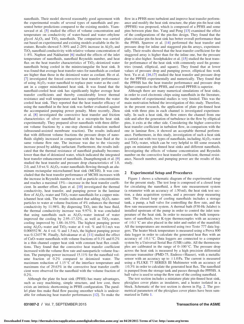
Hydrodynamics and HeatTransfer Characteristics ofa Miniature Plate Pin-Fin HeatSink Utilizing Al2O3–Waterand TiO2–Water NanofluidsIn this paper, the hydrodynamic and thermal performance of a miniature plate pin-finnedheat sink is investigated experimentally by utilizing two widely used nanofluids, Al2O3–water and TiO2–water. The heat sink base plate, which is used in the cooling process ofelectronic devices, has the dimensions of 42 mm (L)� 42 mm (W)� 14 mm (H) and ismade of aluminum and placed in a plexiglass case which is isolated from the environmentusing an insulator foam. The thermal performance of the heat sink is investigated bypassing the nanofluid at constant inlet temperature while applying a constant heat flux of124.8 kW/m2 to the bottom surface of the heat sink. The nanofluids are prepared in vol-ume concentrations of 0.5, 1, 1.5, and 2% and their performances are measured consider-ing water as the base fluid. Measuring the pressure difference between the entrance andexit of the heat sink made it possible to study the hydrodynamic performance of the heatsink. Although the measurements showed 15% and 30% increase in the pumping powerfor the volume concentration of 2% of Al2O3–water and TiO2–water nanofluids, respec-tively, the average heat transfer coefficients increased by 16% and 14% and the thermalresistance decreased by 17% and 14% for each nanofluid. [DOI: 10.1115/1.4030103]
Keywords: miniature plate pin-fin heat sink, nanofluids, heat transfer coefficient, thermalresistance, pumping power
1 Introduction
The wonderful progress in the technology of constructing tran-sistors in nanometric dimensions and using them in electronicchips is one of the most significant achievements of humankindover the past decade. The heat flux generated in such electronicdevices and the method of removing them have been consideredas a significant challenge for researchers. Considering the fact thatthe conventional heat dampers are not proper for removing such aheat flux, using new methods and devices seems to be of highnecessity. In this regard, a miniature plate pin-finned heat sinkwhich has a high surface area to volume ratio seems to be a properdevice for removing such heat flux. Using methods of producingturbulence in fluid flow in order to increase the convective heattransfer potential inside the heat sink has always been theresearch.
Moreover, using nanofluid as a cooling fluid has attracted theattention of researchers considering its potential in increasing theconvective heat transfer coefficient and producing almost uniformtemperature in the heat sink. Therefore, discussing and investigat-ing the hydrodynamic and thermal performance of nanofluid have
been continuing and this implies the significance of using them inthe devices of compact thermal convection.
The invention of nanofluids by Choi [1] initiated a new perspec-tive to increase the efficiency in cooling fluids. Brolossy et al. [2]used photo acoustic technique as a nonintrusive optical method tomeasure thermophysical properties (diffusivity, diffusivity, andconductivity) of TiO2 and Al2O3 nanoparticles in transparentnanofluids at low volume concentrations. Their results showedthat thermal parameters of both nanofluids increase as the particleconcentrations increase and are higher than the values of the baseliquid for all concentrations of TiO2 nanoparticles. They also indi-cated that despite the larger thermal conductivity of bulk Al2O3 incomparison with that of TiO2, thermal parameters of Al2O3 nano-fluids were generally lower than those of TiO2 nanofluids. Reddyet al. [3] prepared a set of three nanofluids of different blends withethylene glycol–water and TiO2 nanoparticles. They were charac-terized for thermal conductivity as a function of temperature andvolume concentration of nanoparticles. Their results showed thatthermal conductivity of TiO2 nanofluids increased with increasein volume concentration of TiO2 and also with temperature.Murshed et al. [4] presented a combined static and dynamicmechanism-based model, including the effects of particle size,nanolayer, Brownian motion, and particle surface chemistry andinteraction potential, for predicting the effective thermal conduc-tivity of Al2O3–water, TiO2–water, CuO–water, and Fe3O4–water
Contributed by the Heat Transfer Division of ASME for publication in theJOURNAL OF THERMAL SCIENCE AND ENGINEERING APPLICATIONS. Manuscript receivedSeptember 14, 2014; final manuscript received February 26, 2015; published onlineApril 15, 2015. Assoc. Editor: Zahid Ayub.
Journal of Thermal Science and Engineering Applications SEPTEMBER 2015, Vol. 7 / 031007-1Copyright VC 2015 by ASME
Downloaded From: http://thermalscienceapplication.asmedigitalcollection.asme.org/ on 04/20/2015 Terms of Use: http://asme.org/terms
nanofluids. Their model showed reasonably good agreement withthe experimental results of several types of nanofluids and pre-sented better predictions compared to the existing models. Yiam-sawasd et al. [5] studied the effect of volume concentration andtemperature on conductivity of water-based and water–ethyleneglycol Al2O3 and TiO2 nanofluids. The comparison was carriedout based on experimental and existing models available in the lit-erature. Results showed 5–30% and 2–20% increase in Al2O3 andTiO2 nanofluid conductivity with relative volume concentration of1–8%. Naphon and Nakharintr [6] studied the effects of the inlettemperature of nanofluids, nanofluid Reynolds number, and heatflux on the heat transfer characteristics of TiO2–deionized waternanofluids being cooled in the minirectangular fin heat sink. Itwas found that average heat transfer rates for nanofluids as coolantare higher than those in the deionized water as coolant. Ho et al.[7] investigated the forced convective heat transfer performanceof using Al2O3–water nanofluid to replace pure water as the cool-ant in a copper minichannel heat sink. It was found that thenanofluid-cooled heat sink has significantly higher average heattransfer coefficients and thereby considerably lower thermalresistance and wall temperature and hence outperforms the watercooled heat sink. They reported that the heat transfer efficacy ofusing the nanofluid in the heat sink was further evaluated againstthe accompanied pumping power penalty. More recently, Zhouet al. [8] investigated the convective heat transfer and frictioncharacteristics of silver nanofluid in a micropin-fin heat sinkexperimentally. They prepared silver nanofluids with three differ-ent volume fractions by a one-step chemical reduction method(ultrasound-assisted membrane reaction). The results indicatedthat with different volume fractions the pressure drops of nano-fluids slightly increased in comparison with the base fluid at thesame volume flow rate. The increase was due to the viscosityincrease posed by adding surfactant. Furthermore, the results indi-cated that the thermal resistance of nanofluid gradually becomeslower than that of deionized water, which indicated the integratedheat transfer enhancement of nanofluids. Duangthongsuk et al. [9]studied the heat transfer and pressure drop characteristics of 1.0,2.0, and 3.0 wt.% Al2O3–water nanofluids flowing through an alu-minum rectangular microchannel heat sink (MCHS). It was con-cluded that the heat transfer performance of MCHS increases withthe increase in Reynolds number as well as particle concentrationsand reaches a maximal 15%—increase in the heat transfer coeffi-cient. In another effort, Ijam et al. [10] investigated the thermalconductivity, heat transfer, and pumping power in the laminarflow of Al2O3–water and TiO2–water nanofluids for a copper min-ichannel heat sink. The results indicated that adding Al2O3 nano-particles to water at volume fractions of 4% enhances the thermalconductivity by 11.98%. By dispersing TiO2 into the base fluid,the thermal conductivity increase was 9.97%. It was concludedthat using nanofluids such as Al2O3–water instead of waterimproved the cooling by 2.95–17.32%, as well as TiO2–water,cooling improved by 1.88–16.53%. The highest pumping powerusing Al2O3–water and TiO2–water at 4 vol. % and 0.1 m/s was0.000552 W. At 4 vol. % and 1.5 m/s, the highest pumping powerwas 0.12437 W. Finally, Selvakumar et al. [11] studied the effectof CuO–water nanofluids with volume fractions of 0.1% and 0.2%in a thin channel copper heat sink with constant heat flux condi-tions. They found that the convective heat transfer coefficientincreased with the volume flow rate and nanoparticle volume frac-tion. The pumping power increased 15.11% for the nanofluid vol-ume fraction of 0.2% compared to deionized water. Themaximum reduction of 1.15 �C of the interface temperature andmaximum rise of 29.63% in the convective heat transfer coeffi-cient were observed for the nanofluid with the volume fraction of0.2%.
Although the plate fin heat sink (PFHS) has many advantages,such as easy machining, simple structure, and low cost, thereexists an intrinsic shortcoming in PFHS configuration. The paral-lel plate fins make fluid flow passing smoother which is undesir-able for enhancing heat transfer performances [12]. To make the
flow in a PFHS more turbulent and improve heat transfer perform-ance and modify the heat sink structure, the plate pin-fin heat sink(PPFHS) was proposed, which is composed of a PFHS and somepins between plate fins. Yang and Peng [13] examined the effectof the configurations of the pin-fins design. They found that theplate-circular pin-fin heat sink has better overall performance thanthe PFHS. Sparrow et al. [14] performed the heat transfer andpressure drop for inline and staggered pin-fin arrays, experimen-tally. Their results showed that the heat transfer coefficient for thestaggered array is higher than for the inline one, but the pressuredrop is also higher. Soodphakdee et al. [15] studied the heat trans-fer performance of the heat sink with commonly used fin geome-tries (round, elliptical, and square). They found that at lowervalues of pressure drop and pumping power, elliptical fins workbest. Yu et al. [16,17] studied the heat transfer and pressure dropfor the PPFHS experimentally and numerically. They found thatthe PPFHS has the heat transfer performance and pressure drophigher compared to the PFHS, and overall PPFHS is superior.
Although there are many numerical simulations of heat sinks,in order to cool electronic chips using nanofluids in the literature,the number of experimental studies is very limited. This was themain motivation behind the investigation of this study. Therefore,in the present research, the application of plate pin-finned heatsink with three pins in each channel is investigated experimen-tally. In such a heat sink, the flow enters the channel from oneside and after the generation of turbulence in the flow by ellipticalpins, it exits at the other side. Considering the higher convectiveheat transfer coefficient in turbulent flow, in comparison with theone in laminar flow, it showed an acceptable thermal perform-ance. Furthermore, in this study, investigation of such a heat sinkis carried out with two types of nanofluids, including Al2O3–waterand TiO2–water, which can be very helpful to fill some researchgaps on miniature pin-finned heat sinks and different nanofluids.Investigating the effects of volume concentration and Reynoldsnumber on the convective heat transfer coefficient, thermal resist-ance, Nusselt number, and pumping power are the results of thisstudy.
2 Experimental Setup and Procedures
Figure 1 shows a schematic diagram of the experimental setupfor the present study. The test loop is composed of a closed loopfor circulating the nanofluid, a flow rate measurement system(a rotameter with an accuracy of 650 ml), the heat sink test sec-tion, a data acquisition system, and a pressure drop measuringunit. The closed loop of cooling nanofluids includes a storagetank, a pump, a ball valve for controlling the flow rate, and theflow rate measurement system. A thermal bath (F30-Hc Julabo) isinstalled upstream of the pump in order to control the inlet tem-perature of the heat sink. In order to measure the bulk tempera-tures of nanofluids, two K-type thermocouples with an accuracyof 60.1 �C are also placed in the inlet and outlet of the manifold.All the temperatures are monitored using two Testo 777 data log-gers. The heater block temperature is measured using a Prova 800data logger in order to calculate the generated heat flux with anaccuracy of 60.1 �C. Data loggers are connected to a computersystem by a Universal Serial Bus (USB) cable. All the thermocou-ples are calibrated in the range of 0–100 �C. The pressure dropacross the heat sink is measured by a high precision differentialpressure transmitter (PMD-75, EndressþHauser), with a metallicsensor with an accuracy up to 61.0 Pa. The current is measuredusing a FLUKE 77 SERIES III Multimeter with an accuracy of60.3% in order to calculate the generated heat flux. The nanofluidis pumped from the storage tank and passes through the PPFHS. Aball valve is used to setup the flow rate of the cooling nanofluid.
The test section includes a miniature plate pin-finned heat sink,plexiglass cover plates as insulators, and a heater isolated in ablock. Schematic of the test section is shown in Fig. 2. The geo-metrical parameters of the plexiglass cover plates have been sum-marized in Table 1.
031007-2 / Vol. 7, SEPTEMBER 2015 Transactions of the ASME
Downloaded From: http://thermalscienceapplication.asmedigitalcollection.asme.org/ on 04/20/2015 Terms of Use: http://asme.org/terms
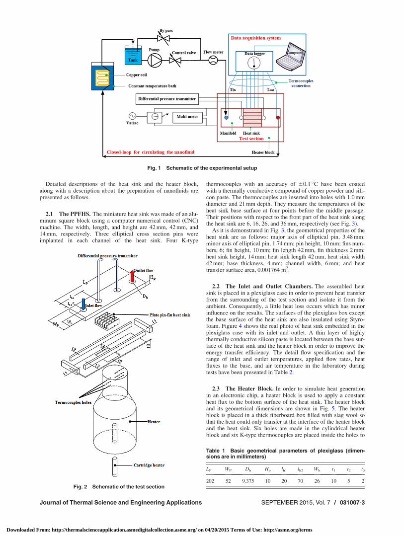
Detailed descriptions of the heat sink and the heater block,along with a description about the preparation of nanofluids arepresented as follows.
2.1 The PPFHS. The miniature heat sink was made of an alu-minum square block using a computer numerical control (CNC)machine. The width, length, and height are 42 mm, 42 mm, and14 mm, respectively. Three elliptical cross section pins wereimplanted in each channel of the heat sink. Four K-type
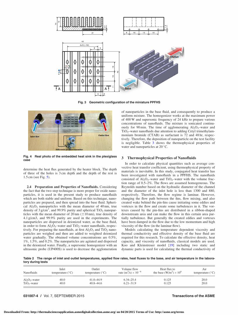
thermocouples with an accuracy of 60.1 �C have been coatedwith a thermally conductive compound of copper powder and sili-con paste. The thermocouples are inserted into holes with 1.0 mmdiameter and 21 mm depth. They measure the temperatures of theheat sink base surface at four points before the middle passage.Their positions with respect to the front part of the heat sink alongthe heat sink are 6, 16, 26, and 36 mm, respectively (see Fig. 3).
As it is demonstrated in Fig. 3, the geometrical properties of theheat sink are as follows: major axis of elliptical pin, 3.48 mm;minor axis of elliptical pin, 1.74 mm; pin height, 10 mm; fins num-bers, 6; fin height, 10 mm; fin length 42 mm, fin thickness 2 mm;heat sink height, 14 mm; heat sink length 42 mm, heat sink width42 mm; base thickness, 4 mm; channel width, 6 mm; and heattransfer surface area, 0.001764 m2.
2.2 The Inlet and Outlet Chambers. The assembled heatsink is placed in a plexiglass case in order to prevent heat transferfrom the surrounding of the test section and isolate it from theambient. Consequently, a little heat loss occurs which has minorinfluence on the results. The surfaces of the plexiglass box exceptthe base surface of the heat sink are also insulated using Styro-foam. Figure 4 shows the real photo of heat sink embedded in theplexiglass case with its inlet and outlet. A thin layer of highlythermally conductive silicon paste is located between the base sur-face of the heat sink and the heater block in order to improve theenergy transfer efficiency. The detail flow specification and therange of inlet and outlet temperatures, applied flow rates, heatfluxes to the base, and air temperature in the laboratory duringtests have been presented in Table 2.
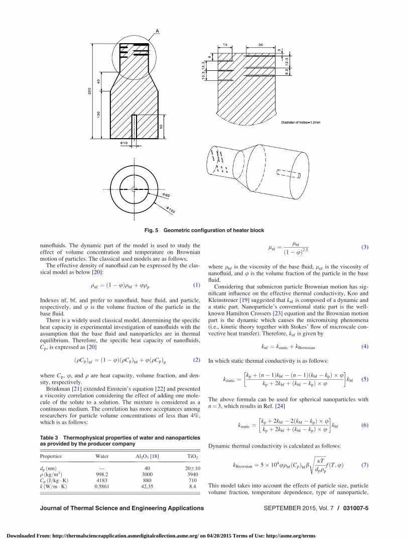
2.3 The Heater Block. In order to simulate heat generationin an electronic chip, a heater block is used to apply a constantheat flux to the bottom surface of the heat sink. The heater blockand its geometrical dimensions are shown in Fig. 5. The heaterblock is placed in a thick fiberboard box filled with slag wool sothat the heat could only transfer at the interface of the heater blockand the heat sink. Six holes are made in the cylindrical heaterblock and six K-type thermocouples are placed inside the holes to
Fig. 1 Schematic of the experimental setup
Fig. 2 Schematic of the test section
Table 1 Basic geometrical parameters of plexiglass (dimen-sions are in millimeters)
LP WP Dh Hp lh1 lh2 Wh t1 t2 t3
202 52 9.375 10 20 70 26 10 5 2
Journal of Thermal Science and Engineering Applications SEPTEMBER 2015, Vol. 7 / 031007-3
Downloaded From: http://thermalscienceapplication.asmedigitalcollection.asme.org/ on 04/20/2015 Terms of Use: http://asme.org/terms
determine the heat flux generated by the heater block. The depthof three of the holes is 3 cm depth and the depth of the rest is1.5 cm (see Fig. 5).
2.4 Preparation and Properties of Nanofluids. Consideringthe fact that the two step technique is more proper for oxide nano-particles, it is used in the present study to produce nanofluidswhich are both stable and uniform. Based on this technique, nano-particles are prepared, and then spread into the base fluid. Spheri-cal Al2O3 nanoparticles with the mean diameter of 40 nm, truedensity of 3 g/cm3, and 99.9% purity and spherical TiO2 nanopar-ticles with the mean diameter of 20 nm (610 nm), true density of4.1 g/cm3, and 99.9% purity are used in the experiments. Thenanoparticles are dispersed in deionized water, as the base fluid,in order to form Al2O3–water and TiO2–water nanofluids, respec-tively. For preparing the nanofluids, at first Al2O3 and TiO2 nano-particles are weighed and then are added to weighted deionizedwater gradually. The obtained volume concentrations are 0.5%,1%, 1.5%, and 0.2%. The nanoparticles are agitated and dispersedin the deionized water. Finally, a supersonic homogenizer with anultrasonic probe (UP400S) is used to decrease the agglomeration
of nanoparticles in the base fluid, and consequently to produce auniform mixture. The homogenizer works at the maximum powerof 400 W and supersonic frequency of 24 kHz to prepare variousconcentrations of nanofluids. The mixture is sonicated continu-ously for 90 min. The time of agglomerating Al2O3–water andTiO2–water nanofluids due attention to adding Cetyl trimethylam-monium bromide (CTAB) as surfactant is 72 and 48 hr, respec-tively. Therefore, the deposition of nanoparticle on the test facilityis negligible. Table 3 shows the thermophysical properties ofwater and nanoparticles at 20 �C.
3 Thermophysical Properties of Nanofluids
In order to calculate physical quantities such as average con-vective heat transfer coefficient, using thermophysical property ofmaterials is inevitable. In this study, conjugated heat transfer hasbeen investigated with nanofluids in a PPFHS. The nanofluidsconsisted of Al2O3–water and TiO2–water with the volume frac-tion range of 0.5–2%. The flows are assumed homogeneous. TheReynolds number based on the hydraulic diameter of the channeland the diameter of the inlet hole is less than 1300 and 880,respectively. Therefore, the flow regime is laminar. However,changing the flow path between the fins, flow mixing, and alsocreated wake behind the pin-fins cause initiating some eddies andvortexes in the flow and create some turbulences in it. The vor-texes caused by the pin-fins are distributed in a ribbon-shapeddownstream area and can make the flow in this certain area par-tially turbulence. But generally the created eddies and vortexeshave been damped in the flow due to the low momentum and highviscosity of the flow (in the laminar flow).
Models calculating the temperature dependent viscosity andthermal conductivity and effective density of the base fluid arerequired for this research. To calculate the effective density, heatcapacity, and viscosity of nanofluids, classical models are used.Koo and Kleinstreuer model [19] including two static anddynamic parts is used for calculating the thermal conductivity of
Fig. 3 Geometric configuration of the miniature PPFHS
Fig. 4 Real photo of the embedded heat sink in the plexiglasscase
Table 2 The range of inlet and outlet temperatures, applied flow rates, heat fluxes to the base, and air temperature in the labora-tory during tests
NanofluidsInlet
temperature (�C)Outlet
temperature (�C)Volume flow
rate (m3/s)� 10�6Heat flux to
the base (W/m2)� 106Air
temperature (�C)
Al2O3–water 40.0 41.0–44.9 6.34–25.4 0.125 20.0TiO2–water 40.0 40.8–44.6 6.21–31.9 0.125 20.0
031007-4 / Vol. 7, SEPTEMBER 2015 Transactions of the ASME
Downloaded From: http://thermalscienceapplication.asmedigitalcollection.asme.org/ on 04/20/2015 Terms of Use: http://asme.org/terms
nanofluids. The dynamic part of the model is used to study theeffect of volume concentration and temperature on Brownianmotion of particles. The classical used models are as follows.
The effective density of nanofluid can be expressed by the clas-sical model as below [20]:
qnf ¼ ð1� uÞqbf þ uqp (1)
Indexes nf, bf, and prefer to nanofluid, base fluid, and particle,respectively, and u is the volume fraction of the particle in thebase fluid.
There is a widely used classical model, determining the specificheat capacity in experimental investigation of nanofluids with theassumption that the base fluid and nanoparticles are in thermalequilibrium. Therefore, the specific heat capacity of nanofluids,Cp, is expressed as [20]
ðqCpÞnf ¼ ð1� uÞðqCpÞbf þ uðqCpÞp (2)
where Cp, u, and q are heat capacity, volume fraction, and den-sity, respectively.
Brinkman [21] extended Einstein’s equation [22] and presenteda viscosity correlation considering the effect of adding one mole-cule of the solute to a solution. The mixture is considered as acontinuous medium. The correlation has more acceptances amongresearchers for particle volume concentrations of less than 4%,which is as follows:
lnf ¼lbf
ð1� uÞ2:5(3)
where lbf is the viscosity of the base fluid, lnf is the viscosity ofnanofluid, and u is the volume fraction of the particle in the basefluid.
Considering that submicron particle Brownian motion has sig-nificant influence on the effective thermal conductivity, Koo andKleinstreuer [19] suggested that knf is composed of a dynamic anda static part. Nanoparticle’s conventional static part is the well-known Hamilton Crossers [23] equation and the Brownian motionpart is the dynamic which causes the micromixing phenomena(i.e., kinetic theory together with Stokes’ flow of microscale con-vective heat transfer). Therefore, knf is given by
knf ¼ kstatic þ kBrownian (4)
In which static thermal conductivity is as follows:
kstatic ¼kp þ ðn� 1Þkbf � ðn� 1Þðkbf � kpÞ � u
kp þ 2kbf þ ðkbf � kpÞ � u
� �kbf (5)
The above formula can be used for spherical nanoparticles withn¼ 3, which results in Ref. [24]
kstatic ¼kp þ 2kbf � 2ðkbf � kpÞ � ukp þ 2kbf þ ðkbf � kpÞ � u
� �kbf (6)
Dynamic thermal conductivity is calculated as follows:
kBrownian ¼ 5� 104uqbfðCpÞbfb
ffiffiffiffiffiffiffiffiffijT
dpqp
sf ðT;uÞ (7)
This model takes into account the effects of particle size, particlevolume fraction, temperature dependence, type of nanoparticle,
Fig. 5 Geometric configuration of heater block
Table 3 Thermophysical properties of water and nanoparticlesas provided by the producer company
Properties Water Al2O3 [18] TiO2
dp ðnmÞ — 40 20610q ðkg=m3Þ 998.2 3000 3940Cp ðJ=kg � KÞ 4183 880 710k ðW=m � KÞ 0.5861 42.35 8.4
Journal of Thermal Science and Engineering Applications SEPTEMBER 2015, Vol. 7 / 031007-5
Downloaded From: http://thermalscienceapplication.asmedigitalcollection.asme.org/ on 04/20/2015 Terms of Use: http://asme.org/terms
and base fluid combination. In the present work, the nanofluidswere assumed to be homogeneous and the volume fraction wasassumed to be constant. The Eq. (8) takes volume fraction andtemperature variations into consideration (presented in Ref. [25])and is expressed as follows:
f ðT;uÞ ¼ ð�0:8467 uþ 0:0753Þ � T
þ ð237:67 u� 21:998Þ ðfor Al2O3Þ(8)
Also in Eq. (7), bparameter, which is determined semi-empirically, takes into account the hydrodynamic interactionbetween the particles and the affected fluid and is evaluated asfollows:
b ¼ 0:0137� ð100 uÞ�0:8229for u < 0:01 ðfor Al2O3Þ
b ¼ 0:0017� ð100 uÞ�0:0841for u � 0:01 ðfor Al2O3Þ
(9)
Indexes of bf, p, and nf refer to the base fluid, particle, andnanofluid, respectively. Also, j is the Boltzmann constant(1.3807� 10�23 J/K). For TiO2, the function f is not found for thespecific conditions of this study. Therefore, the value of thermalconductivity is directly extracted from the research done by Yiam-sawasd et al. [5] (the variation of thermal conductivity is valid inthe range of [0:644 < knf < 0:67 W=m �K]).
Considering the fact that the coolant temperature changes alongthe length of the channel, temperature dependence of density(qbf), viscosity (lbfðTÞ), and thermal conductivity (kbfðTÞ) of the
base fluid (water) are given as Ref. [26] (the variations of theproperties given in Eqs. (10)–(14) are valid in the range of[15� T� 75 �C])
qbf ¼ �13:89ffiffiffiTpþ 1237 (10)
kbfðTÞ ¼ kBð1þ akTÞ (11)
where
kB ¼ 0:6 ðW=m � KÞ and ak ¼ 4:167� 10�5ð1=KÞ (12)
and
lbfðTÞ ¼ lB exp ðTl=TÞ (13)
where
Tl ¼ 1713ðKÞ and lB ¼ 2:761� 10�6ðPa : sÞ (14)
4 Physical Quantities
Using the experimental results, the physical quantities includingthe base temperature of the heat sink, average convection heattransfer coefficient (havg), thermal resistance, Nusselt number, andpumping power (P � P) are obtained. It is worth mentioning that hi
is the local convective heat transfer coefficient considering thefour points in which the thermocouples have been located.
hi ¼q00 �W � xi
Nch � ð2� Hch � xi þWch � xi þ ði� 1ÞðPfinHch � AfinÞÞ � ðTwi� Tmi
Þ (15)
Tmiis the bulk temperature of the fluid in the vertical cross sec-
tions at the four specified points in the bottom of the heat sink
Tmi¼¼ ðq
00 �W � xiÞqnf � Qnf � Cpnf
þ Tin (16)
Furthermore, havg is the average heat transfer coefficient which iscalculated using local heat transfer coefficient through integralmethod
havg ¼
X3
i¼1
hi þ hiþ1
2
� �ðxiþ1 � xiÞ
X3
i¼1
ðxiþ1 � xiÞ(17)
q00 is the heat flux used to calculate the convective heat transfercoefficient
q00 ¼ q
WL(18)
where q is the heat power applied to the bottom surface of theheat sink and is calculated as follows:
q ¼ qnfQCpnfðTout � TinÞ (19)
Another important parameter in evaluating the thermal perform-ance of the heat sink is its thermal resistance, which is defined by
Rth ¼Twmax
� Tc;in
q(20)
Tc;in is the coolant inlet temperature, and Twmaxis the highest tem-
perature on the bottom wall of the heat sink. The Nusselt number(Nu) is defined as the ratio of the convection to conduction heattransfer
Nu ¼ havgDhyd
knf
(21)
Pumping power which is the result of the pressure drop across thechannel and volume flow rate (Q) is needed to drive the fluid inchannels and is defined by
P:P ¼ Q� ðPout � PinÞ (22)
The Reynolds number based on the hydraulic diameter of thechannel is defined by the following equation:
Re ¼ qnfVDhyd
lnf
(23)
where Dhyd is the hydraulic diameter and is defined as
Dhyd ¼4Ach
Pch
¼ 4WchHch
2ðWch þ HchÞ(24)
where Ach and Pch are the cross section area and the wet perimeterof the channel, respectively.
4.1 Uncertainly Analysis. In order to have a meaningful con-clusion from the measured data, it is essential to calculate alluncertainties of the measurements. Measuring physical quantitiessuch as temperature, pressure difference, and volume flow rate
031007-6 / Vol. 7, SEPTEMBER 2015 Transactions of the ASME
Downloaded From: http://thermalscienceapplication.asmedigitalcollection.asme.org/ on 04/20/2015 Terms of Use: http://asme.org/terms
always come with error in experimental researches. So the amountof uncertainty in the presented results is caused by this error inmeasuring of quantities. Since thermophysical properties of nano-fluid are the most effective parameters on the presenting resultsand there is no experimental measurement in this field for thisresearch, the amount of this parameter has been considered 2%for thermal conductivity [27] and 1% for other thermophysicalparameters [28]. Table 4 presents the measurement uncertaintiesin the experimental parameters.
Equations (25)–(29) represent the uncertainty in the experimen-tal results: heat applied to the bottom surface of the heat sink, con-vective heat transfer coefficient, thermal resistance, pumpingpower, and Nusselt number. The achieved results are theuncertainties of the mentioned quantities which are expressed inTable 5.
dq
q¼ dqnf
qnf
� �2
þ dQ
Q
� �2
þ dCpnf
Cpnf
� �2
þ dðTout � TinÞðTout � TinÞ
� �2" #1=2
(25)
dhavg
havg
¼�
dq00
q00
� �2
þ dW
W
� �2
þ dHch
Hch
� �2
þ dWch
Wch
� �2
þ dPfin
Pfin
� �2
þ dAfin
Afin
� �2
þ dxi
xi
� �2
þ dðTWi� Tmi
ÞðTWi
� TmiÞ
� �2�1=2
(26)
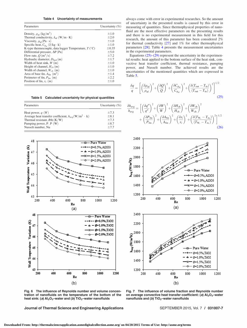
Table 4 Uncertainty of measurements
Parameters Uncertainty (%)
Density, qnf ðkg=m3Þ 61.0Thermal conductivity, knf ðW=m � KÞ 62.0Viscosity, lnfðPa � sÞ 61.0Specific heat, Cpnf
ðJ=kg � kÞ 61.0K-type thermocouple, data logger Temperature, T (�C) 60.35Differential pressure, DP ðPaÞ 65.0Flow rate, Q ðm3=sÞ 67.2Hydraulic diameter, Dhyd ðmÞ 61.7Width of heat sink, W ðmÞ 61.0Height of channel, Hch ðmÞ 61.0Width of channel, Wch ðmÞ 61.0Area of base fin, Afin ðm2Þ 61.4Perimeter of fin, Pfin ðmÞ 62.2Position of fin, xi ðmÞ 61.0
Table 5 Calculated uncertainty for physical quantities
Parameters Uncertainty (%)
Heat power, q ðWÞ 67.3Average heat transfer coefficient, havgðW=m2 � kÞ 68.1Thermal resistant, Rth ðK=WÞ 67.3Pumping power, P : P ðWÞ 68.7Nusselt number, Nu 67.7
Fig. 6 The influence of Reynolds number and volume concen-tration of nanofluids on the temperature of the bottom of theheat sink: (a) Al2O3–water and (b) TiO2–water nanofluids
Fig. 7 The influence of volume fraction and Reynolds numberon average convective heat transfer coefficient: (a) Al2O3–waternanofluids and (b) TiO2–water nanofluids
Journal of Thermal Science and Engineering Applications SEPTEMBER 2015, Vol. 7 / 031007-7
Downloaded From: http://thermalscienceapplication.asmedigitalcollection.asme.org/ on 04/20/2015 Terms of Use: http://asme.org/terms
dRth
Rth
¼ dðTWmax� Tc;inÞ
ðTWmax� Tc;inÞ
� �2
þ dq
q
� �2" #1=2
(27)
dP:P
P:P¼ dQ
Q
� �2
þ dðPout � PinÞPout � Pin
� �2" #1=2
(28)
dNu
Nu¼ dhavg
havg
� �2
þ dDhyd
Dhyd
� �2
þ dknf
knf
� �2" #1=2
(29)
5 Results and Discussion
5.1 The Influence of Reynolds Number and VolumeConcentration of Nanofluids on Temperature of the BottomSurface of the Heat Sink. The main target in cooling electronicchips is to minimize the temperature of the bottom surface of theheat sink, as well as the temperature of the chip, and also tohomogenize the temperature distribution. Prevention of
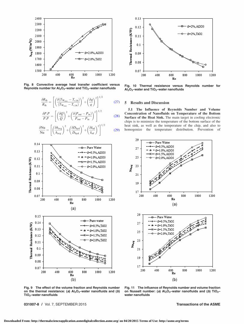
Fig. 8 Convective average heat transfer coefficient versusReynolds number for Al2O3–water and TiO2–water nanofluids
Fig. 9 The effect of the volume fraction and Reynolds numberon the thermal resistance: (a) Al2O3–water nanofluids and (b)TiO2–water nanofluids
Fig. 11 The influence of Reynolds number and volume fractionon Nusselt number: (a) Al2O3–water nanofluids and (b) TiO2–water nanofluids
Fig. 10 Thermal resistance versus Reynolds number forAl2O3–water and TiO2–water nanofluids
031007-8 / Vol. 7, SEPTEMBER 2015 Transactions of the ASME
Downloaded From: http://thermalscienceapplication.asmedigitalcollection.asme.org/ on 04/20/2015 Terms of Use: http://asme.org/terms
temperature alteration has a key effect on the life of the electronicparts. Figures 6(a) and 6(b) show the variation of bottom surfacetemperature of the heat sink versus Reynolds number for differentvolume concentrations of Al2O3–water and TiO2–water nano-fluids. It is clear that using nanofluids has a remarkable effect onthe reducing temperature variations, especially in the higherReynolds number range. This result has been reported by thesimilar studies [11]. Compared to pure distilled water, usingAl2O3–water and TiO2–water nanofluids reduces temperature var-iations around 1.8 �C and 1.4 �C, respectively, in the 2% volumeconcentration and Reynolds number of 1065 and 1099, respec-tively. As it can be seen, adding nanoparticles to the fluidincreases the heat transfer remarkably. This is the major reasonfor temperature variation reduction in the heat sink while usingnanofluids.
5.2 The Influence of Reynolds Number and Volume Con-centration of Nanofluids on Heat Transfer Coefficient. Figure7 shows the average heat transfer coefficient of Al2O3–water andTiO2–water nanofluids with 40 nm and 20 nm particles versusReynolds number for different volume concentrations. Accordingto Fig. 7, the average heat transfer coefficient increases with anincrease in Reynolds number and volume concentration of nano-particles. It is obvious that the values of average heat transfercoefficient for nanofluids are higher than those of the pure water.Various mechanisms have been known as the reasons of increasein the heat transfer in nanofluids such as thermal conductivityenhancement [1], Brownian motion [29], thermophoresis [30], dif-fusionphoresis [31,32], and so on.
Using Al2O3–water and TiO2–water nanofluids, the maximumrise in the convective heat transfer coefficient is observed around16% and 14%, respectively, for 2% volume fraction with respectto deionized water. According to Fig. 7, the slopes of the heattransfer coefficient for Al2O3–water and TiO2–water nanofluidsincrease slightly with an increase in the Reynolds number rangingfrom about 306 to 763 and 252 to 583, respectively.
Figure 8 shows the average convective heat transfer coefficientversus Reynolds number for Al2O3–water and TiO2–water nano-fluids according to the experimental data. As it is shown, the con-vective heat transfer coefficient of Al2O3–water is 2% higher thanTiO2–water nanofluid which can be attributed to the higherthermal conductivity.
5.3 The Influence of Reynolds Number and VolumeConcentration of Nanofluids on Thermal Resistance. By usingthe thermal resistance, the cooling performance of a heat sinkwith nanofluids can be determined. The thermal resistance isdefined as the difference between the maximum temperature ofthe heat sink base plate and the inlet coolant temperature for theconstant heat flux applied to the heat sink base plate, as given byEq. (20). Based on the obtained experimental data, the effects ofReynolds number and the volume concentration of nanofluids onthe thermal resistance of Al2O3–water and TiO2–water nanofluidsare depicted in Figs. 9(a) and 9(b), respectively. Obviously, ther-mal resistance decreases when the volume concentration of nano-fluids and Reynolds number increases. As shown in Fig. 9, usingAl2O3–water and TiO2–water nanofluids in 2% volume concentra-tion decreases the thermal resistance around 17% and 14%,respectively, compared to the base fluid.
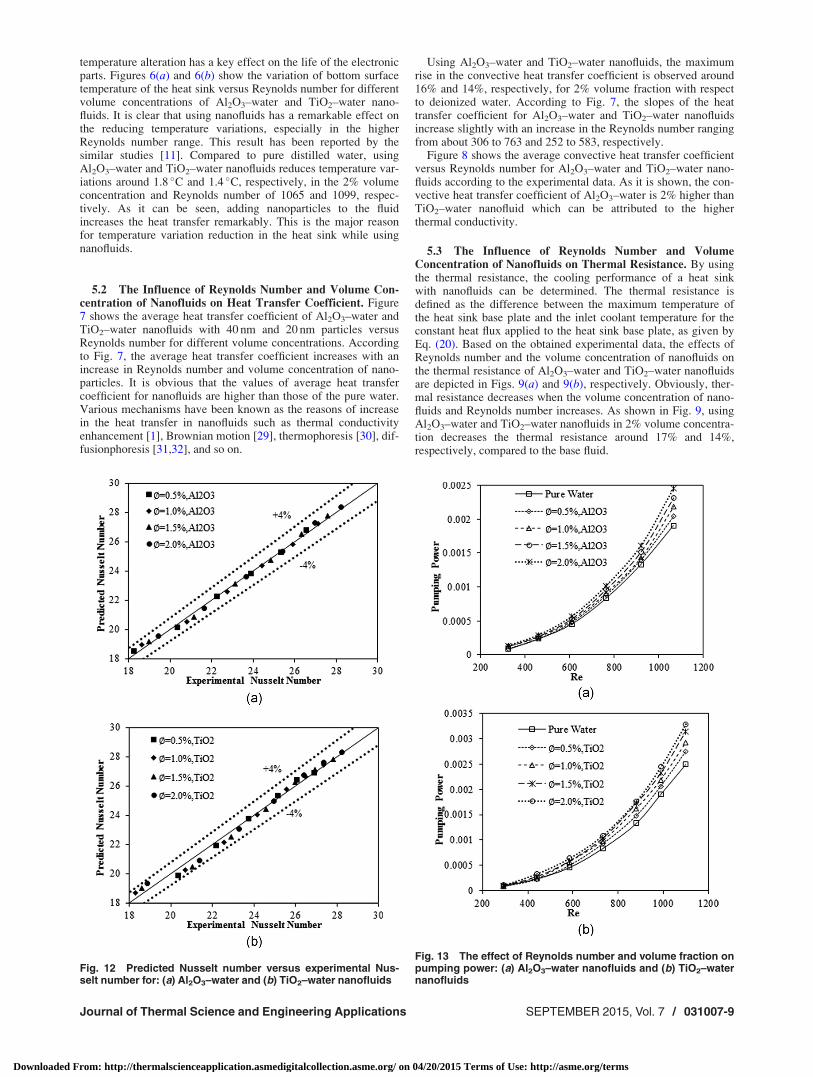
Fig. 12 Predicted Nusselt number versus experimental Nus-selt number for: (a) Al2O3–water and (b) TiO2–water nanofluids
Fig. 13 The effect of Reynolds number and volume fraction onpumping power: (a) Al2O3–water nanofluids and (b) TiO2–waternanofluids
Journal of Thermal Science and Engineering Applications SEPTEMBER 2015, Vol. 7 / 031007-9
Downloaded From: http://thermalscienceapplication.asmedigitalcollection.asme.org/ on 04/20/2015 Terms of Use: http://asme.org/terms
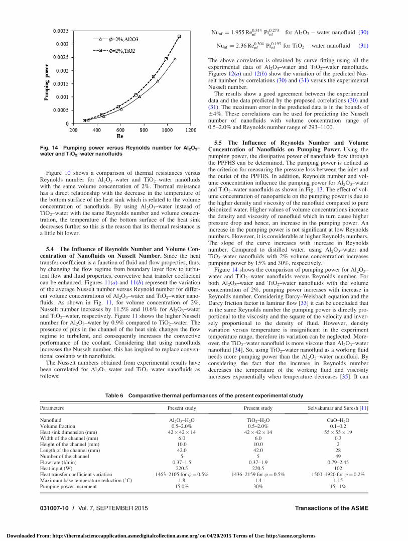
Figure 10 shows a comparison of thermal resistances versusReynolds number for Al2O3–water and TiO2–water nanofluidswith the same volume concentration of 2%. Thermal resistancehas a direct relationship with the decrease in the temperature ofthe bottom surface of the heat sink which is related to the volumeconcentration of nanofluids. By using Al2O3–water instead ofTiO2–water with the same Reynolds number and volume concen-tration, the temperature of the bottom surface of the heat sinkdecreases further so this is the reason that its thermal resistance isa little bit lower.
5.4 The Influence of Reynolds Number and Volume Con-centration of Nanofluids on Nusselt Number. Since the heattransfer coefficient is a function of fluid and flow properties, thus,by changing the flow regime from boundary layer flow to turbu-lent flow and fluid properties, convective heat transfer coefficientcan be enhanced. Figures 11(a) and 11(b) represent the variationof the average Nusselt number versus Reynold number for differ-ent volume concentrations of Al2O3–water and TiO2–water nano-fluids. As shown in Fig. 11, for volume concentration of 2%,Nusselt number increases by 11.5% and 10.6% for Al2O3–waterand TiO2–water, respectively. Figure 11 shows the higher Nusseltnumber for Al2O3–water by 0.9% compared to TiO2–water. Thepresence of pins in the channel of the heat sink changes the flowregime to turbulent, and consequently increases the convectiveperformance of the coolant. Considering that using nanofluidsincreases the Nusselt number, this has inspired to replace conven-tional coolants with nanofluids.
The Nusselt numbers obtained from experimental results havebeen correlated for Al2O3–water and TiO2–water nanofluids asfollows:
Nunf ¼ 1:955 Re0:314nf Pr0:273
nf for Al2O3 � water nanofluid (30)
Nunf ¼ 2:36 Re0:304nf Pr0:193
nf for TiO2 � water nanofluid (31)
The above correlation is obtained by curve fitting using all theexperimental data of Al2O3–water and TiO2–water nanofluids.Figures 12(a) and 12(b) show the variation of the predicted Nus-selt number by correlations (30) and (31) versus the experimentalNusselt number.
The results show a good agreement between the experimentaldata and the data predicted by the proposed correlations (30) and(31). The maximum error in the predicted data is in the bounds of64%. These correlations can be used for predicting the Nusseltnumber of nanofluids with volume concentration range of0.5–2.0% and Reynolds number range of 293–1100.
5.5 The Influence of Reynolds Number and VolumeConcentration of Nanofluids on Pumping Power. Using thepumping power, the dissipative power of nanofluids flow throughthe PPFHS can be determined. The pumping power is defined asthe criterion for measuring the pressure loss between the inlet andthe outlet of the PPFHS. In addition, Reynolds number and vol-ume concentration influence the pumping power for Al2O3–waterand TiO2–water nanofluids as shown in Fig. 13. The effect of vol-ume concentration of nanoparticle on the pumping power is due tothe higher density and viscosity of the nanofluid compared to puredeionized water. Higher values of volume concentrations increasethe density and viscosity of nanofluid which in turn cause higherpressure drop and hence, an increase in the pumping power. Anincrease in the pumping power is not significant at low Reynoldsnumbers. However, it is considerable at higher Reynolds numbers.The slope of the curve increases with increase in Reynoldsnumber. Compared to distilled water, using Al2O3–water andTiO2–water nanofluids with 2% volume concentration increasespumping power by 15% and 30%, respectively.
Figure 14 shows the comparison of pumping power for Al2O3–water and TiO2–water nanofluids versus Reynolds number. Forboth Al2O3–water and TiO2–water nanofluids with the volumeconcentration of 2%, pumping power increases with increase inReynolds number. Considering Darcy–Weisbach equation and theDarcy friction factor in laminar flow [33] it can be concluded thatin the same Reynolds number the pumping power is directly pro-portional to the viscosity and the square of the velocity and inver-sely proportional to the density of fluid. However, densityvariation versus temperature is insignificant in the experimenttemperature range, therefore its variation can be neglected. More-over, the TiO2–water nanofluid is more viscous than Al2O3–waternanofluid [34]. So, using TiO2–water nanofluid as a working fluidneeds more pumping power than the Al2O3–water nanofluid. Byconsidering the fact that the increase in Reynolds numberdecreases the temperature of the working fluid and viscosityincreases exponentially when temperature decreases [35]. It can
Fig. 14 Pumping power versus Reynolds number for Al2O3–water and TiO2–water nanofluids
Table 6 Comparative thermal performances of the present experimental study
Parameters Present study Present study Selvakumar and Suresh [11]
Nanofluid Al2O3–H2O TiO2–H2O CuO–H2OVolume fraction 0.5–2.0% 0.5–2.0% 0.1–0.2Heat sink dimension (mm) 42� 42� 14 42� 42� 14 55� 55� 19Width of the channel (mm) 6.0 6.0 0.3Height of the channel (mm) 10.0 10.0 2Length of the channel (mm) 42.0 42.0 28Number of the channel 5 5 49Flow rate (l/min) 0.37–1.5 0.37–1.9 0.79–2.45Heat input (W) 220.5 220.5 102Heat transfer coefficient variation 1463–2105 for u¼ 0.5% 1436–2159 for u¼ 0.5% 1500–1920 for u¼ 0.2%Maximum base temperature reduction (�C) 1.8 1.4 1.15Pumping power increment 15.0% 30% 15.11%
031007-10 / Vol. 7, SEPTEMBER 2015 Transactions of the ASME
Downloaded From: http://thermalscienceapplication.asmedigitalcollection.asme.org/ on 04/20/2015 Terms of Use: http://asme.org/terms
be deduced that, by increasing the Reynolds Number, the differ-ence of pumping power between Al2O3–water and TiO2–waternanofluids increases exponentially.
5.6 Comparative Performance. The present experimentalstudy has been compared with the previous work done by Selva-kumar and Suresh [11] in Table 6. The geometrical properties ofthe heat sink are not similar to each other and this caused a differ-ence in results. The previous study used higher flow rate, lowerchannel height and width, and more channel number in compari-son with the present study. The comparison shows that the presentwork has a higher heat transfer coefficient compared to the previ-ous study due to higher heat flux, higher volume concentration ofnanofluids, and higher reduction temperature of the heat sink baseplate. The present study also showed a slightly higher pressuredrop as a consequence of the high volume fraction of nanofluids.The comparison reveals that the results follow the similar trend ofincreasing the heat transfer coefficient versus Reynolds number.The observed differences can be attributed to the nanofluids type,volume concentration of nanofluids, geometrical dimension, andflow characteristics.
6 Conclusion
In this paper, the thermal and hydrodynamic performance of aPPFHS with rectangular channels and elliptical pins is investi-gated experimentally using Al2O3–water and TiO2–water nano-fluids as the working fluid. Both nanofluids are prepared atconcentrations of 0.5, 1, 1.5, and 2%, and the increase in the heattransfer performance of nanofluids was compared to those ofwater as the base fluid with Reynolds number range of 300–1100.According to the experimental results, using the mentionedPPFHS changes flow regime to turbulent flow and therefore theaverage heat transfer coefficient will be increased. Moreover, itwas shown that the application of nanofluids in the pin-fin heatsinks improves the thermal performance, reduces the wall temper-ature variations, and enhances the heat transfer coefficient whichleads to more efficient cooling process. Considering the obtainedexperimental results, the following notes can be concluded:
(1) By replacing water by 2% volume concentration of Al2O3–water and TiO2–water nanofluids, temperature of the bot-tom of the heat sink was lowered by 1.8 �C and 1.4 �C,respectively.
(2) Compared to pure water, 2% volume concentration ofAl2O3–water and TiO2–water nanofluids showed higherconvective heat transfer coefficient by 16% and 14%. Also,by increasing volume concentration and Reynolds number,significant increase in Nusselt number is observed.
(3) By using Al2O3–water and TiO2–water nanofluids with 2%volume concentration, at Reynolds 1100 thermal resistanceis decreased by 17% and 14%, respectively.
(4) At the highest Reynolds, pumping powers of 1.65� 10�3
(W) and 1.77� 10�3 (W) are observed for Al2O3–waterand TiO2–water nanofluids and 2% volume concentration.
Nomenclature
A ¼ area (m2)Cp ¼ heat capacity (J/kg K)dp ¼ particle diameter (m)
Dhyd ¼ hydraulic diameter (m)f ¼ function defined in Eq. (8)h ¼ heat transfer coefficient (W/m2 K)H ¼ height (m)
Hch ¼ height of channel (m)k ¼ thermal conductivity (W/m K)L ¼ length (m)n ¼ shape factorN ¼ number of pins
Nch ¼ number of channelsNu ¼ Nusselt number
P ¼ perimeter (m)P:P ¼ pumping power (W)DP ¼ differential pressure (Pa)
q ¼ heat power (W)Q ¼ volume flow rate (m3/s)q00 ¼ heat flux at the bottom surface (W/m2)Re ¼ Reynolds numberRth ¼ thermal resistance (K/W)
T ¼ temperature (K)Tm ¼ bulk temperature of fluid (K)Tw ¼ temperature of the heat sink base plate (K)V ¼ velocity (m/s)W ¼ width of heat sink (m)
Wch ¼ width of channel (m)x ¼ axial position of thermocouples (m)
Greek Symbols
b ¼ model parameter defined in Eq. (9)u ¼ volume fractionj ¼ Boltzmann constant (J/K)l ¼ dynamic viscosity (Pa � s)q ¼ density (kg/m3)
Subscripts
avg ¼ averagebf ¼ base fluid
Constant
ch ¼ channelfin ¼ finin ¼ inlet
max ¼ maximum valuenf ¼ nanofluid
out ¼ outletp ¼ particles ¼ solid
W ¼ wall
References[1] Choi Su, S., 1995, Enhancing Thermal Conductivity of Fluids With Nanopar-
ticles, Vol. 231, ASME, New York, pp. 99–106.[2] El-Brolossy, T. A., and Saber, O., 2013, “Non-Intrusive Method for Thermal
Properties Measurement of Nanofluids,” Exp. Therm. Fluid Sci., 44, pp.498–503.
[3] Reddy, M., and Rao, V. V., 2013, “Experimental Studies on Thermal Conduc-tivity of Blends of Ethylene Glycol–Water-Based TiO2 Nanofluids,” Int. Com-mun. Heat Mass Transfer, 46, pp. 31–36.
[4] Murshed, S. M. S., Leong, K. C., and Yang, C., 2009, “A Combined Model forthe Effective Thermal Conductivity of Nanofluids,” Appl. Therm. Eng., 29(11),pp. 2477–2483.
[5] Yiamsawasd, T., Dalkilic, A. S., and Wongwises, S., 2012, “Measurement ofthe Thermal Conductivity of Titania and Alumina Nanofluids,” Thermochim.Acta, 545, pp. 48–56.
[6] Naphon, P., and Nakharintr, L., 2013, “Heat Transfer of Nanofluids in the Mini-Rectangular Fin Heat Sinks,” Int. Commun. Heat Mass Transfer, 40, pp. 25–31.
[7] Ho, C. J., and Chen, W. C., 2013, “An Experimental Study on Thermal Per-formance of Al2O3/Water Nanofluid in a Minichannel Heat Sink,” Appl. Therm.Eng., 50(1), pp. 516–522.
[8] Zhou, M., Xia, G., Chai, L., Li, J., and Zhou, L., 2012, “Analysis of Flow andHeat Transfer Characteristics of Micro-Pin Fin Heat Sink Using Silver Nano-fluids,” Sci. China Technol. Sci., 55(1), pp. 155–162.
[9] Duangthongsuk, W., Selim Dalkilic, A., and Wongwises, S., 2012, “ConvectiveHeat Transfer of Al2O3–Water Nanofluids in a Microchannel Heat Sink,” Curr.Nanosci., 8(3), pp. 317–322.
[10] Ijam, A., Saidur, R., and Ganesan, P., 2012, “Cooling of Minichannel Heat SinkUsing Nanofluids,” Int. Commun. Heat Mass Transfer, 39(8), pp. 1188–1194.
[11] Selvakumar, P., and Suresh, S., 2012, “Convective Performance of CuO/WaterNanofluid in an Electronic Heat Sink,” Exp. Therm. Fluid Sci., 40, pp. 57–63.
[12] Yu, X., Feng, J., Feng, Q., and Wang, Q., 2005, “Development of a Plate-PinFin Heat Sink and Its Performance Comparisons With a Plate-Fin Heat Sink,”Appl. Therm. Eng., 25(2), pp. 173–182.
Journal of Thermal Science and Engineering Applications SEPTEMBER 2015, Vol. 7 / 031007-11
Downloaded From: http://thermalscienceapplication.asmedigitalcollection.asme.org/ on 04/20/2015 Terms of Use: http://asme.org/terms
[13] Yang, Y. T., and Peng, H. S., 2009, “Investigation of Planted Pin Fins for HeatTransfer Enhancement in Plate Fin Heat Sink,” Microelectron. Reliab., 49(2),pp. 163–169.
[14] Sparrow, E. M., Ramsey, J. W., and Altemani, C. A. C., 1980, “Experiments onIn-Line Pin Fin Arrays and Performance Comparisons With Staggered Arrays,”ASME J. Heat Transfer, 102(1), pp. 44–50.
[15] Soodphakdee, D., Behnia, M., and Copeland, D. W., 2001, “A Comparison ofFin Geometries for Heatsinks in Laminar Forced Convection—Part I: Round,Elliptical, and Plate Fins in Staggered and In-Line Configurations,” Int. J.Microcircuits Electron. Packag., 24(1), pp. 68–76.
[16] Yu, X., Feng, Q., and Liu, Q., 2003, “Research on the Heat Transfer and FlowPerformance of a Composite Heat Sink,” Xi’an Jiaotong Daxue Xuebao (J.Xi’an Jiaotong Univ., China), 37(7), pp. 670–673.
[17] Yu, X., Feng, Q., and Jianmei, F., 2004, “Research on Thermal Performance ofPlate-Pin Fin Heat Sink,” Xi’an Jiaotong Daxue Xuebao (J. Xi’an JiaotongUniv., China), 38(11), pp. 1114–1117.
[18] Heyhat, M. M., Kowsary, F., Rashidi, A. M., Momenpour, M. H., and Amrol-lahi, A., 2013, “Experimental Investigation of Laminar Convective Heat Trans-fer and Pressure Drop of Water-Based Al2O3 Nanofluids in Fully DevelopedFlow Regime,” Exp. Therm. Fluid Sci., 44, pp. 483–489.
[19] Koo, J., and Kleinstreuer, C., 2004, “A New Thermal Conductivity Model forNanofluids,” J. Nanopart. Res., 6(6), pp. 577–588.
[20] Pak, B. C., and Cho, Y. I., 1998, “Hydrodynamic and Heat Transfer Study ofDispersed Fluids With Submicron Metallic Oxide Particles,” Exp. Heat Trans-fer, 11(2), pp. 151–170.
[21] Brinkman, H. C., 1952, “The Viscosity of Concentrated Suspensions and Sol-utions,” J. Chem. Phys., 20(4), p. 571.
[22] Einstein, A., 1906, “A New Determination of Molecular Dimensions,” Ann.Phys., 19(2), pp. 289–306.
[23] Hamilton, R. L., and Crosser, O. K., 1962, “Thermal Conductivity of Heteroge-neous Two-Component Systems,” Ind. Eng. Chem. Fundam., 1(3), pp. 187–191.
[24] Maxwell, J. C., 1873, A Treatise on Electricity and Magnetism, Oxford Univer-sity Press, London, p. 365.
[25] Moghaddami, M., 2005, “Numerical Investigation of Heat Transfer and Pres-sure Drop Coefficients for Different Nanofluids in Laminar and TurbulentFlows,” M.Sc. dissertation, University of Tehran, Tehran, Iran.
[26] Kwak, H. S., Kim, H., Hyun, J. M., and Song, T. H., 2009, “Thermal Control ofElectroosmotic Flow in a Microchannel Through Temperature-Dependent Prop-erties,” J. Colloid Interface Sci., 335(1), pp. 123–129.
[27] Anoop, K. B., Sundararajan, T., and Das, S. K., 2009, “Effect of Particle Sizeon the Convective Heat Transfer in Nanofluid in the Developing Region,” Int.J. Heat Mass Transfer, 52(9), pp. 2189–2195.
[28] Sohel, M. R., Khaleduzzaman, S. S., Saidur, R., Hepbasli, A., Sabri, M. F. M.,and Mahbubul, I. M., 2014, “An Experimental Investigation of Heat TransferEnhancement of a Minichannel Heat Sink Using Al2O3–H2O Nanofluids,” Int.J. Heat Mass Transfer, 74, pp. 164–172.
[29] Daungthongsuk, W., and Wongwises, S., 2007, “A Critical Review of Convec-tive Heat Transfer of Nanofluids,” Renewable Sustainable Energy Rev., 11(5),pp. 797–817.
[30] Wang, X. Q., and Mujumdar, A. S., 2007, “Heat Transfer Characteristics ofNanofluids: A Review,” Int. J. Therm. Sci., 46(1), pp. 1–19.
[31] Cheng, L., Bandarra, F., Enio, P., and Thome, J. R., 2008, “Nanofluid Two-Phase Flow and Thermal Physics: A New Research Frontier of Nanotechnologyand Its Challenges,” J. Nanosci. Nanotechnol., 8(7), pp. 3315–3332.
[32] Mohammed, H. A., Bhaskaran, G., Shuaib, N. H., and Saidur, R., 2011, “HeatTransfer and Fluid Flow Characteristics in Microchannels Heat ExchangerUsing Nanofluids: A Review,” Renewable Sustainable Energy Rev., 15(3), pp.1502–1512.
[33] Ijam, A., and Saidur, R., 2012, “Nanofluid as a Coolant for Electronic Devices(Cooling of Electronic Devices),” Appl. Therm. Eng., 32, pp. 76–82.
[34] Murshed, S. M. S., Leong, K. C., and Yang, C., 2008, “Investigations of Ther-mal Conductivity and Viscosity of Nanofluids,” Int. J. Therm. Sci., 47(5), pp.560–568.
[35] Masoumi, N., Sohrabi, N., and Behzadmehr, A., 2009, “A New Model for Cal-culating the Effective Viscosity of Nanofluids,” J. Phys. D: Appl. Phys., 42(5),p. 055501.
031007-12 / Vol. 7, SEPTEMBER 2015 Transactions of the ASME
Downloaded From: http://thermalscienceapplication.asmedigitalcollection.asme.org/ on 04/20/2015 Terms of Use: http://asme.org/terms
Copyright © 2022 FDOKUMEN