Solis ECO Monoblock Air to Water Heat Pump Operation and ...
32
Solis ECO Monoblock Air to Water Heat Pump Operation and Installation Manual
-
Upload
khangminh22 -
Category
Documents
-
view
0 -
download
0
Transcript of Solis ECO Monoblock Air to Water Heat Pump Operation and ...

Solis ECO Monoblock
Air to Water Heat Pump
Operation and Installation Manual

Contents
1. Preface ...................................................................................................................................................... 2
2. Safety Instructions ..................................................................................................................................... 3
3. Features .................................................................................................................................................... 5
4. Unit Dimension (mm) ................................................................................................................................. 8
5. Handling & Installation ............................................................................................................................... 8
6. Parameters .............................................................................................................................................. 11
7. Hydronic installation ................................................................................................................................. 13
8. Maintenance ............................................................................................................................................ 14
9. Wiring ( including 200 litre cylinder c/w 50 litre buffer internal Unit) ......................................................... 16
10. Display Operation Guide ...................................................................................................................... 17
11. Failure List & Troubleshooting .............................................................................................................. 26
1. Preface
In order to provide customers with high-quality, reliable and versatile products, this heat pump is manufactured by
strict design and manufacturing standards.
This manual includes all the necessary information about installation, debugging and maintenance. Please read the
manual carefully before you start or maintain the unit.
The manufacturer of this product will not be held responsible if someone is injured or the unit is damaged, as a
result of improper installation, debugging, unnecessary maintenance which is not in line with this manual.
The unit must be installed by qualified personnel.
It is vital that the below instructions are adhered to at all times to keep the warranty.
—The unit can only be turned on or repaired by a qualified installer or an authorized dealer.
—Maintenance and operation must be carried out according to the recommended time and frequency, as stated in
this manual.
—Use standard spare parts only.
Failure to comply with these recommendations will invalidate the warranty.
Inverter air to water heat pump is a high efficiency, energy-saving and environment-friendly equipment, which is
mainly used for house heating/cooling and hot water. It can work with indoor units such as fan coils, radiators, or
floor heating, for provision of domestic hot water it should be paired with the designated cylinder from Waterford

Stanley which has been tested and approved to the relevant standard to verify compatibility.
2. Safety Instructions
To maintain the safety of the operator and engineers and avoid damage to the unit or to the property it is necessary
to use the heat pump properly, please read this manual carefully and understand the following information correctly.
Symbol Meaning
WARNING
Incorrect operation may lead to death or serious injury to people.
ATTENTION
Incorrect operation may lead to harm of people or loss of material.
Prohibition. What is prohibited will be nearby this icon.
Compulsory implement. The listed action need to be taken.
ATTENTION (include WARNING)
Please pay attention to what is indicated.
Installation Meaning
Professional installer
is required.
The heat pump must be installed by qualified personals, to avoid
improper installation which may lead to water leakage, electrical
shock or fire.
Earthing is required.
Please make sure that the unit and electrical power supply have good
earthing, otherwise may cause electrical shock.
Operation Meaning
DO NOT put fingers or others into the fans or evaporator of the unit,
Warning
Symbols

PROHIBITION
otherwise harm may occur.
Shut off the
power.
When there is something wrong or strange smell, the power supply
needs to be shut off to stop the unit. To continue running may cause
short circuit or fire.
Move and Repair Meaning
Entrust
When the heat pump needs to be moved or installed again, please
entrust dealer or qualified person to carry it out. Improper installation
will lead to water leakage, electrical shock, injury or fire.
Entrust
It is prohibited to for the user to repair the unit by the user by
themselves otherwise electrical shock or fire may occur.
Prohibit
When the heat pump needs to be repaired, please entrust dealer or
qualified person to carry it out. Improper movement or repair on the
unit will lead to water leakage, electrical shock, injury or fire.
Installation Meaning
Installation Place
The unit CANNOT be installed near the flammable gas. Once
there is any leakage of the gas, fire may occur.
Fix the unit.
Make sure that the basement of the heat pump is strong
enough, to support the heat pump and will not collapse or
deteriorate.
Need circuit
breaker.
Make sure that there is circuit breaker for the unit, lack of circuit
breaker may lead to electrical shock or fire.
ATTENTION
The appliance shall be stored in a room without continuously
operating ignition sources (for example: open flames, an
operating gas appliance or an operating electric heater.)

Operation
Meaning
Check the
installation.
Please check the installation regularly (one month), to
avoid any decline or damage to the unit which may hurt
people or damage the unit.
Switch off the
power.
Please switch off the power when cleaning or maintenance.
Prohibition
It is prohibited to use copper or iron as fuse. The correct
fuse must be fixed by electrician for the heat pump.
Prohibition
It is prohibited to spray the flammable gas to the heat
pump, as it may cause fire.
3. Features
With new technology of DC Inverter EVI, Solis Eco Monoblock
Series can be used in extremely cold area for heating/cooling, hot water. The Series is featured as follows.
3.1. DC Inverter EVI Heat Pump Technology
a. Ruking Driver Board
Ruking driver board controls the compressor running precisely basing on water temperature and air temperature.
And it can work with wide voltage of 456V at maximum.
b. Panasonic Inverter Compressor
Panasonic inverter EVI compressor is adopted for the units to ensure high stability.
c. DC Fan Motor
DC fan motor with adjustable speed ensures the units’ silent running. This makes the units work more efficiently at
different conditions.
3.2. A+++ Energy Level
Solis Eco Monoblock DC inverter technology enables the heat pump to adjust its frequency from 30Hz - 90Hz
according to real heating requirement. With this technology, Solis Eco Monoblock Series achieve an energy level of
A+++ according to ErP directive.
3.3. Certification GuaranT-junctiond
To meet the European market requirement, the series has achieved several certifications such as CE, ErP, MCS.
3.4. R32 Low GWP Gas
Compared with R410A refrigerant heat pumps, Solis Eco Monoblock Series with R32 gas have a GWP of only one-
third. It is an environment-friendly choice for reducing CO2 emission. Meanwhile, R32 heat pump needs 30% less
amount than R410A heat pump.
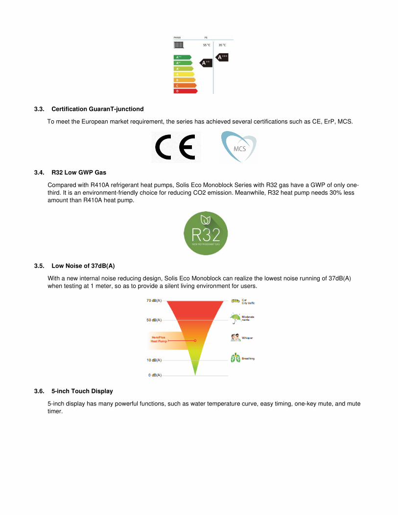
3.5. Low Noise of 37dB(A)
With a new internal noise reducing design, Solis Eco Monoblock can realize the lowest noise running of 37dB(A)
when testing at 1 meter, so as to provide a silent living environment for users.
3.6. 5-inch Touch Display
5-inch display has many powerful functions, such as water temperature curve, easy timing, one-key mute, and mute
timer.

3.7. APP & IOT
Simplify your life with WarmLink. Via connection by Wi-Fi or 4G, you can take full control of your heat pump from
anywhere in your home or office with a single app on your smartphone.
This effectively saves manpower during the after-sales service period. The fault report button allows a direct error
reporting channel to the local service provider. When an error has been reported, the service provider can see the
error information of the target heat pump from the background system, and contact users immediately to offer help.

4. Unit Dimension (mm)
4.1. Models: Solis Eco Monoblock
5. Handling & Installation
5.1. Packing List
Heat Pump Unit × 1
Display Mounting Plate × 1
Rubber Feet × 4
Drain Connection × 1

Display Connecting Wire × 1
Thermistor × 1
*optional accessory
5.2. Installation Site Requirement (Unit: mm)

Solis Eco
L 1006
H 805
W 442
A 750
B 473
P1 200
P2 150
P3 B+100
Φ2

5.3. Cable Specification
Nameplate
max. current Phase
line Earth line MCB Creepage protector Signal line
Less than
10A
2×1.5 mm2 1.5 mm
2 20A 30mA less than 0.1 sec
n×0.5mm2
10~16A 2×2.5 mm2 2.5 mm
2 32A 30mA less than 0.1 sec
16~25A 2×4 mm2 4 mm
2 40A 30mA less than 0.1 sec
25~32A 2×6 mm2 6 mm
2 40A 30mA less than 0.1 sec
32~40A 2×10 mm2 10 mm
2 63A 30mA less than 0.1 sec
6. Parameters
Model Solis Eco
Power Supply / 230V~/30~90Hz
Moisture Resistance IPX IPX4
Electrical Shockproof I I
Heating Condition - Ambient Temp. (DB/WB): 7/6°C, Water Temp. (In/Out): 30/35°C
Heating Capacity Range kW 2.29~8.25
Heating Power Input Range kW 0.63~1.81
Heating Current Input Range A 3.2~8.0
Cooling Condition - Ambient Temp. (DB/WB): 35/24°C, Water Temp. (In/Out): 12/7°C
Cooling Capacity Range kW 1.98~6.10
Cooling Power Input Range kW 0.70~2.22
Heating Current Input Range A 3.3~9.7
Hot Water Function is available for all the sizes.
Max. Power Input kW 2.9
Max. Current Input A 13.0
Water Flow m3/h 1
Refrigerant / Proper Input kg R32 / 1.3kg
CO2 Equivalent Ton 0.88
Sound Pressure (1m) dB(A) 37~54
Unit Dimension(L/W/H) mm 1006×490×800
Shipping Dimension(L/W/H) mm 1120×515×955
Compressor Brand Panasonic

12
Circulation Pump Brand GRUNDFOS
Operating Ambient Temperature ℃ -25~43
Fan Quantity / 1
Fan Motor Type / DC motor
Fan Motor Power Input
(Min~Max) W 30~75
Fan Speed (RPM) RPM 300~850
Water Connection (Inch) Inch 1
Water Pressure Drop (max) kPa 28
Circulation Pump Water Head m 7.5

13
7. Hydronic installation
The hydronic system must be completed in accordance with all local requirements.
The heat pump is designed for connection with a central heating system, the inclusion of a domestic hot water
cylinder is optional , in come cases it may be preferred to use a separate source of domestic hot water in this
case the controller will configured appropriately at commissioning.
Where a cylinder is required it is recommended to pair the unit with a pre-plumbed internal unit from Waterford
Stanley that will combine the central heating and buffer tank and many of the essential system components,
1 Heat Pump 9 Expansion Vessel 16 Heat Emitter
4 Pressure Gauge 10 Pressure Relief 17 Diverter valve
5 Shut off valve 11 Air vent. 19 PT Valve
6 Y Strainer 12 Circulation pump. 20 Electrical heater
7 Shut off Valve 14 Floor Heating valve 21 Hot Water Sensor
8 Buffer Tank. 15 Indirect Hot water Cylinder.
Notes:
Components for High Pressure hot water not shown. Inlet group & Domestic hot water expansion vessel.
Where there are radiators as heat emitters a magnetic filter will be required adjacent to the Y strainer.

14
8. Maintenance
8.1. Precautions for Daily Use
Before starting up the unit for the first time or after a long-time
shutdown, the following preparations must be made:
(1) Thoroughly inspect and clean up the unit.
(2) Clean the waterway system magnetic filter and strainer.
(3) Check water pump, regulating valve and other waterway
equipment.
(4) Tighten all wire connections.
Do not change the system parameters before consulting the engineer.
Ensure the pressure is correct and and pressure vessel is in working
order, otherwise the performance and reliability of the unit will become
compromised.
Ensure the waterways are clean and avoid dirt and blockage.
Where heat pump components need to be replaced only use parts
provided or recommended by the company, do not use nonstandard
parts.
Refrigerant supplement:
Each unit has been equipped with sufficient refrigerant when leaving the
factory. Do not charge or change the refrigerant.
If you need to replenish the refrigerant due to leakage, please contact the
engineer or dealer.

15
8.2. Periodic Maintenance (every 6 months)
8.3. Inspection and Maintenance
8.3.1. Preparing for inspection and maintenance
Danger!
Risk of death caused by fire or explosion if there is a refrigerant leakage!
Only carry out the work if you are a competent person qualified to work with R32 refrigerant.
The product contains combustible refrigerant R32. In the event of a leak, escaping refrigerant may mix with air to form a
flammable atmosphere. There is a risk of fire and explosion.
Ensure that space is sufficiently aerated around the product.
Observe the basic safety rules before carrying out inspection and maintenance work or installing spare parts.
Disconnect the product from the power supply but ensure that the product is still earthed.
8.3.2. Cleaning the product
Do not clean the product with a high-pressure cleaner or a direct jet of water.
Clean the product using a sponge and hot water with a cleaning agent.
Do not use abrasive cleaners. Do not use solvents. Do not use any cleaning agents that contain chlorine or ammonia.
8.3.3. Checking the evaporator, fan, and condensate discharge
Check whether there is dirt between the fins or whether depositions have adhered to the fins.
Clean the fins using a soft brush, avoid fins from being bent.
Check whether dirt has accumulated on the condensate tray or in the condensate discharge pipe.
Check that the water can drain freely
Preparation
Before maintenance, please ensure that the unit has stopped
running and cut off the power supply.
Inspection and
cleaning of fin
heat exchanger
In order to ensure that heat exchangers remain in optimum
condition for heat exchange, their surfaces must be kept clean.
Inspection and
cleaning of plate
heat exchanger
Every 6 months or when the capacity of the unit drops by more
than 10%, check the water-side heat exchanger for scale and
clean the heat exchanger.
Check the
electrical wiring
Check if the contact point is loose, oxidized, or blocked by
sundries, etc., which causes poor contact of the electronic wiring.

16
9. Wiring ( including 200 litre cylinder c/w 50 litre buffer internal Unit)
Wiring Guide
Purpose Specification
1 Supply to External Unit 3 core 16A Supply 4mm2
2 Supply to Internal Unit 3 core 16A Supply 4mm2
3 Wired Controller. Supplied 5 core ( 0.75mm2) - 10 metres
4 Domestic Hot Water Temperature Probe Supplied 2 core( 0.75mm2) - 10 metres
5 Internal to External link cable 5 Core 0.75mm2 (Duct Grade)
6 Call for Heat Signal Cable 2 core shielded twisted pair 0.5m
7 Thermostat Signal Cat 5 Twisted Pair (Duct Grade)
8 Supply to UH 4/8 3 Core 0.75mm2
9 Wiring Centre to Internal Unit ( Pump) 3 Core 0.75mm2
9.1 Wiring layout of Internal Unit

17
10. Display Operation Guide
10.1. Main Interface Display and Function
(1) Power on Interface
(2) Starting up Interface
⑫ ⑪ ⑩ ⑭ ⑨ ⑧ ⑦
⑬
① ② ③ ④ ⑤ ⑥

18
Key
No. Key Name
Key
Function
① ON/OFF Switch the unit ON or OFF. Red represents ON,
while grey represents OFF.
② Lock Screen Lock the screen. White represents disabled,
while green represents enabled.
③ Running Mode
Switch Hot water mode, heating mode, cooling
mode, hot water + heating mode or hot water +
cooling mode
④ Temperature Setting Set the target temperature.
⑤ Timer Setting Set the timer. White represents disabled, while
green represents enabled.
⑥ Setup
Check the unit status, time, factory parameter,
temperature curve, timer setting and mute
setting.
⑦ Fault
This icon will flash when there is an error
showing up. The display will enter fault record
interface after tapping this icon.
⑧ Defrosting The unit is in defrosting mode when this icon
shows up.
⑨ Electric Heater The unit is in electric heater mode when this
icon shows up.
⑩ Ambient Temperature It shows the current ambient temperature.
⑪ Cooling Mode The unit is in cooling mode when this icon
shows up.
⑫ Hot Water Mode The unit is in hot water mode when this icon
shows up.
⑬ Tank Water
Temperature
The unit is in hot water mode when this icon
shows up; Otherwise, this icon is not shown.
⑭
Water Flow
(Not available for
model P24T)
It shows the current water flow (note: When H31=0,
the icon is not displayed).
10.2. ON/OFF
As the main interface shows
(1) In the shutting down interface (on/off key is in grey status), press the on/off key can start up the machine.

19
(2) Note: In starting up interface (on/off key is in red status), press the on/off key can shut down the machine.
10.3. Mode Switch
In the main interface, there are five modes that can be selected after tapping the mode key.
(1)tapping hot water mode icon ①, then the display will change to this mode’s interface;
(2)tapping heating mode icon ②, then the display will enter this mode’s interface;
(3)tapping cooling mode icon ③,then the display will switch to this mode’s interface;
(4)tapping hot water + heating mode icon ④, then the display will go into the hot water + heating mode’s interface;
(5)tapping hot water + cooling mode icon ⑤, then the display will come to the hot water + cooling mode’s interface;
Note: If your unit is a heating-only model (without a cooling function), the "cooling" key will show on the interface.
10.4. Set Target Temperature
①
②
③
④

20
Take hot water + cooling mode for example:
Tapping ①, the wire controller will back to the main interface;
Tapping ②, the target temp of hot water can be set by the pop-up keyboard; Tapping ③, the target temp of cooling
mode can be set by the pop-up keyboard.
When the target temp is being set, the pop-up keyboard is shown as following:
Key No. Key Name Key Function
① Target temp
the new target temp under the current setting
②
Return key Tapping this key can back to the main interface.
③
Delete key Tapping this key to undo the last action.
④
Enter key
Tapping this key can save you action and back to the
main interface.
②
③
①
①
②
③

21
10.5. Unlock Screen
Click the lock screen key again while the screen has been locked, the pop-up keyboard is shown as following:
Note: Input the password of 22 or 022 and click the enter key, the screen will be unlocked.
10.6. Timer Setting
Click the timer setting key to enter the timer setting, the interface display is as follows:
Key
No. Key name Key color Key function
① Return key Click this key to return to the main
interface.
② Enable the timer
on/off
Enable: Green ON
Disable: Gray OFF
Click this key to start or turn off the
timed function
③
Enable the timer
off
Enable: Red ON
Disable: Gray OFF
Click this key to start or turn off the
timed shutdown function
④ Hour of timer on Click this button to set the timing
boot time
⑤ Hour of timer off Click this button to set the scheduled
shutdown time
⑥ Page left Click this button to turn the page left
⑦ Page right Click this button to turn page right
① ④ ⑤
⑥
③
⑦

22
10.7. Setup
Click the setup key to enter the setup and the interface display is shown as follows:
① ② ③ ④
⑤ ⑥ ⑦
Key No. Key Name Key Function
① Return key Click this key to return to the main
interface.
② Operating mode
Click this key to view the current operating
parameters of the unit.
③ Electric heating
Click this key to turn on the unit Electric
heating.
④ Factory parameter
Click the key and enter the password to
enter the factory parameter settings and
status parameters interface.
⑤
System time
setting Click this key to set the system time.
⑥ Mute setting Click this key to set the unit mute function
mode.
⑦ Curve key Click this key to view the temperature
curve.
Note:
If the unit has ②, ⑥ or both functions, the corresponding icon will be displayed on the setting interface.

23
In the setup interface:
(1)Tapping operating mode button②, then the interface display is shown as follows:
(2)Tapping system time setting button⑤, then the interface display is shown as follows:
Key No. Key Name Key Function
① Return key Click this key to return to the setup interface.
② Up key Click this key to increase the value.
③ Down key Click this key to decrease the value.
④ Cannel key Click this key to cancel the current settings and return
to the settings page.
⑤ Enter key Click this key to save the current settings.
(3) Tapping Electric heating button③, then the interface display is shown as follows:
②
④ ⑤
① ②
①

24
Note:
When the unit starts the electric heating, the icon is displayed as ①; When the unit closes the electric heating, the
icon is displayed as ②;
While the unit is in cooling mode, clicking the icon ①, the electric heating will not be turned on;
While the unit is in hot water + cooling mode, if the hot water side is running, the electric heating will be operated
and shown; if the cooling side is running, clicking the icon ①, the electric heating will not be turned on.
(4)Tapping Mute setting button⑥, then the interface display is shown as follows:
Note: When the unit is enabled to activate the mute function, the icon ① is displayed as ; When the unit is
enabled to activate the powerful function, the icon ① is displayed as .
Tapping Mute Timer button ②, then the interface display is shown as follows:
Key No. Key Name Key color Key Function
① Timing Mute Start
Enabled
Enable: Green ON
Disable: Gray OFF
Click this key to start or turn off the
timed mute start enable
① ②
③ ④
① ②

25
② Timed mute end
enabled
Enable: Red ON
Disable: Gray OFF
Click this key to start or turn off the
timed mute end enable
③ Timing mute
start time
Click this button to set the timing mute
start time
④ Timed mute end
time
Click this button to set the timed mute
end time
(5) Tapping Curve button⑦, then the interface display is shown as follows:
a. This curve function records the water inlet temperature and water outlet temperature;
b. Temperature data is collected every five minutes and the 12 sets of temperature data are saved every hour.
Timekeeping is made from the latest data saving, if the power is disrupted when the time is less than 1 hour
(12 sets), the data during such period will not be saved.
c. Only curve for power-on status is recorded, and that for power-off will not be saved;
d. The value of the abscissa indicates the time from the point on the curve to the current time point. The leftmost
point on the first page (0 on the abscissa) is the latest temperature record;
e. Temperature curve record is provided with power-down memory function.
10.8. Locking Window Function
(1) When the main window has been locked, it will show as below:

26
(2) Unlock the mainboard window
Click the “lock” key to unlock the window, it needs to input the password 22 or 022;
11. Failure List & Troubleshooting
11.1. Failure Handling
Issue Possible cause Related components Solution
Unit tripped
when
powered on
Short circuit
Terminals
Relays
Contactors
cables
Check all the components’ connection
Check relays and contactors whether are
broken
Disconnect the electronic components
one by one and powered on to find the
problem
Display
cannot get
power
Cables has
disconnected
The power input cable
is misconnected
Display cable
Power input cable
Check the display cable
Check the power cable
Check the 3-phase power cable whether
connected in right phase sequence
cannot start
up the unit
The unit have error
Cables has
disconnected
Display
Cables
Check the display whether shown error
Check the cable
Reconnect the power cable and check if
it works
Display
cannot work
The display has been
locked
The display is broken
Display
Check the display whether shown locked
icon
Check the cable
Reconnect the power cable and check if
it works
Heating
effect is not
good
The compressor
running low frequency
The fan is not running
or speed is too low
Leakage problem
Compressor
Fan
Refrigerant system
Check the compressor frequency
Check the fan speed
Check the exhaust temperature and low
pressure
Shut off
while didn’t
reach the
Temperature limit
(according to ambient
temperature)
Control logic Check the parameters

27
target
temperature
The
evaporator
has too
much frost
and cannot
defrosting
cleanly
Fan blade or motor
issue
EEV step is not
suitable
Refrigerant amount
issue
Parameters issue
Parameters
Fan
EEV
Refrigerant system
Check the defrosting parameters
Check the compressor frequency
Check the fan speed
Check the exhaust temperature and low
pressure
Abnormal
noise
Screws issue
Fan blade or motor
issue
Compressor issue
Components have
collision
Screws
Fan
Compressor
Other components
(tubes, cables)
Check the screws
Check the fan blade and motor
Check the compressor
Check other components
11.2. Error Code Instruction
Error
code Error name
Relevant parts
information Review and resolve
E04 Electric heater
overheat Protection
1. Check the Electrical heating Overheat protector
open or not.
2. Check the Electrical heater.
E08
Communication
failure between PCB
and display
Communication
error between
PCB and
DISPLAY
1. Check cable connection of PCB and DISPLAY.
2. Check the software version of PCB and
DISPLAY.
E11 HP Protection HP switch is open
1. Check whether showing the error after unit
shutdown.
2. Measure the discharge pressure when unit is
running.
3. Detect EEV step, suction pressure, inlet/outlet
water discharge and suction temp.
4. Release all the gas of the system and refill
refrigerant according to the nameplate.

28
E12 LP Protection LP switch is open
1. Check whether showing the error after unit
shutdown.
2. Measure the suction pressure when unit is
running.
3. Detect EEV step, discharge pressure, inlet/outlet
water discharge and suction temp.
4. Release all the gas of the system and refill
refrigerant according to the nameplate.
E19 Primary Anti-freezing
Protection
Ambient
temp.≤0℃, A04-
2℃ ≤ water
inlet≤A04℃
It is the protection in winter. Once the water
temperature rises up to A04+4oC or the ambient
temp is higher than 1, the error code disappears.
E29 Secondary Anti-
freezing Protection
Ambient
temp.≤0℃, water
inlet≤A04-2℃
It is the protection in winter. Once the water
temperature up to A04+11 oC or the ambient temp
is higher than 1, the error code disappears.
E19 Primary Anti-freezing
Protection
Ambient
temp.≤0℃, 2℃ ≤
water inlet≤4℃
It is the protection in winter. Once the water
temperature rises up to 8 oC or the ambient temp is
higher than 1 oC, the error code disappears.
E29 Secondary Anti-
freezing Protection
Ambient
temp.≤0℃, water
inlet≤2℃
It is the protection in winter. Once the water
temperature up to 15 oC or the ambient temp is
higher than 1 oC, the error code disappears.
E032 Flow Switch
Protection
Flow switch is
open
1. Detect the connection of cables.
2. Detect the flow switch.
3. Detect the water valve is opened or opened
fully.
4. Detect the water pump and the filter.
5. Maybe there is some air in the water route.
E051
Compressor
Overcurrent
Shutdown Fault
Compressor
Overcurrent
1. Check ambient temp. and inlet/outlet water
temp.;
2. Turn on the unit. Record and analyze the
changing process of high/low pressure,
discharge/suction temp., EEV step, compressor
frequency and running current.
3. If they are OK, replace a new compressor driver
board.
E065 High water outlet
temp. protection
Check if the water flow is too low and the outlet
water whether too high
E081
Communication
failure between PCB
and fan drive board
Communication
error between
PCB and fan drive
board
1. Check the connection between PCB and fan
board. All of 12V-12V, GND-GND, A-A, B-B should
be closed;
2. If they are closed, turn on the power, then
measure the voltage between 12V and GND on fan
board, if higher than 15V or lower than 7V, replace
a new fan board.

29
E103 Fan motor overload
protection
1. Check if the fan motor running well.
2. Detect the current of fan motor.
3. If the current is more than 1A, it means the
motor have problem and need to replace a new
one.
4. If the current is less than 1A, it means the motor
control module have problem and nee to replace a
new one.
E171 Anti-freezing
Protection
inlet water ≤A04℃
and the antifreeze
temp ≤A04-
A05 ℃
1. Check the water flow.
2. Check the outlet water temp sensor.
3. Measure the ambient temp.
4. Detect the connection of cables.
5. Check the record of defrosting, whether the
defrosting time is too long or too often.
F01 Compressor
activation failure
Restart the unit.
1. Check the changing process of EEV step, high
pressure, low pressure, inlet/outlet water temp.
2. Check the connection of U/V/W between
compressor and compressor driver board.
3. Check the compressor resistance.
4. Check compressor driver board.
F03 PFC Fault
Restart the unit.
1. Check the power supply connection and
voltage supply is stable or not.
2. 2.Replace a new compressor driver board.
F05 DC Bus Overvoltage
1. Check the voltage between DCP-IN and
DCN-IN, if lower than 300V, the unit will
get this protection.
2. Check the input voltage of R/S/T on
compressor driver board, if lower than
210V, the unit will get this protection
3. If they are OK, please replace a new
compressor driver board.
F06 DC Bus
Undervoltage
1. Check the voltage between DCP-IN and DCN-
IN, if lower than 300V, it will get this protection;
2. Check the input voltage of R/S/T on compressor
driver board, if lower than 210V, it will get this
protection;
3. If they. are OK, please replace a new
compressor driver board
F07 AC Input
Undervoltage
1. Measure the input voltage of R/S/T of driver
board, if lower than 300V, it will get this protection.
2. If it’s OK, replace a new compressor driver
board.

30
F08 AC Input Overcurrent
Only in single phase unit. Restart the unit. Check if
there is electric leakage. If not, replace a new drive
board.
F09 Input voltage
sampling fault
1. Make sure power supply not lower than 300V or
higher than 500V;
2. If it’s OK, please replace a new compressor
driver board.
F10
Communication
Failure between DSP
and PFC
Only in single phase unit.
1. Check the inverter board connection.
2. If no problem, replace a new compressor driver
board.
F11
Communication Fault
between DSP and
Communication
board
1. Please check the inverter board connection.
2. If no problem, please replace a new compressor
driver board
F12
Communication
failure between PCB
and driver board
1. Check the connection between main control
board and compressor driver board. All of 12V-
12V, GND-GND, A-A, B-B should be closed.
2. If they are closed, turn on the power, then
measure the voltage between 12V and GND on
compressor driver board, if higher than 15V or
lower than 7V, please replace a new one
compressor driver board.
F13 IPM Overheat Stop
1. Check the fans are running or not.
2. Check the installation distance and space.
3. Leave enough distance and space to make heat
pump have a good transfer heating condition.
4. Clean the finned heat exchanger.
5. If they are OK, replace a new compressor driver
board.
F15 Input voltage Lacking
Phase
1. Check the phase of power supply R/S/T to
compressor driver board.
2. If it’s OK, replace a new compressor driver
board.
F16
Compressor weak
magnetic protection
alarm
1. Check the refrigeration system.
2. If it’s OK, replace a new compressor driver
board.
F17 Temperature fault of
drive board
1. Check the connection of heat sink temp. sensor.
2. Check the resistance of heat sink temp. sensor.
3. If they are OK, please replace a new heat sink
and heat sink temp. sensor.
F18 IPM Current
Sampling Fault
1. Check ambient temp. and inlet/outlet water
temp.
2. Check high/low pressure and discharge temp.
and suction temp.

31
3. Check EEV step.
4. Check the compressor frequency and current.
5. If they are OK, replace a new compressor driver
board.
F20 IGBT Power Device
Overheat Alarm
1. Check the fans are running or not.
2. Check the installation distance and space.
3. If they are OK, please replace a new
compressor driver board.
4. Leave enough distance and space to make heat
pump have a good transfer heating condition.
5. Clean air to fin heat exchanger.
F22 AC input overcurrent
protection alarm
Only in single phase unit. Restart the unit.
1. Check if there is electric leakage.
2. If still have the failure, replace a new drive
board.
F23 EEPROM Fault
Alarm
1. Check the connection;
2. Replace a new driver board; F24
Destroyed EEPROM
Activation Ban Alarm
F25 LP 15V Underload
Fault
1. Check the power supply is stable or not, and
restart unit.
2. If the problem still on, please replace a new
drive board.
F26 IGBT Power Device
Overheat Fault
1. Check the fans are running or not;
2. Check the installation distance and space;
3. Leave enough distance and space to make heat
pump have a good transfer heating condition;
4. Clean the finned heat exchanger.
5. If they are OK, please replace a new driver
board;
F031 DC Fan Motor 1
Failure
1. Turn off the unit and check the connection.
2. Restart and check if the motor is running normal
or the error happens again.
3. Replace a new fan motor. F032
DC Fan Motor 2
Failure
Pp1 Exhaust Pressure
Sensor Fault
1. Detect the exhaust pressure sensor connection
2. If the connection is OK, please replace a new
one.
Pp2 Suction Pressure
Sensor Fault
1. Detect the suction pressure sensor connection
2. If the connection is OK, please replace a new
one.

32
TP Low Ambient Temp.
Protection
Ambient temp ≤-
30
1 Check the ambient temp
2. When ambient temp ≥-28℃, the fault will
disappear.
P01 Water Inlet Temp.
Sensor Fault
1. Detect the connection.
2. Measure the resistance of sensor, if lower than
100Ω or higher than 500kΩ, please replace a new
one.
P02 Water Outlet Temp.
Sensor Fault
P04 Ambient Temp.
Sensor Fault
P17 Water Outlet Temp.
Sensor Fault
P032 Hot Water Tank
Temp. Sensor Fault
P42 Room Temp. Sensor
Fault
P101 EVI Inlet Temp.
Sensor Fault
P102 EVI Outlet Temp.
Sensor Fault
P153 Coil Temp. Sensor
Fault
P181 Exhaust Temp.
Sensor Fault
P182 Exhaust Over Temp. (Exhaust temp.) ≥
C05 default 110
1. Measure the resistance of sensor, if lower than
100Ω or higher than 500kΩ, please replace a new
one.
2. Check the unit find if it has refrigerant leakage.
P191 Antifreeze Temp.
Sensor Fault
1. Detect the connection
2. Measure the resistance of sensor, if lower than
100Ω or higher than 500kΩ, please replace a new
one.
Supplied By
Waterford Stanley Ltd
Unit 401-403, IDA Industrial Estate,
Cork Road,
Waterford, Ireland.
Tel: 051 302300
www.waterfordstanley.com