Hydride Re-orientation in Zircaloy and its Effect on the Tensile ...
49
SKI Report 98:32 SE9900008 Revised edition Hydride Re-orientation in Zircaloy and its Effect on the Tensile Properties Kwadwo Kese August 1998 ISSN 1104-1374 ISRNSKI-R-98/32-SE 30- 07 STATENS KARNKRAFTINSPEKTION Swedish Nuclear Power Inspectorate
-
Upload
khangminh22 -
Category
Documents
-
view
1 -
download
0
Transcript of Hydride Re-orientation in Zircaloy and its Effect on the Tensile ...

SKI Report 98:32 SE9900008
Revised edition
Hydride Re-orientation in Zircaloy andits Effect on the Tensile Properties
Kwadwo Kese
August 1998
ISSN 1104-1374ISRNSKI-R-98/32-SE
30- 07
STATENS KARNKRAFTINSPEKTIONSwedish Nuclear Power Inspectorate

SKI Report 98:32
Revised edition
Hydride Re-orientation in Zircaloy andits Effect on the Tensile Properties
Kwadwo Kese
Department of Materials Science and Engineering,Royal Institute of Technology, SE-100 44 Stockholm, Sweden
August 1998
SKI Project Number 97228
This report concerns a study which has been conducted for the Swedish Nuclear PowerInspectorate (SKI). The conclusions and viewpoints presented in the report are those of
the author and do not necessarily coincide with those of the SKI.

Norstedt Tryckeri AB,Stockholm 1998

Summary
Based on literature studies and experimental work, investigations were carried out to determine
the stress and thermal conditions required for the reorientation of hydrides from an initial
circumferential orientation to a radial one. The section of microscopic reference was transverse,
in hydrided ring samples of Zircaloy. It was found that, both the degree of reorientation and the
relative amount of radial hydrides achieved, were dependent on the hydrogen content of the
material, given the same stress and thermal conditions. The need to take most of the hydrides into
solution at the uppermost temperature of the thermal cycle, in order for complete reorientation to
occur, became also clear. In general, an upper temperature of 500°C, in combination with an
orientation stress in the interval 150-200MPa was found to be adequate for the reorientation to
radial hydrides.
On the basis of these inital results, attempts were then made to produce ring test samples in which
the hydrides had assumed the radial orientation. These were subsequently subjected to the tensile
test in order to investigate the effect of hydride reorientation on the tensile properties of the
material. The tests, which were conducted at room temperature and higher temperatures (100°C,
150°C, 200°C, 250°C, 300°C), showed that the hydrides were brittle at room temperature but
became less so at higher temperatures. With the exception of the samples which were tested at
room temperature, all the other samples did show a ductile failure. At the strain rate employed in
the present work (0.02cm/min) therefore, the radial hydrides could not be said to have a reducing
effect on the ductile characteristics of Zircaloy at higher temperatures.
Sammanfattning
Genom litteraturstudie och experimentella försök har man undersökt de termiska- och
spänningsvillkor som krävs för att åstadkomma hydridomorientering i Zircaloy. Man har utgått
från ringprover av hydrerade rör av materialet. Hydridorienteringen defineras m.a.p de radiella
och tangentiella riktingarna i ett tvärsnitt. Till en början hade hydriderna en tangentiell
orientering och man har kommit fram till att såväl omorienteringsgraden som mängden
omorienterade hydrider är beroende av materialets vätehalt om man utgår från samma spännings-
och termiska villkor. Ett annat viktigt resultat var att en förutsättning för hydridomorientering är
återupplösningen av hydrider vid den högsta temperaturen under värmebehandlingen. Allmänt
gäller att en upplösningstemperatur av 500°C i samband med en orienteringsspänning i intervallet
150-200MPa är tillräcklig för att åstadkomma radiella hydrider.
Utgående från de föregående resultaten har man försökt att tillverka ringprover som innehöll
radiella hydrider. Man har sedan dragprovat dessa för att undersöka vilka samband som skulle
råda mellan det radiella tillståndet och dragegenskaperna. Försöken utfördes vid rumstemperatur
och högre temperaturer (100°C, 150°C, 200°C, 250°C, 300°C). Det visade sig att hydriderna var
spröda bara vid rumstemperatur och blev alltmer duktila vid högre temperaturer. Med undantag
av de prov som testades vid rumstemperatur visade alla andra prover duktilt brott. Vid den
töjningshastighet som rått under de här testerna (0.02cm/min) kan man således inte konstatera
någon draghållfasthetsnedsättningseffekt i Zircaloy orsakad av radiella hydrider vid förhöjda
temperaturer.
n

Dedicated
To
Kerttu and Jan-Erik Bergsten
" Av Herren har den blivit detta, underbartdr det i vdra ogon."
Ps. 118:23
in

Acknowledgement
I have had the privilege of working under the able supervision of Prof. Kjell Pettersson. I have
always drawn inspiration from the keen interest he has shown throughout the course of this
project. Here is therefore to thank you, Prof., for the enormous support and encouragement.
I wish to thank Per-Olof Soderholm, Nils Lange, and Hans Bergquist for the technical assistance
relating to the project.
Magnus Oscarsson was generous in placing at my disposal his collection of literature material
relating to the subject of investigation; Lars Ekman was the one who made me to understand the
operation of the various test equipment; Torbjorn Narstr6m was forthcoming when I needed help
with the software: to these post-graduate students at the Division of Mechanical Metallurgy I
would like to express my sincere gratitude. I would also like to thank Pal Efsing for reading
through the manucsript and offering useful suggestions.
The discussions that I had with Ann Svensson who also, almost concurrently, did conduct studies
in different aspects of the subject are also noted here as having been helpful.
I should also like to thank Kristina Wendt for the administrative work in connection with this
project.
Finally the interest shown by Irene Jansson, Marika Wallin, Kofi Akosah and S. Appiah-Kubi in
regard of the progress of this work is also acknowledged with much appreciation.
Finally, the financial support by the Swedish Nuclear Power Inpectorate (SKI) is gratefully
acknowledged.
IV

ContentsSummarySammaniattningAcknowledgement
1 BACKGROUND .. 1
2 THEORETICAL CONSIDERATIONS 3
2.1 Hydrides in Zirconium 32.1.1 The Zr-H System 32.1.2 Hydride Precipitation— nucleation and growth 42.1.3 Stress Re-orientation of Hydrides in Zircaloy 4
3 LITERATURE REVIEW — RELATED WORK BY OTHERS 6
4 EXPERIMENTAL 8
4.1 Work Schedule and Tools for Analysis 84.1.1 Definitions and Methods of Evaluations of Relevant Parameters 8
4.2 Auxiliaries 104.2.1 Determination of Hydrogen Content 104.2.2 Metallographic Analysis 10
4.3 Experimental Procedure 114.3.1 Determination of the stress-thermal conditions for hydride re-orientation 114.3.2 Production of Test Samples with Radial Hydrides 114.3.3 Tensile Testing of 'Radial' Specimens 12
5 RESULTS AND DISCUSSION 13
5.1 Determination of the Stress -Thermal Conditions 135.1.1 Results 135.1.2 Discussion 185.1.3 Conclusion , 21
5.2 Tensile Testing of Specimens Containing 215.2.1 Discussion 215.2.2 The "fully oriented" samples 265.2.3 Conclusion 33
5.3 Fractography 33
6 SUGGESTIONS FOR FURTHER WORK 36
7 REFERENCES 37
8 APPENDIX 38

1 Background
When the hydrogen content exceeds the solubility limit in Zircaloy, hydride precipitation may
occur. The hydrides are generally thought to be brittle and can, in sufficiently large quantities,
impart brittle characteristics to the alloy. This material embrittlement has, as a result of
extensive research work, been shown to be non-existent at temperatures in excess of 150°C, in
a manner reminiscent of the ductile-brittle transition behaviour observed in ferritic steels. It is
however not quite clear if this behaviour can be attributed to the brittle characteristics of the
hydrides, or to the composite behaviour of the metal-hydride mixture. When a crack is
present, then according to the general theories of delayed hydride cracking (DHC), the
process of crack propagation is driven by the combined mechanisms of diffusion and
precipitation whereby hydrogen atoms diffuse to the stressed crack tip and later precipitate as
the hydride; when it has grown large enough, the hydride cracks and the process continues in
a like manner. A necessary condition for this to occur is for the hydride to remain brittle at the
temperatures concerned. At temperatures higher than 150°C one would expect a breakdown in
this mechanism if the hydrides became ductile. The work of Efsing [1] has shown however,
that crack propagation does occur in hydrided Zircaloy at 300°C. Therefore, if one asserts that
a ductile-brittle transition in the hydride could be the sole factor underlying the exhibition of a
similar behaviour in the alloy, then one has to find an explanation for Efsing's observation in
yet another hydrogen-related crack propagation mechanism. Photomicrograph studies (see
Fig.l) of regions around cracks reveal a hydride network structure in the immediate vicinity
of a growing crack, instead of the single isolated hydride that the DHC theory might give an
impression of. The direction of crack propagation is found to be parallel to the orientation of
the hydrides which, in turn, is perpendicular to the direction of the applied stress. It is
believed that this network, whose formation is diffusion-related, constitutes a metal-hydride
composite the mechanical properties of which are quite different from those of the parent
microstructure. In particular, the network is thought to have a local fracture toughness value
that is lower than in other parts of the material. The amount of hydride contained in this
network is important to the extent that, a certain minimum of hydride presence is necessary
for the conditions of crack propagation to be met. This last point implies that one considers
the formation of the hydride structure with reduced toughness properties as a time-dependent
process and that a necessary pre-requisite is the existence of a crack in a stressed material.
The crack first propagates through a composite network and is stopped on reaching a tougher
material; after some time, diffusion and growth have proceeded to such an extent that the
necessary network structure for crack propagation is formed, crack propagation is resumed
and the process is repeated.
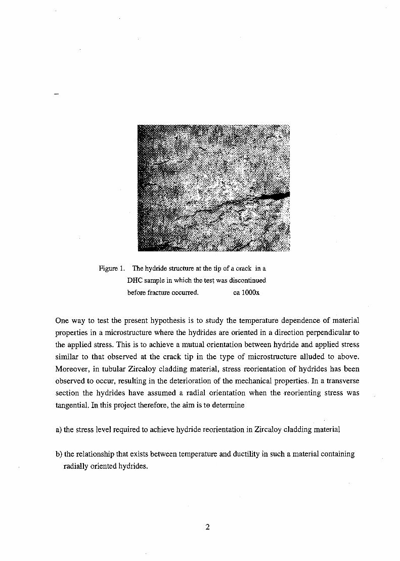
Figure 1. The hydride structure at the tip of a crack in a
DHC sample in which the test was discontinued
before fracture occurred. ca lOOOx
One way to test the present hypothesis is to study the temperature dependence of material
properties in a microstructure where the hydrides are oriented in a direction perpendicular to
the applied stress. This is to achieve a mutual orientation between hydride and applied stress
similar to that observed at the crack tip in the type of microstructure alluded to above.
Moreover, in tubular Zircaloy cladding material, stress reorientation of hydrides has been
observed to occur, resulting in the deterioration of the mechanical properties. In a transverse
section the hydrides have assumed a radial orientation when the reorienting stress was
tangential. In this project therefore, the aim is to determine
a) the stress level required to achieve hydride reorientation in Zircaloy cladding material
b) the relationship that exists between temperature and ductility in such a material containing
radially oriented hydrides.

Theoretical Considerations
2.1 Hydrides in Zirconium
Figure 2. The Zr-H phase diagram.
2.1.1 The Zr-H System
Atomic Percent Hydrogen30 40 SO
0 0.2
Zr0.6 0.B 1 12 1.4
Weight PerceijL Hydrogtin
Fig. 2 [2] shows that the Zr-H equilibrium phase diagram is of the eutectoid type. The system
consists of two solid solution phases of hydrogen in zirconium known as the a- and P- phases,
and three hydride phases known respectively as the y-hydride, the 5-hydride and the e-
hydride. Table 1 summarises some of the crystallographic properties of the various phases
that can exist at temperatures below 550°C. The metal sublattice transforms its structure
between these phases changing [3] for instance from a hep structure for cx-Zr, through fee for
8, to fct for y and e whilst the hydrogen invariably occupies the tetrahedral sites in preference
to the octahedral interstitial sites in a rather random manner. In the bec structure of the (3-Zr
however, the hydrogen location is not known with certainty [3].
Table 1. Crystallographic data for the different phases of the Zr-H system [3].
Phase Crystal Structure Lattice Parameter
(nm)
Density (g/cm3)
a-Zr
y(ZrH)
5(ZrH,6)
8(ZrH2)
hep
fct
fee
fct
a0.323
0.460
0.478
0.498
c0.515
0.497
-
0.445
6.51
5.82
5.64
5.61

2.1.2 Hydride Precipitation nucleation and growth
The hydrides are normally precipitated from supersaturated solutions in the form of discs [4]
with a preponderant preferred orientation that traces to the material processing history. In
tubular cladding material for example, the manufacturing process is controlled to leave the
finished product with a deliberate texture the ultimate aim of which is to assure peripheral
orientation of the hydrides. Such a microstructure has been found to be desirable from the
point of view of the fracture properties of the material [4].
The type of hydride that forms has been found [3] to depend on factors such as grain size, heat
treatment, method of hydriding and specimen purity. High cooling rates are reported as
generally favouring the formation of y-hydrides whilst at slow cooling rates, the level of
specimen purity as determined by the oxygen content may result in the formation of 8-
hydrides at high oxygen contents (above lOOOppm) and of y-hydrides at low oxygen contents
(below 200 ppm).
A unified theory of nucleation and growth of hydrides in zirconium is not to be found in the
literature; nevertheless, much research effort has been done, as indicated by Pettersson [2] in
his study of the subject. In general, it is believed that the nucleation of hydrides is
heterogeneous and occurs in the hep-lattice as a result of a shear transformation caused by the
gliding of Shockley partial dislocations on alternate basal (0001) planes of the matrix, and a
subsequent diffusion of hydrogen atoms to the resultant high energy sites. The said
transformation leads to the formation of fee areas within the hep lattice. In the recrystallized
and annealed state, heterogeneous nucleation, evenly distributed in the grain boundaries, is
proposed in the literature whereas twin boundaries and transgranular nucleation sites are
proposed for the cold-worked state. It appears therefore that the site for hydride nucleation is
influenced by the internal stress state of the material as well as prevailing temperature
conditions.
2.1.3 Stress Re-orientation of Hydrides in ZircaloyC.E. Ells [4] has shown that the theory of stress orientation of Fe16N2 precipitates in iron
which was derived by J.C.M. Li can also be used largely to describe the same phenomenon of
hydrides in zirconium. The angular deviation of the traces of the individual hydride platelets
in relation to a reference direction in the same plane of sectioning is usually assigned the
value <|). In the present discussion, this reference is chosen to be the direction perpendicular to
the applied stress. For a pre-selected limit of angular deviation denoted by x (in degrees), one
would like to determine the proportion of hydrides whose <j>-values fall within the range 0-x°.
Expressed as a percentage, this quantity is also called the fN parameter in the literature [2],

where N has the same definition as x above. For tubular specimens for instance, the ASTM
standards B 353-91 and B 811-90 specify a radial hydride as one oriented within 0-40° of the
radial direction in the transverse section [1]. Ells defined a quantity, Ra, as the ratio between
the number of hydrides with (Rvalues in the (0-x°) range, to the number in the complementary
range and arrived at the following expression
Rc = Roexp(Vc5aco/kT) (1)
where
Ro = the value of Rc in the absence of an applied stress.
GOO = the effective stress during nucleation at a nucleation site.
CO = cos2(3, where |3 is the angle between the stress direction and the normal to the hydride
such that 0 <co< 1.
5 = the linear strain of the lattice in the direction of the applied stress due to formation of a
new phase.
Vc = the volume of the nucleus.
Since Ra is an orientation parameter, Eq.(l) describes that the orientation of hydrides in
zirconium has an exponential dependence on the applied stress. Two different premises for
stress orientation must be distinguished: (i) orientational growth of stable precipitates and (ii)
orientation of nucleation. In the first case, the achievement of perceptible orientation under
the constraint of the normal times of experiment is dependent on the hydrogen concentration
gradient existing between parallel and perpendicular hydrides, the sense of orientation being
relative to the direction of the applied stress. Ells has estimated, using reasonable
assumptions, that the effect of the said concentration gradient would be small in comparison
with the effect of the applied stress on nucleation. One comes therefore to the conclusion that
hydride orientation occurs as a result of nucleation orientation rather than through the
orientational growth of stable precipitates. Later work by others including Ells [5] has
however shown that when hydride is present, stress-induced movement of hydrogen in
zirconium can occur, and this is generally accompanied by hydride orientation even though
much longer times are required for its observation. One further observation is that, when all
the hydrogen is in solution at the upper temperature of a thermal recycling process, stress
orientation appears to be due to a martensitic memory effect. When hydrides are present at the

upper temperature, stress-induced growth may be used to explain much of the observed
reorientation.
3 Literature Review Related Work by Others
Marshall and Louthan [6] investigated the effects of hydrogen content and hydride orientation
on the mechanical properties of Zircaloy at room temperature conditions. In order to achieve
radial hydrides, specimens were solution annealed at 415 °C for 16 to 18 hrs and then loaded
and cooled to room temperature in 6hrs. The applied stress range was 0-174 MPa; their aim
must therefore have been to achieve different degrees of reorientation in the different
specimens. The specimens were then tested to fracture at room temperature and the relevant
mechanical properties evaluated. From their observations they concluded that the influence of
hydrogen on the mechanical properties was determined by the orientation of the hydride
platelets. They were able to show that reductions in strength and ductility were caused by the
amount of hydride that was oriented perpendicular to the deforming stress and that parallel
hydrides had relatively little effect.
- In a similar experiment Bell and Duncan [7] solution heated test specimens (of hydrided
cold-worked and heat-treated Zr-2.5%Nb pressure tubing) at 500°C for lhr; furnace cooling
was then started until 450 °C where tensile loading was applied, and cooling was continued
down to room temperature.The applied stress varied among the specimens as 200, 150, 100,
75, and 17 MPa. Upon evaluation of the results they concluded that stress-induced hydride
orientation is more pronounced when the temperature of initial precipitation is increased and
that there is a minimum applied stress for hydride reorientation when the initial precipitation
temperature was below 430°C. In this experiment the effect of hydride orientation on the
mechanical properties was not considered.
- Hardie and Shanahan [8] also carried out an investigation on stress reorientation and came
to the conclusion that only hydride taken into solution can become re-oriented. They stressed
however the importance of having a manufacturing texture that gives a high concentration of
basal poles parallel to the direction of the applied stress. Still on the effect of fabrication
texture, Parry and Evans [9] observed from their experimental results that the hydrides did
precipitate in the direction parallel to the direction of grain deformation. The degree of
directionality increased with increasing strain, the minimum strain for directionality to occur
being about 7%.

- In another experiment, Price [10] determined the effect of radially oriented hydrides on the
tensile properties of a Zr-2.5wt%Nb pressure tubing. In this case, hydride reorientation was
achieved through the corrosion hydriding of internally pressurised samples. He observed that
under the biaxial stress state resulting from the kind of loading employed, hoop stresses in
excess of 138 MPa was adequate for the achievement of complete radial reorientation. By
conducting transverse tensile tests on the hydrided specimens using a reduced ring test
technique it was revealed that the material with radial hydrides had a ductile-brittle transition
temperature below 100°C; above this temperature serious reduction in ductility occurred only
in the case of massive surface hydride precipitation. He also noted that specimen geometry
had an effect on the tensile strength and the per cent elongation.
- Garde et al [11], when they investigated the ductile properties of irradiated Zircaloy-4,
concluded that the decrease in ductility observed in the material was due the combined effects
of localised hydride distribution and the orientation of the hydride precipitates relative to the
loading direction. They also noted that the extent of reduction in ductility depended on the
method of testing, asserting the comparatively high severity of the burst test in relation to
either the tube tensile test or the ring tensile test as a method for ductility evaluation.
- The last to be considered in this series is another work by Parry and Evans [12] which, in
several respects, has direct similarities with the current project. The main difference is the
geometry of the test specimens which, in their case, was of the conventional tensile type with
cylindrical gauge length. They however showed in the same paper that this should not affect
test results. Their work covered, among other things, aspects of stress reorientation of the
hydrides and its effect on the tensile properties of Zircaloy under both room-temperature and
other elevated-temperature conditions. Their conclusion was that hydride orientation, texture,
test temperature and metallurgical condition (referring to the irradiated /unirradiated states)
were important contributory factors to the tensile behaviour of the material. One further
important observation they made was that the strain rate can also have a major influence on
the results obtained from such tests.

4 Experimental
4.1 Work Schedule and Tools for Analysis
Based on relevant literature studies, it was expected through experimental work to establish
the thermal and stress conditions necessary for hydride reorientation to occur. Having
achieved this, several samples with reoriented hydrides were produced. The samples were
then subjected to the tensile test. Finally, the results of the tensile tests were analysed and the
relevant parameters evaluated.
4.1.1 Definitions and Methods of Evaluation of Relevant Parameters
Ductility : The ability of a material to deform plastically without fracture. Strain to
fracture and percentage reduction in area are used as measures of ductility
[13].
Strain to fracture: The permanent extension in length (measured by fitting the broken pieces
together) expressed as a percentage of the original gauge length.
In this project the total plastic strain is determined.
It is determined as the ratio between the measured displacement of the
cross-head to the gauge length. The gauge length is taken to be 20% of the
ring circumference. This is based on the method used by Garde et al.[l 1].
Reduction in area :The maximum decrease in cross-sectional area at fracture expressed as a
percentage of the original cross-sectional area.
(A o -A b r e a k ) /A oxl00
Tensile Strength : Maximum value of F/Ao during a test to failure.

Specimen Description
The specimen was received as hydrided Zircaloy tubes of 100 mm-length. The average wall
thickness and outer tube diameter were 0.65 and 9.65 millimetres respectively. They were cut
into approx. 3mm long rings which served as the test samples. For a more detailed description
of the test material and how samples are mounted on the testing machines, see Refs.l&14 or
the appendix.
Test Equipment
1. Creep Machine Type Bofors 3,6 Mp with a vertical bore type furnace
-used for the production of oriented samples.
2. Instron Tensile Testing Machine equipped with a 10-ton load cell, a load amplifier
(D2000), a strain gauge transducer with direct coupling to a Lab View Macintosh program
which gives a voltage-vs. displacement reading. Mounted on the Instron is a vertical bore
furnace.
Speed of travel of crosshead during tensile testing: 0.02cm/min = 0.0002/60 m/s
Load-Voltage conversion factor : 1 volt. = 6455.3 kg
Illustrative Calculation of basic parameters.
Sample Identification : P 44
Sample dimensions : initial wall thickness, to= 0.675mm
wall thickness at fracture section, tf = 0.64 mm
initial axial length, l0 = 3,265mm
axial length at fracture section, lf = 2.79 mm
initial outer diameter, d0 = 9.65 mm
Initial cross-sectional area, Ao = 210 Jo = 2(0.675)(3.265) = 4.40775 = 4.408 mm2
Cross-sectional area at fracture, Af = 2(2.79)(0.64) = 3.571 mm2
Area reduction for P44 = (Ao- Af) / Ao x 100% = (4.408 - 3.571) / 4.408x 100% = 18.98 %
Initial outer circumference, Co =rc d0 = 30.316 mm
Gauge length (=20% of Co) = 6.06 mm
At time t (= 15s, say), during the tensile test the quantities are evaluated as follows
Displacement = (time x 0.0002)/60 = 0.00005 m
Loadl = 6455.3 x voltage = 6455.3 x 0.00046 = 2.969438 kg
Load = Loadl x 9.81 = 29.130187 N
Strain = Displacement x 1000 / Co = (0.00005 x 1000)/ 6.06 = 0.00825083
Stress = Load / Ao = 29.130187 / 4.408 = 6.60848157
4.2 Auxiliaries
Under this heading various supporting activities, as opposed to the main experimental work,
are described. Their function is mainly auxiliary and often recurrent and are better treated
separately.
4.2.1 Determination of Hydrogen Content
In order to determine the hydrogen content, a small bit of the material was cut off each
specimen after the tensile test. The hydrogen content of the cut-off bit was then determined
using the vacuum extraction method. The results obtained from such analyses are the values
of ppm hydrogen used throughout this report for the test samples.
4.2.2 Metallographic Analysis
Sample preparation
Samples for metallographic analysis were first cast in Bakelite. They were then ground down
in succession on emery paper grades 240, 320, 600, 1200 after which they were washed in
water and ethanol. Upon drying they were polished in two stages on polishing cloths smeared
with diamond paste.The samples were then etched.
Etching
The etching solution was made up of: 40 parts% hydrogen peroxide, 40 parts% acetic acid, 15
parts % nitric acid and 5 parts% hydrofluoric acid by volume. Etching time was 16 seconds
followed by successive washing under the tap and in ethanol. The final step was the use of the
ultra-sonic bath and subsequent washing-off with ethanol and drying.
10
Microscopic examination and photography
Polished and etched specimens were examined under the light-optical microscope with the
main objective of determining the orientation of the hydrides. Photomicrographs were taken
as has been found necessary.
4.3 Experimental Procedure
The experimental procedure is arranged into three main different phases to reflect the defined
objectives of the project. This section will therefore discuss each one of them in turn.
4.3.1 Determination of the stress-thermal conditions forHydride re-orientation
Hydrided tubular specimens were cut into test rings of 3mm nominal axial length. The rings
were placed in the creep machines and then subjected to different conditions of temperature
and stress. The results, in terms of degree of hydride re-orientation were determined through
metallographic analysis. The tests differed from each other in the type of thermal re-cycling
(namely, highest temperature reached, time at temperature, method of cooling to room
temperature) and the applied-stress characteristics (namely, stress magnitude and its point of
application in the thermal cycle). A summary of the different attempts is presented in Table A
in the Appendix and photomicrographs of the more interesting cases are shown on pages 14-
17 and 19-20. The reported results have been based on the method of visual inspection of the
metallographic sections in the microscope rather than the much more quantitative method of
determining the hydride orientation through the f N - value. The visual method is adequate for
the purpose of this part of the work namely, the achievement of full radial re-orientation of
the hydrides.
4.3.2 Production of Test Samples with Radial Hydrides
Based on the results of 4.3.1, production parameters for the achievement of radial hydrides in
test samples were determined. The chosen parameters were those corresponding to Test KP16
in Table A. The idea was to replicate the results corresponding to fully re-oriented hydrides
by subjecting the samples to the same experimental conditions as in KP16. Since several of
such 'radial' samples were to be produced, this part of the project was called the production
11

part. Hydrided ring test samples of similar dimensions as in 4.3.1 were prepared. These were
then placed in the creep machines and heated to 500 °C. After holding at that temperature for
lhr. the furnace was shut down and the specimens were allowed to cool in the closed furnace
down to room temperature. At 425 °C during the cooling process, loads corresponding to a
tensile stress of about 150MPa were applied; this loading condition was maintained
throughout the cooling process The samples thus produced were then subjected to the tensile
test.
4.3.3 Tensile Testing of 'Radial' Specimens
Six different test temperatures (25°C, 100°C, 150°C, 200°C, 250°C, 300°C ) were chosen at
which tensile tests were to be conducted. About 8 samples were assigned to each test
temperature. At each test temperature the samples differed from one another by the ppm H
value. Each test sample was placed in the Instron and heated to the pre-determined test
temperature and held for lhr after which tensile loading was applied at that constant
temperature until rupture occurred. The load-extension process was both monitored and
recorded on the computer.
The dimensional changes on each of the ruptured samples were then noted and recorded.
Small bits of the tested samples were cut off for hydrogen content analysis and the remaining
part was prepared for metallographic examination to determine the extent of reproducibility
achieved, with respect to hydride re-orientation. Photomicrographs of only those samples that
contained full radial hydrides are shown in this report (see Section 5.2.2).
12

5 Results and Discussion
5.1 Determination of the Stress -Thermal Conditionsfor Hydride Re-orientation
5.1.1 Results
The results are presented in Table A of the Appendix and the photomicrographs of the more
interesting cases are shown in Figs.3-14 below. The photomicrographs are grouped as
follows: 1. hydrided only sample; 2. sample with circumferential hydrides only; 3. sample
with circumferential + hydride particles; 4-7..samples with mixed radial and circumferential
hydrides; 8-9. samples with varying hydride orientation toward radial; 10-12. samples with
predominantly radial hydrides.
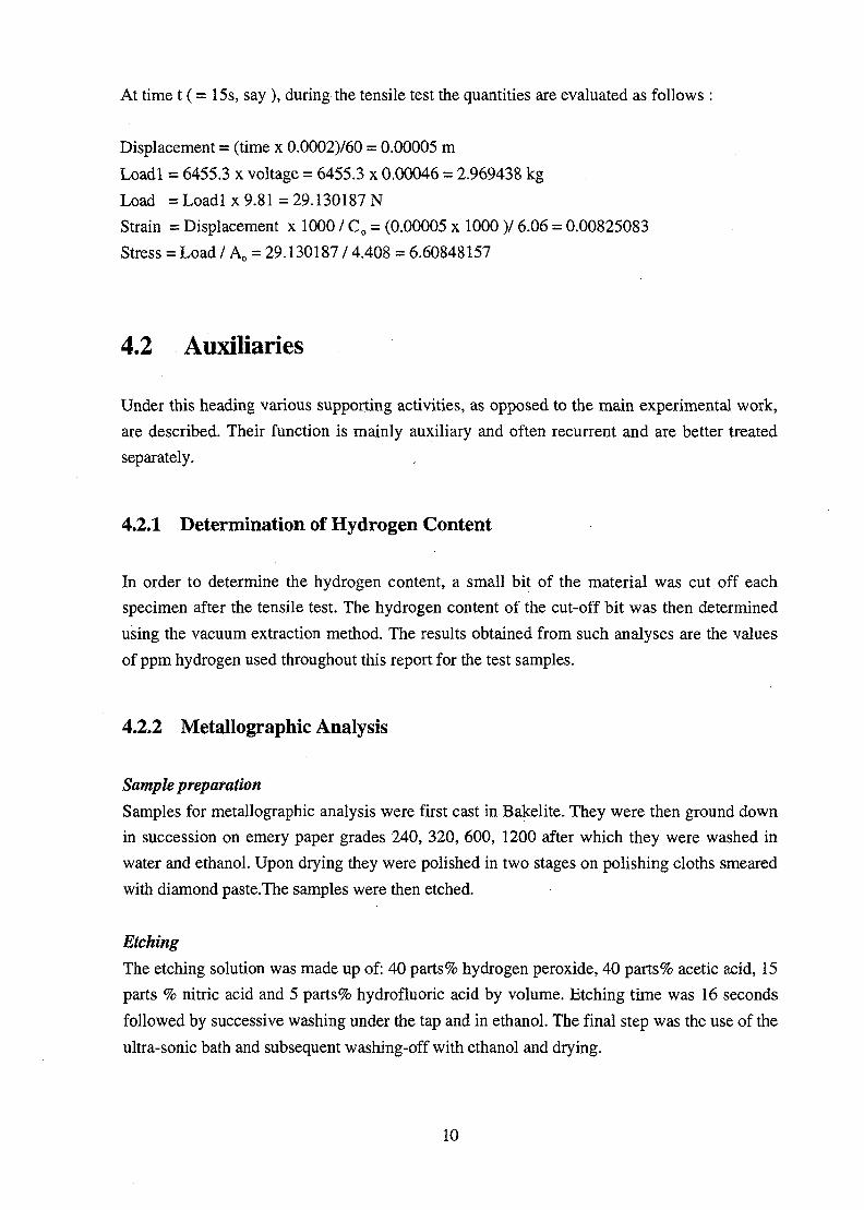
Sample 1
The sample had only been hydrided without any subsequent attempt at stress reorientation.
The hydrides have precipitated as particles. (Fig.3)
Sample 2
Complete circumferential orientation of the hydrides. The sample was heated to 300°C and
loaded and held for 24 hrs. The applied stress was 140 MPa. The results show that hydride
reorientation did not occur since hydrides here have the characteristic manufacturing texture
orientation. (Fig.4)
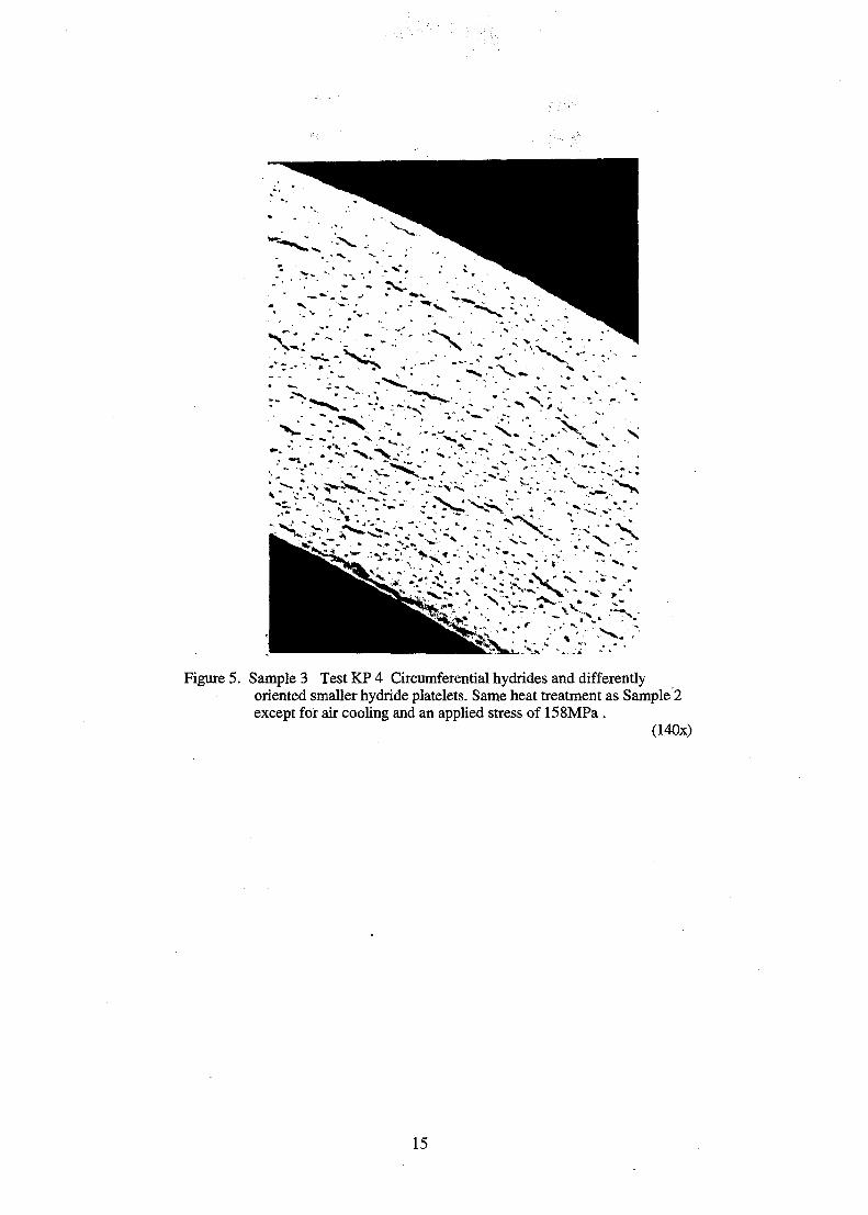
Sample 3
The micro-structure shows circumferential hydrides on a background of smaller hydride
platelets. These platelets, which are uniformly distributed throughout the matrix, do seem to
have a certain degree of orientation relative to the peripheral direction. Apart from cooling in
air the other difference between this sample and Sample 2 is that the applied stress was
158MPa. (Fig.5)
Samples 4-7
Characteristic to this group is the presence of both radial and circumferential hydrides. The
kind of heat treatment as well as the applied stress differed widely between the samples.
(Figs.6-9)
13
» ; * . '.':•.••'
Figure 3. Sample 1 Test H Sample as-hydrided only without any attemptat hydride reorientation
Figure 4. Sample 2 Test KP 3 Circumferential hydrides. Sample was heatedto 300°C, loaded (140MPa) and held for 24hr. (140x)
14
" ; < . • > > > - . * • : _ :
Figure 5. Sample 3 Test KP 4 Circumferential hydrides and differentlyoriented smaller hydride platelets. Same heat treatment as Sample 2except for air cooling and an applied stress of 158MPa.
(140x)
15
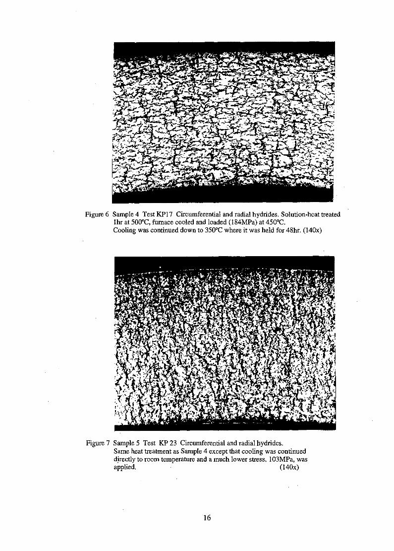
Figure 6 Sample 4 Test KP17 Circumferential and radial hydrides. Solution-heat treatedlhr at 500°C, furnace cooled and loaded (184MPa) at 450°C.Cooling was continued down to 350°C where it was held for 48hr. (140x)
Figure 7 Sample 5 Test KP 23 Circumferential and radial hydrides.Same heat treatment as Sample 4 except that cooling was continueddirectly to room temperature and a much lower stress, 103MPa, wasapplied. (140x)
16

\i- '. .• ,-].-,: '.,•.>,.•
Figure 8. Sample 6 Test KPX Circumferential and radial hydrides.Heated to 300°C, loaded (103MPa) and held 6 1/2 days (157hr).
(140x)
Figure 9. Sample 7 Test KP 11 Circumferential and radial hydrides.Solution-heated lhr at 500°C; furnace cooling to 318°C, loading(220MPa) and holding 23hr. (140x)
17

Samples 8-9
These samples contain hydrides that show varying degrees of orientation toward the radial
direction. The temperature of load application was relatively higher in these samples than in
the others whilst the applied stress was among the lowest. (Figs. 10, 11)
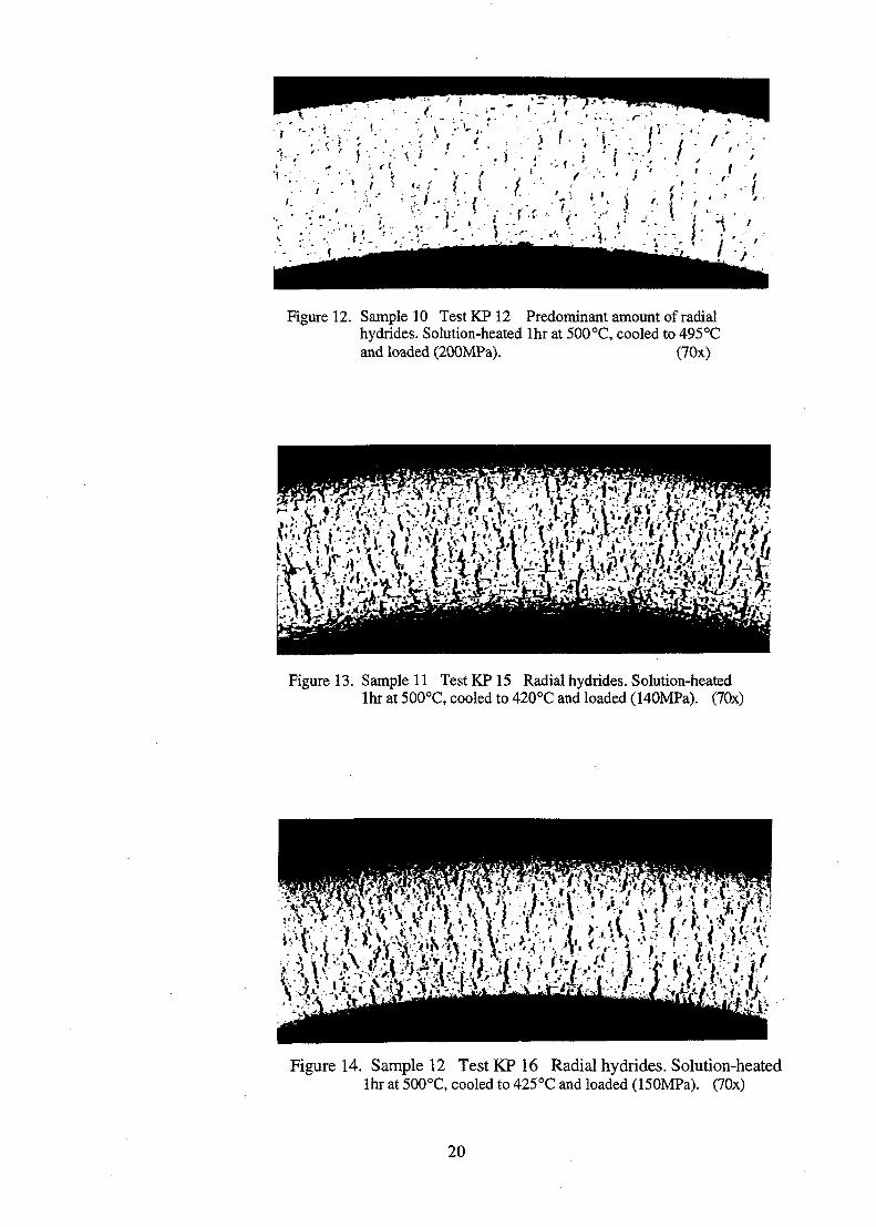
Samples 10-12
The micro-structure shows a predominant amount of completely reoriented radial hydrides.
The samples had the same solution temperature and in two of them, KP15 and KP16, the
temperature for stress application was almost the same, 420°C and 425°C respectively .The
stress levels ranged from moderate to high (150-200 MPa) in comparison with what obtained
in the other samples.(Figs. 12, 13,14)
5.1.2 Discussion
The minimum heat treatment temperature used in these experiments was 300 °C. At that
temperature none of the tests resulted in significant degrees of hydride reorientation; the
applied stress varied between 140 MPa and 160 MPa. Length of time of load application did
not seem to have much effect on reorientation at this temperature since KPX, taken through
the test for almost 7 days, did not show a result different from those taken through much
shorter test times. When the heat treatment temperature was increased to 500°C, more
reoriented hydrides could be observed. At this temperature, the magnitude of the applied
stress seemed to have a clear influence on hydride reorientation. This fact is exemplified by
tests KP 15 and KP16 where the only significant difference between them was the magnitude
of the applied stress. For KP 15,200 MPa was applied and the result was a micro-structure
showing predominantly fully oriented hydrides throughout the cross-section, whereas a
similar structure had regions of mixed radial and circumferential hydrides in the case of
KP16, where the applied stress was 150 MPa. Too much stress may however not be applied at
this temperature since the risk for dimensional changes could be high. This was especially
observed to be the case in KP12 where a 200 MPa stress was applied at 495 °C. The sample
subsequently showed dimensional changes even though completely oriented hydrides was
obtained. At still higher heat treatment and loading temperatures, 560 °C and 550°C
respectively for KP22, a much lower stress was required to effect hydride reorientation. In the
cited test, complete reorientation could not be achieved; instead, the hydrides were observed
to have assumed varying degrees of orientation toward the radial direction. This may perhaps
be an indication of the fact that, all things being equal, there is a minimum stress that may be
applied at the temperature concerned in order for hydride reorientation to occur.
18

Figure 10. Sample 8 Test KP 22 Hydrides showing varying degrees oforientation toward the radial direction. Solution-heated lhr at 560 °C, cooled to 550°C and loaded (107MPa).
(140x)
Figure 11. Sample 9 Test KP 24 Hydrides showing varying degrees oforientation toward the radial direction plus circumferentialhydrides. Solution-heated lhr at 500 °C, cooled to 450°C andloaded (103MPa). (140x)
19
> > / ' ' < ' • ' ••••t'-\\:;:,V:'r.'*.•>'•' • ; • I ; ' ; , - ' : ' ' • • " • . * • •
Figure 12. Sample 10 Test KP 12 Predominant amount of radialhydrides. Solution-heated lhr at 500°C, cooled to 495°Cand loaded (200MPa). (70x)
Figure 13. Sample 11 Test KP 15 Radial hydrides. Solution-heatedlhr at 500°C, cooled to 420°C and loaded (WOMPa). (70x)
itm
Figure 14. Sample 12 TestKP 16 Radial hydrides. Solution-heatedlhr at 500°C, cooled to 425°C and loaded (ISOMPa). (70x)
20
Even though the present work did not specifically look at the of. effect of the hydrogen content
on the extent of achievable reorientation, the observations made above could lead one to infer
that the higher the hydrogen content the moreNdifficult it is for complete reorientation to
occur. This follows from the fact that the essence of employing higher heat treatment
temperatures stems from the need to take most of the hydrides into solution in order for stress
orientation of nucleatipn to occur. Since there is a hydrogen solubility limit at each
equilibrium temperature, it follows that more hydrides will be left undissolved the higher the
hydrogen content. Then, since hydride dissolution increases with temperature, more hydrides
can be dissolved as higher heat treatment temperatures are selected.
5.1.3 Conclusion
It can therefore be concluded that a combination of factors are necessary in order to achieve
complete reorientation of hydrides in Zircaloy. These include the value of the highest
temperature reached in a thermal treatment, and the stress applied. The fraction of oriented
hydrides to be obtained at a selected highest temperature depends on the hydrogen content.
The lower the hydrogen content, the higher the fraction of radially oriented hydrides. It is
therefore not possible to obtain proportionately equal amounts of radial hydrides in different
samples having different hydrogen contents, given the same thermal and loading conditions.
Using a hydride dissolution temperature of 500 °C, a minimum applied stress of 150MPa
would be adequate for the achievement of radial hydrides in samples containing up to about
350ppm hydrogen; for higher ppm hydrogen values, then higher stress values, up to about
200MPa, would be necessary.
5.2 Tensile Testing of Specimens ContainingRe-oriented Hydrides
5.2.1 Discussion
Ductility is evaluated primarily in terms of the variation of the tensile properties with
temperature. These properties include the tensile strength, the total strain at fracture and the
area reduction. In addition, the variation of these properties with the hydrogen content at
constant test temperature is also evaluated. The results are presented graphically in Figs. 15-
20.
21

Tensile Strength
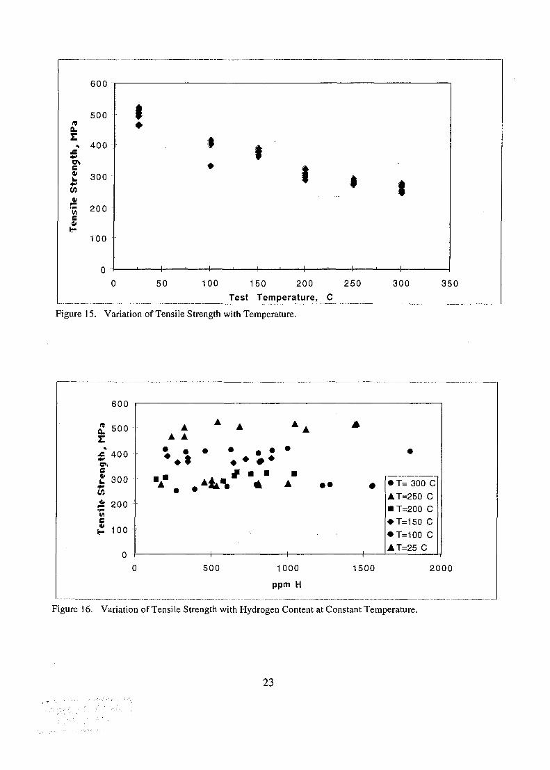
As Fig. 15 indicates, tensile strength decreased with temperature for the tested specimens. The
highest recorded value was 522 MPa corresponding to P41 which was tested at room
temperature whilst the lowest was 247 MPa corresponding to P61 which was tested at 300°C.
At constant temperature (Fig. 16) the tensile strength did not seem to vary significantly with
the hydrogen content even though slight increases at higher hydrogen contents could be
observed at the lower temperatures (25 °C, 100°C, 150°C). Also at these temperatures, an
initial drop in tensile strength was observed for hydrogen contents up to about 300ppm.
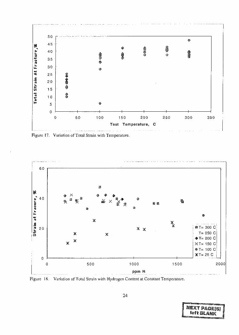
Total Strain at Fracture
The total strain at fracture increased with temperature (Fig. 17), reaching a maximum at
around 250°C and falling off again with increasing temperature. The highest elongation
recorded, 47%, was at 300°C and corresponded to P42. Even at room temperature relatively
high strains were recorded, the highest being 25% for P41, the same sample that had the
highest tensile strength. The total strain varied with the hydrogen content in an irregular
manner, fig. 18, between the different temperatures. Whilst it decreased with the hydrogen
content at 100°C, it did increase at room temperature. At the higher temperatures, 250 °C and
300°C, it almost remained constant over the hydrogen content range.
Area Reduction
The area reduction also increased with increasing temperature, Fig. 19. At 300°C as much as
76% area reduction was recorded for P46. Only two samples (P57 and P56 respectively)
showed zero or almost none area reduction, and these occurred at room temperature. Even at
room temperature as much as 30% area reduction was recorded (P2). At constant temperature,
Fig.20, the area reduction showed, in general, only slight decreases with increasing hydrogen
content. At 100°C the trend was relatively more pronounced than at the other temperatures for
hydrogen contents up about 800ppm. The behaviour at 25 °C exhibits the same kind of
anomaly as with the total strain, where property increase was observed instead of a decrease
at higher hydrogen contents.
22
9
ot,
4
CO
600
500 -
400
300
it
r* 200
100
0
1•
1 1—
• Ii
—1 1 1 1
1r
1
1 1 1
_• 1
1 , 1 ,
50 100 150 200 250Test Temperature, C
300 350
Figure 15. Variation of Tensile Strength with Temperature.
MP
a
O i l
L.
CO
Ten
<
600 "
500
400
300
200
100
uC
AA A
- A
)
A A
• • "
500
* m, A
1000
ppm H
• • •
1
1500
*
• T= 300 CAT=250 C• T=200 C• T=150 C• T=100 CAT=25 C
2000
Figure 16. Variation of Tensile Strength with Hydrogen Content at Constant Temperature.
23
*3
•**
U.
<
:rain
w
o
50
45
40
35
30
25
20
15
10
5
50 100 150 200
Test Temperature, C
250 300 350
Figure 17. Variation of Total Strain with Temperature.
60
en
20
# xX
XX
B T= 300 CT= 250 C
•# T= 200 CXT= 150 C@T= 100 CXT= 25 C
0 500 15001000
ppm H
Figure 18. Variation of Total Strain with Hydrogen Content at Constant Temperature.
2000
24

Figure 21 Sample P57, tested at 25 °C. A photo sequence showing progressivehydride deformation from the least stressed section (top) to the fracturesection (down). The picture in the middle depicts the situationjust before fracture.Hydride deformation is not observed throughthe sequence. (70x)
27

Figure 22 Sample P 47, tested at 100°C. A photo sequenceshowing progressive hydride deformation from theleast stressed section (top) to the fracture section (down).The picture in the middle depicts the situation just beforefracture. Limited hydride deformation can be observedthrough the sequence. (70x)
28

Figure 23 Sample P 50, tested at 150 °C. A photo sequence showingprogressive hydride deformation from the least stressedsection (top) to the fracture section (down). The middlepicture depicts the situation just before fracture. Limitedhydride deformation is observed through the sequence.
(70x)
29

w'y?' I
Figure 24 Sample P 59, tested at 200°C. A photo sequence showingprogressive hydride deformation from the least stressedsection (top) to the fracture section (down). The middlepicture depicts the situation just before fracture. Extensivehydride deformation can be observed (70x)
30

'-•>' '-if" . ' v-
Figure 25 Sample P 60, tested at 250°C. A photo sequenceof progressive hydride deformation. Top: leaststressed section. Middle: section depicting situationjust before fracture. Down: fracture section. Lowhydride density is observed just before and afterfracture. . (70x)
31

Figure 26 Sample 61, tested at 300°C. A photo sequence of progressivehydride deformation. Top & Middle: least stressed section(140x, 70x respectively). Down: fracture section (70x). Muchlower hydride density is observed at the fracture section.
32
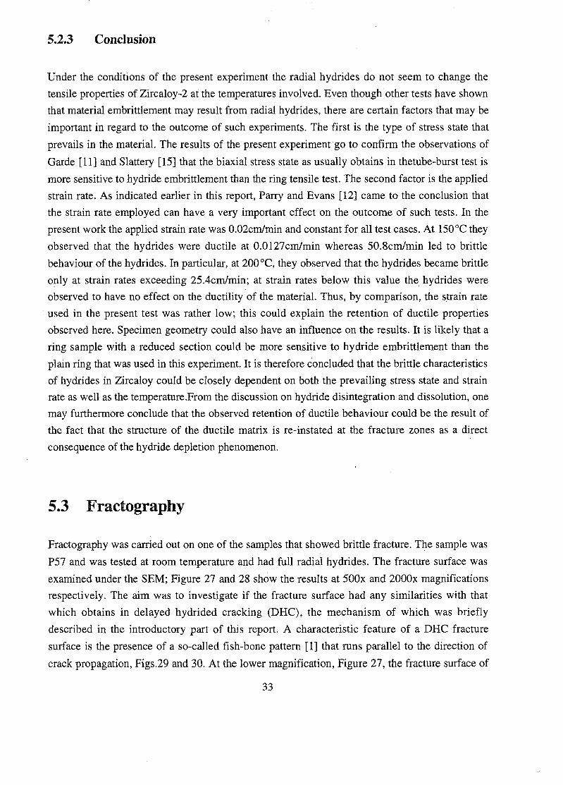
5.2.3 Conclusion
Under the conditions of the present experiment the radial hydrides do not seem to change the
tensile properties of Zircaloy-2 at the temperatures involved. Even though other tests have shown
that material embrittlement may result from radial hydrides, there are certain factors that may be
important in regard to the outcome of such experiments. The first is the type of stress state that
prevails in the material. The results of the present experiment go to confirm the observations of
Garde [11] and Slattery [15] that the biaxial stress state as usually obtains in thetube-burst test is
more sensitive to hydride embrittlement than the ring tensile test. The second factor is the applied
strain rate. As indicated earlier in this report, Parry and Evans [12] came to the conclusion that
the strain rate employed can have a very important effect on the outcome of such tests. In the
present work the applied strain rate was 0.02cm/min and constant for all test cases. At 150°C they
observed that the hydrides were ductile at 0.0127cm/min whereas 50.8cm/min led to brittle
behaviour of the hydrides. In particular, at 200°C, they observed that the hydrides became brittle
only at strain rates exceeding 25.4cm/min; at strain rates below this value the hydrides were
observed to have no effect on the ductility of the material. Thus, by comparison, the strain rate
used in the present test was rather low; this could explain the retention of ductile properties
observed here. Specimen geometry could also have an influence on the results. It is likely that a
ring sample with a reduced section could be more sensitive to hydride embrittlement than the
plain ring that was used in this experiment. It is therefore concluded that the brittle characteristics
of hydrides in Zircaloy could be closely dependent on both the prevailing stress state and strain
rate as well as the temperature.From the discussion on hydride disintegration and dissolution, one
may furthermore conclude that the observed retention of ductile behaviour could be the result of
the fact that the structure of the ductile matrix is re-instated at the fracture zones as a direct
consequence of the hydride depletion phenomenon.
5.3 Fractography
Fractography was carried out on one of the samples that showed brittle fracture. The sample was
P57 and was tested at room temperature and had full radial hydrides. The fracture surface was
examined under the SEM; Figure 27 and 28 show the results at 500x and 2000x magnifications
respectively. The aim was to investigate if the fracture surface had any similarities with that
which obtains in delayed hydrided cracking (DHC), the mechanism of which was briefly
described in the introductory part of this report. A characteristic feature of a DHC fracture
surface is the presence of a so-called fish-bone pattern [1] that runs parallel to the direction of
crack propagation, Figs.29 and 30. At the lower magnification, Figure 27, the fracture surface of
33

the test sample shows features that resemble those of a DHC surface but, at still higher
magnification, Figure 28 , one clearly observes features quite different from those that would
have been caused by a DHC. What is observed here is a different type of brittle fracture surface.
It is thus indicated that the crack growth mechanism under DHC conditions is slightly different
from that of a purely mechanical failure caused by radial hydrides.
Figure 27. Fracture surface of P57. At this magnification the features resemblethose of a DHC fracture surface.
"-;....» . -.» ' V f c * ; . •
r -Figure 28. Fracture surface of P57 at a higher magnification.
Characteristic features of a DHC fracture are not seen
34

s
Figure 29. Fracture surface of an irradiated specimen. Note the fish-bonepattern parallel to the direction of propagation.
Adapted from [1].
3& ,>£****
Figure 30. Magnifications of the large markings seen on the overview picture.
Adapted from [1],
35
6 Suggestions for Further Work
In order for definite conclusions to be drawn on the effect of radial hydrides on the tensile
properties of Zircaloy, it is hereby suggested that further work be carried out to specifically study
the effect of different strain rates on the ductile-brittle characteristics of radial hydrides in
Zircaloy. It would also be of interest to investigate how different test methods and sample shapes
do affect the behaviour of radial hydrides in Zircloy.
To shed light on the subject of hydride deformation it is further suggested that a quantitative
analysis be carried out to ascertain the mechanisms of both the observed hydride disintegration
and the apparent attendant hydride dissolution, and how they are influenced by temperature and
stress.
Finally it would be interesting to study the electromagnetic properties of the hydrides, with the
aim of developing a non-destructive method of determining the orientation of the hydrides and
especially, of the transition between the two orthogonal orientations dealt with in this project.
36

7 References8 Efsing, P., Delayed hydride Cracking in Irradiated Zircaloy, Ph.D. Thesis, Royal Institute
of Technology, Stockholm 1998.
9 Pettersson, P., and McPherson, M., Fracture Toughness ofHydrided Zircaloy Tube-methodological studies, Internal Report-SKI Project 93118, Inst. Matl. Sci. & Eng., Dept.Mech. Met., Royal Institute of Technology, Stockholm 1997.
10 Zuzek, E., and Abriata, J.P., The H-Zr (Hydrogen-Zirconium) System, Bull. Alloy PhaseDiagrams, Vol. 11 No.4 1990, pp. 385-388.
11 Ells, C.E., The Stress Orientation of Hydride in Zirconium Alloys, J. Nucl. Mater., 35,1970,pp.306-315.
12 Ells, C.E., and Simpson C.J., Stress Induced Movement of Hydrogen in Zirconium Alloys,Proceedings of International Conference on Hydrogen, Eds. I.M. Bernstein and A.W.Thompson, ASM Metals Park, 1974, pp. 345-360.
13 Marshall, R.P., and Louthan, M.R., JR., Tensile Properties of Zircaloy with OrientedHydrides, Trans. ASM, Vol.56,1963, pp. 693-700.
14 Bell, L.G., and Duncan, R.G., Hydride Orientation in Zr-2.5% Nb; How it is Affected byStress, Temperature and Heat Treatment, Atomic Energy of Canada Limited, AECL-5110,1975.
15 Hardie, D., and Shanahan, M.W., Stress Orientation of Hydrides in Zirconium -2.5%Niobium, J. Nucl. Mater., 55 (1975) 1-13.
16 Parry, G.W., and Evans, W., The Effect of Strain on the Directional Precipitation ofZirconium Hydride in Zircaloy-2, AECL-1707, Dec. 1962.
17 Price, E.G., Hydride Orientation and Tensile Properties ofZr-2.5 wt% Nb Pressure TubingHydridedwhile Internally Pressurized, Can. Met. Quart., Vol.11, No.l, 1972, pp.129-138.
18 Garde, A.M., Smith, G.P., and Pirek, R.C., Effects of Hydride Precipitate Localization andNeutron Fluence on the Ductility of Irradiated Zircaloy-4, Zirconium in the NuclearIndustry: 11th International Symposium, ASTM STP 1295, E.R. Bradley and G.P. Sabol,Eds., 1996, pp. 407-430.
19 Evans,W., and Parry, G.W., The Deformation Behaviour of Zircaloy-2 ContainingDirectionally Oriented Zirconium Hydride Precipitates, Electrochem. Technol., Vol.4No. 5-6,1966, pp. 225-231.
20 Ashby, M. F., and Jones, D.R.H., Engineering Materials - An Introduction to theirProperties and Applications, 1st edition, Pergamon Press, 1980.
21 Svensson, A., En Studie av Omslagsbeteendet hos Hydrerad Zircaloy, Project Report,Dept. Mech. Met., Royal Institute of Technology, Stockholm 1998.
22 Slattery, G.F., The Mechanical Properties of Zircaloy-2 Tubing ContainingCircumferentially Aligned Hydride, Applications-related Phenomenon for Zirconium andits Alloys, ASTM STP 458,1969, pp.95-110.
37
8 Appendix
List of Appendices
1 .Table A. Results of Temperature-Stress Orientation Attempts
2/TableB. Sample Data Sheet.
3. Figure Al. Fixture for Holding Test Rings onto Testing Machines
38
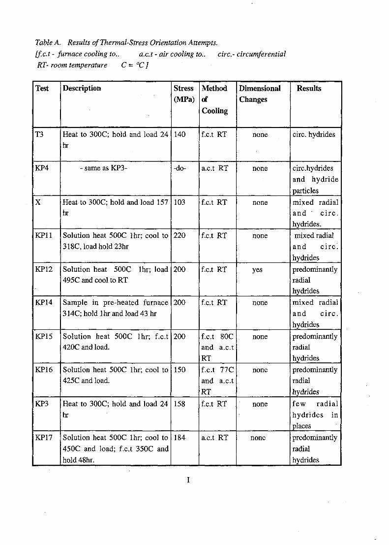
Table A. Results of Thermal-Stress Orientation Attempts.
[f.c.t - furnace cooling to.. a.c.t - air cooling to.. circ- circumferential
RT- room temperature C = °C]
Test
T3
KP4
X
KP11
KP12
KP14
KP15
KP16
KP3
KP17
Description
Heat to 300C; hold and load 24
hr
- same as KP3-
Heat to 300C; hold and load 157hr
Solution heat 500C lhr; cool to
318C, load hold 23hr
Solution heat 500C lhr; load495C and cool to RT
Sample in pre-heated furnace
314C; hold lhr and load 43 hr
Solution heat 500C lhr; f.c.t420C and load.
Solution heat 500C lhr; cool to425C and load.
Heat to 300C; hold and load 24
hr
Solution heat 500C lhr; cool to
450C and load; f.c.t 350C and
hold 48hr.
Stress(MPa)
140
-do-
103
220
200
200
200
150
158
184
MethodofCooling
f.c.t RT
a.c.t RT
f.c.t RT
f.c.t RT
f.c.t RT
f.c.t RT
f.c.t 80Cand a.c.tRT
f.c.t 77C
and a.c.t
RT
f.c.t RT
a.c.t RT
DimensionalChanges
none
none
none
none
yes
none
none
none
none
none
Results
circ. hydrides
circ.hydrides
and hydride
particles
mixed radialand c i rc .hydrides.
mixed radial
and circ^
hydrides
predominantlyradialhydrides
mixed radial
and c i rc .
hydrides
predominantlyradialhydrides
predominantly
radial
hydrides
few radial
hydrides in
places
predominantly
radial
hydrides
Test
HI
KP19
KP21
H2
KP22
KP23
KP24
H
Description
untested; copper- plated before
hydriding.
Solution heat 500C lhr; cool to
430C and load.
Solution heat 500C lhr; cool to
450C and load.
untested
Solution heat 560C lhr; cool to
550C and load.
Solution heat 500C lhr; cool to
450C and load.
Solution heat 500C lhr; cool to
450C and load.
untested
Stress
(MPa)
115
127
107
93
103
MethodofCooling
f.c.t RT
f.c.t RT
f.c.t RT
f.c.t RT
f.c.t RT
DimensionalChanges
none
none
none
none
none
Results
circ. hydrides
predominantly
circ. hydrides
more circ.
than radial
hydrides
circ. hydrides
more radial
hydrides
more radial
varying
degree radial
and circ.
hydride
particles
n

Table B. Sample Dataspppppp
£pp
ppppppp
pp
pp
ppppppPpPPPp
p
pppp
SamplePS7PS5P56P41P30P33P44P2P24P47P3P25P26P38P20P31P4P58P49P51P50P17P12P18P7P5P53P59P48P16P27
T C
252525252525252525
100100100100100100100100150150150150150150150150150200200200200200
P19 i 200P8P22P6OP28P2BPis'"'P54P35P39P34P61P46P42P40P23P36P1OP37
200200250250250
2502502 5 0250250
ppm233320320540S82
1047112014401450
332460630760810832898
1004212278342344647
7268148268951402015 8 06 5 0670763862
1044168452SOOS025308 0 9810
1000300 270300 390300; 605300i 800300300300300
1230128015501561
M«SpIn(MPi466.11501,26463,3
522.45506,35514,97493.06512.64515,71401,46404,8
414,51405,12
400,3431,44408,05416,68389,32363,45380.48366,77362,4
375,92366,61368,92379,93296,14303,18288,13309,93324,9
319,83322.42319.93276,84285,11274,36291,15272.43281,4
274.83281,67247,61256,51266,17274,3
271,29274,81252,38272.2
Ao(mm2)
4.434,1364,4354,354,424.25
4,4084.15
4,3384,52
4.3564,356
4.49SS4,1854,164.474.034.16
. . 4,394,374,354,49
•4,234,384,39
3,84,4814.42
4,4824.0924t2564,374,43
4,25254,374,34
4.4814,324,29
4.34,5563,887
4.34,409
4,314,4494,1094.026
4,834.2
Aflna|(miTi2)4.43
3.7884,3928
3,2894,3693,389
3,80162.9023,6482,223
2.172.21762,40562.00082,3562,3792.1841,6371,6131.7021,7791,5961,6821,9961,7051.605
1,56941,55
1,54581,55441,58921,6351.662
1.61661.2771.51
1,49861,5611,4521.20B
1,43841,64721,345
1,03881.322
1,0692.IJO780,9721.2641,378
MaxLoacKkg)210.49211.34209.45231.67227,99223,1
221.55216.86228.05184,97179,75184,06185,16170,76182,95186.22171.17165,09162.65169.49162,63165J7162,09163.68165,09147,17135,27136,6
131,64129,27140.96142,47
145.6138,68123,32126.14125,32128.22119,13123,35127,64111,6
108.53115,29116.94124,4
113,65112.78124,26116.94
MaxTravel:mm0.6
10.7
1,520,951,191,151,43
1,32,33
22,251,712,172.282,182,012,282,572,262,322,32
2.32.2
2,292.152,462,52
2.52,32.5
2.522.37
2,42,482.512.462.492.5
2.592,6
2,282.37
2,42,85
2,42.22,22,3
2.28
corr.clrc(mm)6,0826,06
6,0416,05
6,0326,056,06
6,0446,06
6,0566.0856,0536,0546,0856,012
6.066.0446.0786,07
6,0446,044
. . 6,0446,0566,0826,0826.0446,0416,0326,0416.09
5,9286,044
6,026,06
6,0446,0326,0856,0446,0416,0446,06
6.0546,0826,0476.026
8,05.6,066,06
6,0386,1
Strain % Area red.,%9,865175929. 0
16.5 12,2211.59' 0.96
25.12396894 24.3915,74933687: 1,1519.66942149 20,25
18.9823,65982793
21.4538,47424042
32.8637,2723.25
35,637,9241517
35,9735973633,2561217737,5123395942.3393739737,3924553338.3851753838,3851753837.9788639436,1723117437,6520881335,57246856
40,7841,77718833
42,137.7542,16
41,6942422239,36877076
39,641.0324288641,61140584
40,4241,1978822
41,2742,85241562
42,937,72
38,96744492
13,7530.07
L_ 15,9150,8150,1849.0946,4952,1943,3645,5645,8160.6563,2661,05
59,164,4560,2454,2361,1657.7664.9864,9365,5162,0162,6662,5862,4861,9870,7765,2166,5463,8666,1571,9168,4357.6268,72
39,74i 76,4347.29505476: 69,33
39,61: 75,9736,336.3
38,0920834737,37704918
73,7775.8673,8367,19
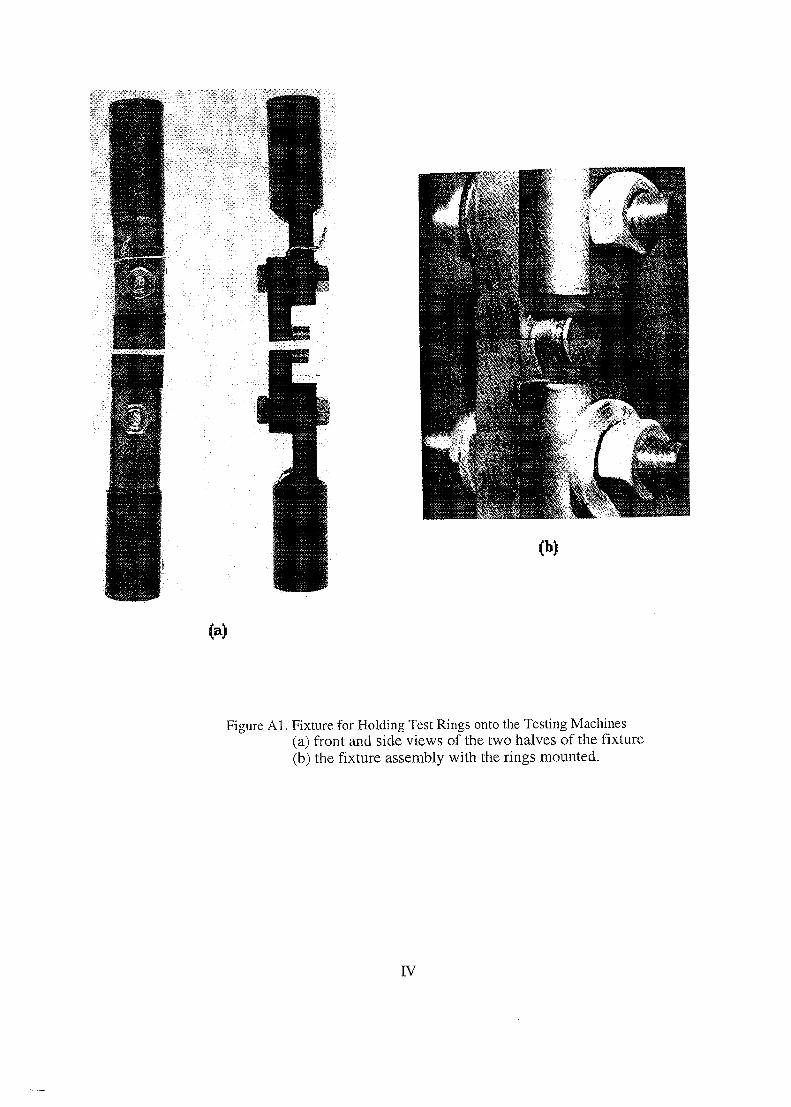
Figure Al. Fixture for Holding Test Rings onto the Testing Machines(a) front and side views of the two halves of the fixture(b) the fixture assembly with the rings mounted.
IV

STATENS KARNKRAFTINSPEKTIONSwedish Nuclear Power Inspectorate
Postadress/Postal address Telefon/Telephone Telefax
SKIS-106 58 STOCKHOLM
Nat 08-698 84 00Int +46 8 698 84 00
Nat 08-661 90 86Int +46 8 661 90 86
Telex
11961 S WE ATOMS