Hummer-H3-Engine-Mechanical-3.7L-1-4-1.pdf - Schwarttzy
832
2007 ENGINE Engine Mechanical - 3.7L - H3 SPECIFICATIONS FASTENER TIGHTENING SPECIFICATIONS Fastener Tightening Specifications Application Specifications Metric English A/C Compressor Hose/Pipe Bracket Bolt 9 N.m 80 lb in A.I.R. Cover Stud 25 N.m 18 lb ft Balance Shaft Retaining Bolt 10 N.m 89 lb in Balance Shaft Chain Guide Bolt 10 N.m 89 lb in Balance Shaft Chain Tensioner Bolt 10 N.m 89 lb in Battery Negative Cable to Engine Block Bolt 35 N.m 26 lb in Battery Positive Cable to Starter Terminal Nut 9 N.m 80 lb in Camshaft Cap Bolt 12 N.m 106 lb in Camshaft Cover Bolt 10 N.m 89 lb in Camshaft Position Actuator Valve Bolt 10 N.m 89 lb in Connecting Rod Cap Bolt First Pass 25 N.m 18 lb ft Final Pass 110 degrees Coolant Temperature Sensor 16 N.m 12 lb ft Crankshaft Balancer Bolt First Pass 150 N.m 110 lb ft Final Pass 180 degrees Crankshaft Main Bearing Cap Bolt First Pass 25 N.m 18 lb ft Final Pass 180 degrees Crankshaft Position Sensor Bolt 10 N.m 89 lb in Crankshaft Rear Oil Seal Housing Bolt 10 N.m 89 lb in Cylinder Head Access Hole Plug - Plastic 5 N.m 44 lb in Cylinder Head Bolt - 12 2007 Hummer H3 2007 ENGINE Engine Mechanical - 3.7L - H3 2007 Hummer H3 2007 ENGINE Engine Mechanical - 3.7L - H3
-
Upload
khangminh22 -
Category
Documents
-
view
0 -
download
0
Transcript of Hummer-H3-Engine-Mechanical-3.7L-1-4-1.pdf - Schwarttzy

2007 ENGINE
Engine Mechanical - 3.7L - H3
SPECIFICATIONS
FASTENER TIGHTENING SPECIFICATIONS
Fastener Tightening Specifications
ApplicationSpecifications
Metric EnglishA/C Compressor Hose/Pipe Bracket Bolt 9 N.m 80 lb inA.I.R. Cover Stud 25 N.m 18 lb ftBalance Shaft Retaining Bolt 10 N.m 89 lb inBalance Shaft Chain Guide Bolt 10 N.m 89 lb inBalance Shaft Chain Tensioner Bolt 10 N.m 89 lb inBattery Negative Cable to Engine Block Bolt 35 N.m 26 lb inBattery Positive Cable to Starter Terminal Nut 9 N.m 80 lb inCamshaft Cap Bolt 12 N.m 106 lb inCamshaft Cover Bolt 10 N.m 89 lb inCamshaft Position Actuator Valve Bolt 10 N.m 89 lb inConnecting Rod Cap Bolt
� First Pass 25 N.m 18 lb ft
� Final Pass 110 degrees
Coolant Temperature Sensor 16 N.m 12 lb ftCrankshaft Balancer Bolt
� First Pass 150 N.m 110 lb ft
� Final Pass 180 degrees
Crankshaft Main Bearing Cap Bolt
� First Pass 25 N.m 18 lb ft
� Final Pass 180 degrees
Crankshaft Position Sensor Bolt 10 N.m 89 lb inCrankshaft Rear Oil Seal Housing Bolt 10 N.m 89 lb inCylinder Head Access Hole Plug - Plastic 5 N.m 44 lb inCylinder Head Bolt - 12
2007 Hummer H3
2007 ENGINE Engine Mechanical - 3.7L - H3
2007 Hummer H3
2007 ENGINE Engine Mechanical - 3.7L - H3
MY
Sunday, March 29, 2009 8:40:24 PM Page 1 © 2005 Mitchell Repair Information Company, LLC.
MY
Sunday, March 29, 2009 8:41:15 PM Page 1 © 2005 Mitchell Repair Information Company, LLC.

� First Pass 30 N.m 22 lb ft
� Final Pass 155 degrees
Cylinder Head End Bolts - 2 Short
� First Pass 7 N.m 62 lb in
� Final Pass 60 degrees
Cylinder Head End Bolts - 1 Long
� First Pass 7 N.m 62 lb in
� Final Pass 120 degrees
Cylinder Head Oil Gallery Plug 38 N.m 28 lb ftDifferential Carrier Assembly Bushing to Frame Bolt
152 N.m 112 lb ft
Drive Belt Idler Pulley Bolt 50 N.m 37 lb ftDrive Belt Tensioner Bolt 50 N.m 37 lb ftEngine Block Coolant Plug 50 N.m 37 lb ftEngine Block Oil Gallery Plug - Side 35 N.m 26 lb ftEngine Flywheel Bolt
� First Pass 40 N.m 30 lb ft
� Final Pass 45 degrees
Engine Front Cover Bolt 10 N.m 89 lb inEngine Front Cover - Center - Small Bolt 8 N.m 71 lb inEngine Front Cover Spacer Bolt 10 N.m 89 lb inEngine Front Lift Bracket Bolt
� First Pass 5 N.m 44 lb in
� Final Pass 50 N.m 37 lb ft
Engine Mount Bolt 50 N.m 37 lb ftEngine Mount-to-Frame Bracket Bolt 85 N.m 63 lb ftEngine Wiring Ground Lead Bolt 20 N.m 15 lb ftEngine Wiring Harness Bracket Bolt 10 N.m 89 lb ftEVAP Purge Solenoid Valve Bolt 10 N.m 89 lb inExhaust Camshaft Actuator Bolt
� First Pass 25 N.m 18 lb ft
� Final Pass 135 degrees
2007 Hummer H3
2007 ENGINE Engine Mechanical - 3.7L - H3
MY
Sunday, March 29, 2009 8:40:25 PM Page 2 © 2005 Mitchell Repair Information Company, LLC.

Exhaust Camshaft Position Sensor Bolt 10 N.m 89 lb inExhaust Manifold Bolt
� First Pass 20 N.m 15 lb ft
� Second Pass 20 N.m 15 lb ft
� Final Pass 20 N.m 15 lb ft
Exhaust Manifold Heat Shield Nut 10 N.m 89 lb inExhaust Manifold Heat Shield Stud 10 N.m 89 lb inFuel Hose/Pipe Bracket Nut 20 N.m 15 lb ftFuel Injector Rail Bolt 10 N.m 89 lb inFuel Pressure Regulator Bolt 8 N.m 70 lb inGenerator Mounting Bolt 50 N.m 37 lb inHeater Inlet Pipe Bolt 10 N.m 89 lb inHeater Outlet Fitting 45 N.m 33 lb ftIgnition Control Module Bolt 10 N.m 89 lb inHeater Outlet Hose/Pipe Bracket to Left Engine Mount Bolt
9 N.m 80 lb in
Intake Camshaft Position Sensor Bolt 10 N.m 89 lb inIntake Camshaft Sprocket Bolt
� First Pass 20 N.m 15 lb ft
� Final Pass 100 degrees
Intake Manifold Bolt 10 N.m 89 lb inKnock Sensor 25 N.m 18 lb ftOil Filter 30 N.m 22 lb ftOil Filter Adapter 50 N.m 37 lb ftOil Filter Bypass Hole Plug 14 N.m 124 lb inOil Level Indicator Tube Bolt 10 N.m 89 lb inOil Pan Bolt - Ends 10 N.m 89 lb inOil Pan Bolt - Sides 25 N.m 18 lb ftOil Pan Drain Plug 26 N.m 19 lb ftOil Pressure Switch 20 N.m 15 lb ftOil Pump Cover Bolt 10 N.m 89 lb inOil Pump Pipe and Screen Assembly Bolt 10 N.m 89 lb inOil Pump Pressure Relief Valve Plug 14 N.m 124 lb inPower Steering Pump Bolt 25 N.m 18 lb ft
2007 Hummer H3
2007 ENGINE Engine Mechanical - 3.7L - H3
MY
Sunday, March 29, 2009 8:40:25 PM Page 3 © 2005 Mitchell Repair Information Company, LLC.

ENGINE MECHANICAL SPECIFICATIONS
Engine Mechanical Specifications
Power Steering Pump Bracket Bolt 50 N.m 37 lb ftSpark Plug 18 N.m 13 lb ftStarter Motor Bolt 50 N.m 37 lb ftStarter Motor Nut 50 N.m 37 lb ftStarter Motor Stud 16 N.m 12 lb ftStarter Solenoid - S Terminal Nut 3.5 N.m 31 lb inThermostat Housing bolt 10 N.m 89 lb inThrottle Control Module Bolt 10 N.m 89 lb inTiming Chain Tensioner Bolt 25 N.m 18 lb ftTiming Chain Tensioner Guide Bolt 22 N.m 16 lb ftTiming Chain Tensioner Shoe Bolt 25 N.m 18 lb ftTorque Converter Bolts 60 N.m 44 lb ftTransmission Mounting Bolts 50 N.m 37 lb ftTransmission Oil Cooler Pipes Bracket Bolt 20 N.m 15 lb ftWater Outlet Bolt 10 N.m 89 lb inWater Pump Bolt 10 N.m 89 lb inWater Pump Pulley Bolt 25 N.m 18 lb ft
ApplicationSpecifications
Metric EnglishGeneral
� Engine Type In-Line-5
� Displacement 3.7L 223 cu in
� RPO LLR
� VIN E
� Bore 95.5 mm 3.76 in
� Stroke 102 mm 4.02 in
� Compression Ratio 10.3:1
� Engine Compression Test 1482 kPa 215 psi
� Firing Order 1-3-5-4-2
1.14-1.25 mm 0.044-0.050 in
2007 Hummer H3
2007 ENGINE Engine Mechanical - 3.7L - H3
MY
Sunday, March 29, 2009 8:40:25 PM Page 4 © 2005 Mitchell Repair Information Company, LLC.

� Spark Plug Gap Block
� Crankshaft Main Bearing Bore Diameter
78.070-78.088 mm 3.0760-3.0766 in
� Cylinder Bore Diameter 95.490-95.506 mm 3.7623-3.7629 in
� Cylinder Bore Out-of-Round 0.013 mm 0.0005 in
� Cylinder Head Deck Surface Flatness 0.08 mm 0.003 in
� Cylinder Sleeve Recession 0.015 mm 0.0006 in
Camshaft
� Camshaft End Play - Exhaust 0.045-0.215 mm 0.0017-0.0084 in
� Camshaft End Play - Intake 0.051-0.201 mm 0.0020-0.0079 in
� Camshaft Journal Diameter - All Intake and Exhaust #2-#7
26.936-26.960 mm 1.0612-1.0622 in
� Camshaft Journal Diameter - Exhaust #1
29.936-29.960 mm 1.1794-1.1804 in
� Camshaft Journal to Bore Clearance 0.040-0.085 mm 0.0015-0.0033 in
Connecting Rod
� Connecting Rod Bearing Clearance 0.021-0.065 mm 0.0008-0.0025 in
� Connecting Rod Bore Diameter - Bearing End
60.332-60.338 mm 2.3749-2.3755 in
� Connecting Rod Bore Out-of-Round - Bearing End
0.006 mm 0.0002 in
Connecting Rod Side Clearance 0.05-0.35 mm 0.0019-0.0137 inCrankshaft
� Crankshaft End Play 0.112-0.388 mm 0.0044-0.0153 in
� Crankshaft Main Bearing Clearance 0.012-0.064 mm 0.0004-0.0025 in
� Crankshaft Main Journal Diameter 69.968-69.984 mm 2.7567-2.7574 in
� Crankshaft Main Journal Out-of-Round 0.005 mm 0.0002 in
� Crankshaft Main Journal Taper 0.005 mm 0.0002 in
Cylinder Head
� Surface Flatness - Block Deck 0.08 mm 0.003 in
2007 Hummer H3
2007 ENGINE Engine Mechanical - 3.7L - H3
MY
Sunday, March 29, 2009 8:40:25 PM Page 5 © 2005 Mitchell Repair Information Company, LLC.

� Surface Flatness - Exhaust Manifold Deck
0.08 mm 0.003 in
� Surface Flatness - Intake Manifold Deck
0.08 mm 0.003 in
Exhaust Manifold
� Surface Flatness 0.08 mm 0.003 in
Lubrication System
� Oil Capacity - with Filter 5.6 L 6.0 qts
� Oil Capacity - without Filter 5.1 L 5.5 qts
� Oil Pressure - Minimum 85 kPa 12 psi at 1200 RPM
Oil Pump
� Gear Diameter - Drive 73.415-73.370 mm 2.893-2.891 in
� Gear Diameter - Driven 87-86.975 mm 3.428-3.426 in
� Gear Pocket - Depth 15.609-15.584 mm 0.615-0.614 in
� Gear Pocket - Diameter 87.065-87.040 mm 3.430-3.429 in
� Gear Thickness - Drive 15.546-15.521 mm 0.613-0.611 in
� Gear Thickness - Driven 15.360-15.511 mm 0.605-0.611 in
� Lobe Inner Diameter - Maximum 11.9 mm 0.469 in
� Relief Valve-to-Bore Clearance 2.57-1.63 mm 0.101-0.064 in
Piston Rings
� Piston Ring End Gap - First Compression Ring
0.2-0.4 mm 0.0079-0.0157 in
� Piston Ring End Gap - Second Compression Ring
0.36-0.51 mm 0.0142-0.0201 in
� Piston Ring End Gap - Oil Control Ring
0.250-0.760 mm 0.0098-0.0299 in
� Piston Ring to Groove Clearance - First Compression Ring
0.043-0.093 mm 0.0017-0.0037 in
� Piston Ring to Groove Clearance - Second Compression Ring
0.053-0.093 mm 0.0021-0.0037 in
� Piston Ring to Groove Clearance - Oil Control Ring
0.059-0.215 mm 0.0023-0.0085 in
2007 Hummer H3
2007 ENGINE Engine Mechanical - 3.7L - H3
MY
Sunday, March 29, 2009 8:40:25 PM Page 6 © 2005 Mitchell Repair Information Company, LLC.

SEALERS, ADHESIVES AND LUBRICANTS
Sealers, Adhesives and Lubricants
Pistons and Pins
� Piston - Piston Diameter 92.963-92.977 mm 3.6627-3.6633 in
� Piston - Piston Pin Bore Diameter 23.002-23.008 mm 0.9056-0.9058 in
� Piston - Piston to Bore Clearance 0.013-0.043 mm 0.0004-0.0017 in
� Pin - Piston Pin Clearance to Connecting Rod Bore
0.001-0.018 mm 0.0004-0.0007 in
� Pin - Piston Pin Clearance to Piston Pin Bore
0.003-0.012 mm 0.00012-0.0005 in
� Pin - Piston Pin Diameter 22.996-22.999 mm 0.9054-0.9055 in
Valve System
� Valves - Valve Face Runout 0.038 mm 0.0015 in
� Valves - Valve Seat Runout 0.05 mm 0.002 in
� Valves - Valve Stem-to-Guide Clearance - Exhaust
0.0375-0.0775 mm 0.0015-0.0030 in
� Valves - Valve Stem-to-Guide Clearance - Intake
0.030-0.065 mm 0.0011-0.0025 in
� Valve Springs - Valve Spring Load - Closed
211-233 N at 35 mm47.4-52.4 lb at 1.379
in
� Valve Springs - Valve Spring Load - Open
578-632 N at 24.5 mm130-142 lb at 0.965 in
Application Type of Material
GM Part NumberUnited States Canada
Camshaft Position Actuator Bolt Sealant 89021297 10953488Camshaft Position Sensor Bolt Sealant 12378521 88901148Coolant Sensor Threads Sealant 12378521 88901148Crankshaft Position Sensor Bolt Sealant 12378521 88901148Cylinder Head Core Hole Plugs Sealant 12378521 88901148Cylinder Head Expansion Plugs (Aluminum) Sealant 12378521
88901148
2007 Hummer H3
2007 ENGINE Engine Mechanical - 3.7L - H3
MY
Sunday, March 29, 2009 8:40:25 PM Page 7 © 2005 Mitchell Repair Information Company, LLC.
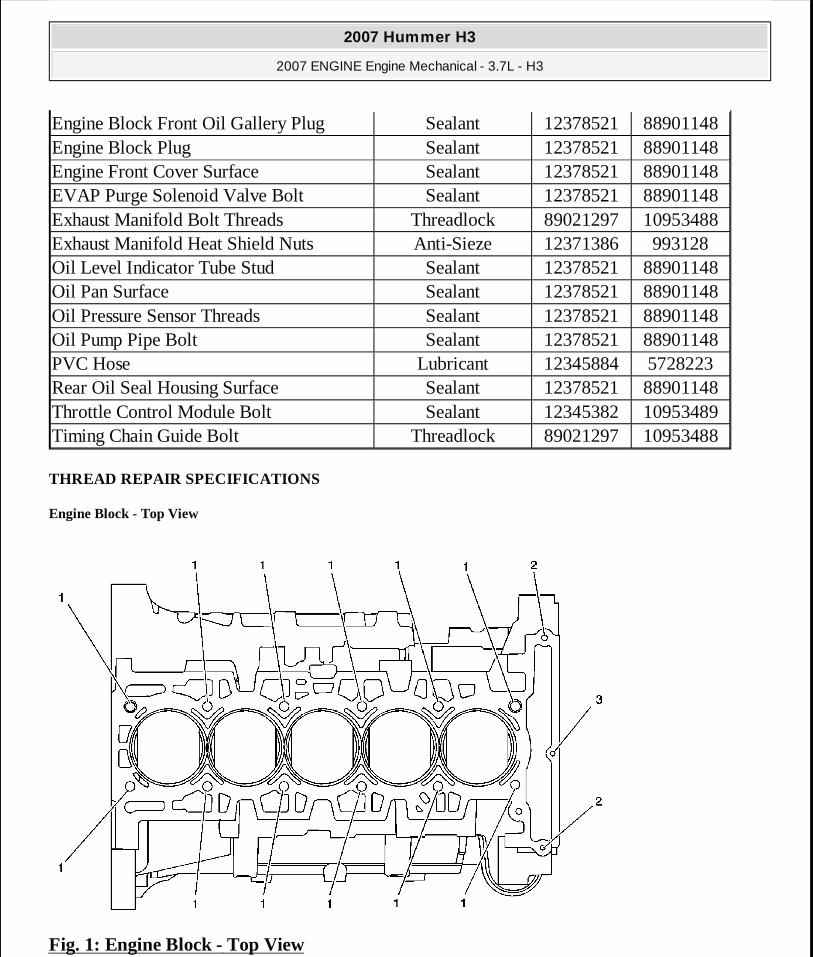
THREAD REPAIR SPECIFICATIONS
Engine Block - Top View
Fig. 1: Engine Block - Top View
Engine Block Front Oil Gallery Plug Sealant 12378521 88901148Engine Block Plug Sealant 12378521 88901148Engine Front Cover Surface Sealant 12378521 88901148EVAP Purge Solenoid Valve Bolt Sealant 12378521 88901148Exhaust Manifold Bolt Threads Threadlock 89021297 10953488Exhaust Manifold Heat Shield Nuts Anti-Sieze 12371386 993128Oil Level Indicator Tube Stud Sealant 12378521 88901148Oil Pan Surface Sealant 12378521 88901148Oil Pressure Sensor Threads Sealant 12378521 88901148Oil Pump Pipe Bolt Sealant 12378521 88901148PVC Hose Lubricant 12345884 5728223Rear Oil Seal Housing Surface Sealant 12378521 88901148Throttle Control Module Bolt Sealant 12345382 10953489Timing Chain Guide Bolt Threadlock 89021297 10953488
2007 Hummer H3
2007 ENGINE Engine Mechanical - 3.7L - H3
MY
Sunday, March 29, 2009 8:40:25 PM Page 8 © 2005 Mitchell Repair Information Company, LLC.

Courtesy of GENERAL MOTORS CORP.
Engine Block - Top View
Engine Block - Bottom View
Fig. 2: Engine Block - Bottom View Courtesy of GENERAL MOTORS CORP.
Engine Block - Bottom View
Service Hole
LocationThread
Size DrillCounterbore
ToolStop
Collar Tap Driver Insert
Drill Depth (Max)
Tap Depth (Min)
J 42385-400 . See Special Tools. mm (in) mm (in)
1M 11 x
2402 n/a n/a 403 404 108 59 2.324 51 2.009
2 M 6 x 1 201 202 n/a 203 204 205 22 0.866 18 0.7093 M 6 x 1 201 202 n/a 203 204 205 30 1.182 26 1.024
Service Hole Thread Counterbore Stop Drill Depth
Tap Depth
2007 Hummer H3
2007 ENGINE Engine Mechanical - 3.7L - H3
MY
Sunday, March 29, 2009 8:40:25 PM Page 9 © 2005 Mitchell Repair Information Company, LLC.

Engine Block - Left Side View
Fig. 3: Engine Block - Left Side View Courtesy of GENERAL MOTORS CORP.
Engine Block - Left Side View
Location Size Drill Tool Collar Tap Driver Insert (Max) (Min)J 42385-400 . See Special Tools. mm (in) mm (in)
1M 10 x
1.5417 n/a n/a 418 419 420 49 1.93 42 1.655
2M 8 x 1.25
206 207 n/a 208 209 210 30 1.182 25 0.985
3M 10 x
1.5417 n/a n/a 418 419 420 30 1.182 25 0.985
Service Hole
LocationThread
Size DrillCounterbore
ToolStop
Collar Tap Driver Insert
Drill Depth (Max)
Tap Depth (Min)
J 42385-400 . See Special Tools. mm (in) mm (in)
1M 10 x
1.5211 212 n/a 213 214 420 33 1.3 27 1.063
2 M 6 x 1 201 202 n/a 203 204 205 22 0.866 18 0.709
2007 Hummer H3
2007 ENGINE Engine Mechanical - 3.7L - H3
MY
Sunday, March 29, 2009 8:40:25 PM Page 10 © 2005 Mitchell Repair Information Company, LLC.

Engine Block - Right Side View
Fig. 4: Engine Block - Right Side View Courtesy of GENERAL MOTORS CORP.
Engine Block - Right Side View
3M 12 x 1.75
856 857 n/a 858 859 416 33 1.3 17 0.669
4M 8x 1.25
206 207 n/a 208 209 210 25 0.985 20 0.788
5M 28x 1.25
n/a n/a n/a n/a n/a n/a 25 0.985 17 0.669
6M 24 x
1.5n/a n/a n/a n/a n/a n/a 30 1.182 20 0.788
7 M 6 x 1 201 202 n/a 203 204 205 19 0.748 15 0.5918 M 6 x 1 206 207 n/a 208 209 210 19 0.748 15 0.591
Service Hole
LocationThread
Size DrillCounterbore
ToolStop
Collar Tap Driver Insert
Drill Depth (Max)
Tap Depth (Min)
J 42385-400 . See Special Tools. mm (in) mm (in)
1 M 16 x n/a n/a n/a n/a n/a n/a 32 1.260 23 0.906
2007 Hummer H3
2007 ENGINE Engine Mechanical - 3.7L - H3
MY
Sunday, March 29, 2009 8:40:25 PM Page 11 © 2005 Mitchell Repair Information Company, LLC.

Engine Block - Front View
Fig. 5: Engine Block - Front View Courtesy of GENERAL MOTORS CORP.
Engine Block - Front View
1.52 M 6 x 1 201 202 n/a 203 204 205 22 0.866 18 0.709
3M 8 x 1.25
206 207 n/a 208 209 210 23 0.906 18 0.709
4M 10 x
1.5211 212 n/a 213 214 420 33 1.300 27 1.063
5M 16 x
2.0n/a n/a n/a n/a n/a n/a 29 1.142 16 1.024
6 M 10 x 1.5
211 212 n/a 213 214 420 23 0.906 18 0.709
Service Drill Tap
2007 Hummer H3
2007 ENGINE Engine Mechanical - 3.7L - H3
MY
Sunday, March 29, 2009 8:40:25 PM Page 12 © 2005 Mitchell Repair Information Company, LLC.

Engine Block - Rear View
Fig. 6: Engine Block - Rear View Courtesy of GENERAL MOTORS CORP.
Engine Block - Rear View
Hole Location
Thread Size Drill
Counterbore Tool
Stop Collar Tap Driver Insert
Depth (Max)
Depth (Min)
J 42385-400 . See Special Tools. mm (in) mm (in)1 M 6 x 1 405 n/a 407 203 204 205 30 1.182 26 1.0242 M 6 x 1 201 202 n/a 203 204 205 18 0.709 14 0.5513 M 6 x 1 201 202 n/a 203 204 205 22 0.866 18 0.709
4M 8 x 1.25
206 207 n/a 208 209 210 23 0.906 18 0.709
5M 16 x
1.5405 n/a 407 203 204 205 24 0.945 16 0.630
Service Hole Thread Counterbore Stop Drill Depth
Tap Depth
2007 Hummer H3
2007 ENGINE Engine Mechanical - 3.7L - H3
MY
Sunday, March 29, 2009 8:40:25 PM Page 13 © 2005 Mitchell Repair Information Company, LLC.

Cylinder Head - Top View
Fig. 7: Cylinder Head - Top View Courtesy of GENERAL MOTORS CORP.
Cylinder Head - Top View
Location Size Drill Tool Collar Tap Driver Insert (Max) (Min)J 42385-400 . See Special Tools. mm (in) mm (in)
1M 16 x
1.5n/a n/a n/a n/a n/a n/a 39 1.536 33 1.300
2M 10 x
1.5211 212 n/a 213 214 420 39 1.536 33 1.300
3 M 6 x 1 201 202 n/a 203 204 205 20 0.788 16 0.6304 M 8 x 1 206 207 n/a 208 209 210 39 1.536 33 1.3005 M 6 x 1 211 212 n/a 213 214 215 39 1.536 33 1.300
6M 10 x
1.5211 212 n/a 213 214 215 57 2.245 54 2.127
Service Hole
LocationThread
Size DrillCounterbore
ToolStop
Collar Tap Driver Insert
Drill Depth (Max)
Tap Depth (Min)
2007 Hummer H3
2007 ENGINE Engine Mechanical - 3.7L - H3
MY
Sunday, March 29, 2009 8:40:25 PM Page 14 © 2005 Mitchell Repair Information Company, LLC.

Cylinder Head - End - Front View
Fig. 8: Cylinder Head - End - Front View Courtesy of GENERAL MOTORS CORP.
Cylinder Head - End - Front View
Cylinder Head - End - Rear View
J 42385-400 . See Special Tools. mm (in) mm (in)1 M 6 x 1 405 n/a 406 203 204 205 28 1.103 24 0.9452 M 6 x 1 201 202 n/a 203 204 205 THRU THRU3 M 6 x 1 201 202 n/a 203 204 205 22 0.866 18 0.709
Service Hole
LocationThread
Size DrillCounterbore
ToolStop
Collar Tap Driver Insert
Drill Depth (Max)
Tap Depth (Min)
J 42385-400 . See Special Tools. mm (in) mm (in)1 M 6 x 1 201 202 n/a 203 204 205 28 1.103 22 0.866
2M 10 x
1.5211 212 n/a 213 214 215 28 1.103 22 0.866
3M 24 x
1.5n/a n/a n/a n/a n/a n/a THRU THRU
4M 8 x 1.25
206 207 n/a 208 209 210 28 1.103 23 0.906
2007 Hummer H3
2007 ENGINE Engine Mechanical - 3.7L - H3
MY
Sunday, March 29, 2009 8:40:26 PM Page 15 © 2005 Mitchell Repair Information Company, LLC.

Fig. 9: Cylinder Head - End - Rear View Courtesy of GENERAL MOTORS CORP.
Cylinder Head - End - Rear View
Cylinder Head - Intake Manifold Deck View
Service Hole
LocationThread
Size DrillCounterbore
ToolStop
Collar Tap Driver InsertDrill Depth
(Max)
Tap Depth (Min)
J 42385-400 . See Special Tools. mm (in) mm (in)
1M 14 x
1.5409 410 n/a 411 412 413 36 1.418 28 1.103
2M 10 x
1.5409 410 n/a 411 412 413 28 1.103 22 0.866
3M 14 x
1.5211 212 n/a 213 214 215 36 1.418 28 1.103
4M 10 x
1.5211 212 n/a 213 214 215 28 1.103 22 0.866
2007 Hummer H3
2007 ENGINE Engine Mechanical - 3.7L - H3
MY
Sunday, March 29, 2009 8:40:26 PM Page 16 © 2005 Mitchell Repair Information Company, LLC.

Fig. 10: Cylinder Head - Intake Manifold Deck View Courtesy of GENERAL MOTORS CORP.
Cylinder Head - Intake Manifold Deck View
Cylinder Head - Exhaust Manifold Deck View
Service Hole
LocationThread
Size DrillCounterbore
ToolStop
Collar Tap Driver Insert
Drill Depth (Max)
Tap Depth (Min)
J 42385-400 . See Special Tools. mm (in) mm (in)
1M 10 x
1.5211 212 n/a 213 214 420 33 1.3 27 1.063
2M 10 x
1.5 211 212 n/a 213 214 215 28 1.103 22 0.866
3 M 6 x 1 201 202 n/a 203 204 205 23 0.906 18 0.709
2007 Hummer H3
2007 ENGINE Engine Mechanical - 3.7L - H3
MY
Sunday, March 29, 2009 8:40:26 PM Page 17 © 2005 Mitchell Repair Information Company, LLC.

Fig. 11: Cylinder Head - Exhaust Manifold Deck View Courtesy of GENERAL MOTORS CORP.
Cylinder Head - Exhaust Manifold Deck View
Oil Pan - Bottom View
Fig. 12: Oil Pan - Bottom View Courtesy of GENERAL MOTORS CORP.
Service Hole
LocationThread
Size DrillCounterbore
ToolStop
Collar Tap Driver InsertDrill Depth
(Max)
Tap Depth (Min)
J 42385-400 . See Special Tools. mm (in) mm (in)
1M 8 x 1.25
206 207 n/a 208 209 210 28 1.103 23 0.906
2 M 6 x 1 201 202 n/a 203 204 205 22 0.866 18 0.7093 M 6 x 1 405 n/a 406 203 204 205 28 1.103 23 0.906
4M 10 x
1.5417 n/a n/a 418 419 420 53 2.088 45 1.773
2007 Hummer H3
2007 ENGINE Engine Mechanical - 3.7L - H3
MY
Sunday, March 29, 2009 8:40:26 PM Page 18 © 2005 Mitchell Repair Information Company, LLC.

Oil Pan - Bottom View
Oil Pan - Rear View
Fig. 13: Oil Pan - Rear View Courtesy of GENERAL MOTORS CORP.
Oil Pan - Rear View
Engine Front Cover
Service Hole
LocationThread
Size DrillCounterbore
ToolStop
Collar Tap Driver InsertDrill Depth
(Max)
Tap Depth (Min)
J 42385-400 . See Special Tools. mm (in) mm (in)
1M 8 x 1.25
206 207 n/a 208 209 415 THRU THRU
Service Hole
LocationThread
Size DrillCounterbore
ToolStop
Collar Tap Driver Insert
Drill Depth (Max)
Tap Depth (Min)
J 42385-400 . See Special Tools. mm (in) mm (in)
1M 10 x
1.5211 212 n/a 213 214 215 THRU THRU
2007 Hummer H3
2007 ENGINE Engine Mechanical - 3.7L - H3
MY
Sunday, March 29, 2009 8:40:26 PM Page 19 © 2005 Mitchell Repair Information Company, LLC.

Fig. 14: View Of Engine Front Cover Courtesy of GENERAL MOTORS CORP.
Engine Front Cover Service
Hole Location
Thread Size Drill
Counterbore Tool
Stop Collar Tap Driver Insert
Drill Depth (Max)
Tap Depth (Min)
J 42385-400 . See Special Tools. mm (in) mm (in)1 M 6 x 1 n/a n/a n/a n/a n/a n/a 30 1.182 26 1.0242 M 6 x 1 201 202 n/a 203 204 205 17 0.669 14 0.5513 M 6 x 1 201 202 n/a 203 204 205 THRU THRU
2007 Hummer H3
2007 ENGINE Engine Mechanical - 3.7L - H3
MY
Sunday, March 29, 2009 8:40:26 PM Page 20 © 2005 Mitchell Repair Information Company, LLC.

Crankshaft Rear Oil Seal Housing
Fig. 15: View Of Crankshaft Rear Oil Seal Housing Courtesy of GENERAL MOTORS CORP.
Crankshaft Rear Oil Seal Housing
COMPONENT LOCATOR
DISASSEMBLED VIEWS
Service Hole
LocationThread
Size DrillCounterbore
ToolStop
Collar Tap Driver InsertDrill Depth
(Max)
Tap Depth (Min)
J 42385-400 . See Special Tools. mm (in) mm (in)1 M 6 x 1 201 202 n/a 203 204 205 22 0.866 18 0.709
2007 Hummer H3
2007 ENGINE Engine Mechanical - 3.7L - H3
MY
Sunday, March 29, 2009 8:40:26 PM Page 21 © 2005 Mitchell Repair Information Company, LLC.

Fig. 16: Lower Engine Components Disassembled View Courtesy of GENERAL MOTORS CORP.
Callouts For Fig. 16 Callout Component Name
100 Engine Block101 Transmission Locator Pin102 Cylinder Head Locator Pin102 Cylinder Head Locator Pin103 Main Bearing Cap Locator Pin104 Engine Front Cover Locator Pin105 Cylinder Sleeve106 Connecting Rod Bolt107 Connecting Rod Cap
2007 Hummer H3
2007 ENGINE Engine Mechanical - 3.7L - H3
MY
Sunday, March 29, 2009 8:40:26 PM Page 22 © 2005 Mitchell Repair Information Company, LLC.

108 Connecting Rod Lower Bearing109 Connecting Rod Upper Bearing110 Connecting Rod111 Connecting Rod Bushing112 Piston Pin Retainer112 Piston Pin Retainer113 Piston Pin114 Piston115 Oil Control Ring Set116 Lower Compression Ring117 Upper Compression Ring118 Crankshaft119 Upper Main Bearings119 Upper Main Bearings120 Main Thrust Bearing121 Lower Main Bearings122 Main Bearing Caps123 Main Bearing Cap Stiffener124 Main Bearing Cap Bolt125 Flywheel - Automatic Transmission126 Flywheel Bolt127 Flywheel - Manual Transmission128 Flywheel Locator129 Clutch Pilot Bearing130 Crankshaft Sprocket131 Crankshaft Balancer132 Crankshaft Balancer Bolt133 Friction Washer
2007 Hummer H3
2007 ENGINE Engine Mechanical - 3.7L - H3
MY
Sunday, March 29, 2009 8:40:26 PM Page 23 © 2005 Mitchell Repair Information Company, LLC.

Fig. 17: Cylinder Head Components Disassembled View Courtesy of GENERAL MOTORS CORP.
Callouts For Fig. 17 Callout Component Name
200 Cylinder Head201 Cylinder Head Gasket202 Engine Lift Bracket203 Engine Lift Bracket Bolts204 Intake Valve205 Exhaust Valve206 Access Hole Plugs207 Cylinder Head Bolt208 Valve Lash Adjusters
2007 Hummer H3
2007 ENGINE Engine Mechanical - 3.7L - H3
MY
Sunday, March 29, 2009 8:40:26 PM Page 24 © 2005 Mitchell Repair Information Company, LLC.

209 Valve Seals210 Valve Springs211 Valve Spring Retainers212 Valve Keys213 Valve Rocker Arms214 Cylinder Head Bolt215 Spark Plug216 A.I.R. Pipe Plug217 Water Jacket Plug218 Oil Gallery Plug219 Oil Gallery Plug222 Intake Camshaft223 Exhaust Camshaft224 Camshaft Cap Bolts225 Camshaft Cap225 Camshaft Cap226 Exhaust Camshaft Actuator227 Exhaust Camshaft Actuator Bolt228 Intake Camshaft Sprocket229 Intake Camshaft Sprocket Bolt230 Timing Chain231 Timing Chain Tensioner Shoe232 Timing Chain Tensioner Shoe Bolt233 Timing Chain Guide234 Timing Chain Guide Bolt235 Timing Chain Tensioner236 Timing Chain Tensioner Bolt237 Right Balance Shaft238 Right Front and Rear Balance Shaft Bearings239 Left Balance Shaft240 Left Front and Rear Balance Shaft Bearings241 Balance Shaft Chain Guide242 Balance Shaft Chain243 Balance Shaft Chain Tensioner
2007 Hummer H3
2007 ENGINE Engine Mechanical - 3.7L - H3
MY
Sunday, March 29, 2009 8:40:26 PM Page 25 © 2005 Mitchell Repair Information Company, LLC.

Fig. 18: Cooling Components Disassembled View Courtesy of GENERAL MOTORS CORP.
Callouts For Fig. 18 Callout Component Name
300 Water Pump301 Water Pump Pulley302 Water Pump Pulley Bolt303 Water Pump Gasket304 Water Pump Bolt305 Thermostat Housing306 Thermostat Housing Seal307 Thermostat Housing Bolt308 Water Outlet309 Water Outlet Bolt310 Water Outlet Seal311 Heater Inlet Hose Fitting312 Heater Outlet Hose Fitting313 Coolant Temperature Sensor
2007 Hummer H3
2007 ENGINE Engine Mechanical - 3.7L - H3
MY
Sunday, March 29, 2009 8:40:26 PM Page 26 © 2005 Mitchell Repair Information Company, LLC.

Fig. 19: Identifying Lubrication Components Courtesy of GENERAL MOTORS CORP.
Callouts For Fig. 19 Callout Component Name
400 Oil Pan401 Oil Pan Bolt401 Oil Pan Bolts402 Oil Pan Bolt403 Oil Pan Bolt404 Oil Drain Plug405 Oil Drain Plug Gasket406 Oil Pump Pickup Tube407 Oil Pump Pickup Tube Bolt407 Oil Pump Pickup Tube Bolt408 Oil Filter409 Oil Filter Adapter
2007 Hummer H3
2007 ENGINE Engine Mechanical - 3.7L - H3
MY
Sunday, March 29, 2009 8:40:26 PM Page 27 © 2005 Mitchell Repair Information Company, LLC.

Fig. 20: View Of Engine Cover & Components
410 Oil Filter Bypass Valve411 Oil Pump412 Oil Pump Seal413 Oil Pump Bolt414 Oil Pressure Relief Valve415 Oil Pressure Relief Valve Spring416 Oil Pressure Relief Valve Plug417 Oil Pump Inner Gear418 Oil Pump Outer Gear419 Oil Pump Pickup Tube Gasket420 Oil Pressure Switch421 Camshaft Position Actuator Solenoid Valve422 Camshaft Position Actuator Solenoid Valve Bolt423 Oil Level Indicator Tube424 Oil Level Indicator425 Oil Level Indicator Tube Stud426 Oil Level Indicator Nut
2007 Hummer H3
2007 ENGINE Engine Mechanical - 3.7L - H3
MY
Sunday, March 29, 2009 8:40:26 PM Page 28 © 2005 Mitchell Repair Information Company, LLC.

Courtesy of GENERAL MOTORS CORP.
Callouts For Fig. 20 Callout Component Name
500 Intake Manifold501 Intake Manifold Seal502 Intake Manifold Bolt503 Positive Crankcase Vent Hose504 Throttle Control Module505 Throttle Control Module Bolt506 Throttle Control Module Seal507 Fuel Injector Rail508 Fuel Injector Rail Bolt509 Crankshaft Rear Oil Seal Housing510 Crankshaft Rear Oil Seal Housing Bolt511 Crankshaft Rear Oil Seal512 Engine Front Cover513 Engine Front Cover Bolt514 Engine Front Center Cover Bolt515 Engine Front Oil Seal516 Engine Front Cover Bolt517 Engine Front Cover Bolt Spacer518 Camshaft Cover519 Camshaft Cover Bolt520 Camshaft Cover Seal521 Oil Fill Cap
2007 Hummer H3
2007 ENGINE Engine Mechanical - 3.7L - H3
MY
Sunday, March 29, 2009 8:40:26 PM Page 29 © 2005 Mitchell Repair Information Company, LLC.

Fig. 21: Identifying Engine Exhaust Components Courtesy of GENERAL MOTORS CORP.
Callouts For Fig. 21 Callout Component Name
600 Exhaust Manifold601 Exhaust Manifold Gasket602 Exhaust Manifold Bolt603 Exhaust Manifold Heat Shield604 Exhaust Manifold Heat Shield Stud605 Exhaust Manifold Heat Shield Nut700 Ignition Control Module701 Ignition Control Module Spring702 Ignition Control Module Boot703 Exhaust Camshaft Position Sensor704 Exhaust Camshaft Position Sensor Bolt705 EVAP Emission Canister Purge Solenoid706 EVAP Emission Canister Purge Solenoid Bolt707 Knock Sensor Bolt
2007 Hummer H3
2007 ENGINE Engine Mechanical - 3.7L - H3
MY
Sunday, March 29, 2009 8:40:26 PM Page 30 © 2005 Mitchell Repair Information Company, LLC.

ENGINE IDENTIFICATION
Fig. 22: Locating Engine ID Tag Courtesy of GENERAL MOTORS CORP.
Callouts For Fig. 22
708 Knock Sensor709 Knock Sensor710 Intake Camshaft Sensor711 Intake Camshaft Sensor Bolt712 Crankshaft Position Sensor
Callout Component Name1 Engine ID Location2 Engine ID Location
3The first digit identifies the engine build location - All first digits will be a T, this engine is only being built at Tonawanda
4 The second and third digits identifies the build year
2007 Hummer H3
2007 ENGINE Engine Mechanical - 3.7L - H3
MY
Sunday, March 29, 2009 8:40:26 PM Page 31 © 2005 Mitchell Repair Information Company, LLC.

SCHEMATIC AND ROUTING DIAGRAMS
TIMING CHAIN ALIGNMENT DIAGRAM
5 The fourth, fifth and sixth digits identify the build month - Julian Date6 The seventh through tenth digits identify the engine build sequence
2007 Hummer H3
2007 ENGINE Engine Mechanical - 3.7L - H3
MY
Sunday, March 29, 2009 8:40:26 PM Page 32 © 2005 Mitchell Repair Information Company, LLC.

2007 Hummer H3
2007 ENGINE Engine Mechanical - 3.7L - H3
MY
Sunday, March 29, 2009 8:40:26 PM Page 33 © 2005 Mitchell Repair Information Company, LLC.

Fig. 23: Timing Chain Alignment Diagram Courtesy of GENERAL MOTORS CORP.
Callouts For Fig. 23
DIAGNOSTIC INFORMATION AND PROCEDURES
DIAGNOSTIC STARTING POINT - ENGINE MECHANICAL
Begin the system diagnosis by reviewing the Disassembled Views, Engine Component Description and Lubrication Description. Reviewing the description and operation information will help you determine the correct symptom diagnostic procedure when a malfunction exists. Reviewing the description and operation information will also help you determine if the condition described by the customer is normal operation. Refer to Symptoms - Engine Mechanical in order to identify the correct procedure for diagnosing the system and where the procedure is located.
SYMPTOMS - ENGINE MECHANICAL
Strategy Based Diagnostics
1. Perform A Diagnostic System Check in Engine Controls before using the symptom tables (if applicable).
2. Review the system operations in order to familiarize yourself with the system functions. Refer to Disassembled Views, Engine Component Description and Lubrication Description.
All diagnosis on a vehicle should follow a logical process. Strategy based diagnostics is a uniform approach for repairing all systems. The diagnostic flow may always be used in order to resolve a system problem. The diagnostic flow is the place to start when repairs are necessary.
Visual/Physical Inspection
� Inspect for aftermarket devices which could affect the operation of the engine. � Inspect the easily accessible or visible system components for obvious damage or conditions
which could cause the symptom.
Callout Component Name1 Timing Marks1 Timing Marks1 Timing Marks
2007 Hummer H3
2007 ENGINE Engine Mechanical - 3.7L - H3
MY
Sunday, March 29, 2009 8:40:26 PM Page 34 © 2005 Mitchell Repair Information Company, LLC.

� Check for the correct oil level, proper oil viscosity and correct filter application. � Verify the exact operating conditions under which the concern exists. Note factors such as
engine RPM, ambient temperature, engine temperature, amount of engine warm-up time and other specifics.
� Compare the engine sounds (if applicable) to a known good engine and make sure you are not trying to correct a normal condition.
Intermittent
Test the vehicle under the same conditions that the customer reported in order to verify the system is operating properly.
Symptom List
Refer to a symptom diagnostic procedure from the following list in order to diagnose the symptom:
� Base Engine Misfire without Internal Engine Noises � Base Engine Misfire with Abnormal Internal Lower Engine Noises � Base Engine Misfire with Abnormal Valve Train Noise
� Base Engine Misfire with Coolant Consumption
� Base Engine Misfire with Excessive Oil Consumption
� Engine Noise on Start-Up, but Only Lasting a Few Seconds � Upper Engine Noise, Regardless of Engine Speed
� Lower Engine Noise, Regardless of Engine Speed
� Engine Noise Under Load
� Engine Will Not Crank - Crankshaft Will Not Rotate
� Engine Compression Test � Oil Consumption Diagnosis � Oil Pressure Diagnosis and Testing
� Oil Leak Diagnosis � Drive Belt Chirping, Squeal and Whine Diagnosis � Drive Belt Rumbling and Vibration Diagnosis � Drive Belt Falls Off and Excessive Wear Diagnosis
BASE ENGINE MISFIRE WITHOUT INTERNAL ENGINE NOISES
2007 Hummer H3
2007 ENGINE Engine Mechanical - 3.7L - H3
MY
Sunday, March 29, 2009 8:40:26 PM Page 35 © 2005 Mitchell Repair Information Company, LLC.

Base Engine Misfire without Internal Engine Noises Cause Correction
Abnormalities (severe cracking, bumps or missing areas) in the accessory drive belt (Abnormalities in the accessory drive system and/or components may cause engine RPM variations and lead to a misfire DTC. A misfire code may be present without an actual misfire condition).
Replace the drive belt.
Worn, damaged or mis-aligned accessory drive components or excessive pulley runout and may lead to a misfire DTC. A misfire code may be present without an actual misfire condition.
Inspect the components and repair or replace as required.
Loose or improperly installed engine flywheel or crankshaft balancer A misfire code may be present without an actual misfire condition.
Repair or replace the flywheel and/or balancer as required.
Restricted exhaust system A severe restriction in the exhaust flow can cause significant loss of engine performance and may set a DTC. Possible causes of restrictions include collapsed or dented pipes or plugged mufflers and/or catalytic converters.
Repair or replace as required.
Improperly installed or damaged vacuum hoses
Repair or replace as required.
Improper sealing between the intake manifold and cylinder head or throttle body.
Replace the intake manifold, gaskets, cylinder head, and/or throttle body as required.
Improperly installed or damaged MAP sensor The sealing grommet of the MAP sensor should not be torn or damaged.
Repair or replace the MAP sensor as required.
Damage to the MAP sensor housing and/or O-ring seal
Replace the intake manifold.
Worn or loose valve rocker arms The rocker arm bearing end caps and/or needle bearings should be intact and in the
Replace the valve rocker arms as required.
2007 Hummer H3
2007 ENGINE Engine Mechanical - 3.7L - H3
MY
Sunday, March 29, 2009 8:40:26 PM Page 36 © 2005 Mitchell Repair Information Company, LLC.

proper position.Worn valve lash adjusters Replace the valve lash adjusters.Stuck valves Carbon buildup on the valve stem can cause the valve not to close properly.
Repair or replace as required.
Excessively worn or mis-aligned timing chainReplace the timing chain and sprockets as required.
Worn camshaft lobes Replace the camshaft and rocker arms.Excessive oil pressure
� Perform an oil pressure test. Refer to Oil Pressure Diagnosis and Testing.
� Repair or replace the oil pump as required.
Faulty cylinder head gasket and/or cracking or other damage to the cylinder head and engine block cooling system passages. Coolant consumption may or may not cause the engine to overheat.
� Inspect for spark plugs saturated by coolant.
� Inspect the cylinder head, engine block, and/or head gasket.
� Repair or replace as required. Worn Piston Rings Oil consumption may or may not cause the engine to misfire.
� Inspect the spark plugs for oil deposits. � Inspect the cylinders for a loss of
compression. Refer to Engine Compression Test.
� Perform cylinder leak down and compression testing to identify the cause.
� Repair or replace as required. A damaged crankshaft reluctor wheel A damaged crankshaft reluctor wheel can result in different symptoms depending on the severity and location of the damage.
� Systems with electronic communications (DIS or coil per cylinder) and severe reluctor ring damage may exhibit periodic loss of crankshaft position, stop delivering a signal and then re-sync the crankshaft
Replace the sensor and/or crankshaft as required.
2007 Hummer H3
2007 ENGINE Engine Mechanical - 3.7L - H3
MY
Sunday, March 29, 2009 8:40:26 PM Page 37 © 2005 Mitchell Repair Information Company, LLC.

BASE ENGINE MISFIRE WITH ABNORMAL INTERNAL LOWER ENGINE NOISES
Base Engine Misfire with Abnormal Internal Lower Engine Noises
position. � Systems with electronic communication
(DIS or coil per cylinder) and slight reluctor ring damage may exhibit no loss of crankshaft position and no misfire may occur. However, a P0300 DTC may be set.
� Systems with mechanical communications (high voltage switch) and severe reluctor ring damage may cause additional pulses and effect fuel and spark delivery to the point of generating a P0300 DTC or P0336.
Cause CorrectionAbnormalities (severe cracking, bumps or missing areas) in the accessory drive belt Abnormalities in the accessory drive system and/or components may cause engine RPM variations, noises similar to a faulty lower engine and also lead to a misfire condition. A misfire code may be present without an actual misfire condition.
Replace the drive belt.
Worn, damaged or mis-aligned accessory drive components or excessive pulley runout A misfire code may be present without an actual misfire condition.
Inspect the components, repair or replace as required.
Loose or improperly installed engine flywheel or crankshaft balancer A misfire code may be present without an actual misfire condition.
Repair or replace the flywheel and/or balancer as required.
Worn Piston Rings Oil consumption may or may not cause the engine to misfire.
� Inspect the spark plugs for oil deposits. � Inspect the cylinders for a loss of
compression. Refer to Engine Compression Test.
2007 Hummer H3
2007 ENGINE Engine Mechanical - 3.7L - H3
MY
Sunday, March 29, 2009 8:40:26 PM Page 38 © 2005 Mitchell Repair Information Company, LLC.

BASE ENGINE MISFIRE WITH ABNORMAL VALVE TRAIN NOISE
Base Engine Misfire with Abnormal Valve Train Noise
BASE ENGINE MISFIRE WITH COOLANT CONSUMPTION
Base Engine Misfire with Coolant Consumption
� Perform cylinder leak down and compression testing to determine the cause.
� Repair or replace as required. Worn Crankshaft Thrust Bearings Severely worn thrust surfaces on the crankshaft and/or thrust bearing may permit fore and aft movement of the crankshaft and create a DTC without an actual misfire condition.
Replace the crankshaft and bearings as required.
Cause CorrectionWorn or loose valve rocker arms The rocker arm needle bearings should be intact within the rocker arm assembly.
Replace the valve rocker arms as required.
Stuck valves Carbon buildup on the valve stem can cause the valve not to close properly.
Repair or replace as required.
Excessively worn or mis-aligned timing chainReplace the timing chain and sprockets as required.
Worn camshaft lobes Replace the camshaft, valve lash adjusters and rocker arms.
Sticking valve lash adjusters Replace as required.
Cause CorrectionFaulty cylinder head gasket and/or cracking or other damage to the cylinder head and engine block cooling system passages. Coolant consumption may or may not cause the engine to overheat.
� Inspect for spark plugs saturated by coolant.
� Perform a cylinder leak down test. � Inspect the cylinder head and engine
block for damage to the coolant passages and/or a faulty head gasket.
2007 Hummer H3
2007 ENGINE Engine Mechanical - 3.7L - H3
MY
Sunday, March 29, 2009 8:40:26 PM Page 39 © 2005 Mitchell Repair Information Company, LLC.

BASE ENGINE MISFIRE WITH EXCESSIVE OIL CONSUMPTION
Base Engine Misfire with Excessive Oil Consumption
ENGINE NOISE ON START-UP, BUT ONLY LASTING A FEW SECONDS
Engine Noise on Start-Up, but Only Lasting a Few Seconds
UPPER ENGINE NOISE, REGARDLESS OF ENGINE SPEED
Upper Engine Noise, Regardless of Engine Speed
� Repair or replace as required.
Cause CorrectionWorn valves, valve guides and/or valve stem oil seals
� Inspect the spark plugs for oil deposits. � Repair or replace as required.
Worn Piston Rings Oil consumption may or may not cause the engine to misfire.
� Inspect the spark plugs for oil deposits. � Inspect the cylinders for a loss of
compression. Refer to Engine Compression Test.
� Perform cylinder leak down and compression testing to determine the cause.
� Repair or replace as required.
Cause CorrectionIncorrect oil filter without anti-drainback feature
Install the correct oil filter.
Incorrect oil viscosity 1. Drain the oil. 2. Install the correct viscosity oil.
Worn crankshaft thrust bearing� Inspect the thrust bearing and
crankshaft. � Repair or replace as required.
Damaged or faulty oil filter by-pass valve� Inspect the oil filter by-pass valve for
proper operation. � Repair or replace as required.
Cause Correction
2007 Hummer H3
2007 ENGINE Engine Mechanical - 3.7L - H3
MY
Sunday, March 29, 2009 8:40:26 PM Page 40 © 2005 Mitchell Repair Information Company, LLC.

LOWER ENGINE NOISE, REGARDLESS OF ENGINE SPEED
Low oil pressure� Perform an oil pressure test. Refer to
Oil Pressure Diagnosis and Testing. � Repair or replace as required.
Worn or damaged valve rocker arm� Inspect the rocker arm for wear or
missing needle bearings � Replace the valve rocker arms as
required. Improper lubrication to the valve rocker armsInspect the following components and repair
or replace as required:
� The valve rocker arm � The valve lash adjusters � The oil filter bypass valve � The oil transfer tube � The oil pump and pump screen � The engine block oil galleries
Broken valve spring Replace the valve spring.Worn or dirty valve lash adjusters Replace the valve lash adjusters.Stretched or broken timing chain and/or damaged sprocket teeth
Replace the timing chain and sprockets.
Worn engine camshaft lobes� Inspect the engine camshaft lobes. � Replace the camshaft, valve lash
adjusters and rocker arms as required. Worn valve guides or valve stems Inspect the following components and repair
as required:
� The valves � The valve guides
Stuck Valves Carbon on the valve stem or valve seat may cause the valve to stay open.
Inspect the following components and repair as required:
� The valves � The valve guides
2007 Hummer H3
2007 ENGINE Engine Mechanical - 3.7L - H3
MY
Sunday, March 29, 2009 8:40:26 PM Page 41 © 2005 Mitchell Repair Information Company, LLC.

Lower Engine Noise, Regardless of Engine Speed Cause Correction
Low oil pressure� Perform an oil pressure test. Refer to
Oil Pressure Diagnosis and Testing. � Repair or replace damaged components
as required. Worn accessory drive components Abnormalities such as severe cracking, bumps or missing areas in the accessory drive belt and/or misalignment of system components.
� Inspect the accessory drive system. � Repair or replace as required.
Loose or damaged crankshaft balancer� Inspect the crankshaft balancer. � Repair or replace as required.
Detonation or spark knock Verify the correct operation of the ignition system. Refer to Detonation/Spark Knock in engine controls.
Loose torque converter bolts� Inspect the torque converter bolts and
flywheel. � Repair or replace as required.
Loose or damaged flywheel Repair or replace the flywheel.Oil pump screen loose, damaged or restricted
� Inspect the oil pump screen. � Repair or replace as required.
Oil transfer tube loose, damaged or restricted� Inspect the transfer tube. � Repair or replace as required.
Excessive piston-to-cylinder bore clearance� Inspect the piston and cylinder bore. � Repair as required.
Excessive piston pin-to-bore clearance� Inspect the piston, piston pin and the
connecting rod. � Repair or replace as required.
Excessive connecting rod bearing clearanceInspect the following components and repair as required:
� The connecting rod bearings � The connecting rods � The crankshaft
2007 Hummer H3
2007 ENGINE Engine Mechanical - 3.7L - H3
MY
Sunday, March 29, 2009 8:40:26 PM Page 42 © 2005 Mitchell Repair Information Company, LLC.

ENGINE NOISE UNDER LOAD
Engine Noise Under Load
� The crankshaft journals Excessive crankshaft bearing clearance Inspect the following components and repair
as required:
� The crankshaft bearings � The crankshaft journals
Incorrect piston, piston pin and connecting rod installation Pistons must be installed with the arrow or paint on the top of the piston facing the front of the engine. From the bottom, the squared pin boss must be toward the front of the engine.
� Verify the pistons, piston pins and connecting rods are installed correctly.
� Repair as required.
Cause CorrectionLow oil pressure
� Perform an oil pressure test. Refer to Oil Pressure Diagnosis and Testing.
� Repair or replace as required. Detonation or spark knock Verify the correct operation of the ignition
system. Refer to Detonation/Spark Knock in engine controls.
Loose torque converter bolts� Inspect the torque converter bolts and
flywheel. � Repair as required.
Cracked flywheel (automatic transmission)� Inspect the flywheel bolts and flywheel. � Repair as required.
Excessive connecting rod bearing clearanceInspect the following components and repair as required:
� The connecting rod bearings � The connecting rods � The crankshaft
Excessive crankshaft bearing clearance Inspect the following components and repair
2007 Hummer H3
2007 ENGINE Engine Mechanical - 3.7L - H3
MY
Sunday, March 29, 2009 8:40:26 PM Page 43 © 2005 Mitchell Repair Information Company, LLC.

ENGINE WILL NOT CRANK - CRANKSHAFT WILL NOT ROTATE
Engine Will Not Crank - Crankshaft Will Not Rotate
as required:
� The crankshaft bearings � The crankshaft journals � The cylinder block crankshaft bearing
bore
Cause CorrectionSeized accessory drive system component 1. Remove the accessory drive belt.
2. Confirm that the engine will rotate. Rotate the crankshaft by hand at the crankshaft balancer or flywheel location.
3. Repair or replace the components as required.
Seized automatic transmission torque converter
1. Remove the torque converter-to-flywheel bolts.
2. Confirm that the engine will rotate. Rotate the crankshaft by hand at the crankshaft balancer or flywheel location.
3. Repair or replace the components as required.
Broken timing chain� Inspect the timing chain and gears. � Repair or replace the components as
required. Seized timing chain or timing gears
� Inspect the timing chain and gears for foreign material or a seized chain.
� Repair or replace the components as required.
Seized or broken camshaft� Inspect the camshaft. � Repair or replace the components as
required.
2007 Hummer H3
2007 ENGINE Engine Mechanical - 3.7L - H3
MY
Sunday, March 29, 2009 8:40:26 PM Page 44 © 2005 Mitchell Repair Information Company, LLC.

COOLANT IN COMBUSTION CHAMBER
Bent valve in the cylinder head� Inspect the valves and the cylinder head. � Repair or replace the components as
required. Seized oil pump
� Inspect the oil pump assembly. � Repair or replace as required.
Hydraulically locked cylinder
� Coolant/antifreeze in the cylinder � Oil in the cylinder � Fuel in the cylinder
1. Remove spark plugs and check for fluid in the cylinder. When rotating the engine with the spark plugs removed, the piston (on compression stroke) will push fluid from the combustion chamber.
2. Inspect for failed/broken head gasket. 3. Inspect for a cracked engine block or
cylinder head. 4. Inspect for a sticking fuel injector. 5. Repair or replace the components as
required. Material in the cylinder
� Broken valve � Broken piston ring(s) � Piston material � Foreign material
� Inspect the cylinder for damaged components and/or foreign materials.
� Repair or replace the components as required.
Seized crankshaft or connecting rod bearings� Inspect crankshaft and connecting rod
bearings. � Repair or replace the components as
required. Bent or broken connecting rod
� Inspect the connecting rods. � Repair or replace the components as
required. Broken crankshaft
� Inspect the crankshaft. � Repair or replace the components as
required.
2007 Hummer H3
2007 ENGINE Engine Mechanical - 3.7L - H3
MY
Sunday, March 29, 2009 8:40:26 PM Page 45 © 2005 Mitchell Repair Information Company, LLC.

Coolant in Combustion Chamber
COOLANT IN ENGINE OIL
Coolant in Engine Oil
Cause CorrectionDEFINITION: Excessive white smoke and/or coolant type odor coming from the exhaust pipe may indicate coolant in the combustion chamber. Low coolant levels, an inoperative cooling fan or a faulty thermostat may lead to an "overtemperature" condition which may cause engine component damage.
� A slower than normal cranking speed may indicate coolant entering the combustion chamber. Refer to Engine Will Not Crank - Crankshaft Will Not Rotate.
� Remove the spark plugs and inspect for spark plugs saturated by coolant or coolant in the cylinder bore.
� Inspect by performing a Cylinder Leakage Test. During this test, excessive air bubbles within the coolant may indicate a faulty gasket or damaged component.
� Inspect by performing a cylinder compression test. Two cylinders "side-by-side" on the engine block, with low compression, may indicate a failed cylinder head gasket. Refer to Engine Compression Test.
Faulty cylinder head gasket Replace the head gasket and components as required. Refer to Cylinder Head Cleaning and Inspection and Cylinder Head Replacement.
Warped cylinder head Replace the cylinder head and gasket. Refer to Cylinder Head Replacement.
Cracked cylinder head Replace the cylinder head and gasket.Cracked cylinder sleeve or engine block Replace the components as required.Cylinder head or engine block porosity Replace the components as required.
Cause CorrectionDEFINITION: Foamy or discolored oil or an engine oil "overfill" condition may indicate coolant entering the engine crankcase. Low coolant levels, an inoperative cooling fan or a faulty thermostat may lead to an "overtemperature" condition which may cause engine component damage. Contaminated engine oil and oil filter should be changed.
� Inspect the oil for excessive foaming or an overfill condition. Oil diluted by coolant may not properly lubricate the crankshaft bearings and may lead to component damage. Refer to Lower Engine Noise, Regardless of Engine Speed.
2007 Hummer H3
2007 ENGINE Engine Mechanical - 3.7L - H3
MY
Sunday, March 29, 2009 8:40:26 PM Page 46 © 2005 Mitchell Repair Information Company, LLC.

ENGINE COMPRESSION TEST
Tools Required
J 38722 Compression Tester. See Special Tools.
A compression pressure test of the engine cylinders determines the condition of the rings, the valves and the head gasket.
Test Procedure
1. Remove the air duct from the throttle control module. 2. Remove the ignition control modules. 3. Disable the fuel system. 4. Remove the spark plugs.
� Inspect by performing a Cylinder Leakage Test. During this test, excessive air bubbles within the cooling system may indicate a faulty gasket or damaged component.
� Inspect by performing a cylinder compression test. Two cylinders "side-by-side" on the engine block with low compression may indicate a failed cylinder head gasket. Refer to Engine Compression Test.
Faulty external engine oil cooler Replace the components as required.Faulty cylinder head gasket Replace the head gasket and components as
required. Refer to Cylinder Head Cleaning and Inspection and Cylinder Head Replacement.
Warped cylinder head Replace the cylinder head gasket. Refer to Cylinder Head Replacement.
Cracked cylinder head Replace the cylinder head and gasket.Cracked cylinder sleeve or engine block Replace the components as required.Cylinder head, block or manifold porosity Replace the components as required.Faulty sealing on engine front cover Reseal or replace front cover.
IMPORTANT: The battery must be at or near full charg e. Do not block the throttle open.
2007 Hummer H3
2007 ENGINE Engine Mechanical - 3.7L - H3
MY
Sunday, March 29, 2009 8:40:27 PM Page 47 © 2005 Mitchell Repair Information Company, LLC.

Fig. 24: Measuring Compression Pressure Courtesy of GENERAL MOTORS CORP.
5. Measure the engine compression, using the following procedure:
1. Firmly install J 38722 to the spark plug hole. See Special Tools. 2. Have an assistant crank the engine through at least four compression strokes in the
testing cylinder.
3. Check and record the readings on J 38722 at each stroke. See Special Tools. 4. Disconnect J 38722 . See Special Tools. 5. Repeat the compression test for each cylinder.
6. Record the compression readings from all of the cylinders. A normal reading should be approximately 1482 kPa (215 psi).
2007 Hummer H3
2007 ENGINE Engine Mechanical - 3.7L - H3
MY
Sunday, March 29, 2009 8:40:27 PM Page 48 © 2005 Mitchell Repair Information Company, LLC.

The lowest reading should not be less than 70 percent of the highest reading.
7. The following are examples of the possible measurements: � When the compression measurement is normal, the compression builds up quickly and
evenly to the specified compression on each cylinder. � When the compression is low on the first stroke and tends to build up on the following
strokes, but does not reach the normal compression or if the compression improves considerably with the addition of three squirts of oil, the piston rings may be the cause.
� When the compression is low on the first stroke and does not build up in the following strokes or the addition of oil does not affect the compression, the valves may be the cause.
� When the compression is low on two adjacent cylinders or coolant is present in the crankcase, the head gasket may be the cause.
8. Install the air duct to the throttle body. 9. Install the spark plugs.
10. Enable the fuel system. 11. Install the ignition control modules.
CYLINDER LEAKAGE TEST
Tools Required
J 35667-A Cylinder Head Leakdown Tester. See Special Tools.
Test Procedure
2007 Hummer H3
2007 ENGINE Engine Mechanical - 3.7L - H3
MY
Sunday, March 29, 2009 8:40:27 PM Page 49 © 2005 Mitchell Repair Information Company, LLC.

Fig. 25: View Of Leakdown Tester Courtesy of GENERAL MOTORS CORP.
CAUTION: Refer to BATTERY DISCONNECT CAUTION .
2007 Hummer H3
2007 ENGINE Engine Mechanical - 3.7L - H3
MY
Sunday, March 29, 2009 8:40:27 PM Page 50 © 2005 Mitchell Repair Information Company, LLC.

1. Disconnect the battery ground negative cable.
2. Remove the spark plugs. Refer to Spark Plug Replacement . 3. Rotate the crankshaft to place the piston in the cylinder being tested at Top Dead Center
(TDC) of the compression stroke.
4. Install J 35667-A . See Special Tools.
5. Apply shop air pressure to J 35667-A and adjust according to the manufacturers instructions. See Special Tools.
6. Record the cylinder leakage value. Cylinder leakage that exceeds 25 percent is considered excessive and may require component service. In excessive leakage situations, inspect for the following conditions:
� Air leakage sounds at the throttle control module or air inlet hose may indicate a worn or burnt intake valve or a broken valve spring.
� Air leakage sounds at the exhaust system tailpipe may indicate a worn or burnt exhaust valve or a broken valve spring.
� Air leakage sounds from the crankcase, oil level indicator tube or oil fill tube may indicate worn piston rings, a damaged piston, a worn or scored cylinder bore, a damaged engine block or a damaged cylinder head.
� Air bubbles in the cooling system may indicate a damaged cylinder head or a damaged
IMPORTANT: A leakage test may be performed to measur e cylinder/combustion chamber leakage. High cylinder leakage may indicate one or more of the following:
� Worn or burnt valves � Broken valve springs � Stuck valve lash adjuster � Damaged piston � Worn piston rings � Worn or scored cylinder bore � Damaged cylinder head gasket � Cracked or damaged cylinder head � Cracked or damaged engine block
IMPORTANT: It may be necessary to hold the crankshaf t balancer bolt to prevent the engine from rotating.
2007 Hummer H3
2007 ENGINE Engine Mechanical - 3.7L - H3
MY
Sunday, March 29, 2009 8:40:27 PM Page 51 © 2005 Mitchell Repair Information Company, LLC.

cylinder head gasket. 7. Perform the leakage test on the remaining cylinders and record the values.
OIL CONSUMPTION DIAGNOSIS
Oil Consumption Diagnosis Checks Causes
Excessive oil consumption (not due to leaks) is the use of 0.95 L (1.0 qts) or more of engine oil within 2,414 kilometers (1,500 miles).Preliminary The causes of excessive oil consumption may include the
following conditions:
� External oil leaks
Refer to Oil Leak Diagnosis.
� Incorrect oil level or improper reading of the oil level indicator
With the vehicle on a level surface, run the engine for a few minutes, allow adequate drain down time (2-3 minutes) and check for the correct engine oil level.
� Improper oil viscosity
Refer to the vehicle owners manual and use the recommended SAE grade and viscosity for the prevailing temperatures.
� Continuous high speed driving and/or severe usage � Crankcase ventilation system restrictions or
malfunctioning components � Worn valve guides and/or valve stems � Worn or improperly installed valve stem oil seals � Piston rings broken, worn, not seated properly
Allow adequate time for the rings to seat.
Replace worn piston rings as necessary.
2007 Hummer H3
2007 ENGINE Engine Mechanical - 3.7L - H3
MY
Sunday, March 29, 2009 8:40:27 PM Page 52 © 2005 Mitchell Repair Information Company, LLC.

OIL PRESSURE DIAGNOSIS AND TESTING
Tools Required
� J 21867 Pressure Gage and Hose Assembly. See Special Tools. � J 42907 Oil Pressure Tester. See Special Tools.
Test Procedure
� Piston and rings improperly installed or miss-fitted to the cylinder bore
2007 Hummer H3
2007 ENGINE Engine Mechanical - 3.7L - H3
MY
Sunday, March 29, 2009 8:40:27 PM Page 53 © 2005 Mitchell Repair Information Company, LLC.

Fig. 26: Measuring Engine Oil Pressure Courtesy of GENERAL MOTORS CORP.
1. With the vehicle on a level surface, run the vehicle for a few minutes, allow adequate drain down time (2-3 minutes) and measure for a low oil level.
2. If required, add the recommended grade engine oil and fill the crankcase until the oil level measures full on the oil level indicator.
3. Run the engine briefly (10-15 seconds) and verify low or no oil pressure on the vehicle gage or light.
4. Listen for a noisy valve train or a knocking noise. 5. Inspect for the following:
� Oil diluted by water or glycol (anti freeze) � Foamy oil
6. Remove the oil filter and install the J 42907 . See Special Tools. 7. Install J 21867 or equivalent to the J 42907 . See Special Tools. 8. Run the engine and measure the engine oil pressure.
9. Compare the readings to Engine Mechanical Specifications. 10. If the engine oil pressure is below specifications, inspect the engine for one or more of the
following: � Oil pump worn or dirty
Refer to Oil Pump Cleaning and Inspection .
� Oil pump screen loose, plugged or damaged � Oil pump screen O-ring seal missing or damaged � Malfunctioning oil pump pressure regulator valve � Excessive bearing clearance � Cracked, porous or restricted oil galleries � Oil gallery plugs missing or incorrectly installed
Refer to Engine Block Plug Installation .
� Broken valve lash adjusters
Repair as necessary
11. If the reading on J 21867 or equivalent is within specifications, inspect for the following.
2007 Hummer H3
2007 ENGINE Engine Mechanical - 3.7L - H3
MY
Sunday, March 29, 2009 8:40:27 PM Page 54 © 2005 Mitchell Repair Information Company, LLC.

See Special Tools. � Plugged or incorrect oil filter and/or malfunctioning oil bypass valve � Malfunctioning vehicle oil pressure gage or sensor
Repair as necessary
OIL LEAK DIAGNOSIS
Oil Leak Diagnosis Step Action Yes No
IMPORTANT:
You can repair most fluid leaks by first visually l ocating the leak, repairing or replacing the component or by resealing the gasket surface. Once the leak is identified, determine the cause of the leak. Repair the cause of the leak as well as t he leak itself.
1
1. Operate the vehicle until it reaches normal operating temperature.
2. Park the vehicle on a level surface, over a large sheet of paper or other clean surface.
3. Wait 15 minutes. 4. Check for drippings.
Are drippings present? Go to Step 2 System OK
2Can you identify the type of fluid and the approximate location of the leak? Go to Step 10 Go to Step 3
3
1. Visually inspect the suspected area. Use a small mirror to assist in looking at hard to see areas.
2. Check for leaks at the following locations:
� Sealing surfaces � Fittings � Cracked or damaged components
Can you identify the type of fluid and the approximate location of the leak? Go to Step 10 Go to Step 4
1. Completely clean the entire engine
2007 Hummer H3
2007 ENGINE Engine Mechanical - 3.7L - H3
MY
Sunday, March 29, 2009 8:40:27 PM Page 55 © 2005 Mitchell Repair Information Company, LLC.

4
and surrounding components. 2. Operate the vehicle for several
kilometers (miles) at normal operating temperature and at varying speeds.
3. Park the vehicle on a level surface, over a large sheet of paper or other clean surface.
4. Wait 15 minutes. 5. Identify the type of fluid and the
approximate location of the leak.
Can you identify the type of fluid and the approximate location of the leak? Go to Step 10 Go to Step 5
5
1. Visually inspect the suspected area. Use a small mirror to assist in looking at hard to see areas.
2. Check for leaks at the following locations:
� Sealing surfaces � Fittings � Cracked or damaged components
Can you identify the type of fluid and the approximate location of the leak? Go to Step 10 Go to Step 6
6
1. Completely clean the entire engine and surrounding components.
2. Apply an aerosol-type powder (baby powder, foot powder, etc.) to the suspected area.
3. Operate the vehicle for several kilometers (miles) at normal operating temperature and at varying speeds.
4. Identify the type of fluid and the approximate location of the leak, from the discolorations in the powder surface.
2007 Hummer H3
2007 ENGINE Engine Mechanical - 3.7L - H3
MY
Sunday, March 29, 2009 8:40:27 PM Page 56 © 2005 Mitchell Repair Information Company, LLC.

Can you identify the type of fluid and the approximate location of the leak? Go to Step 10 Go to Step 7
7
1. Visually inspect the suspected area. Use a small mirror to assist in looking at hard to see areas.
2. Check for leaks at the following locations:
� Sealing surfaces � Fittings � Cracked or damaged components
Can you identify the type of fluid and the approximate location of the leak? Go to Step 10 Go to Step 8
8
Use J 28428-E High Intensity Black Light to identify the type of fluid and the approximate location of the leak. See Special Tools. Refer to the manufacturer's instructions when using the tool. Can you identify the type of fluid and the approximate location of the leak? Go to Step 10 Go to Step 9
9
1. Visually inspect the suspected area. Use a small mirror to assist in looking at hard to see areas.
2. Check for leaks at the following locations:
� Sealing surfaces � Fittings � Cracked or damaged components
Can you identify the type of fluid and the approximate location of the leak? Go to Step 10 System OK
1. Inspect the engine for mechanical damage. Special attention should be shown to the following areas:
� Higher than recommended fluid levels
2007 Hummer H3
2007 ENGINE Engine Mechanical - 3.7L - H3
MY
Sunday, March 29, 2009 8:40:27 PM Page 57 © 2005 Mitchell Repair Information Company, LLC.

CRANKCASE VENTILATION SYSTEM INSPECTION/DESCRIPTION
Crankcase Ventilation (CV) System Inspection
10
� Higher than recommended fluid pressures
� Plugged or malfunctioning fluid filters or pressure bypass valves
� Plugged or malfunctioning engine ventilation system
� Improperly tightened or damaged fasteners
� Cracked or porous components � Improper sealants or gaskets
where required � Improper sealant or gasket
installation � Damaged or worn gaskets or
seals � Damaged or worn sealing
surfaces 2. Inspect the engine for customer
modifications.
Is there mechanical damage or customer modifications to the engine? Go to Step 11 System OK
11Repair or replace all damaged or modified components. Does the engine still leak oil? Go to Step 1 System OK
2007 Hummer H3
2007 ENGINE Engine Mechanical - 3.7L - H3
MY
Sunday, March 29, 2009 8:40:27 PM Page 58 © 2005 Mitchell Repair Information Company, LLC.

Fig. 27: View Of Crankcase Ventilation System Courtesy of GENERAL MOTORS CORP.
� Test for vacuum at the positive crankcase ventilation (PCV) dirty air hose (2) where it connects to the vacuum orifice tube (5) in the camshaft cover. There should be manifold vacuum present at the hose (2). If there is no vacuum, inspect for a plugged hose, leaking hose or a plugged intake manifold passage.
� If oil has accumulated in the air cleaner resonator (1), inspect for the following conditions:
2007 Hummer H3
2007 ENGINE Engine Mechanical - 3.7L - H3
MY
Sunday, March 29, 2009 8:40:27 PM Page 59 © 2005 Mitchell Repair Information Company, LLC.

� Plugged vacuum orifice tube (5) in the camshaft cover � Plugged, restricted or leaking PCV dirty air hose (2) � Plugged or restricted intake manifold passage (3)
� Excessive crankcase pressure or blow-by, refer to Engine Compression Test � Additional items to inspect:
� Plugged or restricted vacuum tube (4) in the camshaft cover � Plugged or restricted PCV fresh air hose (6) � Plugged or restricted passage in the air cleaner resonator (1) � Inspect the cam cover, the oil pan, engine front cover and other sealing areas for leaks
Results of Incorrect Operation
A plugged crankcase ventilation system may contribute to the following conditions:
� A rough idle � Stalling or a slow idle speed � Oil leaks � Oil accumulation in the air cleaner resonator (1) � Sludge in the engine
A leaking hose may contribute to the following conditions:
� A rough idle � Stalling � Unstable idle speed
The crankcase ventilation system has no serviceable components so no maintenance of the system is required.
DRIVE BELT CHIRPING, SQUEAL AND WHINE DIAGNOSIS
Diagnostic Aids
� A chirping or squeal noise may be intermittent due to moisture on the drive belts or the pulleys. It may be necessary to spray a small amount of water on the drive belts in order to duplicate the customers concern. If spraying water on the drive belt duplicates the symptom, cleaning the belt pulleys may be the probable solution.
� If the noise is intermittent, verify the accessory drive components by varying their loads
2007 Hummer H3
2007 ENGINE Engine Mechanical - 3.7L - H3
MY
Sunday, March 29, 2009 8:40:27 PM Page 60 © 2005 Mitchell Repair Information Company, LLC.

making sure they are operated to their maximum capacity. An overcharged A/C system, power steering system with a pinched hose or wrong fluid or a generator failing are suggested items to inspect.
� A chirping, squeal or whine noise may be caused by a loose or improper installation of a body or suspension component. Other items of the vehicle may also cause the noise.
� The drive belts will not cause a whine noise.
Test Description
The numbers below refer to the step numbers on the diagnostic table.
2: The noise may not be engine related. This step is to verify that the engine is making the noise. If the engine is not making the noise do not proceed further with this table.
3: The noise may be an internal engine noise. Removing the drive belts one at a time and operating the engine for a brief period will verify the noise is related to the drive belt. When removing the drive belt the water pump may not be operating and the engine may overheat. Also DTCs may set when the engine is operating with the drive belts removed.
4: Inspect all drive belt pulleys for pilling. Pilling is the small balls or pills or it can be strings in the drive belt grooves from the accumulation of rubber dust.
6: Misalignment of the pulleys may be caused from improper mounting of the accessory drive component, incorrect installation of the accessory drive component pulley or the pulley bent inward or outward from a previous repair. Test for a misaligned pulley using a straight edge in the pulley grooves across two or three pulleys. If a misaligned pulley is found refer to that accessory drive component for the proper installation procedure for that pulley.
10: Inspecting of the fasteners can eliminate the possibility that a wrong bolt, nut, spacer or washer was installed.
12: Inspecting the pulleys for being bent should include inspecting for a dent or other damage to the pulleys that would prevent the drive belt from not seating properly in all of the pulley grooves or on the smooth surface of a pulley when the back side of the belt is used to drive the pulley.
14: This test is to verify that the drive belt tensioner operates properly. If the drive belt tensioner is not operating properly, proper belt tension may not be achieved to keep the drive belt from slipping which could cause a squeal noise.
15: This test is to verify that the drive belt is not too long, which would prevent the drive belt tensioner from working properly. Also if an incorrect length drive belt was installed, it may not be routed properly and may be turning an accessory drive component in the wrong direction.
2007 Hummer H3
2007 ENGINE Engine Mechanical - 3.7L - H3
MY
Sunday, March 29, 2009 8:40:27 PM Page 61 © 2005 Mitchell Repair Information Company, LLC.

16: Misalignment of the pulleys may be caused from improper mounting of the accessory drive component, incorrect installation of the accessory drive component pulley or the pulley bent inward or outward from a previous repair. Test for a misaligned pulley using a straight edge in the pulley grooves across two or three pulleys. If a misaligned pulley is found refer to that accessory drive component for the proper installation procedure for that pulley.
17: This test is to verify that the pulleys are the correct diameter or width. Using a known good vehicle compare the pulley sizes.
19: Replacing the drive belt when it is not damaged or there is not excessive pilling will only be a temporary repair.
Drive Belt Chirping, Squeal and Whine Diagnosis Step Action Yes No
DEFINITION: The following items are indications of chirping:
� A high pitched noise that is heard once per revolution of the drive belt or a pulley. � Chirping may occur on cold damp start-ups and will subside once the vehicle reaches
normal operating temp.
DEFINITION: The following items are indications of drive belt squeal:
� A loud screeching noise that is caused by a slipping drive belt. This is unusual for a drive belt with multiple ribs.
� The noise occurs when a heavy load is applied to the drive belt, such as an air conditioning compressor engagement snapping the throttle or slipping on a seized pulley or a faulty accessory drive component.
DEFINITION: The following items are indications of drive belt whine:
� A high pitched continuous noise. � The noise may be caused by an accessory drive component failed bearing.
NOTE:Refer to Belt Dressing Notice .
1
Did you review the Drive Belt Symptom operation and perform the necessary inspections?
Go to Step 2
Go to Symptoms - Engine Mechanical
Verify that there is a chirping, squeal or
2007 Hummer H3
2007 ENGINE Engine Mechanical - 3.7L - H3
MY
Sunday, March 29, 2009 8:40:27 PM Page 62 © 2005 Mitchell Repair Information Company, LLC.

2 whine noise. Does the engine make the chirping squeal or whine noise? Go to Step 3
Go to Diagnostic Aids
3
1. Remove the drive belt.
If the engine has multiple drive belts, remove the belts one at a time and perform the test below each time a belt is removed.
2. Operate the engine for no longer than 30-40 seconds.
3. Repeat this test if necessary by removing the remaining belt(s).
Does the chirping, squeal or whine noise still exist?
Go to Symptoms - Engine Mechanical Go to Step 4
4
If diagnosing a chirping noise, inspect for severe pilling exceeding 1/3 of the belt groove depth. If diagnosing a squeal or whine noise, proceed to step 13. Do the belt grooves have pilling? Go to Step 5 Go to Step 6
5Clean the drive belt pulleys with a suitable wire brush. Did you complete the repair? Go to Step 20 Go to Step 6
6 Inspect for misalignment of the pulleys. Are any of the pulleys misaligned? Go to Step 7 Go to Step 8
7Replace or repair any misaligned pulleys. Did you complete the repair? Go to Step 20 Go to Step 8
8Inspect for bent or cracked brackets. Did you find any bent or cracked brackets? Go to Step 9 Go to Step 10
9Replace any bent or cracked brackets. Did you complete the repair? Go to Step 20 Go to Step 10
10 Inspect for improper, loose or missing fasteners. Did you find the condition? Go to Step 11 Go to Step 12
2007 Hummer H3
2007 ENGINE Engine Mechanical - 3.7L - H3
MY
Sunday, March 29, 2009 8:40:27 PM Page 63 © 2005 Mitchell Repair Information Company, LLC.

11
1. Tighten any loose fasteners. Refer to Fastener Tightening Specifications.
2. Replace any improper or missing fasteners.
Did you complete the repair?
NOTE:Refer to Fastener Notice .
Go to Step 20 Go to Step 12
12 Inspect for a bent pulley. Did you find the condition? Go to Step 18 Go to Step 19
13
Inspect for an accessory drive component seized bearing or a faulty accessory drive component. Did you find and correct the condition? If diagnosing a whine noise and the condition still exist, proceed to Diagnostic Aids. Go to Step 20 Go to Step 14
14
Test the drive belt tensioner for proper operation. Refer to Drive Belt Tensioner Diagnosis. Did you find and correct the condition? Go to Step 20 Go to Step 15
15 Inspect for the correct drive belt length. Did you find and correct the condition? Go to Step 20 Go to Step 16
16 Inspect for misalignment of a pulley. Did you find and correct the condition? Go to Step 20 Go to Step 17
17 Inspect for the correct pulley size. Did you find and correct the condition? Go to Step 20
Go to Diagnostic Aids
18Replace the bent pulley. Did you complete the repair? Go to Step 20 Go to Step 19
19
Replace the drive belt. Refer to Drive Belt Replacement (Without A/C) or Drive Belt Replacement (With A/C). Did you complete the repair? Go to Step 20
Go to Diagnostic Aids
20Operate the system in order to verify the repair. Did you correct the condition? System OK Go to Step 3
2007 Hummer H3
2007 ENGINE Engine Mechanical - 3.7L - H3
MY
Sunday, March 29, 2009 8:40:27 PM Page 64 © 2005 Mitchell Repair Information Company, LLC.

DRIVE BELT RUMBLING AND VIBRATION DIAGNOSIS
Diagnostic Aids
The accessory drive components can have an affect on engine vibration. Vibration from the engine operating may cause a body component or another part of the vehicle to make rumbling noise. Vibration can be caused by, but not limited to the A/C system over charged, the power steering system restricted or the incorrect fluid or an extra load on the generator. To help identify an intermittent or an improper condition, vary the loads on the accessory drive components.
The drive belt may have a rumbling condition that can not be seen or felt. Sometimes replacing the drive belt may be the only repair for the symptom.
If replacing the drive belt, completing the diagnostic table and the noise is only heard when the drive belts are installed, there might be an accessory drive component with a failure. Varying the load on the different accessory drive components may aid in identifying which component is causing the rumbling noise.
Test Description
The numbers below refer to the step numbers on the diagnostic table.
2: This test is to verify that the symptom is present during diagnosing. Other vehicle components may cause a similar symptom.
3: This test is to verify that one of the drive belts is causing the rumbling noise or vibration. Rumbling noise may be confused with an internal engine noise due to the similarity in the description. Remove only one drive belt at a time if the vehicle has multiple drive belts. When removing the drive belts the water pump may not be operating and the engine may overheat. Also DTCs may set when the engine is operating with the drive belts removed.
4: Inspecting the drive belts is to ensure that they are not causing the noise. Small cracks across the ribs of the drive belt will not cause the noise. Belt separation is identified by the plys of the belt separating and may be seen at the edge of the belt our felt as a lump in the belt.
5: Small amounts of pilling is normal condition and acceptable. When the pilling is severe the drive belt does not have a smooth surface for proper operation.
9: Inspecting of the fasteners can eliminate the possibility that the wrong bolt, nut, spacer or washer was installed.
11: This step should only be performed if the water pump is driven by the drive belt. Inspect the water pump shaft for being bent. Also inspect the water pump bearings for smooth operation and excessive play. Compare the water pump with a known good water pump.
2007 Hummer H3
2007 ENGINE Engine Mechanical - 3.7L - H3
MY
Sunday, March 29, 2009 8:40:27 PM Page 65 © 2005 Mitchell Repair Information Company, LLC.

12: Accessory drive component brackets that are bent, cracked or loose may put extra strain on that accessory component causing it to vibrate.
Drive Belt Rumbling and Vibration Diagnosis Step Action Yes No
DEFINITION: The following items are indications of drive belt rumbling:
� A low pitch tapping, knocking or thumping noise heard at or just above idle. � Heard once per revolution of the drive belt or a pulley. � Rumbling may be caused from:
� Pilling, the accumulation of rubber dust that forms small balls (pills) or strings in the drive belt pulley groove
� The separation of the drive belt � A damaged drive belt
DEFINITION: The following items are indications of drive belt vibration:
� The vibration is engine-speed related. � The vibration may be sensitive to accessory load.
NOTE:
Refer to Belt Dressing Notice .
1
Did you review the Drive Belt Symptom operation and perform the necessary inspections?
Go to Step 2
Go to Symptoms - Engine Mechanical
2
Verify that there is a rumbling noise or that the vibration is engine related. Does the engine make the rumbling noise or vibration? Go to Step 3
Go to Diagnostic Aids
3
1. Remove the drive belt.
If the engine has multiple drive belts, remove the belts one at a time and perform the test below each time a belt is removed.
2. Operate the engine for no longer
Go to Symptoms - Engine
2007 Hummer H3
2007 ENGINE Engine Mechanical - 3.7L - H3
MY
Sunday, March 29, 2009 8:40:27 PM Page 66 © 2005 Mitchell Repair Information Company, LLC.

than 30-40 seconds. 3. Repeat this test if necessary by
removing the remaining belt(s).
Does the rumbling or vibration still exist?
Mechanical or Go to Vibration Analysis - Engine Go to Step 4
4
Inspect the drive belts for wear, damage, separation, sections of missing ribs and debris build-up. Did you find any of these conditions? Go to Step 7 Go to Step 5
5 Inspect for severe pilling of more than 1/3 of the drive belt pulley grooves. Did you find severe pilling? Go to Step 6 Go to Step 7
6
1. Clean the drive belt pulleys using a suitable wire brush.
2. Reinstall the drive belts. Refer to Drive Belt Replacement (Without A/C) or Drive Belt Replacement (With A/C).
Did you correct the condition? Go to Step 8 Go to Step 7
7
Install a new drive belt. Refer to Drive Belt Replacement (Without A/C) or Drive Belt Replacement (With A/C). Did you complete the replacement? Go to Step 8 Go to Step 9
8Operate the system in order to verify the repair. Did you correct the condition? System OK Go to Step 9
9 Inspect for improper, loose or missing fasteners. Did you find any of these conditions? Go to Step 10 Go to Step 11
101. Tighten any loose fasteners. Refer to
Fastener Tightening Specifications.
2. Replace improper or missing fasteners.
NOTE:
Refer to Fastener Notice .
2007 Hummer H3
2007 ENGINE Engine Mechanical - 3.7L - H3
MY
Sunday, March 29, 2009 8:40:27 PM Page 67 © 2005 Mitchell Repair Information Company, LLC.

DRIVE BELT FALLS OFF AND EXCESSIVE WEAR DIAGNOSIS
Diagnostic Aids
If the drive belt repeatedly falls off the drive belt pulleys, this is because of pulley misalignment.
An extra load that is quickly applied on released by an accessory drive component may cause the drive belt to fall off the pulleys. Verify the accessory drive components operate properly.
If the drive belt is the incorrect length, the drive belt tensioner may not keep the proper tension on the drive belt.
Excessive wear on a drive belt is usually caused by an incorrect installation or the wrong drive belt for the application.
Minor misalignment of the drive belt pulleys will not cause excessive wear, but will probably cause the drive belt to make a noise or to fall off.
Excessive misalignment of the drive belt pulleys will cause excessive wear but may also make the drive belt fall off.
Test Description
The numbers below refer to the step numbers on the diagnostic table.
2: This inspection is to verify the condition of the drive belt. Damage may of occurred to the drive belt when the drive belt fell off. The drive belt may of been damaged, which caused the drive belt to fall off. Inspect the belt for cuts, tears, sections of ribs missing or damaged belt plys.
4: Misalignment of the pulleys may be caused from improper mounting of the accessory
Did you complete the repair? Go to Step 13 Go to Step 11
11 Inspect for a bent water pump shaft. Refer to Water Pump Replacement . Did you find and correct the condition? Go to Step 13 Go to Step 12
12 Inspect for bent or cracked brackets. Did you find and correct the condition? Go to Step 13
Go to Diagnostic Aids
13Operate the system in order to verify the repair. Did you correct the condition? System OK Go to Step 3
2007 Hummer H3
2007 ENGINE Engine Mechanical - 3.7L - H3
MY
Sunday, March 29, 2009 8:40:27 PM Page 68 © 2005 Mitchell Repair Information Company, LLC.

drive component, incorrect installation of the accessory drive component pulley or the pulley bent inward or outward from a previous repair. Test for a misaligned pulley using a straight edge in the pulley grooves across two or three pulleys. If a misaligned pulley is found refer to that accessory drive component for the proper installation procedure of that pulley.
5: Inspecting the pulleys for being bent should include inspecting for a dent or other damage to the pulleys that would prevent the drive belt from not seating properly in all of the pulley grooves or on the smooth surface of a pulley when the back side of the belt is used to drive the pulley.
6: Accessory drive component brackets that are bent or cracked will let the drive belt fall off.
7: Inspecting of the fasteners can eliminate the possibility that a wrong bolt, nut, spacer or washer was installed. Missing. loose or the wrong fasteners may cause pulley misalignment from the bracket moving under load. Over tightening of the fasteners may cause misalignment of the accessory component bracket.
13: The inspection is to verify the drive belt is correctly installed on all of the drive belt pulleys. Wear on the drive belt may be caused by mis-positioning the drive belt by one groove on a pulley.
14: The installation of a drive belt that is too wide or too narrow will cause wear on the drive belt. The drive belt ribs should match all of the grooves on all of the pulleys.
15: This inspection is to verify the drive belt is not contacting any parts of the engine or body while the engine is operating. There should be sufficient clearance when the drive belt accessory drive components load varies. The drive belt should not come in contact with an engine or a body component when snapping the throttle.
Drive Belt Falls Off and Excessive Wear Diagnosis Step Action Yes No
DEFINITION: The drive belt falls off the pulleys or may not ride correctly on the pulleys.DEFINITION: Wear at the outside ribs of the drive belt due to an incorrectly installed drive belt.
NOTE:Refer to Belt Dressing Notice .
1
Did you review the Drive Belt Symptom operation and perform the necessary inspections?
Go to Step 2
Go to Symptoms - Engine Mechanical
If diagnosing excessive wear, proceed to
2007 Hummer H3
2007 ENGINE Engine Mechanical - 3.7L - H3
MY
Sunday, March 29, 2009 8:40:27 PM Page 69 © 2005 Mitchell Repair Information Company, LLC.

2
step 13. If diagnosing a drive belt that falls off, inspect for a damaged drive belt. Did you find the condition? Go to Step 3 Go to Step 4
3
Install a new drive belt. Refer to Drive Belt Replacement (Without A/C) or Drive Belt Replacement (With A/C). Does the drive belt continue to fall off? Go to Step 4 System OK
4 Inspect for misalignment of the pulleys. Did you find and repair the condition? Go to Step 12 Go to Step 5
5 Inspect for a bent or dented pulley. Did you find and repair the condition? Go to Step 12 Go to Step 6
6 Inspect for a bent or a cracked bracket. Did you find and repair the condition? Go to Step 12 Go to Step 7
7 Inspect for improper, loose or missing fasteners. Did you find loose or missing fasteners? Go to Step 8 Go to Step 9
8
1. Tighten any loose fasteners. Refer to Fastener Tightening Specifications.
2. Replace improper or missing fasteners.
Does the drive belt continue to fall off?
NOTE:Refer to Fastener Notice .
Go to Step 9 System OK
9
Test the drive belt tensioner for operating correctly. Refer to Drive Belt Tensioner Diagnosis. Does the drive belt tensioner operate correctly? Go to Step 11 Go to Step 10
10Replace the drive belt tensioner. Refer to Drive Belt Tensioner Replacement. Does the drive belt continue to fall off? Go to Step 11 System OK
11Inspect for failed drive belt idler and drive belt tensioner pulley bearings. Did you find and repair the condition? Go to Step 12
Go to Diagnostic Aids
2007 Hummer H3
2007 ENGINE Engine Mechanical - 3.7L - H3
MY
Sunday, March 29, 2009 8:40:27 PM Page 70 © 2005 Mitchell Repair Information Company, LLC.

DRIVE BELT TENSIONER DIAGNOSIS
Inspection Procedure
1. Remove the drive belts. Refer to Drive Belt Replacement (Without A/C) or Drive Belt Replacement (With A/C).
2. Position a hex-head socket on the belt tensioner pulley bolt head. 3. Move the drive belt tensioner through it's full travel.
� The movement should feel smooth. � There should be no binding. � The tensioner should return freely.
4. If any binding is observed, replace the tensioner. Refer to Drive Belt Tensioner Replacement.
5. Install the drive belt. Refer to Drive Belt Replacement (Without A/C) or Drive Belt
12Operate the system in order to verify the repair. Did you correct the condition? System OK Go to Step 2
13
Inspect the drive belt for the proper installation. Refer to Drive Belt Replacement (Without A/C) or Drive Belt Replacement (With A/C). Did you find this condition? Go to Step 16 Go to Step 14
14 Inspect for the proper drive belt. Did you find this condition? Go to Step 16 Go to Step 15
15 Inspect for the drive belt rubbing against a bracket, hose or wiring harness. Did you find and repair the condition? Go to Step 17
Go to Diagnostic Aids
16
Replace the drive belt. Refer to Drive Belt Replacement (Without A/C) or Drive Belt Replacement (With A/C). Did you complete the replacement? Go to Step 17 -
17Operate the system in order to verify the repair. Did you correct the condition? System OK -
NOTE: Allowing the drive belt tensioner to snap into the free position may result in damage to the tensioner.
2007 Hummer H3
2007 ENGINE Engine Mechanical - 3.7L - H3
MY
Sunday, March 29, 2009 8:40:27 PM Page 71 © 2005 Mitchell Repair Information Company, LLC.

Replacement (With A/C).
CAMSHAFT POSITION ACTUATOR DIAGNOSIS
For overall description of the camshaft position actuator refer to Exhaust Camshaft Position Actuator Description.
The camshaft position actuator will only phase 25-cam degrees retard (counterclockwise). Full advance (clockwise) is 0 degrees.
2007 Hummer H3
2007 ENGINE Engine Mechanical - 3.7L - H3
MY
Sunday, March 29, 2009 8:40:27 PM Page 72 © 2005 Mitchell Repair Information Company, LLC.

Fig. 28: Camshaft Position (CMP) Actuator Courtesy of GENERAL MOTORS CORP.
The camshaft position actuator should always be serviced/replaced in the full advanced position (full clockwise or 0 degrees). New replacement (service) camshaft position actuators are shipped at full advance or 0 degrees. To be sure the camshaft position actuator is performing properly, perform the following to help in the diagnostics.
The camshaft position actuator must be removed from the engine to perform the proper diagnostic test.
1. Clamp the camshaft actuator in a vice. Use care not to damage the contact area of the sprocket.
2007 Hummer H3
2007 ENGINE Engine Mechanical - 3.7L - H3
MY
Sunday, March 29, 2009 8:40:27 PM Page 73 © 2005 Mitchell Repair Information Company, LLC.

Fig. 29: Scribing Or Drawing a Line Courtesy of GENERAL MOTORS CORP.
2. Scribe or draw a line (1) on the camshaft position actuator outer ring face, in the full advanced position.
3. Apply compressed air pressure to the oil port (1) on the back side of the actuator to unlock the locking pin.
2007 Hummer H3
2007 ENGINE Engine Mechanical - 3.7L - H3
MY
Sunday, March 29, 2009 8:40:27 PM Page 74 © 2005 Mitchell Repair Information Company, LLC.

Fig. 30: Ensuring Wording Is Level Courtesy of GENERAL MOTORS CORP.
4. Turn the actuator, by hand, to the full counterclockwise position.
2007 Hummer H3
2007 ENGINE Engine Mechanical - 3.7L - H3
MY
Sunday, March 29, 2009 8:40:27 PM Page 75 © 2005 Mitchell Repair Information Company, LLC.

Fig. 31: Scribing Or Drawing 2nd Line Courtesy of GENERAL MOTORS CORP.
5. Scribe or draw a line (2) on the camshaft position actuator at that position.
2007 Hummer H3
2007 ENGINE Engine Mechanical - 3.7L - H3
MY
Sunday, March 29, 2009 8:40:27 PM Page 76 © 2005 Mitchell Repair Information Company, LLC.

Fig. 32: Measure Distance Between The Two Lines Courtesy of GENERAL MOTORS CORP.
6. Measure the distance between the two lines. The measurement (3) should be 14-15 mm (0.55-0.59 in).
IMPORTANT: It is normal for oil and air to leak out of the cam shaft actuator when compressed air is applied. It is also normal f or oil bubbles to form on the camshaft sprocket surface du e to porosity caused by the casting process. Do not repl ace the actuator due to this leakage.
2007 Hummer H3
2007 ENGINE Engine Mechanical - 3.7L - H3
MY
Sunday, March 29, 2009 8:40:27 PM Page 77 © 2005 Mitchell Repair Information Company, LLC.

The camshaft position actuator must be replaced if it does not unlock when air pressure is applied, does not lock when air pressure is removed or does not move within the 14-15 mm (0.55-0.59 in).
REPAIR INSTRUCTIONS - ON VEHICLE
DRIVE BELT REPLACEMENT (WITHOUT A/C)
Removal Procedure
Fig. 33: View Of Drive Belt & Pulleys (Without A/C) Courtesy of GENERAL MOTORS CORP.
1. Install a 3/8 inch breaker bar into the drive belt tensioner (5).
2007 Hummer H3
2007 ENGINE Engine Mechanical - 3.7L - H3
MY
Sunday, March 29, 2009 8:40:28 PM Page 78 © 2005 Mitchell Repair Information Company, LLC.

2. Rotate the tensioner (7) clockwise, in order to relieve the tension on the drive belt (1). 3. Slide the drive belt (1) off of the water pump pulley (3). 4. Rotate the drive belt tensioner (7) counterclockwise, allowing the tensioner to return to the
relaxed position. 5. Remove the drive belt (1) from the remaining pulleys.
Installation Procedure
Fig. 34: View Of Drive Belt & Pulleys (Without A/C) Courtesy of GENERAL MOTORS CORP.
1. Install the drive belt (1) over all the pulleys, except for the water pump pulley (3). 2. Install the 3/8 inch breaker bar into the drive belt tensioner (5).
2007 Hummer H3
2007 ENGINE Engine Mechanical - 3.7L - H3
MY
Sunday, March 29, 2009 8:40:28 PM Page 79 © 2005 Mitchell Repair Information Company, LLC.

3. Rotate the tensioner (5) clockwise. 4. Install the drive belt (1) over the top of the water pump pulley (3). 5. Slowly release the tension on the drive belt tensioner (5).
6. Inspect for proper installation of the drive belt (1) on the pulleys.
DRIVE BELT REPLACEMENT (WITH A/C)
Removal Procedure
IMPORTANT: Ensure the drive belt is properly aligned and seated into the grooves of the drive pulleys.
2007 Hummer H3
2007 ENGINE Engine Mechanical - 3.7L - H3
MY
Sunday, March 29, 2009 8:40:28 PM Page 80 © 2005 Mitchell Repair Information Company, LLC.

Fig. 35: View Of Drive Belt & Pulleys (With A/C) Courtesy of GENERAL MOTORS CORP.
1. Install a 3/8 inch breaker bar into the drive belt tensioner (7). 2. Rotate the tensioner (7) clockwise, in order to relieve the tension on the drive belt (1). 3. Slide the drive belt (1) off of the water pump pulley (2). 4. Rotate the drive belt tensioner (7) counterclockwise, allowing the tensioner to return to the
relaxed position. 5. Remove the drive belt (1) from the remaining pulleys.
Installation Procedure
Fig. 36: View Of Drive Belt & Pulleys (With A/C)
2007 Hummer H3
2007 ENGINE Engine Mechanical - 3.7L - H3
MY
Sunday, March 29, 2009 8:40:28 PM Page 81 © 2005 Mitchell Repair Information Company, LLC.

Courtesy of GENERAL MOTORS CORP.
1. Install the drive belt (1) over all the pulleys, except for the water pump pulley (2). 2. Install the 3/8 inch breaker bar into the drive belt tensioner (7). 3. Rotate the tensioner (7) clockwise. 4. Install the drive belt (1) over the top of the water pump pulley (2). 5. Slowly release the tension on the drive belt tensioner (7).
6. Inspect for proper installation of the drive belt (1) on the pulleys.
DRIVE BELT TENSIONER REPLACEMENT
Removal Procedure
IMPORTANT: Ensure the drive belt is properly aligned and seated into the grooves of the drive pulleys.
2007 Hummer H3
2007 ENGINE Engine Mechanical - 3.7L - H3
MY
Sunday, March 29, 2009 8:40:28 PM Page 82 © 2005 Mitchell Repair Information Company, LLC.

Fig. 37: View Of Drive Belt Tensioner Courtesy of GENERAL MOTORS CORP.
1. Remove the drive belt. Refer to Drive Belt Replacement (Without A/C) or Drive Belt Replacement (With A/C).
2. Using a wrench, loosen and remove the drive belt tensioner bolt. 3. Remove the drive belt tensioner.
Installation Procedure
2007 Hummer H3
2007 ENGINE Engine Mechanical - 3.7L - H3
MY
Sunday, March 29, 2009 8:40:28 PM Page 83 © 2005 Mitchell Repair Information Company, LLC.

Fig. 38: View Of Drive Belt Tensioner Courtesy of GENERAL MOTORS CORP.
1. Position the drive belt tensioner. Ensure the alignment tab is in the proper location.
2. Install the drive belt tensioner bolt.
Tighten: Tighten the bolt to 50 N.m (37 lb ft).
3. Inspect the drive belt. Replace the drive belt if necessary.
NOTE: Refer to Fastener Notice .
2007 Hummer H3
2007 ENGINE Engine Mechanical - 3.7L - H3
MY
Sunday, March 29, 2009 8:40:28 PM Page 84 © 2005 Mitchell Repair Information Company, LLC.

4. Install the drive belt Drive Belt Replacement (Without A/C) or Drive Belt Replacement (With A/C).
DRIVE BELT IDLER PULLEY REPLACEMENT
Removal Procedure
Fig. 39: View Of Drive Belt Idler Pulley & Bolts Courtesy of GENERAL MOTORS CORP.
1. Remove the drive belt. Refer to Drive Belt Replacement (Without A/C) or Drive Belt Replacement (With A/C).
2. Remove the left front wheel. Refer to Tire and Wheel Removal and Installation .
2007 Hummer H3
2007 ENGINE Engine Mechanical - 3.7L - H3
MY
Sunday, March 29, 2009 8:40:28 PM Page 85 © 2005 Mitchell Repair Information Company, LLC.

3. Remove the left front wheelhouse liner. Refer to Wheelhouse Panel Replacement (Front) or Wheelhouse Panel Replacement (Rear) .
4. Drain the engine cooling system. Refer to Cooling System Draining and Filling (Static Fill) or Cooling System Draining and Filling (Vac-N-Fill) .
5. Remove the radiator outlet hose. Refer to Radiator Outlet Hose Replacement (LLR) . 6. Remove the drive belt idler pulley bolts. 7. Remove drive belt idler pulley.
Installation Procedure
Fig. 40: View Of Drive Belt Idler Pulley & Bolts Courtesy of GENERAL MOTORS CORP.
2007 Hummer H3
2007 ENGINE Engine Mechanical - 3.7L - H3
MY
Sunday, March 29, 2009 8:40:28 PM Page 86 © 2005 Mitchell Repair Information Company, LLC.

1. Position drive belt idler pulley to the engine.
2. Install the drive belt idler pulley bolts.
Tighten: Tighten the bolts in sequence to 50 N.m (37 lb ft).
3. Install the radiator outlet hose. Refer to Radiator Outlet Hose Replacement (LLR) . 4. Install the left front wheelhouse liner. Refer to Wheelhouse Panel Replacement (Front)
or Wheelhouse Panel Replacement (Rear) . 5. Install the left front wheel. Refer to Tire and Wheel Removal and Installation .
6. Fill the engine cooling system. Refer to Cooling System Draining and Filling (Static Fill) or Cooling System Draining and Filling (Vac-N-Fill) .
7. Install the drive belt. Refer to Drive Belt Replacement (Without A/C) or Drive Belt Replacement (With A/C).
ENGINE MOUNT INSPECTION
1. Measure the engine movement at the engine mount in order to inspect for damage to the rubber portions of the mount.
1. Apply the park brake. 2. Start the engine. 3. Firmly apply and hold the primary brakes. 4. Have an assistant stand to the side of the vehicle in order to observe for engine
movement.
NOTE: Refer to Fastener Notice .
NOTE: Broken or deteriorated mounts can cause misali gnment and destruction of certain drive train components. When a single mount breaks, the remaining mounts are subjected to abnor mally high stresses.
NOTE: When raising or supporting the engine for any reason, do not use a jack under the oil pan, any sheet metal or the cran kshaft pulley. Due to the small clearance between the oil pan and the oil pump screen, jacking against the oil pan may cause the pan to be bent against the pump screen. This will result in a damaged oil pick up unit.
2007 Hummer H3
2007 ENGINE Engine Mechanical - 3.7L - H3
MY
Sunday, March 29, 2009 8:40:28 PM Page 87 © 2005 Mitchell Repair Information Company, LLC.

5. Slightly load the engine shifting from drive to reverse a few times. 6. If the engine moves more than 24 mm (0.945 in) from the at rest position, in either
direction, inspect for loose engine mount bolts. 2. If the engine mount bolt torque is within specifications, inspect the condition of the engine
mount. 3. Replace the engine mount if any of the following conditions exist:
� Heat check cracks cover the rubber cushion surface. � The rubber cushion is separated from the metal plate of the mount. � There is a split through the rubber cushion.
ENGINE MOUNT REPLACEMENT - LEFT SIDE
Removal Procedure
1. Raise and suitably support the vehicle. Refer to Lifting and Jacking the Vehicle .
2. Remove the left front wheel and tire assembly. Refer to Tire and Wheel Removal and Installation .
3. Remove the engine shield, if equipped. Refer to Engine Shield Replacement . 4. Remove the lower intermediate steering shaft. Refer to Lower Intermediate Steering
Shaft Replacement . 5. Support the engine using a jack stand and a block of wood.
2007 Hummer H3
2007 ENGINE Engine Mechanical - 3.7L - H3
MY
Sunday, March 29, 2009 8:40:28 PM Page 88 © 2005 Mitchell Repair Information Company, LLC.

Fig. 41: Locating Left Engine Mount-To-Frame Bracket Through Bolt Courtesy of GENERAL MOTORS CORP.
6. Remove the left engine mount-to-frame bracket through bolt. 7. Loosen the right side through bolt. 8. Raise the engine using the jack stand; the engine will tilt to one side.
2007 Hummer H3
2007 ENGINE Engine Mechanical - 3.7L - H3
MY
Sunday, March 29, 2009 8:40:28 PM Page 89 © 2005 Mitchell Repair Information Company, LLC.

Fig. 42: View Of Engine Mount Courtesy of GENERAL MOTORS CORP.
9. Remove the engine mount bolts. 10. Remove the engine mount. You will need to articulate the mount in order to remove the
mount.
Installation Procedure
1. Install the engine mount. You will need to articulate the mount in order to install the mount.
2007 Hummer H3
2007 ENGINE Engine Mechanical - 3.7L - H3
MY
Sunday, March 29, 2009 8:40:28 PM Page 90 © 2005 Mitchell Repair Information Company, LLC.

Fig. 43: View Of Engine Mount Courtesy of GENERAL MOTORS CORP.
2. Install the engine mount bolts until snug, following the installation sequence.
3. Tighten the bolts.
Tighten: Tighten the bolts to 50 N.m (37 lb ft).
Lower the engine.
NOTE: Refer to Fastener Notice .
2007 Hummer H3
2007 ENGINE Engine Mechanical - 3.7L - H3
MY
Sunday, March 29, 2009 8:40:28 PM Page 91 © 2005 Mitchell Repair Information Company, LLC.

Fig. 44: Locating Left Engine Mount-To-Frame Bracket Through Bolt Courtesy of GENERAL MOTORS CORP.
4. Install the left engine mount-to-frame bracket through bolt.
Tighten: Tighten both of the engine mount-to-frame bracket bolts to 85 N.m (63 lb ft).
5. Remove the jack stand.
2007 Hummer H3
2007 ENGINE Engine Mechanical - 3.7L - H3
MY
Sunday, March 29, 2009 8:40:28 PM Page 92 © 2005 Mitchell Repair Information Company, LLC.

6. Install the lower intermediate steering shaft. Refer to Lower Intermediate Steering Shaft Replacement .
7. Install the engine shield, if equipped. Refer to Engine Shield Replacement . 8. Install the wheel and tire assembly. Refer to Tire and Wheel Removal and Installation . 9. Lower the vehicle.
ENGINE MOUNT REPLACEMENT - RIGHT SIDE
Removal Procedure
1. Raise and suitably support the vehicle. Refer to Lifting and Jacking the Vehicle .
2. Remove the tire and wheel assembly. Refer to Tire and Wheel Removal and Installation .
3. Remove the engine shield, if equipped. Refer to Engine Shield Replacement . 4. Support the engine using a jack stand and a block of wood.
2007 Hummer H3
2007 ENGINE Engine Mechanical - 3.7L - H3
MY
Sunday, March 29, 2009 8:40:28 PM Page 93 © 2005 Mitchell Repair Information Company, LLC.

Fig. 45: Identifying Right Engine Mount-To-Frame Bracket Bolt Courtesy of GENERAL MOTORS CORP.
5. Remove the right engine mount-to-frame bracket through bolt. 6. Loosen the left side through bolt. 7. Raise the engine using the jack stand. The engine will tilt to one side.
2007 Hummer H3
2007 ENGINE Engine Mechanical - 3.7L - H3
MY
Sunday, March 29, 2009 8:40:28 PM Page 94 © 2005 Mitchell Repair Information Company, LLC.

Fig. 46: Identifying Engine Mount Courtesy of GENERAL MOTORS CORP.
8. Remove the engine mount bolts. 9. Remove the engine mount. You will need to articulate the mount in order to remove the
mount.
Installation Procedure
1. Install the engine mount. You will need to articulate the mount in order to install the mount.
2007 Hummer H3
2007 ENGINE Engine Mechanical - 3.7L - H3
MY
Sunday, March 29, 2009 8:40:28 PM Page 95 © 2005 Mitchell Repair Information Company, LLC.

Fig. 47: Identifying Engine Mount Courtesy of GENERAL MOTORS CORP.
2. Install the engine mount bolts until snug, following the installation sequence.
3. Tighten the bolts.
Tighten: Tighten the bolts to 50 N.m (37 lb ft).
4. Lower the engine.
NOTE: Refer to Fastener Notice .
2007 Hummer H3
2007 ENGINE Engine Mechanical - 3.7L - H3
MY
Sunday, March 29, 2009 8:40:28 PM Page 96 © 2005 Mitchell Repair Information Company, LLC.

Fig. 48: Identifying Right Engine Mount-To-Frame Bracket Bolt Courtesy of GENERAL MOTORS CORP.
5. Install the right engine mount-to-frame bracket through bolt.
Tighten: Tighten both of the engine mount-to-frame bracket bolts to 85 N.m (63 lb ft).
2007 Hummer H3
2007 ENGINE Engine Mechanical - 3.7L - H3
MY
Sunday, March 29, 2009 8:40:28 PM Page 97 © 2005 Mitchell Repair Information Company, LLC.

6. Remove the jack stand.
7. Install the engine shield, if equipped. Refer to Engine Shield Replacement . 8. Install the tire and wheel assembly. Refer to Tire and Wheel Removal and Installation . 9. Lower the vehicle.
ENGINE LIFT BRACKET REPLACEMENT
Removal Procedure
Fig. 49: View Of Engine Lift Bracket & Attachments Courtesy of GENERAL MOTORS CORP.
1. Remove the drive belt. Refer to Drive Belt Replacement (Without A/C) or Drive Belt Replacement (With A/C).
2007 Hummer H3
2007 ENGINE Engine Mechanical - 3.7L - H3
MY
Sunday, March 29, 2009 8:40:28 PM Page 98 © 2005 Mitchell Repair Information Company, LLC.

2. Remove the bolt (3) securing the A/C compressor hose/pipe bracket (2) to the engine lift bracket (1).
3. Carefully disengage the engine wiring harness conduit from the engine lift bracket (1).
Fig. 50: View Of Generator & Mounting Bolts Courtesy of GENERAL MOTORS CORP.
4. Remove the 3 generator bolts and reposition the generator.
2007 Hummer H3
2007 ENGINE Engine Mechanical - 3.7L - H3
MY
Sunday, March 29, 2009 8:40:28 PM Page 99 © 2005 Mitchell Repair Information Company, LLC.

Fig. 51: Removing Engine Lift Bracket Courtesy of GENERAL MOTORS CORP.
5. Remove the engine lift bracket bolts. 6. Remove the engine lift bracket.
Installation Procedure
2007 Hummer H3
2007 ENGINE Engine Mechanical - 3.7L - H3
MY
Sunday, March 29, 2009 8:40:28 PM Page 100 © 2005 Mitchell Repair Information Company, LLC.

Fig. 52: Installing Engine Lift Bracket Courtesy of GENERAL MOTORS CORP.
1. Position the engine lift bracket.
2. Install the engine lift bracket bolts.
Tighten: 1. Tighten the bolts a first pass in sequence to 5 N.m (44 lb in).
NOTE: Refer to Fastener Notice .
2007 Hummer H3
2007 ENGINE Engine Mechanical - 3.7L - H3
MY
Sunday, March 29, 2009 8:40:28 PM Page 101 © 2005 Mitchell Repair Information Company, LLC.

2. Tighten the bolts a final pass in sequence to 50 N.m (37 lb ft).
Fig. 53: View Of Generator & Mounting Bolts Courtesy of GENERAL MOTORS CORP.
3. Position the generator to the engine. 4. Install the 3 generator bolts.
Tighten: Tighten the bolts in sequence to 50 N.m (37 lb ft).
2007 Hummer H3
2007 ENGINE Engine Mechanical - 3.7L - H3
MY
Sunday, March 29, 2009 8:40:28 PM Page 102 © 2005 Mitchell Repair Information Company, LLC.

Fig. 54: View Of Engine Lift Bracket & Attachments Courtesy of GENERAL MOTORS CORP.
5. Engage the engine wiring harness conduit to the engine lift bracket (1). 6. Install the bolt (3) securing the A/C compressor hose/pipe bracket (2) to the engine lift
bracket (1).
Tighten: Tighten the bolt to 9 N.m (80 lb in).
7. Install the drive belt. Refer to Drive Belt Replacement (Without A/C) or Drive Belt Replacement (With A/C).
POSITIVE CRANKCASE VENTILATION HOSE/PIPE/TUBE REPLACEMENT
Removal Procedure
2007 Hummer H3
2007 ENGINE Engine Mechanical - 3.7L - H3
MY
Sunday, March 29, 2009 8:40:28 PM Page 103 © 2005 Mitchell Repair Information Company, LLC.

Fig. 55: View Of Crankcase Ventilation System Courtesy of GENERAL MOTORS CORP.
1. Remove the air cleaner resonator and outlet duct. Refer to Air Cleaner Resonator and Outlet Duct Replacement .
2. Disconnect the positive crankcase ventilation (PCV) fresh air tube (6) from the air cleaner resonator (1).
3. Disconnect the PCV dirty air tube (2) from the following:
2007 Hummer H3
2007 ENGINE Engine Mechanical - 3.7L - H3
MY
Sunday, March 29, 2009 8:40:28 PM Page 104 © 2005 Mitchell Repair Information Company, LLC.

� The camshaft cover (5) � The intake manifold (3)
Installation Procedure
Fig. 56: View Of Crankcase Ventilation System Courtesy of GENERAL MOTORS CORP.
1. Connect the PCV fresh air tube (6) to the air cleaner resonator (1).
2007 Hummer H3
2007 ENGINE Engine Mechanical - 3.7L - H3
MY
Sunday, March 29, 2009 8:40:28 PM Page 105 © 2005 Mitchell Repair Information Company, LLC.

2. Connect the PCV dirty air tube (2) to the following: � The camshaft cover (5) � The intake manifold (3)
3. Install the air cleaner resonator and outlet duct. Refer to Air Cleaner Resonator and Outlet Duct Replacement .
INTAKE MANIFOLD REPLACEMENT
Removal Procedure
1. Remove the throttle body. Refer to Throttle Body Assembly Replacement . 2. Remove the battery box. Refer to Battery Box Replacement . 3. Remove the oil level indicator and tube. Refer to Oil Level Indicator and Tube
Replacement.
2007 Hummer H3
2007 ENGINE Engine Mechanical - 3.7L - H3
MY
Sunday, March 29, 2009 8:40:28 PM Page 106 © 2005 Mitchell Repair Information Company, LLC.

Fig. 57: Identifying Intake Manifold & Attachments Courtesy of GENERAL MOTORS CORP.
4. Disconnect the manifold absolute pressure (MAP) sensor electrical connector (3). 5. Disconnect the MAP sensor wiring harness retainer (4) from the intake manifold. 6. Disconnect the positive crankcase ventilation (PCV) dirty air tube (2) from the camshaft
cover.
7. Remove the generator. Refer to Generator Replacement .
2007 Hummer H3
2007 ENGINE Engine Mechanical - 3.7L - H3
MY
Sunday, March 29, 2009 8:40:28 PM Page 107 © 2005 Mitchell Repair Information Company, LLC.

Fig. 58: Identifying Engine Wiring Harness Retainer At Engine Wiring Harness Bracket Courtesy of GENERAL MOTORS CORP.
8. Remove the engine wiring harness retainer from the engine wiring harness bracket.
2007 Hummer H3
2007 ENGINE Engine Mechanical - 3.7L - H3
MY
Sunday, March 29, 2009 8:40:28 PM Page 108 © 2005 Mitchell Repair Information Company, LLC.

Fig. 59: View Of Engine Wiring Harness Bracket Courtesy of GENERAL MOTORS CORP.
9. Remove the 2 upper bolts securing the engine wiring harness bracket to the intake manifold. 10. Raise and support the vehicle only high enough to access the remaining components through
the wheelhouse. Refer to Lifting and Jacking the Vehicle .
11. Remove the left front wheel. Refer to Tire and Wheel Removal and Installation .
12. Remove the left front wheelhouse liner. Refer to Wheelhouse Panel Replacement (Front) or Wheelhouse Panel Replacement (Rear) .
2007 Hummer H3
2007 ENGINE Engine Mechanical - 3.7L - H3
MY
Sunday, March 29, 2009 8:40:29 PM Page 109 © 2005 Mitchell Repair Information Company, LLC.

Fig. 60: View Of Wiring Harness Retainers Courtesy of GENERAL MOTORS CORP.
13. Disconnect the following wiring harness retainers from the engine wiring harness bracket: � The battery cable � The engine (4, 6) � The MAP sensor (5)
14. Remove the remaining lower engine wiring harness bracket bolt. Remove the bracket from the engine compartment through the wheelhouse opening.
2007 Hummer H3
2007 ENGINE Engine Mechanical - 3.7L - H3
MY
Sunday, March 29, 2009 8:40:29 PM Page 110 © 2005 Mitchell Repair Information Company, LLC.

Fig. 61: View Of Intake Manifold Courtesy of GENERAL MOTORS CORP.
15. Remove the intake manifold bolts. 16. Lower the vehicle. 17. Remove the intake manifold from the cylinder head. 18. Remove and discard the seal from the intake manifold. 19. Mask off the open ports to the cylinder head, in order to prevent foreign objects from
entering the engine.
20. Clean and inspect the intake manifold. Refer to Intake Manifold Cleaning and Inspection.
Installation Procedure
1. Remove the masking from the cylinder head and ensure the sealing surface is clean and dry.
2007 Hummer H3
2007 ENGINE Engine Mechanical - 3.7L - H3
MY
Sunday, March 29, 2009 8:40:29 PM Page 111 © 2005 Mitchell Repair Information Company, LLC.

2. Install a NEW seal into the intake manifold groove.
Fig. 62: View Of Intake Manifold Courtesy of GENERAL MOTORS CORP.
3. Position the intake manifold to the cylinder head. 4. Raise and support the vehicle only high enough to access the following components through
the wheelhouse. Refer to Lifting and Jacking the Vehicle : � The intake manifold bolts � The engine wiring harness bracket bolts � The wiring harnesses
5. Install the intake manifold bolts.
NOTE: Refer to Fastener Notice .
2007 Hummer H3
2007 ENGINE Engine Mechanical - 3.7L - H3
MY
Sunday, March 29, 2009 8:40:29 PM Page 112 © 2005 Mitchell Repair Information Company, LLC.

Tighten: Tighten the bolts from the inside working outward to 10 N.m (89 lb in).
Fig. 63: View Of Engine Wiring Harness Bracket Courtesy of GENERAL MOTORS CORP.
6. Position the engine wiring harness bracket to the engine and harnesses. 7. Install the engine wiring harness bracket bolts.
Tighten: Tighten the bolts to 10 N.m (89 lb in).
2007 Hummer H3
2007 ENGINE Engine Mechanical - 3.7L - H3
MY
Sunday, March 29, 2009 8:40:29 PM Page 113 © 2005 Mitchell Repair Information Company, LLC.

Fig. 64: View Of Wiring Harness Retainers Courtesy of GENERAL MOTORS CORP.
8. Secure the following wiring harness retainers to the engine wiring harness bracket: � The battery cable � The engine (4, 6) � The MAP sensor (5)
9. Install the left front wheelhouse liner. Refer to Wheelhouse Panel Replacement (Front) or Wheelhouse Panel Replacement (Rear) .
10. Install the left front wheel. Refer to Tire and Wheel Removal and Installation .
2007 Hummer H3
2007 ENGINE Engine Mechanical - 3.7L - H3
MY
Sunday, March 29, 2009 8:40:29 PM Page 114 © 2005 Mitchell Repair Information Company, LLC.

11. Lower the vehicle.
Fig. 65: Identifying Engine Wiring Harness Retainer At Engine Wiring Harness Bracket Courtesy of GENERAL MOTORS CORP.
12. Connect the engine wiring harness retainer to the engine wiring harness bracket.
13. Install the generator. Refer to Generator Replacement .
2007 Hummer H3
2007 ENGINE Engine Mechanical - 3.7L - H3
MY
Sunday, March 29, 2009 8:40:29 PM Page 115 © 2005 Mitchell Repair Information Company, LLC.

Fig. 66: Identifying Intake Manifold & Attachments Courtesy of GENERAL MOTORS CORP.
14. Connect the PCV dirty air tube (2) to the camshaft cover. 15. Connect the MAP sensor wiring harness retainer (4) to the intake manifold. 16. Connect the MAP sensor electrical connector (3).
17. Install the oil level indicator and tube. Refer to Oil Level Indicator and Tube Replacement.
18. Install the battery box. Refer to Battery Box Replacement . 19. Install the throttle body. Refer to Throttle Body Assembly Replacement .
2007 Hummer H3
2007 ENGINE Engine Mechanical - 3.7L - H3
MY
Sunday, March 29, 2009 8:40:29 PM Page 116 © 2005 Mitchell Repair Information Company, LLC.

CAMSHAFT COVER REPLACEMENT
Removal Procedure
Fig. 67: View Of ECT Sensor, Fuel Injector, Ignition Coil & HO2S Engine Wiring Harness Electrical Connectors Courtesy of GENERAL MOTORS CORP.
1. Remove the intake manifold. Refer to Intake Manifold Replacement. 2. Remove the ignition coils. Refer to Ignition Coil Replacement . 3. Disconnect the following electrical connectors from the camshaft cover:
2007 Hummer H3
2007 ENGINE Engine Mechanical - 3.7L - H3
MY
Sunday, March 29, 2009 8:40:29 PM Page 117 © 2005 Mitchell Repair Information Company, LLC.

� The engine coolant temperature (ECT) sensor (1) � The fuel injector (2) � The heated oxygen sensor (HO2S) (5)
4. Remove the fuel pressure regulator screw, in order to gain clearance to remove the camshaft cover.
Fig. 68: View Of Camshaft Cover Courtesy of GENERAL MOTORS CORP.
5. Remove the camshaft cover bolts. 6. Remove the camshaft cover from the cylinder head.
2007 Hummer H3
2007 ENGINE Engine Mechanical - 3.7L - H3
MY
Sunday, March 29, 2009 8:40:29 PM Page 118 © 2005 Mitchell Repair Information Company, LLC.

7. Remove and discard the seals from the camshaft cover. 8. Clean and inspect the cylinder head sealing surface.
9. Clean and inspect the camshaft cover. Refer to Camshaft Cover Cleaning and Inspection.
Installation Procedure
Fig. 69: View Of Camshaft Cover Courtesy of GENERAL MOTORS CORP.
1. Install a NEW camshaft cover seal into the camshaft cover groove. 2. Install NEW ignition control module seals into the camshaft cover grooves.
2007 Hummer H3
2007 ENGINE Engine Mechanical - 3.7L - H3
MY
Sunday, March 29, 2009 8:40:29 PM Page 119 © 2005 Mitchell Repair Information Company, LLC.

3. Position the camshaft cover to the cylinder head.
4. Install the camshaft cover bolts.
Tighten: Tighten the bolts to 10 N.m (89 lb in).
5. Install the fuel pressure regulator screw.
Tighten: Tighten the screw to 8 N.m (71 lb in).
NOTE: Refer to Fastener Notice .
2007 Hummer H3
2007 ENGINE Engine Mechanical - 3.7L - H3
MY
Sunday, March 29, 2009 8:40:29 PM Page 120 © 2005 Mitchell Repair Information Company, LLC.

Fig. 70: View Of ECT Sensor, Fuel Injector, Ignition Coil & HO2S Engine Wiring Harness Electrical Connectors Courtesy of GENERAL MOTORS CORP.
6. Connect the following electrical connectors to the camshaft cover: � The ECT sensor (1) � The fuel injector (2) � The HO2S (5)
7. Install the ignition coils. Refer to Ignition Coil Replacement .
2007 Hummer H3
2007 ENGINE Engine Mechanical - 3.7L - H3
MY
Sunday, March 29, 2009 8:40:29 PM Page 121 © 2005 Mitchell Repair Information Company, LLC.

8. Install the intake manifold. Refer to Intake Manifold Replacement.
VALVE ROCKER ARM AND VALVE LASH ADJUSTER REPLACEMENT
Tools Required
EN-47945 Valve Spring Compressor
Removal Procedure
1. Remove the camshaft cover. Refer to Camshaft Cover Replacement. 2. Rotate the crankshaft until the affected cylinder valve is fully open (cam lobe fully
depressing the spring).
Fig. 71: Compressing Valve Spring Courtesy of GENERAL MOTORS CORP.
2007 Hummer H3
2007 ENGINE Engine Mechanical - 3.7L - H3
MY
Sunday, March 29, 2009 8:40:29 PM Page 122 © 2005 Mitchell Repair Information Company, LLC.

3. Install the EN-47945 on the engine cylinder head using either one or two of the supplied fasteners installed in the coil fastener hole.
4. Rotate the engine clockwise enough to ensure the cam is on the base circle (spring will stay compressed by the tool).
This will allow the lash adjuster and rocker to be removed.
5. Remove the valve rocker arm and valve lash adjuster.
6. Clean and inspect the valve rocker arm and valve lash adjuster. Refer to Valve Rocker Arm and Valve Lash Adjuster Cleaning and Inspection.
Installation Procedure
1. Lubricate the valve rocker arm and fill the valve lash adjuster with oil. 2. Install the valve rocker arm and valve lash adjuster. 3. When the valve rocker arm and valve lash adjuster are in place, slowly rotate the engine
counterclockwise enough that the cam lobe fully depresses the spring again.
IMPORTANT: Engine design and packaging does not allo w all cylinder locations to use both fasteners for holding the too l to the cylinder head. One fastener is sufficient in these locations.
IMPORTANT: DO NOT rotate the engine with the tool in stalled. It is possible to damage the valves if they contact the p iston. Rotate the engine enough to come back to the base c ircle of the cam.
2007 Hummer H3
2007 ENGINE Engine Mechanical - 3.7L - H3
MY
Sunday, March 29, 2009 8:40:29 PM Page 123 © 2005 Mitchell Repair Information Company, LLC.

Fig. 72: Compressing Valve Spring Courtesy of GENERAL MOTORS CORP.
4. Remove the EN-47945 from the cylinder head and repeat as required.
5. Install the camshaft cover. Refer to Camshaft Cover Replacement.
VALVE STEM OIL SEAL AND VALVE SPRING REPLACEMENT
Tools Required
� EN 46547 Flywheel Holding Tool. See Special Tools. � J 38820 Valve Stem Seal Installer. See Special Tools. � J 39313 Spark Plug Port Adapter. See Special Tools. � J 43059 Valve Retainer Remover/Installer
� J-44228-A Valve Spring Compressor
2007 Hummer H3
2007 ENGINE Engine Mechanical - 3.7L - H3
MY
Sunday, March 29, 2009 8:40:29 PM Page 124 © 2005 Mitchell Repair Information Company, LLC.

Removal Procedure
Fig. 73: View Of Service Slot Plug Courtesy of GENERAL MOTORS CORP.
1. Raise and support the vehicle. Refer to Lifting and Jacking the Vehicle . 2. Remove the service slot plug.
2007 Hummer H3
2007 ENGINE Engine Mechanical - 3.7L - H3
MY
Sunday, March 29, 2009 8:40:29 PM Page 125 © 2005 Mitchell Repair Information Company, LLC.

Fig. 74: View Of EN 46547 Courtesy of GENERAL MOTORS CORP.
3. Install the EN 46547 (1) into the flywheel teeth. See Special Tools. 4. Lower the vehicle.
5. Remove the camshafts. Refer to Camshaft Replacement. 6. Remove the spark plugs. Refer to Spark Plug Replacement .
2007 Hummer H3
2007 ENGINE Engine Mechanical - 3.7L - H3
MY
Sunday, March 29, 2009 8:40:29 PM Page 126 © 2005 Mitchell Repair Information Company, LLC.

Fig. 75: View Of J 44228 Base Plate Courtesy of GENERAL MOTORS CORP.
7. Install the base plate of the J-44228-A over the spark plug hole of the cylinder to be serviced.
8. Install the J 39313 in the spark plug hole. See Special Tools. 9. Apply constant air pressure to the J 39313 in order to keep the valve closed. See Special
Tools. 10. Install the arm and swivel nut of the J-44228-A over the stud corresponding to the valve to
be serviced.
CAUTION: Compressed valve springs have high tension against the valve spring compressor. Valve springs that are not properly compressed by or released from the valve s pring compressor can be ejected from the valve spring
2007 Hummer H3
2007 ENGINE Engine Mechanical - 3.7L - H3
MY
Sunday, March 29, 2009 8:40:29 PM Page 127 © 2005 Mitchell Repair Information Company, LLC.

11. Tighten the swivel nut of the J-44228-A down only enough to allow access for removal of the valve locks.
Fig. 76: View Of Valve Locks Courtesy of GENERAL MOTORS CORP.
12. Remove the valve locks. A magnet is the most suitable tool for this activity.
13. Loosen the swivel nut of the J-44228-A and swing the arm away from the valve spring retainer.
compressor with intense force. Use care when compressing or releasing the valve spring with the valve spring compressor and when removing or installing t he valve stem keys. Failing to use care may cause pers onal injury.
2007 Hummer H3
2007 ENGINE Engine Mechanical - 3.7L - H3
MY
Sunday, March 29, 2009 8:40:29 PM Page 128 © 2005 Mitchell Repair Information Company, LLC.

Fig. 77: View Of Valve Springs & Retainers Courtesy of GENERAL MOTORS CORP.
14. Remove the valve spring retainer and valve spring.
2007 Hummer H3
2007 ENGINE Engine Mechanical - 3.7L - H3
MY
Sunday, March 29, 2009 8:40:29 PM Page 129 © 2005 Mitchell Repair Information Company, LLC.

Fig. 78: View Of Valve Stem Seals Courtesy of GENERAL MOTORS CORP.
15. Use the J 38820 in order to grip the seal. See Special Tools. Remove the seal by exerting a twisting, pulling motion.
Discard the old valve stem seal.
Installation Procedure
2007 Hummer H3
2007 ENGINE Engine Mechanical - 3.7L - H3
MY
Sunday, March 29, 2009 8:40:29 PM Page 130 © 2005 Mitchell Repair Information Company, LLC.

Fig. 79: View Of Valve Stem Seals Courtesy of GENERAL MOTORS CORP.
1. Lubricate the valve stem and inner diameter of the new seal with clean engine oil.
2. Using a twisting, pushing motion install the NEW valve stem seal using the J 38820 . See Special Tools.
IMPORTANT: Install a seal protector over the valve s tem prior to installing the valve stem seal.
2007 Hummer H3
2007 ENGINE Engine Mechanical - 3.7L - H3
MY
Sunday, March 29, 2009 8:40:29 PM Page 131 © 2005 Mitchell Repair Information Company, LLC.

Fig. 80: View Of Valve Springs & Retainers Courtesy of GENERAL MOTORS CORP.
3. Install the valve spring and valve spring retainer.
2007 Hummer H3
2007 ENGINE Engine Mechanical - 3.7L - H3
MY
Sunday, March 29, 2009 8:40:29 PM Page 132 © 2005 Mitchell Repair Information Company, LLC.

Fig. 81: View Of J 44228 Base Plate Courtesy of GENERAL MOTORS CORP.
4. Swing the arm over the valve spring retainer and tighten the swivel nut of the J-44228-A down only enough to allow access for installation of the valve locks.
5. Position the valve locks to the valve stem retainer groove using the J 43059 .
6. Remove the swivel nut and arm of the J-44228-A
7. Install the arm and swivel nut of the J-44228-A over the stud of any other valves being serviced for this cylinder and repeat removal steps 11 through 16 and installation steps 1 through 7.
8. Relieve the air pressure to the cylinder being serviced.
9. Remove the J 39313 from the spark plug hole. See Special Tools. 10. Remove the base plate of the J-44228-A . 11. Repeat removal steps 7 through 16 and installation steps 1 through 10 on any other cylinders
being serviced.
2007 Hummer H3
2007 ENGINE Engine Mechanical - 3.7L - H3
MY
Sunday, March 29, 2009 8:40:29 PM Page 133 © 2005 Mitchell Repair Information Company, LLC.

12. Install the spark plugs. Refer to Spark Plug Replacement . 13. Install the camshafts. Refer to Camshaft Replacement. 14. Raise and support the vehicle. Refer to Lifting and Jacking the Vehicle .
Fig. 82: View Of EN 46547 Courtesy of GENERAL MOTORS CORP.
15. Remove the EN 46547 (1) from the flywheel teeth. See Special Tools.
2007 Hummer H3
2007 ENGINE Engine Mechanical - 3.7L - H3
MY
Sunday, March 29, 2009 8:40:29 PM Page 134 © 2005 Mitchell Repair Information Company, LLC.

Fig. 83: View Of Service Slot Plug Courtesy of GENERAL MOTORS CORP.
16. Install the service slot plug. 17. Lower the vehicle.
OIL LEVEL INDICATOR AND TUBE REPLACEMENT
Removal Procedure
2007 Hummer H3
2007 ENGINE Engine Mechanical - 3.7L - H3
MY
Sunday, March 29, 2009 8:40:29 PM Page 135 © 2005 Mitchell Repair Information Company, LLC.

Fig. 84: View Of Fuel Hoses & Retainers Courtesy of GENERAL MOTORS CORP.
1. Disengage the fuel lines from the retainers at the oil level indicator bracket and intake manifold.
2007 Hummer H3
2007 ENGINE Engine Mechanical - 3.7L - H3
MY
Sunday, March 29, 2009 8:40:29 PM Page 136 © 2005 Mitchell Repair Information Company, LLC.

Fig. 85: View Of Oil Level Indicator Tube Courtesy of GENERAL MOTORS CORP.
2. Remove the oil level indicator from the tube. 3. Remove the oil level indicator tube bolt. 4. Remove the oil level indicator tube from the engine oil pan.
2007 Hummer H3
2007 ENGINE Engine Mechanical - 3.7L - H3
MY
Sunday, March 29, 2009 8:40:29 PM Page 137 © 2005 Mitchell Repair Information Company, LLC.

Installation Procedure
Fig. 86: View Of Oil Level Indicator Tube Courtesy of GENERAL MOTORS CORP.
1. Lightly lubricate the O-ring seal with clean engine oil. 2. Install the oil level indicator tube into the engine oil pan.
2007 Hummer H3
2007 ENGINE Engine Mechanical - 3.7L - H3
MY
Sunday, March 29, 2009 8:40:30 PM Page 138 © 2005 Mitchell Repair Information Company, LLC.

3. Install the oil level indicator tube bolt.
Tighten: Tighten the bolt to 10 N.m (89 lb in).
4. Install the oil level indicator into the tube.
Fig. 87: View Of Fuel Hoses & Retainers Courtesy of GENERAL MOTORS CORP.
5. Insert the fuel lines into the retainers at the oil level indicator bracket and intake manifold.
NOTE: Refer to Fastener Notice .
2007 Hummer H3
2007 ENGINE Engine Mechanical - 3.7L - H3
MY
Sunday, March 29, 2009 8:40:30 PM Page 139 © 2005 Mitchell Repair Information Company, LLC.

CYLINDER HEAD REPLACEMENT
Tools Required
� EN-48464 Lower Timing Gear Tensioner Holding Tool. See Special Tools. � EN 46547 Flywheel Holding Tool. See Special Tools. � J 44221 Camshaft Holding Tool. See Special Tools. � J 45059 Angle Meter. See Special Tools.
Removal Procedure
1. Bleed the fuel pressure. Refer to Fuel Pressure Relief (With CH 48027) or Fuel Pressure Relief (Without CH 48027) .
2. Remove the air induction assembly from the vehicle. Refer to Air Cleaner Resonator and Outlet Duct Replacement and Air Cleaner Assembly Replacement .
3. Remove the battery from the vehicle. Refer to Battery Replacement . 4. Disconnect the fuel/EVAP lines from the intake manifold and move aside. Includes fuel line
removal from fuel rail. Refer to Evaporative Emission Hoses/Pipes Replacement - Engine .
5. Remove the bolt holding the oil indicator tube to the intake manifold and move the oil indicator tube aside. Do not remove.
6. Lift the vehicle. Refer to Lifting and Jacking the Vehicle . 7. Remove the engine shield from the vehicle. 8. Remove the oil pan skid plate from the vehicle.
9. Remove the drive belt. Refer to Drive Belt Replacement (Without A/C) or Drive Belt Replacement (With A/C).
10. Drain the engine oil.
11. Drain the engine coolant. Refer to Cooling System Draining and Filling (Static Fill) or Cooling System Draining and Filling (Vac-N-Fill) .
12. Remove the left front wheelhouse panel. Refer to Wheelhouse Panel Replacement (Front) or Wheelhouse Panel Replacement (Rear) .
13. Remove the fir tree wiring harness connectors from the engine wring harness bracket from the left front wheelhouse opening.
14. From the left front wheelhouse, remove the engine wiring harness bracket from the engine and set aside.
15. Remove the intake manifold bolts from the wheelhouse access. The bolts stay with intake
2007 Hummer H3
2007 ENGINE Engine Mechanical - 3.7L - H3
MY
Sunday, March 29, 2009 8:40:30 PM Page 140 © 2005 Mitchell Repair Information Company, LLC.

manifold. Refer to Intake Manifold Replacement. 16. Lower the vehicle.
Fig. 88: View Of Crankcase Ventilation System Courtesy of GENERAL MOTORS CORP.
17. Remove the positive crankcase ventilation (PCV) pipes (2, 6) from the cam cover and remove the intake manifold from the vehicle.
2007 Hummer H3
2007 ENGINE Engine Mechanical - 3.7L - H3
MY
Sunday, March 29, 2009 8:40:30 PM Page 141 © 2005 Mitchell Repair Information Company, LLC.

18. Remove the generator output BAT terminal nut. 19. Remove the generator lead from the generator. 20. Disconnect the generator electrical connector.
21. Remove the generator bolts and set the generator aside. Refer to Generator Replacement . 22. Disconnect the A/C pipe clamp from the engine lift hook bracket. 23. Remove the engine lift hook bracket bolts and bracket from the vehicle. 24. Remove the bolts holding the windshield washer solvent container and coolant recovery
reservoir to the right inner fender. Move aside to gain access to the engine wiring harness to the powertrain control module (PCM). Refer to Washer Solvent Container Replacement (Prior to VIN 78135604) or Washer Solvent Container Replacement (Base) or Washer Solvent Container Replacement (Post VIN 78135604) .
25. Disconnect the following cross-vehicle engine wiring harness connectors: � PCM � Engine coolant temperature sensor � Manifold absolute pressure (MAP) sensor � Ignition coils � Harness clamps at power steering pump � Wiring harness fastener at right front inner fender � Throttle body � Camshaft sensors � Exhaust camshaft actuator � Fuel injectors � HO2S 1
Set aside the cross-vehicle engine wiring harness on the left side of the vehicle.
26. If equipped, remove the secondary air injection (AIR) injection pipe block-off plate bolts from the cylinder head.
27. If equipped, remove the AIR injection pipe block-off plate.
IMPORTANT: The generator does not have to be removed from the vehicle. On a two- wheel drive vehicle, the generator must be removed from the vehicle.
2007 Hummer H3
2007 ENGINE Engine Mechanical - 3.7L - H3
MY
Sunday, March 29, 2009 8:40:30 PM Page 142 © 2005 Mitchell Repair Information Company, LLC.

Fig. 89: View Of Exhaust Manifold Heat Shield Courtesy of GENERAL MOTORS CORP.
28. Remove the bolts from the exhaust manifold heat shield. 29. Remove the exhaust manifold heat shield.
2007 Hummer H3
2007 ENGINE Engine Mechanical - 3.7L - H3
MY
Sunday, March 29, 2009 8:40:30 PM Page 143 © 2005 Mitchell Repair Information Company, LLC.

Fig. 90: View Of Exhaust Manifold Courtesy of GENERAL MOTORS CORP.
30. Remove the exhaust manifold bolts. 31. Move the exhaust manifold back and away from the cylinder head.
2007 Hummer H3
2007 ENGINE Engine Mechanical - 3.7L - H3
MY
Sunday, March 29, 2009 8:40:30 PM Page 144 © 2005 Mitchell Repair Information Company, LLC.

Fig. 91: View Of Ignition Control Module Courtesy of GENERAL MOTORS CORP.
32. Remove the bolts to all ignition coil assemblies and remove all ignition coil assemblies from the cam cover.
33. Remove all the spark plugs from the cylinder head.
34. Remove the cam cover from the cylinder head. Refer to Camshaft Cover Replacement. 35. Remove the inlet radiator hose and clamp from the cylinder head. Refer to Radiator Inlet
Hose Replacement (LLR) .
2007 Hummer H3
2007 ENGINE Engine Mechanical - 3.7L - H3
MY
Sunday, March 29, 2009 8:40:30 PM Page 145 © 2005 Mitchell Repair Information Company, LLC.

Fig. 92: Loosening Camshaft Sprocket Bolt Courtesy of GENERAL MOTORS CORP.
36. Before performing one of the top dead center (TDC) procedures, break loose both the exhaust and intake camshaft sprocket bolts. Use a 25 mm (1 in) open end wrench on the camshaft hexes to hold the camshaft from turning. DO NOT remove the bolts.
37. Perform one of the following methods for the service timing procedure.
2007 Hummer H3
2007 ENGINE Engine Mechanical - 3.7L - H3
MY
Sunday, March 29, 2009 8:40:30 PM Page 146 © 2005 Mitchell Repair Information Company, LLC.

Fig. 93: Rotating Engine To TDC Courtesy of GENERAL MOTORS CORP.
38. First Method-Rotate the engine clockwise by hand to TDC on the compression stroke by using a piston TDC indicator tool and/or dial indicator in the number 1 cylinder.
2007 Hummer H3
2007 ENGINE Engine Mechanical - 3.7L - H3
MY
Sunday, March 29, 2009 8:40:30 PM Page 147 © 2005 Mitchell Repair Information Company, LLC.

Fig. 94: View Of TDC Indicator Tool Courtesy of GENERAL MOTORS CORP.
39. First Method (continued) - The TDC indicator tool graduation marks on the shaft should note top of the piston stroke.
2007 Hummer H3
2007 ENGINE Engine Mechanical - 3.7L - H3
MY
Sunday, March 29, 2009 8:40:30 PM Page 148 © 2005 Mitchell Repair Information Company, LLC.

Fig. 95: Checking For TDC Position Courtesy of GENERAL MOTORS CORP.
40. First Method (continued) - When the piston is at TDC, the flats at the rear of the camshafts will be facing up and level when using a straight edge across the camshaft flats.
2007 Hummer H3
2007 ENGINE Engine Mechanical - 3.7L - H3
MY
Sunday, March 29, 2009 8:40:30 PM Page 149 © 2005 Mitchell Repair Information Company, LLC.

Fig. 96: Checking For TDC Position (Method 2) Courtesy of GENERAL MOTORS CORP.
41. Second Method-Rotate the crankshaft in the engine rotational direction clockwise until the number 1 piston is at TDC on the compression stroke. The word Delphi on the exhaust camshaft position actuator will be parallel with the cylinder head to cam cover mating surface. When the piston is at TDC, the flats at the rear of the camshafts will be facing up and level when using a straight edge across the camshaft flats. A 0.005 inch feeler gage should not slide under the straight edge (1).
2007 Hummer H3
2007 ENGINE Engine Mechanical - 3.7L - H3
MY
Sunday, March 29, 2009 8:40:30 PM Page 150 © 2005 Mitchell Repair Information Company, LLC.

Fig. 97: Locking Flywheel With Special Tools Courtesy of GENERAL MOTORS CORP.
42. Once TDC is located for the number 1 cylinder using above methods, raise the vehicle and lock the flywheel with the EN 46547 . See Special Tools.
2007 Hummer H3
2007 ENGINE Engine Mechanical - 3.7L - H3
MY
Sunday, March 29, 2009 8:40:30 PM Page 151 © 2005 Mitchell Repair Information Company, LLC.

Fig. 98: View Of Reference Mark On Harmonic Balancer Courtesy of GENERAL MOTORS CORP.
43. Use a white paint pen or equivalent to place a reference mark on the harmonic balancer to the front cover for alignment purposes.
44. Lower the vehicle.
2007 Hummer H3
2007 ENGINE Engine Mechanical - 3.7L - H3
MY
Sunday, March 29, 2009 8:40:30 PM Page 152 © 2005 Mitchell Repair Information Company, LLC.

Fig. 99: Securing Camshafts Courtesy of GENERAL MOTORS CORP.
45. Install J 44221 to the back of the camshafts. See Special Tools.
CAUTION: The camshaft holding tools must be installe d on the camshafts to prevent camshaft rotation. When perfor ming service to the valve train and/or timing components , valve spring pressure can cause the camshafts to rotate unexpectedly and can cause personal injury.
IMPORTANT: If the timing is correct (TDC compression stroke number 1 cylinder), the camshaft flats will be in the up pos ition.
2007 Hummer H3
2007 ENGINE Engine Mechanical - 3.7L - H3
MY
Sunday, March 29, 2009 8:40:30 PM Page 153 © 2005 Mitchell Repair Information Company, LLC.

46. Remove the upper timing chain guide to the cylinder head.
Fig. 100: Cleaning Timing Chain Courtesy of GENERAL MOTORS CORP.
47. Clean the timing chain and gears with brake cleaner or suitable solvent. Use a white paint pen or equivalent to place a reference mark on both timing gear sprockets and the timing chain to mark location prior to disassembly. It is recommended that the paint marks be in the 12 o'clock position.
2007 Hummer H3
2007 ENGINE Engine Mechanical - 3.7L - H3
MY
Sunday, March 29, 2009 8:40:30 PM Page 154 © 2005 Mitchell Repair Information Company, LLC.

Fig. 101: Installing Wedge Tool Courtesy of GENERAL MOTORS CORP.
48. Install EN-48464 . See Special Tools. It is important to install the tool with the proper orientation and to ensure that it is seated square against the timing chain and against the timing cover center bolt.
NOTE: DO NOT use excessive force to seat the wedge t ool. If excessive force is used, you may damage the timing chain tensioner or break the front cover bolt requiring c omplete disassembly of the front engine.
2007 Hummer H3
2007 ENGINE Engine Mechanical - 3.7L - H3
MY
Sunday, March 29, 2009 8:40:30 PM Page 155 © 2005 Mitchell Repair Information Company, LLC.

Fig. 102: Ensuring Proper Placement Of Wedge Tool Courtesy of GENERAL MOTORS CORP.
49. The narrow ramp of the wedge tool needs to be placed so that it faces the timing chain. Front cover removed for illustration purposes.
2007 Hummer H3
2007 ENGINE Engine Mechanical - 3.7L - H3
MY
Sunday, March 29, 2009 8:40:30 PM Page 156 © 2005 Mitchell Repair Information Company, LLC.

Fig. 103: Securing Wedge Tool Courtesy of GENERAL MOTORS CORP.
50. The wedge tool should be lightly seated using a couple of very light taps with a small plastic or brass hammer.
51. Once the tool is correctly installed, unscrew the handle and remove the handle.
IMPORTANT:� Use a 25 mm (1 in) open end wrench on the camshaft
hexes to hold the camshaft from turning. It is crit ical that the crankshaft does not move and is held at TDC whe n the intake and exhaust camshaft sprocket bolts are removed.
� If the crankshaft is not held in place, the wedge t ool could be dislodged. If the crankshaft moves or if t he tool is not seated properly allowing the timing chain tensioner to extend, the repair will have to be com pleted
2007 Hummer H3
2007 ENGINE Engine Mechanical - 3.7L - H3
MY
Sunday, March 29, 2009 8:40:30 PM Page 157 © 2005 Mitchell Repair Information Company, LLC.

52. Remove both upper cylinder head access hole plugs from the front of the cylinder head. 53. Remove the 1 long and 2 short cylinder head bolts next to the exhaust and intake timing
chain tensioner shoes and discard the bolts. 54. Remove both upper timing chain tensioner shoe bolts. 55. Remove the exhaust and the intake camshaft sprocket bolts. Discard the bolts.
Fig. 104: View Of Camshaft Sprockets Courtesy of GENERAL MOTORS CORP.
56. Carefully remove the exhaust and intake camshaft sprockets with the timing chain from the exhaust and intake camshafts. The illustration shows the exhaust camshaft sprocket already removed.
by removing the front cover to release the timing c hain tensioner.
2007 Hummer H3
2007 ENGINE Engine Mechanical - 3.7L - H3
MY
Sunday, March 29, 2009 8:40:30 PM Page 158 © 2005 Mitchell Repair Information Company, LLC.

Fig. 105: Attaching Wire To Timing Chain Courtesy of GENERAL MOTORS CORP.
57. Remove the sprockets from the chain, tie a piece of mechanic's wire on the timing chain and let it drop.
2007 Hummer H3
2007 ENGINE Engine Mechanical - 3.7L - H3
MY
Sunday, March 29, 2009 8:40:30 PM Page 159 © 2005 Mitchell Repair Information Company, LLC.

Fig. 106: Striking Head Bolts With Hammer Prior To Removal Courtesy of GENERAL MOTORS CORP.
58. Before removing the cylinder head bolts, use a drift punch and hammer to shock the bolts. This will ensure that the cylinder head bolts will not strip out the threads in the engine block or break. If a bolt breaks during engine disassembly, EN-47702 is available to assist in the removal of the remaining bolt segment. See Special Tools.
2007 Hummer H3
2007 ENGINE Engine Mechanical - 3.7L - H3
MY
Sunday, March 29, 2009 8:40:30 PM Page 160 © 2005 Mitchell Repair Information Company, LLC.

Fig. 107: View Of Cylinder Head Bolts Courtesy of GENERAL MOTORS CORP.
59. Remove the cylinder head bolts. Discard the bolts.
2007 Hummer H3
2007 ENGINE Engine Mechanical - 3.7L - H3
MY
Sunday, March 29, 2009 8:40:30 PM Page 161 © 2005 Mitchell Repair Information Company, LLC.

Fig. 108: View Of Cylinder Head Courtesy of GENERAL MOTORS CORP.
60. Remove the cylinder head. 61. Place the cylinder head on a flat, clean surface with the combustion chambers face up, in
order to prevent damage to the deck face.
2007 Hummer H3
2007 ENGINE Engine Mechanical - 3.7L - H3
MY
Sunday, March 29, 2009 8:40:30 PM Page 162 © 2005 Mitchell Repair Information Company, LLC.

Fig. 109: View Of Cylinder Head Gasket Courtesy of GENERAL MOTORS CORP.
62. Remove the cylinder head gasket.
Discard the gasket.
63. Remove all remaining gasket material from the engine block. 64. Inspect the cylinder head gasket mating surface on the engine block.
65. Clean and inspect the cylinder head. Refer to Cylinder Head Cleaning and Inspection.
66. Disassemble the cylinder head if necessary. Refer to Cylinder Head Disassemble.
2007 Hummer H3
2007 ENGINE Engine Mechanical - 3.7L - H3
MY
Sunday, March 29, 2009 8:40:30 PM Page 163 © 2005 Mitchell Repair Information Company, LLC.

Installation Procedure
1. Assemble the cylinder head if necessary. Refer to Cylinder Head Assemble.
Fig. 110: View Of Cylinder Head Gasket Courtesy of GENERAL MOTORS CORP.
2. Install the dowel pins, cylinder head locator, if necessary. 3. Position a NEW cylinder head gasket to the engine block.
2007 Hummer H3
2007 ENGINE Engine Mechanical - 3.7L - H3
MY
Sunday, March 29, 2009 8:40:30 PM Page 164 © 2005 Mitchell Repair Information Company, LLC.

Fig. 111: View Of Cylinder Head Courtesy of GENERAL MOTORS CORP.
4. Install the cylinder head.
IMPORTANT: Ensure all wires, components, etc. are ou t of the way when installing the cylinder head.
2007 Hummer H3
2007 ENGINE Engine Mechanical - 3.7L - H3
MY
Sunday, March 29, 2009 8:40:31 PM Page 165 © 2005 Mitchell Repair Information Company, LLC.

Fig. 112: View Of Cylinder Head Bolts Courtesy of GENERAL MOTORS CORP.
5. Install NEW cylinder head bolts.
NOTE: This component uses torque-to- yield bolts. When servicing this component do not reuse the bolts, New torque-to-yie ld bolts must be installed. Reusing used torque-to-yield bol ts will not provide proper bolt torque and clamp load. Failure to install NEW torque-to-yield bolts may lead to engine damage .
2007 Hummer H3
2007 ENGINE Engine Mechanical - 3.7L - H3
MY
Sunday, March 29, 2009 8:40:31 PM Page 166 © 2005 Mitchell Repair Information Company, LLC.

Fig. 113: Installing Cylinder Head Bolts Courtesy of GENERAL MOTORS CORP.
6. Tighten the NEW cylinder head bolts in the following sequence:
Tighten: 1. Tighten the cylinder head bolts (1-12) in sequence to 30 N.m (22 lb ft).
Use the J 45059 to rotate the cylinder head bolts (1-12) in sequence an additional 155 degrees. See Special Tools.
NOTE: Refer to Fastener Notice .
2007 Hummer H3
2007 ENGINE Engine Mechanical - 3.7L - H3
MY
Sunday, March 29, 2009 8:40:31 PM Page 167 © 2005 Mitchell Repair Information Company, LLC.

2. Tighten the (2 Short) end bolts (14-15) to 7 N.m (62 lb in).
Use the J 45059 to rotate the short cylinder head end bolts (14-15) an additional 60 degrees. See Special Tools.
3. Tighten the (1 Long) end bolt (13) to 7 N.m (62 lb in).
Use the J 45059 to rotate the long cylinder head end bolt (13) an additional 120 degrees. See Special Tools.
Fig. 114: Installing Camshafts Courtesy of GENERAL MOTORS CORP.
CAUTION: The camshaft holding tools must be installe d on the
2007 Hummer H3
2007 ENGINE Engine Mechanical - 3.7L - H3
MY
Sunday, March 29, 2009 8:40:31 PM Page 168 © 2005 Mitchell Repair Information Company, LLC.

7. Install the camshafts with the flats up using J 44221 . See Special Tools. Refer to Camshaft Installation.
8. Ensure that the camshaft position actuator is in the fully advanced position. Refer to Camshaft Position Actuator Diagnosis.
9. Install the exhaust camshaft actuator/sprocket and chain onto the exhaust camshaft. Use the paint marks as an alignment guide.
10. Install the intake camshaft sprocket and chain onto the intake camshaft. Use paint marks as
camshafts to prevent camshaft rotation. When perfor ming service to the valve train and/or timing components , valve spring pressure can cause the camshafts to rotate unexpectedly and can cause personal injury.
IMPORTANT: Before installing the camshafts, refer to Camshafts Cleaning and Inspection .
NOTE: Tension must be always kept on the intake side of the timing chain to properly keep the engine in time. If the c hain is loose the timing will be off, which may cause internal en gine damage or set DTC P0017.
NOTE: The exhaust camshaft actuator must be fully ad vanced during installation. Engine damage may occur if the camsha ft actuator is not fully advanced.
IMPORTANT: To aid in aligning the actuator to the ca mshaft, use a 25 mm (1 in) open end wrench on the hex of the camshaft t o rotate. This will ensure the alignment pin is properly enga ged with the camshaft and hand tighten the new exhaust camsh aft sprocket bolt.
IMPORTANT: To aid in aligning the intake sprocket to the camshaft, use a 25 mm (1 in) open end wrench on the hex of the cams haft to rotate. This will ensure the alignment pin is prope rly engaged with the camshaft and hand tighten the new intake camshaft sprocket bolt.
2007 Hummer H3
2007 ENGINE Engine Mechanical - 3.7L - H3
MY
Sunday, March 29, 2009 8:40:31 PM Page 169 © 2005 Mitchell Repair Information Company, LLC.

alignment guide.
Fig. 115: View Of Timing Chain Tensioner Shoe & Bolt Courtesy of GENERAL MOTORS CORP.
11. Position the timing chain tensioner shoe to the engine. 12. Install the timing chain tensioner shoe bolt.
Tighten: Tighten the timing chain tensioner shoe bolt to 25 N.m (18 lb ft).
2007 Hummer H3
2007 ENGINE Engine Mechanical - 3.7L - H3
MY
Sunday, March 29, 2009 8:40:31 PM Page 170 © 2005 Mitchell Repair Information Company, LLC.

Fig. 116: View Of Timing Chain Guide & Bolts Courtesy of GENERAL MOTORS CORP.
13. Position the lower timing chain guide to the engine. 14. Install the lower timing chain guide bolts.
Tighten: Tighten the lower timing chain guide bolts to 12 N.m (107 lb in).
15. Install both upper cylinder head access hole plugs to the front of the cylinder head.
Tighten: Tighten the plugs to 5 N.m (44 lb in).
2007 Hummer H3
2007 ENGINE Engine Mechanical - 3.7L - H3
MY
Sunday, March 29, 2009 8:40:31 PM Page 171 © 2005 Mitchell Repair Information Company, LLC.
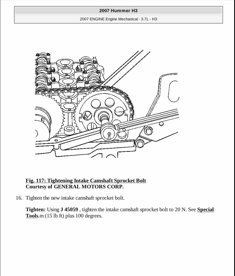
Fig. 117: Tightening Intake Camshaft Sprocket Bolt Courtesy of GENERAL MOTORS CORP.
16. Tighten the new intake camshaft sprocket bolt.
Tighten: Using J 45059 , tighten the intake camshaft sprocket bolt to 20 N. See Special Tools.m (15 lb ft) plus 100 degrees.
2007 Hummer H3
2007 ENGINE Engine Mechanical - 3.7L - H3
MY
Sunday, March 29, 2009 8:40:31 PM Page 172 © 2005 Mitchell Repair Information Company, LLC.

Fig. 118: Tightening Exhaust Camshaft Sprocket Bolt Courtesy of GENERAL MOTORS CORP.
17. Tighten the new exhaust camshaft actuator sprocket bolt.
Tighten: Using J 45059 , tighten the exhaust camshaft actuator sprocket bolt to 25 N. See Special Tools.m (18 lb ft) plus 135 degrees.
2007 Hummer H3
2007 ENGINE Engine Mechanical - 3.7L - H3
MY
Sunday, March 29, 2009 8:40:31 PM Page 173 © 2005 Mitchell Repair Information Company, LLC.

Fig. 119: Removing Special Tool Courtesy of GENERAL MOTORS CORP.
18. Lift the vehicle and remove the EN 46547 . See Special Tools. 19. Lower the vehicle.
20. Remove the J 44221 from the back of the camshafts. See Special Tools.
2007 Hummer H3
2007 ENGINE Engine Mechanical - 3.7L - H3
MY
Sunday, March 29, 2009 8:40:31 PM Page 174 © 2005 Mitchell Repair Information Company, LLC.

Fig. 120: Installing Wedge Tool Handle Courtesy of GENERAL MOTORS CORP.
21. Install the handle of EN-48464 and remove the wedge portion of the tool from the engine. See Special Tools.
NOTE: Ensure that the wedge tool is removed from eng ine prior to rotation. If the wedge tool is not removed, engine damage will result.
2007 Hummer H3
2007 ENGINE Engine Mechanical - 3.7L - H3
MY
Sunday, March 29, 2009 8:40:31 PM Page 175 © 2005 Mitchell Repair Information Company, LLC.

Fig. 121: Rotating Engine Clockwise Courtesy of GENERAL MOTORS CORP.
22. Rotate the engine clockwise by hand two complete revolutions to TDC number 1 on the compression stroke. Use the First Method or Second Method for TDC. If you go past TDC,
IMPORTANT: It is critical that the engine is at TDC and not a couple of degrees off. If in doubt, repeat this step.
2007 Hummer H3
2007 ENGINE Engine Mechanical - 3.7L - H3
MY
Sunday, March 29, 2009 8:40:31 PM Page 176 © 2005 Mitchell Repair Information Company, LLC.

rotate the engine back approximately 45 degrees before TDC and then rotate clockwise up to TDC to ensure that the timing chain is tight (no slack) between the crank sprocket and the timing gears.
Fig. 122: Installing Camshafts Courtesy of GENERAL MOTORS CORP.
23. Both intake and exhaust camshaft flats should be facing up and flat and level with the cylinder head. If J 44221 is used to verify cam timing, you could be off approximately one tooth and cause DTC P0017 to set. See Special Tools. If a worn or new J 44221 is used to verify timing, the timing will be off. See Special Tools.
IMPORTANT: DO NOT use the J 44221 , installed to the back of the camshafts, as a method to verify timing. See Specia l Tools .
2007 Hummer H3
2007 ENGINE Engine Mechanical - 3.7L - H3
MY
Sunday, March 29, 2009 8:40:31 PM Page 177 © 2005 Mitchell Repair Information Company, LLC.

Fig. 123: Verifying Camshaft Placement With Straightedge Courtesy of GENERAL MOTORS CORP.
24. To verify timing, set a straight edge across the flats of the camshafts.
2007 Hummer H3
2007 ENGINE Engine Mechanical - 3.7L - H3
MY
Sunday, March 29, 2009 8:40:31 PM Page 178 © 2005 Mitchell Repair Information Company, LLC.

Fig. 124: Measuring Clearance Under Camshaft Flats Courtesy of GENERAL MOTORS CORP.
25. A 0.005 inch feeler gage should not be able to slip under the straight edge (1). If the feeler gage slips under one or both camshaft flats, then the timing is off. Repeat step 20 and recheck. If the camshaft flats are still not flat, the camshaft timing will have to be reset. This may require removal and reinstallation of one or both camshaft sprockets.
26. Install the 1 long and 2 short cylinder head bolts next to the exhaust and intake timing chain tensioner shoes and tighten the bolts.
27. Position the upper timing chain guide to the cylinder head. Apply threadlocker GM P/N 89021297 (Canadian P/N 10953488) to the upper timing chain guide bolt threads.
28. Install the upper timing chain guide bolts.
Tighten: Tighten the bolts to 10 N.m (89 lb in).
2007 Hummer H3
2007 ENGINE Engine Mechanical - 3.7L - H3
MY
Sunday, March 29, 2009 8:40:31 PM Page 179 © 2005 Mitchell Repair Information Company, LLC.

29. Install the radiator inlet hose and clamp to the cylinder head. Refer to Radiator Inlet Hose Replacement (LLR) .
30. Clean and inspect the camshaft cover. Refer to Camshaft Cover Cleaning and Inspection.
Fig. 125: View Of Camshaft Cover (Valve Cover) Courtesy of GENERAL MOTORS CORP.
31. Install a NEW camshaft cover seal and NEW ignition control module seals to the cam cover. Position the camshaft cover to the cylinder head.
32. Install the camshaft cover bolts.
2007 Hummer H3
2007 ENGINE Engine Mechanical - 3.7L - H3
MY
Sunday, March 29, 2009 8:40:31 PM Page 180 © 2005 Mitchell Repair Information Company, LLC.

Tighten: Tighten the bolts to 10 N.m (89 lb in).
33. Check the gap on all of the spark plugs. The gap should be 1.08 mm (0.042 in). Tighten all of the spark plugs.
Tighten: Tighten the spark plug to 18 N.m (13 lb ft).
34. Install the ignition coils into the camshaft cover.
Fig. 126: View Of Ignition Control Module Courtesy of GENERAL MOTORS CORP.
35. Install the ignition coil bolts.
2007 Hummer H3
2007 ENGINE Engine Mechanical - 3.7L - H3
MY
Sunday, March 29, 2009 8:40:31 PM Page 181 © 2005 Mitchell Repair Information Company, LLC.

Tighten: Tighten the bolts to 10 N.m (89 lb in).
36. Reposition the exhaust manifold to cylinder head and install the exhaust manifold bolts to the cylinder head. Refer to Exhaust Manifold Replacement .
37. If equipped, install a NEW AIR injection gasket, then the cover and pipe studs to the cylinder head.
Tighten: Tighten the pipe studs to 25 N.m (18 lb ft).
38. Install the exhaust manifold heat shield to the exhaust manifold. 39. Apply anti-seize GM P/N 12371386 (Canadian P/N 89021945) to the exhaust manifold heat
shield nuts. 40. Install the exhaust manifold heat shield nuts.
Tighten: Tighten the nuts to 10 N.m (89 lb in).
41. Install the intake manifold to the cylinder head. Refer to Intake Manifold Replacement. 42. Reposition the engine wiring harness bracket to the engine and harnesses. Install the engine
wiring harness bracket bolts.
Tighten: Tighten the bracket bolts to 10 N.m (89 lb in).
43. Install the left front wheelhouse panel and the left wheel and tire. Refer to Wheelhouse Panel Replacement (Front) or Wheelhouse Panel Replacement (Rear) .
44. Drain the engine oil again.
45. If removed, install the radiator outlet hose. Refer to Radiator Outlet Hose Replacement (LLR) .
46. Install the oil pan skid plate and the engine shield. Refer to Oil Pan Skid Plate Replacement .
47. Install the engine shield. 48. Lower the vehicle. 49. Install the cross-vehicle wiring harness connectors to the following components:
� PCM � Map sensor � Ignition coils � Harness clamps at power steering pump � Wiring harness fastener at right front inner fender
2007 Hummer H3
2007 ENGINE Engine Mechanical - 3.7L - H3
MY
Sunday, March 29, 2009 8:40:31 PM Page 182 © 2005 Mitchell Repair Information Company, LLC.

� Throttle body � Camshaft sensors � Exhaust camshaft actuator � Fuel injectors � HO2S 1
50. Install the windshield washer solvent container and coolant recovery reservoir bolts to the right inner fender.
Tighten: Tighten the bolts to 10 N.m (89 lb in).
51. Install the PCV pipes to the intake manifold. Refer to Crankcase Ventilation Hoses/Pipes Replacement.
52. Reposition the oil indicator (dipstick) tube and tighten the bolt to the intake manifold. Refer to Oil Level Indicator and Tube Replacement.
53. Reposition the Fuel/EVAP lines to the intake manifold retainer. Refer to Evaporative Emission Hoses/Pipes Replacement - Engine .
54. Install the following components:
� Generator-Refer to Generator Replacement . � A/C compressor hose/pipe bracket clamp for the engine lift bracket-Refer to Engine
Lift Bracket Replacement. � Drive belt-Refer to Drive Belt Replacement (Without A/C) or Drive Belt
Replacement (With A/C). 55. Install the battery. Refer to Battery Replacement . 56. Install the air induction assembly. Refer to Air Cleaner Resonator and Outlet Duct
Replacement and Air Cleaner Assembly Replacement . 57. Install NEW engine oil. Refer to Engine Mechanical Specifications. 58. Install NEW coolant. Refer to Cooling System Draining and Filling (Static Fill) or
Cooling System Draining and Filling (Vac-N-Fill) . 59. Install a scan tool and start the engine.
� Check for DTCs. � Road test the vehicle. DTC P0017 is a Type B diagnostic code. Three consecutive
ignition key cycles must be performed during the road test with a minimum of a one minute run time between key cycles to verify that a DTC P0017 did not set. For further information on DTC P0017, refer to DTC P0017 .
2007 Hummer H3
2007 ENGINE Engine Mechanical - 3.7L - H3
MY
Sunday, March 29, 2009 8:40:31 PM Page 183 © 2005 Mitchell Repair Information Company, LLC.

CRANKSHAFT BALANCER REPLACEMENT
Tools Required
� J 41816-2 Crankshaft Balancer Puller. See Special Tools. � EN 46547 Flywheel Holding Tool. See Special Tools. � J 41478 Crankshaft Balancer Installer. See Special Tools. � J 41816-2 Crankshaft End Protector. See Special Tools. � J 45059 Angle Meter. See Special Tools.
Removal Procedure
1. Remove the drive belt. Refer to Drive Belt Replacement (Without A/C) or Drive Belt Replacement (With A/C).
2. Raise and support the vehicle. Refer to Lifting and Jacking the Vehicle .
2007 Hummer H3
2007 ENGINE Engine Mechanical - 3.7L - H3
MY
Sunday, March 29, 2009 8:40:31 PM Page 184 © 2005 Mitchell Repair Information Company, LLC.

Fig. 127: View Of Service Slot Plug Courtesy of GENERAL MOTORS CORP.
3. Remove the service slot plug.
2007 Hummer H3
2007 ENGINE Engine Mechanical - 3.7L - H3
MY
Sunday, March 29, 2009 8:40:31 PM Page 185 © 2005 Mitchell Repair Information Company, LLC.

Fig. 128: View Of EN 46547 Flywheel Holding Tool Courtesy of GENERAL MOTORS CORP.
4. Install the EN 46547 (1) into the flywheel teeth. See Special Tools.
IMPORTANT: The crankshaft balancer does not have a k ey-way; so the crankshaft could turn when tightening, causing an i mproper torque.
2007 Hummer H3
2007 ENGINE Engine Mechanical - 3.7L - H3
MY
Sunday, March 29, 2009 8:40:31 PM Page 186 © 2005 Mitchell Repair Information Company, LLC.

5. Lower the vehicle.
6. Remove the fan. Refer to Fan Replacement . 7. Remove the fan shroud. Refer to Fan Shroud Replacement (LLR) . 8. Drain the engine cooling system. Refer to Cooling System Draining and Filling (Static
Fill) or Cooling System Draining and Filling (Vac-N-Fill) . 9. Remove the radiator. Refer to Radiator Replacement .
Fig. 129: View Of Crankshaft Balancer Bolt Courtesy of GENERAL MOTORS CORP.
10. Remove and discard the crankshaft balancer bolt.
2007 Hummer H3
2007 ENGINE Engine Mechanical - 3.7L - H3
MY
Sunday, March 29, 2009 8:40:31 PM Page 187 © 2005 Mitchell Repair Information Company, LLC.

Fig. 130: View Of Crankshaft Balancer Courtesy of GENERAL MOTORS CORP.
11. Install the J 41816-2 into the end of the crankshaft. See Special Tools.
12. Using a J 41816-2 , remove the crankshaft balancer. See Special Tools. 13. Remove the J 41816-2 . See Special Tools. 14. Remove the crankshaft balancer friction washer.
This will be located at the end of the crankshaft balancer or on the crankshaft.
15. Clean and inspect the crankshaft balancer. Refer to Crankshaft Balancer Cleaning and Inspection.
IMPORTANT: Do not pull on outer edge of the cranksha ft balancer.
2007 Hummer H3
2007 ENGINE Engine Mechanical - 3.7L - H3
MY
Sunday, March 29, 2009 8:40:31 PM Page 188 © 2005 Mitchell Repair Information Company, LLC.

Installation Procedure
1. Install the crankshaft balancer friction washer to the end of the crankshaft balancer.
Fig. 131: Installing Crankshaft Balancer Using The J 41478 Courtesy of GENERAL MOTORS CORP.
2. Install the crankshaft balancer using the J 41478 . See Special Tools. 3. Remove the J 41478 . See Special Tools.
2007 Hummer H3
2007 ENGINE Engine Mechanical - 3.7L - H3
MY
Sunday, March 29, 2009 8:40:31 PM Page 189 © 2005 Mitchell Repair Information Company, LLC.

Fig. 132: View Of Crankshaft Balancer Bolt Courtesy of GENERAL MOTORS CORP.
4. Install the crankshaft balancer washer and a NEW bolt.
Tighten: Tighten the bolt a first pass to 150 N.m (111 lb ft). Using the J 45059 rotate the bolt a final pass an additional 180 degrees. See Special Tools.
5. Raise and support the vehicle. Refer to Lifting and Jacking the Vehicle .
NOTE: Refer to Fastener Notice .
2007 Hummer H3
2007 ENGINE Engine Mechanical - 3.7L - H3
MY
Sunday, March 29, 2009 8:40:31 PM Page 190 © 2005 Mitchell Repair Information Company, LLC.

Fig. 133: View Of EN 46547 Flywheel Holding Tool Courtesy of GENERAL MOTORS CORP.
6. Remove the EN 46547 (1) from the flywheel teeth. See Special Tools.
2007 Hummer H3
2007 ENGINE Engine Mechanical - 3.7L - H3
MY
Sunday, March 29, 2009 8:40:32 PM Page 191 © 2005 Mitchell Repair Information Company, LLC.

Fig. 134: View Of Service Slot Plug Courtesy of GENERAL MOTORS CORP.
7. Install the service slot plug. 8. Lower the vehicle.
9. Install the radiator. Refer to Radiator Replacement . 10. Install the fan. Refer to Fan Replacement . 11. Install the fan shroud. Refer to Fan Shroud Replacement (LLR) . 12. Install the drive belt. Refer to Drive Belt Replacement (Without A/C) or Drive Belt
Replacement (With A/C). 13. Fill the engine cooling system. Refer to Cooling System Draining and Filling (Static
2007 Hummer H3
2007 ENGINE Engine Mechanical - 3.7L - H3
MY
Sunday, March 29, 2009 8:40:32 PM Page 192 © 2005 Mitchell Repair Information Company, LLC.

Fill) or Cooling System Draining and Filling (Vac-N-Fill) .
CRANKSHAFT FRONT OIL SEAL REPLACEMENT
Tools Required
J 45951 Front Seal Installer. See Special Tools.
Removal Procedure
1. Remove the crankshaft balancer. Refer to Crankshaft Balancer Replacement.
2007 Hummer H3
2007 ENGINE Engine Mechanical - 3.7L - H3
MY
Sunday, March 29, 2009 8:40:32 PM Page 193 © 2005 Mitchell Repair Information Company, LLC.

Fig. 135: View Of Crankshaft Front Oil Seal Courtesy of GENERAL MOTORS CORP.
2. Pry out the crankshaft front oil seal using a suitable tool.
Discard the seal.
Installation Procedure
Fig. 136: View Of Crankshaft Front Oil Seal
IMPORTANT: Do not damage the engine front cover or t he crankshaft.
2007 Hummer H3
2007 ENGINE Engine Mechanical - 3.7L - H3
MY
Sunday, March 29, 2009 8:40:32 PM Page 194 © 2005 Mitchell Repair Information Company, LLC.

Courtesy of GENERAL MOTORS CORP.
1. Apply the engine oil to the outside diameter of the crankshaft front oil seal.
Fig. 137: Installing Crankshaft Front Oil Seal Courtesy of GENERAL MOTORS CORP.
2. Use the J 45951 to install the NEW crankshaft front oil seal. See Special Tools. 3. Remove the J 45951 . See Special Tools.
2007 Hummer H3
2007 ENGINE Engine Mechanical - 3.7L - H3
MY
Sunday, March 29, 2009 8:40:32 PM Page 195 © 2005 Mitchell Repair Information Company, LLC.

4. Install the crankshaft balancer. Refer to Crankshaft Balancer Replacement.
ENGINE FRONT COVER REPLACEMENT
Tools Required
J 44219 Cover Alignment Pins. See Special Tools.
Removal Procedure
1. Remove the water pump. Refer to Water Pump Replacement . 2. Remove the crankshaft balancer. Refer to Crankshaft Balancer Replacement. 3. Remove the drive belt tensioner. Refer to Drive Belt Tensioner Replacement. 4. Remove the power steering pump. Refer to Power Steering Pump Replacement (LLR) . 5. Remove the oil pump pipe and screen assembly. Refer to Oil Pump Suction Pipe and
Screen Assembly Replacement. 6. Lower the vehicle.
2007 Hummer H3
2007 ENGINE Engine Mechanical - 3.7L - H3
MY
Sunday, March 29, 2009 8:40:32 PM Page 196 © 2005 Mitchell Repair Information Company, LLC.

Fig. 138: View Of 7 mm Center Bolt Courtesy of GENERAL MOTORS CORP.
7. Remove the 7 mm center bolt (1). 8. Remove the remaining engine front cover bolts. 9. Install 2 bolts into any of the threaded holes to act as jack screws and tighten evenly in order
to separate the engine front cover from the engine block. 10. Remove the engine front cover. 11. Remove the 2 bolts from the jack screw holes.
12. Remove the oil pump if necessary. Refer to Oil Pump Replacement.
2007 Hummer H3
2007 ENGINE Engine Mechanical - 3.7L - H3
MY
Sunday, March 29, 2009 8:40:32 PM Page 197 © 2005 Mitchell Repair Information Company, LLC.

13. Clean and inspect the engine front cover. Refer to Engine Front Cover Cleaning and Inspection.
14. Clean and inspect the engine block sealing surface.
Installation Procedure
1. Install the oil pump, if previously removed. Refer to Oil Pump Replacement.
Fig. 139: Installing J 44219 Into Engine Block Courtesy of GENERAL MOTORS CORP.
2. To aid in alignment of the front cover, thread the J 44219 into the engine block. See Special Tools.
2007 Hummer H3
2007 ENGINE Engine Mechanical - 3.7L - H3
MY
Sunday, March 29, 2009 8:40:32 PM Page 198 © 2005 Mitchell Repair Information Company, LLC.

Fig. 140: Applying Sealant To Engine Front Cover Courtesy of GENERAL MOTORS CORP.
3. Apply a 3 mm (0.12 in) bead of sealer to the engine front cover (1). Refer to Sealers, Adhesives and Lubricants.
IMPORTANT: The engine front cover must be installed within 10 minutes from when the sealer was applied.
2007 Hummer H3
2007 ENGINE Engine Mechanical - 3.7L - H3
MY
Sunday, March 29, 2009 8:40:32 PM Page 199 © 2005 Mitchell Repair Information Company, LLC.

Fig. 141: View Of 7 mm Center Bolt Courtesy of GENERAL MOTORS CORP.
4. Align the oil pump to the crankshaft sprocket splines.
5. Install the engine front cover over the J 44219 and to the engine block. See Special Tools. 6. Install the engine front cover bolts.
7. Remove the J 44219 from the engine block. See Special Tools.
8. Install the 2 remaining engine front cover bolts.
NOTE: Refer to Fastener Notice .
2007 Hummer H3
2007 ENGINE Engine Mechanical - 3.7L - H3
MY
Sunday, March 29, 2009 8:40:32 PM Page 200 © 2005 Mitchell Repair Information Company, LLC.

Tighten: 1. Tighten the bolts to 10 N.m (89 lb in). 2. Tighten the small center bolt (1) last to 8 N.m (71 lb in).
9. Install the oil pump pipe and screen assembly. Refer to Oil Pump Suction Pipe and Screen Assembly Replacement.
10. Install the power steering pump. Refer to Power Steering Pump Replacement (LLR) . 11. Install the drive belt tensioner. Refer to Drive Belt Tensioner Replacement. 12. Install the crankshaft balancer. Refer to Crankshaft Balancer Replacement. 13. Install the water pump. Refer to Water Pump Replacement .
CAMSHAFT POSITION EXHAUST ACTUATOR REPLACEMENT
Tools Required
� J-44217-45 Chain Holding Tool. See Special Tools. � J 44221 Camshaft Holding Tool. See Special Tools. � J 45059 Angle Meter. See Special Tools.
Removal Procedure
1. Remove the camshaft cover. Refer to Camshaft Cover Replacement. 2. Ensure the exhaust camshaft position (CMP) actuator is functioning properly. Refer to
Camshaft Position Actuator Diagnosis. 3. Remove the exhaust CMP sensor. Refer to Camshaft Position Sensor Replacement -
Exhaust . 4. Remove the intake CMP sensor. Refer to Camshaft Position Sensor Replacement -
Intake . 5. Rotate the crankshaft in the engine rotational direction clockwise, until the #1 piston is at
top dead center (TDC) on the compression stroke. 6. Using the timing mark on the exhaust camshaft position actuator sprocket as a reference,
make a mark on the timing chain link adjacent to it.
2007 Hummer H3
2007 ENGINE Engine Mechanical - 3.7L - H3
MY
Sunday, March 29, 2009 8:40:32 PM Page 201 © 2005 Mitchell Repair Information Company, LLC.

Fig. 142: View Of J 44221 Camshaft Holding Tool Installed On Camshafts Courtesy of GENERAL MOTORS CORP.
7. Install the J 44221 to the rear of the camshafts. See Special Tools.
CAUTION: Refer to Camshaft Holding Tool Caution .
2007 Hummer H3
2007 ENGINE Engine Mechanical - 3.7L - H3
MY
Sunday, March 29, 2009 8:40:32 PM Page 202 © 2005 Mitchell Repair Information Company, LLC.

Fig. 143: View Of J 44217 & EN-44217-45 At Timing Chains Courtesy of GENERAL MOTORS CORP.
8. Complete the following in order to install the J-44217-45 (1). See Special Tools. 1. Install the hook portion of the timing chain retention tools into one of the timing chain
links near the timing chain shoe on both sides of the engine. 2. Tighten the wingnuts. 3. Ensure the hooks are still in one of the links and the gage blocks of the tool are firmly
in place on the edge of the head.
2007 Hummer H3
2007 ENGINE Engine Mechanical - 3.7L - H3
MY
Sunday, March 29, 2009 8:40:32 PM Page 203 © 2005 Mitchell Repair Information Company, LLC.

Fig. 144: Identifying Exhaust Camshaft Position Actuator Courtesy of GENERAL MOTORS CORP.
9. Remove and discard the exhaust camshaft position actuator bolt. 10. Remove the exhaust camshaft position actuator.
11. Clean and inspect the sprocket. Refer to Timing Chain and Sprockets Cleaning and Inspection.
Installation Procedure
1. Ensure the camshaft actuator is fully advanced prior to installation.
2007 Hummer H3
2007 ENGINE Engine Mechanical - 3.7L - H3
MY
Sunday, March 29, 2009 8:40:32 PM Page 204 © 2005 Mitchell Repair Information Company, LLC.

Fig. 145: View Of Exhaust Camshaft Actuator Courtesy of GENERAL MOTORS CORP.
2. Install the exhaust camshaft actuator into the timing chain.
Aligning the marked link (1) on the timing chain with the timing mark (1) on the exhaust camshaft position actuator sprocket.
IMPORTANT:� To aid in aligning the actuator to the camshaft, us e a 25
mm (1 in) wrench on the hex of the camshaft to rota te � Ensure the alignment pin is properly engaged with t he
2007 Hummer H3
2007 ENGINE Engine Mechanical - 3.7L - H3
MY
Sunday, March 29, 2009 8:40:32 PM Page 205 © 2005 Mitchell Repair Information Company, LLC.

3. Install the exhaust camshaft actuator onto the exhaust camshaft.
Fig. 146: Identifying Exhaust Camshaft Position Actuator Courtesy of GENERAL MOTORS CORP.
4. Install a NEW exhaust camshaft actuator bolt.
Tighten: Tighten the bolt a first pass to 25 N.m (18 lb ft). Using the J 45059 rotate the bolt
camshaft
NOTE: Refer to Fastener Notice .
2007 Hummer H3
2007 ENGINE Engine Mechanical - 3.7L - H3
MY
Sunday, March 29, 2009 8:40:32 PM Page 206 © 2005 Mitchell Repair Information Company, LLC.

a final pass an additional 135 degrees. See Special Tools.
Fig. 147: View Of J 44217 & EN-44217-45 At Timing Chains Courtesy of GENERAL MOTORS CORP.
5. Remove the J-44217-45 (1). See Special Tools.
2007 Hummer H3
2007 ENGINE Engine Mechanical - 3.7L - H3
MY
Sunday, March 29, 2009 8:40:32 PM Page 207 © 2005 Mitchell Repair Information Company, LLC.

Fig. 148: View Of J 44221 Installed On Camshafts Courtesy of GENERAL MOTORS CORP.
6. Remove the J 44221 from the camshafts. See Special Tools. 7. Install the CMP sensor. Refer to Camshaft Position Sensor Replacement - Intake .
8. Install the exhaust CMP sensor. Refer to Camshaft Position Sensor Replacement - Exhaust .
9. Install the camshaft cover. Refer to Camshaft Cover Replacement.
CAMSHAFT INTAKE SPROCKET REPLACEMENT
Tools Required
� J-44217-45 Chain Holding Tool. See Special Tools.
2007 Hummer H3
2007 ENGINE Engine Mechanical - 3.7L - H3
MY
Sunday, March 29, 2009 8:40:32 PM Page 208 © 2005 Mitchell Repair Information Company, LLC.

� J 44221 Camshaft Holding Tool. See Special Tools. � J 45059 Angle Meter. See Special Tools.
Removal Procedure
1. Remove the camshaft cover. Refer to Camshaft Cover Replacement. 2. Remove the intake camshaft position (CMP) sensor. Refer to Camshaft Position Sensor
Replacement - Intake . 3. Rotate the crankshaft in the engine rotational direction clockwise, until the #1 piston is at
top dead center (TDC) on the compression stroke. 4. Using the timing mark on the intake camshaft sprocket as a reference, make a mark on the
timing chain link adjacent to it.
2007 Hummer H3
2007 ENGINE Engine Mechanical - 3.7L - H3
MY
Sunday, March 29, 2009 8:40:32 PM Page 209 © 2005 Mitchell Repair Information Company, LLC.

Fig. 149: View Of J 44221 Installed On Camshafts Courtesy of GENERAL MOTORS CORP.
5. Install the J 44221 to the rear of the camshafts. See Special Tools.
Fig. 150: View Of J 44217 & EN-44217-45 At Timing Chains Courtesy of GENERAL MOTORS CORP.
CAUTION: Refer to Camshaft Holding Tool Caution .
2007 Hummer H3
2007 ENGINE Engine Mechanical - 3.7L - H3
MY
Sunday, March 29, 2009 8:40:32 PM Page 210 © 2005 Mitchell Repair Information Company, LLC.

6. Complete the following in order to install the J-44217-45 (1). See Special Tools. 1. Install the hook portion of the timing chain retention tools into one of the timing chain
links near the timing chain shoe on both sides of the engine. 2. Tighten the wingnuts. 3. Ensure the hooks are still in one of the links and the gage blocks of the tool are firmly
in place on the edge of the head.
Fig. 151: View Of Intake Camshaft Sprocket Washer & Bolt Courtesy of GENERAL MOTORS CORP.
2007 Hummer H3
2007 ENGINE Engine Mechanical - 3.7L - H3
MY
Sunday, March 29, 2009 8:40:32 PM Page 211 © 2005 Mitchell Repair Information Company, LLC.

7. Remove and discard the intake camshaft sprocket bolt. 8. Remove the intake camshaft sprocket.
9. Clean and inspect the sprocket. Refer to Timing Chain and Sprockets Cleaning and Inspection.
Installation Procedure
2007 Hummer H3
2007 ENGINE Engine Mechanical - 3.7L - H3
MY
Sunday, March 29, 2009 8:40:32 PM Page 212 © 2005 Mitchell Repair Information Company, LLC.

Fig. 152: Identifying Chain Alignment Links Courtesy of GENERAL MOTORS CORP.
1. Install the intake camshaft sprocket into the timing chain.
Aligning the dark link (1) on the timing chain with the timing mark on the intake camshaft
2007 Hummer H3
2007 ENGINE Engine Mechanical - 3.7L - H3
MY
Sunday, March 29, 2009 8:40:32 PM Page 213 © 2005 Mitchell Repair Information Company, LLC.

sprocket.
2. Install the intake camshaft sprocket onto the intake camshaft.
3. Install a NEW intake camshaft sprocket bolt.
Tighten: Tighten the bolt a first pass to 20 N.m (15 lb ft). Using the J 45059 rotate the bolt a final pass an additional 100 degrees. See Special Tools.
IMPORTANT:� To aid in aligning the sprocket to the camshaft, us e a 25
mm (1 in) wrench on the hex of the camshaft to rota te � Ensure the alignment pin is properly engaged with t he
camshaft
NOTE: Refer to Fastener Notice .
2007 Hummer H3
2007 ENGINE Engine Mechanical - 3.7L - H3
MY
Sunday, March 29, 2009 8:40:32 PM Page 214 © 2005 Mitchell Repair Information Company, LLC.

Fig. 153: View Of J 44217 & EN-44217-45 At Timing Chains Courtesy of GENERAL MOTORS CORP.
4. Remove the J-44217-45 (1). See Special Tools.
2007 Hummer H3
2007 ENGINE Engine Mechanical - 3.7L - H3
MY
Sunday, March 29, 2009 8:40:32 PM Page 215 © 2005 Mitchell Repair Information Company, LLC.

Fig. 154: View Of J 44221 Installed On Camshafts Courtesy of GENERAL MOTORS CORP.
5. Remove the J 44221 from the camshafts. See Special Tools. 6. Install the intake CMP sensor. Refer to Camshaft Position Sensor Replacement -
Intake .
7. Install the camshaft cover. Refer to Camshaft Cover Replacement.
TIMING CHAIN AND SPROCKET REPLACEMENT
Tools Required
� J 44221 Camshaft Holding Tool. See Special Tools. � J 45059 Angle Meter. See Special Tools.
2007 Hummer H3
2007 ENGINE Engine Mechanical - 3.7L - H3
MY
Sunday, March 29, 2009 8:40:33 PM Page 216 © 2005 Mitchell Repair Information Company, LLC.

Removal Procedure
1. Remove the #1 cylinder spark plug. Refer to Spark Plug Replacement . 2. Remove the camshaft cover. Refer to Camshaft Cover Replacement. 3. Remove the exhaust camshaft position (CMP) sensor. Refer to Camshaft Position Sensor
Replacement - Exhaust . 4. Remove the intake CMP sensor. Refer to Camshaft Position Sensor Replacement -
Intake .
5. Remove the engine front cover. Refer to Engine Front Cover Replacement. 6. Rotate the crankshaft in the engine rotational direction clockwise, until the #1 piston is at
top dead center (TDC) on the compression stroke.
Fig. 155: View Of J 44221 Installed On Camshafts
2007 Hummer H3
2007 ENGINE Engine Mechanical - 3.7L - H3
MY
Sunday, March 29, 2009 8:40:33 PM Page 217 © 2005 Mitchell Repair Information Company, LLC.

Courtesy of GENERAL MOTORS CORP.
7. Install the J 44221 to the rear of the camshafts. See Special Tools.
Fig. 156: Releasing Timing Chain Tension Courtesy of GENERAL MOTORS CORP.
8. Release the tension on the timing chain by moving the tensioner shoe in.
CAUTION: Refer to Camshaft Holding Tool Caution .
2007 Hummer H3
2007 ENGINE Engine Mechanical - 3.7L - H3
MY
Sunday, March 29, 2009 8:40:33 PM Page 218 © 2005 Mitchell Repair Information Company, LLC.

Fig. 157: View Of Tee At Timing Chain Tensioner Courtesy of GENERAL MOTORS CORP.
9. Place the tee into the tensioner to hold the shoe in place.
2007 Hummer H3
2007 ENGINE Engine Mechanical - 3.7L - H3
MY
Sunday, March 29, 2009 8:40:33 PM Page 219 © 2005 Mitchell Repair Information Company, LLC.

Fig. 158: Identifying Exhaust Camshaft Position Actuator Bolt Courtesy of GENERAL MOTORS CORP.
10. Remove and discard the exhaust camshaft position actuator bolt. 11. Remove the exhaust camshaft position actuator.
2007 Hummer H3
2007 ENGINE Engine Mechanical - 3.7L - H3
MY
Sunday, March 29, 2009 8:40:33 PM Page 220 © 2005 Mitchell Repair Information Company, LLC.

Fig. 159: View Of Timing Chain & Sprockets Courtesy of GENERAL MOTORS CORP.
12. Remove and discard the intake camshaft sprocket bolt. 13. Remove the intake camshaft sprocket. 14. Remove the timing chain. 15. Remove the crankshaft sprocket.
16. Clean and inspect the timing chain and sprockets. Refer to Timing Chain and Sprockets Cleaning and Inspection.
Installation Procedure
2007 Hummer H3
2007 ENGINE Engine Mechanical - 3.7L - H3
MY
Sunday, March 29, 2009 8:40:33 PM Page 221 © 2005 Mitchell Repair Information Company, LLC.

Fig. 160: Installing Timing Chain & Sprockets Courtesy of GENERAL MOTORS CORP.
1. Install the crankshaft sprocket to the crankshaft snout.
2. Install the intake camshaft sprocket into the timing chain.
IMPORTANT: Ensure the #1 piston is at TDC. The pin o n the crankshaft for the timing chain sprocket should be straight up.
IMPORTANT: Every 7th link of the timing chain is dar kened to aid in aligning the timing marks.
2007 Hummer H3
2007 ENGINE Engine Mechanical - 3.7L - H3
MY
Sunday, March 29, 2009 8:40:33 PM Page 222 © 2005 Mitchell Repair Information Company, LLC.

Aligning the dark link (1) of the timing chain with the timing mark on the intake camshaft sprocket.
3. Feed the timing chain down through the opening in the cylinder head. 4. Install the timing chain on the crankshaft sprocket.
Aligning the dark link (2) of the timing chain with the timing mark on to the crankshaft sprocket.
5. Install the intake camshaft sprocket onto the intake camshaft.
IMPORTANT: Ensure the alignment pin is properly enga ged with the camshaft
2007 Hummer H3
2007 ENGINE Engine Mechanical - 3.7L - H3
MY
Sunday, March 29, 2009 8:40:33 PM Page 223 © 2005 Mitchell Repair Information Company, LLC.

Fig. 161: View Of Intake Camshaft Sprocket Washer & Bolt Courtesy of GENERAL MOTORS CORP.
6. Install a NEW intake camshaft sprocket bolt.
Tighten: Tighten the bolt a first pass to 20 N.m (15 lb ft). Using the J 45059 rotate the bolt a final pass an additional 100 degrees. See Special Tools.
NOTE: Refer to Fastener Notice .
2007 Hummer H3
2007 ENGINE Engine Mechanical - 3.7L - H3
MY
Sunday, March 29, 2009 8:40:33 PM Page 224 © 2005 Mitchell Repair Information Company, LLC.

7. Ensure the camshaft actuator is fully advanced prior to installation. Refer to Camshaft Position Actuator Diagnosis.
Fig. 162: View Of Exhaust Camshaft Actuator Courtesy of GENERAL MOTORS CORP.
8. Install the exhaust camshaft actuator into the timing chain.
Aligning the dark link (1) of the timing chain with the timing mark (1) on the exhaust camshaft position actuator sprocket.
2007 Hummer H3
2007 ENGINE Engine Mechanical - 3.7L - H3
MY
Sunday, March 29, 2009 8:40:33 PM Page 225 © 2005 Mitchell Repair Information Company, LLC.

9. Install the exhaust camshaft actuator onto the exhaust camshaft.
Fig. 163: Identifying Exhaust Camshaft Position Actuator Bolt Courtesy of GENERAL MOTORS CORP.
10. Install a NEW exhaust camshaft actuator bolt.
IMPORTANT:� To aid in aligning the actuator to the camshaft, us e a 25
mm (1 in) wrench on the hex of the camshaft to rota te � Ensure the alignment pin is properly engaged with t he
camshaft
2007 Hummer H3
2007 ENGINE Engine Mechanical - 3.7L - H3
MY
Sunday, March 29, 2009 8:40:33 PM Page 226 © 2005 Mitchell Repair Information Company, LLC.

Tighten: Tighten the bolt a first pass to 25 N.m (18 lb ft). Using the J 45059 rotate the bolt a final pass an additional 135 degrees. See Special Tools.
Fig. 164: View Of Tee At Timing Chain Tensioner Courtesy of GENERAL MOTORS CORP.
11. Remove the tee in the timing chain tensioner in order to regain tension on the timing chain.
2007 Hummer H3
2007 ENGINE Engine Mechanical - 3.7L - H3
MY
Sunday, March 29, 2009 8:40:33 PM Page 227 © 2005 Mitchell Repair Information Company, LLC.

Fig. 165: View Of J 44221 Installed On Camshafts Courtesy of GENERAL MOTORS CORP.
12. Remove the J 44221 from the camshafts. See Special Tools.
2007 Hummer H3
2007 ENGINE Engine Mechanical - 3.7L - H3
MY
Sunday, March 29, 2009 8:40:33 PM Page 228 © 2005 Mitchell Repair Information Company, LLC.

Fig. 166: Identifying Chain Alignment Links Courtesy of GENERAL MOTORS CORP.
13. The dark links (1) on the timing chain should be aligned with the marks on the sprockets as shown.
2007 Hummer H3
2007 ENGINE Engine Mechanical - 3.7L - H3
MY
Sunday, March 29, 2009 8:40:33 PM Page 229 © 2005 Mitchell Repair Information Company, LLC.

14. Install the engine front cover. Refer to Engine Front Cover Replacement. 15. Install the intake CMP sensor. Refer to Camshaft Position Sensor Replacement -
Intake .
16. Install the exhaust CMP sensor. Refer to Camshaft Position Sensor Replacement - Exhaust .
17. Install the camshaft cover. Refer to Camshaft Cover Replacement. 18. Install #1 cylinder spark plug. Refer to Spark Plug Replacement .
TIMING CHAIN TENSIONER REPLACEMENT
Tools Required
J 44221 Camshaft Holding Tool. See Special Tools.
Removal Procedure
1. Remove the camshaft cover. Refer to Camshaft Cover Replacement. 2. Remove the engine front cover. Refer to Engine Front Cover Replacement. 3. Rotate the crankshaft in the engine rotational direction clockwise, until the #1 piston is at
top dead center (TDC) on the compression stroke.
2007 Hummer H3
2007 ENGINE Engine Mechanical - 3.7L - H3
MY
Sunday, March 29, 2009 8:40:33 PM Page 230 © 2005 Mitchell Repair Information Company, LLC.

Fig. 167: View Of J 44221 Installed On Camshafts Courtesy of GENERAL MOTORS CORP.
4. Install the J 44221 to the rear of the camshafts. See Special Tools.
CAUTION: Refer to Camshaft Holding Tool Caution .
2007 Hummer H3
2007 ENGINE Engine Mechanical - 3.7L - H3
MY
Sunday, March 29, 2009 8:40:33 PM Page 231 © 2005 Mitchell Repair Information Company, LLC.

Fig. 168: Identifying Chain Alignment Links Courtesy of GENERAL MOTORS CORP.
5. Using the timing marks on the following as a reference, make a mark on the timing chain links (1) adjacent to them:
2007 Hummer H3
2007 ENGINE Engine Mechanical - 3.7L - H3
MY
Sunday, March 29, 2009 8:40:33 PM Page 232 © 2005 Mitchell Repair Information Company, LLC.

� The exhaust camshaft position actuator sprocket � The Intake camshaft sprocket � The crankshaft sprocket
Fig. 169: Releasing Timing Chain Tension Courtesy of GENERAL MOTORS CORP.
6. Release the tension on the timing chain by moving the tensioner shoe in.
2007 Hummer H3
2007 ENGINE Engine Mechanical - 3.7L - H3
MY
Sunday, March 29, 2009 8:40:33 PM Page 233 © 2005 Mitchell Repair Information Company, LLC.

Fig. 170: View Of Tee At Timing Chain Tensioner Courtesy of GENERAL MOTORS CORP.
7. Place the tee into the tensioner to hold the shoe in place.
2007 Hummer H3
2007 ENGINE Engine Mechanical - 3.7L - H3
MY
Sunday, March 29, 2009 8:40:33 PM Page 234 © 2005 Mitchell Repair Information Company, LLC.

Fig. 171: View Of Timing Chain Tensioner & Bolts Courtesy of GENERAL MOTORS CORP.
8. Remove the timing chain tensioner bolts. 9. Remove the timing chain tensioner from the engine.
Installation Procedure
2007 Hummer H3
2007 ENGINE Engine Mechanical - 3.7L - H3
MY
Sunday, March 29, 2009 8:40:33 PM Page 235 © 2005 Mitchell Repair Information Company, LLC.

Fig. 172: View Of Timing Chain Tensioner & Bolts Courtesy of GENERAL MOTORS CORP.
1. Position the timing chain tensioner to the engine.
2. Install the timing chain tensioner bolts.
Tighten: Tighten the bolts to 25 N.m (18 lb ft).
NOTE: Refer to Fastener Notice .
2007 Hummer H3
2007 ENGINE Engine Mechanical - 3.7L - H3
MY
Sunday, March 29, 2009 8:40:33 PM Page 236 © 2005 Mitchell Repair Information Company, LLC.

Fig. 173: View Of Tee At Timing Chain Tensioner Courtesy of GENERAL MOTORS CORP.
3. Remove the tee in the timing chain tensioner in order to regain tension on the timing chain.
2007 Hummer H3
2007 ENGINE Engine Mechanical - 3.7L - H3
MY
Sunday, March 29, 2009 8:40:33 PM Page 237 © 2005 Mitchell Repair Information Company, LLC.

Fig. 174: View Of J 44221 Installed On Camshafts Courtesy of GENERAL MOTORS CORP.
4. Remove the J 44221 from the camshafts. See Special Tools.
2007 Hummer H3
2007 ENGINE Engine Mechanical - 3.7L - H3
MY
Sunday, March 29, 2009 8:40:33 PM Page 238 © 2005 Mitchell Repair Information Company, LLC.

Fig. 175: Identifying Chain Alignment Links Courtesy of GENERAL MOTORS CORP.
IMPORTANT: Every 7th link of the timing chain is dar kened to aid in aligning the timing marks.
2007 Hummer H3
2007 ENGINE Engine Mechanical - 3.7L - H3
MY
Sunday, March 29, 2009 8:40:33 PM Page 239 © 2005 Mitchell Repair Information Company, LLC.

5. Align the marked links (1) on the timing chain with the timing marks on the following: � The exhaust camshaft position actuator sprocket � The Intake camshaft sprocket � The crankshaft sprocket
6. Install the engine front cover. Refer to Engine Front Cover Replacement. 7. Install the camshaft cover. Refer to Camshaft Cover Replacement.
TIMING CHAIN TENSIONER SHOE REPLACEMENT
Tools Required
J 44221 Camshaft Holding Tool. See Special Tools.
Removal Procedure
1. Remove the camshaft cover. Refer to Camshaft Cover Replacement. 2. Remove the engine front cover. Refer to Engine Front Cover Replacement. 3. Rotate the crankshaft in the engine rotational direction clockwise, until the #1 piston is at
top dead center (TDC) on the compression stroke.
2007 Hummer H3
2007 ENGINE Engine Mechanical - 3.7L - H3
MY
Sunday, March 29, 2009 8:40:34 PM Page 240 © 2005 Mitchell Repair Information Company, LLC.

Fig. 176: View Of J 44221 Installed On Camshafts Courtesy of GENERAL MOTORS CORP.
4. Install the J 44221 to the rear of the camshafts. See Special Tools.
CAUTION: Refer to Camshaft Holding Tool Caution .
2007 Hummer H3
2007 ENGINE Engine Mechanical - 3.7L - H3
MY
Sunday, March 29, 2009 8:40:34 PM Page 241 © 2005 Mitchell Repair Information Company, LLC.

Fig. 177: Identifying Chain Alignment Links Courtesy of GENERAL MOTORS CORP.
5. Using the timing marks on the following as a reference, make a mark on the timing chain links (1) adjacent to them:
2007 Hummer H3
2007 ENGINE Engine Mechanical - 3.7L - H3
MY
Sunday, March 29, 2009 8:40:34 PM Page 242 © 2005 Mitchell Repair Information Company, LLC.

� The exhaust camshaft position actuator sprocket � The Intake camshaft sprocket � The crankshaft sprocket
Fig. 178: Releasing Timing Chain Tension Courtesy of GENERAL MOTORS CORP.
6. Release the tension on the timing chain by moving the tensioner shoe in.
2007 Hummer H3
2007 ENGINE Engine Mechanical - 3.7L - H3
MY
Sunday, March 29, 2009 8:40:34 PM Page 243 © 2005 Mitchell Repair Information Company, LLC.

Fig. 179: View Of Tee At Timing Chain Tensioner Courtesy of GENERAL MOTORS CORP.
7. Place the tee into the tensioner to hold the shoe in place.
2007 Hummer H3
2007 ENGINE Engine Mechanical - 3.7L - H3
MY
Sunday, March 29, 2009 8:40:34 PM Page 244 © 2005 Mitchell Repair Information Company, LLC.

Fig. 180: View Of Cylinder Head Access Hole Plugs Courtesy of GENERAL MOTORS CORP.
8. Remove the cylinder head access hole plug.
2007 Hummer H3
2007 ENGINE Engine Mechanical - 3.7L - H3
MY
Sunday, March 29, 2009 8:40:34 PM Page 245 © 2005 Mitchell Repair Information Company, LLC.

Fig. 181: View Of Timing Chain Tensioner Shoe & Bolt Courtesy of GENERAL MOTORS CORP.
9. Remove the timing chain tensioner shoe bolt. 10. Remove the timing chain tensioner shoe from the engine.
Installation Procedure
2007 Hummer H3
2007 ENGINE Engine Mechanical - 3.7L - H3
MY
Sunday, March 29, 2009 8:40:34 PM Page 246 © 2005 Mitchell Repair Information Company, LLC.

Fig. 182: View Of Timing Chain Tensioner Shoe & Bolt Courtesy of GENERAL MOTORS CORP.
1. Position the timing chain tensioner shoe to the engine.
2. Install the timing chain tensioner shoe bolt.
Tighten: Tighten the bolt to 25 N.m (18 lb ft).
NOTE: Refer to Fastener Notice .
2007 Hummer H3
2007 ENGINE Engine Mechanical - 3.7L - H3
MY
Sunday, March 29, 2009 8:40:34 PM Page 247 © 2005 Mitchell Repair Information Company, LLC.

Fig. 183: View Of Cylinder Head Access Hole Plugs Courtesy of GENERAL MOTORS CORP.
3. Install the cylinder head access hole plug.
Tighten: Tighten the plug to 5 N.m (44 lb in).
2007 Hummer H3
2007 ENGINE Engine Mechanical - 3.7L - H3
MY
Sunday, March 29, 2009 8:40:34 PM Page 248 © 2005 Mitchell Repair Information Company, LLC.

Fig. 184: View Of Tee At Timing Chain Tensioner Courtesy of GENERAL MOTORS CORP.
4. Remove the tee in the timing chain tensioner in order to regain tension on the timing chain.
2007 Hummer H3
2007 ENGINE Engine Mechanical - 3.7L - H3
MY
Sunday, March 29, 2009 8:40:34 PM Page 249 © 2005 Mitchell Repair Information Company, LLC.

Fig. 185: View Of J 44221 Installed On Camshafts Courtesy of GENERAL MOTORS CORP.
5. Remove the J 44221 from the camshafts. See Special Tools.
2007 Hummer H3
2007 ENGINE Engine Mechanical - 3.7L - H3
MY
Sunday, March 29, 2009 8:40:34 PM Page 250 © 2005 Mitchell Repair Information Company, LLC.

Fig. 186: Identifying Chain Alignment Links Courtesy of GENERAL MOTORS CORP.
IMPORTANT: Every 7th link of the timing chain is dar kened to aid in aligning the timing marks.
2007 Hummer H3
2007 ENGINE Engine Mechanical - 3.7L - H3
MY
Sunday, March 29, 2009 8:40:34 PM Page 251 © 2005 Mitchell Repair Information Company, LLC.

6. Align the marked links (1) of the timing chain with the timing marks on the following: � The exhaust camshaft position actuator sprocket � The Intake camshaft sprocket � The crankshaft sprocket
7. Install the engine front cover. Refer to Engine Front Cover Replacement. 8. Install the camshaft cover. Refer to Camshaft Cover Replacement.
TIMING CHAIN GUIDE REPLACEMENT - UPPER
Removal Procedure
2007 Hummer H3
2007 ENGINE Engine Mechanical - 3.7L - H3
MY
Sunday, March 29, 2009 8:40:34 PM Page 252 © 2005 Mitchell Repair Information Company, LLC.

Fig. 187: View Of Upper Timing Chain Guide Courtesy of GENERAL MOTORS CORP.
1. Remove the camshaft cover. Refer to Camshaft Cover Replacement. 2. Remove the upper timing chain guide bolts. 3. Remove the upper timing chain guide from the cylinder head.
Installation Procedure
Fig. 188: View Of Upper Timing Chain Guide Courtesy of GENERAL MOTORS CORP.
2007 Hummer H3
2007 ENGINE Engine Mechanical - 3.7L - H3
MY
Sunday, March 29, 2009 8:40:34 PM Page 253 © 2005 Mitchell Repair Information Company, LLC.

1. Position the upper timing chain guide to the cylinder head.
2. Apply threadlock to the upper timing chain guide bolt threads. Refer to Sealers, Adhesives and Lubricants.
3. Install the upper timing chain guide bolts.
Tighten: Tighten the bolts to 10 N.m (89 lb in).
4. Install the camshaft cover. Refer to Camshaft Cover Replacement.
TIMING CHAIN GUIDE REPLACEMENT - LOWER
Removal Procedure
1. Remove the timing chain tensioner shoe. Refer to Timing Chain Tensioner Shoe Replacement.
2. Slide the crankshaft sprocket from the crankshaft sprocket snout, in order to gain slack in the timing chain to remove the lower timing chain guide.
NOTE: Refer to Fastener Notice .
2007 Hummer H3
2007 ENGINE Engine Mechanical - 3.7L - H3
MY
Sunday, March 29, 2009 8:40:34 PM Page 254 © 2005 Mitchell Repair Information Company, LLC.

Fig. 189: View Of Cylinder Head Access Hole Plugs Courtesy of GENERAL MOTORS CORP.
3. Remove the cylinder head access hole plug.
2007 Hummer H3
2007 ENGINE Engine Mechanical - 3.7L - H3
MY
Sunday, March 29, 2009 8:40:34 PM Page 255 © 2005 Mitchell Repair Information Company, LLC.

Fig. 190: View Of Timing Chain Guide & Bolts Courtesy of GENERAL MOTORS CORP.
4. Remove the lower timing chain guide bolts. 5. Remove the lower timing chain guide from the engine.
Installation Procedure
2007 Hummer H3
2007 ENGINE Engine Mechanical - 3.7L - H3
MY
Sunday, March 29, 2009 8:40:34 PM Page 256 © 2005 Mitchell Repair Information Company, LLC.

Fig. 191: View Of Timing Chain Guide & Bolts Courtesy of GENERAL MOTORS CORP.
1. Position the lower timing chain guide to the engine.
2. Install the lower timing chain guide bolts.
Tighten: Tighten the bolts to 18 N.m (13 lb ft).
NOTE: Refer to Fastener Notice .
2007 Hummer H3
2007 ENGINE Engine Mechanical - 3.7L - H3
MY
Sunday, March 29, 2009 8:40:34 PM Page 257 © 2005 Mitchell Repair Information Company, LLC.

Fig. 192: View Of Cylinder Head Access Hole Plugs Courtesy of GENERAL MOTORS CORP.
3. Install the cylinder head access hole plug.
Tighten: Tighten the plug to 5 N.m (44 lb in).
4. Install the crankshaft sprocket to the crankshaft sprocket snout.
Aligning the marked link on the timing chain with the timing mark on the crankshaft
2007 Hummer H3
2007 ENGINE Engine Mechanical - 3.7L - H3
MY
Sunday, March 29, 2009 8:40:34 PM Page 258 © 2005 Mitchell Repair Information Company, LLC.

sprocket.
5. Install the timing chain tensioner shoe. Refer to Timing Chain Tensioner Shoe Replacement.
CAMSHAFT REPLACEMENT
Tools Required
� J 44221 Camshaft Holding Tool. See Special Tools. � J 44222 Camshaft Sprocket Holding Tool. See Special Tools. � J 45059 Angle Meter. See Special Tools.
Removal Procedure
1. Remove the camshaft cover. Refer to Camshaft Cover Replacement. 2. Remove the exhaust camshaft position (CMP) sensor. Refer to Camshaft Position Sensor
Replacement - Exhaust . 3. Remove the intake CMP sensor. Refer to Camshaft Position Sensor Replacement -
Intake . 4. Rotate the crankshaft in the engine rotational direction clockwise, until the #1 piston is at
top dead center (TDC) on the compression stroke.
2007 Hummer H3
2007 ENGINE Engine Mechanical - 3.7L - H3
MY
Sunday, March 29, 2009 8:40:34 PM Page 259 © 2005 Mitchell Repair Information Company, LLC.

Fig. 193: View Of J 44221 Installed On Camshafts Courtesy of GENERAL MOTORS CORP.
5. Install the J 44221 to the rear of the camshafts. See Special Tools. 6. Remove and discard the intake and the exhaust camshaft sprocket bolts.
CAUTION: Refer to Camshaft Holding Tool Caution .
2007 Hummer H3
2007 ENGINE Engine Mechanical - 3.7L - H3
MY
Sunday, March 29, 2009 8:40:34 PM Page 260 © 2005 Mitchell Repair Information Company, LLC.

Fig. 194: View Of J 44222 Installed Onto Cylinder Head Courtesy of GENERAL MOTORS CORP.
7. Install the J 44222 onto the cylinder head and adjust the horizontal bolts into the camshaft sprockets in order to maintain chain tension and keep from disturbing the timing chain components. See Special Tools.
8. Carefully slide the sprockets with the timing chain from the camshafts to the J 44222 . See Special Tools.
2007 Hummer H3
2007 ENGINE Engine Mechanical - 3.7L - H3
MY
Sunday, March 29, 2009 8:40:34 PM Page 261 © 2005 Mitchell Repair Information Company, LLC.

Fig. 195: View Of Camshaft Caps Courtesy of GENERAL MOTORS CORP.
9. Alternately loosen the camshaft cap bolts a few turns at a time until all valve spring pressure has been released.
10. Remove the camshaft caps.
11. Remove the J 44221 from the camshafts. See Special Tools.
IMPORTANT: Place the camshaft caps in a rack to ensu re the caps are installed in the same location from which they were removed.
2007 Hummer H3
2007 ENGINE Engine Mechanical - 3.7L - H3
MY
Sunday, March 29, 2009 8:40:34 PM Page 262 © 2005 Mitchell Repair Information Company, LLC.

Fig. 196: View Of Camshafts Courtesy of GENERAL MOTORS CORP.
12. Remove the camshafts from the cylinder head.
13. Clean and inspect the camshafts. Refer to Camshafts Cleaning and Inspection.
Installation Procedure
1. Coat the camshaft journals, camshaft journal thrust face and camshaft lobes with clean engine oil.
2007 Hummer H3
2007 ENGINE Engine Mechanical - 3.7L - H3
MY
Sunday, March 29, 2009 8:40:35 PM Page 263 © 2005 Mitchell Repair Information Company, LLC.

Fig. 197: Installing J 44221 To Camshafts Courtesy of GENERAL MOTORS CORP.
2. Install the J 44221 with the camshaft flats up and the #1 piston at TDC. See Special Tools. 3. Install the intake and exhaust camshafts to their original positions.
2007 Hummer H3
2007 ENGINE Engine Mechanical - 3.7L - H3
MY
Sunday, March 29, 2009 8:40:35 PM Page 264 © 2005 Mitchell Repair Information Company, LLC.

Fig. 198: Identifying Camshaft Bearing Cap Markings Courtesy of GENERAL MOTORS CORP.
4. Observe the markings on the camshaft caps. Each camshaft cap is marked in order to identify its location. The markings have the following meanings:
� The arrow should point to the front of the engine � The number indicates the position from the front of the engine � The "E" indicates the exhaust camshaft. � The "I" indicates the intake camshaft.
2007 Hummer H3
2007 ENGINE Engine Mechanical - 3.7L - H3
MY
Sunday, March 29, 2009 8:40:35 PM Page 265 © 2005 Mitchell Repair Information Company, LLC.

Fig. 199: View Of Camshaft Caps Courtesy of GENERAL MOTORS CORP.
5. Install the camshaft caps according to the identification marks.
6. Install the camshaft cap bolts. Tighten the bolts evenly in order to compress the valve springs before final torque.
Tighten: Tighten the bolts to 12 N.m (106 lb in).
NOTE: Refer to Fastener Notice .
2007 Hummer H3
2007 ENGINE Engine Mechanical - 3.7L - H3
MY
Sunday, March 29, 2009 8:40:35 PM Page 266 © 2005 Mitchell Repair Information Company, LLC.

Fig. 200: View Of J 44222 Installed Onto Cylinder Head Courtesy of GENERAL MOTORS CORP.
7. Carefully slide the sprockets with the timing chain from the J 44222 to the camshafts. See Special Tools.
8. Remove the J 44222 from the cylinder head. See Special Tools.
IMPORTANT:� To aid in aligning the sprockets to the camshafts, use a
25 mm (1 in) wrench on the hex of the camshafts to rotate
� Ensure the alignment pins are properly engaged with the camshafts
2007 Hummer H3
2007 ENGINE Engine Mechanical - 3.7L - H3
MY
Sunday, March 29, 2009 8:40:35 PM Page 267 © 2005 Mitchell Repair Information Company, LLC.

9. Install the new intake camshaft sprocket bolt. 10. Install the new exhaust camshaft actuator bolt.
Tighten: 1. Tighten the intake camshaft sprocket bolt a first pass to 20 N.m (15 lb ft). Using the J
45059 rotate the bolt a final pass an additional 100 degrees. See Special Tools. 2. Tighten the exhaust camshaft sprocket bolt a first pass to 25 N.m (18 lb ft). Using the J
45059 rotate the bolt a final pass an additional 135 degrees. See Special Tools.
Fig. 201: View Of J 44221 Installed On Camshafts Courtesy of GENERAL MOTORS CORP.
11. Remove the J 44221 from the camshafts. See Special Tools.
2007 Hummer H3
2007 ENGINE Engine Mechanical - 3.7L - H3
MY
Sunday, March 29, 2009 8:40:35 PM Page 268 © 2005 Mitchell Repair Information Company, LLC.

12. Install the intake CMP sensor. Refer to Camshaft Position Sensor Replacement - Intake .
13. Install the exhaust CMP sensor. Refer to Camshaft Position Sensor Replacement - Exhaust .
14. Install the camshaft cover. Refer to Camshaft Cover Replacement.
OIL FILTER ADAPTER REPLACEMENT
Removal Procedure
2007 Hummer H3
2007 ENGINE Engine Mechanical - 3.7L - H3
MY
Sunday, March 29, 2009 8:40:35 PM Page 269 © 2005 Mitchell Repair Information Company, LLC.

Fig. 202: Identifying Oil Filter Adapter Courtesy of GENERAL MOTORS CORP.
1. Remove the oil filter. Refer to Engine Oil and Oil Filter Replacement. 2. Remove the oil filter adapter from the engine block.
Installation Procedure
2007 Hummer H3
2007 ENGINE Engine Mechanical - 3.7L - H3
MY
Sunday, March 29, 2009 8:40:35 PM Page 270 © 2005 Mitchell Repair Information Company, LLC.

Fig. 203: Identifying Oil Filter Adapter Courtesy of GENERAL MOTORS CORP.
1. Install the oil filter adapter into the engine block.
NOTE: Refer to Component Fastener Tightening Notice .
2007 Hummer H3
2007 ENGINE Engine Mechanical - 3.7L - H3
MY
Sunday, March 29, 2009 8:40:35 PM Page 271 © 2005 Mitchell Repair Information Company, LLC.

Tighten: Tighten the adapter to 50 N.m (37 lb ft).
2. Install the oil filter. Refer to Engine Oil and Oil Filter Replacement.
OIL FILTER BYPASS VALVE REPLACEMENT
Removal Procedure
Fig. 204: Identifying Oil Filter Bypass Valve
2007 Hummer H3
2007 ENGINE Engine Mechanical - 3.7L - H3
MY
Sunday, March 29, 2009 8:40:35 PM Page 272 © 2005 Mitchell Repair Information Company, LLC.

Courtesy of GENERAL MOTORS CORP.
1. Remove the oil filter. Refer to Engine Oil and Oil Filter Replacement. 2. Using a suitable tool, pry the oil filter bypass valve from the engine block. Discard the oil
filter bypass valve.
Installation Procedure
Fig. 205: Identifying Oil Filter Bypass Valve
2007 Hummer H3
2007 ENGINE Engine Mechanical - 3.7L - H3
MY
Sunday, March 29, 2009 8:40:35 PM Page 273 © 2005 Mitchell Repair Information Company, LLC.

Courtesy of GENERAL MOTORS CORP.
1. Press the NEW oil filter bypass valve into the engine block.
2. Install the oil filter. Refer to Engine Oil and Oil Filter Replacement.
OIL PAN REPLACEMENT
Removal Procedure
1. Remove the oil level indicator and tube. Refer to Oil Level Indicator and Tube Replacement.
2. Remove the oil pan skid plate. Refer to Oil Pan Skid Plate Replacement . 3. Drain the engine oil. Refer to Engine Oil and Oil Filter Replacement. 4. Remove the crossmember. Refer to Crossmember Replacement .
2007 Hummer H3
2007 ENGINE Engine Mechanical - 3.7L - H3
MY
Sunday, March 29, 2009 8:40:35 PM Page 274 © 2005 Mitchell Repair Information Company, LLC.

Fig. 206: View Of Mounting Bracket To Frame Bolts Courtesy of GENERAL MOTORS CORP.
5. Remove the differential carrier assembly bushing to frame bolts ONLY. 6. Pull the differential carrier assembly downward. 7. Secure the pinion yoke, in order to prevent the differential carrier from rotating.
2007 Hummer H3
2007 ENGINE Engine Mechanical - 3.7L - H3
MY
Sunday, March 29, 2009 8:40:35 PM Page 275 © 2005 Mitchell Repair Information Company, LLC.

Fig. 207: View Of Transmission Mounting Bolts Courtesy of GENERAL MOTORS CORP.
8. Remove the service slot plug. 9. Remove the nuts securing the fuel hose/pipe bracket to the transmission and position aside.
10. Remove 4 lower transmission mounting bolts that are attached to the oil pan.
11. Remove the power steering gear. Refer to Steering Gear Replacement . 12. Pull the power steering gear downward in order to gain access to the oil pan. 13. Disconnect the engine wiring harness retainers from the oil pan.
2007 Hummer H3
2007 ENGINE Engine Mechanical - 3.7L - H3
MY
Sunday, March 29, 2009 8:40:35 PM Page 276 © 2005 Mitchell Repair Information Company, LLC.

Fig. 208: View Oil Pan & Mounting Bolts Courtesy of GENERAL MOTORS CORP.
14. Remove the oil pan bolts. 15. Install 2 bolts in the threaded holes at the rear of the oil pan to act as jack screws and tighten
evenly to release the oil pan from the engine block. 16. Remove the oil pan. 17. Remove the 2 bolts from the jack screw holes.
2007 Hummer H3
2007 ENGINE Engine Mechanical - 3.7L - H3
MY
Sunday, March 29, 2009 8:40:35 PM Page 277 © 2005 Mitchell Repair Information Company, LLC.

18. Clean and inspect the oil pan. Refer to Oil Pan Cleaning and Inspection. 19. Clean and inspect the engine block sealing surface.
Installation Procedure
Fig. 209: View Of Oil Pan Sealant Application Courtesy of GENERAL MOTORS CORP.
1. Apply a 5.5 mm (0.22 in) bead of sealer to the oil pan in the areas marked (1). Refer to Sealers, Adhesives and Lubricants.
2. Apply a 3 mm (0.12 in) bead of sealer to the oil pan in the area marked (2). Refer to Sealers, Adhesives and Lubricants.
IMPORTANT: The oil pan must be installed within 10 m inutes from when the sealer was applied.
2007 Hummer H3
2007 ENGINE Engine Mechanical - 3.7L - H3
MY
Sunday, March 29, 2009 8:40:35 PM Page 278 © 2005 Mitchell Repair Information Company, LLC.

Fig. 210: View Oil Pan & Mounting Bolts Courtesy of GENERAL MOTORS CORP.
3. Position the oil pan to the engine block. 4. Ensure the oil pan is positioned fully rearward against the transmission mounting surface.
IMPORTANT: Use care not to allow the sealer to conta ct the oil pump pipe and screen assembly.
2007 Hummer H3
2007 ENGINE Engine Mechanical - 3.7L - H3
MY
Sunday, March 29, 2009 8:40:35 PM Page 279 © 2005 Mitchell Repair Information Company, LLC.

5. Install the oil pan bolts.
6. Tighten the oil pan bolts.
Tighten: � Tighten the (side) bolts to 25 N.m (18 lb ft). � Tighten the (end) bolts to 10 N.m (89 lb in).
7. Connect the engine wiring harness retainers to the oil pan. 8. Position the power steering gear upward to the frame assembly.
9. Install the power steering gear. Refer to Steering Gear Replacement .
NOTE: Refer to Fastener Notice .
2007 Hummer H3
2007 ENGINE Engine Mechanical - 3.7L - H3
MY
Sunday, March 29, 2009 8:40:35 PM Page 280 © 2005 Mitchell Repair Information Company, LLC.

Fig. 211: View Of Transmission Mounting Bolts Courtesy of GENERAL MOTORS CORP.
10. Install the 4 lower transmission mounting bolts.
Tighten: Tighten the bolts to 50 N.m (37 lb ft).
11. Install the nuts securing the fuel hose/pipe bracket to the transmission.
Tighten: Tighten the nuts to 20 N.m (15 lb ft).
2007 Hummer H3
2007 ENGINE Engine Mechanical - 3.7L - H3
MY
Sunday, March 29, 2009 8:40:35 PM Page 281 © 2005 Mitchell Repair Information Company, LLC.

12. Install the service slot plug.
Fig. 212: View Of Mounting Bracket To Frame Bolts Courtesy of GENERAL MOTORS CORP.
13. Position the differential carrier assembly to the frame. 14. Install the differential carrier assembly bushing to frame bolts.
Tighten: Tighten the bolts to 152 N.m (112 lb ft).
2007 Hummer H3
2007 ENGINE Engine Mechanical - 3.7L - H3
MY
Sunday, March 29, 2009 8:40:35 PM Page 282 © 2005 Mitchell Repair Information Company, LLC.

15. Install the crossmember. Refer to Crossmember Replacement . 16. Install the oil pan skid plate. Refer to Oil Pan Skid Plate Replacement . 17. Install the oil level indicator and tube. Refer to Oil Level Indicator and Tube
Replacement. 18. Fill the engine oil. Refer to Engine Oil and Oil Filter Replacement.
ENGINE OIL PRESSURE SENSOR AND/OR SWITCH REPLACEMENT
Removal Procedure
Fig. 213: View Of Oil Pressure Switch Engine Wiring Harness Electrical Connector
2007 Hummer H3
2007 ENGINE Engine Mechanical - 3.7L - H3
MY
Sunday, March 29, 2009 8:40:35 PM Page 283 © 2005 Mitchell Repair Information Company, LLC.

Courtesy of GENERAL MOTORS CORP.
1. Remove the engine shield. Refer to Engine Shield Replacement . 2. Disconnect the oil pressure switch electrical connector (1).
Fig. 214: View Of Engine Oil Pressure Switch Courtesy of GENERAL MOTORS CORP.
3. Remove the engine oil pressure switch.
Installation Procedure
2007 Hummer H3
2007 ENGINE Engine Mechanical - 3.7L - H3
MY
Sunday, March 29, 2009 8:40:35 PM Page 284 © 2005 Mitchell Repair Information Company, LLC.

Fig. 215: View Of Engine Oil Pressure Switch Courtesy of GENERAL MOTORS CORP.
1. Install the engine oil pressure switch.
Tighten: Tighten the switch to 20 N.m (15 lb ft).
NOTE: Refer to Component Fastener Tightening Notice .
2007 Hummer H3
2007 ENGINE Engine Mechanical - 3.7L - H3
MY
Sunday, March 29, 2009 8:40:35 PM Page 285 © 2005 Mitchell Repair Information Company, LLC.

Fig. 216: View Of Oil Pressure Switch Engine Wiring Harness Electrical Connector Courtesy of GENERAL MOTORS CORP.
2. Connect the oil pressure switch electrical connector (1).
3. Install the engine shield. Refer to Engine Shield Replacement .
OIL PUMP SUCTION PIPE AND SCREEN ASSEMBLY REPLACEMENT
Removal Procedure
2007 Hummer H3
2007 ENGINE Engine Mechanical - 3.7L - H3
MY
Sunday, March 29, 2009 8:40:36 PM Page 286 © 2005 Mitchell Repair Information Company, LLC.

Fig. 217: Identifying Oil Pump Pipe and Screen Assembly Courtesy of GENERAL MOTORS CORP.
1. Remove the oil pan. Refer to Oil Pan Replacement. 2. Remove the oil pump pipe screen brace bolts. 3. Remove the oil pump pipe screen bolt. 4. Remove the oil pump pipe screen from the engine. 5. Remove and discard the oil pump pipe seal. 6. Clean and inspect the oil pump pipe screen.
Installation Procedure
2007 Hummer H3
2007 ENGINE Engine Mechanical - 3.7L - H3
MY
Sunday, March 29, 2009 8:40:36 PM Page 287 © 2005 Mitchell Repair Information Company, LLC.

Fig. 218: Identifying Oil Pump Pipe and Screen Assembly Courtesy of GENERAL MOTORS CORP.
1. Install a NEW oil pump pipe seal onto the oil pump pipe screen assembly. 2. Install the oil pump pipe screen to the engine.
3. Apply sealant to the oil pump pipe bolt threads. Refer to Sealers, Adhesives and Lubricants.
4. Install the oil pump pipe screen assembly bolts.
Tighten: Tighten the bolts to 10 N.m (89 lb in).
5. Install the oil pan. Refer to Oil Pan Replacement.
OIL PUMP REPLACEMENT
NOTE: Refer to Fastener Notice .
2007 Hummer H3
2007 ENGINE Engine Mechanical - 3.7L - H3
MY
Sunday, March 29, 2009 8:40:36 PM Page 288 © 2005 Mitchell Repair Information Company, LLC.

Removal Procedure
1. Remove the engine front cover. Refer to Engine Front Cover Replacement.
Fig. 219: Exploded View Of Oil Pump Courtesy of GENERAL MOTORS CORP.
2. Remove the oil pump cover bolts. 3. Remove the oil pump cover. 4. Mark the inner and the outer gears in relation to the oil pump housing. 5. Remove the inner and the outer oil pump gears. 6. Remove the oil pump pressure relief valve plug.
2007 Hummer H3
2007 ENGINE Engine Mechanical - 3.7L - H3
MY
Sunday, March 29, 2009 8:40:36 PM Page 289 © 2005 Mitchell Repair Information Company, LLC.

7. Remove the oil pump pressure relief valve and the spring.
8. Clean and inspect the oil pump. Refer to Oil Pump Cleaning and Inspection.
Installation Procedure
Fig. 220: Exploded View Of Oil Pump Courtesy of GENERAL MOTORS CORP.
1. Install the oil pump pressure relief valve and the spring.
NOTE: Refer to Component Fastener Tightening Notice .
2007 Hummer H3
2007 ENGINE Engine Mechanical - 3.7L - H3
MY
Sunday, March 29, 2009 8:40:36 PM Page 290 © 2005 Mitchell Repair Information Company, LLC.

2. Install the oil pump pressure relief valve plug.
Tighten: Tighten the plug to 14 N.m (124 lb in).
3. Install the oil pump outer and inner gears as removed. 4. Install the oil pump cover.
5. Install the oil pump cover bolts.
Tighten: Tighten the bolts to 10 N.m (89 lb in).
6. Install the engine front cover. Refer to Engine Front Cover Replacement.
CRANKSHAFT REAR OIL SEAL AND HOUSING REPLACEMENT
Tools Required
� J 8092 Driver Handle
� J 44215 Rear Seal Installer. See Special Tools.
Removal Procedure
NOTE: Refer to Fastener Notice .
2007 Hummer H3
2007 ENGINE Engine Mechanical - 3.7L - H3
MY
Sunday, March 29, 2009 8:40:36 PM Page 291 © 2005 Mitchell Repair Information Company, LLC.

Fig. 221: View Of Crankshaft Rear Oil Seal Housing Courtesy of GENERAL MOTORS CORP.
1. Remove the flywheel. Refer to Engine Flywheel Replacement (w/Automatic Transmission).
2. Remove the 2 bolts securing the oil pan to the crankshaft rear oil seal housing. 3. Remove the crankshaft rear oil seal housing bolts. 4. Install 2 bolts into the threaded holes to act as jack screws and tighten evenly to separate the
crankshaft rear oil seal housing from the engine block and oil pan. 5. Remove the crankshaft rear oil seal housing. 6. Remove the 2 bolts from the jack screw holes.
2007 Hummer H3
2007 ENGINE Engine Mechanical - 3.7L - H3
MY
Sunday, March 29, 2009 8:40:36 PM Page 292 © 2005 Mitchell Repair Information Company, LLC.

Fig. 222: Identifying Crankshaft Rear Oil Seal Courtesy of GENERAL MOTORS CORP.
7. Using a hammer and a punch, remove and discard the crankshaft rear oil seal. 8. Clean and inspect the crankshaft rear oil seal housing. 9. Clean and inspect the engine block and oil pan sealing surface.
Installation Procedure
IMPORTANT: Do not damage the seal bore.
2007 Hummer H3
2007 ENGINE Engine Mechanical - 3.7L - H3
MY
Sunday, March 29, 2009 8:40:36 PM Page 293 © 2005 Mitchell Repair Information Company, LLC.

Fig. 223: View Of Crankshaft Rear Oil Seal Housing Sealant Application Courtesy of GENERAL MOTORS CORP.
1. Apply a 3 mm (0.12 in) bead of sealer to the following: � The crankshaft rear oil seal housing, were the housing meets the engine block � The surface of the crankshaft rear oil seal housing, were the housing meets the oil pan � The surface of the oil pan, were the oil pan meets the housing
Refer to Sealers, Adhesives and Lubricants.
IMPORTANT: The crankshaft rear oil seal housing must be installed within 10 minutes from when the sealer was applied.
2007 Hummer H3
2007 ENGINE Engine Mechanical - 3.7L - H3
MY
Sunday, March 29, 2009 8:40:36 PM Page 294 © 2005 Mitchell Repair Information Company, LLC.

Fig. 224: View Of Crankshaft Rear Oil Seal Housing Courtesy of GENERAL MOTORS CORP.
2. Complete the following to install the crankshaft rear oil seal housing: 1. Align the housing with the right alignment dowel, tilting the left side up slightly. 2. Align the housing with the left alignment dowel. 3. Press the housing against the engine block into place.
3. Install the crankshaft rear oil seal housing bolts.
4. Install the 2 oil pan bolts.
IMPORTANT: Tilting the crankshaft rear oil seal hous ing will allow sealer between the housing and the oil pan.
NOTE: Refer to Fastener Notice .
2007 Hummer H3
2007 ENGINE Engine Mechanical - 3.7L - H3
MY
Sunday, March 29, 2009 8:40:36 PM Page 295 © 2005 Mitchell Repair Information Company, LLC.

Tighten: � Tighten the crankshaft rear oil seal housing bolts to 10 N.m (89 lb in). � Tighten the (end) oil pan bolts to 10 N.m (89 lb in).
5. Lightly lubricate the crankshaft rear oil seal lip with clean engine oil. 6. Position the plastic installation sleeve supplied with the new seal to the crankshaft.
Fig. 225: Installing Crankshaft Rear Oil Seal Courtesy of GENERAL MOTORS CORP.
7. Using the J 44215 with the J 8092 and a hammer, install the crankshaft rear oil seal into the crankshaft rear oil seal housing. See Special Tools.
2007 Hummer H3
2007 ENGINE Engine Mechanical - 3.7L - H3
MY
Sunday, March 29, 2009 8:40:36 PM Page 296 © 2005 Mitchell Repair Information Company, LLC.

� The spring side of the seal goes toward the engine. � Ensure the seal is installed square. � The seal will bottom out in the housing when fully installed.
8. Install the flywheel. Refer to Engine Flywheel Replacement (w/Automatic Transmission).
BALANCE SHAFT CHAIN TENSIONER REPLACEMENT
Removal Procedure
Fig. 226: View Of Sprocket Timing Marks Courtesy of GENERAL MOTORS CORP.
1. Remove the crankshaft rear oil seal housing. Refer to Crankshaft Rear Oil Seal and
2007 Hummer H3
2007 ENGINE Engine Mechanical - 3.7L - H3
MY
Sunday, March 29, 2009 8:40:36 PM Page 297 © 2005 Mitchell Repair Information Company, LLC.

Housing Replacement.
2. Rotate the crankshaft until the left hand balance shaft sprocket timing mark (1) is at the 12 o'clock position. The right hand balance shaft sprocket timing mark (2) should be at the 2:30 position. The crankshaft sprocket timing mark (3) should be at the 4:30 position. Make sure the 3 timing marks on the sprockets line up with a dark link on the chain.
Fig. 227: View Of Balance Shaft Chain Tensioner Courtesy of GENERAL MOTORS CORP.
IMPORTANT: Every 11 crankshaft rotations, 3 of the 5 dark links on the timing chain will line up with the timing marks.
2007 Hummer H3
2007 ENGINE Engine Mechanical - 3.7L - H3
MY
Sunday, March 29, 2009 8:40:36 PM Page 298 © 2005 Mitchell Repair Information Company, LLC.

3. Remove the balance shaft chain tensioner bolts. 4. Remove the balance shaft chain tensioner.
Installation Procedure
Fig. 228: View Of Balance Shaft Chain Tensioner Courtesy of GENERAL MOTORS CORP.
IMPORTANT: It may be necessary to retract the tensio ner plunger by rotating the link plate clockwise. Insert a small t ool into the link plate hole in order the prevent the tensioner from ratcheting to full extension.
2007 Hummer H3
2007 ENGINE Engine Mechanical - 3.7L - H3
MY
Sunday, March 29, 2009 8:40:36 PM Page 299 © 2005 Mitchell Repair Information Company, LLC.

1. Install a NEW balance shaft chain tensioner and bolts.
Tighten: Tighten the bolts to 10 N.m (89 lb in).
Fig. 229: View Of Sprocket Timing Marks Courtesy of GENERAL MOTORS CORP.
2. Verify the correct timing chain timing mark alignments. The left hand balance shaft sprocket timing mark (1) is at the 12 o'clock position. The right hand balance shaft sprocket timing mark (2) should be at the 2:30 position. The crankshaft sprocket timing mark (3) should be at the 4:30 position. The 3 timing marks on the sprockets line up with a dark link on the chain.
NOTE: Refer to Fastener Notice .
2007 Hummer H3
2007 ENGINE Engine Mechanical - 3.7L - H3
MY
Sunday, March 29, 2009 8:40:36 PM Page 300 © 2005 Mitchell Repair Information Company, LLC.

3. Install the crankshaft rear oil seal housing. Refer to Crankshaft Rear Oil Seal and Housing Replacement.
BALANCE SHAFT DRIVE CHAIN REPLACEMENT
Removal Procedure
1. Remove the balance shaft chain tensioner. Refer to Balance Shaft Chain Tensioner Replacement.
Fig. 230: View Of Balance Shaft Drive Chain Courtesy of GENERAL MOTORS CORP.
2. Remove the balance shaft drive chain from the following:
2007 Hummer H3
2007 ENGINE Engine Mechanical - 3.7L - H3
MY
Sunday, March 29, 2009 8:40:36 PM Page 301 © 2005 Mitchell Repair Information Company, LLC.

1. The crankshaft sprocket 2. The left balance sprocket 3. The right balance sprocket
Installation Procedure
Fig. 231: View Of Balance Shaft Drive Chain Courtesy of GENERAL MOTORS CORP.
1. Install the balance shaft drive chain to the following: 1. The left balance sprocket
IMPORTANT: Ensure the darkened links are facing outw ard.
2007 Hummer H3
2007 ENGINE Engine Mechanical - 3.7L - H3
MY
Sunday, March 29, 2009 8:40:36 PM Page 302 © 2005 Mitchell Repair Information Company, LLC.

2. The right balance sprocket 3. The crankshaft sprocket
Fig. 232: View Of Sprocket Timing Marks Courtesy of GENERAL MOTORS CORP.
2. Verify the correct timing chain and timing mark alignments: � The left hand balance shaft sprocket timing mark (1) is at the 12:00 position. � The right hand balance shaft sprocket timing mark (2) is at the 2:30 position. � The crankshaft sprocket timing mark (3) is at the 4:30 position. � The 3 timing marks (1-3) on the sprockets line up with a dark link on the chain.
3. Install the balance shaft chain tensioner. Refer to Balance Shaft Chain Tensioner Replacement.
2007 Hummer H3
2007 ENGINE Engine Mechanical - 3.7L - H3
MY
Sunday, March 29, 2009 8:40:36 PM Page 303 © 2005 Mitchell Repair Information Company, LLC.

BALANCE SHAFT REPLACEMENT - LEFT SIDE
Removal Procedure
1. Remove the balance shaft drive chain. Refer to Balance Shaft Drive Chain Replacement.
Fig. 233: View Of Balance Shafts Courtesy of GENERAL MOTORS CORP.
2. Remove and discard the left balance shaft bolt. 3. Remove the left balance shaft.
Installation Procedure
IMPORTANT:� Do not disassemble the balance shaft. Remove and
install the balance shaft as a complete assembly. � Rotate the balance shaft to check for free rotation . If the
balance shaft does not turn free, inspect the balan ce shaft bearings and bearing surface for damage.
2007 Hummer H3
2007 ENGINE Engine Mechanical - 3.7L - H3
MY
Sunday, March 29, 2009 8:40:36 PM Page 304 © 2005 Mitchell Repair Information Company, LLC.

Fig. 234: View Of Balance Shafts Courtesy of GENERAL MOTORS CORP.
1. Lubricate the balance shaft bearing journals with clean engine oil. 2. Install the left balance shaft with the counterweight down to prevent damage to the balance
shaft bearings.
3. Install a NEW balance shaft bolt.
Tighten: Tighten the bolt to 12 N.m (106 lb in).
4. Install the balance shaft drive chain. Refer to Balance Shaft Drive Chain Replacement.
BALANCE SHAFT REPLACEMENT - RIGHT SIDE
Removal Procedure
1. Remove the balance shaft drive chain. Refer to Balance Shaft Drive Chain Replacement.
NOTE: Refer to Fastener Notice .
2007 Hummer H3
2007 ENGINE Engine Mechanical - 3.7L - H3
MY
Sunday, March 29, 2009 8:40:36 PM Page 305 © 2005 Mitchell Repair Information Company, LLC.

Fig. 235: View Of Balance Shafts Courtesy of GENERAL MOTORS CORP.
2. Remove the right balance shaft.
Installation Procedure
IMPORTANT:� Do not disassemble the balance shaft. Remove and
install the balance shaft as a complete assembly. � Rotate the balance shaft to check for free rotation . If the
balance shaft does not turn free, inspect the balan ce shaft bearings and bearing surface for damage.
2007 Hummer H3
2007 ENGINE Engine Mechanical - 3.7L - H3
MY
Sunday, March 29, 2009 8:40:36 PM Page 306 © 2005 Mitchell Repair Information Company, LLC.

Fig. 236: View Of Balance Shafts Courtesy of GENERAL MOTORS CORP.
1. Lubricate the balance shaft bearing journals with clean engine oil. 2. Install the right balance shaft assembly with the counterweight down to prevent damage to
the balance shaft bearings.
3. Install the balance shaft drive chain. Refer to Balance Shaft Drive Chain Replacement.
BALANCE SHAFT CHAIN GUIDE REPLACEMENT
Removal Procedure
1. Remove the balance shaft drive chain. Refer to Balance Shaft Drive Chain Replacement.
2007 Hummer H3
2007 ENGINE Engine Mechanical - 3.7L - H3
MY
Sunday, March 29, 2009 8:40:36 PM Page 307 © 2005 Mitchell Repair Information Company, LLC.

Fig. 237: View Of Balance Shaft Chain Guide Courtesy of GENERAL MOTORS CORP.
2. Remove the balance shaft chain guide bolts. 3. Remove the balance shaft chain guide.
Installation Procedure
2007 Hummer H3
2007 ENGINE Engine Mechanical - 3.7L - H3
MY
Sunday, March 29, 2009 8:40:37 PM Page 308 © 2005 Mitchell Repair Information Company, LLC.

Fig. 238: View Of Balance Shaft Chain Guide Courtesy of GENERAL MOTORS CORP.
1. Install the balance shaft chain guide.
2. Install the balance shaft chain guide bolts.
Tighten: Tighten the bolts to 10 N.m (89 lb in).
3. Install the balance shaft drive chain. Refer to Balance Shaft Drive Chain Replacement.
NOTE: Refer to Fastener Notice .
2007 Hummer H3
2007 ENGINE Engine Mechanical - 3.7L - H3
MY
Sunday, March 29, 2009 8:40:37 PM Page 309 © 2005 Mitchell Repair Information Company, LLC.

CRANKSHAFT REAR OIL SEAL REPLACEMENT
Tools Required
� J 8092 Driver Handle
� J 44215 Rear Seal Installer. See Special Tools.
Removal Procedure
1. Remove the flywheel. Refer to Engine Flywheel Replacement (w/Automatic Transmission).
Fig. 239: Identifying Crankshaft Rear Oil Seal Courtesy of GENERAL MOTORS CORP.
IMPORTANT: Do not damage the crankshaft or seal bore .
2007 Hummer H3
2007 ENGINE Engine Mechanical - 3.7L - H3
MY
Sunday, March 29, 2009 8:40:37 PM Page 310 © 2005 Mitchell Repair Information Company, LLC.

2. Using a suitable tool, pry the crankshaft rear oil seal out from the crankshaft rear oil seal housing. Discard the seal.
Installation Procedure
1. Lightly lubricate the crankshaft rear oil seal lip with clean engine oil. 2. Position the plastic installation sleeve supplied with the NEW seal to the crankshaft.
Fig. 240: Installing Crankshaft Rear Oil Seal Courtesy of GENERAL MOTORS CORP.
3. Using the J 44215 with the J 8092 and a hammer, install the crankshaft rear oil seal into the crankshaft rear oil seal housing. See Special Tools.
2007 Hummer H3
2007 ENGINE Engine Mechanical - 3.7L - H3
MY
Sunday, March 29, 2009 8:40:37 PM Page 311 © 2005 Mitchell Repair Information Company, LLC.

� The spring side of the seal goes toward the engine. � Ensure the seal is installed square. � The seal will bottom out in the housing when fully installed.
4. Install the flywheel. Refer to Engine Flywheel Replacement (w/Automatic Transmission).
ENGINE FLYWHEEL REPLACEMENT (W/AUTOMATIC TRANSMISSION)
Tools Required
J 45059 Angle Meter. See Special Tools.
Removal Procedure
1. Remove the transmission. Refer to Transmission Replacement .
2007 Hummer H3
2007 ENGINE Engine Mechanical - 3.7L - H3
MY
Sunday, March 29, 2009 8:40:37 PM Page 312 © 2005 Mitchell Repair Information Company, LLC.

Fig. 241: View Of Engine Flywheel Courtesy of GENERAL MOTORS CORP.
2. Remove and discard the flywheel bolts. 3. Remove the flywheel.
4. Clean and inspect the flywheel. Refer to Engine Flywheel Cleaning and Inspection (Automatic Transmission) or Engine Flywheel Cleaning and Inspection (Manual Transmission).
Installation Procedure
2007 Hummer H3
2007 ENGINE Engine Mechanical - 3.7L - H3
MY
Sunday, March 29, 2009 8:40:37 PM Page 313 © 2005 Mitchell Repair Information Company, LLC.

Fig. 242: View Of Engine Flywheel Courtesy of GENERAL MOTORS CORP.
1. Position the flywheel to the crankshaft.
2. Install the NEW flywheel bolts.
Tighten: Tighten the bolts a first pass to 25 N.m (18 lb ft). Using the J 45059 rotate the bolts a final pass an additional 50 degrees. See Special Tools.
NOTE: Refer to Fastener Notice .
2007 Hummer H3
2007 ENGINE Engine Mechanical - 3.7L - H3
MY
Sunday, March 29, 2009 8:40:37 PM Page 314 © 2005 Mitchell Repair Information Company, LLC.
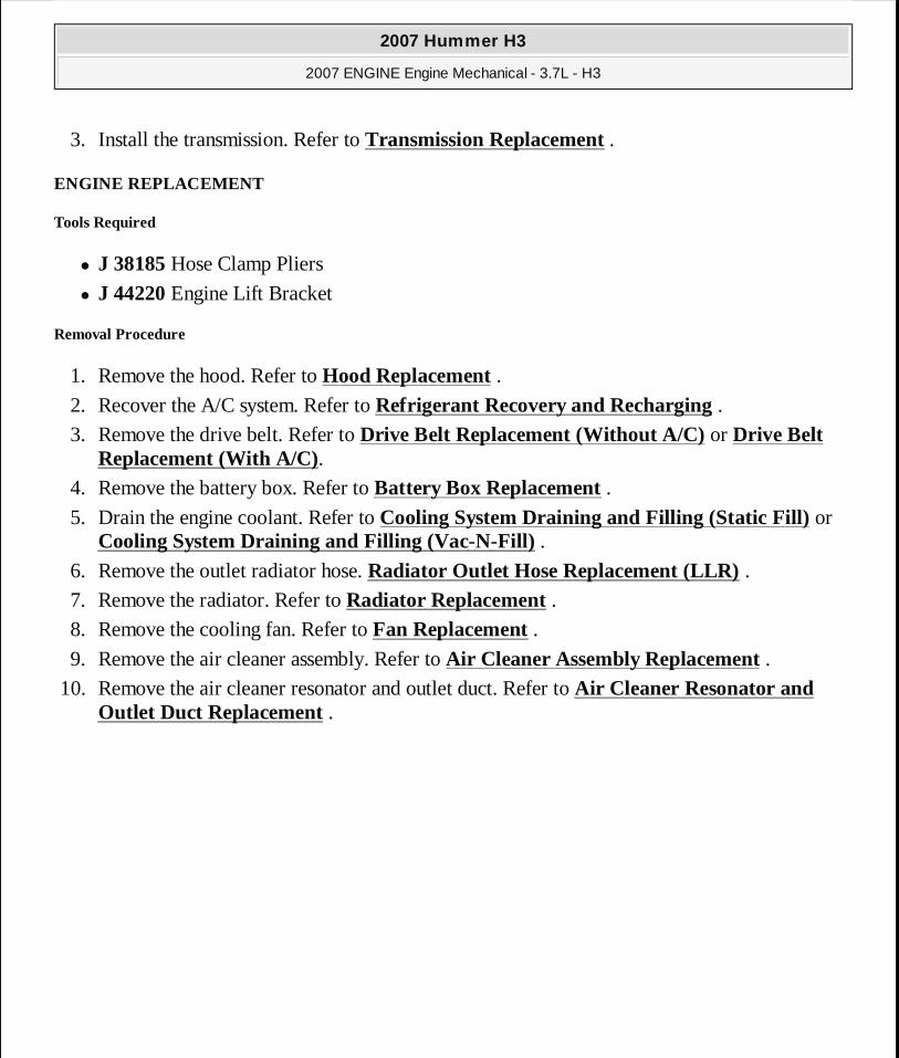
3. Install the transmission. Refer to Transmission Replacement .
ENGINE REPLACEMENT
Tools Required
� J 38185 Hose Clamp Pliers
� J 44220 Engine Lift Bracket
Removal Procedure
1. Remove the hood. Refer to Hood Replacement . 2. Recover the A/C system. Refer to Refrigerant Recovery and Recharging .
3. Remove the drive belt. Refer to Drive Belt Replacement (Without A/C) or Drive Belt Replacement (With A/C).
4. Remove the battery box. Refer to Battery Box Replacement . 5. Drain the engine coolant. Refer to Cooling System Draining and Filling (Static Fill) or
Cooling System Draining and Filling (Vac-N-Fill) . 6. Remove the outlet radiator hose. Radiator Outlet Hose Replacement (LLR) . 7. Remove the radiator. Refer to Radiator Replacement . 8. Remove the cooling fan. Refer to Fan Replacement . 9. Remove the air cleaner assembly. Refer to Air Cleaner Assembly Replacement .
10. Remove the air cleaner resonator and outlet duct. Refer to Air Cleaner Resonator and Outlet Duct Replacement .
2007 Hummer H3
2007 ENGINE Engine Mechanical - 3.7L - H3
MY
Sunday, March 29, 2009 8:40:37 PM Page 315 © 2005 Mitchell Repair Information Company, LLC.

Fig. 243: View Of Radiator Inlet Hose Courtesy of GENERAL MOTORS CORP.
11. Position the J 38185 to the clamp (3) in order to remove the radiator inlet hose (2) from the water outlet housing (4).
12. Remove the washer solvent container/coolant recovery reservoir mounting bolts ONLY, in order to gain clearance to remove the engine wiring harness. Refer to Washer Solvent Container Replacement (Prior to VIN 78135604) or Washer Solvent Container Replacement (Base) or Washer Solvent Container Replacement (Post VIN 78135604) .
2007 Hummer H3
2007 ENGINE Engine Mechanical - 3.7L - H3
MY
Sunday, March 29, 2009 8:40:37 PM Page 316 © 2005 Mitchell Repair Information Company, LLC.

Fig. 244: Locating PCM & Engine Wiring Harness PCM Connectors Courtesy of GENERAL MOTORS CORP.
13. Disconnect the 2 engine wiring harness connectors from the powertrain control module (PCM).
14. Remove the engine wiring harness clips from the wheelhouse.
2007 Hummer H3
2007 ENGINE Engine Mechanical - 3.7L - H3
MY
Sunday, March 29, 2009 8:40:37 PM Page 317 © 2005 Mitchell Repair Information Company, LLC.

Fig. 245: View Of Power Steering Pump & Engine Wiring Harness Retainers Courtesy of GENERAL MOTORS CORP.
15. Disconnect the engine wiring harness retainers (1) from the power steering pump (2). 16. Disconnect the engine wiring harness connectors from the following components:
� The electric motor actuator connector � The oil pressure switch
2007 Hummer H3
2007 ENGINE Engine Mechanical - 3.7L - H3
MY
Sunday, March 29, 2009 8:40:37 PM Page 318 © 2005 Mitchell Repair Information Company, LLC.

Fig. 246: View Of CMP Sensor Connector, Exhaust Camshaft Actuator Connector & Engine Wiring Harness Retainer Courtesy of GENERAL MOTORS CORP.
17. Disconnect the engine wiring harness retainer (2) from the camshaft cover (3). 18. Disconnect the engine wiring harness connectors from the following components:
� The exhaust camshaft position (CMP) sensor (5) � The exhaust camshaft actuator (6)
2007 Hummer H3
2007 ENGINE Engine Mechanical - 3.7L - H3
MY
Sunday, March 29, 2009 8:40:37 PM Page 319 © 2005 Mitchell Repair Information Company, LLC.

Fig. 247: View Of ECT Sensor, Fuel Injector, Ignition Coil & HO2S Engine Wiring Harness Electrical Connectors Courtesy of GENERAL MOTORS CORP.
19. Disconnect the engine wiring harness connectors from the following components: � The engine coolant temperature (ECT) sensor (1) � The fuel injector harness (2) � The ignition coils (4) � The heated oxygen sensor (HO2S) (5)
2007 Hummer H3
2007 ENGINE Engine Mechanical - 3.7L - H3
MY
Sunday, March 29, 2009 8:40:37 PM Page 320 © 2005 Mitchell Repair Information Company, LLC.

Fig. 248: View Of Engine Wiring Harness Connections To Camshaft Cover & Throttle Body Courtesy of GENERAL MOTORS CORP.
20. Disconnect the engine wiring harness retainer (3) from the camshaft cover (4). 21. Disconnect the engine wiring harness connector (2) from the throttle body (1).
2007 Hummer H3
2007 ENGINE Engine Mechanical - 3.7L - H3
MY
Sunday, March 29, 2009 8:40:37 PM Page 321 © 2005 Mitchell Repair Information Company, LLC.

Fig. 249: View Of Intake CMP Sensor Engine Wiring Harness Connector Courtesy of GENERAL MOTORS CORP.
22. Disconnect the engine wiring harness connector from the intake CMP sensor.
2007 Hummer H3
2007 ENGINE Engine Mechanical - 3.7L - H3
MY
Sunday, March 29, 2009 8:40:37 PM Page 322 © 2005 Mitchell Repair Information Company, LLC.

Fig. 250: View Of Engine Wiring Harness Conduit Courtesy of GENERAL MOTORS CORP.
23. Carefully disengage the engine wiring harness conduit from the camshaft cover.
24. Remove the transmission filler tube, if equipped. Refer to Transmission Fluid Filler Tube and Seal Replacement .
2007 Hummer H3
2007 ENGINE Engine Mechanical - 3.7L - H3
MY
Sunday, March 29, 2009 8:40:37 PM Page 323 © 2005 Mitchell Repair Information Company, LLC.

Fig. 251: Identifying Air Conditioning (A/C) Compressor Evaporator Hose Bracket Bolts Courtesy of GENERAL MOTORS CORP.
25. Remove the air conditioning (A/C) compressor evaporator hose bracket bolt from the cylinder head.
26. Drain the engine oil, if necessary. Refer to Engine Oil and Oil Filter Replacement.
2007 Hummer H3
2007 ENGINE Engine Mechanical - 3.7L - H3
MY
Sunday, March 29, 2009 8:40:37 PM Page 324 © 2005 Mitchell Repair Information Company, LLC.

Fig. 252: View Of A.I.R. Injection Pipe Cover Courtesy of GENERAL MOTORS CORP.
27. Remove the studs securing the secondary air injection (AIR) pipe cover to the cylinder head.
Remove the AIR pipe cover and gasket.
Discard the gasket.
2007 Hummer H3
2007 ENGINE Engine Mechanical - 3.7L - H3
MY
Sunday, March 29, 2009 8:40:37 PM Page 325 © 2005 Mitchell Repair Information Company, LLC.

Fig. 253: Identifying J 44220 Courtesy of GENERAL MOTORS CORP.
28. Install the J 44220 in place of the AIR adapter.
2007 Hummer H3
2007 ENGINE Engine Mechanical - 3.7L - H3
MY
Sunday, March 29, 2009 8:40:37 PM Page 326 © 2005 Mitchell Repair Information Company, LLC.

Fig. 254: View Of Inlet Heater Hose Quick Connect Courtesy of GENERAL MOTORS CORP.
29. Disconnect the inlet heater hose quick connect (1) from the heater core (2) and secure to the engine.
2007 Hummer H3
2007 ENGINE Engine Mechanical - 3.7L - H3
MY
Sunday, March 29, 2009 8:40:37 PM Page 327 © 2005 Mitchell Repair Information Company, LLC.

Fig. 255: View Of Power Steering Pump & Mounting Bolts Courtesy of GENERAL MOTORS CORP.
30. Remove the power steering pump mounting bolts ONLY and position aside.
2007 Hummer H3
2007 ENGINE Engine Mechanical - 3.7L - H3
MY
Sunday, March 29, 2009 8:40:37 PM Page 328 © 2005 Mitchell Repair Information Company, LLC.

Fig. 256: Identifying Right Engine Mount-To-Frame Bracket Bolt Courtesy of GENERAL MOTORS CORP.
31. Remove the right engine mount-to-frame bracket bolt.
2007 Hummer H3
2007 ENGINE Engine Mechanical - 3.7L - H3
MY
Sunday, March 29, 2009 8:40:38 PM Page 329 © 2005 Mitchell Repair Information Company, LLC.

Fig. 257: Identifying Engine Wiring Harness Retainer At Engine Wiring Harness Bracket Courtesy of GENERAL MOTORS CORP.
32. Disconnect the engine wiring harness retainer from the engine wiring harness bracket. 33. Position the engine wiring harness aside.
34. Disconnect the fuel feed pipe from the fuel rail. Refer to Metal Collar Quick Connect Fitting Service .
35. Disconnect the evaporative emission (EVAP) pipe at the purge solenoid. Refer to Plastic Collar Quick Connect Fitting Service .
36. Remove the oil level indicator and tube. Refer to Oil Level Indicator and Tube Replacement.
2007 Hummer H3
2007 ENGINE Engine Mechanical - 3.7L - H3
MY
Sunday, March 29, 2009 8:40:38 PM Page 330 © 2005 Mitchell Repair Information Company, LLC.

Fig. 258: Identifying Intake Manifold & Attachments Courtesy of GENERAL MOTORS CORP.
37. Remove the manifold absolute pressure (MAP) sensor. Refer to Manifold Absolute Pressure Sensor Replacement .
38. Disconnect the MAP sensor wiring harness retainer (4) from the intake manifold. 39. Raise and support the vehicle only high enough to access the wiring harnesses through the
wheelhouse. Refer to Lifting and Jacking the Vehicle .
2007 Hummer H3
2007 ENGINE Engine Mechanical - 3.7L - H3
MY
Sunday, March 29, 2009 8:40:38 PM Page 331 © 2005 Mitchell Repair Information Company, LLC.

Fig. 259: View Of A/C Condenser Line Bolt & A/C Compressor Courtesy of GENERAL MOTORS CORP.
40. Remove the A/C condenser line bolt at the A/C compressor, remove the line from the compressor, if equipped.
2007 Hummer H3
2007 ENGINE Engine Mechanical - 3.7L - H3
MY
Sunday, March 29, 2009 8:40:38 PM Page 332 © 2005 Mitchell Repair Information Company, LLC.

Fig. 260: Identifying A/C Evaporator Line Courtesy of GENERAL MOTORS CORP.
41. Remove the A/C evaporator line bolt at the A/C compressor, remove the line from the compressor, if equipped.
2007 Hummer H3
2007 ENGINE Engine Mechanical - 3.7L - H3
MY
Sunday, March 29, 2009 8:40:38 PM Page 333 © 2005 Mitchell Repair Information Company, LLC.

Fig. 261: Identifying A/C Compressor & Bolts Courtesy of GENERAL MOTORS CORP.
42. Remove the A/C compressor bolts and compressor, if equipped.
2007 Hummer H3
2007 ENGINE Engine Mechanical - 3.7L - H3
MY
Sunday, March 29, 2009 8:40:38 PM Page 334 © 2005 Mitchell Repair Information Company, LLC.

Fig. 262: View Of Wiring Harness Retainers Courtesy of GENERAL MOTORS CORP.
43. Disconnect the following wiring harness retainers from the engine wiring harness bracket: � The battery cable � The engine (4, 6) � The MAP sensor (5)
2007 Hummer H3
2007 ENGINE Engine Mechanical - 3.7L - H3
MY
Sunday, March 29, 2009 8:40:38 PM Page 335 © 2005 Mitchell Repair Information Company, LLC.

Fig. 263: Locating Positive Battery Cable Courtesy of GENERAL MOTORS CORP.
44. Remove the starter solenoid "S" terminal nut (3) and disconnect the lead (4) from the starter.
45. Remove the starter terminal nut (1) and disconnect the battery positive cable (2) from the starter.
2007 Hummer H3
2007 ENGINE Engine Mechanical - 3.7L - H3
MY
Sunday, March 29, 2009 8:40:38 PM Page 336 © 2005 Mitchell Repair Information Company, LLC.

Fig. 264: Locating Battery Negative Cable Ground Terminal Courtesy of GENERAL MOTORS CORP.
46. Remove the bolt (5) securing the battery negative cable ground terminal (4) to the engine block.
2007 Hummer H3
2007 ENGINE Engine Mechanical - 3.7L - H3
MY
Sunday, March 29, 2009 8:40:38 PM Page 337 © 2005 Mitchell Repair Information Company, LLC.

Fig. 265: View Of EVAP Canister Purge Solenoid Valve Engine Wiring Harness Connector Courtesy of GENERAL MOTORS CORP.
47. Disconnect the engine wiring harness connector from the EVAP canister purge solenoid valve.
2007 Hummer H3
2007 ENGINE Engine Mechanical - 3.7L - H3
MY
Sunday, March 29, 2009 8:40:38 PM Page 338 © 2005 Mitchell Repair Information Company, LLC.

Fig. 266: View Of KS Engine Wiring Harness Connector Courtesy of GENERAL MOTORS CORP.
48. Disconnect the engine wiring harness connector (3) from the # 2 knock sensor (KS) (1). 49. Disconnect the coolant heater cord from the coolant heater, if equipped.
2007 Hummer H3
2007 ENGINE Engine Mechanical - 3.7L - H3
MY
Sunday, March 29, 2009 8:40:38 PM Page 339 © 2005 Mitchell Repair Information Company, LLC.

Fig. 267: Identifying Engine Wiring Harness Retainers Courtesy of GENERAL MOTORS CORP.
50. Disconnect the engine wiring harness retainers (1, 2) from the A/C compressor and the engine oil pan rail.
2007 Hummer H3
2007 ENGINE Engine Mechanical - 3.7L - H3
MY
Sunday, March 29, 2009 8:40:38 PM Page 340 © 2005 Mitchell Repair Information Company, LLC.

Fig. 268: View Of J 38185 Courtesy of GENERAL MOTORS CORP.
51. Position the J 38185 (2) to the clamp (1) in order to remove the heater outlet hose from the heater outlet hose fitting (3).
2007 Hummer H3
2007 ENGINE Engine Mechanical - 3.7L - H3
MY
Sunday, March 29, 2009 8:40:38 PM Page 341 © 2005 Mitchell Repair Information Company, LLC.

Fig. 269: View Of Engine Wiring Harness Courtesy of GENERAL MOTORS CORP.
52. Disconnect the engine wiring harness connector (3) from the crankshaft position (CKP) sensor (1).
53. Raise the vehicle completely. Refer to Lifting and Jacking the Vehicle . 54. Remove the 3 bolts securing the engine wiring ground leads (2) to the engine block. 55. Disconnect the engine wiring harness retainer (5) from the engine oil pan rail. 56. Position the engine wiring harness aside.
2007 Hummer H3
2007 ENGINE Engine Mechanical - 3.7L - H3
MY
Sunday, March 29, 2009 8:40:38 PM Page 342 © 2005 Mitchell Repair Information Company, LLC.

Fig. 270: Identifying Clips Attaching Fuel Feed Lines To Transmission Courtesy of GENERAL MOTORS CORP.
57. Disconnect the fuel line clips from the brackets on the transmission.
2007 Hummer H3
2007 ENGINE Engine Mechanical - 3.7L - H3
MY
Sunday, March 29, 2009 8:40:38 PM Page 343 © 2005 Mitchell Repair Information Company, LLC.

Fig. 271: View Of Clips Attaching Fuel Feed Lines To Transmission Courtesy of GENERAL MOTORS CORP.
58. Remove the crossmember. Refer to Crossmember Replacement . 59. Remove the front propeller shaft. Refer to Front Propeller Shaft Replacement .
2007 Hummer H3
2007 ENGINE Engine Mechanical - 3.7L - H3
MY
Sunday, March 29, 2009 8:40:38 PM Page 344 © 2005 Mitchell Repair Information Company, LLC.

Fig. 272: View Of Mounting Bracket To Frame Bolts Courtesy of GENERAL MOTORS CORP.
60. Remove the differential carrier assembly bushing to frame bolts ONLY. 61. Position the differential carrier assembly forward. 62. Secure the pinion yoke, in order to prevent the differential carrier from rotating.
63. Remove the exhaust seal. Refer to Exhaust Seal Replacement .
2007 Hummer H3
2007 ENGINE Engine Mechanical - 3.7L - H3
MY
Sunday, March 29, 2009 8:40:38 PM Page 345 © 2005 Mitchell Repair Information Company, LLC.

Fig. 273: View Of Transmission Oil Cooler Pipe Bracket Bolt Courtesy of GENERAL MOTORS CORP.
64. Remove the bolt (2) securing the transmission oil cooler pipe bracket to the right side of the engine oil pan rail (automatic only).
2007 Hummer H3
2007 ENGINE Engine Mechanical - 3.7L - H3
MY
Sunday, March 29, 2009 8:40:38 PM Page 346 © 2005 Mitchell Repair Information Company, LLC.

Fig. 274: View Of Inspection Plug Courtesy of GENERAL MOTORS CORP.
65. Remove the inspection plug (3) from the transmission (1) (M30 only). 66. Mark the torque converter to flexplate/flywheel orientation to ensure proper realignment
(M30 only).
2007 Hummer H3
2007 ENGINE Engine Mechanical - 3.7L - H3
MY
Sunday, March 29, 2009 8:40:38 PM Page 347 © 2005 Mitchell Repair Information Company, LLC.

Fig. 275: View Of Service Slot Plug Courtesy of GENERAL MOTORS CORP.
67. Remove the service slot plug. 68. Repeat the following steps for all 3 torque converter bolts (automatic only):
1. Rotate the harmonic balancer center bolt clockwise ONLY, in order to access the torque converter bolt through the service slot.
2. Remove the torque converter bolts.
2007 Hummer H3
2007 ENGINE Engine Mechanical - 3.7L - H3
MY
Sunday, March 29, 2009 8:40:38 PM Page 348 © 2005 Mitchell Repair Information Company, LLC.

Fig. 276: View Of Transmission Mounting Bolts Courtesy of GENERAL MOTORS CORP.
69. Lower the transmission slightly. 70. Remove the 9 transmission bolts.
2007 Hummer H3
2007 ENGINE Engine Mechanical - 3.7L - H3
MY
Sunday, March 29, 2009 8:40:38 PM Page 349 © 2005 Mitchell Repair Information Company, LLC.

Fig. 277: Locating Left Engine Mount-To-Frame Bracket Through Bolt Courtesy of GENERAL MOTORS CORP.
71. Lower the vehicle. 72. Remove the left engine mount-to-frame bracket bolt.
2007 Hummer H3
2007 ENGINE Engine Mechanical - 3.7L - H3
MY
Sunday, March 29, 2009 8:40:39 PM Page 350 © 2005 Mitchell Repair Information Company, LLC.

Fig. 278: View Of Transmission Mounting Bolts & Engine Dowels Courtesy of GENERAL MOTORS CORP.
73. Place a jack under the transmission for support. 74. Remove the remaining transmission mounting bolts (2).
2007 Hummer H3
2007 ENGINE Engine Mechanical - 3.7L - H3
MY
Sunday, March 29, 2009 8:40:39 PM Page 351 © 2005 Mitchell Repair Information Company, LLC.

Fig. 279: View Of Engine Lift Chain Courtesy of GENERAL MOTORS CORP.
75. Install an engine lift chain to the engine lift brackets and attach to an engine lift device. 76. Using the engine lift device, raise the engine only enough to remove the engine mounts. 77. Remove the bolts securing the following to the engine block:
� The left engine mount � The right engine mount
78. Remove the engine mounts.
IMPORTANT: Ensure clearance is maintained between th e engine and the following:
� The A/C compressor
2007 Hummer H3
2007 ENGINE Engine Mechanical - 3.7L - H3
MY
Sunday, March 29, 2009 8:40:39 PM Page 352 © 2005 Mitchell Repair Information Company, LLC.

79. Carefully raise the engine from the engine compartment, ensuring the transmission stays supported.
80. Install the engine to an engine stand. 81. Remove the engine lift chain from the engine lift brackets.
Installation Procedure
� The A/C hoses � The engine mounts � The engine wiring harness � The fuel hose/pipes � The heater outlet hose/pipe � The power steering pump � The transmission input shaft (manual only) � The transmission oil cooler pipes (automatic only)
2007 Hummer H3
2007 ENGINE Engine Mechanical - 3.7L - H3
MY
Sunday, March 29, 2009 8:40:39 PM Page 353 © 2005 Mitchell Repair Information Company, LLC.

Fig. 280: Identifying Engine Mount Courtesy of GENERAL MOTORS CORP.
1. Install an engine lift chain to the engine lift brackets and attach to an engine lift device. 2. Remove the engine from the engine stand. 3. Ensure the torque converter is fully engaged with the transmission oil pump (M30 only). 4. Position the engine mounts to the engine. 5. Install the engine mount bolts until snug, following the installation sequence.
The engine lift device may have to be raised or lowered slightly to install these bolts.
6. Tighten the bolts using the installation sequence.
NOTE: Refer to Fastener Notice .
2007 Hummer H3
2007 ENGINE Engine Mechanical - 3.7L - H3
MY
Sunday, March 29, 2009 8:40:39 PM Page 354 © 2005 Mitchell Repair Information Company, LLC.

Tighten: Tighten the engine mount bolts to 50 N.m (37 lb ft).
Fig. 281: View Of Engine Lift Chain Courtesy of GENERAL MOTORS CORP.
IMPORTANT: Ensure clearance is maintained between th e engine and the following:
� The A/C compressor � The A/C hoses � The engine mounts � The engine wiring harness � The fuel hose/pipes � The heater outlet hose/pipe
2007 Hummer H3
2007 ENGINE Engine Mechanical - 3.7L - H3
MY
Sunday, March 29, 2009 8:40:39 PM Page 355 © 2005 Mitchell Repair Information Company, LLC.

7. Carefully lower the engine into the engine compartment, aligning the engine dowels with the transmission.
Fig. 282: View Of Transmission Mounting Bolts & Engine Dowels Courtesy of GENERAL MOTORS CORP.
� The power steering pump � The transmission input shaft (manual only) � The transmission oil cooler pipes (automatic only)
IMPORTANT: Ensure the torque converter turns freely while tightening the transmission mounting bolts (automatic only).
2007 Hummer H3
2007 ENGINE Engine Mechanical - 3.7L - H3
MY
Sunday, March 29, 2009 8:40:39 PM Page 356 © 2005 Mitchell Repair Information Company, LLC.

8. Align the engine dowels (1) with the transmission. 9. Loosely install the 2 transmission mounting bolts (2).
Ensure the dowels (1) are fully engaged into the transmission.
10. Remove the jack from under the vehicle. 11. Lower the engine fully on to the engine mounts. 12. Remove the engine lift chain from the engine lift brackets.
13. Raise and support the vehicle. Refer to Lifting and Jacking the Vehicle .
Fig. 283: View Of Transmission Mounting Bolts & Engine Dowels Courtesy of GENERAL MOTORS CORP.
2007 Hummer H3
2007 ENGINE Engine Mechanical - 3.7L - H3
MY
Sunday, March 29, 2009 8:40:39 PM Page 357 © 2005 Mitchell Repair Information Company, LLC.

14. Tighten the 2 transmission mounting bolts (2) previously installed.
Tighten: Tighten the transmission mounting bolts to 50 N.m (37 lb ft).
Fig. 284: View Of Transmission Mounting Bolts Courtesy of GENERAL MOTORS CORP.
IMPORTANT:� Ensure the studded mounting bolts (2) are located i n the
correct position. � The heater pipe (1) must be secured with the 2 uppe r
mounting bolts.
2007 Hummer H3
2007 ENGINE Engine Mechanical - 3.7L - H3
MY
Sunday, March 29, 2009 8:40:39 PM Page 358 © 2005 Mitchell Repair Information Company, LLC.

15. Install the remaining transmission mounting bolts.
Tighten: Tighten the transmission mounting bolts to 50 N.m (37 lb ft).
16. Align the torque converter to flexplate/flywheel orientation marks made during the removal procedure (automatic only).
17. Repeat the following steps for all 3 torque converter bolts (automatic only): 1. Rotate the harmonic balancer center bolt clockwise ONLY, in order to access the
torque converter bolt holes in the flexplate/flywheel through the service slot. 2. To aid in alignment of the torque converter to the flexplate/flywheel. Install all 3
torque converter bolts before fully tightening using one of the following:
Tighten: Tighten the torque converter bolts to 60 N.m (44 lb ft).
2007 Hummer H3
2007 ENGINE Engine Mechanical - 3.7L - H3
MY
Sunday, March 29, 2009 8:40:39 PM Page 359 © 2005 Mitchell Repair Information Company, LLC.

Fig. 285: View Of Inspection Plug Courtesy of GENERAL MOTORS CORP.
18. Install the inspection plug (3) to the transmission (1) (automatic only).
2007 Hummer H3
2007 ENGINE Engine Mechanical - 3.7L - H3
MY
Sunday, March 29, 2009 8:40:39 PM Page 360 © 2005 Mitchell Repair Information Company, LLC.

Fig. 286: View Of Transmission Oil Cooler Pipe Bracket Bolt Courtesy of GENERAL MOTORS CORP.
19. Install the bolt (2) securing the transmission oil cooler pipe bracket to the right side of the engine oil pan rail (automatic only).
Tighten: Tighten the transmission oil cooler pipe bracket bolt to 20 N.m (15 lb ft).
20. Install the exhaust seal. Refer to Exhaust Seal Replacement .
2007 Hummer H3
2007 ENGINE Engine Mechanical - 3.7L - H3
MY
Sunday, March 29, 2009 8:40:39 PM Page 361 © 2005 Mitchell Repair Information Company, LLC.

Fig. 287: View Of Service Slot Plug Courtesy of GENERAL MOTORS CORP.
21. Install the service slot plug.
22. Install the crossmember. Refer to Crossmember Replacement .
2007 Hummer H3
2007 ENGINE Engine Mechanical - 3.7L - H3
MY
Sunday, March 29, 2009 8:40:39 PM Page 362 © 2005 Mitchell Repair Information Company, LLC.

Fig. 288: View Of Mounting Bracket To Frame Bolts Courtesy of GENERAL MOTORS CORP.
23. Position the differential carrier assembly to the frame. 24. Install the differential carrier assembly bushing to frame bolts.
Tighten: Tighten the differential carrier assembly bushing to frame bolts to 152 N.m (112 lb ft).
25. Install the front propeller shaft. Refer to Front Propeller Shaft Replacement .
2007 Hummer H3
2007 ENGINE Engine Mechanical - 3.7L - H3
MY
Sunday, March 29, 2009 8:40:39 PM Page 363 © 2005 Mitchell Repair Information Company, LLC.

Fig. 289: View Of Clips Attaching Fuel Feed Lines To Transmission Courtesy of GENERAL MOTORS CORP.
26. Install the fuel line clips to the brackets on the transmission (automatic only).
Tighten: Tighten the fuel hose/pipe bracket nuts to 20 N.m (15 lb ft).
2007 Hummer H3
2007 ENGINE Engine Mechanical - 3.7L - H3
MY
Sunday, March 29, 2009 8:40:39 PM Page 364 © 2005 Mitchell Repair Information Company, LLC.

Fig. 290: Identifying Clips Attaching Fuel Feed Lines To Transmission Courtesy of GENERAL MOTORS CORP.
27. Install the fuel line clips to the brackets on the transmission (manual only).
Tighten: Tighten the fuel hose/pipe bracket nuts to 20 N.m (15 lb ft).
2007 Hummer H3
2007 ENGINE Engine Mechanical - 3.7L - H3
MY
Sunday, March 29, 2009 8:40:39 PM Page 365 © 2005 Mitchell Repair Information Company, LLC.

Fig. 291: View Of Engine Wiring Harness Courtesy of GENERAL MOTORS CORP.
28. Connect the engine wiring harness retainer (5) to the engine oil pan rail. 29. Install the 3 bolts securing the engine wiring ground leads (2) to the engine block.
Tighten: Tighten the engine wiring ground lead bolts to 20 N.m (15 lb ft).
30. Lower the vehicle to chest level in order to access the components through the wheelhouse. 31. Connect the engine wiring harness connector (3) to the CKP sensor (1).
2007 Hummer H3
2007 ENGINE Engine Mechanical - 3.7L - H3
MY
Sunday, March 29, 2009 8:40:39 PM Page 366 © 2005 Mitchell Repair Information Company, LLC.

Fig. 292: Identifying A/C Compressor & Bolts Courtesy of GENERAL MOTORS CORP.
32. Install the A/C compressor and bolts, if equipped.
Tighten: Tighten the bolts to 50 N.m (37 lb ft).
2007 Hummer H3
2007 ENGINE Engine Mechanical - 3.7L - H3
MY
Sunday, March 29, 2009 8:40:39 PM Page 367 © 2005 Mitchell Repair Information Company, LLC.

Fig. 293: Identifying A/C Evaporator Line Courtesy of GENERAL MOTORS CORP.
33. Install the A/C evaporator line to the compressor and install the bolt at the A/C compressor, if equipped.
Tighten: Tighten the bolt to 16 N.m (12 lb ft).
2007 Hummer H3
2007 ENGINE Engine Mechanical - 3.7L - H3
MY
Sunday, March 29, 2009 8:40:39 PM Page 368 © 2005 Mitchell Repair Information Company, LLC.

Fig. 294: View Of A/C Condenser Line Bolt & A/C Compressor Courtesy of GENERAL MOTORS CORP.
34. Install the A/C condenser line to the compressor and install the bolt at the A/C compressor, if equipped.
Tighten: Tighten the bolts to 16 N.m (12 lb ft).
2007 Hummer H3
2007 ENGINE Engine Mechanical - 3.7L - H3
MY
Sunday, March 29, 2009 8:40:39 PM Page 369 © 2005 Mitchell Repair Information Company, LLC.

Fig. 295: View Of J 38185 Courtesy of GENERAL MOTORS CORP.
35. Position the J 38185 (2) to the clamp (1) in order to connect the heater outlet hose to the heater outlet hose fitting (3).
2007 Hummer H3
2007 ENGINE Engine Mechanical - 3.7L - H3
MY
Sunday, March 29, 2009 8:40:40 PM Page 370 © 2005 Mitchell Repair Information Company, LLC.

Fig. 296: Identifying Engine Wiring Harness Retainers Courtesy of GENERAL MOTORS CORP.
36. Connect the engine wiring harness retainers (1, 2) to the A/C compressor and the engine oil pan rail.
2007 Hummer H3
2007 ENGINE Engine Mechanical - 3.7L - H3
MY
Sunday, March 29, 2009 8:40:40 PM Page 371 © 2005 Mitchell Repair Information Company, LLC.

Fig. 297: View Of KS Engine Wiring Harness Connector Courtesy of GENERAL MOTORS CORP.
37. Connect the engine wiring harness connector (3) to the # 2 KS (1). 38. Connect the coolant heater cord to the coolant heater, if equipped.
2007 Hummer H3
2007 ENGINE Engine Mechanical - 3.7L - H3
MY
Sunday, March 29, 2009 8:40:40 PM Page 372 © 2005 Mitchell Repair Information Company, LLC.

Fig. 298: View Of EVAP Canister Purge Solenoid Valve Engine Wiring Harness Connector Courtesy of GENERAL MOTORS CORP.
39. Connect the engine wiring harness connector to the EVAP canister purge solenoid valve.
2007 Hummer H3
2007 ENGINE Engine Mechanical - 3.7L - H3
MY
Sunday, March 29, 2009 8:40:40 PM Page 373 © 2005 Mitchell Repair Information Company, LLC.

Fig. 299: Locating Battery Negative Cable Ground Terminal Courtesy of GENERAL MOTORS CORP.
40. Install the bolt (5) securing the battery negative cable ground terminal (4) to the engine block.
Tighten: Tighten the battery negative cable to engine block bolt to 35 N.m (26 lb ft).
2007 Hummer H3
2007 ENGINE Engine Mechanical - 3.7L - H3
MY
Sunday, March 29, 2009 8:40:40 PM Page 374 © 2005 Mitchell Repair Information Company, LLC.

Fig. 300: Locating Positive Battery Cable Courtesy of GENERAL MOTORS CORP.
41. Connect the battery positive cable (2) to the starter and install the starter terminal nut (1).
Tighten: Tighten the battery positive cable to starter terminal nut to 9 N.m (80 lb in).
42. Connect the lead (4) to the starter solenoid and install the starter solenoid "S" terminal nut (3).
Tighten: Tighten the starter solenoid "S" terminal nut to 3.5 N.m (31 lb in).
2007 Hummer H3
2007 ENGINE Engine Mechanical - 3.7L - H3
MY
Sunday, March 29, 2009 8:40:40 PM Page 375 © 2005 Mitchell Repair Information Company, LLC.

Fig. 301: View Of Wiring Harness Retainers Courtesy of GENERAL MOTORS CORP.
43. Secure the following wiring harness retainers to the engine wiring harness bracket: � The battery cable � The engine (4, 6) � The MAP sensor (5)
44. Lower the vehicle.
2007 Hummer H3
2007 ENGINE Engine Mechanical - 3.7L - H3
MY
Sunday, March 29, 2009 8:40:40 PM Page 376 © 2005 Mitchell Repair Information Company, LLC.

Fig. 302: Locating Left Engine Mount-To-Frame Bracket Through Bolt Courtesy of GENERAL MOTORS CORP.
45. Install the left engine mount-to-frame bracket bolt.
Tighten: Tighten the engine mount-to-frame bracket bolt to 85 N.m (63 lb ft).
2007 Hummer H3
2007 ENGINE Engine Mechanical - 3.7L - H3
MY
Sunday, March 29, 2009 8:40:40 PM Page 377 © 2005 Mitchell Repair Information Company, LLC.

Fig. 303: Identifying Intake Manifold & Attachments Courtesy of GENERAL MOTORS CORP.
46. Connect the MAP sensor wiring harness retainer (4) to the intake manifold.
47. Install the MAP sensor. Refer to Manifold Absolute Pressure Sensor Replacement . 48. Install the oil level indicator and tube. Refer to Oil Level Indicator and Tube
Replacement. 49. Connect the EVAP pipe at the purge solenoid. Refer to Plastic Collar Quick Connect
Fitting Service .
50. Connect the fuel feed pipe to the fuel rail. Refer to Metal Collar Quick Connect Fitting Service .
2007 Hummer H3
2007 ENGINE Engine Mechanical - 3.7L - H3
MY
Sunday, March 29, 2009 8:40:40 PM Page 378 © 2005 Mitchell Repair Information Company, LLC.

Fig. 304: Identifying Engine Wiring Harness Retainer At Engine Wiring Harness Bracket Courtesy of GENERAL MOTORS CORP.
51. Connect the engine wiring harness retainer to the engine wiring harness bracket.
2007 Hummer H3
2007 ENGINE Engine Mechanical - 3.7L - H3
MY
Sunday, March 29, 2009 8:40:40 PM Page 379 © 2005 Mitchell Repair Information Company, LLC.

Fig. 305: Identifying Right Engine Mount-To-Frame Bracket Bolt Courtesy of GENERAL MOTORS CORP.
52. Install the right engine mount-to-frame bracket bolt.
Tighten: Tighten the engine mount-to-frame bracket bolt to 85 N.m (63 lb ft).
2007 Hummer H3
2007 ENGINE Engine Mechanical - 3.7L - H3
MY
Sunday, March 29, 2009 8:40:40 PM Page 380 © 2005 Mitchell Repair Information Company, LLC.

Fig. 306: View Of Power Steering Pump & Mounting Bolts Courtesy of GENERAL MOTORS CORP.
53. Position the power steering pump to the power steering pump bracket. 54. Install the power steering pump mounting bolts.
Tighten: Tighten the power steering pump mounting bolts to 25 N.m (18 lb ft).
2007 Hummer H3
2007 ENGINE Engine Mechanical - 3.7L - H3
MY
Sunday, March 29, 2009 8:40:40 PM Page 381 © 2005 Mitchell Repair Information Company, LLC.

Fig. 307: View Of Inlet Heater Hose Quick Connect Courtesy of GENERAL MOTORS CORP.
55. Connect the inlet heater hose quick connect (1) to the heater core (2).
2007 Hummer H3
2007 ENGINE Engine Mechanical - 3.7L - H3
MY
Sunday, March 29, 2009 8:40:40 PM Page 382 © 2005 Mitchell Repair Information Company, LLC.

Fig. 308: Identifying J 44220 Courtesy of GENERAL MOTORS CORP.
56. Remove the J 44220 from the cylinder head.
2007 Hummer H3
2007 ENGINE Engine Mechanical - 3.7L - H3
MY
Sunday, March 29, 2009 8:40:40 PM Page 383 © 2005 Mitchell Repair Information Company, LLC.

Fig. 309: View Of A.I.R. Injection Pipe Cover Courtesy of GENERAL MOTORS CORP.
57. Position the AIR pipe cover and NEW gasket to the cylinder head. 58. Install the AIR pipe cover studs.
Tighten: Tighten the AIR cover studs to 25 N.m (18 lb ft).
59. Install the transmission filler tube, if equipped. Refer to Transmission Fluid Filler Tube and Seal Replacement .
2007 Hummer H3
2007 ENGINE Engine Mechanical - 3.7L - H3
MY
Sunday, March 29, 2009 8:40:40 PM Page 384 © 2005 Mitchell Repair Information Company, LLC.

Fig. 310: Identifying Air Conditioning (A/C) Compressor Evaporator Hose Bracket Bolts Courtesy of GENERAL MOTORS CORP.
60. Position the A/C compressor evaporator hose bracket to the cylinder head and install the bolt.
Tighten: Tighten the bolt to 9 N.m (80 lb in).
2007 Hummer H3
2007 ENGINE Engine Mechanical - 3.7L - H3
MY
Sunday, March 29, 2009 8:40:40 PM Page 385 © 2005 Mitchell Repair Information Company, LLC.

Fig. 311: View Of Engine Wiring Harness Conduit Courtesy of GENERAL MOTORS CORP.
61. Engage the engine wiring harness conduit to the camshaft cover.
2007 Hummer H3
2007 ENGINE Engine Mechanical - 3.7L - H3
MY
Sunday, March 29, 2009 8:40:40 PM Page 386 © 2005 Mitchell Repair Information Company, LLC.

Fig. 312: View Of Intake CMP Sensor Engine Wiring Harness Connector Courtesy of GENERAL MOTORS CORP.
62. Connect the engine wiring harness connector to the Intake CMP sensor.
2007 Hummer H3
2007 ENGINE Engine Mechanical - 3.7L - H3
MY
Sunday, March 29, 2009 8:40:40 PM Page 387 © 2005 Mitchell Repair Information Company, LLC.

Fig. 313: View Of Engine Wiring Harness Connections To Camshaft Cover & Throttle Body Courtesy of GENERAL MOTORS CORP.
63. Connect the engine wiring harness retainer (3) to the camshaft cover (4). 64. Connect the engine wiring harness connector (2) to the throttle body (1).
2007 Hummer H3
2007 ENGINE Engine Mechanical - 3.7L - H3
MY
Sunday, March 29, 2009 8:40:40 PM Page 388 © 2005 Mitchell Repair Information Company, LLC.

Fig. 314: View Of ECT Sensor, Fuel Injector, Ignition Coil & HO2S Engine Wiring Harness Electrical Connectors Courtesy of GENERAL MOTORS CORP.
65. Connect the engine wiring harness connectors to the following components: � The ECT sensor (1) � The fuel injector harness (2) � The ignition coils (4) � The HO2S (5)
2007 Hummer H3
2007 ENGINE Engine Mechanical - 3.7L - H3
MY
Sunday, March 29, 2009 8:40:40 PM Page 389 © 2005 Mitchell Repair Information Company, LLC.

Fig. 315: View Of CMP Sensor Connector, Exhaust Camshaft Actuator Connector & Engine Wiring Harness Retainer Courtesy of GENERAL MOTORS CORP.
66. Connect the engine wiring harness retainer (2) to the camshaft cover (3). 67. Connect the engine wiring harness connectors to the following components:
� The exhaust CMP sensor (5) � The exhaust camshaft actuator (6)
2007 Hummer H3
2007 ENGINE Engine Mechanical - 3.7L - H3
MY
Sunday, March 29, 2009 8:40:41 PM Page 390 © 2005 Mitchell Repair Information Company, LLC.

Fig. 316: View Of Power Steering Pump & Engine Wiring Harness Retainers Courtesy of GENERAL MOTORS CORP.
68. Connect the engine wiring harness retainers (1) to the power steering pump (2). 69. Connect the engine wiring harness connectors to the following components:
� The electric motor actuator connector (4WD only) � The oil pressure switch
2007 Hummer H3
2007 ENGINE Engine Mechanical - 3.7L - H3
MY
Sunday, March 29, 2009 8:40:41 PM Page 391 © 2005 Mitchell Repair Information Company, LLC.

Fig. 317: Locating PCM & Engine Wiring Harness PCM Connectors Courtesy of GENERAL MOTORS CORP.
70. Connect the engine wiring harness retainers to the wheelhouse. 71. Connect the 2 engine wiring harness connectors to the PCM. 72. Install the washer solvent container/coolant recovery reservoir mounting bolts. Refer to
Washer Solvent Container Replacement (Prior to VIN 78135604) , Washer Solvent Container Replacement (Base) or Washer Solvent Container Replacement (Post VIN 78135604) .
73. Install the radiator. Refer to Radiator Replacement .
2007 Hummer H3
2007 ENGINE Engine Mechanical - 3.7L - H3
MY
Sunday, March 29, 2009 8:40:41 PM Page 392 © 2005 Mitchell Repair Information Company, LLC.

Fig. 318: View Of Radiator Inlet Hose Courtesy of GENERAL MOTORS CORP.
74. Position the J 38185 to the clamp (3) in order to connect the radiator inlet hose (2) to the water outlet housing (4).
75. Install the generator. Refer to Generator Replacement . 76. Install the air cleaner resonator and outlet duct. Refer to Air Cleaner Resonator and
Outlet Duct Replacement . 77. Install the air cleaner assembly. Refer to Air Cleaner Assembly Replacement . 78. Install the cooling fan. Refer to Fan Replacement .
2007 Hummer H3
2007 ENGINE Engine Mechanical - 3.7L - H3
MY
Sunday, March 29, 2009 8:40:41 PM Page 393 © 2005 Mitchell Repair Information Company, LLC.

79. Install the outlet radiator hose. Refer to Radiator Outlet Hose Replacement (LLR) . 80. Fill the cooling system. Refer to Cooling System Draining and Filling (Static Fill) or
Cooling System Draining and Filling (Vac-N-Fill) . 81. Install the battery box. Refer to Battery Box Replacement . 82. Install the hood. Refer to Hood Replacement . 83. Fill the engine oil, if previously drained. Refer to Engine Oil and Oil Filter
Replacement. 84. Charge the A/C system. Refer to Refrigerant Recovery and Recharging .
Engine Final Test and Inspection
Complete the following procedure after the engine is installed in the vehicle:
1. With the ignition OFF or disconnected, crank the engine several times. Listen for any unusual noises or evidence that any parts are binding.
2. Start the engine and listen for abnormal conditions. 3. Check the vehicle oil pressure gage or light and confirm that the engine has acceptable oil
pressure. 4. Run the engine at approximately 1,000 RPM until the engine reaches normal operating
temperature.
5. While the engine continues to idle raise and support the vehicle. Refer to Lifting and Jacking the Vehicle .
6. Inspect for oil, coolant, transmission fluid and exhaust leaks while the engine is idling. 7. Lower the vehicle.
8. Perform the CKP variation learn procedure. Refer to Crankshaft Position System Variation Learn .
9. Perform a final inspection for the proper engine oil, transmission fluid and coolant levels. 10. Road test the vehicle.
ENGINE OIL AND OIL FILTER REPLACEMENT
Removal Procedure
1. Remove the oil fill cap.
2. Remove the engine shield. Refer to Engine Shield Replacement . 3. Remove the oil pan skid plate. Refer to Oil Pan Skid Plate Replacement . 4. Clean away all dirt and debris from the engine oil pan drain plug area.
2007 Hummer H3
2007 ENGINE Engine Mechanical - 3.7L - H3
MY
Sunday, March 29, 2009 8:40:41 PM Page 394 © 2005 Mitchell Repair Information Company, LLC.

5. Position an appropriate container under the engine oil pan.
Fig. 319: View Of Oil Pan Drain Plug Courtesy of GENERAL MOTORS CORP.
6. Remove the oil pan drain plug.
Allow the engine oil to drain into the container.
7. Position the container under the engine oil filter drain deflector.
2007 Hummer H3
2007 ENGINE Engine Mechanical - 3.7L - H3
MY
Sunday, March 29, 2009 8:40:41 PM Page 395 © 2005 Mitchell Repair Information Company, LLC.

Fig. 320: View Of Oil Filter Courtesy of GENERAL MOTORS CORP.
8. Remove the oil filter using a suitable wrench.
IMPORTANT: Ensure the old oil filter seal is not lef t on the engine block.
2007 Hummer H3
2007 ENGINE Engine Mechanical - 3.7L - H3
MY
Sunday, March 29, 2009 8:40:41 PM Page 396 © 2005 Mitchell Repair Information Company, LLC.

Allow the engine oil to drain to the oil filter drain deflector and into the container.
Installation Procedure
Fig. 321: View Of Oil Filter Courtesy of GENERAL MOTORS CORP.
1. Lubricate the oil filter seal with clean engine oil.
2007 Hummer H3
2007 ENGINE Engine Mechanical - 3.7L - H3
MY
Sunday, March 29, 2009 8:40:41 PM Page 397 © 2005 Mitchell Repair Information Company, LLC.

2. Install a NEW oil filter.
Tighten: Tighten the filter to 30 N.m (22 lb ft).
3. Wipe the excess oil from the oil filter drain deflector.
Fig. 322: View Of Oil Pan Drain Plug Courtesy of GENERAL MOTORS CORP.
4. Install the oil pan drain plug.
Tighten: Tighten the oil pan drain plug to 26 N.m (19 lb ft).
NOTE: Refer to Component Fastener Tightening Notice .
2007 Hummer H3
2007 ENGINE Engine Mechanical - 3.7L - H3
MY
Sunday, March 29, 2009 8:40:41 PM Page 398 © 2005 Mitchell Repair Information Company, LLC.

5. Fill the crankcase with the proper type and amount of engine oil. Refer to Fluid and Lubricant Recommendations and Approximate Fluid Capacities .
6. Install the oil fill cap. 7. Start the engine and check the oil pressure gage for the appropriate pressure to build up. 8. Shut the engine off. 9. Inspect under the vehicle in the oil filter and oil pan drain plug areas for leaks.
10. Remove the oil level indicator and check for the correct oil level. Add oil if necessary.
11. Install the oil pan skid plate. Refer to Oil Pan Skid Plate Replacement . 12. Install the engine shield. Refer to Engine Shield Replacement .
REPAIR INSTRUCTIONS - OFF VEHICLE
ENGINE FLYWHEEL REMOVAL (AUTOMATIC TRANSMISSION)
2007 Hummer H3
2007 ENGINE Engine Mechanical - 3.7L - H3
MY
Sunday, March 29, 2009 8:40:41 PM Page 399 © 2005 Mitchell Repair Information Company, LLC.

Fig. 323: View Of Engine Flywheel Courtesy of GENERAL MOTORS CORP.
1. Remove and discard the flywheel bolts. 2. Remove the flywheel.
ENGINE FLYWHEEL REMOVAL (MANUAL TRANSMISSION)
2007 Hummer H3
2007 ENGINE Engine Mechanical - 3.7L - H3
MY
Sunday, March 29, 2009 8:40:41 PM Page 400 © 2005 Mitchell Repair Information Company, LLC.

Fig. 324: View Of Engine Flywheel - Manual Transmission Courtesy of GENERAL MOTORS CORP.
1. Remove and discard the flywheel bolts. 2. Remove the flywheel.
DRAINING FLUIDS AND OIL FILTER REMOVAL
2007 Hummer H3
2007 ENGINE Engine Mechanical - 3.7L - H3
MY
Sunday, March 29, 2009 8:40:41 PM Page 401 © 2005 Mitchell Repair Information Company, LLC.

Fig. 325: Removing Oil Pan Drain Plug Courtesy of GENERAL MOTORS CORP.
1. Remove the oil pan drain plug. 2. Drain the engine oil.
2007 Hummer H3
2007 ENGINE Engine Mechanical - 3.7L - H3
MY
Sunday, March 29, 2009 8:40:41 PM Page 402 © 2005 Mitchell Repair Information Company, LLC.

Fig. 326: View Of Oil Filter Courtesy of GENERAL MOTORS CORP.
3. Remove the oil filter.
DRIVE BELT TENSIONER REMOVAL
2007 Hummer H3
2007 ENGINE Engine Mechanical - 3.7L - H3
MY
Sunday, March 29, 2009 8:40:41 PM Page 403 © 2005 Mitchell Repair Information Company, LLC.

Fig. 327: View Of Drive Belt Tensioner Courtesy of GENERAL MOTORS CORP.
1. Remove the drive belt tensioner bolt. 2. Remove the drive belt tensioner.
POWER STEERING PUMP BRACKET REMOVAL
2007 Hummer H3
2007 ENGINE Engine Mechanical - 3.7L - H3
MY
Sunday, March 29, 2009 8:40:41 PM Page 404 © 2005 Mitchell Repair Information Company, LLC.

Fig. 328: View Of Power Steering Pump Bracket Courtesy of GENERAL MOTORS CORP.
1. Remove the power steering pump bracket bolts. 2. Remove the power steering pump bracket.
DRIVE BELT IDLER PULLEY REMOVAL
2007 Hummer H3
2007 ENGINE Engine Mechanical - 3.7L - H3
MY
Sunday, March 29, 2009 8:40:41 PM Page 405 © 2005 Mitchell Repair Information Company, LLC.

Fig. 329: View Of Drive Belt Idler Pulley Courtesy of GENERAL MOTORS CORP.
1. Remove the drive belt idler pulley bolts. 2. Remove the drive belt idler pulley.
OIL LEVEL INDICATOR AND TUBE REMOVAL
2007 Hummer H3
2007 ENGINE Engine Mechanical - 3.7L - H3
MY
Sunday, March 29, 2009 8:40:41 PM Page 406 © 2005 Mitchell Repair Information Company, LLC.

Fig. 330: View Of Oil Level Indicator & Tube Courtesy of GENERAL MOTORS CORP.
1. Remove the oil level indicator. 2. Remove the oil level indicator tube bolt. 3. Remove the oil level indicator tube.
2007 Hummer H3
2007 ENGINE Engine Mechanical - 3.7L - H3
MY
Sunday, March 29, 2009 8:40:41 PM Page 407 © 2005 Mitchell Repair Information Company, LLC.

EXHAUST MANIFOLD REMOVAL
Fig. 331: View Of Exhaust Manifold Heat Shield Courtesy of GENERAL MOTORS CORP.
1. Remove the exhaust manifold heat shield nuts. 2. Remove the exhaust manifold heat shield.
2007 Hummer H3
2007 ENGINE Engine Mechanical - 3.7L - H3
MY
Sunday, March 29, 2009 8:40:41 PM Page 408 © 2005 Mitchell Repair Information Company, LLC.

Fig. 332: View Of Exhaust Manifold Studs Courtesy of GENERAL MOTORS CORP.
3. Remove the exhaust manifold studs (if needed)
2007 Hummer H3
2007 ENGINE Engine Mechanical - 3.7L - H3
MY
Sunday, March 29, 2009 8:40:41 PM Page 409 © 2005 Mitchell Repair Information Company, LLC.

Fig. 333: View Of Exhaust Manifold Courtesy of GENERAL MOTORS CORP.
4. Remove the exhaust manifold bolts. 5. Remove the exhaust manifold.
2007 Hummer H3
2007 ENGINE Engine Mechanical - 3.7L - H3
MY
Sunday, March 29, 2009 8:40:42 PM Page 410 © 2005 Mitchell Repair Information Company, LLC.

Fig. 334: View Of Exhaust Manifold Gasket Courtesy of GENERAL MOTORS CORP.
6. Remove and discard the exhaust manifold gasket.
OIL FILTER ADAPTER REMOVAL
2007 Hummer H3
2007 ENGINE Engine Mechanical - 3.7L - H3
MY
Sunday, March 29, 2009 8:40:42 PM Page 411 © 2005 Mitchell Repair Information Company, LLC.

Fig. 335: View Of Oil Filter Adapter Courtesy of GENERAL MOTORS CORP.
1. Remove the oil filter adapter.
2007 Hummer H3
2007 ENGINE Engine Mechanical - 3.7L - H3
MY
Sunday, March 29, 2009 8:40:42 PM Page 412 © 2005 Mitchell Repair Information Company, LLC.

Fig. 336: View Of Oil Filter Bypass Valve Courtesy of GENERAL MOTORS CORP.
2. Remove the oil filter bypass valve.
HEATER INLET PIPE REMOVAL
2007 Hummer H3
2007 ENGINE Engine Mechanical - 3.7L - H3
MY
Sunday, March 29, 2009 8:40:42 PM Page 413 © 2005 Mitchell Repair Information Company, LLC.

Fig. 337: View Of Heater Inlet Pipe Courtesy of GENERAL MOTORS CORP.
1. Remove the heater inlet pipe bolt. 2. Remove the heater inlet pipe.
HEATER OUTLET HOSE FITTING REMOVAL
2007 Hummer H3
2007 ENGINE Engine Mechanical - 3.7L - H3
MY
Sunday, March 29, 2009 8:40:42 PM Page 414 © 2005 Mitchell Repair Information Company, LLC.

Fig. 338: View Of Heater Outlet Hose Fitting Courtesy of GENERAL MOTORS CORP.
Remove the heater outlet hose fitting.
WATER OUTLET REMOVAL
2007 Hummer H3
2007 ENGINE Engine Mechanical - 3.7L - H3
MY
Sunday, March 29, 2009 8:40:42 PM Page 415 © 2005 Mitchell Repair Information Company, LLC.

Fig. 339: View Of Water Outlet Courtesy of GENERAL MOTORS CORP.
1. Remove the water outlet bolts. 2. Remove the water outlet.
WATER PUMP REMOVAL
2007 Hummer H3
2007 ENGINE Engine Mechanical - 3.7L - H3
MY
Sunday, March 29, 2009 8:40:42 PM Page 416 © 2005 Mitchell Repair Information Company, LLC.

Tool Required
J 41240 Pulley Holding Tool
Removal Procedure
Fig. 340: View Of Water Pump Pulley, Bolts & J 41240 Courtesy of GENERAL MOTORS CORP.
1. Install J 41240 to hold the pulley. 2. Remove the water pump pulley bolts.
3. Remove J 41240 . 4. Remove the water pump pulley
2007 Hummer H3
2007 ENGINE Engine Mechanical - 3.7L - H3
MY
Sunday, March 29, 2009 8:40:42 PM Page 417 © 2005 Mitchell Repair Information Company, LLC.

Fig. 341: View Of Water Pump, Gasket & Bolts Courtesy of GENERAL MOTORS CORP.
5. Remove the water pump bolts. 6. Remove the water pump. 7. Remove and discard the water pump gasket.
ENGINE COOLANT THERMOSTAT HOUSING REMOVAL
2007 Hummer H3
2007 ENGINE Engine Mechanical - 3.7L - H3
MY
Sunday, March 29, 2009 8:40:42 PM Page 418 © 2005 Mitchell Repair Information Company, LLC.

Fig. 342: View Of Thermostat Housing Courtesy of GENERAL MOTORS CORP.
1. Remove the thermostat housing bolts. 2. Remove the thermostat housing.
INTAKE MANIFOLD REMOVAL
2007 Hummer H3
2007 ENGINE Engine Mechanical - 3.7L - H3
MY
Sunday, March 29, 2009 8:40:42 PM Page 419 © 2005 Mitchell Repair Information Company, LLC.

Fig. 343: Identifying Throttle Control Module Bolts Courtesy of GENERAL MOTORS CORP.
1. Remove the throttle control module bolts. 2. Remove the throttle control module. 3. Remove and discard the throttle control module gasket.
2007 Hummer H3
2007 ENGINE Engine Mechanical - 3.7L - H3
MY
Sunday, March 29, 2009 8:40:42 PM Page 420 © 2005 Mitchell Repair Information Company, LLC.

Fig. 344: Identifying Intake Manifold And Bolts Courtesy of GENERAL MOTORS CORP.
4. Remove the intake manifold and bolts. 5. Remove and discard the intake manifold gasket.
FUEL RAIL AND INJECTORS REMOVAL
2007 Hummer H3
2007 ENGINE Engine Mechanical - 3.7L - H3
MY
Sunday, March 29, 2009 8:40:42 PM Page 421 © 2005 Mitchell Repair Information Company, LLC.

Fig. 345: Identifying Fuel Injector Rail Bolts Courtesy of GENERAL MOTORS CORP.
1. Remove the fuel injector rail bolts. 2. Remove the fuel injector rail.
CAMSHAFT POSITION ACTUATOR SOLENOID VALVE REMOVAL
2007 Hummer H3
2007 ENGINE Engine Mechanical - 3.7L - H3
MY
Sunday, March 29, 2009 8:40:42 PM Page 422 © 2005 Mitchell Repair Information Company, LLC.

Fig. 346: Identifying Camshaft Position Actuator Valve & Bolt Courtesy of GENERAL MOTORS CORP.
1. Remove the camshaft position actuator valve bolt. 2. Remove the camshaft position actuator valve.
CAMSHAFT COVER REMOVAL
2007 Hummer H3
2007 ENGINE Engine Mechanical - 3.7L - H3
MY
Sunday, March 29, 2009 8:40:42 PM Page 423 © 2005 Mitchell Repair Information Company, LLC.

Fig. 347: View Of Ignition Control Modules & Bolts Courtesy of GENERAL MOTORS CORP.
1. Remove the ignition control modules and bolts.
2007 Hummer H3
2007 ENGINE Engine Mechanical - 3.7L - H3
MY
Sunday, March 29, 2009 8:40:42 PM Page 424 © 2005 Mitchell Repair Information Company, LLC.

Fig. 348: Identifying Camshaft Cover & Bolts Courtesy of GENERAL MOTORS CORP.
2. Remove the camshaft cover and bolts. 3. Remove the discard the camshaft cover seal.
OIL PAN REMOVAL
2007 Hummer H3
2007 ENGINE Engine Mechanical - 3.7L - H3
MY
Sunday, March 29, 2009 8:40:42 PM Page 425 © 2005 Mitchell Repair Information Company, LLC.

Fig. 349: View Of Oil Pan Courtesy of GENERAL MOTORS CORP.
1. Remove the oil pan bolts. 2. Install 2 of the oil pan bolts into the threaded holes (jack bolts) to break the seal of oil pan. 3. Remove the oil pan.
OIL PUMP SUCTION PIPE AND SCREEN ASSEMBLY REMOVAL
2007 Hummer H3
2007 ENGINE Engine Mechanical - 3.7L - H3
MY
Sunday, March 29, 2009 8:40:42 PM Page 426 © 2005 Mitchell Repair Information Company, LLC.

Fig. 350: View Of Oil Pump Pipe & Screen Assembly Courtesy of GENERAL MOTORS CORP.
1. Remove the oil pump pipe bolts. 2. Remove the oil pump pipe. 3. Remove and discard the oil pump pipe gasket.
CRANKSHAFT BALANCER REMOVAL
Tools Required
� J-41816 Crankshaft Balancer Remover. See Special Tools.
2007 Hummer H3
2007 ENGINE Engine Mechanical - 3.7L - H3
MY
Sunday, March 29, 2009 8:40:42 PM Page 427 © 2005 Mitchell Repair Information Company, LLC.

� J 41816-2 Crankshaft End Protector. See Special Tools. � J-41816-3 Crankshaft Balancer Remover Legs. See Special Tools.
Removal Procedure
Fig. 351: View Of Crankshaft Balancer Bolt Courtesy of GENERAL MOTORS CORP.
1. Remove and discard the crankshaft balancer bolt.
2007 Hummer H3
2007 ENGINE Engine Mechanical - 3.7L - H3
MY
Sunday, March 29, 2009 8:40:43 PM Page 428 © 2005 Mitchell Repair Information Company, LLC.

Fig. 352: View Of Crankshaft Balancer Courtesy of GENERAL MOTORS CORP.
2. Install J 41816-2 into the end of the crankshaft. See Special Tools.
3. Use J-41816 and J-41816-3 to remove the crankshaft balancer. See Special Tools. 4. Remove J 41816-2 . See Special Tools.
CRANKSHAFT FRONT OIL SEAL REMOVAL
IMPORTANT: Do not pull on outer edge of the cranksha ft balancer.
IMPORTANT: The friction washer may come off with the crankshaft balancer.
2007 Hummer H3
2007 ENGINE Engine Mechanical - 3.7L - H3
MY
Sunday, March 29, 2009 8:40:43 PM Page 429 © 2005 Mitchell Repair Information Company, LLC.

Fig. 353: View Of Crankshaft Front Oil Seal Courtesy of GENERAL MOTORS CORP.
Pry out and discard the crankshaft front oil seal using a suitable tool.
ENGINE FRONT COVER REMOVAL
IMPORTANT: Do not damage the engine front cover or t he crankshaft.
2007 Hummer H3
2007 ENGINE Engine Mechanical - 3.7L - H3
MY
Sunday, March 29, 2009 8:40:43 PM Page 430 © 2005 Mitchell Repair Information Company, LLC.

Fig. 354: View Of 7 mm Center Bolt Courtesy of GENERAL MOTORS CORP.
1. Remove the 7 mm center bolt (1) first. 2. Loosen the engine front cover bolts. 3. Remove the engine front cover and bolts.
2007 Hummer H3
2007 ENGINE Engine Mechanical - 3.7L - H3
MY
Sunday, March 29, 2009 8:40:43 PM Page 431 © 2005 Mitchell Repair Information Company, LLC.

Fig. 355: View Of Spacer Bolt Courtesy of GENERAL MOTORS CORP.
4. Remove the spacer bolt.
5. Remove the crankshaft balancer friction washer from the crankshaft snout.
OIL PUMP REMOVAL
IMPORTANT: The friction washer may have come off wit h the crankshaft balancer.
2007 Hummer H3
2007 ENGINE Engine Mechanical - 3.7L - H3
MY
Sunday, March 29, 2009 8:40:43 PM Page 432 © 2005 Mitchell Repair Information Company, LLC.

Fig. 356: Exploded View Of Oil Pump Courtesy of GENERAL MOTORS CORP.
1. Remove the oil pump cover bolts. 2. Remove the oil pump cover. 3. Mark the inner and outer gears in relation to the oil pump housing. 4. Remove the inner and outer oil pump gears. 5. Remove the oil pump pressure relief valve plug. 6. Remove the oil pump pressure relief valve and spring.
TIMING CHAIN AND SPROCKETS REMOVAL
2007 Hummer H3
2007 ENGINE Engine Mechanical - 3.7L - H3
MY
Sunday, March 29, 2009 8:40:43 PM Page 433 © 2005 Mitchell Repair Information Company, LLC.

Fig. 357: View Of Exhaust Camshaft Sensor Courtesy of GENERAL MOTORS CORP.
1. Remove the exhaust camshaft sensor bolt. 2. Remove the exhaust camshaft sensor.
2007 Hummer H3
2007 ENGINE Engine Mechanical - 3.7L - H3
MY
Sunday, March 29, 2009 8:40:43 PM Page 434 © 2005 Mitchell Repair Information Company, LLC.

Fig. 358: View Of Intake Camshaft Sensor Courtesy of GENERAL MOTORS CORP.
3. Remove the intake camshaft sensor bolt. 4. Remove the intake camshaft sensor.
2007 Hummer H3
2007 ENGINE Engine Mechanical - 3.7L - H3
MY
Sunday, March 29, 2009 8:40:43 PM Page 435 © 2005 Mitchell Repair Information Company, LLC.

Fig. 359: Identifying Exhaust Camshaft Position Actuator Courtesy of GENERAL MOTORS CORP.
5. Remove and discard the exhaust camshaft position actuator bolt. 6. Remove the exhaust camshaft position actuator.
2007 Hummer H3
2007 ENGINE Engine Mechanical - 3.7L - H3
MY
Sunday, March 29, 2009 8:40:43 PM Page 436 © 2005 Mitchell Repair Information Company, LLC.

Fig. 360: View Of Timing Chain & Sprockets Courtesy of GENERAL MOTORS CORP.
7. Remove the intake camshaft sprocket bolt. 8. Remove the intake camshaft sprocket. 9. Remove the timing chain.
10. Remove the crankshaft sprocket.
CRANKSHAFT REAR OIL SEAL AND HOUSING REMOVAL
2007 Hummer H3
2007 ENGINE Engine Mechanical - 3.7L - H3
MY
Sunday, March 29, 2009 8:40:43 PM Page 437 © 2005 Mitchell Repair Information Company, LLC.

Fig. 361: View Of Crankshaft Rear Oil Seal Housing Courtesy of GENERAL MOTORS CORP.
1. Remove the crankshaft rear oil seal housing and bolts. 2. Install 2 bolts (Jack Screws) into the threaded holes to break the seal of the housing. 3. Remove the crankshaft rear oil seal housing.
CRANKSHAFT REAR OIL SEAL REMOVAL
2007 Hummer H3
2007 ENGINE Engine Mechanical - 3.7L - H3
MY
Sunday, March 29, 2009 8:40:43 PM Page 438 © 2005 Mitchell Repair Information Company, LLC.

Fig. 362: View Of Crankshaft Rear Oil Seal Courtesy of GENERAL MOTORS CORP.
Remove the crankshaft rear oil seal and discard.
BALANCE SHAFT REMOVAL
IMPORTANT: Do not damage the crankshaft or seal bore. Pry out the crankshaft rear oil seal out using a suitable tool.
2007 Hummer H3
2007 ENGINE Engine Mechanical - 3.7L - H3
MY
Sunday, March 29, 2009 8:40:43 PM Page 439 © 2005 Mitchell Repair Information Company, LLC.

Fig. 363: Sprocket Timing Marks Courtesy of GENERAL MOTORS CORP.
1. Rotate the crankshaft until the left hand balance shaft sprocket timing mark is at 12:00. The right hand balance shaft sprocket timing mark should be at 2:30. The crankshaft sprocket timing mark should be at 4:30. Make sure the 3 timing marks on the sprockets line up with a dark link on the chain (1). Every 11-crankshaft rotations, 3 of the 5 dark links on the timing chain will line up with the timing marks.
IMPORTANT: Do not disassemble the balance shaft asse mbles. Remove and install the balance shafts as complete assembli es.
2007 Hummer H3
2007 ENGINE Engine Mechanical - 3.7L - H3
MY
Sunday, March 29, 2009 8:40:43 PM Page 440 © 2005 Mitchell Repair Information Company, LLC.

Fig. 364: View Of Balance Shaft Chain Tensioner Courtesy of GENERAL MOTORS CORP.
2. Remove the balance shaft chain tensioner and bolts.
IMPORTANT: It may be necessary to retract the tensio ner plunger by rotating the link plate clockwise. Insert a small t ool into the link plate hole in order to prevent the tensioner f rom ratcheting to full extension.
2007 Hummer H3
2007 ENGINE Engine Mechanical - 3.7L - H3
MY
Sunday, March 29, 2009 8:40:43 PM Page 441 © 2005 Mitchell Repair Information Company, LLC.

Fig. 365: View Of Balance Shaft Drive Chain Courtesy of GENERAL MOTORS CORP.
3. Remove the chain from the crankshaft sprocket.
4. Remove the chain from the balancer sprockets.
IMPORTANT: It may be necessary to remove the right b alance shaft bolts and rotate the retainer plate counter-clockwise in order to gain chain slack.
2007 Hummer H3
2007 ENGINE Engine Mechanical - 3.7L - H3
MY
Sunday, March 29, 2009 8:40:43 PM Page 442 © 2005 Mitchell Repair Information Company, LLC.

Fig. 366: View Of Balance Shaft Chain Guide Courtesy of GENERAL MOTORS CORP.
5. Remove the balance shaft chain guide bolts. 6. Remove the balance shaft chain guide.
IMPORTANT: Rotate the balance shafts to check for fr ee rotation. If the balance shafts do not turn free, inspect the balanc e shaft bearings and bearing surface for damage.
2007 Hummer H3
2007 ENGINE Engine Mechanical - 3.7L - H3
MY
Sunday, March 29, 2009 8:40:43 PM Page 443 © 2005 Mitchell Repair Information Company, LLC.

Fig. 367: View Of Balance Shafts Courtesy of GENERAL MOTORS CORP.
7. Remove the balance shaft assembly retaining bolts. 8. Remove the balance shaft assemblies.
TIMING CHAIN TENSIONER REMOVAL
2007 Hummer H3
2007 ENGINE Engine Mechanical - 3.7L - H3
MY
Sunday, March 29, 2009 8:40:43 PM Page 444 © 2005 Mitchell Repair Information Company, LLC.

Fig. 368: View Of Cylinder Head Access Hole Plugs Courtesy of GENERAL MOTORS CORP.
1. Remove the cylinder head access hole plugs.
2007 Hummer H3
2007 ENGINE Engine Mechanical - 3.7L - H3
MY
Sunday, March 29, 2009 8:40:43 PM Page 445 © 2005 Mitchell Repair Information Company, LLC.

Fig. 369: View Of Timing Chain Tensioner Shoe & Bolt Courtesy of GENERAL MOTORS CORP.
2. Remove the timing chain tensioner shoe bolt. 3. Remove the timing chain tensioner shoe.
2007 Hummer H3
2007 ENGINE Engine Mechanical - 3.7L - H3
MY
Sunday, March 29, 2009 8:40:43 PM Page 446 © 2005 Mitchell Repair Information Company, LLC.

Fig. 370: View Of Timing Chain Guide & Bolts Courtesy of GENERAL MOTORS CORP.
4. Remove and discard the timing chain tensioner guide bolts. 5. Remove the timing chain tensioner guide.
2007 Hummer H3
2007 ENGINE Engine Mechanical - 3.7L - H3
MY
Sunday, March 29, 2009 8:40:44 PM Page 447 © 2005 Mitchell Repair Information Company, LLC.

Fig. 371: View Of Timing Chain Tensioner & Bolts Courtesy of GENERAL MOTORS CORP.
6. Remove the timing chain tensioner bolts. 7. Remove the timing chain tensioner.
ENGINE LIFT BRACKET REMOVAL
2007 Hummer H3
2007 ENGINE Engine Mechanical - 3.7L - H3
MY
Sunday, March 29, 2009 8:40:44 PM Page 448 © 2005 Mitchell Repair Information Company, LLC.

Fig. 372: Removing Engine Lift Bracket Courtesy of GENERAL MOTORS CORP.
1. Remove the engine lift bracket bolts. 2. Remove the engine lift bracket.
CAMSHAFT REMOVAL
2007 Hummer H3
2007 ENGINE Engine Mechanical - 3.7L - H3
MY
Sunday, March 29, 2009 8:40:44 PM Page 449 © 2005 Mitchell Repair Information Company, LLC.

Fig. 373: View Of Camshaft Caps Courtesy of GENERAL MOTORS CORP.
1. Remove the camshaft cap bolts.
2. Remove the camshaft caps.
IMPORTANT: Place the camshaft caps in a rack to ensu re the caps are installed in the same location from which they were removed.
2007 Hummer H3
2007 ENGINE Engine Mechanical - 3.7L - H3
MY
Sunday, March 29, 2009 8:40:44 PM Page 450 © 2005 Mitchell Repair Information Company, LLC.

Fig. 374: View Of Camshafts Courtesy of GENERAL MOTORS CORP.
3. Remove the camshafts.
VALVE ROCKER ARM AND VALVE LASH ADJUSTER REMOVAL
2007 Hummer H3
2007 ENGINE Engine Mechanical - 3.7L - H3
MY
Sunday, March 29, 2009 8:40:44 PM Page 451 © 2005 Mitchell Repair Information Company, LLC.

Fig. 375: View Of Valve Rocker Arms Courtesy of GENERAL MOTORS CORP.
1. Remove the valve rocker arms.
IMPORTANT: Once removed, place the valve rocker arms and valve lash adjusters in an organized order so the components c an be installed into the original locations.
2007 Hummer H3
2007 ENGINE Engine Mechanical - 3.7L - H3
MY
Sunday, March 29, 2009 8:40:44 PM Page 452 © 2005 Mitchell Repair Information Company, LLC.

Fig. 376: View Of Valve Lash Adjusters Courtesy of GENERAL MOTORS CORP.
2. Remove the valve lash adjusters.
CYLINDER HEAD REMOVAL
Tools Required
EN-47702 Bolt Extractor Kit. See Special Tools.
Removal Procedure
2007 Hummer H3
2007 ENGINE Engine Mechanical - 3.7L - H3
MY
Sunday, March 29, 2009 8:40:44 PM Page 453 © 2005 Mitchell Repair Information Company, LLC.

Fig. 377: View Of Cylinder Head Bolts Courtesy of GENERAL MOTORS CORP.
1. Remove and discard the cylinder head bolts.
IMPORTANT: Rap on the head of each bolt using an appropriate s ize punch and hammer. The vibration produced by this procedur e assists in successful removal. If a bolt breaks dur ing engine disassembly, a broken bolt extractor kit EN-47702 i s available to assist in removal of the remaining bol t segment. See Special Tools .
2007 Hummer H3
2007 ENGINE Engine Mechanical - 3.7L - H3
MY
Sunday, March 29, 2009 8:40:44 PM Page 454 © 2005 Mitchell Repair Information Company, LLC.
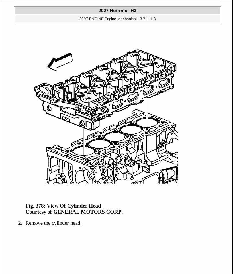
Fig. 378: View Of Cylinder Head Courtesy of GENERAL MOTORS CORP.
2. Remove the cylinder head.
2007 Hummer H3
2007 ENGINE Engine Mechanical - 3.7L - H3
MY
Sunday, March 29, 2009 8:40:44 PM Page 455 © 2005 Mitchell Repair Information Company, LLC.

Fig. 379: View Of Cylinder Head Gasket Courtesy of GENERAL MOTORS CORP.
3. Remove the cylinder head gasket.
PISTON, CONNECTING ROD AND BEARING REMOVAL
Tools Required
J 41556 Connecting Rod Guides. See Special Tools.
Removal Procedure
2007 Hummer H3
2007 ENGINE Engine Mechanical - 3.7L - H3
MY
Sunday, March 29, 2009 8:40:44 PM Page 456 © 2005 Mitchell Repair Information Company, LLC.

Fig. 380: View Of Connecting Rod, Cap & Bolts Courtesy of GENERAL MOTORS CORP.
1. Mark the piston with the number of the cylinder from which the piston is being removed. Also mark the orientation.
2. Mark the connecting rod and the connecting rod cap with the cylinder position. Also mark the orientation. This will ensure the caps and connecting rods are re-assembled properly.
3. Remove the connecting rod bolts.
2007 Hummer H3
2007 ENGINE Engine Mechanical - 3.7L - H3
MY
Sunday, March 29, 2009 8:40:44 PM Page 457 © 2005 Mitchell Repair Information Company, LLC.

4. Remove the connecting rod cap and bearing half.
Fig. 381: View Of J 41556 Courtesy of GENERAL MOTORS CORP.
5. Install J 41556 on the connecting rod. See Special Tools.
2007 Hummer H3
2007 ENGINE Engine Mechanical - 3.7L - H3
MY
Sunday, March 29, 2009 8:40:44 PM Page 458 © 2005 Mitchell Repair Information Company, LLC.

Fig. 382: Connecting Rod & Piston Assembly Courtesy of GENERAL MOTORS CORP.
6. Remove the connecting rod and piston assembly. Push out the assembly.
7. Remove J 41556 . See Special Tools.
2007 Hummer H3
2007 ENGINE Engine Mechanical - 3.7L - H3
MY
Sunday, March 29, 2009 8:40:44 PM Page 459 © 2005 Mitchell Repair Information Company, LLC.

CRANKSHAFT AND BEARING REMOVAL
Tools Required
� EN-47702 Bolt Extractor Kit. See Special Tools. � EN-48268 Main Bearing Cap Remover. See Special Tools. � J 6125-1B Slide Hammer with Adapter. See Special Tools.
Removal Procedure
Fig. 383: View Of Crankshaft Main Bearing Cap Bolt Courtesy of GENERAL MOTORS CORP.
2007 Hummer H3
2007 ENGINE Engine Mechanical - 3.7L - H3
MY
Sunday, March 29, 2009 8:40:44 PM Page 460 © 2005 Mitchell Repair Information Company, LLC.

1. Remove and discard the crankshaft main bearing cap bolts.
IMPORTANT: Rap on the head of each bolt using an appropriate s ize punch and hammer. The vibration produced by this procedur e assists in successful removal. If a bolt breaks dur ing engine disassembly, a broken bolt extractor kitEN-47702 is available to assist in removal of the remaining bolt segment. See Special Tools .
2007 Hummer H3
2007 ENGINE Engine Mechanical - 3.7L - H3
MY
Sunday, March 29, 2009 8:40:44 PM Page 461 © 2005 Mitchell Repair Information Company, LLC.

Fig. 384: View Of Crankshaft Main Bearing Cap Stiffener Courtesy of GENERAL MOTORS CORP.
2. Remove the crankshaft main bearing cap stiffener.
Fig. 385: View Of Crankshaft Main Bearing Caps & Lower Bearings Courtesy of GENERAL MOTORS CORP.
3. Use EN-48268 and J 6125-1B to remove the crankshaft main bearing caps. See Special Tools.
2007 Hummer H3
2007 ENGINE Engine Mechanical - 3.7L - H3
MY
Sunday, March 29, 2009 8:40:44 PM Page 462 © 2005 Mitchell Repair Information Company, LLC.

4. Remove the lower crankshaft main bearing halves.
Fig. 386: View Of Crankshaft Courtesy of GENERAL MOTORS CORP.
5. Remove the crankshaft.
2007 Hummer H3
2007 ENGINE Engine Mechanical - 3.7L - H3
MY
Sunday, March 29, 2009 8:40:44 PM Page 463 © 2005 Mitchell Repair Information Company, LLC.

Fig. 387: View Of Upper Crankshaft Main Bearing Halves Courtesy of GENERAL MOTORS CORP.
6. Remove the upper crankshaft main bearing halves.
CLUTCH PILOT BEARING REMOVAL
Tools Required
J 43276 Clutch Pilot Bearing Removal Tool. See Special Tools.
Removal Procedure
2007 Hummer H3
2007 ENGINE Engine Mechanical - 3.7L - H3
MY
Sunday, March 29, 2009 8:40:44 PM Page 464 © 2005 Mitchell Repair Information Company, LLC.

Fig. 388: View Of Clutch Pilot Bearing Courtesy of GENERAL MOTORS CORP.
1. Install J 43276 into the pilot bearing. See Special Tools. 2. Remove the pilot bearing from the crankshaft.
3. Remove J 43276 . See Special Tools.
AUTOMATIC TRANSMISSION FLYWHEEL LOCATOR REMOVAL
Tools Required
J 45849 Bearing Remover. See Special Tools.
2007 Hummer H3
2007 ENGINE Engine Mechanical - 3.7L - H3
MY
Sunday, March 29, 2009 8:40:45 PM Page 465 © 2005 Mitchell Repair Information Company, LLC.

Removal Procedure
Fig. 389: View Of Flywheel Locator Courtesy of GENERAL MOTORS CORP.
1. Install J 45849 into the flywheel locator. See Special Tools. 2. Remove the flywheel locator from the crankshaft.
3. Remove J 45849 . See Special Tools.
BALANCE SHAFT BEARING REMOVAL
Tools Required
2007 Hummer H3
2007 ENGINE Engine Mechanical - 3.7L - H3
MY
Sunday, March 29, 2009 8:40:45 PM Page 466 © 2005 Mitchell Repair Information Company, LLC.

J 44225 Balance Shaft Bearing Remover/Installer
Removal Procedure
Fig. 390: View Of Balance Shaft Journals Courtesy of GENERAL MOTORS CORP.
1. Position the cylinder block so the cylinder head deck face is down and identify the following:
� The left balance shaft bearings are in the shorter length balance shaft journal (3) and (4).
� The right balance shaft - outer diameter is grooved, bearings are in the longer length
2007 Hummer H3
2007 ENGINE Engine Mechanical - 3.7L - H3
MY
Sunday, March 29, 2009 8:40:45 PM Page 467 © 2005 Mitchell Repair Information Company, LLC.

balance shaft journal (1) and (2).
Fig. 391: Identifying Front & Rear Bearings Courtesy of GENERAL MOTORS CORP.
2. Identify the following: � Bearings (2) and (3) are the front bearings and bearings (1) and (4) are the rear
bearings. � The rear bearings (1) and (4) have a slightly larger diameter than the front bearings (2)
and (3). This allows for easier removal and installation of the front bearings. The rear bearings also have notches on them.
2007 Hummer H3
2007 ENGINE Engine Mechanical - 3.7L - H3
MY
Sunday, March 29, 2009 8:40:45 PM Page 468 © 2005 Mitchell Repair Information Company, LLC.

Fig. 392: Installing 44225 Into Right Balance Shaft Bearing Bore Courtesy of GENERAL MOTORS CORP.
3. Install J 44225 into the right balance shaft bearing bore.
4. Position the swivel end inside lip of J 44225 against the frontside of the rear bearing. 5. Turn the nut clockwise to remove the bearing.
IMPORTANT: It may help to stand the block on end to aid in positioning the swivel end of J 44225 .
2007 Hummer H3
2007 ENGINE Engine Mechanical - 3.7L - H3
MY
Sunday, March 29, 2009 8:40:45 PM Page 469 © 2005 Mitchell Repair Information Company, LLC.

Fig. 393: View Of Right Bearing Courtesy of GENERAL MOTORS CORP.
6. Remove and discard the right rear bearing (1).
2007 Hummer H3
2007 ENGINE Engine Mechanical - 3.7L - H3
MY
Sunday, March 29, 2009 8:40:45 PM Page 470 © 2005 Mitchell Repair Information Company, LLC.

Fig. 394: Installing 44225 Into Right Balance Shaft Bearing Bore Courtesy of GENERAL MOTORS CORP.
7. Install J 44225 into the right balance shaft bearing bore.
8. Position the swivel end inside lip of J 44225 against the frontside of the front bearing. 9. Turn the nut clockwise to remove the bearing.
2007 Hummer H3
2007 ENGINE Engine Mechanical - 3.7L - H3
MY
Sunday, March 29, 2009 8:40:45 PM Page 471 © 2005 Mitchell Repair Information Company, LLC.

Fig. 395: View Of Right Bearing Courtesy of GENERAL MOTORS CORP.
10. Remove and discard the right front bearing (1).
2007 Hummer H3
2007 ENGINE Engine Mechanical - 3.7L - H3
MY
Sunday, March 29, 2009 8:40:45 PM Page 472 © 2005 Mitchell Repair Information Company, LLC.

Fig. 396: Installing J 4425 Into Left Balance Shaft Bearing Bore Courtesy of GENERAL MOTORS CORP.
11. Install J 44225 into the left balance shaft bearing bore.
12. Position the swivel end inside lip of J 44225 against the frontside of the rear bearing.
2007 Hummer H3
2007 ENGINE Engine Mechanical - 3.7L - H3
MY
Sunday, March 29, 2009 8:40:45 PM Page 473 © 2005 Mitchell Repair Information Company, LLC.

13. Turn the nut clockwise to remove the bearing.
Fig. 397: View Of Left Bearing Courtesy of GENERAL MOTORS CORP.
14. Remove and discard the left rear bearing (1).
2007 Hummer H3
2007 ENGINE Engine Mechanical - 3.7L - H3
MY
Sunday, March 29, 2009 8:40:45 PM Page 474 © 2005 Mitchell Repair Information Company, LLC.

Fig. 398: Installing J 4425 Into Left Balance Shaft Bearing Bore Courtesy of GENERAL MOTORS CORP.
15. Install J 44225 into the left balance shaft bearing bore.
16. Position the swivel end inside lip of J 44225 against the frontside of the front bearing.
2007 Hummer H3
2007 ENGINE Engine Mechanical - 3.7L - H3
MY
Sunday, March 29, 2009 8:40:45 PM Page 475 © 2005 Mitchell Repair Information Company, LLC.

17. Turn the nut clockwise to remove the bearing.
Fig. 399: View Of Left Bearing Courtesy of GENERAL MOTORS CORP.
18. Remove and discard the left front bearing (1).
ENGINE BLOCK PLUG REMOVAL
2007 Hummer H3
2007 ENGINE Engine Mechanical - 3.7L - H3
MY
Sunday, March 29, 2009 8:40:45 PM Page 476 © 2005 Mitchell Repair Information Company, LLC.

Fig. 400: View Of Engine Block Oil Gallery Plugs Courtesy of GENERAL MOTORS CORP.
1. Remove the engine block oil gallery plugs.
2007 Hummer H3
2007 ENGINE Engine Mechanical - 3.7L - H3
MY
Sunday, March 29, 2009 8:40:45 PM Page 477 © 2005 Mitchell Repair Information Company, LLC.

Fig. 401: View Of Engine Block Coolant Plug Courtesy of GENERAL MOTORS CORP.
2. Remove the engine block coolant plug.
2007 Hummer H3
2007 ENGINE Engine Mechanical - 3.7L - H3
MY
Sunday, March 29, 2009 8:40:45 PM Page 478 © 2005 Mitchell Repair Information Company, LLC.

Fig. 402: View Of Crankshaft Position Sensor Courtesy of GENERAL MOTORS CORP.
3. Remove the crankshaft position sensor.
2007 Hummer H3
2007 ENGINE Engine Mechanical - 3.7L - H3
MY
Sunday, March 29, 2009 8:40:45 PM Page 479 © 2005 Mitchell Repair Information Company, LLC.

Fig. 403: View Of Knock Sensor Courtesy of GENERAL MOTORS CORP.
4. Remove the knock sensor.
2007 Hummer H3
2007 ENGINE Engine Mechanical - 3.7L - H3
MY
Sunday, March 29, 2009 8:40:45 PM Page 480 © 2005 Mitchell Repair Information Company, LLC.

Fig. 404: View Of EVAP Solenoid Courtesy of GENERAL MOTORS CORP.
5. Remove the EVAP solenoid.
2007 Hummer H3
2007 ENGINE Engine Mechanical - 3.7L - H3
MY
Sunday, March 29, 2009 8:40:45 PM Page 481 © 2005 Mitchell Repair Information Company, LLC.

Fig. 405: View Of Coolant Temperature Sensor Courtesy of GENERAL MOTORS CORP.
6. Remove the coolant temperature sensor.
2007 Hummer H3
2007 ENGINE Engine Mechanical - 3.7L - H3
MY
Sunday, March 29, 2009 8:40:45 PM Page 482 © 2005 Mitchell Repair Information Company, LLC.

Fig. 406: View Of Oil Pressure Switch Courtesy of GENERAL MOTORS CORP.
7. Remove the oil pressure switch.
ENGINE BLOCK CLEANING AND INSPECTION
Tools Required
� J 8001 Dial Indicator Set
� J 8087 Cylinder Bore Gage. See Special Tools. � J 45059 Angle Meter. See Special Tools.
Removal Procedure
2007 Hummer H3
2007 ENGINE Engine Mechanical - 3.7L - H3
MY
Sunday, March 29, 2009 8:40:46 PM Page 483 © 2005 Mitchell Repair Information Company, LLC.

Fig. 407: Checking Deck Surface For Flatness Courtesy of GENERAL MOTORS CORP.
1. Clean the sealing material from all gasket mating surfaces. 2. Clean the engine block with a cleaning solution. 3. Flush the engine block with clean water. 4. Clean the oil passages. 5. Coat the cylinder bores and the machined surfaces with engine oil. 6. Inspect the threaded holes. Clean the holes with a tap, if needed. 7. Use a straight edge and a feeler gage to check the deck surface for flatness. Carefully
2007 Hummer H3
2007 ENGINE Engine Mechanical - 3.7L - H3
MY
Sunday, March 29, 2009 8:40:46 PM Page 484 © 2005 Mitchell Repair Information Company, LLC.

remove any minor irregularities. Replace the block if there is more than 0.08 mm (0.003 in) gap.
Fig. 408: Measuring Cylinder Bores With J 8087 Courtesy of GENERAL MOTORS CORP.
2007 Hummer H3
2007 ENGINE Engine Mechanical - 3.7L - H3
MY
Sunday, March 29, 2009 8:40:46 PM Page 485 © 2005 Mitchell Repair Information Company, LLC.

8. Inspect the cylinder bores. Use J 8087 to measure the cylinder bore. See Special Tools. Inspect the bores for the following conditions:
� Wear � Taper � Runout � Ridging
9. Replace the cylinder sleeve if the bore is out of specification.
Fig. 409: Measuring Engine Block Flange Runout Courtesy of GENERAL MOTORS CORP.
2007 Hummer H3
2007 ENGINE Engine Mechanical - 3.7L - H3
MY
Sunday, March 29, 2009 8:40:46 PM Page 486 © 2005 Mitchell Repair Information Company, LLC.

10. Inspect the oil pan rail for nicks. Use a flat file to remove an nicks. 11. Inspect the front cover attaching area for nicks. Use a flat file to remove any nicks. 12. Inspect the mating surfaces of the transmission case. 13. Use the following procedure to measure the engine block flange runout at the mounting bolt
hole bosses: 1. Temporarily install the crankshaft. Measure the crankshaft flange runout. 2. Hold a gage plate flat against the crankshaft flange.
3. Place J 8001 (dial indicator stem) on the transmission mounting bolt hole boss. Set the indicator to zero.
4. Record the readings obtained from all of the bolt hole bosses. The measurements should not vary more than 0.25 mm (0.010 in).
5. Recheck the crankshaft flange runout if the readings vary more than 0.25 mm (0.010 in). If the crankshaft flange runout is within the specification, replace the engine block.
2007 Hummer H3
2007 ENGINE Engine Mechanical - 3.7L - H3
MY
Sunday, March 29, 2009 8:40:46 PM Page 487 © 2005 Mitchell Repair Information Company, LLC.

Fig. 410: Measuring Bearing Bore Concentricity & Alignment Courtesy of GENERAL MOTORS CORP.
14. Remove the crankshaft.
15. Re-install the crankshaft bearing caps, stiffener and bolts.
Tighten: 1. Tighten the crankshaft bearing cap bolts to 25 N.m (18 lb ft).
NOTE: Refer to FASTENER NOTICE .
2007 Hummer H3
2007 ENGINE Engine Mechanical - 3.7L - H3
MY
Sunday, March 29, 2009 8:40:46 PM Page 488 © 2005 Mitchell Repair Information Company, LLC.

2. Use J 45059 to tighten the crankshaft bearing cap bolts an additional 180 degrees. See Special Tools.
16. Inspect the crankshaft main bearing bores. Use J 8087 to measure the bearing bore concentricity and alignment. See Special Tools.
17. Remove the crankshaft main bearing cap stiffener and main bearing caps with bearings.
CYLINDER HONING
Fig. 411: Identifying Cylinder Bore Cross Hatch Pattern Courtesy of GENERAL MOTORS CORP.
IMPORTANT: Perform the following inspections and rec onditioning (if necessary), with the crankshaft main bearing caps i nstalled and tightened to specification.
2007 Hummer H3
2007 ENGINE Engine Mechanical - 3.7L - H3
MY
Sunday, March 29, 2009 8:40:46 PM Page 489 © 2005 Mitchell Repair Information Company, LLC.

1. When honing the cylinder bores, follow the manufacturer's recommendations for equipment use, cleaning and lubrication.
� Use only clean sharp stones of the proper grade for the amount of material to be removed.
� Dull, dirty stones cut unevenly and generate excessive heat. � DO NOT hone to a final grade with a coarse or medium-grade stone. � Leave sufficient metal so that all the stone marks will be removed with the fine grade
stones. � Perform the final honing with a fine-grade stone and hone the cylinder bore in a cross
hatch pattern at 45-65 degrees to obtain the proper clearance. 2. During the honing operation, thoroughly check the cylinder bore.
� Repeatedly check the cylinder bore fit with the selected piston. � All measurements of the piston or cylinder bore should be made with the components
at normal room temperature. 3. When honing to eliminate taper in the cylinder bore, use full strokes the complete length of
the cylinder bore.
Repeatedly check the measurement at the top, the middle and the bottom of the cylinder bore.
� The finish marks should be clean but not sharp. � The finish marks should be free from imbedded particles or torn or folded metal.
4. When finished, the reconditioned cylinder bores should have less than or meet the specified out-of-round and taper requirements.
5. After the final honing and before the piston is checked for fit, clean the cylinder bore with hot water and detergent.
1. Scrub the cylinder bores with a stiff bristle brush. 2. Rinse the cylinder bores thoroughly with clean hot water. 3. Dry the cylinder bores with a clean rag. 4. Do not allow any abrasive material to remain in the cylinder bores.
� Abrasive material may cause premature wear of the new piston rings and the cylinder bores.
� Abrasive material will contaminate the engine oil and may cause premature wear
CAUTION: Refer to SAFETY GLASSES CAUTION .
2007 Hummer H3
2007 ENGINE Engine Mechanical - 3.7L - H3
MY
Sunday, March 29, 2009 8:40:46 PM Page 490 © 2005 Mitchell Repair Information Company, LLC.

of the bearings. 6. Perform final measurements of the piston and the cylinder bore. 7. Permanently mark the top of the piston for the specified cylinder to which it has been fitted. 8. Apply clean engine oil to each cylinder bore in order to prevent rusting.
CRANKSHAFT AND BEARING CLEANING AND INSPECTION
Tools Required
� J 8087 Cylinder Bore Gauge. See Special Tools. � J 45059 Angle Meter. See Special Tools.
Inspection Procedure
Fig. 412: Inspecting Crankshaft Courtesy of GENERAL MOTORS CORP.
2007 Hummer H3
2007 ENGINE Engine Mechanical - 3.7L - H3
MY
Sunday, March 29, 2009 8:40:46 PM Page 491 © 2005 Mitchell Repair Information Company, LLC.

1. Clean the crankshaft of all elements. 2. Inspect the crankshaft oil passages for obstructions. 3. Inspect the crankshaft for the following conditions:
� Damaged threads (1) � Damaged mounting faces � Worn crankshaft pin (2) � Wear without any grooves or scratches (3) � Grooves or scoring (3) � Scratches (3) � Pitting or embedded bearing material (3) � Overheating - discoloration (3) � Damaged teeth (4)
IMPORTANT: Use care when handling the crankshaft. Av oid damage to the reluctor wheel and crankshaft bearing surfaces.
2007 Hummer H3
2007 ENGINE Engine Mechanical - 3.7L - H3
MY
Sunday, March 29, 2009 8:40:46 PM Page 492 © 2005 Mitchell Repair Information Company, LLC.

Fig. 413: View Of Crankshaft Bearing Inserts Courtesy of GENERAL MOTORS CORP.
4. Inspect the corresponding crankshaft bearing inserts for embedded material and determine the source of the material.
IMPORTANT: If cracks, severe gouges or burned spots are found, replace the crankshaft. Remove slight roughness using a fin e polishing cloth soaked in clean engine oil. Remove any burrs using a fine oil stone.
2007 Hummer H3
2007 ENGINE Engine Mechanical - 3.7L - H3
MY
Sunday, March 29, 2009 8:40:46 PM Page 493 © 2005 Mitchell Repair Information Company, LLC.

5. Inspect the outer surfaces of the crankshaft bearings for the following conditions: � Wear - surface wear indicates either movement of the insert or high spots in the
surrounding material (spot wear) � Overheating or discoloration � Looseness or rotation indicated by flattened tangs and wear grooves
6. Inspect the crankshaft main bearings for craters or pockets. Flattened sections on the crankshaft bearing halves also indicate fatigue.
7. Inspect the thrust surfaces of the main thrust bearing for the following conditions: � Wear � Grooving - Grooves are caused by irregularities of the crankshaft thrust surface.
8. Inspect the crankshaft bearings for excessive scoring or discoloration. 9. Inspect the crankshaft bearings for dirt or imbedded debris.
10. Inspect the crankshaft bearings for improper seating indicated by bright, polished sections. 11. Inspect the crankshaft bearings for uneven side-to-side wear. This may indicate a bent
crankshaft or a tapered bearing journal.
12. Inspect the connecting rod bearing bores using the following procedure: 1. Tighten the connecting rod bearing cap to specification.
2. Use J 8087 to measure the bearing bore for taper and out-of-round. See Special Tools. Record the readings.
3. No taper or out-of-round should exist.
IMPORTANT: Note the location of the crankshaft main bearing high spots. If the spots are not in line, the crankshaft is ben t. Replace the crankshaft.
IMPORTANT: If crankshaft bearing failure is due to c onditions other than normal wear, investigate the cause of the condition . Inspect the crankshaft or connecting rod bearing bores.
2007 Hummer H3
2007 ENGINE Engine Mechanical - 3.7L - H3
MY
Sunday, March 29, 2009 8:40:46 PM Page 494 © 2005 Mitchell Repair Information Company, LLC.

Fig. 414: Measuring Crankshaft Bearing Journal Courtesy of GENERAL MOTORS CORP.
13. Measure the crankshaft bearing journal diameter with a micrometer in several places, 90 degrees apart. Average the measurements.
2007 Hummer H3
2007 ENGINE Engine Mechanical - 3.7L - H3
MY
Sunday, March 29, 2009 8:40:46 PM Page 495 © 2005 Mitchell Repair Information Company, LLC.

Fig. 415: View Of Crankshaft Bearing Caps Courtesy of GENERAL MOTORS CORP.
14. Measure the crankshaft bearing journal taper and runout. 15. Install the crankshaft bearing caps. 16. Install the crankshaft main bearing cap stiffener.
17. Install the crankshaft bearing cap bolts.
NOTE: Refer to FASTENER NOTICE .
2007 Hummer H3
2007 ENGINE Engine Mechanical - 3.7L - H3
MY
Sunday, March 29, 2009 8:40:46 PM Page 496 © 2005 Mitchell Repair Information Company, LLC.

Tighten: 1. Tighten the crankshaft bearing cap bolts to 25 N.m (18 lb ft).
2. Use J 45059 to tighten the crankshaft bearing cap bolts an additional 180 degrees. See Special Tools.
18. Measure the crankshaft main bearing inside diameter with an inside micrometer. 19. Measure the connecting rod inside diameter in the same direction as the length of the rod
with an inside micrometer. 20. If the specified clearances cannot be met, the crankshaft, connecting rods or block may need
to be replaced.
CRANKSHAFT BALANCER CLEANING AND INSPECTION
2007 Hummer H3
2007 ENGINE Engine Mechanical - 3.7L - H3
MY
Sunday, March 29, 2009 8:40:46 PM Page 497 © 2005 Mitchell Repair Information Company, LLC.

Fig. 416: View Of Crankshaft Balancer Sealing Area & Belt Ribs Courtesy of GENERAL MOTORS CORP.
1. Inspect the crankshaft balancer sealing area for grooves, nicks or burs (1). 2. Inspect the crankshaft balancer belt ribs for dents or damage (2). 3. Replace the crankshaft balancer if damage is present.
ENGINE FLYWHEEL CLEANING AND INSPECTION (AUTOMATIC TRANSMISSION)
2007 Hummer H3
2007 ENGINE Engine Mechanical - 3.7L - H3
MY
Sunday, March 29, 2009 8:40:46 PM Page 498 © 2005 Mitchell Repair Information Company, LLC.

Fig. 417: Inspecting Engine Flywheel For Damage - Automatic Transmission Courtesy of GENERAL MOTORS CORP.
1. Inspect the engine flywheel for cracks (1). 2. Inspect the engine flywheel teeth for damage (2). 3. Replace the engine flywheel if damage is present.
2007 Hummer H3
2007 ENGINE Engine Mechanical - 3.7L - H3
MY
Sunday, March 29, 2009 8:40:46 PM Page 499 © 2005 Mitchell Repair Information Company, LLC.

ENGINE FLYWHEEL CLEANING AND INSPECTION (MANUAL TRANSMISSION)
Fig. 418: Inspecting Engine Flywheel For Damage - Manual Transmission Courtesy of GENERAL MOTORS CORP.
IMPORTANT: In order to maintain the proper component balance, contact surface taper and heat transfer, manual transmissio n flywheels are NOT to be machined.
2007 Hummer H3
2007 ENGINE Engine Mechanical - 3.7L - H3
MY
Sunday, March 29, 2009 8:40:47 PM Page 500 © 2005 Mitchell Repair Information Company, LLC.

1. Inspect the engine flywheel for damaged teeth (1). 2. Inspect the engine flywheel for cracks, hot spots or any surface damage (2). 3. Replace the engine flywheel if damage is present.
PISTON AND CONNECTING ROD DISASSEMBLE
Tools Required
EN-46745 Piston Pin Retainer Remover and Installer. See Special Tools.
Disassembly Procedure
2007 Hummer H3
2007 ENGINE Engine Mechanical - 3.7L - H3
MY
Sunday, March 29, 2009 8:40:47 PM Page 501 © 2005 Mitchell Repair Information Company, LLC.

Fig. 419: Piston Ring Expander Courtesy of GENERAL MOTORS CORP.
CAUTION: Handle the piston carefully. Worn piston ri ngs are sharp and may cause bodily injury.
2007 Hummer H3
2007 ENGINE Engine Mechanical - 3.7L - H3
MY
Sunday, March 29, 2009 8:40:47 PM Page 502 © 2005 Mitchell Repair Information Company, LLC.

1. Remove the piston rings using a piston ring expander.
Fig. 420: View Of Piston Pin Retaining Clips Courtesy of GENERAL MOTORS CORP.
2. Remove the piston pin retainers using EN-46745 . See Special Tools.
IMPORTANT: Do not reuse the piston rings.
IMPORTANT: Two retainers hold the piston pins in pla ce. Reuse the retainers if they are not damaged during removal.
2007 Hummer H3
2007 ENGINE Engine Mechanical - 3.7L - H3
MY
Sunday, March 29, 2009 8:40:47 PM Page 503 © 2005 Mitchell Repair Information Company, LLC.

Fig. 421: View Of Piston Pin & Connecting Rod Courtesy of GENERAL MOTORS CORP.
3. Remove the piston pin.
PISTON, CONNECTING ROD AND BEARING CLEANING AND INSPECTION
Tools Required
2007 Hummer H3
2007 ENGINE Engine Mechanical - 3.7L - H3
MY
Sunday, March 29, 2009 8:40:47 PM Page 504 © 2005 Mitchell Repair Information Company, LLC.

J 8087 Cylinder Bore Gage. See Special Tools.
Cleaning and Inspection Procedure
Fig. 422: View Of Piston Pin & Connecting Rod Courtesy of GENERAL MOTORS CORP.
2007 Hummer H3
2007 ENGINE Engine Mechanical - 3.7L - H3
MY
Sunday, March 29, 2009 8:40:47 PM Page 505 © 2005 Mitchell Repair Information Company, LLC.

1. Clean and soak the following components in a carburetor cleaning solution to remove carbon, sludge and varnish:
� Piston � Piston pin � Connecting rod
2007 Hummer H3
2007 ENGINE Engine Mechanical - 3.7L - H3
MY
Sunday, March 29, 2009 8:40:47 PM Page 506 © 2005 Mitchell Repair Information Company, LLC.

Fig. 423: Identifying Twisted Connecting Rod Courtesy of GENERAL MOTORS CORP.
2. Install the connecting rod cap. 3. Place the connecting rod assembly on a checking fixture. 4. Inspect the connecting rod assembly for bending or twisting. 5. Replace any bent or twisted connecting rods. 6. If the connecting rod large bore contains minor scratches or abrasions, clean the bore in a
circular direction with light emery paper. DO NOT scrape the connecting rod or cap. 7. Measure the piston pin to connecting rod bore using the following procedure:
� Using an outside micrometer, take two measurements of the piston pin in the area of the connecting rod contact.
� Using an inside micrometer, measure the connecting rod piston pin bore. � Subtract the piston pin diameter from the piston pin bore diameter. � The clearance should not be more than 0.018 mm (0.0007 in).
8. If there is excessive clearance, replace the piston pin. 9. If there is still excessive clearance, replace the connecting rod.
10. If there is evidence of pin bore or pin scoring, replace the rod and pin assembly.
2007 Hummer H3
2007 ENGINE Engine Mechanical - 3.7L - H3
MY
Sunday, March 29, 2009 8:40:47 PM Page 507 © 2005 Mitchell Repair Information Company, LLC.

Fig. 424: Inspecting Connecting Rod Cap Bolts Courtesy of GENERAL MOTORS CORP.
11. Inspect the connecting rod bearings for the following conditions: � Craters or pockets � Flattened sections � Excessive scoring or discoloration. � Imbedded debris � Bright, polished sections
12. Inspect the inside of the connecting rod bearing and outside diameter of the connecting rod bearing journal for wear. This indicates high spots.
13. Inspect the connecting rod bearing bore for taper and out-of-round. 14. Inspect the connecting rod bolts for stretching (compare to new or known good bolt). The
callout (1) is a stretched bolt, (2) is a new or good bolt. 15. Clean the piston skirts and the pins with a cleaning solvent. DO NOT wire brush any part of
the piston. 16. Clean the piston ring grooves. Ensure that the oil ring holes and slots are clean. 17. Inspect the pistons for the following conditions:
2007 Hummer H3
2007 ENGINE Engine Mechanical - 3.7L - H3
MY
Sunday, March 29, 2009 8:40:47 PM Page 508 © 2005 Mitchell Repair Information Company, LLC.

� Cracked ring lands, skirts or pin bosses � Ring grooves for nicks, burrs that may cause binding � Warped or worn ring lands � Eroded areas at the top of the piston � Scuffed or damaged skirts � Worn piston pin bores
18. Replace pistons that show any signs or damage or excessive wear.
Fig. 425: Measuring Piston Diameter Courtesy of GENERAL MOTORS CORP.
IMPORTANT: When fitting pistons, consider both the p iston and the cylinder bore conditions together. Production and s ervice pistons have the same nominal weight and may be
2007 Hummer H3
2007 ENGINE Engine Mechanical - 3.7L - H3
MY
Sunday, March 29, 2009 8:40:47 PM Page 509 © 2005 Mitchell Repair Information Company, LLC.

19. Measure the piston diameter for size with a micrometer or caliper at a right angle to the pin center line, across the skirts, 38 mm (1.50 in) from the top of the piston.
intermixed without affecting engine balance. If nec essary, used pistons may be fitted selectively to any cylin der of the engine, providing the pistons are in good condition and the same weight. Do not cut oversize pistons down or th e engine balance may be affected. Finish hone when selecting the piston.
2007 Hummer H3
2007 ENGINE Engine Mechanical - 3.7L - H3
MY
Sunday, March 29, 2009 8:40:47 PM Page 510 © 2005 Mitchell Repair Information Company, LLC.

Fig. 426: Measuring Cylinder Bores With J 8087 Courtesy of GENERAL MOTORS CORP.
20. Replace the piston if worn beyond specifications or if damaged.
21. Use J 8087 to measure the cylinder bore. See Special Tools.
2007 Hummer H3
2007 ENGINE Engine Mechanical - 3.7L - H3
MY
Sunday, March 29, 2009 8:40:47 PM Page 511 © 2005 Mitchell Repair Information Company, LLC.

Fig. 427: Honing Cylinder Bore Courtesy of GENERAL MOTORS CORP.
22. Hone to size if necessary. Use the following procedure to hone the cylinder bore to the correct size.
1. Select a piston. 2. Hone the cylinder bore to obtain the recommended clearance.
2007 Hummer H3
2007 ENGINE Engine Mechanical - 3.7L - H3
MY
Sunday, March 29, 2009 8:40:47 PM Page 512 © 2005 Mitchell Repair Information Company, LLC.

3. Clean the piston and cylinder bore with soap and water. Dry the cylinder bore and piston. Lubricate the cylinder bore with clean engine oil.
23. Use the following procedure to measure the piston-to-cylinder bore clearance. 1. Subtract the piston diameter from the cylinder bore diameter to determine the piston-
to-bore clearance. 2. Compare the piston-to-bore clearance using the specifications to determine if the
clearance is in the acceptable range. 3. If the used piston is not acceptable, a new service piston may be selected.
24. When a piston has been selected, mark the piston to identify the cylinder for which the piston was fitted.
25. Select a set of new piston rings. 26. Install each ring, one at a time, into the corresponding cylinder. 27. Install the piston for that cylinder, upside down (top of piston pushing on the ring) and push
the ring to approximately 25 mm (1 in) down from the deck surface. 28. Remove the piston. 29. Measure the ring end gap with a feeler gage.
2007 Hummer H3
2007 ENGINE Engine Mechanical - 3.7L - H3
MY
Sunday, March 29, 2009 8:40:47 PM Page 513 © 2005 Mitchell Repair Information Company, LLC.

Fig. 428: Measuring Ring End Gap Courtesy of GENERAL MOTORS CORP.
30. If the ring gap is not within the specification range, replace the rings. 31. Measure the piston ring side clearance - compression rings.
NOTE: The piston ring groove must only be cleaned wi th a ring groove cleaning tool. Proper engine performance and durabi lity depends on the straightness and smoothness of the r ing groove. Cleaning the piston ring groove with an imp roper tool can damage the piston ring groove and effect the pe rformance and durability of the engine.
2007 Hummer H3
2007 ENGINE Engine Mechanical - 3.7L - H3
MY
Sunday, March 29, 2009 8:40:47 PM Page 514 © 2005 Mitchell Repair Information Company, LLC.

32. Use the following procedure to measure the compression ring side clearance. 1. Roll the piston ring around the groove. 2. Measure the side clearance with a feeler gage. 3. If the ring is too tight, inspect the piston ring groove for nicks, burrs or damage. Use
emery cloth to remove any minor burrs. 4. If the ring side clearance is greater than the specification, replace the piston.
CYLINDER SLEEVE REMOVAL
Tools Required
EN-45680-450 Cylinder Sleeve Removal and Installation Kit. See Special Tools.
Removal Procedure
NOTE: Do not chill or heat the cylinder bore sleeve or the cylinder block when removing or installing a new cylinder bo re sleeve. Chilling or heating the cylinder bore sleeve or the cylinder block will cause engine damage and will not aid the removal or installation of the new cylinder bore sleeve.
NOTE: Do not damage the crankshaft connecting rod jo urnals or reluctor ring or engine damage will occur.
2007 Hummer H3
2007 ENGINE Engine Mechanical - 3.7L - H3
MY
Sunday, March 29, 2009 8:40:47 PM Page 515 © 2005 Mitchell Repair Information Company, LLC.

Fig. 429: View Of Cylinder Bore Liner Puller Courtesy of GENERAL MOTORS CORP.
1. If the crankshaft is still installed, rotate the crankshaft so that the counterweight is to the right side and the connecting rod journal is to the left side and not in alignment with the cylinder bore.
2. Install the cylinder bore sleeve puller EN 45680-402 (1) which is part of EN-45680-450 , through the cylinder bore. See Special Tools.
NOTE: Ensure that the shoe is flat against the botto m of the cylinder bore sleeve or damage to the cylinder bore sleeve p uller will occur.
2007 Hummer H3
2007 ENGINE Engine Mechanical - 3.7L - H3
MY
Sunday, March 29, 2009 8:40:47 PM Page 516 © 2005 Mitchell Repair Information Company, LLC.

3. Align the shoe (1) of the cylinder bore sleeve puller EN 45680-402 to the bottom of the cylinder bore sleeve (117).
Fig. 430: Threaded Shaft Courtesy of GENERAL MOTORS CORP.
2007 Hummer H3
2007 ENGINE Engine Mechanical - 3.7L - H3
MY
Sunday, March 29, 2009 8:40:48 PM Page 517 © 2005 Mitchell Repair Information Company, LLC.

4. Hold the threaded shaft of the cylinder bore sleeve puller EN 45680-402 upward in order to retain the shoe alignment to the bottom of the cylinder bore sleeve.
5. Install the fixture EN 456850-401 (4) onto the threaded shaft of the cylinder bore sleeve puller EN 456850-402 and the engine block.
6. Install the bearing (3) and the nut (1). 7. Tighten the nut (1) to the bearing (3).
8. Install and tighten the 4 attaching bolts (2) into the cylinder head bolt holes of the block.
Tighten: Tighten the bolts to 15 N.m (11 lb ft).
NOTE: Refer to Fastener Notice .
IMPORTANT: Use four old cylinder head bolts for the attaching bolts.
2007 Hummer H3
2007 ENGINE Engine Mechanical - 3.7L - H3
MY
Sunday, March 29, 2009 8:40:48 PM Page 518 © 2005 Mitchell Repair Information Company, LLC.

Fig. 431: Removing Cylinder Bore Sleeve By Rotating Nut Courtesy of GENERAL MOTORS CORP.
9. Rotate the nut clockwise in order to remove the cylinder bore sleeve.
2007 Hummer H3
2007 ENGINE Engine Mechanical - 3.7L - H3
MY
Sunday, March 29, 2009 8:40:48 PM Page 519 © 2005 Mitchell Repair Information Company, LLC.

Fig. 432: Removing Cylinder Bore Sleeve Courtesy of GENERAL MOTORS CORP.
10. Remove fixture EN 45680-401, cylinder bore sleeve puller EN 45680-402 and the cylinder bore sleeve (117) from the engine block.
11. Loosen the nut (1) in order to remove the cylinder bore sleeve (117). 12. Inspect the cylinder bore in the cylinder block for cracks or damage. If cracked or damaged,
replace the cylinder block.
13. Inspect the piston, piston rings and connecting rod for damage. Refer to Piston, Connecting Rod and Bearing Cleaning and Inspection.
CYLINDER SLEEVE INSTALLATION
Tools Required
EN-45680-450 Cylinder Sleeve Removal and Installation Kit. See Special Tools.
Installation Procedure
NOTE: Do not damage the cylinder block surface. Dama ge to the cylinder block surface can cause engine failure.
2007 Hummer H3
2007 ENGINE Engine Mechanical - 3.7L - H3
MY
Sunday, March 29, 2009 8:40:48 PM Page 520 © 2005 Mitchell Repair Information Company, LLC.

NOTE: Do not use assembly aids or lubricants on the cylinder bore sleeve or the cylinder bore block when installing a new cylinder bore sleeve or engine damage will occur. T hese items will not aid in the installation of the new cylinde r bore sleeve.
NOTE: Do not chill or heat the cylinder bore sleeve or the cylinder block when removing or installing a new cylinder bo re sleeve. Chilling or heating the cylinder bore sleeve or the cylinder block will cause engine damage and will not aid the removal or installation of the new cylinder bore sleeve.
2007 Hummer H3
2007 ENGINE Engine Mechanical - 3.7L - H3
MY
Sunday, March 29, 2009 8:40:48 PM Page 521 © 2005 Mitchell Repair Information Company, LLC.

Fig. 433: View Of Cylinder Bore Sleeve Fixture Courtesy of GENERAL MOTORS CORP.
1. Place the NEW cylinder bore sleeve (117) onto the cylinder block. 2. Install fixture EN 45680-401/cylinder bore sleeve installer EN 45680-403 assembly (1)
which is part of EN-45680-450 , over the cylinder bore sleeve (117) and onto the cylinder block. See Special Tools. Do not apply downward pressure to the cylinder bore sleeve (117).
2007 Hummer H3
2007 ENGINE Engine Mechanical - 3.7L - H3
MY
Sunday, March 29, 2009 8:40:48 PM Page 522 © 2005 Mitchell Repair Information Company, LLC.

Fig. 434: Installing Cylinder Bore Sleeve Puller Attachment Bolts Courtesy of GENERAL MOTORS CORP.
3. Insert the 4 attachment bolts into the legs of the fixture EN 45680-401 (1).
4. Tighten the 4 attachment bolts. Do not apply downward pressure to the cylinder bore sleeve
IMPORTANT: Use 4 old cylinder head bolts for the att aching bolts.
NOTE: Refer to Fastener Notice .
2007 Hummer H3
2007 ENGINE Engine Mechanical - 3.7L - H3
MY
Sunday, March 29, 2009 8:40:48 PM Page 523 © 2005 Mitchell Repair Information Company, LLC.

(117).
Tighten: Tighten the 4 attachment bolts to 15 N.m (11 lb ft).
Fig. 435: View Of Proper Liner Alignment Courtesy of GENERAL MOTORS CORP.
5. Align the bottom of the cylinder bore sleeve (117) with the cylinder bore of the block (100).
2007 Hummer H3
2007 ENGINE Engine Mechanical - 3.7L - H3
MY
Sunday, March 29, 2009 8:40:48 PM Page 524 © 2005 Mitchell Repair Information Company, LLC.

Fig. 436: View Of Installation Arbor Courtesy of GENERAL MOTORS CORP.
6. Align the installation arbor (1) onto the top of the cylinder bore sleeve (117).
2007 Hummer H3
2007 ENGINE Engine Mechanical - 3.7L - H3
MY
Sunday, March 29, 2009 8:40:48 PM Page 525 © 2005 Mitchell Repair Information Company, LLC.

Fig. 437: View Of Pusher Block Courtesy of GENERAL MOTORS CORP.
7. Align the pusher block (2) of cylinder bore sleeve installer EN 45680-403 into the groove of fixture EN 45680-401 (1).
2007 Hummer H3
2007 ENGINE Engine Mechanical - 3.7L - H3
MY
Sunday, March 29, 2009 8:40:48 PM Page 526 © 2005 Mitchell Repair Information Company, LLC.

Fig. 438: Installing Cylinder Bore Sleeve Into Engine Block Using Tool Courtesy of GENERAL MOTORS CORP.
8. Using a ratchet, rotate the threaded shaft of fixture EN 45680-401/cylinder bore sleeve installer EN 45680-403 assembly (1) in order to install the cylinder bore sleeve (117) into the engine block (100).
NOTE: Do not use any air powered or electric tools t o rotate the threaded shaft of the fixture EN 45680-401/cylinder bore sleeve installer EN 45680-403 assembly or damage to the cy linder bore sleeve will occur.
2007 Hummer H3
2007 ENGINE Engine Mechanical - 3.7L - H3
MY
Sunday, March 29, 2009 8:40:48 PM Page 527 © 2005 Mitchell Repair Information Company, LLC.

9. Do not completely seat the cylinder bore sleeve in the block. Leave approximately 1/16 inch of the cylinder bore sleeve above the surface of the cylinder block.
Fig. 439: Seating Cylinder Bore Sleeve Completely Using Tool Courtesy of GENERAL MOTORS CORP.
10. Using a torque wrench, torque the threaded shaft of the fixture EN 45680-401/cylinder bore sleeve installer EN 45680-403 assembly to 102 N.m (75 lb ft) in order to completely seat the cylinder bore sleeve in the cylinder block. With the cylinder bore sleeve properly installed, a minimal portion of the cylinder bore sleeve flange will protrude above the block deck surface.
2007 Hummer H3
2007 ENGINE Engine Mechanical - 3.7L - H3
MY
Sunday, March 29, 2009 8:40:48 PM Page 528 © 2005 Mitchell Repair Information Company, LLC.

Fig. 440: View Of Service Tool Assembly Courtesy of GENERAL MOTORS CORP.
11. Remove the fixture EN 45680-401/cylinder bore sleeve installer EN 45680-403 assembly (1) from the cylinder block (100).
Cylinder Sleeve Trimming
2007 Hummer H3
2007 ENGINE Engine Mechanical - 3.7L - H3
MY
Sunday, March 29, 2009 8:40:48 PM Page 529 © 2005 Mitchell Repair Information Company, LLC.

Fig. 441: Cylinder Liner Trimming Tools View (1 Of 2) Courtesy of GENERAL MOTORS CORP.
� EN 45680-865 Debris Collector (3) � EN 45680-411 Trim Tool Assembly (2) � EN 45680-499 Updated Trimmer Pilot (white in color) � Air Control Valve (1 - Part of EN 45680-411 � Drill Motor with 1/2 inch chuck, 1 1/8 hp, 7 amps, triple gear reduction and a 450-600
RPM rotational speed in a clockwise direction
2007 Hummer H3
2007 ENGINE Engine Mechanical - 3.7L - H3
MY
Sunday, March 29, 2009 8:40:48 PM Page 530 © 2005 Mitchell Repair Information Company, LLC.

Fig. 442: Cylinder Liner Trimming Tools View (2 Of 2) Courtesy of GENERAL MOTORS CORP.
� Trim Tool Preloader (1) � EN 45680-412 Set Gage Ring (2) � EN 45680-413 Metal Shavings Catch Plug (3) � EN 45680-866 Drive Adapter (4) � EN 45680-414 Bolts (5)
NOTE: Do not bore or hone the cylinder bore sleeve. The cylinder bore sleeve inside diameter (I.D) is fully machined and honed to size and is optimally finished as shipped. Any attempt t o modify this factory-produced sizing and finish with additi onal boring and honing will lead to engine damage, excessive no ise or abnormal oil consumption.
2007 Hummer H3
2007 ENGINE Engine Mechanical - 3.7L - H3
MY
Sunday, March 29, 2009 8:40:48 PM Page 531 © 2005 Mitchell Repair Information Company, LLC.

Fig. 443: Placing Metal Shaving Catch Plug Into Cylinder Bore Sleeve Courtesy of GENERAL MOTORS CORP.
1. After installing the NEW cylinder bore sleeve(s) into the engine block, trim the excess material from the cylinder bore sleeve flange.
2. Place metal shaving catch plug EN 45680-413 into the cylinder bore sleeve to be trimmed. Position the top of the EN 45680-413 approximately 3.0 mm (0.12 in) below the top
NOTE: Ensure that all the metal particles are collec ted in order to prevent internal damage to the transaxle or bearing s.
2007 Hummer H3
2007 ENGINE Engine Mechanical - 3.7L - H3
MY
Sunday, March 29, 2009 8:40:48 PM Page 532 © 2005 Mitchell Repair Information Company, LLC.

surface of the cylinder bore sleeve. 3. Place additional metal shaving catch plugs EN 45680-413 into all remaining cylinder bore
sleeves.
Fig. 444: Identifying Catch Plug Positioning Courtesy of GENERAL MOTORS CORP.
NOTE: Installing the metal shaving catch plug deeper than the recommended depth will create a decrease in vacuum system performance. A decrease in vacuum system performanc e will cause metal shavings to enter the engine and cause engine
2007 Hummer H3
2007 ENGINE Engine Mechanical - 3.7L - H3
MY
Sunday, March 29, 2009 8:40:49 PM Page 533 © 2005 Mitchell Repair Information Company, LLC.

4. Ensure that the metal shaving catch plug EN 45680-413 is 3.0 mm (0.12 in) below the top surface of the cylinder bore sleeve.
Fig. 445: Identifying Set Gauge Ring Groove Courtesy of GENERAL MOTORS CORP.
failure.
NOTE: Installing the metal shaving catch plug above the recommended depth will cause damage to the metal sh aving catch plug.
IMPORTANT: Before using trim tool assembly EN 45680- 411, the height of the cutting blades must be set to the proper specif ication. The proper specification is that the cylinder bore sleeve flange must be flush to +0.02 mm (0.0008 in) above the block
2007 Hummer H3
2007 ENGINE Engine Mechanical - 3.7L - H3
MY
Sunday, March 29, 2009 8:40:49 PM Page 534 © 2005 Mitchell Repair Information Company, LLC.

5. The groove side of the set gage ring EN 45680-412 (1) should be positioned upward on a flat surface.
Fig. 446: View Of Trim Tool Assembly Components And Positioning Courtesy of GENERAL MOTORS CORP.
deck surface.
IMPORTANT: Ensure that the set gage ring EN 45680-41 2 surfaces are clean.
2007 Hummer H3
2007 ENGINE Engine Mechanical - 3.7L - H3
MY
Sunday, March 29, 2009 8:40:49 PM Page 535 © 2005 Mitchell Repair Information Company, LLC.

6. Carefully position trim tool assembly EN 45680-411 onto the set gage ring EN 45680-412. 7. Loosen the shaft collar screw (2). 8. Push the shaft collar (2) downward using the trim tool preloader (1) until the shaft collar is
positioned against the top of the flange bearing (3).
9. Apply downward pressure on the collar and inner drive shaft using the trim tool preloader (1), then tighten the shaft collar screw.
Tighten: Tighten the shaft collar screw to 19 N.m (14 lb ft).
IMPORTANT: Once this procedure is done, it is not ne cessary to reset the trim tool assembly EN 45680-411 height until the bl ades are worn or damaged.
2007 Hummer H3
2007 ENGINE Engine Mechanical - 3.7L - H3
MY
Sunday, March 29, 2009 8:40:49 PM Page 536 © 2005 Mitchell Repair Information Company, LLC.

Fig. 447: Trim Tool Assembly Alignment Courtesy of GENERAL MOTORS CORP.
10. Place trim tool assembly EN 45680-411 onto the cylinder to be trimmed with the directional arrow (1) pointing in line with the crankshaft centerline and the front of the block.
11. Install the 4 bolts EN 45680-414 (2) into the cylinder head bolt holes in the block.
Tighten: Tighten the bolts to 20 N.m (15 lb ft).
2007 Hummer H3
2007 ENGINE Engine Mechanical - 3.7L - H3
MY
Sunday, March 29, 2009 8:40:49 PM Page 537 © 2005 Mitchell Repair Information Company, LLC.

Fig. 448: Drive Adapter Courtesy of GENERAL MOTORS CORP.
12. Fasten drive adapter EN 45680-866 (1) into the drill chuck.
NOTE: For proper tool operation, a drill motor with a 1/2 inch chuck, 1 1/8 hp, 7 amps, triple gear reduction and a 450-600 RPM rotational speed in a clockwise direction must be u sed. If the proper drill motor is not used, damage to the cylin der bore sleeve will occur.
2007 Hummer H3
2007 ENGINE Engine Mechanical - 3.7L - H3
MY
Sunday, March 29, 2009 8:40:49 PM Page 538 © 2005 Mitchell Repair Information Company, LLC.

13. Connect a compressed air supply (75-125 psi) to the male quick connect (3) located on trim tool assembly EN 45680-411. Turn the compressed air valve (2) to the open position. This starts the venturi vacuum system that will catch the metal shavings.
14. Place drive adapter EN 45680-866 and drill assembly (1) vertically onto the drive adapter end of trim tool assembly EN 45680-411. Do not apply downward force on the drill until full rotational speed has been reached. After reaching full rotational speed, apply firm downward force until the cutting action is complete.
15. Remove drive adapter EN 45680-866 (1) and drill assembly from the trim tool assembly EN 45680-411.
16. Turn off the compressed air valve (2). 17. Remove trim tool assembly EN 45680-411 from the engine block. 18. Remove any material shavings that may be found on the metal shaving catch plug EN
45680-413. 19. Wipe the cylinder bore sleeve and surrounding areas free of any powder residue and then
remove the metal shaving catch plug EN 45680-413.
NOTE: Ensure that there are no crimps in the air fee d hose or the vacuum hose. Crimps in the hose may cause metal sha vings to exit the cutting tool in any direction, causing eng ine damage.
IMPORTANT: It should not take longer than 15 seconds to complete the trimming procedure. If it does, the trimming bits m ust be repositioned to a new cutting surface.
2007 Hummer H3
2007 ENGINE Engine Mechanical - 3.7L - H3
MY
Sunday, March 29, 2009 8:40:49 PM Page 539 © 2005 Mitchell Repair Information Company, LLC.

Fig. 449: Checking Cylinder Block Deck Surface With Straight Edge Courtesy of GENERAL MOTORS CORP.
20. Install a straight edge on the cylinder block perpendicular to the crankshaft center line. 21. Using a light, illuminate the backside of the straight edge.
2007 Hummer H3
2007 ENGINE Engine Mechanical - 3.7L - H3
MY
Sunday, March 29, 2009 8:40:49 PM Page 540 © 2005 Mitchell Repair Information Company, LLC.

Fig. 450: View Of Improperly Cut Cylinder Bore Sleeve Courtesy of GENERAL MOTORS CORP.
22. Looking at the front of the straight edge, check to see if light is protruding through the bottom of the straight edge and the top of the cylinder bore sleeve flange. If light is present on either side or both sides of the cylinder bore sleeve, the cylinder bore sleeve is cut incorrectly and a new cylinder bore sleeve needs to be installed.
2007 Hummer H3
2007 ENGINE Engine Mechanical - 3.7L - H3
MY
Sunday, March 29, 2009 8:40:49 PM Page 541 © 2005 Mitchell Repair Information Company, LLC.

Fig. 451: View Of For Properly Cut Cylinder Bore Sleeve Courtesy of GENERAL MOTORS CORP.
23. Looking at the front of the straight edge, check to see if light is protruding through the bottom of the straight edge and the top of the cylinder block deck surface. If light is present on both sides of the cylinder block, the cylinder bore sleeve is cut correctly.
24. Proceed to the next bore sleeve to be trimmed repeating steps 10-23 if necessary.
PISTON AND CONNECTING ROD ASSEMBLE
Tools Required
EN-46745 Piston Pin Retainer Remover and Installer. See Special Tools.
Assembly Procedure
2007 Hummer H3
2007 ENGINE Engine Mechanical - 3.7L - H3
MY
Sunday, March 29, 2009 8:40:49 PM Page 542 © 2005 Mitchell Repair Information Company, LLC.

Fig. 452: View Of Piston Pin Retaining Clips Courtesy of GENERAL MOTORS CORP.
1. Lubricate the piston pin with clean engine oil.
2007 Hummer H3
2007 ENGINE Engine Mechanical - 3.7L - H3
MY
Sunday, March 29, 2009 8:40:49 PM Page 543 © 2005 Mitchell Repair Information Company, LLC.

Fig. 453: View Of Piston Oil Hole Courtesy of GENERAL MOTORS CORP.
IMPORTANT: The oil hole, in the connecting rod, shou ld be facing the exhaust side of the block.
2007 Hummer H3
2007 ENGINE Engine Mechanical - 3.7L - H3
MY
Sunday, March 29, 2009 8:40:49 PM Page 544 © 2005 Mitchell Repair Information Company, LLC.

2. Install one of the piston pin retainers into the retainer groove using EN-46745 . See Special Tools.
Fig. 454: View Of Piston Pin & Connecting Rod Courtesy of GENERAL MOTORS CORP.
3. Install the connecting rod and piston pin. Push the piston pin in until it bottoms against the
2007 Hummer H3
2007 ENGINE Engine Mechanical - 3.7L - H3
MY
Sunday, March 29, 2009 8:40:49 PM Page 545 © 2005 Mitchell Repair Information Company, LLC.

installed piston pin retainer.
Fig. 455: View Of Piston Pin Retaining Clips Courtesy of GENERAL MOTORS CORP.
4. Install the second piston pin retainer.
2007 Hummer H3
2007 ENGINE Engine Mechanical - 3.7L - H3
MY
Sunday, March 29, 2009 8:40:49 PM Page 546 © 2005 Mitchell Repair Information Company, LLC.

Fig. 456: Piston Ring Expander Courtesy of GENERAL MOTORS CORP.
5. Install the following components of the bottom ring assembly (oil control ring).
NOTE: Use a piston ring expander to install the piston ri ngs. The rings may be damaged if expanded more than necessary.
IMPORTANT: The piston ring end gaps must be staggere d 90 degrees apart.
2007 Hummer H3
2007 ENGINE Engine Mechanical - 3.7L - H3
MY
Sunday, March 29, 2009 8:40:49 PM Page 547 © 2005 Mitchell Repair Information Company, LLC.

1. The expander 2. The lower oil control ring 3. The upper oil control ring
Fig. 457: Identifying Middle Ring
2007 Hummer H3
2007 ENGINE Engine Mechanical - 3.7L - H3
MY
Sunday, March 29, 2009 8:40:49 PM Page 548 © 2005 Mitchell Repair Information Company, LLC.

Courtesy of GENERAL MOTORS CORP.
6. Install the middle ring (compression ring) with the napier groove facing down. 7. Install the top ring.
CAMSHAFTS CLEANING AND INSPECTION
Tools Required
J 7872 Magnetic Base Dial Indicator Set
Cleaning and Inspection Procedure
Fig. 458: Measuring Camshaft Lobes Courtesy of GENERAL MOTORS CORP.
1. Clean the camshafts with cleaning solvent. 2. Inspect the camshafts for the following conditions:
2007 Hummer H3
2007 ENGINE Engine Mechanical - 3.7L - H3
MY
Sunday, March 29, 2009 8:40:50 PM Page 549 © 2005 Mitchell Repair Information Company, LLC.

� Scored camshaft journals � Damaged camshaft lobes � Damaged camshaft sprocket locator slots � Damaged threads
3. Measure the camshaft lobes using a micrometer. The intake camshaft lobes should be a minimum of 41.5 mm (1.635 in). The exhaust camshaft lobes should be a minimum of 41 mm (1.615 in).
Fig. 459: Measuring Camshaft Runout & Lobe Lift Courtesy of GENERAL MOTORS CORP.
4. Use J 7872 to measure the camshaft runout. 1. Set the camshaft in V-blocks between the centers. 2. Measure the intermediate camshaft journal.
5. Use J 7872 to measure the camshaft lobe lift. 1. Lubricate the camshaft to V-block contact areas with engine oil. 2. Set the camshaft on V-blocks. 3. Measure the camshaft lobe lift.
2007 Hummer H3
2007 ENGINE Engine Mechanical - 3.7L - H3
MY
Sunday, March 29, 2009 8:40:50 PM Page 550 © 2005 Mitchell Repair Information Company, LLC.

6. If the runout or camshaft lobe lift is not within specifications, replace the camshaft.
TIMING CHAIN AND SPROCKETS CLEANING AND INSPECTION
Fig. 460: View Of Timing Chain & Sprockets Courtesy of GENERAL MOTORS CORP.
1. Inspect the timing chain sprockets for cracks or teeth that are worn, broken or chipped. 2. Inspect the dowel pin for wear or damage. 3. Inspect the timing chain for binding or stretching.
2007 Hummer H3
2007 ENGINE Engine Mechanical - 3.7L - H3
MY
Sunday, March 29, 2009 8:40:50 PM Page 551 © 2005 Mitchell Repair Information Company, LLC.

4. Inspect the crankshaft sprocket keyway and locating dowel pin in the crankshaft for damage.
5. Inspect the timing chain shoe and guide for excessive wear or cracks. 6. Inspect the timing chain tensioner for damage. 7. Replace the timing chain and sprockets if damaged.
VALVE ROCKER ARM AND VALVE LASH ADJUSTER CLEANING AND INSPECTION
Fig. 461: View Of Valve Rocker Arm Courtesy of GENERAL MOTORS CORP.
1. Clean the valve rocker arms and valve lash adjusters in cleaning solvent. 2. Dry the valve rocker arms and valve lash adjusters with compressed air. 3. Inspect the valve rocker arms for the following conditions:
� Excessive wear at the valve contact or valve lash adjuster socket area
2007 Hummer H3
2007 ENGINE Engine Mechanical - 3.7L - H3
MY
Sunday, March 29, 2009 8:40:50 PM Page 552 © 2005 Mitchell Repair Information Company, LLC.

� A loose or damaged pin � A worn or damaged roller. The roller should rotate freely with no binding or
roughness.
Fig. 462: View Of Valve Lash Adjuster Courtesy of GENERAL MOTORS CORP.
2007 Hummer H3
2007 ENGINE Engine Mechanical - 3.7L - H3
MY
Sunday, March 29, 2009 8:40:50 PM Page 553 © 2005 Mitchell Repair Information Company, LLC.

4. Inspect the valve lash adjusters for the following conditions: � Excessive wear � Clogging of the oil passage � Damage � Collapsed or spongy
CYLINDER HEAD DISASSEMBLE
Tools Required
� EN 46119 Off-Vehicle Valve Spring Compressor Adapter. See Special Tools. � J 8062 Valve Spring Compressor. See Special Tools. � J 38820 Valve Stem Seal Remover/Installer. See Special Tools.
Disassembly Procedure
IMPORTANT: Keep the valve rocker arms and valve lash adjusters in the order from where they where removed.
2007 Hummer H3
2007 ENGINE Engine Mechanical - 3.7L - H3
MY
Sunday, March 29, 2009 8:40:50 PM Page 554 © 2005 Mitchell Repair Information Company, LLC.

Fig. 463: Installing Spark Plugs Courtesy of GENERAL MOTORS CORP.
1. Remove the spark plugs.
2007 Hummer H3
2007 ENGINE Engine Mechanical - 3.7L - H3
MY
Sunday, March 29, 2009 8:40:50 PM Page 555 © 2005 Mitchell Repair Information Company, LLC.

Fig. 464: View Of A.I.R. Injection Pipe Cover Courtesy of GENERAL MOTORS CORP.
2. Remove the A.I.R. injection pipe cover studs. 3. Remove the A.I.R. injection pipe cover and gasket.
2007 Hummer H3
2007 ENGINE Engine Mechanical - 3.7L - H3
MY
Sunday, March 29, 2009 8:40:50 PM Page 556 © 2005 Mitchell Repair Information Company, LLC.

Fig. 465: Using J 8062 & J 42037 To Compress Valve Spring Courtesy of GENERAL MOTORS CORP.
4. Use J 8062 (2) and EN 46119 (1) to compress the valve spring. See Special Tools.
IMPORTANT: Organize the valve train components when disassembling so they can be reassembled in the same location and ma tched up with the same components as previously installed .
2007 Hummer H3
2007 ENGINE Engine Mechanical - 3.7L - H3
MY
Sunday, March 29, 2009 8:40:50 PM Page 557 © 2005 Mitchell Repair Information Company, LLC.

Fig. 466: View Of Valve Locks Courtesy of GENERAL MOTORS CORP.
5. Remove the valve keys.
2007 Hummer H3
2007 ENGINE Engine Mechanical - 3.7L - H3
MY
Sunday, March 29, 2009 8:40:50 PM Page 558 © 2005 Mitchell Repair Information Company, LLC.

Fig. 467: View Of Valve Springs & Retainers Courtesy of GENERAL MOTORS CORP.
6. Remove J 8062 and EN 46119 . See Special Tools. 7. Remove the valve spring retainer and valve spring.
2007 Hummer H3
2007 ENGINE Engine Mechanical - 3.7L - H3
MY
Sunday, March 29, 2009 8:40:50 PM Page 559 © 2005 Mitchell Repair Information Company, LLC.

Fig. 468: View Of Valves Courtesy of GENERAL MOTORS CORP.
8. Remove the valves.
2007 Hummer H3
2007 ENGINE Engine Mechanical - 3.7L - H3
MY
Sunday, March 29, 2009 8:40:50 PM Page 560 © 2005 Mitchell Repair Information Company, LLC.

Fig. 469: View Of Valve Stem Seals Courtesy of GENERAL MOTORS CORP.
9. Use J 38820 to remove the valve seals. See Special Tools.
2007 Hummer H3
2007 ENGINE Engine Mechanical - 3.7L - H3
MY
Sunday, March 29, 2009 8:40:50 PM Page 561 © 2005 Mitchell Repair Information Company, LLC.

Fig. 470: View Of Water Jacket Plug Courtesy of GENERAL MOTORS CORP.
10. Inspect the water jacket plug, for leakage. Replace if necessary.
2007 Hummer H3
2007 ENGINE Engine Mechanical - 3.7L - H3
MY
Sunday, March 29, 2009 8:40:50 PM Page 562 © 2005 Mitchell Repair Information Company, LLC.

Fig. 471: View Of Inner Oil Gallery Plug Courtesy of GENERAL MOTORS CORP.
11. Inspect the (inner) oil gallery plug, for leakage. Replace if necessary.
2007 Hummer H3
2007 ENGINE Engine Mechanical - 3.7L - H3
MY
Sunday, March 29, 2009 8:40:50 PM Page 563 © 2005 Mitchell Repair Information Company, LLC.

Fig. 472: Locating Oil Gallery Plugs Courtesy of GENERAL MOTORS CORP.
12. Inspect the (end) oil gallery plugs, for leakage. Replace if necessary.
CYLINDER HEAD CLEANING AND INSPECTION
Tools Required
J 9666 Valve Spring Tester
Cleaning and Inspection procedure
2007 Hummer H3
2007 ENGINE Engine Mechanical - 3.7L - H3
MY
Sunday, March 29, 2009 8:40:50 PM Page 564 © 2005 Mitchell Repair Information Company, LLC.

Fig. 473: View Of Cylinder Head Gasket Courtesy of GENERAL MOTORS CORP.
1. Inspect the cylinder head gasket and the mating surface. Inspect for leaks, corrosion and blowby.
2007 Hummer H3
2007 ENGINE Engine Mechanical - 3.7L - H3
MY
Sunday, March 29, 2009 8:40:51 PM Page 565 © 2005 Mitchell Repair Information Company, LLC.

Fig. 474: Checking For Cylinder Head Warpage Courtesy of GENERAL MOTORS CORP.
2. If the gasket failed, determine the cause. The following conditions may cause gasket failure: � Improper installation � Warped cylinder head � Missing or not fully seated dowel pins � Low torque on the cylinder head bolts � Incorrect length cylinder head bolts � A warped engine block surface � Scratched surfaces � Foreign material
2007 Hummer H3
2007 ENGINE Engine Mechanical - 3.7L - H3
MY
Sunday, March 29, 2009 8:40:51 PM Page 566 © 2005 Mitchell Repair Information Company, LLC.

� Cracked engine block threaded holes 3. Clean the following components:
� The gasket surfaces
Do not use a motorized brush on the head gasket sealing surface.
� Valve stems and valve heads � The bolt hole threads
Remove all dirt, debris or threadlocking material from the bolt holes.
4. Inspect the cylinder head mating surfaces for flatness. Use a feeler gauge and a straight edge. 5. Replace the cylinder head if warped more than 0.08 mm (0.003 in). 6. Inspect the cylinder head for cracks.
7. Inspect the cylinder head deck for corrosion.
IMPORTANT: Do not attempt to weld the cylinder head. If the cylinder head is damaged, replace the cylinder head. Minor nicks may be repaired with a fine flat file or emery cloth.
2007 Hummer H3
2007 ENGINE Engine Mechanical - 3.7L - H3
MY
Sunday, March 29, 2009 8:40:51 PM Page 567 © 2005 Mitchell Repair Information Company, LLC.

Fig. 475: Measuring Valve Spring Tension Courtesy of GENERAL MOTORS CORP.
8. Inspect the valve springs for squareness.
9. Use J 9666 to measure the valve spring tension. Replace the valve spring if the tension is not within specification.
2007 Hummer H3
2007 ENGINE Engine Mechanical - 3.7L - H3
MY
Sunday, March 29, 2009 8:40:51 PM Page 568 © 2005 Mitchell Repair Information Company, LLC.

Fig. 476: Inspecting Valve Guides Courtesy of GENERAL MOTORS CORP.
10. Inspect the valve guides for wear. The valve guides may be reamed oversized 0.075 mm (0.003 in) and oversized stemmed valves may be installed. The same size valve seal should be used.
11. Inspect the valve seats for excessive wear, damage or hot spots. 12. Use the following procedure to measure the valve seat concentricity:
2007 Hummer H3
2007 ENGINE Engine Mechanical - 3.7L - H3
MY
Sunday, March 29, 2009 8:40:51 PM Page 569 © 2005 Mitchell Repair Information Company, LLC.

1. Lift the valve off the valve seat. 2. Apply a dab of blue dye to the valve face. 3. Seat and rotate the valve. The blue dye traces transferred to the valve seat are an
indication of concentricity of the valve seat. 13. Use the following procedure to measure the valve runout:
1. Clean off the blue dye. 2. Apply blue dye to the valve seat. 3. Seat and rotate the valve. 4. The traces of blue dye transferred to the valve indicates valve runout.
14. Replace the head if the valve seats are damaged. 15. Inspect the valves for the following damage:
� Grooving (1, 2) � Bent valve stem (3). Replace any bent valve. � Burrs or scratches (4). Minor burrs or scratches may be removed with a fine oil stone. � Chipped or worn key grooves (5). Replace if damaged. � Valve tip wear (6). Replace if worn.
CYLINDER HEAD ASSEMBLE
Tools Required
� EN 46119 Off-Vehicle Valve Spring Compressor Adapter. See Special Tools. � J 8062 Valve Spring Compressor. See Special Tools. � J 38820 Valve Stem Seal Remover/Installer. See Special Tools.
Assembly Procedure
2007 Hummer H3
2007 ENGINE Engine Mechanical - 3.7L - H3
MY
Sunday, March 29, 2009 8:40:51 PM Page 570 © 2005 Mitchell Repair Information Company, LLC.

Fig. 477: Locating Oil Gallery Plugs Courtesy of GENERAL MOTORS CORP.
1. Apply sealant GM P/N 12346004 (Canadian P/N 10953480) or equivalent to the threads.
2. Install the (end) oil gallery plugs.
Tighten: Tighten the oil gallery plugs to 38 N.m (28 lb ft).
NOTE: Refer to FASTENER NOTICE .
2007 Hummer H3
2007 ENGINE Engine Mechanical - 3.7L - H3
MY
Sunday, March 29, 2009 8:40:51 PM Page 571 © 2005 Mitchell Repair Information Company, LLC.

Fig. 478: View Of Inner Oil Gallery Plug Courtesy of GENERAL MOTORS CORP.
3. Apply sealant GM P/N 12346004 (Canadian P/N 10953480) or equivalent to the plugs. 4. Install the (inner) oil gallery plugs.
2007 Hummer H3
2007 ENGINE Engine Mechanical - 3.7L - H3
MY
Sunday, March 29, 2009 8:40:51 PM Page 572 © 2005 Mitchell Repair Information Company, LLC.

Fig. 479: View Of Water Jacket Plug Courtesy of GENERAL MOTORS CORP.
5. Apply sealant GM P/N 12346004 (Canadian P/N 10953480) or equivalent to the plug. 6. Install the water jacket plug.
2007 Hummer H3
2007 ENGINE Engine Mechanical - 3.7L - H3
MY
Sunday, March 29, 2009 8:40:51 PM Page 573 © 2005 Mitchell Repair Information Company, LLC.

Fig. 480: View Of Valve Stem Seals Courtesy of GENERAL MOTORS CORP.
7. Use J 38820 to install the valve seals. See Special Tools. There is only one size valve seal.
2007 Hummer H3
2007 ENGINE Engine Mechanical - 3.7L - H3
MY
Sunday, March 29, 2009 8:40:51 PM Page 574 © 2005 Mitchell Repair Information Company, LLC.

Fig. 481: View Of Valves Courtesy of GENERAL MOTORS CORP.
8. Install the valves. 0.075 mm (0.003 in) oversized valves are available if the valve guides needed to be reamed. Use the same (original size) valve seal.
IMPORTANT: Lubricate the valve stems with clean engi ne oil before installing.
2007 Hummer H3
2007 ENGINE Engine Mechanical - 3.7L - H3
MY
Sunday, March 29, 2009 8:40:51 PM Page 575 © 2005 Mitchell Repair Information Company, LLC.

Fig. 482: View Of Valve Springs & Retainers Courtesy of GENERAL MOTORS CORP.
9. Install the valve spring and the valve spring retainer.
2007 Hummer H3
2007 ENGINE Engine Mechanical - 3.7L - H3
MY
Sunday, March 29, 2009 8:40:51 PM Page 576 © 2005 Mitchell Repair Information Company, LLC.

Fig. 483: Using J 8062 & J 42037 To Compress Valve Spring Courtesy of GENERAL MOTORS CORP.
10. Use J 8062 (2) and EN 46119 (1) to compress the valve spring. See Special Tools.
2007 Hummer H3
2007 ENGINE Engine Mechanical - 3.7L - H3
MY
Sunday, March 29, 2009 8:40:51 PM Page 577 © 2005 Mitchell Repair Information Company, LLC.

Fig. 484: View Of Valve Locks Courtesy of GENERAL MOTORS CORP.
11. Install the valve keys.
12. Remove J 8062 and EN 46119 . See Special Tools. 13. Install the remaining valves, springs and other components.
2007 Hummer H3
2007 ENGINE Engine Mechanical - 3.7L - H3
MY
Sunday, March 29, 2009 8:40:51 PM Page 578 © 2005 Mitchell Repair Information Company, LLC.

Fig. 485: Installing Spark Plugs Courtesy of GENERAL MOTORS CORP.
14. Install the spark plugs.
Tighten: Tighten the spark plugs to 18 N.m (13 lb ft).
IMPORTANT: Do not try to centralize the electrode on the spark plug. The electrode is offset by design.
2007 Hummer H3
2007 ENGINE Engine Mechanical - 3.7L - H3
MY
Sunday, March 29, 2009 8:40:51 PM Page 579 © 2005 Mitchell Repair Information Company, LLC.

Fig. 486: View Of A.I.R. Injection Pipe Cover Courtesy of GENERAL MOTORS CORP.
15. Install the A.I.R. injection pipe gasket. 16. Install the A.I.R. injection pipe cover. 17. Install the A.I.R. injection pipe studs.
Tighten: Tighten the studs to 25 N.m (18 lb ft).
CAMSHAFT COVER CLEANING AND INSPECTION
2007 Hummer H3
2007 ENGINE Engine Mechanical - 3.7L - H3
MY
Sunday, March 29, 2009 8:40:51 PM Page 580 © 2005 Mitchell Repair Information Company, LLC.

Fig. 487: View Of Camshaft Cover Courtesy of GENERAL MOTORS CORP.
1. Remove and discard the rubber ignition coil seals and the camshaft cover seal. 2. Clean the camshaft cover with a suitable cleaning solvent. 3. Inspect the camshaft cover for cracks or damage. 4. Inspect the bolt threads for damage. 5. Replace the camshaft cover if necessary.
OIL PUMP CLEANING AND INSPECTION
2007 Hummer H3
2007 ENGINE Engine Mechanical - 3.7L - H3
MY
Sunday, March 29, 2009 8:40:52 PM Page 581 © 2005 Mitchell Repair Information Company, LLC.

Fig. 488: Measuring Inner Oil Pump Gear Tip Clearance Courtesy of GENERAL MOTORS CORP.
1. Clean all parts of sludge, oil and varnish by soaking in carburetor cleaner or cleaning solvent.
2. Inspect for foreign material and determine the source of the foreign material. 3. Inspect the oil pump housing and engine front cover for the following conditions:
� Cracks or casting imperfections � Scoring
2007 Hummer H3
2007 ENGINE Engine Mechanical - 3.7L - H3
MY
Sunday, March 29, 2009 8:40:52 PM Page 582 © 2005 Mitchell Repair Information Company, LLC.

� Damaged threads 4. Do not attempt to repair the oil pump housing. Replace the oil pump housing if damage is
found. 5. Inspect the oil pump gears for damage. 6. Measure the inner oil pump gear tip clearance in several places.
Fig. 489: Measuring Outer Oil Pump Gear Diameter Clearance Courtesy of GENERAL MOTORS CORP.
7. Measure the outer oil pump gear tip clearance in several places.
2007 Hummer H3
2007 ENGINE Engine Mechanical - 3.7L - H3
MY
Sunday, March 29, 2009 8:40:52 PM Page 583 © 2005 Mitchell Repair Information Company, LLC.

Fig. 490: Measuring Clearance Of Oil Pump Gear Side Courtesy of GENERAL MOTORS CORP.
8. Measure the oil pump gear side clearance. 9. Inspect the pressure regulator valve for the following conditions:
� Scoring � Sticking � Burrs - Burrs may be removed using a fine oil stone.
IMPORTANT: When deciding oil pump serviceability bas ed on end clearance, consider depth of the wear pattern in th e pump cover.
2007 Hummer H3
2007 ENGINE Engine Mechanical - 3.7L - H3
MY
Sunday, March 29, 2009 8:40:52 PM Page 584 © 2005 Mitchell Repair Information Company, LLC.

10. Inspect the pressure regulator valve spring for loss of tension or bending. Replace the pressure regulator spring if damaged.
11. Inspect the oil pump pipe pickup tube and screen assembly for the following conditions: � Looseness - If the oil pump pipe pickup tube is loose or bent, replace the oil pump
pipe pickup tube. � Broken wire mesh or screen � Inspect the O-ring seal at the base of the oil pump pickup tube for damage.
OIL PAN CLEANING AND INSPECTION
Fig. 491: Inspecting Oil Pan Courtesy of GENERAL MOTORS CORP.
1. Clean the oil pan in solvent. Remove all sludge and debris from the oil pan.
IMPORTANT: Do not use a motorized tool or bristle di sc to clean this component.
2007 Hummer H3
2007 ENGINE Engine Mechanical - 3.7L - H3
MY
Sunday, March 29, 2009 8:40:52 PM Page 585 © 2005 Mitchell Repair Information Company, LLC.

2. Remove all sealing material from the oil pan rails. 3. Inspect the oil pan sealing surfaces for nicks or damage. Remove any minor nicks with a fine
flat file. 4. Inspect the threads in the oil drain plug hole. 5. Replace the oil pan if necessary.
ENGINE FRONT COVER CLEANING AND INSPECTION
2007 Hummer H3
2007 ENGINE Engine Mechanical - 3.7L - H3
MY
Sunday, March 29, 2009 8:40:52 PM Page 586 © 2005 Mitchell Repair Information Company, LLC.

Fig. 492: Inspecting Engine Front Cover Courtesy of GENERAL MOTORS CORP.
1. Clean the engine front cover with cleaning solvent.
IMPORTANT: Do not use a motorized tool or bristle di sc to clean this
2007 Hummer H3
2007 ENGINE Engine Mechanical - 3.7L - H3
MY
Sunday, March 29, 2009 8:40:52 PM Page 587 © 2005 Mitchell Repair Information Company, LLC.

2. Remove all sealing material. 3. Inspect the engine front cover sealing surfaces for nicks or damage. Use a fine flat file to
remove any minor nicks. 4. Inspect the engine front cover threaded holes for damage. 5. Repair or replace the engine front cover as necessary.
INTAKE MANIFOLD CLEANING AND INSPECTION
Fig. 493: Inspecting Intake Manifold Courtesy of GENERAL MOTORS CORP.
1. Clean the intake manifold gasket mating surface.
component.
2007 Hummer H3
2007 ENGINE Engine Mechanical - 3.7L - H3
MY
Sunday, March 29, 2009 8:40:52 PM Page 588 © 2005 Mitchell Repair Information Company, LLC.

2. Inspect the threads on the retaining bolts. 3. Inspect the intake manifold for cracks. 4. Clean the internal ports of all debris. 5. Replace the intake manifold if necessary.
EXHAUST MANIFOLD CLEANING AND INSPECTION
Fig. 494: Inspecting Exhaust Manifold Courtesy of GENERAL MOTORS CORP.
1. Clean the exhaust manifold. 2. Inspect the exhaust manifold for cracks or damage. 3. Inspect the exhaust manifold threads and studs (if necessary).
2007 Hummer H3
2007 ENGINE Engine Mechanical - 3.7L - H3
MY
Sunday, March 29, 2009 8:40:52 PM Page 589 © 2005 Mitchell Repair Information Company, LLC.

Fig. 495: Checking Exhaust Manifold Mating Surface For Flatness Courtesy of GENERAL MOTORS CORP.
4. Check the exhaust manifold mating surface for flatness. Use a straight edge and a feeler gage.
5. Replace the exhaust manifold if necessary.
WATER PUMP CLEANING AND INSPECTION
2007 Hummer H3
2007 ENGINE Engine Mechanical - 3.7L - H3
MY
Sunday, March 29, 2009 8:40:52 PM Page 590 © 2005 Mitchell Repair Information Company, LLC.

Fig. 496: View Of Water Pump Courtesy of GENERAL MOTORS CORP.
1. Remove all sealing material from the sealing surface. 2. Inspect the water pump impeller for damage. 3. Inspect the water pump shaft for looseness. 4. Inspect the threads for damage. 5. Replace the water pump if necessary.
THREAD REPAIR
Tools Required
2007 Hummer H3
2007 ENGINE Engine Mechanical - 3.7L - H3
MY
Sunday, March 29, 2009 8:40:52 PM Page 591 © 2005 Mitchell Repair Information Company, LLC.

� J 42385-400 Thread Repair Kit. See Special Tools. � J 43965 Extension Kit. See Special Tools.
The thread repair process involves a solid, thin walled, self-locking, carbon steel, bushing type insert. During the insert installation process, the installation driver tool cold-rolls the bottom internal threads and expands the bottom external threads of the insert into the base material. This action mechanically locks the insert into place.
Fig. 497: View Of J 42385-400 Tool Kit Courtesy of GENERAL MOTORS CORP.
The tool kit J 42385-400 is designed for use with either a suitable tap wrench or drill motor. See
2007 Hummer H3
2007 ENGINE Engine Mechanical - 3.7L - H3
MY
Sunday, March 29, 2009 8:40:52 PM Page 592 © 2005 Mitchell Repair Information Company, LLC.

Special Tools. Limited access and larger hole repair may process better using a tap wrench. An extension J 43965 may also be necessary to drive the thread repair tooling dependent on access to the hole being repaired. See Special Tools.
Fig. 498: Drilled Hole Centerline Courtesy of GENERAL MOTORS CORP.
It is critical that the drilling, counterboring and tapping of the hole to be repaired follows the same centerline as the original hole.
2007 Hummer H3
2007 ENGINE Engine Mechanical - 3.7L - H3
MY
Sunday, March 29, 2009 8:40:52 PM Page 593 © 2005 Mitchell Repair Information Company, LLC.

Fig. 499: Identifying Proper Drilling Angle Courtesy of GENERAL MOTORS CORP.
During the drilling and tapping of the hole being repaired ensure the tooling is consistently machining perpendicular to the surface of the base material.
2007 Hummer H3
2007 ENGINE Engine Mechanical - 3.7L - H3
MY
Sunday, March 29, 2009 8:40:52 PM Page 594 © 2005 Mitchell Repair Information Company, LLC.

Fig. 500: View Of Tapping Guide Courtesy of GENERAL MOTORS CORP.
If the threaded hole being repaired has a base surface perpendicular to the hole centerline, tapping guides are available to aid in tapping the hole.
Thread Repair Tap Size Tap Guide Tape Size Tape Guide Tap Size Tape Guide
- J 42385- - J 42385- - J 42385-6 x 1.0 729 10 x 1.5 731 14 x 1.5 7368 x 1.25 730 12 x 1.5 732 20 x 1.5 737
2007 Hummer H3
2007 ENGINE Engine Mechanical - 3.7L - H3
MY
Sunday, March 29, 2009 8:40:52 PM Page 595 © 2005 Mitchell Repair Information Company, LLC.

Standard Thread Repair - Flush Hole
Fig. 501: View Of Bushing Type Insert & Base Material Courtesy of GENERAL MOTORS CORP.
CAUTION: Refer to SAFETY GLASSES CAUTION .
IMPORTANT: The use of a cutting type fluid GM P/N 10 52864 (Canadian P/N 992881), WD 40® or equivalent is recommended when p erforming the drilling, counterboring and tapping procedures.
2007 Hummer H3
2007 ENGINE Engine Mechanical - 3.7L - H3
MY
Sunday, March 29, 2009 8:40:52 PM Page 596 © 2005 Mitchell Repair Information Company, LLC.

When installed to the proper depth, the flange (1) of the insert will be seated against the counterbore of the drilled/tapped hole and just below the surface (2) of the base material.
Fig. 502: Drilling Out Threads Of Damaged Hole Courtesy of GENERAL MOTORS CORP.
2007 Hummer H3
2007 ENGINE Engine Mechanical - 3.7L - H3
MY
Sunday, March 29, 2009 8:40:53 PM Page 597 © 2005 Mitchell Repair Information Company, LLC.

1. Drill out the threads of the damaged hole. � M6 inserts require a minimum drill depth of 15 mm (0.59 in). � M8 inserts require a minimum drill depth of 20 mm (0.79 in). � M10 inserts require a minimum drill depth of 23.5 mm (0.93 in).
Fig. 503: Cleaning Out Metal Chips Courtesy of GENERAL MOTORS CORP.
IMPORTANT:� During the drilling process, it is necessary to rep eatedly
remove the drill and clean chips from the hole and the flutes of the drill.
� Do NOT drill any further than the original hole dep th.
IMPORTANT: All chips must be removed from the drille d hole prior to tapping.
2007 Hummer H3
2007 ENGINE Engine Mechanical - 3.7L - H3
MY
Sunday, March 29, 2009 8:40:53 PM Page 598 © 2005 Mitchell Repair Information Company, LLC.

2. Using compressed air, clean out any chips.
Fig. 504: View Of Counterbore Drill Courtesy of GENERAL MOTORS CORP.
2007 Hummer H3
2007 ENGINE Engine Mechanical - 3.7L - H3
MY
Sunday, March 29, 2009 8:40:53 PM Page 599 © 2005 Mitchell Repair Information Company, LLC.

3. Counterbore the drilled hole to the full depth permitted by the tool (1).
Fig. 505: Cleaning Out Metal Chips Courtesy of GENERAL MOTORS CORP.
4. Using compressed air, clean out any chips.
IMPORTANT: A properly counterbored hole will show a slight burnishing on the surface of the base material for 360 degrees around the drilled hole.
IMPORTANT: All chips must be removed from the drille d hole prior to tapping.
2007 Hummer H3
2007 ENGINE Engine Mechanical - 3.7L - H3
MY
Sunday, March 29, 2009 8:40:53 PM Page 600 © 2005 Mitchell Repair Information Company, LLC.

Fig. 506: Tapping Threads Of Drilled Hole Courtesy of GENERAL MOTORS CORP.
IMPORTANT:� During the tapping process, it is necessary to repe atedly
2007 Hummer H3
2007 ENGINE Engine Mechanical - 3.7L - H3
MY
Sunday, March 29, 2009 8:40:53 PM Page 601 © 2005 Mitchell Repair Information Company, LLC.

5. Using a suitable tapping wrench, tap the threads of the drilled hole. � M6 inserts require a minimum tap depth of 15 mm (0.59 in). � M8 inserts require a minimum tap depth of 20 mm (0.79 in). � M10 inserts require a minimum tap depth of 23.5 mm (0.93 in).
Fig. 507: Cleaning Out Metal Chips Courtesy of GENERAL MOTORS CORP.
remove the tap and clean chips from the hole and th e flutes of the tap.
� Ensure the tap has created full threads at least to the depth equal to the insert length.
IMPORTANT: All chips must be removed from the tapped hole prior to insert installation.
2007 Hummer H3
2007 ENGINE Engine Mechanical - 3.7L - H3
MY
Sunday, March 29, 2009 8:40:53 PM Page 602 © 2005 Mitchell Repair Information Company, LLC.

6. Using compressed air, clean out any chips.
Fig. 508: Spraying Cleaner Into Tapped Hole Courtesy of GENERAL MOTORS CORP.
7. Spray cleaner GM P/N 12377981 (Canadian P/N 10953463) or equivalent into the tapped hole.
2007 Hummer H3
2007 ENGINE Engine Mechanical - 3.7L - H3
MY
Sunday, March 29, 2009 8:40:53 PM Page 603 © 2005 Mitchell Repair Information Company, LLC.

Fig. 509: Cleaning Out Metal Chips Courtesy of GENERAL MOTORS CORP.
8. Using compressed air, clean out any chips.
IMPORTANT: All chips must be removed from the tapped hole prior to insert installation.
2007 Hummer H3
2007 ENGINE Engine Mechanical - 3.7L - H3
MY
Sunday, March 29, 2009 8:40:53 PM Page 604 © 2005 Mitchell Repair Information Company, LLC.

Fig. 510: Lubricating Installer Tool Using Driver Oil Courtesy of GENERAL MOTORS CORP.
9. Lubricate the threads of the driver installation tool (2) with the driver oil (1) J 42385-110.
IMPORTANT: Do not allow oil or other foreign materia l to contact the outside diameter (OD) of the insert.
2007 Hummer H3
2007 ENGINE Engine Mechanical - 3.7L - H3
MY
Sunday, March 29, 2009 8:40:53 PM Page 605 © 2005 Mitchell Repair Information Company, LLC.

Fig. 511: View of Bushing Type Insert Courtesy of GENERAL MOTORS CORP.
10. Install the insert (2) onto the driver installation tool (1).
2007 Hummer H3
2007 ENGINE Engine Mechanical - 3.7L - H3
MY
Sunday, March 29, 2009 8:40:53 PM Page 606 © 2005 Mitchell Repair Information Company, LLC.

Fig. 512: Applying Threadlock To Insert Courtesy of GENERAL MOTORS CORP.
11. Apply threadlock sealant GM P/N 12345493 (Canadian P/N 10953488), J 42385-109, LOCTITE 277® or equivalent (1) to the insert OD threads (2).
2007 Hummer H3
2007 ENGINE Engine Mechanical - 3.7L - H3
MY
Sunday, March 29, 2009 8:40:53 PM Page 607 © 2005 Mitchell Repair Information Company, LLC.

Fig. 513: Installing Insert Into Tapped Bolt Hole Courtesy of GENERAL MOTORS CORP.
12. Install the insert (2) into the tapped hole.
2007 Hummer H3
2007 ENGINE Engine Mechanical - 3.7L - H3
MY
Sunday, March 29, 2009 8:40:53 PM Page 608 © 2005 Mitchell Repair Information Company, LLC.

Fig. 514: Installing Insert - Standard Thread Courtesy of GENERAL MOTORS CORP.
IMPORTANT: If the insert will not thread down until the flange contacts the counterbored surface, remove the insert immediately with a
2007 Hummer H3
2007 ENGINE Engine Mechanical - 3.7L - H3
MY
Sunday, March 29, 2009 8:40:53 PM Page 609 © 2005 Mitchell Repair Information Company, LLC.

13. Install the insert until the flange (2) of the insert contacts the counterbored surface.
Fig. 515: View Insert And Tool - Standard Thread Courtesy of GENERAL MOTORS CORP.
screw extracting tool and inspect the tapped hole f or any remaining chips and/or improper tapping.
2007 Hummer H3
2007 ENGINE Engine Mechanical - 3.7L - H3
MY
Sunday, March 29, 2009 8:40:53 PM Page 610 © 2005 Mitchell Repair Information Company, LLC.

14. Continue to rotate the driver installation tool (1) through the insert (2).
Fig. 516: View Of Bushing Type Insert & Base Material Courtesy of GENERAL MOTORS CORP.
15. Inspect the insert for proper installation into the tapped hole. A properly installed insert (1)
IMPORTANT: The driver installation tool will tighten up before screwing completely through the insert. This is acceptable. The threads at the bottom of the insert are being forme d and the insert is mechanically locking the insert into the base material threads.
2007 Hummer H3
2007 ENGINE Engine Mechanical - 3.7L - H3
MY
Sunday, March 29, 2009 8:40:53 PM Page 611 © 2005 Mitchell Repair Information Company, LLC.

will be either flush or slightly below flush with the surface of the base material (2).
Fig. 517: View Of Restricted Engine Coolant Passages - Standard Thread Repair Courtesy of GENERAL MOTORS CORP.
16. Any installed insert that restricts or blocks an oil or engine coolant passage (3) will need to have the oil or engine coolant passage drilled out (4) to the original size of the oil or engine coolant passage. After drilling the restriction or blockage, clean out any chips and thread the installation driver tool through the insert again to remove any burrs caused by the drilling of the oil or engine coolant passage.
Recessed Thread Repair
2007 Hummer H3
2007 ENGINE Engine Mechanical - 3.7L - H3
MY
Sunday, March 29, 2009 8:40:54 PM Page 612 © 2005 Mitchell Repair Information Company, LLC.

Fig. 518: Inspecting Insert For Proper Installation - Recessed Thread Courtesy of GENERAL MOTORS CORP.
When installed to the proper depth, the flange of the insert (1) will be seated against the
CAUTION: Refer to SAFETY GLASSES CAUTION .
IMPORTANT:� The use of a cutting type fluid GM P/N 1052864 (Can adian P/N
992881), WD 40® or equivalent is recommended when performing the drilling, counterboring and tapping procedures.
� Do NOT remove the original stop collar from a count erbore drill.
2007 Hummer H3
2007 ENGINE Engine Mechanical - 3.7L - H3
MY
Sunday, March 29, 2009 8:40:54 PM Page 613 © 2005 Mitchell Repair Information Company, LLC.

counterbore (2) of the drilled/tapped hole.
Fig. 519: View Of Stop Collar & Counterbore Drill Courtesy of GENERAL MOTORS CORP.
1. Install a stop collar (2) on the counterbore drill (1), if required.
2007 Hummer H3
2007 ENGINE Engine Mechanical - 3.7L - H3
MY
Sunday, March 29, 2009 8:40:54 PM Page 614 © 2005 Mitchell Repair Information Company, LLC.

Fig. 520: Drilling Out Threads Of Damaged Hole Courtesy of GENERAL MOTORS CORP.
IMPORTANT:� During the drilling process, it is necessary to rep eatedly
remove the drill and clean chips from the hole and the flutes of the drill.
2007 Hummer H3
2007 ENGINE Engine Mechanical - 3.7L - H3
MY
Sunday, March 29, 2009 8:40:54 PM Page 615 © 2005 Mitchell Repair Information Company, LLC.

2. Drill out the threads of the damaged hole.
Fig. 521: Cleaning Out Metal Chips Courtesy of GENERAL MOTORS CORP.
3. Using compressed air, clean out any chips.
� Drill the hole until the stop collar contacts the s urface of the base material.
IMPORTANT: All chips must be removed from the drille d hole prior to tapping.
2007 Hummer H3
2007 ENGINE Engine Mechanical - 3.7L - H3
MY
Sunday, March 29, 2009 8:40:54 PM Page 616 © 2005 Mitchell Repair Information Company, LLC.

Fig. 522: Tapping Threads Of Drilled Hole Courtesy of GENERAL MOTORS CORP.
IMPORTANT:� During the tapping process, it is necessary to repe atedly
2007 Hummer H3
2007 ENGINE Engine Mechanical - 3.7L - H3
MY
Sunday, March 29, 2009 8:40:54 PM Page 617 © 2005 Mitchell Repair Information Company, LLC.

4. Using a suitable tapping wrench, tap the threads of the drilled hole.
Fig. 523: Cleaning Out Metal Chips Courtesy of GENERAL MOTORS CORP.
5. Using compressed air, clean out any chips.
remove the tap and clean chips from the hole and th e flutes of the tap.
� Ensure the tap has created full threads at least to the depth equal to the insert length.
IMPORTANT: All chips must be removed from the tapped hole prior to insert installation.
2007 Hummer H3
2007 ENGINE Engine Mechanical - 3.7L - H3
MY
Sunday, March 29, 2009 8:40:54 PM Page 618 © 2005 Mitchell Repair Information Company, LLC.

Fig. 524: Spraying Cleaner Into Tapped Hole Courtesy of GENERAL MOTORS CORP.
6. Spray cleaner GM P/N 12377981 (Canadian P/N 10953463) or equivalent into the tapped hole.
2007 Hummer H3
2007 ENGINE Engine Mechanical - 3.7L - H3
MY
Sunday, March 29, 2009 8:40:54 PM Page 619 © 2005 Mitchell Repair Information Company, LLC.

Fig. 525: Cleaning Out Metal Chips Courtesy of GENERAL MOTORS CORP.
7. Using compressed air, clean out any chips.
IMPORTANT: All chips must be removed from the tapped hole prior to insert installation.
2007 Hummer H3
2007 ENGINE Engine Mechanical - 3.7L - H3
MY
Sunday, March 29, 2009 8:40:54 PM Page 620 © 2005 Mitchell Repair Information Company, LLC.

Fig. 526: Lubricating Installer Tool Using Driver Oil Courtesy of GENERAL MOTORS CORP.
8. Lubricate the threads of the driver installation tool (2) with the driver oil (1) J 42385-110.
IMPORTANT: Do not allow oil or other foreign materia l to contact the outside diameter (OD) of the insert.
2007 Hummer H3
2007 ENGINE Engine Mechanical - 3.7L - H3
MY
Sunday, March 29, 2009 8:40:54 PM Page 621 © 2005 Mitchell Repair Information Company, LLC.

Fig. 527: View of Bushing Type Insert Courtesy of GENERAL MOTORS CORP.
9. Install the insert (2) onto the driver installation tool (1).
2007 Hummer H3
2007 ENGINE Engine Mechanical - 3.7L - H3
MY
Sunday, March 29, 2009 8:40:54 PM Page 622 © 2005 Mitchell Repair Information Company, LLC.

Fig. 528: Applying Threadlock To Insert Courtesy of GENERAL MOTORS CORP.
10. Apply threadlock sealant GM P/N 12345493 (Canadian P/N 10953488), J 42385-109, LOCTITE 277® or equivalent (1) to the insert OD threads (2).
2007 Hummer H3
2007 ENGINE Engine Mechanical - 3.7L - H3
MY
Sunday, March 29, 2009 8:40:54 PM Page 623 © 2005 Mitchell Repair Information Company, LLC.

Fig. 529: Installing Insert - Recessed Thread Courtesy of GENERAL MOTORS CORP.
11. Install the insert (2) into the tapped hole.
2007 Hummer H3
2007 ENGINE Engine Mechanical - 3.7L - H3
MY
Sunday, March 29, 2009 8:40:54 PM Page 624 © 2005 Mitchell Repair Information Company, LLC.

Fig. 530: View Of Installed Insert - Recessed Thread Courtesy of GENERAL MOTORS CORP.
IMPORTANT: If the insert will not thread down until the flange contacts the counterbored surface remove the insert immediately with a screw extracting tool and inspect the tapped hole f or any
2007 Hummer H3
2007 ENGINE Engine Mechanical - 3.7L - H3
MY
Sunday, March 29, 2009 8:40:54 PM Page 625 © 2005 Mitchell Repair Information Company, LLC.

12. Install the insert until the flange (2) of the insert contacts the counterbored surface.
Fig. 531: Installed Insert - Recessed Thread Repair Courtesy of GENERAL MOTORS CORP.
remaining chips and/or improper tapping.
IMPORTANT: The driver installation tool will tighten up before screwing completely through the insert. This is acceptable. The
2007 Hummer H3
2007 ENGINE Engine Mechanical - 3.7L - H3
MY
Sunday, March 29, 2009 8:40:54 PM Page 626 © 2005 Mitchell Repair Information Company, LLC.

13. Continue to rotate the driver installation tool (1) through the insert (2).
Fig. 532: Inspecting Insert For Proper Installation - Recessed Thread Courtesy of GENERAL MOTORS CORP.
14. Inspect the insert (1) for proper installation (2) into the tapped hole.
threads at the bottom of the insert are being forme d and the insert is mechanically locking the insert into the base material threads.
2007 Hummer H3
2007 ENGINE Engine Mechanical - 3.7L - H3
MY
Sunday, March 29, 2009 8:40:55 PM Page 627 © 2005 Mitchell Repair Information Company, LLC.

Fig. 533: View Of Restricted Engine Coolant Passage - Recessed Thread Repair Courtesy of GENERAL MOTORS CORP.
15. Any installed insert that restricts or blocks an oil or engine coolant passage (3) will need to have the oil or engine coolant passage drilled out (4) to the original size of the oil or engine coolant passage. After drilling the restriction or blockage, clean out any chips and thread the installation driver tool through the insert again to remove any burrs caused by the drilling of the oil or engine coolant passage.
Tapered Pipe Thread Repair
The thread repair insert for tapered pipe threads is coated with a clear silver zinc coating.
2007 Hummer H3
2007 ENGINE Engine Mechanical - 3.7L - H3
MY
Sunday, March 29, 2009 8:40:55 PM Page 628 © 2005 Mitchell Repair Information Company, LLC.

Fig. 534: Inspecting Insert For Proper Installation - Tapered Thread Courtesy of GENERAL MOTORS CORP.
When installed to the proper depth, the flange (1) of the insert will be seated against surface (2) of the base material of the drilled/tapped hole.
CAUTION: Refer to SAFETY GLASSES CAUTION .
IMPORTANT: The use of a cutting type fluid GM P/N 10 52864 (Canadian P/N 992881), WD 40® or equivalent is recommended when p erforming the drilling, counterboring and tapping procedures.
2007 Hummer H3
2007 ENGINE Engine Mechanical - 3.7L - H3
MY
Sunday, March 29, 2009 8:40:55 PM Page 629 © 2005 Mitchell Repair Information Company, LLC.

Fig. 535: Drilling Out Threads Of Damaged Hole Courtesy of GENERAL MOTORS CORP.
IMPORTANT:� During the drilling process, it is necessary to rep eatedly
remove the drill and clean chips from the hole and the flutes of the drill.
2007 Hummer H3
2007 ENGINE Engine Mechanical - 3.7L - H3
MY
Sunday, March 29, 2009 8:40:55 PM Page 630 © 2005 Mitchell Repair Information Company, LLC.

1. Drill out the threads of the damaged hole.
Fig. 536: Cleaning Out Metal Chips Courtesy of GENERAL MOTORS CORP.
2. Using compressed air, clean out any chips.
� Drill the hole until the stop collar contacts the s urface of the base material.
IMPORTANT: All chips must be removed from the drille d hole prior to tapping.
2007 Hummer H3
2007 ENGINE Engine Mechanical - 3.7L - H3
MY
Sunday, March 29, 2009 8:40:55 PM Page 631 © 2005 Mitchell Repair Information Company, LLC.

Fig. 537: Tapping Threads Of Drilled Hole Courtesy of GENERAL MOTORS CORP.
IMPORTANT:� During the tapping process, it is necessary to repe atedly
2007 Hummer H3
2007 ENGINE Engine Mechanical - 3.7L - H3
MY
Sunday, March 29, 2009 8:40:55 PM Page 632 © 2005 Mitchell Repair Information Company, LLC.

3. Using a suitable tapping wrench, tap the threads of the drilled hole.
Fig. 538: View Of Proper Tapping Distance - Tapered Thread Courtesy of GENERAL MOTORS CORP.
4. Tap the drilled hole until the threads at the top of the tap (2) are down to the surface of the
remove the tap and clean chips from the hole and th e flutes of the tap.
� Ensure the tap has created full threads at least to the depth equal to the insert length.
2007 Hummer H3
2007 ENGINE Engine Mechanical - 3.7L - H3
MY
Sunday, March 29, 2009 8:40:55 PM Page 633 © 2005 Mitchell Repair Information Company, LLC.

base material.
Fig. 539: Cleaning Out Metal Chips Courtesy of GENERAL MOTORS CORP.
5. Using compressed air, clean out any chips.
IMPORTANT: All chips must be removed from the tapped hole prior to insert installation.
2007 Hummer H3
2007 ENGINE Engine Mechanical - 3.7L - H3
MY
Sunday, March 29, 2009 8:40:55 PM Page 634 © 2005 Mitchell Repair Information Company, LLC.

Fig. 540: Spraying Cleaner Into Tapped Hole Courtesy of GENERAL MOTORS CORP.
6. Spray cleaner GM P/N 12377981 (Canadian P/N 10953463) or equivalent into the tapped hole.
2007 Hummer H3
2007 ENGINE Engine Mechanical - 3.7L - H3
MY
Sunday, March 29, 2009 8:40:55 PM Page 635 © 2005 Mitchell Repair Information Company, LLC.

Fig. 541: Cleaning Out Metal Chips Courtesy of GENERAL MOTORS CORP.
7. Using compressed air, clean out any chips.
IMPORTANT: All chips must be removed from the tapped hole prior to insert installation.
2007 Hummer H3
2007 ENGINE Engine Mechanical - 3.7L - H3
MY
Sunday, March 29, 2009 8:40:55 PM Page 636 © 2005 Mitchell Repair Information Company, LLC.

Fig. 542: Lubricating Installer Tool Using Driver Oil Courtesy of GENERAL MOTORS CORP.
8. Lubricate the threads of the driver installation tool (2) with the driver oil (1) J 42385-110.
IMPORTANT: Do not allow oil or other foreign materia l to contact the outside diameter (OD) of the insert.
2007 Hummer H3
2007 ENGINE Engine Mechanical - 3.7L - H3
MY
Sunday, March 29, 2009 8:40:55 PM Page 637 © 2005 Mitchell Repair Information Company, LLC.

Fig. 543: View of Bushing Type Insert Courtesy of GENERAL MOTORS CORP.
9. Install the insert (2) onto the driver installation tool (1).
2007 Hummer H3
2007 ENGINE Engine Mechanical - 3.7L - H3
MY
Sunday, March 29, 2009 8:40:55 PM Page 638 © 2005 Mitchell Repair Information Company, LLC.

Fig. 544: Applying Threadlock To Insert Courtesy of GENERAL MOTORS CORP.
10. Apply threadlock sealant GM P/N 12345493 (Canadian P/N 10953488), J 42385-109, LOCTITE 277® or equivalent (1) to the insert OD threads (2).
2007 Hummer H3
2007 ENGINE Engine Mechanical - 3.7L - H3
MY
Sunday, March 29, 2009 8:40:55 PM Page 639 © 2005 Mitchell Repair Information Company, LLC.

Fig. 545: Installing Insert - Tapered Thread Courtesy of GENERAL MOTORS CORP.
11. Install the insert (2) into the tapped hole.
2007 Hummer H3
2007 ENGINE Engine Mechanical - 3.7L - H3
MY
Sunday, March 29, 2009 8:40:55 PM Page 640 © 2005 Mitchell Repair Information Company, LLC.

Fig. 546: Installing Insert - Tapered Pipe Thread Repair Courtesy of GENERAL MOTORS CORP.
IMPORTANT: If the insert will not thread down until the flange contacts the surface of the base material remove the insert imme diately
2007 Hummer H3
2007 ENGINE Engine Mechanical - 3.7L - H3
MY
Sunday, March 29, 2009 8:40:55 PM Page 641 © 2005 Mitchell Repair Information Company, LLC.

12. Install the insert until the flange (2) of the insert contacts the surface of the base material.
Fig. 547: Installed Insert - Tapered Pipe Thread Repair
with a screw extracting tool and inspect the tapped hole for any remaining chips and/or improper tapping.
2007 Hummer H3
2007 ENGINE Engine Mechanical - 3.7L - H3
MY
Sunday, March 29, 2009 8:40:56 PM Page 642 © 2005 Mitchell Repair Information Company, LLC.

Courtesy of GENERAL MOTORS CORP.
13. Continue to rotate the driver installation tool (1) until the top of the threaded section (2) is level with the top of the insert (3).
Fig. 548: Inspecting Insert For Proper Installation - Tapered Thread Courtesy of GENERAL MOTORS CORP.
14. Inspect the insert (1) for proper installation (2) into the tapped hole.
IMPORTANT: The driver installation tool will tighten up before screwing completely through the insert. This is acceptable. The threads at the bottom of the insert are being forme d and the insert is mechanically locking the insert into the base material threads.
2007 Hummer H3
2007 ENGINE Engine Mechanical - 3.7L - H3
MY
Sunday, March 29, 2009 8:40:56 PM Page 643 © 2005 Mitchell Repair Information Company, LLC.

Fig. 549: View Of Restricted Engine Coolant Passages - Tapered Pipe Thread Repair Courtesy of GENERAL MOTORS CORP.
15. Any installed insert that restricts or blocks an oil or engine coolant passage (3) will need to have the oil or engine coolant passage drilled out (4) to the original size of the oil or engine coolant passage. After drilling the restriction or blockage, clean out any chips and thread the installation driver tool through the insert again to remove any burrs caused by the drilling of the oil or engine coolant passage.
Cylinder Head Bolt Hole Thread Repair
2007 Hummer H3
2007 ENGINE Engine Mechanical - 3.7L - H3
MY
Sunday, March 29, 2009 8:40:56 PM Page 644 © 2005 Mitchell Repair Information Company, LLC.

Fig. 550: View Of Cylinder Head Bolt Hole Required Tools Courtesy of GENERAL MOTORS CORP.
The cylinder head bolt hole required tools consist of the following:
� Drill (1) J 42385-402
2007 Hummer H3
2007 ENGINE Engine Mechanical - 3.7L - H3
MY
Sunday, March 29, 2009 8:40:56 PM Page 645 © 2005 Mitchell Repair Information Company, LLC.

� Tap (2) J 42385-403 � Installation driver (3) J 42385-404 � Alignment pin (4) J 42385-303 � Bushing (5) J 42385-302 � Bolts (6) J 42385-421 � Fixture plate (7) J 42385-401
When installed to the proper depth, the flange of the insert will be seated against the counterbore of the drilled/tapped hole.
CAUTION: Refer to SAFETY GLASSES CAUTION .
IMPORTANT:� Remove the fixture plate prior to installing the in sert with the
installer tool. � The use of a cutting type fluid GM P/N 1052864 (Can adian P/N
992881), WD 40® or equivalent is recommended when performing the drilling, counterboring and tapping procedures.
2007 Hummer H3
2007 ENGINE Engine Mechanical - 3.7L - H3
MY
Sunday, March 29, 2009 8:40:56 PM Page 646 © 2005 Mitchell Repair Information Company, LLC.

Fig. 551: View Of Bushing, Fixture Plate, Bolts & Bolt Hole Courtesy of GENERAL MOTORS CORP.
1. Position the fixture plate (3) with the bushing (1) installed over the cylinder head bolt hole to be repaired (4).
2. Loosely install the fixture plate bolts (2) into the remaining cylinder head bolt holes.
2007 Hummer H3
2007 ENGINE Engine Mechanical - 3.7L - H3
MY
Sunday, March 29, 2009 8:40:56 PM Page 647 © 2005 Mitchell Repair Information Company, LLC.

Fig. 552: View Of Alignment Pin & Fixture Retaining Bolts Courtesy of GENERAL MOTORS CORP.
3. Position the alignment pin (1) through the bushing and into the cylinder head bolt hole. 4. With the alignment pin in the desired cylinder head bolt hole, tighten the fixture retaining
bolts (2). 5. Remove the alignment pin (1) from the cylinder head bolt hole.
2007 Hummer H3
2007 ENGINE Engine Mechanical - 3.7L - H3
MY
Sunday, March 29, 2009 8:40:56 PM Page 648 © 2005 Mitchell Repair Information Company, LLC.

Fig. 553: Drilling Out Threads Of Damaged Hole Courtesy of GENERAL MOTORS CORP.
6. Drill out the threads of the damaged hole.
IMPORTANT: During the drilling process, it is necess ary to repeatedly remove the drill and clean chips from the hole and the flutes of the drill.
2007 Hummer H3
2007 ENGINE Engine Mechanical - 3.7L - H3
MY
Sunday, March 29, 2009 8:40:56 PM Page 649 © 2005 Mitchell Repair Information Company, LLC.

Fig. 554: Cleaning Out Metal Chips Courtesy of GENERAL MOTORS CORP.
7. Using compressed air, clean out any chips.
IMPORTANT: All chips must be removed from the drille d hole prior to tapping.
2007 Hummer H3
2007 ENGINE Engine Mechanical - 3.7L - H3
MY
Sunday, March 29, 2009 8:40:56 PM Page 650 © 2005 Mitchell Repair Information Company, LLC.

Fig. 555: Tapping Out Threads Of Drilled Hole Courtesy of GENERAL MOTORS CORP.
8. Using a suitable tapping wrench, tap the threads of the drilled hole.
IMPORTANT:� During the tapping process, it is necessary to repe atedly
remove the tap and clean chips from the hole and th e flutes of the tap.
� Ensure the tap has created full threads at least to the depth equal to the insert length.
2007 Hummer H3
2007 ENGINE Engine Mechanical - 3.7L - H3
MY
Sunday, March 29, 2009 8:40:56 PM Page 651 © 2005 Mitchell Repair Information Company, LLC.

Fig. 556: View Of Tap Upper & Lower Marks, Fixture Plate & Bushing Courtesy of GENERAL MOTORS CORP.
9. In order to tap the new threads for the insert to the proper depth, rotate the tap into the cylinder head bolt hole until the first mark (1) on the tap aligns with the top of the drill bushing (3).
2007 Hummer H3
2007 ENGINE Engine Mechanical - 3.7L - H3
MY
Sunday, March 29, 2009 8:40:56 PM Page 652 © 2005 Mitchell Repair Information Company, LLC.

Fig. 557: View Of Bushing, Fixture Plate, Bolts & Bolt Hole Courtesy of GENERAL MOTORS CORP.
10. Remove the fixture plate bolts (2). 11. Remove the fixture plate (3) and bushing (1).
IMPORTANT: Remove the fixture plate prior to installing the in sert with the installer tool.
2007 Hummer H3
2007 ENGINE Engine Mechanical - 3.7L - H3
MY
Sunday, March 29, 2009 8:40:56 PM Page 653 © 2005 Mitchell Repair Information Company, LLC.

Fig. 558: Cleaning Out Metal Chips Courtesy of GENERAL MOTORS CORP.
12. Using compressed air, clean out any chips.
IMPORTANT: All chips must be removed from the tapped hole prior to insert installation.
2007 Hummer H3
2007 ENGINE Engine Mechanical - 3.7L - H3
MY
Sunday, March 29, 2009 8:40:56 PM Page 654 © 2005 Mitchell Repair Information Company, LLC.

Fig. 559: Spraying Cleaner Into Tapped Hole Courtesy of GENERAL MOTORS CORP.
13. Spray cleaner GM P/N 12377981 (Canadian P/N 10953463) or equivalent into the tapped hole.
2007 Hummer H3
2007 ENGINE Engine Mechanical - 3.7L - H3
MY
Sunday, March 29, 2009 8:40:56 PM Page 655 © 2005 Mitchell Repair Information Company, LLC.

Fig. 560: Cleaning Out Metal Chips Courtesy of GENERAL MOTORS CORP.
14. Using compressed air, clean out any chips.
IMPORTANT: All chips must be removed from the tapped hole prior to insert installation.
2007 Hummer H3
2007 ENGINE Engine Mechanical - 3.7L - H3
MY
Sunday, March 29, 2009 8:40:57 PM Page 656 © 2005 Mitchell Repair Information Company, LLC.

Fig. 561: Lubricating Installer Tool Using Driver Oil Courtesy of GENERAL MOTORS CORP.
15. Lubricate the threads of the driver installation tool (2) with the driver oil (1) J 42385-110.
IMPORTANT: Do not allow oil or other foreign materia l to contact the outside diameter (OD) of the insert.
2007 Hummer H3
2007 ENGINE Engine Mechanical - 3.7L - H3
MY
Sunday, March 29, 2009 8:40:57 PM Page 657 © 2005 Mitchell Repair Information Company, LLC.

Fig. 562: View of Bushing Type Insert Courtesy of GENERAL MOTORS CORP.
16. Install the insert (2) onto the driver installation tool (1).
2007 Hummer H3
2007 ENGINE Engine Mechanical - 3.7L - H3
MY
Sunday, March 29, 2009 8:40:57 PM Page 658 © 2005 Mitchell Repair Information Company, LLC.

Fig. 563: Applying Threadlock To Insert Courtesy of GENERAL MOTORS CORP.
17. Apply threadlock sealant GM P/N 12345493 (Canadian P/N 10953488), J 42385-109, LOCTITE 277® or equivalent (1) to the insert OD threads (2).
2007 Hummer H3
2007 ENGINE Engine Mechanical - 3.7L - H3
MY
Sunday, March 29, 2009 8:40:57 PM Page 659 © 2005 Mitchell Repair Information Company, LLC.

Fig. 564: View Of Installation Driver Courtesy of GENERAL MOTORS CORP.
18. Install the insert and installation driver (1) into the tapped hole. 19. Start the insert into the threaded hole.
IMPORTANT: If the insert will not thread down until the flange contacts the counterbored surface remove the insert immediately with a screw extracting tool and inspect the tapped hole f or any
2007 Hummer H3
2007 ENGINE Engine Mechanical - 3.7L - H3
MY
Sunday, March 29, 2009 8:40:57 PM Page 660 © 2005 Mitchell Repair Information Company, LLC.

20. Install the insert until the flange of the insert contacts the counterbored surface.
21. Continue to rotate the driver installation tool through the insert. 22. Inspect the insert for proper installation into the tapped hole.
Crankshaft Main Bolt Hole Thread Repair
remaining chips and/or improper tapping.
IMPORTANT: The driver installation tool will tighten up before screwing completely through the insert. This is acceptable. The threads at the bottom of the insert are being forme d and the insert is mechanically locking the insert into the base material threads.
2007 Hummer H3
2007 ENGINE Engine Mechanical - 3.7L - H3
MY
Sunday, March 29, 2009 8:40:57 PM Page 661 © 2005 Mitchell Repair Information Company, LLC.

Fig. 565: View Of Crankshaft Main Bearing Bolt Hole Required Tools Courtesy of GENERAL MOTORS CORP.
The crankshaft main bearing bolt hole required tools consist of the following:
IMPORTANT:� In order to repair some crankshaft main bolt holes it will be
necessary to mount the fixture plate upside down. � Do NOT remove the fixture plate prior to installing the insert
with the installation driver. The fixture plate rem ains in position throughout the thread repair process.
2007 Hummer H3
2007 ENGINE Engine Mechanical - 3.7L - H3
MY
Sunday, March 29, 2009 8:40:57 PM Page 662 © 2005 Mitchell Repair Information Company, LLC.

� Drill (1) J 42385-417 � Tap (2) J 42385-418 � Installation driver (3) J 42385-419 � Fixture plate (4) J 42385-401 � Bushing (5) J 42385-307 � Alignment pin (6) J 42385-308 � Bolts (7) J 42385-510
When installed to the proper depth, the flange of the insert will be seated against the counterbore of the drilled/tapped hole.
CAUTION: Refer to SAFETY GLASSES CAUTION .
IMPORTANT:� Ensure the fixture plate is installed during the ma chining and
installation processes of the insert. � The use of a cutting type fluid GM P/N United State s 1052864,
GM P/N Canada 992881, WD 40® or equivalent is recommended when performing the drilling, counterbo ring and tapping procedures.
2007 Hummer H3
2007 ENGINE Engine Mechanical - 3.7L - H3
MY
Sunday, March 29, 2009 8:40:57 PM Page 663 © 2005 Mitchell Repair Information Company, LLC.

Fig. 566: View Fixture Plate & Bolts - Crankshaft Main Bolt Hole Thread Repair Courtesy of GENERAL MOTORS CORP.
1. Position the fixture plate (3) with the bushing (2), installed over the crankshaft main cap bolt hole to be repaired.
2. Loosely install the fixture plate bolts (1) into the remaining crankshaft main cap bolt holes.
2007 Hummer H3
2007 ENGINE Engine Mechanical - 3.7L - H3
MY
Sunday, March 29, 2009 8:40:57 PM Page 664 © 2005 Mitchell Repair Information Company, LLC.

Fig. 567: View Of Alignment Pin & Fixture Retaining Bolts - Crankshaft Main Bolt Hole Thread Repair Courtesy of GENERAL MOTORS CORP.
3. Position the alignment pin (1) through the bushing and into the crankshaft main cap bolt hole.
4. With the alignment pin in the desired crankshaft main cap bolt hole, tighten the fixture retaining bolts (2).
5. Remove the alignment pin (1) from the crankshaft main cap bolt hole.
2007 Hummer H3
2007 ENGINE Engine Mechanical - 3.7L - H3
MY
Sunday, March 29, 2009 8:40:57 PM Page 665 © 2005 Mitchell Repair Information Company, LLC.

Fig. 568: Drilling Out Threads Of Damaged Hole - Crankshaft Main Bolt Hole Thread Repair Courtesy of GENERAL MOTORS CORP.
IMPORTANT:� During the drilling process, it is necessary to rep eatedly
remove the drill and clean chips from the hole and the flutes of the drill.
� Drill the crankshaft main bolt hole until the mark (1) on the drill aligns with the top of the drill bushing (2).
2007 Hummer H3
2007 ENGINE Engine Mechanical - 3.7L - H3
MY
Sunday, March 29, 2009 8:40:57 PM Page 666 © 2005 Mitchell Repair Information Company, LLC.

6. Drill out the threads of the damaged hole.
Fig. 569: Cleaning Out Metal Chips Courtesy of GENERAL MOTORS CORP.
7. Using compressed air, clean out any chips.
IMPORTANT: All chips must be removed from the drille d hole prior to tapping.
2007 Hummer H3
2007 ENGINE Engine Mechanical - 3.7L - H3
MY
Sunday, March 29, 2009 8:40:57 PM Page 667 © 2005 Mitchell Repair Information Company, LLC.

Fig. 570: Tapping Threads Using Tapping Wrench - Crankshaft Main Bolt Hole Thread Repair Courtesy of GENERAL MOTORS CORP.
IMPORTANT:� Do not remove the fixture plate, ensure the fixture plate
is installed during the machining and installation processes of the insert.
� During the tapping process, it is necessary to repe atedly remove the tap and clean chips from the hole and th e flutes of the tap.
� Ensure the tap has created full threads at least to the depth equal to the insert length.
2007 Hummer H3
2007 ENGINE Engine Mechanical - 3.7L - H3
MY
Sunday, March 29, 2009 8:40:57 PM Page 668 © 2005 Mitchell Repair Information Company, LLC.

8. Using a suitable tapping wrench, tap the threads of the drilled hole.
Fig. 571: View Of Fixture Plate, Drill Bushing & Tool Marking Courtesy of GENERAL MOTORS CORP.
9. In order to tap the new threads for the insert to the proper depth, rotate the tap into the crankshaft main cap bolt hole until the mark (3) on the tap aligns with the top of the drill bushing (2).
2007 Hummer H3
2007 ENGINE Engine Mechanical - 3.7L - H3
MY
Sunday, March 29, 2009 8:40:57 PM Page 669 © 2005 Mitchell Repair Information Company, LLC.

Fig. 572: Cleaning Out Metal Chips Courtesy of GENERAL MOTORS CORP.
10. Using compressed air, clean out any chips.
IMPORTANT: All chips must be removed from the tapped hole prior to insert installation.
2007 Hummer H3
2007 ENGINE Engine Mechanical - 3.7L - H3
MY
Sunday, March 29, 2009 8:40:57 PM Page 670 © 2005 Mitchell Repair Information Company, LLC.

Fig. 573: Spraying Cleaner Into Tapped Hole Courtesy of GENERAL MOTORS CORP.
11. Spray cleaner GM P/N 12377981 (Canadian P/N 10953463) or equivalent into the tapped hole.
2007 Hummer H3
2007 ENGINE Engine Mechanical - 3.7L - H3
MY
Sunday, March 29, 2009 8:40:58 PM Page 671 © 2005 Mitchell Repair Information Company, LLC.

Fig. 574: Cleaning Out Metal Chips Courtesy of GENERAL MOTORS CORP.
12. Using compressed air, clean out any chips.
IMPORTANT: All chips must be removed from the tapped hole prior to insert installation.
2007 Hummer H3
2007 ENGINE Engine Mechanical - 3.7L - H3
MY
Sunday, March 29, 2009 8:40:58 PM Page 672 © 2005 Mitchell Repair Information Company, LLC.

Fig. 575: Lubricating Installer Tool Using Driver Oil Courtesy of GENERAL MOTORS CORP.
13. Lubricate the threads of the driver installation tool (2) with the driver oil (1) J 42385-110.
IMPORTANT:� Do not remove the fixture plate, ensure the fixture plate
is installed during the installation process of the insert. � Do not allow oil or other foreign material to conta ct the
outside diameter (OD) of the insert.
2007 Hummer H3
2007 ENGINE Engine Mechanical - 3.7L - H3
MY
Sunday, March 29, 2009 8:40:58 PM Page 673 © 2005 Mitchell Repair Information Company, LLC.

Fig. 576: View of Bushing Type Insert Courtesy of GENERAL MOTORS CORP.
14. Install the insert (2) onto the driver installation tool (1).
2007 Hummer H3
2007 ENGINE Engine Mechanical - 3.7L - H3
MY
Sunday, March 29, 2009 8:40:58 PM Page 674 © 2005 Mitchell Repair Information Company, LLC.

Fig. 577: Applying Threadlock To Insert Courtesy of GENERAL MOTORS CORP.
15. Apply threadlock sealant GM P/N 12345493 (Canadian P/N 10953488), J 42385-109, LOCTITE 277® or equivalent (1) to the insert OD threads (2).
2007 Hummer H3
2007 ENGINE Engine Mechanical - 3.7L - H3
MY
Sunday, March 29, 2009 8:40:58 PM Page 675 © 2005 Mitchell Repair Information Company, LLC.

Fig. 578: Tapping Threads Using Tapping Wrench - Crankshaft Main Bolt Hole Thread Repair Courtesy of GENERAL MOTORS CORP.
16. Install the insert and installation driver into the tapped hole. 17. Start the insert into the threaded hole.
18. Install the insert until the flange of the insert contacts the counterbored surface.
IMPORTANT: If the insert will not thread down until the flange contacts the counterbored surface remove the insert immediately with a screw extracting tool and inspect the tapped hole f or any remaining chips and/or improper tapping.
2007 Hummer H3
2007 ENGINE Engine Mechanical - 3.7L - H3
MY
Sunday, March 29, 2009 8:40:58 PM Page 676 © 2005 Mitchell Repair Information Company, LLC.

19. Continue to rotate the driver installation tool through the insert.
IMPORTANT: The driver installation tool will tighten up before screwing completely through the insert. This is acceptable. The threads at the bottom of the insert are being forme d and the insert is mechanically locking the insert into the base material threads.
2007 Hummer H3
2007 ENGINE Engine Mechanical - 3.7L - H3
MY
Sunday, March 29, 2009 8:40:58 PM Page 677 © 2005 Mitchell Repair Information Company, LLC.

Fig. 579: View Of Fixture Plate, Drill Bushing & Tool Marking Courtesy of GENERAL MOTORS CORP.
20. Rotate the driver installation tool until the mark (3) on the driver installation tool aligns with the top of the drill bushing (2).
21. Inspect the insert for proper installation into the tapped hole.
2007 Hummer H3
2007 ENGINE Engine Mechanical - 3.7L - H3
MY
Sunday, March 29, 2009 8:40:58 PM Page 678 © 2005 Mitchell Repair Information Company, LLC.

Fig. 580: View Fixture Plate & Bolts - Crankshaft Main Bolt Hole Thread Repair Courtesy of GENERAL MOTORS CORP.
22. Remove the fixture plate bolts (1). 23. Remove the fixture plate (3) and bushing (2).
SERVICE PRIOR TO ASSEMBLY
Dirt will cause premature wear of the rebuilt engine. Clean all of the components. Use the proper tools in order to measure components when inspecting for excessive wear. Repair or replace the components that are not within the manufacturers specification. When components are reinstalled into an engine, return the components to their original location, position and direction. During assembly, lubricate all of the moving parts with clean engine oil or engine assembly lubricant (unless otherwise specified). This will provide initial lubrication when the engine is first started.
BALANCE SHAFT BEARING INSTALLATION
Tools Required
J 44225 Balance Shaft Bearing Remover/Installer
2007 Hummer H3
2007 ENGINE Engine Mechanical - 3.7L - H3
MY
Sunday, March 29, 2009 8:40:58 PM Page 679 © 2005 Mitchell Repair Information Company, LLC.

Fig. 581: View Of Balance Shaft Journals Courtesy of GENERAL MOTORS CORP.
Position the cylinder block so the cylinder head deck face is down and identify the following:
� The left balance shaft bearings are in the shorter length balance shaft journal (3) and (4). � The right balance shaft - grooved bearings are in the longer length balance shaft journal (1)
and (2).
2007 Hummer H3
2007 ENGINE Engine Mechanical - 3.7L - H3
MY
Sunday, March 29, 2009 8:40:58 PM Page 680 © 2005 Mitchell Repair Information Company, LLC.

Fig. 582: Identifying Front & Rear Bearings Courtesy of GENERAL MOTORS CORP.
Identify the following:
� Bearings (2) and (3) are the front bearings and bearings (1) and (4) are the rear bearings. � The rear bearings (1) and (4) have a slightly larger diameter than the front bearings (2) and
(3). This allows for easier removal and installation of the front bearings. The rear bearings also have notches on them for identification purposes.
Installation Procedure
2007 Hummer H3
2007 ENGINE Engine Mechanical - 3.7L - H3
MY
Sunday, March 29, 2009 8:40:58 PM Page 681 © 2005 Mitchell Repair Information Company, LLC.

Fig. 583: Installing Right Balance Shaft Bearing Courtesy of GENERAL MOTORS CORP.
1. Install the new right front balance shaft bearing onto J 44225 (2).
2. Install J 44225 into the balance shaft bearing bore and align the front bearing. 3. Turn the threaded rod clockwise until the guide (1) is seated into the rear journal.
2007 Hummer H3
2007 ENGINE Engine Mechanical - 3.7L - H3
MY
Sunday, March 29, 2009 8:40:58 PM Page 682 © 2005 Mitchell Repair Information Company, LLC.

Fig. 584: Installing Right Balance Shaft Mounting Bolt To J 44225 Courtesy of GENERAL MOTORS CORP.
4. Install and tighten the balance shaft mounting bolt (1) to hold J 44225 . 5. Turn the threaded rod clockwise until it bottoms to install the right front balance shaft
2007 Hummer H3
2007 ENGINE Engine Mechanical - 3.7L - H3
MY
Sunday, March 29, 2009 8:40:58 PM Page 683 © 2005 Mitchell Repair Information Company, LLC.

bearing to the proper depth.
6. Remove the balance shaft mounting bolt and J 44225 .
Fig. 585: Installing Right Balance Shaft Bearing Courtesy of GENERAL MOTORS CORP.
7. Install the new right rear balance shaft bearing onto J 44225 (2).
8. Install J 44225 into the balance shaft bearing bore and align the rear bearing. 9. Turn the threaded rod clockwise until the guide (1) is seated into the rear journal.
2007 Hummer H3
2007 ENGINE Engine Mechanical - 3.7L - H3
MY
Sunday, March 29, 2009 8:40:58 PM Page 684 © 2005 Mitchell Repair Information Company, LLC.

Fig. 586: Installing Right Balance Shaft Mounting Bolt To J 44225 Courtesy of GENERAL MOTORS CORP.
10. Install and tighten the balance shaft mounting bolt (1) to hold J 44225 .
2007 Hummer H3
2007 ENGINE Engine Mechanical - 3.7L - H3
MY
Sunday, March 29, 2009 8:40:59 PM Page 685 © 2005 Mitchell Repair Information Company, LLC.

Fig. 587: Installing J 44225 - Spacer Between Guide & Washer - Right Courtesy of GENERAL MOTORS CORP.
11. Install J 44225 - spacer (2) between the guide (3) and the washer (1). 12. Turn the threaded rod clockwise until it bottoms to install the right rear balance shaft
bearing to the proper depth.
2007 Hummer H3
2007 ENGINE Engine Mechanical - 3.7L - H3
MY
Sunday, March 29, 2009 8:40:59 PM Page 686 © 2005 Mitchell Repair Information Company, LLC.

Fig. 588: Removing Right Balance Shaft Mounting Bolt Courtesy of GENERAL MOTORS CORP.
13. Remove the balance shaft mounting bolt (1) and J 44225 .
2007 Hummer H3
2007 ENGINE Engine Mechanical - 3.7L - H3
MY
Sunday, March 29, 2009 8:40:59 PM Page 687 © 2005 Mitchell Repair Information Company, LLC.

Fig. 589: Installing Left Balance Shaft Bearing Courtesy of GENERAL MOTORS CORP.
14. Install the new left front balance shaft bearing onto J 44225 (2).
15. Install J 44225 into the balance shaft bearing bore and align the front bearing. 16. Turn the threaded rod clockwise until the guide (1) is seated into the rear journal.
2007 Hummer H3
2007 ENGINE Engine Mechanical - 3.7L - H3
MY
Sunday, March 29, 2009 8:40:59 PM Page 688 © 2005 Mitchell Repair Information Company, LLC.

Fig. 590: Installing Left Balance Shaft Mounting Bolt Courtesy of GENERAL MOTORS CORP.
17. Install and tighten the balance shaft mounting bolt (1) to hold J 44225 . 18. Turn the threaded rod clockwise until it bottoms to install the left front balance shaft
bearing to the proper depth.
19. Remove the balance shaft mounting bolt (1) and J 44225 .
2007 Hummer H3
2007 ENGINE Engine Mechanical - 3.7L - H3
MY
Sunday, March 29, 2009 8:40:59 PM Page 689 © 2005 Mitchell Repair Information Company, LLC.

Fig. 591: Installing Left Balance Shaft Bearing Courtesy of GENERAL MOTORS CORP.
20. Install the new left rear balance shaft bearing onto J 44225 (2).
21. Install J 44225 into the balance shaft bearing bore and align the rear bearing. 22. Turn the threaded rod clockwise until the guide (1) is seated into the rear journal.
2007 Hummer H3
2007 ENGINE Engine Mechanical - 3.7L - H3
MY
Sunday, March 29, 2009 8:40:59 PM Page 690 © 2005 Mitchell Repair Information Company, LLC.

Fig. 592: Installing Left Balance Shaft Mounting Bolt Courtesy of GENERAL MOTORS CORP.
23. Install and tighten the balance shaft mounting bolt (1) to hold J 44225 .
2007 Hummer H3
2007 ENGINE Engine Mechanical - 3.7L - H3
MY
Sunday, March 29, 2009 8:40:59 PM Page 691 © 2005 Mitchell Repair Information Company, LLC.

Fig. 593: Installing J 44225 - Spacer Between Guide & Washer - Left Courtesy of GENERAL MOTORS CORP.
24. Install J 44225 - spacer (2) between the guide (3) and the washer (1). 25. Turn the threaded rod clockwise until it bottoms to install the left rear balance shaft bearing
to the proper depth.
2007 Hummer H3
2007 ENGINE Engine Mechanical - 3.7L - H3
MY
Sunday, March 29, 2009 8:40:59 PM Page 692 © 2005 Mitchell Repair Information Company, LLC.

Fig. 594: Removing Left Balance Shaft Mounting Bolt Courtesy of GENERAL MOTORS CORP.
26. Remove the balance shaft mounting bolt (1) and J 44225 .
ENGINE BLOCK PLUG INSTALLATION
2007 Hummer H3
2007 ENGINE Engine Mechanical - 3.7L - H3
MY
Sunday, March 29, 2009 8:40:59 PM Page 693 © 2005 Mitchell Repair Information Company, LLC.

Fig. 595: View Of Engine Block Coolant Plug Courtesy of GENERAL MOTORS CORP.
1. Add sealer GM P/N 12346004 (Canadian P/N 10953480) to the plug threads.
2. Install the engine block coolant plug.
Tighten: Tighten the engine block coolant plug to 50 N.m (37 lb ft).
NOTE: Refer to FASTENER NOTICE .
2007 Hummer H3
2007 ENGINE Engine Mechanical - 3.7L - H3
MY
Sunday, March 29, 2009 8:40:59 PM Page 694 © 2005 Mitchell Repair Information Company, LLC.

Fig. 596: View Of Front Engine Block Oil Gallery Plug Courtesy of GENERAL MOTORS CORP.
3. Add sealer GM P/N 12346004 (Canadian P/N 10953480) to the plug threads. 4. Install the engine block oil gallery plugs to front and left of block.
Tighten: � Tighten the side engine block oil gallery plugs to 35 N.m (26 lb ft). � Tighten the front (1) engine block oil gallery plug to 80 N.m (40 lb ft).
2007 Hummer H3
2007 ENGINE Engine Mechanical - 3.7L - H3
MY
Sunday, March 29, 2009 8:40:59 PM Page 695 © 2005 Mitchell Repair Information Company, LLC.

Fig. 597: View Of EVAP Solenoid Courtesy of GENERAL MOTORS CORP.
5. Add sealer GM P/N 12346004 (Canadian P/N 10953480) to the EVAP solenoid bolt threads.
Tighten: Tighten the EVAP solenoid bolt to 10 N.m (89 lb in).
2007 Hummer H3
2007 ENGINE Engine Mechanical - 3.7L - H3
MY
Sunday, March 29, 2009 8:40:59 PM Page 696 © 2005 Mitchell Repair Information Company, LLC.

Fig. 598: View Of Knock Sensor Courtesy of GENERAL MOTORS CORP.
6. Install the knock sensor.
Tighten: Tighten the knock sensor to 25 N.m (18 lb ft).
2007 Hummer H3
2007 ENGINE Engine Mechanical - 3.7L - H3
MY
Sunday, March 29, 2009 8:40:59 PM Page 697 © 2005 Mitchell Repair Information Company, LLC.

Fig. 599: View Of Crankshaft Position Sensor Courtesy of GENERAL MOTORS CORP.
7. Add sealer GM P/N 12346004 (Canadian P/N 10953480) to the crankshaft position sensor bolt.
8. Install the crankshaft position sensor and bolt.
Tighten: Tighten the crankshaft position sensor bolt to 10 N.m (89 lb in).
2007 Hummer H3
2007 ENGINE Engine Mechanical - 3.7L - H3
MY
Sunday, March 29, 2009 8:40:59 PM Page 698 © 2005 Mitchell Repair Information Company, LLC.

Fig. 600: View Of Oil Pressure Switch Courtesy of GENERAL MOTORS CORP.
9. Install the oil pressure switch.
Tighten: Tighten the oil pressure switch to 20 N.m (15 lb ft).
CLUTCH PILOT BEARING INSTALLATION
Tools Required
J 45949 Pilot Bearing and Flywheel Locator Installer. See Special Tools.
Installation Procedure
2007 Hummer H3
2007 ENGINE Engine Mechanical - 3.7L - H3
MY
Sunday, March 29, 2009 8:41:00 PM Page 699 © 2005 Mitchell Repair Information Company, LLC.

Fig. 601: View Of Clutch Pilot Bearing Courtesy of GENERAL MOTORS CORP.
1. Install J 45949 into the pilot bearing. See Special Tools. 2. Install the pilot bearing into the crankshaft.
3. Remove J 45949 . See Special Tools.
AUTOMATIC TRANSMISSION FLYWHEEL LOCATOR INSTALLATION
Tools Required
J 45949 Pilot Bearing and Flywheel Locator Installer. See Special Tools.
2007 Hummer H3
2007 ENGINE Engine Mechanical - 3.7L - H3
MY
Sunday, March 29, 2009 8:41:00 PM Page 700 © 2005 Mitchell Repair Information Company, LLC.

Installation Procedure
Fig. 602: View Of Flywheel Locator Courtesy of GENERAL MOTORS CORP.
1. Install J 45949 into the flywheel locator. See Special Tools. 2. Install the flywheel locator into the crankshaft.
3. Remove J 45949 . See Special Tools.
CRANKSHAFT AND BEARING INSTALLATION
Tools Required
2007 Hummer H3
2007 ENGINE Engine Mechanical - 3.7L - H3
MY
Sunday, March 29, 2009 8:41:00 PM Page 701 © 2005 Mitchell Repair Information Company, LLC.

J 45059 Angle Meter. See Special Tools.
Installation Procedure
Fig. 603: View Of Upper Crankshaft Main Bearing Halves Courtesy of GENERAL MOTORS CORP.
1. Install the upper crankshaft main bearings into the block.
2007 Hummer H3
2007 ENGINE Engine Mechanical - 3.7L - H3
MY
Sunday, March 29, 2009 8:41:00 PM Page 702 © 2005 Mitchell Repair Information Company, LLC.

Fig. 604: View Of Crankshaft Courtesy of GENERAL MOTORS CORP.
2. Lubricate the upper crankshaft main bearing surface with clean engine oil. 3. Install the crankshaft.
2007 Hummer H3
2007 ENGINE Engine Mechanical - 3.7L - H3
MY
Sunday, March 29, 2009 8:41:00 PM Page 703 © 2005 Mitchell Repair Information Company, LLC.

Fig. 605: View Of Crankshaft Main Bearing Caps & Lower Bearings Courtesy of GENERAL MOTORS CORP.
4. Install the lower crankshaft main bearings into the main bearing caps. 5. Lubricate the lower crankshaft main bearing surface with clean engine oil. 6. Install the crankshaft main bearing caps.
IMPORTANT: Refer to the pin stamp on the crankshaft main bearing caps for sequence and direction of installation.
2007 Hummer H3
2007 ENGINE Engine Mechanical - 3.7L - H3
MY
Sunday, March 29, 2009 8:41:00 PM Page 704 © 2005 Mitchell Repair Information Company, LLC.

Fig. 606: View Of Crankshaft Main Bearing Cap Stiffener Courtesy of GENERAL MOTORS CORP.
7. Install the crankshaft main bearing cap stiffener.
IMPORTANT: The crankshaft main bearing cap stiffener is directional. The end marked front goes to the front.
2007 Hummer H3
2007 ENGINE Engine Mechanical - 3.7L - H3
MY
Sunday, March 29, 2009 8:41:00 PM Page 705 © 2005 Mitchell Repair Information Company, LLC.

Fig. 607: View Of Crankshaft Main Bearing Cap Bolt Courtesy of GENERAL MOTORS CORP.
8. Install new crankshaft main bearing bolts. Start the crankshaft main bearing cap bolts by hand. Ensure the bottom of the crankshaft main bearing cap is parallel to the block surface.
2007 Hummer H3
2007 ENGINE Engine Mechanical - 3.7L - H3
MY
Sunday, March 29, 2009 8:41:00 PM Page 706 © 2005 Mitchell Repair Information Company, LLC.

Fig. 608: Installing Crankshaft Main Bearing Cap Bolts Courtesy of GENERAL MOTORS CORP.
9. Tighten the crankshaft main bearing cap bolts in equal increments.
Tighten: 1. Tighten the crankshaft main bearing cap bolts to 25 N.m (18 lb ft) in sequence.
2. Use J 45059 to tighten the crankshaft main bearing cap bolts an additional 180 degrees. See Special Tools.
NOTE: Refer to FASTENER NOTICE .
2007 Hummer H3
2007 ENGINE Engine Mechanical - 3.7L - H3
MY
Sunday, March 29, 2009 8:41:00 PM Page 707 © 2005 Mitchell Repair Information Company, LLC.

Fig. 609: Measuring Crankshaft End Play Courtesy of GENERAL MOTORS CORP.
10. Measure the crankshaft end play. 1. Thrust the crankshaft forward or rearward. 2. Insert a feeler gage between the thrust crankshaft bearing and the bearing surface of
the crankshaft and measure the bearing clearance. Refer to Engine Mechanical Specifications for the proper clearance.
3. If the bearing clearance is not within specifications, inspect the thrust surfaces for nicks, gouges or raised metal. Minor imperfections may be removed with a fine stone.
PISTON, CONNECTING ROD AND BEARING INSTALLATION
2007 Hummer H3
2007 ENGINE Engine Mechanical - 3.7L - H3
MY
Sunday, March 29, 2009 8:41:00 PM Page 708 © 2005 Mitchell Repair Information Company, LLC.

Tools Required
� EN-48260 Piston Ring Compressor. See Special Tools. � J 41556 Connecting Rod Guide. See Special Tools. � J 45059 Angle Meter. See Special Tools.
Installation Procedure
2007 Hummer H3
2007 ENGINE Engine Mechanical - 3.7L - H3
MY
Sunday, March 29, 2009 8:41:00 PM Page 709 © 2005 Mitchell Repair Information Company, LLC.

Fig. 610: View Of Connecting Rods & Caps Courtesy of GENERAL MOTORS CORP.
1. Rotate the crankshaft so the connecting rod journal for the piston being installed is at Bottom Dead Center.
2. Lubricate the cylinder wall with engine oil. 3. Lubricate the piston and rings with engine oil. 4. Stagger the ring end gaps 90 degrees apart.
5. Use EN-48260 to compress the rings. See Special Tools. 6. Install the connecting rod bearings into the connecting rods and caps (1).
2007 Hummer H3
2007 ENGINE Engine Mechanical - 3.7L - H3
MY
Sunday, March 29, 2009 8:41:00 PM Page 710 © 2005 Mitchell Repair Information Company, LLC.

Fig. 611: Installing J 41556 Into Connecting Rod Courtesy of GENERAL MOTORS CORP.
7. Lubricate the connecting rod bearing contact surfaces with engine oil.
8. Install the J 41556 into the connecting rod. See Special Tools.
2007 Hummer H3
2007 ENGINE Engine Mechanical - 3.7L - H3
MY
Sunday, March 29, 2009 8:41:00 PM Page 711 © 2005 Mitchell Repair Information Company, LLC.

Fig. 612: View Of Piston Alignment Mark & Flat Casting Boss Courtesy of GENERAL MOTORS CORP.
IMPORTANT: The piston and cylinder bore have been me asured and the bore has been sized for the proper clearance. Insta ll the piston and connecting rod assembly into the proper cylinder bore. The piston alignment mark MUST face the front of the engine block (1) or the flat casting boss (2).
2007 Hummer H3
2007 ENGINE Engine Mechanical - 3.7L - H3
MY
Sunday, March 29, 2009 8:41:00 PM Page 712 © 2005 Mitchell Repair Information Company, LLC.

9. Install the connecting rod and piston into the proper cylinder bore.
Fig. 613: Identifying Connecting Rod Oil Hole Courtesy of GENERAL MOTORS CORP.
2007 Hummer H3
2007 ENGINE Engine Mechanical - 3.7L - H3
MY
Sunday, March 29, 2009 8:41:01 PM Page 713 © 2005 Mitchell Repair Information Company, LLC.

10. Make sure to install the connecting rod facing the right direction.
Fig. 614: Installing Piston Courtesy of GENERAL MOTORS CORP.
11. Hold EN-48260 firmly against the engine block. See Special Tools. Using a wooden
IMPORTANT: The oil hole, in the connecting rod, shou ld be facing the exhaust side of the block.
2007 Hummer H3
2007 ENGINE Engine Mechanical - 3.7L - H3
MY
Sunday, March 29, 2009 8:41:01 PM Page 714 © 2005 Mitchell Repair Information Company, LLC.

hammer handle, lightly tap the top of the piston until all of the piston rings enter the cylinder bore.
Fig. 615: View Of Connecting Rod, Cap & Bolts Courtesy of GENERAL MOTORS CORP.
12. Guide the connecting rod end onto the crankshaft journal.
2007 Hummer H3
2007 ENGINE Engine Mechanical - 3.7L - H3
MY
Sunday, March 29, 2009 8:41:01 PM Page 715 © 2005 Mitchell Repair Information Company, LLC.

Use J 41556 to pull the connecting rod into place. See Special Tools.
13. Install the connecting rod bearing, cap and bolts.
Tighten: 1. Tighten the connecting rod bearing cap bolts on the first pass to 25 N.m (18 lb ft).
2. Use J 45059 to tighten the connecting rod bearing cap bolts on the second pass an additional 110 degrees. See Special Tools.
NOTE: Refer to FASTENER NOTICE .
2007 Hummer H3
2007 ENGINE Engine Mechanical - 3.7L - H3
MY
Sunday, March 29, 2009 8:41:01 PM Page 716 © 2005 Mitchell Repair Information Company, LLC.

Fig. 616: Tapping Connecting Rod Assembly Parallel To Crankshaft Courtesy of GENERAL MOTORS CORP.
14. With the pistons and connecting rods installed, use a soft faced mallet and lightly tap each connecting rod assembly parallel to the crankshaft.
15. Measure the connecting rod side clearance using a feeler gauge. Connecting rod side clearance should be between 0.05-0.35 mm (0.0019-0.0137 in).
BALANCE SHAFT INSTALLATION
2007 Hummer H3
2007 ENGINE Engine Mechanical - 3.7L - H3
MY
Sunday, March 29, 2009 8:41:01 PM Page 717 © 2005 Mitchell Repair Information Company, LLC.

Fig. 617: View Of Balance Shafts Courtesy of GENERAL MOTORS CORP.
1. Lubricate the balance shaft bearing journals with clean engine oil. 2. Install NEW balance shaft assemblies with the counterweight down to prevent damage to
the balance shaft bearings.
3. Install NEW left balance shaft assembly retaining bolts.
Tighten: Tighten the NEW left balance shaft assembly retaining bolts to 10 N.m (89 lb in).
IMPORTANT: Do not disassemble the balance shaft asse mblies. Remove and install the balance shafts as complete assembli es.
NOTE: Refer to FASTENER NOTICE .
2007 Hummer H3
2007 ENGINE Engine Mechanical - 3.7L - H3
MY
Sunday, March 29, 2009 8:41:01 PM Page 718 © 2005 Mitchell Repair Information Company, LLC.

Fig. 618: View Of Balance Shaft Chain Guide Courtesy of GENERAL MOTORS CORP.
4. Install the balance shaft chain guide. 5. Install the balance shaft chain guide bolts.
Tighten: Tighten the balance shaft chain guide bolts to 10 N.m (89 lb in).
2007 Hummer H3
2007 ENGINE Engine Mechanical - 3.7L - H3
MY
Sunday, March 29, 2009 8:41:01 PM Page 719 © 2005 Mitchell Repair Information Company, LLC.

Fig. 619: View Of Balance Shaft Drive Chain Courtesy of GENERAL MOTORS CORP.
6. Install the balance shaft chain onto the balancer sprockets and crankshaft sprocket.
IMPORTANT: Rotate the right balance shaft retainer p late counter-clockwise to allow chain installation over all 3 sp rockets.
2007 Hummer H3
2007 ENGINE Engine Mechanical - 3.7L - H3
MY
Sunday, March 29, 2009 8:41:01 PM Page 720 © 2005 Mitchell Repair Information Company, LLC.

Fig. 620: Sprocket Timing Marks Courtesy of GENERAL MOTORS CORP.
7. Rotate the crankshaft until the left hand balance shaft sprocket timing mark is at 12:00. The right hand balance shaft sprocket timing mark should be at 2:30. The crankshaft sprocket mark should be at 4:30. Make sure the 3 timing marks on the sprockets (1) line up with a dark link on the chain. Every 11 crankshaft rotations, 3 of the 5 dark links on the chain will line up with the timing marks.
8. Rotate the retainer plate clockwise while holding the chain onto the crankshaft sprocket.
2007 Hummer H3
2007 ENGINE Engine Mechanical - 3.7L - H3
MY
Sunday, March 29, 2009 8:41:01 PM Page 721 © 2005 Mitchell Repair Information Company, LLC.

Fig. 621: View Of Balance Shaft Chain Tensioner Courtesy of GENERAL MOTORS CORP.
9. Install NEW right balance shaft assembly retaining bolts.
Tighten: Tighten the NEW right balance shaft assembly retaining bolts to 12 N.m (106 lb in).
10. Install the balance shaft chain tensioner and bolts.
Tighten: Tighten the balance shaft chain tensioner bolts to 10 N.m (89 lb in).
2007 Hummer H3
2007 ENGINE Engine Mechanical - 3.7L - H3
MY
Sunday, March 29, 2009 8:41:01 PM Page 722 © 2005 Mitchell Repair Information Company, LLC.

11. Remove the small tool from the link plate hole in order to regain chain tension.
CYLINDER HEAD INSTALLATION
Tools Required
J 45059 Angle Meter. See Special Tools.
Installation Procedure
IMPORTANT: Do not force the tensioner to the next notch by pus hing up on the tensioner shoe. This will over-tension the chai n and may result in a whine noise.
2007 Hummer H3
2007 ENGINE Engine Mechanical - 3.7L - H3
MY
Sunday, March 29, 2009 8:41:01 PM Page 723 © 2005 Mitchell Repair Information Company, LLC.

Fig. 622: View Of Cylinder Head Gasket Courtesy of GENERAL MOTORS CORP.
1. Install the dowel pins - cylinder head locator, if necessary. 2. Install a new cylinder head gasket.
2007 Hummer H3
2007 ENGINE Engine Mechanical - 3.7L - H3
MY
Sunday, March 29, 2009 8:41:01 PM Page 724 © 2005 Mitchell Repair Information Company, LLC.

Fig. 623: View Of Cylinder Head Courtesy of GENERAL MOTORS CORP.
3. Install the cylinder head.
2007 Hummer H3
2007 ENGINE Engine Mechanical - 3.7L - H3
MY
Sunday, March 29, 2009 8:41:01 PM Page 725 © 2005 Mitchell Repair Information Company, LLC.

Fig. 624: View Of Cylinder Head Bolts Courtesy of GENERAL MOTORS CORP.
4. Install new cylinder head bolts.
2007 Hummer H3
2007 ENGINE Engine Mechanical - 3.7L - H3
MY
Sunday, March 29, 2009 8:41:01 PM Page 726 © 2005 Mitchell Repair Information Company, LLC.

Fig. 625: Installing Cylinder Head Bolts Courtesy of GENERAL MOTORS CORP.
5. Tighten the new cylinder head bolts in the following sequence:
Tighten: 1. Tighten the (12) long cylinder head bolts in sequence to 30 N.m (22 lb ft).
2. Use J 45059 to tighten the cylinder head bolts in sequence an additional 155 degrees. See Special Tools.
NOTE: Refer to FASTENER NOTICE .
2007 Hummer H3
2007 ENGINE Engine Mechanical - 3.7L - H3
MY
Sunday, March 29, 2009 8:41:02 PM Page 727 © 2005 Mitchell Repair Information Company, LLC.

3. Tighten the (2 Short) end bolts to 7 N.m (62 lb in).
Use J 45059 to tighten the short cylinder head end bolts an additional 60 degrees. See Special Tools.
4. Tighten the (1 Long) end bolt to 7 N.m (62 lb in).
Use J 45059 to tighten the long cylinder head end bolt an additional 120 degrees. See Special Tools.
VALVE ROCKER ARM AND VALVE LASH ADJUSTER INSTALLATION
Fig. 626: View Of Valve Lash Adjusters Courtesy of GENERAL MOTORS CORP.
1. Lubricate and fill the valve lash adjusters with engine oil.
2007 Hummer H3
2007 ENGINE Engine Mechanical - 3.7L - H3
MY
Sunday, March 29, 2009 8:41:02 PM Page 728 © 2005 Mitchell Repair Information Company, LLC.

2. Install the valve lash adjusters in their original locations.
Fig. 627: View Of Valve Rocker Arms Courtesy of GENERAL MOTORS CORP.
3. Lubricate the valve rocker arm. 4. Install the valve rocker arms in their original locations.
CAMSHAFT INSTALLATION
Tools Required
J 44221 Camshaft Holding Tool. See Special Tools.
Installation Procedure
2007 Hummer H3
2007 ENGINE Engine Mechanical - 3.7L - H3
MY
Sunday, March 29, 2009 8:41:02 PM Page 729 © 2005 Mitchell Repair Information Company, LLC.

Fig. 628: View Of Camshafts Courtesy of GENERAL MOTORS CORP.
1. Coat the camshaft journals, camshaft journal thrust face and camshaft lobes with clean engine oil.
2. Install the exhaust camshaft. 3. Install the intake camshaft.
2007 Hummer H3
2007 ENGINE Engine Mechanical - 3.7L - H3
MY
Sunday, March 29, 2009 8:41:02 PM Page 730 © 2005 Mitchell Repair Information Company, LLC.

Fig. 629: Installing J 44221 To Camshafts Courtesy of GENERAL MOTORS CORP.
4. Install J 44221 with the camshaft flats up and the number 1 cylinder at top dead center. See Special Tools.
2007 Hummer H3
2007 ENGINE Engine Mechanical - 3.7L - H3
MY
Sunday, March 29, 2009 8:41:02 PM Page 731 © 2005 Mitchell Repair Information Company, LLC.

Fig. 630: View Of Camshaft Caps Courtesy of GENERAL MOTORS CORP.
5. Install the exhaust camshaft caps. 6. Install the intake camshaft caps.
IMPORTANT: Install the same camshaft cap onto the sa me camshaft journal from which it was removed. The camshaft cap s are pin stamped for direction and numerical order.
NOTE: Refer to FASTENER NOTICE .
2007 Hummer H3
2007 ENGINE Engine Mechanical - 3.7L - H3
MY
Sunday, March 29, 2009 8:41:02 PM Page 732 © 2005 Mitchell Repair Information Company, LLC.

7. Install the camshaft cap bolts. Tighten the bolts evenly in order to compress the valve springs before final torque.
Tighten: Tighten the camshaft cap bolts to 12 N.m (106 lb in).
8. Remove J 44221 . See Special Tools.
ENGINE LIFT BRACKET INSTALLATION
Fig. 631: Installing Engine Lift Bracket Courtesy of GENERAL MOTORS CORP.
2007 Hummer H3
2007 ENGINE Engine Mechanical - 3.7L - H3
MY
Sunday, March 29, 2009 8:41:02 PM Page 733 © 2005 Mitchell Repair Information Company, LLC.

1. Install the engine lift bracket.
2. Install the engine lift bracket bolts in sequence.
Tighten: � Tighten the engine lift bracket bolts a first pass in sequence to 5 N.m (44 lb in) � Tighten the engine lift bracket bolts a final pass in sequence to 50 N.m (37 lb ft)
TIMING CHAIN TENSIONER INSTALLATION
Fig. 632: View Of Timing Chain Tensioner Courtesy of GENERAL MOTORS CORP.
NOTE: Refer to FASTENER NOTICE .
2007 Hummer H3
2007 ENGINE Engine Mechanical - 3.7L - H3
MY
Sunday, March 29, 2009 8:41:02 PM Page 734 © 2005 Mitchell Repair Information Company, LLC.

1. Install the timing chain tensioner.
2. Install the timing chain tensioner bolts.
Tighten: Tighten the timing chain tensioner bolts to 25 N.m (18 lb ft).
Fig. 633: View Of Timing Chain Guide & Bolts Courtesy of GENERAL MOTORS CORP.
NOTE: Refer to FASTENER NOTICE .
2007 Hummer H3
2007 ENGINE Engine Mechanical - 3.7L - H3
MY
Sunday, March 29, 2009 8:41:02 PM Page 735 © 2005 Mitchell Repair Information Company, LLC.

3. Install the timing chain tensioner guide. 4. Install the timing chain tensioner guide bolts.
Tighten: Tighten the timing chain tensioner guide bolts to 22 N.m (16 lb ft).
Fig. 634: View Of Timing Chain Tensioner Shoe & Bolt Courtesy of GENERAL MOTORS CORP.
5. Install the timing chain tensioner shoe. 6. Install the timing chain tensioner shoe bolt.
2007 Hummer H3
2007 ENGINE Engine Mechanical - 3.7L - H3
MY
Sunday, March 29, 2009 8:41:02 PM Page 736 © 2005 Mitchell Repair Information Company, LLC.

Tighten: Tighten the timing chain tension shoe bolt to 25 N.m (18 lb ft).
Fig. 635: View Of Cylinder Head Access Hole Plugs Courtesy of GENERAL MOTORS CORP.
7. Install the cylinder head access hole plugs.
Tighten: Tighten the cylinder head access hole plugs to 5 N.m (44 lb in).
TIMING CHAIN AND SPROCKETS INSTALLATION
Tools Required
2007 Hummer H3
2007 ENGINE Engine Mechanical - 3.7L - H3
MY
Sunday, March 29, 2009 8:41:02 PM Page 737 © 2005 Mitchell Repair Information Company, LLC.

� J 44221 Camshaft Holding Tool. See Special Tools. � J 45059 Angle Meter. See Special Tools.
Installation Procedure
Fig. 636: View Of J 44221 Installed On Camshafts Courtesy of GENERAL MOTORS CORP.
1. Install J 44221 with the camshaft flats up and the number 1 cylinder at top dead center. See Special Tools. The crankshaft pin should be at 12 o'clock when the number 1 piston is at top dead center.
2007 Hummer H3
2007 ENGINE Engine Mechanical - 3.7L - H3
MY
Sunday, March 29, 2009 8:41:02 PM Page 738 © 2005 Mitchell Repair Information Company, LLC.

Fig. 637: Installing Timing Chain & Sprockets Courtesy of GENERAL MOTORS CORP.
2. Compress the tensioner and lock in place. 3. Install the crankshaft sprocket. 4. Install the intake camshaft sprocket into the timing chain. 5. Align the (dark) link of the timing chain with the timing mark on the intake camshaft
sprocket (1). 6. Feed the timing chain down through the opening in the head. 7. Install the timing chain onto the crankshaft sprocket. Align the (dark) link of the timing
chain with the timing mark on the crankshaft sprocket (2).
2007 Hummer H3
2007 ENGINE Engine Mechanical - 3.7L - H3
MY
Sunday, March 29, 2009 8:41:02 PM Page 739 © 2005 Mitchell Repair Information Company, LLC.

8. Install the intake camshaft sprocket onto the intake camshaft.
Fig. 638: View Of Intake Camshaft Sprocket Washer & Bolt Courtesy of GENERAL MOTORS CORP.
IMPORTANT: It may be necessary to temporarily remove J 44221 to rotate and hold the camshaft (hex) to align the pin to the camshaft sprocket. See Special Tools .
NOTE: Refer to FASTENER NOTICE .
2007 Hummer H3
2007 ENGINE Engine Mechanical - 3.7L - H3
MY
Sunday, March 29, 2009 8:41:03 PM Page 740 © 2005 Mitchell Repair Information Company, LLC.

9. Install the intake camshaft sprocket washer and new bolt.
Tighten: � Tighten the new intake camshaft sprocket bolt the first pass to 20 N.m (15 lb ft).
� Use J 45059 to tighten the intake camshaft sprocket bolt the final pass an additional 100 degrees. See Special Tools.
Fig. 639: View Of Exhaust Camshaft Actuator Courtesy of GENERAL MOTORS CORP.
10. Install the exhaust camshaft actuator into the timing chain.
2007 Hummer H3
2007 ENGINE Engine Mechanical - 3.7L - H3
MY
Sunday, March 29, 2009 8:41:03 PM Page 741 © 2005 Mitchell Repair Information Company, LLC.

11. Align the (dark) link of the timing chain with the timing mark on the exhaust camshaft actuator (1).
12. Install the exhaust camshaft actuator onto the exhaust camshaft. 13. Install the new exhaust camshaft actuator bolt.
Tighten: � Tighten the exhaust camshaft actuator bolt the first pass to 25 N.m (18 lb ft).
� Use J 45059 to tighten the exhaust camshaft actuator bolt the final pass an additional 135 degrees. See Special Tools.
14. Unlock the tensioner.
15. Remove J 44221 . See Special Tools.
IMPORTANT: It may be necessary to temporarily remove J 44221 to rotate and hold the camshaft (hex) to align the pin to the camshaft sprocket. See Special Tools .
2007 Hummer H3
2007 ENGINE Engine Mechanical - 3.7L - H3
MY
Sunday, March 29, 2009 8:41:03 PM Page 742 © 2005 Mitchell Repair Information Company, LLC.

Fig. 640: Identifying Chain Alignment Links Courtesy of GENERAL MOTORS CORP.
16. The dark links (1) on the chain should be aligned with marks on sprockets as shown.
2007 Hummer H3
2007 ENGINE Engine Mechanical - 3.7L - H3
MY
Sunday, March 29, 2009 8:41:03 PM Page 743 © 2005 Mitchell Repair Information Company, LLC.

Fig. 641: View Of Exhaust Camshaft Sensor Courtesy of GENERAL MOTORS CORP.
17. Lube the exhaust camshaft position sensor bore with clean engine oil. 18. Install and seat the exhaust camshaft position sensor. 19. Install the exhaust camshaft position sensor bolt.
Tighten: Tighten the exhaust camshaft position sensor bolt to 10 N.m (89 lb in).
2007 Hummer H3
2007 ENGINE Engine Mechanical - 3.7L - H3
MY
Sunday, March 29, 2009 8:41:03 PM Page 744 © 2005 Mitchell Repair Information Company, LLC.

Fig. 642: View Of Intake Camshaft Sensor Courtesy of GENERAL MOTORS CORP.
20. Lube the intake camshaft position sensor bore with clean engine oil. 21. Install and seat the intake camshaft position sensor. 22. Install the intake camshaft position sensor bolt.
Tighten: Tighten the intake camshaft position sensor bolt to 10 N.m (89 lb in).
CAMSHAFT COVER INSTALLATION
2007 Hummer H3
2007 ENGINE Engine Mechanical - 3.7L - H3
MY
Sunday, March 29, 2009 8:41:03 PM Page 745 © 2005 Mitchell Repair Information Company, LLC.

Fig. 643: Identifying Camshaft Cover & Bolts Courtesy of GENERAL MOTORS CORP.
1. Install a new camshaft cover seal.
2. Install the camshaft cover and bolts.
Tighten: Tighten the camshaft cover bolts to 10 N.m (89 lb in).
NOTE: Refer to FASTENER NOTICE .
2007 Hummer H3
2007 ENGINE Engine Mechanical - 3.7L - H3
MY
Sunday, March 29, 2009 8:41:03 PM Page 746 © 2005 Mitchell Repair Information Company, LLC.

Fig. 644: View Of Ignition Control Modules & Bolts Courtesy of GENERAL MOTORS CORP.
3. Install new ignition control module seals. 4. Install the ignition control modules and bolts.
Tighten: Tighten the ignition control module bolts to 10 N.m (89 lb in).
2007 Hummer H3
2007 ENGINE Engine Mechanical - 3.7L - H3
MY
Sunday, March 29, 2009 8:41:03 PM Page 747 © 2005 Mitchell Repair Information Company, LLC.

Fig. 645: View Of Coolant Temperature Sensor Courtesy of GENERAL MOTORS CORP.
5. Add sealer GM P/N 12346004 (Canadian P/N 10953480) to the coolant temperature sensor threads.
6. Install the coolant temperature sensor.
Tighten: Tighten the coolant temperature sensor to 16 N.m (12 lb ft).
2007 Hummer H3
2007 ENGINE Engine Mechanical - 3.7L - H3
MY
Sunday, March 29, 2009 8:41:03 PM Page 748 © 2005 Mitchell Repair Information Company, LLC.

CAMSHAFT POSITION ACTUATOR SOLENOID VALVE INSTALLATION
Fig. 646: Identifying Camshaft Position Actuator Valve & Bolt Courtesy of GENERAL MOTORS CORP.
1. Apply clean engine oil to the camshaft position actuator valve hole. 2. Install the camshaft position actuator valve. 3. Add threadlock GM P/N 12346004 (Canadian P/N 10953480) to the camshaft position
actuator valve bolt threads.
NOTE: Refer to FASTENER NOTICE .
2007 Hummer H3
2007 ENGINE Engine Mechanical - 3.7L - H3
MY
Sunday, March 29, 2009 8:41:03 PM Page 749 © 2005 Mitchell Repair Information Company, LLC.

4. Install the camshaft position actuator valve bolt.
Tighten: Tighten the camshaft position actuator valve bolt to 10 N.m (89 lb in).
OIL PUMP INSTALLATION
Fig. 647: Exploded View Of Oil Pump Courtesy of GENERAL MOTORS CORP.
1. Install the oil pump pressure relief valve and spring.
NOTE: Refer to FASTENER NOTICE .
2007 Hummer H3
2007 ENGINE Engine Mechanical - 3.7L - H3
MY
Sunday, March 29, 2009 8:41:03 PM Page 750 © 2005 Mitchell Repair Information Company, LLC.

2. Install the oil pump pressure relief valve plug.
Tighten: Tighten the oil pump pressure relief valve plug to 14 N.m (124 lb in).
3. Install the oil pump outer and inner gears as removed. 4. Install the oil pump cover. 5. Install the oil pump cover bolts.
Tighten: Tighten the oil pump cover bolts to 10 N.m (89 lb in).
ENGINE FRONT COVER INSTALLATION
Tools Required
J 44219 Engine Cover Alignment Pins. See Special Tools.
Installation Procedure
2007 Hummer H3
2007 ENGINE Engine Mechanical - 3.7L - H3
MY
Sunday, March 29, 2009 8:41:03 PM Page 751 © 2005 Mitchell Repair Information Company, LLC.

Fig. 648: View Of Engine Front Cover Spacer Bolt Courtesy of GENERAL MOTORS CORP.
1. Install the engine front cover spacer bolt.
Tighten: Tighten the engine front cover spacer bolt to 10 N.m (89 lb in).
NOTE: Refer to FASTENER NOTICE .
2007 Hummer H3
2007 ENGINE Engine Mechanical - 3.7L - H3
MY
Sunday, March 29, 2009 8:41:03 PM Page 752 © 2005 Mitchell Repair Information Company, LLC.

Fig. 649: Installing J 44219 Into Engine Block Courtesy of GENERAL MOTORS CORP.
2. Install J 44219 . See Special Tools. 3. Remove 2 bolts from the engine front cover in the location of the alignment pins.
2007 Hummer H3
2007 ENGINE Engine Mechanical - 3.7L - H3
MY
Sunday, March 29, 2009 8:41:03 PM Page 753 © 2005 Mitchell Repair Information Company, LLC.

Fig. 650: Applying Sealant To Block Sealing Surface Courtesy of GENERAL MOTORS CORP.
IMPORTANT: The engine front cover must be installed within 10 minutes from when the sealer was applied.
2007 Hummer H3
2007 ENGINE Engine Mechanical - 3.7L - H3
MY
Sunday, March 29, 2009 8:41:04 PM Page 754 © 2005 Mitchell Repair Information Company, LLC.

4. Apply a 3 mm (0.12 in) bead of sealer GM P/N 12378521 (Canadian P/N 88901148) to the block sealing surface (1).
Fig. 651: View Of Engine Front Cover & Bolts Courtesy of GENERAL MOTORS CORP.
5. Align the oil pump to the crankshaft sprocket splines. 6. Install the engine front cover and bolts.
7. Remove J 44219 . See Special Tools. 8. Install the 2 remaining engine front cover bolts.
2007 Hummer H3
2007 ENGINE Engine Mechanical - 3.7L - H3
MY
Sunday, March 29, 2009 8:41:04 PM Page 755 © 2005 Mitchell Repair Information Company, LLC.

Tighten: 1. Tighten the engine front cover bolts to 10 N.m (89 lb in). 2. Tighten the small center bolt (1) last to 8 N.m (71 lb in).
CRANKSHAFT FRONT OIL SEAL INSTALLATION
Tools Required
J 45951 Front Seal Installer. See Special Tools.
Installation Procedure
2007 Hummer H3
2007 ENGINE Engine Mechanical - 3.7L - H3
MY
Sunday, March 29, 2009 8:41:04 PM Page 756 © 2005 Mitchell Repair Information Company, LLC.

Fig. 652: Installing Crankshaft Front Oil Seal Courtesy of GENERAL MOTORS CORP.
1. Apply engine oil to the outside diameter of the crankshaft front oil seal.
2. Use J 45951 to install a new crankshaft front oil seal. See Special Tools. 3. Remove J 45951 . See Special Tools.
WATER PUMP INSTALLATION
2007 Hummer H3
2007 ENGINE Engine Mechanical - 3.7L - H3
MY
Sunday, March 29, 2009 8:41:04 PM Page 757 © 2005 Mitchell Repair Information Company, LLC.

Tool Required
J 41240 Fan Clutch Remover and Installer
Installation Procedure
Fig. 653: View Of Water Pump, Gasket & Bolts Courtesy of GENERAL MOTORS CORP.
1. Install the NEW water pump gasket. 2. Install the water pump.
3. Install the water pump bolts.
Tighten: Tighten the water pump bolts to 10 N.m (89 lb in).
NOTE: Refer to FASTENER NOTICE .
2007 Hummer H3
2007 ENGINE Engine Mechanical - 3.7L - H3
MY
Sunday, March 29, 2009 8:41:04 PM Page 758 © 2005 Mitchell Repair Information Company, LLC.

Fig. 654: View Of Water Pump Pulley, Bolts & J 41240 Courtesy of GENERAL MOTORS CORP.
4. Install the water pump pulley. 5. Install the water pump pulley bolts.
6. Install J 41240 to hold pulley. 7. Tighten the water pump pulley bolts.
Tighten: Tighten the water pump pulley bolts to 25 N.m (18 lb ft).
8. Remove J 41240 .
CRANKSHAFT REAR OIL SEAL AND HOUSING INSTALLATION
Tools Required
2007 Hummer H3
2007 ENGINE Engine Mechanical - 3.7L - H3
MY
Sunday, March 29, 2009 8:41:04 PM Page 759 © 2005 Mitchell Repair Information Company, LLC.

J 44219 Cover Alignment Pins. See Special Tools.
Installation Procedure
Fig. 655: Locating Rear Block Sealing Surface Adhesive Courtesy of GENERAL MOTORS CORP.
1. Apply a 3 mm (0.12 in) bead of GM P/N 12378521 (Canadian P/N 88901148) to the rear sealing surface of the block (1).
2007 Hummer H3
2007 ENGINE Engine Mechanical - 3.7L - H3
MY
Sunday, March 29, 2009 8:41:04 PM Page 760 © 2005 Mitchell Repair Information Company, LLC.

Fig. 656: View Of Crankshaft Rear Oil Seal Housing Courtesy of GENERAL MOTORS CORP.
2. Install J 44219 into the block. See Special Tools.
3. Slide the crankshaft rear oil seal housing and bolts over the J 44219 and crankshaft, except
IMPORTANT: The crankshaft rear oil seal housing must be installed within 10 minutes from the time the sealer was applied.
IMPORTANT: With the help of the plastic installation aid (supplied with the new seal), be sure the lip of the seal faces inward .
2007 Hummer H3
2007 ENGINE Engine Mechanical - 3.7L - H3
MY
Sunday, March 29, 2009 8:41:04 PM Page 761 © 2005 Mitchell Repair Information Company, LLC.

the 2 in place of the guide pins. See Special Tools. 4. Remove J 44219 . See Special Tools. 5. Snug the crankshaft rear oil seal housing bolts.
6. Install the remaining two crankshaft rear oil seal housing bolts.
Tighten: Tighten the crankshaft rear oil seal housing bolts to 10 N.m (89 lb in).
NOTE: Refer to FASTENER NOTICE .
2007 Hummer H3
2007 ENGINE Engine Mechanical - 3.7L - H3
MY
Sunday, March 29, 2009 8:41:04 PM Page 762 © 2005 Mitchell Repair Information Company, LLC.

Fig. 657: View Of Bottom Of Oil Pan Sealing Area Courtesy of GENERAL MOTORS CORP.
7. Wipe off any excess material from the bottom of the oil pan sealing area (1).
OIL PUMP SUCTION PIPE AND SCREEN ASSEMBLY INSTALLATION
2007 Hummer H3
2007 ENGINE Engine Mechanical - 3.7L - H3
MY
Sunday, March 29, 2009 8:41:04 PM Page 763 © 2005 Mitchell Repair Information Company, LLC.

Fig. 658: View Of Oil Pump Pipe & Screen Assembly Courtesy of GENERAL MOTORS CORP.
1. Install a new oil pump pipe gasket. 2. Install the oil pump pipe and screen assembly. 3. Add sealant GM P/N 12346004 (Canadian P/N 10953480) to the oil pump pipe bolt
threads.
4. Install the oil pump pipe and screen assembly bolts.
NOTE: Refer to FASTENER NOTICE .
2007 Hummer H3
2007 ENGINE Engine Mechanical - 3.7L - H3
MY
Sunday, March 29, 2009 8:41:04 PM Page 764 © 2005 Mitchell Repair Information Company, LLC.

Tighten: Tighten the oil pump pipe and screen assembly bolts to 10 N.m (89 lb in).
OIL PAN INSTALLATION
Fig. 659: View Of Oil Pan Sealant Application Courtesy of GENERAL MOTORS CORP.
1. Apply a 5.5 mm (0.22 in) bead of sealer GM P/N 12378521 (Canadian P/N 88901148) or equivalent, to the oil pan in areas marked (1).
2. Apply a 3 mm (0.12 in) bead of sealer GM P/N 12378521 (Canadian P/N 88901148) to the oil pan area marked (2).
2007 Hummer H3
2007 ENGINE Engine Mechanical - 3.7L - H3
MY
Sunday, March 29, 2009 8:41:04 PM Page 765 © 2005 Mitchell Repair Information Company, LLC.

Fig. 660: View Of Oil Pan Courtesy of GENERAL MOTORS CORP.
3. Install the oil pan. 4. Install the oil pan bolts.
IMPORTANT: The oil pan must be installed within 10 m inutes from when the sealer was applied.
2007 Hummer H3
2007 ENGINE Engine Mechanical - 3.7L - H3
MY
Sunday, March 29, 2009 8:41:04 PM Page 766 © 2005 Mitchell Repair Information Company, LLC.

Fig. 661: Aligning Oil Pan Courtesy of GENERAL MOTORS CORP.
5. Check the oil pan alignment. Use a straight edge on the back of the block and oil pan (transmission mounting surface).
6. Tighten the oil pan bolts.
Tighten: � Tighten the (side) oil pan bolts to 25 N.m (18 lb ft).
IMPORTANT: When installing the oil pan, it could be shifted fr ont or back a little which could cause a transmission alignment p roblem. The back of the oil pan needs to be flush with the block.
NOTE: Refer to FASTENER NOTICE .
2007 Hummer H3
2007 ENGINE Engine Mechanical - 3.7L - H3
MY
Sunday, March 29, 2009 8:41:05 PM Page 767 © 2005 Mitchell Repair Information Company, LLC.

� Tighten the (end) oil pan bolts to 10 N.m (89 lb in).
CRANKSHAFT BALANCER INSTALLATION
Tools Required
� J 45059 Angle Meter. See Special Tools. � J 41478 Crankshaft Balancer Installer. See Special Tools.
Installation Procedure
Fig. 662: Installing Crankshaft Balancer Using The J 41478 Courtesy of GENERAL MOTORS CORP.
1. Install the friction washer on the back side of the crankshaft balancer.
2007 Hummer H3
2007 ENGINE Engine Mechanical - 3.7L - H3
MY
Sunday, March 29, 2009 8:41:05 PM Page 768 © 2005 Mitchell Repair Information Company, LLC.

2. Install the crankshaft balancer using J 41478 . See Special Tools. 3. Remove J 41478 . See Special Tools. 4. Hold the flywheel or back of the crankshaft. The crankshaft balancer does not have a
keyway so the crankshaft could turn when tightening, causing an improper torque.
Fig. 663: View Of Crankshaft Balancer Bolt Courtesy of GENERAL MOTORS CORP.
5. Install the crankshaft balancer washer and new bolt.
Tighten:
NOTE: Refer to FASTENER NOTICE .
2007 Hummer H3
2007 ENGINE Engine Mechanical - 3.7L - H3
MY
Sunday, March 29, 2009 8:41:05 PM Page 769 © 2005 Mitchell Repair Information Company, LLC.

1. Tighten the new crankshaft balancer bolt while holding the back to 150 N.m (110 lb ft).
2. Use J 45059 to tighten the crankshaft balancer bolt an additional 180 degrees. See Special Tools.
FUEL RAIL AND INJECTORS INSTALLATION
Fig. 664: Identifying Fuel Injector Rail Bolts Courtesy of GENERAL MOTORS CORP.
1. Lubricate the lower injector O-rings with mineral oil GM P/N 9981704.
2007 Hummer H3
2007 ENGINE Engine Mechanical - 3.7L - H3
MY
Sunday, March 29, 2009 8:41:05 PM Page 770 © 2005 Mitchell Repair Information Company, LLC.

2. Install the fuel injector rail.
3. Install the fuel injector rail bolts.
Tighten: Tighten the fuel injector rail bolts to 10 N.m (89 lb in).
INTAKE MANIFOLD INSTALLATION
Fig. 665: Identifying Intake Manifold And Bolts Courtesy of GENERAL MOTORS CORP.
1. Install a new intake manifold gasket.
NOTE: Refer to FASTENER NOTICE .
NOTE: Refer to FASTENER NOTICE .
2007 Hummer H3
2007 ENGINE Engine Mechanical - 3.7L - H3
MY
Sunday, March 29, 2009 8:41:05 PM Page 771 © 2005 Mitchell Repair Information Company, LLC.

2. Install the intake manifold and bolts.
Tighten: Tighten the intake manifold bolts from the inside out to 10 N.m (89 lb in).
Fig. 666: Identifying Throttle Control Module Bolts Courtesy of GENERAL MOTORS CORP.
3. Install a new throttle control module gasket. 4. Install the throttle control module. 5. Add threadlock GM P/N 12346004 (Canadian P/N 10953480) to the throttle control
module bolt threads. 6. Install the throttle control module bolts.
2007 Hummer H3
2007 ENGINE Engine Mechanical - 3.7L - H3
MY
Sunday, March 29, 2009 8:41:05 PM Page 772 © 2005 Mitchell Repair Information Company, LLC.

Tighten: Tighten the throttle control module bolts to 10 N.m (89 lb in).
ENGINE COOLANT THERMOSTAT HOUSING INSTALLATION
Fig. 667: View Of Thermostat Housing Courtesy of GENERAL MOTORS CORP.
1. Install the thermostat housing.
2. Install the thermostat housing bolts.
NOTE: Refer to FASTENER NOTICE .
2007 Hummer H3
2007 ENGINE Engine Mechanical - 3.7L - H3
MY
Sunday, March 29, 2009 8:41:05 PM Page 773 © 2005 Mitchell Repair Information Company, LLC.

Tighten: Tighten the thermostat housing bolts to 10 N.m (89 lb in).
HEATER INLET PIPE INSTALLATION
Fig. 668: View Of Heater Inlet Pipe Courtesy of GENERAL MOTORS CORP.
1. Install the heater inlet pipe.
NOTE: Refer to FASTENER NOTICE .
2007 Hummer H3
2007 ENGINE Engine Mechanical - 3.7L - H3
MY
Sunday, March 29, 2009 8:41:05 PM Page 774 © 2005 Mitchell Repair Information Company, LLC.

2. Install the heater inlet pipe bolt.
Tighten: Tighten the heater inlet pipe bolt to 10 N.m (89 lb in).
HEATER OUTLET HOSE FITTING INSTALLATION
Fig. 669: View Of Heater Outlet Hose Fitting Courtesy of GENERAL MOTORS CORP.
1. Apply sealant GM P/N 12346004 (Canadian P/N 10953480) or equivalent to the heater
2007 Hummer H3
2007 ENGINE Engine Mechanical - 3.7L - H3
MY
Sunday, March 29, 2009 8:41:05 PM Page 775 © 2005 Mitchell Repair Information Company, LLC.

outlet hose fitting threads.
2. Install the heater outlet hose fitting.
Tighten: Tighten the heater outlet hose fitting to 45 N.m (33 lb ft).
WATER OUTLET INSTALLATION
NOTE: Refer to FASTENER NOTICE .
2007 Hummer H3
2007 ENGINE Engine Mechanical - 3.7L - H3
MY
Sunday, March 29, 2009 8:41:05 PM Page 776 © 2005 Mitchell Repair Information Company, LLC.

Fig. 670: View Of Water Outlet Courtesy of GENERAL MOTORS CORP.
1. Install the water outlet.
NOTE: Refer to FASTENER NOTICE .
2007 Hummer H3
2007 ENGINE Engine Mechanical - 3.7L - H3
MY
Sunday, March 29, 2009 8:41:05 PM Page 777 © 2005 Mitchell Repair Information Company, LLC.

2. Install the water outlet bolts.
Tighten: Tighten the water outlet bolts to 10 N.m (89 lb in).
OIL FILTER ADAPTER INSTALLATION
Fig. 671: View Of Oil Filter Bypass Valve Courtesy of GENERAL MOTORS CORP.
1. Install the oil filter bypass valve.
2007 Hummer H3
2007 ENGINE Engine Mechanical - 3.7L - H3
MY
Sunday, March 29, 2009 8:41:05 PM Page 778 © 2005 Mitchell Repair Information Company, LLC.

Fig. 672: View Of Oil Filter Adapter Courtesy of GENERAL MOTORS CORP.
2. Install the oil filter adapter.
Tighten: Tighten the oil filter adapter to 30 N.m (22 lb ft).
EXHAUST MANIFOLD INSTALLATION
NOTE: Refer to FASTENER NOTICE .
2007 Hummer H3
2007 ENGINE Engine Mechanical - 3.7L - H3
MY
Sunday, March 29, 2009 8:41:05 PM Page 779 © 2005 Mitchell Repair Information Company, LLC.

Fig. 673: View Of Exhaust Manifold Gasket Courtesy of GENERAL MOTORS CORP.
1. Install the NEW exhaust manifold gasket.
2007 Hummer H3
2007 ENGINE Engine Mechanical - 3.7L - H3
MY
Sunday, March 29, 2009 8:41:06 PM Page 780 © 2005 Mitchell Repair Information Company, LLC.

Fig. 674: View Of Exhaust Manifold Courtesy of GENERAL MOTORS CORP.
2. Install the exhaust manifold. 3. Add threadlock GM P/N 89021297 (Canadian P/N 10953488) to the exhaust manifold bolt
threads. 4. Install the exhaust manifold bolts.
2007 Hummer H3
2007 ENGINE Engine Mechanical - 3.7L - H3
MY
Sunday, March 29, 2009 8:41:06 PM Page 781 © 2005 Mitchell Repair Information Company, LLC.

Fig. 675: Installing Exhaust Manifold Bolts Courtesy of GENERAL MOTORS CORP.
5. Tighten the exhaust manifold bolts.
Tighten:
NOTE: Refer to FASTENER NOTICE .
2007 Hummer H3
2007 ENGINE Engine Mechanical - 3.7L - H3
MY
Sunday, March 29, 2009 8:41:06 PM Page 782 © 2005 Mitchell Repair Information Company, LLC.

1. Tighten the exhaust manifold bolts a first pass in sequence to 20 N.m (15 lb ft). 2. Tighten the exhaust manifold bolts a second pass in sequence to 20 N.m (15 lb ft). 3. Tighten the exhaust manifold bolts a final pass in sequence to 20 N.m (15 lb ft).
Fig. 676: View Of Exhaust Manifold Studs Courtesy of GENERAL MOTORS CORP.
6. Install the exhaust manifold heat shield studs (if required).
Tighten: Tighten the exhaust manifold heat shield studs to 10 N.m (89 lb in).
2007 Hummer H3
2007 ENGINE Engine Mechanical - 3.7L - H3
MY
Sunday, March 29, 2009 8:41:06 PM Page 783 © 2005 Mitchell Repair Information Company, LLC.

Fig. 677: View Of Exhaust Manifold Heat Shield Courtesy of GENERAL MOTORS CORP.
7. Install the exhaust manifold heat shield. 8. Add anti-seize GM P/N 12371386 (Canadian P/N 993128) to the exhaust manifold heat
shield nuts. 9. Install the exhaust manifold heat shield nuts.
Tighten: Tighten the exhaust manifold heat shield nuts to 10 N.m (89 lb in).
OIL LEVEL INDICATOR AND TUBE INSTALLATION
2007 Hummer H3
2007 ENGINE Engine Mechanical - 3.7L - H3
MY
Sunday, March 29, 2009 8:41:06 PM Page 784 © 2005 Mitchell Repair Information Company, LLC.

Fig. 678: View Of Oil Level Indicator & Tube Courtesy of GENERAL MOTORS CORP.
1. Install the oil level indicator tube. 2. Add sealant GM P/N 12346004 (Canadian P/N 10953480) to the oil level indicator tube
stud threads.
2007 Hummer H3
2007 ENGINE Engine Mechanical - 3.7L - H3
MY
Sunday, March 29, 2009 8:41:06 PM Page 785 © 2005 Mitchell Repair Information Company, LLC.

3. Install the oil level indicator tube stud.
Tighten: Tighten the oil level indicator tube stud to 10 N.m (89 lb in).
4. Install the oil level indicator.
POWER STEERING PUMP BRACKET INSTALLATION
Fig. 679: View Of Power Steering Pump Bracket Courtesy of GENERAL MOTORS CORP.
NOTE: Refer to FASTENER NOTICE .
2007 Hummer H3
2007 ENGINE Engine Mechanical - 3.7L - H3
MY
Sunday, March 29, 2009 8:41:06 PM Page 786 © 2005 Mitchell Repair Information Company, LLC.

1. Install the power steering pump bracket.
2. Install the power steering pump bracket bolts.
Tighten: Tighten the power steering pump bracket bolts to 50 N.m (37 lb ft).
DRIVE BELT TENSIONER INSTALLATION
Fig. 680: View Of Drive Belt Tensioner Courtesy of GENERAL MOTORS CORP.
NOTE: Refer to FASTENER NOTICE .
2007 Hummer H3
2007 ENGINE Engine Mechanical - 3.7L - H3
MY
Sunday, March 29, 2009 8:41:06 PM Page 787 © 2005 Mitchell Repair Information Company, LLC.

1. Install the drive belt tensioner.
2. Install the drive belt tensioner bolt.
Tighten: Tighten the drive belt tensioner bolt to 50 N.m (37 lb ft).
DRIVE BELT IDLER PULLEY INSTALLATION
NOTE: Refer to FASTENER NOTICE .
2007 Hummer H3
2007 ENGINE Engine Mechanical - 3.7L - H3
MY
Sunday, March 29, 2009 8:41:06 PM Page 788 © 2005 Mitchell Repair Information Company, LLC.

Fig. 681: View Of Drive Belt Idler Pulley Courtesy of GENERAL MOTORS CORP.
1. Install the drive belt idler pulley.
2. Install the drive belt idler pulley bolts.
Tighten: Tighten the drive belt idler pulley bolts to 50 N.m (37 lb ft).
CRANKSHAFT REAR OIL SEAL INSTALLATION
Tools Required
J 44215 Rear Seal Installer. See Special Tools.
Installation Procedure
NOTE: Refer to FASTENER NOTICE .
2007 Hummer H3
2007 ENGINE Engine Mechanical - 3.7L - H3
MY
Sunday, March 29, 2009 8:41:06 PM Page 789 © 2005 Mitchell Repair Information Company, LLC.

Fig. 682: Installing Crankshaft Rear Oil Seal Courtesy of GENERAL MOTORS CORP.
1. Use the plastic installation sleeve supplied with the new seal when installing a new seal.
Use J 44215 to install the crankshaft rear oil seal. See Special Tools.
2. Remove J 44215 . See Special Tools.
ENGINE FLYWHEEL INSTALLATION (AUTOMATIC TRANSMISSION)
Tools Required
J 45059 Angle Meter. See Special Tools.
2007 Hummer H3
2007 ENGINE Engine Mechanical - 3.7L - H3
MY
Sunday, March 29, 2009 8:41:06 PM Page 790 © 2005 Mitchell Repair Information Company, LLC.

Installation Procedure
Fig. 683: Installing Flywheel - Automatic Transmission Courtesy of GENERAL MOTORS CORP.
1. Install the flywheel.
2. Install new flywheel bolts.
Tighten:
NOTE: Refer to FASTENER NOTICE .
2007 Hummer H3
2007 ENGINE Engine Mechanical - 3.7L - H3
MY
Sunday, March 29, 2009 8:41:06 PM Page 791 © 2005 Mitchell Repair Information Company, LLC.

1. Tighten the new flywheel bolts to 40 N.m (30 lb ft).
2. Use J 45059 to tighten the flywheel bolts an additional 45 degrees. See Special Tools.
ENGINE FLYWHEEL INSTALLATION (MANUAL TRANSMISSION)
Tools Required
J 45059 Angle Meter. See Special Tools.
Installation Procedure
Fig. 684: Installing Flywheel - Manual Transmission
2007 Hummer H3
2007 ENGINE Engine Mechanical - 3.7L - H3
MY
Sunday, March 29, 2009 8:41:06 PM Page 792 © 2005 Mitchell Repair Information Company, LLC.

Courtesy of GENERAL MOTORS CORP.
1. Install the flywheel.
2. Install new flywheel bolts.
Tighten: 1. Tighten the new flywheel bolts to 40 N.m (30 lb ft).
2. Use J 45059 to tighten the flywheel bolts an additional 45 degrees. See Special Tools.
ENGINE PRELUBING
Tools Required
J 45299 Engine Preluber. See Special Tools.
Installation Procedure
NOTE: Refer to FASTENER NOTICE .
2007 Hummer H3
2007 ENGINE Engine Mechanical - 3.7L - H3
MY
Sunday, March 29, 2009 8:41:07 PM Page 793 © 2005 Mitchell Repair Information Company, LLC.

Fig. 685: View Of Engine Block Oil Gallery Plug Courtesy of GENERAL MOTORS CORP.
1. Remove the engine oil filter, fill with clean engine oil and reinstall.
Tighten: Tighten the oil filter to 30 N.m (22 lb ft).
IMPORTANT: A constant/continuous flow of clean engin e oil is required to properly prime the engine. Be sure to use an approv ed engine oil as specified in the owners manual.
NOTE: Refer to FASTENER NOTICE .
2007 Hummer H3
2007 ENGINE Engine Mechanical - 3.7L - H3
MY
Sunday, March 29, 2009 8:41:07 PM Page 794 © 2005 Mitchell Repair Information Company, LLC.

2. Remove the engine block oil gallery plug (1). 3. Install the M16 x 1.5 adapter P/N 509375.
Fig. 686: Identifying Engine Preluber J 45299 Courtesy of GENERAL MOTORS CORP.
2007 Hummer H3
2007 ENGINE Engine Mechanical - 3.7L - H3
MY
Sunday, March 29, 2009 8:41:07 PM Page 795 © 2005 Mitchell Repair Information Company, LLC.

4. Install the flexible hose to the adapter and open the valve.
5. Pump the handle on J 45299 to flow a minimum of 1-2 quarts of engine oil. See Special Tools. Observe the flow of engine oil through the flexible hose and into the engine assembly.
6. Close the valve and remove the flexible hose and adapter from the engine. 7. Install the oil pressure sensor.
Tighten: Tighten the oil pressure sensor to 35 N.m (26 lb ft).
8. Top-off the engine oil to the proper level.
DESCRIPTION AND OPERATION
CRANKCASE VENTILATION SYSTEM DESCRIPTION
2007 Hummer H3
2007 ENGINE Engine Mechanical - 3.7L - H3
MY
Sunday, March 29, 2009 8:41:07 PM Page 796 © 2005 Mitchell Repair Information Company, LLC.

Fig. 687: View Of Crankcase Ventilation System Courtesy of GENERAL MOTORS CORP.
A crankcase ventilation system is used to consume crankcase vapors created during the combustion process instead of venting them to the atmosphere.
Fresh air is supplied through a filter to the crankcase, the crankcase mixes the fresh air with the blow-by gases and then passed through a positive crankcase ventilation (PCV) orificed tube (5) into the intake manifold (3).
2007 Hummer H3
2007 ENGINE Engine Mechanical - 3.7L - H3
MY
Sunday, March 29, 2009 8:41:07 PM Page 797 © 2005 Mitchell Repair Information Company, LLC.

The PCV orificed tube (5) restricts the flow rate of the blow-by gases using a 2.5 mm (0.098 in) orifice located in the camshaft cover tube (5). If abnormal operating conditions arise, the system is designed to allow excessive amounts of blow-by gases to back flow through the crankcase ventilation fresh air tube (6) into the air cleaner resonator (1) in order to be consumed by normal combustion.
DRIVE BELT SYSTEM DESCRIPTION
The drive belt system consists of the following components:
� The drive belt � The drive belt tensioner � The drive belt idler pulley � The crankshaft balancer pulley � The accessory drive component mounting brackets � The accessory drive components
� The power steering pump, if belt driven � The generator � The A/C compressor, if equipped � The engine cooling fan, if belt driven � The water pump, if belt driven � The vacuum pump, if equipped � The air compressor, if equipped
The drive belt system may use 1 belt or 2 belts. The drive belt is thin so that it can bend backwards and has several ribs to match the grooves in the pulleys. The drive belts are made of different types of rubbers, chloroprene or EPDM and have different layers or plys containing either fiber cloth or cords for reinforcement.
Both sides of the drive belt may be used to drive the different accessory drive components. When the back side of the drive belt is used to drive a pulley, the pulley is smooth.
The drive belt is pulled by the crankshaft balancer pulley across the accessory drive component pulleys. The spring loaded drive belt tensioner keeps constant tension on the drive belt to prevent the drive belt from slipping. The drive belt tensioner arm will move when loads are applied to the drive belt by the accessory drive components and the crankshaft.
The drive belt system may have an idler pulley, which is used to add wrap to the adjacent pulleys.
2007 Hummer H3
2007 ENGINE Engine Mechanical - 3.7L - H3
MY
Sunday, March 29, 2009 8:41:07 PM Page 798 © 2005 Mitchell Repair Information Company, LLC.

Some systems use an idler pulley in place of an accessory drive component when the vehicle is not equipped with the accessory.
ENGINE COMPONENT DESCRIPTION
Engine Block
The lost foam all aluminum engine block utilizes a deep skirt design for increased rigidity. The cylinders are positioned in a straight in-line orientation. The crankshaft bearing caps have a bearing beam or "ladder" for enhanced structural rigidity and vibration reduction.
Oil Pan
A single piece cast aluminum oil pan contributes to crankshaft and block rigidity while reducing overall weight. The oil pan bolts to the bell housing as well as the block. This eliminates points of vibration and makes the complete powertrain act as a single casting. Jack screws are used to remove the oil pan.
Crankshaft
The crankshaft is a nodular iron design.
Connecting Rods
The connecting rods are forged powdered metal. The connecting rods and caps are of a fractured split design to improve durability and reduce internal friction. Care must be taken to ensure the mating surfaces are not damaged during service procedures.
Pistons
The pistons are a full-floating design. The piston pins are a slip fit in the bronze bushed connecting rod and are retained in the piston by round wire retainers. There are 2 compression rings and 1 oil control ring.
Cylinder Head
The cylinder head is also made of the lost foam aluminum for lighter weight and rapid heat dissipation. There are 4 valves per cylinder and the ports are of a high swirl design for improved combustion. The cylinder head gasket consists of a steel laminated construction.
Valve Train
The engine utilizes dual overhead camshafts and roller followers for reduced friction, which results in improved gas mileage.
2007 Hummer H3
2007 ENGINE Engine Mechanical - 3.7L - H3
MY
Sunday, March 29, 2009 8:41:07 PM Page 799 © 2005 Mitchell Repair Information Company, LLC.

Fuel System
A new electronic throttle control system is used on the engine. A throttle actuator control or TAC system eliminates cable linkage from the pedal to the throttle control module. All throttle movements are controlled by the powertrain control module (PCM).
Oil Pump
The oil pump is gear driven directly from the crankshaft. The oil pump drive gear is a slip fit to the crankshaft.
Engine Covers
There is a front engine cover and a rear engine cover, both are made of aluminum. The front engine cover and rear engine cover have "T" sealing joints and need to be removed after the oil pan. The front and rear covers need to be installed before the oil pan. Jack screws are used to remove the covers. Guide pins are used to aid in the installation of both covers.
EXHAUST CAMSHAFT POSITION ACTUATOR DESCRIPTION
The camshaft position actuator is bolted to the front of the exhaust camshaft and is integral with the sprocket. The actuator and sprocket can only be replaced as one unit. The total range of actuator rotation is 0 to 25 camshaft degrees. At idle, the exhaust camshaft position actuator is at full advance or 0 degrees.
NEW PRODUCT INFORMATION
The purpose of New Product Information is to highlight or indicate important new features for the service community.
Changes may include one or more of the following items:
� Torque values and/or fastener tightening strategies � Engine specifications � New sealants and/or adhesives � Disassembly and assembly procedure revisions � Engine mechanical diagnostic procedure revisions � Special tools required
New Sealants and/or Adhesives
2007 Hummer H3
2007 ENGINE Engine Mechanical - 3.7L - H3
MY
Sunday, March 29, 2009 8:41:07 PM Page 800 © 2005 Mitchell Repair Information Company, LLC.

� U.S. and Canadian SPO part numbers � 3-Bond sealant P/N 12378521
Engine Features
� Powder metal connecting rods with oil squirter hole � Full floating piston pins � Lost foam casted aluminum block and head � Aluminum camshaft cover � Electronic Throttle Control - ETC � Composite intake manifold � Bridge/bearing beam - stiffener ladder � Stainless steel fuel rail � Coil-on-plug ignition system � Inlet side thermostat � No EGR
LUBRICATION DESCRIPTION
2007 Hummer H3
2007 ENGINE Engine Mechanical - 3.7L - H3
MY
Sunday, March 29, 2009 8:41:07 PM Page 801 © 2005 Mitchell Repair Information Company, LLC.

Fig. 688: View Of Engine Lubrication System
2007 Hummer H3
2007 ENGINE Engine Mechanical - 3.7L - H3
MY
Sunday, March 29, 2009 8:41:07 PM Page 802 © 2005 Mitchell Repair Information Company, LLC.

Courtesy of GENERAL MOTORS CORP.
The engine lubrication system is of the force-feed type. The oil is supplied under full pressure to the crankshaft, connecting rods, valve lash adjusters and cam phasing system. A controlled volume of oil is supplied to the camshaft and valve rocker arms. Gravity flow or splash lubricates all other parts. The engine oil is stored in the oil pan, which is filled through a fill cap in the camshaft cover. A removable oil level indicator, on the right side of the engine block, is provided to check the oil level. The oil pump is located in the engine front cover and is driven by the crankshaft. It is a gerotor-style pump, which is a combination of a gear and a rotor pump. It is connected by a passage in the cylinder block to an oil screen and pipe assembly. The screen is submerged in the oil supply and has ample volume for all operating conditions. Oil is drawn into the pump through the screen and pipe assembly and a passage in the crankcase, connecting to the passages in the engine front cover. Oil is discharged from the oil pump to the oil filter. The oil pressure relief valve limits the oil pressure. The oil filter bypass valve opens when the oil filter is restricted to approximately 68.95 kPa (10 psi) of pressure difference between the oil filter inlet and discharge. The oil will then bypass the oil filter and channel unfiltered oil directly to the main oil galleries of the engine. A full-flow oil filter is mounted to the oil filter adapter on the lower right front side of the engine. The main oil galleries run the full length of the engine block and cut into the valve lash adjuster holes to supply oil at full pressure to the valve lash adjusters. Holes are drilled from the crankshaft bearings to the main oil gallery. Oil is transferred from the crankshaft bearings to the connecting rod bearings through holes drilled in the crankshaft. Pistons, piston pins and cylinder walls are lubricated by oil splash from the crankshaft and connecting rods. The camshafts and valve rocker arms are supplied with oil from the oil passages drilled into the camshaft mounting areas.
CLEANLINESS AND CARE
An automobile engine is a combination of many of the following surfaces:
� Machined � Honed � Polished � Lapped
The tolerances of these surfaces are measured in the ten-thousandths of an inch. When you service any internal engine part, cleanliness and care are important. Apply a liberal coating of engine oil to the friction areas during assembly in order to protect and lubricate the surfaces on initial operation. Throughout this section, practice proper cleaning and protection procedures to the machined surfaces and to the friction areas.
2007 Hummer H3
2007 ENGINE Engine Mechanical - 3.7L - H3
MY
Sunday, March 29, 2009 8:41:07 PM Page 803 © 2005 Mitchell Repair Information Company, LLC.

Whenever you remove the valve train components, keep the components in order. Follow this procedure in order to install the components in the same locations and with the same mating surfaces as when removed.
Disconnect the negative battery cables before you perform any major work on the engine.
SEPARATING PARTS
The components of an internal combustion engine develop wear patterns with their mating components. During disassembly of the engine, parts should be separated and kept in order so they may be reinstalled in the same location from which they were removed.
REPLACING ENGINE GASKETS
1. Do not reuse any gasket unless otherwise specified. Reusable gaskets will be identified in the service procedure. Do not apply sealant to any gasket or sealing surface unless called out in the service procedure.
2. Use jack screws to separate components.
NOTE: Engine damage may result if an abrasive paper, pad or motorized wire brush is used to clean any engine gasket surfa ces.
CAUTION: Refer to BATTERY DISCONNECT CAUTION .
IMPORTANT: Do not use any other method or technique in order to remove the gasket material from a components. Do not use the following items in order to clean th e gasket surfaces:
� Abrasive pads � Sand paper � Power tools
These methods of cleaning may damage the component. Abrasive pads also produce a fine grit that the oil filter cannot remove from the oil. This grit is abrasive a nd may cause internal engine damage.
2007 Hummer H3
2007 ENGINE Engine Mechanical - 3.7L - H3
MY
Sunday, March 29, 2009 8:41:07 PM Page 804 © 2005 Mitchell Repair Information Company, LLC.

3. Remove all of the gasket and the sealing material from the component using a plastic or a wood scraper. Do not gouge or scrape the sealing surfaces.
4. When assembling components, use only the sealant specified in the service procedure. Ensure that the sealing surfaces are clean and free of debris or oil. When applying sealant to a component, apply a bead size as specified in the service procedure.
5. Tighten the bolts to the specifications.
USE OF ROOM TEMPERATURE VULCANIZING (RTV) AND ANAEROBIC SEALER
Sealant Types
The following 2 major types of sealant are commonly used in engines:
� Aerobic sealant (Room Temperature Vulcanizing (RTV)) � Anaerobic sealant, which include the following:
� Gasket eliminator � Pipe � Threadlock
Aerobic Type Room Temperature Vulcanizing (RTV) Sealant
Aerobic type Room Temperature Vulcanizing (RTV) sealant cures when exposed to air. This type of sealant is used where 2 components (such as the intake manifold and the engine block) are assembled together.
Use the following information when using RTV sealant:
IMPORTANT: Do not allow the sealant to enter any bli nd threaded holes. The sealant may cause the following conditions:
� Prevent you from properly seating the bolt � Cause damage when you tighten the bolt
IMPORTANT: The correct sealant and amount of sealant must be used in the proper location to prevent oil leaks, coolant leaks or the loosening of the fasteners. DO NOT interchange the sealants. Use only the sealant (or equivalent) as specified in th e service procedure.
2007 Hummer H3
2007 ENGINE Engine Mechanical - 3.7L - H3
MY
Sunday, March 29, 2009 8:41:08 PM Page 805 © 2005 Mitchell Repair Information Company, LLC.

� Do not use RTV sealant in areas where extreme temperatures are expected. These areas include:
� The exhaust manifold � The head gasket � Any other surfaces where a different type of sealant is specified in the service
procedure � Always follow all the safety recommendations and the directions that are on the RTV
sealant container. � Use a plastic or wood scraper in order to remove all the RTV sealant from the components.
� The surfaces to be sealed must be clean and dry. � Use a RTV sealant bead size as specified in the service procedure. � Apply the RTV sealant bead to the inside of any bolt holes areas. � Assemble the components while the RTV sealant is still wet to the touch. Do not wait for
the RTV sealant to skin over. � Tighten the fasteners in sequence (if specified) and to the proper torque specifications. DO
NOT overtighten the fasteners.
Anaerobic Type Threadlock Sealant
Anaerobic type threadlock sealant cures in the absence of air. This type of sealant is used for threadlocking and sealing of bolts, fittings, nuts and studs. This type of sealant cures only when confined between 2 close fitting metal surfaces.
Use the following information when using threadlock sealant:
� Always follow all safety recommendations and directions that are on the threadlock sealant container.
� The threaded surfaces to be sealed must be clean and dry. � Apply the threadlock sealant as specified on the threadlock sealant container.
IMPORTANT: Do not allow the RTV sealant to enter any blind threaded holes, as it may prevent the fasteners from clampin g properly or cause damage when the fastener is tight ened.
IMPORTANT: Fasteners that are partially torqued and then the threadlock sealant allowed to cure more than five minutes, may result in
2007 Hummer H3
2007 ENGINE Engine Mechanical - 3.7L - H3
MY
Sunday, March 29, 2009 8:41:08 PM Page 806 © 2005 Mitchell Repair Information Company, LLC.

� Tighten the fasteners in sequence (if specified) and to the proper torque specifications. DO NOT overtighten the fasteners.
Anaerobic Type Pipe Sealant
Anaerobic type pipe sealant cures in the absence of air and remains pliable when cured. This type of sealant is used where 2 parts are assembled together and require a leak proof joint.
Use the following information when using pipe sealant:
� Do not use pipe sealant in areas where extreme temperatures are expected. These areas include:
� The exhaust manifold � The head gasket � Surfaces where a different sealant is specified
� Always follow all the safety recommendations and the directions that are on the pipe sealant container.
� The surfaces to be sealed must be clean and dry. � Use a pipe sealant bead of the size or quantity as specified in the service procedure.
� Apply the pipe sealant bead to the inside of any bolt hole areas. � Apply a continuous bead of pipe sealant to 1 sealing surface. � Tighten the fasteners in sequence (if specified) and to the proper torque specifications. DO
NOT overtighten the fasteners.
TOOLS AND EQUIPMENT
Work in a clean and well-lit area. Have the following components available before you begin to work:
� A suitable parts cleaning tank � A compressed air supply
incorrect clamp load of assembled components.
IMPORTANT: Do not allow the pipe sealant to enter an y of the blind threaded holes, as the pipe sealant may prevent the fastener from clamping properly or cause component damage wh en the fastener is tightened.
2007 Hummer H3
2007 ENGINE Engine Mechanical - 3.7L - H3
MY
Sunday, March 29, 2009 8:41:08 PM Page 807 © 2005 Mitchell Repair Information Company, LLC.

� Trays, in order to keep the parts and the fasteners organized � An adequate set of hand tools
An approved engine repair stand will prevent personal injury or damage to the engine components. The special tools are designed in order to quickly and safely accomplish the operations for which the tools are intended. Using the tools will minimize possible damage to the engine components. Precision measuring tools are required for the inspection of certain critical components. Torque wrenches are needed for the correct assembly of various parts.
SPECIAL TOOLS AND EQUIPMENT
SPECIAL TOOLS
Special Tools Illustration Tool Number/Description
EN 45680-450 Cylinder Sleeve Removal and Installation Kit
2007 Hummer H3
2007 ENGINE Engine Mechanical - 3.7L - H3
MY
Sunday, March 29, 2009 8:41:08 PM Page 808 © 2005 Mitchell Repair Information Company, LLC.

EN 46119 Off-Vehicle Valve Spring Compressor
Adapter
EN 46547 Flywheel Holding Tool
2007 Hummer H3
2007 ENGINE Engine Mechanical - 3.7L - H3
MY
Sunday, March 29, 2009 8:41:08 PM Page 809 © 2005 Mitchell Repair Information Company, LLC.

EN 46745 Piston Pin Retainer Remover and Installer
EN 47702 Bolt Extractor Kit
2007 Hummer H3
2007 ENGINE Engine Mechanical - 3.7L - H3
MY
Sunday, March 29, 2009 8:41:08 PM Page 810 © 2005 Mitchell Repair Information Company, LLC.

EN 48260 Piston Ring Compressor
EN 48268
2007 Hummer H3
2007 ENGINE Engine Mechanical - 3.7L - H3
MY
Sunday, March 29, 2009 8:41:08 PM Page 811 © 2005 Mitchell Repair Information Company, LLC.

Main Bearing Cap Remover
EN 48464 Lower Timing Gear Tensioner Holding Tool
GE-48326 Sealant Dispenser
2007 Hummer H3
2007 ENGINE Engine Mechanical - 3.7L - H3
MY
Sunday, March 29, 2009 8:41:08 PM Page 812 © 2005 Mitchell Repair Information Company, LLC.

J 6125-1B Slide Hammer with Adapter
2007 Hummer H3
2007 ENGINE Engine Mechanical - 3.7L - H3
MY
Sunday, March 29, 2009 8:41:08 PM Page 813 © 2005 Mitchell Repair Information Company, LLC.

J 7872 Magnetic Base Indicator Set
J 8001 Dial Indicator Set
J 8062 Valve Spring Compressor (Head-Off)
2007 Hummer H3
2007 ENGINE Engine Mechanical - 3.7L - H3
MY
Sunday, March 29, 2009 8:41:08 PM Page 814 © 2005 Mitchell Repair Information Company, LLC.

J 8087 Cylinder Bore Checking Gage
2007 Hummer H3
2007 ENGINE Engine Mechanical - 3.7L - H3
MY
Sunday, March 29, 2009 8:41:08 PM Page 815 © 2005 Mitchell Repair Information Company, LLC.

J 8092 Driver Handle
J 9666 Valve Spring Tester
2007 Hummer H3
2007 ENGINE Engine Mechanical - 3.7L - H3
MY
Sunday, March 29, 2009 8:41:08 PM Page 816 © 2005 Mitchell Repair Information Company, LLC.

J 21867 Pressure Gage and Hose
J 28428-E High Intensity Black Light
2007 Hummer H3
2007 ENGINE Engine Mechanical - 3.7L - H3
MY
Sunday, March 29, 2009 8:41:08 PM Page 817 © 2005 Mitchell Repair Information Company, LLC.

J 35667-A Cylinder Leakdown Tester
J 38185 Hose Clamp Pliers
J 38722
2007 Hummer H3
2007 ENGINE Engine Mechanical - 3.7L - H3
MY
Sunday, March 29, 2009 8:41:09 PM Page 818 © 2005 Mitchell Repair Information Company, LLC.

Compression Tester
J 38820 Valve Stem Seal Remover & Installer
J 39313 Spark Plug Port Adapter
2007 Hummer H3
2007 ENGINE Engine Mechanical - 3.7L - H3
MY
Sunday, March 29, 2009 8:41:09 PM Page 819 © 2005 Mitchell Repair Information Company, LLC.

J 41240 Fan Clutch Wrench
J 41478 Crankshaft Balancer Installer
2007 Hummer H3
2007 ENGINE Engine Mechanical - 3.7L - H3
MY
Sunday, March 29, 2009 8:41:09 PM Page 820 © 2005 Mitchell Repair Information Company, LLC.

J 41556 Connecting Rod Guides
J 41816 Crankshaft Balancer Remover
2007 Hummer H3
2007 ENGINE Engine Mechanical - 3.7L - H3
MY
Sunday, March 29, 2009 8:41:09 PM Page 821 © 2005 Mitchell Repair Information Company, LLC.

J 41816-2 Crankshaft End Protector
J 41816-3 Crankshaft Balancer Remover Legs
J 42385-400 Thread Repair Kit
2007 Hummer H3
2007 ENGINE Engine Mechanical - 3.7L - H3
MY
Sunday, March 29, 2009 8:41:09 PM Page 822 © 2005 Mitchell Repair Information Company, LLC.

J 42907 Oil Pressure Tester Adapter
J 43059-A Valve Retainer Remover/Installer
2007 Hummer H3
2007 ENGINE Engine Mechanical - 3.7L - H3
MY
Sunday, March 29, 2009 8:41:09 PM Page 823 © 2005 Mitchell Repair Information Company, LLC.

J 43276 Clutch Pilot Bearing Remover
J 43965 Thread Repair Extension Kit
2007 Hummer H3
2007 ENGINE Engine Mechanical - 3.7L - H3
MY
Sunday, March 29, 2009 8:41:09 PM Page 824 © 2005 Mitchell Repair Information Company, LLC.

J 44215 Rear Seal Installer
J 44217 Timing Chain Retention Tool
J 44217-45 Timing Chain Retention Tool
2007 Hummer H3
2007 ENGINE Engine Mechanical - 3.7L - H3
MY
Sunday, March 29, 2009 8:41:09 PM Page 825 © 2005 Mitchell Repair Information Company, LLC.

J 44219 Cover Alignment Pins
2007 Hummer H3
2007 ENGINE Engine Mechanical - 3.7L - H3
MY
Sunday, March 29, 2009 8:41:09 PM Page 826 © 2005 Mitchell Repair Information Company, LLC.

J 44220-A Engine Lift Bracket
J 44221 Camshaft Holding Tool
J 44222 Camshaft Sprocket Holding Tool
2007 Hummer H3
2007 ENGINE Engine Mechanical - 3.7L - H3
MY
Sunday, March 29, 2009 8:41:09 PM Page 827 © 2005 Mitchell Repair Information Company, LLC.

J 44225 Balance Shaft Bearing Remover/Installer
J 44228-A Valve Spring Compressor
2007 Hummer H3
2007 ENGINE Engine Mechanical - 3.7L - H3
MY
Sunday, March 29, 2009 8:41:09 PM Page 828 © 2005 Mitchell Repair Information Company, LLC.

J 45059 Angle Meter
2007 Hummer H3
2007 ENGINE Engine Mechanical - 3.7L - H3
MY
Sunday, March 29, 2009 8:41:09 PM Page 829 © 2005 Mitchell Repair Information Company, LLC.

J 45299 Engine Pre-Luber
J 45849 Bearing Remover
2007 Hummer H3
2007 ENGINE Engine Mechanical - 3.7L - H3
MY
Sunday, March 29, 2009 8:41:10 PM Page 830 © 2005 Mitchell Repair Information Company, LLC.

J 45949 Pilot Bearing and Flywheel Locator Installer
J 45951 Front Seal Installer
2007 Hummer H3
2007 ENGINE Engine Mechanical - 3.7L - H3
MY
Sunday, March 29, 2009 8:41:10 PM Page 831 © 2005 Mitchell Repair Information Company, LLC.

J 46525 Storage Case
2007 Hummer H3
2007 ENGINE Engine Mechanical - 3.7L - H3
MY
Sunday, March 29, 2009 8:41:10 PM Page 832 © 2005 Mitchell Repair Information Company, LLC.