How to Comprehend Large and Complicated Systems
12
HOW TO COMPREHEND LARGE AND COMPLICATED SYSTEMS Janis Barzdins, Audris Kalnins * 1. INTRODUCTION The basic problem at early analysis stage of the development life cycle is how to quickly comprehend a large and complicated system. One of the ways to comprehend such a system is to build an object model, as it was suggested by the pioneers of object modelling approach such as J.Rumbaugh 1 and J.Martin 2 . In up-to-date terminology it means building a UML class diagram. The authors have got convinced in their everyday practice on extreme efficiency of this type of modelling, though at the same time a sig- nificant experience for this job is also required. To make this job easier, a modelling methodology must be developed. The goal of this paper is, on the one hand, to give some methodological recommendations in the conceptual modelling by means of class dia- grams, and on the other hand, to discuss requirements for tools which support this type of modelling. As it is widely known, class diagrams may be used for various purposes. The most popular usage is for object-oriented software design. A lot of books has been devoted to this area, 3-10 and this type of usage is fully supported by such well-known tools as Ra- tional Rose and TogetherJ. The area of building class diagrams for comprehension of complicated systems, started by J.Rumbaugh 1 and J.Martin 2 in the beginning of nineties, in recent years has got significantly less publicity. No widely known methodology here is available, even the books 6-8 covering complete UML-based development life-cycle pay little attention to this area. Most of popular tools support that type of modelling to a sig- nificantly lesser degree. One of the tools which is mainly oriented towards conceptual modelling by means of class diagrams is GRADE, 11 in the development of which the au- thors of this paper have taken part. The GRADE tool has a well developed stereotype mechanism and a number of other facilities which are essential for conceptual modelling support. To avoid any misunderstanding, in this paper by term “conceptual modelling” we understand the above mentioned type of modelling, which is required for understanding a system during the early analysis phase. * Institute of Mathematics and Computer Science, University of Latvia Raina bulv. 29, LV-1459, Riga, Latvia 1
Transcript of How to Comprehend Large and Complicated Systems

HOW TO COMPREHEND LARGE AND COMPLICATED SYSTEMS
Janis Barzdins, Audris Kalnins* 1. INTRODUCTION
The basic problem at early analysis stage of the development life cycle is how to
quickly comprehend a large and complicated system. One of the ways to comprehend such a system is to build an object model, as it was suggested by the pioneers of object modelling approach such as J.Rumbaugh1 and J.Martin2. In up-to-date terminology it means building a UML class diagram. The authors have got convinced in their everyday practice on extreme efficiency of this type of modelling, though at the same time a sig-nificant experience for this job is also required. To make this job easier, a modelling methodology must be developed. The goal of this paper is, on the one hand, to give some methodological recommendations in the conceptual modelling by means of class dia-grams, and on the other hand, to discuss requirements for tools which support this type of modelling.
As it is widely known, class diagrams may be used for various purposes. The most popular usage is for object-oriented software design. A lot of books has been devoted to this area,3-10 and this type of usage is fully supported by such well-known tools as Ra-tional Rose and TogetherJ. The area of building class diagrams for comprehension of complicated systems, started by J.Rumbaugh1 and J.Martin2 in the beginning of nineties, in recent years has got significantly less publicity. No widely known methodology here is available, even the books6-8
covering complete UML-based development life-cycle pay little attention to this area. Most of popular tools support that type of modelling to a sig-nificantly lesser degree. One of the tools which is mainly oriented towards conceptual modelling by means of class diagrams is GRADE,11 in the development of which the au-thors of this paper have taken part. The GRADE tool has a well developed stereotype mechanism and a number of other facilities which are essential for conceptual modelling support.
To avoid any misunderstanding, in this paper by term “conceptual modelling” we understand the above mentioned type of modelling, which is required for understanding a system during the early analysis phase.
* Institute of Mathematics and Computer Science, University of Latvia Raina bulv. 29, LV-1459, Riga, Latvia
1

2 J.BARZDINS, A.KALNINS
2. BRIEF NOTES ON SEMANTICS OF CLASS DIAGRAMS
The semantics of class diagrams when applied to software design is quite clear and
well documented in UML approach.2 But the semantics for conceptual modelling is much more vague and intuitive. At the same time this semantics must be understandable for a very broad class of users, because conceptual models frequently must be read unambigu-ously by non-IT specialists. In this paper we follow the Object Role Modelling (ORM)12 approach and use natural language sentences as the basis for defining the semantics of class diagrams. We will consider only such class diagrams where the associations present in them express unambiguously readable sentences in a natural language. Consequently, the semantics of a class diagram is defined as a set of natural language sentences which are derivable from the associations of this diagram. We call this semantics the linguistic semantics. Let us explain the approach by an example (Fig. 1).
TownFactoryPerson works at is located in
Figure 1. Simple example
This class diagram corresponds to two simple sentences:
Person works at factory. Factory is located in town. To enable an unambiguous derivation of sentences from a class diagram, we use one
agreement proposed by J.Martin.2 Namely, the class corresponding to the subject of the sentence we place on the left-hand side, the association name (placed above the associa-tion line) is used as the predicate, and the object class is placed on the right-hand side. When an association line is rotated in a class diagram, it should be mentally rotated back to the “normal position”, so that the name is again above the line. Let us remind that in UML standard the association name direction is marked by a black triangle symbol, but the most popular UML tool Rational Rose doesn’t support this mark-up.
3. HOW TO DESCRIBE ACTIVITIES BY CLASS DIAGRAMS
Traditionally, in conceptual modelling class diagrams are used to describe the static structure of a system. Namely this aspect has been thoroughly discussed in early works on object oriented modelling by J.Rumbough1 and J.Martin,2 as well as in some recent UML-based publications.3, 5-7, 10 However, our experience shows that at the conceptual modelling stage class diagrams should cover much broader range of aspects. One of these important aspects is a generalised description of system activities.13 Now let us cover this aspect in more detail.
OrderCustomer places
Figure 2. Simple activity
HOW TO COMPREHEND LARGE AND COMPLICATED SYSTEMS 3
From the linguistic point of view an activity is a sentence describing an action, e.g.,
Customer places order (see Fig.2). This example of an activity is extremely simple. In real life activities are much more complicated and frequently can not be described by binary associations in an adequate manner.
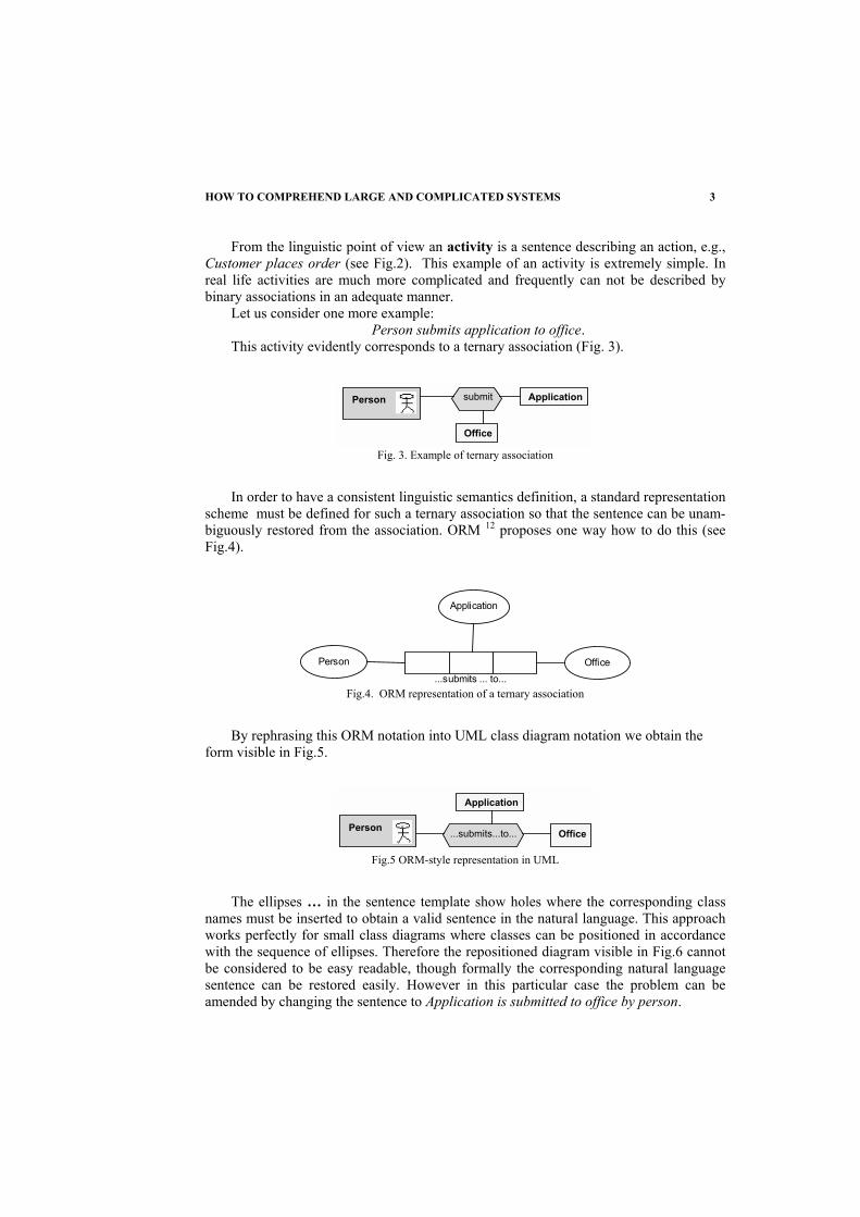
Let us consider one more example: Person submits application to office.
This activity evidently corresponds to a ternary association (Fig. 3).
submit Application
Office
Person
Fig. 3. Example of ternary association
In order to have a consistent linguistic semantics definition, a standard representation scheme must be defined for such a ternary association so that the sentence can be unam-biguously restored from the association. ORM 12 proposes one way how to do this (see Fig.4).
Person
...submits ... to...Office
Application
Fig.4. ORM representation of a ternary association
By rephrasing this ORM notation into UML class diagram notation we obtain the form visible in Fig.5.
...submits...to... Office
Application
Person
Fig.5 ORM-style representation in UML
The ellipses … in the sentence template show holes where the corresponding class names must be inserted to obtain a valid sentence in the natural language. This approach works perfectly for small class diagrams where classes can be positioned in accordance with the sequence of ellipses. Therefore the repositioned diagram visible in Fig.6 cannot be considered to be easy readable, though formally the corresponding natural language sentence can be restored easily. However in this particular case the problem can be amended by changing the sentence to Application is submitted to office by person.

4 J.BARZDINS, A.KALNINS
Application Office Person...submits...to...
Fig.6 Repositioned representation
Another way how to deal with n-ary associations is by means of role names. How-ever the selection of appropriate role names is not easy, there exists a lot of research in the area of ontologies where this issue is discussed. A role name classification appropri-ate for our goals is given by J.Sowa in his book on knowledge representation.14 This classification is based on Aristotle's four causes or aitia, as described in the Metaphysics: Initiator, Resource, Goal, Essence .
Table 1. Role name classification proposed by J.Sowa
Initiator Resource Goal Essence
Action Agent, Instrument Result, Recipient
Patient,
Process Agent, Origin Matter Result,
Recipient Patient,
Transfer Agent, Origin
Instrument,Medium
Experiencer,Recipient Theme
Spatial Origin Path Destination Location
Temporal Start Duration Completion PointInTime
Ambient Origin Instrument,Matter Result Theme
Effector Theme
Theme
Table 1 taken from 14 refines these basic roles for various types of activities (the first
column names these types of activities). Most of the roles in Table 1 are self-explanatory, some comments are necessary on what distinguishes Agent from Effector and Theme from Patient. The difference is that Agent is a voluntary initiator and Effector is an invol-untary initiator of an action. Theme is an essential participant that may be moved, said, or experienced, but which is not structurally changed, but Patient is an essential participant that undergoes some structural change as a result of the activity.
Office
Person submit ApplicationTheme
Recipient
Agent
Fig.7. Representation using standard role names

HOW TO COMPREHEND LARGE AND COMPLICATED SYSTEMS 5
Using these roles, the previous example Person submits application to office can be represented as in Fig.7. The usage of roles has one more advantage. By means of roles it is possible to have a simple description of complicated situations which are hard to de-scribe in natural language (Fig.8).
Error_reportProgram tests
Tester
ThemeResult
Agent
Fig.8. Example of a complicated action
Sometimes it is convenient to represent associations describing activities by separate classes having the stereotype Activity. In this case the usage of standardised role names is even more important.
Flight_Coupon
Ticket
Boarding_PassBoarding_number
Bag_TagBoarding_number
Preparing_of_Boarding_passes
Baggage_checking_and_printing_of_Bag_tags
Check-in_agentPassenger Registration_for_Flight
1..*
has 1
Resource 1..*
Result 1..* Result *
receivesinspects
Agent 1
Fig. 9. Activity decomposition
One more possibility is demonstrated in the example in Fig. 9, namely, the activity decomposition. The activity Registration for Flight is shown to be consisting of smaller activities Preparing of Boarding passes and Baggage checking and printing of Bag tags. Certainly, the activity decomposition can be represented in any typical business-modelling formalism such as ARIS eEPC.15 but components of an activity there require a separate diagram. This is convenient when the decomposition is very complicated, but not so convenient for simple cases, such as the one in Fig. 9.
Ticket
Flight_Coupon
Validation
Boarding_PassBoarding_number
Bag_TagBoarding_number
Preparing_of_Boarding_passes
Baggage_checking_and_printing_of_Bag_tags
1..*
Result 1..* Result *
Theme
1
Fig.10. Control flows

6 J.BARZDINS, A.KALNINS
If a diagram contains several activities, then frequently also the sequence of actions is of great importance. We propose to represent the sequence by an association with the stereotype <<Control flow>>, graphically depicted as a dashed arrow. Fig. 10 shows an example of control flows.
Frequently the flow of activities is branching, depending on various conditions. This can be represented by attaching guard conditions to control flows. These conditions may be informal texts or formal expressions, both enclosed in square brackets, but anyway they must be mutually exclusive. Fig. 11 shows an example of a branching flow.
Assigning_of_Boarding_number
Rejecting_passenger
Registering_late_passenger
TicketValidation
[Flight closed][Ticket OK & Flight open]
[Invalid ticket]Theme
1
Fig. 11. Branching
Guard conditions on associations are useful in other cases too - see Fig. 12.
Person Company
A BCar
works_for 0..1
has
[if works for A]1
Fig. 12. Other case for branching
Class diagram permits also to show the generalisation relation between activities (see Fig. 13) which is useful, though not present in any business modelling language.
Registration_for_Flight Registration_on_Waiting_List
Registration
Fig. 13. Activity generalization
To sum up, there are several reasons why class diagrams should be used for high level conceptual modelling of activities. Firstly, from the first glance it is not always clear which classes really are activities. Secondly, only class diagram permits to depict also the complete environment of activities – what objects are used, on what they depend, who performs the activity, etc. And only class diagram permits to show vital associations be-tween these environment objects. In addition, class diagram permits to represent far more relations between activities themselves, such as containment and generalisation. So, our

HOW TO COMPREHEND LARGE AND COMPLICATED SYSTEMS 7
conclusion is that high level view on business activities should be represented by class diagrams, this representation makes them more readable. Specialised business process diagrams can be used after that step, when the main concepts of a system are already un-derstood and categorised.
4. NEW PREDEFINED CONSTRAINTS FOR ASSOCIATIONS UML contains some predefined constraints for associations, such as {ordered},
{xor}, {subset}. From the formal point of view more predefined constraints are not nec-essary since all imaginable meaningful constraints can be expressed in OCL.16 However our practical experience shows that there are more frequently used constraints for which simple graphical shorthands would be of high value. This is confirmed also by the rich set of predefined constraints in ORM, frequently stated as one of preferences of ORM over UML. The goal of this chapter is to investigate whether these constraints can be naturally transferred to UML without “spoiling” the class diagram notation.
Apparently, without any problems in addition to the existing {xor} constraint new constraints {or} and {x} can be added. The latter one expresses the fact that an instance of A cannot simultaneously have associations of both types p and r (see Fig.14).
C
A
B
r *
{x}
p *
Fig.14. X constraint
This proposal has been already mentioned by Halpin,13 where this issue is discussed in details. The situation with possible generalizations of the {subset} constraint (which exist in the ORM context) is more complicated. In the result of this analysis we propose the following constraint (see Fig.15).
A Br
p
Fig.15. Generalized subset constraint
The meaning of it in the situation of Fig.15 is exactly the same as that of UML {sub-set}. But this new notation can be easily generalized to more complicated situations (see Fig.16). This last notation means that if instances a and b of A and B respectively have a connecting path via C (i.e., there is an appropriate instance of C), then there exists a link p directly connecting a and b. An equivalent OCL statement expressing the same fact would look quite clumsy: A self.B->includesAll (self.C.B)

8 J.BARZDINS, A.KALNINS
The same notation can be used to express relationships between longer paths. The necessity for such constraints is frequent in real examples.
C
A
B
sr
p
Fig.16. A more complicated case of generalized subset
5. EXISTING MODEL STRUCTURING FEATURES AND THEIR USAGE
The main technique for comprehending complicated diagrams (descriptions, models) is their structuring, i.e., their splitting into more or less independent parts and then refin-ing these parts by subdiagrams. However the practical experience shows that conceptual models (class diagrams) for real domains (such as Internet, Web architecture etc) as a rule cannot be split into independent parts, the whole model is one large “cobweb”. Appar-ently this is the reason why the structuring of class diagrams in its classical sense has not been elaborated. For class diagrams a different approach is used, which in a sense com-pensates the lack of classical structuring. Firstly, there are mechanisms of generalisation and aggregation, which form the basis for comprehending complicated class diagrams. Another mechanism for structuring - in a sense a completely new approach to structuring - is the concept of stereotype (though actually the role of stereotype is much wider in UML). By defining appropriate stereotypes and assigning easy distinguishable styles (colours, shapes, icons) to them, we can group semantically close classes in a very read-able way according to their stereotypes.
It is a function of a good support tool to offer specific symbol styles for each of the class stereotypes. Actually, by a symbol style here we mean all its graphical style attrib-utes: shape, icon, background colour, border line style, font styles etc. Similarly, stereo-types for associations and other lines must support all line style elements: line colour, line style, end shapes (arrows etc). It should be noted that the official UML recommendations for graphical stereotype notations (a graphic icon, texture or color) which are typically implemented in tools are far too limited for good conceptual modeling.
The GRADE tool has such extended stereotype support. For example, it has a prede-fined stereotype for the activity (represented by a blue rounded rectangle), and there is an easy facility for defining new stereotypes and assigning styles to them. It should be noted that the formal facility for structuring of UML models is the package mechanism, but it is, in a sense, cutting a large model into pieces by scissors, without any care for semantic independence for fragments (to ascertain, look at the official UML metamodel). The packages are a perfect tool for structuring software design diagrams which must be struc-tured by the very nature of design, but are unacceptable for conceptual modelling.
6. NEW STRUCTURING FEATURE – FRAME
As it was noted in the previous section, traditional structuring mechanisms cannot be used in a proper way for conceptual class diagrams. In this section we offer a principally

HOW TO COMPREHEND LARGE AND COMPLICATED SYSTEMS 9
new structuring feature which we call frame. By frame we understand a rectangle, which can be positioned onto a semantically related class diagram fragment and given a read-able name. The figure 17 displays (part of) a conceptual model of Web architecture (built by J.Rogovs) and frames User, URL, Server, Server software are typical examples of frames. A class diagram enhanced by properly selected frames becomes much more read-able and comprehendible.
It is a bit strange that this concept has not been officially included in UML, because such frames are used in everyday practice when we want to present a readable drawing in any area. For the goals of conceptual modelling, which is not for formal processing by computer, but for human understanding, such a little bit fuzzy concept is quite appropri-ate, if it encourages understanding.
The frame notation becomes especially readable if each frame is assigned a separate colour. The GRADE modelling tool supports the frame feature (it is called there free comment symbol).
7. SOME METHODOLOGICAL ADVICES
Rather comprehensive methodological advices on building class diagrams have al-
ready been given by J.Rumbough 1 and we will not repeat them. We will add just some important items, gained from our practical experience.
1. According to J.Rumbough,1 the building of conceptual class diagram starts with finding the classes. But a new essential criterion for this is offered - only these concepts can be selected for classes, where it is absolutely clear, what are their instances, or in other words, their identity is defined.17 Not always this can be so easy decided. Appar-ently, water can not be used as a class, but ocean can be. In addition, it should be taken into account, that classes may be physical objects (car), abstract concepts (car model, flight) and also activities (testing).
2. When classes are chosen, the saturating of diagram by associations can be started. Again the basic principle must be adhered to, that only these associations whose seman-tics is unambiguous should be added.
3. No anomalies should be directly represented in the class diagram, they can be documented by means of notes (which are official parts of the class diagram).
4. A tool must be used which supports good automatic layouts of class diagrams, since always during the diagram building new classes and associations must be inserted inside the fragments already built. This insertion should never “spoil” the used semantic class positioning principles. If the diagram has 100 or more classes (and real domains are such), it is impossible to draw this diagram “by hand” or by a tool where each class must manually positioned. 8. REQUIREMENTS TO TOOLS FOR CONCEPTUAL MODELLING
Several requirements to tools for adequate support of conceptual modelling were out-lined already in previous sections. In this section we will summarise them and give some more requirements.

10 J.BARZDINS, A.KALNINS
As it was already mentioned, the most important specific requirement for conceptual modelling is a good stereotype support. First, there should be a set of predefined class and association stereotypes corresponding to widely used modelling concepts, with the most accepted symbol shapes assigned to these stereotypes. For example, activity could be represented by a blue rounded rectangle. Typical association shapes could be dashed arrows for an activity sequence, solid arrows for linguistic links etc. On the other hand, there should be a very convenient facility for introduction of new stereotypes (and their corresponding shapes) by the tool user. These stereotypes should be available model-wide, in order to give easily recognisable graphical notations for system-specific concept groups. For example, the stereotypes could be defined in a model-wide stereotype table. To our mind, an additional, stereotype feature would also be desirable, namely, there should be a possibility to attach to a class stereotype a set of predefined attributes. For example, the stereotype position could have predefined attributes competencies, working hours, cost per hour, number of instances. The stereotype definition for activity should have attributes duration and cost. The expected tool support for the feature is such that, when a new class with the given stereotype is created, the predefined attributes are prompted in the attribute definition window and the user can select them and define the relevant attribute values. The current UML version 1.4 offers the mechanism of tagged values attached to a stereotype for this purpose, but none of well-known tools implements this mechanism in a usable way, a direct association of default attributes would be much more convenient for end-user.
There are also two purely tool-technical requirements for conceptual modelling, but experience of GRADE usage has shown their great importance in practice.
First, there must be an easy way to maintain the readability of diagrams, because conceptual models are built for reading by other humans. There can be several solutions to the diagram readability problem. GRADE solves this problem by its powerful con-trolled automatic diagram layout mechanism, based on sophisticated graph drawing algorithms.18 This autolayout mechanism permits the user to insert a new class symbol where it is most desired. The existing symbols and lines are automatically moved, to give the necessary space and avoid any overlapping of the new symbol by existing symbols or lines. The movement is “delicate”, it doesn’t destroy the existing relative placement of symbols. Thus the main graphical aspect of readability – appropriate positioning and clustering of class symbols is supported. Association lines are automatically positioned so that unnecessary line crossings are avoided, thus good traceability of lines is obtained.
Another requirement is a support for large class diagrams. Conceptual models of complicated systems tend to be large because human understanding frequently requires to see the whole “big picture”. GRADE supports maintenance of extra large class diagrams, firstly, by its autolayout mechanism, which works efficiently also for diagrams with hun-dreds of classes. In addition, a special diagram zooming feature is provided, similar to that typically available in camcorders. But for extra large diagrams even this may be in-sufficient. Therefore GRADE supports views for class diagrams. The user can maintain a large diagram via views corresponding to subsystems, then any updates will be automati-cally transferred to other relevant views and to the main diagram.

HOW TO COMPREHEND LARGE AND COMPLICATED SYSTEMS 11
Browser
Resource
User
Server
URL
Server software World Wide Web Architecture Class Diagram
Password
Example_4
Server
Example_5
Example_6
File
<<<mailto:[email protected]>>>Copyright © 2001 by Jevgenijs Rogovs
Searchpart
- human agent (actor)
File_system
Workstation
Username
WWW_browser
Static_resource
Additional_information
Static_pageHTTP_server_software
Embeddable_resource
User
NNTP
FTP
Protocol
WWW
WWW_resource
Displayable_resource
URL
Protocol_name Unified
Resource Locator
Dynamic_image
Static_image
Image
Dynamic_page Hyperlink
Server_file_system
Plug-in_module
World Wide Web
Dynamic_resource
HTML_page
HTTP
Enter
Save
Browser_window
Example_1
Example_2 - auxiliary design entity (abstract class)
Example_3 - action or process
Domain Name System
DNS_name
Resource_path
Authorization_data
Port_number
Netware_Web_Server<<<http://www.novell.com/products/netware/>>>
IIS<<<http://www.microsoft.com/ntserver/web/exec/>>>
Enterprise_Server<<<http://home.netscape.com/enterprise/>>>
iPlanet<<<http://www.sun.com/software/iplanet/>>>
Internet Information Server
Apache<<<http://httpd.apache.org/>>>
Send
- software entity
- hardware entity
- general class
runs_onlocated_on
stored_in
has
has
belongs_to
structure_depends_on
made_accessible_by_running
Agent
Theme
used_to_transmit
identifies
is_identified_by
resides_in
points_to
transmits
Theme
used_to_access
shown_underlined_in
Recipient
uses
Theme
requests
Agent
Agent
Recipientruns_on
used_to_access
is_displayed_by
can_click_on
identifies
provides
connects_to
identifies
identifies
identifies
Recipient
Fig.17 Conceptual model of Web architecture (part)

12 J.BARZDINS, A.KALNINS
One novel idea is to add simple multimedia facilities to the class diagram, more pre-cisely, to add speech. In this way each class could “explain" itself in a spoken text when selected in the tool. The most important feature in this context is the presentation facility where classes and associations are automatically highlighted (by a moving cursor) in the desired order and spoken comments are given accordingly. This feature employs the in-herent human capability to see and listen simultaneously. The automatic highlighting is very useful for understanding large models, since it is the viewing of parts of the diagram in the order conceived by the author that reveals the content in the best way. The presen-tation feature exists in the GRADE tool since the version 4.0.9 in 1999.11 The described feature has its highest value in cases when a conceptual model has to be understood by a reader without the presence of the author, e.g. when a model is downloaded via Internet.
It should be mentioned that in fact the problem here is more general – how to link formal modelling methods with multimedia in order to ease the perception of a model. 9. CONCLUSIONS
Evidently, the conceptual modelling is the main facility for comprehending compli-cated systems (banks, insurance companies, airports etc). In addition to application of conceptual modelling for such important practical goals, we have obtained a good experi-ence in education-related conceptual modelling of Internet architecture, GSM system principles, DCOM component architecture etc. This model building is a very stimulating job for students to understand in details various sophisticated computer-based systems.
REFERENCES 1. J.Rumbaugh, M.Blaha, W.Premerlani, F.Eddy, W.Lorensen, Object-oriented Modeling and Design, Prentice-
Hall (1991) 2. J.Martin, Principles of object-oriented analysis and design, Prentice Hall (1993) 3. G.Booch, I.Jackobson, J.Rumbaugh, The Unified Modeling Language User Guide, Addison-Wesley (1999) 4. H.-E.Eriksson, M.Penker, UML Toolkit, Wiley Computer Publishing (1998) 5. P.Harmon, M.Watson, Understanding UML, Morgan Kaufmann Publishers (1998) 6. C.Larman, Applying UML and Patterns, Prentice-Hall,2nd ed. (2002) 7. P.-A.Muller, Instant UML, Wrox Press Ltd. (1997) 8. I.Jackobson, G.Booch, J.Rumbaugh, The Unified Software Development Process, Addison-Wesley (1999) 9. G.Booch, I.Jackobson, J.Rumbaugh, The Unified Modeling Language Reference Manual, Addison-Wesley
(1999) 10. M.Fowler, UML distilled , Addison-Wesley (1997) 11. GRADE tools; http://www.gradetools.com/ 12. Object Role Modeling ; htpp:// www.orm.net 13. T.Halpin, UML data models from an ORM perspective (part 8), Journal of Conceptual Modeling (April
1999) 14. J.F.Sowa, Knowledge Representation, Brooks/Cole (2000) 15.A.-W. Scheer, ARIS Business Process Modeling, Springer (2000) 16. J.Warmer and A.Kleppe, The Object Constraint Language, Addison-Wesley (1999) 17. N.Guarino and C.Welty, Evaluating Ontological Decisions with ONTOCLEAN, Communications of the
ACM (February, 2002) vol. 45, N.2, p.61-65 18.P.Kikusts, P.Rucevskis, Layout algorithms of graph-like diagrams for GRADE, Windows graphical editors, LNCS (1996), v.1027, p.361-364