How-electric-devices-work-Leviton.pdf - Waterheatertimer.org
226
http://waterheatertimer.org/Basic-house-wiring.html http://waterheatertimer.org/Troubleshoot-household-electricity.html
-
Upload
khangminh22 -
Category
Documents
-
view
0 -
download
0
Transcript of How-electric-devices-work-Leviton.pdf - Waterheatertimer.org
http://waterheatertimer.org/Basic-house-wiring.htmlhttp://waterheatertimer.org/Troubleshoot-household-electricity.html


Introduction ...........................................................................................................................1
Switches ................................................................................................................................3
Dimmers .............................................................................................................................. 25
Motion Sensors.................................................................................................................. 45
Timers .................................................................................................................................. 63
Fan Speed Controls .......................................................................................................... 75
Humidity Sensor and Fan Control .................................................................................. 89
Outlets and USB Charger Devices...............................................................................101
GFCI Outlets ......................................................................................................................119
AFCI Outlets ......................................................................................................................133
Plugs and Connectors....................................................................................................149
Wallplates .........................................................................................................................169
Lamp Sockets and Lampholders .................................................................................181
Adapters ..........................................................................................................................195
Merchandising ................................................................................................................205
Glossary ............................................................................................................................215
Table of Contents
Table of Contents


Introduction PAGE 1
IntroductionLeviton is proud to be a leader in the electrical industry. For over 100 years, Leviton has been delivering groundbreaking products that improve electrical safety, provide energy e�ciency and cost savings and add convenience and value to our daily lives.
This manual has been developed to assist you to better understand the features of Leviton products so you may provide the best customer service possible. It is broken down into the following key product categories: Switches, Dimmers, Motion Sensors, Timers, Fan Speed Controls, Humidity Sensor, Outlets/USB Charger Devices, GFCI, AFCI, Plugs/Connectors, Wallplates, Lamp Sockets/Lampholders and Adapters. Additionally, there is a section covering Merchandising as well as a Glossary of Terms for reference.
In general, you will find references to the following Grades within many product categories. This is important to know when helping customers so they can select the appropriate product for the intended application.
Standard Good – suitable for most household applications
Preferred Better – for high tra�c areas, more features such as improved safety and durability
Professional Best – feature rich for the professional or serious DIY’er
Protection GFCI - helps protect against electrical shocksAFCI - helps protect against electrical fires
Decorative alternative to traditional switches and outlets and adds a finishing touch
Throughout the chapters you may also notice the icons below. They are included for easy reference.
Take some time to familiarize yourself with the contents of this manual and use it as a handy reference on the selling floor. From types of models available to sell-up opportunities, the information provided will help make your sales experience easier and more fulfilling. We also recommend visiting www.learnitatleviton.com where you and your customers can view helpful videos, buying guides, application ideas and more.
IMPORTANT NOTE SELL-UP REMINDER

Don’t just do it yourself, do it with Leviton!A library of resources right at your fingertips...Leviton is dedicated to providing quality resources to help with everything from installations, purchasing decisions, home improvements and safety and energy saving upgrades. Learn it at Leviton o�ers one-click access to the Leviton library of videos, buying guides, interactive tools and more to help both new and seasoned DIY’ers get the job done. Be sure to bookmark www.learnitatleviton.com where support is just a click away!
Video Library
Buying Guides
Interactive Tools
Installation
Energy Savings Calculator AFCI/GFCI Safety Tutorial
Education Home Improvement
By reducing the amount of energy provided to the lighting fixtures they control, dim-mers are an easy and effective way to save energy and extend the life of the bulb. They also offer an ideal way to create ambiance in a room or adjust lighting to meet the requirements of a specific task or activity. There are a number of factors to consider when choosing a dimmer to ensure the desired results are achieved:
1) Dimmer and Bulb Compatibility2) Dimmer Wiring Options – Single Pole,
3-Way, Multi-Location Dimming3) Dimmer Wattage 4) Dimmer Style
Dimmers Buying Guide
Sensors Buying Guide
Occupancy and Vacancy Sensors, which provide automatic switching of lighting and motor loads, are fast becoming a common fixture in both commercial and residential buildings – and with good reason. With regular use they provide convenience, energy savings, increased safety and lower electric bills. However, what many consumers don’t realize is how easily and cost-effectively they can be installed in any room – many times by simply replacing a standard wall switch.
Today, sensors are designed to operate with a wide range of bulbs including Incandescent, CFL, LED, Halogen, and Fluorescent as well as motor loads. It is important to refer to the packaging on the sensor or to the manufacturer website before you make a purchase to be certain the sensor you select will control the type of bulb you intend to use.
Safety Products Buying Guide
Scan this code with your smartphone for a quicklink to www.learnitatleviton.com
IntroductionPAGE 2
Switches PAGE 3
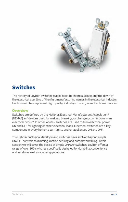
SwitchesThe history of Leviton switches traces back to Thomas Edison and the dawn of the electrical age. One of the first manufacturing names in the electrical industry, Leviton switches represent high quality, industry-trusted, essential home devices.
OverviewSwitches are defined by the National Electrical Manufacturers Association®
(NEMA®) as “devices used for making, breaking, or changing connections in an electrical circuit”. In other words - switches are used to turn electrical power ON and OFF for lighting or other electrical loads. Electrical switches are a key component in every home to turn lights and/or appliances ON and OFF.
Through technological development, switches have evolved beyond simple ON/OFF controls to dimming, motion sensing and automated timing. In this section we will cover the basics of simple ON/OFF switches. Leviton o�ers a range of over 300 switches specifically designed for durability, convenience and safety as well as special applications.


Switches PAGE 5
Grades of SwitchesLeviton has established product grades as a way to clearly define the best application for each product. Always ask customers where they are planning on installing a switch before making a recommendation.
n Good - Basic replacement- Suitable for most household applications
n Better- For high tra�c areas- Heavy duty steel mounting strap- Impact resistant toggle and frame- Back and side wire terminals for
easy installation
n Best - Feature rich for the professional or serious DIY’er- Built to function in the most punishing environments- Meets specification requirements in high
abuse applications
n Decorative - Easily replaces traditional switches- Adds a decorative touch

SwitchesPAGE 6
Types of SwitchesThere are four basic types of switches: single-pole, 3-way, 4-way and double pole. Within this group, there are variations and specialty switches which will be explained later in this handbook.
Single PoleControls light(s)/load from one location.
3-WayControls light(s) from two locations. For example, the ability to turn ON/OFF the same light in a staircase from one location at the bottom of the stairs and another location at the top of the stairs. Two 3-way switches must be used in a 3-way application.
4-Way Controls light(s) from three locations. For example, a room with three entrances has a switch at each entrance that can be used to turn the same ceiling light(s) ON/OFF. One 4-way switch and two 3-way switches must be used in a 4-way application.
Double PoleSwitches two conductors. Commonly used on 240 Volt loads.

Switches PAGE 7
Electrical Ratings of SwitchesEvery Leviton switch has an electrical rating indicated on the device. The electrical rating tells you two important things: the voltage and the maximum electrical load. A typical rating for wall switches is 15 Amp 120VAC but there are also 20 Amp and 30 Amp rated switches.
Switches are often rated at 120 Volts. However, there are some for dual-voltage use rated at BOTH 120 Volts and 277 Volts. Although 277 Volt electrical service is almost never used in a home, it is very common in commercial facilities like stores, o�ces and schools.
n Voltage – Generally, residential wall switches are designed for use on 120 Volt circuits. The voltage rating means the switch can be used only on 120 Volt lines. Preferred, Professional and Decora switches are generally rated 120/277 meaning they can be used on either 120 or 277 Volt lines.Example – A switch rated for 120 Volts must NEVER be used to control 277 Volt household loads.
n Maximum load – The maximum electrical load that the switch can control. Example – A switch stamped 15A-120VAC can have a maximum load of 15 Amps at 120 Volts.
Switches should never be installed to control a load greater than its maximum rating. The majority of switches are 15, 20 or 30 Amps.
SwitchesPAGE 8
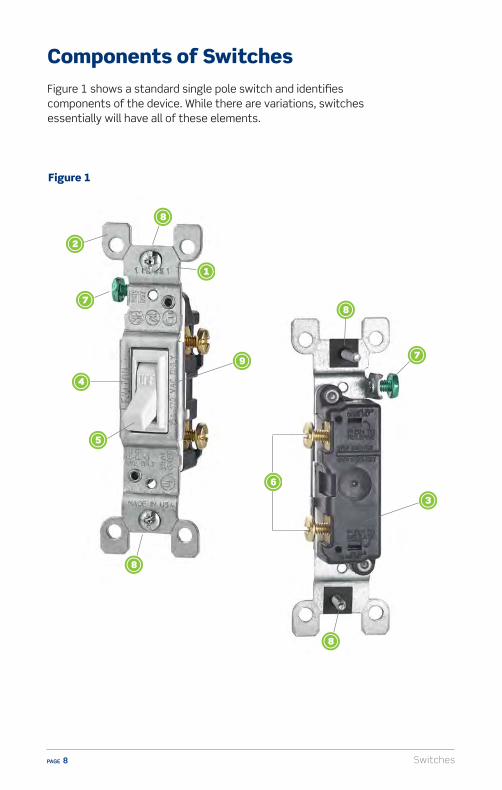
Components of SwitchesFigure 1 shows a standard single pole switch and identifies components of the device. While there are variations, switches essentially will have all of these elements.
Figure 1

Switches PAGE 9
The MOUNTING STRAP is the backbone of the switch. It’s the piece that holds the switch in place within the wallbox and should be sturdy.
The PLASTER EARS are part of the mounting strap and help the switch lay flush with the wall. They can also be removed and used as washers under the mounting strap for leveling.
The BODY is the back part of the switch.
The COVER is the front part of the switch.
The ACTUATOR is what is used to switch lights ON/OFF. In this case, the switch has an ordinary toggle, but Decora® decorative switches have a sleek, low-profile rocker.
The TERMINAL SCREWS are used to connect the wires (called electrical conductors) from a power source to the switch and from the switch to the electrical load it controls.
The green hexagonal GROUND SCREW is fastened to the strap and is used for connecting the switch to the ground wire in the wallbox.
The MOUNTING SCREWS fasten the wired switch in the wallbox and hold it firmly in place.
The RATING is indicated on the device and shows the switch’s electrical rating.
SwitchesPAGE 10
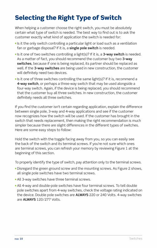
Selecting the Right Type of SwitchWhen helping a customer choose the right switch, you must be absolutely certain what type of switch is needed. The best way to find out is to ask the customer exactly what kind of application the switch is needed for:
n Is it the only switch controlling a particular light or load such as a ventilation fan or garbage disposal? If it is, a single pole switch is needed.
n Is it one of two switches controlling a light(s)? If it is, a 3-way switch is needed. As a matter of fact, you should recommend the customer buy two 3-way switches, because if one is being replaced, its partner should be replaced as well. If the 3-way switches are being used in new construction, the customer will definitely need two devices.
n Is it one of three switches controlling the same light(s)? If it is, recommend a 4-way switch, or perhaps a three-way switch that may be used alongside a four-way switch. Again, if the device is being replaced, you should recommend that the customer buy all three switches. In new construction, the customer definitely needs all three switches.
If you find the customer isn’t certain regarding application, explain the di�erence between single pole, 3-way and 4-way applications and see if the customer now recognizes how the switch will be used. If the customer has brought in the switch that needs replacement, then making the right recommendation is much simpler because there are slight di�erences in the di�erent types of switches. Here are some easy steps to follow:
Hold the switch with the toggle facing away from you, so you can easily see the back of the switch and its terminal screws. If you’re not sure which ones are terminal screws, you can refresh your memory by reviewing Figure 1 at the beginning of this section.
To properly identify the type of switch, pay attention only to the terminal screws.
n Disregard the green ground screw and the mounting screws. As Figure 2 shows, all single pole switches have two terminal screws.
n All 3-way switches have three terminal screws.
n All 4-way and double-pole switches have four terminal screws. To tell double pole switches apart from 4-way switches, check the voltage rating indicated on the device. Double pole switches are ALWAYS 220 or 240 Volts. 4-way switches are ALWAYS 120/277 Volts.

Switches PAGE 11
Switches cannot be interchanged. This means if a customer is replacing a damaged 3-way switch, the new device MUST be another 3-way switch.
3-Way3 screws
4-Way4 screws + check the voltage on the strap – are always 120/277 Volt
Double-Pole4 screws + check the voltage on the strap – are always 220 or 240 Volts
Single Pole2 screws
Figure 2
SwitchesPAGE 12
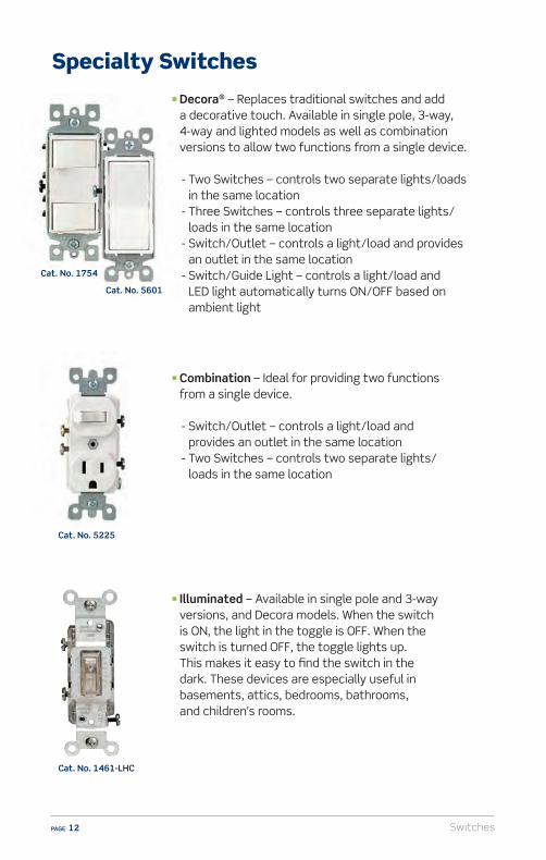
Cat. No. 5225
Cat. No. 1461-LHC
Specialty Switches
n Illuminated – Available in single pole and 3-way versions, and Decora models. When the switch is ON, the light in the toggle is OFF. When the switch is turned OFF, the toggle lights up. This makes it easy to find the switch in the dark. These devices are especially useful in basements, attics, bedrooms, bathrooms, and children’s rooms.
n Combination – Ideal for providing two functions from a single device.
- Switch/Outlet – controls a light/load and provides an outlet in the same location
- Two Switches – controls two separate lights/loads in the same location
Cat. No. 1754
Cat. No. 5601
n Decora® – Replaces traditional switches and add a decorative touch. Available in single pole, 3-way, 4-way and lighted models as well as combination versions to allow two functions from a single device.
- Two Switches – controls two separate lights/loads in the same location
- Three Switches – controls three separate lights/loads in the same location
- Switch/Outlet – controls a light/load and provides an outlet in the same location
- Switch/Guide Light – controls a light/load and LED light automatically turns ON/OFF based on ambient light

Switches PAGE 13
Cat. No. 2651-2
Cat. No. 1221-2L
Cat. No. 5226
n Pilot Light – The special feature of pilot light switches is when the LOAD is ON, the pilot light is illuminated. When the LOAD is OFF, the pilot light is also OFF. Pilot light switches require a neutral wire.
n CO/ALR – Available in single pole and 3-way versions, THESE ARE THE ONLY SWITCHES THAT MAY BE USED WITH ALUMINUM WIRING. The letters CO/ALR are stamped directly on the switch strap, near the rating. The acronym “CO/ALR” is a term that means the device is suitable for use with aluminum wiring. If a customer has aluminum wiring installed or brings in a worn-out CO/ALR switch to buy a replacement, ONLY a CO/ALR switch MUST be recommended. IT IS DANGEROUS AND A VIOLATION OF ELECTRICAL CODES TO USE ANYTHING BUT PROPERLY MARKED CO/ALR DEVICES WITH ALUMINUM WIRING.
n Locking – These switches do not have a toggle. They are commonly used to prevent tampering with switch settings or when unauthorized switching is not permitted. These are most commonly found in commercial or industrial facilities.
SwitchesPAGE 14
Installation and Wiring Considerations
1. If there is any installation where the customer is unsure of how to proceed, or does not feel able to carry out the tasks specified in the wiring device instruction sheets, STOP RIGHT THERE! In such a case always advise the customer to CONSULT AN ELECTRICIAN. Electrical wiring can be complicated, and unless the installation can be properly and safely completed by the customer, the very best plan is to contact an electrician.
2. The information in this manual is here to help you serve your customers. Do not use this information as a substitute for the installation instructions provided with the devices. The instructions contain very specific and detailed directions for the device they’re packed with. Use this guide as a general reference, but familiarize yourself with the specific instruction sheets for the devices your customers will be asking about.
3. Remind your customers that in order to prevent death or injury before they begin any wiring project, THEY MUST TURN OFF POWER AT THE FUSE OR CIRCUIT BREAKER THAT SUPPLIES ELECTRICITY TO THE WIRES THEY WILL BE WORKING WITH. And after they complete their installation, they should restore power at the fuse or circuit breaker and verify that the new device is working properly. If the fuse blows or the circuit breaker trips when power is restored, or if the new device doesn’t seem to be working properly the customer should immediately contact an electrician.
4. Be sure only properly rated devices are chosen for replacement and repair projects.
For instance, a 3-way switch MUST be replaced only with another 3-way switch. Although a single pole switch may look similar it wouldn’t be a suitable replacement.
Also, if devices are being installed on a 15 Amp branch circuit, then only 15 Amp devices may be used. Using a 20 Amp device on a 15 Amp branch circuit is potentially dangerous, and must be avoided. However, it is acceptable to use 15 Amp devices on a 20 Amp circuit.

Switches PAGE 15
There are three common ways to wire switches, side wire, back wire and QuickwireTM. Note all three wiring methods comply with electrical codes.
Side Wiring
Back Wiring
Leviton Quickwire™
Uses the side terminal screws
Uses the screw- and-clamp system
Uses the backwire push-in feature also referred to as “backstab”
Wire is stripped and looped around the side terminal screw
The screw-and-clamp mechanism securely holds the wire in place
The Quickwire hole accepts 14 gauge solid wire ONLY
The terminal screw is then tightened down on the wire
The screw is then tightened down on the wire
The wire is inserted directly into the Quickwire hole on the back of the device
SwitchesPAGE 16
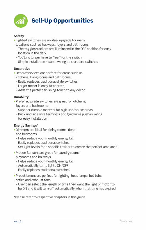
Safety n Lighted switches are an ideal upgrade for many
locations such as hallways, foyers and bathrooms - The toggles/rockers are illuminated in the OFF position for easy
location in the dark - You’ll no longer have to “feel” for the switch - Simple installation – same wiring as standard switches
Decorativen Decora® devices are perfect for areas such as
kitchens, living rooms and bathrooms - Easily replaces traditional style switches - Larger rocker is easy to operate - Adds the perfect finishing touch to any décor
Durabilityn Preferred grade switches are great for kitchens,
foyers and bathrooms - Superior durable material for high use/abuse areas - Back and side wire terminals and Quickwire push-in wiring
for easy installation
Energy Savings*n Dimmers are ideal for dining rooms, dens
and bedrooms - Helps reduce your monthly energy bill - Easily replaces traditional switches - Set light levels for a specific task or to create the perfect ambiance
n Motion Sensors are great for laundry rooms, playrooms and hallways
- Helps reduce your monthly energy bill - Automatically turns lights ON/OFF - Easily replaces traditional switches
n Preset timers are perfect for lighting, heat lamps, hot tubs, attics and exhaust fans
- User can select the length of time they want the light or motor to be ON and it will turn o� automatically when that time has expired
*Please refer to respective chapters in this guide.
Sell-Up Opportunities
Switches PAGE 17
Kitchen
Living Room
Dining Room
Bedroom
Foyer
Basement
Hallway
Laundry Room
Closet
Staircase
Utility Room
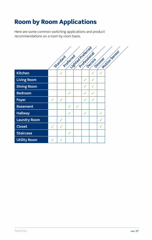
Room by Room Applications
Here are some common switching applications and product recommendations on a room by room basis.
Standard
Prefe
rred
Profe
ssional
DecoraDim
mer
Motion Senso
r
Lighte
d Prefe
rred
SwitchesPAGE 18
Q: What is a Single Pole, 3-Way and 4-Way switch?
A: Single Pole - Standard ON/OFF switch - Controls one light(s)/load, such as ventilation fans or garbage
disposals from one location - 2 screw terminals
A: 3-Way - Controls one light(s) from two locations - Example, a light controlled from either end of a stairway or hallway - 3-way installations require two 3-way switches - 3 screw terminals; one is black or marked “COMMON”
A: 4-Way - Allows control of light(s) from three locations in large rooms
or hallways - 4-way installations require one 4-way and two 3-way switches - 4 screw terminals; two are black
Q: When should I replace a switch?
A: Toggle is loose and doesn’t stay in ON position - Switch feels warm, buzzes or produces a spark - For a stylish upgrade from toggle to Decora switches
Q: When are CO/ALR devices required?
A: If your home has aluminum wiring, you must use CO/ALR switches - Terminal screws on CO/ALR devices are made of special materials
and are designed to terminate aluminum wires - Never connect standard devices to aluminum wiring – this is a
dangerous code violation that increases the likelihood of electrical arcing, short circuits, fire and shock
FAQs (Frequently Asked Questions)

Switches PAGE 19
(Frequently Asked Questions)Resources
Video library, buying guides and more
www.learnitatleviton.com
Still have questions?Contact our Technical Support Team
1-800-824-3005
Need to place a special order?Contact Customer Service
1-800-367-5424
www.leviton.com
Training Notes

SwitchesPAGE 20
1. How are 3-way switches di�erent from a single pole switch?A) They control two lights from one locationB) They control three lights from one locationC) They control one light(s) from two locationsD) They control only motors
2. Features of Preferred grade Leviton switches include:A) Heavy-duty steel mounting strapB) Impact resistant toggle and frameC) Back and side wire terminals or Quickwire push-in wiring
for easy installationD) All of the above
3. How can you identify the di�erent types of switches?A) By sizeB) By toggleC) By voltageD) By terminal screws
4. Which is the only type of switch that can be used with aluminum wiring?A) Single poleB) A switch marked CO/ALRC) A switch marked UL/CSAD) None of the above
5. Which Leviton switch has a large decorative rocker?A) DecoraB) Triple-gangC) CO/ALRD) None of the above
Switches – Self Test Questions
Switches PAGE 21
6. How can you verify the electrical rating of any switch?A) It’s indicated on the deviceB) With a Volt meterC) By using an AmmeterD) None of the above
7. What is the green hexagonal screw on the switch mounting strap?A) The wallplate screwB) The adjustment screwC) The ground screwD) The wallbox screw
8. When a lighted switch is OFF, will the toggle/rocker be illuminated or not?A) LightedB) Not lighted
9. What are the specialty switches that provide more than one function in a single device?A) Lighted switchesB) Combination switchesC) Locking switchesD) All of the above
Switches – Self Test Questions
SwitchesPAGE 22
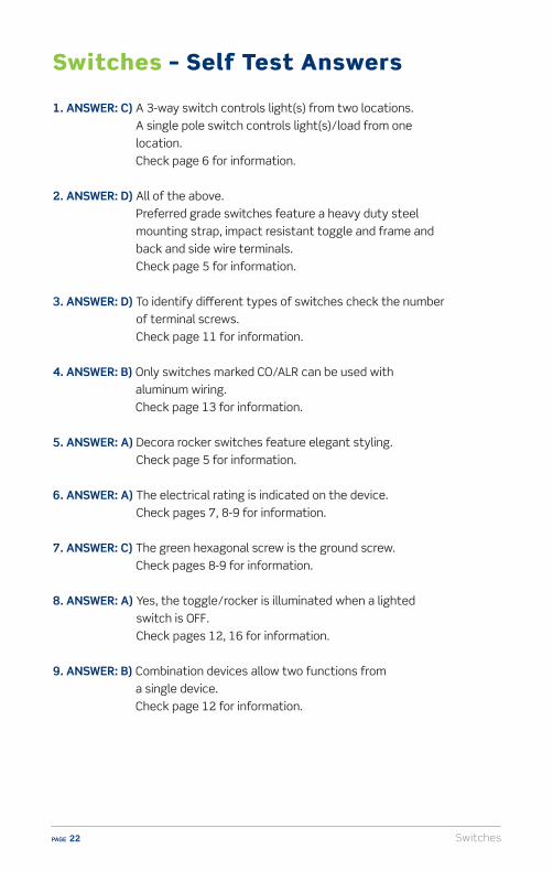
1. ANSWER: C) A 3-way switch controls light(s) from two locations. A single pole switch controls light(s)/load from one location. Check page 6 for information.
2. ANSWER: D) All of the above. Preferred grade switches feature a heavy duty steel mounting strap, impact resistant toggle and frame and back and side wire terminals. Check page 5 for information.
3. ANSWER: D) To identify di�erent types of switches check the number of terminal screws. Check page 11 for information.
4. ANSWER: B) Only switches marked CO/ALR can be used with aluminum wiring. Check page 13 for information.
5. ANSWER: A) Decora rocker switches feature elegant styling. Check page 5 for information.
6. ANSWER: A) The electrical rating is indicated on the device. Check pages 7, 8-9 for information.
7. ANSWER: C) The green hexagonal screw is the ground screw. Check pages 8-9 for information.
8. ANSWER: A) Yes, the toggle/rocker is illuminated when a lighted switch is OFF. Check pages 12, 16 for information.
9. ANSWER: B) Combination devices allow two functions from a single device. Check page 12 for information.
Switches – Self Test Answers


Dimmers PAGE 25
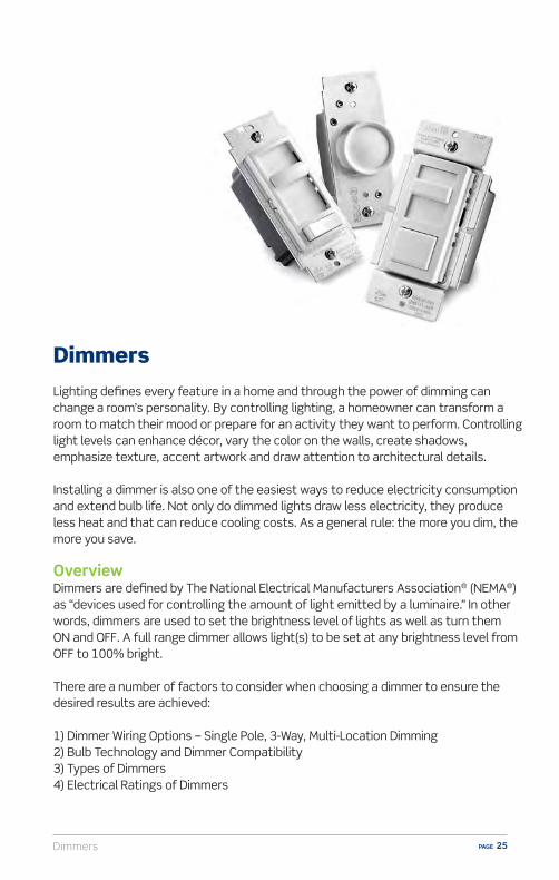
DimmersLighting defines every feature in a home and through the power of dimming can change a room’s personality. By controlling lighting, a homeowner can transform a room to match their mood or prepare for an activity they want to perform. Controlling light levels can enhance décor, vary the color on the walls, create shadows, emphasize texture, accent artwork and draw attention to architectural details.
Installing a dimmer is also one of the easiest ways to reduce electricity consumption and extend bulb life. Not only do dimmed lights draw less electricity, they produce less heat and that can reduce cooling costs. As a general rule: the more you dim, the more you save.
OverviewDimmers are defined by The National Electrical Manufacturers Association® (NEMA®) as “devices used for controlling the amount of light emitted by a luminaire.” In other words, dimmers are used to set the brightness level of lights as well as turn them ON and OFF. A full range dimmer allows light(s) to be set at any brightness level from OFF to 100% bright.
There are a number of factors to consider when choosing a dimmer to ensure the desired results are achieved:
1) Dimmer Wiring Options – Single Pole, 3-Way, Multi-Location Dimming2) Bulb Technology and Dimmer Compatibility 3) Types of Dimmers4) Electrical Ratings of Dimmers
DimmersPAGE 26
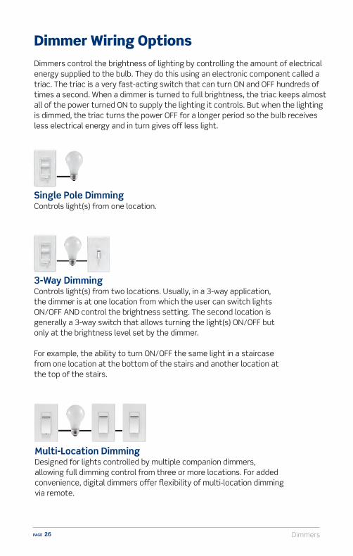
Dimmer Wiring OptionsDimmers control the brightness of lighting by controlling the amount of electrical energy supplied to the bulb. They do this using an electronic component called a triac. The triac is a very fast-acting switch that can turn ON and OFF hundreds of times a second. When a dimmer is turned to full brightness, the triac keeps almost all of the power turned ON to supply the lighting it controls. But when the lighting is dimmed, the triac turns the power OFF for a longer period so the bulb receives less electrical energy and in turn gives o� less light.
Multi-Location DimmingDesigned for lights controlled by multiple companion dimmers, allowing full dimming control from three or more locations. For added convenience, digital dimmers o�er flexibility of multi-location dimming via remote.
3-Way Dimming Controls light(s) from two locations. Usually, in a 3-way application, the dimmer is at one location from which the user can switch lights ON/OFF AND control the brightness setting. The second location is generally a 3-way switch that allows turning the light(s) ON/OFF but only at the brightness level set by the dimmer.
For example, the ability to turn ON/OFF the same light in a staircase from one location at the bottom of the stairs and another location at the top of the stairs.
Single Pole DimmingControls light(s) from one location.

Dimmers PAGE 27
Bulb Technology and Dimmer Compatibility Incandescent bulbs are gradually taking a back seat to energy e�cient bulb technology such as LEDs (Light Emitting Diode) and CFLs (Compact Fluorescent Lamp). These new bulbs provide homeowners greater savings and benefits due to more e�cient energy performance. When homeowners use an energy e�cient bulb, whether LED or CFL, they expect smooth operating performance similar to what they are familiar with when using incandescent bulbs. Currently, that is not always the case. Although some LED and CFL bulbs are marked as compatible with incandescent dimmers, there are varying degrees of what may be defined as truly “compatible”.
Many bulb suppliers publish a compatibility listing in hard copy as well on their website. If you encounter an issue with a specific brand of bulb, be sure to check with that manufacturer’s resources first.
Examples of what may occur when an incandescent dimmer is paired with LED or CFL bulbs include:n Reduced dimming rangen Flickering of the bulbn Inconsistent performance based on the number and type
of bulbs usedn Unable to start at low light levels
Leviton Universal Dimmers provide a solution and are available in multiple styles consumers can choose from for optimized performance with dimmable LED and CFL bulbs.
When choosing an energy e�cient bulb, shopping by lumens is more important than shopping by watts. Lumens measure the amount of light you are getting from a bulb. More lumens mean a brighter light; fewer lumens mean a less bright light. The new Lighting Facts Label will help. This new label makes it easy to compare bulb brightness, color, life and estimated operating cost for the year.
For example, to replace a 100W incandescent bulb, look for an energy e�cient bulb that gives you about 1600 lumens. If you want something dimmer, go for less lumens; if you prefer brighter light, look for more lumens.
Lighting Facts Per Bulb
Based on 3 hrs/day, 11¢/kWh
Based on 3 hrs/day
Warm
2700 K
Cool
Cost depends on rates and use
Brightness
Light Appearance
Energy Used 60 watts
Estimated Yearly Energy Cost $7.23
Life
820 lumens
1.4 years
DimmersPAGE 28
Types of Dimmers
With the wide variety of bulbs now available on the market it is important to choose a dimmer wisely since not all dimmers are designed to control all types of bulbs. It is important to know the features of the types of dimmers available and compare them to the needs of your customer and the type of bulb they wish to use.
Universal Dimmers are designed to control dimmable LED, dimmable CFL, incandescent and halogen bulbs. They o�er full-range dimming, smooth start-up and eliminate flickering and fluttering of lights. When using LED or CFL bulbs with a dimmer, be sure the packaging on the bulb indicates that it is DIMMABLE. Most dimmer and bulb manufacturers provide bulb compatibility information on their websites to ensure that the brand/type of dimmer chosen will function properly with the bulb selected.
Incandescent/Halogen Dimmers are designed to control incandescent and halogen bulbs. They are not designed to control dimmable LED and CFL bulbs and using them to do so may result in inconsistent or limited performance.
Electronic Low Voltage Dimmers (ELV) control electronic low voltage transformers (ELVs) and dimmable LED power supplies such as those found in ELV track lighting, recessed lighting, under cabinet lighting and LED strips. ELV dimmers require a neutral wire for installation.
Magnetic Low Voltage Dimmers (MLV) are typically used for track or under cabinet lighting which are most often magnetic low voltage.
Fluorescent Dimmers control only fluorescent fixtures that incorporate rapid start fluorescent lamps and dimming ballasts.
High Wattage Dimmers are specifically designed to control high wattage lighting. A 1000W dimmer should be used to control any lighting exceeding 600 Watts. This would include large chandeliers or recessed lighting that controls multiple bulbs with total wattage exceeding 600 Watts.
Dimmers PAGE 29
Electrical Ratings of Dimmers
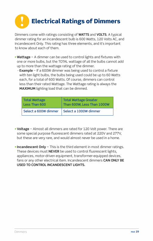
Dimmers come with ratings consisting of WATTS and VOLTS. A typical dimmer rating for an incandescent bulb is 600 Watts, 120 Volts AC, and Incandescent Only. This rating has three elements, and it’s important to know about each of them.
n Wattage − A dimmer can be used to control lights and fixtures with one or more bulbs, but the TOTAL wattage of all the bulbs cannot add up to more than the wattage rating of the dimmer.- Example − If a 600W dimmer was being used to control a fixture
with ten light bulbs, the bulbs being used could be up to 60 Watts each, for a total of 600 Watts. Of course, dimmers can control less than their rated Wattage. The Wattage rating is always the MAXIMUM lighting load that can be dimmed.
n Voltage − Almost all dimmers are rated for 120 Volt power. There are some special purpose fluorescent dimmers rated at 220V and 277V, but these are very rare, and would almost never be used in a home.
n Incandescent Only − This is the third element in most dimmer ratings. These devices must NEVER be used to control fluorescent lights, appliances, motor-driven equipment, transformer-equipped devices, fans or any other electrical item. Incandescent dimmers CAN ONLY BE USED TO CONTROL INCANDESCENT LIGHTS.
Total Wattage Less Than 600
Total Wattage Greater Than 600W, Less Than 1000W
Select a 600W dimmer Select a 1000W dimmer

DimmersPAGE 30
Ganging and Derating
When dimmers are operating normally, they may feel warm to the touch. Moreover, the greater the wattage of lighting being controlled, the warmer the dimmer may be.n Example − A dimmer controlling 500 Watts of lighting will be slightly
warmer than an identical dimmer controlling only 120 Watts of lighting.
When dimmers are ganged, meaning installed side by side in the same wallbox, their temperature could rise too high if both units are controlling their maximum rated Wattage. To prevent overheating, the dimmers installed this way must be “derated”. This means the maximum allowable wattage is reduced for each dimmer.n Example − If two 600 Watt dimmers are ganged, then each must be
derated to 500 Watts. If three or more are ganged together, then all must be derated to 400 Watts. The actual derating necessary for any particular dimmer is clearly explained in the instructions provided with the dimmer.
DIMMER TYPE
1 DIMMER 2 DIMMERS 3 DIMMERS
Incandescent 600W per dimmer
500W per dimmer
400W per dimmer
Universal 600W incandescent 150W Dimmable LED/CFL Per dimmer
500W incandescent150W Dimmable LED/CFLPer dimmer
400W incandescent150W Dimmable LED/CFLPer dimmer
Electronic Low Voltage
400VA (320W) per dimmer
350VA (280W) per dimmer
250VA (200W) per dimmer
De-Rating Chart for Types of Dimmers

Dimmers PAGE 31
Installation and Wiring Considerations
1. If there is any installation where the customer is unsure of how to proceed, or does not feel able to carry out the tasks specified in the wiring device instruction sheets, STOP RIGHT THERE! In such a case always advise the customer to CONSULT AN ELECTRICIAN. Electrical wiring can be complicated, and unless the installation can be properly and safely completed by the customer, the very best plan is to contact an electrician.
2. The information in this manual is here to help you serve your customers. Do not use this information as a substitute for the installation instructions provided with the devices. The instructions contain very specific and detailed directions for the device they’re packed with. Use this guide as a general reference, but familiarize yourself with the specific instruction sheets for the devices your customers will be asking about.
3. Remind your customers that in order to prevent death or injury before they begin any wiring project, THEY MUST TURN OFF POWER AT THE FUSE OR CIRCUIT BREAKER THAT SUPPLIES ELECTRICITY TO THE WIRES THEY WILL BE WORKING WITH. And after they complete their installation, they should restore power at the fuse or circuit breaker and verify that the new device is working properly. If the fuse blows or the circuit breaker trips when power is restored, or if the new device doesn’t seem to be working properly the customer should immediately contact an electrician.
4. Be sure only properly rated devices are chosen for replacement and repair projects.
For instance, a 3-way device MUST be replaced only with another 3-way device. Although a single-pole device may look similar it wouldn’t be a suitable replacement.
Also, if devices are being installed on a 15 Amp branch circuit, then only 15 Amp devices may be used. Using a 20 Amp device on a 15 Amp branch circuit is potentially dangerous, and must be avoided. However, it is acceptable to use 15 Amp devices on a 20 Amp circuit.

DimmersPAGE 32
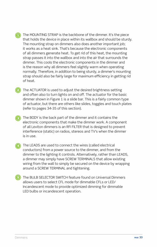
Components of DimmersFigure 1 shows a Leviton slide dimmer and identifies several components of the device. There are some variations, but basically all dimmers have these elements.
Figure 1
Dimmers PAGE 33
The MOUNTING STRAP is the backbone of the dimmer. It’s the piece that holds the device in place within its wallbox and should be sturdy. The mounting strap on dimmers also does another important job; it works as a heat sink. That’s because the electronic components of all dimmers generate heat. To get rid of this heat, the mounting strap passes it into the wallbox and into the air that surrounds the dimmer. This cools the electronic components in the dimmer and is the reason why all dimmers feel slightly warm when operating normally. Therefore, in addition to being sturdy, a dimmer’s mounting strap should also be fairly large for maximum e�ciency in getting rid of heat.
The ACTUATOR is used to adjust the desired brightness setting and often also to turn lights on and o�. The actuator for the basic dimmer shown in Figure 1 is a slide bar. This is a fairly common type of actuator, but there are others like slides, toggles and touch plates (refer to pages 34-35 of this section).
The BODY is the back part of the dimmer and it contains the electronic components that make the dimmer work. A component of all Leviton dimmers is an RFI FILTER that is designed to prevent interference (static) on radios, stereos and TV’s when the dimmer is in use.
The LEADS are used to connect the wires (called electrical conductors) from a power source to the dimmer, and from the dimmer to the lighting it controls. Alternatively, rather than LEADS, a dimmer may simply have SCREW TERMINALS that allow existing wiring from the wall to simply be secured on the device by wrapping around a SCREW TERMINAL and tightening.
The BULB SELECTOR SWITCH feature found on Universal Dimmers allows users to select CFL mode for dimmable CFLs or LED/Incandescent mode to provide optimized dimming for dimmable LED bulbs or incandescent operation.

DimmersPAGE 34
Dimmer StylesDimmers come in a variety of styles to meet both the decorative and functional needs of the user.
n Slide with Preset – This contemporary design utilizes a slide bar to control the level of light. The ON/OFF function varies by model and may be either a rocker switch or push button. The ON/OFF function preserves the dimming level.
n Rotary – Traditional in appearance, a rotary dimmer switches lights ON/ OFF by either turning or pushing the knob. Once the lights are ON, lighting may be adjusted to the desired level.
n Slide – This sleek style features slide-to-OFF functionality for users who choose to adjust lighting levels each time the device is used.
SureslideCat. No. 6674
IllumatechCat. No. IPL06
Cat. No. 6672
Cat. No. 6681
IllumatechCat. No. IPL06

Dimmers PAGE 35
Lamp Dimmers – These devices are designed to provide dimming control for plug-in lamps rather than for lighting fixtures. They come in three styles:
Cat. No. TGI06
n Toggle – Resembles the traditional toggle switch and features two touch pads alongside the ON/OFF toggle for dimming and brightening lights. Some models utilize the actual toggle to control dimming.
n Tabletop – The cord of this dimmer is plugged into the outlet. Then the cord from the lamp is plugged into an outlet on the dimmer and the dimmer sits on a table or desk providing easy access to regulate the level of light desired. No wiring is required.
n Cord – These dimmers are installed directly on the line cord of any plug-in lamp.
n Socket – Replaces standard bulb holder on lamps for dimmer conversion. Allows ON/OFF switching and dimming control of lamps using a turn knob.
Cat. No. TBL06
Cat. No. 1420
Cat. No. 6151

DimmersPAGE 36
Dimmers have come a long way from the basic rotary style. Today, stylish Decora® dimmers enhance any room with their clean, contemporary lines and seamless operation. And, our Universal Dimmers are ideal for controlling all current and emerging bulbs including incandescent, dimmable CFLs, and dimmable LEDs – a simple way to “futureproof” home lighting.
Decorativen With a variety of styles and designs, dimmers add a stylish
and modern look to our homes.
Dimmers vs. Switchesn Setting the lights at a lower level than 100% saves on energy costs.
Remember, not every task nor moment indoors requires a fully bright light.n Dimming allows users the ability to customize their environment,
creating the ambiance that the occasion calls for.
Leviton Advantagen Leviton is an industry leader with over 100 years of history. Reliability
of Leviton dimmers provides customers with confidence they are buying a quality product.
n Leviton is committed to “universal control” of all types of residential bulbs a consumer might use.
n Built-in “smart technology” in Leviton Universal dimmers can identify the type of bulb a device is controlling for seamless operation.
Sell-Up Opportunities
Dimmers PAGE 37
Room by Room Applications
Bedroom/Children’s RoomDimmers provide an ideal solution for comfort lighting for children. At bedtime, lights can be dimmed so children are not left in a dark room. Dimmers also o�er an easy way for parents to check in on sleeping children without waking them – simply raise the light level slightly to see that everything is okay and then turn back down.
BathroomBathroom lighting loads are often overlooked as an area to install a dimmer yet they are an ideal place to use one. Di�erent tasks have unique lighting level requirements ranging from full on for make-up and shaving to a dimmed level for a relaxing bath or midnight bathroom trip.
Dining RoomsDimmers are a standard lighting control for dining rooms to create ambiance.
KitchensCooking, cleaning, eating and doing homework: there’s a lot going on in the typical kitchen and various tasks require varying lighting levels. In a large kitchen, there may be several banks of lights for illuminating di�erent areas.
O�ce/Dens/Home TheatersToday’s homes often have dedicated o�ces requiring lighting appropriate to the task – from brighter lights for paperwork to lower levels to reduce glare on computer screens.
DimmersPAGE 38
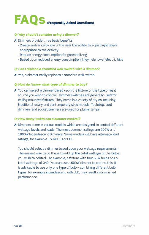
Q: Why should I consider using a dimmer?
A: Dimmers provide three basic benefits: - Create ambiance by giving the user the ability to adjust light levels
appropriate to the activity - Reduce energy consumption for greener living - Based upon reduced energy consumption, they help lower electric bills
Q: Can I replace a standard wall switch with a dimmer?
A: Yes, a dimmer easily replaces a standard wall switch.
Q: How do I know what type of dimmer to buy?
A: You can select a dimmer based upon the fixture or the type of light source you wish to control. Dimmer switches are generally used for ceiling mounted fixtures. They come in a variety of styles including traditional rotary and contemporary slide models. Tabletop, cord dimmers and socket dimmers are used for plug-in lamps.
Q: How many watts can a dimmer control?
A: Dimmers come in various models which are designed to control di�erent wattage levels and loads. The most common ratings are 600W and 1000W Incandescent Dimmers. Some models will have alternate load ratings, for example 150W LED or CFL. You should select a dimmer based upon your wattage requirements. The easiest way to do this is to add up the total wattage of the bulbs you wish to control. For example, a fixture with four 60W bulbs has a total wattage of 240. You can use a 600W dimmer to control this. It is advisable to use only one type of bulb – combining di�erent bulb types, for example incandescent with LED, may result in diminished performance.
FAQs (Frequently Asked Questions)

Dimmers PAGE 39
Q: What is a Universal Dimmer?
A: Universal Dimmers are designed to control incandescent, dimmable LED and dimmable CFL bulbs. They offer full-range dimming, smooth start-up, and eliminate flickering and fluttering of lights.
Q: How does a Universal Dimmer differ from an Incandescent Dimmer?
A: Incandescent Dimmers are designed to control incandescent bulbs. Unlike Universal Dimmers, they are not designed to control LED and CFL bulbs and using them to do so may result in inconsistent or limited performance.
Q: What are the benefits of using a Universal LED/CFL compatible dimmer?
A: The benefits of using this dimmer include smooth operation for precise dimming, low level starting and flicker-free operation when used with incandescent and dimmable LED/CFL bulbs. It is designed to provide optimized performance when used on dimmable LED or dimmable CFL bulbs. Even if you are currently using Incandescent bulbs, you can future proof by installing a Universal Dimmer to ensure compatibility in the future with dimmable LED/CFL bulbs.
Q: What types of bulbs can be used with Universal Dimmers?
A: Dimmable LEDs, dimmable CFLs, incandescent and halogen bulbs are all compatible with Universal Dimmers. It is recommended that only LED and CFL bulbs that are labeled as DIMMABLE be used with Universal Dimmers. The packaging on the bulb should identify it as dimmable.
DimmersPAGE 40
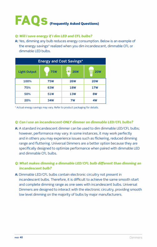
Q: Will I save energy if I dim LED and CFL bulbs?A: Yes, dimming any bulb reduces energy consumption. Below is an example of
the energy savings* realized when you dim incandescent, dimmable CFL or dimmable LED bulbs.
* Actual energy savings may vary. Refer to product packaging for details.
Q: Can I use an incandescent-ONLY dimmer on dimmable LED/CFL bulbs?
A: A standard incandescent dimmer can be used to dim dimmable LED/CFL bulbs; however, performance may vary. In some instances, it may work perfectly and in others you may experience issues such as flickering, reduced dimming range and fluttering. Universal Dimmers are a better option because they are specifically designed to optimize performance when paired with dimmable LED and dimmable CFL bulbs.
Q: What makes dimming a dimmable LED/CFL bulb different than dimming an incandescent bulb?
A: Dimmable LED/CFL bulbs contain electronic circuitry not present in incandescent bulbs. Therefore, it is difficult to achieve the same smooth start and complete dimming range as one sees with incandescent bulbs. Universal Dimmers are designed to interact with the electronic circuitry, providing smooth low level dimming on the majority of bulbs by major manufacturers.
FAQs (Frequently Asked Questions)
Energy and Cost Savings*
Light Output 75W 26W 20W
100% 75W 26W 20W
75% 63W 18W 17W
50% 51W 13W 8W
20% 34W 7W 4W

Dimmers PAGE 41
Q: What is the difference between single pole and 3-way applications?
A: Single pole controls one light(s) from one location. 3-way allows control of one light(s) from two locations (example: the ability to control the same fixture from a switch at the top of a staircase and from another switch at the bottom of the staircase).
Q: Sometimes the bulbs make a buzzing sound when I use my dimmer. What
can I do about this?
A: Filament hum is caused by the way dimmers control power to the bulb and is typically a problem with inexpensive bulbs. Upgrade to higher quality, name brand bulbs to eliminate or greatly reduce hum.
Q: Can a dimmer control a ceiling fan?
A: No. A dimmer can damage the motor in a ceiling fan. There are controls designed specifically to control ceiling fans and they are generally called fan speed controls.
Q: Is derating required when installing more than one dimmer in the same wallbox?
A: Derating may be required if you have two or more dimmers sharing a wallbox. If you install more than one dimmer next to each other and are using incandescent bulbs, it is required that you reduce the load that each dimmer can control (derating). No derating is required when using dimmable LED or dimmable CFL bulbs in multi-dimmer installations. Refer to the derating chart in the dimmer instructions for maximum load per dimmer.
DimmersPAGE 42
1. A benefit of dimmers in the home is:A) Mood lightingB) Saving energy resulting in reduced electric billsC) Longer bulb lifeD) All of the above
2. Which two elements are in incandescent dimmer electrical ratings? A) Bright and dim B) Watts and volts C) Amps and Watts D) Watts and dimming
3. What is a full-range dimmer?A) Provides any brightness level from OFF to 100% brightB) Changes brightness settings for plug-in lamps onlyC) Changes brightness when Amperage changesD) None of the above
4. What is derating?A) Reducing the maximum Wattage of dimmers when two or more are installed in one wallboxB) Reducing the Voltage for the controlled light fixtureC) Reducing the Amperage and Voltage of multiple light fixturesD) Installing more than one dimmer to control multiple lights
5. In addition to holding the dimmer in place within the wallbox, what other job does the mounting strap do?
A) It derates the dimmerB) It holds the terminalsC) It removes heat from dimmer circuitryD) None of the above
Dimmers – Self Test Questions

Dimmers PAGE 43
ResourcesVideo library, buying guides and more
www.learnitatleviton.com
Still have questions?Contact our Technical Support Team
1-800-824-3005
Need to place a special order?Contact Customer Service
1-800-367-5424
www.leviton.com
Training Notes
DimmersPAGE 44
1. ANSWER: D) Benefits of dimmers in the home are: mood lighting, saving energy for reduced electric bills and longer bulb life. Check pages 25, 36, 30 for information.
2. ANSWER: B) Watts and Volts are two elements in incandescent dimmer electrical ratings. Check page 29 for information.
3. ANSWER: A) A full range dimmer allows light(s) to be set at any brightness level from OFF to 100% bright. Check page 25 for information.
4. ANSWER: A) Derating is reducing the maximum Wattage of dimmers when two or more are installed in one wallbox. Check page 30 for information.
5. ANSWER: C) In addition to holding the dimmer in place within the wallbox, the mounting strap removes heat from the dimmer circuitry. Check pages 32-33 for information.
Dimmers – Self Test Answers

Motion Sensors PAGE 45
Motion SensorsMotion sensors, which provide automatic switching of lighting and motor loads, are fast becoming a common fixture in both residential and commercial environments – and with good reason. With regular use they provide convenience, energy savings, increased safety and lower electric bills. However, what many consumers don’t realize is how easily and cost-e�ectively they can be installed in any room – many times by simply replacing a standard wall switch.
OverviewToday’s sensors are designed to operate with a wide range of bulbs including LED, CFL, Incandescent, Halogen and Fluorescent as well as motor loads.Automatic-On sensors automatically turn lights ON/OFF. They provide the convenience of hands-free switching which can prove very useful in rooms where a homeowner might have their hands full like a laundry room or garage. Manual-On (Vacancy) sensors, which require the user to manually turn the switch ON but will switch OFF automatically, are practical in high tra�c areas such as hallways, children’s rooms and bathrooms. Although convenience remains the most compelling feature with homeowners, the energy savings and reduced frequency of bulb replacement over time can also provide significant savings. Actual energy savings from sensors vary greatly depending on usage patterns and occupant habits. And, the ease of installation makes sensors a cost e�ective and viable energy saving alternative in both new construction and retrofit applications.
Motion SensorsPAGE 46
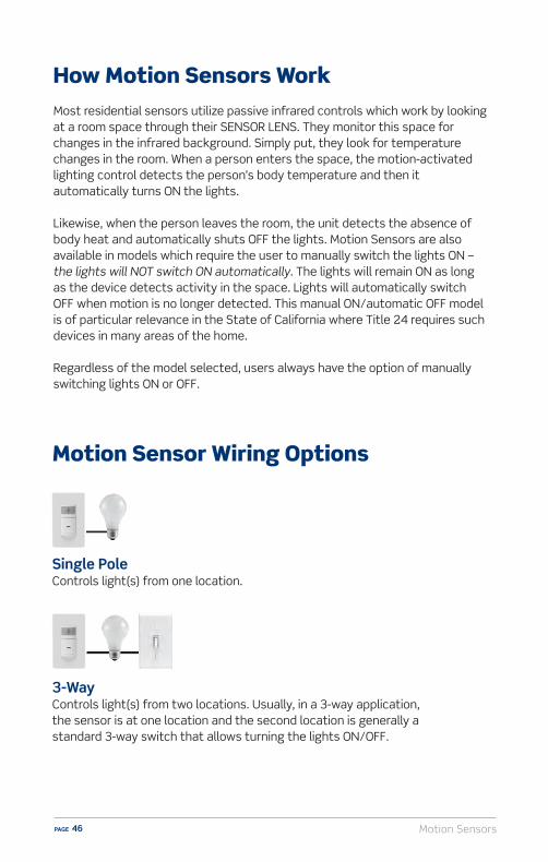
How Motion Sensors WorkMost residential sensors utilize passive infrared controls which work by looking at a room space through their SENSOR LENS. They monitor this space for changes in the infrared background. Simply put, they look for temperature changes in the room. When a person enters the space, the motion-activated lighting control detects the person’s body temperature and then it automatically turns ON the lights.
Likewise, when the person leaves the room, the unit detects the absence of body heat and automatically shuts OFF the lights. Motion Sensors are also available in models which require the user to manually switch the lights ON – the lights will NOT switch ON automatically. The lights will remain ON as long as the device detects activity in the space. Lights will automatically switch OFF when motion is no longer detected. This manual ON/automatic OFF model is of particular relevance in the State of California where Title 24 requires such devices in many areas of the home.
Regardless of the model selected, users always have the option of manually switching lights ON or OFF.
Single PoleControls light(s) from one location.
Motion Sensor Wiring Options
3-WayControls light(s) from two locations. Usually, in a 3-way application, the sensor is at one location and the second location is generally a standard 3-way switch that allows turning the lights ON/OFF.

Motion Sensors PAGE 47
Motion Sensors come with ratings consisting of WATTS and VOLTS, and sometimes VOLT/AMPS, which is written VA. A typical motion sensors rating could be 600 Watts to 1800W, 120 Volts AC, Incandescent only. This rating has three elements, and it’s important to know about each of them.
n Wattage – The device can be used to control lighting fixtures with one or more bulbs, but the TOTAL wattage of all the bulbs cannot add up to more than the wattage rating. For example, if a device rated at 600 Watts was being used to control a fixture with ten light bulbs, the bulbs being used could be up to 60 Watts each, for a total of 600 Watts. Of course, devices can control less than their rated Wattage. The Wattage rating is always the MAXIMUM lighting load that can be controlled.
n Voltage – Sensors are often rated at 120 Volts. However, there are some for dual-voltage use rated at BOTH 120 Volts and 277 Volts. Although 277 Volt electrical service is almost never used in a home, it is very common in commercial facilities like stores, o�ces and schools.
n Incandescent Only – This is the third element ONLY IN SOME device ratings and it’s an important reminder that the unit CAN ONLY BE USED TO CONTROL INCANDESCENT LIGHTS. These devices must NEVER be used to control fluorescent lights, appliances, motor-driven equipment, transformer- equipped devices, or any other electrical item. In addition, these units can never be used to switch outlets on and o�.
n Volt/Amps (VA) Fluorescent Rating – This type of rating is another element that’s added to the wattage and voltage rating ONLY FOR SOME sensors. It means the device can be used to control fluorescent lighting. The VOLT/AMP, or VA rating, corresponds to the MAXIMUM RATING OF THE BALLAST FOR THE FLUORESCENT LIGHTING TO BE CONTROLLED.
Electrical Ratings of Motion Sensors

Motion SensorsPAGE 48
Types of Motion Sensors
Motion Sensor Function Applications
Automatic-On Sensor
Automatically turns the lights ON when motion is detected and automatically turns the lights OFF when the room is vacant and motion is no longer detected.
Laundry rooms, kitchens, garages, basements, pantries and storage areas.
Manual-On Sensor
Lights must be manually turned ON but will automatically turn OFF when the room is vacant and motion is no longer detected.
High tra�c areas such as hallways, children’s rooms, living rooms, dining rooms and bathrooms where people, as well as pets, pass through often.
Dimming Sensor
The convenience of a sensor with the ability to adjust light levels.
Dining rooms, living rooms and family rooms.
Auto-Onn Can be set to Manual Onn Controls LED, CFL, Incandescent and Halogen bulbs and
motor loadsn 2-Wiren Ideal for lighting, bath fans and other motor loads
throughout the home
Manual-Onn Controls LED, CFL, Incandescent and Halogen bulbs and
motor loadsn 2-Wiren Ideal for lighting, bath fans and other motor loads
throughout the home
Cat. No. IPS02Cat. No. IPV02
Motion Sensors PAGE 49
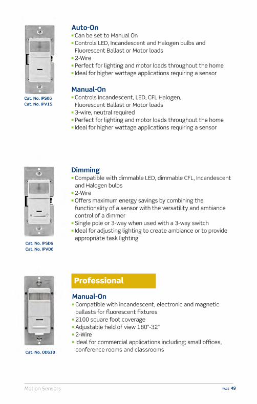
Auto-Onn Can be set to Manual Onn Controls LED, Incandescent and Halogen bulbs and
Fluorescent Ballast or Motor loadsn 2-Wiren Perfect for lighting and motor loads throughout the homen Ideal for higher wattage applications requiring a sensor
Manual-Onn Controls Incandescent, LED, CFL Halogen,
Fluorescent Ballast or Motor loadsn 3-wire, neutral requiredn Perfect for lighting and motor loads throughout the homen Ideal for higher wattage applications requiring a sensor
Manual-Onn Compatible with incandescent, electronic and magnetic
ballasts for fluorescent fixturesn 2100 square foot coveragen Adjustable field of view 180°-32°n 2-Wiren Ideal for commercial applications including; small o�ces,
conference rooms and classrooms
Dimmingn Compatible with dimmable LED, dimmable CFL, Incandescent
and Halogen bulbs n 2-Wiren O�ers maximum energy savings by combining the
functionality of a sensor with the versatility and ambiance control of a dimmer
n Single pole or 3-way when used with a 3-way switchn Ideal for adjusting lighting to create ambiance or to provide
appropriate task lighting
Cat. No. IPS06Cat. No. IPV15
Cat. No. IPSD6Cat. No. IPVD6
Cat. No. ODS10

Motion SensorsPAGE 50
Components of Motion SensorsFigure 1 shows a typical Leviton single-pole motion sensor and identifies several components of the device. There are some variations, but basically, all sensors have these elements.
Figure 1

Motion Sensors PAGE 51
The OPTIC LENS is the mechanism that monitors a room for the presence of people.
The INDICATOR is a light that illuminates when the unit detects a person’s presence. It confirms the device is powered and functioning.
The MANUAL OVERRIDE/MANUAL-ON allows a person to turn lights ON or OFF.
The MOUNTING STRAP is the backbone of the unit. It’s the piece that holds the device in place within its wallbox, and it should be sturdy.
The AMBIENT LIGHT OVERRIDE ADJUSTER* functions to prevent the device from turning on the lights during the daytime when there’s plenty of natural illumination. When turned all the way down the unit can function as a Manual On device.
The DELAYED-OFF ADJUSTER is used to set the interval of time that the lights will remain on in a room after its left unoccupied. Typically, this interval can be set to last from 15 seconds to 20 minutes, but there are di�erent settings available depending on the model of device being used. Also, some control units don’t have an adjustable delayed-o� time. Instead, they come with a factory-set interval. The instruction sheet for the particular model of sensors control will explain this information.
*Only found on Auto-On models.
Delayed-OFF Adjuster
1 2
0 3
6 Ambient Light Override Adjuster
1 2
0 3
5

Motion SensorsPAGE 52
Installation and Wiring Considerations
1. If there is any installation where the customer is unsure of how to proceed, or does not feel able to carry out the tasks specified in the wiring device instruction sheets, STOP RIGHT THERE! In such a case always advise the customer to CONSULT AN ELECTRICIAN. Electrical wiring can be complicated, and unless the installation can be properly and safely completed by the customer, the very best plan is to contact an electrician.
2. The information in this manual is here to help you serve your customers. Do not use this information as a substitute for the installation instructions provided with the devices. The instructions contain very specific and detailed directions for the device they’re packed with. Use this guide as a general reference, but familiarize yourself with the specific instruction sheets for the devices your customers will be asking about.
3. Remind your customers that in order to prevent death or injury before they begin any wiring project, THEY MUST TURN OFF POWER AT THE FUSE OR CIRCUIT BREAKER THAT SUPPLIES ELECTRICITY TO THE WIRES THEY WILL BE WORKING WITH. And after they complete their installation, they should restore power at the fuse or circuit breaker and verify that the new device is working properly. If the fuse blows or the circuit breaker trips when power is restored, or if the new device doesn’t seem to be working properly the customer should immediately contact an electrician.
4. Be sure only properly rated devices are chosen for replacement and repair projects.
For instance, a 3-way device MUST be replaced only with another 3-way device. Although a single pole device may look similar it wouldn’t be a suitable replacement.
Also, if devices are being installed on a 15 Amp branch circuit, then only 15 Amp devices may be used. Using a 20 Amp device on a 15 Amp branch circuit is potentially dangerous, and must be avoided. However, it is acceptable to use 15 Amp devices on a 20 Amp circuit.

Motion Sensors PAGE 53
Many homeowners are aware of motion sensors and understand what they do because they have seen them in public spaces or use them on the exterior of their home, but may not realize that they can be used inside their home as well. Sensors can be an easy upsell item because their functionality and benefits are easily understood by a homeowner.
n Hands-free automatic lights ON adds convenience and safety when entering dark rooms.
n Ambient light override function prevents motion sensors from automatically turning the lights ON when there is ample natural sunlight; may also be adjusted for manual-on operation.
n Adjustable time delay setting for lights to turn OFF after the space is vacated can be set for 30 seconds, 5 minutes, 15 minutes or 30 minutes for e�ective energy management.
n Provides 180° Field of View, 900 sq. ft. coverage making these devices suitable for use in large areas such as basements, garages and living rooms.
n Saves energy – Automatic OFF ensures lights won’t be left on for hours when no one is in the basement, laundry room, attic or play room.
n Ideal for children’s rooms so children are never in the dark when they’re up and about.
n Contemporary styling complements any décor. Compatible with Decora® wallplates.
n Easy installation – replaces a standard wall switch.
n Rebates are often available for purchasing and installing energy e�cient lighting through manufacturers, State rebate programs and local power companies. For instance, many CFL and LED bulbs qualify as do sensors and Energy Star products. Some rebates come in the form of fixed dollar amounts while others are based upon the KWH saved over a period of time. To investigate what rebates might be available visit www.leviton.com/rebates.
Sell-Up Opportunities
Motion SensorsPAGE 54
Room by Room Applications
BathroomsBathrooms are used numerous times a day by family members as well as guests and it is not unusual for lights to be left on inadvertently. This results in unnecessary energy usage and reduces the lifespan of bulbs.
Vacancy sensors can help to reduce energy consumption in the bathroom by automatically switching lights o� after a period of inactivity. The lights still have to be manually turned on when entering the room, but they will automatically turn o� if someone forgets to do so when exiting.
BedroomsChildren often leave the lights on in their bedrooms due to inattention or because they simply cannot easily reach the light switch. Additionally, at bedtime young children are often more comfortable falling asleep with a light left on. These practices frequently result in lights being left on longer than needed, using electricity unnecessarily.
A Leviton vacancy sensor with dimmer requires the person entering the room to manually switch the light on but allows a user to adjust the sensor to automatically turn lights o� after a defined period of inactivity. The integrated dimmer allows a parent to dim or brighten the lights for the desired mood or task, including dimming lights to “night light” level to monitor an infant or provide soothing illumination for a child falling asleep without leaving a light on at full brightness.
Laundry RoomsEntering and exiting laundry rooms is often challenging because hands are full with laundry baskets and reaching for a light switch is di�cult and sometimes dangerous.
An Auto-On sensor will automatically turn the lights on when motion is detected and o� when the room is unoccupied. The hands-free switching benefit Auto-On motion sensors provide is sensible and convenient when carrying a heavy laundry basket.
Motion Sensors PAGE 55
Q: Why would I want to use a motion sensor?A: Most people choose to install sensors to save energy and, as a result, reduce
energy costs. A sensor will automatically shut the lights or motor loads off after a set period of time when motion is no longer detected. Sensors also provide convenience for hands free lighting and in some areas, like California, the building code requires them.
Q: What is the difference between an Auto-On and a Manual-On (Vacancy) sensor?
A: An Auto-On sensor automatically turns the lights or motor load ON when motion is detected within the sensor viewing range and automatically turns the lights/motor load OFF after a designated time elapses when the room is vacant and motion is no longer detected. Manual-On (Vacancy) sensors require the user to manually turn ON the lights or motor load. The sensor will automatically turn lights/motor OFF after a designated time elapses when the room is vacant and motion is no longer detected.
Q: Where would I use an Auto-On sensor? Where would I use a Manual-On (Vacancy) sensor?
A: Auto-On sensors are great in areas where you want the convenience of the lights turning ON and OFF automatically such as laundry rooms, garages, basements, pantries, closets and storage areas. Manual-On sensors are recommended for high traffic areas such as hallways, children’s rooms, living rooms, dining rooms and bathrooms where people and pets frequent often. Manual-On sensors are also required by code in some areas such as California.
Q: If there is sufficient daylight in an area, will the motion sensor still automatically turn the lights on?
A: No, the Leviton IPS05, IPSD6, IPS06 and IPS15 motion sensors incorporate an Ambient Light Override setting which, when enabled, will prevent the sensors from switching the lights on when there is ample daylight.
FAQs (Frequently Asked Questions)

Motion SensorsPAGE 56
Q: If I have pets, will their movement trigger the motion sensor and turn the lights on?
A: There is a possibility that the movement of a pet or small child within 8 feet of a motion sensor will trigger the lights to turn on. However, the sensor can be adjusted so it will need to be manually turned ON and function as a manual-on sensor.
Q: Can a sensor be triggered by humidity or a heat source?
A: In general this is highly unlikely. However, in some instances if the sensor is placed too close to a heat source such as a dryer, stove or heating vent, the heat generated may trigger the lights ON or prevent them from turning off. For optimal performance, Leviton recommends installing sensors a reasonable distance away from heat sources.
Q: Can an auto-on sensor be converted to a manual-on (vacancy) sensor?
A: Yes, Leviton Universal Motion Sensors can be converted by changing the light level adjustment. See the product instruction guide for details.
Q: When using sensors, can I manually turn the lights or fan off?
A: Yes, all lighting and motor loads controlled by sensors can be manually turned off by pressing the push pad.
Q: Can I adjust how long the lights or fan stay on after the space is vacated?
A: Yes, all Universal Sensors have a time delay option with four adjustable settings. The four delay settings are 30 seconds, 5 minutes, 15 minutes and 30 minutes. Once a setting is chosen, the lights or fan load will turn off at the selected interval of time after a room is unoccupied and motion is no longer detected.
Q: Can a sensor replace a standard wall switch?A: Yes, Leviton’s Universal Sensors have been designed to replace standard wall
switches and most do not require a neutral wire for installation, making them perfect for retrofit applications where a neutral wire may not be present.
FAQs (Frequently Asked Questions)

Motion Sensors PAGE 57
Q: Do sensors require special wiring?
A: Most sensors have been designed to use existing wiring and do not require a neutral wire for installation. The sensors that require a neutral wire for installation are the IPS15 and IPV15. When installing the sensors in a 3-way application, standard wiring methods apply. Always refer to the product instruction guide for details.
Q: Do sensors require a ground connection?
A: The Leviton IPS05 and IPV05 require a ground connection for operation; the other Leviton Universal Sensors do not require a ground connection for operation.
Q: Can Leviton sensors be used to control exhaust fans?
A: Yes, the sensors which use a relay can be used to control exhaust fans. The following table shows the catalog numbers and load ratings of Leviton’s relay based sensors.
Q: Do any of the Leviton Sensors meet the requirements of California Title 24?
A: All of Leviton’s vacancy sensor models meet California Title 24 requirements. Leviton vacancy sensors models are: IPV05, IPV06, IPVD6 and IPV15.
Q: Do the sensors work with LED or CFL bulbs?
A: Yes, Leviton’s relay based sensors are compatible with all LED and CFL bulbs. The Leviton dimming sensors are tested to be compatible with most major manufacturers dimmable LED and dimmable CFL bulbs.
Part No. IPS05 IPV05 IPS15 IPV15
Motor Load Rating 1/6 HP 1/6HP 1/2 HP 1/2 HP
Motion SensorsPAGE 58
FAQs (Frequently Asked Questions)
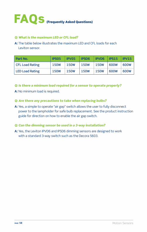
Q: What is the maximum LED or CFL load?
A: The table below illustrates the maximum LED and CFL loads for each Leviton sensor.
Q: Is there a minimum load required for a sensor to operate properly?
A: No minimum load is required.
Q: Are there any precautions to take when replacing bulbs?
A: Yes, a simple to operate “air gap” switch allows the user to fully disconnect power to the lampholder for safe bulb replacement. See the product instruction guide for direction on how to enable the air gap switch.
Q: Can the dimming sensor be used in a 3-way installation?
A: Yes, the Leviton IPVD6 and IPSD6 dimming sensors are designed to work with a standard 3-way switch such as the Decora 5603.
Part No. IPS05 IPV05 IPSD6 IPVD6 IPS15 IPV15
CFL Load Rating 150W 150W 150W 150W 600W 600W
LED Load Rating 150W 150W 150W 150W 600W 600W
Motion Sensors PAGE 59
1. How do “Manual-On” sensors also referred to as “Vacancy” sensors” operate? A) User must turn the sensor ON when they enter a room and OFF when
they leaveB) User must turn the sensor ON when they enter a room but it automatically
turns o� when they leave C) The sensor automatically turns ON but must be manually turned OFF
when leavingD) The sensor automatically turns ON and the sensor automatically turns OFF
2. Leviton sensors have a broad 180 degree field of view.A) True B) False
3. Which of these types of bulbs can Leviton sensors control?A) LED B) CFL C) Incandescent and Halogen D) All of the above
4. Leviton sensors cannot be used in a 3-way application. They can only replace a single switch.A) True B) False
Motion Sensors – Self Test Questions

Motion SensorsPAGE 60
ResourcesVideo library, buying guides and more
www.learnitatleviton.com
Still have questions?Contact our Technical Support Team
1-800-824-3005
Need to place a special order?Contact Customer Service
1-800-367-5424
www.leviton.com
Training Notes
Motion Sensors PAGE 61
1. ANSWER: B) Manual-On sensors, also referred to as Vacancy sensors must be MANUALLY turned on and they turn o� AUTOMATICALLY when a person leaves. Check pages 45, 55 for information.
2. ANSWER: B) True. Leviton sensors have a sensing angle of 180°. Check page 53 for information.
3. ANSWER: D) Leviton sensors control LED, CFL, Incandescent and Halogen bulbs. Check pages 45, 48-49 for information.
4. ANSWER: B) False. Leviton sensors are available in single pole and 3-way versions. Check page 46 for information.
Motion Sensors – Self Test Answers

Timers PAGE 63
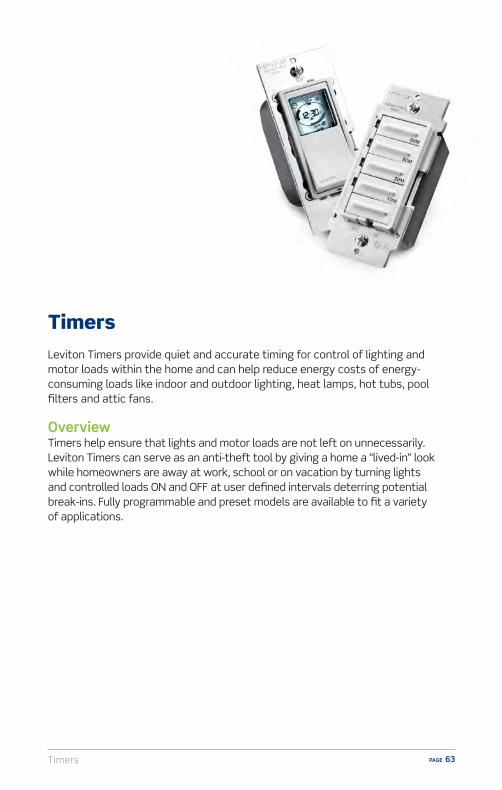
TimersLeviton Timers provide quiet and accurate timing for control of lighting and motor loads within the home and can help reduce energy costs of energy-consuming loads like indoor and outdoor lighting, heat lamps, hot tubs, pool filters and attic fans.
OverviewTimers help ensure that lights and motor loads are not left on unnecessarily. Leviton Timers can serve as an anti-theft tool by giving a home a “lived-in” look while homeowners are away at work, school or on vacation by turning lights and controlled loads ON and OFF at user defined intervals deterring potential break-ins. Fully programmable and preset models are available to fit a variety of applications.
TimersPAGE 64
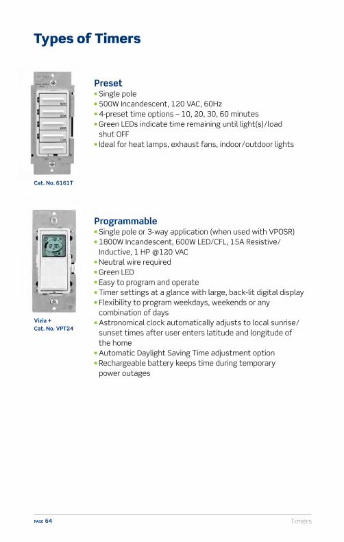
Types of Timers
Preset n Single polen 500W Incandescent, 120 VAC, 60Hzn 4-preset time options – 10, 20, 30, 60 minutesn Green LEDs indicate time remaining until light(s)/load
shut OFFn Ideal for heat lamps, exhaust fans, indoor/outdoor lights
Programmable n Single pole or 3-way application (when used with VPOSR)n 1800W Incandescent, 600W LED/CFL, 15A Resistive/
Inductive, 1 HP @120 VACn Neutral wire requiredn Green LEDn Easy to program and operaten Timer settings at a glance with large, back-lit digital displayn Flexibility to program weekdays, weekends or any
combination of daysn Astronomical clock automatically adjusts to local sunrise/
sunset times after user enters latitude and longitude of the home
n Automatic Daylight Saving Time adjustment optionn Rechargeable battery keeps time during temporary
power outages
Cat. No. 6161T
Vizia + Cat. No. VPT24

Timers PAGE 65
Installation and Wiring Considerations
1. If there is any installation where the customer is unsure of how to proceed, or does not feel able to carry out the tasks specified in the wiring device instruction sheets, STOP RIGHT THERE! In such a case always advise the customer to CONSULT AN ELECTRICIAN. Electrical wiring can be complicated, and unless the installation can be properly and safely completed by the customer, the very best plan is to contact an electrician.
2. The information in this manual is here to help you serve your customers. Do not use this information as a substitute for the installation instructions provided with the devices. The instructions contain very specific and detailed directions for the device they’re packed with. So, use this guide as a general reference, but familiarize yourself with the specific instruction sheets for the devices your customers will be asking about.
3. Remind your customers that in order to prevent death or injury before they begin any wiring project, THEY MUST TURN OFF POWER AT THE FUSE OR CIRCUIT BREAKER THAT SUPPLIES ELECTRICITY TO THE WIRES THEY WILL BE WORKING WITH. And after they complete their installation, they should restore power at the fuse or circuit breaker and verify that the new device is working properly. If the fuse blows or the circuit breaker opens when power is restored, or if the new device doesn’t seem to be working properly, the customer should immediately contact an electrician.
4. Be sure only properly rated devices are chosen for replacement and repair projects.
For instance, a 3-way device MUST be replaced only with another 3-way device. Although a single-pole device may look similar it wouldn’t be a suitable replacement.
Also, if devices are being installed on a 15 Amp branch circuit, then only 15 Amp devices may be used. Using a 20 Amp device on a 15 Amp branch circuit is potentially dangerous, and must be avoided. However, it is accept able to use 15 Amp devices on a 20 Amp circuit.

TimersPAGE 66
Components of Preset Timer
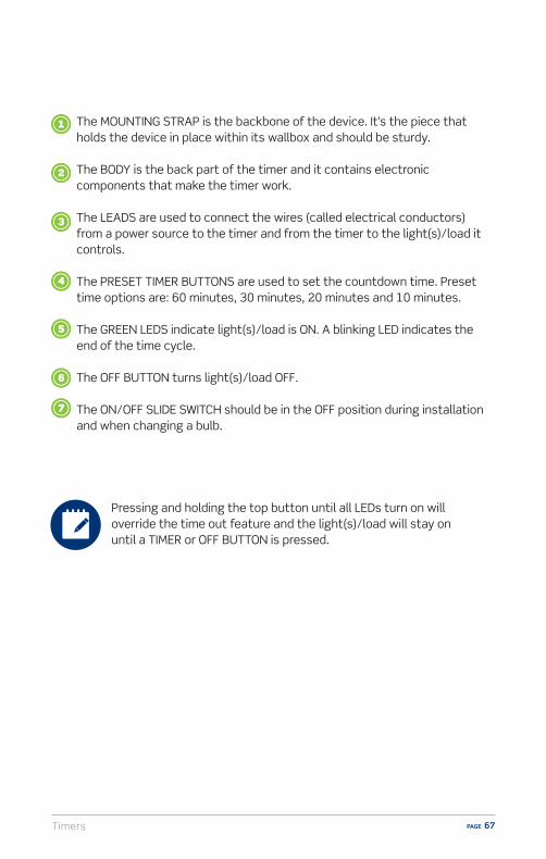
Timers PAGE 67
The MOUNTING STRAP is the backbone of the device. It’s the piece that holds the device in place within its wallbox and should be sturdy.
The BODY is the back part of the timer and it contains electronic components that make the timer work.
The LEADS are used to connect the wires (called electrical conductors) from a power source to the timer and from the timer to the light(s)/load it controls.
The PRESET TIMER BUTTONS are used to set the countdown time. Preset time options are: 60 minutes, 30 minutes, 20 minutes and 10 minutes.
The GREEN LEDS indicate light(s)/load is ON. A blinking LED indicates the end of the time cycle.
The OFF BUTTON turns light(s)/load OFF.
The ON/OFF SLIDE SWITCH should be in the OFF position during installation and when changing a bulb.
Pressing and holding the top button until all LEDs turn on will override the time out feature and the light(s)/load will stay on until a TIMER or OFF BUTTON is pressed.

TimersPAGE 68
Components of a Programmable Timer
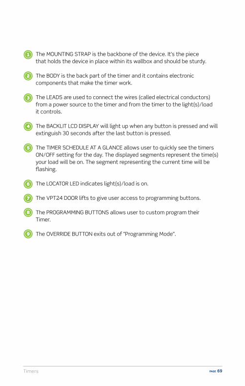
Timers PAGE 69
The MOUNTING STRAP is the backbone of the device. It’s the piece that holds the device in place within its wallbox and should be sturdy.
The BODY is the back part of the timer and it contains electronic components that make the timer work.
The LEADS are used to connect the wires (called electrical conductors) from a power source to the timer and from the timer to the light(s)/load it controls.
The BACKLIT LCD DISPLAY will light up when any button is pressed and will extinguish 30 seconds after the last button is pressed.
The TIMER SCHEDULE AT A GLANCE allows user to quickly see the timers ON/OFF setting for the day. The displayed segments represent the time(s) your load will be on. The segment representing the current time will be flashing.
The LOCATOR LED indicates light(s)/load is on.
The VPT24 DOOR lifts to give user access to programming buttons.
The PROGRAMMING BUTTONS allows user to custom program their Timer.
The OVERRIDE BUTTON exits out of “Programming Mode”.
TimersPAGE 70
Saves Energy – Regular use of timers can help lower electrical costs and add convenience to everyday living. Simply replacing standard switches with timers can reduce energy consumption and extend bulb life by shutting o� lights, bathroom and kitchen fans or other indoor motor loads that might be inadvertently left on. They can also be used to automate control of pool pumps and attic fans so they operate on a fixed schedule.
Safety – For a cost e�ective theft deterrent, homeowners can set indoor and outdoor lights to turn ON and OFF at random intervals for a lived-in look while they’re away. Smart technology such as a built-in “astronomical” clock allows the device to operate accurately based on the geographic location of the home, even accounting for seasonal changes and Daylight Saving Time.
Sell-Up Opportunities
Q: When programming the VPT24 what’s the di�erence between Pro Mode and Standard Mode?
A: Pro Mode provides up to 50 ON/OFF events for any day or combination of days, M-Su, M-F, or Sa-Su at desired fixed times or self-adjusting Sunup and Sundown times. In this mode self-adjusting Daylight Saving Time and random modes are also available.
A: Std Mode provides up to 3 ON/OFF events for M-Su, M-F, or Sa-Su at desired fixed times only. Self-adjusting Sunup and Sundown and Daylight Saving Time are NOT available in Standard Mode.
Q: When programming the VPT24 how do I find the longitude and latitude coordinates?
A: To obtain the longitude and latitude coordinates of your location go to www.leviton.com/VPT24 and click on Longitude/Latitude Coordinates Lookup. Type in your home address and press enter. Your latitude (N) and longitude (W) coordinates will be shown on the screen. Write down only the 2 or 3 digit number. Disregard a negative symbol (-) if it precedes the number.
Q: The programming instructions for the VPT24 are complicated. Is there a video available to help walk me through it?
A: Yes. For help programming the VPT24 please visit www.leviton.com/VPT24
FAQs (Frequently Asked Questions)

Timers PAGE 71
1. Leviton timers work with what type of electric loads? A) Indoor and outdoor lightingB) Heat lamps and attic fansC) Hot tubs and pool filtersD) All of the above
2. The Leviton 6161T preset timer has how many buttons for preset time options?A) 1B) 2C) 3D) 4
3. What is the maximum countdown time for the 6161T preset timer?A) 60 minutesB) 30 minutesC) UnlimitedD) It is programmable up to 12 hours
4. The Leviton VPT24 programmable timer operates as only a 12-hour device and must be re-programmed.A) TrueB) False
5. What is an astronomical clock?A) Aligns the home’s schedule with phases of the moonB) Automatically adjusts to local sunrise/sunset times after
user enters latitude and longitude of the homeC) Turns lights on and o� according to the days of the weekD) Works by solar power
Timers – Self Test Questions

TimersPAGE 72
ResourcesVideo library, buying guides and more
www.learnitatleviton.com
Still have questions?Contact our Technical Support Team
1-800-824-3005
Need to place a special order?Contact Customer Service
1-800-367-5424
www.leviton.com
Training Notes

Timers PAGE 73
1. ANSWER: D) All of the above. Timers work with indoor and outdoor lighting, heat lamps, attic fans, hot tubs and pool filters. Check pages 63, 64, 70 for information.
2. ANSWER: D) The Leviton 6161T has 4 buttons for preset time options. Check pages 64, 66-67 for information.
3. ANSWER: A) 60 minutes is the maximum countdown time for the 6161T preset timer. Check pages 64, 66-67 for information.
4. ANSWER: B) False.The Leviton VPT24 is a 24-hour programmable timer operates as only a 12-hour device and must be re-programmed. Check page 64 for information.
5. ANSWER: B) An astronomical clock automatically adjusts to local sunrise/sunset times when the user plugs in the latitude and longitude of the home. Check pages 64, 70 for information.
Timers – Self Test Answers


Fan Speed Controls PAGE 75
Fan Speed ControlsCeiling fans are very popular in homes throughout the country. Leviton o�ers a variety of Fan Speed Controls ranging from basic rotary to decorative to satisfy every customer’s preference. The comprehensive line comes in a vast array of styles and lighting loads. They provide precise, dependable, and quiet control, coordinate with other Leviton dimmers and switches and o�er energy savings when used on a regular basis.
OverviewVirtually all ceiling fans are driven by a self-contained electrical motor. Fan Speed Controls provide a means to turn fans ON and OFF and regulate how fast the fan spins without the need for pull-chains from the fan itself. It’s important to know that only fan speed controls can be used for this job. DIMMERS MUST NEVER BE USED AS FAN SPEED CONTROLS because doing so will cause damage to both the dimmer and the fan. Fan speed controls provide an excellent sell-up opportunity for customers who may be using just a standard wall switch to turn their ceiling fans ON and OFF. The fan speed control is easy to install in the same wallbox as the switch it replaces and it connects to the same wires.
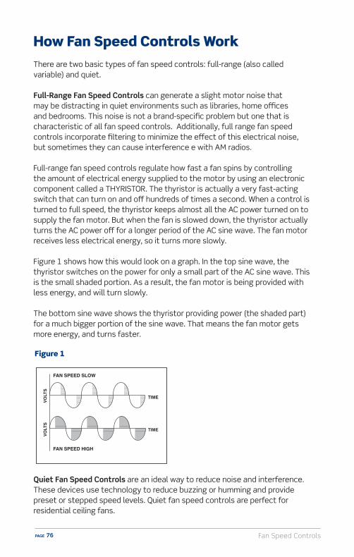
Fan Speed ControlsPAGE 76
How Fan Speed Controls WorkThere are two basic types of fan speed controls: full-range (also called variable) and quiet.
Full-Range Fan Speed Controls can generate a slight motor noise that may be distracting in quiet environments such as libraries, home o�ces and bedrooms. This noise is not a brand-specific problem but one that is characteristic of all fan speed controls. Additionally, full range fan speed controls incorporate filtering to minimize the e�ect of this electrical noise, but sometimes they can cause interference e with AM radios.
Full-range fan speed controls regulate how fast a fan spins by controlling the amount of electrical energy supplied to the motor by using an electronic component called a THYRISTOR. The thyristor is actually a very fast-acting switch that can turn on and o� hundreds of times a second. When a control is turned to full speed, the thyristor keeps almost all the AC power turned on to supply the fan motor. But when the fan is slowed down, the thyristor actually turns the AC power o� for a longer period of the AC sine wave. The fan motor receives less electrical energy, so it turns more slowly.
Figure 1 shows how this would look on a graph. In the top sine wave, the thyristor switches on the power for only a small part of the AC sine wave. This is the small shaded portion. As a result, the fan motor is being provided with less energy, and will turn slowly.
The bottom sine wave shows the thyristor providing power (the shaded part) for a much bigger portion of the sine wave. That means the fan motor gets more energy, and turns faster.
Quiet Fan Speed Controls are an ideal way to reduce noise and interference. These devices use technology to reduce buzzing or humming and provide preset or stepped speed levels. Quiet fan speed controls are perfect for residential ceiling fans.
FAN SPEED SLOW
TIME
TIME
VOLT
SVO
LTS
FAN SPEED HIGH
Figure 1
Fan Speed Controls PAGE 77
Fan speed controls come with ratings consisting of AMPS and VOLTS. A typical fan speed control rating is 1.5 Amps, 120 Volts AC. This rating has two elements and it’s important to know about each of them.
n Amps – The fan speed control can be used to operate a fan that draws up to 1.5 Amps of power. Of course, controls can be used to operate fans that draw less power, but not more. The amperage rating is always the MAXIMUM fan amperage that can be controlled.
n Voltage – Almost all fan speed controls are rated for 120 Volt power and certainly ALL fan speed controls that are designed to operate household ceiling fans are rated at 120 Volts.
Electrical Ratings of Fan Speed Controls
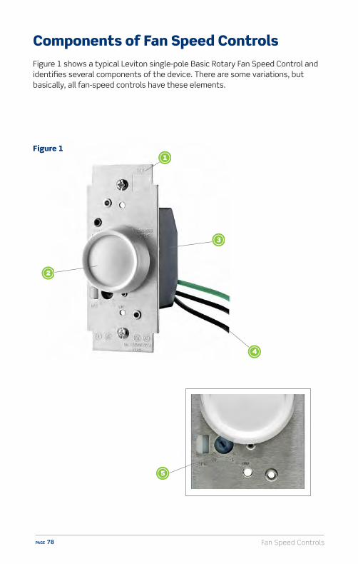
Fan Speed ControlsPAGE 78
Components of Fan Speed ControlsFigure 1 shows a typical Leviton single-pole Basic Rotary Fan Speed Control and identifies several components of the device. There are some variations, but basically, all fan-speed controls have these elements.
Figure 1
Fan Speed Controls PAGE 79
The MOUNTING STRAP is the backbone of the control. It’s the piece that holds the device in place within its wallbox and should be sturdy. With fan speed controls, the mounting strap also performs another important job: it works as a heat sink. That’s because the electronic components of all fan speed controls generate heat. In order to get rid of this heat, the mounting strap passes it into the wallbox and into the air that surrounds the fan speed control. This cools the electronic components in the device, and it’s the reason that all fan-speed controls feel slightly warm when they’re operating normally. So in addition to being sturdy, a fan speed control’s mounting strap should also be fairly large for maximum e�ciency in releasing heat.
The ACTUATOR is used to adjust the desired fan speed setting and often also to turn fan ON and OFF. The actuator for the basic control shown in Figure 1 is a rotary knob. This is a fairly common type of actuator, but some fan speed controls use slides instead.
The BODY is the back part of the control and it contains the electronic components that make it work.
The LEADS are used to connect the wires (called electrical conductors) from a power source to the fan speed control, and from the control to the fan it operates.
The LOW-END TRIM ADJUSTMENT is a set-screw that can be easily turned with a small-blade screwdriver. It allows setting the correct speeds for proper fan re-start in the event of power interruption.

Fan Speed ControlsPAGE 80
Fan Speed Control Styles
Slide w/Preset SwitchThis contemporary design uses a slide bar with preset fan levels to regulate the speed of the fan. The ON/OFF function preserves the last level.
Traditional RotaryTraditional in appearance, this fan speed control uses a rotary knob to turn fans ON and OFF and set the fan speed.
Cat. No. 6627
Cat. No. 6616
Fan Speed Controls come in a variety of styles to meet both the decorative and functional needs of the user. They o�er full range control and are perfect for libraries, bedrooms, study rooms and any area where ceiling fan noise could become distracting.
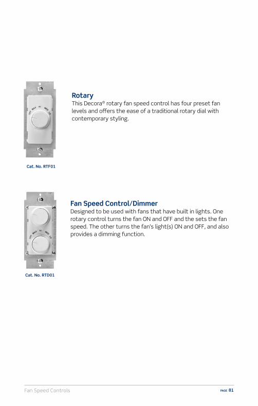
Fan Speed Controls PAGE 81
Fan Speed Control/DimmerDesigned to be used with fans that have built in lights. One rotary control turns the fan ON and OFF and the sets the fan speed. The other turns the fan’s light(s) ON and OFF, and also provides a dimming function.
RotaryThis Decora® rotary fan speed control has four preset fan levels and o�ers the ease of a traditional rotary dial with contemporary styling.
Cat. No. RTD01
Cat. No. RTF01

Fan Speed ControlsPAGE 82
Installation and Wiring Considerations
1. If there is any installation where the customer is unsure of how to proceed, or does not feel able to carry out the tasks specified in the wiring device instruction sheets, STOP RIGHT THERE! In such a case always advise the customer to CONSULT AN ELECTRICIAN. Electrical wiring can be complicated, and unless the installation can be properly and safely completed by the customer, the very best plan is to contact an electrician.
2. The information in this manual is here to help you serve your customers. Do not use this information as a substitute for the installation instructions provided with the devices. The instructions contain very specific and detailed directions for the device they’re packed with. So, use this guide as a general reference, but familiarize yourself with the specific instruction sheets for the devices your customers will be asking about.
3. Remind your customers that in order to prevent death or injury before they begin any wiring project, THEY MUST TURN OFF POWER AT THE FUSE OR CIRCUIT BREAKER THAT SUPPLIES ELECTRICITY TO THE WIRES THEY WILL BE WORKING WITH. And after they complete their installation, they should restore power at the fuse or circuit breaker and verify that the new device is working properly. If the fuse blows or the circuit breaker opens when power is restored, or if the new device doesn’t seem to be working properly, the customer should immediately contact an electrician.
4. Be sure only properly rated devices are chosen for replacement and repair projects. For instance, a 3-way device MUST be replaced only with another 3-way device. Although a single-pole device may look similar it wouldn’t be a suitable replacement. Also, if devices are being installed on a 15 Amp branch circuit, then only 15 Amp devices may be used. Using a 20 Amp device on a 15 Amp branch circuit is potentially dangerous, and must be avoided. However, it is acceptable to use 15 Amp devices on a 20 Amp circuit.

Fan Speed Controls PAGE 83
Convenience – replacing a standard switch with a fan speed control o�ers the ability to control the fan from the outlet location as opposed to having to reach for a pull chain on the fan itself.
Noise reduction – quiet fan speed controls prevent the buzzing and humming that sometimes occurs when a fan is operating. This creates a more pleasant environment in the home.
Sell-Up Opportunities
Q: Why would I need a quiet fan speed control?A: Some fans, particularly economy models, have a tendency to hum or buzz when
they’re set to turn at slow speed. This isn’t a dangerous condition but it can be very annoying, especially in a quiet room. Quiet fan speed controls feature special electronic circuitry that’s designed to prevent fans from humming when they turn at slow speeds.
Q: Can I use a dimmer to control a fan?
A: Dimmers must NEVER be used to control a fan. Both the dimmer and fan will be damaged.
Q: Is special wiring required for a dual fan speed control and dimmer?
A: Yes. Review the instruction sheet for details.
FAQs (Frequently Asked Questions)

Fan Speed ControlsPAGE 84
1. What two elements make up the rating of fan speed controls?A) Fast and slowB) Amperage and VoltageC) Voltage and speedD) Both A and C
2. What is special about “quiet fan speed controls”?A) They operate silentlyB) They are sound-activatedC) They help prevent fan humming or buzzingD) All of the above
3. What models of Leviton fan speed controls are available?A) Rotary and slideB) Quiet fan speed controlsC) Combination fan/dimmerD) Both A and C
4. How do fan speed controls work?A) They regulate the electrical energy supplied to fansB) They monitor temperture to regulate fan speedC) They monitor eletrical usageD) None of the above
5. In normal operation, a fan speed control may feel warm to the touch. A) TrueB) False
Fan Speed Controls – Self Test Questions
Fan Speed Controls PAGE 85
6. When would a combination fan speed control/dimmer control be used? A) For fans with built-in light fixturesB) For lights in the same room as the fanC) For fans without built-in light fixturesD) For fans in brightly lit rooms
7. Dimmers can be used as fan controls?A) TrueB) False
8. What is the voltage for which residential fan speed controls are designed?A) 120 VoltsB) 240 VoltsC) 40-60 Volts DCD) 277 Volts
Fan Speed Controls – Self Test Questions

Fan Speed ControlsPAGE 86
ResourcesVideo library, buying guides and more
www.learnitatleviton.com
Still have questions?Contact our Technical Support Team
1-800-824-3005
Need to place a special order?Contact Customer Service
1-800-367-5424
www.leviton.com
Training Notes
Fan Speed Controls PAGE 87
1. ANSWER: B) The two elements that make up the rating of fan speed controls are Amperage and Voltage. Check page 77 for information.
2. ANSWER: C) Quiet fan speed controls are designed to eliminate the humming sound that some fans make when turning at slow speed. Check page 83 for information.
3. ANSWER: D) Leviton makes a variety of fan speed control models including Rotary, Slide, and Combination. Check pages 80-81 for information.
4. ANSWER: A) Fan speed controls work by regulating the amount of electrical energy that is provided to the fan motor. Check page 76 for information.
5. ANSWER: A) True. All fan speed controls become warm when the fan is on. Check pages 78-79 for information.
6. ANSWER: A) A combination fan speed control/dimmer would be used only for fans that have built-in light fixtures. Check page 81 for information.
7. ANSWER: B) False. Dimmers must NEVER be used as fan speed controls. Check pages 75, 83 for information.
8. ANSWER: A) Residential fan speed controls are designed for 120 Volts. Check page 77 for information.
Fan Speed Controls – Self Test Answers


Humidity Sensors PAGE 89
Humidity Sensor and Fan ControlExcess humidity, whether in the bathroom or basement, can lead to mold and mildew and potentially compromise the environmental safety of a home. Installing a Humidity Sensor and Fan Control is a simple and e�ective way to reduce excess condensation in areas of the home prone to dampness and mildew such as bathrooms, basements, laundry rooms and home spas.
OverviewThe Leviton Humidity Sensor and Fan Control automatically detects excess humidity in a room and activates the ventilation fan to lessen condensation which helps reduce potential mold and mildew.
The sensor uses a microprocessor combined with state-of-the-art digital sensing technology to continuously monitor and manage humidity levels in areas of the home prone to condensation and mildew. It features user-friendly controls to adjust sensitivity, humidity level, time out and cycle time settings.
The sensor can replace a single pole switch and can be used with most bathroom or ventilation fans or fan/light combinations. It is designed to fit within a standard wallbox and requires a neutral wire for operation.The Humidity Sensor and Fan Control is the ideal solution for controlling ventilation. The sensor also helps reduce energy usage by automatically operating the fan only when needed to control excess humidity.

Humidity SensorsPAGE 90
Components of Humidity Sensor and Fan ControlFigure 1 shows the Leviton Humidity Sensor and Fan Control and identifies several components of the device.
Figure 1

Humidity Sensors PAGE 91
The OPTIC LENS is the mechanism that monitors a room for the presence of humidity.
The LED INDICATOR is a light on the face of the device that indicates the status.
Sensitivity
Lo Md
Off
Off
HiTime Humidistat
2 3
1 4
20 80
cycle(10 min.) (45 min.)
(20 min.) (30 min.)(Stop Mark)
4
5 6
LED Status
ON Fan (load) OFF
OFF Fan (load) ON
Blinking 2 sec. ON, 2 sec. OFF Air cycle mode is active
Blinking 2 sec. ON, 1/10 sec. OFF Manual override
The MOUNTING STRAP is the backbone of the unit. It’s the piece that holds the device in place within its wallbox, and should be sturdy.
The USER ADJUSTABLE SENSITIVITY SETTING can be adjusted to low, medium or high depending on how quickly residents want their fan to automatically turn ON when the air quality begins to change.
The USER ADJUSTABLE TIME SETTING sets the interval of time that the Humidity Sensor and Fan Control will continue to activate the fan once excess humidity is detected. The sensor timer settings can be custom set to 10, 20, 30 or 45 minute intervals.
The USER ADJUSTABLE HUMIDISTAT SETTING allows the user to set the minimum humidity level at which the fan will automatically operate.
Adjustable humidity set points allow the user to set the minimum humidity level at which the fan will automatically operate. Adjustable humidity set points are a requirement of CALGREEN and CA Title 24.
Humidity SensorsPAGE 92
1. If there is any installation where the customer is unsure of how to proceed, or does not feel able to carry out the tasks specified in the wiring device instruction sheets, STOP RIGHT THERE! In such a case always advise the customer to CONSULT A QUALIFIED ELECTRICIAN. Electrical wiring can be complicated, and unless the installation can be properly and safely completed by the customer, the very best plan is to contact an electrician.
2. The information in this manual is here to help you serve your customers. Do not use this information as a substitute for the installation instructions provided with the devices. The instructions contain very specific and detailed directions for the device they’re packed with. So, use this guide as a general reference, but familiarize yourself with the specific instruction sheets for the devices your customers will be asking about.
3. Remind your customers that in order to prevent death or injury before they begin any wiring project, THEY MUST TURN OFF POWER AT THE FUSE OR CIRCUIT BREAKER THAT SUPPLIES ELECTRICITY TO THE WIRES THEY WILL BE WORKING WITH. And after they complete their installation, they should restore power at the fuse or circuit breaker and verify that the new device is working properly. If the fuse blows or the circuit breaker opens when power is restored, or if the new device doesn’t seem to be working properly, the customer should immediately contact an electrician.
4. Be sure only properly rated devices are chosen for replacement and repair projects. For instance, a 3-way device MUST be replaced only with another 3-way device. Although a single-pole device may look similar it wouldn’t be a suitable replacement. Also, if devices are being installed on a 15 Amp branch circuit, then only 15 Amp devices may be used. Using a 20 Amp device on a 15 Amp branch circuit is potentially dangerous, and must be avoided. However, it is acceptable to use 15 Amp devices on a 20 Amp circuit.
Installation and Wiring Considerations

Humidity Sensors PAGE 93
Installation Recommendations for Bath Fan ControlWhen installing a Humidity Sensor and Fan Control in the bathroom it is important that the customer be aware of the following factors that may a�ect the optimal performance of the device.
n It is recommended that in large spaces the Humidity Sensor and Fan Control be placed within close proximity to the shower/ tub (steam/vapor source) to most e�ectively measure/monitor for excess humidity.
n Ceiling heights in excess of 8 feet may a�ect the sensors’ ability to properly detect shower/tub steam.
n The sensor requires a closed room to properly operate. Opening a door during operation may temporarily interrupt the operating cycle.
n Changes in season may a�ect operation of the sensor due to ambient air temperature and humidity. Please review the sensor instructions for sensitivity and humidity adjustment if required.
n The Humidity Sensor and Fan Control operates both the fan and the light when used with a fan/light combination; meaning the light will switch o� automatically when the fan automatically shuts o�.

Humidity SensorsPAGE 94
General Operation The Humidity Sensor and Fan Control has three modes of operation to meet the needs of the user.
Automatic Humidity Control Mode – The sensor will automatically turn the ventilation fan ON upon detecting excess humidity. The sensor will continue to monitor the ambient air and automatically turn the fan OFF when the humidity level has dropped or the preset time has been reached.
Manual Operation – For immediate ventilation needs, the user can manually switch the fan ON or OFF by pressing the fan icon. The fan will run for 10 minutes and automatically turn OFF (time out period can be adjusted).
If humidity levels change, the sensor will shift into automatic mode and time out accordingly.
Air Cycle Mode – Automatically turns ON a ventilation fan for a set period of time and repeats the cycle hourly (eg. 20 minutes ON/40 minutes OFF each hour). This feature may be used in areas requiring periodic ventilation on a continuous basis such as basements or home spas.
The Leviton Humidity Sensor and Fan Control will not independently eliminate condensation. It must be used with a properly sized and rated ventilation fan in an enclosed space.
n Single Polen 600W Incandescent, 150W LED/CFLn 400VA Inductive/Ballast n 1/6th HP Motorn CALGREEN and CA Title 24 Compliantn Ideal for bathrooms, basements,
laundry rooms and home spas
Cat. No. IPHS5

Humidity Sensors PAGE 95
Q: Does the Leviton Humidity Sensor and Fan Control meet the requirements of CALGreen and California Title 24 for indoor air quality and exhaust?
A: Yes, the Leviton Humidity Sensor and Fan Control meets the 2010 California green building standard requirements for indoor air quality and exhaust found under section 4.506: Unless functioning as a component of a whole house ventilation system, fans must be controlled by a humidistat which shall be readily accessible. Humidistat controls shall be capable of adjustment between a relative humidity range of 50 to 80 percent.
Q: If I install the Humidity Sensor and Fan Control, can I manually control my exhaust fan?
A: Yes, by simply pressing the fan icon on the face of the device you can manually activate the fan. Once turned on, the Leviton Humidity Sensor and Fan Control has a built in count down timer function to allow the fan to run for a set period of time. The time out function is pre-set to a default of 10 minutes but can be adjusted to 10, 20, 30 or 45 minutes. (Note: the time out represents the minimum ON time as the sensor will continue to function in humidity sensing mode.)
Q: How does the Humidity Sensor and Fan Control save energy?
A: By automatically operating the fan only when needed to control excess humidity, the Leviton Humidity Sensor and Fan Control helps reduce energy usage by assuring the fan is not left on continuously or unnecessarily.
Q: Can the Humidity Sensor and Fan Control eliminate condensation?
A: The Leviton Humidity Sensor and Fan Control is designed to work in conjunction with a properly sized and rated ventilation fan in an enclosed room to remove moisture.
FAQs (Frequently Asked Questions)
Humidity SensorsPAGE 96
FAQs (Frequently Asked Questions)
Q: Is the Humidity Sensor and Fan Control easy to install?A: The Leviton Humidity Sensor and Fan Control can replace an existing single pole
switch that is wired to a fan. The device requires a neutral wire and has screw terminals for ease of installation. It can be used with most bathroom exhaust or ventilation fans or fan/light combinations.
Q: What is the Air Cycle mode on the Humidity Sensor and Fan Control?A: The Air Cycle mode automatically turns ON a ventilation fan for a set period of
time and repeats the cycle hourly (e.g., 20 minutes ON/40 minutes OFF each hour). This feature may be used in areas requiring periodic ventilation on a continuous basis such as basements or home spas.
Q: What is the maximum fan load for the Humidity Sensor and Fan Control?
A: The device is rated for 1/6th HP (3 Amp) fan load or motor load.
Q: Can the Humidity Sensor and Fan Control operate a fan with a light load?
A: Yes, if the light and fan are on the same “hot” switched leg. It is not recommended in applications where the fan/light combination is the sole light source.
Q: Can the Humidity Sensor and Fan Control be used in applications other than a bathroom?
A: The device is designed to control fans up to 1/6th HP (3 Amp). Other applications may include home spas, basements or laundry rooms for ventilation.
Q: Does the Humidity Sensor and Fan Control require a neutral wire for installation?
A: Yes, the installation requires connection to a neutral wire.
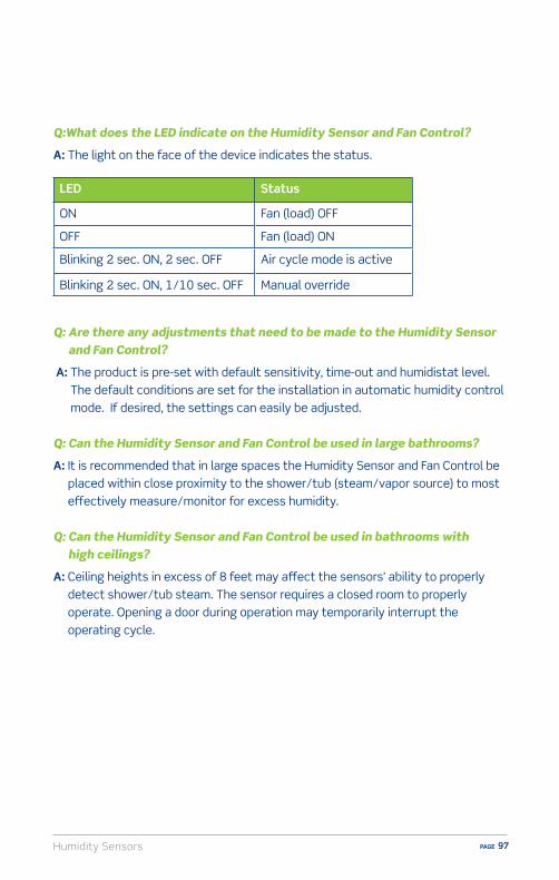
Humidity Sensors PAGE 97
Q:What does the LED indicate on the Humidity Sensor and Fan Control?
A: The light on the face of the device indicates the status.
Q: Are there any adjustments that need to be made to the Humidity Sensor and Fan Control?
A: The product is pre-set with default sensitivity, time-out and humidistat level. The default conditions are set for the installation in automatic humidity control mode. If desired, the settings can easily be adjusted.
Q: Can the Humidity Sensor and Fan Control be used in large bathrooms?
A: It is recommended that in large spaces the Humidity Sensor and Fan Control be placed within close proximity to the shower/tub (steam/vapor source) to most e�ectively measure/monitor for excess humidity.
Q: Can the Humidity Sensor and Fan Control be used in bathrooms with high ceilings?
A: Ceiling heights in excess of 8 feet may a�ect the sensors’ ability to properly detect shower/tub steam. The sensor requires a closed room to properly operate. Opening a door during operation may temporarily interrupt the operating cycle.
LED Status
ON Fan (load) OFF
OFF Fan (load) ON
Blinking 2 sec. ON, 2 sec. OFF Air cycle mode is active
Blinking 2 sec. ON, 1/10 sec. OFF Manual override
Humidity SensorsPAGE 98
1. The Humidity Sensor and Fan Control is designed to:A) Beep when humidity levels riseB) Activate the ventilation fan when excess humidity is detectedC) Eliminate mold and mildewD) All of the above
2. The Humidity Sensor and Fan Control requires a neutral wire for operation.A) TrueB) False
3. Which of the following is NOT a user adjustable setting?A) SensitivityB) TimeC) Fan SpeedD) Humidistat
4. When the sensor automatically turns on the fan for a set period of time each hour the device is in:A) Air Cycle ModeB) Automatic Humidity Control ModeC) Manual OperationD) Energy Saver Mode
Humidity Sensor and Fan Control – Self Test Questions

Humidity Sensors PAGE 99
ResourcesVideo library, buying guides and more
www.learnitatleviton.com
Still have questions?Contact our Technical Support Team
1-800-824-3005
Need to place a special order?Contact Customer Service
1-800-367-5424
www.leviton.com
Training Notes

Humidity SensorsPAGE 100
1. ANSWER: B) The Humidity Sensor and Fan Control is designed to activate the ventilation fan when excess humidity is detected. Check page 89 for information.
2. ANSWER: A) True. The Humidity Sensor and Fan Control requires a neutral wire for operation. Check page 96 for information.
3. ANSWER: C) The Fan Speed is NOT a user adjustable setting. Check pages 90-91, 94 for information.
4. ANSWER: A) When the sensor automatically turns ON the fan for a set period of time each hour the device is in Air Cycle Mode. Check pages 94, 96 for information.
Humidity Sensor and Fan Control – Self Test Answers

Outlets PAGE 101
Outlets and USB Charger DevicesLeviton o�ers an extensive selection of outlets in a variety of grades from Standard residential devices to durable Preferred commercial grade. Most notable are Leviton Decora® outlets, which add a touch of elegance and a designer look to any home.
OverviewAlways an advocate for electrical safety, Leviton o�ers Tamper Resistant outlets to help provide a safer living environment, especially for young children. And, keeping up with technology is easy with Leviton USB Charger Devices. These outlets allow homeowners to manage the increasing everyday demands of powering their mobile devices by e�ectively utilizing outlet space.
The National Electrical Manufacturer’s Association® (NEMA®) has a formal definition for outlets, which are usually called RECEPTACLES by electrical professionals. They are “devices with female contacts intended to establish an electrical connection with an inserted plug”. In other words, outlets are used as a source of power for electrical loads that are plugged into them.


Outlets PAGE 103
Grades of OutletsLeviton has established product grades as a way to clearly define the best application for each product. Always ask customers where they are planning on installing an outlet before making a recommendation.
n Good - Basic replacement- Suitable for most household applications
n Better- For heavily used areas- Heavy duty contacts hold tight- Impact resistant face and body - Back and side wiring options
n Best - Ground Fault Circuit Interrupters (GFCI) help protect
against electrical shock- Arc Fault Circuit Interrupters (AFCI) help prevent
electrical firesBoth of these products meet National Electrical Code® (NEC®) requirements and are covered in their own sections in this manual.
n Decorative - Easily replaces traditional outlets- Adds a decorative touch
OutletsPAGE 104
Electrical Ratings of OutletsEvery outlet has its electrical rating indicated on the device. The electrical rating tells you two important things: the voltage and the maximum electrical load for which the outlet is designed to support and can safely supply power. Generally, household outlets are designed for use on 125 Volt circuits, 250 Volt circuits are used for range and dryer outlets.
For example, an outlet marked with a rating that reads 15A-125VAC can be used to supply a maximum load of 15 Amps at 125 Volts.
A typical rating indication for household outlets is 15 Amp 125 Volts AC. There are also 20 Amp, 30 Amp, and even 50 Amp outlets in household use, generally for 125 Volt and 250 Volt ratings.
In addition, outlets have their slots arranged according to their ratings. This is done to help prevent mismatching of plugs and outlets with di�erent ratings, which might lead to damage of the outlet or equipment plugged into it. The arrangement of outlet slots is called the CONFIGURATION. All outlets in the United States use identical configurations for corresponding voltage/amperage ratings. The configurations are determined by NEMA.
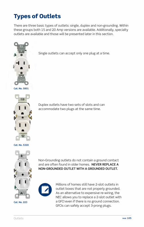
Outlets PAGE 105
Types of OutletsThere are three basic types of outlets: single, duplex and non-grounding. Within these groups both 15 and 20 Amp versions are available. Additionally, specialty outlets are available and those will be presented later in this section.
Single outlets can accept only one plug at a time.
Duplex outlets have two sets of slots and can accommodate two plugs at the same time.
Non-Grounding outlets do not contain a ground contact and are often found in older homes. NEVER REPLACE A NON-GROUNDED OUTLET WITH A GROUNDED OUTLET.
Cat. No. 5801
Cat. No. 5320
Cat. No. 223
Millions of homes still have 2-slot outlets in outlet boxes that are not properly grounded. As an alternative to expensive re-wiring, the NEC allows you to replace a 2-slot outlet with a GFCI even if there is no ground connection. GFCIs can safely accept 3-prong plugs.

OutletsPAGE 106
Components of OutletsFigure 1 shows a typical Leviton duplex outlet and identifies several components of the device. There are some variations, but basically, all outlets have these elements.
Figure 1

Outlets PAGE 107
The MOUNTING STRAP is the backbone of the outlet. It’s the piece that holds the outlet in place within the wallbox and should be sturdy. Leviton provides a riveted self-grounding clip on the mounting strap of many outlets. This clip provides automatic grounding of the outlet when it’s properly installed in a properly grounded metal wallbox.
The PLASTER EARS are part of the mounting strap and help the outlet lay flush with the wall surface. They can also be removed and used as washers under the mounting strap for leveling.
The BODY is the back part of the outlet.
The FACE is the front part of the outlet.
The CONTACTS are inside the outlet. They grip the blades of an inserted plug and provide the electrical current to the lamp or appliance.
The GROUND CONTACT is also inside the outlet. It grips the ground pin of three-pronged plugs.
TERMINAL SCREWS are used to connect the wires (called electrical conductors) from a power source to the outlet. The terminal screws on outlets are color coded, so they clearly show which conductor should be connected to which terminal screw. The brass screws are for the “hot” conductor. The silver terminal screws are for the neutral conductor.
The GREEN HEXAGONAL GROUND SCREW is fastened to the strap and is used for connecting the outlet to the ground wire (if any) in the wallbox.
The MOUNTING SCREWS fasten the wired outlet in its wallbox and hold it firmly in place.
The RATING is indicated on the device and shows the outlet’s electrical rating. A typical rating indication for household outlets is 15 Amp 125 Volts AC. There are also 20 Amp, 30 Amp, and even 50 Amp outlets in household use, generally for 125 Volt and 250 Volt ratings.

OutletsPAGE 108
Cat. No. 688
Cat. No. 689
Specialty Outlets
n Decora® Outlets – Available exclusively from Leviton, Decora outlets feature contemporary styling. Their sleek, sophisticated appeal and smooth, low-profile fit serves as a décor enhancement for virtually any interior. They are available in a large selection of colors so customers can match or contrast any interior design theme from traditional to contemporary. Decora outlets are available in single and duplex models so you can suggest Decora for almost any job that is equipped with traditional outlets. Also, Decora outlets are just one part of the Decora wiring device family that includes switches, dimmers, phone jacks and much more. Your customers can coordinate the look of all their wiring devices with Decora.
n Recessed Outlets – These o�er flush-mounted installation that’s unobtrusive behind today’s TVs, monitors and entertainment centers.
Cat. No. T5320
Cat. No. 5325
n Tamper Resistant (TR) Outlets – Designed to help protect children from the hazards of inserting foreign objects into electrical outlets. A shutter mechanism inside the outlet blocks access to the contacts unless a two prong plug is inserted. TR outlets are required by the NEC to be installed in all new residential renovations/new construction.
Most Leviton outlets are available in tamper resistant models to meet the NEC requirement for child safety.

Outlets PAGE 109
n CO/ALR Outlets – THESE ARE THE ONLY OUTLETS THAT MAY BE USED WITH ALUMINUM WIRING. The letters CO/ALR are stamped directly on the mounting strap, near the rating. The acronym “CO/ALR” is a term that means the device is suitable for use with aluminum wiring. If a customer has aluminum wiring installed, or brings in a worn-out CO/ALR outlet to buy a replacement, ONLY a CO/ALR outlet MUST be recommend. IT IS DANGEROUS AND A VIOLATION OF ELECTRICAL CODES TO USE ANYTHING BUT PROPERLY MARKED CO/ALR DEVICES WITH ALUMINUM WIRING.
n Surge Protective Outlets – Prevent transient voltage surges from damaging sensitive electronic equipment or causing that equipment to malfunction. These surge protective outlets look very much like standard outlets, but they contain special circuitry that reduces voltage spikes to low levels so they protect equipment plugged into them from the damaging e�ects of surges.
Cat. No. 12650
Cat. No. T5280
Cat. No. 5362-IG
n Isolated Ground Outlets – Are mainly found in factories, schools, hospitals and commercial o�ce buildings to protect sensitive electronic equipment like computers, file servers, and other peripherals which can be damaged by electronic disturbances in a building’s grounding system. To prevent this, some facilities have a separate grounding system installed just for electronic equipment. This system is called an ISOLATED GROUND NETWORK.
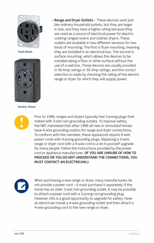
OutletsPAGE 110
Prior to 1996, ranges and dryers typically had 3-prong plugs that mated with 3-slot non-grounding outlets. To improve safety, the NEC mandated that after 1996 all new or renovated homes have 4-wire grounding outlets for range and dryer connections. To conform with the mandate, these appliances require 4-wire power cords with 4-prong grounding plugs. Replacing a 3-wire range or dryer cord with a 4-wire cord is a do-it-yourself upgrade for many people. Follow the instructions provided by the power cord or appliance manufacturer. (IF YOU ARE UNSURE OF HOW TO PROCEED OR YOU DO NOT UNDERSTAND THE CONNECTIONS, YOU MUST CONTACT AN ELECTRICIAN.)
n Range and Dryer Outlets – These devices work just like ordinary household outlets, but they are larger in size, and they have a higher rating because they are used as a source of electrical power for electric cooking ranges/ovens and clothes dryers. These outlets are available in two di�erent versions for two kinds of mounting: The first is flush mounting, meaning they are installed in an electrical box. The second is surface mounting, which allows the devices to be installed along a floor or other surface without the use of a wall box. These devices are usually provided in 30 Amp ratings or 50 Amp ratings, and the correct selection is made by checking the rating of the electric range or dryer for which they will supply power.
Flush Mount
When purchasing a new range or dryer, many manufacturers do not provide a power cord – it must purchase it separately. If the home has an older 3-slot non-grounding outlet, it may be possible to attach a power cord with a 3-prong non-grounding plugHowever, this is a good opportunity to upgrade for safety. Have an electrician install a 4-wire grounding outlet and then attach a 4-wire grounding cord to the new range or dryer.
Surface Mount
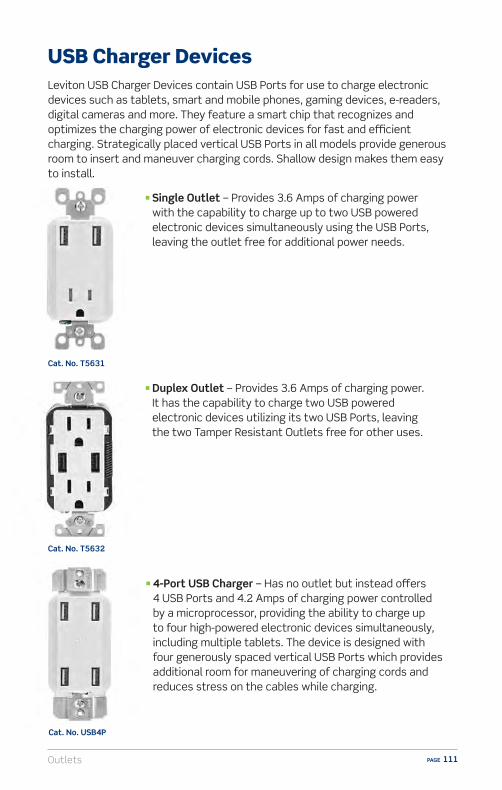
Outlets PAGE 111
n 4-Port USB Charger – Has no outlet but instead o�ers 4 USB Ports and 4.2 Amps of charging power controlled by a microprocessor, providing the ability to charge up to four high-powered electronic devices simultaneously, including multiple tablets. The device is designed with four generously spaced vertical USB Ports which provides additional room for maneuvering of charging cords and reduces stress on the cables while charging.
n Single Outlet – Provides 3.6 Amps of charging power with the capability to charge up to two USB powered electronic devices simultaneously using the USB Ports, leaving the outlet free for additional power needs.
Leviton USB Charger Devices contain USB Ports for use to charge electronic devices such as tablets, smart and mobile phones, gaming devices, e-readers, digital cameras and more. They feature a smart chip that recognizes and optimizes the charging power of electronic devices for fast and e�cient charging. Strategically placed vertical USB Ports in all models provide generous room to insert and maneuver charging cords. Shallow design makes them easy to install.
USB Charger Devices
n Duplex Outlet – Provides 3.6 Amps of charging power. It has the capability to charge two USB powered electronic devices utilizing its two USB Ports, leaving the two Tamper Resistant Outlets free for other uses.
Cat. No. USB4P
Cat. No. T5631
Cat. No. T5632

OutletsPAGE 112
Installation and Wiring Considerations
1. If there is any installation where the customer is unsure of how to proceed, or does not feel able to carry out the tasks specified in the wiring device instruction sheets, STOP RIGHT THERE! In such a case always advise the customer to CONSULT AN ELECTRICIAN. Electrical wiring can be complicated, and unless the installation can be properly and safely completed by the customer, the very best plan is to contact an electrician.
2. The information in this manual is here to help you serve your customers. Do not use this information as a substitute for the installation instructions provided with the devices. The instructions contain very specific and detailed directions for the device they’re packed with. Use this guide as a general reference, but familiarize yourself with the specific instruction sheets for the devices your customers will be asking about.
3. Remind your customers that in order to prevent death or injury before they begin any wiring project, THEY MUST TURN OFF POWER AT THE FUSE OR CIRCUIT BREAKER THAT SUPPLIES ELECTRICITY TO THE WIRES THEY WILL BE WORKING WITH. And after they complete their installation, they should restore power at the fuse or circuit breaker and verify that the new device is working properly. If the fuse blows or the circuit breaker opens when power is restored, or if the new device doesn’t seem to be working properly, the customer should immediately contact an electrician.
4. Be sure only properly rated devices are chosen for replacement and repair projects. For instance, a 3-way device MUST be replaced only with another 3-way device. Although a single-pole device may look similar it wouldn’t be a suitable replacement. Also, if devices are being installed on a 15 Amp branch circuit, then only 15 Amp devices may be used. Using a 20 Amp device on a 15 Amp branch circuitis potentially dangerous, and must be avoided. However, it is acceptable to use 15 Amp devices on a 20 Amp circuit.

Outlets PAGE 113
There are three common ways to wire outlets: side wire, back wire and QuickwireTM. Note all three wiring methods comply with electrical codes.
Side Wiring
Back Wiring
Leviton Quickwire™
Uses the side terminal screws
Uses the screw- and-clamp system
Uses the backwire push-in feature also referred to as “backstab”
Wire is stripped and looped around the side terminal screw
The screw-and-clamp mechanism securely holds the wire in place
The Quickwire hole accepts 14 gauge solid wire ONLY
The terminal screw is then tightened down on the wire
The screw is then tightened down on the wire
The wire is inserted directly into the Quickwire hole on the back of the device

OutletsPAGE 114
Decorativen Decora® devices are perfect for areas such as kitchens, living rooms
and bathrooms - Easily replace traditional style outlets - Adds the perfect finishing touch to any décor
Safetyn Tamper Resistant Outlets - Helps protect children from electrical injuries - Built-in shutter prevents access by most foreign/non-rated objects - O�er a higher measure of safety than removable outlet caps - Complies with NEC requirement for child safety
n GFCIs - Helps prevent against electrical shock - Automatically shuts o� power if ground fault occurs - Required by NEC - SmartlockPro® shallow design is easy to install - For indoor and outdoor wet or damp locations
n AFCIs - Helps prevent electrical fires resulting from arc-faults - Automatically shuts o� power if a dangerous arc-fault is detected - Required by NEC - Install in hallway, bedrooms and family room/living/den
Durabilityn Preferred grade outlets are great for frequently used areas in the home
and for workshops and garages - Superior durable construction for high use/abuse areas - Back and side wire terminals for easy installation
Conveniencen USB Charger Devices - Designed for maximum charging e�ciency - Compatible with a wide range of electronics such as tablets, smart and
mobile phones, gaming devices, e-readers and digital cameras - Eliminates clutter of cords and transformers plugged into the wall
Sell-Up Opportunities
Outlets PAGE 115
Q: When should I replace a outlet?
A: If there are visible cracks or chips on the outlet face. It no longer holds plugs firmly – plugs are loose or fall out. Outlet feels warm or produces a spark.
Q: I have an outlet with only 2 slots that only works with 2-prong plugs. Can I replace it with an outlet that works with 3-prong grounding plugs?
A: You can replace a 2-slot outlet with a grounding outlet only if there’s a ground connection in the outlet box. If not, you can ONLY use a 2-slot outlet. An electrician can determine if you have a ground connection.
Q: Are plastic caps and shuttered wallplates the best way to child-proof outlets?
A: No. A Consumer Product Safety Commission study documents thousands of children under the age of 10 are injured every year by attempting to insert objects into outlets. Tamper Resistant Outlets are permanently installed and the best option for child-proofing outlets.
Q: The laundry room in our new home has a 4-slot dryer outlet, but our dryer has a 3-prong plug. What should we do?
A: The 4-slot dryer outlet in your new home complies with NEC requirements. Do not change the outlet. Replace the dryer’s power cord with a new 4-wire power cord equipped with a 4-prong grounding plug.
FAQs (Frequently Asked Questions)
OutletsPAGE 116
1. An ungrounded outlet may be replaced by a grounded outlet.A) TrueB) False
2. USB Charger Devices can power:A) TabletsB) Smart and mobile phonesC) E-ReadersD) All of the above
3. CO/ALR outlets are made to be used with what type of wiring?A) CopperB) AluminumC) SteelD) Any wiring
4. How can the electrical rating of an outlet be determined?A) It is indicated on the deviceB) With a Volt meterC) By checking the rating of what is plugged into itD) With a test lamp
5. What are the two elements of every outlet’s electrical rating?A) Voltage and SizeB) Amperage and SizeC) Voltage and AmperageD) Single and Duplex
Outlets – Self Test Questions

Outlets PAGE 117
ResourcesVideo library, buying guides and more
www.learnitatleviton.com
Still have questions?Contact our Technical Support Team
1-800-824-3005
Need to place a special order?Contact Customer Service
1-800-367-5424
www.leviton.com
Training Notes

OutletsPAGE 118
1. ANSWER: B) False. An ungrounded outlet must be replaced with a grounded outlet. Check pages 105, 108 for information.
2. ANSWER: D) All of the Above. USB Charger Devices can power up tablets, smart and mobile phones and e-readers. Check pages 114, 111 for information.
3. ANSWER: B) CO/ALR outlets are designed to be used with aluminum wiring. Check page 109 for information.
4. ANSWER: A) The electrical rating of an outlet is indicated on the device. Check pages 104, 106-107 for information.
5. ANSWER: C) Voltage and Amperage are the two elements of every outlet’s electrical rating. Check page 104 for information.
Outlets – Self Test Answers
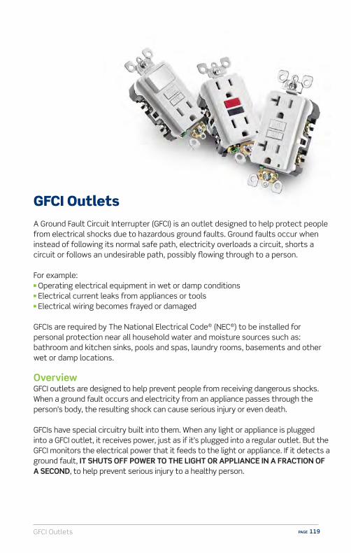
GFCI Outlets PAGE 119
GFCI OutletsA Ground Fault Circuit Interrupter (GFCI) is an outlet designed to help protect people from electrical shocks due to hazardous ground faults. Ground faults occur when instead of following its normal safe path, electricity overloads a circuit, shorts a circuit or follows an undesirable path, possibly flowing through to a person.
For example:n Operating electrical equipment in wet or damp conditionsn Electrical current leaks from appliances or toolsn Electrical wiring becomes frayed or damaged
GFCIs are required by The National Electrical Code® (NEC®) to be installed for personal protection near all household water and moisture sources such as: bathroom and kitchen sinks, pools and spas, laundry rooms, basements and other wet or damp locations.
OverviewGFCI outlets are designed to help prevent people from receiving dangerous shocks. When a ground fault occurs and electricity from an appliance passes through the person’s body, the resulting shock can cause serious injury or even death.
GFCIs have special circuitry built into them. When any light or appliance is plugged into a GFCI outlet, it receives power, just as if it’s plugged into a regular outlet. But the GFCI monitors the electrical power that it feeds to the light or appliance. If it detects a ground fault, IT SHUTS OFF POWER TO THE LIGHT OR APPLIANCE IN A FRACTION OF A SECOND, to help prevent serious injury to a healthy person.

GFCI OutletsPAGE 120
Where to Install GFCI OutletsThe NEC requires the installation of GFCIs in the following areas of the home: kitchens, bathrooms, laundry rooms, workshops, basements, garages/carports and outdoor areas such as pools, decks and patios.
When customers are installing or replacing electrical outlets, you should recommend they upgrade to GFCI outlets to provide themselves and their family with this important protection. GFCI outlets not only protect what’s plugged into them, but also provide feed-through protection to ordinary outlets wired downstream (other outlets on the same circuit).
Benefits of Leviton SmartlockPro® GFCI Outlets Patented Reset Lockout – prevents reset if a SmartlockPro GFCI is damaged so that it cannot respond to a ground fault. Competitive GFCIs may allow reset even if they are no longer providing protection. The SmartlockPro RESET button will not engage if:
n The GFCI is miswired due to reversal of the line and load leads, delivery of power to feed-through terminal and face will be blocked
n There is no power being supplied to the GFCI n The GFCI cannot pass its internal test
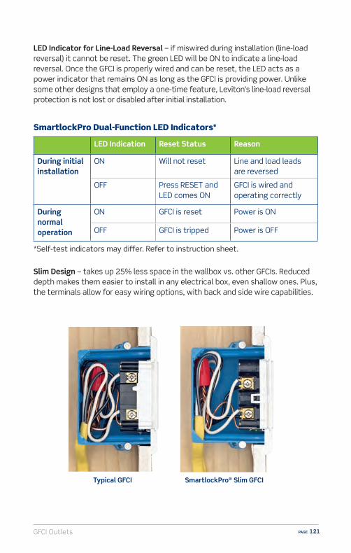
GFCI Outlets PAGE 121
LED Indication Reset Status Reason
During initial installation
ON Will not reset Line and load leads are reversed
OFF Press RESET and LED comes ON
GFCI is wired and operating correctly
During normal operation
ON GFCI is reset Power is ON
OFF GFCI is tripped Power is OFF
SmartlockPro Dual-Function LED Indicators*
*Self-test indicators may di�er. Refer to instruction sheet.
LED Indicator for Line-Load Reversal – if miswired during installation (line-load reversal) it cannot be reset. The green LED will be ON to indicate a line-load reversal. Once the GFCI is properly wired and can be reset, the LED acts as a power indicator that remains ON as long as the GFCI is providing power. Unlike some other designs that employ a one-time feature, Leviton’s line-load reversal protection is not lost or disabled after initial installation.
Typical GFCI SmartlockPro® Slim GFCI
Slim Design – takes up 25% less space in the wallbox vs. other GFCIs. Reduced depth makes them easier to install in any electrical box, even shallow ones. Plus, the terminals allow for easy wiring options, with back and side wire capabilities.

GFCI OutletsPAGE 122
Components of GFCI OutletsFigure 1 shows a typical Leviton duplex GFCI outlet and identifies several components of the device. There are some variations, but basically, all GFCI outlets have these elements.
Figure 1
The MOUNTING STRAP is the backbone of the GFCI and holds the device in place within the wallbox.
The PLASTER EARS are part of the mounting strap and help the GFCI sit flush with the wall.
The BODY is the back part of the GFCI.

GFCI Outlets PAGE 123
The IMPACT RESISTANT FACE reduces cracking or damage from hard contact.
The TEST BUTTON is used to test the GFCI and confirm it is working properly. When pressed, the RESET BUTTON pops up and the GFCI shuts o� the power.
The RESET BUTTON pops up when the GFCI is tested. SmartlockPro GFCIs PATENTED RESET LOCKOUT will prevent reset if the GFCI circuit is not functioning properly and cannot respond to a ground fault. It also will shut o� power when it detects a faulty light or an appliance leaking current. It can be pressed back down to restore power, but will immediately trip again until faulty equipment is unplugged.
The DUAL FUNCTION INDICATOR LIGHT indicates: (1) if the device is miswired during installation (line-load reversal) and cannot be reset, the green LED will be ON to indicate a line-load reversal. Once the GFCI is properly wired and can be RESET, (2) the LED acts as a power indicator that remains ON as long as the GFCI is operating correctly and providing power.
The CONTACTS are inside the GFCI. They grip the blades of an inserted plug and provide the electrical current to the lamp or appliance.
The GROUND CONTACT is also inside the GFCI outlet. It grips the ground pin of three-pronged plugs.
The TAMPER RESISTANT SHUTTER blocks access to the contacts unless a properly rated two or three prong plug is inserted into the device.
The SELF GROUND CLIP ensures device is grounded in a properly grounded metal wallbox without having to connect a ground wire directly to the GFCI.
The EXTERNAL BACK WIRE CLAMP connects the wires (called electrical conductors) from a power source to the GFCI. The terminal screws on GFCIs are color coded so they clearly show which conductor should be connected to which terminal screw. The brass screws are for the “hot” conductor. The silver terminal screws are for the neutral conductor.
The GREEN HEXAGONAL GROUND SCREW is fastened to the strap and is used to connect the GFCI outlet to the ground wire (if any) in the wallbox.
The RATING is indicated on the device and shows the GFCIs electrical rating. GFCIs are available with either 15 Amp or 20 Amp ratings at 125 Volts. All GFCIs are rated 20A-125V Feed-Through. (Meaning it can be installed on a branch circuit protected by a 20A circuit breaker.)
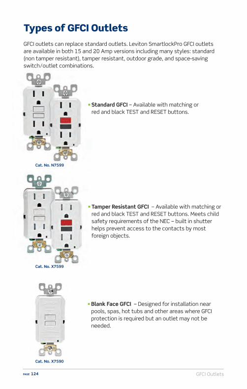
GFCI OutletsPAGE 124
n Tamper Resistant GFCI – Available with matching or red and black TEST and RESET buttons. Meets child safety requirements of the NEC – built in shutter helps prevent access to the contacts by most foreign objects.
n Blank Face GFCI – Designed for installation near pools, spas, hot tubs and other areas where GFCI protection is required but an outlet may not be needed.
Cat. No. N7599
n Standard GFCI – Available with matching or red and black TEST and RESET buttons.
Cat. No. X7599
Cat. No. X7590
Types of GFCI OutletsGFCI outlets can replace standard outlets. Leviton SmartlockPro GFCI outlets are available in both 15 and 20 Amp versions including many styles: standard (non tamper resistant), tamper resistant, outdoor grade, and space-saving switch/outlet combinations.
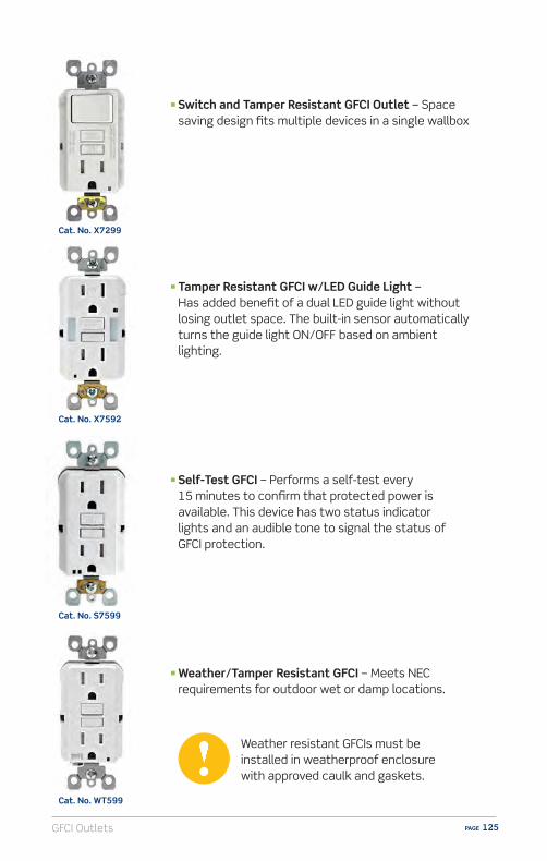
GFCI Outlets PAGE 125
n Switch and Tamper Resistant GFCI Outlet – Space saving design fits multiple devices in a single wallbox
n Tamper Resistant GFCI w/LED Guide Light – Has added benefit of a dual LED guide light without losing outlet space. The built-in sensor automatically turns the guide light ON/OFF based on ambient lighting.
n Self-Test GFCI – Performs a self-test every 15 minutes to confirm that protected power is available. This device has two status indicator lights and an audible tone to signal the status of GFCI protection.
n Weather/Tamper Resistant GFCI – Meets NEC requirements for outdoor wet or damp locations.
Cat. No. X7299
Cat. No. X7592
Cat. No. S7599
Cat. No. WT599
Weather resistant GFCIs must be installed in weatherproof enclosure with approved caulk and gaskets.
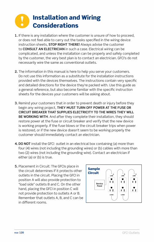
GFCI OutletsPAGE 126
1. If there is any installation where the customer is unsure of how to proceed, or does not feel able to carry out the tasks specified in the wiring device instruction sheets, STOP RIGHT THERE! Always advise the customer to CONSULT AN ELECTRICIAN in such a case. Electrical wiring can be complicated, and unless the installation can be properly and safely completed by the customer, the very best plan is to contact an electrician. GFCI’s do not necessarily wire the same as conventional outlets.
2. The information in this manual is here to help you serve your customers. Do not use this information as a substitute for the installation instructions provided with the devices themselves. The instructions contain very specific and detailed directions for the device they’re packed with. Use this guide as a general reference, but also become familiar with the specific instruction sheets for the devices your customers will be asking about.
3. Remind your customers that in order to prevent death or injury before they begin any wiring project, THEY MUST TURN OFF POWER AT THE FUSE OR CIRCUIT BREAKER THAT SUPPLIES ELECTRICITY TO THE WIRES THEY WILL BE WORKING WITH. And after they complete their installation, they should restore power at the fuse or circuit breaker and verify that the new device is working properly. If the fuse blows or the circuit breaker trips when power is restored, or if the new device doesn’t seem to be working properly the customer should immediately contact an electrician.
4. DO NOT install the GFCI outlet in an electrical box containing (a) more than four (4) wires (not including the grounding wires) or (b) cables with more than two (2) wires (not including the grounding wire). Contact an electrician if either (a) or (b) is true.
5. Placement in Circuit: The GFCIs place in the circuit determines if it protects other outlets in the circuit. Placing the GFCI in position A will also provide protection to “load side” outlets B and C. On the other hand, placing the GFCI in position C will not provide protection to outlets A or B. Remember that outlets A, B, and C can be in di�erent rooms.
ServicePanel
LINE
LOAD
LINE
LOAD
LINEA B C
Sample Circuit
Installation and Wiring Considerations
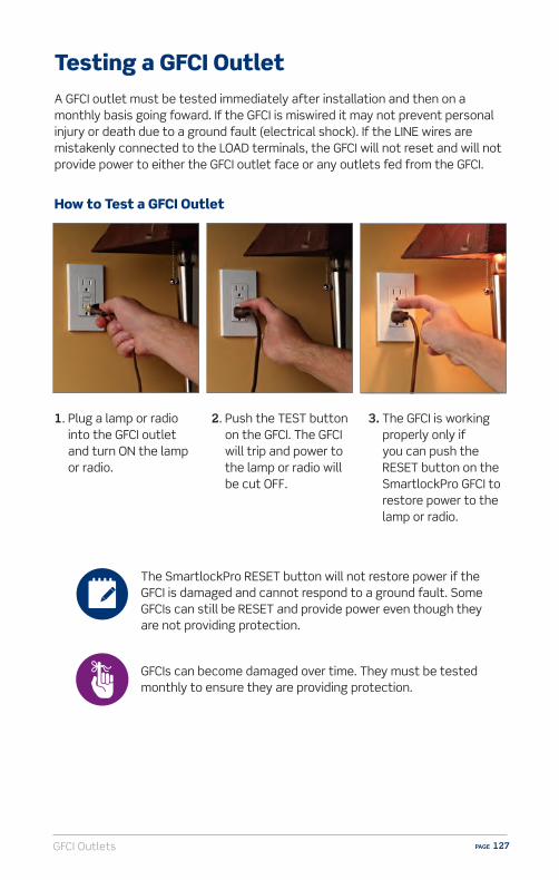
GFCI Outlets PAGE 127
Testing a GFCI OutletA GFCI outlet must be tested immediately after installation and then on a monthly basis going foward. If the GFCI is miswired it may not prevent personal injury or death due to a ground fault (electrical shock). If the LINE wires are mistakenly connected to the LOAD terminals, the GFCI will not reset and will not provide power to either the GFCI outlet face or any outlets fed from the GFCI.
How to Test a GFCI Outlet
1. Plug a lamp or radio into the GFCI outlet and turn ON the lamp or radio.
2. Push the TEST button on the GFCI. The GFCI will trip and power to the lamp or radio will be cut OFF.
3. The GFCI is working properly only if you can push the RESET button on the SmartlockPro GFCI to restore power to the lamp or radio.
The SmartlockPro RESET button will not restore power if the GFCI is damaged and cannot respond to a ground fault. Some GFCIs can still be RESET and provide power even though they are not providing protection.
GFCIs can become damaged over time. They must be tested monthly to ensure they are providing protection.

GFCI OutletsPAGE 128
n Lockout Action- Automatically tests the GFCI every time the RESET button is pushed in. The
GFCI will not reset if its circuit is not functioning properly- Disables the RESET button if GFCI protection has been compromised, reducing
the possibility of end-users incorrectly assuming that a reset GFCI is providing ground fault protection when it is not
- Dual function LED o�ers indication of line/load reversal and power availability
n Reduced depth makes it easier to install in any electrical box, even shallow ones
n Provides up to 25% or more space in the wallbox vs. other GFCIsn Terminals allow for easy wiring options – back and side wire capablen External back wire clamps provide visual indication of proper clampingn Standard brass self-grounding clipn Terminals withstand high torque and resists wire pulloutn Tamper Resistant versions meet NEC requirement for child safetyn Guide Light version adds an extra element of safety when its dark
without losing outlet space
Sell-Up Opportunities
GFCI Outlets PAGE 129
Q: I thought circuit breakers protect my family from electrical shock. Why do I need GFCIs?
A: Circuit breakers and fuses protect against electrical shock and fire caused by dangerous current overloads. GFCIs protect against electrical shock caused by current leaking from faulty appliances.
Q: What is the benefit of a “Slim” GFCI?
A: Leviton SmartlockPro® Slim GFCIs take up to 25% less space in the wallbox than traditional GFCIs. This makes for easier installation.
Q: What is Reset/Lockout?
A: The patented Reset/Lockout feature on SmartlockPro GFCIs serves two purposes: it provides an end-of-life indication and it prevents reset of the device if for any reason it is unable to respond to a ground fault or if it is not wired correctly and receiveing power. Competitive GFCIs may allow reset of the device even if they are no longer providing protection.
Q: Where should GFCIs be installed? Is there a Code requirement?
A: GFCIs are required by the National Electrical Code to be installed in wet or damp locations. This would include kitchens, bathrooms, basements, laundry rooms, garages, porches and any other areas where a water source is present.
Q: Why do you need to test a GFCI?
A: It is recommended that GFCIs are tested monthly to ensure protected power is present. Please refer to page 127 of this handbook for the testing procedure. Note that Leviton makes a Self-Test model of GFCI which performs a self-test every 15 minutes to confirm that protected power is available.
FAQs (Frequently Asked Questions)
GFCI OutletsPAGE 130
1. GFCIs protect from:A) Arc-faultsB) Electrical shockC) Power surgesD) All of the above
2. GFCIs are required: A) In children’s rooms B) In closets C) In wet and damp locations D) For use with appliances
3. GFCIs should be tested:A) DailyB) WeeklyC) AnnuallyD) Monthly
GFCIs – Self Test Questions

GFCI Outlets PAGE 131
ResourcesVideo library, buying guides and more
www.learnitatleviton.com
Still have questions?Contact our Technical Support Team
1-800-824-3005
Need to place a special order?Contact Customer Service
1-800-367-5424
www.leviton.com
Training Notes

GFCI OutletsPAGE 132
1. ANSWER: B) GFCIs protect from electrical shock. Check page 119 for information.
2. ANSWER: C) GFCIs are required in wet and damp locations. Check page 119 for information.
3. ANSWER: D) GFCIs should be tested monthly. Check page 127 for information.
GFCIs – Self Test Answers
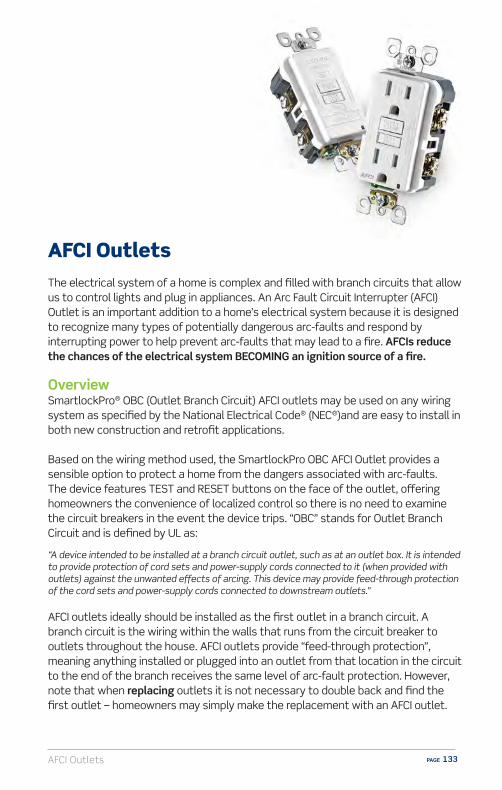
AFCI Outlets PAGE 133
AFCI OutletsThe electrical system of a home is complex and filled with branch circuits that allow us to control lights and plug in appliances. An Arc Fault Circuit Interrupter (AFCI) Outlet is an important addition to a home’s electrical system because it is designed to recognize many types of potentially dangerous arc-faults and respond by interrupting power to help prevent arc-faults that may lead to a fire. AFCIs reduce the chances of the electrical system BECOMING an ignition source of a fire.
OverviewSmartlockPro® OBC (Outlet Branch Circuit) AFCI outlets may be used on any wiring system as specified by the National Electrical Code® (NEC®)and are easy to install in both new construction and retrofit applications.
Based on the wiring method used, the SmartlockPro OBC AFCI Outlet provides a sensible option to protect a home from the dangers associated with arc-faults. The device features TEST and RESET buttons on the face of the outlet, o�ering homeowners the convenience of localized control so there is no need to examine the circuit breakers in the event the device trips. “OBC” stands for Outlet Branch Circuit and is defined by UL as:
“A device intended to be installed at a branch circuit outlet, such as at an outlet box. It is intended to provide protection of cord sets and power-supply cords connected to it (when provided with outlets) against the unwanted e�ects of arcing. This device may provide feed-through protection of the cord sets and power-supply cords connected to downstream outlets.”
AFCI outlets ideally should be installed as the first outlet in a branch circuit. A branch circuit is the wiring within the walls that runs from the circuit breaker to outlets throughout the house. AFCI outlets provide “feed-through protection”, meaning anything installed or plugged into an outlet from that location in the circuit to the end of the branch receives the same level of arc-fault protection. However, note that when replacing outlets it is not necessary to double back and find the first outlet – homeowners may simply make the replacement with an AFCI outlet.
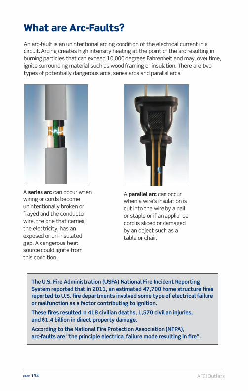
AFCI OutletsPAGE 134
What are Arc-Faults?An arc-fault is an unintentional arcing condition of the electrical current in a circuit. Arcing creates high intensity heating at the point of the arc resulting in burning particles that can exceed 10,000 degrees Fahrenheit and may, over time, ignite surrounding material such as wood framing or insulation. There are two types of potentially dangerous arcs, series arcs and parallel arcs.
A series arc can occur when wiring or cords become unintentionally broken or frayed and the conductor wire, the one that carries the electricity, has an exposed or un-insulated gap. A dangerous heat source could ignite from this condition.
The U.S. Fire Administration (USFA) National Fire Incident Reporting System reported that in 2011, an estimated 47,700 home structure fires reported to U.S. fire departments involved some type of electrical failure or malfunction as a factor contributing to ignition.
These fires resulted in 418 civilian deaths, 1,570 civilian injuries, and $1.4 billion in direct property damage.
According to the National Fire Protection Association (NFPA), arc-faults are “the principle electrical failure mode resulting in fire”.
A parallel arc can occur when a wire’s insulation is cut into the wire by a nail or staple or if an appliance cord is sliced or damaged by an object such as a table or chair.

AFCI Outlets PAGE 135
What causes Arc-Faults?Although the source can be unseen or unnoticed, arc-faults can occur anywhere in the home’s electrical system including:
Within walls from nails, screws or staples inadvertently driven into wires.
Other general causes include:
Wire Degradationn Natural degradation through agen Humidity or heatn Extended mechanical stress
from bending or winding or other physical damage
n Extended voltage stress
Physical Damagen Animals chewing through insulationn Nails, tacks from construction or
picture hanging driven into a wall through a wire(s)
n Extension or power supply cord damage from sharp bends or furniture on or against cords
n General cord damagen Poor wiring or connection at
devices/ j-boxes
Through old or cracked wires or cords.
At loose electrical connections or cords damaged by doors closing on them.
Through wires or cords damaged by heat, sunlight or humidity.
Within electrical cords accidently damaged by furniture resting or pressing upon them.
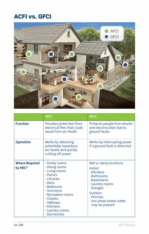
AFCI OutletsPAGE 136
AFCI GFCI
Function Provides protection from electrical fires that could result from arc-faults
Protects people from shocks and electrocution due to ground faults
Operation Works by detecting potentially hazardous arc-faults and quickly cutting o� power
Works by interrupting power if a ground fault is detected
Where Required by NEC®
- Family rooms- Dining rooms - Living rooms- Parlors - Libraries- Dens - Bedrooms - Sunrooms - Recreation rooms- Closets- Hallways- Kitchens- Laundry rooms- Dormitories
Wet or damp locations
Indoor: - Kitchens- Bathrooms - Basements- Laundry rooms- Garages
Outdoor:- Porches - Any areas where water
may be present
ACFI vs. GFCI

AFCI Outlets PAGE 137
AFCI Outlet Installations Based on 2014 National Electrical CodeThe National Electrical Code specifically points out the applications when AFCI protection is required. These applications are based on three di�erent construction scenarios.
AFCI
AFCI Protected
Extensions toBranch Circuit
Panel Board
Service EntranceConductors
AFCIProtected Outlets
AFCI
BranchCircuitExtended
AFCI Protected
Extensions toBranch Circuit
Panel Board
Service EntranceConductors
AFCIProtected Outlets
AFCI
Panel Board
Service EntranceConductors
Place AFCI:
If this is receptaclebeing replaced
or or
Modifications or extension to an existing branch circuit
Changing out an existing outlet
NEC 210.12(A)Covers new branch circuits originating from the panel. AFCI protection required for all 15A and 20A, 120V branch circuits supplying outlets in designated locations.
NEC 210.12(B)AFCI protection needs to be added when modifying or extending existing branch circuits in locations designated in 210.12(A). Not required if extension of circuit is less than 6 ft. and does not include any additional outlets or devices.
New Branch Circuit
NEC 406.4(D)Covers replacement of any outlets in those locations designated in 210.12 that are not currently AFCI protected.
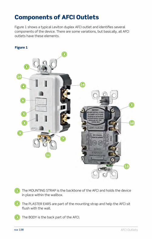
AFCI OutletsPAGE 138
Components of AFCI OutletsFigure 1 shows a typical Leviton duplex AFCI outlet and identifies several components of the device. There are some variations, but basically, all AFCI outlets have these elements.
Figure 1
The MOUNTING STRAP is the backbone of the AFCI and holds the device in place within the wallbox.
The PLASTER EARS are part of the mounting strap and help the AFCI sit flush with the wall.
The BODY is the back part of the AFCI.

AFCI Outlets PAGE 139
The IMPACT RESISTANT FACE reduces cracking or damage from hard contact.
The TEST BUTTON is used to test the AFCI and confirm it is working properly. When pressed, the RESET BUTTON pops up and the AFCI shuts o� the power.
The RESET BUTTON pops up when the AFCI is tested. SmartlockPro AFCIs PATENTED RESET LOCKOUT will prevent reset if the AFCI circuit is not functioning properly and cannot respond to an arc fault.
The DUAL FUNCTION INDICATOR LIGHT: (1) if the device is miswired during installation (line-load reversal) and cannot be reset, the green LED will be ON to indicate a line-load reversal. Once the AFCI is properly wired and can be RESET, (2) the LED acts as a power indicator that remains ON as long as the AFCI is operating correctly and providing power.
The CONTACTS are inside the AFCI. They grip the blades of an inserted plug and provide the electrical current to the lamp or appliance.
The GROUND CONTACT is also inside the AFCI. It grips the ground pin of three-pronged plugs.
The TAMPER RESISTANT SHUTTER blocks access to the contacts unless a properly rated two or three prong plug is inserted into the device.
The SELF GROUND CLIP ensures the device is grounded in a properly grounded metal wallbox without having to connect a ground wire directly to the AFCI.
The EXTERNAL BACK WIRE CLAMP connects the wires (called electrical conductors) from a power source to the AFCI. The terminal screws on AFCIs are color coded so they clearly show which conductor should be connected to which terminal screw. The brass colored screws are for the “hot” conductor. The silver colored terminal screws are for the neutral conductor.
The GREEN HEXAGONAL GROUND SCREW is fastened to the strap and is used to connect the AFCI outlet to the ground wire (if any) in the wallbox.
The RATING is indicated on the device and shows the AFCIs electrical rating. AFCIs are available with either 15 Amp or 20 Amp ratings at 125 Volts. All AFCIs are rated 20A-125V Feed-Through. (Meaning it can be installed on a branch circuit protected by a 20A circuit breaker.)

AFCI OutletsPAGE 140
Types of AFCI Outlets
n 15 Amp Duplex – Use for replacement or new outlet circuits.
n 20 Amp Duplex – For circuits that use appliances, tools and equipment with a higher rating.
n Blank Face – Install where AFCI protection is desired but an outlet is not needed such as lighting circuits and smoke detectors.
n 15 Amp Switch – Use on branch circuits where a single pole switch is controlled from the first outlet. Helps protect switched load and all downstream switches/outlets.
Cat. No. AFTR1
Cat. No. AFTR2
Cat. No. AFRBF
Cat. No. AFSW1
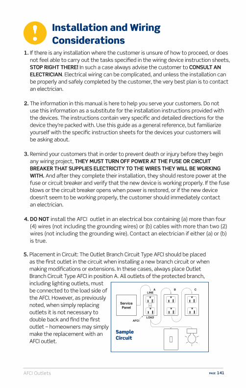
AFCI Outlets PAGE 141
1. If there is any installation where the customer is unsure of how to proceed, or does not feel able to carry out the tasks specified in the wiring device instruction sheets, STOP RIGHT THERE! In such a case always advise the customer to CONSULT AN ELECTRICIAN. Electrical wiring can be complicated, and unless the installation can be properly and safely completed by the customer, the very best plan is to contact an electrician.
2. The information in this manual is here to help you serve your customers. Do not
use this information as a substitute for the installation instructions provided with the devices. The instructions contain very specific and detailed directions for the device they’re packed with. Use this guide as a general reference, but familiarize yourself with the specific instruction sheets for the devices your customers will be asking about.
3. Remind your customers that in order to prevent death or injury before they begin any wiring project, THEY MUST TURN OFF POWER AT THE FUSE OR CIRCUIT BREAKER THAT SUPPLIES ELECTRICITY TO THE WIRES THEY WILL BE WORKING WITH. And after they complete their installation, they should restore power at the fuse or circuit breaker and verify that the new device is working properly. If the fuse blows or the circuit breaker opens when power is restored, or if the new device doesn’t seem to be working properly, the customer should immediately contact an electrician.
4. DO NOT install the AFCI outlet in an electrical box containing (a) more than four (4) wires (not including the grounding wires) or (b) cables with more than two (2) wires (not including the grounding wire). Contact an electrician if either (a) or (b) is true.
LINEA
AFCI
B C
LOAD
ServicePanel
Sample Circuit
5. Placement in Circuit: The Outlet Branch Circuit Type AFCI should be placed as the first outlet in the circuit when installing a new branch circuit or when making modifications or extensions. In these cases, always place Outlet Branch Circuit Type AFCI in position A. All outlets of the protected branch, including lighting outlets, must be connected to the load side of the AFCI. However, as previously noted, when simply replacing outlets it is not necessary to double back and find the first outlet – homeowners may simply make the replacement with an AFCI outlet.
Installation and Wiring Considerations
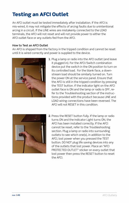
AFCI OutletsPAGE 142
1. Plug a lamp or radio into the AFCI outlet (and leave it plugged in). For the AFCI/Switch combination device put the switch in the ON position to turn on its controlled load. For the blank face, a down-stream load should be similarly turned on. Turn the power ON at the service panel. Ensure that the AFCI is still in the tripped condition by pressing the TEST button. If the indicator light on the AFCI outlet face is ON and the lamp or radio is OFF, re-fer to the Troubleshooting section of the instruc-tions provided with the product because LINE and LOAD wiring connections have been reversed. The AFCI will not RESET in this condition.
2. Press the RESET button fully. If the lamp or radio turns ON and the Indicator Light turns ON, the AFCI has been installed correctly. If the AFCI cannot be reset, refer to the Troubleshooting section. Plug a lamp or radio into surrounding outlets to see which one(s), in addition to the AFCI, lost power when you pressed the TEST button. DO NOT plug life saving devices into any of the outlets that lost power. Place an “AFCI PROTECTED OUTLET” sticker on every outlet that lost power then press the RESET button to reset the AFCI.
Testing an AFCI OutletAn AFCI outlet must be tested immediately after installation. If the AFCI is mis-wired, it may not mitigate the e�ects of arcing faults due to unintentional arcing in a circuit. If the LINE wires are mistakenly connected to the LOAD terminals, the AFCI will not reset and will not provide power to either the AFCI outlet face or any outlets fed from the AFCI.
How to Test an AFCI OutletAn AFCI is shipped from the factory in the tripped condition and cannot be reset until it is wired correctly and power is supplied to the device.
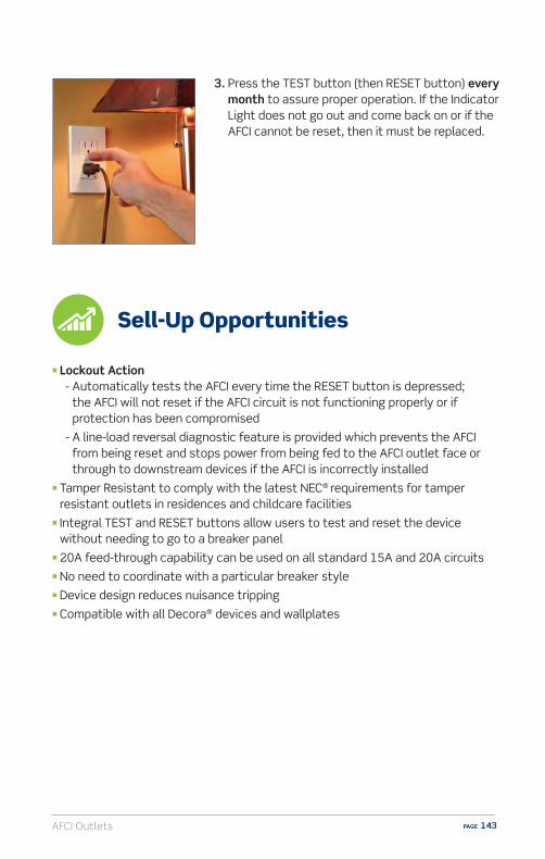
AFCI Outlets PAGE 143
3. Press the TEST button (then RESET button) every month to assure proper operation. If the Indicator Light does not go out and come back on or if the AFCI cannot be reset, then it must be replaced.
Sell-Up Opportunities
n Lockout Action - Automatically tests the AFCI every time the RESET button is depressed;
the AFCI will not reset if the AFCI circuit is not functioning properly or if protection has been compromised
- A line-load reversal diagnostic feature is provided which prevents the AFCI from being reset and stops power from being fed to the AFCI outlet face or through to downstream devices if the AFCI is incorrectly installed
n Tamper Resistant to comply with the latest NEC® requirements for tamper resistant outlets in residences and childcare facilities
n Integral TEST and RESET buttons allow users to test and reset the device without needing to go to a breaker panel
n 20A feed-through capability can be used on all standard 15A and 20A circuitsn No need to coordinate with a particular breaker style n Device design reduces nuisance tripping n Compatible with all Decora® devices and wallplates

AFCI OutletsPAGE 144
Q: Why would I use an AFCI outlet instead of a AFCI circuit breaker?
A: An AFCI outlet provides protection similar to an AFCI circuit breaker but has the convenience of localized TEST and RESET buttons on the face of the outlet. This allows for immediate response when the AFCI outlet responds to an arc-fault and saves the consumer a trip to the circuit box. The AFCI outlet is easy to install. Simply replace a standard outlet; the Leviton AFCI outlet fits in a standard wallbox. Also, AFCI circuit breakers do not always fit in older panels therefore making the AFCI outlet an easier retrofit. AFCI outlets work with any type of wiring and are not dependent on the type of circuit breaker in the panel.
Q: Is this Code approved for AFCI protection?
A: The 2014 NEC requires AFCI protection in many locations for new, modified or extended branch circuits. It is also required that AFCI protection be added to those locations when replacing outlets. The AFCI outlet can be used for new branch circuits, depending on the wiring method used, and is also suitable for use on branch circuit modifications and extensions as well as replacement outlets. Please refer to the NEC for specific requirements.
Q: Do I need an AFCI for every outlet?
A: No, a single AFCI outlet provides arc-fault protection for all wiring and outlets downstream from its location. It also provides protection against series types of arc-faults upstream of its location as long as it is installed as the first outlet in the branch circuit and in compliance with latest NEC requirements.
Q: Will an AFCI protect what I have plugged into the outlet?
A: Yes, an AFCI provides protection for the both the branch circuit wiring (the wiring inside your walls) as well as extensions to the branch circuit wiring (i.e. appliance cords, extension cords). Appliance and extension cords can become worn or damaged and are recognized as potential sources of arc-faults that could lead to fires.
FAQs (Frequently Asked Questions)

AFCI Outlets PAGE 145
Q: How do I know where the first outlet in the branch circuit is?
A: Unless you are familiar with your home’s wiring, contact an electrician. If you are comfortable with replacing outlets, to begin, TURN THE BREAKER OFF. Remove the outlet that you believe is the most likely to be first in the circuit. Cap the wires. Turn the circuit breaker back on and test the other outlets. If you chose correctly, all the others will be dead. If you chose incorrectly, put the original outlet back in and try another and repeat the process.
Q: What’s the difference between an AFCI circuit breaker and an AFCI outlet?
A: An AFCI circuit breaker is located in the service panel and when tripped, requires the user to reset the breaker at the panel. An AFCI outlet replaces a standard outlet and when tripped, requires the user to reset by pressing a button located on the outlet.
Q: Are AFCI outlets required by the electric code?
A: The NEC provides options for using either combination type AFCI circuit breakers or OBC AFCI outlets.
Q: Can an AFCI outlet and a GFCI outlet be used on the same circuit?
A: Yes, they both can be used on the same circuit.
Q: Can AFCI outlets be used on the two wire circuits found in older homes?
A: Yes, AFCI outlets can be used in older homes that contain two wire circuits. Replacement of non-grounding-type outlets with grounding-type outlets should be in accordance with applicable NEC requirements.
Q: Can the same neutral wire be used for the installation of more than one AFCI outlet?
A: While OBC AFCI outlets can work with a shared neutral on the line side, please refer to specific code requirements regarding acceptable methods for feeding an AFCI outlet. If you are unfamiliar with the function of a neutral wire, contact a licensed electrician.
Q: How many outlets are protected downstream from an AFCI outlet?
A: All OBC AFCI outlets are rated as 20A feed-through. This means they can protect all outlets on both 15A and 20A branch circuits.

AFCI OutletsPAGE 146
1. An arc-fault is an unintentional arcing condition of the electrical current in a circuit. Arcing creates high intensity heating at the point of the arc resulting in burning particles that can exceed 10,000 degrees Fahrenheit and may, over time, ignite surrounding material such as wood framing or insulation.
A) True B) False
2. Which of the following is NOT a potential cause of an arc-faulting condition?
A) Wire degradation over time B) Cracking of cords and exposure of the wires inside C) Moisture creating a short circuit D) A nail being driven through the wall and into some of the home wiring
3. An AFCI (Arc Fault Circuit Interrupter) Outlet and a GFCI (Ground Fault Circuit Interrupter) Outlet are interchangeable and can both be used in all the same applications.
A) True B) False
4. Ideally, where is the best place in the circuit to install an AFCI Outlet in a new construction scenario?
A) As the first outlet in the circuit B) Anywhere in the middle of the circuit C) As the last outlet in the circuit D) It does not matter where
5. An AFCI Outlet provides what kind of protection for the homeowner?
A) Protection from electric shock
B) Protection from electrical blackouts C) Protection from the ignition of electrical fires D) All of the above
AFCIs – Self Test Questions

AFCI Outlets PAGE 147
ResourcesVideo library, buying guides and more
www.learnitatleviton.com
Still have questions?Contact our Technical Support Team
1-800-824-3005
Need to place a special order?Contact Customer Service
1-800-367-5424
www.leviton.com
Training Notes
AFCI OutletsPAGE 148
1. ANSWER: A) True. An arc-fault is an unintentional arcing condition of the electrical current in a circuit. Arcing creates high intensity heating at the point of the arc resulting in burning particles that can exceed 10,000 degrees Fahrenheit and may, over time, ignite surrounding material such as wood framing or insulation. Check page 134 for information.
2. ANSWER: C) Moisture creating a short circuit is not a potential cause of an arc-faulting condition. Check page 135 for information.
3. ANSWER: B) False. An AFCI (Arc Fault Circuit Interrupter) Outlet and a GFCI (Ground Fault Circuit Interrupter) Outlet are not interchangeable and cannot both be used in all the same applications. Check page 136 for information.
4. ANSWER: A) As the first outlet in the circuit is the best place in a circuit to install an AFCI outlet in a new construction scenario. Check page 133 for information.
5. ANSWER: C) An AFCI outlet provides the homeowner protection from the ignition of electrical fires. Check page 133 for information.
AFCIs – Self Test Answers
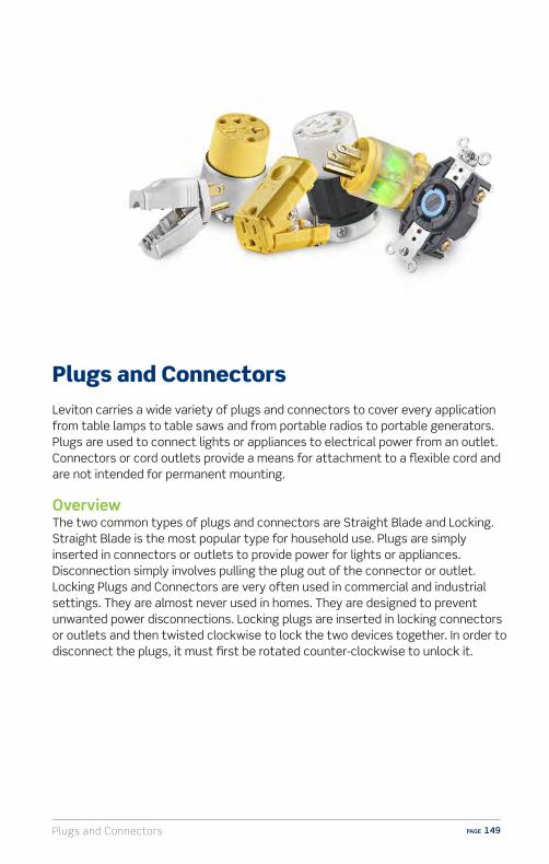
Plugs and Connectors PAGE 149
Plugs and ConnectorsLeviton carries a wide variety of plugs and connectors to cover every application from table lamps to table saws and from portable radios to portable generators. Plugs are used to connect lights or appliances to electrical power from an outlet. Connectors or cord outlets provide a means for attachment to a flexible cord and are not intended for permanent mounting.
OverviewThe two common types of plugs and connectors are Straight Blade and Locking. Straight Blade is the most popular type for household use. Plugs are simply inserted in connectors or outlets to provide power for lights or appliances. Disconnection simply involves pulling the plug out of the connector or outlet. Locking Plugs and Connectors are very often used in commercial and industrial settings. They are almost never used in homes. They are designed to prevent unwanted power disconnections. Locking plugs are inserted in locking connectors or outlets and then twisted clockwise to lock the two devices together. In order to disconnect the plugs, it must first be rotated counter-clockwise to unlock it.
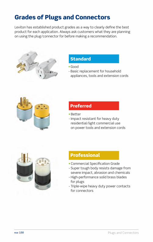
Plugs and ConnectorsPAGE 150
Grades of Plugs and ConnectorsLeviton has established product grades as a way to clearly define the best product for each application. Always ask customers what they are planning on using the plug/connector for before making a recommendation.
n Good - Basic replacement for household
appliances, tools and extension cords
n Better- Impact resistant for heavy duty
residential/light commercial use on power tools and extension cords
n Commercial Specification Grade- Super tough body resists damage from
severe impact, abrasion and chemicals- High-performance solid brass blades
for plugs- Triple-wipe heavy duty power contacts
for connectors
Plugs and Connectors PAGE 151
Every plug and connector has an electrical rating indicated on the device. The electrical rating tells you two important things: the voltage and the maximum load in amps for which the plug/connector can safely supply power.
For example, a plug or connector marked with a rating of 15A-125VAC can be used to supply a maximum load of 15 Amps at 125 Volts.
In addition, plugs have blades and connectors have slots arranged according to their ratings. This is done to help prevent mismatching of plugs and connectors with di�erent ratings. The arrangement of blades and slots is called the NEMA®
(National Electrical Manufacturers Association®) configuration.
A common configuration for household use is NEMA 1-15P (which appears on the NEMA chart on pages 152-153). This type of two-prong plug is also called a polarized plug. It has one blade wider than the other, and can mate with polarized outlets or connectors in only one way: the wider blade fits into the wider slot.
There are other configurations and they all have the following in common:n All devices use identical configurations for corresponding voltage/amperage
ratings.n The configurations are determined by NEMA.n When making an extension cord, or replacing the plug or connector on an
extension cord, THE PLUG AND CONNECTOR MUST HAVE CORRESPONDING RATINGS AND NEMA CONFIGURATIONS. MISMATCHING THE RATING AND NEMA CONFIGURATIONS ON AN EXTENSION CORD IS UNSAFE, AND A VIOLATION OF ELECTRICAL CODE.
The following charts show all NEMA configurations for the two main types of plugs and connectors, straight blade and locking.
Electrical Ratings of Plugs and Connectors

Plugs and ConnectorsPAGE 152
L-1-15R
W1-15R1-15P
W1-15P
G
W
G
W
5-15P 5-15R
5-15RG
W
G
W
5-15P 5-15R
5-15P
2-15P 2-20R 2-20P 2-30R 2-30P
2-15P
2-15P 2-20R 2-20P 2-30R 2-30P
2-20R
2-15P 2-20R 2-20P 2-30R 2-30P
2-20P
2-15P 2-20R 2-20P 2-30R 2-30P
2-30R
GW
5-20R
5-20RG
W
5-20P
5-20P
G
6-15R
6-15RG
6-15P
6-15PG
6-20R
6-20RG
6-20P
6-20P
G
W
7-15R
7-15RG
W
7-15P
7-15P
Z YX
ZYX
Z Y
X
ZY
X
Z YX
ZYX
Z Y
X
ZY
X
11-15R 11-15P
11-50R 11-50P11-30R 11-30P
11-20R 11-20P
11-15R Z YX
ZYX
Z Y
X
ZY
X
Z YX
ZYX
Z Y
X
ZY
X
11-15R 11-15P
11-50R 11-50P11-30R 11-30P
11-20R 11-20P
11-15P
G
W
G
W
G
W
G
W
G
W
G
W
7-20R 7-20P 7-30R 7-30P 7-50R 7-50P
7-20RG
W
G
W
G
W
G
W
G
W
G
W
7-20R 7-20P 7-30R 7-30P 7-50R 7-50P
7-20P
G
W
5-30R
5-30R
2-15P 2-20R 2-20P 2-30R 2-30P
2-30P
5-30PG
W
5-50R
5-50RG
W
5-50P
5-50P
G
6-30R
6-30RG
6-30P
6-30PG
6-50R
6-50RG
6-50P
6-50P
G
W
G
W
G
W
G
W
G
W
G
W
7-20R 7-20P 7-30R 7-30P 7-50R 7-50P
7-30RG
W
G
W
G
W
G
W
G
W
G
W
7-20R 7-20P 7-30R 7-30P 7-50R 7-50P
7-30P
W
YX
W
Y X
WW
Y X
W
Y
XW
Y
X
��10-20R 10-20P 10-30R
YX
10-30P 10-50R 10-50P
10-20RW
YX
W
Y X
WW
Y X
W
Y
XW
Y
X
��10-20R 10-20P 10-30R
YX
10-30P 10-50R 10-50P
10-20PW
YX
W
Y X
WW
Y X
W
Y
XW
Y
X
��10-20R 10-20P 10-30R
YX
10-30P 10-50R 10-50P
10-30RW
YX
W
Y X
WW
Y X
W
Y
XW
Y
X
��10-20R 10-20P 10-30R
YX
10-30P 10-50R 10-50P
10-30P
Z YX
ZYX
Z Y
X
ZY
X
Z YX
ZYX
Z Y
X
ZY
X
11-15R 11-15P
11-50R 11-50P11-30R 11-30P
11-20R 11-20P
11-20RZ YX
ZYX
Z Y
X
ZY
X
Z YX
ZYX
Z Y
X
ZY
X
11-15R 11-15P
11-50R 11-50P11-30R 11-30P
11-20R 11-20P
11-20P
GYX
W
GGY X
W
GY X
W
GYX
W
GY X
W
GYX
W
GY X
W
GYX
W
GY X
W
GYX
W
14-15R 14-15P 14-20R 14-20P 14-30R 14-30P 14-50R 14-50P 14-60R 14-60P
14-15RG
YX
W
GGY X
W
GY X
W
GYX
W
GY X
W
GYX
W
GY X
W
GYX
W
GY X
W
GYX
W
14-15R 14-15P 14-20R 14-20P 14-30R 14-30P 14-50R 14-50P 14-60R 14-60P
14-15PG
YX
W
GGY X
W
GY X
W
GYX
W
GY X
W
GYX
W
GY X
W
GYX
W
GY X
W
GYX
W
14-15R 14-15P 14-20R 14-20P 14-30R 14-30P 14-50R 14-50P 14-60R 14-60P
14-20RG
YX
W
GGY X
W
GY X
W
GYX
W
GY X
W
GYX
W
GY X
W
GYX
W
GY X
W
GYX
W
14-15R 14-15P 14-20R 14-20P 14-30R 14-30P 14-50R 14-50P 14-60R 14-60P
14-20P
GZX
Y
GZ X
Y
GZ X
Y
GZX
Y
GZ X
Y
GZX
Y
GZX
Y
GGZ X
Y
GZ X
Y
GZX
Y
15-15R 15-15P 15-20R 15-20P 15-30R 15-30P
15-50R 15-50P 15-60R 15-60P
15-15RG
ZX
Y
GZ X
Y
GZ X
Y
GZX
Y
GZ X
Y
GZX
Y
GZX
Y
GGZ X
Y
GZ X
Y
GZX
Y
15-15R 15-15P 15-20R 15-20P 15-30R 15-30P
15-50R 15-50P 15-60R 15-60P
15-15PG
ZX
Y
GZ X
Y
GZ X
Y
GZX
Y
GZ X
Y
GZX
Y
GZX
Y
GGZ X
Y
GZ X
Y
GZX
Y
15-15R 15-15P 15-20R 15-20P 15-30R 15-30P
15-50R 15-50P 15-60R 15-60P
15-20RG
ZX
Y
GZ X
Y
GZ X
Y
GZX
Y
GZ X
Y
GZX
Y
GZX
Y
GGZ X
Y
GZ X
Y
GZX
Y
15-15R 15-15P 15-20R 15-20P 15-30R 15-30P
15-50R 15-50P 15-60R 15-60P
15-20P
WZ X
Y
WZ X
Y
W ZX
Y
WZ X
Y
W
ZX
Y
WZ X
Y
W
ZX
Y
WZ X
Y
W
ZX
Y
WX Z
Y
18-15R 18-15P 18-20R 18-20P 18-30R 18-30P 18-50R 18-50P 18-60R 18-60P
18-15RW
Z X
Y
WZ X
Y
W ZX
Y
WZ X
Y
W
ZX
Y
WZ X
Y
W
ZX
Y
WZ X
Y
W
ZX
Y
WX Z
Y
18-15R 18-15P 18-20R 18-20P 18-30R 18-30P 18-50R 18-50P 18-60R 18-60P
18-15PW
Z X
Y
WZ X
Y
W ZX
Y
WZ X
Y
W
ZX
Y
WZ X
Y
W
ZX
Y
WZ X
Y
W
ZX
Y
WX Z
Y
18-15R 18-15P 18-20R 18-20P 18-30R 18-30P 18-50R 18-50P 18-60R 18-60P
18-20RW
Z X
Y
WZ X
Y
W ZX
Y
WZ X
Y
W
ZX
Y
WZ X
Y
W
ZX
Y
WZ X
Y
W
ZX
Y
WX Z
Y
18-15R 18-15P 18-20R 18-20P 18-30R 18-30P 18-50R 18-50P 18-60R 18-60P
18-20P
Z YX
ZYX
Z Y
X
ZY
X
Z YX
ZYX
Z Y
X
ZY
X
11-15R 11-15P
11-50R 11-50P11-30R 11-30P
11-20R 11-20P
11-30R
Z YX
ZYX
Z Y
X
ZY
X
Z YX
ZYX
Z Y
X
ZY
X
11-15R 11-15P
11-50R 11-50P11-30R 11-30P
11-20R 11-20P
11-30P
G
W
G
W
G
W
G
W
G
W
G
W
7-20R 7-20P 7-30R 7-30P 7-50R 7-50P
7-50RG
W
G
W
G
W
G
W
G
W
G
W
7-20R 7-20P 7-30R 7-30P 7-50R 7-50P
7-50P
G
W
24-15R
G
W
24-15P
24-15RG
W
24-15R
G
W
24-15P
24-15PG
W
24-20P
G
W
24-20R
24-20RG
W
24-20P
G
W
24-20R
24-20PG
W
24-30R 24-30P
G
W24-30R
G
W
24-30R 24-30P
G
W24-30P
G
W
24-50R 24-50P
G
W24-50R
G
W
24-50R 24-50P
G
W25-50P
W
YX
W
Y X
WW
Y X
W
Y
XW
Y
X
��10-20R 10-20P 10-30R
YX
10-30P 10-50R 10-50P
10-50RW
YX
W
Y X
WW
Y X
W
Y
XW
Y
X
��10-20R 10-20P 10-30R
YX
10-30P 10-50R 10-50P
10-50PZ Y
XZY
XZ Y
X
ZY
X
Z YX
ZYX
Z Y
X
ZY
X
11-15R 11-15P
11-50R 11-50P11-30R 11-30P
11-20R 11-20P
11-50R
Z YX
ZYX
Z Y
X
ZY
X
Z YX
ZYX
Z Y
X
ZY
X
11-15R 11-15P
11-50R 11-50P11-30R 11-30P
11-20R 11-20P
11-50P
GYX
W
GGY X
W
GY X
W
GYX
W
GY X
W
GYX
W
GY X
W
GYX
W
GY X
W
GYX
W
14-15R 14-15P 14-20R 14-20P 14-30R 14-30P 14-50R 14-50P 14-60R 14-60P
14-30RG
YX
W
GGY X
W
GY X
W
GYX
W
GY X
W
GYX
W
GY X
W
GYX
W
GY X
W
GYX
W
14-15R 14-15P 14-20R 14-20P 14-30R 14-30P 14-50R 14-50P 14-60R 14-60P
14-30PG
YX
W
GGY X
W
GY X
W
GYX
W
GY X
W
GYX
W
GY X
W
GYX
W
GY X
W
GYX
W
14-15R 14-15P 14-20R 14-20P 14-30R 14-30P 14-50R 14-50P 14-60R 14-60P
14-50RG
YX
W
GGY X
W
GY X
W
GYX
W
GY X
W
GYX
W
GY X
W
GYX
W
GY X
W
GYX
W
14-15R 14-15P 14-20R 14-20P 14-30R 14-30P 14-50R 14-50P 14-60R 14-60P
14-50P
GZX
Y
GZ X
Y
GZ X
Y
GZX
Y
GZ X
Y
GZX
Y
GZX
Y
GGZ X
Y
GZ X
Y
GZX
Y
15-15R 15-15P 15-20R 15-20P 15-30R 15-30P
15-50R 15-50P 15-60R 15-60P
15-30RG
ZX
Y
GZ X
Y
GZ X
Y
GZX
Y
GZ X
Y
GZX
Y
GZX
Y
GGZ X
Y
GZ X
Y
GZX
Y
15-15R 15-15P 15-20R 15-20P 15-30R 15-30P
15-50R 15-50P 15-60R 15-60P
15-30P
GZX
Y
GZ X
Y
GZ X
Y
GZX
Y
GZ X
Y
GZX
Y
GZX
Y
GGZ X
Y
GZ X
Y
GZX
Y
15-15R 15-15P 15-20R 15-20P 15-30R 15-30P
15-50R 15-50P 15-60R 15-60P
15-50R
GZX
Y
GZ X
Y
GZ X
Y
GZX
Y
GZ X
Y
GZX
Y
GZX
Y
GGZ X
Y
GZ X
Y
GZX
Y
15-15R 15-15P 15-20R 15-20P 15-30R 15-30P
15-50R 15-50P 15-60R 15-60P
15-50P
WZ X
Y
WZ X
Y
W ZX
Y
WZ X
Y
W
ZX
Y
WZ X
Y
W
ZX
Y
WZ X
Y
W
ZX
Y
WX Z
Y
18-15R 18-15P 18-20R 18-20P 18-30R 18-30P 18-50R 18-50P 18-60R 18-60P
18-30PW
Z X
Y
WZ X
Y
W ZX
Y
WZ X
Y
W
ZX
Y
WZ X
Y
W
ZX
Y
WZ X
Y
W
ZX
Y
WX Z
Y
18-15R 18-15P 18-20R 18-20P 18-30R 18-30P 18-50R 18-50P 18-60R 18-60P
18-50RW
Z X
Y
WZ X
Y
W ZX
Y
WZ X
Y
W
ZX
Y
WZ X
Y
W
ZX
Y
WZ X
Y
W
ZX
Y
WX Z
Y
18-15R 18-15P 18-20R 18-20P 18-30R 18-30P 18-50R 18-50P 18-60R 18-60P
18-50P
GYX
W
GGY X
W
GY X
W
GYX
W
GY X
W
GYX
W
GY X
W
GYX
W
GY X
W
GYX
W
14-15R 14-15P 14-20R 14-20P 14-30R 14-30P 14-50R 14-50P 14-60R 14-60P
14-60RG
YX
W
GGY X
W
GY X
W
GYX
W
GY X
W
GYX
W
GY X
W
GYX
W
GY X
W
GYX
W
14-15R 14-15P 14-20R 14-20P 14-30R 14-30P 14-50R 14-50P 14-60R 14-60P
14-60PG
ZX
Y
GZ X
Y
GZ X
Y
GZX
Y
GZ X
Y
GZX
Y
GZX
Y
GGZ X
Y
GZ X
Y
GZX
Y
15-15R 15-15P 15-20R 15-20P 15-30R 15-30P
15-50R 15-50P 15-60R 15-60P
15-60R
GZX
Y
GZ X
Y
GZ X
Y
GZX
Y
GZ X
Y
GZX
Y
GZX
Y
GGZ X
Y
GZ X
Y
GZX
Y
15-15R 15-15P 15-20R 15-20P 15-30R 15-30P
15-50R 15-50P 15-60R 15-60P
15-60P
WZ X
Y
WZ X
Y
W ZX
Y
WZ X
Y
W
ZX
Y
WZ X
Y
W
ZX
Y
WZ X
Y
W
ZX
Y
WX Z
Y
18-15R 18-15P 18-20R 18-20P 18-30R 18-30P 18-50R 18-50P 18-60R 18-60P
18-60RW
Z X
Y
WZ X
Y
W ZX
Y
WZ X
Y
W
ZX
Y
WZ X
Y
W
ZX
Y
WZ X
Y
W
ZX
Y
WX Z
Y
18-15R 18-15P 18-20R 18-20P 18-30R 18-30P 18-50R 18-50P 18-60R 18-60P
18-60PW
Z X
Y
WZ X
Y
W ZX
Y
WZ X
Y
W
ZX
Y
WZ X
Y
W
ZX
Y
WZ X
Y
W
ZX
Y
WX Z
Y
18-15R 18-15P 18-20R 18-20P 18-30R 18-30P 18-50R 18-50P 18-60R 18-60P
18-30R
125V
250V
277V
600V
125V
250V
277V AC
347V AC
480V AC
600V AC
125/250V AC
3Ø 250V
3Ø 480V
3Ø 600V
125/250V AC
3Ø 250V
3Ø 480V
3Ø 600V
3ØY 208Y/120V
3ØY 480Y/277V
3ØY 600Y/347V
3ØY 208Y/120V
3ØY 480Y/277V
3ØY 600Y/347V
NEMA Straight Blade ConfigurationsNEMA Configurations for General-Purpose Nonlocking Plugs and Receptacles
15 AMPERE 20 AMPERE 30 AMPERE 50 AMPERE 60 AMPERE
RECEPTACLE PLUG RECEPTACLE PLUG RECEPTACLE PLUG RECEPTACLE PLUG RECEPTACLE PLUG
(RESERVED FOR FUTURE CONFIGURATIONS)
(RESERVED FOR FUTURE CONFIGURATIONS)
(RESERVED FOR FUTURE CONFIGURATIONS)
(RESERVED FOR FUTURE CONFIGURATIONS)
(RESERVED FOR FUTURE CONFIGURATIONS)
(RESERVED FOR FUTURE CONFIGURATIONS)
(RESERVED FOR FUTURE CONFIGURATIONS)
(RESERVED FOR FUTURE CONFIGURATIONS)
(RESERVED FOR FUTURE CONFIGURATIONS)
(RESERVED FOR FUTURE CONFIGURATIONS)
(RESERVED FOR FUTURE CONFIGURATIONS)
(RESERVED FOR FUTURE CONFIGURATIONS)
(RESERVED FOR FUTURE CONFIGURATIONS)
1
2
3
4
5
6
7
24
8
9
10
11
12
13
14
15
16
17
18
19
20
21
22
23
2-PO
LE 2
-WIR
E2-
POLE
3-W
IRE
GRO
UN
DIN
G3-
POLE
4-W
IRE
GRO
UN
DIN
G4-
POLE
5-W
IRE
GRO
UN
DIN
G3-
POLE
3-W
IRE
4-PO
LE 4
-WIR
E

Plugs and Connectors PAGE 153
W
G
W
G
W
G
W
G
W
G
W
G
L-5-15R L-5-15P L-5-20R L-5-20P L-5-30R L-5-30P
L5-15R
W W
L1-15R L1-15P
W W
L1-15R L1-15P
L1-15R L1-15P
L2-20R L2-20P
125V
250V
277V AC
600V
125V
250V
277V AC
347V AC
480V
600V
125/250V
3Ø 250V
3Ø 480V
3Ø 600V
125/250V
3Ø 250V
3Ø 480V
3Ø 600V
3ØY 120/208V
3ØY 277/480V
3ØY 347/600V
3ØY 120/208V
3ØY 277/480V
3ØY 347/600V
15 AMPERE 20 AMPERE 30 AMPERE
RECEPTACLE PLUG RECEPTACLE PLUG RECEPTACLE PLUG
L24
2-PO
LE 2
-WIR
E2-
POLE
3-W
IRE
G
ROU
NDI
NG
3-PO
LE 4
-WIR
E G
ROU
NDI
NG
4-PO
LE 5
-WIR
E G
ROU
NDI
NG
3-PO
LE 3
-WIR
E4-
POLE
4-W
IRE
NEMA Locking ConfigurationsNEMA Configurations for Locking Type Plugs and Receptacles
L1
L2
L3
L4
L5
L6
L7
L8
L9
L10
L11
L12
L13
L14
L15
L16
L17
L18
L19
L20
L21
L22
L23
G
X
Y
L-6-15R
G
X
Y
L-6-15P
G
X
Y
L-6-20R
G
X
Y
L-6-20P
G
X
Y
L-6-30R
G
X
Y
L-6-30P
GW
GW
G
W
G
W
G
W
G
W
L-7-15R L-7-15P L-7-20R L-7-20P L-7-30R L-7-30P
GW
GW
G
W
G
W
G
W
G
W
L-7-15R L-7-15P L-7-20R L-7-20P L-7-30R L-7-30P
GW
GW
G
W
G
W
G
W
G
W
L-7-15R L-7-15P L-7-20R L-7-20P L-7-30R L-7-30P
G
X
Y
G
X
Y
G
X
YG
X
Y
L-8-20R L-8-20P L-8-30R L-8-30P
G
X
Y
G
X
Y
G
X
Y
G
X
Y
L-9-20R L-9-20P L-9-30R L-9-30P
G
X
Y
G
X
Y
G
X
Y
G
X
Y
L-9-20R L-9-20P L-9-30R L-9-30P
G
X
Y
G
X
Y
G
X
Y
G
X
Y
L-9-20R L-9-20P L-9-30R L-9-30P
G
X
Y
G
X
Y
G
X
Y
G
X
Y
L-9-20R L-9-20P L-9-30R L-9-30P
W
X
Y
W
X
Y
W
X
Y
W
X
Y
L-10-20R L-10-20P L-10-30R L-10-30P
W
X
Y
W
X
Y
W
X
Y
W
X
Y
L-10-20R L-10-20P L-10-30R L-10-30P
W
X
Y
W
X
Y
W
X
Y
W
X
Y
L-10-20R L-10-20P L-10-30R L-10-30P
W
X
Y
W
X
Y
W
X
Y
W
X
Y
L-10-20R L-10-20P L-10-30R L-10-30P
Z
X
Y�
ZX
Y
Z
X
Y
Z
X
Y
Z
X
Y
ZX
Y
L11-15R L-11-15P L-11-20R L-11-20P L-11-30R L-11-30P
W
X
Y
W
X
Y
W
X
Y
W
X
Y
L-10-20R L-10-20P L-10-30R L-10-30P
Z
X
Y�
ZX
Y
Z
X
Y
Z
X
Y
Z
X
Y
ZX
Y
L11-15R L-11-15P L-11-20R L-11-20P L-11-30R L-11-30P
Z
X
Y
Z
X
Y
Z
X
Y
Z
X
Y
L-12-20R L-12-20P L-12-30R L-12-30P
Z
X
Y
Z
X
Y
Z
X
Y
Z
X
Y
L-12-20R L-12-20P L-12-30R L-12-30P
Z
X
Y
Z
X
Y
Z
X
Y
Z
X
Y
L-12-20R L-12-20P L-12-30R L-12-30P
Z
X
Y
Z
X
Y
Z
X
Y
Z
X
Y
L-12-20R L-12-20P L-12-30R L-12-30P
W
X
Y
G W
X
Y
G W
X
Y
G W
X
Y
G
L-14-20R L-14-20P L-14-30R L-14-30P
W
X
Y
G W
X
Y
G W
X
Y
G W
X
Y
G
L-14-20R L-14-20P L-14-30R L-14-30P
W
X
Y
G W
X
Y
G W
X
Y
G W
X
Y
G
L-14-20R L-14-20P L-14-30R L-14-30P
W
X
Y
G W
X
Y
G W
X
Y
G W
X
Y
G
L-14-20R L-14-20P L-14-30R L-14-30P
Z
X
YG
Z
X
Y G
Z
X
YG
Z
X
Y G
L-15-20R L-15-20P L-15-30R L-15-30P
Z
X
YG
Z
X
Y G
Z
X
YG
Z
X
Y G
L-15-20R L-15-20P L-15-30R L-15-30P
Z
X
YG
Z
X
Y G
Z
X
YG
Z
X
Y G
L-15-20R L-15-20P L-15-30R L-15-30P
Z
X
YG
Z
X
Y G
Z
X
YG
Z
X
Y G
L-15-20R L-15-20P L-15-30R L-15-30P
Z
X
YG
Z
X
Y G
Z
X
YG
Z
X
Y G
L-16-20R L-16-20P L-16-30R L-16-30P
Z
X
YG
Z
X
Y G
Z
X
YG
Z
X
Y G
L-16-20R L-16-20P L-16-30R L-16-30P
Z
X
YW
Z
X
Y W
Z
X
YW
Z
X
Y W
L-18-20R L-18-20P L-18-30R L-18-30P
Z
X
YW
Z
X
Y W
Z
X
YW
Z
X
Y W
L-18-20R L-18-20P L-18-30R L-18-30P
Z
X
YG
Z
X
Y G
Z
X
YG
Z
X
Y G
L-16-20R L-16-20P L-16-30R L-16-30P
Z
X
YG
Z
X
Y G
Z
X
YG
Z
X
Y G
L-16-20R L-16-20P L-16-30R L-16-30P
Z
X
YG
L-17-30R L-17-30P
Z
X
Y G
Z
X
YG
L-17-30R L-17-30P
Z
X
Y G
Z
X
YW
Z
X
Y W
Z
X
YW
Z
X
Y W
L-18-20R L-18-20P L-18-30R L-18-30P
Z
X
YW
Z
X
Y W
Z
X
YW
Z
X
Y W
L-18-20R L-18-20P L-18-30R L-18-30P
Z
X
YW
Z
X
Y W
Z
X
YW
Z
X
YW
L-19-20R L-19-20P L-19-30R L-19-30P
Z
X
YW
Z
X
Y W
Z
X
YW
Z
X
YW
L-19-20R L-19-20P L-19-30R L-19-30P
Z
X
YW
Z
X
Y W
Z
X
YW
Z
X
YW
L-19-20R L-19-20P L-19-30R L-19-30P
Z
X
YW
Z
X
Y W
Z
X
YW
Z
X
YW
L-19-20R L-19-20P L-19-30R L-19-30P
Z
X
YW
Z
X
Y W
Z
X
YW
Z
X
Y W
L-20-20R L-20-20P L-20-30R L-20-30P
Z
X
YW
Z
X
Y W
Z
X
YW
Z
X
Y W
L-20-20R L-20-20P L-20-30R L-20-30P
Z
X
YW
Z
X
Y W
Z
X
YW
Z
X
Y W
L-20-20R L-20-20P L-20-30R L-20-30P
Z
X
YW
Z
X
Y W
Z
X
YW
Z
X
Y W
L-20-20R L-20-20P L-20-30R L-20-30P
Z
X
YW G
Z
X
YWG
Z
X
YWG
Z
X
YWG
L-21-20R L-21-20P L-21-30R L-21-30P
Z
X
YW G
Z
X
YWG
Z
X
YWG
Z
X
YWG
L-21-20R L-21-20P L-21-30R L-21-30P
Z
X
YW G
Z
X
YWG
Z
X
YWG
Z
X
YWG
L-21-20R L-21-20P L-21-30R L-21-30P
Z
X
YW G
Z
X
YWG
Z
X
YWG
Z
X
YWG
L-21-20R L-21-20P L-21-30R L-21-30P
Z
X
YWG
Z
X
Y WG
Z
X
YWG
Z
X
Y WG
L-22-30R L-22-30PL-22-20R L-22-20P
Z
X
YWG
Z
X
Y WG
Z
X
YWG
Z
X
Y WG
L-22-30R L-22-30PL-22-20R L-22-20P
Z
X
YWG
Z
X
Y WG
Z
X
YWG
Z
X
Y WG
L-22-30R L-22-30PL-22-20R L-22-20P
Z
X
YWG
Z
X
Y WG
Z
X
YWG
Z
X
Y WG
L-22-30R L-22-30PL-22-20R L-22-20P
Z
X
YWG
Z
X
Y WG
Z
X
YWG
Z
X
Y WG
L-23-20R L-23-20P L-23-30R L-23-30P
Z
X
YWG
Z
X
Y WG
Z
X
YWG
Z
X
Y WG
L-23-20R L-23-20P L-23-30R L-23-30P
Z
X
YWG
Z
X
Y WG
Z
X
YWG
Z
X
Y WG
L-23-20R L-23-20P L-23-30R L-23-30P
Z
X
YWG
Z
X
Y WG
Z
X
YWG
Z
X
Y WG
L-23-20R L-23-20P L-23-30R L-23-30P
G
X
Y
G
X
Y
G
X
YG
X
Y
L-8-20R L-8-20P L-8-30R L-8-30P
l-24-20R Can.l-24-20P Can. l-24-20R Can.l-24-20P Can.
G
X
Y
G
X
Y
G
X
YG
X
Y
L-8-20R L-8-20P L-8-30R L-8-30P
G
X
Y
G
X
Y
G
X
YG
X
Y
L-8-20R L-8-20P L-8-30R L-8-30P
GW
GW
G
W
G
W
G
W
G
W
L-7-15R L-7-15P L-7-20R L-7-20P L-7-30R L-7-30P
GW
GW
G
W
G
W
G
W
G
W
L-7-15R L-7-15P L-7-20R L-7-20P L-7-30R L-7-30P
GW
GW
G
W
G
W
G
W
G
W
L-7-15R L-7-15P L-7-20R L-7-20P L-7-30R L-7-30P
W
G
W
G
W
G
W
G
W
G
W
G
L-5-15R L-5-15P L-5-20R L-5-20P L-5-30R L-5-30P
W
G
W
G
W
G
W
G
W
G
W
G
L-5-15R L-5-15P L-5-20R L-5-20P L-5-30R L-5-30P
W
G
W
G
W
G
W
G
W
G
W
G
L-5-15R L-5-15P L-5-20R L-5-20P L-5-30R L-5-30P
W
G
W
G
W
G
W
G
W
G
W
G
L-5-15R L-5-15P L-5-20R L-5-20P L-5-30R L-5-30P
W
G
W
G
W
G
W
G
W
G
W
G
L-5-15R L-5-15P L-5-20R L-5-20P L-5-30R L-5-30P
G
X
Y
L-6-15R
G
X
Y
L-6-15P
G
X
Y
L-6-20R
G
X
Y
L-6-20P
G
X
Y
L-6-30R
G
X
Y
L-6-30P
G
X
Y
L-6-15R
G
X
Y
L-6-15P
G
X
Y
L-6-20R
G
X
Y
L-6-20P
G
X
Y
L-6-30R
G
X
Y
L-6-30P
G
X
Y
L-6-15R
G
X
Y
L-6-15P
G
X
Y
L-6-20R
G
X
Y
L-6-20P
G
X
Y
L-6-30R
G
X
Y
L-6-30P
G
X
Y
L-6-15R
G
X
Y
L-6-15P
G
X
Y
L-6-20R
G
X
Y
L-6-20P
G
X
Y
L-6-30R
G
X
Y
L-6-30P
G
X
Y
L-6-15R
G
X
Y
L-6-15P
G
X
Y
L-6-20R
G
X
Y
L-6-20P
G
X
Y
L-6-30R
G
X
Y
L-6-30P
Z
X
Y�
ZX
Y
Z
X
Y
Z
X
Y
Z
X
Y
ZX
Y
L11-15R L-11-15P L-11-20R L-11-20P L-11-30R L-11-30P
Z
X
Y�
ZX
Y
Z
X
Y
Z
X
Y
Z
X
Y
ZX
Y
L11-15R L-11-15P L-11-20R L-11-20P L-11-30R L-11-30P
L5-15P L5-20R L5-20P L5-30R L5-30P
L6-15R L6-15P L6-20R L6-20P L6-30R L6-30P
L7-15R L7-15P L7-20R L7-20P L7-30R L7-30P
L24-20R L24-20P
L8-20R L8-20P L8-30R L8-30P
L9-20R L9-20P L9-30R L9-30P
L10-20R L10-20P L10-30R L10-30P
L11-15R L11-15P L11-20R L11-20P L11-30P
L12-20R L12-20P L12-30R L12-30P
L13-30R L13-30P
L14-20R L14-20P L14-30R L14-30P
L15-20R L15-20P L15-30R L15-30P
L16-20R L16-20P L16-30R L16-30P
L17-30R L17-30P
L18-20R L18-20P
L19-30R L19-30PL19-20R L19-20P
L18-30R L18-30P
L20-20R L20-20P L20-30R L20-30P
L21-20R L21-20P L21-30R L21-30P
L22-20R L22-20P L22-30R L22-30P
L23-20R L23-20P L23-30R L23-30P
Z
X
Y�
ZX
Y
Z
X
Y
Z
X
Y
Z
X
Y
ZX
Y
L11-15R L-11-15P L-11-20R L-11-20P L-11-30R L-11-30P
L11-30R
RESERVED FOR FUTURE CONFIGURATIONS
RESERVED FOR FUTURE CONFIGURATIONS

Plugs and ConnectorsPAGE 154
Cat. No. 101
Cat. No. 3W101
Cat. No. 515PV
Cat. No. 515PR
Cat. No. 102
Cat. No. 3W102
Cat. No. 515CV
Cat. No. 515CR
n Light Duty
– Polarized for replacement on lamps and small appliances
– Hinged design for easy, fast assembly
– Grounding for replacement on tools, appliances and household extension cords
– Hinged design for easy, fast assembly
n Vinyl – Resists moisture and chemicals – Replacement for household extension cords
n Rubber
– Resists cold, moisture, chemicals, dirt and extreme temperatures
– Ideal for power tools and shop vacs
Cat. No. 3W1013W101 Cat. No.
3W102
Types of Plugs and Connectors
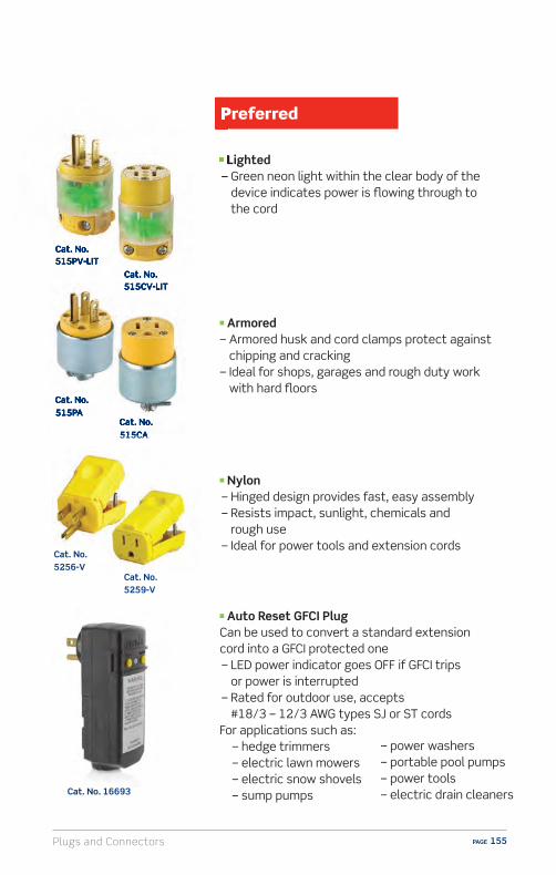
Plugs and Connectors PAGE 155
Cat. No. 515PV-LIT
Cat. No. 515PA
Cat. No. 5256-V
Cat. No. 515CV-LIT
Cat. No. 515CA
Cat. No. 5259-V
Cat. No. 16693
n Lighted – Green neon light within the clear body of the
device indicates power is flowing through to the cord
n Armored– Armored husk and cord clamps protect against
chipping and cracking– Ideal for shops, garages and rough duty work
with hard floors
n Nylon – Hinged design provides fast, easy assembly – Resists impact, sunlight, chemicals and
rough use – Ideal for power tools and extension cords
n Auto Reset GFCI PlugCan be used to convert a standard extension cord into a GFCI protected one – LED power indicator goes OFF if GFCI trips
or power is interrupted – Rated for outdoor use, accepts
#18/3 – 12/3 AWG types SJ or ST cordsFor applications such as:
– hedge trimmers – electric lawn mowers – electric snow shovels – sump pumps
Cat. No. 515PV-LIT
Cat. No.
n Lighted–
Cat. No. 515PA
515CV-LIT
Cat. No. 515CA
– power washers – portable pool pumps – power tools – electric drain cleaners

Plugs and ConnectorsPAGE 156
Cat. No. 5266
Cat. No. 5269-CA
Cat. No. 2311
Cat. No. 5269
Cat. No. 2313
n Heavy Duty Nylon
black & white®
– Super tough body resists damage from severe impact, abrasion and chemicals
– High-performance solid brass blades for plugs and triple-wipe heavy duty power contacts for connectors
– Available in a broad range of ratings and NEMA configurations– Accommodate a wide range of cord types and sizes, from 18/3 SVT to
10/3 ST (.245 inches to .700 inches, outside diameter)– Available in straight blade and locking configurations
n Heavy Duty Angle Nylon– Lays flush with wall
n Heavy Duty Locking Nylon– Prevents unwanted power disconnections

Plugs and Connectors PAGE 157
n Heavy Duty Locking Nylon– Prevents unwanted power
disconnections– Color-coded by amperage ratings
n Heavy Duty Locking Nylon Flush Mount
– Prevents unwanted power disconnections
– Color-coded by amperage ratings
15A 20A 30A
125V 250V 125/250V
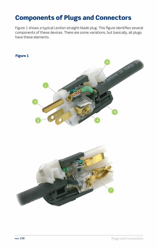
Plugs and ConnectorsPAGE 158
Components of Plugs and ConnectorsFigure 1 shows a typical Leviton straight-blade plug. This figure identifies several components of these devices. There are some variations, but basically, all plugs have these elements.
Figure 1
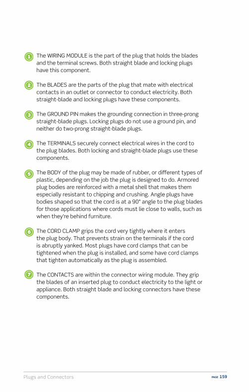
Plugs and Connectors PAGE 159
The WIRING MODULE is the part of the plug that holds the blades and the terminal screws. Both straight blade and locking plugs have this component.
The BLADES are the parts of the plug that mate with electrical contacts in an outlet or connector to conduct electricity. Both straight-blade and locking plugs have these components.
The GROUND PIN makes the grounding connection in three-prong straight-blade plugs. Locking plugs do not use a ground pin, and neither do two-prong straight-blade plugs.
The TERMINALS securely connect electrical wires in the cord to the plug blades. Both locking and straight-blade plugs use these components.
The BODY of the plug may be made of rubber, or di�erent types of plastic, depending on the job the plug is designed to do. Armored plug bodies are reinforced with a metal shell that makes them especially resistant to chipping and crushing. Angle plugs have bodies shaped so that the cord is at a 90° angle to the plug blades for those applications where cords must lie close to walls, such as when they’re behind furniture.
The CORD CLAMP grips the cord very tightly where it enters the plug body. That prevents strain on the terminals if the cord is abruptly yanked. Most plugs have cord clamps that can be tightened when the plug is installed, and some have cord clamps that tighten automatically as the plug is assembled.
The CONTACTS are within the connector wiring module. They grip the blades of an inserted plug to conduct electricity to the light or appliance. Both straight blade and locking connectors have these components.

Plugs and ConnectorsPAGE 160
Selecting the Right Type of Plugs andConnectors for the Right Cords
SPT-2 is common two-wire cord that’s found in every home. It’s usually used for lamp cords and small appliances such as toasters and blenders. USE ONLY WITH TWO-PRONG PLUGS OR TWO-SLOT CONNECTORS. It must never be used with three-prong devices.
Jacketed Cord or Cable features insulated conductors surrounded by a jacket made of rubber or plastic that bundle and protects the conductors. This type of cord is often used with larger electrical devices such as heavy-duty power tools, microwaves, electric motors, compressors and even some heavy-duty work lights. Nearly all heavy-duty commercial and industrial equipment uses jacketed cord and heavy-duty extension cords are always jacketed. The individual conductors are always provided with color coded insulation to distinguish them from one another so that proper terminations can be made when being wired. Depending on the intended use, jacketed cord can have up to five conductors inside the jacket.
All plugs and connectors are ONLY wired to flexible cords with stranded conductors. NEVER USE SOLID WIRE. But just as there are many di�erent types of plugs and connectors, there are also many di�erent types and sizes of cords and cables designed for di�erent applications.
Cord TypesThe two most commonly used cords are called SPT-2 and Jacketed Cord. There are other types, but almost all household plugs and connectors are used with these two kinds of cords.
Jacketed Cord
SPT-2
Plugs and Connectors PAGE 161
The electrical industry uses a standard measurement to describe the diameter of copper in a cord conductor. The measurement is called the American Wire Gauge, and its abbreviated AWG. The size of the conductor’s diameter is simply expressed as a number followed by the letters AWG.
It’s also important to remember that the AWG numbers ONLY REFER TO THESIZE OF THE COPPER CONDUCTORS, not to the diameter of the whole cord. Inaddition, there will be more than one conductor in any line cord. For example,if a cord is stamped SJT 12/3, the letters SJT describe the jacket material andconstruction. The numbers 12/3 mean that the conductors are twelve AWG, andthere are three of them. ALL CORDS HAVE THIS TYPE OF NAME AND CONDUCTORIDENTIFICATION PRINTED RIGHT ON THE JACKET OR ON THE INSULATION.
There are dozens of cord types such as SJT, SOO, STW, and many others. Youreally can’t remember all of them, and the fact is you don’t need to. That’sbecause there’s one useful thing about cords to know: THE CORD DIAMETER.
One thing to keep in mind when wiring plugs and connectors is the NUMBER OF CONDUCTORS in the cord. The NUMBER OF CONDUCTORS MUST MATCH THE NUMBER OF PLUG BLADES OR CONNECTOR SLOTS EXACTLY.
For example, a three prong plug MUST be wired using a three conductor cord,it is unsafe and a violation of electrical codes to wire a three prong plug to atwo-conductor cord.
The LOWER THE NUMBER, THE THICKER THE WIRE. Thinner conductors are used for lamps and smaller appliances that don’t draw much current. The thicker conductors are for larger tools or appliances that make heavier electrical demands.
More Information About Cords
Plugs and ConnectorsPAGE 162
Installation and Wiring Considerations
1. If there is any installation where the customer is unsure of how to proceed, or does not feel able to carry out the tasks specified in the wiring device instruction sheets, STOP RIGHT THERE! In such a case always advise the customer to CONSULT AN ELECTRICIAN. Electrical wiring can be complicated, and unless the installation can be properly and safely completed by the customer, the very best plan is to contact an electrician.
2. The information in this manual is here to help you serve your customers. Do not use this information as a substitute for the installation instructions provided with the devices. The instructions contain very specific and detailed directions for the device they’re packed with. So, use this guide as a general reference, but familiarize yourself with the specific instruction sheets for the devices your customers will be asking about.
3. Remind your customers that in order to prevent death or injury before they begin any wiring project, THEY MUST TURN OFF POWER AT THE FUSE OR CIRCUIT BREAKER THAT SUPPLIES ELECTRICITY TO THE WIRES THEY WILL BE WORKING WITH. And after they complete their installation, they should restore power at the fuse or circuit breaker and verify that the new device is working properly. If the fuse blows or the circuit breaker opens when power is restored, or if the new device doesn’t seem to be working properly, the customer should immediately contact an electrician.
4. Be sure only properly rated devices are chosen for replacement and repair projects. For instance, a 3-way device MUST be replaced only with another 3-way device. Although a single-pole device may look similar it wouldn’t be a suitable replacement. Also, if devices are being installed on a 15 Amp branch circuit, then only 15 Amp devices may be used. Using a 20 Amp device on a 15 Amp branch circuit is potentially dangerous, and must be avoided. However, it is acceptable to use 15 Amp devices on a 20 Amp circuit.

Plugs and Connectors PAGE 163
n Lighted plugs and connectors provide visual indication power is flowing through to the cord.
n Hinged plugs and connectors are quick and easy to wire.n Use angle plugs and connectors behind furniture of equipment.n Locking plugs and connectors prevent unwanted power
disconnections for outdoor power tools.n The GFCI plug is ideal for replacement when being used outdoors or
near water.
Sell-Up Opportunities

Plugs and ConnectorsPAGE 164
Q: Can I make an extension cord with plugs on both sides as an adapter (most commonly asked at Christmas).
A: No, this is dangerous as both sides are live.
Q: Can I replace the 20 Amp plug on my appliance or tool so I can plug it into a 15 Amp outlet?
A: No, this is dangerous.
Q: Are these plugs waterproof?
A: No, only plugs that are specifically rated as “weatherproof” can be used in wet locations.
FAQs (Frequently Asked Questions)
Plugs and Connectors PAGE 165
(Frequently Asked Questions)
1. What are the two main types of plugs and connectors? A) Straight blade and locking B) Rubber and metal C) Plastic and metal D) Single and duplex
2. Which part of a plug holds the plug blades and terminal screws? A) The cord B) The clamp C) The wiring module D) None of the above
3. When a plug and connector are attached to an extension cord what two things must match EXACTLY? A) Size and color B) Rating and NEMA configuration C) Terminals and size D) The cord clamps of the two devices
4. Why do plugs and connectors have di�erent NEMA configurations? A) For di�erent equipment B) So they can supply power or draw power only with other properly
matched devices C) For easier installation D) For faster wiring
5 . What keeps the cord firmly in place for plugs and connectors? A) Terminals screws B) Cord clamp C) Mounting screws D) Cord insulation
6. What are examples of Preferred grade plugs and connectors? A) Armored and nylon B) Decora plugs and connectors C) CO/ALR plugs and connectors D) None of the above
Plugs and Connectors – Self Test Questions
Plugs and ConnectorsPAGE 166
7. How many wires must there be in a cord connected to a three prong plug? A) Two B) Three C) Four D) Six
8. Which part of a connector grip the blades of an inserted plug and provide the plug with electricity? A) The terminal screws B) The contacts C) The cord clamp D) None of the above
9. Why are locking plugs and connectors used in many commercial and industrial applications? A) More economical B) More extensive color selection C) To prevent unwanted power disconnections D) For superior heat resistance
10. What is the most common type of cord used with two-prong plugs? A) SPT-2 B) Fireproof cord C) Telephone cord D) Beige cord
Plugs and Connectors – Self Test Questions

Plugs and Connectors PAGE 167
ResourcesVideo library, buying guides and more
www.learnitatleviton.com
Still have questions?Contact our Technical Support Team
1-800-824-3005
Need to place a special order?Contact Customer Service
1-800-367-5424
www.leviton.com
Training Notes
Plugs and ConnectorsPAGE 168
1. ANSWER: A) The two main types of plugs and connectors are straight blade and locking. Check page 149 for information.
2. ANSWER: C) The wiring module on a plug holds the plug blades and terminal screws. Check pages 158-159 for information.
3. ANSWER: B) The rating and NEMA configuration must match EXACTLY when mounting a plug and connector on an extension cord.Check page 151 for information.
4. ANSWER: B) Plugs and connectors have di�erent NEMA configurations so they can supply power or draw power only with other properly matched devices. Check page 151 for information.
5. ANSWER: B) The cord clamp keeps the cord firmly in place. Check pages 158-159 for information.
6. ANSWER: A) Armored and nylon are examples of Preferred grade plugs and connectors. Check page 155 for information.
7. ANSWER: D) There must be three wires on a cord connected to a three-prong plug. Check page 161 for information.
8. ANSWER: B) The contacts on a connector grip the blades of an inserted plug and provide the plug with electricity. Check pages 158-159 for information.
9. ANSWER: B) Locking plugs and connectors are used in many commercial and industrial applications to prevent unwanted power disconnections. Check pages 149, 156-157 for information.
10. ANSWER: A) SPT-2 is the most common type of cord used with two prong plugs. Check page 160 for information.
Plugs and Connectors – Self Test Answers

Wallplates PAGE 169
WallplatesWallplates provide the finishing touch to switches, outlets and lighting controls. They serve to protect the devices as well as provide a decorative accent which can blend in or contrast with the wall. In some cases wallplates are packaged with the device, but generally they are sold separately.
OverviewLeviton wallplates are available in a broad selection of configurations from single to multi-gang, as well as outdoor weather resistant covers. Leviton wallplates are constructed of quality materials which include unbreakable nylon, plastic and stainless steel. Selected wallplates are available in Regular, Midway and Jumbo sizes.

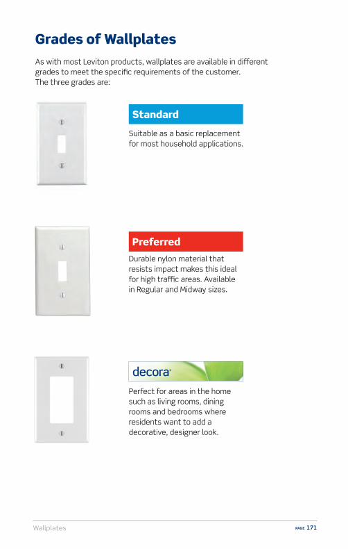
Wallplates PAGE 171
Grades of WallplatesAs with most Leviton products, wallplates are available in di�erent grades to meet the specific requirements of the customer. The three grades are:
Durable nylon material that resists impact makes this ideal for high tra�c areas. Available in Regular and Midway sizes.
Perfect for areas in the home such as living rooms, dining rooms and bedrooms where residents want to add a decorative, designer look.
Suitable as a basic replacement for most household applications.

WallplatesPAGE 172
Wallplate Sizes
Regular4.50'' x 2.75'' – Standard size for general use
Midway4.88'' x 3.13'' – 3/8'' larger on all sides to help cover wall imperfections
Jumbo5.25'' x 3.50'' – 3/4'' larger on all sides to help cover more significant wall imperfections
Leviton wallplates are available in the following three sizes:
4.50''
4.88''
5.25''
2.75''
3.13''
3.50''
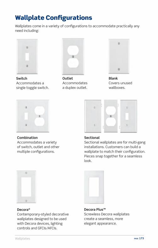
Wallplates PAGE 173
Wallplate Configurations
Decora Plus™ Screwless Decora wallplates create a seamless, more elegant appearance.
Wallplates come in a variety of configurations to accommodate practically any need including:
Switch Accommodates a single toggle switch.
Outlet Accommodates a duplex outlet.
Blank Covers unused wallboxes.
Combination Accommodates a variety of switch, outlet and other multiple configurations.
Decora® Contemporary-styled decorative wallplates designed to be used with Decora devices, lighting controls and GFCIs/AFCIs.
Sectional Sectional wallplates are for multi-gang installations. Customers can build a wallplate to match their configuration. Pieces snap together for a seamless look.
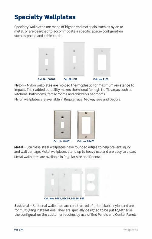
WallplatesPAGE 174
Specialty WallplatesSpecialty Wallplates are made of higher-end materials, such as nylon or metal, or are designed to accommodate a specific space/configuration such as phone and cable cords.
Nylon – Nylon wallplates are molded thermoplastic for maximum resistance to impact. Their added durability makes them ideal for high tra�c areas such as kitchens, bathrooms, family rooms and children’s bedrooms.
Nylon wallplates are available in Regular size, Midway size and Decora.
Metal – Stainless steel wallplates have rounded edges to help prevent injury and wall damage. Metal wallplates stand up to heavy use and are easy to clean.
Metal wallplates are available in Regular size and Decora.
Sectional – Sectional wallplates are constructed of unbreakable nylon and are for multi-gang installations. They are specially designed to be put together in the configuration the customer requires by use of End Panels and Center Panels.
Cat. No. 80707
Cat. No. 84001 Cat. No. 84401
Cat. No. PJ1 Cat. No. PJ26
Cat. Nos. PSE1, PSC14, PSC26, PSE
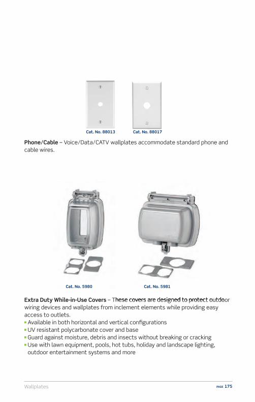
Wallplates PAGE 175
Phone/Cable – Voice/Data/CATV wallplates accommodate standard phone and cable wires.
Extra Duty While-in-Use Covers – These covers are designed to protect outdoor wiring devices and wallplates from inclement elements while providing easy access to outlets.n Available in both horizontal and vertical configurationsn UV resistant polycarbonate cover and basen Guard against moisture, debris and insects without breaking or cracking n Use with lawn equipment, pools, hot tubs, holiday and landscape lighting,
outdoor entertainment systems and more
– These covers are designed to protect outdoor
Cat. No. 88013 Cat. No. 88017
Cat. No. 5981Cat. No. 5980

WallplatesPAGE 176
n Plastic is good but nylon wallplates are more durable and are able to withstand heavy use/abuse.
n For replacement, recommend Midway and Jumbo size wallplates to help cover wall imperfections.
n Standard Decora provides a decorative look. For a smoother, sleeker look, Screwless Decora is a simple solution.
n Metal wallplates are ideal for high abuse applications such as basements, garages and utility rooms.
Sell-Up Opportunities

Wallplates PAGE 177
Q: Why would I need to use a Midway or Jumbo wallplate?
A: The larger size of Midway and Jumbo wallplates helps to hide imperfections that may be on the wall surrounding the outlet
Q: What is the difference between a Decora wallplate and a Regular wallplate?
A: Decora wallplates by design provide a clean, decorative look. They come in a wide selection of colors and finishes, and color matched mounting screws are included.
Q: I have an outlet that I do not use and want to cover it. Is there a cover available?
A: Yes. Blank face wallplates are perfect for this application.
FAQs (Frequently Asked Questions)

WallplatesPAGE 178
1. Leviton wallplates come in all the following sizes except:A) JumboB) RegularC) BonusD) Midway
2. Wallplates can be used for:A) OutletsB) Switches/Lighting ControlsC) Phone/CableD) All of the above
3. For a decorative look, customers should use:A) A Decora wallplateB) A Combination wallplateC) A Metal WallplateD) No wallplate
Wallplates – Self Test Questions

Wallplates PAGE 179
ResourcesVideo library, buying guides and more
www.learnitatleviton.com
Still have questions?Contact our Technical Support Team
1-800-824-3005
Need to place a special order?Contact Customer Service
1-800-367-5424
www.leviton.com
Training Notes

WallplatesPAGE 180
1. ANSWER: C) Leviton wallplates come in Regular, Midway and Jumbo sizes. Check pages 169, 172 for information.
2. ANSWER: D) All of the above. Wallplates can be used for switches/lighting controls, outlets, and phone/cable. Check pages 173, 174-175 for information.
3. ANSWER: A) Decora wallplates provide a decorative look. Check pages 171, 173 for information.
Wallplates – Self Test Answers
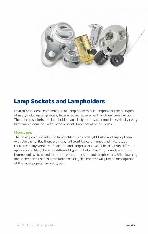
Lamp Sockets and Lampholders PAGE 181
Lamp Sockets and LampholdersLeviton produces a complete line of Lamp Sockets and Lampholders for all types of uses, including lamp repair, fixture repair, replacement, and new construction. These lamp sockets and lampholders are designed to accommodate virtually every light source equipped with incandescent, fluorescent or CFL bulbs.
OverviewThe basic job of sockets and lampholders is to hold light bulbs and supply them with electricity. But there are many di�erent types of lamps and fixtures, so there are many versions of sockets and lampholders available to satisfy di�erent applications. Also, there are di�erent types of bulbs, like CFL, incandescent and fluorescent, which need di�erent types of sockets and lampholders. After learning about the parts used in basic lamp sockets, this chapter will provide descriptions of the most popular socket types.

Lamp Sockets and LampholdersPAGE 182
Components of Basic Lamp SocketsFigure 1 shows a basic incandescent lamp socket, and identifies several components of the device. There are some variations, but basically all incandescent lamp sockets have these elements.
Figure 1

Lamp Sockets and Lampholders PAGE 183
The BASE is the part of the socket that screws onto the lamp or fixture.
The SHELL snaps into the base and covers the lampholder’s interior mechanism.
The INTERIOR MECHANISM holds the bulb and provides it with electricity. It also can provide the switch for turning power to the bulb ON and OFF. It’s the part that the lamp or fixture cord will be wired to.
The TERMINAL SCREWS are used to connect the lamp cord to the socket, and they’re color coded. The brass screw is for the “hot” wire, and the silver-colored screw is for the neutral wire of the lamp cord.
The LINER is the important part of the socket which fits inside the shell of metal lampholders, and it insulates the interior mechanism. Some plastic or porcelain lampholders don’t use liners.

Lamp Sockets and LampholdersPAGE 184
Cat. No. 688
Types of Sockets
n Turn-Knob Lamp Sockets – These sockets have ON/OFF switches that work by turning the switch knob. The knob clicks into the ON setting, then OFF, then ON again. It only turns in one direction.
n Pull-Chain Lamp Sockets – These sockets provide ON/OFF switching simply by using the pull chain. They are generally used in lamps and fixtures where the style of lampshade would make it di�cult to reach a turn knob on the socket itself.
Cat. No. 7080
Cat. No. 10083
n Push-Through Lamp Sockets – Feature ON/OFF switches that work by being pushed back and forth. Push them one way, the light goes ON, push them back, it goes OFF.
Lamp Repair
Cat. No. 19980

Lamp Sockets and Lampholders PAGE 185
n Dimmer Sockets – These devices look like ordinary turn-knob sockets, but they’re actually dimmers. They can provide full-range dimming using ordinary light bulbs for any lamp. They are ideal replacements for lamps that use a push-through or turn knob socket.
Cat. No. 6151
Cat. No. 7090
n Lamp Sockets for 3-Way Bulbs – These sockets use a four-position turn knob to provide three di�erent light levels in lamps that use three-way bulbs. The available settings are OFF, LOW, MEDIUM, HIGH then back to OFF. Although these sockets will work properly with any standard light bulb, they can only provide the three light levels when used with three-way light bulbs.
Cat. No. 8004-M
n Socket Interiors – Sometimes, when making repairs to a lamp, customers prefer not to replace the entire socket. Instead, they simply replace the socket interior. Socket interiors are provided for keyless, push-through, turn-knob, and pull-chain sockets.
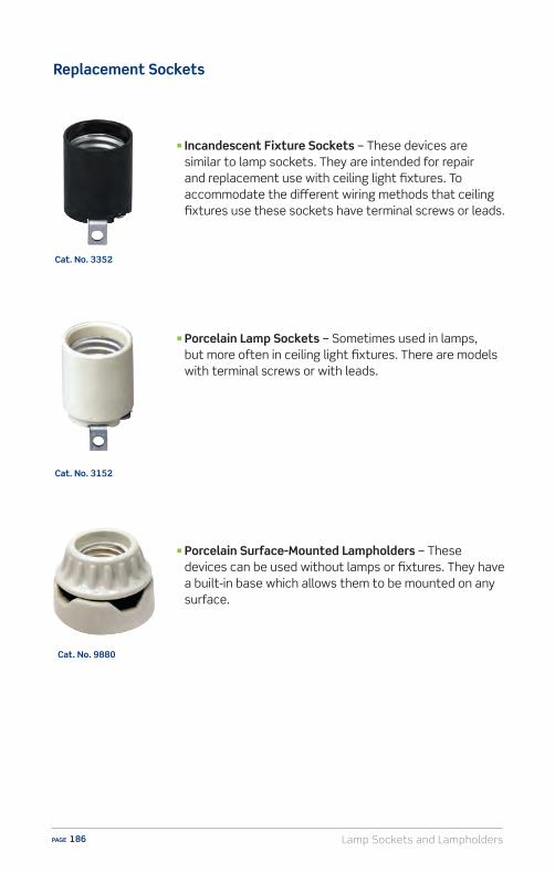
Lamp Sockets and LampholdersPAGE 186
Cat. No. 9880
n Porcelain Lamp Sockets – Sometimes used in lamps, but more often in ceiling light fixtures. There are models with terminal screws or with leads.
n Porcelain Surface-Mounted Lampholders – These devices can be used without lamps or fixtures. They have a built-in base which allows them to be mounted on any surface.
Cat. No. 3352
Cat. No. 3152
n Incandescent Fixture Sockets – These devices are similar to lamp sockets. They are intended for repair and replacement use with ceiling light fixtures. To accommodate the di�erent wiring methods that ceiling fixtures use these sockets have terminal screws or leads.
Replacement Sockets

Lamp Sockets and Lampholders PAGE 187
n Outdoor Sockets – These sockets are designed to accept ordinary bulbs and they’re engineered for outdoor use. Some are provided with hooks so they can hang from suspended lines.
Cat. No. 167
Cat. No. 55
Cat. No. 10025
n Candelabra Sockets – These small sockets are designed for the small-base decorative bulbs that are used in candelabras. They come with screw terminals or leads, and a variety of mounting brackets.
Cat. No. 167
Cat. No. 4015
n Cluster Sockets – These devices o�er multiple sockets that can accommodate more than one bulb. They are often used as replacement sockets in older lamps and ceiling fixtures and are only available with leads for wiring.
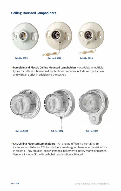
Lamp Sockets and LampholdersPAGE 188
n CFL Ceiling Mounted Lampholders – An energy-e�cient alternative to incandescent fixtures, CFL lampholders are designed to reduce the risk of fire in closets. They are also ideal in garages, basements, utility rooms and attics. Versions include CFL with pull-chain and motion activated.
Cat. No. 9875
n Porcelain and Plastic Ceiling Mounted Lampholders – Available in multiple types for di�erent household applications. Versions include with pull-chain and with an outlet in addition to the socket.
Ceiling Mounted Lampholders
Cat. No. 29816 Cat. No. 9716
Cat. No. 9863Cat. No. 9862Cat. No. 9860
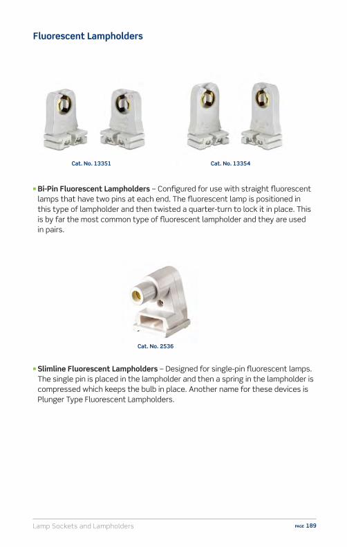
Lamp Sockets and Lampholders PAGE 189
Fluorescent Lampholders
n Slimline Fluorescent Lampholders – Designed for single-pin fluorescent lamps. The single pin is placed in the lampholder and then a spring in the lampholder is compressed which keeps the bulb in place. Another name for these devices is Plunger Type Fluorescent Lampholders.
n Bi-Pin Fluorescent Lampholders – Configured for use with straight fluorescent lamps that have two pins at each end. The fluorescent lamp is positioned in this type of lampholder and then twisted a quarter-turn to lock it in place. This is by far the most common type of fluorescent lampholder and they are used in pairs.
Cat. No. 13351 Cat. No. 13354
Cat. No. 2536
Lamp Sockets and LampholdersPAGE 190
Installation and Wiring Considerations
1. If there is any installation where the customer is unsure of how to proceed, or does not feel able to carry out the tasks specified in the wiring device instruction sheets, STOP RIGHT THERE! In such a case always advise the customer to CONSULT AN ELECTRICIAN. Electrical wiring can be complicated, and unless the installation can be properly and safely completed by the customer, the very best plan is to contact an electrician.
2. The information in this manual is here to help you serve your customers. Do not use this information as a substitute for the installation instructions provided with the devices. The instructions contain very specific and detailed directions for the device they’re packed with. Use this guide as a general reference, but familiarize yourself with the specific instruction sheets for the devices your customers will be asking about.
3. Remind your customers that in order to prevent death or injury before they begin any wiring project, THEY MUST TURN OFF POWER AT THE FUSE OR CIRCUIT BREAKER THAT SUPPLIES ELECTRICITY TO THE WIRES THEY WILL BE WORKING WITH. And after they complete their installation, they should restore power at the fuse or circuit breaker and verify that the new device is working properly. If the fuse blows or the circuit breaker opens when power is restored, or if the new device doesn’t seem to be working properly, the customer should immediately contact an electrician.
4. Be sure only properly rated devices are chosen for replacement and repair projects. For instance, a 3-way device MUST be replaced only with another 3-way device. Although a single-pole device may look similar it wouldn’t be a suitable replacement. Also, if devices are being installed on a 15 Amp branch circuit, then only 15 Amp devices may be used. Using a 20 Amp device on a 15 Amp branch circuit is potentially dangerous, and must be avoided. However, it is acceptable to use 15 Amp devices on a 20 Amp circuit.

Lamp Sockets and Lampholders PAGE 191
ResourcesVideo library, buying guides and more
www.learnitatleviton.com
Still have questions?Contact our Technical Support Team
1-800-824-3005
Need to place a special order?Contact Customer Service
1-800-367-5424
www.leviton.com
Training Notes
Lamp Sockets and LampholdersPAGE 192
1. Name some parts of a typical socket.A) Terminal screws and baseB) Liner and shellC) Interior mechanismD) All of the above
2. When wiring a socket to lamp cord, which wire goes to the brass terminal screw, and which wire goes to the silver-colored terminal screw?
A) Hot to brass, neutral to silverB) Hot to silver, neutral to brassC) Ground to brass, neutral to silverD) Neutral to brass, load to silver
3. What are candelabra sockets?A) Larger than standardB) Designed for small-base decorative bulbsC) Designed for flashlightsD) None of the above
4. What are the two types of Leviton fluorescent lampholders?A) Aluminum and brassB) AC and DCC) Bi-pin and SlimlineD) Vertical and horizontal
5. Why are there many di�erent types of lampholders?A) To meet the requirements of di�erent fixturesB) To meet the requirements of di�erent bulb typesC) To meet the requirements of di�erent applicationsD) All of the above
6. Name a few types of Leviton sockets.A) Push-through, turn-knob, and pull chain socketsB) Three-way, dimmer, and fixture socketsC) Porcelain and candelabra socketsD) All of the above
Lampholder – Self Test Questions

Lamp Sockets and Lampholders PAGE 193
7. Which part of a socket actually screws onto a lamp or fixture?A) The baseB) The shellC) The linerD) The interior mechanism
8. When repairing a lamp, is there an alternative to replacing the socket?A) YesB) No
Lampholder – Self Test Questions

Lamp Sockets and LampholdersPAGE 194
1. ANSWER: D) The base, shell, interior mechanism and liner are all parts of a typical socket. Check pages 182-183 for information.
2. ANSWER: A) When wiring a socket to a lamp cord the brass screw is for the “hot” wire, and the silver-colored screw is for the neutral wire. Check pages 182-183 for information.
3. ANSWER: C) Candelabra sockets are designed for small-base decorative bulbs. Check page 187 for information.
4. ANSWER: C) The two types of Leviton fluorescent lampholders are bi-pin and slimline. Check page 189 for information.
5. ANSWER: D) There are di�erent types of lampholders to meet requirements of di�erent fixtures, applications and bulb types. Check page 181 for information.
6. ANSWER: D) A few types of Leviton sockets are keyless, push-through, turn-knob, pull-chain, three-way, dimmer socket, fixture sockets, porcelain, candelabra sockets. Check pages 184-188 for information.
7. ANSWER: A) The base of a socket screws into a lamp or fixture. Check pages 182-183 for information.
8. ANSWER: A) Yes, it is often practical to replace just the socket interior when repairing a lamp. Check page 185 for information.
Lampholder – Self Test Answers
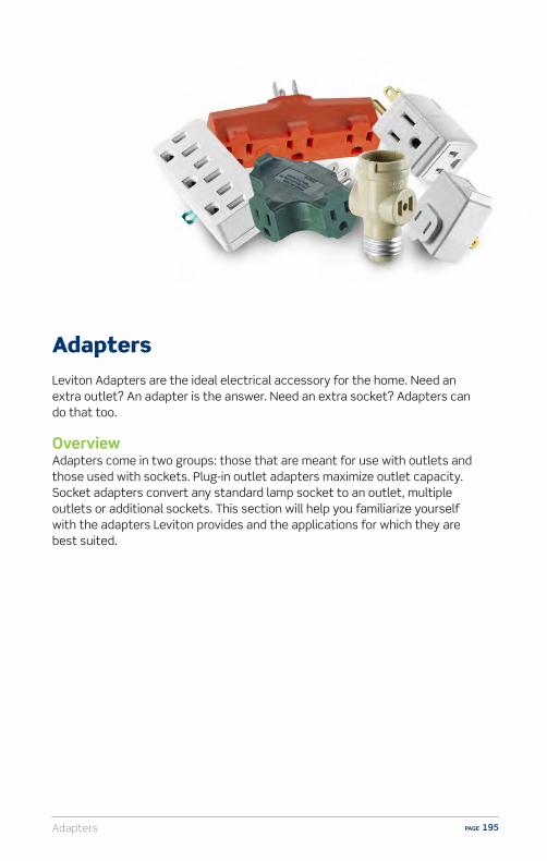
Adapters PAGE 195
AdaptersLeviton Adapters are the ideal electrical accessory for the home. Need an extra outlet? An adapter is the answer. Need an extra socket? Adapters can do that too.
OverviewAdapters come in two groups: those that are meant for use with outlets and those used with sockets. Plug-in outlet adapters maximize outlet capacity. Socket adapters convert any standard lamp socket to an outlet, multiple outlets or additional sockets. This section will help you familiarize yourself with the adapters Leviton provides and the applications for which they are best suited.

AdaptersPAGE 196
Types of Outlet Adapters
Non-Grounding to Grounding
Grounding is accomplished only when the outlet box is properly grounded. The ground connection for a 2-to-3 prong grounding adapter is made by fastening the adapter’s tab with the center screw that secures the outlet’s wallplate.
Outlet Adapter – Our most popular adapter, this device converts a 2-wire non-grounding outlet into a 3-wire grounding outlet.
Triple Outlet Adapter – Converts a 2-wire outlet to three 3-wire grounding outlets.
Cat. No. 274
Cat. No. 698
Remind your customers that in order to prevent death of injury, TURN OFF POWER TO THE FUSE OR CIRCUIT BEFORE INSTALLING. Consult an electrican to determine whether cover plate screw is grounded. Grounding continuity must be maintained. Fasten green tab under cover plate screw. Do not use GROUNDED adapters on extension cords or on outlets where the green tab cannot be connected.
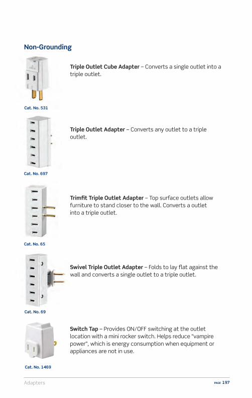
Adapters PAGE 197
Swivel Triple Outlet Adapter – Folds to lay flat against the wall and converts a single outlet to a triple outlet.
Trimfit Triple Outlet Adapter – Top surface outlets allow furniture to stand closer to the wall. Converts a outlet into a triple outlet.
Triple Outlet Cube Adapter – Converts a single outlet into a triple outlet.
Triple Outlet Adapter – Converts any outlet to a triple outlet.
Non-Grounding
Cat. No. 697
Cat. No. 65
Cat. No. 531
Switch Tap – Provides ON/OFF switching at the outlet location with a mini rocker switch. Helps reduce “vampire power”, which is energy consumption when equipment or appliances are not in use.
Cat. No. 1469
Cat. No. 69

AdaptersPAGE 198
Types of Outlet Adapters
Triple Outlet Adapter – For use with 3-prong grounding plugs. Converts a single grounded outlet into three grounded outlets.
Heavy Duty Triple Outlet Adapter – Sturdy vinyl construction for heavy duty applications, converts a single grounded outlet into three grounded outlets.
Grounded
Cat. No. 697
Cat. No. 694
Cat. No. 699
Six Outlet, 2-Wire Adapter – Can be permanently mounted to an outlet and converts a duplex outlet into six outlets.
Non-Grounding (cont’d)
Cat. No. 49687
Heavy Duty Triple Outlet Adapter construction for heavy duty applications, converts a single grounded outlet into three grounded outlets.
Cat. No. 699
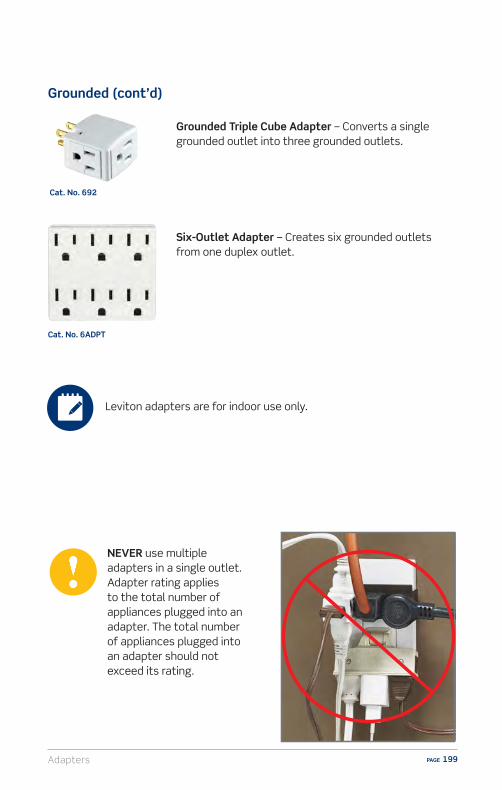
Adapters PAGE 199
NEVER use multiple adapters in a single outlet. Adapter rating applies to the total number of appliances plugged into an adapter. The total number of appliances plugged into an adapter should not exceed its rating.
Grounded Triple Cube Adapter – Converts a single grounded outlet into three grounded outlets.
Six-Outlet Adapter – Creates six grounded outlets from one duplex outlet.
Grounded (cont’d)
Cat. No. 692
Cat. No. 6ADPT
Leviton adapters are for indoor use only.

AdaptersPAGE 200
Types of Socket Adapters
Socket Adapter – Converts any standard lamp socket to a 2-wire outlet.
Two Outlet Socket Adapter – Converts a single lamp socket to a lamp socket plus two outlets.
Socket Adapter w/Pull Chain – Converts a single lamp socket to a pull chain lampholder plus two outlets.
Cat. No. 125
Cat. No. 1403
Cat. No. 1406
Socket to Outlet

Adapters PAGE 201
Twin Socket Adapter – Converts a single lamp socket to a double lamp socket.
Plug-In Outlet Adapter – Converts a standard outlet into a lamp socket.
Cat. No. 128
Cat. No. 61
Socket Extender
The design of Trimfit and Swivel adapters allow furniture to sit closer to the wall.
The ON/OFF Switch Tap is ideal for appliances, holiday and decorative lighting. Also helps reduce energy consumption when appliances such as toaster ovens and co�ee makers are not in use.
Sell-Up Opportunities
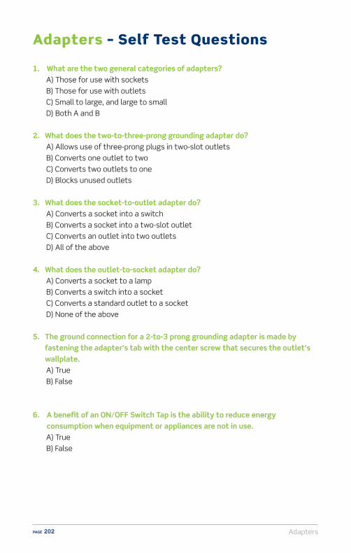
AdaptersPAGE 202
1. What are the two general categories of adapters?A) Those for use with socketsB) Those for use with outletsC) Small to large, and large to smallD) Both A and B
2. What does the two-to-three-prong grounding adapter do?A) Allows use of three-prong plugs in two-slot outletsB) Converts one outlet to twoC) Converts two outlets to oneD) Blocks unused outlets
3. What does the socket-to-outlet adapter do?A) Converts a socket into a switchB) Converts a socket into a two-slot outletC) Converts an outlet into two outletsD) All of the above
4. What does the outlet-to-socket adapter do?A) Converts a socket to a lampB) Converts a switch into a socketC) Converts a standard outlet to a socketD) None of the above
5. The ground connection for a 2-to-3 prong grounding adapter is made by fastening the adapter’s tab with the center screw that secures the outlet’s wallplate.A) TrueB) False
6. A benefit of an ON/OFF Switch Tap is the ability to reduce energy consumption when equipment or appliances are not in use.A) TrueB) False
Adapters – Self Test Questions

Adapters PAGE 203
ResourcesVideo library, buying guides and more
www.learnitatleviton.com
Still have questions?Contact our Technical Support Team
1-800-824-3005
Need to place a special order?Contact Customer Service
1-800-367-5424
www.leviton.com
Training Notes

AdaptersPAGE 204
1. ANSWER: D) The two general categories of adapters are those meant for use with sockets, and those for use with outlets. Check page 195 for information.
2. ANSWER: A) The two-to-three-prong grounding adapter allows the use of three prong plugs in two-slot outlets. Check page 196 for information.
3. ANSWER: B) The socket-to-outlet adapter converts a standard socket into a two-slot outlet. Check page 200 for information.
4. ANSWER: C) The outlet-to-socket adapter converts a standard outlet opening into a bulb socket. Check page 201 for information.
5. ANSWER: A) True. The ground connection for a 2-to-3 prong grounding adapter is made by fastening the adapter’s tab with the center screw that secures the outlet’s wallplate. Check page 196 for information.
6. ANSWER: A) True. A benefit of an ON/OFF Switch Tap is the ability to reduce energy consumption when equipment or appliances are not in use. Check page 197 for information.
Adapters – Self Test Answers

Merchandising PAGE 205
MerchandisingThe electrical aisle can be overwhelming due to the large number of products, models and grades within a category. Leviton o�ers a packaging and a merchandising program which makes it easier for associates to navigate shelves, take advantage of sell-up opportunities and generate sales. The bold colors and clear labeling of Leviton products attract attention, deliver important information and provide a positive shopping experience so your customers look forward to making future purchases.
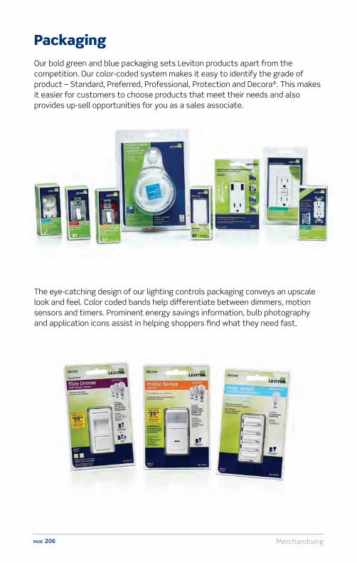
MerchandisingPAGE 206
PackagingOur bold green and blue packaging sets Leviton products apart from the competition. Our color-coded system makes it easy to identify the grade of product – Standard, Preferred, Professional, Protection and Decora®. This makes it easier for customers to choose products that meet their needs and also provides up-sell opportunities for you as a sales associate.
The eye-catching design of our lighting controls packaging conveys an upscale look and feel. Color coded bands help di�erentiate between dimmers, motion sensors and timers. Prominent energy savings information, bulb photography and application icons assist in helping shoppers find what they need fast.

Merchandising PAGE 207
Standard/Preferred/Professional grades indicated by bold color coding creates a sell-up environment. Protection and Decora categories guide customers to sensible upgrades for safety and appealing decorative alternatives.
Sell-Up Program
Bold red color emphasizes Preferred grade products and encourages sale of higher-margin items.
Decora products feature a decorative graphic to ensure di�erentiation from standard products.
Standard Preferred Professional Protection
Standard Good – suitable for most household applications
Preferred Better – for high tra�c areas, more features such as improved safety and durability
Professional Best – feature rich for the professional or serious DIY’er
Protection GFCI - helps protect against electrical shocksAFCI - helps protect against electrical fires
Decorative alternative to traditional switches and outlets and adds a finishing touch

MerchandisingPAGE 208
Product Identification CardsLeviton Product Identification Cards provide a wealth of information at a glance. Along with a product photo, these bilingual cards call out grade, product description, application, color, catalog number and, if applicable, the Made in USA cerification mark. There is also ample space at the bottom for customized SKU’s and pricing information.
Grade
Color
Application Icon
Cat. No.
Product Photo
Made in USA Certification Mark
Bilingual Product Description
Additional 1.25 area for price/SKU label
`̀
4.75 `̀
3.5 `̀
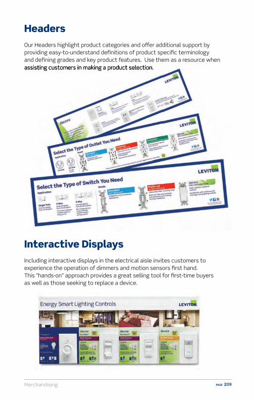
Merchandising PAGE 209
HeadersOur Headers highlight product categories and o�er additional support by providing easy-to-understand definitions of product specific terminology and defining grades and key product features. Use them as a resource when assisting customers in making a product selection.assisting customers in making a product selection.
Interactive DisplaysIncluding interactive displays in the electrical aisle invites customers to experience the operation of dimmers and motion sensors first hand. This “hands-on” approach provides a great selling tool for first-time buyers as well as those seeking to replace a device.
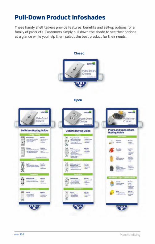
MerchandisingPAGE 210
Pull-Down Product InfoshadesThese handy shelf talkers provide features, benefits and sell-up options for a family of products. Customers simply pull down the shade to see their options at a glance while you help them select the best product for their needs.
Closed
Open

Merchandising PAGE 211
Prepackaged DisplaysGreat looking displays get a customer’s attention and help drive sales. Leviton makes it easy for you to engage customers in everyday promotions with appealing floor displays, counter displays and gravity feed units.
Gravity Feed
Floor Display
Counter Display
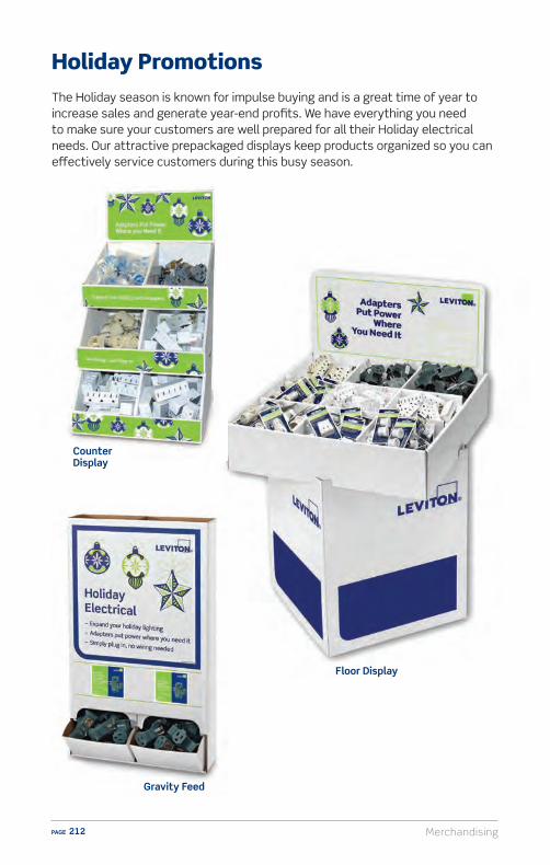
MerchandisingPAGE 212
Holiday PromotionsThe Holiday season is known for impulse buying and is a great time of year to increase sales and generate year-end profits. We have everything you need to make sure your customers are well prepared for all their Holiday electrical needs. Our attractive prepackaged displays keep products organized so you can e�ectively service customers during this busy season.
Floor Display
Gravity Feed
Counter Display
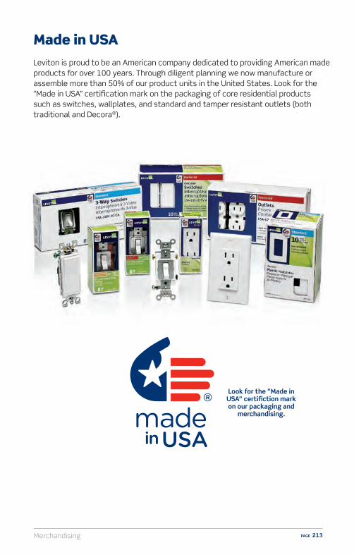
Merchandising PAGE 213
Made in USALeviton is proud to be an American company dedicated to providing American made products for over 100 years. Through diligent planning we now manufacture or assemble more than 50% of our product units in the United States. Look for the “Made in USA” certification mark on the packaging of core residential products such as switches, wallplates, and standard and tamper resistant outlets (both traditional and Decora®).
Look for the “Made in USA” certifiction mark on our packaging and
merchandising.


Glossary PAGE 215
2-Wire – Two-prong outlets connected to two-wire cables. 2-wire outlets don’t have ground wires that protect people and electrical devices in case of a fault.
3-Wire – Three-prong outlets which contain a ground wire.
Alternating Current (AC) – Electrons move in one direction for a very short time, and then they reverse direction. This happens over and over again. Generally, all of the appliances and lights in a home run o� of AC power.
AC Only – A switch designated for use with Alternating Current (AC) only.
Actuator – The mechanism on the switch that is used to switch lights ON/OFF. Examples include toggle and rocker.
Adapter – An accessory used for interconnecting non-mating devices converting an existing device for modified use.
AFCI (Arc Fault Circuit Interrupter) Outlet – An outlet designed to recognize many types of potentially dangerous arc-faults and respond by interrupting power to help prevent arc-faults that may lead to a fire.
Amp (Amperage) – The strength of an electric current measured in amperes.
Arc-Fault – An unwanted flow of electrical current in a circuit. Arcing creates high intensity heating at the point of the arc resulting in burning particles that can exceed 10,000 Fahrenheit.
Branch Circuit – The wiring within the walls that runs from the circuit breaker to outlets throughout the house.
CFL – Abbreviation for Compact Fluorescent Lamp, a type of energy-e�cient bulb.
CO/ALR – Switches and outlets designated for use with aluminum or copper circuit conductors, identified by “CO/ALR” stamped on the device. Switches and outlets without this designation must never be used with aluminum circuit conductors.
Combination – Provides two functions from a single device.
Configuration – Identifies the various combinations found in plugs, connectors and receptacles to prevent the wrong combinations of electrical systems from being plugged together.
Current – The flow of an electrical charge.
Glossary
GlossaryPAGE 216
Decora® – Leviton’s line of decorative devices which add a finishing touch to any interior, from traditional to contemporary.
Derating – The process of reducing the maximum allowable wattage in dimmers that are ganged to reduce excess heat during operation.
Device – An object made for a specific purpose.
Dimmer – A switch with electronic circuitry that provides DIM/BRIGHT control of lighting loads. Has a round knob, slide lever or fingertip controlled buttons used to dim/brighten lighting in a room.
Direct Current (DC) – A constant stream of charges (electrons) moving in one direction.
Double Pole – A switch that switches two conductors. Commonly used on 240 Volt loads.
Duplex – Two receptacles built with a common body and mounting means; accepts two plugs.
Electrical Rating – Identifies the voltage and the maximum electrical load for a device.
Fan Speed Control – The management of the rotational speed of an electric fan.
Feed-through Protection – The same level of protection is provided to anything installed or plugged into an outlet from that location in the circuit to the end of the branch.
Fluorescent Starter – A device with a voltage-sensitive switch and a capacitor that provides a high-voltage pulse to start a fluorescent lamp. Rated in watts.
Four-Way – A switch used in conjunction with two 3-Way switches to control a single load (such as a light fixture) from three or more locations. This switch has four terminal screws.
Flush – A wallplate designed for flush-mounting with wall surfaces or the plane surfaces of electrical equipment.
Gang – A term that describes the number of devices a wallplate is sized to fit (i.e. “2- gang” designates two devices).
Glossary PAGE 217
GFCI (Ground Fault Circuit Interrupter) Outlet– An outlet with a built in circuit that will detect leakage current to ground on the load side of the device. When the GFCI detects leakage current to ground, it will interrupt power to the load side of the device, preventing a hazardous ground fault condition. GFCI outlets must conform to UL requirements, and their use is required by the National Electric Code® in wet or damp indoor and outdoor locations.
Ground Fault – A situation where, instead of following its normal safe path, electricity overloads a circuit, shorts a circuit or otherwise follows an undesirable path.
Grounded – Sometimes referred to as a neutral wire, grounded wires carry electrical current under normal operating conditions. A grounded wire is required by the National Electrical Code to be white or gray in color on the customer side of the meter.
Grounding – An adapter that converts a two-wire receptacle opening into a two-pole, three-wire grounding receptacle opening.
Hertz – A measurement of frequency based upon cycles per second.
Horsepower Rated – A switch with a marked horsepower rating, intended for use in switching motor loads.
Hospital Grade – A device designed to meet the performance requirements of high-abuse areas typically found in health care facilities.
Hot – The black wire is the hot wire, which provides a 120 VAC current source.
Illuminated – A switch whose toggle and/or frame becomes illuminated when the device is connected to an energized electrical circuit.
Isolated Ground – Outlets intended for use in an Isolated Grounding system where the ground path is isolated from the facility grounding system. The grounding connection on these outlets is isolated from the mounting strap.
Jumbo Wallplate – Wallplates that are approx. 3/4'' taller and wider than the standard size and are used to conceal greater wall irregularities than those hidden by Midway wallplates. These wallplates are approx. 1/4'' deep to ensure a proper fit when used with protruding devices.
Jacketed Cord – A protective outer covering for a cable. Depending on the intended use for the cable and the operational environment, it may protect against moisture, abrasion, magnetic fields, radiation, and so on.

GlossaryPAGE 218
Lamp – The industry term for “bulb”.
Lampholder – A device with contacts that establishes mechanical and electrical connection to an inserted lamp.
Leads – An electrical connection consisting of a length of wire that comes from a device. They are used for physical support or to transfer power.
LED – Abbreviation for Light-Emitting Diodes, a type of energy-e�cient bulb.
Locking Connector – A connector designed to lock an inserted plug with a matching blade configuration when the plug is rotated in a clockwise direction. The plug can only be removed by first turning it in a counter-clockwise direction.
Locking Plug – A plug designed to lock into a matching connector or outlet configuration when the plug is rotated in a clockwise direction. The plug can only be removed by turning it in a counter-clockwise direction.
Locking Receptacle – An outlet designed to lock an inserted plug with a matching blade configuration when the plug is rotated in a clockwise direction. The plug can only be removed by first turning it in a counter-clockwise direction.
Low-Voltage – A switch rated for use on low-voltage circuits of 50 volts or less.
Lumen – A measurement of the amount of light a bulb gives o�.
Midway Wallplate – Wallplates that are approx. 3/8'' higher and wider than the standard size that can be mounted onto larger volume outlet boxes and/or used to hide wall surface irregularities. These wallplates are approx. 1/4'' deep to ensure a proper fit when used with protruding devices.
Mounting Strap – The backbone of a device. Used to hold the device in place within the wallbox.
Multi-Gang Wallplate – A wallplate that has two or more gangs (openings).
National Electrical Code® (NEC®) – A United States standard for the safe installation of electrical wiring and equipment. The Code is updated every three years.
National Electrical Manufacturer’s Association® (NEMA®) – The association of electrical equipment and medical imaging manufacturers which provides a forum for the development of technical standards.
Neutral – The white wire is called the neutral wire. It provides the return path for the current provided by the hot wire. The neutral wire is connected to an earth ground.
Glossary PAGE 219
Outlet – Point on the wiring system at which electric power is actually used by devices such as receptacles and fixtures.
Overload – Operation of equipment in excess of normal, full-load current rating; or of a conductor in excess of rated ampacity for a su�cient length of time to cause damage or dangerous overheating.
Pilot Light – A switch with an integral lamp in its actuator (toggle, rocker or push button) that illuminates when the switch is connected to an energized circuit and the actuator is in the ON position.
Plug – A device with male contacts intended for insertion into an outlet to establish electrical connection between the attached flexible cord and the conductors connected to the outlet.
Polarized – A plug with one wide and one narrow blade.
Preset Timer Switch – Devices that permit timed control of lights and appliances. Users choose from up to four time-out options (i.e. – 10 minutes, 20 minutes, 30 minutes, 60 minutes).
Programmable Timer Switch – Devices that allow users to program timed control of lighting, appliance and other loads. Times may be programmed daily, weekly, monthly etc… and can be varied. Devices often feature an astronomical clock for automatic adjustment to sunrise/sunset times.
Push Button – A switch with an actuator mechanism that is operated by depressing a button.
Receptacle – Also known as an outlet. A device with female contacts designed for fixed installation in a structure or piece of equipment and which is intended to establish electrical connection with an inserted plug.
Reset/Lockout – Prevents reset if a SmartlockPro GFCI or AFCI is damaged and is unable to respond to a ground fault.
Rotary – A switch where rotating the actuator in a clockwise direction makes the circuit connection, and then rotating the actuator in either the same or opposite direction breaks the connection.
Single – An outlet that accepts only one plug.
Single Pole – Controls lights from one location.
Slide – A switch with a slide-action actuator for making or breaking circuit contact. Dimmer switches and fan speed controls are also available with slide-action mechanisms for lighting and fan speed control.

GlossaryPAGE 220
Socket – A device in a wall into which an electric cord can be plugged. An opening on a piece of electrical equipment into which a plug, light bulb, etc., fits.
Straight Blade Connector – A non-locking connector into which mating plugs are inserted at a right angle to the plane of the connector face.
Straight Blade Plug – A non-locking plug that is inserted at a right angle to the plane of the matching device face.
Surface-Mounted – Any switch that mounts on a flat or plane surface.
Switch – A device for making, breaking, or changing the connections in an electric circuit.
Tamper Resistant – An outlet specially constructed with a built-in shutter mechanism so that access to its energized contacts is limited. Tamper Resistant outlets are required by the National Electric Code in new or renovated residential construction.
Three-Way – A switch, always used in pairs, that controls a single load such as a light fixture from two locations. This switch has three terminal screws.
Time Delay – A switch with an integral mechanism or electronic circuit that will automatically switch a load OFF at a predetermined time interval.
Timer Switch – A switch with an integral mechanism or electronic circuit that can be set to switch an electrical load ON/OFF at a predetermined time.
Toggle – A switch with a lever-type actuator that makes or breaks switch contact as its position is changed.
Volt (Voltage) – A measurement of the energy contained within an electric field, or an electric circuit, at a given point.
Wallplate – A plate designed to enclose an electrical box, with or without a device installed within the box.
Watt – A measurement of the rate at which electrical energy is dissipated.
Weather-Resistant – A device specially constructed so that exposure to weather will not interfere with its operation.
Wire – Conductor through which electrical current flows.